Embed Size (px)
Citation preview
Motorcycles
TechnicalTraining
BMW MotorcyclesMotorcycle Training
J:\BULLETIN\SERVICE\MCTRAINI\Manuals\R1200CL-PDI.qxd
R 1200 CL• Technical Features in Detail• Uncrating & Set up• Pre Delivery Inspection • Inspection Procedures (600 Mile)• Special Tools• Wiring Diagrams
09/02
BMW of North America, LLC BMW MotorcyclesZU-X-S-51
R 1200 CLDisclaimer
R 1200 CL Introduction
This training reference book is not intended to be a complete and all inclusivesource of servicing, repairing or troubleshooting the motorcycle. This is only partof the training information designed to ensure that uniform procedures andinformation are presented to all participants of Technical Training conducted byBMW Motorcycles.
The technician must always refer to and adhere to the following official BMWMotorrad and BMW North America, Inc service publications.
• Training Materials
• Repair Manuals
• Service Bulletins
• MoDiTeC
Service Bulletins are issued by the BMW Motorcycle Service Department,regarding changes in operation, and repair or maintenance procedures. ServiceBulletins are available on MTAS (www.bmwmc.net). From the departments menubutton on the home page, select “On-line bulletin search”.
Information Status, (date indicated on front cover).
For changes/additions to the technical data, please refer to current informationissued by the BMW NA Motorcycle Service Department.
1
R 1200 CLTable of Contents
R 1200 CL Introduction
Subject PageTechnical Features in Detail
Introduction . . . . . . . . . . . . . . . . . . . . . . . . . . . . . . . . . . . . . . 2Engine . . . . . . . . . . . . . . . . . . . . . . . . . . . . . . . . . . . . . . . . . . 4Clutch . . . . . . . . . . . . . . . . . . . . . . . . . . . . . . . . . . . . . . . . . . 7Gearbox . . . . . . . . . . . . . . . . . . . . . . . . . . . . . . . . . . . . . . . . 8Digital Motor Electronics (MA 2.4) . . . . . . . . . . . . . . . . . . . . . 10Chassis and wheels . . . . . . . . . . . . . . . . . . . . . . . . . . . . . . . 14Brakes (Integral ABS). . . . . . . . . . . . . . . . . . . . . . . . . . . . . . . 20Bodywork . . . . . . . . . . . . . . . . . . . . . . . . . . . . . . . . . . . . . . . 24Headlights . . . . . . . . . . . . . . . . . . . . . . . . . . . . . . . . . . . . . . . 28Cockpit and Instruments . . . . . . . . . . . . . . . . . . . . . . . . . . . . 30Electrical components . . . . . . . . . . . . . . . . . . . . . . . . . . . . . . 31Cruise Control . . . . . . . . . . . . . . . . . . . . . . . . . . . . . . . . . . . . 32Sound and Communication Systems. . . . . . . . . . . . . . . . . . . 36
Technical data . . . . . . . . . . . . . . . . . . . . . . . . . . . . . . . . . . . . . . 38
Pre Delivery Inspection Procedures . . . . . . . . . . . . . . . . . . . . . 42
Retail Delivery Handover Procedure . . . . . . . . . . . . . . . . . . . . . 61
600 Mile Inspection Procedures . . . . . . . . . . . . . . . . . . . . . . . . 64
New Special Tools . . . . . . . . . . . . . . . . . . . . . . . . . . . . . . . . . . . . 78
Wiring DiagramsTerminal & Electrical Component Designation Legend . . . . . 83Power Distribution & Grounds . . . . . . . . . . . . . . . . . . . . . . . . 85Starter & Alternator . . . . . . . . . . . . . . . . . . . . . . . . . . . . . . . . 89Motronic MA 2.4 Engine Management. . . . . . . . . . . . . . . . . . 91Anti-lock Brakes . . . . . . . . . . . . . . . . . . . . . . . . . . . . . . . . . . 97Cruise Control . . . . . . . . . . . . . . . . . . . . . . . . . . . . . . . . . . . . 99Instrumentation . . . . . . . . . . . . . . . . . . . . . . . . . . . . . . . . . . . 101Lights . . . . . . . . . . . . . . . . . . . . . . . . . . . . . . . . . . . . . . . . . . 105Horn,Turn Indicators with Hazard Flashers . . . . . . . . . . . . . . 107Radio/CD Player . . . . . . . . . . . . . . . . . . . . . . . . . . . . . . . . . . 109Heated Grips/Seat and Diagnostic Plug . . . . . . . . . . . . . . . . 111Alarm System . . . . . . . . . . . . . . . . . . . . . . . . . . . . . . . . . . . . 113
Electrical Component Location Charts . . . . . . . . . . . . . . . . . . 115
Alarm System Components and Programming Information. . 121
2
R 1200 CLIntroduction
Technical Features in Detail
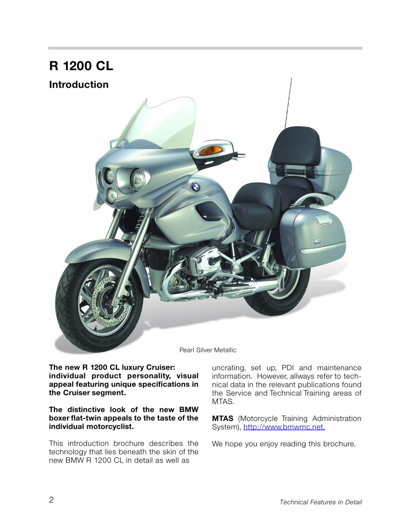
The new R 1200 CL luxury Cruiser:individual product personality, visualappeal featuring unique specifications inthe Cruiser segment.
The distinctive look of the new BMWboxer flat-twin appeals to the taste of theindividual motorcyclist.
This introduction brochure describes thetechnology that lies beneath the skin of thenew BMW R 1200 CL in detail as well as
uncrating, set up, PDI and maintenanceinformation. However, allways refer to tech-nical data in the relevant publications foundthe Service and Technical Training areas ofMTAS.
MTAS (Motorcycle Training AdministrationSystem), http://www.bmwmc.net.
We hope you enjoy reading this brochure.
Pearl Silver Metallic
3
Overview. Assembled at the Berlin plantwith its sister models, the R 1200 CL is yetanother milestone for BMW Motorcycles. Ittakes its place in the line up of previouslyintroduced R 1200 C models including theClassic introduced in 1997, and the latermodel variants including the R 1200 CMontana, Euro, Stilleto and Phoenix, all ofwhich have laid the foundation for anextremely successful series.
The name identifies the character of thisnew R Series addition; R 1200 CL: Cruiserand Luxury, comfort with everyday suitabili-ty and a powerful appearance.
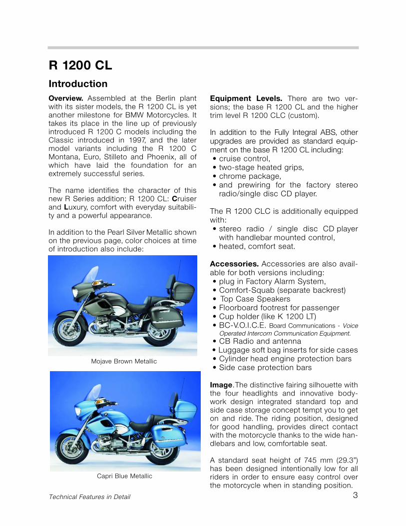
In addition to the Pearl Silver Metallic shownon the previous page, color choices at timeof introduction also include:
Equipment Levels. There are two ver-sions; the base R 1200 CL and the highertrim level R 1200 CLC (custom).
In addition to the Fully Integral ABS, otherupgrades are provided as standard equip-ment on the base R 1200 CL including:• cruise control,• two-stage heated grips,• chrome package,• and prewiring for the factory stereo
radio/single disc CD player.
The R 1200 CLC is additionally equippedwith:• stereo radio / single disc CD player
with handlebar mounted control,• heated, comfort seat.
Accessories. Accessories are also avail-able for both versions including:• plug in Factory Alarm System,• Comfort-Squab (separate backrest) • Top Case Speakers• Floorboard footrest for passenger• Cup holder (like K 1200 LT)• BC-V.O.I.C.E. Board Communications - Voice
Operated Intercom Communication Equipment.• CB Radio and antenna• Luggage soft bag inserts for side cases• Cylinder head engine protection bars• Side case protection bars
Image.The distinctive fairing silhouette withthe four headlights and innovative body-work design integrated standard top andside case storage concept tempt you to geton and ride. The riding position, designedfor good handling, provides direct contactwith the motorcycle thanks to the wide han-dlebars and low, comfortable seat.
A standard seat height of 745 mm (29.3”)has been designed intentionally low for allriders in order to ensure easy control overthe motorcycle when in standing position.
R 1200 CLIntroduction
Technical Features in Detail
Capri Blue Metallic
Mojave Brown Metallic
4
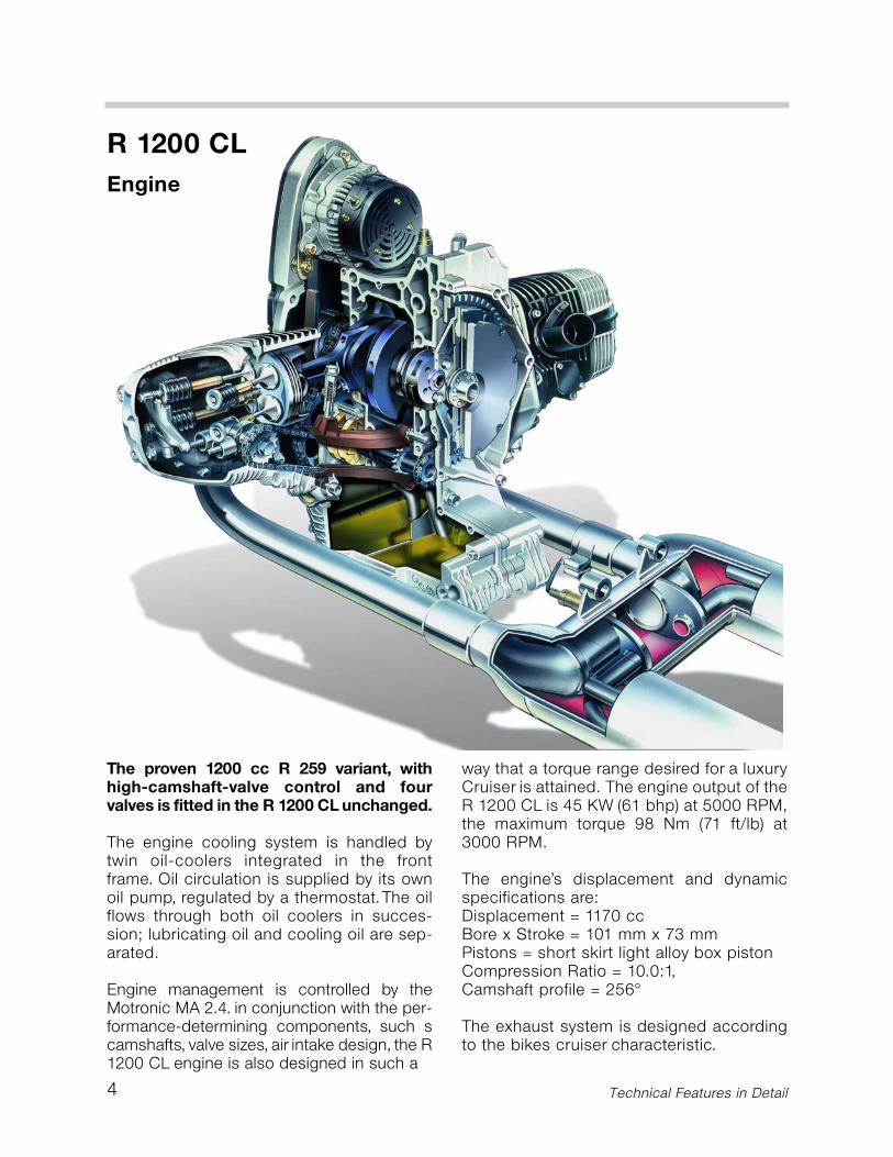
The proven 1200 cc R 259 variant, withhigh-camshaft-valve control and fourvalves is fitted in the R 1200 CL unchanged.
The engine cooling system is handled bytwin oil-coolers integrated in the frontframe. Oil circulation is supplied by its ownoil pump, regulated by a thermostat.The oilflows through both oil coolers in succes-sion; lubricating oil and cooling oil are sep-arated.
Engine management is controlled by theMotronic MA 2.4. in conjunction with the per-formance-determining components, such scamshafts, valve sizes, air intake design, the R1200 CL engine is also designed in such a
way that a torque range desired for a luxuryCruiser is attained. The engine output of theR 1200 CL is 45 KW (61 bhp) at 5000 RPM,the maximum torque 98 Nm (71 ft/lb) at3000 RPM.
The engine’s displacement and dynamicspecifications are:Displacement = 1170 ccBore x Stroke = 101 mm x 73 mmPistons = short skirt light alloy box pistonCompression Ratio = 10.0:1,Camshaft profile = 256°
The exhaust system is designed accordingto the bikes cruiser characteristic.
R 1200 CLEngine
Technical Features in Detail
5
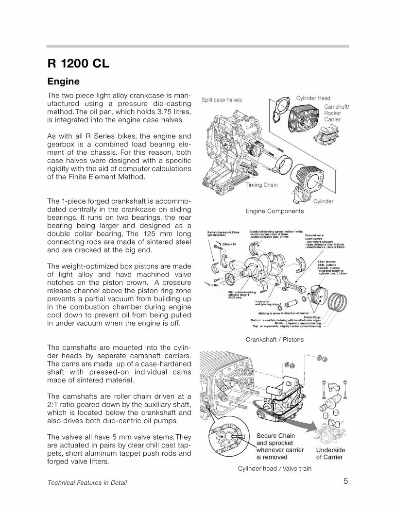
The two piece light alloy crankcase is man-ufactured using a pressure die-castingmethod.The oil pan, which holds 3.75 litres,is integrated into the engine case halves.
As with all R Series bikes, the engine andgearbox is a combined load bearing ele-ment of the chassis. For this reason, bothcase halves were designed with a specificrigidity with the aid of computer calculationsof the Finite Element Method.
The 1-piece forged crankshaft is accommo-dated centrally in the crankcase on slidingbearings. It runs on two bearings, the rearbearing being larger and designed as adouble collar bearing. The 125 mm longconnecting rods are made of sintered steeland are cracked at the big end.
The weight-optimized box pistons are madeof light alloy and have machined valvenotches on the piston crown. A pressurerelease channel above the piston ring zoneprevents a partial vacuum from building upin the combustion chamber during enginecool down to prevent oil from being pulledin under vacuum when the engine is off.
The camshafts are mounted into the cylin-der heads by separate camshaft carriers.The cams are made up of a case-hardenedshaft with pressed-on individual camsmade of sintered material.
The camshafts are roller chain driven at a2:1 ratio geared down by the auxiliary shaft,which is located below the crankshaft andalso drives both duo-centric oil pumps.
The valves all have 5 mm valve stems.Theyare actuated in pairs by clear chill cast tap-pets, short aluminum tappet push rods andforged valve lifters.
R 1200 CLEngine
Technical Features in Detail
Engine Components
Crankshaft / Pistons
Cylinder head / Valve train

6
R 1200 CLEngine
The engine is designed to run on premiumgrade fuel (95 RON/92 AKI).The air fuel mix-ture is ignited by a centrally placed sparkplug.
Directly connected to each spark plug arethe new direct connection ignition coils (ie:F 650 CS). These coils eliminate the sec-ondary spark plug wire ensuring consistentspark voltage over the lifetime of the motor-cycle. Due to the ignition coils, the cylinderhead covers are new.The ignition coils eachhave a separate ground wire that connectsto the engine cylinder head.
The exhaust system with a hard chromeplated surface is produced in three sec-tions: two exhaust manifolds consisting of a55 mm double walled tube and a flange-mounted, 1-section exhaust silencer withshort tail pipes.This has 4 chambers and isbased on the reflection and absorption prin-ciple.
In the exhaust silencer of the R 1200 CL, twocatalytic converters are used. The smalldiameter and a flat design, offers a highersectional flow. The cylindrical catalytic con-verter carriers have a diameter of 60 mmand a length of 74 mm.
The heated O2 sensor is located in theexhaust gas stream of the two exhaust man-ifolds beyond the catalytic converters.During the warm-up period from 60° Cmotor oil temperature (just a few minutesafter starting), it already ensures that theengine runs in accordance with the stoi-chiometric mixture (lambda=1).
The catalytic converters are made of palla-dium and rhodium. Palladium acceleratesthe oxidation of hydrocarbons and carbonmonoxide. Rhodium reduces nitric oxide.
New Ignition Coils
Exhaust Components
Twin Catalytic Converters, Single O2 Sensor
R 1200 CL Introduction
7
R 1200 CLClutch
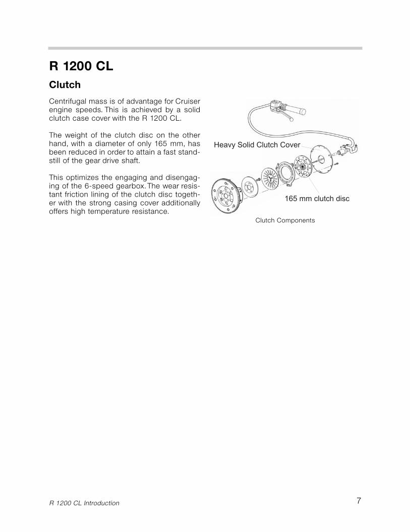
Centrifugal mass is of advantage for Cruiserengine speeds. This is achieved by a solidclutch case cover with the R 1200 CL.
The weight of the clutch disc on the otherhand, with a diameter of only 165 mm, hasbeen reduced in order to attain a fast stand-still of the gear drive shaft.
This optimizes the engaging and disengag-ing of the 6-speed gearbox.The wear resis-tant friction lining of the clutch disc togeth-er with the strong casing cover additionallyoffers high temperature resistance.
Clutch Components
R 1200 CL Introduction
8
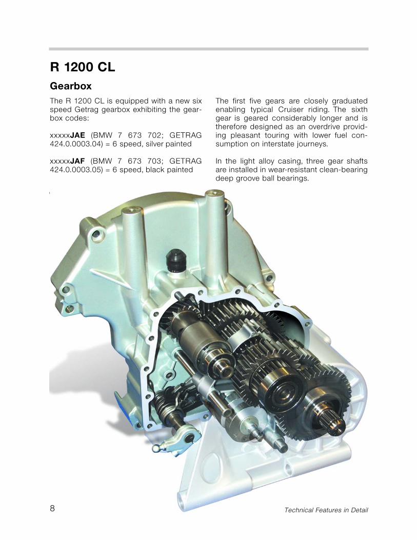
The R 1200 CL is equipped with a new sixspeed Getrag gearbox exhibiting the gear-box codes:
xxxxxJAE (BMW 7 673 702; GETRAG424.0.0003.04) = 6 speed, silver painted
xxxxxJAF (BMW 7 673 703; GETRAG424.0.0003.05) = 6 speed, black painted
The first five gears are closely graduatedenabling typical Cruiser riding. The sixthgear is geared considerably longer and istherefore designed as an overdrive provid-ing pleasant touring with lower fuel con-sumption on interstate journeys.
In the light alloy casing, three gear shaftsare installed in wear-resistant clean-bearingdeep groove ball bearings.
R 1200 CLGearbox
Technical Features in Detail
9
The engaging and disengaging gears arelocated on the auxiliary shaft and the drivenshaft. All driven gears are installed on low-friction needle bearings.
The new heal/toe shifter transfers the ridersshift action to the gearbox through ball andpin pivots to the input shaft. The heal/toeshifter is made of chrome plated forged alu-minum.
The aluminum shifter drum is fixed in theexact gear positions by a cam plate. Thedie-cast aluminum shifter forks are actuat-ed by the shifting gates of the camshaftcontrollers via anti-friction steel bushes.Theshifter forks glide smoothly on hollow boredsteel shafts and engage the gears exactly.
The gear pair of the primary drive has a qui-etly running, wear-resistant spiral gearing.All other gears are provided with a spurtoothing and are constructed tightly inter-locked.This provides smoother meshing forparticularly quiet running.
The hollow-bored drive shaft bears a com-pact, two phase starting damper. The rota-tional oscillations occurring during the idlespeed of the engine are absorbed by a pre-stressed washer. A heavy-duty coil springworks in the main damper, which is respon-sible for reducing the noise occurring dur-ing the changing of gear and load.
R 1200 CLGear Box
Technical Features in Detail
10
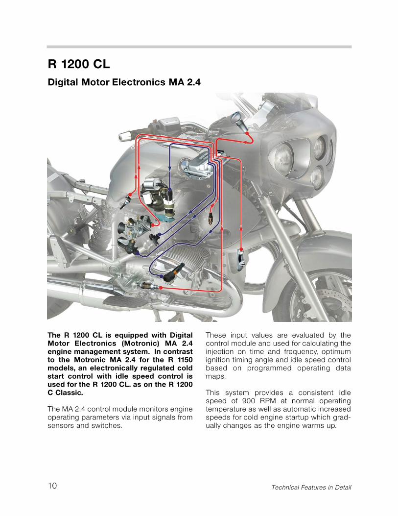
The R 1200 CL is equipped with DigitalMotor Electronics (Motronic) MA 2.4engine management system. In contrastto the Motronic MA 2.4 for the R 1150models, an electronically regulated coldstart control with idle speed control isused for the R 1200 CL. as on the R 1200C Classic.
The MA 2.4 control module monitors engineoperating parameters via input signals fromsensors and switches.
These input values are evaluated by thecontrol module and used for calculating theinjection on time and frequency, optimumignition timing angle and idle speed controlbased on programmed operating datamaps.
This system provides a consistent idlespeed of 900 RPM at normal operatingtemperature as well as automatic increasedspeeds for cold engine startup which grad-ually changes as the engine warms up.
R 1200 CLDigital Motor Electronics MA 2.4
Technical Features in Detail
11
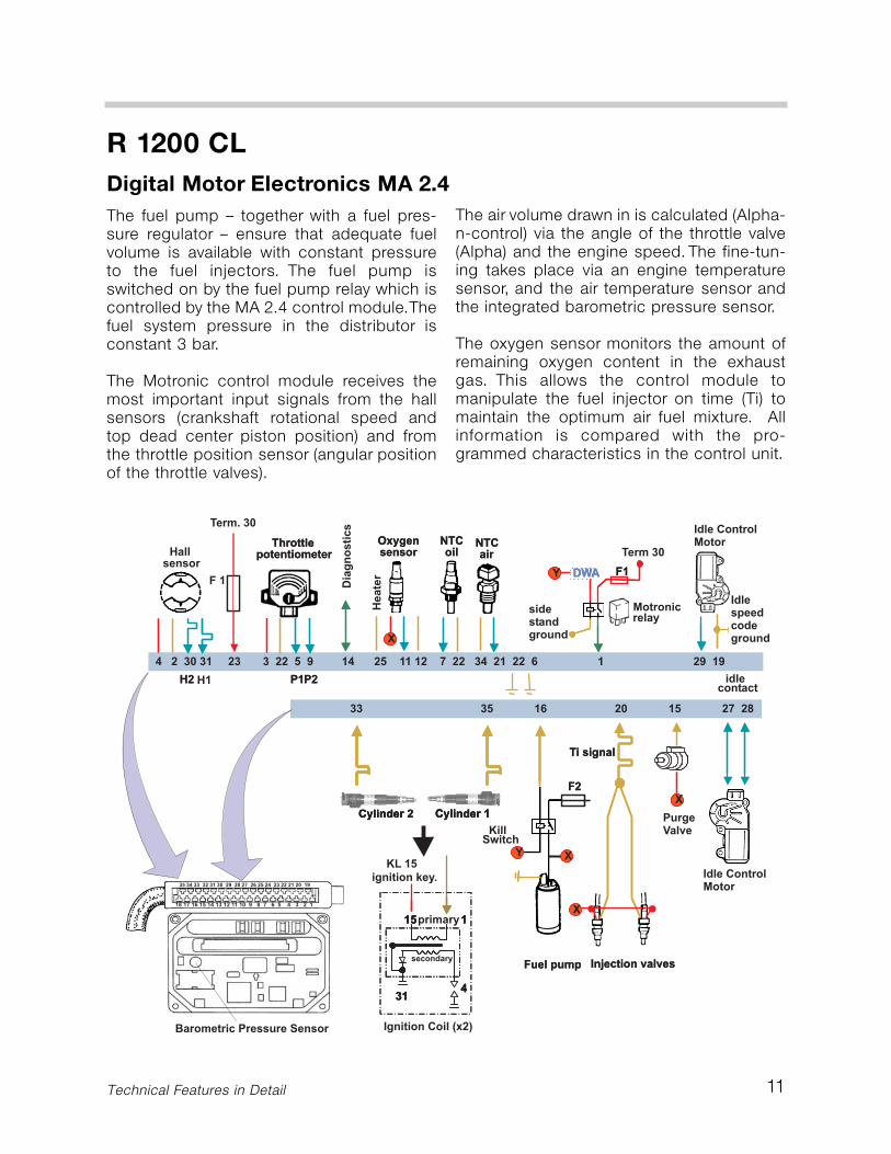
The fuel pump – together with a fuel pres-sure regulator – ensure that adequate fuelvolume is available with constant pressureto the fuel injectors. The fuel pump isswitched on by the fuel pump relay which iscontrolled by the MA 2.4 control module.Thefuel system pressure in the distributor isconstant 3 bar.
The Motronic control module receives themost important input signals from the hallsensors (crankshaft rotational speed andtop dead center piston position) and fromthe throttle position sensor (angular positionof the throttle valves).
The air volume drawn in is calculated (Alpha-n-control) via the angle of the throttle valve(Alpha) and the engine speed. The fine-tun-ing takes place via an engine temperaturesensor, and the air temperature sensor andthe integrated barometric pressure sensor.
The oxygen sensor monitors the amount ofremaining oxygen content in the exhaustgas. This allows the control module tomanipulate the fuel injector on time (Ti) tomaintain the optimum air fuel mixture. Allinformation is compared with the pro-grammed characteristics in the control unit.
R 1200 CLDigital Motor Electronics MA 2.4
Technical Features in Detail
12
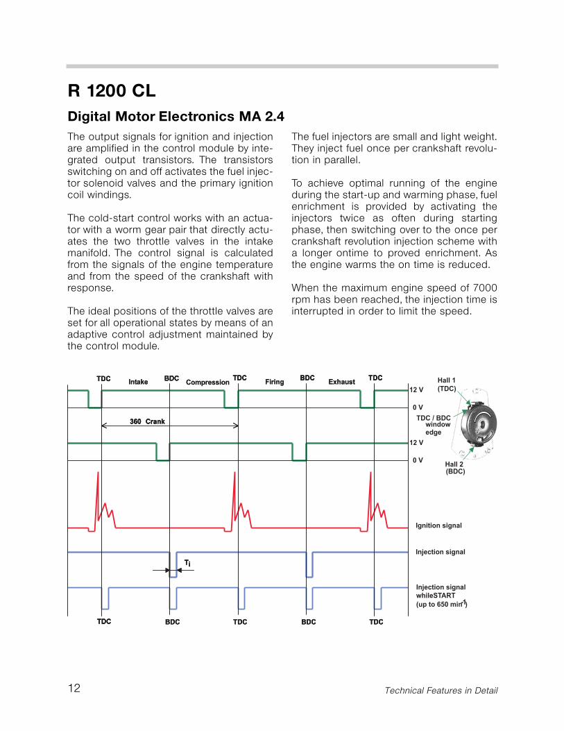
The output signals for ignition and injectionare amplified in the control module by inte-grated output transistors. The transistorsswitching on and off activates the fuel injec-tor solenoid valves and the primary ignitioncoil windings.
The cold-start control works with an actua-tor with a worm gear pair that directly actu-ates the two throttle valves in the intakemanifold. The control signal is calculatedfrom the signals of the engine temperatureand from the speed of the crankshaft withresponse.
The ideal positions of the throttle valves areset for all operational states by means of anadaptive control adjustment maintained bythe control module.
The fuel injectors are small and light weight.They inject fuel once per crankshaft revolu-tion in parallel.
To achieve optimal running of the engineduring the start-up and warming phase, fuelenrichment is provided by activating theinjectors twice as often during startingphase, then switching over to the once percrankshaft revolution injection scheme witha longer ontime to proved enrichment. Asthe engine warms the on time is reduced.
When the maximum engine speed of 7000rpm has been reached, the injection time isinterrupted in order to limit the speed.
R 1200 CLDigital Motor Electronics MA 2.4
Technical Features in Detail
13
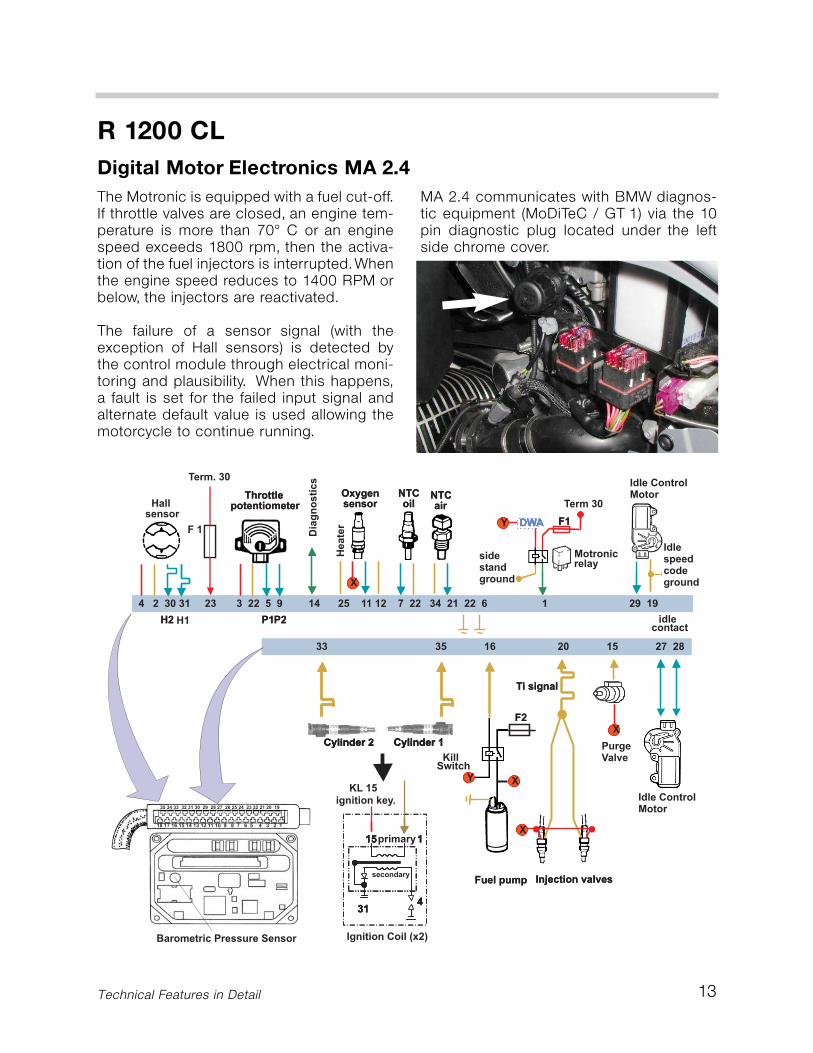
The Motronic is equipped with a fuel cut-off.If throttle valves are closed, an engine tem-perature is more than 70° C or an enginespeed exceeds 1800 rpm, then the activa-tion of the fuel injectors is interrupted.Whenthe engine speed reduces to 1400 RPM orbelow, the injectors are reactivated.
The failure of a sensor signal (with theexception of Hall sensors) is detected bythe control module through electrical moni-toring and plausibility. When this happens,a fault is set for the failed input signal andalternate default value is used allowing themotorcycle to continue running.
MA 2.4 communicates with BMW diagnos-tic equipment (MoDiTeC / GT 1) via the 10pin diagnostic plug located under the leftside chrome cover.
R 1200 CLDigital Motor Electronics MA 2.4
Technical Features in Detail
14
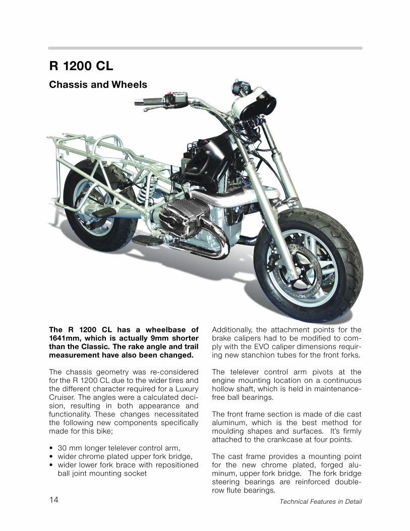
The R 1200 CL has a wheelbase of1641mm, which is actually 9mm shorterthan the Classic. The rake angle and trailmeasurement have also been changed.
The chassis geometry was re-consideredfor the R 1200 CL due to the wider tires andthe different character required for a LuxuryCruiser. The angles were a calculated deci-sion, resulting in both appearance andfunctionality. These changes necessitatedthe following new components specificallymade for this bike;
• 30 mm longer telelever control arm,• wider chrome plated upper fork bridge,• wider lower fork brace with repositioned
ball joint mounting socket
Additionally, the attachment points for thebrake calipers had to be modified to com-ply with the EVO caliper dimensions requir-ing new stanchion tubes for the front forks.
The telelever control arm pivots at theengine mounting location on a continuoushollow shaft, which is held in maintenance-free ball bearings.
The front frame section is made of die castaluminum, which is the best method formoulding shapes and surfaces. It’s firmlyattached to the crankcase at four points.
The cast frame provides a mounting pointfor the new chrome plated, forged alu-minum, upper fork bridge. The fork bridgesteering bearings are reinforced double-row flute bearings.
R 1200 CLChassis and Wheels
Technical Features in Detail
15
R 1200 CLChassis and Wheels
Technical Features in Detail
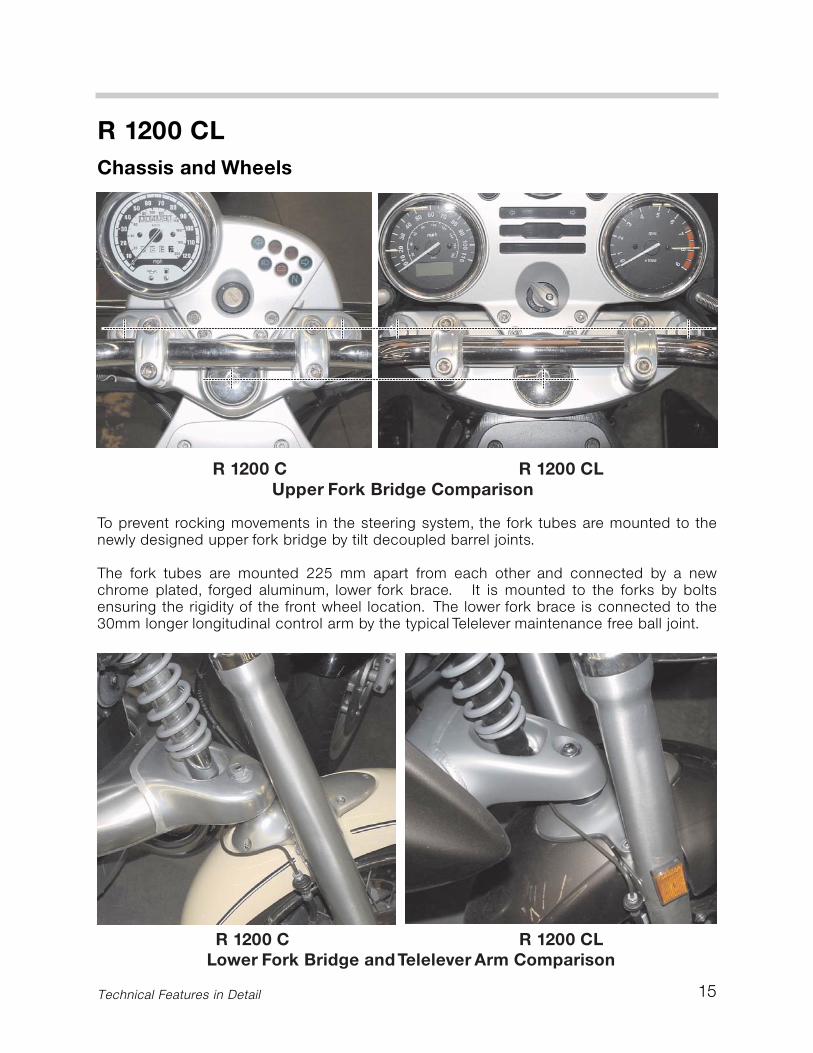
To prevent rocking movements in the steering system, the fork tubes are mounted to thenewly designed upper fork bridge by tilt decoupled barrel joints.
The fork tubes are mounted 225 mm apart from each other and connected by a newchrome plated, forged aluminum, lower fork brace. It is mounted to the forks by boltsensuring the rigidity of the front wheel location. The lower fork brace is connected to the30mm longer longitudinal control arm by the typical Telelever maintenance free ball joint.
16
R 1200 CLChassis and Wheels
Technical Features in Detail
The travel of the front wheel is damped by acentral suspension strut with twin-sleevedamper principle. It provides 144 mm offront suspension travel.
To review the changes in the chassis geom-etry we will compare the R 1200 C to theCL. But first lets review the basics of chas-sis geometry.
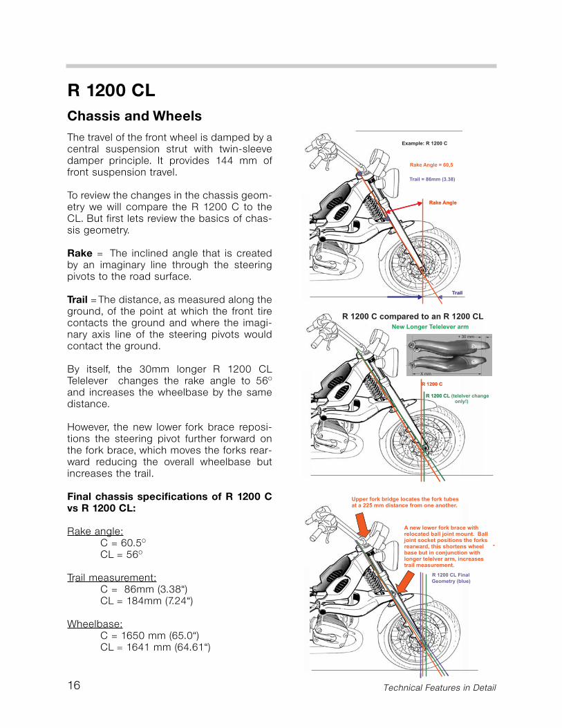
Rake = The inclined angle that is createdby an imaginary line through the steeringpivots to the road surface.
Trail = The distance, as measured along theground, of the point at which the front tirecontacts the ground and where the imagi-nary axis line of the steering pivots wouldcontact the ground.
By itself, the 30mm longer R 1200 CLTelelever changes the rake angle to 56O
and increases the wheelbase by the samedistance.
However, the new lower fork brace reposi-tions the steering pivot further forward onthe fork brace, which moves the forks rear-ward reducing the overall wheelbase butincreases the trail.
Final chassis specifications of R 1200 Cvs R 1200 CL:
Rake angle:C = 60.5O
CL = 56O
Trail measurement:C = 86mm (3.38“)CL = 184mm (7.24“)
Wheelbase:C = 1650 mm (65.0“)CL = 1641 mm (64.61“)
17
R 1200 CLChassis and Wheels
Technical Features in Detail
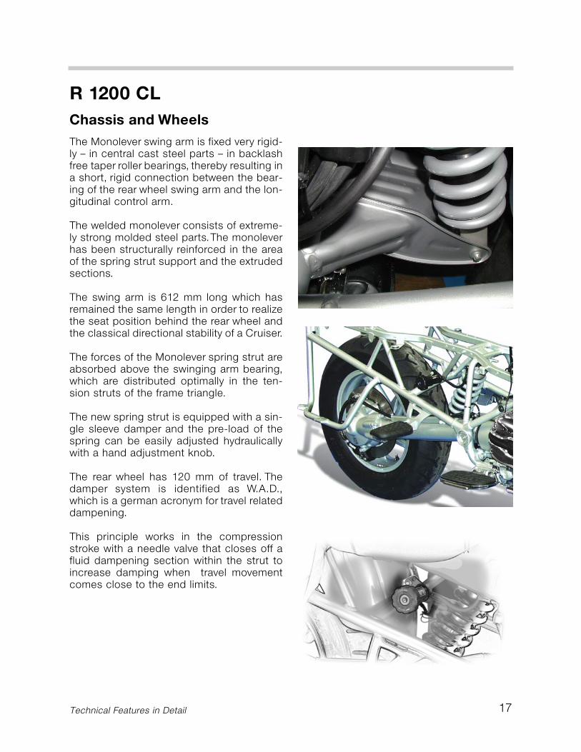
The Monolever swing arm is fixed very rigid-ly – in central cast steel parts – in backlashfree taper roller bearings, thereby resulting ina short, rigid connection between the bear-ing of the rear wheel swing arm and the lon-gitudinal control arm.
The welded monolever consists of extreme-ly strong molded steel parts.The monoleverhas been structurally reinforced in the areaof the spring strut support and the extrudedsections.
The swing arm is 612 mm long which hasremained the same length in order to realizethe seat position behind the rear wheel andthe classical directional stability of a Cruiser.
The forces of the Monolever spring strut areabsorbed above the swinging arm bearing,which are distributed optimally in the ten-sion struts of the frame triangle.
The new spring strut is equipped with a sin-gle sleeve damper and the pre-load of thespring can be easily adjusted hydraulicallywith a hand adjustment knob.
The rear wheel has 120 mm of travel. Thedamper system is identified as W.A.D.,which is a german acronym for travel relateddampening.
This principle works in the compressionstroke with a needle valve that closes off afluid dampening section within the strut toincrease damping when travel movementcomes close to the end limits.
18
R 1200 CLChassis and Wheels
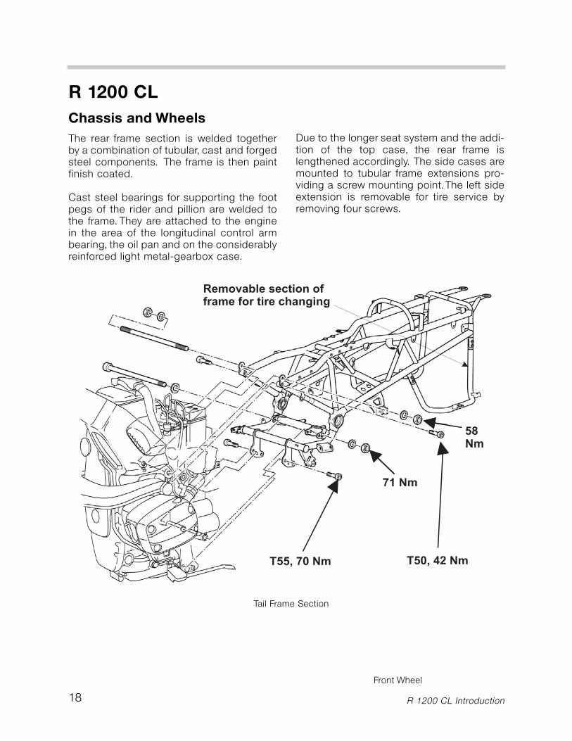
Tail Frame Section
Front Wheel
R 1200 CL Introduction
The rear frame section is welded togetherby a combination of tubular, cast and forgedsteel components. The frame is then paintfinish coated.
Cast steel bearings for supporting the footpegs of the rider and pillion are welded tothe frame. They are attached to the enginein the area of the longitudinal control armbearing, the oil pan and on the considerablyreinforced light metal-gearbox case.
Due to the longer seat system and the addi-tion of the top case, the rear frame islengthened accordingly. The side cases aremounted to tubular frame extensions pro-viding a screw mounting point.The left sideextension is removable for tire service byremoving four screws.
Front & Rear Wheels
19
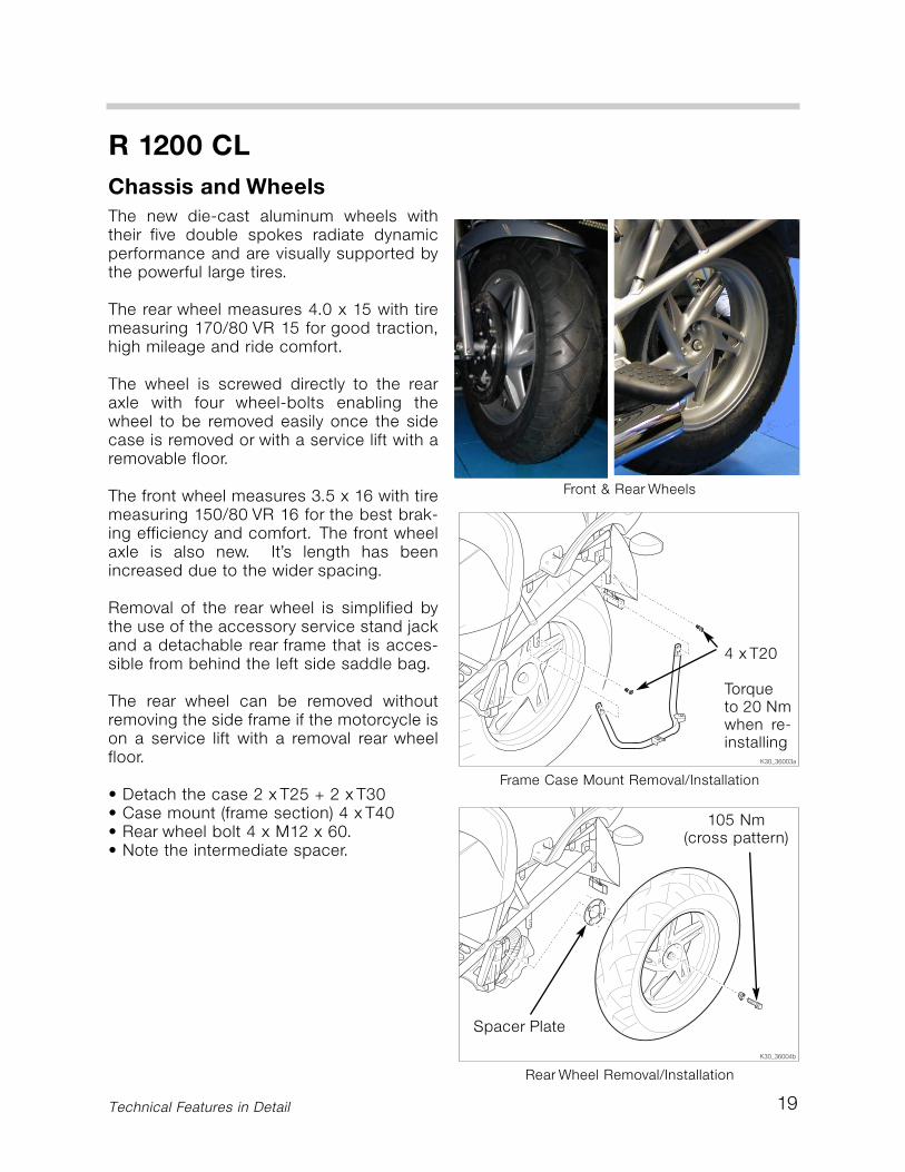
The new die-cast aluminum wheels withtheir five double spokes radiate dynamicperformance and are visually supported bythe powerful large tires.
The rear wheel measures 4.0 x 15 with tiremeasuring 170/80 VR 15 for good traction,high mileage and ride comfort.
The wheel is screwed directly to the rearaxle with four wheel-bolts enabling thewheel to be removed easily once the sidecase is removed or with a service lift with aremovable floor.
The front wheel measures 3.5 x 16 with tiremeasuring 150/80 VR 16 for the best brak-ing efficiency and comfort. The front wheelaxle is also new. It’s length has beenincreased due to the wider spacing.
Removal of the rear wheel is simplified bythe use of the accessory service stand jackand a detachable rear frame that is acces-sible from behind the left side saddle bag.
The rear wheel can be removed withoutremoving the side frame if the motorcycle ison a service lift with a removal rear wheelfloor.
• Detach the case 2 x T25 + 2 x T30• Case mount (frame section) 4 x T40• Rear wheel bolt 4 x M12 x 60.• Note the intermediate spacer.
R 1200 CLChassis and Wheels
Technical Features in Detail
Frame Case Mount Removal/Installation
4 x T20
Torqueto 20 Nmwhen re-installing
Rear Wheel Removal/Installation
105 Nm (cross pattern)
Spacer Plate

20
R 1200 CLBrake Components and Integral ABS
Technical Features in Detail
The brake system has been designed tomeet the demands of a touring Cruiser. TheEVO brake and fully integral ABS are usedfor the first time on the R 1200 C model.
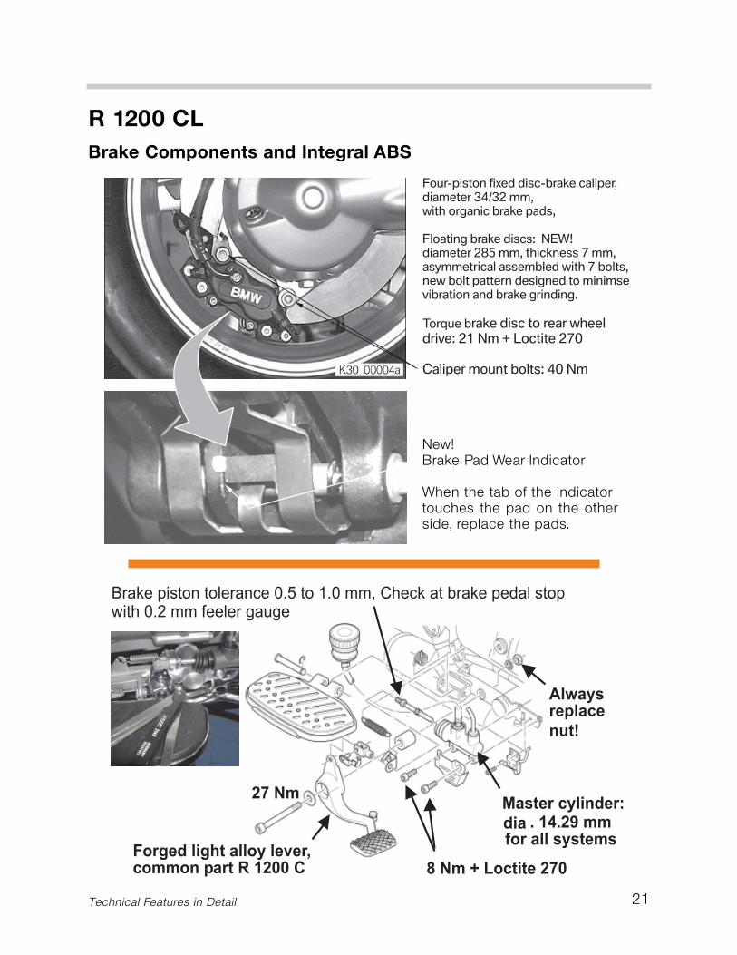
The large 305mm floating brake discs madeof high-grade steel are used on the frontwheel.The bearings are connected directlyto the hub of the front wheel by means of asecondary support and five screws. Drilleddiscs enhance the brake reaction in wetconditions and increase the self-cleaningeffect.
The two hydraulically operated 4-pistoncalipers are designed as fixed calipers pro-viding angular wear compensation due tothe offset piston diameters. The pistondiameters are 36 or 32 mm.
The sintered metal brake pads have a brakepad surface of 86 cm2.The rear wheel brakeis a hydraulically operated single disc brakewith 4-piston caliper and organic brakepads. It has been taken over essentiallyfrom the K 1200 LT model.
The floating high-grade steel brake discscrewed to the ring gear of the rear axle hasretained the diameter of 285 mm. The thick-ness of the disc has been increased to 7 mm.
A visual wear indicator is mounted on thesteel support of the outer brake pad tomake it easy to check the available padthickness as the brakes where and as anindicator that they require replacement.
21
R 1200 CLBrake Components and Integral ABS
Technical Features in Detail
New!Brake Pad Wear Indicator
When the tab of the indicatortouches the pad on the otherside, replace the pads.
22
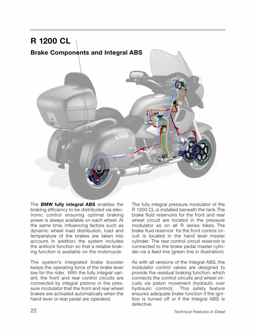
The BMW fully integral ABS enables thebraking efficiency to be distributed via elec-tronic control ensuring optimal brakingpower is always available on each wheel. Atthe same time, influencing factors such asdynamic wheel load distribution, load andtemperature of the brakes are taken intoaccount. In addition, the system includesthe antilock function so that a reliable brak-ing function is available on the motorcycle.
The system’s integrated brake boosterkeeps the operating force of the brake leverlow for the rider. With the fully integral vari-ant, the front and rear control circuits areconnected by integral pistons in the pres-sure modulator that the front and rear wheelbrakes are activated automatically when thehand lever or rear pedal are operated.
The fully integral pressure modulator of theR 1200 CL is installed beneath the tank.Thebrake fluid reservoirs for the front and rearwheel circuit are located in the pressuremodulator as on all R series bikes. Thebrake fluid reservoir for the front control cir-cuit is located in the hand lever mastercylinder. The rear control circuit reservoir isconnected to the brake pedal master cylin-der via a feed line (green line in illustration).
As with all versions of the Integral ABS, themodulator control valves are designed toprovide the residual braking function, whichconnects the control circuits and wheel cir-cuits via piston movement (hydraulic overhydraulic control). This safety featureensures adequate brake function if the igni-tion is turned off or if the Integral ABS isdefective.
R 1200 CLBrake Components and Integral ABS
Technical Features in Detail
23
R 1200 CLBrake Components and Integral ABS
Technical Features in Detail
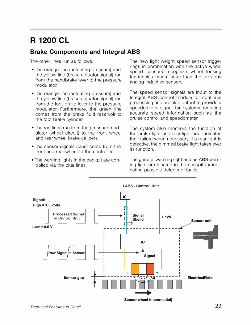
The new light weight speed sensor triggerrings in combination with the active wheelspeed sensors recognize wheel lockingtendencies much faster than the previousanalog inductive sensors.
The speed sensor signals are input to theIntegral ABS control module for continualprocessing and are also output to provide aspeedometer signal for systems requiringaccurate speed information such as thecruise control and speedometer.
The system also monitors the function ofthe brake light and rear light and indicatestheir failure when necessary. If a rear light isdefective, the dimmed brake light takes overits function.
The general warning light and an ABS warn-ing light are located in the cockpit for indi-cating possible defects or faults.
The other lines run as follows:
• The orange line (actuating pressure) andthe yellow line (brake actuator signal) runfrom the handbrake lever to the pressuremodulator.
• The orange line (actuating pressure) andthe yellow line (brake actuator signal) runfrom the foot brake lever to the pressuremodulator. Furthermore, the green linecomes from the brake fluid reservoir tothe foot brake cylinder.
• The red lines run from the pressure mod-ulator (wheel circuit) to the front wheeland rear wheel brake calipers.
• The sensor signals (blue) come from thefront and rear wheel to the controller.
• The warning lights in the cockpit are con-trolled via the blue lines.
24
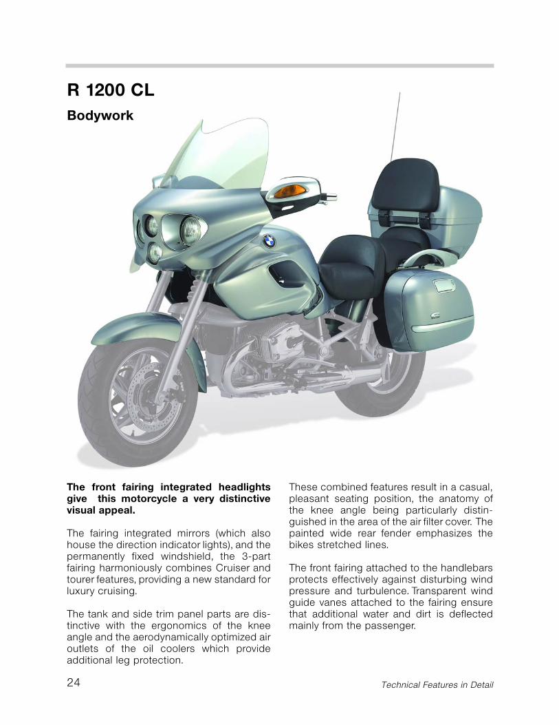
The front fairing integrated headlightsgive this motorcycle a very distinctivevisual appeal.
The fairing integrated mirrors (which alsohouse the direction indicator lights), and thepermanently fixed windshield, the 3-partfairing harmoniously combines Cruiser andtourer features, providing a new standard forluxury cruising.
The tank and side trim panel parts are dis-tinctive with the ergonomics of the kneeangle and the aerodynamically optimized airoutlets of the oil coolers which provideadditional leg protection.
These combined features result in a casual,pleasant seating position, the anatomy ofthe knee angle being particularly distin-guished in the area of the air filter cover. Thepainted wide rear fender emphasizes thebikes stretched lines.
The front fairing attached to the handlebarsprotects effectively against disturbing windpressure and turbulence. Transparent windguide vanes attached to the fairing ensurethat additional water and dirt is deflectedmainly from the passenger.
R 1200 CLBodywork
Technical Features in Detail
25
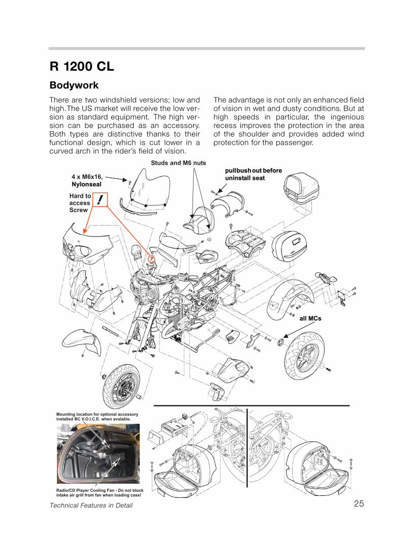
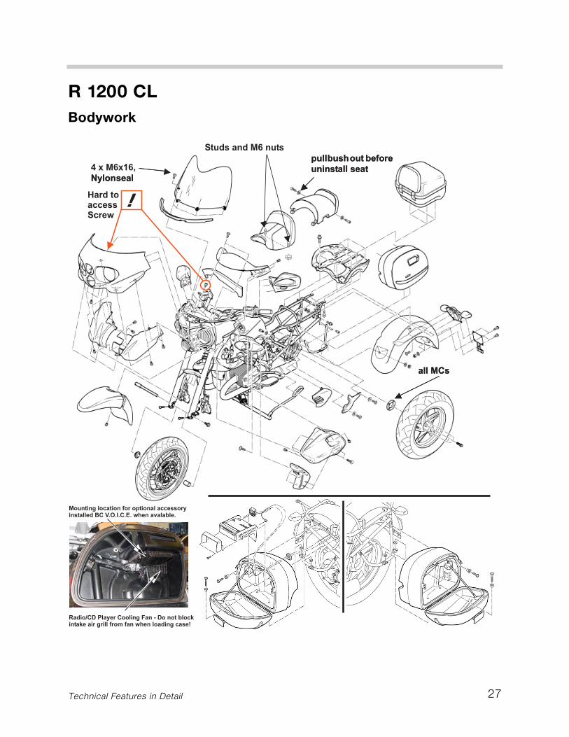
There are two windshield versions; low andhigh.The US market will receive the low ver-sion as standard equipment. The high ver-sion can be purchased as an accessory.Both types are distinctive thanks to theirfunctional design, which is cut lower in acurved arch in the rider’s field of vision.
The advantage is not only an enhanced fieldof vision in wet and dusty conditions. But athigh speeds in particular, the ingeniousrecess improves the protection in the areaof the shoulder and provides added windprotection for the passenger.
R 1200 CLBodywork
Technical Features in Detail
26
R 1200 CLBodywork
Technical Features in Detail
The mirror housings are designed as aero-dynamic hand protectors.They are ventilat-ed at the rear in order to prevent turbulencefrom forming on the handlebar grips. Therear-view mirrors can be quickly removedfrom the fairing by means ball sockets (ie: K1200 LT, R 1150 RT).
The fuel tank trim panels protect the rider’slegs against the air stream and have inte-grated rain deflectors built in by design(edges flair outward).
The panels are hollow plastic covers thatattach to sheet steel carriers by screws.The space between the colored covers andsteel carries houses a portion of the motor-cycles electronic equipment (left side:optional Anti Theft System, right side: cruisecontrol module). The side trim panels donot have to be removed if the fuel tank isremoved.
The handlebars are made from a 3.5 mmthick steel tube and have a diameter of28mm. The surface is coated with hardchrome. Handlebar weights are fitted at theends of the handlebars for damping vibra-tion.
Perfect seating comfort includes the feettoo: Running boards made of forged alu-minum and vibration decoupled for the riderby rubber bearings and wide passengerfoot rests derived from the K 1200 LT guar-antee good foothold, and combined withthe pleasant knee angle, ensure relaxed rid-ing.
The seats include optional heating ele-ments (standard on the CLC). The boldlydesigned border of the upper passengersupporting straps makes the luggagebridge a real eye catcher.
A special feature of the side cases is theone-hand closing concept. After pressingthe lock cylinder in, the flush finger lift leversprings up to unlatch the cover. Whenclosed, the case cover latching systemevenly compresses the lid into the seal byfour integrated tension rods.
A same key lock set is equipped with themotorcycle allowing a single key to operatethe ignition lock/steering lock, filler cap andluggage system.
The luggage system is integrated into theoverall appearance of the R 1200 CL. Thetop case with a volume of 45 litres provid-ing plenty of space for luggage.The centralhandle easily operates the latch and lockingsystem as on the K 1200 LT. The combinedside case volume of approximately 63 litresbrings the total lockable storage capacity ofthe R 1200 CL to 108 litres.
Case Capacities:
Top Case = 45 liter (1.59 cu ft)
Left Case = 33 liters (1.16 cu ft)
Right Case = 30 liters (1.06 cu ft)
27
R 1200 CLBodywork
Technical Features in Detail

28
The four round headlights have been inte-grated in a new arrangement never beforeused on a BMW Motorcycle. The head-lamps are mounted to an adjustable sup-port made of a synthetic material.
They consist of two larger low beam head-lights and two smaller high beam headlightspositioned one on top of the other.
The low beam headlights work with an H4-light and can be readjusted from the front.The high beam headlights with H1-lightsenable wide illumination of the road withtheir scattered light.
The park lamps with 4-watt conventionalbulbs are installed in the low beam head-lights. All electric light bulbs can bereplaced from the outside after removingeach inner trim.
The beam distance can be adjusted tocompensate for two up riding with thespring-loaded lever located on left side offairing rear surface. For normal position,lever is up, to adjust flip down (as shown).
R 1200 CLHeadlights
Technical Features in Detail
Load compensation light beam adjustment lever
R 1200 CLHeadlights
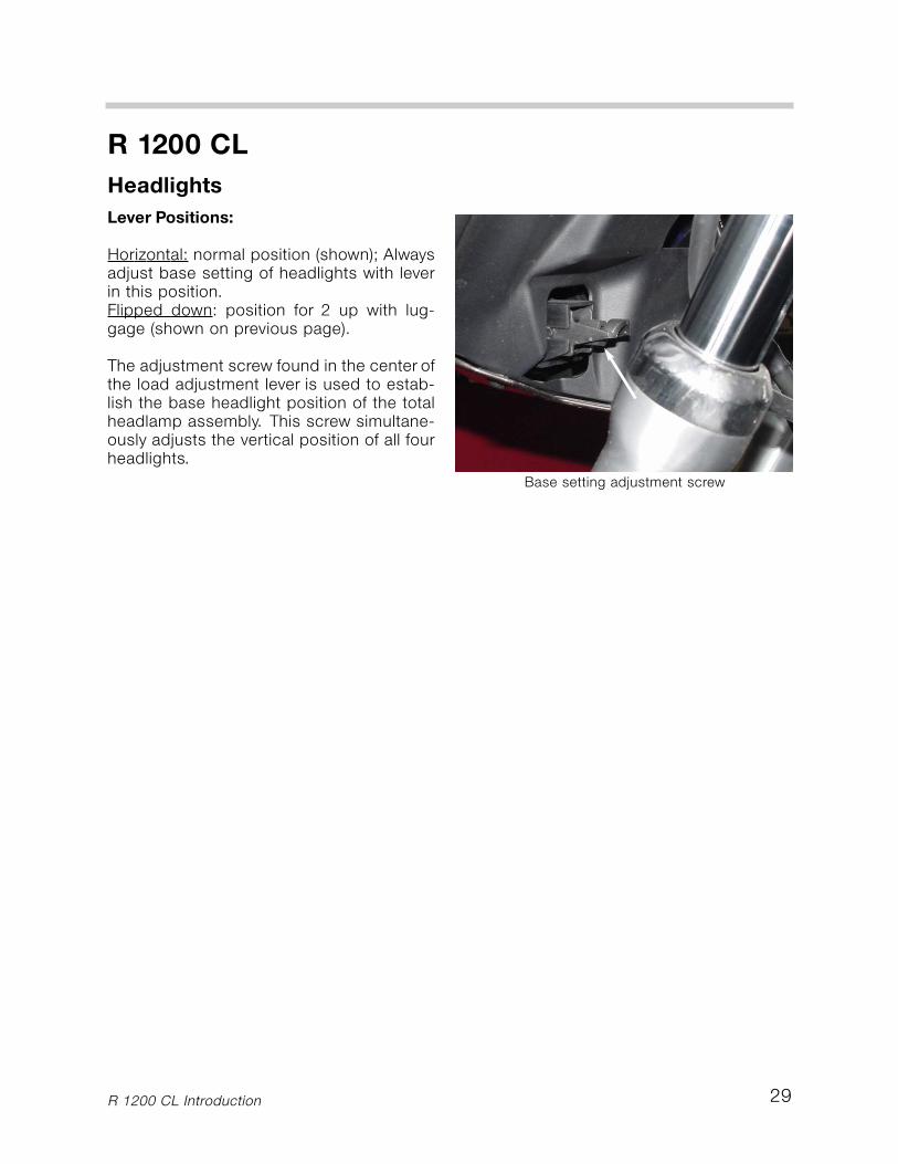
Base setting adjustment screw
R 1200 CL Introduction 29
Lever Positions:
Horizontal: normal position (shown); Alwaysadjust base setting of headlights with leverin this position.Flipped down: position for 2 up with lug-gage (shown on previous page).
The adjustment screw found in the center ofthe load adjustment lever is used to estab-lish the base headlight position of the totalheadlamp assembly. This screw simultane-ously adjusts the vertical position of all fourheadlights.
30
R 1200 CL
Technical Features in Detail
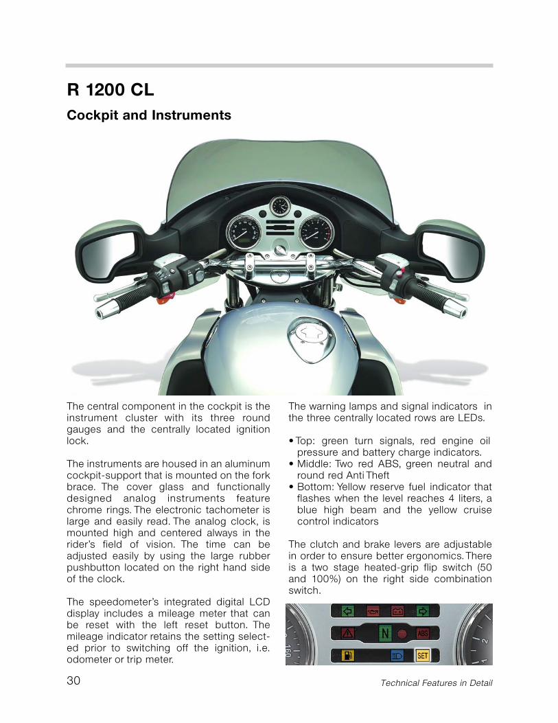
The central component in the cockpit is theinstrument cluster with its three roundgauges and the centrally located ignitionlock.
The instruments are housed in an aluminumcockpit-support that is mounted on the forkbrace. The cover glass and functionallydesigned analog instruments featurechrome rings. The electronic tachometer islarge and easily read. The analog clock, ismounted high and centered always in therider’s field of vision. The time can beadjusted easily by using the large rubberpushbutton located on the right hand sideof the clock.
The speedometer’s integrated digital LCDdisplay includes a mileage meter that canbe reset with the left reset button. Themileage indicator retains the setting select-ed prior to switching off the ignition, i.e.odometer or trip meter.
The warning lamps and signal indicators inthe three centrally located rows are LEDs.
• Top: green turn signals, red engine oilpressure and battery charge indicators.
• Middle: Two red ABS, green neutral andround red Anti Theft
• Bottom: Yellow reserve fuel indicator thatflashes when the level reaches 4 liters, ablue high beam and the yellow cruisecontrol indicators
The clutch and brake levers are adjustablein order to ensure better ergonomics.Thereis a two stage heated-grip flip switch (50and 100%) on the right side combinationswitch.
Cockpit and Instruments
31
R 1200 CL
Technical Features in Detail
The neatly arranged electrical system islocated under the fuel tank and is thebasis for operating the electrical compo-nents. In addition to the distribution sys-tem technology and high quality connec-tors, the new wiring harness provides thepossibility of options such as the AntiTheft System to simply plug into wiringprovisions.
The Motronic control module is locatedabove the central electrical control box.Different electrical accessories can be con-nected to the wiring harness via the prein-stalled special accessory-terminal.
The electronic speedometer is suppliedwith a processed speed signal from theIntegral ABS control module.The turn signalindicator relay is also fed with the speedsignal, which ensures that the directionindicator is reset after approx. 210 m and/or11 seconds.
The light-emitting diode for the reserve fuelis controlled via an electronic module,which has a time delay of 17 seconds.
The alternator’s maximum output is 840Watt, of which 300 watts is available atengine idle speed.The compact battery hasa capacity of 19 Ah.
Cranking the engine is accomplished withan 1.1-kW planetary gear starter. Cranking isonly possible when the gear box is in neu-tral or in gear with the clutch lever pulled in.Only then is there voltage on the coil of theignition relay via the clutch lever and gearlever. Starting is only possible after the propstand has been folded in. This is a typicalsafety feature of BMW. If a gear change ismade when the side prop is folded out, thenthe Motronic relay is switched off.
Two easily accessible fuse boxes with newmini fuses are arranged behind the left airfilter cover.
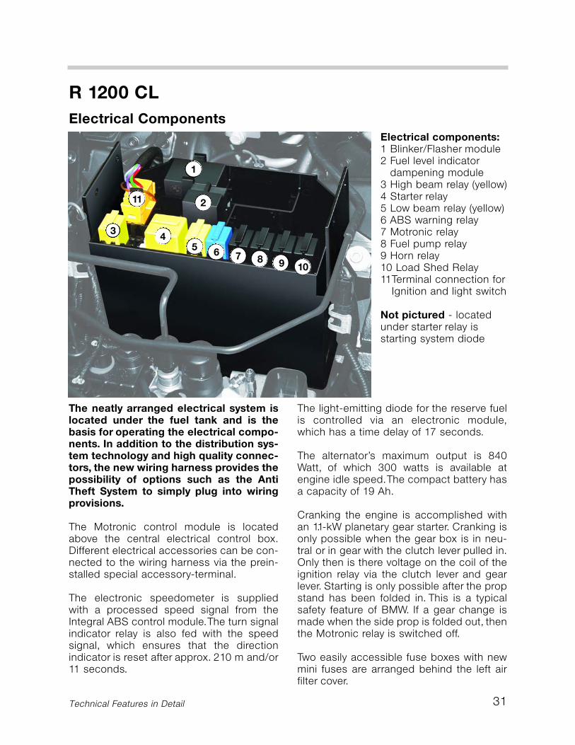
Electrical ComponentsElectrical components:1 Blinker/Flasher module2 Fuel level indicator
dampening module3 High beam relay (yellow)4 Starter relay5 Low beam relay (yellow)6 ABS warning relay7 Motronic relay8 Fuel pump relay9 Horn relay10 Load Shed Relay11Terminal connection for
Ignition and light switch
Not pictured - locatedunder starter relay isstarting system diode
11
43
8 9 10765
2
1
32
R 1200 CL
Technical Features in Detail
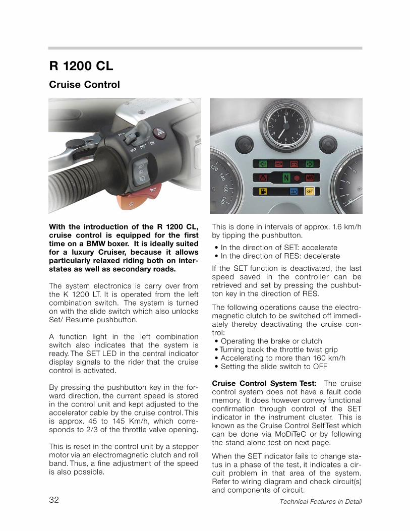
With the introduction of the R 1200 CL,cruise control is equipped for the firsttime on a BMW boxer. It is ideally suitedfor a luxury Cruiser, because it allowsparticularly relaxed riding both on inter-states as well as secondary roads.
The system electronics is carry over fromthe K 1200 LT. It is operated from the leftcombination switch. The system is turnedon with the slide switch which also unlocksSet/ Resume pushbutton.
A function light in the left combinationswitch also indicates that the system isready. The SET LED in the central indicatordisplay signals to the rider that the cruisecontrol is activated.
By pressing the pushbutton key in the for-ward direction, the current speed is storedin the control unit and kept adjusted to theaccelerator cable by the cruise control.Thisis approx. 45 to 145 Km/h, which corre-sponds to 2/3 of the throttle valve opening.
This is reset in the control unit by a steppermotor via an electromagnetic clutch and rollband.Thus, a fine adjustment of the speedis also possible.
This is done in intervals of approx. 1.6 km/hby tipping the pushbutton.
• In the direction of SET: accelerate• In the direction of RES: decelerate
If the SET function is deactivated, the lastspeed saved in the controller can beretrieved and set by pressing the pushbut-ton key in the direction of RES.
The following operations cause the electro-magnetic clutch to be switched off immedi-ately thereby deactivating the cruise con-trol:• Operating the brake or clutch• Turning back the throttle twist grip• Accelerating to more than 160 km/h• Setting the slide switch to OFF
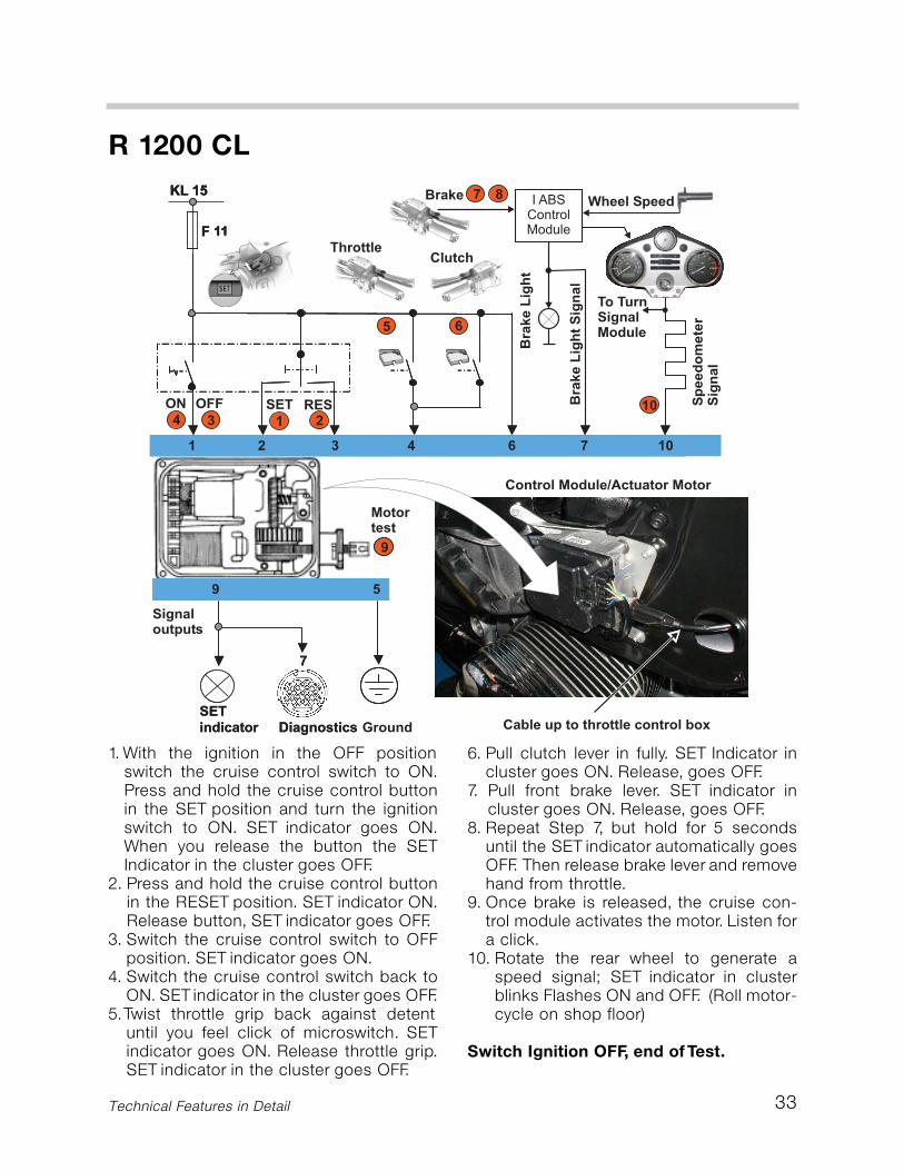
Cruise Control System Test: The cruisecontrol system does not have a fault codememory. It does however convey functionalconfirmation through control of the SETindicator in the instrument cluster. This isknown as the Cruise Control Self Test whichcan be done via MoDiTeC or by followingthe stand alone test on next page.
When the SET indicator fails to change sta-tus in a phase of the test, it indicates a cir-cuit problem in that area of the system.Refer to wiring diagram and check circuit(s)and components of circuit.
Cruise Control
33
1. With the ignition in the OFF positionswitch the cruise control switch to ON.Press and hold the cruise control buttonin the SET position and turn the ignitionswitch to ON. SET indicator goes ON.When you release the button the SETIndicator in the cluster goes OFF.
2. Press and hold the cruise control buttonin the RESET position. SET indicator ON.Release button, SET indicator goes OFF.
3. Switch the cruise control switch to OFFposition. SET indicator goes ON.
4. Switch the cruise control switch back toON. SET indicator in the cluster goes OFF.
5.Twist throttle grip back against detentuntil you feel click of microswitch. SETindicator goes ON. Release throttle grip.SET indicator in the cluster goes OFF.
6. Pull clutch lever in fully. SET Indicator incluster goes ON. Release, goes OFF.
7. Pull front brake lever. SET indicator incluster goes ON. Release, goes OFF.
8. Repeat Step 7, but hold for 5 secondsuntil the SET indicator automatically goesOFF. Then release brake lever and removehand from throttle.
9. Once brake is released, the cruise con-trol module activates the motor. Listen fora click.
10. Rotate the rear wheel to generate aspeed signal; SET indicator in clusterblinks Flashes ON and OFF. (Roll motor-cycle on shop floor)
Switch Ignition OFF, end of Test.
R 1200 CL
Technical Features in Detail
34
R 1200 CL
Cable box location
Cable Box internal view
R 1200 CL Introduction
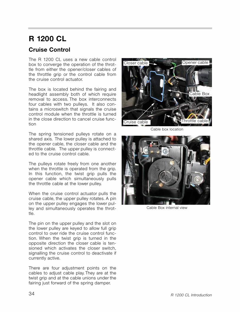
The R 1200 CL uses a new cable controlbox to converge the operation of the throt-tle from either the opener/closer cables ofthe throttle grip or the control cable fromthe cruise control actuator.
The box is located behind the fairing andheadlight assembly both of which requireremoval to access. The box interconnectsfour cables with two pulleys. It also con-tains a microswitch that signals the cruisecontrol module when the throttle is turnedin the close direction to cancel cruise func-tion
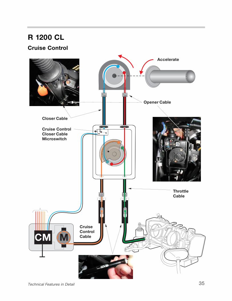
The spring tensioned pulleys rotate on ashared axis. The lower pulley is attached tothe opener cable, the closer cable and thethrottle cable. The upper pulley is connect-ed to the cruise control cable.
The pulleys rotate freely from one anotherwhen the throttle is operated from the grip.In this function, the twist grip pulls theopener cable which simultaneously pullsthe throttle cable at the lower pulley.
When the cruise control actuator pulls thecruise cable, the upper pulley rotates. A pinon the upper pulley engages the lower pul-ley and simultaneously operates the throt-tle.
The pin on the upper pulley and the slot onthe lower pulley are keyed to allow full gripcontrol to over ride the cruise control func-tion. When the twist grip is turned in theopposite direction the closer cable is ten-sioned which activates the closer switch,signalling the cruise control to deactivate ifcurrently active.
There are four adjustment points on thecables to adjust cable play.They are at thetwist grip and at the cable unions under thefairing just forward of the spring damper.
Cruise Control
Cable Box
Opener cableCloser cable
Throttle cableCruise cable
35
R 1200 CLCruise Control
Technical Features in Detail
Technical Features in Detail36
R 1200 CL
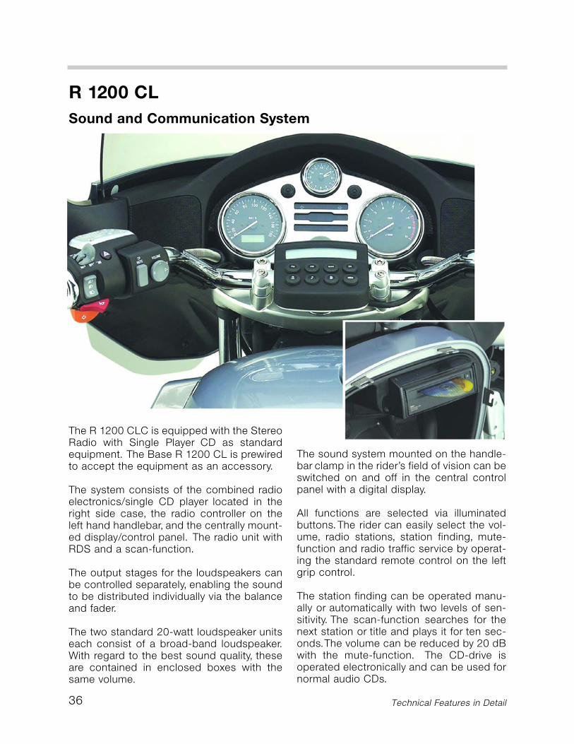
The sound system mounted on the handle-bar clamp in the rider’s field of vision can beswitched on and off in the central controlpanel with a digital display.
All functions are selected via illuminatedbuttons.The rider can easily select the vol-ume, radio stations, station finding, mute-function and radio traffic service by operat-ing the standard remote control on the leftgrip control.
The station finding can be operated manu-ally or automatically with two levels of sen-sitivity. The scan-function searches for thenext station or title and plays it for ten sec-onds.The volume can be reduced by 20 dBwith the mute-function. The CD-drive isoperated electronically and can be used fornormal audio CDs.
Sound and Communication System
The R 1200 CLC is equipped with the StereoRadio with Single Player CD as standardequipment. The Base R 1200 CL is prewiredto accept the equipment as an accessory.
The system consists of the combined radioelectronics/single CD player located in theright side case, the radio controller on theleft hand handlebar, and the centrally mount-ed display/control panel. The radio unit withRDS and a scan-function.
The output stages for the loudspeakers canbe controlled separately, enabling the soundto be distributed individually via the balanceand fader.
The two standard 20-watt loudspeaker unitseach consist of a broad-band loudspeaker.With regard to the best sound quality, theseare contained in enclosed boxes with thesame volume.
37
R 1200 CLSound and Communication System
Technical Features in Detail
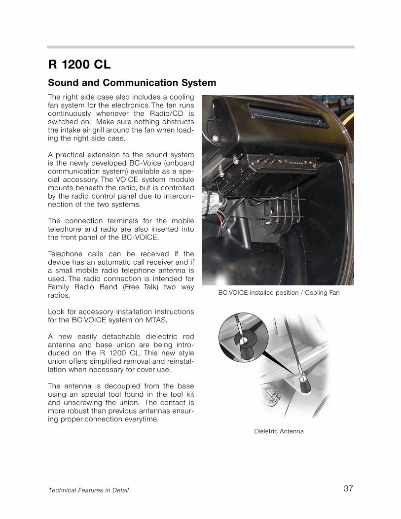
The right side case also includes a coolingfan system for the electronics.The fan runscontinuously whenever the Radio/CD isswitched on. Make sure nothing obstructsthe intake air grill around the fan when load-ing the right side case.
A practical extension to the sound systemis the newly developed BC-Voice (onboardcommunication system) available as a spe-cial accessory. The VOICE system modulemounts beneath the radio, but is controlledby the radio control panel due to intercon-nection of the two systems.
The connection terminals for the mobiletelephone and radio are also inserted intothe front panel of the BC-VOICE.
Telephone calls can be received if thedevice has an automatic call receiver and ifa small mobile radio telephone antenna isused. The radio connection is intended forFamily Radio Band (Free Talk) two wayradios.
Look for accessory installation instructionsfor the BC VOICE system on MTAS.
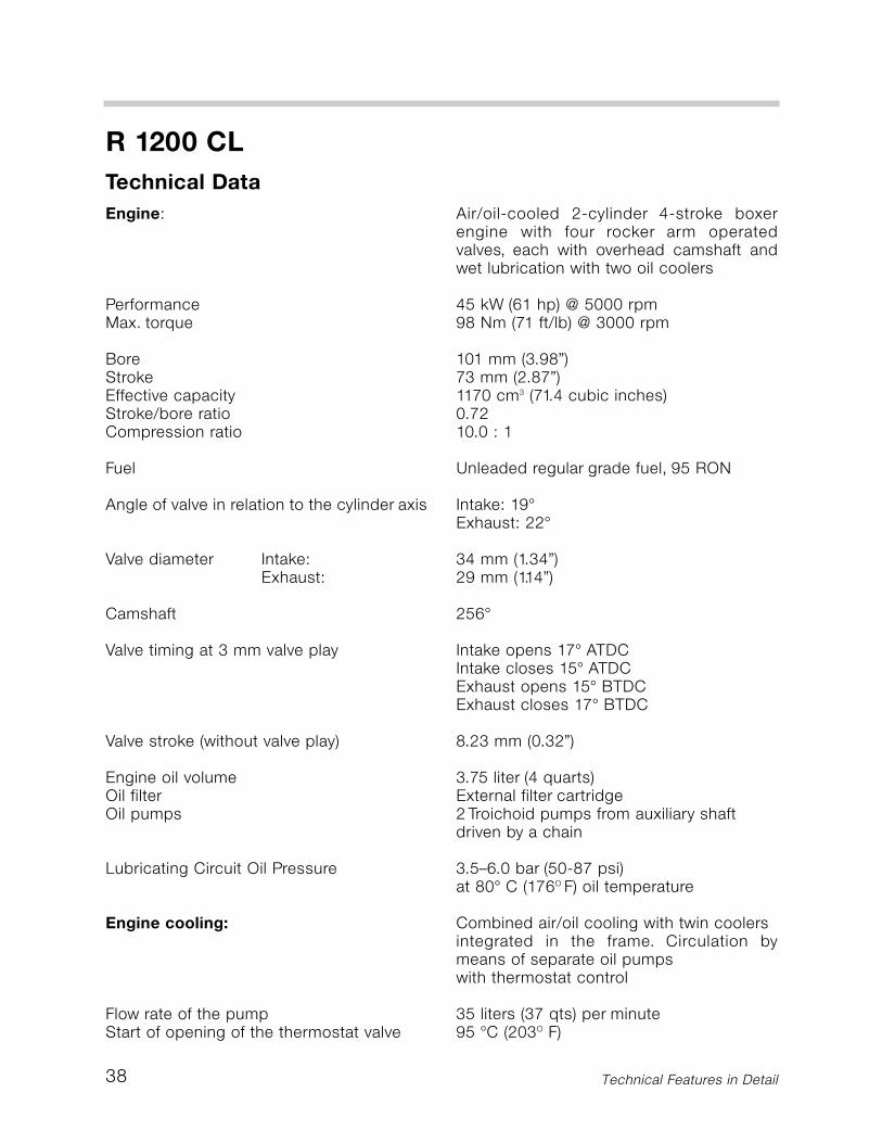
A new easily detachable dielectric rodantenna and base union are being intro-duced on the R 1200 CL. This new styleunion offers simplified removal and reinstal-lation when necessary for cover use.
The antenna is decoupled from the baseusing an special tool found in the tool kitand unscrewing the union. The contact ismore robust than previous antennas ensur-ing proper connection everytime.
Dieletric Antenna
BC VOICE installed position / Cooling Fan
38 Technical Features in Detail
R 1200 CL
Engine:
PerformanceMax. torque
BoreStrokeEffective capacityStroke/bore ratioCompression ratio
Fuel
Angle of valve in relation to the cylinder axis
Valve diameter Intake:Exhaust:
Camshaft
Valve timing at 3 mm valve play
Valve stroke (without valve play)
Engine oil volumeOil filterOil pumps
Lubricating Circuit Oil Pressure
Engine cooling:
Flow rate of the pumpStart of opening of the thermostat valve
Air/oil-cooled 2-cylinder 4-stroke boxerengine with four rocker arm operatedvalves, each with overhead camshaft andwet lubrication with two oil coolers
45 kW (61 hp) @ 5000 rpm98 Nm (71 ft/lb) @ 3000 rpm
101 mm (3.98”)73 mm (2.87”)1170 cm3 (71.4 cubic inches)0.7210.0 : 1
Unleaded regular grade fuel, 95 RON
Intake: 19°Exhaust: 22°
34 mm (1.34”)29 mm (1.14”)
256°
Intake opens 17° ATDCIntake closes 15° ATDCExhaust opens 15° BTDCExhaust closes 17° BTDC
8.23 mm (0.32”)
3.75 liter (4 quarts)External filter cartridge2 Troichoid pumps from auxiliary shaftdriven by a chain
3.5–6.0 bar (50-87 psi)at 80° C (176O F) oil temperature
Combined air/oil cooling with twin coolersintegrated in the frame. Circulation bymeans of separate oil pumpswith thermostat control
35 liters (37 qts) per minute95 °C (203O F)
Technical Data

39Technical Features in Detail
Technical Data
R 1200 CL
Clutch:
Clutch disc diameterMaster cylinder piston diameterSlave cylinder piston diameter
Gearbox:
Primary input shaft gear reductionGear Ratios
Rear wheel drive:TransmissionRing/Pinion teeth
Mixture control/ignition system:Maximum engine speedIdle speed
Lambda controlFuel cut-off
Fuel pressureCapacity of the fuel tank
Ignition angle range (motronic controlled)Spark plug
Generator:Maximum powerVoltageTransmission
Starter:
PowerTransmission of planetary gear
Hydraulically operated single-disc dryclutch with transmission disc spring andasbestos-free friction lining165 mm (6.5”)13 mm (0.5”)24 mm (0.94”)
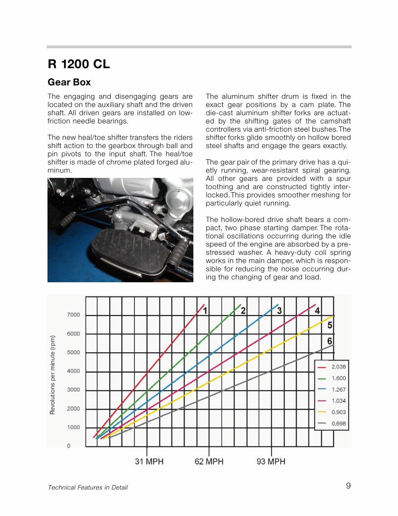
Constant mesh 6-speed transmissionintegrated in flange-mounted case1:1.8891st gear: 1 : 2.0382nd gear: 1 : 1.6003rd gear: 1 : 1.2674th gear: 1 : 1.0345th gear: 1 : 0.9036th gear: 1 : 0.698
Angular gear with Palloid tooth system1 : 2.6234/13
Digital motor electronics: Motronic MA 2.47000 rpm (disabling of the injection signal)900 rpm
Engine temperature above 60° C (140OF)Speed above 1800 rpmEngine temperature above 70 °C (158OF)
3.0 bar (43.5 psi)17.5 liters (4.62 gallons), including approxi-mate 4 liter (1 gallon) reserve (light on)+43° to 0° OT (characteristic zone)Bosch FR6 DDC
Alternator with voltage control840 W14 V1 : 1.5
With magneto-electrically excited electro-motor, drives the clutch plate by means ofintermediate gearbox and pre-engageddrive 1.1 kW (1.5 hp)1: 5.5
40 Technical Features in Detail
Technical Data
R 1200 CL
Front wheel suspension:
Full spring travel on the wheelStanchion diameterSteering lock angleSpring/Dampening
Rear wheel suspension:
Effective length of swing-armSpring deflection on the wheelDamping system
Wheels:Dimensions
Tires:Dimensions
Brake system:
Front:
Brake disc diameterBrake disc thicknessCaliper piston diametersMaster cylinder piston diameterBrake pad friction material
Rear:
Brake disc diameterBrake disc thicknessCaliper piston diametersMaster cylinder piston diameterBrake pad friction material
Telelever with central strut and tilt decou-pling of the upper fork brace144 mm (5.67”)35 mm (1.38”)35 ° right / leftStrut with coil spring and twin-sleevedamper (non adjustable)
Monolever with central strut, Steel swingarm and single-sleeve damper Spring pre-load adjustable hydraulically612 mm (24”)120 mm (4.72)WAD (Travel related damping on the com-pression stroke)
Die-cast aluminum wheel, 5 double spokesFront: 3.50"x16" MTH2Rear: 4.00"x15" MTH2
Light low-section Cruiser tireFront: 150/80 VR 16Rear: 170/80 VR 15
Hydraulically operated, Standard I-ABS
Double-disc brake with 4-piston fixedcaliper, de-skew, floating high-grade steelbrake discs305 mm (12.0”)5 mm (0.2”)32/36 mm16 mm (0.63”)Sintered metal
4-piston fixed caliper, floating high-gradesteel brake disc with asymmetrical bearings285 mm (11.2”)7 mm (0.27”)32/34 mm14.29 mm (0.56”)Semi-metal (organic)

41
R 1200 CL
Technical Data
Technical Features in Detail
Dimensions:Overall lengthWidth at the rear view mirrorsHeight at the top edge of the windshieldWheelbase in normal positionTrail in normal positionSteering head angle in normal positionSeat height, unladen weight
laden weight (187 lb rider)Ground clearance in normal position
Weights:Unladen, road ready and fully fueledPermitted total weight (GAVR)
Performance:Maximum speedAcceleration 0–100 km/h (0-62 MPH)Average fuel consumption for one hour ofriding at a constant:
• 90 km/h (55.9 mph)• 120 km/h (75.0 mph)
2,415 mm (95.0” - or - 7.92’)1,075 mm (42.3”)1,435 mm (56.4”)1,641 mm (64.6”)184 mm (7.24”)56.5°755 mm (29.7”)745 mm (29.3”)159 mm (6.25”)
308 kg (679.0 lbs) standard equipment530 kg (1,168.5 lbs)allows max rider, passenger and luggageweight of 222 kg (489.5 lbs)
165 km/h (102.5 mph)6.3 s
5.1 liters (1.34 gallons)6.2 liters (1.64 gallons)
R 1200 CL Introduction
R 1200 CL
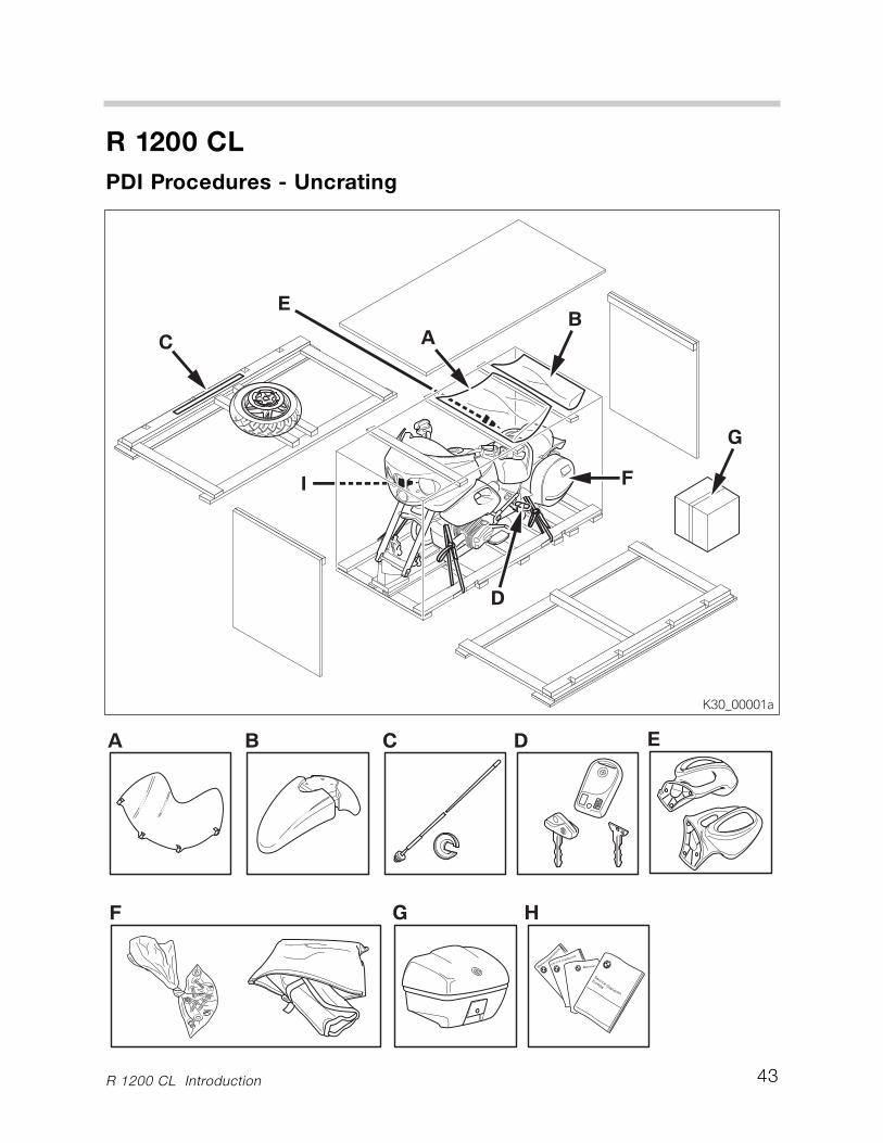
PDI Procedures - Uncrating
Delivery and Crate Inspection
While the motorcycle is being unloaded by the shipper, thoroughly inspect thecrate for damage. Department of Transportation law requires the driver to allowyou, the representative of your dealership ample time to perform a thoroughlycrate inspection for each delivered unit.
Maintain your familiarity of motorcycle delivery receipt, inspection and claimsprocessing by reviewing the following official BMW Motorcycle documents:
• Motorcycle Transportation Damage Policies and Procedures. This documentis available on MTAS (Service>Warranty Information).
• Motorcycle Service Information Bulletins, Group 4 (Warranty).
If any crate damaged is present:
• Thoroughly examine the motorcycle and all contents for consequential dam-age or missing parts.
• Clearly note damage and or missing parts on the truckers bill of lading (deliv-ery slip).
• Inform the trucking company in writing without delay.• Damage under $750.00 must be claimed via warranty.• Damage over $750.00 requires your field representative to be contacted. The
field representative must authorize your claim prior to submittal.
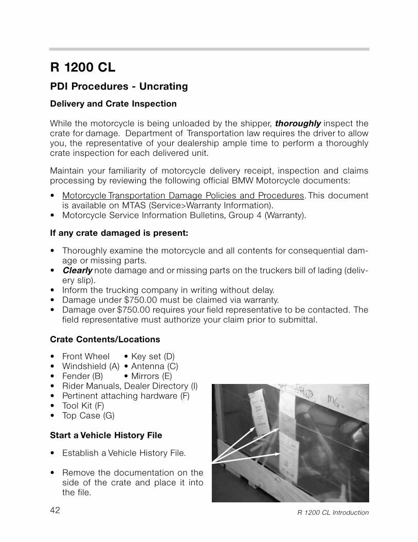
Crate Contents/Locations
• Front Wheel • Key set (D)• Windshield (A) • Antenna (C)• Fender (B) • Mirrors (E)• Rider Manuals, Dealer Directory (I)• Pertinent attaching hardware (F)• Tool Kit (F)• Top Case (G)
Start a Vehicle History File
• Establish a Vehicle History File.
• Remove the documentation on theside of the crate and place it intothe file.
42
R 1200 CL
PDI Procedures - Uncrating
R 1200 CL Introduction 43
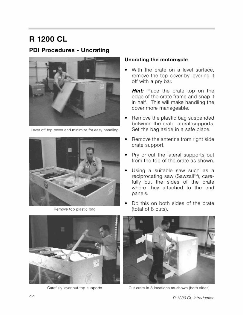
Cut crate in 8 locations as shown (both sides)
44
R 1200 CL
PDI Procedures - Uncrating
Uncrating the motorcycle
• With the crate on a level surface,remove the top cover by levering itoff with a pry bar.
Hint: Place the crate top on theedge of the crate frame and snap itin half. This will make handling thecover more manageable.
• Remove the plastic bag suspendedbetween the crate lateral supports.Set the bag aside in a safe place.
• Remove the antenna from right sidecrate support.
• Pry or cut the lateral supports outfrom the top of the crate as shown.
• Using a suitable saw such as areciprocating saw (SawzallTM), care-fully cut the sides of the cratewhere they attached to the endpanels.
• Do this on both sides of the crate(total of 8 cuts).
Lever off top cover and minimize for easy handling
Remove top plastic bag
Carefully lever out top supports
R 1200 CL Introduction
R 1200 CL
PDI Procedures - Uncrating
• Remove the front tire from the right side area of the crate and set it aside.
• Remove both side panels from the crate base by carefully pivoting forwardand backward until vertical brace detaches from base.You may also chooseto cut the vertical braces at the bottom with someone assisting you.
• Remove both crate end panels by forcibly pulling the panels from the cratebase. Give a good yank, they will separate from the crate base quite easily.
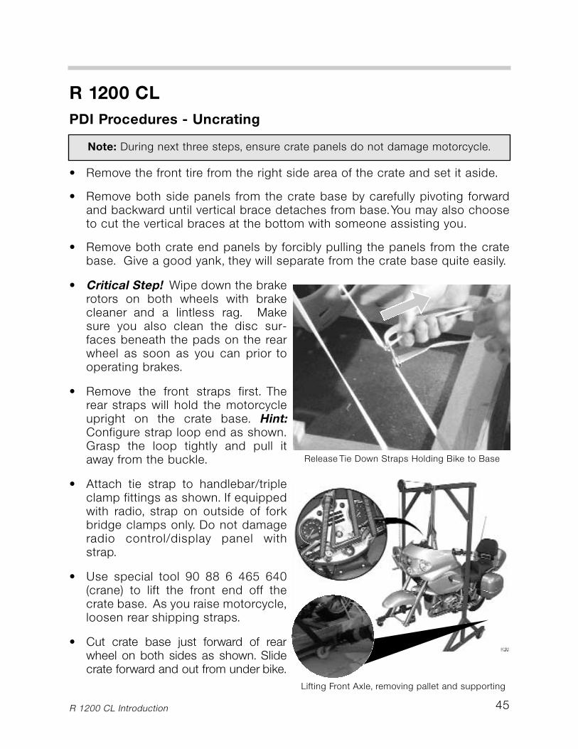
• Critical Step! Wipe down the brakerotors on both wheels with brakecleaner and a lintless rag. Makesure you also clean the disc sur-faces beneath the pads on the rearwheel as soon as you can prior tooperating brakes.
• Remove the front straps first. Therear straps will hold the motorcycleupright on the crate base. Hint:Configure strap loop end as shown.Grasp the loop tightly and pull itaway from the buckle.
• Attach tie strap to handlebar/tripleclamp fittings as shown. If equippedwith radio, strap on outside of forkbridge clamps only. Do not damageradio control/display panel withstrap.
• Use special tool 90 88 6 465 640(crane) to lift the front end off thecrate base. As you raise motorcycle,loosen rear shipping straps.
• Cut crate base just forward of rearwheel on both sides as shown. Slidecrate forward and out from under bike.
Lifting Front Axle, removing pallet and supporting
R 1200 CL Introduction
Note: During next three steps, ensure crate panels do not damage motorcycle.
Release Tie Down Straps Holding Bike to Base
45
46
R 1200 CL
PDI Procedures - Set Up
R 1200 CL Introduction
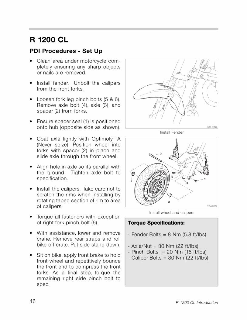
• Clean area under motorcycle com-pletely ensuring any sharp objectsor nails are removed.
• Install fender. Unbolt the calipersfrom the front forks.
• Loosen fork leg pinch bolts (5 & 6).Remove axle bolt (4), axle (3), andspacer (2) from forks.
• Ensure spacer seal (1) is positionedonto hub (opposite side as shown).
• Coat axle lightly with Optimoly TA(Never seize). Position wheel intoforks with spacer (2) in place andslide axle through the front wheel.
• Align hole in axle so its parallel withthe ground. Tighten axle bolt tospecification.
• Install the calipers. Take care not toscratch the rims when installing byrotating taped section of rim to areaof calipers.
• Torque all fasteners with exceptionof right fork pinch bolt (6).
• With assistance, lower and removecrane. Remove rear straps and rollbike off crate. Put side stand down.
• Sit on bike, apply front brake to holdfront wheel and repetitively bouncethe front end to compress the frontforks. As a final step, torque theremaining right side pinch bolt tospec.
Install wheel and calipers
Install Fender
TToorrqquuee SSppeecciiffiiccaattiioonnss::
- Fender Bolts = 8 Nm (5.8 ft/lbs)
- Axle/Nut = 30 Nm (22 ft/lbs)- Pinch Bolts = 20 Nm (15 ft/lbs)- Caliper Bolts = 30 Nm (22 ft/lbs)
47
R 1200 CL
PDI Procedures - Set Up
R 1200 CL Introduction
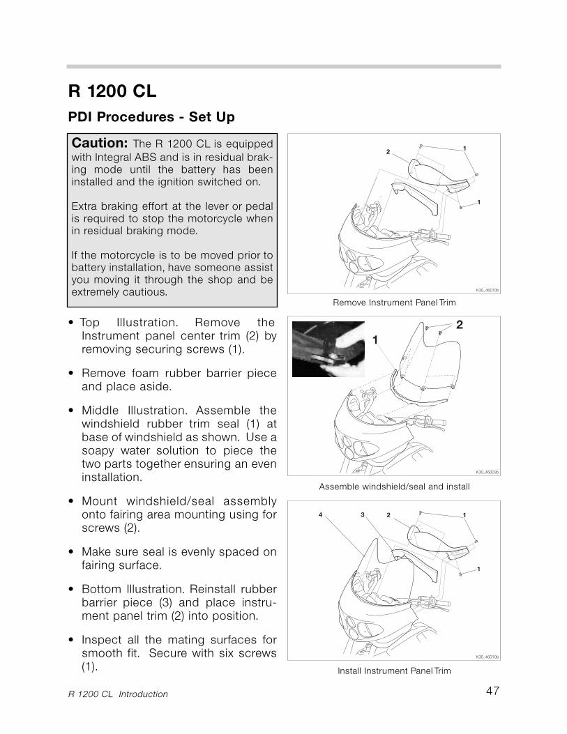
• Top Illustration. Remove theInstrument panel center trim (2) byremoving securing screws (1).
• Remove foam rubber barrier pieceand place aside.
• Middle Illustration. Assemble thewindshield rubber trim seal (1) atbase of windshield as shown. Use asoapy water solution to piece thetwo parts together ensuring an eveninstallation.
• Mount windshield/seal assemblyonto fairing area mounting using forscrews (2).
• Make sure seal is evenly spaced onfairing surface.
• Bottom Illustration. Reinstall rubberbarrier piece (3) and place instru-ment panel trim (2) into position.
• Inspect all the mating surfaces forsmooth fit. Secure with six screws(1).
Caution: The R 1200 CL is equippedwith Integral ABS and is in residual brak-ing mode until the battery has beeninstalled and the ignition switched on.
Extra braking effort at the lever or pedalis required to stop the motorcycle whenin residual braking mode.
If the motorcycle is to be moved prior tobattery installation, have someone assistyou moving it through the shop and beextremely cautious.
Assemble windshield/seal and install
Install Instrument Panel Trim
Remove Instrument Panel Trim
48
R 1200 CL
PDI Procedures - Set Up
R 1200 CL Introduction
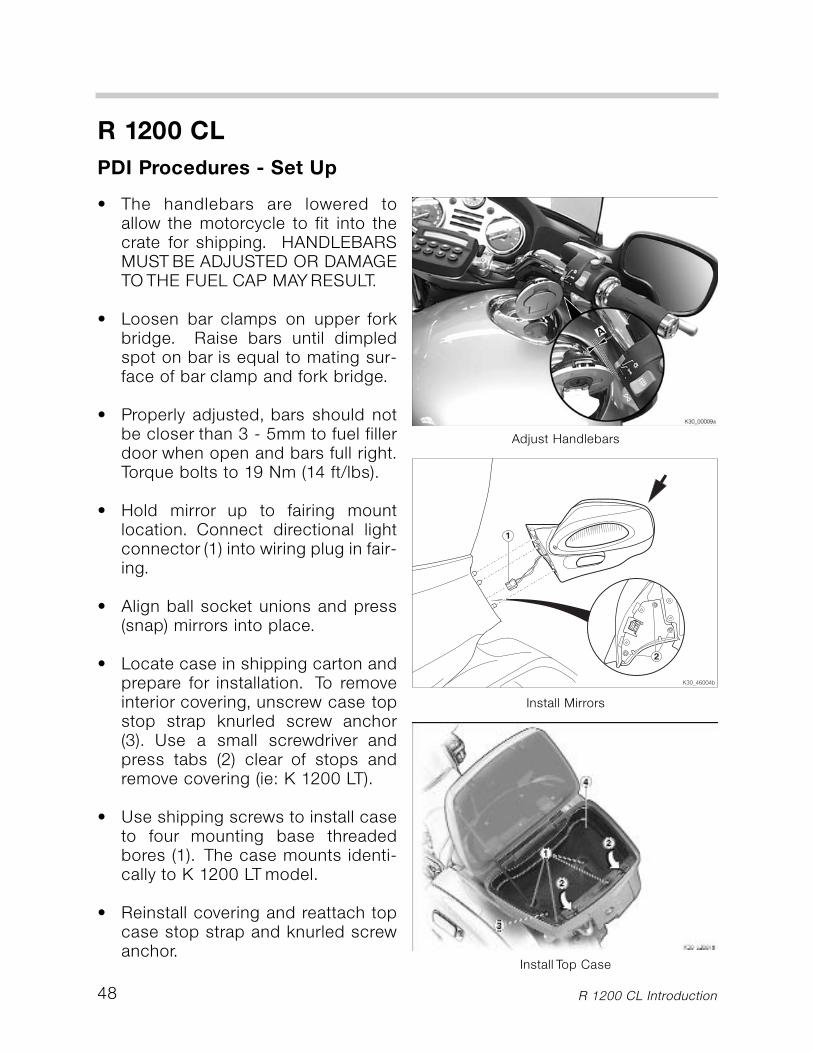
• The handlebars are lowered toallow the motorcycle to fit into thecrate for shipping. HANDLEBARSMUST BE ADJUSTED OR DAMAGETO THE FUEL CAP MAY RESULT.
• Loosen bar clamps on upper forkbridge. Raise bars until dimpledspot on bar is equal to mating sur-face of bar clamp and fork bridge.
• Properly adjusted, bars should notbe closer than 3 - 5mm to fuel fillerdoor when open and bars full right.Torque bolts to 19 Nm (14 ft/lbs).
• Hold mirror up to fairing mountlocation. Connect directional lightconnector (1) into wiring plug in fair-ing.
• Align ball socket unions and press(snap) mirrors into place.
• Locate case in shipping carton andprepare for installation. To removeinterior covering, unscrew case topstop strap knurled screw anchor(3). Use a small screwdriver andpress tabs (2) clear of stops andremove covering (ie: K 1200 LT).
• Use shipping screws to install caseto four mounting base threadedbores (1). The case mounts identi-cally to K 1200 LT model.
• Reinstall covering and reattach topcase stop strap and knurled screwanchor.
Install Mirrors
Install Top Case
Adjust Handlebars
49
R 1200 CL
PDI Procedures - Set Up
R 1200 CL Introduction
Make sure tool kit is complete
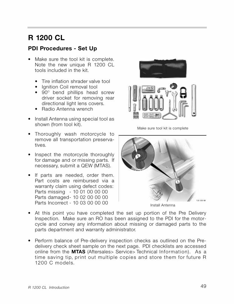
• Make sure the tool kit is complete.Note the new unique R 1200 CLtools included in the kit.
• Tire inflation shrader valve tool• Ignition Coil removal tool• 90O bend phillips head screw
driver socket for removing reardirectional light lens covers.
• Radio Antenna wrench
• Install Antenna using special tool asshown (from tool kit).
• Thoroughly wash motorcycle toremove all transportation preserva-tives.
• Inspect the motorcycle thoroughlyfor damage and or missing parts. Ifnecessary, submit a QEW (MTAS).
• If parts are needed, order them.Part costs are reimbursed via awarranty claim using defect codes:Parts missing - 10 01 00 00 00Parts damaged- 10 02 00 00 00Parts Incorrect - 10 03 00 00 00
• At this point you have completed the set up portion of the Pre DeliveryInspection. Make sure an RO has been assigned to the PDI for the motor-cycle and convey any information about missing or damaged parts to theparts department and warranty administrator.
• Perform balance of Pre-delivery inspection checks as outlined on the Pre-delivery check sheet sample on the next page. PDI checklists are accessedonline from the MTAS (Aftersales> Service> Technical Information). As atime saving tip, print out multiple copies and store them for future R1200 C models.
Install Antenna
R 1200 CL
PDI Checklist Sample
R 1200 CL Introduction50
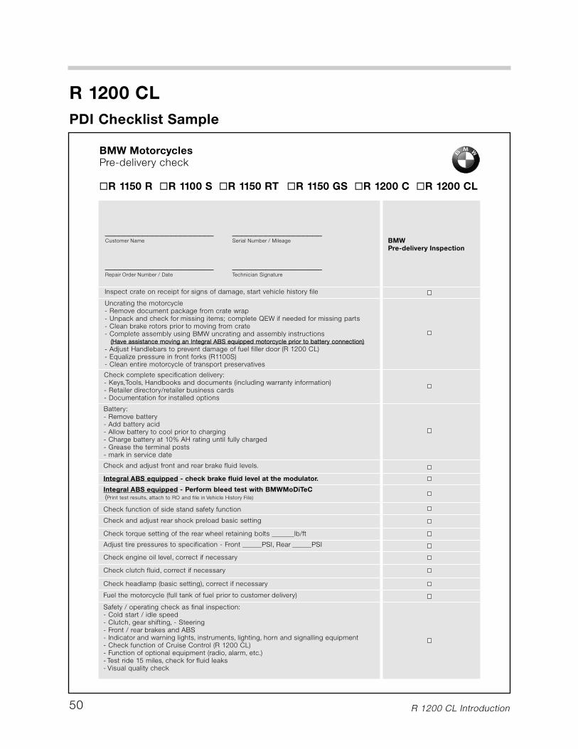
BMW MotorcyclesPre-delivery check
�R 1150 R �R 1100 S �R 1150 RT �R 1150 GS �R 1200 C �R 1200 CL
_______________________ ___________________Customer Name Serial Number / Mileage
_______________________ ___________________Repair Order Number / Date Technician Signature
BMWPre-delivery Inspection
Inspect crate on receipt for signs of damage, start vehicle history file
Uncrating the motorcycle- Remove document package from crate wrap- Unpack and check for missing items; complete QEW if needed for missing parts- Clean brake rotors prior to moving from crate- Complete assembly using BMW uncrating and assembly instructions
((HHaavvee aassssiissttaannccee mmoovviinngg aann IInntteeggrraall AABBSS eeqquuiippppeedd mmoottoorrccyyccllee pprriioorr ttoo bbaatttteerryy ccoonnnneeccttiioonn))
- Adjust Handlebars to prevent damage of fuel filler door (R 1200 CL)- Equalize pressure in front forks (R1100S)- Clean entire motorcycle of transport preservatives
Battery:- Remove battery- Add battery acid- Allow battery to cool prior to charging- Charge battery at 10% AH rating until fully charged- Grease the terminal posts- mark in service date
Check complete specification delivery:- Keys,Tools, Handbooks and documents (including warranty information)- Retailer directory/retailer business cards- Documentation for installed options
Check function of side stand safety function
Check headlamp (basic setting), correct if necessary
Check and adjust front and rear brake fluid levels.
Adjust tire pressures to specification - Front ______PSI, Rear ______PSI
Check torque setting of the rear wheel retaining bolts _______lb/ft
Check engine oil level, correct if necessary
Fuel the motorcycle (full tank of fuel prior to customer delivery)
Check clutch fluid, correct if necessary
Safety / operating check as final inspection:- Cold start / idle speed- Clutch, gear shifting, - Steering- Front / rear brakes and ABS- Indicator and warning lights, instruments, lighting, horn and signalling equipment- Check function of Cruise Control (R 1200 CL)- Function of optional equipment (radio, alarm, etc.)- Test ride 15 miles, check for fluid leaks- Visual quality check
Check and adjust rear shock preload basic setting
Integral ABS equipped - Perform bleed test with BMWMoDiTeC(Print test results, attach to RO and file in Vehicle History File)
Integral ABS equipped - check brake fluid level at the modulator.
51
R 1200 CL
PDI Procedures - Accessing Battery
R 1200 CL Introduction
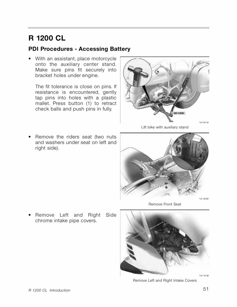
• With an assistant, place motorcycleonto the auxiliary center stand.Make sure pins fit securely intobracket holes under engine.
The fit tolerance is close on pins. Ifresistance is encountered, gentlytap pins into holes with a plasticmallet. Press button (1) to retractcheck balls and push pins in fully.
• Remove the riders seat (two nutsand washers under seat on left andright side).
• Remove Left and Right Sidechrome intake pipe covers.
Remove Front Seat
Remove Left and Right Intake Covers
Lift bike with auxiliary stand
R 1200 CL
R 1200 CL Introduction52
PDI Procedures - Accessing Battery
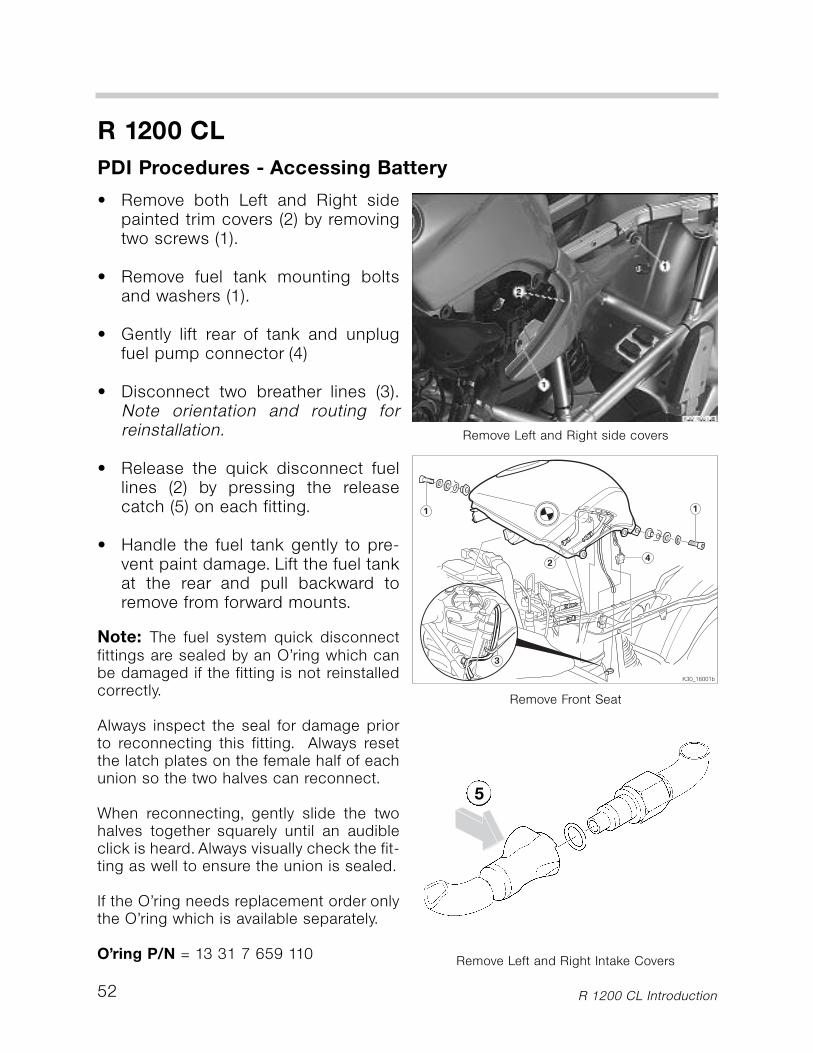
• Remove both Left and Right sidepainted trim covers (2) by removingtwo screws (1).
• Remove fuel tank mounting boltsand washers (1).
• Gently lift rear of tank and unplugfuel pump connector (4)
• Disconnect two breather lines (3).Note orientation and routing forreinstallation.
• Release the quick disconnect fuellines (2) by pressing the releasecatch (5) on each fitting.
• Handle the fuel tank gently to pre-vent paint damage. Lift the fuel tankat the rear and pull backward toremove from forward mounts.
Note: The fuel system quick disconnectfittings are sealed by an O’ring which canbe damaged if the fitting is not reinstalledcorrectly.
Always inspect the seal for damage priorto reconnecting this fitting. Always resetthe latch plates on the female half of eachunion so the two halves can reconnect.
When reconnecting, gently slide the twohalves together squarely until an audibleclick is heard. Always visually check the fit-ting as well to ensure the union is sealed.
If the O’ring needs replacement order onlythe O’ring which is available separately.
O’ring P/N = 13 31 7 659 110
Remove Front Seat
Remove Left and Right Intake Covers
Remove Left and Right side covers
5
PDI Procedures - Removing, Filling and Charging Battery
53
R 1200 CL
R 1200 CL Introduction
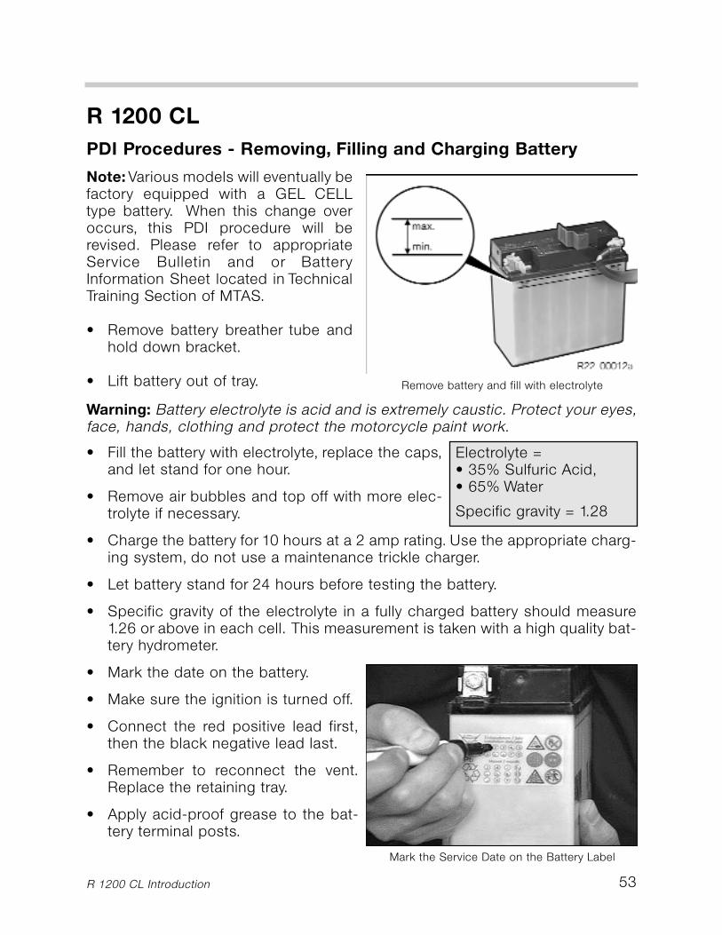
Note:Various models will eventually befactory equipped with a GEL CELLtype battery. When this change overoccurs, this PDI procedure will berevised. Please refer to appropriateService Bulletin and or BatteryInformation Sheet located in TechnicalTraining Section of MTAS.
• Remove battery breather tube andhold down bracket.
• Lift battery out of tray. Remove battery and fill with electrolyte
Warning: Battery electrolyte is acid and is extremely caustic. Protect your eyes,face, hands, clothing and protect the motorcycle paint work.
• Fill the battery with electrolyte, replace the caps,and let stand for one hour.
• Remove air bubbles and top off with more elec-trolyte if necessary.
• Charge the battery for 10 hours at a 2 amp rating. Use the appropriate charg-ing system, do not use a maintenance trickle charger.
• Let battery stand for 24 hours before testing the battery.
• Specific gravity of the electrolyte in a fully charged battery should measure1.26 or above in each cell. This measurement is taken with a high quality bat-tery hydrometer.
• Mark the date on the battery.
• Make sure the ignition is turned off.
• Connect the red positive lead first,then the black negative lead last.
• Remember to reconnect the vent.Replace the retaining tray.
• Apply acid-proof grease to the bat-tery terminal posts.
Electrolyte = • 35% Sulfuric Acid,• 65% Water
Specific gravity = 1.28
Mark the Service Date on the Battery Label
54
R 1200 CL
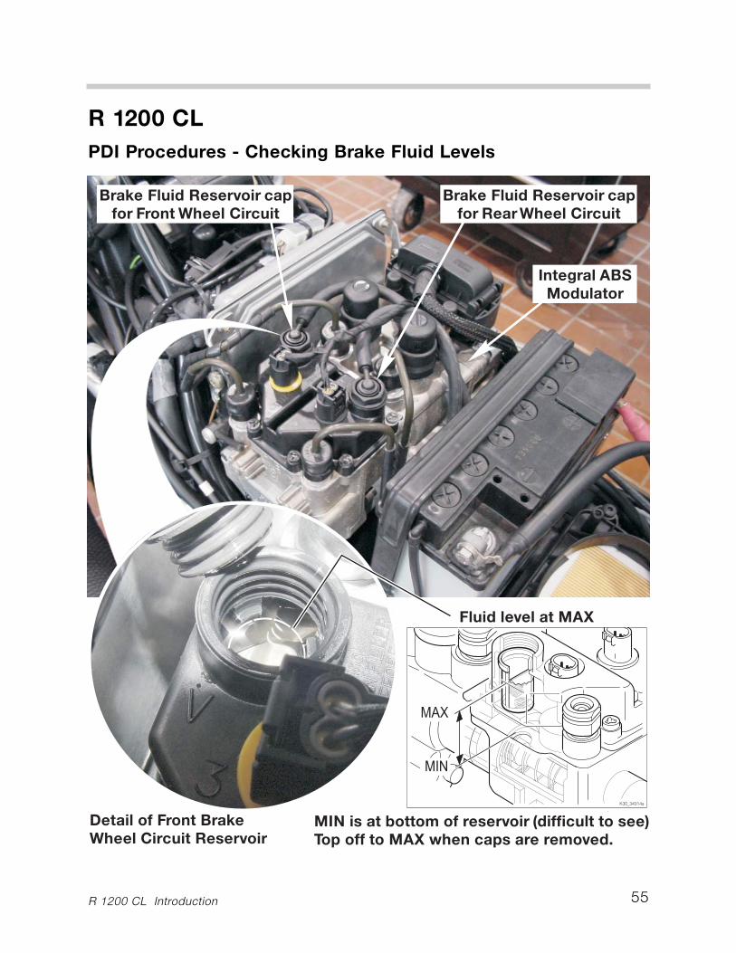
PDI Procedures - Checking Brake Fluid Levels
R 1200 CL Introduction
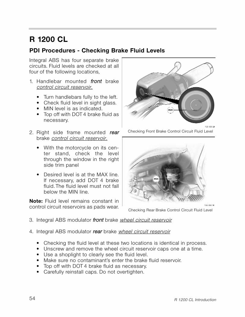
Integral ABS has four separate brakecircuits. Fluid levels are checked at allfour of the following locations,
1. Handlebar mounted ffrroonntt brakecontrol circuit reservoir.
• Turn handlebars fully to the left.• Check fluid level in sight glass.• MIN level is as indicated.• Top off with DOT4 brake fluid as
necessary.
2. Right side frame mounted rreeaarrbrake control circuit reservoir.
• With the motorcycle on its cen-ter stand, check the levelthrough the window in the rightside trim panel
• Desired level is at the MAX line.If necessary, add DOT 4 brakefluid.The fluid level must not fallbelow the MIN line.
Note: Fluid level remains constant incontrol circuit reservoirs as pads wear.
Checking Front Brake Control Circuit Fluid Level
Checking Rear Brake Control Circuit Fluid Level
3. Integral ABS modulator ffrroonntt brake wheel circuit reservoir
4. Integral ABS modulator rreeaarr brake wheel circuit reservoir
• Checking the fluid level at these two locations is identical in process.• Unscrew and remove the wheel circuit reservoir caps one at a time.• Use a shoplight to clearly see the fluid level.• Make sure no contaminant’s enter the brake fluid reservoir.• Top off with DOT 4 brake fluid as necessary.• Carefully reinstall caps. Do not overtighten.
55
R 1200 CL
PDI Procedures - Checking Brake Fluid Levels
R 1200 CL Introduction
56
R 1200 CL
PDI Procedures - Integral ABS Bleed Test
R 1200 CL Introduction
Bleed Test Requirements
Prior to performing Bleed Test, make sure the following preconditions are met:
• Up to date MoDiTeC software must always be loaded.• Motorcycle battery must be fully charged.• Battery charger must be connected to motorcycle.• From the Integral ABS Toolbox, launch the bleed test program. Follow all
onscreen instructions.• Printout and sign your name and date to the successful bleed test results and
insert into vehicle history file.
If you encounter problems that can not be rectified either with bleed test or bleedprocedure please contact the Integral ABS Hotline.
Integral ABS Hotline: 1 888-217-9725 (Monday-Friday, 8:30am - 4:30pm EST).
BMW is the inventor of ABS for motorcycles and therefore places the greatestemphasis on safety and customer satisfaction. For that reason, this compre-hensive ABS bleed test using the MoDiTeC is required as part of the PDIprocess prior to any operation of the vehicle.
During the test, the MoDiTeC prompts you to individually apply the brakes at thefront lever and rear pedal. The Integral ABS control module monitors the pres-sures generated in the control and wheel circuits. The MoDiTeC program com-pares the generated pressures to a specific value. If the generated pressuresare within specification, the system passes. If not, the system fails.
During the test a large amount of data is read out from the control module. Asa record of the test being carried out, the documentation generated by the com-pletion of this test must be printed out and kept in the vehicle history file.
Important !
If the motorcycle fails this bleed test during the PDI, the reported failed circuitwill require bleeding. Refer to the appropriate repair manual and training man-uals for for system bleeding instructions.
This motorcycle shall not be test ridden, retailed, traded, or in any waydemonstrated, or handed over to, the retail customer until a successful bleedtest printout for the motorcycle is placed into the vehicle history file.
57
R 1200 CL
PDI Procedures - Check Engine Oil Level
R 1200 CL Introduction
Battery:
- Remove battery
- Add battery acid
- Allow battery to cool prior to charging
- Charge battery at 10% AH rating until fully charged
- Grease the terminal posts
- mark in service date
Check function of side stand safety function
Check headlamp (basic setting), adjust if necessary
Check and adjust front and rear brake fluid levelsCheck tire pressures - set at ______PSI front, ______PSCheck torque setting of the rear wheel retaining bolts _
Check engine oil level, top up if necessary
f cessary
Integral ABS equipped - Perform bleed test with MoD
Checking Clutch Operating Fluid Level
Record measured Tire Pressures
Checking Engine Oil Level
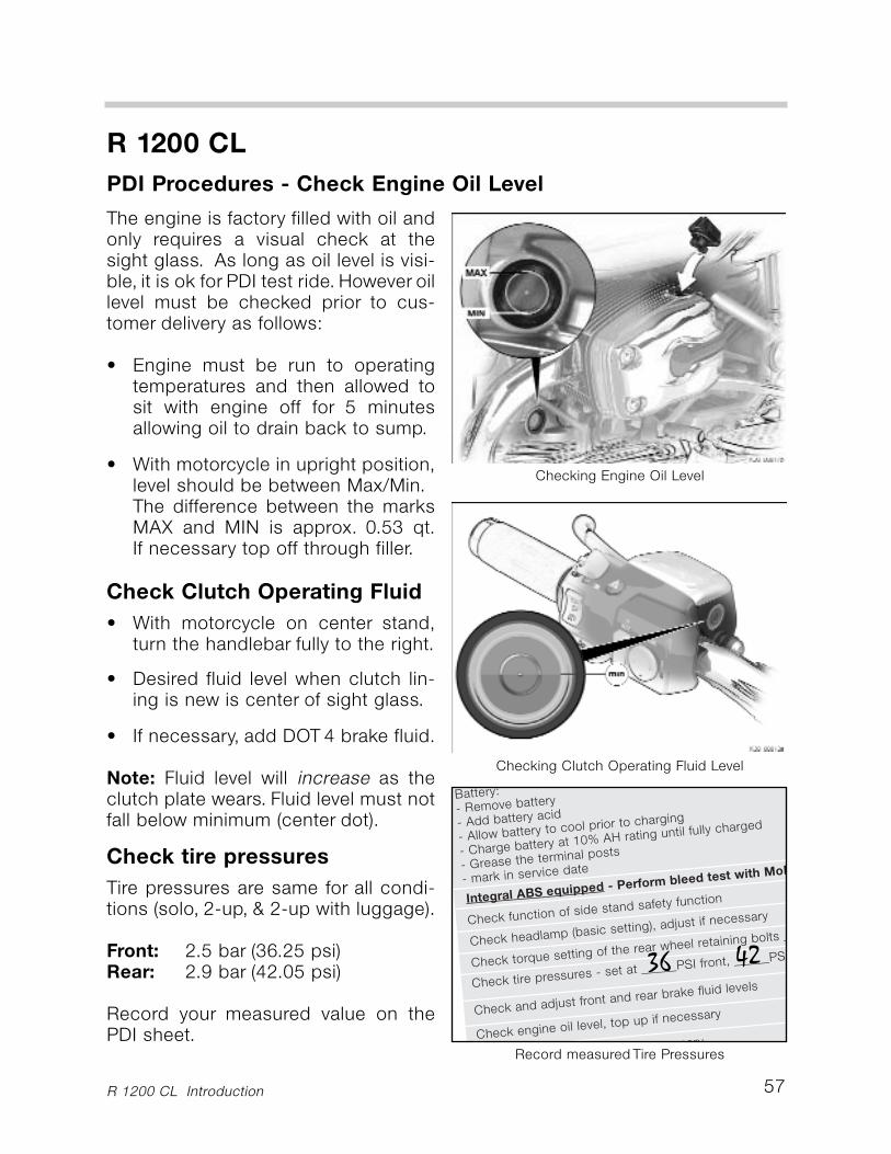
The engine is factory filled with oil andonly requires a visual check at thesight glass. As long as oil level is visi-ble, it is ok for PDI test ride. However oillevel must be checked prior to cus-tomer delivery as follows:
• Engine must be run to operatingtemperatures and then allowed tosit with engine off for 5 minutesallowing oil to drain back to sump.
• With motorcycle in upright position,level should be between Max/Min.The difference between the marksMAX and MIN is approx. 0.53 qt.If necessary top off through filler.
Check Clutch Operating Fluid
• With motorcycle on center stand,turn the handlebar fully to the right.
• Desired fluid level when clutch lin-ing is new is center of sight glass.
• If necessary, add DOT 4 brake fluid.
Note: Fluid level will increase as theclutch plate wears. Fluid level must notfall below minimum (center dot).
Check tire pressures
Tire pressures are same for all condi-tions (solo, 2-up, & 2-up with luggage).
Front: 2.5 bar (36.25 psi)Rear: 2.9 bar (42.05 psi)
Record your measured value on thePDI sheet.
36 42
58
R 1200 CL
PDI Procedures - Check Side Stand Function
R 1200 CL Introduction
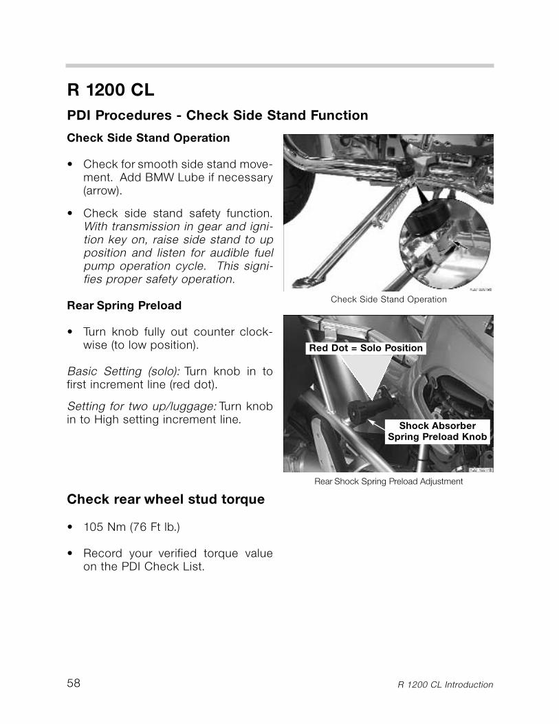
Check Side Stand Operation
• Check for smooth side stand move-ment. Add BMW Lube if necessary(arrow).
• Check side stand safety function.With transmission in gear and igni-tion key on, raise side stand to upposition and listen for audible fuelpump operation cycle. This signi-fies proper safety operation.
Rear Spring Preload
• Turn knob fully out counter clock-wise (to low position).
Basic Setting (solo): Turn knob in tofirst increment line (red dot).
Setting for two up/luggage: Turn knobin to High setting increment line.
Check rear wheel stud torque
• 105 Nm (76 Ft lb.)
• Record your verified torque valueon the PDI Check List.
Check Side Stand Operation
Rear Shock Spring Preload Adjustment
Shock AbsorberSpring Preload Knob
Red Dot = Solo Position
59
R 1200 CL
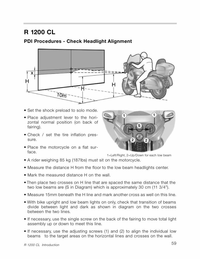
PDI Procedures - Check Headlight Alignment
R 1200 CL Introduction
• Set the shock preload to solo mode.
• Place adjustment lever to the hori-zontal normal position (on back offairing).
• Check / set the tire inflation pres-sure.
• Place the motorcycle on a flat sur-face.
• A rider weighing 85 kg (187lbs) must sit on the motorcycle.
• Measure the distance H from the floor to the low beam headlights center.
• Mark the measured distance H on the wall.
• Then place two crosses on H line that are spaced the same distance that thetwo low beams are (S in Diagram) which is approximately 30 cm (11 3/4”).
• Measure 15mm beneath the H line and mark another cross as well on this line.
• With bike upright and low beam lights on only, check that transition of beamsdivide between light and dark as shown in diagram on the two crossesbetween the two lines.
• If necessary, use the single screw on the back of the fairing to move total lightassembly up or down to meet this line.
• If necessary, use the adjusting screws (1) and (2) to align the individual lowbeams to the target areas on the horizontal lines and crosses on the wall.
1=Left/Right, 2=Up/Down for each low beam
PDI Procedures - Final Inspections and Function Checks
60
R 1200 CL
R 1200 CL Introduction
Fill Fuel Tank
• Fill the fuel tank with premium unleaded gasoline• Thoroughly check for leaks.
Check the operation of the following:
• Clutch & gearshift operation.• Steering (smooth, not binding).• Front & rear brakes.• Cruise Control Operation • Alarm System (if equipped)• Tail light, stop light, and turn signals.• Horn operation.• Test ride (14 - 16 miles).• ABS brake operation.• Idle speed (after the test ride).• Rubber stamp, sign, and date the PDI block in the Service & Technical
Booklet.• Make sure the PDI Check List is completed with your signature.• Insert PDI Check List along with the Integral ABS Bleed Test Trace
Documentation (if applicable) into the vehicle history file.
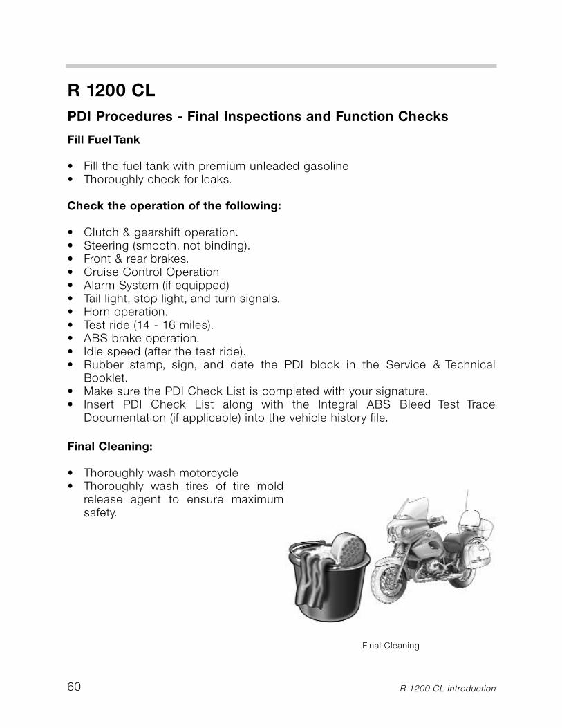
Final Cleaning:
• Thoroughly wash motorcycle• Thoroughly wash tires of tire mold
release agent to ensure maximumsafety.
Final Cleaning
61
Retail Delivery Handover Process
R 1200 CL Introduction
R 1200 CL
• The customer delivery process or“handover” is a critical step in establish-ing a successful relationship between you and your new customer. A pos-itive delivery experience reinforces the image of your Dealership and thepeople who run it. Be prepared for the delivery by reviewing the sampleRetail Delivery Check List on the following pages.
• Retail Delivery Check Lists are accessed online from the MTAS(Aftersales> Service> Technical Information). As a time saving tip, print outmultiple copies and store them for readiness when you are delivering yournext motorcycle.
• Familiarize yourself with the Rider Manual and Technical Book. These con-tain information the customer reads to become familiar with his or her newbike. Review these books at time of delivery, showing run in requirements,important basic safety information, as well as explaining maintenancerequirements and scheduling for their 600 mile Inspection.
• Convey product information about BMW Rider Apparel and Accessories tofurther the excitement of experiencing and enjoying the complete BMWproduct line.
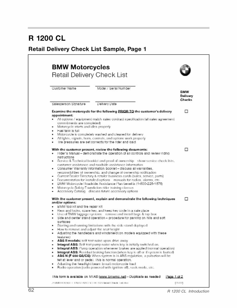
62
R 1200 CL
Retail Delivery Check List Sample, Page 1
R 1200 CL Introduction
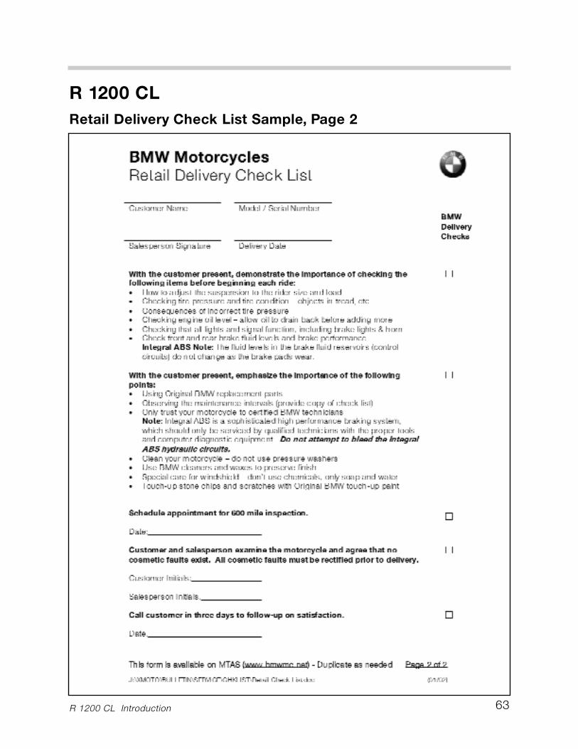
63
R 1200 CL
Retail Delivery Check List Sample, Page 2
R 1200 CL Introduction
64
R 1200 CL
600 Mile Inspection Procedures
R 1200 CL Introduction
Maintenance Schedule Checklist
• The Maintenance Schedule Checklist is used to make sure all the maintenance is carriedout at the proper time. The checklists are displayed on pages 66 and 67 to alert you ofnew procedures necessary on the R 1200 CL.
• All current model Maintenance Schedule Checklists are accessed online from the MTAS(Aftersales> Service> Technical Information). As a time saving tip, print out multiplecopies and store them for readiness.
Note: This manual only includes the 600 Mile Service Procedures solely asan introduction convenience. For complete service maintenance procedures,always refer to the official factory service manual. Repair Manuals for all cur-rent models are located in MTAS, http://www.bmwmc.net (Aftersales> Ser-vice>Technical Information).
Key to maintenance intervalsMaintenance tasks consist of the first Inspection (afterthe first 1,000 km/600 miles), the BMW Service, BMWInspection and BMW Annual Service.
Inspection 1,000 km (600 miles)BMW Running-in Check after thefirst 1,000 km (600 miles).
BMW ServiceAfter the first 10,000 km (6,000 miles) and eachadditional 20,000 km (12,000 miles)(at 30,000 km ... 50,000 km ... 70,000 km)(at 18,000 miles ... 30,000 miles ... 42,000 miles).
BMW InspectionAfter the first 20,000 km (12,000 miles) and eachadditional 20,000 km (12,000 miles)(at 40,000 km ... 60,000 km ... 80,000 km)(at 24,000 miles ... 36,000 miles ... 48,000 miles).
BMW Annual ServiceCertain maintenance tasks depend on elapsedtime as well as the distance the motorcycle hascovered.They should therefore be carried out atleast once a year (e. g. changing brake fluid).If these tasks cannot be carried out during aService or an Inspection, a BMW Annual Servicemust be performed.
In this RepairManual, the individual maintenance inter-valsare shown by the following codes:— Inspection at 1,000 km (600 miles)......................I— BMW Service at 10,000 km (6,000 miles)...........II— BMW Inspection at 20,000 km (12,000 miles) .. III— BMW Annual Service........................................ IV

65
R 1200 CL
US Market Service Lubricants, Sealants and Thread Lockers
R 1200 CL Introduction
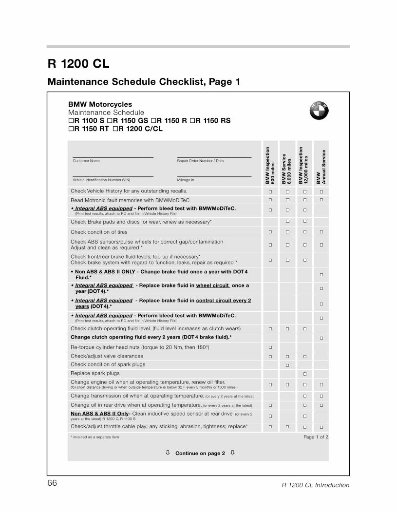
R 1200 CL Introduction66
R 1200 CL
Maintenance Schedule Checklist, Page 1
BM
WIn
sp
ec
tio
n60
0 m
ile
s
BM
WS
erv
ice
6,0
00 m
ile
s
BM
WA
nn
ua
l S
erv
ice
BM
WIn
sp
ec
tio
n12,0
00 m
ile
s
Check Vehicle History for any outstanding recalls.
Read Motronic fault memories with BMWMoDiTeC
• Integral ABS equipped - Perform bleed test with BMWMoDiTeC.(Print test results, attach to RO and file in Vehicle History File)
Check condition of tires
Check ABS sensors/pulse wheels for correct gap/contaminationAdjust and clean as required *
Check front/rear brake fluid levels, top up if necessary*Check brake system with regard to function, leaks, repair as required *
• Non ABS & ABS II ONLY - Change brake fluid once a year with DOT 4 Fluid.*
• Integral ABS equipped - Replace brake fluid in wheel circuit once a year (DOT 4).*
• Integral ABS equipped - Replace brake fluid in control circuit every 2years (DOT 4).*
Check clutch operating fluid level. (fluid level increases as clutch wears)
Change clutch operating fluid every 2 years (DOT 4 brake fluid).*
Re-torque cylinder head nuts (torque to 20 Nm, then 180O)
Check/adjust valve clearances
Check condition of spark plugs
Change transmission oil when at operating temperature. (or every 2 years at the latest)
Replace spark plugs
* invoiced as a separate item
Check Brake pads and discs for wear, renew as necessary*
Page 1 of 2
Change engine oil when at operating temperature, renew oil filter.(for short distance driving or when outside temperature is below 32 F every 3 months or 1800 miles.)
� Continue on page 2 �
Change oil in rear drive when at operating temperature. (or every 2 years at the latest)
_________________________ _______________________Customer Name Repair Order Number / Date
_________________________ _______________________Vehicle Identification Number (VIN) Mileage In
• Integral ABS equipped - Perform bleed test with BMWMoDiTeC.(Print test results, attach to RO and file in Vehicle History File)
Check/adjust throttle cable play; any sticking, abrasion, tightness; replace*
BMW MotorcyclesMaintenance Schedule�R 1100 S �R 1150 GS �R 1150 R �R 1150 RS �R 1150 RT �R 1200 C/CL
Non ABS & ABS II Only- Clean inductive speed sensor at rear drive. (or every 2
years at the latest) R 1200 C, R 1100 S
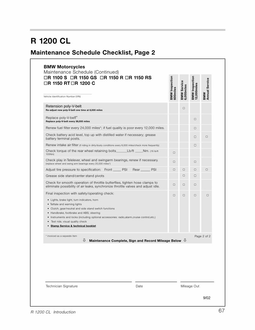
R 1200 CL
R 1200 CL Introduction 67
Maintenance Schedule Checklist, Page 2
BM
WS
erv
ice
6,0
00m
ile
s
BM
WIn
sp
ec
tio
n60
0m
ile
s
BM
WIn
sp
ec
tio
n12,0
00m
ile
s
BM
WA
nn
ua
l S
erv
ice
Final inspection with safety/operating check:
• Lights, brake light, turn indicators, horn
• Telltale and warning lights
• Clutch, gear/neutral and side stand switch functions
• Handbrake, footbrake and ABS; steering
• Instruments and locks (including optional accessories: radio,alarm,cruise control,etc.)
• Test ride, visual quality check
• Stamp Service & technical booklet
Check for smooth operation of throttle butterflies, tighten hose clamps toeliminate possibility of air leaks, synchronize throttle valves and adjust idle.
Grease side stand/center stand pivots
Adjust tire pressure to specification: Front _____ PSI Rear ______ PSI
Check play in Telelever, wheel and swingarm bearings, renew if necessary.(replace wheel and swing arm bearings every 25,000 miles*)
Check torque of the rear wheel retaining bolts_______Lb/ft _____Nm. (76 lb/ft
105Nm)
Renew intake air filter (if riding in dirty/dusty conditions every 6,000 miles/check more frequently)
* invoiced as a separate item Page 2 of 2
Technician Signature Date Mileage Out
Check battery acid level, top up with distilled water if necessary; greasebattery terminal posts.
� Maintenance Complete, Sign and Record Mileage Below �
Vehicle Identification Number (VIN)
BMW MotorcyclesMaintenance Schedule (Continued)�R 1100 S �R 1150 GS �R 1150 R �R 1150 RS
�R 1150 RT�R 1200 C
Renew fuel filter every 24,000 miles*; if fuel quality is poor every 12,000 miles.
Replace poly-V-belt*Replace poly-V-belt every 36,000 miles
Retension poly-V-beltRe-adjust new poly-V-belt one time at 6,000 miles
9/02
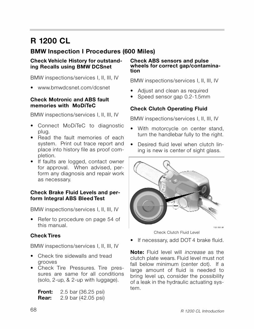
R 1200 CL
R 1200 CL Introduction68
Check Vehicle History for outstand-ing Recalls using BMW DCSnet
BMW inspections/services I, II, III, IV
• www.bmwdcsnet.com/dcsnet
Check Motronic and ABS faultmemories with MoDiTeC
BMW inspections/services I, II, III, IV
• Connect MoDiTeC to diagnosticplug.
• Read the fault memories of eachsystem. Print out trace report andplace into history file as proof com-pletion.
• If faults are logged, contact ownerfor approval. When advised, per-form any diagnosis and repair workas necessary.
Check Brake Fluid Levels and per-form Integral ABS Bleed Test
BMW inspections/services I, II, III, IV
• Refer to procedure on page 54 ofthis manual.
Check Tires
BMW inspections/services I, II, III, IV
• Check tire sidewalls and treadgrooves
• Check Tire Pressures. Tire pres-sures are same for all conditions(solo, 2-up, & 2-up with luggage).
Front: 2.5 bar (36.25 psi)Rear: 2.9 bar (42.05 psi)
Check ABS sensors and pulsewheels for correct gap/contamina-tion
BMW inspections/services I, II, III, IV
• Adjust and clean as required• Speed sensor gap 0.2-1.5mm
Check Clutch Operating Fluid
BMW inspections/services I, II, III, IV
• With motorcycle on center stand,turn the handlebar fully to the right.
• Desired fluid level when clutch lin-ing is new is center of sight glass.
• If necessary, add DOT 4 brake fluid.
Note: Fluid level will increase as theclutch plate wears. Fluid level must notfall below minimum (center dot). If alarge amount of fluid is needed tobring level up, consider the possibilityof a leak in the hydraulic actuating sys-tem.
BMW Inspection I Procedures (600 Miles)
Check Clutch Fluid Level
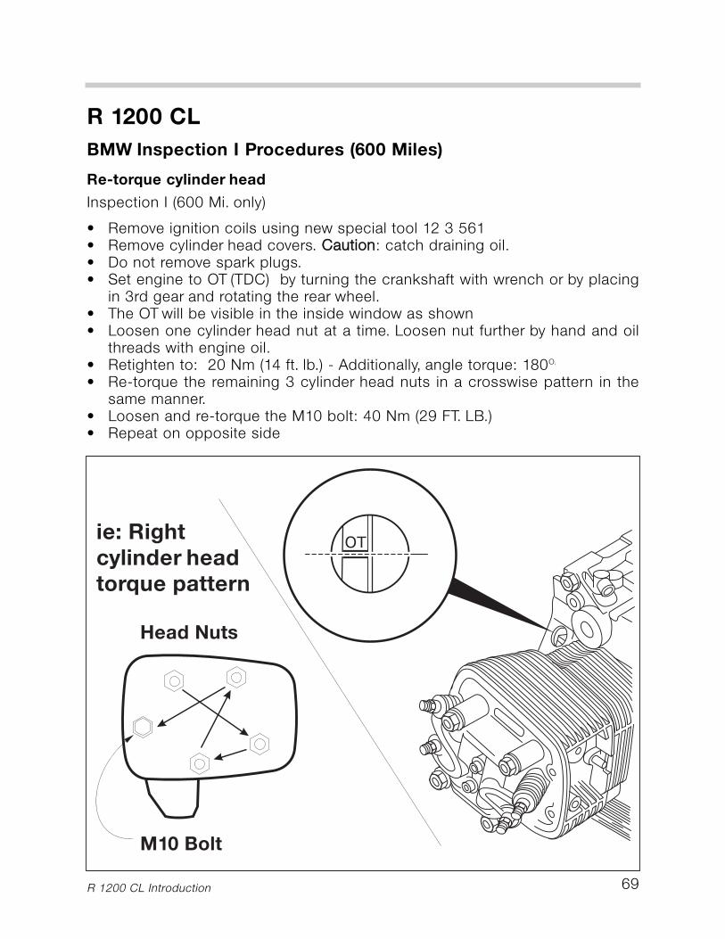
BMW Inspection I Procedures (600 Miles)
Re-torque cylinder head
Inspection I (600 Mi. only)
• Remove ignition coils using new special tool 12 3 561• Remove cylinder head covers. CCaauuttiioonn: catch draining oil.• Do not remove spark plugs.• Set engine to OT (TDC) by turning the crankshaft with wrench or by placing
in 3rd gear and rotating the rear wheel.• The OT will be visible in the inside window as shown• Loosen one cylinder head nut at a time. Loosen nut further by hand and oil
threads with engine oil.• Retighten to: 20 Nm (14 ft. lb.) - Additionally, angle torque: 180O.
• Re-torque the remaining 3 cylinder head nuts in a crosswise pattern in thesame manner.
• Loosen and re-torque the M10 bolt: 40 Nm (29 FT. LB.)• Repeat on opposite side
R 1200 CL Introduction
R 1200 CL
69
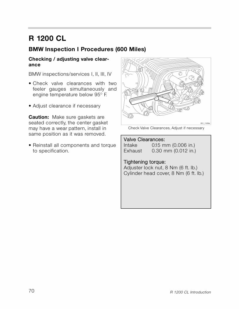
70
R 1200 CL
BMW Inspection I Procedures (600 Miles)
Checking / adjusting valve clear-ance
BMW inspections/services I, II, III, IV
• Check valve clearances with twofeeler gauges simultaneously andengine temperature below 95O F.
• Adjust clearance if necessary
Caution: Make sure gaskets areseated correctly, the center gasketmay have a wear pattern, install insame position as it was removed.
• Reinstall all components and torqueto specification.
Check Valve Clearances, Adjust if necessary
R 1200 CL Introduction
VVaallvvee CClleeaarraanncceess::Intake 0.15 mm (0.006 in.)Exhaust 0.30 mm (0.012 in.)
TTiigghhtteenniinngg ttoorrqquuee::Adjuster lock nut, 8 Nm (6 ft. lb.)Cylinder head cover, 8 Nm (6 ft. lb.)
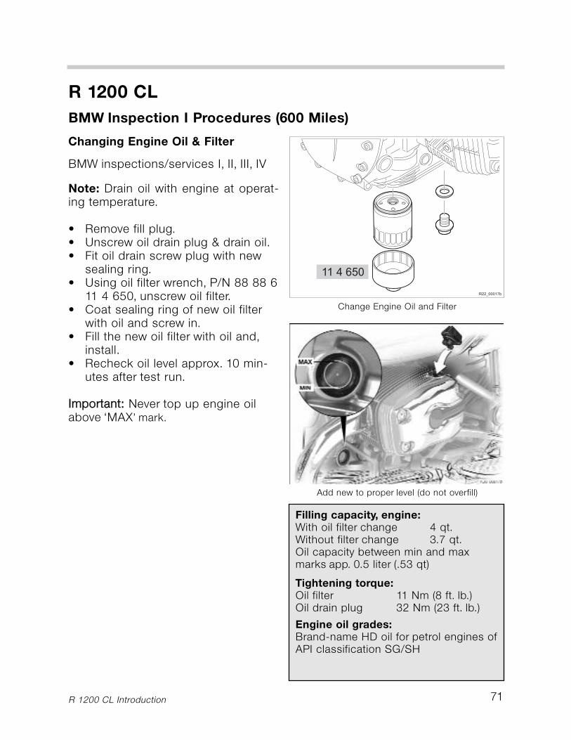
71
R 1200 CL
BMW Inspection I Procedures (600 Miles)
Changing Engine Oil & Filter
BMW inspections/services I, II, III, IV
Note: Drain oil with engine at operat-ing temperature.
• Remove fill plug.• Unscrew oil drain plug & drain oil.• Fit oil drain screw plug with new
sealing ring.• Using oil filter wrench, P/N 88 88 6
11 4 650, unscrew oil filter.• Coat sealing ring of new oil filter
with oil and screw in.• Fill the new oil filter with oil and,
install.• Recheck oil level approx. 10 min-
utes after test run.
IImmppoorrttaanntt:: Never top up engine oilabove ‘MAX’ mark.
Change Engine Oil and Filter
Add new to proper level (do not overfill)
R 1200 CL Introduction
Filling capacity, engine:With oil filter change 4 qt.Without filter change 3.7 qt.Oil capacity between min and max marks app. 0.5 liter (.53 qt)
Tightening torque:Oil filter 11 Nm (8 ft. lb.)Oil drain plug 32 Nm (23 ft. lb.)
Engine oil grades:Brand-name HD oil for petrol engines ofAPI classification SG/SH
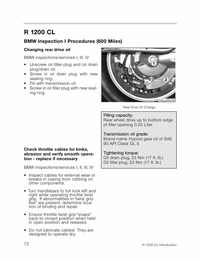
72
R 1200 CL
BMW Inspection I Procedures (600 Miles)
Changing rear drive oil
BMW inspections/services I, III, IV
• Unscrew oil filler plug and oil drainplug/drain oil.
• Screw in oil drain plug with newsealing ring.
• Fill with transmission oil.• Screw in oil filler plug with new seal-
ing ring.
Check throttle cables for kinks,abrasion and verify smooth opera-tion - replace if necessary
BMW inspections/services I, II, III, IV
• Inspect cables for external wear orbreaks in casing from rubbing onother components.
• Turn handlebars to full lock left andright while operating throttle twistgrip. If abnormalities in “twist gripfeel” are present, determine loca-tion of binding and repair.
• Ensure throttle twist grip “snaps”back to closed position when heldin open position and released.
• Do not lubricate cables! They aredesigned to operate dry.
Rear Drive Oil Change
R 1200 CL Introduction
FFiilllliinngg ccaappaacciittyy::Rear wheel drive up to bottom edgeof filler opening 0.25 Liter
TTrraannssmmiissssiioonn ooiill ggrraaddee::Brand-name Hypoid gear oil of SAE90 API Class GL 5
TTiigghhtteenniinngg ttoorrqquuee::Oil drain plug, 23 Nm (17 ft. lb.)Oil filler plug, 23 Nm (17 ft. lb.)
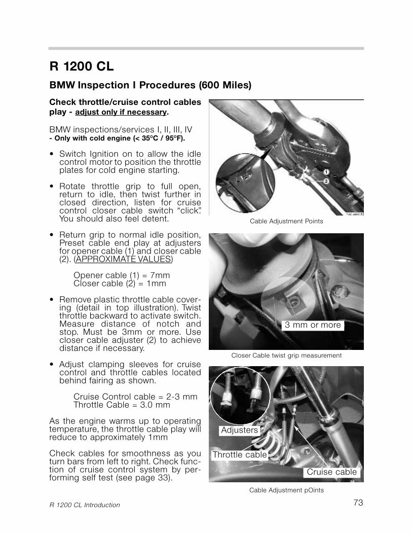
73
R 1200 CL
BMW Inspection I Procedures (600 Miles)
Check throttle/cruise control cablesplay - adjust only if necessary.
BMW inspections/services I, II, III, IV- Only with cold engine (< 35OC / 95OF).
• Switch Ignition on to allow the idlecontrol motor to position the throttleplates for cold engine starting.
• Rotate throttle grip to full open,return to idle, then twist further inclosed direction, listen for cruisecontrol closer cable switch “click”.You should also feel detent.
• Return grip to normal idle position,Preset cable end play at adjustersfor opener cable (1) and closer cable(2). (APPROXIMATE VALUES)
Opener cable (1) = 7mmCloser cable (2) = 1mm
• Remove plastic throttle cable cover-ing (detail in top illustration). Twistthrottle backward to activate switch.Measure distance of notch andstop. Must be 3mm or more. Usecloser cable adjuster (2) to achievedistance if necessary.
• Adjust clamping sleeves for cruisecontrol and throttle cables locatedbehind fairing as shown.
Cruise Control cable = 2-3 mm Throttle Cable = 3.0 mm
As the engine warms up to operatingtemperature, the throttle cable play willreduce to approximately 1mm
Check cables for smoothness as youturn bars from left to right. Check func-tion of cruise control system by per-forming self test (see page 33).
Cable Adjustment Points
Closer Cable twist grip measurement
Cable Adjustment pOints
R 1200 CL Introduction
3 mm or more
Cruise cable
Throttle cable
Adjusters
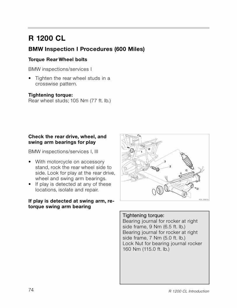
74
R 1200 CL
BMW Inspection I Procedures (600 Miles)
Torque Rear Wheel bolts
BMW inspections/services I
• Tighten the rear wheel studs in acrosswise pattern.
Tightening torque:Rear wheel studs; 105 Nm (77 ft. lb.)
Check the rear drive, wheel, andswing arm bearings for play
BMW inspections/services I, III
• With motorcycle on accessorystand, rock the rear wheel side toside. Look for play at the rear drive,wheel and swing arm bearings.
• If play is detected at any of theselocations, isolate and repair.
If play is detected at swing arm, re-torque swing arm bearing
R 1200 CL Introduction
TTiigghhtteenniinngg ttoorrqquuee::Bearing journal for rocker at rightside frame, 9 Nm (6.5 ft. lb.)Bearing journal for rocker at rightside frame, 7 Nm (5.0 ft. lb.)Lock Nut for bearing journal rocker160 Nm (115.0 ft. lb.)

75
R 1200 CL
BMW Inspection I Procedures (600 Miles)
Check throttle synchronization val-ues with MoDiTeC
BMW inspections/services I, II, III, IV
Note: The R 1200 CL has a commonthrottle linkage system and an IdleControl management feature ofMotronic. These two features havedeemed the throttle synchronizationuseless on the R 1200 C/CL models.
However, as a measure of quality ser-vice, the throttle sync should bechecked solely to ensure the system isfree of air leaks that could lead toengine poor performance issues andcustomer dissatisfaction.
• Connect Synchro unit to intake vac-uum ports and MoDiTeC.
• Engine should not run longer than10 minutes while stationary. Have afan running to cool engine. Do notleave unattended.
• The max difference should notexceed 0.3 bar as displayed byMoDiTeC.
If excessive difference is present, it ismost likely an intake air leak whichmust be repaired.
Throttle Synchronization Test
R 1200 CL Introduction
76
R 1200 CL
BMW Inspection I Procedures (600 Miles)
FFiinnaall IInnssppeeccttiioonn wwiitthh rrooaadd ssaaffeettyyaanndd ffuunnccttiioonn cchheecckk
BMW inspections/services I, II, III, IV
CChheecckk tthhee ooppeerraattiioonn ooff tthhee ffoolllloowwiinngg::
• Clutch & gearshift operation.• Steering.• Front & rear brakes.• Clutch & gearshift operation.• Cruise Control• Tail light, stop light, and turn sig-
nals.• Horn operation.• Test ride (14 - 16 miles).• ABS brake operation.• Idle speed (after the test ride).• Radio/ sound system• Complete the Proof of Ownership
section in the Service & TechnicalBooklet.
R 1200 CL Introduction
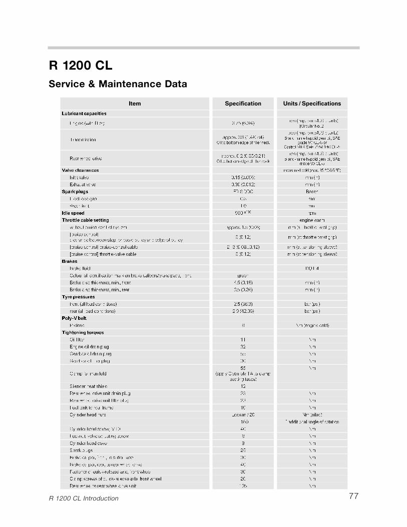
77
R 1200 CL
Service & Maintenance Data
R 1200 CL Introduction
���� ����������� �������������������
����������������
��������������� � �������������� �������������������� ��
����������� �
� �������� ���� !��"�#��$���"�#��
���������������������������
�� �������������������� ��������������������������� !
����� "#$%�&����'����()*� !+&,-.#$%�&
%�� ������& �'���� !��"�(��"����"�($�
���������������������������
�� �������������������� ��������������������������� !
����� "#$%�&
�������������� ���'��������/��0�1&2�3"&245
�����'��'� "�$���"�""�� �������
�!����'��'� "��"��"�"$(� �������
��������� )%���**+ , �-�
���- &����� "�# ���
.�� ����� $�" ���
���� ���� /""����� ��
����������� ���� ��������� �
�� ��- ����0- � ���1��� ��� !��$����"�"�� ������ �������� ���
2- �����- � �3�-��� ��-��4������� ��� �-�4��������1���&��&��� �������1
���"�$(� ������ �������� ���
2- �����- � �3�- ����0- � ��-�4�� (������"�"#���"�$(� ���������� ���������'��
2- �����- � �3� ��0'��'��-�4�� ���"�$(� ���������� ���������'��
����� �
, �5������& *6���
+ � � � ���&�����-�� ���� 5� ��4 �5��-����� ��4 �5����&�7�� � � ���
, �5��&��-��-5����7�����7�� � �����"�$#� �������
, �5��&��-��-5����7�����7� �� �����"�(�� �������
������� ���
� �������� �&�- �&�� ��� (��������� 4� ������
�� ������� �&�- �&�� ��� (�/���(�"�� 4� ������
���������
8 �� �& # 9����������- �&�
��������������
6������� $$ 9�
������� ���& �������� �( 9�
:�� 4 !� ���& �������� �� 9�
:�� 4 !� �������� ����� �" 9�
+������ ������ �&��
�����1�6��� �1��;� �-�����
���������-���
9�
�����-� ��������& $(
%�� ������& �'������& �������� (� 9�
%�� ������& �'����������� ����� (� 9�
)������5� � �� �� ��� $" 9�
+1���&� ���&���� < ������(" 9��� ���&�
=$#" >��&&�� ���������� �� �� �
+1���&� ���&��- ��7�?$" �" 9�
< -5��7�'��'���&@�������- �� # 9�
+1���&� ���&�- '� # 9�
��� 5������ (� 9�
, �5��-����� 7�� �7� ����&� ��4� �" 9�
, �5��-����� 7� �� 7� � �� ������& �'� �" 9�
)����� � �����-50 ��������!��7�� ������ �" 9�
+������- ���� �����-50 ��������!��7�� ������ (" 9�
%�� ������ � �� ������& �'����� $"� 9�
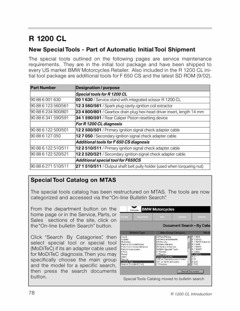
Special Tool Catalog on MTAS
The special tools catalog has been restructured on MTAS. The tools are nowcategorized and accessed via the “On-line Bulletin Search”.
From the department button on thehome page or in the Service, Parts, orSales sections of the site, click onthe “On-line bulletin Search” button.
Click “Search By Catagories”, thenselect special tool or special tool(MoDiTeC) if its an adapter cable usedfor MoDiTeC diagnosis.Then you mayspecifically choose the main groupand the model for a specific search,then press the search documentsbutton.
The special tools outlined on the following pages are service maintenancerequirements. They are in the initial tool package and have been shipped toevery US market BMW Motorcycles Retailer. Also included in the R 1200 CL ini-tial tool package are additional tools for F 650 CS and the latest SD ROM (9/02).
78
R 1200 CL
New Special Tools - Part of Automatic Initial Tool Shipment
Special Tools Catalog moved to bulletin search
R 1200 CL Introduction
Part Number Designation / purpose
Special tools for R 1200 CL
90 88 6 001 630 00 1 630 / Service stand with integrated scissor R 1200 CL
90 88 6 123 560/561 12 3 560/561 / Spark plug cavity-ignition coil extractor
90 88 6 234 800/801 23 4 800/801 / Gearbox drain plug hex-head driver insert, length 14 mm
90 88 6 341 590/591 34 1 590/591 / Rear Caliper Piston resetting device
For R 1200 CL diagnosis
90 88 6 122 500/501 12 2 500/501 / Primary ignition signal check adapter cable
90 88 6 127 050 12 7 050 / Secondary ignition signal check adapter cable
Additional tools for F 650 CS diagnosis
90 88 6 122 510/511 12 2 510/511 / Primary ignition signal check adapter cable
90 88 6 122 520/521 12 2 520/521 / Secondary ignition signal check adapter cable
Additional special tool for F650CS
90 88 6 271 510/511 27 1 510/511 / Output shaft belt pully holder (used when torqueing nut)
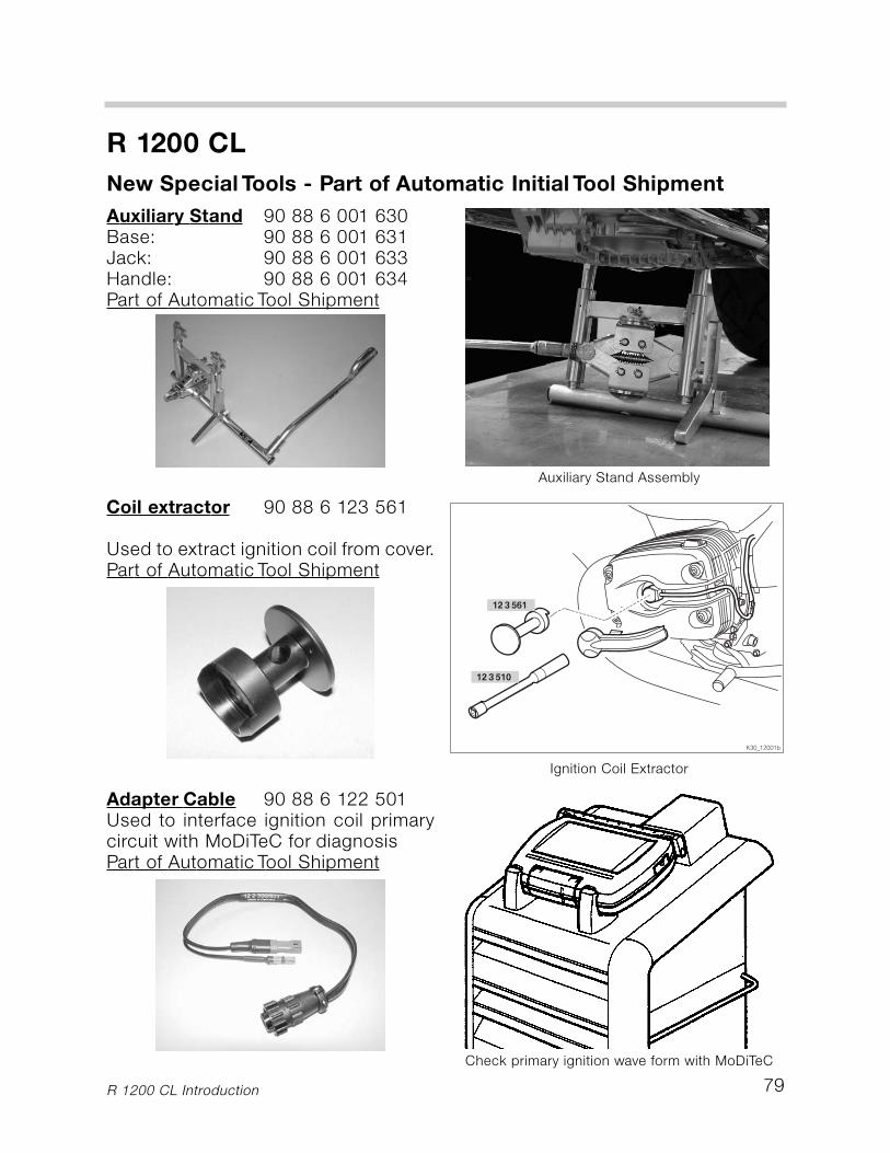
79
R 1200 CL
New Special Tools - Part of Automatic Initial Tool Shipment
R 1200 CL Introduction
Auxiliary Stand 90 88 6 001 630Base: 90 88 6 001 631Jack: 90 88 6 001 633Handle: 90 88 6 001 634Part of Automatic Tool Shipment
Auxiliary Stand Assembly
Coil extractor 90 88 6 123 561
Used to extract ignition coil from cover.Part of Automatic Tool Shipment
Ignition Coil Extractor
Adapter Cable 90 88 6 122 501Used to interface ignition coil primarycircuit with MoDiTeC for diagnosisPart of Automatic Tool Shipment
Check primary ignition wave form with MoDiTeC
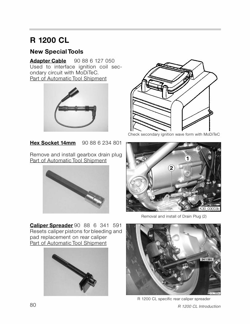
80
R 1200 CL
New Special Tools
R 1200 CL Introduction
Adapter Cable 90 88 6 127 050Used to interface ignition coil sec-ondary circuit with MoDiTeC.Part of Automatic Tool Shipment
Check secondary ignition wave form with MoDiTeC
Hex Socket 14mm 90 88 6 234 801
Remove and install gearbox drain plugPart of Automatic Tool Shipment
Removal and install of Drain Plug (2)
Caliper Spreader 90 88 6 341 591Resets caliper pistons for bleeding andpad replacement on rear caliperPart of Automatic Tool Shipment
R 1200 CL specific rear caliper spreader
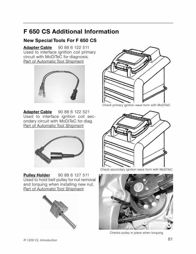
81
F 650 CS Additional Information
New Special Tools For F 650 CS
R 1200 CL Introduction
Adapter Cable 90 88 6 122 511Used to interface ignition coil primarycircuit with MoDiTeC for diagnosis.Part of Automatic Tool Shipment
Check primary ignition wave form with MoDiTeC
Adapter Cable 90 88 6 122 521Used to interface ignition coil sec-ondary circuit with MoDiTeC for diag.Part of Automatic Tool Shipment
Check secondary ignition wave form with MoDiTeC
Pulley Holder 90 88 6 127 511Used to hold belt pulley for nut removaland torquing when installing new nut.Part of Automatic Tool Shipment
Checks pulley in place when torquing

R 1200 CL
F 650 CS Introduction82
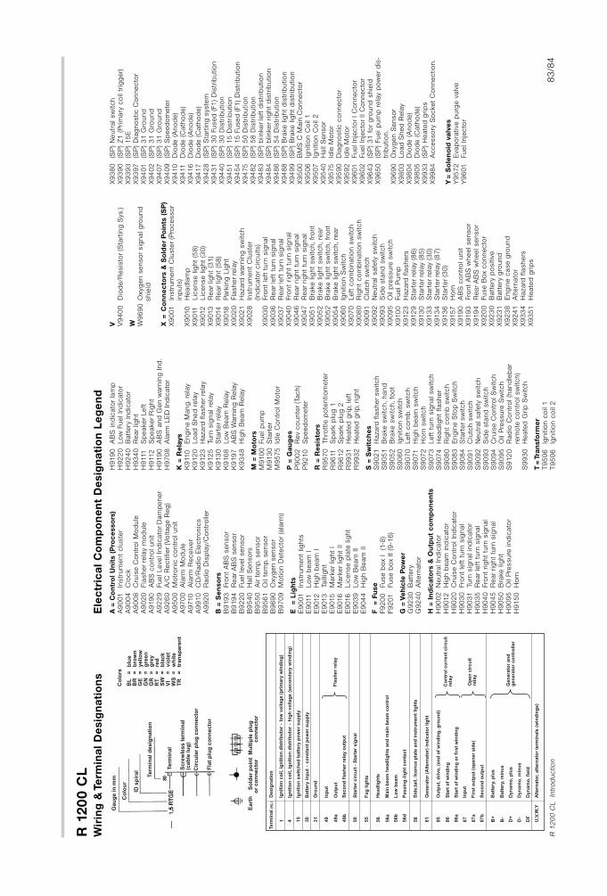
R 1
20
0 C
L
83
/84
R 1
20
0 C
L
Intr
od
uctio
n
Wir
ing
& T
erm
ina
l D
esig
na
tio
ns
Ele
ctr
ica
l C
om
po
ne
nt
De
sig
na
tio
n L
eg
en
d
A=
Co
ntr
ol
Un
its (
Pro
ce
sso
rs)
A9
001
In
str
um
ent
clu
ste
rA
90
04
C
lock
A9
00
8C
ruis
e C
ontr
ol M
od
ule
A9
02
0
Fla
sher
rela
ym
od
ule
A9
19
0
AB
S c
ontr
ol unit
A9
22
9Fuel Level In
dic
ato
rD
am
pener
A9
26
0
A/C
Rectifier
(Vo
ltag
e R
eg
)A
95
00
M
otr
onic
co
ntr
ol unit
A9
70
0A
larm
Mo
dule
A9
710
Ala
rm R
eceiv
er
A9
910
CD
/Rad
io E
lectr
onic
sA
99
20
Rad
io D
isp
lay/C
ontr
olle
r
B =
Se
nso
rsB
919
3
Fro
nt
AB
S s
enso
rB
919
4
RearA
BS
senso
rB
92
20
Fuel le
vel senso
rB
95
40
H
all
Senso
rsB
95
50
A
irte
mp.senso
rB
95
61
Oil
tem
p.senso
rB
96
90
O
xyg
en s
enso
rB
970
9M
otio
n D
ete
cto
r(a
larm
)
E
= L
igh
tsE
90
01
In
str
um
ent
lights
E9
011
Low
beam
I
E9
012
H
igh b
eam
IE
9013
Ta
illig
ht
E9
015
M
ark
er
light
IE
9016
Mark
er
light
IIE
9016
Lic
ense p
late
lig
ht
E9
03
9Low
Beam
II
E9
04
4H
igh B
eam
II
F
= F
use
F9
20
0
Fuse b
ox I
(1-8
)F9
201
Fuse b
ox II (9
-16
)
G =
Ve
hic
le P
ow
er
G9
23
0
Batt
ery
G9
24
0
Altern
ato
r
H =
In
dic
ato
rs &
Ou
tpu
t c
om
po
ne
nts
H9
00
2
Neutr
al In
dic
ato
rH
9012
H
igh b
eam
ind
icato
rH
90
20
Cru
ise C
ontr
ol In
dic
ato
rH
90
30
Fro
nt
left
turn
sig
nal
H9
03
1
Turn
sig
nal in
dic
ato
rH
90
35
R
ear
left
turn
sig
nal
H9
04
0
Fro
nt
rig
ht
turn
sig
nal
H9
04
5
Rear
rig
ht
turn
sig
nal
H9
05
0
Bra
ke lig
ht
H9
09
5
Oil
Pre
ssure
ind
icato
rH
915
0
Ho
rn
H9
19
0
AB
S ind
icato
rla
mp
H9
22
0
Low
Fuel In
dic
ato
rH
92
40
Batt
ery
Ind
icato
rH
93
40
R
ear
light
H9
111
Sp
eaker
Left
H9
112
Sp
eaker
Rig
ht
H9
19
0A
BS
and
Gen w
arn
ing
Ind
.H
970
8A
larm
LE
D Ind
icato
r
K =
Re
lays
K9
110
E
ng
ine M
ang.re
lay
K9
12
0Lo
ad
Shed
rela
yK
912
3
Hazard
fla
sher
rela
yK
912
5
Turn
sig
nal re
lay
K9
13
0
Sta
rter
rela
yK
916
8Low
Beam
Rela
yK
919
7A
BS
Warn
ing
Rela
yK
93
48
Hig
h B
eam
Rela
y
M =
Mo
tors
M9
10
0 Fuel p
um
p
M9
13
0 S
tart
er
M9
575
Id
le C
ontr
ol M
oto
r
P =
Gau
ge
sP
90
02
R
ev
co
unte
r(T
ach)
P9
210
S
peed
om
ete
r
R =
Re
sis
tors
R
95
70
Thro
ttle
po
tentio
mete
rR
96
11
S
park
plu
g 1
R9
612
Sp
ark
plu
g 2
R9
93
1
Heate
d g
rip,le
ftR
99
32
H
eate
d g
rip,rig
ht
S =
Sw
itc
he
sS
90
21
H
azard
fla
sher
sw
itch
S9
05
1
Bra
ke s
witch,hand
S
90
52
B
rake s
witch,fo
ot
S9
06
0
Ignitio
n s
witch
S9
070
Left
co
mb.sw
itch
S9
071
H
igh b
eam
sw
itch
S9
07
2
Ho
rn s
witch
S9
073
Left
turn
sig
nal sw
itch
S9
074
H
ead
light
flasher
S9
08
0
Rig
ht
co
mb
sw
itch
S9
08
3
Eng
ine S
top
Sw
itch
S9
08
4
Sta
rter
sw
itch
S9
09
1
Clu
tch s
witch
S9
09
2
Neutr
al safe
tysw
itch
S9
09
3
Sid
e s
tand
sw
itch
S9
09
4C
ruis
e C
ontr
ol S
witch
S9
09
5
Oil
Pre
ssure
Sw
itch
S9
12
0R
ad
io C
ontr
ol (h
and
leb
ar
rem
ote
co
ntr
ol sw
itch)
S9
93
0
Heate
d G
rip
Sw
itch
T=
Tra
nsfo
rme
rT
95
06
Ig
nitio
n c
oil
1T
95
06
Ignitio
n c
oil
2
V V9
40
0
Dio
de/R
esis
tor
(Sta
rtin
g S
ys.)
W W9
69
0 O
xyg
en s
enso
rsig
nal g
round
shie
ld
X =
Co
nn
ec
tors
& S
old
er
Po
ints
(S
P)
X9
001
In
str
um
ent
Clu
ste
r(P
rocesso
rin
puts
)X
9010
H
ead
lam
pX
9011
Lic
ense lig
ht
(58
)X
9012
Lic
ense lig
ht
(30
)X
9013
R
ear
light
(31
)X
9014
R
ear
light
(58
)X
9018
P
ark
ing
Lig
ht
X9
02
0
Fla
sher
rela
yX
90
21
H
azard
warn
ing
sw
itch
X9
02
8
Instr
um
ent
Clu
ste
r(Ind
icato
rcircuits)
X9
03
0
Fro
nt
left
turn
sig
nal
X9
03
6
Rear
left
turn
sig
nal
X9
03
7
Rear
left
turn
sig
nal
X9
04
0
Fro
nt
rig
ht
turn
sig
nal
X9
04
6
Rear
rig
ht
turn
sig
nal
X9
04
7
Rear
rig
ht
turn
sig
nal
X9
05
1
Bra
ke lig
ht
sw
itch,fr
ont
X9
05
2
Bra
ke lig
ht
sw
itch,re
ar
X9
05
2
Bra
ke lig
ht
sw
itch,fr
ont
X9
05
4
Bra
ke lig
ht
sw
itch,re
ar
X9
06
0
Ignitio
n S
witch
X9
070
Left
co
mb
inatio
n s
witch
X9
08
0
Rig
ht
co
mb
inatio
n s
witch
X9
09
1
Clu
tch s
witch
X9
09
2
Neutr
al safe
tysw
itch
X9
09
3
Sid
e s
tand
sw
itch
X9
09
5
Oil
pre
ssure
sw
itch
X9
10
0
Fuel P
um
pX
912
3
Hazard
fla
shers
X9
12
9
Sta
rter
rela
y(8
6)
X9
13
0
Sta
rter
rela
y(8
5)
X9
13
3
Sta
rter
rela
y(3
0)
X9
13
4
Sta
rter
rela
y(8
7)
X9
13
6
Sta
rter
(30
)X
915
7
Ho
rnX
919
0
AB
S c
ontr
ol unit
X9
19
3
Fro
nt
AB
Sw
heel senso
rX
919
4
RearA
BS
wheel senso
rX
92
00
Fuse B
ox c
onnecto
rX
92
30
B
att
ery
po
sitiv
eX
92
31
B
att
ery
gro
und
X9
23
8
Eng
ine c
ase g
round
X9
24
1
Altern
ato
rX
93
34
H
azard
fla
shers
X9
35
1
Heate
d g
rip
s
X9
38
0
(SP
) N
eutr
al sw
itch
X9
39
0
(SP
) Z
1 (P
rim
ary
co
il tr
igg
er)
X9
39
3(S
P) 15
EX
93
97
(S
P) D
iag
no
stic C
onnecto
rX
94
01
(SP
) 3
1 G
round
X9
40
2(S
P) 3
1 G
round
X9
40
7(S
P) 3
1 G
round
X9
40
9(S
P) S
peed
om
ete
rX
94
10
Dio
de (A
no
de)
X9
411
Dio
de (C
ath
od
e)
X9
416
Dio
de (A
no
de)
X9
417
Dio
de (C
ath
od
e)
X9
42
8(S
P) S
tart
ing
syste
mX
94
31
(SP
) 3
0 F
used
(F1
) D
istr
ibutio
nX
94
40
(SP
) 3
0 D
istr
ibutio
nX
94
51
(SP
) 15
Dis
trib
utio
nX
94
54
(SP
) 15
Fused
(F1
) D
istr
ibutio
nX
94
75
(S
P) 5
0 D
istr
ibutio
nX
94
82
(SP
) 5
8 D
istr
ibutio
nX
94
83
(SP
) b
linker
left
dis
trib
utio
nX
94
84
(S
P) b
linker
rig
ht
dis
trib
utio
nX
94
86
(S
P) 5
4 D
istr
ibutio
nX
94
88
(SP
) B
rake lig
ht
dis
trib
utio
nX
94
99
(SP
) B
rake lig
ht
dis
trib
utio
nX
95
00
BM
S C
Main
Co
nnecto
rX
95
06
Ignitio
n C
oil
1X
95
07
Ignitio
n C
oil
2X
95
40
Hall
Senso
rX
95
75
Idle
Mo
tor
X9
59
0
Dia
gno
stic c
onnecto
rX
95
92
Idle
Mo
tor
X9
601
Fuel In
jecto
rI C
onnecto
rX
96
02
Fuel In
jecto
rII
Co
nnecto
rX
96
43
(S
P) 3
1 f
or
gro
und
shie
ldX
96
50
(S
P) Fuel p
um
p r
ela
yp
ow
er
dis
-tr
ibutio
n.
X9
69
0O
xyg
en S
enso
rX
98
03
Lo
ad
Shed
Rela
yX
98
04
Dio
de (A
no
de)
X9
80
5D
iod
e (C
ath
od
e)
X9
93
3(S
P) H
eate
d g
rip
s
X9
98
4A
ccesso
ryS
ocket
Co
nnectio
n.
Y=
So
len
oid
va
lve
sY
95
72
Evap
ora
tive p
urg
e v
alv
e
Y9
601
Fuel In
jecto
r
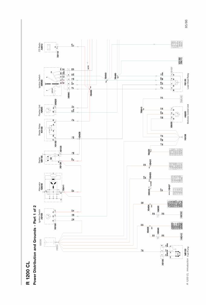
R 1
20
0 C
L
85
/86
R 1
20
0 C
L
Intr
od
uctio
n
Po
we
rD
istr
ibu
tio
n a
nd
Gro
un
ds -
Pa
rt 1
of
2
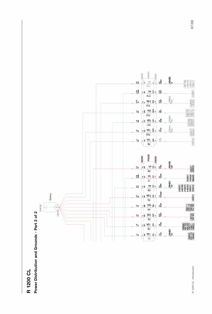
R 1
20
0 C
L
87
/88
R 1
20
0 C
L
Intr
od
uctio
n
Po
we
rD
istr
ibu
tio
n a
nd
Gro
un
ds -
Pa
rt 2
of
2
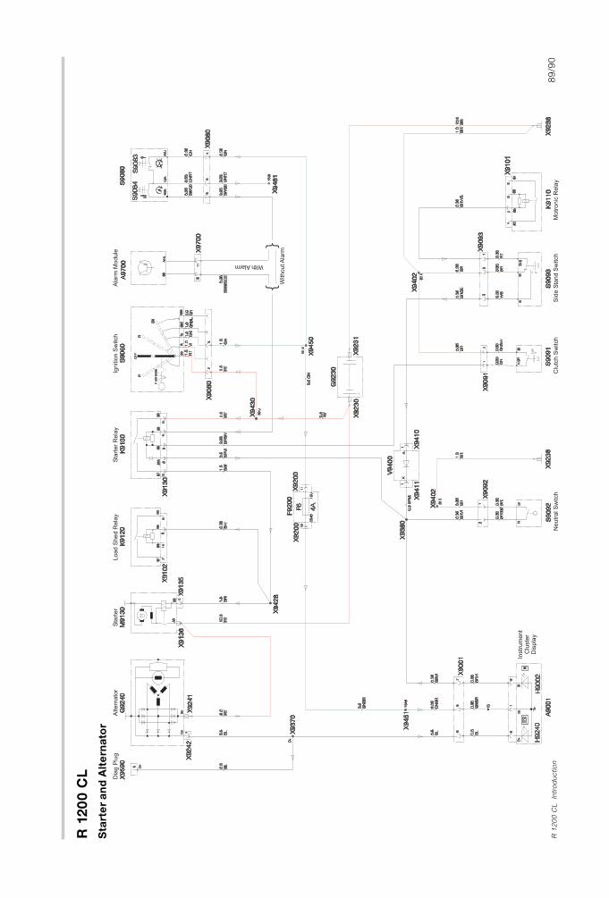
R 1
20
0 C
L
89
/90
R 1
20
0 C
L
Intr
od
uctio
n
Sta
rte
ra
nd
Alt
ern
ato
r
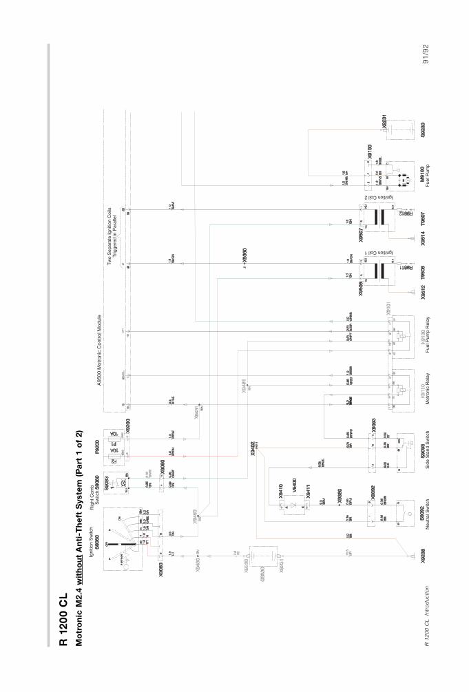
R 1
20
0 C
L
91
/92
R 1
20
0 C
L
Intr
od
uctio
n
Mo
tro
nic
M2.4
wit
ho
ut
An
ti-T
he
ft S
yste
m (
Pa
rt 1
of
2)
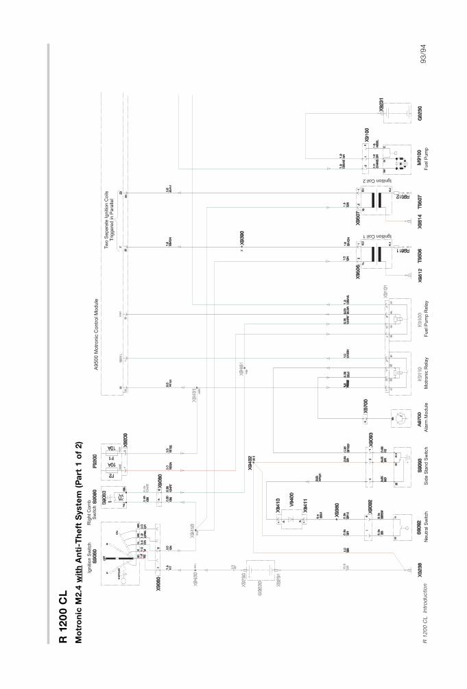
R 1
20
0 C
L
93
/94
R 1
20
0 C
L
Intr
od
uctio
n
Mo
tro
nic
M2.4
wit
hA
nti
-Th
eft
Syste
m (
Pa
rt 1
of
2)
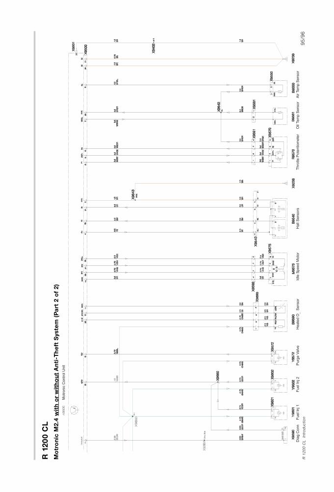
R 1
20
0 C
L
95
/96
R 1
20
0 C
L
Intr
od
uctio
n
Mo
tro
nic
M2.4
wit
h o
rw
ith
ou
tA
nti
-Th
eft
Syste
m (
Pa
rt 2
of
2)
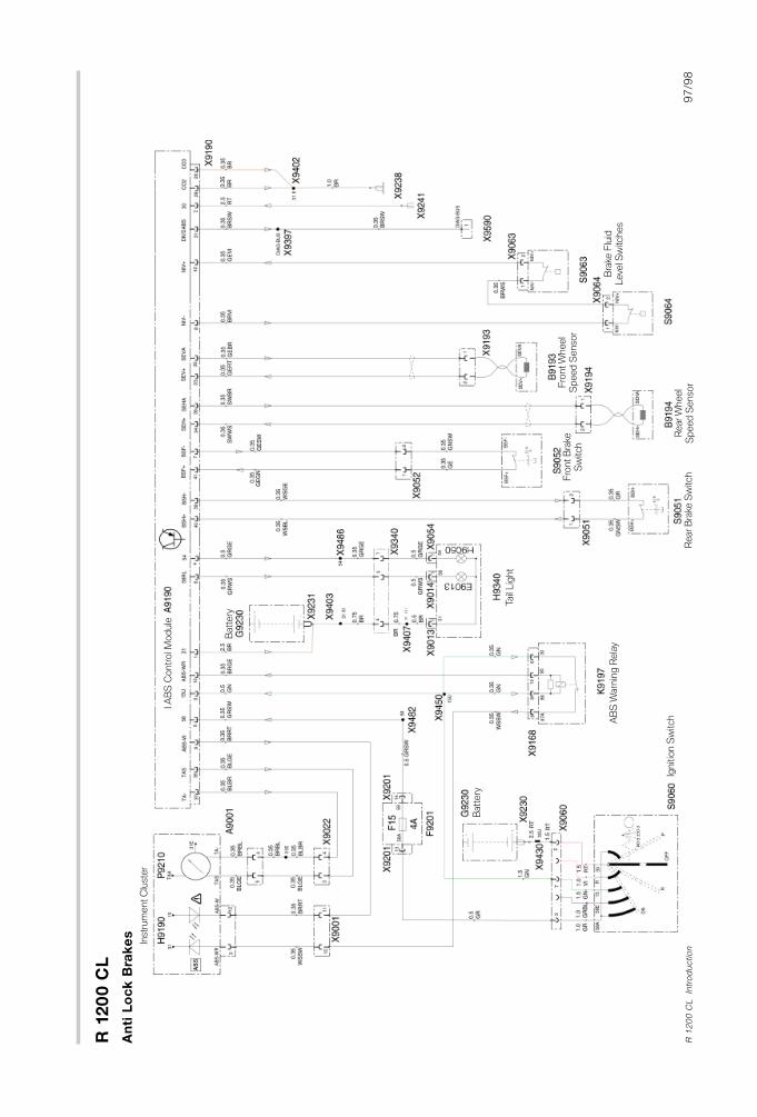
R 1
20
0 C
L
97
/98
R 1
20
0 C
L
Intr
od
uctio
n
An
ti L
oc
k B
rake
s
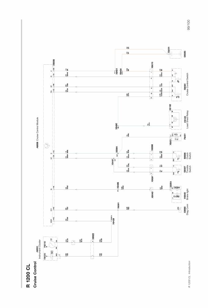
R 1
20
0 C
L
99
/10
0R
12
00
CL
Intr
od
uctio
n
Cru
ise
Co
ntr
ol
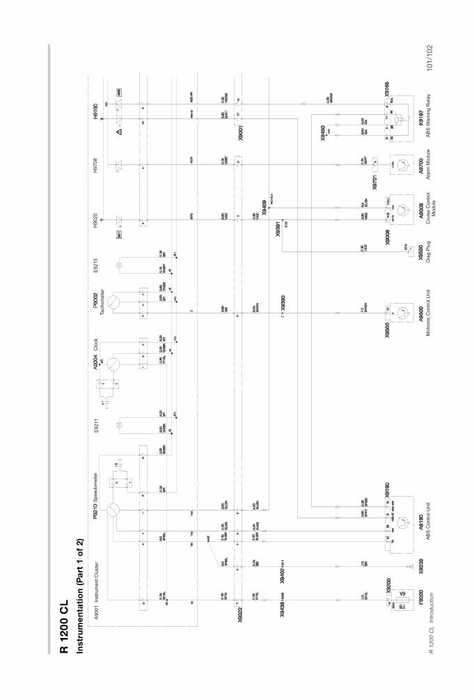
R 1
20
0 C
L
101
/10
2R
12
00
CL
Intr
od
uctio
n
Instr
um
en
tati
on
(P
art
1 o
f 2)
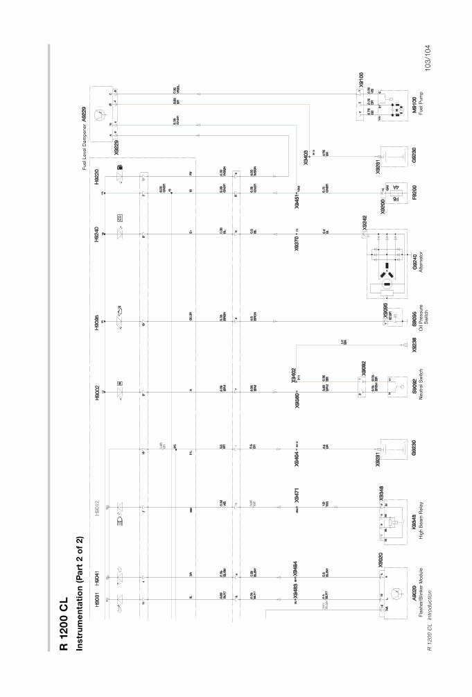
R 1
20
0 C
L
10
3/1
04
R 1
20
0 C
L
Intr
od
uctio
n
Instr
um
en
tati
on
(P
art
2 o
f 2)
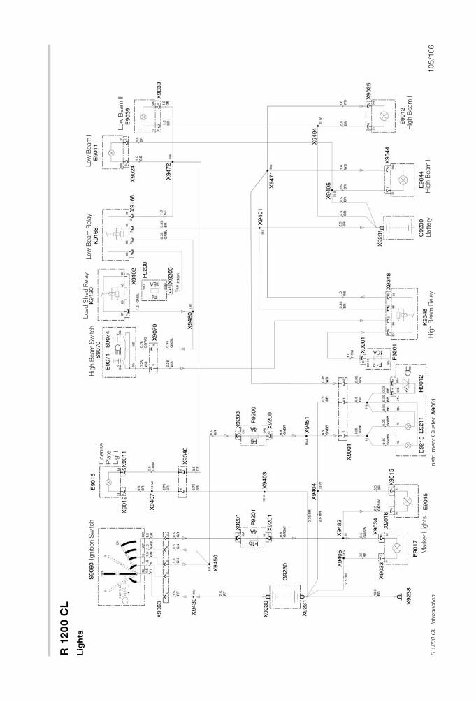
R 1
20
0 C
L
10
5/1
06
R 1
20
0 C
L
Intr
od
uctio
n
Lig
hts
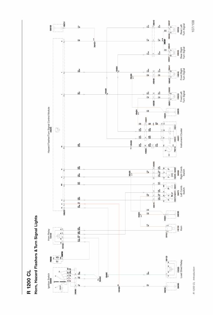
R 1
20
0 C
L
10
7/1
08
R 1
20
0 C
L
Intr
od
uctio
n
Ho
rn,H
aza
rd F
lash
ers
& T
urn
Sig
na
l L
igh
ts
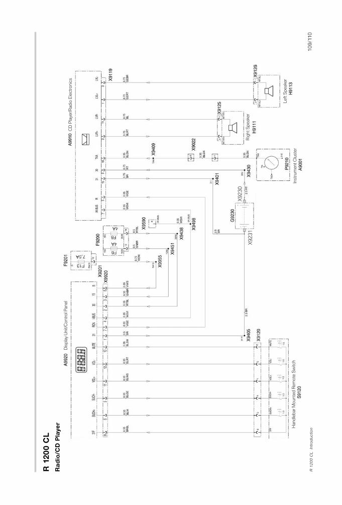
Ra
dio
/CD
Pla
ye
r
R 1
20
0 C
L
10
9/1
10
R 1
20
0 C
L
Intr
od
uctio
n
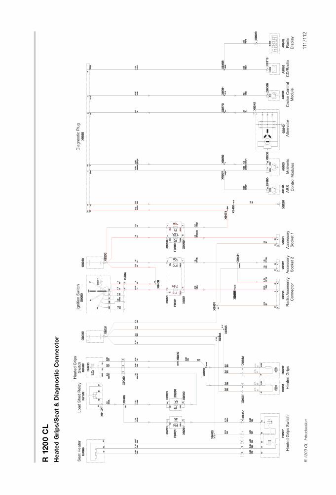
R 1
20
0 C
L
111
/112
R 1
20
0 C
L
Intr
od
uctio
n
He
ate
d G
rip
s/S
ea
t &
Dia
gn
osti
c C
on
ne
cto
r
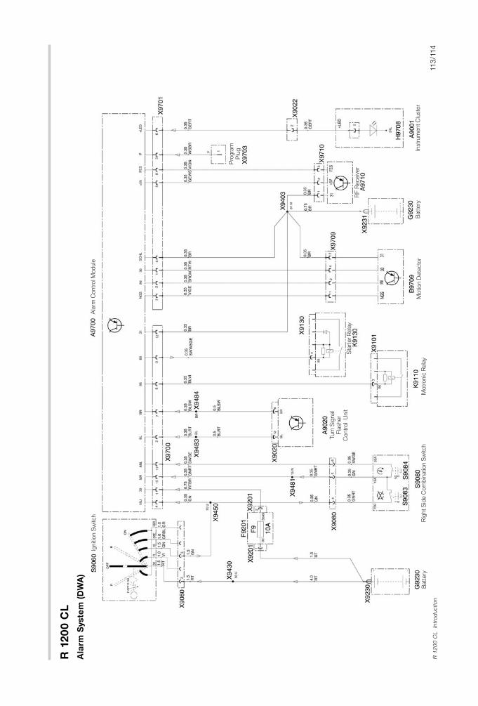
R 1
20
0 C
L
113
/114
R 1
20
0 C
L
Intr
od
uctio
n
Ala
rm S
yste
m (
DW
A)
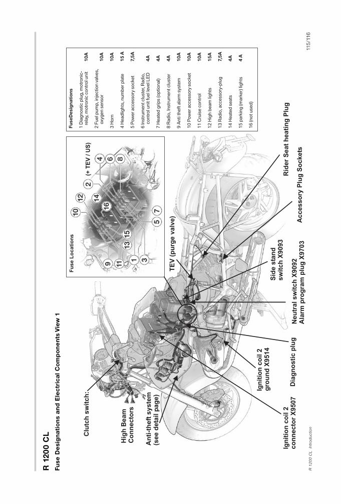
R 1
20
0 C
L
115
/116
R 1
20
0 C
L
Intr
od
uctio
n
Fu
se
De
sig
na
tio
ns a
nd
Ele
ctr
ica
l C
om
po
ne
nts
Vie
w1
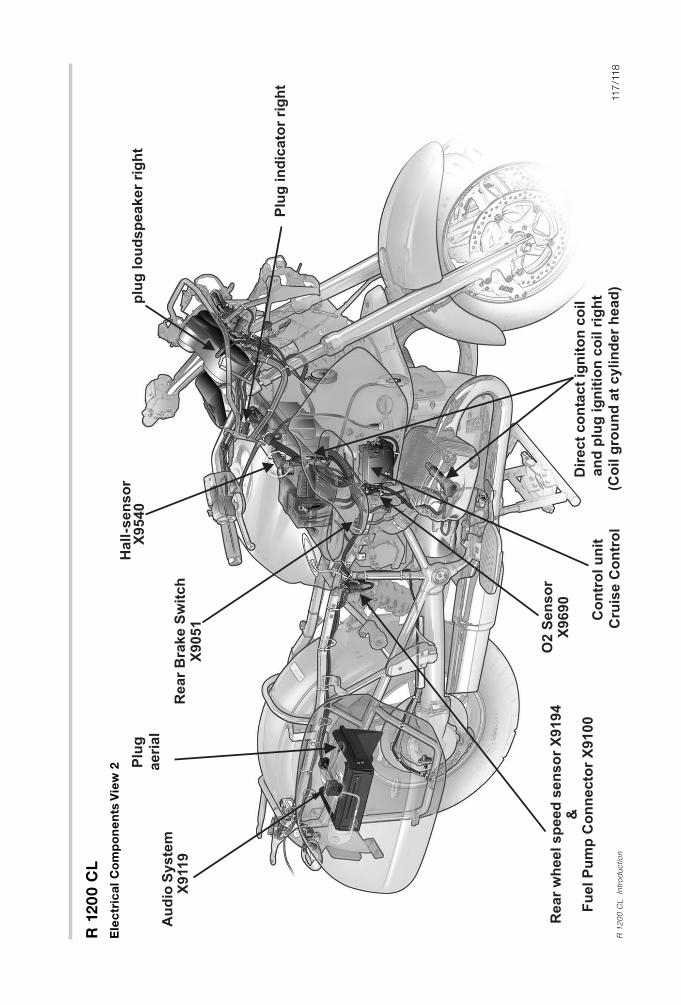
R 1
20
0 C
L
117
/118
R 1
20
0 C
L
Intr
od
uctio
n
Ele
ctr
ica
l C
om
po
ne
nts
Vie
w2
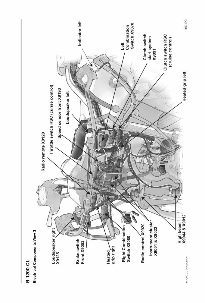
R 1
20
0 C
L
119
/12
0R
12
00
CL
Intr
od
uctio
n
Ele
ctr
ica
l C
om
po
ne
nts
Vie
w3

R 1
20
0 C
L
12
1/1
22
R 1
20
0 C
L
Intr
od
uctio
n
Ala
rm S
yste
m C
om
po
ne
nts
an
d P
rog
ram
min
g i
nfo
rma
tio
n
Ove
rvie
w
The
ala
rm
syste
m
is
pro
gra
mm
ed
fo
rvario
us
functio
ncho
ices b
yusin
g the r
em
ote
co
ntr
ol p
ush b
utt
ons a
fterth
esyste
m
has
been
set
to
pro
gra
mm
ing
m
od
e.
Pro
gra
mm
ab
le c
ho
ices inclu
de:
1.A
larm
To
ne T
yp
e (in
term
itte
nt
or
ste
ad
y)
2.A
rm/D
isarm
Beep
ing
To
ne (o
n o
ro
ff)
3.A
uto
matic im
mo
bili
zatio
n (o
n o
ro
ff)
4.A
uto
matic A
larm
Arm
ing
(o
n o
ro
ff)
5.P
anic
ala
rm f
eatu
re (o
n o
ro
ff)
En
ab
lin
g P
rog
ram
min
g M
od
e
• L
ocate
sin
gle
pin
pro
gra
mm
ing
co
nnecto
r(X
970
3) in
the a
rea o
f th
e f
use b
ox.
• F
ab
ricate
a jum
per
lead
lo
ng
eno
ug
h t
o c
onnect
the
pro
gra
mm
ing
plu
g t
o a
suitab
le g
round
po
int.
Co
nnect
jum
per
lead
to
pro
gra
mm
ing
plu
g b
ut
do
no
t co
nnect
oth
er
end
to
gro
und
at
this
po
int.
• W
ith t
he ig
nitio
n k
ey
OFF,
pre
ss b
utt
on A
on r
em
ote
to
Arm
syste
m.T
he d
irectio
nal lig
hts
blin
k t
wic
e a
nd
the
ala
rm w
ill b
eep
tw
ice if
it is c
urr
ently
pro
gra
mm
ed
fo
raud
ible
beep
ing
to
ne.
• N
ow
pre
ss b
utt
on A
ag
ain
to
dis
arm
ala
rm.
• Im
med
iate
lyco
nnect
jum
per
lead
to
suitab
le g
round
.
• P
ress b
utt
on A
ag
ain
.
• Im
med
iate
lysw
itch ig
nitio
n k
ey
ON
.A
series o
f th
ree
uniq
ue b
eep
to
nes w
ill b
e h
eard
fro
m a
larm
syste
m,
this
so
und
sig
nifie
s t
he p
rog
ram
min
g m
od
e is a
ctive.
• D
isco
nnect
pro
gra
mm
ing
lead
fro
m b
att
ery
gro
und
.Yo
uare
now
read
yto
pro
gra
m a
s o
utlin
ed
on t
he n
ext
pag
e.
NO
TE
:If t
he b
eep
s w
here
no
t heard
,yo
u m
ust
rep
eat
the s
tep
s a
bove f
ollo
win
g t
he instr
uctio
ns c
om
ple
tely.
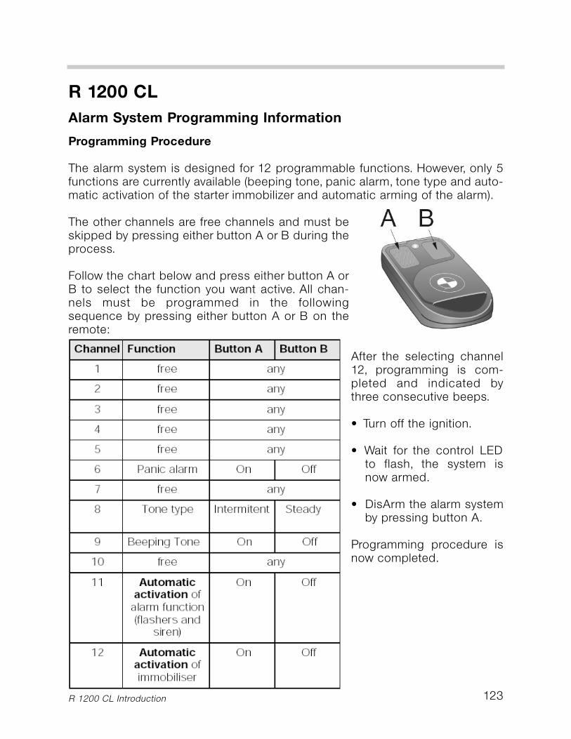
123
R 1200 CL
Alarm System Programming Information
Programming Procedure
The alarm system is designed for 12 programmable functions. However, only 5functions are currently available (beeping tone, panic alarm, tone type and auto-matic activation of the starter immobilizer and automatic arming of the alarm).
The other channels are free channels and must beskipped by pressing either button A or B during theprocess.
Follow the chart below and press either button A orB to select the function you want active. All chan-nels must be programmed in the followingsequence by pressing either button A or B on theremote:
After the selecting channel12, programming is com-pleted and indicated bythree consecutive beeps.
• Turn off the ignition.
• Wait for the control LEDto flash, the system isnow armed.
• DisArm the alarm systemby pressing button A.
Programming procedure isnow completed.
R 1200 CL Introduction
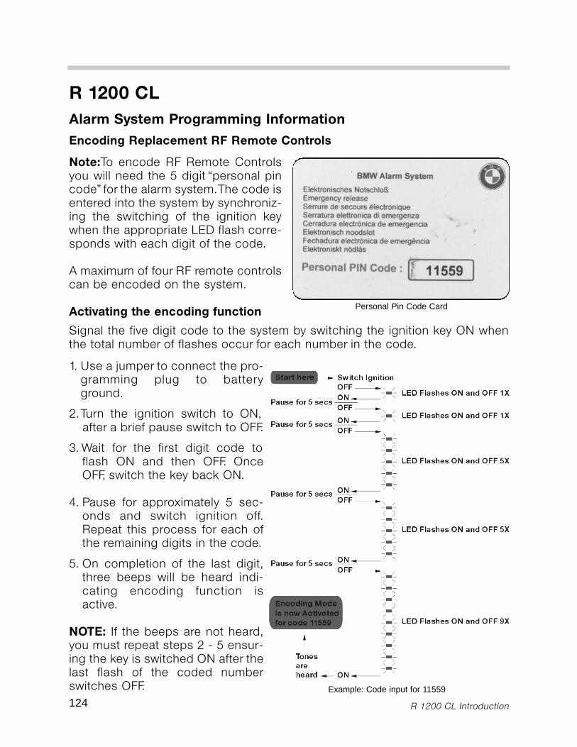
124 R 1200 CL Introduction
R 1200 CL
Alarm System Programming Information
Note:To encode RF Remote Controlsyou will need the 5 digit “personal pincode” for the alarm system.The code isentered into the system by synchroniz-ing the switching of the ignition keywhen the appropriate LED flash corre-sponds with each digit of the code.
A maximum of four RF remote controlscan be encoded on the system.
Activating the encoding function
1. Use a jumper to connect the pro-gramming plug to batteryground.
2.Turn the ignition switch to ON,after a brief pause switch to OFF.
3. Wait for the first digit code toflash ON and then OFF. OnceOFF, switch the key back ON.
4. Pause for approximately 5 sec-onds and switch ignition off.Repeat this process for each ofthe remaining digits in the code.
5. On completion of the last digit,three beeps will be heard indi-cating encoding function isactive.
NOTE: If the beeps are not heard,you must repeat steps 2 - 5 ensur-ing the key is switched ON after thelast flash of the coded numberswitches OFF.
Personal Pin Code Card
Encoding Replacement RF Remote Controls
Example: Code input for 11559
Signal the five digit code to the system by switching the ignition key ON whenthe total number of flashes occur for each number in the code.
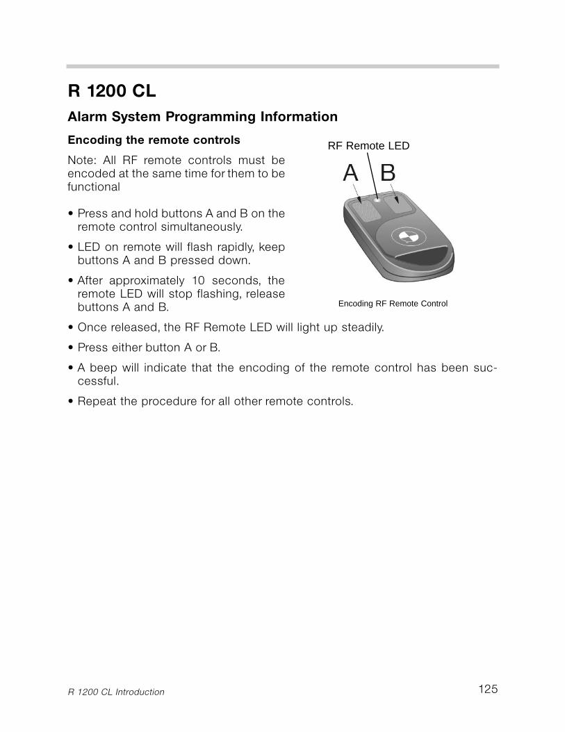
Encoding the remote controls
Note: All RF remote controls must beencoded at the same time for them to befunctional
• Press and hold buttons A and B on theremote control simultaneously.
• LED on remote will flash rapidly, keepbuttons A and B pressed down.
• After approximately 10 seconds, theremote LED will stop flashing, releasebuttons A and B.
• Once released, the RF Remote LED will light up steadily.
• Press either button A or B.
• A beep will indicate that the encoding of the remote control has been suc-cessful.
• Repeat the procedure for all other remote controls.
125
R 1200 CL
Alarm System Programming Information
R 1200 CL Introduction
RF Remote LED
Encoding RF Remote Control