Embed Size (px)
Citation preview
SALPA ANCORA VERTICALICIMA E CATENA SU UN UNICO BARBOTIN
ARIES FLAIR RIDER700 / 1000 / 1400W
PAG.10
PAG.16
PAG.22
PAG.28
REV 007
MANUALE D’USO
VERTICAL WINDLASSESROPE AND CHAIN ON A SINGLE GYPSY
ARIES FLAIR RIDER700 / 1000 / 1400W
USER’S MANUAL
GUINDEAUX VERTICAUXCORDAGE ET CHÂINE SUR LE MÊME BARBOTIN
ARIES FLAIR RIDER700 / 1000 / 1400W
MANUEL DE L’UTILISATEUR
VERTIKAL ANKERWINDENKETTE AUF EINER KOMBINIERTEN KETTENNUß
ARIES FLAIR RIDER700 / 1000 / 1400W
BENUTZERHANDBUCH
MOLINETES VERTICALECAVO Y CADENA EN UN UNICO BARBOTIN
ARIES FLAIR RIDER700 / 1000 / 1400W
MANUAL DEL USUARIO
PAG. 4
I
GB
F
D
E

3
Pag. 4 Caratteristiche tecnichePag. 5 InstallazionePag. 6 Schema di collegamento
Pag. 7 UsoPag. 8/9 Manutenzione
Pag. 10 Technical dataPag. 11 InstallationPag. 12 Connection diagram
Pag.13 UsagePag. 14/15 Maintenance
Pag. 16 Caractéristiques techniquesPag. 17 InstallationPag. 18 Schema de cablage
Pag. 19 UtilisationPag. 20/21 Entretien
SEITE 22 Technische EigenschaftenSEITE 23 MontageSEITE 24 Anschlussplan
SEITE 25 GebrauchSEITE 26/27 Wartung
PÁG. 28 Características técnicasPÁG. 29 InstalaciónPÁG. 30 Esquema de montage
PÁG. 31 UsoPÁG. 32/33 Mantenimiento
INDICE
INDEX
SOMMAIRE
INHALTSANGABE
INDICE
I
GB
F
D
E
4
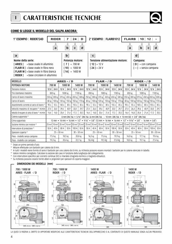
ARIES – / D700 W 1000 W 1400 W
12 V 24 V 12 V 24 V 12 V 24 V
850 kg 1000 kg 1100 kg
250 kg 300 kg 370 kg 450 kg 450 kg 500 kg
80 kg 100 kg 120 kg 150 kg 150 kg 170 kg
90 A 55 A 140 A 80 A 155 A 85 A
27,4 26,4 39,6 40,9 33,0 29,7
14,4 14,8 20,4 21,4 17,5 20,5
25 mm2 10 mm2 35 mm2 16 mm2 50 mm2 25 mm2
50 A 40 A 80 A 50 A 100 A 50 A
25 ÷ 50 mm 30 ÷ 50 mm
17,4 kg 18,5 kg 20,8 kg
19,3 kg 20,4 kg 22,7 kg
FLAIR – / D700 W 1000 W 1400 W
12 V 24 V 12 V 24 V 12 V 24 V
850 kg 1000 kg 1100 kg
250 kg 300 kg 370 kg 450 kg 450 kg 500 kg
80 kg 100 kg 120 kg 150 kg 150 kg 170 kg
90 A 55 A 140 A 80 A 155 A 85 A
27,4 26,4 39,6 40,9 33,0 29,7
14,4 14,8 20,4 21,4 17,5 20,5
25 mm2 10 mm2 35 mm2 16 mm2 50 mm2 25 mm2
50 A 40 A 80 A 50 A 100 A 50 A
25 ÷ 50 mm 30 ÷ 50 mm
16,5 kg 17,6 kg 19,9 kg
18,4 kg 19,5 kg 21,8 kg
RIDER – / D700 W 1000 W 1400 W
12 V 24 V 12 V 24 V 12 V 24 V
850 kg 1000 kg 1100 kg
250 kg 300 kg 370 kg 450 kg 450 kg 500 kg
80 kg 100 kg 120 kg 150 kg 150 kg 170 kg
90 A 55 A 140 A 80 A 155 A 85 A
27,4 26,4 39,6 40,9 33,0 29,7
14,4 14,8 20,4 21,4 17,5 20,5
25 mm2 10 mm2 35 mm2 16 mm2 50 mm2 25 mm2
50 A 40 A 80 A 50 A 100 A 50 A
25 ÷ 50 mm 30 ÷ 50 mm
16,0 kg 17,1 kg 19,4 kg
18,0 kg 19,1 kg 21,4 kg
MODELLOPOTENZA MOTORETensione motore
Tiro istantaneo massimo
Carico di lavoro massimo
Carico di lavoro
Assorbimento corrente al carico di lavoro (1)
Velocità massima di recupero (2) m/min
Velocità di recupero al carico di lavoro (2) m/min
Catena supportata (3)
Cima supportata
Sezione minima cavi motore (4)
Interruttore di protezione (5)
Spessore coperta (6)
Peso - modello senza campana
Peso - modello con campana(1) Dopo un primo periodo d’uso.(2) Misure effettuate con barbotin per catena da 8 mm.(3) In tutti i modelli viene fornito di serie il barbotin per una catena da 8 mm, su richiesta possono essere montati i barbotin per le catene elencate in tabella.(4) Valore minimo consigliato. Calcolare la sezione del cavo in funzione della lunghezza del collegamento.(5) Con interruttore specifico per correnti continue (DC) e ritardato (magneto-termico o magneto-idraulico).(6) Su richiesta possono essere forniti alberi e prigionieri per spessori di coperta maggiori.
700 / 1000 W ARIES - FLAIR - / D
700 / 1000 W RIDER - / D
1400 W ARIES - FLAIR - / D
1400 W RIDER - / D
LA QUICK SI RISERVA IL DIRITTO DI APPORTARE MODIFICHE ALLE CARATTERISTICHE TECNICHE DELL’APPARECCHIO E AL CONTENUTO DI QUESTO MANUALE SENZA ALCUN PREAVVISO.
9815
514
1
345 (700 W) - 360 (1000 W)
7887
250
164
100
155
141
345 (700 W) - 360 (1000 W)
Ø 1
55
166
159
164
9817
914
1
385
7887
250
166
100
179
141
385
159
Ø15
5
CARATTERISTICHE TECNICHE
8 mm DIN 766 • 5/16” DIN 766 (6 mm DIN 766 - 10 mm DIN 766 • 10 mm ISO • 3/8” DIN 766)
12 mm • 14 mm • 16 mm • 1/2” • 9/16” • 5/8” (12 mm • 14 mm • 16 mm • 1/2” • 9/16” • 5/8” - 16 mm • 5/8”)
DIMENSIONI DEI MODELLI (mm)
1° ESEMPIO : RIDER724D RIDER 7 24 D
� � � �
2° ESEMPIO : FLAIRB1012 FLAIRB 10 12 –
� � � �
Nome della serie:[ ARIES ] = base ovale in alluminio[ FLAIR B ] = base ovale in fibra nera[ FLAIR W ] = base ovale in fibra bianca[ RIDER ] = base circolare in alluminio
Potenza motore:[ 7 ] = 700 W[ 10 ] = 1000 W[ 14 ] = 1400 W
Tensione alimentazione motore:[ 12 ] = 12 V [ 24 ] = 24 V
Campana:[ D ] = con campana[ – ] = senza campana
COME SI LEGGE IL MODELLO DEL SALPA ANCORA:
I
a b c d
a b c d a b c d
5
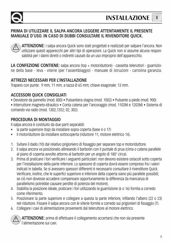
PRIMA DI UTILIZZARE IL SALPA ANCORA LEGGERE ATTENTAMENTE IL PRESENTE MANUALE D’USO. IN CASO DI DUBBI CONSULTARE IL RIVENDITORE QUICK.
ATTENZIONE: i salpa ancora Quick sono stati progettati e realizzati per salpare l’ancora. Nonutilizzare questi apparecchi per altri tipi di operazioni. La Quick non si assume alcuna respon-sabilità per i danni diretti o indiretti causati da un uso improprio dell’apparecchio.
LA CONFEZIONE CONTIENE: salpa ancora (top + motoriduttore) - cassetta teleruttori - guarnizio-ne della base - leva - viterie (per l’assemblaggio) - manuale di istruzioni - cartolina garanzia.
ATTREZZI NECESSARI PER L’INSTALLAZIONETrapano con punte: 9 mm, 11 mm, a tazza Ø 65 mm; chiave esagonale: 13 mm.
ACCESSORI QUICK CONSIGLIATI• Deviatore da pannello (mod. 800) • Pulsantiera stagna (mod. 1002) • Pulsante a piede (mod. 900) • Interruttore magneto-idraulico • Conta catena per l’ancoraggio (mod. 1102M e 1202M) • Sistema dicomando via radio (mod. 1302,1352; 02, 302).
PROCEDURA DI MONTAGGIOIl salpa ancora è costituito da due parti separabili:• la parte superiore (top) da installare sopra coperta (base 4 o 17)• il motoriduttore da installare sottocoperta (riduttore 11, motore elettrico 14).
1. Svitare il dado (10) dal relativo prigioniero di fissaggio per separare top e motoriduttore.2. Il salpa ancora va posizionato allineando il barbotin con il puntale di prua (cima o catena parallele
al piano di coperta avvolte attorno al barbotin per un angolo di 180° circa).3. Prima di praticare i fori verificare i seguenti particolari: non devono esistere ostacoli sotto coperta
per l’installazione della parte inferiore. Lo spessore di coperta dovrà essere compreso fra i valoriindicati in tabella. Se si avessero spessori differenti è necessario consultare il rivenditore Quick.Verificare, inoltre, che le superfici superiore e inferiore della coperta siano più parallele possibili;se ciò non dovesse accadere compensare opportunamente la differenza (la mancanza diparallelismo potrebbe causare perdite di potenza del motore).
4. Stabilita la posizione ideale, praticare i fori utilizzando la guarnizione (6 o 16) fornita a corredocome riferimento.
5. Posizionare la parte superiore e collegare a questa la parte inferiore, infilando l’albero (22 o 23)nel riduttore. Fissare il salpa ancora con le viterie fornite a corredo sui prigionieri di fissaggio (7).
6. Collegare i cavi di alimentazione provenienti dal teleruttore al motore elettrico.
ATTENZIONE: prima di effettuare il collegamento accertarsi che non sia presentel’alimentazione sui cavi.
INSTALLAZIONE I
6
SCHEMA DI COLLEGAMENTOI
- +
M1
M2
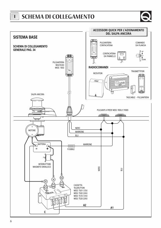
SISTEMA BASE
SCHEMA DI COLLEGAMENTO GENERALE PAG. 34
I T A L Y
1 2
1 2
RADIOCOMANDI
CONTACATENADA PANNELLO
COMANDO DA PLANCIA
UP
DOWN
PULSANTIERA CONTACATENA
TASCABILE - PULSANTIERA
RICEVITORI
PULSANTIERAMULTIUSO
MOD. 1002
SALPA ANCORA
MOTORE
BATTERIA
INTERRUTTOREMAGNETO IDRAULICO
CASSETTA TELERUTTORIMOD. T501 (12V)MOD. T502 (24V)MOD. T510 (12V)MOD. T520 (24V)
C
A2
PULSANTI A PIEDE MOD. 900U E 900D
NERO
MARRONE
BLU
MARRONE
NERO
BLU
A1
FUSIBILE
ACCESSORI QUICK PER L’AZIONAMENTO DEL SALPA ANCORA
TRASMETTITORI
7
AVVERTENZE IMPORTANTI
ATTENZIONE: non avvicinare parti del corpo o oggetti alla zona in cui scorrono catena, cimae barbotin. Accertarsi che non sia presente l’alimentazione al motore elettrico quando si ope-ra manualmente sul salpa ancora (anche quando si utilizza la leva per allentare la frizione); in-fatti persone dotate di comando a distanza del salpa ancora (pulsantiera remota o radioco-mando) potrebbero accidentalmente attivarlo.
ATTENZIONE: bloccare la catena con un fermo prima di partire per la navigazione.
ATTENZIONE: non attivare elettricamente il salpa ancora con la leva inserita nella campanao nel coperchio del barbotin.
USO DELLA FRIZIONEIl barbotin è reso solidale all’albero principale (22 o 23) dalla frizione (29). La frizione si apre (stacco)utilizzando la leva (35) che inserita nella bussola della campana o coperchio barbotin (34 o 32) dovràruotare in senso antiorario. Ruotando in senso orario si provocherà la chiusura (attacco) della frizione.
PER SALPAREAccendere il motore dell’imbarcazione. Assicurarsi che la frizione sia serrata ed estrarre la leva. Pre-mere il pulsante UP del comando a vostra disposizione. Se il salpa ancora si arresta senza che l’inter-ruttore magneto-idraulico (o magnetotermico) sia scattato, attendere qualche secondo e riprovare(evitare una pressione continuata del pulsante). Se l’interruttore magneto-idraulico (o magnetotermi-co) è scattato, riattivare l’interruttore e attendere qualche minuto prima di riprendere a salpare. Se,dopo ripetuti tentativi, il salpa ancora continua a bloccarsi consigliamo di manovrare l’imbarcazioneper disincagliare l’ancora.Controllare la salita degli ultimi metri di catena per evitare danni alla prua.
PER CALARELa calata dell’ancora si può effettuare tramite comandi elettrici oppure manualmente. Per effettuarel’operazione manualmente occorre aprire la frizione lasciando libero il barbotin di girare sul proprioasse e trascinare la catena o la cima in acqua. Per frenare la caduta dell’ancora bisogna ruotare la le-va in senso orario.Per calare l’ancora elettricamente occorre premere il pulsante DOWN del comando a vostra disposi-zione. In questo modo la calata è perfettamente controllabile e lo svolgimento della catena o della ci-ma è regolare.Per evitare sollecitazioni sul salpa ancora, una volta ancorati, bloccare la catena con un fermo oppurefissarla ad un punto saldo con una cima.
USO I
8
1920
13
7
7
12
21
10
8
9
11
1
2
3
4
5
6
35
18
3332
29
31
30
29
23
29
31
3029
22
34
17
16
21
14
24
25
24
26
27
28
24
25
24
26
27
28
15
18
36
37
38
39
40
41
42
4344
45
POS. DENOMINAZIONE CODICE
1A Sportello base Aries SGMSGG100000
1B Sportello base Flair bianca PDGC10DW0000
1C Sportello base Flair nera PDGC10DB0000
2A Vite per base Aries MBV0516MXSC0
2B Vite per base Flair MBV0530MXSC0
3A Stacca catena per base Aries MSN10VXP0000
3B Stacca catena per base Flair MSN10VXD0000
4A Base ovale Aries SGMSC10V0000
4B Base ovale Flair bianca SMPD10VW0000
4C Base ovale Flair nera SMPD10VB0000
5 Perno MSR10X000000
6 Guarnizione/dima Aries-Flair PGBSV1000000
7A Prigionieri base Aries MBP080807X00
7B Prigionieri base Flair MBP080808X00
8 Rondella MBR08X000000
9 Rondella dentellata MBR08XDE0000
POS. DENOMINAZIONE CODICE
10 Dado MBD08MXEN000
11A Riduttore 700-1000W MR1000000000
11B Riduttore 1400W MR1400000000
12 Dado autobloccante MBD06MXET000
13 Rondella MBR061815X00
MANUTENZIONEI
9
ATTENZIONE: accertarsi che non sia presen-te l’alimentazione al motore elettrico quando siopera manualmente sul salpa ancora; rimuove-re con cura la catena o cima dal barbotin o lacima dalla campana.
I salpa ancora Quick sono costituiti da materiali resi-stenti all’ambiente marino: è indispensabile, in ognicaso, rimuovere periodicamente i depositi di sale chesi formano sulle superfici esterne per evitare corrosio-ni e di conseguenza danni all’apparecchio.Lavare accuratamente con acqua dolce le superfici ele parti in cui il sale può depositarsi.
Smontare una volta all’anno il barbotin e la campanaattenendosi alla seguente sequenza:
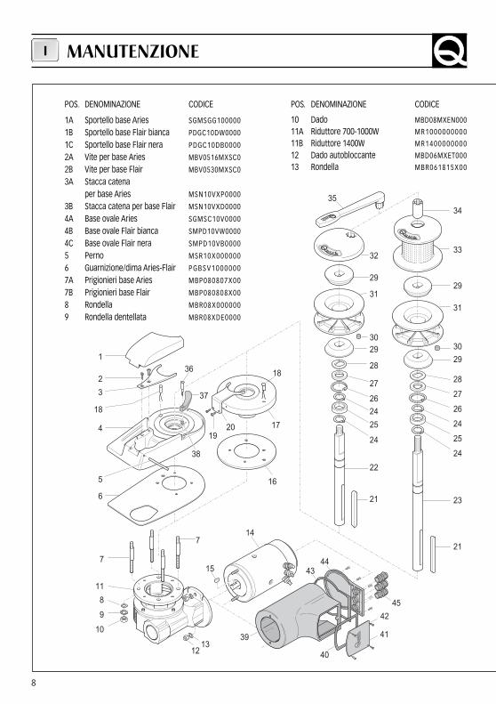
VERSIONE CON CAMPANACon la leva (35) svitare la bussola (34); estrarre la cam-pana (33) e il cono frizione superiore (29); svitare le vitidi fissaggio (2 o 19) dello stacca catena (3 o 20) e ri-muoverlo; estrarre il barbotin (31).
VERSIONE SENZA CAMPANACon la leva (35) svitare il coperchio barbotin (32);estrarre il cono frizione superiore (29); svitare le viti difissaggio (2 o 19) dello stacca catena (3 o 20) e rimuo-verlo; estrarre il barbotin (31).
Pulire ogni parte smontata affinché non si verifichinoattacchi di corrosione e ingrassare (con grasso mari-no) il filetto dell’albero (22 o 23) e il barbotin (31) doveappoggiano i coni frizione (29).
Ingrassare periodicamente il perno (5) dello sportellodi ispezione (solamente per salpa ancora con base inalluminio).
Rimuovere eventuali depositi di ossido sui morsetti dialimentazione del motore elettrico e su quelli dellacassetta teleruttori; cospargerli di grasso.
POS. DENOMINAZIONE CODICE
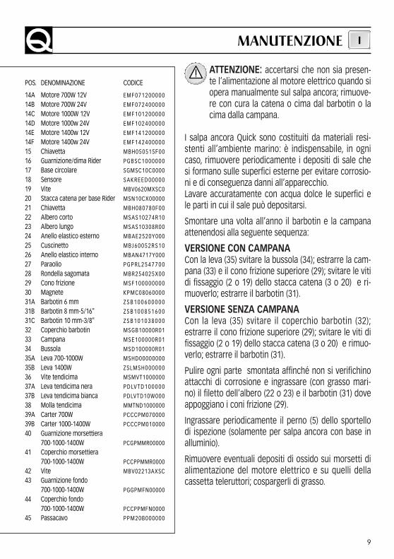
14A Motore 700W 12V EMF071200000
14B Motore 700W 24V EMF072400000
14C Motore 1000W 12V EMF101200000
14D Motore 1000w 24V EMF102400000
14E Motore 1400w 12V EMF141200000
14F Motore 1400w 24V EMF142400000
15 Chiavetta MBH050515F00
16 Guarnizione/dima Rider PGBSC1000000
17 Base circolare SGMSC10C0000
18 Sensore SAKREED00000
19 Vite MBV0620MXSC0
20 Stacca catena per base Rider MSN10CX00000
21 Chiavetta MBH080780F00
22 Albero corto MSAS10274R10
23 Albero lungo MSAS10308R00
24 Anello elastico esterno MBAE2520Y000
25 Cuscinetto M B J 6 0 0 5 2 R S 1 0
26 Anello elastico interno MBAN4717Y000
27 Paraolio P G P R L 2 5 4 7 7 0 0
28 Rondella sagomata MBR254025X00
29 Cono frizione MSF100000000
30 Magnete KPMC08060000
31A Barbotin 6 mm Z S B 1 0 0 6 0 0 0 0 0
31B Barbotin 8 mm-5/16" Z S B 1 0 0 8 5 1 6 0 0
31C Barbotin 10 mm-3/8" Z S B 1 0 1 0 3 8 0 0 0
32 Coperchio barbotin MSGB10000R01
33 Campana MSE100000R01
34 Bussola MSD100000R01
35A Leva 700-1000W MSHD00000000
35B Leva 1400W ZSLMSH000000
36 Vite tendicima MSMVT1000000
37A Leva tendicima nera P D LV T D 1 0 0 0 0 0
37B Leva tendicima bianca PDLVTD10W000
38 Molla tendicima MMTND1000000
39A Carter 700W PCCCPM070000
39B Carter 1000-1400W PCCCPM010000
40 Guarnizione morsettiera 700-1000-1400W PCGPMMR00000
41 Coperchio morsettiera700-1000-1400W PCCPPMMR0000
42 Vite MBV02213AXSC
43 Guarnizione fondo700-1000-1400W PGGPMFN00000
44 Coperchio fondo700-1000-1400W PCCPPMFN0000
45 Passacavo PPM20B000000
MANUTENZIONE I
10
TECHNICAL DATAGB
ARIES – / D700 W 1000 W 1400 W
12 V 24 V 12 V 24 V 12 V 24 V
850 kg 1000 kg 1100 kg
250 kg 300 kg 370 kg 450 kg 450 kg 500 kg
80 kg 100 kg 120 kg 150 kg 150 kg 170 kg
90 A 55 A 140 A 80 A 155 A 85 A
27,4 26,4 39,6 40,9 33,0 29,7
14,4 14,8 20,4 21,4 17,5 20,5
25 mm2 10 mm2 35 mm2 16 mm2 50 mm2 25 mm2
50 A 40 A 80 A 50 A 100 A 50 A
25 ÷ 50 mm 30 ÷ 50 mm
17,4 kg 18,5 kg 20,8 kg
19,3 kg 20,4 kg 22,7 kg
FLAIR – / D700 W 1000 W 1400 W
12 V 24 V 12 V 24 V 12 V 24 V
850 kg 1000 kg 1100 kg
250 kg 300 kg 370 kg 450 kg 450 kg 500 kg
80 kg 100 kg 120 kg 150 kg 150 kg 170 kg
90 A 55 A 140 A 80 A 155 A 85 A
27,4 26,4 39,6 40,9 33,0 29,7
14,4 14,8 20,4 21,4 17,5 20,5
25 mm2 10 mm2 35 mm2 16 mm2 50 mm2 25 mm2
50 A 40 A 80 A 50 A 100 A 50 A
25 ÷ 50 mm 30 ÷ 50 mm
16,5 kg 17,6 kg 19,9 kg
18,4 kg 19,5 kg 21,8 kg
RIDER – / D700 W 1000 W 1400 W
12 V 24 V 12 V 24 V 12 V 24 V
850 kg 1000 kg 1100 kg
250 kg 300 kg 370 kg 450 kg 450 kg 500 kg
80 kg 100 kg 120 kg 150 kg 150 kg 170 kg
90 A 55 A 140 A 80 A 155 A 85 A
27,4 26,4 39,6 40,9 33,0 29,7
14,4 14,8 20,4 21,4 17,5 20,5
25 mm2 10 mm2 35 mm2 16 mm2 50 mm2 25 mm2
50 A 40 A 80 A 50 A 100 A 50 A
25 ÷ 50 mm 30 ÷ 50 mm
16,0 kg 17,1 kg 19,4 kg
18,0 kg 19,1 kg 21,4 kg
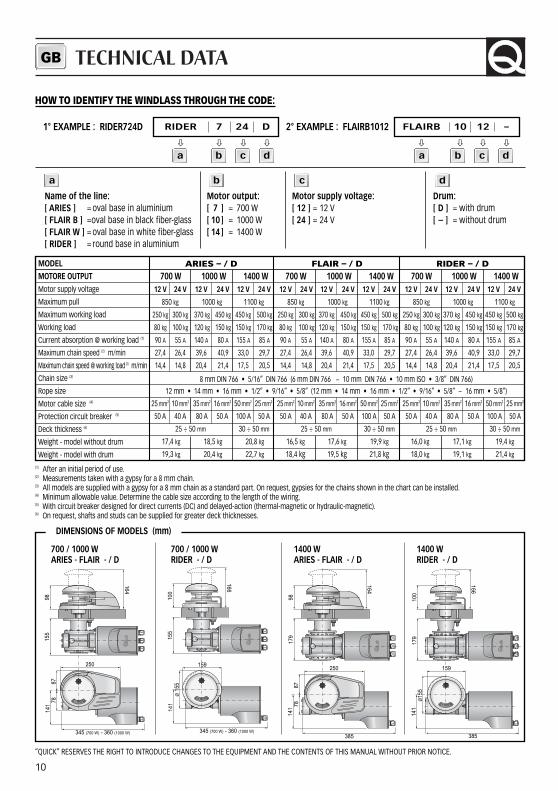
MODELMOTORE OUTPUTMotor supply voltage
Maximum pull
Maximum working load
Working load
Current absorption @ working load (1)
Maximum chain speed (2) m/min
Maximum chain speed @ working load (2) m/min
Chain size (3)
Rope size
Motor cable size (4)
Protection circuit breaker (5)
Deck thickness (6)
Weight - model without drum
Weight - model with drum(1) After an initial period of use.(2) Measurements taken with a gypsy for a 8 mm chain.(3) All models are supplied with a gypsy for a 8 mm chain as a standard part. On request, gypsies for the chains shown in the chart can be installed.(4) Minimum allowable value. Determine the cable size according to the length of the wiring.(5) With circuit breaker designed for direct currents (DC) and delayed-action (thermal-magnetic or hydraulic-magnetic).(6) On request, shafts and studs can be supplied for greater deck thicknesses.
700 / 1000 W ARIES - FLAIR - / D
700 / 1000 W RIDER - / D
1400 W ARIES - FLAIR - / D
1400 W RIDER - / D
“QUICK” RESERVES THE RIGHT TO INTRODUCE CHANGES TO THE EQUIPMENT AND THE CONTENTS OF THIS MANUAL WITHOUT PRIOR NOTICE.
9815
514
1
345 (700 W) - 360 (1000 W)
7887
250
164
100
155
141
345 (700 W) - 360 (1000 W)
Ø 1
55
166
159
164
9817
914
1
385
7887
250
166
100
179
141
385
159
Ø15
5
8 mm DIN 766 • 5/16” DIN 766 (6 mm DIN 766 - 10 mm DIN 766 • 10 mm ISO • 3/8” DIN 766)
12 mm • 14 mm • 16 mm • 1/2” • 9/16” • 5/8” (12 mm • 14 mm • 16 mm • 1/2” • 9/16” • 5/8” - 16 mm • 5/8”)
DIMENSIONS OF MODELS (mm)
1° EXAMPLE : RIDER724D RIDER 7 24 D
� � � �
2° EXAMPLE : FLAIRB1012 FLAIRB 10 12 –
� � � �
Name of the line:[ ARIES ] = oval base in aluminium [ FLAIR B ] =oval base in black fiber-glass [ FLAIR W ] = oval base in white fiber-glass [ RIDER ] = round base in aluminium
Motor output:[ 7 ] = 700 W[ 10 ] = 1000 W[ 14 ] = 1400 W
Motor supply voltage:[ 12 ] = 12 V [ 24 ] = 24 V
Drum:[ D ] = with drum[ – ] = without drum
HOW TO IDENTIFY THE WINDLASS THROUGH THE CODE:
a b c d
a b c d a b c d

11
BEFORE USING THE WINDLASS READ THESE INSTRUCTIONS CAREFULLY.IF IN DOUBT, CONTACT YOUR NEAREST “QUICK” DEALER.
WARNING: the QUICK windlasses are designed to weigh the anchor. Do not use theequipments for other purposes. QUICK shall not be held responsible for damage to equipmentand/or personal injury, caused by a faulty use of the equipment.
THE PACKAGE CONTAINS: windlass (on deck unit + geared motor) - reversing solenoid unit - basegasket - Handle - bolts and screws (for assembly) - user’s manual - warranty card.
TOOLS REQUIRED FOR INSTALLATIONDrill and drill bits: 9 mm, 11 mm, 65 mm Ø hollow mill; hex. wrenches: 13 mm.
“QUICK”ACCESSORIES RECOMMENDED• Anchoring RL control board (mod. 800) • Waterproof hand helds R/C (mod. 1002) • Foot switch(mod. 900) • Hydraulic-magnetic circuit breaker • Anchor chain counter (mod. 1102M and 1202M) • Radio control (mod. 1302,1352; 02, 302).
ASSEMBLY PROCEDURE The windlass is made up of two separate parts:• the upper part is to be installed on deck (base 4 or 17) • geared motor is to be installed below deck (gearbox 11, electric motor 14).
1. Remove the nut (10) from the stud to take apart the on deck unit from gear box.2. The windlass has to be placed in position by aligning the gypsy with the bow point (rope or chain
leveled with the deck and wound around the gypsy at an angle of about 180°).3. Before drilling holes, check the following:there are to be no obstacles below deck in order to
install the bottom part. Deck thickness must range among the ratings indicated in the schedule;for a different thickness, contact your nearest QUICK dealer. Also make sure the top and bottomsurfaces of the deck are as parallel as possible; if necessary, compensate for any differences (ifnot parallel, the motor power may drop)
4. Once the ideal position has been found, drill the holes using the jig (6 or 15) supplied.5. Place the upper part in position and connect it to the bottom part. Fit the shaft (21 or 23) into the
gearbox. Secure the windlass by using the studs (7) and the screws supplied.6. Connect the power cables coming from the reversing solenoid unit to the electric motor.
WARNING: before wiring up, be sure the electrical cables are not live.
INSTALLATION GB
12
CONNECTION DIAGRAMGB
- +
M1
M2
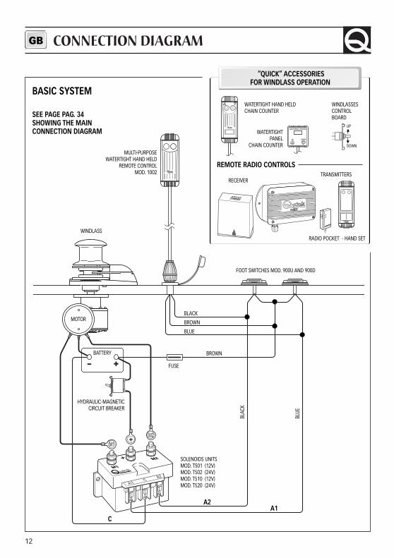
BASIC SYSTEM
SEE PAGE PAG. 34SHOWING THE MAINCONNECTION DIAGRAM
I T A L Y
1 2
1 2
REMOTE RADIO CONTROLS
WATERTIGHTPANEL
CHAIN COUNTER
WINDLASSESCONTROLBOARD
UP
DOWN
WATERTIGHT HAND HELDCHAIN COUNTER
RADIO POCKET - HAND SET
RECEIVER
MULTI-PURPOSEWATERTIGHT HAND HELD
REMOTE CONTROLMOD. 1002
WINDLASS
MOTOR
BATTERY
HYDRAULIC-MAGNETIC CIRCUIT BREAKER
SOLENOIDS UNITSMOD. T501 (12V)MOD. T502 (24V)MOD. T510 (12V)MOD. T520 (24V)
C
A2
FOOT SWITCHES MOD. 900U AND 900D
BLACK
BROWN
BLUE
BROWN
BLAC
K
BLUE
A1
FUSE
“QUICK” ACCESSORIES FOR WINDLASS OPERATION
TRANSMITTERS
13
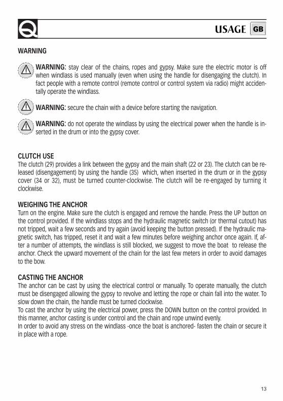
WARNING
WARNING: stay clear of the chains, ropes and gypsy. Make sure the electric motor is offwhen windlass is used manually (even when using the handle for disengaging the clutch). Infact people with a remote control (remote control or control system via radio) might acciden-tally operate the windlass.
WARNING: secure the chain with a device before starting the navigation.
WARNING: do not operate the windlass by using the electrical power when the handle is in-serted in the drum or into the gypsy cover.
CLUTCH USEThe clutch (29) provides a link between the gypsy and the main shaft (22 or 23). The clutch can be re-leased (disengagement) by using the handle (35) which, when inserted in the drum or in the gypsycover (34 or 32), must be turned counter-clockwise. The clutch will be re-engaged by turning itclockwise.
WEIGHING THE ANCHOR Turn on the engine. Make sure the clutch is engaged and remove the handle. Press the UP button onthe control provided. If the windlass stops and the hydraulic magnetic switch (or thermal cutout) hasnot tripped, wait a few seconds and try again (avoid keeping the button pressed). If the hydraulic ma-gnetic switch, has tripped, reset it and wait a few minutes before weighing anchor once again. If, af-ter a number of attempts, the windlass is still blocked, we suggest to move the boat to release theanchor. Check the upward movement of the chain for the last few meters in order to avoid damagesto the bow.
CASTING THE ANCHOR The anchor can be cast by using the electrical control or manually. To operate manually, the clutchmust be disengaged allowing the gypsy to revolve and letting the rope or chain fall into the water. Toslow down the chain, the handle must be turned clockwise.To cast the anchor by using the electrical power, press the DOWN button on the control provided. Inthis manner, anchor casting is under control and the chain and rope unwind evenly.In order to avoid any stress on the windlass -once the boat is anchored- fasten the chain or secure itin place with a rope.
USAGE GB
14
1920
13
7
7
12
21
10
8
9
11
1
2
3
4
5
6
35
18
3332
29
31
30
29
23
29
31
3029
22
34
17
16
21
14
24
25
24
26
27
28
24
25
24
26
27
28
15
18
36
37
38
39
40
41
42
4344
45
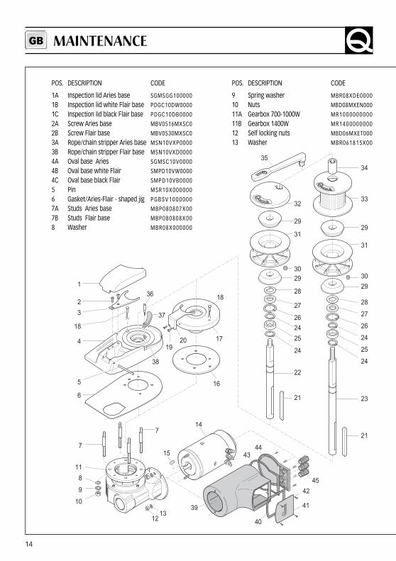
POS. DESCRIPTION CODE
1A Inspection lid Aries base SGMSGG100000
1B Inspection lid white Flair base PDGC10DW0000
1C Inspection lid black Flair base PDGC10DB0000
2A Screw Aries base MBV0516MXSC0
2B Screw Flair base MBV0530MXSC0
3A Rope/chain stripper Aries base MSN10VXP0000
3B Rope/chain stripper Flair base MSN10VXD0000
4A Oval base Aries SGMSC10V0000
4B Oval base white Flair SMPD10VW0000
4C Oval base black Flair SMPD10VB0000
5 Pin MSR10X000000
6 Gasket/Aries-Flair - shaped jig PGBSV1000000
7A Studs Aries base MBP080807X00
7B Studs Flair base MBP080808X00
8 Washer MBR08X000000
POS. DESCRIPTION CODE
9 Spring washer MBR08XDE0000
10 Nuts MBD08MXEN000
11A Gearbox 700-1000W MR1000000000
11B Gearbox 1400W MR1400000000
12 Self locking nuts MBD06MXET000
13 Washer MBR061815X00
MAINTENANCEGB

15
WARNING: make sure the electrical power tothe motor is switched off when workingmanually on the windlass. Carefully remove thechain or rope from the gypsy or the rope fromthe drum.
QUICK windlasses are manufactured with materialsresistant to marine environments. In any case, any saltdeposits on the outside must be removed periodicallyto avoid corrosion and damage to the equipment. Theparts where salt may have built up should be washedthoroughly with fresh water.
Once a year, the drum and the gypsy are to be takenapart as follows:
DRUM VERSIONUse the handle (35) to loosen the bush (34); pull offthe drum (33) and the top clutch cone (29); loosen thefixing screws (2 or 19) of the rope/chain stripper (3 or20) and remove it. Pull off the gypsy (31).
NO-DRUM VERSIONUse the handle (35) to remove the gypsy cover (32);remove the top clutch cone (29); loosen the fixingscrews (2 or 19) of the rope/chain stripper (3 or 20)and remove it and pull off the gypsy (31).
Clean all the parts removed to avoid corrosion, andgrease the shaft thread (22 or 23) and the gypsy (31)where the clutch cones rest (29) (use grease suitablefor marine environment).
Periodically grease the hinge pin (5) of the inspectiondoor (only windlasses with aluminium bases).
Remove any oxide deposits from the terminals of theelectric motor and the reversing solenoid unit; greasethem.
POS. DESCRIPTION CODE
14A Electric motor 700W 12V EMF071200000
14B Electric motor 700W 24V EMF072400000
14C Electric motor 1000W 12V EMF101200000
14D Electric motor 1000W 24V EMF102400000
14E Electric motor 1400W12V EMF141200000
14F Electric motor 1400W 24V EMF142400000
15 Key MBH050515F00
16 Gasket/Rider jig PGBSC1000000
17 Rider base SGMSC10C0000
18 Sensor SAKREED00000
19 Screw MBV0620MXSC0
20 Rope/chain stripper Rider base MSN10CX00000
21 Key MBH080780F00
22 Short shaft MSAS10274R10
23 Long shaft MSAS10308R00
24 External circlip MBAE2520Y000
25 Bearing M B J 6 0 0 5 2 R S 1 0
26 Internal circlip MBAN4717Y000
27 Oil seal P G P R L 2 5 4 7 7 0 0
28 Spring washer MBR254025X00
29 Clutch cone MSF100000000
30 Magnet KPMC08060000
31A Gypsy 6 mm Z S B 1 0 0 6 0 0 0 0 0
31B Gypsy 8 mm-5/16" Z S B 1 0 0 8 5 1 6 0 0
31C Gypsy 10 mm-3/8" Z S B 1 0 1 0 3 8 0 0 0
32 Gypsy cover MSGB10000R01
33 Drum MSE100000R01
34 Bush MSD100000R01
35A Handle 700-1000W MSHD00000000
35B Handle 1400W ZSLMSH000000
36 Screw for pressure lever MSMVT1000000
37A Black pressure lever P D LV T D 1 0 0 0 0 0
37B White pressure lever PDLVTD10W000
38 Spring for gypsy pressure lever MMTND1000000
39A Watertight 700W MMTND1000000
39B Watertight 1000-1400W PCCCPM100000
40 Grommet 1000-1400W PCGPMMR00000
41 Terminal board cover 700-1000-1400W PCCPPMMR0000
42 Screw MBV02213AXSC
43 Bottom gasket 700-1000-1400W PGGPMFN00000
44 Bottom protec cover 700-1000-1400W PCCPPMFN0000
45 Cable outlet PPM20B000000
MAINTENANCE GB
16
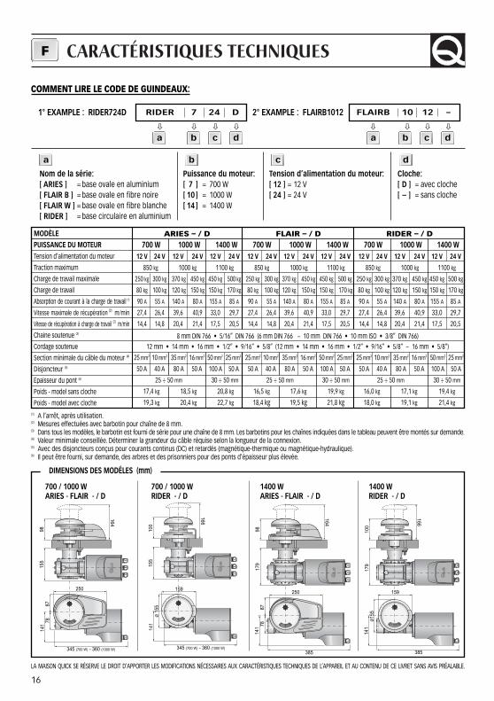
CARACTÉRISTIQUES TECHNIQUESF
ARIES – / D700 W 1000 W 1400 W
12 V 24 V 12 V 24 V 12 V 24 V
850 kg 1000 kg 1100 kg
250 kg 300 kg 370 kg 450 kg 450 kg 500 kg
80 kg 100 kg 120 kg 150 kg 150 kg 170 kg
90 A 55 A 140 A 80 A 155 A 85 A
27,4 26,4 39,6 40,9 33,0 29,7
14,4 14,8 20,4 21,4 17,5 20,5
25 mm2 10 mm2 35 mm2 16 mm2 50 mm2 25 mm2
50 A 40 A 80 A 50 A 100 A 50 A
25 ÷ 50 mm 30 ÷ 50 mm
17,4 kg 18,5 kg 20,8 kg
19,3 kg 20,4 kg 22,7 kg
FLAIR – / D700 W 1000 W 1400 W
12 V 24 V 12 V 24 V 12 V 24 V
850 kg 1000 kg 1100 kg
250 kg 300 kg 370 kg 450 kg 450 kg 500 kg
80 kg 100 kg 120 kg 150 kg 150 kg 170 kg
90 A 55 A 140 A 80 A 155 A 85 A
27,4 26,4 39,6 40,9 33,0 29,7
14,4 14,8 20,4 21,4 17,5 20,5
25 mm2 10 mm2 35 mm2 16 mm2 50 mm2 25 mm2
50 A 40 A 80 A 50 A 100 A 50 A
25 ÷ 50 mm 30 ÷ 50 mm
16,5 kg 17,6 kg 19,9 kg
18,4 kg 19,5 kg 21,8 kg
RIDER – / D700 W 1000 W 1400 W
12 V 24 V 12 V 24 V 12 V 24 V
850 kg 1000 kg 1100 kg
250 kg 300 kg 370 kg 450 kg 450 kg 500 kg
80 kg 100 kg 120 kg 150 kg 150 kg 170 kg
90 A 55 A 140 A 80 A 155 A 85 A
27,4 26,4 39,6 40,9 33,0 29,7
14,4 14,8 20,4 21,4 17,5 20,5
25 mm2 10 mm2 35 mm2 16 mm2 50 mm2 25 mm2
50 A 40 A 80 A 50 A 100 A 50 A
25 ÷ 50 mm 30 ÷ 50 mm
16,0 kg 17,1 kg 19,4 kg
18,0 kg 19,1 kg 21,4 kg
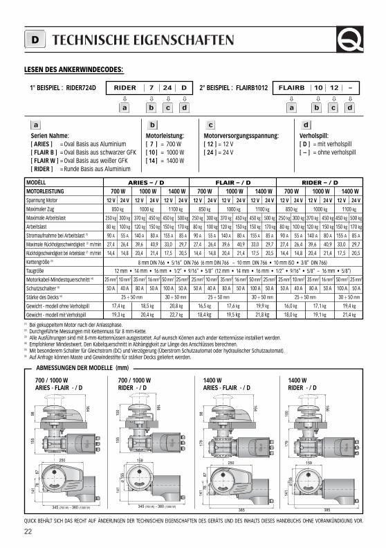
MODÈLEPUISSANCE DU MOTEURTension d’alimentation du moteur
Traction maximum
Charge de travail maximale
Charge de travail
Absorption de courant à la charge de travail (1)
Vitesse maximale de récupération (2) m/min
Vitesse de récupération à charge de travail (2) m/min
Chaine soutenue (3)
Cordage soutenue
Section minimale du câble du moteur (4)
Disjoncteur (5)
Epaisseur du pont (6)
Poids - model sans cloche
Poids - model avec cloche(1) A l’arrêt, après utilisation.(2) Mesures effectuées avec barbotin pour chaîne de 8 mm.(3) Dans tous les modèles, le barbotin est fourni de série pour une chaîne de 8 mm. Les barbotins pour les chaînes indiquées dans le tableau peuvent être montés sur demande.(4) Valeur minimale conseillée. Déterminer la grandeur du câble réquise selon la longueur de la connexion.(5) Avec des disjoncteurs conçus pour courants continus (DC) et retardés (magnétique-thermique ou magnétique-hydraulique).(6) Il peut être fourni, sur demande, des arbres et des prisonniers pour des ponts d’épaisseur plus élevée.
700 / 1000 W ARIES - FLAIR - / D
700 / 1000 W RIDER - / D
1400 W ARIES - FLAIR - / D
1400 W RIDER - / D
LA MAISON QUICK SE RÉSERVE LE DROIT D’APPORTER LES MODIFICATIONS NÉCESSAIRES AUX CARACTÉRISTIQUES TECHNIQUES DE L’APPAREIL ET AU CONTENU DE CE LIVRET SANS AVIS PRÉALABLE.
9815
514
1
345 (700 W) - 360 (1000 W)
7887
250
164
100
155
141
345 (700 W) - 360 (1000 W)
Ø 1
55
166
159
164
9817
914
1
385
7887
250
166
100
179
141
385
159
Ø15
5
8 mm DIN 766 • 5/16” DIN 766 (6 mm DIN 766 - 10 mm DIN 766 • 10 mm ISO • 3/8” DIN 766)
12 mm • 14 mm • 16 mm • 1/2” • 9/16” • 5/8” (12 mm • 14 mm • 16 mm • 1/2” • 9/16” • 5/8” - 16 mm • 5/8”)
DIMENSIONS DES MODÉLES (mm)
1° EXAMPLE : RIDER724D RIDER 7 24 D
� � � �
2° EXAMPLE : FLAIRB1012 FLAIRB 10 12 –
� � � �
Nom de la série:[ ARIES ] = base ovale en aluminium[ FLAIR B ] = base ovale en fibre noire[ FLAIR W ] = base ovale en fibre blanche[ RIDER ] = base circulaire en aluminium
Puissance du moteur:[ 7 ] = 700 W[ 10 ] = 1000 W[ 14 ] = 1400 W
Tension d’alimentation du moteur:[ 12 ] = 12 V [ 24 ] = 24 V
Cloche:[ D ] = avec cloche[ – ] = sans cloche
COMMENT LIRE LE CODE DE GUINDEAUX:
a b c d
a b c d a b c d
17
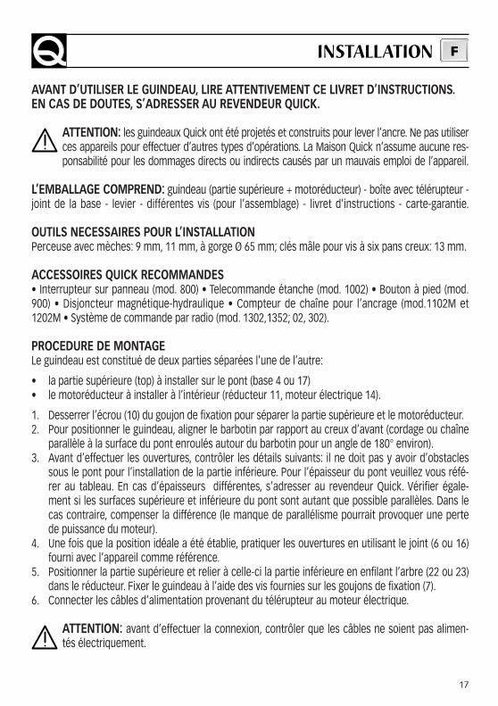
AVANT D’UTILISER LE GUINDEAU, LIRE ATTENTIVEMENT CE LIVRET D’INSTRUCTIONS.EN CAS DE DOUTES, S’ADRESSER AU REVENDEUR QUICK.
ATTENTION: les guindeaux Quick ont été projetés et construits pour lever l’ancre. Ne pas utiliserces appareils pour effectuer d’autres types d’opérations. La Maison Quick n’assume aucune res-ponsabilité pour les dommages directs ou indirects causés par un mauvais emploi de l’appareil.
L’EMBALLAGE COMPREND: guindeau (partie supérieure + motoréducteur) - boîte avec télérupteur -joint de la base - levier - différentes vis (pour l’assemblage) - livret d’instructions - carte-garantie.
OUTILS NECESSAIRES POUR L’INSTALLATIONPerceuse avec mèches: 9 mm, 11 mm, à gorge Ø 65 mm; clés mâle pour vis à six pans creux: 13 mm.
ACCESSOIRES QUICK RECOMMANDES• Interrupteur sur panneau (mod. 800) • Telecommande étanche (mod. 1002) • Bouton à pied (mod.900) • Disjoncteur magnétique-hydraulique • Compteur de chaîne pour l’ancrage (mod.1102M et1202M • Système de commande par radio (mod. 1302,1352; 02, 302).
PROCEDURE DE MONTAGELe guindeau est constitué de deux parties séparées l’une de l’autre:
• la partie supérieure (top) à installer sur le pont (base 4 ou 17)• le motoréducteur à installer à l’intérieur (réducteur 11, moteur électrique 14).
1. Desserrer l’écrou (10) du goujon de fixation pour séparer la partie supérieure et le motoréducteur.2. Pour positionner le guindeau, aligner le barbotin par rapport au creux d’avant (cordage ou chaîne
parallèle à la surface du pont enroulés autour du barbotin pour un angle de 180° environ).3. Avant d’effectuer les ouvertures, contrôler les détails suivants: il ne doit pas y avoir d’obstacles
sous le pont pour l’installation de la partie inférieure. Pour l’épaisseur du pont veuillez vous réfé-rer au tableau. En cas d’épaisseurs différentes, s’adresser au revendeur Quick. Vérifier égale-ment si les surfaces supérieure et inférieure du pont sont autant que possible parallèles. Dans lecas contraire, compenser la différence (le manque de parallélisme pourrait provoquer une pertede puissance du moteur).
4. Une fois que la position idéale a été établie, pratiquer les ouvertures en utilisant le joint (6 ou 16)fourni avec l’appareil comme référence.
5. Positionner la partie supérieure et relier à celle-ci la partie inférieure en enfilant l’arbre (22 ou 23)dans le réducteur. Fixer le guindeau à l’aide des vis fournies sur les goujons de fixation (7).
6. Connecter les câbles d’alimentation provenant du télérupteur au moteur électrique.
ATTENTION: avant d’effectuer la connexion, contrôler que les câbles ne soient pas alimen-tés électriquement.
INSTALLATION F
18
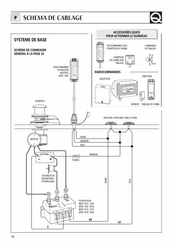
SCHEMA DE CABLAGEF
- +
M1
M2
SYSTEME DE BASE
SCHÉMA DE CONNEXIONGENERAL À LA PAGE 34
I T A L Y
1 2
1 2
RADIOCOMMANDES
COMPTEURDE CHAÎNE SUR
TABLEAU
COMMANDE DU TABLEAU
UP
DOWN
TELECOMMANDE AVEC COMPTEUR DE CHAÎNE
MIGNON - TABLEAU DE COMM.
RÉCEPTEUR
TELECOMMANDEÀ FONCTION
MULTIPLEMOD. 1002
GUINDEAU
MOTEUR
BATTERIE
DISJONCTEUR MAGNÉTIQUE-HYDRAULIQUE
TELERUPTEURMOD. T501 (12V)MOD. T502 (24V)MOD. T510 (12V)MOD. T52O (24V)
C
A2
BOUTONS À PIED MOD. 900U ET 900D
NOIRE
MARRON
BLEU
MARRON
NOIR
E
BLEU
A1
FUSIBLE
ACCESSOIRES QUICK POUR ACTIONNER LE GUINDEAU
EMETTEUR
19
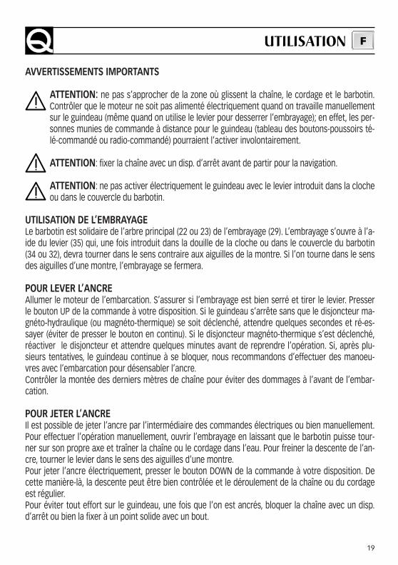
AVVERTISSEMENTS IMPORTANTS
ATTENTION: ne pas s’approcher de la zone où glissent la chaîne, le cordage et le barbotin.Contrôler que le moteur ne soit pas alimenté électriquement quand on travaille manuellementsur le guindeau (même quand on utilise le levier pour desserrer l’embrayage); en effet, les per-sonnes munies de commande à distance pour le guindeau (tableau des boutons-poussoirs té-lé-commandé ou radio-commandé) pourraient l’activer involontairement.
ATTENTION: fixer la chaîne avec un disp. d’arrêt avant de partir pour la navigation.
ATTENTION: ne pas activer électriquement le guindeau avec le levier introduit dans la clocheou dans le couvercle du barbotin.
UTILISATION DE L’EMBRAYAGELe barbotin est solidaire de l’arbre principal (22 ou 23) de l’embrayage (29). L’embrayage s’ouvre à l’a-ide du levier (35) qui, une fois introduit dans la douille de la cloche ou dans le couvercle du barbotin(34 ou 32), devra tourner dans le sens contraire aux aiguilles de la montre. Si l’on tourne dans le sensdes aiguilles d’une montre, l’embrayage se fermera.
POUR LEVER L’ANCREAllumer le moteur de l’embarcation. S’assurer si l’embrayage est bien serré et tirer le levier. Presserle bouton UP de la commande à votre disposition. Si le guindeau s’arrête sans que le disjoncteur ma-gnéto-hydraulique (ou magnéto-thermique) se soit déclenché, attendre quelques secondes et ré-es-sayer (éviter de presser le bouton en continu). Si le disjoncteur magnéto-thermique s’est déclenché,réactiver le disjoncteur et attendre quelques minutes avant de reprendre l’opération. Si, après plu-sieurs tentatives, le guindeau continue à se bloquer, nous recommandons d’effectuer des manoeu-vres avec l’embarcation pour désensabler l’ancre.Contrôler la montée des derniers mètres de chaîne pour éviter des dommages à l’avant de l’embar-cation.
POUR JETER L’ANCREIl est possible de jeter l’ancre par l’intermédiaire des commandes électriques ou bien manuellement.Pour effectuer l’opération manuellement, ouvrir l’embrayage en laissant que le barbotin puisse tour-ner sur son propre axe et traîner la chaîne ou le cordage dans l’eau. Pour freiner la descente de l’an-cre, tourner le levier dans le sens des aiguilles d’une montre.Pour jeter l’ancre électriquement, presser le bouton DOWN de la commande à votre disposition. Decette manière-là, la descente peut être bien contrôlée et le déroulement de la chaîne ou du cordageest régulier.Pour éviter tout effort sur le guindeau, une fois que l’on est ancrés, bloquer la chaîne avec un disp.d’arrêt ou bien la fixer à un point solide avec un bout.
UTILISATION F
20
1920
13
7
7
12
21
10
8
9
11
1
2
3
4
5
6
35
18
3332
29
31
30
29
23
29
31
3029
22
34
17
16
21
14
24
25
24
26
27
28
24
25
24
26
27
28
15
18
36
37
38
39
40
41
42
4344
45
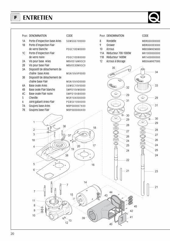
POSIT. DENOMINATION CODE
1A Porte d’inspection base Aries S G M S G G 1 0 0 0 0 0
1B Porte d’inspection Flair de verre blanche PDGC10D W0000
1C Porte d’inspection Flairde verre noire P D G C 1 0 D B 0 0 0 0
2A Vis pour base Aries MBV0516MXSC0
2B Vis pour base Flair MBV0530MXSC0
3A Dispositif de détachement de chaîne base Aries M S N 1 0 V X P 0 0 0 0
3B Dispositif de détachement de chaîne base Flair M S N 1 0 V X D 0 0 0 0
4A Base ovale Aries S G M S C 1 0 V 0 0 0 0
4B Base ovale Flair blanche SMPD10VW0000
4C Base ovale Flair noire S M P D 1 0 V B 0 0 0 0
5 Cheville M S R 1 0 X 0 0 0 0 0 0
6 Joint/gabarit Aries-Flair P G B S V 1 0 0 0 0 0 0
7A Goujons base Aries M B P 0 8 0 8 0 7 X 0 0
7B Goujons base Flair M B P 0 8 0 8 0 8 X 0 0
POSIT. DENOMINATION CODE
8 Rondelle MBR08X000000
9 Grower MBR08XDE0000
10 écrous MBD08MXEN000
11A Réducteur 700-1000W MR1000000000
11B Réducteur 1400W MR1400000000
12 écrous à blocage MBD06MXET000
ENTRETIENF
21
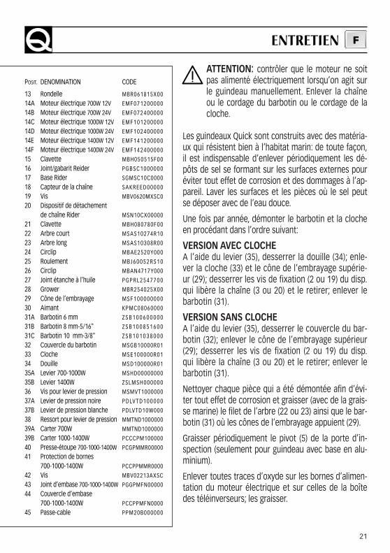
ATTENTION: contrôler que le moteur ne soitpas alimenté électriquement lorsqu’on agit surle guindeau manuellement. Enlever la chaîneou le cordage du barbotin ou le cordage de lacloche.
Les guindeaux Quick sont construits avec des matéria-ux qui résistent bien à l’habitat marin: de toute façon,il est indispensable d’enlever périodiquement les dé-pôts de sel se formant sur les surfaces externes pouréviter tout effet de corrosion et des dommages à l’ap-pareil. Laver les surfaces et les pièces où le sel peutse déposer avec de l’eau douce.
Une fois par année, démonter le barbotin et la clocheen procédant dans l’ordre suivant:
VERSION AVEC CLOCHEA l’aide du levier (35), desserrer la douille (34); enle-ver la cloche (33) et le cône de l’embrayage supérie-ur (29); desserrer les vis de fixation (2 ou 19) du disp.qui libère la chaîne (3 ou 20) et le retirer; enlever lebarbotin (31).
VERSION SANS CLOCHEA l’aide du levier (35), desserrer le couvercle du bar-botin (32); enlever le cône de l’embrayage supérieur(29); desserrer les vis de fixation (2 ou 19) du disp.qui libère la chaîne (3 ou 20) et le retirer; enlever lebarbotin (31).
Nettoyer chaque pièce qui a été démontée afin d’évi-ter tout effet de corrosion et graisser (avec de la grais-se marine) le filet de l’arbre (22 ou 23) ainsi que le bar-botin (31) où les cônes de l’embrayage appuient (29).
Graisser périodiquement le pivot (5) de la porte d’in-spection (seulement pour guindeau avec base en alu-minium).
Enlever toutes traces d’oxyde sur les bornes d’alimen-tation du moteur électrique et sur celles de la boîtedes téléinverseurs; les graisser.
POSIT. DENOMINATION CODE
13 Rondelle MBR061815X00
14A Moteur électrique 700W 12V EMF071200000
14B Moteur électrique 700W 24V EMF072400000
14C Moteur électrique 1000W 12V EMF101200000
14D Moteur électrique 1000W 24V EMF102400000
14E Moteur électrique 1400W 12V EMF141200000
14F Moteur électrique 1400W 24V EMF142400000
15 Clavette MBH050515F00
16 Joint/gabarit Reider PGBSC1000000
17 Base Rider SGMSC10C0000
18 Capteur de la chaîne SAKREED00000
19 Vis MBV0620MXSC0
20 Dispositif de détachement de chaîne Rider MSN10CX00000
21 Clavette MBH080780F00
22 Arbre court MSAS10274R10
23 Arbre long MSAS10308R00
24 Circlip MBAE2520Y000
25 Roulement M B J 6 0 0 5 2 R S 1 0
26 Circlip MBAN4717Y000
27 Joint étanche à l’huile P G P R L 2 5 4 7 7 0 0
28 Grower MBR254025X00
29 Cône de l’embrayage MSF100000000
30 Aimant KPMC08060000
31A Barbotin 6 mm Z S B 1 0 0 6 0 0 0 0 0
31B Barbotin 8 mm-5/16" Z S B 1 0 0 8 5 1 6 0 0
31C Barbotin 10 mm-3/8" Z S B 1 0 1 0 3 8 0 0 0
32 Couvercle du barbotin MSGB10000R01
33 Cloche MSE100000R01
34 Douille MSD100000R01
35A Levier 700-1000W MSHD00000000
35B Levier 1400W ZSLMSH000000
36 Vis pour levier de pression MSMVT1000000
37A Levier de pression noire P D LV T D 1 0 0 0 0 0
37B Levier de pression blanche PDLVTD10W000
38 Ressort pour levier de pression MMTND1000000
39A Carter 700W MMTND1000000
39B Carter 1000-1400W PCCCPM100000
40 Presse-étoupe 700-1000-1400W PCGPMMR00000
41 Protection de bornes 700-1000-1400W PCCPPMMR0000
42 Vis MBV02213AXSC
43 Joint d’embase 700-1000-1400W PGGPMFN00000
44 Couvercle d’embase 700-1000-1400W PCCPPMFN0000
45 Passe-cable PPM20B000000
ENTRETIEN F
22
TECHNISCHE EIGENSCHAFTEND
ARIES – / D700 W 1000 W 1400 W
12 V 24 V 12 V 24 V 12 V 24 V
850 kg 1000 kg 1100 kg
250 kg 300 kg 370 kg 450 kg 450 kg 500 kg
80 kg 100 kg 120 kg 150 kg 150 kg 170 kg
90 A 55 A 140 A 80 A 155 A 85 A
27,4 26,4 39,6 40,9 33,0 29,7
14,4 14,8 20,4 21,4 17,5 20,5
25 mm2 10 mm2 35 mm2 16 mm2 50 mm2 25 mm2
50 A 40 A 80 A 50 A 100 A 50 A
25 ÷ 50 mm 30 ÷ 50 mm
17,4 kg 18,5 kg 20,8 kg
19,3 kg 20,4 kg 22,7 kg
FLAIR – / D700 W 1000 W 1400 W
12 V 24 V 12 V 24 V 12 V 24 V
850 kg 1000 kg 1100 kg
250 kg 300 kg 370 kg 450 kg 450 kg 500 kg
80 kg 100 kg 120 kg 150 kg 150 kg 170 kg
90 A 55 A 140 A 80 A 155 A 85 A
27,4 26,4 39,6 40,9 33,0 29,7
14,4 14,8 20,4 21,4 17,5 20,5
25 mm2 10 mm2 35 mm2 16 mm2 50 mm2 25 mm2
50 A 40 A 80 A 50 A 100 A 50 A
25 ÷ 50 mm 30 ÷ 50 mm
16,5 kg 17,6 kg 19,9 kg
18,4 kg 19,5 kg 21,8 kg
RIDER – / D700 W 1000 W 1400 W
12 V 24 V 12 V 24 V 12 V 24 V
850 kg 1000 kg 1100 kg
250 kg 300 kg 370 kg 450 kg 450 kg 500 kg
80 kg 100 kg 120 kg 150 kg 150 kg 170 kg
90 A 55 A 140 A 80 A 155 A 85 A
27,4 26,4 39,6 40,9 33,0 29,7
14,4 14,8 20,4 21,4 17,5 20,5
25 mm2 10 mm2 35 mm2 16 mm2 50 mm2 25 mm2
50 A 40 A 80 A 50 A 100 A 50 A
25 ÷ 50 mm 30 ÷ 50 mm
16,0 kg 17,1 kg 19,4 kg
18,0 kg 19,1 kg 21,4 kg
MODÈLLMOTORLEISTUNGSpannung Motor
Maximaler Zug
Maximale Arbeitslast
Arbeitslast
Stromaufnahme bei Arbeitslast (1)
Maximale Rückholgeschwindigkeit (2) m/min
Rückholgeschwindigkeit bei Arbeitslast (2) m/min
Kettengröße (3)
Taugröße
Motorkabel-Mindestquerschnitt (4)
Schutzschalter (5)
Stärke des Decks (6)
Gewicht - modell ohne Verholspill
Gewicht - modell mit Verholspill(1) Bei gekuppeltem Motor nach der Anlassphase.(2) Durchgeführte Messungen mit Kettennuss für 8 mm-Kette.(3) Alle Ausführungen sind mit 8-mm-Kettennüssen ausgestattet. Auf wunsch Können auch ander Kettennüsse installiert werden.(4) Empfohlener Mindestwert. Den Kabelquerschnitt in Abhängigkeit zur Länge des Anschlüsses berechnen.(5) Mit besonderem Schalter für Gleichstrom (DC) und Verzögerung (Überstrom Schutzautomat oder hydraulischer Schutzautomat).(6) Auf Anfrage können Maste und Gewindestifte für stärker Decks geliefert werden.
700 / 1000 W ARIES - FLAIR - / D
700 / 1000 W RIDER - / D
1400 W ARIES - FLAIR - / D
1400 W RIDER - / D
QUICK BEHÄLT SICH DAS RECHT AUF ÄNDERUNGEN DER TECHNISCHEN EIGENSCHAFTEN DES GERÄTS UND DES INHALTS DIESES HANDBUCHS OHNE VORANKÜNDIGUNG VOR.
9815
514
1
345 (700 W) - 360 (1000 W)
7887
250
164
100
155
141
345 (700 W) - 360 (1000 W)
Ø 1
55
166
159
164
9817
914
1
385
7887
250
166
100
179
141
385
159
Ø15
5
8 mm DIN 766 • 5/16” DIN 766 (6 mm DIN 766 - 10 mm DIN 766 • 10 mm ISO • 3/8” DIN 766)
12 mm • 14 mm • 16 mm • 1/2” • 9/16” • 5/8” (12 mm • 14 mm • 16 mm • 1/2” • 9/16” • 5/8” - 16 mm • 5/8”)
ABMESSUNGEN DER MODELLE (mm)
1° BEISPIEL : RIDER724D RIDER 7 24 D
� � � �
2° BEISPIEL : FLAIRB1012 FLAIRB 10 12 –
� � � �
Serien Nahme:[ ARIES ] = Oval Basis aus Aluminium[ FLAIR B ] = Oval Basis aus schwarzer GFK[ FLAIR W ] = Oval Basis aus weißer GFK[ RIDER ] = Runde Basis aus Aluminium
Motorleistung:[ 7 ] = 700 W[ 10 ] = 1000 W[ 14 ] = 1400 W
Motorversorgungsspannung:[ 12 ] = 12 V [ 24 ] = 24 V
Verholspill:[ D ] = mit verholspill[ – ] = ohne verholspill
LESEN DES ANKERWINDECODES:
a b c d
a b c d a b c d

23
VOR DEM GEBRAUCH DER ANKERWINDE DIESE BETRIEBSANLEITUNG AUFMERKSAM DURCH-LESEN. IM ZWEIFELSFALL WENDEN SIE SICH BITTE AN DEN QUICK-VERTRAGSHÄNDLER.
ACHTUNG: die Quick-Ankerwinden wurden für das Lichten des Ankers entwickelt und ge-baut. Diese Vorrichtungen für keine anderen Zwecke verwenden. Quick haftet nicht für direkteoder indirekte Schäden, die durch einen unsachgemäßen Gebrauch des Geräts entstehen.
DIE PACKUNG ENTHÄLT: winde (top + getriebemotor) - relais box - basisdichtung - kurbel -schrauben (für den zusammenbau) - betriebsanleitung - garantiekarte.
NOTWENDIGE WERKZEUGE FÜR DIE INSTALLATIONBohrmaschine: Bohrer 9 mm, 11 mm, Scheibe Ø 65 mm; Inbusschlüssel: 13 mm.
EMPFOHLENE QUICK-ZUBEHÖRTEILE • Schalter an Bedientafel (mod. 800) • Wasserdichte Fernbedienung (mod. 1002) • Fußschalter (mod.900)• hydraulischer Schutzautomat • Kettenzähler für Verankerung (mod. 1102M und 1202M) • Funk-steuersystem (mod. 1302,1352; 02, 302).
VORGANGSWEISE FÜR DIE MONTAGEDie Ankerwinde setzt sich aus zwei separaten Teilen zusammen:
• Der obere Teil (Top) muß an Deck (Basis 4 oder 17).• Der Getriebemotor muß unter Deck montiert werden (Untersetzungsgetriebe 11, elektrischer Motor 14).
1. Die Mutter (10) von der Befestigungsschraube abschrauben, um Top und Getriebemotor zu trennen.2. Zur Positionierung der Ankerwinde die Kettennuß auf die Bugstütze ausrichten (Leine oder Kette
parallel zum Boden des Decks und um die Kettennuß mit einem Winkel von ca. 180 ° gewickelt).3. Vor Anbringung der Bohrungen folgendes kontrollieren: Unter Deck dürfen keine Hindernisse für
die Installation des unteren Teils vorliegen. Bezüglich der Dekstärke beachten Sie bitte die anlie-gende technische Tabelle. Im Falle anderer Dicken wenden Sie sich an den Quick-Vertragshändler.Außerdem kontrollieren, ob die Deckoberflächen oben und unten so weit als möglich parallelsind. Anderenfalls den Unterschied entsprechend ausgleichen (fehlende Parallelität könnte einenAbfall der Motorleistung bewirken).
4. Nach Festlegung der idealen Position, die Bohrungen anbringen. Als Bezug die mitgelieferte Dich-tung (6 oder 16) verwenden.
5. Das obere Teil positionieren und mit dem unteren Teil verbinden. Dazu die Welle (22 oder 23) indas Untersetzungsgetriebe einsetzen. Die Ankerwinde mit den mitgelieferten Schrauben an denStiftschrauben (7) befestigen.
6. Die vom Schalter kommenden Versorgungskabel an den elektrischen Motor anschließen.
ACHTUNG: vor Durchführung des Anschlusses sicherstellen, daß an den Kabeln keine Span-nung anliegt.
MONTAGEI
I
D
24
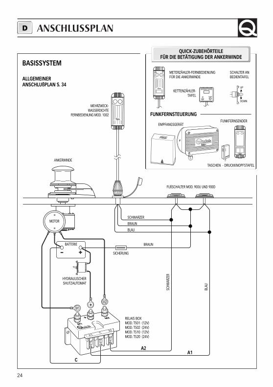
ANSCHLUSSPLAND
- +
M1
M2
BASISSYSTEM
ALLGEMEINER ANSCHLUßPLAN S. 34
I T A L Y
1 2
1 2
FUNKFERNSTEUERUNG
KETTENZÄHLER-TAFEL
SCHALTER ANBEDIENTAFEL
UP
DOWN
METERZÄHLER-FERNBEDIENUNGFÜR DIE ANKERWINDE
TASCHEN - DRUCKKNOPFSTAFEL
EMPFANGSGERÄT
MEHRZWECK-WASSERDICHTE
FERNBEDIENUNG MOD. 1002
ANKERWINDE
MOTOR
BATTERIE
HYDRAULISCHERSHUTZAUTOMAT
RELAIS BOXMOD. T501 (12V)MOD. T502 (24V)MOD. T510 (12V)MOD. T520 (24V)
C
A2
FUßSCHALTER MOD. 900U UND 900D
SCHWARZER
BRAUN
BLAU
BRAUN
SCHW
ARZE
R
BLAU
A1
SICHERUNG
QUICK-ZUBEHÖRTEILEFÜR DIE BETÄTIGUNG DER ANKERWINDE
FUNKFERNSENDER
25
WICHTIGE HINWEISE
ACHTUNG: körperteile oder Gegenstände fern von den Bereichen halten, in denen sich dieKette, Leine und die Kettennuß bewegen. Sicherstellen, daß der elektrische Motor nicht anSpannung liegt, wenn man manuell an der Ankerwinde eingreift (auch dann, wenn man denHebel zum Lösen der Kupplung verwendet): mit Fernbedienung der Ankerwinde ausgestattetePersonen (Fernbedienfeld oder Funksteuerung) könnten die Ankerwinde einschalten.
ACHTUNG: die Kette mit einer Feststellvorrichtung blockieren, bevor man mit dem Boot aus-fährt.
ACHTUNG: die Ankerwinde nicht elektrisch einschalten, wenn der Hebel in der Verholspilloder im Kettennußdeckel eingesetzt ist.
GEBRAUCH DER KUPPLUNGDie Kettennuß ist über die Kupplung (29) fest mit der Hauptwelle (22 oder 23) verbunden. Zum Öffnen(Lösen) der Kupplung dreht man den Hebel (35) in der Buchse der Verholspill oder der Kettennuß (34oder 32) gegen den Uhrzeigersinn. Dreht man ihn im Uhrzeigersinn, so wird die Kupplung geschlossen(angezogen).
ZUM LICHTEN DES ANKERSDen Bootmotor einschalten. Sich vergewissern, daß die Kupplung angezogen ist und den Hebel he-rausziehen. Die UP-Taste an der Ihnen zur Verfügung stehenden Bedientafel drücken. Falls die Anker-winde anhält, ohne daß der Schutzautomat (oder thermomagnetische Schalter) ausgelöst wurde, eini-ge Sekunden warten und nochmals probieren (die Taste sollte nicht lange gedrückt werden).Falls der Schutzautomat ausgelöst wurde, den Schalter rückstellen und einige Minuten vor Lichtendes Ankers warten. Falls nach mehreren Versuchen die Ankerwinde weiter blockiert wird, empfehlenwir Ihnen das Boot zu manövrieren, um den Anker freizumachen.Beim lichten der letzten Kettenmeter darauf achten, daß der Bug nicht beschädigt wird.
ZUM SENKEN DES ANKERSDer Anker kann mit den elektrischen Steuerungen oder von Hand gesenkt werden. Für das manuelleSenken muß man die Kupplung lösen, damit die Kettennuß frei um die eigene Achse dreht und dieKette oder Leine ins Wasser mitzieht. Zum Abbremsen des Falls den Hebel im Uhrzeigersinn drehen.Für das elektrisch gesteuerte Senken des Ankers muß man die DOWN-Taste an der Bedientafel drüc-ken. Auf diese Weise wird der Anker kontrolliert gesenkt und die Kette oder Leine gleichmäßig abge-wickelt.Zur Verhinderung von Belastungen an der Ankerwinde muß man die Kette mit einer Feststellrichtungblockieren oder an einer Stelle fest mit einer Leine festmachen, nachdem man sie verankert hat.
GEBRAUCH D
26
1920
13
7
7
12
21
10
8
9
11
1
2
3
4
5
6
35
18
3332
29
31
30
29
23
29
31
3029
22
34
17
16
21
14
24
25
24
26
27
28
24
25
24
26
27
28
15
18
36
37
38
39
40
41
42
4344
45
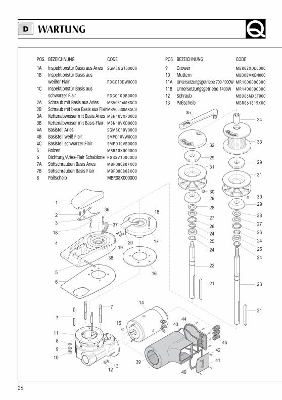
POS. BEZEICHNUNG CODE
1A Inspektionstür Basis aus Aries SGMSGG100000
1B Inspektionstür Basis aus weißer Flair PDGC10DW0000
1C Inspektionstür Basis aus schwarzer Flair PDGC10DB0000
2A Schraub mit Basis aus Aries MBV0516MXSC0
2B Schraub mit base Basis aus FlairMBV0530MXSC0
3A Kettenabweiser mit Basis Aries MSN10VXP0000
3B Kettenabweiser mit Basis Flair MSN10VXD0000
4A Basisteil Aries SGMSC10V0000
4B Basisteil weiß Flair SMPD10VW0000
4C Basisteil schwarzer Flair SMPD10VB0000
5 Bolzen MSR10X000000
6 Dichtung/Aries-Flair Schablone PGBSV1000000
7A Stiftschrauben Basis Aries MBP080807X00
7B Stiftschrauben Basis Flair MBP080808X00
8 Paßscheib MBR08X000000
POS. BEZEICHNUNG CODE
9 Grower MBR08XDE0000
10 Muttern MBD08MXEN000
11A Untersetzungsgetriebe 700-1000W MR1000000000
11B Untersetzungsgetriebe 1400W MR1400000000
12 Schraub MBD06MXET000
13 Paßscheib MBR061815X00
WARTUNGD
27
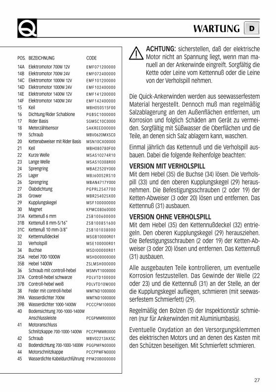
ACHTUNG: sicherstellen, daß der elektrischeMotor nicht an Spannung liegt, wenn man ma-nuell an der Ankerwinde eingreift. Sorgfältig dieKette oder Leine vom Kettennuß oder die Leinevon der Verholspill nehmen.
Die Quick-Ankerwinden werden aus seewasserfestemMaterial hergestellt. Dennoch muß man regelmäßigSalzablagerung an den Außenflächen entfernen, umKorrosion und folglich Schäden am Gerät zu vermei-den. Sorgfältig mit Süßwasser die Oberflächen und dieTeile, an denen sich Salz ablagern kann, waschen.
Einmal jährlich das Kettennuß und die Verholspill aus-bauen. Dabei die folgende Reihenfolge beachten:
VERSION MIT VERHOLSPILLMit dem Hebel (35) die Buchse (34) lösen. Die Verhols-pill (33) und den oberen Kupplungskegel (29) heraus-nehmen. Die Befestigungsschrauben (2 oder 19) derKetten-Abweiser (3 oder 20) lösen und entfernen. DasKettennuß (31) ausbauen.
VERSION OHNE VERHOLSPILLMit dem Hebel (35) den Kettennußdeckel (32) entrie-geln. Den oberen Kupplungskegel (29) herausziehen.Die Befestigungsschrauben (2 oder 19) der Ketten-Ab-weiser (3 oder 20) lösen und entfernen. Das Kettennuß(31) ausbauen.
Alle ausgebauten Teile kontrollieren, um eventuelleKorrosion festzustellen. Das Gewinde der Welle (22oder 23) und die Kettennuß (31) an der Stelle, an derdie Kupplungskegel aufliegen, schmieren (mit seewas-serfestem Schmierfett) (29).
Regelmäßig den Bolzen (5) der Inspektionstür schmie-ren (nur für Ankerwinden mit Aluminiumbasis).
Eventuelle Oxydation an den Versorgungsklemmendes elektrischen Motors und an denen des Kasten mitden Schützen beseitigen. Mit Schmierfett schmieren.
POS. BEZEICHNUNG CODE
14A Elektromotor 700W 12V EMF071200000
14B Elektromotor 700W 24V EMF072400000
14C Elektromotor 1000W 12V EMF101200000
14D Elektromotor 1000W 24V EMF102400000
14E Elektromotor 1400W 12V EMF141200000
14F Elektromotor 1400W 24V EMF142400000
15 Keil MBH050515F00
16 Dichtung/Rider Schablone PGBSC1000000
17 Rider Basis SGMSC10C0000
18 Meterzählsensor SAKREED00000
19 Schraub MBV0620MXSC0
20 Kettenabweiser mit Rider Basis MSN10CX00000
21 Keil MBH080780F00
22 Kurze Welle MSAS10274R10
23 Lange Welle MSAS10308R00
24 Sprengring MBAE2520Y000
25 Lager M B J 6 0 0 5 2 R S 1 0
26 Sprengring MBAN4717Y000
27 Ölabdichtung P G P R L 2 5 4 7 7 0 0
28 Grower MBR254025X00
29 Kupplungskegel MSF100000000
30 Magnet KPMC08060000
31A Kettenuß 6 mm Z S B 1 0 0 6 0 0 0 0 0
31B Kettenuß 8 mm-5/16" Z S B 1 0 0 8 5 1 6 0 0
31C Kettenuß 10 mm-3/8" Z S B 1 0 1 0 3 8 0 0 0
32 Kettennußdeckel MSGB10000R01
33 Verholspill MSE100000R01
34 Buchse M S D I 0 0 0 0 0 R 0 1
35A Hebel 700-1000W MSHD00000000
35B Hebel 1400W ZSLMSH000000
36 Schraub mit controll-hebel MSMVT1000000
37A Controll-hebel schwarze P D LV T D 1 0 0 0 0 0
37B Controll-hebel weiß PDLVTD10W000
38 Feder mit controll-hebel MMTND1000000
39A Wasserdichter 700W MMTND1000000
39B Wasserdichter 1000-1400W PCCCPM100000
40 Bodensichtung 700-1000-1400WAnschlussleiste PCGPMMR00000
41 Motoranschluss Schnitzkappe 700-1000-1400W PCCPPMMR0000
42 Schraub MBV02213AXSC
43 Bodendichtung 700-1000-1400W PGGPMFN00000
44 Motorschnitzkappe PCCPPMFN0000
45 Wasserdichte Kabeldurchführung PPM20B000000
WARTUNG D
CARACTERÍSTICAS TÉCNICAS
26
E
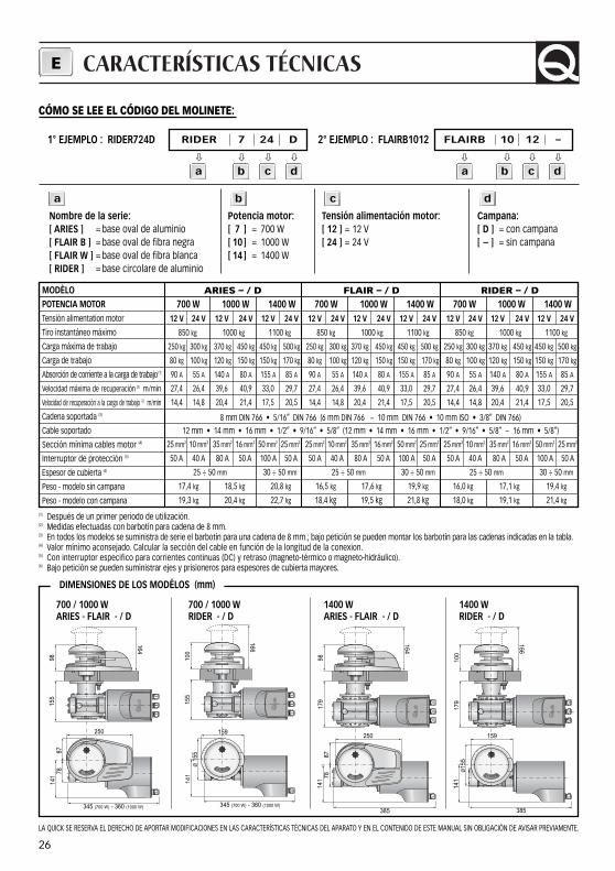
ARIES – / D700 W 1000 W 1400 W
12 V 24 V 12 V 24 V 12 V 24 V
850 kg 1000 kg 1100 kg
250 kg 300 kg 370 kg 450 kg 450 kg 500 kg
80 kg 100 kg 120 kg 150 kg 150 kg 170 kg
90 A 55 A 140 A 80 A 155 A 85 A
27,4 26,4 39,6 40,9 33,0 29,7
14,4 14,8 20,4 21,4 17,5 20,5
25 mm2 10 mm2 35 mm2 16 mm2 50 mm2 25 mm2
50 A 40 A 80 A 50 A 100 A 50 A
25 ÷ 50 mm 30 ÷ 50 mm
17,4 kg 18,5 kg 20,8 kg
19,3 kg 20,4 kg 22,7 kg
FLAIR – / D700 W 1000 W 1400 W
12 V 24 V 12 V 24 V 12 V 24 V
850 kg 1000 kg 1100 kg
250 kg 300 kg 370 kg 450 kg 450 kg 500 kg
80 kg 100 kg 120 kg 150 kg 150 kg 170 kg
90 A 55 A 140 A 80 A 155 A 85 A
27,4 26,4 39,6 40,9 33,0 29,7
14,4 14,8 20,4 21,4 17,5 20,5
25 mm2 10 mm2 35 mm2 16 mm2 50 mm2 25 mm2
50 A 40 A 80 A 50 A 100 A 50 A
25 ÷ 50 mm 30 ÷ 50 mm
16,5 kg 17,6 kg 19,9 kg
18,4 kg 19,5 kg 21,8 kg
RIDER – / D700 W 1000 W 1400 W
12 V 24 V 12 V 24 V 12 V 24 V
850 kg 1000 kg 1100 kg
250 kg 300 kg 370 kg 450 kg 450 kg 500 kg
80 kg 100 kg 120 kg 150 kg 150 kg 170 kg
90 A 55 A 140 A 80 A 155 A 85 A
27,4 26,4 39,6 40,9 33,0 29,7
14,4 14,8 20,4 21,4 17,5 20,5
25 mm2 10 mm2 35 mm2 16 mm2 50 mm2 25 mm2
50 A 40 A 80 A 50 A 100 A 50 A
25 ÷ 50 mm 30 ÷ 50 mm
16,0 kg 17,1 kg 19,4 kg
18,0 kg 19,1 kg 21,4 kg
MODÈLOPOTENCIA MOTORTensión alimentation motor
Tiro instantáneo máximo
Carga máxima de trabajo
Carga de trabajo
Absorción de corriente a la carga de trabajo (1)
Velocidad máxima de recuperación (2) m/min
Velocidad de recuperación a la carga de trabajo (2) m/min
Cadena soportada (3)
Cable soportado
Sección mínima cables motor (4)
Interruptor de protección (5)
Espesor de cubierta (6)
Peso - modelo sin campana
Peso - modelo con campana(1) Después de un primer periodo de utilización.(2) Medidas efectuadas con barbotín para cadena de 8 mm.(3) En todos los modelos se suministra de serie el barbotín para una cadena de 8 mm.; bajo petición se pueden montar los barbotín para las cadenas indicadas en la tabla.(4) Valor mínimo aconsejado. Calcular la sección del cable en función de la longitud de la conexion.(5) Con interruptor especifico para corrientes continuas (DC) y retraso (magneto-térmico o magneto-hidráulico).(6) Bajo petición se pueden suministrar ejes y prisioneros para espesores de cubierta mayores.
700 / 1000 W ARIES - FLAIR - / D
700 / 1000 W RIDER - / D
1400 W ARIES - FLAIR - / D
1400 W RIDER - / D
LA QUICK SE RESERVA EL DERECHO DE APORTAR MODIFICACIONES EN LAS CARACTERÍSTICAS TÉCNICAS DEL APARATO Y EN EL CONTENIDO DE ESTE MANUAL SIN OBLIGACIÓN DE AVISAR PREVIAMENTE.
9815
514
1
345 (700 W) - 360 (1000 W)
7887
250
164
100
155
141
345 (700 W) - 360 (1000 W)
Ø 1
55
166
159
164
9817
914
1
385
7887
250
166
100
179
141
385
159
Ø15
5
8 mm DIN 766 • 5/16” DIN 766 (6 mm DIN 766 - 10 mm DIN 766 • 10 mm ISO • 3/8” DIN 766)
12 mm • 14 mm • 16 mm • 1/2” • 9/16” • 5/8” (12 mm • 14 mm • 16 mm • 1/2” • 9/16” • 5/8” - 16 mm • 5/8”)
DIMENSIONES DE LOS MODÉLOS (mm)
1° EJEMPLO : RIDER724D RIDER 7 24 D
� � � �
2° EJEMPLO : FLAIRB1012 FLAIRB 10 12 –
� � � �
Nombre de la serie:[ ARIES ] = base oval de aluminio[ FLAIR B ] = base oval de fibra negra[ FLAIR W ] = base oval de fibra blanca[ RIDER ] = base circolare de aluminio
Potencia motor:[ 7 ] = 700 W[ 10 ] = 1000 W[ 14 ] = 1400 W
Tensión alimentación motor:[ 12 ] = 12 V [ 24 ] = 24 V
Campana:[ D ] = con campana[ – ] = sin campana
CÓMO SE LEE EL CÓDIGO DEL MOLINETE:
a b c d
a b c d a b c d
29
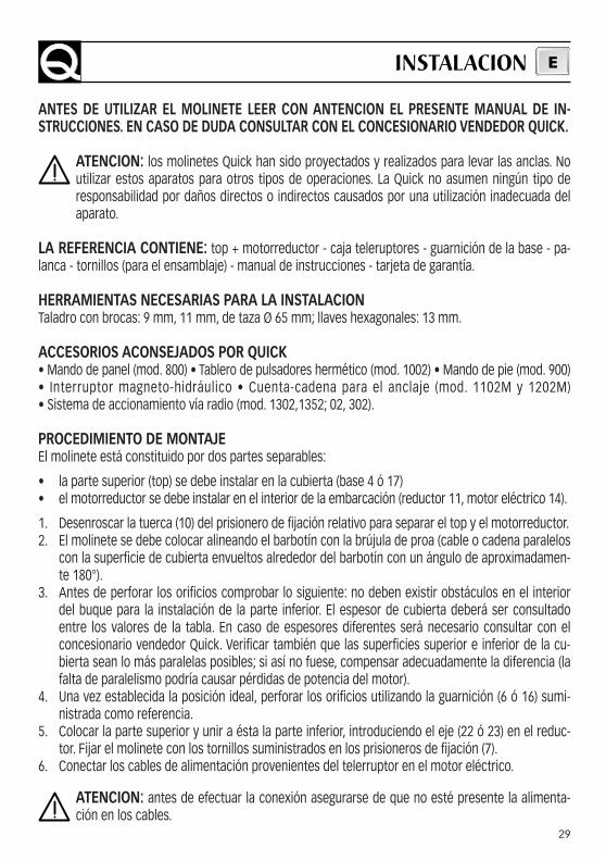
ANTES DE UTILIZAR EL MOLINETE LEER CON ANTENCION EL PRESENTE MANUAL DE IN-STRUCCIONES. EN CASO DE DUDA CONSULTAR CON EL CONCESIONARIO VENDEDOR QUICK.
ATENCION: los molinetes Quick han sido proyectados y realizados para levar las anclas. Noutilizar estos aparatos para otros tipos de operaciones. La Quick no asumen ningún tipo deresponsabilidad por daños directos o indirectos causados por una utilización inadecuada delaparato.
LA REFERENCIA CONTIENE: top + motorreductor - caja teleruptores - guarnición de la base - pa-lanca - tornillos (para el ensamblaje) - manual de instrucciones - tarjeta de garantía.
HERRAMIENTAS NECESARIAS PARA LA INSTALACIONTaladro con brocas: 9 mm, 11 mm, de taza Ø 65 mm; llaves hexagonales: 13 mm.
ACCESORIOS ACONSEJADOS POR QUICK • Mando de panel (mod. 800) • Tablero de pulsadores hermético (mod. 1002) • Mando de pie (mod. 900)• Interruptor magneto-hidráulico • Cuenta-cadena para el anclaje (mod. 1102M y 1202M) • Sistema de accionamiento vía radio (mod. 1302,1352; 02, 302).
PROCEDIMIENTO DE MONTAJEEl molinete está constituido por dos partes separables:
• la parte superior (top) se debe instalar en la cubierta (base 4 ó 17)• el motorreductor se debe instalar en el interior de la embarcación (reductor 11, motor eléctrico 14).
1. Desenroscar la tuerca (10) del prisionero de fijación relativo para separar el top y el motorreductor.2. El molinete se debe colocar alineando el barbotín con la brújula de proa (cable o cadena paralelos
con la superficie de cubierta envueltos alrededor del barbotín con un ángulo de aproximadamen-te 180°).
3. Antes de perforar los orificios comprobar lo siguiente: no deben existir obstáculos en el interiordel buque para la instalación de la parte inferior. El espesor de cubierta deberá ser consultadoentre los valores de la tabla. En caso de espesores diferentes será necesario consultar con elconcesionario vendedor Quick. Verificar también que las superficies superior e inferior de la cu-bierta sean lo más paralelas posibles; si así no fuese, compensar adecuadamente la diferencia (lafalta de paralelismo podría causar pérdidas de potencia del motor).
4. Una vez establecida la posición ideal, perforar los orificios utilizando la guarnición (6 ó 16) sumi-nistrada como referencia.
5. Colocar la parte superior y unir a ésta la parte inferior, introduciendo el eje (22 ó 23) en el reduc-tor. Fijar el molinete con los tornillos suministrados en los prisioneros de fijación (7).
6. Conectar los cables de alimentación provenientes del telerruptor en el motor eléctrico.
ATENCION: antes de efectuar la conexión asegurarse de que no esté presente la alimenta-ción en los cables.
INSTALACION E
30
ESQUEMA DE MONTAGEE
- +
M1
M2
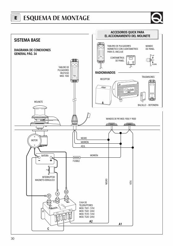
SISTEMA BASE
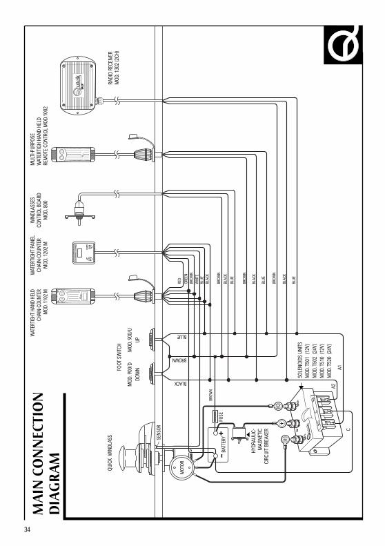
DIAGRAMA DE CONEXIONES GENERAL PÁG. 34
I T A L Y
1 2
1 2
RADIOMANDOS
CONTAMETROSDE PANEL
MANDO DE PANEL
UP
DOWN
TABLERO DE PULSADORES HERMETICO CON CUENTAMETROS PARA EL ANCLAJE
BALSILLO - BOTONERA
RECEPTOR
TABLERO DE PULSADORES
MULTIUSOMOD. 1002
MOLINETE
MOTOR
BATERÍA
INTERRUPTORMAGNETO-IDRAULICO
CAJA DETELERUPTORESMOD. T501 (12V)MOD. T502 (24V)MOD. T510 (12V)MOD. T520 (24V)
C
A2
MANDOS DE PIE MOD. 900U Y 900D
NEGRO
MORRÓN
AZUL
MORRÓN
NEGR
O
AZUL
A1
FUSIBLE
ACCESORIOS QUICK PARAEL ACCIONAMIENTO DEL MOLINETE
TRASMISORES
31
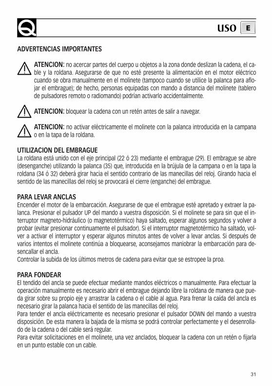
ADVERTENCIAS IMPORTANTES
ATENCION: no acercar partes del cuerpo u objetos a la zona donde deslizan la cadena, el ca-ble y la roldana. Asegurarse de que no esté presente la alimentación en el motor eléctricocuando se obra manualmente en el molinete (tampoco cuando se utilice la palanca para aflo-jar el embrague); de hecho, personas equipadas con mando a distancia del molinete (tablerode pulsadores remoto o radiomando) podrían activarlo accidentalmente.
ATENCION: bloquear la cadena con un retén antes de salir a navegar.
ATENCION: no activar eléctricamente el molinete con la palanca introducida en la campanao en la tapa de la roldana.
UTILIZACION DEL EMBRAGUELa roldana está unido con el eje principal (22 ó 23) mediante el embrague (29). El embrague se abre(desenganche) utilizando la palanca (35) que, introducida en la brújula de la campana o en la tapa laroldana (34 ó 32) deberá girar hacia el sentido contrario de las manecillas del reloj. Girando hacia elsentido de las manecillas del reloj se provocará el cierre (enganche) del embrague.
PARA LEVAR ANCLASEncender el motor de la embarcación. Asegurarse de que el embrague esté apretado y extraer la pa-lanca. Presionar el pulsador UP del mando a vuestra disposición. Si el molinete se para sin que el in-terruptor magneto-hidráulico (o magnetotérmico) haya saltado, esperar algunos segundos y volver aprobar (evitar presionar continuamente el pulsador). Si el interruptor magnetotérmico ha saltado, vol-ver a activar el interruptor y esperar algunos minutos antes de volver a levar anclas. Si después devarios intentos el molinete continúa a bloquearse, aconsejamos maniobrar la embarcación para de-sencallar el ancla.Controlar la subida de los últimos metros de cadena para evitar que se estropee la proa.
PARA FONDEAREl tendido del ancla se puede efectuar mediante mandos eléctricos o manualmente. Para efectuar laoperación manualmente es necesario abrir el embrague dejando libre la roldana de manera que pue-da girar sobre su propio eje y arrastrar la cadena o el cable al agua. Para frenar la caída del ancla esnecesario girar la palanca hacia el sentido de las manecillas del reloj.Para tender el ancla eléctricamente es necesario presionar el pulsador DOWN del mando a vuestradisposición. De esta manera la bajada de la misma se podrá controlar perfectamente y el desenrolla-do de la cadena o del cable será regular.Para evitar solicitaciones en el molinete, una vez anclados, bloquear la cadena con un retén o fijarlaen un punto estable con un cable.
USO E
32
1920
13
7
7
12
21
10
8
9
11
1
2
3
4
5
6
35
18
3332
29
31
30
29
23
29
31
3029
22
34
17
16
21
14
24
25
24
26
27
28
24
25
24
26
27
28
15
18
36
37
38
39
40
41
42
4344
45
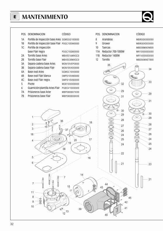
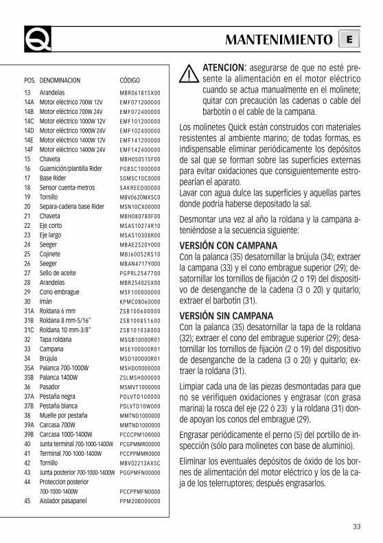
POS. DENOMINACION CÓDIGO
1A Portilla de inspección base Aries SGMSGG100000
1B Portilla de inspección base Flair PDGC10DW0000
1C Portilla de inspección base Flair negra PDGC10DB0000
2A Tornillo base Aries MBV0516MXSC0
2B Tornillo base Flair MBV0530MXSC0
3A Separa-cadena base Aries MSN10VXP0000
3B Separa-cadena base Flair MSN10VXD0000
4A Base oval Aries SGMSC10V0000
4B Base oval Flair blanca SMPD10VW0000
4C Base oval Flair negra SMPD10VB0000
5 Pivote MSR10X000000
6 Guarnición/plantilla Aries-Flair PGBSV1000000
7A Prisioneros base Arier MBP080807X00
7B Prisioneros base Flair MBP080808X00
POS. DENOMINACION CÓDIGO
8 Arandelas MBR08X000000
9 Grower MBR08XDE0000
10 Tuercas MBD08MXEN000
11A Reductor 700-1000W MR1000000000
11B Reductor 1400W MR1400000000
12 Tornillo MBD06MXET000
MANTENIMIENTOE
33
ATENCION: asegurarse de que no esté pre-sente la alimentación en el motor eléctricocuando se actua manualmente en el molinete;quitar con precaución las cadenas o cable delbarbotín o el cable de la campana.
Los molinetes Quick están construidos con materialesresistentes al ambiente marino; de todas formas, esindispensable eliminar periódicamente los depósitosde sal que se forman sobre las superficies externaspara evitar oxidaciones que consiguientemente estro-pearían el aparato.Lavar con agua dulce las superficies y aquellas partesdonde podría haberse depositado la sal.
Desmontar una vez al año la roldana y la campana a-teniéndose a la secuencia siguiente:
VERSIÓN CON CAMPANACon la palanca (35) desatornillar la brújula (34); extraerla campana (33) y el cono embrague superior (29); de-satornillar los tornillos de fijación (2 o 19) del dispositi-vo de desenganche de la cadena (3 o 20) y quitarlo;extraer el barbotín (31).
VERSIÓN SIN CAMPANACon la palanca (35) desatornillar la tapa de la roldana(32); extraer el cono del embrague superior (29); desa-tornillar los tornillos de fijación (2 o 19) del dispositivode desenganche de la cadena (3 o 20) y quitarlo; ex-traer la roldana (31).
Limpiar cada una de las piezas desmontadas para queno se verifiquen oxidaciones y engrasar (con grasamarina) la rosca del eje (22 ó 23) y la roldana (31) don-de apoyan los conos del embrague (29).
Engrasar periódicamente el perno (5) del portillo de in-spección (sólo para molinetes con base de aluminio).
Eliminar los eventuales depósitos de óxido de los bor-nes de alimentación del motor eléctrico y los de la ca-ja de los telerruptores; después engrasarlos.
POS. DENOMINACION CÓDIGO
13 Arandelas MBR061815X00
14A Motor eléctrico 700W 12V EMF071200000
14B Motor eléctrico 700W 24V EMF072400000
14C Motor eléctrico 1000W 12V EMF101200000
14D Motor eléctrico 1000W 24V EMF102400000
14E Motor eléctrico 1400W 12V EMF141200000
14F Motor eléctrico 1400W 24V EMF142400000
15 Chaveta MBH050515F00
16 Guarnición/plantilla Rider PGBSC1000000
17 Base Rider SGMSC10C0000
18 Sensor cuenta-metros SAKREED00000
19 Tornillo MBV0620MXSC0
20 Separa-cadena base Rider MSN10CX00000
21 Chaveta MBH080780F00
22 Eje corto MSAS10274R10
23 Eje largo MSAS10308R00
24 Seeger MBAE2520Y000
25 Cojinete M B J 6 0 0 5 2 R S 1 0
26 Seeger MBAN4717Y000
27 Sello de aceite P G P R L 2 5 4 7 7 0 0
28 Arandelas MBR254025X00
29 Cono embrague MSF100000000
30 Imán KPMC08060000
31A Roldana 6 mm Z S B 1 0 0 6 0 0 0 0 0
31B Roldana 8 mm-5/16" Z S B 1 0 0 8 5 1 6 0 0
31C Roldana 10 mm-3/8" Z S B 1 0 1 0 3 8 0 0 0
32 Tapa roldana MSGB10000R01
33 Campana MSE100000R01
34 Brújula MSD100000R01
35A Palanca 700-1000W MSHD00000000
35B Palanca 1400W ZSLMSH000000
36 Pasador MSMVT1000000
37A Pestaña negra P D LV T D 1 0 0 0 0 0
37B Pestaña blanca PDLVTD10W000
38 Muelle por pestaña MMTND1000000
39A Carcasa 700W MMTND1000000
39B Carcasa 1000-1400W PCCCPM100000
40 Junta terminal 700-1000-1400W PCGPMMR00000
41 Terminal 700-1000-1400W PCCPPMMR0000
42 Tornillo MBV02213AXSC
43 Junta posterior 700-1000-1400W PGGPMFN00000
44 Proteccion posterior 700-1000-1400W PCCPPMFN0000
45 Aislador pasapanel PPM20B000000
MANTENIMIENTO E
-+
M1M2
ITA
LY
MA
IN C
ON
NEC
TIO
ND
IAG
RAM
QUIC
K W
INDL
ASS SENS
OR
MOT
ORRE
D
GREE
NBR
OWN
WHI
TEBL
UEBL
ACK
BROW
N
BLAC
K
BROW
N
BLAC
K
BLUE
BROW
N
BLAC
K
BLUE
BLUE
BLACK
BROWN
BLUE
C
A1A2
BATT
ERY
HYDR
AULIC
-M
AGNE
TIC
CIRC
UIT
BREA
KER
SOLE
NOID
S UN
ITS
MOD
.T50
1 (1
2V)
MOD
.T50
2 (2
4V)
MOD
.T51
0 (1
2V)
MOD
.T52
0 (2
4V)
WAT
ERTIG
HT H
AND
HELD
CH
AIN-
COUN
TER
MOD
.110
2 M
MUL
TI-P
URPO
SEW
ATER
TIGH
HAN
D HE
LD
REM
OTE
CONT
ROL
MOD
.100
2
RADI
O RE
CEIV
ERM
OD.1
302
(2CH
)
WAT
ERTI
GHT
PANE
LCH
AIN-
COUN
TER
MOD
.120
2 M
WIN
DLAS
SES
CONT
ROL
BOAR
DM
OD.8
00
MOD
.900
/DDO
WNFO
OT S
WIT
CH MOD
.900
/UUP
34
FUSE
BROW
N


QUICK - VIA PIANGIPANE , 120/A - 48020 PIANGIPANE (RAVENNA) - ITALYTEL. +39.0544.415061 - FAX +39.0544.415047www.quickitaly.com - E-mail: [email protected]
CMSLP07V0R07


