Embed Size (px)
Citation preview
Company BusinessZamil Air Conditioners (ZAC), a sector business of Zamil Industrial, is the largest supplier of air conditioners in the Middle East. It manufactures
and markets a whole range of air conditioners from room air conditioners to packaged units to large capacity chillers for residential, commercial
and industrial applications. Zamil Air Conditioners was founded in 1974 as one of the first air conditioning companies to be established in Saudi
Arabia and today is a leading international manufacturer of air conditioning systems & service solutions and is Number One in the Middle East.
ZAC’s operations are structured into four companies supporting seven in-house brands and twelve products and service units as well as a
number of international brands under the OEM Sales. The seven in-house brands are Zamil Air Conditioners, Classic, Zamil, Cooline, CoolCare,
Climatech and Geoclima.
The four companies are:1. Zamil Air Conditioners & Home Appliances Co. (L.L.C.), supporting Zamil, Classic, Cooline, GE and OEM brands for consumers.
2. Zamil Central Air Conditioners Co. (L.L.C.), supporting Zamil Air Conditioners, Cooline and Climatech for commercial and industrial customers.
3. Zamil Air Conditioning and Refrigeration Services Co. (L.L.C.), providing electromechanical engineering, construction and project management
services, HVAC Operation & Maintenance, Retrofit Services, Spare Parts, Fire Protection, Controls, Electrical Services, Coils, Ducting and Coating.
4. Geoclima srl is an independent business supporting other three companies for their requirements of Chillers and Double Skin AHU’s.
The first three Companies- direct their business operations from the First and Second Industrial Cities in Dammam, Saudi Arabia and have a
product design center in Austria.
GEOCLIMA has its engineering and production departments located at Monfalcone, Italy.
All the four companies, while operating independently, supplement each other’s activities in a way that makes synergy work at its best and
achieves ZAC’s goals of maximizing customer value and satisfaction.
OEM Sales - Private LabelingZamil Air Conditioners produces branded air conditioners under OEM agreements for several leading international brands. Such relationships are
testimony to the excellence of ZAC’s engineering and production processes. Most of the units produced under the private labeling agreements
are for window and mini-split systems. However, ZAC is expanding its OEM offerings to include residential and light commercial units. Some of
the OEM brands manufactured at Zamil Air Conditioners are: Supra, Sanyo and Blue Star.
Joint VentureMiddle East Air Conditioners - Joint Venture with General Electric.
Zamil Air Conditioners partners with GE Appliances - Europe since 1997, in a joint venture called Middle East Air Conditioners (MEAC), for
manufacturing and marketing of GE branded air conditioners.
MEAC was awarded the license to manufacture Window, Mini Splits and Ducted Split types under the brand names GE, Hotpoint and RCA. Today,
MEAC enjoys extensive coverage in Saudi Arabia, GCC and the African market. In an ever-changing market, MEAC continually strives to acquirenew technologies and stylish integrated design with optimum performance and reliability that bring greater value to customers.
Factories and ProductionZamil Air Conditioners has two prime manufacturing plants in Dammam, Saudi Arabia and a production facility in Italy operated by GEOCLIMA and
a product design center in Austria. ZAC can produce up to 900,000 room air conditioners, 300,000 mini-split systems and 65,000 central air-
conditioning systems per annum and supplies air conditioning products to over 55 countries across the world - the major markets being GCC,
Middle East, North Africa, Europe and Asia.
Quality & Product CertificatesThe Quality systems and policies at Zamil Air Conditioners comply with the required ISO 9001:2008 certification.
ZAC’s products are certified with:
1. CE (Council of European Community).
2. UL (Underwriters Laboratory).
3. Eurovent (Certified Performance).
4. ISO 9001-2008 (International Organization for Standardization).
5. AHRI (Air-Conditioning, Heating and Refrigeration Institute).
Other awards include the prestigious Engineering Excellence Award of General Electric and the inaugural Prince Mohammed bin Fahd Al Saud
Award for Factory Safety.
Our Products & Service UnitsIn addition to consumer products such as the Room Air Conditioners (RAC) and the Mini Splits, Zamil Air Conditioners manufactures a host of
residential, commercial and industrial air conditioners. This broad product range extends from the concealed units up to 5 TR, the ducted splits
up to 30 TR, the packaged units up to 95 TR, the single and double skin air handling units up to 138,316 CFM, the water chillers up to 500 TR and
the centrifugal chillers up to 5,000 TR cooling capacity.
Our products and services include, in addition to Maintenance, Retrofit & Operations (MRO), complete integrate suite of solutions like:
• Zamil Projects: Providing EPC for electromechanical works for Industrial, Utility and Oil & Gas customers.
• Zamil Controls: Design, assembly, integration and commissioning of low current & low voltage systems.
• Zamil Fire Protection: Design, integration and commissioning of active fire protection systems.
• Zamil Electrical: Design, integration and commissioning of lv/mv (low voltage/middle voltage) systems.
• Coil & Coating: Coil replacement, anti-corrosion coating, water proofing & reflective coating and passive fire protection solutions.
• Zamil Ducting: Facilities designs and manufactures high quality duct systems and other HVAC industry related products, utilizing state of the
art automated duct lines, Plasma Cutting, CNC Turret punch press and other specific machinery through two duct factories located in Saudi
Arabia western province (Yanbu) and Eastern province (Dammam).
1
CONTINUING RESEARCH RESULTS IN STEADY IMPROVEMENTS.
THEREFORE, THESE SPECIFICATIONS ARE SUBJECT TO CHANGE WITHOUT NOTICE.
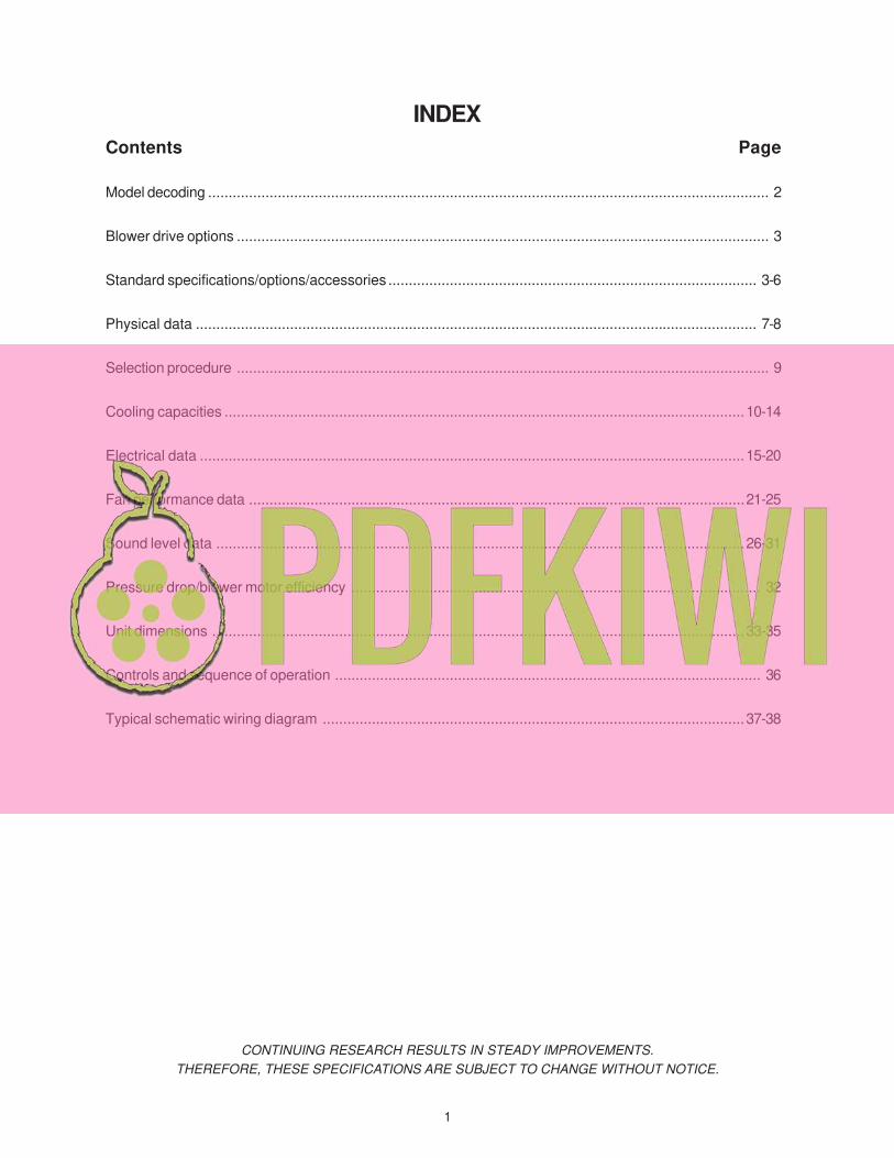
Contents Page
Model decoding ......................................................................................................................................... 2
Blower drive options .................................................................................................................................. 3
Standard specifications/options/accessories .......................................................................................... 3-6
Physical data ......................................................................................................................................... 7-8
Selection procedure .................................................................................................................................. 9
Cooling capacities ...............................................................................................................................10-14
Electrical data .....................................................................................................................................15-20
Fan performance data .........................................................................................................................21-25
Sound level data .................................................................................................................................26-31
Pressure drop/blower motor efficiency .................................................................................................... 32
Unit dimensions ..................................................................................................................................33-35
Controls and sequence of operation ........................................................................................................ 36
Typical schematic wiring diagram .......................................................................................................37-38
INDEX
2
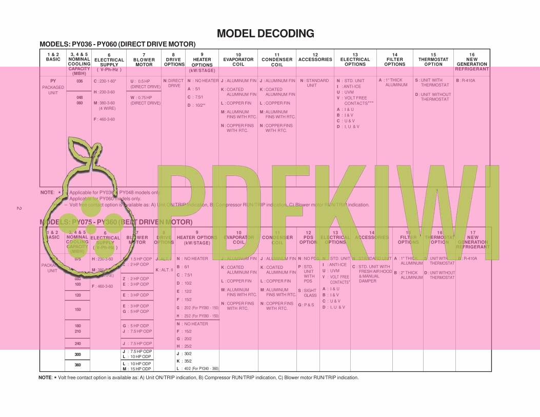
MODEL DECODING
NOTE: * Volt free contact option is available as: A) Unit ON/TRIP indication, B) Compressor RUN/TRIP indication, C) Blower motor RUN/TRIP indication.
NOTE: * – Applicable for PY036 & PY048 models only.
** – Applicable for PY060 models only.
*** – Volt free contact option is available as: A) Unit ON/TRIP indication, B) Compressor RUN/TRIP indication, C) Blower motor RUN/TRIP indication.
17NEW
GENERATIONREFRIGERANT
B : R-410A
16NEW
GENERATIONREFRIGERANT
B : R-410A
15THERMOSTAT
OPTION
S : UNIT WITHTHERMOSTAT
D : UNIT WITHOUTTHERMOSTAT
16THERMOSTAT
OPTION
S : UNIT WITHTHERMOSTAT
D : UNIT WITHOUTTHERMOSTAT
1 & 2BASIC
3, 4 & 5NOMINALCOOLINGCAPACITY
(MBH)
7BLOWERMOTOR
6ELECTRICAL
SUPPLY( V-Ph-Hz )
9HEATER OPTIONS
(kW/STAGE)
11CONDENSER
COIL
PY
PACKAGED
UNIT
075
090
100
120
150
180
210
240
300
360
R : 1.5 HP ODP
Z : 2 HP ODP
Z : 2 HP ODP
E : 3 HP ODP
E : 3 HP ODP
E : 3 HP ODP
G : 5 HP ODP
G : 5 HP ODP
J : 7.5 HP ODP
J : 7.5 HP ODP
J : 7.5 HP ODP
L : 10 HP ODP
L : 10 HP ODP
M : 15 HP ODP
N : NO HEATER
B : 6/1
C : 7.5/1
D : 10/2
E : 12/2
F : 15/2
G : 20/2 (For PY090 - 150)
H : 25/2 (For PY090 - 150)
J : ALUMINUM FIN
K : COATED
ALUMINUM FIN
L : COPPER FIN
M : ALUMINUM
FINS WITH RTC.
N : COPPER FINS
WITH RTC.
8DRIVE
OPTIONS
10EVAPORATOR
COIL
J : ALUMINUM FIN
K : COATED
ALUMINUM FIN
L : COPPER FIN
M : ALUMINUM
FINS WITH RTC.
N : COPPER FINS
WITH RTC.
MODELS: PY075 - PY360 (BELT DRIVEN MOTOR)
1 & 2BASIC
3, 4 & 5NOMINALCOOLINGCAPACITY
(MBH)
9HEATER
OPTIONS
(kW/STAGE)
11CONDENSER
COIL
PY
PACKAGED
UNIT
036
048
060
J : ALUMINUM FIN
K : COATED
ALUMINUM FIN
L : COPPER FIN
M : ALUMINUM
FINS WITH RTC.
N : COPPER FINS
WITH RTC.
8DRIVE
OPTIONS
N: DIRECT
DRIVE
10EVAPORATOR
COIL
12ACCESSORIES
N : STANDARDUNIT
MODELS: PY036 - PY060 (DIRECT DRIVE MOTOR)
N : NO HEATER
F : 15/2
G : 20/2
H : 25/2
J : 30/2
K : 35/2
L : 40/2 (For PY240 - 360)
H : 230-3-60
M : 380-3-60
(4 WIRE)
F : 460-3-60
J : ALT. I
K : ALT. II
13ELECTRICAL
OPTIONS
13ELECTRICAL
OPTIONS
14FILTER
OPTIONS
15FILTER
OPTIONS
12PDS
OPTION
N : NO PDS
P : STD.UNITWITHPDS
S : SIGHTGLASS
G : P & S
14ACCESSORIES
6ELECTRICAL
SUPPLY( V-Ph-Hz )
C : 230-1-60*
H : 230-3-60
M : 380-3-60
(4 WIRE)
F : 460-3-60
7BLOWERMOTOR
U : 0.5 HP
(DIRECT DRIVE)
W : 0.75 HP
(DIRECT DRIVE)
N : NO HEATER
A : 5/1
C : 7.5/1
D : 10/2**
J : ALUMINUM FIN
K : COATED
ALUMINUM FIN
L : COPPER FIN
M : ALUMINUM
FINS WITH RTC.
N : COPPER FINS
WITH RTC.
N : STD. UNIT
I : ANTI-ICE
U : UVM
V : VOLT FREE
CONTACTS*
A : I & U
B : I & V
C : U & V
D : I, U & V
A : 1" THICKALUMINUM
B : 2" THICKALUMINUM
N : STANDARD UNIT
C : STD. UNIT WITHFRESH AIR HOOD& MANUALDAMPER
N : STD. UNIT
I : ANTI-ICE
U : UVM
V : VOLT FREE
CONTACTS***
A : I & U
B : I & V
C : U & V
D : I, U & V
A : 1" THICKALUMINUM
3
STANDARD SPECIFICATIONSA. GeneralPackaged cooling or combination heating and cooling units suitable for mounting on the roof or ground. The packaged unit
consists of scroll compressors, cooling coil, condenser coil, control wiring and interconnecting piping - all factory as-
sembled and mounted on heavy gauge G-90 galvanized steel sheet press formed base, ready for field connection to utilities
and ducts. The packaged unit is of rigid construction with holes provided in the base rails for overhead rigging. The unit is
provided with an integral weather resistant control panel.
These units are rated, tested and certified in accordance with AHRI standards 210/240 and AHRI 340/360. Also, these units
are UL certified and meet ASHRAE 90.1 requirements.
B. Unit EnclosurePanels are of heavy gauge, G-90 galvanized steel sheet with removable access panels, completely weatherized for outdoor
installation and properly reinforced and brazed. Panels and access doors are provided for inspection and access for all
internal parts. Enclosures are provided with adequately reinforced points of support for setting the unit. Steel sheet panels
are zinc-coated and galvanized by the hot dip process of lock forming quality conforming to ASTM A 653 commercial
weight G-90, followed by baked on electrostatic polyester dry powder coat paint, on all external panels.
C. CompressorCompressors are hermetic scroll for all models. They are provided with all the standard controls and accessories necessary
for safe operation. These are equipped with internal motor protector, factory installed crank case heater and rubber vibration
isolator for quiet and efficient operation.
D. Air Cooled Condensing Section
1. The air-cooled condensing section is enclosed within the unit housing and consists of condenser coil, fan(s), electric
motor(s) and inherently protected compressor(s). Inner grooved copper tubes with wall thickness of 0.023 inches
(0.5842 mm), mechanically bonded to enhanced aluminum fins are standard for all condenser coils. Return bends have
0.022 inch thickness (0.56 mm). As an option, corrugated copper fins or enhanced coated aluminum fins maybe provided. Tube support sheets are galvanized steel, formed to provide structural strength.
2. Fans are propeller type, direct driven, upward discharge and provided with fan grille mounted on the casing.
3. Motors are totally enclosed air-over type with class 'F' insulation & IP55 ratings. Inherent thermal protection is automatic
reset type.
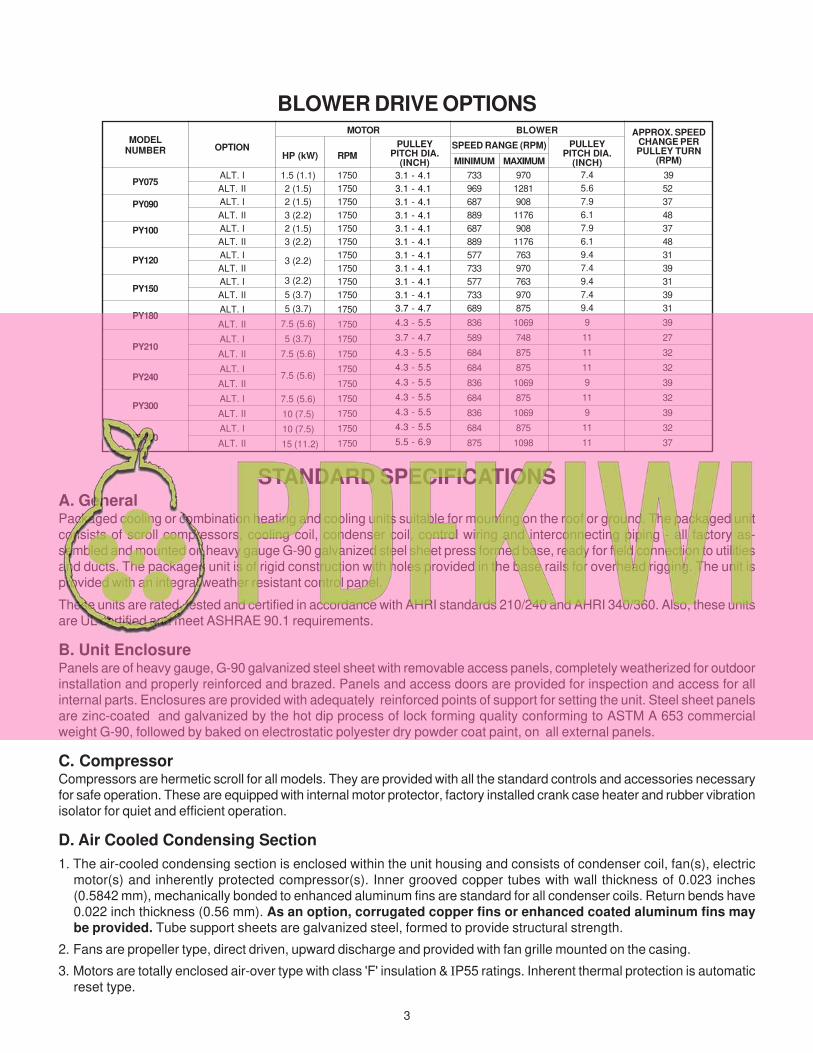
BLOWER DRIVE OPTIONS
MODELNUMBER OPTION
MOTOR BLOWER
SPEED RANGE (RPM)
MINIMUM MAXIMUMRPM
ALT. I
ALT. II
ALT. I
ALT. II
ALT. I
ALT. II
ALT. I
ALT. II
ALT. I
ALT. II
ALT. I
ALT. II
ALT. I
ALT. II
ALT. I
ALT. II
ALT. I
ALT. II
ALT. I
ALT. II
1750
1750
1750
1750
1750
1750
1750
1750
1750
1750
1750
1750
1750
1750
1750
1750
1750
1750
1750
1750
733
969
687
889
687
889
577
733
577
733
689
836
589
684
684
836
684
836
684
875
970
1281
908
1176
908
1176
763
970
763
970
875
1069
748
875
875
1069
875
1069
875
1098
39
52
37
48
37
48
31
39
31
39
31
39
27
32
32
39
32
39
32
37
1.5 (1.1)
2 (1.5)
2 (1.5)
3 (2.2)
2 (1.5)
3 (2.2)
3 (2.2)
3 (2.2)
5 (3.7)
5 (3.7)
7.5 (5.6)
5 (3.7)
7.5 (5.6)
7.5 (5.6)
7.5 (5.6)
10 (7.5)
10 (7.5)
15 (11.2)
APPROX. SPEEDCHANGE PERPULLEY TURN
(RPM)
PY075
PY090
PY100
PY120
PY150
PY180
PY210
PY240
PY300
PY360
HP (kW)
PULLEYPITCH DIA.
(INCH)
3.1 - 4.1
3.1 - 4.1
3.1 - 4.1
3.1 - 4.1
3.1 - 4.1
3.1 - 4.1
3.1 - 4.1
3.1 - 4.1
3.1 - 4.1
3.1 - 4.1
3.7 - 4.7
4.3 - 5.5
3.7 - 4.7
4.3 - 5.5
4.3 - 5.5
4.3 - 5.5
4.3 - 5.5
4.3 - 5.5
4.3 - 5.5
5.5 - 6.9
PULLEYPITCH DIA.
(INCH)
7.4
5.6
7.9
6.1
7.9
6.1
9.4
7.4
9.4
7.4
9.4
9
11
11
11
9
11
9
11
11
4
E. Evaporator Coil Section1. All cooling coils are of enhanced louvered fins and inner grooved copper tubes with wall thickness of 0.0175 inches
(0.445mm), mechanically bonded to aluminum fins . Return bend has 0.022 inch thickness (0.56 mm). As option,
enhanced coated aluminum fins or corrugated copper fins may be provided. Tube support sheets are galva-
nized steel, formed to provide structural strength.
2. Drain Pan: An insulated drain Pan made of G-90 galvanized steel is provided.
3. Insulation: Insulation is supplied in adequate density and thickness for all units to prevent condensation from forming
on the unit casing. Insulation meets the requirements of NFPA 90A and is protected against deterioration and erosion
from air currents.
F. Evaporator FanPY036 - PY060: Evaporator fan is of a centrifugal forward-curved blade design and sized to meet system airflow/pressure
using direct drive motors. These fans are statically / dynamically balanced in the fan housing during final assembly. Fan
motors have ball bearings and conform to NEMA MG standards. Motor starters are magnetic contactor, across-the-line
type.
PY075 - PY360: Evaporator fan is of centrifugal forward-curved blade design capable of handling total required CFM and
static pressure in the low and the medium ranges. Casings are made of galvanized steel. Blower motors are of the open drip
proof type (totally enclosed types are optional) and conform to NEMA MG standards. Fan drive is through adjustable
pitch pulleys and belt driven. Blower motor is mounted on adjustable base and secured by locking device. Fan wheels
shafts and bearing are selected to operate at 25% below first critical speed. Pillow block bearings are selected for at
200,000 hours average life at design operating conditions. Shaft is turned, ground and polished from solid steel. Fans and
pulleys are keyed to shaft and designed for continuous operation at maximum motor horse power and fan speed. All rotating
components and assemblies are statically and dynamically balanced and every unit is vibration tested before shipment
from the factory.
G. Microprocessor ControllerThese Packaged units are provided with a microprocessor control board incorporating the following features:
• BALANCE LOADING OF COMPRESSORS: The unit’s electronic control automatically operates lead/lag sequence
of compressors. This is to load the compressors evenly over long periods of operation. If required however, compres-
sor-1 can also be set to always lead. In this case, compressor-1 always starts first and stops last. (Selectable through
dip switch setting on control board).
• PUMP DOWN FUNCTION: In units equipped with pump down system, the controller provides the time delay between
solenoid’s opening and compressor starting to equalize the pressure in the system necessary for compressor to start-
up. (Selectable through dip switch setting on control board).
• COMPRESSOR ANTI-RECYCLING PROTECTION: The controller has a built-in 3 minutes minimum off timer for
compressor. This is for compressor protection in case of accidental manual re-set or immediate re-cycling of thermo-
stat due to load demand.
• COMPRESSOR LOCK-OUT FUNCTION: If any of the unit’s safety control trips due to abnormal conditions, the
electronic controls locks out the compressor after a pre-determined timing preventing a re-start unless attended by a
qualified service technician. The unit can be re-started through thermostat re-set after ensuring safe system condi-
tions.
• FAULT DIAGNOSTICS: In case of system fault, LED’s on the board emits a flashing signal indicating where the fault
is. This is to guide the service technician in identifying the fault.
• DIGITAL I/O’s: The unit’s control board is compatible to operate with a DDC controller or any standard 24V a.c.
thermostat commercially available.
• SEQUENTIAL CONTROL: With input signals from the thermostat, the motors in the equipment is started in sequen-
tial order: supply fan – condenser fan – compressor; at a pre-determined timings.
5
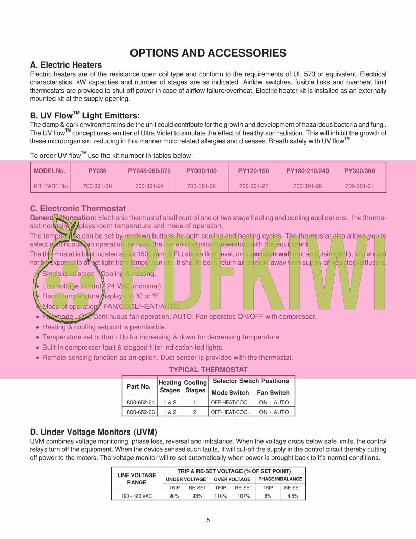
MODEL No. PY036 PY048/060/075 PY090/100 PY120/150 PY180/210/240 PY300/360
KIT PART No. 700-391-30 700-391-24 700-391-26 700-391-27 700-391-28 700-391-31
OPTIONS AND ACCESSORIESA. Electric HeatersElectric heaters are of the resistance open coil type and conform to the requirements of UL 573 or equivalent. Electrical
characteristics, kW capacities and number of stages are as indicated. Airflow switches, fusible links and overheat limit
thermostats are provided to shut-off power in case of airflow failure/overheat. Electric heater kit is installed as an externally
mounted kit at the supply opening.
B. UV FlowTM
Light Emitters:The damp & dark environment inside the unit could contribute for the growth and development of hazardous bacteria and fungi.
The UV flowTM
concept uses emitter of Ultra Violet to simulate the effect of healthy sun radiation. This will inhibit the growth of
these microorganism reducing in this manner mold related allergies and diseases. Breath safely with UV flowTM
.
To order UV flowTM
use the kit number in tables below:
C. Electronic ThermostatGeneral information: Electronic thermostat shall control one or two stage heating and cooling applications. The thermo-
stat normally displays room temperature and mode of operation.
The temperature can be set by up/down buttons for both cooling and heating cycles. The thermostat also allows you to
select continuous fan operation, or have the fan on intermittent operation with the equipment.
The thermostat is best located about 1500 mm (5 Ft.) above floor level, on a partition wall (not an outside wall), and should
not be exposed to direct light from lamps, sun etc. It should be in return air stream, away from supply air registers/diffusers.
• Single/dual stage - Cooling & heating.
• Low voltage control - 24 VAC (nominal).
• Room temperature display - in 0C or 0F.
• Mode of operation - FAN/COOL/HEAT/AUTO.
• Fan mode - ON: Continuous fan operation; AUTO: Fan operates ON/OFF with compressor.
• Heating & cooling setpoint is permissible.
• Temperature set button - Up for increasing & down for decreasing temperature.
• Built-in compressor fault & clogged filter indication led lights.
• Remote sensing function as an option. Duct sensor is provided with the thermostat.
D. Under Voltage Monitors (UVM)UVM combines voltage monitoring, phase loss, reversal and imbalance. When the voltage drops below safe limits, the control
relays turn off the equipment. When the device sensed such faults, it will cut-off the supply in the control circuit thereby cutting
off power to the motors. The voltage monitor will re-set automatically when power is brought back to it’s normal conditions.
LINE VOLTAGE
RANGEUNDER VOLTAGE
TRIP
90%190 - 480 VAC
TRIP & RE-SET VOLTAGE (% OF SET POINT)
OVER VOLTAGE PHASE IMBALANCE
RE-SET
93%
TRIP
110%
RE-SET
107%
TRIP
6%
RE-SET
4.5%
800-652-64 1 & 2 1 OFF-HEAT/COOL ON - AUTO
800-652-66 1 & 2 2 OFF-HEAT/COOL ON - AUTO
TYPICAL THERMOSTAT
Part No.Heating
Stages
Cooling
Stages
Selector Switch Positions
Mode Switch Fan Switch
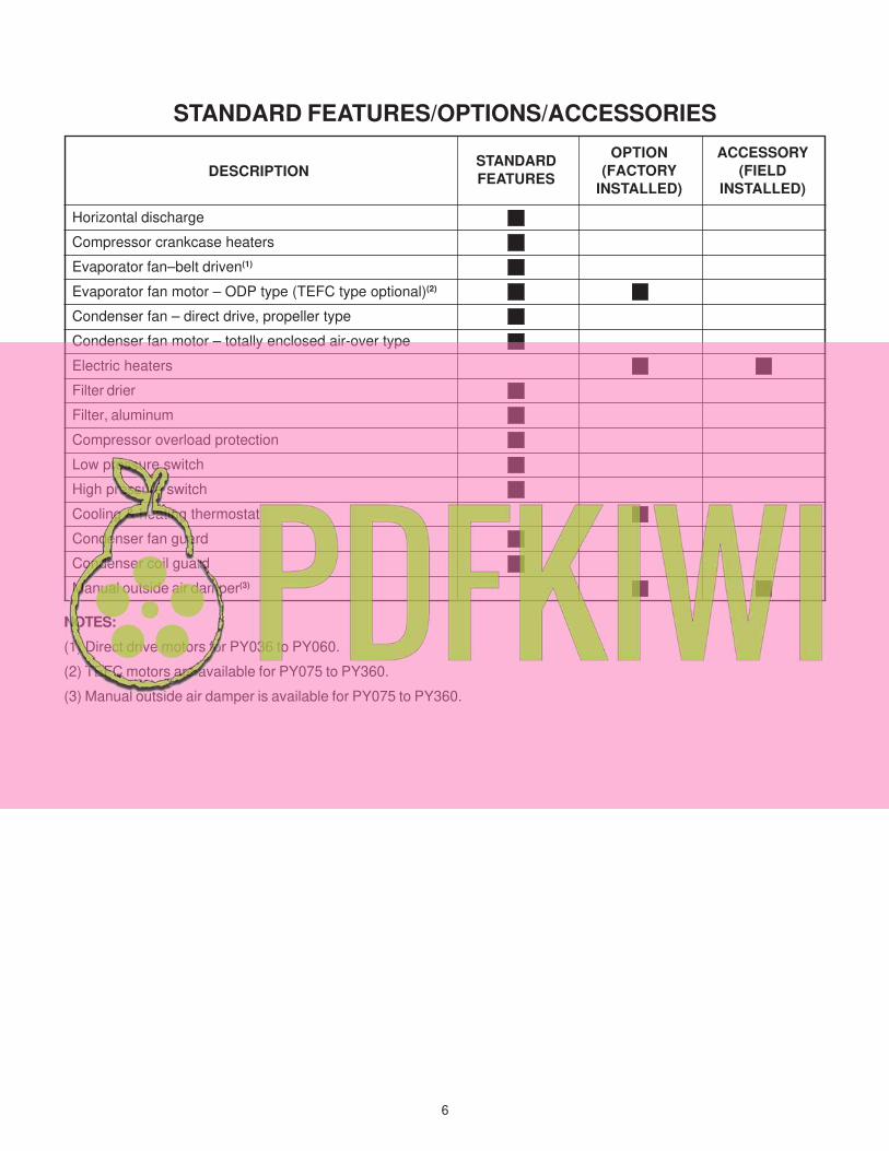
STANDARD FEATURES/OPTIONS/ACCESSORIES
NOTES:
(1) Direct drive motors for PY036 to PY060.
(2) TEFC motors are available for PY075 to PY360.
(3) Manual outside air damper is available for PY075 to PY360.
Horizontal discharge
Compressor crankcase heaters
Evaporator fan–belt driven(1)
Evaporator fan motor – ODP type (TEFC type optional)(2)
Condenser fan – direct drive, propeller type
Condenser fan motor – totally enclosed air-over type
Electric heaters
Filter drier
Filter, aluminum
Compressor overload protection
Low pressure switch
High pressure switch
Cooling & heating thermostat
Condenser fan guard
Condenser coil guard
Manual outside air damper(3)
DESCRIPTIONSTANDARD
FEATURES
OPTION
(FACTORY
INSTALLED)
ACCESSORY
(FIELD
INSTALLED)
6
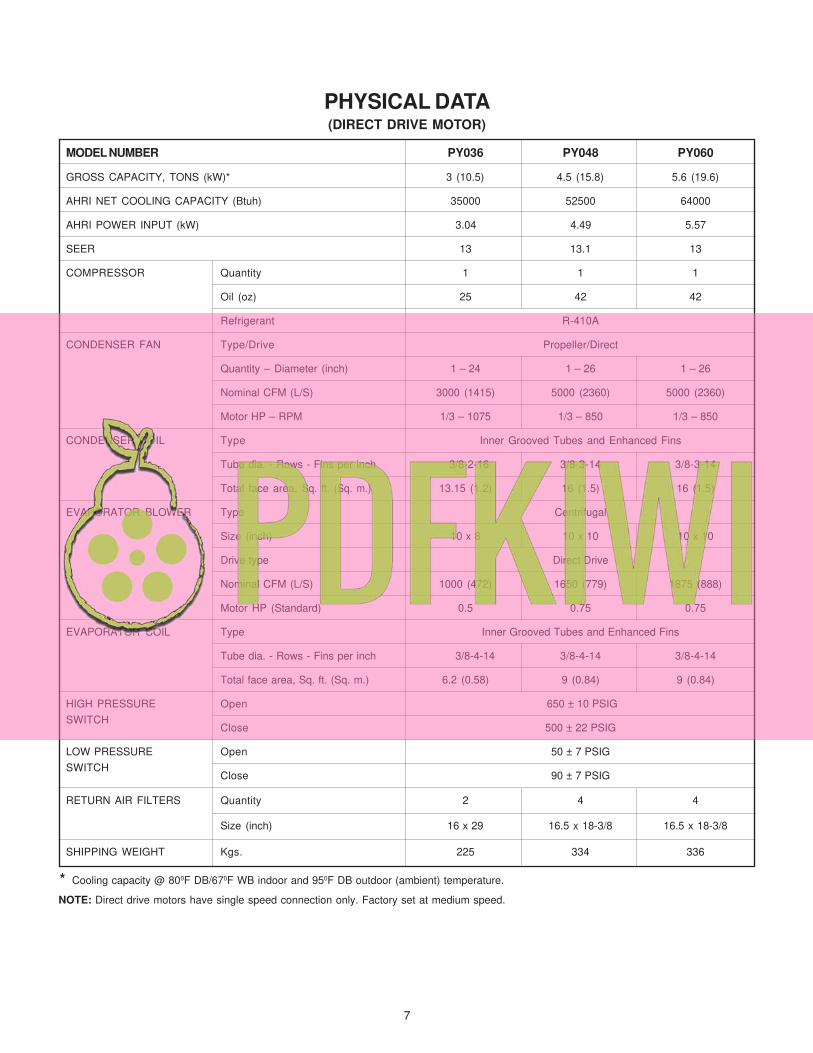
MODEL NUMBER PY036 PY048 PY060
GROSS CAPACITY, TONS (kW)* 3 (10.5) 4.5 (15.8) 5.6 (19.6)
AHRI NET COOLING CAPACITY (Btuh) 35000 52500 64000
AHRI POWER INPUT (kW) 3.04 4.49 5.57
SEER 13 13.1 13
COMPRESSOR Quantity 1 1 1
Oil (oz) 25 42 42
Refrigerant R-410A
CONDENSER FAN Type/Drive Propeller/Direct
Quantity – Diameter (inch) 1 – 24 1 – 26 1 – 26
Nominal CFM (L/S) 3000 (1415) 5000 (2360) 5000 (2360)
Motor HP – RPM 1/3 – 1075 1/3 – 850 1/3 – 850
CONDENSER COIL Type Inner Grooved Tubes and Enhanced Fins
Tube dia. - Rows - Fins per inch 3/8-2-16 3/8-3-14 3/8-3-14
Total face area, Sq. ft. (Sq. m.) 13.15 (1.2) 16 (1.5) 16 (1.5)
EVAPORATOR BLOWER Type Centrifugal
Size (inch) 10 x 8 10 x 10 10 x 10
Drive type Direct Drive
Nominal CFM (L/S) 1000 (472) 1650 (779) 1875 (888)
Motor HP (Standard) 0.5 0.75 0.75
EVAPORATOR COIL Type Inner Grooved Tubes and Enhanced Fins
Tube dia. - Rows - Fins per inch 3/8-4-14 3/8-4-14 3/8-4-14
Total face area, Sq. ft. (Sq. m.) 6.2 (0.58) 9 (0.84) 9 (0.84)
HIGH PRESSURE Open 650 ± 10 PSIG
SWITCHClose 500 ± 22 PSIG
LOW PRESSURE Open 50 ± 7 PSIG
SWITCHClose 90 ± 7 PSIG
RETURN AIR FILTERS Quantity 2 4 4
Size (inch) 16 x 29 16.5 x 18-3/8 16.5 x 18-3/8
SHIPPING WEIGHT Kgs. 225 334 336
PHYSICAL DATA(DIRECT DRIVE MOTOR)
7
NOTE: Direct drive motors have single speed connection only. Factory set at medium speed.
* Cooling capacity @ 800F DB/670F WB indoor and 950F DB outdoor (ambient) temperature.
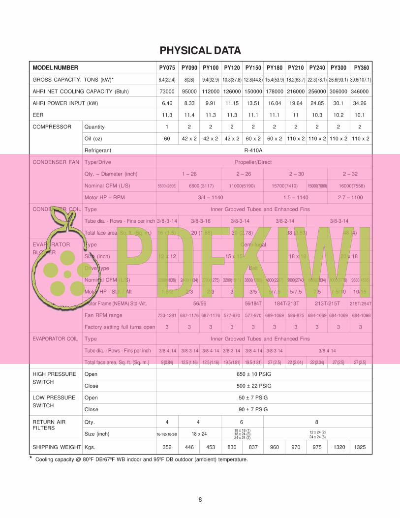
MODEL NUMBER PY075 PY090 PY100 PY120 PY150 PY180 PY210 PY240 PY300 PY360
GROSS CAPACITY, TONS (kW)* 6.4(22.4) 8(28) 9.4(32.9) 10.8(37.8) 12.8(44.8) 15.4(53.9) 18.2(63.7) 22.3(78.1) 26.6(93.1) 30.6(107.1)
AHRI NET COOLING CAPACITY (Btuh) 73000 95000 112000 126000 150000 178000 216000 256000 306000 346000
AHRI POWER INPUT (kW) 6.46 8.33 9.91 11.15 13.51 16.04 19.64 24.85 30.1 34.26
EER 11.3 11.4 11.3 11.3 11.1 11.1 11 10.3 10.2 10.1
COMPRESSOR Quantity 1 2 2 2 2 2 2 2 2 2
Oil (oz) 60 42 x 2 42 x 2 42 x 2 60 x 2 60 x 2 110 x 2 110 x 2 110 x 2 110 x 2
Refrigerant R-410A
CONDENSER FAN Type/Drive Propeller/Direct
Qty. – Diameter (inch) 1 – 26 2 – 26 2 – 30 2 – 32
Nominal CFM (L/S) 5500 (2606) 6600 (3117) 11000(5190) 15700(7410) 15000(7080) 16000(7558)
Motor HP – RPM 3/4 – 1140 1.5 – 1140 2.7 – 1100
CONDENSER COIL Type Inner Grooved Tubes and Enhanced Fins
Tube dia. - Rows - Fins per inch 3/8-3-14 3/8-3-16 3/8-3-14 3/8-2-14 3/8-3-14
Total face area, Sq. ft. (Sq. m.) 16 (1.5) 20 (1.86) 30 (2.78) 38 (3.53) 48 (4)
EVAPORATOR Type Centrifugal
BLOWERSize (inch) 12 x 12 15 x 15 18 x 18 20 x 18
Drive type Belt
Nominal CFM (L/S) 2200(1038) 2400(1134) 2700(1275) 3200(1511) 3800(1795) 4800(2267) 5800(2740) 6000(2834) 8000(3779) 9600(4535)
Motor HP - Std. / Alt 1.5/2 2/3 2/3 3 3/5 5/7.5 5/7.5 7.5 7.5/10 10/15
Motor Frame (NEMA) Std./Alt. 56/56 56/184T 184T/213T 213T/215T 215T/254T
Fan RPM range 733-1281 687-1176 687-1176 577-970 577-970 689-1069 589-875 684-1069 684-1069 684-1098
Factory setting full turns open 3 3 3 3 3 3 3 3 3 3
EVAPORATOR COIL Type Inner Grooved Tubes and Enhanced Fins
Tube dia. - Rows - Fins per inch 3/8-4-14 3/8-3-14 3/8-4-14 3/8-3-14 3/8-4-14 3/8-3-14 3/8-4-14
Total face area, Sq. ft. (Sq. m.) 9 (0.84) 12.5 (1.16) 12.5 (1.16) 19.5 (1.81) 19.5 (1.81) 27 (2.5) 22 (2.04) 22 (2.04) 27 (2.5) 27 (2.5)
HIGH PRESSURE Open 650 ± 10 PSIG
SWITCHClose 500 ± 22 PSIG
LOW PRESSURE Open 50 ± 7 PSIG
SWITCHClose 90 ± 7 PSIG
RETURN AIR Qty. 4 4 6 8FILTERS
Size (inch) 16-1/2x18-3/8 18 x 24
SHIPPING WEIGHT Kgs. 352 446 453 830 837 960 970 975 1320 1325
PHYSICAL DATA
18 x 18 (1)18 x 24 (3)24 x 24 (2)
12 x 24 (2)
24 x 24 (6)
8
* Cooling capacity @ 800F DB/670F WB indoor and 950F DB outdoor (ambient) temperature.
![Spin Crossover in a 3,5-Bis(2-pyridyl)-1,2,4-triazolate-Bridged Dinuclear Iron(II) Complex [{Fe(NCBH 3 )(py)} 2 (μ-L 1 ) 2 ] - Powder versus Single Crystal Study](https://img.dokumen.tips/doc/110x75/6358b9f0a90bb46f520885c3/spin-crossover-in-a-35-bis2-pyridyl-124-triazolate-bridged-dinuclear-ironii-1701180035.jpg)


![Aliphatic neodymium alkoxides with sterically demanding ligands. Preparation and x-ray crystal structures of Nd2(OCH-iso-Pr2)6L2 (L = THF, py) and [Nd2(OCH-iso-Pr2)6(.mu.-DME)].infin](https://img.dokumen.tips/doc/110x75/6360c74a4b9aa63a9e00731f/aliphatic-neodymium-alkoxides-with-sterically-demanding-ligands-preparation-and.jpg)


![K L]^\\KM^ /^RSMKV ]^YMU^KUSXQ$ K ^YYV PY\\ ]^\\OXQ^ROXSXQ Y\\QKXS]K^SYXKV](https://img.dokumen.tips/doc/110x75/6343d98430acffa12000648d/k-lkm-rsmkv-ymukusxq-k-yyv-py-oxqroxsxq-yqkxsksyxkv.jpg)
![Feugere Lhermet Py 2005 [Br longostaletes]](https://img.dokumen.tips/doc/110x75/6352594c2aff637f8b01bcd7/feugere-lhermet-py-2005-br-longostaletes.jpg)
![Synthesis and Characterization of a Linear [Mn3(O2CMe)4(py)8]2+ Complex](https://img.dokumen.tips/doc/110x75/633599b9b5f91cb18a0b79d6/synthesis-and-characterization-of-a-linear-mn3o2cme4py82-complex.jpg)


