Embed Size (px)
Citation preview

ИБП MGE Pulsar EXtreme C - Pulsar EXtreme CLA 1500C - Installation and User Manual
Постоянная ссылка на страницу: https://eaton-power.ru/catalog/mge-pulsar-extreme-c/
51031998EN/AA - Page 1
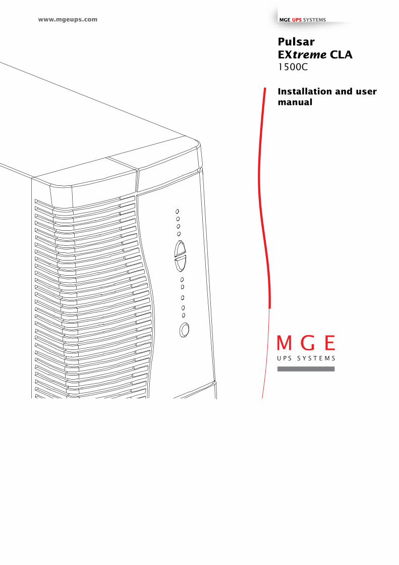
Installation and usermanual
PulsarEXtreme CLA1500C
www.mgeups.com MGE UPS SYSTEMS

Page 2 - 51031998EN/AA
Introduction
Thank you for selecting an MGE UPS SYSTEMS product to protect your electrical equipment.
The Pulsar EXtreme range has been designed with the utmost care. We recommend that you take the time to read thismanual to take full advantage of the many features of your UPS.
MGE UPS SYSTEMS pays great attention to the environmental impact of its products. Measures that have made PulsarEXtreme a reference in environmental protection include:◗ the eco-design approach used in product development;◗ recycling of Pulsar EXtreme at the end of its service life.
To discover the entire range of MGE UPS SYSTEMS products and the options available for the Pulsar EXtreme range, weinvite you to visit our web site at www.mgeups.com or contact your MGE UPS SYSTEMS representative.
51031998EN/AA - Page 3
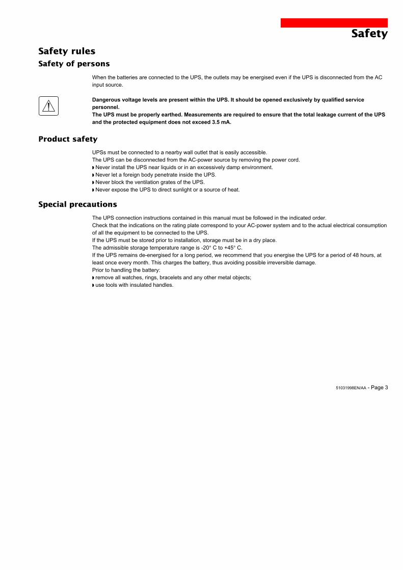
Safety
Safety of persons
Safety rules
When the batteries are connected to the UPS, the outlets may be energised even if the UPS is disconnected from the ACinput source.
Dangerous voltage levels are present within the UPS. It should be opened exclusively by qualified servicepersonnel.The UPS must be properly earthed. Measurements are required to ensure that the total leakage current of the UPSand the protected equipment does not exceed 3.5 mA.
Product safety
UPSs must be connected to a nearby wall outlet that is easily accessible.The UPS can be disconnected from the AC-power source by removing the power cord.◗ Never install the UPS near liquids or in an excessively damp environment.◗ Never let a foreign body penetrate inside the UPS.◗ Never block the ventilation grates of the UPS.◗ Never expose the UPS to direct sunlight or a source of heat.
Special precautions
The UPS connection instructions contained in this manual must be followed in the indicated order.Check that the indications on the rating plate correspond to your AC-power system and to the actual electrical consumptionof all the equipment to be connected to the UPS.If the UPS must be stored prior to installation, storage must be in a dry place.The admissible storage temperature range is -20° C to +45° C.If the UPS remains de-energised for a long period, we recommend that you energise the UPS for a period of 48 hours, atleast once every month. This charges the battery, thus avoiding possible irreversible damage.Prior to handling the battery:◗ remove all watches, rings, bracelets and any other metal objects;◗ use tools with insulated handles.
Page 4 - 51031998EN/AA
Foreword
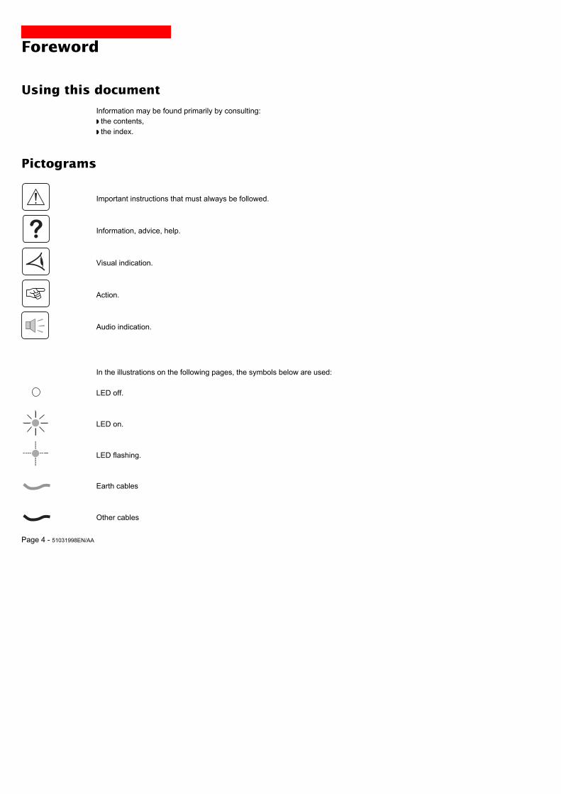
Using this document
Important instructions that must always be followed.
Information, advice, help.
Visual indication.
Action.
Audio indication.
In the illustrations on the following pages, the symbols below are used:
LED off.
LED on.
LED flashing.
Information may be found primarily by consulting:◗ the contents,◗ the index.
Pictograms
Earth cables
Other cables
51031998EN/AA - Page 5
Contents
1. Presentation1.1 Pulsar EXtreme range ................................................................................................................. 7
Tower model .................................................................................................................................... 7
Rack model ..................................................................................................................................... 7
1.2 Back ............................................................................................................................................. 8
Tower model .................................................................................................................................... 8
Rack model ..................................................................................................................................... 9
1.3 Control panel ............................................................................................................................... 10
2. Installation2.1 Unpacking and checks ............................................................................................................... 11
Tower model .................................................................................................................................. 11
Rack model ................................................................................................................................... 12
2.2 Installation of the rack version .................................................................................................. 13
2.3 Connection to the RS 232 or USB communications port (optional) ........................................ 14
2.4 Installation of the communications-card option ...................................................................... 15
Tower model .................................................................................................................................. 15
Rack model ................................................................................................................................... 15
2.5 Battery connection ..................................................................................................................... 16
Warning ......................................................................................................................................... 16
Interconnecting the batteries to obtain the required configuration ................................................ 16
Connecting the battery configuration to the UPS .......................................................................... 16
2.6 UPS connection and settings .................................................................................................... 19
Tower model .................................................................................................................................. 19
Rack model ................................................................................................................................... 19
3. Operation3.1 Start-up ........................................................................................................................................ 20
3.2 Bargraph indications .................................................................................................................. 20
3.3 Operation on battery power (following failure of AC input power) ............................................. 21
Transfer to battery power .............................................................................................................. 21
Threshold for the low-battery warning ........................................................................................... 21
End of backup time ....................................................................................................................... 21
Page 6 - 51031998EN/AA
Contents
3.4 Personalisation (optional) ........................................................................................................... 22
Function ........................................................................................................................................ 22
"ON / OFF conditions" tab ............................................................................................................. 22
"Battery" tab .................................................................................................................................. 22
"Output" tab ................................................................................................................................... 23
"Bypass" tab .................................................................................................................................. 23
3.5 Shutdown..................................................................................................................................... 23
4. Maintenance4.1 Troubleshooting .......................................................................................................................... 24
5. Environment ............................................................................................................. 26
6. Appendices6.1 Technical characteristics ........................................................................................................... 27
Simplified diagram ........................................................................................................................ 27
Operating conditions ..................................................................................................................... 27
6.2 Glossary ....................................................................................................................................... 28
6.3 Index............................................................................................................................................. 29
51031998EN/AA - Page 7
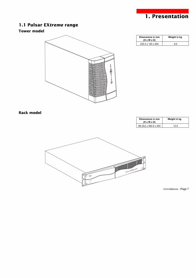
1. Presentation
1.1 Pulsar EXtreme rangeTower model
Rack model
EX1000 Rack
Dimensions in mm(H x W x D)
235.5 x 145 x 505
Weight in kg
9.5
Dimensions in mm(H x W x D)
88 (2U) x 482.6 x 493
Weight in kg
12.5
Page 8 - 51031998EN/AA
RS232 USB
1
2
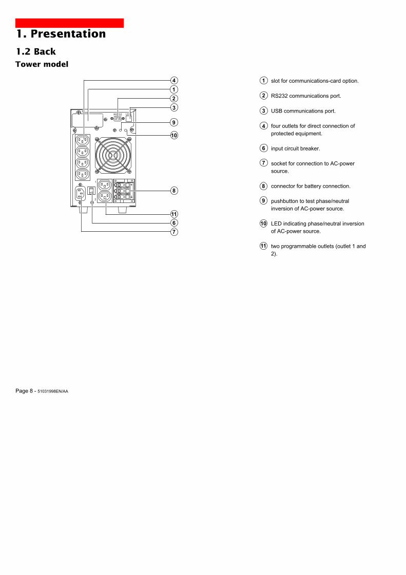
1. Presentation
1.2 Back
slot for communications-card option.
RS232 communications port.
USB communications port.
four outlets for direct connection ofprotected equipment.
input circuit breaker.
socket for connection to AC-powersource.
connector for battery connection.
pushbutton to test phase/neutralinversion of AC-power source.
LED indicating phase/neutral inversionof AC-power source.
two programmable outlets (outlet 1 and2).
1
2
3
4
6
7
8
10
9
11
Tower model
7
8
11
1
2
3
9
10
4
6
51031998EN/AA - Page 9
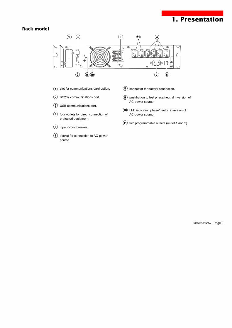
1. PresentationRack model
slot for communications-card option.
RS232 communications port.
USB communications port.
four outlets for direct connection ofprotected equipment.
input circuit breaker.
socket for connection to AC-powersource.
1
2
3
4
6
7
8
10
9
11
connector for battery connection.
pushbutton to test phase/neutral inversion ofAC-power source.
LED indicating phase/neutral inversion ofAC-power source.
two programmable outlets (outlet 1 and 2).
12
RS232
USB
83 411
6
1
792 10
Page 10 - 51031998EN/AA
100%
80%
50%
20%
test
%
%
1
2
bypass
1.3 Control panel
Alarms
UPS overload.
electronics fault.
battery fault.
hold down to display percent load:
- lamp test or buzzer OFF.- forced transfer to bypass and backby pressing button 3 times in less than5 seconds.
status of programmable outlet 1:
operation on bypass(no backup power available).
operation in ON-LINE mode(backup power available).
ON / OFF.
% battery ␣ ␣ ␣ ␣ ␣ remaining
100 %
80 %
50 %
20 %
% load
100 %
80 %
50 %
20 %
status of programmable outlet 2:
operation on battery power.
13
14
15
16
17
20
21
22
23
12
18
19
1. Presentation
Supplied with power
Status change inprogress.
51031998EN/AA - Page 11
2. Installation
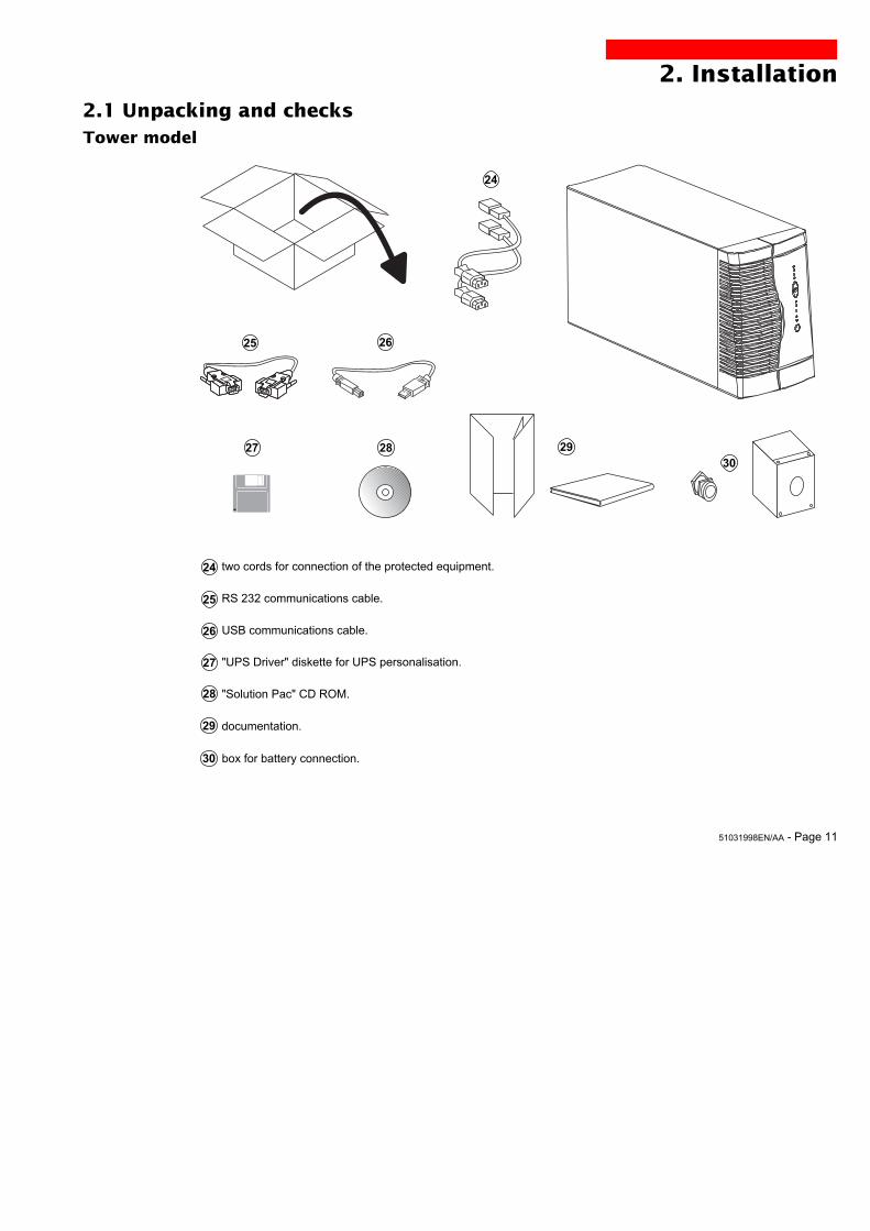
2.1 Unpacking and checks
two cords for connection of the protected equipment.
RS 232 communications cable.
USB communications cable.
"UPS Driver" diskette for UPS personalisation.
"Solution Pac" CD ROM.
documentation.
␣ box for battery connection.
27 28 29
25
24
25
26
27
28
Tower model
26
24
29
30
30
Page 12 - 51031998EN/AA
2. Installation
27 28
31
24
Rack model
24
29
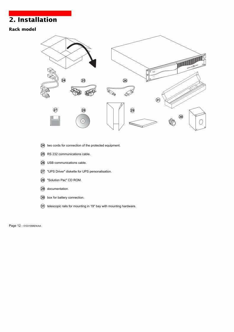
␣ 24 two cords for connection of the protected equipment.
␣ 25 RS 232 communications cable.
␣ 26 USB communications cable.
␣ 27 "UPS Driver" diskette for UPS personalisation.
␣ 28 "Solution Pac" CD ROM.
␣ 29 documentation.
␣ 30 box for battery connection.
␣ 31 telescopic rails for mounting in 19" bay with mounting hardware.
25 26
EX1000 Rack
30
51031998EN/AA - Page 13
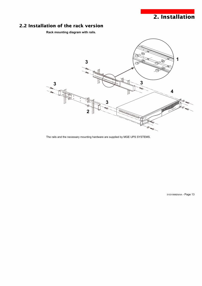
2.2 Installation of the rack version
2. Installation
Rack mounting diagram with rails.
The rails and the necessary mounting hardware are supplied by MGE UPS SYSTEMS.
1
2
3
3 3
3
4
EX1000 Rack

Page 14 - 51031998EN/AA
2. Installation
2.3 Connection to the RS 232 or USB communications port (optional)
1 - Connect the RS 232 25 or USB 26communications cable to the serial port orthe USB port on the computer.
2 - Connect the other end of thecommunications cable 25 or 26 to the RS232 2 or USB 3 communications porton the UPS.
The UPS can now communicate with allMGE UPS SYSTEMS supervision, set-up orsafety software.
25
26
The RS 232 and USB communications ports cannot operate simultaneously.
RS232
USB
3
2
RS232 USB
32

51031998EN/AA - Page 15
RS232 USB
1
2
2.4 Installation of the communications-card option
It is not necessary to shut down the UPS toinstall the communications card:
1 - Remove the slot 1 cover secured bytwo screws.
2 - Insert the card in the slot.
3 - Secure the card with the two screws.
Tower model
Rack model
Slot for the communications-cardoption.
1
Slot for the communications-card option.
1
2. Installation
12
RS232
USB
Page 16 - 51031998EN/AA
2. Installation
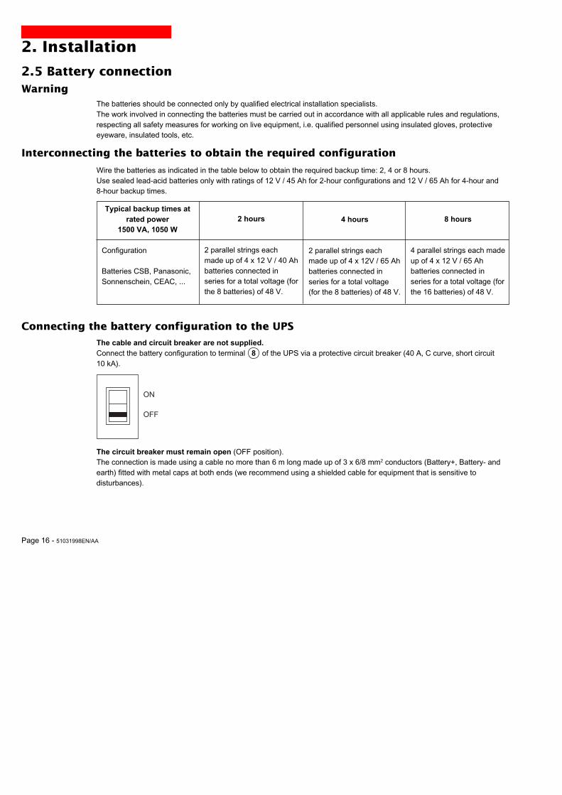
2.5 Battery connectionWarning
The batteries should be connected only by qualified electrical installation specialists.The work involved in connecting the batteries must be carried out in accordance with all applicable rules and regulations,respecting all safety measures for working on live equipment, i.e. qualified personnel using insulated gloves, protectiveeyeware, insulated tools, etc.
Interconnecting the batteries to obtain the required configuration
Connecting the battery configuration to the UPS
Wire the batteries as indicated in the table below to obtain the required backup time: 2, 4 or 8 hours.Use sealed lead-acid batteries only with ratings of 12 V / 45 Ah for 2-hour configurations and 12 V / 65 Ah for 4-hour and8-hour backup times.
Typical backup times atrated power
1500 VA, 1050 W
Configuration
Batteries CSB, Panasonic,Sonnenschein, CEAC, ...
2 hours
2 parallel strings eachmade up of 4 x 12 V / 40 Ahbatteries connected inseries for a total voltage (forthe 8 batteries) of 48␣ V.
4 hours
2 parallel strings eachmade up of 4 x 12V / 65 Ahbatteries connected inseries for a total voltage(for the 8 batteries) of 48␣ V.
8 hours
4 parallel strings each madeup of 4 x 12 V / 65 Ahbatteries connected inseries for a total voltage (forthe 16 batteries) of 48 V.
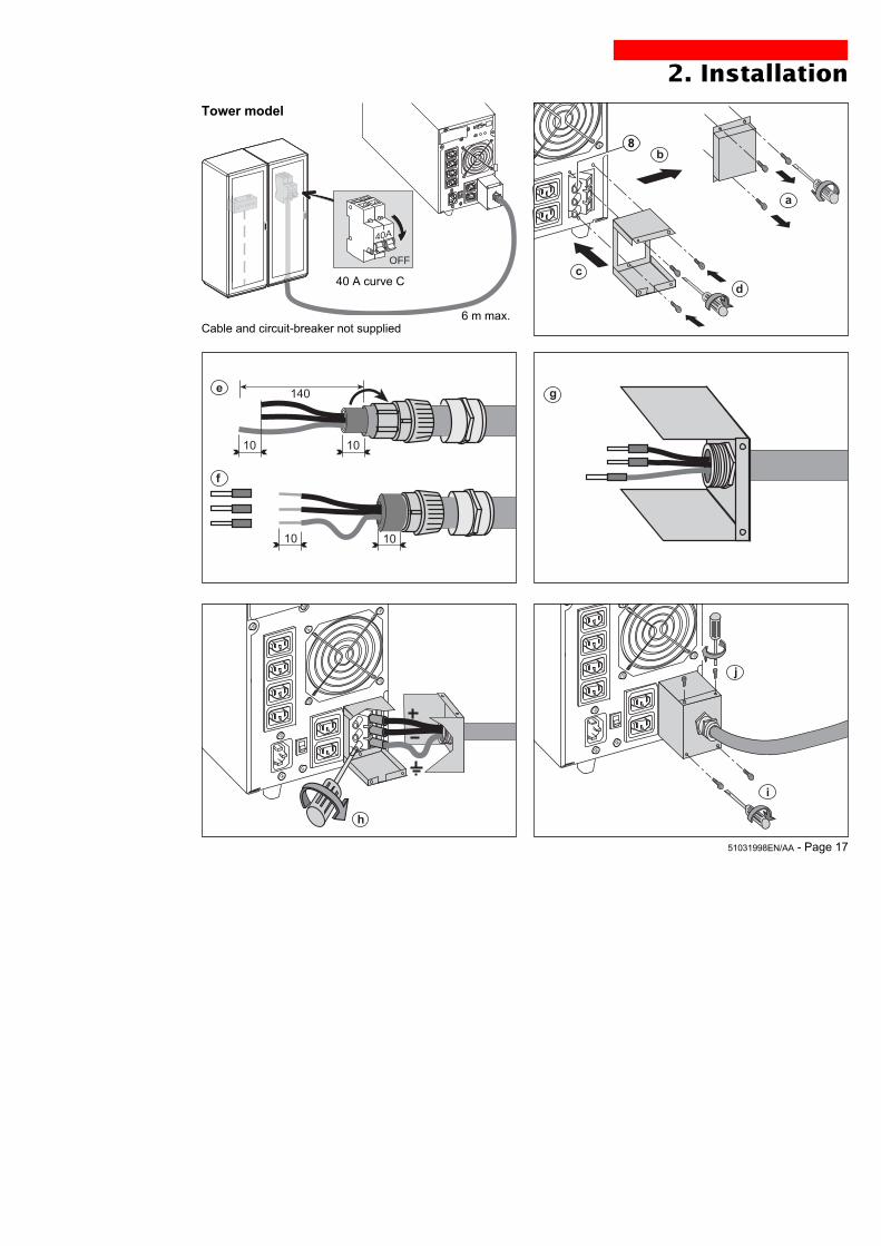
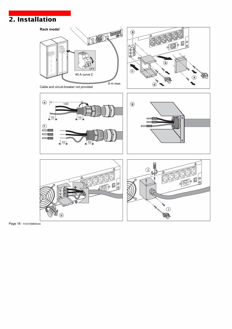
The cable and circuit breaker are not supplied.Connect the battery configuration to terminal 8 of the UPS via a protective circuit breaker (40 A, C curve, short circuit10␣ kA).
The circuit breaker must remain open (OFF position).The connection is made using a cable no more than 6 m long made up of 3 x 6/8 mm2 conductors (Battery+, Battery- andearth) fitted with metal caps at both ends (we recommend using a shielded cable for equipment that is sensitive todisturbances).
ON
OFF
51031998EN/AA - Page 17
2. Installation
i
j
h
b
a
d
c
10
140e
10
10 10
f
g
8
Tower model
40A
12V-65Ah
40A
OFF
Cable and circuit-breaker not supplied6 m max.
40 A curve C
Page 18 - 51031998EN/AA
2. Installation
12
i
j
12
h
Rack model
12
c
d
b
a
8
10
140e
10
10 10
f
g
12
RS232
USB
40A
12V-65Ah
40A
OFF
Cable and circuit-breaker not provided6 m max.
40 A curve C
51031998EN/AA - Page 19
2. Installation
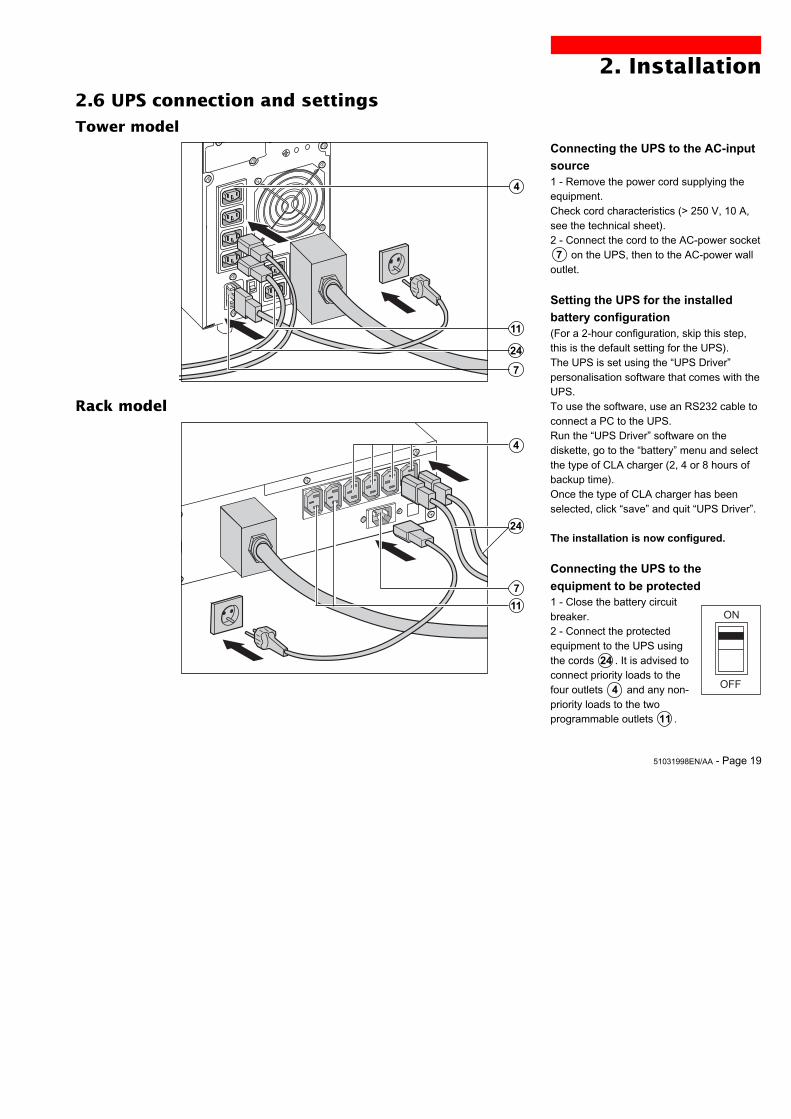
Connecting the UPS to the AC-input
source1 - Remove the power cord supplying theequipment.Check cord characteristics (> 250 V, 10 A,see the technical sheet).2 - Connect the cord to the AC-power socket␣ ␣ 7 on the UPS, then to the AC-power walloutlet.
Setting the UPS for the installed
battery configuration(For a 2-hour configuration, skip this step,this is the default setting for the UPS).The UPS is set using the “UPS Driver”personalisation software that comes with theUPS.To use the software, use an RS232 cable toconnect a PC to the UPS.Run the “UPS Driver” software on thediskette, go to the “battery” menu and selectthe type of CLA charger (2, 4 or 8 hours ofbackup time).Once the type of CLA charger has beenselected, click “save” and quit “UPS Driver”.
The installation is now configured.
Connecting the UPS to the
equipment to be protected1 - Close the battery circuitbreaker.2 - Connect the protectedequipment to the UPS usingthe cords 24 . It is advised toconnect priority loads to thefour outlets ␣ ␣ 4 and any non-priority loads to the twoprogrammable outlets 11 .
Tower model
Rack model
2.6 UPS connection and settings
12
24
11
4
7
7
4
11
24
ON
OFF
Page 20 - 51031998EN/AA
3. Operation
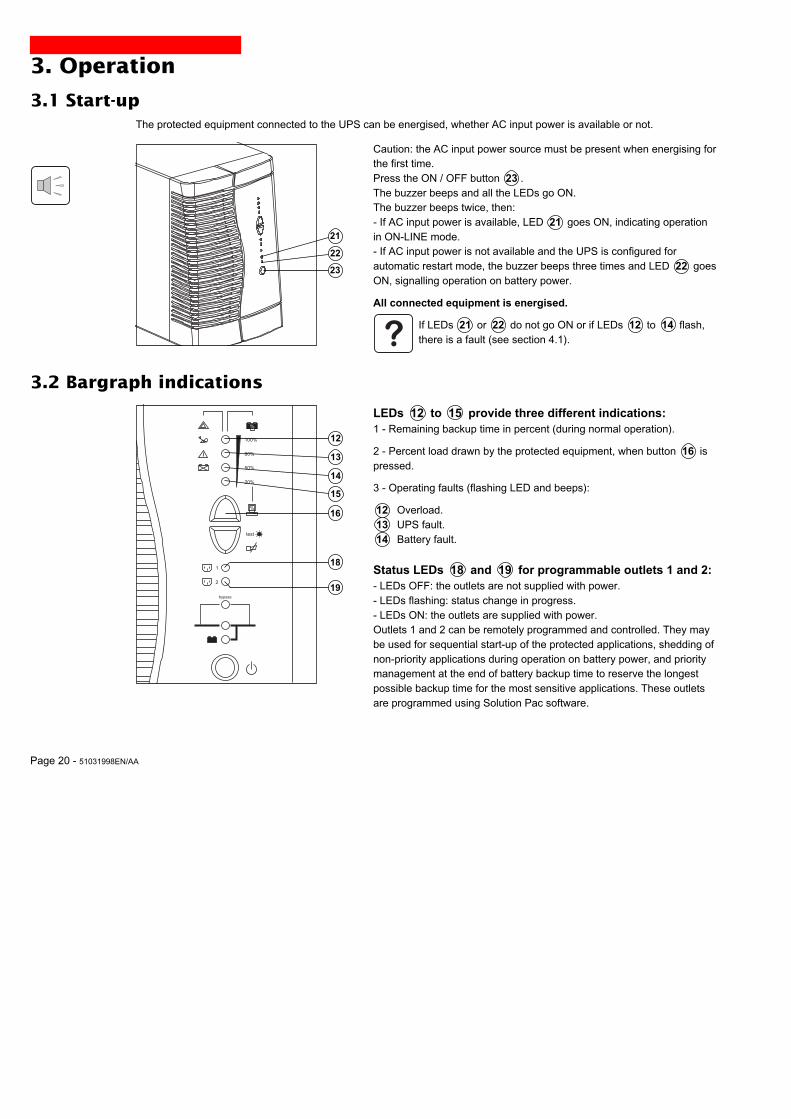
3.1 Start-up
100%
80%
50%
20%
test
%
%
1
2
bypass
The protected equipment connected to the UPS can be energised, whether AC input power is available or not.
12
13
14
23
Caution: the AC input power source must be present when energising forthe first time.Press the ON / OFF button 23 .The buzzer beeps and all the LEDs go ON.The buzzer beeps twice, then:- If AC input power is available, LED 21 goes ON, indicating operationin ON-LINE mode.- If AC input power is not available and the UPS is configured forautomatic restart mode, the buzzer beeps three times and LED 22 goesON, signalling operation on battery power.
All connected equipment is energised.
If LEDs 21 or 22 do not go ON or if LEDs 12 to 14 flash,there is a fault (see section 4.1).
3.2 Bargraph indications
LEDs 12 to 15 provide three different indications:1 - Remaining backup time in percent (during normal operation).
2 - Percent load drawn by the protected equipment, when button 16 ispressed.
3 - Operating faults (flashing LED and beeps):
␣ 12 Overload.␣ 13 UPS fault.␣ 14 Battery fault.
Status LEDs 18 and 19 for programmable outlets 1 and 2:- LEDs OFF: the outlets are not supplied with power.- LEDs flashing: status change in progress.- LEDs ON: the outlets are supplied with power.Outlets 1 and 2 can be remotely programmed and controlled. They maybe used for sequential start-up of the protected applications, shedding ofnon-priority applications during operation on battery power, and prioritymanagement at the end of battery backup time to reserve the longestpossible backup time for the most sensitive applications. These outletsare programmed using Solution Pac software.
16
22
21
15
18
19
51031998EN/AA - Page 21
3. Operation
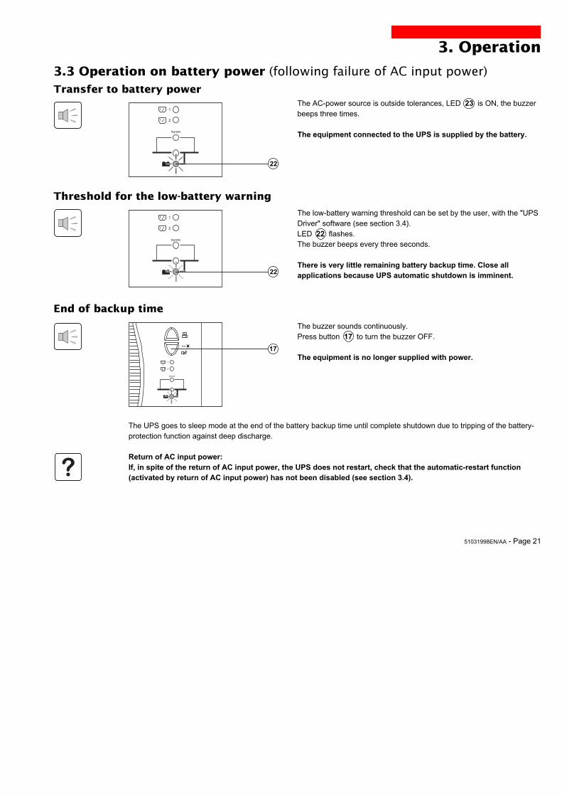
3.3 Operation on battery power (following failure of AC input power)
1
2
bypass
1
2
bypass
test
%
1
2
bypass
22
Transfer to battery powerThe AC-power source is outside tolerances, LED 23 is ON, the buzzerbeeps three times.
The equipment connected to the UPS is supplied by the battery.
Threshold for the low-battery warning
The low-battery warning threshold can be set by the user, with the "UPSDriver" software (see section 3.4).LED 22 flashes.The buzzer beeps every three seconds.
There is very little remaining battery backup time. Close allapplications because UPS automatic shutdown is imminent.
End of backup time
The buzzer sounds continuously.Press button 17 to turn the buzzer OFF.
The equipment is no longer supplied with power.
The UPS goes to sleep mode at the end of the battery backup time until complete shutdown due to tripping of the battery-protection function against deep discharge.
Return of AC input power:If, in spite of the return of AC input power, the UPS does not restart, check that the automatic-restart function(activated by return of AC input power) has not been disabled (see section 3.4).
22
17
Page 22 - 51031998EN/AA
3. Operation
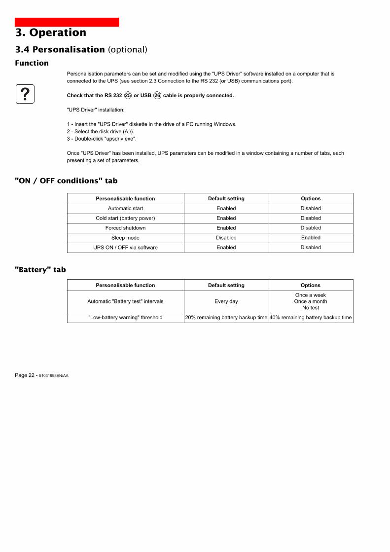
3.4 Personalisation (optional)
Function
Personalisable function
Automatic start
Cold start (battery power)
Forced shutdown
Sleep mode
UPS ON / OFF via software
Default setting
Enabled
Enabled
Enabled
Disabled
Enabled
Personalisation parameters can be set and modified using the "UPS Driver" software installed on a computer that isconnected to the UPS (see section 2.3 Connection to the RS 232 (or USB) communications port).
Check that the RS 232 25 or USB 26 cable is properly connected.
"UPS Driver" installation:
1 - Insert the "UPS Driver" diskette in the drive of a PC running Windows.2 - Select the disk drive (A:\).3 - Double-click "upsdriv.exe".
Once "UPS Driver" has been installed, UPS parameters can be modified in a window containing a number of tabs, eachpresenting a set of parameters.
"ON / OFF conditions" tab
"Battery" tab
Personalisable function
Automatic "Battery test" intervals
"Low-battery warning" threshold
Default setting
Every day
20% remaining battery backup time
Options
Once a weekOnce a month
No test
40% remaining battery backup time
Options
Disabled
Disabled
Disabled
Enabled
Disabled

51031998EN/AA - Page 23
3. Operation
bypass
Personalisable function
Rated UPS voltage
Rated UPS frequency
UPS tolerance for AC-powersource frequency
Overload alarm threshold
UPS restart following short-circuit
Default setting
230 V
F = 50 Hz
F ± 5 %
110 %
Disabled
Options
200 V - 210 V - 220 V - 240 V
60 Hz
F ± 1 % to ± 10 %, in 1 % steps
0 to 110 %, in 10 % steps
Enabled (click to add check)
Personalisable function
Transfer to bypass if overload
Transfer to bypass following a fault, whatever theconditions on the AC-power source
Default setting
Enabled
Disabled
Options
Disabled (click to remove check)
Enabled (click to add check)
"Output" tab
"Bypass" tab
23
Press button 23 (return to the OFF position).
The connected equipment is no longer supplied with power.
Page 24 - 51031998EN/AA
4. Maintenance
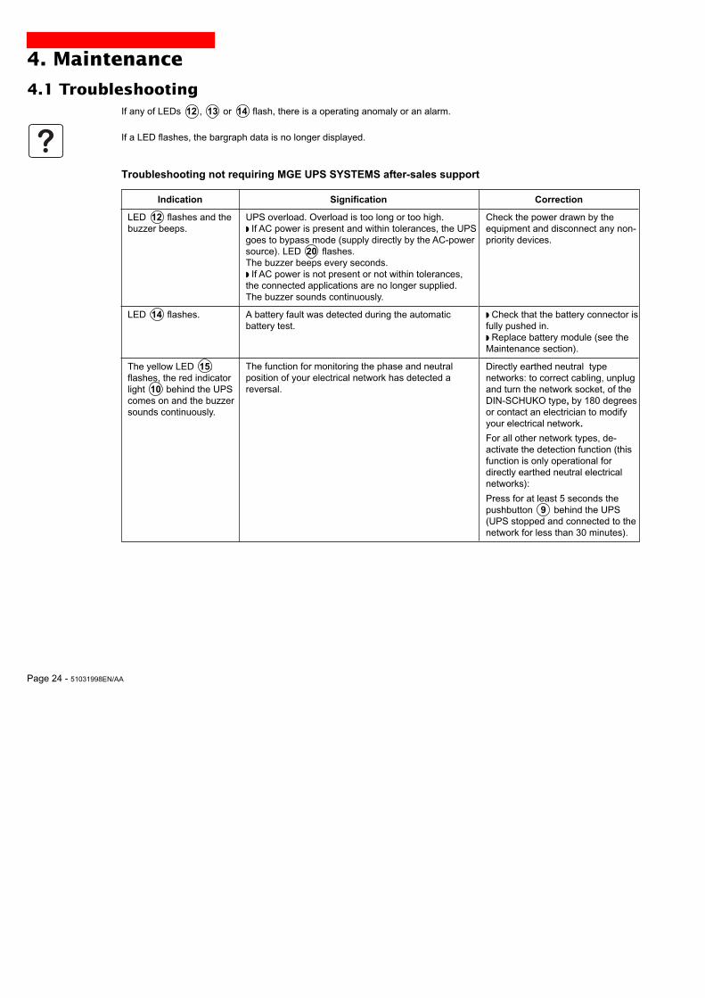
4.1 Troubleshooting
Indication
LED 12 flashes and thebuzzer beeps.
LED 14 flashes.
The yellow LED ␣ 15.flashes, the red indicatorlight 10 behind the UPScomes on and the buzzersounds continuously.
Signification
UPS overload. Overload is too long or too high.◗ If AC power is present and within tolerances, the UPSgoes to bypass mode (supply directly by the AC-powersource). LED 20 flashes.The buzzer beeps every seconds.◗ If AC power is not present or not within tolerances,the connected applications are no longer supplied.The buzzer sounds continuously.
A battery fault was detected during the automaticbattery test.
The function for monitoring the phase and neutralposition of your electrical network has detected areversal.
Correction
Check the power drawn by theequipment and disconnect any non-priority devices.
◗ Check that the battery connector isfully pushed in.◗ Replace battery module (see theMaintenance section).
Directly earthed neutral typenetworks: to correct cabling, unplugand turn the network socket, of theDIN-SCHUKO type, by 180 degreesor contact an electrician to modifyyour electrical network.
For all other network types, de-activate the detection function (thisfunction is only operational fordirectly earthed neutral electricalnetworks):
Press for at least 5 seconds thepushbutton 9 behind the UPS(UPS stopped and connected to thenetwork for less than 30 minutes).
If any of LEDs 12 , 13 or 14 flash, there is a operating anomaly or an alarm.
If a LED flashes, the bargraph data is no longer displayed.
Troubleshooting not requiring MGE UPS SYSTEMS after-sales support
51031998EN/AA - Page 25
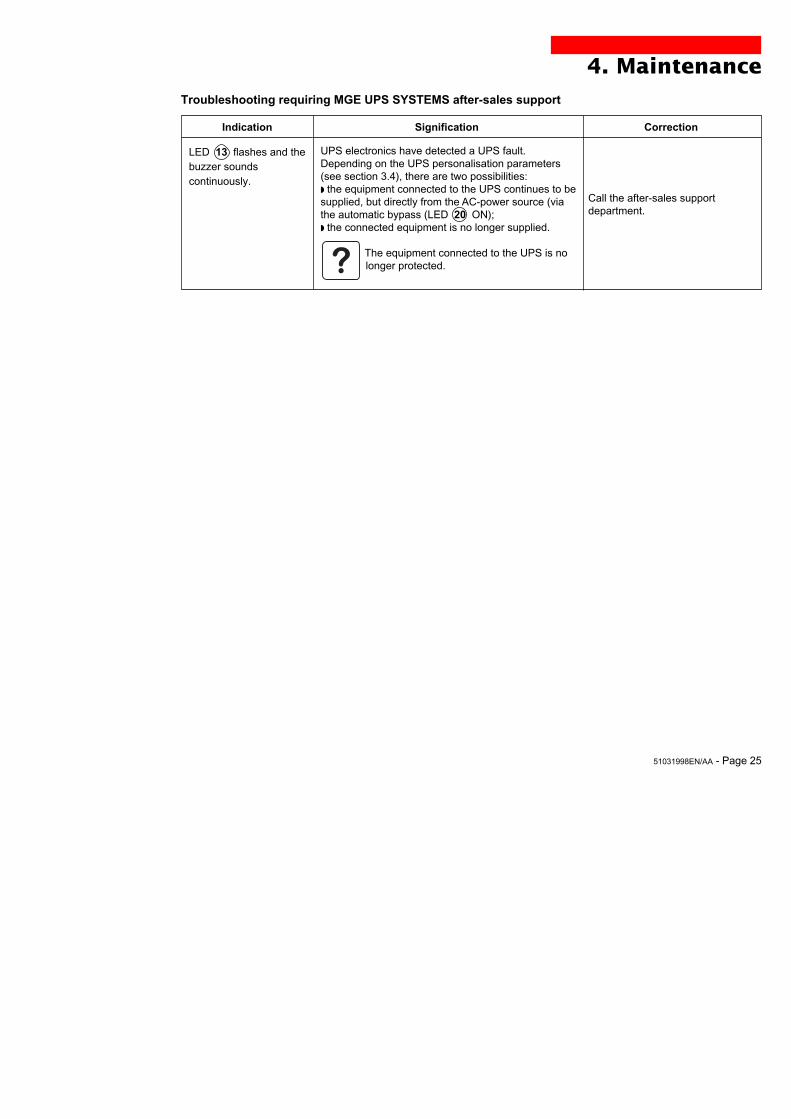
Troubleshooting requiring MGE UPS SYSTEMS after-sales support
Indication
LED 13 flashes and thebuzzer soundscontinuously.
Signification
UPS electronics have detected a UPS fault.Depending on the UPS personalisation parameters(see section 3.4), there are two possibilities:◗ the equipment connected to the UPS continues to besupplied, but directly from the AC-power source (viathe automatic bypass (LED 20 ON);◗ the connected equipment is no longer supplied.
The equipment connected to the UPS is nolonger protected.
Correction
Call the after-sales supportdepartment.
4. Maintenance
Page 26 - 51031998EN/AA
5. EnvironmentThis product has been designed to respect the environment:
It does not contain CFCs or HCFCs.
UPS recycling at the end of service life:
MGE UPS SYSTEMS undertakes to recycle, by certified companies and in compliance with all applicable regulations, allUPS products recovered at the end of their service life (contact your MGE UPS SYSTEMS branch office).
Packing:
UPS packing materials must be recycled in compliance with all applicable regulations.
Warning:
This product contains lead-acid batteries. Lead is a dangerous substance for the environment if it is not properly recycledby specialised companies.
Web site: www.mgeups.com
51031998EN/AA - Page 27
6. Appendices
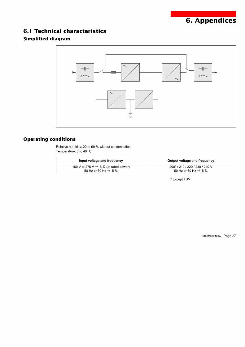
6.1 Technical characteristics
Operating conditions
Relative humidity: 20 to 90 % without condensation.Temperature: 0 to 40° C.
Simplified diagram
Input voltage and frequency
160 V to 276 V +/- 5 % (at rated power)50 Hz or 60 Hz +/- 5 %
Output voltage and frequency
200* / 210 / 220 / 230 / 240 V50 Hz or 60 Hz +/- 5 %
* Except TUV
Page 28 - 51031998EN/AA
6. Appendices
6.2 Glossary
Authorised voltage range for Upper and lower voltage thresholds within which the UPS can operate on the automatictransfer to bypass if fault or bypass in the event of a UPS fault or overload.overload
Automatic bypass Automatic switch controlled by the UPS, used to connect the equipment directly to theAC-power source in the event of a UPS failure or an overload.
Automatic start following This function automatically starts the UPS when AC input power returns followingreturn of AC input power shutdown at the end of the battery backup time. It can be enabled or disabled.
Backup time Time that the connected equipment can operate on battery power.
Bargraph Device on the front panel indicating the percent remaining backup time or the percentload.
Battery test Internal UPS test on battery status.
Dialog box A window in a computer program displayed for selection by the user of various optionsand parameter settings.
Double conversion The power supplied to the connected equipment is completely regenerated bycontinuous double conversion, i.e. the AC power from the AC-power source is rectified(AC - DC), then converted back (DC - AC) to AC power.
Equipment Devices or systems connected to the UPS output.
Forced shutdown Ten-second interruption in the supply of power to the connected equipment following asystem shutdown, even if AC input power returns during the interruption period.
Percent load Ratio between the power drawn by the connected equipment and the total power thatthe UPS can supply.
Personalisation A number of UPS functions can be modified using the «UPS Driver» software to bettermeet the user’s needs.
Programmable outlets Outlets that can be automatically shed during operation on battery power (a sheddingtime delay may be programmed using Solution-Pac software.
Start on battery power This function makes it possible to energise the connected equipment even when ACinput power is not available (operation exclusively on battery power).
UPS Uninterruptible Power Supply
UPS ON / OFF via software It is possible to enable or disable use of UPS ON / OFF controls by the computer-system protection software.
51031998EN/AA - Page 29
6. Appendices
6.3 IndexAAC power
Failure .................................................................... 21Frequency tolerance ............................................... 23Return ..................................................................... 21
Automatic start ............................................................... 22
BBargraph ................................................................... 10-20Battery
Battery test ............................................................. 22End of backup time ................................................. 21Fault .................................................................. 10-20Handling precautions ................................................ 3Low-battery warning ............................................... 22Recycling ............................................................. 3-26Transfer to battery power ....................................... 21
Buttons ..................................................................... 8-9-10Buzzer ....................................................................... 20-21Bypass
Automatic bypass ......................................... 10-23-25
CCommunication .................................................. 8-9-14-15Connection
Additional battery module ...................................... 8-9Communications card ............................................. 14RS 232 communications port ................................. 14USB communications port ...................................... 14
DDimensions ...................................................................... 7
EEnvironnement ......................................................... 2-3-26
FFault (UPS) .................................................... 10-20-24-25
LLEDs ....................................................................... 8-9-10
Lamp test ................................................................ 10
MMode
ON LINE mode ....................................................... 10
OOverload ............................................................. 10-23-25
SSafety ............................................................................... 3Shutdown
Buzzer .............................................................. 10-21Forced shutdown .................................................... 22UPS ON / OFF via software ................................... 22UPS shutdown .................................................. 10-23
Sleep mode .................................................................... 22Automatic restart .............................................. 20-23
SoftwareUPS Driver .............................................................22
Start-up .......................................................................... 20
TTechnical characteristics ................................................ 27Temperature
Excessive ambient temp. ....................................... 27Transfer (forced) ........................................................... 10
UUPS Driver .................................................................... 22UPS fault ............................................................. 10-20-23UPS storage .................................................................... 3
WWeb site ...........................................................................2Weight .............................................................................. 7

5103199800/AA
MGE UPS SYSTEMS
140, Avenue Jean KuntzmannZIRST - Montbonnot St Martin38334 - Saint Ismier Cedex - Francewww.mgeups.com
Nothing will stop you now
5103199800-AA