Embed Size (px)
Citation preview
Doc. No.: 255-700-154
PacketStar®
PSAX 2300 Multiservice Media Gateway User GuideA PacketStar® PSAX Central Office Product
Issue 1, August 2001
System Software Release 7.0.0
AQueView® EMS Software Release 5.0

Copyright © 2001 by Lucent Technologies. All rights reserved.
For trademark, regulatory compliance, and related legal information, see the "Copyright and Legal Notices" section.

255-700-154 iii
PacketStar® PSAX 2300 Multiservice Media Gateway User Guide, Issue 1 Release 7.0.0
Copyright and Legal Notices
Copyright
Copyright © 2000 by Lucent Technologies. All rights reserved.
This material is protected by the copyright laws of the United States and other countries. It may not be reproduced, distributed, or altered in any fashion by any entity (either internal or external to Lucent Technologies), except in accordance with applicable agreements, contracts or licensing, without the express written consent of the originating organization and the business management owner of the material.
This document was prepared by the Information Design and Development Team of Lucent Technologies, PacketStar™® PSAX Products. Offices are located in Landover, Maryland, USA.
Trademarks
7R/E, APX-8000, CellPipe, ConnectReach, ConnectStar, and STINGER are trademarks; and PacketStar, AQueView, Lucent Technologies, and the Lucent Technologies logo are registered trademarks of Lucent Technologies in the USA. Other product and brand names mentioned in this guide are trademarks or registered trademarks of their respective owners.
Warranty Information
Software and Hardware Limited Warranties
Lucent Technologies provides a 90-day limited software warranty, and a one-year limited hardware warranty on this product. Refer to the Software License and Limited Warranty Agreement and the Lucent Technologies InterNetworking Systems Global Warranty that accompanied your package for more information.
Every effort has been made to ensure that this document is complete and accurate at the time of release, but information is subject to change. Lucent Technologies assumes no responsibility or liability for errors or inaccuracies that may appear in this guide.
Copyright and Legal NoticesSoftware and Hardware Limited Warranties
iv 255-700-154
PacketStar® PSAX 2300 Multiservice Media Gateway User Guide, Issue 1 Release 7.0.0
Warranty Warnings
! CAUTION:Modifying or tampering with PSAX chassis components may void your warranty. Any modification to this equipment not expressly authorized by Lucent Technologies may void your granted authority to operate such equipment.
! CAUTION:Air vents in the PSAX chassis are provided to aid in ventilation and to protect from overheating. These vents must be regularly inspected by the user and cleared of dust and blockage. Equipment failure associated with improper maintenance or suspected failure to adhere to proper ventilation procedures as described above will void your warranty.
! CAUTION:You must replace an air filter having an accumulation of dust to ensure adequate airflow through the PSAX chassis. Reduced airflow could result in damaging heat buildup within the chassis.
• Periodically inspect the air filter for accumulated dust and replace the filter as needed. At a minimum, quarterly inspection is recommended. Equipment failure due to inadequate airflow voids your equipment warranty.
• Use only filters supplied by Lucent Technologies in your PSAX chassis. Use of other filters voids your equipment warranty.
! CAUTION:When inserting modules into the chassis, slide them gently, not forcefully. Excessive force may cause the modules to be seated improperly in the chassis, and result in possible damage to the module or the chassis. Install or remove modules one at a time. Doing this aids in preventing the PSAX 2300 system from indicating any erroneous failure messages, and allows the PSAX 2300 system to reinitialize and display the accurate configuration of the module that is inserted.
! CAUTION:Shipping the chassis with removable modules installed may cause damage to the chassis and the modules. Damage to any of the components in the system resulting from shipping the chassis with removable modules installed could void your warranty. Only Lucent-authorized personnel should ship the PSAX 2300 chassis with a module installed.
255-700-154 v
PacketStar® PSAX 2300 Multiservice Media Gateway User Guide, Issue 1 Release 7.0.0
Copyright and Legal NoticesRegulatory Standards Compliance
! CAUTION:You must maintain a minimum 10.16 cm (4 in.) of clearance around the chassis for adequate airflow. Failure to adhere to this space requirement may result in equipment failure due to overheating. Failure to provide a minimum of 10.16 cm (4 in.) of clearance between this unit and any other device/structure will void your warranty.
Regulatory Standards Compliance
The PacketStar® PSAX 2300 Multiservice Media Gateway, model 23S00, is compliant with the listed safety, electromagnetic compatibility (EMC) and telecommunications standards. Applicable statements are provided in the next subsection.
Safety
The PacketStar® PSAX 2300 Multiservice Media Gateway, model 23S00, is compliant with the following safety standards.
• UL 1950, Third Edition (USA)
• CSA 22.2 No. 950, Third Edition (Canada)
• EN 60950:1992+A1:1993+A2:1993+A3:1995+A4:1997 +A11:1997 (Europe)
• AS/NZS 3260:1993+S1:1996 (Australia/New Zealand)
• ACA TS 001:1997 (Australia)
• NOM (Mexico)
• S-Mark (Argentina)
• CB-Scheme – IEC 60950:1991+A1:1992+A2:1993+A3:1995+A4:1996 (International)
Electromagnetic Compatibility
The PacketStar® PSAX 2300 Multiservice Media Gateway, model 23S00, is compliant with the following electromagnetic compatibility (EMC) standards.
• FCC Part 15 Class A (USA)
• ICES-003, Issue 3:1998 Class A (Canada)
• EN 55022:1998 Class A (Europe)
• EN55024:1998 (Europe)
• EN 300 386-2:1997 Class A (Europe)
• AS/NZS 3548:1995+A1:1997+A2:1997 Class A (Australia/New Zealand)
• VCCI Class A (Japan)
Copyright and Legal NoticesRegulatory Statements
vi 255-700-154
PacketStar® PSAX 2300 Multiservice Media Gateway User Guide, Issue 1 Release 7.0.0
• CISPR 22:1997 Class A (International)
• CISPR 24:1997 (International)
Telecommunications
The PacketStar® PSAX 2300 Multiservice Media Gateway, model 23S00, is compliant with the following telecommunications standards.
• FCC Part 68 (USA)
• CS-03 Issue 8 (Canada)
• ETSI TBR 12:1993+A1:1996 (Europe)
• ETSI TBR 13:1996 (Europe)
• ETSI TBR 24:1997 (Europe)
• TS 016:1997 (Australia)
• TS 026:1997 (Australia)
• JATE (Japan)
Regulatory Statements
USA Regulatory Statements
FCC Part 15 This equipment has been tested and found to comply with the limits for a Class A digital device, pursuant to Part 15 of the FCC rules. These limits are designed to provide reasonable protection against harmful interference when the equipment is operated in a commercial environment. This equipment generates, uses, and can radiate radio frequency energy, and, if not installed and used in accordance with this guide, may cause harmful interference to radio communications. Operation of this equipment in a residential area is likely to cause harmful interference; in this case, you would be required to correct the interference at your own expense.
All cables used to connect to peripherals must be shielded and grounded. Operation with cables, connected to peripherals, that are not shielded and grounded may result in interference to radio and television reception.
The user is cautioned that any changes or modifications not expressly approved by the party responsible for compliance could void the user’s authority to operate the equipment.
FCC Part 68 This equipment complies with Part 68 of the FCC rules. On the back of the PSAX chassis is a label that contains the FCC registration number, in addition to other information. You must provide this information to the telephone
255-700-154 vii
PacketStar® PSAX 2300 Multiservice Media Gateway User Guide, Issue 1 Release 7.0.0
Copyright and Legal NoticesRegulatory Statements
company, if they request it. The FCC requires Lucent Technologies to provide you with the following information:
1. This equipment has digital service interface capabilities using RJ-48C and RJ-48H connectors. The facility interface codes with which this equipment complies for digital services are as follows: 04DU9-BN, 04DU9-DN, 04DU9-1KN, and 04DU9-1SN. This equipment has loop start interface capabilities using an RJ-11C connector. The facility interface code with which this equipment complies for service is 02LS2. The service order codes for this equipment are 6.0F for the T-1 interface and 9.0Y for the loop start interface.
2. An FCC-compliant telephone network interface jack is built into this equipment and is compatible with interconnections that are Part 68 compliant.
3. The REN for the Voice 2-Wire Office module when used in this equipment is 0.7B.
4. If this equipment causes harm to the telephone network, the telephone company will notify you in advance that temporary discontinuance of service might be required. But if advance notice is not practical, the telephone company will notify you as soon as possible. Also, you will be advised of your right to file a complaint with the FCC if you believe this is necessary.
5. The telephone company might make changes in its facilities, equipment, operations, or procedures that could affect the operation of this equipment. If this happens, the telephone company will provide advance notice for you to make necessary modifications to maintain uninterrupted service.
6. If you experience trouble with this equipment, or need repairs or warranty information, please refer to the Lucent Technologies InterNetworking Systems Global Warranty that accompanied your PSAX product shipment for instructions on obtaining technical support in your area.
If this equipment is causing harm to the telephone network, the telephone company might request that you disconnect the equipment until the problem is resolved.
7. This equipment has no user-serviceable parts.
This equipment cannot be used on public coin telephone service provided by the telephone company. Connection to party line service is subject to state tariffs. Contact your state public utility commission, public service commission, or corporation commission for information.
UL 1950 This product is UL Listed only when supplied with the following assemblies:
• PSAX 2300 Chassis Assembly, model 23S00
• -48 V dc Power Supply module, model 23N11 (two required)
• Stratum 3–4 modules, model 23N05 (two required)
• Up to two CPU modules, consisting of the following;
Copyright and Legal NoticesRegulatory Statements
viii 255-700-154
PacketStar® PSAX 2300 Multiservice Media Gateway User Guide, Issue 1 Release 7.0.0
~ CPU/CPU2 module, model 20N20
~ CPU/CPU2 module, model 20Pnn (where nn may be 19–25)
• Up to fifteen I/O, server, or blank faceplate modules consisting of the following:
~ 1-Port Channelized DS3 CES module, model 23N61
~ 1-Port Channelized DS3 Multiservice module, model 23N60
~ 1-Port Channelized STS-1e T1 module, model 23N62
~ 1-Port DS3 Frame Relay module, model 20N03
~ 1-Port DS3 IMA module, model 23N68
~ 1-Port OC-12c/STM-4c 1+1 APS/MSP Multimode module, model 23N72
~ 1-Port OC-12c/STM-4c 1+1 APS/MSP Single-Mode module, model 23N73
~ 1-Port OC-3c 1+1 APS Multimode module with AQueMan, model 20N72
~ 1-Port OC-3c 1+1 APS Single-Mode module with AQueMan, model 20N73
~ 1-Port OC-3c Multimode module with AQueMan, model 20N12
~ 1-Port OC-3c Multimode module with Traffic Shaping, model 20N14
~ 1-Port OC-3c Single-Mode module with AQueMan, model 20N13
~ 1-Port OC-3c Single-Mode module with Traffic Shaping, model 20N15
~ 1-Port STM-1 1+1 MSP Multimode module, model 20N92
~ 1-Port STM-1 1+1 MSP Single-Mode module, model 20N93
~ 1-Port STM-1 Multimode module with AQueMan, model 20N62
~ 1-Port STM-1 Multimode module with Traffic Shaping, model 20N64
~ 1-Port STM-1 Single-Mode module with AQueMan, model 20N63
~ 1-Port STM-1 Single-Mode module with Traffic Shaping, model 20N65
~ 2-Port DS3 ATM module, model 20N02
~ 2-Port E3 ATM module, model 20N22
~ 3-Port Channelized DS3/STS-1e CES module, model 23N03
~ 3-Port Unstructured DS3/E3 CES module, model 23N02
~ 4-Port Quadserial module, model 23N07
~ 4-Port Voice 2-Wire Office module, model 20N32
~ 5-Port Ethernet module, model 20N40
~ 6-Port DS1 IMA module, model 20N33
~ 6-Port E1 IMA module, model 20N34
~ 6-Port Enhanced DS1 module, model 20N36
~ 6-Port Enhanced E1 module, model 20N56
~ 6-Port Multiserial module, model 20N07
255-700-154 ix
PacketStar® PSAX 2300 Multiservice Media Gateway User Guide, Issue 1 Release 7.0.0
Copyright and Legal NoticesRegulatory Statements
Canadian Regulatory Statements
ICES-003 This Class A digital apparatus complies with Canadian ICES-003.
NMB-003 Cet appareil numérique de la classe A est conforme à la norme NMB-003 du Canada.
CS-03 The Industry Canada label identifies certified equipment. This certification means that the equipment meets certain telecommunications network protective, operational, and safety requirements. The Department does not guarantee that the equipment will operate to the user’s satisfaction.
Before installing this equipment, the user should ensure that it is permissible to be connected to the facilities of the local telecommunications company. The equipment must also be installed by using an acceptable method of connection. In some cases, the company’s inside wiring associated with a single-line individual service may be extended by means of a certified connector assembly (telephone extension cord). The customer should be aware that compliance with the above condition may not prevent degradation of service in some situations.
Repairs to some certified equipment should be made by an authorized maintenance facility designated by the supplier. Any repairs or alterations made by the user to this equipment or equipment malfunctions might give the telecommunications company cause to request the user to disconnect the equipment.
For their own protection, users should ensure that the ground connections of the power utility, telephone lines, and internal metallic water pipe system are connected together. This precaution may be particularly important in rural areas.
~ 8-Port Voice 2-Wire Station module, model 20N30
~ 12-Port Medium-Density DS1, model 23N64
~ 21-Port High-Density E1 module, model 23N66
~ Alarm module, model 20N79
~ DSP2 Voice Server module, model 20N27
~ DSP2A Voice Server module, model 20N29
~ DSP2B Voice Server module, model 20N28
~ DSP2C Voice Server module, model 23N27
~ DSP2D Voice Server module, model 23N29
~ PSAX 1250/2300 I/O or CPU Blank Faceplate, model 20N87
~ Route Server module, model 20N41
~ Tones and Announcements Server module, model 23N28
Copyright and Legal NoticesRegulatory Statements
x 255-700-154
PacketStar® PSAX 2300 Multiservice Media Gateway User Guide, Issue 1 Release 7.0.0
! CAUTION:Users should not attempt to make such connections themselves, but should contact the appropriate electric inspection authority or electrician.
The Ringer Equivalence Number (REN) assigned to the Voice 2-Wire Office module denotes the percentage of the total load to be connected to a telephone loop, which is used by the device, to prevent overloading. The termination on a loop may consist of any combination of devices subject only to the requirement that the total of the REN of all devices does not exceed 5.
The REN for the Voice 2-Wire Office module when used in the PSAX system is 0.7B.
SH03 Le label Industrie Canada permet de reconnaître les équipements homologués. Cette homologation indique que l’équipement satisfait certaines règles de protection, d’exploitation et de sécurité des réseaux de télécommunications. Le ministère de l’Industrie ne garantit pas que l’équipement fonctionnera à la satisfaction de l’utilisateur.
Avant d’installer cet équipement, l’utilisateur doit s’assurer qu’il est permis de le connecter aux installations de la compagnie de télécommunications locale. L’équipement doit également être connecté suivant une méthode convenable. Dans certains cas, il sera nécessaire de prolonger le câblage intérieur de la ligne d’abonné de la compagnie au moyen d’un connecteur homologué (rallonge de téléphone). L’abonné doit savoir que, dans certaines situations, la conformité aux dispositions ci-dessus ne prévient pas nécessairement la dégradation du service.
La réparation de certains équipements homologués doit être assurée par un atelier agréé désigné par le fournisseur. Toute réparation ou altération effectuée par l’utilisateur ou tout mauvais fonctionnement de cet équipement peut donner à la compagnie de téléphone des raisons de demander audit utilisateur de déconnecter celui-ci.
Pour leur propre sécurité, les utilisateurs doivent veiller à ce que les mises à la terre de l’alimentation secteur, des lignes téléphoniques et du système intérieur de conduites d’eau métalliques soient raccordés ensemble. Cette précaution peut s’avérer particulièrement importante dans les zones rurales.
! CAUTION:Les utilisateurs ne doivent pas tenter d’effectuer eux-mêmes ces raccordements, mais doivent prendre contact avec un électricien ou organisme de vérification compétent.
Le nombre équivalent de sonnerie (REN) attribué au module central bifilaire (Voice 2-Wire Office) correspond au pourcentage de la charge totale à connecter à un circuit téléphonique bifilaire; il est utilisé par l’appareil pour prévenir la surcharge. Le circuit peut être terminé par n’importe quelle combinaison d’appareils, à la seule condition que le total des REN de ces derniers ne dépasse pas cinq.
Lorsqu’il est utilisé dans le système PSAX, le module central bifilaire possède un REN de 0,7 B.
255-700-154 xi
PacketStar® PSAX 2300 Multiservice Media Gateway User Guide, Issue 1 Release 7.0.0
Copyright and Legal NoticesRegulatory Statements
European Union Regulatory Statement
CE Marking Hereby, Lucent Technologies declares that the PacketStar® PSAX 1250 (-48 V dc), PSAX 2300, PSAX 4500, and PSAX AC 60 (-48 V dc) Multiservice Media Gateways are in compliance with the essential requirements and other relevant provisions of the following Council Directives:
• Low Voltage 72/23/EEC
• Electromagnetic Compatibility (EMC) 89/336/EEC
• Radio Equipment and Telecommunications Terminal Equipment 1999/5/EC
The Lucent PacketStar® PSAX Multiservice Media Gateways deployed in the European Economic Area (EEA) are intended for connection to E1, E3, STM-1, and STM-4c networks. The EC Declarations of Conformity may be viewed or printed at the following public-access Internet site:
http://www.lucent.com/ins/doclibrary
EU-regulativer
CE-mærkning Lucent Technologies erklærer hermed at PacketStar® PSAX 1250 (-48 V dc), PSAX 2300, PSAX 4500, and PSAX AC 60 (-48 V dc) Multiservice Media Gateways overholder kravene i følgende EU-direktiver:
• Lavspændingsdirektivet 72/23/EEC
• EMC-direktivet 89/336/EEC
• Direktivet om radio og teleterminaludstyr 1999/5/EC
Lucent PacketStar® PSAX Multiservice Media Gateways, anvendt i EØS (Europæiske Økonomiske Samarbejde) skal forbindes med E1, E3 STM-1 og STM-4c netværk. EU-overensstemmelseserklæringen er at finde på følgende internetside hvorfra den også kan udskrives:
http://www.lucent.com/ins/doclibrary
Behördliche Standard-CE-Kennzeichnung für die Europäische Gemeinschaft
CE-Markierung Hiermit erklärt Lucent Technologies, dass die PacketStar® PSAX 1250 (-48 V DC), PSAX 2300, PSAX 4500 und PSAX AC 60 (-48 V DC) Multiservice Media Gateways die notwendigen Anforderungen und anderen relevanten Vorschriften der folgenden Council-Direktiven einhalten:
• Niederspannungsdirektive 72/23/EEC
• Elektromagnetische Verträglichkeit (EMC) 89/336/EEC
• Funkgeräte und Funkverkehr-Endeinrichtungen 1999/5/EC
Die Lucent PacketStar® PSAX Multiservice Media Gateways, die in der Europäischen Gemeinschaft im Einsatz stehen, dienen zum Anschluss an folgende Netztypen: E1, E3, STM-1 und STM-4c. Die Konformitätserklärung
Copyright and Legal NoticesRegulatory Statements
xii 255-700-154
PacketStar® PSAX 2300 Multiservice Media Gateway User Guide, Issue 1 Release 7.0.0
für die Europäische Gemeinschaft kann auf folgendem, öffentlich zugänglichem Internet-Site eingesehen oder ausgedruckt werden:
http://www.lucent.com/ins/doclibrary
������������� ������ ��������������
��������� ������������� ���������������������������������PacketStar®�PSAX1250 (-48Vdc), PSAX2300, PSAX�� ��!���"#$%AC60 (-48V&�'�(������)*����(�&�+�,+��-+.�����/�01�����/����2�3�4�!52������64��2�!�������52�47���!52�����89��2��:�;��<�����=�>=/3�=�0�=?
• @�/��6��84��ABCBDCEFG
• H��!���/�<���!6�4=/3�������IE(J'�KLCDDMCEFG)
• N����O:�!2��9����4/2�!���P9����4/2����/���!�Q�������!��:���RLLLC�CEG
S�� ����������������®�"#$%�(������)*����(�&�+�,+��-+.�����=�57�=�����T���T�0�4���P=�:��U!�;�!��/�!�@����IPPV'������01�����<���4Q��4��/������0!�=��ER��ED��#�(R��!���#�(W��X ;��Y���4��2�P��/�4�2���2�PZ�/����Q������3��T�Q�6����=�:T�Q�����������!8�:����4��6�4���!�������T�40����=�[�����?
http://www.lucent.com/ins/doclibrary
Euroopan unionin sääntelystandardi
CE-merkintä Lucent Technologies vakuuttaa täten, että PacketStar® PSAX 1250 (-48 V dc), PSAX 2300, PSAX 4500 ja PSAX AC 60 (-48 V dc) Multiservice Media Gatewayt täyttävät seuraavien neuvoston direktiivien keskeiset vaatimukset ja asiaankuuluvat määräykset:
• Pienjännite 72/23/EY
• Sähkömagneettinen yhteensopivuus (EMC) 89/336/EY
• Radiolaitteet ja telepäätelaitteet 1999/5/EY
Lucent PacketStar® PSAX Multiservice Media Gatewayt, joita käytetään Euroopan talousalueella, on tarkoitettu liitettäväksi E1-, E3-, STM-1- ja STM-4c-verkkoihin. EU:n vaatimustenmukaisuusvakuutus voidaan nähdä tai tulostaa seuraavalta julkiselta Internet-sivulta:
http://www.lucent.com/ins/doclibrary
Norme réglementaire de l’Union européenne
Label CE Lucent Technologies déclare en ceci que les passerelles de média multiservices PacketStar® PSAX 1250 (-48 V c.c.), PSAX 2300, PSAX 4500 et PSAX AC 60 (-48 V c.c.) sont conformes aux exigences essentielles et autres dispositions pertinentes des directives suivantes du Conseil :
255-700-154 xiii
PacketStar® PSAX 2300 Multiservice Media Gateway User Guide, Issue 1 Release 7.0.0
Copyright and Legal NoticesRegulatory Statements
• Basse tension 72/23/CEE
• Compatibilité électromagnétique (CEM) 89/336/CEE
• Matériel radio et terminaux de télécommunications 1999/5/CE
Les passerelles de média multiservices PacketStar® PSAX de Lucent, commercialisées dans l’Espace économique européen sont destinées aux connexions à des réseaux E1, E3, STM-1 et STM-4c. Les déclarations de conformité CE peuvent être consultées ou imprimées à partir du site Internet d’accès public :
http://www.lucent.com/ins/doclibrary
Normativa dell’Unione Europea
Apposizione del marchio CE
La Lucent Technologies dichiara che i gateway multiservizio PacketStar® PSAX 1250 (-48 V dc), PSAX 2300, PSAX 4500 e PSAX AC 60 (-48 V dc), rispondono ai requisiti essenziali ed ad altre norme rilevanti delle seguenti direttive del Consiglio:
• Direttiva 72/23/CEE “Basse tensioni”
• Direttiva 89/336/CEE sulla compatibilità elettromagnetica
• Direttiva 1999/5/CE riguardante le apparecchiature radio e le apparecchiature terminali di telecomunicazione
I gateway multiservizio Lucent PacketStar® PSAX impiegati nell’area economica europea (EEA), sono concepiti per il collegamento con reti E1, E3, STM-1 e STM-4c. Le dichiarazioni di conformità CE possono essere stampate o visionate presso il seguente sito Internet di pubblico accesso:
http://www.lucent.com/ins/doclibrary
Norm van de Europese Unie
CE-markering Lucent Technologies verklaart hierbij dat de PacketStar® PSAX 1250 (-48 V dc), PSAX 2300, PSAX 4500, en PSAX AC 60 (-48 V dc) Multi Service Media Gateways voldoen aan de essentiële vereisten en andere relevante bepalingen van de volgende Richtlijnen van de Raad:
• Laagspanning 72/23/EEG
• Elektromagnetische compatibiliteit (EMC) 89/336/EEG
• Radioapparatuur en telecommunicatie-eindapparatuur 1999/5/EG
De Lucent PacketStar® PSAX Multi Service Media Gateways die in de Europese Economische Ruimte (EER) zijn ingezet, zijn bestemd voor aansluiting op E1, E3, STM-1 en STM-4c netwerken. DE EU-verklaringen van overeenstemming kunnen worden bekeken of afgedrukt op de volgende Internet-site met openbare toegang:
http://www.lucent.com/ins/doclibrary

Copyright and Legal NoticesRegulatory Statements
xiv 255-700-154
PacketStar® PSAX 2300 Multiservice Media Gateway User Guide, Issue 1 Release 7.0.0
Padrão Regulador da União Europeia
Marca CE A Lucent Technologies vem por este meio declarar que os Concentradores de Acesso PacketStar® PSAX 1250 (-48 V dc), PSAX 2300, PSAX 4500 e PSAX AC 60 (-48 V dc) obedecem aos requisitos essenciais e a outras disposições relevantes das seguintes Directivas do Conselho:
• Baixa Voltagem 72/23/EEC
• Compatibilidade Electromagnética (EMC) 89/336/EEC
• Equipamento de Rádio e Equipamento Terminal de Telecomunicações 1999/5/EC
Os Concentradores de Acesso PacketStar® PSAX da Lucent instalados na Área Económica Europeia (EEA) foram concebidos para serem ligados a redes do tipo E1, E3, STM-1 e STM-4c. As Declarações de Conformidade CE podem ser vistas ou impressas no seguinte sítio de acesso público da Internet:
http://www.lucent.com/ins/doclibrary
Norma reguladora de la Unión Europea
Marcas de la CE Por el presente, Lucent Technologies declara que las pasarelas de medios multiservicio PacketStar® PSAX 1250 (-48 V cc), PSAX 2300, PSAX 4500 y PSAX AC 60 (-48 V cc) Multiservice Media Gateways están en conformidad con los requisitos esenciales y otras disposiciones pertinentes de las siguientes directrices del consejo:
• Bajo voltaje 72/23/EEC
• Compatibilidad electromagnética (EMC) 89/336/EEC
• Equipo de radio y equipo de terminales de telecomunicaciones 1999/5/EC
Las pasarelas de medios multiservicio Lucent PacketStar® PSAX Multiservice Media Gateways desplegadas en el área económica europea (European Economic Area, EEA) están destinadas a conectarse en redes E1, E3, STM-1 y STM-4c. Las declaraciones de conformidad de la CE pueden verse o imprimirse en el siguiente sitio Internet de acceso público:
http://www.lucent.com/ins/doclibrary
Europeiska unionens standardförordning
CE-märkning Lucent Technologies deklarerar härmed att PacketStar® PSAX 1250 (-48 V likström), PSAX 2300, PSAX 4500, och PSAX AC 60 (-48 V likström) Multiservice Media Gateways uppfyller de väsentliga kraven och andra relevanta bestämmelser som gäller enligt följande Europarådsdirektiv:
• Lågspänning 72/23/EEC
255-700-154 xv
PacketStar® PSAX 2300 Multiservice Media Gateway User Guide, Issue 1 Release 7.0.0
Copyright and Legal NoticesRegulatory Statements
• Elektromagnetisk kompatibilitet (EMC) 89/336/EEC
• Radioutrustning och telekommunikationskopplingsutrustning 1999/5/EC
Lucent PacketStar® PSAX Multiservice Media Gateways, som är placerad i EEA (European Economic Area), är avsedd för att anslutas till E1, E3, STM-1 och STM-4c nätverk. Europarådets Konformitetsdeklarationer kan ses på bildskärm eller skrivas ut på följande, för allmänheten tillgängliga Internet-ställe:
http://www.lucent.com/ins/doclibrary
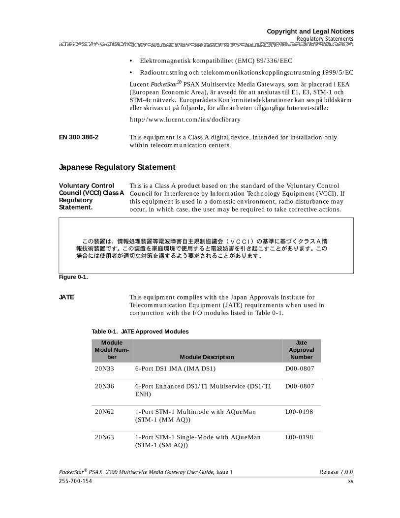
EN 300 386-2 This equipment is a Class A digital device, intended for installation only within telecommunication centers.
Japanese Regulatory Statement
Voluntary Control Council (VCCI) Class A Regulatory Statement.
This is a Class A product based on the standard of the Voluntary Control Council for Interference by Information Technology Equipment (VCCI). If this equipment is used in a domestic environment, radio disturbance may occur, in which case, the user may be required to take corrective actions.
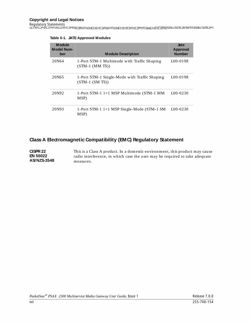
JATE This equipment complies with the Japan Approvals Institute for Telecommunication Equipment (JATE) requirements when used in conjunction with the I/O modules listed in Table 0-1.
Figure 0-1.
Table 0-1. JATE Approved Modules
Module Model Num-
ber Module Description
Jate Approval Number
20N33 6-Port DS1 IMA (IMA DS1) D00-0807
20N36 6-Port Enhanced DS1/T1 Multiservice (DS1/T1 ENH)
D00-0807
20N62 1-Port STM-1 Multimode with AQueMan (STM-1 (MM AQ))
L00-0198
20N63 1-Port STM-1 Single-Mode with AQueMan (STM-1 (SM AQ))
L00-0198
Copyright and Legal NoticesRegulatory Statements
xvi 255-700-154
PacketStar® PSAX 2300 Multiservice Media Gateway User Guide, Issue 1 Release 7.0.0
Class A Electromagnetic Compatibility (EMC) Regulatory Statement
CISPR 22EN 55022AS/NZS-3548
This is a Class A product. In a domestic environment, this product may cause radio interference, in which case the user may be required to take adequate measures.
20N64 1-Port STM-1 Multimode with Traffic Shaping (STM-1 (MM TS))
L00-0198
20N65 1-Port STM-1 Single-Mode with Traffic Shaping (STM-1 (SM TS))
L00-0198
20N92 1-Port STM-1 1+1 MSP Multimode (STM-1 MM MSP)
L00-0230
20N93 1-Port STM-1 1+1 MSP Single-Mode (STM-1 SM MSP)
L00-0230
Table 0-1. JATE Approved Modules
Module Model Num-
ber Module Description
Jate Approval Number
255-700-154 xvii
PacketStar® PSAX 2300 Multiservice Media Gateway User Guide, Issue 1 Release 7.0.0
Safety Warnings and Information
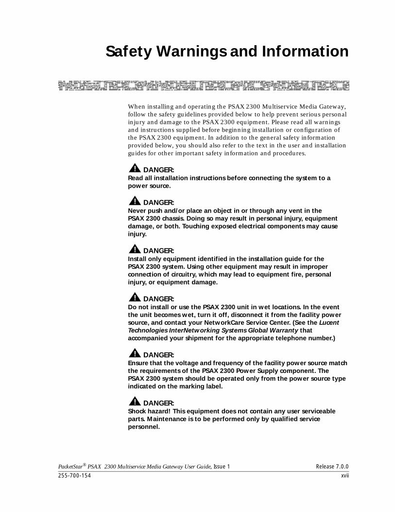
When installing and operating the PSAX 2300 Multiservice Media Gateway, follow the safety guidelines provided below to help prevent serious personal injury and damage to the PSAX 2300 equipment. Please read all warnings and instructions supplied before beginning installation or configuration of the PSAX 2300 equipment. In addition to the general safety information provided below, you should also refer to the text in the user and installation guides for other important safety information and procedures.
! DANGER:Read all installation instructions before connecting the system to a power source.
! DANGER:Never push and/or place an object in or through any vent in the PSAX 2300 chassis. Doing so may result in personal injury, equipment damage, or both. Touching exposed electrical components may cause injury.
! DANGER:Install only equipment identified in the installation guide for the PSAX 2300 system. Using other equipment may result in improper connection of circuitry, which may lead to equipment fire, personal injury, or equipment damage.
! DANGER:Do not install or use the PSAX 2300 unit in wet locations. In the event the unit becomes wet, turn it off, disconnect it from the facility power source, and contact your NetworkCare Service Center. (See the Lucent Technologies InterNetworking Systems Global Warranty that accompanied your shipment for the appropriate telephone number.)
! DANGER:Ensure that the voltage and frequency of the facility power source match the requirements of the PSAX 2300 Power Supply component. The PSAX 2300 system should be operated only from the power source type indicated on the marking label.
! DANGER:Shock hazard! This equipment does not contain any user serviceable parts. Maintenance is to be performed only by qualified service personnel.
Safety Warnings and Information
xviii 255-700-154
PacketStar® PSAX 2300 Multiservice Media Gateway User Guide, Issue 1 Release 7.0.0
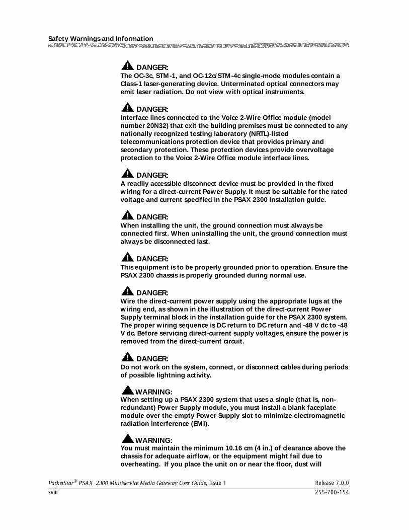
! DANGER:The OC-3c, STM-1, and OC-12c/STM-4c single-mode modules contain a Class-1 laser-generating device. Unterminated optical connectors may emit laser radiation. Do not view with optical instruments.
! DANGER:Interface lines connected to the Voice 2-Wire Office module (model number 20N32) that exit the building premises must be connected to any nationally recognized testing laboratory (NRTL)-listed telecommunications protection device that provides primary and secondary protection. These protection devices provide overvoltage protection to the Voice 2-Wire Office module interface lines.
! DANGER:A readily accessible disconnect device must be provided in the fixed wiring for a direct-current Power Supply. It must be suitable for the rated voltage and current specified in the PSAX 2300 installation guide.
! DANGER:When installing the unit, the ground connection must always be connected first. When uninstalling the unit, the ground connection must always be disconnected last.
! DANGER:This equipment is to be properly grounded prior to operation. Ensure the PSAX 2300 chassis is properly grounded during normal use.
! DANGER:Wire the direct-current power supply using the appropriate lugs at the wiring end, as shown in the illustration of the direct-current Power Supply terminal block in the installation guide for the PSAX 2300 system. The proper wiring sequence is DC return to DC return and -48 V dc to -48 V dc. Before servicing direct-current supply voltages, ensure the power is removed from the direct-current circuit.
! DANGER:Do not work on the system, connect, or disconnect cables during periods of possible lightning activity.
WARNING:!
When setting up a PSAX 2300 system that uses a single (that is, non-redundant) Power Supply module, you must install a blank faceplate module over the empty Power Supply slot to minimize electromagnetic radiation interference (EMI).
WARNING:!
You must maintain the minimum 10.16 cm (4 in.) of clearance above the chassis for adequate airflow, or the equipment might fail due to overheating. If you place the unit on or near the floor, dust will
255-700-154 xix
PacketStar® PSAX 2300 Multiservice Media Gateway User Guide, Issue 1 Release 7.0.0
Safety Warnings and Information
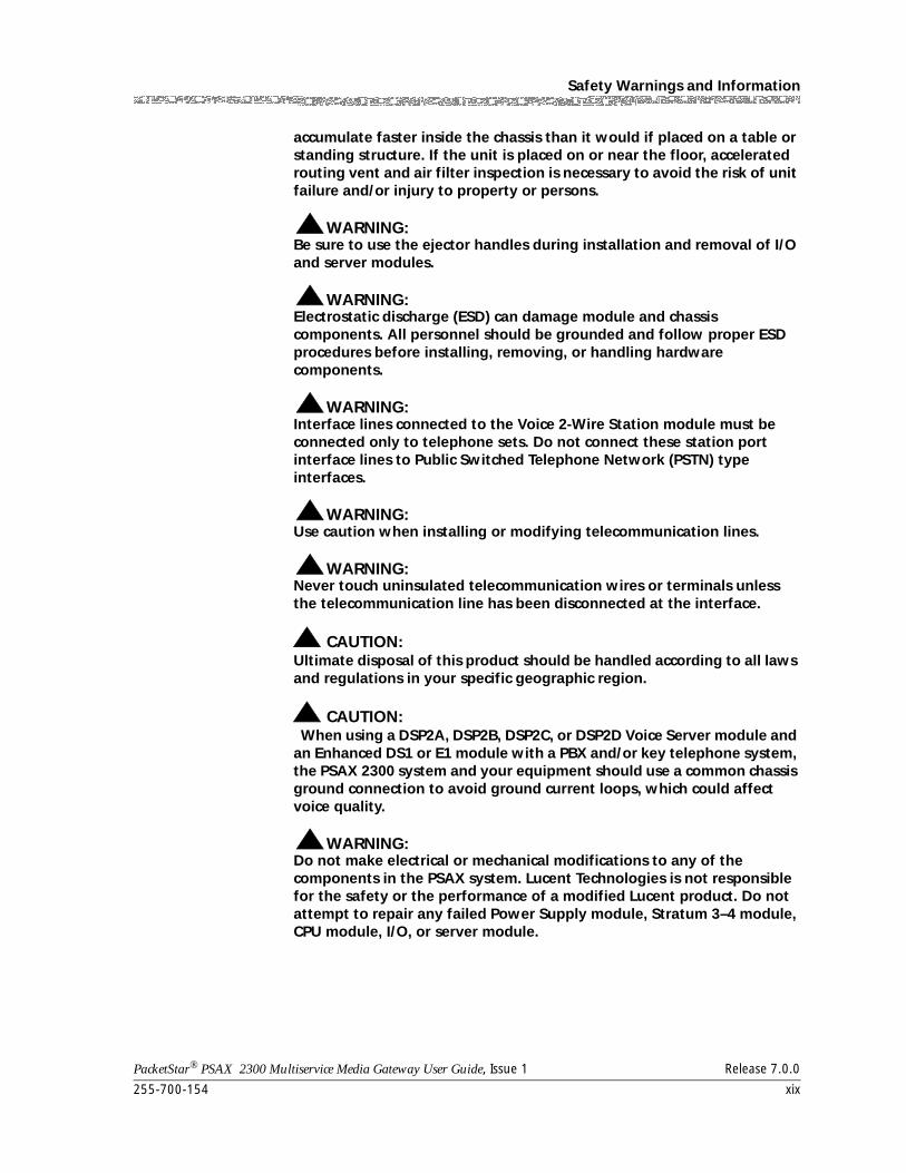
accumulate faster inside the chassis than it would if placed on a table or standing structure. If the unit is placed on or near the floor, accelerated routing vent and air filter inspection is necessary to avoid the risk of unit failure and/or injury to property or persons.
WARNING:!
Be sure to use the ejector handles during installation and removal of I/O and server modules.
WARNING:!
Electrostatic discharge (ESD) can damage module and chassis components. All personnel should be grounded and follow proper ESD procedures before installing, removing, or handling hardware components.
WARNING:!
Interface lines connected to the Voice 2-Wire Station module must be connected only to telephone sets. Do not connect these station port interface lines to Public Switched Telephone Network (PSTN) type interfaces.
WARNING:!
Use caution when installing or modifying telecommunication lines.
WARNING:!
Never touch uninsulated telecommunication wires or terminals unless the telecommunication line has been disconnected at the interface.
! CAUTION:Ultimate disposal of this product should be handled according to all laws and regulations in your specific geographic region.
! CAUTION: When using a DSP2A, DSP2B, DSP2C, or DSP2D Voice Server module and an Enhanced DS1 or E1 module with a PBX and/or key telephone system, the PSAX 2300 system and your equipment should use a common chassis ground connection to avoid ground current loops, which could affect voice quality.
WARNING:!
Do not make electrical or mechanical modifications to any of the components in the PSAX system. Lucent Technologies is not responsible for the safety or the performance of a modified Lucent product. Do not attempt to repair any failed Power Supply module, Stratum 3–4 module, CPU module, I/O, or server module.

Safety Warnings and Information
xx 255-700-154
PacketStar® PSAX 2300 Multiservice Media Gateway User Guide, Issue 1 Release 7.0.0
255-700-154 xxi
PacketStar® PSAX 2300 Multiservice Media Gateway User Guide, Issue 1 Release 7.0.0
Contents
Copyright and Legal Notices . . . . . . . . . . . . . . . . . . . . . . . . . . . . . . . . . . . . . . . . . iiiCopyright. . . . . . . . . . . . . . . . . . . . . . . . . . . . . . . . . . . . . . . . . . . . . . . . . . . . . . . . . . . . . . iii
Trademarks . . . . . . . . . . . . . . . . . . . . . . . . . . . . . . . . . . . . . . . . . . . . . . . . . . . . . . . . . . . . iii
Warranty Information. . . . . . . . . . . . . . . . . . . . . . . . . . . . . . . . . . . . . . . . . . . . . . . . . . . . . iii
Software and Hardware Limited Warranties . . . . . . . . . . . . . . . . . . . . . . . . . . . . . . . . . . . . iii
Warranty Warnings . . . . . . . . . . . . . . . . . . . . . . . . . . . . . . . . . . . . . . . . . . . . . . . . . . . iv
Regulatory Standards Compliance . . . . . . . . . . . . . . . . . . . . . . . . . . . . . . . . . . . . . . . . . . . v
Safety . . . . . . . . . . . . . . . . . . . . . . . . . . . . . . . . . . . . . . . . . . . . . . . . . . . . . . . . . . . . . v
Electromagnetic Compatibility . . . . . . . . . . . . . . . . . . . . . . . . . . . . . . . . . . . . . . . . . . . v
Telecommunications . . . . . . . . . . . . . . . . . . . . . . . . . . . . . . . . . . . . . . . . . . . . . . . . . . vi
Regulatory Statements . . . . . . . . . . . . . . . . . . . . . . . . . . . . . . . . . . . . . . . . . . . . . . . . . . . . vi
USA Regulatory Statements . . . . . . . . . . . . . . . . . . . . . . . . . . . . . . . . . . . . . . . . . . . . . vi
FCC Part 15 . . . . . . . . . . . . . . . . . . . . . . . . . . . . . . . . . . . . . . . . . . . . . . . . . . . . . . vi
FCC Part 68 . . . . . . . . . . . . . . . . . . . . . . . . . . . . . . . . . . . . . . . . . . . . . . . . . . . . . . vi
UL 1950. . . . . . . . . . . . . . . . . . . . . . . . . . . . . . . . . . . . . . . . . . . . . . . . . . . . . . . . .vii
Canadian Regulatory Statements . . . . . . . . . . . . . . . . . . . . . . . . . . . . . . . . . . . . . . . . . ix
ICES-003 . . . . . . . . . . . . . . . . . . . . . . . . . . . . . . . . . . . . . . . . . . . . . . . . . . . . . . . . ix
NMB-003. . . . . . . . . . . . . . . . . . . . . . . . . . . . . . . . . . . . . . . . . . . . . . . . . . . . . . . . ix
CS-03 . . . . . . . . . . . . . . . . . . . . . . . . . . . . . . . . . . . . . . . . . . . . . . . . . . . . . . . . . . ix
SH03 . . . . . . . . . . . . . . . . . . . . . . . . . . . . . . . . . . . . . . . . . . . . . . . . . . . . . . . . . . . x
European Union Regulatory Statement. . . . . . . . . . . . . . . . . . . . . . . . . . . . . . . . . . . . . xi
CE Marking . . . . . . . . . . . . . . . . . . . . . . . . . . . . . . . . . . . . . . . . . . . . . . . . . . . . . . xi
EN 300 386-2 . . . . . . . . . . . . . . . . . . . . . . . . . . . . . . . . . . . . . . . . . . . . . . . . . . . .xv
Japanese Regulatory Statement . . . . . . . . . . . . . . . . . . . . . . . . . . . . . . . . . . . . . . . . . .xv
Voluntary Control Council (VCCI) Class A Regulatory Statement. . . . . . . . . . . . . . .xv
JATE. . . . . . . . . . . . . . . . . . . . . . . . . . . . . . . . . . . . . . . . . . . . . . . . . . . . . . . . . . . .xv
Class A Electromagnetic Compatibility (EMC) Regulatory Statement. . . . . . . . . . . . . . xvi
CISPR 22EN 55022AS/NZS-3548 . . . . . . . . . . . . . . . . . . . . . . . . . . . . . . . . . . . . . . . . . . . . . . . . . . . xvi
Safety Warnings and Information . . . . . . . . . . . . . . . . . . . . . . . . . . . . . . . . . . . . xvii
1 Getting Started . . . . . . . . . . . . . . . . . . . . . . . . . . . . . . . . . . . . . . . . . . . . . . . . . 1-1Overview of This Guide . . . . . . . . . . . . . . . . . . . . . . . . . . . . . . . . . . . . . . . . . . . . . . . . . .1-1.1-1
1-1
xvii
xvi
xvi
.xv
.xv
.xv
.xv
xi
xi
x
ix
ix
ix
ix
.vii
vi
vi
vi
vi
vi
v
v
v
iv
iii
iii
iii
iii
iii
Contents
xxii 255-700-154
PacketStar® PSAX 2300 Multiservice Media Gateway User Guide, Issue 1 Release 7.0.0
Audience for This Guide . . . . . . . . . . . . . . . . . . . . . . . . . . . . . . . . . . . . . . . . . . . . . . . . . 1-1
What You Should Know . . . . . . . . . . . . . . . . . . . . . . . . . . . . . . . . . . . . . . . . . . . . . . . . . 1-1
Related Reading . . . . . . . . . . . . . . . . . . . . . . . . . . . . . . . . . . . . . . . . . . . . . . . . . . . . . . . 1-1
Lucent Technologies Information Products . . . . . . . . . . . . . . . . . . . . . . . . . . . . . . . . 1-1
Product Information Library . . . . . . . . . . . . . . . . . . . . . . . . . . . . . . . . . . . . . . . . 1-1
Printed Documents . . . . . . . . . . . . . . . . . . . . . . . . . . . . . . . . . . . . . . . . . . . . . . . 1-2
Other Publications . . . . . . . . . . . . . . . . . . . . . . . . . . . . . . . . . . . . . . . . . . . . . . . 1-2
About Lucent Technologies . . . . . . . . . . . . . . . . . . . . . . . . . . . . . . . . . . . . . . . . . . . . . . . 1-2
History . . . . . . . . . . . . . . . . . . . . . . . . . . . . . . . . . . . . . . . . . . . . . . . . . . . . . . . . . . . 1-2
For More Information . . . . . . . . . . . . . . . . . . . . . . . . . . . . . . . . . . . . . . . . . . . . . . . . 1-2
About the PacketStar®PSAX Product Family . . . . . . . . . . . . . . . . . . . . . . . . . . . . . . . . . . 1-2
Text Types Used in This Document . . . . . . . . . . . . . . . . . . . . . . . . . . . . . . . . . . . . . . 1-4
Icons and Symbols . . . . . . . . . . . . . . . . . . . . . . . . . . . . . . . . . . . . . . . . . . . . . . . . . . 1-5
Electrostatic Discharge Precautions . . . . . . . . . . . . . . . . . . . . . . . . . . . . . . . . . . . . . . 1-6
Grounding Wrist Straps . . . . . . . . . . . . . . . . . . . . . . . . . . . . . . . . . . . . . . . . . . . . . . 1-6
Floor Covering . . . . . . . . . . . . . . . . . . . . . . . . . . . . . . . . . . . . . . . . . . . . . . . . . . . . . 1-6
Temperature and Humidity . . . . . . . . . . . . . . . . . . . . . . . . . . . . . . . . . . . . . . . . . . . . 1-6
Clothing. . . . . . . . . . . . . . . . . . . . . . . . . . . . . . . . . . . . . . . . . . . . . . . . . . . . . . . . . . 1-7
Handling PSAX 2300 System Components . . . . . . . . . . . . . . . . . . . . . . . . . . . . . . . . 1-7
Technical Support . . . . . . . . . . . . . . . . . . . . . . . . . . . . . . . . . . . . . . . . . . . . . . . . . . . . . . 1-7
Comments on This Guide . . . . . . . . . . . . . . . . . . . . . . . . . . . . . . . . . . . . . . . . . . . . . . . . 1-7
Before You Begin . . . . . . . . . . . . . . . . . . . . . . . . . . . . . . . . . . . . . . . . . . . . . . . . . . . . . . 1-7
2 Hardware Description . . . . . . . . . . . . . . . . . . . . . . . . . . . . . . . . . . . . . . . . . . . .2-1Overview of This Chapter . . . . . . . . . . . . . . . . . . . . . . . . . . . . . . . . . . . . . . . . . . . . . . . . 2-1
PSAX 2300 System Features . . . . . . . . . . . . . . . . . . . . . . . . . . . . . . . . . . . . . . . . . . . . . . 2-1
PSAX 2300 System Hardware Components . . . . . . . . . . . . . . . . . . . . . . . . . . . . . . . . . . 2-2
PSAX 2300 Chassis. . . . . . . . . . . . . . . . . . . . . . . . . . . . . . . . . . . . . . . . . . . . . . . . . . 2-4
Module Slots . . . . . . . . . . . . . . . . . . . . . . . . . . . . . . . . . . . . . . . . . . . . . . . . . . . 2-4
PSAX 2300 Backplane . . . . . . . . . . . . . . . . . . . . . . . . . . . . . . . . . . . . . . . . . . . . 2-5
Power Supply Modules . . . . . . . . . . . . . . . . . . . . . . . . . . . . . . . . . . . . . . . . . . . . . . . 2-6
CPU Module. . . . . . . . . . . . . . . . . . . . . . . . . . . . . . . . . . . . . . . . . . . . . . . . . . . . . . . 2-7
3 System Features . . . . . . . . . . . . . . . . . . . . . . . . . . . . . . . . . . . . . . . . . . . . . . . . .3-1Overview of This Chapter . . . . . . . . . . . . . . . . . . . . . . . . . . . . . . . . . . . . . . . . . . . . . . . . 3-1
System Capabilites . . . . . . . . . . . . . . . . . . . . . . . . . . . . . . . . . . . . . . . . . . . . . . . . . . . . . 3-1
Interface Architecture . . . . . . . . . . . . . . . . . . . . . . . . . . . . . . . . . . . . . . . . . . . . . . . . . . . 3-4
User Interfaces . . . . . . . . . . . . . . . . . . . . . . . . . . . . . . . . . . . . . . . . . . . . . . . . . . . . . . . . 3-4
Circuit Emulation Service . . . . . . . . . . . . . . . . . . . . . . . . . . . . . . . . . . . . . . . . . . . . . 3-43-4
3-4
3-4
3-1
3-1
3-1
2-7
2-6
2-5
2-4
2-4
2-2
2-1
2-1
2-1
1-7
1-7
1-7
1-7
1-7
1-6
1-6
1-6
1-6
1-5
1-4
1-2
1-2
1-2
1-2
1-2
1-2
1-1
1-1
1-1
1-1
1-1
Contents
255-700-154 xxiii
PacketStar® PSAX 2300 Multiservice Media Gateway User Guide, Issue 1 Release 7.0.0
SPVC Support for CES . . . . . . . . . . . . . . . . . . . . . . . . . . . . . . . . . . . . . . . . . . . . .3-5
Circuit Emulation Service for the Multi-Serial Module . . . . . . . . . . . . . . . . . . . . . .3-5
Dynamic Bandwidth Circuit Emulation Service . . . . . . . . . . . . . . . . . . . . . . . . . . . . . .3-5
DS1 Service . . . . . . . . . . . . . . . . . . . . . . . . . . . . . . . . . . . . . . . . . . . . . . . . . . . . . . . .3-6
DS1 ANI In-line Codes for Loopbacks . . . . . . . . . . . . . . . . . . . . . . . . . . . . . . . . . . . . .3-6
DS3 Service . . . . . . . . . . . . . . . . . . . . . . . . . . . . . . . . . . . . . . . . . . . . . . . . . . . . . . . .3-6
HDLC Passthrough. . . . . . . . . . . . . . . . . . . . . . . . . . . . . . . . . . . . . . . . . . . . . . . . . . .3-6
HDLC Passthrough Bit Inversion . . . . . . . . . . . . . . . . . . . . . . . . . . . . . . . . . . . . . . . . .3-7
Interface Protection Groups . . . . . . . . . . . . . . . . . . . . . . . . . . . . . . . . . . . . . . . . . . . .3-7
Internet Protocol (IP) Forwarding . . . . . . . . . . . . . . . . . . . . . . . . . . . . . . . . . . . . . . . .3-9
Interim Interswitch Signaling Protocol (IISP) Interface . . . . . . . . . . . . . . . . . . . . . . . .3-10
Private Network-Network Interface (PNNI) 1.0 . . . . . . . . . . . . . . . . . . . . . . . . . . . . .3-10
PNNI Features Supported by the PSAX Systems. . . . . . . . . . . . . . . . . . . . . . . . . .3-10
PNNI Peer Group Dynamics . . . . . . . . . . . . . . . . . . . . . . . . . . . . . . . . . . . . . . . .3-11
PNNI Topology Information. . . . . . . . . . . . . . . . . . . . . . . . . . . . . . . . . . . . . . . . .3-11
PNNI Hierarchies. . . . . . . . . . . . . . . . . . . . . . . . . . . . . . . . . . . . . . . . . . . . . . . . .3-12
ATM Maintenance . . . . . . . . . . . . . . . . . . . . . . . . . . . . . . . . . . . . . . . . . . . . . . .3-12
Integrated Link Management Interface (ILMI) . . . . . . . . . . . . . . . . . . . . . . . . . . . . . .3-13
ILMI Over PNNI Overview . . . . . . . . . . . . . . . . . . . . . . . . . . . . . . . . . . . . . . . . . .3-13
Load Balancing for IISP and PNNI . . . . . . . . . . . . . . . . . . . . . . . . . . . . . . . . . . . .3-14
ATM UNI 4.0 Signaling. . . . . . . . . . . . . . . . . . . . . . . . . . . . . . . . . . . . . . . . . . . . . . .3-14
ATM Terminal Emulation . . . . . . . . . . . . . . . . . . . . . . . . . . . . . . . . . . . . . . . . . . . . .3-14
Network Management . . . . . . . . . . . . . . . . . . . . . . . . . . . . . . . . . . . . . . . . . . . . . . . . . .3-15
AQueView® Element Management System . . . . . . . . . . . . . . . . . . . . . . . . . . . . . . .3-16
Multiservice Media Gateway PSAX 2300 Software Features . . . . . . . . . . . . . . . . . . . . . .3-17
Alternate Rerouting Using Dual-Homed PVCs. . . . . . . . . . . . . . . . . . . . . . . . . . . . . .3-17
Overview . . . . . . . . . . . . . . . . . . . . . . . . . . . . . . . . . . . . . . . . . . . . . . . . . . . . . .3-17
Operation . . . . . . . . . . . . . . . . . . . . . . . . . . . . . . . . . . . . . . . . . . . . . . . . . . . . .3-18
Application . . . . . . . . . . . . . . . . . . . . . . . . . . . . . . . . . . . . . . . . . . . . . . . . . . . .3-18
The AQueMan Algorithm. . . . . . . . . . . . . . . . . . . . . . . . . . . . . . . . . . . . . . . . . . . . .3-19
ATM Trunking . . . . . . . . . . . . . . . . . . . . . . . . . . . . . . . . . . . . . . . . . . . . . . . . . . . . .3-24
Connection Gateway API . . . . . . . . . . . . . . . . . . . . . . . . . . . . . . . . . . . . . . . . . . . . .3-24
Firmware Release Control . . . . . . . . . . . . . . . . . . . . . . . . . . . . . . . . . . . . . . . . . . . .3-25
Forward Error Correction . . . . . . . . . . . . . . . . . . . . . . . . . . . . . . . . . . . . . . . . . . . . .3-26
Frame Relay-to-ATM Interworking . . . . . . . . . . . . . . . . . . . . . . . . . . . . . . . . . . . . . .3-27
FRF.5 Encapsulating Frames . . . . . . . . . . . . . . . . . . . . . . . . . . . . . . . . . . . . . . . .3-28
FRF.8 Converting Frames . . . . . . . . . . . . . . . . . . . . . . . . . . . . . . . . . . . . . . . . . .3-28
Frame Relay-to-Frame Relay Interworking. . . . . . . . . . . . . . . . . . . . . . . . . . . . . . . . .3-28
GR-303 Interface . . . . . . . . . . . . . . . . . . . . . . . . . . . . . . . . . . . . . . . . . . . . . . . . . . .3-28.3-28
.3-28
.3-28
.3-28
.3-27
.3-26
.3-25
.3-24
.3-24
.3-19
.3-18
.3-18
.3-17
.3-17
.3-17
.3-16
.3-15
.3-14
.3-14
.3-14
.3-13
.3-13
.3-12
.3-12
.3-11
.3-11
.3-10
.3-10
.3-10
.3-9
.3-7
.3-7
.3-6
.3-6
.3-6
.3-6
.3-5
.3-5
.3-5
Contents
xxiv 255-700-154
PacketStar® PSAX 2300 Multiservice Media Gateway User Guide, Issue 1 Release 7.0.0
Inverse Multiplexing over ATM (IMA) . . . . . . . . . . . . . . . . . . . . . . . . . . . . . . . . . . . 3-29
LANET Protocol . . . . . . . . . . . . . . . . . . . . . . . . . . . . . . . . . . . . . . . . . . . . . . . . . . . 3-29
Operations, Administration, and Maintenance (OAM). . . . . . . . . . . . . . . . . . . . . . . 3-32
Overview . . . . . . . . . . . . . . . . . . . . . . . . . . . . . . . . . . . . . . . . . . . . . . . . . . . . . 3-32
OAM Cell Characteristics . . . . . . . . . . . . . . . . . . . . . . . . . . . . . . . . . . . . . . . . . 3-33
OAM ATM Layer Flows . . . . . . . . . . . . . . . . . . . . . . . . . . . . . . . . . . . . . . . . . . . 3-34
OAM F4 Cells . . . . . . . . . . . . . . . . . . . . . . . . . . . . . . . . . . . . . . . . . . . . . . . . . . 3-35
OAM F5 Flows . . . . . . . . . . . . . . . . . . . . . . . . . . . . . . . . . . . . . . . . . . . . . . . . . 3-35
ATM Layer OAM Functions . . . . . . . . . . . . . . . . . . . . . . . . . . . . . . . . . . . . . . . . 3-36
Soft Permanent Virtual Circuits (SPVCs). . . . . . . . . . . . . . . . . . . . . . . . . . . . . . . . . . . . . 3-38
Switched Virtual Circuits . . . . . . . . . . . . . . . . . . . . . . . . . . . . . . . . . . . . . . . . . . . . . . . . 3-38
SVC Functional Description. . . . . . . . . . . . . . . . . . . . . . . . . . . . . . . . . . . . . . . . 3-39
Call States . . . . . . . . . . . . . . . . . . . . . . . . . . . . . . . . . . . . . . . . . . . . . . . . . . . . 3-39
Traffic Management (UPC Support). . . . . . . . . . . . . . . . . . . . . . . . . . . . . . . . . . . . . . . . 3-42
Traffic Shaping . . . . . . . . . . . . . . . . . . . . . . . . . . . . . . . . . . . . . . . . . . . . . . . . . . . . . . . 3-42
Rate Shaping . . . . . . . . . . . . . . . . . . . . . . . . . . . . . . . . . . . . . . . . . . . . . . . . . . . . . 3-45
Where to Apply Rate Shaping During Configuration. . . . . . . . . . . . . . . . . . . . . . . . 3-45
Configuring Rate Shaping for HDLC, Frame Relay, and Ethernet Virtual Channels . . 3-46
Modules Used With Rate Shaping . . . . . . . . . . . . . . . . . . . . . . . . . . . . . . . . . . . . . 3-46
VBR Rate Shaping Priorities. . . . . . . . . . . . . . . . . . . . . . . . . . . . . . . . . . . . . . . . . . . 3-46
Rate Shaping for CBR and VBR-rt . . . . . . . . . . . . . . . . . . . . . . . . . . . . . . . . . . . . . . 3-47
Rate Shaping Connection Maximum. . . . . . . . . . . . . . . . . . . . . . . . . . . . . . . . . . . . 3-47
How the Algorithm Works . . . . . . . . . . . . . . . . . . . . . . . . . . . . . . . . . . . . . . . . . . . 3-47
Formula for Determining the PCR of a Rate Shaped Connection . . . . . . . . . . . . . . . 3-49
Virtual Interfaces. . . . . . . . . . . . . . . . . . . . . . . . . . . . . . . . . . . . . . . . . . . . . . . . . . . . . . 3-49
Voice Compression . . . . . . . . . . . . . . . . . . . . . . . . . . . . . . . . . . . . . . . . . . . . . . . . . . . . 3-54
Voice Processing . . . . . . . . . . . . . . . . . . . . . . . . . . . . . . . . . . . . . . . . . . . . . . . . . . . . . . 3-54
I/O, Optical, and Server Modules. . . . . . . . . . . . . . . . . . . . . . . . . . . . . . . . . . . . . . . . . . 3-55
Alarm Module . . . . . . . . . . . . . . . . . . . . . . . . . . . . . . . . . . . . . . . . . . . . . . . . . . . . . . . 3-57
Software Features. . . . . . . . . . . . . . . . . . . . . . . . . . . . . . . . . . . . . . . . . . . . . . . . . . 3-57
Defining Alarm Conditions . . . . . . . . . . . . . . . . . . . . . . . . . . . . . . . . . . . . . . . . . . . 3-57
Alarm Module Response. . . . . . . . . . . . . . . . . . . . . . . . . . . . . . . . . . . . . . . . . . . . . 3-58
Hardware Features . . . . . . . . . . . . . . . . . . . . . . . . . . . . . . . . . . . . . . . . . . . . . . . . . 3-58
External Inputs . . . . . . . . . . . . . . . . . . . . . . . . . . . . . . . . . . . . . . . . . . . . . . . . . 3-59
Alarm Outputs . . . . . . . . . . . . . . . . . . . . . . . . . . . . . . . . . . . . . . . . . . . . . . . . . 3-59
Alarm Cut-Off . . . . . . . . . . . . . . . . . . . . . . . . . . . . . . . . . . . . . . . . . . . . . . . . . 3-59
Control Outputs . . . . . . . . . . . . . . . . . . . . . . . . . . . . . . . . . . . . . . . . . . . . . . . . 3-59
1-Port Channelized DS3 Module . . . . . . . . . . . . . . . . . . . . . . . . . . . . . . . . . . . . . . . . . . 3-60
Software Features. . . . . . . . . . . . . . . . . . . . . . . . . . . . . . . . . . . . . . . . . . . . . . . . . . 3-603-60
3-60
3-59
3-59
3-59
3-59
3-58
3-58
3-57
3-57
3-57
3-55
3-54
3-54
3-49
3-49
3-47
3-47
3-47
3-46
3-46
3-46
3-45
3-45
3-42
3-42
3-39
3-39
3-38
3-38
3-36
3-35
3-35
3-34
3-33
3-32
3-32
3-29
3-29
Contents
255-700-154 xxv
PacketStar® PSAX 2300 Multiservice Media Gateway User Guide, Issue 1 Release 7.0.0
Hardware Features . . . . . . . . . . . . . . . . . . . . . . . . . . . . . . . . . . . . . . . . . . . . . . . . . .3-61
3-Port Channelized DS3/STS-1e CES Module . . . . . . . . . . . . . . . . . . . . . . . . . . . . . . . . .3-62
Hardware Features . . . . . . . . . . . . . . . . . . . . . . . . . . . . . . . . . . . . . . . . . . . . . . . . . .3-63
1-Port Channelized STS-1e T1 Module . . . . . . . . . . . . . . . . . . . . . . . . . . . . . . . . . . . . . .3-63
Software Features . . . . . . . . . . . . . . . . . . . . . . . . . . . . . . . . . . . . . . . . . . . . . . . . . .3-64
Hardware Features . . . . . . . . . . . . . . . . . . . . . . . . . . . . . . . . . . . . . . . . . . . . . . . . . .3-65
6-Port DS1 IMA Module . . . . . . . . . . . . . . . . . . . . . . . . . . . . . . . . . . . . . . . . . . . . . . . . .3-65
Software Features . . . . . . . . . . . . . . . . . . . . . . . . . . . . . . . . . . . . . . . . . . . . . . . . . .3-65
Hardware Features . . . . . . . . . . . . . . . . . . . . . . . . . . . . . . . . . . . . . . . . . . . . . . . . . .3-66
2-Port DS3 ATM Module . . . . . . . . . . . . . . . . . . . . . . . . . . . . . . . . . . . . . . . . . . . . . . . .3-66
Software Features . . . . . . . . . . . . . . . . . . . . . . . . . . . . . . . . . . . . . . . . . . . . . . . . . .3-66
Hardware Features . . . . . . . . . . . . . . . . . . . . . . . . . . . . . . . . . . . . . . . . . . . . . . . . . .3-67
1-Port DS3 Frame Relay Module . . . . . . . . . . . . . . . . . . . . . . . . . . . . . . . . . . . . . . . . . . .3-67
Software Features . . . . . . . . . . . . . . . . . . . . . . . . . . . . . . . . . . . . . . . . . . . . . . . . . .3-67
Hardware Features . . . . . . . . . . . . . . . . . . . . . . . . . . . . . . . . . . . . . . . . . . . . . . . . . .3-68
1-Port DS3 IMA Module . . . . . . . . . . . . . . . . . . . . . . . . . . . . . . . . . . . . . . . . . . . . . . . . .3-68
Software Features . . . . . . . . . . . . . . . . . . . . . . . . . . . . . . . . . . . . . . . . . . . . . . . . . .3-68
Hardware Features . . . . . . . . . . . . . . . . . . . . . . . . . . . . . . . . . . . . . . . . . . . . . . . . . .3-69
6-Port E1 IMA Module . . . . . . . . . . . . . . . . . . . . . . . . . . . . . . . . . . . . . . . . . . . . . . . . . .3-69
Software Features . . . . . . . . . . . . . . . . . . . . . . . . . . . . . . . . . . . . . . . . . . . . . . . . . .3-70
Hardware Features . . . . . . . . . . . . . . . . . . . . . . . . . . . . . . . . . . . . . . . . . . . . . . . . . .3-70
2-Port E3 ATM Module. . . . . . . . . . . . . . . . . . . . . . . . . . . . . . . . . . . . . . . . . . . . . . . . . .3-70
Software Features . . . . . . . . . . . . . . . . . . . . . . . . . . . . . . . . . . . . . . . . . . . . . . . . . .3-70
Hardware Features . . . . . . . . . . . . . . . . . . . . . . . . . . . . . . . . . . . . . . . . . . . . . . . . . .3-71
6-Port Enhanced DS1 Module. . . . . . . . . . . . . . . . . . . . . . . . . . . . . . . . . . . . . . . . . . . . .3-71
Software Features . . . . . . . . . . . . . . . . . . . . . . . . . . . . . . . . . . . . . . . . . . . . . . . . . .3-72
Hardware Features . . . . . . . . . . . . . . . . . . . . . . . . . . . . . . . . . . . . . . . . . . . . . . . . . .3-73
6-Port Enhanced E1 Module . . . . . . . . . . . . . . . . . . . . . . . . . . . . . . . . . . . . . . . . . . . . . .3-73
Software Features . . . . . . . . . . . . . . . . . . . . . . . . . . . . . . . . . . . . . . . . . . . . . . . . . .3-73
Hardware Features . . . . . . . . . . . . . . . . . . . . . . . . . . . . . . . . . . . . . . . . . . . . . . . . . .3-74
Ethernet Module . . . . . . . . . . . . . . . . . . . . . . . . . . . . . . . . . . . . . . . . . . . . . . . . . . . . . .3-74
Software Features . . . . . . . . . . . . . . . . . . . . . . . . . . . . . . . . . . . . . . . . . . . . . . . . . .3-75
Hardware Features . . . . . . . . . . . . . . . . . . . . . . . . . . . . . . . . . . . . . . . . . . . . . . . . . .3-75
21-Port High-Density E1 Module . . . . . . . . . . . . . . . . . . . . . . . . . . . . . . . . . . . . . . . . . .3-75
Software Features . . . . . . . . . . . . . . . . . . . . . . . . . . . . . . . . . . . . . . . . . . . . . . . . . .3-76
Hardware Features . . . . . . . . . . . . . . . . . . . . . . . . . . . . . . . . . . . . . . . . . . . . . . . . . .3-77
12-Port Medium-Density DS1 Module . . . . . . . . . . . . . . . . . . . . . . . . . . . . . . . . . . . . . .3-77
Software Features . . . . . . . . . . . . . . . . . . . . . . . . . . . . . . . . . . . . . . . . . . . . . . . . . .3-78
Hardware Features . . . . . . . . . . . . . . . . . . . . . . . . . . . . . . . . . . . . . . . . . . . . . . . . . .3-78.3-78
.3-78
.3-77
.3-77
.3-76
.3-75
.3-75
.3-75
.3-74
.3-74
.3-73
.3-73
.3-73
.3-72
.3-71
.3-71
.3-70
.3-70
.3-70
.3-70
.3-69
.3-69
.3-68
.3-68
.3-68
.3-67
.3-67
.3-67
.3-66
.3-66
.3-66
.3-65
.3-65
.3-65
.3-64
.3-63
.3-63
.3-62
.3-61
Contents
xxvi 255-700-154
PacketStar® PSAX 2300 Multiservice Media Gateway User Guide, Issue 1 Release 7.0.0
6-Port Multiserial Module . . . . . . . . . . . . . . . . . . . . . . . . . . . . . . . . . . . . . . . . . . . . . . . 3-78
Bit Stuffing and CES Conversion . . . . . . . . . . . . . . . . . . . . . . . . . . . . . . . . . . . . 3-78
Interfaces . . . . . . . . . . . . . . . . . . . . . . . . . . . . . . . . . . . . . . . . . . . . . . . . . . . . . 3-79
Software Features. . . . . . . . . . . . . . . . . . . . . . . . . . . . . . . . . . . . . . . . . . . . . . . . . . 3-79
Frame Relay . . . . . . . . . . . . . . . . . . . . . . . . . . . . . . . . . . . . . . . . . . . . . . . . . . . 3-79
Circuit Emulation . . . . . . . . . . . . . . . . . . . . . . . . . . . . . . . . . . . . . . . . . . . . . . . 3-80
Terminal Emulation . . . . . . . . . . . . . . . . . . . . . . . . . . . . . . . . . . . . . . . . . . . . . . 3-80
HDLC Pass-through . . . . . . . . . . . . . . . . . . . . . . . . . . . . . . . . . . . . . . . . . . . . . 3-80
ATM . . . . . . . . . . . . . . . . . . . . . . . . . . . . . . . . . . . . . . . . . . . . . . . . . . . . . . . . . 3-80
Hardware Features . . . . . . . . . . . . . . . . . . . . . . . . . . . . . . . . . . . . . . . . . . . . . . . . . 3-80
Quadserial Module . . . . . . . . . . . . . . . . . . . . . . . . . . . . . . . . . . . . . . . . . . . . . . . . . . . . 3-81
Software Features. . . . . . . . . . . . . . . . . . . . . . . . . . . . . . . . . . . . . . . . . . . . . . . . . . 3-82
Hardware Features . . . . . . . . . . . . . . . . . . . . . . . . . . . . . . . . . . . . . . . . . . . . . . . . . 3-82
3-Port Unstructured DS3/E3 CES Module . . . . . . . . . . . . . . . . . . . . . . . . . . . . . . . . . . . 3-82
Software Features. . . . . . . . . . . . . . . . . . . . . . . . . . . . . . . . . . . . . . . . . . . . . . . . . . 3-83
Hardware Features . . . . . . . . . . . . . . . . . . . . . . . . . . . . . . . . . . . . . . . . . . . . . . . . . 3-83
2-Port Voice 2-Wire Office Module . . . . . . . . . . . . . . . . . . . . . . . . . . . . . . . . . . . . . . . . 3-83
Software Features. . . . . . . . . . . . . . . . . . . . . . . . . . . . . . . . . . . . . . . . . . . . . . . . . . 3-84
Hardware Features . . . . . . . . . . . . . . . . . . . . . . . . . . . . . . . . . . . . . . . . . . . . . . . . . 3-84
8-Port Voice 2-Wire Station Module . . . . . . . . . . . . . . . . . . . . . . . . . . . . . . . . . . . . . . . 3-84
Software Features. . . . . . . . . . . . . . . . . . . . . . . . . . . . . . . . . . . . . . . . . . . . . . . . . . 3-84
Hardware Features . . . . . . . . . . . . . . . . . . . . . . . . . . . . . . . . . . . . . . . . . . . . . . . . . 3-85
Optical-Type I/O Modules . . . . . . . . . . . . . . . . . . . . . . . . . . . . . . . . . . . . . . . . . . . . . . . 3-85
1-Port OC-12c/STM-4c 1+1 APS/MSP Multimode and Single-Mode Modules. . . . . . . . . 3-85
Hardware Features . . . . . . . . . . . . . . . . . . . . . . . . . . . . . . . . . . . . . . . . . . . . . . . . . 3-86
1-Port OC-3c Multimode and Single-Mode Modules . . . . . . . . . . . . . . . . . . . . . . . . . . . 3-86
Software Features. . . . . . . . . . . . . . . . . . . . . . . . . . . . . . . . . . . . . . . . . . . . . . . . . . 3-87
Hardware Features . . . . . . . . . . . . . . . . . . . . . . . . . . . . . . . . . . . . . . . . . . . . . . . . . 3-87
1-Port OC-3c Multimode and Single-Mode 1+1 APS Modules . . . . . . . . . . . . . . . . . . . . 3-88
Software Features. . . . . . . . . . . . . . . . . . . . . . . . . . . . . . . . . . . . . . . . . . . . . . . . . . 3-88
Hardware Features . . . . . . . . . . . . . . . . . . . . . . . . . . . . . . . . . . . . . . . . . . . . . . . . . 3-89
1-Port STM-1 Multimode and Single-Mode Modules. . . . . . . . . . . . . . . . . . . . . . . . . . . 3-89
Software Features. . . . . . . . . . . . . . . . . . . . . . . . . . . . . . . . . . . . . . . . . . . . . . . . . . 3-90
Hardware Features . . . . . . . . . . . . . . . . . . . . . . . . . . . . . . . . . . . . . . . . . . . . . . . . . 3-91
1-Port STM-1 Multi-Mode and Single-Mode 1+1 MSP Modules. . . . . . . . . . . . . . . . . . . 3-91
Software Features. . . . . . . . . . . . . . . . . . . . . . . . . . . . . . . . . . . . . . . . . . . . . . . . . . 3-92
Hardware Features . . . . . . . . . . . . . . . . . . . . . . . . . . . . . . . . . . . . . . . . . . . . . . . . . 3-92
Server Modules. . . . . . . . . . . . . . . . . . . . . . . . . . . . . . . . . . . . . . . . . . . . . . . . . . . . . . . 3-93
DSP2x Voice Server Modules . . . . . . . . . . . . . . . . . . . . . . . . . . . . . . . . . . . . . . . . . . . . . 3-933-93
3-93
3-92
3-92
3-91
3-91
3-90
3-89
3-89
3-88
3-88
3-87
3-87
3-86
3-86
3-85
3-85
3-85
3-84
3-84
3-84
3-84
3-83
3-83
3-83
3-82
3-82
3-82
3-81
3-80
3-80
3-80
3-80
3-80
3-79
3-79
3-79
3-78
3-78
Contents
255-700-154 xxvii
PacketStar® PSAX 2300 Multiservice Media Gateway User Guide, Issue 1 Release 7.0.0
Software Features . . . . . . . . . . . . . . . . . . . . . . . . . . . . . . . . . . . . . . . . . . . . . . . . . .3-93
Hardware Features . . . . . . . . . . . . . . . . . . . . . . . . . . . . . . . . . . . . . . . . . . . . . . . . . .3-94
Route Server Module . . . . . . . . . . . . . . . . . . . . . . . . . . . . . . . . . . . . . . . . . . . . . . . . . . .3-94
Software Features . . . . . . . . . . . . . . . . . . . . . . . . . . . . . . . . . . . . . . . . . . . . . . . . . .3-95
Hardware Features . . . . . . . . . . . . . . . . . . . . . . . . . . . . . . . . . . . . . . . . . . . . . . . . . .3-96
Tones and Announcements Server Module . . . . . . . . . . . . . . . . . . . . . . . . . . . . . . . . . . .3-96
Hardware Features . . . . . . . . . . . . . . . . . . . . . . . . . . . . . . . . . . . . . . . . . . . . . . . . . .3-96
4 Configuring the Basic System . . . . . . . . . . . . . . . . . . . . . . . . . . . . . . . . . . . . . 4-1Overview of This Chapter . . . . . . . . . . . . . . . . . . . . . . . . . . . . . . . . . . . . . . . . . . . . . . . . .4-1
Logging onto the System . . . . . . . . . . . . . . . . . . . . . . . . . . . . . . . . . . . . . . . . . . . . . . . . .4-1
Help Information . . . . . . . . . . . . . . . . . . . . . . . . . . . . . . . . . . . . . . . . . . . . . . . . . . . .4-4
Selecting Options, Fields, and Commands . . . . . . . . . . . . . . . . . . . . . . . . . . . . . . . . .4-7
Changing the System Password and Other User Options . . . . . . . . . . . . . . . . . . . . . . . . .4-8
Console Interface Main Menu . . . . . . . . . . . . . . . . . . . . . . . . . . . . . . . . . . . . . . . . . . . .4-10
Configuring the System for Your Site . . . . . . . . . . . . . . . . . . . . . . . . . . . . . . . . . . . . . . .4-10
System Identification Data . . . . . . . . . . . . . . . . . . . . . . . . . . . . . . . . . . . . . . . . .4-11
Rules for Configuring IP Addresses. . . . . . . . . . . . . . . . . . . . . . . . . . . . . . . . . . . . . .4-12
Rules for Configuring IP Address Masks . . . . . . . . . . . . . . . . . . . . . . . . . . . . . . . . . .4-13
Configuring System Identification . . . . . . . . . . . . . . . . . . . . . . . . . . . . . . . . . . . . . .4-13
ATM Addresses and OAM Properties . . . . . . . . . . . . . . . . . . . . . . . . . . . . . . . . .4-13
Entering and Displaying ATM Addresses and OAM Properties . . . . . . . . . . . . . . .4-14
Configuring System Date and Time . . . . . . . . . . . . . . . . . . . . . . . . . . . . . . . . . . . . .4-16
System Date and Time Data . . . . . . . . . . . . . . . . . . . . . . . . . . . . . . . . . . . . . . . .4-16
Configuring the TCP Server and Client . . . . . . . . . . . . . . . . . . . . . . . . . . . . . . . . . . . . . .4-17
Connection Gateway Application Programming Interface (API) . . . . . . . . . . . . . .4-19
Configuring the TCP Server . . . . . . . . . . . . . . . . . . . . . . . . . . . . . . . . . . . . . . . .4-19
Configuring SNMP Trap Destinations . . . . . . . . . . . . . . . . . . . . . . . . . . . . . . . . . . . .4-21
Configuring In-Band Management . . . . . . . . . . . . . . . . . . . . . . . . . . . . . . . . . . . . . . . . .4-22
Adding an In-Band Management ATM SVC Connection. . . . . . . . . . . . . . . . . . . . . .4-23
Preparing for an In-Band Management SVC Connection . . . . . . . . . . . . . . . . . .4-23
Creating an In-Band-Management SVC Connection . . . . . . . . . . . . . . . . . . . . . .4-24
Viewing In-Band Statistics Data . . . . . . . . . . . . . . . . . . . . . . . . . . . . . . . . . . . . .4-31
Deleting an In-Band Management SVC Route . . . . . . . . . . . . . . . . . . . . . . . . . .4-33
PNNI System-Wide Configuration . . . . . . . . . . . . . . . . . . . . . . . . . . . . . . . . . . . . . . . . . .4-33
Configuring PNNI . . . . . . . . . . . . . . . . . . . . . . . . . . . . . . . . . . . . . . . . . . . . . . . .4-33
Configuring PNNI Route Addresses. . . . . . . . . . . . . . . . . . . . . . . . . . . . . . . . . . .4-40
Configuring PNNI Metrics . . . . . . . . . . . . . . . . . . . . . . . . . . . . . . . . . . . . . . . . . . . .4-45
Configuring Summary Addresses . . . . . . . . . . . . . . . . . . . . . . . . . . . . . . . . . . . . . . .4-49.4-49
.4-45
.4-40
.4-33
.4-33
.4-33
.4-31
.4-24
.4-23
.4-23
.4-22
.4-21
.4-19
.4-19
.4-17
.4-16
.4-16
.4-14
.4-13
.4-13
.4-13
.4-12
.4-11
.4-10
.4-10
.4-8
.4-7
.4-4
.4-1
.4-1
4-1
.3-96
.3-96
.3-96
.3-95
.3-94
.3-94
.3-93
Contents
xxviii 255-700-154
PacketStar® PSAX 2300 Multiservice Media Gateway User Guide, Issue 1 Release 7.0.0
Viewing the PNNI Map Link Table . . . . . . . . . . . . . . . . . . . . . . . . . . . . . . . . . . . . . . 4-53
Viewing the PNNI Link Table . . . . . . . . . . . . . . . . . . . . . . . . . . . . . . . . . . . . . . . . . . 4-57
Viewing the PNNI Neighbor Peer Table . . . . . . . . . . . . . . . . . . . . . . . . . . . . . . . . . . 4-63
Viewing PNNI System Statistics . . . . . . . . . . . . . . . . . . . . . . . . . . . . . . . . . . . . . . . . 4-67
Configuring Call Control Resource Allocation . . . . . . . . . . . . . . . . . . . . . . . . . . . . . . . . 4-70
Setting the Configuration Values . . . . . . . . . . . . . . . . . . . . . . . . . . . . . . . . . . . . . . 4-70
Configuration Guidelines . . . . . . . . . . . . . . . . . . . . . . . . . . . . . . . . . . . . . . . . . . . . 4-72
Saving the Configuration and Rebooting the System . . . . . . . . . . . . . . . . . . . . . . . 4-75
Backing Up Your Configuration Data . . . . . . . . . . . . . . . . . . . . . . . . . . . . . . . . . . . 4-77
Configuring the GR-303 Interface. . . . . . . . . . . . . . . . . . . . . . . . . . . . . . . . . . . . . . . . . 4-77
Configuring ATM Trunking . . . . . . . . . . . . . . . . . . . . . . . . . . . . . . . . . . . . . . . . . . . . . . 4-78
Configuring the Local IWF Node. . . . . . . . . . . . . . . . . . . . . . . . . . . . . . . . . . . . . . . 4-78
Configuring a Remote IWF Node . . . . . . . . . . . . . . . . . . . . . . . . . . . . . . . . . . . . . . 4-81
Adding a Bearer VCC Identifier. . . . . . . . . . . . . . . . . . . . . . . . . . . . . . . . . . . . . . . . 4-85
Viewing ATM Trunking Information . . . . . . . . . . . . . . . . . . . . . . . . . . . . . . . . . . . . 4-92
Configuring Systemwide Use of the TAS Module. . . . . . . . . . . . . . . . . . . . . . . . . . . . . . 4-94
Turn On/Off Feature . . . . . . . . . . . . . . . . . . . . . . . . . . . . . . . . . . . . . . . . . . . . . . . . . . . 4-94
Interface Protection Feature . . . . . . . . . . . . . . . . . . . . . . . . . . . . . . . . . . . . . . . . . . . . 4-102
Adding Interface Protection Groups . . . . . . . . . . . . . . . . . . . . . . . . . . . . . . . . . . . 4-105
Using the Equipment Configuration Window . . . . . . . . . . . . . . . . . . . . . . . . . . . . . . . 4-110
Configuring the Stratum 3–4 Module . . . . . . . . . . . . . . . . . . . . . . . . . . . . . . . . . . . . . 4-111
Setting the Stratum Configuration Values. . . . . . . . . . . . . . . . . . . . . . . . . . . . . . . 4-111
Switching the Line Timing Source . . . . . . . . . . . . . . . . . . . . . . . . . . . . . . . . . . . . . 4-115
Configuring I/O and Server Modules . . . . . . . . . . . . . . . . . . . . . . . . . . . . . . . . . . . . . . 4-116
Alarm Status Values . . . . . . . . . . . . . . . . . . . . . . . . . . . . . . . . . . . . . . . . . . . . . . . 4-116
Saving the Equipment Configuration Values and Logging Off . . . . . . . . . . . . . . . . . . . 4-116
5 Using System Diagnostics . . . . . . . . . . . . . . . . . . . . . . . . . . . . . . . . . . . . . . . . .5-1Overview of This Chapter . . . . . . . . . . . . . . . . . . . . . . . . . . . . . . . . . . . . . . . . . . . . . . . . 5-1
Overview of Diagnostic Capabilities . . . . . . . . . . . . . . . . . . . . . . . . . . . . . . . . . . . . . . . . 5-1
Viewing System Status . . . . . . . . . . . . . . . . . . . . . . . . . . . . . . . . . . . . . . . . . . . . . . . . . . 5-1
Running Cell Test Diagnostics . . . . . . . . . . . . . . . . . . . . . . . . . . . . . . . . . . . . . . . . . . . . . 5-6
Cell Test Diagnostics . . . . . . . . . . . . . . . . . . . . . . . . . . . . . . . . . . . . . . . . . . . . . . . . . 5-6
Rebooting PSAX Hardware Components. . . . . . . . . . . . . . . . . . . . . . . . . . . . . . . . . . . . 5-11
Rebooting the PSAX System Hardware Components. . . . . . . . . . . . . . . . . . . . . 5-11
Removing Configuration Files . . . . . . . . . . . . . . . . . . . . . . . . . . . . . . . . . . . . . . . . . . . . 5-13
Removing Configuration Files . . . . . . . . . . . . . . . . . . . . . . . . . . . . . . . . . . . . . . 5-13
Unlocking a Telnet Session . . . . . . . . . . . . . . . . . . . . . . . . . . . . . . . . . . . . . . . . . . . . . . 5-14
Unlocking a Telnet Session . . . . . . . . . . . . . . . . . . . . . . . . . . . . . . . . . . . . . . . . 5-145-14
5-14
5-13
5-13
5-11
5-11
5-6
5-6
5-1
5-1
5-1
5-1
4-116
4-116
4-116
4-115
4-111
4-111
4-110
4-105
4-102
4-94
4-94
4-92
4-85
4-81
4-78
4-78
4-77
4-77
4-75
4-72
4-70
4-70
4-67
4-63
4-57
4-53
Contents
255-700-154 xxix
PacketStar® PSAX 2300 Multiservice Media Gateway User Guide, Issue 1 Release 7.0.0
Operations Administration and Maintenance (OAM). . . . . . . . . . . . . . . . . . . . . . . . . . . .5-15
Enabling OAM Loopback Functions . . . . . . . . . . . . . . . . . . . . . . . . . . . . . . . . . . . . . . . .5-16
OAM Activation and Deactivation . . . . . . . . . . . . . . . . . . . . . . . . . . . . . . . . . . . . . .5-20
6 Using VT100 Terminal Emulation. . . . . . . . . . . . . . . . . . . . . . . . . . . . . . . . . . . 6-1Overview of This Chapter . . . . . . . . . . . . . . . . . . . . . . . . . . . . . . . . . . . . . . . . . . . . . . . . .6-1
Overview of Terminal Emulation . . . . . . . . . . . . . . . . . . . . . . . . . . . . . . . . . . . . . . . . . . . .6-1
Setting Up The Windows 3.1 Terminal Emulator . . . . . . . . . . . . . . . . . . . . . . . . . . . . . . . .6-1
Setting Up The Windows 95 HyperTerminal Emulator . . . . . . . . . . . . . . . . . . . . . . . . . . . .6-3
Other Software for VT100 Terminal Emulation . . . . . . . . . . . . . . . . . . . . . . . . . . . . . . . . .6-3
Setting Up a U.S. Robotics-Compatible Modem . . . . . . . . . . . . . . . . . . . . . . . . . . . . . . . .6-4
7 Upgrading and Backing Up PSAX System Software . . . . . . . . . . . . . . . . . . . 7-1Overview of This Chapter . . . . . . . . . . . . . . . . . . . . . . . . . . . . . . . . . . . . . . . . . . . . . . . . .7-1
Directory Structures . . . . . . . . . . . . . . . . . . . . . . . . . . . . . . . . . . . . . . . . . . . . . . . . . .7-2
Installing a New Software Release . . . . . . . . . . . . . . . . . . . . . . . . . . . . . . . . . . . . . . .7-2
Setting Up a Windows FTP Server. . . . . . . . . . . . . . . . . . . . . . . . . . . . . . . . . . . . . . . .7-4
Upgrading System Software Using FTP . . . . . . . . . . . . . . . . . . . . . . . . . . . . . . . . . . . .7-4
CPU2 LED Indicators During Reboot . . . . . . . . . . . . . . . . . . . . . . . . . . . . . . . . . .7-10
Upgrading Using XModem/YModem File Transfer Method . . . . . . . . . . . . . . . . . . . . . . .7-11
Setting Up for the File Transfer Process . . . . . . . . . . . . . . . . . . . . . . . . . . . . . . . .7-12
Transferring Software Upgrade Files . . . . . . . . . . . . . . . . . . . . . . . . . . . . . . . . . .7-12
Field Descriptions . . . . . . . . . . . . . . . . . . . . . . . . . . . . . . . . . . . . . . . . . . . . . . . .7-14
Upgrading Firmware. . . . . . . . . . . . . . . . . . . . . . . . . . . . . . . . . . . . . . . . . . . . . . . . . . . .7-17
System Updating of Firmware Drivers. . . . . . . . . . . . . . . . . . . . . . . . . . . . . . . . . . . .7-18
Selecting Firmware Drivers . . . . . . . . . . . . . . . . . . . . . . . . . . . . . . . . . . . . . . . . . . . .7-19
Upgrading I/O and Server Module Firmware. . . . . . . . . . . . . . . . . . . . . . . . . . . . . . .7-19
Falling Back to the Previous Software Release . . . . . . . . . . . . . . . . . . . . . . . . . . . . . . . . .7-24
Backing Up System Database Files . . . . . . . . . . . . . . . . . . . . . . . . . . . . . . . . . . . . . . . . .7-26
Backing Up Database Files Using FTP . . . . . . . . . . . . . . . . . . . . . . . . . . . . . . . . . . . .7-27
Backing Up Database Files Using FTP . . . . . . . . . . . . . . . . . . . . . . . . . . . . . . . . .7-27
Backing Up Database Files Using XModem/YModem File Transfer . . . . . . . . . . . . . .7-28
Setting Up for the File Transfer Process . . . . . . . . . . . . . . . . . . . . . . . . . . . . . . . .7-29
Copying the Database Files to a Storage Medium. . . . . . . . . . . . . . . . . . . . . . . .7-29
Restoring System Database Files . . . . . . . . . . . . . . . . . . . . . . . . . . . . . . . . . . . . . . . . . . .7-33
Configuration and Connection Data Files . . . . . . . . . . . . . . . . . . . . . . . . . . . . . .7-33
Restoring Database Files Using FTP . . . . . . . . . . . . . . . . . . . . . . . . . . . . . . . . . . . . . .7-34
Restoring Database Files Using FTP . . . . . . . . . . . . . . . . . . . . . . . . . . . . . . . . . . .7-34
Rebooting the AC System . . . . . . . . . . . . . . . . . . . . . . . . . . . . . . . . . . . . . . . . .7-35.7-35
.7-34
.7-34
.7-33
.7-33
.7-29
.7-29
.7-28
.7-27
.7-27
.7-26
.7-24
.7-19
.7-19
.7-18
.7-17
.7-14
.7-12
.7-12
.7-11
.7-10
.7-4
.7-4
.7-2
.7-2
.7-1
7-1
.6-4
.6-3
.6-3
.6-1
.6-1
.6-1
6-1
.5-20
.5-16
.5-15
Contents
xxx 255-700-154
PacketStar® PSAX 2300 Multiservice Media Gateway User Guide, Issue 1 Release 7.0.0
Restoring Database Files Using XModem/YModem File Transfer . . . . . . . . . . . . . . . 7-36
Setting Up for the File Transfer Process . . . . . . . . . . . . . . . . . . . . . . . . . . . . . . . 7-36
Copying the Backup Files to the System. . . . . . . . . . . . . . . . . . . . . . . . . . . . . . 7-37
Rebooting the AC System. . . . . . . . . . . . . . . . . . . . . . . . . . . . . . . . . . . . . . . . . 7-40
Restoring Backup Files to the Standby CPU2 Module . . . . . . . . . . . . . . . . . . . . 7-40
Appendix A: SNMP Trap Messages . . . . . . . . . . . . . . . . . . . . . . . . . . . . . . . . . . A-1Viewing SNMP Trap Messages. . . . . . . . . . . . . . . . . . . . . . . . . . . . . . . . . . . . . . . . . . . . . A-1
Definitions of MIB Objects Used for Traps . . . . . . . . . . . . . . . . . . . . . . . . . . . . . . . . . . . A-37
Appendix B: Pin Configurations . . . . . . . . . . . . . . . . . . . . . . . . . . . . . . . . . . . . .B-1Overview of This Appendix . . . . . . . . . . . . . . . . . . . . . . . . . . . . . . . . . . . . . . . . . . . . . . . B-1
Configuration for the CPU Connectors . . . . . . . . . . . . . . . . . . . . . . . . . . . . . . . . . . . . . . B-1
Console Serial Interface . . . . . . . . . . . . . . . . . . . . . . . . . . . . . . . . . . . . . . . . . . . . . . B-1
Ethernet 10Base-T Interface . . . . . . . . . . . . . . . . . . . . . . . . . . . . . . . . . . . . . . . . . . . B-2
Configuration for the Stratum 3–4 Connector . . . . . . . . . . . . . . . . . . . . . . . . . . . . . . . . B-3
Appendix C: Configuring In-Band Management. . . . . . . . . . . . . . . . . . . . . . . . .C-1Setting Up In-Band Management Configuration . . . . . . . . . . . . . . . . . . . . . . . . . . . . . . . C-1
Using the Direct Connection Configuration. . . . . . . . . . . . . . . . . . . . . . . . . . . . . . . . . . . C-2
Using the Routed Connection Configuration. . . . . . . . . . . . . . . . . . . . . . . . . . . . . . . . . . C-4
Setting PVC Connections for Routed Connection Configuration . . . . . . . . . . . . . C-7
Using the Hybrid Connection Configuration . . . . . . . . . . . . . . . . . . . . . . . . . . . . . . . . . C-10
Setting PVC Connections for Hybrid Connection Configuration . . . . . . . . . . . . C-12
Appendix D: ATM Traffic Descriptors. . . . . . . . . . . . . . . . . . . . . . . . . . . . . . . . . D-1Overview of This Appendix . . . . . . . . . . . . . . . . . . . . . . . . . . . . . . . . . . . . . . . . . . . . . . . D-1
Connections Supporting Traffic Descriptors. . . . . . . . . . . . . . . . . . . . . . . . . . . . . . . . D-1
Traffic Descriptors Supported . . . . . . . . . . . . . . . . . . . . . . . . . . . . . . . . . . . . . . . . . . D-1
Appendix E: Reference Tables . . . . . . . . . . . . . . . . . . . . . . . . . . . . . . . . . . . . . . .E-1Overview of This Appendix . . . . . . . . . . . . . . . . . . . . . . . . . . . . . . . . . . . . . . . . . . . . . . . E-1
ATM Traffic Descriptors . . . . . . . . . . . . . . . . . . . . . . . . . . . . . . . . . . . . . . . . . . . . . . . . . . E-1
Connections Supporting Traffic Descriptors. . . . . . . . . . . . . . . . . . . . . . . . . . . . . . . . E-1
Traffic Descriptors Supported . . . . . . . . . . . . . . . . . . . . . . . . . . . . . . . . . . . . . . . . . . E-2
ATM User-Network Interface Specification Cause Codes Table. . . . . . . . . . . . . . . . . . . . . E-3
Connection Retry Table. . . . . . . . . . . . . . . . . . . . . . . . . . . . . . . . . . . . . . . . . . . . E-3
DSP Tone Detection Modes Table . . . . . . . . . . . . . . . . . . . . . . . . . . . . . . . . . . . . . . . . . . E-5
DSP2C Module Channel Reduction Table . . . . . . . . . . . . . . . . . . . . . . . . . . . . . . . . . . . . E-5
Industry Compliance Specifications Table . . . . . . . . . . . . . . . . . . . . . . . . . . . . . . . . . . . . E-6
Interface Type by Connection Type Table . . . . . . . . . . . . . . . . . . . . . . . . . . . . . . . . . . . . E-26E-26
E-6
E-5
E-5
E-3
E-3
E-2
E-1
E-1
E-1
E-1
D-1
D-1
D-1
D-1
C-12
C-10
C-7
C-4
C-2
C-1
.C-1
B-3
B-2
B-1
B-1
B-1
.B-1
A-37
A-1
A-1
7-40
7-40
7-37
7-36
7-36
Contents
255-700-154 xxxi
PacketStar® PSAX 2300 Multiservice Media Gateway User Guide, Issue 1 Release 7.0.0
Interface Type by I/O Module Type Table . . . . . . . . . . . . . . . . . . . . . . . . . . . . . . . . . . . . .E-27
Minimum AAL2 Trunk Size Requirements Tables . . . . . . . . . . . . . . . . . . . . . . . . . . . . . . .E-31
Example Using Table E-7 Data for 32 Kbps . . . . . . . . . . . . . . . . . . . . . . . . . . . . . . . .E-32
Fax Relay Using AAL2 Requirements. . . . . . . . . . . . . . . . . . . . . . . . . . . . . . . . . . . . .E-33
Module Alarm Status Table. . . . . . . . . . . . . . . . . . . . . . . . . . . . . . . . . . . . . . . . . . . . . . .E-34
Quality of Service (QoS) Information Tables. . . . . . . . . . . . . . . . . . . . . . . . . . . . . . . . . . .E-35
Rate Shaping Table . . . . . . . . . . . . . . . . . . . . . . . . . . . . . . . . . . . . . . . . . . . . . . . . . . . . .E-37
Glossary . . . . . . . . . . . . . . . . . . . . . . . . . . . . . . . . . . . . . . . . . . . . . . . . . . . Glossary-1
Index . . . . . . . . . . . . . . . . . . . . . . . . . . . . . . . . . . . . . . . . . . . . . . . . . . . . . . . . Index-1
E-37
E-35
E-34
E-33
E-32
E-31
E-27

Contents
255-700-154 xxxii
PacketStar® PSAX 2300 Multiservice Media Gateway User Guide, Issue 1 Release 7.0.0
PacketStar® PSAX 2300 Multiservice Media Gateway User Guide, Issue 1 Release 7.0.0
255-700-154 1-1
1 Getting Started
Overview of This Guide
The PacketStar® PSAX 2300 Multiservice Media Gateway User Guide provides information about the following:
• Understanding the PSAX 2300 system functions and features
• Configuring basic system parameters and managing the PSAX 2300 system
Note: If you are setting configuration values for a new, unconfigured PSAX device for the first time, you should read through this guide before beginning the configuration process.
Audience for This Guide
The information in this guide is intended for users who will configure and maintain the basic PSAX 2300 system.
What You Should Know
Before you use this document or operate the PSAX 2300 chassis you should already understand and have experience with the following:
• ATM Forum and Frame Relay Forum specifications
• Ethernet network capabilities
• Internet Protocol capabilities
• Data network design
• Telephony network design
• General network management practices
Only authorized personnel should install and use the Multiservice Media Gateway system.
Related Reading
Lucent Technologies Information Products
Product Information Library
To install and configure your PSAX 2300 system and I/O or server modules, read the PSAX publications provided on your Lucent Technologies
Chapter 1 Getting StartedAbout Lucent Technologies
1-2 255-700-154
PacketStar® PSAX 2300 Multiservice Media Gateway User Guide, Issue 1 Release 7.0.0
PacketStar® PSAX Multiservice Media Gateways Central Office (CO) Products, Product Information Library CD-ROM.
Printed Documents For your convenience, many of the documents included on the PacketStar® Multiservice Media Gateway Central Office (CO) Products Product Information Library CD-ROM are also available in printed form. You can order these documents through the Lucent Technologies Customer Information Center Web site at: www.lucentdocs.com.
Other Publications Numerous books are currently available on the subject of basic telecommunications technology and specific protocols. In addition to such general reading, you should also be familiar with the specifications identified in the appendix entitled Reference Tables at the back of the guide.
About Lucent Technologies
History
Lucent Technologies is the communications systems and technology company formed through the restructuring of AT&T. We bring with us a tradition of more than 125 years of experience and a dedication to superior customer service.
Lucent Technologies manufactures, sells, and services a complete line of customer premises communications units, and commercial and multimedia communications and messaging systems designed and supported by our research and development unit, Bell Laboratories.
Our legacy and our spirit of innovation allow Lucent to provide our customers with the tools needed to communicate effectively, any time and anywhere, and to integrate the latest technologies into real-life solutions that help make business work.
For More Information
To learn more about the PacketStar® PSAX family of ATM Multiservice Media Gateways and the complete line of Lucent Technologies products, visit our Web site at www.lucent.com.
About the PacketStar®PSAX Product Family
Lucent Technologies provides a complete range of PSAX Multiservice Media Gateways in the PacketStar® PSAX family, as described in Table 1-1.
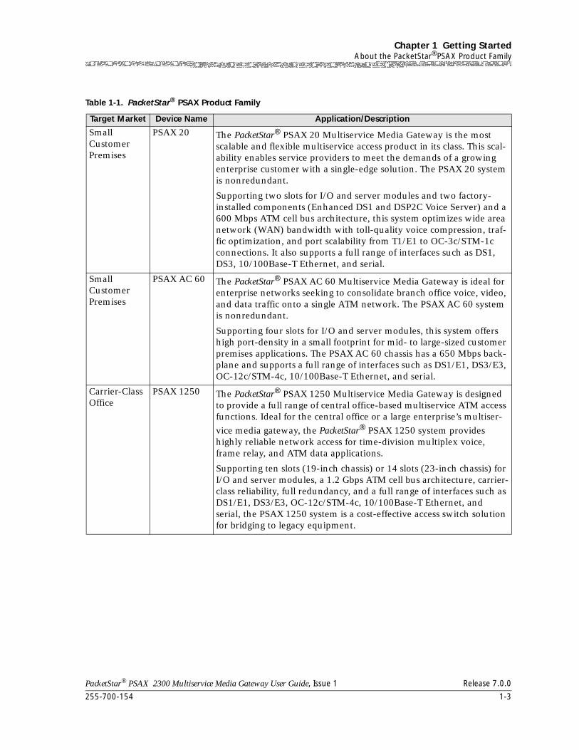
255-700-154 1-3
PacketStar® PSAX 2300 Multiservice Media Gateway User Guide, Issue 1 Release 7.0.0
Chapter 1 Getting StartedAbout the PacketStar®PSAX Product Family
Table 1-1. PacketStar® PSAX Product Family
Target Market Device Name Application/Description
Small Customer Premises
PSAX 20 The PacketStar® PSAX 20 Multiservice Media Gateway is the most scalable and flexible multiservice access product in its class. This scal-ability enables service providers to meet the demands of a growing enterprise customer with a single-edge solution. The PSAX 20 system is nonredundant.
Supporting two slots for I/O and server modules and two factory-installed components (Enhanced DS1 and DSP2C Voice Server) and a 600 Mbps ATM cell bus architecture, this system optimizes wide area network (WAN) bandwidth with toll-quality voice compression, traf-fic optimization, and port scalability from T1/E1 to OC-3c/STM-1c connections. It also supports a full range of interfaces such as DS1, DS3, 10/100Base-T Ethernet, and serial.
Small Customer Premises
PSAX AC 60 The PacketStar® PSAX AC 60 Multiservice Media Gateway is ideal for enterprise networks seeking to consolidate branch office voice, video, and data traffic onto a single ATM network. The PSAX AC 60 system is nonredundant.
Supporting four slots for I/O and server modules, this system offers high port-density in a small footprint for mid- to large-sized customer premises applications. The PSAX AC 60 chassis has a 650 Mbps back-plane and supports a full range of interfaces such as DS1/E1, DS3/E3, OC-12c/STM-4c, 10/100Base-T Ethernet, and serial.
Carrier-Class Office
PSAX 1250 The PacketStar® PSAX 1250 Multiservice Media Gateway is designed to provide a full range of central office-based multiservice ATM access functions. Ideal for the central office or a large enterprise’s multiser-
vice media gateway, the PacketStar® PSAX 1250 system provides highly reliable network access for time-division multiplex voice, frame relay, and ATM data applications.
Supporting ten slots (19-inch chassis) or 14 slots (23-inch chassis) for I/O and server modules, a 1.2 Gbps ATM cell bus architecture, carrier-class reliability, full redundancy, and a full range of interfaces such as DS1/E1, DS3/E3, OC-12c/STM-4c, 10/100Base-T Ethernet, and serial, the PSAX 1250 system is a cost-effective access switch solution for bridging to legacy equipment.
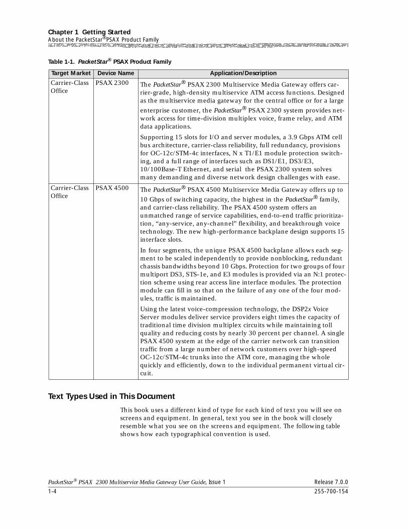
Chapter 1 Getting StartedAbout the PacketStar®PSAX Product Family
1-4 255-700-154
PacketStar® PSAX 2300 Multiservice Media Gateway User Guide, Issue 1 Release 7.0.0
Text Types Used in This Document
This book uses a different kind of type for each kind of text you will see on screens and equipment. In general, text you see in the book will closely resemble what you see on the screens and equipment. The following table shows how each typographical convention is used.
Carrier-Class Office
PSAX 2300 The PacketStar® PSAX 2300 Multiservice Media Gateway offers car-rier-grade, high-density multiservice ATM access functions. Designed as the multiservice media gateway for the central office or for a large
enterprise customer, the PacketStar® PSAX 2300 system provides net-work access for time-division multiplex voice, frame relay, and ATM data applications.
Supporting 15 slots for I/O and server modules, a 3.9 Gbps ATM cell bus architecture, carrier-class reliability, full redundancy, provisions for OC-12c/STM-4c interfaces, N x T1/E1 module protection switch-ing, and a full range of interfaces such as DS1/E1, DS3/E3, 10/100Base-T Ethernet, and serial the PSAX 2300 system solves many demanding and diverse network design challenges with ease.
Carrier-Class Office
PSAX 4500 The PacketStar® PSAX 4500 Multiservice Media Gateway offers up to
10 Gbps of switching capacity, the highest in the PacketStar® family, and carrier-class reliability. The PSAX 4500 system offers an unmatched range of service capabilities, end-to-end traffic prioritiza-tion, “any-service, any-channel” flexibility, and breakthrough voice technology. The new high-performance backplane design supports 15 interface slots.
In four segments, the unique PSAX 4500 backplane allows each seg-ment to be scaled independently to provide nonblocking, redundant chassis bandwidths beyond 10 Gbps. Protection for two groups of four multiport DS3, STS-1e, and E3 modules is provided via an N:1 protec-tion scheme using rear access line interface modules. The protection module can fill in so that on the failure of any one of the four mod-ules, traffic is maintained.
Using the latest voice-compression technology, the DSP2x Voice Server modules deliver service providers eight times the capacity of traditional time division multiplex circuits while maintaining toll quality and reducing costs by nearly 30 percent per channel. A single PSAX 4500 system at the edge of the carrier network can transition traffic from a large number of network customers over high-speed OC-12c/STM-4c trunks into the ATM core, managing the whole quickly and efficiently, down to the individual permanent virtual cir-cuit.
Table 1-1. PacketStar® PSAX Product Family
Target Market Device Name Application/Description
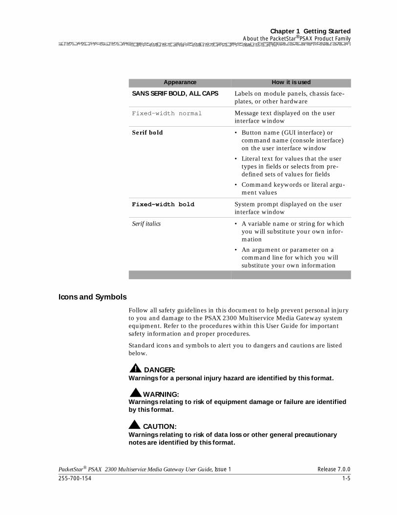
255-700-154 1-5
PacketStar® PSAX 2300 Multiservice Media Gateway User Guide, Issue 1 Release 7.0.0
Chapter 1 Getting StartedAbout the PacketStar®PSAX Product Family
Icons and Symbols
Follow all safety guidelines in this document to help prevent personal injury to you and damage to the PSAX 2300 Multiservice Media Gateway system equipment. Refer to the procedures within this User Guide for important safety information and proper procedures.
Standard icons and symbols to alert you to dangers and cautions are listed below.
! DANGER:Warnings for a personal injury hazard are identified by this format.
WARNING:!Warnings relating to risk of equipment damage or failure are identified by this format.
! CAUTION:Warnings relating to risk of data loss or other general precautionary notes are identified by this format.
Appearance How it is used
SANS SERIF BOLD, ALL CAPS Labels on module panels, chassis face-plates, or other hardware
Fixed-width normal Message text displayed on the user interface window
Serif bold • Button name (GUI interface) or command name (console interface) on the user interface window
• Literal text for values that the user types in fields or selects from pre-defined sets of values for fields
• Command keywords or literal argu-ment values
Fixed-width bold System prompt displayed on the user interface window
Serif italics • A variable name or string for which you will substitute your own infor-mation
• An argument or parameter on a command line for which you will substitute your own information
Chapter 1 Getting StartedAbout the PacketStar®PSAX Product Family
1-6 255-700-154
PacketStar® PSAX 2300 Multiservice Media Gateway User Guide, Issue 1 Release 7.0.0
Note: Identifies additional information pertinent to the text preceding this note.
Electrostatic Discharge Precautions
The room where the PSAX 2300 system is located must have built-in precautions to provide protection from electrostatic discharge damage to electronic components. The following sections provide details on these necessary precautions.
Grounding Wrist Straps
Attach at least one grounding wrist strap to a common ground for each chassis/electronic rack to be handled. Follow these guidelines for wrist straps:
• Make sure the wrist straps or wrist strap cords have built-in 1-megaohm (minimum) resistance.
• Make sure the wrist straps and wrist strap cords are UL listed.
• Ensure the wrist strap cord is long enough so it can be worn while working either at the front or the back of the rack.
• Always discharge any static charge by touching your wrist strap before you touch the PSAX 2300 chassis.
Floor Covering
Be sure the room has an antistatic floor covering (conductive mat, tiles, or carpeting) to minimize static charge buildup as you walk across the room. Follow these guidelines for installing and maintaining proper floor coverings:
• Using foot grounding straps (attached to the heels of your shoes) is recommended, even if you are walking in rooms with antistatic floor covering. These straps provide additional protection against electrostatic discharge. The straps should have built-in 1-megaohm (minimum) resistance.
• Wool carpet is not an acceptable floor covering.
• Other types of carpet must be sprayed daily with a topical antistatic chemical before you perform any work in the room. Paying constant attention to carpet maintenance is time-consuming but required, if used.
Temperature and Humidity
Establishing the proper temperature and humidity in the room where the PSAX 2300 system is located helps control many static discharge problems. Maintaining proper room climate is especially important when heat is turned on during the cold weather. To avoid damage to the PSAX 2300 system, do not allow the humidity to increase to the level where water droplets appear on surfaces. The temperature and relative humidity must be kept within the
255-700-154 1-7
PacketStar® PSAX 2300 Multiservice Media Gateway User Guide, Issue 1 Release 7.0.0
Chapter 1 Getting StartedTechnical Support
specified tolerance limits as shown in the PacketStar® PSAX 2300 Installation and Operation Guide.
Clothing
When working with the PSAX 2300 system, avoid wearing clothing made from wool or synthetic materials. Try to minimize contact between clothing and electronic components.
Handling PSAX 2300 System Components
Follow these guidelines for proper handling of the PSAX 2300 hardware to minimize electrostatic discharge damage:
• Do not remove the chassis, modules, and other items from their protective packaging until you are ready to install them.
• When installing modules and components, use a grounding wrist strap connected to a common electrical ground to prevent electrostatic discharge damage. (A common electrical ground is a complete circuit between a person or an electrical/electronic device and the earth.)
• Store components in electrostatic-discharge-protective bags when they are not in use.
Technical Support
If you experience a problem with your PSAX 2300 system, refer to the Lucent Technologies InterNetworking Systems Global Warranty, which accompanied your shipment, for instructions on obtaining support in your area.
Comments on This Guide
To comment on the PacketStar® PSAX 2300 Multiservice Media Gateway User Guide, please complete the comment card that accompanied your shipment and mail it to the following address:
Manager, Information Design and Development TeamLucent TechnologiesPacketStar® PSAX Products8301 Professional PlaceLandover, MD 20785USA
You can also fax the comment card to us at: 301-809-4540.
Before You Begin
Before you begin using your new PSAX 2300 Multiservice Media Gateway system, be sure you accomplish the following:
Chapter 1 Getting StartedBefore You Begin
1-8 255-700-154
PacketStar® PSAX 2300 Multiservice Media Gateway User Guide, Issue 1 Release 7.0.0
• Install the PSAX 2300 system according to directions in the PacketStar™ PSAX 2300 Installation and Operation Guide, Issue 1, accompanying this guide.
• Read carefully the safety cautions listed in the section "Safety Information," in the front matter of this guide.
• Work out and record your site-specific specifications such as IP addresses you will use, connections and interfaces you will need, user names and passwords you will assign, and so on.
PacketStar® PSAX 2300 Multiservice Media Gateway User Guide, Issue 1 Release 7.0.0
255-700-154 2-1
2 Hardware Description
Overview of This Chapter
This chapter presents a hardware overview of the PSAX 2300 system hardware. The content is organized as follows:
• PSAX 2300 System Features
• PSAX 2300 System Hardware Components
~ PSAX 2300 Chassis
~ Power Supply Modules
~ PSAX 2300 Stratum 3–4 Module
~ CPU Module
• PSAX 2300 Specifications
~ PSAX 2300 Hardware Specifications
~ PSAX 2300 Chassis Environmental Specifications
~ PSAX 2300 Power Supply Hardware Specifications
~ PSAX 2300 Power Supply Environmental Specifications
~ PSAX 2300 Stratum 3–4 Module Hardware Specifications
~ PSAX 2300 CPU Module Hardware Specifications
~ I/O and Server Module Specifications
~ I/O and Server Modules Memory, Bandwidth, and Power Consumption
~ Power, Stratum, I/O, and Server Modules Environmental Specifications
PSAX 2300 System Features
The PSAX 2300 provides high-capacity, universal connectivity over an asynchronous transfer mode (ATM) wide area network (WAN).
The PacketStar® PSAX 2300 Multiservice Media Gateway is a carrier-grade, high-density ATM access concentrator providing network access for TDM voice, frame relay, and ATM data applications. The PSAX 2300 system I/O interfaces are supported by a sophisticated package of features, such as PNNI (private network-node interface), ILMI (integrated local management interface), 1+1 APS (automatic protection switching) and 1+1 MSP (multisection protection), trunk conditioning, a connection gateway API, and redundant common equipment modules. Echo cancellation and silence suppression features make the PSAX 2300 a true multiservice platform. Featuring a 3.9 Gbps ATM cell bus architecture, carrier-class reliability, provisions for OC-12c interfaces and N:1 DS3/E3/STS-1e module protection-
Chapter 2 Hardware DescriptionPSAX 2300 System Hardware Components
2-2 255-700-154
PacketStar® PSAX 2300 Multiservice Media Gateway User Guide, Issue 1 Release 7.0.0
switching, the PSAX 2300 Multiservice Media Gateway solves demanding and diverse network design challenges.
Descriptions of the hardware components that make up the PSAX 2300 system follow.
PSAX 2300 System Hardware Components
The following hardware components make up the PSAX 2300 system:
• Chassis:
~ 44.45 cm (17.5-in) wide, 30.48 cm (12 in) deep, 44.45 cm (17.5 in) high chassis, mounted in a standard telco frame
• Common equipment modules:
~ Power Supply modules:
• -48 V dc module requires power at -42.5 to -56 V dc at 12 A and 400 W maximum
The chassis accommodates redundant power supplies.
~ Stratum 3–4 module
The chassis accommodates redundant Stratum 3–4 modules.
~ Central Processing Unit (CPU) module
Two CPU modules are installed to increase system reliability through redundancy.
• User-selected input/output (I/O) and server modules
• DS1/T1 Interface Modules
6-Port DS1 IMA (IMA DS1)
6-Port Enhanced DS1/T1 Multiservice (DS1/T1 ENH)
12-Port Medium-Density DS1 Multiservice (MD DS1)
• E1 Interface Modules
6-Port E1 IMA (IMA E1)
6-Port Enhanced E1 Multiservice (E1 ENH)
21-Port High-Density E1 Multiservice (HD E1)
21-Port High-Density E1 IMA (HD E1 IMA)
• DS3, E3, and STS-1e Interface Modules
1-Port Channelized DS3 Multiservice (CH DS3)
1-Port Channelized DS3 CES (CH DS3)
1-Port DS3 IMA (DS3 IMA)
1-Port Unchannelized DS3 Frame Relay (DS3 FR)
2-Port DS3 ATM (DS3 ATM)
2-Port E3 ATM (E3 ATM)
255-700-154 2-3
PacketStar® PSAX 2300 Multiservice Media Gateway User Guide, Issue 1 Release 7.0.0
Chapter 2 Hardware DescriptionPSAX 2300 System Hardware Components
3-Port Channelized DS3/STS-1e CES (CH DS3/STS-1E)
3-Port Unstructured DS3/E3 CES (UNSTR DS3/E3 CES)
1-Port Channelized STS-1e, T1 Format (CH STS-1E T1)
• Fiber-Optic Interface Modules
1-Port OC-3c Multimode with AQueMan (OC-3C (MM AQ))
1-Port OC-3c Single-Mode with AQueMan (OC-3C (SM AQ))
1-Port OC-3c Multimode with Traffic Shaping (OC-3C (MM TS))
1-Port OC-3c Single-Mode with Traffic Shaping (OC-3C (SM TS))
1-Port OC-3c 1+1 APS Multimode (OC-3C MM APS)
1-Port OC-3c 1+1 APS Single-Mode (OC-3C SM APS)
1-Port STM-1 Multimode with AQueMan (STM-1 (MM AQ))
1-Port STM-1 Single-Mode with AQueMan (STM-1 (SM AQ))
1-Port STM-1 Multimode with Traffic Shaping (STM-1 (MM TS))
1-Port STM-1 Single-Mode with Traffic Shaping (STM-1 (SM TS))
1-Port STM-1 1+1 MSP Multimode (STM-1 MM MSP)
1-Port STM-1 1+1 MSP Single-Mode (STM-1 SM MSP)
1-Port OC-12c/STM-4c 1+1 APS/MSP Multimode (OC-12C/STM-4C MM)
1-Port OC-12c/STM-4c 1+1 APS/MSP Single-Mode (OC-12C/STM-4C SM)
• 2-Wire Interface Modules
4-Port Voice 2-Wire Office (VOICE 2WO)
8-Port Voice 2-Wire Station (VOICE 2WS)
• Serial Interface Modules
Quadserial (QUAD SERIAL)
6-Port Multiserial (SERIAL)
• Ethernet Interface Module
Ethernet (ENET)
• DSP2 Voice Servers
DSP2A Voice Server (DSP2A)
DSP2B Voice Server (DSP2B)
DSP2D Voice Server (DSP2D)
• Other Modules
Alarm (ALARM)
Route Server (ROUTE SERVER)
Tones and Announcements Server (TAS)
Chapter 2 Hardware DescriptionPSAX 2300 System Hardware Components
2-4 255-700-154
PacketStar® PSAX 2300 Multiservice Media Gateway User Guide, Issue 1 Release 7.0.0
PSAX 2300 Chassis
The PSAX 2300 chassis can support either one or two Stratum 3–4 modules, one or two Power Supply modules, and one or two CPU modules, to obtain the redundancy of common system equipment.
The PSAX 2300 chassis consists of an open front with a slotted shelf, a backplane, a filter, and a solid metal housing on five sides.
Module Slots The chassis has 17 slots available for I/O and server modules. Two middle slots, slots A and B, are reserved for the optionally redundant Stratum 3–4 modules.
The module slots in the PSAX 2300 are numbered from left to right:
• Slots 1 through 8 are recommended for high-bandwidth modules and slots 9 through 15 are recommended for low-bandwidth modules. The optimum placement for high-bandwidth modules is to spread them across two segments, placing them first in slots 1, 5, 2, 6, and then in slots 3, 7, 4, 8.
• The CPU modules must be placed in slots 16 and 17.
• The Stratum 3–4 modules must be placed between slots 8 and 9, in slots A and B.
For optimum EMI shielding and cooling, blank faceplates must be inserted in all empty slots.
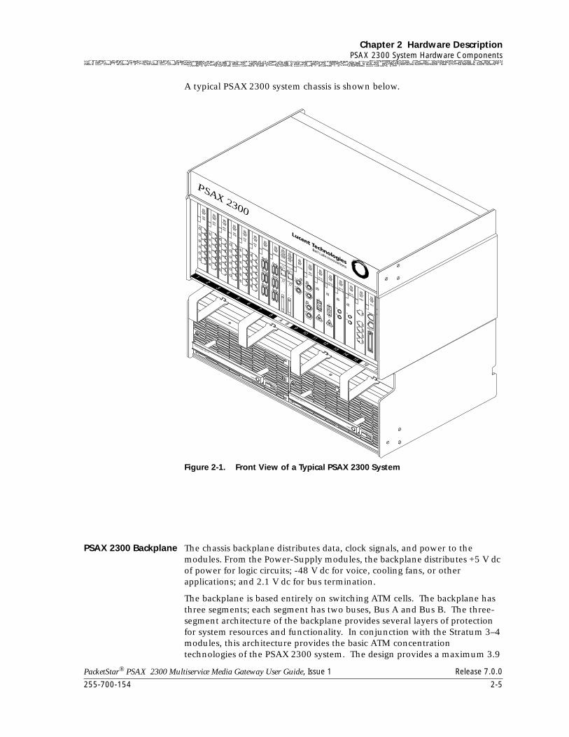
255-700-154 2-5
PacketStar® PSAX 2300 Multiservice Media Gateway User Guide, Issue 1 Release 7.0.0
Chapter 2 Hardware DescriptionPSAX 2300 System Hardware Components
A typical PSAX 2300 system chassis is shown below.
PSAX 2300 Backplane The chassis backplane distributes data, clock signals, and power to the modules. From the Power-Supply modules, the backplane distributes +5 V dc of power for logic circuits; -48 V dc for voice, cooling fans, or other applications; and 2.1 V dc for bus termination.
The backplane is based entirely on switching ATM cells. The backplane has three segments; each segment has two buses, Bus A and Bus B. The three- segment architecture of the backplane provides several layers of protection for system resources and functionality. In conjunction with the Stratum 3–4 modules, this architecture provides the basic ATM concentration technologies of the PSAX 2300 system. The design provides a maximum 3.9
Figure 2-1. Front View of a Typical PSAX 2300 System
10 A
FAILnon-redundant
ACTIVE
Power Supply -48 V
Power Supply -48 V
ACTIVE
DS1IMA
FAIL
LOS
1
6
5
4
3
2
ACTIVE
DS1Enh
FAIL
LOS
1
6
5
4
3
2
ACTIVE
DS1Enh
FAIL
LOS
1
6
5
4
3
2
ACTIVE
DS1ATM
FAIL
LOS
1
6
5
4
3
2
ACTIVE
DS1CE
FAIL
LOS
1
6
5
4
3
2
ACTIVE
DS1CE
FAIL
LOS
1
6
5
4
3
2
ACTIVE
SERIAL
FAIL
5
3
1
6
4
2
SERIAL
5
3
1
6
4
2
ACTIVE
FAIL
ACTIVEUNLOCK
FAIL
CLK LOS
STRATUM 3 4
LAMP TEST
ACTIVEUNLOCK
FAIL
STRATUM 3 4
LAMP TEST
CLK LOS
ACTIVE
CH DS3
FAIL
LOSTX
RX
ACTIVE
DS3ATM
FAIL
LOSTX
RX
LOSTX
RX
ACTIVE
OC-3c(SM AQ)
FAIL
LOS
TX
RX
laser hazard
ACTIVE
OC-3c(SM AQ)
FAIL
LOS
TX
RX
laser hazard
ACTIVE
OC-3c(MM AQ)
FAIL
LOS
TX
RX
ACTIVE
OC-3c(MM AQ)
FAIL
LOS
TX
RX
ACTIVE
ENET
FAIL
1
2
3
4
5
ACTIVE
CPU
FAIL
ETHERNET
CONSALE
KEY
LOAD
ACTIVE
CPU
FAIL
ETHERNET
CONSALE
key
load
10 A
PSAX 2300
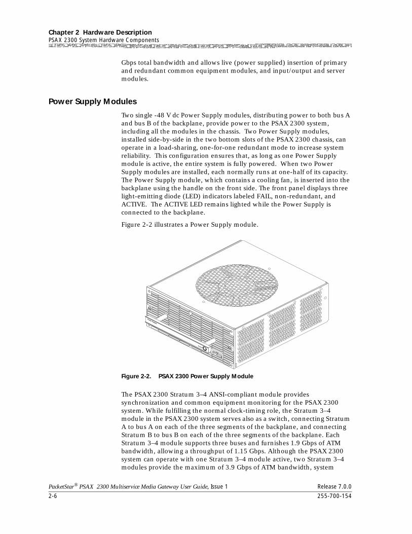
Chapter 2 Hardware DescriptionPSAX 2300 System Hardware Components
2-6 255-700-154
PacketStar® PSAX 2300 Multiservice Media Gateway User Guide, Issue 1 Release 7.0.0
Gbps total bandwidth and allows live (power supplied) insertion of primary and redundant common equipment modules, and input/output and server modules.
Power Supply Modules
Two single -48 V dc Power Supply modules, distributing power to both bus A and bus B of the backplane, provide power to the PSAX 2300 system, including all the modules in the chassis. Two Power Supply modules, installed side-by-side in the two bottom slots of the PSAX 2300 chassis, can operate in a load-sharing, one-for-one redundant mode to increase system reliability. This configuration ensures that, as long as one Power Supply module is active, the entire system is fully powered. When two Power Supply modules are installed, each normally runs at one-half of its capacity. The Power Supply module, which contains a cooling fan, is inserted into the backplane using the handle on the front side. The front panel displays three light-emitting diode (LED) indicators labeled FAIL, non-redundant, and ACTIVE. The ACTIVE LED remains lighted while the Power Supply is connected to the backplane.
Figure 2-2 illustrates a Power Supply module.
The PSAX 2300 Stratum 3–4 ANSI-compliant module provides synchronization and common equipment monitoring for the PSAX 2300 system. While fulfilling the normal clock-timing role, the Stratum 3–4 module in the PSAX 2300 system serves also as a switch, connecting Stratum A to bus A on each of the three segments of the backplane, and connecting Stratum B to bus B on each of the three segments of the backplane. Each Stratum 3–4 module supports three buses and furnishes 1.9 Gbps of ATM bandwidth, allowing a throughput of 1.15 Gbps. Although the PSAX 2300 system can operate with one Stratum 3–4 module active, two Stratum 3–4 modules provide the maximum of 3.9 Gbps of ATM bandwidth, system
Figure 2-2. PSAX 2300 Power Supply Module
10 A
255-700-154 2-7
PacketStar® PSAX 2300 Multiservice Media Gateway User Guide, Issue 1 Release 7.0.0
Chapter 2 Hardware DescriptionPSAX 2300 System Hardware Components
throughput of 2.3 Gbps, and offer redundancy to protect service in case one module fails. With both Stratum 3–4 modules in service, the installed PSAX I/O modules use all buses. If one Stratum 3–4 module fails, all the I/O modules in the system use the bus from the remaining Stratum 3–4 module, and system throughput is reduced by half.
In addition, the PSAX 2300 system can obtain network clock synchronization from any of its interfaces except the Route Server, the DSP2A/DSP2B/DSP2C Voice Servers, the Voice 2-Wire Station, the Voice 2-Wire Office, the Ethernet, and the Alarm modules. With the ability to accept a timing reference from any physical interface at low transmission rates, the PSAX 2300 system provides the network with a reliable transport and access infrastructure. The Stratum 3–4 module is accurate to Stratum 3 requirements, allowing the PSAX 2300 system to run freely even if the module loses external timing for as long as 24 hours, without synchronization problems.
The faceplates of the Stratum 3–4 modules have four LED indicators, FAIL, ACTIVE, UNLOCKED, and CLK LOS (clock loss of signal). When the UNLOCKED LED is lighted, it signifies that the Stratum 3–4 is not locked to a reference signal. When the UNLOCKED light is not lighted, it signifies that the Stratum 3–4 is locked to a reference signal. The LAMP TEST push button is provided to test the functioning of the LED indicators.
CPU Module
Operating in a nonload-sharing, primary/standby mode, the PSAX CPU module provides the processing, switching, and storage functions for the PSAX 2300 system. A RISC-based microprocessor, the PSAX CPU module has the processing power to maintain data flow, perform numerical calculations, and manage the direct memory access (DMA) interfaces. The processor performs the interface-specific physical and link layer protocol functions, in addition to the queuing and traffic management functions being performed on the various I/O and server modules. The PSAX CPU module has 64 MB of memory for routing and signalling functions, forward error correction, processing SVC connections, and managing network capabilities.
SVC retention preserves active ATM switched virtual connections (SVCs) and switched permanent virtual connections (SPVCs). However, virtual connections on calls in a transient state will not be saved. To preserve active virtual connections, do not remove the primary PSAX CPU module while it is synchronizing with the redundant PSAX CPU module.
In a redundant configuration, when you upgrade or remove the primary PSAX CPU module, the standby (backup) PSAX CPU module now becomes the primary, and the original primary module becomes the standby PSAX CPU module. This switchover is designed to minimize the time the equipment is down.
The standby PSAX CPU module supports complete console and SNMP interfaces, in the same way the primary PSAX CPU module supports them, except the standby PSAX CPU module blocks all set operations.

Chapter 2 Hardware DescriptionPSAX 2300 System Hardware Components
2-8 255-700-154
PacketStar® PSAX 2300 Multiservice Media Gateway User Guide, Issue 1 Release 7.0.0
PacketStar® PSAX 2300 Multiservice Media Gateway User Guide, Issue 1 Release 7.0.0
255-700-154 3-1
3 System Features
Overview of This Chapter
This chapter presents an overview of the PSAX 2300 Multiservice Media Gateway system and software features. The following aspects of the PSAX 2300 Multiservice Media Gateway system are discussed:
• Features and capabilities of the system
• Architecture, interfaces, and functions of the PSAX 2300 Multiservice Media Gateway system
• Features that enable users to customize the PSAX 2300 Multiservice Media Gateway system for specific requirements and applications
System Capabilites
The PSAX 2300 system enables service providers, central offices, or end users at customer premises to do the following:
• Consolidate voice, video, and data traffic on a single ATM network
• Extend the capabilities of embedded ATM-based equipment to voice and video traffic
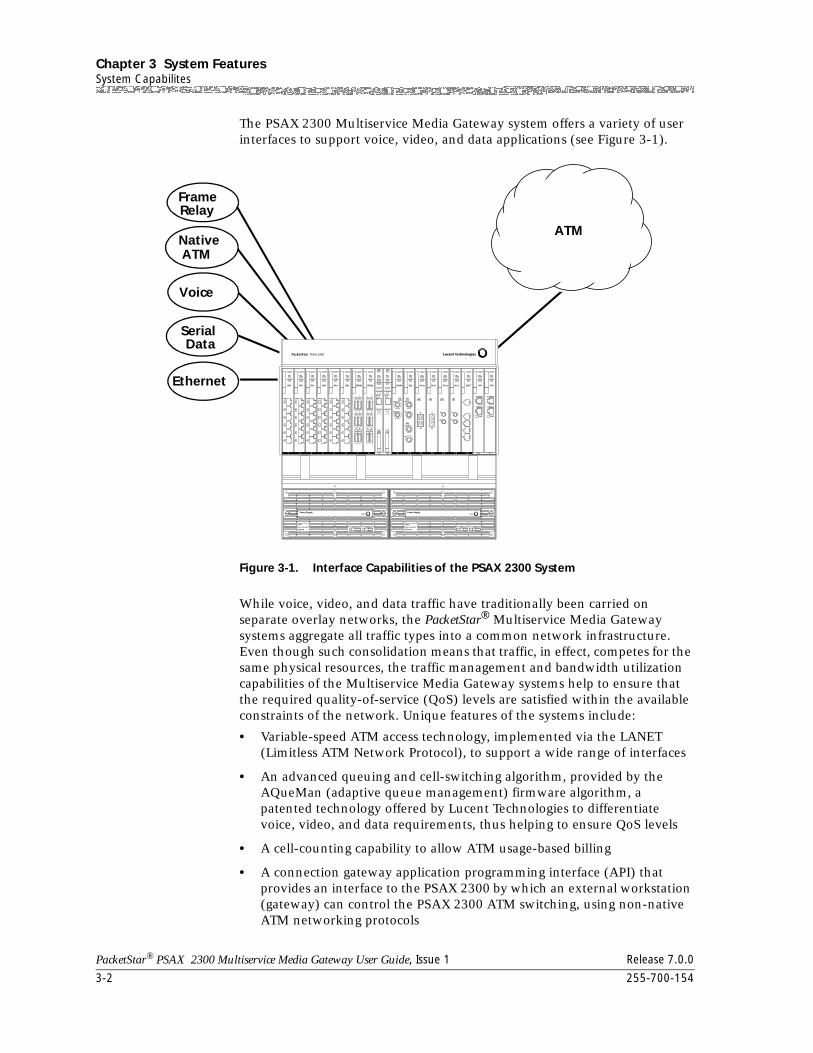
Chapter 3 System FeaturesSystem Capabilites
3-2 255-700-154
PacketStar® PSAX 2300 Multiservice Media Gateway User Guide, Issue 1 Release 7.0.0
The PSAX 2300 Multiservice Media Gateway system offers a variety of user interfaces to support voice, video, and data applications (see Figure 3-1).
While voice, video, and data traffic have traditionally been carried on separate overlay networks, the PacketStar® Multiservice Media Gateway systems aggregate all traffic types into a common network infrastructure. Even though such consolidation means that traffic, in effect, competes for the same physical resources, the traffic management and bandwidth utilization capabilities of the Multiservice Media Gateway systems help to ensure that the required quality-of-service (QoS) levels are satisfied within the available constraints of the network. Unique features of the systems include:
• Variable-speed ATM access technology, implemented via the LANET (Limitless ATM Network Protocol), to support a wide range of interfaces
• An advanced queuing and cell-switching algorithm, provided by the AQueMan (adaptive queue management) firmware algorithm, a patented technology offered by Lucent Technologies to differentiate voice, video, and data requirements, thus helping to ensure QoS levels
• A cell-counting capability to allow ATM usage-based billing
• A connection gateway application programming interface (API) that provides an interface to the PSAX 2300 by which an external workstation (gateway) can control the PSAX 2300 ATM switching, using non-native ATM networking protocols
Figure 3-1. Interface Capabilities of the PSAX 2300 System
Voice
Ethernet
FrameRelay
SerialData
NativeATM
ATM
RX
TX
RX
255-700-154 3-3
PacketStar® PSAX 2300 Multiservice Media Gateway User Guide, Issue 1 Release 7.0.0
Chapter 3 System FeaturesSystem Capabilites
Through the use of the API, the gateway and the PSAX 2300 can combine to perform powerful interworking among ATM, Integrated Services Digital Network (ISDN), Signaling System 7 (SS7), channel associated signaling (CAS), and other protocols
• Inverse multiplexing over ATM (IMA) to create virtual access lines that are faster than E1 lines, but not as expensive as T3/E3 lines
• Live insertion and removal of modules
• An integrated local management interface (ILMI) feature that supports bidirectional exchange of ATM interface parameters between two connected ATM interface management entities (IMEs) using Simple Network Management Protocol (SNMP) and an ATM interface management information base (MIB)
• An alternate rerouting feature, known as dual-homed permanent virtual circuits (DHPVCs), that improves reliability of PVC connections and supports redundancy options to deliver near-zero downtime using circuit emulation, terminal emulation, frame relay, Ethernet, and ATM interfaces
• A switched virtual circuit (SVC) feature that provides dynamic allocation of connections by using Interim Interswitch Signaling Protocol (IISP) or Private Network-to-Network Interface (PNNI) for call setup and (automatic) rerouting
• A soft PVC (SPVC) feature, which is a semipermanent virtual connection used for call setup and (automatic) rerouting that has attributes of both a switched virtual connection and a permanent virtual connection
• PNNI, which computes paths through a network by defining a method for distributing topology information between switches and clusters of switches. PNNI also provides a method for signaling used to establish point-to-point and point-to-multipoint connections across ATM networks
• An operations, administration, and maintenance (OAM) feature that affects the system software and input/output (I/O) module firmware associated with generating, receiving, and interpreting F4 and F5 OAM flows. The function types of the OAM cells include fault management, performance management, and system management
• A keep-alive/heartbeat timer to confirm that connections are live
• Unidirectional connection and path modification
• A Remote Firmware Release feature that allows upgrading both CPU software and I/O module firmware at a user site from either a CD-ROM or a downloaded FTP software file.
Chapter 3 System FeaturesInterface Architecture
3-4 255-700-154
PacketStar® PSAX 2300 Multiservice Media Gateway User Guide, Issue 1 Release 7.0.0
Interface Architecture
The PSAX 2300 interface architecture distinctly separates the ATM adaptation functions from the switching functions of the Multiservice Media Gateway system. The interface architecture has four distinct processes:
• Physical media access
• Service protocol translation
• ATM addressing
• Queuing
The physical media access layer handles functions specific to each physical interface, connecting each user port to other users or network elements.
The service protocol translation process performs segmentation and reassembly (SAR) to adapt non-native ATM services to ATM-based services and back again. It ensures that the data stream is mapped to standard ATM Adaptation Layer (AAL) protocols.
ATM addressing provides user-specified virtual path identifier/virtual channel identifier (VPI/VCI) coding, bandwidth allocation, and quality of service (QoS) information.
ATM cells are placed in input and output queues based on their QoS parameters. Employing the AQueMan adaptive queue management algorithm, the PSAX 2300 Multiservice Media Gateway transports these cells from the ATM switching fabric to the I/O port.
User Interfaces
The PSAX 2300 offers a variety of user interfaces to support voice, video, and data applications.
Circuit Emulation Service
Circuit emulation service transports traffic over a virtual channel-based connection. Circuit emulation service provides service to the end user that is indistinguishable from a real point-to-point, fixed-bandwith circuit. The PacketStar® PSAX Multiservice Media Gateways support structured circuit emulation (individual DS0 circuit emulation) of traditional voice-based and data services on the DS1 and E1 modules. Because voice services are essentially constant bit rate (CBR) data, ATM Forum ATM Adaptation Layer 1 (AAL1) standards are used in circuit emulation. The circuit emulation service also provides signaling bit transport based on ATM Forum standards for channel-associated signaling (CAS).
The PacketStar® Multiservice Media Gateways provide AAL1 circuit emulation at the DS0 level. The individual DS0 modes of structured circuit
255-700-154 3-5
PacketStar® PSAX 2300 Multiservice Media Gateway User Guide, Issue 1 Release 7.0.0
Chapter 3 System FeaturesUser Interfaces
emulation allow service providers to switch time-division multiplexing (TDM) traffic across the ATM network at individual subscriber levels; that is, each DS0 can be assigned a separate virtual path identifier (VPI) or virtual channel identifier (VCI). This service transports ABCD signaling bits based on the ATM Forum standard for G.704 CAS. M13 multiplexing capabilities are also supported, providing the ability to perform circuit emulation on a T1 or E1 link connected to a TDM network and convert it into ATM cells, in accordance with the ATM Forum CAS specification af-saa-0032.000. Each T1 or E1 carries all of the Extended Super Frame (ESF) information required for a full T1 or E1 in cases where the interfaces to the service access multiplexer (SAM) are a full T1 or E1. The Multiservice Media Gateways can convert superframe (SF) format to ESF format. Signaling from any input interface (including customer premises equipment [CPE] interfaces) is converted to the appropriate signaling on the output interface. Framing information is converted and assignments are made on an individual DS0 basis.
Voice frames are converted into ATM cells based on the ATM Forum Circuit Emulation Service Interoperability Specification Version 2.0, af-vtm-0078.00. The DS0 mode of structured circuit emulation transparently supports voice applications in a network environment.
SPVC Support for CES Also offered are DSP2C Voice Server processing options (including voice compression, silence detection, echo cancellation, tone detection, and PCM coding translation) for voice traffic on soft permanent virtual circuit (SPVC) connections between two or more PacketStar® PSAX Multiservice Media Gateways.
Circuit Emulation Service for the Multi-Serial Module
Circuit emulation to ATM connections made through the Multi-Serial module now support 56 Kbps to 64 Kbps bit stuffing for SS7 link transport applications. Bit stuffing is selectable on a port basis by using the CPU software.
Dynamic Bandwidth Circuit Emulation Service
The dynamic bandwidth circuit emulation service (DBCES) feature is used with voice PVC connections to best utilize the available network bandwidth. This feature allows channels to be allocated dynamically as needed, based on ABCD signaling-bit information. The firmware supports 1x56 Kbps time-slot trunking with channel-associated signaling (CAS) detection used, based on ATM Forum Specification af-vtoa-0085.000. Note that this feature is not fully compliant with the specification and does not interoperate with other devices that are fully compliant.
The DBCES feature, in essence, performs idle channel suppression for voice traffic. PBX voice traffic uses DBCES to save some of the available T1 WAN bandwidth for LAN traffic. On average, only 8 DS0s are used for voice traffic, but at peak times, the number of DS0s used might approach the full 24 T1 channels. When channels are not being used for voice traffic, the available bandwidth can be used for LAN UBR-class traffic.
Chapter 3 System FeaturesUser Interfaces
3-6 255-700-154
PacketStar® PSAX 2300 Multiservice Media Gateway User Guide, Issue 1 Release 7.0.0
DS1 Service
With the channelized DS1 interface, service providers can concentrate and adapt voice, video, and data traffic to an ATM network. The DS1 interface can adapt any number of DS0 channels on the service access interface to ATM virtual channels with individual virtual path identifiers (VPIs) and virtual channel identifiers (VCIs). Users can thus adapt traffic to ATM at the individual DS0 level; that is, using structured circuit emulation, frame relay, HDLC, and native ATM services. The PSAX 2300 system also offers unstructured circuit emulation on the service interface of the DS1 interface.
DS1 ANI In-line Codes for Loopbacks
The Channelized DS3 Multiservice and CES modules support activating and deactivating DS1 access network interface (ANI) in-line loopback codes embedded in the DS1 signal. These codes test transmissions between customer interface equipment and network interface equipment, for example, between PSAX central office (CO) products and customer premises equipment (CPE) products at the edge of an ATM network. The PSAX system also generates alarm indication signals on all affected DS1 connections whenever a loop is activated.
DS3 Service
With the PSAX 2300 system, service providers can also now concentrate the various ATM circuits onto an upstream interface to an ATM edge switch, typically at the DS3 rate. With the DS3 interface, service providers can concentrate various traffic types up to 45 Mbps. The DS3 ATM module, designed to meet the ATM Forum UNI 3.0 specifications, serves as an interface to the service provider’s ATM edge switch. Each DS3 ATM module supports two 45-Mbps DS3 ports.
HDLC Passthrough
The high-level data link control (HDLC) passthrough interface is a bit-oriented, ITU-TSS (Telecommunications Standard Section) link layer protocol standard for point-to-point and point-to-multipoint communication. In HDLC, control information is always placed in the same position. Specific bit patterns used for control are different from those used in representing data, so errors are unlikely to occur. The following Access Concentrator I/O modules support the HDLC Passthrough interface:
• Channelized DS3
• Channelized STS-1e
• Enhanced DS1 module
• Enhanced E1 module
255-700-154 3-7
PacketStar® PSAX 2300 Multiservice Media Gateway User Guide, Issue 1 Release 7.0.0
Chapter 3 System FeaturesUser Interfaces
• Multi-Serial module
HDLC Passthrough Bit Inversion
High-level data link control (HDLC) uses an ITU-TSS link layer protocol standard for point-to-point and point-to-multipoint communication. Control information is always placed in the same position, using specified bit patterns dramatically different from data, reducing the likelihood of confusion. Providers are using this option primarily in wireless TDMA applications with ATM, finding that it is possible to save money by using ATM for backhauling calls from wireless cell sites to mobile switching centers, instead of using time division multiplexing (TDM).
The process uses the new 5ESS switches that support a mixture of inverted and standard HDLC passthrough interfaces. The HDLC Passthrough Bit Inversion option is enabled by a nondefault driver file to support the bit-inverted mode.
Inversion will work for HDLC passthrough links at both 56 Kbps and 64 Kbps. Currently, bit inversion is available only with the Enhanced DS1 and STS-1e modules, by selecting a nondefault driver file.
Interface Protection Groups
The Interface Protection Group software feature enables the grouping of ATM interfaces that support PVC connections on all PSAX modules. A secondary interface is then defined as an alternate “holder” of an ATM address in the event the primary ATM link fails.
Specifically, this feature allows a user to group similar types of interfaces together by specifying which interfaces in the group are primary (normally carrying traffic) or standby (normally idle). The feature permits a “many-to many”, or “M:N” protection scenario by allowing several primary interfaces and several standby interfaces to exist with a user-defined interface protection group.
When a failure condition is detected on a primary interface, the feature moves all affected connections from the primary interface to a standby interface. The standby interface is selected from those available in the interface protection group based on criteria selected by the user.
This feature is configuration order dependent, meaning that certain features must be configured in a particular order. The order of configuration is as follows:
1. Equipment Configuration (Physical Layer Interface)
2. Connection Configuration (ATM Layer and IWF)
3. Interface Protection Feature Configuration
a. Protection Group Table
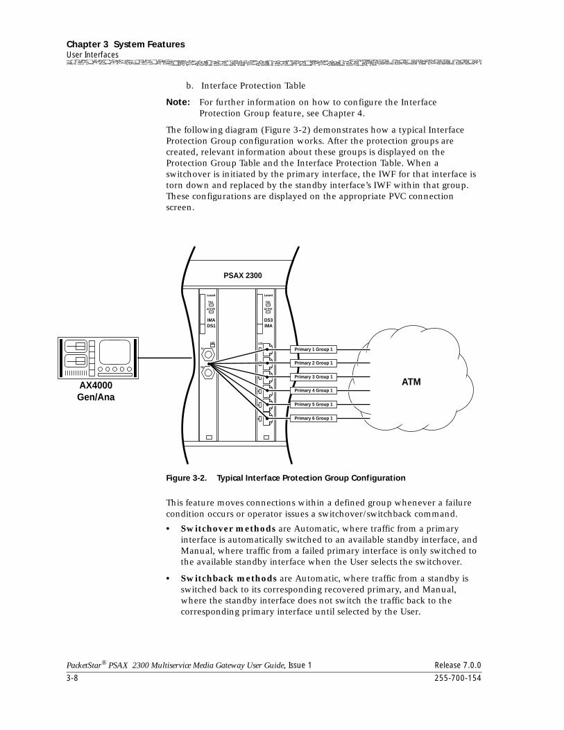
Chapter 3 System FeaturesUser Interfaces
3-8 255-700-154
PacketStar® PSAX 2300 Multiservice Media Gateway User Guide, Issue 1 Release 7.0.0
b. Interface Protection Table
Note: For further information on how to configure the Interface Protection Group feature, see Chapter 4.
The following diagram (Figure 3-2) demonstrates how a typical Interface Protection Group configuration works. After the protection groups are created, relevant information about these groups is displayed on the Protection Group Table and the Interface Protection Table. When a switchover is initiated by the primary interface, the IWF for that interface is torn down and replaced by the standby interface’s IWF within that group. These configurations are displayed on the appropriate PVC connection screen.
This feature moves connections within a defined group whenever a failure condition occurs or operator issues a switchover/switchback command.
• Switchover methods are Automatic, where traffic from a primary interface is automatically switched to an available standby interface, and Manual, where traffic from a failed primary interface is only switched to the available standby interface when the User selects the switchover.
• Switchback methods are Automatic, where traffic from a standby is switched back to its corresponding recovered primary, and Manual, where the standby interface does not switch the traffic back to the corresponding primary interface until selected by the User.
Figure 3-2. Typical Interface Protection Group Configuration
AX4000Gen/Ana
DS3IMA
IMADS1
PSAX 2300
Primary 4 Group 1
Primary 5 Group 1
Primary 2 Group 1
Primary 3 Group 1
Primary 6 Group 1
Primary 1 Group 1
ATM
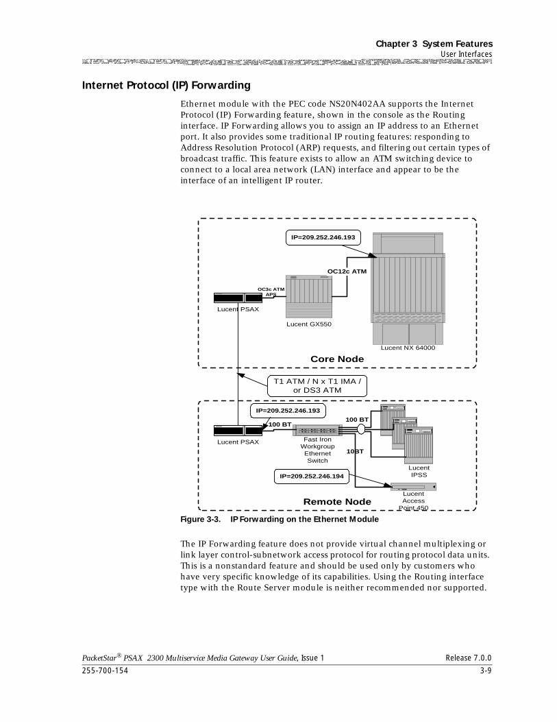
255-700-154 3-9
PacketStar® PSAX 2300 Multiservice Media Gateway User Guide, Issue 1 Release 7.0.0
Chapter 3 System FeaturesUser Interfaces
Internet Protocol (IP) Forwarding
Ethernet module with the PEC code NS20N402AA supports the Internet Protocol (IP) Forwarding feature, shown in the console as the Routing interface. IP Forwarding allows you to assign an IP address to an Ethernet port. It also provides some traditional IP routing features: responding to Address Resolution Protocol (ARP) requests, and filtering out certain types of broadcast traffic. This feature exists to allow an ATM switching device to connect to a local area network (LAN) interface and appear to be the interface of an intelligent IP router.
The IP Forwarding feature does not provide virtual channel multiplexing or link layer control-subnetwork access protocol for routing protocol data units. This is a nonstandard feature and should be used only by customers who have very specific knowledge of its capabilities. Using the Routing interface type with the Route Server module is neither recommended nor supported.
Figure 3-3. IP Forwarding on the Ethernet Module
Remote Node
Core Node
Lucent GX550
Lucent PSAX
Lucent NX 64000
OC12c ATM
Lucent PSAX
T1 ATM / N x T1 IMA /or DS3 ATM
Fast IronWorkgroupEthernetSwitch
LucentIPSS
100 BT100 BT
OC3c ATMAPS
IP=209.252.246.193
IP=209.252.246.193
LucentAccess
Point 450
10BT
IP=209.252.246.194
Chapter 3 System FeaturesUser Interfaces
3-10 255-700-154
PacketStar® PSAX 2300 Multiservice Media Gateway User Guide, Issue 1 Release 7.0.0
Interim Interswitch Signaling Protocol (IISP) Interface
Interim Interswitch Signaling Protocol, or IISP, was formerly known as PNNI Phase 0. Building on ATM UNI 3.0/3.1, it uses static routing tables established by the network administrator to route connections around link failures. IISP is meant to be used pending completion of the PNNI Phase 1.
Private Network-Network Interface (PNNI) 1.0
Overview The Private Network-to-Network Interface, known as PNNI, is a link-state routing information protocol that enables extremely scalable, full function, dynamic multivendor ATM switches to be integrated in the same network. It computes paths through a network by defining a method for distributing topology information between switches and clusters of switches. This information is used to compute paths through the network, whether it is local or worldwide. The hierarchy mechanism of PNNI ensures that this protocol scales well for any size ATM network, and automatically configures itself in networks in which the address structure reflects the topology.
PNNI topology and routing is based on the link-state routing technique.
Another feature of PNNI is that it provides a method for signaling used to establish point-to-point and point-to-multipoint connections across ATM networks. PNNI is based on the ATM Forum UNI signaling, with mechanisms added to support source routing, crankback and alternate routing of all call setup requests in case of connection setup failure.
The path selections for specific calls are based on route options provided by PNNI messages. Load sharing between parallel paths is addressed by the route determination algorithm, which provides options for such factors as load sharing, cost, and override options.
PNNI Features Supported by the PSAX Systems
The following is a list of PNNI features supported for the PSAX systems:
• Alternate routing as a result of crankback
Blocked calls will be cranked back with an indication of the cause. Alternate routes will be consistent with the higher-level designated transit lists in the original call request, and will avoid the blocked part of the network.
• CBR, rt-VBR, nrt-VBR, and UBR service
• Hello protocol
• Peer group leader election algorithm
• Point-to-point SVC and SPVC connections
• Point-to-multipoint SVC and SPVC connections
• Transfer of incoming extended Quality of Service (QoS)
• End-to-end transit delay parameters to outgoing PNNI interfaces
255-700-154 3-11
PacketStar® PSAX 2300 Multiservice Media Gateway User Guide, Issue 1 Release 7.0.0
Chapter 3 System FeaturesUser Interfaces
• Single peer group hierarchy
• Topology database synchronization
• PNNI topology state element (PTSE) aging within topology databases
• Summation and advertising of reachable addresses
• Source path selection and generic connection admission control (GCAC)
PNNI Peer Group Dynamics
PNNI performs these functions:
• Simplifies the configuration of large networks because it allows ATM switches to automatically learn about their neighbors and to distribute call routing information dynamically.
• Allows switches to be arranged in a hierarchy, where each level represents one or more switches. A cluster of switches at the same level is called a peer group. Link-state topology updates circulate within a peer group.
• Allows hierarchies but does not require them. It is also possible to deploy PNNI with one peer group encompassing all switches within a network.
• Sends hello packets across interswitch network-to-network interface (NNI) links that enable switches in the same peer group to discover one another. After a switch confirms that its neighbor at the other end of a link is a member of the same peer group, both exchange PNNI topology state packets (PTSPs) to advise and update their call routing information. PTSPs carry one or more PTSEs, describing the resources of the originating switch and the outbound resources of each of that switch’s attached links.
PTSEs describe attributes, such as:
~ Traffic types each link can support (any of the various ATM QoS levels)
~ Maximum cell rate the link can sustain; cell delay variation (only for constant bit rate (CBR) and variable bit rate real-time circuits (VBRrt)
~ Cell-loss ratio or cell-loss margin (CLM), a measure of the difference between effective bandwidth allocation and sustainable cell rate
~ Administrative weight (AW), a parameter that allows network architects to indicate relative link preference when deciding between alternative routes
Switches make use of this resource information to assess which of the available paths will best ensure QoS parameters are met.
PNNI Topology Information
After the initial exchange of topology information among switches in a peer group, regular broadcast topology updates are unnecessary. Each PTSE has a finite lifetime. Since individual elements age differently, their refresh updates occur at different times. This reduces the overhead associated with keeping the topology of the group updated. The only time a PTSE is rebroadcast is when there is a significant change in any of the key topology elements. For example, any change in cell-delay performance on a link will trigger a PTSE update from attached switches. Triggered updates further reduce network overhead.
Chapter 3 System FeaturesUser Interfaces
3-12 255-700-154
PacketStar® PSAX 2300 Multiservice Media Gateway User Guide, Issue 1 Release 7.0.0
Every switch in a peer group is aware of the topology state of the entire group. Thus it can build the entire call setup route from source to destination.
PNNI Hierarchies As peer groups grow and incorporate more nodes, the state information in each switch increases. PNNI supports hierarchies, which collapse the amount of state information shared by all switches.
In networks that use a PNNI hierarchy, the switches at each level elect one switch as a peer group leader (PGL). This PGL concurrently belongs to its own level and to the next highest level, where it acts as a logical group node (LGN) that represents and summarizes topology information needed to reach any of the lower-level switches. The higher-level peer group can mirror this dual constituency, electing a PGL to represent it at the next highest level. This process may scale to over a hundred levels.
Each switch in a PNNI network has a unique 20-byte address that corresponds to the network service access point (NSAP) schema. Much like IP subnet addresses, NSAP identifiers have a network part and a user part. The user part is the last seven bytes, and is reserved for end-system identification (insignificant to the PNNI). The network part is the first 13 bytes, and is used to identify peer groups.
Each level in the PNNI hierarchy is also assigned a scope number. Similar to an IP subnet mask, the scope specifies how much of the 13-byte network part is common to the switch addresses at a particular level in the hierarchy. For example, a scope of 72 (bits) masks the first 9 bytes of the network part as being common in all switches at that level. Higher levels have shorter scopes because they do not look as far into the NSAP; a level with a scope of 64 (masking the first 8 bytes) resides above a level with a scope of 72.
To make the best use of PNNI’s capabilities, network architects must pay careful attention to the ATM addressing structure, allocating correct addresses to switches at each level of the hierarchy.
ATM Maintenance ATM Maintenance Mode is a way of rerouting SPVCs and SVCs from an ATM port running PNNI. When a PNNI interface's administrative weight is changed, traffic on existing connections (PVC, SVC, SPVC) will not be disturbed. New SVCs and SPVCs are routed away from a PNNI link that has high administrative weight.
ATM Maintenance Mode supports the following:
• PNNI interface on all ATM ports.
• PNNI administrative weights are configured at the PNNI interface level. The administrative weight can be changed without taking the interface down or disturbing existing traffic on that ATM port.
• The new administrative weight will be communicated to the ATM switch on the other end of the PNNI link via PNNI link messages.
• Both SVCs and SPVCs from far end and near end ATM switch [n1]are routed away from the PNNI link with high administrative weight.
255-700-154 3-13
PacketStar® PSAX 2300 Multiservice Media Gateway User Guide, Issue 1 Release 7.0.0
Chapter 3 System FeaturesUser Interfaces
• This procedure interoperates with Marconi/Fore and GX 550 ATM switches.
Integrated Link Management Interface (ILMI)
The integrated link management interface (ILMI) is a network management function that supports bidirectional exchange of ATM interface parameters between two connected ATM Interface Management Entities (IMEs). These entities are an end user and a public or private network, or a public network and a private network.
Based on an ATM Forum-defined interim specification, ILMI uses a limited subset of Simple Network Management Protocol (SNMP) capabilities. ILMI provides status information and statistics using SNMP and a MIB to provide any ATM device with status and configuration information about the following information available at its ATM interfaces:
• Virtual path connections (VPCs)
• Virtual channel connections (VCCs)
• Registered ATM network prefixes
• Registered ATM addresses
• Registered services and capabilities
With System Software Release 6.5.0, VPI and VCI range negotiation is supported. It also determines the operational status of the logical port. ILMI is supported for all ATM UNI 3.0 and ATM UNI 3.1 interfaces.
ILMI Over PNNI Overview
The ILMI over PNNI feature included in Release 6.5 supports VPI and VCI range negotiation using automatic configuration procedures.
The automatic configuration procedure is the ability to automatically config-ure the following fields, found on the ATM PNNI Interface Configuration window, based on the local VPI/VCI and the remote VPI/VCI ranges (VPI and VCI range negotiation):
• Min/Max SVC VPI
• Min/Max SVC VCI
The PNNI ILMI Configuration window and PNNI ILMI Statistics window can be accessed from the ATM PNNI Interface Configuration window. The PNNI ILMI Configuration window is very similar to the ATM UNI ILMI Configuration window.
For more information on automatic configuration procedures, see ATM Forum ILMI (Integrated Local Management Interface), 4.0, af-ilmi-0065.000, Section 8.3.4.
Chapter 3 System FeaturesUser Interfaces
3-14 255-700-154
PacketStar® PSAX 2300 Multiservice Media Gateway User Guide, Issue 1 Release 7.0.0
Load Balancing for IISP and PNNI
Load balancing allows communications trunks connecting access and edge switches to balance traffic between PNNI (dynamic source routing) and IISP (static hop-by-hop routing) links. In addition to the existing parameters of path and route selection, the PSAX devices can now consider the values of available bandwidth and available cell rate associated with the interfaces. The PSAX calculates routes by using available bandwidth within the default parameters for both IISP and PNNI routing. Load balancing between PNNI and IISP links, not available prior to this release, uses available bandwidth more efficiently while strengthening the routing function.
ATM UNI 4.0 Signaling
The UNI 4.0 Signaling feature supports the mandatory functions required by the ATM Forum UNI Signaling Specification Version 4.0, as well as some of its optional features. UNI 4.0 provides the signaling procedures for dynamically establishing, maintaining, and clearing ATM connections at the ATM user-network interface. UNI 4.0 applies both to public and private UNI interfaces.
Major highlights of UNI 4.0 include:
1. Individual QoS parameters
2. Elements to support narrowband ISDN over ATM
3. Procedures,connection scope selection information element, and new MIB object to support the ATM AnyCast capability.
4. Procedures and new information elements to support bandwidth modification
5. New virtual path indicator (VPI)/virtual channel indicator (VCI) options
6. Procedures to support multiple virtual UNIs on a physical UNI
7. Error handling for instruction indicators
8. Using setup for adding parties
ATM Terminal Emulation
Terminal Emulation is an application that follows an intelligent computing device to mimic the operation of a dumb terminal for communications with a mainframe or minicomputer. This is made possible by inserting special printed circuit boards into the motherboard of the emulating device, and/or special software. The 6-Port Multiserial module is the only Multiservice Media Gateway module that supports this interface.
255-700-154 3-15
PacketStar® PSAX 2300 Multiservice Media Gateway User Guide, Issue 1 Release 7.0.0
Chapter 3 System FeaturesNetwork Management
Network Management
The Multiservice Media Gateway system provides all the telecommunications management network (TMN) functions applicable to the system. The PSAX 2300 system (which contains network elements) can be managed in several ways using a network element management system or network management system. The Multiservice Media Gateway system software features a Simple Network Management Protocol (SNMP)-compliant management information base (MIB) that gives external management systems access to the Multiservice Media Gateway system software.
In conjunction with the visual indicators displayed on the front panels of the individual modules, the system offers a full complement of SNMP trap messages that alert the user to faults in the PSAX 2300 system. Usage-based messages collected on the CPU module allow a service provider to collect cell counts for traffic and performance monitoring, and for fault detection.
The SNMP MIB provides an extensive series of configuration management and provisioning features that allow the user to prepare the various components for supporting services.
The Multiservice Media Gateway system software supports the following options for network management:
• Serial port interface with a direct connection to a standard VT100 terminal emulator.
As the simplest option, the CPU module faceplate provides an EIA-232 serial port (RJ-11 connector labeled CONSOLE), to which a PC workstation or a console monitor, running a standard VT100 terminal emulator, is connected.
The console interface provides access to the configuration, fault, network data-collection, and security-management features of the system software. The Multiservice Media Gateway system software lets users perform management tasks using a menu-based interface.
This port is typically used for local management (using a direct serial connection), but it can also be used for remote management. Remote management may be performed over a public switched telephone network (PSTN) with the use of an external modem, or over an ATM network with the use of a terminal emulation connection from a Multi-Serial module. The serial port is also used for the configuration of Internet Protocol (IP) parameters, which are necessary for IP-based management.
• Ethernet interface connection on a local-area network (LAN).
A 10BaseT Ethernet interface (RJ-45 connector labeled ETHERNET) on the PSAX 1250, PSAX 2300, and PSAX 4500 CPU module faceplates (and the front panels of the PSAX 20 and AC 60) allow the user to access
the MIB, either using the AQueView® application over a LAN or by telneting to the PSAX system. If a telnet session is used to manage a PSAX device, then the console interface is displayed (similar to that which is used for the serial interface, as explained above). Only one person can have access to the console interface at a time; therefore,
Chapter 3 System FeaturesNetwork Management
3-16 255-700-154
PacketStar® PSAX 2300 Multiservice Media Gateway User Guide, Issue 1 Release 7.0.0
direct access using the serial port precludes telnet access using the Ethernet port.
• In-band management by using a PVC connection over an ATM wide-area network (WAN).
The in-band management feature on the CPU module allows a user to access and manage one or more PSAX systems (managed targets) via a single PVC connection from a management workstation (management host) running an SNMP client over an ATM WAN. This allows for IP-based functions (that is, telnet) and SNMP functions (that is, element and network management software) to be performed remotely using ATM virtual circuits, which terminate within the managed node. The PVC/SVC connection is set up using an I/O module with an ATM cell bearing port (for example, the OC-3c, STM-1, DS1, DS3, E1, and E3 modules). Three basic types of configuration are possible:
• Direct connection
• Routed connection
• Hybrid connection
For more information on these three basic connection types, see the appendix, “Configuring In-band Management.” For more information on configuring in-band management SVC connections, see Chapter 4, “Site-Specific Configuration.” For more information on configuring in-
band management PVC connections, see the appropriate PacketStar® Module User Guide.
AQueView® Element Management System
The AQueView element management system (EMS) software is a graphic user interface (GUI)-based element management tool that is used to provision the PacketStar PSAX Multiservice Media Gateway Central Office (CO) systems. The AQueView EMS enables a network of PSAX devices to be managed and provisioned with easy-to-use windows from a single location. The AQueView
EMS also provides centralized configuration, fault, performance, accounting, and security management of PSAX systems.
Release 5.0 of the AQueView EMS software supports the same software features supported in the PSAX system software Release 7.0.0. In addition, Release 5.0 supports the following new features since AQueView Release 4.5:
• Support for the Client/Server application on Windows 2000 operating system (Client-only installation)
• Updates to SNMP table structures for the AQueView server to improve memory usage and performance
• Updated the AQueView client so that devices open faster in the Main AQueView window
255-700-154 3-17
PacketStar® PSAX 2300 Multiservice Media Gateway User Guide, Issue 1 Release 7.0.0
Chapter 3 System FeaturesMultiservice Media Gateway PSAX 2300 Software Features
• Ping server that periodically polls all open PSAX systems from the AQueView server and notifies AQueView clients whenever a connection is lost
The AQueView EMS is available in two versions:
• Client/Server application—for use within the HP OpenView Network Node Manager (NNM) framework on Sun Solaris platforms
• Standalone—designed for use with Windows NT, Windows 2000, and Solaris platforms without HP OpenView NNM
The AQueView R5.0 system software supports PSAX system software Releases 6.3.0, 6.5.0, and 7.0.0 for the PSAX 4500, PSAX 2300, PSAX 1250, PSAX 20, AC 60 Multiservice Media Gateways.
Multiservice Media Gateway PSAX 2300 Software Features
The Multiservice Media Gateway system software uses permanent virtual circuits (PVCs) and switched virtual circuits (SVCs) to provide end-to-end connectivity for transmission over a network. Because virtual connections are logical and not physical, multiple connections can be defined simultaneously across a single network facility, with each connection having flexible bandwidth.
Because PVCs establish end-to-end connections, a PVC eliminates the need to establish a new route (call setup) each time a transmission is sent to a remote location. When establishing a connection with a PVC, the user only needs to select a class of service for each connection.
The Multiservice Media Gateway system also features cell-counting capabilities that allow network data collection systems to generate usage-based billing reports. The AQueMan algorithm maximizes bandwidth efficiency while ensuring QoS on a congested network. LANET, a physical layer protocol, efficiently adapts ATM to high-noise wireless and satellite environments.
Alternate Rerouting Using Dual-Homed PVCs
Overview To protect ATM traffic from network power outages, the Multiservice Media Gateway system can detect alarms or failures on an ATM backbone and reroute PVC traffic around the affected portions of the network. Using dual-homed PVCs (DHPVCs), the system performs the rerouting function independently, without relying on operator intervention or rerouting capabilities within the network itself.
This implementation allows for DHPVCs to be established for ATM-to-ATM connections, circuit emulation-to-ATM connections, frame relay-to-ATM
Chapter 3 System FeaturesMultiservice Media Gateway PSAX 2300 Software Features
3-18 255-700-154
PacketStar® PSAX 2300 Multiservice Media Gateway User Guide, Issue 1 Release 7.0.0
connections, bridge-to-ATM connections, and terminal emulation-to-ATM connections. DHPVCs for virtual paths can only be implemented on ATM-to-ATM connections. Alternate rerouting is a standard feature of the system software. The system sets up DHPVCs according to an industry-standard technique.
It is not necessary to designate an interface to perform solely as the "standby" for DHPVCs. Rather, ATM trunk interfaces can be used in a load-sharing design with the connection admission control (CAC) constraints automatically considered as the DHPVC is established. This allows particular links to be used as the primary link for certain DHPVCs while they are used simultaneously as the standby for other DHPVCs.
Operation As the DHPVC is established, both the primary and standby circuits are provisioned from the originating node to the terminating node, through the ATM network. When provisioning the primary circuit, the user enters the network parameters that are appropriate for the type of connection being established (ingress slot, ingress port, egress slot, egress port, QoS, AAL type, peak cell rate, VPI, VCI, and so on). When provisioning the standby circuit, the user is only required to enter the network parameters that are associated with the standby link (egress slot, egress port, VPI, and VCI). The remaining parameters are taken from the primary circuit. Because DHPVCs make use of simple PVCs within the network, interoperability issues do not exist with intervening switches.
During normal operation, the primary PVC carries all the data associated with the DHPVC. During this time, user data is not transmitted over the standby PVC.
The DHPVC implementation makes use of ATM Forum OAM F5 flows to automatically initiate rerouting. If a link failure is detected on the primary PVC (on either the transmitting path or the receiving path), the associated network element that detects the failure generates an OAM F5 alarm indication signal (AIS) to the downstream node, which in turn sends the AIS to the destination edge node. At that point the edge node converts the AIS to remote defect indication (RDI) messages, which are transmitted to the originating node.
Intermediary nodes relay the RDI messages upstream, ultimately to the originating or terminating nodes. Affected nodes that implement DHPVCs automatically switch over to standby PVCs upon detecting an RDI or AIS. In addition, this switchover will occur upon detecting a hardware failure associated with the ports used for the circuit. In such instances, the CPU will recognize the failure and initiate the DHPVC reroute.
Application A pair of PSAX 2300 systems, acting as the originating node and terminating node, cooperatively accomplish the network-wide rerouting regardless of the number of connections affected by the network outage. The systems can switch the PVCs to the standby link within one second, avoiding service interruptions under reasonably likely network congestion conditions. Figure 3-4 illustrates how the alternate rerouting is accomplished.
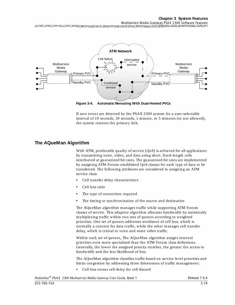
255-700-154 3-19
PacketStar® PSAX 2300 Multiservice Media Gateway User Guide, Issue 1 Release 7.0.0
Chapter 3 System FeaturesMultiservice Media Gateway PSAX 2300 Software Features
If zero errors are detected by the PSAX 2300 system for a user-selectable interval of 10 seconds, 30 seconds, 1 minute, or 5 minutes (or not allowed), the system restores the primary link.
The AQueMan Algorithm
With ATM, predictable quality of service (QoS) is achieved for all applications by transmitting voice, video, and data using short, fixed-length cells interleaved at guaranteed bit rates. The guaranteed bit rates are implemented by assigning ATM Forum-established QoS classes for each type of data to be transferred. The following attributes are considered in assigning an ATM service class:
• Cell transfer delay characteristics
• Cell loss ratio
• The type of connection required
• The timing or synchronization of the source and destination
The AQueMan algorithm manages traffic while supporting ATM Forum classes of service. This adaptive algorithm allocates bandwidth by statistically multiplexing traffic within two sets of queues according to weighted priorities. One set of queues addresses avoidance of cell loss, which is normally a concern for data traffic, while the other manages cell transfer delay, which is critical to voice and some video traffic.
Within each set of queues, The AQueMan algorithm assigns internal priorities even more specialized than the ATM Forum class definitions. Generally, the lower the assigned priority number, the greater the access to bandwidth and the less likelihood of loss.
The AQueMan algorithm classifies traffic based on service-level priorities and limits congestion by addressing three dimensions of traffic management:
• Cell loss versus cell delay for cell discard
Figure 3-4. Automatic Rerouting With Dual-Homed PVCs
MultiserviceMedia
GatewayPrimary PVC
Standby PVC
Primary PVC
Standby PVC
ATM Network
InterruptedLink failure
service
Continuedservice
MultiserviceMedia
Gateway
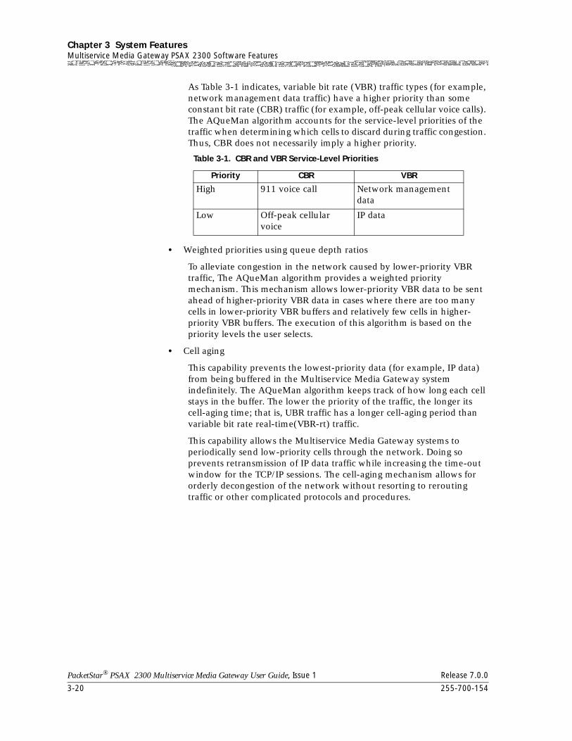
Chapter 3 System FeaturesMultiservice Media Gateway PSAX 2300 Software Features
3-20 255-700-154
PacketStar® PSAX 2300 Multiservice Media Gateway User Guide, Issue 1 Release 7.0.0
As Table 3-1 indicates, variable bit rate (VBR) traffic types (for example, network management data traffic) have a higher priority than some constant bit rate (CBR) traffic (for example, off-peak cellular voice calls). The AQueMan algorithm accounts for the service-level priorities of the traffic when determining which cells to discard during traffic congestion. Thus, CBR does not necessarily imply a higher priority.
• Weighted priorities using queue depth ratios
To alleviate congestion in the network caused by lower-priority VBR traffic, The AQueMan algorithm provides a weighted priority mechanism. This mechanism allows lower-priority VBR data to be sent ahead of higher-priority VBR data in cases where there are too many cells in lower-priority VBR buffers and relatively few cells in higher-priority VBR buffers. The execution of this algorithm is based on the priority levels the user selects.
• Cell aging
This capability prevents the lowest-priority data (for example, IP data) from being buffered in the Multiservice Media Gateway system indefinitely. The AQueMan algorithm keeps track of how long each cell stays in the buffer. The lower the priority of the traffic, the longer its cell-aging time; that is, UBR traffic has a longer cell-aging period than variable bit rate real-time(VBR-rt) traffic.
This capability allows the Multiservice Media Gateway systems to periodically send low-priority cells through the network. Doing so prevents retransmission of IP data traffic while increasing the time-out window for the TCP/IP sessions. The cell-aging mechanism allows for orderly decongestion of the network without resorting to rerouting traffic or other complicated protocols and procedures.
Table 3-1. CBR and VBR Service-Level Priorities
Priority CBR VBR
High 911 voice call Network management data
Low Off-peak cellular voice
IP data
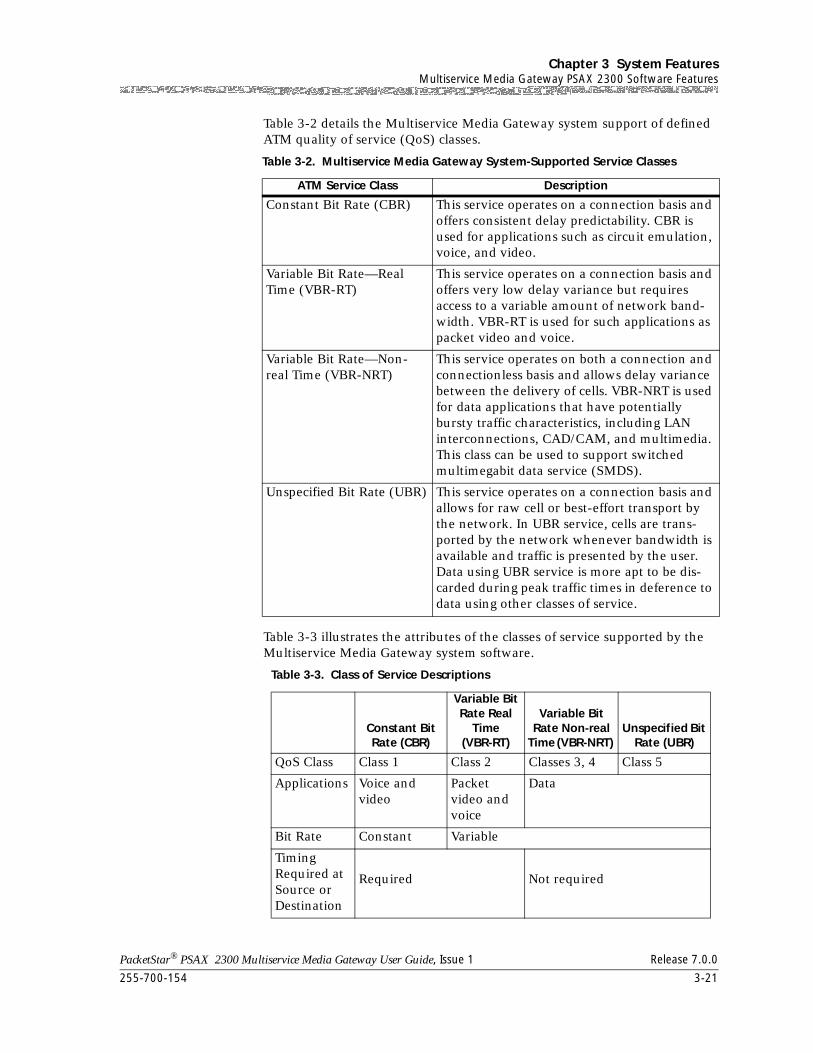
255-700-154 3-21
PacketStar® PSAX 2300 Multiservice Media Gateway User Guide, Issue 1 Release 7.0.0
Chapter 3 System FeaturesMultiservice Media Gateway PSAX 2300 Software Features
Table 3-2 details the Multiservice Media Gateway system support of defined ATM quality of service (QoS) classes.
Table 3-3 illustrates the attributes of the classes of service supported by the Multiservice Media Gateway system software.
Table 3-2. Multiservice Media Gateway System-Supported Service Classes
ATM Service Class Description
Constant Bit Rate (CBR) This service operates on a connection basis and offers consistent delay predictability. CBR is used for applications such as circuit emulation, voice, and video.
Variable Bit Rate—Real Time (VBR-RT)
This service operates on a connection basis and offers very low delay variance but requires access to a variable amount of network band-width. VBR-RT is used for such applications as packet video and voice.
Variable Bit Rate—Non-real Time (VBR-NRT)
This service operates on both a connection and connectionless basis and allows delay variance between the delivery of cells. VBR-NRT is used for data applications that have potentially bursty traffic characteristics, including LAN interconnections, CAD/CAM, and multimedia. This class can be used to support switched multimegabit data service (SMDS).
Unspecified Bit Rate (UBR) This service operates on a connection basis and allows for raw cell or best-effort transport by the network. In UBR service, cells are trans-ported by the network whenever bandwidth is available and traffic is presented by the user. Data using UBR service is more apt to be dis-carded during peak traffic times in deference to data using other classes of service.
Table 3-3. Class of Service Descriptions
Constant Bit Rate (CBR)
Variable Bit Rate Real
Time (VBR-RT)
Variable Bit Rate Non-real
Time (VBR-NRT) Unspecified Bit
Rate (UBR)
QoS Class Class 1 Class 2 Classes 3, 4 Class 5
Applications Voice and video
Packet video and voice
Data
Bit Rate Constant Variable
Timing Required at Source or Destination
Required Not required
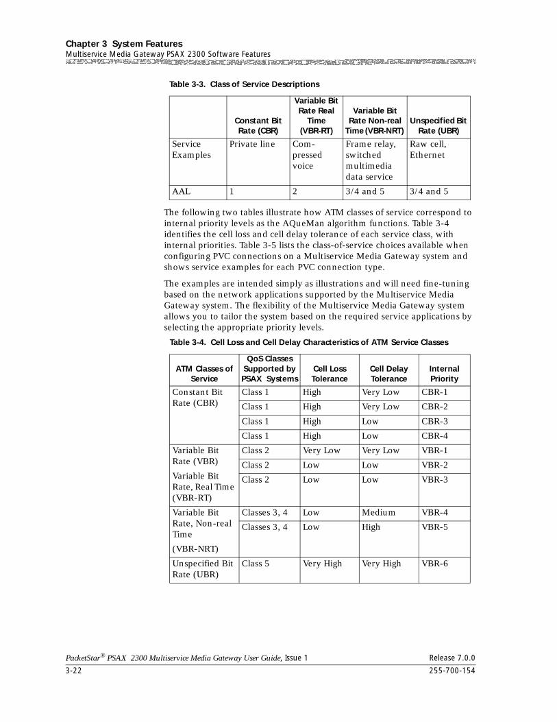
Chapter 3 System FeaturesMultiservice Media Gateway PSAX 2300 Software Features
3-22 255-700-154
PacketStar® PSAX 2300 Multiservice Media Gateway User Guide, Issue 1 Release 7.0.0
The following two tables illustrate how ATM classes of service correspond to internal priority levels as the AQueMan algorithm functions. Table 3-4 identifies the cell loss and cell delay tolerance of each service class, with internal priorities. Table 3-5 lists the class-of-service choices available when configuring PVC connections on a Multiservice Media Gateway system and shows service examples for each PVC connection type.
The examples are intended simply as illustrations and will need fine-tuning based on the network applications supported by the Multiservice Media Gateway system. The flexibility of the Multiservice Media Gateway system allows you to tailor the system based on the required service applications by selecting the appropriate priority levels.
Service Examples
Private line Com-pressed voice
Frame relay, switched multimedia data service
Raw cell, Ethernet
AAL 1 2 3/4 and 5 3/4 and 5
Table 3-4. Cell Loss and Cell Delay Characteristics of ATM Service Classes
ATM Classes of Service
QoS Classes Supported by PSAX Systems
Cell Loss Tolerance
Cell Delay Tolerance
Internal Priority
Constant Bit Rate (CBR)
Class 1 High Very Low CBR-1
Class 1 High Very Low CBR-2
Class 1 High Low CBR-3
Class 1 High Low CBR-4
Variable Bit Rate (VBR)
Variable Bit Rate, Real Time (VBR-RT)
Class 2 Very Low Very Low VBR-1
Class 2 Low Low VBR-2
Class 2 Low Low VBR-3
Variable Bit Rate, Non-real Time
(VBR-NRT)
Classes 3, 4 Low Medium VBR-4
Classes 3, 4 Low High VBR-5
Unspecified Bit Rate (UBR)
Class 5 Very High Very High VBR-6
Table 3-3. Class of Service Descriptions
Constant Bit Rate (CBR)
Variable Bit Rate Real
Time (VBR-RT)
Variable Bit Rate Non-real
Time (VBR-NRT) Unspecified Bit
Rate (UBR)
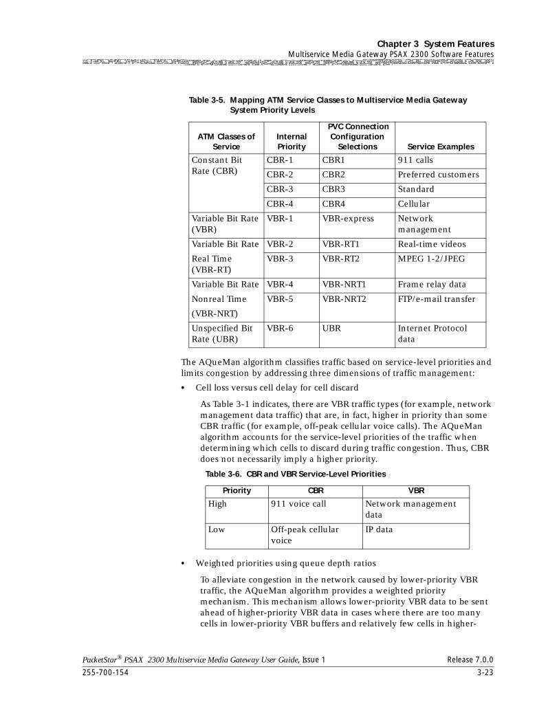
255-700-154 3-23
PacketStar® PSAX 2300 Multiservice Media Gateway User Guide, Issue 1 Release 7.0.0
Chapter 3 System FeaturesMultiservice Media Gateway PSAX 2300 Software Features
The AQueMan algorithm classifies traffic based on service-level priorities and limits congestion by addressing three dimensions of traffic management:
• Cell loss versus cell delay for cell discard
As Table 3-1 indicates, there are VBR traffic types (for example, network management data traffic) that are, in fact, higher in priority than some CBR traffic (for example, off-peak cellular voice calls). The AQueMan algorithm accounts for the service-level priorities of the traffic when determining which cells to discard during traffic congestion. Thus, CBR does not necessarily imply a higher priority.
• Weighted priorities using queue depth ratios
To alleviate congestion in the network caused by lower-priority VBR traffic, the AQueMan algorithm provides a weighted priority mechanism. This mechanism allows lower-priority VBR data to be sent ahead of higher-priority VBR data in cases where there are too many cells in lower-priority VBR buffers and relatively few cells in higher-
Table 3-5. Mapping ATM Service Classes to Multiservice Media Gateway System Priority Levels
ATM Classes of Service
Internal Priority
PVC Connection Configuration
Selections Service Examples
Constant Bit Rate (CBR)
CBR-1 CBR1 911 calls
CBR-2 CBR2 Preferred customers
CBR-3 CBR3 Standard
CBR-4 CBR4 Cellular
Variable Bit Rate (VBR)
VBR-1 VBR-express Network management
Variable Bit Rate
Real Time (VBR-RT)
VBR-2 VBR-RT1 Real-time videos
VBR-3 VBR-RT2 MPEG 1-2/JPEG
Variable Bit Rate
Nonreal Time
(VBR-NRT)
VBR-4 VBR-NRT1 Frame relay data
VBR-5 VBR-NRT2 FTP/e-mail transfer
Unspecified Bit Rate (UBR)
VBR-6 UBR Internet Protocol data
Table 3-6. CBR and VBR Service-Level Priorities
Priority CBR VBR
High 911 voice call Network management data
Low Off-peak cellular voice
IP data
Chapter 3 System FeaturesMultiservice Media Gateway PSAX 2300 Software Features
3-24 255-700-154
PacketStar® PSAX 2300 Multiservice Media Gateway User Guide, Issue 1 Release 7.0.0
priority VBR buffers. The execution of this algorithm is based on the priority levels the user selects.
• Cell aging
This capability prevents the lowest-priority data (for example, IP data) from being buffered in the Multiservice Media Gateway systems indefinitely. The AQueMan algorithm keeps track of how long each cell stays in the buffer. The lower the priority of the traffic, the longer its cell-aging time; that is, UBR traffic has a longer cell-aging period than VBR-RT traffic.
This capability allows the Multiservice Media Gateway systems to periodically send low-priority cells through the network. Doing so prevents retransmission of IP data traffic while increasing the time-out window for the TCP/IP sessions. The cell-aging mechanism allows for orderly decongestion of the network without resorting to traffic rerouting and other complicated protocols and procedures.
ATM Trunking
The ATM trunking feature uses standard AAL2 trunking along with narrowband services to carry voice, data, circuit mode data, frame mode data, and fax traffic over DS1 or E1 lines. Using narrowband services leads to substantial bandwidth savings, a primary advantage in ATM. ATM trunking is part of the total voice telephony over ATM solution that allows virtual circuit applications that include PVCs, SVCs, and SPVCs, in addition to derived voice over xDSL applications, in conjunction with GR-303 services. While using the compression standards and coding inherent in AAL2, local exchange carriers can group up to 255 narrowband voice calls on a single virtual channel connection. This feature includes support for transport channel-associated signaling (CAS).
ATM trunking is designed to interconnect an interworking function (IWF) with broadband facilities and with other telecommunications devices including PBXs and ATM network switches. Typically, an IWF concentrates a number of narrowband channels over one or more broadband channels.
Connection Gateway API
The Connection Gateway Application Programming Interface (API) was initially used only in custom releases, to work with PacketStar® central office products such as the PSAX 1250 and the PSAX 2300. Using this interface, an external call controller can control ATM switching in a PSAX 1250 or PSAX 2300 using nonnative ATM networking protocols. The Connection Gateway API allows powerful interworking of ATM, ISDN, SS7, CAS, and other protocols.
These capabilities support such features as Type 102, Type 105, and Type 108 milliwatt termination tests on the Tones and Announcements Server module, CAS signaling, and extending existing Connection Gateway API functionality
255-700-154 3-25
PacketStar® PSAX 2300 Multiservice Media Gateway User Guide, Issue 1 Release 7.0.0
Chapter 3 System FeaturesMultiservice Media Gateway PSAX 2300 Software Features
to new PSAX hardware and software components such as the Medium-Density DS1, and the DSP2C and DSP2D Voice Server modules.
The Connection Gateway includes support for continuity checking and line test support for the new 3-port Channelized DS3/STS-1e CES module. Existing Connection Gateway service level interworking, provisioning, and fault monitoring are extended to the newly released I/O modules.
Modifications to comply with the Lucent 7R/E™ switch include support for ATM UNI signaling 4.0, offering support for extended quality of service parameters like cell delay variation, and cell loss ratio and bandwidth regulation. The interface supports AAL1 traffic for echo cancellation with the DSP2D module. Messages enable users to obtain information on connection status of DS0s, to retransmit UNI release indication messages, to suppress transmission of the UNI release indication message on line failure, to supply a list of active SVCs, and to do in-band digit collection on ISDN PRI and SS7 TDM trunks. A message has been extended to release SVCs for implicit cut-through, and alarms have been added for the DSP2C and Tones and Announcements Server modules.
The Connection Gateway API provides a communications protocol or set of messages by which a call controller can control PSAX 2300 ATM switching using nonnative ATM networking protocols. See the PacketStar® Connection Gateway Application Programming Interface Developer’s Guide for detailed information about implementing a connection gateway API.
Firmware Release Control
Note: The Firmware Version Control window, as described in the procedure in the "Upgrading and Backing Up System Software and Firmware" chapter, should be used only on the advice of Lucent Technologies NetworkCare personnel (see the "Technical Support" section in Chapter 1, "Getting Started.").
The Multiservice Media Gateway CPU has access to the firmware binaries of all modules present in the Multiservice Media Gateway mainframe. The firmware is downloaded into the random access memory (RAM), into the secondary FLASH of each module, through a dedicated communication channel.
The firmware download is performed under the control of two interworking functions (IWFs) resident in the Multiservice Media Gateway CPU, and in the I/O or server module, respectively. Once the binaries are downloaded, the modules execute the downloaded code that controls the module.
You do not need to download an I/O or server module’s firmware separately from the Multiservice Media Gateway CPU software upgrade. When the Multiservice Media Gateway software is upgraded using the SRD Download Configuration window (see Chapter 7, "Upgrading and Backing Up the PSAX System Software"), the system reboots and all firmware of the I/O and server modules (in the rebooted chassis) is also upgraded.
Chapter 3 System FeaturesMultiservice Media Gateway PSAX 2300 Software Features
3-26 255-700-154
PacketStar® PSAX 2300 Multiservice Media Gateway User Guide, Issue 1 Release 7.0.0
You can use the following procedure to revert to an older firmware release if a module is not working properly with its current firmware.
Multiservice Media Gateway I/O modules released with Multiservice Media Gateway Release 6.0.0 and subsequent releases are supported by the Firmware Release Control feature. The I/O modules that were released before Multiservice Media Gateway Release 6.0.0 will work in the Multiservice Media Gateway chassis, but are not supported by the Firmware Release Control feature.
Forward Error Correction
The forward error correction (FEC) feature is a combination of functions designed to protect data transmission in a noisy communications environment, such as traffic transmitted across satellite or line-of-sight radio-frequency circuits. Most of these types of circuits transmit at the rate of 2.048 Mbps or slower. The three stages of FEC are multiple redundancy addressing, cell encoding, and cell scrambling. Since these FEC functions are applied in conjunction with the LANET protocol, which helps maintain cell-delineation capability up to a random 10-2 bit error rate (BER) with 0.625 percent bandwidth overhead, maximum protection is obtained.
Multiple redundancy addressing sets up multiple virtual circuits to the same destination. The addresses for the circuits are within the error space of the principal one used for actual transmission. The most probable error patterns occurring in the address field cause the address to be changed to another valid one.
To tolerate 2-bit random errors or 5-bit burst errors, 526 addresses are required for each channel. This is not a serious constraint because high-noise, low-speed links are normally used by only a small number of users. The more constraining situation, however, is that the signaling channel VPI value 0 and the VCI value 5 are within 2 bit-errors of the null cell address (0,0). Thus, in high-error conditions, signaling is inhibited. The payload type indicator (PTI) and generic flow control (GFC) fields need to be separately protected with the payload.
The user needs only to set up a single connection using a VPI value 0 and a VCI value in the range from 32 to 92. This provides for 60 simultaneous, noise-tolerant base connections. Each connection (ATM-to-ATM, VCC, or PVC) is created between an ATM-enabled port on a Multi-Serial module and on another ATM port (such as the OC-3c and the STM-1 modules). Internally within the Multiservice Media Gateway chassis, the connection is routed through the CPU module for the cell-encoding stage.
Cell encoding is executed by the CPU module on cell payload data destined for noisy interfaces. Based on a user-selected encoding rate for the connection, source-data cell payloads are divided into six blocks and fed into a Reed Solomon encoder. The encoded data, now approximately 48 bytes larger, is loaded into new cell payloads and forwarded to the Multi-Serial module where the cells are scrambled. The user selects a Reed Solomon encoding rate with a specific error-correction capability, as follows:
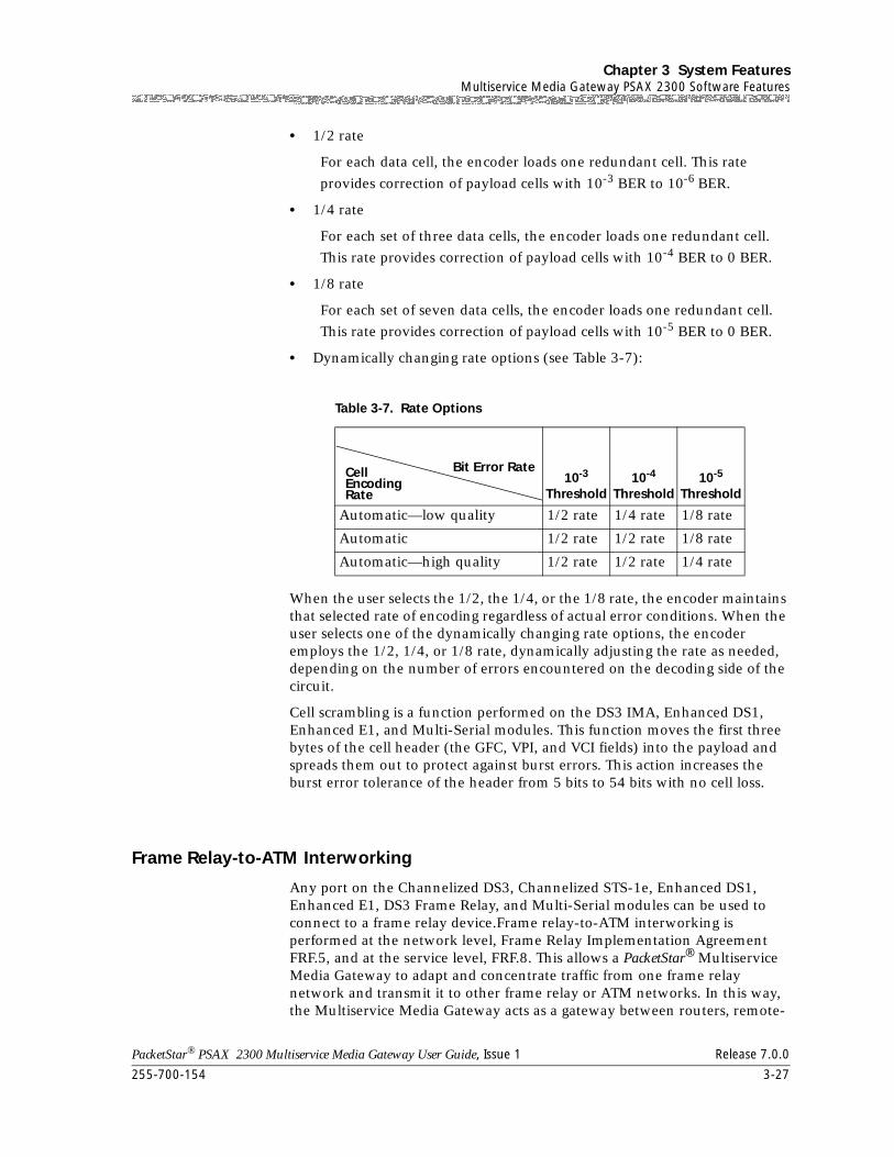
255-700-154 3-27
PacketStar® PSAX 2300 Multiservice Media Gateway User Guide, Issue 1 Release 7.0.0
Chapter 3 System FeaturesMultiservice Media Gateway PSAX 2300 Software Features
• 1/2 rate
For each data cell, the encoder loads one redundant cell. This rate
provides correction of payload cells with 10-3 BER to 10-6 BER.
• 1/4 rate
For each set of three data cells, the encoder loads one redundant cell.
This rate provides correction of payload cells with 10-4 BER to 0 BER.
• 1/8 rate
For each set of seven data cells, the encoder loads one redundant cell.
This rate provides correction of payload cells with 10-5 BER to 0 BER.
• Dynamically changing rate options (see Table 3-7):
When the user selects the 1/2, the 1/4, or the 1/8 rate, the encoder maintains that selected rate of encoding regardless of actual error conditions. When the user selects one of the dynamically changing rate options, the encoder employs the 1/2, 1/4, or 1/8 rate, dynamically adjusting the rate as needed, depending on the number of errors encountered on the decoding side of the circuit.
Cell scrambling is a function performed on the DS3 IMA, Enhanced DS1, Enhanced E1, and Multi-Serial modules. This function moves the first three bytes of the cell header (the GFC, VPI, and VCI fields) into the payload and spreads them out to protect against burst errors. This action increases the burst error tolerance of the header from 5 bits to 54 bits with no cell loss.
Frame Relay-to-ATM Interworking
Any port on the Channelized DS3, Channelized STS-1e, Enhanced DS1, Enhanced E1, DS3 Frame Relay, and Multi-Serial modules can be used to connect to a frame relay device.Frame relay-to-ATM interworking is performed at the network level, Frame Relay Implementation Agreement FRF.5, and at the service level, FRF.8. This allows a PacketStar® Multiservice Media Gateway to adapt and concentrate traffic from one frame relay network and transmit it to other frame relay or ATM networks. In this way, the Multiservice Media Gateway acts as a gateway between routers, remote-
Table 3-7. Rate Options
10-3
Threshold10-4
Threshold10-5
Threshold
Automatic—low quality 1/2 rate 1/4 rate 1/8 rate
Automatic 1/2 rate 1/2 rate 1/8 rate
Automatic—high quality 1/2 rate 1/2 rate 1/4 rate
Bit Error RateCellEncodingRate

Chapter 3 System FeaturesMultiservice Media Gateway PSAX 2300 Software Features
3-28 255-700-154
PacketStar® PSAX 2300 Multiservice Media Gateway User Guide, Issue 1 Release 7.0.0
dial access servers, systems network architecture (SNA) equipment, and other devices configured for frame relay operation.
FRF.5 Encapsulating Frames
With FRF.5 network level interworking, frames are encapsulated within ATM cells at the network ingress point and "tunneled" through the ATM network. At the network egress point, the ATM cell headers are removed and the frames are reassembled for delivery to a frame relay device.
FRF.8 Converting Frames
With FRF.8 service level interworking, frames are converted into one or more ATM cells at the network ingress point. At the network egress point, the ATM cells are delivered to an ATM device. This conversion is compliant with both the FRF.8 implementation agreement and the IEFT multiprotocol encapsulation specifications (RFC 1490, RFC 1483). FRF.8 interworking is performed at the end of the ATM network that connects to the frame relay device.
Note: FRF.5 and FRF.8 are not interoperable and cannot be used at both sides of a network. You may wish to use an FRF.8 approach for applications involving interconnectivity between two frame relay devices because the capabilities of FRF.8 include those that are available with FRF.5.
Frame Relay-to-Frame Relay Interworking
In addition to frame relay-to-ATM interworking, it is possible to configure a Multiservice Media Gateway for strictly frame relay operation. A frame relay-to-frame relay connection can be made between two ports of a Multiservice Media Gateway if both ports have frame relay capacity. In this case, frame relay data received by one of the ports is converted to ATM cells for transmission across the backplane of the Multiservice Media Gateway, and then converted back into frame relay for transmission from another port.
GR-303 Interface
The Telcordia Technologies General Requirements 303 standard provides for both an open interface network architecture and a digital loop carrier system that operates on T1 circuits. This standard allows a remote terminal such as a central office PacketStar® PSAX Multiservice Media Gateway to flawlessly interface with a Lucent Stinger™ DSLAM, a CellPipe™ IAD, and a central office voice switch, such as the Lucent Technologies 5ESS switch, or with Nortel’s DMS switch.
The GR-303 interface protocol is available on the PacketStar 6-Port Enhanced DS1/T1 Multiservice, the 1-Port Channelized DS3 Multiservice, and the 1-Port Channelized STS-1e, T1 Format I/O modules, and works in conjunction with the DSP2C Voice Server module’s voice processing capabilities. Operating on T1 circuits, the GR-303 digital loop carrier service has provisions for both an open interface network architecture and a digital loop carrier system. The performance standards of the GR-303 interface are
255-700-154 3-29
PacketStar® PSAX 2300 Multiservice Media Gateway User Guide, Issue 1 Release 7.0.0
Chapter 3 System FeaturesMultiservice Media Gateway PSAX 2300 Software Features
derived from the high-level internetworking capabilities established in Telcordia Technologies General Requirements 303, and allow a central office PacketStar PSAX Multiservice Media Gateway to interface with central office voice switching equipment as a remote terminal.
The interface assigns and manages connections on a time slot management channel (TMC) and supports operating functions on an embedded operations channel (EOC), with each channel configured on I/O modules that support the GR-303 interface protocol. The application note details a configuration for one GR-303 group using the ratio concentration of 2048 CRVs to 668 DS0s, approximately a 3:1 oversubscription rate. (A CRV is a call reference value that the 5ESS switch will map to a phone number). The GR-303 specifications require connection concentrations from 1:1 up to 3:1, expandability from 2 to 28 DS1 circuits for each GR-303 group, and expandability from 1 to 2,048 subscriber channels per GR-303 interface group. The maximum number of GR-303 interface groups supported is 84. In addition, the GR-303 interface can handle PRI ISDN circuits, while also allowing multiple interface groups to simultaneously interface with a large number of switches. BRI ISDN is not supported.
Loop emulation services provide multiplexed AAL2 PVC support for the PacketStar® PSAX Multiservice Media Gateway central office product line. Loop emulation services allow voice traffic, DTMF, and signaling to be handled over the packet network. The circuits can interwork with time division multiplexing (TDM), ATM digital subscriber line (DSL), or GR-303 interfaces.
Because GR-303 software requires a large amount of random access memory (RAM), which exceeds the capacity of the original CPU module, full implementation of all GR-303 features requires using a CPU2 module (model 20P25). The CPU2 module has double the RAM capacity as the original CPU module. Users can enable or disable the GR-303 feature as needed. If this feature is not needed, disabling it allows the system to allocate more RAM for other system functions.
Inverse Multiplexing over ATM (IMA)
Inverse multiplexing over ATM (IMA) creates virtual access pipes that are faster than an E1 line, but not nearly as expensive as a T3/E3 line. This allows customers to gain ATM capabilities without the costs associated with broadband access. The DS1 IMA, DS3 IMA, and E1 IMA I/O modules support the ATM IMA interface.
LANET Protocol
The LANET (limitless ATM network) protocol, coupled with a simple error-tolerant addressing scheme, facilitates reliable delivery of ATM cells in a
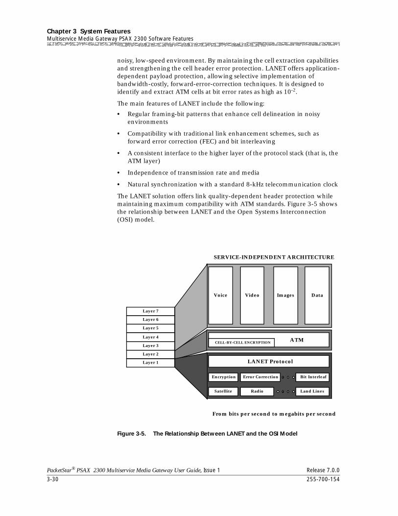
Chapter 3 System FeaturesMultiservice Media Gateway PSAX 2300 Software Features
3-30 255-700-154
PacketStar® PSAX 2300 Multiservice Media Gateway User Guide, Issue 1 Release 7.0.0
noisy, low-speed environment. By maintaining the cell extraction capabilities and strengthening the cell header error protection. LANET offers application-dependent payload protection, allowing selective implementation of bandwidth-costly, forward-error-correction techniques. It is designed to identify and extract ATM cells at bit error rates as high as 10-2.
The main features of LANET include the following:
• Regular framing-bit patterns that enhance cell delineation in noisy environments
• Compatibility with traditional link enhancement schemes, such as forward error correction (FEC) and bit interleaving
• A consistent interface to the higher layer of the protocol stack (that is, the ATM layer)
• Independence of transmission rate and media
• Natural synchronization with a standard 8-kHz telecommunication clock
The LANET solution offers link quality-dependent header protection while maintaining maximum compatibility with ATM standards. Figure 3-5 shows the relationship between LANET and the Open Systems Interconnection (OSI) model.
Figure 3-5. The Relationship Between LANET and the OSI Model
Layer 2
Layer 3
Layer 4
Layer 5
Layer 6
Layer 7
LANET Protocol
Encryption Error Correction Bit Interleaf
Satellite Radio Land Lines
ATM
Voice Video Images Data
SERVICE-INDEPENDENT ARCHITECTURE
Layer 1
From bits per second to megabits per second
CELL-BY-CELL ENCRYPTION
255-700-154 3-31
PacketStar® PSAX 2300 Multiservice Media Gateway User Guide, Issue 1 Release 7.0.0
Chapter 3 System FeaturesMultiservice Media Gateway PSAX 2300 Software Features
The LANET protocol is designed to be active in the upper end of the physical layer of the OSI seven-layer model. Within a byte-oriented serial data stream, LANET provides a framing structure around ATM cells for transmission purposes and regular frame-marker bit patterns for cell extraction. Each LANET frame (2,400 bytes) is subdivided into 45 ATM cells (totaling 2,385 bytes) with a 15-byte overhead. This structure permits a transmission rate scalable according to the physical medium.
The 15-byte overhead, accounting for 0.63 percent of the bandwidth, includes the LANET frame and subframe headers, which are used in conjunction with traditional cell header error-detection methods, such as header error control (HEC), to enhance cell delineation for noisy environments. The protocol thus becomes independent of the transmission rate while still naturally synchronizing with an 8-kHz transmission clock via the 2,400-bytes-per-frame structure.
Traditionally, block-error correction schemes, such as Reed Solomon coding, have been used to protect the header. As a simple alternative, the Multiservice Media Gateway system software uses an error-tolerant addressing scheme (multiple redundancy addressing) that establishes multiple virtual circuits to the same destination, requiring no special hardware nor modification to the current standard. The addresses for the circuits are within the error space of the principal address used for actual transmission. The most probable error patterns occurring in the address field will simply change the address to another valid address. This approach maintains independence from the application layer because it encodes the header address within the same 10-nibble header space of standard ATM cells. In addition, it avoids the extra delay (detrimental to CBR traffic) required of multiple header-encoding schemes.
In practice, to tolerate 2-bit random errors or 5-bit burst errors requires setting up 526 addresses for each channel. This is not a serious constraint because noisy low-speed links will likely only be used to support a small number of users.
Finally, given the ability to deliver cells, the payload can now be FEC-protected on each virtual circuit, depending on the error tolerance of the application at the service-specific convergence sublayer (SSCS). Figure 3-6 shows the LANET frame structure.
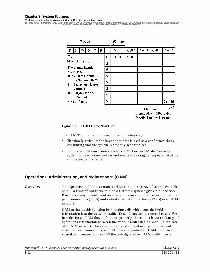
Chapter 3 System FeaturesMultiservice Media Gateway PSAX 2300 Software Features
3-32 255-700-154
PacketStar® PSAX 2300 Multiservice Media Gateway User Guide, Issue 1 Release 7.0.0
The LANET subframe functions in the following ways:
• The timely arrival of the header patterns is used as a confidence check, confirming that the system is properly synchronized.
• In the event of synchronization loss, a Multiservice Media Gateway system can easily seek and resynchronize to the regular appearance of the simple header patterns.
Operations, Administration, and Maintenance (OAM)
Overview The Operations, Administration, and Maintenance (OAM) feature, available on all PacketStar® Multiservice Media Gateway systems gives Public Service Providers a way to detect and receive reports on abnormal behavior in virtual path connections (VPCs) and virtual channel connections (VCCs) in an ATM network.
OAM performs this function by injecting cells which contain OAM information into the network traffic. This information is referred to as a flow. In order for an OAM flow to function properly, there must be an exchange of operations information between the various nodes in a network. In the case of an ATM network, this information is exchanged over permanent and switch virtual connections, with F4 flows designated for OAM traffic over a virtual path connection, and F5 flows designated for OAM traffic over a
Figure 3-6. LANET Frame Structure
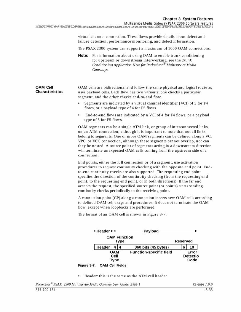
255-700-154 3-33
PacketStar® PSAX 2300 Multiservice Media Gateway User Guide, Issue 1 Release 7.0.0
Chapter 3 System FeaturesMultiservice Media Gateway PSAX 2300 Software Features
virtual channel connection. These flows provide details about defect and failure detection, performance monitoring, and defect information.
The PSAX 2300 system can support a maximum of 1000 OAM connections.
Note: For information about using OAM to enable trunk conditioning for upstream or downstream interworking, see the Trunk Conditioning Application Note for PacketStar® Multiservice Media Gateways.
OAM Cell Characteristics
OAM cells are bidirectional and follow the same physical and logical route as user payload cells. Each flow has two variants: one checks a particular segment, and the other checks end-to-end flow.
• Segments are indicated by a virtual channel identifier (VCI) of 3 for F4 flows, or a payload type of 4 for F5 flows.
• End-to-end flows are indicated by a VCI of 4 for F4 flows, or a payload type of 5 for F5 flows.
OAM segments can be a single ATM link, or group of interconnected links, on an ATM connection, although it is important to note that not all links belong to segments. One or more OAM segments can be defined along a VC, VPC, or VCC connection, although these segments cannot overlap, nor can they be nested. A source point of segments acting in a downstream direction will terminate unexpected OAM cells coming from the upstream side of a connection.
End points, either the full connection or of a segment, use activation procedures to request continuity checking with the opposite end point. End-to-end continuity checks are also supported. The requesting end point specifies the direction of the continuity checking (from the requesting end point, to the requesting end point, or in both directions). If the far end accepts the request, the specified source point (or points) starts sending continuity checks periodically to the receiving point.
A connection point (CP) along a connection inserts new OAM cells according to defined OAM cell usage and procedures. It does not terminate the OAM flow, except when loopbacks are performed.
The format of an OAM cell is shown in Figure 3-7:
• Header: this is the same as the ATM cell header
Figure 3-7. OAM Cell Fields
OAM FunctionType Reserved
OAMCellType
ErrorDetectio
Code
Function-specific field
Payload
Header
Header
4 4 6 10360 bits (45 bytes)
Chapter 3 System FeaturesMultiservice Media Gateway PSAX 2300 Software Features
3-34 255-700-154
PacketStar® PSAX 2300 Multiservice Media Gateway User Guide, Issue 1 Release 7.0.0
• OAM Cell Type: the management type (fault, activation/deactivation)
• OAM Function Type: the specific function (AIS, RDI, continuity check, loopback, forward monitoring, backward reporting, and so on)
• Function-Specific Field: data required for the specific function
• Reserved: reserved for further specification
• EDC: CRC-10 error detection code computed over the cell payload (except the CRC-10 field) and used to check for data corruption
OAM ATM Layer Flows
OAM has two flows of management information: F4 and F5. F4/F5 in-band maintenance flows are defined at the ATM layer for the VPC and VCC level, respectively. F4 is used for path-level connections, where the virtual path (VP) flows are identified by reserved values within the path. F5 is used for circuit-level connections, where the circuit virtual channel (VC) flows are identified by the payload type (PT) indicator field values.
These flows can be initiated at, or after, a connection setup by:
• call process functions
• OAM functions, or
• the network operator.
The hierachial structure of OAM flows is shown in Figure 3-7:
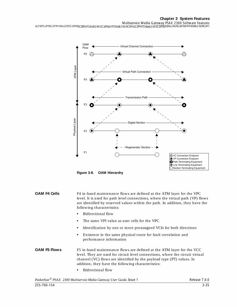
255-700-154 3-35
PacketStar® PSAX 2300 Multiservice Media Gateway User Guide, Issue 1 Release 7.0.0
Chapter 3 System FeaturesMultiservice Media Gateway PSAX 2300 Software Features
OAM F4 Cells F4 in-band maintenance flows are defined at the ATM layer for the VPC level. It is used for path level connections, where the virtual path (VP) flows are identified by reserved values within the path. In addition, they have the following characteristics:
• Bidirectional flow
• The same VPI value as user cells for the VPC
• Identification by one or more preassigned VCIs for both directions
• Existence in the same physical route for fault correlation and performance information
OAM F5 Flows F5 in-band maintenance flows are defined at the ATM layer for the VCC level. They are used for circuit level connections, where the circuit virtual channel (VC) flows are identified by the payload type (PT) values. In addition, they have the following characteristics:
• Bidrectional flow
Figure 3-8. OAM Hierarchy
Chapter 3 System FeaturesMultiservice Media Gateway PSAX 2300 Software Features
3-36 255-700-154
PacketStar® PSAX 2300 Multiservice Media Gateway User Guide, Issue 1 Release 7.0.0
• The same VPI/VCI values as the user cells for the VCC
• Identification by one or more preassigned VCIs for both directions
• Existence in the same physical route for fault correlation and performance information
User cells at the F5 level carry VCI cells which are defined below:
PTI=4 is a segment OAM F5 flow cell. This flow is identified by its standardized Payload Type Indicator (PTI), and is used for end-to-end VCC operations communication.
PTI= 5 is an end-to-end OAM F5 flow cell. This flow is identified by its standardized PTI, and is used for communicating operational information within the bounds of one VCC link that is a part of multiple inter-connected VCC links (called VCC segments).
ATM Layer OAM Functions
OAM functions performed at the ATM layer are:
• Fault Management
~ Alarm Indication Signals (AIS) — A network element (NE) transmits an AIS alarm downstream when it receives a major alarm condition such as a loss of frame. This prevents the generation of unnecessary alarms, and maintains communications.
~ Remote Defect Indication (RDI) — RDI cells are generated and tranmitted while the AIS state persists in order to indicate in the backward direction an interruption of the cell transfer capability in the forward direction.
~ Continuity Check — This check is used within a network to provide the continuous detection of ATM layer failures. End points, of either the full connection, or a segment, use activation procedures to request continuity checking with the opposite end point, at predetermined intervals. If the sink point does not receive continuity cells as expected, AIS and RDI alarms are transmitted.
~ Loopback — Loopback checks isolate failed entities if defect information is insufficient. A loopback check detects faults in the physical and ATM layers, and detects defects and declarations of failure within the network elements. It is also used for on-demand connectivity monitoring and pre-service connectivity verification.
A loopback procedure can be initiated at any connecting, segment, or end point by a Network Management System (NMS) that also receives the report on loopback performance.
A loopback location identifier is assigned to each connecting point at the operator’s option. This identifier identifies a unique connecting point within a segment or within the entire path. Then, a VPC or VCC end or connecting point sends a loopback cell to a destination end or connecting point, while a segment loopback is looped back at the destination point. If the source receives a looped cell back within five
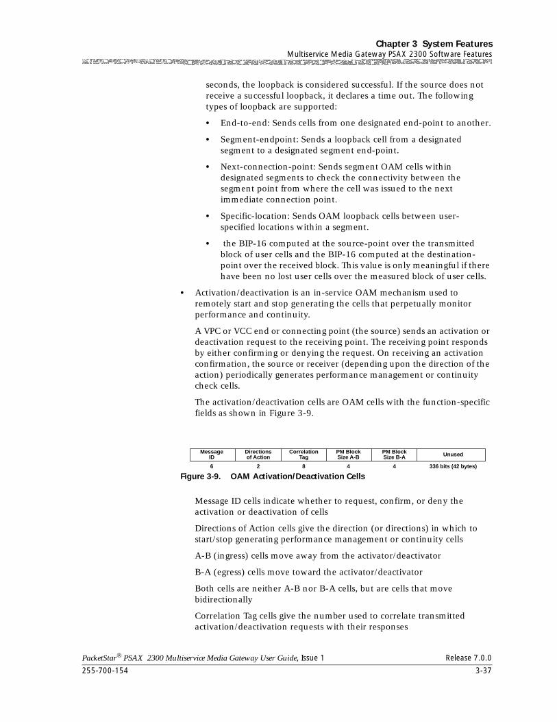
255-700-154 3-37
PacketStar® PSAX 2300 Multiservice Media Gateway User Guide, Issue 1 Release 7.0.0
Chapter 3 System FeaturesMultiservice Media Gateway PSAX 2300 Software Features
seconds, the loopback is considered successful. If the source does not receive a successful loopback, it declares a time out. The following types of loopback are supported:
• End-to-end: Sends cells from one designated end-point to another.
• Segment-endpoint: Sends a loopback cell from a designated segment to a designated segment end-point.
• Next-connection-point: Sends segment OAM cells within designated segments to check the connectivity between the segment point from where the cell was issued to the next immediate connection point.
• Specific-location: Sends OAM loopback cells between user-specified locations within a segment.
• the BIP-16 computed at the source-point over the transmitted block of user cells and the BIP-16 computed at the destination-point over the received block. This value is only meaningful if there have been no lost user cells over the measured block of user cells.
• Activation/deactivation is an in-service OAM mechanism used to remotely start and stop generating the cells that perpetually monitor performance and continuity.
A VPC or VCC end or connecting point (the source) sends an activation or deactivation request to the receiving point. The receiving point responds by either confirming or denying the request. On receiving an activation confirmation, the source or receiver (depending upon the direction of the action) periodically generates performance management or continuity check cells.
The activation/deactivation cells are OAM cells with the function-specific fields as shown in Figure 3-9.
Message ID cells indicate whether to request, confirm, or deny the activation or deactivation of cells
Directions of Action cells give the direction (or directions) in which to start/stop generating performance management or continuity cells
A-B (ingress) cells move away from the activator/deactivator
B-A (egress) cells move toward the activator/deactivator
Both cells are neither A-B nor B-A cells, but are cells that move bidirectionally
Correlation Tag cells give the number used to correlate transmitted activation/deactivation requests with their responses
Figure 3-9. OAM Activation/Deactivation Cells
MessageID
Directionsof Action
CorrelationTag
PM BlockSize A-B
PM BlockSize B-A Unused
6 2 8 4 4 336 bits (42 bytes)
Chapter 3 System FeaturesSoft Permanent Virtual Circuits (SPVCs)
3-38 255-700-154
PacketStar® PSAX 2300 Multiservice Media Gateway User Guide, Issue 1 Release 7.0.0
PM Block Size (A-B, B-A) is a feature that works with activation requests only. It monitors the size of user cell blocks that monitor the performance in the forward or backward direction. (The default is 1,024 cells.)
Soft Permanent Virtual Circuits (SPVCs)
The soft permanent virtual circuit (SPVC) feature is a semipermanent virtual circuit enabled by management action. It is a permanent virtual circuit (PVC) type of circuit in which switched virtual circuits (SVCs) are used for call setup and (automatic) rerouting. Once either a PVC or a permanent virtual path connection has been configured, an SPVC can be established between the two network interfaces serving the PVC by using signaling procedures. Consequently, this type of connection has attributes of both a switched virtual connection and a permanent virtual connection.
Specifically, an SPVC is established and released between the two network interfaces (NIs) serving the PVC. The user assigns unique ATM addresses, including the SEL octet in the case of a private ATM address (see Section 3.1 of the UNI 4.0 signaling specification), to the corresponding NIs, thus identifying the starting point and ending point of the SPVC.
Switched Virtual Circuits
Switched virtual circuit (SVC) connections are used for voice traffic over a public ATM WAN or private line network. SVCs are supported on all the ATM cell-bearing interfaces, including the DS3, E3, OC-3c, STM-1, Multi-Serial, and High Speed modules. The Multiservice Media Gateway system software supports the following features:
• Each ATM port on a single module can be individually configured for ATM UNI 3.0, UNI 3.1, IISP user, IISP network, or PNNI interfaces.
• SVCs can be allocated on UNI (public and private), IISP, and PNNI interfaces.
• Point-to-point and point-to-multipoint VCC connections are supported.
• VCC connections support both symmetric and asymmetric bandwidth requirements.
• An Multiservice Media Gateway system can process 60 calls per second. Maximum limits include 100 UNIs per system; 5,000 simultaneous point-to-point SVC call originations, and 2,000 point-to-multipoint call originations.
• An Multiservice Media Gateway system (equipped with 64 MB of memory on the CPU module) can process a maximum of 20,000 simultaneous SVC calls in progress.
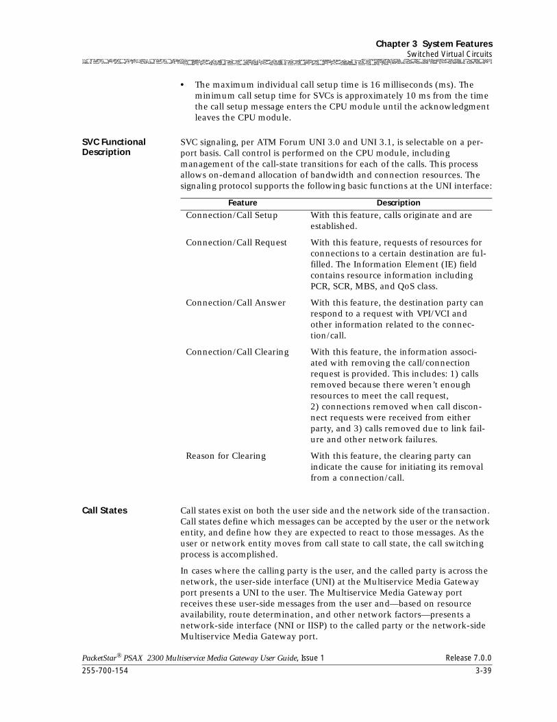
255-700-154 3-39
PacketStar® PSAX 2300 Multiservice Media Gateway User Guide, Issue 1 Release 7.0.0
Chapter 3 System FeaturesSwitched Virtual Circuits
• The maximum individual call setup time is 16 milliseconds (ms). The minimum call setup time for SVCs is approximately 10 ms from the time the call setup message enters the CPU module until the acknowledgment leaves the CPU module.
SVC Functional Description
SVC signaling, per ATM Forum UNI 3.0 and UNI 3.1, is selectable on a per-port basis. Call control is performed on the CPU module, including management of the call-state transitions for each of the calls. This process allows on-demand allocation of bandwidth and connection resources. The signaling protocol supports the following basic functions at the UNI interface:
Call States Call states exist on both the user side and the network side of the transaction. Call states define which messages can be accepted by the user or the network entity, and define how they are expected to react to those messages. As the user or network entity moves from call state to call state, the call switching process is accomplished.
In cases where the calling party is the user, and the called party is across the network, the user-side interface (UNI) at the Multiservice Media Gateway port presents a UNI to the user. The Multiservice Media Gateway port receives these user-side messages from the user and—based on resource availability, route determination, and other network factors—presents a network-side interface (NNI or IISP) to the called party or the network-side Multiservice Media Gateway port.
Feature Description
Connection/Call Setup With this feature, calls originate and are established.
Connection/Call Request With this feature, requests of resources for connections to a certain destination are ful-filled. The Information Element (IE) field contains resource information including PCR, SCR, MBS, and QoS class.
Connection/Call Answer With this feature, the destination party can respond to a request with VPI/VCI and other information related to the connec-tion/call.
Connection/Call Clearing With this feature, the information associ-ated with removing the call/connection request is provided. This includes: 1) calls removed because there weren’t enough resources to meet the call request, 2) connections removed when call discon-nect requests were received from either party, and 3) calls removed due to link fail-ure and other network failures.
Reason for Clearing With this feature, the clearing party can indicate the cause for initiating its removal from a connection/call.
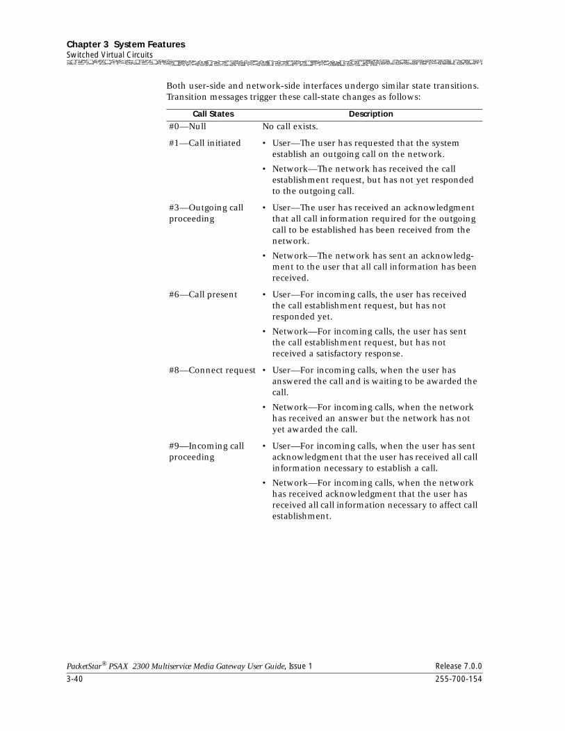
Chapter 3 System FeaturesSwitched Virtual Circuits
3-40 255-700-154
PacketStar® PSAX 2300 Multiservice Media Gateway User Guide, Issue 1 Release 7.0.0
Both user-side and network-side interfaces undergo similar state transitions. Transition messages trigger these call-state changes as follows:
Call States Description
#0—Null No call exists.
#1—Call initiated • User—The user has requested that the system establish an outgoing call on the network.
• Network—The network has received the call establishment request, but has not yet responded to the outgoing call.
#3—Outgoing call proceeding
• User—The user has received an acknowledgment that all call information required for the outgoing call to be established has been received from the network.
• Network—The network has sent an acknowledg-ment to the user that all call information has been received.
#6—Call present • User—For incoming calls, the user has received the call establishment request, but has not responded yet.
• Network—For incoming calls, the user has sent the call establishment request, but has not received a satisfactory response.
#8—Connect request • User—For incoming calls, when the user has answered the call and is waiting to be awarded the call.
• Network—For incoming calls, when the network has received an answer but the network has not yet awarded the call.
#9—Incoming call proceeding
• User—For incoming calls, when the user has sent acknowledgment that the user has received all call information necessary to establish a call.
• Network—For incoming calls, when the network has received acknowledgment that the user has received all call information necessary to affect call establishment.
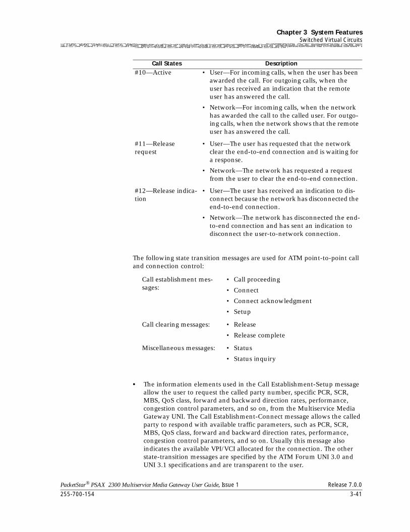
255-700-154 3-41
PacketStar® PSAX 2300 Multiservice Media Gateway User Guide, Issue 1 Release 7.0.0
Chapter 3 System FeaturesSwitched Virtual Circuits
The following state transition messages are used for ATM point-to-point call and connection control:
• The information elements used in the Call Establishment-Setup message allow the user to request the called party number, specific PCR, SCR, MBS, QoS class, forward and backward direction rates, performance, congestion control parameters, and so on, from the Multiservice Media Gateway UNI. The Call Establishment-Connect message allows the called party to respond with available traffic parameters, such as PCR, SCR, MBS, QoS class, forward and backward direction rates, performance, congestion control parameters, and so on. Usually this message also indicates the available VPI/VCI allocated for the connection. The other state-transition messages are specified by the ATM Forum UNI 3.0 and UNI 3.1 specifications and are transparent to the user.
#10—Active • User—For incoming calls, when the user has been awarded the call. For outgoing calls, when the user has received an indication that the remote user has answered the call.
• Network—For incoming calls, when the network has awarded the call to the called user. For outgo-ing calls, when the network shows that the remote user has answered the call.
#11—Release request
• User—The user has requested that the network clear the end-to-end connection and is waiting for a response.
• Network—The network has requested a request from the user to clear the end-to-end connection.
#12—Release indica-tion
• User—The user has received an indication to dis-connect because the network has disconnected the end-to-end connection.
• Network—The network has disconnected the end-to-end connection and has sent an indication to disconnect the user-to-network connection.
Call establishment mes-sages:
• Call proceeding
• Connect
• Connect acknowledgment
• Setup
Call clearing messages: • Release
• Release complete
Miscellaneous messages: • Status
• Status inquiry
Call States Description
Chapter 3 System FeaturesTraffic Management (UPC Support)
3-42 255-700-154
PacketStar® PSAX 2300 Multiservice Media Gateway User Guide, Issue 1 Release 7.0.0
Traffic Management (UPC Support)
Release 6.3.0 implemented Phase 2 of a multiphase development program to provide ingress ATM policing on ATM interfaces. Over several development phases, Lucent will add new service classes and expand feature coverage on ATM interface modules. Phase 1 added traffic management to the OC-3c 1+1 APS and the STM-1 1+1 MSP modules. Phase 2 gives this capability to the Channelized DS3, Medium-Density DS1, and High-Density E1 modules.
One of the main improvements is upgraded usage parameter control (UPC). This feature allows the end system to police ingress connections for service level agreement compliance. After a set of service categories is specified, UPC is given a set of parameters for each, describing the traffic presented to the network and the quality of service the network requires. A number of traffic control mechanisms are defined, which the network may use to meet the QoS objectives.
Traffic Shaping
The traffic shaping feature is a method for controlling the flow of data traffic. It is implemented in firmware on modules that are offered with traffic-shaping variations. Those modules are the OC-3c Multi-Mode, OC-3c Single-Mode, STM-1 Multi-Mode, and STM-1 Single-Mode modules.
Traffic shaping ensures that variable bit-rate (VBR) traffic entering the Multiservice Media Gateway system (via the OC-3c and the STM-1 modules) complies with the parameters of established service contracts. If bursty VBR traffic exceeds the parameters of the output connection, the rate of the traffic flow is controlled to comply with the specified output rate by means of an input cell-selection algorithm before the traffic flow reaches the Multiservice Media Gateway backplane. If traffic exceeds the buffer capacity of the OC-3c or the STM-1 module (that is, rises above the maximum-capacity level), cells are discarded. Traffic shaping allows the network side of the Multiservice Media Gateway system to multiplex more efficiently the traffic-shaped virtual channel connections (VCCs) with other customer premises equipment (CPE) traffic (voice, video, and so on) for transport across the ATM network link. Constant bit-rate (CBR) traffic is unaffected by traffic shaping.
The only application of the traffic-shaping feature is shown in Figure 3-10.
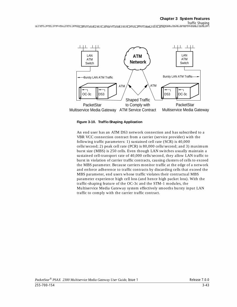
255-700-154 3-43
PacketStar® PSAX 2300 Multiservice Media Gateway User Guide, Issue 1 Release 7.0.0
Chapter 3 System FeaturesTraffic Shaping
An end user has an ATM DS3 network connection and has subscribed to a VBR VCC connection contract from a carrier (service provider) with the following traffic parameters: 1) sustained cell rate (SCR) is 40,000 cells/second; 2) peak cell rate (PCR) is 80,000 cells/second; and 3) maximum burst size (MBS) is 250 cells. Even though LAN switches usually maintain a sustained cell-transport rate of 40,000 cells/second, they allow LAN traffic to burst in violation of carrier traffic contracts, causing clusters of cells to exceed the MBS parameter. Because carriers monitor traffic at the edge of a network and enforce adherence to traffic contracts by discarding cells that exceed the MBS parameter, end users whose traffic violates their contractual MBS parameter experience high cell loss (and hence high packet loss). With the traffic-shaping feature of the OC-3c and the STM-1 modules, the Multiservice Media Gateway system effectively smooths bursty input LAN traffic to comply with the carrier traffic contract.
Figure 3-10. Traffic-Shaping Application
ATM Network
LANATM
Switch
LANATM
Switch
Bursty LAN ATM Traffic Bursty LAN ATM Traffic
ATMATM
OC-3c OC-3cDS3 DS3
Shaped Trafficto Comply with
ATM Service ContractPacketStar
Multiservice Media GatewayPacketStar
Multiservice Media Gateway
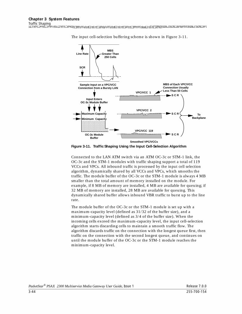
Chapter 3 System FeaturesTraffic Shaping
3-44 255-700-154
PacketStar® PSAX 2300 Multiservice Media Gateway User Guide, Issue 1 Release 7.0.0
The input cell-selection buffering scheme is shown in Figure 3-11.
Connected to the LAN ATM switch via an ATM OC-3c or STM-1 link, the OC-3c and the STM-1 modules with traffic shaping support a total of 119 VCCs and VPCs. All inbound traffic is processed by the input cell selection algorithm, dynamically shared by all VCCs and VPCs, which smooths the traffic. The module buffer of the OC-3c or the STM-1 module is always 4 MB smaller than the total amount of memory installed on the module. For example, if 8 MB of memory are installed, 4 MB are available for queuing; if 32 MB of memory are installed, 28 MB are available for queuing. This dynamically shared buffer allows inbound VBR traffic to burst up to the line rate.
The module buffer of the OC-3c or the STM-1 module is set up with a maximum-capacity level (defined as 31/32 of the buffer size), and a minimum-capacity level (defined as 3/4 of the buffer size). When the incoming cells exceed the maximum-capacity level, the input cell-selection algorithm starts discarding cells to maintain a smooth traffic flow. The algorithm discards traffic on the connection with the longest queue first, then traffic on the connection with the second longest queue, and continues on until the module buffer of the OC-3c or the STM-1 module reaches the minimum-capacity level.
Figure 3-11. Traffic Shaping Using the Input Cell-Selection Algorithm
MBSGreater Than
250 CellsLine Rate
VPC/VCC 1
VPC/VCC 2
S C R
S C R ToBackplane
MBS of Each VPC/VCCConnection UsuallyLess Than 50 Cells
S C RVPC/VCC 119
Smoothed VPC/VCCs
SCR
Sample Input on a VPC/VCCConnection from a Bursty LAN
Input EntersOC-3c Module Buffer
OC-3c ModuleBuffer
Maximum Capacity
Minimum Capacity
255-700-154 3-45
PacketStar® PSAX 2300 Multiservice Media Gateway User Guide, Issue 1 Release 7.0.0
Chapter 3 System FeaturesTraffic Shaping
The algorithm processes traffic moving out of the input cell selection buffer according to the SCR of the particular VPC/VCC. The MBSs of traffic-shaped output are set as follows:
The OC-3c and the STM-1 modules can perform traffic shaping on multiple high-rate connections (such as three 40-Mbps connections). Assigning a SCR to a connection above 75 Mbps, however, is not recommended in sensitive, bursty traffic environments. Assigning a SCR above 120 Mbps will essentially eliminate any traffic shaping, and thus is strongly discouraged.
• The OC-3c and the STM-1 modules perform only limited traffic management on the output side. The output buffer is limited to 2 Mbps for VBR traffic and 128 cells for CBR traffic, with only three priority levels supported: CBR, VBR1, and VBR2. The maximum-capacity level for congestion control is 32,000 cells, and the minimum-capacity level is 24,576 cells, with VBR traffic being shut off first from the backplane.
Rate Shaping
With Release 6.5.0 and beyond, the OC-3c 1+1 APS and STM-1 1+1 MSP Multi-mode modules offer rate shaping for frame relay, HDLC, and Ethernet traffic before it leaves the ATM trunk port. Rate shaping transmits ATM cells onto the ATM network at a peak cell rate, based on an algorithm. For frame relay traffic, the PSAX system software automatically calculates egress peak cell rate based on frame relay traffic parameters. For Ethernet traffic, the user must configure the egress peak cell rate. Connections employing the rate shaping feature have egress priority above VBRnrt and UBR connections but below that of CBR and VBRrt connections.
Where to Apply Rate Shaping During Configuration
Rate shaping is aligned with traffic shaping on egress, defined in the ATM Forum Traffic Management 4.0 specification. Called rate shaping to distinguish it from the traffic shaping, this feature is used on ingress to the OC-3c 1+1 APS traffic shaping modules. Rate shaping is applied to Frame Relay and Ethernet traffic prior to egress from the ATM trunk port. The feature can be used on PVC, SVC, or SPVC connections.
Sustained Cell Rate (SCR) of VPC/VCC
Maximum Burst Size (MBS) of Traffic-Shaped Output
0–20 Mbits/sec. < 4 cells
20–30 Mbits/sec. < 5 cells
30–40 Mbits/sec. < 6 cells
75–120 Mbits/sec. approximately 20–50 cells
Chapter 3 System FeaturesTraffic Shaping
3-46 255-700-154
PacketStar® PSAX 2300 Multiservice Media Gateway User Guide, Issue 1 Release 7.0.0
Configuring Rate Shaping for HDLC, Frame Relay, and Ethernet Virtual Channels
To configure the rate shaping feature, the traffic shaping feature must be enabled on the ATM UNI 3.1, ATM PNNI, or ATM IISP interface configuration windows of the OC-3c 1+1 APS or the STM-1 1+1 MSP modules.
• For frame relay traffic, the PSAX system software automatically calculates egress peak cell rate based on frame relay traffic parameters.
• For Ethernet and HDLC traffic, the user must enter the egress peak cell rate (PCR) on the VBR-to-ATM PVC or SPVC Connection window. See the Rate Shaping Table in the appendix in this document for the Minimum/Actual Target rate for the bps rate you want to use.
In either case, the PCR is used to shape the egress traffic not to exceed the PCR.
Modules Used With Rate Shaping
The feature can be configured only on frame relay, Ethernet, and HDLC traffic connections routed through a rate shaping-enabled ATM module for any class of service except UBR. Rate shaping is automatic if you select a class of service other than UBR. The feature cannot be used with UBR. All non-UBR traffic is rate shaped on a per connection basis. The major difference between a virtual interface and rate shaping is the number of connections: virtual interfaces consist of more than one connection; rate shaping is performed on one connection only, and the rate shaped connection must be non-UBR. When you enable traffic shaping on an OC-3c APS or an STM-1 MSP modules, the module will not support a virtual interface.
VBR Rate Shaping Priorities
Connections employing the rate shaping feature on the PSAX CO product line have an egress priority less than CBR and VBR-rt connections, and greater than VBR-nrt and UBR connections. The data rate available on rate shaped connections on a given interface is the interface data rate minus the overall data rate reserved for CBR and VBR-rt connections.
The rate shaping feature is designed to transmit frames segmented into ATM cells onto the ATM network at a steady rate; for example, at the sustained cell rate (PCR) of the connection. The feature performs per virtual channel (VC) queuing with a maximum queue size of 200 cells. As the amount of CBR and VBR-rt traffic on an interface increases, the probability increases that rate shaped traffic will have to be queued. This will impede the ability to maintain the SCR of the rate shaped connection(s) and eventually the queues will overflow, causing packets to be dropped.
To prevent a rate shaped connection from having packets dropped due to queuing, it is necessary to provision the connection’s peak cell rate (PCR)
255-700-154 3-47
PacketStar® PSAX 2300 Multiservice Media Gateway User Guide, Issue 1 Release 7.0.0
Chapter 3 System FeaturesTraffic Shaping
greater than its SCR. Include in your calculation the function (F) in the formula (see the section titled ”Formula for Determining the PCR of a Rate Shaped Connection” below for the total CBR and VBR-rt traffic provisioned for the interface (see the earlier section ”VBR Rate Shaping Priorities”). Note that the rate shaping function does not use the connection's maximum burst size (MBS). This, in effect, creates a ‘guard band’ around the connection to minimize the probability that a CBR or VBR-rt cell will be transmitted at the same time a rate shaped cell is scheduled to be transmitted. It is critical that accurate values for the connection parameters be used.
Rate Shaping for CBR and VBR-rt
The CBR traffic and VBR-rt connection affect the actual PCR rate of the traffic shaped connections. CBR and VBR-rt traffic should be limited to 75% to 80% of the port speed when traffic shaping is being used by the port. Furthermore, the SCR / PCR of shaping connections should be less than or equal to (1 - fraction of (cbr + vbr-rt)) for guaranteed performance of the traffic shaping algorithm.
Rate Shaping Connection Maximum
Each OC-3c 1+1 APS and STM-1 1+1 MSP module supports 2,046 traffic-shaped connections. The minimum PCR rate supported by the algorithm is 20 cps; the maximum is 4680 cps (E1 interface speed). A rounding error is introduced by the integer division used by the algorithm, so the granularity of the PCR rates supported by the algorithm suffers when the PCR exceeds the E1 speed. See the Rate Shaping Table in the appendix for a comparison between configured PCR and actual PCR delivered by the traffic shaper. For example, if the traffic shaped connection is configured with PCR (Min/Actual Target CPS column) of 906 to (Max Target CPS column) of 909, the traffic shaper is actually shaping the traffic to the (Actual PCR column) of 906 cps. The divergence is smallest at low PCR.
How the Algorithm Works
Queuing is maintained for the traffic shaped connections on a per VC basis. To schedule the processing of the queues appropriately such that cells will be sent at appropriate intervals, an offset time (versus zero) for each queue is calculated based on the PCR.
Offset Time Value Formula
The offset time value is calculated by the following formula:
T = 353207/PCR
Rate Shaping Algorithm
The traffic shaper has a table of 80,000 boxes. Each box holds a list of queue numbers. Each queue can have up to 200 data cells. For example, if the traffic shaper reads the data in box 1(see Figure 3-12) and the queue number
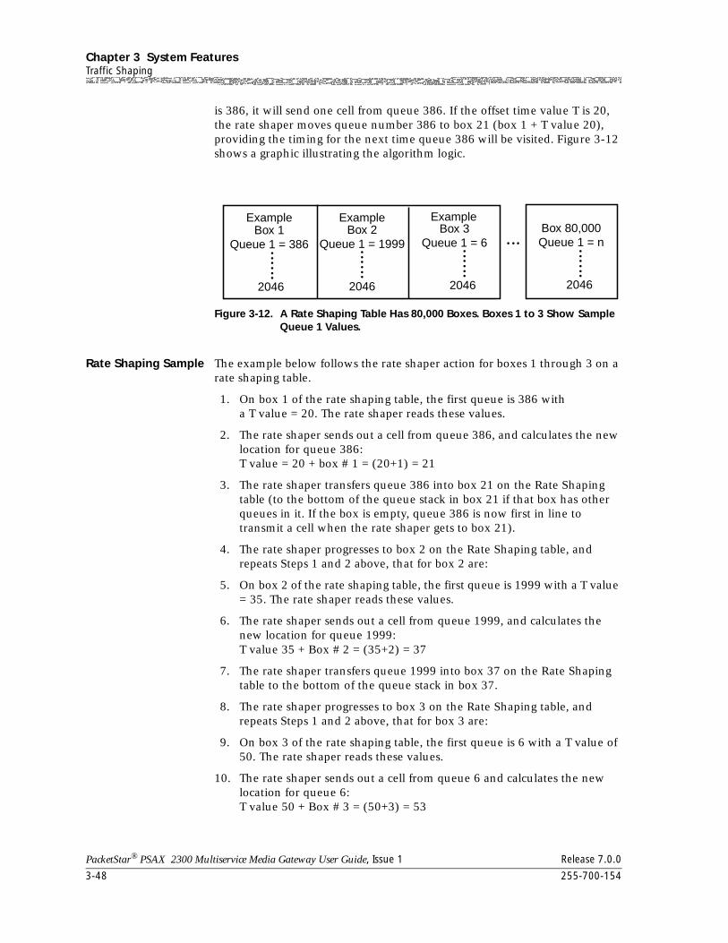
Chapter 3 System FeaturesTraffic Shaping
3-48 255-700-154
PacketStar® PSAX 2300 Multiservice Media Gateway User Guide, Issue 1 Release 7.0.0
is 386, it will send one cell from queue 386. If the offset time value T is 20, the rate shaper moves queue number 386 to box 21 (box 1 + T value 20), providing the timing for the next time queue 386 will be visited. Figure 3-12 shows a graphic illustrating the algorithm logic.
Rate Shaping Sample The example below follows the rate shaper action for boxes 1 through 3 on a rate shaping table.
1. On box 1 of the rate shaping table, the first queue is 386 witha T value = 20. The rate shaper reads these values.
2. The rate shaper sends out a cell from queue 386, and calculates the new location for queue 386:T value = 20 + box # 1 = (20+1) = 21
3. The rate shaper transfers queue 386 into box 21 on the Rate Shaping table (to the bottom of the queue stack in box 21 if that box has other queues in it. If the box is empty, queue 386 is now first in line to transmit a cell when the rate shaper gets to box 21).
4. The rate shaper progresses to box 2 on the Rate Shaping table, and repeats Steps 1 and 2 above, that for box 2 are:
5. On box 2 of the rate shaping table, the first queue is 1999 with a T value = 35. The rate shaper reads these values.
6. The rate shaper sends out a cell from queue 1999, and calculates the new location for queue 1999:T value 35 + Box # 2 = (35+2) = 37
7. The rate shaper transfers queue 1999 into box 37 on the Rate Shaping table to the bottom of the queue stack in box 37.
8. The rate shaper progresses to box 3 on the Rate Shaping table, and repeats Steps 1 and 2 above, that for box 3 are:
9. On box 3 of the rate shaping table, the first queue is 6 with a T value of 50. The rate shaper reads these values.
10. The rate shaper sends out a cell from queue 6 and calculates the new location for queue 6:T value 50 + Box # 3 = (50+3) = 53
Figure 3-12. A Rate Shaping Table Has 80,000 Boxes. Boxes 1 to 3 Show Sample Queue 1 Values.
Box 1Queue 1 = 386
2046
Box 2Queue 1 = 1999
2046
Box 3Queue 1 = 6
2046
Box 80,000Queue 1 = n
2046
Example Example Example
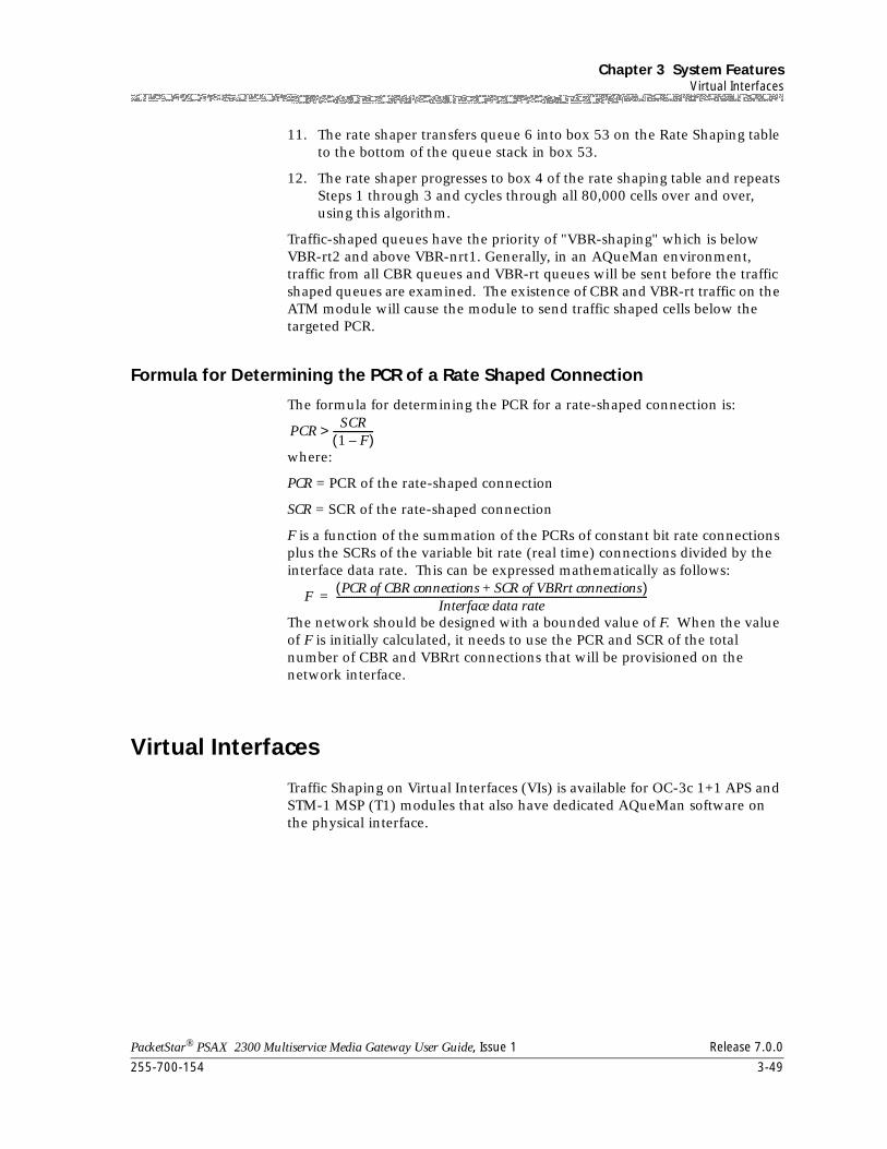
255-700-154 3-49
PacketStar® PSAX 2300 Multiservice Media Gateway User Guide, Issue 1 Release 7.0.0
Chapter 3 System FeaturesVirtual Interfaces
11. The rate shaper transfers queue 6 into box 53 on the Rate Shaping table to the bottom of the queue stack in box 53.
12. The rate shaper progresses to box 4 of the rate shaping table and repeats Steps 1 through 3 and cycles through all 80,000 cells over and over, using this algorithm.
Traffic-shaped queues have the priority of "VBR-shaping" which is below VBR-rt2 and above VBR-nrt1. Generally, in an AQueMan environment, traffic from all CBR queues and VBR-rt queues will be sent before the traffic shaped queues are examined. The existence of CBR and VBR-rt traffic on the ATM module will cause the module to send traffic shaped cells below the targeted PCR.
Formula for Determining the PCR of a Rate Shaped Connection
The formula for determining the PCR for a rate-shaped connection is:
where:
PCR = PCR of the rate-shaped connection
SCR = SCR of the rate-shaped connection
F is a function of the summation of the PCRs of constant bit rate connections plus the SCRs of the variable bit rate (real time) connections divided by the interface data rate. This can be expressed mathematically as follows:
The network should be designed with a bounded value of F. When the value of F is initially calculated, it needs to use the PCR and SCR of the total number of CBR and VBRrt connections that will be provisioned on the network interface.
Virtual Interfaces
Traffic Shaping on Virtual Interfaces (VIs) is available for OC-3c 1+1 APS and STM-1 MSP (T1) modules that also have dedicated AQueMan software on the physical interface.
PCRSCR1 F–( )----------------->
FPCR of CBR connections SCR of VBRrt connections+( )
Interface data rate---------------------------------------------------------------------------------------------------------------------------------=
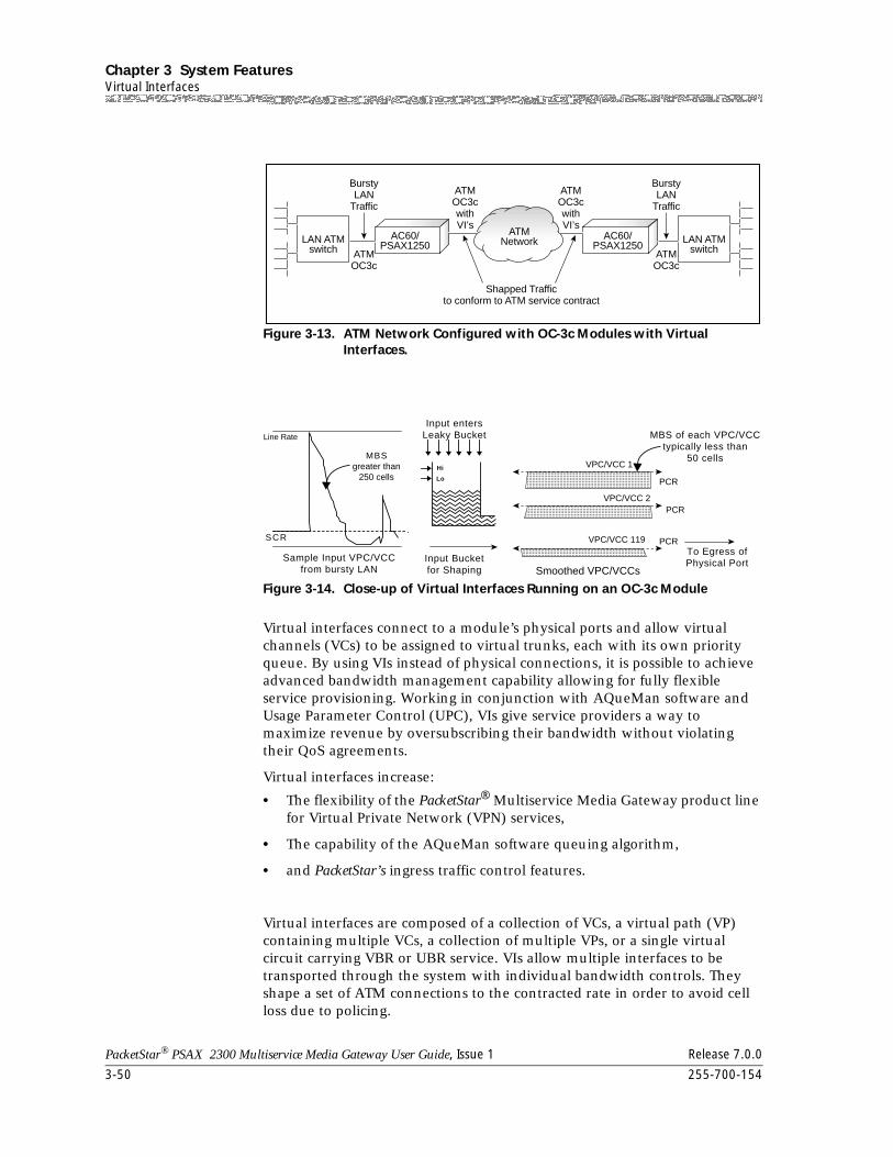
Chapter 3 System FeaturesVirtual Interfaces
3-50 255-700-154
PacketStar® PSAX 2300 Multiservice Media Gateway User Guide, Issue 1 Release 7.0.0
Virtual interfaces connect to a module’s physical ports and allow virtual channels (VCs) to be assigned to virtual trunks, each with its own priority queue. By using VIs instead of physical connections, it is possible to achieve advanced bandwidth management capability allowing for fully flexible service provisioning. Working in conjunction with AQueMan software and Usage Parameter Control (UPC), VIs give service providers a way to maximize revenue by oversubscribing their bandwidth without violating their QoS agreements.
Virtual interfaces increase:
• The flexibility of the PacketStar® Multiservice Media Gateway product line for Virtual Private Network (VPN) services,
• The capability of the AQueMan software queuing algorithm,
• and PacketStar’s ingress traffic control features.
Virtual interfaces are composed of a collection of VCs, a virtual path (VP) containing multiple VCs, a collection of multiple VPs, or a single virtual circuit carrying VBR or UBR service. VIs allow multiple interfaces to be transported through the system with individual bandwidth controls. They shape a set of ATM connections to the contracted rate in order to avoid cell loss due to policing.
Figure 3-13. ATM Network Configured with OC-3c Modules with Virtual Interfaces.
Figure 3-14. Close-up of Virtual Interfaces Running on an OC-3c Module
LAN ATMswitch
LAN ATMswitch
AC60/PSAX1250
AC60/PSAX1250
ATMNetwork
Shapped Trafficto conform to ATM service contract
ATMOC3c
ATMOC3cwithVI’s
ATMOC3cwithVI’s
BurstyLAN
Traffic
ATMOC3c
BurstyLAN
Traffic
Sample Input VPC/VCCfrom bursty LAN
SCR
Line Rate
MBSgreater than
250 cellsVPC/VCC 1
VPC/VCC 2
PCR
PCR
PCRVPC/VCC 119
Input entersLeaky Bucket MBS of each VPC/VCC
typically less than50 cells
To Egress ofPhysical PortInput Bucket
for Shaping Smoothed VPC/VCCs
Hi
Lo
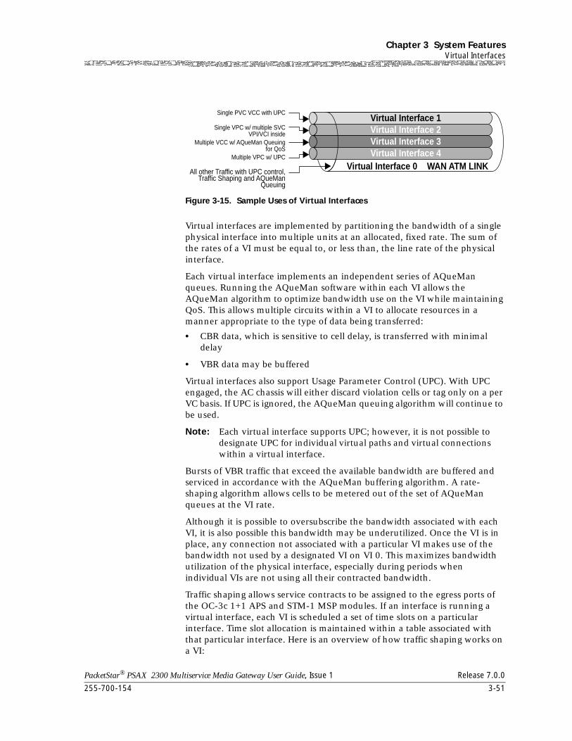
255-700-154 3-51
PacketStar® PSAX 2300 Multiservice Media Gateway User Guide, Issue 1 Release 7.0.0
Chapter 3 System FeaturesVirtual Interfaces
Virtual interfaces are implemented by partitioning the bandwidth of a single physical interface into multiple units at an allocated, fixed rate. The sum of the rates of a VI must be equal to, or less than, the line rate of the physical interface.
Each virtual interface implements an independent series of AQueMan queues. Running the AQueMan software within each VI allows the AQueMan algorithm to optimize bandwidth use on the VI while maintaining QoS. This allows multiple circuits within a VI to allocate resources in a manner appropriate to the type of data being transferred:
• CBR data, which is sensitive to cell delay, is transferred with minimal delay
• VBR data may be buffered
Virtual interfaces also support Usage Parameter Control (UPC). With UPC engaged, the AC chassis will either discard violation cells or tag only on a per VC basis. If UPC is ignored, the AQueMan queuing algorithm will continue to be used.
Note: Each virtual interface supports UPC; however, it is not possible to designate UPC for individual virtual paths and virtual connections within a virtual interface.
Bursts of VBR traffic that exceed the available bandwidth are buffered and serviced in accordance with the AQueMan buffering algorithm. A rate-shaping algorithm allows cells to be metered out of the set of AQueMan queues at the VI rate.
Although it is possible to oversubscribe the bandwidth associated with each VI, it is also possible this bandwidth may be underutilized. Once the VI is in place, any connection not associated with a particular VI makes use of the bandwidth not used by a designated VI on VI 0. This maximizes bandwidth utilization of the physical interface, especially during periods when individual VIs are not using all their contracted bandwidth.
Traffic shaping allows service contracts to be assigned to the egress ports of the OC-3c 1+1 APS and STM-1 MSP modules. If an interface is running a virtual interface, each VI is scheduled a set of time slots on a particular interface. Time slot allocation is maintained within a table associated with that particular interface. Here is an overview of how traffic shaping works on a VI:
Figure 3-15. Sample Uses of Virtual Interfaces
Virtual Interface 1
Virtual Interface 0 WAN ATM LINK
Virtual Interface 2Virtual Interface 3Virtual Interface 4
Single PVC VCC with UPC
Single VPC w/ multiple SVCVPI/VCI inside
Multiple VCC w/ AQueMan Queuingfor QoS
Multiple VPC w/ UPC
All other Traffic with UPC control,Traffic Shaping and AQueMan
Queuing
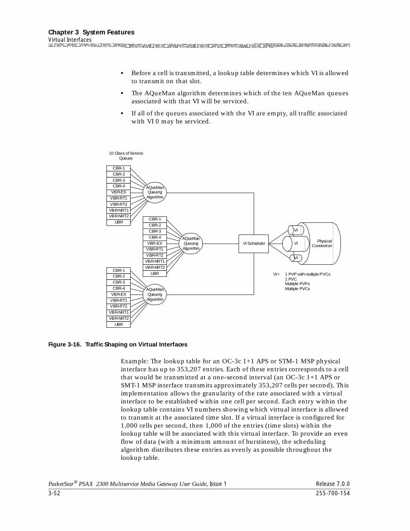
Chapter 3 System FeaturesVirtual Interfaces
3-52 255-700-154
PacketStar® PSAX 2300 Multiservice Media Gateway User Guide, Issue 1 Release 7.0.0
• Before a cell is transmitted, a lookup table determines which VI is allowed to transmit on that slot.
• The AQueMan algorithm determines which of the ten AQueMan queues associated with that VI will be serviced.
• If all of the queues associated with the VI are empty, all traffic associated with VI 0 may be serviced.
Example: The lookup table for an OC-3c 1+1 APS or STM-1 MSP physical interface has up to 353,207 entries. Each of these entries corresponds to a cell that would be transmitted at a one-second interval (an OC-3c 1+1 APS or SMT-1 MSP interface transmits approximately 353,207 cells per second). This implementation allows the granularity of the rate associated with a virtual interface to be established within one cell per second. Each entry within the lookup table contains VI numbers showing which virtual interface is allowed to transmit at the associated time slot. If a virtual interface is configured for 1,000 cells per second, then 1,000 of the entries (time slots) within the lookup table will be associated with this virtual interface. To provide an even flow of data (with a minimum amount of burstiness), the scheduling algorithm distributes these entries as evenly as possible throughout the lookup table.
Figure 3-16. Traffic Shaping on Virtual Interfaces
10 Class of ServiceQueues
VI Scheduler
CBR-1
CBR-2CBR-3
CBR-4VBR-EXVBR-RT1
VBR-RT2VBR-NRT1
VBR-NRT2
UBR
AQueManQueuingAlgorithm
CBR-1CBR-2
CBR-3CBR-4
VBR-EX
VBR-RT1
VBR-RT2VBR-NRT1VBR-NRT2
UBR
AQueManQueuingAlgorithm
CBR-1CBR-2CBR-3
CBR-4
VBR-EXVBR-RT1VBR-RT2
VBR-NRT1VBR-NRT2
UBR
AQueManQueuingAlgorithm
PhysicalConnection
VI
VI
VI
VI = 1 PVP with multiple PVCs1 PVCMulitple PVPsMultiple PVCs
255-700-154 3-53
PacketStar® PSAX 2300 Multiservice Media Gateway User Guide, Issue 1 Release 7.0.0
Chapter 3 System FeaturesVirtual Interfaces
Note: Not all connections need to run through a virtual interface. There is a separate AQueMan queue for all connections not belonging to a VI. When a VI is enabled, these connections are not guaranteed, but are also nonrestricted. They use whatever bandwidth is available and are ideal for UBR traffic.
Example: If 10 virtual interfaces are allocated, each at 4 Mbps inside a DS-3 pipe, as long as the VIs are fully utilized, the remaining non-VI traffic gets only 5 Mbps. However, if none of the VIs are sending traffic, the remaining non-VI traffic can burst up to 45 Mbps. This provides a natural separation between guaranteed versus nonguaranteed traffic. UPC parameters can be involved at the ingress, allowing the service provider to not only control the ingress traffic but to also ensure that the bandwidth throughout the network does not violate the SLA.
There are many applications for using VIs for flexible bandwidth management. One basic way to use VIs for a single VC or VP is to perform VC/VP queuing. Single VPs carry multiple virtual circuits that are associated with a single virtual interface. This configuration allows a service provider to contract an entire virtual path to a customer at a fixed rate. The VP is shaped to a rate that does not exceed the contracted rate, thus allowing traffic within the VP to pass through an ATM core network without violating the traffic contract.
In a more advanced scenario, VIs are used to address bandwidth guarantees that arise in a VPN environment. By using AQueMan and VIs, total port use is decreased. This guarantees a fixed amount of bandwidth to the collection of virtual circuits. The result is a VPN solution where each VI is provisioned with its own channel.
Example: An Internet service provider (ISP) using VIs with AQueMan and UPC wants to provide differentiated services to its customers. Each service has a different oversubscription capability, bandwidth guarantee, and risk of loss factor.
The ISP’s sample services are Platinum, Gold, Silver, and Basic:
The Platinum service, the most expensive, would allow the buyer to oversubscribe bandwidth to his or her benefit. In addition, this service would not be interfered with, or interfere with any other service. Platinum service will have a guaranteed bandwidth (through virtual interfaces, typically using a virtual path), and full flexibillity to assign virtual connections within the VP with all ten classes of service.
The Gold service would be similar to Platinum, but would use usage parameter control for traffic and quequing control. Priced less than Platinum, the Gold service would have a higher risk of discard when the customer bursts too much traffic.
The Silver service would be a nonguaranteed, nonrestrictive service that uses AQueMan as the traffic and quequing mechanism. Without VIs, this traffic would be subject to congestion if the guaranteed bandwidth used more of the WAN link but would have the advantage of large buffering and AQueMan quequing to prevent loss or delay of cells.
Chapter 3 System FeaturesVoice Compression
3-54 255-700-154
PacketStar® PSAX 2300 Multiservice Media Gateway User Guide, Issue 1 Release 7.0.0
The Basic service would be nonguaranteed, nonrestrictive service that uses UPC as the traffic and quequing mechanism. This service would still be transported with the rest of the AQueMan-based service, but would have the highest possibility of discard via UPC.
Software Features:
The software also supports the following ATM Forum Technical Committee specifications:
UNI 3.1 Signaling, af-uni-0010.002
UNI 4.0 Signaling, af-sig-0061
Traffic Management, af-tm-0056
Voice Compression
A noncompressed voice channel uses 64 Kbps of bandwidth. Voice compression reduces the 64 Kbps bandwidth to a lower value, based on the algorithm chosen. Compressed voice messages can be carried over ATM Adaptation Layer 2 (AAL2) only. The software on the CPU module assumes a 30 percent bandwidth savings.
Voice compression over AAL2 will only work for a voice channel that is connected to an Multiservice Media Gateway through an ISDN PRI line. This is because AAL2 does not transfer the voice channel signaling bits. If silence detection is enabled for a voice compression channel and no voice is detected, no ATM cell will be sent.
Voice Processing
With the DSP2C module, the Multiservice Media Gateway system can process voice traffic on selected DS0 circuits within the DS1 connections of the system. This module, a significant improvement over the earlier DSP2A and DSP2B server modules, processes ciruit emulation voice messages and can apply voice compression, echo cancellation, silence suppression, and comfort noise. Used with the channelized circuit emulation service modules, the DSP2C offers superior voice processing capability through the PacketStar® line for the Lucent voice traffic over ATM (VToA) solution.
The DSP2C module supports ATM Adaptation Layer 2 (AAL2) SVC connections and PVC multiplexing for reduced call latency.
To protect facsimile transmissions, the DSP2C module automatically turns off voice processing and echo cancellation on any channel when it detects a modem tone.
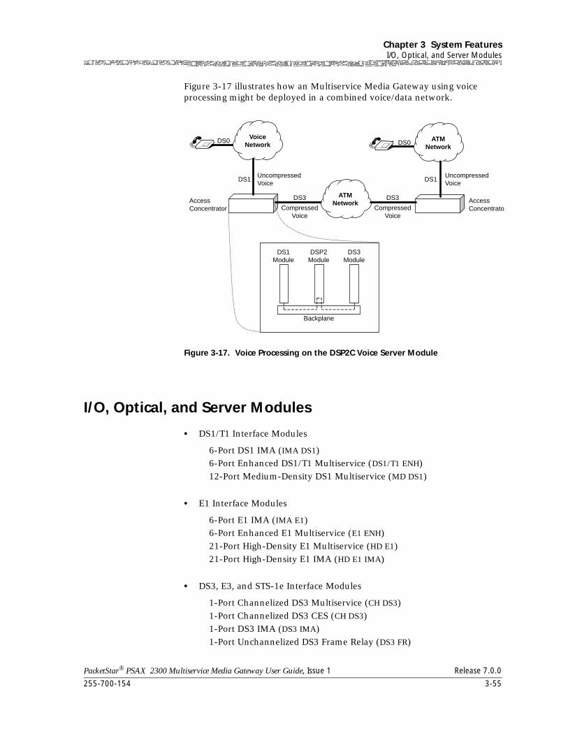
255-700-154 3-55
PacketStar® PSAX 2300 Multiservice Media Gateway User Guide, Issue 1 Release 7.0.0
Chapter 3 System FeaturesI/O, Optical, and Server Modules
Figure 3-17 illustrates how an Multiservice Media Gateway using voice processing might be deployed in a combined voice/data network.
I/O, Optical, and Server Modules
• DS1/T1 Interface Modules
6-Port DS1 IMA (IMA DS1)
6-Port Enhanced DS1/T1 Multiservice (DS1/T1 ENH)
12-Port Medium-Density DS1 Multiservice (MD DS1)
• E1 Interface Modules
6-Port E1 IMA (IMA E1)
6-Port Enhanced E1 Multiservice (E1 ENH)
21-Port High-Density E1 Multiservice (HD E1)
21-Port High-Density E1 IMA (HD E1 IMA)
• DS3, E3, and STS-1e Interface Modules
1-Port Channelized DS3 Multiservice (CH DS3)
1-Port Channelized DS3 CES (CH DS3)
1-Port DS3 IMA (DS3 IMA)
1-Port Unchannelized DS3 Frame Relay (DS3 FR)
Figure 3-17. Voice Processing on the DSP2C Voice Server Module
DS0 DS0
DS1
DS3 DS3
DS1UncompressedVoice
UncompressedVoice
CompressedVoice
CompressedVoice
AccessConcentrato
AccessConcentrator
DS1Module
DSP2Module
DS3Module
Backplane
VoiceNetwork
ATMNetwork
ATMNetwork
VoiceNetwork
Chapter 3 System FeaturesI/O, Optical, and Server Modules
3-56 255-700-154
PacketStar® PSAX 2300 Multiservice Media Gateway User Guide, Issue 1 Release 7.0.0
2-Port DS3 ATM (DS3 ATM)
2-Port E3 ATM (E3 ATM)
3-Port Channelized DS3/STS-1e CES (CH DS3/STS-1E)
3-Port Unstructured DS3/E3 CES (UNSTR DS3/E3 CES)
1-Port Channelized STS-1e, T1 Format (CH STS-1E T1)
• Fiber-Optic Interface Modules
1-Port OC-3c Multimode with AQueMan (OC-3C (MM AQ))
1-Port OC-3c Single-Mode with AQueMan (OC-3C (SM AQ))
1-Port OC-3c Multimode with Traffic Shaping (OC-3C (MM TS))
1-Port OC-3c Single-Mode with Traffic Shaping (OC-3C (SM TS))
1-Port OC-3c 1+1 APS Multimode (OC-3C MM APS)
1-Port OC-3c 1+1 APS Single-Mode (OC-3C SM APS)
1-Port STM-1 Multimode with AQueMan (STM-1 (MM AQ))
1-Port STM-1 Single-Mode with AQueMan (STM-1 (SM AQ))
1-Port STM-1 Multimode with Traffic Shaping (STM-1 (MM TS))
1-Port STM-1 Single-Mode with Traffic Shaping (STM-1 (SM TS))
1-Port STM-1 1+1 MSP Multimode (STM-1 MM MSP)
1-Port STM-1 1+1 MSP Single-Mode (STM-1 SM MSP)
1-Port OC-12c/STM-4c 1+1 APS/MSP Multimode (OC-12C/STM-4C MM)
1-Port OC-12c/STM-4c 1+1 APS/MSP Single-Mode (OC-12C/STM-4C SM)
• 2-Wire Interface Modules
4-Port Voice 2-Wire Office (VOICE 2WO)
8-Port Voice 2-Wire Station (VOICE 2WS)
• Serial Interface Modules
Quadserial (QUAD SERIAL)
6-Port Multiserial (SERIAL)
• Ethernet Interface Module
Ethernet (ENET)
• DSP2 Voice Servers
DSP2A Voice Server (DSP2A)
DSP2B Voice Server (DSP2B)
DSP2D Voice Server (DSP2D)
• Other Modules
Alarm (ALARM)
255-700-154 3-57
PacketStar® PSAX 2300 Multiservice Media Gateway User Guide, Issue 1 Release 7.0.0
Chapter 3 System FeaturesAlarm Module
Route Server (ROUTE SERVER)
Tones and Announcements Server (TAS)
Alarm Module
The Alarm module detects environmental changes on the PSAX 1250 and PSAX 2300 systems that are in remote locations without human supervision, and consolidates alarm presentations and control of external devices. The Alarm module consolidates alarm presentations, monitors external status points, and controls external devices.
The Alarm module uses both a standard 150-pin card connector for I/O circuit packs, and a 100-pin, dual-row card-edge connector which is located in the center of the slot. The Alarm module provides two front panel connectors for external status inputs and external alarm/control outputs.
The Alarm module is intended for use only with the following:
• PSAX 1250 system, 19” chassis (slot 11 only), and 23” chassis (slot 14 only)
• PSAX 2300 system, (slot 14 only)
The Alarm module is not supported in the PSAX 20 and AC 60 systems.
Note: In the PSAX 1250 and PSAX 2300 chassis, when the Alarm module is inserted into slot 14, it is always displayed on the Equipment Configuration window as being inserted in slot 25.
Using the Equipment Configuration window, users can view the Alarm module and its current remote input status, and can also configure control outputs. The Alarm module has three types of light-emitting diode (LED) indicators: CRITICAL, MAJOR, and MINOR.
Software Features
Defining Alarm Conditions
You can define the external alarm condition (input) that you want to use, such as a temperature sensor or a door alarm, and the resulting action (output) that you want to use, such as a fan or a warning light, respectively (see Figure 3-18). You define inputs and outputs by configuring the appropriate equipment at your site.
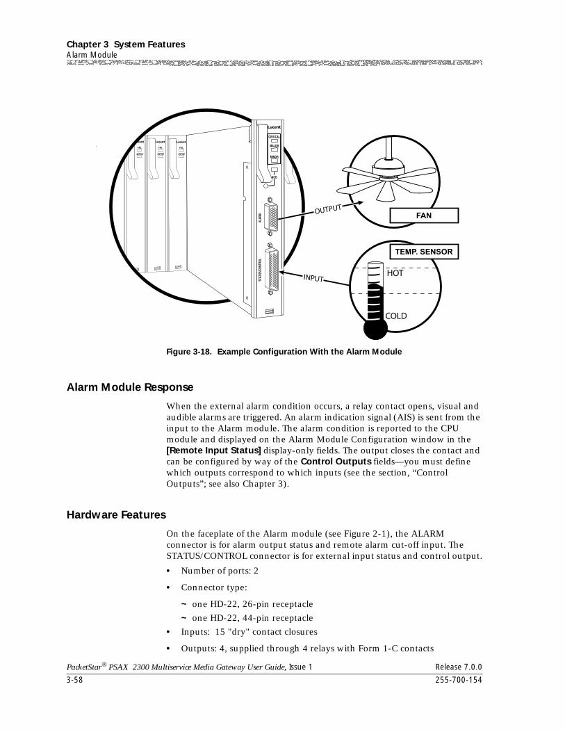
Chapter 3 System FeaturesAlarm Module
3-58 255-700-154
PacketStar® PSAX 2300 Multiservice Media Gateway User Guide, Issue 1 Release 7.0.0
Alarm Module Response
When the external alarm condition occurs, a relay contact opens, visual and audible alarms are triggered. An alarm indication signal (AIS) is sent from the input to the Alarm module. The alarm condition is reported to the CPU module and displayed on the Alarm Module Configuration window in the [Remote Input Status] display-only fields. The output closes the contact and can be configured by way of the Control Outputs fields—you must define which outputs correspond to which inputs (see the section, “Control Outputs”; see also Chapter 3).
Hardware Features
On the faceplate of the Alarm module (see Figure 2-1), the ALARM connector is for alarm output status and remote alarm cut-off input. The STATUS/CONTROL connector is for external input status and control output.
• Number of ports: 2
• Connector type:
~ one HD-22, 26-pin receptacle
~ one HD-22, 44-pin receptacle
• Inputs: 15 "dry" contact closures
• Outputs: 4, supplied through 4 relays with Form 1-C contacts
Figure 3-18. Example Configuration With the Alarm Module
255-700-154 3-59
PacketStar® PSAX 2300 Multiservice Media Gateway User Guide, Issue 1 Release 7.0.0
Chapter 3 System FeaturesAlarm Module
• Power:
~ +5 V DC
~ -48V DC
External Inputs Fifteen dry contact closure inputs monitor the status of devices external to the PSAX 1250 and PSAX 2300 systems. The external contact closure inputs are activated by electrical connection of the external input to a common point (-48V battery return). This operation is typically established by a relay or contact closure on an external device such as a smoke detector, intrusion alarm or power failure monitor. The external inputs have an open circuit voltage of approximately -48 VDC between the input and common (-48V battery return).
Alarm Outputs The Alarm module provides visible alarm contact closures with three severity levels as indicated by the LEDs. Each of these alarm outputs is supplied through a relay with Form 1-C contacts. Normally open (N.O.), normally closed (N.C.), and common contacts are provided for use by external alarm monitoring systems.
Visual alarms usually light external displays that assist in identifying and locating equipment in an alarm condition.
Alarms raised at each of the three severity levels are interdependent. If a higher severity alarm condition occurs during the presence of a lower severity alarm, the higher severity alarm will be raised and the lower severity alarm will be removed. If the condition causing the higher severity alarm is cleared, the higher severity alarm shall be removed and the lower severity alarm re-established (if applicable).
To meet the requirements to produce an alarm when no power is being supplied to the chassis, the coils of the critical visual alarm relays are energized when no alarm is present. Therefore, a loss of power to the chassis causes the loss of relay coil current and establishes the critical visual alarm.
Alarm Cut-Off The alarm cut-off function provides a method of silencing audible alarms. It has no effect on visual alarms. The alarm cut-off can operate by either a local push button switch (shown on the Alarm Configuration window by the [Local Alarm] field), or by an external contact closure input (shown on the Alarm Configuration window by the [Remote Alarm] field). Functionally, the local and remote alarm cut-off functions work together; performing either or both of the alarm cut-off functions will establish an alarm cut-off state (shown on the Alarm Configuration window by the [Composite Alarm Status] field).
Control Outputs The Alarm module provides four independent Form 1-C relay outputs for the control of external devices such as generators, fans, and water pumps. N.O., N.C., and common contacts are provided for each of the four relays. In the normal Deactivated state, the relay coils associated with controls outputs 1–3 are not energized (see the Control Outputs panel in Figure 3-1 on the Alarm Configuration Window).
Chapter 3 System Features1-Port Channelized DS3 Module
3-60 255-700-154
PacketStar® PSAX 2300 Multiservice Media Gateway User Guide, Issue 1 Release 7.0.0
Control output 4 is connected in the opposite way. The NC signal is connected to NO contact and NO signal is connected to NC contact of the relay. The relay coil is energized during the Deactivated condition and not energized during the Activated condition. This operation is required for external equipment that must function properly upon power loss to the chassis. Upon applying power to the PSAX chassis, the system software energizes only the 4th relay, so that the NC signal is connected to common; thus you can tell if the control cable has been removed or if power has been lost.
1-Port Channelized DS3 Module
The Channelized DS3 module provides one port with a line rate of 44.736 Mbps. The user can configure this module to provide N x 64 Kbps (fractional DS1) structured circuit emulation service. When configured for DS1 circuit-emulation service, the module interfaces with TDM channelized DS1 circuits. It converts the channelized digital signals (usually voice data) to ATM virtual channels. By using structured (channelized) circuit emulation, the Channelized DS3 module can adapt a maximum of 28 DS1 channels per port to ATM virtual channels with individual VPIs and VCIs. Signaling bit transport is also provided, using ATM Forum standards for channel-associated signaling (CAS). This module can connect to a device using 56 Kbps or 64 Kbps for service transport, with 8 Kbps for robbed-bit signaling per DS0. With the 64 Kbps "clear channel" capability, this module can connect to a device using ISDN primary rate interface (PRI) service. Because this structured circuit-emulation service can be configured to use only a fraction of the time slots, the user can configure several independent emulated circuits to share one service interface.
The Channelized DS3 module uses ATM Forum specifications UNI 3.0 or UNI 3.1, which allow any DS1 port to act as a user network interface (UNI), or an interim inter-switch protocol (IISP) user or IISP network interface to an ATM network.
DS1 modules support activating and deactivating DS1 access network interface (ANI) in-line loopback codes embedded in the DS1 signal. These codes test transmissions between customer interface equipment and network interface equipment, such as between central office (CO) PSAX products and customer premises equipment (CPE) PSAX products at the edge of the ATM network. The system also generates alarm indication signals on all affected DS1 connections whenever a loop is activated.
Software Features
The following Frame Relay Forum (FRF) Implementation Agreements are supported by the software:
• FRF.1—User-to-Network Interface (UNI)
• FRF.2—Network-to-Network Interface (NNI)
255-700-154 3-61
PacketStar® PSAX 2300 Multiservice Media Gateway User Guide, Issue 1 Release 7.0.0
Chapter 3 System Features1-Port Channelized DS3 Module
• FRF.5—Frame Relay/ATM PVC Network Interworking
• FRF.8—Frame Relay/ATM PVC Service Interworking
The following ATM Forum Technical Committee Specifications are supported by the software:
• Circuit Emulation Service Interoperability Specification Version 2.0 af-vtoa-0078.00
• User-to-Network Interface Specification Version 3.0, af-uni.0010.001
• User-to-Network Interface Specification Version 3.1, af-uni.0010.002
• Private Network-Network Interface (PNNI), Specification Version 1.0, af-pnni-0055.000
• Integrated Local Management Interface (ILMI) Specification Version 4.0, af-ilmi-0065.000
The following services and functions are available:
• ATM services (channelized and unchannelized) with ATM traffic policing (UPC support) capability:
~ ATM UNI 3.0 and 3.1, with integrated link management interface (ILMI) capability
~ Interim inter-switch signaling protocol (IISP) user and IISP network
~ ATM private network-node interface (PNNI)
• Circuit emulation service (CES):
~ Unstructured and structured DS1 signal transport
~ Nx64 Kbps circuit emulation (where 1=N=24)
~ Dynamic bandwidth circuit emulation service (DBCES)—proprietary version
~ Channel-associated signalling (CAS)
• Integrated services digital network with primary rate interface service (PRI ISDN) with 64 Kbps clear channel capability and HDLC passthrough mode for the D-channel
• Frame relay UNI and NNI with frame relay policing (ITU-T I.370) capability
• High-level data link link control (HDLC) passthrough mode (Nx64)
• AAL2 cell formatting is provided for interworking with the DSP2A, DSP2B, and DSP2C Voice Server modules.
• Mixed circuit emulation, ATM, and frame relay channels can be configured within a virtual DS1 port.
Hardware Features
• Number of ports: one
• Connector type: two BNC connectors, one to receive data and one to transmit data
Chapter 3 System Features3-Port Channelized DS3/STS-1e CES Module
3-62 255-700-154
PacketStar® PSAX 2300 Multiservice Media Gateway User Guide, Issue 1 Release 7.0.0
• Line rate: 44.736 Mbps
3-Port Channelized DS3/STS-1e CES Module
The 3-Port Channelized DS3/STS-1e CES module supports circuit emulation services (CES) and primary rate interfaces (PRI) with processing power required to handle 3 x 672 DS0s. Additionally, this module is software configurable to function in either DS3 or STS-1e modes. This dual-mode capability allows you to deliver channelized DS3 or STS-1e configurations while maintaining inventory of a single module type.
The module’s three high-speed circuit emulation network interfaces operate at Digital Signal Level 3 (DS3), with a line rate of 44.736 Mbps, or at Synchronous Transport Signal Level 1e (STS-1e), with a line rate of 51.84 Mbps. Each port is capable of supporting 28 channelized DS1 interfaces for circuit emulation services and HDLC passthrough.
Note: This module supports an HDLC passthrough channel of only 64 Kbps. Each port can support up to 64 HDLC channels.
Typically, this module is used to connect the Multiservice Media Gateway system to a TDM voice switch or digital cross-connect device (DACS) via three ports.
This module can be configured to provide Nx64 Kbps (fractional DS1) structured circuit emulation service. When configured for DS1 circuit emulation service, the module interfaces with TDM channelized DS1 circuits. It converts the channelized digital signals (usually voice data) to ATM virtual channels for transport to ATM interfaces via the backplane. By using structured (channelized) circuit emulation, the 3-Port Channelized DS3/STS-1e CES module can adapt a maximum of 28 DS1 channels per port to ATM virtual channels with individual VPIs and VCIs. Signaling bit transport is also provided, using ATM Forum standards for channel-associated signaling (CAS).
You can connect this module to a device using 56 Kbps or 64 Kbps for service transport, with 8 Kbps for robbed-bit signaling per DS0. With the 64 Kbps "clear channel" capability, this module can be connected to a device using ISDN primary rate interface (PRI) service. Because this structured circuit-emulation service can be configured to use only a fraction of the time slots, several independent emulated circuits can be configured to share one service interface.
The Channelized DS3 Multiservice and CES modules support activating and deactivating DS1 access network interface (ANI) in-line loopback codes embedded in the DS1 signal. These codes test transmissions between customer interface equipment and network interface equipment, for example, between PSAX central office (CO) products and customer premises equipment (CPE) products at the edge of an ATM network. The PSAX system also generates alarm indication signals on all affected DS1 connections whenever a loop is activated.
255-700-154 3-63
PacketStar® PSAX 2300 Multiservice Media Gateway User Guide, Issue 1 Release 7.0.0
Chapter 3 System Features1-Port Channelized STS-1e T1 Module
Software Features
The 3-Port Channelized DS3/STS-1e CES module supports the following services:
• Circuit emulation service (CES):
~ Structured DS1 signal transport
~ Nx64 Kbps circuit emulation (where 1<=N<=24)
~ Channel-associated signaling (CAS) 1x56
• Integrated services digital network with primary rate interface service (PRI ISDN) with 64 Kbps clear channel capability for the D-channel
• AAL2 cell formatting for interworking with the DSP2A, DSP2B, and DSP2C Voice Server modules.
Hardware Features
The 3-Port Channelized DS3/STS-1e CES module provides the following hardware features:
• Number of ports: 3
• Connector type: 6 BNC connectors; 1 receive connector and 1 transmit connector for each port
• Line rate: 44.736 Mbps (DS3); 51.84 Mbps (STS-1e)
• Line encoding mode: B3ZS
• Loopback capabilities: line loopback, local loopback, and DS1 ANI in-line codes for loopback
• Line buildout: short (0–133 feet); long (134–266 feet)
• Framing modes: ESF and SF for CES
The 3-Port Channelized DS3/STS-1e CES module supports the following ATM Forum hardware specifications:
• 44.736 DS3 Mbps Physical Layer Specification, af-uni-0010.002
• DS3 Physical Interface Specification, af-phy-0054
1-Port Channelized STS-1e T1 Module
The Channelized STS-1e T1 module provides one port with a line rate of 51.84 Mbps. The user can configure this module to provide n X 64 Kbps (fractional DS-1) structured circuit-emulation service. When configured for DS-1 circuit-emulation service, the module interfaces with TDM channelized DS-1 circuits. It converts the channelized digital signals (usually voice data)
Chapter 3 System Features1-Port Channelized STS-1e T1 Module
3-64 255-700-154
PacketStar® PSAX 2300 Multiservice Media Gateway User Guide, Issue 1 Release 7.0.0
to ATM virtual channels. By using structured (channelized) circuit emulation, the Channelized STS-1e T1 module can adapt a maximum of 28 DS-1 channels per port to ATM virtual channels with individual VPIs and VCIs. Signalling bit transport is also provided, using ATM Forum standards for channel-associated signaling (CAS). This module can connect to a device using 56 Kbps or 64 Kbps for service transport, with 8 Kbps for robbed-bit signalling per DS-0. With the 64 Kbps "clear channel" capability, this module can connect to a device using ISDN primary rate interface (PRI) service. Because this structured circuit-emulation service can be configured to use only a fraction of the time slots, the user can configure several independent emulated circuits to share one service interface.
The Channelized STS-1e T1 module uses ATM Forum specifications UNI 3.0 or UNI 3.1, which allow any DS-1 port to act as a user network interface (UNI), or an interim inter-switch protocol (IISP) user or IISP network interface to an ATM network.
Software Features
The following services are supported:
• Circuit emulation service (CES) with unstructured and structured DS1 signal transport
• N X 64 kbps circuit emulation service (1 = N = 24)
• Primary ISDN service with optional HDLC pass-through mode for the D-channel
• Channel-associated signalling (CAS)
The PacketStar® Access Concentrator system software supports the following specifications, agreements, and protocols:
• Frame Relay Forum (FRF) Implementation Agreements:
~ FRF.1—User-to-Network Interface (UNI)
~ FRF.2—Network-to-Network Interface (NNI)
~ FRF.5—Frame Relay/ATM PVC Network Interworking
~ FRF.8—Frame Relay/ATM PVC Service Interworking
• ATM Forum Technical Committee Specifications:
~ Circuit Emulation Service Interoperability Specification Version 2.0, af-vtoa-0078.00
~ User-to-Network Interface Specification Version 3.0, af-uni.0010.001
~ User-to-Network Interface Specification Version 3.1, af-uni.0010.002
~ Integrated Local Management Interface (ILMI) Specification Version 4.0, af-ilmi-0065.000
~ Private Network-Network Interface (PNNI), Version 1.0, af-pnni-0055.000
• Multiservices:
~ ATM: ATM UNI 3.0 and 3.1; Interim inter-switch signaling protocol (IISP) user, IISP network, ILMI, PNNI
255-700-154 3-65
PacketStar® PSAX 2300 Multiservice Media Gateway User Guide, Issue 1 Release 7.0.0
Chapter 3 System Features6-Port DS1 IMA Module
~ CE: Circuit emulation service (CES) with ISDN PRI using 64 Kbps clear channel; 1 X 56 Kbps structured CAS; unstructured CES
~ Frame relay UNI and NNI (FRF.1, FRF.2, FRF.5, and FRF.8)
~ ITU-T I.370 (frame relay policing)
~ Congestion management
~ Traffic policing
Hardware Features
• Number of ports: one
• Connector type: two BNC connectors, one to receive data and the other to transmit data
• Line rate: 51.84 Mbps
6-Port DS1 IMA Module
The DS1 IMA module has six physical RJ-45 ports. Inverse multiplexing over ATM permits a user to strap two to six of the physical ports together to create ATM interfaces that support 3–9 Mbps of bandwidth. A maximum of three IMA groups may be configured per module.
The DS1 IMA module offers native DS1 ATM services and DS1 IMA services, including permanent virtual circuits, soft permanent virtual circuits, and switched virtual circuits. The module supports UNI v3.a, IISP, PNNI, and ILMI. This functionality enables service providers to offer both individual unchannelized DS1 ATM services (without IMA overhead) and multiple DS1 IMA group services using a single module.
Source data enters the module from the backplane and is divided between the ports within the IMA group specified in the virtual circuit connection. The data leaves the front of the module and is transported across individual T1 lines. At the destination IMA module, the T1 streams are merged back together in correct order and passed on to other modules as directed by virtual circuit connections. IMA dynamically handles conditions when T1s within an IMA group become unavailable: the IMA "pipe" shrinks in bandwidth to the remaining T1s and continues to pass traffic. When a problem T1 comes back on line, the IMA "pipe" will enlarge to take full advantage of the restored bandwidth.
Software Features
The DS1 IMA module supports the following ATM Forum Technical Committee Specifications:
• User-to-Network Interface Specification Version 3.0, af-uni.0010.001
• User-to-Network Interface Specification Version 3.1, af-uni.0010.002
• Private Network-Network Interface (PNNI), Specification Version 1.0, af-pnni-0055.000
Chapter 3 System Features2-Port DS3 ATM Module
3-66 255-700-154
PacketStar® PSAX 2300 Multiservice Media Gateway User Guide, Issue 1 Release 7.0.0
• Integrated Local Management Interface (ILMI) Specification Version 4.0, af-ilmi-0065.000
• Inverse Multiplexing over ATM Version 1.0, af-phy-0086.000
• Inverse Multiplexing over ATM Version 1.1, af-phy-0086.001
Hardware Features
The DS1 IMA module provides the following hardware features:
• Number of ports: 6
• Connector type: RJ-45
• Line rate: 1.544 Mbps
• Line encoding mode: B8ZS
• Loopback capabilities: local loopback, line loopback, payload loopback
• Line buildout: Up to 133, 266, 399, 533, and 655 feet; negative 7-5 Db, negative 15 Db, negative 22-5 Db.
• Framing mode: cyclic redundancy check multifrequency (CRC-mf)
2-Port DS3 ATM Module
The DS3 ATM module provides a network interface at Digital Signal Level 3 (DS-3), with a line rate of 44.736 Mbps. This module accommodates ATM cell-bearing traffic. Typically, this module is used to connect the Access Concentrator system to an ATM edge switch. The DS3 ATM module has three types of LED indicators: FAIL, ACTIVE, and LOS (loss of signal).
Software Features
The DS3 ATM module uses ATM Forum specifications UNI 3.0 or UNI 3.1, which allows either DS-3 port to act as a user network interface (UNI), an interim inter-switch protocol (IISP) user or IISP network interface, or as a PNNI network interface to an ATM network.
The software supports the following ATM Forum Technical Committee Specifications:
• User-to-Network Interface Specification Version 3.0, af-uni.0010.001
• User-to-Network Interface Specification Version 3.1, af-uni.0010.002
• Interim Inter-switch Signaling Protocol, Version 1.0, af-pnni-0026.000
• Private Network-Network Interface (PNNI), Version 1.0, af-pnni-0055.000
• Integrated Local Management Interface Specification Version 4.0,
af-ilmi-0065.000
255-700-154 3-67
PacketStar® PSAX 2300 Multiservice Media Gateway User Guide, Issue 1 Release 7.0.0
Chapter 3 System Features1-Port DS3 Frame Relay Module
Hardware Features
The DS3 ATM module has the following features:
• Number of ports: two
• Connector type: four BNC connectors for the two ports (each port has one receive connector and one transmit connector)
• Line rate: 44.736 Mbps (typical)
• Line encoding mode: B3ZS
• Line type: C-bit parity, clear channel
• Loopback capabilities: local loop, line loop, payload loop
• Cell mapping: PLCP, direct mapping
1-Port DS3 Frame Relay Module
The DS3 Frame Relay module provides an unchannelized, high-speed frame relay network interface at Digital Signal Level 3 (DS3), with a line rate of 44.736 Mbps. Typically, the DS3 module is used to connect the Access Concentrator system to an ATM edge switch. The module has three types of light-emitting diode (LED) indicators: FAIL, ACTIVE, and LOS (loss of signal).
Software Features
The software supports the following Frame Relay Forum (FRF) Implementation Agreements:
• FRF.1—User-to-Network Interface (UNI)
• FRF.2—Network-to-Network Interface (NNI)
• FRF.5—Frame Relay/ATM PVC Network Interworking
• FRF.8—Frame Relay/ATM PVC Service Interworking
• Multiservices:
~ Frame relay UNI and NNI (FRF.1, FRF.2, FRF.5, and FRF.8)
~ ITU-T I.370 (frame relay policing)
~ Congestion management
~ Traffic policing
~ HDLC pass-through
Frame Relay
The DS3 Frame Relay module has interfaces for frame-relay network-level interworking (FRF.5) and service-level interworking (FRF.8). A maximum of 350 permanent virtual circuits (PVCs) can be assigned on each frame relay user-network interface (UNI) port. These features enable the Access Concentrator system to act as a gateway between routers, remote dial-access
Chapter 3 System Features1-Port DS3 IMA Module
3-68 255-700-154
PacketStar® PSAX 2300 Multiservice Media Gateway User Guide, Issue 1 Release 7.0.0
servers, IBM SNA equipment, and other devices configured for frame-relay operation.
Frame relay policing, and user-selected point-to-point SVCs are supported on the DS3 Frame Relay module. Frame relay policing enables the user to manage traffic at the user-network interface (UNI) or network-network interface (NNI) by setting performance parameters such as the Committed Information Rate (CIR), Excess Burst size (Be), and Committed Burst size (Bc).
HDLC Pass-through
Each port on the DS3 Frame Relay module can be configured to perform adaptation for high-level data link control (HDLC) pass-through. Without this feature, AAL-1 adaptation would be required for data from HDLC devices connected to a port on the DS3 Frame Relay module. With this feature, AAL-5 adaptation can be used to allow HDLC data to be handled as if it were VBR rather than CBR. Since ATM cells are only generated when HDLC is present, optimal bandwidth is used.
Hardware Features
• Number of ports: one
• Connector type: two BNC connectors for the single port which has one receive connector and one transmit connector
• Line rate: 44.736 Mbps (typical)
1-Port DS3 IMA Module
The DS3 IMA (Inverse Multiplexing over ATM) module combines the features of the Channelized DS3 module (see the PacketStar™ Channelized DS3 Module User Guide) and the DS1 IMA module (see the PacketStar™ DS1 IMA Module User Guide). It allows you to configure up to 28 virtual T1 ports for native DS1 ATM services or for as many as 14 independent groups. This gives you point-to-point bandwidth options between that of a single T1 line and that of a T3 line.
Software Features
The following services and functions are available:
• Protocols: ATM, IMA (inverse multiplexing over ATM)
• ATM channelized services over IMA groups:
~ ATM UNI 3.0 and 3.1, with integrated link management interface (ILMI) capability
~ Interim inter-switch signaling protocol (IISP) user and IISP network
~ ATM private network-network interface (PNNI)
255-700-154 3-69
PacketStar® PSAX 2300 Multiservice Media Gateway User Guide, Issue 1 Release 7.0.0
Chapter 3 System Features6-Port E1 IMA Module
The following ATM Forum Technical Committee Specifications are supported by the software:
• User-to-Network Interface Specification Version 3.0, af-uni.0010.001
• User-to-Network Interface Specification Version 3.1, af-uni.0010.002
• Private Network-Network Interface (PNNI), Specification Version 1.0, af-pnni-0055.000
• Integrated Local Management Interface (ILMI) Specification Version 4.0, af-ilmi-0065.000
• Inverse Multiplexing over ATM Version 1.0, af-phy-0086.000
• Inverse Multiplexing over ATM Version 1.1, af-phy-0086.001
Hardware Features
• Front-End: DMA interface with one physical port
• Number of ports: one; port density: 28 virtual channels
• Connector type: two BNC connectors, one to receive data and one to transmit data
• Line rate: 44.736 Mbps
• Bandwidth: 1.544 to 44.736 Mbps
6-Port E1 IMA Module
The E1 IMA module has six physical RJ-45 ports. Inverse multiplexing over ATM permits a user to strap two to six of the physical ports together to create ATM interfaces that support 4 to 12 Mbps of bandwidth. A maximum of three IMA groups may be configured per module.
The E1 IMA module offers native E1 ATM services and E1 IMA services, including permanent virtual circuits, soft permanent virtual circuits, and switched virtual circuits. The module supports UNI v3.a, IISP, PNNI, and ILMI. This functionality enables service providers to offer both individual unchannelized E1 ATM services (without IMA overhead) and multiple E1 IMA group services using a single module.
Source data enters the module from the backplane and is divided between the ports within the IMA group specified in the virtual circuit connection. The data leaves the front of the module and is transported across individual E-1 lines. At the destination IMA module, the E-1 streams are merged back together in correct order and passed on to other modules as directed by virtual circuit connections. IMA dynamically handles conditions when E-1s within an IMA group become unavailable: the IMA "pipe" shrinks in bandwidth to the remaining E-1s and continues to pass traffic. When a problem E-1 comes back online, the IMA "pipe" will enlarge to take full advantage of the restored bandwidth.
Chapter 3 System Features2-Port E3 ATM Module
3-70 255-700-154
PacketStar® PSAX 2300 Multiservice Media Gateway User Guide, Issue 1 Release 7.0.0
Software Features
The E1IMA module supports the following ATM Forum Technical Committee Specifications:
• User-to-Network Interface Specification Version 3.0, af-uni.0010.001
• User-to-Network Interface Specification Version 3.1, af-uni.0010.002
• Private Network-Network Interface (PNNI), Specification Version 1.0, af-pnni-0055.000
• Integrated Local Management Interface (ILMI) Specification Version 4.0, af-ilmi-0065.000
• Inverse Multiplexing over ATM Version 1.0, af-phy-0086.000
• Inverse Multiplexing over ATM Version 1.1, af-phy-0086.001
Hardware Features
The E1 IMA module provides the following hardware features:
• Number of ports: 6
• Connector type: RJ-45 (120-Ohm symmetrical pair [4 wire] interface)
• Line rate: 2.048 Mbps
• Line encoding mode: HDB3
• Loopback capabilities: local loopback, line loopback, payload loopback
• Line buildout: N/A
• Framing mode: cyclic redundancy check multifrequency (CRC-mf)
2-Port E3 ATM Module
The E3 ATM module provides a network interface with a line rate of 34.368 Mbps. Typically, the E3 ATM module is used to connect the Multiservice Media Gateway system to an ATM edge switch. Each port can be configured for ATM service, including ATM UNI 3.0 and 3.1, IISP user and network, and ATM PNNI interfaces. This module has three types of light-emitting diode (LED) indicators: ACTIVE, FAIL, and LOS (loss of signal).
Software Features
The E3 ATM module uses ATM Forum specifications UNI 3.0 or UNI 3.1, which allow either E-3 port to act as a user network interface (UNI), an interim inter-switch protocol (IISP) user or network interface, or as a PNNI network interface to an ATM network.
The software supports the following ATM Forum Technical Committee Specifications:
• User-to-Network Interface Specification Version 3.0, af-uni-0010.001
255-700-154 3-71
PacketStar® PSAX 2300 Multiservice Media Gateway User Guide, Issue 1 Release 7.0.0
Chapter 3 System Features6-Port Enhanced DS1 Module
• User-to-Network Interface Specification Version 3.1, af-uni-0010.002
• Interim Inter-switch Signaling Protocol, Version 1.0, af-pnni-0026.000
• Private Network-Network Interface (PNNI), Version 1.0, af-pnni-0055.000
• Integrated Local Management Interface Specification Version 4.0,
af-ilmi-0065.000
Hardware Features
The E3 ATM module has the following features:
• Number of ports: two
• Connector type: four BNC connectors for the two ports (each port has one receive connector and one transmit connector)
• Line rate: 34.368 Mbps (typical)
• Line encoding mode: HDB3
• Line type: G832
• Loopback capabilities: local loop, line loop, payload loop
• Cell mapping: direct mapping
6-Port Enhanced DS1 Module
The 6-Port Enhanced DS1/T1 Multiservice module provides six ports, each with a line rate of 1.544 Mbps. The interfaces support American National Standards Institute (ANSI) T1.403, af-phy-0016.000 and af-test-0037.000. Each port can be independently configured to provide services for channelized and unchannelized frame relay configurations, circuit emulation service, dynamic bandwidth circuit emulation service, and ATM service. Three light-emitting diode (LED) status indicators provide the operational status of the module.
The module has built-in channel service unit (CSU) capability that allows it to interface directly to a DS1/T1 line with multiple repeaters. This feature allows the module to interface with a time-division multiplex (TDM) channelized DS1/T1 circuit. Configured for channelized T1 service, the 6-Port Enhanced DS1/T1 Multiservice module maps up to 24 individual high-level data link control (HDLC) data links on a single T1 connection (144 HDLC data links per module). This module also provides a data service unit/channel service unit (DSU/CSU) for each port in order to configure individual DS0s.
The user can configure this module to provide N x 64 Kbps (fractional DS1) structured circuit-emulation service. When configured for DS1 circuit-emulation service, the 6-Port Enhanced DS1/T1 Multiservice module interfaces with TDM channelized DS1 circuits. It converts channelized digital signals (usually voice data) to ATM virtual channels. This module can adapt a maximum of 24 DS0 channels per port to ATM virtual channels with individual virtual path identifiers (VPIs) and virtual channel identifiers (VCIs) using structured (channelized) circuit emulation. Signaling bit transport is also provided, based on ATM Forum standards for channel-associated
Chapter 3 System Features6-Port Enhanced DS1 Module
3-72 255-700-154
PacketStar® PSAX 2300 Multiservice Media Gateway User Guide, Issue 1 Release 7.0.0
signaling (CAS). This module can connect to a device using 56 Kbps with 8 Kbps for robbed-bit signaling per DS0. With the 64 Kbps "clear channel" capability, the 6-Port Enhanced DS1/T1 Multiservice module can connect to a device using an ISDN primary rate interface (PRI) service. Because this structured circuit-emulation service can be configured to use only a fraction of the time slots, the user can configure several independent emulated circuits to share one service interface.
The 6-Port Enhanced DS1/T1 Multiservice module uses an ATM UNI 3.0, UNI 3.1, or 4.0 interface, which allows any DS1 port to act as a user network interface (UNI), or an interim inter-switch protocol (IISP) user or network interface to an ATM network.
Software Features
The software supports the following Frame Relay Forum (FRF) Implementation Agreements:
• FRF.1—User-to-Network Interface (UNI)
• FRF.2—Network-to-Network Interface (NNI)
• FRF.5—Frame Relay/ATM PVC Network Interworking
• FRF.8—Frame Relay/ATM PVC Service Interworking
ATM Forum Technical Committee Specifications:
• Circuit Emulation Service Interoperability Specification Version 2.0, af-vtoa-0078.00
• User-to-Network Interface Specification Version 3.0, af-uni.0010.001
• User-to-Network Interface Specification Version 3.1, af-uni.0010.002
• Private Network-Network Interface (PNNI), Specification Version 1.0, af-pnni-0055.000
• Integrated Local Management Interface Specification Version 4.0,
af-ilmi-0065.000
Multiservices:
• ATM: ATM UNI 3.0 and 3.1; Interim inter-switch signaling protocol (IISP) user, IISP network
• CE: Circuit emulation service (CES) with ISDN PRI using 64 Kbps clear channel; dynamic bandwidth circuit emulation service (DBCES—proprietary version); 1 X 56 Kbps structured CAS; unstructured CES
• HDLC Passthrough
• Frame relay UNI and NNI (FRF.1, FRF.2, FRF.5, and FRF.8)
• PRI ISDN
• ITU-T I.370 (Frame relay policing)
• Congestion management
255-700-154 3-73
PacketStar® PSAX 2300 Multiservice Media Gateway User Guide, Issue 1 Release 7.0.0
Chapter 3 System Features6-Port Enhanced E1 Module
• Traffic policing
Hardware Features
• Number of ports: six
• Connector type: RJ-45
• Line rate: 1.544 Mbps
6-Port Enhanced E1 Module
The Enhanced E1 module contains six ports, each with a line rate of 2.048 Mbps. The interfaces support ITU-T G.703 and ITU G.704. Each port can be independently configured to provide services for channelized and unchannelized frame relay configurations, circuit emulation service, and ATM service. This module has three types of light-emitting diode (LED) indicators: FAIL, ACTIVE, and LOS (loss of signal).
Configured for channelized E1 service, the Enhanced E1 module maps up to 31 individual high-level data links (HDLCs) on a single E1 connection (180 HDLCs per module). This module provides a data service unit (DSU)/channel service unit (CSU) for each port in order to configure individual DS0s. The module has a built-in CSU capability that allows it to interface directly to an E1 line with multiple repeaters. This feature allows the module to interface with a time-division multiplex (TDM) channelized E1 circuit.
The user can configure the Enhanced E1 module to provide N x 64 Kbps (fractional E1) structured circuit emulation service. When configured for E1 circuit emulation service, the module interfaces with TDM channelized E1 circuits. It converts channelized data (usually voice data) to ATM virtual channels. This module can adapt a maximum of 31 channels per port to ATM virtual channels with individual virtual path identifiers (VPIs) and virtual channel identifiers (VCIs), using structured (channelized) circuit emulation. Signaling bit transport from time slot 16 is also provided, based on ATM Forum standards for channel-associated signaling (CAS). With the 64 Kbps “clear channel” capability, this module can connect to a device using an integrated services digital network with a primary rate interface (ISDN PRI) service. Because this structured circuit emulation service can be configured to use only a fraction of the time slots, the user can configure several independent emulated circuits to share one service interface. The Enhanced E1 module uses ATM Forum Specification UNI 3.0 or UNI 3.1, which allows the E1 port to act as a user-network interface (UNI), an interim interswitch protocol (IISP) user or IISP network interface to an ATM network.
Software Features
The software supports the following Frame Relay Forum (FRF) Implementation Agreements:
• FRF.1—User-to-Network Interface (UNI)
• FRF.2—Network-to-Network Interface (NNI)
Chapter 3 System FeaturesEthernet Module
3-74 255-700-154
PacketStar® PSAX 2300 Multiservice Media Gateway User Guide, Issue 1 Release 7.0.0
• FRF.5—Frame Relay/ATM PVC Network Interworking
• FRF.8—Frame Relay/ATM PVC Service Interworking
ATM Forum Technical Committee Specifications:
• Circuit Emulation Service Interoperability Specification Version 2.0 af-vtoa-0078.00
• User-to-Network Interface Specification Version 3.0, af-uni.0010.001
• User-to-Network Interface Specification Version 3.1, af-uni.0010.002
• Private Network-Network Interface (PNNI), Specification Version 1.0, af-pnni-0055.000
• Integrated Local Management Interface Specification Version 4.0,
af-ilmi-0065.000
Multiservices:
• ATM: ATM UNI 3.0 and 3.1; Interim inter-switch signaling protocol (IISP) user, IISP network
• CE: Circuit emulation service (CES) with ISDN PRI using 64 Kbps clear channel; dynamic bandwidth circuit emulation service (DBCES—proprietary version); 1 X 64 Kbps structured CAS; unstructured CES
• HDLC Pass-through
• Frame relay UNI and NNI (FRF.1, FRF.2, FRF.5, and FRF.8)
• ITU-T I.370 (frame relay policing)
• Congestion management
• Traffic policing
Hardware Features
The Enhanced E1 module has the following features:
• Number of ports: six
• Connector type: RJ-45 (120-Ohm symmetrical pair [4-wire] interface)
• Line rate: 2.048 Mbps
• Line encoding mode: HDB3
• Loopback capabilities: local loop, line loop
• Framing mode: cyclic redundancy check-multifrequency (CRC-mf) (also known as CRC-4)
Ethernet Module
The Ethernet module provides Ethernet bridging from one local area network (LAN) to another LAN, and from a LAN to an ATM wide area
255-700-154 3-75
PacketStar® PSAX 2300 Multiservice Media Gateway User Guide, Issue 1 Release 7.0.0
Chapter 3 System Features21-Port High-Density E1 Module
network (WAN). The module has five ports on the faceplate and a sixth virtual port. The virtual port provides 70 virtual channels that transmit data through the backplane. The Ethernet module has two types of light-emitting diode (LED) indicators: FAIL, and ACTIVE.
Software Features
The Ethernet bridging feature includes the encapsulation of the media access control (MAC) layer data, using standards in the ATM Forum RFC 2684 specification, for filtering and bridge management (see "Ethernet LAN Bridging" for more detail).
Note: RFC 2684 supersedes RFC 1483. The Ethernet module supports RFC 1483 and RFC 2684, but RFC 2685 (VPN identification) is not supported.
Hardware Features
The Ethernet module provides the following hardware features:
• Number of ports: 6
~ physical ports: 5
~ virtual port used for backplane connections: 1
• Connector type: RJ-45
• Line rate: NA
• Physical interfaces supported:
~ IP over frame relay (RFC 1490)
~ Per port:
• port 1 supports 10 or 100 Mbps;
• ports 2, 3, 4, and 5 each support 10 Mbps
~ Aggregate bandwidth of all ports, maximum: 30 Mbps throughput
• Line encoding modes: NA
• Loopback capabilities: NA
• Line build out: NA
• Framing modes: NA
21-Port High-Density E1 Module
The 21-Port High-Density E1 Multiservice module provides 21 ports, each with a line rate of 2.048 Mbps. The interfaces support ITU-T G.703 and ITU G.704. Each port can be independently configured to provide services for channelized and unchannelized frame relay configurations, circuit emulation service, and ATM service. This module has two types of light-emitting diode (LED) indicators: FAIL and ACTIVE.
Chapter 3 System Features21-Port High-Density E1 Module
3-76 255-700-154
PacketStar® PSAX 2300 Multiservice Media Gateway User Guide, Issue 1 Release 7.0.0
Configured for channelized E1 service, the 21-Port High-Density E1 Multiservice module maps up to 31 individual high level data links (HDLC) on a single E1 connection (180 HDLC data links per module). This module provides a data service unit (DSU)/channel service unit (CSU) for each port in order to configure individual channels. The module has a built-in CSU capability, which allows it to interface directly to an E1 line with multiple repeaters. This feature allows the module to interface with a time-division multiplex (TDM) channelized E1 circuit.
You can configure the 21-Port High-Density E1 Multiservice module to provide N x 64 Kbps (fractional E1) structured circuit emulation service. When configured for E1 circuit emulation service, the module interfaces with TDM channelized E1 circuits. It converts channelized data (usually voice data) to ATM virtual channels. This module can adapt a maximum of 31channels per port to ATM virtual channels with individual virtual path identifiers (VPIs) and virtual channel identifiers (VCIs), using structured (channelized) circuit emulation. Signalling bit transport from time slot 16 is also provided, based on ATM Forum standards for channel-associated signalling (CAS). With the 64 Kbps "clear channel" capability, this module can connect to a device using an integrated services digital network with a primary rate interface (ISDN PRI) service. Because this structured circuit emulation service can be configured to use only a fraction of the time slots, you can configure several independent emulated circuits to share one service interface.
The 21-Port High-Density E1 Multiservice module uses ATM Forum Specification UNI 3.0 or UNI 3.1, which allows any E1 port to act as a user network interface (UNI), an interim inter-switch protocol (IISP) user or network interface to an ATM network.
Software Features
The 21-Port High-Density E1 Multiservice module supports the following services:
• ATM: ATM UNI 3.0 and 3.1; Interim inter-switch signaling protocol (IISP) user, IISP network
• CE: Circuit emulation service (CES) with ISDN PRI using 64 Kbps clear channel; dynamic bandwidth circuit emulation service (DBCES—proprietary version); 1 x 64 Kbps structured CAS; unstructured CES
• HDLC Passthrough
• Frame relay UNI and NNI (FRF.1, FRF.2, FRF.5, and FRF.8)
• ITU-T I.370 (Frame relay policing)
• Congestion management
• Traffic policing

255-700-154 3-77
PacketStar® PSAX 2300 Multiservice Media Gateway User Guide, Issue 1 Release 7.0.0
Chapter 3 System Features12-Port Medium-Density DS1 Module
Hardware Features
The 21-Port High-Density E1 Multiservice module provides the following hardware features:
• Number of ports: 21
• Connector type: two Mini-Champ connectors that mate with the AMP cable #1324936-1
• Line rate: 2.048 Mbps
• Physical interfaces supported: ITU-T G.703, ITU G.704
• Line encoding mode: HDB3
• Loopback capabilities: line loopback, local loopback
• Line buildout: N/A
• Framing mode: cyclic redundancy check multi-frequency (CRC-mf)
12-Port Medium-Density DS1 Module
The 12-Port Medium-Density DS1 Multiservice module provides a line rate of 1.544 Mbps per port. Each port can be independently configured to provide for channelized and unchannelized frame relay configurations, circuit emulation service (CES), high-level data link control (HDLC) pass-through mode, integrated services digital network with a primary rate interface (ISDN PRI) service, and ATM services.You can configure the 12-Port Medium-Density DS1 Multiservice module to provide N x 64 Kbps (fractional T1) structured circuit emulation service. When configured for DS1 circuit emulation service, the module interfaces with TDM channelized DS1 circuits. It converts channelized data (usually voice data) to ATM virtual channels. By using structured (channelized) circuit emulation, this module can adapt a maximum of 24 DS1channels per port to ATM virtual channels with individual virtual path identifiers (VPIs) and virtual channel identifiers (VCIs). Signaling bit transport is also provided, based on ATM Forum standards for channel-associated signalling (CAS). With the 64 Kbps "clear channel" capability, this module can connect to a device using an ISDN PRI service. Because this structured circuit emulation service can be configured to use only a fraction of the time slots, you can configure several independent emulated circuits to share one service interface.
The 12-Port Medium-Density DS1 Multiservice module uses ATM Forum Specification UNI 3.0 or UNI 3.1, which allows any DS1 port to act as a user network interface (UNI), an interim inter-switch protocol (IISP) user or network interface to an ATM network.
Chapter 3 System Features6-Port Multiserial Module
3-78 255-700-154
PacketStar® PSAX 2300 Multiservice Media Gateway User Guide, Issue 1 Release 7.0.0
Software Features
The 12-Port Medium-Density DS1 Multiservice module supports the following services:
• ATM: ATM UNI 3.0 and 3.1; Interim inter-switch signaling protocol (IISP) user, IISP network
• CE: Circuit emulation service (CES) with ISDN PRI using 64 Kbps clear channel; 1 x 64 Kbps structured CAS; unstructured CES
• HDLC passthrough mode (N x 56 and N x 64)
• Frame relay UNI and NNI (FRF.1, FRF.2, FRF.5, and FRF.8)
• ITU-T I.370 (Frame relay policing)
• Congestion management
• Traffic policing
Hardware Features
The 12-Port Medium-Density DS1 Multiservice module provides the following hardware features:
• Number of ports: 12
• Connector type: one Mini-Champ connector that mates with the AMP cable #1324936-1
• Line rate: 1.544 Mbps
• Physical interfaces supported: ITU-T G.703, ITU G.704
• Line encoding mode: B8ZS
• Loopback capabilities: line loopback, local loopback
• Line buildout: Up to 133, 266, 399, 533, and 655 feet
• Framing mode: cyclic redundancy check multi-frequency (CRC-mf)
6-Port Multiserial Module
The 6-Port Multiserial module provides six serial ports for several types of serial data interfaces, with a maximum line rate of 2.048 Mbps, and a maximum aggregate rate of 4 Mbps.
Bit Stuffing and CES Conversion
The module also supports bit stuffing and 56K–64K circuit emulation service (CES) conversion, available as standard features in the R6.3 software.
The framing for SS7's Message Transfer Part (MTP) Level 2 is a modified version of HDLC. The difference between SS7 MTP framing and standard HDLC is in the opening and closing 1-byte flag. SS7 MTP messages use only the closing flag. In order to support external SS7 transport requirements, it is necessary to exchange information via T1 circuits where each 64 Kbps DS0 of
255-700-154 3-79
PacketStar® PSAX 2300 Multiservice Media Gateway User Guide, Issue 1 Release 7.0.0
Chapter 3 System Features6-Port Multiserial Module
the T1 is filled with 56 Kbps of SS7 data and 8 Kbps of overhead (stuffing) data.
The SS7 circuits originating from the Multiserial interface can be mapped using AAL1 to an individual ATM constant bit rate (CBR) class of service exiting on a DS3 ATM cell-bearing interface. At the far-end, the ATM circuit is adapted (based on AAL-1 adaptation) to a native Multiserial (TDM) or CES (TDM) circuit. SS7 traffic can originate from the Multiserial interface and terminate on the Enhanced DS1 interface.
Interfaces The interfaces support RS-232 (synchronous and asynchronous), RS-449, RS-530, and V.35. For synchronous interfaces, each port can be independently configured as either data terminating equipment (DTE) or data communications equipment (DCE). Each port can be independently configured for frame relay, circuit emulation, terminal emulation and asynchronous transfer mode (ATM) (using limitless ATM network [LANET] protocol).
Software Features
The 6-Port Multiserial module provides the following software features::
• ATM: ATM UNI 3.0 and 3.1; Interim inter-switch signaling protocol (IISP) user, IISP network
• CE: Circuit emulation service (CES)
• Frame relay UNI and NNI (FRF.1, FRF.2, FRF.5, and FRF.8)
• HDLC Passthrough
• ITU-T I.370 (frame relay policing)
• Congestion management
• Traffic policing
The following sections explain the application of the interfaces supported on the 6-Port Multiserial module: frame relay, circuit emulation, terminal emulation, HDLC pass-through, and ATM.
Frame Relay The 6-Port Multiserial module has interfaces for frame-relay network-level interworking (FRF.5) and service-level interworking (FRF.8). A maximum of 350 permanent virtual circuits (PVCs) can be assigned on each frame relay user-network interface (UNI) port. These features enable the Multiservice Media Gateway system to act as a gateway between routers, remote dial-access servers, IBM SNA equipment, and other devices configured for frame-relay operation.
Frame relay policing, and user-selected point-to-point SVCs are supported on the 6-Port Multiserial module. Frame relay policing enables the user to manage traffic at the user-network interface (UNI) or network-network interface (NNI) by setting performance parameters such as the Committed
Chapter 3 System Features6-Port Multiserial Module
3-80 255-700-154
PacketStar® PSAX 2300 Multiservice Media Gateway User Guide, Issue 1 Release 7.0.0
Information Rate (CIR), Excess Burst size (Be), and Committed Burst size (Bc).
Circuit Emulation Each port on the 6-Port Multiserial module can be configured to perform adaptation for circuit emulation. The implementation of ATM Adaptation Layer 1 (AAL-1) allows for the transmission of circuit emulation data as Constant Bit Rate (CBR) traffic across an ATM network. With circuit emulation support, the 6-Port Multiserial module can adapt and concentrate circuit emulation traffic onto an ATM network. This feature enables the Multiservice Media Gateway system to interface with non-frame relay routers, video encoders, encryption devices, and other devices which use a synchronous interface.
Terminal Emulation Each port on the 6-Port Multiserial module can be configured to perform an adaptation for terminal emulation. The implementation of ATM Adaptation Layer 5 (AAL-5) allows for the transmission of terminal emulation data as Variable Bit Rate (VBR) traffic across an ATM network. With terminal emulation support, the 6-Port Multiserial module can adapt and concentrate terminal emulation traffic onto an ATM network. This feature enables the Multiservice Media Gateway system to interface with terminal equipment such as monitors, craft interfaces, console ports, sensors, and other devices implementing an asynchronous interface.
HDLC Pass-through Each port on the 6-Port Multiserial module can be configured to perform adaptation for high-level data link control (HDLC) pass-through. Without this feature, AAL-1 adaptation would be required for data from HDLC devices connected to a port on the 6-Port Multiserial module. With this feature, AAL-5 adaptation can be used to allow HDLC data to be handled as if it were VBR rather than CBR. Since ATM cells are only generated when HDLC is present, optimal bandwidth is utilized.
ATM Each port on the 6-Port Multiserial module can be configured for ATM service as per the ATM Forum’s UNI 3.0/3.1 specifications. With this feature, a port on the 6-Port Multiserial module can be used as an ATM network interface, using the LANET protocol.
With this feature, statistical multiplexing gains can be achieved over low speed serial links. By using LANET, the advantages of ATM can be used over serial links to optimally interleave traffic for efficient bandwidth utilization and multi-media capability. The LANET protocol efficiently adapts ATM to low speed, high noise applications such as wireless and satellite. It is a physical layer protocol that maintains cell extraction capability at bit-error rates up to 10 to the negative second power (-2). LANET overhead accounts for 0.63% of link bandwidth It can be implemented over each of the supported serial interface types, and is independent of the transmission rate.
Hardware Features
The 6-Port Multiserial module provides the following hardware features:
• Number of ports: 6 serial
255-700-154 3-81
PacketStar® PSAX 2300 Multiservice Media Gateway User Guide, Issue 1 Release 7.0.0
Chapter 3 System FeaturesQuadserial Module
• Connector type: micro-DB15
• Physical interfaces supported: EIA-232-D, EIA-530, EIA-449 v.11 (subset), and V.35, with the Access Concentrator system configured as either a data terminating equipment (DTE) or a data communications equipment (DCE) device.
• Line rate:
~ Minimum: 75 Mbps per port
~ Maximum: 2.048 Mbps per port
~ Aggregate of all ports maximum: 4 Mbps
• Throughput: 5,000 packets per second maximum
• Line encoding mode: N/A
• Loopback capabilities: external DTE loopback
• Line buildout: N/A
• Framing modes: cyclic redundancy check multi-frequency (CRC-mf), Cell Delineation, LANET
Quadserial Module
The Quadserial module provides four serial ports for several types of serial data interfaces. Each port on the Quadserial module can be independently configured for circuit emulation or asynchronous transfer mode (ATM). Each port on the module provides a maximum line rate of 16 Mbps and a minimum line rate of 600 bps. The maximum aggregate port rate is 32 Mbps. The Quadserial interfaces support RS-449, RS-530, RS-530A, and V.35. For synchronous interfaces, each port can be independently configured as either data terminating equipment (DTE) or data communications equipment (DCE).
This module has three types of LED indicators: FAIL, ACTIVE, and LOS (loss of signal). The Quadserial module also supports bit stuffing and 56K–64K circuit emulation service (CES) conversion, available as standard features in the Release 7.0.0 software. The framing for SS7's Message Transfer Part (MTP) Level 2 is a modified version of high-level data link control (HDLC). The difference between SS7 MTP framing and standard HDLC is in the opening and closing 1-byte flag. The SS7 MTP messages use only the closing flag. In order to support external SS7 transport requirements, it is necessary to exchange information via T1 circuits where each 64 Kbps DS0 of the T1 is filled with 56 Kbps of SS7 data and 8 Kbps of overhead (stuffing) data.
The SS7 circuits originating from the Quadserial interface can be mapped using AAL1 to an individual ATM constant bit rate (CBR) class of service exiting on a DS3 ATM cell-bearing interface. At the far-end, the ATM circuit is adapted (based on AAL1 adaptation) to a native Quadserial (TDM) or CES (TDM) circuit. The SS7 traffic can originate from the Quadserial interface and terminate on the Enhanced DS1 interface.
Chapter 3 System Features3-Port Unstructured DS3/E3 CES Module
3-82 255-700-154
PacketStar® PSAX 2300 Multiservice Media Gateway User Guide, Issue 1 Release 7.0.0
Software Features
The Quadserial module supports the following services:
• ATM: ATM UNI 3.0 and 3.1; Interim inter-switch signaling protocol (IISP) user, IISP network; PNNI user, PNNI network
• CE: Circuit emulation service (CES) with AAL1 adaptive clocking
• ITU-T I.370 (Frame relay policing)
• Congestion management
• Traffic policing
Hardware Features
The Quadserial module provides the following hardware features:
• Number of ports: 4 serial (serial interface leads comply with AF-VTOA-0119.000)
• Connector type: Mini-DB26
• Line rate (synchronous):
~ Minimum: 600 bps per port
~ Maximum: 16 Mbps per port
~ Aggregate of all ports maximum: 32 Mbps
• Physical interfaces supported: EIA-232-D, EIA-530, EIA-449 v.11 (subset), V.35, and KG with the Multiservice Media Gateway system configured as either a data terminating equipment (DTE) or a data communications equipment (DCE) device
• Line encoding mode: N/A
• Loopback capabilities: line loopback and local loopback from console, Telnet, or EMS interfaces
• Line buildout: N/A
• Framing modes: HDLC checksum,Cell Delineation, LANET
3-Port Unstructured DS3/E3 CES Module
The 3-Port Unstructured DS3/E3 CES module provides a clear channel, high-speed circuit emulation network interface at Digital Signal Level 3 (DS3), with a line rate of 44.736 Mbps, or at E3, with a line rate of 34.368 Mbps. Typically, this module is used to connect the Multiservice Media Gateway system to an ATM edge switch via three ports. The dual-mode capability allows the customer to deliver unchannelized and unframed traffic in North
255-700-154 3-83
PacketStar® PSAX 2300 Multiservice Media Gateway User Guide, Issue 1 Release 7.0.0
Chapter 3 System Features2-Port Voice 2-Wire Office Module
American and international ATM networks from a single module. The 3-Port Unstructured DS3/E3 CES module has three types of LED indicators: FAIL, ACTIVE, and LOS (loss of signal).
Software Features
Each port on the 3-Port Unstructured DS3/E3 CES module can be configured to perform adaptation for circuit emulation. The implementation of ATM Adaptation Layer 1 (AAL-1) allows for the transmission of circuit emulation data as constant bit rate (CBR) traffic across an ATM network. Voice frames are converted into ATM cells. With circuit emulation support, the 3-Port Unstructured DS3/E3 CES module can adapt and concentrate circuit emulation traffic onto an ATM network. This feature enables the Multiservice Media Gateway system to interface with non-frame relay routers, video encoders, encryption devices, and other devices that use a synchronous interface.
Hardware Features
The 3-Port Unstructured DS3/E3 CES module provides the following hardware features:
• Number of ports: 3
• Connector type: 6 BNC connectors for the 3 ports (each port has one receive connector and one transmit connector)
• Line rate: 44.736 Mbps (DS3); 34.368 Mbps (E3)
• Line encoding mode: B3ZS
• Loopback capabilities: line loopback, local loopback
• Line buildout: short (0–133 feet); long (134–266 feet)
• Framing mode: N/A
The 3-Port Unstructured DS3/E3 CES module supports the following ATM Forum hardware specifications:
• 44.736 DS3 Mbps Physical Layer Specification, af-uni-0010.002
• DS3 Physical Interface Specification, af-phy-0054
2-Port Voice 2-Wire Office Module
The Voice 2-Wire Office module provides support for the office (central office or PABX switch) end of a two-wire analog telephone line. This allows a voice loop from a voice switch to be connected directly to an Access Concentrator system and communicate over an ATM network to a distant telephone or other analog device.
The Voice 2-Wire Office module has three types of LED indicators: ACTIVE, FAIL, and LOS (loss of signal). There is a LOS LED for each port on the
Chapter 3 System Features8-Port Voice 2-Wire Station Module
3-84 255-700-154
PacketStar® PSAX 2300 Multiservice Media Gateway User Guide, Issue 1 Release 7.0.0
faceplate. The LED turns on when the port goes off-hook. It also turns on and off in synchonization with an incoming ringing signal to the port.
Software Features
A PVC connection can be set up between a Voice 2-Wire Office module and a Voice 2-Wire Station module. This connection enables foreign exchange (FXO) voice service to be transmitted across an ATM network. With FXO service, the voice switch provides dial tone, ringing, and digit translation, which are not provided by the ATM network.
Hardware Features
The Voice 2-Wire Office module supports these hardware features:
• Number of ports: 4
• Connector type: RJ-11
• Ringing frequency: 20 Hz
• Termination impedance: 600 Ohms
• Signaling: dual tone multi-frequency (DTMF)
• Supervision: loop start
8-Port Voice 2-Wire Station Module
The Voice 2-Wire Station module provides support for the station (telephone set) end of a two-wire analog telephone line. A telephone or other analog voice device can be connected directly to this module in the Access Concentrator system to communicate over an ATM network.
The Voice 2-Wire Station module has three types of LED indicators: ACTIVE, FAIL, and LOS (loss of signal). The LOS LED turns on when the port goes off-hook. It also turns on and off in synchronization with an incoming ringing signal to the port.
Software Features
The Voice 2-Wire Station module can be used to establish a permanent virtual circuit (PVC) on a voice circuit that originates on the same module. This module also provides private-line automatic ring-down (PLAR) service for the PVC. PLAR provides a point-to-point private line between two telephone sets. If either station goes off-hook, the other one automatically rings. The ringing will stop when the called station goes off-hook or the calling station goes back on-hook. The PLAR service provides 20-Hz ring-down, loop-start supervision, and no signalling. The module also supports FXS service.
255-700-154 3-85
PacketStar® PSAX 2300 Multiservice Media Gateway User Guide, Issue 1 Release 7.0.0
Chapter 3 System FeaturesOptical-Type I/O Modules
Hardware Features
The Voice 2-Wire Station module supports these hardware features:
• Number of ports: 8
• Connector type: RJ-11
• Ringing frequency: 20 Hz
• Termination impedance: 600 Ohms
• Signaling: none
• Supervision: loop start
Optical-Type I/O Modules
1-Port OC-12c/STM-4c 1+1 APS/MSP Multimode and Single-Mode Modules
The 1-Port OC-12c/STM-4c 1+1 APS/MSP (with Automatic Protection Switching [APS]/Multiplex Section Protection [MSP]) Multimode (MM) Module and the 1-Port OC-12c/STM-4c 1+1 APS/MSP Single-Mode (SM) Module provide connection redundancy to convey data reliably for access applications. These modules provide a fiber-optic interface operating in the concatenated mode line rate of 622.08 Mbps.
The 1+1 protection implementation is compliant with the GR-253-CORE standard and supports linear non-revertive 1+1 protection, in both bidirectional and unidirectional modes.
Two versions of the OC-12c/STM-4c module are offered to support different applications:
• The 1-Port OC-12c/STM-4c 1+1 APS/MSP Single-mode module is intended for long-reach applications, typically between LANs, for links up to 15 km (9.3 miles) apart. This module is frequently used to connect high-speed LAN devices (such as routers) to an ATM network, for voice gateway PRI Offload data aggregation. It is also used to provide a highly reliable means for interconnection of cell locations in wireless networks.
• The 1-Port OC-12c/STM-4c 1+1 APS/MSP Multimode module is intended for short-reach applications, for example, interoffice or intraoffice sections of a local area network (LAN) within a distance of 500 meters (1,640 feet).
Both versions of the module can operate in an OC-12c or an STM-4c mode. Optical cables to both the Single-Mode and Multimode modules attach to the modules using snap-on connectors. The physical differences between the OC-12c/STM-4c 1+1 APS/MSP MM 1P module and the OC-12c/STM-4c 1+1 APS/MSP SM 1P modules are listed in the hardware specifications in the appropriate PSAX chassis user guide.
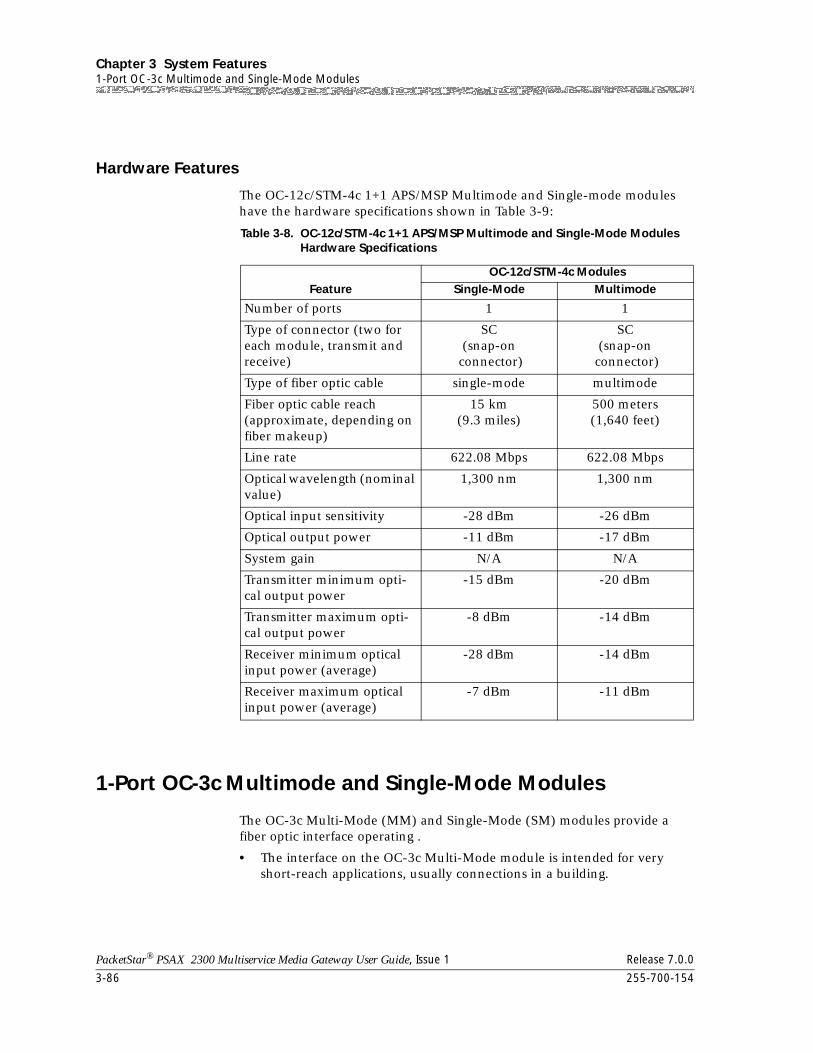
Chapter 3 System Features1-Port OC-3c Multimode and Single-Mode Modules
3-86 255-700-154
PacketStar® PSAX 2300 Multiservice Media Gateway User Guide, Issue 1 Release 7.0.0
Hardware Features
The OC-12c/STM-4c 1+1 APS/MSP Multimode and Single-mode modules have the hardware specifications shown in Table 3-9:
1-Port OC-3c Multimode and Single-Mode Modules
The OC-3c Multi-Mode (MM) and Single-Mode (SM) modules provide a fiber optic interface operating .
• The interface on the OC-3c Multi-Mode module is intended for very short-reach applications, usually connections in a building.
Table 3-8. OC-12c/STM-4c 1+1 APS/MSP Multimode and Single-Mode Modules Hardware Specifications
FeatureOC-12c/STM-4c Modules
Single-Mode Multimode
Number of ports 1 1
Type of connector (two for each module, transmit and receive)
SC(snap-on
connector)
SC(snap-on
connector)
Type of fiber optic cable single-mode multimode
Fiber optic cable reach (approximate, depending on fiber makeup)
15 km(9.3 miles)
500 meters(1,640 feet)
Line rate 622.08 Mbps 622.08 Mbps
Optical wavelength (nominal value)
1,300 nm 1,300 nm
Optical input sensitivity -28 dBm -26 dBm
Optical output power -11 dBm -17 dBm
System gain N/A N/A
Transmitter minimum opti-cal output power
-15 dBm -20 dBm
Transmitter maximum opti-cal output power
-8 dBm -14 dBm
Receiver minimum optical input power (average)
-28 dBm -14 dBm
Receiver maximum optical input power (average)
-7 dBm -11 dBm
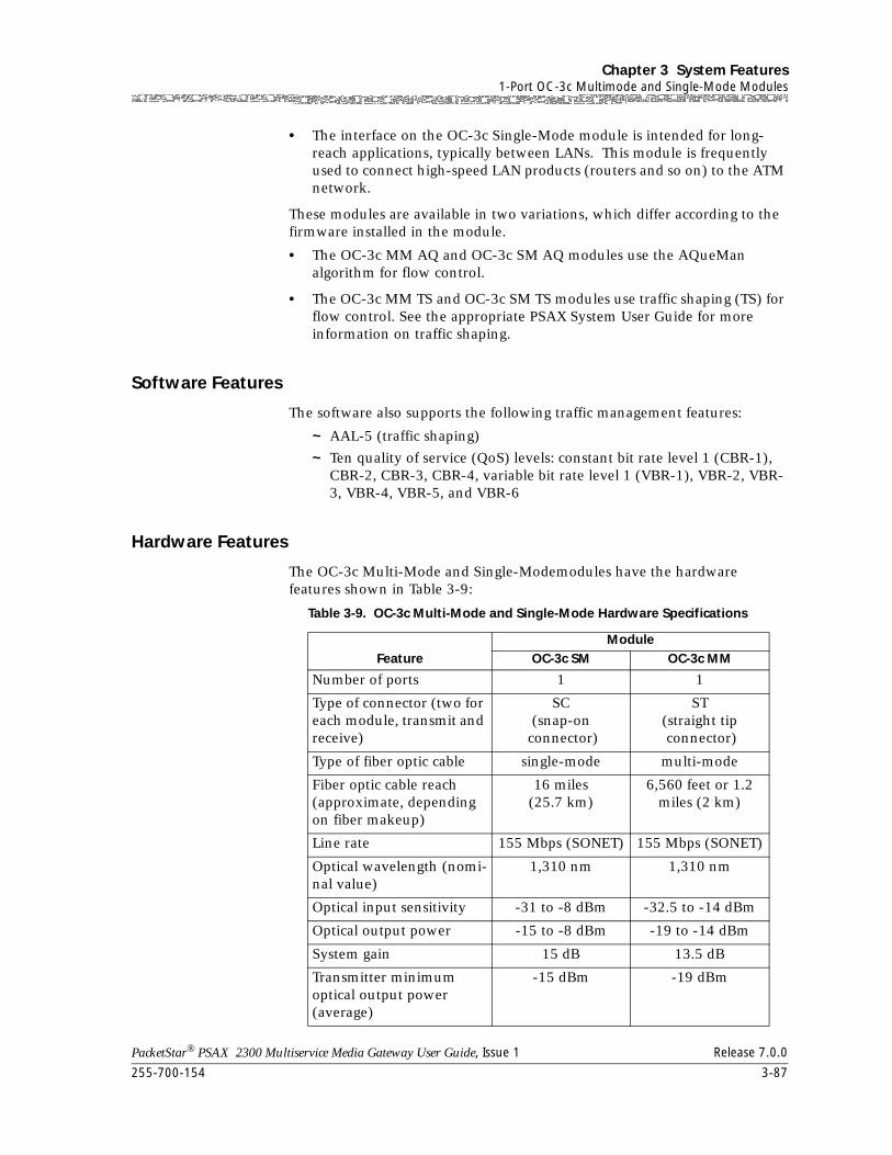
255-700-154 3-87
PacketStar® PSAX 2300 Multiservice Media Gateway User Guide, Issue 1 Release 7.0.0
Chapter 3 System Features1-Port OC-3c Multimode and Single-Mode Modules
• The interface on the OC-3c Single-Mode module is intended for long-reach applications, typically between LANs. This module is frequently used to connect high-speed LAN products (routers and so on) to the ATM network.
These modules are available in two variations, which differ according to the firmware installed in the module.
• The OC-3c MM AQ and OC-3c SM AQ modules use the AQueMan algorithm for flow control.
• The OC-3c MM TS and OC-3c SM TS modules use traffic shaping (TS) for flow control. See the appropriate PSAX System User Guide for more information on traffic shaping.
Software Features
The software also supports the following traffic management features:
~ AAL-5 (traffic shaping)
~ Ten quality of service (QoS) levels: constant bit rate level 1 (CBR-1), CBR-2, CBR-3, CBR-4, variable bit rate level 1 (VBR-1), VBR-2, VBR-3, VBR-4, VBR-5, and VBR-6
Hardware Features
The OC-3c Multi-Mode and Single-Modemodules have the hardware features shown in Table 3-9:
Table 3-9. OC-3c Multi-Mode and Single-Mode Hardware Specifications
FeatureModule
OC-3c SM OC-3c MM
Number of ports 1 1
Type of connector (two for each module, transmit and receive)
SC(snap-on
connector)
ST(straight tip connector)
Type of fiber optic cable single-mode multi-mode
Fiber optic cable reach (approximate, depending on fiber makeup)
16 miles(25.7 km)
6,560 feet or 1.2 miles (2 km)
Line rate 155 Mbps (SONET) 155 Mbps (SONET)
Optical wavelength (nomi-nal value)
1,310 nm 1,310 nm
Optical input sensitivity -31 to -8 dBm -32.5 to -14 dBm
Optical output power -15 to -8 dBm -19 to -14 dBm
System gain 15 dB 13.5 dB
Transmitter minimum optical output power (average)
-15 dBm -19 dBm
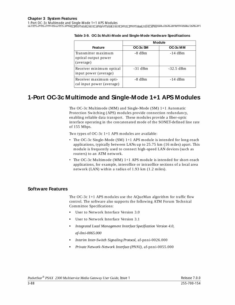
Chapter 3 System Features1-Port OC-3c Multimode and Single-Mode 1+1 APS Modules
3-88 255-700-154
PacketStar® PSAX 2300 Multiservice Media Gateway User Guide, Issue 1 Release 7.0.0
1-Port OC-3c Multimode and Single-Mode 1+1 APS Modules
The OC-3c Multimode (MM) and Single-Mode (SM) 1+1 Automatic Protection Switching (APS) modules provide connection redundancy, enabling reliable data transport. These modules provide a fiber-optic interface operating in the concatenated mode of the SONET-defined line rate of 155 Mbps.
Two types of OC-3c 1+1 APS modules are available:
• The OC-3c Single-Mode (SM) 1+1 APS module is intended for long-reach applications, typically between LANs up to 25.75 km (16 miles) apart. This module is frequently used to connect high-speed LAN devices (such as routers) to an ATM network.
• The OC-3c Multimode (MM) 1+1 APS module is intended for short-reach applications, for example, interoffice or intraoffice sections of a local area network (LAN) within a radius of 1.93 km (1.2 miles).
Software Features
The OC-3c 1+1 APS modules use the AQueMan algorithm for traffic flow control. The software also supports the following ATM Forum Technical Committee Specifications:
• User to Network Interface Version 3.0
• User to Network Interface Version 3.1
• Integrated Local Management Interface Specification Version 4.0,
af-ilmi-0065.000
• Interim Inter-Switch Signaling Protocol, af-pnni-0026.000
• Private Network-Network Interface (PNNI), af-pnni-0055.000
Transmitter maximum optical output power (average)
-8 dBm -14 dBm
Receiver minimum optical input power (average)
-31 dBm -32.5 dBm
Receiver maximum opti-cal input power (average)
-8 dBm -14 dBm
Table 3-9. OC-3c Multi-Mode and Single-Mode Hardware Specifications
FeatureModule
OC-3c SM OC-3c MM
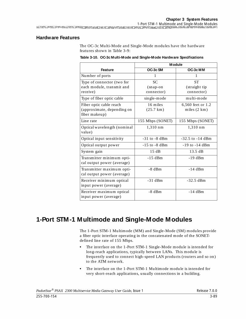
255-700-154 3-89
PacketStar® PSAX 2300 Multiservice Media Gateway User Guide, Issue 1 Release 7.0.0
Chapter 3 System Features1-Port STM-1 Multimode and Single-Mode Modules
Hardware Features
The OC-3c Multi-Mode and Single-Mode modules have the hardware features shown in Table 3-9:
1-Port STM-1 Multimode and Single-Mode Modules
The 1-Port STM-1 Multimode (MM) and Single-Mode (SM) modules provide a fiber optic interface operating in the concatenated mode of the SONET-defined line rate of 155 Mbps.
• The interface on the 1-Port STM-1 Single-Mode module is intended for long-reach applications, typically between LANs. This module is frequently used to connect high-speed LAN products (routers and so on) to the ATM network.
• The interface on the 1-Port STM-1 Multimode module is intended for very short-reach applications, usually connections in a building.
Table 3-10. OC-3c Multi-Mode and Single-Mode Hardware Specifications
FeatureModule
OC-3c SM OC-3c MM
Number of ports 1 1
Type of connector (two for each module, transmit and receive)
SC(snap-on
connector)
ST(straight tip connector)
Type of fiber optic cable single-mode multi-mode
Fiber optic cable reach (approximate, depending on fiber makeup)
16 miles(25.7 km)
6,560 feet or 1.2 miles (2 km)
Line rate 155 Mbps (SONET) 155 Mbps (SONET)
Optical wavelength (nominal value)
1,310 nm 1,310 nm
Optical input sensitivity -31 to -8 dBm -32.5 to -14 dBm
Optical output power -15 to -8 dBm -19 to -14 dBm
System gain 15 dB 13.5 dB
Transmitter minimum opti-cal output power (average)
-15 dBm -19 dBm
Transmitter maximum opti-cal output power (average)
-8 dBm -14 dBm
Receiver minimum optical input power (average)
-31 dBm -32.5 dBm
Receiver maximum optical input power (average)
-8 dBm -14 dBm
Chapter 3 System Features1-Port STM-1 Multimode and Single-Mode Modules
3-90 255-700-154
PacketStar® PSAX 2300 Multiservice Media Gateway User Guide, Issue 1 Release 7.0.0
These modules are available in two variations, which differ according to the firmware installed on the circuit boards.
• One variation for both the Multi-Mode and Single-Mode types, with the names STM-1 MM AQ module and STM-1 SM AQ module, uses the AQueMan algorithm for flow control.
• The other variation for both the Multi-Mode and Single-Mode types, with the names STM-1 MM TS module and STM-1 SM TS module, uses traffic shaping for flow control. See Chapter 3 of the appropriate PSAX System User’s Guide for more information on traffic shaping.
Software Features
The software also supports the following ATM Forum Technical Committee Specifications:
• User to Network Interface Version 3.0
• User to Network Interface Version 3.1
• Integrated Local Management Interface Specification Version 4.0,
af-ilmi-0065.000
• Interim Inter-Switch Signaling Protocol, af-pnni-0026.000
• Private Network-Network Interface (PNNI), af-pnni-0055.000
Protocols:
• Traffic management:
~ AQueMan™ algorithm (for traffic flow control)
~ AAL-5 (traffic shaping)
~ 10 quality of service (Qos) levels:
• Constant bit rate level 1 (CBR-1), CBR-2, CBR-3, and CBR-4
• Variable bit rate (VBR): VBR real time level 1 (VBR-RT1), VBR real time level 2 (VBR-RT2), VBR non-real time level 1 (VBR-NRT1), VBR non-real time level 2 (VBR-NRT2), VBR-express
• Unspecified bit rate (UBR)
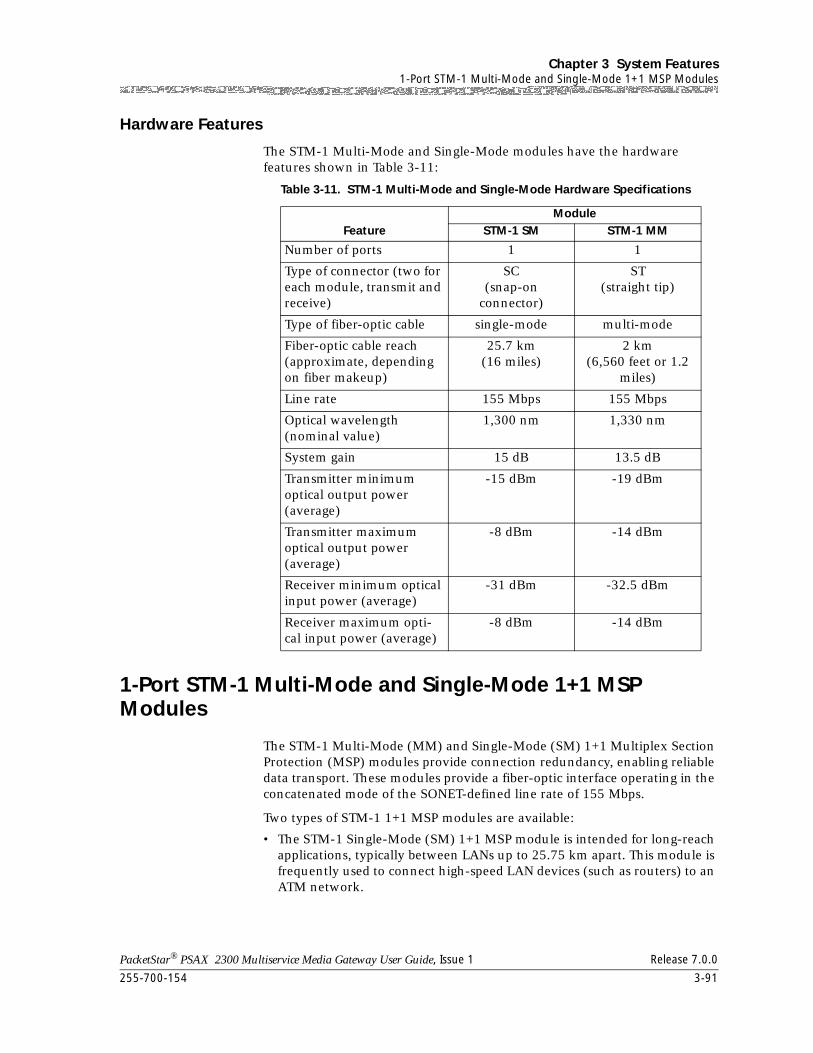
255-700-154 3-91
PacketStar® PSAX 2300 Multiservice Media Gateway User Guide, Issue 1 Release 7.0.0
Chapter 3 System Features1-Port STM-1 Multi-Mode and Single-Mode 1+1 MSP Modules
Hardware Features
The STM-1 Multi-Mode and Single-Mode modules have the hardware features shown in Table 3-11:
1-Port STM-1 Multi-Mode and Single-Mode 1+1 MSP Modules
The STM-1 Multi-Mode (MM) and Single-Mode (SM) 1+1 Multiplex Section Protection (MSP) modules provide connection redundancy, enabling reliable data transport. These modules provide a fiber-optic interface operating in the concatenated mode of the SONET-defined line rate of 155 Mbps.
Two types of STM-1 1+1 MSP modules are available:
• The STM-1 Single-Mode (SM) 1+1 MSP module is intended for long-reach applications, typically between LANs up to 25.75 km apart. This module is frequently used to connect high-speed LAN devices (such as routers) to an ATM network.
Table 3-11. STM-1 Multi-Mode and Single-Mode Hardware Specifications
FeatureModule
STM-1 SM STM-1 MM
Number of ports 1 1
Type of connector (two for each module, transmit and receive)
SC(snap-on
connector)
ST(straight tip)
Type of fiber-optic cable single-mode multi-mode
Fiber-optic cable reach (approximate, depending on fiber makeup)
25.7 km (16 miles)
2 km(6,560 feet or 1.2
miles)
Line rate 155 Mbps 155 Mbps
Optical wavelength (nominal value)
1,300 nm 1,330 nm
System gain 15 dB 13.5 dB
Transmitter minimum optical output power (average)
-15 dBm -19 dBm
Transmitter maximum optical output power (average)
-8 dBm -14 dBm
Receiver minimum optical input power (average)
-31 dBm -32.5 dBm
Receiver maximum opti-cal input power (average)
-8 dBm -14 dBm
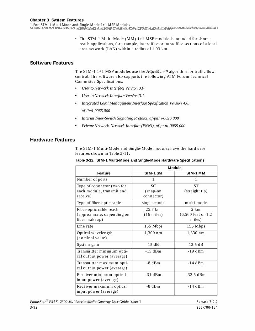
Chapter 3 System Features1-Port STM-1 Multi-Mode and Single-Mode 1+1 MSP Modules
3-92 255-700-154
PacketStar® PSAX 2300 Multiservice Media Gateway User Guide, Issue 1 Release 7.0.0
• The STM-1 Multi-Mode (MM) 1+1 MSP module is intended for short-reach applications, for example, interoffice or intraoffice sections of a local area network (LAN) within a radius of 1.93 km.
Software Features
The STM-1 1+1 MSP modules use the AQueMan™ algorithm for traffic flow control. The software also supports the following ATM Forum Technical Committee Specifications:
• User to Network Interface Version 3.0
• User to Network Interface Version 3.1
• Integrated Local Management Interface Specification Version 4.0,
af-ilmi-0065.000
• Interim Inter-Switch Signaling Protocol, af-pnni-0026.000
• Private Network-Network Interface (PNNI), af-pnni-0055.000
Hardware Features
The STM-1 Multi-Mode and Single-Mode modules have the hardware features shown in Table 3-11:
Table 3-12. STM-1 Multi-Mode and Single-Mode Hardware Specifications
FeatureModule
STM-1 SM STM-1 MM
Number of ports 1 1
Type of connector (two for each module, transmit and receive)
SC(snap-on
connector)
ST(straight tip)
Type of fiber-optic cable single-mode multi-mode
Fiber-optic cable reach (approximate, depending on fiber makeup)
25.7 km (16 miles)
2 km(6,560 feet or 1.2
miles)
Line rate 155 Mbps 155 Mbps
Optical wavelength (nominal value)
1,300 nm 1,330 nm
System gain 15 dB 13.5 dB
Transmitter minimum opti-cal output power (average)
-15 dBm -19 dBm
Transmitter maximum opti-cal output power (average)
-8 dBm -14 dBm
Receiver minimum optical input power (average)
-31 dBm -32.5 dBm
Receiver maximum optical input power (average)
-8 dBm -14 dBm
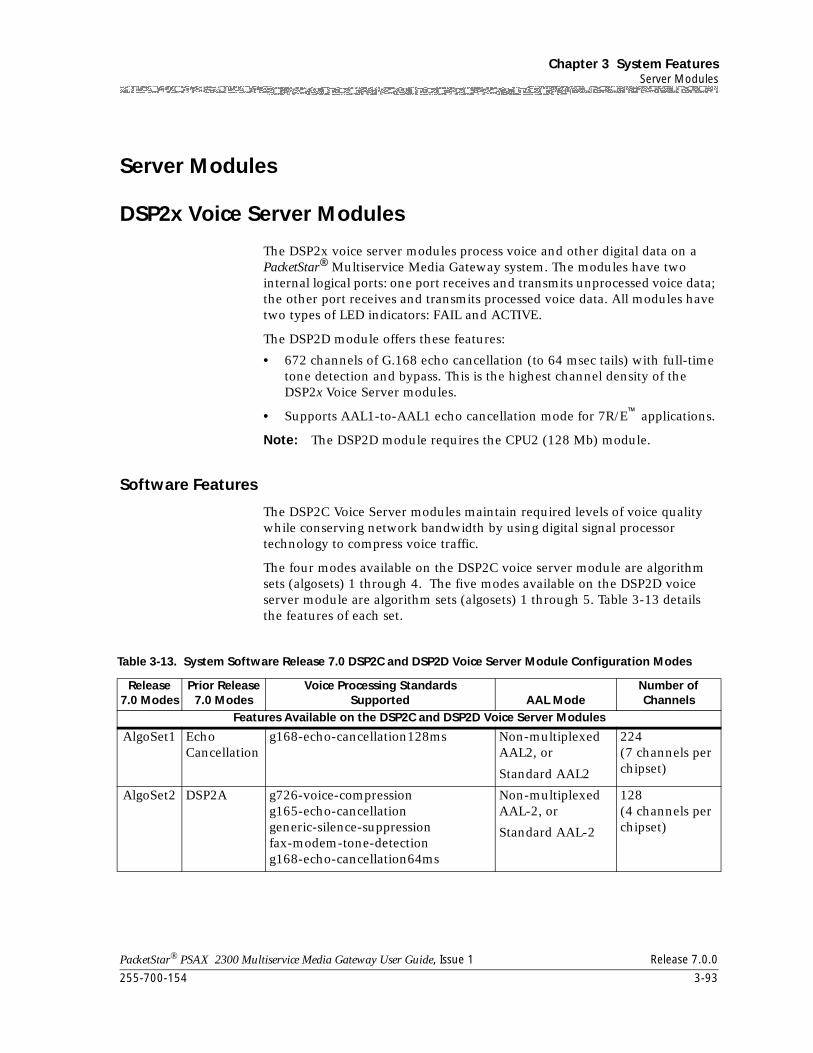
255-700-154 3-93
PacketStar® PSAX 2300 Multiservice Media Gateway User Guide, Issue 1 Release 7.0.0
Chapter 3 System FeaturesServer Modules
Server Modules
DSP2x Voice Server Modules
The DSP2x voice server modules process voice and other digital data on a PacketStar® Multiservice Media Gateway system. The modules have two internal logical ports: one port receives and transmits unprocessed voice data; the other port receives and transmits processed voice data. All modules have two types of LED indicators: FAIL and ACTIVE.
The DSP2D module offers these features:
• 672 channels of G.168 echo cancellation (to 64 msec tails) with full-time tone detection and bypass. This is the highest channel density of the DSP2x Voice Server modules.
• Supports AAL1-to-AAL1 echo cancellation mode for 7R/E™ applications.
Note: The DSP2D module requires the CPU2 (128 Mb) module.
Software Features
The DSP2C Voice Server modules maintain required levels of voice quality while conserving network bandwidth by using digital signal processor technology to compress voice traffic.
The four modes available on the DSP2C voice server module are algorithm sets (algosets) 1 through 4. The five modes available on the DSP2D voice server module are algorithm sets (algosets) 1 through 5. Table 3-13 details the features of each set.
Table 3-13. System Software Release 7.0 DSP2C and DSP2D Voice Server Module Configuration Modes
Release 7.0 Modes
Prior Release7.0 Modes
Voice Processing StandardsSupported AAL Mode
Number ofChannels
Features Available on the DSP2C and DSP2D Voice Server Modules
AlgoSet1 EchoCancellation
g168-echo-cancellation128ms Non-multiplexed AAL2, or
Standard AAL2
224(7 channels per chipset)
AlgoSet2 DSP2A g726-voice-compressiong165-echo-cancellationgeneric-silence-suppressionfax-modem-tone-detectiong168-echo-cancellation64ms
Non-multiplexed AAL-2, or
Standard AAL-2
128(4 channels per chipset)
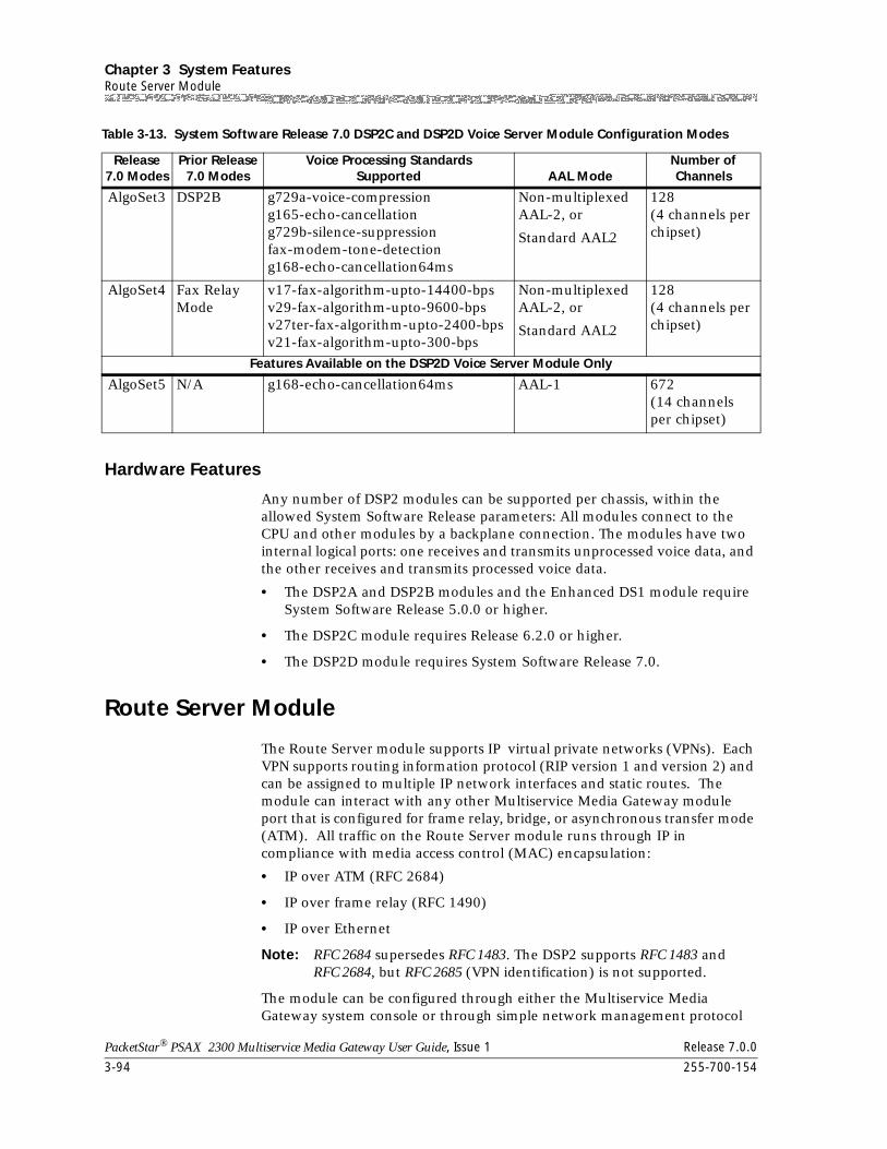
Chapter 3 System FeaturesRoute Server Module
3-94 255-700-154
PacketStar® PSAX 2300 Multiservice Media Gateway User Guide, Issue 1 Release 7.0.0
Hardware Features
Any number of DSP2 modules can be supported per chassis, within the allowed System Software Release parameters: All modules connect to the CPU and other modules by a backplane connection. The modules have two internal logical ports: one receives and transmits unprocessed voice data, and the other receives and transmits processed voice data.
• The DSP2A and DSP2B modules and the Enhanced DS1 module require System Software Release 5.0.0 or higher.
• The DSP2C module requires Release 6.2.0 or higher.
• The DSP2D module requires System Software Release 7.0.
Route Server Module
The Route Server module supports IP virtual private networks (VPNs). Each VPN supports routing information protocol (RIP version 1 and version 2) and can be assigned to multiple IP network interfaces and static routes. The module can interact with any other Multiservice Media Gateway module port that is configured for frame relay, bridge, or asynchronous transfer mode (ATM). All traffic on the Route Server module runs through IP in compliance with media access control (MAC) encapsulation:
• IP over ATM (RFC 2684)
• IP over frame relay (RFC 1490)
• IP over Ethernet
Note: RFC 2684 supersedes RFC 1483. The DSP2 supports RFC 1483 and RFC 2684, but RFC 2685 (VPN identification) is not supported.
The module can be configured through either the Multiservice Media Gateway system console or through simple network management protocol
AlgoSet3 DSP2B g729a-voice-compressiong165-echo-cancellationg729b-silence-suppressionfax-modem-tone-detectiong168-echo-cancellation64ms
Non-multiplexed AAL-2, or
Standard AAL2
128(4 channels per chipset)
AlgoSet4 Fax Relay Mode
v17-fax-algorithm-upto-14400-bpsv29-fax-algorithm-upto-9600-bpsv27ter-fax-algorithm-upto-2400-bpsv21-fax-algorithm-upto-300-bps
Non-multiplexed AAL-2, or
Standard AAL2
128(4 channels per chipset)
Features Available on the DSP2D Voice Server Module Only
AlgoSet5 N/A g168-echo-cancellation64ms AAL-1 672(14 channels per chipset)
Table 3-13. System Software Release 7.0 DSP2C and DSP2D Voice Server Module Configuration Modes
Release 7.0 Modes
Prior Release7.0 Modes
Voice Processing StandardsSupported AAL Mode
Number ofChannels
255-700-154 3-95
PacketStar® PSAX 2300 Multiservice Media Gateway User Guide, Issue 1 Release 7.0.0
Chapter 3 System FeaturesRoute Server Module
(SNMP). Each Multiservice Media Gateway system may support multiple Route Server modules, but multiple Route Server modules cannot be configured for hot standby redundancy purposes.
Software Release 6.3.0 introduces routing information protocol (RIP) Version 2 to the Route Server module. The module now supports Internet Protocol virtual private networks (VPNs) by assigning multiple IP network interfaces and static routes. (The Route Server module also supports RIP v1.0, and can interact with any other Access Concentrator module port that is configured for frame relay, Ethernet bridging, or ATM.)
Release 6.3.0 software, supporting RIP v2.0, allows you to divide networks to a further extent than the traditional subnet classes (Class A, B, and C) available with RIP v1.0. RIP v2.0 enables authentication and multicasting, and allows you to run different masks on different subnets. Rip v2.0 can be either active or passive.
You can assign an authentication password to an IP network interface for maximum security. Doing so can prevent those who cannot directly access the network from sending false routing information to the routers. RIP v1.0 messages will be ignored when authentication is in use. However, authentication does not prevent RIP v1.0 routers from viewing RIP v2.0 messages. To prevent RIP v1.0 routers from viewing RIP v2.0 messages, you must use multicasting.
Multicasting reduces load on hosts not using RIP v2.0 messages. Multicasting also allows RIP v2.0 routers to share information that RIP v1.0 routers cannot access. Available bandwidth becomes the tiebreaker in calculating routes using default parameters for both IISP and PNNI routing.
Software Features
The software supports the following Frame Relay Forum (FRF) Implementation Agreements:
~ FRF.5—Frame Relay/ATM PVC Network Interworking
~ FRF.8—Frame Relay/ATM PVC Service Interworking
• Interfaces: IP over ATM (IETF RFC 2684), IP over frame relay (IETF RFC 1490), IP over Ethernet (bridge)
Note: RFC 2684 supercedes RFC 1483. The DSP2 supports RFC 1483 and RFC 2684, but RFC 2685 (VPN identification) is not supported.
• Multi-service routing:
~ ICMP (RFC 792)
~ Static routing with six independent VPNs
~ IP routing
~ Frame relay (FRF.5, FRF.8)
~ ATM
Chapter 3 System FeaturesTones and Announcements Server Module
3-96 255-700-154
PacketStar® PSAX 2300 Multiservice Media Gateway User Guide, Issue 1 Release 7.0.0
Hardware Features
The Route Server module provides the following forwarding speeds (measured in packets per second):
• 64-byte IP packet size: 22K pps (11.3 Mbps)
• 256-byte IP packet size: 16K pps (32.8 Mbps)
• 1518-byte IP packet size: 4.6K pps (55.8 Mbps)
Tones and Announcements Server Module
The Tones and Announcements Server (TAS) module offers these tests in a switch-to-switch capacity:
~ SS7 (Signaling System 7) continuity test for VToA
~ 1004 Hz (miliwatt) test tone support (Type 102)
~ Digital, non-inverting loopback (Type 108)
~ Automatic Transmisson measurement( Type 105)
These tests enable PSAX products to provide tones and signaling testing on voice equipment in the customer’s premises, such as PBXs. Designed for use between central office products, such as the PSAX 2300 and the PSAX 1250, and edge devices such as the AC 60 and the PSAX 20, the module offers call routing information to a connection gateway without using an expensive circuit switch. Up to 128 circuits can be tested simultaneously using the TAS Server Module.
The SS7 Continuity Test enables PSAX products to be deployed with other applications in connection gateways involving hand-offs to ILECs which require the quality assurance of conducting the continuity test from the circuit switch.
The test features work in conjunction with the Enhanced DS1, the Enhanced E1, the High-Density E1/DS1, the Channelized DS3/STS-1e, the CPU module, and a Connection Gateway Application Programming Interface (API).
Hardware Features
The Tones and Announcements Server Module consists of 32 digital signal processer chipsets. All modules connect to the CPU and other modules by a backplane connection.
Any number of Tones and Announcements Server Modules are supported by the PSAX 2300, PSAX 1250, and PSAX 2300 Multiservice Media Gateways. A TAS module can be placed in any available slot on the PSAX 1250, 2300, PSAX 20, and AC 60.
PacketStar® PSAX 2300 Multiservice Media Gateway User Guide, Issue 1 Release 7.0.0
255-700-154 4-1
4 Configuring the Basic System
Overview of This Chapter
This chapter describes how to configure the PSAX 2300 Multiservice Media Gateway system and set the system values for your site. Before you do this, be sure you have done the following tasks as described in the Packetstar®
PSAX 2300 Installation and Operation Guide:
• Installed the system hardware components
• Applied power to the system
For procedures to configure the I/O and server modules, see the appropriate PacketStar® PSAX Module User guide.
The PSAX 2300 system is designed for continuous operation after power is applied.
Telnet sessions are supported on the Ethernet interface. Both the telnet session on the Ethernet interface and the console session provide a console interface for VT100 terminal emulation. See Chapter 6, "Using VT100 Terminal Emulation," for information on configuring this application.
Logging onto the System
Before beginning the following procedure, be sure that your cabling on the CPU module is connected properly (see the Packetstar® PSAX 2300 Installation and Operation Guide). To log onto the PSAX 2300 system, perform the following steps.
Begin
Logging onto the PSAX 2300 System
1 Configure your VT100 terminal emulator (see Chapter 6, “Using VT100 Terminal Emulation).
2 To start the console session, press Enter.
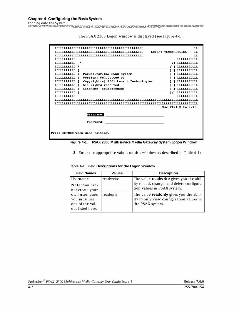
Chapter 4 Configuring the Basic SystemLogging onto the System
4-2 255-700-154
PacketStar® PSAX 2300 Multiservice Media Gateway User Guide, Issue 1 Release 7.0.0
The PSAX 2300 Logon window is displayed (see Figure 4-1).
3 Enter the appropriate values on this window as described in Table 4-1:
Figure 4-1. PSAX 2300 Multiservice Media Gateway System Logon Window
Table 4-1. Field Descriptions for the Logon Window
Field Names Values Description
Username
Note: You can-not create your own username; you must use one of the val-ues listed here.
readwrite The value readwrite gives you the abil-ity to add, change, and delete configura-tion values in PSAX system.
readonly The value readonly gives you the abil-ity to only view configuration values in the PSAX system.
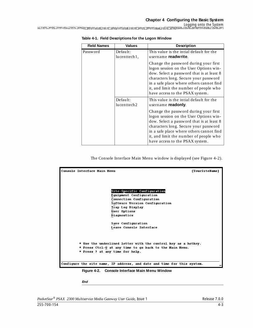
255-700-154 4-3
PacketStar® PSAX 2300 Multiservice Media Gateway User Guide, Issue 1 Release 7.0.0
Chapter 4 Configuring the Basic SystemLogging onto the System
The Console Interface Main Menu window is displayed (see Figure 4-2).
End
Password Default:lucenttech1,
This value is the intial default for the username readwrite.
Change the password during your first logon session on the User Options win-dow. Select a password that is at least 8 characters long. Secure your password in a safe place where others cannot find it, and limit the number of people who have access to the PSAX system.
Default:lucenttech2
This value is the intial default for the username readonly.
Change the password during your first logon session on the User Options win-dow. Select a password that is at least 8 characters long. Secure your password in a safe place where others cannot find it, and limit the number of people who have access to the PSAX system.
Figure 4-2. Console Interface Main Menu Window
Table 4-1. Field Descriptions for the Logon Window
Field Names Values Description
Chapter 4 Configuring the Basic SystemLogging onto the System
4-4 255-700-154
PacketStar® PSAX 2300 Multiservice Media Gateway User Guide, Issue 1 Release 7.0.0
At the time of initial configuration, the Console Interface Main Menu window is displayed a field with a pair of opposing square brackets in the upper right corner. This field contains the site name, which you enter during site-specific configuration (see the procedure in ”Configuring System Identification” on page 4-13).
Help Information
The Help windows are accessible from any window in the PSAX system console interface. To access the Help windows, press the Question Mark (?) key on any window. In addition to the Help windows, the Console Interface windows have contextual help displayed in the information line at the bottom of each window. Contextual help provides information about the command or field currently highlighted on that window. The information line also is displayed error codes and responses to commands. All responses and notifications are recorded in a trap log. (See Appendix A, "SNMP Trap Messages," for details on displaying the trap log and explanations of the messages).
To view the Help windows from the Console Interface Main Menu window, perform the steps in the following procedure.
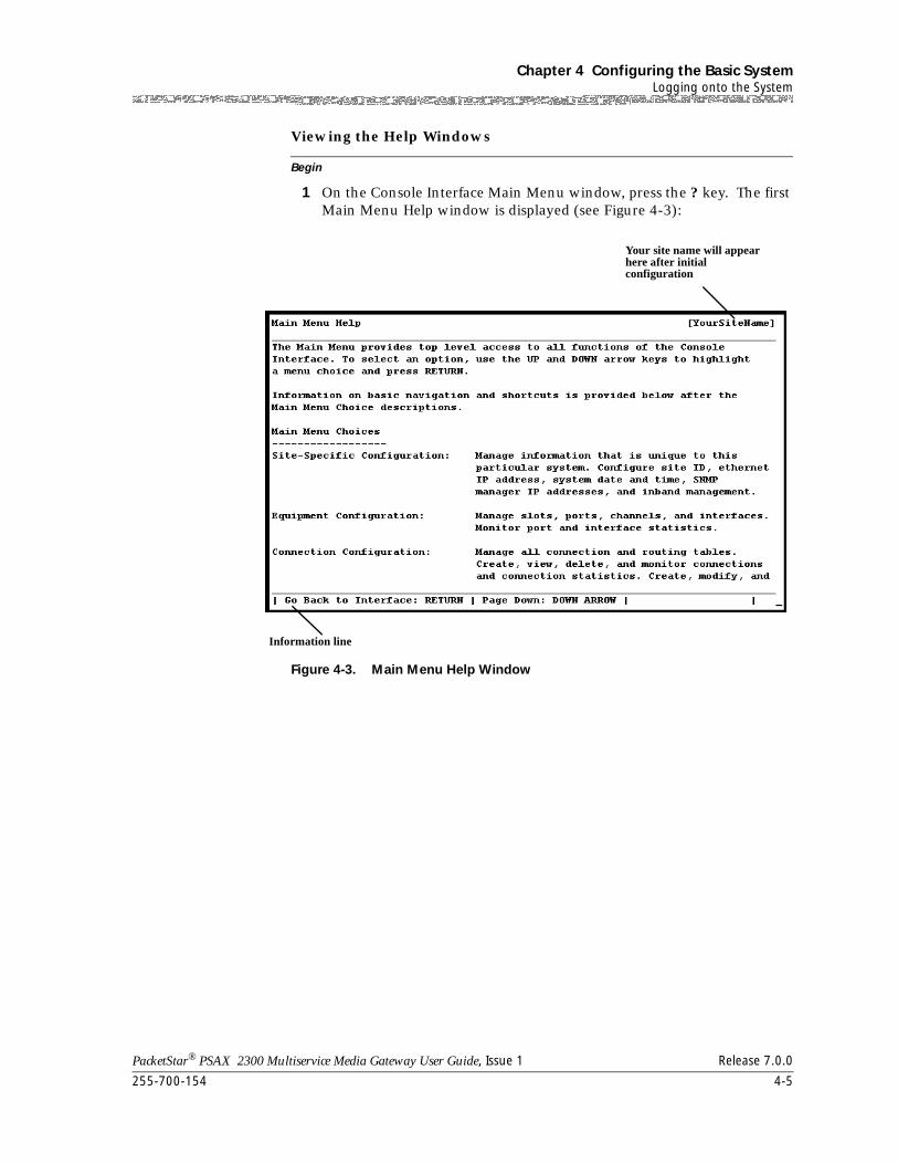
255-700-154 4-5
PacketStar® PSAX 2300 Multiservice Media Gateway User Guide, Issue 1 Release 7.0.0
Chapter 4 Configuring the Basic SystemLogging onto the System
Begin
Viewing the Help Windows
1 On the Console Interface Main Menu window, press the ? key. The first Main Menu Help window is displayed (see Figure 4-3):
Figure 4-3. Main Menu Help Window
Your site name will appear here after initial configuration
Information line
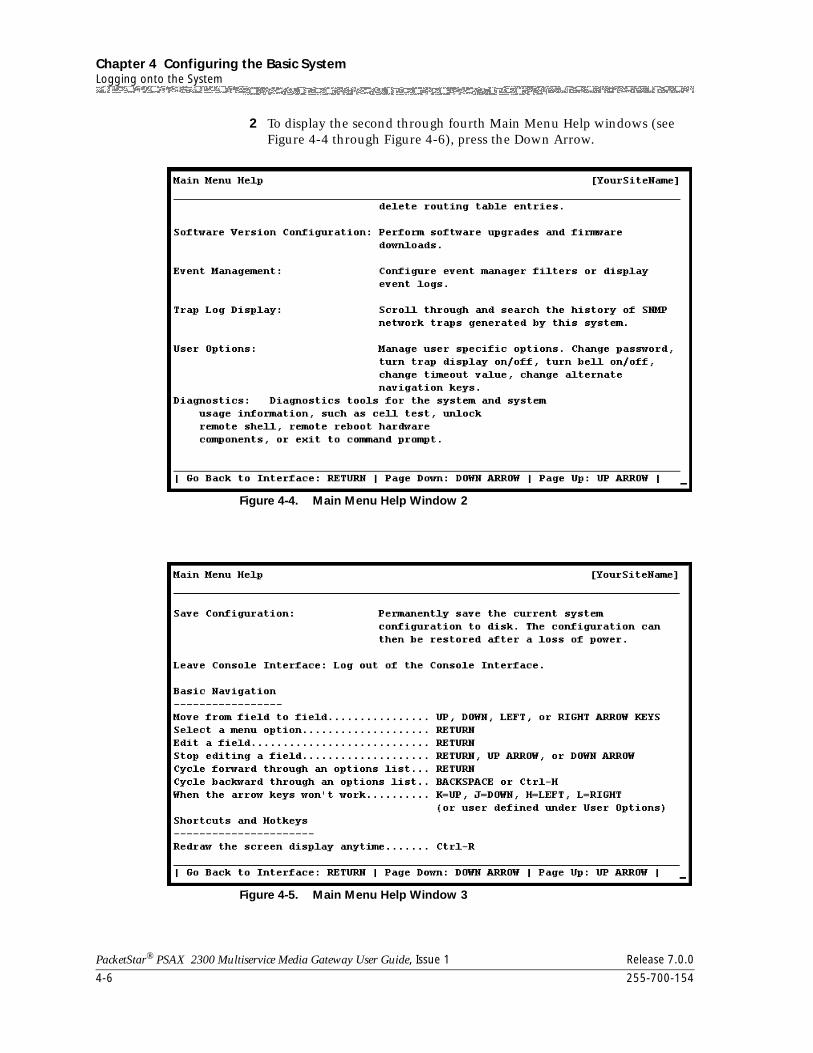
Chapter 4 Configuring the Basic SystemLogging onto the System
4-6 255-700-154
PacketStar® PSAX 2300 Multiservice Media Gateway User Guide, Issue 1 Release 7.0.0
2 To display the second through fourth Main Menu Help windows (see Figure 4-4 through Figure 4-6), press the Down Arrow.
Figure 4-4. Main Menu Help Window 2
Figure 4-5. Main Menu Help Window 3
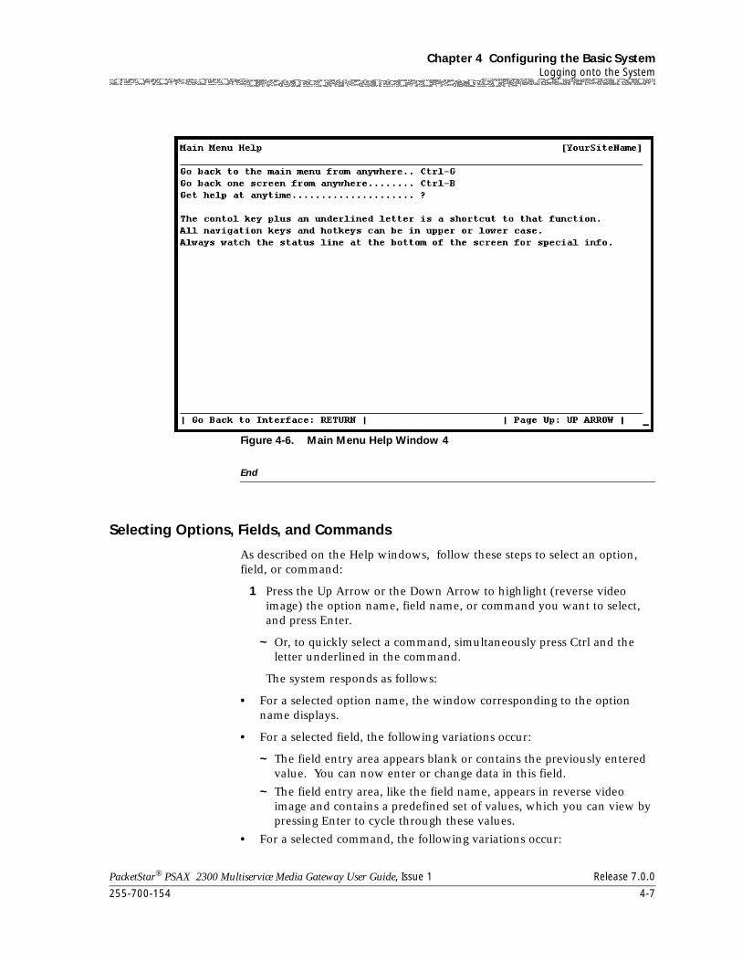
255-700-154 4-7
PacketStar® PSAX 2300 Multiservice Media Gateway User Guide, Issue 1 Release 7.0.0
Chapter 4 Configuring the Basic SystemLogging onto the System
End
Selecting Options, Fields, and Commands
As described on the Help windows, follow these steps to select an option, field, or command:
1 Press the Up Arrow or the Down Arrow to highlight (reverse video image) the option name, field name, or command you want to select, and press Enter.
~ Or, to quickly select a command, simultaneously press Ctrl and the letter underlined in the command.
The system responds as follows:
• For a selected option name, the window corresponding to the option name displays.
• For a selected field, the following variations occur:
~ The field entry area appears blank or contains the previously entered value. You can now enter or change data in this field.
~ The field entry area, like the field name, appears in reverse video image and contains a predefined set of values, which you can view by pressing Enter to cycle through these values.
• For a selected command, the following variations occur:
Figure 4-6. Main Menu Help Window 4
Chapter 4 Configuring the Basic SystemChanging the System Password and Other User Options
4-8 255-700-154
PacketStar® PSAX 2300 Multiservice Media Gateway User Guide, Issue 1 Release 7.0.0
~ The information line displays a message indicating an error or successful completion of the command.
~ The system displays the next higher level or previous window (Enter to <window name> ).
~ The system displays the next lower level or succeeding window (<window name>).
The following tips will also help you:
• Read-only fields, which you cannot change, are enclosed in square brackets (example: [LineStatus]).
• Press Ctrl+B on any window to to move back to the previous window.
• Press Ctrl+G on any window to return to the Main Menu window.
Changing the System Password and Other User Options
When initially configuring the system, you can log in with configuration access or read-only access. Usernames cannot be changed. However, you should change the default passwords and the default SNMP community string name to ones of your choosing. You can change the password and SNMP community string name at any time, as needed.
! CAUTION:For optimum system security, we highly recommend that you change the password and the SNMP community string name from their initial default values.
To change the system password, perform the following procedure.
Begin
Changing the System Password
1 On the Console Interface Main Menu window, select the User Options command.
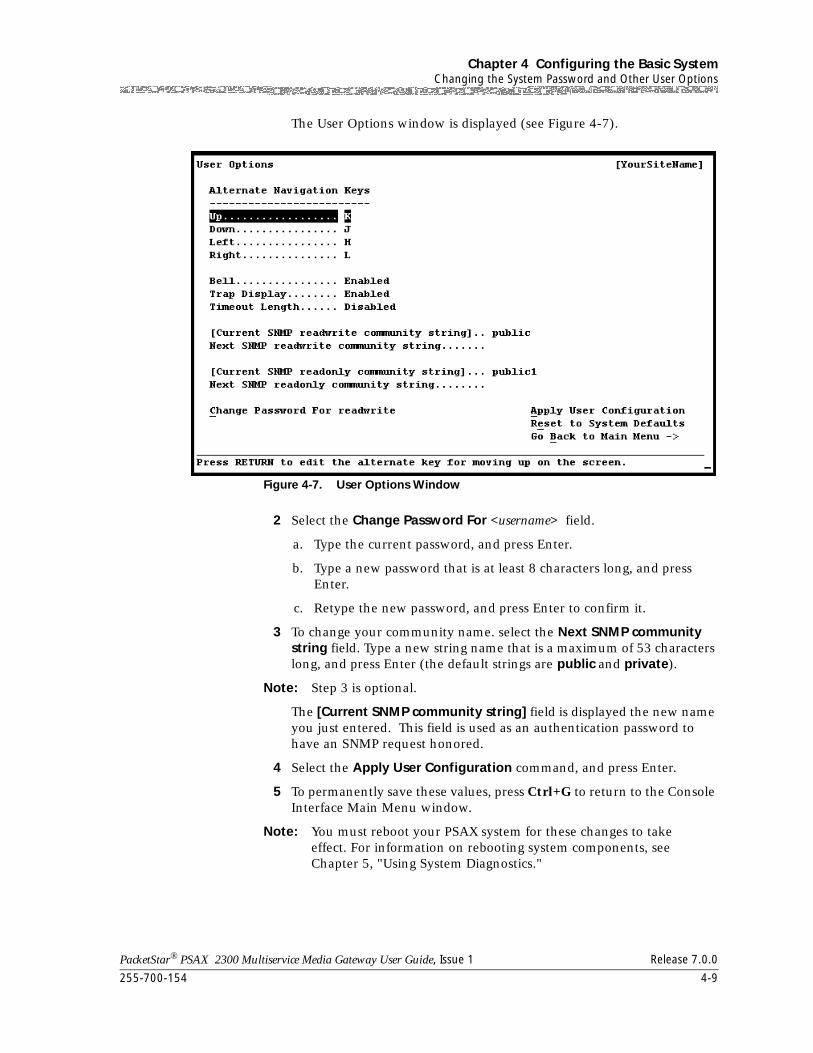
255-700-154 4-9
PacketStar® PSAX 2300 Multiservice Media Gateway User Guide, Issue 1 Release 7.0.0
Chapter 4 Configuring the Basic SystemChanging the System Password and Other User Options
The User Options window is displayed (see Figure 4-7).
2 Select the Change Password For <username> field.
a. Type the current password, and press Enter.
b. Type a new password that is at least 8 characters long, and press Enter.
c. Retype the new password, and press Enter to confirm it.
3 To change your community name. select the Next SNMP community string field. Type a new string name that is a maximum of 53 characters long, and press Enter (the default strings are public and private).
Note: Step 3 is optional.
The [Current SNMP community string] field is displayed the new name you just entered. This field is used as an authentication password to have an SNMP request honored.
4 Select the Apply User Configuration command, and press Enter.
5 To permanently save these values, press Ctrl+G to return to the Console Interface Main Menu window.
Note: You must reboot your PSAX system for these changes to take effect. For information on rebooting system components, see Chapter 5, "Using System Diagnostics."
Figure 4-7. User Options Window
Chapter 4 Configuring the Basic SystemConsole Interface Main Menu
4-10 255-700-154
PacketStar® PSAX 2300 Multiservice Media Gateway User Guide, Issue 1 Release 7.0.0
6 On the Console Interface Main Menu window, select the Save Configuration command, and press Enter to store the values in the PSAX system database. The new values will take effect after the chassis reboots.
End
Console Interface Main Menu
The Console Interface Main Menu window includes the following options:
• Site-Specific Configuration
• Equipment Configuration
• Connection Configuration (see the appropriate PacketStar® Module User Guide)
• Software Version Configuration (see Chapter 7, “Upgrading, Restoring, and Backing Up System Software and Firmware)
• Trap Log Display (see Appendix A, “SNMP Trap Messages”)
• User Options (see “Changing the System Password”)
• Diagnostics (see Chapter 5, “Using System Diagnostics”)
• Save Configuration
• Leave Console Interface
Configuring the System for Your Site
Before proceeding with the site configuration, you must first determine the actual values you use for the following configuration identifiers:
• Site name
• Site identifier
• Switch master IP address
• Ethernet mask address
• Gateway address
• IP addresses of remote network managers configured to receive SNMP traps
To configure your system, perform the steps in the following procedure.
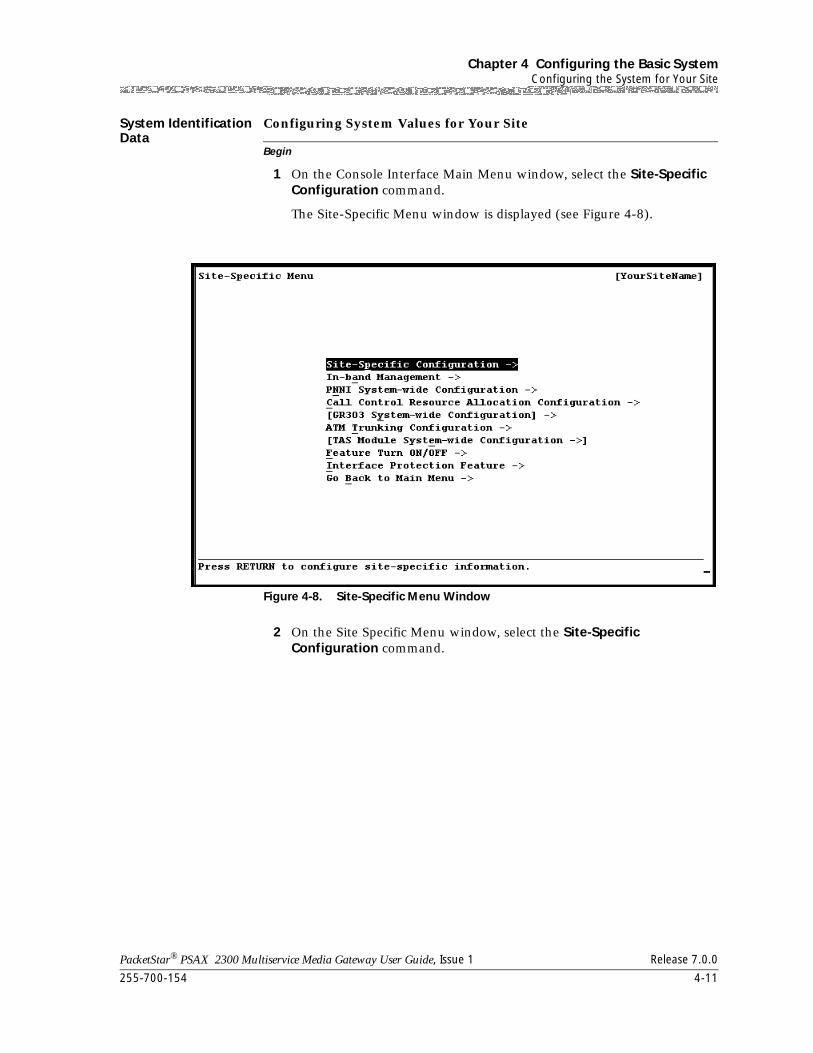
255-700-154 4-11
PacketStar® PSAX 2300 Multiservice Media Gateway User Guide, Issue 1 Release 7.0.0
Chapter 4 Configuring the Basic SystemConfiguring the System for Your Site
System Identification Data
Begin
Configuring System Values for Your Site
1 On the Console Interface Main Menu window, select the Site-Specific Configuration command.
The Site-Specific Menu window is displayed (see Figure 4-8).
2 On the Site Specific Menu window, select the Site-Specific Configuration command.
Figure 4-8. Site-Specific Menu Window
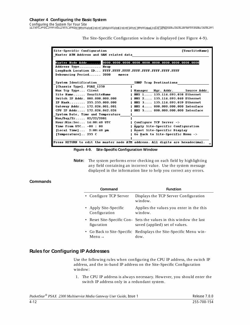
Chapter 4 Configuring the Basic SystemConfiguring the System for Your Site
4-12 255-700-154
PacketStar® PSAX 2300 Multiservice Media Gateway User Guide, Issue 1 Release 7.0.0
The Site-Specific Configuration window is displayed (see Figure 4-9).
Note: The system performs error checking on each field by highlighting any field containing an incorrect value. Use the system message displayed in the information line to help you correct any errors.
Commands
Rules for Configuring IP Addresses
Use the following rules when configuring the CPU IP address, the switch IP address, and the in-band IP address on the Site-Specific Configuration window:
1. The CPU IP address is always necessary. However, you should enter the switch IP address only in a redundant system.
Figure 4-9. Site-Specific Configuration Window
Command Function
• Configure TCP Server Displays the TCP Server Configuration window.
• Apply Site-Specific Configuration
Applies the values you enter in the this window.
• Reset Site-Specific Con-figuration
Sets the values in this window the last saved (applied) set of values.
• Go Back to Site-Specific Menu→
Redisplays the Site-Specific Menu win-dow.
255-700-154 4-13
PacketStar® PSAX 2300 Multiservice Media Gateway User Guide, Issue 1 Release 7.0.0
Chapter 4 Configuring the Basic SystemConfiguring the System for Your Site
2. CPU IP and switch IP addresses cannot be the same.
3. CPU IP and switch IP addresses cannot be on the same subnet as the in-band IP address.
4. CPU IP, switch IP, and in-band IP addresses may each be zero, but CPU IP and Switch IP addresses cannot both be zero (see Number 2 above).
Note: If the CPU IP address is zero and the ssid file on the CPU module is corrupted, the system cannot access the Ethernet.
5. If non-zero, then the CPU IP, switch IP, and in-band IP addresses have to be valid IP addresses.
6. If the switch IP address is not zero, then the system will respond to the Switch IP address; otherwise, the system will respond to the CPU IP address on the Ethernet port.
7. In a redundant system, both CPU modules must have a unique CPU IP address; they will have the same switch IP address and in-band IP address if either address is defined. After initial setup, the IP settings can be modified only on the active CPU.
Rules for Configuring IP Address Masks
Use the following rules when configuring the CPU IP address and switch IP address on the Site-Specific Configuration window:
1. The CPU IP address and switch IP address share the same IP mask.
2. The CPU IP address (or switch IP address) and in-band IP address masks are independent of each other, as long as the CPU IP address (or switch IP address) and in-band IP address are in different networks.
3. If the CPU IP address (or switch IP address) and in-band IP address are in the same network, then their masks must be the same.
4. The CPU IP address (or switch IP address) and the in-band IP address are in the same subnet if the CPU IP address mask (or switch IP address mask) is the same as the in-band IP address, and if the CPU IP address (or switch IP address) masked-out result is the same as the in-band IP address masked-out result.
5. The CPU IP address and switch IP address must always be on a different subnet from the in-band IP address; CPU IP and switch IP addresses cannot be on the same subnet as the in-band IP address.
Configuring System Identification
ATM Addresses and OAM Properties
The Master ATM Address and OAM related data panel allows you to enter and display information about the Master ATM address, the loopback, and OAM debouncing period.
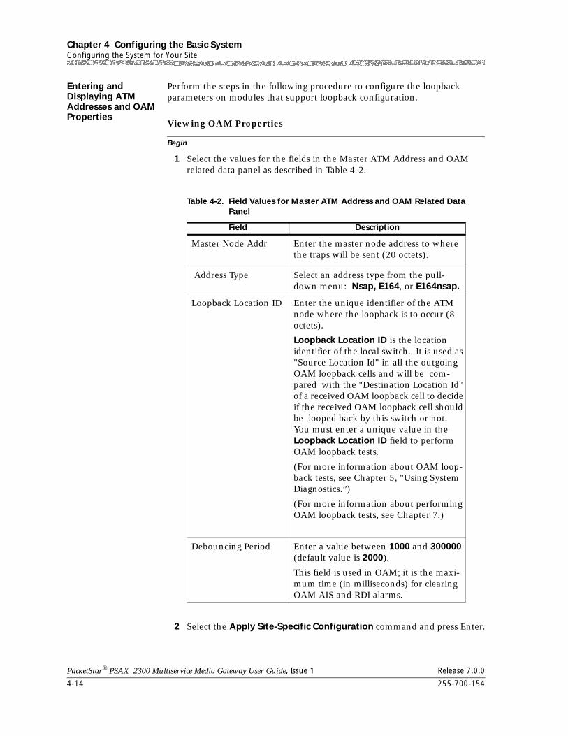
Chapter 4 Configuring the Basic SystemConfiguring the System for Your Site
4-14 255-700-154
PacketStar® PSAX 2300 Multiservice Media Gateway User Guide, Issue 1 Release 7.0.0
Entering and Displaying ATM Addresses and OAM Properties
Perform the steps in the following procedure to configure the loopback parameters on modules that support loopback configuration.
Begin
Viewing OAM Properties
1 Select the values for the fields in the Master ATM Address and OAM related data panel as described in Table 4-2.
2 Select the Apply Site-Specific Configuration command and press Enter.
Table 4-2. Field Values for Master ATM Address and OAM Related Data Panel
Field Description
Master Node Addr Enter the master node address to where the traps will be sent (20 octets).
Address Type Select an address type from the pull-down menu: Nsap, E164, or E164nsap.
Loopback Location ID Enter the unique identifier of the ATM node where the loopback is to occur (8 octets).
Loopback Location ID is the location identifier of the local switch. It is used as "Source Location Id" in all the outgoing OAM loopback cells and will be com-pared with the "Destination Location Id" of a received OAM loopback cell to decide if the received OAM loopback cell should be looped back by this switch or not. You must enter a unique value in the Loopback Location ID field to perform OAM loopback tests.
(For more information about OAM loop-back tests, see Chapter 5, "Using System Diagnostics.”)
(For more information about performing OAM loopback tests, see Chapter 7.)
Debouncing Period Enter a value between 1000 and 300000 (default value is 2000).
This field is used in OAM; it is the maxi-mum time (in milliseconds) for clearing OAM AIS and RDI alarms.
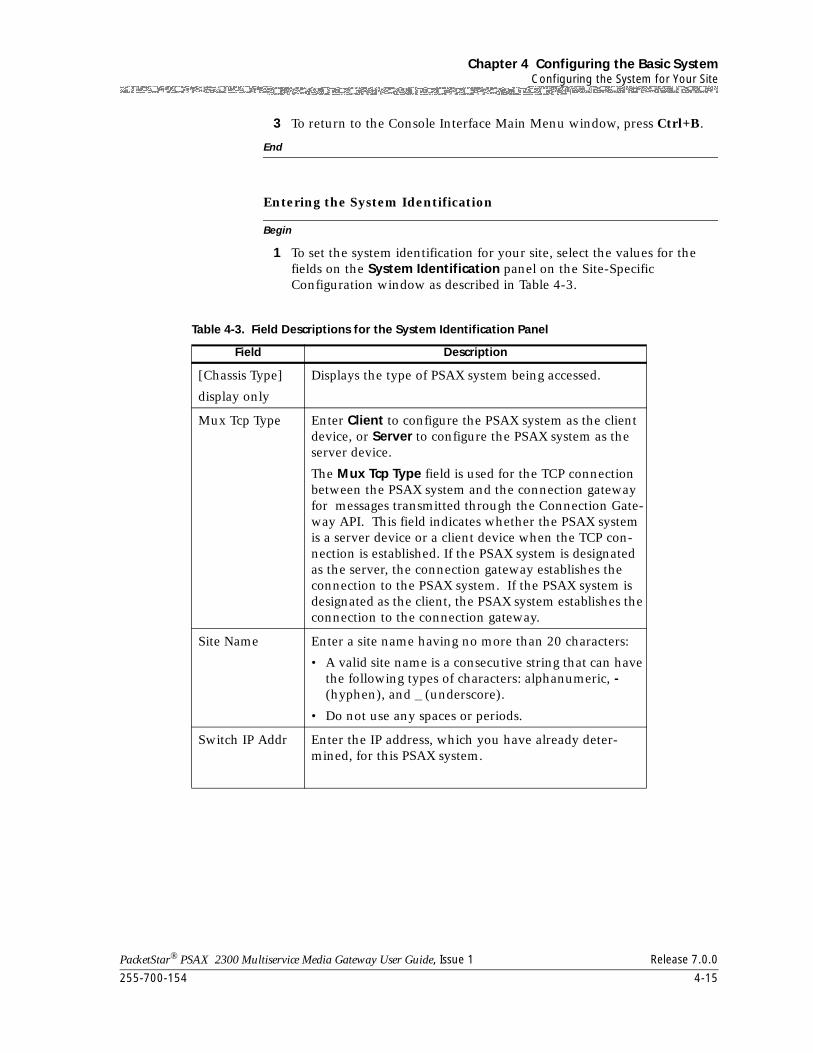
255-700-154 4-15
PacketStar® PSAX 2300 Multiservice Media Gateway User Guide, Issue 1 Release 7.0.0
Chapter 4 Configuring the Basic SystemConfiguring the System for Your Site
3 To return to the Console Interface Main Menu window, press Ctrl+B.
End
Begin
Entering the System Identification
1 To set the system identification for your site, select the values for the fields on the System Identification panel on the Site-Specific Configuration window as described in Table 4-3.
Table 4-3. Field Descriptions for the System Identification Panel
Field Description
[Chassis Type]
display only
Displays the type of PSAX system being accessed.
Mux Tcp Type Enter Client to configure the PSAX system as the client device, or Server to configure the PSAX system as the server device.
The Mux Tcp Type field is used for the TCP connection between the PSAX system and the connection gateway for messages transmitted through the Connection Gate-way API. This field indicates whether the PSAX system is a server device or a client device when the TCP con-nection is established. If the PSAX system is designated as the server, the connection gateway establishes the connection to the PSAX system. If the PSAX system is designated as the client, the PSAX system establishes the connection to the connection gateway.
Site Name Enter a site name having no more than 20 characters:
• A valid site name is a consecutive string that can have the following types of characters: alphanumeric, - (hyphen), and _ (underscore).
• Do not use any spaces or periods.
Switch IP Addr Enter the IP address, which you have already deter-mined, for this PSAX system.
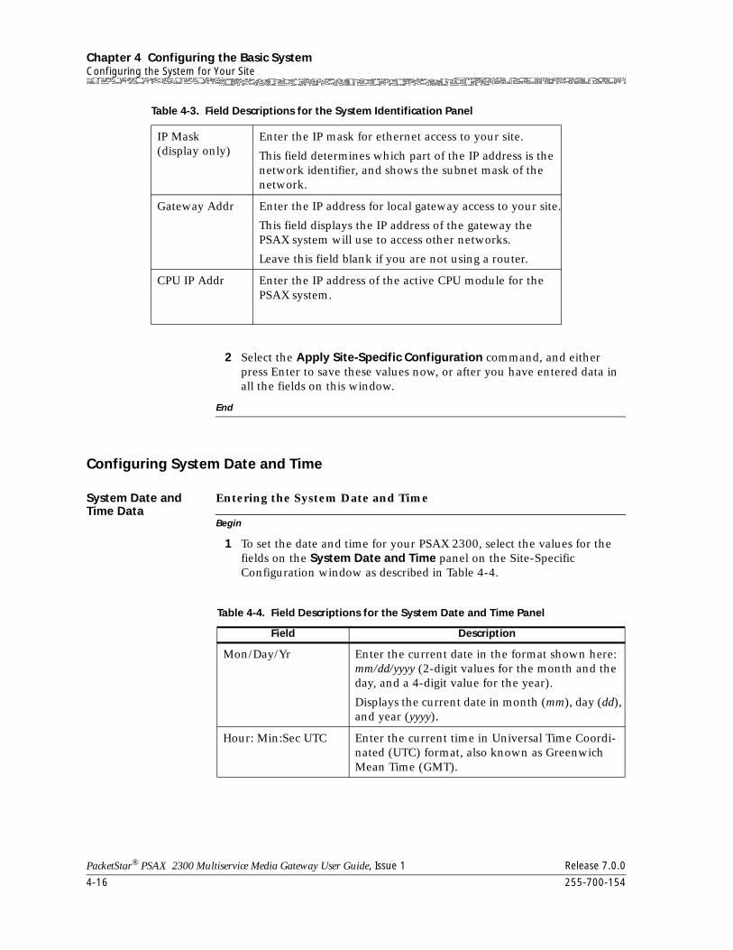
Chapter 4 Configuring the Basic SystemConfiguring the System for Your Site
4-16 255-700-154
PacketStar® PSAX 2300 Multiservice Media Gateway User Guide, Issue 1 Release 7.0.0
2 Select the Apply Site-Specific Configuration command, and either press Enter to save these values now, or after you have entered data in all the fields on this window.
End
Configuring System Date and Time
System Date and Time Data
Begin
Entering the System Date and Time
1 To set the date and time for your PSAX 2300, select the values for the fields on the System Date and Time panel on the Site-Specific Configuration window as described in Table 4-4.
IP Mask(display only)
Enter the IP mask for ethernet access to your site.
This field determines which part of the IP address is the network identifier, and shows the subnet mask of the network.
Gateway Addr Enter the IP address for local gateway access to your site.
This field displays the IP address of the gateway the PSAX system will use to access other networks.
Leave this field blank if you are not using a router.
CPU IP Addr Enter the IP address of the active CPU module for the PSAX system.
Table 4-3. Field Descriptions for the System Identification Panel
Table 4-4. Field Descriptions for the System Date and Time Panel
Field Description
Mon/Day/Yr Enter the current date in the format shown here: mm/dd/yyyy (2-digit values for the month and the day, and a 4-digit value for the year).
Displays the current date in month (mm), day (dd), and year (yyyy).
Hour: Min:Sec UTC Enter the current time in Universal Time Coordi-nated (UTC) format, also known as Greenwich Mean Time (GMT).
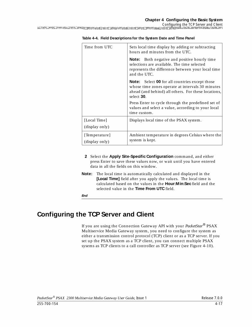
255-700-154 4-17
PacketStar® PSAX 2300 Multiservice Media Gateway User Guide, Issue 1 Release 7.0.0
Chapter 4 Configuring the Basic SystemConfiguring the TCP Server and Client
2 Select the Apply Site-Specific Configuration command, and either press Enter to save these values now, or wait until you have entered data in all the fields on this window.
Note: The local time is automatically calculated and displayed in the [Local Time] field after you apply the values. The local time is calculated based on the values in the Hour:Min:Sec field and the selected value in the Time From UTC field.
End
Configuring the TCP Server and Client
If you are using the Connection Gateway API with your PacketStar® PSAX Multiservice Media Gateway system, you need to configure the system as either a transmission control protocol (TCP) client or as a TCP server. If you set up the PSAX system as a TCP client, you can connect multiple PSAX sysems as TCP clients to a call controller as TCP server (see Figure 4-10).
Time from UTC Sets local time display by adding or subtracting hours and minutes from the UTC.
Note: Both negative and positive hourly time selections are available. The time selected represents the difference between your local time and the UTC.
Note: Select 00 for all countries except those whose time zones operate at intervals 30 minutes ahead (and behind) all others. For these locations, select 30.
Press Enter to cycle through the predefined set of values and select a value, according to your local time custom.
[Local Time]
(display only)
Displays local time of the PSAX system.
[Temperature]
(display only)
Ambient temperature in degrees Celsius where the system is kept.
Table 4-4. Field Descriptions for the System Date and Time Panel
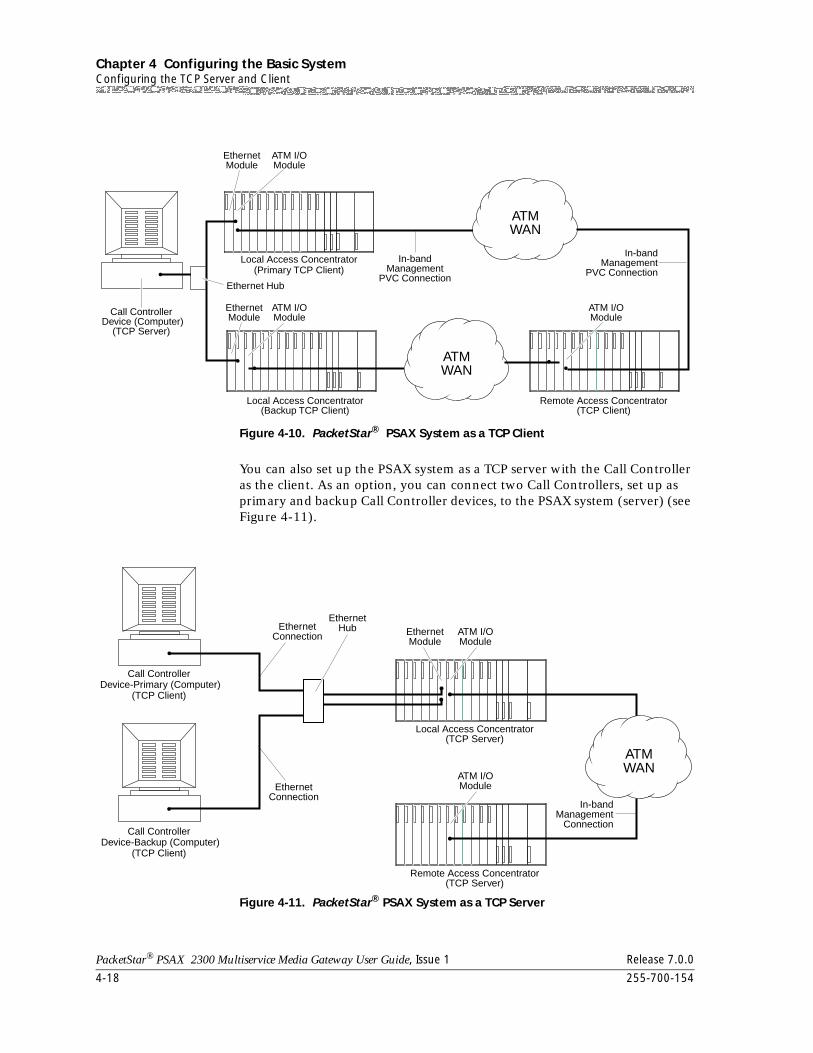
Chapter 4 Configuring the Basic SystemConfiguring the TCP Server and Client
4-18 255-700-154
PacketStar® PSAX 2300 Multiservice Media Gateway User Guide, Issue 1 Release 7.0.0
You can also set up the PSAX system as a TCP server with the Call Controller as the client. As an option, you can connect two Call Controllers, set up as primary and backup Call Controller devices, to the PSAX system (server) (see Figure 4-11).
Figure 4-10. PacketStar® PSAX System as a TCP Client
Figure 4-11. PacketStar® PSAX System as a TCP Server
In-bandManagement
PVC Connection
Local Access Concentrator(Primary TCP Client)
Call Controller Device (Computer)
(TCP Server)
ATM I/OModule
EthernetModule
Ethernet Hub
ATM I/OModule
Remote Access Concentrator(TCP Client)
ATM I/OModule
Local Access Concentrator(Backup TCP Client)
In-bandManagement
PVC Connection
EthernetModule
ATMWAN
ATMWAN
Call Controller Device-Primary (Computer)
(TCP Client)
Call Controller Device-Backup (Computer)
(TCP Client)
EthernetConnection
EthernetHub
EthernetConnection
EthernetModule
ATM I/OModule
Local Access Concentrator(TCP Server)
ATM I/OModule
Remote Access Concentrator(TCP Server)
ATMWAN
In-bandManagement
Connection
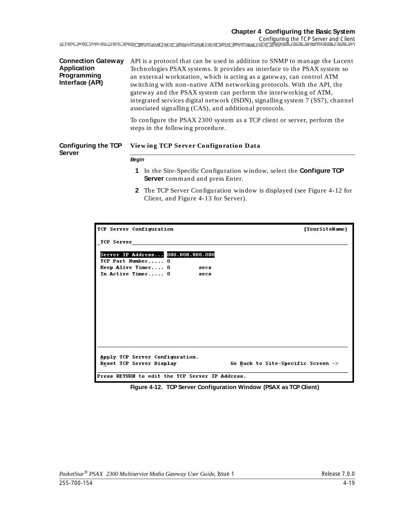
255-700-154 4-19
PacketStar® PSAX 2300 Multiservice Media Gateway User Guide, Issue 1 Release 7.0.0
Chapter 4 Configuring the Basic SystemConfiguring the TCP Server and Client
Connection Gateway Application Programming Interface (API)
API is a protocol that can be used in addition to SNMP to manage the Lucent Technologies PSAX systems. It provides an interface to the PSAX system so an external workstation, which is acting as a gateway, can control ATM switching with non-native ATM networking protocols. With the API, the gateway and the PSAX system can perform the interworking of ATM, integrated services digital network (ISDN), signalling system 7 (SS7), channel associated signalling (CAS), and additional protocols.
To configure the PSAX 2300 system as a TCP client or server, perform the steps in the following procedure.
Configuring the TCP Server
Begin
Viewing TCP Server Configuration Data
1 In the Site-Specific Configuration window, select the Configure TCP Server command and press Enter.
2 The TCP Server Configuration window is displayed (see Figure 4-12 for Client, and Figure 4-13 for Server).
Figure 4-12. TCP Server Configuration Window (PSAX as TCP Client)
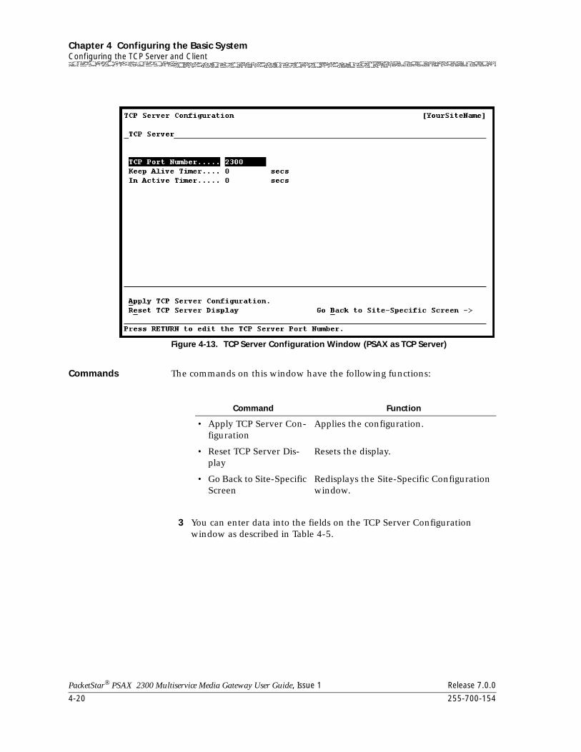
Chapter 4 Configuring the Basic SystemConfiguring the TCP Server and Client
4-20 255-700-154
PacketStar® PSAX 2300 Multiservice Media Gateway User Guide, Issue 1 Release 7.0.0
Commands The commands on this window have the following functions:
3 You can enter data into the fields on the TCP Server Configuration window as described in Table 4-5.
Figure 4-13. TCP Server Configuration Window (PSAX as TCP Server)
Command Function
• Apply TCP Server Con-figuration
Applies the configuration.
• Reset TCP Server Dis-play
Resets the display.
• Go Back to Site-Specific Screen
Redisplays the Site-Specific Configuration window.
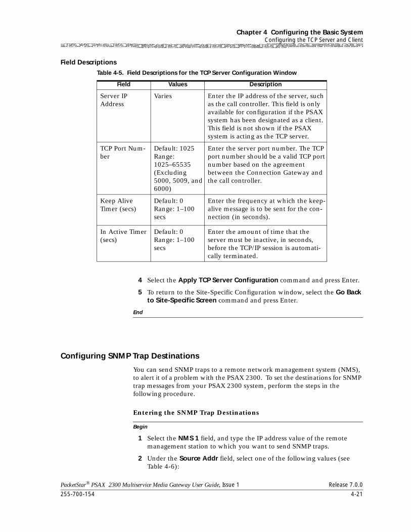
255-700-154 4-21
PacketStar® PSAX 2300 Multiservice Media Gateway User Guide, Issue 1 Release 7.0.0
Chapter 4 Configuring the Basic SystemConfiguring the TCP Server and Client
Field Descriptions
4 Select the Apply TCP Server Configuration command and press Enter.
5 To return to the Site-Specific Configuration window, select the Go Back to Site-Specific Screen command and press Enter.
End
Configuring SNMP Trap Destinations
You can send SNMP traps to a remote network management system (NMS), to alert it of a problem with the PSAX 2300. To set the destinations for SNMP trap messages from your PSAX 2300 system, perform the steps in the following procedure.
Begin
Entering the SNMP Trap Destinations
1 Select the NMS 1 field, and type the IP address value of the remote management station to which you want to send SNMP traps.
2 Under the Source Addr field, select one of the following values (see Table 4-6):
Table 4-5. Field Descriptions for the TCP Server Configuration Window
Field Values Description
Server IP Address
Varies Enter the IP address of the server, such as the call controller. This field is only available for configuration if the PSAX system has been designated as a client. This field is not shown if the PSAX system is acting as the TCP server.
TCP Port Num-ber
Default: 1025Range: 1025–65535 (Excluding 5000, 5009, and 6000)
Enter the server port number. The TCP port number should be a valid TCP port number based on the agreement between the Connection Gateway and the call controller.
Keep Alive Timer (secs)
Default: 0Range: 1–100 secs
Enter the frequency at which the keep-alive message is to be sent for the con-nection (in seconds).
In Active Timer (secs)
Default: 0Range: 1–100 secs
Enter the amount of time that the server must be inactive, in seconds, before the TCP/IP session is automati-cally terminated.
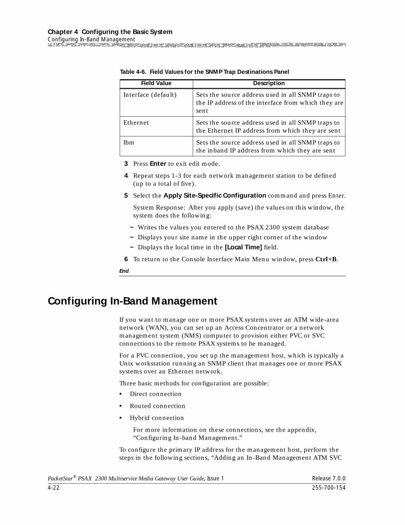
Chapter 4 Configuring the Basic SystemConfiguring In-Band Management
4-22 255-700-154
PacketStar® PSAX 2300 Multiservice Media Gateway User Guide, Issue 1 Release 7.0.0
3 Press Enter to exit edit mode.
4 Repeat steps 1-3 for each network management station to be defined (up to a total of five).
5 Select the Apply Site-Specific Configuration command and press Enter.
System Response: After you apply (save) the values on this window, the system does the following:
~ Writes the values you entered to the PSAX 2300 system database
~ Displays your site name in the upper right corner of the window
~ Displays the local time in the [Local Time] field.
6 To return to the Console Interface Main Menu window, press Ctrl+B.
End
Configuring In-Band Management
If you want to manage one or more PSAX systems over an ATM wide-area network (WAN), you can set up an Access Concentrator or a network management system (NMS) computer to provision either PVC or SVC connections to the remote PSAX systems to be managed.
For a PVC connection, you set up the management host, which is typically a Unix workstation running an SNMP client that manages one or more PSAX systems over an Ethernet network.
Three basic methods for configuration are possible:
• Direct connection
• Routed connection
• Hybrid connection
For more information on these connections, see the appendix, “Configuring In-band Management.”
To configure the primary IP address for the management host, perform the steps in the following sections, “Adding an In-Band Management ATM SVC
Table 4-6. Field Values for the SNMP Trap Destinations Panel
Field Value Description
Interface (default) Sets the source address used in all SNMP traps to the IP address of the interface from which they are sent
Ethernet Sets the source address used in all SNMP traps to the Ethernet IP address from which they are sent
Ibm Sets the source address used in all SNMP traps to the inband IP address from which they are sent
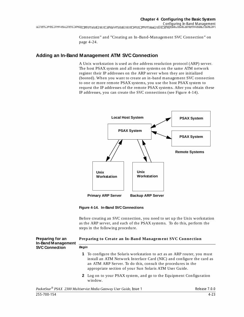
255-700-154 4-23
PacketStar® PSAX 2300 Multiservice Media Gateway User Guide, Issue 1 Release 7.0.0
Chapter 4 Configuring the Basic SystemConfiguring In-Band Management
Connection” and ”Creating an In-Band-Management SVC Connection” on page 4-24.
Adding an In-Band Management ATM SVC Connection
A Unix workstation is used as the address resolution protocol (ARP) server. The host PSAX system and all remote systems on the same ATM network register their IP addresses on the ARP server when they are initialized (booted). When you want to create an in-band management SVC connection to one or more remote PSAX systems, you use the host PSAX system to request the IP addresses of the remote PSAX systems. After you obtain these IP addresses, you can create the SVC connections (see Figure 4-14).
Before creating an SVC connection, you need to set up the Unix workstation as the ARP server, and each of the PSAX systems. To do this, perform the steps in the following procedure.
Preparing for an In-Band Management SVC Connection Begin
Preparing to Create an In-Band Management SVC Connection
1 To configure the Solaris workstation to act as an ARP router, you must install an ATM Network Interface Card (NIC) and configure the card as an ATM ARP Server. To do this, consult the procedures in the appropriate section of your Sun Solaris ATM User Guide.
2 Log on to your PSAX system, and go to the Equipment Configuration window.
Figure 4-14. In-Band SVC Connections
Unix Unix
PSAX System
PSAX System
Primary ARP Server Backup ARP Server
Local Host System
Remote Systems
PSAX System
Workstation Workstation
Chapter 4 Configuring the Basic SystemConfiguring In-Band Management
4-24 255-700-154
PacketStar® PSAX 2300 Multiservice Media Gateway User Guide, Issue 1 Release 7.0.0
3 In the Equipment Configuration window, select the module you will use. The OC-3c module is the most often used I/O module for this connection.
4 Configure the OC-3c module (or the module you have selected) for Interface Type ATMUNI 3.1 and select Apply Port and Channel Configuration.
5 Select Configure the Interface.
6 On the ATM UNI 3.1 Configuration window, in the ATM Signaling field, select Enabled. In the Interface Type field, select Network.
7 Enter the Address Prefix. This is the Address Prefix of the node address of the OC-3c module.
8 Configure the ILMI interface. (This is an optional step, but strongly recommended.)
9 On the ILMI Configuration window enable ILMI Protocol, Address Registration, and Connectivity Procedure.
10 Select Apply ILMI Configuration, and Go Back to Previous Screen.
11 Check the ILMI Register User Address window to see that the address has been created, and return to the Main Menu.
12 From the Site-Specific Menu, select PNNI System-Wide Configuration.
13 Select Create a Node and follow the instructions in the "PNNI System-Wide Configuration" section in this chapter.
14 Return to the Site-Specific window to create the In-Band SVC Connection.
End
An in-band management SVC connection can be created between a configured in-band management address and any module that supports ATM interfaces. This connection supports the UBR and VBR-express service types.
Creating an In-Band-Management SVC Connection
Perform the steps in the following procedure to create an in-band management SVC connection.
Begin
Creating an In-Band Management SVC Connection
1 From the Console Interface Main Menu, select Site Specific Configuration.
The Site Specific window is displayed (see Figure 4-15).
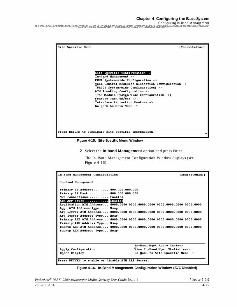
255-700-154 4-25
PacketStar® PSAX 2300 Multiservice Media Gateway User Guide, Issue 1 Release 7.0.0
Chapter 4 Configuring the Basic SystemConfiguring In-Band Management
2 Select the In-band Management option and press Enter.
The In-Band Management Configuration Window displays (see Figure 4-16).
Figure 4-15. Site-Specific Menu Window
Figure 4-16. In-Band Management Configuration Window (SVC Disabled)
Chapter 4 Configuring the Basic SystemConfiguring In-Band Management
4-26 255-700-154
PacketStar® PSAX 2300 Multiservice Media Gateway User Guide, Issue 1 Release 7.0.0
Commands The commands on this window have the following functions:
3 In the In-Band Management Configuration window, enter the IP address and IP Mask for the PSAX device.
Note: This address must be on a different subnet from the subnet that is assigned to the Ethernet interface for the management host.
4 In the SVC Connections field, select Enabled.
The In-Band Management Configuration Window with SVC enabled displays (see Figure 4-17 ).
Command Function
• Apply Configuration Applies the configuration.
• Reset Display Resets the display.
• In-Band Mgmt Route Table
Displays the In-Band Mgmt Route Table.
This button is ghosted if Disabled is selected in the ATM ARP Server field, and active if Enabled is selected in the ATM ARP Server field.
• View In-Band Mgmt Statistics
Displays the In-Band Mgmt Statistics win-dow.
• Go Back to Site-Specific Menu
Redisplays the Site-Specific Menu win-dow.
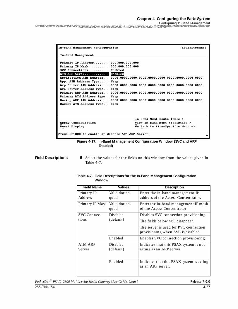
255-700-154 4-27
PacketStar® PSAX 2300 Multiservice Media Gateway User Guide, Issue 1 Release 7.0.0
Chapter 4 Configuring the Basic SystemConfiguring In-Band Management
Field Descriptions 5 Select the values for the fields on this window from the values given in Table 4-7.
Figure 4-17. In-Band Management Configuration Window (SVC and ARP Enabled)
Table 4-7. Field Descriptions for the In-Band Management Configuration Window
Field Name Values Description
Primary IP Address
Valid dotted-quad
Enter the in-band management IP address of the Access Concentrator.
Primary IP Mask Valid dotted-quad
Enter the in-band management IP mask of the Access Concentrator
SVC Connec-tions
Disabled (default)
Disables SVC connection provisioning.
The fields below will disappear.
The server is used for PVC connection provisioning when SVC is disabled.
Enabled Enables SVC connection provisioning.
ATM ARP Server
Disabled (default)
Indicates that this PSAX system is not acting as an ARP server.
Enabled Indicates that this PSAX system is acting as an ARP server.
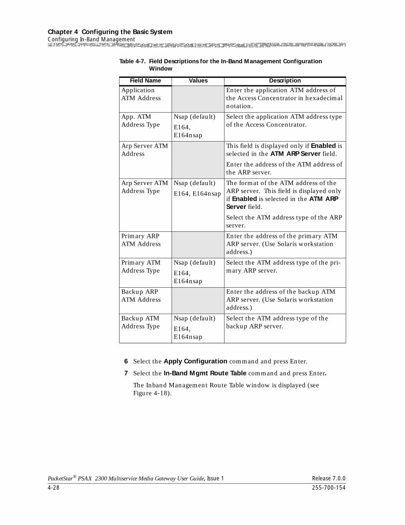
Chapter 4 Configuring the Basic SystemConfiguring In-Band Management
4-28 255-700-154
PacketStar® PSAX 2300 Multiservice Media Gateway User Guide, Issue 1 Release 7.0.0
6 Select the Apply Configuration command and press Enter.
7 Select the In-Band Mgmt Route Table command and press Enter.
The Inband Management Route Table window is displayed (see Figure 4-18).
Application ATM Address
Enter the application ATM address of the Access Concentrator in hexadecimal notation.
App. ATM Address Type
Nsap (default)
E164, E164nsap
Select the application ATM address type of the Access Concentrator.
Arp Server ATM Address
This field is displayed only if Enabled is selected in the ATM ARP Server field.
Enter the address of the ATM address of the ARP server.
Arp Server ATM Address Type
Nsap (default)
E164, E164nsap
The format of the ATM address of the ARP server. This field is displayed only if Enabled is selected in the ATM ARP Server field.
Select the ATM address type of the ARP server.
Primary ARP ATM Address
Enter the address of the primary ATM ARP server. (Use Solaris workstation address.)
Primary ATM Address Type
Nsap (default)
E164, E164nsap
Select the ATM address type of the pri-mary ARP server.
Backup ARP ATM Address
Enter the address of the backup ATM ARP server. (Use Solaris workstation address.)
Backup ATM Address Type
Nsap (default)
E164, E164nsap
Select the ATM address type of the backup ARP server.
Table 4-7. Field Descriptions for the In-Band Management Configuration Window
Field Name Values Description
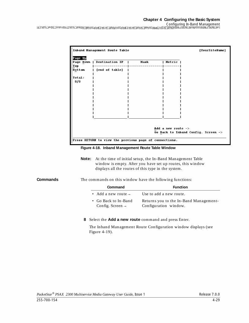
255-700-154 4-29
PacketStar® PSAX 2300 Multiservice Media Gateway User Guide, Issue 1 Release 7.0.0
Chapter 4 Configuring the Basic SystemConfiguring In-Band Management
Note: At the time of initial setup, the In-Band Management Table window is empty. After you have set up routes, this window displays all the routes of this type in the system.
Commands The commands on this window have the following functions:
8 Select the Add a new route command and press Enter.
The Inband Management Route Configuration window displays (see Figure 4-19).
Figure 4-18. Inband Management Route Table Window
Command Function
• Add a new route→ Use to add a new route.
• Go Back to In-Band Config. Screen→
Returns you to the In-Band Management-Configuration window.
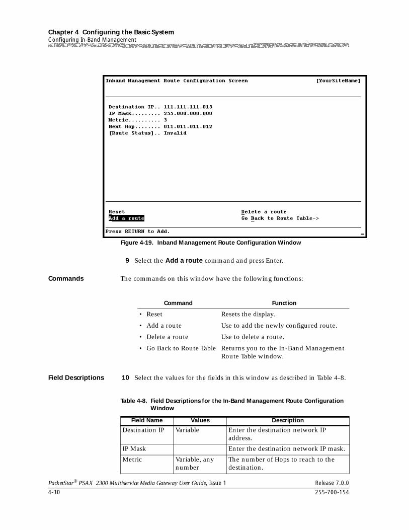
Chapter 4 Configuring the Basic SystemConfiguring In-Band Management
4-30 255-700-154
PacketStar® PSAX 2300 Multiservice Media Gateway User Guide, Issue 1 Release 7.0.0
9 Select the Add a route command and press Enter.
Commands The commands on this window have the following functions:
Field Descriptions 10 Select the values for the fields in this window as described in Table 4-8.
Figure 4-19. Inband Management Route Configuration Window
Command Function
• Reset Resets the display.
• Add a route Use to add the newly configured route.
• Delete a route Use to delete a route.
• Go Back to Route Table Returns you to the In-Band Management Route Table window.
Table 4-8. Field Descriptions for the In-Band Management Route Configuration Window
Field Name Values Description
Destination IP Variable Enter the destination network IP address.
IP Mask Enter the destination network IP mask.
Metric Variable, any number
The number of Hops to reach to the destination.
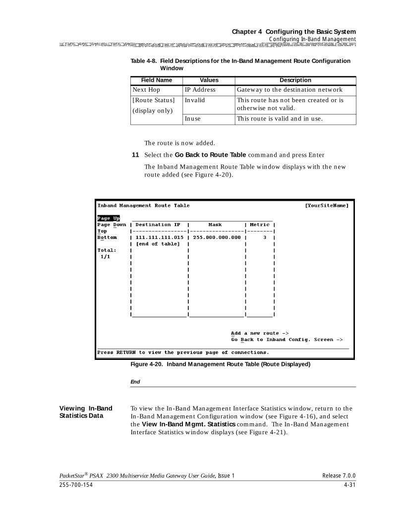
255-700-154 4-31
PacketStar® PSAX 2300 Multiservice Media Gateway User Guide, Issue 1 Release 7.0.0
Chapter 4 Configuring the Basic SystemConfiguring In-Band Management
The route is now added.
11 Select the Go Back to Route Table command and press Enter
The Inband Management Route Table window displays with the new route added (see Figure 4-20).
End
Viewing In-Band Statistics Data
To view the In-Band Management Interface Statistics window, return to the In-Band Management Configuration window (see Figure 4-16), and select the View In-Band Mgmt. Statistics command. The In-Band Management Interface Statistics window displays (see Figure 4-21).
Next Hop IP Address Gateway to the destination network
[Route Status]
(display only)
Invalid This route has not been created or is otherwise not valid.
Inuse This route is valid and in use.
Figure 4-20. Inband Management Route Table (Route Displayed)
Table 4-8. Field Descriptions for the In-Band Management Route Configuration Window
Field Name Values Description
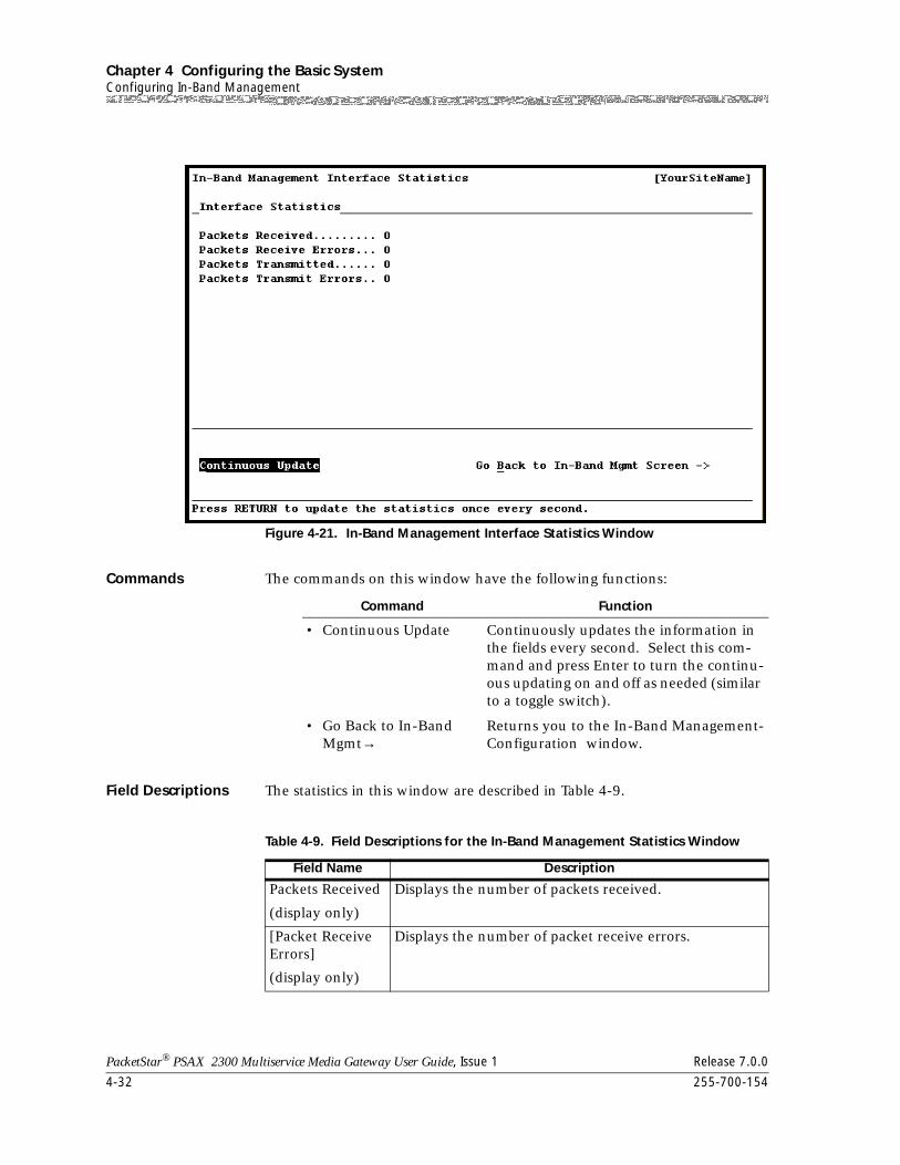
Chapter 4 Configuring the Basic SystemConfiguring In-Band Management
4-32 255-700-154
PacketStar® PSAX 2300 Multiservice Media Gateway User Guide, Issue 1 Release 7.0.0
Commands The commands on this window have the following functions:
Field Descriptions The statistics in this window are described in Table 4-9.
Figure 4-21. In-Band Management Interface Statistics Window
Command Function
• Continuous Update Continuously updates the information in the fields every second. Select this com-mand and press Enter to turn the continu-ous updating on and off as needed (similar to a toggle switch).
• Go Back to In-Band Mgmt→
Returns you to the In-Band Management-Configuration window.
Table 4-9. Field Descriptions for the In-Band Management Statistics Window
Field Name Description
Packets Received
(display only)
Displays the number of packets received.
[Packet Receive Errors]
(display only)
Displays the number of packet receive errors.
255-700-154 4-33
PacketStar® PSAX 2300 Multiservice Media Gateway User Guide, Issue 1 Release 7.0.0
Chapter 4 Configuring the Basic SystemPNNI System-Wide Configuration
Deleting an In-Band Management SVC Route
Perform the steps in the following procedure to delete an In-Band SVC route.
Begin
Deleting an In-Band SVC Route
1 In the Inband Management Route Configuration window (see Figure 4-18 on page 4-29), select the Delete a route command and press Enter.
2 Select the Go Back to Route Table command to check that the Inband Management Route Table (see Figure 4-19 on page 4-30) does not contain the route you just deleted.
End
PNNI System-Wide Configuration
For an overview of PNNI and the PNNI features supported on the PSAX 2300 system, see the section about PNNI in Chapter 3.
To configure a PNNI node for your PSAX 2300 system, perform the steps in the following procedure.
Note: Before you can configure an I/O module with the ATM PNNI 1.0 interface, you must configure PNNI for your PSAX 2300 system.
Configuring PNNI
Begin
PNNI System-Wide Configuration
1 At the Console Interface Main Menu, select Site-Specific Configuration.
2 On the Site-Specific Menu, select PNNI System-Wide Configuration.
The PNNI System-Wide Configuration window is displayed (see Figure 4-22).
Packets Transmit-ted
(display only)
Displays the number of packets transmitted.
Packet Transmit Errors
(display only)
Displays the number of packet transmit errors.
Table 4-9. Field Descriptions for the In-Band Management Statistics Window
Field Name Description
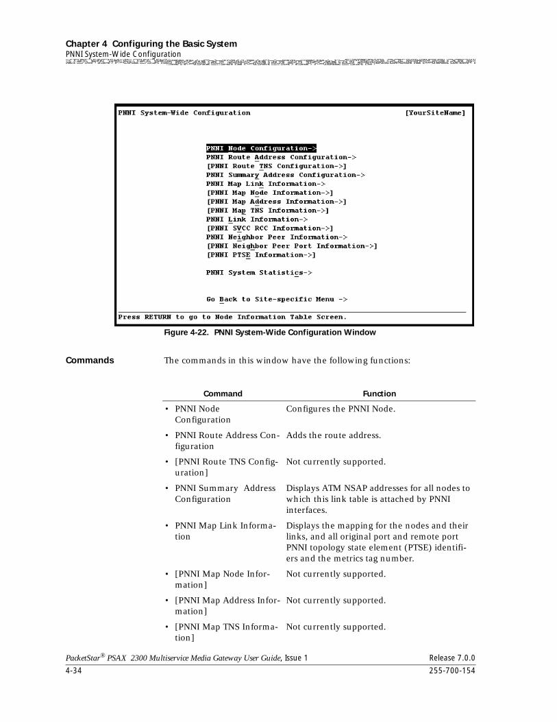
Chapter 4 Configuring the Basic SystemPNNI System-Wide Configuration
4-34 255-700-154
PacketStar® PSAX 2300 Multiservice Media Gateway User Guide, Issue 1 Release 7.0.0
Commands The commands in this window have the following functions:
Figure 4-22. PNNI System-Wide Configuration Window
Command Function
• PNNI Node Configuration
Configures the PNNI Node.
• PNNI Route Address Con-figuration
Adds the route address.
• [PNNI Route TNS Config-uration]
Not currently supported.
• PNNI Summary Address Configuration
Displays ATM NSAP addresses for all nodes to which this link table is attached by PNNI interfaces.
• PNNI Map Link Informa-tion
Displays the mapping for the nodes and their links, and all original port and remote port PNNI topology state element (PTSE) identifi-ers and the metrics tag number.
• [PNNI Map Node Infor-mation]
Not currently supported.
• [PNNI Map Address Infor-mation]
Not currently supported.
• [PNNI Map TNS Informa-tion]
Not currently supported.
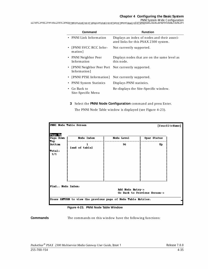
255-700-154 4-35
PacketStar® PSAX 2300 Multiservice Media Gateway User Guide, Issue 1 Release 7.0.0
Chapter 4 Configuring the Basic SystemPNNI System-Wide Configuration
3 Select the PNNI Node Configuration command and press Enter.
The PNNI Node Table window is displayed (see Figure 4-23).
Commands The commands on this window have the following functions:
• PNNI Link Information Displays an index of nodes and their associ-ated links for this PSAX 2300 system.
• [PNNI SVCC RCC Infor-mation]
Not currently supported.
• PNNI Neighbor Peer Information
Displays nodes that are on the same level as this node.
• [PNNI Neighbor Peer Port Information]
Not currently supported.
• [PNNI PTSE Information] Not currently supported.
• PNNI System Statistics Displays PNNI statistics.
• Go Back to Site-Specific Menu
Re-displays the Site-Specific window.
Figure 4-23. PNNI Node Table Window
Command Function
Chapter 4 Configuring the Basic SystemPNNI System-Wide Configuration
4-36 255-700-154
PacketStar® PSAX 2300 Multiservice Media Gateway User Guide, Issue 1 Release 7.0.0
The display fields on this window have the following values:
Field Descriptions
4 Select Add Node Entry and press Enter.
The PNNI Node Configuration window is displayed (see Figure 4-24).
Command Function
• Page Up Scroll up one page.
• Page Down Scrolls down one page.
• Top Displays entries at the top of the table.
• Bottom Displays entries at the bottom of the table.
• Find Node Index Displays default five-number value on the Node Table window.
• Add Node Entry Adds only one node entry in the PSAX sys-tem.
• Go Back to Previous Screen
Redisplays the PNNI System-Wide configura-tion window.
Table 4-10. Field Descriptions for the PNNI Node Table Window
Field Description
• Total: 0/0 The first number in this field indicates the identification number of the connection table entry on the first line of the currently dis-played window. The second number indicates the total number of connection table entries for this connection type.
• For more information on the values in the display columns below, see the Field Description Table for the PNNI Node Configuration Screen.
• Node Index Displays default five-number value on the Node Table window. Identifies a logical PNNI entity in the PSAX system.
• Node Level Number of significant bits in the network por-tion of the ATM address on the PSAX system.
• Oper Status Node is either up or down
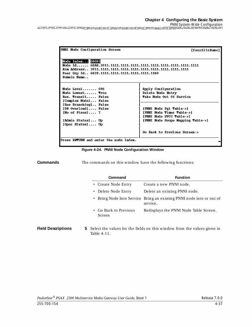
255-700-154 4-37
PacketStar® PSAX 2300 Multiservice Media Gateway User Guide, Issue 1 Release 7.0.0
Chapter 4 Configuring the Basic SystemPNNI System-Wide Configuration
Commands The commands on this window have the following functions:
Field Descriptions 5 Select the values for the fields on this window from the values given in Table 4-11.
Figure 4-24. PNNI Node Configuration Window
Command Function
• Create Node Entry Create a new PNNI node.
• Delete Node Entry Delete an existing PNNI node.
• Bring Node Into Service Bring an existing PNNI node into or out of service.
• Go Back to Previous Screen
Redisplays the PNNI Node Table Screen.
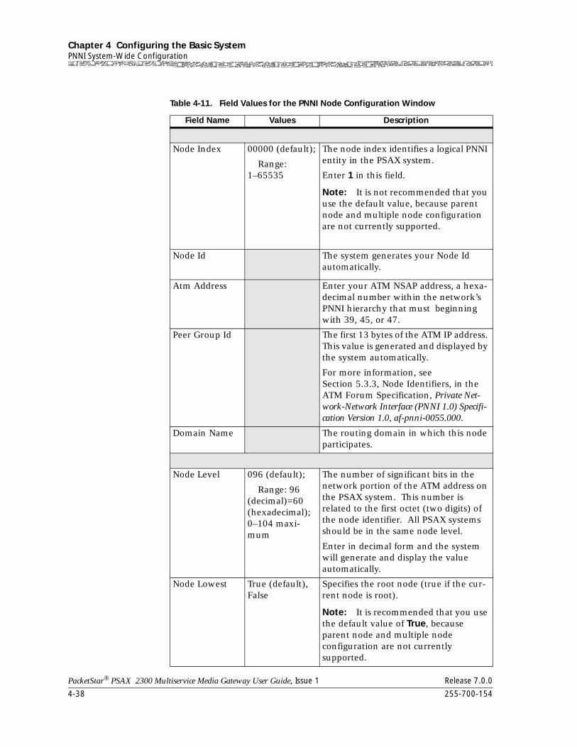
Chapter 4 Configuring the Basic SystemPNNI System-Wide Configuration
4-38 255-700-154
PacketStar® PSAX 2300 Multiservice Media Gateway User Guide, Issue 1 Release 7.0.0
Table 4-11. Field Values for the PNNI Node Configuration Window
Field Name Values Description
Node Index 00000 (default);
Range: 1–65535
The node index identifies a logical PNNI entity in the PSAX system.
Enter 1 in this field.
Note: It is not recommended that you use the default value, because parent node and multiple node configuration are not currently supported.
Node Id The system generates your Node Id automatically.
Atm Address Enter your ATM NSAP address, a hexa-decimal number within the network’s PNNI hierarchy that must beginning with 39, 45, or 47.
Peer Group Id The first 13 bytes of the ATM IP address. This value is generated and displayed by the system automatically.
For more information, see Section 5.3.3, Node Identifiers, in the ATM Forum Specification, Private Net-work-Network Interface (PNNI 1.0) Specifi-cation Version 1.0, af-pnni-0055.000.
Domain Name The routing domain in which this node participates.
Node Level 096 (default);
Range: 96 (decimal)=60 (hexadecimal); 0–104 maxi-mum
The number of significant bits in the network portion of the ATM address on the PSAX system. This number is related to the first octet (two digits) of the node identifier. All PSAX systems should be in the same node level.
Enter in decimal form and the system will generate and display the value automatically.
Node Lowest True (default), False
Specifies the root node (true if the cur-rent node is root).
Note: It is recommended that you use the default value of True, because parent node and multiple node configuration are not currently supported.
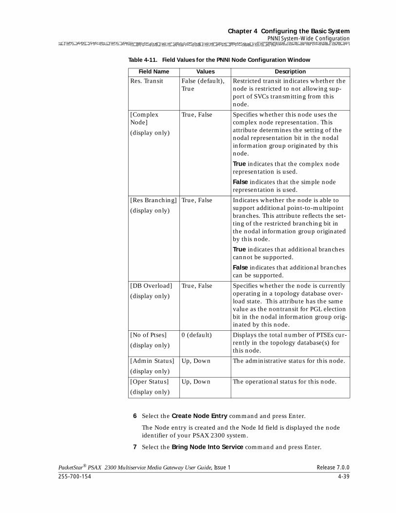
255-700-154 4-39
PacketStar® PSAX 2300 Multiservice Media Gateway User Guide, Issue 1 Release 7.0.0
Chapter 4 Configuring the Basic SystemPNNI System-Wide Configuration
6 Select the Create Node Entry command and press Enter.
The Node entry is created and the Node Id field is displayed the node identifier of your PSAX 2300 system.
7 Select the Bring Node Into Service command and press Enter.
Res. Transit False (default), True
Restricted transit indicates whether the node is restricted to not allowing sup-port of SVCs transmitting from this node.
[Complex Node]
(display only)
True, False Specifies whether this node uses the complex node representation. This attribute determines the setting of the nodal representation bit in the nodal information group originated by this node.
True indicates that the complex node representation is used.
False indicates that the simple node representation is used.
[Res Branching]
(display only)
True, False Indicates whether the node is able to support additional point-to-multipoint branches. This attribute reflects the set-ting of the restricted branching bit in the nodal information group originated by this node.
True indicates that additional branches cannot be supported.
False indicates that additional branches can be supported.
[DB Overload]
(display only)
True, False Specifies whether the node is currently operating in a topology database over-load state. This attribute has the same value as the nontransit for PGL election bit in the nodal information group orig-inated by this node.
[No of Ptses]
(display only)
0 (default) Displays the total number of PTSEs cur-rently in the topology database(s) for this node.
[Admin Status]
(display only)
Up, Down The administrative status for this node.
[Oper Status]
(display only)
Up, Down The operational status for this node.
Table 4-11. Field Values for the PNNI Node Configuration Window
Field Name Values Description
Chapter 4 Configuring the Basic SystemPNNI System-Wide Configuration
4-40 255-700-154
PacketStar® PSAX 2300 Multiservice Media Gateway User Guide, Issue 1 Release 7.0.0
The OperStatus display field indicates that the node is up.
Note: You must bring the node into service to enable PNNI support on your PSAX 2300 system. The ATM PNNI interface cannot be brought into service until a PNNI node is created and in service. If you need to take the node out of service, you must first delete any ATM PNNI interfaces you have configured on your PSAX 2300 system.
8 Select the Go Back to Previous Screen command and press Enter.
The PNNI Node Table Screen (see Figure 4-23) is displayed, showing your current node index, node level, and operating status. Use this screen to check a node’s status whenever you create, delete, or bring a node into service.
9 Press Ctrl+G to go back to the Console Interface Main Menu window.
10 Select the Equipment Configuration option and press Enter.
The Equipment Configuration window is displayed.
11 Select an I/O module that supports the ATM PNNI 1.0 interface type.
The Port and Channel Configuration window is displayed.
12 In the Interface Type field, select AtmPnni1-0.
The ATM PNNI 1.0 Interface Configuration window is displayed.
13 Configure the fields for this interface as described in the appropriate PacketStar™ Module User Guide.
14 Select the Apply Configuration command and press Enter.
15 Select the Bring Interface Into Service command and press Enter.
16 Type Ctrl+G to return to the Console Interface Main Menu window.
End
The PNNI node you just configured has been brought into service. At this time, you can select a route address using the PNNI System-Wide Configuration window. The following procedure is not necessary to follow unless you want to advertise the reachable addresses that the system cannot learn or automatically detect. The Route Address table displays the rachable addresses and other information that the PSAX 2300 system learns from other switches in the same network as the PSAX 2300 system.
Configuring PNNI Route Addresses
Begin
Steps for Configuring PNNI Route Addresses
Note: If you are configuring an SPVC as ActiveSvc, do not configure a route address. If you configuring an SPVC as PassiveSvc, configure a route address.
1 Select the Site-Specific Configuration option, and press Enter.
The Site-Specific Menu is displayed.
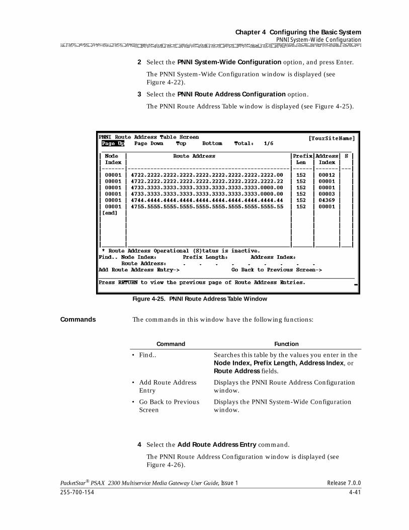
255-700-154 4-41
PacketStar® PSAX 2300 Multiservice Media Gateway User Guide, Issue 1 Release 7.0.0
Chapter 4 Configuring the Basic SystemPNNI System-Wide Configuration
2 Select the PNNI System-Wide Configuration option, and press Enter.
The PNNI System-Wide Configuration window is displayed (see Figure 4-22).
3 Select the PNNI Route Address Configuration option.
The PNNI Route Address Table window is displayed (see Figure 4-25).
Commands The commands in this window have the following functions:
4 Select the Add Route Address Entry command.
The PNNI Route Address Configuration window is displayed (see Figure 4-26).
Figure 4-25. PNNI Route Address Table Window
Command Function
• Find.. Searches this table by the values you enter in the Node Index, Prefix Length, Address Index, or Route Address fields.
• Add Route Address Entry
Displays the PNNI Route Address Configuration window.
• Go Back to Previous Screen
Displays the PNNI System-Wide Configuration window.
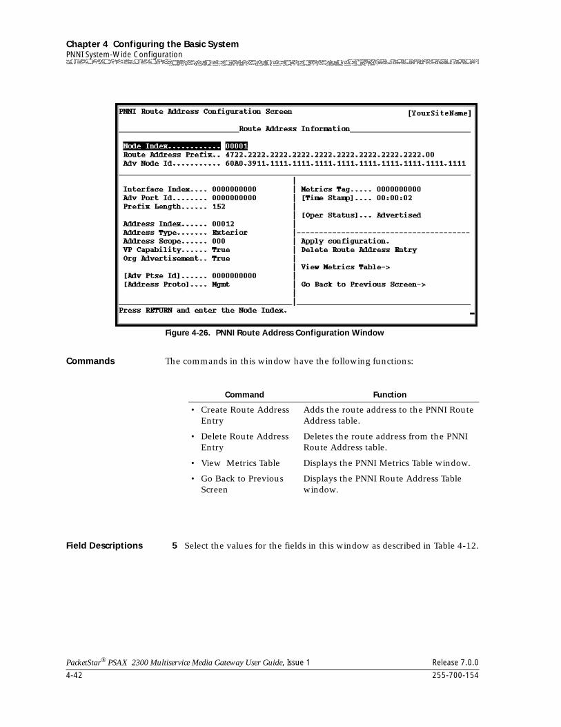
Chapter 4 Configuring the Basic SystemPNNI System-Wide Configuration
4-42 255-700-154
PacketStar® PSAX 2300 Multiservice Media Gateway User Guide, Issue 1 Release 7.0.0
Commands The commands in this window have the following functions:
Field Descriptions 5 Select the values for the fields in this window as described in Table 4-12.
Figure 4-26. PNNI Route Address Configuration Window
Command Function
• Create Route Address Entry
Adds the route address to the PNNI Route Address table.
• Delete Route Address Entry
Deletes the route address from the PNNI Route Address table.
• View Metrics Table Displays the PNNI Metrics Table window.
• Go Back to Previous Screen
Displays the PNNI Route Address Table window.
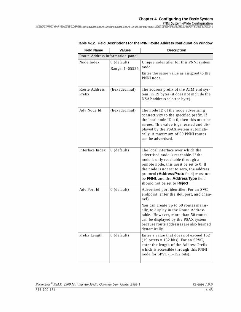
255-700-154 4-43
PacketStar® PSAX 2300 Multiservice Media Gateway User Guide, Issue 1 Release 7.0.0
Chapter 4 Configuring the Basic SystemPNNI System-Wide Configuration
Table 4-12. Field Descriptions for the PNNI Route Address Configuration Window
Field Name Values Description
Route Address Information panel
Node Index 0 (default)
Range: 1–65535
Unique indentifier for this PNNI system node.
Enter the same value as assigned to the PNNI node.
Route Address Prefix
(hexadecimal) The address prefix of the ATM end sys-tem, in 19 bytes (it does not include the NSAP address selector byte).
Adv Node Id (hexadecimal) The node ID of the node advertising connectivity to the specified prefix. If the local node ID is 0, then this must be zeroes. This value is generated and dis-played by the PSAX system automati-cally. A maximum of 50 PNNI routes can be advertised.
Interface Index 0 (default) The local interface over which the advertised node is reachable. If the node is only reachable through a remote node, this must be set to 0. If the node is not set to zero, the address protocol (Address Proto field) must not be PNNI, and the Address Type field should not be set to Reject.
Adv Port Id 0 (default) Advertised port identifier. For an SVC endpoint, enter the slot, port, and chan-nel).
You can create up to 50 routes manu-ally, to display in the Route Address table. However, more than 50 routes can be displayed by the PSAX system because route addresses are also learned dynamically.
Prefix Length 0 (default) Enter a value that does not exceed 152 (19 octets = 152 bits). For an SPVC, enter the length of the Address Prefix which is accessible through this PNNI node for SPVC (1–152 bits).
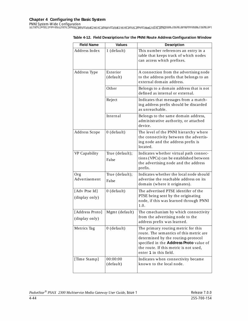
Chapter 4 Configuring the Basic SystemPNNI System-Wide Configuration
4-44 255-700-154
PacketStar® PSAX 2300 Multiservice Media Gateway User Guide, Issue 1 Release 7.0.0
Address Index 1 (default) This number references an entry in a table that keeps track of which nodes can access which prefixes.
Address Type Exterior (default)
A connection from the advertising node to the address prefix that belongs to an external domain address.
Other Belongs to a domain address that is not defined as internal or external.
Reject Indicates that messages from a match-ing address prefix should be discarded as unreachable.
Internal Belongs to the same domain address, administrative authority, or attached device.
Address Scope 0 (default) The level of the PNNI hierarchy where the connectivity between the advertis-ing node and the address prefix is located.
VP Capability True (default);
False
Indicates whether virtual path connec-tions (VPCs) can be established between the advertising node and the address prefix.
OrgAdvertisement
True (default);
False
Indicates whether the local node should advertise the reachable address on its domain (where it originates).
[Adv Ptse Id]
(display only)
0 (default) The advertised PTSE identifer of the PTSE being sent by the originating node, if this was learned through PNNI 1.0.
[Address Proto]
(display only)
Mgmt (default) The cmechanism by which connectivity from the advertising node to the address prefix was learned.
Metrics Tag 0 (default) The primary routing metric for this route. The semantics of this metric are determined by the routing-protocol specified in the Address Proto value of the route. If this metric is not used, enter 1 in this field.
[Time Stamp] 00:00:00 (default)
Indicates when connectivity became known to the local node.
Table 4-12. Field Descriptions for the PNNI Route Address Configuration Window
Field Name Values Description
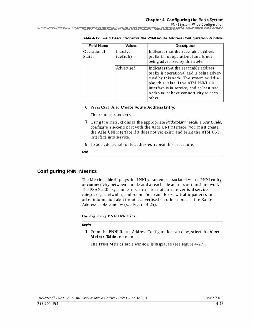
255-700-154 4-45
PacketStar® PSAX 2300 Multiservice Media Gateway User Guide, Issue 1 Release 7.0.0
Chapter 4 Configuring the Basic SystemPNNI System-Wide Configuration
6 Press Ctrl+A to Create Route Address Entry.
The route is completed.
7 Using the instructions in the appropriate PacketStar™ Module User Guide, configure a second port with the ATM UNI interface (you must create the ATM UNI interface if it does not yet exist) and bring the ATM UNI interface into service.
8 To add additional route addresses, repeat this procedure.
End
Configuring PNNI Metrics
The Metrics table displays the PNNI parameters associated with a PNNI entity, or connectivity between a node and a reachable address or transit network. The PSAX 2300 system learns such information as advertised service categories, bandwidth, and so on. You can also view traffic patterns and other information about routes advertised on other nodes in the Route Address Table window (see Figure 4-25).
Begin
Configuring PNNI Metrics
1 From the PNNI Route Address Configuration window, select the View Metrics Table command.
The PNNI Metrics Table window is displayed (see Figure 4-27).
Operational Status
Inactive (default)
Indicates that the reachable address prefix is not operational and is not being advertised by this node.
Advertised Indicates that the reachable address prefix is operational and is being adver-tised by this node. The system will dis-play this value if the ATM PNNI 1.0 interface is in service, and at least two nodes must have connectivity to each other.
Table 4-12. Field Descriptions for the PNNI Route Address Configuration Window
Field Name Values Description
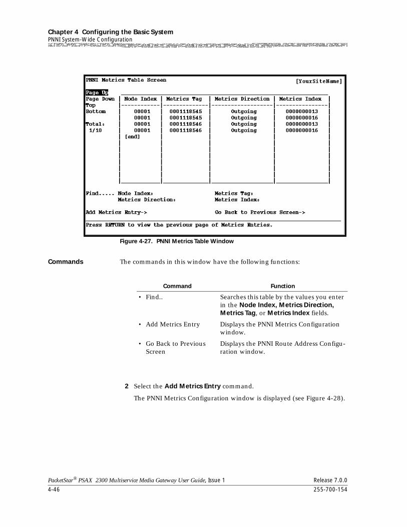
Chapter 4 Configuring the Basic SystemPNNI System-Wide Configuration
4-46 255-700-154
PacketStar® PSAX 2300 Multiservice Media Gateway User Guide, Issue 1 Release 7.0.0
Commands The commands in this window have the following functions:
2 Select the Add Metrics Entry command.
The PNNI Metrics Configuration window is displayed (see Figure 4-28).
Figure 4-27. PNNI Metrics Table Window
Command Function
• Find.. Searches this table by the values you enter in the Node Index, Metrics Direction, Metrics Tag, or Metrics Index fields.
• Add Metrics Entry Displays the PNNI Metrics Configuration window.
• Go Back to Previous Screen
Displays the PNNI Route Address Configu-ration window.
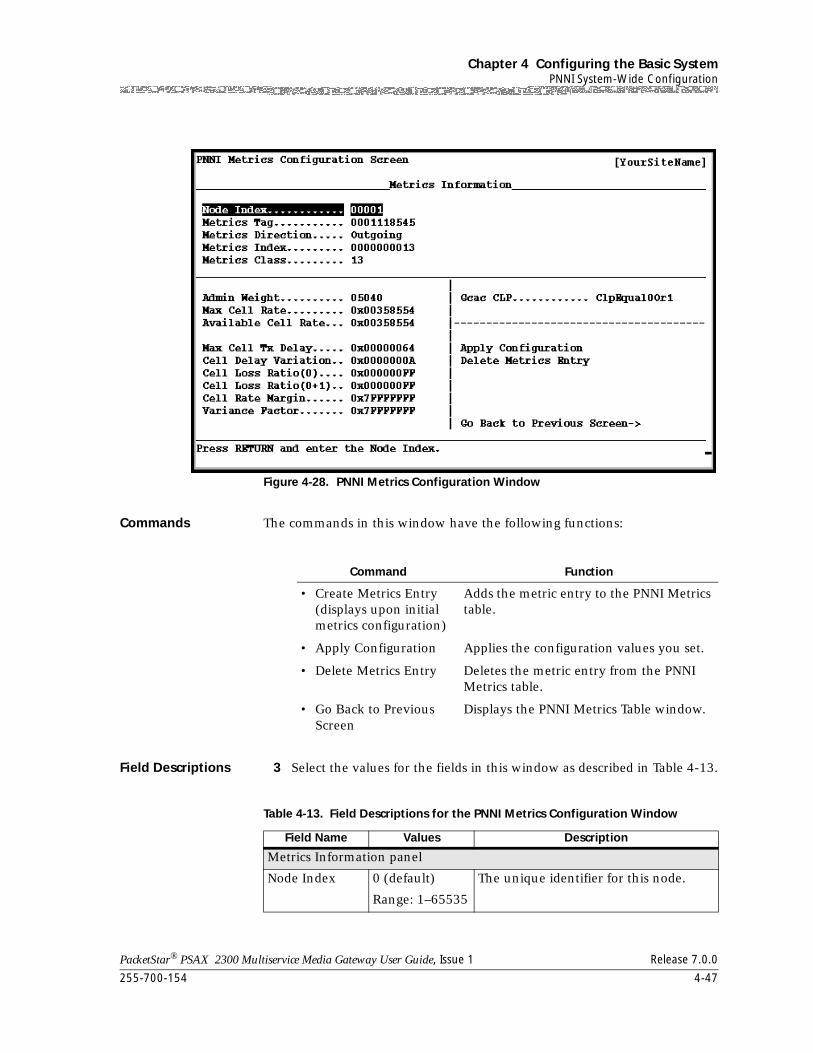
255-700-154 4-47
PacketStar® PSAX 2300 Multiservice Media Gateway User Guide, Issue 1 Release 7.0.0
Chapter 4 Configuring the Basic SystemPNNI System-Wide Configuration
Commands The commands in this window have the following functions:
Field Descriptions 3 Select the values for the fields in this window as described in Table 4-13.
Figure 4-28. PNNI Metrics Configuration Window
Command Function
• Create Metrics Entry (displays upon initial metrics configuration)
Adds the metric entry to the PNNI Metrics table.
• Apply Configuration Applies the configuration values you set.
• Delete Metrics Entry Deletes the metric entry from the PNNI Metrics table.
• Go Back to Previous Screen
Displays the PNNI Metrics Table window.
Table 4-13. Field Descriptions for the PNNI Metrics Configuration Window
Field Name Values Description
Metrics Information panel
Node Index 0 (default)
Range: 1–65535
The unique identifier for this node.
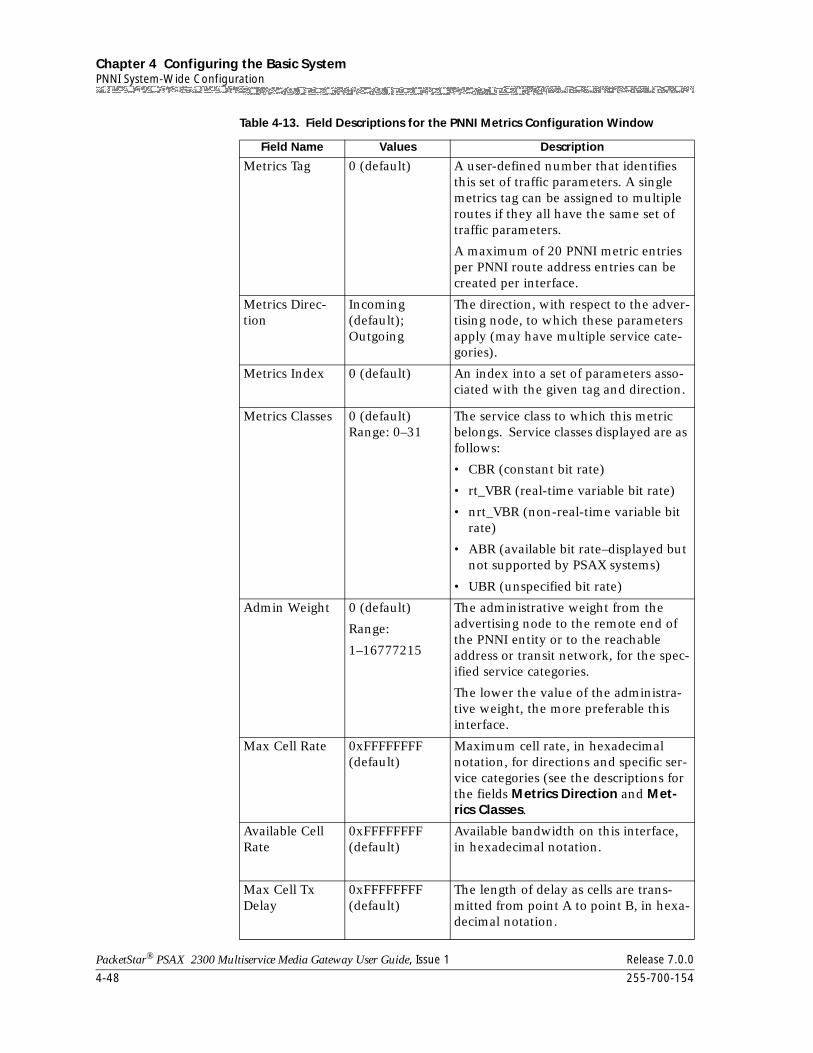
Chapter 4 Configuring the Basic SystemPNNI System-Wide Configuration
4-48 255-700-154
PacketStar® PSAX 2300 Multiservice Media Gateway User Guide, Issue 1 Release 7.0.0
Metrics Tag 0 (default) A user-defined number that identifies this set of traffic parameters. A single metrics tag can be assigned to multiple routes if they all have the same set of traffic parameters.
A maximum of 20 PNNI metric entries per PNNI route address entries can be created per interface.
Metrics Direc-tion
Incoming (default); Outgoing
The direction, with respect to the adver-tising node, to which these parameters apply (may have multiple service cate-gories).
Metrics Index 0 (default) An index into a set of parameters asso-ciated with the given tag and direction.
Metrics Classes 0 (default) Range: 0–31
The service class to which this metric belongs. Service classes displayed are as follows:
• CBR (constant bit rate)
• rt_VBR (real-time variable bit rate)
• nrt_VBR (non-real-time variable bit rate)
• ABR (available bit rate–displayed but not supported by PSAX systems)
• UBR (unspecified bit rate)
Admin Weight 0 (default)
Range:
1–16777215
The administrative weight from the advertising node to the remote end of the PNNI entity or to the reachable address or transit network, for the spec-ified service categories.
The lower the value of the administra-tive weight, the more preferable this interface.
Max Cell Rate 0xFFFFFFFF (default)
Maximum cell rate, in hexadecimal notation, for directions and specific ser-vice categories (see the descriptions for the fields Metrics Direction and Met-rics Classes.
Available Cell Rate
0xFFFFFFFF (default)
Available bandwidth on this interface, in hexadecimal notation.
Max Cell Tx Delay
0xFFFFFFFF (default)
The length of delay as cells are trans-mitted from point A to point B, in hexa-decimal notation.
Table 4-13. Field Descriptions for the PNNI Metrics Configuration Window
Field Name Values Description
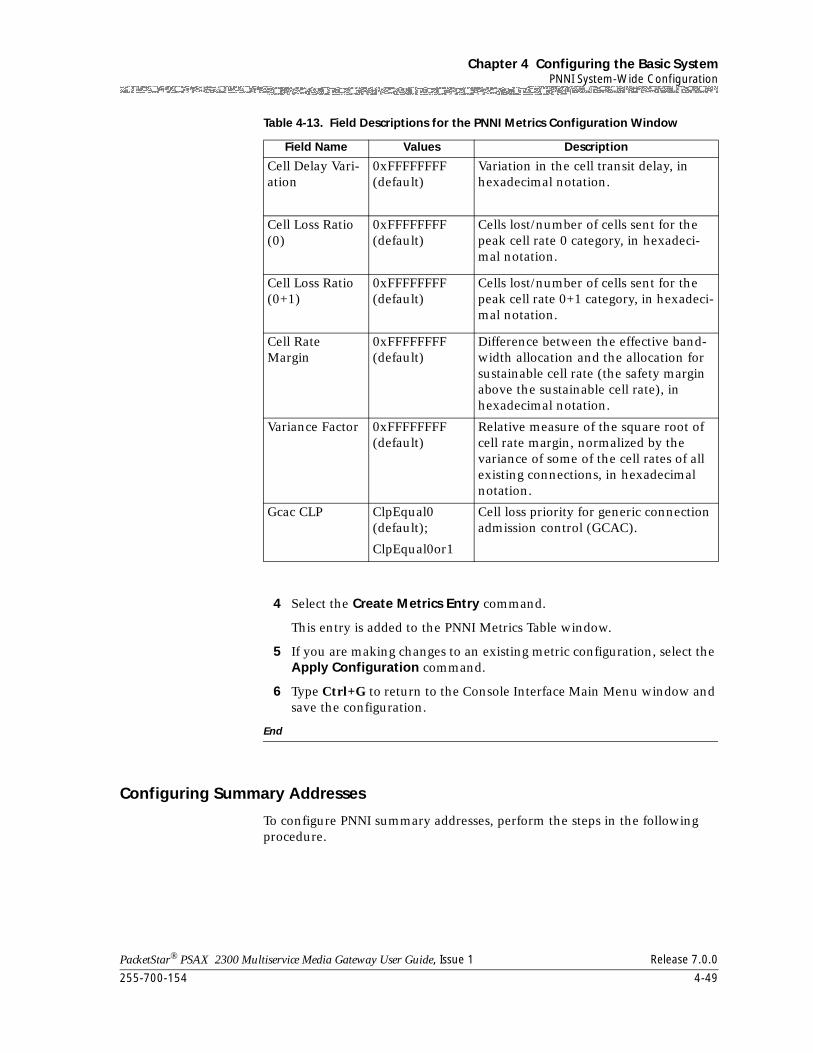
255-700-154 4-49
PacketStar® PSAX 2300 Multiservice Media Gateway User Guide, Issue 1 Release 7.0.0
Chapter 4 Configuring the Basic SystemPNNI System-Wide Configuration
4 Select the Create Metrics Entry command.
This entry is added to the PNNI Metrics Table window.
5 If you are making changes to an existing metric configuration, select the Apply Configuration command.
6 Type Ctrl+G to return to the Console Interface Main Menu window and save the configuration.
End
Configuring Summary Addresses
To configure PNNI summary addresses, perform the steps in the following procedure.
Cell Delay Vari-ation
0xFFFFFFFF (default)
Variation in the cell transit delay, in hexadecimal notation.
Cell Loss Ratio (0)
0xFFFFFFFF (default)
Cells lost/number of cells sent for the peak cell rate 0 category, in hexadeci-mal notation.
Cell Loss Ratio (0+1)
0xFFFFFFFF (default)
Cells lost/number of cells sent for the peak cell rate 0+1 category, in hexadeci-mal notation.
Cell RateMargin
0xFFFFFFFF (default)
Difference between the effective band-width allocation and the allocation for sustainable cell rate (the safety margin above the sustainable cell rate), in hexadecimal notation.
Variance Factor 0xFFFFFFFF (default)
Relative measure of the square root of cell rate margin, normalized by the variance of some of the cell rates of all existing connections, in hexadecimal notation.
Gcac CLP ClpEqual0 (default);
ClpEqual0or1
Cell loss priority for generic connection admission control (GCAC).
Table 4-13. Field Descriptions for the PNNI Metrics Configuration Window
Field Name Values Description
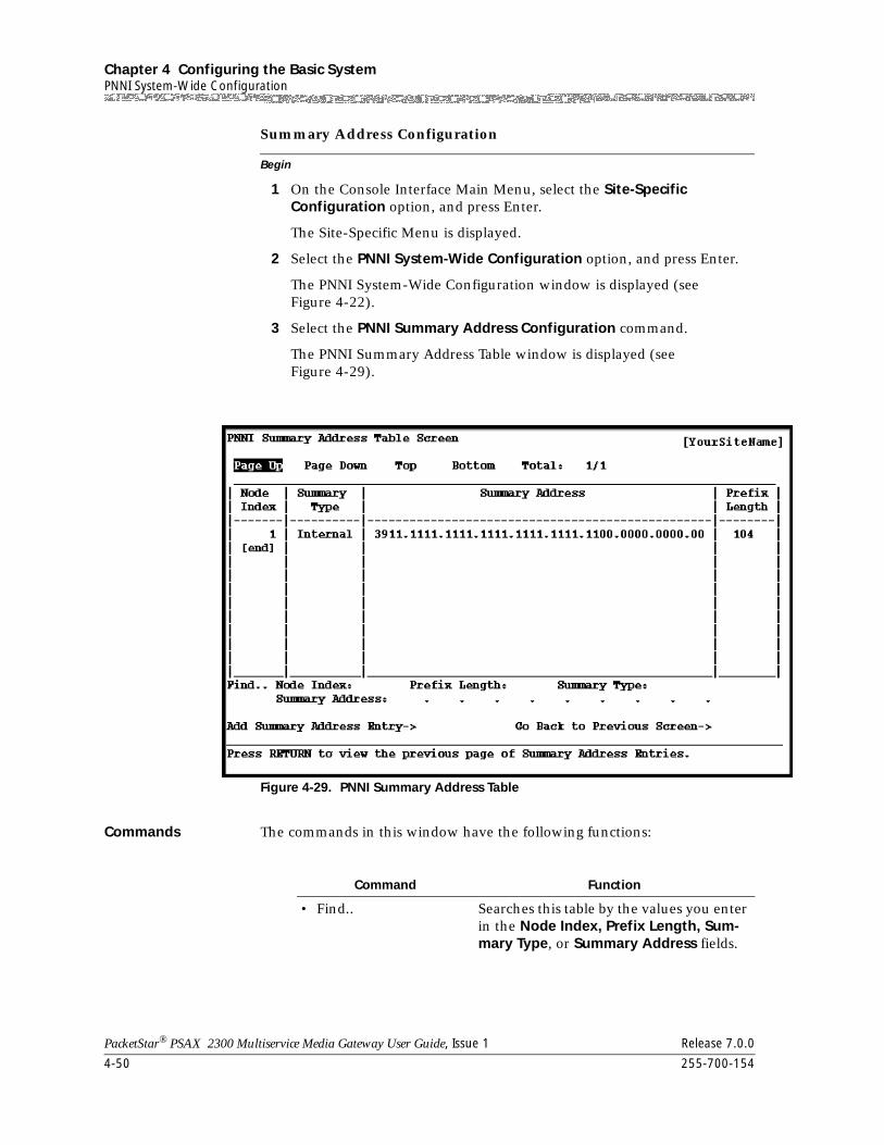
Chapter 4 Configuring the Basic SystemPNNI System-Wide Configuration
4-50 255-700-154
PacketStar® PSAX 2300 Multiservice Media Gateway User Guide, Issue 1 Release 7.0.0
Begin
Summary Address Configuration
1 On the Console Interface Main Menu, select the Site-Specific Configuration option, and press Enter.
The Site-Specific Menu is displayed.
2 Select the PNNI System-Wide Configuration option, and press Enter.
The PNNI System-Wide Configuration window is displayed (see Figure 4-22).
3 Select the PNNI Summary Address Configuration command.
The PNNI Summary Address Table window is displayed (see Figure 4-29).
Commands The commands in this window have the following functions:
Figure 4-29. PNNI Summary Address Table
Command Function
• Find.. Searches this table by the values you enter in the Node Index, Prefix Length, Sum-mary Type, or Summary Address fields.
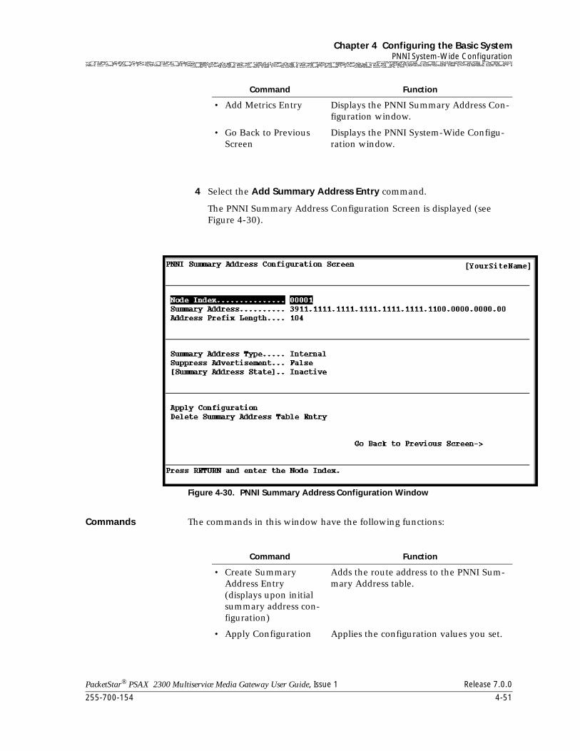
255-700-154 4-51
PacketStar® PSAX 2300 Multiservice Media Gateway User Guide, Issue 1 Release 7.0.0
Chapter 4 Configuring the Basic SystemPNNI System-Wide Configuration
4 Select the Add Summary Address Entry command.
The PNNI Summary Address Configuration Screen is displayed (see Figure 4-30).
Commands The commands in this window have the following functions:
• Add Metrics Entry Displays the PNNI Summary Address Con-figuration window.
• Go Back to Previous Screen
Displays the PNNI System-Wide Configu-ration window.
Figure 4-30. PNNI Summary Address Configuration Window
Command Function
Command Function
• Create Summary Address Entry (displays upon initial summary address con-figuration)
Adds the route address to the PNNI Sum-mary Address table.
• Apply Configuration Applies the configuration values you set.
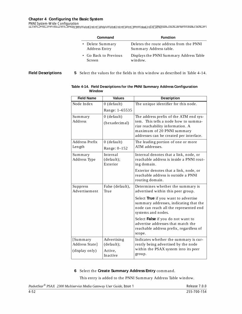
Chapter 4 Configuring the Basic SystemPNNI System-Wide Configuration
4-52 255-700-154
PacketStar® PSAX 2300 Multiservice Media Gateway User Guide, Issue 1 Release 7.0.0
Field Descriptions 5 Select the values for the fields in this window as described in Table 4-14.
6 Select the Create Summary Address Entry command.
This entry is added to the PNNI Summary Address Table window.
• Delete Summary Address Entry
Deletes the route address from the PNNI Summary Address table.
• Go Back to Previous Screen
Displays the PNNI Summary Address Table window.
Command Function
Table 4-14. Field Descriptions for the PNNI Summary Address Configuration Window
Field Name Values Description
Node Index 0 (default)
Range: 1–65535
The unique identifier for this node.
Summary Address
0 (default)
(hexadecimal)
The address prefix of the ATM end sys-tem. This tells a node how to summa-rize reachability information. A maximum of 20 PNNI summary addresses can be created per interface.
Address Prefix Length
0 (default)
Range: 0–152
The leading portion of one or more ATM addresses.
Summary Address Type
Internal (default); Exterior
Internal denotes that a link, node, or reachable address is inside a PNNI rout-ing domain.
Exterior denotes that a link, node, or reachable address is outside a PNNI routing domain.
Suppress Advertisement
False (default), True
Determines whether the summary is advertised within this peer group.
Select True if you want to advertise summary addresses, indicating that the node can reach all the represented end systems and nodes.
Select False if you do not want to advertise addresses that match the reachable address prefix, regardless of scope.
[Summary Address State]
(display only)
Advertising (default);
Active,Inactive
Indicates whether the summary is cur-rently being advertised by the node within the PSAX system into its peer group.
255-700-154 4-53
PacketStar® PSAX 2300 Multiservice Media Gateway User Guide, Issue 1 Release 7.0.0
Chapter 4 Configuring the Basic SystemPNNI System-Wide Configuration
7 Type Ctrl+G to return to the Console Interface Main Menu window and save the configuration.
End
Viewing the PNNI Map Link Table
The PNNI Map Link Table contains attributes necessary to find and analyze the operation of all links and nodes within the PNNI hierarchy, as seen from the perspective of a local node. It also provides information for network managers to map port identifiers, showing the ports and links between the nodes at both endpoints.
The PNNI Map Link table is read-only, because the map is generated dynamically during operation of the PNNI protocol, not manually configured.
To view PNNI map links, perform the steps in the following procedure.
Begin
Viewing PNNI Map Links
1 On the Console Interface Main Menu, select the Site-Specific Configuration option, and press Enter.
The Site-Specific Menu is displayed.
2 Select the PNNI System-Wide Configuration option, and press Enter.
The PNNI System-Wide Configuration window is displayed (see Figure 4-22).
3 Select the PNNI Map Link Information command.
The PNNI Map Link Table window is displayed (see Figure 4-31).
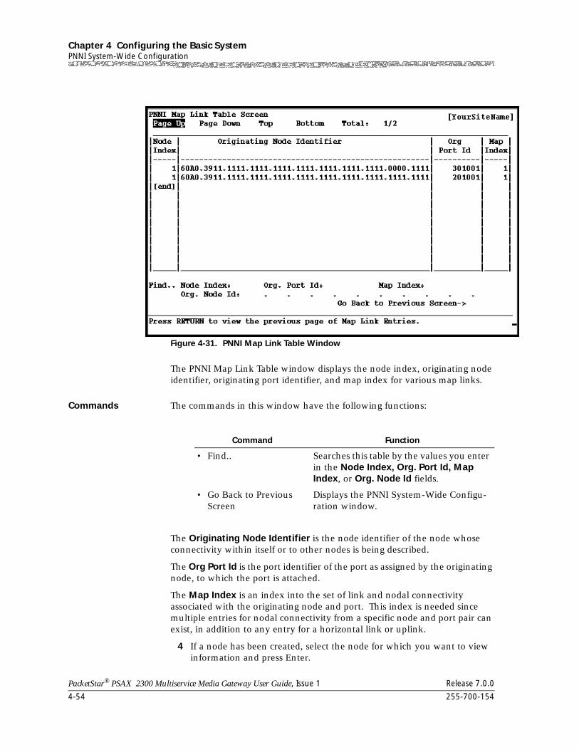
Chapter 4 Configuring the Basic SystemPNNI System-Wide Configuration
4-54 255-700-154
PacketStar® PSAX 2300 Multiservice Media Gateway User Guide, Issue 1 Release 7.0.0
The PNNI Map Link Table window displays the node index, originating node identifier, originating port identifier, and map index for various map links.
Commands The commands in this window have the following functions:
The Originating Node Identifier is the node identifier of the node whose connectivity within itself or to other nodes is being described.
The Org Port Id is the port identifier of the port as assigned by the originating node, to which the port is attached.
The Map Index is an index into the set of link and nodal connectivity associated with the originating node and port. This index is needed since multiple entries for nodal connectivity from a specific node and port pair can exist, in addition to any entry for a horizontal link or uplink.
4 If a node has been created, select the node for which you want to view information and press Enter.
Figure 4-31. PNNI Map Link Table Window
Command Function
• Find.. Searches this table by the values you enter in the Node Index, Org. Port Id, Map Index, or Org. Node Id fields.
• Go Back to Previous Screen
Displays the PNNI System-Wide Configu-ration window.
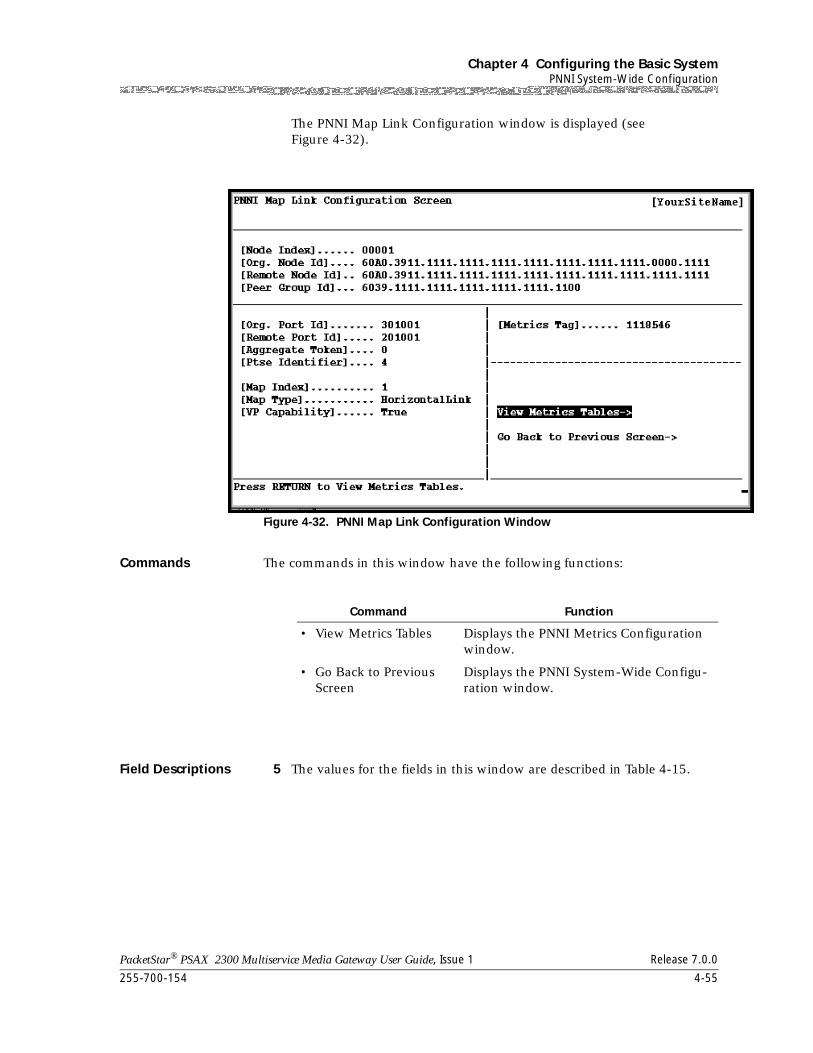
255-700-154 4-55
PacketStar® PSAX 2300 Multiservice Media Gateway User Guide, Issue 1 Release 7.0.0
Chapter 4 Configuring the Basic SystemPNNI System-Wide Configuration
The PNNI Map Link Configuration window is displayed (see Figure 4-32).
Commands The commands in this window have the following functions:
Field Descriptions 5 The values for the fields in this window are described in Table 4-15.
Figure 4-32. PNNI Map Link Configuration Window
Command Function
• View Metrics Tables Displays the PNNI Metrics Configuration window.
• Go Back to Previous Screen
Displays the PNNI System-Wide Configu-ration window.
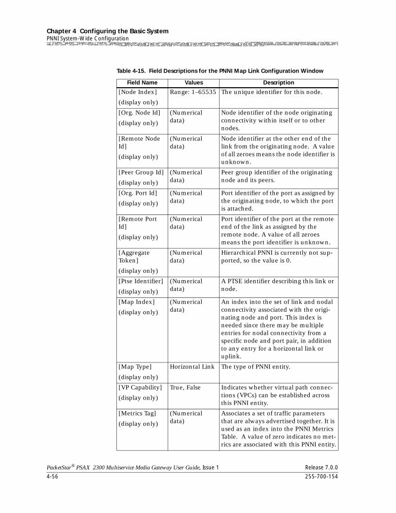
Chapter 4 Configuring the Basic SystemPNNI System-Wide Configuration
4-56 255-700-154
PacketStar® PSAX 2300 Multiservice Media Gateway User Guide, Issue 1 Release 7.0.0
Table 4-15. Field Descriptions for the PNNI Map Link Configuration Window
Field Name Values Description
[Node Index]
(display only)
Range: 1–65535 The unique identifier for this node.
[Org. Node Id]
(display only)
(Numerical data)
Node identifier of the node originating connectivity within itself or to other nodes.
[Remote Node Id]
(display only)
(Numerical data)
Node identifier at the other end of the link from the originating node. A value of all zeroes means the node identifier is unknown.
[Peer Group Id]
(display only)
(Numerical data)
Peer group identifier of the originating node and its peers.
[Org. Port Id]
(display only)
(Numerical data)
Port identifier of the port as assigned by the originating node, to which the port is attached.
[Remote Port Id]
(display only)
(Numerical data)
Port identifier of the port at the remote end of the link as assigned by the remote node. A value of all zeroes means the port identifier is unknown.
[Aggregate Token]
(display only)
(Numerical data)
Hierarchical PNNI is currently not sup-ported, so the value is 0.
[Ptse Identifier]
(display only)
(Numerical data)
A PTSE identifier describing this link or node.
[Map Index]
(display only)
(Numerical data)
An index into the set of link and nodal connectivity associated with the origi-nating node and port. This index is needed since there may be multiple entries for nodal connectivity from a specific node and port pair, in addition to any entry for a horizontal link or uplink.
[Map Type]
(display only)
Horizontal Link The type of PNNI entity.
[VP Capability]
(display only)
True, False Indicates whether virtual path connec-tions (VPCs) can be established across this PNNI entity.
[Metrics Tag]
(display only)
(Numerical data)
Associates a set of traffic parameters that are always advertised together. It is used as an index into the PNNI Metrics Table. A value of zero indicates no met-rics are associated with this PNNI entity.
255-700-154 4-57
PacketStar® PSAX 2300 Multiservice Media Gateway User Guide, Issue 1 Release 7.0.0
Chapter 4 Configuring the Basic SystemPNNI System-Wide Configuration
6 To view the Metrics table, select View Metrics Tables and press Enter.
The Metrics Table window is displayed (see Figure 4-27).
7 To return to the Map Link Table window, Go Back to Previous Screen and press Enter.
The Map Link Table window is displayed (see Figure 4-31).
End
Viewing the PNNI Link Table
The PNNI Link Table contains the attributes necessary to describe the operation of logical links attached to the PSAX device and the relationship with the neighbor nodes on the other end of the links. Links are attached to a specific node within the PSAX device. Links may represent horizontal links between the lowest level of neighboring peers, outside links, uplinks, or horizontal links to or from logical group nodes (LGNs). A maximum of 100 PNNI links can be created per interface.
The PNNI Link table is read-only because the information in the PNNI Link table is generated dynamically by the PNNI protocol, not manually configured. For more information, see the ATM Forum Specification, Private Network-Network Interface (PNNI 1.0) Specification Version 1.0, af-pnni-0055.000, Section 5.6.
To view PNNI links, perform the steps in the following procedure.
Begin
Viewing PNNI Links
1 On the Console Interface Main Menu, select the Site-Specific Configuration option, and press Enter.
The Site-Specific Menu is displayed.
2 Select the PNNI System-Wide Configuration option, and press Enter.
The PNNI System-Wide Configuration window is displayed (see Figure 4-22).
3 Select the PNNI Link Information command.
The PNNI Link Table window is displayed (see Figure 4-33).
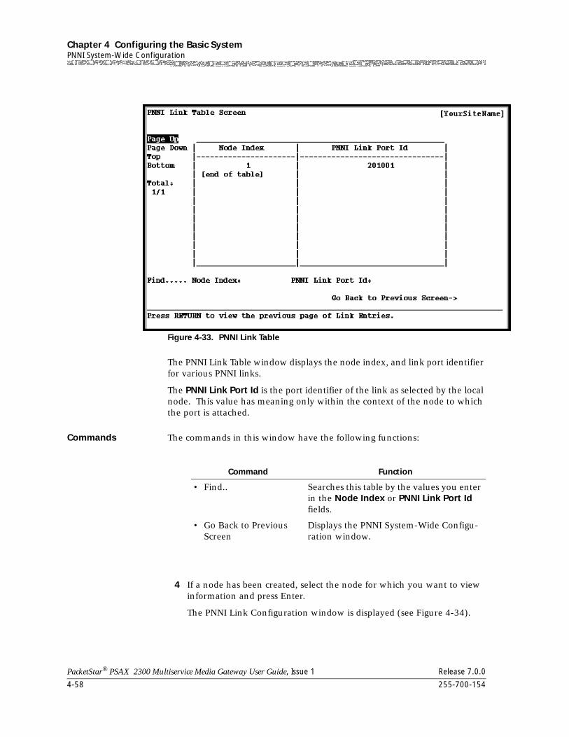
Chapter 4 Configuring the Basic SystemPNNI System-Wide Configuration
4-58 255-700-154
PacketStar® PSAX 2300 Multiservice Media Gateway User Guide, Issue 1 Release 7.0.0
The PNNI Link Table window displays the node index, and link port identifier for various PNNI links.
The PNNI Link Port Id is the port identifier of the link as selected by the local node. This value has meaning only within the context of the node to which the port is attached.
Commands The commands in this window have the following functions:
4 If a node has been created, select the node for which you want to view information and press Enter.
The PNNI Link Configuration window is displayed (see Figure 4-34).
Figure 4-33. PNNI Link Table
Command Function
• Find.. Searches this table by the values you enter in the Node Index or PNNI Link Port Id fields.
• Go Back to Previous Screen
Displays the PNNI System-Wide Configu-ration window.
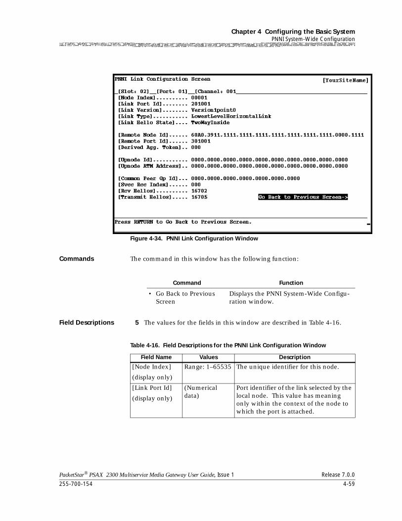
255-700-154 4-59
PacketStar® PSAX 2300 Multiservice Media Gateway User Guide, Issue 1 Release 7.0.0
Chapter 4 Configuring the Basic SystemPNNI System-Wide Configuration
Commands The command in this window has the following function:
Field Descriptions 5 The values for the fields in this window are described in Table 4-16.
Figure 4-34. PNNI Link Configuration Window
Command Function
• Go Back to Previous Screen
Displays the PNNI System-Wide Configu-ration window.
Table 4-16. Field Descriptions for the PNNI Link Configuration Window
Field Name Values Description
[Node Index]
(display only)
Range: 1–65535 The unique identifier for this node.
[Link Port Id]
(display only)
(Numerical data)
Port identifier of the link selected by the local node. This value has meaning only within the context of the node to which the port is attached.
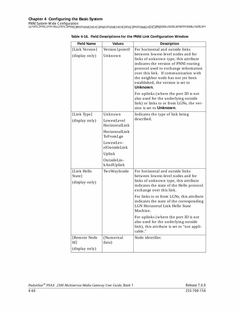
Chapter 4 Configuring the Basic SystemPNNI System-Wide Configuration
4-60 255-700-154
PacketStar® PSAX 2300 Multiservice Media Gateway User Guide, Issue 1 Release 7.0.0
[Link Version]
(display only)
Version1point0
Unknown
For horizontal and outside links between lowest-level nodes and for links of unknown type, this attribute indicates the version of PNNI routing protocol used to exchange information over this link. If communication with the neighbor node has not yet been established, the version is set to Unknown.
For uplinks (where the port ID is not also used for the underlying outside link) or links to or from LGNs, the ver-sion is set to Unknown.
[Link Type]
(display only)
Unknown
LowestLevelHorizontalLink
HorizontalLinkToFromLgn
LowestLev-elOutsideLink
Uplink
OutsideLin-kAndUplink
Indicates the type of link being described.
[Link Hello State]
(display only)
TwoWayInside For horizontal and outside links between lowest-level nodes and for links of unknown type, this attribute indicates the state of the Hello protocol exchange over this link.
For links to or from LGNs, this attribute indicates the state of the corresponding LGN Horizontal Link Hello State Machine.
For uplinks (where the port ID is not also used for the underlying outside link), this attribute is set to "not appli-cable."
[Remote Node Id]
(display only)
(Numerical data)
Node identifier.
Table 4-16. Field Descriptions for the PNNI Link Configuration Window
Field Name Values Description
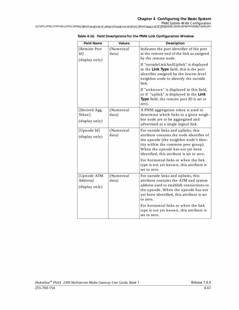
255-700-154 4-61
PacketStar® PSAX 2300 Multiservice Media Gateway User Guide, Issue 1 Release 7.0.0
Chapter 4 Configuring the Basic SystemPNNI System-Wide Configuration
[Remote Port Id]
(display only)
(Numerical data)
Indicates the port identifier of the port at the remote end of the link as assigned by the remote node.
If "outsideLinkAndUplink" is displayed in the Link Type field, this is the port identifier assigned by the lowest-level neighbor node to identify the outside link.
If "unknown" is displayed in this field, or if "uplink" is displayed in the Link Type field, the remote port ID is set to zero.
[Derived Agg. Token]
(display only)
(Numerical data)
A PNNI aggregation token is used to determine which links to a given neigh-bor node are to be aggregated and advertised as a single logical link.
[Upnode Id]
(display only)
(Numerical data)
For outside links and uplinks, this attribute contains the node identifier of the upnode (the neighbor node’s iden-tity within the common peer group). When the upnode has not yet been identified, this attribute is set to zero.
For horizontal links or when the link type is not yet known, this attribute is set to zero.
[Upnode ATM Address]
(display only)
(Numerical data)
For outside links and uplinks, this attribute contains the ATM end system address used to establish connections to the upnode. When the upnode has not yet been identified, this attribute is set to zero.
For horizontal links or when the link type is not yet known, this attribute is set to zero.
Table 4-16. Field Descriptions for the PNNI Link Configuration Window
Field Name Values Description
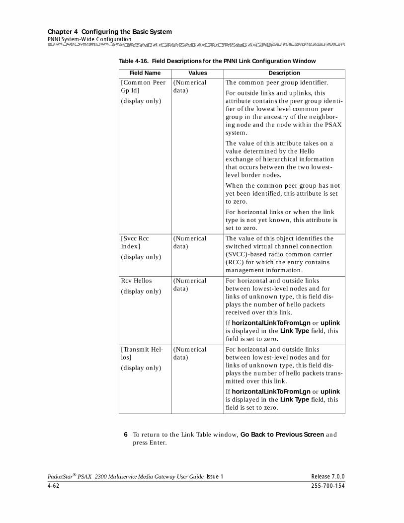
Chapter 4 Configuring the Basic SystemPNNI System-Wide Configuration
4-62 255-700-154
PacketStar® PSAX 2300 Multiservice Media Gateway User Guide, Issue 1 Release 7.0.0
6 To return to the Link Table window, Go Back to Previous Screen and press Enter.
[Common Peer Gp Id]
(display only)
(Numerical data)
The common peer group identifier.
For outside links and uplinks, this attribute contains the peer group identi-fier of the lowest level common peer group in the ancestry of the neighbor-ing node and the node within the PSAX system.
The value of this attribute takes on a value determined by the Hello exchange of hierarchical information that occurs between the two lowest-level border nodes.
When the common peer group has not yet been identified, this attribute is set to zero.
For horizontal links or when the link type is not yet known, this attribute is set to zero.
[Svcc Rcc Index]
(display only)
(Numerical data)
The value of this object identifies the switched virtual channel connection (SVCC)-based radio common carrier (RCC) for which the entry contains management information.
Rcv Hellos
(display only)
(Numerical data)
For horizontal and outside links between lowest-level nodes and for links of unknown type, this field dis-plays the number of hello packets received over this link.
If horizontalLinkToFromLgn or uplink is displayed in the Link Type field, this field is set to zero.
[Transmit Hel-los]
(display only)
(Numerical data)
For horizontal and outside links between lowest-level nodes and for links of unknown type, this field dis-plays the number of hello packets trans-mitted over this link.
If horizontalLinkToFromLgn or uplink is displayed in the Link Type field, this field is set to zero.
Table 4-16. Field Descriptions for the PNNI Link Configuration Window
Field Name Values Description
255-700-154 4-63
PacketStar® PSAX 2300 Multiservice Media Gateway User Guide, Issue 1 Release 7.0.0
Chapter 4 Configuring the Basic SystemPNNI System-Wide Configuration
The Link Table window is displayed (see Figure 4-33).
End
Viewing the PNNI Neighbor Peer Table
The PNNI Neighbor Peer table contains all the attributes necessary to describe the relationship a node in the PSAX system has with a neighboring node within the same peer group.
The PNNI Neighbor Peer table is read-only because neighboring peers are generated dynamically by the PNNI protocol, not manually configured. For more information, see the ATM Forum Specification, Private Network-Network Interface (PNNI 1.0) Specification Version 1.0, af-pnni-0055.000, Sections 5.7 and 5.8.
To view PNNI neighbor peers, perform the steps in the following procedure.
Begin
Viewing PNNI Neighbor Peers
1 On the Console Interface Main Menu, select the Site-Specific Configuration option, and press Enter.
The Site-Specific Menu is displayed.
2 Select the PNNI System-Wide Configuration option, and press Enter.
The PNNI System-Wide Configuration window is displayed (see Figure 4-22).
3 Select the PNNI Neighbor Peer Information command.
The PNNI Neighbor Peer Table window is displayed (see Figure 4-35).
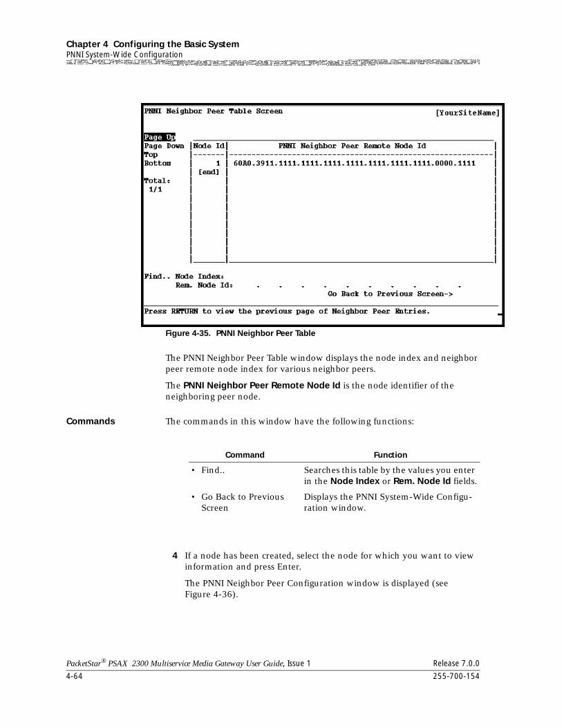
Chapter 4 Configuring the Basic SystemPNNI System-Wide Configuration
4-64 255-700-154
PacketStar® PSAX 2300 Multiservice Media Gateway User Guide, Issue 1 Release 7.0.0
The PNNI Neighbor Peer Table window displays the node index and neighbor peer remote node index for various neighbor peers.
The PNNI Neighbor Peer Remote Node Id is the node identifier of the neighboring peer node.
Commands The commands in this window have the following functions:
4 If a node has been created, select the node for which you want to view information and press Enter.
The PNNI Neighbor Peer Configuration window is displayed (see Figure 4-36).
Figure 4-35. PNNI Neighbor Peer Table
Command Function
• Find.. Searches this table by the values you enter in the Node Index or Rem. Node Id fields.
• Go Back to Previous Screen
Displays the PNNI System-Wide Configu-ration window.
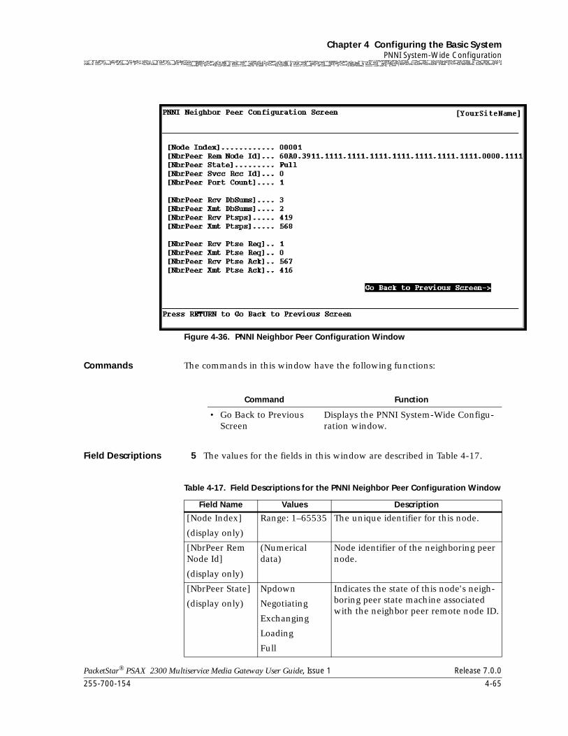
255-700-154 4-65
PacketStar® PSAX 2300 Multiservice Media Gateway User Guide, Issue 1 Release 7.0.0
Chapter 4 Configuring the Basic SystemPNNI System-Wide Configuration
Commands The commands in this window have the following functions:
Field Descriptions 5 The values for the fields in this window are described in Table 4-17.
Figure 4-36. PNNI Neighbor Peer Configuration Window
Command Function
• Go Back to Previous Screen
Displays the PNNI System-Wide Configu-ration window.
Table 4-17. Field Descriptions for the PNNI Neighbor Peer Configuration Window
Field Name Values Description
[Node Index]
(display only)
Range: 1–65535 The unique identifier for this node.
[NbrPeer Rem Node Id]
(display only)
(Numerical data)
Node identifier of the neighboring peer node.
[NbrPeer State]
(display only)
Npdown
Negotiating
Exchanging
Loading
Full
Indicates the state of this node's neigh-boring peer state machine associated with the neighbor peer remote node ID.
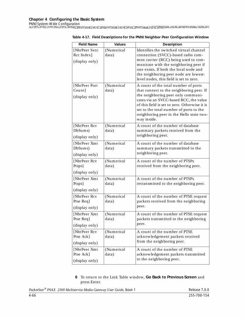
Chapter 4 Configuring the Basic SystemPNNI System-Wide Configuration
4-66 255-700-154
PacketStar® PSAX 2300 Multiservice Media Gateway User Guide, Issue 1 Release 7.0.0
6 To return to the Link Table window, Go Back to Previous Screen and press Enter.
[NbrPeer Svcc Rcc Index]
(display only)
(Numerical data)
Identifies the switched virtual channel connection (SVCC)-based radio com-mon carrier (RCC) being used to com-municate with the neighboring peer if one exists. If both the local node and the neighboring peer node are lowest-level nodes, this field is set to zero.
[NbrPeer Port Count]
(display only)
(Numerical data)
A count of the total number of ports that connect to the neighboring peer. If the neighboring peer only communi-cates via an SVCC-based RCC, the value of this field is set to zero. Otherwise it is set to the total number of ports to the neighboring peer in the Hello state two-way inside.
[NbrPeer Rcv DbSums)
(display only)
(Numerical data)
A count of the number of database summary packets received from the neighboring peer.
[NbrPeer Xmt DbSums)
(display only)
(Numerical data)
A count of the number of database summary packets transmitted to the neighboring peer.
[NbrPeer Rcv Ptsps]
(display only)
(Numerical data)
A count of the number of PTSPs received from the neighboring peer.
[NbrPeer Xmt Ptsps]
(display only)
(Numerical data)
A count of the number of PTSPs retransmitted to the neighboring peer.
[NbrPeer Rcv Ptse Req]
(display only)
(Numerical data)
A count of the number of PTSE request packets received from the neighboring peer.
[NbrPeer Xmt Ptse Req]
(display only)
(Numerical data)
A count of the number of PTSE request packets transmitted to the neighboring peer.
[NbrPeer Rcv Ptse Ack]
(display only)
(Numerical data)
A count of the number of PTSE acknowledgement packets received from the neighboring peer.
[NbrPeer Xmt Ptse Ack]
(display only)
(Numerical data)
A count of the number of PTSE acknowledgement packets transmitted to the neighboring peer.
Table 4-17. Field Descriptions for the PNNI Neighbor Peer Configuration Window
Field Name Values Description
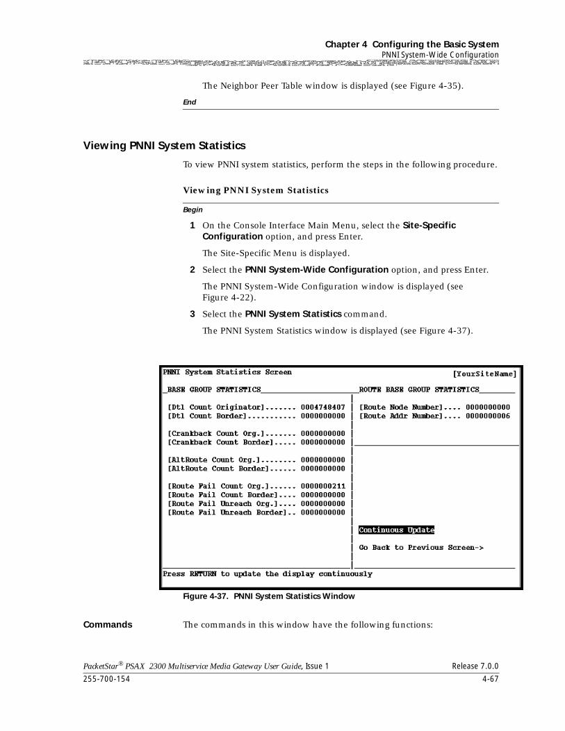
255-700-154 4-67
PacketStar® PSAX 2300 Multiservice Media Gateway User Guide, Issue 1 Release 7.0.0
Chapter 4 Configuring the Basic SystemPNNI System-Wide Configuration
The Neighbor Peer Table window is displayed (see Figure 4-35).
End
Viewing PNNI System Statistics
To view PNNI system statistics, perform the steps in the following procedure.
Begin
Viewing PNNI System Statistics
1 On the Console Interface Main Menu, select the Site-Specific Configuration option, and press Enter.
The Site-Specific Menu is displayed.
2 Select the PNNI System-Wide Configuration option, and press Enter.
The PNNI System-Wide Configuration window is displayed (see Figure 4-22).
3 Select the PNNI System Statistics command.
The PNNI System Statistics window is displayed (see Figure 4-37).
Commands The commands in this window have the following functions:
Figure 4-37. PNNI System Statistics Window
Chapter 4 Configuring the Basic SystemPNNI System-Wide Configuration
4-68 255-700-154
PacketStar® PSAX 2300 Multiservice Media Gateway User Guide, Issue 1 Release 7.0.0
Field Descriptions The fields in this window are described in Table 4-18.
Command Function
• Continuous Update Updates the values in the fields on this window continuously. Use this command as a toggle switch to view the statistics.
• Go Back to Previous Screen
Displays the PNNI System-Wide Configu-ration window.
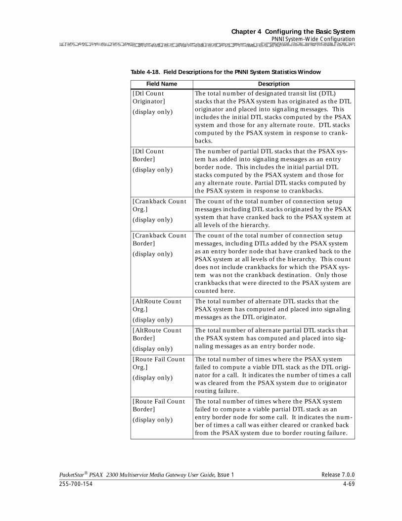
255-700-154 4-69
PacketStar® PSAX 2300 Multiservice Media Gateway User Guide, Issue 1 Release 7.0.0
Chapter 4 Configuring the Basic SystemPNNI System-Wide Configuration
Table 4-18. Field Descriptions for the PNNI System Statistics Window
Field Name Description
[Dtl Count Originator]
(display only)
The total number of designated transit list (DTL) stacks that the PSAX system has originated as the DTL originator and placed into signaling messages. This includes the initial DTL stacks computed by the PSAX system and those for any alternate route. DTL stacks computed by the PSAX system in response to crank-backs.
[Dtl Count Border]
(display only)
The number of partial DTL stacks that the PSAX sys-tem has added into signaling messages as an entry border node. This includes the initial partial DTL stacks computed by the PSAX system and those for any alternate route. Partial DTL stacks computed by the PSAX system in response to crankbacks.
[Crankback Count Org.]
(display only)
The count of the total number of connection setup messages including DTL stacks originated by the PSAX system that have cranked back to the PSAX system at all levels of the hierarchy.
[Crankback Count Border]
(display only)
The count of the total number of connection setup messages, including DTLs added by the PSAX system as an entry border node that have cranked back to the PSAX system at all levels of the hierarchy. This count does not include crankbacks for which the PSAX sys-tem was not the crankback destination. Only those crankbacks that were directed to the PSAX system are counted here.
[AltRoute Count Org.]
(display only)
The total number of alternate DTL stacks that the PSAX system has computed and placed into signaling messages as the DTL originator.
[AltRoute Count Border]
(display only)
The total number of alternate partial DTL stacks that the PSAX system has computed and placed into sig-naling messages as an entry border node.
[Route Fail Count Org.]
(display only)
The total number of times where the PSAX system failed to compute a viable DTL stack as the DTL origi-nator for a call. It indicates the number of times a call was cleared from the PSAX system due to originator routing failure.
[Route Fail Count Border]
(display only)
The total number of times where the PSAX system failed to compute a viable partial DTL stack as an entry border node for some call. It indicates the num-ber of times a call was either cleared or cranked back from the PSAX system due to border routing failure.
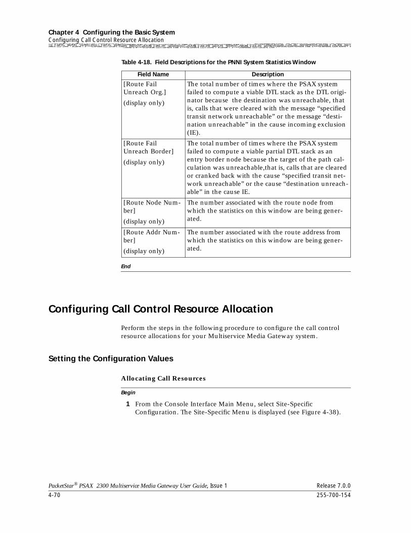
Chapter 4 Configuring the Basic SystemConfiguring Call Control Resource Allocation
4-70 255-700-154
PacketStar® PSAX 2300 Multiservice Media Gateway User Guide, Issue 1 Release 7.0.0
End
Configuring Call Control Resource Allocation
Perform the steps in the following procedure to configure the call control resource allocations for your Multiservice Media Gateway system.
Setting the Configuration Values
Begin
Allocating Call Resources
1 From the Console Interface Main Menu, select Site-Specific Configuration. The Site-Specific Menu is displayed (see Figure 4-38).
[Route Fail Unreach Org.]
(display only)
The total number of times where the PSAX system failed to compute a viable DTL stack as the DTL origi-nator because the destination was unreachable, that is, calls that were cleared with the message “specified transit network unreachable” or the message “desti-nation unreachable” in the cause incoming exclusion (IE).
[Route Fail Unreach Border]
(display only)
The total number of times where the PSAX system failed to compute a viable partial DTL stack as an entry border node because the target of the path cal-culation was unreachable,that is, calls that are cleared or cranked back with the cause “specified transit net-work unreachable” or the cause “destination unreach-able” in the cause IE.
[Route Node Num-ber]
(display only)
The number associated with the route node from which the statistics on this window are being gener-ated.
[Route Addr Num-ber]
(display only)
The number associated with the route address from which the statistics on this window are being gener-ated.
Table 4-18. Field Descriptions for the PNNI System Statistics Window
Field Name Description
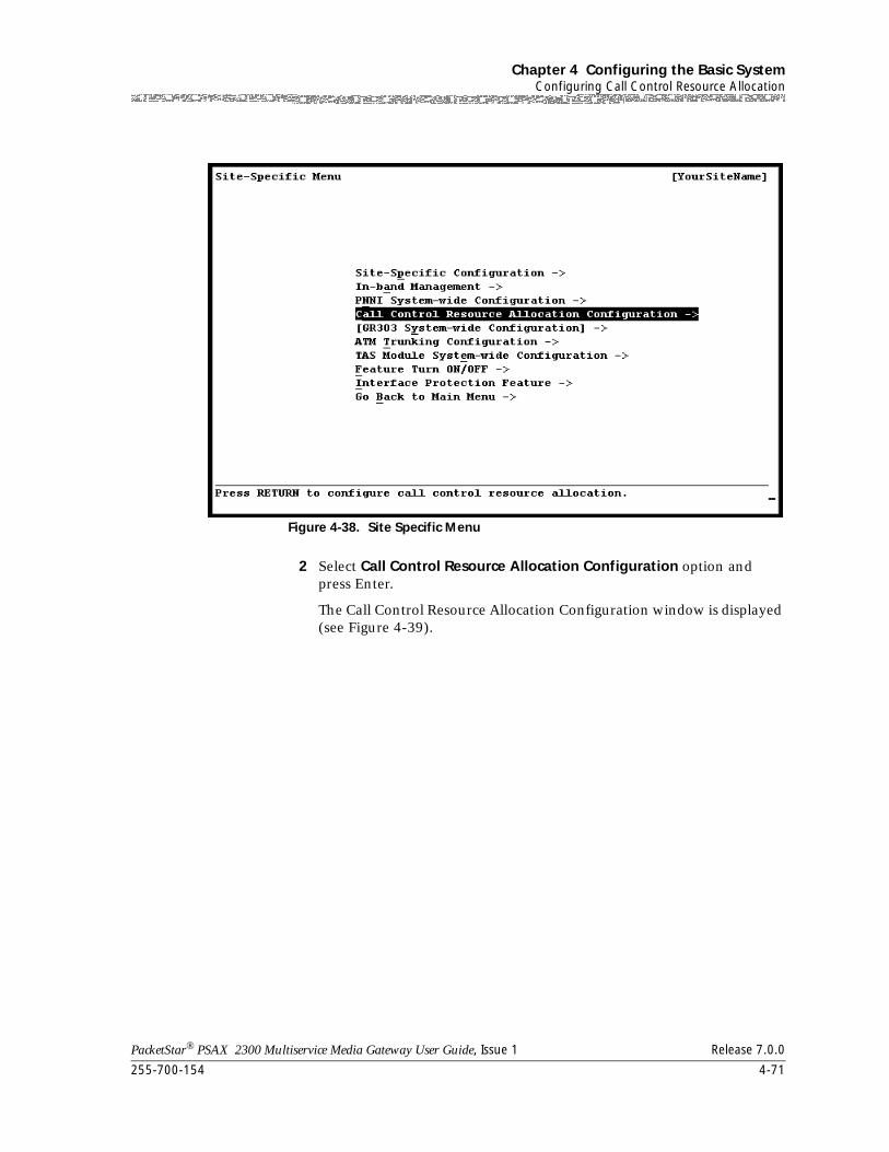
255-700-154 4-71
PacketStar® PSAX 2300 Multiservice Media Gateway User Guide, Issue 1 Release 7.0.0
Chapter 4 Configuring the Basic SystemConfiguring Call Control Resource Allocation
2 Select Call Control Resource Allocation Configuration option and press Enter.
The Call Control Resource Allocation Configuration window is displayed (see Figure 4-39).
Figure 4-38. Site Specific Menu
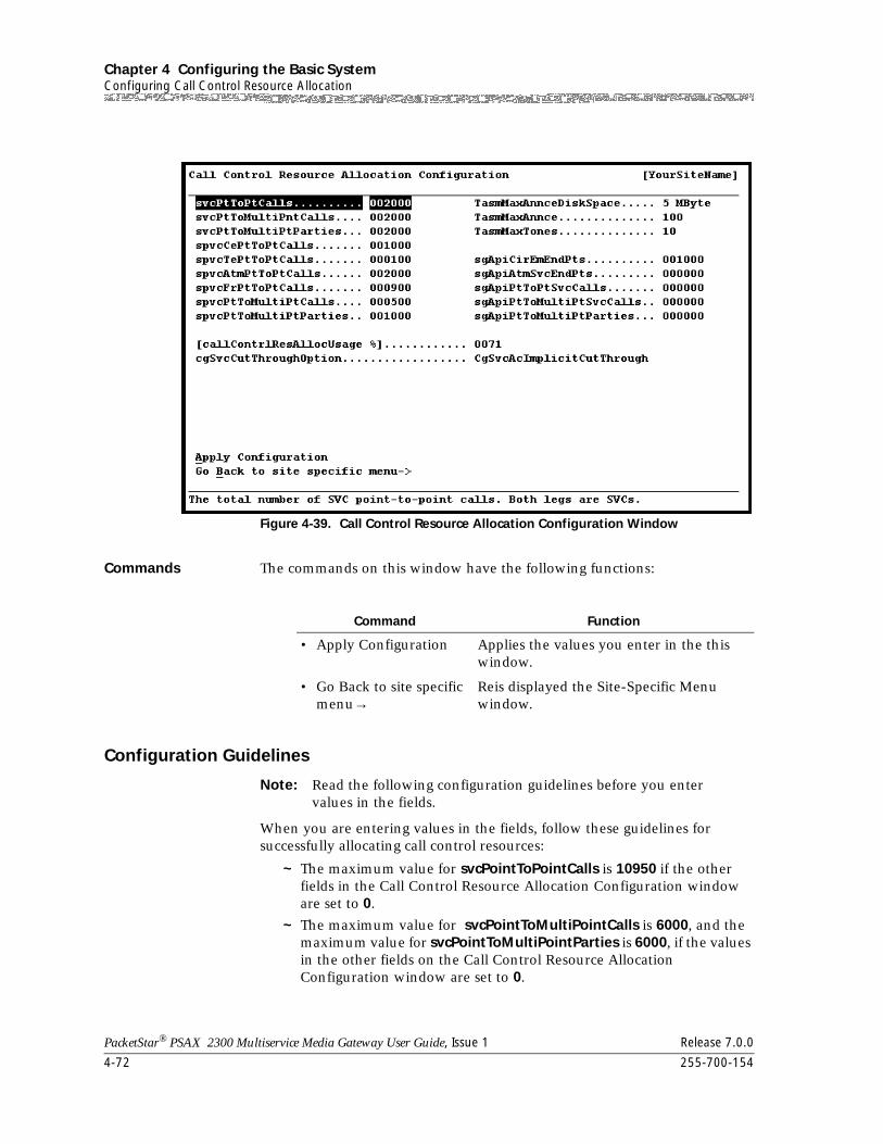
Chapter 4 Configuring the Basic SystemConfiguring Call Control Resource Allocation
4-72 255-700-154
PacketStar® PSAX 2300 Multiservice Media Gateway User Guide, Issue 1 Release 7.0.0
Commands The commands on this window have the following functions:
Configuration Guidelines
Note: Read the following configuration guidelines before you entervalues in the fields.
When you are entering values in the fields, follow these guidelines for successfully allocating call control resources:
~ The maximum value for svcPointToPointCalls is 10950 if the other fields in the Call Control Resource Allocation Configuration window are set to 0.
~ The maximum value for svcPointToMultiPointCalls is 6000, and the maximum value for svcPointToMultiPointParties is 6000, if the values in the other fields on the Call Control Resource Allocation Configuration window are set to 0.
Figure 4-39. Call Control Resource Allocation Configuration Window
Command Function
• Apply Configuration Applies the values you enter in the this window.
• Go Back to site specific menu→
Reis displayed the Site-Specific Menu window.
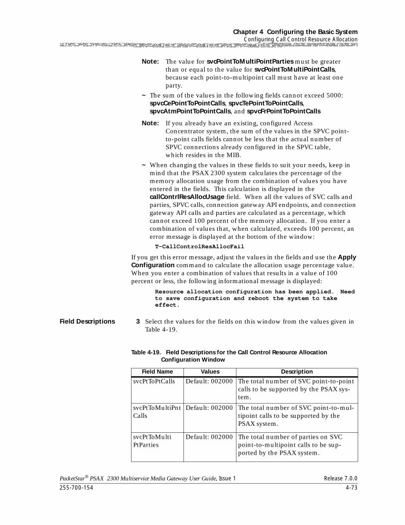
255-700-154 4-73
PacketStar® PSAX 2300 Multiservice Media Gateway User Guide, Issue 1 Release 7.0.0
Chapter 4 Configuring the Basic SystemConfiguring Call Control Resource Allocation
Note: The value for svcPointToMultiPointParties must be greater than or equal to the value for svcPointToMultiPointCalls, because each point-to-multipoint call must have at least one party.
~ The sum of the values in the following fields cannot exceed 5000: spvcCePointToPointCalls, spvcTePointToPointCalls, spvcAtmPointToPointCalls, and spvcFrPointToPointCalls
Note: If you already have an existing, configured Access Concentrator system, the sum of the values in the SPVC point-to-point calls fields cannot be less that the actual number of SPVC connections already configured in the SPVC table, which resides in the MIB.
~ When changing the values in these fields to suit your needs, keep in mind that the PSAX 2300 system calculates the percentage of the memory allocation usage from the combination of values you have entered in the fields. This calculation is displayed in the callContrlResAllocUsage field. When all the values of SVC calls and parties, SPVC calls, connection gateway API endpoints, and connection gateway API calls and parties are calculated as a percentage, which cannot exceed 100 percent of the memory allocation. If you enter a combination of values that, when calculated, exceeds 100 percent, an error message is displayed at the bottom of the window:
T-CallControlResAllocFail
If you get this error message, adjust the values in the fields and use the Apply Configuration command to calculate the allocation usage percentage value. When you enter a combination of values that results in a value of 100 percent or less, the following informational message is displayed:
Resource allocation configuration has been applied. Need to save configuration and reboot the system to take effect.
Field Descriptions 3 Select the values for the fields on this window from the values given in Table 4-19.
Table 4-19. Field Descriptions for the Call Control Resource Allocation Configuration Window
Field Name Values Description
svcPtToPtCalls Default: 002000 The total number of SVC point-to-point calls to be supported by the PSAX sys-tem.
svcPtToMultiPntCalls
Default: 002000 The total number of SVC point-to-mul-tipoint calls to be supported by the PSAX system.
svcPtToMultiPtParties
Default: 002000 The total number of parties on SVC point-to-multipoint calls to be sup-ported by the PSAX system.
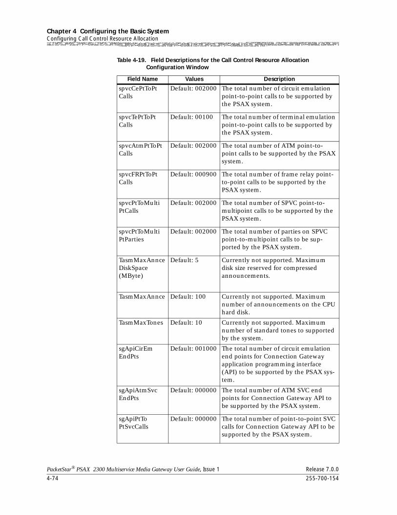
Chapter 4 Configuring the Basic SystemConfiguring Call Control Resource Allocation
4-74 255-700-154
PacketStar® PSAX 2300 Multiservice Media Gateway User Guide, Issue 1 Release 7.0.0
spvcCePtToPtCalls
Default: 002000 The total number of circuit emulation point-to-point calls to be supported by the PSAX system.
spvcTePtToPtCalls
Default: 00100 The total number of terminal emulation point-to-point calls to be supported by the PSAX system.
spvcAtmPtToPtCalls
Default: 002000 The total number of ATM point-to-point calls to be supported by the PSAX system.
spvcFRPtToPtCalls
Default: 000900 The total number of frame relay point-to-point calls to be supported by the PSAX system.
spvcPtToMultiPtCalls
Default: 002000 The total number of SPVC point-to-multipoint calls to be supported by the PSAX system.
spvcPtToMultiPtParties
Default: 002000 The total number of parties on SPVC point-to-multipoint calls to be sup-ported by the PSAX system.
TasmMaxAnnceDiskSpace (MByte)
Default: 5 Currently not supported. Maximum disk size reserved for compressed announcements.
TasmMaxAnnce Default: 100 Currently not supported. Maximum number of announcements on the CPU hard disk.
TasmMaxTones Default: 10 Currently not supported. Maximum number of standard tones to supported by the system.
sgApiCirEmEndPts
Default: 001000 The total number of circuit emulation end points for Connection Gateway application programming interface (API) to be supported by the PSAX sys-tem.
sgApiAtmSvcEndPts
Default: 000000 The total number of ATM SVC end points for Connection Gateway API to be supported by the PSAX system.
sgApiPtToPtSvcCalls
Default: 000000 The total number of point-to-point SVC calls for Connection Gateway API to be supported by the PSAX system.
Table 4-19. Field Descriptions for the Call Control Resource Allocation Configuration Window
Field Name Values Description
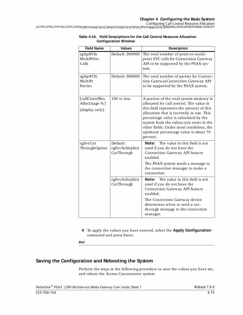
255-700-154 4-75
PacketStar® PSAX 2300 Multiservice Media Gateway User Guide, Issue 1 Release 7.0.0
Chapter 4 Configuring the Basic SystemConfiguring Call Control Resource Allocation
4 To apply the values you have entered, select the Apply Configuration command and press Enter.
End
Saving the Configuration and Rebooting the System
Perform the steps in the following procedure to save the values you have set, and reboot the Access Concentrator system
sgApiPtToMultiPtSvcCalls
Default: 000000 The total number of point-to-multi-point SVC calls for Connection Gateway API to be supported by the PSAX sys-tem.
sgApiPtToMultiPtParties
Default: 000000 The total number of parties for Connec-tion GatewayConnection Gateway API to be supported by the PSAX system.
[callContrlResAllocUsage %]
(display only)
100 or less A portion of the total system memory is allocated for call control. The value in this field represents the amount of this allocation that is currently in use. This percentage value is calculated by the system from the values you enter in the other fields. Under most conditions, the optimum percentage value is about 70 percent.
cgSvcCutThroughOption
Default:cgSvcAcImplicitCutThrough
Note: The value in this field is not used if you do not have the Connection Gateway API feature enabled.
The PSAX system sends a message to the connection manager to make a connection.
cgSvcAcExplicitCutThrough
Note: The value in this field is not used if you do not have the Connection Gateway API feature enabled.
The Connection Gateway device determines when to send a cut-through message to the connection manager.
Table 4-19. Field Descriptions for the Call Control Resource Allocation Configuration Window
Field Name Values Description
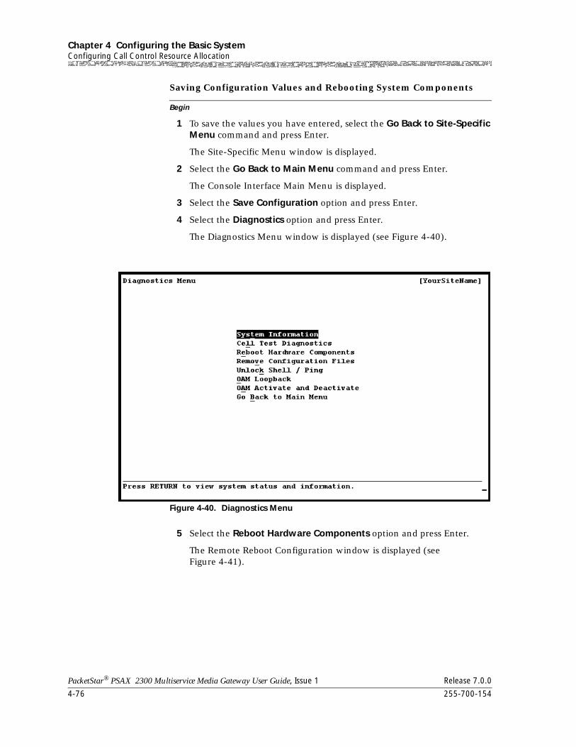
Chapter 4 Configuring the Basic SystemConfiguring Call Control Resource Allocation
4-76 255-700-154
PacketStar® PSAX 2300 Multiservice Media Gateway User Guide, Issue 1 Release 7.0.0
Begin
Saving Configuration Values and Rebooting System Components
1 To save the values you have entered, select the Go Back to Site-Specific Menu command and press Enter.
The Site-Specific Menu window is displayed.
2 Select the Go Back to Main Menu command and press Enter.
The Console Interface Main Menu is displayed.
3 Select the Save Configuration option and press Enter.
4 Select the Diagnostics option and press Enter.
The Diagnostics Menu window is displayed (see Figure 4-40).
5 Select the Reboot Hardware Components option and press Enter.
The Remote Reboot Configuration window is displayed (see Figure 4-41).
Figure 4-40. Diagnostics Menu
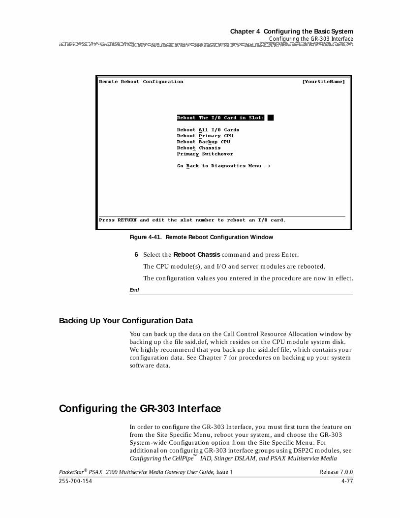
255-700-154 4-77
PacketStar® PSAX 2300 Multiservice Media Gateway User Guide, Issue 1 Release 7.0.0
Chapter 4 Configuring the Basic SystemConfiguring the GR-303 Interface
6 Select the Reboot Chassis command and press Enter.
The CPU module(s), and I/O and server modules are rebooted.
The configuration values you entered in the procedure are now in effect.
End
Backing Up Your Configuration Data
You can back up the data on the Call Control Resource Allocation window by backing up the file ssid.def, which resides on the CPU module system disk. We highly recommend that you back up the ssid.def file, which contains your configuration data. See Chapter 7 for procedures on backing up your system software data.
Configuring the GR-303 Interface
In order to configure the GR-303 Interface, you must first turn the feature on from the Site Specific Menu, reboot your system, and choose the GR-303 System-wide Configuration option from the Site Specific Menu. For additional on configuring GR-303 interface groups using DSP2C modules, see Configuring the CellPipe™ IAD, Stinger DSLAM, and PSAX Multiservice Media
Figure 4-41. Remote Reboot Configuration Window
Chapter 4 Configuring the Basic SystemConfiguring ATM Trunking
4-78 255-700-154
PacketStar® PSAX 2300 Multiservice Media Gateway User Guide, Issue 1 Release 7.0.0
Gateway as Interworking Functions Using the GR-303 Standard: Application Note, Issue 1, Release 6.5.0, Document Number 255-700-135.
Configuring ATM Trunking
ATM trunking configuration supports nonswitched IWF trunks.
Configuring Nonswitched IWF Trunks
For configuring IWF trunks in nonswitched mode, the following list describes the tasks you need to perform:
1. Configuring the local IWF node (see the procedure “Configuring the Local IWF Node”)
2. Configuring the remote IWF nodes (see the procedure ”Configuring the Remote IWF Nodes” on page 4-81)
3. Configuring one or more bearer VCC identifiers and their parameters (see the procedure ”Adding a Bearer VCC Identifier” on page 4-85)
In addition, you can view all ATM trunking configuration information for both switched and nonswitched IWF trunks (see the procedure ”Viewing ATM Trunking Information” on page 4-91)
To configure the system for ATM trunking, perform the steps in the following procedures.
Configuring the Local IWF Node
Begin
Configuring the Local IWF Node
1 On the Console Interface Main Menu window, select the Site-Specific Configuration option and press Enter.
The Site-Specific Menu window (Figure 4-42) is displayed.
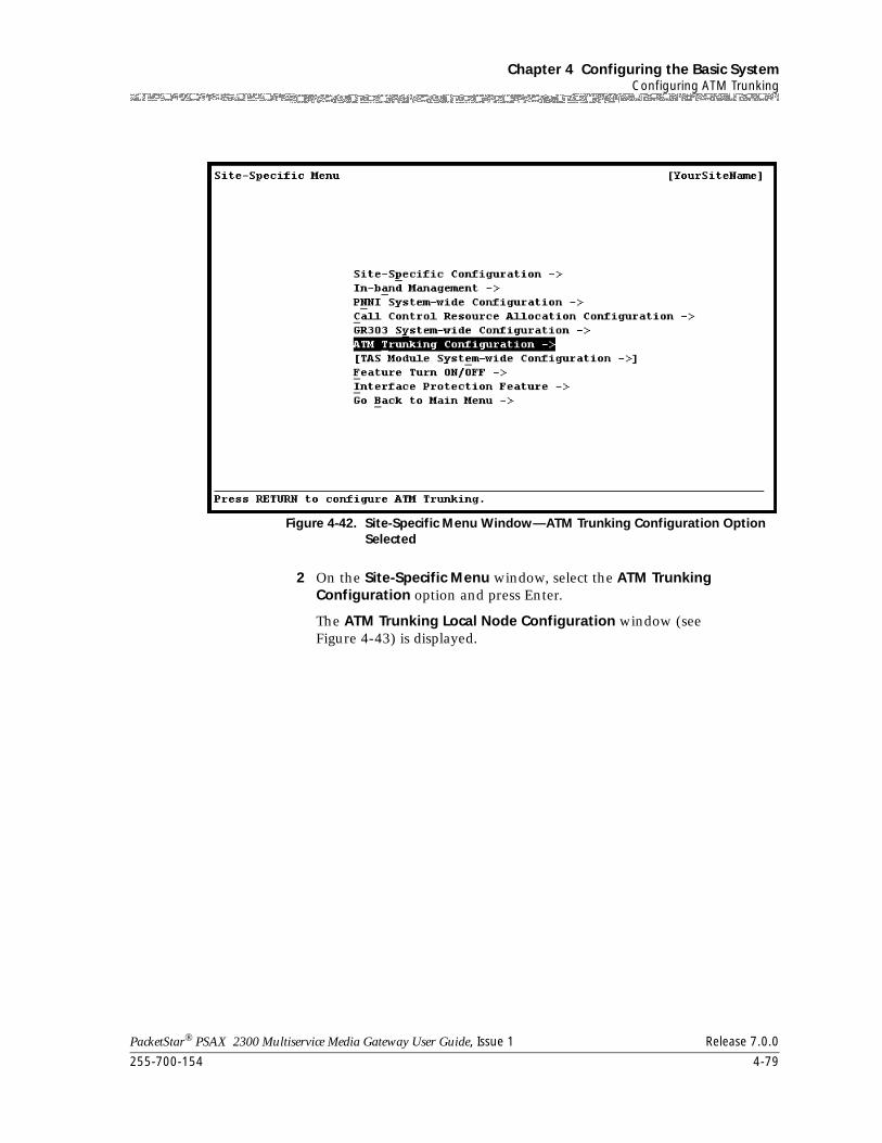
255-700-154 4-79
PacketStar® PSAX 2300 Multiservice Media Gateway User Guide, Issue 1 Release 7.0.0
Chapter 4 Configuring the Basic SystemConfiguring ATM Trunking
2 On the Site-Specific Menu window, select the ATM Trunking Configuration option and press Enter.
The ATM Trunking Local Node Configuration window (see Figure 4-43) is displayed.
Figure 4-42. Site-Specific Menu Window—ATM Trunking Configuration Option Selected
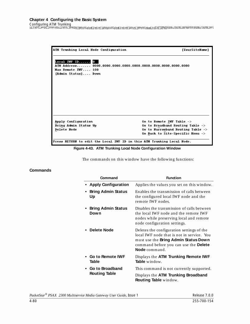
Chapter 4 Configuring the Basic SystemConfiguring ATM Trunking
4-80 255-700-154
PacketStar® PSAX 2300 Multiservice Media Gateway User Guide, Issue 1 Release 7.0.0
The commands on this window have the following functions:
Commands
Figure 4-43. ATM Trunking Local Node Configuration Window
Command Function
• Apply Configuration Applies the values you set on this window.
• Bring Admin Status Up
Enables the transmission of calls between the configured local IWF node and the remote IWF nodes.
• Bring Admin Status Down
Disables the transmission of calls between the local IWF node and the remote IWF nodes while preserving local and remote node configuration settings.
• Delete Node Deletes the configuration settings of the local IWF node that is not in service. You must use the Bring Admin Status Down command before you can use the Delete Node command.
• Go to Remote IWF Table
Displays the ATM Trunking Remote IWF Table window.
• Go to Broadband Routing Table
This command is not currently supported.
Displays the ATM Trunking Broadband Routing Table window.
255-700-154 4-81
PacketStar® PSAX 2300 Multiservice Media Gateway User Guide, Issue 1 Release 7.0.0
Chapter 4 Configuring the Basic SystemConfiguring ATM Trunking
3 Select the values for the fields on this window from the values given in Table 4-20.
Field Descriptions
4 To apply the configuration values, select the Apply Configuration command and press Enter.
End
After you have completed configuring the local IWF node, configure the remote IWF nodes. You can configure a maximum of 100 remote IWF nodes per PSAX system.
Configuring a Remote IWF Node
Begin
Configuring the Remote IWF Nodes
1 On the ATM Trunking Local Node Configuration window, select the Go to Remote IWF Table command and press Enter.
• Go to Narrowband Routing Table
This command is not currently supported.
Displays the ATM Trunking Narrowband Routing Table window.
• Go Back to Site-Spe-cific Menu
Redisplays the Site-Specific Menu win-dow.
Command Function
Table 4-20. Field Descriptions for the ATM Trunking Local Node Configuration Window
Field Name Values Description
Local IWF ID Default: 0 Local interworking function (IWF) identifier for the local endpoint.
ATM Address Varies IWF ATM address for the local end-point. Type an address in hexadecimal format up to 20 bytes (160 bits) long (10 groups of 4 characters each).
Max Remote IWF
Default: 100 Maximum number of remote IWF IDs that can be connected to the local end-point.
[Admin Status] Default: Up,
Down
Indicates whether the local IWF is active or not.
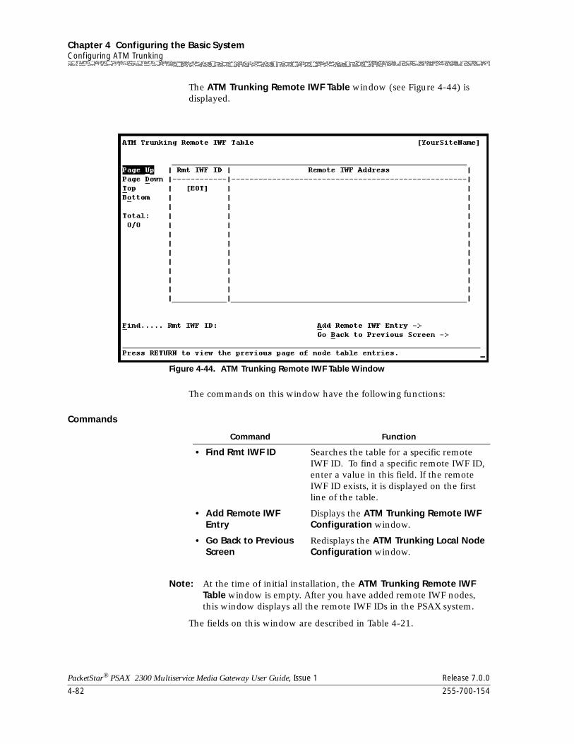
Chapter 4 Configuring the Basic SystemConfiguring ATM Trunking
4-82 255-700-154
PacketStar® PSAX 2300 Multiservice Media Gateway User Guide, Issue 1 Release 7.0.0
The ATM Trunking Remote IWF Table window (see Figure 4-44) is displayed.
The commands on this window have the following functions:
Commands
Note: At the time of initial installation, the ATM Trunking Remote IWF Table window is empty. After you have added remote IWF nodes, this window displays all the remote IWF IDs in the PSAX system.
The fields on this window are described in Table 4-21.
Figure 4-44. ATM Trunking Remote IWF Table Window
Command Function
• Find Rmt IWF ID Searches the table for a specific remote IWF ID. To find a specific remote IWF ID, enter a value in this field. If the remote IWF ID exists, it is displayed on the first line of the table.
• Add Remote IWF Entry
Displays the ATM Trunking Remote IWF Configuration window.
• Go Back to Previous Screen
Redisplays the ATM Trunking Local Node Configuration window.
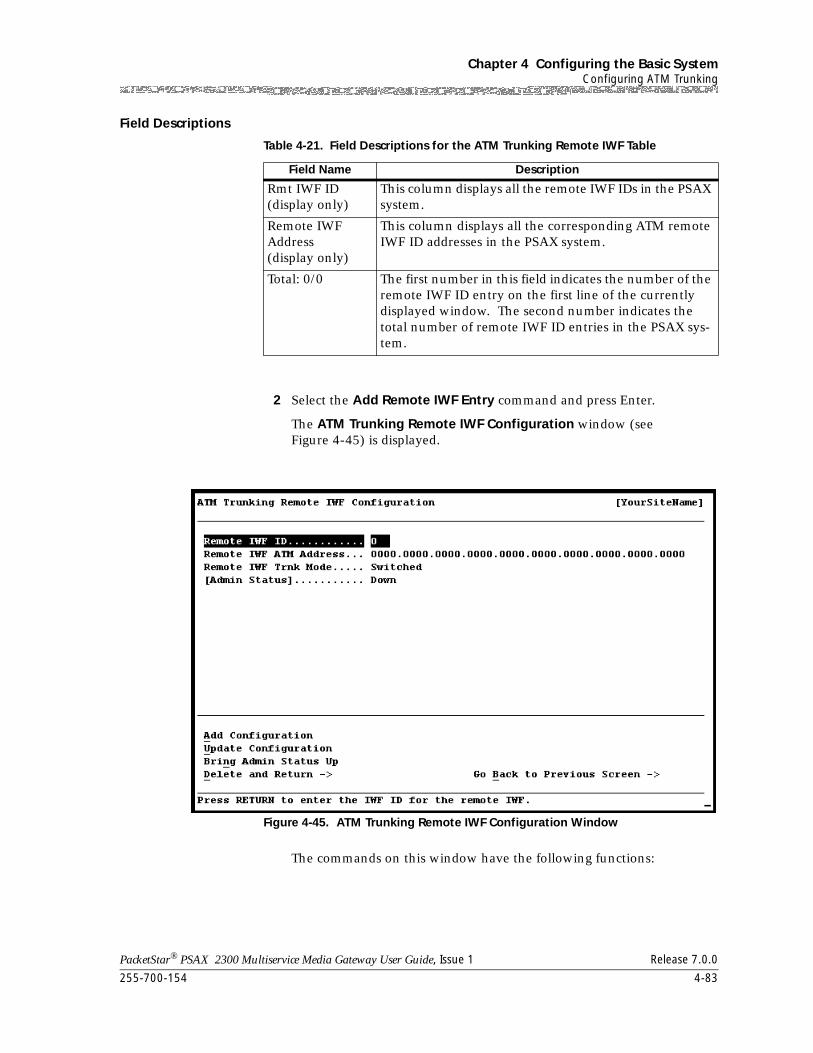
255-700-154 4-83
PacketStar® PSAX 2300 Multiservice Media Gateway User Guide, Issue 1 Release 7.0.0
Chapter 4 Configuring the Basic SystemConfiguring ATM Trunking
Field Descriptions
2 Select the Add Remote IWF Entry command and press Enter.
The ATM Trunking Remote IWF Configuration window (see Figure 4-45) is displayed.
The commands on this window have the following functions:
Table 4-21. Field Descriptions for the ATM Trunking Remote IWF Table
Field Name Description
Rmt IWF ID(display only)
This column displays all the remote IWF IDs in the PSAX system.
Remote IWF Address(display only)
This column displays all the corresponding ATM remote IWF ID addresses in the PSAX system.
Total: 0/0 The first number in this field indicates the number of the remote IWF ID entry on the first line of the currently displayed window. The second number indicates the total number of remote IWF ID entries in the PSAX sys-tem.
Figure 4-45. ATM Trunking Remote IWF Configuration Window
Chapter 4 Configuring the Basic SystemConfiguring ATM Trunking
4-84 255-700-154
PacketStar® PSAX 2300 Multiservice Media Gateway User Guide, Issue 1 Release 7.0.0
3 Select the values for the fields on this window from the values given in Table 4-22.
Command Function
• Add Configuration Applies the values you set on this window.
• Update Configuration This command is not currently supported.
• Bring Admin Status Up
When the value in the [Admin Status] field is Down, brings the remote IWF node to the status Up.
• Bring Admin Status Down
When the value in the [Admin Status] field is Up, brings the remote IWF node to the status Down.
• Delete and Return Deletes the remote IWF node that is not in service.
• Go to Sig VCC Table This command is not currently supported.
Displays the ATM Trunking Sig VCC Table window. This command is displayed only after you have added a remote IWF ID.
• Go to Bearer VCC Table
Displays the ATM Trunking Bearer VCC Table window. This command is displayed only after you have added a remote IWF ID.
• Go to Data Channel Table
Displays the ATM Trunking Data Channel Table window.
This command is displayed only after you have added a remote IWF ID.
• Go Back to Previous Screen
Redisplays the ATM Trunking Remote IWF Table window
Table 4-22. Field Descriptions for the ATM Trunking Remote IWF Configuration Window
Field Name Values Description
Remote IWF ID Default: 0 Remote interworking function (IWF) identifier for the remote endpoint.
Remote IWF ATM Address
User-assigned IWF ATM address for the remote end-point. Type an address in hexadecimal format up to 20 bytes (160) bits long (10 groups of 4 characters each).
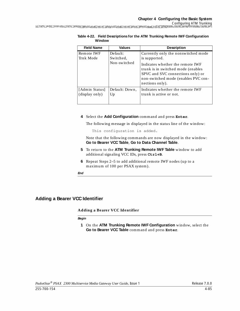
255-700-154 4-85
PacketStar® PSAX 2300 Multiservice Media Gateway User Guide, Issue 1 Release 7.0.0
Chapter 4 Configuring the Basic SystemConfiguring ATM Trunking
4 Select the Add Configuration command and press Enter.
The following message in displayed in the status line of the window:
This configuration is added.
Note that the following commands are now displayed in the window: Go to Bearer VCC Table, Go to Data Channel Table.
5 To return to the ATM Trunking Remote IWF Table window to add additional signaling VCC IDs, press Ctrl+B.
6 Repeat Steps 2–5 to add additional remote IWF nodes (up to a maximum of 100 per PSAX system).
End
Adding a Bearer VCC Identifier
Begin
Adding a Bearer VCC Identifier
1 On the ATM Trunking Remote IWF Configuration window, select the Go to Bearer VCC Table command and press Enter.
Remote IWF Trnk Mode
Default: Switched,Non-switched
Currently only the nonswitched mode is supported.
Indicates whether the remote IWF trunk is in switched mode (enables SPVC and SVC connections only) or non-switched mode (enables PVC con-nections only).
[Admin Status](display only)
Default: Down,Up
Indicates whether the remote IWF trunk is active or not.
Table 4-22. Field Descriptions for the ATM Trunking Remote IWF Configuration Window
Field Name Values Description
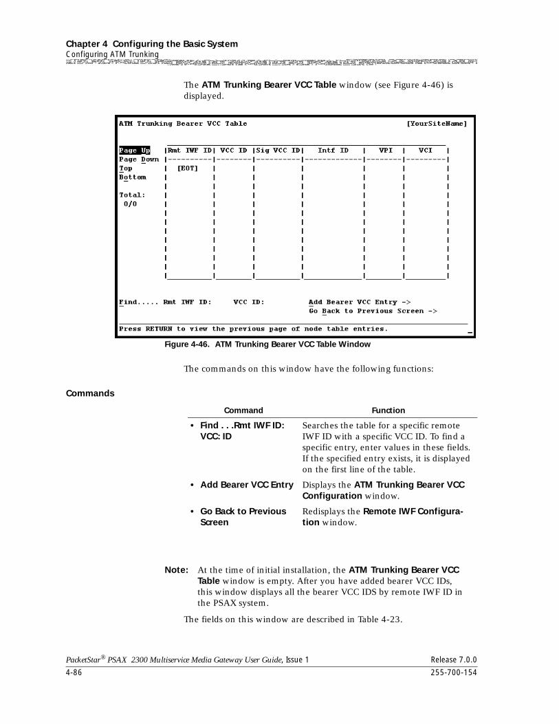
Chapter 4 Configuring the Basic SystemConfiguring ATM Trunking
4-86 255-700-154
PacketStar® PSAX 2300 Multiservice Media Gateway User Guide, Issue 1 Release 7.0.0
The ATM Trunking Bearer VCC Table window (see Figure 4-46) is displayed.
The commands on this window have the following functions:
Commands
Note: At the time of initial installation, the ATM Trunking Bearer VCC Table window is empty. After you have added bearer VCC IDs, this window displays all the bearer VCC IDS by remote IWF ID in the PSAX system.
The fields on this window are described in Table 4-23.
Figure 4-46. ATM Trunking Bearer VCC Table Window
Command Function
• Find . . .Rmt IWF ID:VCC: ID
Searches the table for a specific remote IWF ID with a specific VCC ID. To find a specific entry, enter values in these fields. If the specified entry exists, it is displayed on the first line of the table.
• Add Bearer VCC Entry Displays the ATM Trunking Bearer VCC Configuration window.
• Go Back to Previous Screen
Redisplays the Remote IWF Configura-tion window.
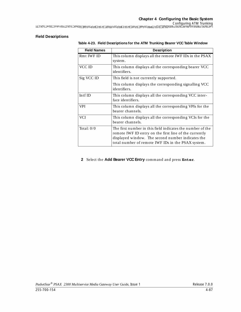
255-700-154 4-87
PacketStar® PSAX 2300 Multiservice Media Gateway User Guide, Issue 1 Release 7.0.0
Chapter 4 Configuring the Basic SystemConfiguring ATM Trunking
Field Descriptions
2 Select the Add Bearer VCC Entry command and press Enter.
Table 4-23. Field Descriptions for the ATM Trunking Bearer VCC Table Window
Field Names Description
Rmt IWF ID This column displays all the remote IWF IDs in the PSAX system.
VCC ID This column displays all the corresponding bearer VCC identifiers.
Sig VCC ID This field is not currently supported.
This column displays the corresponding signalling VCC identifiers.
Intf ID This column displays all the corresponding VCC inter-face identifiers.
VPI This column displays all the corresponding VPIs for the bearer channels.
VCI This column displays all the corresponding VCIs for the bearer channels.
Total: 0/0 The first number in this field indicates the number of the remote IWF ID entry on the first line of the currently displayed window. The second number indicates the total number of remote IWF IDs in the PSAX system.
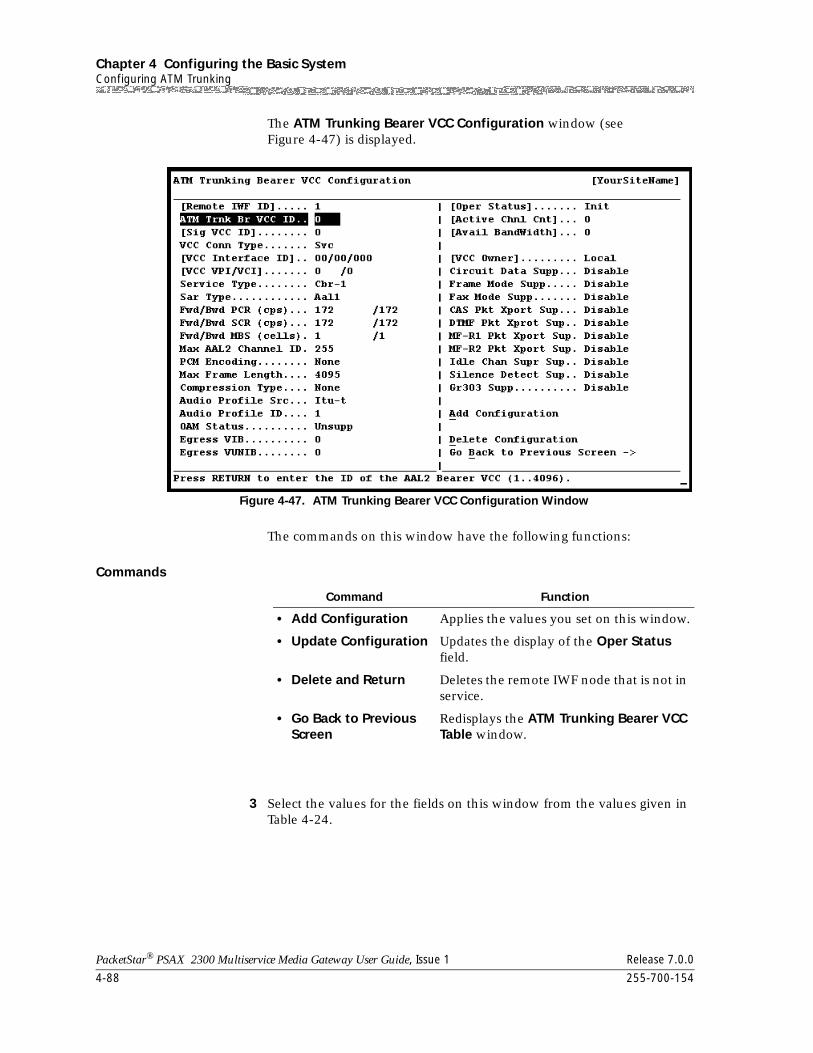
Chapter 4 Configuring the Basic SystemConfiguring ATM Trunking
4-88 255-700-154
PacketStar® PSAX 2300 Multiservice Media Gateway User Guide, Issue 1 Release 7.0.0
The ATM Trunking Bearer VCC Configuration window (see Figure 4-47) is displayed.
The commands on this window have the following functions:
Commands
3 Select the values for the fields on this window from the values given in Table 4-24.
Figure 4-47. ATM Trunking Bearer VCC Configuration Window
Command Function
• Add Configuration Applies the values you set on this window.
• Update Configuration Updates the display of the Oper Status field.
• Delete and Return Deletes the remote IWF node that is not in service.
• Go Back to Previous Screen
Redisplays the ATM Trunking Bearer VCC Table window.
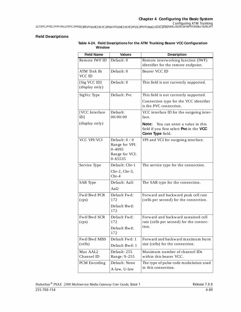
255-700-154 4-89
PacketStar® PSAX 2300 Multiservice Media Gateway User Guide, Issue 1 Release 7.0.0
Chapter 4 Configuring the Basic SystemConfiguring ATM Trunking
Field Descriptions
Table 4-24. Field Descriptions for the ATM Trunking Bearer VCC Configuration Window
Field Name Values Description
Remote IWF ID Default: 0 Remote interworking function (IWF) identifier for the remote endpoint.
ATM Trnk Br VCC ID
Default: 0 Bearer VCC ID
[Sig VCC ID](display only)
Default: 0 This field is not currently supported.
SigVcc Type Default: Pvc This field is not currently supported.
Connection type for the VCC identifier is the PVC connection.
[VCC Interface ID]
(display only)
Default: 00/00/00
VCC interface ID for the outgoing inter-face.
Note: You can enter a value in this field if you first select Pvc in the VCC Conn Type field.
VCC VPI/VCI Default: 0 / 0Range for VPI: 0–4095Range for VCI: 0–65535
VPI and VCI for outgoing interface.
Service Type Default: Cbr-1
Cbr-2, Cbr-3, Cbr-4
The service type for the connection.
SAR Type Default: Aal1
Aal2
The SAR type for the connection.
Fwd/Bwd PCR (cps)
Default Fwd: 172
Default Bwd: 172
Forward and backward peak cell rate (cells per second) for the connection.
Fwd/Bwd SCR (cps)
Default Fwd: 172
Default Bwd: 172
Forward and backward sustained cell rate (cells per second) for the connec-tion.
Fwd/Bwd MBS (cells)
Default Fwd: 1
Default Bwd: 1
Forward and backward maximum burst size (cells) for the connection.
Max AAL2 Channel ID
Default: 255Range: 9–255
Maximum number of channel IDs within this bearer VCC.
PCM Encoding Default: None
A-law, U-law
The type of pulse code modulation used in this connection.
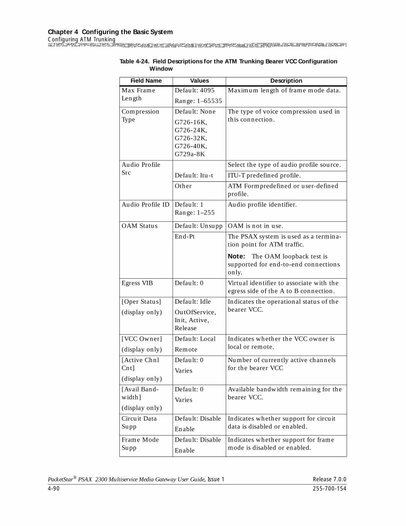
Chapter 4 Configuring the Basic SystemConfiguring ATM Trunking
4-90 255-700-154
PacketStar® PSAX 2300 Multiservice Media Gateway User Guide, Issue 1 Release 7.0.0
Max Frame Length
Default: 4095
Range: 1–65535
Maximum length of frame mode data.
Compression Type
Default: None
G726-16K,G726-24K,G726-32K,G726-40K,G729a-8K
The type of voice compression used in this connection.
Audio Profile Src
Select the type of audio profile source.
Default: Itu-t ITU-T predefined profile.
Other ATM Formpredefined or user-defined profile.
Audio Profile ID Default: 1Range: 1–255
Audio profile identifier.
OAM Status Default: Unsupp OAM is not in use.
End-Pt The PSAX system is used as a termina-tion point for ATM traffic.
Note: The OAM loopback test is supported for end-to-end connections only.
Egress VIB Default: 0 Virtual identifier to associate with the egress side of the A to B connection.
[Oper Status]
(display only)
Default: Idle
OutOfService,Init, Active, Release
Indicates the operational status of the bearer VCC.
[VCC Owner]
(display only)
Default: Local
Remote
Indicates whether the VCC owner is local or remote.
[Active Chnl Cnt]
(display only)
Default: 0
Varies
Number of currently active channels for the bearer VCC
[Avail Band-width]
(display only)
Default: 0
Varies
Available bandwidth remaining for the bearer VCC.
Circuit Data Supp
Default: Disable
Enable
Indicates whether support for circuit data is disabled or enabled.
Frame Mode Supp
Default: Disable
Enable
Indicates whether support for frame mode is disabled or enabled.
Table 4-24. Field Descriptions for the ATM Trunking Bearer VCC Configuration Window
Field Name Values Description
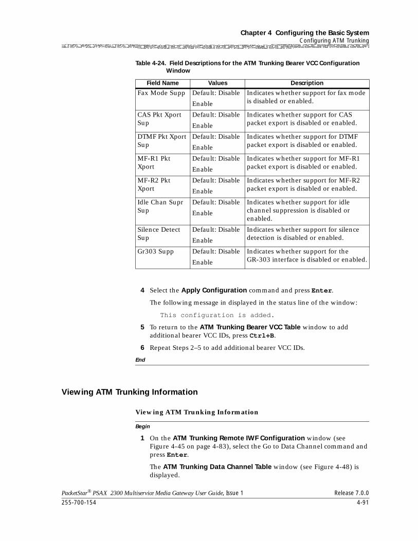
255-700-154 4-91
PacketStar® PSAX 2300 Multiservice Media Gateway User Guide, Issue 1 Release 7.0.0
Chapter 4 Configuring the Basic SystemConfiguring ATM Trunking
4 Select the Apply Configuration command and press Enter.
The following message in displayed in the status line of the window:
This configuration is added.
5 To return to the ATM Trunking Bearer VCC Table window to add additional bearer VCC IDs, press Ctrl+B.
6 Repeat Steps 2–5 to add additional bearer VCC IDs.
End
Viewing ATM Trunking Information
Begin
Viewing ATM Trunking Information
1 On the ATM Trunking Remote IWF Configuration window (see Figure 4-45 on page 4-83), select the Go to Data Channel command and press Enter.
The ATM Trunking Data Channel Table window (see Figure 4-48) is displayed.
Fax Mode Supp Default: Disable
Enable
Indicates whether support for fax mode is disabled or enabled.
CAS Pkt Xport Sup
Default: Disable
Enable
Indicates whether support for CAS packet export is disabled or enabled.
DTMF Pkt Xport Sup
Default: Disable
Enable
Indicates whether support for DTMF packet export is disabled or enabled.
MF-R1 Pkt Xport
Default: Disable
Enable
Indicates whether support for MF-R1 packet export is disabled or enabled.
MF-R2 Pkt Xport
Default: Disable
Enable
Indicates whether support for MF-R2 packet export is disabled or enabled.
Idle Chan Supr Sup
Default: Disable
Enable
Indicates whether support for idle channel suppression is disabled or enabled.
Silence Detect Sup
Default: Disable
Enable
Indicates whether support for silence detection is disabled or enabled.
Gr303 Supp Default: Disable
Enable
Indicates whether support for the GR-303 interface is disabled or enabled.
Table 4-24. Field Descriptions for the ATM Trunking Bearer VCC Configuration Window
Field Name Values Description
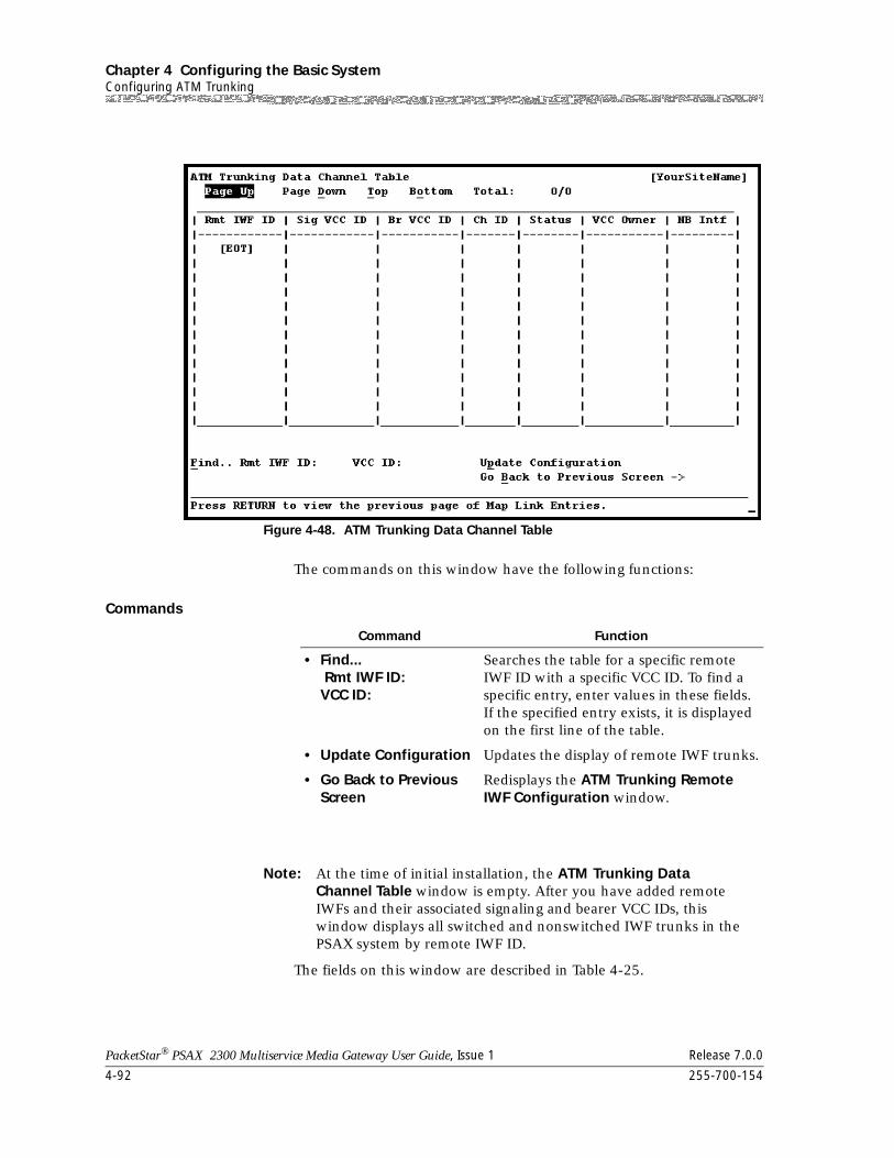
Chapter 4 Configuring the Basic SystemConfiguring ATM Trunking
4-92 255-700-154
PacketStar® PSAX 2300 Multiservice Media Gateway User Guide, Issue 1 Release 7.0.0
The commands on this window have the following functions:
Commands
Note: At the time of initial installation, the ATM Trunking Data Channel Table window is empty. After you have added remote IWFs and their associated signaling and bearer VCC IDs, this window displays all switched and nonswitched IWF trunks in the PSAX system by remote IWF ID.
The fields on this window are described in Table 4-25.
Figure 4-48. ATM Trunking Data Channel Table
Command Function
• Find... Rmt IWF ID: VCC ID:
Searches the table for a specific remote IWF ID with a specific VCC ID. To find a specific entry, enter values in these fields. If the specified entry exists, it is displayed on the first line of the table.
• Update Configuration Updates the display of remote IWF trunks.
• Go Back to Previous Screen
Redisplays the ATM Trunking Remote IWF Configuration window.
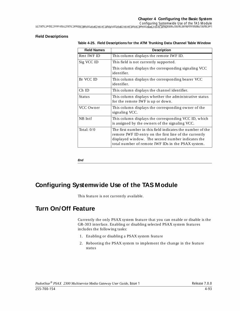
255-700-154 4-93
PacketStar® PSAX 2300 Multiservice Media Gateway User Guide, Issue 1 Release 7.0.0
Chapter 4 Configuring the Basic SystemConfiguring Systemwide Use of the TAS Module
Field Descriptions
End
Configuring Systemwide Use of the TAS Module
This feature is not currently available.
Turn On/Off Feature
Currently the only PSAX system feature that you can enable or disable is the GR-303 interface. Enabling or disabling selected PSAX system features includes the following tasks:
1. Enabling or disabling a PSAX system feature
2. Rebooting the PSAX system to implement the change in the feature status
Table 4-25. Field Descriptions for the ATM Trunking Data Channel Table Window
Field Names Description
Rmt IWF ID This column displays the remote IWF ID.
Sig VCC ID This field is not currently supported.
This column displays the corresponding signaling VCC identifier.
Br VCC ID This column displays the corresponding bearer VCC identifier.
Ch ID This column displays the channel identifier.
Status This column displays whether the administrative status for the remote IWF is up or down.
VCC Owner This column displays the corresponding owner of the signaling VCC.
NB Intf This column displays the corresponding VCC ID, which is assigned by the owners of the signaling VCC.
Total: 0/0 The first number in this field indicates the number of the remote IWF ID entry on the first line of the currently displayed window. The second number indicates the total number of remote IWF IDs in the PSAX system.
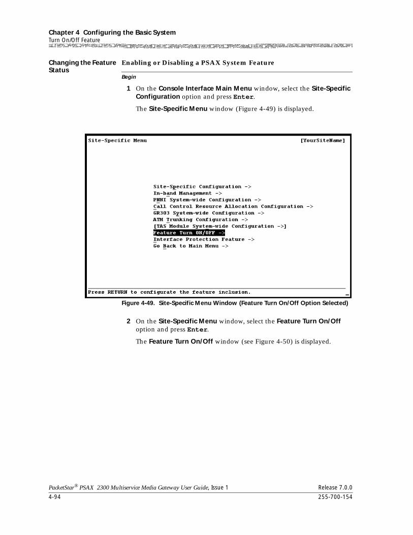
Chapter 4 Configuring the Basic SystemTurn On/Off Feature
4-94 255-700-154
PacketStar® PSAX 2300 Multiservice Media Gateway User Guide, Issue 1 Release 7.0.0
Changing the Feature Status
Begin
Enabling or Disabling a PSAX System Feature
1 On the Console Interface Main Menu window, select the Site-Specific Configuration option and press Enter.
The Site-Specific Menu window (Figure 4-49) is displayed.
2 On the Site-Specific Menu window, select the Feature Turn On/Off option and press Enter.
The Feature Turn On/Off window (see Figure 4-50) is displayed.
Figure 4-49. Site-Specific Menu Window (Feature Turn On/Off Option Selected)
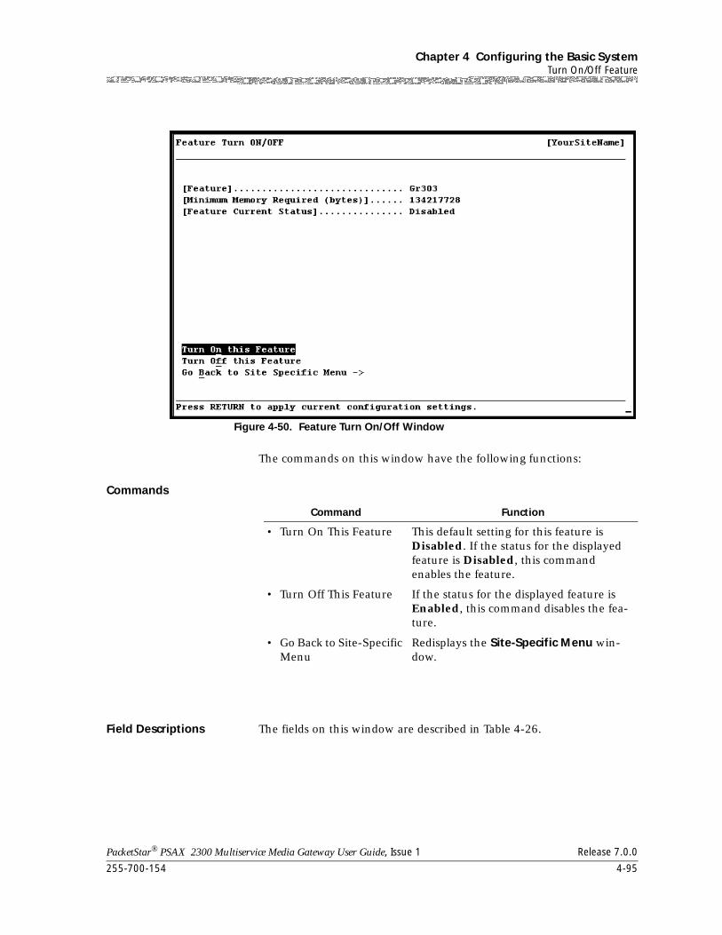
255-700-154 4-95
PacketStar® PSAX 2300 Multiservice Media Gateway User Guide, Issue 1 Release 7.0.0
Chapter 4 Configuring the Basic SystemTurn On/Off Feature
The commands on this window have the following functions:
Commands
Field Descriptions The fields on this window are described in Table 4-26.
Figure 4-50. Feature Turn On/Off Window
Command Function
• Turn On This Feature This default setting for this feature is Disabled. If the status for the displayed feature is Disabled, this command enables the feature.
• Turn Off This Feature If the status for the displayed feature is Enabled, this command disables the fea-ture.
• Go Back to Site-Specific Menu
Redisplays the Site-Specific Menu win-dow.
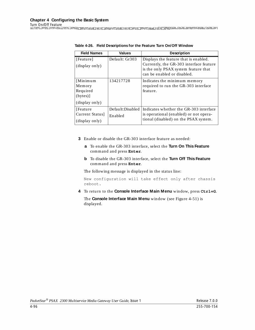
Chapter 4 Configuring the Basic SystemTurn On/Off Feature
4-96 255-700-154
PacketStar® PSAX 2300 Multiservice Media Gateway User Guide, Issue 1 Release 7.0.0
3 Enable or disable the GR-303 interface feature as needed:
a To enable the GR-303 interface, select the Turn On This Feature command and press Enter.
b To disable the GR-303 interface, select the Turn Off This Feature command and press Enter.
The following message is displayed in the status line:
New configuration will take effect only after chassis reboot.
4 To return to the Console Interface Main Menu window, press Ctrl+G.
The Console Interface Main Menu window (see Figure 4-51) is displayed.
Table 4-26. Field Descriptions for the Feature Turn On/Off Window
Field Names Values Description
[Feature]
(display only)
Default: Gr303 Displays the feature that is enabled. Currently, the GR-303 interface feature is the only PSAX system feature that can be enabled or disabled.
[Minimum Memory Required (bytes)]
(display only)
134217728 Indicates the minimum memory required to run the GR-303 interface feature.
[Feature Current Status]
(display only)
Default:Disabled
Enabled
Indicates whether the GR-303 interface is operational (enabled) or not opera-tional (disabled) on the PSAX system.
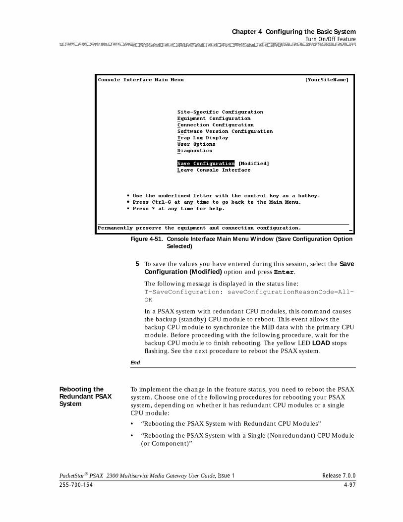
255-700-154 4-97
PacketStar® PSAX 2300 Multiservice Media Gateway User Guide, Issue 1 Release 7.0.0
Chapter 4 Configuring the Basic SystemTurn On/Off Feature
5 To save the values you have entered during this session, select the Save Configuration (Modified) option and press Enter.
The following message is displayed in the status line:T-SaveConfiguration: saveConfigurationReasonCode=All-OK
In a PSAX system with redundant CPU modules, this command causes the backup (standby) CPU module to reboot. This event allows the backup CPU module to synchronize the MIB data with the primary CPU module. Before proceeding with the following procedure, wait for the backup CPU module to finish rebooting. The yellow LED LOAD stops flashing. See the next procedure to reboot the PSAX system.
End
Rebooting the Redundant PSAX System
To implement the change in the feature status, you need to reboot the PSAX system. Choose one of the following procedures for rebooting your PSAX system, depending on whether it has redundant CPU modules or a single CPU module:
• “Rebooting the PSAX System with Redundant CPU Modules”
• “Rebooting the PSAX System with a Single (Nonredundant) CPU Module (or Component)”
Figure 4-51. Console Interface Main Menu Window (Save Configuration Option Selected)
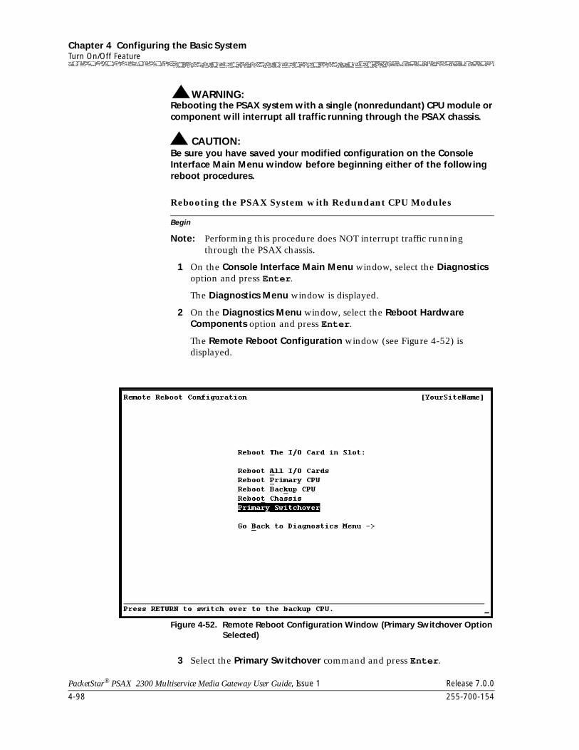
Chapter 4 Configuring the Basic SystemTurn On/Off Feature
4-98 255-700-154
PacketStar® PSAX 2300 Multiservice Media Gateway User Guide, Issue 1 Release 7.0.0
WARNING:!Rebooting the PSAX system with a single (nonredundant) CPU module or component will interrupt all traffic running through the PSAX chassis.
! CAUTION:Be sure you have saved your modified configuration on the Console Interface Main Menu window before beginning either of the following reboot procedures.
Begin
Rebooting the PSAX System with Redundant CPU Modules
Note: Performing this procedure does NOT interrupt traffic running through the PSAX chassis.
1 On the Console Interface Main Menu window, select the Diagnostics option and press Enter.
The Diagnostics Menu window is displayed.
2 On the Diagnostics Menu window, select the Reboot Hardware Components option and press Enter.
The Remote Reboot Configuration window (see Figure 4-52) is displayed.
3 Select the Primary Switchover command and press Enter.
Figure 4-52. Remote Reboot Configuration Window (Primary Switchover Option Selected)
255-700-154 4-99
PacketStar® PSAX 2300 Multiservice Media Gateway User Guide, Issue 1 Release 7.0.0
Chapter 4 Configuring the Basic SystemTurn On/Off Feature
The following message is displayed in the status line:
Are you sure that you want to do the primary switchover? (y/n)
4 Press the Y key.
The PSAX system switches processing control from the primary CPU module to the backup (standby) CPU module, and immediately begins rebooting the original primary CPU module. As this process proceeds, the new primary CPU module (originally the standby CPU) synchronizes the management information base (MIB) data with the new standby CPU module (originally the primary CPU). The green LED ACTIVE is illuminated on the primary CPU module.
End
Rebooting the Nonredundant PSAX System
The following procedure applies typically to all nonredundant PSAX systems including, but not limited to, the PSAX 20 and the PSAX AC 60 Multiservice Media Gateways.
Rebooting the PSAX System with a Single (Nonredundant) CPU
Begin
Module (or Component)
WARNING:!Rebooting the PSAX system with a single (nonredundant) CPU module or component will interrupt all traffic running through the PSAX chassis.
1 On the Console Interface Main Menu window, select the Diagnostics option and press Enter.
The Diagnostics Menu window is displayed.
2 On the Diagnostics Menu window, select the Reboot Hardware Components option and press Enter.
The Remote Reboot Configuration window (see Figure 4-53) is displayed.
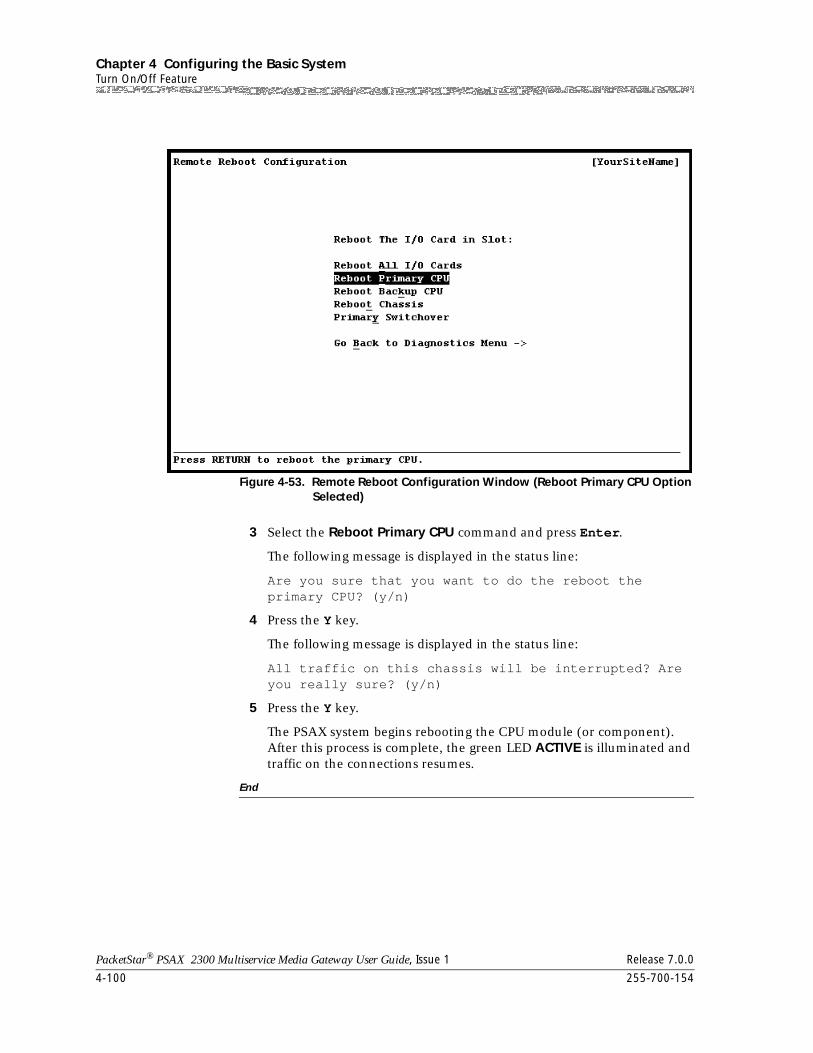
Chapter 4 Configuring the Basic SystemTurn On/Off Feature
4-100 255-700-154
PacketStar® PSAX 2300 Multiservice Media Gateway User Guide, Issue 1 Release 7.0.0
3 Select the Reboot Primary CPU command and press Enter.
The following message is displayed in the status line:
Are you sure that you want to do the reboot the primary CPU? (y/n)
4 Press the Y key.
The following message is displayed in the status line:
All traffic on this chassis will be interrupted? Are you really sure? (y/n)
5 Press the Y key.
The PSAX system begins rebooting the CPU module (or component). After this process is complete, the green LED ACTIVE is illuminated and traffic on the connections resumes.
End
Figure 4-53. Remote Reboot Configuration Window (Reboot Primary CPU Option Selected)
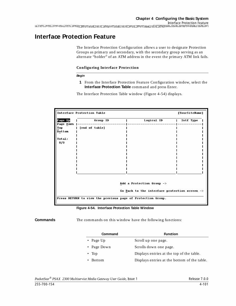
255-700-154 4-101
PacketStar® PSAX 2300 Multiservice Media Gateway User Guide, Issue 1 Release 7.0.0
Chapter 4 Configuring the Basic SystemInterface Protection Feature
Interface Protection Feature
The Interface Protection Configuration allows a user to designate Protection Groups as primary and secondary, with the secondary group serving as an alternate “holder” of an ATM address in the event the primary ATM link fails.
Begin
Configuring Interface Protection
1 From the Interface Protection Feature Configuration window, select the Interface Protection Table command and press Enter.
The Interface Protection Table window (Figure 4-54) displays.
Commands The commands on this window have the following functions:
Figure 4-54. Interface Protection Table Window
Command Function
• Page Up Scroll up one page.
• Page Down Scrolls down one page.
• Top Displays entries at the top of the table.
• Bottom Displays entries at the bottom of the table.
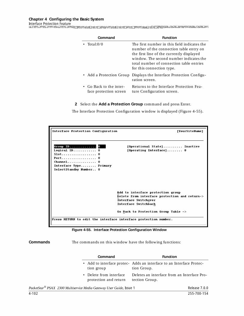
Chapter 4 Configuring the Basic SystemInterface Protection Feature
4-102 255-700-154
PacketStar® PSAX 2300 Multiservice Media Gateway User Guide, Issue 1 Release 7.0.0
2 Select the Add a Protection Group command and press Enter.
The Interface Protection Configuration window is displayed (Figure 4-55).
Commands The commands on this window have the following functions:
• Total:0/0 The first number in this field indicates the number of the connection table entry on the first line of the currently displayed window. The second number indicates the total number of connection table entries for this connection type.
• Add a Protection Group Displays the Interface Protection Configu-ration screen.
• Go Back to the inter-face protection screen
Returns to the Interface Protection Fea-ture Configuration screen.
Figure 4-55. Interface Protection Configuration Window
Command Function
Command Function
• Add to interface protec-tion group
Adds an interface to an Interface Protec-tion Group.
• Delete from interface protection and return
Deletes an interface from an Interface Pro-tection Group.
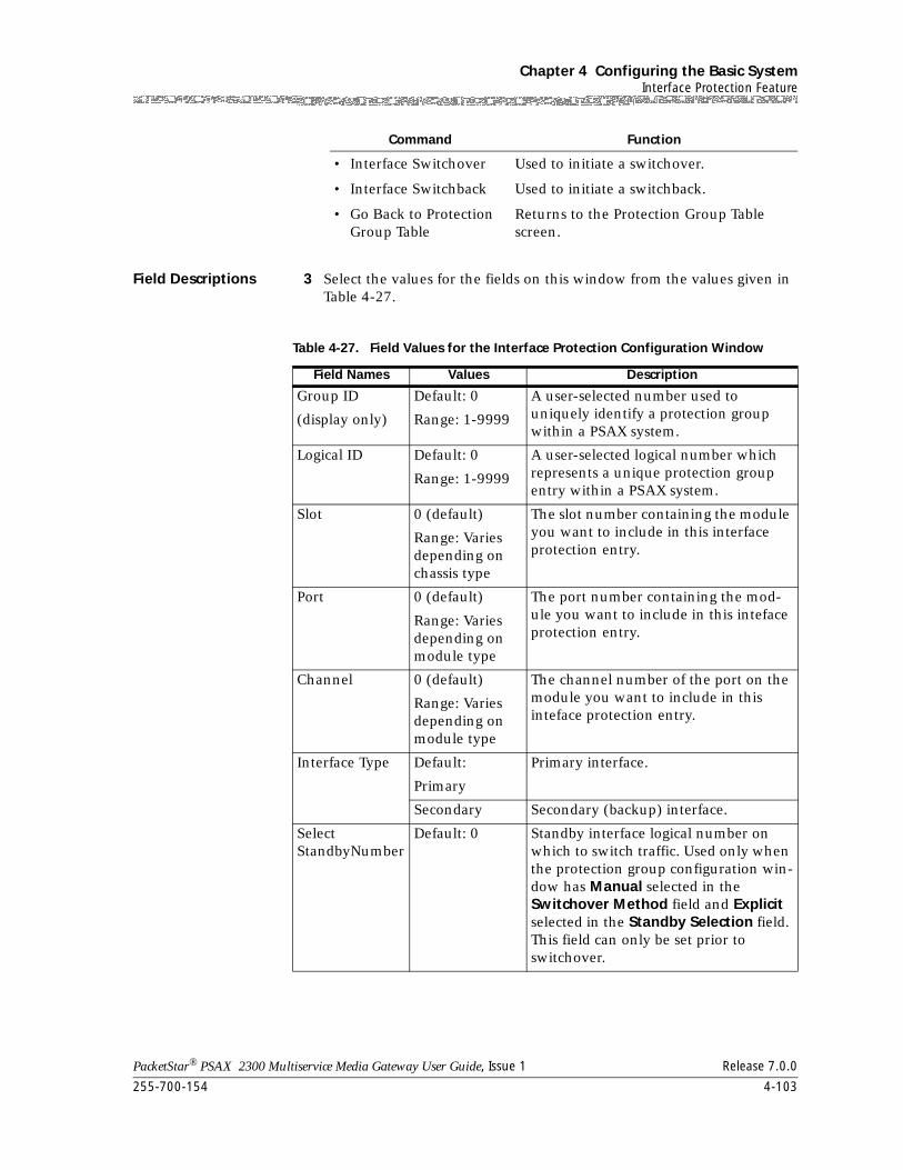
255-700-154 4-103
PacketStar® PSAX 2300 Multiservice Media Gateway User Guide, Issue 1 Release 7.0.0
Chapter 4 Configuring the Basic SystemInterface Protection Feature
Field Descriptions 3 Select the values for the fields on this window from the values given in Table 4-27.
• Interface Switchover Used to initiate a switchover.
• Interface Switchback Used to initiate a switchback.
• Go Back to Protection Group Table
Returns to the Protection Group Table screen.
Command Function
Table 4-27. Field Values for the Interface Protection Configuration Window
Field Names Values Description
Group ID
(display only)
Default: 0
Range: 1-9999
A user-selected number used to uniquely identify a protection group within a PSAX system.
Logical ID Default: 0
Range: 1-9999
A user-selected logical number which represents a unique protection group entry within a PSAX system.
Slot 0 (default)
Range: Varies depending on chassis type
The slot number containing the module you want to include in this interface protection entry.
Port 0 (default)
Range: Varies depending on module type
The port number containing the mod-ule you want to include in this inteface protection entry.
Channel 0 (default)
Range: Varies depending on module type
The channel number of the port on the module you want to include in this inteface protection entry.
Interface Type Default:
Primary
Primary interface.
Secondary Secondary (backup) interface.
SelectStandbyNumber
Default: 0 Standby interface logical number on which to switch traffic. Used only when the protection group configuration win-dow has Manual selected in the Switchover Method field and Explicit selected in the Standby Selection field. This field can only be set prior to switchover.
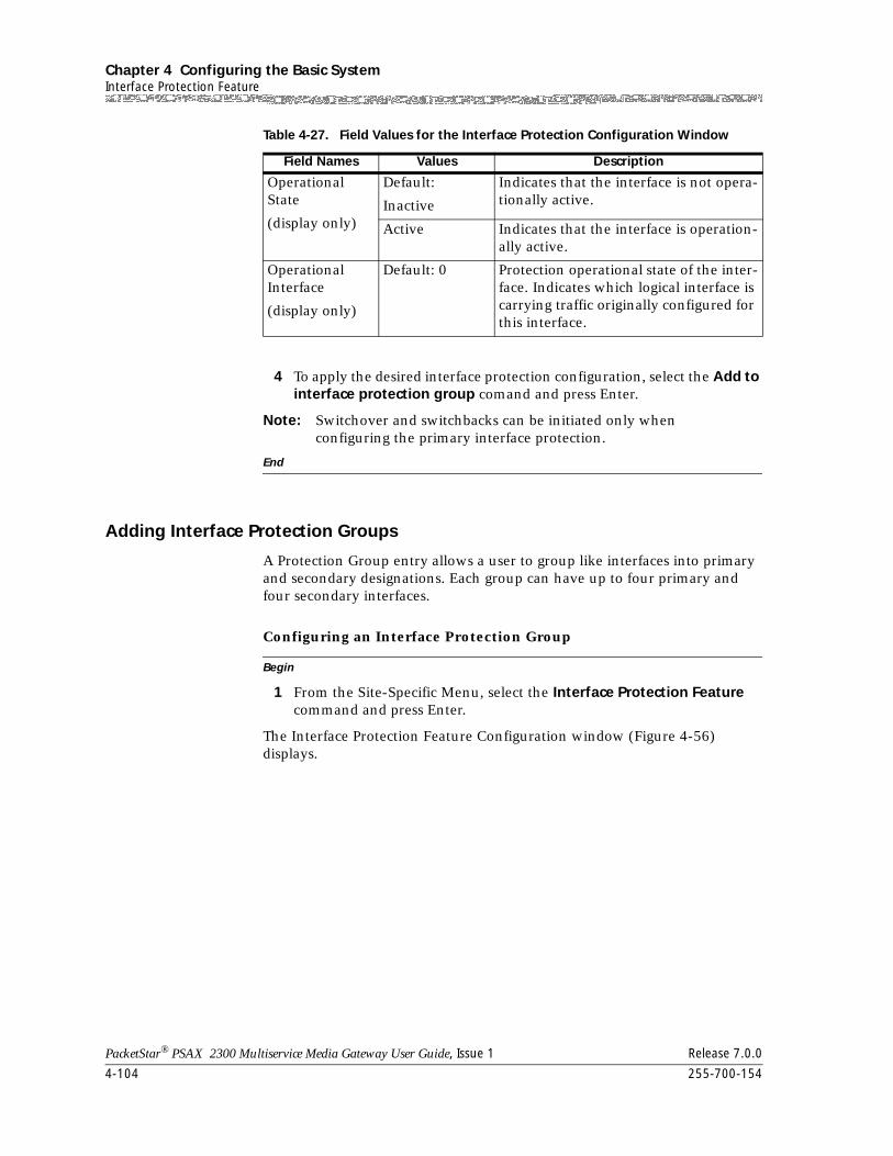
Chapter 4 Configuring the Basic SystemInterface Protection Feature
4-104 255-700-154
PacketStar® PSAX 2300 Multiservice Media Gateway User Guide, Issue 1 Release 7.0.0
4 To apply the desired interface protection configuration, select the Add to interface protection group comand and press Enter.
Note: Switchover and switchbacks can be initiated only when configuring the primary interface protection.
End
Adding Interface Protection Groups
A Protection Group entry allows a user to group like interfaces into primary and secondary designations. Each group can have up to four primary and four secondary interfaces.
Begin
Configuring an Interface Protection Group
1 From the Site-Specific Menu, select the Interface Protection Feature command and press Enter.
The Interface Protection Feature Configuration window (Figure 4-56) displays.
Operational State
(display only)
Default:
Inactive
Indicates that the interface is not opera-tionally active.
Active Indicates that the interface is operation-ally active.
Operational Interface
(display only)
Default: 0 Protection operational state of the inter-face. Indicates which logical interface is carrying traffic originally configured for this interface.
Table 4-27. Field Values for the Interface Protection Configuration Window
Field Names Values Description
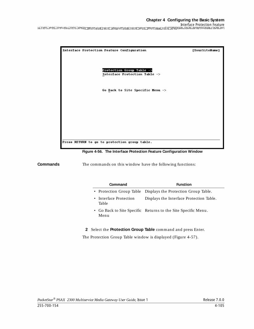
255-700-154 4-105
PacketStar® PSAX 2300 Multiservice Media Gateway User Guide, Issue 1 Release 7.0.0
Chapter 4 Configuring the Basic SystemInterface Protection Feature
Commands The commands on this window have the following functions:
2 Select the Protection Group Table command and press Enter.
The Protection Group Table window is displayed (Figure 4-57).
Figure 4-56. The Interface Protection Feature Configuration Window
Command Function
• Protection Group Table Displays the Protection Group Table.
• Interface Protection Table
Displays the Interface Protection Table.
• Go Back to Site Specific Menu
Returns to the Site Specific Menu.
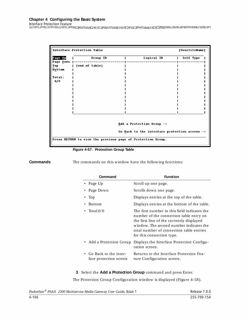
Chapter 4 Configuring the Basic SystemInterface Protection Feature
4-106 255-700-154
PacketStar® PSAX 2300 Multiservice Media Gateway User Guide, Issue 1 Release 7.0.0
Commands The commands on this window have the following functions:
3 Select the Add a Protection Group command and press Enter.
The Protection Group Configuration window is displayed (Figure 4-58).
Figure 4-57. Protection Group Table
Command Function
• Page Up Scroll up one page.
• Page Down Scrolls down one page.
• Top Displays entries at the top of the table.
• Bottom Displays entries at the bottom of the table.
• Total:0/0 The first number in this field indicates the number of the connection table entry on the first line of the currently displayed window. The second number indicates the total number of connection table entries for this connection type.
• Add a Protection Group Displays the Interface Protection Configu-ration screen.
• Go Back to the inter-face protection screen
Returns to the Interface Protection Fea-ture Configuration screen.
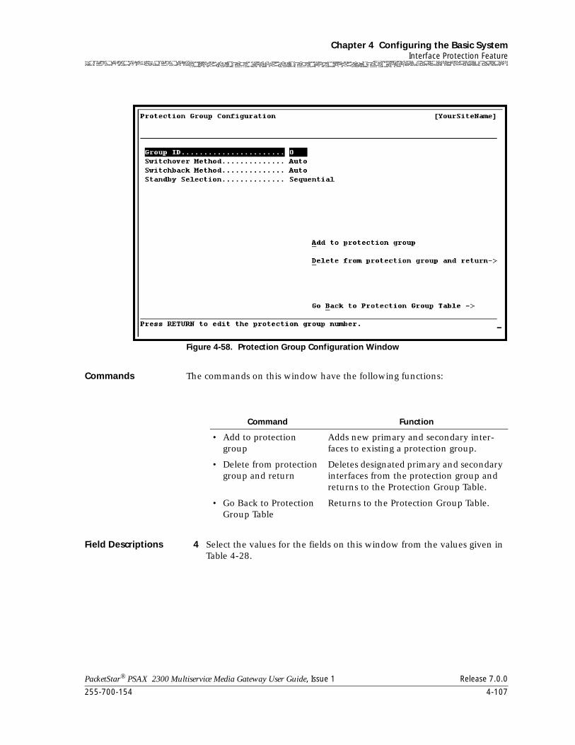
255-700-154 4-107
PacketStar® PSAX 2300 Multiservice Media Gateway User Guide, Issue 1 Release 7.0.0
Chapter 4 Configuring the Basic SystemInterface Protection Feature
Commands The commands on this window have the following functions:
Field Descriptions 4 Select the values for the fields on this window from the values given in Table 4-28.
Figure 4-58. Protection Group Configuration Window
Command Function
• Add to protection group
Adds new primary and secondary inter-faces to existing a protection group.
• Delete from protection group and return
Deletes designated primary and secondary interfaces from the protection group and returns to the Protection Group Table.
• Go Back to Protection Group Table
Returns to the Protection Group Table.
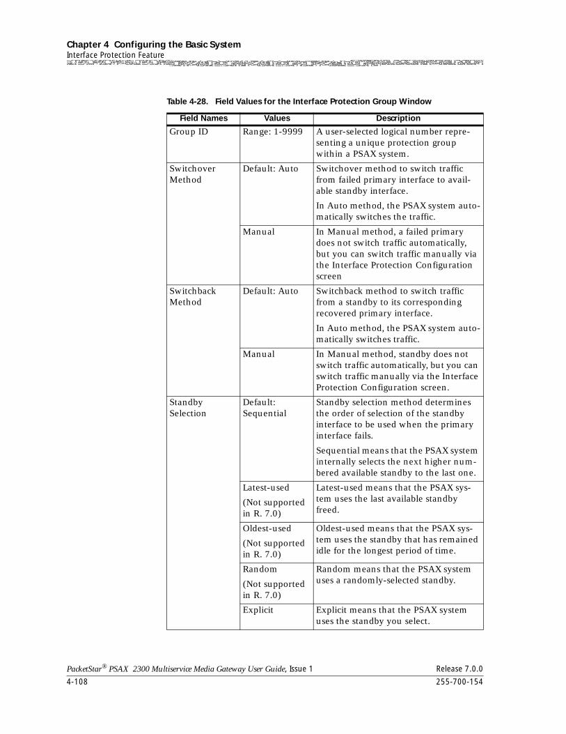
Chapter 4 Configuring the Basic SystemInterface Protection Feature
4-108 255-700-154
PacketStar® PSAX 2300 Multiservice Media Gateway User Guide, Issue 1 Release 7.0.0
Table 4-28. Field Values for the Interface Protection Group Window
Field Names Values Description
Group ID Range: 1-9999 A user-selected logical number repre-senting a unique protection group within a PSAX system.
Switchover Method
Default: Auto Switchover method to switch traffic from failed primary interface to avail-able standby interface.
In Auto method, the PSAX system auto-matically switches the traffic.
Manual In Manual method, a failed primary does not switch traffic automatically, but you can switch traffic manually via the Interface Protection Configuration screen
Switchback Method
Default: Auto Switchback method to switch traffic from a standby to its corresponding recovered primary interface.
In Auto method, the PSAX system auto-matically switches traffic.
Manual In Manual method, standby does not switch traffic automatically, but you can switch traffic manually via the Interface Protection Configuration screen.
Standby Selection
Default: Sequential
Standby selection method determines the order of selection of the standby interface to be used when the primary interface fails.
Sequential means that the PSAX system internally selects the next higher num-bered available standby to the last one.
Latest-used
(Not supported in R. 7.0)
Latest-used means that the PSAX sys-tem uses the last available standby freed.
Oldest-used
(Not supported in R. 7.0)
Oldest-used means that the PSAX sys-tem uses the standby that has remained idle for the longest period of time.
Random
(Not supported in R. 7.0)
Random means that the PSAX system uses a randomly-selected standby.
Explicit Explicit means that the PSAX system uses the standby you select.
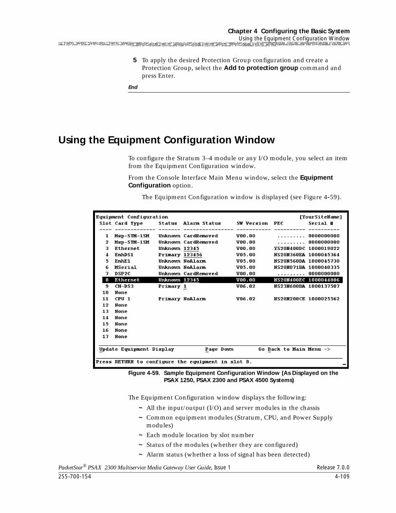
255-700-154 4-109
PacketStar® PSAX 2300 Multiservice Media Gateway User Guide, Issue 1 Release 7.0.0
Chapter 4 Configuring the Basic SystemUsing the Equipment Configuration Window
5 To apply the desired Protection Group configuration and create a Protection Group, select the Add to protection group command and press Enter.
End
Using the Equipment Configuration Window
To configure the Stratum 3–4 module or any I/O module, you select an item from the Equipment Configuration window.
From the Console Interface Main Menu window, select the Equipment Configuration option.
The Equipment Configuration window is displayed (see Figure 4-59).
The Equipment Configuration window displays the following:
~ All the input/output (I/O) and server modules in the chassis
~ Common equipment modules (Stratum, CPU, and Power Supply modules)
~ Each module location by slot number
~ Status of the modules (whether they are configured)
~ Alarm status (whether a loss of signal has been detected)
Figure 4-59. Sample Equipment Configuration Window (As Displayed on the PSAX 1250, PSAX 2300 and PSAX 4500 Systems)
Chapter 4 Configuring the Basic SystemConfiguring the Stratum 3–4 Module
4-110 255-700-154
PacketStar® PSAX 2300 Multiservice Media Gateway User Guide, Issue 1 Release 7.0.0
When a module is inserted into the chassis, its module name appears on the window. When the module is removed from the chassis, its module name disappears from the window. The fields displayed on the Equipment Configuration window are described in Table 4-29.
Configuring the Stratum 3–4 Module
Data and voice transmit most efficiently (with the least amount of cells lost per second) if a proper clock timing source is present in the PSAX 2300. Therefore, we recommend that you configure the Stratum 3–4 module before configuring any I/O or server modules.
Note: You can avoid any system timing errors by configuring the Stratum 3–4 module before you configure and run traffic through any I/O and server modules.
Note: On the Stratum Configuration window, you establish the source of the system synchronization. After you have configured the Stratum 3–4 module, it provides the reference clock to all I/O module ports configured for local timing.
Setting the Stratum Configuration Values
To configure the Stratum 3–4 module, perform the steps in the following procedure.
Table 4-29. Field Values for the Equipment Configuration Window
Field Description
Slot Indicates the slot number location on the PSAX 2300 chassis. You can configure only user-selectable I/O and server modules, and the Stratum 3–4 clock timing.
Card Type Indicates what kind of module is inserted in the slot.
Status Indicates that the module operates in primary mode. This field applies to the I/O and server modules.
Alarm Status Indicates whether any alarms are active. The Alarm Status fields are described in more detail in the Refer-ence Table appendix in the guide.
PEC Indicates the product element code (PEC).
Serial #(serial number)
Indicates the unique identifying number to identify a particular hardware component.
SW Version Indicates the current software version level of the mod-ule.
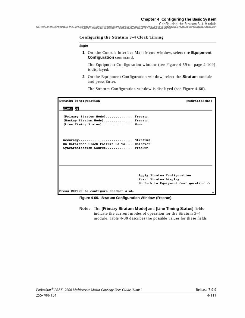
255-700-154 4-111
PacketStar® PSAX 2300 Multiservice Media Gateway User Guide, Issue 1 Release 7.0.0
Chapter 4 Configuring the Basic SystemConfiguring the Stratum 3–4 Module
Begin
Configuring the Stratum 3–4 Clock Timing
1 On the Console Interface Main Menu window, select the Equipment Configuration command.
The Equipment Configuration window (see Figure 4-59 on page 4-109) is displayed:
2 On the Equipment Configuration window, select the Stratum module and press Enter.
The Stratum Configuration window is displayed (see Figure 4-60).
Note: The [Primary Stratum Mode] and [Line Timing Status] fields indicate the current modes of operation for the Stratum 3–4 module. Table 4-30 describes the possible values for these fields.
Figure 4-60. Stratum Configuration Window (Freerun)
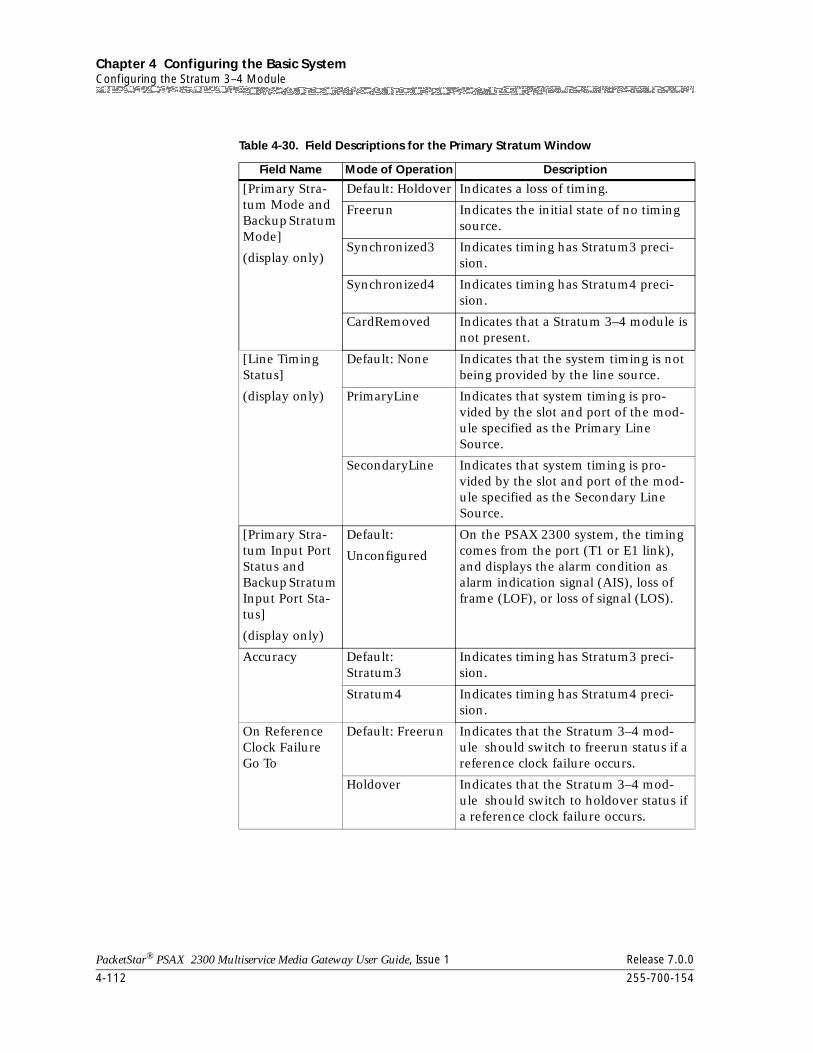
Chapter 4 Configuring the Basic SystemConfiguring the Stratum 3–4 Module
4-112 255-700-154
PacketStar® PSAX 2300 Multiservice Media Gateway User Guide, Issue 1 Release 7.0.0
Table 4-30. Field Descriptions for the Primary Stratum Window
Field Name Mode of Operation Description
[Primary Stra-tum Mode and Backup Stratum Mode]
(display only)
Default: Holdover Indicates a loss of timing.
Freerun Indicates the initial state of no timing source.
Synchronized3 Indicates timing has Stratum3 preci-sion.
Synchronized4 Indicates timing has Stratum4 preci-sion.
CardRemoved Indicates that a Stratum 3–4 module is not present.
[Line Timing Status]
(display only)
Default: None Indicates that the system timing is not being provided by the line source.
PrimaryLine Indicates that system timing is pro-vided by the slot and port of the mod-ule specified as the Primary Line Source.
SecondaryLine Indicates that system timing is pro-vided by the slot and port of the mod-ule specified as the Secondary Line Source.
[Primary Stra-tum Input Port Status and Backup Stratum Input Port Sta-tus]
(display only)
Default:
Unconfigured
On the PSAX 2300 system, the timing comes from the port (T1 or E1 link), and displays the alarm condition as alarm indication signal (AIS), loss of frame (LOF), or loss of signal (LOS).
Accuracy Default: Stratum3
Indicates timing has Stratum3 preci-sion.
Stratum4 Indicates timing has Stratum4 preci-sion.
On Reference Clock Failure Go To
Default: Freerun Indicates that the Stratum 3–4 mod-ule should switch to freerun status if a reference clock failure occurs.
Holdover Indicates that the Stratum 3–4 mod-ule should switch to holdover status if a reference clock failure occurs.
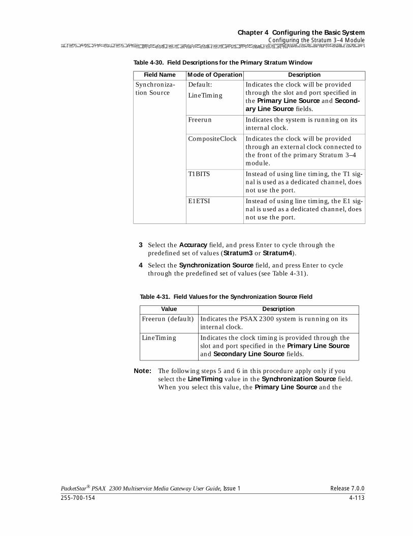
255-700-154 4-113
PacketStar® PSAX 2300 Multiservice Media Gateway User Guide, Issue 1 Release 7.0.0
Chapter 4 Configuring the Basic SystemConfiguring the Stratum 3–4 Module
3 Select the Accuracy field, and press Enter to cycle through the predefined set of values (Stratum3 or Stratum4).
4 Select the Synchronization Source field, and press Enter to cycle through the predefined set of values (see Table 4-31).
Note: The following steps 5 and 6 in this procedure apply only if you select the LineTiming value in the Synchronization Source field. When you select this value, the Primary Line Source and the
Synchroniza-tion Source
Default:
LineTiming
Indicates the clock will be provided through the slot and port specified in the Primary Line Source and Second-ary Line Source fields.
Freerun Indicates the system is running on its internal clock.
CompositeClock Indicates the clock will be provided through an external clock connected to the front of the primary Stratum 3–4 module.
T1BITS Instead of using line timing, the T1 sig-nal is used as a dedicated channel, does not use the port.
E1ETSI Instead of using line timing, the E1 sig-nal is used as a dedicated channel, does not use the port.
Table 4-31. Field Values for the Synchronization Source Field
Value Description
Freerun (default) Indicates the PSAX 2300 system is running on its internal clock.
LineTiming Indicates the clock timing is provided through the slot and port specified in the Primary Line Source and Secondary Line Source fields.
Table 4-30. Field Descriptions for the Primary Stratum Window
Field Name Mode of Operation Description
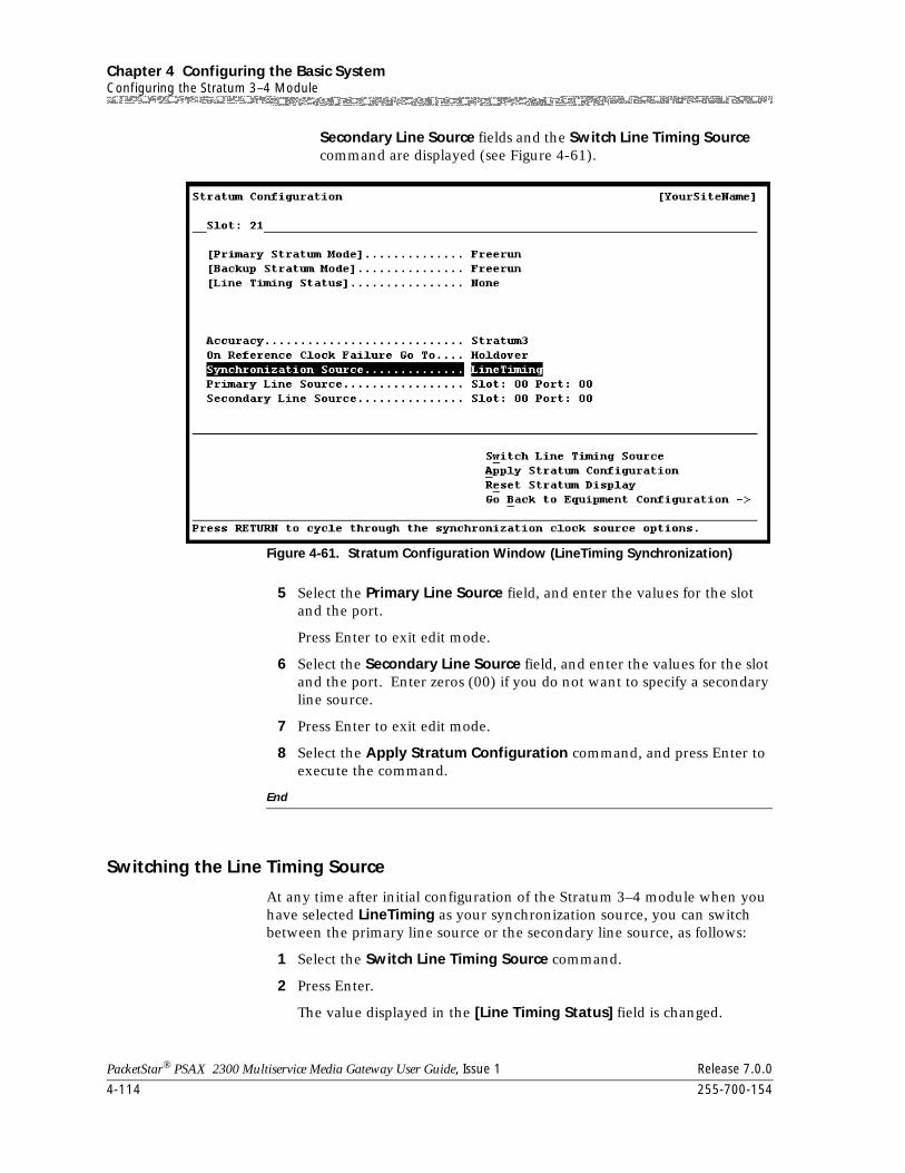
Chapter 4 Configuring the Basic SystemConfiguring the Stratum 3–4 Module
4-114 255-700-154
PacketStar® PSAX 2300 Multiservice Media Gateway User Guide, Issue 1 Release 7.0.0
Secondary Line Source fields and the Switch Line Timing Source command are displayed (see Figure 4-61).
5 Select the Primary Line Source field, and enter the values for the slot and the port.
Press Enter to exit edit mode.
6 Select the Secondary Line Source field, and enter the values for the slot and the port. Enter zeros (00) if you do not want to specify a secondary line source.
7 Press Enter to exit edit mode.
8 Select the Apply Stratum Configuration command, and press Enter to execute the command.
End
Switching the Line Timing Source
At any time after initial configuration of the Stratum 3–4 module when you have selected LineTiming as your synchronization source, you can switch between the primary line source or the secondary line source, as follows:
1 Select the Switch Line Timing Source command.
2 Press Enter.
The value displayed in the [Line Timing Status] field is changed.
Figure 4-61. Stratum Configuration Window (LineTiming Synchronization)
255-700-154 4-115
PacketStar® PSAX 2300 Multiservice Media Gateway User Guide, Issue 1 Release 7.0.0
Chapter 4 Configuring the Basic SystemConfiguring I/O and Server Modules
Configuring I/O and Server Modules
Once the Stratum 3–4 module has been configured, I/O and server modules are configured by returning to the Equipment Configuration window (see Figure 4-59 on page 4-109).
Alarm Status Values
I/O and server modules display the status value of Primary if they are configured, or Unknown if they are unconfigured. The Alarm Status column for unconfigured modules still can have a number listing the ports that are available to be configured. If numbers in the Alarm Status column are underlined, this condition indicates a loss of signal. Table 4-29 describes the values in the Alarm Status field as shown on the Equipment Configuration window.
See the Alarm Status Description for PSAX Modules Table in the Reference Table Appendix of this guide.
Saving the Equipment Configuration Values and Logging Off
! CAUTION:If your system or location loses power or your current session ends abnormally while you are in the process of configuring the system, and you have not yet saved the values permanently, you will lose all unsaved values you have applied on the various windows.
After configuring your basic system-wide values, you need to save them permanently to the PSAX system database by performing the steps in the following procedure.
Begin
Saving the PSAX System Values
1 Press Ctrl+G while on any window to display the Console Interface Main Menu window.
2 Select the Save Configuration command and press Enter (or press Ctrl+A).
Wait a few seconds while the system writes the values permanently to the Multiservice Media Gateway system database. The system displays the following message while it is executing this command:
Saving the equipment and connection information
Chapter 4 Configuring the Basic SystemSaving the Equipment Configuration Values and Logging Off
4-116 255-700-154
PacketStar® PSAX 2300 Multiservice Media Gateway User Guide, Issue 1 Release 7.0.0
When the command is completed, the system displays the following message:
T-SaveConfiguration: saveConfigurationReasonCode=All-OK
You can now safely exit the current session.
Note: In PSAX systems with redundant CPU2 modules, the backup CPU2 module reboots every time you save the configuration on the primary CPU2 module. This event is a function of the SVC retention feature and the result of saving the configuration changes you have made.
3 Select the Leave Console Interface command and press Enter.
You are now logged off the PSAX Multiservice Media Gateway system console interface.
End
PacketStar® PSAX 2300 Multiservice Media Gateway User Guide, Issue 1 Release 7.0.0
255-700-154 5-1
5 Using System Diagnostics
Overview of This Chapter
The information in this chapter is divided into the following headings.
• Viewing System Status
• Running Cell Test Diagnostics
• Rebooting PSAX Hardware Components
• Removing Configuration Files
• Unlocking a Telnet Session
• Operations and Maintenance (OAM)
~ Creating OAM Connections
~ Monitoring OAM Functionality
~ Performing OAM Tests
~ OAM Activation and Deactivation
Overview of Diagnostic Capabilities
The PSAX system diagnostics functions give you the ability to:
• View the status of the PSAX system including:
~ Version of the PSAX system software currently running
~ Status of the hard disk on the CPU
~ Statistics on the message pool and the cell buffers
• Run cell test diagnostics to determine whether a specified port is operating correctly
• Reboot (reinitialize) the PSAX chassis, CPU, user-selected I/O modules, or all components in the chassis
• Unlock a telnet session remotely
• Perform OAM loopback tests
• Configure activate or deactivate OAM functions
Viewing System Status
To view the status of the PSAX system, perform the steps in the following procedure.
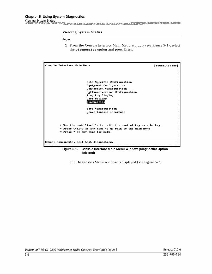
Chapter 5 Using System DiagnosticsViewing System Status
5-2 255-700-154
PacketStar® PSAX 2300 Multiservice Media Gateway User Guide, Issue 1 Release 7.0.0
Begin
Viewing System Status
1 From the Console Interface Main Menu window (see Figure 5-1), select the Diagnostics option and press Enter.
The Diagnostics Menu window is displayed (see Figure 5-2).
Figure 5-1. Console Interface Main Menu Window (Diagnostics Option Selected)
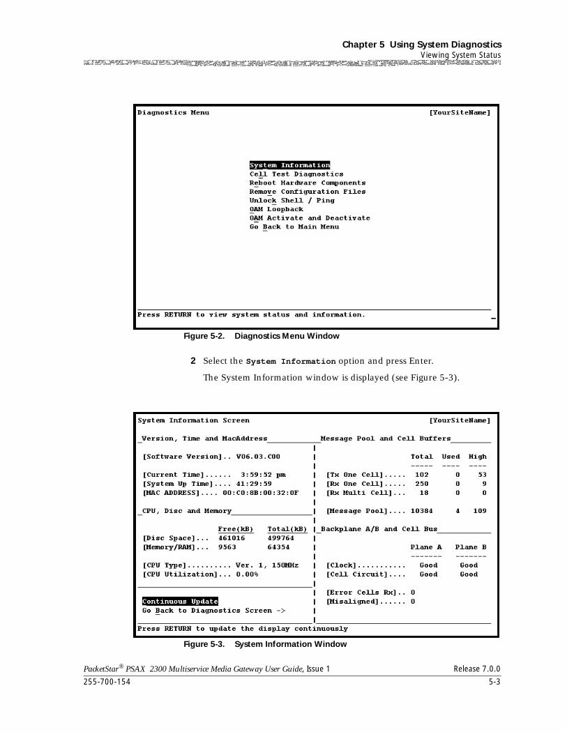
255-700-154 5-3
PacketStar® PSAX 2300 Multiservice Media Gateway User Guide, Issue 1 Release 7.0.0
Chapter 5 Using System DiagnosticsViewing System Status
2 Select the System Information option and press Enter.
The System Information window is displayed (see Figure 5-3).
Figure 5-2. Diagnostics Menu Window
Figure 5-3. System Information Window
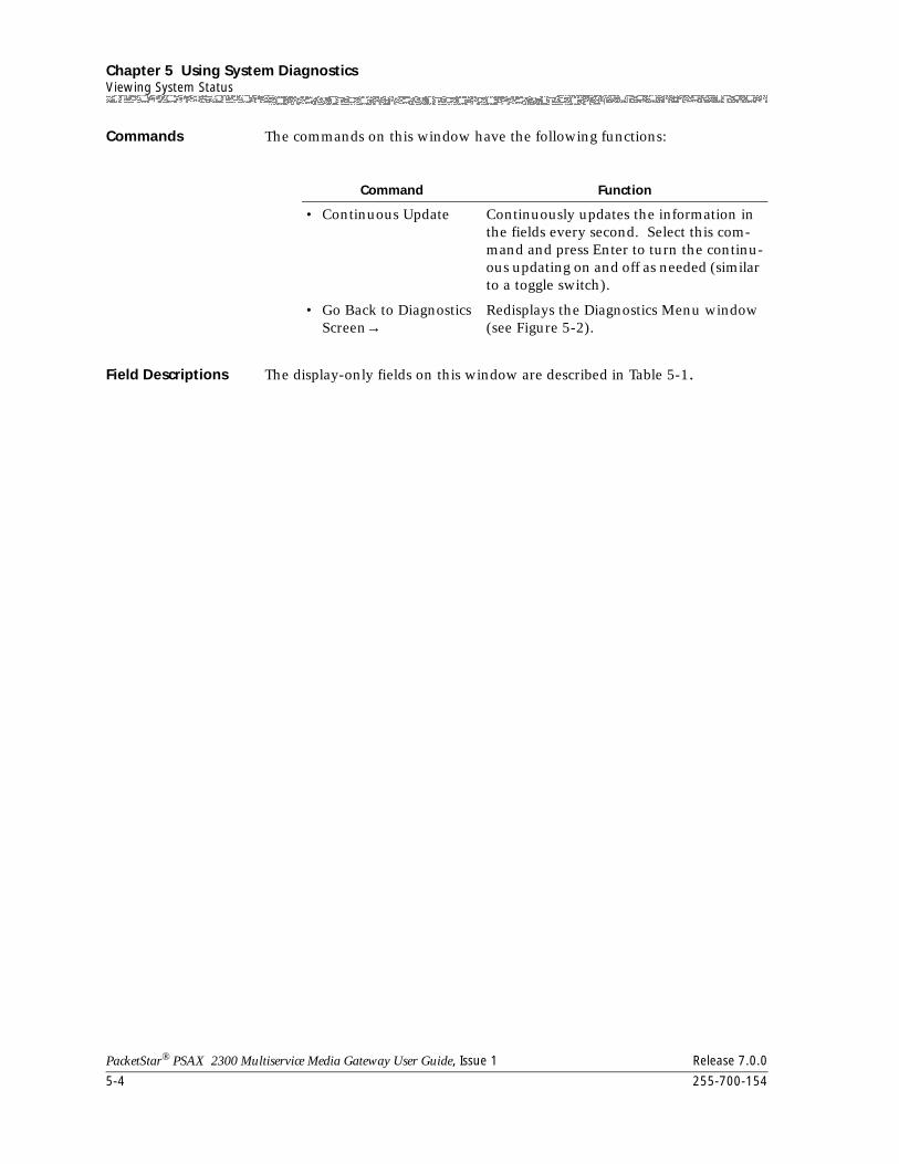
Chapter 5 Using System DiagnosticsViewing System Status
5-4 255-700-154
PacketStar® PSAX 2300 Multiservice Media Gateway User Guide, Issue 1 Release 7.0.0
Commands The commands on this window have the following functions:
Field Descriptions The display-only fields on this window are described in Table 5-1.
Command Function
• Continuous Update Continuously updates the information in the fields every second. Select this com-mand and press Enter to turn the continu-ous updating on and off as needed (similar to a toggle switch).
• Go Back to Diagnostics Screen→
Redisplays the Diagnostics Menu window (see Figure 5-2).
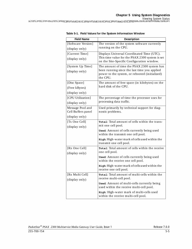
255-700-154 5-5
PacketStar® PSAX 2300 Multiservice Media Gateway User Guide, Issue 1 Release 7.0.0
Chapter 5 Using System DiagnosticsViewing System Status
Table 5-1. Field Values for the System Information Window
Field Name Description
[Software Version]
(display only)
The version of the system software currently running on the CPU.
[Current Time]
(display only)
Displays Universal Coordinated Time (UTC). This time value for the PSAX 2300 system is set on the Site-Specific Configuration window.
[System Up Time]
(display only)
The amount of time the PSAX 2300 system has been running since the last time you applied power to the system, or rebooted (initialized) the CPU.
[Disc Space]
(Free kBytes)
(display only)
The amount of free space (in kilobytes) on the hard disk of the CPU.
[CPU Utilization]
(display only)
The percentage of time the processor uses for processing data traffic.
Message Pool and Cell Buffers panel
(display only)
Used primarily by technical support for diag-nostic problems.
[Tx One Cell]
(display only)
Total: Total amount of cells within the trans-mit one cell pool.
Used: Amount of cells currently being used within the transmit one cell pool.
High: High-water mark of cells used within the transmit one cell pool.
[Rx One Cell]
(display only)
Total: Total amount of cells within the receive one cell pool.
Used: Amount of cells currently being used within the receive one cell pool.
High: High-water mark of cells used within the receive one cell pool.
[Rx Multi Cell]
(display only)
Total: Total amount of multi-cells within the receive multi-cell pool.
Used: Amount of multi-cells currently being used within the receive multi-cell pool.
High: High-water mark of multi-cells used within the receive multi-cell pool.
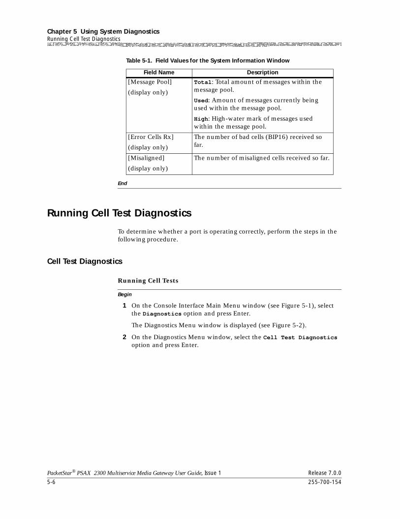
Chapter 5 Using System DiagnosticsRunning Cell Test Diagnostics
5-6 255-700-154
PacketStar® PSAX 2300 Multiservice Media Gateway User Guide, Issue 1 Release 7.0.0
End
Running Cell Test Diagnostics
To determine whether a port is operating correctly, perform the steps in the following procedure.
Cell Test Diagnostics
Begin
Running Cell Tests
1 On the Console Interface Main Menu window (see Figure 5-1), select the Diagnostics option and press Enter.
The Diagnostics Menu window is displayed (see Figure 5-2).
2 On the Diagnostics Menu window, select the Cell Test Diagnostics option and press Enter.
[Message Pool]
(display only)
Total: Total amount of messages within the message pool.
Used: Amount of messages currently being used within the message pool.
High: High-water mark of messages used within the message pool.
[Error Cells Rx]
(display only)
The number of bad cells (BIP16) received so far.
[Misaligned]
(display only)
The number of misaligned cells received so far.
Table 5-1. Field Values for the System Information Window
Field Name Description
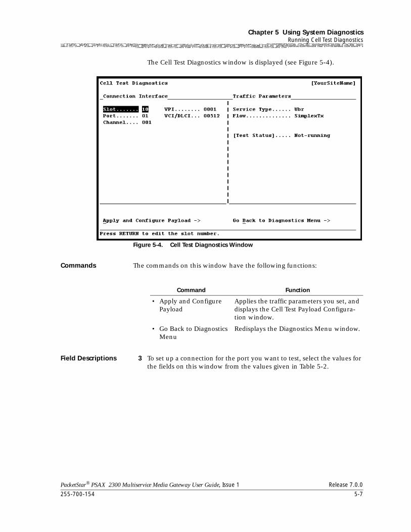
255-700-154 5-7
PacketStar® PSAX 2300 Multiservice Media Gateway User Guide, Issue 1 Release 7.0.0
Chapter 5 Using System DiagnosticsRunning Cell Test Diagnostics
The Cell Test Diagnostics window is displayed (see Figure 5-4).
Commands The commands on this window have the following functions:
Field Descriptions 3 To set up a connection for the port you want to test, select the values for the fields on this window from the values given in Table 5-2.
Figure 5-4. Cell Test Diagnostics Window
Command Function
• Apply and Configure Payload
Applies the traffic parameters you set, and displays the Cell Test Payload Configura-tion window.
• Go Back to Diagnostics Menu
Redisplays the Diagnostics Menu window.
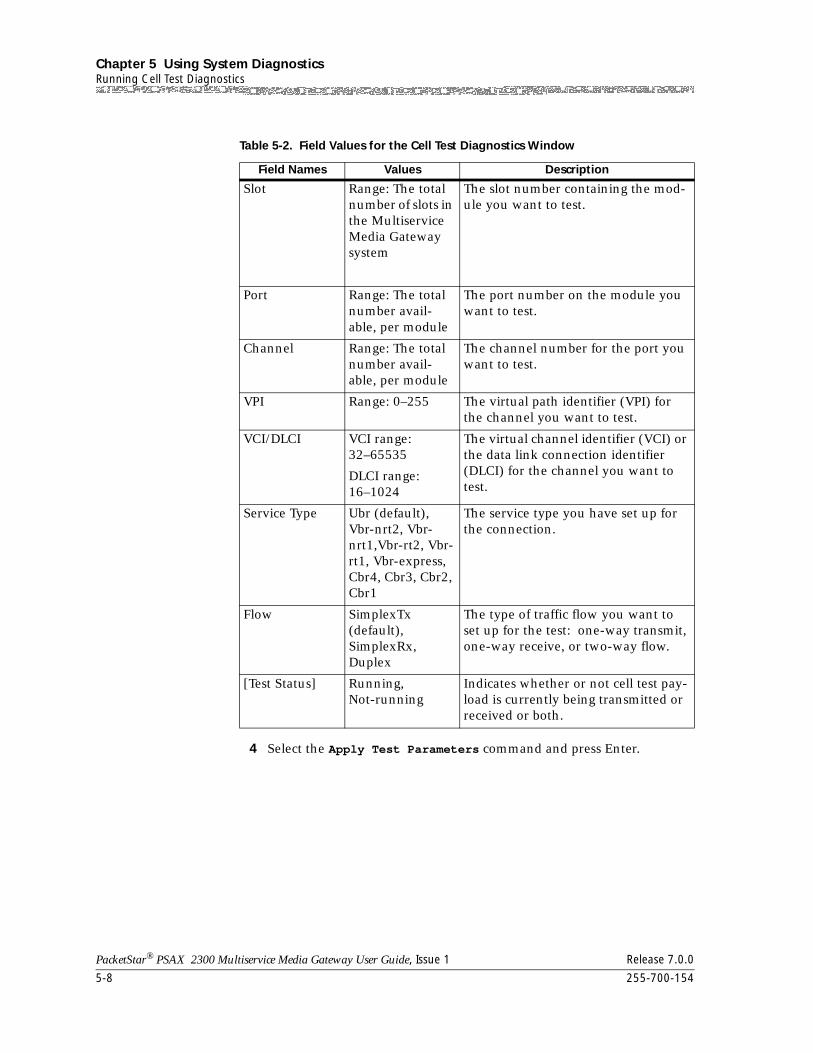
Chapter 5 Using System DiagnosticsRunning Cell Test Diagnostics
5-8 255-700-154
PacketStar® PSAX 2300 Multiservice Media Gateway User Guide, Issue 1 Release 7.0.0
4 Select the Apply Test Parameters command and press Enter.
Table 5-2. Field Values for the Cell Test Diagnostics Window
Field Names Values Description
Slot Range: The total number of slots in the Multiservice Media Gateway system
The slot number containing the mod-ule you want to test.
Port Range: The total number avail-able, per module
The port number on the module you want to test.
Channel Range: The total number avail-able, per module
The channel number for the port you want to test.
VPI Range: 0–255 The virtual path identifier (VPI) for the channel you want to test.
VCI/DLCI VCI range: 32–65535
DLCI range: 16–1024
The virtual channel identifier (VCI) or the data link connection identifier (DLCI) for the channel you want to test.
Service Type Ubr (default),Vbr-nrt2, Vbr-nrt1,Vbr-rt2, Vbr-rt1, Vbr-express,Cbr4, Cbr3, Cbr2, Cbr1
The service type you have set up for the connection.
Flow SimplexTx (default),SimplexRx, Duplex
The type of traffic flow you want to set up for the test: one-way transmit, one-way receive, or two-way flow.
[Test Status] Running,Not-running
Indicates whether or not cell test pay-load is currently being transmitted or received or both.
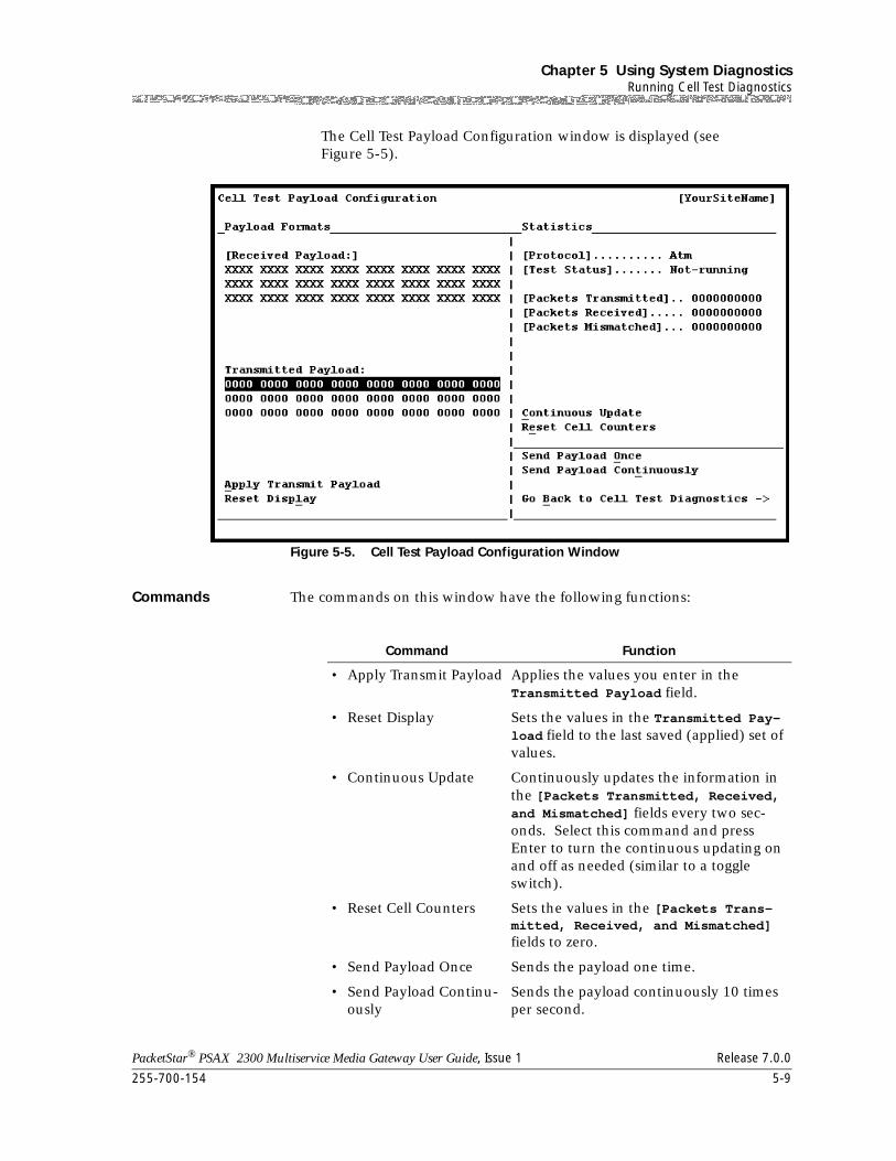
255-700-154 5-9
PacketStar® PSAX 2300 Multiservice Media Gateway User Guide, Issue 1 Release 7.0.0
Chapter 5 Using System DiagnosticsRunning Cell Test Diagnostics
The Cell Test Payload Configuration window is displayed (see Figure 5-5).
Commands The commands on this window have the following functions:
Figure 5-5. Cell Test Payload Configuration Window
Command Function
• Apply Transmit Payload Applies the values you enter in the Transmitted Payload field.
• Reset Display Sets the values in the Transmitted Pay-load field to the last saved (applied) set of values.
• Continuous Update Continuously updates the information in the [Packets Transmitted, Received, and Mismatched] fields every two sec-onds. Select this command and press Enter to turn the continuous updating on and off as needed (similar to a toggle switch).
• Reset Cell Counters Sets the values in the [Packets Trans-mitted, Received, and Mismatched] fields to zero.
• Send Payload Once Sends the payload one time.
• Send Payload Continu-ously
Sends the payload continuously 10 times per second.
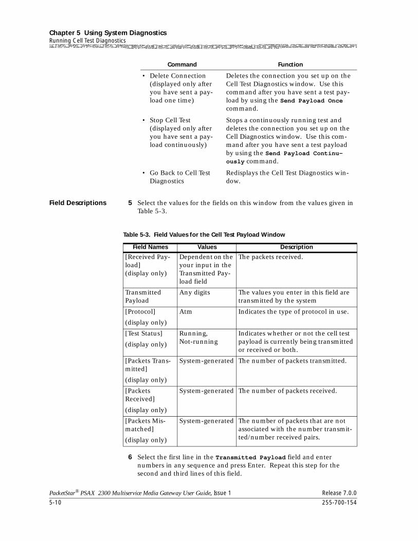
Chapter 5 Using System DiagnosticsRunning Cell Test Diagnostics
5-10 255-700-154
PacketStar® PSAX 2300 Multiservice Media Gateway User Guide, Issue 1 Release 7.0.0
Field Descriptions 5 Select the values for the fields on this window from the values given in Table 5-3.
6 Select the first line in the Transmitted Payload field and enter numbers in any sequence and press Enter. Repeat this step for the second and third lines of this field.
• Delete Connection(displayed only after you have sent a pay-load one time)
Deletes the connection you set up on the Cell Test Diagnostics window. Use this command after you have sent a test pay-load by using the Send Payload Once command.
• Stop Cell Test(displayed only after you have sent a pay-load continuously)
Stops a continuously running test and deletes the connection you set up on the Cell Diagnostics window. Use this com-mand after you have sent a test payload by using the Send Payload Continu-ously command.
• Go Back to Cell Test Diagnostics
Redisplays the Cell Test Diagnostics win-dow.
Command Function
Table 5-3. Field Values for the Cell Test Payload Window
Field Names Values Description
[Received Pay-load](display only)
Dependent on the your input in the Transmitted Pay-load field
The packets received.
Transmitted Payload
Any digits The values you enter in this field are transmitted by the system
[Protocol]
(display only)
Atm Indicates the type of protocol in use.
[Test Status]
(display only)
Running, Not-running
Indicates whether or not the cell test payload is currently being transmitted or received or both.
[Packets Trans-mitted]
(display only)
System-generated The number of packets transmitted.
[Packets Received]
(display only)
System-generated The number of packets received.
[Packets Mis-matched]
(display only)
System-generated The number of packets that are not associated with the number transmit-ted/number received pairs.
255-700-154 5-11
PacketStar® PSAX 2300 Multiservice Media Gateway User Guide, Issue 1 Release 7.0.0
Chapter 5 Using System DiagnosticsRebooting PSAX Hardware Components
7 Select the Refresh Transmit Payload command and press Enter.
This command applies the values for the test payload.
8 Select the Send Payload Once or the Send Payload Continuously command and press Enter.
The system displays the protocol, cells transmitted or the cells received or both, depending on the type of flow you selected on the Cell Test Diagnostics window (see Figure 5-4).
End
Rebooting PSAX Hardware Components
Specific hardware components may need to be restarted for several reasons, including:
• When you want to revert back to a saved configuration
• When a module is not adhering to its configuration
• When timing problems cannot be resolved automatically
• When firmware changes on a module
• After turning on system-wide features (such as the GR-303 Interface)
To reboot (initialize) one or more components in an Access Concentrator chassis, use the steps in the following procedure.
Rebooting the PSAX System Hardware Components Begin
Rebooting the PSAX System Hardware Components
1 On the Console Interface Main Menu window (see Figure 5-1), select the Diagnostics option and press Enter.
The Diagnostics Menu window is displayed.
2 On the Diagnostics Menu window, select the Reboot Hardware Components option and press Enter.
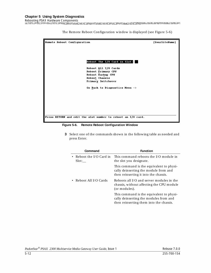
Chapter 5 Using System DiagnosticsRebooting PSAX Hardware Components
5-12 255-700-154
PacketStar® PSAX 2300 Multiservice Media Gateway User Guide, Issue 1 Release 7.0.0
The Remote Reboot Configuration window is displayed (see Figure 5-6)
3 Select one of the commands shown in the following table as needed and press Enter.
Figure 5-6. Remote Reboot Configuration Window
Command Function
• Reboot the I/O Card in Slot:__
This command reboots the I/O module in the slot you designate.
This command is the equivalent to physi-cally deinserting the module from and then reinserting it into the chassis.
• Reboot All I/O Cards Reboots all I/O and server modules in the chassis, without affecting the CPU module (or modules).
This command is the equivalent to physi-cally deinserting the modules from and then reinserting them into the chassis.
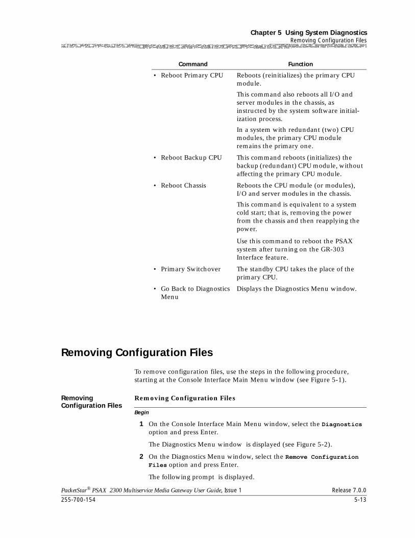
255-700-154 5-13
PacketStar® PSAX 2300 Multiservice Media Gateway User Guide, Issue 1 Release 7.0.0
Chapter 5 Using System DiagnosticsRemoving Configuration Files
Removing Configuration Files
To remove configuration files, use the steps in the following procedure, starting at the Console Interface Main Menu window (see Figure 5-1).
Removing Configuration Files
Begin
Removing Configuration Files
1 On the Console Interface Main Menu window, select the Diagnostics option and press Enter.
The Diagnostics Menu window is displayed (see Figure 5-2).
2 On the Diagnostics Menu window, select the Remove Configuration Files option and press Enter.
The following prompt is displayed.
• Reboot Primary CPU Reboots (reinitializes) the primary CPU module.
This command also reboots all I/O and server modules in the chassis, as instructed by the system software initial-ization process.
In a system with redundant (two) CPU modules, the primary CPU module remains the primary one.
• Reboot Backup CPU This command reboots (initializes) the backup (redundant) CPU module, without affecting the primary CPU module.
• Reboot Chassis Reboots the CPU module (or modules), I/O and server modules in the chassis.
This command is equivalent to a system cold start; that is, removing the power from the chassis and then reapplying the power.
Use this command to reboot the PSAX system after turning on the GR-303 Interface feature.
• Primary Switchover The standby CPU takes the place of the primary CPU.
• Go Back to Diagnostics Menu
Displays the Diagnostics Menu window.
Command Function
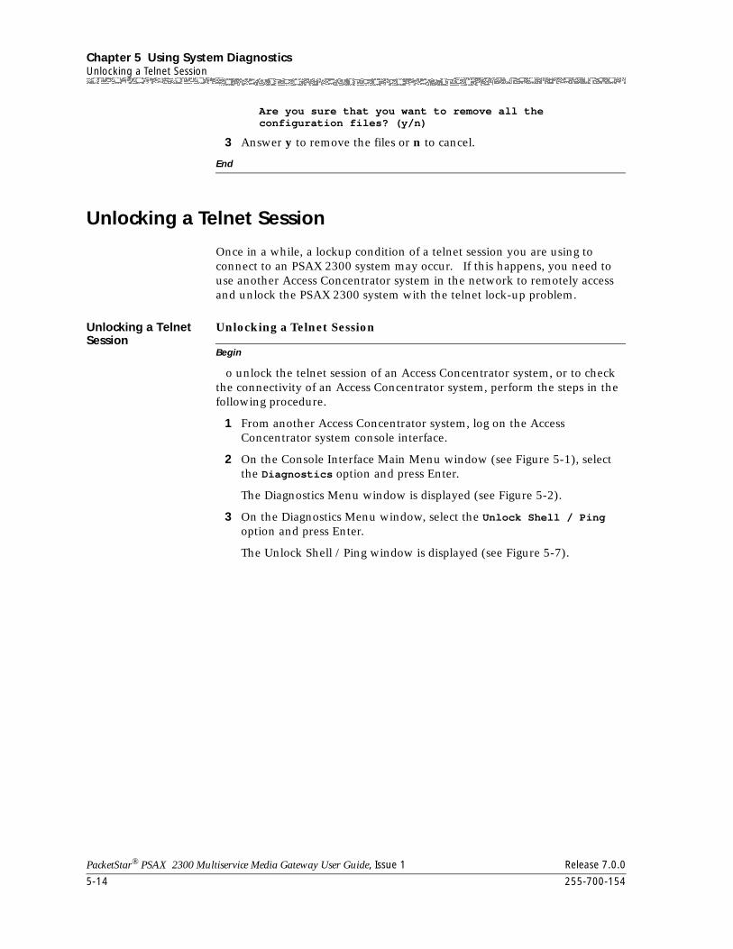
Chapter 5 Using System DiagnosticsUnlocking a Telnet Session
5-14 255-700-154
PacketStar® PSAX 2300 Multiservice Media Gateway User Guide, Issue 1 Release 7.0.0
Are you sure that you want to remove all the configuration files? (y/n)
3 Answer y to remove the files or n to cancel.
End
Unlocking a Telnet Session
Once in a while, a lockup condition of a telnet session you are using to connect to an PSAX 2300 system may occur. If this happens, you need to use another Access Concentrator system in the network to remotely access and unlock the PSAX 2300 system with the telnet lock-up problem.
Unlocking a Telnet Session
Begin
Unlocking a Telnet Session
o unlock the telnet session of an Access Concentrator system, or to check the connectivity of an Access Concentrator system, perform the steps in the following procedure.
1 From another Access Concentrator system, log on the Access Concentrator system console interface.
2 On the Console Interface Main Menu window (see Figure 5-1), select the Diagnostics option and press Enter.
The Diagnostics Menu window is displayed (see Figure 5-2).
3 On the Diagnostics Menu window, select the Unlock Shell / Ping option and press Enter.
The Unlock Shell / Ping window is displayed (see Figure 5-7).
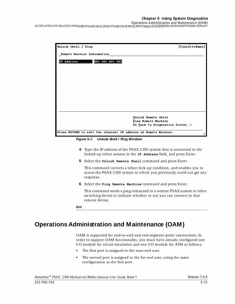
255-700-154 5-15
PacketStar® PSAX 2300 Multiservice Media Gateway User Guide, Issue 1 Release 7.0.0
Chapter 5 Using System DiagnosticsOperations Administration and Maintenance (OAM)
4 Type the IP address of the PSAX 2300 system that is connected to the locked-up telnet session in the IP Address field, and press Enter.
5 Select the Unlock Remote Shell command and press Enter.
This command corrects a telnet lock-up condition, and enables you to access the PSAX 2300 system to which you previously could not get any response.
6 Select the Ping Remote Machine command and press Enter.
This command sends a ping command to a remote PSAX system or other switching device to indicate whether or not you can connect to that remote device.
End
Operations Administration and Maintenance (OAM)
OAM is supported for end-to-end and end-segment-point connections. In order to support OAM functionality, you must have already configured one I/O module for circuit emulation and one I/O module for ATM as follows:
• The first port is assigned to the near-end user.
• The second port is assigned to the far-end user, using the same configuration as the first port.
Figure 5-7. Unlock Shell / Ping Window
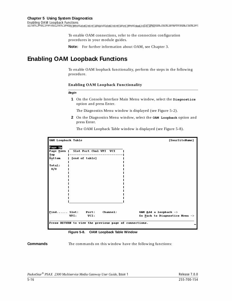
Chapter 5 Using System DiagnosticsEnabling OAM Loopback Functions
5-16 255-700-154
PacketStar® PSAX 2300 Multiservice Media Gateway User Guide, Issue 1 Release 7.0.0
To enable OAM connections, refer to the connection configuration procedures in your module guides.
Note: For further information about OAM, see Chapter 3.
Enabling OAM Loopback Functions
To enable OAM loopback functionality, perform the steps in the following procedure.
Begin
Enabling OAM Loopback Functionality
1 On the Console Interface Main Menu window, select the Diagnostics option and press Enter.
The Diagnostics Menu window is displayed (see Figure 5-2).
2 On the Diagnostics Menu window, select the OAM Loopback option and press Enter.
The OAM Loopback Table window is displayed (see Figure 5-8).
Commands The commands on this window have the following functions:
Figure 5-8. OAM Loopback Table Window
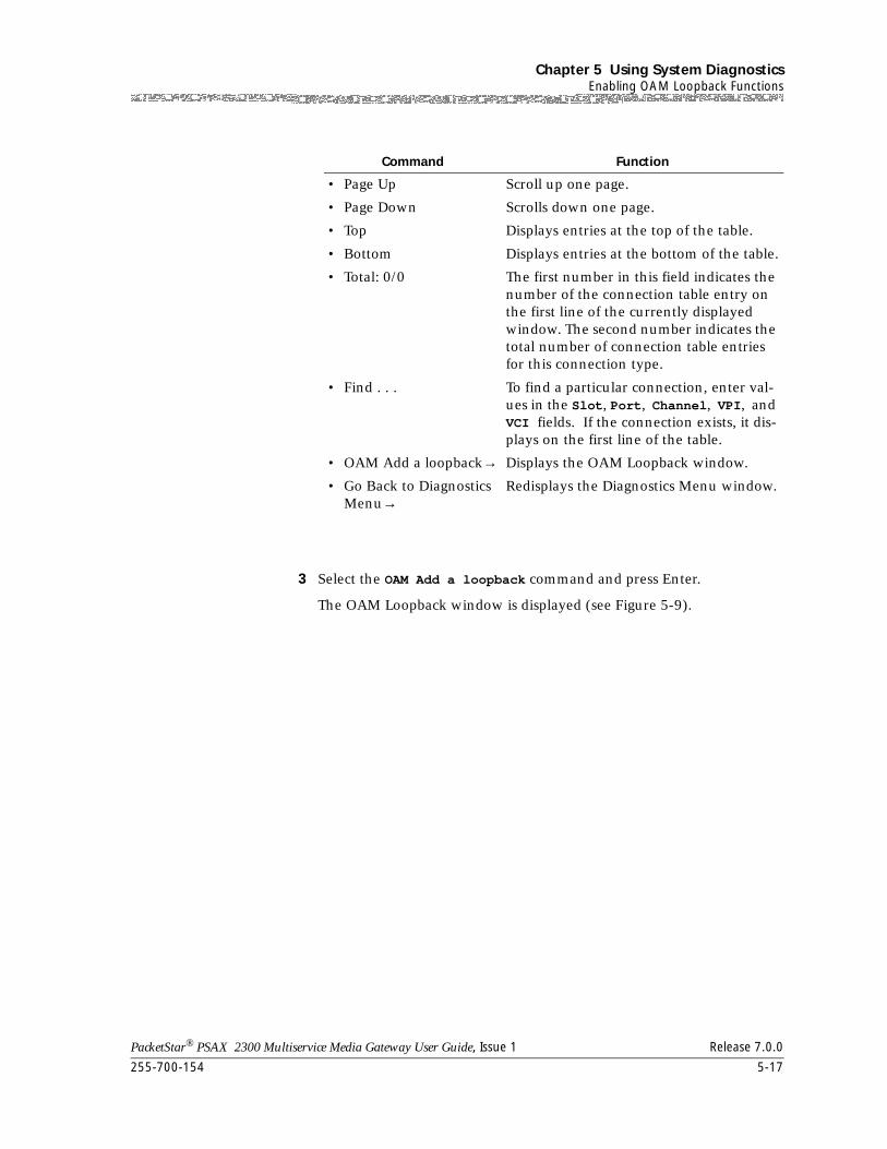
255-700-154 5-17
PacketStar® PSAX 2300 Multiservice Media Gateway User Guide, Issue 1 Release 7.0.0
Chapter 5 Using System DiagnosticsEnabling OAM Loopback Functions
3 Select the OAM Add a loopback command and press Enter.
The OAM Loopback window is displayed (see Figure 5-9).
Command Function
• Page Up Scroll up one page.
• Page Down Scrolls down one page.
• Top Displays entries at the top of the table.
• Bottom Displays entries at the bottom of the table.
• Total: 0/0 The first number in this field indicates the number of the connection table entry on the first line of the currently displayed window. The second number indicates the total number of connection table entries for this connection type.
• Find . . . To find a particular connection, enter val-ues in the Slot, Port, Channel, VPI, and VCI fields. If the connection exists, it dis-plays on the first line of the table.
• OAM Add a loopback→ Displays the OAM Loopback window.
• Go Back to Diagnostics Menu→
Redisplays the Diagnostics Menu window.
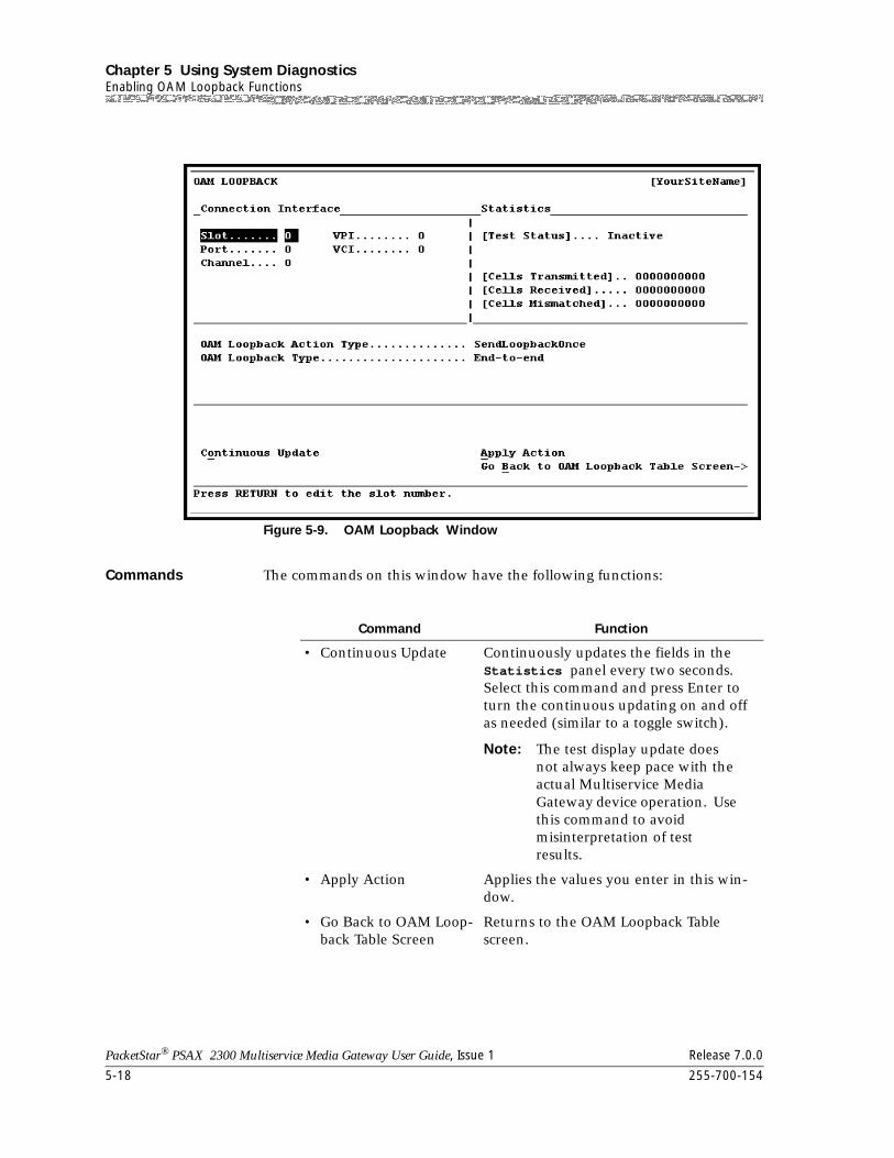
Chapter 5 Using System DiagnosticsEnabling OAM Loopback Functions
5-18 255-700-154
PacketStar® PSAX 2300 Multiservice Media Gateway User Guide, Issue 1 Release 7.0.0
Commands The commands on this window have the following functions:
Figure 5-9. OAM Loopback Window
Command Function
• Continuous Update Continuously updates the fields in the Statistics panel every two seconds. Select this command and press Enter to turn the continuous updating on and off as needed (similar to a toggle switch).
Note: The test display update does not always keep pace with the actual Multiservice Media Gateway device operation. Use this command to avoid misinterpretation of test results.
• Apply Action Applies the values you enter in this win-dow.
• Go Back to OAM Loop-back Table Screen
Returns to the OAM Loopback Table screen.
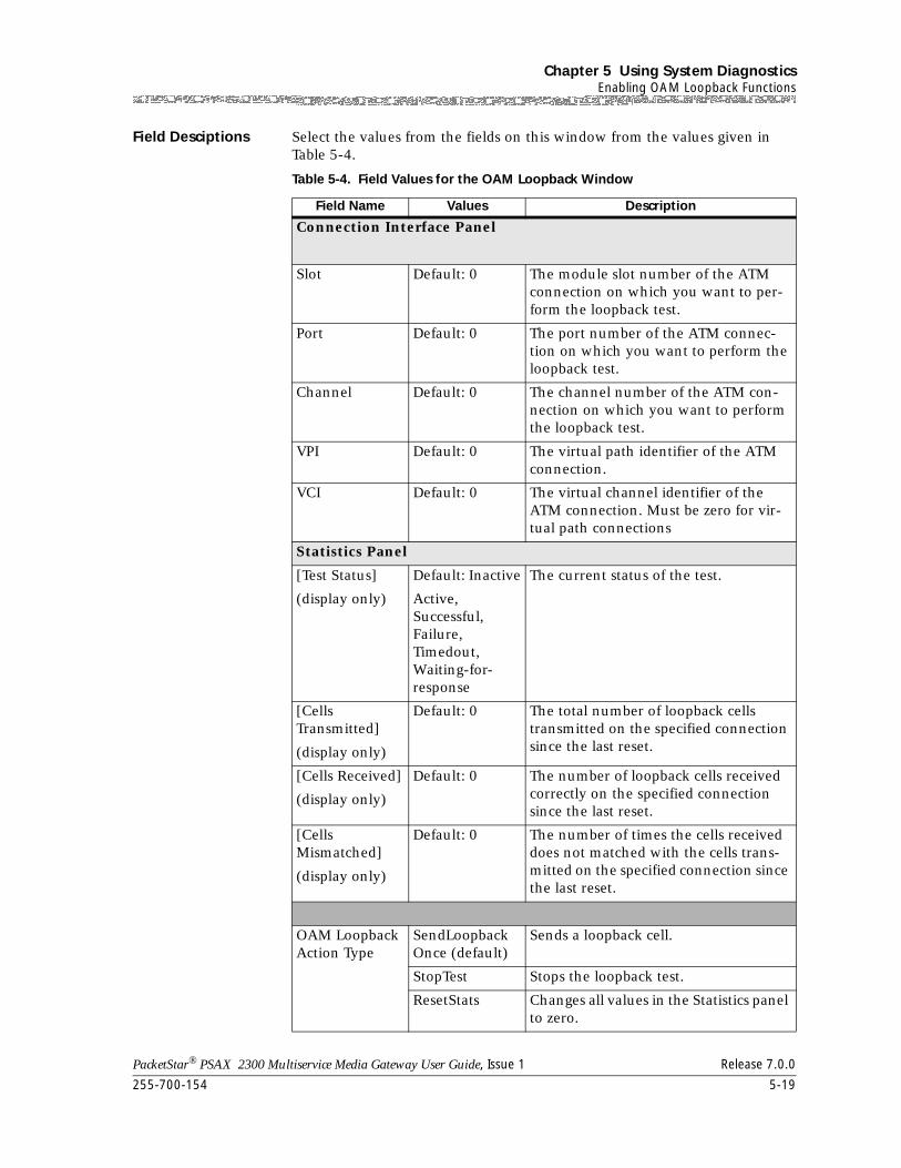
255-700-154 5-19
PacketStar® PSAX 2300 Multiservice Media Gateway User Guide, Issue 1 Release 7.0.0
Chapter 5 Using System DiagnosticsEnabling OAM Loopback Functions
Field Desciptions Select the values from the fields on this window from the values given in Table 5-4.
Table 5-4. Field Values for the OAM Loopback Window
Field Name Values Description
Connection Interface Panel
Slot Default: 0 The module slot number of the ATM connection on which you want to per-form the loopback test.
Port Default: 0 The port number of the ATM connec-tion on which you want to perform the loopback test.
Channel Default: 0 The channel number of the ATM con-nection on which you want to perform the loopback test.
VPI Default: 0 The virtual path identifier of the ATM connection.
VCI Default: 0 The virtual channel identifier of the ATM connection. Must be zero for vir-tual path connections
Statistics Panel
[Test Status]
(display only)
Default: Inactive
Active, Successful, Failure,Timedout,Waiting-for-response
The current status of the test.
[Cells Transmitted]
(display only)
Default: 0 The total number of loopback cells transmitted on the specified connection since the last reset.
[Cells Received]
(display only)
Default: 0 The number of loopback cells received correctly on the specified connection since the last reset.
[Cells Mismatched]
(display only)
Default: 0 The number of times the cells received does not matched with the cells trans-mitted on the specified connection since the last reset.
OAM Loopback Action Type
SendLoopback Once (default)
Sends a loopback cell.
StopTest Stops the loopback test.
ResetStats Changes all values in the Statistics panel to zero.
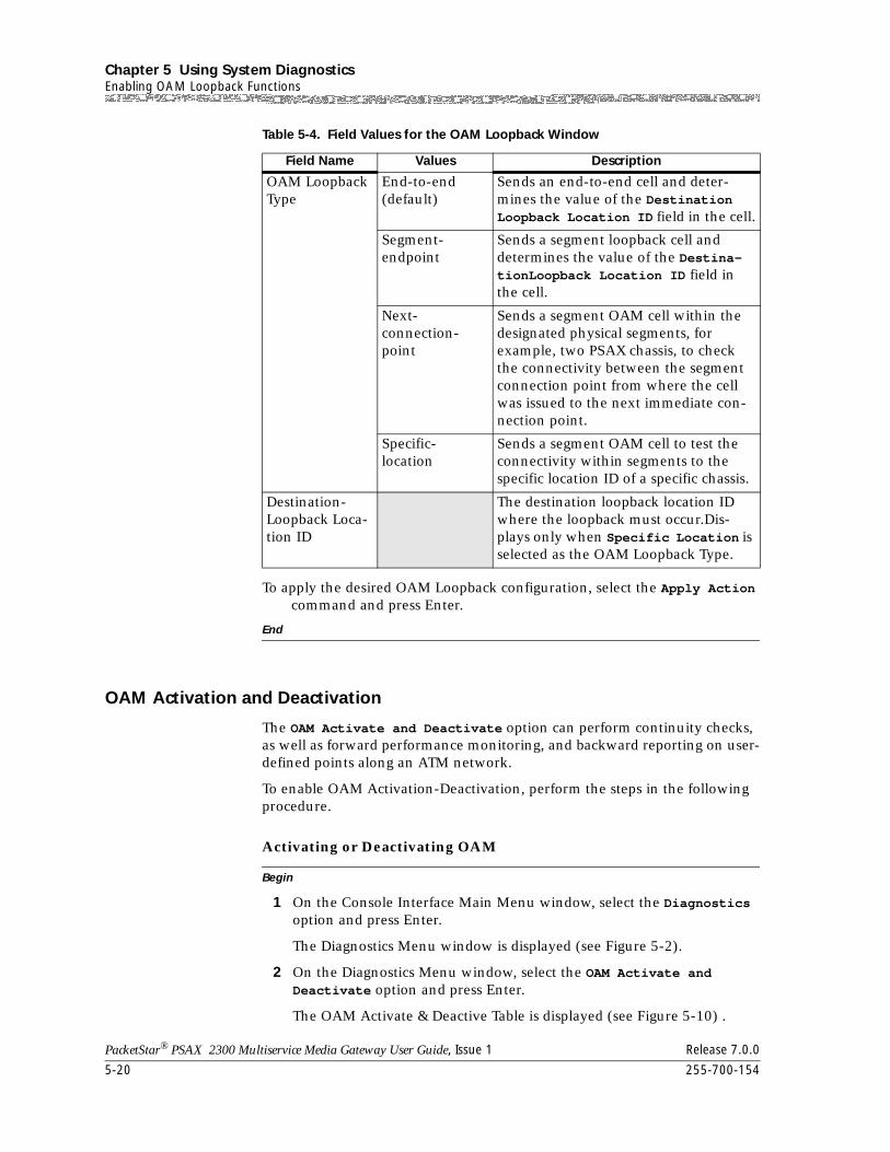
Chapter 5 Using System DiagnosticsEnabling OAM Loopback Functions
5-20 255-700-154
PacketStar® PSAX 2300 Multiservice Media Gateway User Guide, Issue 1 Release 7.0.0
To apply the desired OAM Loopback configuration, select the Apply Action command and press Enter.
End
OAM Activation and Deactivation
The OAM Activate and Deactivate option can perform continuity checks, as well as forward performance monitoring, and backward reporting on user-defined points along an ATM network.
To enable OAM Activation-Deactivation, perform the steps in the following procedure.
Begin
Activating or Deactivating OAM
1 On the Console Interface Main Menu window, select the Diagnostics option and press Enter.
The Diagnostics Menu window is displayed (see Figure 5-2).
2 On the Diagnostics Menu window, select the OAM Activate and Deactivate option and press Enter.
The OAM Activate & Deactive Table is displayed (see Figure 5-10) .
OAM Loopback Type
End-to-end (default)
Sends an end-to-end cell and deter-mines the value of the Destination Loopback Location ID field in the cell.
Segment-endpoint
Sends a segment loopback cell and determines the value of the Destina-tionLoopback Location ID field in the cell.
Next-connection-point
Sends a segment OAM cell within the designated physical segments, for example, two PSAX chassis, to check the connectivity between the segment connection point from where the cell was issued to the next immediate con-nection point.
Specific-location
Sends a segment OAM cell to test the connectivity within segments to the specific location ID of a specific chassis.
Destination-Loopback Loca-tion ID
The destination loopback location ID where the loopback must occur.Dis-plays only when Specific Location is selected as the OAM Loopback Type.
Table 5-4. Field Values for the OAM Loopback Window
Field Name Values Description
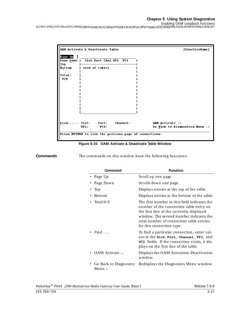
255-700-154 5-21
PacketStar® PSAX 2300 Multiservice Media Gateway User Guide, Issue 1 Release 7.0.0
Chapter 5 Using System DiagnosticsEnabling OAM Loopback Functions
Commands The commands on this window have the following functions:
Figure 5-10. OAM Activate & Deactivate Table Window
Command Function
• Page Up Scroll up one page.
• Page Down Scrolls down one page.
• Top Displays entries at the top of the table.
• Bottom Displays entries at the bottom of the table.
• Total:0/0 The first number in this field indicates the number of the connection table entry on the first line of the currently displayed window. The second number indicates the total number of connection table entries for this connection type.
• Find . . . To find a particular connection, enter val-ues in the Slot, Port, Channel, VPI, and VCI fields. If the connection exists, it dis-plays on the first line of the table.
• OAM Activate→ Displays the OAM Activation-Deactivation window.
• Go Back to Diagnostics Menu→
Redisplays the Diagnostics Menu window.
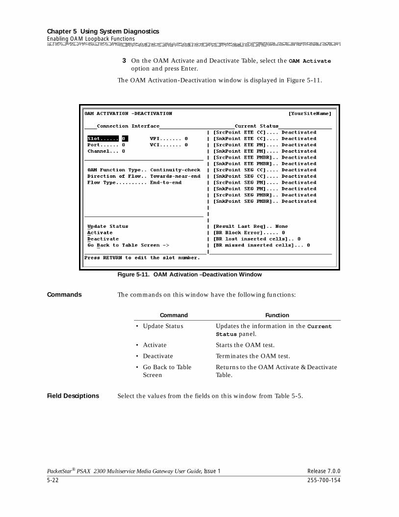
Chapter 5 Using System DiagnosticsEnabling OAM Loopback Functions
5-22 255-700-154
PacketStar® PSAX 2300 Multiservice Media Gateway User Guide, Issue 1 Release 7.0.0
3 On the OAM Activate and Deactivate Table, select the OAM Activate option and press Enter.
The OAM Activation-Deactivation window is displayed in Figure 5-11.
Commands The commands on this window have the following functions:
Field Desciptions Select the values from the fields on this window from Table 5-5.
Figure 5-11. OAM Activation –Deactivation Window
Command Function
• Update Status Updates the information in the Current Status panel.
• Activate Starts the OAM test.
• Deactivate Terminates the OAM test.
• Go Back to Table Screen
Returns to the OAM Activate & Deactivate Table.
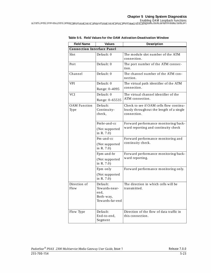
255-700-154 5-23
PacketStar® PSAX 2300 Multiservice Media Gateway User Guide, Issue 1 Release 7.0.0
Chapter 5 Using System DiagnosticsEnabling OAM Loopback Functions
Table 5-5. Field Values for the OAM Activation-Deactivation Window
Field Name Values Description
Connection Interface Panel
Slot Default: 0 The module slot number of the ATM connection.
Port Default: 0 The port number of the ATM connec-tion.
Channel Default: 0 The channel number of the ATM con-nection.
VPI Default: 0
Range: 0–4095
The virtual path identifier of the ATM connection.
VCI Default: 0
Range: 0–65535
The virtual channel identifier of the ATM connection.
OAM Function Type
Default:Continuity-check,
Check to see if OAM cells flow continu-lously throughout the length of a single connection.
Pmbr-and-cc
(Not supported in R. 7.0)
Forward performance monitoring/back-ward reporting and continuity check
Pm-and-cc
(Not supported in R. 7.0)
Forward performance monitoring and continuity check.
Fpm-and-br
(Not supported in R. 7.0)
Forward performance monitoring/back-ward reporting.
Fpm only
(Not supported in R. 7.0)
Forward performance monitoring only.
Direction of Flow
Default:Towards-near-end,Both-way,Towards-far-end
The direction in which cells will be transmitted.
Flow Type Default:End-to-end,Segment
Direction of the flow of data traffic in this connection.
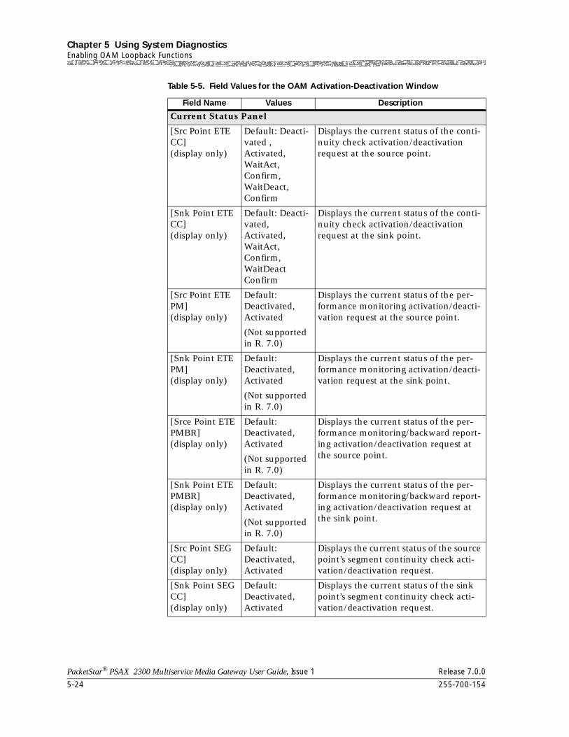
Chapter 5 Using System DiagnosticsEnabling OAM Loopback Functions
5-24 255-700-154
PacketStar® PSAX 2300 Multiservice Media Gateway User Guide, Issue 1 Release 7.0.0
Current Status Panel
[Src Point ETE CC](display only)
Default: Deacti-vated ,Activated, WaitAct,Confirm,WaitDeact,Confirm
Displays the current status of the conti-nuity check activation/deactivation request at the source point.
[Snk Point ETE CC] (display only)
Default: Deacti-vated, Activated, WaitAct,Confirm,WaitDeactConfirm
Displays the current status of the conti-nuity check activation/deactivation request at the sink point.
[Src Point ETE PM] (display only)
Default: Deactivated, Activated
(Not supported in R. 7.0)
Displays the current status of the per-formance monitoring activation/deacti-vation request at the source point.
[Snk Point ETE PM] (display only)
Default:Deactivated, Activated
(Not supported in R. 7.0)
Displays the current status of the per-formance monitoring activation/deacti-vation request at the sink point.
[Srce Point ETE PMBR] (display only)
Default:Deactivated, Activated
(Not supported in R. 7.0)
Displays the current status of the per-formance monitoring/backward report-ing activation/deactivation request at the source point.
[Snk Point ETE PMBR] (display only)
Default:Deactivated, Activated
(Not supported in R. 7.0)
Displays the current status of the per-formance monitoring/backward report-ing activation/deactivation request at the sink point.
[Src Point SEG CC] (display only)
Default:Deactivated, Activated
Displays the current status of the source point’s segment continuity check acti-vation/deactivation request.
[Snk Point SEG CC] (display only)
Default:Deactivated, Activated
Displays the current status of the sink point’s segment continuity check acti-vation/deactivation request.
Table 5-5. Field Values for the OAM Activation-Deactivation Window
Field Name Values Description
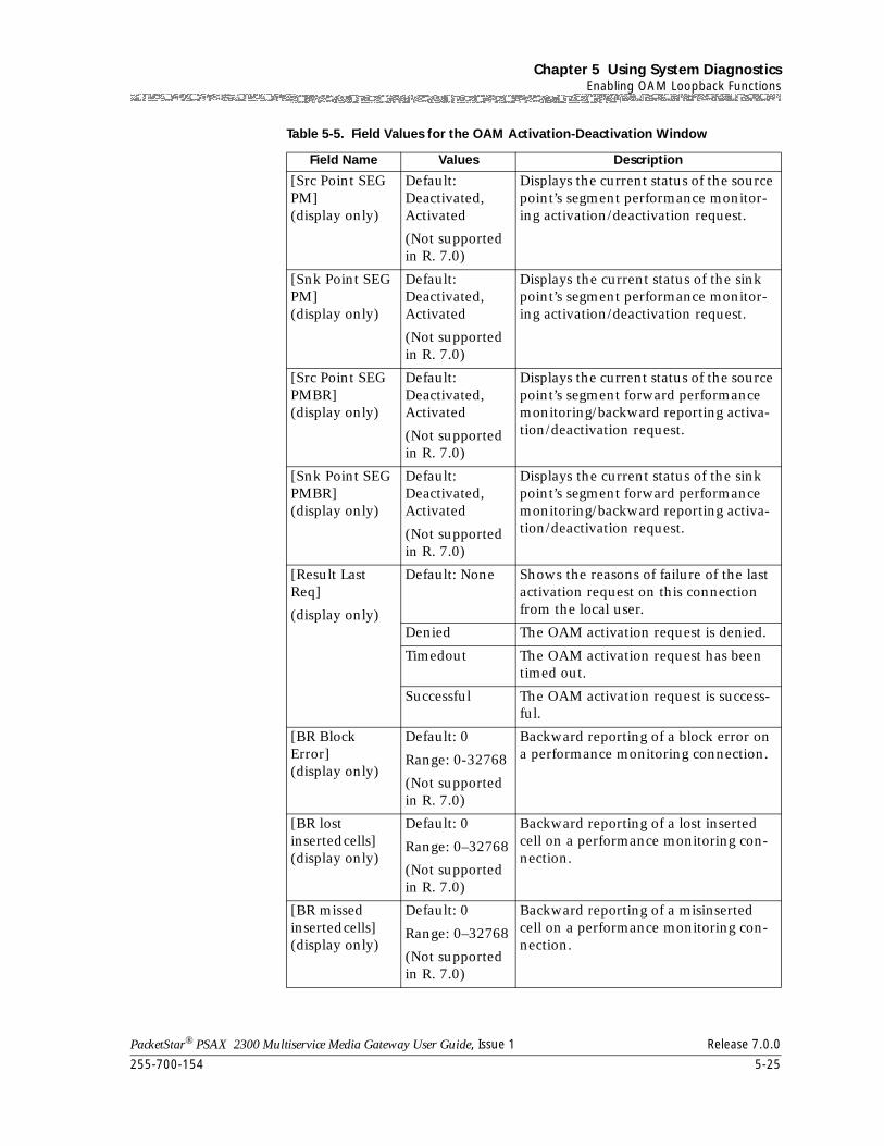
255-700-154 5-25
PacketStar® PSAX 2300 Multiservice Media Gateway User Guide, Issue 1 Release 7.0.0
Chapter 5 Using System DiagnosticsEnabling OAM Loopback Functions
[Src Point SEG PM] (display only)
Default:Deactivated, Activated
(Not supported in R. 7.0)
Displays the current status of the source point’s segment performance monitor-ing activation/deactivation request.
[Snk Point SEG PM] (display only)
Default:Deactivated, Activated
(Not supported in R. 7.0)
Displays the current status of the sink point’s segment performance monitor-ing activation/deactivation request.
[Src Point SEG PMBR] (display only)
Default:Deactivated, Activated
(Not supported in R. 7.0)
Displays the current status of the source point’s segment forward performance monitoring/backward reporting activa-tion/deactivation request.
[Snk Point SEG PMBR] (display only)
Default:Deactivated, Activated
(Not supported in R. 7.0)
Displays the current status of the sink point’s segment forward performance monitoring/backward reporting activa-tion/deactivation request.
[Result Last Req]
(display only)
Default: None Shows the reasons of failure of the last activation request on this connection from the local user.
Denied The OAM activation request is denied.
Timedout The OAM activation request has been timed out.
Successful The OAM activation request is success-ful.
[BR Block Error] (display only)
Default: 0
Range: 0-32768
(Not supported in R. 7.0)
Backward reporting of a block error on a performance monitoring connection.
[BR lost inserted cells] (display only)
Default: 0
Range: 0–32768
(Not supported in R. 7.0)
Backward reporting of a lost inserted cell on a performance monitoring con-nection.
[BR missed inserted cells] (display only)
Default: 0
Range: 0–32768
(Not supported in R. 7.0)
Backward reporting of a misinserted cell on a performance monitoring con-nection.
Table 5-5. Field Values for the OAM Activation-Deactivation Window
Field Name Values Description

Chapter 5 Using System DiagnosticsEnabling OAM Loopback Functions
5-26 255-700-154
PacketStar® PSAX 2300 Multiservice Media Gateway User Guide, Issue 1 Release 7.0.0
4 To begin the test, select the Activate command and press Enter.
5 To terminate the test, select the Deactivate command and press Enter.
End
PacketStar® PSAX 2300 Multiservice Media Gateway User Guide, Issue 1 Release 7.0.0
255-700-154 6-1
6 Using VT100 Terminal Emulation
Overview of This Chapter
The information in this chapter is divided into the following headings.
• Setting Up The Windows 3.1 Terminal Emulator
• Setting Up The Windows 95 HyperTerminal Emulator
• Other Software for VT100 Terminal Emulation
• Setting Up a U.S. Robotics-Compatible Modem
Overview of Terminal Emulation
VT100 terminal emulation is used in configuring and managing the PSAX 2300 system from the serial interface port labeled CONSOLE on the faceplate. The PSAX 2300 Multiservice Media Gateway system software supports the following terminal emulation software:
• Microsoft Windows 3.1 terminal emulator
• Microsoft Windows 95 HyperTerminal terminal emulator
• Alternate terminal emulation software
Use the serial cable (RS-11 with specific pinouts) supplied with your installation kit to connect the Access Concentrator system with the PC.
Setting Up The Windows 3.1 Terminal Emulator
To configure the terminal settings using the Microsoft Windows 3.1 terminal emulator, perform the following procedure.
Begin
Setting Up The Windows 3.1 Terminal Emulator
1 From the Terminal menu, select the Settings option.
2 Select the Terminal Emulation option from the Settings Menu.
3 Set the Terminal Emulation field to DEC VT100 (ANSI).
4 Select OK.
5 Return to the Settings Menu.
6 Select the Terminal Preferences option from the Settings Menu.
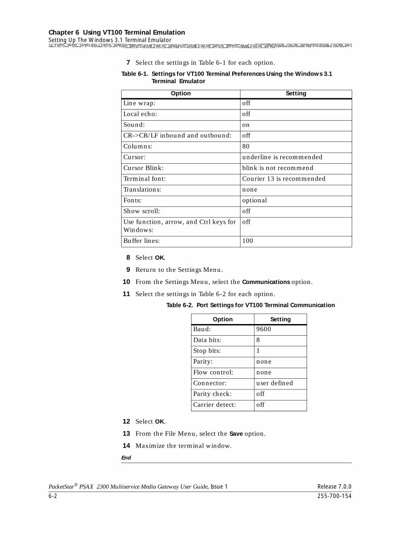
Chapter 6 Using VT100 Terminal EmulationSetting Up The Windows 3.1 Terminal Emulator
6-2 255-700-154
PacketStar® PSAX 2300 Multiservice Media Gateway User Guide, Issue 1 Release 7.0.0
7 Select the settings in Table 6-1 for each option.
8 Select OK.
9 Return to the Settings Menu.
10 From the Settings Menu, select the Communications option.
11 Select the settings in Table 6-2 for each option.
12 Select OK.
13 From the File Menu, select the Save option.
14 Maximize the terminal window.
End
Table 6-1. Settings for VT100 Terminal Preferences Using the Windows 3.1 Terminal Emulator
Option Setting
Line wrap: off
Local echo: off
Sound: on
CR->CR/LF inbound and outbound: off
Columns: 80
Cursor: underline is recommended
Cursor Blink: blink is not recommend
Terminal font: Courier 13 is recommended
Translations: none
Fonts: optional
Show scroll: off
Use function, arrow, and Ctrl keys for Windows:
off
Buffer lines: 100
Table 6-2. Port Settings for VT100 Terminal Communication
Option Setting
Baud: 9600
Data bits: 8
Stop bits: 1
Parity: none
Flow control: none
Connector: user defined
Parity check: off
Carrier detect: off
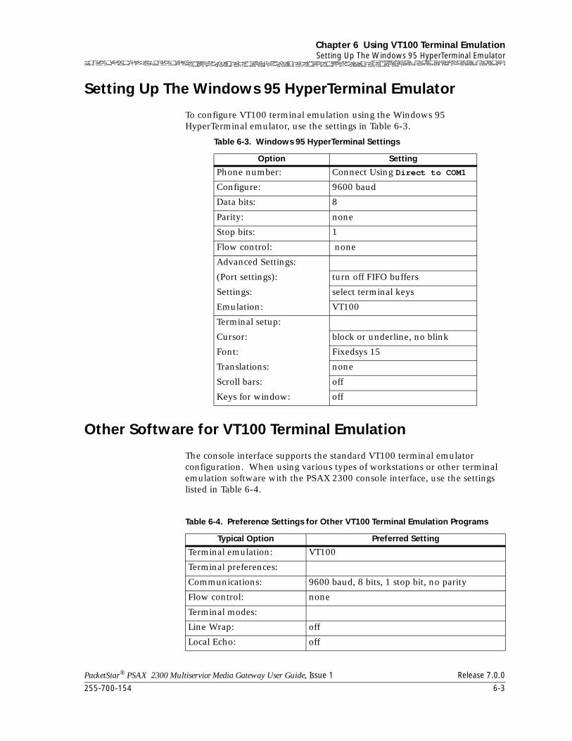
255-700-154 6-3
PacketStar® PSAX 2300 Multiservice Media Gateway User Guide, Issue 1 Release 7.0.0
Chapter 6 Using VT100 Terminal EmulationSetting Up The Windows 95 HyperTerminal Emulator
Setting Up The Windows 95 HyperTerminal Emulator
To configure VT100 terminal emulation using the Windows 95 HyperTerminal emulator, use the settings in Table 6-3.
Other Software for VT100 Terminal Emulation
The console interface supports the standard VT100 terminal emulator configuration. When using various types of workstations or other terminal emulation software with the PSAX 2300 console interface, use the settings listed in Table 6-4.
Table 6-3. Windows 95 HyperTerminal Settings
Option Setting
Phone number: Connect Using Direct to COM1
Configure: 9600 baud
Data bits: 8
Parity: none
Stop bits: 1
Flow control: none
Advanced Settings:
(Port settings):
Settings:
Emulation:
turn off FIFO buffers
select terminal keys
VT100
Terminal setup:
Cursor:
Font:
Translations:
Scroll bars:
Keys for window:
block or underline, no blink
Fixedsys 15
none
off
off
Table 6-4. Preference Settings for Other VT100 Terminal Emulation Programs
Typical Option Preferred Setting
Terminal emulation: VT100
Terminal preferences:
Communications: 9600 baud, 8 bits, 1 stop bit, no parity
Flow control: none
Terminal modes:
Line Wrap: off
Local Echo: off
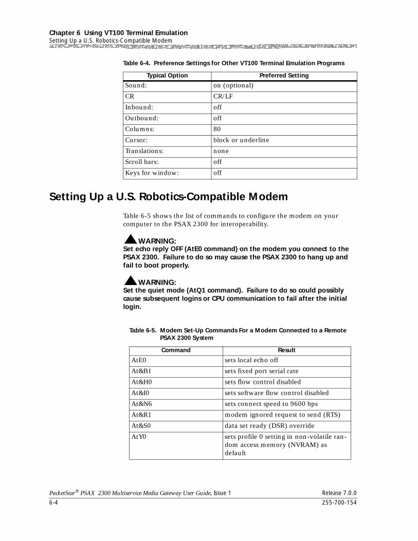
Chapter 6 Using VT100 Terminal EmulationSetting Up a U.S. Robotics-Compatible Modem
6-4 255-700-154
PacketStar® PSAX 2300 Multiservice Media Gateway User Guide, Issue 1 Release 7.0.0
Setting Up a U.S. Robotics-Compatible Modem
Table 6-5 shows the list of commands to configure the modem on your computer to the PSAX 2300 for interoperability.
WARNING:!Set echo reply OFF (AtE0 command) on the modem you connect to the PSAX 2300. Failure to do so may cause the PSAX 2300 to hang up and fail to boot properly.
WARNING:!
Set the quiet mode (AtQ1 command). Failure to do so could possibly cause subsequent logins or CPU communication to fail after the initial login.
Sound: on (optional)
CR CR/LF
Inbound: off
Outbound: off
Columns: 80
Cursor: block or underline
Translations: none
Scroll bars: off
Keys for window: off
Table 6-4. Preference Settings for Other VT100 Terminal Emulation Programs
Typical Option Preferred Setting
Table 6-5. Modem Set-Up Commands For a Modem Connected to a Remote PSAX 2300 System
Command Result
AtE0 sets local echo off
At&B1 sets fixed port serial rate
At&H0 sets flow control disabled
At&I0 sets software flow control disabled
At&N6 sets connect speed to 9600 bps
At&R1 modem ignored request to send (RTS)
At&S0 data set ready (DSR) override
AtY0 sets profile 0 setting in non-volatile ran-dom access memory (NVRAM) as default
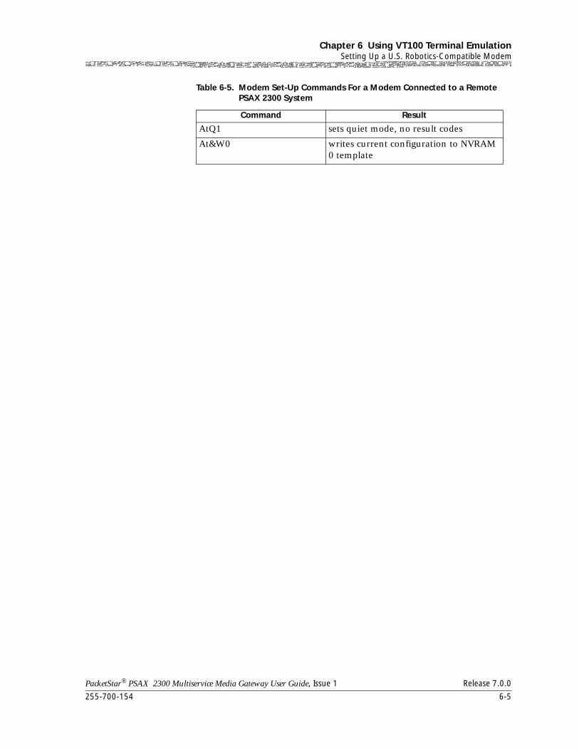
255-700-154 6-5
PacketStar® PSAX 2300 Multiservice Media Gateway User Guide, Issue 1 Release 7.0.0
Chapter 6 Using VT100 Terminal EmulationSetting Up a U.S. Robotics-Compatible Modem
AtQ1 sets quiet mode, no result codes
At&W0 writes current configuration to NVRAM 0 template
Table 6-5. Modem Set-Up Commands For a Modem Connected to a Remote PSAX 2300 System
Command Result

Chapter 6 Using VT100 Terminal EmulationSetting Up a U.S. Robotics-Compatible Modem
6-6 255-700-154
PacketStar® PSAX 2300 Multiservice Media Gateway User Guide, Issue 1 Release 7.0.0

PacketStar® PSAX 2300 Multiservice Media Gateway User Guide, Issue 1 Release 7.0.0
255-700-154 7-1
7 Upgrading and Backing Up PSAXSystem Software
Overview of This Chapter
This chapter describes how to upgrade, back up, and restore the PSAX Multiservice Media Gateway system software and firmware.
Note: If the system software release to which you are upgrading requires a firmware update, you need to perform the remote software upgrade procedure, or arrange for an in-factory or on-site upgrade by Lucent Technologies, Inc. personnel. The Release Note for the system software version to which you are upgrading identifies any affected modules. Your Lucent Technologies customer engineer or a NetworkCareSM representative can provide you with details about the return materials authorization (RMA) process or, depending on the type of service agreement you have, the on-site upgrade procedure. For information on these services, contact Lucent Technologies NetworkCare (see "Technical Support" in Chapter 1, "Getting Started").
The following procedures are presented:
• Installing a new software or firmware release by using the following methods:
~ Upgrading to the new release using FTP (see ”Upgrading System Software Using FTP” on page 7-4)
~ Upgrading to the new release using X/Modem/YModem file transfer (see ”Upgrading Using XModem/YModem File Transfer Method” on page 7-11)
• Upgrading the firmware of I/O modules (see ”Upgrading Firmware” on page 7-17)
• Falling back to the previous software release (see ”Falling Back to the Previous Software Release” on page 7-24)
• Backing up Multiservice Media Gateway system, module, and connection configuration database files by using the following methods:
~ Backing up database files using FTP (see ”Backing Up System Database Files” on page 7-26)
~ Backing up database files using XModem/YModem file transfer (see ”Backing Up Database Files Using XModem/YModem File Transfer” on page 7-28)
• Restoring Multiservice Media Gateway configuration and connection database files by using the following methods:
~ Restoring database files using FTP (see ”Restoring Database Files Using FTP” on page 7-34)
Chapter 7 Upgrading and Backing Up PSAX System SoftwareOverview of This Chapter
7-2 255-700-154
PacketStar® PSAX 2300 Multiservice Media Gateway User Guide, Issue 1 Release 7.0.0
~ Restoring database files using XModem/YModem file transfer (see ”Restoring Database Files Using XModem/YModem File Transfer” on page 7-36)
Directory Structures
In DOS environments, specify the drive letter as follows:
/x/FTP/V6.3.C0/upgrade.lib
where x is the drive letter.
Note: When using Unix operating systems, use forward slashes ( / ) when typing directory strings. When using Windows operating systems, use backward slashes ( \ ) when typing directory strings.
Software upgrades for the Access Concentrator systems are provided on the CD-ROM. The directory structure on the CD-ROM is the following:
• The directory /version/next, where version stands for the new software release number.
• The directory /version/mib, which contains the V1 and V2 management information bases (MIBs), which you can use with an SNMP manager.
The following directory structure is resident on the hard disk of the CPU module:
• /scsi/current/—This directory contains the initialization files for the current, operational version of the system software.
~ /scsi/current/bin—This directory contains the library files for the current version of the software.
~ /scsi/current/snmpagt—This directory contains the SNMP agent files for the current version of the software.
~ /scsi/current/firmware—This directory contains the firmware files for the current version of the firmware.
• /scsi/fallback/—This directory contains all the files for the previous version of system software and database files.
~ /scsi/fallback/firmware—This directory contains the firmware files for the previously downloaded version of the firmware.
• /scsi/next/—This is the directory where all files for future system software upgrades are received.
~ /scsi/next/firmware—This directory contains the firmware files for the when the next version of the firmware is received.
Installing a New Software Release
Installing a new release of the Multiservice Media Gateway System software includes the following tasks:
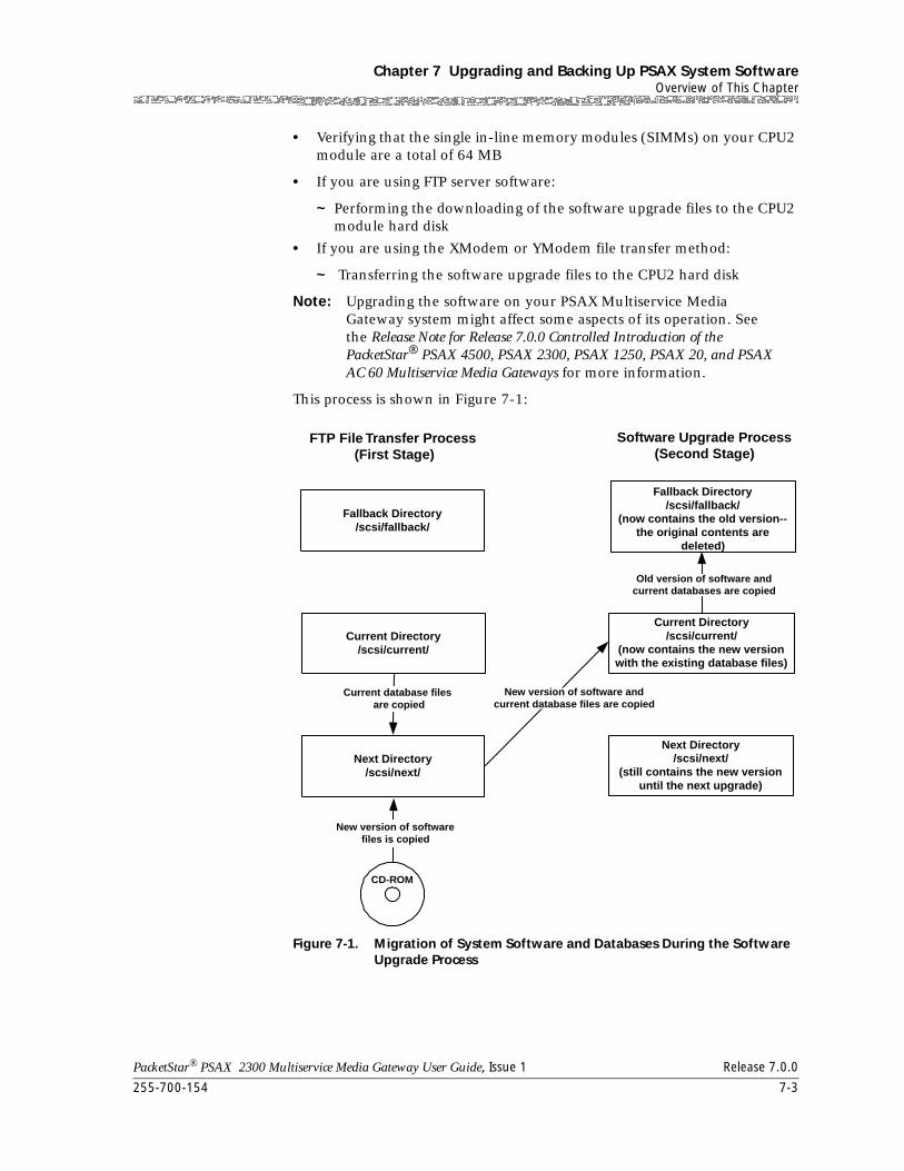
255-700-154 7-3
PacketStar® PSAX 2300 Multiservice Media Gateway User Guide, Issue 1 Release 7.0.0
Chapter 7 Upgrading and Backing Up PSAX System SoftwareOverview of This Chapter
• Verifying that the single in-line memory modules (SIMMs) on your CPU2 module are a total of 64 MB
• If you are using FTP server software:
~ Performing the downloading of the software upgrade files to the CPU2 module hard disk
• If you are using the XModem or YModem file transfer method:
~ Transferring the software upgrade files to the CPU2 hard disk
Note: Upgrading the software on your PSAX Multiservice Media Gateway system might affect some aspects of its operation. See the Release Note for Release 7.0.0 Controlled Introduction of the PacketStar® PSAX 4500, PSAX 2300, PSAX 1250, PSAX 20, and PSAX AC 60 Multiservice Media Gateways for more information.
This process is shown in Figure 7-1:
Figure 7-1. Migration of System Software and Databases During the Software Upgrade Process
Fallback Directory/scsi/fallback/
Current Directory/scsi/current/
Next Directory/scsi/next/
FTP File Transfer Process(First Stage)
Software Upgrade Process(Second Stage)
Current database files are copied
CD-ROM
New version of softwarefiles is copied
Fallback Directory/scsi/fallback/
(now contains the old version--the original contents are
deleted)
Current Directory/scsi/current/
(now contains the new versionwith the existing database files)
Next Directory/scsi/next/
(still contains the new versionuntil the next upgrade)
New version of software andcurrent database files are copied
Old version of software andcurrent databases are copied
Chapter 7 Upgrading and Backing Up PSAX System SoftwareOverview of This Chapter
7-4 255-700-154
PacketStar® PSAX 2300 Multiservice Media Gateway User Guide, Issue 1 Release 7.0.0
Setting Up a Windows FTP Server
If you are using a PC workstation or laptop PC running Windows 3.1, Windows 95 or higher to upgrade your Multiservice Media Gateway system software, you need to obtain an FTP server software program. If you are running Windows NT, you can use the FTP server function that is included in this operating system. For Windows 95, you need to obtain an FTP server software program, which is available from several Internet web sites, including:
• Serv-U from http://www.cat-soft.com
• Wftpd234 from http://www.shareware.com
If you plan to use a shareware program, you are responsible for following the terms of the author’s licensing agreement, including payment. To set up your FTP server software, perform the steps in the following procedure.
Begin
Setting Up a Windows FTP Server
1 Obtain an FTP server software program (freeware, shareware, or commercial) for Windows 95 or Windows 3.1.
2 Set up the FTP server software as follows:
a. Create an account and password.
b. Assign read-only, recursive access privileges to the pathname containing the drive ID and directory where the CD-ROM drive resides.
End
Upgrading System Software Using FTP
To upgrade your Multiservice Media Gateway system software to Release 7.0.0 from an earlier release, perform the steps in the following procedure.
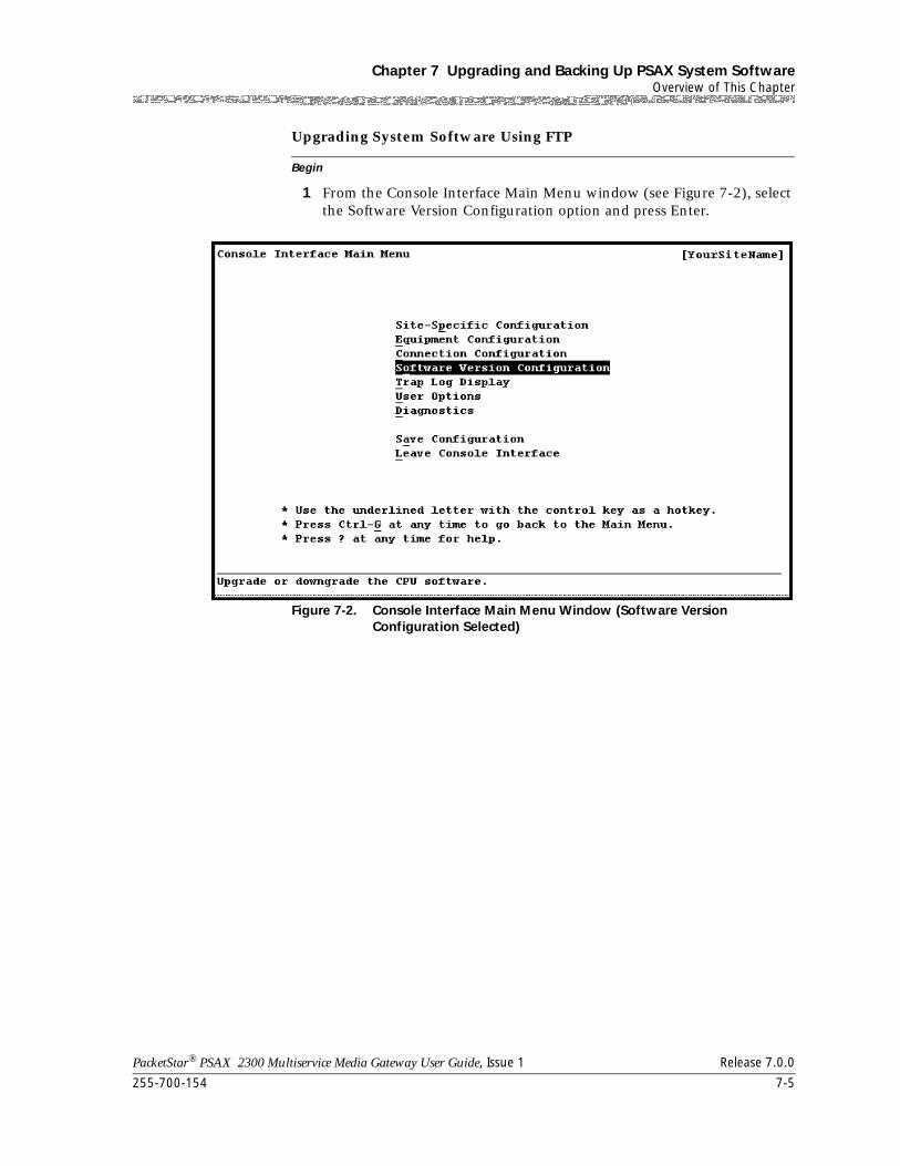
255-700-154 7-5
PacketStar® PSAX 2300 Multiservice Media Gateway User Guide, Issue 1 Release 7.0.0
Chapter 7 Upgrading and Backing Up PSAX System SoftwareOverview of This Chapter
Begin
Upgrading System Software Using FTP
1 From the Console Interface Main Menu window (see Figure 7-2), select the Software Version Configuration option and press Enter.
Figure 7-2. Console Interface Main Menu Window (Software Version Configuration Selected)
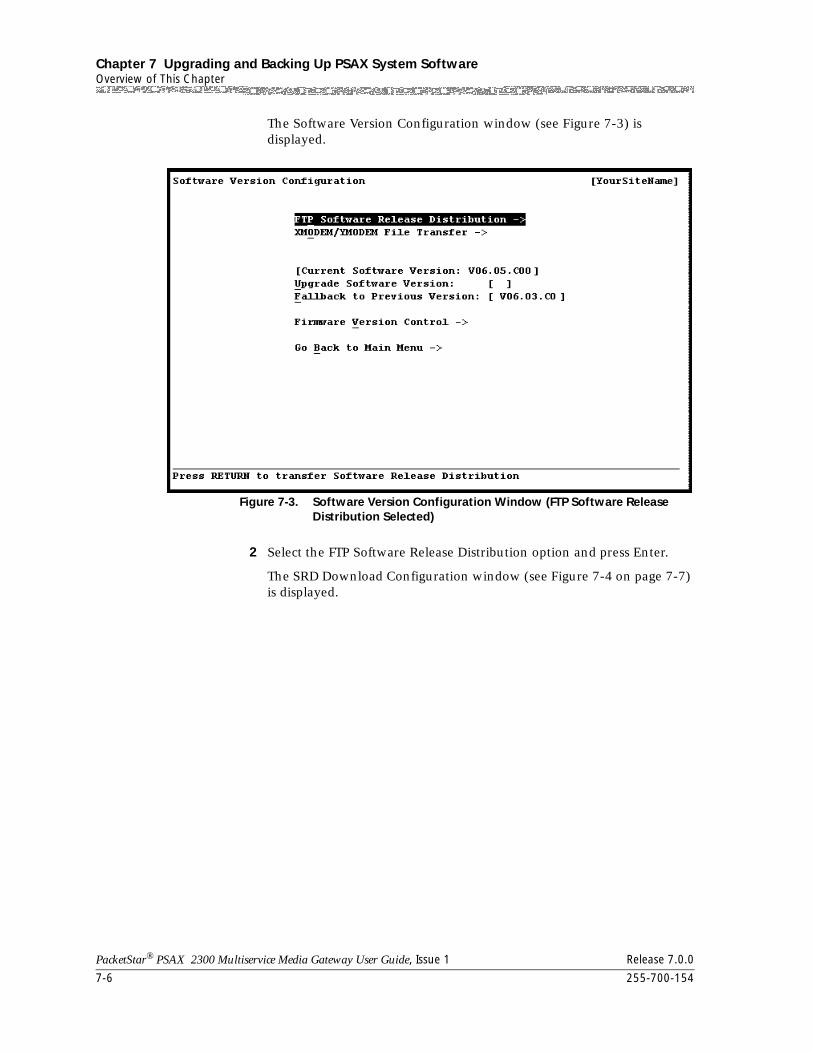
Chapter 7 Upgrading and Backing Up PSAX System SoftwareOverview of This Chapter
7-6 255-700-154
PacketStar® PSAX 2300 Multiservice Media Gateway User Guide, Issue 1 Release 7.0.0
The Software Version Configuration window (see Figure 7-3) is displayed.
2 Select the FTP Software Release Distribution option and press Enter.
The SRD Download Configuration window (see Figure 7-4 on page 7-7) is displayed.
Figure 7-3. Software Version Configuration Window (FTP Software Release Distribution Selected)
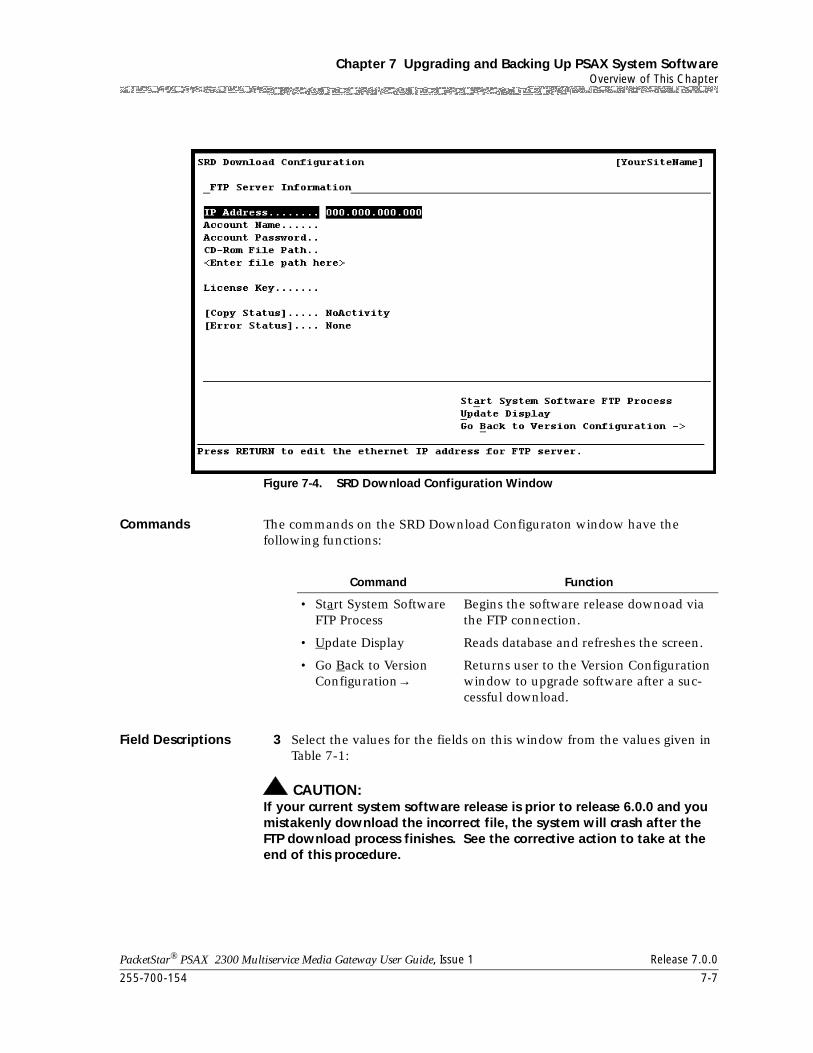
255-700-154 7-7
PacketStar® PSAX 2300 Multiservice Media Gateway User Guide, Issue 1 Release 7.0.0
Chapter 7 Upgrading and Backing Up PSAX System SoftwareOverview of This Chapter
Commands The commands on the SRD Download Configuraton window have the following functions:
Field Descriptions 3 Select the values for the fields on this window from the values given in Table 7-1:
! CAUTION:If your current system software release is prior to release 6.0.0 and you mistakenly download the incorrect file, the system will crash after the FTP download process finishes. See the corrective action to take at the end of this procedure.
Figure 7-4. SRD Download Configuration Window
Command Function
• Start System Software FTP Process
Begins the software release downoad via the FTP connection.
• Update Display Reads database and refreshes the screen.
• Go Back to Version Configuration→
Returns user to the Version Configuration window to upgrade software after a suc-cessful download.
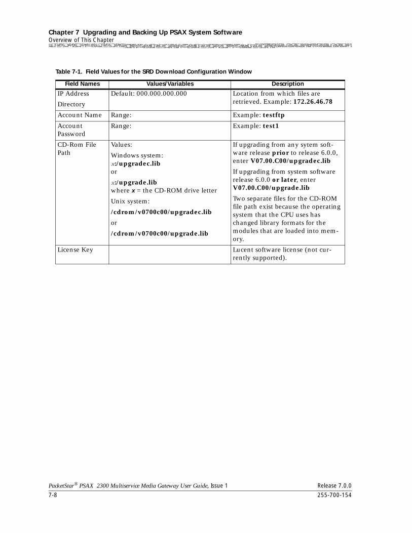
Chapter 7 Upgrading and Backing Up PSAX System SoftwareOverview of This Chapter
7-8 255-700-154
PacketStar® PSAX 2300 Multiservice Media Gateway User Guide, Issue 1 Release 7.0.0
Table 7-1. Field Values for the SRD Download Configuration Window
Field Names Values/Variables Description
IP Address
Directory
Default: 000.000.000.000 Location from which files are retrieved. Example: 172.26.46.78
Account Name Range: Example: testftp
AccountPassword
Range: Example: test1
CD-Rom File Path
Values:
Windows system:x:/upgradec.libor
x:/upgrade.libwhere x = the CD-ROM drive letter
Unix system:
/cdrom/v0700c00/upgradec.lib
or
/cdrom/v0700c00/upgrade.lib
If upgrading from any sytem soft-ware release prior to release 6.0.0, enter V07.00.C00/upgradec.lib
If upgrading from system software release 6.0.0 or later, enter V07.00.C00/upgrade.lib
Two separate files for the CD-ROM file path exist because the operating system that the CPU uses has changed library formats for the modules that are loaded into mem-ory.
License Key Lucent software license (not cur-rently supported).
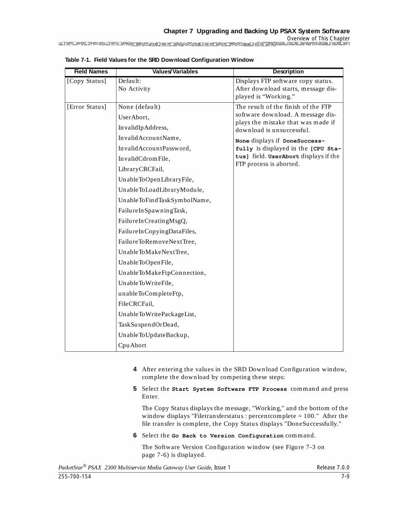
255-700-154 7-9
PacketStar® PSAX 2300 Multiservice Media Gateway User Guide, Issue 1 Release 7.0.0
Chapter 7 Upgrading and Backing Up PSAX System SoftwareOverview of This Chapter
4 After entering the values in the SRD Download Configuration window, complete the download by competing these steps:
5 Select the Start System Software FTP Process command and press Enter.
The Copy Status displays the message, "Working," and the bottom of the window displays "Filetransferstatus : percentcomplete = 100." After the file transfer is complete, the Copy Status displays "DoneSuccessfully."
6 Select the Go Back to Version Configuration command.
The Software Version Configuration window (see Figure 7-3 on page 7-6) is displayed.
[Copy Status] Default: No Activity
Displays FTP software copy status. After download starts, message dis-played is “Working.”
[Error Status] None (default)
UserAbort,
InvalidIpAddress,
InvalidAccountName,
InvalidAccountPassword,
InvalidCdromFile,
LibraryCRCFail,
UnableToOpenLibraryFile,
UnableToLoadLibraryModule,
UnableToFindTaskSymbolName,
FailureInSpawningTask,
FailureInCreatingMsgQ,
FailureInCopyingDataFiles,
FailureToRemoveNextTree,
UnableToMakeNextTree,
UnableToOpenFile,
UnableToMakeFtpConnection,
UnableToWriteFile,
unableToCompleteFtp,
FileCRCFail,
UnableToWritePackageList,
TaskSuspendOrDead,
UnableToUpdateBackup,
CpuAbort
The result of the finish of the FTP software download. A message dis-plays the mistake that was made if download is unsuccessful.
None displays if DoneSuccess-fully is displayed in the [CPU Sta-tus] field. UserAbort displays if the FTP process is aborted.
Table 7-1. Field Values for the SRD Download Configuration Window
Field Names Values/Variables Description
Chapter 7 Upgrading and Backing Up PSAX System SoftwareOverview of This Chapter
7-10 255-700-154
PacketStar® PSAX 2300 Multiservice Media Gateway User Guide, Issue 1 Release 7.0.0
7 Select the Upgrade Software Version option and press Enter.
8 On the bottom of the window, the following message is displayed:
Are you sure that you want to upgrade the software? (y/n)
9 Type Y to continue the upgrade process.
The following message is displayed:
Upgrade the software to the next version...
The CPU2 software upgrades to the system software release you specified, which is displayed in the brackets ([ ]) to the right of the Upgrade Software Version command. The Multiservice Media Gateway chassis reboots, and all firmware of the I/O modules in the chassis are upgraded as the CPU2 system software is being upgraded.
Corrective Action If Incorrect File Is Downloaded
If your current system software release is prior to release 6.0.0, you mistakenly download the incorrect file (upgrade.lib), and you experience a system crash, the following event will occur:
• In a redundant CPU2 environment, the standby CPU2 will become the primary CPU2, and the system will not provide any indication of the previously executed FTP download. The former primary CPU2 (with the valid build in the directory next) will become the standby. After this switchover, you can upgrade using one of the following methods:
• Perform the FTP download again using the correct file, upgradec.lib.
• Perform a CPU2 switchover, which is described in Chapter 5. Perform the FTP download again using the correct file, upgradec.lib.
End
CPU2 LED Indicators During Reboot
When the primary CPU2 module boots up, the libraries are loaded up, the system begins to initialize, and the red LED begins to blink. After the initialization on the primary CPU2 module is complete, the red LED switches off and the green LED switches on.
In a redundant Multiservice Media Gateway system, when a standby (backup) CPU2 module boots, the red LED is on. At the time the CPU2 software is initializing, the red LED begins to blink. After the configuration manager has determined that this CPU2 module is to become the standby CPU2 module, a handshake between the two CPU2 modules takes place, and the configuration database files on the primary CPU2 module are transferred on to the standby CPU2 module. After the transfer of files is completed, the red LED stops blinking.
If the standby CPU2 module has a CPU2 software version which is lower than that of the primary CPU2 module, the database files are incompatible and therefore not transferred from the primary CPU2 module to the standby CPU2 module. The red LED on the standby continues to blink. This does not in any way hinder its capability to take over the role of primary CPU2 on the
255-700-154 7-11
PacketStar® PSAX 2300 Multiservice Media Gateway User Guide, Issue 1 Release 7.0.0
Chapter 7 Upgrading and Backing Up PSAX System SoftwareUpgrading Using XModem/YModem File Transfer Method
event of the primary CPU2 module failing. If CPU2 module switchover occurs when the red LED is blinking, there will be loss of data and any old configuration present on the standby CPU2 module display.
Note: In PSAX systems with redundant CPU2 modules, the backup CPU2 module reboots every time you save the configuration on the primary CPU2 module. This event is a function of the SVC retention feature and the result of saving the configuration changes you have made.
The following events occur during the final stage of the upgrade process:
~ In an Multiservice Media Gateway system with redundant (two) CPU2 modules, the following events occur:
• The software copies the fallback and current directories to the standby (backup) CPU2 module.
• The standby module reinitializes (reboots).
• After the standby module reinitializes successfully, it serves momentarily as the primary module and sends a command to the original primary module to reinitialize.
• The original primary reinitializes and reestablishes itself as the primary, and then the original standby module reinitializes. The system is now ready to perform configuration and other tasks.
~ In an Multiservice Media Gateway system with one CPU2 module, it reinitializes. The system is now ready to perform configuration and other tasks.
Upgrading Using XModem/YModem File Transfer Method
You can use the XModem/YModem file transfer method to load new system software to the CPU2 module.
Upgrading using the XModem/YModem file transfer method includes two major tasks:
• First, you set up the cabling and connections between the PC workstation and the Multiservice Media Gateway system CPU2 module, start up the VT100 terminal emulation software on the PC workstation, and ensure you have communication between the two devices (see the following procedure, “Steps to Set Up for the File Transfer Process”).
• Second, you perform the file transfer process for the new software upgrade files to the Multiservice Media Gateway system, and the upgrading process on the CPU2 module (see the procedure ”Steps to Transfer the Software Upgrade Files to the System” on page 7-12).
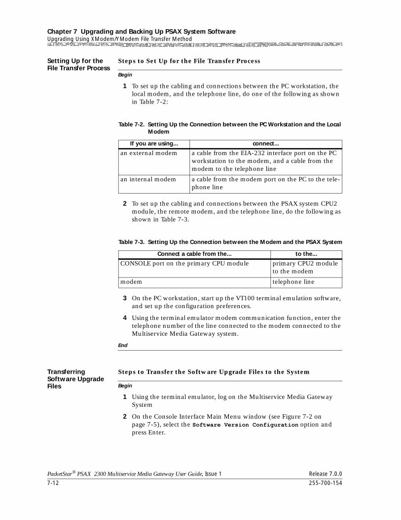
Chapter 7 Upgrading and Backing Up PSAX System SoftwareUpgrading Using XModem/YModem File Transfer Method
7-12 255-700-154
PacketStar® PSAX 2300 Multiservice Media Gateway User Guide, Issue 1 Release 7.0.0
Setting Up for the File Transfer Process
Begin
Steps to Set Up for the File Transfer Process
1 To set up the cabling and connections between the PC workstation, the local modem, and the telephone line, do one of the following as shown in Table 7-2:
2 To set up the cabling and connections between the PSAX system CPU2 module, the remote modem, and the telephone line, do the following as shown in Table 7-3.
3 On the PC workstation, start up the VT100 terminal emulation software, and set up the configuration preferences.
4 Using the terminal emulator modem communication function, enter the telephone number of the line connected to the modem connected to the Multiservice Media Gateway system.
End
Transferring Software Upgrade Files Begin
Steps to Transfer the Software Upgrade Files to the System
1 Using the terminal emulator, log on the Multiservice Media Gateway System
2 On the Console Interface Main Menu window (see Figure 7-2 on page 7-5), select the Software Version Configuration option and press Enter.
Table 7-2. Setting Up the Connection between the PC Workstation and the Local Modem
If you are using... connect...
an external modem a cable from the EIA-232 interface port on the PC workstation to the modem, and a cable from the modem to the telephone line
an internal modem a cable from the modem port on the PC to the tele-phone line
Table 7-3. Setting Up the Connection between the Modem and the PSAX System
Connect a cable from the... to the...
CONSOLE port on the primary CPU module primary CPU2 module to the modem
modem telephone line
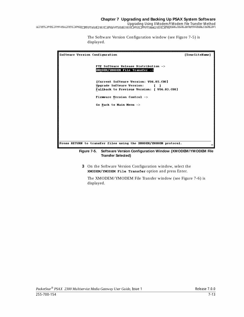
255-700-154 7-13
PacketStar® PSAX 2300 Multiservice Media Gateway User Guide, Issue 1 Release 7.0.0
Chapter 7 Upgrading and Backing Up PSAX System SoftwareUpgrading Using XModem/YModem File Transfer Method
The Software Version Configuration window (see Figure 7-5) is displayed.
3 On the Software Version Configuration window, select the XMODEM/YMODEM File Transfer option and press Enter.
The XMODEM/YMODEM File Transfer window (see Figure 7-6) is displayed.
Figure 7-5. Software Version Configuration Window (XMODEM/YMODEM File Transfer Selected)
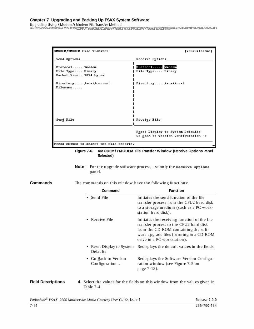
Chapter 7 Upgrading and Backing Up PSAX System SoftwareUpgrading Using XModem/YModem File Transfer Method
7-14 255-700-154
PacketStar® PSAX 2300 Multiservice Media Gateway User Guide, Issue 1 Release 7.0.0
Note: For the upgrade software process, use only the Receive Options panel.
Commands The commands on this window have the following functions:
Field Descriptions 4 Select the values for the fields on this window from the values given in Table 7-4.
Figure 7-6. XMODEM/YMODEM File Transfer Window (Receive Options Panel Selected)
Command Function
• Send File Initiates the send function of the file transfer process from the CPU2 hard disk to a storage medium (such as a PC work-station hard disk).
• Receive File Initiates the receiving function of the file transfer process to the CPU2 hard disk from the CD-ROM containing the soft-ware upgrade files (running in a CD-ROM drive in a PC workstation).
• Reset Display to System Defaults
Redisplays the default values in the fields.
• Go Back to Version Configuration→
Redisplays the Software Version Configu-ration window (see Figure 7-5 on page 7-13).
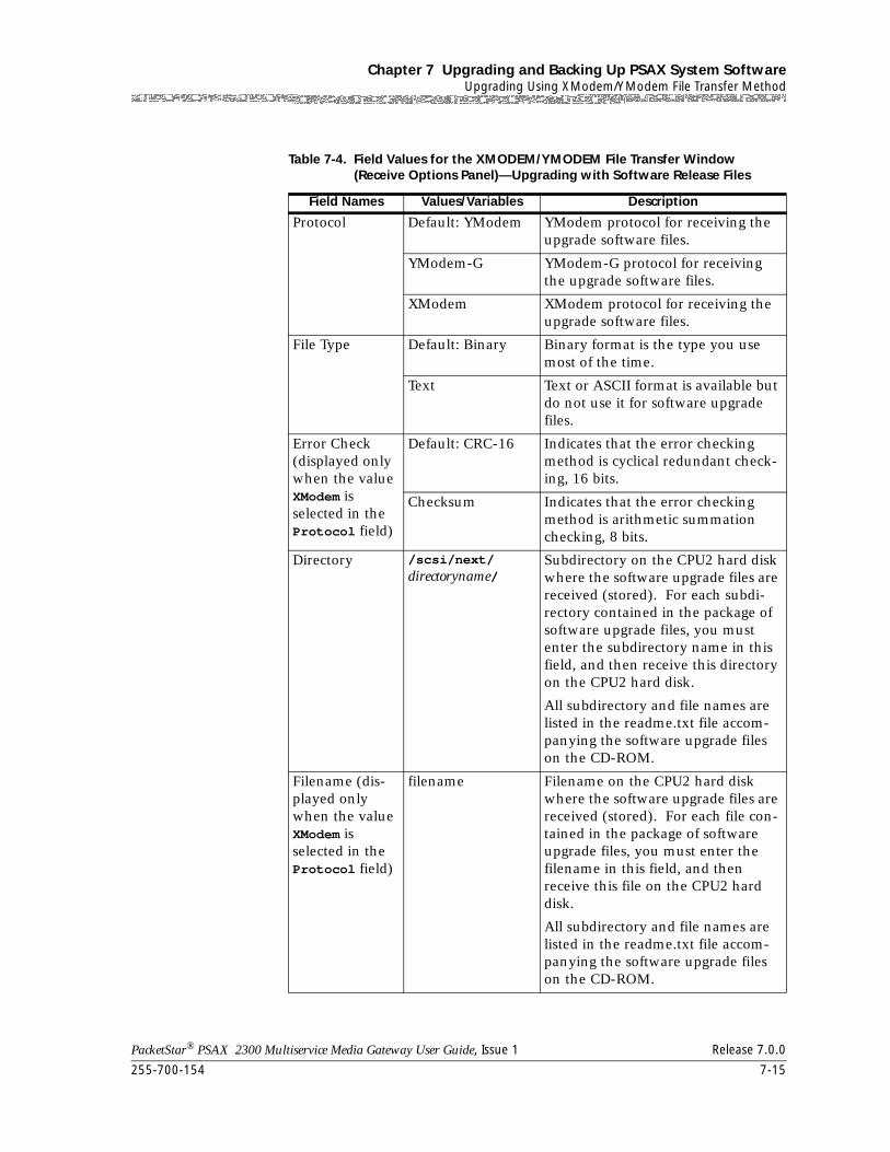
255-700-154 7-15
PacketStar® PSAX 2300 Multiservice Media Gateway User Guide, Issue 1 Release 7.0.0
Chapter 7 Upgrading and Backing Up PSAX System SoftwareUpgrading Using XModem/YModem File Transfer Method
Table 7-4. Field Values for the XMODEM/YMODEM File Transfer Window (Receive Options Panel)—Upgrading with Software Release Files
Field Names Values/Variables Description
Protocol Default: YModem YModem protocol for receiving the upgrade software files.
YModem-G YModem-G protocol for receiving the upgrade software files.
XModem XModem protocol for receiving the upgrade software files.
File Type Default: Binary Binary format is the type you use most of the time.
Text Text or ASCII format is available but do not use it for software upgrade files.
Error Check (displayed only when the value XModem is selected in the Protocol field)
Default: CRC-16 Indicates that the error checking method is cyclical redundant check-ing, 16 bits.
Checksum Indicates that the error checking method is arithmetic summation checking, 8 bits.
Directory /scsi/next/directoryname/
Subdirectory on the CPU2 hard disk where the software upgrade files are received (stored). For each subdi-rectory contained in the package of software upgrade files, you must enter the subdirectory name in this field, and then receive this directory on the CPU2 hard disk.
All subdirectory and file names are listed in the readme.txt file accom-panying the software upgrade files on the CD-ROM.
Filename (dis-played only when the value XModem is selected in the Protocol field)
filename Filename on the CPU2 hard disk where the software upgrade files are received (stored). For each file con-tained in the package of software upgrade files, you must enter the filename in this field, and then receive this file on the CPU2 hard disk.
All subdirectory and file names are listed in the readme.txt file accom-panying the software upgrade files on the CD-ROM.
Chapter 7 Upgrading and Backing Up PSAX System SoftwareUpgrading Using XModem/YModem File Transfer Method
7-16 255-700-154
PacketStar® PSAX 2300 Multiservice Media Gateway User Guide, Issue 1 Release 7.0.0
Note: We recommend that you use either the YModem or the YModem-G protocol. Use the XModem protocol if that is the only one you have available to use.
~ The YModem-G protocol allows the fastest transmission of the three types; however, this protocol does not acknowledge receipt of packets. You can receive all files grouped under a subdirectory at one time.
~ The YModem protocol is a slower method of transmission, but is more reliable because it acknowledges receipt of packets. You can receive all files grouped under a subdirectory at one time.
~ The XModem protocol is a laborious method of transmission because you must enter the filename of each file in the complete package of software upgrade files to accomplish the upgrade task.
5 Select the Receive Files command and press Enter.
The terminal emulator displaying the Multiservice Media Gateway system window interface brings the XMODEM/YMODEM File Transfer window out of view. A message is displayed indicating that you can cancel the transfer by pressing Ctrl+X several times. A second message is displayed indicating that you must start the terminal emulator send function.
6 Using the terminal emulator send function, select one of the three protocol types: 1) YModem, 2) YModem-G, or 3) XModem. Be sure to select the same protocol as the one you selected on the Send Options panel of the XMODEM/YMODEM File Transfer window (see Figure 7-6 on page 7-14).
7 In the terminal emulator field for the location of the file, specify the drive where the Multiservice Media Gateway system upgrade software files reside (normally, the CD-ROM drive) and the directory pathname.
For example, specify a pathname like one of the following:
~ x:/scsi/next/subdirectory\*.* if you are using YModem or YModem-Gwhere x is the drive letter for the CD-ROM drive
~ x:/scsi/next/subdirectory\filename if you are using XModemwhere x is the drive letter for the CD-ROM drive
Be sure you enter the subdirectory name (or the subdirectory and filename if using XModem) exactly so that it matches the names you previously entered on the XMODEM/YMODEM File Transfer window (see Figure 7-6 on page 7-14). All subdirectory and file names are listed in the readme.txt file accompanying the software upgrade files on the CD-ROM.
8 Select the Send File command in the terminal emulator send function dialog box.
9 Repeat steps 4–8 to specify another subdirectory name (for YModem or YModem-G) or another subdirectory name and filename (for XModem) until you have transferred all files for the Multiservice Media Gateway system software upgrade.
255-700-154 7-17
PacketStar® PSAX 2300 Multiservice Media Gateway User Guide, Issue 1 Release 7.0.0
Chapter 7 Upgrading and Backing Up PSAX System SoftwareUpgrading Firmware
Note: The new version of the software and the existing database files are now resident in the directory /scsi/next/ (see Figure 7-1 on page 7-3).
10 Redisplay the Multiservice Media Gateway system Software Version Configuration window (see Figure 7-5 on page 7-13).
11 Select the Upgrade Software Version command and press Enter.
The following message is displayed:
Are you sure that you want to upgrade the software? (y/n)
12 Select the y key (to indicate yes) to continue.
While the system performs the software upgrade process, the follow message is displayed:
Upgrading the software to the next version ...
During the process, the system sends several trap messages indicating events that are occurring. When the process is completed, the system displays a message indicating successful completion.
End
Upgrading Firmware
The PSAX I/O and server modules released with PSAX system Release 6.0.0 software (and higher) are supported by the Firmware Release Control feature. Most of the PSAX I/O and server modules released prior to the Release 6.0.0 software will work in the PSAX system, but are not supported by the Firmware Release Control feature.
Note: To get information about which version (or versions) of the PSAX I/O and server modules are supported by Release 7.0.0, see the Release Note for Release 7.0.0 of the PacketStar® PSAX 4500, PSAX 2300, PSAX 1250 PSAX AC 60, and PSAX 20 Multiservice Media Gateways.
! CAUTION:Use the Firmware Version Control window (see Figure 7-7) described in the following procedure only with the advice of Lucent Technologies NetworkCare. See the “Technical Support” section in Chapter 1, “Getting Started.”
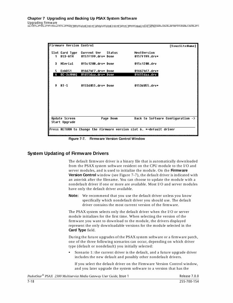
Chapter 7 Upgrading and Backing Up PSAX System SoftwareUpgrading Firmware
7-18 255-700-154
PacketStar® PSAX 2300 Multiservice Media Gateway User Guide, Issue 1 Release 7.0.0
System Updating of Firmware Drivers
The default firmware driver is a binary file that is automatically downloaded from the PSAX system software resident on the CPU module to the I/O and server modules, and is used to initialize the module. On the Firmware Version Control window (see Figure 7-7), the default driver is indicated with an asterisk after the filename. You can choose to update the module with a nondefault driver if one or more are available. Most I/O and server modules have only the default driver available.
Note: We recommend that you use the default driver unless you know specifically which nondefault driver you should use. The default driver contains the most current version of the firmware.
The PSAX system selects only the default driver when the I/O or server module initializes for the first time. When selecting the version of the firmware you want to download to the module, the drivers displayed represent the only downloadable versions for the module selected in the Card Type field.
During the future upgrades of the PSAX system software or a firmware patch, one of the three following scenarios can occur, depending on which driver type (default or nondefault) you initially selected:
• Scenario 1: the current driver is the default, and a future upgrade driver includes the new default and possibly other nondefault drivers.
If you select the default driver on the Firmware Version Control window, and you later upgrade the system software to a version that has the
Figure 7-7. Firmware Version Control Window
255-700-154 7-19
PacketStar® PSAX 2300 Multiservice Media Gateway User Guide, Issue 1 Release 7.0.0
Chapter 7 Upgrading and Backing Up PSAX System SoftwareUpgrading Firmware
default and other nondefault drivers, the system will upgrade the driver to the next version of the default driver.
• Scenario 2: the current driver is the nondefault driver abc, and a future upgrade driver includes the new default and the nondefault driver abc.
If you select the nondefault driver abc on the Firmware Version Control window, and you later upgrade the system software to a version that includes the nondefault driver abc, the system will not upgrade the current nondefault driver abc.
• Scenario 3: the current driver is the nondefault driver abc; and a future upgrade driver includes the new default driver and a new nondefault driver other than the nondefault driver abc.
If you select the nondefault driver abc on the Firmware Version Control window, and you later upgrade the system software to a version that does not include the nondefault driver abc, the system will not upgrade the current nondefault driver abc. You will get a message that the nondefault driver abc cannot be found. You can then either select another available driver or keep the nondefault driver abc. For guidance, seek the advice of Lucent Technologies NetworkCare.
Selecting Firmware Drivers
You can select either the default driver or a nondefault driver from the available drivers:
• If you select the default driver, you can update the firmware of any I/O or server module currently selected in a given slot.
• If you select a nondefault driver, you can update the firmware for the selected module only if that slot contains the same module that was previously configured in that slot. This constraint exists because the PSAX system database has stored values for each of the configured modules in the chassis by slot number. If you try to upgrade a different module from the one originally configured in that slot, the message wrongcardtype is displayed in the status line on the Firmware Version Control window.
The PSAX system attempts to download the driver for this module for approximately six minutes, and recognizes and upgrades it automatically when the module you are upgrading is the one originally configured in this slot. If the system does not recognize the module you selected, you must manually force the firmware upgrade.
Upgrading I/O and Server Module Firmware
To download firmware to a module, perform the steps in the following procedure, beginning at the Console Interface Main Menu window.
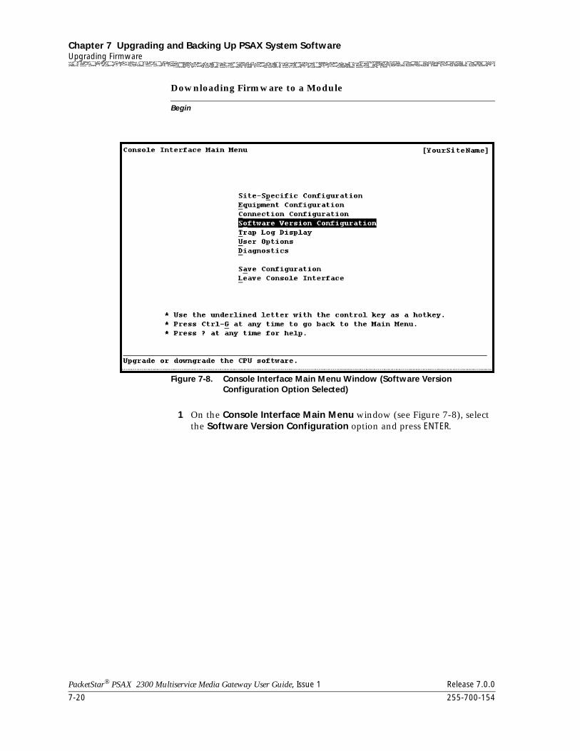
Chapter 7 Upgrading and Backing Up PSAX System SoftwareUpgrading Firmware
7-20 255-700-154
PacketStar® PSAX 2300 Multiservice Media Gateway User Guide, Issue 1 Release 7.0.0
Begin
Downloading Firmware to a Module
1 On the Console Interface Main Menu window (see Figure 7-8), select the Software Version Configuration option and press ENTER.
Figure 7-8. Console Interface Main Menu Window (Software Version Configuration Option Selected)
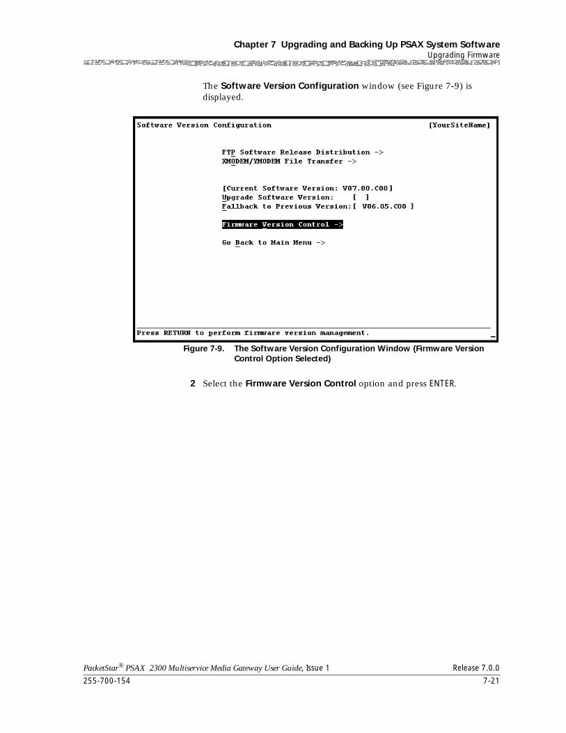
255-700-154 7-21
PacketStar® PSAX 2300 Multiservice Media Gateway User Guide, Issue 1 Release 7.0.0
Chapter 7 Upgrading and Backing Up PSAX System SoftwareUpgrading Firmware
The Software Version Configuration window (see Figure 7-9) is displayed.
2 Select the Firmware Version Control option and press ENTER.
Figure 7-9. The Software Version Configuration Window (Firmware Version Control Option Selected)
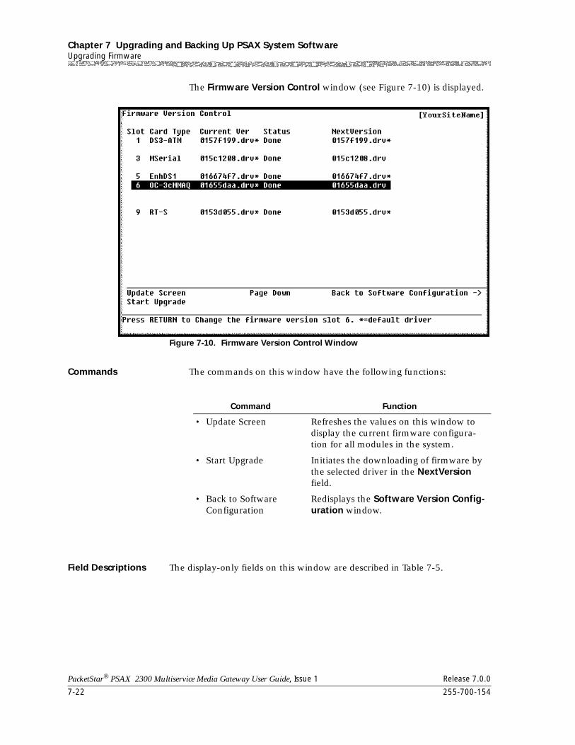
Chapter 7 Upgrading and Backing Up PSAX System SoftwareUpgrading Firmware
7-22 255-700-154
PacketStar® PSAX 2300 Multiservice Media Gateway User Guide, Issue 1 Release 7.0.0
The Firmware Version Control window (see Figure 7-10) is displayed.
Commands The commands on this window have the following functions:
Field Descriptions The display-only fields on this window are described in Table 7-5.
Figure 7-10. Firmware Version Control Window
Command Function
• Update Screen Refreshes the values on this window to display the current firmware configura-tion for all modules in the system.
• Start Upgrade Initiates the downloading of firmware by the selected driver in the NextVersion field.
• Back to Software Configuration
Redisplays the Software Version Config-uration window.
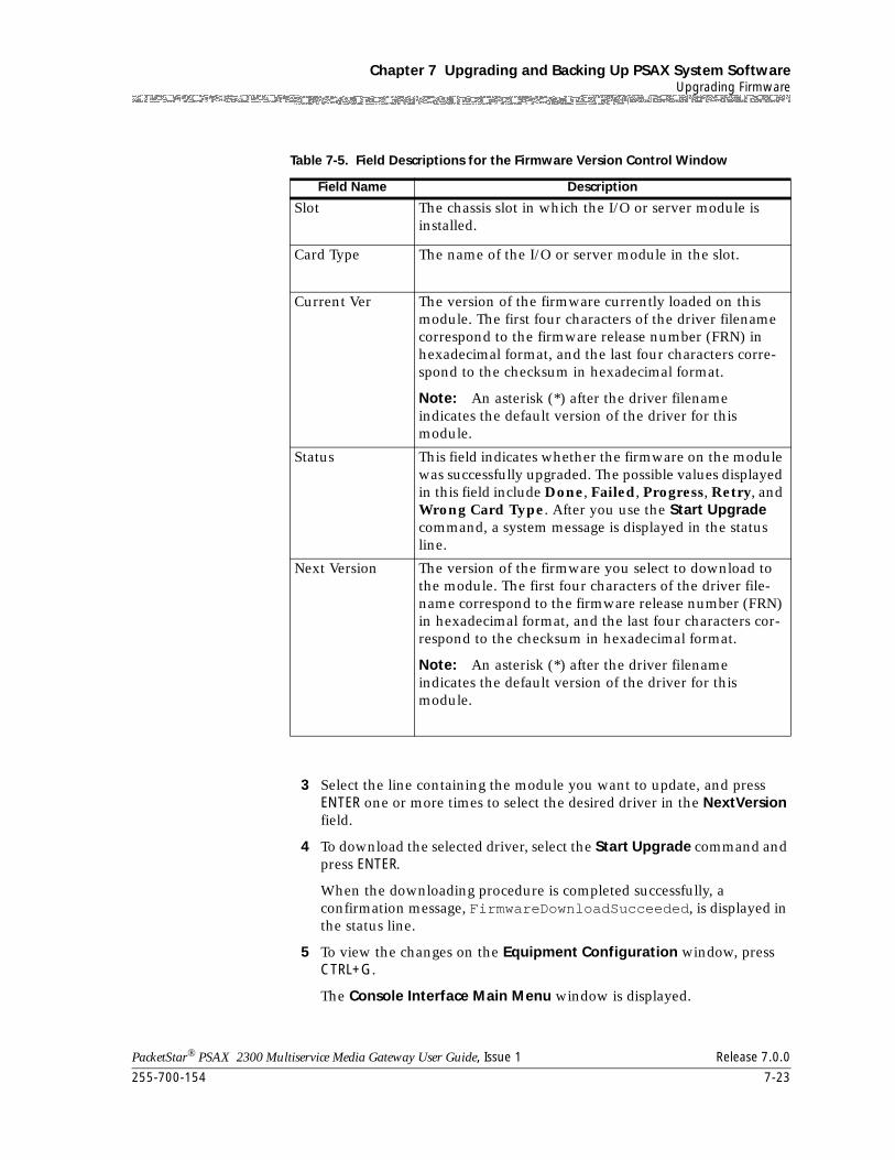
255-700-154 7-23
PacketStar® PSAX 2300 Multiservice Media Gateway User Guide, Issue 1 Release 7.0.0
Chapter 7 Upgrading and Backing Up PSAX System SoftwareUpgrading Firmware
3 Select the line containing the module you want to update, and press ENTER one or more times to select the desired driver in the NextVersion field.
4 To download the selected driver, select the Start Upgrade command and press ENTER.
When the downloading procedure is completed successfully, a confirmation message, FirmwareDownloadSucceeded, is displayed in the status line.
5 To view the changes on the Equipment Configuration window, press CTRL+G.
The Console Interface Main Menu window is displayed.
Table 7-5. Field Descriptions for the Firmware Version Control Window
Field Name Description
Slot The chassis slot in which the I/O or server module is installed.
Card Type The name of the I/O or server module in the slot.
Current Ver The version of the firmware currently loaded on this module. The first four characters of the driver filename correspond to the firmware release number (FRN) in hexadecimal format, and the last four characters corre-spond to the checksum in hexadecimal format.
Note: An asterisk (*) after the driver filename indicates the default version of the driver for this module.
Status This field indicates whether the firmware on the module was successfully upgraded. The possible values displayed in this field include Done, Failed, Progress, Retry, and Wrong Card Type. After you use the Start Upgrade command, a system message is displayed in the status line.
Next Version The version of the firmware you select to download to the module. The first four characters of the driver file-name correspond to the firmware release number (FRN) in hexadecimal format, and the last four characters cor-respond to the checksum in hexadecimal format.
Note: An asterisk (*) after the driver filename indicates the default version of the driver for this module.
Chapter 7 Upgrading and Backing Up PSAX System SoftwareFalling Back to the Previous Software Release
7-24 255-700-154
PacketStar® PSAX 2300 Multiservice Media Gateway User Guide, Issue 1 Release 7.0.0
6 On the Console Interface Main Menu window, select the Equipment Configuration option and press ENTER.
The Equipment Configuration window is displayed. The current software version for the modules in the SW Version field for the upgraded module will be updated in a few seconds. A confirmation message is displayed in the status line.
End
Falling Back to the Previous Software Release
! CAUTION:Use the fallback procedure only if you have previously upgraded your CPU module as described in the section, ”Upgrading System Software Using FTP” on page 7-4.
To fall back (return) to the previous software release, perform the steps in the following procedure, starting at the Console Interface Main Menu window (see Figure 7-2 on page 7-5).
Begin
Steps to Revert Software to a Previous Version
1 On the Console Interface Main Menu window, select the Software Version Configuration option and press Enter.
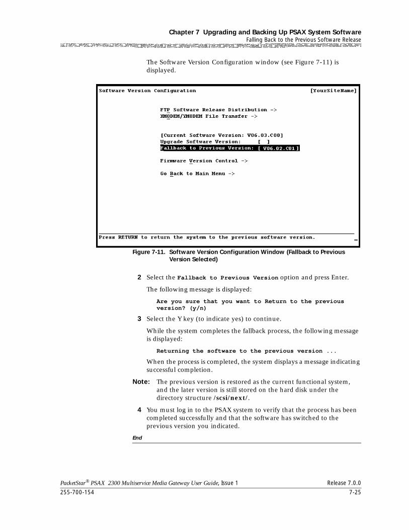
255-700-154 7-25
PacketStar® PSAX 2300 Multiservice Media Gateway User Guide, Issue 1 Release 7.0.0
Chapter 7 Upgrading and Backing Up PSAX System SoftwareFalling Back to the Previous Software Release
The Software Version Configuration window (see Figure 7-11) is displayed.
2 Select the Fallback to Previous Version option and press Enter.
The following message is displayed:
Are you sure that you want to Return to the previous version? (y/n)
3 Select the Y key (to indicate yes) to continue.
While the system completes the fallback process, the following message is displayed:
Returning the software to the previous version ...
When the process is completed, the system displays a message indicating successful completion.
Note: The previous version is restored as the current functional system, and the later version is still stored on the hard disk under the directory structure /scsi/next/.
4 You must log in to the PSAX system to verify that the process has been completed successfully and that the software has switched to the previous version you indicated.
End
Figure 7-11. Software Version Configuration Window (Fallback to Previous Version Selected)
Chapter 7 Upgrading and Backing Up PSAX System SoftwareBacking Up System Database Files
7-26 255-700-154
PacketStar® PSAX 2300 Multiservice Media Gateway User Guide, Issue 1 Release 7.0.0
Backing Up System Database Files
It is recommended that you periodically back up your system, module, and connection configuration database files to a storage medium separate from the hard disk on the CPU or CPU2 module.
! CAUTION:After initially configuring your Multiservice Media Gateway system, and after every configuration modification, be sure to back up the files to a separate storage medium.
You can use one of the following methods:
• Upload the database files using FTP server software (see the following section, “Backing Up Database Files Using FTP”)
• Transfer files using the XModem or YModem serial transfer protocol (see ”Backing Up Database Files Using XModem/YModem File Transfer” on page 7-28)
Note: You cannot backup files using Telnet.
The files containing your configuration and connection data in the scsi/current/ directory are named as follows:
Note: It is necessary to backup all the files in this list. If there are databases listed here that you have not created, do not attempt a backup. Backup files will not be created only if there is data to be backed up.
• Site-specific identification database—ssid.def
• Site-specific identification database backup—ssid.bak
• Password setup—console.def (this file exists only if you have changed your password from the system default password)
• Module configuration database—ecd.db
• Module configuration database backup—ecd_db.bak
• PNNI configuration database—pnnimib.db
• PNNI configuration database backup—pnnimib.bak
• Connection database—cnctn.db
• Vipr task configuration database—vipr.db
• Soft-pvc configuration database—spvc.db
• Firmware configuration database—fwc.def
• Event management configuration information—eventmgr.cfg
• IISP CBR route table—iisp.cbr (this file exists even if you have no configured SVCs on the PSAX 2300 system)
• IISP VBR route table—iisp.vbr (this file exists even if you have no configured SVCs on the PSAX 2300 system)
• Virtual interface database—vi.db
255-700-154 7-27
PacketStar® PSAX 2300 Multiservice Media Gateway User Guide, Issue 1 Release 7.0.0
Chapter 7 Upgrading and Backing Up PSAX System SoftwareBacking Up System Database Files
• IP routing database—iproute.db
• OAM database—oam.db
• Special connections database (signaling connections)—spclConn.db
• ATM virtual UNI database—atmvuni.db
• ATM trunking database—atmtrnk.db
• GR-303 database—gr303.db
• Tones and Announcements module database—tasm.db
• Feature Enable/Disable database—features.db
Backing Up Database Files Using FTP
To back up database files to a separate storage medium using FTP, perform the steps in the following procedure.
Backing Up Database Files Using FTP
Begin
Steps to Back Up Database Files Using FTP
1 Connect a standard 10Base-T Ethernet cable to the Ethernet port on the primary CPU module. Ensure that you have a stable connection from the source PC or network management workstation to the CPU module.
2 Use the DOS drive and change directory commands to access the drive and directory on the computer to which you want to copy (store) the databases.
3 At the DOS prompt, enter:
ftp -n xxx.xxx.xxx.xxx
where
xxx.xxx.xxx.xxx is the IP address of the Multiservice Media Gateway CPU module.
Press Enter.
4 At the prompt ftp, type:
user readwrite currentpassword
where
currentpassword is the password you currently have for the Multiservice Media Gateway system software.
Press Enter.
5 To be sure you have the correct path selected, type cd /scsi/current (Windows); cd \scsi\current (UNIX) and press Enter.
6 To provide a visual indicator during the backup process, type hash and press Enter.
Chapter 7 Upgrading and Backing Up PSAX System SoftwareBacking Up System Database Files
7-28 255-700-154
PacketStar® PSAX 2300 Multiservice Media Gateway User Guide, Issue 1 Release 7.0.0
Note: In Step 7 through Step 17, a message may appear stating that a particular configuration file does not exist. This message is displayed when a particular database file has never been created, because the related feature was never used and no relevant information exists to be stored in that file. Files will be created and present only if there is information to be stored.
7 Type bin and press Enter.
8 Type get ssid.def and press Enter.
9 Type get console.def and press Enter.
10 Type get ecd.def and press Enter.
11 Type get pnnimib.db and press Enter.
12 Type get cnctn.db and press Enter.
13 Type get spvc.db and press Enter.
14 Type get fwc.def and press Enter.
15 Type get eventmgr.cfg and press Enter.
16 If you have SVCs configured on your system, type get iisp.cbr and press Enter.
17 If you have SVCs configured on your system, type get iisp.vbr and press Enter.
18 Type bye and press Enter.
End
Backing Up Database Files Using XModem/YModem File Transfer
You can use the XModem/YModem file transfer option to copy the Multiservice Media Gateway system databases from the CPU hard disk to a separate storage medium. Backing up the databases using the XModem/YModem file transfer option includes two major tasks:
• First, you set up the cabling and connections between the PC workstation and the Multiservice Media Gateway system CPU module, start up the VT100 terminal emulation software on the PC workstation, and ensure you have communication between the two devices (see the following procedure, “Setting Up for the File Transfer Process”).
• Second, you perform the file transfer (copy) process for the databases to the separate storage medium (see the procedure, ”Copying the Database Files to a Storage Medium” on page 7-29).
255-700-154 7-29
PacketStar® PSAX 2300 Multiservice Media Gateway User Guide, Issue 1 Release 7.0.0
Chapter 7 Upgrading and Backing Up PSAX System SoftwareBacking Up System Database Files
Setting Up for the File Transfer Process
Begin
Steps to Set Up for the File Transfer Process
1 Set up the cabling and connections between the PC workstation, the local modem, and the telephone line. For more information, see the section, “Upgrading Using the XModem/YModem File Transfer Method,” earlier in this chapter.
2 Set up the cabling and connections between the Multiservice Media Gateway system CPU2 module, the remote modem, and the telephone line. For more information, see the section, “Upgrading Using the XModem/YModem File Transfer Method,” earlier in this chapter.
3 On the PC workstation, start up the VT100 terminal emulation software, and set up the configuration preferences (see Chapter 6, "Configuring the VT100 Terminal Emulator").
4 Using the terminal emulator modem communication function, Return the telephone number of the line connected to the modem connected to the Multiservice Media Gateway system.
End
Copying the Database Files to a Storage Medium Begin
Steps to Copy Database Files to a Storage Medium
1 Using the terminal emulator, log on the Multiservice Media Gateway system.
2 On the Console Interface Main Menu window (see Figure 7-2 on page 7-5), select the Software Version Configuration option and press Enter.
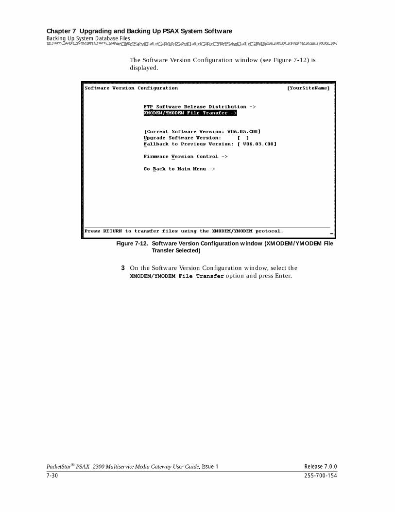
Chapter 7 Upgrading and Backing Up PSAX System SoftwareBacking Up System Database Files
7-30 255-700-154
PacketStar® PSAX 2300 Multiservice Media Gateway User Guide, Issue 1 Release 7.0.0
The Software Version Configuration window (see Figure 7-12) is displayed.
3 On the Software Version Configuration window, select the XMODEM/YMODEM File Transfer option and press Enter.
Figure 7-12. Software Version Configuration window (XMODEM/YMODEM File Transfer Selected)
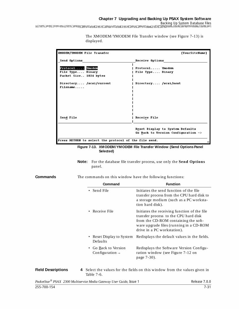
255-700-154 7-31
PacketStar® PSAX 2300 Multiservice Media Gateway User Guide, Issue 1 Release 7.0.0
Chapter 7 Upgrading and Backing Up PSAX System SoftwareBacking Up System Database Files
The XMODEM/YMODEM File Transfer window (see Figure 7-13) is displayed.
Note: For the database file transfer process, use only the Send Options panel.
Commands The commands on this window have the following functions:
Field Descriptions 4 Select the values for the fields on this window from the values given in Table 7-6.
Figure 7-13. XMODEM/YMODEM File Transfer Window (Send Options Panel Selected)
Command Function
• Send File Initiates the send function of the file transfer process from the CPU hard disk to a storage medium (such as a PC worksta-tion hard disk).
• Receive File Initiates the receiving function of the file transfer process to the CPU hard disk from the CD-ROM containing the soft-ware upgrade files (running in a CD-ROM drive in a PC workstation).
• Reset Display to System Defaults
Redisplays the default values in the fields.
• Go Back to Version Configuration→
Redisplays the Software Version Configu-ration window (see Figure 7-12 on page 7-30).
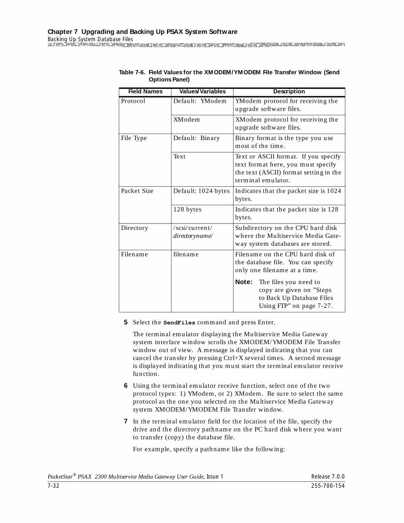
Chapter 7 Upgrading and Backing Up PSAX System SoftwareBacking Up System Database Files
7-32 255-700-154
PacketStar® PSAX 2300 Multiservice Media Gateway User Guide, Issue 1 Release 7.0.0
5 Select the SendFiles command and press Enter.
The terminal emulator displaying the Multiservice Media Gateway system interface window scrolls the XMODEM/YMODEM File Transfer window out of view. A message is displayed indicating that you can cancel the transfer by pressing Ctrl+X several times. A second message is displayed indicating that you must start the terminal emulator receive function.
6 Using the terminal emulator receive function, select one of the two protocol types: 1) YModem, or 2) XModem. Be sure to select the same protocol as the one you selected on the Multiservice Media Gateway system XMODEM/YMODEM File Transfer window.
7 In the terminal emulator field for the location of the file, specify the drive and the directory pathname on the PC hard disk where you want to transfer (copy) the database file.
For example, specify a pathname like the following:
Table 7-6. Field Values for the XMODEM/YMODEM File Transfer Window (Send Options Panel)
Field Names Values/Variables Description
Protocol Default: YModem YModem protocol for receiving the upgrade software files.
XModem XModem protocol for receiving the upgrade software files.
File Type Default: Binary Binary format is the type you use most of the time.
Text Text or ASCII format. If you specify text format here, you must specify the text (ASCII) format setting in the terminal emulator.
Packet Size Default: 1024 bytes Indicates that the packet size is 1024 bytes.
128 bytes Indicates that the packet size is 128 bytes.
Directory /scsi/current/directoryname/
Subdirectory on the CPU hard disk where the Multiservice Media Gate-way system databases are stored.
Filename filename Filename on the CPU hard disk of the database file. You can specify only one filename at a time.
Note: The files you need to copy are given on ”Steps to Back Up Database Files Using FTP” on page 7-27.
255-700-154 7-33
PacketStar® PSAX 2300 Multiservice Media Gateway User Guide, Issue 1 Release 7.0.0
Chapter 7 Upgrading and Backing Up PSAX System SoftwareRestoring System Database Files
x:/directory/filename where x is the drive letter for the PC hard disk and directory is any name you choose (such as acdbase)
Be sure you enter the filename of the database file exactly so that it matches the name you previously entered on the Multiservice Media Gateway system XMODEM/YMODEM File Transfer window.
8 Select the OK or Receive button or command in the terminal emulator receive function dialog box.
9 Repeat steps 4–8 to specify another database filename until you have transferred all the database files to the PC hard disk.
End
Restoring System Database Files
If your system, module, and connection configuration database files become corrupted or otherwise unusable, you must restore them from your backup storage medium to the CPU hard disk by using one of the following methods:
• Download the database files using FTP server software (see ”Restoring Database Files Using FTP” on page 7-34)
• Transfer files using the XModem or YModem serial transfer protocol (see ”Restoring Database Files Using XModem/YModem File Transfer” on page 7-36)
Note: In an Multiservice Media Gateway system with redundant CPU modules, you must restore the database files to both modules, either simultaneously or sequentially, depending on your physical setup.
Configuration and Connection Data Files
Note: The databases listed below can be backed up only if data exists to be backed up. You will get an error message if you attempt to back up a database with no data.
The files containing your configuration and connection data are named as follows:
• System configuration database—ssid.def
• Password setup—console.def (this file exists only if you have changed your password from the system default password)
• Module configuration database—ecd.def
• Pnni configuration database—pnnimib.db
• Connection configuration database—cnctn.db
• Soft-pvc configuration database—spvc.db
• Firmware configuration database—fwc.def
• Event management configuration information—eventmgr.cfg
Chapter 7 Upgrading and Backing Up PSAX System SoftwareRestoring System Database Files
7-34 255-700-154
PacketStar® PSAX 2300 Multiservice Media Gateway User Guide, Issue 1 Release 7.0.0
• IISP CBR route table—iisp.cbr (this file exists even if you have no configured SVCs on your Multiservice Media Gateway system)
• IISP VBR route table—iisp.vbr (this file exists even if you have no configured SVCs on your Multiservice Media Gateway system)
Restoring Database Files Using FTP
To restore database files from a separate storage medium using FTP, perform the steps in the following procedure.
Restoring Database Files Using FTP
Begin
Steps to Restore Database Files Using FTP
1 In a nonredundant Multiservice Media Gateway system, connect a standard 10Base-T Ethernet cable to the Ethernet port on the CPU module. In a redundant Multiservice Media Gateway system, connect cables to both the primary and the standby CPU modules. Ensure that you have a stable connection from the source PC or network management workstation to the CPU module.
2 Use the DOS drive and change directory commands to access the drive and directory on the computer where you have stored the databases.
3 At the DOS prompt, enter:
ftp -n xxx.xxx.xxx.xxx
where
xxx.xxx.xxx.xxx is the IP address of the Multiservice Media Gateway CPU module.
Press Enter.
4 At the prompt ftp, enter:
user readwrite currentpassword
where
currentpassword is the password you currently have for the Multiservice Media Gateway System software.
Press Enter.
5 To be sure you have the correct path selected, type cd /scsi/current (Windows); cd \scsi\current (UNIX) and press Enter.
6 To provide a visual indicator during the backup process, type hash and press Enter.
Note: In Step 7 through Step 17, a message may appear stating that a particular configuration file does not exist. This message is displayed when a particular database file has never been created, because the related feature was never used and no relevant information exists to be stored in that file. Files will be created and present only if there is information to be stored.
255-700-154 7-35
PacketStar® PSAX 2300 Multiservice Media Gateway User Guide, Issue 1 Release 7.0.0
Chapter 7 Upgrading and Backing Up PSAX System SoftwareRestoring System Database Files
7 Type bin and press Enter.
8 Type put ssid.def and press Enter.
9 Type put console.def and press Enter.
10 Type put ecd.def and press Enter.
11 Type put pnnimib.db and press Enter.
12 Type put cnctn.db and press Enter.
13 Type put spvc.db and press Enter.
14 Type put fwc.def and press Enter.
15 Type put eventmgr.cfg and press Enter.
16 If you have SVCs configured on your system, type put iisp.cbr and press Enter.
17 If you have SVCs configured on your system, type put iisp.vbr and press Enter.
18 Type bye and press Enter.
End
At this point, you must reboot (reinitialize) the Multiservice Media Gateway system chassis, so all components are synchronized. To reboot the Multiservice Media Gateway system, perform the steps in the following procedure.
Rebooting the AC System
Begin
Steps to Reboot the Multiservice Media Gateway System
1 Log on the Multiservice Media Gateway system.
The Console Interface Main Menu window (see Figure 7-2 on page 7-5) is displayed.
2 On the Console Interface Main Menu window, select the Diagnostics option.
The Diagnostics Menu window is displayed.
3 On the Diagnostics Menu window, select the Reboot Hardware Components command.
The Remote Reboot Configuration window is displayed.
4 On the Remote Reboot Configuration window, select the Reboot Chassis command.
This command reboots (reinitializes) the primary and standby (redundant) CPU modules, and the I/O and server modules.
End
Chapter 7 Upgrading and Backing Up PSAX System SoftwareRestoring System Database Files
7-36 255-700-154
PacketStar® PSAX 2300 Multiservice Media Gateway User Guide, Issue 1 Release 7.0.0
Restoring Database Files Using XModem/YModem File Transfer
You can use the XModem/YModem file transfer option to restore the Multiservice Media Gateway system databases from a separate storage medium to the CPU hard disk. Restoring the databases using the XModem/YModem file transfer option is a process transferring files from the PC workstation to the Multiservice Media Gateway system. This procedure includes two major tasks:
• First, set up the cabling and connections between the PC workstation and the Multiservice Media Gateway system CPU module, start up the VT100 terminal emulation software on the PC workstation, and ensure you have communication between the two devices (see the following procedure,“Steps to Set Up for the File Transfer Process”).
• Second, you perform the file transfer (copy) process for the backup database files to the Multiservice Media Gateway system (see the procedure, ”Steps to Copy Database Files to a Storage Medium” on page 7-29).
Note: In an Multiservice Media Gateway system with redundant CPU modules, you must restore the database files to both modules.
Setting Up for the File Transfer Process
Begin
Steps to Set Up for the File Transfer Process
1 Set up the cabling and connections between the PC workstation, the local modem, and the telephone line. For more information, see the section, “Upgrading Using the XModem/YModem File Transfer Method,” earlier in this chapter.
Two modem kits are available: a single modem kit and a redundant modem kit.
• The single modem kit consists of a rack-mounted modem, cables, and connectors.
• The redundant (two) modem kit consists of two modems, cables and connectors. With connection to both CPU modules and just one telephone line, one of the modems has the ability to switch connections between the two CPU modules (primary and standby). With this kit, you connect cables to both CPU modules from the redundant modem with switching capability.
2 Set up the cabling and connections between the Multiservice Media Gateway system CPU module, the remote modem, and the telephone line. For more information, see the section, “Upgrading Using the XModem/YModem File Transfer Method,” earlier in this chapter.
3 If you have a redundant modem kit, connect cables from the switching modem to the CONSOLE ports on both CPU modules, and set up the switching modem to establish a connection with the primary CPU module.
4 On the PC workstation, start up the VT100 terminal emulation software, and set up the configuration preferences (see Appendix B).
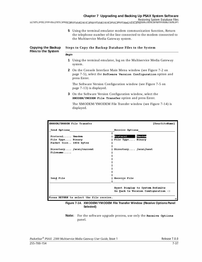
255-700-154 7-37
PacketStar® PSAX 2300 Multiservice Media Gateway User Guide, Issue 1 Release 7.0.0
Chapter 7 Upgrading and Backing Up PSAX System SoftwareRestoring System Database Files
5 Using the terminal emulator modem communication function, Return the telephone number of the line connected to the modem connected to the Multiservice Media Gateway system.
Copying the Backup Files to the System
Begin
Steps to Copy the Backup Database Files to the System
1 Using the terminal emulator, log on the Multiservice Media Gateway system.
2 On the Console Interface Main Menu window (see Figure 7-2 on page 7-5), select the Software Version Configuration option and press Enter.
The Software Version Configuration window (see Figure 7-5 on page 7-13) is displayed.
3 On the Software Version Configuration window, select the XMODEM/YMODEM File Transfer option and press Enter.
The XMODEM/YMODEM File Transfer window (see Figure 7-14) is displayed.
Note: For the software upgrade process, use only the Receive Options panel.
Figure 7-14. XMODEM/YMODEM File Transfer Window (Receive Options Panel Selected)
Chapter 7 Upgrading and Backing Up PSAX System SoftwareRestoring System Database Files
7-38 255-700-154
PacketStar® PSAX 2300 Multiservice Media Gateway User Guide, Issue 1 Release 7.0.0
Commands The commands on this window have the following functions:
Field Descriptions 4 Select the values for the fields on this window from the values given in Table 7-7.
Command Function
• Send File Initiates the send function of the file transfer process from the CPU hard disk to a storage medium (such as a PC work-station hard disk).
• Receive File Initiates the receiving function of the file transfer process to the CPU module hard disk from the separate storage medium containing the backup database files.
• Reset Display to System Defaults
Redisplays the default values in the fields.
• Go Back to Version Configuration→
Redisplays the Software Version Configu-ration window (see Figure 7-3 on page 7-6).
Table 7-7. Field Values for the XMODEM/YMODEM File Transfer Window (Receive Options Panel)—Restoring Backup Files
Field Names Values/Variables Description
Protocol Default: YModem YModem protocol for receiving the upgrade software files.
Ymodem-G YModem-G protocol for receiving the upgrade software files.
XModem XModem protocol for receiving the upgrade software files.
File Type Default: Binary Binary format is the type you use most of the time.
Text Text or ASCII format is available but do not use it for restoring database files.
Error Check (displayed only when the value XModem is selected in the Protocol field)
Default: CRC-16 Indicates that the error checking method is cyclical redundant check-ing, 16 bits.
Checksum Indicates that the error checking method is arithmetic summation checking, 8 bits.
255-700-154 7-39
PacketStar® PSAX 2300 Multiservice Media Gateway User Guide, Issue 1 Release 7.0.0
Chapter 7 Upgrading and Backing Up PSAX System SoftwareRestoring System Database Files
Note: We recommend that you use either the YModem or the YModem-G protocol. Use the XModem protocol if that is the only one you have available to use.
~ The YModem-G protocol allows the fastest transmission of the three types; however, this protocol does not acknowledge receipt of packets. You can receive all files grouped under a subdirectory at one time.
~ The YModem protocol is a slower method of transmission, but is more reliable because it does acknowledge receipt of packets. You can receive all files grouped under a subdirectory at one time.
~ The XModem protocol is a laborious method of transmission because you must enter the filename of each file in the complete package of software upgrade files to accomplish the upgrade task.
5 Select the Receive command and press Enter.
The terminal emulator displaying the Multiservice Media Gateway system window interface scrolls the XMODEM/YMODEM File Transfer window out of view. A message is displayed indicating that you can cancel the transfer by pressing Ctrl+X several times. A second message is displayed indicating that you must start the terminal emulator send function.
6 Using the terminal emulator send function, select one of the three protocol types: 1) YModem, 2) YModem-G, or 3) XModem. Be sure to select the same protocol as the one you selected on the Multiservice Media Gateway system XMODEM/YMODEM File Transfer window.
7 In the terminal emulator field for the location of the file, specify the drive where the Multiservice Media Gateway system backup database files reside and the directory pathname.
For example, specify a pathname like one of the following:
~ x:\acbackup\*.* if you are using YModem or YModem-Gwhere x is the drive letter where the backup database files reside
~ x:\acbackup\filename if you are using XModemwhere x is the drive letter where the backup database files reside
Be sure you enter the directory name (or the directory and filename if using XModem) exactly so that it matches the names you previously
Directory /scsi/current/ Directory on the CPU module hard disk where the backup database files are to be restored.
Filename (dis-played only when the value XModem is selected in the Protocol field)
filename Filename on the CPU module hard disk, which the backup database file (of the same name) will overwrite.
Table 7-7. Field Values for the XMODEM/YMODEM File Transfer Window (Receive Options Panel)—Restoring Backup Files
Field Names Values/Variables Description
Chapter 7 Upgrading and Backing Up PSAX System SoftwareRestoring System Database Files
7-40 255-700-154
PacketStar® PSAX 2300 Multiservice Media Gateway User Guide, Issue 1 Release 7.0.0
entered on the Multiservice Media Gateway system XMODEM/YMODEM File Transfer window.
8 Select the OK or Send button or command in the terminal emulator send function dialog box.
9 Repeat steps 4 through 8 to specify another filename (for XModem) until you have transferred all the backup files to the CPU hard disk.
End
At this point, you must reboot (reinitialize) the Multiservice Media Gateway system chassis, so all components are synchronized. To reboot the Multiservice Media Gateway system, perform the steps in the following procedure.
Rebooting the AC System
Begin
Steps to Reboot the Multiservice Media Gateway System
1 Redisplay the Console Interface Main Menu window (see Figure 7-2 on page 7-5).
2 On the Console Interface Main Menu window, select the Diagnostics option.
The Diagnostics Menu window is displayed.
3 On the Diagnostics Menu window, select the Reboot Hardware Components command.
The Remote Reboot Configuration window is displayed.
4 On the Remote Reboot Configuration window, select the Reboot Chassis command.
This command reboots (reinitializes) the primary and standby (redundant) CPU modules, and the I/O and server modules.
End
Restoring Backup Files to the Standby CPU2 Module
If you have a redundant CPU2 module configuration, you must restore the backup database files to the standby CPU module. To restore the backup database files to the standby CPU2 module, perform the following procedure.
Begin
Steps to Restore Backup Database Files to the Standby CPU2 Module
1 Connect the cable to the standby CPU2 module as described in Table 7-8:
255-700-154 7-41
PacketStar® PSAX 2300 Multiservice Media Gateway User Guide, Issue 1 Release 7.0.0
Chapter 7 Upgrading and Backing Up PSAX System SoftwareRestoring System Database Files
2 Repeat steps 2 through 13 in the section,”Restoring Database Files Using FTP” on page 7-34.
End
Table 7-8. Connecting Cable to Standby (Backup) CPU Module
If you are using... Then do the following...
a redundant modem kit
set up the switching modem to establish a connec-tion with the standby CPU2 module.
single modem kit connect a cable from the modem to the CONSOLE port on the standby CPU2 module.

Chapter 7 Upgrading and Backing Up PSAX System SoftwareRestoring System Database Files
7-42 255-700-154
PacketStar® PSAX 2300 Multiservice Media Gateway User Guide, Issue 1 Release 7.0.0
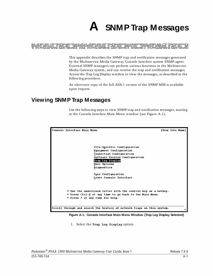
Packetstar® PSAX 2300 Multiservice Media Gateway User Guide, Issue 1 Release 7.0.0
255-700-154 A-1
A SNMP Trap Messages
This appendix describes the SNMP trap and notification messages generated by the Multiservice Media Gateway Console Interface system SNMP agent. External SNMP managers can perform various functions in the Multiservice Media Gateway system, and can receive the trap and notification messages. Access the Trap Log Display window to view the messages, as described in the following procedure.
An electronic copy of the full ASN.1 version of the SNMP MIB is available upon request.
Viewing SNMP Trap Messages
Use the following steps to view SNMP trap and notification messages, starting at the Console Interface Main Menu window (see Figure A-1).
1. Select the Trap Log Display option.
Figure A-1. Console Interface Main Menu Window (Trap Log Display Selected)
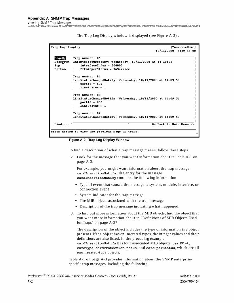
Appendix A SNMP Trap MessagesViewing SNMP Trap Messages
A-2 255-700-154
Packetstar® PSAX 2300 Multiservice Media Gateway User Guide, Issue 1 Release 7.0.0
The Trap Log Display window is displayed (see Figure A-2) .
To find a description of what a trap message means, follow these steps.
2. Look for the message that you want information about in Table A-1 on page A-3.
For example, you might want information about the trap message cardInsertionNotify. The entry for the message cardInsertionNotify contains the following information:
~ Type of event that caused the message: a system, module, interface, or connection event
~ System indicator for the trap message
~ The MIB objects associated with the trap message
~ Description of the trap message indicating what happened.
3. To find out more information about the MIB objects, find the object that you want more information about in ”Definitions of MIB Objects Used for Traps” on page A-37.
The description of the object includes the type of information the object presents. If the object has enumerated types, the integer values and their definitions are also listed. In the preceding example, cardInsertionNotify has four associated MIB objects, cardSlot, cardType, cardProtectionStatus, and cardOperStatus, which are all enumerated-type objects.
Table A-1 on page A-3 provides information about the SNMP enterprise-specific trap messages, including the following:
Figure A-2. Trap Log Display Window
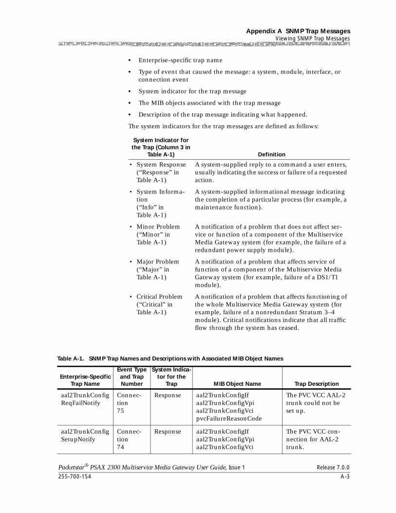
255-700-154 A-3
Packetstar® PSAX 2300 Multiservice Media Gateway User Guide, Issue 1 Release 7.0.0
Appendix A SNMP Trap MessagesViewing SNMP Trap Messages
• Enterprise-specific trap name
• Type of event that caused the message: a system, module, interface, or connection event
• System indicator for the trap message
• The MIB objects associated with the trap message
• Description of the trap message indicating what happened.
The system indicators for the trap messages are defined as follows:
System Indicator for the Trap (Column 3 in
Table A-1) Definition
• System Response(“Response” in Table A-1)
A system-supplied reply to a command a user enters, usually indicating the success or failure of a requested action.
• System Informa-tion(“Info” in Table A-1)
A system-supplied informational message indicating the completion of a particular process (for example, a maintenance function).
• Minor Problem(“Minor” in Table A-1)
A notification of a problem that does not affect ser-vice or function of a component of the Multiservice Media Gateway system (for example, the failure of a redundant power supply module).
• Major Problem(“Major” in Table A-1)
A notification of a problem that affects service of function of a component of the Multiservice Media Gateway system (for example, failure of a DS1/T1 module).
• Critical Problem(“Critical” in Table A-1)
A notification of a problem that affects functioning of the whole Multiservice Media Gateway system (for example, failure of a nonredundant Stratum 3–4 module). Critical notifications indicate that all traffic flow through the system has ceased.
Table A-1. SNMP Trap Names and Descriptions with Associated MIB Object Names
Enterprise-Specific Trap Name
Event Type and Trap Number
System Indica-tor for the
Trap MIB Object Name Trap Description
aal2TrunkConfigReqFailNotify
Connec-tion75
Response aal2TrunkConfigIf aal2TrunkConfigVpiaal2TrunkConfigVcipvcFailureReasonCode
The PVC VCC AAL-2 trunk could not be set up.
aal2TrunkConfigSetupNotify
Connec-tion74
Response aal2TrunkConfigIf aal2TrunkConfigVpiaal2TrunkConfigVci
The PVC VCC con-nection for AAL-2 trunk.
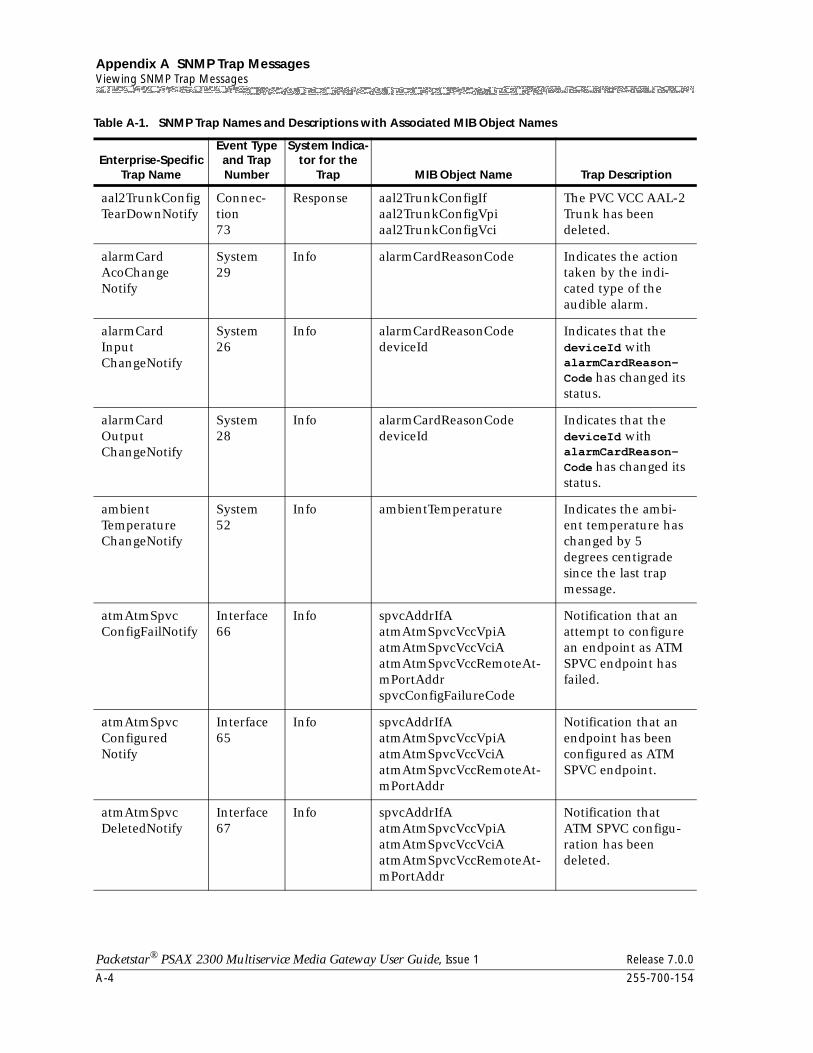
Appendix A SNMP Trap MessagesViewing SNMP Trap Messages
A-4 255-700-154
Packetstar® PSAX 2300 Multiservice Media Gateway User Guide, Issue 1 Release 7.0.0
aal2TrunkConfigTearDownNotify
Connec-tion73
Response aal2TrunkConfigIf aal2TrunkConfigVpiaal2TrunkConfigVci
The PVC VCC AAL-2 Trunk has been deleted.
alarmCardAcoChangeNotify
System29
Info alarmCardReasonCode Indicates the action taken by the indi-cated type of the audible alarm.
alarmCardInputChangeNotify
System26
Info alarmCardReasonCodedeviceId
Indicates that the deviceId with alarmCardReason-Code has changed its status.
alarmCardOutputChangeNotify
System28
Info alarmCardReasonCodedeviceId
Indicates that the deviceId with alarmCardReason-Code has changed its status.
ambientTemperatureChangeNotify
System52
Info ambientTemperature Indicates the ambi-ent temperature has changed by 5 degrees centigrade since the last trap message.
atmAtmSpvcConfigFailNotify
Interface66
Info spvcAddrIfA atmAtmSpvcVccVpiAatmAtmSpvcVccVciAatmAtmSpvcVccRemoteAt-mPortAddrspvcConfigFailureCode
Notification that an attempt to configure an endpoint as ATM SPVC endpoint has failed.
atmAtmSpvcConfiguredNotify
Interface65
Info spvcAddrIfAatmAtmSpvcVccVpiAatmAtmSpvcVccVciAatmAtmSpvcVccRemoteAt-mPortAddr
Notification that an endpoint has been configured as ATM SPVC endpoint.
atmAtmSpvcDeletedNotify
Interface67
Info spvcAddrIfAatmAtmSpvcVccVpiAatmAtmSpvcVccVciAatmAtmSpvcVccRemoteAt-mPortAddr
Notification that ATM SPVC configu-ration has been deleted.
Table A-1. SNMP Trap Names and Descriptions with Associated MIB Object Names
Enterprise-Specific Trap Name
Event Type and Trap Number
System Indica-tor for the
Trap MIB Object Name Trap Description
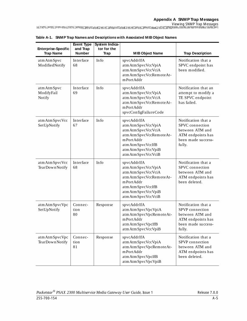
255-700-154 A-5
Packetstar® PSAX 2300 Multiservice Media Gateway User Guide, Issue 1 Release 7.0.0
Appendix A SNMP Trap MessagesViewing SNMP Trap Messages
atmAtmSpvcModifiedNotify
Interface68
Info spvcAddrIfAatmAtmSpvcVccVpiAatmAtmSpvcVccVciAatmAtmSpvcVccRemoteAt-mPortAddr
Notification that a SPVC endpoint has been modified.
atmAtmSpvcModifyFailNotify
Interface69
Info spvcAddrIfAatmAtmSpvcVccVpiAatmAtmSpvcVccVciAatmAtmSpvcVccRemoteAt-mPortAddrspvcConfigFailureCode
Notification that an attempt to modify a TE SPVC endpoint has failed.
atmAtmSpvcVccSetUpNotify
Interface67
Info spvcAddrIfAatmAtmSpvcVccVpiAatmAtmSpvcVccVciAatmAtmSpvcVccRemoteAt-mPortAddratmAtmSpvcVccIfBatmAtmSpvcVccVpiBatmAtmSpvcVccVciB
Notification that a SPVC connection between ATM and ATM endpoints has been made success-fully.
atmAtmSpvcVccTearDownNotify
Interface68
Info spvcAddrIfAatmAtmSpvcVccVpiAatmAtmSpvcVccVciAatmAtmSpvcVccRemoteAt-mPortAddratmAtmSpvcVccIfBatmAtmSpvcVccVpiBatmAtmSpvcVccVciB
Notification that a SPVC connection between ATM and ATM endpoints has been deleted.
atmAtmSpvcVpcSetUpNotify
Connec-tion80
Response spvcAddrIfAatmAtmSpvcVpcVpiAatmAtmSpvcVpcRemoteAt-mPortAddratmAtmSpvcVpcIfBatmAtmSpvcVccVpiB
Notification that a SPVP connection between ATM and ATM endpoints has been made success-fully.
atmAtmSpvcVpcTearDownNotify
Connec-tion81
Response spvcAddrIfAatmAtmSpvcVccVpiAatmAtmSpvcVpcRemoteAt-mPortAddratmAtmSpvcVpcIfBatmAtmSpvcVpcVpiB
Notification that a SPVP connection between ATM and ATM endpoints has been deleted.
Table A-1. SNMP Trap Names and Descriptions with Associated MIB Object Names
Enterprise-Specific Trap Name
Event Type and Trap Number
System Indica-tor for the
Trap MIB Object Name Trap Description
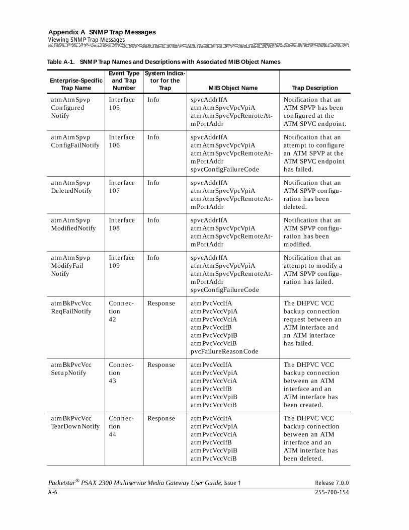
Appendix A SNMP Trap MessagesViewing SNMP Trap Messages
A-6 255-700-154
Packetstar® PSAX 2300 Multiservice Media Gateway User Guide, Issue 1 Release 7.0.0
atmAtmSpvpConfiguredNotify
Interface105
Info spvcAddrIfAatmAtmSpvcVpcVpiAatmAtmSpvcVpcRemoteAt-mPortAddr
Notification that an ATM SPVP has been configured at the ATM SPVC endpoint.
atmAtmSpvpConfigFailNotify
Interface106
Info spvcAddrIfAatmAtmSpvcVpcVpiAatmAtmSpvcVpcRemoteAt-mPortAddrspvcConfigFailureCode
Notification that an attempt to configure an ATM SPVP at the ATM SPVC endpoint has failed.
atmAtmSpvpDeletedNotify
Interface107
Info spvcAddrIfAatmAtmSpvcVpcVpiAatmAtmSpvcVpcRemoteAt-mPortAddr
Notification that an ATM SPVP configu-ration has been deleted.
atmAtmSpvpModifiedNotify
Interface108
Info spvcAddrIfAatmAtmSpvcVpcVpiAatmAtmSpvcVpcRemoteAt-mPortAddr
Notification that an ATM SPVP configu-ration has been modified.
atmAtmSpvpModifyFailNotify
Interface109
Info spvcAddrIfAatmAtmSpvcVpcVpiAatmAtmSpvcVpcRemoteAt-mPortAddrspvcConfigFailureCode
Notification that an attempt to modify a ATM SPVP configu-ration has failed.
atmBkPvcVccReqFailNotify
Connec-tion42
Response atmPvcVccIfAatmPvcVccVpiAatmPvcVccVciAatmPvcVccIfBatmPvcVccVpiBatmPvcVccVciBpvcFailureReasonCode
The DHPVC VCC backup connection request between an ATM interface and an ATM interface has failed.
atmBkPvcVccSetupNotify
Connec-tion43
Response atmPvcVccIfAatmPvcVccVpiAatmPvcVccVciAatmPvcVccIfBatmPvcVccVpiBatmPvcVccVciB
The DHPVC VCC backup connection between an ATM interface and an ATM interface has been created.
atmBkPvcVccTearDownNotify
Connec-tion44
Response atmPvcVccIfAatmPvcVccVpiAatmPvcVccVciAatmPvcVccIfBatmPvcVccVpiBatmPvcVccVciB
The DHPVC VCC backup connection between an ATM interface and an ATM interface has been deleted.
Table A-1. SNMP Trap Names and Descriptions with Associated MIB Object Names
Enterprise-Specific Trap Name
Event Type and Trap Number
System Indica-tor for the
Trap MIB Object Name Trap Description
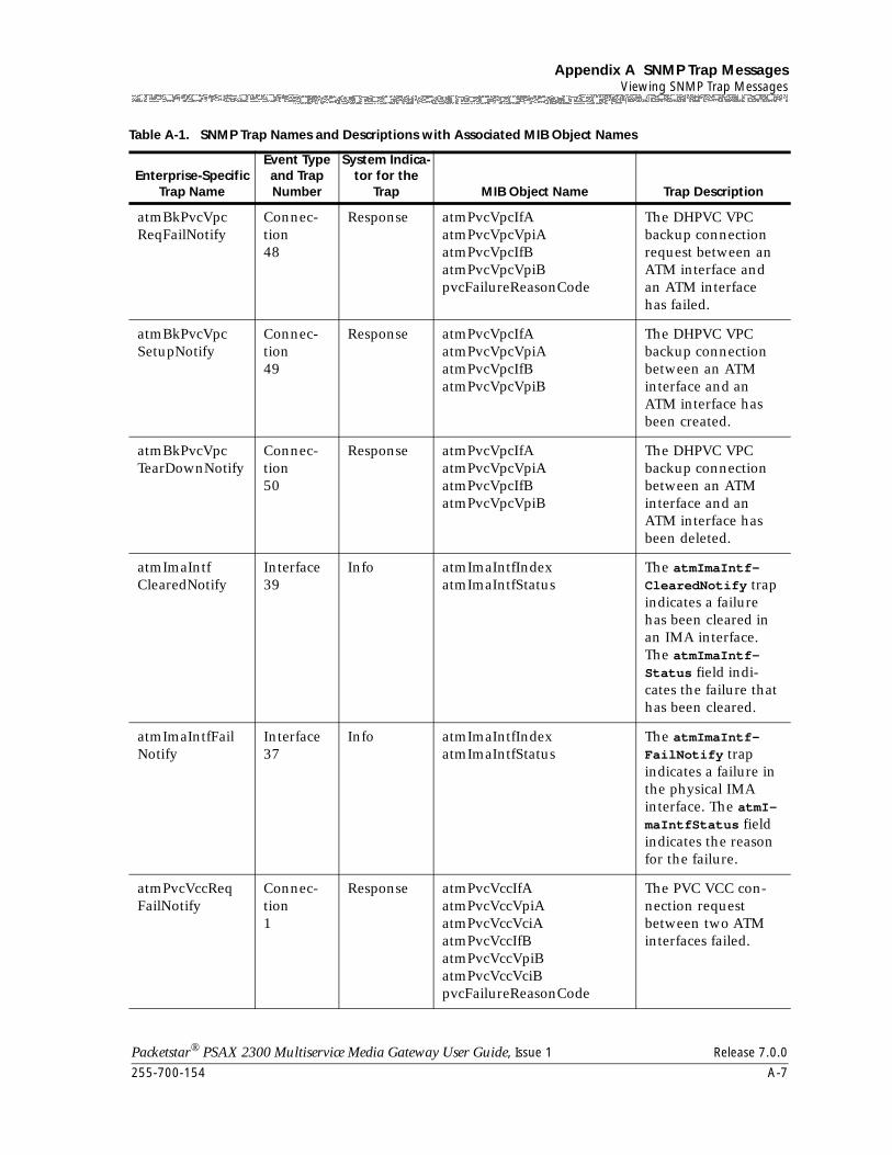
255-700-154 A-7
Packetstar® PSAX 2300 Multiservice Media Gateway User Guide, Issue 1 Release 7.0.0
Appendix A SNMP Trap MessagesViewing SNMP Trap Messages
atmBkPvcVpcReqFailNotify
Connec-tion48
Response atmPvcVpcIfAatmPvcVpcVpiAatmPvcVpcIfBatmPvcVpcVpiBpvcFailureReasonCode
The DHPVC VPC backup connection request between an ATM interface and an ATM interface has failed.
atmBkPvcVpcSetupNotify
Connec-tion49
Response atmPvcVpcIfAatmPvcVpcVpiAatmPvcVpcIfBatmPvcVpcVpiB
The DHPVC VPC backup connection between an ATM interface and an ATM interface has been created.
atmBkPvcVpcTearDownNotify
Connec-tion50
Response atmPvcVpcIfAatmPvcVpcVpiAatmPvcVpcIfBatmPvcVpcVpiB
The DHPVC VPC backup connection between an ATM interface and an ATM interface has been deleted.
atmImaIntfClearedNotify
Interface39
Info atmImaIntfIndexatmImaIntfStatus
The atmImaIntf-ClearedNotify trap indicates a failure has been cleared in an IMA interface. The atmImaIntf-Status field indi-cates the failure that has been cleared.
atmImaIntfFailNotify
Interface37
Info atmImaIntfIndexatmImaIntfStatus
The atmImaIntf-FailNotify trap indicates a failure in the physical IMA interface. The atmI-maIntfStatus field indicates the reason for the failure.
atmPvcVccReqFailNotify
Connec-tion1
Response atmPvcVccIfAatmPvcVccVpiAatmPvcVccVciAatmPvcVccIfBatmPvcVccVpiBatmPvcVccVciBpvcFailureReasonCode
The PVC VCC con-nection request between two ATM interfaces failed.
Table A-1. SNMP Trap Names and Descriptions with Associated MIB Object Names
Enterprise-Specific Trap Name
Event Type and Trap Number
System Indica-tor for the
Trap MIB Object Name Trap Description
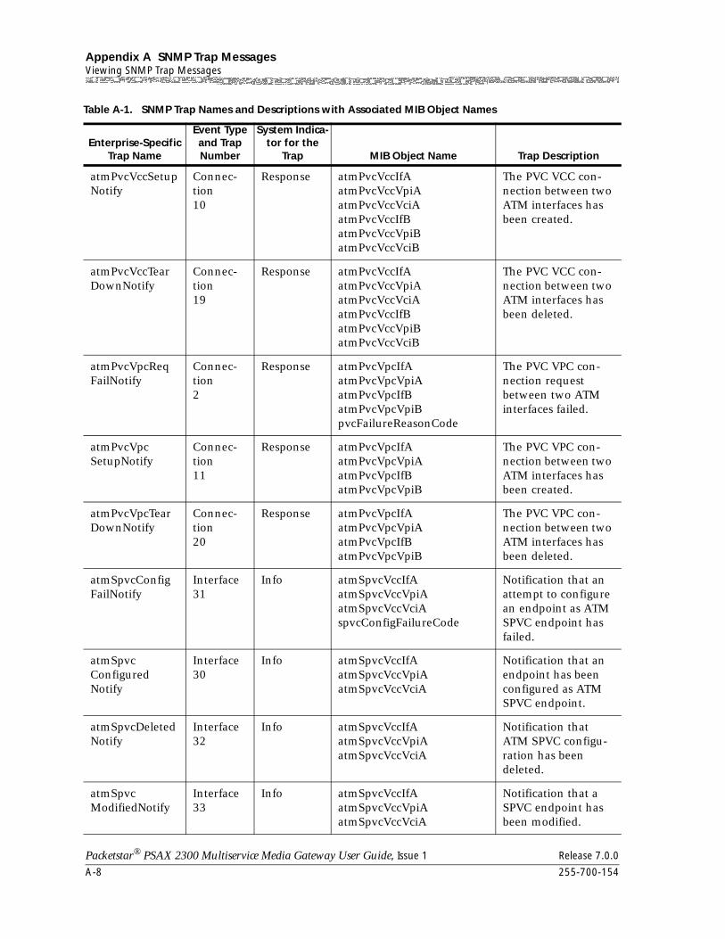
Appendix A SNMP Trap MessagesViewing SNMP Trap Messages
A-8 255-700-154
Packetstar® PSAX 2300 Multiservice Media Gateway User Guide, Issue 1 Release 7.0.0
atmPvcVccSetupNotify
Connec-tion10
Response atmPvcVccIfAatmPvcVccVpiAatmPvcVccVciAatmPvcVccIfBatmPvcVccVpiBatmPvcVccVciB
The PVC VCC con-nection between two ATM interfaces has been created.
atmPvcVccTearDownNotify
Connec-tion19
Response atmPvcVccIfAatmPvcVccVpiAatmPvcVccVciAatmPvcVccIfBatmPvcVccVpiBatmPvcVccVciB
The PVC VCC con-nection between two ATM interfaces has been deleted.
atmPvcVpcReqFailNotify
Connec-tion2
Response atmPvcVpcIfAatmPvcVpcVpiAatmPvcVpcIfBatmPvcVpcVpiBpvcFailureReasonCode
The PVC VPC con-nection request between two ATM interfaces failed.
atmPvcVpcSetupNotify
Connec-tion11
Response atmPvcVpcIfAatmPvcVpcVpiAatmPvcVpcIfBatmPvcVpcVpiB
The PVC VPC con-nection between two ATM interfaces has been created.
atmPvcVpcTearDownNotify
Connec-tion20
Response atmPvcVpcIfAatmPvcVpcVpiAatmPvcVpcIfBatmPvcVpcVpiB
The PVC VPC con-nection between two ATM interfaces has been deleted.
atmSpvcConfigFailNotify
Interface31
Info atmSpvcVccIfAatmSpvcVccVpiAatmSpvcVccVciAspvcConfigFailureCode
Notification that an attempt to configure an endpoint as ATM SPVC endpoint has failed.
atmSpvcConfiguredNotify
Interface30
Info atmSpvcVccIfAatmSpvcVccVpiAatmSpvcVccVciA
Notification that an endpoint has been configured as ATM SPVC endpoint.
atmSpvcDeletedNotify
Interface32
Info atmSpvcVccIfAatmSpvcVccVpiAatmSpvcVccVciA
Notification that ATM SPVC configu-ration has been deleted.
atmSpvcModifiedNotify
Interface33
Info atmSpvcVccIfAatmSpvcVccVpiAatmSpvcVccVciA
Notification that a SPVC endpoint has been modified.
Table A-1. SNMP Trap Names and Descriptions with Associated MIB Object Names
Enterprise-Specific Trap Name
Event Type and Trap Number
System Indica-tor for the
Trap MIB Object Name Trap Description
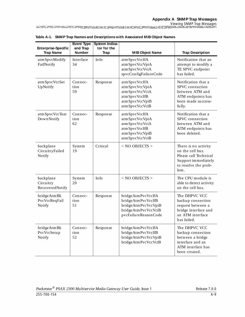
255-700-154 A-9
Packetstar® PSAX 2300 Multiservice Media Gateway User Guide, Issue 1 Release 7.0.0
Appendix A SNMP Trap MessagesViewing SNMP Trap Messages
atmSpvcModifyFailNotify
Interface34
Info atmSpvcVccIfAatmSpvcVccVpiAatmSpvcVccVciAspvcConfigFailureCode
Notification that an attempt to modify a TE SPVC endpoint has failed.
atmSpvcVccSetUpNotify
Connec-tion59
Response atmSpvcVccIfAatmSpvcVccVpiAatmSpvcVccVciAatmSpvcVccIfBatmSpvcVccVpiBatmSpvcVccVciB
Notification that a SPVC connection between ATM and ATM endpoints has been made success-fully.
atmSpvcVccTearDownNotify
Connec-tion62
Response atmSpvcVccIfAatmSpvcVccVpiAatmSpvcVccVciAatmSpvcVccIfBatmSpvcVccVpiBatmSpvcVccVciB
Notification that a SPVC connection between ATM and ATM endpoints has been deleted.
backplaneCircuitryFailedNotify
System19
Critical < NO OBJECTS > There is no activity on the cell bus. Please call Technical Support immediately to resolve the prob-lem.
backplaneCircuitryRecoveredNotify
System20
Info < NO OBJECTS > The CPU module is able to detect activity on the cell bus.
bridgeAtmBkPvcVccReqFailNotify
Connec-tion51
Response bridgeAtmPvcVccIfAbridgeAtmPvcVccIfBbridgeAtmPvcVccVpiBbridgeAtmPvcVccVciBpvcFailureReasonCode
The DHPVC VCC backup connection request between a bridge interface and an ATM interface has failed.
bridgeAtmBkPvcVccSetupNotify
Connec-tion52
Response bridgeAtmPvcVccIfAbridgeAtmPvcVccIfBbridgeAtmPvcVccVpiBbridgeAtmPvcVccVciB
The DHPVC VCC backup connection between a bridge interface and an ATM interface has been created.
Table A-1. SNMP Trap Names and Descriptions with Associated MIB Object Names
Enterprise-Specific Trap Name
Event Type and Trap Number
System Indica-tor for the
Trap MIB Object Name Trap Description
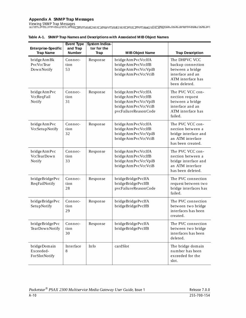
Appendix A SNMP Trap MessagesViewing SNMP Trap Messages
A-10 255-700-154
Packetstar® PSAX 2300 Multiservice Media Gateway User Guide, Issue 1 Release 7.0.0
bridgeAtmBkPvcVccTearDownNotify
Connec-tion53
Response bridgeAtmPvcVccIfAbridgeAtmPvcVccIfBbridgeAtmPvcVccVpiBbridgeAtmPvcVccVciB
The DHPVC VCC backup connection between a bridge interface and an ATM interface has been deleted.
bridgeAtmPvcVccReqFailNotify
Connec-tion31
Response bridgeAtmPvcVccIfAbridgeAtmPvcVccIfBbridgeAtmPvcVccVpiBbridgeAtmPvcVccVciBpvcFailureReasonCode
The PVC VCC con-nection request between a bridge interface and an ATM interface has failed.
bridgeAtmPvcVccSetupNotify
Connec-tion32
Response bridgeAtmPvcVccIfAbridgeAtmPvcVccIfBbridgeAtmPvcVccVpiBbridgeAtmPvcVccVciB
The PVC VCC con-nection between a bridge interface and an ATM interface has been created.
bridgeAtmPvcVccTearDownNotify
Connec-tion33
Response bridgeAtmPvcVccIfAbridgeAtmPvcVccIfBbridgeAtmPvcVccVpiBbridgeAtmPvcVccVciB
The PVC VCC con-nection between a bridge interface and an ATM interface has been deleted.
bridgeBridgePvcReqFailNotify
Connec-tion28
Response bridgeBridgePvcIfAbridgeBridgePvcIfBpvcFailureReasonCode
The PVC connection request between two bridge interfaces has failed.
bridgeBridgePvcSetupNotify
Connec-tion29
Response bridgeBridgePvcIfAbridgeBridgePvcIfB
The PVC connection between two bridge interfaces has been created.
bridgeBridgePvcTearDownNotify
Connec-tion30
Response bridgeBridgePvcIfAbridgeBridgePvcIfB
The PVC connection between two bridge interfaces has been deleted.
bridgeDomainExceeded-ForSlotNotify
Interface8
Info cardSlot The bridge domain number has been exceeded for the slot.
Table A-1. SNMP Trap Names and Descriptions with Associated MIB Object Names
Enterprise-Specific Trap Name
Event Type and Trap Number
System Indica-tor for the
Trap MIB Object Name Trap Description
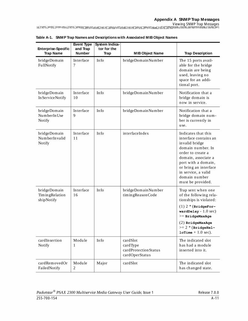
255-700-154 A-11
Packetstar® PSAX 2300 Multiservice Media Gateway User Guide, Issue 1 Release 7.0.0
Appendix A SNMP Trap MessagesViewing SNMP Trap Messages
bridgeDomainFullNotify
Interface7
Info bridgeDomainNumber The 15 ports avail-able for the bridge domain are being used, leaving no space for an addi-tional port.
bridgeDomainInServiceNotify
Interface10
Info bridgeDomainNumber Notification that a bridge domain is now in service.
bridgeDomainNumberInUseNotify
Interface9
Info bridgeDomainNumber Notification that a bridge domain num-ber is currently in use.
bridgeDomainNumberInvalidNotify
Interface11
Info interfaceIndex Indicates that this interface contains an invalid bridge domain number. In order to create a domain, associate a port with a domain, or bring an interface in service, a valid domain number must be provided.
bridgeDomainTimingRelationshipNotify
Interface16
Info bridgeDomainNumbertimingReasonCode
Trap sent when one of the following rela-tionships is violated:
(1) 2 * (BridgeFor-wardDelay - 1.0 sec) >= BridgeMaxAge
(2) BridgeMaxAge >= 2 * (BridgeHel-loTime + 1.0 sec).
cardInsertionNotify
Module1
Info cardSlotcardTypecardProtectionStatuscardOperStatus
The indicated slot has had a module inserted into it.
cardRemovedOrFailedNotify
Module2
Major cardSlot The indicated slot has changed state.
Table A-1. SNMP Trap Names and Descriptions with Associated MIB Object Names
Enterprise-Specific Trap Name
Event Type and Trap Number
System Indica-tor for the
Trap MIB Object Name Trap Description
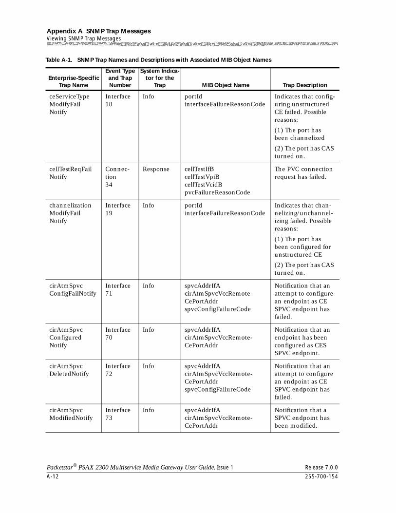
Appendix A SNMP Trap MessagesViewing SNMP Trap Messages
A-12 255-700-154
Packetstar® PSAX 2300 Multiservice Media Gateway User Guide, Issue 1 Release 7.0.0
ceServiceTypeModifyFailNotify
Interface18
Info portIdinterfaceFailureReasonCode
Indicates that config-uring unstructured CE failed. Possible reasons:
(1) The port has been channelized
(2) The port has CAS turned on.
cellTestReqFailNotify
Connec-tion34
Response cellTestIfBcellTestVpiBcellTestVcidBpvcFailureReasonCode
The PVC connection request has failed.
channelizationModifyFailNotify
Interface19
Info portIdinterfaceFailureReasonCode
Indicates that chan-nelizing/unchannel-izing failed. Possible reasons:
(1) The port has been configured for unstructured CE
(2) The port has CAS turned on.
cirAtmSpvcConfigFailNotify
Interface71
Info spvcAddrIfAcirAtmSpvcVccRemote-CePortAddrspvcConfigFailureCode
Notification that an attempt to configure an endpoint as CE SPVC endpoint has failed.
cirAtmSpvcConfiguredNotify
Interface70
Info spvcAddrIfAcirAtmSpvcVccRemote-CePortAddr
Notification that an endpoint has been configured as CES SPVC endpoint.
cirAtmSpvcDeletedNotify
Interface72
Info spvcAddrIfAcirAtmSpvcVccRemote-CePortAddrspvcConfigFailureCode
Notification that an attempt to configure an endpoint as CE SPVC endpoint has failed.
cirAtmSpvcModifiedNotify
Interface73
Info spvcAddrIfAcirAtmSpvcVccRemote-CePortAddr
Notification that a SPVC endpoint has been modified.
Table A-1. SNMP Trap Names and Descriptions with Associated MIB Object Names
Enterprise-Specific Trap Name
Event Type and Trap Number
System Indica-tor for the
Trap MIB Object Name Trap Description
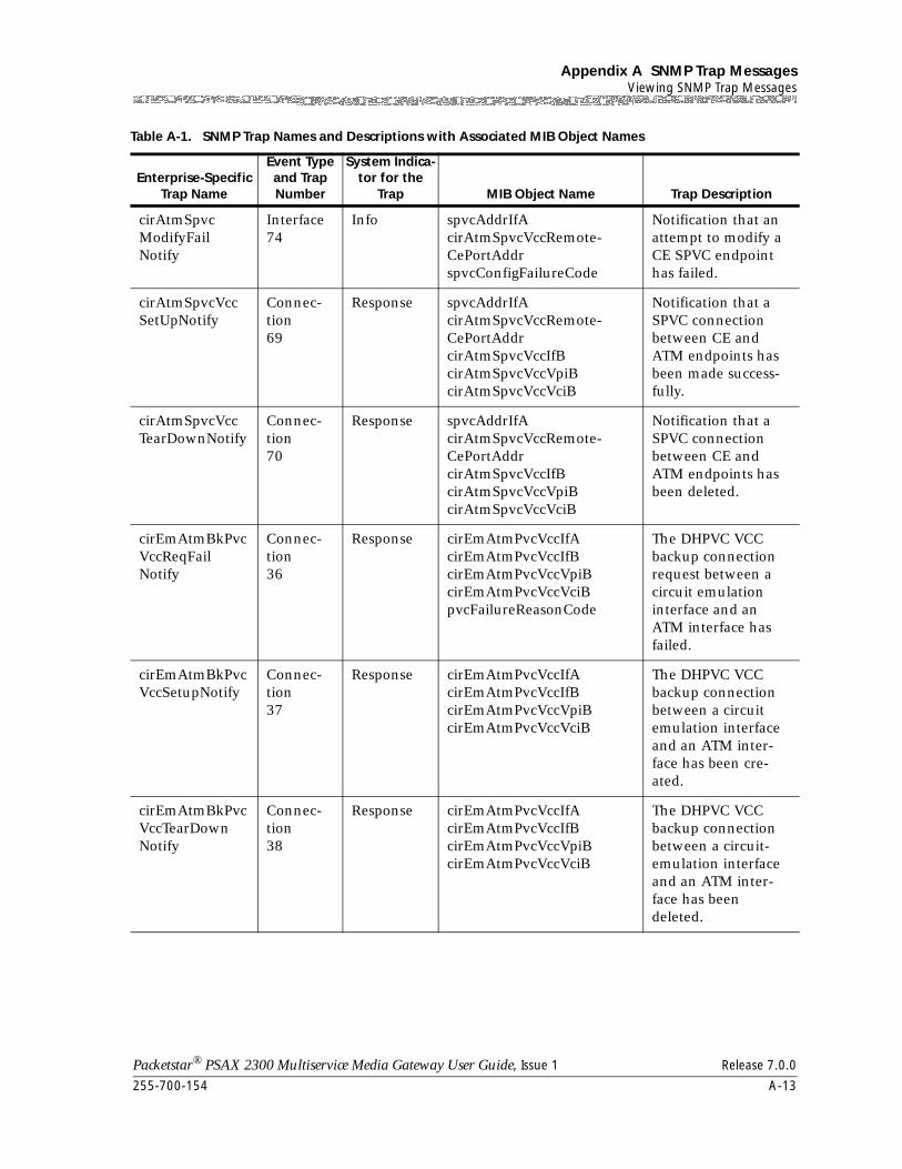
255-700-154 A-13
Packetstar® PSAX 2300 Multiservice Media Gateway User Guide, Issue 1 Release 7.0.0
Appendix A SNMP Trap MessagesViewing SNMP Trap Messages
cirAtmSpvcModifyFailNotify
Interface74
Info spvcAddrIfAcirAtmSpvcVccRemote-CePortAddrspvcConfigFailureCode
Notification that an attempt to modify a CE SPVC endpoint has failed.
cirAtmSpvcVccSetUpNotify
Connec-tion69
Response spvcAddrIfAcirAtmSpvcVccRemote-CePortAddrcirAtmSpvcVccIfBcirAtmSpvcVccVpiBcirAtmSpvcVccVciB
Notification that a SPVC connection between CE and ATM endpoints has been made success-fully.
cirAtmSpvcVccTearDownNotify
Connec-tion70
Response spvcAddrIfAcirAtmSpvcVccRemote-CePortAddrcirAtmSpvcVccIfBcirAtmSpvcVccVpiBcirAtmSpvcVccVciB
Notification that a SPVC connection between CE and ATM endpoints has been deleted.
cirEmAtmBkPvcVccReqFailNotify
Connec-tion36
Response cirEmAtmPvcVccIfAcirEmAtmPvcVccIfBcirEmAtmPvcVccVpiBcirEmAtmPvcVccVciBpvcFailureReasonCode
The DHPVC VCC backup connection request between a circuit emulation interface and an ATM interface has failed.
cirEmAtmBkPvcVccSetupNotify
Connec-tion37
Response cirEmAtmPvcVccIfAcirEmAtmPvcVccIfBcirEmAtmPvcVccVpiBcirEmAtmPvcVccVciB
The DHPVC VCC backup connection between a circuit emulation interface and an ATM inter-face has been cre-ated.
cirEmAtmBkPvcVccTearDownNotify
Connec-tion38
Response cirEmAtmPvcVccIfAcirEmAtmPvcVccIfBcirEmAtmPvcVccVpiBcirEmAtmPvcVccVciB
The DHPVC VCC backup connection between a circuit-emulation interface and an ATM inter-face has been deleted.
Table A-1. SNMP Trap Names and Descriptions with Associated MIB Object Names
Enterprise-Specific Trap Name
Event Type and Trap Number
System Indica-tor for the
Trap MIB Object Name Trap Description
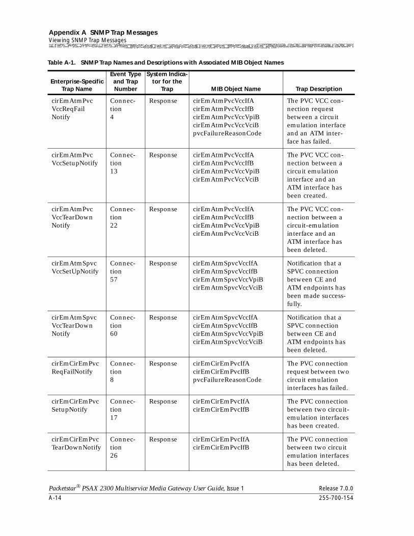
Appendix A SNMP Trap MessagesViewing SNMP Trap Messages
A-14 255-700-154
Packetstar® PSAX 2300 Multiservice Media Gateway User Guide, Issue 1 Release 7.0.0
cirEmAtmPvcVccReqFailNotify
Connec-tion4
Response cirEmAtmPvcVccIfAcirEmAtmPvcVccIfBcirEmAtmPvcVccVpiBcirEmAtmPvcVccVciBpvcFailureReasonCode
The PVC VCC con-nection request between a circuit emulation interface and an ATM inter-face has failed.
cirEmAtmPvcVccSetupNotify
Connec-tion13
Response cirEmAtmPvcVccIfAcirEmAtmPvcVccIfBcirEmAtmPvcVccVpiBcirEmAtmPvcVccVciB
The PVC VCC con-nection between a circuit emulation interface and an ATM interface has been created.
cirEmAtmPvcVccTearDownNotify
Connec-tion22
Response cirEmAtmPvcVccIfAcirEmAtmPvcVccIfBcirEmAtmPvcVccVpiBcirEmAtmPvcVccVciB
The PVC VCC con-nection between a circuit-emulation interface and an ATM interface has been deleted.
cirEmAtmSpvcVccSetUpNotify
Connec-tion57
Response cirEmAtmSpvcVccIfAcirEmAtmSpvcVccIfBcirEmAtmSpvcVccVpiBcirEmAtmSpvcVccVciB
Notification that a SPVC connection between CE and ATM endpoints has been made success-fully.
cirEmAtmSpvcVccTearDownNotify
Connec-tion60
Response cirEmAtmSpvcVccIfAcirEmAtmSpvcVccIfBcirEmAtmSpvcVccVpiBcirEmAtmSpvcVccVciB
Notification that a SPVC connection between CE and ATM endpoints has been deleted.
cirEmCirEmPvcReqFailNotify
Connec-tion8
Response cirEmCirEmPvcIfAcirEmCirEmPvcIfBpvcFailureReasonCode
The PVC connection request between two circuit emulation interfaces has failed.
cirEmCirEmPvcSetupNotify
Connec-tion17
Response cirEmCirEmPvcIfAcirEmCirEmPvcIfB
The PVC connection between two circuit-emulation interfaces has been created.
cirEmCirEmPvcTearDownNotify
Connec-tion26
Response cirEmCirEmPvcIfAcirEmCirEmPvcIfB
The PVC connection between two circuit emulation interfaces has been deleted.
Table A-1. SNMP Trap Names and Descriptions with Associated MIB Object Names
Enterprise-Specific Trap Name
Event Type and Trap Number
System Indica-tor for the
Trap MIB Object Name Trap Description
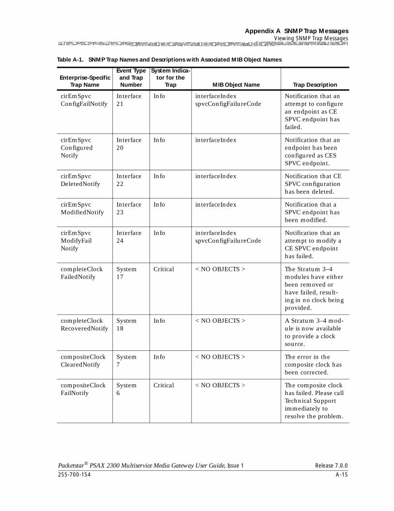
255-700-154 A-15
Packetstar® PSAX 2300 Multiservice Media Gateway User Guide, Issue 1 Release 7.0.0
Appendix A SNMP Trap MessagesViewing SNMP Trap Messages
cirEmSpvcConfigFailNotify
Interface21
Info interfaceIndexspvcConfigFailureCode
Notification that an attempt to configure an endpoint as CE SPVC endpoint has failed.
cirEmSpvcConfiguredNotify
Interface20
Info interfaceIndex Notification that an endpoint has been configured as CES SPVC endpoint.
cirEmSpvcDeletedNotify
Interface22
Info interfaceIndex Notification that CE SPVC configuration has been deleted.
cirEmSpvcModifiedNotify
Interface23
Info interfaceIndex Notification that a SPVC endpoint has been modified.
cirEmSpvcModifyFailNotify
Interface24
Info interfaceIndexspvcConfigFailureCode
Notification that an attempt to modify a CE SPVC endpoint has failed.
completeClockFailedNotify
System17
Critical < NO OBJECTS > The Stratum 3–4 modules have either been removed or have failed, result-ing in no clock being provided.
completeClockRecoveredNotify
System18
Info < NO OBJECTS > A Stratum 3–4 mod-ule is now available to provide a clock source.
compositeClockClearedNotify
System7
Info < NO OBJECTS > The error in the composite clock has been corrected.
compositeClockFailNotify
System6
Critical < NO OBJECTS > The composite clock has failed. Please call Technical Support immediately to resolve the problem.
Table A-1. SNMP Trap Names and Descriptions with Associated MIB Object Names
Enterprise-Specific Trap Name
Event Type and Trap Number
System Indica-tor for the
Trap MIB Object Name Trap Description
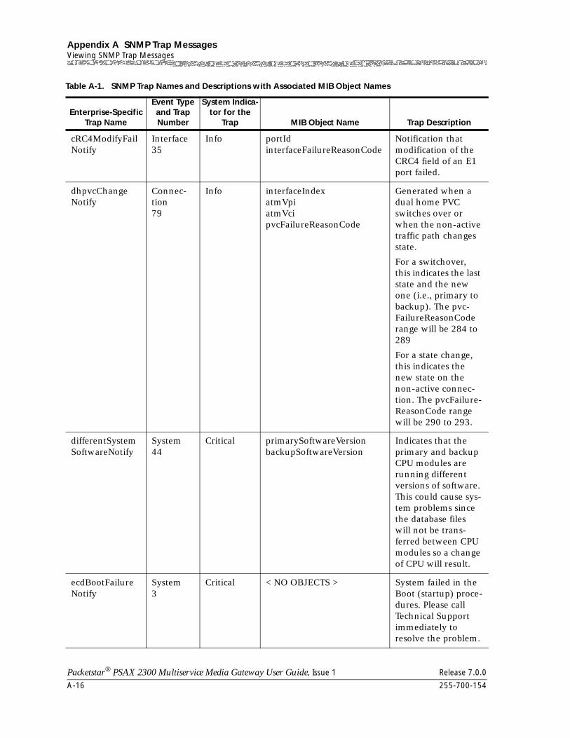
Appendix A SNMP Trap MessagesViewing SNMP Trap Messages
A-16 255-700-154
Packetstar® PSAX 2300 Multiservice Media Gateway User Guide, Issue 1 Release 7.0.0
cRC4ModifyFailNotify
Interface35
Info portIdinterfaceFailureReasonCode
Notification that modification of the CRC4 field of an E1 port failed.
dhpvcChangeNotify
Connec-tion79
Info interfaceIndexatmVpiatmVcipvcFailureReasonCode
Generated when a dual home PVC switches over or when the non-active traffic path changes state.
For a switchover, this indicates the last state and the new one (i.e., primary to backup). The pvc-FailureReasonCode range will be 284 to 289
For a state change, this indicates the new state on the non-active connec-tion. The pvcFailure-ReasonCode range will be 290 to 293.
differentSystemSoftwareNotify
System44
Critical primarySoftwareVersionbackupSoftwareVersion
Indicates that the primary and backup CPU modules are running different versions of software. This could cause sys-tem problems since the database files will not be trans-ferred between CPU modules so a change of CPU will result.
ecdBootFailureNotify
System3
Critical < NO OBJECTS > System failed in the Boot (startup) proce-dures. Please call Technical Support immediately to resolve the problem.
Table A-1. SNMP Trap Names and Descriptions with Associated MIB Object Names
Enterprise-Specific Trap Name
Event Type and Trap Number
System Indica-tor for the
Trap MIB Object Name Trap Description
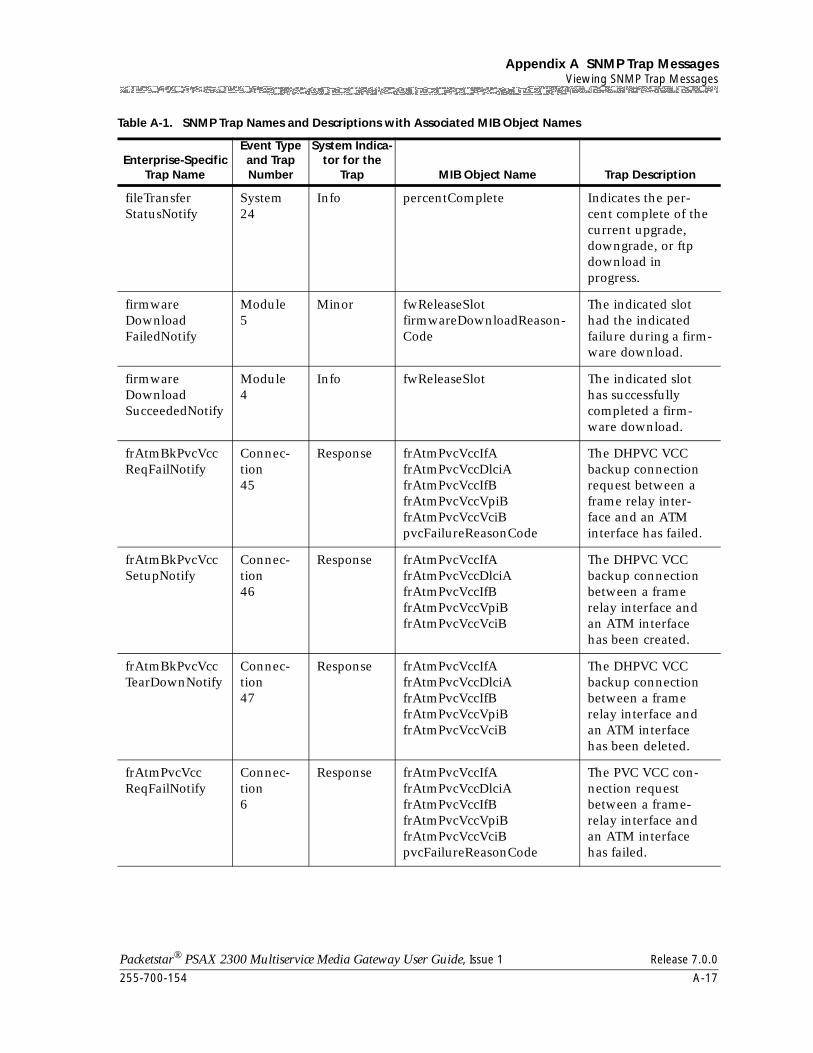
255-700-154 A-17
Packetstar® PSAX 2300 Multiservice Media Gateway User Guide, Issue 1 Release 7.0.0
Appendix A SNMP Trap MessagesViewing SNMP Trap Messages
fileTransferStatusNotify
System24
Info percentComplete Indicates the per-cent complete of the current upgrade, downgrade, or ftp download in progress.
firmwareDownloadFailedNotify
Module5
Minor fwReleaseSlotfirmwareDownloadReason-Code
The indicated slot had the indicated failure during a firm-ware download.
firmwareDownloadSucceededNotify
Module4
Info fwReleaseSlot The indicated slot has successfully completed a firm-ware download.
frAtmBkPvcVccReqFailNotify
Connec-tion45
Response frAtmPvcVccIfAfrAtmPvcVccDlciAfrAtmPvcVccIfBfrAtmPvcVccVpiBfrAtmPvcVccVciBpvcFailureReasonCode
The DHPVC VCC backup connection request between a frame relay inter-face and an ATM interface has failed.
frAtmBkPvcVccSetupNotify
Connec-tion46
Response frAtmPvcVccIfAfrAtmPvcVccDlciAfrAtmPvcVccIfBfrAtmPvcVccVpiBfrAtmPvcVccVciB
The DHPVC VCC backup connection between a frame relay interface and an ATM interface has been created.
frAtmBkPvcVccTearDownNotify
Connec-tion47
Response frAtmPvcVccIfAfrAtmPvcVccDlciAfrAtmPvcVccIfBfrAtmPvcVccVpiBfrAtmPvcVccVciB
The DHPVC VCC backup connection between a frame relay interface and an ATM interface has been deleted.
frAtmPvcVccReqFailNotify
Connec-tion6
Response frAtmPvcVccIfAfrAtmPvcVccDlciAfrAtmPvcVccIfBfrAtmPvcVccVpiBfrAtmPvcVccVciBpvcFailureReasonCode
The PVC VCC con-nection request between a frame-relay interface and an ATM interface has failed.
Table A-1. SNMP Trap Names and Descriptions with Associated MIB Object Names
Enterprise-Specific Trap Name
Event Type and Trap Number
System Indica-tor for the
Trap MIB Object Name Trap Description
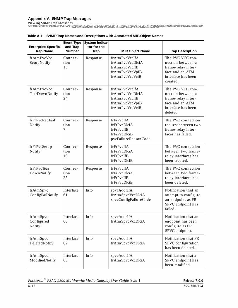
Appendix A SNMP Trap MessagesViewing SNMP Trap Messages
A-18 255-700-154
Packetstar® PSAX 2300 Multiservice Media Gateway User Guide, Issue 1 Release 7.0.0
frAtmPvcVccSetupNotify
Connec-tion15
Response frAtmPvcVccIfAfrAtmPvcVccDlciAfrAtmPvcVccIfBfrAtmPvcVccVpiBfrAtmPvcVccVciB
The PVC VCC con-nection between a frame-relay inter-face and an ATM interface has been created.
frAtmPvcVccTearDownNotify
Connec-tion24
Response frAtmPvcVccIfAfrAtmPvcVccDlciAfrAtmPvcVccIfBfrAtmPvcVccVpiBfrAtmPvcVccVciB
The PVC VCC con-nection between a frame-relay inter-face and an ATM interface has been deleted.
frFrPvcReqFailNotify
Connec-tion7
Response frFrPvcIfAfrFrPvcDlciAfrFrPvcIfBfrFrPvcDlciBpvcFailureReasonCode
The PVC connection request between two frame-relay inter-faces has failed.
frFrPvcSetupNotify
Connec-tion16
Response frFrPvcIfAfrFrPvcDlciAfrFrPvcIfBfrFrPvcDlciB
The PVC connection between two frame-relay interfaces has been created.
frFrPvcTearDownNotify
Connec-tion25
Response frFrPvcIfAfrFrPvcDlciAfrFrPvcIfBfrFrPvcDlciB
The PVC connection between two frame-relay interfaces has been deleted.
frAtmSpvcConfigFailNotify
Interface61
Info spvcAddrIfAfrAtmSpvcVccDlciAspvcConfigFailureCode
Notification that an attempt to configure an endpoint as FR SPVC endpoint has failed.
frAtmSpvcConfiguredNotify
Interface60
Info spvcAddrIfAfrAtmSpvcVccDlciA
Notification that an endpoint has been configure as FR SPVC endpoint.
frAtmSpvcDeletedNotify
Interface62
Info spvcAddrIfAfrAtmSpvcVccDlciA
Notification that FR SPVC configuration has been deleted.
frAtmSpvcModifiedNotify
Interface63
Info spvcAddrIfAfrAtmSpvcVccDlciA
Notification that a SPVC endpoint has been modified.
Table A-1. SNMP Trap Names and Descriptions with Associated MIB Object Names
Enterprise-Specific Trap Name
Event Type and Trap Number
System Indica-tor for the
Trap MIB Object Name Trap Description
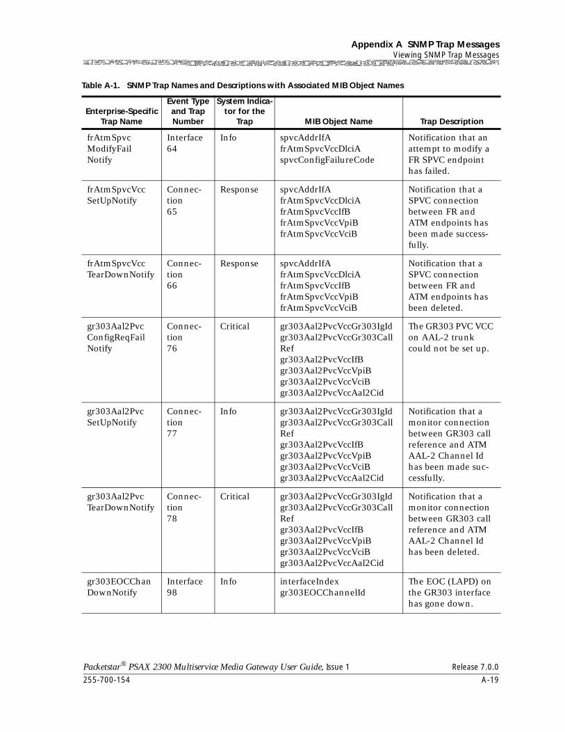
255-700-154 A-19
Packetstar® PSAX 2300 Multiservice Media Gateway User Guide, Issue 1 Release 7.0.0
Appendix A SNMP Trap MessagesViewing SNMP Trap Messages
frAtmSpvcModifyFailNotify
Interface64
Info spvcAddrIfAfrAtmSpvcVccDlciAspvcConfigFailureCode
Notification that an attempt to modify a FR SPVC endpoint has failed.
frAtmSpvcVccSetUpNotify
Connec-tion65
Response spvcAddrIfAfrAtmSpvcVccDlciAfrAtmSpvcVccIfBfrAtmSpvcVccVpiBfrAtmSpvcVccVciB
Notification that a SPVC connection between FR and ATM endpoints has been made success-fully.
frAtmSpvcVccTearDownNotify
Connec-tion66
Response spvcAddrIfAfrAtmSpvcVccDlciAfrAtmSpvcVccIfBfrAtmSpvcVccVpiBfrAtmSpvcVccVciB
Notification that a SPVC connection between FR and ATM endpoints has been deleted.
gr303Aal2PvcConfigReqFailNotify
Connec-tion76
Critical gr303Aal2PvcVccGr303IgIdgr303Aal2PvcVccGr303CallRefgr303Aal2PvcVccIfBgr303Aal2PvcVccVpiBgr303Aal2PvcVccVciBgr303Aal2PvcVccAal2Cid
The GR303 PVC VCC on AAL-2 trunk could not be set up.
gr303Aal2PvcSetUpNotify
Connec-tion77
Info gr303Aal2PvcVccGr303IgIdgr303Aal2PvcVccGr303CallRefgr303Aal2PvcVccIfBgr303Aal2PvcVccVpiBgr303Aal2PvcVccVciBgr303Aal2PvcVccAal2Cid
Notification that a monitor connection between GR303 call reference and ATM AAL-2 Channel Id has been made suc-cessfully.
gr303Aal2PvcTearDownNotify
Connec-tion78
Critical gr303Aal2PvcVccGr303IgIdgr303Aal2PvcVccGr303CallRefgr303Aal2PvcVccIfBgr303Aal2PvcVccVpiBgr303Aal2PvcVccVciBgr303Aal2PvcVccAal2Cid
Notification that a monitor connection between GR303 call reference and ATM AAL-2 Channel Id has been deleted.
gr303EOCChanDownNotify
Interface98
Info interfaceIndexgr303EOCChannelId
The EOC (LAPD) on the GR303 interface has gone down.
Table A-1. SNMP Trap Names and Descriptions with Associated MIB Object Names
Enterprise-Specific Trap Name
Event Type and Trap Number
System Indica-tor for the
Trap MIB Object Name Trap Description
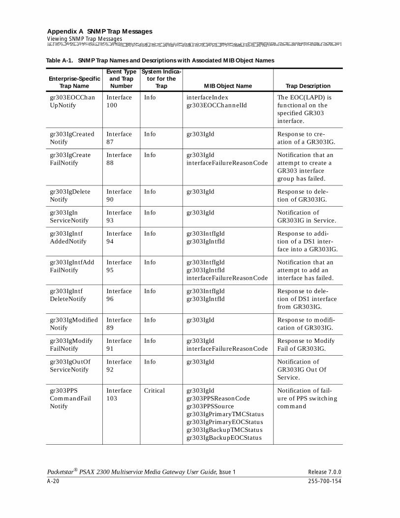
Appendix A SNMP Trap MessagesViewing SNMP Trap Messages
A-20 255-700-154
Packetstar® PSAX 2300 Multiservice Media Gateway User Guide, Issue 1 Release 7.0.0
gr303EOCChanUpNotify
Interface100
Info interfaceIndexgr303EOCChannelId
The EOC(LAPD) is functional on the specified GR303 interface.
gr303IgCreatedNotify
Interface87
Info gr303IgId Response to cre-ation of a GR303IG.
gr303IgCreateFailNotify
Interface88
Info gr303IgId interfaceFailureReasonCode
Notification that an attempt to create a GR303 interface group has failed.
gr303IgDeleteNotify
Interface90
Info gr303IgId Response to dele-tion of GR303IG.
gr303IgInServiceNotify
Interface93
Info gr303IgId Notification of GR303IG in Service.
gr303IgIntfAddedNotify
Interface94
Info gr303IntfIgId gr303IgIntfId
Response to addi-tion of a DS1 inter-face into a GR303IG.
gr303IgIntfAddFailNotify
Interface95
Info gr303IntfIgIdgr303IgIntfIdinterfaceFailureReasonCode
Notification that an attempt to add an interface has failed.
gr303IgIntfDeleteNotify
Interface96
Info gr303IntfIgIdgr303IgIntfId
Response to dele-tion of DS1 interface from GR303IG.
gr303IgModifiedNotify
Interface89
Info gr303IgId Response to modifi-cation of GR303IG.
gr303IgModifyFailNotify
Interface91
Info gr303IgIdinterfaceFailureReasonCode
Response to Modify Fail of GR303IG.
gr303IgOutOfServiceNotify
Interface92
Info gr303IgId Notification of GR303IG Out Of Service.
gr303PPSCommandFailNotify
Interface103
Critical gr303IgIdgr303PPSReasonCodegr303PPSSourcegr303IgPrimaryTMCStatusgr303IgPrimaryEOCStatusgr303IgBackupTMCStatusgr303IgBackupEOCStatus
Notification of fail-ure of PPS switching command
Table A-1. SNMP Trap Names and Descriptions with Associated MIB Object Names
Enterprise-Specific Trap Name
Event Type and Trap Number
System Indica-tor for the
Trap MIB Object Name Trap Description
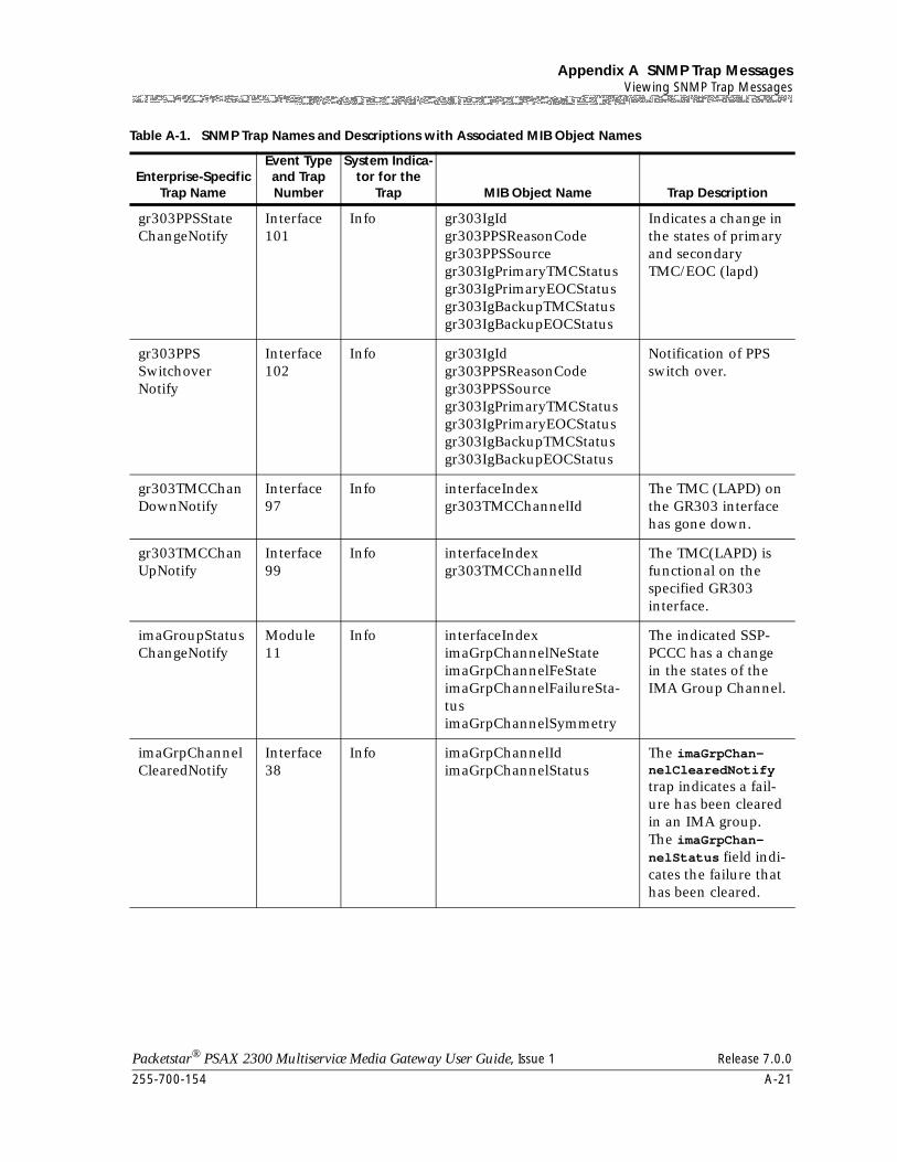
255-700-154 A-21
Packetstar® PSAX 2300 Multiservice Media Gateway User Guide, Issue 1 Release 7.0.0
Appendix A SNMP Trap MessagesViewing SNMP Trap Messages
gr303PPSStateChangeNotify
Interface101
Info gr303IgIdgr303PPSReasonCodegr303PPSSourcegr303IgPrimaryTMCStatusgr303IgPrimaryEOCStatusgr303IgBackupTMCStatusgr303IgBackupEOCStatus
Indicates a change in the states of primary and secondary TMC/EOC (lapd)
gr303PPSSwitchoverNotify
Interface102
Info gr303IgIdgr303PPSReasonCodegr303PPSSourcegr303IgPrimaryTMCStatusgr303IgPrimaryEOCStatusgr303IgBackupTMCStatusgr303IgBackupEOCStatus
Notification of PPS switch over.
gr303TMCChanDownNotify
Interface97
Info interfaceIndexgr303TMCChannelId
The TMC (LAPD) on the GR303 interface has gone down.
gr303TMCChanUpNotify
Interface99
Info interfaceIndexgr303TMCChannelId
The TMC(LAPD) is functional on the specified GR303 interface.
imaGroupStatusChangeNotify
Module11
Info interfaceIndeximaGrpChannelNeStateimaGrpChannelFeStateimaGrpChannelFailureSta-tusimaGrpChannelSymmetry
The indicated SSP-PCCC has a change in the states of the IMA Group Channel.
imaGrpChannelClearedNotify
Interface38
Info imaGrpChannelIdimaGrpChannelStatus
The imaGrpChan-nelClearedNotify trap indicates a fail-ure has been cleared in an IMA group. The imaGrpChan-nelStatus field indi-cates the failure that has been cleared.
Table A-1. SNMP Trap Names and Descriptions with Associated MIB Object Names
Enterprise-Specific Trap Name
Event Type and Trap Number
System Indica-tor for the
Trap MIB Object Name Trap Description
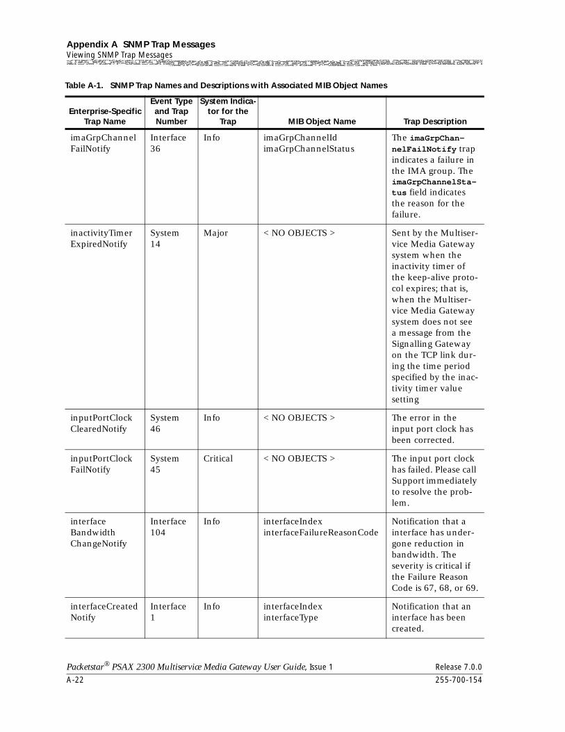
Appendix A SNMP Trap MessagesViewing SNMP Trap Messages
A-22 255-700-154
Packetstar® PSAX 2300 Multiservice Media Gateway User Guide, Issue 1 Release 7.0.0
imaGrpChannelFailNotify
Interface36
Info imaGrpChannelIdimaGrpChannelStatus
The imaGrpChan-nelFailNotify trap indicates a failure in the IMA group. The imaGrpChannelSta-tus field indicates the reason for the failure.
inactivityTimerExpiredNotify
System14
Major < NO OBJECTS > Sent by the Multiser-vice Media Gateway system when the inactivity timer of the keep-alive proto-col expires; that is, when the Multiser-vice Media Gateway system does not see a message from the Signalling Gateway on the TCP link dur-ing the time period specified by the inac-tivity timer value setting
inputPortClockClearedNotify
System46
Info < NO OBJECTS > The error in the input port clock has been corrected.
inputPortClockFailNotify
System45
Critical < NO OBJECTS > The input port clock has failed. Please call Support immediately to resolve the prob-lem.
interfaceBandwidthChangeNotify
Interface104
Info interfaceIndexinterfaceFailureReasonCode
Notification that a interface has under-gone reduction in bandwidth. The severity is critical if the Failure Reason Code is 67, 68, or 69.
interfaceCreatedNotify
Interface1
Info interfaceIndexinterfaceType
Notification that an interface has been created.
Table A-1. SNMP Trap Names and Descriptions with Associated MIB Object Names
Enterprise-Specific Trap Name
Event Type and Trap Number
System Indica-tor for the
Trap MIB Object Name Trap Description
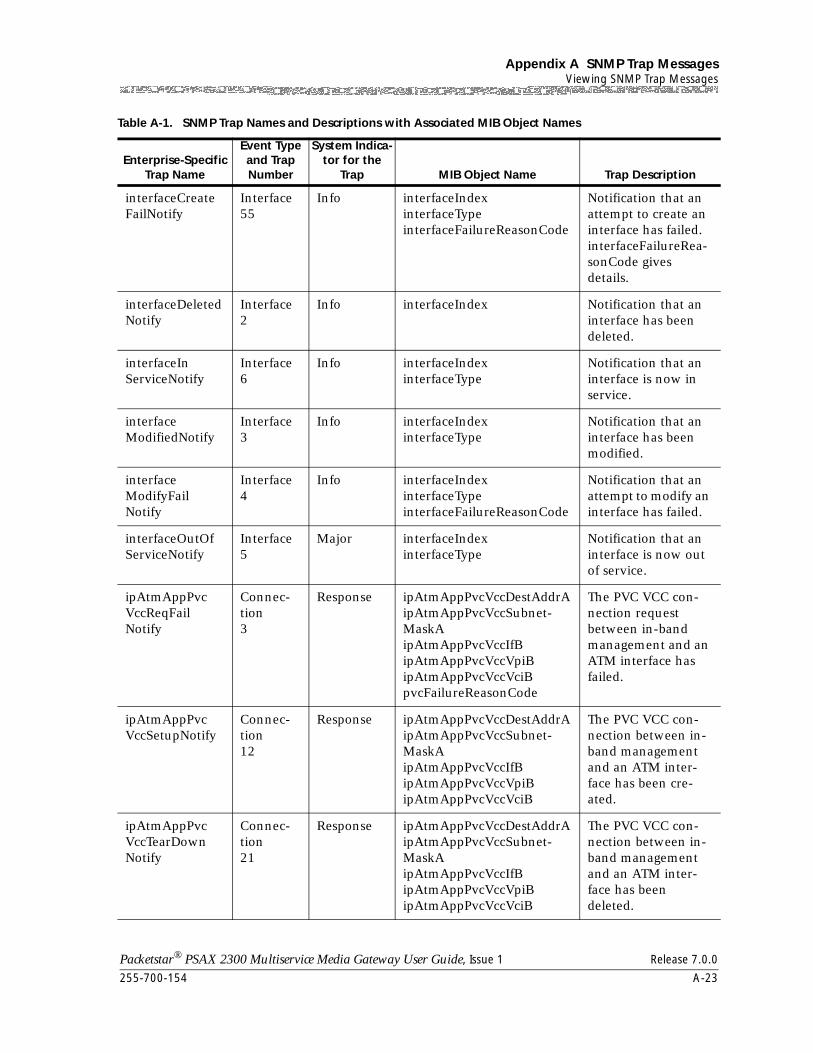
255-700-154 A-23
Packetstar® PSAX 2300 Multiservice Media Gateway User Guide, Issue 1 Release 7.0.0
Appendix A SNMP Trap MessagesViewing SNMP Trap Messages
interfaceCreateFailNotify
Interface55
Info interfaceIndexinterfaceTypeinterfaceFailureReasonCode
Notification that an attempt to create an interface has failed. interfaceFailureRea-sonCode gives details.
interfaceDeletedNotify
Interface2
Info interfaceIndex Notification that an interface has been deleted.
interfaceInServiceNotify
Interface6
Info interfaceIndexinterfaceType
Notification that an interface is now in service.
interfaceModifiedNotify
Interface3
Info interfaceIndexinterfaceType
Notification that an interface has been modified.
interfaceModifyFailNotify
Interface4
Info interfaceIndexinterfaceTypeinterfaceFailureReasonCode
Notification that an attempt to modify an interface has failed.
interfaceOutOfServiceNotify
Interface5
Major interfaceIndexinterfaceType
Notification that an interface is now out of service.
ipAtmAppPvcVccReqFailNotify
Connec-tion3
Response ipAtmAppPvcVccDestAddrAipAtmAppPvcVccSubnet-MaskAipAtmAppPvcVccIfBipAtmAppPvcVccVpiBipAtmAppPvcVccVciBpvcFailureReasonCode
The PVC VCC con-nection request between in-band management and an ATM interface has failed.
ipAtmAppPvcVccSetupNotify
Connec-tion12
Response ipAtmAppPvcVccDestAddrAipAtmAppPvcVccSubnet-MaskAipAtmAppPvcVccIfBipAtmAppPvcVccVpiBipAtmAppPvcVccVciB
The PVC VCC con-nection between in-band management and an ATM inter-face has been cre-ated.
ipAtmAppPvcVccTearDownNotify
Connec-tion21
Response ipAtmAppPvcVccDestAddrAipAtmAppPvcVccSubnet-MaskAipAtmAppPvcVccIfBipAtmAppPvcVccVpiBipAtmAppPvcVccVciB
The PVC VCC con-nection between in-band management and an ATM inter-face has been deleted.
Table A-1. SNMP Trap Names and Descriptions with Associated MIB Object Names
Enterprise-Specific Trap Name
Event Type and Trap Number
System Indica-tor for the
Trap MIB Object Name Trap Description
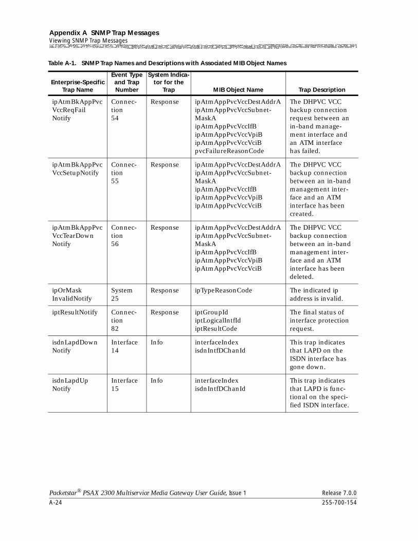
Appendix A SNMP Trap MessagesViewing SNMP Trap Messages
A-24 255-700-154
Packetstar® PSAX 2300 Multiservice Media Gateway User Guide, Issue 1 Release 7.0.0
ipAtmBkAppPvcVccReqFailNotify
Connec-tion54
Response ipAtmAppPvcVccDestAddrAipAtmAppPvcVccSubnet-MaskAipAtmAppPvcVccIfBipAtmAppPvcVccVpiBipAtmAppPvcVccVciBpvcFailureReasonCode
The DHPVC VCC backup connection request between an in-band manage-ment interface and an ATM interface has failed.
ipAtmBkAppPvcVccSetupNotify
Connec-tion55
Response ipAtmAppPvcVccDestAddrAipAtmAppPvcVccSubnet-MaskAipAtmAppPvcVccIfBipAtmAppPvcVccVpiBipAtmAppPvcVccVciB
The DHPVC VCC backup connection between an in-band management inter-face and an ATM interface has been created.
ipAtmBkAppPvcVccTearDownNotify
Connec-tion56
Response ipAtmAppPvcVccDestAddrAipAtmAppPvcVccSubnet-MaskAipAtmAppPvcVccIfBipAtmAppPvcVccVpiBipAtmAppPvcVccVciB
The DHPVC VCC backup connection between an in-band management inter-face and an ATM interface has been deleted.
ipOrMaskInvalidNotify
System25
Response ipTypeReasonCode The indicated ip address is invalid.
iptResultNotify Connec-tion82
Response iptGroupIdiptLogicalIntfIdiptResultCode
The final status of interface protection request.
isdnLapdDownNotify
Interface14
Info interfaceIndexisdnIntfDChanId
This trap indicates that LAPD on the ISDN interface has gone down.
isdnLapdUpNotify
Interface15
Info interfaceIndexisdnIntfDChanId
This trap indicates that LAPD is func-tional on the speci-fied ISDN interface.
Table A-1. SNMP Trap Names and Descriptions with Associated MIB Object Names
Enterprise-Specific Trap Name
Event Type and Trap Number
System Indica-tor for the
Trap MIB Object Name Trap Description
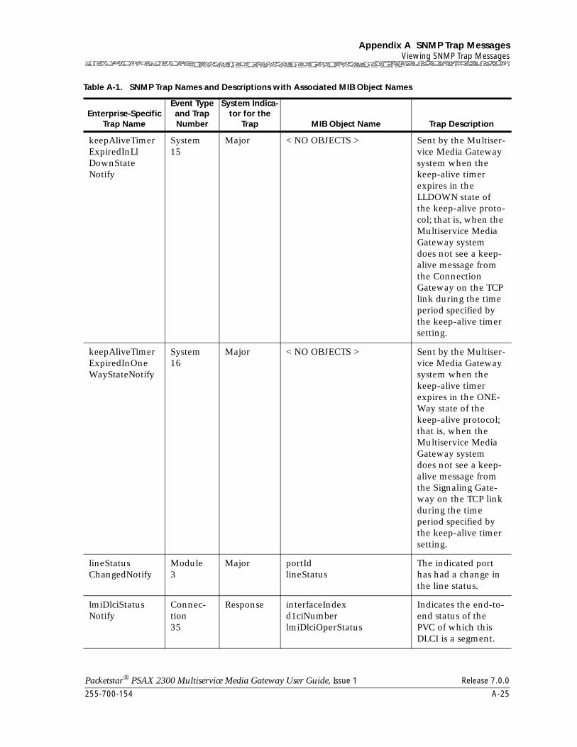
255-700-154 A-25
Packetstar® PSAX 2300 Multiservice Media Gateway User Guide, Issue 1 Release 7.0.0
Appendix A SNMP Trap MessagesViewing SNMP Trap Messages
keepAliveTimerExpiredInLlDownStateNotify
System15
Major < NO OBJECTS > Sent by the Multiser-vice Media Gateway system when the keep-alive timer expires in the LLDOWN state of the keep-alive proto-col; that is, when the Multiservice Media Gateway system does not see a keep-alive message from the Connection Gateway on the TCP link during the time period specified by the keep-alive timer setting.
keepAliveTimerExpiredInOneWayStateNotify
System16
Major < NO OBJECTS > Sent by the Multiser-vice Media Gateway system when the keep-alive timer expires in the ONE-Way state of the keep-alive protocol; that is, when the Multiservice Media Gateway system does not see a keep-alive message from the Signaling Gate-way on the TCP link during the time period specified by the keep-alive timer setting.
lineStatusChangedNotify
Module3
Major portIdlineStatus
The indicated port has had a change in the line status.
lmiDlciStatusNotify
Connec-tion35
Response interfaceIndexd1ciNumberlmiDlciOperStatus
Indicates the end-to-end status of the PVC of which this DLCI is a segment.
Table A-1. SNMP Trap Names and Descriptions with Associated MIB Object Names
Enterprise-Specific Trap Name
Event Type and Trap Number
System Indica-tor for the
Trap MIB Object Name Trap Description
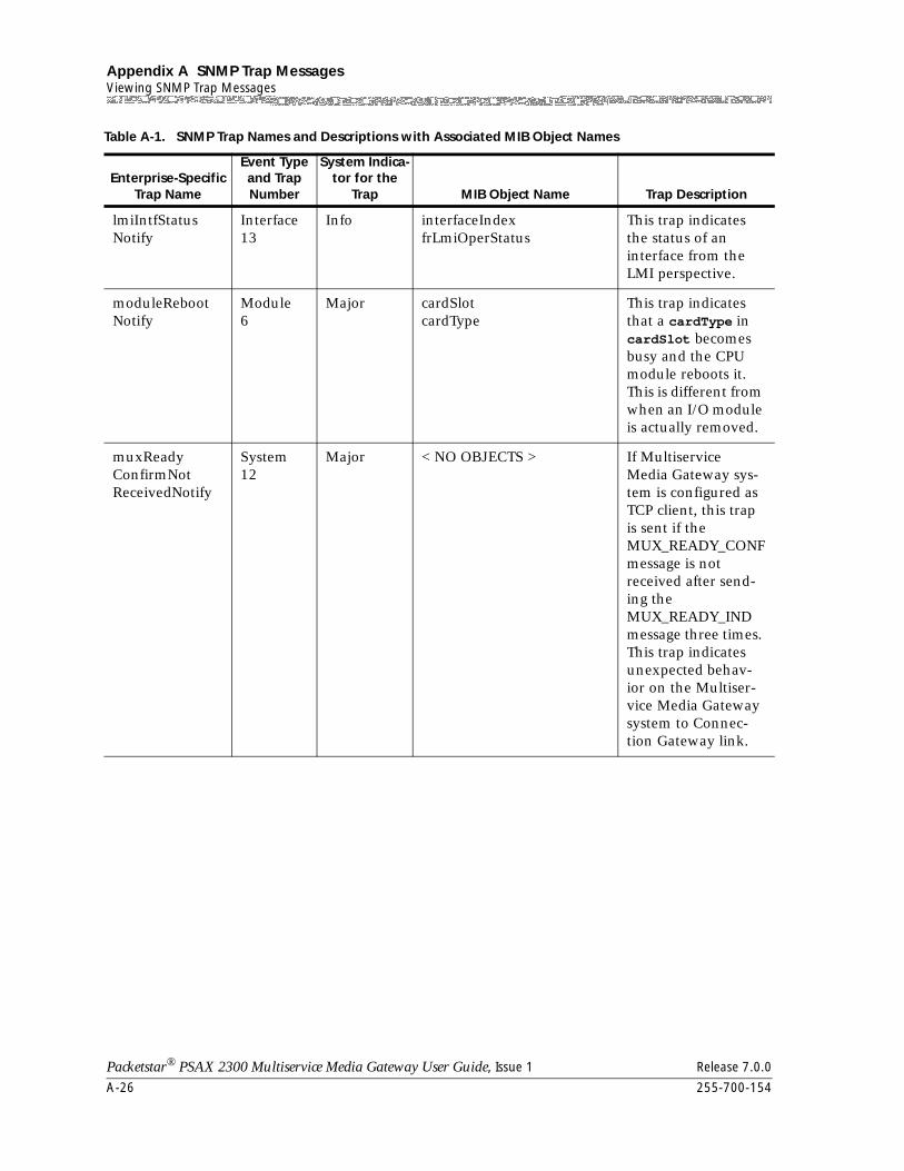
Appendix A SNMP Trap MessagesViewing SNMP Trap Messages
A-26 255-700-154
Packetstar® PSAX 2300 Multiservice Media Gateway User Guide, Issue 1 Release 7.0.0
lmiIntfStatusNotify
Interface13
Info interfaceIndexfrLmiOperStatus
This trap indicates the status of an interface from the LMI perspective.
moduleRebootNotify
Module6
Major cardSlotcardType
This trap indicates that a cardType in cardSlot becomes busy and the CPU module reboots it. This is different from when an I/O module is actually removed.
muxReadyConfirmNotReceivedNotify
System12
Major < NO OBJECTS > If Multiservice Media Gateway sys-tem is configured as TCP client, this trap is sent if the MUX_READY_CONF message is not received after send-ing the MUX_READY_IND message three times. This trap indicates unexpected behav-ior on the Multiser-vice Media Gateway system to Connec-tion Gateway link.
Table A-1. SNMP Trap Names and Descriptions with Associated MIB Object Names
Enterprise-Specific Trap Name
Event Type and Trap Number
System Indica-tor for the
Trap MIB Object Name Trap Description
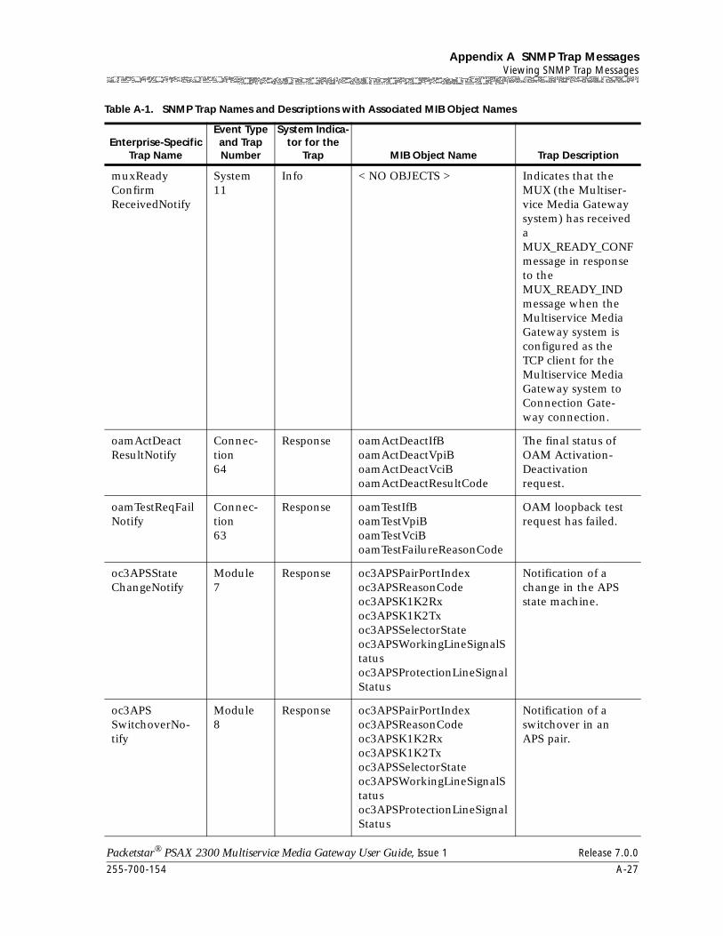
255-700-154 A-27
Packetstar® PSAX 2300 Multiservice Media Gateway User Guide, Issue 1 Release 7.0.0
Appendix A SNMP Trap MessagesViewing SNMP Trap Messages
muxReadyConfirmReceivedNotify
System11
Info < NO OBJECTS > Indicates that the MUX (the Multiser-vice Media Gateway system) has received a MUX_READY_CONF message in response to the MUX_READY_IND message when the Multiservice Media Gateway system is configured as the TCP client for the Multiservice Media Gateway system to Connection Gate-way connection.
oamActDeactResultNotify
Connec-tion64
Response oamActDeactIfBoamActDeactVpiBoamActDeactVciBoamActDeactResultCode
The final status of OAM Activation-Deactivation request.
oamTestReqFailNotify
Connec-tion63
Response oamTestIfBoamTestVpiBoamTestVciBoamTestFailureReasonCode
OAM loopback test request has failed.
oc3APSStateChangeNotify
Module7
Response oc3APSPairPortIndexoc3APSReasonCodeoc3APSK1K2Rxoc3APSK1K2Txoc3APSSelectorStateoc3APSWorkingLineSignalStatusoc3APSProtectionLineSignalStatus
Notification of a change in the APS state machine.
oc3APSSwitchoverNo-tify
Module8
Response oc3APSPairPortIndexoc3APSReasonCodeoc3APSK1K2Rxoc3APSK1K2Txoc3APSSelectorStateoc3APSWorkingLineSignalStatusoc3APSProtectionLineSignalStatus
Notification of a switchover in an APS pair.
Table A-1. SNMP Trap Names and Descriptions with Associated MIB Object Names
Enterprise-Specific Trap Name
Event Type and Trap Number
System Indica-tor for the
Trap MIB Object Name Trap Description
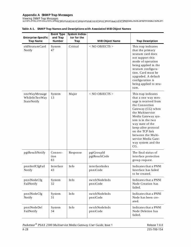
Appendix A SNMP Trap MessagesViewing SNMP Trap Messages
A-28 255-700-154
Packetstar® PSAX 2300 Multiservice Media Gateway User Guide, Issue 1 Release 7.0.0
oldStratumCardNotify
System47
Critical < NO OBJECTS > This trap indicates that the primary stratum card does not support this mode of operation being applied in the stratum configura-tion. Card must be upgraded. A default configuration is being applied to stra-tum.
oneWayMessageWhileInTwoWayStateNotify
System13
Major < NO OBJECTS > This trap indicates that a one way mes-sage is received from the Connection Gateway (CG) when the Multiservice Media Gateway sys-tem is in the two way state of the keep-alive protocol on the TCP link between the Multi-service Media Gate-way system and the CG.
pgtResultNotify Connec-tion83
Response pgtGroupIdpgtResultCode
The final status of interface protection group request.
pnniIntfCfgFailNotify
Interface43
Info interfaceIndexpnniCode
Indicates that a PNNI Interface has failed to be created.
pnniNodeCfgFailNotify
System32
Info swtchNodeIndxpnniCode
Indicates that a PNNI Node Creation has failed.
pnniNodeCfgNotify
System31
Info swtchNodeIndxpnniCode
Indicates that a PNNI Node has been cre-ated.
pnniNodeDelFailNotify
System34
Info swtchNodeIndxpnniCode
Indicates that a PNNI Node Deletion has failed.
Table A-1. SNMP Trap Names and Descriptions with Associated MIB Object Names
Enterprise-Specific Trap Name
Event Type and Trap Number
System Indica-tor for the
Trap MIB Object Name Trap Description
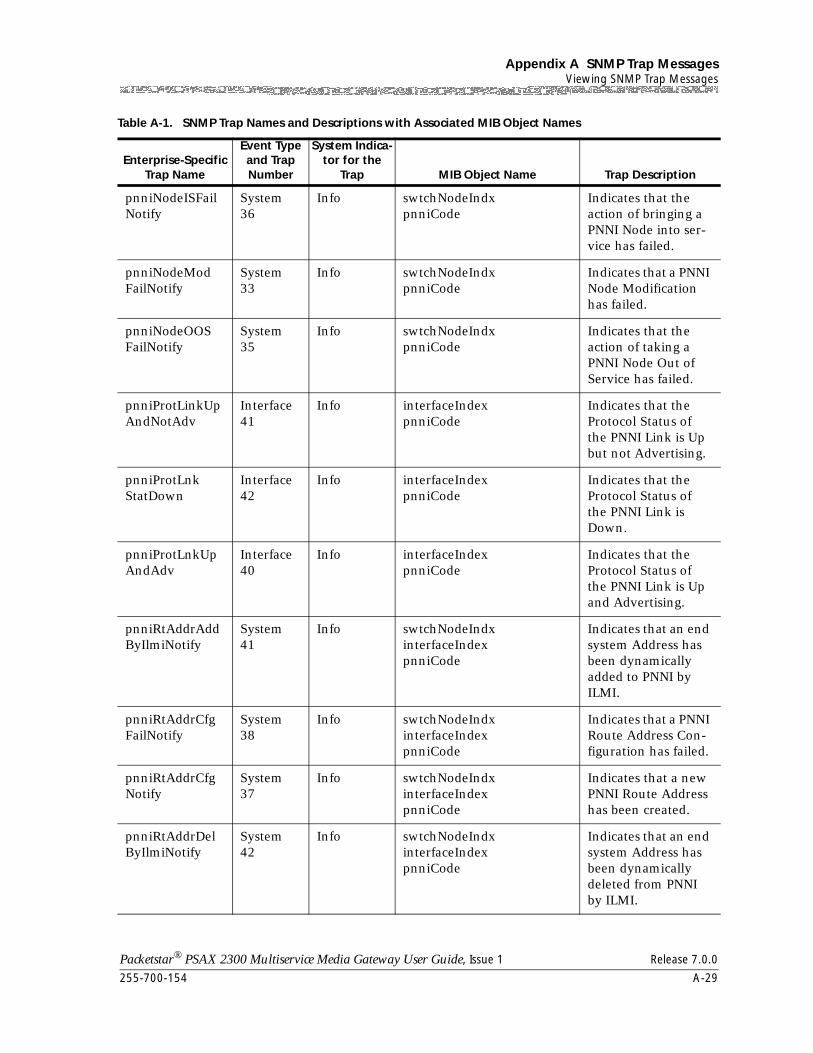
255-700-154 A-29
Packetstar® PSAX 2300 Multiservice Media Gateway User Guide, Issue 1 Release 7.0.0
Appendix A SNMP Trap MessagesViewing SNMP Trap Messages
pnniNodeISFailNotify
System36
Info swtchNodeIndxpnniCode
Indicates that the action of bringing a PNNI Node into ser-vice has failed.
pnniNodeModFailNotify
System33
Info swtchNodeIndxpnniCode
Indicates that a PNNI Node Modification has failed.
pnniNodeOOSFailNotify
System35
Info swtchNodeIndxpnniCode
Indicates that the action of taking a PNNI Node Out of Service has failed.
pnniProtLinkUpAndNotAdv
Interface41
Info interfaceIndexpnniCode
Indicates that the Protocol Status of the PNNI Link is Up but not Advertising.
pnniProtLnkStatDown
Interface42
Info interfaceIndexpnniCode
Indicates that the Protocol Status of the PNNI Link is Down.
pnniProtLnkUpAndAdv
Interface40
Info interfaceIndexpnniCode
Indicates that the Protocol Status of the PNNI Link is Up and Advertising.
pnniRtAddrAddByIlmiNotify
System41
Info swtchNodeIndxinterfaceIndexpnniCode
Indicates that an end system Address has been dynamically added to PNNI by ILMI.
pnniRtAddrCfgFailNotify
System38
Info swtchNodeIndxinterfaceIndexpnniCode
Indicates that a PNNI Route Address Con-figuration has failed.
pnniRtAddrCfgNotify
System37
Info swtchNodeIndxinterfaceIndexpnniCode
Indicates that a new PNNI Route Address has been created.
pnniRtAddrDelByIlmiNotify
System42
Info swtchNodeIndxinterfaceIndexpnniCode
Indicates that an end system Address has been dynamically deleted from PNNI by ILMI.
Table A-1. SNMP Trap Names and Descriptions with Associated MIB Object Names
Enterprise-Specific Trap Name
Event Type and Trap Number
System Indica-tor for the
Trap MIB Object Name Trap Description
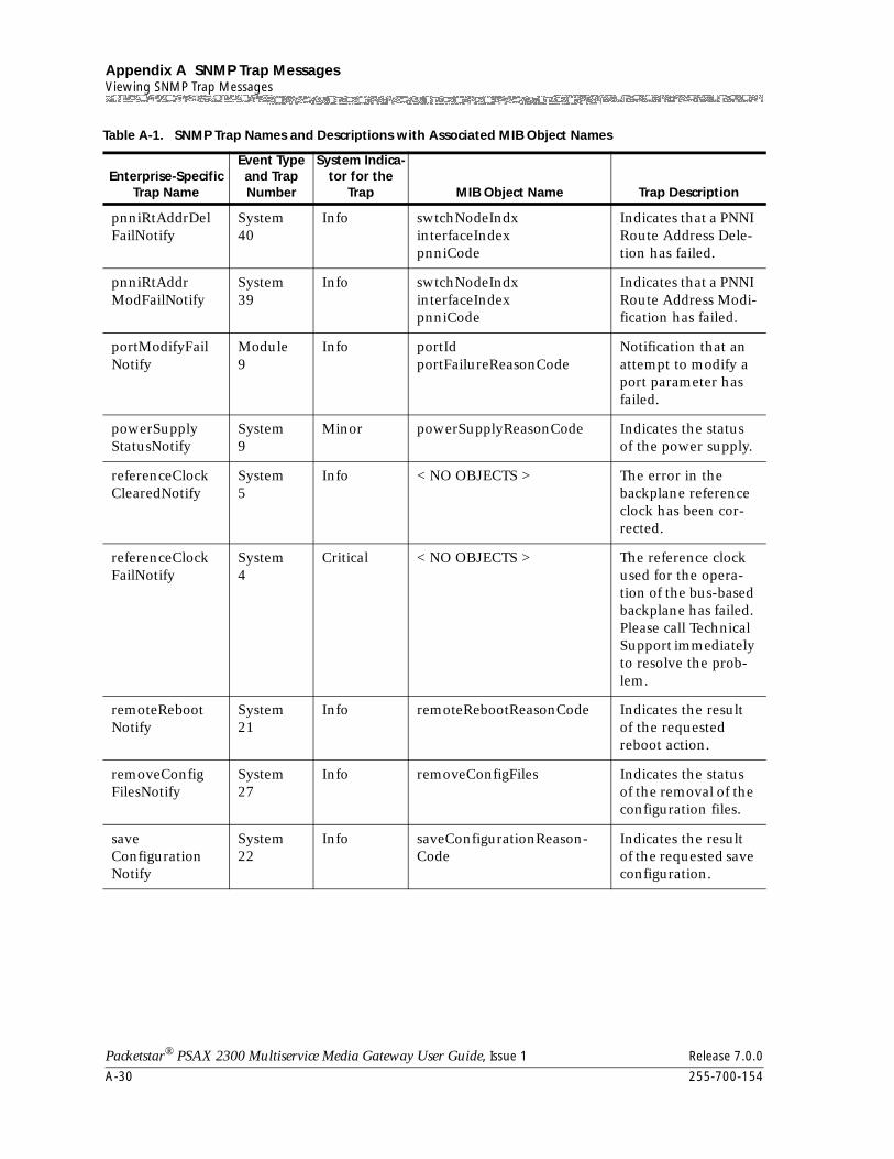
Appendix A SNMP Trap MessagesViewing SNMP Trap Messages
A-30 255-700-154
Packetstar® PSAX 2300 Multiservice Media Gateway User Guide, Issue 1 Release 7.0.0
pnniRtAddrDelFailNotify
System40
Info swtchNodeIndxinterfaceIndexpnniCode
Indicates that a PNNI Route Address Dele-tion has failed.
pnniRtAddrModFailNotify
System39
Info swtchNodeIndxinterfaceIndexpnniCode
Indicates that a PNNI Route Address Modi-fication has failed.
portModifyFailNotify
Module9
Info portIdportFailureReasonCode
Notification that an attempt to modify a port parameter has failed.
powerSupplyStatusNotify
System9
Minor powerSupplyReasonCode Indicates the status of the power supply.
referenceClockClearedNotify
System5
Info < NO OBJECTS > The error in the backplane reference clock has been cor-rected.
referenceClockFailNotify
System4
Critical < NO OBJECTS > The reference clock used for the opera-tion of the bus-based backplane has failed. Please call Technical Support immediately to resolve the prob-lem.
remoteRebootNotify
System21
Info remoteRebootReasonCode Indicates the result of the requested reboot action.
removeConfigFilesNotify
System27
Info removeConfigFiles Indicates the status of the removal of the configuration files.
saveConfigurationNotify
System22
Info saveConfigurationReason-Code
Indicates the result of the requested save configuration.
Table A-1. SNMP Trap Names and Descriptions with Associated MIB Object Names
Enterprise-Specific Trap Name
Event Type and Trap Number
System Indica-tor for the
Trap MIB Object Name Trap Description
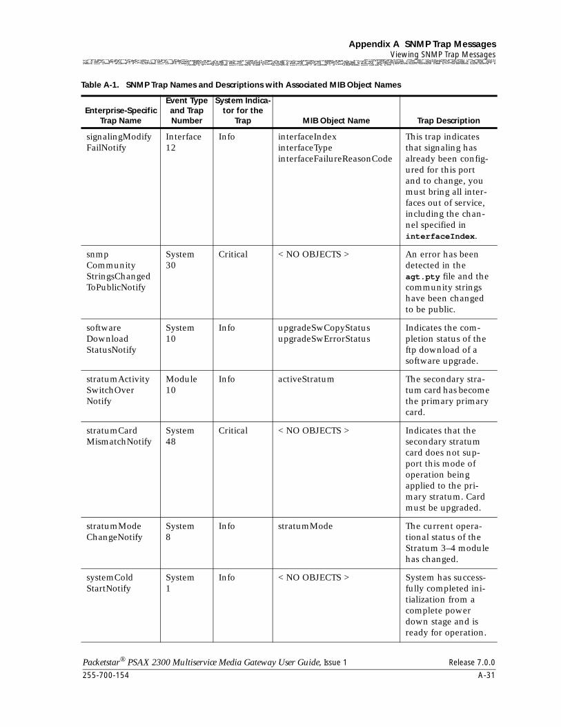
255-700-154 A-31
Packetstar® PSAX 2300 Multiservice Media Gateway User Guide, Issue 1 Release 7.0.0
Appendix A SNMP Trap MessagesViewing SNMP Trap Messages
signalingModifyFailNotify
Interface12
Info interfaceIndexinterfaceTypeinterfaceFailureReasonCode
This trap indicates that signaling has already been config-ured for this port and to change, you must bring all inter-faces out of service, including the chan-nel specified in interfaceIndex.
snmpCommunityStringsChangedToPublicNotify
System30
Critical < NO OBJECTS > An error has been detected in the agt.pty file and the community strings have been changed to be public.
softwareDownloadStatusNotify
System10
Info upgradeSwCopyStatusupgradeSwErrorStatus
Indicates the com-pletion status of the ftp download of a software upgrade.
stratumActivitySwitchOverNotify
Module10
Info activeStratum The secondary stra-tum card has become the primary primary card.
stratumCardMismatchNotify
System48
Critical < NO OBJECTS > Indicates that the secondary stratum card does not sup-port this mode of operation being applied to the pri-mary stratum. Card must be upgraded.
stratumModeChangeNotify
System8
Info stratumMode The current opera-tional status of the Stratum 3–4 module has changed.
systemColdStartNotify
System1
Info < NO OBJECTS > System has success-fully completed ini-tialization from a complete power down stage and is ready for operation.
Table A-1. SNMP Trap Names and Descriptions with Associated MIB Object Names
Enterprise-Specific Trap Name
Event Type and Trap Number
System Indica-tor for the
Trap MIB Object Name Trap Description
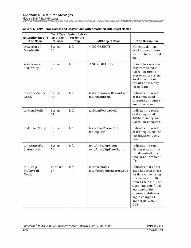
Appendix A SNMP Trap MessagesViewing SNMP Trap Messages
A-32 255-700-154
Packetstar® PSAX 2300 Multiservice Media Gateway User Guide, Issue 1 Release 7.0.0
systemInsuffMemNotify
System53
Info < NO OBJECTS > Not enough mem-ory for one or more features to be turned on.
systemWarmStartNotify
System2
Info < NO OBJECTS > System has success-fully completed ini-tialization from a user or other system level interrupt or restart and is ready for operation.
tasCmprsAnnceNotify
System49
Info tasCmprsAnnceReasonCodetasTrapAnnceId
Indicates the result of the requested compress announce-ment operation.
tasMemNotify System51
Info tasMemReasonCode Indicates the result of the requested TASM memory ini-tialization operation.
tasTstLineNotify System50
Info tasTstLineReasonCodetasTrapTstId
Indicates the result of the requested line test initiation opera-tion.
toneAnnceFtpStatusNotify
System54
Info toneAnnceFtpStatustoneAnnceFtpErrorStatus
Indicates the com-pletion status of the FTP download of a tone announcement file.
ts16UsageModifyFailNotify
Interface17
Info interfaceIndexinterfaceFailureReasonCode
Indicates that either TS16 has been in use for data while trying to change e1 TS16 from CCS to CAS, or signalling is on for at least one of the channels while try-ing to change e1 TS16 from CAS to CCS.
Table A-1. SNMP Trap Names and Descriptions with Associated MIB Object Names
Enterprise-Specific Trap Name
Event Type and Trap Number
System Indica-tor for the
Trap MIB Object Name Trap Description
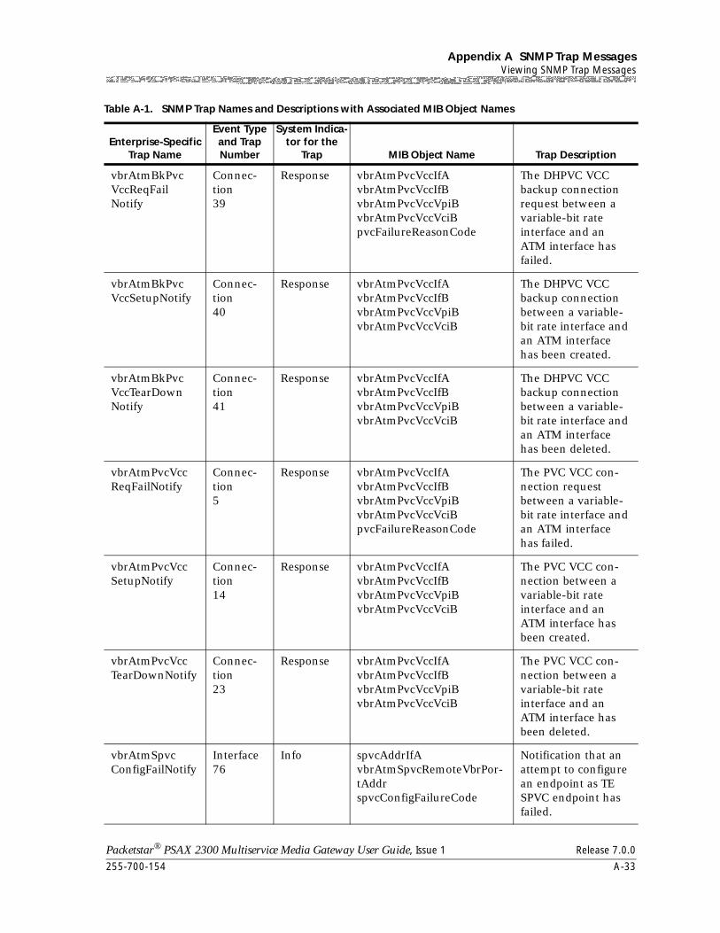
255-700-154 A-33
Packetstar® PSAX 2300 Multiservice Media Gateway User Guide, Issue 1 Release 7.0.0
Appendix A SNMP Trap MessagesViewing SNMP Trap Messages
vbrAtmBkPvcVccReqFailNotify
Connec-tion39
Response vbrAtmPvcVccIfAvbrAtmPvcVccIfBvbrAtmPvcVccVpiBvbrAtmPvcVccVciBpvcFailureReasonCode
The DHPVC VCC backup connection request between a variable-bit rate interface and an ATM interface has failed.
vbrAtmBkPvcVccSetupNotify
Connec-tion40
Response vbrAtmPvcVccIfAvbrAtmPvcVccIfBvbrAtmPvcVccVpiBvbrAtmPvcVccVciB
The DHPVC VCC backup connection between a variable-bit rate interface and an ATM interface has been created.
vbrAtmBkPvcVccTearDownNotify
Connec-tion41
Response vbrAtmPvcVccIfAvbrAtmPvcVccIfBvbrAtmPvcVccVpiBvbrAtmPvcVccVciB
The DHPVC VCC backup connection between a variable-bit rate interface and an ATM interface has been deleted.
vbrAtmPvcVccReqFailNotify
Connec-tion5
Response vbrAtmPvcVccIfAvbrAtmPvcVccIfBvbrAtmPvcVccVpiBvbrAtmPvcVccVciBpvcFailureReasonCode
The PVC VCC con-nection request between a variable-bit rate interface and an ATM interface has failed.
vbrAtmPvcVccSetupNotify
Connec-tion14
Response vbrAtmPvcVccIfAvbrAtmPvcVccIfBvbrAtmPvcVccVpiBvbrAtmPvcVccVciB
The PVC VCC con-nection between a variable-bit rate interface and an ATM interface has been created.
vbrAtmPvcVccTearDownNotify
Connec-tion23
Response vbrAtmPvcVccIfAvbrAtmPvcVccIfBvbrAtmPvcVccVpiBvbrAtmPvcVccVciB
The PVC VCC con-nection between a variable-bit rate interface and an ATM interface has been deleted.
vbrAtmSpvcConfigFailNotify
Interface76
Info spvcAddrIfAvbrAtmSpvcRemoteVbrPor-tAddrspvcConfigFailureCode
Notification that an attempt to configure an endpoint as TE SPVC endpoint has failed.
Table A-1. SNMP Trap Names and Descriptions with Associated MIB Object Names
Enterprise-Specific Trap Name
Event Type and Trap Number
System Indica-tor for the
Trap MIB Object Name Trap Description
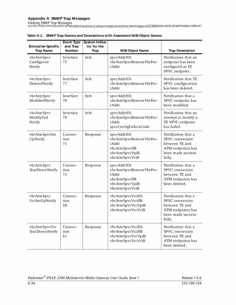
Appendix A SNMP Trap MessagesViewing SNMP Trap Messages
A-34 255-700-154
Packetstar® PSAX 2300 Multiservice Media Gateway User Guide, Issue 1 Release 7.0.0
vbrAtmSpvcConfiguredNotify
Interface75
Info spvcAddrIfAvbrAtmSpvcRemoteVbrPor-tAddr
Notification that an endpoint has been configured as TE SPVC endpoint.
vbrAtmSpvcDeletedNotify
Interface77
Info spvcAddrIfAvbrAtmSpvcRemoteVbrPor-tAddr
Notification that TE SPVC configuration has been deleted.
vbrAtmSpvcModifiedNotify
Interface78
Info spvcAddrIfAvbrAtmSpvcRemoteVbrPor-tAddr
Notification that a SPVC endpoint has been modified.
vbrAtmSpvcModifyFailNotify
Interface79
Info spvcAddrIfAvbrAtmSpvcRemoteVbrPor-tAddrspvcConfigFailureCode
Notification that an attempt to modify a TE SPVC endpoint has failed.
vbrAtmSpvcSetUpNotify
Connec-tion71
Response spvcAddrIfAvbrAtmSpvcRemoteVbrPor-tAddrvbrAtmSpvcIfBvbrAtmSpvcVpiBvbrAtmSpvcVciB
Notification that a SPVC connection between TE and ATM endpoints has been made success-fully.
vbrAtmSpvcTearDownNotify
Connec-tion72
Response spvcAddrIfAvbrAtmSpvcRemoteVbrPor-tAddrvbrAtmSpvcIfBvbrAtmSpvcVpiBvbrAtmSpvcVciB
Notification that a SPVC connection between TE and ATM endpoints has been deleted.
vbrAtmSpvcVccSetUpNotify
Connec-tion58
Response vbrAtmSpvcVccIfAvbrAtmSpvcVccIfBvbrAtmSpvcVccVpiBvbrAtmSpvcVccVciB
Notification that a SPVC connection between TE and ATM endpoints has been made success-fully.
vbrAtmSpvcVccTearDownNotify
Connec-tion61
Response vbrAtmSpvcVccIfAvbrAtmSpvcVccIfBvbrAtmSpvcVccVpiBvbrAtmSpvcVccVciB
Notification that a SPVC connection between TE and ATM endpoints has been deleted.
Table A-1. SNMP Trap Names and Descriptions with Associated MIB Object Names
Enterprise-Specific Trap Name
Event Type and Trap Number
System Indica-tor for the
Trap MIB Object Name Trap Description
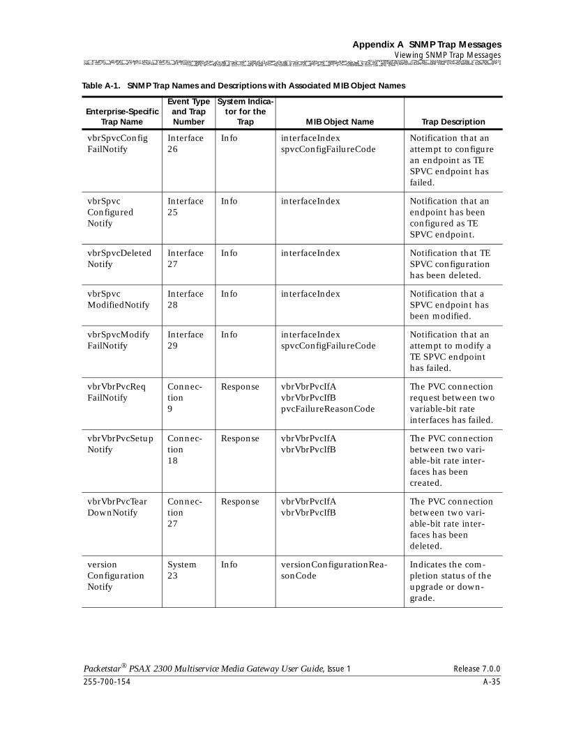
255-700-154 A-35
Packetstar® PSAX 2300 Multiservice Media Gateway User Guide, Issue 1 Release 7.0.0
Appendix A SNMP Trap MessagesViewing SNMP Trap Messages
vbrSpvcConfigFailNotify
Interface26
Info interfaceIndexspvcConfigFailureCode
Notification that an attempt to configure an endpoint as TE SPVC endpoint has failed.
vbrSpvcConfiguredNotify
Interface25
Info interfaceIndex Notification that an endpoint has been configured as TE SPVC endpoint.
vbrSpvcDeletedNotify
Interface27
Info interfaceIndex Notification that TE SPVC configuration has been deleted.
vbrSpvcModifiedNotify
Interface28
Info interfaceIndex Notification that a SPVC endpoint has been modified.
vbrSpvcModifyFailNotify
Interface29
Info interfaceIndexspvcConfigFailureCode
Notification that an attempt to modify a TE SPVC endpoint has failed.
vbrVbrPvcReqFailNotify
Connec-tion9
Response vbrVbrPvcIfAvbrVbrPvcIfBpvcFailureReasonCode
The PVC connection request between two variable-bit rate interfaces has failed.
vbrVbrPvcSetupNotify
Connec-tion18
Response vbrVbrPvcIfAvbrVbrPvcIfB
The PVC connection between two vari-able-bit rate inter-faces has been created.
vbrVbrPvcTearDownNotify
Connec-tion27
Response vbrVbrPvcIfAvbrVbrPvcIfB
The PVC connection between two vari-able-bit rate inter-faces has been deleted.
versionConfigurationNotify
System23
Info versionConfigurationRea-sonCode
Indicates the com-pletion status of the upgrade or down-grade.
Table A-1. SNMP Trap Names and Descriptions with Associated MIB Object Names
Enterprise-Specific Trap Name
Event Type and Trap Number
System Indica-tor for the
Trap MIB Object Name Trap Description
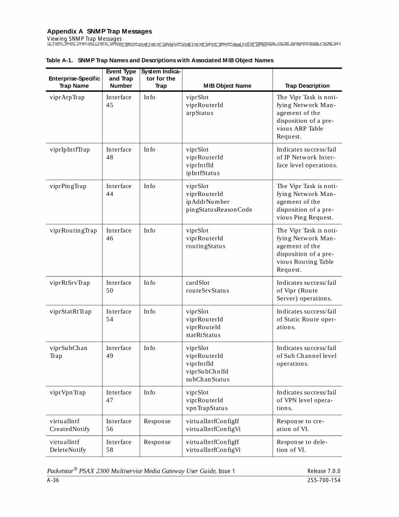
Appendix A SNMP Trap MessagesViewing SNMP Trap Messages
A-36 255-700-154
Packetstar® PSAX 2300 Multiservice Media Gateway User Guide, Issue 1 Release 7.0.0
viprArpTrap Interface45
Info viprSlotviprRouterIdarpStatus
The Vipr Task is noti-fying Network Man-agement of the disposition of a pre-vious ARP Table Request.
viprIpIntfTrap Interface48
Info viprSlotviprRouterIdviprIntfIdipIntfStatus
Indicates success/fail of IP Network Inter-face level operations.
viprPingTrap Interface44
Info viprSlotviprRouterIdipAddrNumberpingStatusReasonCode
The Vipr Task is noti-fying Network Man-agement of the disposition of a pre-vious Ping Request.
viprRoutingTrap Interface46
Info viprSlotviprRouterIdroutingStatus
The Vipr Task is noti-fying Network Man-agement of the disposition of a pre-vious Routing Table Request.
viprRtSrvTrap Interface50
Info cardSlotrouteSrvStatus
Indicates success/fail of Vipr (Route Server) operations.
viprStatRtTrap Interface54
Info viprSlotviprRouterIdviprRouteIdstatRtStatus
Indicates success/fail of Static Route oper-ations.
viprSubChanTrap
Interface49
Info viprSlotviprRouterIdviprIntfIdviprSubChnlIdsubChanStatus
Indicates success/fail of Sub Channel level operations.
viprVpnTrap Interface47
Info viprSlotviprRouterIdvpnTrapStatus
Indicates success/fail of VPN level opera-tions.
virtualIntfCreatedNotify
Interface56
Response virtualIntfConfigIfvirtualIntfConfigVi
Response to cre-ation of VI.
virtualIntfDeleteNotify
Interface58
Response virtualIntfConfigIfvirtualIntfConfigVi
Response to dele-tion of VI.
Table A-1. SNMP Trap Names and Descriptions with Associated MIB Object Names
Enterprise-Specific Trap Name
Event Type and Trap Number
System Indica-tor for the
Trap MIB Object Name Trap Description
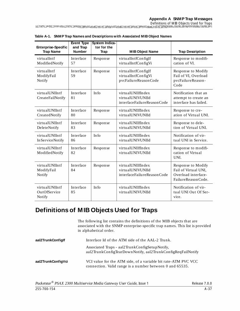
255-700-154 A-37
Packetstar® PSAX 2300 Multiservice Media Gateway User Guide, Issue 1 Release 7.0.0
Appendix A SNMP Trap MessagesDefinitions of MIB Objects Used for Traps
Definitions of MIB Objects Used for Traps
The following list contains the definitions of the MIB objects that are associated with the SNMP enterprise-specific trap names. This list is provided in alphabetical order.
aal2TrunkConfigIf Interface Id of the ATM side of the AAL-2 Trunk.
Associated Traps - aal2TrunkConfigSetupNotify, aal2TrunkConfigTearDownNotify, aal2TrunkConfigReqFailNotify
aal2TrunkConfigVci VCI value for the ATM side, of a variable bit rate-ATM PVC VCC connection. Valid range is a number between 0 and 65535.
virtualIntfModifiedNotify
Interface57
Response virtualIntfConfigIfvirtualIntfConfigVi
Response to modifi-cation of VI.
virtualIntfModifyFailNotify
Interface59
Response virtualIntfConfigIfvirtualIntfConfigVipvcFailureReasonCode
Response to Modify Fail of VI, Overload pvcFailureReason-Code
virtualUNIIntfCreateFailNotify
Interface81
Info virtualUNIIfIndexvirtualUNIVUNIIdinterfaceFailureReasonCode
Notification that an attempt to create an interface has failed.
virtualUNIIntfCreatedNotify
Interface80
Response virtualUNIIfIndexvirtualUNIVUNIId
Response to cre-ation of Virtual UNI.
virtualUNIIntfDeleteNotify
Interface83
Response virtualUNIIfIndexvirtualUNIVUNIId
Response to dele-tion of Virtual UNI.
virtualUNIIntfInServiceNotify
Interface86
Info virtualUNIIfIndexvirtualUNIVUNIId
Notification of vir-tual UNI in Service.
virtualUNIIntfModifiedNotify
Interface82
Response virtualUNIIfIndexvirtualUNIVUNIId
Response to modifi-cation of Virtual UNI.
virtualUNIIntfModifyFailNotify
Interface84
Response virtualUNIIfIndexvirtualUNIVUNIIdinterfaceFailureReasonCode
Response to Modify Fail of Virtual UNI, Overload interface-FailureReasonCode.
virtualUNIIntfOutOfServiceNotify
Interface85
Info virtualUNIIfIndexvirtualUNIVUNIId
Notification of vir-tual UNI Out Of Ser-vice.
Table A-1. SNMP Trap Names and Descriptions with Associated MIB Object Names
Enterprise-Specific Trap Name
Event Type and Trap Number
System Indica-tor for the
Trap MIB Object Name Trap Description
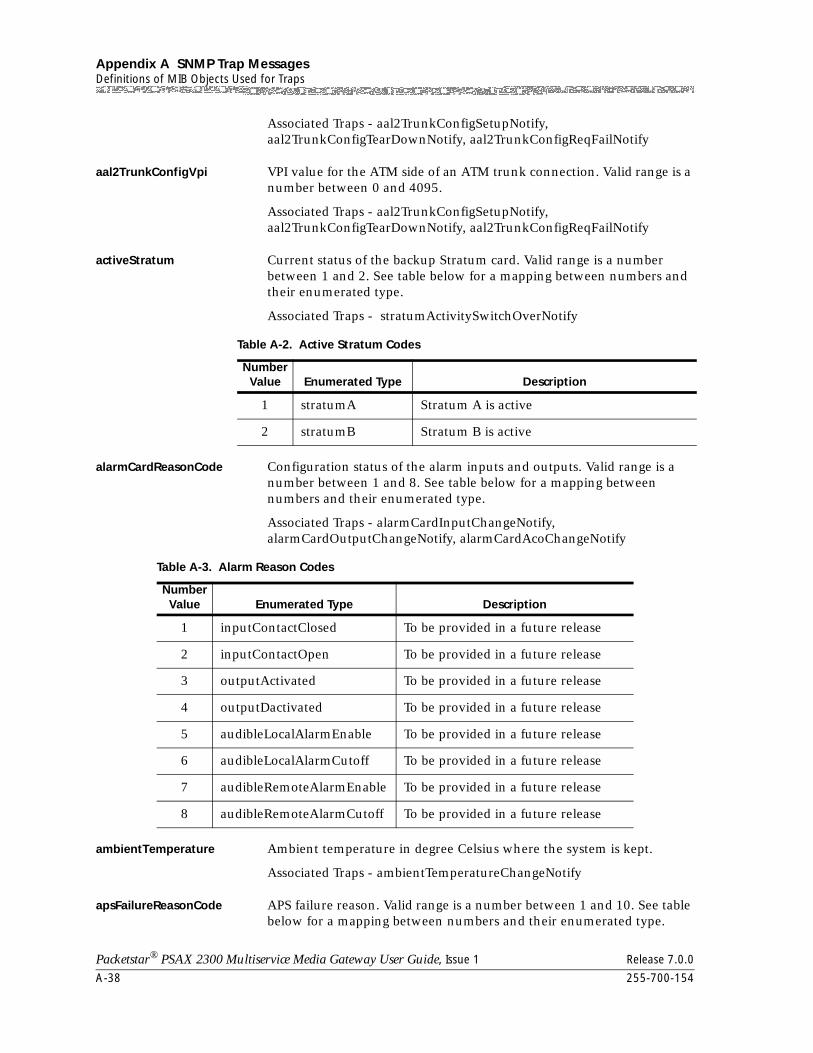
Appendix A SNMP Trap MessagesDefinitions of MIB Objects Used for Traps
A-38 255-700-154
Packetstar® PSAX 2300 Multiservice Media Gateway User Guide, Issue 1 Release 7.0.0
Associated Traps - aal2TrunkConfigSetupNotify, aal2TrunkConfigTearDownNotify, aal2TrunkConfigReqFailNotify
aal2TrunkConfigVpi VPI value for the ATM side of an ATM trunk connection. Valid range is a number between 0 and 4095.
Associated Traps - aal2TrunkConfigSetupNotify, aal2TrunkConfigTearDownNotify, aal2TrunkConfigReqFailNotify
activeStratum Current status of the backup Stratum card. Valid range is a number between 1 and 2. See table below for a mapping between numbers and their enumerated type.
Associated Traps - stratumActivitySwitchOverNotify
alarmCardReasonCode Configuration status of the alarm inputs and outputs. Valid range is a number between 1 and 8. See table below for a mapping between numbers and their enumerated type.
Associated Traps - alarmCardInputChangeNotify, alarmCardOutputChangeNotify, alarmCardAcoChangeNotify
ambientTemperature Ambient temperature in degree Celsius where the system is kept.
Associated Traps - ambientTemperatureChangeNotify
apsFailureReasonCode APS failure reason. Valid range is a number between 1 and 10. See table below for a mapping between numbers and their enumerated type.
Table A-2. Active Stratum Codes
Number Value Enumerated Type Description
1 stratumA Stratum A is active
2 stratumB Stratum B is active
Table A-3. Alarm Reason Codes
Number Value Enumerated Type Description
1 inputContactClosed To be provided in a future release
2 inputContactOpen To be provided in a future release
3 outputActivated To be provided in a future release
4 outputDactivated To be provided in a future release
5 audibleLocalAlarmEnable To be provided in a future release
6 audibleLocalAlarmCutoff To be provided in a future release
7 audibleRemoteAlarmEnable To be provided in a future release
8 audibleRemoteAlarmCutoff To be provided in a future release
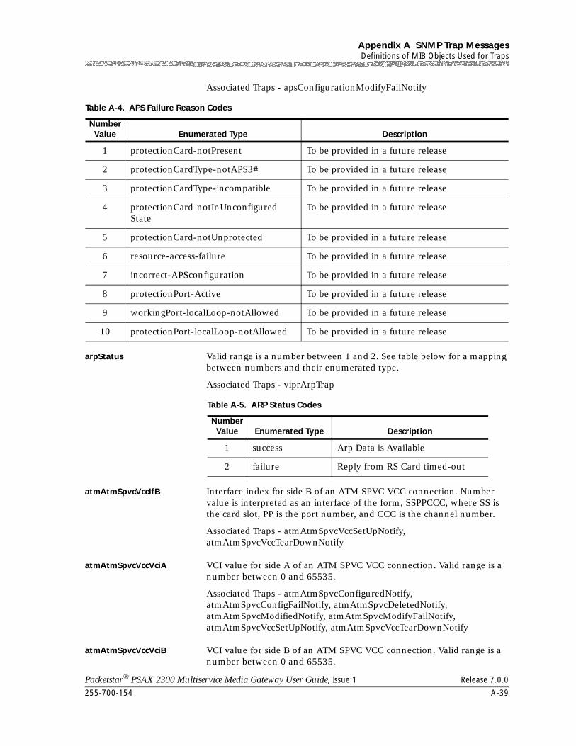
255-700-154 A-39
Packetstar® PSAX 2300 Multiservice Media Gateway User Guide, Issue 1 Release 7.0.0
Appendix A SNMP Trap MessagesDefinitions of MIB Objects Used for Traps
Associated Traps - apsConfigurationModifyFailNotify
arpStatus Valid range is a number between 1 and 2. See table below for a mapping between numbers and their enumerated type.
Associated Traps - viprArpTrap
atmAtmSpvcVccIfB Interface index for side B of an ATM SPVC VCC connection. Number value is interpreted as an interface of the form, SSPPCCC, where SS is the card slot, PP is the port number, and CCC is the channel number.
Associated Traps - atmAtmSpvcVccSetUpNotify, atmAtmSpvcVccTearDownNotify
atmAtmSpvcVccVciA VCI value for side A of an ATM SPVC VCC connection. Valid range is a number between 0 and 65535.
Associated Traps - atmAtmSpvcConfiguredNotify, atmAtmSpvcConfigFailNotify, atmAtmSpvcDeletedNotify, atmAtmSpvcModifiedNotify, atmAtmSpvcModifyFailNotify, atmAtmSpvcVccSetUpNotify, atmAtmSpvcVccTearDownNotify
atmAtmSpvcVccVciB VCI value for side B of an ATM SPVC VCC connection. Valid range is a number between 0 and 65535.
Table A-4. APS Failure Reason Codes
Number Value Enumerated Type Description
1 protectionCard-notPresent To be provided in a future release
2 protectionCardType-notAPS3# To be provided in a future release
3 protectionCardType-incompatible To be provided in a future release
4 protectionCard-notInUnconfiguredState
To be provided in a future release
5 protectionCard-notUnprotected To be provided in a future release
6 resource-access-failure To be provided in a future release
7 incorrect-APSconfiguration To be provided in a future release
8 protectionPort-Active To be provided in a future release
9 workingPort-localLoop-notAllowed To be provided in a future release
10 protectionPort-localLoop-notAllowed To be provided in a future release
Table A-5. ARP Status Codes
Number Value Enumerated Type Description
1 success Arp Data is Available
2 failure Reply from RS Card timed-out
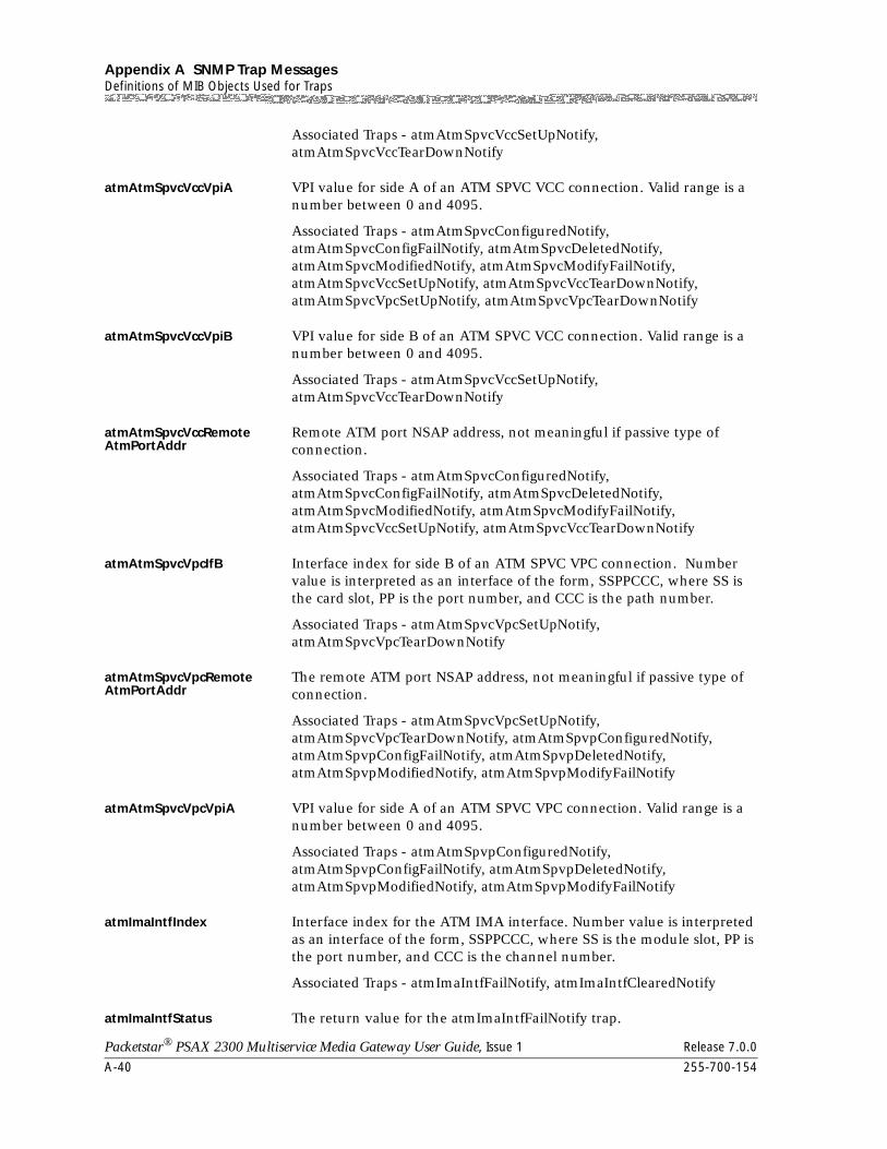
Appendix A SNMP Trap MessagesDefinitions of MIB Objects Used for Traps
A-40 255-700-154
Packetstar® PSAX 2300 Multiservice Media Gateway User Guide, Issue 1 Release 7.0.0
Associated Traps - atmAtmSpvcVccSetUpNotify, atmAtmSpvcVccTearDownNotify
atmAtmSpvcVccVpiA VPI value for side A of an ATM SPVC VCC connection. Valid range is a number between 0 and 4095.
Associated Traps - atmAtmSpvcConfiguredNotify, atmAtmSpvcConfigFailNotify, atmAtmSpvcDeletedNotify, atmAtmSpvcModifiedNotify, atmAtmSpvcModifyFailNotify, atmAtmSpvcVccSetUpNotify, atmAtmSpvcVccTearDownNotify, atmAtmSpvcVpcSetUpNotify, atmAtmSpvcVpcTearDownNotify
atmAtmSpvcVccVpiB VPI value for side B of an ATM SPVC VCC connection. Valid range is a number between 0 and 4095.
Associated Traps - atmAtmSpvcVccSetUpNotify, atmAtmSpvcVccTearDownNotify
atmAtmSpvcVccRemoteAtmPortAddr
Remote ATM port NSAP address, not meaningful if passive type of connection.
Associated Traps - atmAtmSpvcConfiguredNotify, atmAtmSpvcConfigFailNotify, atmAtmSpvcDeletedNotify, atmAtmSpvcModifiedNotify, atmAtmSpvcModifyFailNotify, atmAtmSpvcVccSetUpNotify, atmAtmSpvcVccTearDownNotify
atmAtmSpvcVpcIfB Interface index for side B of an ATM SPVC VPC connection. Number value is interpreted as an interface of the form, SSPPCCC, where SS is the card slot, PP is the port number, and CCC is the path number.
Associated Traps - atmAtmSpvcVpcSetUpNotify, atmAtmSpvcVpcTearDownNotify
atmAtmSpvcVpcRemoteAtmPortAddr
The remote ATM port NSAP address, not meaningful if passive type of connection.
Associated Traps - atmAtmSpvcVpcSetUpNotify, atmAtmSpvcVpcTearDownNotify, atmAtmSpvpConfiguredNotify, atmAtmSpvpConfigFailNotify, atmAtmSpvpDeletedNotify, atmAtmSpvpModifiedNotify, atmAtmSpvpModifyFailNotify
atmAtmSpvcVpcVpiA VPI value for side A of an ATM SPVC VPC connection. Valid range is a number between 0 and 4095.
Associated Traps - atmAtmSpvpConfiguredNotify, atmAtmSpvpConfigFailNotify, atmAtmSpvpDeletedNotify, atmAtmSpvpModifiedNotify, atmAtmSpvpModifyFailNotify
atmImaIntfIndex Interface index for the ATM IMA interface. Number value is interpreted as an interface of the form, SSPPCCC, where SS is the module slot, PP is the port number, and CCC is the channel number.
Associated Traps - atmImaIntfFailNotify, atmImaIntfClearedNotify
atmImaIntfStatus The return value for the atmImaIntfFailNotify trap.
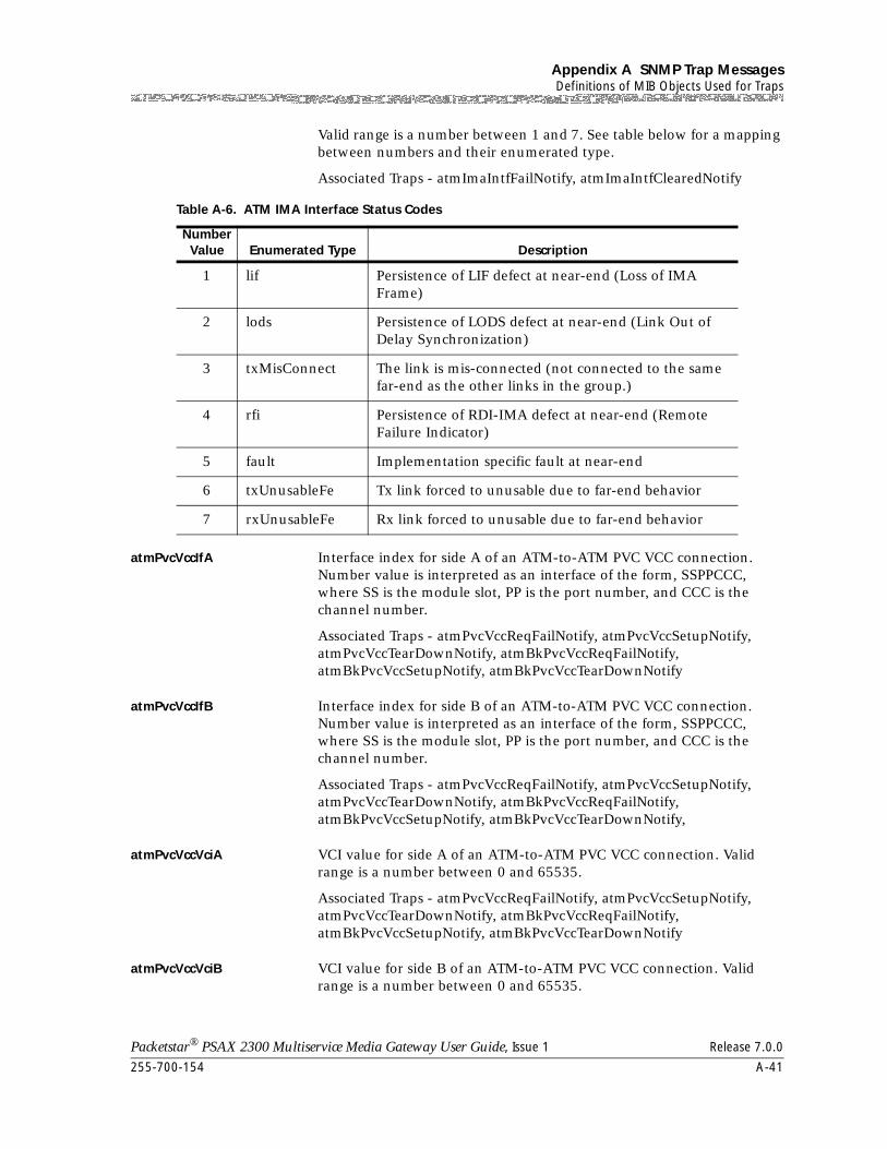
255-700-154 A-41
Packetstar® PSAX 2300 Multiservice Media Gateway User Guide, Issue 1 Release 7.0.0
Appendix A SNMP Trap MessagesDefinitions of MIB Objects Used for Traps
Valid range is a number between 1 and 7. See table below for a mapping between numbers and their enumerated type.
Associated Traps - atmImaIntfFailNotify, atmImaIntfClearedNotify
atmPvcVccIfA Interface index for side A of an ATM-to-ATM PVC VCC connection. Number value is interpreted as an interface of the form, SSPPCCC, where SS is the module slot, PP is the port number, and CCC is the channel number.
Associated Traps - atmPvcVccReqFailNotify, atmPvcVccSetupNotify, atmPvcVccTearDownNotify, atmBkPvcVccReqFailNotify, atmBkPvcVccSetupNotify, atmBkPvcVccTearDownNotify
atmPvcVccIfB Interface index for side B of an ATM-to-ATM PVC VCC connection. Number value is interpreted as an interface of the form, SSPPCCC, where SS is the module slot, PP is the port number, and CCC is the channel number.
Associated Traps - atmPvcVccReqFailNotify, atmPvcVccSetupNotify, atmPvcVccTearDownNotify, atmBkPvcVccReqFailNotify, atmBkPvcVccSetupNotify, atmBkPvcVccTearDownNotify,
atmPvcVccVciA VCI value for side A of an ATM-to-ATM PVC VCC connection. Valid range is a number between 0 and 65535.
Associated Traps - atmPvcVccReqFailNotify, atmPvcVccSetupNotify, atmPvcVccTearDownNotify, atmBkPvcVccReqFailNotify, atmBkPvcVccSetupNotify, atmBkPvcVccTearDownNotify
atmPvcVccVciB VCI value for side B of an ATM-to-ATM PVC VCC connection. Valid range is a number between 0 and 65535.
Table A-6. ATM IMA Interface Status Codes
Number Value Enumerated Type Description
1 lif Persistence of LIF defect at near-end (Loss of IMA Frame)
2 lods Persistence of LODS defect at near-end (Link Out of Delay Synchronization)
3 txMisConnect The link is mis-connected (not connected to the same far-end as the other links in the group.)
4 rfi Persistence of RDI-IMA defect at near-end (Remote Failure Indicator)
5 fault Implementation specific fault at near-end
6 txUnusableFe Tx link forced to unusable due to far-end behavior
7 rxUnusableFe Rx link forced to unusable due to far-end behavior

Appendix A SNMP Trap MessagesDefinitions of MIB Objects Used for Traps
A-42 255-700-154
Packetstar® PSAX 2300 Multiservice Media Gateway User Guide, Issue 1 Release 7.0.0
Associated Traps - atmPvcVccReqFailNotify, atmPvcVccSetupNotify, atmPvcVccTearDownNotify, atmBkPvcVccReqFailNotify, atmBkPvcVccSetupNotify, atmBkPvcVccTearDownNotify
atmPvcVccVpiA VPI value for side A of an ATM-to-ATM PVC VCC connection. Valid range is a number between 0 and 4095.
Associated Traps - atmPvcVccReqFailNotify, atmPvcVccSetupNotify, atmPvcVccTearDownNotify, atmBkPvcVccReqFailNotify, atmBkPvcVccSetupNotify, atmBkPvcVccTearDownNotify
atmPvcVccVpiB VPI value for side B of an ATM-to-ATM PVC VCC connection. Valid range is a number between 0 and 4095.
Associated Traps - atmPvcVccReqFailNotify, atmPvcVccSetupNotify, atmPvcVccTearDownNotify, atmBkPvcVccReqFailNotify, atmBkPvcVccSetupNotify, atmBkPvcVccTearDownNotify
atmPvcVpcIfA Interface index for side A of an ATM-to-ATM PVC VPC connection. Number value is interpreted as an interface of the form, SSPPCCC, where SS is the module slot, PP is the port number, and CCC is the channel number.
Associated Traps - atmPvcVpcReqFailNotify, atmPvcVpcSetupNotify, atmPvcVpcTearDownNotify, atmBkPvcVpcReqFailNotify, atmBkPvcVpcSetupNotify, atmBkPvcVpcTearDownNotify
atmPvcVpcIfB Interface index for side B of an ATM-to-ATM PVC VPC connection. Number value is interpreted as an interface of the form, SSPPCCC, where SS is the module slot, PP is the port number, and CCC is the channel number.
Associated Traps - atmPvcVpcReqFailNotify, atmPvcVpcSetupNotify, atmPvcVpcTearDownNotify, atmBkPvcVpcReqFailNotify, atmBkPvcVpcSetupNotify, atmBkPvcVpcTearDownNotify
atmPvcVpcVpiA VPI value for side A of an ATM-to-ATM PVC VPC connection. Valid range is a number between 0 and 4095.
Associated Traps - atmPvcVpcReqFailNotify, atmPvcVpcSetupNotify, atmPvcVpcTearDownNotify, atmBkPvcVpcReqFailNotify, atmBkPvcVpcSetupNotify, atmBkPvcVpcTearDownNotify,
atmPvcVpcVpiB VPI value for side B of an ATM-to-ATM PVC VPC connection. Valid range is a number between 0 and 4095.
Associated Traps - atmPvcVpcReqFailNotify, atmPvcVpcSetupNotify, atmPvcVpcTearDownNotify, atmBkPvcVpcReqFailNotify, atmBkPvcVpcSetupNotify, atmBkPvcVpcTearDownNotify
atmSpvcVccIfA Interface index for side A of an ATM SPVC VCC connection. Number value is interpreted as an interface of the form, SSPPCCC, where SS is the module slot, PP is the port number, and CCC is the channel number.
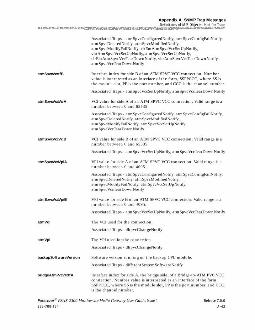
255-700-154 A-43
Packetstar® PSAX 2300 Multiservice Media Gateway User Guide, Issue 1 Release 7.0.0
Appendix A SNMP Trap MessagesDefinitions of MIB Objects Used for Traps
Associated Traps - atmSpvcConfiguredNotify, atmSpvcConfigFailNotify, atmSpvcDeletedNotify, atmSpvcModifiedNotify, atmSpvcModifyFailNotify, cirEmAtmSpvcVccSetUpNotify, vbrAtmSpvcVccSetUpNotify, atmSpvcVccSetUpNotify, cirEmAtmSpvcVccTearDownNotify, vbrAtmSpvcVccTearDownNotify, atmSpvcVccTearDownNotify
atmSpvcVccIfB Interface index for side B of an ATM SPVC VCC connection. Number value is interpreted as an interface of the form, SSPPCCC, where SS is the module slot, PP is the port number, and CCC is the channel number.
Associated Traps - atmSpvcVccSetUpNotify, atmSpvcVccTearDownNotify
atmSpvcVccVciA VCI value for side A of an ATM SPVC VCC connection. Valid range is a number between 0 and 65535.
Associated Traps - atmSpvcConfiguredNotify, atmSpvcConfigFailNotify, atmSpvcDeletedNotify, atmSpvcModifiedNotify, atmSpvcModifyFailNotify, atmSpvcVccSetUpNotify, atmSpvcVccTearDownNotify
atmSpvcVccVciB VCI value for side B of an ATM SPVC VCC connection. Valid range is a number between 0 and 65535.
Associated Traps - atmSpvcVccSetUpNotify, atmSpvcVccTearDownNotify
atmSpvcVccVpiA VPI value for side A of an ATM SPVC VCC connection. Valid range is a number between 0 and 4095.
Associated Traps - atmSpvcConfiguredNotify, atmSpvcConfigFailNotify, atmSpvcDeletedNotify, atmSpvcModifiedNotify, atmSpvcModifyFailNotify, atmSpvcVccSetUpNotify, atmSpvcVccTearDownNotify
atmSpvcVccVpiB VPI value for side B of an ATM SPVC VCC connection. Valid range is a number between 0 and 4095.
Associated Traps - atmSpvcVccSetUpNotify, atmSpvcVccTearDownNotify
atmVci The VCI used for the connection.
Associated Traps - dhpvcChangeNotify
atmVpi The VPI used for the connection.
Associated Traps - dhpvcChangeNotify
backupSoftwareVersion Software version running on the backup CPU module.
Associated Traps - differentSystemSoftwareNotify
bridgeAtmPvcVccIfA Interface index for side A, the bridge side, of a Bridge-to-ATM PVC VCC connection. Number value is interpreted as an interface of the form, SSPPCCC, where SS is the module slot, PP is the port number, and CCC is the channel number.

Appendix A SNMP Trap MessagesDefinitions of MIB Objects Used for Traps
A-44 255-700-154
Packetstar® PSAX 2300 Multiservice Media Gateway User Guide, Issue 1 Release 7.0.0
Associated Traps - bridgeAtmPvcVccReqFailNotify, bridgeAtmPvcVccSetupNotify, bridgeAtmPvcVccTearDownNotify, bridgeAtmBkPvcVccReqFailNotify, bridgeAtmBkPvcVccSetupNotify, bridgeAtmBkPvcVccTearDownNotify
bridgeAtmPvcVccIfB Interface index for side B, the ATM side, of a Bridge-to-ATM PVC VCC connection. Number value is interpreted as an interface of the form, SSPPCCC, where SS is the module slot, PP is the port number, and CCC is the channel number.
Associated Traps - bridgeAtmPvcVccReqFailNotify, bridgeAtmPvcVccSetupNotify, bridgeAtmPvcVccTearDownNotify, bridgeAtmBkPvcVccReqFailNotify, bridgeAtmBkPvcVccSetupNotify, bridgeAtmBkPvcVccTearDownNotify,
bridgeAtmPvcVccVciB VCI value for side B, the ATM side, of a Bridge-to-ATM PVC VCC connection. Valid range is a number between 0 and 65535.
Associated Traps - bridgeAtmPvcVccReqFailNotify, bridgeAtmPvcVccSetupNotify, bridgeAtmPvcVccTearDownNotify, bridgeAtmBkPvcVccReqFailNotify, bridgeAtmBkPvcVccSetupNotify, bridgeAtmBkPvcVccTearDownNotify
bridgeAtmPvcVccVpiB VPI value for side B, the ATM side, of a Bridge-to-ATM PVC VCC connection. Valid range is a number between 0 and 4095.
Associated Traps - bridgeAtmPvcVccReqFailNotify, bridgeAtmPvcVccSetupNotify, bridgeAtmPvcVccTearDownNotify, bridgeAtmBkPvcVccReqFailNotify, bridgeAtmBkPvcVccSetupNotify, bridgeAtmBkPvcVccTearDownNotify
bridgeBridgePvcIfA Interface index for side A of a Bridge-to-Bridge PVC connection. Number value is interpreted as an interface of the form, SSPPCCC, where SS is the module slot, PP is the port number, and CCC is the channel number.
Associated Traps - bridgeBridgePvcReqFailNotify, bridgeBridgePvcSetupNotify, bridgeBridgePvcTearDownNotify
bridgeBridgePvcIfB Interface index for side B of a Bridge-to-Bridge PVC connection. Number value is interpreted as an interface of the form, SSPPCCC, where SS is the module slot, PP is the port number, and CCC is the channel number.
Associated Traps - bridgeBridgePvcReqFailNotify, bridgeBridgePvcSetupNotify, bridgeBridgePvcTearDownNotify
bridgeDomainNumber The bridge number of the bridge that includes this interface. If the interface is currently not associated with any bridge this will be set to none.
Associated Traps - bridgeDomainFullNotify, bridgeDomainNumberInUseNotify, bridgeDomainInServiceNotify, bridgeDomainTimingRelationshipNotify
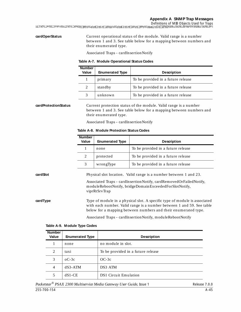
255-700-154 A-45
Packetstar® PSAX 2300 Multiservice Media Gateway User Guide, Issue 1 Release 7.0.0
Appendix A SNMP Trap MessagesDefinitions of MIB Objects Used for Traps
cardOperStatus Current operational status of the module. Valid range is a number between 1 and 3. See table below for a mapping between numbers and their enumerated type.
Associated Traps - cardInsertionNotify
cardProtectionStatus Current protection status of the module. Valid range is a number between 1 and 3. See table below for a mapping between numbers and their enumerated type.
Associated Traps - cardInsertionNotify
cardSlot Physical slot location. Valid range is a number between 1 and 23.
Associated Traps - cardInsertionNotify, cardRemovedOrFailedNotify, moduleRebootNotify, bridgeDomainExceededForSlotNotify, viprRtSrvTrap
cardType Type of module in a physical slot. A specific type of module is associated with each number. Valid range is a number between 1 and 59. See table below for a mapping between numbers and their enumerated type.
Associated Traps - cardInsertionNotify, moduleRebootNotify
Table A-7. Module Operational Status Codes
Number Value Enumerated Type Description
1 primary To be provided in a future release
2 standby To be provided in a future release
3 unknown To be provided in a future release
Table A-8. Module Protection Status Codes
Number Value Enumerated Type Description
1 none To be provided in a future release
2 protected To be provided in a future release
3 wrongType To be provided in a future release
Table A-9. Module Type Codes
Number Value Enumerated Type Description
1 none no module in slot.
2 taxi To be provided in a future release
3 oC-3c OC-3c
4 dS3-ATM DS3 ATM
5 dS1-CE DS1 Circuit Emulation
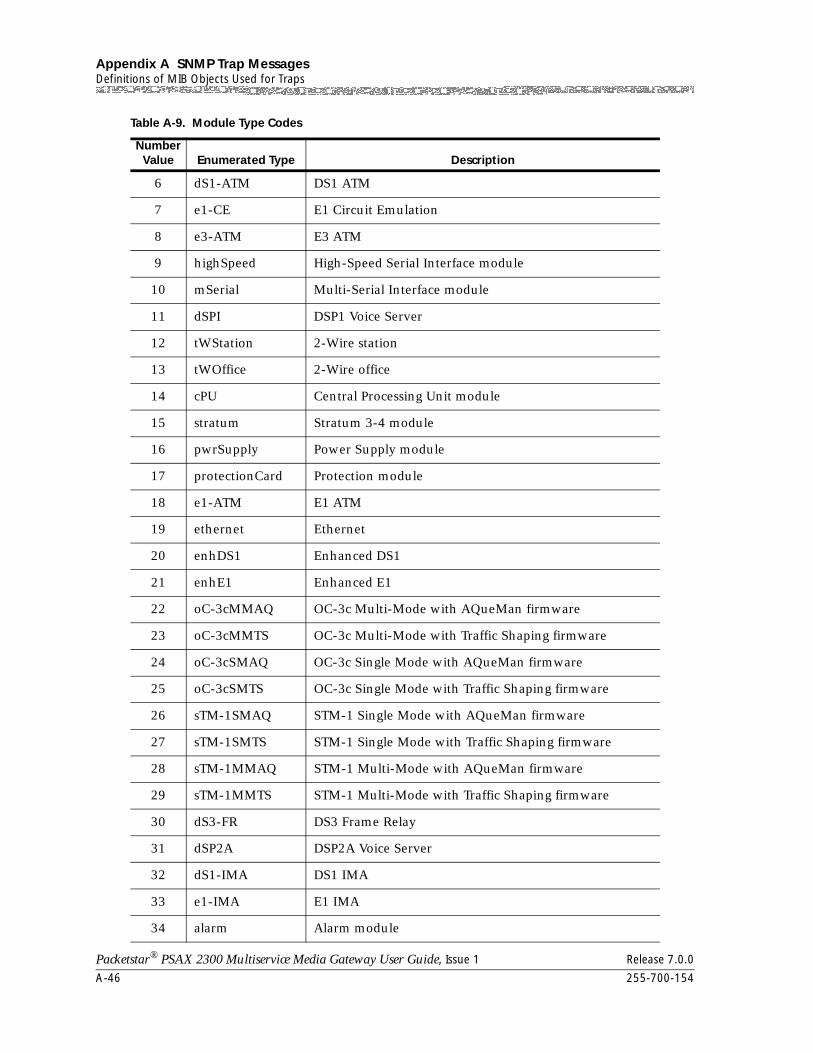
Appendix A SNMP Trap MessagesDefinitions of MIB Objects Used for Traps
A-46 255-700-154
Packetstar® PSAX 2300 Multiservice Media Gateway User Guide, Issue 1 Release 7.0.0
6 dS1-ATM DS1 ATM
7 e1-CE E1 Circuit Emulation
8 e3-ATM E3 ATM
9 highSpeed High-Speed Serial Interface module
10 mSerial Multi-Serial Interface module
11 dSPI DSP1 Voice Server
12 tWStation 2-Wire station
13 tWOffice 2-Wire office
14 cPU Central Processing Unit module
15 stratum Stratum 3-4 module
16 pwrSupply Power Supply module
17 protectionCard Protection module
18 e1-ATM E1 ATM
19 ethernet Ethernet
20 enhDS1 Enhanced DS1
21 enhE1 Enhanced E1
22 oC-3cMMAQ OC-3c Multi-Mode with AQueMan firmware
23 oC-3cMMTS OC-3c Multi-Mode with Traffic Shaping firmware
24 oC-3cSMAQ OC-3c Single Mode with AQueMan firmware
25 oC-3cSMTS OC-3c Single Mode with Traffic Shaping firmware
26 sTM-1SMAQ STM-1 Single Mode with AQueMan firmware
27 sTM-1SMTS STM-1 Single Mode with Traffic Shaping firmware
28 sTM-1MMAQ STM-1 Multi-Mode with AQueMan firmware
29 sTM-1MMTS STM-1 Multi-Mode with Traffic Shaping firmware
30 dS3-FR DS3 Frame Relay
31 dSP2A DSP2A Voice Server
32 dS1-IMA DS1 IMA
33 e1-IMA E1 IMA
34 alarm Alarm module
Table A-9. Module Type Codes
Number Value Enumerated Type Description
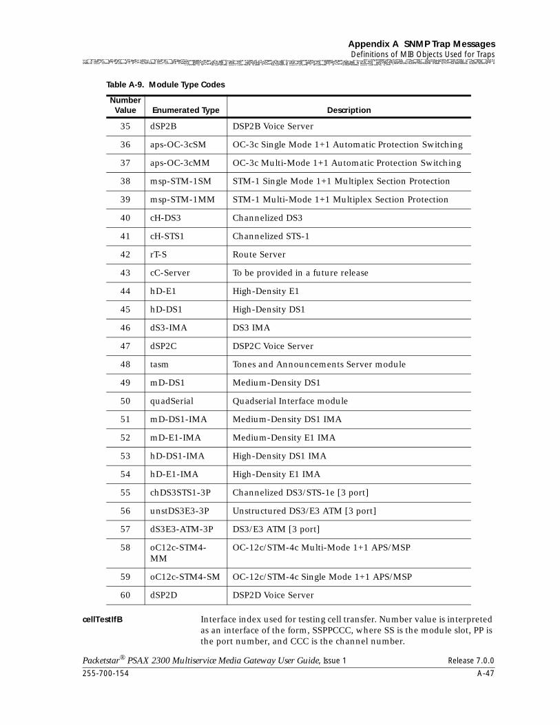
255-700-154 A-47
Packetstar® PSAX 2300 Multiservice Media Gateway User Guide, Issue 1 Release 7.0.0
Appendix A SNMP Trap MessagesDefinitions of MIB Objects Used for Traps
cellTestIfB Interface index used for testing cell transfer. Number value is interpreted as an interface of the form, SSPPCCC, where SS is the module slot, PP is the port number, and CCC is the channel number.
35 dSP2B DSP2B Voice Server
36 aps-OC-3cSM OC-3c Single Mode 1+1 Automatic Protection Switching
37 aps-OC-3cMM OC-3c Multi-Mode 1+1 Automatic Protection Switching
38 msp-STM-1SM STM-1 Single Mode 1+1 Multiplex Section Protection
39 msp-STM-1MM STM-1 Multi-Mode 1+1 Multiplex Section Protection
40 cH-DS3 Channelized DS3
41 cH-STS1 Channelized STS-1
42 rT-S Route Server
43 cC-Server To be provided in a future release
44 hD-E1 High-Density E1
45 hD-DS1 High-Density DS1
46 dS3-IMA DS3 IMA
47 dSP2C DSP2C Voice Server
48 tasm Tones and Announcements Server module
49 mD-DS1 Medium-Density DS1
50 quadSerial Quadserial Interface module
51 mD-DS1-IMA Medium-Density DS1 IMA
52 mD-E1-IMA Medium-Density E1 IMA
53 hD-DS1-IMA High-Density DS1 IMA
54 hD-E1-IMA High-Density E1 IMA
55 chDS3STS1-3P Channelized DS3/STS-1e [3 port]
56 unstDS3E3-3P Unstructured DS3/E3 ATM [3 port]
57 dS3E3-ATM-3P DS3/E3 ATM [3 port]
58 oC12c-STM4-MM
OC-12c/STM-4c Multi-Mode 1+1 APS/MSP
59 oC12c-STM4-SM OC-12c/STM-4c Single Mode 1+1 APS/MSP
60 dSP2D DSP2D Voice Server
Table A-9. Module Type Codes
Number Value Enumerated Type Description
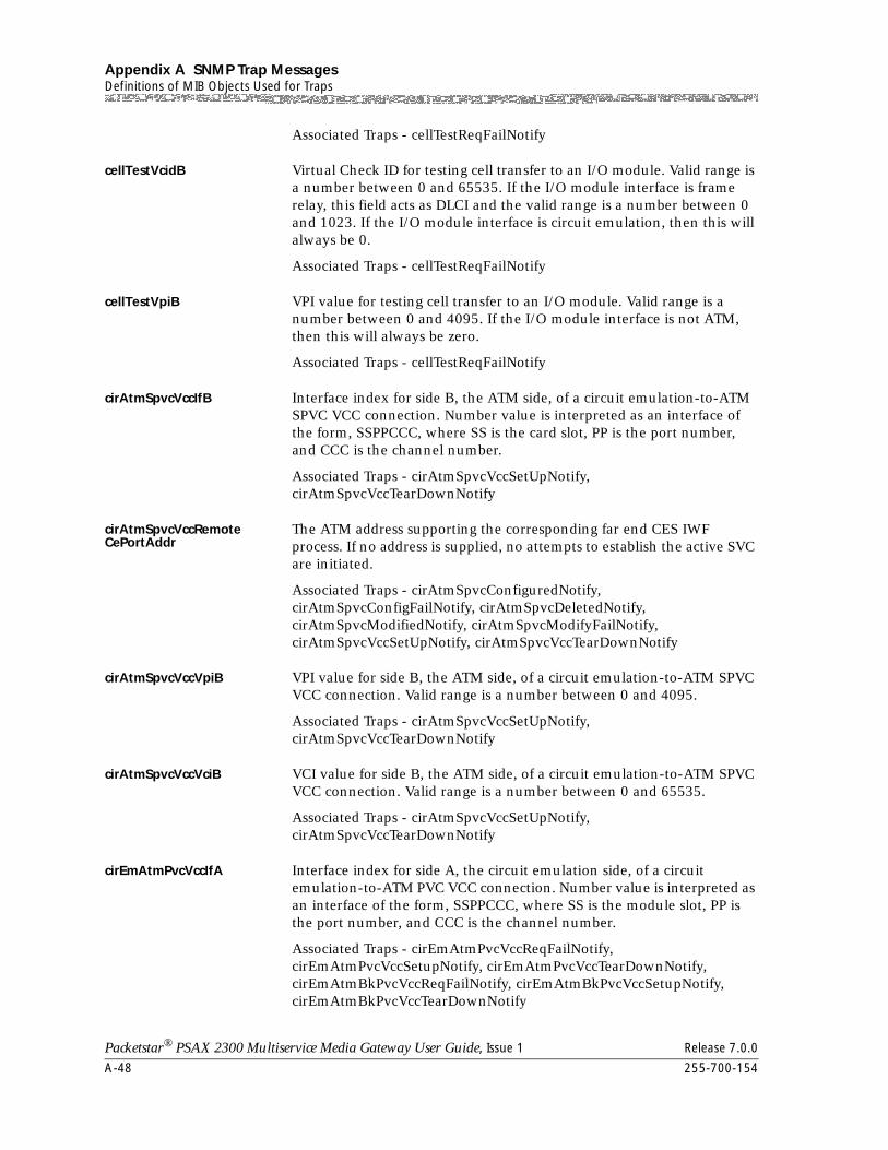
Appendix A SNMP Trap MessagesDefinitions of MIB Objects Used for Traps
A-48 255-700-154
Packetstar® PSAX 2300 Multiservice Media Gateway User Guide, Issue 1 Release 7.0.0
Associated Traps - cellTestReqFailNotify
cellTestVcidB Virtual Check ID for testing cell transfer to an I/O module. Valid range is a number between 0 and 65535. If the I/O module interface is frame relay, this field acts as DLCI and the valid range is a number between 0 and 1023. If the I/O module interface is circuit emulation, then this will always be 0.
Associated Traps - cellTestReqFailNotify
cellTestVpiB VPI value for testing cell transfer to an I/O module. Valid range is a number between 0 and 4095. If the I/O module interface is not ATM, then this will always be zero.
Associated Traps - cellTestReqFailNotify
cirAtmSpvcVccIfB Interface index for side B, the ATM side, of a circuit emulation-to-ATM SPVC VCC connection. Number value is interpreted as an interface of the form, SSPPCCC, where SS is the card slot, PP is the port number, and CCC is the channel number.
Associated Traps - cirAtmSpvcVccSetUpNotify, cirAtmSpvcVccTearDownNotify
cirAtmSpvcVccRemoteCePortAddr
The ATM address supporting the corresponding far end CES IWF process. If no address is supplied, no attempts to establish the active SVC are initiated.
Associated Traps - cirAtmSpvcConfiguredNotify, cirAtmSpvcConfigFailNotify, cirAtmSpvcDeletedNotify, cirAtmSpvcModifiedNotify, cirAtmSpvcModifyFailNotify, cirAtmSpvcVccSetUpNotify, cirAtmSpvcVccTearDownNotify
cirAtmSpvcVccVpiB VPI value for side B, the ATM side, of a circuit emulation-to-ATM SPVC VCC connection. Valid range is a number between 0 and 4095.
Associated Traps - cirAtmSpvcVccSetUpNotify, cirAtmSpvcVccTearDownNotify
cirAtmSpvcVccVciB VCI value for side B, the ATM side, of a circuit emulation-to-ATM SPVC VCC connection. Valid range is a number between 0 and 65535.
Associated Traps - cirAtmSpvcVccSetUpNotify, cirAtmSpvcVccTearDownNotify
cirEmAtmPvcVccIfA Interface index for side A, the circuit emulation side, of a circuit emulation-to-ATM PVC VCC connection. Number value is interpreted as an interface of the form, SSPPCCC, where SS is the module slot, PP is the port number, and CCC is the channel number.
Associated Traps - cirEmAtmPvcVccReqFailNotify, cirEmAtmPvcVccSetupNotify, cirEmAtmPvcVccTearDownNotify, cirEmAtmBkPvcVccReqFailNotify, cirEmAtmBkPvcVccSetupNotify, cirEmAtmBkPvcVccTearDownNotify
255-700-154 A-49
Packetstar® PSAX 2300 Multiservice Media Gateway User Guide, Issue 1 Release 7.0.0
Appendix A SNMP Trap MessagesDefinitions of MIB Objects Used for Traps
cirEmAtmPvcVccIfB Interface index for side B, the ATM side, of a circuit emulation-to-ATM PVC VCC connection. Number value is interpreted as an interface of the form, SSPPCCC, where SS is the module slot, PP is the port number, and CCC is the channel number.
Associated Traps - cirEmAtmPvcVccReqFailNotify, cirEmAtmPvcVccSetupNotify, cirEmAtmPvcVccTearDownNotify, cirEmAtmBkPvcVccReqFailNotify, cirEmAtmBkPvcVccSetupNotify, cirEmAtmBkPvcVccTearDownNotify
cirEmAtmPvcVccVciB VCI value for side B, the ATM side, of a circuit emulation-to-ATM PVC VCC connection. Valid range is a number between 0 and 65535.
Associated Traps - cirEmAtmPvcVccReqFailNotify, cirEmAtmPvcVccSetupNotify, cirEmAtmPvcVccTearDownNotify, cirEmAtmBkPvcVccReqFailNotify, cirEmAtmBkPvcVccSetupNotify, cirEmAtmBkPvcVccTearDownNotify
cirEmAtmPvcVccVpiB VPI value for side B, the ATM side, of a circuit emulation-to-ATM PVC VCC connection. Valid range is a number between 0 and 4095.
Associated Traps - cirEmAtmPvcVccReqFailNotify, cirEmAtmPvcVccSetupNotify, cirEmAtmPvcVccTearDownNotify, cirEmAtmBkPvcVccReqFailNotify, cirEmAtmBkPvcVccSetupNotify, cirEmAtmBkPvcVccTearDownNotify
cirEmAtmSpvcVccIfA Interface index for side A, the circuit emulation side, of a circuit emulation-to-ATM SPVC VCC connection. Number value is interpreted as an interface of the form, SSPPCCC, where SS is the module slot, PP is the port number, and CCC is the channel number.
Associated Traps - cirEmAtmSpvcVccSetUpNotify, cirEmAtmSpvcVccTearDownNotify
cirEmAtmSpvcVccIfB Interface index for side B, the ATM side, of a circuit emulation-to-ATM SPVC VCC connection. Number value is interpreted as an interface of the form, SSPPCCC, where SS is the module slot, PP is the port number, and CCC is the channel number.
Associated Traps - cirEmAtmSpvcVccSetUpNotify, cirEmAtmSpvcVccTearDownNotify
cirEmAtmSpvcVccVciB VCI value for side B, the ATM side, of a circuit emulation-to-ATM SPVC VCC connection. Valid range is a number between 0 and 65535.
Associated Traps - cirEmAtmSpvcVccSetUpNotify, cirEmAtmSpvcVccTearDownNotify
cirEmAtmSpvcVccVpiB VPI value for side B, the ATM side, of a circuit emulation-to-ATM SPVC VCC connection. Valid range is a number between 0 and 4095.
Associated Traps - cirEmAtmSpvcVccSetUpNotify, cirEmAtmSpvcVccTearDownNotify
Appendix A SNMP Trap MessagesDefinitions of MIB Objects Used for Traps
A-50 255-700-154
Packetstar® PSAX 2300 Multiservice Media Gateway User Guide, Issue 1 Release 7.0.0
cirEmCirEmPvcIfA Interface index for side A of a circuit emulation-to-circuit emulation PVC connection. Number value is interpreted as an interface of the form, SSPPCCC, where SS is the module slot, PP is the port number, and CCC is the channel number.
Associated Traps - cirEmCirEmPvcReqFailNotify, cirEmCirEmPvcSetupNotify, cirEmCirEmPvcTearDownNotify
cirEmCirEmPvcIfB Interface index for side B of a circuit emulation-circuit emulation PVC connection. Number value is interpreted as an interface of the form, SSPPCCC, where SS is the module slot, PP is the port number, and CCC is the channel number.
Associated Traps - cirEmCirEmPvcReqFailNotify, cirEmCirEmPvcSetupNotify, cirEmCirEmPvcTearDownNotify
dlciNumber The number of the DLCI being used.
Associated Traps - lmiDlciStatusNotify
deviceId The device ID is used as the number of external devices. Each device can be an external input device or control output device.
Associated Traps - alarmCardInputChangeNotify, alarmCardOutputChangeNotify
firmwareDownloadReasonCode
The suspected reasons why a firmware download would fail. Valid range is a number between 1 and 17. See table below for a mapping between numbers and their enumerated type.
Associated Traps - firmwareDownloadFailedNotify
Table A-10. Firmware Download Reason Codes
Number Value Enumerated Type Description
1 cardInService To be provided in a future release
2 errorInFile To be provided in a future release
3 otherFailure To be provided in a future release
4 wrongCardSubType To be provided in a future release
5 driverUnavailable To be provided in a future release
6 driverInvalidHeaderChecksum
To be provided in a future release
7 driverInvalidrecordChecksum
To be provided in a future release
8 requestReplyTimeout To be provided in a future release
9 completeReplyTimeout To be provided in a future release
10 mapFileCorrupted To be provided in a future release
255-700-154 A-51
Packetstar® PSAX 2300 Multiservice Media Gateway User Guide, Issue 1 Release 7.0.0
Appendix A SNMP Trap MessagesDefinitions of MIB Objects Used for Traps
frAtmPvcVccDlciA DLCI value for side A, the frame relay side, of a frame relay-atm PVC VCC connection. Valid range is a number between 0 and 1023.
Associated Traps - frAtmPvcVccReqFailNotify, frAtmPvcVccSetupNotify, frAtmPvcVccTearDownNotify, frAtmBkPvcVccReqFailNotify, frAtmBkPvcVccSetupNotify, frAtmBkPvcVccTearDownNotify
frAtmPvcVccIfA Interface index for side A, the frame relay side, of a frame relay-to-ATM PVC VCC connection. Number value is interpreted as an interface of the form, SSPPCCC, where SS is the module slot, PP is the port number, and CCC is the channel number.
Associated Traps - frAtmPvcVccReqFailNotify, frAtmPvcVccSetupNotify, frAtmPvcVccTearDownNotify, frAtmBkPvcVccReqFailNotify, frAtmBkPvcVccSetupNotify, frAtmBkPvcVccTearDownNotify
frAtmPvcVccIfB Interface index for side B, the ATM side, of a frame relay-to-ATM PVC VCC connection. Number value is interpreted as an interface of the form, SSPPCCC, where SS is the module slot, PP is the port number, and CCC is the channel number.
Associated Traps - frAtmPvcVccReqFailNotify, frAtmPvcVccSetupNotify, frAtmPvcVccTearDownNotify, frAtmBkPvcVccReqFailNotify, frAtmBkPvcVccSetupNotify, frAtmBkPvcVccTearDownNotify
frAtmPvcVccVciB VCI value for side B, the ATM side, of a frame relay-to-ATM PVC VCC connection. Valid range is a number between 0 and 65535.
Associated Traps - frAtmPvcVccReqFailNotify, frAtmPvcVccSetupNotify, frAtmPvcVccTearDownNotify, frAtmBkPvcVccReqFailNotify, frAtmBkPvcVccSetupNotify, frAtmBkPvcVccTearDownNotify
frAtmPvcVccVpiB VPI value for side B, the ATM side, of a frame relay-to-ATM PVC VCC connection. Valid range is a number between 0 and 4095.
11 mapFileUnavailable To be provided in a future release
12 mapFileInvalidCheck-sum
To be provided in a future release
13 mapFileNameImproper To be provided in a future release
14 cfgFileCorrupted To be provided in a future release
15 cfgFileUnavailable To be provided in a future release
16 cfgFileInvalidChecksum To be provided in a future release
17 wrongCardType To be provided in a future release
18 removeCardBeforeFin-ish
To be provided in a future release
Table A-10. Firmware Download Reason Codes
Number Value Enumerated Type Description
Appendix A SNMP Trap MessagesDefinitions of MIB Objects Used for Traps
A-52 255-700-154
Packetstar® PSAX 2300 Multiservice Media Gateway User Guide, Issue 1 Release 7.0.0
Associated Traps - frAtmPvcVccReqFailNotify, frAtmPvcVccSetupNotify, frAtmPvcVccTearDownNotify, frAtmBkPvcVccReqFailNotify, frAtmBkPvcVccSetupNotify, frAtmBkPvcVccTearDownNotify
frAtmSpvcVccDlciA DLCI value for side A, the frame relay side, of a frame relay-to-ATM SPVC VCC connection. Valid range is a number between 0 and 1023.
Associated Traps - frAtmSpvcConfiguredNotify, frAtmSpvcConfigFailNotify, frAtmSpvcDeletedNotify, frAtmSpvcModifiedNotify, frAtmSpvcModifyFailNotify, frAtmSpvcVccSetUpNotify, frAtmSpvcVccTearDownNotify
frAtmSpvcVccIfB Interface index for side B, the ATM side, of a frame relay-to-ATM SPVC VCC connection. Number value is interpreted as an interface of the form, SSPPCCC, where SS is the card slot, PP is the port number, and CCC is the channel number.
Associated Traps - frAtmSpvcVccSetUpNotify, frAtmSpvcVccTearDownNotify
frAtmSpvcVccVpiB VPI value for side B, the ATM side, of a frame relay-atm SPVC VCC connection. Valid range is a number between 0 and 4095.
Associated Traps - frAtmSpvcVccSetUpNotify, frAtmSpvcVccTearDownNotify
frAtmSpvcVccVciB VCI value for side B, the ATM side, of a frame relay-atm SPVC VCC connection. Valid range is a number between 0 and 65535.
Associated Traps - frAtmSpvcVccSetUpNotify, frAtmSpvcVccTearDownNotify
frFrPvcDlciA DLCI value for side A of a frame relay-to-frame relay PVC connection. Valid range is a number between 0 and 1023.
Associated Traps - frFrPvcReqFailNotify, frFrPvcSetupNotify, frFrPvcTearDownNotify
frFrPvcDlciB DLCI value for side B of a frame relay-to-frame relay PVC connection. Valid range is a number between 0 and 1023.
Associated Traps - frFrPvcReqFailNotify, frFrPvcSetupNotify, frFrPvcTearDownNotify
frFrPvcIfA Interface index for side A of a frame relay-to-frame relay PVC connection. Number value is interpreted as an interface of the form, SSPPCCC, where SS is the module slot, PP is the port number, and CCC is the channel number.
Associated Traps - frFrPvcReqFailNotify, frFrPvcSetupNotify, frFrPvcTearDownNotify
frFrPvcIfB Interface index for side B of a frame relay-to-frame relay PVC connection. Number value is interpreted as an interface of the form,
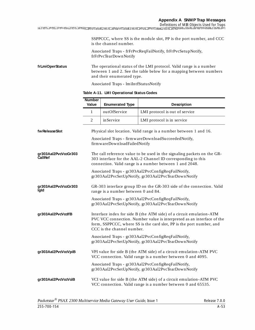
255-700-154 A-53
Packetstar® PSAX 2300 Multiservice Media Gateway User Guide, Issue 1 Release 7.0.0
Appendix A SNMP Trap MessagesDefinitions of MIB Objects Used for Traps
SSPPCCC, where SS is the module slot, PP is the port number, and CCC is the channel number.
Associated Traps - frFrPvcReqFailNotify, frFrPvcSetupNotify, frFrPvcTearDownNotify
frLmiOperStatus The operational status of the LMI protocol. Valid range is a number between 1 and 2. See the table below for a mapping between numbers and their enumerated type.
Associated Traps - lmiIntfStatusNotify
fwReleaseSlot Physical slot location. Valid range is a number between 1 and 16.
Associated Traps - firmwareDownloadSucceededNotify, firmwareDownloadFailedNotify
gr303Aal2PvcVccGr303CallRef
The call reference value to be used in the signaling packets on the GR-303 interface for the AAL-2 Channel ID corresponding to this connection. Valid range is a number between 1 and 2048.
Associated Traps - gr303Aal2PvcConfigReqFailNotify, gr303Aal2PvcSetUpNotify, gr303Aal2PvcTearDownNotify
gr303Aal2PvcVccGr303IgId
GR-303 interface group ID on the GR-303 side of the connection. Valid range is a number between 0 and 84.
Associated Traps - gr303Aal2PvcConfigReqFailNotify, gr303Aal2PvcSetUpNotify, gr303Aal2PvcTearDownNotify
gr303Aal2PvcVccIfB Interface index for side B (the ATM side) of a circuit emulation-ATM PVC VCC connection. Number value is interpreted as an interface of the form, SSPPCCC, where SS is the card slot, PP is the port number, and CCC is the channel number.
Associated Traps - gr303Aal2PvcConfigReqFailNotify, gr303Aal2PvcSetUpNotify, gr303Aal2PvcTearDownNotify
gr303Aal2PvcVccVpiB VPI value for side B (the ATM side) of a circuit emulation-ATM PVC VCC connection. Valid range is a number between 0 and 4095.
Associated Traps - gr303Aal2PvcConfigReqFailNotify, gr303Aal2PvcSetUpNotify, gr303Aal2PvcTearDownNotify
gr303Aal2PvcVccVciB VCI value for side B (the ATM side) of a circuit emulation-ATM PVC VCC connection. Valid range is a number between 0 and 65535.
Table A-11. LMI Operational Status Codes
Number Value Enumerated Type Description
1 outOfService LMI protocol is out of service
2 inService LMI protocol is in service
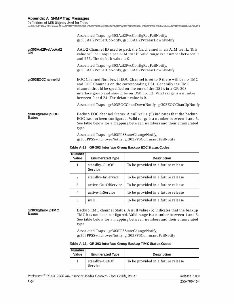
Appendix A SNMP Trap MessagesDefinitions of MIB Objects Used for Traps
A-54 255-700-154
Packetstar® PSAX 2300 Multiservice Media Gateway User Guide, Issue 1 Release 7.0.0
Associated Traps - gr303Aal2PvcConfigReqFailNotify, gr303Aal2PvcSetUpNotify, gr303Aal2PvcTearDownNotify
gr303Aal2PvcVccAal2Cid
AAL-2 Channel ID used to pack the CE channel in an ATM trunk. This value will be unique per ATM trunk. Valid range is a number between 0 and 255. The default value is 0.
Associated Traps - gr303Aal2PvcConfigReqFailNotify, gr303Aal2PvcSetUpNotify, gr303Aal2PvcTearDownNotify
gr303EOCChannelId EOC Channel Number. If EOC Channel is set to 0 there will be no TMC and EOC Channels on the corresponding DS1. Generally the TMC channel should be specified on the one of the DS1’s in a GR-303 interface group and should be on DS0 no. 12. Valid range is a number between 0 and 24. The default value is 0.
Associated Traps - gr303EOCChanDownNotify, gr303EOCChanUpNotify
gr303IgBackupEOCStatus
Backup EOC channel Status. A null value (5) indicates that the backup EOC has not been configured. Valid range is a number between 1 and 5. See table below for a mapping between numbers and their enumerated type.
Associated Traps - gr303PPSStateChangeNotify, gr303PPSSwitchoverNotify, gr303PPSCommandFailNotify
gr303IgBackupTMCStatus
Backup TMC channel Status. A null value (5) indicates that the backup TMC has not been configured. Valid range is a number between 1 and 5. See table below for a mapping between numbers and their enumerated type.
Associated Traps - gr303PPSStateChangeNotify, gr303PPSSwitchoverNotify, gr303PPSCommandFailNotify
Table A-12. GR-303 Interface Group Backup EOC Status Codes
Number Value Enumerated Type Description
1 standby-OutOfService
To be provided in a future release
2 standby-InService To be provided in a future release
3 active-OutOfService To be provided in a future release
4 active-InService To be provided in a future release
5 null To be provided in a future release
Table A-13. GR-303 Interface Group Backup TIMC Status Codes
Number Value Enumerated Type Description
1 standby-OutOfService
To be provided in a future release
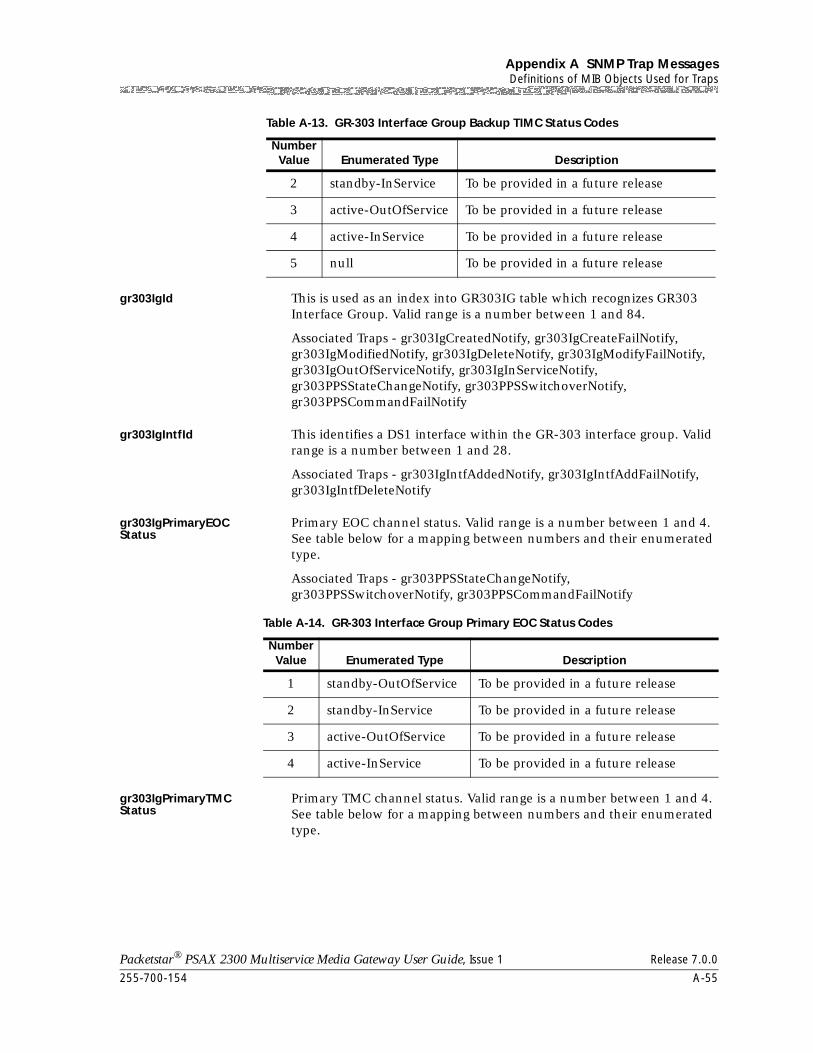
255-700-154 A-55
Packetstar® PSAX 2300 Multiservice Media Gateway User Guide, Issue 1 Release 7.0.0
Appendix A SNMP Trap MessagesDefinitions of MIB Objects Used for Traps
gr303IgId This is used as an index into GR303IG table which recognizes GR303 Interface Group. Valid range is a number between 1 and 84.
Associated Traps - gr303IgCreatedNotify, gr303IgCreateFailNotify, gr303IgModifiedNotify, gr303IgDeleteNotify, gr303IgModifyFailNotify, gr303IgOutOfServiceNotify, gr303IgInServiceNotify, gr303PPSStateChangeNotify, gr303PPSSwitchoverNotify, gr303PPSCommandFailNotify
gr303IgIntfId This identifies a DS1 interface within the GR-303 interface group. Valid range is a number between 1 and 28.
Associated Traps - gr303IgIntfAddedNotify, gr303IgIntfAddFailNotify, gr303IgIntfDeleteNotify
gr303IgPrimaryEOCStatus
Primary EOC channel status. Valid range is a number between 1 and 4. See table below for a mapping between numbers and their enumerated type.
Associated Traps - gr303PPSStateChangeNotify, gr303PPSSwitchoverNotify, gr303PPSCommandFailNotify
gr303IgPrimaryTMCStatus
Primary TMC channel status. Valid range is a number between 1 and 4. See table below for a mapping between numbers and their enumerated type.
2 standby-InService To be provided in a future release
3 active-OutOfService To be provided in a future release
4 active-InService To be provided in a future release
5 null To be provided in a future release
Table A-13. GR-303 Interface Group Backup TIMC Status Codes
Number Value Enumerated Type Description
Table A-14. GR-303 Interface Group Primary EOC Status Codes
Number Value Enumerated Type Description
1 standby-OutOfService To be provided in a future release
2 standby-InService To be provided in a future release
3 active-OutOfService To be provided in a future release
4 active-InService To be provided in a future release
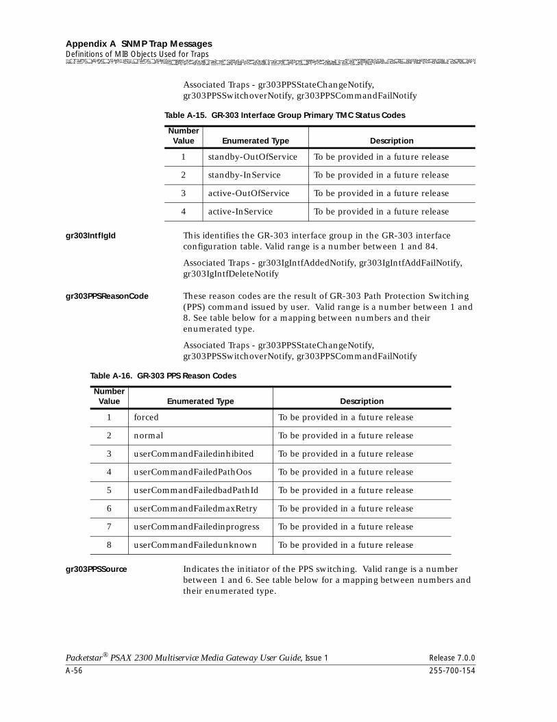
Appendix A SNMP Trap MessagesDefinitions of MIB Objects Used for Traps
A-56 255-700-154
Packetstar® PSAX 2300 Multiservice Media Gateway User Guide, Issue 1 Release 7.0.0
Associated Traps - gr303PPSStateChangeNotify, gr303PPSSwitchoverNotify, gr303PPSCommandFailNotify
gr303IntfIgId This identifies the GR-303 interface group in the GR-303 interface configuration table. Valid range is a number between 1 and 84.
Associated Traps - gr303IgIntfAddedNotify, gr303IgIntfAddFailNotify, gr303IgIntfDeleteNotify
gr303PPSReasonCode These reason codes are the result of GR-303 Path Protection Switching (PPS) command issued by user. Valid range is a number between 1 and 8. See table below for a mapping between numbers and their enumerated type.
Associated Traps - gr303PPSStateChangeNotify, gr303PPSSwitchoverNotify, gr303PPSCommandFailNotify
gr303PPSSource Indicates the initiator of the PPS switching. Valid range is a number between 1 and 6. See table below for a mapping between numbers and their enumerated type.
Table A-15. GR-303 Interface Group Primary TMC Status Codes
Number Value Enumerated Type Description
1 standby-OutOfService To be provided in a future release
2 standby-InService To be provided in a future release
3 active-OutOfService To be provided in a future release
4 active-InService To be provided in a future release
Table A-16. GR-303 PPS Reason Codes
Number Value Enumerated Type Description
1 forced To be provided in a future release
2 normal To be provided in a future release
3 userCommandFailedinhibited To be provided in a future release
4 userCommandFailedPathOos To be provided in a future release
5 userCommandFailedbadPathId To be provided in a future release
6 userCommandFailedmaxRetry To be provided in a future release
7 userCommandFailedinprogress To be provided in a future release
8 userCommandFailedunknown To be provided in a future release
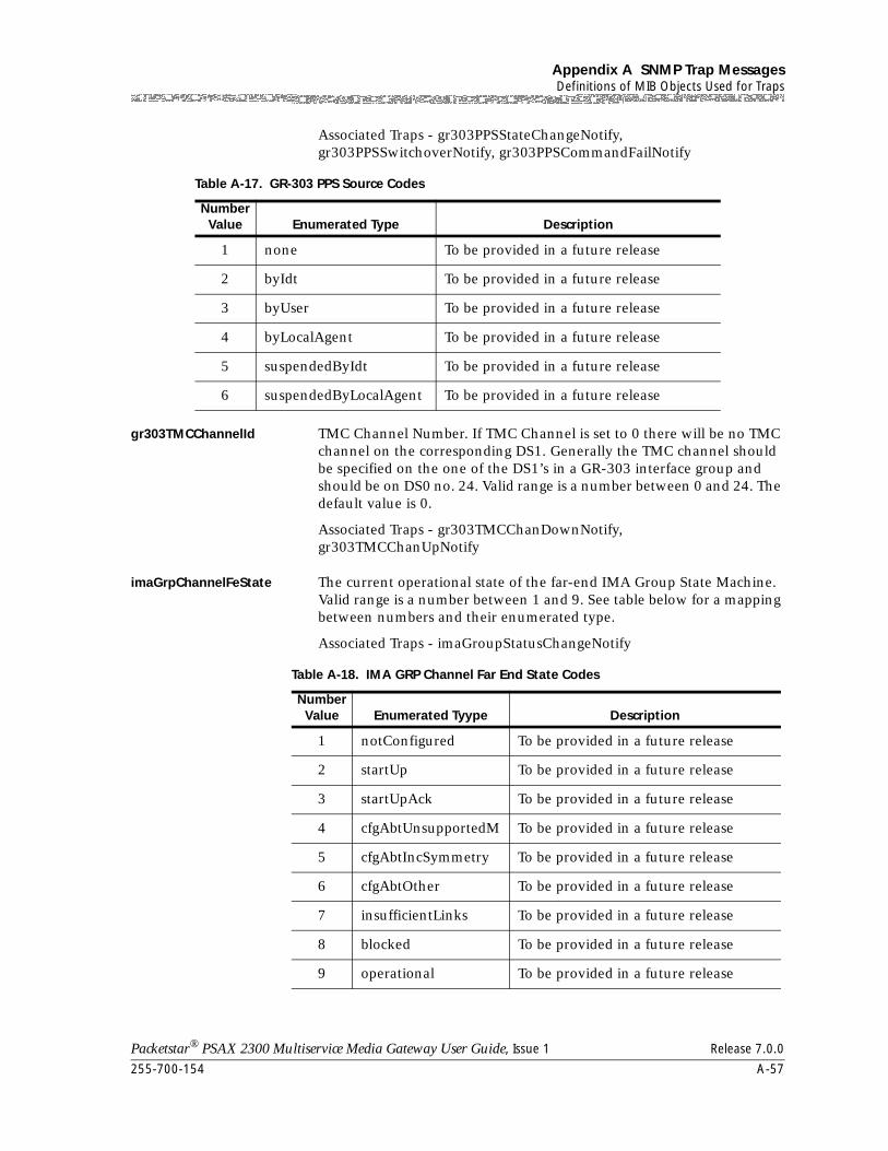
255-700-154 A-57
Packetstar® PSAX 2300 Multiservice Media Gateway User Guide, Issue 1 Release 7.0.0
Appendix A SNMP Trap MessagesDefinitions of MIB Objects Used for Traps
Associated Traps - gr303PPSStateChangeNotify, gr303PPSSwitchoverNotify, gr303PPSCommandFailNotify
gr303TMCChannelId TMC Channel Number. If TMC Channel is set to 0 there will be no TMC channel on the corresponding DS1. Generally the TMC channel should be specified on the one of the DS1’s in a GR-303 interface group and should be on DS0 no. 24. Valid range is a number between 0 and 24. The default value is 0.
Associated Traps - gr303TMCChanDownNotify, gr303TMCChanUpNotify
imaGrpChannelFeState The current operational state of the far-end IMA Group State Machine. Valid range is a number between 1 and 9. See table below for a mapping between numbers and their enumerated type.
Associated Traps - imaGroupStatusChangeNotify
Table A-17. GR-303 PPS Source Codes
Number Value Enumerated Type Description
1 none To be provided in a future release
2 byIdt To be provided in a future release
3 byUser To be provided in a future release
4 byLocalAgent To be provided in a future release
5 suspendedByIdt To be provided in a future release
6 suspendedByLocalAgent To be provided in a future release
Table A-18. IMA GRP Channel Far End State Codes
Number Value Enumerated Tyype Description
1 notConfigured To be provided in a future release
2 startUp To be provided in a future release
3 startUpAck To be provided in a future release
4 cfgAbtUnsupportedM To be provided in a future release
5 cfgAbtIncSymmetry To be provided in a future release
6 cfgAbtOther To be provided in a future release
7 insufficientLinks To be provided in a future release
8 blocked To be provided in a future release
9 operational To be provided in a future release
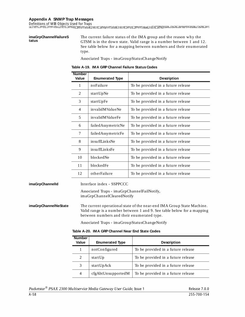
Appendix A SNMP Trap MessagesDefinitions of MIB Objects Used for Traps
A-58 255-700-154
Packetstar® PSAX 2300 Multiservice Media Gateway User Guide, Issue 1 Release 7.0.0
imaGrpChannelFailureStatus
The current failure status of the IMA group and the reason why the GTSM is in the down state. Valid range is a number between 1 and 12. See table below for a mapping between numbers and their enumerated type.
Associated Traps - imaGroupStatusChangeNotify
imaGrpChannelId Interface index - SSPPCCC
Associated Traps - imaGrpChannelFailNotify, imaGrpChannelClearedNotify
imaGrpChannelNeState The current operational state of the near-end IMA Group State Machine. Valid range is a number between 1 and 9. See table below for a mapping between numbers and their enumerated type.
Associated Traps - imaGroupStatusChangeNotify
Table A-19. IMA GRP Channel Failure Status Codes
Number Value Enumerated Type Description
1 noFailure To be provided in a future release
2 startUpNe To be provided in a future release
3 startUpFe To be provided in a future release
4 invalidMValueNe To be provided in a future release
5 invalidMValueFe To be provided in a future release
6 failedAssymetricNe To be provided in a future release
7 failedAssymetricFe To be provided in a future release
8 insuffLinksNe To be provided in a future release
9 insuffLinksFe To be provided in a future release
10 blockedNe To be provided in a future release
11 blockedFe To be provided in a future release
12 otherFailure To be provided in a future release
Table A-20. IMA GRP Channel Near End State Codes
Number Value Enumerated Type Description
1 notConfigured To be provided in a future release
2 startUp To be provided in a future release
3 startUpAck To be provided in a future release
4 cfgAbtUnsupportedM To be provided in a future release
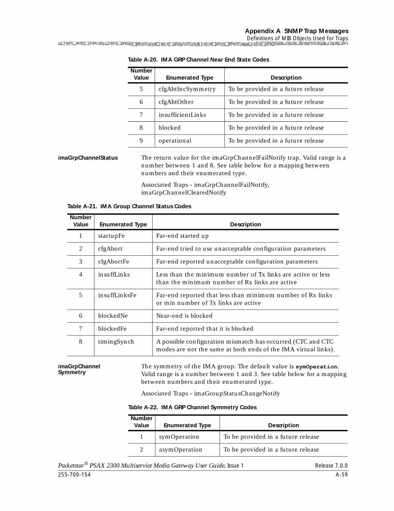
255-700-154 A-59
Packetstar® PSAX 2300 Multiservice Media Gateway User Guide, Issue 1 Release 7.0.0
Appendix A SNMP Trap MessagesDefinitions of MIB Objects Used for Traps
imaGrpChannelStatus The return value for the imaGrpChannelFailNotify trap. Valid range is a number between 1 and 8. See table below for a mapping between numbers and their enumerated type.
Associated Traps - imaGrpChannelFailNotify, imaGrpChannelClearedNotify
imaGrpChannelSymmetry
The symmetry of the IMA group. The default value is symOperation. Valid range is a number between 1 and 3. See table below for a mapping between numbers and their enumerated type.
Associated Traps - imaGroupStatusChangeNotify
5 cfgAbtIncSymmetry To be provided in a future release
6 cfgAbtOther To be provided in a future release
7 insufficientLinks To be provided in a future release
8 blocked To be provided in a future release
9 operational To be provided in a future release
Table A-20. IMA GRP Channel Near End State Codes
Number Value Enumerated Type Description
Table A-21. IMA Group Channel Status Codes
Number Value Enumerated Type Description
1 startupFe Far-end started up
2 cfgAbort Far-end tried to use unacceptable configuration parameters
3 cfgAbortFe Far-end reported unacceptable configuration parameters
4 insuffLinks Less than the minimum number of Tx links are active or less than the minimum number of Rx links are active
5 insuffLinksFe Far-end reported that less than minimum number of Rx links or min number of Tx links are active
6 blockedNe Near-end is blocked
7 blockedFe Far-end reported that it is blocked
8 timingSynch A possible configuration mismatch has occurred (CTC and CTC modes are not the same at both ends of the IMA virtual links).
Table A-22. IMA GRP Channel Symmetry Codes
Number Value Enumerated Type Description
1 symOperation To be provided in a future release
2 asymOperation To be provided in a future release
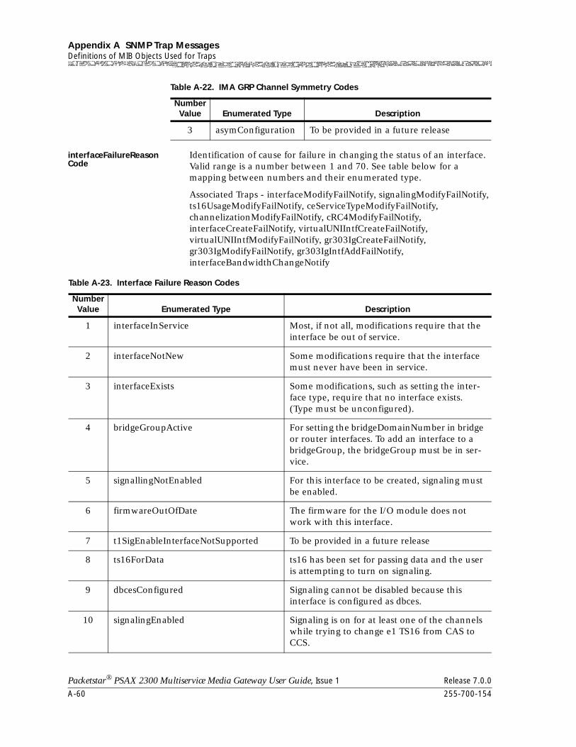
Appendix A SNMP Trap MessagesDefinitions of MIB Objects Used for Traps
A-60 255-700-154
Packetstar® PSAX 2300 Multiservice Media Gateway User Guide, Issue 1 Release 7.0.0
interfaceFailureReason Code
Identification of cause for failure in changing the status of an interface. Valid range is a number between 1 and 70. See table below for a mapping between numbers and their enumerated type.
Associated Traps - interfaceModifyFailNotify, signalingModifyFailNotify, ts16UsageModifyFailNotify, ceServiceTypeModifyFailNotify, channelizationModifyFailNotify, cRC4ModifyFailNotify, interfaceCreateFailNotify, virtualUNIIntfCreateFailNotify, virtualUNIIntfModifyFailNotify, gr303IgCreateFailNotify, gr303IgModifyFailNotify, gr303IgIntfAddFailNotify, interfaceBandwidthChangeNotify
3 asymConfiguration To be provided in a future release
Table A-22. IMA GRP Channel Symmetry Codes
Number Value Enumerated Type Description
Table A-23. Interface Failure Reason Codes
Number Value Enumerated Type Description
1 interfaceInService Most, if not all, modifications require that the interface be out of service.
2 interfaceNotNew Some modifications require that the interface must never have been in service.
3 interfaceExists Some modifications, such as setting the inter-face type, require that no interface exists. (Type must be unconfigured).
4 bridgeGroupActive For setting the bridgeDomainNumber in bridge or router interfaces. To add an interface to a bridgeGroup, the bridgeGroup must be in ser-vice.
5 signallingNotEnabled For this interface to be created, signaling must be enabled.
6 firmwareOutOfDate The firmware for the I/O module does not work with this interface.
7 t1SigEnableInterfaceNotSupported To be provided in a future release
8 ts16ForData ts16 has been set for passing data and the user is attempting to turn on signaling.
9 dbcesConfigured Signaling cannot be disabled because this interface is configured as dbces.
10 signalingEnabled Signaling is on for at least one of the channels while trying to change e1 TS16 from CAS to CCS.
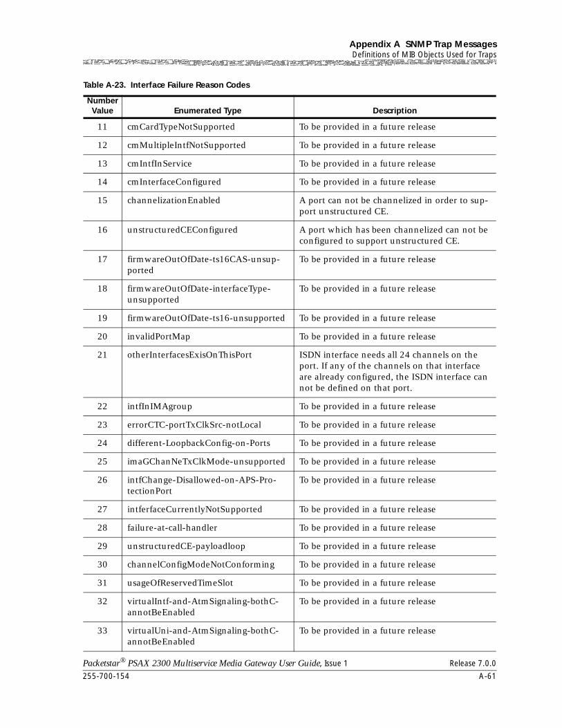
255-700-154 A-61
Packetstar® PSAX 2300 Multiservice Media Gateway User Guide, Issue 1 Release 7.0.0
Appendix A SNMP Trap MessagesDefinitions of MIB Objects Used for Traps
11 cmCardTypeNotSupported To be provided in a future release
12 cmMultipleIntfNotSupported To be provided in a future release
13 cmIntfInService To be provided in a future release
14 cmInterfaceConfigured To be provided in a future release
15 channelizationEnabled A port can not be channelized in order to sup-port unstructured CE.
16 unstructuredCEConfigured A port which has been channelized can not be configured to support unstructured CE.
17 firmwareOutOfDate-ts16CAS-unsup-ported
To be provided in a future release
18 firmwareOutOfDate-interfaceType-unsupported
To be provided in a future release
19 firmwareOutOfDate-ts16-unsupported To be provided in a future release
20 invalidPortMap To be provided in a future release
21 otherInterfacesExisOnThisPort ISDN interface needs all 24 channels on the port. If any of the channels on that interface are already configured, the ISDN interface can not be defined on that port.
22 intfInIMAgroup To be provided in a future release
23 errorCTC-portTxClkSrc-notLocal To be provided in a future release
24 different-LoopbackConfig-on-Ports To be provided in a future release
25 imaGChanNeTxClkMode-unsupported To be provided in a future release
26 intfChange-Disallowed-on-APS-Pro-tectionPort
To be provided in a future release
27 intferfaceCurrentlyNotSupported To be provided in a future release
28 failure-at-call-handler To be provided in a future release
29 unstructuredCE-payloadloop To be provided in a future release
30 channelConfigModeNotConforming To be provided in a future release
31 usageOfReservedTimeSlot To be provided in a future release
32 virtualIntf-and-AtmSignaling-bothC-annotBeEnabled
To be provided in a future release
33 virtualUni-and-AtmSignaling-bothC-annotBeEnabled
To be provided in a future release
Table A-23. Interface Failure Reason Codes
Number Value Enumerated Type Description
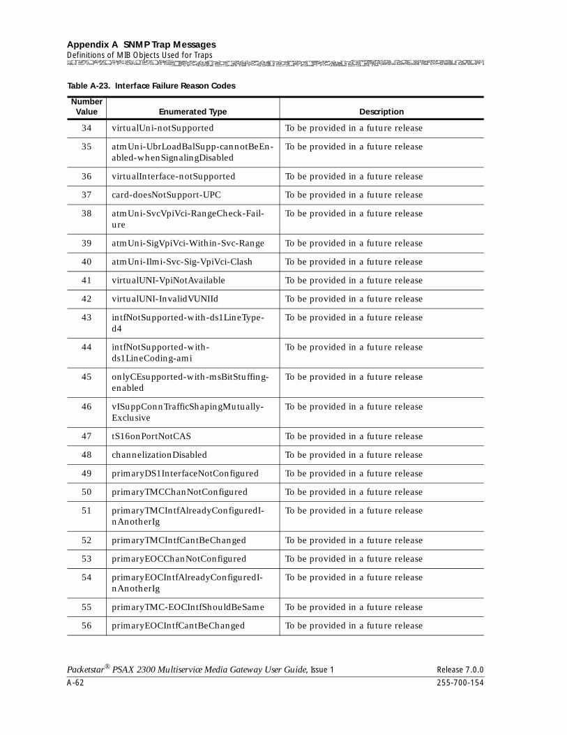
Appendix A SNMP Trap MessagesDefinitions of MIB Objects Used for Traps
A-62 255-700-154
Packetstar® PSAX 2300 Multiservice Media Gateway User Guide, Issue 1 Release 7.0.0
34 virtualUni-notSupported To be provided in a future release
35 atmUni-UbrLoadBalSupp-cannotBeEn-abled-whenSignalingDisabled
To be provided in a future release
36 virtualInterface-notSupported To be provided in a future release
37 card-doesNotSupport-UPC To be provided in a future release
38 atmUni-SvcVpiVci-RangeCheck-Fail-ure
To be provided in a future release
39 atmUni-SigVpiVci-Within-Svc-Range To be provided in a future release
40 atmUni-Ilmi-Svc-Sig-VpiVci-Clash To be provided in a future release
41 virtualUNI-VpiNotAvailable To be provided in a future release
42 virtualUNI-InvalidVUNIId To be provided in a future release
43 intfNotSupported-with-ds1LineType-d4
To be provided in a future release
44 intfNotSupported-with-ds1LineCoding-ami
To be provided in a future release
45 onlyCEsupported-with-msBitStuffing-enabled
To be provided in a future release
46 vISuppConnTrafficShapingMutually-Exclusive
To be provided in a future release
47 tS16onPortNotCAS To be provided in a future release
48 channelizationDisabled To be provided in a future release
49 primaryDS1InterfaceNotConfigured To be provided in a future release
50 primaryTMCChanNotConfigured To be provided in a future release
51 primaryTMCIntfAlreadyConfiguredI-nAnotherIg
To be provided in a future release
52 primaryTMCIntfCantBeChanged To be provided in a future release
53 primaryEOCChanNotConfigured To be provided in a future release
54 primaryEOCIntfAlreadyConfiguredI-nAnotherIg
To be provided in a future release
55 primaryTMC-EOCIntfShouldBeSame To be provided in a future release
56 primaryEOCIntfCantBeChanged To be provided in a future release
Table A-23. Interface Failure Reason Codes
Number Value Enumerated Type Description
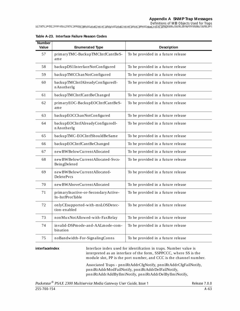
255-700-154 A-63
Packetstar® PSAX 2300 Multiservice Media Gateway User Guide, Issue 1 Release 7.0.0
Appendix A SNMP Trap MessagesDefinitions of MIB Objects Used for Traps
interfaceIndex Interface index used for identifcation in traps. Number value is interpreted as an interface of the form, SSPPCCC, where SS is the module slot, PP is the port number, and CCC is the channel number.
Associated Traps - pnniRtAddrCfgNotify, pnniRtAddrCfgFailNotify, pnniRtAddrModFailNotify, pnniRtAddrDelFailNotify, pnniRtAddrAddByIlmiNotify, pnniRtAddrDelByIlmiNotify,
57 primaryTMC-BackupTMCIntfCantBeS-ame
To be provided in a future release
58 backupDS1InterfaceNotConfigured To be provided in a future release
59 backupTMCChanNotConfigured To be provided in a future release
60 backupTMCIntfAlreadyConfiguredI-nAnotherIg
To be provided in a future release
61 backupTMCIntfCantBeChanged To be provided in a future release
62 primaryEOC-BackupEOCIntfCantBeS-ame
To be provided in a future release
63 backupEOCChanNotConfigured To be provided in a future release
64 backupEOCIntfAlreadyConfiguredI-nAnotherIg
To be provided in a future release
65 backupTMC-EOCIntfShouldBeSame To be provided in a future release
66 backupEOCIntfCantBeChanged To be provided in a future release
67 newBWBelowCurrentAllocated To be provided in a future release
68 newBWBelowCurrentAllocated-Svcs-BeingDeleted
To be provided in a future release
69 newBWBelowCurrentAllocated-DeletePvcs
To be provided in a future release
70 newBWAboveCurrentAllocated To be provided in a future release
71 primaryInactive-or-SecondaryActive-In-IntfProtTable
To be provided in a future release
72 onlyCEsupported-with-msLOSDetec-tion-enabled
To be provided in a future release
73 nonMuxNotAllowed-with-FaxRelay To be provided in a future release
74 invalid-DSPmode-and-AALmode-com-bination
To be provided in a future release
75 noBandwidth-For-SignalingConns To be provided in a future release
Table A-23. Interface Failure Reason Codes
Number Value Enumerated Type Description
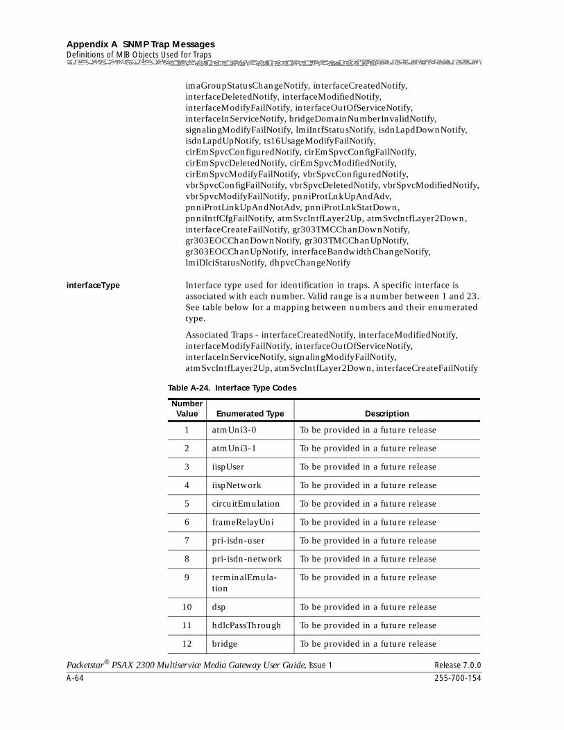
Appendix A SNMP Trap MessagesDefinitions of MIB Objects Used for Traps
A-64 255-700-154
Packetstar® PSAX 2300 Multiservice Media Gateway User Guide, Issue 1 Release 7.0.0
imaGroupStatusChangeNotify, interfaceCreatedNotify, interfaceDeletedNotify, interfaceModifiedNotify, interfaceModifyFailNotify, interfaceOutOfServiceNotify, interfaceInServiceNotify, bridgeDomainNumberInvalidNotify, signalingModifyFailNotify, lmiIntfStatusNotify, isdnLapdDownNotify, isdnLapdUpNotify, ts16UsageModifyFailNotify, cirEmSpvcConfiguredNotify, cirEmSpvcConfigFailNotify, cirEmSpvcDeletedNotify, cirEmSpvcModifiedNotify, cirEmSpvcModifyFailNotify, vbrSpvcConfiguredNotify, vbrSpvcConfigFailNotify, vbrSpvcDeletedNotify, vbrSpvcModifiedNotify, vbrSpvcModifyFailNotify, pnniProtLnkUpAndAdv, pnniProtLinkUpAndNotAdv, pnniProtLnkStatDown, pnniIntfCfgFailNotify, atmSvcIntfLayer2Up, atmSvcIntfLayer2Down, interfaceCreateFailNotify, gr303TMCChanDownNotify, gr303EOCChanDownNotify, gr303TMCChanUpNotify, gr303EOCChanUpNotify, interfaceBandwidthChangeNotify, lmiDlciStatusNotify, dhpvcChangeNotify
interfaceType Interface type used for identification in traps. A specific interface is associated with each number. Valid range is a number between 1 and 23. See table below for a mapping between numbers and their enumerated type.
Associated Traps - interfaceCreatedNotify, interfaceModifiedNotify, interfaceModifyFailNotify, interfaceOutOfServiceNotify, interfaceInServiceNotify, signalingModifyFailNotify, atmSvcIntfLayer2Up, atmSvcIntfLayer2Down, interfaceCreateFailNotify
Table A-24. Interface Type Codes
Number Value Enumerated Type Description
1 atmUni3-0 To be provided in a future release
2 atmUni3-1 To be provided in a future release
3 iispUser To be provided in a future release
4 iispNetwork To be provided in a future release
5 circuitEmulation To be provided in a future release
6 frameRelayUni To be provided in a future release
7 pri-isdn-user To be provided in a future release
8 pri-isdn-network To be provided in a future release
9 terminalEmula-tion
To be provided in a future release
10 dsp To be provided in a future release
11 hdlcPassThrough To be provided in a future release
12 bridge To be provided in a future release
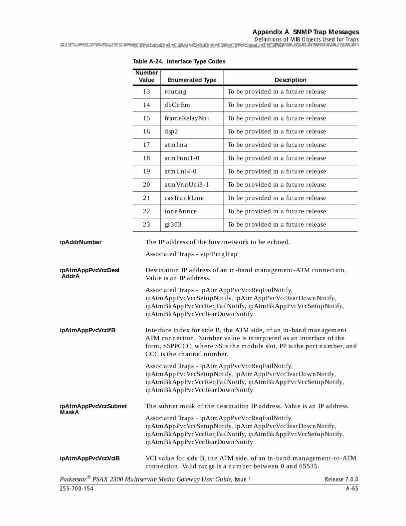
255-700-154 A-65
Packetstar® PSAX 2300 Multiservice Media Gateway User Guide, Issue 1 Release 7.0.0
Appendix A SNMP Trap MessagesDefinitions of MIB Objects Used for Traps
ipAddrNumber The IP address of the host/network to be echoed.
Associated Traps - viprPingTrap
ipAtmAppPvcVccDest AddrA
Destination IP address of an in-band management-ATM connection. Value is an IP address.
Associated Traps - ipAtmAppPvcVccReqFailNotify, ipAtmAppPvcVccSetupNotify, ipAtmAppPvcVccTearDownNotify, ipAtmBkAppPvcVccReqFailNotify, ipAtmBkAppPvcVccSetupNotify, ipAtmBkAppPvcVccTearDownNotify
ipAtmAppPvcVccIfB Interface index for side B, the ATM side, of an in-band management ATM connection. Number value is interpreted as an interface of the form, SSPPCCC, where SS is the module slot, PP is the port number, and CCC is the channel number.
Associated Traps - ipAtmAppPvcVccReqFailNotify, ipAtmAppPvcVccSetupNotify, ipAtmAppPvcVccTearDownNotify, ipAtmBkAppPvcVccReqFailNotify, ipAtmBkAppPvcVccSetupNotify, ipAtmBkAppPvcVccTearDownNotify
ipAtmAppPvcVccSubnetMaskA
The subnet mask of the destination IP address. Value is an IP address.
Associated Traps - ipAtmAppPvcVccReqFailNotify, ipAtmAppPvcVccSetupNotify, ipAtmAppPvcVccTearDownNotify, ipAtmBkAppPvcVccReqFailNotify, ipAtmBkAppPvcVccSetupNotify, ipAtmBkAppPvcVccTearDownNotify
ipAtmAppPvcVccVciB VCI value for side B, the ATM side, of an in-band management-to-ATM connection. Valid range is a number between 0 and 65535.
13 routing To be provided in a future release
14 dbCirEm To be provided in a future release
15 frameRelayNni To be provided in a future release
16 dsp2 To be provided in a future release
17 atmIma To be provided in a future release
18 atmPnni1-0 To be provided in a future release
19 atmUni4-0 To be provided in a future release
20 atmVnnUni3-1 To be provided in a future release
21 casTrunkLine To be provided in a future release
22 toneAnnce To be provided in a future release
23 gr303 To be provided in a future release
Table A-24. Interface Type Codes
Number Value Enumerated Type Description
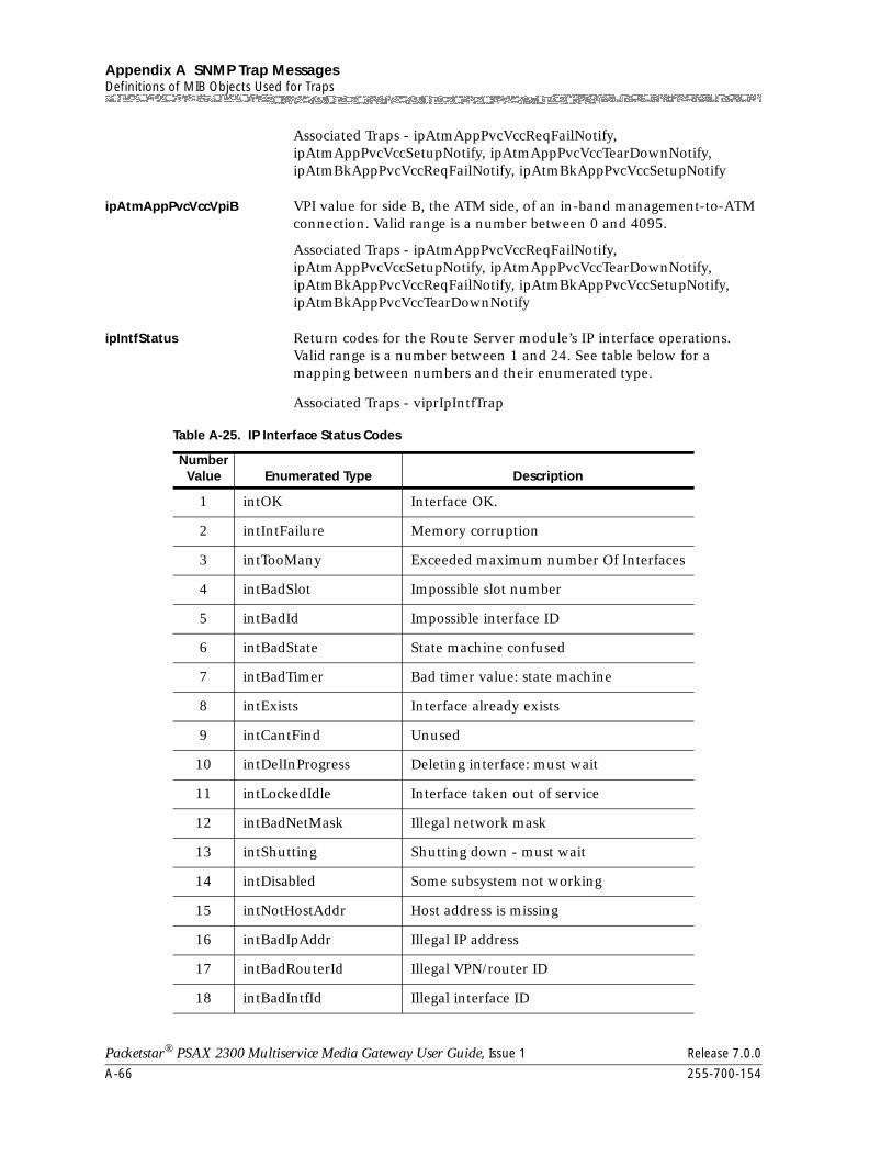
Appendix A SNMP Trap MessagesDefinitions of MIB Objects Used for Traps
A-66 255-700-154
Packetstar® PSAX 2300 Multiservice Media Gateway User Guide, Issue 1 Release 7.0.0
Associated Traps - ipAtmAppPvcVccReqFailNotify, ipAtmAppPvcVccSetupNotify, ipAtmAppPvcVccTearDownNotify, ipAtmBkAppPvcVccReqFailNotify, ipAtmBkAppPvcVccSetupNotify
ipAtmAppPvcVccVpiB VPI value for side B, the ATM side, of an in-band management-to-ATM connection. Valid range is a number between 0 and 4095.
Associated Traps - ipAtmAppPvcVccReqFailNotify, ipAtmAppPvcVccSetupNotify, ipAtmAppPvcVccTearDownNotify, ipAtmBkAppPvcVccReqFailNotify, ipAtmBkAppPvcVccSetupNotify, ipAtmBkAppPvcVccTearDownNotify
ipIntfStatus Return codes for the Route Server module’s IP interface operations. Valid range is a number between 1 and 24. See table below for a mapping between numbers and their enumerated type.
Associated Traps - viprIpIntfTrap
Table A-25. IP Interface Status Codes
Number Value Enumerated Type Description
1 intOK Interface OK.
2 intIntFailure Memory corruption
3 intTooMany Exceeded maximum number Of Interfaces
4 intBadSlot Impossible slot number
5 intBadId Impossible interface ID
6 intBadState State machine confused
7 intBadTimer Bad timer value: state machine
8 intExists Interface already exists
9 intCantFind Unused
10 intDelInProgress Deleting interface: must wait
11 intLockedIdle Interface taken out of service
12 intBadNetMask Illegal network mask
13 intShutting Shutting down - must wait
14 intDisabled Some subsystem not working
15 intNotHostAddr Host address is missing
16 intBadIpAddr Illegal IP address
17 intBadRouterId Illegal VPN/router ID
18 intBadIntfId Illegal interface ID
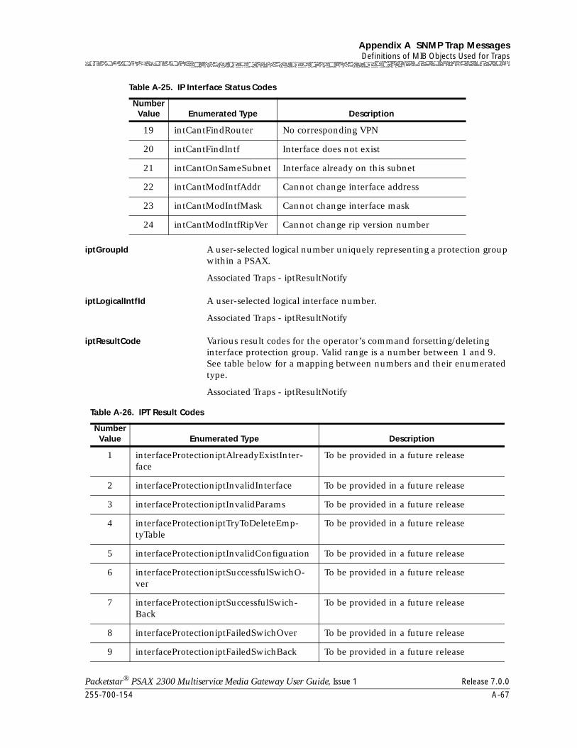
255-700-154 A-67
Packetstar® PSAX 2300 Multiservice Media Gateway User Guide, Issue 1 Release 7.0.0
Appendix A SNMP Trap MessagesDefinitions of MIB Objects Used for Traps
iptGroupId A user-selected logical number uniquely representing a protection group within a PSAX.
Associated Traps - iptResultNotify
iptLogicalIntfId A user-selected logical interface number.
Associated Traps - iptResultNotify
iptResultCode Various result codes for the operator’s command forsetting/deleting interface protection group. Valid range is a number between 1 and 9. See table below for a mapping between numbers and their enumerated type.
Associated Traps - iptResultNotify
19 intCantFindRouter No corresponding VPN
20 intCantFindIntf Interface does not exist
21 intCantOnSameSubnet Interface already on this subnet
22 intCantModIntfAddr Cannot change interface address
23 intCantModIntfMask Cannot change interface mask
24 intCantModIntfRipVer Cannot change rip version number
Table A-25. IP Interface Status Codes
Number Value Enumerated Type Description
Table A-26. IPT Result Codes
Number Value Enumerated Type Description
1 interfaceProtectioniptAlreadyExistInter-face
To be provided in a future release
2 interfaceProtectioniptInvalidInterface To be provided in a future release
3 interfaceProtectioniptInvalidParams To be provided in a future release
4 interfaceProtectioniptTryToDeleteEmp-tyTable
To be provided in a future release
5 interfaceProtectioniptInvalidConfiguation To be provided in a future release
6 interfaceProtectioniptSuccessfulSwichO-ver
To be provided in a future release
7 interfaceProtectioniptSuccessfulSwich-Back
To be provided in a future release
8 interfaceProtectioniptFailedSwichOver To be provided in a future release
9 interfaceProtectioniptFailedSwichBack To be provided in a future release
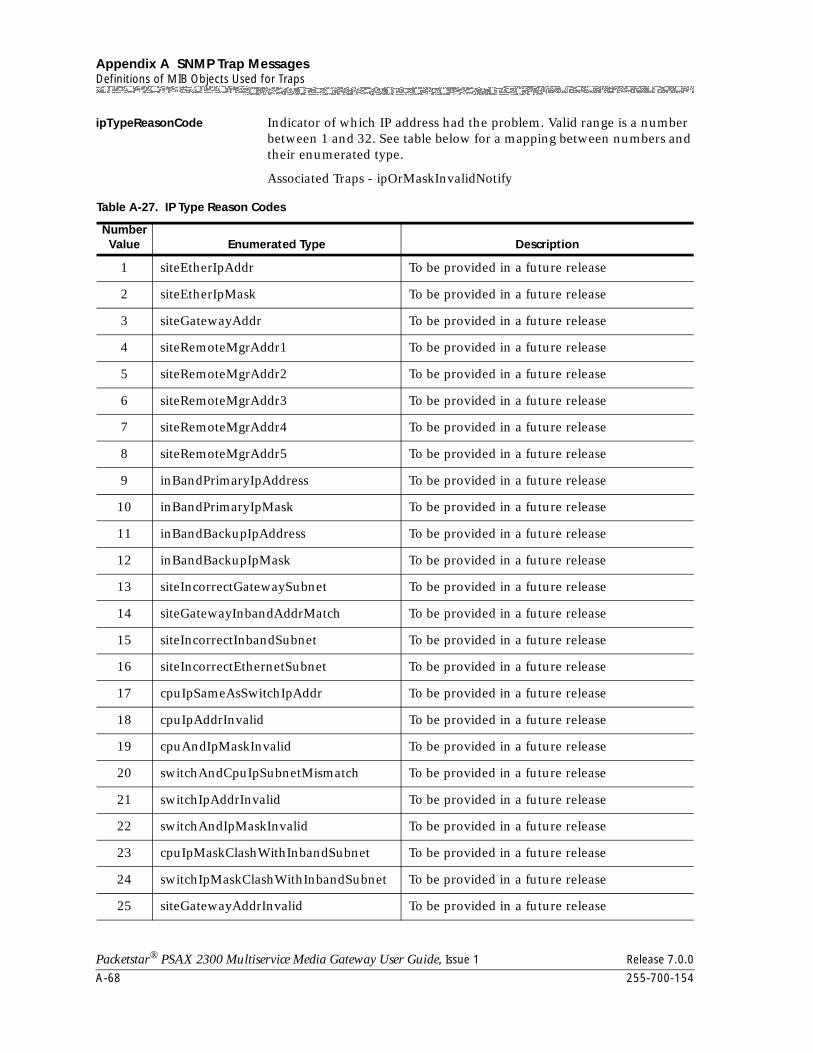
Appendix A SNMP Trap MessagesDefinitions of MIB Objects Used for Traps
A-68 255-700-154
Packetstar® PSAX 2300 Multiservice Media Gateway User Guide, Issue 1 Release 7.0.0
ipTypeReasonCode Indicator of which IP address had the problem. Valid range is a number between 1 and 32. See table below for a mapping between numbers and their enumerated type.
Associated Traps - ipOrMaskInvalidNotify
Table A-27. IP Type Reason Codes
Number Value Enumerated Type Description
1 siteEtherIpAddr To be provided in a future release
2 siteEtherIpMask To be provided in a future release
3 siteGatewayAddr To be provided in a future release
4 siteRemoteMgrAddr1 To be provided in a future release
5 siteRemoteMgrAddr2 To be provided in a future release
6 siteRemoteMgrAddr3 To be provided in a future release
7 siteRemoteMgrAddr4 To be provided in a future release
8 siteRemoteMgrAddr5 To be provided in a future release
9 inBandPrimaryIpAddress To be provided in a future release
10 inBandPrimaryIpMask To be provided in a future release
11 inBandBackupIpAddress To be provided in a future release
12 inBandBackupIpMask To be provided in a future release
13 siteIncorrectGatewaySubnet To be provided in a future release
14 siteGatewayInbandAddrMatch To be provided in a future release
15 siteIncorrectInbandSubnet To be provided in a future release
16 siteIncorrectEthernetSubnet To be provided in a future release
17 cpuIpSameAsSwitchIpAddr To be provided in a future release
18 cpuIpAddrInvalid To be provided in a future release
19 cpuAndIpMaskInvalid To be provided in a future release
20 switchAndCpuIpSubnetMismatch To be provided in a future release
21 switchIpAddrInvalid To be provided in a future release
22 switchAndIpMaskInvalid To be provided in a future release
23 cpuIpMaskClashWithInbandSubnet To be provided in a future release
24 switchIpMaskClashWithInbandSubnet To be provided in a future release
25 siteGatewayAddrInvalid To be provided in a future release
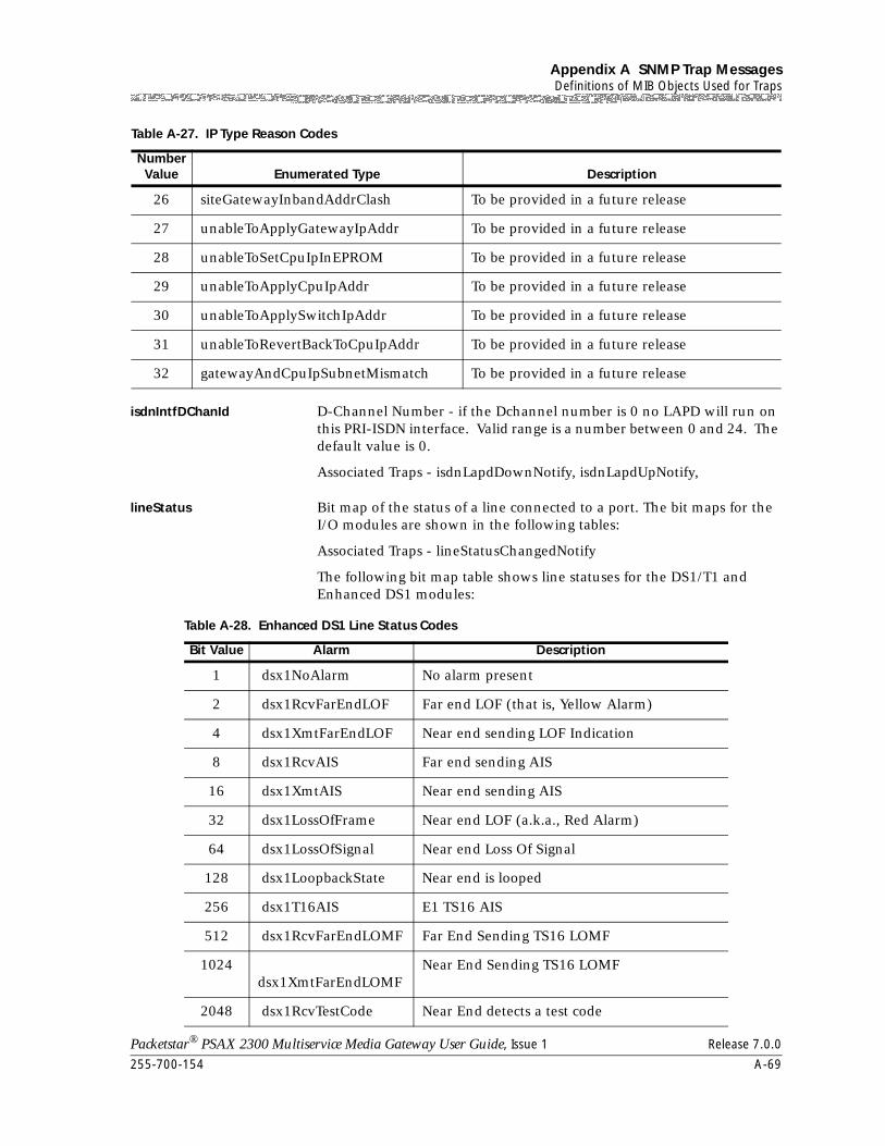
255-700-154 A-69
Packetstar® PSAX 2300 Multiservice Media Gateway User Guide, Issue 1 Release 7.0.0
Appendix A SNMP Trap MessagesDefinitions of MIB Objects Used for Traps
isdnIntfDChanId D-Channel Number - if the Dchannel number is 0 no LAPD will run on this PRI-ISDN interface. Valid range is a number between 0 and 24. The default value is 0.
Associated Traps - isdnLapdDownNotify, isdnLapdUpNotify,
lineStatus Bit map of the status of a line connected to a port. The bit maps for the I/O modules are shown in the following tables:
Associated Traps - lineStatusChangedNotify
The following bit map table shows line statuses for the DS1/T1 and Enhanced DS1 modules:
26 siteGatewayInbandAddrClash To be provided in a future release
27 unableToApplyGatewayIpAddr To be provided in a future release
28 unableToSetCpuIpInEPROM To be provided in a future release
29 unableToApplyCpuIpAddr To be provided in a future release
30 unableToApplySwitchIpAddr To be provided in a future release
31 unableToRevertBackToCpuIpAddr To be provided in a future release
32 gatewayAndCpuIpSubnetMismatch To be provided in a future release
Table A-27. IP Type Reason Codes
Number Value Enumerated Type Description
Table A-28. Enhanced DS1 Line Status Codes
Bit Value Alarm Description
1 dsx1NoAlarm No alarm present
2 dsx1RcvFarEndLOF Far end LOF (that is, Yellow Alarm)
4 dsx1XmtFarEndLOF Near end sending LOF Indication
8 dsx1RcvAIS Far end sending AIS
16 dsx1XmtAIS Near end sending AIS
32 dsx1LossOfFrame Near end LOF (a.k.a., Red Alarm)
64 dsx1LossOfSignal Near end Loss Of Signal
128 dsx1LoopbackState Near end is looped
256 dsx1T16AIS E1 TS16 AIS
512 dsx1RcvFarEndLOMF Far End Sending TS16 LOMF
1024 dsx1XmtFarEndLOMF
Near End Sending TS16 LOMF
2048 dsx1RcvTestCode Near End detects a test code
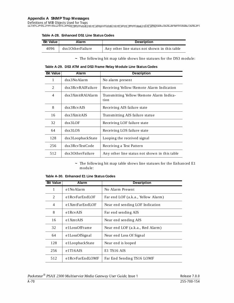
Appendix A SNMP Trap MessagesDefinitions of MIB Objects Used for Traps
A-70 255-700-154
Packetstar® PSAX 2300 Multiservice Media Gateway User Guide, Issue 1 Release 7.0.0
~ The following bit map table shows line statuses for the DS3 module:
~ The following bit map table shows line statuses for the Enhanced E1 module:
4096 dsx1OtherFailure Any other line status not shown in this table
Table A-28. Enhanced DS1 Line Status Codes
Bit Value Alarm Description
Table A-29. DS3 ATM and DS3 Frame Relay Module Line Status Codes
Bit Value Alarm Description
1 dsx3NoAlarm No alarm present
2 dsx3RcvRAIFailure Receiving Yellow/Remote Alarm Indication
4 dsx3XmitRAIAlarm Transmitting Yellow/Remote Alarm Indica-tion
8 dsx3RcvAIS Receiving AIS failure state
16 dsx3XmitAIS Transmitting AIS failure statue
32 dsx3LOF Receiving LOF failure state
64 dsx3LOS Receiving LOS failure state
128 dsx3LoopbackState Looping the received signal
256 dsx3RcvTestCode Receiving a Test Pattern
512 dsx3OtherFailure Any other line status not shown in this table
Table A-30. Enhanced E1 Line Status Codes
Bit Value Alarm Description
1 e1NoAlarm No Alarm Present
2 e1RcvFarEndLOF Far end LOF (a.k.a., Yellow Alarm)
4 e1XmtFarEndLOF Near end sending LOF Indication
8 e1RcvAIS Far end sending AIS
16 e1XmtAIS Near end sending AIS
32 e1LossOfFrame Near end LOF (a.k.a., Red Alarm)
64 e1LossOfSignal Near end Loss Of Signal
128 e1LoopbackState Near end is looped
256 e1T16AIS E1 TS16 AIS
512 e1RcvFarEndLOMF Far End Sending TS16 LOMF
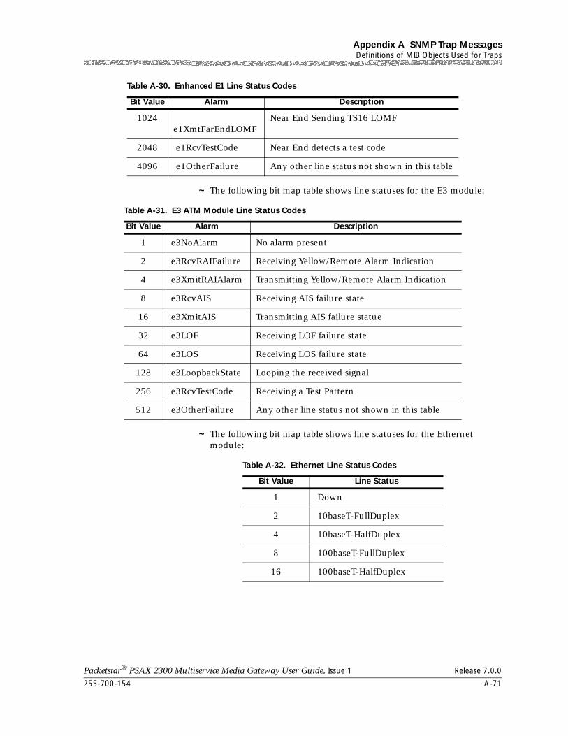
255-700-154 A-71
Packetstar® PSAX 2300 Multiservice Media Gateway User Guide, Issue 1 Release 7.0.0
Appendix A SNMP Trap MessagesDefinitions of MIB Objects Used for Traps
~ The following bit map table shows line statuses for the E3 module:
~ The following bit map table shows line statuses for the Ethernet module:
1024 e1XmtFarEndLOMF
Near End Sending TS16 LOMF
2048 e1RcvTestCode Near End detects a test code
4096 e1OtherFailure Any other line status not shown in this table
Table A-30. Enhanced E1 Line Status Codes
Bit Value Alarm Description
Table A-31. E3 ATM Module Line Status Codes
Bit Value Alarm Description
1 e3NoAlarm No alarm present
2 e3RcvRAIFailure Receiving Yellow/Remote Alarm Indication
4 e3XmitRAIAlarm Transmitting Yellow/Remote Alarm Indication
8 e3RcvAIS Receiving AIS failure state
16 e3XmitAIS Transmitting AIS failure statue
32 e3LOF Receiving LOF failure state
64 e3LOS Receiving LOS failure state
128 e3LoopbackState Looping the received signal
256 e3RcvTestCode Receiving a Test Pattern
512 e3OtherFailure Any other line status not shown in this table
Table A-32. Ethernet Line Status Codes
Bit Value Line Status
1 Down
2 10baseT-FullDuplex
4 10baseT-HalfDuplex
8 100baseT-FullDuplex
16 100baseT-HalfDuplex
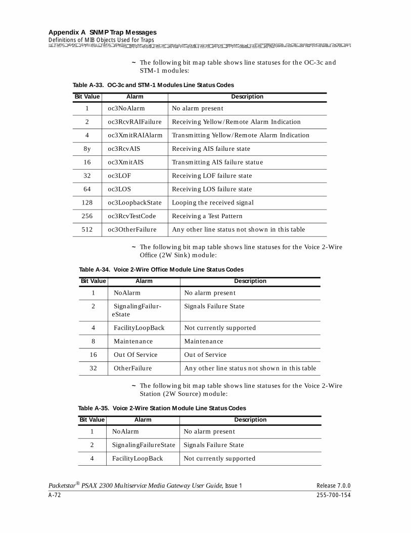
Appendix A SNMP Trap MessagesDefinitions of MIB Objects Used for Traps
A-72 255-700-154
Packetstar® PSAX 2300 Multiservice Media Gateway User Guide, Issue 1 Release 7.0.0
~ The following bit map table shows line statuses for the OC-3c and STM-1 modules:
~ The following bit map table shows line statuses for the Voice 2-Wire Office (2W Sink) module:
~ The following bit map table shows line statuses for the Voice 2-Wire Station (2W Source) module:
Table A-33. OC-3c and STM-1 Modules Line Status Codes
Bit Value Alarm Description
1 oc3NoAlarm No alarm present
2 oc3RcvRAIFailure Receiving Yellow/Remote Alarm Indication
4 oc3XmitRAIAlarm Transmitting Yellow/Remote Alarm Indication
8y oc3RcvAIS Receiving AIS failure state
16 oc3XmitAIS Transmitting AIS failure statue
32 oc3LOF Receiving LOF failure state
64 oc3LOS Receiving LOS failure state
128 oc3LoopbackState Looping the received signal
256 oc3RcvTestCode Receiving a Test Pattern
512 oc3OtherFailure Any other line status not shown in this table
Table A-34. Voice 2-Wire Office Module Line Status Codes
Bit Value Alarm Description
1 NoAlarm No alarm present
2 SignalingFailur-eState
Signals Failure State
4 FacilityLoopBack Not currently supported
8 Maintenance Maintenance
16 Out Of Service Out of Service
32 OtherFailure Any other line status not shown in this table
Table A-35. Voice 2-Wire Station Module Line Status Codes
Bit Value Alarm Description
1 NoAlarm No alarm present
2 SignalingFailureState Signals Failure State
4 FacilityLoopBack Not currently supported
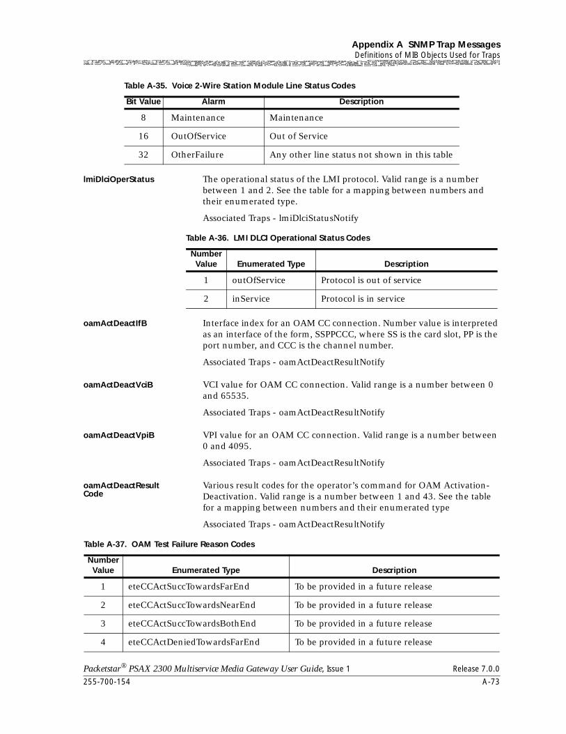
255-700-154 A-73
Packetstar® PSAX 2300 Multiservice Media Gateway User Guide, Issue 1 Release 7.0.0
Appendix A SNMP Trap MessagesDefinitions of MIB Objects Used for Traps
lmiDlciOperStatus The operational status of the LMI protocol. Valid range is a number between 1 and 2. See the table for a mapping between numbers and their enumerated type.
Associated Traps - lmiDlciStatusNotify
oamActDeactIfB Interface index for an OAM CC connection. Number value is interpreted as an interface of the form, SSPPCCC, where SS is the card slot, PP is the port number, and CCC is the channel number.
Associated Traps - oamActDeactResultNotify
oamActDeactVciB VCI value for OAM CC connection. Valid range is a number between 0 and 65535.
Associated Traps - oamActDeactResultNotify
oamActDeactVpiB VPI value for an OAM CC connection. Valid range is a number between 0 and 4095.
Associated Traps - oamActDeactResultNotify
oamActDeactResultCode
Various result codes for the operator’s command for OAM Activation-Deactivation. Valid range is a number between 1 and 43. See the table for a mapping between numbers and their enumerated type
Associated Traps - oamActDeactResultNotify
8 Maintenance Maintenance
16 OutOfService Out of Service
32 OtherFailure Any other line status not shown in this table
Table A-35. Voice 2-Wire Station Module Line Status Codes
Bit Value Alarm Description
Table A-36. LMI DLCI Operational Status Codes
Number Value Enumerated Type Description
1 outOfService Protocol is out of service
2 inService Protocol is in service
Table A-37. OAM Test Failure Reason Codes
Number Value Enumerated Type Description
1 eteCCActSuccTowardsFarEnd To be provided in a future release
2 eteCCActSuccTowardsNearEnd To be provided in a future release
3 eteCCActSuccTowardsBothEnd To be provided in a future release
4 eteCCActDeniedTowardsFarEnd To be provided in a future release
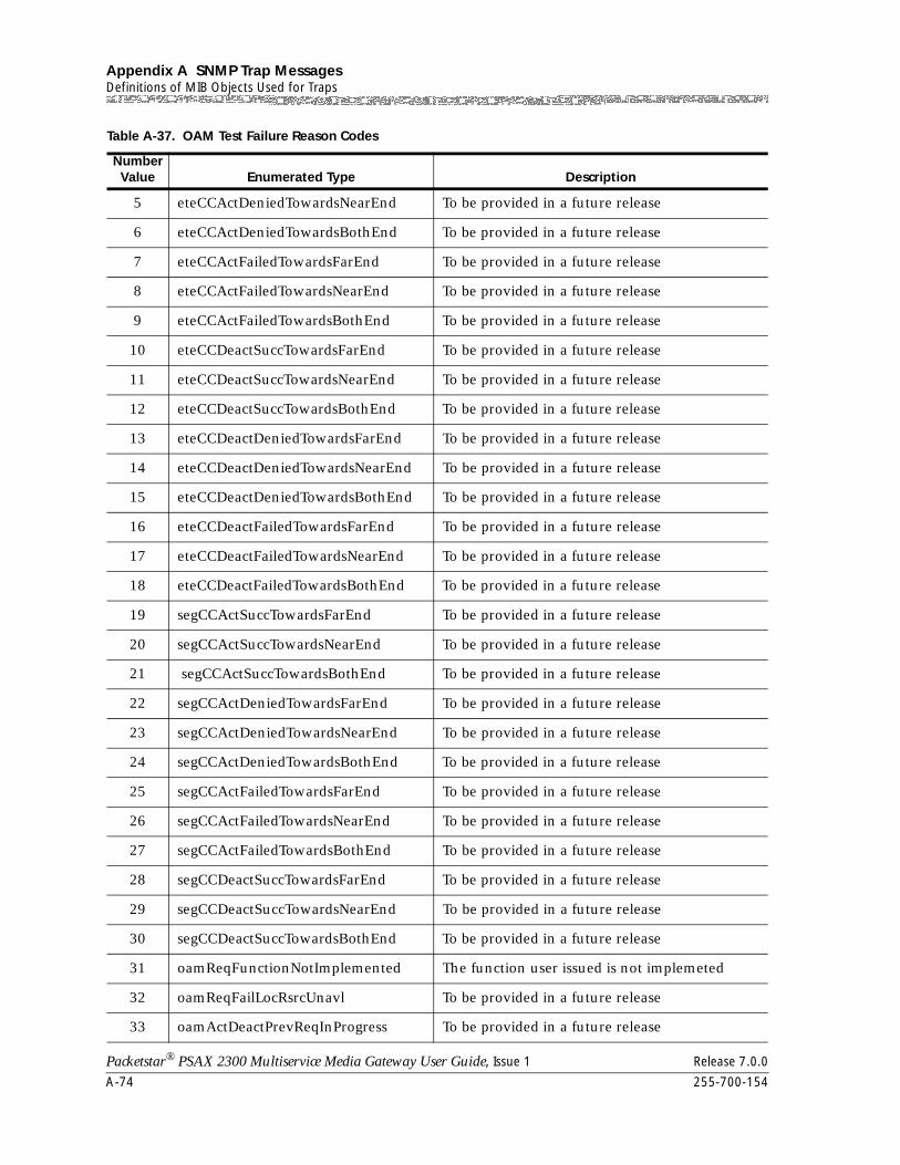
Appendix A SNMP Trap MessagesDefinitions of MIB Objects Used for Traps
A-74 255-700-154
Packetstar® PSAX 2300 Multiservice Media Gateway User Guide, Issue 1 Release 7.0.0
5 eteCCActDeniedTowardsNearEnd To be provided in a future release
6 eteCCActDeniedTowardsBothEnd To be provided in a future release
7 eteCCActFailedTowardsFarEnd To be provided in a future release
8 eteCCActFailedTowardsNearEnd To be provided in a future release
9 eteCCActFailedTowardsBothEnd To be provided in a future release
10 eteCCDeactSuccTowardsFarEnd To be provided in a future release
11 eteCCDeactSuccTowardsNearEnd To be provided in a future release
12 eteCCDeactSuccTowardsBothEnd To be provided in a future release
13 eteCCDeactDeniedTowardsFarEnd To be provided in a future release
14 eteCCDeactDeniedTowardsNearEnd To be provided in a future release
15 eteCCDeactDeniedTowardsBothEnd To be provided in a future release
16 eteCCDeactFailedTowardsFarEnd To be provided in a future release
17 eteCCDeactFailedTowardsNearEnd To be provided in a future release
18 eteCCDeactFailedTowardsBothEnd To be provided in a future release
19 segCCActSuccTowardsFarEnd To be provided in a future release
20 segCCActSuccTowardsNearEnd To be provided in a future release
21 segCCActSuccTowardsBothEnd To be provided in a future release
22 segCCActDeniedTowardsFarEnd To be provided in a future release
23 segCCActDeniedTowardsNearEnd To be provided in a future release
24 segCCActDeniedTowardsBothEnd To be provided in a future release
25 segCCActFailedTowardsFarEnd To be provided in a future release
26 segCCActFailedTowardsNearEnd To be provided in a future release
27 segCCActFailedTowardsBothEnd To be provided in a future release
28 segCCDeactSuccTowardsFarEnd To be provided in a future release
29 segCCDeactSuccTowardsNearEnd To be provided in a future release
30 segCCDeactSuccTowardsBothEnd To be provided in a future release
31 oamReqFunctionNotImplemented The function user issued is not implemeted
32 oamReqFailLocRsrcUnavl To be provided in a future release
33 oamActDeactPrevReqInProgress To be provided in a future release
Table A-37. OAM Test Failure Reason Codes
Number Value Enumerated Type Description
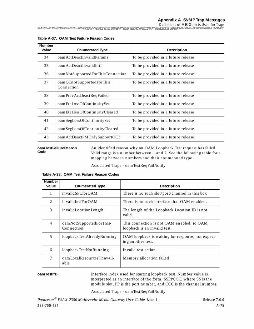
255-700-154 A-75
Packetstar® PSAX 2300 Multiservice Media Gateway User Guide, Issue 1 Release 7.0.0
Appendix A SNMP Trap MessagesDefinitions of MIB Objects Used for Traps
oamTestFailureReason Code
An identified reason why an OAM Loopback Test request has failed. Valid range is a number between 1 and 7. See the following table for a mapping between numbers and their enumerated type.
Associated Traps - oamTestReqFailNotify
oamTestIfB Interface index used for starting loopback test. Number value is interpreted as an interface of the form, SSPPCCC, where SS is the module slot, PP is the port number, and CCC is the channel number.
Associated Traps - oamTestReqFailNotify
34 oamActDeactInvalidParams To be provided in a future release
35 oamActDeactInvalidIntf To be provided in a future release
36 oamNotSupportedForThisConnection To be provided in a future release
37 oamCCnotSupportedForThisConnection
To be provided in a future release
38 oamPrevActDeactReqFailed To be provided in a future release
39 oamEteLossOfContinuitySet To be provided in a future release
40 oamEteLossOfContinuityCleared To be provided in a future release
41 oamSegLossOfContinuitySet To be provided in a future release
42 oamSegLossOfContinuityCleared To be provided in a future release
43 oamActDeactPMOnlySupportOC3 To be provided in a future release
Table A-37. OAM Test Failure Reason Codes
Number Value Enumerated Type Description
Table A-38. OAM Test Failure Reason Codes
Number Value Enumerated Type Description
1 invalidSPCforOAM There is no such slot/port/channel in this box
2 invalidIntfForOAM There is no such interface that OAM enabled.
3 invalidLocationLength The length of the Loopback Location ID is not valid.
4 oamNotSupportedForThis-Connection
This connection is not OAM enabled, so OAM loopback is an invalid test.
5 loopbackTestAlreadyRunning OAM loopback is waiting for response, not expect-ing another test.
6 loopbackTestNotRunning Invalid test action
7 oamLocalResourcesUnavail-able
Memory allocation failed
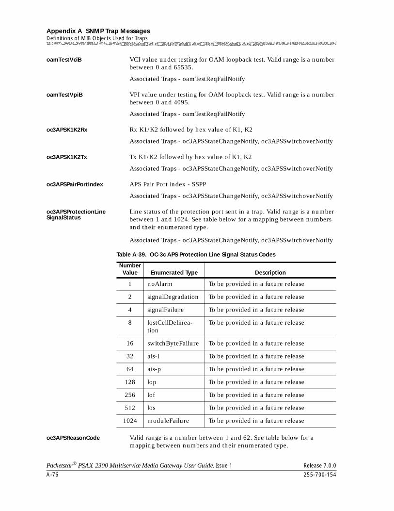
Appendix A SNMP Trap MessagesDefinitions of MIB Objects Used for Traps
A-76 255-700-154
Packetstar® PSAX 2300 Multiservice Media Gateway User Guide, Issue 1 Release 7.0.0
oamTestVciB VCI value under testing for OAM loopback test. Valid range is a number between 0 and 65535.
Associated Traps - oamTestReqFailNotify
oamTestVpiB VPI value under testing for OAM loopback test. Valid range is a number between 0 and 4095.
Associated Traps - oamTestReqFailNotify
oc3APSK1K2Rx Rx K1/K2 followed by hex value of K1, K2
Associated Traps - oc3APSStateChangeNotify, oc3APSSwitchoverNotify
oc3APSK1K2Tx Tx K1/K2 followed by hex value of K1, K2
Associated Traps - oc3APSStateChangeNotify, oc3APSSwitchoverNotify
oc3APSPairPortIndex APS Pair Port index - SSPP
Associated Traps - oc3APSStateChangeNotify, oc3APSSwitchoverNotify
oc3APSProtectionLine SignalStatus
Line status of the protection port sent in a trap. Valid range is a number between 1 and 1024. See table below for a mapping between numbers and their enumerated type.
Associated Traps - oc3APSStateChangeNotify, oc3APSSwitchoverNotify
oc3APSReasonCode Valid range is a number between 1 and 62. See table below for a mapping between numbers and their enumerated type.
Table A-39. OC-3c APS Protection Line Signal Status Codes
Number Value Enumerated Type Description
1 noAlarm To be provided in a future release
2 signalDegradation To be provided in a future release
4 signalFailure To be provided in a future release
8 lostCellDelinea-tion
To be provided in a future release
16 switchByteFailure To be provided in a future release
32 ais-l To be provided in a future release
64 ais-p To be provided in a future release
128 lop To be provided in a future release
256 lof To be provided in a future release
512 los To be provided in a future release
1024 moduleFailure To be provided in a future release
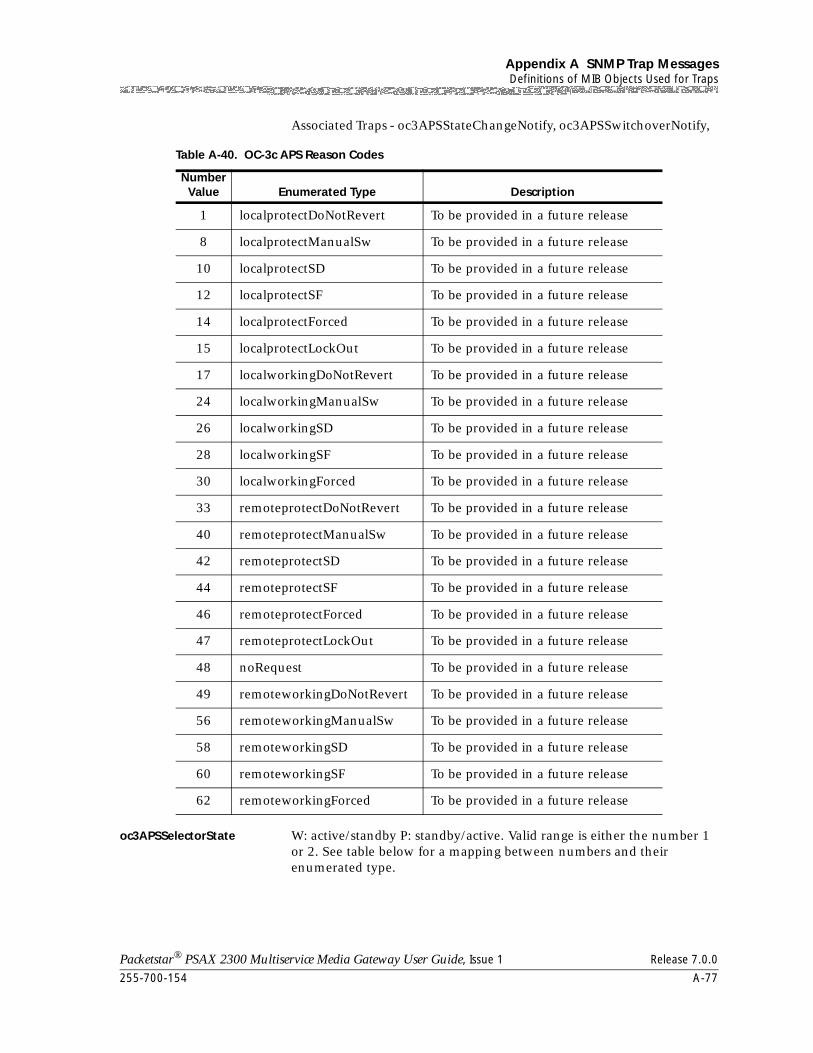
255-700-154 A-77
Packetstar® PSAX 2300 Multiservice Media Gateway User Guide, Issue 1 Release 7.0.0
Appendix A SNMP Trap MessagesDefinitions of MIB Objects Used for Traps
Associated Traps - oc3APSStateChangeNotify, oc3APSSwitchoverNotify,
oc3APSSelectorState W: active/standby P: standby/active. Valid range is either the number 1 or 2. See table below for a mapping between numbers and their enumerated type.
Table A-40. OC-3c APS Reason Codes
Number Value Enumerated Type Description
1 localprotectDoNotRevert To be provided in a future release
8 localprotectManualSw To be provided in a future release
10 localprotectSD To be provided in a future release
12 localprotectSF To be provided in a future release
14 localprotectForced To be provided in a future release
15 localprotectLockOut To be provided in a future release
17 localworkingDoNotRevert To be provided in a future release
24 localworkingManualSw To be provided in a future release
26 localworkingSD To be provided in a future release
28 localworkingSF To be provided in a future release
30 localworkingForced To be provided in a future release
33 remoteprotectDoNotRevert To be provided in a future release
40 remoteprotectManualSw To be provided in a future release
42 remoteprotectSD To be provided in a future release
44 remoteprotectSF To be provided in a future release
46 remoteprotectForced To be provided in a future release
47 remoteprotectLockOut To be provided in a future release
48 noRequest To be provided in a future release
49 remoteworkingDoNotRevert To be provided in a future release
56 remoteworkingManualSw To be provided in a future release
58 remoteworkingSD To be provided in a future release
60 remoteworkingSF To be provided in a future release
62 remoteworkingForced To be provided in a future release
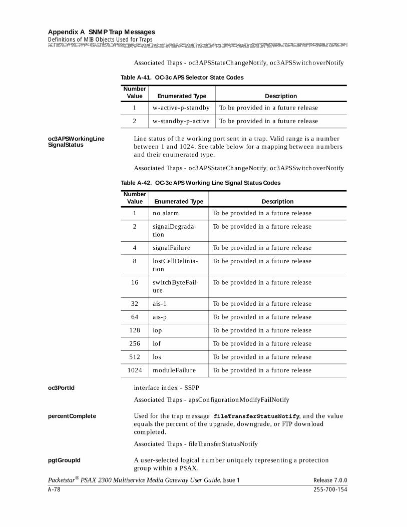
Appendix A SNMP Trap MessagesDefinitions of MIB Objects Used for Traps
A-78 255-700-154
Packetstar® PSAX 2300 Multiservice Media Gateway User Guide, Issue 1 Release 7.0.0
Associated Traps - oc3APSStateChangeNotify, oc3APSSwitchoverNotify
oc3APSWorkingLine SignalStatus
Line status of the working port sent in a trap. Valid range is a number between 1 and 1024. See table below for a mapping between numbers and their enumerated type.
Associated Traps - oc3APSStateChangeNotify, oc3APSSwitchoverNotify
oc3PortId interface index - SSPP
Associated Traps - apsConfigurationModifyFailNotify
percentComplete Used for the trap message fileTransferStatusNotify, and the value equals the percent of the upgrade, downgrade, or FTP download completed.
Associated Traps - fileTransferStatusNotify
pgtGroupId A user-selected logical number uniquely representing a protection group within a PSAX.
Table A-41. OC-3c APS Selector State Codes
Number Value Enumerated Type Description
1 w-active-p-standby To be provided in a future release
2 w-standby-p-active To be provided in a future release
Table A-42. OC-3c APS Working Line Signal Status Codes
Number Value Enumerated Type Description
1 no alarm To be provided in a future release
2 signalDegrada-tion
To be provided in a future release
4 signalFailure To be provided in a future release
8 lostCellDelinia-tion
To be provided in a future release
16 switchByteFail-ure
To be provided in a future release
32 ais-1 To be provided in a future release
64 ais-p To be provided in a future release
128 lop To be provided in a future release
256 lof To be provided in a future release
512 los To be provided in a future release
1024 moduleFailure To be provided in a future release
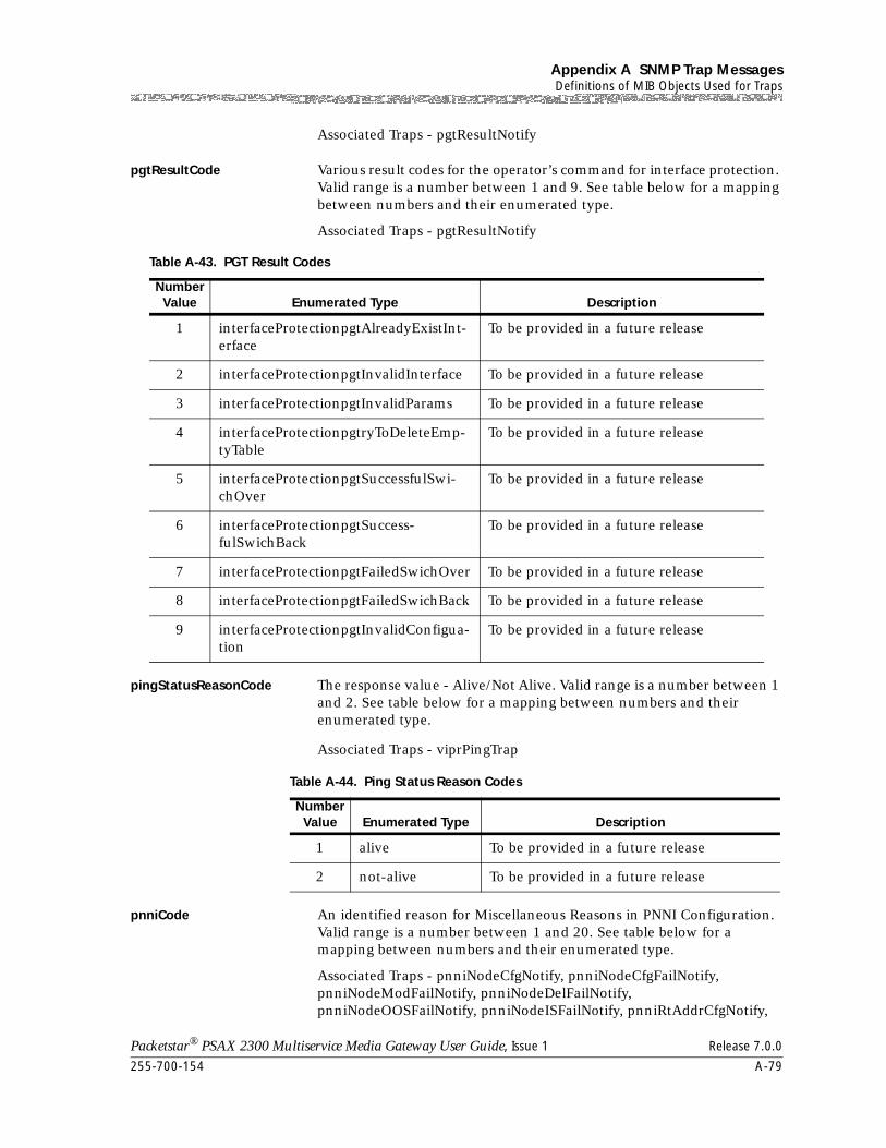
255-700-154 A-79
Packetstar® PSAX 2300 Multiservice Media Gateway User Guide, Issue 1 Release 7.0.0
Appendix A SNMP Trap MessagesDefinitions of MIB Objects Used for Traps
Associated Traps - pgtResultNotify
pgtResultCode Various result codes for the operator’s command for interface protection. Valid range is a number between 1 and 9. See table below for a mapping between numbers and their enumerated type.
Associated Traps - pgtResultNotify
pingStatusReasonCode The response value - Alive/Not Alive. Valid range is a number between 1 and 2. See table below for a mapping between numbers and their enumerated type.
Associated Traps - viprPingTrap
pnniCode An identified reason for Miscellaneous Reasons in PNNI Configuration. Valid range is a number between 1 and 20. See table below for a mapping between numbers and their enumerated type.
Associated Traps - pnniNodeCfgNotify, pnniNodeCfgFailNotify, pnniNodeModFailNotify, pnniNodeDelFailNotify, pnniNodeOOSFailNotify, pnniNodeISFailNotify, pnniRtAddrCfgNotify,
Table A-43. PGT Result Codes
Number Value Enumerated Type Description
1 interfaceProtectionpgtAlreadyExistInt-erface
To be provided in a future release
2 interfaceProtectionpgtInvalidInterface To be provided in a future release
3 interfaceProtectionpgtInvalidParams To be provided in a future release
4 interfaceProtectionpgtryToDeleteEmp-tyTable
To be provided in a future release
5 interfaceProtectionpgtSuccessfulSwi-chOver
To be provided in a future release
6 interfaceProtectionpgtSuccess-fulSwichBack
To be provided in a future release
7 interfaceProtectionpgtFailedSwichOver To be provided in a future release
8 interfaceProtectionpgtFailedSwichBack To be provided in a future release
9 interfaceProtectionpgtInvalidConfigua-tion
To be provided in a future release
Table A-44. Ping Status Reason Codes
Number Value Enumerated Type Description
1 alive To be provided in a future release
2 not-alive To be provided in a future release
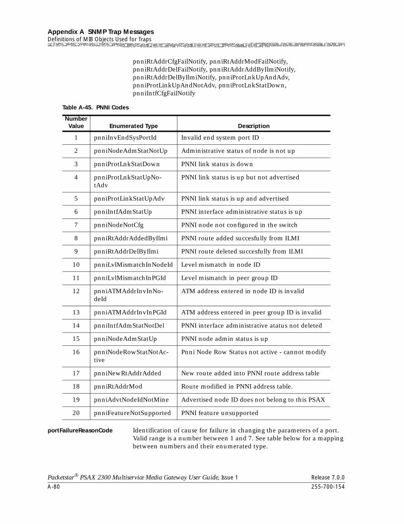
Appendix A SNMP Trap MessagesDefinitions of MIB Objects Used for Traps
A-80 255-700-154
Packetstar® PSAX 2300 Multiservice Media Gateway User Guide, Issue 1 Release 7.0.0
pnniRtAddrCfgFailNotify, pnniRtAddrModFailNotify, pnniRtAddrDelFailNotify, pnniRtAddrAddByIlmiNotify, pnniRtAddrDelByIlmiNotify, pnniProtLnkUpAndAdv, pnniProtLinkUpAndNotAdv, pnniProtLnkStatDown, pnniIntfCfgFailNotify
portFailureReasonCode Identification of cause for failure in changing the parameters of a port. Valid range is a number between 1 and 7. See table below for a mapping between numbers and their enumerated type.
Table A-45. PNNI Codes
NumberValue Enumerated Type Description
1 pnniInvEndSysPortId Invalid end system port ID
2 pnniNodeAdmStatNotUp Administrative status of node is not up
3 pnniProtLnkStatDown PNNI link status is down
4 pnniProtLnkStatUpNo-tAdv
PNNI link status is up but not advertised
5 pnniProtLinkStatUpAdv PNNI link status is up and advertised
6 pnniIntfAdmStatUp PNNI interface administrative status is up
7 pnniNodeNotCfg PNNI node not configured in the switch
8 pnniRtAddrAddedByIlmi PNNI route added succesfully from ILMI
9 pnniRtAddrDelByIlmi PNNI route deleted succesfully from ILMI
10 pnniLvlMismatchInNodeId Level mismatch in node ID
11 pnniLvlMismatchInPGId Level mismatch in peer group ID
12 pnniATMAddrInvInNo-deId
ATM address entered in node ID is invalid
13 pnniATMAddrInvInPGId ATM address entered in peer group ID is invalid
14 pnniIntfAdmStatNotDel PNNI interface administrative atatus not deleted
15 pnniNodeAdmStatUp PNNI node admin status is up
16 pnniNodeRowStatNotAc-tive
Pnni Node Row Status not active - cannot modify
17 pnniNewRtAddrAdded New route added into PNNI route address table
18 pnniRtAddrMod Route modified in PNNI address table.
19 pnniAdvtNodeIdNotMine Advertised node ID does not belong to this PSAX
20 pnniFeatureNotSupported PNNI feature unsupported
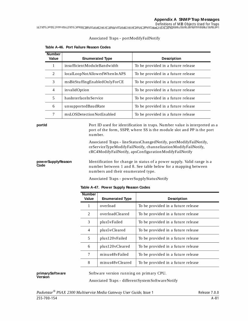
255-700-154 A-81
Packetstar® PSAX 2300 Multiservice Media Gateway User Guide, Issue 1 Release 7.0.0
Appendix A SNMP Trap MessagesDefinitions of MIB Objects Used for Traps
Associated Traps - portModifyFailNotify
portId Port ID used for identification in traps. Number value is interpreted as a port of the form, SSPP, where SS is the module slot and PP is the port number.
Associated Traps - lineStatusChangedNotify, portModifyFailNotify, ceServiceTypeModifyFailNotify, channelizationModifyFailNotify, cRC4ModifyFailNotify, apsConfigurationModifyFailNotify
powerSupplyReasonCode
Identification for change in status of a power supply. Valid range is a number between 1 and 8. See table below for a mapping between numbers and their enumerated type.
Associated Traps - powerSupplyStatusNotify
primarySoftware Version
Software version running on primary CPU.
Associated Traps - differentSystemSoftwareNotify
Table A-46. Port Failure Reason Codes
Number Value Enumerated Type Description
1 insufficientModuleBandwidth To be provided in a future release
2 localLoopNotAllowedWhenInAPS To be provided in a future release
3 msBitStuffingEnabledOnlyForCE To be provided in a future release
4 invalidOption To be provided in a future release
5 hasInterfaceInService To be provided in a future release
6 unsupportedBaudRate To be provided in a future release
7 msLOSDetectionNotEnabled To be provided in a future release
Table A-47. Power Supply Reason Codes
Number Value Enumerated Type Description
1 overload To be provided in a future release
2 overloadCleared To be provided in a future release
3 plus5vFailed To be provided in a future release
4 plus5vCleared To be provided in a future release
5 plus120vFailed To be provided in a future release
6 plus120vCleared To be provided in a future release
7 minus48vFailed To be provided in a future release
8 minus48vCleared To be provided in a future release
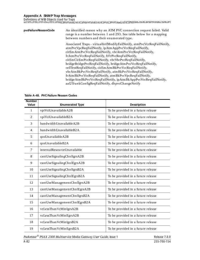
Appendix A SNMP Trap MessagesDefinitions of MIB Objects Used for Traps
A-82 255-700-154
Packetstar® PSAX 2300 Multiservice Media Gateway User Guide, Issue 1 Release 7.0.0
pvcFailureReasonCode An identified reason why an ATM PVC connection request failed. Valid range is a number between 1 and 293. See table below for a mapping between numbers and their enumerated type.
Associated Traps - virtualIntfModifyFailNotify, atmPvcVccReqFailNotify, atmPvcVpcReqFailNotify, ipAtmAppPvcVccReqFailNotify, cirEmAtmPvcVccReqFailNotify, vbrAtmPvcVccReqFailNotify, frAtmPvcVccReqFailNotify, frFrPvcReqFailNotify, cirEmCirEmPvcReqFailNotify, vbrVbrPvcReqFailNotify, bridgeBridgePvcReqFailNotify, bridgeAtmPvcVccReqFailNotify, cellTestReqFailNotify, cirEmAtmBkPvcVccReqFailNotify, vbrAtmBkPvcVccReqFailNotify, atmBkPvcVccReqFailNotify, frAtmBkPvcVccReqFailNotify, atmBkPvcVpcReqFailNotify, bridgeAtmBkPvcVccReqFailNotify, ipAtmBkAppPvcVccReqFailNotify, aal2TrunkConfigReqFailNotify, dhpvcChangeNotify
Table A-48. PVC Failure Reason Codes
Number Value Enumerated Type Description
1 vpiVciUnavailableA2B To be provided in a future release
2 vpiVciUnavailableB2A To be provided in a future release
3 bandwidthUnavailableA2B To be provided in a future release
4 bandwidthUnavailableB2A To be provided in a future release
5 qosUnavailableA2B To be provided in a future release
6 qosUnavailableB2A To be provided in a future release
7 internalResourceUnavailable To be provided in a future release
8 cantUseSignalingChnlIgrsA2B To be provided in a future release
9 cantUseSignalingChnlEgrsA2B To be provided in a future release
10 cantUseSignalingChnlIgrsB2A To be provided in a future release
11 cantUseSignalingChnlEgrsB2A To be provided in a future release
12 cantUseManagementChnlIgrsA2B To be provided in a future release
13 cantUseManagementChnlEgrsA2B To be provided in a future release
14 cantUseManagementChnlIgrsB2A To be provided in a future release
15 cantUseManagementChnlEgrsB2A To be provided in a future release
16 vcLessThanVcMinIgrsA2B To be provided in a future release
17 vcLessThanVcMinEgrsA2B To be provided in a future release
18 vcLessThanVcMinIgrsB2A To be provided in a future release
19 vcLessThanVcMinEgrsB2A To be provided in a future release
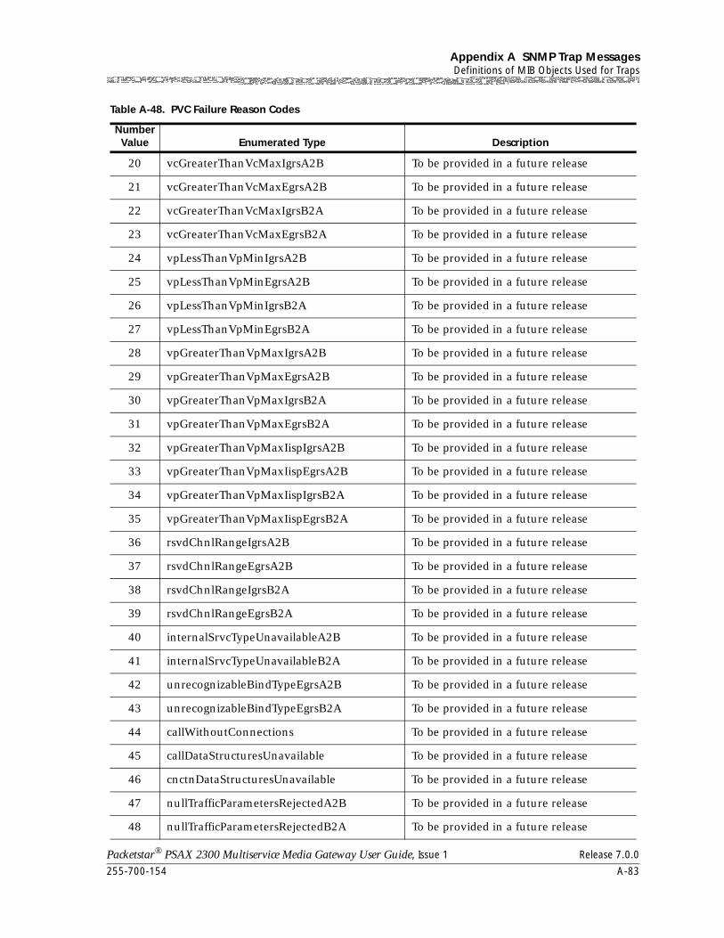
255-700-154 A-83
Packetstar® PSAX 2300 Multiservice Media Gateway User Guide, Issue 1 Release 7.0.0
Appendix A SNMP Trap MessagesDefinitions of MIB Objects Used for Traps
20 vcGreaterThanVcMaxIgrsA2B To be provided in a future release
21 vcGreaterThanVcMaxEgrsA2B To be provided in a future release
22 vcGreaterThanVcMaxIgrsB2A To be provided in a future release
23 vcGreaterThanVcMaxEgrsB2A To be provided in a future release
24 vpLessThanVpMinIgrsA2B To be provided in a future release
25 vpLessThanVpMinEgrsA2B To be provided in a future release
26 vpLessThanVpMinIgrsB2A To be provided in a future release
27 vpLessThanVpMinEgrsB2A To be provided in a future release
28 vpGreaterThanVpMaxIgrsA2B To be provided in a future release
29 vpGreaterThanVpMaxEgrsA2B To be provided in a future release
30 vpGreaterThanVpMaxIgrsB2A To be provided in a future release
31 vpGreaterThanVpMaxEgrsB2A To be provided in a future release
32 vpGreaterThanVpMaxIispIgrsA2B To be provided in a future release
33 vpGreaterThanVpMaxIispEgrsA2B To be provided in a future release
34 vpGreaterThanVpMaxIispIgrsB2A To be provided in a future release
35 vpGreaterThanVpMaxIispEgrsB2A To be provided in a future release
36 rsvdChnlRangeIgrsA2B To be provided in a future release
37 rsvdChnlRangeEgrsA2B To be provided in a future release
38 rsvdChnlRangeIgrsB2A To be provided in a future release
39 rsvdChnlRangeEgrsB2A To be provided in a future release
40 internalSrvcTypeUnavailableA2B To be provided in a future release
41 internalSrvcTypeUnavailableB2A To be provided in a future release
42 unrecognizableBindTypeEgrsA2B To be provided in a future release
43 unrecognizableBindTypeEgrsB2A To be provided in a future release
44 callWithoutConnections To be provided in a future release
45 callDataStructuresUnavailable To be provided in a future release
46 cnctnDataStructuresUnavailable To be provided in a future release
47 nullTrafficParametersRejectedA2B To be provided in a future release
48 nullTrafficParametersRejectedB2A To be provided in a future release
Table A-48. PVC Failure Reason Codes
Number Value Enumerated Type Description
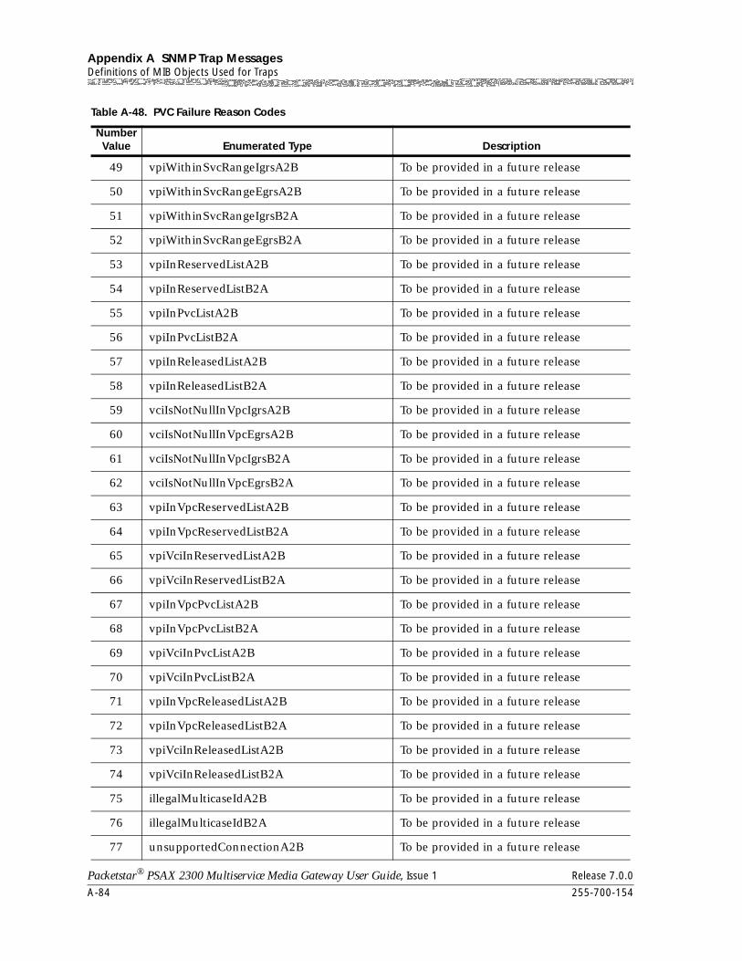
Appendix A SNMP Trap MessagesDefinitions of MIB Objects Used for Traps
A-84 255-700-154
Packetstar® PSAX 2300 Multiservice Media Gateway User Guide, Issue 1 Release 7.0.0
49 vpiWithinSvcRangeIgrsA2B To be provided in a future release
50 vpiWithinSvcRangeEgrsA2B To be provided in a future release
51 vpiWithinSvcRangeIgrsB2A To be provided in a future release
52 vpiWithinSvcRangeEgrsB2A To be provided in a future release
53 vpiInReservedListA2B To be provided in a future release
54 vpiInReservedListB2A To be provided in a future release
55 vpiInPvcListA2B To be provided in a future release
56 vpiInPvcListB2A To be provided in a future release
57 vpiInReleasedListA2B To be provided in a future release
58 vpiInReleasedListB2A To be provided in a future release
59 vciIsNotNullInVpcIgrsA2B To be provided in a future release
60 vciIsNotNullInVpcEgrsA2B To be provided in a future release
61 vciIsNotNullInVpcIgrsB2A To be provided in a future release
62 vciIsNotNullInVpcEgrsB2A To be provided in a future release
63 vpiInVpcReservedListA2B To be provided in a future release
64 vpiInVpcReservedListB2A To be provided in a future release
65 vpiVciInReservedListA2B To be provided in a future release
66 vpiVciInReservedListB2A To be provided in a future release
67 vpiInVpcPvcListA2B To be provided in a future release
68 vpiInVpcPvcListB2A To be provided in a future release
69 vpiVciInPvcListA2B To be provided in a future release
70 vpiVciInPvcListB2A To be provided in a future release
71 vpiInVpcReleasedListA2B To be provided in a future release
72 vpiInVpcReleasedListB2A To be provided in a future release
73 vpiVciInReleasedListA2B To be provided in a future release
74 vpiVciInReleasedListB2A To be provided in a future release
75 illegalMulticaseIdA2B To be provided in a future release
76 illegalMulticaseIdB2A To be provided in a future release
77 unsupportedConnectionA2B To be provided in a future release
Table A-48. PVC Failure Reason Codes
Number Value Enumerated Type Description
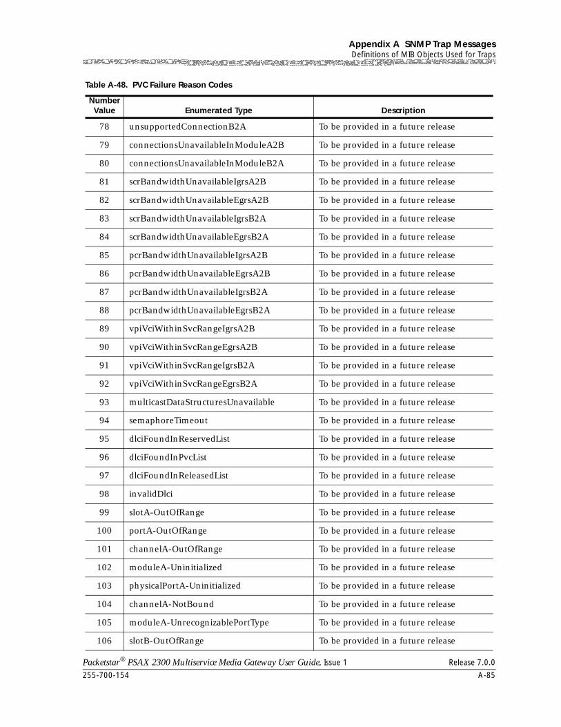
255-700-154 A-85
Packetstar® PSAX 2300 Multiservice Media Gateway User Guide, Issue 1 Release 7.0.0
Appendix A SNMP Trap MessagesDefinitions of MIB Objects Used for Traps
78 unsupportedConnectionB2A To be provided in a future release
79 connectionsUnavailableInModuleA2B To be provided in a future release
80 connectionsUnavailableInModuleB2A To be provided in a future release
81 scrBandwidthUnavailableIgrsA2B To be provided in a future release
82 scrBandwidthUnavailableEgrsA2B To be provided in a future release
83 scrBandwidthUnavailableIgrsB2A To be provided in a future release
84 scrBandwidthUnavailableEgrsB2A To be provided in a future release
85 pcrBandwidthUnavailableIgrsA2B To be provided in a future release
86 pcrBandwidthUnavailableEgrsA2B To be provided in a future release
87 pcrBandwidthUnavailableIgrsB2A To be provided in a future release
88 pcrBandwidthUnavailableEgrsB2A To be provided in a future release
89 vpiVciWithinSvcRangeIgrsA2B To be provided in a future release
90 vpiVciWithinSvcRangeEgrsA2B To be provided in a future release
91 vpiVciWithinSvcRangeIgrsB2A To be provided in a future release
92 vpiVciWithinSvcRangeEgrsB2A To be provided in a future release
93 multicastDataStructuresUnavailable To be provided in a future release
94 semaphoreTimeout To be provided in a future release
95 dlciFoundInReservedList To be provided in a future release
96 dlciFoundInPvcList To be provided in a future release
97 dlciFoundInReleasedList To be provided in a future release
98 invalidDlci To be provided in a future release
99 slotA-OutOfRange To be provided in a future release
100 portA-OutOfRange To be provided in a future release
101 channelA-OutOfRange To be provided in a future release
102 moduleA-Uninitialized To be provided in a future release
103 physicalPortA-Uninitialized To be provided in a future release
104 channelA-NotBound To be provided in a future release
105 moduleA-UnrecognizablePortType To be provided in a future release
106 slotB-OutOfRange To be provided in a future release
Table A-48. PVC Failure Reason Codes
Number Value Enumerated Type Description
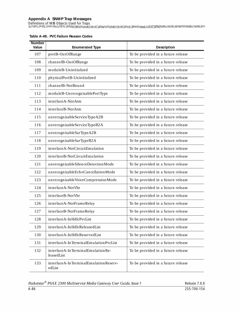
Appendix A SNMP Trap MessagesDefinitions of MIB Objects Used for Traps
A-86 255-700-154
Packetstar® PSAX 2300 Multiservice Media Gateway User Guide, Issue 1 Release 7.0.0
107 portB-OutOfRange To be provided in a future release
108 channelB-OutOfRange To be provided in a future release
109 moduleB-Uninitialized To be provided in a future release
110 physicalPortB-Uninitialized To be provided in a future release
111 channelB-NotBound To be provided in a future release
112 moduleB-UnrecognizablePortType To be provided in a future release
113 interfaceA-NotAtm To be provided in a future release
114 interfaceB-NotAtm To be provided in a future release
115 unrecognizableServiceTypeA2B To be provided in a future release
116 unrecognizableServiceTypeB2A To be provided in a future release
117 unrecognizableSarTypeA2B To be provided in a future release
118 unrecognizableSarTypeB2A To be provided in a future release
119 interfaceA-NotCircuitEmulation To be provided in a future release
120 interfaceB-NotCircuitEmulation To be provided in a future release
121 unrecognizableSilenceDetectionMode To be provided in a future release
122 unrecognizableEchoCancellationMode To be provided in a future release
123 unrecognizableVoiceCompressionMode To be provided in a future release
124 interfaceA-NotVbr To be provided in a future release
125 interfaceB-NotVbr To be provided in a future release
126 interfaceA-NotFrameRelay To be provided in a future release
127 interfaceB-NotFrameRelay To be provided in a future release
128 interfaceA-InHdlcPvcList To be provided in a future release
129 interfaceA-InHdlcReleasedList To be provided in a future release
130 interfaceA-InHdlcReservedList To be provided in a future release
131 interfaceA-InTerminalEmulationPvcList To be provided in a future release
132 interfaceA-InTerminalEmulationRe-leasedList
To be provided in a future release
133 interfaceA-InTerminalEmulationReserv-edList
To be provided in a future release
Table A-48. PVC Failure Reason Codes
Number Value Enumerated Type Description
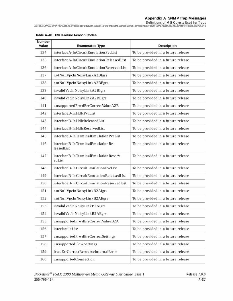
255-700-154 A-87
Packetstar® PSAX 2300 Multiservice Media Gateway User Guide, Issue 1 Release 7.0.0
Appendix A SNMP Trap MessagesDefinitions of MIB Objects Used for Traps
134 interfaceA-InCircuitEmulationPvcList To be provided in a future release
135 interfaceA-InCircuitEmulationReleasedList To be provided in a future release
136 interfaceA-InCircuitEmulationReservedList To be provided in a future release
137 notNullVpcInNoisyLinkA2BIgrs To be provided in a future release
138 notNullVpcInNoisyLinkA2BEgrs To be provided in a future release
139 invalidVccInNoisyLinkA2BIgrs To be provided in a future release
140 invalidVccInNoisyLinkA2BEgrs To be provided in a future release
141 unsupportedFrwdErrCorrectValueA2B To be provided in a future release
142 interfaceB-InHdlcPvcList To be provided in a future release
143 interfaceB-InHdlcReleasedList To be provided in a future release
144 interfaceB-InHdlcReservedList To be provided in a future release
145 interfaceB-InTerminalEmulationPvcList To be provided in a future release
146 interfaceB-InTerminalEmulationRe-leasedList
To be provided in a future release
147 interfaceB-InTerminalEmulationReserv-edList
To be provided in a future release
148 interfaceB-InCircuitEmulationPvcList To be provided in a future release
149 interfaceB-InCircuitEmulationReleasedList To be provided in a future release
150 interfaceB-InCircuitEmulationReservedList To be provided in a future release
151 notNullVpcInNoisyLinkB2AIgrs To be provided in a future release
152 notNullVpcInNoisyLinkB2AEgrs To be provided in a future release
153 invalidVccInNoisyLinkB2AIgrs To be provided in a future release
154 invalidVccInNoisyLinkB2AEgrs To be provided in a future release
155 unsupportedFrwdErrCorrectValueB2A To be provided in a future release
156 interfaceInUse To be provided in a future release
157 unsupportedFrwdErrCorrectSettings To be provided in a future release
158 unsupportedFlowSettings To be provided in a future release
159 frwdErrCorrectResourceInternalError To be provided in a future release
160 unsupportedConnection To be provided in a future release
Table A-48. PVC Failure Reason Codes
Number Value Enumerated Type Description
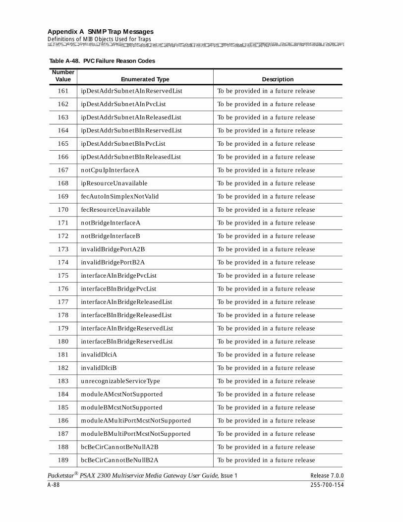
Appendix A SNMP Trap MessagesDefinitions of MIB Objects Used for Traps
A-88 255-700-154
Packetstar® PSAX 2300 Multiservice Media Gateway User Guide, Issue 1 Release 7.0.0
161 ipDestAddrSubnetAInReservedList To be provided in a future release
162 ipDestAddrSubnetAInPvcList To be provided in a future release
163 ipDestAddrSubnetAInReleasedList To be provided in a future release
164 ipDestAddrSubnetBInReservedList To be provided in a future release
165 ipDestAddrSubnetBInPvcList To be provided in a future release
166 ipDestAddrSubnetBInReleasedList To be provided in a future release
167 notCpuIpInterfaceA To be provided in a future release
168 ipResourceUnavailable To be provided in a future release
169 fecAutoInSimplexNotValid To be provided in a future release
170 fecResourceUnavailable To be provided in a future release
171 notBridgeInterfaceA To be provided in a future release
172 notBridgeInterfaceB To be provided in a future release
173 invalidBridgePortA2B To be provided in a future release
174 invalidBridgePortB2A To be provided in a future release
175 interfaceAInBridgePvcList To be provided in a future release
176 interfaceBInBridgePvcList To be provided in a future release
177 interfaceAInBridgeReleasedList To be provided in a future release
178 interfaceBInBridgeReleasedList To be provided in a future release
179 interfaceAInBridgeReservedList To be provided in a future release
180 interfaceBInBridgeReservedList To be provided in a future release
181 invalidDlciA To be provided in a future release
182 invalidDlciB To be provided in a future release
183 unrecognizableServiceType To be provided in a future release
184 moduleAMcstNotSupported To be provided in a future release
185 moduleBMcstNotSupported To be provided in a future release
186 moduleAMultiPortMcstNotSupported To be provided in a future release
187 moduleBMultiPortMcstNotSupported To be provided in a future release
188 bcBeCirCannotBeNullA2B To be provided in a future release
189 bcBeCirCannotBeNullB2A To be provided in a future release
Table A-48. PVC Failure Reason Codes
Number Value Enumerated Type Description
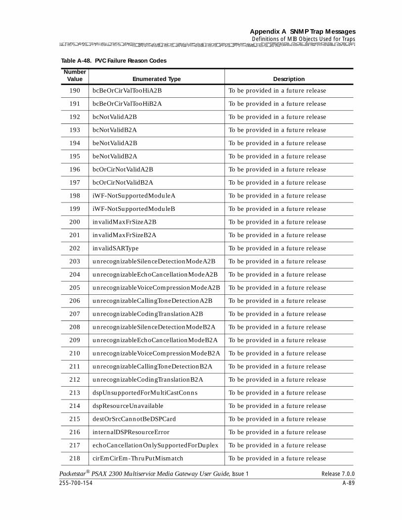
255-700-154 A-89
Packetstar® PSAX 2300 Multiservice Media Gateway User Guide, Issue 1 Release 7.0.0
Appendix A SNMP Trap MessagesDefinitions of MIB Objects Used for Traps
190 bcBeOrCirValTooHiA2B To be provided in a future release
191 bcBeOrCirValTooHiB2A To be provided in a future release
192 bcNotValidA2B To be provided in a future release
193 bcNotValidB2A To be provided in a future release
194 beNotValidA2B To be provided in a future release
195 beNotValidB2A To be provided in a future release
196 bcOrCirNotValidA2B To be provided in a future release
197 bcOrCirNotValidB2A To be provided in a future release
198 iWF-NotSupportedModuleA To be provided in a future release
199 iWF-NotSupportedModuleB To be provided in a future release
200 invalidMaxFrSizeA2B To be provided in a future release
201 invalidMaxFrSizeB2A To be provided in a future release
202 invalidSARType To be provided in a future release
203 unrecognizableSilenceDetectionModeA2B To be provided in a future release
204 unrecognizableEchoCancellationModeA2B To be provided in a future release
205 unrecognizableVoiceCompressionModeA2B To be provided in a future release
206 unrecognizableCallingToneDetectionA2B To be provided in a future release
207 unrecognizableCodingTranslationA2B To be provided in a future release
208 unrecognizableSilenceDetectionModeB2A To be provided in a future release
209 unrecognizableEchoCancellationModeB2A To be provided in a future release
210 unrecognizableVoiceCompressionModeB2A To be provided in a future release
211 unrecognizableCallingToneDetectionB2A To be provided in a future release
212 unrecognizableCodingTranslationB2A To be provided in a future release
213 dspUnsupportedForMultiCastConns To be provided in a future release
214 dspResourceUnavailable To be provided in a future release
215 destOrSrcCannotBeDSPCard To be provided in a future release
216 internalDSPResourceError To be provided in a future release
217 echoCancellationOnlySupportedForDuplex To be provided in a future release
218 cirEmCirEm-ThruPutMismatch To be provided in a future release
Table A-48. PVC Failure Reason Codes
Number Value Enumerated Type Description
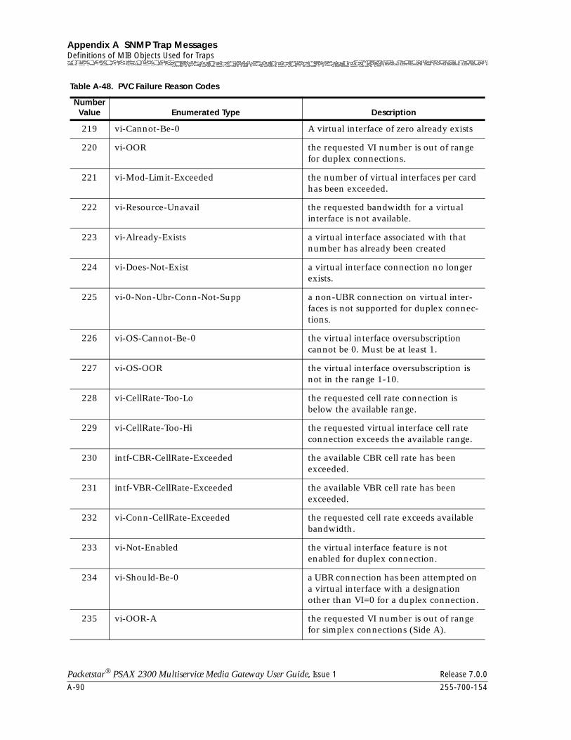
Appendix A SNMP Trap MessagesDefinitions of MIB Objects Used for Traps
A-90 255-700-154
Packetstar® PSAX 2300 Multiservice Media Gateway User Guide, Issue 1 Release 7.0.0
219 vi-Cannot-Be-0 A virtual interface of zero already exists
220 vi-OOR the requested VI number is out of range for duplex connections.
221 vi-Mod-Limit-Exceeded the number of virtual interfaces per card has been exceeded.
222 vi-Resource-Unavail the requested bandwidth for a virtual interface is not available.
223 vi-Already-Exists a virtual interface associated with that number has already been created
224 vi-Does-Not-Exist a virtual interface connection no longer exists.
225 vi-0-Non-Ubr-Conn-Not-Supp a non-UBR connection on virtual inter-faces is not supported for duplex connec-tions.
226 vi-OS-Cannot-Be-0 the virtual interface oversubscription cannot be 0. Must be at least 1.
227 vi-OS-OOR the virtual interface oversubscription is not in the range 1-10.
228 vi-CellRate-Too-Lo the requested cell rate connection is below the available range.
229 vi-CellRate-Too-Hi the requested virtual interface cell rate connection exceeds the available range.
230 intf-CBR-CellRate-Exceeded the available CBR cell rate has been exceeded.
231 intf-VBR-CellRate-Exceeded the available VBR cell rate has been exceeded.
232 vi-Conn-CellRate-Exceeded the requested cell rate exceeds available bandwidth.
233 vi-Not-Enabled the virtual interface feature is not enabled for duplex connection.
234 vi-Should-Be-0 a UBR connection has been attempted on a virtual interface with a designation other than VI=0 for a duplex connection.
235 vi-OOR-A the requested VI number is out of range for simplex connections (Side A).
Table A-48. PVC Failure Reason Codes
Number Value Enumerated Type Description
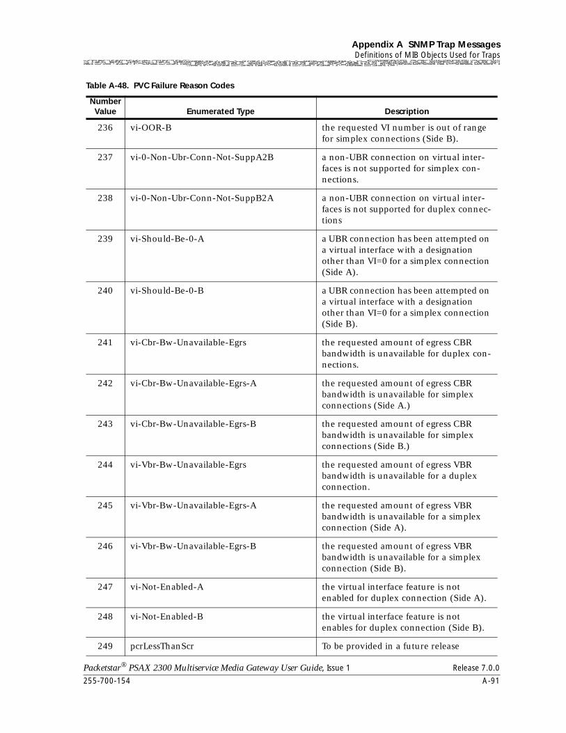
255-700-154 A-91
Packetstar® PSAX 2300 Multiservice Media Gateway User Guide, Issue 1 Release 7.0.0
Appendix A SNMP Trap MessagesDefinitions of MIB Objects Used for Traps
236 vi-OOR-B the requested VI number is out of range for simplex connections (Side B).
237 vi-0-Non-Ubr-Conn-Not-SuppA2B a non-UBR connection on virtual inter-faces is not supported for simplex con-nections.
238 vi-0-Non-Ubr-Conn-Not-SuppB2A a non-UBR connection on virtual inter-faces is not supported for duplex connec-tions
239 vi-Should-Be-0-A a UBR connection has been attempted on a virtual interface with a designation other than VI=0 for a simplex connection (Side A).
240 vi-Should-Be-0-B a UBR connection has been attempted on a virtual interface with a designation other than VI=0 for a simplex connection (Side B).
241 vi-Cbr-Bw-Unavailable-Egrs the requested amount of egress CBR bandwidth is unavailable for duplex con-nections.
242 vi-Cbr-Bw-Unavailable-Egrs-A the requested amount of egress CBR bandwidth is unavailable for simplex connections (Side A.)
243 vi-Cbr-Bw-Unavailable-Egrs-B the requested amount of egress CBR bandwidth is unavailable for simplex connections (Side B.)
244 vi-Vbr-Bw-Unavailable-Egrs the requested amount of egress VBR bandwidth is unavailable for a duplex connection.
245 vi-Vbr-Bw-Unavailable-Egrs-A the requested amount of egress VBR bandwidth is unavailable for a simplex connection (Side A).
246 vi-Vbr-Bw-Unavailable-Egrs-B the requested amount of egress VBR bandwidth is unavailable for a simplex connection (Side B).
247 vi-Not-Enabled-A the virtual interface feature is not enabled for duplex connection (Side A).
248 vi-Not-Enabled-B the virtual interface feature is not enables for duplex connection (Side B).
249 pcrLessThanScr To be provided in a future release
Table A-48. PVC Failure Reason Codes
Number Value Enumerated Type Description
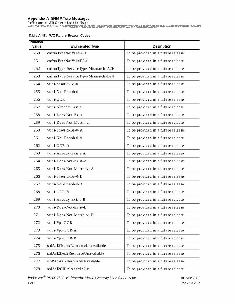
Appendix A SNMP Trap MessagesDefinitions of MIB Objects Used for Traps
A-92 255-700-154
Packetstar® PSAX 2300 Multiservice Media Gateway User Guide, Issue 1 Release 7.0.0
250 cnfrmTypeNotValidA2B To be provided in a future release
251 cnfrmTypeNotValidB2A To be provided in a future release
252 cnfrmType-ServiceType-Mismatch-A2B To be provided in a future release
253 cnfrmType-ServiceType-Mismatch-B2A To be provided in a future release
254 vuni-Should-Be-0 To be provided in a future release
255 vuni-Not-Enabled To be provided in a future release
256 vuni-OOR To be provided in a future release
257 vuni-Already-Exists To be provided in a future release
258 vuni-Does-Not-Exist To be provided in a future release
259 vuni-Does-Not-Match-vi To be provided in a future release
260 vuni-Should-Be-0-A To be provided in a future release
261 vuni-Not-Enabled-A To be provided in a future release
262 vuni-OOR-A To be provided in a future release
263 vuni-Already-Exists-A To be provided in a future release
264 vuni-Does-Not-Exist-A To be provided in a future release
265 vuni-Does-Not-Match-vi-A To be provided in a future release
266 vuni-Should-Be-0-B To be provided in a future release
267 vuni-Not-Enabled-B To be provided in a future release
268 vuni-OOR-B To be provided in a future release
269 vuni-Already-Exists-B To be provided in a future release
270 vuni-Does-Not-Exist-B To be provided in a future release
271 vuni-Does-Not-Match-vi-B To be provided in a future release
272 vuni-Vpi-OOR To be provided in a future release
273 vuni-Vpi-OOR-A To be provided in a future release
274 vuni-Vpi-OOR-B To be provided in a future release
275 stdAal2TrunkResourceUnavailable To be provided in a future release
276 stdAal2Dsp2ResourceUnavailable To be provided in a future release
277 slotStdAal2ResourceUavailable To be provided in a future release
278 stdAal2CIDAlreadyInUse To be provided in a future release
Table A-48. PVC Failure Reason Codes
Number Value Enumerated Type Description
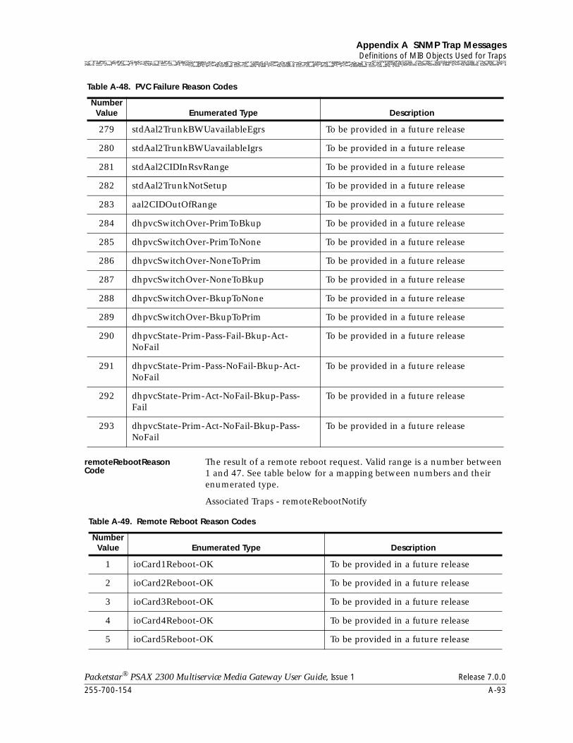
255-700-154 A-93
Packetstar® PSAX 2300 Multiservice Media Gateway User Guide, Issue 1 Release 7.0.0
Appendix A SNMP Trap MessagesDefinitions of MIB Objects Used for Traps
remoteRebootReason Code
The result of a remote reboot request. Valid range is a number between 1 and 47. See table below for a mapping between numbers and their enumerated type.
Associated Traps - remoteRebootNotify
279 stdAal2TrunkBWUavailableEgrs To be provided in a future release
280 stdAal2TrunkBWUavailableIgrs To be provided in a future release
281 stdAal2CIDInRsvRange To be provided in a future release
282 stdAal2TrunkNotSetup To be provided in a future release
283 aal2CIDOutOfRange To be provided in a future release
284 dhpvcSwitchOver-PrimToBkup To be provided in a future release
285 dhpvcSwitchOver-PrimToNone To be provided in a future release
286 dhpvcSwitchOver-NoneToPrim To be provided in a future release
287 dhpvcSwitchOver-NoneToBkup To be provided in a future release
288 dhpvcSwitchOver-BkupToNone To be provided in a future release
289 dhpvcSwitchOver-BkupToPrim To be provided in a future release
290 dhpvcState-Prim-Pass-Fail-Bkup-Act-NoFail
To be provided in a future release
291 dhpvcState-Prim-Pass-NoFail-Bkup-Act-NoFail
To be provided in a future release
292 dhpvcState-Prim-Act-NoFail-Bkup-Pass-Fail
To be provided in a future release
293 dhpvcState-Prim-Act-NoFail-Bkup-Pass-NoFail
To be provided in a future release
Table A-48. PVC Failure Reason Codes
Number Value Enumerated Type Description
Table A-49. Remote Reboot Reason Codes
Number Value Enumerated Type Description
1 ioCard1Reboot-OK To be provided in a future release
2 ioCard2Reboot-OK To be provided in a future release
3 ioCard3Reboot-OK To be provided in a future release
4 ioCard4Reboot-OK To be provided in a future release
5 ioCard5Reboot-OK To be provided in a future release
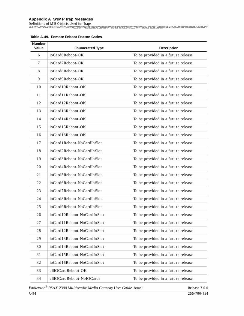
Appendix A SNMP Trap MessagesDefinitions of MIB Objects Used for Traps
A-94 255-700-154
Packetstar® PSAX 2300 Multiservice Media Gateway User Guide, Issue 1 Release 7.0.0
6 ioCard6Reboot-OK To be provided in a future release
7 ioCard7Reboot-OK To be provided in a future release
8 ioCard8Reboot-OK To be provided in a future release
9 ioCard9Reboot-OK To be provided in a future release
10 ioCard10Reboot-OK To be provided in a future release
11 ioCard11Reboot-OK To be provided in a future release
12 ioCard12Reboot-OK To be provided in a future release
13 ioCard13Reboot-OK To be provided in a future release
14 ioCard14Reboot-OK To be provided in a future release
15 ioCard15Reboot-OK To be provided in a future release
16 ioCard16Reboot-OK To be provided in a future release
17 ioCard1Reboot-NoCardInSlot To be provided in a future release
18 ioCard2Reboot-NoCardInSlot To be provided in a future release
19 ioCard3Reboot-NoCardInSlot To be provided in a future release
20 ioCard4Reboot-NoCardInSlot To be provided in a future release
21 ioCard5Reboot-NoCardInSlot To be provided in a future release
22 ioCard6Reboot-NoCardInSlot To be provided in a future release
23 ioCard7Reboot-NoCardInSlot To be provided in a future release
24 ioCard8Reboot-NoCardInSlot To be provided in a future release
25 ioCard9Reboot-NoCardInSlot To be provided in a future release
26 ioCard10Reboot-NoCardInSlot To be provided in a future release
27 ioCard11Reboot-NoCardInSlot To be provided in a future release
28 ioCard12Reboot-NoCardInSlot To be provided in a future release
29 ioCard13Reboot-NoCardInSlot To be provided in a future release
30 ioCard14Reboot-NoCardInSlot To be provided in a future release
31 ioCard15Reboot-NoCardInSlot To be provided in a future release
32 ioCard16Reboot-NoCardInSlot To be provided in a future release
33 allIOCardReboot-OK To be provided in a future release
34 allIOCardReboot-NoIOCards To be provided in a future release
Table A-49. Remote Reboot Reason Codes
Number Value Enumerated Type Description
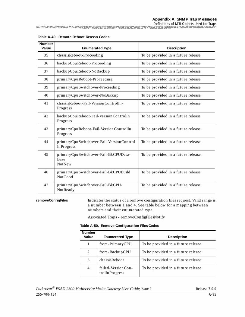
255-700-154 A-95
Packetstar® PSAX 2300 Multiservice Media Gateway User Guide, Issue 1 Release 7.0.0
Appendix A SNMP Trap MessagesDefinitions of MIB Objects Used for Traps
removeConfigFiles Indicates the status of a remove configuration files request. Valid range is a number between 1 and 4. See table below for a mapping between numbers and their enumerated type.
Associated Traps - removeConfigFilesNotify
35 chassisReboot-Proceeding To be provided in a future release
36 backupCpuReboot-Proceeding To be provided in a future release
37 backupCpuReboot-NoBackup To be provided in a future release
38 primaryCpuReboot-Proceeding To be provided in a future release
39 primaryCpuSwitchover-Proceeding To be provided in a future release
40 primaryCpuSwitchover-NoBackup To be provided in a future release
41 chassisReboot-Fail-VersionControlIn-Progress
To be provided in a future release
42 backupCpuReboot-Fail-VersionControlInProgress
To be provided in a future release
43 primaryCpuReboot-Fail-VersionControlInProgress
To be provided in a future release
44 primaryCpuSwitchover-Fail-VersionControlInProgress
To be provided in a future release
45 primaryCpuSwitchover-Fail-BkCPUData-BaseNotNew
To be provided in a future release
46 primaryCpuSwitchover-Fail-BkCPUBuildNotGood
To be provided in a future release
47 primaryCpuSwitchover-Fail-BkCPU-NotReady
To be provided in a future release
Table A-49. Remote Reboot Reason Codes
Number Value Enumerated Type Description
Table A-50. Remove Configuration Files Codes
Number Value Enumerated Type Description
1 from-PrimaryCPU To be provided in a future release
2 from-BackupCPU To be provided in a future release
3 chassisReboot To be provided in a future release
4 failed-VersionCon-trolInProgress
To be provided in a future release
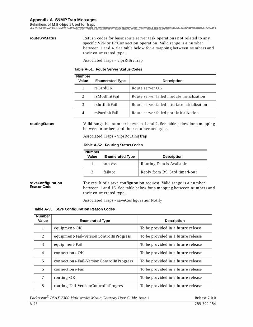
Appendix A SNMP Trap MessagesDefinitions of MIB Objects Used for Traps
A-96 255-700-154
Packetstar® PSAX 2300 Multiservice Media Gateway User Guide, Issue 1 Release 7.0.0
routeSrvStatus Return codes for basic route server task operations not related to any specific VPN or IP/Connection operation. Valid range is a number between 1 and 4. See table below for a mapping between numbers and their enumerated type.
Associated Traps - viprRtSrvTrap
routingStatus Valid range is a number between 1 and 2. See table below for a mapping between numbers and their enumerated type.
Associated Traps - viprRoutingTrap
saveConfiguration ReasonCode
The result of a save configuration request. Valid range is a number between 1 and 16. See table below for a mapping between numbers and their enumerated type.
Associated Traps - saveConfigurationNotify
Table A-51. Route Server Status Codes
Number Value Enumerated Type Description
1 rsCardOK Route server OK
2 rsModInitFail Route server failed module initialization
3 rsIntfInitFail Route server failed interface initialization
4 rsPortInitFail Route server failed port initialization
Table A-52. Routing Status Codes
Number Value Enumerated Type Description
1 success Routing Data is Available
2 failure Reply from RS Card timed-out
Table A-53. Save Configuration Reason Codes
Number Value Enumerated Type Description
1 equipment-OK To be provided in a future release
2 equipment-Fail-VersionControlInProgress To be provided in a future release
3 equipment-Fail To be provided in a future release
4 connections-OK To be provided in a future release
5 connections-Fail-VersionControlInProgress To be provided in a future release
6 connections-Fail To be provided in a future release
7 routing-OK To be provided in a future release
8 routing-Fail-VersionControlInProgress To be provided in a future release
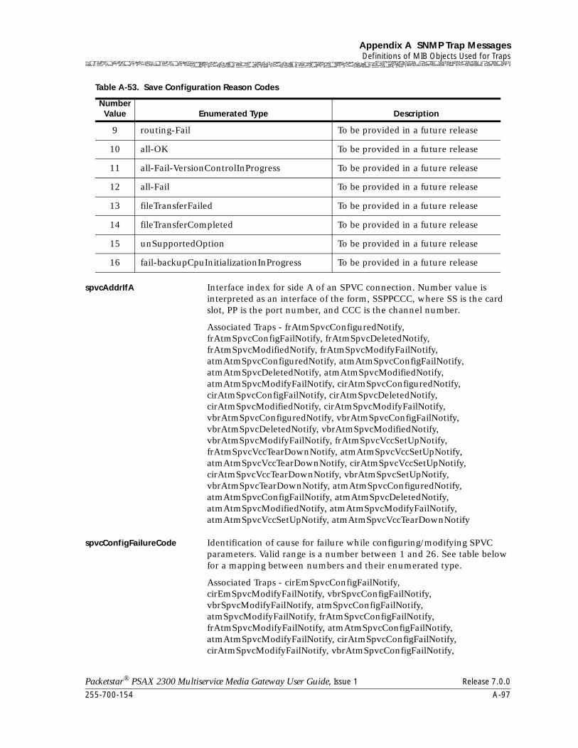
255-700-154 A-97
Packetstar® PSAX 2300 Multiservice Media Gateway User Guide, Issue 1 Release 7.0.0
Appendix A SNMP Trap MessagesDefinitions of MIB Objects Used for Traps
spvcAddrIfA Interface index for side A of an SPVC connection. Number value is interpreted as an interface of the form, SSPPCCC, where SS is the card slot, PP is the port number, and CCC is the channel number.
Associated Traps - frAtmSpvcConfiguredNotify, frAtmSpvcConfigFailNotify, frAtmSpvcDeletedNotify, frAtmSpvcModifiedNotify, frAtmSpvcModifyFailNotify, atmAtmSpvcConfiguredNotify, atmAtmSpvcConfigFailNotify, atmAtmSpvcDeletedNotify, atmAtmSpvcModifiedNotify, atmAtmSpvcModifyFailNotify, cirAtmSpvcConfiguredNotify, cirAtmSpvcConfigFailNotify, cirAtmSpvcDeletedNotify, cirAtmSpvcModifiedNotify, cirAtmSpvcModifyFailNotify, vbrAtmSpvcConfiguredNotify, vbrAtmSpvcConfigFailNotify, vbrAtmSpvcDeletedNotify, vbrAtmSpvcModifiedNotify, vbrAtmSpvcModifyFailNotify, frAtmSpvcVccSetUpNotify, frAtmSpvcVccTearDownNotify, atmAtmSpvcVccSetUpNotify, atmAtmSpvcVccTearDownNotify, cirAtmSpvcVccSetUpNotify, cirAtmSpvcVccTearDownNotify, vbrAtmSpvcSetUpNotify, vbrAtmSpvcTearDownNotify, atmAtmSpvcConfiguredNotify, atmAtmSpvcConfigFailNotify, atmAtmSpvcDeletedNotify, atmAtmSpvcModifiedNotify, atmAtmSpvcModifyFailNotify, atmAtmSpvcVccSetUpNotify, atmAtmSpvcVccTearDownNotify
spvcConfigFailureCode Identification of cause for failure while configuring/modifying SPVC parameters. Valid range is a number between 1 and 26. See table below for a mapping between numbers and their enumerated type.
Associated Traps - cirEmSpvcConfigFailNotify, cirEmSpvcModifyFailNotify, vbrSpvcConfigFailNotify, vbrSpvcModifyFailNotify, atmSpvcConfigFailNotify, atmSpvcModifyFailNotify, frAtmSpvcConfigFailNotify, frAtmSpvcModifyFailNotify, atmAtmSpvcConfigFailNotify, atmAtmSpvcModifyFailNotify, cirAtmSpvcConfigFailNotify, cirAtmSpvcModifyFailNotify, vbrAtmSpvcConfigFailNotify,
9 routing-Fail To be provided in a future release
10 all-OK To be provided in a future release
11 all-Fail-VersionControlInProgress To be provided in a future release
12 all-Fail To be provided in a future release
13 fileTransferFailed To be provided in a future release
14 fileTransferCompleted To be provided in a future release
15 unSupportedOption To be provided in a future release
16 fail-backupCpuInitializationInProgress To be provided in a future release
Table A-53. Save Configuration Reason Codes
Number Value Enumerated Type Description
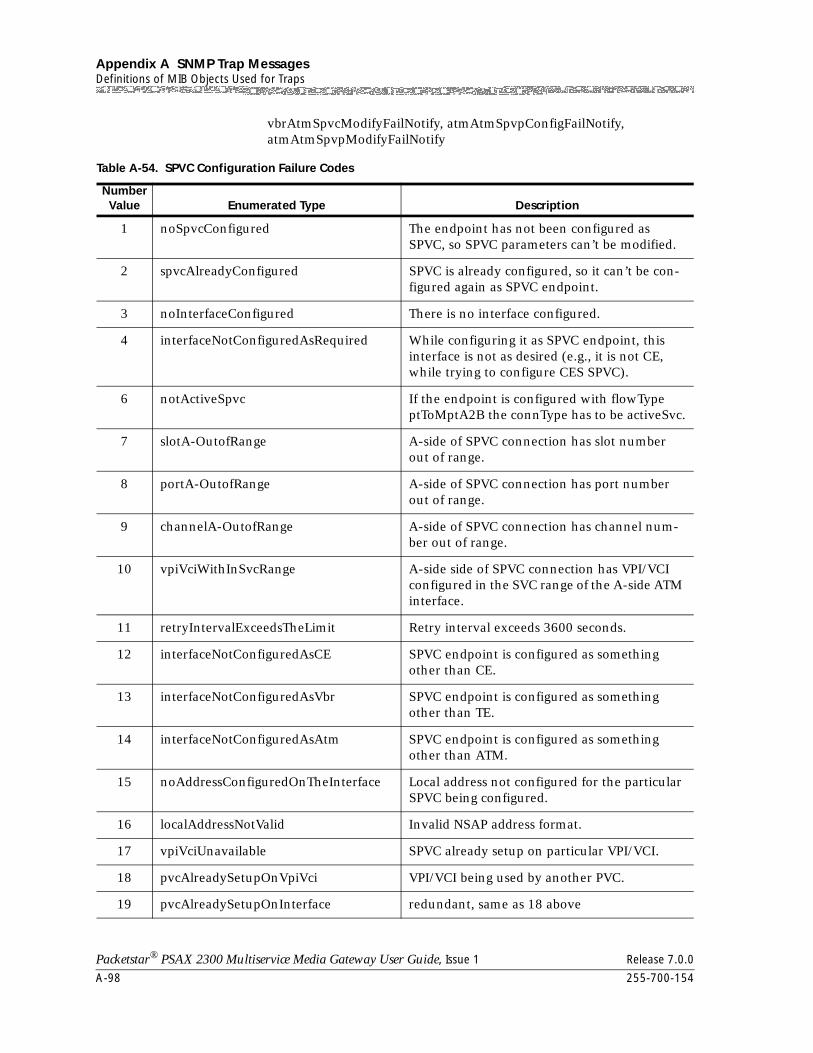
Appendix A SNMP Trap MessagesDefinitions of MIB Objects Used for Traps
A-98 255-700-154
Packetstar® PSAX 2300 Multiservice Media Gateway User Guide, Issue 1 Release 7.0.0
vbrAtmSpvcModifyFailNotify, atmAtmSpvpConfigFailNotify, atmAtmSpvpModifyFailNotify
Table A-54. SPVC Configuration Failure Codes
Number Value Enumerated Type Description
1 noSpvcConfigured The endpoint has not been configured as SPVC, so SPVC parameters can’t be modified.
2 spvcAlreadyConfigured SPVC is already configured, so it can’t be con-figured again as SPVC endpoint.
3 noInterfaceConfigured There is no interface configured.
4 interfaceNotConfiguredAsRequired While configuring it as SPVC endpoint, this interface is not as desired (e.g., it is not CE, while trying to configure CES SPVC).
6 notActiveSpvc If the endpoint is configured with flowType ptToMptA2B the connType has to be activeSvc.
7 slotA-OutofRange A-side of SPVC connection has slot number out of range.
8 portA-OutofRange A-side of SPVC connection has port number out of range.
9 channelA-OutofRange A-side of SPVC connection has channel num-ber out of range.
10 vpiVciWithInSvcRange A-side side of SPVC connection has VPI/VCI configured in the SVC range of the A-side ATM interface.
11 retryIntervalExceedsTheLimit Retry interval exceeds 3600 seconds.
12 interfaceNotConfiguredAsCE SPVC endpoint is configured as something other than CE.
13 interfaceNotConfiguredAsVbr SPVC endpoint is configured as something other than TE.
14 interfaceNotConfiguredAsAtm SPVC endpoint is configured as something other than ATM.
15 noAddressConfiguredOnTheInterface Local address not configured for the particular SPVC being configured.
16 localAddressNotValid Invalid NSAP address format.
17 vpiVciUnavailable SPVC already setup on particular VPI/VCI.
18 pvcAlreadySetupOnVpiVci VPI/VCI being used by another PVC.
19 pvcAlreadySetupOnInterface redundant, same as 18 above
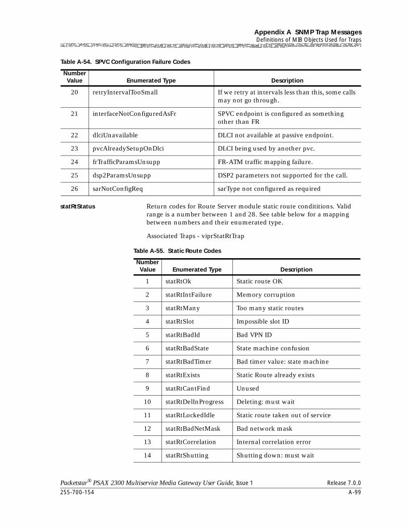
255-700-154 A-99
Packetstar® PSAX 2300 Multiservice Media Gateway User Guide, Issue 1 Release 7.0.0
Appendix A SNMP Trap MessagesDefinitions of MIB Objects Used for Traps
statRtStatus Return codes for Route Server module static route condititions. Valid range is a number between 1 and 28. See table below for a mapping between numbers and their enumerated type.
Associated Traps - viprStatRtTrap
20 retryIntervalTooSmall If we retry at intervals less than this, some calls may not go through.
21 interfaceNotConfiguredAsFr SPVC endpoint is configured as something other than FR
22 dlciUnavailable DLCI not available at passive endpoint.
23 pvcAlreadySetupOnDlci DLCI being used by another pvc.
24 frTrafficParamsUnsupp FR-ATM traffic mapping failure.
25 dsp2ParamsUnsupp DSP2 parameters not supported for the call.
26 sarNotConfigReq sarType not configured as required
Table A-54. SPVC Configuration Failure Codes
Number Value Enumerated Type Description
Table A-55. Static Route Codes
Number Value Enumerated Type Description
1 statRtOk Static route OK
2 statRtIntFailure Memory corruption
3 statRtMany Too many static routes
4 statRtSlot Impossible slot ID
5 statRtBadId Bad VPN ID
6 statRtBadState State machine confusion
7 statRtBadTimer Bad timer value: state machine
8 statRtExists Static Route already exists
9 statRtCantFind Unused
10 statRtDelInProgress Deleting: must wait
11 statRtLockedIdle Static route taken out of service
12 statRtBadNetMask Bad network mask
13 statRtCorrelation Internal correlation error
14 statRtShutting Shutting down: must wait
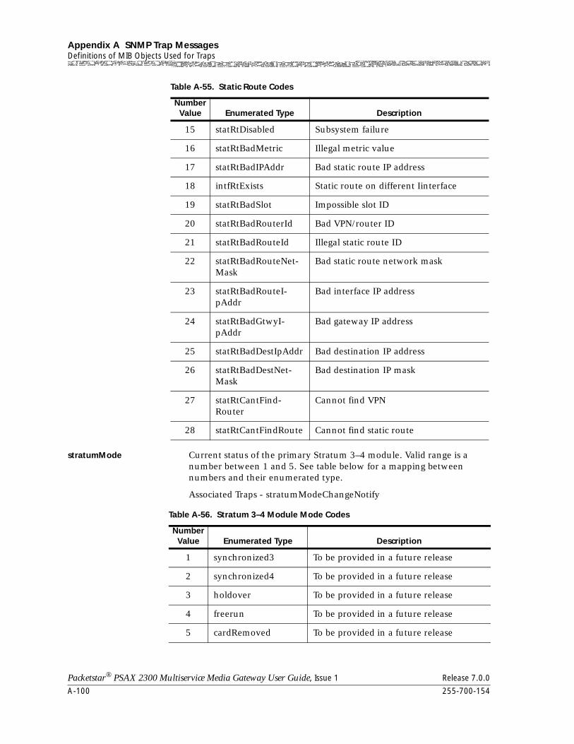
Appendix A SNMP Trap MessagesDefinitions of MIB Objects Used for Traps
A-100 255-700-154
Packetstar® PSAX 2300 Multiservice Media Gateway User Guide, Issue 1 Release 7.0.0
stratumMode Current status of the primary Stratum 3–4 module. Valid range is a number between 1 and 5. See table below for a mapping between numbers and their enumerated type.
Associated Traps - stratumModeChangeNotify
15 statRtDisabled Subsystem failure
16 statRtBadMetric Illegal metric value
17 statRtBadIPAddr Bad static route IP address
18 intfRtExists Static route on different Iinterface
19 statRtBadSlot Impossible slot ID
20 statRtBadRouterId Bad VPN/router ID
21 statRtBadRouteId Illegal static route ID
22 statRtBadRouteNet-Mask
Bad static route network mask
23 statRtBadRouteI-pAddr
Bad interface IP address
24 statRtBadGtwyI-pAddr
Bad gateway IP address
25 statRtBadDestIpAddr Bad destination IP address
26 statRtBadDestNet-Mask
Bad destination IP mask
27 statRtCantFind-Router
Cannot find VPN
28 statRtCantFindRoute Cannot find static route
Table A-55. Static Route Codes
Number Value Enumerated Type Description
Table A-56. Stratum 3–4 Module Mode Codes
Number Value Enumerated Type Description
1 synchronized3 To be provided in a future release
2 synchronized4 To be provided in a future release
3 holdover To be provided in a future release
4 freerun To be provided in a future release
5 cardRemoved To be provided in a future release
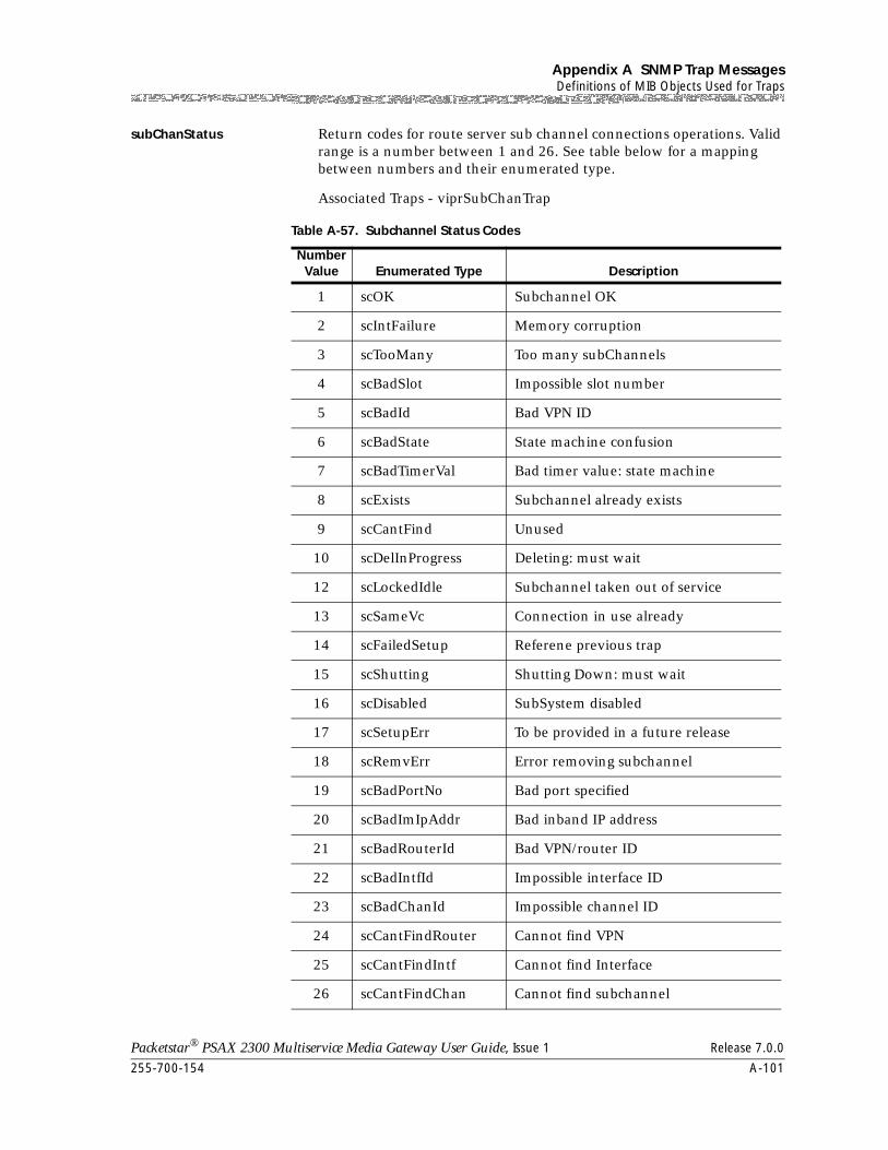
255-700-154 A-101
Packetstar® PSAX 2300 Multiservice Media Gateway User Guide, Issue 1 Release 7.0.0
Appendix A SNMP Trap MessagesDefinitions of MIB Objects Used for Traps
subChanStatus Return codes for route server sub channel connections operations. Valid range is a number between 1 and 26. See table below for a mapping between numbers and their enumerated type.
Associated Traps - viprSubChanTrap
Table A-57. Subchannel Status Codes
Number Value Enumerated Type Description
1 scOK Subchannel OK
2 scIntFailure Memory corruption
3 scTooMany Too many subChannels
4 scBadSlot Impossible slot number
5 scBadId Bad VPN ID
6 scBadState State machine confusion
7 scBadTimerVal Bad timer value: state machine
8 scExists Subchannel already exists
9 scCantFind Unused
10 scDelInProgress Deleting: must wait
12 scLockedIdle Subchannel taken out of service
13 scSameVc Connection in use already
14 scFailedSetup Referene previous trap
15 scShutting Shutting Down: must wait
16 scDisabled SubSystem disabled
17 scSetupErr To be provided in a future release
18 scRemvErr Error removing subchannel
19 scBadPortNo Bad port specified
20 scBadImIpAddr Bad inband IP address
21 scBadRouterId Bad VPN/router ID
22 scBadIntfId Impossible interface ID
23 scBadChanId Impossible channel ID
24 scCantFindRouter Cannot find VPN
25 scCantFindIntf Cannot find Interface
26 scCantFindChan Cannot find subchannel
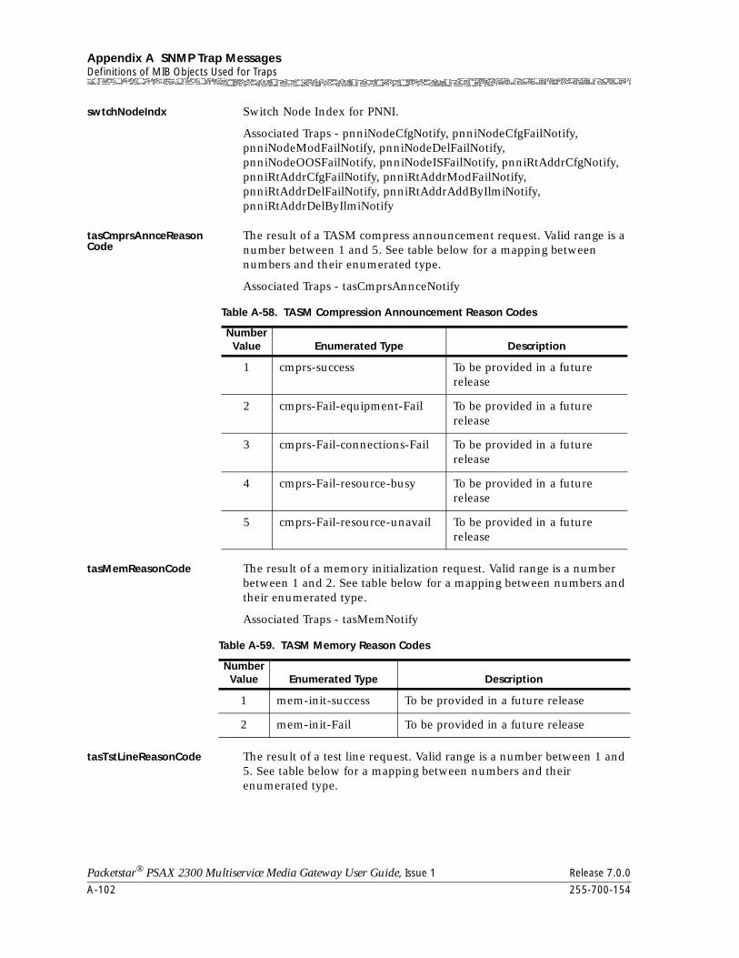
Appendix A SNMP Trap MessagesDefinitions of MIB Objects Used for Traps
A-102 255-700-154
Packetstar® PSAX 2300 Multiservice Media Gateway User Guide, Issue 1 Release 7.0.0
swtchNodeIndx Switch Node Index for PNNI.
Associated Traps - pnniNodeCfgNotify, pnniNodeCfgFailNotify, pnniNodeModFailNotify, pnniNodeDelFailNotify, pnniNodeOOSFailNotify, pnniNodeISFailNotify, pnniRtAddrCfgNotify, pnniRtAddrCfgFailNotify, pnniRtAddrModFailNotify, pnniRtAddrDelFailNotify, pnniRtAddrAddByIlmiNotify, pnniRtAddrDelByIlmiNotify
tasCmprsAnnceReasonCode
The result of a TASM compress announcement request. Valid range is a number between 1 and 5. See table below for a mapping between numbers and their enumerated type.
Associated Traps - tasCmprsAnnceNotify
tasMemReasonCode The result of a memory initialization request. Valid range is a number between 1 and 2. See table below for a mapping between numbers and their enumerated type.
Associated Traps - tasMemNotify
tasTstLineReasonCode The result of a test line request. Valid range is a number between 1 and 5. See table below for a mapping between numbers and their enumerated type.
Table A-58. TASM Compression Announcement Reason Codes
Number Value Enumerated Type Description
1 cmprs-success To be provided in a future release
2 cmprs-Fail-equipment-Fail To be provided in a future release
3 cmprs-Fail-connections-Fail To be provided in a future release
4 cmprs-Fail-resource-busy To be provided in a future release
5 cmprs-Fail-resource-unavail To be provided in a future release
Table A-59. TASM Memory Reason Codes
Number Value Enumerated Type Description
1 mem-init-success To be provided in a future release
2 mem-init-Fail To be provided in a future release
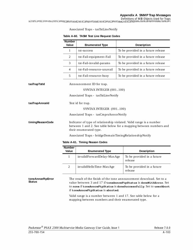
255-700-154 A-103
Packetstar® PSAX 2300 Multiservice Media Gateway User Guide, Issue 1 Release 7.0.0
Appendix A SNMP Trap MessagesDefinitions of MIB Objects Used for Traps
Associated Traps - tasTstLineNotify
tasTrapTstId Announcement ID for trap.
SYNTAX INTEGER (001..100)
Associated Traps - tasTstLineNotify
tasTrapAnnceId Test id for trap.
SYNTAX INTEGER (001..100)
Associated Traps - tasCmprsAnnceNotify
timingReasonCode Indicator of type of relationship violated. Valid range is a number between 1 and 2. See table below for a mapping between numbers and their enumerated type.
Associated Traps - bridgeDomainTimingRelationshipNotify
toneAnnceFtpErrorStatus
The result of the finish of the tone announcement download. Set to a value between 3 and 17 if toneAnnceFtpStatus is doneWithError. Set to none if toneAnnceFtpStatus is doneSuccessfully. Set to userAbort if toneAnnceFtpStatus is aborted.
Valid range is a number between 1 and 17. See table below for a mapping between numbers and their enumerated type.
Table A-60. TASM Test Line Request Codes
Number Value Enumerated Type Description
1 tst-success To be provided in a future release
2 tst-Fail-equipment-Fail To be provided in a future release
3 tst-Fail-invalid-params To be provided in a future release
4 tst-Fail-resource-unavail To be provided in a future release
5 tst-Fail-resource-busy To be provided in a future release
Table A-61. Timing Reason Codes
Number Value Enumerated Type Description
1 invalidForwardDelay-MaxAge To be provided in a future release
2 invalidHelloTime-MaxAge To be provided in a future release
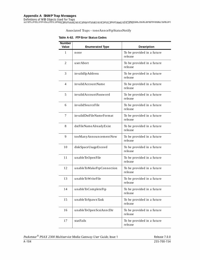
Appendix A SNMP Trap MessagesDefinitions of MIB Objects Used for Traps
A-104 255-700-154
Packetstar® PSAX 2300 Multiservice Media Gateway User Guide, Issue 1 Release 7.0.0
Associated Traps - toneAnnceFtpStatusNotify
Table A-62. FTP Error Status Codes
Number Value Enumerated Type Description
1 none To be provided in a future release
2 userAbort To be provided in a future release
3 invalidIpAddress To be provided in a future release
4 invalidAccountName To be provided in a future release
5 invalidAccountPassword To be provided in a future release
6 invalidSourceFile To be provided in a future release
7 invalidDstFileNameFormat To be provided in a future release
8 dstFileNameAlreadyExist To be provided in a future release
9 tooManyAnnouncementNow To be provided in a future release
10 diskSpaceUsageExceed To be provided in a future release
11 unableToOpenFile To be provided in a future release
12 unableToMakeFtpConnection To be provided in a future release
13 unableToWriteFile To be provided in a future release
14 unableToCompleteFtp To be provided in a future release
15 unableToSpawnTask To be provided in a future release
16 unableToOpenScsiAnncDir To be provided in a future release
17 statFails To be provided in a future release
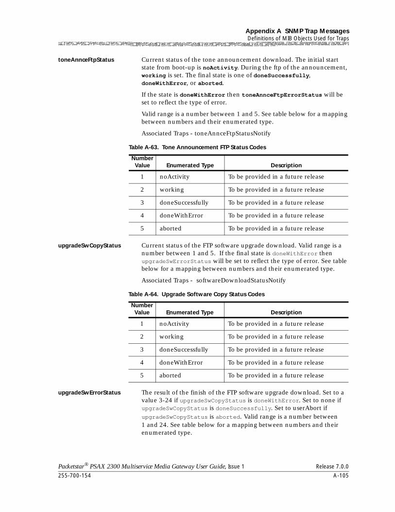
255-700-154 A-105
Packetstar® PSAX 2300 Multiservice Media Gateway User Guide, Issue 1 Release 7.0.0
Appendix A SNMP Trap MessagesDefinitions of MIB Objects Used for Traps
toneAnnceFtpStatus Current status of the tone announcement download. The initial start state from boot-up is noActivity. During the ftp of the announcement, working is set. The final state is one of doneSuccessfully, doneWithError, or aborted.
If the state is doneWithError then toneAnnceFtpErrorStatus will be set to reflect the type of error.
Valid range is a number between 1 and 5. See table below for a mapping between numbers and their enumerated type.
Associated Traps - toneAnnceFtpStatusNotify
upgradeSwCopyStatus Current status of the FTP software upgrade download. Valid range is a number between 1 and 5. If the final state is doneWithError then upgradeSwErrorStatus will be set to reflect the type of error. See table below for a mapping between numbers and their enumerated type.
Associated Traps - softwareDownloadStatusNotify
upgradeSwErrorStatus The result of the finish of the FTP software upgrade download. Set to a value 3-24 if upgradeSwCopyStatus is doneWithError. Set to none if upgradeSwCopyStatus is doneSuccessfully. Set to userAbort if upgradeSwCopyStatus is aborted. Valid range is a number between 1 and 24. See table below for a mapping between numbers and their enumerated type.
Table A-63. Tone Announcement FTP Status Codes
Number Value Enumerated Type Description
1 noActivity To be provided in a future release
2 working To be provided in a future release
3 doneSuccessfully To be provided in a future release
4 doneWithError To be provided in a future release
5 aborted To be provided in a future release
Table A-64. Upgrade Software Copy Status Codes
Number Value Enumerated Type Description
1 noActivity To be provided in a future release
2 working To be provided in a future release
3 doneSuccessfully To be provided in a future release
4 doneWithError To be provided in a future release
5 aborted To be provided in a future release
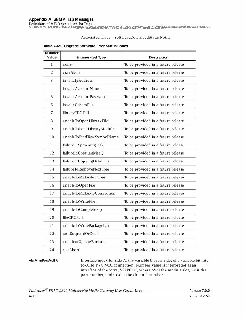
Appendix A SNMP Trap MessagesDefinitions of MIB Objects Used for Traps
A-106 255-700-154
Packetstar® PSAX 2300 Multiservice Media Gateway User Guide, Issue 1 Release 7.0.0
Associated Traps - softwareDownloadStatusNotify
vbrAtmPvcVccIfA Interface index for side A, the variable bit rate side, of a variable bit rate-to-ATM PVC VCC connection. Number value is interpreted as an interface of the form, SSPPCCC, where SS is the module slot, PP is the port number, and CCC is the channel number.
Table A-65. Upgrade Software Error Status Codes
Number Value Enumerated Type Description
1 none To be provided in a future release
2 userAbort To be provided in a future release
3 invalidIpAddress To be provided in a future release
4 invalidAccountName To be provided in a future release
5 invalidAccountPassword To be provided in a future release
6 invalidCdromFile To be provided in a future release
7 libraryCRCFail To be provided in a future release
8 unableToOpenLibraryFile To be provided in a future release
9 unableToLoadLibraryModule To be provided in a future release
10 unableToFindTaskSymbolName To be provided in a future release
11 failureInSpawningTask To be provided in a future release
12 failureInCreatingMsgQ To be provided in a future release
13 failureInCopyingDataFiles To be provided in a future release
14 failureToRemoveNextTree To be provided in a future release
15 unableToMakeNextTree To be provided in a future release
16 unableToOpenFile To be provided in a future release
17 unableToMakeFtpConnection To be provided in a future release
18 unableToWriteFile To be provided in a future release
19 unableToCompleteFtp To be provided in a future release
20 fileCRCFail To be provided in a future release
21 unableToWritePackageList To be provided in a future release
22 taskSuspendOrDead To be provided in a future release
23 unabletoUpdateBackup To be provided in a future release
24 cpuAbort To be provided in a future release
255-700-154 A-107
Packetstar® PSAX 2300 Multiservice Media Gateway User Guide, Issue 1 Release 7.0.0
Appendix A SNMP Trap MessagesDefinitions of MIB Objects Used for Traps
Associated Traps - vbrAtmPvcVccReqFailNotify, vbrAtmPvcVccSetupNotify, vbrAtmPvcVccTearDownNotify, vbrAtmBkPvcVccReqFailNotify, vbrAtmBkPvcVccSetupNotify, vbrAtmBkPvcVccTearDownNotify
vbrAtmPvcVccIfB Interface index for side B, the ATM side, of a variable bit rate-to-ATM PVC VCC connection. Number value is interpreted as an interface of the form, SSPPCCC, where SS is the module slot, PP is the port number, and CCC is the channel number.
Associated Traps - vbrAtmPvcVccReqFailNotify, vbrAtmPvcVccSetupNotify, vbrAtmPvcVccTearDownNotify, vbrAtmBkPvcVccReqFailNotify, vbrAtmBkPvcVccSetupNotify, vbrAtmBkPvcVccTearDownNotify
vbrAtmPvcVccVciB VCI value for side B, the ATM side, of a variable bit rate-to-ATM PVC VCC connection. Valid range is a number between 0 and 65535.
Associated Traps - vbrAtmPvcVccReqFailNotify, vbrAtmPvcVccSetupNotify, vbrAtmPvcVccTearDownNotify, vbrAtmBkPvcVccReqFailNotify, vbrAtmBkPvcVccSetupNotify, vbrAtmBkPvcVccTearDownNotify
vbrAtmPvcVccVpiB VPI value for side B, the ATM side, of a variable bit rate-to-ATM PVC VCC connection. Valid range is a number between 0 and 4095.
Associated Traps - vbrAtmPvcVccReqFailNotify, vbrAtmPvcVccSetupNotify, vbrAtmPvcVccTearDownNotify, vbrAtmBkPvcVccReqFailNotify, vbrAtmBkPvcVccSetupNotify, vbrAtmBkPvcVccTearDownNotify,
vbrAtmSpvcIfB Interface index for side B, the ATM side, of a variable bit rate-to-ATM SPVC VCC connection. Number value is interpreted as an interface of the form, SSPPCCC, where SS is the card slot, PP is the port number, and CCC is the channel number.
Associated Traps - vbrAtmSpvcSetUpNotify, vbrAtmSpvcTearDownNotify
vbrAtmSpvcRemoteVbrPortAddr
Remote VBR port NSAP address implemening IWF, not meaningful if passive type of connection.
Associated Traps - vbrAtmSpvcConfiguredNotify, vbrAtmSpvcConfigFailNotify, vbrAtmSpvcDeletedNotify, vbrAtmSpvcModifiedNotify, vbrAtmSpvcModifyFailNotify, vbrAtmSpvcSetUpNotify, vbrAtmSpvcTearDownNotify
vbrAtmSpvcVccIfA Interface index for side A, the variable bit rate side, of a variable bit rate-to-ATM SPVC VCC connection. Number value is interpreted as an interface of the form, SSPPCCC, where SS is the module slot, PP is the port number, and CCC is the channel number.
Associated Traps - vbrAtmSpvcVccSetUpNotify, vbrAtmSpvcVccTearDownNotify
Appendix A SNMP Trap MessagesDefinitions of MIB Objects Used for Traps
A-108 255-700-154
Packetstar® PSAX 2300 Multiservice Media Gateway User Guide, Issue 1 Release 7.0.0
vbrAtmSpvcVccIfB Interface index for side B, the ATM side, of a variable bit rate-to-ATM SPVC VCC connection. Number value is interpreted as an interface of the form, SSPPCCC, where SS is the module slot, PP is the port number, and CCC is the channel number.
Associated Traps - vbrAtmSpvcVccSetUpNotify, vbrAtmSpvcVccTearDownNotify
vbrAtmSpvcVccVciB VCI value for side B, the ATM side, of a variable bit rate-to-ATM SPVC VCC connection. Valid range is a number between 0 and 65535.
Associated Traps - vbrAtmSpvcVccSetUpNotify, vbrAtmSpvcVccTearDownNotify
vbrAtmSpvcVccVpiB VPI value for side B, the ATM side, of a variable bit rate-to-ATM SPVC VCC connection. Valid range is a number between 0 and 4095.
Associated Traps - vbrAtmSpvcVccSetUpNotify, vbrAtmSpvcVccTearDownNotify
vbrAtmSpvcVciB VCI value for side B, the ATM side, of a variable bit rate-to-ATM SPVC VCC connection. Valid range is a number between 0 and 65535.
Associated Traps - vbrAtmSpvcSetUpNotify, vbrAtmSpvcTearDownNotify
vbrAtmSpvcVpiB VPI value for side B, the ATM side, of a variable bit rate-to-ATM SPVC VCC connection. Valid range is a number between 0 and 4095.
Associated Traps - vbrAtmSpvcSetUpNotify, vbrAtmSpvcTearDownNotify
vbrVbrPvcIfA Interface index for side A of a variable bit rate-to-variable bit rate PVC connection. Number value is interpreted as an interface of the form, SSPPCCC, where SS is the module slot, PP is the port number, and CCC is the channel number.
Associated Traps - vbrVbrPvcReqFailNotify, vbrVbrPvcSetupNotify, vbrVbrPvcTearDownNotify
vbrVbrPvcIfB Interface index for side B of a variable bit rate-to-variable bit rate PVC connection. Number value is interpreted as an interface of the form, SSPPCCC, where SS is the module slot, PP is the port number, and CCC is the channel number.
Associated Traps - vbrVbrPvcReqFailNotify, vbrVbrPvcSetupNotify, vbrVbrPvcTearDownNotify
versionConfigurationReasonCode
Indicated status and results of version changing Valid range is a number between 1 and 36. See the table below for a mapping between numbers and their enumerated type.
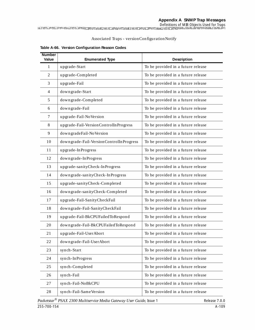
255-700-154 A-109
Packetstar® PSAX 2300 Multiservice Media Gateway User Guide, Issue 1 Release 7.0.0
Appendix A SNMP Trap MessagesDefinitions of MIB Objects Used for Traps
Associated Traps - versionConfigurationNotify
Table A-66. Version Configuration Reason Codes
Number Value Enumerated Type Description
1 upgrade-Start To be provided in a future release
2 upgrade-Completed To be provided in a future release
3 upgrade-Fail To be provided in a future release
4 downgrade-Start To be provided in a future release
5 downgrade-Completed To be provided in a future release
6 downgrade-Fail To be provided in a future release
7 upgrade-Fail-NoVersion To be provided in a future release
8 upgrade-Fail-VersionControlInProgress To be provided in a future release
9 downgradeFail-NoVersion To be provided in a future release
10 downgrade-Fail-VersionControlInProgress To be provided in a future release
11 upgrade-InProgress To be provided in a future release
12 downgrade-InProgress To be provided in a future release
13 upgrade-sanityCheck-InProgress To be provided in a future release
14 downgrade-sanityCheck-InProgress To be provided in a future release
15 upgrade-sanityCheck-Completed To be provided in a future release
16 downgrade-sanityCheck-Completed To be provided in a future release
17 upgrade-Fail-SanityCheckFail To be provided in a future release
18 downgrade-Fail-SanityCheckFail To be provided in a future release
19 upgrade-Fail-BkCPUFailedToRespond To be provided in a future release
20 downgrade-Fail-BkCPUFailedToRespond To be provided in a future release
21 upgrade-Fail-UserAbort To be provided in a future release
22 downgrade-Fail-UserAbort To be provided in a future release
23 synch-Start To be provided in a future release
24 synch-InProgress To be provided in a future release
25 synch-Completed To be provided in a future release
26 synch-Fail To be provided in a future release
27 synch-Fail-NoBkCPU To be provided in a future release
28 synch-Fail-SameVersion To be provided in a future release
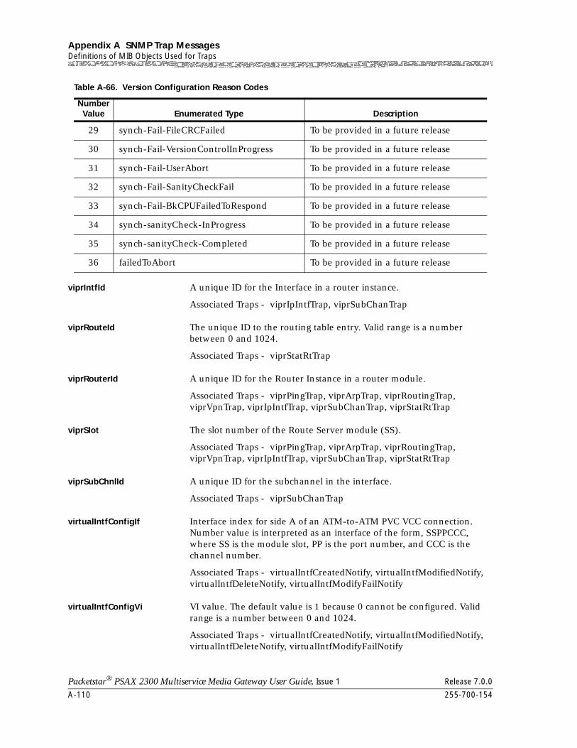
Appendix A SNMP Trap MessagesDefinitions of MIB Objects Used for Traps
A-110 255-700-154
Packetstar® PSAX 2300 Multiservice Media Gateway User Guide, Issue 1 Release 7.0.0
viprIntfId A unique ID for the Interface in a router instance.
Associated Traps - viprIpIntfTrap, viprSubChanTrap
viprRouteId The unique ID to the routing table entry. Valid range is a number between 0 and 1024.
Associated Traps - viprStatRtTrap
viprRouterId A unique ID for the Router Instance in a router module.
Associated Traps - viprPingTrap, viprArpTrap, viprRoutingTrap, viprVpnTrap, viprIpIntfTrap, viprSubChanTrap, viprStatRtTrap
viprSlot The slot number of the Route Server module (SS).
Associated Traps - viprPingTrap, viprArpTrap, viprRoutingTrap, viprVpnTrap, viprIpIntfTrap, viprSubChanTrap, viprStatRtTrap
viprSubChnlId A unique ID for the subchannel in the interface.
Associated Traps - viprSubChanTrap
virtualIntfConfigIf Interface index for side A of an ATM-to-ATM PVC VCC connection. Number value is interpreted as an interface of the form, SSPPCCC, where SS is the module slot, PP is the port number, and CCC is the channel number.
Associated Traps - virtualIntfCreatedNotify, virtualIntfModifiedNotify, virtualIntfDeleteNotify, virtualIntfModifyFailNotify
virtualIntfConfigVi VI value. The default value is 1 because 0 cannot be configured. Valid range is a number between 0 and 1024.
Associated Traps - virtualIntfCreatedNotify, virtualIntfModifiedNotify, virtualIntfDeleteNotify, virtualIntfModifyFailNotify
29 synch-Fail-FileCRCFailed To be provided in a future release
30 synch-Fail-VersionControlInProgress To be provided in a future release
31 synch-Fail-UserAbort To be provided in a future release
32 synch-Fail-SanityCheckFail To be provided in a future release
33 synch-Fail-BkCPUFailedToRespond To be provided in a future release
34 synch-sanityCheck-InProgress To be provided in a future release
35 synch-sanityCheck-Completed To be provided in a future release
36 failedToAbort To be provided in a future release
Table A-66. Version Configuration Reason Codes
Number Value Enumerated Type Description
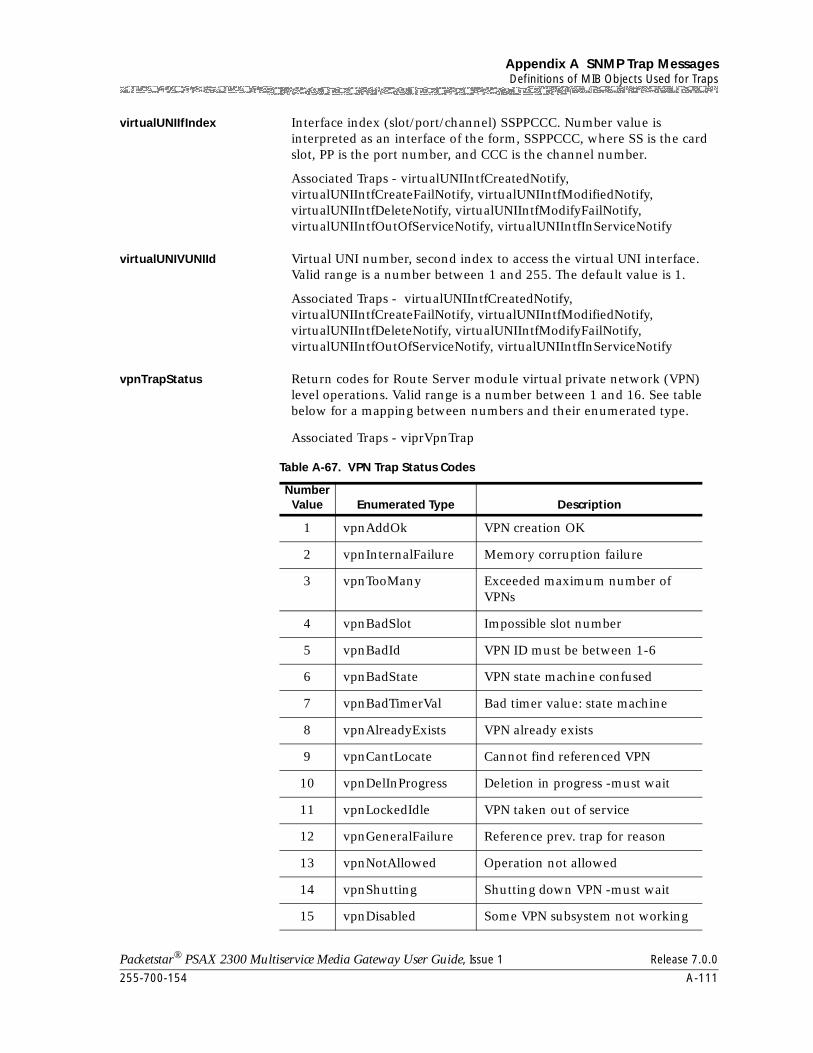
255-700-154 A-111
Packetstar® PSAX 2300 Multiservice Media Gateway User Guide, Issue 1 Release 7.0.0
Appendix A SNMP Trap MessagesDefinitions of MIB Objects Used for Traps
virtualUNIIfIndex Interface index (slot/port/channel) SSPPCCC. Number value is interpreted as an interface of the form, SSPPCCC, where SS is the card slot, PP is the port number, and CCC is the channel number.
Associated Traps - virtualUNIIntfCreatedNotify, virtualUNIIntfCreateFailNotify, virtualUNIIntfModifiedNotify, virtualUNIIntfDeleteNotify, virtualUNIIntfModifyFailNotify, virtualUNIIntfOutOfServiceNotify, virtualUNIIntfInServiceNotify
virtualUNIVUNIId Virtual UNI number, second index to access the virtual UNI interface. Valid range is a number between 1 and 255. The default value is 1.
Associated Traps - virtualUNIIntfCreatedNotify, virtualUNIIntfCreateFailNotify, virtualUNIIntfModifiedNotify, virtualUNIIntfDeleteNotify, virtualUNIIntfModifyFailNotify, virtualUNIIntfOutOfServiceNotify, virtualUNIIntfInServiceNotify
vpnTrapStatus Return codes for Route Server module virtual private network (VPN) level operations. Valid range is a number between 1 and 16. See table below for a mapping between numbers and their enumerated type.
Associated Traps - viprVpnTrap
Table A-67. VPN Trap Status Codes
Number Value Enumerated Type Description
1 vpnAddOk VPN creation OK
2 vpnInternalFailure Memory corruption failure
3 vpnTooMany Exceeded maximum number of VPNs
4 vpnBadSlot Impossible slot number
5 vpnBadId VPN ID must be between 1-6
6 vpnBadState VPN state machine confused
7 vpnBadTimerVal Bad timer value: state machine
8 vpnAlreadyExists VPN already exists
9 vpnCantLocate Cannot find referenced VPN
10 vpnDelInProgress Deletion in progress -must wait
11 vpnLockedIdle VPN taken out of service
12 vpnGeneralFailure Reference prev. trap for reason
13 vpnNotAllowed Operation not allowed
14 vpnShutting Shutting down VPN -must wait
15 vpnDisabled Some VPN subsystem not working
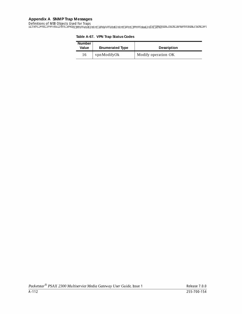
Appendix A SNMP Trap MessagesDefinitions of MIB Objects Used for Traps
A-112 255-700-154
Packetstar® PSAX 2300 Multiservice Media Gateway User Guide, Issue 1 Release 7.0.0
16 vpnModifyOk Modify operation OK
Table A-67. VPN Trap Status Codes
Number Value Enumerated Type Description
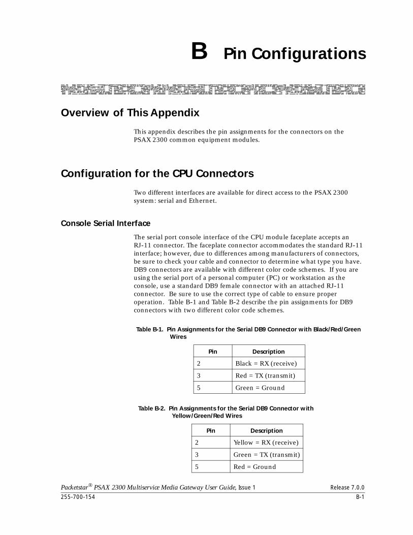
Packetstar® PSAX 2300 Multiservice Media Gateway User Guide, Issue 1 Release 7.0.0
255-700-154 B-1
B Pin Configurations
Overview of This Appendix
This appendix describes the pin assignments for the connectors on the PSAX 2300 common equipment modules.
Configuration for the CPU Connectors
Two different interfaces are available for direct access to the PSAX 2300 system: serial and Ethernet.
Console Serial Interface
The serial port console interface of the CPU module faceplate accepts an RJ-11 connector. The faceplate connector accommodates the standard RJ-11 interface; however, due to differences among manufacturers of connectors, be sure to check your cable and connector to determine what type you have. DB9 connectors are available with different color code schemes. If you are using the serial port of a personal computer (PC) or workstation as the console, use a standard DB9 female connector with an attached RJ-11 connector. Be sure to use the correct type of cable to ensure proper operation. Table B-1 and Table B-2 describe the pin assignments for DB9 connectors with two different color code schemes.
Table B-1. Pin Assignments for the Serial DB9 Connector with Black/Red/Green Wires
Pin Description
2 Black = RX (receive)
3 Red = TX (transmit)
5 Green = Ground
Table B-2. Pin Assignments for the Serial DB9 Connector with Yellow/Green/Red Wires
Pin Description
2 Yellow = RX (receive)
3 Green = TX (transmit)
5 Red = Ground
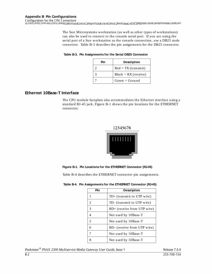
Appendix B Pin ConfigurationsConfiguration for the CPU Connectors
B-2 255-700-154
Packetstar® PSAX 2300 Multiservice Media Gateway User Guide, Issue 1 Release 7.0.0
The Sun Microsystems workstation (as well as other types of workstations) can also be used to connect to the console serial port. If you are using the serial port of a Sun workstation as the console connection, use a DB25 male connector. Table B-3 describes the pin assignments for the DB25 connector.
Ethernet 10Base-T Interface
The CPU module faceplate also accommodates the Ethernet interface using a standard RJ-45 jack. Figure B-1 shows the pin locations for the ETHERNET connector.
Table B-4 describes the ETHERNET connector pin assignments.
Table B-3. Pin Assignments for the Serial DB25 Connector
Pin Description
2 Red = TX (transmit)
3 Black = RX (receive)
7 Green = Ground
Figure B-1. Pin Locations for the ETHERNET Connector (RJ-45)
Table B-4. Pin Assignments for the ETHERNET Connector (RJ-45)
Pin Description
1 TD+ (transmit to UTP wire)
2 TD– (transmit to UTP wire)
3 RD+ (receive from UTP wire)
4 Not used by 10Base-T
5 Not used by 10Base-T
6 RD– (receive from UTP wire)
7 Not used by 10Base-T
8 Not used by 10Base-T
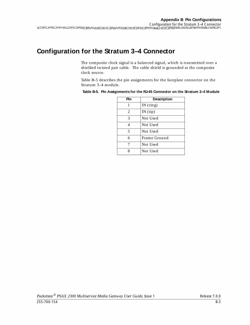
255-700-154 B-3
Packetstar® PSAX 2300 Multiservice Media Gateway User Guide, Issue 1 Release 7.0.0
Appendix B Pin ConfigurationsConfiguration for the Stratum 3–4 Connector
Configuration for the Stratum 3–4 Connector
The composite clock signal is a balanced signal, which is transmitted over a shielded twisted pair cable. The cable shield is grounded at the composite clock source.
Table B-5 describes the pin assignments for the faceplate connector on the Stratum 3–4 module.
Table B-5. Pin Assignments for the RJ-45 Connector on the Stratum 3–4 Module
Pin Description
1 IN (ring)
2 IN (tip)
3 Not Used
4 Not Used
5 Not Used
6 Frame Ground
7 Not Used
8 Not Used

Appendix B Pin ConfigurationsConfiguration for the Stratum 3–4 Connector
B-4 255-700-154
Packetstar® PSAX 2300 Multiservice Media Gateway User Guide, Issue 1 Release 7.0.0
Packetstar® PSAX 2300 Multiservice Media Gateway User Guide, Issue 1 Release 7.0.0
255-700-154 C-1
C Configuring In-Band Management
Setting Up In-Band Management Configuration
Three types of in-band management configurations are available:
Three basic methods for configuration are possible:
• Direct connection (see ”Using the Direct Connection Configuration” on page C-2)
The management host connects over an ATM WAN directly to an I/O module port in a remote managed target (the PSAX system being managed).
A direct connection can also be made between the network management system (NMS) machine, usually a Sun Solaris workstation,
to a Packetstar® PSAX Multiservice Media Gateway system through an OC-3c interface. This configuration requires that the NMS machine have an FORE card.
• Routed connection (see ”Using the Routed Connection Configuration” on page C-4)
The management host connects over an Ethernet network to an I/O module port in an PSAX system acting as a router. The “router” PSAX system in turn has direct in-band management PVC connections to remote PSAX systems (managed targets).
The routed connection configuration connects a PSAX system through another PSAX system, which acts as a main router. The “main router” PSAX system is connected to the NMS machine through an Ethernet connection. The “main router” is connected to an “intermediate router” PSAX system, or an “end system” PSAX system through ATM connections. In this configuration, ATM connections are made to the nearest hop in the tree structure.
This route connection allows you to flexibly manage any number of PSAX devices.
• Hybrid connection (see ”Using the Hybrid Connection Configuration” on page C-10)
Hybrid connection, which connects the main router PSAX device directly to the end system PSAX systems through ATM PVC connections. These ATM PVC connections can be sent through several PSAX systems to reach the “end system” PSAX systems. The main router PSAX system is connected to the NMS computer through an Ethernet LAN.
Hybrid connection configuration connects the “main router” PSAX system directly to the “end system” PSAX system through ATM connections. These ATM connections can be tunneled through a
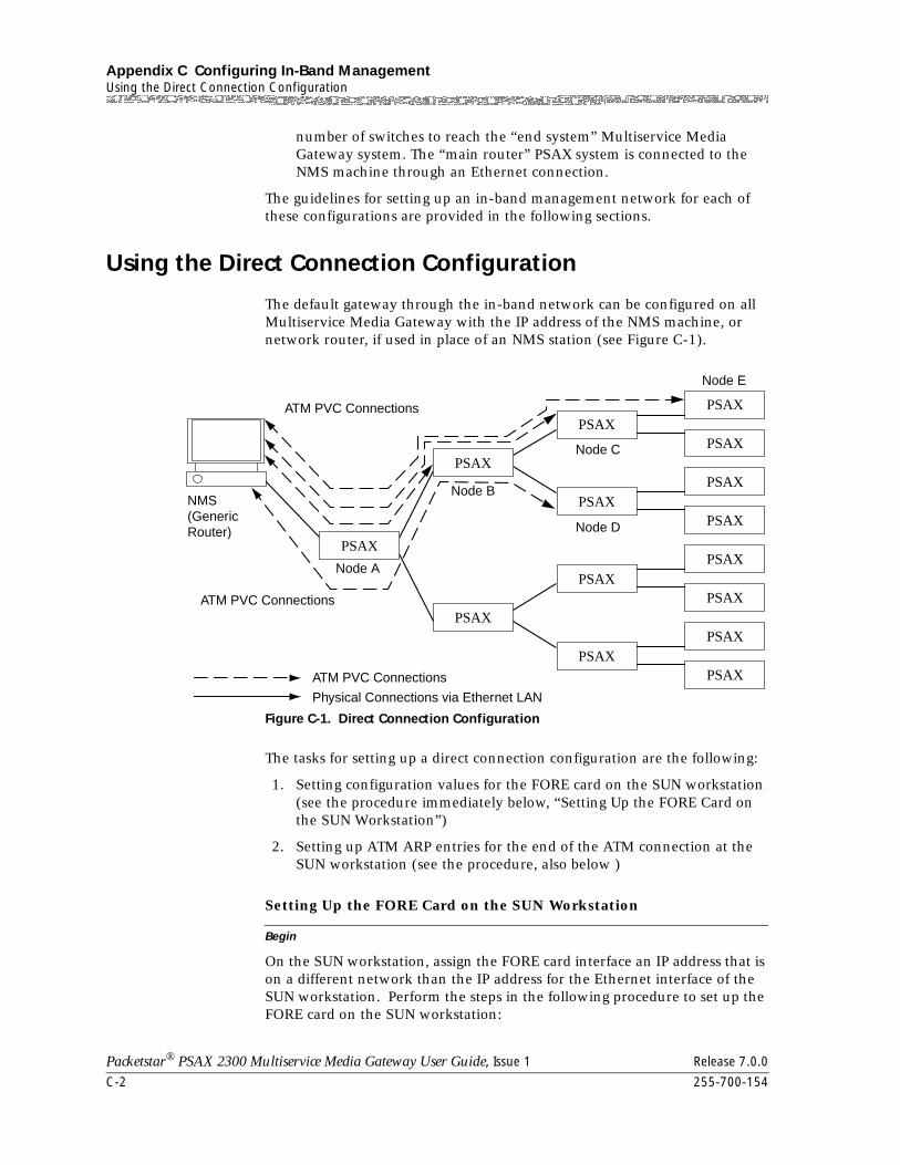
Appendix C Configuring In-Band ManagementUsing the Direct Connection Configuration
C-2 255-700-154
Packetstar® PSAX 2300 Multiservice Media Gateway User Guide, Issue 1 Release 7.0.0
number of switches to reach the “end system” Multiservice Media Gateway system. The “main router” PSAX system is connected to the NMS machine through an Ethernet connection.
The guidelines for setting up an in-band management network for each of these configurations are provided in the following sections.
Using the Direct Connection Configuration
The default gateway through the in-band network can be configured on all Multiservice Media Gateway with the IP address of the NMS machine, or network router, if used in place of an NMS station (see Figure C-1).
The tasks for setting up a direct connection configuration are the following:
1. Setting configuration values for the FORE card on the SUN workstation (see the procedure immediately below, “Setting Up the FORE Card on the SUN Workstation”)
2. Setting up ATM ARP entries for the end of the ATM connection at the SUN workstation (see the procedure, also below )
Begin
Setting Up the FORE Card on the SUN Workstation
On the SUN workstation, assign the FORE card interface an IP address that is on a different network than the IP address for the Ethernet interface of the SUN workstation. Perform the steps in the following procedure to set up the FORE card on the SUN workstation:
Figure C-1. Direct Connection Configuration
PSAX
ATM PVC Connections
ATM PVC Connections
ATM PVC Connections
Node A
Node BNMS(GenericRouter)
Node C
Node E
Node D
Physical Connections via Ethernet LAN
PSAX
PSAX
PSAXPSAX
PSAX
PSAX
PSAX
PSAX
PSAX
PSAX
PSAXPSAX
PSAX
PSAX
255-700-154 C-3
Packetstar® PSAX 2300 Multiservice Media Gateway User Guide, Issue 1 Release 7.0.0
Appendix C Configuring In-Band ManagementUsing the Direct Connection Configuration
1 On the SUN workstation, log in and type root.
2 To configure the FORE card, type the following command:
ifconfig fa0 forecard_Ip_Address netmask Netmask broadcast Bcast_address mtu Mtu_Size up
where,
forecard_Ip_Address = the IP address of the FORE card (for example, 136.242.140.222)
Netmask = the IP subnet mask (for example, 255.255.255.0)
Bcast_address = the IP address of the broadcast server (for example, 136.242.140.255)
Mtu_Size = maximum transfer unit size [packet size] (for example, 9180—refer to RFC 1577)
3 To test whether the FORE card has been configured correctly, type the following command:
ifconfig fa0
Consult your FORE user’s manual for additional instructions on the many variables you may encounter beyond this point.
End
ATM ARP table entries should be created on the SUN machine. Each entry specifies the remote PSAX system in-band management IP address (primary) and the corresponding ATM connection (VCC: VPC) that is connected to the remote PSAX system. Add a PVC connection on the FORE card to the in-band management port on the PSAX system. Set up the following PVC connections:
Begin
Setting Up ATM ARP Table Entries
1 Type the following command:
Atmarp -s Remote_Ip fa0 VPI VCI AAL llc
Atmarp -l fa0 VPI VCI AAL llc
Where Remote_Ip = (IP Address of the in-band connection on the CPU CARD)
Example:
Local IP = 136.242.140.223 (Primary IP Address of Node A)
VPI= 0
VCI= 300
AAL= 5
and
Remote IP = 136.242.140.225 (Primary IP Address of Node B)
Appendix C Configuring In-Band ManagementUsing the Routed Connection Configuration
C-4 255-700-154
Packetstar® PSAX 2300 Multiservice Media Gateway User Guide, Issue 1 Release 7.0.0
VPI= 0
VCI= 302
AAL= 5
Check whether the connections have been configured by using the command atmarp -a
2 All the remote PSAX systems’ in-band interface IP addresses may or may not be in the same subnet as that of the FORE card’s IP address.
3 If the remote PSAX systems’ in-band interface IP address is not in the same subnet as that of the FORE card’s IP address, then a route entry should be added on the SUN machine for the remote PSAX systems’ subnet, using the FORE card interface as the gateway.
4 On the PSAX system, the in-band management interface (primary) should be assigned an IP address that lies in a different network than that of its Ethernet interface.
5 The in-band connection from each of the remote PSAX systems is a direct connection to the SUN machine’s FORE card interface IP address. (Here a direct connection implies that it should not be IP routed through a CPU module. It should be an ATM connection, which may be tunneled through a number of switches.)
6 If the ATM end points are connected to a Cisco router instead of a SUN machine, then the remote PSAX system can be configured with a default gateway address, which should be the same as the in-band connection end point’s IP address (that is, the Cisco router’s address).
7 The gateway IP address should be either an Ethernet subnet or an in-band management subnet. The gateway IP address should not be the same as the in-band IP address.
8 If the gateway IP address is in the in-band management subnet, then there should be an in-band connection to that address.
9 If a traffic-shaping OC-3c module is used, the recommended values for in-band connection are Peak Rate: 2000 cps; Sustained Rate: 1000 cps; MBS: 10000 cells.
End
Using the Routed Connection Configuration
No default gateway through an in-band network should be configured on any of the PSAX systems.
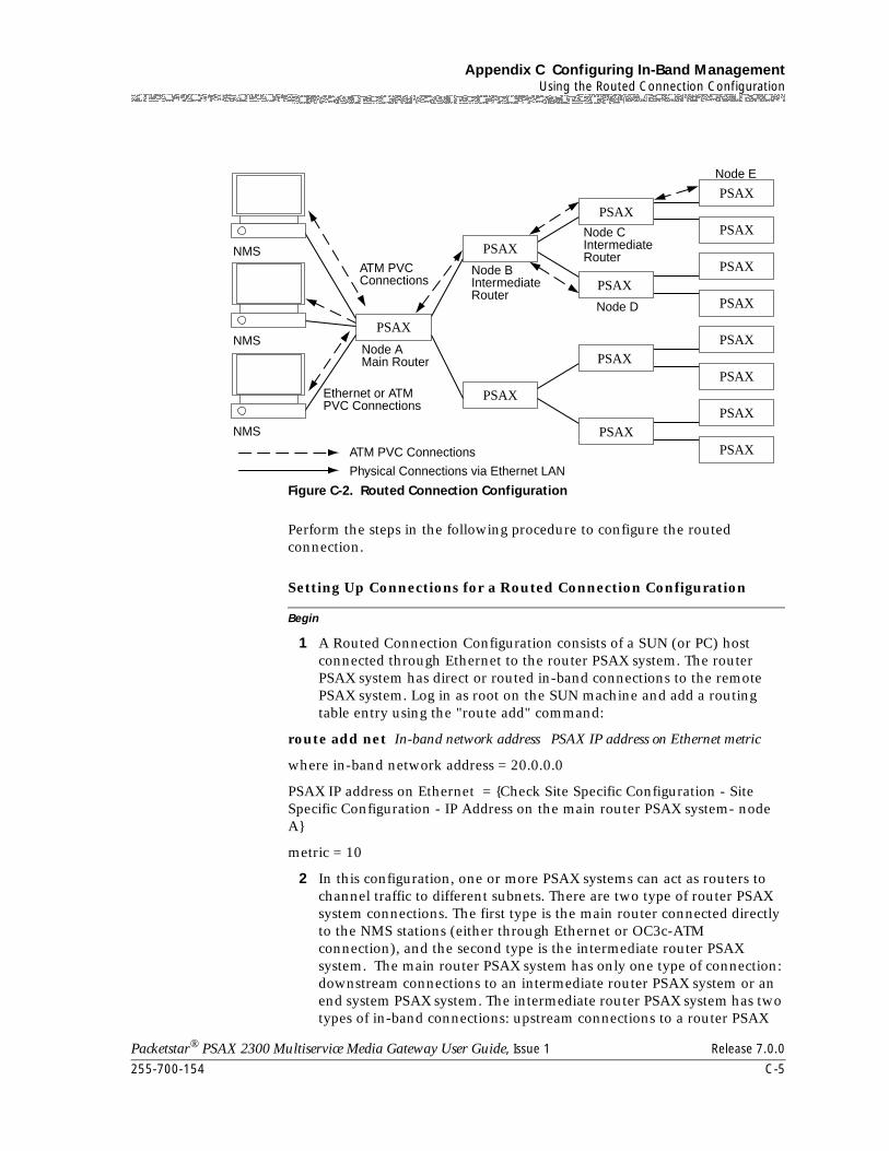
255-700-154 C-5
Packetstar® PSAX 2300 Multiservice Media Gateway User Guide, Issue 1 Release 7.0.0
Appendix C Configuring In-Band ManagementUsing the Routed Connection Configuration
Perform the steps in the following procedure to configure the routed connection.
Begin
Setting Up Connections for a Routed Connection Configuration
1 A Routed Connection Configuration consists of a SUN (or PC) host connected through Ethernet to the router PSAX system. The router PSAX system has direct or routed in-band connections to the remote PSAX system. Log in as root on the SUN machine and add a routing table entry using the "route add" command:
route add net In-band network address PSAX IP address on Ethernet metric
where in-band network address = 20.0.0.0
PSAX IP address on Ethernet = {Check Site Specific Configuration - Site Specific Configuration - IP Address on the main router PSAX system- node A}
metric = 10
2 In this configuration, one or more PSAX systems can act as routers to channel traffic to different subnets. There are two type of router PSAX system connections. The first type is the main router connected directly to the NMS stations (either through Ethernet or OC3c-ATM connection), and the second type is the intermediate router PSAX system. The main router PSAX system has only one type of connection: downstream connections to an intermediate router PSAX system or an end system PSAX system. The intermediate router PSAX system has two types of in-band connections: upstream connections to a router PSAX
Figure C-2. Routed Connection Configuration
PSAX
ATM PVCConnections
ATM PVC Connections
Node AMain Router
Ethernet or ATMPVC Connections
Node BIntermediateRouter
NMS
Node CIntermediateRouter
Node E
Node D
NMS
NMS
Physical Connections via Ethernet LAN
PSAX
PSAX
PSAXPSAX
PSAX
PSAX
PSAX
PSAX
PSAX
PSAX
PSAXPSAX
PSAX
PSAX
Appendix C Configuring In-Band ManagementUsing the Routed Connection Configuration
C-6 255-700-154
Packetstar® PSAX 2300 Multiservice Media Gateway User Guide, Issue 1 Release 7.0.0
system and downstream connections to either the router PSAX system or the end system PSAX system. This helps to form a simple tree structure (see Figure C-2 on page C-5).
3 On the PSAX system, the in-band management interface (primary) should be assigned an IP address that should be on a different network than that of its Ethernet interface.
4 Also, for all the PSAX system models (except the main router PSAX system), the Ethernet interface IP network should be different from the SUN machine’s Ethernet interface IP network.
5 All of the NMS stations should be in the one IP network, but can be in different subnets connected to the main router PSAX system by an Ethernet or OC3-ATM connection.
6 All the end system and router PSAX system in-band interface IP addresses should be in the same IP network. They can have different masks (that is, the PSAX system downstream can have a mask wider in ones than that of the parent node). This allows multiple connections to be set to end system PSAX system that are in the same in-band subnet. Routing to intermediate PSAX systems is done based on the subnet mask. The subnetwork address provided in the connection table and routing to the end system PSAX system is based on the host address of the end system configured in the connection table. Routing to the NMS stations is based on the mask and network address to the NMS stations configured in the connection table. (With this configuration, an upstream connection should be made only to the NMS network).
7 The tree structure is based on subnet routing, where connections to each subtree lie in one subnet and the connections to a downstream subtree are configured with in-band subnetwork addresses and a mask larger (wider in ones) than the parent subtree. (See the example configuration in the next section).
8 The downstream connections to intermediate routers should be configured with the subnetwork address of the subtree and a mask larger (wider in ones) than that of the parent connections.
9 The upstream connection should only be to the NMS stations’ network address with an appropriate mask.
10 On the host (SUN or PC) machine, an IP routing table entry should be added. This entry should be a network-specific routing table entry, with the in-band network address of each of the remote PSAX systems and the main router PSAX system Ethernet interface IP address as the gateway. The metric should be set to the depth of the tree (or default 10).
11 The default gateway should not be configured with an IP address within the in-band network.
End
255-700-154 C-7
Packetstar® PSAX 2300 Multiservice Media Gateway User Guide, Issue 1 Release 7.0.0
Appendix C Configuring In-Band ManagementUsing the Routed Connection Configuration
Setting PVC Connections for Routed Connection Configuration
Assume that the VPI:VCI for the connection between node A and B is VPIab: VCIab, etc. Also assume that the Ethernet IP addresses of all nodes except node A do not lie in the NMS station’s network address range.
Perform the steps in the following procedure to set PVC connections for a routed connection.
Begin
Setting Up PVC Connections for Routed Connection Configuration
1 Configure the primary IP address for in-band management on the CPU module of the main router PSAX system (Node A) using the console interface:
Select the Site Specific Configuration> In-Band Management menu options.
Example:
Primary IP Address: 020.001.001.001
Primary IP Mask: 255.000.000.000
The connection downstream from Node A to subtrees should have a mask greater than 255.0.0.0 if they go to network 20.0.0.0. For example, mask 255.255.0.0 is assigned for downstream connection.
2 Configure the primary and backup IP addresses for in-band management on the CPU module of the intermediate router PSAX system (Node B) using the console interface:
Example:
Primary IP Address:020.001.001.002
Primary IP Mask: 255.255.000.000
Connections downstream from Node B to the subtrees should have a mask greater than for the connection downstream on parent Node A (255.255.0.0) if they go to network 20.0.0.0. For example, mask 255.255.255.0 is assigned for downstream connection.
3 Configure the primary IP Address for in-band management on the CPU module of main router PSAX system (Node C) using the console interface:
Select the Site Specific Configuration> In-Band Management menu options.
Example:
Primary IP Address: 020.001.001.003
Primary IP Mask: 255.255.255.000
Connections downstream from Node C to subtrees will go directly to end-system PSAX systems and should have mask greater than or equal to that for connections on parent Node B (255.255.255.0) if they go to network
Appendix C Configuring In-Band ManagementUsing the Routed Connection Configuration
C-8 255-700-154
Packetstar® PSAX 2300 Multiservice Media Gateway User Guide, Issue 1 Release 7.0.0
20.0.0.0. For example, mask 255.255.255.0 is assigned for downstream connections
4 Configure the primary IP Address for in-band management on the CPU module of main router PSAX system (Node D) using the console interface:
Select the Site Specific Configuration> In-Band Management menu options.
Example:
Primary IP Address: 020.001.002.001
Primary IP Mask: 255.255.255.000
5 Configure the primary IP Address for in-band management on the CPU module of the main router PSAX system (Node E) using the console interface:
Select the Site Specific Configuration> In-Band Management menu options.
Example:
Primary IP Address: 020.001.001.004
Primary IP Mask: 255.255.255.000
6 Configure the primary IP address for in-band management on the CPU module of the main router PSAX system (Node X) using the console interface:
Select the Site Specific Configuration> In-Band Management menu options.
Example:
Primary IP Address: 020.002.001.001
Primary IP Mask: 255.255.000.000
7 Configure the primary IP Address for in-band management on the CPU module of the main router PSAX system (Node Y) using the console interface:
Select the Site Specific Configuration> In-Band Management menu options.
Example:
Primary IP Address: 020.002.001.002
Primary IP Mask: 255.255.255.000
8 Configure the primary IP Address for in-band management on the CPU module of main router PSAX system (Node Z) using the console interface:
Select the Site Specific Configuration> In-Band Management menu options.
Example:
255-700-154 C-9
Packetstar® PSAX 2300 Multiservice Media Gateway User Guide, Issue 1 Release 7.0.0
Appendix C Configuring In-Band ManagementUsing the Routed Connection Configuration
Primary IP Address: 020.002.002.001
Primary IP Mask: 255.255.255.000
9 Set up in-band management connections on the CPU module of Node A to DS3:
For setting up an in-band connection from the DS3 module to the CPU module, configure the DS3 module and put it into service. Select the Connection Configuration > In-Band Management IP PVC > Add
Connection menu options, configure the PVC to the FORECARD.
Example:
Slot:Slot Number VPI:VPIabIP Address: 020.001.000.000
Port:1 VCI:VCIab IP Mask: 255.255.000.000
Channel: 1
Slot:Slot Number VPI: VPIaxIP Address: 020.002.000.000
Port: 1 VCI: VCIax IP Mask: 255.255.000.000
Channel: 1
10 Set up in-band management connections on the CPU module of Node B:
Example:
Slot:Slot Number VPI: VPIabIP Address: NMS net. addr
Port:1 VCI: VCIabIP Mask: NMS net. mask
Channel: 1
Slot:Slot Number VPI: VPIbcIP Address: 020.001.001.000
Port:1 VCI: VCIbcIP Mask: 255.255.255.000
Channel: 1
Slot:Slot Number VPI: VPIbdIP Address: 020.001.002.000
Port:1 VCI: VCIbdIP Mask: 255.255.255.000
Channel: 1
11 Set up in-band management connections on the CPU module of Node C:
Example:
Slot:Slot Number VPI: VPIbcIP Address: NMS net. addr
Port:1 VCI: VCIbcIP Mask: NMS net. mask
Channel: 1
Slot:Slot Number VPI: VPIceIP Address: 020.001.001.003
Appendix C Configuring In-Band ManagementUsing the Hybrid Connection Configuration
C-10 255-700-154
Packetstar® PSAX 2300 Multiservice Media Gateway User Guide, Issue 1 Release 7.0.0
Port:1 VCI: VCIceIP Mask: 255.255.255.000
Channel: 1
Slot:Slot Number VPI: VPIcfIP Address: 020.001.001.004
Port:1 VCI: VCIcfIP Mask: 255.255.255.000
Channel: 1
12 Set up in-band managment connections on the CPU module of Node E:
Example:
Slot:Slot Number VPI: VPIceIP Address: NMS net. addr
Port:1 VCI: VCIceIP Mask: NMS net. mask
Channel: 1
13 Verify that a routing table entry from the SUN machine’s network to network 20.0.0.0 exists on the SUN machine using the “netstat -nr” command.
14 Use ping, telnet, rlogin and ftp from the SUN machine to nodes A, B, C, E and F to test the TCP/IP connectivity.
End
Using the Hybrid Connection Configuration
The main router PSAX system (Node A) has two or more connections to remote PSAX systems that are in the same in-band subnet as the Node A PSAX system.
Default gateways through in-band connections can be configured on all remote PSAX systems (that is, all PSAX systems except Node A) with the IP address of Node A’s in-band interface. In this case, in-band connections on remote PSAX systems should be configured with Node A’s in-band IP address and a default gateway should be set to Node A’s in-band IP address.
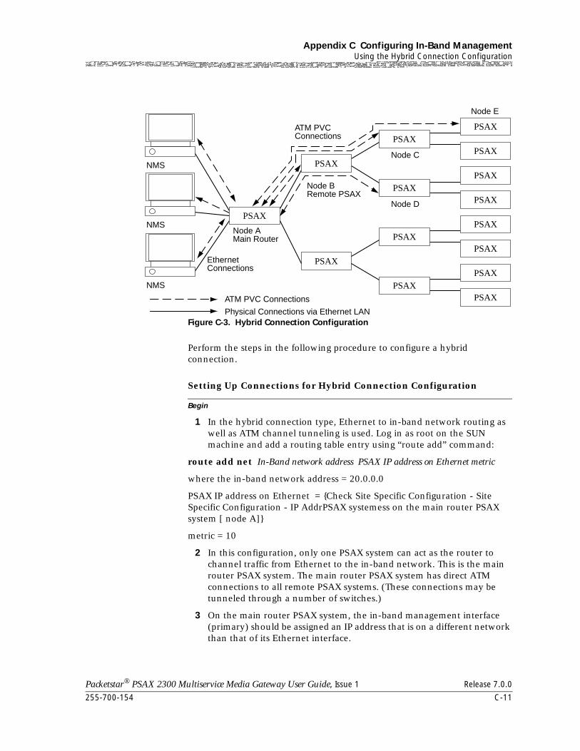
255-700-154 C-11
Packetstar® PSAX 2300 Multiservice Media Gateway User Guide, Issue 1 Release 7.0.0
Appendix C Configuring In-Band ManagementUsing the Hybrid Connection Configuration
Perform the steps in the following procedure to configure a hybrid connection.
Begin
Setting Up Connections for Hybrid Connection Configuration
1 In the hybrid connection type, Ethernet to in-band network routing as well as ATM channel tunneling is used. Log in as root on the SUN machine and add a routing table entry using “route add” command:
route add net In-Band network address PSAX IP address on Ethernet metric
where the in-band network address = 20.0.0.0
PSAX IP address on Ethernet = {Check Site Specific Configuration - Site Specific Configuration - IP AddrPSAX systemess on the main router PSAX system [ node A]}
metric = 10
2 In this configuration, only one PSAX system can act as the router to channel traffic from Ethernet to the in-band network. This is the main router PSAX system. The main router PSAX system has direct ATM connections to all remote PSAX systems. (These connections may be tunneled through a number of switches.)
3 On the main router PSAX system, the in-band management interface (primary) should be assigned an IP address that is on a different network than that of its Ethernet interface.
Figure C-3. Hybrid Connection Configuration
PSAX
ATM PVCConnections
ATM PVC Connections
Node AMain Router
EthernetConnections
Node BRemote PSAX
NMSNode C
Node E
Node D
NMS
NMS
Physical Connections via Ethernet LAN
PSAX
PSAX
PSAXPSAX
PSAX
PSAX
PSAX
PSAX
PSAX
PSAX
PSAXPSAX
PSAX
PSAX
Appendix C Configuring In-Band ManagementUsing the Hybrid Connection Configuration
C-12 255-700-154
Packetstar® PSAX 2300 Multiservice Media Gateway User Guide, Issue 1 Release 7.0.0
4 For all the PSAX systems except the main router PSAX system, the Ethernet interface IP network should be different from the SUN machine’s Ethernet interface IP network.
5 All of the NMS stations should be in the one IP network, but can be in different subnets connected to the main router PSAX system via Ethernet or OC3-ATM connections.
6 All the end system and router PSAX system in-band interface IP addresses may or may not be in the same IP network. For each different IP network, a route should be configured on each of the NMS station (SUN machine) to use the main router PSAX system as gateway to that network. (The metric should be set to 2).
7 The default gateway can be configured on the remote PSAX system to use the main router PSAX system as a gateway.
8 The main router PSAX system should be configured with in-band connections to each of the remote PSAX systems.
9 The remote PSAX system should have only one connection to the NMS station’s network and the appropriate mask if the main router PSAX system is not used as default gateway by the remote PSAX system.
10 If the main router PSAX system is used as a default gateway by the remote PSAX system, then the remote PSAX system should have only one in-band connection to the main router PSAX system, the in-band IP address.
End
Setting PVC Connections for Hybrid Connection Configuration
Assume that the VPI: VCI for connection between node A and B is VPIab: VCIab and so on. Also assume that the Ethernet IP address of all nodes, except node A, do not lie in the NMS stations’ network address range.
Perform the steps in the following procedure to set PVC connections for hybrid connection.
Begin
Setting Up PVC Connections for Hybrid Connection Configuration
1 Configure the primary IP address for in-band management on the CPU module of the main router PSAX system (Node A) using the console interface:
Select the Site Specific Configuration> In-Band Management menu options.
Example:
Primary IP Address: 020.001.001.001
Primary IP Mask: 255.000.000.000
255-700-154 C-13
Packetstar® PSAX 2300 Multiservice Media Gateway User Guide, Issue 1 Release 7.0.0
Appendix C Configuring In-Band ManagementUsing the Hybrid Connection Configuration
2 Configure the primary and backup IP Address for in-band management on the CPU module of the intermediate router PSAX system (Node B) using the console interface:
Example:
Primary IP Address: 020.001.001.2
Primary IP Mask: 255.000.000.000
3 Configure the primary IP address for in-band management on the CPU module of the main router PSAX system (Node C) using the console interface:
Select the Site Specific Configuration> In-Band Management menu options.
Example:
Primary IP Address: 020.001.001.003
Primary IP Mask: 255.000.000.000
4 Configure the primary IP Address for in-band management on the CPU module of main router PSAX system (Node D) using the console interface:
Select the Site Specific Configuration> In-Band Management menu options.
Example:
Primary IP Address: 020.001.001.004
Primary IP Mask: 255.000.000.000
5 Configure the primary IP address for in-band management on the CPU module of main router PSAX system (Node E) using the console interface:
Select the Site Specific Configuration> In-Band Management menu options.
Example:
Primary IP Address: 020.001.001.005
Primary IP Mask: 255.000.000.000
6 Set up in-band management connections on the CPU module of Node A to a remote PSAX system:
For setting up an in-band connection from the DS3 module to the CPU module, configure the DS3 module and bring the interface into service. Select the Connection Configuration > In-Band Management IP PVC > Add Connection menu options, configure the PVC to the FORECARD.
Example:
Slot:Slot Number VPI: VPIabIP Address: 020.001.001.002
Port:1 VCI: VCIabIP Mask: 255.000.000.000
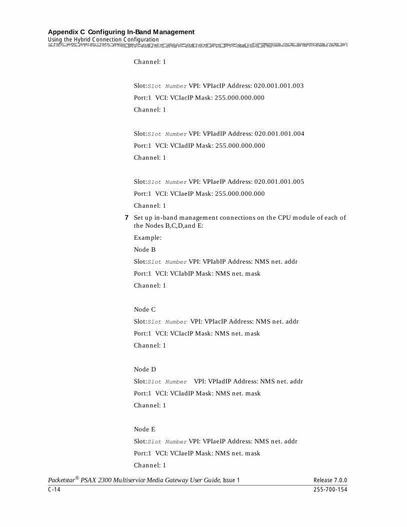
Appendix C Configuring In-Band ManagementUsing the Hybrid Connection Configuration
C-14 255-700-154
Packetstar® PSAX 2300 Multiservice Media Gateway User Guide, Issue 1 Release 7.0.0
Channel: 1
Slot:Slot Number VPI: VPIacIP Address: 020.001.001.003
Port:1 VCI: VCIacIP Mask: 255.000.000.000
Channel: 1
Slot:Slot Number VPI: VPIadIP Address: 020.001.001.004
Port:1 VCI: VCIadIP Mask: 255.000.000.000
Channel: 1
Slot:Slot Number VPI: VPIaeIP Address: 020.001.001.005
Port:1 VCI: VCIaeIP Mask: 255.000.000.000
Channel: 1
7 Set up in-band management connections on the CPU module of each of the Nodes B,C,D,and E:
Example:
Node B
Slot:Slot Number VPI: VPIabIP Address: NMS net. addr
Port:1 VCI: VCIabIP Mask: NMS net. mask
Channel: 1
Node C
Slot:Slot Number VPI: VPIacIP Address: NMS net. addr
Port:1 VCI: VCIacIP Mask: NMS net. mask
Channel: 1
Node D
Slot:Slot Number VPI: VPIadIP Address: NMS net. addr
Port:1 VCI: VCIadIP Mask: NMS net. mask
Channel: 1
Node E
Slot:Slot Number VPI: VPIaeIP Address: NMS net. addr
Port:1 VCI: VCIaeIP Mask: NMS net. mask
Channel: 1

255-700-154 C-15
Packetstar® PSAX 2300 Multiservice Media Gateway User Guide, Issue 1 Release 7.0.0
Appendix C Configuring In-Band ManagementUsing the Hybrid Connection Configuration
8 Verify that a routing table entry from the SUN machine’s network to network 20.0.0.0 exists on the SUN machine using the netstat -nr command:
9 Use ping, telnet, rlogin and ftp from the SUN machine to nodes A, B, C, E and F to test the TCP/IP connectivity.
End

Appendix C Configuring In-Band ManagementUsing the Hybrid Connection Configuration
C-16 255-700-154
Packetstar® PSAX 2300 Multiservice Media Gateway User Guide, Issue 1 Release 7.0.0
Packetstar® PSAX 2300 Multiservice Media Gateway User Guide, Issue 1 Release 7.0.0
255-700-154 D-1
D ATM Traffic Descriptors
Overview of This Appendix
Connections Supporting Traffic Descriptors
When you create a PVC, you can select one of several traffic descriptors. The traffic descriptor specifies which traffic parameters are used for traffic control. It also determines the number and type of cells that are admitted into a congested queue, and whether high-priority cells are tagged as low-priority cells when traffic exceeds the traffic parameter thresholds. The traffic descriptors used in the PacketStar® Multiservice Media Gateway system software are selected on the user interface windows for the following types of connections:
• ATM-to-ATM VCC PVC connection
• ATM-to-ATM VPC PVC connection
• Bridge-to-ATM VCC PVC connection
• Circuit Emulation-to-ATM VCC PVC connection
• Frame Relay-to-ATM VCC PVC connection
• In-band ATM PVC connection
• VBR-to-ATM VCC PVC connection
Traffic Descriptors Supported
The traffic descriptors available for these connections types are as follows (the values as they appear on the window are shown in parentheses):
• Best effort (Best-effort)
This traffic descriptor allows the system to attempt to send all cells in a “best effort” fashion, without specifying traffic parameters, similar to the AQueMan algorithm. The Multiservice Media Gateway might drop some or all cells during congestion.
• Best effort with tagging (Best-effort-tag)
This traffic descriptor allows the system to tag all CLP=0 (high priority) cells to change them to CLP=1 (low priority) cells, and then attempt to send all cells in a “best effort” fashion, without specifying any other traffic parameters, similar to the AQueMan algorithm. The network might drop some or all cells during congestion.
• One bucket, with no tagging for cells with both CLP bit=0 and CLP bit=1 (1B-NT-0+1)
Appendix D ATM Traffic DescriptorsOverview of This Appendix
D-2 255-700-154
Packetstar® PSAX 2300 Multiservice Media Gateway User Guide, Issue 1 Release 7.0.0
This traffic descriptor uses the parameters one bucket, no tagging, cell loss priority (CLP)=0+1 cells (high and low priority). The Multiservice Media Gateway ignores the CLP bit value and drops all cells violating the value set for the peak cell rate (PCR).
• Two buckets, with no tagging for cells with both CLP bit=0 and CLP bit=1 (2B-NT-0+1-0+1)
This traffic descriptor uses the parameters two buckets, no tagging, CLP=0+1 cells (high and low priority) for bucket 1, and CLP=0+1 cells (high and low priority) for bucket 2. The Multiservice Media Gateway ignores the CLP bit value for cells passing into bucket 1 and drops all cells violating the value set for the PCR. The remainder of the cells are passed to bucket 2. The Multiservice Media Gateway ignores the CLP bit value for cells passing into bucket 2, and drops all cells violating the value set for the sustainable cell rate (SCR).
• Two buckets, with no tagging for cells with both CLP bit=0+1 and CLP bit=0 (2B-NT-0+1-0)
This traffic descriptor uses the parameters two buckets, no tagging, CLP=0+1 cells (high and low priority) for bucket 1, and CLP=0 cells (high priority) for bucket 2. For bucket 1, the Multiservice Media Gateway ignores the CLP bit value for cells passing into bucket 1 and drops all cells violating the value set for the PCR. For bucket 2, the system takes one of the following actions:
~ When the connection is configured for variable bit rate (VBR) traffic, the Multiservice Media Gateway drops all CLP=0 cells violating the value set for the SCR in bucket 2.
~ When the connection is configured for constant bit rate (CBR) traffic, the Multiservice Media Gateway drops all CLP=0 cells violating the value set for the PCR in bucket 2.
• Two buckets, for cells with CLP bit=0 and CLP bit=0 (2B-NT-0+1-0)
This traffic descriptor uses the parameters two buckets, tagging, CLP=0+1 cells (high and low priority) for bucket 1, and CLP=0 cells (high priority) for bucket 2. For bucket 1, the Multiservice Media Gateway ignores the CLP bit value for cells passing into bucket 1 and drops all cells violating the value set for the PCR. For bucket 2, the system takes one of the following actions:
~ When the connection is configured for variable bit rate (VBR) traffic, the Multiservice Media Gateway tags all CLP=0 cells violating the value set for the SCR to CLP=1 in bucket 2.
~ When the connection is configured for constant bit rate (CBR) traffic, the Multiservice Media Gateway tags all CLP=0 cells violating the value set for the PCR to CLP=1 in bucket 2.
The network then might drop some or all cells during congestion.
PacketStar® PSAX 2300 Multiservice Media Gateway User Guide, Issue 1 Release 7.0.0
255-700-154 E-1
E Reference Tables
Overview of This Appendix
This appendix contains reference tables that are helpful while configuring your PSAX Multiservice Media Gateway system. The following types of information are provided:
• ATM Traffic Descriptors
• ATM User-Network Interface Specification Cause Codes Table, Version 3.1(for Connection Retry)
• DSP Tone Detection Modes Table
• DSP2C Module Channel Reduction When Using Fax Relay Mode Table
• Industry Compliance Specifications Table
• Connection Types by Interfaces Type Table
• Interface Types by I/O Module Types Table
• Minimum AAL2 Trunk Size Requirements Tables
• Module Alarm Status Table
• Quality of Service (QoS) Information Tables
• Rate Shaping Table
ATM Traffic Descriptors
Connections Supporting Traffic Descriptors
When you create a PVC, you can select one of several traffic descriptors. The traffic descriptor specifies which traffic parameters are used for traffic control. It also determines the number and type of cells that are admitted into a congested queue, and whether high-priority cells are tagged as low-priority cells when traffic exceeds the traffic parameter thresholds. The traffic descriptors used in the PacketStar® Multiservice Media Gateway system software are selected on the user interface windows for the following types of connections:
• ATM-to-ATM VCC PVC connection
• ATM-to-ATM VPC PVC connection
• Bridge-to-ATM VCC PVC connection
• Circuit Emulation-to-ATM VCC PVC connection
• Frame Relay-to-ATM VCC PVC connection
Appendix E Reference TablesATM Traffic Descriptors
E-2 255-700-154
PacketStar® PSAX 2300 Multiservice Media Gateway User Guide, Issue 1 Release 7.0.0
• In-band ATM PVC connection
• VBR-to-ATM VCC PVC connection
Traffic Descriptors Supported
The traffic descriptors available for these connections types are as follows (the values as they appear on the window are shown in parentheses):
• Best effort (Best-effort)
This traffic descriptor allows the system to attempt to send all cells in a “best effort” fashion, without specifying traffic parameters, similar to the AQueMan algorithm. The Multiservice Media Gateway might drop some or all cells during congestion.
• Best effort with tagging (Best-effort-tag)
This traffic descriptor allows the system to tag all CLP=0 (high priority) cells to change them to CLP=1 (low priority) cells, and then attempt to send all cells in a “best effort” fashion, without specifying any other traffic parameters, similar to the AQueMan algorithm. The network might drop some or all cells during congestion.
• One bucket, with no tagging for cells with both CLP bit=0 and CLP bit=1 (1B-NT-0+1)
This traffic descriptor uses the parameters one bucket, no tagging, cell loss priority (CLP)=0+1 cells (high and low priority). The Multiservice Media Gateway ignores the CLP bit value and drops all cells violating the value set for the peak cell rate (PCR).
• Two buckets, with no tagging for cells with both CLP bit=0 and CLP bit=1 (2B-NT-0+1-0+1)
This traffic descriptor uses the parameters two buckets, no tagging, CLP=0+1 cells (high and low priority) for bucket 1, and CLP=0+1 cells (high and low priority) for bucket 2. The Multiservice Media Gateway ignores the CLP bit value for cells passing into bucket 1 and drops all cells violating the value set for the PCR. The remainder of the cells are passed to bucket 2. The Multiservice Media Gateway ignores the CLP bit value for cells passing into bucket 2, and drops all cells violating the value set for the sustainable cell rate (SCR).
• Two buckets, with no tagging for cells with both CLP bit=0+1 and CLP bit=0 (2B-NT-0+1-0)
This traffic descriptor uses the parameters two buckets, no tagging, CLP=0+1 cells (high and low priority) for bucket 1, and CLP=0 cells (high priority) for bucket 2. For bucket 1, the Multiservice Media Gateway ignores the CLP bit value for cells passing into bucket 1 and drops all cells violating the value set for the PCR. For bucket 2, the system takes one of the following actions:
~ When the connection is configured for variable bit rate (VBR) traffic, the Multiservice Media Gateway drops all CLP=0 cells violating the value set for the SCR in bucket 2.
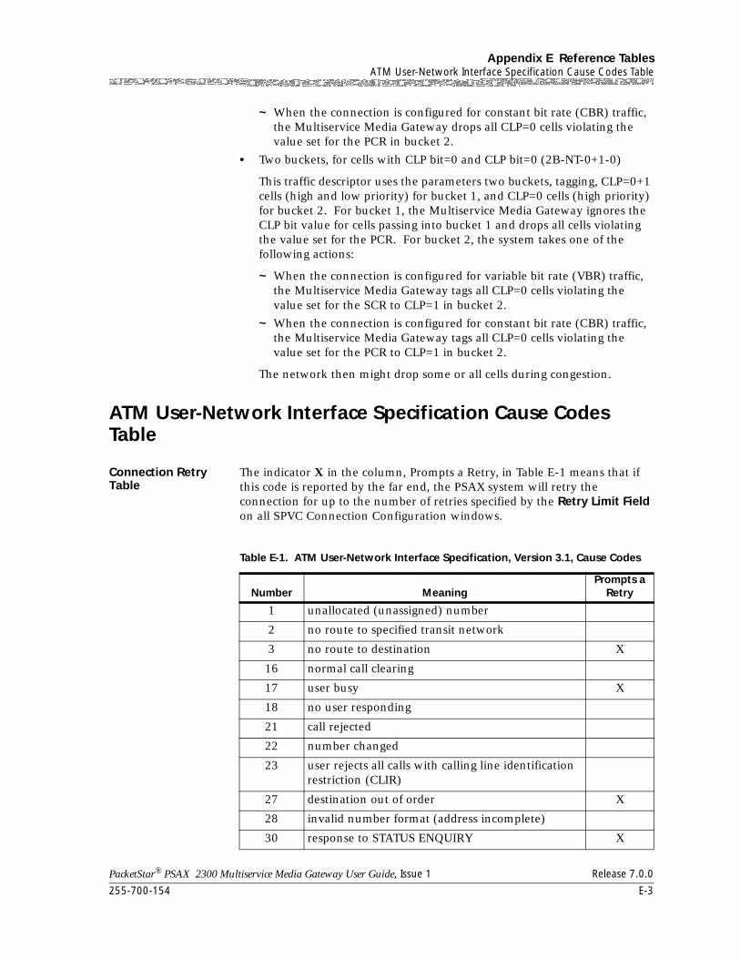
255-700-154 E-3
PacketStar® PSAX 2300 Multiservice Media Gateway User Guide, Issue 1 Release 7.0.0
Appendix E Reference TablesATM User-Network Interface Specification Cause Codes Table
~ When the connection is configured for constant bit rate (CBR) traffic, the Multiservice Media Gateway drops all CLP=0 cells violating the value set for the PCR in bucket 2.
• Two buckets, for cells with CLP bit=0 and CLP bit=0 (2B-NT-0+1-0)
This traffic descriptor uses the parameters two buckets, tagging, CLP=0+1 cells (high and low priority) for bucket 1, and CLP=0 cells (high priority) for bucket 2. For bucket 1, the Multiservice Media Gateway ignores the CLP bit value for cells passing into bucket 1 and drops all cells violating the value set for the PCR. For bucket 2, the system takes one of the following actions:
~ When the connection is configured for variable bit rate (VBR) traffic, the Multiservice Media Gateway tags all CLP=0 cells violating the value set for the SCR to CLP=1 in bucket 2.
~ When the connection is configured for constant bit rate (CBR) traffic, the Multiservice Media Gateway tags all CLP=0 cells violating the value set for the PCR to CLP=1 in bucket 2.
The network then might drop some or all cells during congestion.
ATM User-Network Interface Specification Cause Codes Table
Connection Retry Table
The indicator X in the column, Prompts a Retry, in Table E-1 means that if this code is reported by the far end, the PSAX system will retry the connection for up to the number of retries specified by the Retry Limit Field on all SPVC Connection Configuration windows.
Table E-1. ATM User-Network Interface Specification, Version 3.1, Cause Codes
Number MeaningPrompts a
Retry
1 unallocated (unassigned) number
2 no route to specified transit network
3 no route to destination X
16 normal call clearing
17 user busy X
18 no user responding
21 call rejected
22 number changed
23 user rejects all calls with calling line identification restriction (CLIR)
27 destination out of order X
28 invalid number format (address incomplete)
30 response to STATUS ENQUIRY X
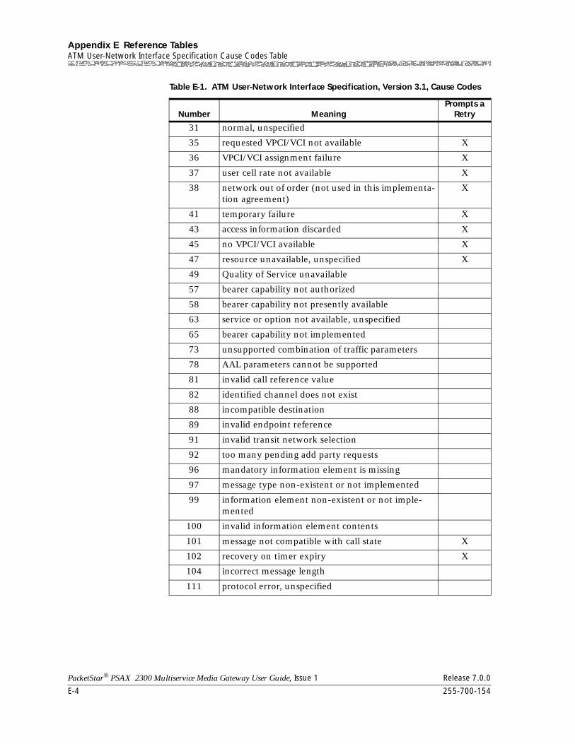
Appendix E Reference TablesATM User-Network Interface Specification Cause Codes Table
E-4 255-700-154
PacketStar® PSAX 2300 Multiservice Media Gateway User Guide, Issue 1 Release 7.0.0
31 normal, unspecified
35 requested VPCI/VCI not available X
36 VPCI/VCI assignment failure X
37 user cell rate not available X
38 network out of order (not used in this implementa-tion agreement)
X
41 temporary failure X
43 access information discarded X
45 no VPCI/VCI available X
47 resource unavailable, unspecified X
49 Quality of Service unavailable
57 bearer capability not authorized
58 bearer capability not presently available
63 service or option not available, unspecified
65 bearer capability not implemented
73 unsupported combination of traffic parameters
78 AAL parameters cannot be supported
81 invalid call reference value
82 identified channel does not exist
88 incompatible destination
89 invalid endpoint reference
91 invalid transit network selection
92 too many pending add party requests
96 mandatory information element is missing
97 message type non-existent or not implemented
99 information element non-existent or not imple-mented
100 invalid information element contents
101 message not compatible with call state X
102 recovery on timer expiry X
104 incorrect message length
111 protocol error, unspecified
Table E-1. ATM User-Network Interface Specification, Version 3.1, Cause Codes
Number MeaningPrompts a
Retry
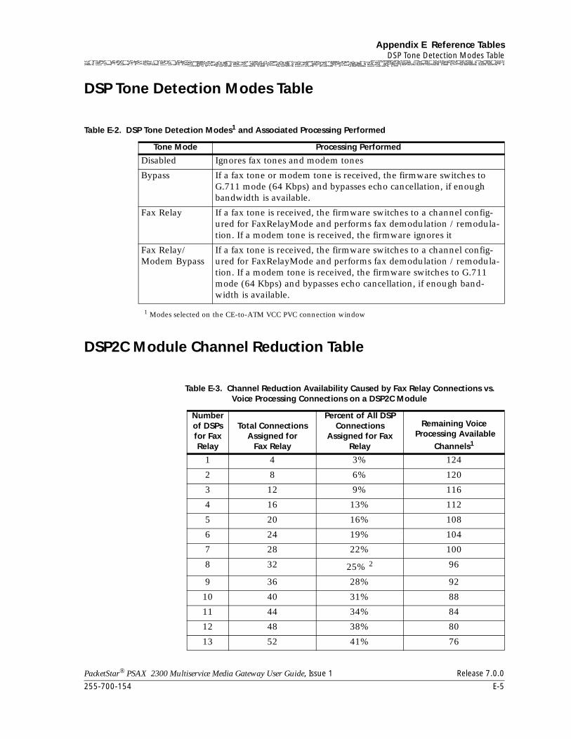
255-700-154 E-5
PacketStar® PSAX 2300 Multiservice Media Gateway User Guide, Issue 1 Release 7.0.0
Appendix E Reference TablesDSP Tone Detection Modes Table
DSP Tone Detection Modes Table
DSP2C Module Channel Reduction Table
Table E-2. DSP Tone Detection Modes1 and Associated Processing Performed
Tone Mode Processing Performed
Disabled Ignores fax tones and modem tones
Bypass If a fax tone or modem tone is received, the firmware switches to G.711 mode (64 Kbps) and bypasses echo cancellation, if enough bandwidth is available.
Fax Relay If a fax tone is received, the firmware switches to a channel config-ured for FaxRelayMode and performs fax demodulation / remodula-tion. If a modem tone is received, the firmware ignores it
Fax Relay/Modem Bypass
If a fax tone is received, the firmware switches to a channel config-ured for FaxRelayMode and performs fax demodulation / remodula-tion. If a modem tone is received, the firmware switches to G.711 mode (64 Kbps) and bypasses echo cancellation, if enough band-width is available.
1 Modes selected on the CE-to-ATM VCC PVC connection window
Table E-3. Channel Reduction Availability Caused by Fax Relay Connections vs. Voice Processing Connections on a DSP2C Module
Number of DSPs for Fax Relay
Total Connections Assigned for
Fax Relay
Percent of All DSP Connections
Assigned for Fax Relay
Remaining Voice Processing Available
Channels1
1 4 3% 124
2 8 6% 120
3 12 9% 116
4 16 13% 112
5 20 16% 108
6 24 19% 104
7 28 22% 100
8 32 25% 2 96
9 36 28% 92
10 40 31% 88
11 44 34% 84
12 48 38% 80
13 52 41% 76
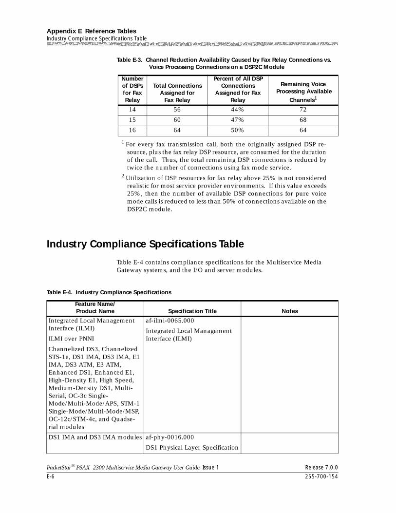
Appendix E Reference TablesIndustry Compliance Specifications Table
E-6 255-700-154
PacketStar® PSAX 2300 Multiservice Media Gateway User Guide, Issue 1 Release 7.0.0
Industry Compliance Specifications Table
Table E-4 contains compliance specifications for the Multiservice Media Gateway systems, and the I/O and server modules.
14 56 44% 72
15 60 47% 68
16 64 50% 64
1 For every fax transmission call, both the originally assigned DSP re-source, plus the fax relay DSP resource, are consumed for the durationof the call. Thus, the total remaining DSP connections is reduced bytwice the number of connections using fax mode service.
2 Utilization of DSP resources for fax relay above 25% is not consideredrealistic for most service provider environments. If this value exceeds25%, then the number of available DSP connections for pure voicemode calls is reduced to less than 50% of connections available on theDSP2C module.
Table E-3. Channel Reduction Availability Caused by Fax Relay Connections vs. Voice Processing Connections on a DSP2C Module
Number of DSPs for Fax Relay
Total Connections Assigned for
Fax Relay
Percent of All DSP Connections
Assigned for Fax Relay
Remaining Voice Processing Available
Channels1
Table E-4. Industry Compliance Specifications
Feature Name/Product Name Specification Title Notes
Integrated Local Management Interface (ILMI)
ILMI over PNNI
Channelized DS3, Channelized STS-1e, DS1 IMA, DS3 IMA, E1 IMA, DS3 ATM, E3 ATM, Enhanced DS1, Enhanced E1, High-Density E1, High Speed, Medium-Density DS1, Multi-Serial, OC-3c Single-Mode/Multi-Mode/APS, STM-1 Single-Mode/Multi-Mode/MSP, OC-12c/STM-4c, and Quadse-rial modules
af-ilmi-0065.000
Integrated Local Management Interface (ILMI)
DS1 IMA and DS3 IMA modules af-phy-0016.000
DS1 Physical Layer Specification
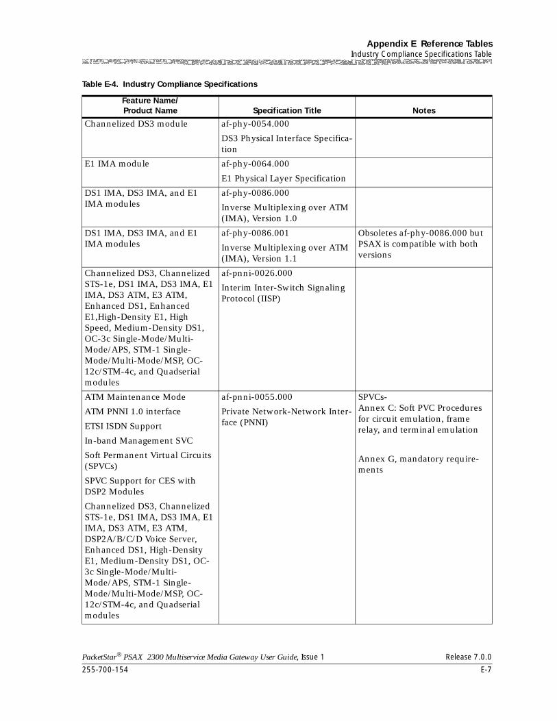
255-700-154 E-7
PacketStar® PSAX 2300 Multiservice Media Gateway User Guide, Issue 1 Release 7.0.0
Appendix E Reference TablesIndustry Compliance Specifications Table
Channelized DS3 module af-phy-0054.000
DS3 Physical Interface Specifica-tion
E1 IMA module af-phy-0064.000
E1 Physical Layer Specification
DS1 IMA, DS3 IMA, and E1 IMA modules
af-phy-0086.000
Inverse Multiplexing over ATM (IMA), Version 1.0
DS1 IMA, DS3 IMA, and E1 IMA modules
af-phy-0086.001
Inverse Multiplexing over ATM (IMA), Version 1.1
Obsoletes af-phy-0086.000 but PSAX is compatible with both versions
Channelized DS3, Channelized STS-1e, DS1 IMA, DS3 IMA, E1 IMA, DS3 ATM, E3 ATM, Enhanced DS1, Enhanced E1,High-Density E1, High Speed, Medium-Density DS1, OC-3c Single-Mode/Multi-Mode/APS, STM-1 Single-Mode/Multi-Mode/MSP, OC-12c/STM-4c, and Quadserial modules
af-pnni-0026.000
Interim Inter-Switch Signaling Protocol (IISP)
ATM Maintenance Mode
ATM PNNI 1.0 interface
ETSI ISDN Support
In-band Management SVC
Soft Permanent Virtual Circuits (SPVCs)
SPVC Support for CES with DSP2 Modules
Channelized DS3, Channelized STS-1e, DS1 IMA, DS3 IMA, E1 IMA, DS3 ATM, E3 ATM, DSP2A/B/C/D Voice Server, Enhanced DS1, High-Density E1, Medium-Density DS1, OC-3c Single-Mode/Multi-Mode/APS, STM-1 Single-Mode/Multi-Mode/MSP, OC-12c/STM-4c, and Quadserial modules
af-pnni-0055.000
Private Network-Network Inter-face (PNNI)
SPVCs- Annex C: Soft PVC Procedures for circuit emulation, frame relay, and terminal emulation
Annex G, mandatory require-ments
Table E-4. Industry Compliance Specifications
Feature Name/Product Name Specification Title Notes
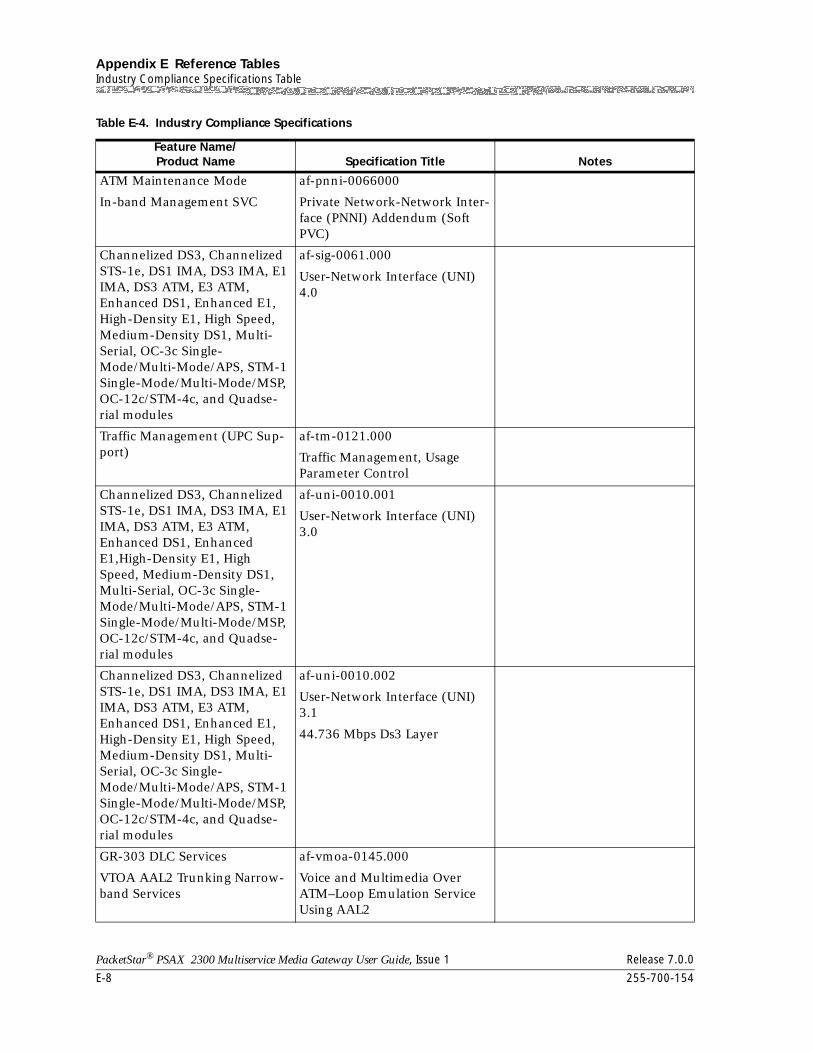
Appendix E Reference TablesIndustry Compliance Specifications Table
E-8 255-700-154
PacketStar® PSAX 2300 Multiservice Media Gateway User Guide, Issue 1 Release 7.0.0
ATM Maintenance Mode
In-band Management SVC
af-pnni-0066000
Private Network-Network Inter-face (PNNI) Addendum (Soft PVC)
Channelized DS3, Channelized STS-1e, DS1 IMA, DS3 IMA, E1 IMA, DS3 ATM, E3 ATM, Enhanced DS1, Enhanced E1, High-Density E1, High Speed, Medium-Density DS1, Multi-Serial, OC-3c Single-Mode/Multi-Mode/APS, STM-1 Single-Mode/Multi-Mode/MSP, OC-12c/STM-4c, and Quadse-rial modules
af-sig-0061.000
User-Network Interface (UNI) 4.0
Traffic Management (UPC Sup-port)
af-tm-0121.000
Traffic Management, Usage Parameter Control
Channelized DS3, Channelized STS-1e, DS1 IMA, DS3 IMA, E1 IMA, DS3 ATM, E3 ATM, Enhanced DS1, Enhanced E1,High-Density E1, High Speed, Medium-Density DS1, Multi-Serial, OC-3c Single-Mode/Multi-Mode/APS, STM-1 Single-Mode/Multi-Mode/MSP, OC-12c/STM-4c, and Quadse-rial modules
af-uni-0010.001
User-Network Interface (UNI) 3.0
Channelized DS3, Channelized STS-1e, DS1 IMA, DS3 IMA, E1 IMA, DS3 ATM, E3 ATM, Enhanced DS1, Enhanced E1, High-Density E1, High Speed, Medium-Density DS1, Multi-Serial, OC-3c Single-Mode/Multi-Mode/APS, STM-1 Single-Mode/Multi-Mode/MSP, OC-12c/STM-4c, and Quadse-rial modules
af-uni-0010.002
User-Network Interface (UNI) 3.1
44.736 Mbps Ds3 Layer
GR-303 DLC Services
VTOA AAL2 Trunking Narrow-band Services
af-vmoa-0145.000
Voice and Multimedia Over ATM–Loop Emulation Service Using AAL2
Table E-4. Industry Compliance Specifications
Feature Name/Product Name Specification Title Notes
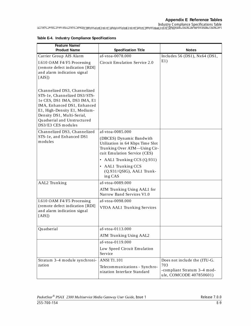
255-700-154 E-9
PacketStar® PSAX 2300 Multiservice Media Gateway User Guide, Issue 1 Release 7.0.0
Appendix E Reference TablesIndustry Compliance Specifications Table
Carrier Group AIS Alarm
I.610 OAM F4/F5 Processing (remote defect indication [RDI] and alarm indication signal [AIS])
Channelized DS3, Channelized STS-1e, Channelized DS3/STS-1e CES, DS1 IMA, DS3 IMA, E1 IMA, Enhanced DS1, Enhanced E1, High-Density E1, Medium-Density DS1, Multi-Serial, Quadserial and Unstructured DS3/E3 CES modules
af-vtoa-0078.000
Circuit Emulation Service 2.0
Includes 56 (DS1), Nx64 (DS1, E1)
Channelized DS3, Channelized STS-1e, and Enhanced DS1 modules
af-vtoa-0085.000
(DBCES) Dynamic Bandwith Utilization in 64 Kbps Time Slot Trunking Over ATM—Using Cir-cuit Emulation Service (CES)
• AAL1 Trunking CCS (Q.931)
• AAL1 Trunking CCS (Q.931/QSIG), AAL1 Trunk-ing CAS
AAL2 Trunking af-vtoa-0089.000
ATM Trunking Using AAL1 for Narrow Band Services V1.0
I.610 OAM F4/F5 Processing (remote defect indication [RDI] and alarm indication signal [AIS])
af-vtoa-0098.000
VTOA AAL1 Trunking Services
Quadserial af-vtoa-0113.000
ATM Trunking Using AAL2
af-vtoa-0119.000
Low Speed Circuit Emulation Service
Stratum 3–4 module synchroni-zation
ANSI T1.101
Telecommunications - Synchro-nization Interface Standard
Does not include the (ITU-G. 703 -compliant Stratum 3–4 mod-ule, COMCODE 407850601)
Table E-4. Industry Compliance Specifications
Feature Name/Product Name Specification Title Notes
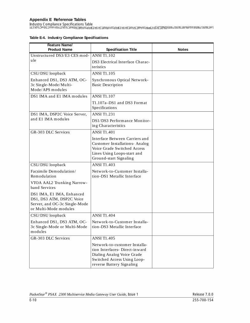
Appendix E Reference TablesIndustry Compliance Specifications Table
E-10 255-700-154
PacketStar® PSAX 2300 Multiservice Media Gateway User Guide, Issue 1 Release 7.0.0
Unstructured DS3/E3 CES mod-ule
ANSI T1.102
DS3 Electrical Interface Charac-teristics
CSU/DSU loopback
Enhanced DS1, DS3 ATM, OC-3c Single-Mode/Multi-Mode/APS modules
ANSI T1.105
Synchronous Optical Network-Basic Description
DS1 IMA and E1 IMA modules ANSI T1.107
T1.107a–DS1 and DS3 Format Specifications
DS1 IMA, DSP2C Voice Server, and E1 IMA modules
ANSI T1.231
DS1/DS3 Performance Monitor-ing Characteristics
GR-303 DLC Services ANSI T1.401
Interface Between Carriers and Customer Installations- Analog Voice Grade Switched Access Lines Using Loops-start and Ground-start Signaling
CSU/DSU loopback
Facsimile Demodulation/Remodulation
VTOA AAL2 Trunking Narrow-band Services
DS1 IMA, E1 IMA, Enhanced DS1, DS3 ATM, DSP2C Voice Server, and OC-3c Single-Mode or Multi-Mode modules
ANSI T1.403
Network-to-Customer Installa-tion-DS1 Metallic Interface
CSU/DSU loopback
Enhanced DS1, DS3 ATM, OC-3c Single-Mode or Multi-Mode modules
ANSI T1.404
Network-to-Customer Installa-tion-DS3 Metallic Interface
GR-303 DLC Services ANSI T1.405
Network-to-customer Installa-tion Interfaces- Direct-inward Dialing Analog Voice Grade Switched Access Using Loop-reverse Battery Signaling
Table E-4. Industry Compliance Specifications
Feature Name/Product Name Specification Title Notes
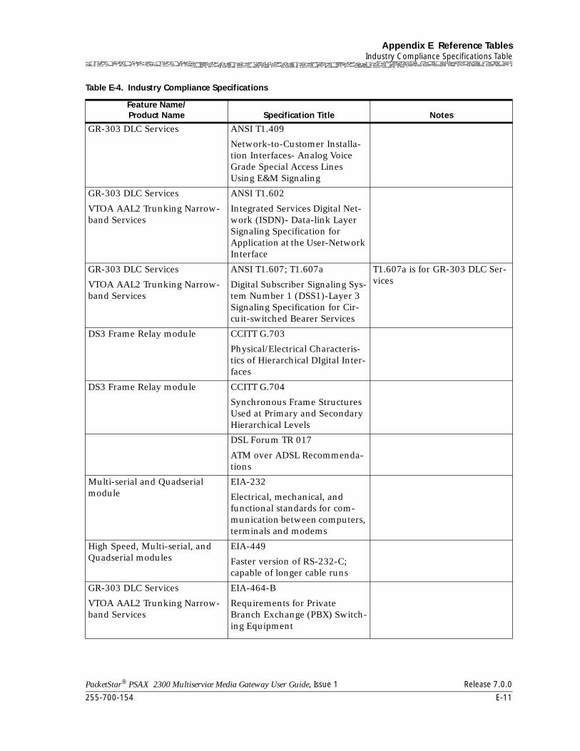
255-700-154 E-11
PacketStar® PSAX 2300 Multiservice Media Gateway User Guide, Issue 1 Release 7.0.0
Appendix E Reference TablesIndustry Compliance Specifications Table
GR-303 DLC Services ANSI T1.409
Network-to-Customer Installa-tion Interfaces- Analog Voice Grade Special Access Lines Using E&M Signaling
GR-303 DLC Services
VTOA AAL2 Trunking Narrow-band Services
ANSI T1.602
Integrated Services Digital Net-work (ISDN)- Data-link Layer Signaling Specification for Application at the User-Network Interface
GR-303 DLC Services
VTOA AAL2 Trunking Narrow-band Services
ANSI T1.607; T1.607a
Digital Subscriber Signaling Sys-tem Number 1 (DSS1)-Layer 3 Signaling Specification for Cir-cuit-switched Bearer Services
T1.607a is for GR-303 DLC Ser-vices
DS3 Frame Relay module CCITT G.703
Physical/Electrical Characteris-tics of Hierarchical DIgital Inter-faces
DS3 Frame Relay module CCITT G.704
Synchronous Frame Structures Used at Primary and Secondary Hierarchical Levels
DSL Forum TR 017
ATM over ADSL Recommenda-tions
Multi-serial and Quadserial module
EIA-232
Electrical, mechanical, and functional standards for com-munication between computers, terminals and modems
High Speed, Multi-serial, and Quadserial modules
EIA-449
Faster version of RS-232-C; capable of longer cable runs
GR-303 DLC Services
VTOA AAL2 Trunking Narrow-band Services
EIA-464-B
Requirements for Private Branch Exchange (PBX) Switch-ing Equipment
Table E-4. Industry Compliance Specifications
Feature Name/Product Name Specification Title Notes
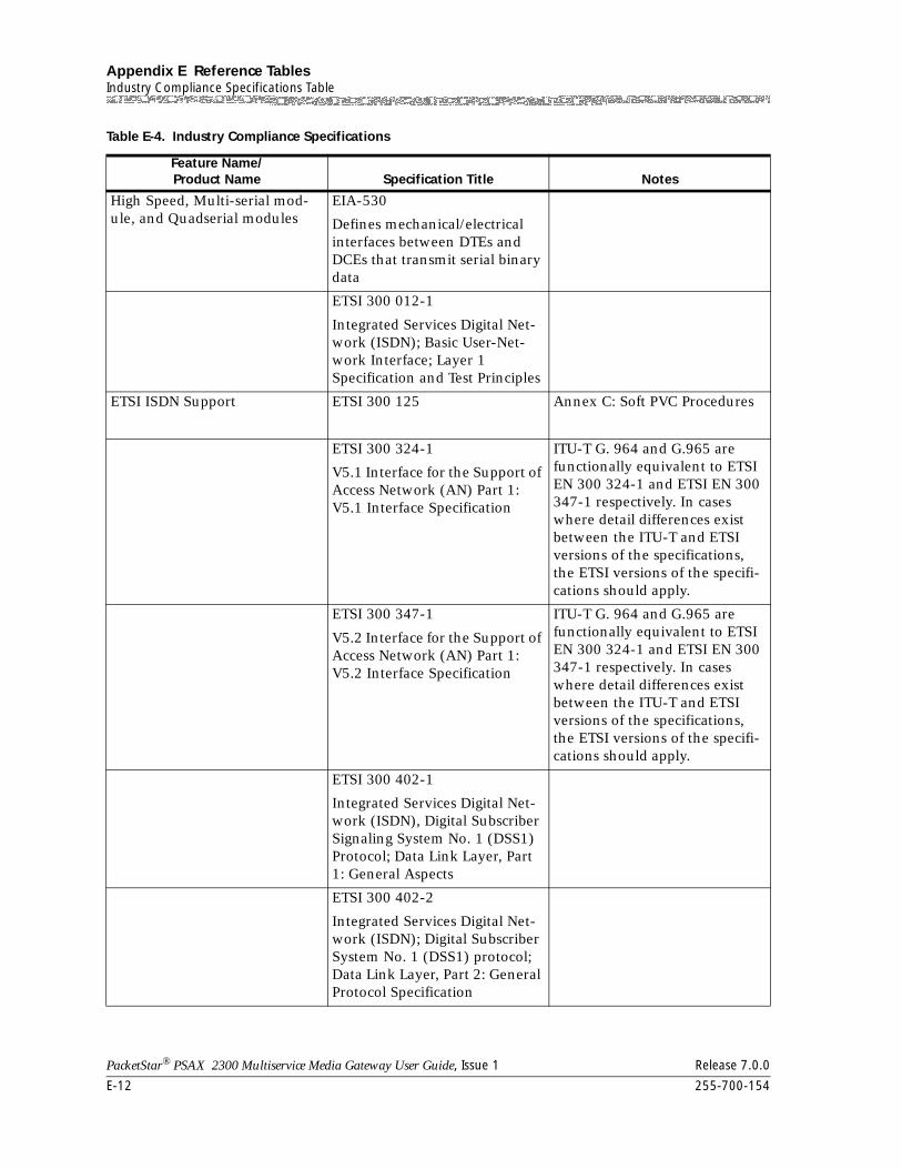
Appendix E Reference TablesIndustry Compliance Specifications Table
E-12 255-700-154
PacketStar® PSAX 2300 Multiservice Media Gateway User Guide, Issue 1 Release 7.0.0
High Speed, Multi-serial mod-ule, and Quadserial modules
EIA-530
Defines mechanical/electrical interfaces between DTEs and DCEs that transmit serial binary data
ETSI 300 012-1
Integrated Services Digital Net-work (ISDN); Basic User-Net-work Interface; Layer 1 Specification and Test Principles
ETSI ISDN Support ETSI 300 125 Annex C: Soft PVC Procedures
ETSI 300 324-1
V5.1 Interface for the Support of Access Network (AN) Part 1: V5.1 Interface Specification
ITU-T G. 964 and G.965 are functionally equivalent to ETSI EN 300 324-1 and ETSI EN 300 347-1 respectively. In cases where detail differences exist between the ITU-T and ETSI versions of the specifications, the ETSI versions of the specifi-cations should apply.
ETSI 300 347-1
V5.2 Interface for the Support of Access Network (AN) Part 1: V5.2 Interface Specification
ITU-T G. 964 and G.965 are functionally equivalent to ETSI EN 300 324-1 and ETSI EN 300 347-1 respectively. In cases where detail differences exist between the ITU-T and ETSI versions of the specifications, the ETSI versions of the specifi-cations should apply.
ETSI 300 402-1
Integrated Services Digital Net-work (ISDN), Digital Subscriber Signaling System No. 1 (DSS1) Protocol; Data Link Layer, Part 1: General Aspects
ETSI 300 402-2
Integrated Services Digital Net-work (ISDN); Digital Subscriber System No. 1 (DSS1) protocol; Data Link Layer, Part 2: General Protocol Specification
Table E-4. Industry Compliance Specifications
Feature Name/Product Name Specification Title Notes
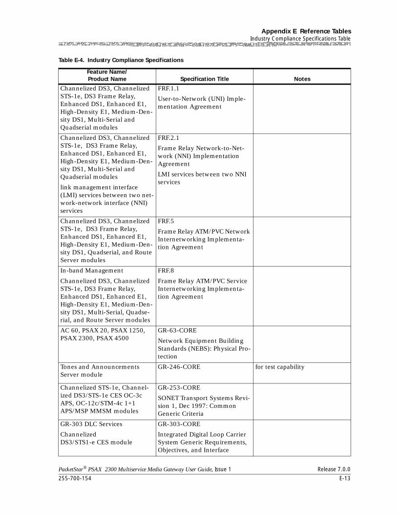
255-700-154 E-13
PacketStar® PSAX 2300 Multiservice Media Gateway User Guide, Issue 1 Release 7.0.0
Appendix E Reference TablesIndustry Compliance Specifications Table
Channelized DS3, Channelized STS-1e, DS3 Frame Relay, Enhanced DS1, Enhanced E1, High-Density E1, Medium-Den-sity DS1, Multi-Serial and Quadserial modules
FRF.1.1
User-to-Network (UNI) Imple-mentation Agreement
Channelized DS3, Channelized STS-1e, DS3 Frame Relay, Enhanced DS1, Enhanced E1, High-Density E1, Medium-Den-sity DS1, Multi-Serial and Quadserial modules
link management interface (LMI) services between two net-work-network interface (NNI) services
FRF.2.1
Frame Relay Network-to-Net-work (NNI) Implementation Agreement
LMI services between two NNI services
Channelized DS3, Channelized STS-1e, DS3 Frame Relay, Enhanced DS1, Enhanced E1, High-Density E1, Medium-Den-sity DS1, Quadserial, and Route Server modules
FRF.5
Frame Relay ATM/PVC Network Internetworking Implementa-tion Agreement
In-band Management
Channelized DS3, Channelized STS-1e, DS3 Frame Relay, Enhanced DS1, Enhanced E1, High-Density E1, Medium-Den-sity DS1, Multi-Serial, Quadse-rial, and Route Server modules
FRF.8
Frame Relay ATM/PVC Service Internetworking Implementa-tion Agreement
AC 60, PSAX 20, PSAX 1250, PSAX 2300, PSAX 4500
GR-63-CORE
Network Equipment Building Standards (NEBS): Physical Pro-tection
Tones and Announcements Server module
GR-246-CORE for test capability
Channelized STS-1e, Channel-ized DS3/STS-1e CES OC-3c APS, OC-12c/STM-4c 1+1 APS/MSP MMSM modules
GR-253-CORE
SONET Transport Systems Revi-sion 1, Dec 1997: Common Generic Criteria
GR-303 DLC Services
Channelized DS3/STS1-e CES module
GR-303-CORE
Integrated Digital Loop Carrier System Generic Requirements, Objectives, and Interface
Table E-4. Industry Compliance Specifications
Feature Name/Product Name Specification Title Notes
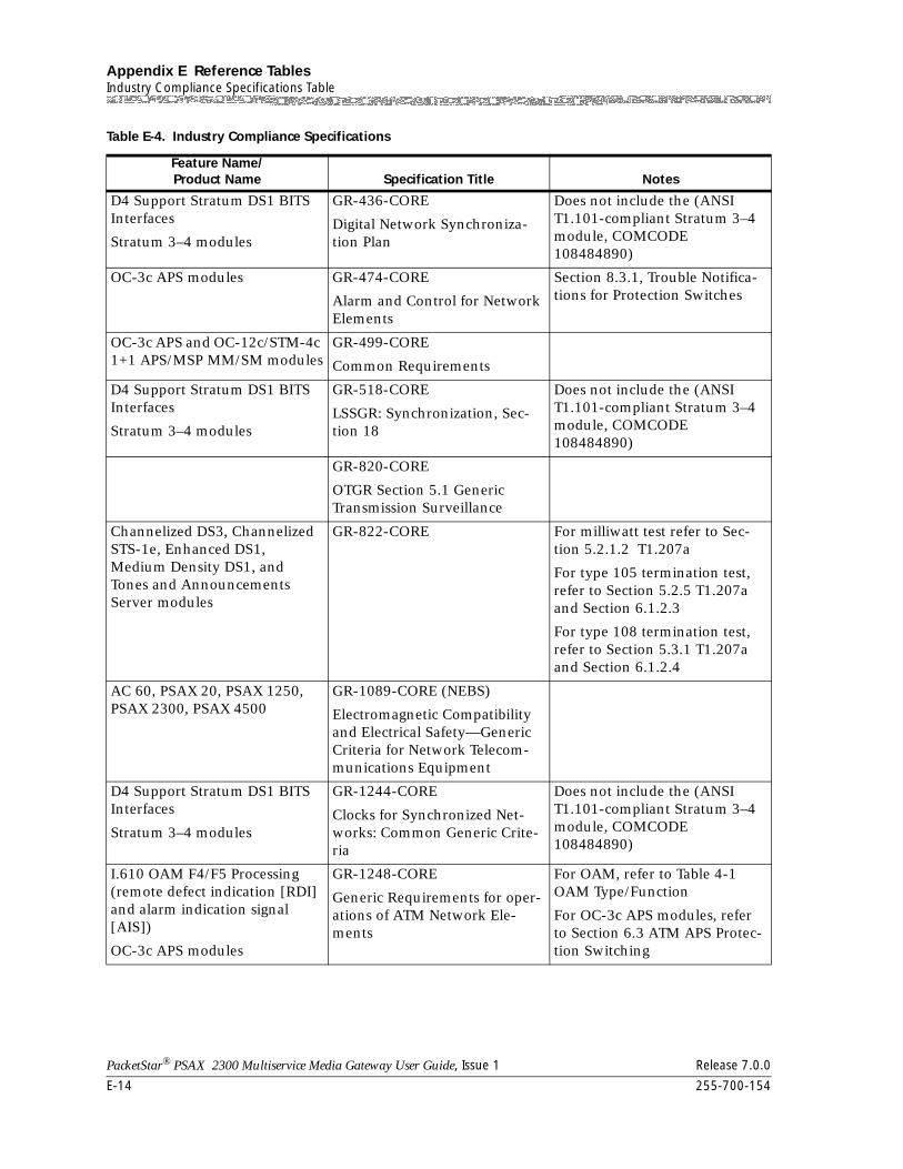
Appendix E Reference TablesIndustry Compliance Specifications Table
E-14 255-700-154
PacketStar® PSAX 2300 Multiservice Media Gateway User Guide, Issue 1 Release 7.0.0
D4 Support Stratum DS1 BITS Interfaces
Stratum 3–4 modules
GR-436-CORE
Digital Network Synchroniza-tion Plan
Does not include the (ANSI T1.101-compliant Stratum 3–4 module, COMCODE 108484890)
OC-3c APS modules GR-474-CORE
Alarm and Control for Network Elements
Section 8.3.1, Trouble Notifica-tions for Protection Switches
OC-3c APS and OC-12c/STM-4c 1+1 APS/MSP MM/SM modules
GR-499-CORE
Common Requirements
D4 Support Stratum DS1 BITS Interfaces
Stratum 3–4 modules
GR-518-CORE
LSSGR: Synchronization, Sec-tion 18
Does not include the (ANSI T1.101-compliant Stratum 3–4 module, COMCODE 108484890)
GR-820-CORE
OTGR Section 5.1 Generic Transmission Surveillance
Channelized DS3, Channelized STS-1e, Enhanced DS1, Medium Density DS1, and Tones and Announcements Server modules
GR-822-CORE For milliwatt test refer to Sec-tion 5.2.1.2 T1.207a
For type 105 termination test, refer to Section 5.2.5 T1.207a and Section 6.1.2.3
For type 108 termination test, refer to Section 5.3.1 T1.207a and Section 6.1.2.4
AC 60, PSAX 20, PSAX 1250, PSAX 2300, PSAX 4500
GR-1089-CORE (NEBS)
Electromagnetic Compatibility and Electrical Safety—Generic Criteria for Network Telecom-munications Equipment
D4 Support Stratum DS1 BITS Interfaces
Stratum 3–4 modules
GR-1244-CORE
Clocks for Synchronized Net-works: Common Generic Crite-ria
Does not include the (ANSI T1.101-compliant Stratum 3–4 module, COMCODE 108484890)
I.610 OAM F4/F5 Processing (remote defect indication [RDI] and alarm indication signal [AIS])
OC-3c APS modules
GR-1248-CORE
Generic Requirements for oper-ations of ATM Network Ele-ments
For OAM, refer to Table 4-1 OAM Type/Function
For OC-3c APS modules, refer to Section 6.3 ATM APS Protec-tion Switching
Table E-4. Industry Compliance Specifications
Feature Name/Product Name Specification Title Notes
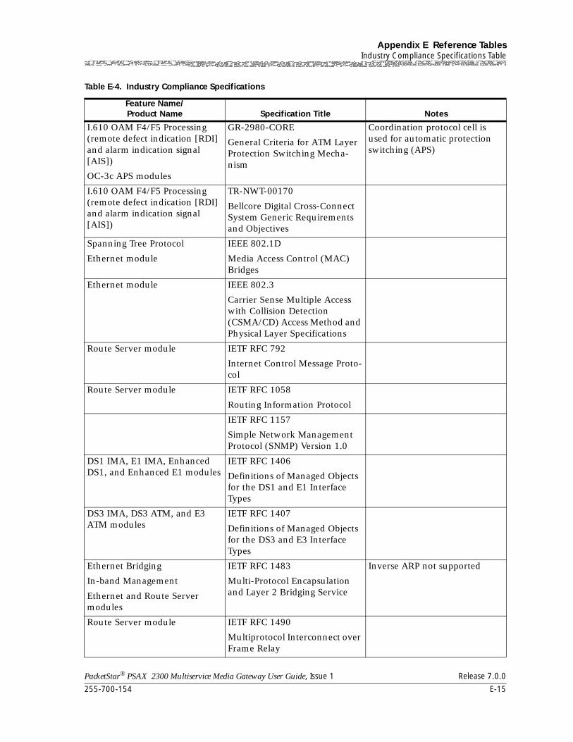
255-700-154 E-15
PacketStar® PSAX 2300 Multiservice Media Gateway User Guide, Issue 1 Release 7.0.0
Appendix E Reference TablesIndustry Compliance Specifications Table
I.610 OAM F4/F5 Processing (remote defect indication [RDI] and alarm indication signal [AIS])
OC-3c APS modules
GR-2980-CORE
General Criteria for ATM Layer Protection Switching Mecha-nism
Coordination protocol cell is used for automatic protection switching (APS)
I.610 OAM F4/F5 Processing (remote defect indication [RDI] and alarm indication signal [AIS])
TR-NWT-00170
Bellcore Digital Cross-Connect System Generic Requirements and Objectives
Spanning Tree Protocol
Ethernet module
IEEE 802.1D
Media Access Control (MAC) Bridges
Ethernet module IEEE 802.3
Carrier Sense Multiple Access with Collision Detection (CSMA/CD) Access Method and Physical Layer Specifications
Route Server module IETF RFC 792
Internet Control Message Proto-col
Route Server module IETF RFC 1058
Routing Information Protocol
IETF RFC 1157
Simple Network Management Protocol (SNMP) Version 1.0
DS1 IMA, E1 IMA, Enhanced DS1, and Enhanced E1 modules
IETF RFC 1406
Definitions of Managed Objects for the DS1 and E1 Interface Types
DS3 IMA, DS3 ATM, and E3 ATM modules
IETF RFC 1407
Definitions of Managed Objects for the DS3 and E3 Interface Types
Ethernet Bridging
In-band Management
Ethernet and Route Server modules
IETF RFC 1483
Multi-Protocol Encapsulation and Layer 2 Bridging Service
Inverse ARP not supported
Route Server module IETF RFC 1490
Multiprotocol Interconnect over Frame Relay
Table E-4. Industry Compliance Specifications
Feature Name/Product Name Specification Title Notes
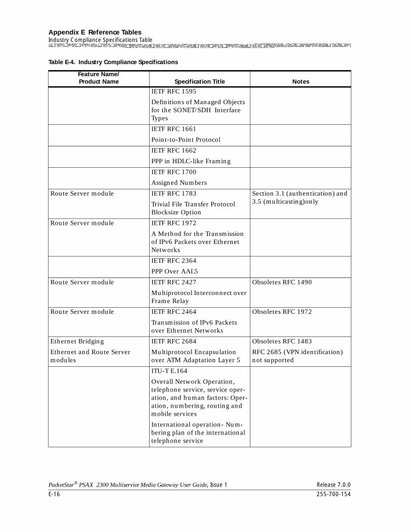
Appendix E Reference TablesIndustry Compliance Specifications Table
E-16 255-700-154
PacketStar® PSAX 2300 Multiservice Media Gateway User Guide, Issue 1 Release 7.0.0
IETF RFC 1595
Definitions of Managed Objects for the SONET/SDH Interface Types
IETF RFC 1661
Point-to-Point Protocol
IETF RFC 1662
PPP in HDLC-like Framing
IETF RFC 1700
Assigned Numbers
Route Server module IETF RFC 1783
Trivial File Transfer Protocol Blocksize Option
Section 3.1 (authentication) and 3.5 (multicasting)only
Route Server module IETF RFC 1972
A Method for the Transmission of IPv6 Packets over Ethernet Networks
IETF RFC 2364
PPP Over AAL5
Route Server module IETF RFC 2427
Multiprotocol Interconnect over Frame Relay
Obsoletes RFC 1490
Route Server module IETF RFC 2464
Transmission of IPv6 Packets over Ethernet Networks
Obsoletes RFC 1972
Ethernet Bridging
Ethernet and Route Server modules
IETF RFC 2684
Multiprotocol Encapsulation over ATM Adaptation Layer 5
Obsoletes RFC 1483
RFC 2685 (VPN identification) not supported
ITU-T E.164
Overall Network Operation, telephone service, service oper-ation, and human factors: Oper-ation, numbering, routing and mobile services
International operation- Num-bering plan of the international telephone service
Table E-4. Industry Compliance Specifications
Feature Name/Product Name Specification Title Notes
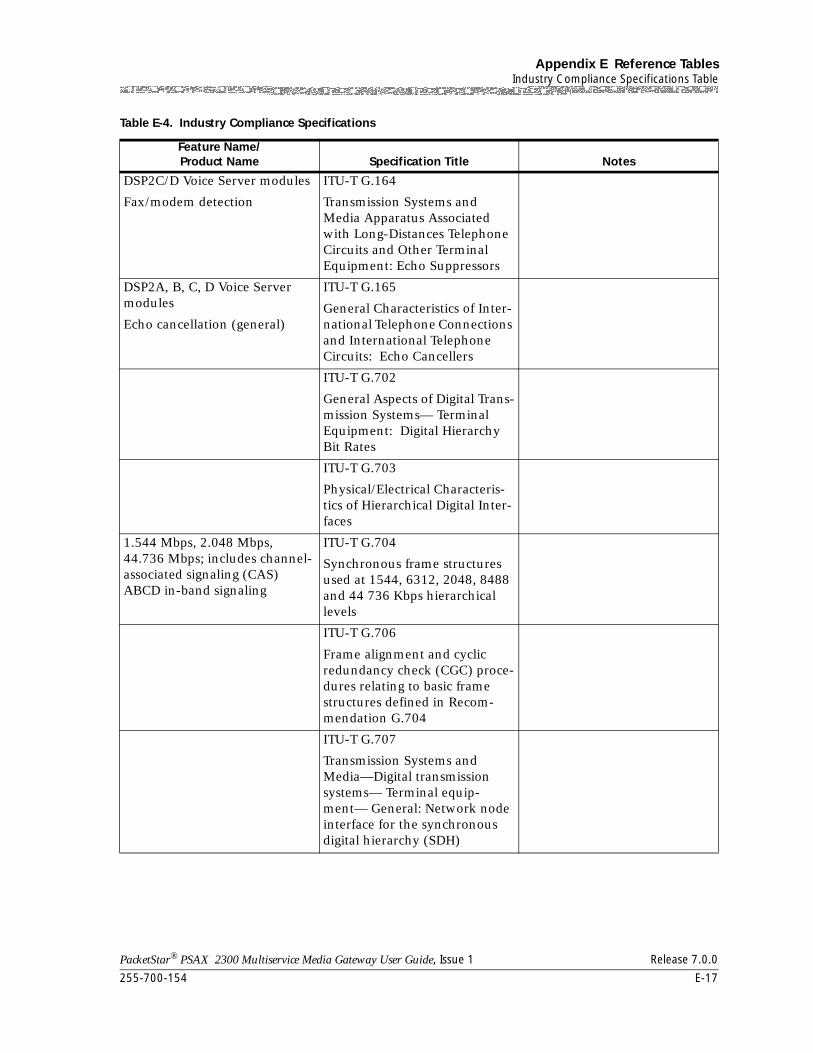
255-700-154 E-17
PacketStar® PSAX 2300 Multiservice Media Gateway User Guide, Issue 1 Release 7.0.0
Appendix E Reference TablesIndustry Compliance Specifications Table
DSP2C/D Voice Server modules
Fax/modem detection
ITU-T G.164
Transmission Systems and Media Apparatus Associated with Long-Distances Telephone Circuits and Other Terminal Equipment: Echo Suppressors
DSP2A, B, C, D Voice Server modules
Echo cancellation (general)
ITU-T G.165
General Characteristics of Inter-national Telephone Connections and International Telephone Circuits: Echo Cancellers
ITU-T G.702
General Aspects of Digital Trans-mission Systems— Terminal Equipment: Digital Hierarchy Bit Rates
ITU-T G.703
Physical/Electrical Characteris-tics of Hierarchical Digital Inter-faces
1.544 Mbps, 2.048 Mbps, 44.736 Mbps; includes channel-associated signaling (CAS) ABCD in-band signaling
ITU-T G.704
Synchronous frame structures used at 1544, 6312, 2048, 8488 and 44 736 Kbps hierarchical levels
ITU-T G.706
Frame alignment and cyclic redundancy check (CGC) proce-dures relating to basic frame structures defined in Recom-mendation G.704
ITU-T G.707
Transmission Systems and Media—Digital transmission systems— Terminal equip-ment— General: Network node interface for the synchronous digital hierarchy (SDH)
Table E-4. Industry Compliance Specifications
Feature Name/Product Name Specification Title Notes
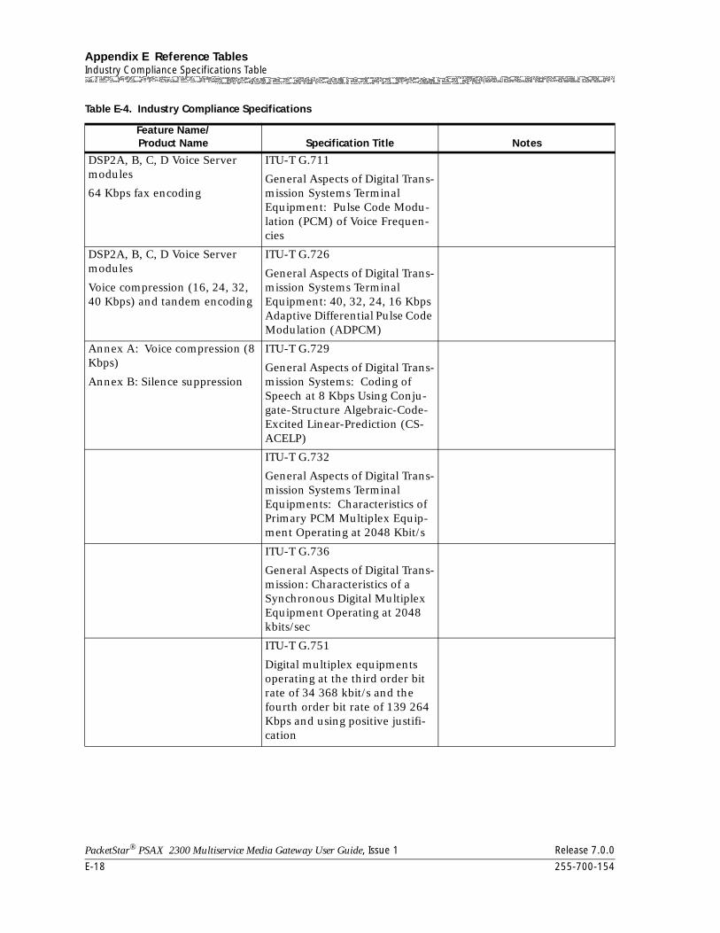
Appendix E Reference TablesIndustry Compliance Specifications Table
E-18 255-700-154
PacketStar® PSAX 2300 Multiservice Media Gateway User Guide, Issue 1 Release 7.0.0
DSP2A, B, C, D Voice Server modules
64 Kbps fax encoding
ITU-T G.711
General Aspects of Digital Trans-mission Systems Terminal Equipment: Pulse Code Modu-lation (PCM) of Voice Frequen-cies
DSP2A, B, C, D Voice Server modules
Voice compression (16, 24, 32, 40 Kbps) and tandem encoding
ITU-T G.726
General Aspects of Digital Trans-mission Systems Terminal Equipment: 40, 32, 24, 16 Kbps Adaptive Differential Pulse Code Modulation (ADPCM)
Annex A: Voice compression (8 Kbps)
Annex B: Silence suppression
ITU-T G.729
General Aspects of Digital Trans-mission Systems: Coding of Speech at 8 Kbps Using Conju-gate-Structure Algebraic-Code-Excited Linear-Prediction (CS-ACELP)
ITU-T G.732
General Aspects of Digital Trans-mission Systems Terminal Equipments: Characteristics of Primary PCM Multiplex Equip-ment Operating at 2048 Kbit/s
ITU-T G.736
General Aspects of Digital Trans-mission: Characteristics of a Synchronous Digital Multiplex Equipment Operating at 2048 kbits/sec
ITU-T G.751
Digital multiplex equipments operating at the third order bit rate of 34 368 kbit/s and the fourth order bit rate of 139 264 Kbps and using positive justifi-cation
Table E-4. Industry Compliance Specifications
Feature Name/Product Name Specification Title Notes
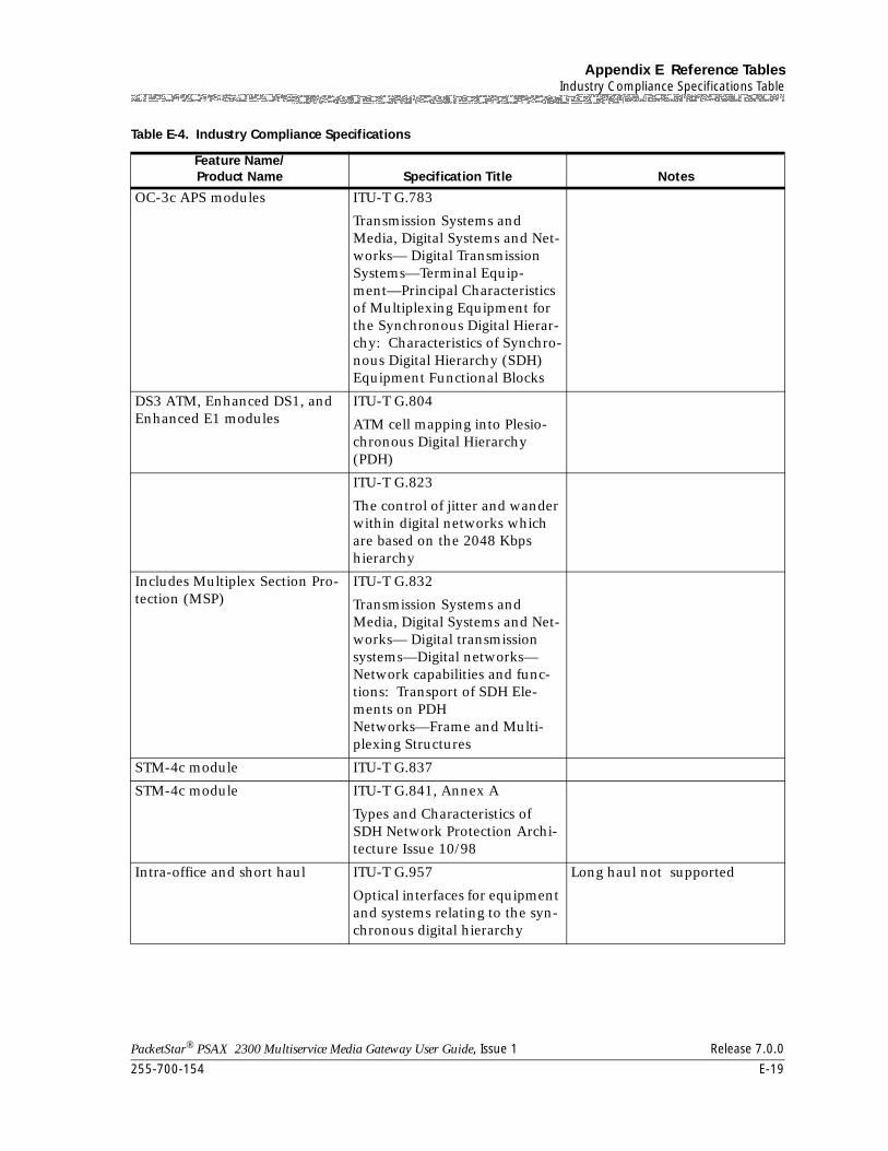
255-700-154 E-19
PacketStar® PSAX 2300 Multiservice Media Gateway User Guide, Issue 1 Release 7.0.0
Appendix E Reference TablesIndustry Compliance Specifications Table
OC-3c APS modules ITU-T G.783
Transmission Systems and Media, Digital Systems and Net-works— Digital Transmission Systems—Terminal Equip-ment—Principal Characteristics of Multiplexing Equipment for the Synchronous Digital Hierar-chy: Characteristics of Synchro-nous Digital Hierarchy (SDH) Equipment Functional Blocks
DS3 ATM, Enhanced DS1, and Enhanced E1 modules
ITU-T G.804
ATM cell mapping into Plesio-chronous Digital Hierarchy (PDH)
ITU-T G.823
The control of jitter and wander within digital networks which are based on the 2048 Kbps hierarchy
Includes Multiplex Section Pro-tection (MSP)
ITU-T G.832
Transmission Systems and Media, Digital Systems and Net-works— Digital transmission systems—Digital networks— Network capabilities and func-tions: Transport of SDH Ele-ments on PDH Networks—Frame and Multi-plexing Structures
STM-4c module ITU-T G.837
STM-4c module ITU-T G.841, Annex A
Types and Characteristics of SDH Network Protection Archi-tecture Issue 10/98
Intra-office and short haul ITU-T G.957
Optical interfaces for equipment and systems relating to the syn-chronous digital hierarchy
Long haul not supported
Table E-4. Industry Compliance Specifications
Feature Name/Product Name Specification Title Notes
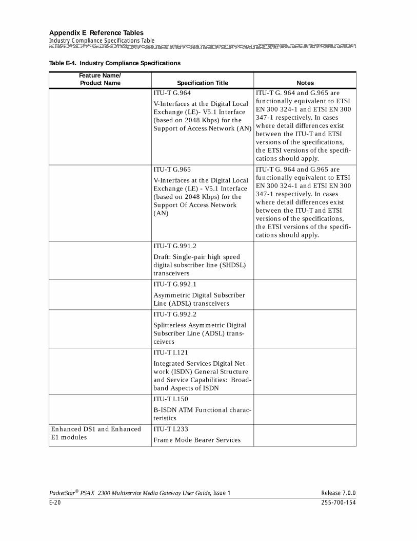
Appendix E Reference TablesIndustry Compliance Specifications Table
E-20 255-700-154
PacketStar® PSAX 2300 Multiservice Media Gateway User Guide, Issue 1 Release 7.0.0
ITU-T G.964
V-Interfaces at the Digital Local Exchange (LE)- V5.1 Interface (based on 2048 Kbps) for the Support of Access Network (AN)
ITU-T G. 964 and G.965 are functionally equivalent to ETSI EN 300 324-1 and ETSI EN 300 347-1 respectively. In cases where detail differences exist between the ITU-T and ETSI versions of the specifications, the ETSI versions of the specifi-cations should apply.
ITU-T G.965
V-Interfaces at the Digital Local Exchange (LE) - V5.1 Interface (based on 2048 Kbps) for the Support Of Access Network (AN)
ITU-T G. 964 and G.965 are functionally equivalent to ETSI EN 300 324-1 and ETSI EN 300 347-1 respectively. In cases where detail differences exist between the ITU-T and ETSI versions of the specifications, the ETSI versions of the specifi-cations should apply.
ITU-T G.991.2
Draft: Single-pair high speed digital subscriber line (SHDSL) transceivers
ITU-T G.992.1
Asymmetric Digital Subscriber Line (ADSL) transceivers
ITU-T G.992.2
Splitterless Asymmetric Digital Subscriber Line (ADSL) trans-ceivers
ITU-T I.121
Integrated Services Digital Net-work (ISDN) General Structure and Service Capabilities: Broad-band Aspects of ISDN
ITU-T I.150
B-ISDN ATM Functional charac-teristics
Enhanced DS1 and Enhanced E1 modules
ITU-T I.233
Frame Mode Bearer Services
Table E-4. Industry Compliance Specifications
Feature Name/Product Name Specification Title Notes
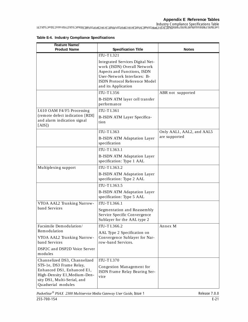
255-700-154 E-21
PacketStar® PSAX 2300 Multiservice Media Gateway User Guide, Issue 1 Release 7.0.0
Appendix E Reference TablesIndustry Compliance Specifications Table
ITU-T I.321
Integrated Services Digital Net-work (ISDN) Overall Network Aspects and Functions, ISDN User-Network Interfaces: B-ISDN Protocol Reference Model and its Application
ITU-T I.356
B-ISDN ATM layer cell transfer performance
ABR not supported
I.610 OAM F4/F5 Processing (remote defect indication [RDI] and alarm indication signal [AIS])
ITU-T I.361
B-ISDN ATM Layer Specifica-tion
ITU-T I.363
B-ISDN ATM Adaptation Layer specification
Only AAL1, AAL2, and AAL5 are supported
ITU-T I.363.1
B-ISDN ATM Adaptation Layer specification: Type 1 AAL
Multiplexing support ITU-T I.363.2
B-ISDN ATM Adaptation Layer specification: Type 2 AAL
ITU-T I.363.5
B-ISDN ATM Adaptation Layer specification: Type 5 AAL
VTOA AAL2 Trunking Narrow-band Services
ITU-T I.366.1
Segmentation and Reassembly Service Specific Convergence Sublayer for the AAL type 2
Facsimile Demodulation/Remodulation
VTOA AAL2 Trunking Narrow-band Services
DSP2C and DSP2D Voice Server modules
ITU-T I.366.2
AAL Type 2 Specification on Convergence Sublayer for Nar-row-band Services.
Annex M
Channelized DS3, Channelized STS-1e, DS3 Frame Relay, Enhanced DS1, Enhanced E1, High-Density E1,Medium-Den-sity DS1, Multi-Serial, and Quadserial modules
ITU-T I.370
Congestion Management for ISDN Frame Relay Bearing Ser-vice
Table E-4. Industry Compliance Specifications
Feature Name/Product Name Specification Title Notes
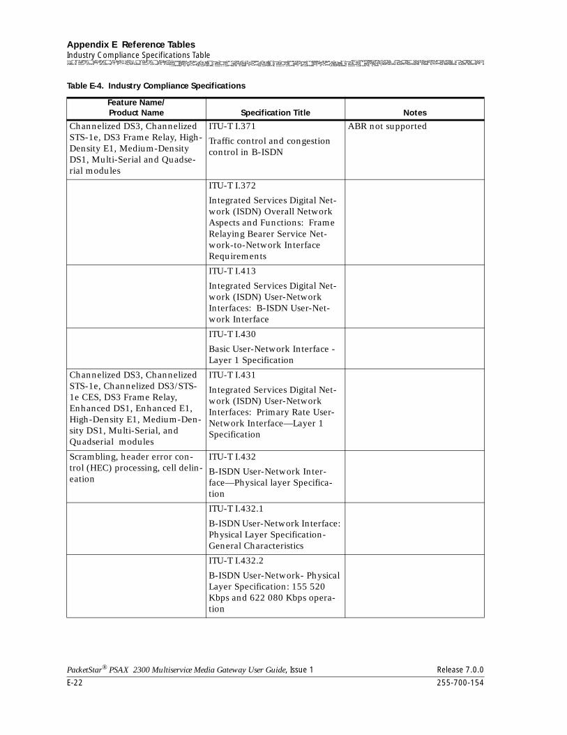
Appendix E Reference TablesIndustry Compliance Specifications Table
E-22 255-700-154
PacketStar® PSAX 2300 Multiservice Media Gateway User Guide, Issue 1 Release 7.0.0
Channelized DS3, Channelized STS-1e, DS3 Frame Relay, High-Density E1, Medium-Density DS1, Multi-Serial and Quadse-rial modules
ITU-T I.371
Traffic control and congestion control in B-ISDN
ABR not supported
ITU-T I.372
Integrated Services Digital Net-work (ISDN) Overall Network Aspects and Functions: Frame Relaying Bearer Service Net-work-to-Network Interface Requirements
ITU-T I.413
Integrated Services Digital Net-work (ISDN) User-Network Interfaces: B-ISDN User-Net-work Interface
ITU-T I.430
Basic User-Network Interface - Layer 1 Specification
Channelized DS3, Channelized STS-1e, Channelized DS3/STS-1e CES, DS3 Frame Relay, Enhanced DS1, Enhanced E1, High-Density E1, Medium-Den-sity DS1, Multi-Serial, and Quadserial modules
ITU-T I.431
Integrated Services Digital Net-work (ISDN) User-Network Interfaces: Primary Rate User-Network Interface—Layer 1 Specification
Scrambling, header error con-trol (HEC) processing, cell delin-eation
ITU-T I.432
B-ISDN User-Network Inter-face—Physical layer Specifica-tion
ITU-T I.432.1
B-ISDN User-Network Interface: Physical Layer Specification- General Characteristics
ITU-T I.432.2
B-ISDN User-Network- Physical Layer Specification: 155 520 Kbps and 622 080 Kbps opera-tion
Table E-4. Industry Compliance Specifications
Feature Name/Product Name Specification Title Notes
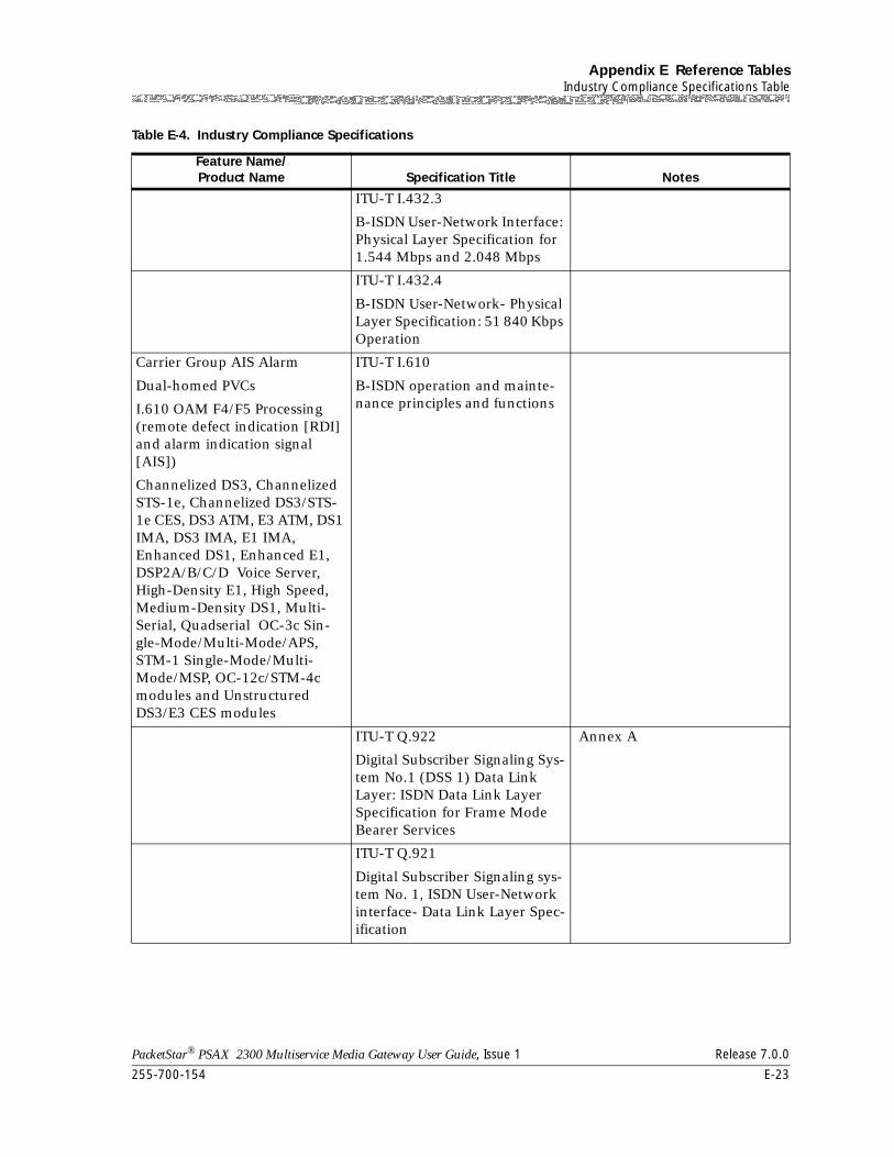
255-700-154 E-23
PacketStar® PSAX 2300 Multiservice Media Gateway User Guide, Issue 1 Release 7.0.0
Appendix E Reference TablesIndustry Compliance Specifications Table
ITU-T I.432.3
B-ISDN User-Network Interface: Physical Layer Specification for 1.544 Mbps and 2.048 Mbps
ITU-T I.432.4
B-ISDN User-Network- Physical Layer Specification: 51 840 Kbps Operation
Carrier Group AIS Alarm
Dual-homed PVCs
I.610 OAM F4/F5 Processing (remote defect indication [RDI] and alarm indication signal [AIS])
Channelized DS3, Channelized STS-1e, Channelized DS3/STS-1e CES, DS3 ATM, E3 ATM, DS1 IMA, DS3 IMA, E1 IMA, Enhanced DS1, Enhanced E1, DSP2A/B/C/D Voice Server, High-Density E1, High Speed, Medium-Density DS1, Multi-Serial, Quadserial OC-3c Sin-gle-Mode/Multi-Mode/APS, STM-1 Single-Mode/Multi-Mode/MSP, OC-12c/STM-4c modules and Unstructured DS3/E3 CES modules
ITU-T I.610
B-ISDN operation and mainte-nance principles and functions
ITU-T Q.922
Digital Subscriber Signaling Sys-tem No.1 (DSS 1) Data Link Layer: ISDN Data Link Layer Specification for Frame Mode Bearer Services
Annex A
ITU-T Q.921
Digital Subscriber Signaling sys-tem No. 1, ISDN User-Network interface- Data Link Layer Spec-ification
Table E-4. Industry Compliance Specifications
Feature Name/Product Name Specification Title Notes
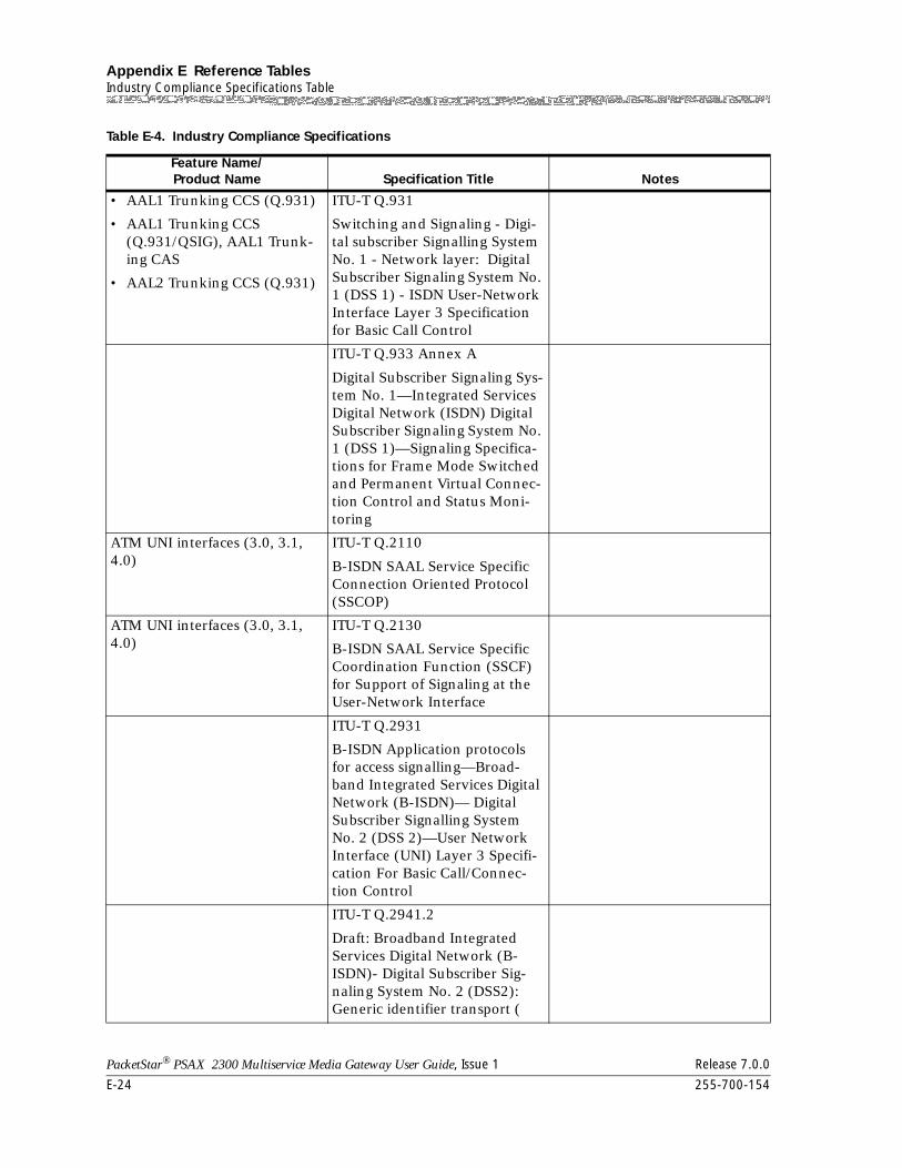
Appendix E Reference TablesIndustry Compliance Specifications Table
E-24 255-700-154
PacketStar® PSAX 2300 Multiservice Media Gateway User Guide, Issue 1 Release 7.0.0
• AAL1 Trunking CCS (Q.931)
• AAL1 Trunking CCS (Q.931/QSIG), AAL1 Trunk-ing CAS
• AAL2 Trunking CCS (Q.931)
ITU-T Q.931
Switching and Signaling - Digi-tal subscriber Signalling System No. 1 - Network layer: Digital Subscriber Signaling System No. 1 (DSS 1) - ISDN User-Network Interface Layer 3 Specification for Basic Call Control
ITU-T Q.933 Annex A
Digital Subscriber Signaling Sys-tem No. 1—Integrated Services Digital Network (ISDN) Digital Subscriber Signaling System No. 1 (DSS 1)—Signaling Specifica-tions for Frame Mode Switched and Permanent Virtual Connec-tion Control and Status Moni-toring
ATM UNI interfaces (3.0, 3.1, 4.0)
ITU-T Q.2110
B-ISDN SAAL Service Specific Connection Oriented Protocol (SSCOP)
ATM UNI interfaces (3.0, 3.1, 4.0)
ITU-T Q.2130
B-ISDN SAAL Service Specific Coordination Function (SSCF) for Support of Signaling at the User-Network Interface
ITU-T Q.2931
B-ISDN Application protocols for access signalling—Broad-band Integrated Services Digital Network (B-ISDN)— Digital Subscriber Signalling System No. 2 (DSS 2)—User Network Interface (UNI) Layer 3 Specifi-cation For Basic Call/Connec-tion Control
ITU-T Q.2941.2
Draft: Broadband Integrated Services Digital Network (B-ISDN)- Digital Subscriber Sig-naling System No. 2 (DSS2): Generic identifier transport (
Table E-4. Industry Compliance Specifications
Feature Name/Product Name Specification Title Notes
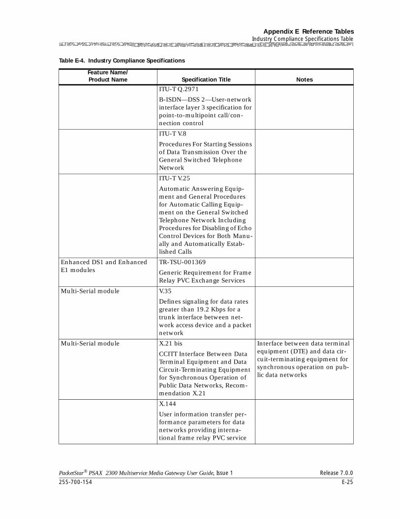
255-700-154 E-25
PacketStar® PSAX 2300 Multiservice Media Gateway User Guide, Issue 1 Release 7.0.0
Appendix E Reference TablesIndustry Compliance Specifications Table
ITU-T Q.2971
B-ISDN—DSS 2—User-network interface layer 3 specification for point-to-multipoint call/con-nection control
ITU-T V.8
Procedures For Starting Sessions of Data Transmission Over the General Switched Telephone Network
ITU-T V.25
Automatic Answering Equip-ment and General Procedures for Automatic Calling Equip-ment on the General Switched Telephone Network Including Procedures for Disabling of Echo Control Devices for Both Manu-ally and Automatically Estab-lished Calls
Enhanced DS1 and Enhanced E1 modules
TR-TSU-001369
Generic Requirement for Frame Relay PVC Exchange Services
Multi-Serial module V.35
Defines signaling for data rates greater than 19.2 Kbps for a trunk interface between net-work access device and a packet network
Multi-Serial module X.21 bis
CCITT Interface Between Data Terminal Equipment and Data Circuit-Terminating Equipment for Synchronous Operation of Public Data Networks, Recom-mendation X.21
Interface between data terminal equipment (DTE) and data cir-cuit-terminating equipment for synchronous operation on pub-lic data networks
X.144
User information transfer per-formance parameters for data networks providing interna-tional frame relay PVC service
Table E-4. Industry Compliance Specifications
Feature Name/Product Name Specification Title Notes
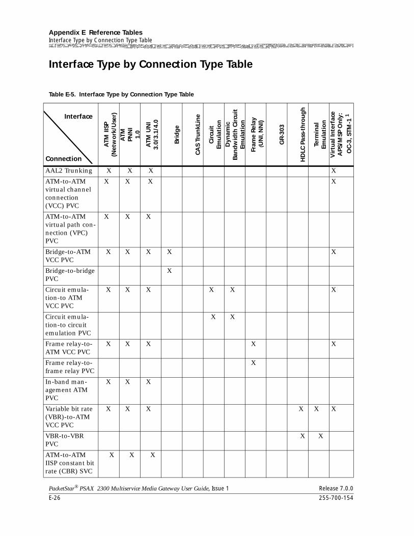
Appendix E Reference TablesInterface Type by Connection Type Table
E-26 255-700-154
PacketStar® PSAX 2300 Multiservice Media Gateway User Guide, Issue 1 Release 7.0.0
Interface Type by Connection Type Table
Table E-5. Interface Type by Connection Type Table
ATM
IISP
(N
etw
ork
/Use
r)A
TM
PNN
I 1.
0
ATM
UN
I 3.
0/3.
1/4.
0
Bri
dg
e
CA
S Tr
un
kLin
e
Cir
cuit
Em
ula
tio
nD
ynam
ic
Ban
dw
idth
Cir
cuit
Em
ula
tio
n
Fram
e R
elay
(UN
I, N
NI)
GR
-303
HD
LC P
ass-
thro
ug
h
Term
inal
Em
ula
tio
nV
irtu
al In
terf
ace
APS
/MSP
On
ly:
OC
-3, S
TM-1
1
AAL2 Trunking X X X X
ATM-to-ATM virtual channel connection (VCC) PVC
X X X X
ATM-to-ATM virtual path con-nection (VPC) PVC
X X X
Bridge-to-ATM VCC PVC
X X X X X
Bridge-to-bridge PVC
X
Circuit emula-tion-to ATM VCC PVC
X X X X X X
Circuit emula-tion-to circuit emulation PVC
X X
Frame relay-to-ATM VCC PVC
X X X X X
Frame relay-to-frame relay PVC
X
In-band man-agement ATM PVC
X X X
Variable bit rate (VBR)-to-ATM VCC PVC
X X X X X X
VBR-to-VBR PVC
X X
ATM-to-ATM IISP constant bit rate (CBR) SVC
X X X
Interface
Connection
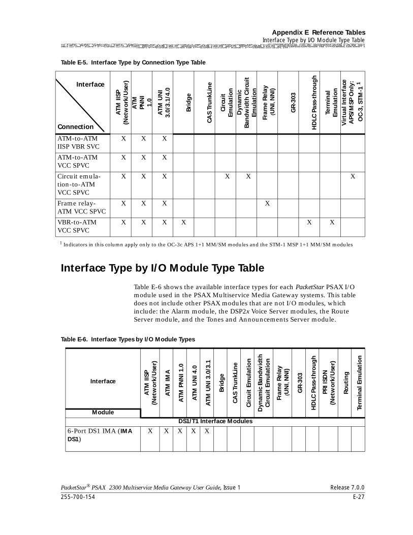
255-700-154 E-27
PacketStar® PSAX 2300 Multiservice Media Gateway User Guide, Issue 1 Release 7.0.0
Appendix E Reference TablesInterface Type by I/O Module Type Table
Interface Type by I/O Module Type Table
Table E-6 shows the available interface types for each PacketStar PSAX I/O module used in the PSAX Multiservice Media Gateway systems. This table does not include other PSAX modules that are not I/O modules, which include: the Alarm module, the DSP2x Voice Server modules, the Route Server module, and the Tones and Announcements Server module.
ATM-to-ATM IISP VBR SVC
X X X
ATM-to-ATM VCC SPVC
X X X
Circuit emula-tion-to-ATM VCC SPVC
X X X X X X
Frame relay-ATM VCC SPVC
X X X X
VBR-to-ATM VCC SPVC
X X X X X X
1 Indicators in this column apply only to the OC-3c APS 1+1 MM/SM modules and the STM-1 MSP 1+1 MM/SM modules
Table E-5. Interface Type by Connection Type Table
ATM
IISP
(N
etw
ork
/Use
r)A
TM
PNN
I 1.
0
ATM
UN
I 3.
0/3.
1/4.
0
Bri
dg
e
CA
S Tr
un
kLin
e
Cir
cuit
Em
ula
tio
nD
ynam
ic
Ban
dw
idth
Cir
cuit
Em
ula
tio
n
Fram
e R
elay
(UN
I, N
NI)
GR
-303
HD
LC P
ass-
thro
ug
h
Term
inal
Em
ula
tio
nV
irtu
al In
terf
ace
APS
/MSP
On
ly:
OC
-3, S
TM-1
1Interface
Connection
Table E-6. Interface Types by I/O Module Types
Interface
ATM
IISP
(N
etw
ork
/Use
r)
ATM
IMA
ATM
PN
NI 1
.0
ATM
UN
I 4.0
ATM
UN
I 3.0
/3.1
Bri
dg
e
CA
S Tr
un
kLin
e
Cir
cuit
Em
ula
tio
n
Dyn
amic
Ban
dw
idth
C
ircu
it E
mu
lati
on
Fram
e R
elay
(UN
I, N
NI)
GR
-303
HD
LC P
ass-
thro
ug
h
PR
I ISD
N
(Net
wo
rk/U
ser)
Ro
uti
ng
Term
inal
Em
ula
tio
n
ModuleDS1/T1 Interface Modules
6-Port DS1 IMA (IMA DS1)
X X X X X
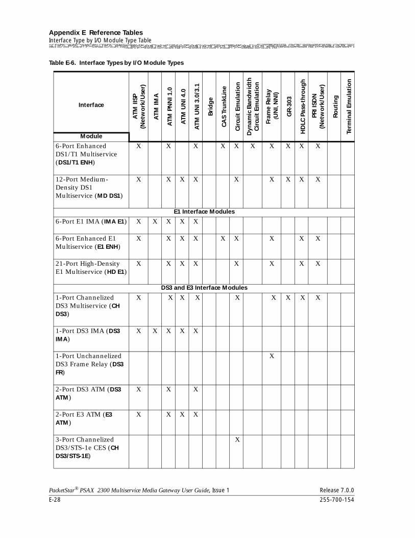
Appendix E Reference TablesInterface Type by I/O Module Type Table
E-28 255-700-154
PacketStar® PSAX 2300 Multiservice Media Gateway User Guide, Issue 1 Release 7.0.0
6-Port Enhanced DS1/T1 Multiservice (DS1/T1 ENH)
X X X X X X X X X X
12-Port Medium-Density DS1 Multiservice (MD DS1)
X X X X X X X X X
E1 Interface Modules
6-Port E1 IMA (IMA E1) X X X X X
6-Port Enhanced E1 Multiservice (E1 ENH)
X X X X X X X X X
21-Port High-Density E1 Multiservice (HD E1)
X X X X X X X X
DS3 and E3 Interface Modules
1-Port Channelized DS3 Multiservice (CH DS3)
X X X X X X X X X
1-Port DS3 IMA (DS3 IMA)
X X X X X
1-Port Unchannelized DS3 Frame Relay (DS3 FR)
X
2-Port DS3 ATM (DS3 ATM)
X X X
2-Port E3 ATM (E3 ATM)
X X X X
3-Port Channelized DS3/STS-1e CES (CH DS3/STS-1E)
X
Table E-6. Interface Types by I/O Module Types
Interface
ATM
IISP
(N
etw
ork
/Use
r)
ATM
IMA
ATM
PN
NI 1
.0
ATM
UN
I 4.0
ATM
UN
I 3.0
/3.1
Bri
dg
e
CA
S Tr
un
kLin
e
Cir
cuit
Em
ula
tio
n
Dyn
amic
Ban
dw
idth
C
ircu
it E
mu
lati
on
Fram
e R
elay
(UN
I, N
NI)
GR
-303
HD
LC P
ass-
thro
ug
h
PR
I ISD
N
(Net
wo
rk/U
ser)
Ro
uti
ng
Term
inal
Em
ula
tio
n
Module
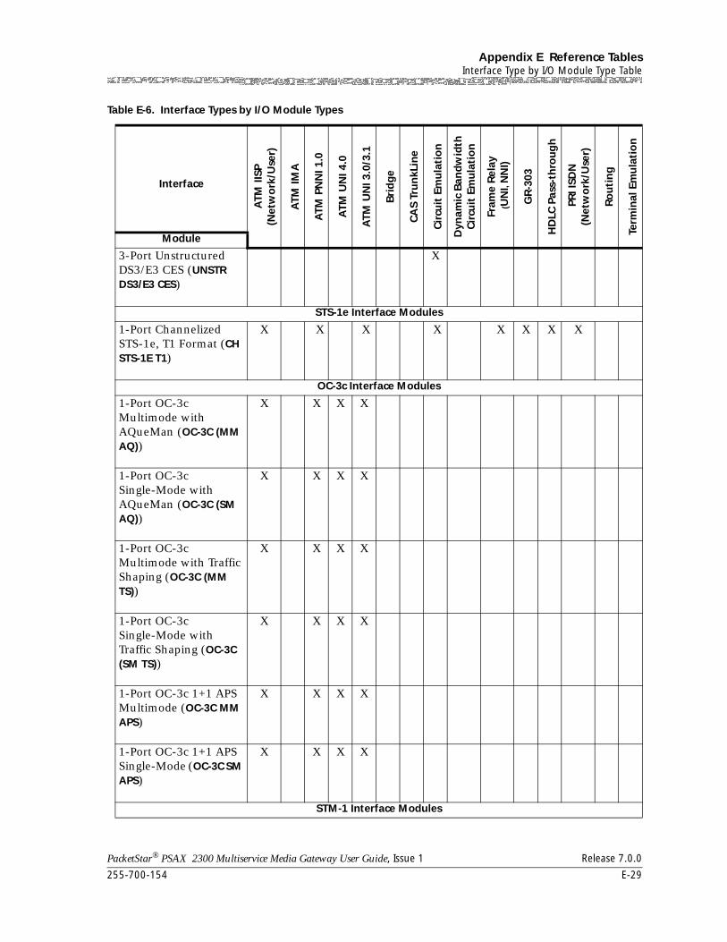
255-700-154 E-29
PacketStar® PSAX 2300 Multiservice Media Gateway User Guide, Issue 1 Release 7.0.0
Appendix E Reference TablesInterface Type by I/O Module Type Table
3-Port Unstructured DS3/E3 CES (UNSTR DS3/E3 CES)
X
STS-1e Interface Modules
1-Port Channelized STS-1e, T1 Format (CH STS-1E T1)
X X X X X X X X
OC-3c Interface Modules
1-Port OC-3c Multimode with AQueMan (OC-3C (MM AQ))
X X X X
1-Port OC-3c Single-Mode with AQueMan (OC-3C (SM AQ))
X X X X
1-Port OC-3c Multimode with Traffic Shaping (OC-3C (MM TS))
X X X X
1-Port OC-3c Single-Mode with Traffic Shaping (OC-3C (SM TS))
X X X X
1-Port OC-3c 1+1 APS Multimode (OC-3C MM APS)
X X X X
1-Port OC-3c 1+1 APS Single-Mode (OC-3C SM APS)
X X X X
STM-1 Interface Modules
Table E-6. Interface Types by I/O Module Types
Interface
ATM
IISP
(N
etw
ork
/Use
r)
ATM
IMA
ATM
PN
NI 1
.0
ATM
UN
I 4.0
ATM
UN
I 3.0
/3.1
Bri
dg
e
CA
S Tr
un
kLin
e
Cir
cuit
Em
ula
tio
n
Dyn
amic
Ban
dw
idth
C
ircu
it E
mu
lati
on
Fram
e R
elay
(UN
I, N
NI)
GR
-303
HD
LC P
ass-
thro
ug
h
PR
I ISD
N
(Net
wo
rk/U
ser)
Ro
uti
ng
Term
inal
Em
ula
tio
n
Module
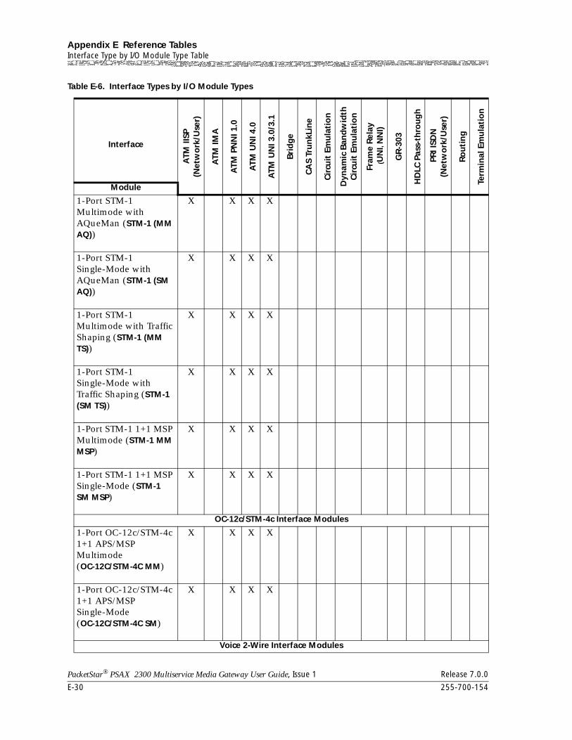
Appendix E Reference TablesInterface Type by I/O Module Type Table
E-30 255-700-154
PacketStar® PSAX 2300 Multiservice Media Gateway User Guide, Issue 1 Release 7.0.0
1-Port STM-1 Multimode with AQueMan (STM-1 (MM AQ))
X X X X
1-Port STM-1 Single-Mode with AQueMan (STM-1 (SM AQ))
X X X X
1-Port STM-1 Multimode with Traffic Shaping (STM-1 (MM TS))
X X X X
1-Port STM-1 Single-Mode with Traffic Shaping (STM-1 (SM TS))
X X X X
1-Port STM-1 1+1 MSP Multimode (STM-1 MM MSP)
X X X X
1-Port STM-1 1+1 MSP Single-Mode (STM-1 SM MSP)
X X X X
OC-12c/STM-4c Interface Modules
1-Port OC-12c/STM-4c 1+1 APS/MSP Multimode (OC-12C/STM-4C MM)
X X X X
1-Port OC-12c/STM-4c 1+1 APS/MSP Single-Mode (OC-12C/STM-4C SM)
X X X X
Voice 2-Wire Interface Modules
Table E-6. Interface Types by I/O Module Types
Interface
ATM
IISP
(N
etw
ork
/Use
r)
ATM
IMA
ATM
PN
NI 1
.0
ATM
UN
I 4.0
ATM
UN
I 3.0
/3.1
Bri
dg
e
CA
S Tr
un
kLin
e
Cir
cuit
Em
ula
tio
n
Dyn
amic
Ban
dw
idth
C
ircu
it E
mu
lati
on
Fram
e R
elay
(UN
I, N
NI)
GR
-303
HD
LC P
ass-
thro
ug
h
PR
I ISD
N
(Net
wo
rk/U
ser)
Ro
uti
ng
Term
inal
Em
ula
tio
n
Module
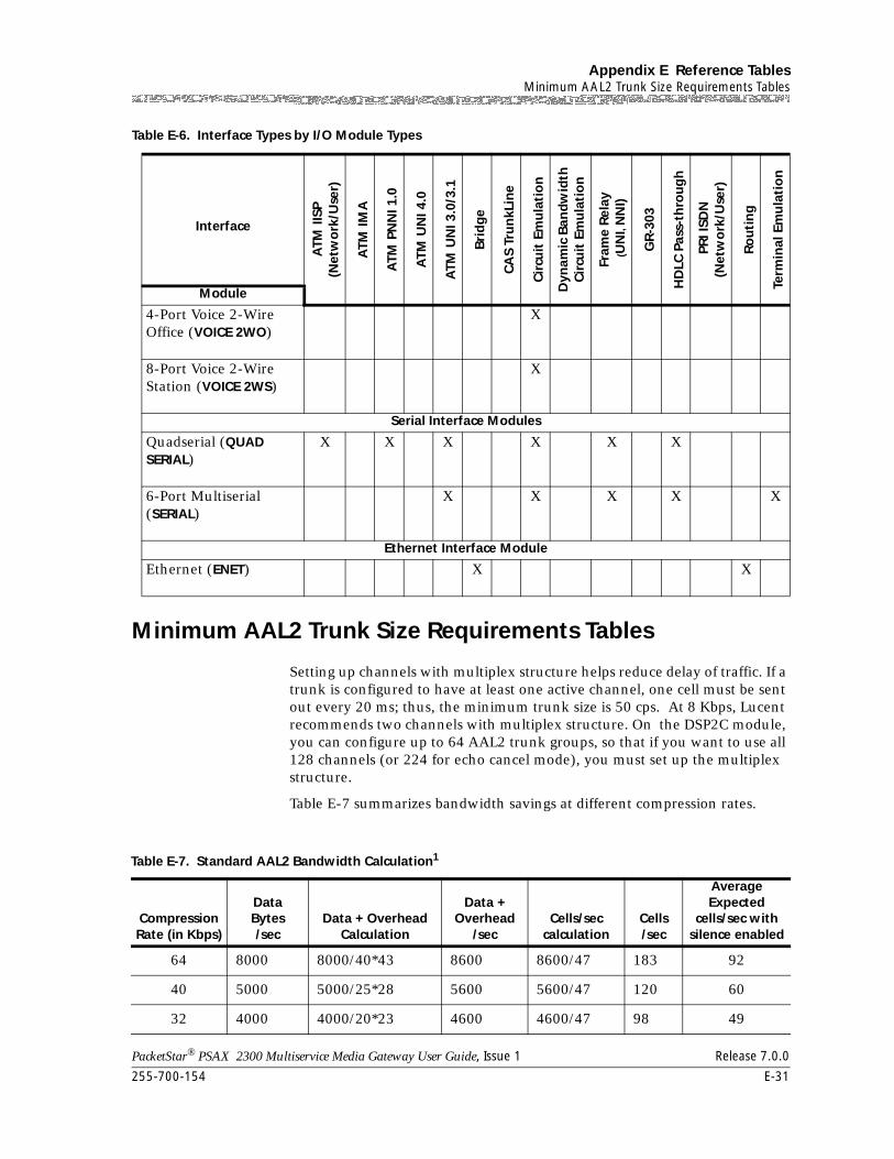
255-700-154 E-31
PacketStar® PSAX 2300 Multiservice Media Gateway User Guide, Issue 1 Release 7.0.0
Appendix E Reference TablesMinimum AAL2 Trunk Size Requirements Tables
Minimum AAL2 Trunk Size Requirements Tables
Setting up channels with multiplex structure helps reduce delay of traffic. If a trunk is configured to have at least one active channel, one cell must be sent out every 20 ms; thus, the minimum trunk size is 50 cps. At 8 Kbps, Lucent recommends two channels with multiplex structure. On the DSP2C module, you can configure up to 64 AAL2 trunk groups, so that if you want to use all 128 channels (or 224 for echo cancel mode), you must set up the multiplex structure.
Table E-7 summarizes bandwidth savings at different compression rates.
4-Port Voice 2-Wire Office (VOICE 2WO)
X
8-Port Voice 2-Wire Station (VOICE 2WS)
X
Serial Interface Modules
Quadserial (QUAD SERIAL)
X X X X X X
6-Port Multiserial (SERIAL)
X X X X X
Ethernet Interface Module
Ethernet (ENET) X X
Table E-6. Interface Types by I/O Module Types
Interface
ATM
IISP
(N
etw
ork
/Use
r)
ATM
IMA
ATM
PN
NI 1
.0
ATM
UN
I 4.0
ATM
UN
I 3.0
/3.1
Bri
dg
e
CA
S Tr
un
kLin
e
Cir
cuit
Em
ula
tio
n
Dyn
amic
Ban
dw
idth
C
ircu
it E
mu
lati
on
Fram
e R
elay
(UN
I, N
NI)
GR
-303
HD
LC P
ass-
thro
ug
h
PR
I ISD
N
(Net
wo
rk/U
ser)
Ro
uti
ng
Term
inal
Em
ula
tio
n
Module
Table E-7. Standard AAL2 Bandwidth Calculation1
Compression Rate (in Kbps)
DataBytes/sec
Data + Overhead Calculation
Data +Overhead
/secCells/sec
calculationCells/sec
Average Expected
cells/sec with silence enabled
64 8000 8000/40*43 8600 8600/47 183 92
40 5000 5000/25*28 5600 5600/47 120 60
32 4000 4000/20*23 4600 4600/47 98 49
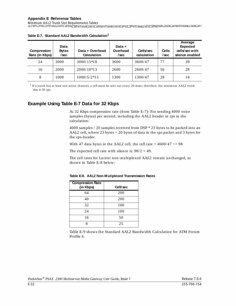
Appendix E Reference TablesMinimum AAL2 Trunk Size Requirements Tables
E-32 255-700-154
PacketStar® PSAX 2300 Multiservice Media Gateway User Guide, Issue 1 Release 7.0.0
Example Using Table E-7 Data for 32 Kbps
At 32 Kbps compression rate (from Table E-7): For sending 4000 voice samples (bytes) per second, including the AAL2 header in cps in the calculation:
4000 samples / 20 samples received from DSP * 23 bytes to be packed into an AAL2 cell, where 23 bytes = 20 bytes of data in the cps packet and 3 bytes for the cps-header.
With 47 data bytes in the AAL2 cell, the cell rate = 4600/47 ~= 98
The expected cell rate with silence is: 98/2 = 49.
The cell rates for Lucent non-multiplexed AAL2 remain unchanged, as shown in Table E-8 below:
Table E-9 shows the Standard AAL2 Bandwidth Calculation for ATM Forum Profile 6.
24 3000 3000/15*18 3600 3600/47 77 39
16 2000 2000/10*13 2600 2600/47 56 28
8 1000 1000/5/2*13 1300 1300/47 28 14
1 If a trunk has at least one active channel, a cell must be sent out every 20 msec; therefore, the minimum AAL2 trunksize is 50 cps.
Table E-7. Standard AAL2 Bandwidth Calculation1
Compression Rate (in Kbps)
DataBytes/sec
Data + Overhead Calculation
Data +Overhead
/secCells/sec
calculationCells/sec
Average Expected
cells/sec with silence enabled
Table E-8. AAL2 Non-Mutiplexed Transmission Rates
Compression Rate (in Kbps) Cell/sec
64 200
40 200
32 100
24 100
16 50
8 25
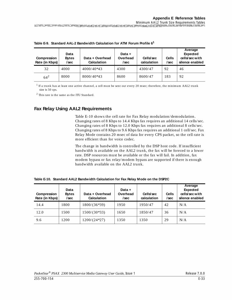
255-700-154 E-33
PacketStar® PSAX 2300 Multiservice Media Gateway User Guide, Issue 1 Release 7.0.0
Appendix E Reference TablesMinimum AAL2 Trunk Size Requirements Tables
Fax Relay Using AAL2 Requirements
Table E-10 shows the cell rate for Fax Relay modulation/demodulation. Changing rates of 8 Kbps to 14.4 Kbps fax requires an additional 14 cells/sec. Changing rates of 8 Kbps to 12.0 Kbps fax requires an additional 8 cells/sec. Changing rates of 8 Kbps to 9.6 Kbps fax requires an additional 1 cell/sec. Fax Relay Mode contains 20 msec of data for every CPS packet, so the cell rate is more efficient than for voice codec.
The change in bandwidth is controlled by the DSP host code. If insufficient bandwidth is available on the AAL2 trunk, the fax will be foreced to a lower rate. DSP resources must be available or the fax will fail. In addition, fax modem bypass or fax relay/modem bypass are supported if there is enough bandwidth available on the AAL2 trunk.
Table E-9. Standard AAL-2 Bandwidth Calculation for ATM Forum Profile 61
Compression Rate (in Kbps)
DataBytes/sec
Data + Overhead Calculation
Data +Overhead
/secCells/sec
calculationCells/sec
Average Expected
cells/sec with silence enabled
32 4000 4000/40*43 4300 4300/47 92 46
642 8000 8000/40*43 8600 8600/47 183 92
1 If a trunk has at least one active channel, a cell must be sent out every 20 msec; therefore, the minimum AAL2 trunksize is 50 cps.
2 This rate is the same as the ITU Standard.
Table E-10. Standard AAL2 Bandwidth Calculation for Fax Relay Mode on the DSP2C
Compression Rate (in Kbps)
DataBytes/sec
Data + Overhead Calculation
Data +Overhead
/secCells/sec
calculationCells/sec
Average Expected
cells/sec with silence enabled
14.4 1800 1800/(36*39) 1950 1950/47 42 N/A
12.0 1500 1500/(30*33) 1650 1850/47 36 N/A
9.6 1200 1200/(24*27) 1350 1350 29 N/A
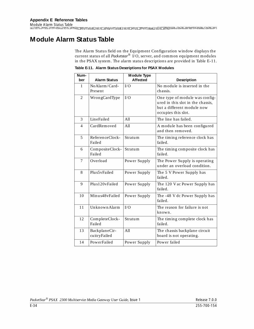
Appendix E Reference TablesModule Alarm Status Table
E-34 255-700-154
PacketStar® PSAX 2300 Multiservice Media Gateway User Guide, Issue 1 Release 7.0.0
Module Alarm Status Table
The Alarm Status field on the Equipment Configuration window displays the current status of all Packetstar® I/O, server, and common equipment modules in the PSAX system. The alarm status descriptions are provided in Table E-11.
Table E-11. Alarm Status Descriptions for PSAX Modules
Num-ber Alarm Status
Module Type Affected Description
1 NoAlarm/Card-Present
I/O No module is inserted in the chassis.
2 WrongCardType I/O One type of module was config-ured in this slot in the chassis, but a different module now occupies this slot.
3 LineFailed All The line has failed.
4 CardRemoved All A module has been configured and then removed.
5 ReferenceClock-Failed
Stratum The timing reference clock has failed.
6 CompositeClock-Failed
Stratum The timing composite clock has failed.
7 Overload Power Supply The Power Supply is operating under an overload condition.
8 Plus5vFailed Power Supply The 5 V Power Supply has failed.
9 Plus120vFailed Power Supply The 120 V ac Power Supply has failed.
10 Minus48vFailed Power Supply The -48 V dc Power Supply has failed.
11 UnknownAlarm I/O The reason for failure is not known.
12 CompleteClock-Failed
Stratum The timing complete clock has failed.
13 BackplaneCir-cuitryFailed
All The chassis backplane circuit board is not operating.
14 PowerFailed Power Supply Power failed
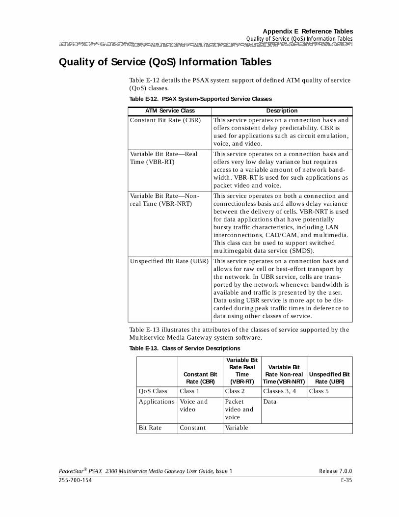
255-700-154 E-35
PacketStar® PSAX 2300 Multiservice Media Gateway User Guide, Issue 1 Release 7.0.0
Appendix E Reference TablesQuality of Service (QoS) Information Tables
Quality of Service (QoS) Information Tables
Table E-12 details the PSAX system support of defined ATM quality of service (QoS) classes.
Table E-13 illustrates the attributes of the classes of service supported by the Multiservice Media Gateway system software.
Table E-12. PSAX System-Supported Service Classes
ATM Service Class Description
Constant Bit Rate (CBR) This service operates on a connection basis and offers consistent delay predictability. CBR is used for applications such as circuit emulation, voice, and video.
Variable Bit Rate—Real Time (VBR-RT)
This service operates on a connection basis and offers very low delay variance but requires access to a variable amount of network band-width. VBR-RT is used for such applications as packet video and voice.
Variable Bit Rate—Non-real Time (VBR-NRT)
This service operates on both a connection and connectionless basis and allows delay variance between the delivery of cells. VBR-NRT is used for data applications that have potentially bursty traffic characteristics, including LAN interconnections, CAD/CAM, and multimedia. This class can be used to support switched multimegabit data service (SMDS).
Unspecified Bit Rate (UBR) This service operates on a connection basis and allows for raw cell or best-effort transport by the network. In UBR service, cells are trans-ported by the network whenever bandwidth is available and traffic is presented by the user. Data using UBR service is more apt to be dis-carded during peak traffic times in deference to data using other classes of service.
Table E-13. Class of Service Descriptions
Constant Bit Rate (CBR)
Variable Bit Rate Real
Time (VBR-RT)
Variable Bit Rate Non-real
Time (VBR-NRT) Unspecified Bit
Rate (UBR)
QoS Class Class 1 Class 2 Classes 3, 4 Class 5
Applications Voice and video
Packet video and voice
Data
Bit Rate Constant Variable
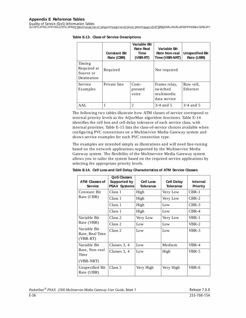
Appendix E Reference TablesQuality of Service (QoS) Information Tables
E-36 255-700-154
PacketStar® PSAX 2300 Multiservice Media Gateway User Guide, Issue 1 Release 7.0.0
The following two tables illustrate how ATM classes of service correspond to internal priority levels as the AQueMan algorithm functions. Table E-14 identifies the cell loss and cell delay tolerance of each service class, with internal priorities. Table E-15 lists the class-of-service choices available when configuring PVC connections on a Multiservice Media Gateway system and shows service examples for each PVC connection type.
The examples are intended simply as illustrations and will need fine-tuning based on the network applications supported by the Multiservice Media Gateway system. The flexibility of the Multiservice Media Gateway system allows you to tailor the system based on the required service applications by selecting the appropriate priority levels.
Timing Required at Source or Destination
Required Not required
Service Examples
Private line Com-pressed voice
Frame relay, switched multimedia data service
Raw cell, Ethernet
AAL 1 2 3/4 and 5 3/4 and 5
Table E-14. Cell Loss and Cell Delay Characteristics of ATM Service Classes
ATM Classes of Service
QoS Classes Supported by PSAX Systems
Cell Loss Tolerance
Cell Delay Tolerance
Internal Priority
Constant Bit Rate (CBR)
Class 1 High Very Low CBR-1
Class 1 High Very Low CBR-2
Class 1 High Low CBR-3
Class 1 High Low CBR-4
Variable Bit Rate (VBR)
Variable Bit Rate, Real Time (VBR-RT)
Class 2 Very Low Very Low VBR-1
Class 2 Low Low VBR-2
Class 2 Low Low VBR-3
Variable Bit Rate, Non-real Time
(VBR-NRT)
Classes 3, 4 Low Medium VBR-4
Classes 3, 4 Low High VBR-5
Unspecified Bit Rate (UBR)
Class 5 Very High Very High VBR-6
Table E-13. Class of Service Descriptions
Constant Bit Rate (CBR)
Variable Bit Rate Real
Time (VBR-RT)
Variable Bit Rate Non-real
Time (VBR-NRT) Unspecified Bit
Rate (UBR)
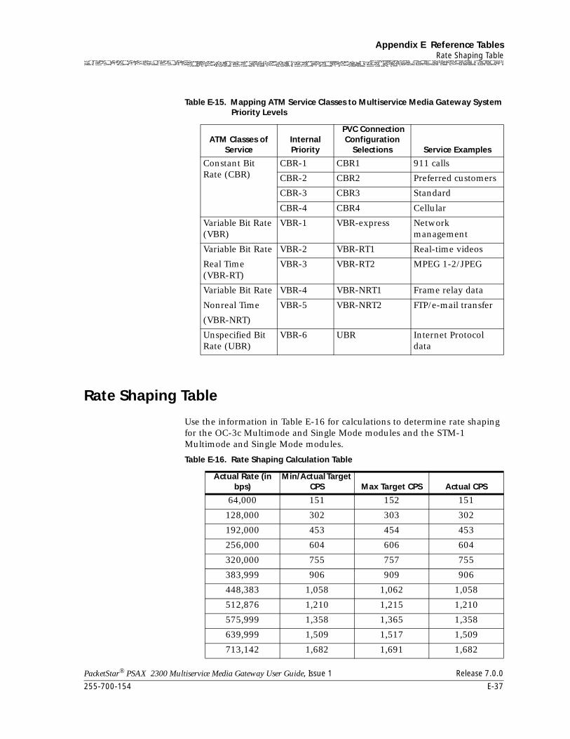
255-700-154 E-37
PacketStar® PSAX 2300 Multiservice Media Gateway User Guide, Issue 1 Release 7.0.0
Appendix E Reference TablesRate Shaping Table
Rate Shaping Table
Use the information in Table E-16 for calculations to determine rate shaping for the OC-3c Multimode and Single Mode modules and the STM-1 Multimode and Single Mode modules.
Table E-15. Mapping ATM Service Classes to Multiservice Media Gateway System Priority Levels
ATM Classes of Service
Internal Priority
PVC Connection Configuration
Selections Service Examples
Constant Bit Rate (CBR)
CBR-1 CBR1 911 calls
CBR-2 CBR2 Preferred customers
CBR-3 CBR3 Standard
CBR-4 CBR4 Cellular
Variable Bit Rate (VBR)
VBR-1 VBR-express Network management
Variable Bit Rate
Real Time (VBR-RT)
VBR-2 VBR-RT1 Real-time videos
VBR-3 VBR-RT2 MPEG 1-2/JPEG
Variable Bit Rate
Nonreal Time
(VBR-NRT)
VBR-4 VBR-NRT1 Frame relay data
VBR-5 VBR-NRT2 FTP/e-mail transfer
Unspecified Bit Rate (UBR)
VBR-6 UBR Internet Protocol data
Table E-16. Rate Shaping Calculation Table
Actual Rate (in bps)
Min/Actual Target CPS Max Target CPS Actual CPS
64,000 151 152 151
128,000 302 303 302
192,000 453 454 453
256,000 604 606 604
320,000 755 757 755
383,999 906 909 906
448,383 1,058 1,062 1,058
512,876 1,210 1,215 1,210
575,999 1,358 1,365 1,358
639,999 1,509 1,517 1,509
713,142 1,682 1,691 1,682
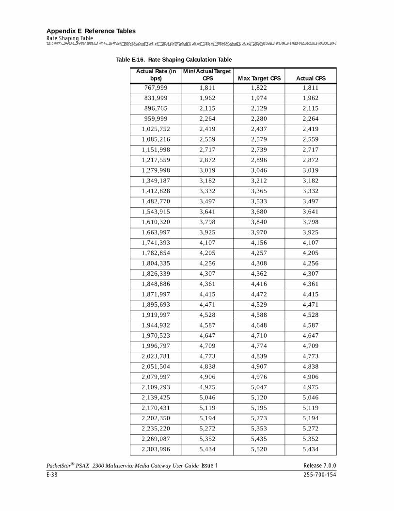
Appendix E Reference TablesRate Shaping Table
E-38 255-700-154
PacketStar® PSAX 2300 Multiservice Media Gateway User Guide, Issue 1 Release 7.0.0
767,999 1,811 1,822 1,811
831,999 1,962 1,974 1,962
896,765 2,115 2,129 2,115
959,999 2,264 2,280 2,264
1,025,752 2,419 2,437 2,419
1,085,216 2,559 2,579 2,559
1,151,998 2,717 2,739 2,717
1,217,559 2,872 2,896 2,872
1,279,998 3,019 3,046 3,019
1,349,187 3,182 3,212 3,182
1,412,828 3,332 3,365 3,332
1,482,770 3,497 3,533 3,497
1,543,915 3,641 3,680 3,641
1,610,320 3,798 3,840 3,798
1,663,997 3,925 3,970 3,925
1,741,393 4,107 4,156 4,107
1,782,854 4,205 4,257 4,205
1,804,335 4,256 4,308 4,256
1,826,339 4,307 4,362 4,307
1,848,886 4,361 4,416 4,361
1,871,997 4,415 4,472 4,415
1,895,693 4,471 4,529 4,471
1,919,997 4,528 4,588 4,528
1,944,932 4,587 4,648 4,587
1,970,523 4,647 4,710 4,647
1,996,797 4,709 4,774 4,709
2,023,781 4,773 4,839 4,773
2,051,504 4,838 4,907 4,838
2,079,997 4,906 4,976 4,906
2,109,293 4,975 5,047 4,975
2,139,425 5,046 5,120 5,046
2,170,431 5,119 5,195 5,119
2,202,350 5,194 5,273 5,194
2,235,220 5,272 5,353 5,272
2,269,087 5,352 5,435 5,352
2,303,996 5,434 5,520 5,434
Table E-16. Rate Shaping Calculation Table
Actual Rate (in bps)
Min/Actual Target CPS Max Target CPS Actual CPS

255-700-154 E-39
PacketStar® PSAX 2300 Multiservice Media Gateway User Guide, Issue 1 Release 7.0.0
Appendix E Reference TablesRate Shaping Table
2,339,996 5,519 5,607 5,519
2,377,139 5,606 5,698 5,606
2,415,480 5,697 5,791 5,697
2,455,078 5,790 5,888 5,790
2,495,996 5,887 5,988 5,887
2,538,301 5,987 6,091 5,987
2,582,065 6,090 6,198 6,090
2,627,364 6,197 6,308 6,197
2,674,282 6,307 6,423 6,307
2,722,905 6,422 6,542 6,422
2,773,329 6,541 6,665 6,541
2,825,656 6,664 6,793 6,664
2,879,996 6,792 6,927 6,792
2,936,466 6,926 7,065 6,926
2,995,195 7,064 7,209 7,064
3,056,322 7,208 7,359 7,208
3,119,995 7,358 7,516 7,358
3,186,378 7,515 7,679 7,515
3,255,647 7,678 7,850 7,678
3,327,995 7,849 8,028 7,849
3,403,631 8,027 8,215 8,027
3,482,785 8,214 8,411 8,214
3,565,709 8,410 8,616 8,410
3,652,677 8,615 8,831 8,615
3,743,994 8,830 9,058 8,830
3,839,994 9,057 9,296 9,057
3,941,047 9,295 9,547 9,295
4,047,561 9,546 9,812 9,546
4,159,994 9,811 10,093 9,811
4,278,851 10,092 10,389 10,092
4,404,699 10,388 10,704 10,388
4,538,175 10,703 11,039 10,703
4,679,993 11,038 11,395 11,038
4,830,960 11,394 11,775 11,394
4,991,992 11,774 12,181 11,774
5,164,130 12,180 12,616 12,180
Table E-16. Rate Shaping Calculation Table
Actual Rate (in bps)
Min/Actual Target CPS Max Target CPS Actual CPS
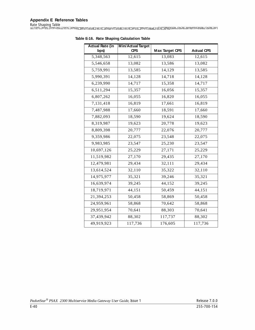
Appendix E Reference TablesRate Shaping Table
E-40 255-700-154
PacketStar® PSAX 2300 Multiservice Media Gateway User Guide, Issue 1 Release 7.0.0
5,348,563 12,615 13,083 12,615
5,546,658 13,082 13,586 13,082
5,759,991 13,585 14,129 13,585
5,990,391 14,128 14,718 14,128
6,239,990 14,717 15,358 14,717
6,511,294 15,357 16,056 15,357
6,807,262 16,055 16,820 16,055
7,131,418 16,819 17,661 16,819
7,487,988 17,660 18,591 17,660
7,882,093 18,590 19,624 18,590
8,319,987 19,623 20,778 19,623
8,809,398 20,777 22,076 20,777
9,359,986 22,075 23,548 22,075
9,983,985 23,547 25,230 23,547
10,697,126 25,229 27,171 25,229
11,519,982 27,170 29,435 27,170
12,479,981 29,434 32,111 29,434
13,614,524 32,110 35,322 32,110
14,975,977 35,321 39,246 35,321
16,639,974 39,245 44,152 39,245
18,719,971 44,151 50,459 44,151
21,394,253 50,458 58,869 50,458
24,959,961 58,868 70,642 58,868
29,951,954 70,641 88,303 70,641
37,439,942 88,302 117,737 88,302
49,919,923 117,736 176,605 117,736
Table E-16. Rate Shaping Calculation Table
Actual Rate (in bps)
Min/Actual Target CPS Max Target CPS Actual CPS
PacketStar® PSAX 2300 Multiservice Media Gateway User Guide, Issue 1 Release 7.0.0
255-700-154 Glossary-1
Glossary
Numeric
1+1 APS (automatic protection switching)
In a North American SONET, 1+1 protection switching is commonly referred to as automatic protection switching (APS). See APS for additional information.
1+1 MSP (multiplex section protec-tion)
In a European synchronous digital hierarchy (SDH) network, 1+1 protection switching is commonly referred to as multi-plex section protection (MSP). See MSP for additional infor-mation.
100Base-T This IEEE standard specifies the transmission of data at 100 Mbps on Ethernet networks.
10Base-T This IEEE standard (802.3) specifies the transmission of data at 10 Mbps on Ethernet networks with twisted-pair cabling and a wiring hub, referred to as a 10Base-T hub.
10-nibble header space In a protocol data unit (PDU), the 40 bits of protocol control information located at the beginning of the PDU.
5ESS switch A digital central office electronic switching system made by Lucent, typically used at an end office, which serves local sub-scribers.
A
AAL ATM adaptation layer. The protocol layer that allows multiple applications to have data converted to and from the ATM cell. AAL also refers to a protocol that is used to translate higher layer services into the size and format of an ATM cell.
AAL1 ATM adaptation layer type 1. This layer supports Class A traf-fic (uncompressed, digitized voice and video).
AAL2 ATM adaptation layer type 2. This layer supports Class B traf-fic (variable bit rate compressed voice and video).
Glossary
Glossary-2 255-700-154
PacketStar® PSAX 2300 Multiservice Media Gateway User Guide, Issue 1 Release 7.0.0
AAL2 trunking A communication line established between two switching systems that supports Class B traffic (AAL2).
AAL3/4 ATM adaption layer 3/4. This layer supports Class C and D traffic (variable bit rate compressed voice and video).
AAL5 ATM adaptation layer type 5. This layer supports Class C traf-fic (connection-oriented variable bit rate [VBR] data traffic and signaling messages, used predominantly for classical IP [CLIP] over ATM and LAN Emulation [LANE] traffic)
ABCD signaling bits Bits robbed from bytes in each DS0 or T1 channel in particu-lar subframes, which are then used to carry in-band all status information.
ABR available bit rate. ABR changes after a connection is estab-lished, and allows the receiving device to accept data from a variety of transmitting devices which are operating at differ-ent speeds, without the need to set up data rates in advance.
ACELP algebraic code excited linear prediction. This voice-coding algorithm standardized by the ITU-T in G.729 provides voice compression. ACELP is specified by the Frame Relay Forum as one of the minimum voice compression algorithms required for network-to-network interoperability.
active/standby mode Alternate terms for working/protection. See Automatic pro-tection switching.
adaption service permanent virtual circuit
See AS-PVC.
adaptive differential pulse code mod-ulation
See ADPCM.
address A data structure or logical convention used to identify a device on a network.
address mask A bit combination used to describe which portion of an address refers to the network or subnet, and which portion refers to the host.
address resolution protocol See ARP.
255-700-154 Glossary-3
PacketStar® PSAX 2300 Multiservice Media Gateway User Guide, Issue 1 Release 7.0.0
Glossary
administrative weight See AW.
administrator A user who has full read-write capabilities on all PSAX devices managed by the AQueView® Element Management System.
ADPCM adaptive differential pulse code modulation. This type of audio encoding is a reduced bit rate variant of PCM audio encoding, which uses fewer bits by determining the difference between consecutive speech samples.
advertising In the context of packet switching, a reference to routing or service updates that are sent at specified intervals. This method allows other routers on the network to maintain lists of usable routes.
aggregation A reference to an instance when the border nodes at the ends of an outside link assign a token number to the outside link, and the same number is associated with all uplinks associated with the outside link (an aggregation token). In the parent and all higher-level peer groups, all uplinks with the same aggregation token are aggregated.
AIS alarm indication signal. This signal is used in-band mainte-nance to ensure that a line is working properly.
alarm An message that warns an administrator about a network problem.
alarm indication signal See AIS.
A-Law This ITU-T companding standard used in PCM systems for conversion between analog and digital signals. The A-Law standard is primarily used in European telephone networks.
algebraic code excited linear predic-tion
See ACELP.
alterable mark inversion See AMI.
alternating current See AC.
American National Standards Insti-tute
See ANSI.
Glossary
Glossary-4 255-700-154
PacketStar® PSAX 2300 Multiservice Media Gateway User Guide, Issue 1 Release 7.0.0
American Standard Code for Infor-mation Exchange
See ASCII.
AMI alterable mark inversion. The signaling format used for T1 lines. This format allows the “one” pulses to have an alternat-ing priority.
analog Voice vibrations converted to electrical signals which have frequencies with varying amplitudes. An analog signal implies continuous operation, in contrast to a digital signal, which is broken up into individual bits of data.
ANSI American National Standards Institute. This organization is a U.S. standards body that accredits standards for programming languages, communications, and networking. It is also the U.S. representative to the International Organization for Standardization.
API application program (or programming) interface. A software routine which uses a specialized language and message for-mat to communicate between an application program and another program, or operating system, that provides services to it. Standard software interrupts, calls, and data formats are used to initiate contact with network services, mainframe communications programs, telephone equipment, or pro-gram-to-program applications.
application program interface (also application programming interface)
See API.
APS automatic protection switching. This feature provides net-work resiliency by automatically switching to a secondary line when the primary line fails or is operating on an unac-ceptably high error rate. SONET allows either 1+1 or 1:N architecture. The 1+1 architecture has permanent electrical bridging at both ends of the serviced equipment. At the trans-mit end, identical signals are transmitted over primary and secondary circuits and then tested at the receive end. The 1:N protection switch architecture is one in which any of the “N” (any number of) service channels (primary circuits) can be bridged to a single optical protection channel (secondary cir-cuit).
255-700-154 Glossary-5
PacketStar® PSAX 2300 Multiservice Media Gateway User Guide, Issue 1 Release 7.0.0
Glossary
AQueMan algorithm A traffic management system that also supports ATM Forum classes of service. This adaptive algorithm allocates bandwidth by statistically multiplexing traffic within two sets of queues according to weighted priorities. One set of queues addresses the avoidance of cell loss, which is normally a concern for data traffic, while the other manages cell transfer delay, which is critical to voice and some video traffic.
Within each set of queues, the AQueMan algorithm assigns internal priorities even more specialized than the ATM Forum class definitions. Generally, the lower the assigned priority number, the greater the access to bandwidth and the less like-lihood of loss.
AQueView® Element Management System
This PacketStar software product is a graphical user interface (GUI)-based element management tool that is used to provi-sion the PacketStar PSAX Multiservice Media Gateway sys-tems. The AQueView system enables a network of PSAX products to be managed and provisioned with easy-to-use windows from a single location.
architecture The design of the hardware and software components of a system that controls how all the various components interop-erate with each other and with other devices or systems.
ARP address resolution protocol. This low-level protocol maps IP addresses, or other non-ATM addresses to the target ATM device. Once the ATM device has been identified, an ARP server can send it data, as long as the session is maintained.
ASCII American Standard Code for Information Exchange. This cod-ing standard specifies the representation of characters in a binary format.
AS-PVC adaption service permanent virtual circuit. This type of circuit allows ATM adaptation services to be connected by ATM switched virtual circuits. AS-PVC specifies parameters (such as circuit emulation) for the sending device, specifying the receiving device.
asynchronous transfer mode See ATM.
Glossary
Glossary-6 255-700-154
PacketStar® PSAX 2300 Multiservice Media Gateway User Guide, Issue 1 Release 7.0.0
ATM asynchronous transfer mode. This cell-switching technology converts multiple incoming streams of information into fixed-length cells of 53 bytes, that are composed of a 48-byte infor-mation field and a five-byte address header. ATM enables high-speed transmission of data, voice, and video over the same lines, at speeds up to 13.22 Gbps.
ATM adaptation layer See AAL.
ATM addressing This addressing scheme enables an operating system to find a specific piece of ATM information in the application memory. Every memory location has an address. ATM addressing pro-vides user-specific virtual path identifier/virtual channel iden-tifier (VPI/VCI) coding, bandwidth allocation, and quality of service (Qos) information.
ATM edge switch A device that resides at the edge of a carrier network and pro-vides access from the end user to a carrier’s ATM network backbone.
ATM Forum This organization is a consortium of corporations who develop hardware and software products using ATM to facili-tate the development, deployment, and standardization of ATM protocols and specifications.
ATM Forum Implementation Agree-ments
The formal documents use for the implementation of the standards for ATM specifications agreed on by the ATM Forum.
ATM interface management entities See IME.
ATM terminal emulation interface Terminal emulation is an application that follows an intelligent computing device to mimic the operation of a nonprogrammable terminal for communication with a mainframe computer or a minicomputer. This communication is made possible by inserting special printed circuit boards into the systemboard of the emulating device, and/or special software. The PacketStar PSAX 6-Port Multiserial module supports this interface.
ATM traffic policing This software feature provides basic data on the amount and type of ATM traffic handled by the network.
255-700-154 Glossary-7
PacketStar® PSAX 2300 Multiservice Media Gateway User Guide, Issue 1 Release 7.0.0
Glossary
ATM UNI ATM user-network interface. The interface between a user’s equipment and an ATM public network service or into an ATM switch on a private enterprise network.
ATM virtual channel This type of channel provides a virtual connection that uses all the addressing bits of the cell header to move traffic from one link to another.
authentication A procedure that establishes the legitimacy of users and defines the parameters of the sessions they establish. Authen-tication can be thought of as a security measure that controls and defines network access. It is always the first task per-formed when a session is started. The range of authentication parameters that can be set depend upon the specific authenti-cation system employed.
automatic protection switching See APS.
automatic switchback An automatic return from the backup CPU module to the pri-mary CPU module is performed by the system, after a fault line has been cleared.
available bit rate See ABR.
AW administrative weight. This parameter allows network archi-tects to indicate relative link preference when deciding between alternate routes.
B
B channel A channel that carries 56-Kbps or 64-Kbps of user data on a line using ISDN D-channel signaling.
B8ZS bipolar 8-zero substitution. This encoding scheme is used for transmitting data bits over T1 transmission systems. This scheme is “smarter” than the B7ZS scheme, because it trans-parently adds a one-bit as needed to ensure that no more than seven zero-bits are ever transmitted in a row. However, unlike the B7ZS scheme, the B8ZS scheme provides a “clear channel” capability, which allows each of the 24 channels to carry 64 Kbps of data.

Glossary
Glossary-8 255-700-154
PacketStar® PSAX 2300 Multiservice Media Gateway User Guide, Issue 1 Release 7.0.0
backbone The portion of a communications network that carries the heaviest traffic and employs high-speed transmission path-ways. In a wide area network (WAN), the backbone is that portion that links all the individual local area networks (LANs) together.
backhauling A technique in which data traffic is transmitted beyond where it is needed and back. In fiber-optic data transmission, backhauling is a traffic management technique used to dimin-ish the cost of multiplexing and demultiplexing.
backplane A circuit board in a chassis in which various modules or com-ponents are connected to the central processing unit. Typi-cally, a backplane runs at a very high capacity bandwidth, and carries a high number of connections, addressing informa-tion, and signaling. A backplane is also sometimes called the backplane bus.
backward direction rate This rate is the rate of speed data transmissions take as they move toward the head-end of a broadband LAN.
bandwidth The amount of data a channel can transmit in a given period of time. Bandwidth is measured in bits (not bytes) per second on digital networks, while on analog networks, it is measured in Hertz (cycles per second).
bandwidth classification The types of bandwidth are narrowband, wideband, and broadband, and are used to describe the capacity of a commu-nications channel. Narrowband generally refers to some number of 64 Kbps channels (Nx64) and provides aggregate bandwidth less than 1.544 Mbps (24x64 Kbps, or T1 rate). Wideband is 1.544 Mbps to 45 Mbps (T1 to T3 rate), while broadband operates at 45 Mbps (T3 rate) or higher.
basic rate interface See BRI.
Bc committed burst size. This parameter is used in frame relay, and is the maximum number of bits transferred during time interval “T.” Time interval “T” is the time interval over which the number of bits used to average the number of bits trans-mitted is averaged. The formula to calculate “T” is:Bc/CIR = T.
Be excess burst size. This parameter is used in frame relay, and is the maximum number of uncommitted bits transferred dur-ing time interval “T”. The formula to calculate “T” is: Bc/CIR = T.
255-700-154 Glossary-9
PacketStar® PSAX 2300 Multiservice Media Gateway User Guide, Issue 1 Release 7.0.0
Glossary
bearer channel This basic communication channel has no enhanced or value-added services other than bandwidth transmission capability.
Bellcore (this organization is now known as Telcordia Technologies)
The research and development arm formed by the Regional Bell Operating Companies (RBOCs). Bellcore, now Telcordia Technologies, focused on developing standards and proce-dures for the RBOCs. A prime example is the Bellcore stan-dard NEBS, Network Equipment Building Standards. Network carriers who interoperate with RBOCs typically are required to obtain Level 3 NEBS compliance on their tele-communications equipment.
BER bit error rate. This parameter is the ratio of error bits to the total number of bits transmitted, usually expressed as a num-ber to the power of 10.
binaries Software programs written in binary, machine-readable code that has been compiled or assembled.
bipolar 8 Zero substitution See B8ZS.
B-ISDN Broadband Integrated Services Digital Network. This type of communications channel has the capability to integrate any type of communications signals (voice, data, image, or multi-media) and carry them over a single broadband channel at 150 Mbps, and higher.
bit The term indicating a binary digit, which represents the value high or low, or yes or no. A bit is written as either the value zero or the value 1.
bit error rate See BER.
bit stuffing The technique of inserting a zero-bit into a string of one-bits to prevent the receiver from interpreting the series of one-bits as something else, such as a flag control character. The sender inserts the zero-bit automatically, and the receiver automati-cally deletes it.
BITS building integrated timing supply. A single-building master timing that provides and distributes timing to a wireline net-work’s lower levels.
bits per second See bps.
Glossary
Glossary-10 255-700-154
PacketStar® PSAX 2300 Multiservice Media Gateway User Guide, Issue 1 Release 7.0.0
block-error correction scheme This scheme provides a method for accomplishing forward error correction (FEC) to compensate for error bursts created in data transmission. This method is done by specifying a polynominal that plots, or statistically samples, a large num-ber of points in a data block.
bps bits per second. This unit of measure indicates the number of bits transmitted every second during data transmission.
BRI basic rate interface. This interface is composed of two B-chan-nels (bearer channels) at 64 Kbps and a data D-channel (data channel) at 16 Kbps. The bearer B-channels are designed for PCM voice, slow-scan video conferencing, Group 4 facsimile data, or other types of data that can fit into a full-duplex 64,000 bps channel. The D-channel used to receive informa-tion about incoming calls and to transmit information about outgoing calls. It is also used for accessing slow-speed data networks, such as packet-switched networks.
bridge A link that connects several LANs, but provides no routing. Each bit of information is transferred to all other bridges on the LANs, which creates the potential for a bridge to clog a network. Routers have generally replaced bridges.
bridging A link across a circuit that is made by placing one test lead from a test set or a conductor from another circuit and placing it on one conductor of another circuit, and then doing the same thing to the second conductor.
broadband In a WAN environment, a description of a transmission capa-bility greater than 45 Mbps (T3 rate), that frequently operates on a fiber- optic transmission line.
Broadband Integrated Services Digi-tal Network
See B-ISDN.
bucket A discrete sample of data.
building integrated timing supply See BITS.
burst errors Transmission errors that occur when data is transmitted in short spurts.
bursty A reference to data that is transmitted in short spurts. Traffic over a local area network is usually bursty.
255-700-154 Glossary-11
PacketStar® PSAX 2300 Multiservice Media Gateway User Guide, Issue 1 Release 7.0.0
Glossary
bus 1. An electrical connection allowing two or more wires or lines to be connected together. Common in electrical and computer use.
2. Broadcast and Unknown Server (an ATM term), working in conjunction with a LAN emulation server, the bus auto-matically registers and resolves differences between LAN MAC addresses and ATM addresses by labeling each device transmission with both addresses.
byte A series of consecutive binary digits operated upon as a unit.
C
CAC connection admission control. The set of actions a network takes during a call setup or renegotiation phase that deter-mine whether to accept or reject a connection request.
CAD/CAM Computer Aid Design/ Computer Aided Manufacturing. A computer and its related software and terminals that is used to design and manufacture things. CAD terminals are often run over LANs and/or WANs.
call control A term used by the telephone companies to describe the set-ting up, monitoring, and tearing down of telephone calls. First Person Call Control is done by a person or a computer via a desktop telephone, or a computer attached to that tele-phone, or the computer attached to the desktop phone line. Third-party call control controls the call through a connection directly to the switch (PBX).
call controller A device that sets up, monitors, and tears down telephone calls.
call establishing procedure See CEP.
call multiplexing When a Multiservice Media Gateway switches back and forth between a number of instruction sequences so rapidly it seems like several tasks are being executed simultaneously. This rapid switching means that no one transaction can over-load the Multiservice Media Gateway while other transac-tions have their service requests neglected.
Glossary
Glossary-12 255-700-154
PacketStar® PSAX 2300 Multiservice Media Gateway User Guide, Issue 1 Release 7.0.0
call states A condition that exists on both the user side and the network side of the transaction. They define which messages can be accepted by the user or the network entity, and how they are expected to react to those messages. As the user or network entity moves from call state to call state, the call switching process is accomplished.
caller ID A service, offered by local telephone companies, that displays the calling party’s number on a special display device.
CAPs Competitive Access Providers. Businesses that compete with the local telephone networks.
carrier-grade The classification for a device that has passed safety and envi-ronmental compliance certifications and has "4-9s" or "5-9s" reliability (i.e., 99.99% online during 1 year, or 99.999% online during 1 year). Reliability is obtained by having redun-dant power supplies, clocks, CPUs, etc., as well as protected trunk lines. For example, if a fiber gets cut by a backhoe, the traffic automatically switches to a different fiber.
CAS channel-associated signaling. Signaling in which the signals necessary to switch a given circuit are transmitted via the cir-cuit itself, or via a signaling channel permanently associated with it.
CBR constant bit rate. An ATM service that supports a constant or guaranteed rate to transport services such as video or voice, as well as circuit emulation. CBR requires rigorous timing con-trol and performance parameters.
CCITT Consultive Committee for International Telephony and Teleg-raphy, formerly known as the United National International Telecommunications Union, or ITU. This organization estab-lishes technical recommendations for telephone and data transmission.
CCS common-channel signaling. A high-speed, packet-switched communications network, distinctive from public packet switched and message networks. CCS is used to carry addressed signaling messages for individual trunk circuits and/or database-related services between signaling points in the CCS network.
CD-ROM Compact Disk, Read-Only Memory. A disk on which large amounts of digitized read-only data can be stored.
255-700-154 Glossary-13
PacketStar® PSAX 2300 Multiservice Media Gateway User Guide, Issue 1 Release 7.0.0
Glossary
CE 1. circuit emulation. A connection over a virtual channel-based network which provides service that is indistinguish-able from a real, point-to-point, fixed bandwidth circuit.
2. Communities European. See EC for additional information.
3. connection end point. An ATM term.
cell The fixed-length packet used to carry data across an ATM net-work. A cell consists of 53 bytes, five of which carry header information.
cell delineation An instance when an idle cell with header error correction is transmitted when there are no real cells to send. Indicator bits 14 or 15 are used to indicate Loss of Cell Delineation to a Central Office. The receiver will then drop both idle and unassigned cells.
cell encoding Based on a user-selected encoding rate for the connection, cell encoding occurs when source-data cell payloads are divided into six blocks and fed into a Reed Solomon encoder. The encoded cells are then executed by the CPU module on the cell payload data destined for noisy interfaces.
cell extraction The removal of a cell from a data stream.
cell header A cell header precedes payload data (user information) in an ATM cell. The header contains various control data specific to the cell switching protocol.
cell loss margin See CLM.
cell loss priority See CLP.
cell payload A cell data field, block, or stream being processed or trans-ported. Also, sometimes a reference to the part of a cell that represents information useful to the user, as opposed to sys-tem overhead information. A cell payload includes user infor-mation and may include such additional information as user-requested network management and accounting information.
cell scrambling A function that moves the first three bytes of the cell header (GFC, VPI, and VCI fields) into the payload and spreads them out to protect against burst errors. This action increases the burst error tolerance of the header from 5 bits to 54 bits with no cell loss.
Glossary
Glossary-14 255-700-154
PacketStar® PSAX 2300 Multiservice Media Gateway User Guide, Issue 1 Release 7.0.0
cell-aging A capability that prevents the lowest-priority data (for exam-ple, IP data) from being buffered in the PSAX system indefi-nitely. The AQueMan algorithm keeps track of how long each cell stays in the buffer. The lower the priority of the traffic, the longer its cell-aging timer; that is, UBR traffic has a longer cell-aging period than VBR-RT traffic. This capability allows the PSAX system to periodically send low-priority cells through the network, which prevents retransmission of IP data traffic while increasing the time-out window for the TCP/IP sessions. The cell-aging mechanism allows for orderly decongestion of the network without resorting to traffic rerouting and other complicated protocols and procedures.
cell-bearing Cell information moved over a communications channel.
central office See CO.
Central Processing Unit See CPU.
CEP call establishing procedure. A procedure that defines how the bits of a PCM carrier system of the 32 channel European type T1/E1 will be used, and in what sequence. In order to cor-rectly receive the transmitted information, the receiving end equipment must know exactly what each bit is used for.
CES circuit mmulation service. An ATM Forum interoperability specification which supports CBR (constant bit rate) over ATM networks and complies with other ATM specifications. This specification also supports the emulation of existing time division multiplexing (TDM) circuits over ATM networks.
channel A voice-grade transmission facility with defined frequency response, gain, and bandwidth (i.e., a DSPx voice processing module hardware chip).
channel-associated signaling See CAS.
channel service unit See CSU.
channel suppression The inhibition of a portion of a line’s bandwidth.
channel tunneling A way of overcoming protocol restrictions on a network by encapsulating channels that use one protocol inside channels that use a protocol supported by the network.
255-700-154 Glossary-15
PacketStar® PSAX 2300 Multiservice Media Gateway User Guide, Issue 1 Release 7.0.0
Glossary
channelization A process that subdivides the bandwidth of a circuit into smaller increments called channels. Typically, each channel would carry a single transmission, such as voice only or data only. Channelization requires either a frequency division multiplexer or a time division multiplexer.
channelized circuit emulation ser-vice
A virtual DS1 port that is subdivided into 24 DS0 channels that provides a connection over a virtual channel-based net-work, providing service to the end use that is indistinguish-able from a real, point-to-point, fixed bandwidth circuit.
channelized digital signals Subdivided digital signals.
characters per second See cps.
chassis A reference to the physical hardware, frame, and mother-board into which are inserted the power supply, stratum, CPU, and I/O modules. The supporting legs and brackets are not considered to be part of the chassis.
checksum The sum of a group of data items used for checking errors.
chip Short for microchip, an very complex, yet tiny module that stores computer memory or provide logic circuitry for micro-processors. A chip is manufactured from a silicon (or, in some special cases, a sapphire) wafer, which is first cut to size and then etched with circuits and electronic devices. A chip is also sometimes called an IC or integrated circuit.
chipset A group of microchips designed to work and be sold as a unit that performs one or more related functions.
CIR committed information rate. The speed at which a frame relay network agrees to transfer information under normal condi-tions, averaged over a minimal increment of time. CIR is measured in bits per second.
circuit emulation See CE.
circuit emulation service See CES.
circuit mode data Data that travels across a fixed bandwidth circuit established from point-to-point through a network, and is held for the duration of a telephone call.
Glossary
Glossary-16 255-700-154
PacketStar® PSAX 2300 Multiservice Media Gateway User Guide, Issue 1 Release 7.0.0
circuit-switched network A network that sets up and maintains a connection for the exclusive use of two or more communicating parties for the duration of their call. The familiar, voice telephone network is circuit-switched.
clear channel A digital circuit where no framing or control bits are required, thus making the full bandwidth available for communica-tions.
CLEC Competitive Local Exchange Carrier. A type of business per-mitted by the Telecommunications Act of 1996. CLECs offer local exchange service, long distance, internal, Internet access and such entertainment as video on demand. These carriers include cellular/PCS providers, ISPs, IXCs, CATV providers, CAPs, LMDS operators, and power utilities. They compete with ILECs.
CLI command line interface. The visual appearance and com-mand input conventions that enable system administrators and system operators to configure, monitor, and manage the connected nodes in a data network.
CLM cell-loss margin. A negotiated Quality of Service parameter in an ATM network. This parameter indicates the margin of error of lost cells to total transmitted cells.
CLP cell loss priority. A bit in the ATM cell header set to 0 or 1. CLP=1 cells may be discarded in congested transmission to preserve the cell loss ratio of CLP=0 cells.
Some service categories generate traffic flows with cell loss priority markings, CLP=0 (higher priority) and CLP=1 (lower priority). The network may follow models which treat this marking as transparent or significant. If the marker is signifi-cant, the network may selectively discard cells marked with low priority to protect the QoS of cells with high priority
CO Central Office. The building that houses the switching equip-ment to which circuits of business and residence phones are connected.
coding translation A means of transmitting the same data to a variety of differ-ent end-user devices. For example, voice messages that can be relayed on a telephone, or on a PC.
255-700-154 Glossary-17
PacketStar® PSAX 2300 Multiservice Media Gateway User Guide, Issue 1 Release 7.0.0
Glossary
colocation Typically, equipment housed at the same site.
comfort noise A very low-level synthesized white noise deliberately added to a digital line to give a comforting "hiss" to the connection, which assures the consumer the connection is active.
command line interface See CLI.
committed burst size See Bc.
committed information rate See CIR.
common-channel signaling See CCS.
community name The name given to an SNMP community for identification purposes. A member has associated access rights (read-only or read/write).
competitive access providers See CAPS.
competitive local exchange carrier See CLEC.
composite clock A timing reference for multiplexer output that includes all data from multiplexed channels that is based on an oscillator-generated signal.
compressed voice The act of reducing a voice signal to use less bandwidth dur-ing transmission. This is done when a voice analog signal is sampled through the use of an algorithm, and converted to a digital signal.
compression The act of reformatting information so fewer bits are neces-sary to represent it.
configurator A user that has read-write capabilities on PSAX devices when using the AQueMan system, but the capabilities are subordi-nate to the Administrator.
Glossary
Glossary-18 255-700-154
PacketStar® PSAX 2300 Multiservice Media Gateway User Guide, Issue 1 Release 7.0.0
conformance type The type of traffic control option used for ATM cells. A traffic descriptor combination that specifies which traffic parameters are used for traffic control; determines the number and type of cells that are admitted into a congested queue; and deter-mines whether high-priority cells are tagged as low-priority cells when traffic exceeds the traffic parameter thresholds.
congestion The point where devices in a network operate at the highest utilization.
congestion control parameters Techniques used in a network to prevent and react to tempo-rary excessive demands for resources.
congestion management The ability of a network to effectively deal with heavy traffic volumes.
Conjugated Structure- Algebraic Code Excited Linear Predictive Voice Coding
See CS-ACLEP.
connection admission control See CAC.
connection gateway Software that allows an external device to interconnect to the PacketStar Multiservice Media Gateway systems and act as an adjunct processor to handle IDSN, SS7 signaling, and other call control.
connectivity The degree to which any given computer or application can cooperate with other network components in a shared-resource network environment.
connector A device connecting wires or fibers in cable either to equip-ment or to other wires or fibers.
connector pin The contacts protruding from a male connector.
constant bit rate See CBR.
Consultive Committee for Interna-tional Telephony and Telegraphy
See CCITT.
255-700-154 Glossary-19
PacketStar® PSAX 2300 Multiservice Media Gateway User Guide, Issue 1 Release 7.0.0
Glossary
continuity check A test to determine whether electrical current flows continu-ously throughout the length of a single wire which is grouped with other individual wires in a cable.
continuity check tone A single frequency of 2000 Hz which is transmitted by the sending exchange, and looped back by the receiving exchange. The reception of the returned signal indicates the channel is working.
control outputs Devices that route the input control signal to the selected out-put.
core events Specific data received (events) on any of the core switches.
core switch A Broadband Switching System (BSS) which is located in the core of the network. Conceptually equivalent to a Tandem Office in the voice world, a core switch serves to interconnect "edge switches," which provide user access to the broadband network much as Central Offices do in the circuit switched voice world.
core switch trap The notification of a problem within a core switch.
CPE Customer Premises Equipment. In Lucent’s line, the PSAX 15 through the PSAX 600, versus the PSAX 1250 and 2300 which are designed for central office use (although customers could use them in home offices).
cps characters per second. Note: Formerly, this was the abbrevia-tion for cycles per second, the unit used to express frequency. However, hertz is the proper unit for frequency.
CPU Central Processing Unit. The computing part of a computer which manipulates data and processes instructions coming from software or a user.
crankback A mechanism which partially releases an ATM connection setup in progress, but has encountered a failure. The use of this mechanism allows PNNI to perform alternate routing.
Glossary
Glossary-20 255-700-154
PacketStar® PSAX 2300 Multiservice Media Gateway User Guide, Issue 1 Release 7.0.0
CRC cyclic redundancy check. A method of error detection using cyclic redundancy code. Based on the contents of the message transmitted, a CRC value is generated at the transmitting ter-minal. An identical CRC generation is performed at the receiving terminal, and any mismatch indicates the message was received incorrectly.
CRC error A condition that occurs when the CRC in a frame does not agree with the CRC frame received from a network.
CRC-MF cyclic redundancy check-multifrequency. A process used to check the integrity of a block of data.
crosstalk This phenomena is occuring when you hear someone you did not call talking on your telephone line to another person you did not call. It can be the result of faulty wire placement, shielding, or transmission techniques.
CS-ACELP conjugated structure - algebraic code excited linear predictive voice coding, (ITU-T G.7290). A voice compression standard that uses algebraic expressions instead of numbers for each set of voice samples. This technique results in better than 2:1 compression at 8 Kbps. It is used on packet switched data net-works.
CSU channel service unit. Along with a Data Service Unit (DSU), a CSU is a component of Data Circuit-terminating Equipment (DCE). A CSU connects a digital telephone line to a cus-tomer’s network-access equipment. It can be built into the network interface of the network-access equipment, or it can be a separate device. The CSU terminates the connection at the user’s end and processes digital signals. It also prevents a faulty DSU from interfering with data transmissions on the digital line.
CTR current transfer ratio. The ratio of output collector current to the forward LED input current, times 100.
current transfer ratio See CTR.
customer premises equipment See CPE.
cyclic redundancy check See CRC.
255-700-154 Glossary-21
PacketStar® PSAX 2300 Multiservice Media Gateway User Guide, Issue 1 Release 7.0.0
Glossary
Cyclic redundancy check-multifre-quency
See CRC-MF.
D
D Channel In an ISDN interface, the D channel is the data channel that carries control signals and customer call data in a packet switched mode. The B Channel is used for voice.
D4 framing A common framing format in the T-1 environment. The name stems from the way framing is performed in the D-series of channel banks from AT&T. There are 12 separate 193-bit frames in a super-frame. A D-4 framing bit is used to identify both the channel and the signaling frame. In D-4 framing, sig-naling for voice channels is carried in-band by every channel, along with the encoded voice.
data bits In asynchronous transmission, the bits that contain the data being sent (also known as payload).
data communications equipment See DCE.
data link Any serial data communications transmission path, without any intermediate nodes, that is generally between two nodes or devices.
data link connection identifier See DLCI.
data link control A standard method for sending data over a single communi-cations link.
data service unit See DSU.
data service unit/channel service unit
See DSU/CSU.
data terminal equipment See DTE.
datagram A logical grouping of information which is sent as a network layer unit over a transmission medium prior to establishing a virtual circuit.
Glossary
Glossary-22 255-700-154
PacketStar® PSAX 2300 Multiservice Media Gateway User Guide, Issue 1 Release 7.0.0
DB-25 The standard 25-pin connector used for RS-232 serial data communications. This connector has 13 pins in one row, and 12 in the next.
DBCES dynamic bandwidth circuit emulation service. This feature is used with voice PVC connections to best utilize the available network bandwidth. Based on ABCD signaling-bit informa-tion, it allows channels to be dynamically allocated as needed.
The implementation of DBCES is Lucent proprietary. The firmware supports 1x56 kbps time-slot trunking with chan-nel-associated signaling (CAS) detection used, based on ATM Forum Specification af-vtoa-0085.000. It should be noted this feature is not fully compliant with the specification and does not interoperate with other devices that are fully compliant.
DBS Direct Broadcast Satellite. A satellite that sends relatively powerful signals to small (generally 18-inch) dishes installed at homes.
DC Direct Current. A flow of electricity always in the same direc-tion.
DCE Data Communications Equipment. An interface standard between computers and printers. DCE works like data termi-nal equipment, except pins 2 and 3 are reversed.
debouncing Bouncing is the tendency of any two metal contacts in an elec-tronic device to generate multiple signals as the contacts close or open; debouncing is any kind of hardware device or soft-ware that ensures that only a single signal will be acted upon for a single opening or closing of a contact.
demodulate To recover a signal from a modulated carrier that has essen-tially the same characteristics as the original modulating sig-nal.
designated transit lists See DTL.
destination address The address portion of the packet that identifies the destina-tion node.
device tree The left pane in the main AQueView® window, which allows a user to access configuration and provisioning menus for all open PSAX devices.
255-700-154 Glossary-23
PacketStar® PSAX 2300 Multiservice Media Gateway User Guide, Issue 1 Release 7.0.0
Glossary
DHPVC Dual-Homed Permanent Virtual Circuit. A virtual circuit that is connected to the network through two independent access points.
digital loop carrier See DLC.
digital loop carrier system A system that concentrates analog local loop lines, digitized, and multiplexed calls for transmission to the central office.
digital service interface An interface that enables the implementation of digital ser-vice circuits with the network interface. It is defined at a point where the signal has not yet been reshaped into a standard digital signal.
digital signal processor See DSP.
digital signal, level 1 See DS1.
digital signal, level 3 See DS3.
digital signal, level zero See DS0.
digital subscriber line access multi-plexer
See DSLAM.
digital subscriber lines See DSL.
DIP switch Dual In-line Position switch. A small switch used to select the operating mode of a device.
direct broadcast satellite See DBS.
direct current See DC.
direct serial connection A direct connection through a serial port to another com-puter.
DLC Digital Loop Carrier. Network transmission equipment used to provide pair gain on a local loop, by deriving multiple channels, typically 64 Kb, from a single 4-wire distribution cable running from the central office to a remote site.
Glossary
Glossary-24 255-700-154
PacketStar® PSAX 2300 Multiservice Media Gateway User Guide, Issue 1 Release 7.0.0
DLCI Data Link Connection Identifier. A frame relay term which defines a 10-bit field within the address field that includes committed information rate, committed burst size, committed rate measurement interval, and excess burst size.
DMA interface Direct Memory Access Interface. A fast method of moving RAM which in turn, speeds processing.
downstream node A reference to the relative position of two nodes in a LAN topology. A node is downstream if it receives data signals after the previous node.
DS0 digital signal, level zero. The North American Digital Hierar-chy signaling standard for transmission at 64,000 bits per sec-ond. DS0 is the basic building block of the DS hierarchy, equal to one voice conversation digitized over PCM. There are 24 DS0 channels in a DS1.
DS1 digital signal, level 1. The North American Digital Hierarchy signaling standard for transmission at 1.544 million bits per second. Based on an old Bell System standard, DS1 is the equivalent of T1, which supports 24 voice conversations, each encoded at 64 Kbps, or 1.544 million. Outside the US, E1 des-ignations are used which start at 2.048 million bits per sec-ond.
DS1 circuit-emulation service A configuration that interfaces with TDM channelized DS1 circuits by converting the channelized digital signals (usually voice data) to ATM virtual channels.
DS3 digital Signal, level 3. The North American Digital Hierarchy signaling standard transmission at 44.736 Mbps that is used by a T3 carrier. DS3 supports 28 DS1s plus overhead. In a channel application, it supports 672 channels, each at 64 kbps.
DSL Digital Subscriber Lines. A family of evolving services local telephone companies provide their local subscribers. DSL is also synonymous with a ISDN BRI channel which offers up to 8 million bits per second downstream to the customer, and somewhat slower service from the customer back to the tele-phone company.
255-700-154 Glossary-25
PacketStar® PSAX 2300 Multiservice Media Gateway User Guide, Issue 1 Release 7.0.0
Glossary
DSLAM Digital Subscriber Line Access Multiplexer. Technology installed in the telephone company’s central office that links through the line to a box in the customer’s home or office. When a PC and telephone are plugged into the box, the DSLAM provides both telephone service and high-speed Internet service.
DSP Digital Signal Processor. A specialized digital microprocessor that performs calculations on digitized signals that were origi-nally analog (for example, voice) and then sends the results on. DSPs are used extensively in telecommunications for tasks such as echo cancellation, call process monitoring, voice processing and for the compression of voice and video signals.
DSU Data (or digital) Service Unit. A device designed to connect data terminal equipment to a digital phone line, thus allowing fully digital communications.
DSU/CSU Data Service Unit/Channel Service Unit. Devices that are used to access digital data channels.
DTE Data Terminal Equipment. Equipment to which DCE (Data Communications Equipment) is connected, such as personal computers or data terminals. As defined in the RS-232 specifi-cation, DTE refers to application equipment, such as a video-conference terminal or LAN bridge or router, while DCE refers to equipment such as network access equipment.
DTL Designated Transit List. A list of nodes and optional link IDs that completely specify a path across a single PNNI peer group.
DTMF dual-tone multi-frequency. Also known as “touchtone”, a specification for the double audio signals generated through touch-tone telephones and auto-dial modems.
dual in-line position switch See DIP switch.
dual-bus A pair of parallel buses arranged so the direction of data flow in one bus is opposite to the direction of data flow in the other bus.
dual-homed permanent virtual cir-cuit
See DHPVC.
Glossary
Glossary-26 255-700-154
PacketStar® PSAX 2300 Multiservice Media Gateway User Guide, Issue 1 Release 7.0.0
dual-tone multi-frequency See DTMF.
duplex Simultaneous two-way transmission in both directions.
dynamic bandwidth circuit emula-tion service
See DBCES.
E
E1 The European equivalent of the North American 1,544 Mbps T1, except that E1 carries information at the rate of 2.048 Mbps. This rate is used by the European Conference of Euro-pean Postal and Telecommunication Administrations (CEPT) carriers to transmit 3064 Kbps digital signals for voice or data calls, plus a 64 Kbps channel for signaling, and a 64 Kbps channel for framing and maintenance.
E3 A CEPT signal which carries 16 CEPT E1 circuits and over-head at an effective data rate of 34,368 Mbps or 512 simulta-neous voice conversations.
E4 A signal which carries four E3 channels, or 139,264 million bits per second, or 1920 simultaneous voice conversations.
EC European Community, also known as the Common Market. Member nations are Austria, Belgium, Denmark, Finland, France, Germany, Greece, Ireland, Italy, Luxembourg, the Netherlands, Portugal, Spain, Sweden and the United King-dom.
echo cancellation A method of controlling speaker echo on long haul digital trunks. An echo cancellation system monitors the transmitted signal, digitally predicts the echo, then cancels it by subtract-ing the prediction from the received signal.
echo canceller Equipment that removes the echo introduced into a voice call by telephone handsets and is further handicapped by network delay.
EDGE enhanced data rates for global evolution. A final stage in the devolution of data communications within the existing GSM standards, supporting data transmission rates up to 384 Kbps. EDGE is also anticipated to be used with IS-136 TDMA net-works in the US.
255-700-154 Glossary-27
PacketStar® PSAX 2300 Multiservice Media Gateway User Guide, Issue 1 Release 7.0.0
Glossary
edge node The closest node to the perimeter of the customer’s network, but still inside the customer’s network. After a transmission leaves this node, it is in the ATM cloud and has to make its own way through switches and nodes not under the control of the originating network.
edge switch A Broadband Switching System located at the edge of the net-work; the first point of user access and the final point of exit.
EEPS End-to-End Provisioning Server. A server that provides ser-vice-level provisioning, and allows a network management system to issue commands that will set up connections to go throughout the network without needing to set up connec-tions on each individual switching device.
egress The direction of traffic leaving a device (for example, sent out of the line card).
electromagnetic interference See EMI.
electrostatic discharge See ESD.
Element Management System See EMS.
embedded operations channel See EOC.
EMI electromagnetic interference. Any electrical or electromag-netic phenomenon, synthetic or natural, that results in unin-tentional and undesirable responses from, or performance degradation or malfunction of,electronic equipment.
EMS Element Management System. A system that manages, or controls, a network element. EMS is in the layer below NMS.
encapsulation The process of wrapping information into another protocol for transport across a network.
end point A network element at the end of the network.
end-to-end provisioning Service-level provisioning that allows a network management systems (NMS) to issue commands that will set up connec-tions to go throughout the network, without setting up con-nections on each individual switching device.
Glossary
Glossary-28 255-700-154
PacketStar® PSAX 2300 Multiservice Media Gateway User Guide, Issue 1 Release 7.0.0
end-to-end provisioning server See EEPS.
enhanced data rates for global evolu-tion
See EDGE.
enterprise provider A business that provides network services such as colocation, high speed Internet access and network management ser-vices.
EOC Embedded Operations Channel, a dedicated communications channel, similar to TMC, which allows remote OAM control. The EOC is frequently found in timeslot 12 of the first and second DS1 circuits (for redundancy).
error rate The ratio between the number of bits received incorrectly and the total number of bits in the transmission.
errored The state of having a value or condition that is inconsistent with the true, specified, or expected value or condition.
errored path A faulty link between two nodes in a network.
error-tolerant addressing scheme A way to protect the cell header by establishing multiple vir-tual circuits to the same destination. The addresses for the cir-cuits are within the error space of the principal address used for actual transmission. Thus, the most probable error pat-terns occurring in the address field simply changes the address to another valid one.
ESD electrostatic discharge. The release of a built-up electrical charge from an electronic component such as a printed circuit board.
ESF extended superframe format. A T1 framing standard used in wide area networks grouping 24 (rather than 12) frames together.
Ethernet A local area network that connects computers, printers, ter-minals, workstations, and servers within the same building or campus. Operating over twisted wire or coaxial cable, it is capable of carrying over ten million Bps.
255-700-154 Glossary-29
PacketStar® PSAX 2300 Multiservice Media Gateway User Guide, Issue 1 Release 7.0.0
Glossary
Ethernet address A 48-bit number physical address. Each Ethernet address is unique to a specific network module or PC on a LAN which forms the basis of a network-addressing scheme.
Ethernet bridge A device that controls data packets within a subnet in an attempt to cut down the amount of traffic. A bridge is usually placed between two separate groups of computers that talk within themselves, and occasionally to computers in another group.
ETSI European Telecommunications Standards Institute. Equiva-lent to ANSI. ETSI is creating a single European telecommu-nications system as part of the single European market program.
European Telecommunications Stan-dards Institute
See ETSI.
events browser The events browser is a view of the received events contained in AQueView’s ® $OV_LOG/trapd.log and $OV_LOG/trapd.log.old.
events log The HP OpenView Events Log is a central repository for all incoming events received by the NNM ovtapd background process.
excess burst size See Be.
extended superframe format See ESF.
F
facility interface code A numerical code designating a facility interface.
fault monitoring In network management, the set of functions that (a) detect, isolate, and correct malfunctions in a telecommunications network, (b) compensate for environmental changes, and (c) include maintaining and examining error logs, accepting and acting on error detection notifications, tracing and identifying faults, carrying out sequences of diagnostics tests, correcting faults, reporting error conditions, and localizing and tracing faults by examining and manipulating database information.
Glossary
Glossary-30 255-700-154
PacketStar® PSAX 2300 Multiservice Media Gateway User Guide, Issue 1 Release 7.0.0
fax demodulation/remodulation A technique for taking a Group III fax signal and converting it from, or back to, its original 9.6 Kbps. For example, when a sheet of paper is inserted into a fax machine, the fax machine scans that paper into digital bits -- a stream of 9600 bps. Then, for transmission over phone lines, that 9.6 Kbps is converted into an analog signal. But if you wish to transmit the fax sig-nal over a digital line, then it makes sense to convert it back to it’s original 9.6 Kbps. In essence, this mean you can put several fax transmissions on one 56 Kbps or 64 Kbps line -- the capacity you’d normally need if you transmitted one voice conversation, or one analog fax transmission.
FEC forward error correction. A combination of functions designed to protect data transmission in a noisy communica-tions environment, such as traffic transmitted across satellite and line-of-sight radio-frequency circuits. Most of these types of circuits transmit at the rate of 2.048 Mbps or slower. The three stages of FEC are multiple redundancy addressing, cell encoding, and cell scrambling.
fiber optic cable Fiber made of extremely pure glass. To date, the best option for voice/data/video communications, being faster and less resistant than metal.
FIFO First In, First Out. A buffering scheme in which the first byte of data that enters the buffer is also the first byte received by the CPU.
file transfer protocol See FTP.
firmware Software which is kept in semipermanent memory, and is usually stored in PROMS (programmable read-only memory) or EPROMS (electrical PROMS). Firmware is used in conjunc-tion with hardware and software and shares the characteris-tics of both. It contains software which is so constantly called upon by a computer or phone system that it is written into a chip electrically, at higher-than-usual voltage, causing the bits to retain the pattern as it is "burned in."
fixed-rate connection A connection whose QoS is determined by a consistent monthly rate.

255-700-154 Glossary-31
PacketStar® PSAX 2300 Multiservice Media Gateway User Guide, Issue 1 Release 7.0.0
Glossary
flash A type of nonvolatile memory. Flash memory is functionally similar to EPROM memory, but it must be erased in blocks, whereas EPROM can be erased one byte at a time. Because of its block-oriented nature, flash memory is commonly used as a supplement to, or a replacement fork in, hard disks in per-sonal computers.
flash hook The button which is depressed when you put the telephone receiver back in the cradle. Also called a switch hook, it releases the line to receive another call.
flash signaling Signaling transitions from off-hook to on-hook, where the on-hook state lasts between 300 msec and 1000 msec.
flash-capable trunk A means of switching between one phone line and another by depressing a telephone’s flash button.
flow control The buffering that turns a device on and off in order to stop or reduce data loss during transmission.
flow-through provisioning This method is similar to end-to-end provisioning, except that the commands originate at a higher-level order management system, which sends commands, or orders, to flow through the network. To use flow-through provisioning, an interface such as an API must be present below the NMS.
foreign exchange office See FXO.
foreign exchange service See FX.
foreign exchange station See FXS.
forward direction The direction of data away from the head-end of a broadband LAN.
forward error correction See FEC.
FR frame relay. A form of packet switching, which uses smaller packets and less error checking than traditional forms of packet switching (such as X.25). This international standard is used for efficiently transmitting high-speed, bursty data over wide area networks (WANs).
frame relay See FR.
Glossary
Glossary-32 255-700-154
PacketStar® PSAX 2300 Multiservice Media Gateway User Guide, Issue 1 Release 7.0.0
Frame Relay Forum Based in Foster City, CA, this organization of frame-relay equipment vendors, carriers, and users was formed in 1991 to speed the development and deployment of frame relay prod-ucts and interfaces with other broadband technologies such as ATM.
Frame Relay Implementation Agree-ment
See FRF.
frame relay policing The prevention of frame relay traffic congestion through the discard of packets that exceed specified traffic parameters.
Frame Relay/ATM Network Inter-working Implementation Agreement
See FRF.5.
Frame Relay/ATM PVC Service Interworking Implementation Agreement
See FRF.8.
framing The data-formatting conventions that allow a receiver to syn-chronize with the transmitting end of a circuit. For example, T-1 frames contain an 8-bit sample from each of the 24 chan-nels on the interface (192 bits total) plus a framing bit (for a total of 193 bits). Each framing bit marks the end of a timed sample the input at the transmission end.
framing-bit A bit used for frame synchronization purposes. A bit at a spe-cific interval in a bit stream is used to determine the begin-ning or end of a frame. Framing bits are non-information-carrying bits used to make possible the separation of charac-ters in a bit stream into lines, paragraphs, pages, channels, etc. The framing in a digital signal is usually repetitive.
frequency shift keying See FSK.
FRF.x A reference to a voice over Frame Relay Implementation Agreement, which specifies how frames are relayed.
FRF.1.1 User-to-network (UNI) Implementation Agreement. The interoperability standard adopted by the ATM Forum to define connections between users or end stations and a local switch.
255-700-154 Glossary-33
PacketStar® PSAX 2300 Multiservice Media Gateway User Guide, Issue 1 Release 7.0.0
Glossary
FRF.2.1 Network-to-network (NNI) Implementation Agreement. The interoperability standard adopted by the ATM Forum which describes the transfer of C-Plane and U-Plane information between two network nodes belonging to two different frame relay networks.
FRF.5 Frame Relay/ATM Network Interworking Implementation Agreement. The interoperability standard adopted by the ATM Forum which defines a standard way to carry out frame relay traffic across an ATM backbone. This specification is dependent on the encapsulation of frames carried by the frame relay network.
FRF.8 Frame Relay/ATM PVC Service Interworking Implementation Agreement. The interoperability standard adopted by the ATM Forum which defines a standard way for a frame relay site to communicate with an ATM site; it depends on conver-sion of the frames into ATM cells.
FSK frequency shift keying. A modulation technique for translat-ing 1’s and 0’s into something that can be carried over tele-phone lines, such as sounds.
FTP file transfer protocol. A program that allows users to quickly transfer text and binary files to and from a distant or local PC, list directories, delete and rename files on the foreign host, and perform wildcard transfers between hosts.
FX foreign exchange service. A service that provides local tele-phone service from a central office which outside (foreign to) the subscriber’s exchange area.
FXO foreign exchange office. A service provided by the local tele-phone company from a central office outside the subscriber's exchange area, that is provided by a foreign exchange (FX) trunk line.
FXS foreign exchange station. The connection configuration between an FXO and a POTS.
G
gateway A shared connection between a LAN and a larger system, or a large packet-switched network whose communication proto-cols differ.
Glossary
Glossary-34 255-700-154
PacketStar® PSAX 2300 Multiservice Media Gateway User Guide, Issue 1 Release 7.0.0
Gb gigabit, 109 bits
GB gigabyte, a unit of physical data storage equal to 1,073,741,824 bytes.
Gbps gigabits per second
GBR guaranteed bit rate
GCAC generic connection admission control. A process that deter-mines if a link has enough resources to support a connection.
generic connection admission con-trol
See GCAC.
generic flow control See GFC.
GFC generic flow control. A field in the ATM header which can be used to provide local functions (e.g., flow control). It has local significance only and the value encoded in the field is not car-ried end-to-end.
GFR guaranteed frame rate. A service that provides minimum cell rate guarantees and fair access to excess bandwidth left over from higher-priority services.
GMT Greenwich Mean Time. The former name for mean solar time at the original site of the Royal Observatory in Greenwich, England, which is located on the prime meridian. GMT is now called Coordinated Universal Time.
GR-303 The Telcordia Technologies General Requirements 303 (GR-303) standard provides for both an open interface network architecture and a digital loop carrier system that operates on T1 circuits. This standard allows a remote terminal such as a central office PacketStar PSAX Multiservice Media Gateway to interface with a central office voice switch, such as the Lucent Technologies 5ESS switch.
graphical user interface See GUI.
Greenwich Mean Time See GMT.
255-700-154 Glossary-35
PacketStar® PSAX 2300 Multiservice Media Gateway User Guide, Issue 1 Release 7.0.0
Glossary
guaranteed bit rate See GBR.
guaranteed frame rate See GFR.
GUI graphical user interface. This type of user interface uses graphics such as windows, icons, pull-down menus, and a pointer icon; for example, the Windows, Macintosh, and UNIX operating systems use this interface.
GX 550 A member of the Lucent Multiservice WAN switch family that offers a wide array of core and access capabilities such as native frame relay, IP and MPLS multi-protocol label switch-ing (MPLS).
H
handshake An exchange of predetermined control signals for establishing a session between a computer and a modem.
HDLC high-level data link control. An ITU-TSS link layer protocol standard for point-to-point and multipoint communication. In HDLC, the control information is always placed in the same position, and it uses specified bit patterns dramatically different from the data, thus reducing the likelihood of confu-sion.
header The initial part of a data block, packet, or frame, which pro-vides basic information about how to handle the rest of the block, packet, or frame.
header error correction See HEC.
heartbeat An Ethernet-defined signal quality error (SQE) signal quality test function, as defined in IEEE 802.3. Heartbeat is created by a circuit (normally part of the transceiver) that generates a collision signal at the end of a transmission. This signal is used by the controller interface for self-testing.
HEC header error control (or correction). A code located in the last byte of an ATM header. It is used to check the integrity of the cell header at the various cell switches.
HELLO A routing protocol that allows trusting packet switches to dis-cover minimal delay routes.
Glossary
Glossary-36 255-700-154
PacketStar® PSAX 2300 Multiservice Media Gateway User Guide, Issue 1 Release 7.0.0
hertz See Hz.
hexadecimal A numbering system using any of the following 16 characters: 0 to 9 and A to F.
high-level data link control See HDLC.
horizontal link A link between two logical ATM nodes belonging to the same peer group.
hot-swappable A feature that allows the user to install, or remove I/O and server modules in the PSAX system without interrupting its operations.
HP OpenView A Hewlett-Packard application often referred to in Release Notes with the AQueView® system.
hub A wiring device that has multiple connections of network and internetworking modules. Active hubs amplify or repeat sig-nals to extend a LAN’s distance, while passive hubs split up the transmission signal, allowing the administrator to add users to a LAN.
hybrid connection configuration A configuration that connects the “main router” Multiservice Media Gateway system directly to the “end system” Multiser-vice Media Gateway systems through ATM connections. These ATM connections can be tunneled through a number of switches to reach the “end system” Multiservice Media Gateway system. The “main router” of the Multiservice Media Gateway system is connected to the NMS machine through an Ethernet connection.
Hz Hertz. A unit of measure of frequency in cycles per second.
I
I/O input/output. The interrelated tasks computers do (in addi-tion to processing) that provide information to the computer, perhaps by keyboard (input) and get the results of processing to the user, perhaps by a printer (output).
IBM SNA equipment International Business Machines Systems Network Architec-ture. Computer network architecture equipment created by IBM.
255-700-154 Glossary-37
PacketStar® PSAX 2300 Multiservice Media Gateway User Guide, Issue 1 Release 7.0.0
Glossary
IC integrated circuit. A chip that contains electrical components -- such as transistors, resistors, and capacitors -- connected by wiring, to form a circuit designed to perform a specific task (or tasks).
ICMP Internet Control Message Protocol, the IP portion of the TCP that provides the functions used for network layer manage-ment and control.
ICP - IMA communication (control) protocol
A rule or format for the transfer of cells within inverse multi-plexing for ATM (IMA) groups.
IDT Inter-machine Digital Trunk. A high-speed circuit between switches.
IEEE Institute of Electrical and Electronic Engineers. A worldwide engineering publishing and standards-making body for the electronics industry.
IETF Internet Engineering Task Force. The organization that coor-dinates the standards and specification development for Transmission Protocol/Internet Protocol (TCP/IP) networking.
IISP Interim Inter-Switch Signaling Protocol. An ATM Forum defined protocol employing UNI-based signaling for switch-to-switch communication in private networks. Unlike PNNI, IISP relies on static routing tables and makes support for QoS an alternate routing option.
ILEC Incumbent Local Exchange Carrier. One of the Baby Bell companies, for example.
ILMI Integrated Local (or Link) Management Interface. A specifica-tion for network-management functions for the link between a public network and a private network, or between a user and a network.
IMA Inverse Multiplexing over ATM. An access specification of the ATM Forum, used to link several low-speed transmission links, allowing a high-speed data stream to pass through the system.
IMA Communication protocol See ICP.
Glossary
Glossary-38 255-700-154
PacketStar® PSAX 2300 Multiservice Media Gateway User Guide, Issue 1 Release 7.0.0
IME Interface Management Entity, two entities; either an end user and a public or private network, or a public network and a private network.
in-band management A network management application that configures and man-ages an interface based on simple network management pro-tocol (SNMP).
in-band signaling Signals made of tones that pass through the voice frequency band and are carried by the same circuit as the talk path. These include requests for service, dialing, and disconnecting information.
incumbent local exchange carrier See ILEC.
ingress The incoming direction.
input/output See I/O.
Input/output (I/O) module A circuit pack which provides the electrical/optical ports into which incoming/outgoing facilities are connected; the net-work interface module.
Institute of Electrical and Electronic Engineers
See IEEE.
integrated circuit See IC.
integrated local management inter-face
See ILMI.
integrated services digital network See ISDN.
Integrated services digital network with primary rate interface service
See PRI ISDN.
interface 1. Hardware microprocessor (chip) on a DSPx voice process-ing module. Also see channel.
2. An end-to-end connection protocol that governs the trans-mission parameters of a configured port or channel interface. Examples: ATM UNI 4.0, PNNI, IISP.
Interface management entity See IME.
255-700-154 Glossary-39
PacketStar® PSAX 2300 Multiservice Media Gateway User Guide, Issue 1 Release 7.0.0
Glossary
intergrated services digital network user part
See ISUP.
interim inter-switch protocol See IISP.
inter-machine digital trunk See IDT.
intermediary node Any device connected to a network that data must pass through in order to go from one end to another.
International Standards Organiza-tion
See ISO.
International Telecommunication Union
See ITU.
Internet Originally developed by the U.S. Defense Department, the Internet has become the world’s largest computer network. It is a packet-switched network, running on the TCP/IP proto-col.
internet control message protocol See ICMP.
Internet Engineering Task Force See IETF.
Internet Protocol See IP.
Internet service provider See ISP.
intervening switch If the call has to go through multiple switches to get to a des-tination, each of these switches is referred to as an interven-ing switch.
interworking The ability to communicate between devices supporting dis-similar protocols, (such as between frame relay and ATM), by using translation between protocols rather than encapsula-tion. Many carriers are planning to add the equipment and conversion algorithms so networks can transparently convert frame relay to ATM and vice versa.
interworking function See IWF.
Glossary
Glossary-40 255-700-154
PacketStar® PSAX 2300 Multiservice Media Gateway User Guide, Issue 1 Release 7.0.0
intranet A private network that uses Internet software and Internet standards.
Inverse multiplexing over ATM See IMA.
IP internet protocol. The most significant protocol on which the Internet is based. This software operates at the network level (Layer 3) of the OSI model and keeps track of the Internet’s addresses for different nodes, routes outgoing messages, and recognizes incoming messages.
IP Address A unique numerical identifier that is assigned by a system administrator to any station or other device that uses IP. Each address is a 32-bit string expressed in four octets in decimal notation, such as 323.34.45.67, with one portion for the net-work number and another the host address. The administra-tor sets the subnet mask to identify how much of the address applies to the network and how much applies to the host.
IP Mask A range of IP addresses defined so that only machines with IP addresses within the range are allowed access to an Internet service.
IPO - internet PRI offload The Lucent Softswitch Internet Primary Rate Interface (PRI) Offload (IPO) solution relieves traditional switch port conges-tion by offloading calls onto ATM networks. It serves as an intelligent bridge between network elements that speak dif-ferent signaling protocols, and simplifyies the interworking between circuit-switched and data networks. With seamless connectivity and migration, the Lucent Softswitch IPO pro-vides CLECs and ISPs with a true, carrier-class, high-availabil-ity platform with the scalability and performance of traditional circuit switches.
ISDN Integrated Services Digital Network. A network that offers either a basic rate interface (BRI) at 144,000 bits per second, or a primary rate interface (PRI) at 1,544,000 bits per second. ISDN provides standard digital service capability that features one or more circuit-switched communication channels that are capable of carrying digital voice, data, or image signals over copper loop.
ISO International Standards Organization. A group based in Swit-zerland that defines and/or adopts protocols widely used in the computer and telecommunications industries.
255-700-154 Glossary-41
PacketStar® PSAX 2300 Multiservice Media Gateway User Guide, Issue 1 Release 7.0.0
Glossary
ISP Internet Service Provider. A vendor who gives individuals and companies access to the Internet and the World Wide Web.
ISUP Integrated Services digital Network User Part. The call control part of the SS7 protocol. It determines the procedures for set-ting up, coordinating, and taking down trunk calls on the SS7 network.
ITU International TelecommunicationsUnion, the principal inter-national telecommunications standards organization, a United Nations agency based in Geneva, Switzerland.
ITU-T The Telecommunications Standardization Sector of the ITU.
IWF InterWorking Function. A mechanism that mask differences in physical, link, and network technologies by converting (or mapping) states and protocols into consistent network and user services.
K
Kb A kilobit, as defined as 1024 bits.
KB A kilobyte, defined as 1024 bytes.
Kbps Kilobits per second, the amount of data transferred in a sec-ond between two end points. For example, 1 Kbps is 1024 bits per second.
keep alive/heartbeat timer A polling method a PSAX chassis uses to ensure connections are up; if not, it generates a system error message.
kilobit See Kb.
kilobyte See KB.
L
LAN Local Area Network. A geographically localized network that includes both hardware and software and typically links per-sonal computers, printers, file servers, and other peripherals.
Glossary
Glossary-42 255-700-154
PacketStar® PSAX 2300 Multiservice Media Gateway User Guide, Issue 1 Release 7.0.0
LANET Limitless ATM Network Protocol. The LANET protocol, cou-ples with a simple error-tolerant addressing scheme, addresses the fundamental problem of noise in adapting ATM to low-speed environments. LANET permits application-dependent payload protection, that allows selective imple-mentation of bandwidth-costly, forward-error-correction techniques. It is designed to identify and extract ATM cells at
bit error rates as high as 10-2.
LAPD Link Access Procedure-D. A link level protocol devised for ISDN connections.
latency The time it takes to get information through a network.
layer 2 bridging service A way of moving LAN traffic at near wire speed through the use of an ATM which uses MAC addresses between the LAN segments on each side.
leaf The receiving end of a connection.
LED Light-Emitting Diode. A small solid-state light that shows hardware or firmware status.
LGN logical group node. A peer group leader that represents and summarizes topology information needed to reach lower-level switches in a PNNI hierarchy.
light-emitting diode See LED.
limitless ATM network protocol See LANET.
line coding The data format that lets either end of a communications channel correctly interpret messages from the other. Line coding systems specify the voltage levels and patterns that represent binary digits (1s and 0s), based on the requirements of the transmission network,
line loop When the received signal is sent through the receiver and the line driver, and then back out to the originating point.
255-700-154 Glossary-43
PacketStar® PSAX 2300 Multiservice Media Gateway User Guide, Issue 1 Release 7.0.0
Glossary
link Another name for a communications channel or circuit. The ATM Forum defines a link as an entity that defines a topolog-ical relationship (including available transport capacity) between two nodes in different subnetworks. Synonymous with logical link.
link access procedure-D See LAPD.
local exchange carrier See LEC.
link jitter A type of distortion found on analog communication lines, that results in data transmission errors. Also, a variation in the time it takes for a voice packet to traverse the link between the sending and receiving end points.
link management interface See LMI.
link out of delay synchronization See LODS.
LMI Link Management Interface. A synchronous polling scheme used for the link management of a frame relay channel. It provides the user with dynamic notification of the addition and deletion of PVCs, and monitors each network connection through a periodic heartbeat keepalive polling process.
load balancing The practice of splitting communication into two (or more) routes. By balancing traffic on each route, communication is faster and more reliable.
load sharing The technique of using two computers to balance the process-ing normally assigned to one of them. In local area network-ing, load sharing is performed by token ring routers when connecting remote LANs. It allows a combination of Ethernet and Token Ring traffic over a common WAN link such as a T-1 or 56 Kbps circuit. Load sharing eliminates the need for duplicate WAN links (and bridges or routers), each serving a different type of LAN.
local area network See LAN.
local loop A telephone line that runs from the local telephone company to the end user’s premises; it can be fiber, copper, or wireless media. Also known as a subscriber line.
Glossary
Glossary-44 255-700-154
PacketStar® PSAX 2300 Multiservice Media Gateway User Guide, Issue 1 Release 7.0.0
local node A network’s local server.
LODS Link Out of Delay Synchronization. A link event that indi-cates a link is not synchronized with the other links within the IMA group.
logical group node See LGN.
logical link See link.
logical port A configured circuit that defines protocol interaction between a Frame Relay or ATM switch and user equipment, a switch, or a network.
loop emulation This service uses the ATM AAL-2 network to essentially cre-ate an extension cord between voice ports on the CPE and the corresponding voice ports on the class 5 switch, that termi-nates on the GR-303-based voice gateway. The interface between the CPE and the first ATM-based edge switch or DSLAM may be T1 or xDSL. In either case, the use of AAL-2 allows multiple voice circuits to be carried simultaneously.
loop start interface A type of interface in which the CPE signals an off-hook con-dition by closing a relay at the CO.
loopback A test pattern sent and returned to the sending device to diag-nose problems.
LOS loss of signal. A condition at the receiver or a maintenance signal which is transmitted in the physical overhead and indi-cates the receiving equipment has lost the received signal. LOS is used to monitor the performance of the physical layer.
loss of signal See LOS.
M
MAC media-specific access control. A protocol that determines how devices will share resources on a local area network
MAC address The built-in hardware address of a device connected to shared media.
255-700-154 Glossary-45
PacketStar® PSAX 2300 Multiservice Media Gateway User Guide, Issue 1 Release 7.0.0
Glossary
management information base See MIB.
mask A field comprised of letters or numbers and wildcard charac-ters, used to filter data. For example, a mask 800xxxxxxx may be applied to the dialed digits field of a call record to identify toll-free calls.
max PD parameter Located on the remote end peer, the Max PD parameter is the maximum possible number of SSCOP transmitted since the last PSAX chassis polling of the peer.
maximum burst size See MBS.
maximum input buffer The maximum amount of bytes that should be retrieved.
maximum transmission unit See MTU.
Mb A megabit, defined as 1,048,576 bits.
MB A megabyte, defined as 1,048,576 bytes.
Mbps Megabits per second, a unit for measuring data rates.
MBS maximum burst size. In an ATM transmission, MBS is the maximum number of cells that can be received at the peak cell rate (PCR). If the burst is larger than anticipated, the additional cells are either tagged or dropped. MBS applies only to variable bit rate (VBR) traffic. It does not apply to con-stant bit rate (CBR) or unspecified bit rate (UBR) traffic.
media access control (MAC) layer See MAC.
megabit See Mb.
megabits per second See Mbps
megabyte See MB.
megaohm A resistance of 1,000,000 ohms.
MIB Management Information Base. A database of network per-formance information.
Glossary
Glossary-46 255-700-154
PacketStar® PSAX 2300 Multiservice Media Gateway User Guide, Issue 1 Release 7.0.0
millisecond See msec.
mixed circuit emulation Mixed voice/data traffic on a single private access line.
MMAQ A Multi-Mode module which uses the AQueMan algorithm
MMTS A Multi-Mode module which uses traffic shaping for flow control.
modulate To merge information an signal containing voice, data, or images with an electrical carrier wave in order to transmit the information over a network
monitor A user that has read-only capabilities on PSAX devices when
using the AQueView® system.
Moving Pictures Experts Group See MPEG.
MPEG Moving Pictures Experts Group. A joint committee of the International Standards Organization and the Electrotechni-cal Commission. A series of hardware and software standards designed to reduce the storage requirements of digital video, especially a compression scheme for full-motion video. Its compression is greater than the comparable JPEG.
msec Millisecond, one-thousandth of a second.
MSP multiplex section protection. In a European synchronous dig-ital hierarchy (SDH) network, the 1+1 protection switching is commonly referred to as multiplex section protection. See APS for additional information.
MTU maximum transmission unit. The largest number of bytes of "payload" data a frame can carry, not counting the frame’s header and trailer.
Mu-Law The companding standard for conversion between analog and digital signals in PCM systems in Japan and North America.
multicast Broadcasting messages simultaneously to a selected group of workstations on a LAN, a WAN, or on the Internet.
255-700-154 Glossary-47
PacketStar® PSAX 2300 Multiservice Media Gateway User Guide, Issue 1 Release 7.0.0
Glossary
multimedia Communication through various forms of media simulta-neously, such as voice (voice encoding, speech recognition, speaker verification, and text-to-speech), audio processing (music synthesis, CD-ROMs), data communications, image processing, and telecommunications.
multimode fiber By having a much larger core than single-mode fiber, this broadband fiber allows many modes of light to propagate down the fiber-optic path.
multiple redundancy addressing The act of establishing multiple virtual circuits to the same destination. The addresses for the circuits are within the error space of the principle one used for actual transmission. Thus, the most probable error patterns that occur in the address field cause the address to be changed to another valid one.
multiple repeaters A series of opto-electronic devices inserted at intervals along a circuit to boost and amplify an analog signal being transmit-ted. Repeaters are needed because the quality and strength of a signal decays over distance.
multiplex section protection See MSP.
multiplexer A device that merges several lower-speed transmission chan-nels into one high-speed channel at one end of the link. A demultiplexer reverses this process at the opposite end.
multiplexing The process of transmitting several signals over a single com-munications channel.
multi-protocol encapsulation As defined in IETF RFC 1483, multi-protocol encapsulation allows multiple higher-layer protocols, such as IP to be routed over a single ATM VCC using the MAC header.
Multiservice Media Gateway A Lucent Technologies ATM access concentrator/switch that efficiently forwards data, handling incoming calls for a net-work point of presence (POP). In general, a Multiservice Media Gateway system supports dial-in modem calls, ISDN connections, nailed-up links, frame relay traffic, and multi-protocol routing. Formerly this product was named the PSAX Access Concentrator system.
Multiservice Media Gateway systems or MMG systems
Refers to the whole "box" functioning as an entity, including the chassis, modules, and CPU loaded with system software.
Glossary
Glossary-48 255-700-154
PacketStar® PSAX 2300 Multiservice Media Gateway User Guide, Issue 1 Release 7.0.0
N
narrowband In communications technology, digital communication at the rate of 64,000 bits per second or lower.
NavisCore An application that operates in conjunction with HP Open-View to provide multiservice IP, frame relay, asynchronous transfer mode (ATM) switched multimegabit data service (SMDS) configuration, and management of Lucent core switches from a single platform.
NE Network Elements. 1. Any basic part of the network, such as a modem, a multiplexer, a switch. 2. Processor-controlled parts of the telecommunications network that primarily pro-vides switching and transporting functions and contains net-work operating functions. In SONET, the five network elements are: add/drop multiplexer, broadband digital cross-connect, wideband digital cross-connect, digital loop carrier, and switch interface.
near-end echo cancellation The isolation and filtering of unwanted signals caused by ech-oes from the main transmitted signal at the originating end of a trunk circuit or connecting path.
NEBS Network Equipment Building Standard. A standard that defines a rigid, extensive set of performance, quality, environ-mental, and safety standards. They range from fire spreading and extinguishability tests to earthquake tests, thermal shock measures, cyclic temperature, mechanical shock, and electro-static discharge standards.
neighbor peer The relationship a node in the PSAX system has with a neigh-boring node within the same peer group.
network A network consists of one or more management stations and network elements, which are individual nodes on the net-work that can communicate with one another. These nodes are individual machines on the network and can be PSAX systems, routers, computers, or other communications equip-ment.
network elements See NE.
network equipment building stan-dard
See NEBS.
255-700-154 Glossary-49
PacketStar® PSAX 2300 Multiservice Media Gateway User Guide, Issue 1 Release 7.0.0
Glossary
network interface card See NIC.
network management system See NMS.
network mask A 32-bit number that distinguishes the portion of an IP address referring to the network or subnet from the portion referring to the host.
network service access point See NSAP.
network-network interface See NNI.
network-to-network (NNI) Imple-mentation Agreement
See FRF2.1
nibble Four bits. Usually described as one hexadecimal digit.
NIC Network Interface Card. The device that connects a computer or other device to a LAN.
NMS Network Management System. A comprehensive set of equipment used in monitoring, controlling, and managing a data communications network. Typically, it includes testing devices, CRT displays and printers, patch panels, and circuitry for diagnosing and reconfiguring channels, generally all housed in the same central console.
NNI network to network interface. A Frame Relay Forum/ATM Forum protocol governing how ATM switches establish con-nections and how ATM signals get routed.
node An abstract representation of a peer group or a switching sys-tem as a single point.
node index An index that identifies a logical PNNI entity in the PSAX sys-tem.
non-native ATM networking proto-cols
Communications protocols such as ISDN, SS7, and CAS.
nonscrambled An undistorted or scrambled voice or data communication type.
Glossary
Glossary-50 255-700-154
PacketStar® PSAX 2300 Multiservice Media Gateway User Guide, Issue 1 Release 7.0.0
non-switched mode The setting fused to establish a point-to-point line.
NRTL Nationally Recognized Testing Laboratory
NSAP network service access point. The Open Systems Interconnec-tion (OSI) generic standard for a network address consisting of 20 octets.
O
OAM Operations, Administration, and Maintenance. These cells typically provide network fault indications, performance information, and data diagnosis functions.
OC-3 Optical carrier 3. A SONET channel equal to three DS3s, which is equal to 155.52 million bits per second. (Three times OC-1.)
OC-3c Optical carrier 3, concatenated payload.
OC-12 Optical carrier 12. A SONET channel that transmits at 622 Mbps.
octet A term for eight bits that is sometimes used interchangeably with byte.
off-hook, on-hook queuing In off-hook queuing, the dialer has to hold the receiver to his ear and continually dial until he gets an open line. In off-hook queuing, he dials and on getting a busy number, the switch informs him and automatically redials, informing him when a connection is ready.
offset time The length of time it takes in a generic filter, for the number of bytes from the start of a frame to the data, to be tested against the filter.
Ohm The resistance that allows one ampere of current to pass at the electrical potential of one volt. Amperes are volts divided by Ohms; Volts are the product of Amperes and Ohms; Ohms are Volts divided by Amperes.
255-700-154 Glossary-51
PacketStar® PSAX 2300 Multiservice Media Gateway User Guide, Issue 1 Release 7.0.0
Glossary
online Available through the computer, either on the hard disk (online documentation, online help) or, by using a modem, from another computer.
open systems interconnection See OSI.
operations, administration, and maintenance
See OAM.
originating node The first point of connection into a network.
OSI open systems interconnection. The only internationally accepted framework of standards for communicating between different systems made by different vendors, developed by the International Standards Organization.
The OSI model organizes the communication process into seven different categories and places these categories in a lay-ered sequence based on their relation to the user. Layers 7 through 4 deal with end to end communications between the message source and the message destination, while layers 3 through 1 deal with network access.
out of frame A T1 error condition where two or three framing bits of any consecutive frames are in error.
out-of-service The condition, or state, of an interface that is operating but not ready to accept or place calls.
outside link A link to an outside node.
P
PABX Private Automatic Branch Exchange, see PBX.
packet Also referred to as a Level 3 Protocol Data Unit (L3-PDU). A packet is a group of bits that is transmitted as a unit through a network. It usually includes data and control information such as addressing, identification, and error control fields.
packet internet groper See ping.
Glossary
Glossary-52 255-700-154
PacketStar® PSAX 2300 Multiservice Media Gateway User Guide, Issue 1 Release 7.0.0
packet video When a video camera feeds the signal into a coder/decoder, which then converts the native analog signal into a digital format, and segments the data into data packets. The packets are sent across a packet network as a packet stream for reas-sembly by a coder/decoder on the receiving end of the trans-mission before presentation on the monitor.
PacketStar® PSAX family of products The Lucent Technologies PacketStar® PSAX Multiservice Media Gateways are a product line of scalable, flexible multi-service ATM access devices offered to service providers’ cen-tral offices, and small to large enterprises.
pass-through Gaining access to one network through another element.
payload The portion of a frame that contains the actual data.
payload length The length of a data field, block or stream being processed or transported. The payload includes user information and may include such additional information such as user-requested network management and accounting information.
payload loop When a received signal is sent through the framing chip on the module, but not the SAR circuitry, and then back out to the originating point.
payload protection A process that identifies and extracts ATM cells at bit error
rates as high as 10-2.
payload scrambling The removal of long strings of 1s and 0s that could be mis-taken as error conditions.
payload type indicator See PTI.
PBX private branch exchange. Originally a switch inside a private business, part of a manual device that requires an operator to complete the call. Now those calls are automatic (at one time there was the need to differentiate the manual private auto-matic branch exchange [PABX] from the automatic PBX).
255-700-154 Glossary-53
PacketStar® PSAX 2300 Multiservice Media Gateway User Guide, Issue 1 Release 7.0.0
Glossary
PCM pulse code modulation. The most common method of encod-ing an analog voice signal into a digital bit stream. The most common PCM method samples a voice conversation at 8,000 times a second, twice the highest frequency in a voice line, 4,000 Hz.
PCM coding translation There are two different PCM coding schemes in G.711, A-law and µ-law. In the US and Canada, µ-law is used. In many other parts of the world, A-law is used. When calls are placed between countries that use different coding laws, a code translation is performed in the network.
PCR peak cell rate. An ATM term for cell-rate-per-second limit the transmitting source can never exceed.
PDU protocol data unit. A packet created at any one of the OSI lay-ers. It contains control information and a payload, and passes through the interfaces between one protocol layer and another.
peak cell rate See PCR.
peer In data networking, a router that operates on the same proto-col layer as another router.
peer group A set of logical nodes, grouped to create a routing hierarchy. All members of the group exchange PNNI topology state ele-ments (PTSEs).
peer group identifier A string of bits that unambiguously identifies a peer group.
peer group leader See PGL.
permanent virtual circuit See PVC.
PGL peer group leader. In networks that use a PNNI hierarchy, the switches at each level elect one switch that concurrently belongs to its own level, and the next highest level. This switch is referred to as the peer group leader.
physical layer convergence control See PLCP.
physical media access layer This handles functions specific to each physical interface, and connects each user port to other users, or network elements.
Glossary
Glossary-54 255-700-154
PacketStar® PSAX 2300 Multiservice Media Gateway User Guide, Issue 1 Release 7.0.0
pin configuration The physical arrangement of prongs on a connector.
PING packet internet groper. A utility program, originally used in the Internet, to test whether a destination can be reached by sending it an Internet Control Message Protocol (ICMP) echo request and waiting for a reply; it also tests for delay.
PING server A utility serving PINGs; a signal also called the Internet Con-trol Message Protocol (ICMP) Special Request Packet, to a specific address to test the connection. If the PING does not return a response, the address is either down or unreachable. If only a portion of the PING returns, it indicates trouble with the connection and warns that communications may be slow or unreliable.
pinout A description or diagram of the pins of a chip or connector.
plain old telephone service See POTS.
PLAR private line, automatic ringdown. A leased voice circuit con-necting two telephones. When either handset is lifted, the other telephone rings automatically.
PLCP Physical Layer Convergence Protocol. Part of the physical layer that adapts the transmission facility to handle Distrib-uted Queue Dual Bus (DQDB) functions, used for DC-3 trans-mission of ATM. ATM cells are encapsulated in a 125-microsecond frame defined by the PLCP, which is defined within the DS3 M-frame.
PNNI Private Network-to-Network Interface. A routing information protocol that enables extremely scalable, full function, dynamic multivendor ATM switches to be integrated in the same network.
PNNI topology state packets See PTSP.
point-to-multipoint A circuit by which a single signal goes from one origination point to many destination points.
255-700-154 Glossary-55
PacketStar® PSAX 2300 Multiservice Media Gateway User Guide, Issue 1 Release 7.0.0
Glossary
point-to-point protocol A protocol that connects two nodes (for example, router-to-router and host-to-network) over both synchronous and asynchronous circuits. PPP replaces Serial Line Interface Pro-tocol (SLIP), an older protocol.
polling An access control method in which one master device, such as a NMS, queries other network devices, and requests they transmit one at a time.
POTS Plain Old Telephone Service. The basic service supplying stan-dard, single-line telephones (with no features like call waiting or call forwarding).
PRI Primary Rate Interface. The ISDN equivalent of a T1 circuit. Delivered to the customer’s premises, it delivers 23 B+D at 1.544 Mbps. PRI enables IP connectivity to the PSTN.
PRI ISDN Integrated Services Digital Network with Primary Rate Inter-face service. A network with 24 B (bearer) channels, each of which is a full 64,000 bits per second. One of these channels is typically used to carry signaling information for other 23 channels. In Europe, PRI ISDN is 30 bearer channels of 64 Kbps and two signaling channels, each of 64 Kbps.
primary rate interface See PRI.
private automatic branch exchange See PBX.
private branch exchange See PBX.
private line automatic ring-down service
See PLAR.
private network-to-network inter-face
See PNNI.
programable read-only memory See PROM.
Glossary
Glossary-56 255-700-154
PacketStar® PSAX 2300 Multiservice Media Gateway User Guide, Issue 1 Release 7.0.0
PROM Programable Read-Only Memory. A programmable semicon-ductor device whose contents are not intended to be altered during normal operations. An autoboot PROM on a LAN net-work board can allow network servers to boot up worksta-tions, which works particularly well with diskless workstations.
protocol A set of rules governing communication between two entities or systems to provide interoperability between services and vendors.
protocol data unit See PDU.
protocol stack A collection of software modules that combine to produce the software that enables the protocol to work, i.e., allowing communications between dissimilar computer devices. It is called a stack because the software modules are piled on top of each other. The process of communicating typically starts at the bottom of the pile and works its way up. Each software module typically (not always) needs the one below it. A pro-tocol stack is also called a protocol family or protocol suite.
provisioning In National Security and Emergency Preparedness (NS/EP) telecommunication services, provisioning is synonymous with initiation, and also includes altering the state of an exist-ing priority service or capability. Lucent has two additions
used specifically in AQueView®. End-to-end provisioning means controlling the entire building’s telecommunications by soft-ware at a central location. Flow-through provisioning is a step up from that, that allows a central location to control a net-work across several locations, such as a college campus.
PTI payload type indicator. This field value distinguishes the vari-ous management cells and user cells. Example: Resource Management cells has PTI=110, end-to-end OAM F5 Flow cell has PTI=101.
PTSP PNNI Topology State Packet. The PNNI routing packet used to exchange reachability and resource information between ATM switches. It is also designed to ensure that a connection request is routed on a path with high probability of meeting quality of service standards. Typical, PTSP includes bidirec-tional information about the transit behavior of particular nodes (based on entry and exit ports) and current internal states.
255-700-154 Glossary-57
PacketStar® PSAX 2300 Multiservice Media Gateway User Guide, Issue 1 Release 7.0.0
Glossary
pulse code modulation See PCM.
PVC Permanent Virtual Circuit. A virtual circuit that provides the equivalent of a dedicated private line service over a packet switching network between two DTEs. Virtual circuits and SDNs are other types of virtual networks.
Q
QoS quality of service. An ATM Forum Protocol that is defined in terms of an end-to-end ATM connection under ITU-T Recom-mendation 1.350. QoS measures cell error ratio, severely errored cell block ratio, cell loss ratio and cell misinsertion rate, cell transfer delay, mean cell transfer delay, and cell delay variability.
Quadserial A Lucent module, superseding multiserial and high-speed modules.
quality of service See QoS.
queuing Stacking or holding calls to be handled by a trunk, or trunk group, when there are insufficient trunks to handle the amount of traffic.
R
R1 ITU name for a particular North American digital trunk proto-col that uses multi-frequency (MF) pulsing.
R2 A series of ITU-T specs for European analog and digital trunk signaling, which uses compelled handshaking on every MF (multi-frequency) signaling digit.
radio frequency A group of electromagnetic energy whose wavelengths are between the audio and the light range. The electromagnetic waves transmitted usually are between 500 KHz and 300 GHz.
RAI remote alarm indication. This alarm indicates that a device on the T1 line, DS3 line, or DS2 stream is detecting framing-error conditions in the signal it receives. An RAI is also called a yel-low alarm signal.
Glossary
Glossary-58 255-700-154
PacketStar® PSAX 2300 Multiservice Media Gateway User Guide, Issue 1 Release 7.0.0
RAS remote access service. A network unit that enables branch offices, telecommuters, and traveling computer users to gain access to the corporate LAN backbone over dedicated or dialed, digital, or analog lines.
rate shaping The transmission of ATM cells onto the ATM network at a peak cell rate, based on an algorithm. For frame relay traffic, the PSAX system software automatically calculates egress peak cell rate based on frame relay traffic parameters. For Ethernet traffic, the user must configure the egress peak cell rate. Connections employing the rate shaping feature have BRnrt and UBR connections.
RDI remote defect indication. An alert to a failure at the far end of an ATM network. Unlike FERF (far-end remote failure), the RDI alarm doesn’t indicate the specific circuit with failure.
ready to receive See RR.
ready to send See RTS.
recommended standard See RS.
redundancy The duplication of hardware or software within a network to endure fault-tolerant or back-up operation.
Reed Solomon (RS) coding An algorithm that performs forward error correction (FEC) in order to compensate for error bursts in data transmission.
remote access service See RAS.
remote alarm indication See RAI.
remote defect indication See RDI.
remote dial-access server See RAS.
remote input status A reference to how a user defines the external alarm condi-tion (input) at their site, such as a temperature sensor, that results in an action (output) such as a fan. When the STA-TUS/CONTROL connectors on the Alarm module are con-nected to an external device that is triggered remotely, a signal is sent, indicating a fault condition, which is displayed by either Closed or Open on the Remote Input Status field.
255-700-154 Glossary-59
PacketStar® PSAX 2300 Multiservice Media Gateway User Guide, Issue 1 Release 7.0.0
Glossary
repeater A device that receives data on one communication link and transmits it, bit by bit, on another link as fast as it is received without buffering.
RFC request for comment. Draft RFCs on particular topics are cir-culated through the Internet community to gain feedback from engineers and programmers on proposed TCP/IP stan-dards about the Internet. The Internet Engineering Task Force meets three times a year and either adopts what becomes a standard RFC, or discards it.
right mouse button The right button on a computer mouse. Clicking the right mouse button on many computer screens brings up a menu different from the drop-down options, or is more comfortable for some users.
RIP routing information protocol. A set of rules based on dis-tance-vector algorithms that measure the shortest path between points on a network. Each router maintains a rout-ing table or database with this information and periodically broadcasts it to neighboring routers.
RJ-11,
RJ-45
registered jacks. An RJ-11 is a six-conductor modular jack typically wired for four conductors, the most common tele-phone jack in the world. The male connects a telephone, modem, or fax machine to a female RJ-11 jack in the wall or floor. The RJ-45 is an eight-pin connector used for transmit-ting data from a data PBX, a modem, a printer, or a print buffer over telephone wire.
robbed-bit signaling A popular signaling mechanism used in T1 connections. Robbed-bit signaling typically uses bits known as A and B bits. These bits are sent by each side of a T1 termination and are buried in the voice data of each voice channel in the T1 cir-cuit, hence the term "robbed bit" as the bits are stolen from the voice data.
rounding error A cumulative calculation error caused by omission of pre-selected values. The omitted values can be the ones, tens, and/or hundreds decimal places. A typical rounding algo-rithm increases the value to the left by one if the value to the right is over 5. The value to the right is then dropped. The more aggressive the algorithm used, the greater the rounding error.
Glossary
Glossary-60 255-700-154
PacketStar® PSAX 2300 Multiservice Media Gateway User Guide, Issue 1 Release 7.0.0
router A physical device, connected to two or more networks, that receives Internet Protocol (IP) packets through one network interface and forwards them out another interface, based on network layer information.
routing The process of directing data from a source node to the cor-rect interface.
routing entry The NSAP address on a routing table.
routing information protocol See RIP.
routing protocol Rules that determine a path between two nodes, that often occurs in an environment in which two nodes in different networks interwork with routers and bridges.
routing table A database that contains entries, each of which includes a destination address and a pointer to the destination.
RR ready to receive
RSRS-232RS-449RS-530 recommended standard. Standards often set by the EIA (Elec-tronic Industries Association), the TIA (Telecommunications Industry Association), or both (EIA/TIA).
RS-232 is a set of standards specifying three sets of interfaces (electrical, functional, and mechanical) for communicating between computers, terminals, and modems. Once only available on a 25-pin connector, they now come in a variety of configurations that aren’t always compatible to other devices without add-ons.
The RS-449 is essentially a faster version of RS-232, and typi-cally has 37 pins. Each RS-449 pin has its own signal return instead the common ground available on the RS-449 pin.
RS-530 supersedes RS-449 and complements RS-232. Based on a 25-pin connection, it works in conjunction with either electrical interface RS-422 (balanced electrical circuits) or RS-423 (unbalanced electrical circuits).
RTS request to send
S
255-700-154 Glossary-61
PacketStar® PSAX 2300 Multiservice Media Gateway User Guide, Issue 1 Release 7.0.0
Glossary
SAM Service Access Multiplexer. A device that determines how to map ATM cells into SONET rings.
SAP Service Access Point. The point at which the services of an OSI layer are made available to the next highest layer. A SAP is used for the following purposes:
1. When the application initiates an outgoing call to a remote ATM device, a destination_SAP specifies the ATM address of the remote device, and also specifies further addressing that identifies the target software entity within the remote device.
2. When the application prepares to respond to incoming calls from remote ATM devices, a local_SAP specifies the ATM address of the device housing the application, and also speci-fies further addressing that identifies the application within the local device.
Sapphire Another term for Connection Gateway API..
SAR segmentation and reassembly. A process of segmenting rela-tively large data packets into smaller packets compatible with SAR. It often works in conjunction with ATM, SMDS, and X.25 networks.
scope number Similar to an IP subnet mask, the scope number specifies how much of the 13-byte network part is common to the switch addresses at a particular level in the hierarchy.
SCR sustained cell rate. A parameter defined by the ATM forum for ATM traffic management. The SCR is an upper bound on the conforming average rate of an ATM connection over time scales which are long enough relative to those for which the peak cell rate (PCR) is defined. The enforcement of this boundary by the UPC can allow the network to allocate suffi-cient resources, but less than those based on the PCR, while at the same time, ensuring that the network’s performance objectives can still be achieved.
SCSI Small Computer System Interface. A standard high-speed parallel interface defined by ANSI. A SCSI interface is used to connect CPUs to SCSI peripheral devices.
SDH Synchronous Digital Hierarchy, a set of fiber-optics-based standards planned for use with SONET and ATM in Europe, standardized by the ITU-T. Some of the SDH and SONET stan-dards are identical.
Glossary
Glossary-62 255-700-154
PacketStar® PSAX 2300 Multiservice Media Gateway User Guide, Issue 1 Release 7.0.0
SDRAM Synchronized Dynamic Random Access Memory. An emerg-ing replacement for DRAM because SDRAM’s memory access cycles are synchronized with the CPU clock, thus eliminating the wait time associated with memory fetches between RAM and the CPU.
segment A single ATM link, or group of interconnected links, of an ATM connection.
segmentation and reassembly See SAR.
SEL selector. A subfield in the SETUP message part of an ATM endpoint address domain specific part (DSP), defined by ISO 10589. This is not used for ATM network routing, but by ATM end systems only.
semipermanent virtual circuit See SPVC.
serial A transmission method that sends each data bit sequentially on a single channel.
server Any system that maintains and administers files that are used by independent, client applications.
service access multiplexer See SAM.
service access point See SAP.
service level interworking See FRF.8
service protocol translation A process that performs segmentation and reassembly (SAR) to adapt non-native ATM services to ATM-based services and back again. It ensures that the data stream is mapped to stan-dard ATM Adaption Layer (AAL) protocols.
service provider A company that offers voice, video, or data access to a net-work or to another service; for example, to the Internet.
service types A category of data transmission provided by a public data net-work in which the data signaling rate, the terminal operating mode, and the code structure, are standardized. Note: Class of service (service types) are defined in CCITT Recommendation X.1.
255-700-154 Glossary-63
PacketStar® PSAX 2300 Multiservice Media Gateway User Guide, Issue 1 Release 7.0.0
Glossary
service-specific connection-oriented protocol
See SSCOP.
service-specific convergence sub-layer
See SSCS.
SF superframe. A DS1 framing format is which 24 DSO timeslots plus a coded framing bit are organized into a frame. This frame is then repeated 12 times to form the superframe.
SG signaling gateway. A devise that initiates and manages call setup and release, and then executes call routing in a Signal-ing System 7 (SS7) configuration. A signaling gateway uses an Access SS7 Gateway Control Protocol-Q.931+ (ASGCP-Q.931+) license, and Internet Protocol Device Control (IPDC) license, or a Q.931+ license. It uses a TCP/IP protocol to carry control messages back and forth between a Multiservice Media Gateway.
Signaling System 7 See SS7.
signaling The control of information a network uses to set up and maintain connections. On-hook and off-hook are, for instance, the familiar voice-telephone signals that tell the central office that you have picked up the telephone handset or hung up at the end of a call.
In-channel signaling reserves part of the available data-com-munication bandwidth for control information. Out-of-channel signaling schemes use a separate channel for signals, so data transmissions can use all available bandwidth.
signaling gateway See SG.
silence detection The identification of unwanted periods of silence caused by corrupt sound data or certain system failures.
silence suppression The removal of pauses in speech before transporting voice traffic over a network.
Glossary
Glossary-64 255-700-154
PacketStar® PSAX 2300 Multiservice Media Gateway User Guide, Issue 1 Release 7.0.0
SIMM Single In-line Memory Module. A form of chip packaging found in PCs and Macs where the pins are arranged in a sin-gle row protruding from the chip. It can be inserted into a slot like an expansion adapter.
simple mail transfer protocol See SMTP.
simple network management proto-col
See SNMP.
simplex The operation of a channel in only one direction with no abil-ity to operate in the other direction.
single in-line memory module See SIMM.
single-mode See SM.
single-mode fiber A fiber that allows only a single mode of light to propagate.
SM single mode. A reference to the single mode fiber which is used in Lucent’s optical modules.
small computer system interface See SCSI.
SMDS Switched Multimegabit Data Service. A connectionless, high-speed data transmission service intended for applications in a metropolitan area network (MAN) environment, primarily for LAN-to-LAN connections. SMDS converts data into cells before presenting it to the network. Frame relay and ATM overshadow this service.
SMTP Simple Mail Transfer Protocol. An application-level protocol which runs over TCP/IP, supporting text-oriented email between devices supporting Message Handling Service.
SMTS A single-mode module which uses traffic shaping for flow control.
255-700-154 Glossary-65
PacketStar® PSAX 2300 Multiservice Media Gateway User Guide, Issue 1 Release 7.0.0
Glossary
SNA Systems Network Architecture. A successful computer net-work architecture from IBM. A mainframe host computer controls the network, with boundaries including the host computer, front-end processors, cluster controllers, and ter-minals (the network’s domain) establishes logical paths between network nodes, and uses routing information con-tained in a protocol which uses 7 layers.
SNMP Simple Network Management Protocol. A standard way for computers to share networking information. In SNMP, two types of communicating devices exist: agents and managers. An agent provides networking information to a manager application running on another computer. The agents and managers share a database of information, called the Manage-ment Information Base (MIB). An agent can use a message called a traps-PDU to send unsolicited information to the manager.
SNMP agent The interface that enables a device to communicate with other SNMP devices. The agent for a PSAX system can be con-figured to send SNMP messages to a management station without a specific request. These messages are called traps. To retrieve and modify MIB information through an agent, the software loaded on the CPU of the PSAX system itself must be directly accessed, either through the console user interface or
an SNMP-based manager, such as the AQueView® element Man-agement System.
soft permanent virtual circuit See SPVC.
software release distribution See SRD.
SONET Synchronous Optical Network. An optical multiplexing inter-face for wideband, high-speed transmission (up to 13.22 Gbps), used mainly in carrier and telecommunications networks.
source routing See SR.
Glossary
Glossary-66 255-700-154
PacketStar® PSAX 2300 Multiservice Media Gateway User Guide, Issue 1 Release 7.0.0
SPVC SemiPermanent Virtual Circuit. A PVC-type connection in which SVCs are used for call setup and (automatic) rerouting. Once either a PVC connection or a permanent virtual path connection has been configured, an SPVC can be established between the two network interfaces serving the PVC connec-tion through the use of signaling procedures. Consequently, this type of connection has attributes of both a switched vir-tual connection and a permanent virtual connection.
SR source routing. A bridging method whereby the source at a data exchange determines the route subsequent frames use.
SRAM Static Random Access Memory. A form of RAM that retains its data without constantly refreshing, as DRAM must. SRAM is commonly used to cache data traveling between the CPU and a RAM subsystem populated with DRAM.
SRD software release distribution. The way by which a user upgrades the PSAX Multiservice Media Gateway system soft-ware.
SS7 Signaling System 7. A signaling method, separate from voice or data channel, that allows intelligent network elements exchange information among themselves.
SSCOP Service-Specific Connection-Oriented Protocol. This protocol provides mechanisms for establishing, releasing, and monitor-ing signaling information exchanged between peer signaling entities.
SSCS Service Specific Convergence Sublayer. The portion of the convergence sublayer that is dependent upon the type of traf-fic that is being converted.
standalone A monolithic application for AQueView®that binds the client and the server into a single process, without HP OpenView or NNM.
static random access memory See SRAM.
static route A route that is manually entered into a routing table. Static routes take precedence over routes chosen by all dynamic routing protocols.
255-700-154 Glossary-67
PacketStar® PSAX 2300 Multiservice Media Gateway User Guide, Issue 1 Release 7.0.0
Glossary
STM-1 synchronous transport. A SHD standard for transmitting over an OC-3 optical fiber at 155.52 Mbps. An STM-1 module is equivalent to a SONET STS-3c module.
STM-4c The “c” stands for concatentated, which means the whole STM-4 is seen as one link.
Stratum3–4 timing, Stratum 3–4 module
These terms refer to the stratum level, the clock that lets a digital network transmission know where it begins and ends. These levels were established by ANSI/TI.101.1987, “Syn-chronization Interface Standards for Digital Networks.” Level one is best, and is usually based on atomic clock or reference oscillator. Stratum 2 tracks on input and in an emergency, holds to the last, best estimate of that input reference fre-quency. Level 3 also tracks an input but over a wider range. Stratum 4 also tracks an input, but has a wider adjustment and drift range. It has no holdover capability, and runs freely within the adjustment range limits if the external reference fails. Therefore, it is typically written as either Stratum 3, or Stratum 4, not 3–4. However, the Stratum in the PacketStar line qualifies for both Stratum 3 and Stratum 4, so 3–4 is appropriate.
structured A type of bandwidth that offers framing which indicates where a channel begins and ends, while an unstructured bandwidth has no framing. While unstructured bandwidth can only be unchannelized (because it does not have fram-ing), structured bandwidth can either be channelized or unchannelized.
structured circuit emulation service See channelized circuit emulation service.
subchannel connection The associations between IP network interfaces and their traf-fic-bearing connections.
subnet A portion of a network, possibly a physically independent network, which shares a network address with other portions of the network and is distinguished by a subnet number. A subnet is to a network what a network is to the Internet.
Glossary
Glossary-68 255-700-154
PacketStar® PSAX 2300 Multiservice Media Gateway User Guide, Issue 1 Release 7.0.0
subnet mask A bit pattern that lets a network administrator define a “sub-net” by using the host-machine portion of the IP address. A subnet mask has binary ones in positions which correspond to the network and subnet parts of the address, and zeros in the remaining, host-address positions. During IP address resolu-tion, zero fields in the mask hide corresponding host-address field in the address, causing the router to ignore them. The router resolves only the networking part of the address, leav-ing the host part for the local subnet to resolve. This increases speed and makes multicasting more efficient. Subnet mass are usually written in the decimal notation used for IP address, 255 represents a binary one and 0 represents a zero.
subtree Any node within a tree, along with any selection of con-nected, descendant nodes.
superframe See SF.
sustained cell rate See SCR.
SVC Switched Virtual Circuit. A network connection that is cre-ated only as needed, and lasts only the duration of the mes-sage transfer. Used extensively in X.25 and frame relay networks, SVCs are far more complex than permanent virtual circuits, as they automatically consider the level of network congestion, including at both end points, and dynamically balance the network, by transmitting on a route specifically designed for the least possible delay in transmitting data.
SVCC Switched Virtual Channel Connection, a switched connection is one that is established and taken down dynamically through control signaling. A virtual channel connection is an ATM connection where switching is performed on the VPI/VCI fields of each cell.
switch A computer that maintains circuits by matching an input port to an output port for each connection. The switch contains switching tables to track this information.
switched multimegabit data service See SMDS.
switched virtual channel connection See SVCC.
switched virtual circuit See SVC.
255-700-154 Glossary-69
PacketStar® PSAX 2300 Multiservice Media Gateway User Guide, Issue 1 Release 7.0.0
Glossary
symmetric operation A connection with the same bandwidth in both directions.
synchronization The timing of separate elements or events to occur simulta-neously. Hardware and software must be synchronized so file transfers can occur.
synchronized dynamic random access memory
See SDRAM.
synchronous digital hierarchy See SDH.
synchronous optical network See SONET.
systems network architecture See SNA.
T
T1 A digital transmission link with a capacity of 1.544 Mbit/s, used in North America. Typically channelized into 24 DS0s, each link is capable of carrying a single voice conversation or data stream. T1 links use two pairs of twisted pair wires.
T3 A digital transmission link with a capacity of 45 Mbps, or 28 T1 lines.
tails An echo cancellation term. The tail, measured in millisec-onds, is the amount of your conversation which returns to you in echo, as measured in milliseconds.
TCP/IP Transmission Control Protocol/Internet Protocol. A network-ing protocol allowing communication over interconnected networks between computers with diverse hardware archi-tectures and various operating systems.
TDM time-division multiplex. A method of transmitting a number of separate voice, data, and/or video signals simultaneously over one communications medium by interleaving a piece of each signal, one after another.
Glossary
Glossary-70 255-700-154
PacketStar® PSAX 2300 Multiservice Media Gateway User Guide, Issue 1 Release 7.0.0
TDMA time-division multiplex access. One of several technologies used to separate multiple conversation transmissions over a finite allocation of bandwidth. TDMA allocates a set amount of frequency bandwidth and a specific timeslot to each user. Cellular telephones send bursts of information during those timeslots. The receiving equipment then reassembles the packets of information into the original voice components. This allows multiple simultaneous conversations over the same equipment.
telco The local telephone company. (The industry derives the word “telco” from the word “telecommunications.”)
telco frame, telco rack A metal framework on which equipment is mounted.
Telcordia Technologies See Bellcore.
telecommunications management network
See TMN.
telnet Terminal/remote host protocol developed for ARPAnet to allow a computer user to log onto a computer in a remote location and communicate between the two. Mostly super-seded by GUI browsers such as Netscape and Internet Explorer.
terminating node The last point of connection from a network.
throughput The measure of the rate at which data flows through a device.
Time-division multiplex See TDM.
time-division multiplex access See TDMA.
timeslot management channel See TMC.
TMC Timeslot Management Channel. A dedicated channel for sending control messages to set up and tear down calls in a T1 frame. In a GR-303 interface group, the primary TMC is usu-ally in channel 24 of the first DS1, while the redundant TMC if used, is in a different DS1.
255-700-154 Glossary-71
PacketStar® PSAX 2300 Multiservice Media Gateway User Guide, Issue 1 Release 7.0.0
Glossary
TMN Telecommunications Management Network. A framework for describing and managing network resources. TMN specifies a set of standard functions with standard interfaces, and makes use of a management network which is separate and distinct from the information transmission network.
toll quality A description of the standard, TDM, 56kbps telephone quality usually available in the U.S. A MOS (Mean Opinion Score) test is conducted by asking people their opinion on the qual-ity of voice calls on specific equipment. The standard, high-quality TDM voice equates to 4.0 on the grading scale. Lucent achieves a MOS score of 3.9 with our 8:1 compression.
toll routing The intra-switching of long distance telephone calls.
tone detection A signal provided by a network or modem. When a CO detects this signal, it is sent through the network to an active call center.
topology The configuration of a communication network. The physical topology is the way the network looks. LAN physical topolo-gies includes the bus, ring and star. WAN physical topology may be meshed, with each network node directly connected to every other network node, or partially meshed. Logical topology describes the way the network works.
ToS Type of Service. A feature that enables an Internet device to select the Quality of Service (QoS) for an application. The ToS is specified by precedence, delay, throughput, reliability, and cost. You can configure a Multiservice Media Gateway chassis to set priority bits and TOS classes of service on behalf of cus-tomer applications. The Multiservice Media Gateway chassis does not implement priority queuing, but it does set informa-tion that can be used by upstream routers to prioritize and select links for particular data streams.
ToS mask A field made up of letters of numbers and wildcard characters, that is used to filter data based on a subscriber’s type of ser-vice.
ToS Value An indicator that denotes a better quality of service on a user’s line. For example, voice data would be set with a ToS value for minimum delay.
traffic descriptor Generic traffic parameters that capture the intrinsic traffic characteristics of a requested ATM connection.
Glossary
Glossary-72 255-700-154
PacketStar® PSAX 2300 Multiservice Media Gateway User Guide, Issue 1 Release 7.0.0
traffic management An ATM term for network actions taken to prevent system congestion of layer traffic
traffic shaping A method for controlling the flow of data traffic. It is imple-mented on modules that are offered with traffic-shaping vari-ations: the OC-3c Multimode, OC-3c Single-Mode, STM-1 Multimode, and STM-1 Single-Mode modules. Traffic shaping ensures that the variable bit-rate (VBR) traffic entering the PSAX system (via the OC-3c and STM-1 modules) complies with the parameters of the established service contracts.
Transmission control protocol/Inter-net protocol
See TCP/IP.
trap A Simple Network Management Protocol (SNMP) mechanism for transferring data in an unsolicited manner to the network management system. Traps indicate when a significant event, such as a threshold, has been reached.
tree A data structure containing zero or more nodes that are linked together in a hierarchical fashion. If there are any nodes, one node is the root; each node except the root is the child or one and only one other node; and each node has zero or more nodes as children.
tree structure Any structure that has the essential organizational properties of a tree. See tree.
trunk alarming A type of fault detection on ATM trunks. Trunk alarms fall into two categories. Logical trunk alarms provide statistical alarming on dropped cells and are separately maintained for the virtual trunks on the same port. Physical alarm trunks are used when a virtual trunk also has trunk port alarms that are shared with all other virtual trunks on the port. These alarms are cleared and set together for all the virtual trunks sharing the same port.
trunk group A collection of trunks that all terminate at the same public switch, PBX, or server.
trunk line 1. A direct line between two telephone switchboards. 2. The main line of a communications system.
255-700-154 Glossary-73
PacketStar® PSAX 2300 Multiservice Media Gateway User Guide, Issue 1 Release 7.0.0
Glossary
trunking The establishment of a communications line between two switching systems.
Type 102, 105, 108 milliwatt termi-nation tests
For the 102, 105 108 milliwatt termination tests, calls are defined for a responder, a director, and a remote office test line (ROTL). The PSAX behaves as the ROTL, as it makes more logical sense for the 5E or PBX to be the responder (ini-tiator of the test). The initiator of the tests sends an inband MF tone to stimulate the PSAX to generate the tone.
Type of Service See ToS.
U
UBR undefined (or unspecified) bit rate. An ATM service class that handles bursty LAN traffic and data that is tolerant of delays and cell loss. UBR is a best-effort service that does not specify bit-rate or traffic values, and offers no QoS guarantees.
undefined (or unspecified) bit rate See UBR.
UNI User Network Interface. The physical, electrical, and func-tional demarcation between the user and the network service provider. A UNI sets the specifications for procedures and pro-tocols between the user’s equipment and an ATM or frame relay network.
unidirectional The transmission of information in one direction only.
universal time coordinate See UTC.
unshielded twisted pair See UTP.
unspecified bit rate See UBR.
UPC usage parameter control. Network actions used to monitor and control traffic at the end system. UPS detects negotiated parameters violations, and it can take appropriate action to protect against malicious or unintentional misbehavior. Its actions include cell tagging and cell discarding.
Glossary
Glossary-74 255-700-154
PacketStar® PSAX 2300 Multiservice Media Gateway User Guide, Issue 1 Release 7.0.0
uplink The connectivity between an ATM border node and an upn-ode.
upnode In ATM, the border node’s outside neighbor in the common peer group. The upnode must be a neighboring peer of one of the border node’s ancestors.
usage parameter control See UPC.
user network interface See UNI.
user-to-network (UNI) Implementa-tion Agreement
See FRF.1
UTC Universal Time Coordinate. The new term for Greenwich Mean Time. See GMT.
UTP unshielded twisted pair. A pair of wires that is twisted so as to minimize the crosstalk with other pairs of wires in the same cable (which are twisted at a slightly different rate) but not shielded.
V
V ac volt, alternating current
V dc volt, direct current
V.35 A standard module used for communication between a net-work access device and a packet network. It provides clocking 19.2 Kbps to 4.0966 Mbps.
validation The checking of data for correctness or for compliance with applicable standards, rules, and conventions.
variable bit rate See VBR.
variable bit rate - real time See VBR-RT
variable bit rate- non-real time See VBR-NRT.
255-700-154 Glossary-75
PacketStar® PSAX 2300 Multiservice Media Gateway User Guide, Issue 1 Release 7.0.0
Glossary
VBR variable bit rate. A voice service over an ATM switch which provides only as much bandwidth as voice conversations need at any moment (making bandwidth “elastic”). The remaining bandwidth is dynamically allocated to other ser-vices. VBR be divided into VBRnrt (variable bit rate, nonreal time) and VBRrt (variable bit rate, real time). See also VBR-NRT, and VBR-RT.
VBR-NRT variable bit rate-non-real time. A voice service that operates on both a connection and connectionless basis and allows delay variance between the delivery of cell. VBR-NRT is used for data applications that have potentially bursty traffic char-acteristics, including LAN interconnect, CAD/CAM, and mul-timedia. This class can be used to support SMDS (switched multimegabit data service).
VBR-RT variable bit rate - real time. A voice service that operates on a connection basis and offers very low delay variance but requires access to a variable amount of network bandwidth. It is used for such applications as packet video and voice.
VC virtual channel. A logical circuit set up to ensure reliable communication between two network devices.
virtual circuit. The pre-arranged route through the ATM net-work that all cells in an ATM transmission follow.
VCC virtual channel connection,. An ATM term describing unidi-rectional virtual channel links that extends beyond where the ATM service users access the ATM layer. The VCC end is where the cell load is passed to, or received from, the users of the ATM layer.
VCI virtual channel identifier. An ATM term for the 16-bit field in the ATM cell header that indicates which virtual channel the ATM should use in routing the stream of cells.
verification The act of determining whether an operation has been accomplished correctly.
Glossary
Glossary-76 255-700-154
PacketStar® PSAX 2300 Multiservice Media Gateway User Guide, Issue 1 Release 7.0.0
VI Virtual Interface. Connections made to a module’s physical ports that allow virtual channels (VCs) to be assigned to vir-tual trunks, each with its own priority queue. By using VIs instead of physical connections, it is possible to achieve advanced bandwidth management capability that allows for fully flexible service provisioning. Working in conjunction with AQueMan software and Usage Parameter Control (UPC), VIs give service providers a way to maximize revenue by oversubscribing their bandwidth without violating their QoS agreements.
virtual access line A communications link that appears to the end user to be dedicated point-to-point circuit. For IMA, the virtual access line would be the link between IMA groups.
virtual channel See VC.
virtual channel indentifier See VCI.
virtual circuit See VC.
virtual circuit connection See VCC.
virtual interface See VI.
virtual network navigator See VNN.
virtual path See VP.
virtual path identifier See VPI.
virtual private network See VPN.
virtual router A virtual router is a grouping of IP interfaces. Each virtual router with IP interfaces has its own associated IP routing table, IP ARP table, IP route cache, and IP address pools, and maintains it’s own routing and packet statistics.
255-700-154 Glossary-77
PacketStar® PSAX 2300 Multiservice Media Gateway User Guide, Issue 1 Release 7.0.0
Glossary
VNN Virtual Network NavigatorTM. Lucent’s, open shortest path first network routing technology embedded as firmware in
switches such as the Lucent GX 550TM. multiservice WAN switch. VNN builds seamless networks where data and OAM functions flow seamlessly across service and technology (ATM, frame relay and IP) boundaries to build end-to-end multiservice networks.
voice compression The process of reducing a voice signal to use less bandwidth during transmission to obtain a channel of 32 Kbps or fewer, currently to under 10 Kbps.
voice traffic over ATM See VoTA.
VP virtual path. A group of VCs carried between two points that provide a way to bundle traffic headed in the same direction.
VPC virtual path connections. Unidirectional virtual path links between virtual path terminators.
VPI Virtual Path Identifier. An ATM term for the 8-bit field in the ATM cell header that indicates which virtual path the ATM should use in routing the cell.
VPN Virtual Private Network, a restricted network that uses public wires to connect nodes. A VPN provides a way to encapsulate, or "tunnel," private data cheaply, reliably, and securely through a public network, usually the Internet.
VToA voice traffic over ATM. A single integrated infrastructure, that is able to manage and deliver all subscriber signals (audio, data, voice, and video) and switched and dedicated services reliably and efficiently.
W
WAN Wide Area Network. A computer and voice network geo-graphically larger than a metropolitan area network (MAN). Telephone companies treat WANs different from MANs because of speed of light-timing considerations, and because regional Bell operating companies are prohibited from carry-ing traffic across Local Access Transport Areas (LATAS).
wide area network See WAN.
Glossary
Glossary-78 255-700-154
PacketStar® PSAX 2300 Multiservice Media Gateway User Guide, Issue 1 Release 7.0.0
wideband Originally, any line allowing more than voice transmission. It has come to be interpreted as any facility allowing more than narrowband transmission (T1 at 1.544 megabits per second).
workstation A powerful, stand-alone computer.
X
xDSL A generic term standing for a variety of digital subscriber line services (the lowercase x standing for generic): ADSL, HDSL, IDSL, SDSL, and VDSL. This family of services provides extremely high bandwidth over the telephone company unshielded twisted-pair lines. Telephone companies are offer-ing these services to compete with the cable TV industry’s high speed access via modem as a way to provide high speed Internet services to consumers.
Z
ZBTSI Zero Byte Timeslot Interchange. A technique used with the T carrier extended superframe (ESF) in which an area in the ESF frame carries information about the location of all-zero bytes (eight consecutive “0”s) within the data stream.
ZCS zero code suppression. This type of line coding substitutes a 1 for the second least-significant bit of every all-zero byte in AMI-encoded data. ZCS encoding has no effect on voice com-munications, but corrupts digital data.
Zero Bit Timeslot Interchange See ZBTSI.
zero code suppression See ZCS.
255-700-154 Index-1
PacketStar® PSAX 2300 Multiservice Media Gateway User Guide, Issue 1
Index
A
About Lucent Technologies 1-2About the PacketStar PSAX Product Family 1-2accessing a PSAX device
serial port interface 3-15Adaptive Queue Management (AQueMan) 3-2analog 3-84ATM interface management entities (IME) 3-3ATM interface management information base
(MIB) 3-3ATM Routing Properties 4-14Audience for this Guide 1-1Available Interface Types
by I/O module E-27
C
Canadian Regulatory Statements ixchannel-associated signalling (CAS) 3-73, 3-76,
3-77chassis
components 2-4Class A Electromagnetic Compatibility (EMC)
Regulatory Statement xviComments on This Guide 1-7Configuration for the CPU Connectors B-1connection gateway application programming
interface 3-2connection types
ATM IISP CBR E-26ATM IISP VBR E-27ATM-to-ATM VCC E-26bridge-to-ATM VCC E-26bridge-to-bridge E-26circuit emulation-to-ATM VCC E-26circuit emulation-to-circuit emulation E-26frame relay-to-ATM VCC E-26frame relay-to-frame relay E-26VBR-to-ATM VCC E-26VBR-to-VBR E-26
Connectionspin assignments
CONSOLE B-1
ETHERNET B-2external clock input B-3
Connector TypeDS1 IMA Module 3-66DS3 ATM Module 3-67, 3-83DS3 Frame Relay Module 3-68Ethernet Module 3-75Multi-Serial Module 3-81, 3-82
CONSOLE Connectorpin assignments B-1
control outputs 3-57Conventions Used in This Document 1-4Copyright Information iiiCPU Component
pin assignmentsCONSOLE connector B-1ETHERNET connector B-2
cyclic redundancy check multi-frequency (CRC-mf) 3-77, 3-78
D
Data Transmission RateMulti-Serial Module 3-81, 3-82
Digital Signal Level 3 (DS3) 3-66, 3-67, 3-82digital signal processor technology 3-93DS0s 3-73, 3-76dual-homed permanent virtual circuit (DHPVC)
3-3, 3-17
E
ETHERNET Connectorpin assignments B-2
European Union Regulatory Statements xiExternal Clock Connection
Stratum 3–4 modulepin assignments B-3
H
hardware specifications 2-2B-1 2-2
E-26E-26
E-26 B-3E-26 3-4
E-26E-26 xi
E-26 B-2E-26
E-26E-27E-26
3-23-3 3-17
B-13-73 3-761-7
3-93xvi3-66 3-67 3-82
3-81 3-822-4
3-773-73 3-76
ix
3-77 3-78
B-2B-1E-27
1-1iii4-14
1-43-33-57
B-13-33-84
3-81 3-823-23-753-15
3-683-67 3-831-23-661-2
B-3B-2
IndexI
Index-2 255-700-154
PacketStar® PSAX 2300 Multiservice Media Gateway User Guide, Issue 1
HDLC data links 3-73, 3-76
I
I/O Modulesavailable interface types E-27
Icons and Symbols 1-5IMA groups 3-69in-band management 4-24In-Band Management Configuration Data 4-31integrated local management interface (ILMI)
3-3Interface Types
modules E-27Interfaces
Multi-Serial Module 3-81, 3-82Inverse multiplexing over ATM (IMA) 3-3
J
Japanese Regulatory Statements xv
L
LED indicators 3-73, 3-75Limitless ATM Network (LANET) 3-2Line Rate
DS1 IMA Module 3-66DS3 ATM Module 3-63, 3-67, 3-83DS3 Frame Relay Module 3-67E3 ATM Module 3-70Enhanced E1 Module 3-73Multi-Serial Module 3-78, 3-81OC-3c Modules 3-85, 3-88STM-1 Modules 3-89
line rate 3-75, 3-77, 3-91logging on the PSAX system 4-1
M
management information base (MIB)object definitions A-37
media access control (MAC) layer 3-75MIB, see management information base A-37Module Interface Types E-27module slots
numbering 2-4Modules
interface types E-27
O
operations and maintenance (OAM) 3-3Other Publications 1-2
P
passwordschanging 4-8
permanent virtual circuit (PVC) 3-84physical interfaces 3-75Pin Assignments
CPU componentCONSOLE B-1ETHERNET B-2
DB25 to RJ-11 adapter B-2DB9 to RJ-11 adapter B-1serial port
personal computer B-1workstation B-2
Stratum 3–4 moduleexternal clock connector B-3
PNNIlink table 4-57map link table 4-53neighbor peer table 4-63
Printed Documents 1-2private network-network interface (PNNI) 3-3private-line automatic ring-down (PLAR) 3-84Product Information Library CD-ROM 1-1Protocols
DS1 IMA Module 3-68Multi-Serial Module 3-81
R
Regulatory StatementsCanada
CS-03 Issue 8 ixICES-003 ixNMB-003 ixSH-03 Version 8 x
Class A Electromagnetic Compatibility (EMC)
E-27 xA-37 ix
3-75 ixA-37 ix
4-13-75 3-77 3-91 3-81
STM-1 3-89 3-683-85 3-88
3-78 3-81 1-13-73 3-84
3-70 3-33-67 1-2
3-63 3-67 3-83 4-633-66 4-53
4-573-2
3-73 3-75 B-33-4
B-2B-1
B-1xvB-2
B-2B-1
3-33-753-81 3-82
3-844-8E-27
3-3
4-314-24
3-69 1-21-5 3-3
E-27
E-27
2-43-73 3-76
255-700-154 Index-3
PacketStar® PSAX 2300 Multiservice Media Gateway User Guide, Issue 1
IndexS
CISPR 22 xviEN 55022 xvi
European UnionCE-Marking xiEN 300 386-2 xv
JapaneseVCCI xv
USAFCC Part 15 viFCC Part 68 vi
Related Reading 1-1remote input status 3-57removing configuration files 5-13
S
Safety Information xviiSimple Network Management Protocol (SNMP)
3-3, 3-94, A-1soft permanent virtual circuit (SPVC) 3-3Software and Hardware Limited Warranties iiiStratum 3–4 Module
external clock connectorpin assignments B-3
structured circuit emulation service 3-73, 3-76, 3-77
switched virtual circuits (SVC) 3-3
T
Technical Support 1-7Text Types Used in This Document 1-4time-division multiplex (TDM) 3-73, 3-76Trademark Information iiitrap messages, see Simple Network Management
Protocol (SNMP) A-1
U
USA Regulatory Statements vi
V
virtual port 3-75virtual private networks 3-94
W
Warranty Information iiiWarranty Warnings ivWhat You Should Know 1-1
3-943-75
vi
A-1
iii3-73 3-76
1-41-7
3-33-77
3-73 3-76B-3
3-4iii
3-33-3 3-94 A-1
xvii
5-133-57
1-1vivi
xv
1-1xv iv
xi iii
xvixvi

IndexW
Index-4 255-700-154
PacketStar® PSAX 2300 Multiservice Media Gateway User Guide, Issue 1


Copyright © 2001 Lucent TechnologiesAll rights reserved.Printed in the USA.Part No.: 2300M0A7001A1
Printed on paper with 100% total recycled content.Please recycle.


