Embed Size (px)
Citation preview
PrPrPrPrProgramming ogramming ogramming ogramming ogramming SoftwareSoftwareSoftwareSoftwareSoftwareUser ManUser ManUser ManUser ManUser Manualualualualual
(Manual P/N MAN-UTICW-M)(Manual P/N MAN-UTICW-M)(Manual P/N MAN-UTICW-M)(Manual P/N MAN-UTICW-M)(Manual P/N MAN-UTICW-M)

WARNING!
Programmable control devices such as PowerPanel must not be used as stand-alone protection inany application. Unless proper safeguards are used, unwanted start-ups could result in equip-ment damage or personal injury. The operator must be made aware of this hazard and appropri-ate precautions must be taken.
In addition, consideration must be given to the use of an emergency stop function that is indepen-dent of the programmable controller.
The diagrams and examples in this user manual are included for illustrative purposes only. Themanufacturer cannot assume responsibility or liability for actual use based on the diagrams andexamples.
CAUTIONDo not press the PowerPanel touchscreen with any sharp objects. This practice may damage theunit beyond repair.
TrademarksThis publication may contain references to products produced and/or offered by other companies.The product and company names may be trademarked and are the sole property of their respec-tive owners. UTICOR Technology, L.P. disclaims any proprietary interest in the marks and namesof others.
Manual Part No. MAN-UTICW-M
© Copyright 2001,UTICOR Technology, L.P.All Rights Reserved
No part of this manual shall be copied, reproduced, or transmitted in any way without the priorwritten consent of UTICOR Technology, L.P. UTICOR Technology, L.P. retains the exclusive rightsto all information included in this document.
MANUFACTURED and MARKETED by UTICOR Technology, L.P.4140 Utica Ridge Rd. • Bettendorf, IA 52722-1327
Phone: 1-563-359-7501 • Fax: 1-563-359-9094 • www.uticor.net
iiiii
Programming Software User ManualProgramming Software User ManualProgramming Software User ManualProgramming Software User ManualProgramming Software User Manual
Table of ContentsWARNING/Caution ....................................................................................................... inside front coverTable of Contents ................................................................................................................................... iManual Revisions ................................................................................................................................. ivEU Information ....................................................................................................................... v
Chapter 1Manual Organization .................................................................................................................................... 2Introduction .................................................................................................................................................. 3What you need to get started ....................................................................................................................... 3
Hardware ................................................................................................................................................ 3Software ................................................................................................................................................. 3
Need Help? .................................................................................................................................................. 4Onscreen HELP ..................................................................................................................................... 4Fly-Over HELP ....................................................................................................................................... 4PLC HELP ............................................................................................................................................. 4Technical Support ................................................................................................................................. 4
PowerPanel Models .................................................................................................................................... 5Features .................................................................................................................................................. 6PLCs Supported by PowerPanels ............................................................................................................. 7PLC Cable Part Numbers ............................................................................................................................ 8Programming Cable Part Number ............................................................................................................... 8PowerPanel Programming Software ......................................................................................................... 9
Installing the Software ......................................................................................................................... 9
Chapter 2Tutorial—Configure PLC ........................................................................................................................ 12Tutorial—Create a Project ...................................................................................................................... 13
Step 1 ................................................................................................................................................ 13Step 2 ................................................................................................................................................ 15Step 3 ................................................................................................................................................ 21
Chapter 3Project Setup ........................................................................................................................................... 26
Decide now if you want to work ON-LINE or OFF-LINE ...................................................................... 26Step 1 Project Information .................................................................................................................. 27
SELECT ACTION .................................................................................................................... 27Edit Program OFF-LINE (Write to Panel Later) ..................................................................... 27Read Program from Panel and Edit OFF-LINE ...................................................................... 28Edit Program ON-LINE ........................................................................................................... 30A QUICK REVIEW for “ENTER PROJECT INFORMATION” ................................................... 31
Step 2 Design Your Screens ........................................................................................................... 33Step 3 Write Your Program to Panel ................................................................................................ 35
Chapter 4Objects Menu .......................................................................................................................................... 38
Button Object ....................................................................................................................................... 40Protection Tab ............................................................................................................................... 42Visibility/Details Tab ...................................................................................................................... 44
Indicator Button Object ........................................................................................................................ 45Radio Buttons ...................................................................................................................................... 47Switch Object ..................................................................................................................................... 50Step Switch Object ............................................................................................................................ 52
iiiiiiiiii
Programming Software User ManualProgramming Software User ManualProgramming Software User ManualProgramming Software User ManualProgramming Software User Manual
Tri-State Switch Object ...................................................................................................................... 54Numeric Entry Object ......................................................................................................................... 56
Scaling Tab .................................................................................................................................. 59Recipe Object ..................................................................................................................................... 60Thumbwheel Object ........................................................................................................................... 62Indicator Light Object ......................................................................................................................... 64Numeric Display Object ...................................................................................................................... 66
Scaling Tab .................................................................................................................................. 68Text Object .......................................................................................................................................... 69
Static Text .................................................................................................................................... 69Triggered Text .............................................................................................................................. 70Lookup Text ................................................................................................................................. 72
Message Database ............................................................................................................... 73Dynamic Text ............................................................................................................................... 74Text Entry ..................................................................................................................................... 76
Clock Object ........................................................................................................................................ 78Analog Clock ................................................................................................................................ 78Digital Clock .................................................................................................................................. 79
Meter Object ........................................................................................................................................ 80AlarmsTab .................................................................................................................................... 81Digital Display Tab ....................................................................................................................... 82
Bar Graph Object ............................................................................................................................... 83Digital Display Tab ....................................................................................................................... 84
Line Graph Object .............................................................................................................................. 86Pen Tab ........................................................................................................................................ 87XY Axis Tab ................................................................................................................................. 88
PID Faceplate Object .......................................................................................................................... 90Legends Tab ................................................................................................................................ 92
Dynamic Bitmap Object ...................................................................................................................... 93Change Screen Object ....................................................................................................................... 96Alarm History Object .......................................................................................................................... 98System Objects ................................................................................................................................ 100
Increment/Decrement Hour ....................................................................................................... 100Activate Screen Saver ............................................................................................................. 101Adjust Contrast ......................................................................................................................... 103Select Language ....................................................................................................................... 104
Chapter 5Main Programming Screen ............................................................................................................ 108
Title Bar ............................................................................................................................................. 108Main Menu Bar .................................................................................................................................. 109Standard Tool Bar ............................................................................................................................. 109Object Tool Bar ................................................................................................................................. 110Draw Tool Bar ................................................................................................................................... 112Panel Tool Bar ................................................................................................................................... 112Status Bar ......................................................................................................................................... 1123 Easy Steps Tool Bar ...................................................................................................................... 113Programming Screen ........................................................................................................................ 114Project Screens Explorer View ....................................................................................................... 114
Chapter 6Reference
File Menu ........................................................................................................................................... 116Edit Menu ........................................................................................................................................... 119
iiiiiiiiiiiiiii
Programming Software User ManualProgramming Software User ManualProgramming Software User ManualProgramming Software User ManualProgramming Software User Manual
Screen Menu ..................................................................................................................................... 121Objects Menu .................................................................................................................................... 125Draw Menu ....................................................................................................................................... 126
Sizing a Bitmap in Symbol Factory ........................................................................................... 129Panel Menu ........................................................................................................................................ 130Setup Menu ....................................................................................................................................... 134
Tag Database ............................................................................................................................. 134Tag Cross Reference ................................................................................................................ 137Export Tags ................................................................................................................................ 138Alarm Database ......................................................................................................................... 140Export Alarms ............................................................................................................................ 142Message Database ................................................................................................................... 143Export Messages ...................................................................................................................... 145Project Attributes ...................................................................................................................... 146Project Description .................................................................................................................... 154Select PLC ................................................................................................................................. 154Upgrade Firmware .................................................................................................................... 155
Window Menu ................................................................................................................................... 157Help Menu ......................................................................................................................................... 158Right Click Menus ............................................................................................................................. 159Symbol Factory® .............................................................................................................................. 160
Appendix A Troubleshooting Frequently Asked Questions (FAQs) ................................................................................................. A-2Troubleshooting ................................................................................................................................. A-5PowerPanel Error Messages ........................................................................................................A-15PowerPanel Programming Software Error Messages ................................................................A-16
Appendix B ASCII CharactersPowerPanel ASCII Characters ....................................................................................................... B-2
INDEX ................................................................................................................................................ I-1
iviviviviv
Programming Software User ManualProgramming Software User ManualProgramming Software User ManualProgramming Software User ManualProgramming Software User Manual
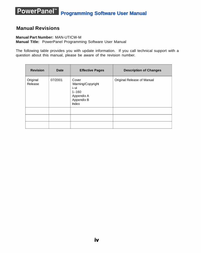
Manual Revisions
Manual Part Number: MAN-UTICW-MManual Title: PowerPanel Programming Software User Manual
The following table provides you with update information. If you call technical support with aquestion about this manual, please be aware of the revision number.
Revision Date Effective Pages Description of Changes
OriginalRelease
07/2001 CoverWarning/Copyrighti–vi1–160Appendix AAppendix BIndex
Original Release of Manual
vvvvv
Programming Software User ManualProgramming Software User ManualProgramming Software User ManualProgramming Software User ManualProgramming Software User Manual
EU Information
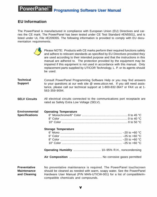
The PowerPanel is manufactured in compliance with European Union (EU) Directives and car-ries the CE mark. The PowerPanel has been tested under CE Test Standard #EN55011, and islisted under UL File #E209355. The following information is provided to comply with EU docu-mentation requirements.
Please NOTE: Products with CE marks perform their required functions safelyand adhere to relevant standards as specified by EU Directives provided theyare used according to their intended purpose and that the instructions in thismanual are adhered to. The protection provided by the equipment may beimpaired if this equipment is not used in accordance with this manual. Onlyreplacement parts supplied by UTICOR Technology, L. P. or its agents shouldbe used.
TechnicalSupport
Consult PowerPanel Programming Software Help or you may find answersto your questions at our web site @ www.uticor.net. If you still need assis-tance, please call our technical support at 1-800-832-3647 or FAX us at 1-563-359-9094.
EnvironmentalSpecifications
Operating Temperature6" Monochrome/6" Color ........................................................ 0 to 45 °C8" Color ................................................................................... 0 to 40 °C10" Color ................................................................................. 0 to 50 °C
Storage Temperature6" Mono ............................................................................ –20 to +60 °C6" Color ............................................................................ –25 to +60 °C8" Color ............................................................................ –20 to +60 °C10" Color .......................................................................... –25 to +60 °C
Operating Humidity .................................. 10–95% R.H., noncondensing
Air Composition ........................................ No corrosive gases permitted
No preventative maintenance is required. The PowerPanel touchscreenshould be cleaned as needed with warm, soapy water. See the PowerPanelHardware User Manual (P/N MAN-UTICW-001) for a list of compatible/in-compatible chemicals and compounds.
PreventativeMaintenanceand Cleaning
SELV Circuits All electrical circuits connected to the communications port receptacle arerated as Safety Extra Low Voltage (SELV).

vivivivivi
Programming Software User ManualProgramming Software User ManualProgramming Software User ManualProgramming Software User ManualProgramming Software User Manual
This page intentionally left blank.
Introduction
In this chapter....— Manual Organization— Introduction— What you need to get started— Need HELP?— Models— Features— PLCs Supported by PowerPanel— PLC Cable Part Numbers— Programming Cable Part Number— PowerPanel Programming Software Installation
11111
22222
Intr
od
uct
ion
PrPrPrPrProgramming Software User Manogramming Software User Manogramming Software User Manogramming Software User Manogramming Software User Manualualualualual
MAN-UTICW-M
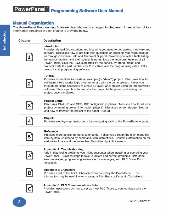
ManManManManManual Orual Orual Orual Orual OrganizationganizationganizationganizationganizationThe PowerPanel Programming Software User Manual is arranged in chapters. A description of keyinformation contained in each chapter is provided below.
IntroductionProvides Manual Organization, and lists what you need to get started, hardware andsoftware. Discusses how to get help with questions or problems you might encoun-ter through Onscreen Help and Technical Support. Provides you with a table listingthe various models, and their special features. Lists the important features of allPowerPanels. Lists the PLCs supported by the panels, by brand, model andprotocol. Lists the part numbers for PLC cables and the programming cable. Tellshow to install programming software.
2
1
3
TutorialProvides instructions to create an example (or “demo”) project. Discusses how toconfigure a PLC ladder logic program to use with the demo project. Takes youthrough the steps necessary to create a PowerPanel project using the programmingsoftware. Shows you how to transfer the project to the panel, and testing theproject once transferred.
4
Project SetupDiscusses ON-LINE and OFF-LINE configuration options. Tells you how to set up aproject by entering project information (Step 1). Discusses screen design (Step 2),and how to transfer the project to the panel (Step 3).
ObjectsProvides step-by-step instructions for configuring each of the PowerPanel objects.
5
AAppendix A TroubleshootingAids in diagnosing problems you might encounter when installing or operating yourPowerPanel. Provides steps to take to isolate and correct problems. Lists panelerror messages, programming software error messages, and PLC Driver Errormessages.
Chapter Description
ReferenceProvides more details on menu commands. Takes you through the main menu baritem by item, command by command, with instructions. Contains information on thevarious tool bars and the status bar. Describes right click menus
BAppendix B CharactersProvides a list of the ASCII Characters supported by the PowerPanel. Thisinformation may be useful when creating a Text Entry or Dynamic Text object.
CAppendix C PLC Communications SetupProvides instructions on how to set up most PLC Types to communicate with thePowerPanel.
33333
Intro
du
ction
Intro
du
ction
PrPrPrPrProgramming Software User Manogramming Software User Manogramming Software User Manogramming Software User Manogramming Software User Manualualualualual
MAN-UTICW-M
There are two manuals that you will need for installation — this manual,the PowerPanel Software User Manual, and the PowerPanel HardwareUser Manual (P/N MAN-UTICW-001) shipped with your PowerPanel.
Don’t worry — you won’t be bouncing back and forth between them— and we’ll always let you know exactly where the information is thatyou will need for the next step.
These manuals will take you through the steps necessary to get yourPowerPanel up and running in the shortest possible time. Althoughyour familiarity with programmable graphic operator interface deviceswill determine how quickly you move through the steps — it’s aseasy as 1 — 2 — 3.
Hardware
• PowerPanel (6" Monochrome, 6" Color, 8" Color, or 10"Color)
• 24 Volt DC Power Supply (FA-24PS recommended)• RS-232C Programming Cable (P/N CBL-UTICW-009)• RS-232C or RS-422A/485A PLC Interface Cable (see
page 8 for part numbers)• PC requirements:
— IBM or compatible PC (486 or better) with amouse and separate serial port
— VGA display with at least 800 x 600 resolution(1024 x 768 recommended)
— Standard Windows 95/98/NT4.0/2000®
Requirements— CD ROM Drive
Software
• PowerPanel Programming Software (P/N MAN-UTICW-CD)
What yWhat yWhat yWhat yWhat you need to gou need to gou need to gou need to gou need to get staret staret staret staret started....ted....ted....ted....ted....
IntrIntrIntrIntrIntroductionoductionoductionoductionoduction
Install the PowerPanel usingthe instructions in theHardware Manual.
Program the PowerPanelusing the instructions in thisSoftware Manual.
PowerPanel
PowerPanel
44444
Intr
od
uct
ion
PrPrPrPrProgramming Software User Manogramming Software User Manogramming Software User Manogramming Software User Manogramming Software User Manualualualualual
MAN-UTICW-M
Onscreen HELPOne of the most important features of the PowerPanel ProgrammingSoftware is the availability of context sensitive onscreen help. Toaccess the Help windows, simply press the F1 function key while onthe topic where you need help. For example, if you need help whileworking with screens, press the F1 function key while in that areaand a popup window will be displayed. You may also click on theHelp button located at the bottom of most dialog boxes to go to thehelp topic.
Fly-Over HELPWhen the mouse cursor comes to rest over any tool bar or objectbutton for a short while, a small window will appear containing a briefdescription of the function of that particular button. The window willdisappear as soon as the cursor has been moved off the button.
PLC HELPIf you need help with the PLC to PowerPanel Interface, consult thePowerPanel Programming Software Help. Each PLC Driver has aHelp Topic that lists the error messages and provides an explanationfor each. Also provided are PLC to PowerPanel wiring diagrams.
Technical SupportAlthough most questions can be answered with PowerPanel HELPor the manuals, you may find answers to your questions in the operatorinterface section of our web site @ www.uticor.net. If you still needassistance, please call our technical support at 1-800-832-3647 orFAX us at 1-563-359-9094.
Need HELP?Need HELP?Need HELP?Need HELP?Need HELP?
PLEASE NOTE: The Troubleshooting section (Appendix A) shouldbe able to help you with most problems you might encounter.
55555
Intro
du
ction
Intro
du
ction
PrPrPrPrProgramming Software User Manogramming Software User Manogramming Software User Manogramming Software User Manogramming Software User Manualualualualual
MAN-UTICW-M
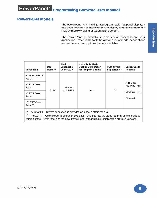
PPPPPooooowerPwerPwerPwerPwerPanel Modelsanel Modelsanel Modelsanel Modelsanel ModelsThe PowerPanel is an intelligent, programmable, flat panel display. Ithas been designed to interchange and display graphical data from aPLC by merely viewing or touching the screen.
The PowerPanel is available in a variety of models to suit yourapplication. Refer to the table below for a list of model descriptionsand some important options that are available.
DescriptionUserMemory
FieldExpandableUser RAM?
Nonvolatile FlashBackup Card Optionfor Program Backup?
PLC DriversSupported? *
Option CardsAvailable
6" MonochromePanel
512KYes —
to 1 MEG Yes All
A-B DataHighway Plus
ModBus Plus
Ethernet
6" STN ColorPanel
8" STN ColorPanel
10" TFT ColorPanel**
* A list of PLC Drivers supported is provided on page 7 of this manual.
** The 10" TFT Color Model is offered in two sizes. One that has the same footprint as the previousversion of the PowerPanel and the new PowerPanel standard size (smaller than previous version).
66666
Intr
od
uct
ion
PrPrPrPrProgramming Software User Manogramming Software User Manogramming Software User Manogramming Software User Manogramming Software User Manualualualualual
MAN-UTICW-M
The following is a list of important features for the PowerPanels:
• Pre-built panel components for easy screen design
• Special parts, such as: Toggle Switch, Slide Switch, Selector Switch,Throw Switch, Thumbwheel Object, Meters, PID Faceplates, and AnalogClock
• Flash based design for easy firmware upgrade
• Field expandable user RAM
• Nonvolatile flash card option for user program backup
• Color models support 128-color palette for components and bitmaps
• 16 shades of gray on monochrome models
• Multiple languages (up to 9)
• Two communications ports — Computer (RS-232C) and PLC (RS-232C,RS-422A, or RS-485A)
• Up to 999 screens
• Built-in clock and calendar or reference the PLC clock
• Built-in soft keypad for numeric and alphanumeric entry
• Password Protection for every touch object
• Passwords for up to 8 definable user groups
• 16 level undo and redo
• Import bitmaps
• Serial Printer support
• 40-character tag names allow you to use meaningful names for PLCmemory locations instead of cryptic PLC addresses
FeaturesFeaturesFeaturesFeaturesFeatures
77777
Intro
du
ction
Intro
du
ction
PrPrPrPrProgramming Software User Manogramming Software User Manogramming Software User Manogramming Software User Manogramming Software User Manualualualualual
MAN-UTICW-M
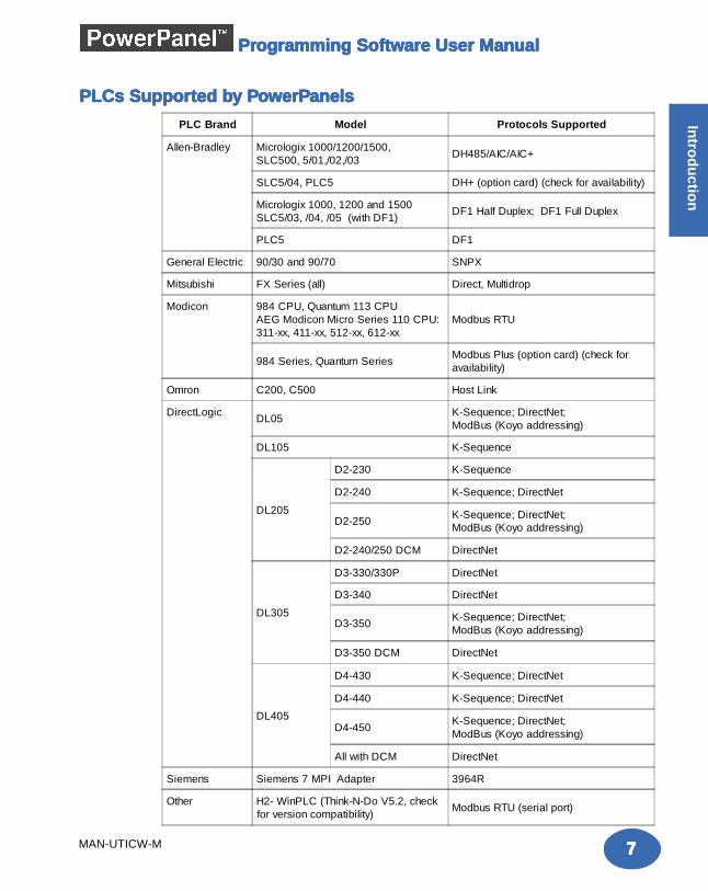
PLCs SupporPLCs SupporPLCs SupporPLCs SupporPLCs Supported bted bted bted bted by Py Py Py Py PooooowerPwerPwerPwerPwerPanelsanelsanelsanelsanels
PLC Brand Model Protocols Supported
Allen-Bradley Micrologix 1000/1200/1500,SLC500, 5/01,/02,/03
DH485/AIC/AIC+
SLC5/04, PLC5 DH+ (option card) (check for availability)
Micrologix 1000, 1200 and 1500SLC5/03, /04, /05 (with DF1)
DF1 Half Duplex; DF1 Full Duplex
PLC5 DF1
General Electric 90/30 and 90/70 SNPX
Mitsubishi FX Series (all) Direct, Multidrop
Modicon 984 CPU, Quantum 113 CPUAEG Modicon Micro Series 110 CPU:311-xx, 411-xx, 512-xx, 612-xx
Modbus RTU
984 Series, Quantum SeriesModbus Plus (option card) (check foravailability)
Omron C200, C500 Host Link
DirectLogicDL05
K-Sequence; DirectNet;ModBus (Koyo addressing)
DL105 K-Sequence
DL205
D2-230 K-Sequence
D2-240 K-Sequence; DirectNet
D2-250K-Sequence; DirectNet;ModBus (Koyo addressing)
D2-240/250 DCM DirectNet
DL305
D3-330/330P DirectNet
D3-340 DirectNet
D3-350K-Sequence; DirectNet;ModBus (Koyo addressing)
D3-350 DCM DirectNet
DL405
D4-430 K-Sequence; DirectNet
D4-440 K-Sequence; DirectNet
D4-450K-Sequence; DirectNet;ModBus (Koyo addressing)
All with DCM DirectNet
Siemens Siemens 7 MPI Adapter 3964R
Other H2- WinPLC (Think-N-Do V5.2, checkfor version compatibility)
Modbus RTU (serial port)
88888
Intr
od
uct
ion
PrPrPrPrProgramming Software User Manogramming Software User Manogramming Software User Manogramming Software User Manogramming Software User Manualualualualual
MAN-UTICW-M
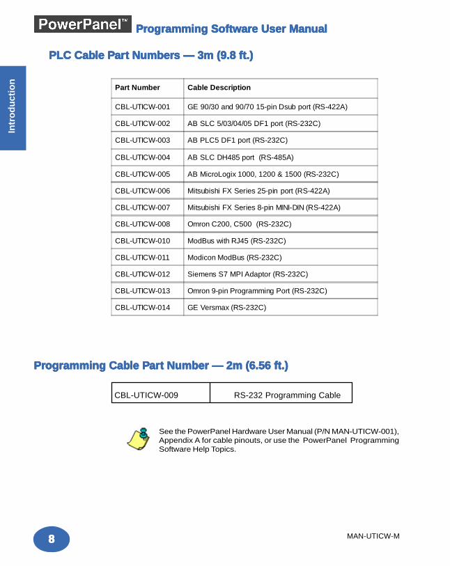
PLC CabPLC CabPLC CabPLC CabPLC Cable Ple Ple Ple Ple Pararararart Numbert Numbert Numbert Numbert Numbers — 3m (9.8 ft.)s — 3m (9.8 ft.)s — 3m (9.8 ft.)s — 3m (9.8 ft.)s — 3m (9.8 ft.)
PrPrPrPrProgramming Cabogramming Cabogramming Cabogramming Cabogramming Cable Ple Ple Ple Ple Pararararart Number — 2m (6.56 ft.)t Number — 2m (6.56 ft.)t Number — 2m (6.56 ft.)t Number — 2m (6.56 ft.)t Number — 2m (6.56 ft.)
CBL-UTICW-009 RS-232 Programming Cable
See the PowerPanel Hardware User Manual (P/N MAN-UTICW-001),Appendix A for cable pinouts, or use the PowerPanel ProgrammingSoftware Help Topics.
Part Number Cable Description
CBL-UTICW-001 GE 90/30 and 90/70 15-pin Dsub port (RS-422A)
CBL-UTICW-002 AB SLC 5/03/04/05 DF1 port (RS-232C)
CBL-UTICW-003 AB PLC5 DF1 port (RS-232C)
CBL-UTICW-004 AB SLC DH485 port (RS-485A)
CBL-UTICW-005 AB MicroLogix 1000, 1200 & 1500 (RS-232C)
CBL-UTICW-006 Mitsubishi FX Series 25-pin port (RS-422A)
CBL-UTICW-007 Mitsubishi FX Series 8-pin MINI-DIN (RS-422A)
CBL-UTICW-008 Omron C200, C500 (RS-232C)
CBL-UTICW-010 ModBus with RJ45 (RS-232C)
CBL-UTICW-011 Modicon ModBus (RS-232C)
CBL-UTICW-012 Siemens S7 MPI Adaptor (RS-232C)
CBL-UTICW-013 Omron 9-pin Programming Port (RS-232C)
CBL-UTICW-014 GE Versmax (RS-232C)
99999
Intro
du
ction
Intro
du
ction
PrPrPrPrProgramming Software User Manogramming Software User Manogramming Software User Manogramming Software User Manogramming Software User Manualualualualual
MAN-UTICW-M
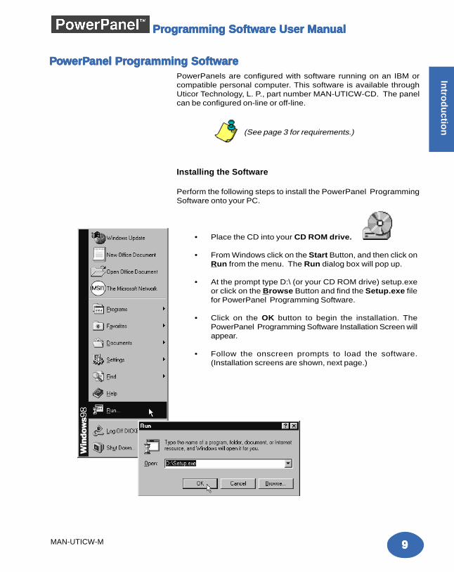
• Place the CD into your CD ROM drive.
• From Windows click on the Start Button, and then click onRun from the menu. The Run dialog box will pop up.
• At the prompt type D:\ (or your CD ROM drive) setup.exeor click on the Browse Button and find the Setup.exe filefor PowerPanel Programming Software.
• Click on the OK button to begin the installation. ThePowerPanel Programming Software Installation Screen willappear.
• Follow the onscreen prompts to load the software.(Installation screens are shown, next page.)
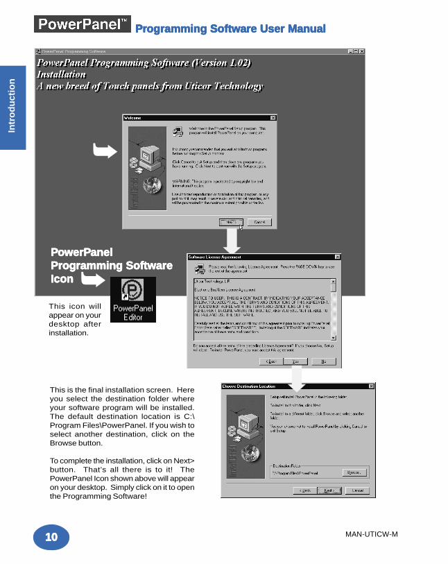
Installation ScreensInstallation ScreensInstallation ScreensInstallation ScreensInstallation Screens
PowerPanels are configured with software running on an IBM orcompatible personal computer. This software is available throughUticor Technology, L. P., part number MAN-UTICW-CD. The panelcan be configured on-line or off-line.
(See page 3 for requirements.)
Installing the Software
Perform the following steps to install the PowerPanel ProgrammingSoftware onto your PC.
PPPPPooooowerPwerPwerPwerPwerPanel Pranel Pranel Pranel Pranel Programming Softwareogramming Softwareogramming Softwareogramming Softwareogramming Software
1010101010
Intr
od
uct
ion
PrPrPrPrProgramming Software User Manogramming Software User Manogramming Software User Manogramming Software User Manogramming Software User Manualualualualual
MAN-UTICW-M
This is the final installation screen. Hereyou select the destination folder whereyour software program will be installed.The default destination location is C:\Program Files\PowerPanel. If you wish toselect another destination, click on theBrowse button.
To complete the installation, click on Next>button. That’s all there is to it! ThePowerPanel Icon shown above will appearon your desktop. Simply click on it to openthe Programming Software!
➥
PPPPPooooowerPwerPwerPwerPwerPanelanelanelanelanelProgramming SoftwareProgramming SoftwareProgramming SoftwareProgramming SoftwareProgramming SoftwareIconIconIconIconIcon ➥This icon willappear on yourdesktop afterinstallation.
➡
➡

TTTTTutorialutorialutorialutorialutorial
In this chapter....— Configure a PLC— Create a Project
22222
1212121212
Tuto
rial
MAN-UTICW-M
Programming Software User ManualProgramming Software User ManualProgramming Software User ManualProgramming Software User ManualProgramming Software User Manual
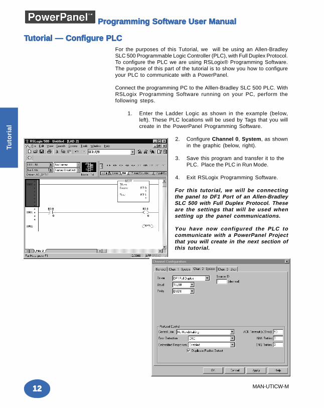
For the purposes of this Tutorial, we will be using an Allen-BradleySLC 500 Programmable Logic Controller (PLC), with Full Duplex Protocol.To configure the PLC we are using RSLogix® Programming Software.The purpose of this part of the tutorial is to show you how to configureyour PLC to communicate with a PowerPanel.
Connect the programming PC to the Alllen-Bradley SLC 500 PLC. WithRSLogix Programming Software running on your PC, perform thefollowing steps.
1. Enter the Ladder Logic as shown in the example (below,left). These PLC locations will be used by Tags that you willcreate in the PowerPanel Programming Software.
2. Configure Channel 0, System, as shownin the graphic (below, right).
3. Save this program and transfer it to thePLC. Place the PLC in Run Mode.
4. Exit RSLogix Programming Software.
For this tutorial, we will be connectingthe panel to DF1 Port of an Allen-BradleySLC 500 with Full Duplex Protocol. Theseare the settings that will be used whensetting up the panel communications.
You have now configured the PLC tocommunicate with a PowerPanel Projectthat you will create in the next section ofthis tutorial.
TTTTTutorial — Configure PLCutorial — Configure PLCutorial — Configure PLCutorial — Configure PLCutorial — Configure PLC
1313131313
Intro
du
ction
Tuto
rial
MAN-UTICW-M
Programming Software User ManualProgramming Software User ManualProgramming Software User ManualProgramming Software User ManualProgramming Software User Manual
The following is a project tutorial. You’ve already configured your PLCto work with the PowerPanel project you will be creating in this section.Now we’ll take you through the process of creating a new project,placing objects on the screen, and transferring a project to thePowerPanel. This should help familiarize you with the PowerPanelProgramming Software environment.
Let’s assume you have the programming software installed on your PC(if you don’t, go back to page 9 and install now). Connect the PowerPanelto your PC using the P/N CBL-UTICW-009 cable. Connect the PowerPanelto your PLC using the appropriate panel to PLC cable.
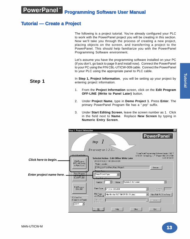
In Step 1, Project Information, you will be setting up your project byentering project information.
1. From the Project Information screen, click on the Edit ProgramOFF-LINE (Write to Panel Later) button.
2. Under Project Name, type in Demo Project 1. Press Enter. Theprimary PowerPanel Program file has a “.prp” suffix.
3. Under Start Editing Screen, leave the screen number as 1. Clickin the field next to Name. Replace New Screen by typing inNumeric Entry Screen.
TTTTTutorial — Create a Prutorial — Create a Prutorial — Create a Prutorial — Create a Prutorial — Create a Projectojectojectojectoject
Step 1
Click here to begin.
Enter project name here.
1414141414
Tuto
rial
MAN-UTICW-M
Programming Software User ManualProgramming Software User ManualProgramming Software User ManualProgramming Software User ManualProgramming Software User Manual
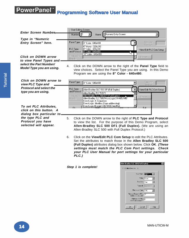
4. Click on the DOWN arrow to the right of the Panel Type field toview choices. Select the Panel Type you are using. In this DemoProgram we are using the 8" Color - 640x480.
5. Click on the DOWN arrow to the right of PLC Type and Protocolto view the list. For the purpose of this Demo Program, selectAllen-Bradley SLC 500 DF1 (Full Duplex). (We are using anAllen-Bradley SLC 500 with Full Duplex Protocol.)
6. Click on the View/Edit PLC Com Setup to edit the PLC Attributes.Set the attributes to match those in the Allen Bradley SLC 500(Full Duplex) attributes dialog box shown below. Click OK. (Thesesettings must match the PLC Com Port settings. Checkyour PLC User Manual for port settings for your particularPLC.)
Step 1 is complete!
Enter Screen Number.
Type in “NumericEntry Screen” here.
Click on DOWN arrowto view Panel Types andselect the Part Number/Model Type you are using.
Click on DOWN arrow toview PLC Type andProtocol and select thetype you are using.
To set PLC Attributes,click on this button. Adialog box particular tothe type PLC andProtocol you haveselected will appear.
1515151515
Intro
du
ction
Tuto
rial
MAN-UTICW-M
Programming Software User ManualProgramming Software User ManualProgramming Software User ManualProgramming Software User ManualProgramming Software User Manual
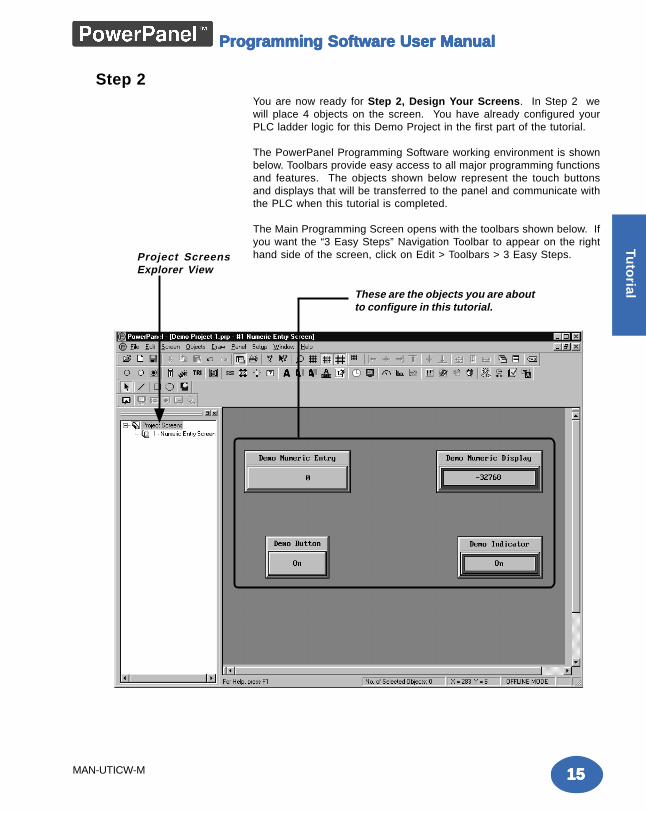
You are now ready for Step 2, Design Your Screens. In Step 2 wewill place 4 objects on the screen. You have already configured yourPLC ladder logic for this Demo Project in the first part of the tutorial.
The PowerPanel Programming Software working environment is shownbelow. Toolbars provide easy access to all major programming functionsand features. The objects shown below represent the touch buttonsand displays that will be transferred to the panel and communicate withthe PLC when this tutorial is completed.
The Main Programming Screen opens with the toolbars shown below. Ifyou want the “3 Easy Steps” Navigation Toolbar to appear on the righthand side of the screen, click on Edit > Toolbars > 3 Easy Steps.
Step 2
These are the objects you are aboutto configure in this tutorial.
Project ScreensExplorer View
1616161616
Tuto
rial
MAN-UTICW-M
Programming Software User ManualProgramming Software User ManualProgramming Software User ManualProgramming Software User ManualProgramming Software User Manual
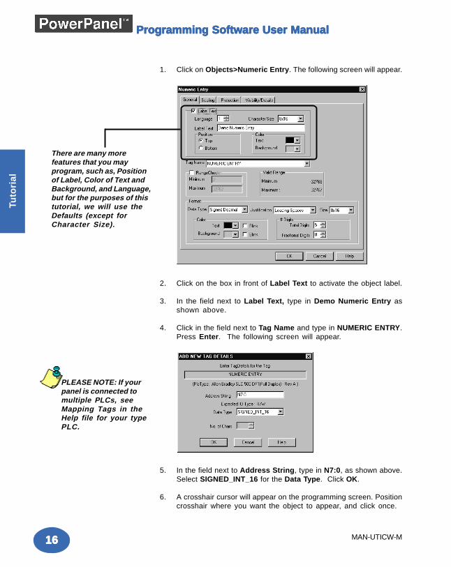
1. Click on Objects>Numeric Entry. The following screen will appear.
2. Click on the box in front of Label Text to activate the object label.
3. In the field next to Label Text, type in Demo Numeric Entry asshown above.
4. Click in the field next to Tag Name and type in NUMERIC ENTRY.Press Enter. The following screen will appear.
5. In the field next to Address String, type in N7:0, as shown above.Select SIGNED_INT_16 for the Data Type. Click OK.
6. A crosshair cursor will appear on the programming screen. Positioncrosshair where you want the object to appear, and click once.
There are many morefeatures that you mayprogram, such as, Positionof Label, Color of Text andBackground, and Language,but for the purposes of thistutorial, we will use theDefaults (except forCharacter Size).
PLEASE NOTE: If yourpanel is connected tomultiple PLCs, seeMapping Tags in theHelp file for your typePLC.
1717171717
Intro
du
ction
Tuto
rial
MAN-UTICW-M
Programming Software User ManualProgramming Software User ManualProgramming Software User ManualProgramming Software User ManualProgramming Software User Manual
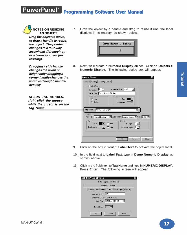
7. Grab the object by a handle and drag to resize it until the labeldisplays in its entirety, as shown below.
8. Next, we’ll create a Numeric Display object. Click on Objects >Numeric Display. The following dialog box will appear.
9. Click on the box in front of Label Text to activate the object label.
10. In the field next to Label Text, type in Demo Numeric Display asshown above.
11. Click in the field next to Tag Name and type in NUMERIC DISPLAY.Press Enter. The following screen will appear.
NOTES ON RESIZINGAN OBJECT:
Drag the object to move,or drag a handle to resize,the object. The pointerchanges to a four-wayarrowhead (for moving),or a two-way arrow (forresizing).
Dragging a side handlechanges the width orheight only; dragging acorner handle changes thewidth and height simulta-neously.
To EDIT TAG DETAILS,right click the mousewhile the cursor is on theTag Name.
1818181818
Tuto
rial
MAN-UTICW-M
Programming Software User ManualProgramming Software User ManualProgramming Software User ManualProgramming Software User ManualProgramming Software User Manual
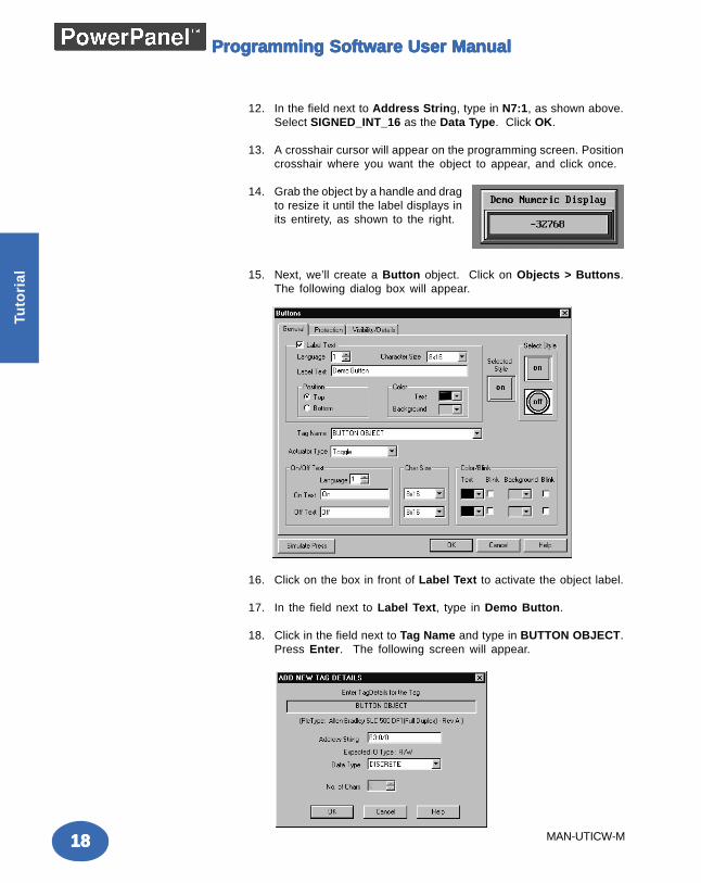
12. In the field next to Address String, type in N7:1, as shown above.Select SIGNED_INT_16 as the Data Type. Click OK.
13. A crosshair cursor will appear on the programming screen. Positioncrosshair where you want the object to appear, and click once.
14. Grab the object by a handle and dragto resize it until the label displays inits entirety, as shown to the right.
15. Next, we’ll create a Button object. Click on Objects > Buttons.The following dialog box will appear.
16. Click on the box in front of Label Text to activate the object label.
17. In the field next to Label Text, type in Demo Button.
18. Click in the field next to Tag Name and type in BUTTON OBJECT.Press Enter. The following screen will appear.
1919191919
Intro
du
ction
Tuto
rial
MAN-UTICW-M
Programming Software User ManualProgramming Software User ManualProgramming Software User ManualProgramming Software User ManualProgramming Software User Manual
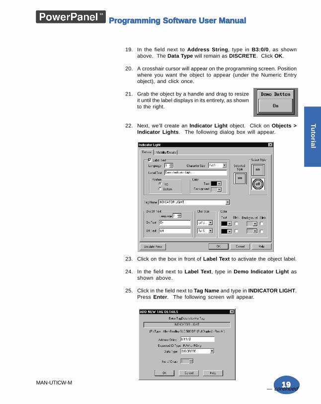
19. In the field next to Address String, type in B3:0/0, as shownabove. The Data Type will remain as DISCRETE. Click OK.
20. A crosshair cursor will appear on the programming screen. Positionwhere you want the object to appear (under the Numeric Entryobject), and click once.
21. Grab the object by a handle and drag to resizeit until the label displays in its entirety, as shownto the right.
22. Next, we’ll create an Indicator Light object. Click on Objects >Indicator Lights. The following dialog box will appear.
23. Click on the box in front of Label Text to activate the object label.
24. In the field next to Label Text, type in Demo Indicator Light asshown above.
25. Click in the field next to Tag Name and type in INDICATOR LIGHT.Press Enter. The following screen will appear.
— continued
2020202020
Tuto
rial
MAN-UTICW-M
Programming Software User ManualProgramming Software User ManualProgramming Software User ManualProgramming Software User ManualProgramming Software User Manual
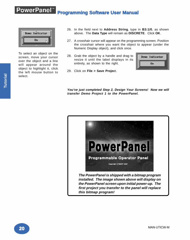
26. In the field next to Address String, type in B3:1/0, as shownabove. The Data Type will remain as DISCRETE. Click OK.
27. A crosshair cursor will appear on the programming screen. Positionthe crosshair where you want the object to appear (under theNumeric Display object), and click once.
28. Grab the object by a handle and drag toresize it until the label displays in itsentirety, as shown to the right.
29. Click on File > Save Project.
You’ve just completed Step 2, Design Your Screens! Now we willtransfer Demo Project 1 to the PowerPanel.
To select an object on thescreen, move your cursorover the object and a linewill appear around theobject to highlight it, clickthe left mouse button toselect.
The PowerPanel is shipped with a bitmap programinstalled. The image shown above will display onthe PowerPanel screen upon initial power-up. Thefirst project you transfer to the panel will replacethis bitmap program!
2121212121
Intro
du
ction
Tuto
rial
MAN-UTICW-M
Programming Software User ManualProgramming Software User ManualProgramming Software User ManualProgramming Software User ManualProgramming Software User Manual
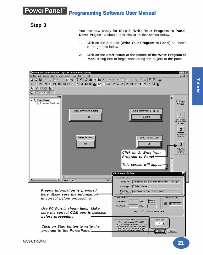
Click on 3, Write YourProgram to Panel
This screen will appear
Project Information is providedhere. Make sure the informationis correct before proceeding.
Use PC Port is shown here. Makesure the correct COM port is selectedbefore proceeding.
Click on Start button to write theprogram to the PowerPanel
You are now ready for Step 3, Write Your Program to Panel.Demo Project 1 should look similar to that shown below.
1. Click on the 3 button (Write Your Program to Panel) as shownin the graphic below.
2. Click on the Start button at the bottom of the Write Program toPanel dialog box to begin transferring the project to the panel.
Step 3
2222222222
Tuto
rial
MAN-UTICW-M
Programming Software User ManualProgramming Software User ManualProgramming Software User ManualProgramming Software User ManualProgramming Software User Manual
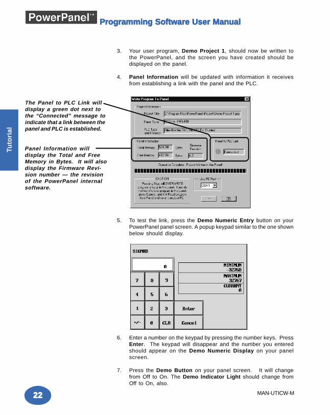
The Panel to PLC Link willdisplay a green dot next tothe “Connected” message toindicate that a link between thepanel and PLC is established.
Panel Information willdisplay the Total and FreeMemory in Bytes. It will alsodisplay the Firmware Revi-sion number — the revisionof the PowerPanel internalsoftware.
3. Your user program, Demo Project 1, should now be written tothe PowerPanel, and the screen you have created should bedisplayed on the panel.
4. Panel Information will be updated with information it receivesfrom establishing a link with the panel and the PLC.
5. To test the link, press the Demo Numeric Entry button on yourPowerPanel panel screen. A popup keypad similar to the one shownbelow should display.
6. Enter a number on the keypad by pressing the number keys. PressEnter. The keypad will disappear and the number you enteredshould appear on the Demo Numeric Display on your panelscreen.
7. Press the Demo Button on your panel screen. It will changefrom Off to On. The Demo Indicator Light should change fromOff to On, also.
2323232323
Intro
du
ction
Tuto
rial
MAN-UTICW-M
Programming Software User ManualProgramming Software User ManualProgramming Software User ManualProgramming Software User ManualProgramming Software User Manual
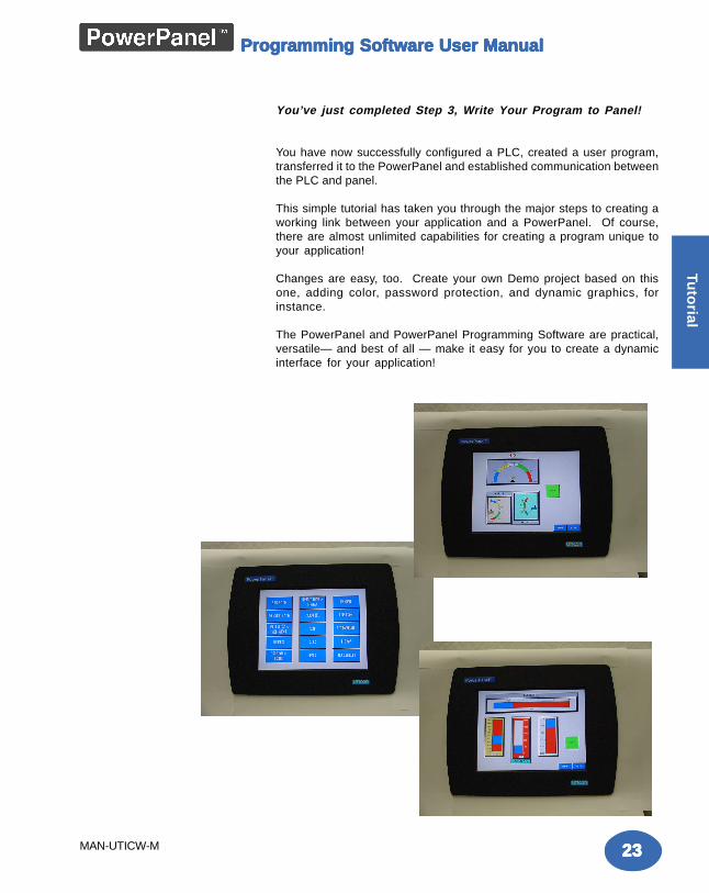
You’ve just completed Step 3, Write Your Program to Panel!
You have now successfully configured a PLC, created a user program,transferred it to the PowerPanel and established communication betweenthe PLC and panel.
This simple tutorial has taken you through the major steps to creating aworking link between your application and a PowerPanel. Of course,there are almost unlimited capabilities for creating a program unique toyour application!
Changes are easy, too. Create your own Demo project based on thisone, adding color, password protection, and dynamic graphics, forinstance.
The PowerPanel and PowerPanel Programming Software are practical,versatile— and best of all — make it easy for you to create a dynamicinterface for your application!
2424242424
Tuto
rial
MAN-UTICW-M
Programming Software User ManualProgramming Software User ManualProgramming Software User ManualProgramming Software User ManualProgramming Software User Manual
This page intentionally left blank
PrPrPrPrProject Setupoject Setupoject Setupoject Setupoject Setup
In this chapter....— ON-LINE and OFF-LINE Projects— Project Setup— Entering Project Information (Step 1)— Designing Screens (Step 2)— Write Your Program to Panel (Step 3)
33333

2626262626
Pro
ject
Set
up
Programming Software User ManualProgramming Software User ManualProgramming Software User ManualProgramming Software User ManualProgramming Software User Manual
Decide now if you want to work ON-LINE orDecide now if you want to work ON-LINE orDecide now if you want to work ON-LINE orDecide now if you want to work ON-LINE orDecide now if you want to work ON-LINE orOFF-LINE....OFF-LINE....OFF-LINE....OFF-LINE....OFF-LINE....
You may create a new project on your PC by working off-line (notconnected to a PowerPanel.) You may also work on-line with thePowerPanel unit to make changes to an existing project.
Working off-line you may use PowerPanel Programming Software todesign your PowerPanel in your office or home — or even while traveling.Your project becomes as portable as your laptop, and your PowerPanelis not “down” while you are redesigning or making modifications asyour unique application needs grow or change. Your project may betransferred to the PowerPanel at any time. The transfer function allowsyou to select a project to be transferred to the Panel.
Working on-line is unique to PowerPanels. Working in this mode allowsyou to make quick fixes or design changes to an installed PowerPaneland its existing program. You can eliminate a step or two and save timeby transferring these changes directly to the current opened screen.Now you can see the effect of the screen design changes you havemade immediately, eliminating the traditional “edit-compile-download”cycle. Simply click on Save Screen or Save Project and all changeson the current opened screen will immediately be saved in thePowerPanel.
Most users will employ both methods at one time or another, but whetherworking off-line or on-line — you will certainly appreciate the versatilityand accessibility provided by the PowerPanel and its easy-to-useprogramming software.
The next section takes you through the steps necessary to create aproject and transfer it to the PowerPanel. PowerPanel ProgrammingSoftware simplifies this process by using Windows-based architectureand lots of popup and pulldown selections that guide you through theprocess to quickly build your screens and get you up and running in notime at all!
Project SetupProject SetupProject SetupProject SetupProject Setup
WWWWWe recommend ye recommend ye recommend ye recommend ye recommend you go throu go throu go throu go throu go through the tutorial beginning on paough the tutorial beginning on paough the tutorial beginning on paough the tutorial beginning on paough the tutorial beginning on paggggge 11e 11e 11e 11e 11of this manof this manof this manof this manof this manual.ual.ual.ual.ual. YYYYYou’ou’ou’ou’ou’ll see holl see holl see holl see holl see how easy it is to gw easy it is to gw easy it is to gw easy it is to gw easy it is to get up and running!et up and running!et up and running!et up and running!et up and running!
2727272727
Pro
ject Setu
p
Programming Software User ManualProgramming Software User ManualProgramming Software User ManualProgramming Software User ManualProgramming Software User Manual
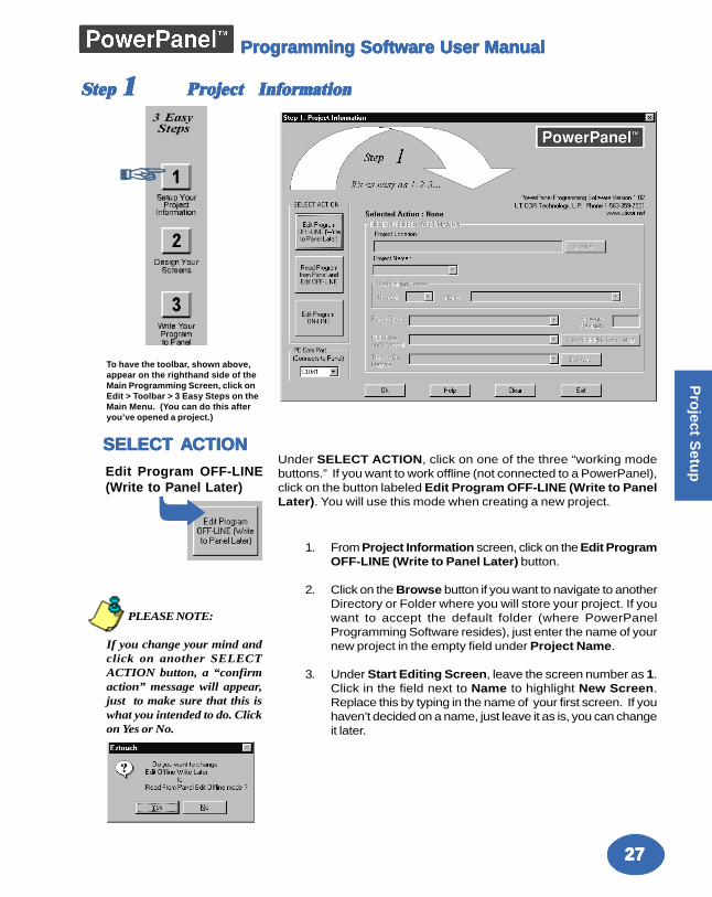
Step Step Step Step Step 11111 Project InformationProject InformationProject InformationProject InformationProject Information
Under SELECT ACTION, click on one of the three “working modebuttons.” If you want to work offline (not connected to a PowerPanel),click on the button labeled Edit Program OFF-LINE (Write to PanelLater). You will use this mode when creating a new project.
1. From Project Information screen, click on the Edit ProgramOFF-LINE (Write to Panel Later) button.
2. Click on the Browse button if you want to navigate to anotherDirectory or Folder where you will store your project. If youwant to accept the default folder (where PowerPanelProgramming Software resides), just enter the name of yournew project in the empty field under Project Name.
3. Under Start Editing Screen, leave the screen number as 1.Click in the field next to Name to highlight New Screen.Replace this by typing in the name of your first screen. If youhaven’t decided on a name, just leave it as is, you can changeit later.
SELECT ASELECT ASELECT ASELECT ASELECT ACTIONCTIONCTIONCTIONCTIONEdit Program OFF-LINE(Write to Panel Later)
PLEASE NOTE:
If you change your mind andclick on another SELECTACTION button, a “confirmaction” message will appear,just to make sure that this iswhat you intended to do. Clickon Yes or No.
➥
To have the toolbar, shown above,appear on the righthand side of theMain Programming Screen, click onEdit > Toolbar > 3 Easy Steps on theMain Menu. (You can do this afteryou’ve opened a project.)
2828282828
Pro
ject
Set
up
Programming Software User ManualProgramming Software User ManualProgramming Software User ManualProgramming Software User ManualProgramming Software User Manual
Read Program fromPanel and Edit OFF-LINE
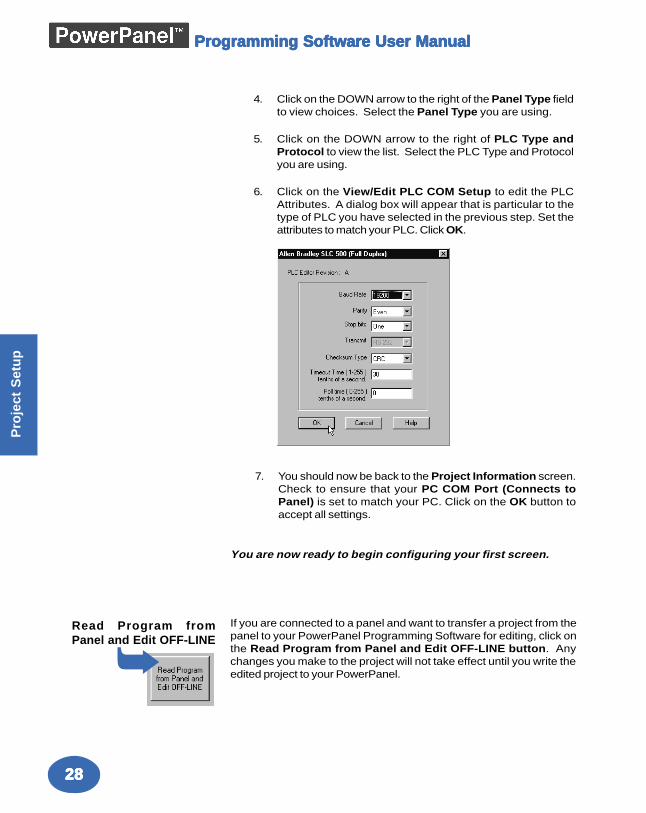
4. Click on the DOWN arrow to the right of the Panel Type fieldto view choices. Select the Panel Type you are using.
5. Click on the DOWN arrow to the right of PLC Type andProtocol to view the list. Select the PLC Type and Protocolyou are using.
6. Click on the View/Edit PLC COM Setup to edit the PLCAttributes. A dialog box will appear that is particular to thetype of PLC you have selected in the previous step. Set theattributes to match your PLC. Click OK.
7. You should now be back to the Project Information screen.Check to ensure that your PC COM Port (Connects toPanel) is set to match your PC. Click on the OK button toaccept all settings.
You are now ready to begin configuring your first screen.
If you are connected to a panel and want to transfer a project from thepanel to your PowerPanel Programming Software for editing, click onthe Read Program from Panel and Edit OFF-LINE button. Anychanges you make to the project will not take effect until you write theedited project to your PowerPanel.➥
2929292929
Pro
ject Setu
p
Programming Software User ManualProgramming Software User ManualProgramming Software User ManualProgramming Software User ManualProgramming Software User Manual
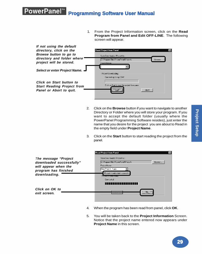
1. From the Project Information screen, click on the ReadProgram from Panel and Edit OFF-LINE. The followingscreen will appear.
2. Click on the Browse button if you want to navigate to anotherDirectory or Folder where you will store your program. If youwant to accept the default folder (usually where thePowerPanel Programming Software resides), just enter thename that you desire for the project you are about to Read inthe empty field under Project Name.
3. Click on the Start button to start reading the project from thepanel.
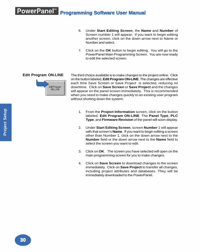
4. When the program has been read from panel, click OK.
5. You will be taken back to the Project Information Screen.Notice that the project name entered now appears underProject Name in this screen.
If not using the defaultdirectory, click on theBrowse button to go todirectory and folder whereproject will be stored.
Select or enter Project Name.
Click on Start button toStart Reading Project fromPanel or Abort to quit.
The message “Projectdownloaded successfully”will appear when theprogram has finisheddownloading.
Click on OK toexit screen.
3030303030
Pro
ject
Set
up
Programming Software User ManualProgramming Software User ManualProgramming Software User ManualProgramming Software User ManualProgramming Software User Manual
6. Under Start Editing Screen, the Name and Number ofScreen number 1 will appear. If you want to begin editinganother screen, click on the down arrow next to Name orNumber and select.
7. Click on the OK button to begin editing. You will go to thePowerPanel Main Programming Screen. You are now readyto edit the selected screen.
The third choice available is to make changes to the project online. Clickon the button labeled, Edit Program ON-LINE. The changes are effectiveeach time Save Screen or Save Project is selected, reducing nodowntime. Click on Save Screen or Save Project and the changeswill appear on the panel screen immediately. This is recommendedwhen you need to make changes quickly to an existing user programwithout shutting down the system.
1. From the Project Information screen, click on the buttonlabeled, Edit Program ON-LINE. The Panel Type, PLCType, and Firmware Revision of the panel will soon display.
2. Under Start Editing Screen, screen Number 1 will appearwith that screen’s Name. If you want to begin editing a screenother than Number 1, click on the down arrow next to theNumber field or the down arrow next to the Name field toselect the screen you want to edit.
3. Click on OK. The screen you have selected will open on themain programming screen for you to make changes.
4. Click on Save Screen to download changes to the screenimmediately. Click on Save Project to transfer all changes,including project attributes and databases. They will beimmediately downloaded to the PowerPanel.
Edit Program ON-LINE
➥
3131313131
Pro
ject Setu
p
Programming Software User ManualProgramming Software User ManualProgramming Software User ManualProgramming Software User ManualProgramming Software User Manual
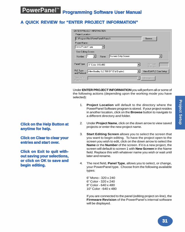
A QA QA QA QA QUICK REVIEW fUICK REVIEW fUICK REVIEW fUICK REVIEW fUICK REVIEW for or or or or “ENTER PR“ENTER PR“ENTER PR“ENTER PR“ENTER PROJECT INFORMAOJECT INFORMAOJECT INFORMAOJECT INFORMAOJECT INFORMATION”TION”TION”TION”TION”
Under ENTER PROJECT INFORMATION you will perform all or some ofthe following actions (depending upon the working mode you haveselected):
1. Project Location will default to the directory where thePowerPanel Software program is stored. If your project residesin another location, click on the Browse button to navigate toa different directory and folder.
2. Under Project Name, click on the down arrow to view savedprojects or enter the new project name.
3. Start Editing Screen allows you to select the screen thatyou want to begin editing. To have the project open to thescreen you wish to edit, click on the down arrow to select theName or the Number of the screen. If it is a new project, thescreen will default to screen 1 with New Screen in the Namefield. Replace this with whatever name you wish or wait untillater and rename.
4. The next field, Panel Type, allows you to select, or change,your PowerPanel type. Choose from the following availabletypes:
6” Mono - 320 x 2406” Color - 320 x 2408” Color - 640 x 48010” Color - 640 x 480
If you are connected to the panel (editing project on-line), theFirmware Revision of the PowerPanel’s internal softwarewill be displayed.
Click on the Help Button atClick on the Help Button atClick on the Help Button atClick on the Help Button atClick on the Help Button atanytime for help.anytime for help.anytime for help.anytime for help.anytime for help.
Click on Clear to clear yourClick on Clear to clear yourClick on Clear to clear yourClick on Clear to clear yourClick on Clear to clear yourentries and starentries and starentries and starentries and starentries and start ot ot ot ot oververververver.....
Click on Exit to quit with-Click on Exit to quit with-Click on Exit to quit with-Click on Exit to quit with-Click on Exit to quit with-out saving your selections,out saving your selections,out saving your selections,out saving your selections,out saving your selections,or click on OK to save andor click on OK to save andor click on OK to save andor click on OK to save andor click on OK to save andbegin editing.begin editing.begin editing.begin editing.begin editing.
3232323232
Pro
ject
Set
up
Programming Software User ManualProgramming Software User ManualProgramming Software User ManualProgramming Software User ManualProgramming Software User Manual
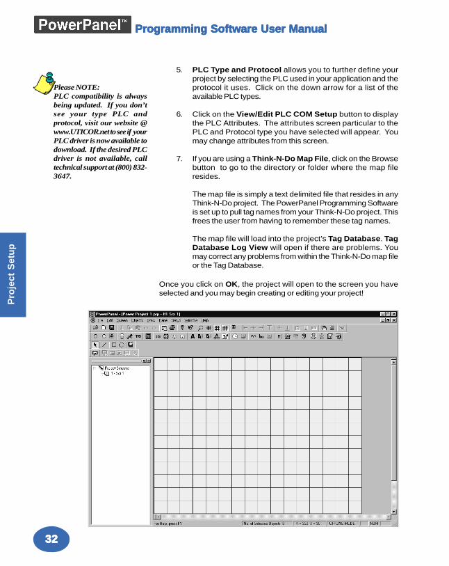
5. PLC Type and Protocol allows you to further define yourproject by selecting the PLC used in your application and theprotocol it uses. Click on the down arrow for a list of theavailable PLC types.
6. Click on the View/Edit PLC COM Setup button to displaythe PLC Attributes. The attributes screen particular to thePLC and Protocol type you have selected will appear. Youmay change attributes from this screen.
7. If you are using a Think-N-Do Map File, click on the Browsebutton to go to the directory or folder where the map fileresides.
The map file is simply a text delimited file that resides in anyThink-N-Do project. The PowerPanel Programming Softwareis set up to pull tag names from your Think-N-Do project. Thisfrees the user from having to remember these tag names.
The map file will load into the project’s Tag Database. TagDatabase Log View will open if there are problems. Youmay correct any problems from within the Think-N-Do map fileor the Tag Database.
Once you click on OK, the project will open to the screen you haveselected and you may begin creating or editing your project!
Please NOTE:PLC compatibility is alwaysbeing updated. If you don’tsee your type PLC andprotocol, visit our website @www.UTICOR.net to see if yourPLC driver is now available todownload. If the desired PLCdriver is not available, calltechnical support at (800) 832-3647.
3333333333
Pro
ject Setu
p
Programming Software User ManualProgramming Software User ManualProgramming Software User ManualProgramming Software User ManualProgramming Software User Manual
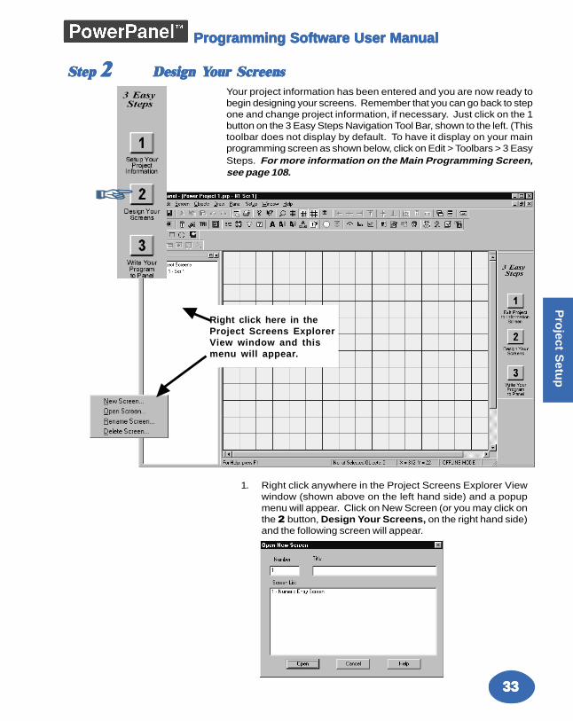
Step Step Step Step Step 22222 Design YDesign YDesign YDesign YDesign Your Scrour Scrour Scrour Scrour ScreenseenseenseenseensYour project information has been entered and you are now ready tobegin designing your screens. Remember that you can go back to stepone and change project information, if necessary. Just click on the 1button on the 3 Easy Steps Navigation Tool Bar, shown to the left. (Thistoolbar does not display by default. To have it display on your mainprogramming screen as shown below, click on Edit > Toolbars > 3 EasySteps. For more information on the Main Programming Screen,see page 108.
1. Right click anywhere in the Project Screens Explorer Viewwindow (shown above on the left hand side) and a popupmenu will appear. Click on New Screen (or you may click onthe 2 button, Design Your Screens, on the right hand side)and the following screen will appear.
Right click here in theProject Screens ExplorerView window and thismenu will appear.
3434343434
Pro
ject
Set
up
Programming Software User ManualProgramming Software User ManualProgramming Software User ManualProgramming Software User ManualProgramming Software User Manual
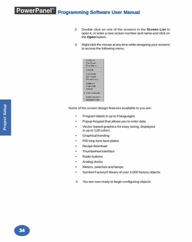
Some of the screen design features available to you are:
• Program labels in up to 9 languages
• Popup Keypad that allows you to enter data
• Vector-based graphics for easy sizing, displayedin up to 128 colors
• Graphical trending
• PID loop tune face plates
• Recipe download
• Thumbwheel interface
• Radio buttons
• Analog clocks
• Meters, switches and lamps
• Symbol Factory® library of over 3,000 factory objects
4. You are now ready to begin configuring objects.
2. Double click on one of the screens in the Screen List toopen it, or enter a new screen number and name and click onthe Open button.
3. Right click the mouse at any time while designing your screensto access the following menu.
3535353535
Pro
ject Setu
p
Programming Software User ManualProgramming Software User ManualProgramming Software User ManualProgramming Software User ManualProgramming Software User Manual
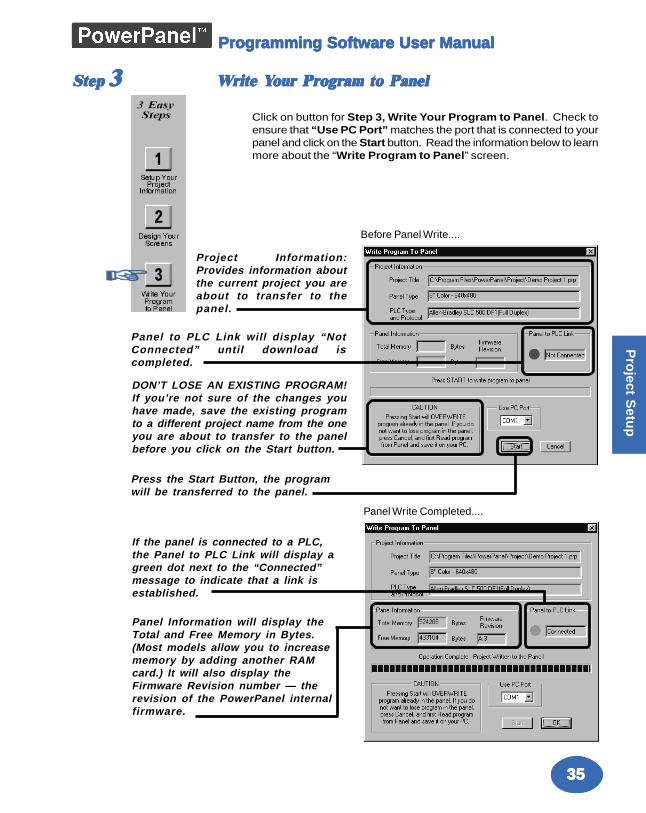
Step Step Step Step Step 33333 WWWWWrite Yrite Yrite Yrite Yrite Your Prour Prour Prour Prour Program to Panelogram to Panelogram to Panelogram to Panelogram to Panel
Click on button for Step 3, Write Your Program to Panel. Check toensure that “Use PC Port” matches the port that is connected to yourpanel and click on the Start button. Read the information below to learnmore about the “Write Program to Panel” screen.
Project Information:Provides information aboutthe current project you areabout to transfer to thepanel.
DON’T LOSE AN EXISTING PROGRAM!If you’re not sure of the changes youhave made, save the existing programto a different project name from the oneyou are about to transfer to the panelbefore you click on the Start button.
If the panel is connected to a PLC,the Panel to PLC Link will display agreen dot next to the “Connected”message to indicate that a link isestablished.
Panel Information will display theTotal and Free Memory in Bytes.(Most models allow you to increasememory by adding another RAMcard.) It will also display theFirmware Revision number — therevision of the PowerPanel internalfirmware.
Press the Start Button, the programwill be transferred to the panel.
Panel to PLC Link will display “NotConnected” until download iscompleted.
Before Panel Write....
Panel Write Completed....
3636363636
Pro
ject
Set
up
Programming Software User ManualProgramming Software User ManualProgramming Software User ManualProgramming Software User ManualProgramming Software User Manual
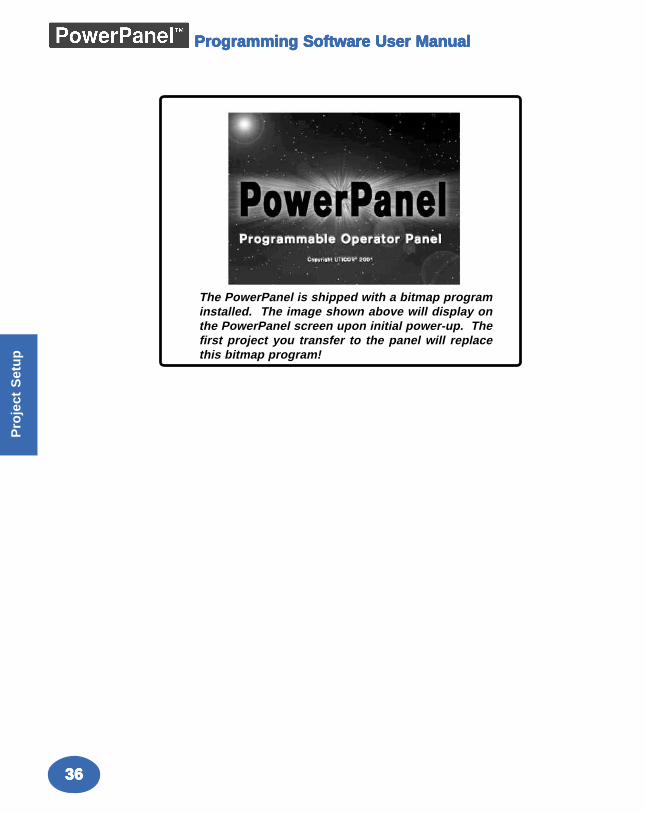
The PowerPanel is shipped with a bitmap programinstalled. The image shown above will display onthe PowerPanel screen upon initial power-up. Thefirst project you transfer to the panel will replacethis bitmap program!
ObjectsObjectsObjectsObjectsObjects
In this chapter you will be shown how to create....— Buttons— Indicator Buttons— Radio Buttons— Switches— Step Switch— Tri-state Switch— Recipe— Thumbwheel— Indicator Lights— Numeric Display— Text— Clock— Meter— Bar Graphs— Line Graph— PID Face Plate— Dynamic Bitmap— Change Screen— Alarm History— System Objects
44444
3838383838
Ob
jec
ts
MAN-UTICW-M
Programming Software User ManualProgramming Software User ManualProgramming Software User ManualProgramming Software User ManualProgramming Software User Manual
Objects MenuObjects MenuObjects MenuObjects MenuObjects Menu
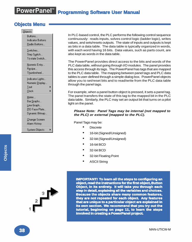
In PLC-based control, the PLC performs the following control sequencecontinuously: reads inputs, solves control logic (ladder logic), writesvalues, and sets/resets outputs. The state of inputs and outputs is keptas bits in a data table. The data table is typically organized in words,with each word having 16 bits. Data values, such as parts count, arealso kept as words in the data table.
The PowerPanel provides direct access to the bits and words of thePLC data table, without going through I/O modules. The panel providesthis access through its tags. The PowerPanel has tags that are mappedto the PLC data table. The mapping between panel tags and PLC datatables is user-defined through a simple dialog box. PowerPanel objectsallow you to set/reset bits and to read/write from the PLC data tablethrough the panel tags.
For example, when a panel button object is pressed, it sets a panel tag.The panel transfers the state of this tag to the mapped bit in the PLCdata table. Similarly, the PLC may set an output bit that turns on a pilotlight on the panel.
Please Note: Panel Tags may be internal (not mapped tothe PLC) or external (mapped to the PLC).
Panel Tags may be:
• Discrete
• 16-bit (Signed/Unsigned)
• 32-bit (Signed/Unsigned)
• 16-bit BCD
• 32-bit BCD
• 32-bit Floating Point
• ASCII String
IMPORIMPORIMPORIMPORIMPORTTTTTANT! ANT! ANT! ANT! ANT! TTTTTo learn all the steps to configuring ano learn all the steps to configuring ano learn all the steps to configuring ano learn all the steps to configuring ano learn all the steps to configuring anobject,object,object,object,object, read the instructions f read the instructions f read the instructions f read the instructions f read the instructions for the firor the firor the firor the firor the first object,st object,st object,st object,st object, Button Button Button Button ButtonObject,Object,Object,Object,Object, in its entirety in its entirety in its entirety in its entirety in its entirety..... It will take y It will take y It will take y It will take y It will take you throu throu throu throu through eacough eacough eacough eacough eachhhhhstep in detail,step in detail,step in detail,step in detail,step in detail, e e e e explaining all the vxplaining all the vxplaining all the vxplaining all the vxplaining all the variabariabariabariabariables and cles and cles and cles and cles and choices.hoices.hoices.hoices.hoices.Because the objects share manBecause the objects share manBecause the objects share manBecause the objects share manBecause the objects share many common fy common fy common fy common fy common features,eatures,eatures,eatures,eatures,thethethethethey are not repeated fy are not repeated fy are not repeated fy are not repeated fy are not repeated for eacor eacor eacor eacor each object.h object.h object.h object.h object. An An An An Any fy fy fy fy featureseatureseatureseatureseaturesthat are unique to a parthat are unique to a parthat are unique to a parthat are unique to a parthat are unique to a particular object are eticular object are eticular object are eticular object are eticular object are explained inxplained inxplained inxplained inxplained inits oits oits oits oits own section.wn section.wn section.wn section.wn section. WWWWWe recommend that ye recommend that ye recommend that ye recommend that ye recommend that you trou trou trou trou try out they out they out they out they out thetutorial,tutorial,tutorial,tutorial,tutorial, beginning on pa beginning on pa beginning on pa beginning on pa beginning on paggggge 11,e 11,e 11,e 11,e 11, to learn the steps to learn the steps to learn the steps to learn the steps to learn the stepsinvolved in creating a PowerPanel project.involved in creating a PowerPanel project.involved in creating a PowerPanel project.involved in creating a PowerPanel project.involved in creating a PowerPanel project.
3939393939
Ob
jec
ts
MAN-UTICW-M
Programming Software User ManualProgramming Software User ManualProgramming Software User ManualProgramming Software User ManualProgramming Software User Manual
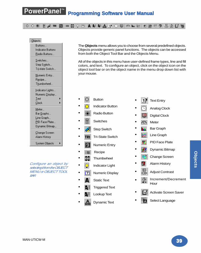
The Objects menu allows you to choose from several predefined objects.Objects provide generic panel functions. The objects can be accessedfrom both the Object Tool Bar and the Objects Menu.
All of the objects in this menu have user-defined frame types, line and fillcolors, and text. To configure an object, click on the object icon on theobject tool bar or on the object name in the menu drop down list withyour mouse.
• Button
• Indicator Button
• Radio Button
• Switches
• Step Switch
• Tri-State Switch
• Numeric Entry
• Recipe
• Thumbwheel
• Indicator Light
• Numeric Display
• Static Text
• Triggered Text
• Lookup Text
• Dynamic Text
• Text Entry
• Analog Clock
• Digital Clock
• Meter
• Bar Graph
• Line Graph
• PID Face Plate
• Dynamic Bitmap
• Change Screen
• Alarm History
• Adjust Contrast
• Increment/DecrementHour
• Activate Screen Saver
• Select Language
Configure an object byselecting it from the OBJECTMENU or OBJECT TOOLBAR
4040404040
Ob
jec
ts
MAN-UTICW-M
Programming Software User ManualProgramming Software User ManualProgramming Software User ManualProgramming Software User ManualProgramming Software User Manual
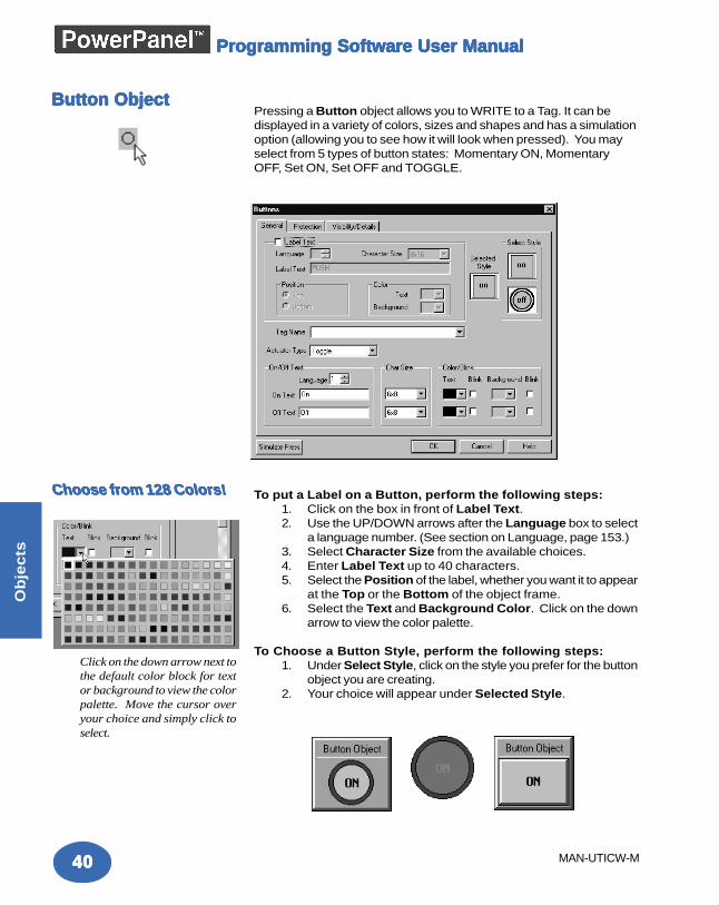
Button ObjectButton ObjectButton ObjectButton ObjectButton ObjectPressing a Button object allows you to WRITE to a Tag. It can bedisplayed in a variety of colors, sizes and shapes and has a simulationoption (allowing you to see how it will look when pressed). You mayselect from 5 types of button states: Momentary ON, MomentaryOFF, Set ON, Set OFF and TOGGLE.
To put a Label on a Button, perform the following steps:1. Click on the box in front of Label Text.2. Use the UP/DOWN arrows after the Language box to select
a language number. (See section on Language, page 153.)3. Select Character Size from the available choices.4. Enter Label Text up to 40 characters.5. Select the Position of the label, whether you want it to appear
at the Top or the Bottom of the object frame.6. Select the Text and Background Color. Click on the down
arrow to view the color palette.
To Choose a Button Style, perform the following steps:1. Under Select Style, click on the style you prefer for the button
object you are creating.2. Your choice will appear under Selected Style.
Click on the down arrow next tothe default color block for textor background to view the colorpalette. Move the cursor overyour choice and simply click toselect.
Choose from 128 Colors!Choose from 128 Colors!Choose from 128 Colors!Choose from 128 Colors!Choose from 128 Colors!
4141414141
Ob
jec
ts
MAN-UTICW-M
Programming Software User ManualProgramming Software User ManualProgramming Software User ManualProgramming Software User ManualProgramming Software User Manual
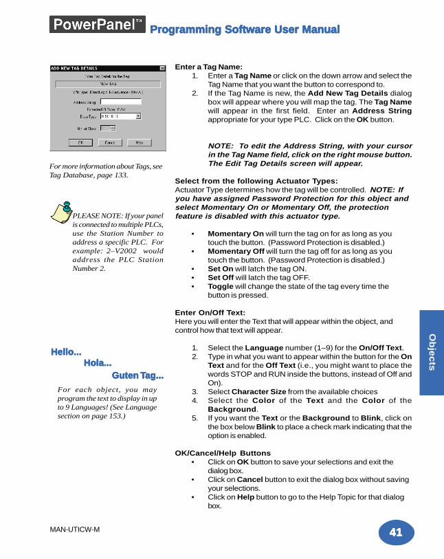
Enter a Tag Name:1. Enter a Tag Name or click on the down arrow and select the
Tag Name that you want the button to correspond to.2. If the Tag Name is new, the Add New Tag Details dialog
box will appear where you will map the tag. The Tag Namewill appear in the first field. Enter an Address Stringappropriate for your type PLC. Click on the OK button.
NOTE: To edit the Address String, with your cursorin the Tag Name field, click on the right mouse button.The Edit Tag Details screen will appear.
Select from the following Actuator Types:Actuator Type determines how the tag will be controlled. NOTE: Ifyou have assigned Password Protection for this object andselect Momentary On or Momentary Off, the protectionfeature is disabled with this actuator type.
• Momentary On will turn the tag on for as long as youtouch the button. (Password Protection is disabled.)
• Momentary Off will turn the tag off for as long as youtouch the button. (Password Protection is disabled.)
• Set On will latch the tag ON.• Set Off will latch the tag OFF.• Toggle will change the state of the tag every time the
button is pressed.
Enter On/Off Text:Here you will enter the Text that will appear within the object, andcontrol how that text will appear.
1. Select the Language number (1–9) for the On/Off Text.2. Type in what you want to appear within the button for the On
Text and for the Off Text (i.e., you might want to place thewords STOP and RUN inside the buttons, instead of Off andOn).
3. Select Character Size from the available choices4. Select the Color of the Text and the Color of the
Background.5. If you want the Text or the Background to Blink, click on
the box below Blink to place a check mark indicating that theoption is enabled.
OK/Cancel/Help Buttons• Click on OK button to save your selections and exit the
dialog box.• Click on Cancel button to exit the dialog box without saving
your selections.• Click on Help button to go to the Help Topic for that dialog
box.
For more information about Tags, seeTag Database, page 133.
For each object, you mayprogram the text to display in upto 9 Languages! (See Languagesection on page 153.)
Hello...Hello...Hello...Hello...Hello...Hola...Hola...Hola...Hola...Hola... Guten Guten Guten Guten Guten TTTTTaaaaag...g...g...g...g...
PLEASE NOTE: If your panelis connected to multiple PLCs,use the Station Number toaddress a specific PLC. Forexample: 2–V2002 wouldaddress the PLC StationNumber 2.
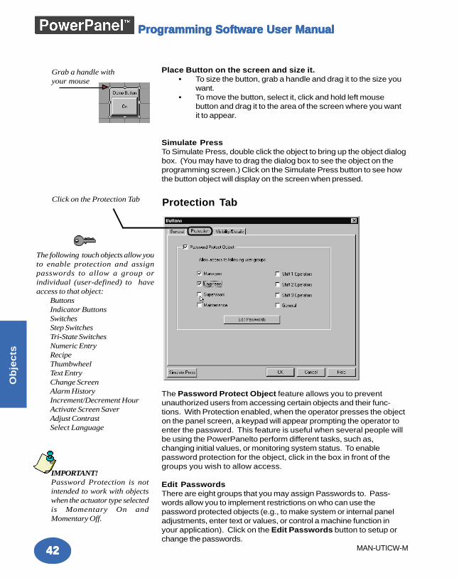
4242424242
Ob
jec
ts
MAN-UTICW-M
Programming Software User ManualProgramming Software User ManualProgramming Software User ManualProgramming Software User ManualProgramming Software User Manual
The Password Protect Object feature allows you to preventunauthorized users from accessing certain objects and their func-tions. With Protection enabled, when the operator presses the objecton the panel screen, a keypad will appear prompting the operator toenter the password. This feature is useful when several people willbe using the PowerPanelto perform different tasks, such as,changing initial values, or monitoring system status. To enablepassword protection for the object, click in the box in front of thegroups you wish to allow access.
Edit PasswordsThere are eight groups that you may assign Passwords to. Pass-words allow you to implement restrictions on who can use thepassword protected objects (e.g., to make system or internal paneladjustments, enter text or values, or control a machine function inyour application). Click on the Edit Passwords button to setup orchange the passwords.
The following touch objects allow youto enable protection and assignpasswords to allow a group orindividual (user-defined) to haveaccess to that object:
ButtonsIndicator ButtonsSwitchesStep SwitchesTri-State SwitchesNumeric EntryRecipeThumbwheelText EntryChange ScreenAlarm HistoryIncrement/Decrement HourActivate Screen SaverAdjust ContrastSelect Language
Protection Tab
Place Button on the screen and size it.• To size the button, grab a handle and drag it to the size you
want.• To move the button, select it, click and hold left mouse
button and drag it to the area of the screen where you wantit to appear.
Simulate PressTo Simulate Press, double click the object to bring up the object dialogbox. (You may have to drag the dialog box to see the object on theprogramming screen.) Click on the Simulate Press button to see howthe button object will display on the screen when pressed.
Grab a handle withyour mouse
Click on the Protection Tab
IMPORTANT!Password Protection is notintended to work with objectswhen the actuator type selectedis Momentary On andMomentary Off.
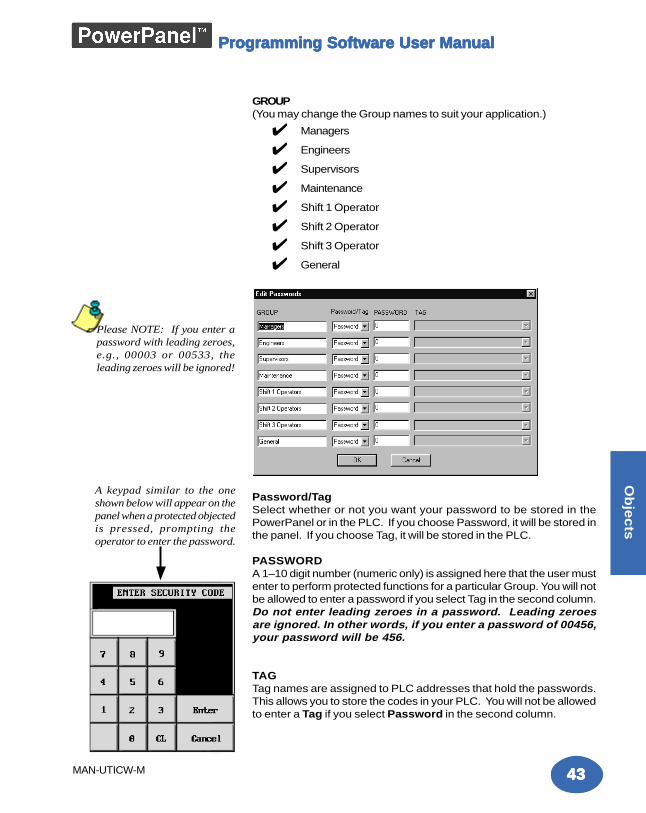
4343434343
Ob
jec
ts
MAN-UTICW-M
Programming Software User ManualProgramming Software User ManualProgramming Software User ManualProgramming Software User ManualProgramming Software User Manual
GROUP(You may change the Group names to suit your application.)
✔ Managers
✔ Engineers
✔ Supervisors
✔ Maintenance
✔ Shift 1 Operator
✔ Shift 2 Operator
✔ Shift 3 Operator
✔ General
Password/TagSelect whether or not you want your password to be stored in thePowerPanel or in the PLC. If you choose Password, it will be stored inthe panel. If you choose Tag, it will be stored in the PLC.
PASSWORDA 1–10 digit number (numeric only) is assigned here that the user mustenter to perform protected functions for a particular Group. You will notbe allowed to enter a password if you select Tag in the second column.Do not enter leading zeroes in a password. Leading zeroesare ignored. In other words, if you enter a password of 00456,your password will be 456.
TAGTag names are assigned to PLC addresses that hold the passwords.This allows you to store the codes in your PLC. You will not be allowedto enter a Tag if you select Password in the second column.
Please NOTE: If you enter apassword with leading zeroes,e.g., 00003 or 00533, theleading zeroes will be ignored!
A keypad similar to the oneshown below will appear on thepanel when a protected objectedis pressed, prompting theoperator to enter the password.
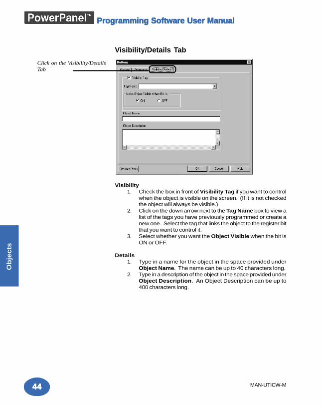
4444444444
Ob
jec
ts
MAN-UTICW-M
Programming Software User ManualProgramming Software User ManualProgramming Software User ManualProgramming Software User ManualProgramming Software User Manual
Visibility/Details Tab
Visibility1. Check the box in front of Visibility Tag if you want to control
when the object is visible on the screen. (If it is not checkedthe object will always be visible.)
2. Click on the down arrow next to the Tag Name box to view alist of the tags you have previously programmed or create anew one. Select the tag that links the object to the register bitthat you want to control it.
3. Select whether you want the Object Visible when the bit isON or OFF.
Details1. Type in a name for the object in the space provided under
Object Name. The name can be up to 40 characters long.2. Type in a description of the object in the space provided under
Object Description. An Object Description can be up to400 characters long.
Click on the Visibility/DetailsTab
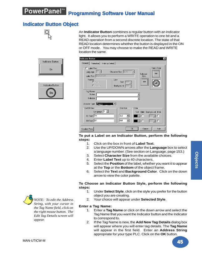
4545454545
Ob
jec
ts
MAN-UTICW-M
Programming Software User ManualProgramming Software User ManualProgramming Software User ManualProgramming Software User ManualProgramming Software User Manual
An Indicator Button combines a regular button with an indicatorlight. It allows you to perform a WRITE operation to one bit and aREAD operation from a second discrete location. The state of thatREAD location determines whether the button is displayed in the ONor OFF mode. You may choose to make the READ and WRITElocation the same.
To put a Label on an Indicator Button, perform the followingsteps:
1. Click on the box in front of Label Text.2. Use the UP/DOWN arrows after the Language box to select
a language number. (See section on Language, page 153.)3. Select Character Size from the available choices.4. Enter Label Text up to 40 characters.5. Select the Position of the label, whether you want it to appear
at the Top or the Bottom of the object frame.6. Select the Text and Background Color. Click on the down
arrow to view the color palette.
To Choose an Indicator Button Style, perform the followingsteps:
1. Under Select Style, click on the style you prefer for the buttonobject you are creating.
2. Your choice will appear under Selected Style.
Enter a Tag Name:1. Enter a Tag Name or click on the down arrow and select the
Tag Name that you want the Indicator button and the Indicatorto correspond to.
2. If the Tag Name is new, the Add New Tag Details dialog boxwill appear where you will enter tag details. The Tag Namewill appear in the first field. Enter an Address Stringappropriate for your type PLC. Click on the OK button.
Indicator Button ObjectIndicator Button ObjectIndicator Button ObjectIndicator Button ObjectIndicator Button Object
NOTE: To edit the AddressString, with your cursor inthe Tag Name field, click onthe right mouse button. TheEdit Tag Details screen willappear.
4646464646
Ob
jec
ts
MAN-UTICW-M
Programming Software User ManualProgramming Software User ManualProgramming Software User ManualProgramming Software User ManualProgramming Software User Manual
Select from the following Actuator Types:Actuator Type determines how the tag will be controlled. If you haveassigned Password Protection for this object and selectMomentary On or Momentary Off, the protection feature willnot be enabled.
• Momentary On will turn the tag on for as long as you touchthe button. (Password Protection is disabled.)
• Momentary Off will turn the tag off for as long as youtouch the button. (Password Protection is disabled.)
• Set On will latch the tag ON.• Set Off will latch the tag OFF.• Toggle will change the state of the tag every time the button
is pressed.
Enter On/Off Text:Here you will enter the Text that will appear within the object, andcontrol how that text will appear.
1. Select the Language number (1–9) for the On/Off Text.2. Type in what you want to appear within the button for the On
Text and for the Off Text (i.e., you might want to place thewords STOP and RUN inside the buttons, instead of Off andOn).
3. Select Character Size from the available choices4. Select the Color of the Text and the Color of the Background.5. If you want the Text or the Background to Blink, click on the
box below Blink to place a check mark indicating that theoption is enabled.
Protection (See Button Object.)
Visibility/Details (See Button Object.)
OK/Cancel/Help Buttons• Click on OK button to save your selections and exit the dialog
box.• Click on Cancel button to exit the dialog box without saving
your selections.• Click on Help button to go to the Help Topic for that dialog
box.
Place Indicator Button on the screen and size it.• To size the Indicator button, select it, grab a handle and drag.• To move the button, select it, click and hold left mouse button
and drag it to where you want it to appear on the screen.
Simulate PressTo Simulate Press, double click the object to bring up the object dialogbox. (You may have to drag the dialog box to one side to see theobject on the programming screen.) Click on the Simulate Pressbutton to see how the button object will display on the screen whenpressed.
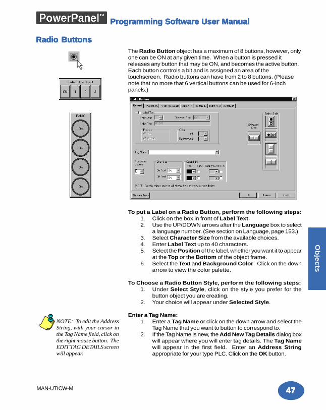
4747474747
Ob
jec
ts
MAN-UTICW-M
Programming Software User ManualProgramming Software User ManualProgramming Software User ManualProgramming Software User ManualProgramming Software User Manual
The Radio Button object has a maximum of 8 buttons, however, onlyone can be ON at any given time. When a button is pressed itreleases any button that may be ON, and becomes the active button.Each button controls a bit and is assigned an area of thetouchscreen. Radio buttons can have from 2 to 8 buttons. (Pleasenote that no more that 6 vertical buttons can be used for 6-inchpanels.)
To put a Label on a Radio Button, perform the following steps:1. Click on the box in front of Label Text.2. Use the UP/DOWN arrows after the Language box to select
a language number. (See section on Language, page 153.)3. Select Character Size from the available choices.4. Enter Label Text up to 40 characters.5. Select the Position of the label, whether you want it to appear
at the Top or the Bottom of the object frame.6. Select the Text and Background Color. Click on the down
arrow to view the color palette.
To Choose a Radio Button Style, perform the following steps:1. Under Select Style, click on the style you prefer for the
button object you are creating.2. Your choice will appear under Selected Style.
Enter a Tag Name:1. Enter a Tag Name or click on the down arrow and select the
Tag Name that you want to button to correspond to.2. If the Tag Name is new, the Add New Tag Details dialog box
will appear where you will enter tag details. The Tag Namewill appear in the first field. Enter an Address Stringappropriate for your type PLC. Click on the OK button.
Radio ButtonsRadio ButtonsRadio ButtonsRadio ButtonsRadio Buttons
NOTE: To edit the AddressString, with your cursor inthe Tag Name field, click onthe right mouse button. TheEDIT TAG DETAILS screenwill appear.
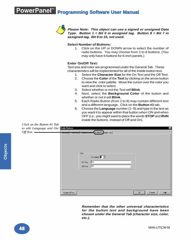
4848484848
Ob
jec
ts
MAN-UTICW-M
Programming Software User ManualProgramming Software User ManualProgramming Software User ManualProgramming Software User ManualProgramming Software User Manual
Please Note: This object can use a signed or unsigned DataType. Button 1 = Bit 0 in assigned tag. Button 8 = Bit 7 inassigned tag. Bit 9 to 15, not used.
Select Number of Buttons:1. Click on the UP or DOWN arrow to select the number of
radio buttons. You may choose from 2 to 8 buttons. (Youmay only have 6 buttons for 6-inch panels.)
Enter On/Off Text:Text size and color are programmed under the General Tab. Thesecharacteristics will be implemented for all of the inside button text.
1. Select the Character Size for the On Text and the Off Text.2. Choose the Color of the Text by clicking on the arrow button
to view the color palette. Move the cursor over the color youwant and click to select.
3. Select whether or not the Text will Blink.4. Next, select the Background Color of the button and
whether or not it will Blink.5. Each Radio Button (from 2 to 8) may contain different text
and a different language. Click on the Button #1 tab.6. Choose the Language number (1–9) and type in the text as
you want it to appear within that button when ON and whenOFF (i.e., you might want to place the words STOP and RUNinside the buttons, instead of Off and On).
Remember that the other universal characteristicsfor the button text and background have beenchosen under the General Tab (character size, color,etc.).
Click on the Button #1 Tabto edit Language and On/Off Text.
4949494949
Ob
jec
ts
MAN-UTICW-M
Programming Software User ManualProgramming Software User ManualProgramming Software User ManualProgramming Software User ManualProgramming Software User Manual
Protection (See Button Object.)
Visibility/Details (See Button Object.)
OK/Cancel/Help Buttons• Click on OK button to save your selections and exit the
dialog box.• Click on Cancel button to exit the dialog box without saving
your selections.• Click on Help button to go to the Help Topic for that dialog
box.
Place Radio Button on the screen and size it.• To size the button, select it, grab a handle and drag.• To move the button, select it, click and hold left mouse
button and drag to where you want it to appear on thescreen.
Simulate PressTo Simulate Press, double click the object to bring up the object dialogbox. (You may have to drag the dialog box to see the object on theprogramming screen.) Select the tab of the button you want tosimulate. Click on the Simulate Press button to see how the buttonobject will display on the screen when pressed.
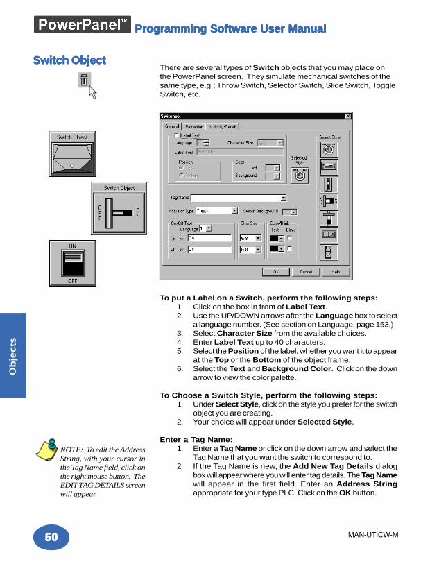
5050505050
Ob
jec
ts
MAN-UTICW-M
Programming Software User ManualProgramming Software User ManualProgramming Software User ManualProgramming Software User ManualProgramming Software User Manual
There are several types of Switch objects that you may place onthe PowerPanel screen. They simulate mechanical switches of thesame type, e.g.; Throw Switch, Selector Switch, Slide Switch, ToggleSwitch, etc.
To put a Label on a Switch, perform the following steps:1. Click on the box in front of Label Text.2. Use the UP/DOWN arrows after the Language box to select
a language number. (See section on Language, page 153.)3. Select Character Size from the available choices.4. Enter Label Text up to 40 characters.5. Select the Position of the label, whether you want it to appear
at the Top or the Bottom of the object frame.6. Select the Text and Background Color. Click on the down
arrow to view the color palette.
To Choose a Switch Style, perform the following steps:1. Under Select Style, click on the style you prefer for the switch
object you are creating.2. Your choice will appear under Selected Style.
Enter a Tag Name:1. Enter a Tag Name or click on the down arrow and select the
Tag Name that you want the switch to correspond to.2. If the Tag Name is new, the Add New Tag Details dialog
box will appear where you will enter tag details. The Tag Namewill appear in the first field. Enter an Address Stringappropriate for your type PLC. Click on the OK button.
Switch ObjectSwitch ObjectSwitch ObjectSwitch ObjectSwitch Object
NOTE: To edit the AddressString, with your cursor inthe Tag Name field, click onthe right mouse button. TheEDIT TAG DETAILS screenwill appear.
5151515151
Ob
jec
ts
MAN-UTICW-M
Programming Software User ManualProgramming Software User ManualProgramming Software User ManualProgramming Software User ManualProgramming Software User Manual
Select the Switch Background color by clicking on the DOWN arrowand selecting a color from the palette.
Select from the following Actuator Types:Actuator Type determines how the tag will be controlled. If you haveassigned Password Protection for this object and selectMomentary On or Momentary Off, the protection feature willnot be enabled with this actuator type.
• Momentary On will turn the tag on for as long as youtouch the switch. (Password Protection is disabled.)
• Momentary Off will turn the tag off for as long as youtouch the switch. (Password Protection is disabled.)
• Set On will latch the tag ON.• Set Off will latch the tag OFF.• Toggle will change the state of the tag every time the
switch is pressed.
Enter On/Off Text:Here you will enter the Text that will appear within the object, andcontrol how that text will appear.
1. Select the Language number (1–9) for the On/Off Text.2. Type in what you want to appear within the switch for the On
Text and for the Off Text (i.e., you might want to place thewords STOP and RUN inside the switches, instead of Offand On).
3. Select Character Size from the available choices4. Select the Color of the On Text and the Color of the Off
Text.5. If you want the Text to Blink, click on the box below Blink to
place a check mark indicating that the option is enabled.
Protection (See Button Object.)
Visibility/Details (See Button Object.)
OK/Cancel/Help Buttons• Click on OK button to save your selections and exit the
dialog box.• Click on Cancel button to exit the dialog box without saving
your selections.• Click on Help button to go to the Help Topic for that dialog
box.
Place Switch on the screen and size it.• To size a switch, click on it to select, grab a handle with the
mouse and drag to the size you want.• To move the switch, select it, click and hold left mouse
button, and drag to where you want it to appear on thescreen.
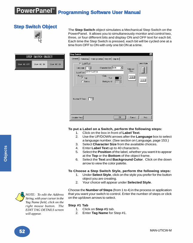
5252525252
Ob
jec
ts
MAN-UTICW-M
Programming Software User ManualProgramming Software User ManualProgramming Software User ManualProgramming Software User ManualProgramming Software User Manual
The Step Switch object simulates a Mechanical Step Switch on thePowerPanel. It allows you to simultaneously monitor and control two,three, or four different bits and display ON and OFF text for each bit.Each time the Step Switch is pressed, each bit will be cycled one at atime from OFF to ON with only one bit ON at a time.
To put a Label on a Switch, perform the following steps:1. Click on the box in front of Label Text.2. Use the UP/DOWN arrows after the Language box to select
a language number. (See section on Language, page 153.)3. Select Character Size from the available choices.4. Enter Label Text up to 40 characters.5. Select the Position of the label, whether you want it to appear
at the Top or the Bottom of the object frame.6. Select the Text and Background Color. Click on the down
arrow to view the color palette.
To Choose a Step Switch Style, perform the following steps:1. Under Select Style, click on the style you prefer for the button
object you are creating.2. Your choice will appear under Selected Style.
Choose the Number of Steps (from 1 to 4) in the process or applicationthat you want your switch to control. Enter the number of steps or clickon the up/down arrows to select.
Step #1 Tab1. Click on Step #1 tab.2. Enter Tag Name for Step #1.
Step Switch ObjectStep Switch ObjectStep Switch ObjectStep Switch ObjectStep Switch Object
NOTE: To edit the AddressString, with your cursor in theTag Name field, click on theright mouse button. TheEDIT TAG DETAILS screenwill appear.
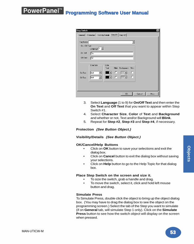
5353535353
Ob
jec
ts
MAN-UTICW-M
Programming Software User ManualProgramming Software User ManualProgramming Software User ManualProgramming Software User ManualProgramming Software User Manual
3. Select Language (1 to 9) for On/Off Text and then enter theOn Text and Off Text that you want to appear within StepSwitch #1.
4. Select Character Size, Color of Text and Backgroundand whether or not, Text and/or Background will Blink.
5. Repeat for Step #2, Step #3 and Step #4, if necessary.
Protection (See Button Object.)
Visibility/Details (See Button Object.)
OK/Cancel/Help Buttons• Click on OK button to save your selections and exit the
dialog box.• Click on Cancel button to exit the dialog box without saving
your selections.• Click on Help button to go to the Help Topic for that dialog
box.
Place Step Switch on the screen and size it.• To size the switch, grab a handle and drag.• To move the switch, select it, click and hold left mouse
button and drag.
Simulate PressTo Simulate Press, double click the object to bring up the object dialogbox. (You may have to drag the dialog box to see the object on theprogramming screen.) Select the tab of the Step you want to simulate(if on General tab, will simulate Step 1 only). Click on the SimulatePress button to see how the switch object will display on the screenwhen pressed.
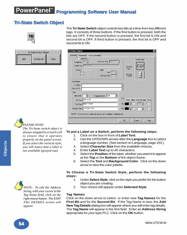
5454545454
Ob
jec
ts
MAN-UTICW-M
Programming Software User ManualProgramming Software User ManualProgramming Software User ManualProgramming Software User ManualProgramming Software User Manual
The Tri-State Switch object controls two bits at a time from two differenttags. It consists of three buttons. If the first button is pressed, both thebits are OFF. If the second button is pressed, the first bit is ON andsecond bit is OFF. If third button is pressed, the first bit is OFF andsecond bit is ON.
To put a Label on a Switch, perform the following steps:1. Click on the box in front of Label Text.2. Use the UP/DOWN arrows after the Language box to select
a language number. (See section on Language, page 153.)3. Select Character Size from the available choices.4. Enter Label Text up to 40 characters.5. Select the Position of the label, whether you want it to appear
at the Top or the Bottom of the object frame.6. Select the Text and Background Color. Click on the down
arrow to view the color palette.
To Choose a Tri-State Switch Style, perform the followingsteps:
1. Under Select Style, click on the style you prefer for the buttonobject you are creating.
2. Your choice will appear under Selected Style.
Tag NamesClick on the down arrow to select or enter new Tag Names for theFirst Bit and for the Second Bit. If the Tag Name is new, the AddNew Tag Details dialog box will appear where you will enter tag details.The Tag Name will appear in the first field. Enter an Address Stringappropriate for your type PLC. Click on the OK button.
TTTTTri-State Switcri-State Switcri-State Switcri-State Switcri-State Switch Objecth Objecth Objecth Objecth Object
NOTE: To edit the AddressString, with your cursor in theTag Name field, click on theright mouse button. The EDITTAG DETAILS screen willappear.
PLEASE NOTE:The Tri-State switch object isalways snapped to a touch cellto ensure that it operatesproperly on the panel screen.If you select the vertical style,you will notice that a label isnot available (grayed out).
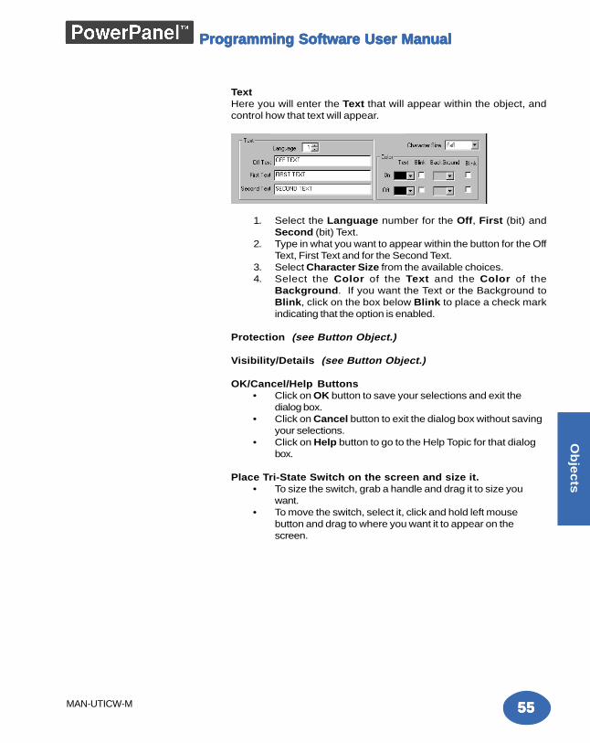
5555555555
Ob
jec
ts
MAN-UTICW-M
Programming Software User ManualProgramming Software User ManualProgramming Software User ManualProgramming Software User ManualProgramming Software User Manual
TextHere you will enter the Text that will appear within the object, andcontrol how that text will appear.
1. Select the Language number for the Off, First (bit) andSecond (bit) Text.
2. Type in what you want to appear within the button for the OffText, First Text and for the Second Text.
3. Select Character Size from the available choices.4. Select the Color of the Text and the Color of the
Background. If you want the Text or the Background toBlink, click on the box below Blink to place a check markindicating that the option is enabled.
Protection (see Button Object.)
Visibility/Details (see Button Object.)
OK/Cancel/Help Buttons• Click on OK button to save your selections and exit the
dialog box.• Click on Cancel button to exit the dialog box without saving
your selections.• Click on Help button to go to the Help Topic for that dialog
box.
Place Tri-State Switch on the screen and size it.• To size the switch, grab a handle and drag it to size you
want.• To move the switch, select it, click and hold left mouse
button and drag to where you want it to appear on thescreen.
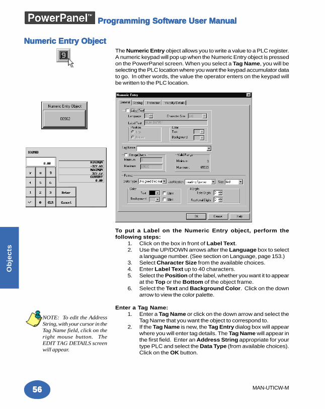
5656565656
Ob
jec
ts
MAN-UTICW-M
Programming Software User ManualProgramming Software User ManualProgramming Software User ManualProgramming Software User ManualProgramming Software User Manual
The Numeric Entry object allows you to write a value to a PLC register.A numeric keypad will pop up when the Numeric Entry object is pressedon the PowerPanel screen. When you select a Tag Name, you will beselecting the PLC location where you want the keypad accumulator datato go. In other words, the value the operator enters on the keypad willbe written to the PLC location.
To put a Label on the Numeric Entry object, perform thefollowing steps:
1. Click on the box in front of Label Text.2. Use the UP/DOWN arrows after the Language box to select
a language number. (See section on Language, page 153.)3. Select Character Size from the available choices.4. Enter Label Text up to 40 characters.5. Select the Position of the label, whether you want it to appear
at the Top or the Bottom of the object frame.6. Select the Text and Background Color. Click on the down
arrow to view the color palette.
Enter a Tag Name:1. Enter a Tag Name or click on the down arrow and select the
Tag Name that you want the object to correspond to.2. If the Tag Name is new, the Tag Entry dialog box will appear
where you will enter tag details. The Tag Name will appear inthe first field. Enter an Address String appropriate for yourtype PLC and select the Data Type (from available choices).Click on the OK button.
Numeric Entry ObjectNumeric Entry ObjectNumeric Entry ObjectNumeric Entry ObjectNumeric Entry Object
NOTE: To edit the AddressString, with your cursor in theTag Name field, click on theright mouse button. TheEDIT TAG DETAILS screenwill appear.
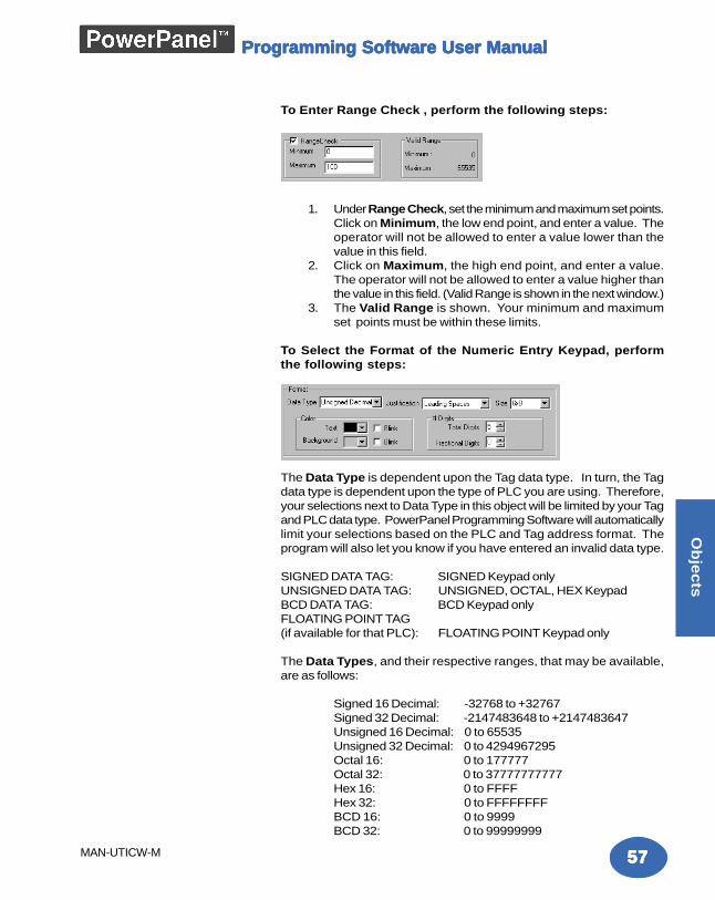
5757575757
Ob
jec
ts
MAN-UTICW-M
Programming Software User ManualProgramming Software User ManualProgramming Software User ManualProgramming Software User ManualProgramming Software User Manual
To Enter Range Check , perform the following steps:
1. Under Range Check, set the minimum and maximum set points.Click on Minimum, the low end point, and enter a value. Theoperator will not be allowed to enter a value lower than thevalue in this field.
2. Click on Maximum, the high end point, and enter a value.The operator will not be allowed to enter a value higher thanthe value in this field. (Valid Range is shown in the next window.)
3. The Valid Range is shown. Your minimum and maximumset points must be within these limits.
To Select the Format of the Numeric Entry Keypad, performthe following steps:
The Data Type is dependent upon the Tag data type. In turn, the Tagdata type is dependent upon the type of PLC you are using. Therefore,your selections next to Data Type in this object will be limited by your Tagand PLC data type. PowerPanel Programming Software will automaticallylimit your selections based on the PLC and Tag address format. Theprogram will also let you know if you have entered an invalid data type.
SIGNED DATA TAG: SIGNED Keypad onlyUNSIGNED DATA TAG: UNSIGNED, OCTAL, HEX KeypadBCD DATA TAG: BCD Keypad onlyFLOATING POINT TAG(if available for that PLC): FLOATING POINT Keypad only
The Data Types, and their respective ranges, that may be available,are as follows:
Signed 16 Decimal: -32768 to +32767Signed 32 Decimal: -2147483648 to +2147483647Unsigned 16 Decimal: 0 to 65535Unsigned 32 Decimal: 0 to 4294967295Octal 16: 0 to 177777Octal 32: 0 to 37777777777Hex 16: 0 to FFFFHex 32: 0 to FFFFFFFFBCD 16: 0 to 9999BCD 32: 0 to 99999999
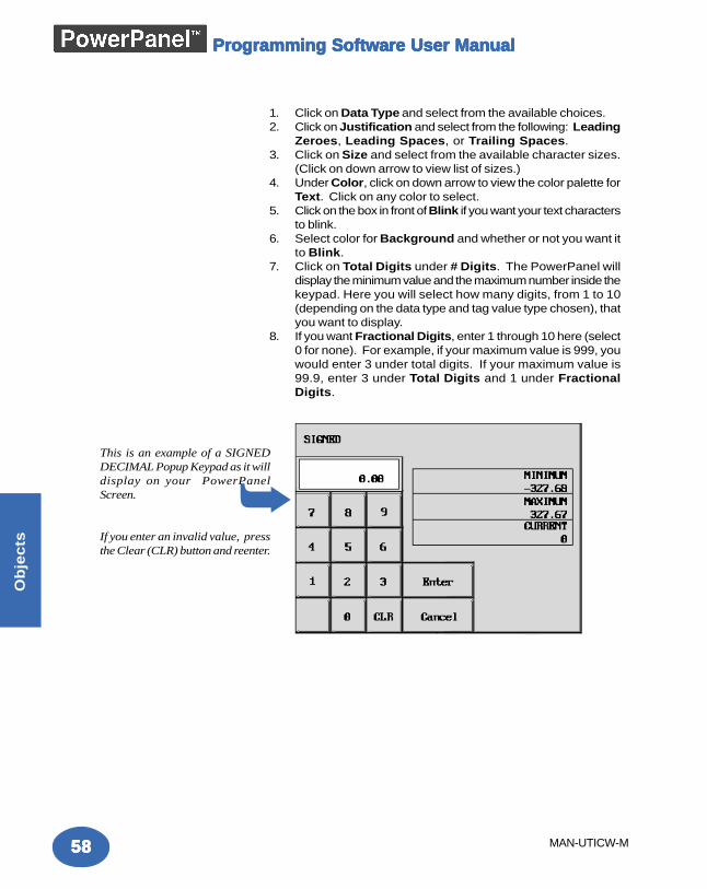
5858585858
Ob
jec
ts
MAN-UTICW-M
Programming Software User ManualProgramming Software User ManualProgramming Software User ManualProgramming Software User ManualProgramming Software User Manual
1. Click on Data Type and select from the available choices.2. Click on Justification and select from the following: Leading
Zeroes, Leading Spaces, or Trailing Spaces.3. Click on Size and select from the available character sizes.
(Click on down arrow to view list of sizes.)4. Under Color, click on down arrow to view the color palette for
Text. Click on any color to select.5. Click on the box in front of Blink if you want your text characters
to blink.6. Select color for Background and whether or not you want it
to Blink.7. Click on Total Digits under # Digits. The PowerPanel will
display the minimum value and the maximum number inside thekeypad. Here you will select how many digits, from 1 to 10(depending on the data type and tag value type chosen), thatyou want to display.
8. If you want Fractional Digits, enter 1 through 10 here (select0 for none). For example, if your maximum value is 999, youwould enter 3 under total digits. If your maximum value is99.9, enter 3 under Total Digits and 1 under FractionalDigits.
This is an example of a SIGNEDDECIMAL Popup Keypad as it willdisplay on your PowerPanelScreen.
If you enter an invalid value, pressthe Clear (CLR) button and reenter.
➥
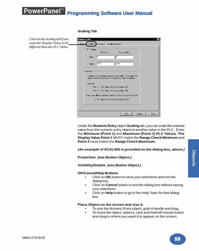
5959595959
Ob
jec
ts
MAN-UTICW-M
Programming Software User ManualProgramming Software User ManualProgramming Software User ManualProgramming Software User ManualProgramming Software User Manual
Scaling Tab
Under the Numeric Entry object Scaling tab, you can scale the enteredvalue from the numeric entry object to another value in the PLC. Enterthe Minimum (Point 1) and Maximum (Point 2) PLC Values. TheDisplay Value Point 1 MUST match the Range Check Minimum andPoint 2 must match the Range Check Maximum.
(An example of SCALING is provided on the dialog box, above.)
Protection (see Button Object.)
Visibility/Details (see Button Object.)
OK/Cancel/Help Buttons• Click on OK button to save your selections and exit the
dialog box.• Click on Cancel button to exit the dialog box without saving
your selections.• Click on Help button to go to the Help Topic for that dialog
box.
Place Object on the screen and size it.• To size the Numeric Entry object, grab a handle and drag.• To move the object, select it, click and hold left mouse button
and drag to where you want it to appear on the screen.
Click on the Scaling tab if youwant the Display Value to bedifferent than the PLC Value.
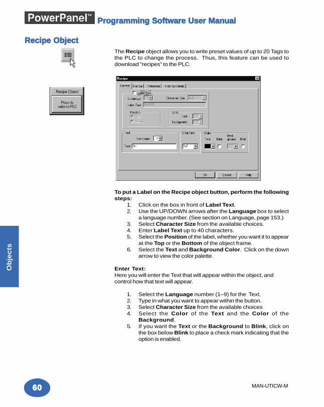
6060606060
Ob
jec
ts
MAN-UTICW-M
Programming Software User ManualProgramming Software User ManualProgramming Software User ManualProgramming Software User ManualProgramming Software User Manual
The Recipe object allows you to write preset values of up to 20 Tags tothe PLC to change the process. Thus, this feature can be used todownload "recipes" to the PLC.
To put a Label on the Recipe object button, perform the followingsteps:
1. Click on the box in front of Label Text.2. Use the UP/DOWN arrows after the Language box to select
a language number. (See section on Language, page 153.)3. Select Character Size from the available choices.4. Enter Label Text up to 40 characters.5. Select the Position of the label, whether you want it to appear
at the Top or the Bottom of the object frame.6. Select the Text and Background Color. Click on the down
arrow to view the color palette.
Enter Text:Here you will enter the Text that will appear within the object, andcontrol how that text will appear.
1. Select the Language number (1–9) for the Text.2. Type in what you want to appear within the button.3. Select Character Size from the available choices4. Select the Color of the Text and the Color of the
Background.5. If you want the Text or the Background to Blink, click on
the box below Blink to place a check mark indicating that theoption is enabled.
Recipe ObjectRecipe ObjectRecipe ObjectRecipe ObjectRecipe Object
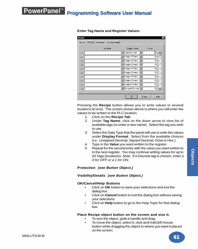
6161616161
Ob
jec
ts
MAN-UTICW-M
Programming Software User ManualProgramming Software User ManualProgramming Software User ManualProgramming Software User ManualProgramming Software User Manual
Enter Tag Name and Register Values:
Pressing the Recipe button allows you to write values to severallocations at once. The screen shown above is where you will enter thevalues to be written to the PLC location.
1. Click on the Recipe Tab.2. Under Tag Name, click on the down arrow to view list of
available tags (or enter a new name). Select the tag you wishto use.
3. Select the Data Type that the panel will use to write the valuesunder Display Format. Select from the available choices(i.e., Unsigned Decimal, Signed Decimal, Octal or Hex.)
4. Type in the Value you want written to the register.5. Repeat for the second entry with the value you want written to
in the next register. You may continue writing values for up to20 Tags (locations). Note: If a Discrete tag is chosen, enter a0 for OFF or a 1 for ON.
Protection (see Button Object.)
Visibility/Details (see Button Object.)
OK/Cancel/Help Buttons• Click on OK button to save your selections and exit the
dialog box.• Click on Cancel button to exit the dialog box without saving
your selections.• Click on Help button to go to the Help Topic for that dialog
box.
Place Recipe object button on the screen and size it.• To size the object, grab a handle and drag.• To move the object, select it, click and hold left mouse
button while dragging the object to where you want it placedon the screen.
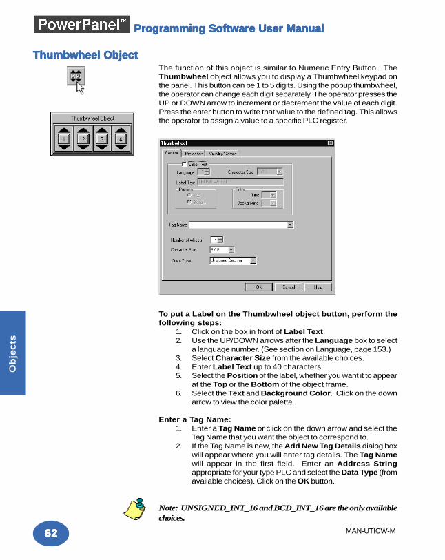
6262626262
Ob
jec
ts
MAN-UTICW-M
Programming Software User ManualProgramming Software User ManualProgramming Software User ManualProgramming Software User ManualProgramming Software User Manual
The function of this object is similar to Numeric Entry Button. TheThumbwheel object allows you to display a Thumbwheel keypad onthe panel. This button can be 1 to 5 digits. Using the popup thumbwheel,the operator can change each digit separately. The operator presses theUP or DOWN arrow to increment or decrement the value of each digit.Press the enter button to write that value to the defined tag. This allowsthe operator to assign a value to a specific PLC register.
To put a Label on the Thumbwheel object button, perform thefollowing steps:
1. Click on the box in front of Label Text.2. Use the UP/DOWN arrows after the Language box to select
a language number. (See section on Language, page 153.)3. Select Character Size from the available choices.4. Enter Label Text up to 40 characters.5. Select the Position of the label, whether you want it to appear
at the Top or the Bottom of the object frame.6. Select the Text and Background Color. Click on the down
arrow to view the color palette.
Enter a Tag Name:1. Enter a Tag Name or click on the down arrow and select the
Tag Name that you want the object to correspond to.2. If the Tag Name is new, the Add New Tag Details dialog box
will appear where you will enter tag details. The Tag Namewill appear in the first field. Enter an Address Stringappropriate for your type PLC and select the Data Type (fromavailable choices). Click on the OK button.
Note: UNSIGNED_INT_16 and BCD_INT_16 are the only availablechoices.
Thumbwheel ObjectThumbwheel ObjectThumbwheel ObjectThumbwheel ObjectThumbwheel Object
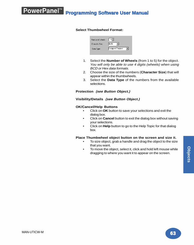
6363636363
Ob
jec
ts
MAN-UTICW-M
Programming Software User ManualProgramming Software User ManualProgramming Software User ManualProgramming Software User ManualProgramming Software User Manual
Select Thumbwheel Format:
1. Select the Number of Wheels (from 1 to 5) for the object.You will only be able to use 4 digits (wheels) when usingBCD or Hex data formats.
2. Choose the size of the numbers (Character Size) that willappear within the thumbwheels.
3. Select the Data Type of the numbers from the availableselections.
Protection (see Button Object.)
Visibility/Details (see Button Object.)
OK/Cancel/Help Buttons• Click on OK button to save your selections and exit the
dialog box.• Click on Cancel button to exit the dialog box without saving
your selections.• Click on Help button to go to the Help Topic for that dialog
box.
Place Thumbwheel object button on the screen and size it.• To size object, grab a handle and drag the object to the size
that you want.• To move the object, select it, click and hold left mouse while
dragging to where you want it to appear on the screen.
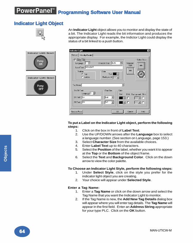
6464646464
Ob
jec
ts
MAN-UTICW-M
Programming Software User ManualProgramming Software User ManualProgramming Software User ManualProgramming Software User ManualProgramming Software User Manual
An Indicator Light object allows you to monitor and display the state ofa bit. The Indicator Light reads the bit information and produces theappropriate display. For example, the Indictor Light could display thestatus of a bit linked to a push button.
Indicator Light ObjectIndicator Light ObjectIndicator Light ObjectIndicator Light ObjectIndicator Light Object
To put a Label on the Indicator Light object, perform the followingsteps:
1. Click on the box in front of Label Text.2. Use the UP/DOWN arrows after the Language box to select
a language number. (See section on Language, page 153.)3. Select Character Size from the available choices.4. Enter Label Text up to 40 characters.5. Select the Position of the label, whether you want it to appear
at the Top or the Bottom of the object frame.6. Select the Text and Background Color. Click on the down
arrow to view the color palette.
To Choose an Indicator Light Style, perform the following steps:1. Under Select Style, click on the style you prefer for the
indicator light object you are creating.2. Your choice will appear under Selected Style.
Enter a Tag Name:1. Enter a Tag Name or click on the down arrow and select the
Tag Name that you want the Indicator Light to monitor.2. If the Tag Name is new, the Add New Tag Details dialog box
will appear where you will enter tag details. The Tag Name willappear in the first field. Enter an Address String appropriatefor your type PLC. Click on the OK button.
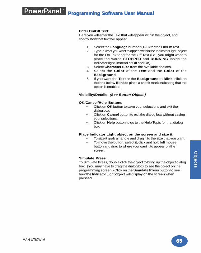
6565656565
Ob
jec
ts
MAN-UTICW-M
Programming Software User ManualProgramming Software User ManualProgramming Software User ManualProgramming Software User ManualProgramming Software User Manual
Enter On/Off Text:Here you will enter the Text that will appear within the object, andcontrol how that text will appear.
1. Select the Language number (1–9) for the On/Off Text.2. Type in what you want to appear within the Indicator Light object
for the On Text and for the Off Text (i.e., you might want toplace the words STOPPED and RUNNING inside theIndicator light, instead of Off and On).
3. Select Character Size from the available choices.4. Select the Color of the Text and the Color of the
Background.5. If you want the Text or the Background to Blink, click on
the box below Blink to place a check mark indicating that theoption is enabled.
Visibility/Details (See Button Object.)
OK/Cancel/Help Buttons• Click on OK button to save your selections and exit the
dialog box.• Click on Cancel button to exit the dialog box without saving
your selections.• Click on Help button to go to the Help Topic for that dialog
box.
Place Indicator Light object on the screen and size it.• To size it grab a handle and drag it to the size that you want.• To move the button, select it, click and hold left mouse
button and drag to where you want it to appear on thescreen.
Simulate PressTo Simulate Press, double click the object to bring up the object dialogbox. (You may have to drag the dialog box to see the object on theprogramming screen.) Click on the Simulate Press button to seehow the Indicator Light object will display on the screen whenpressed.
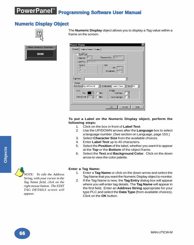
6666666666
Ob
jec
ts
MAN-UTICW-M
Programming Software User ManualProgramming Software User ManualProgramming Software User ManualProgramming Software User ManualProgramming Software User Manual
The Numeric Display object allows you to display a Tag value within aframe on the screen.
To put a Label on the Numeric Display object, perform thefollowing steps:
1. Click on the box in front of Label Text.2. Use the UP/DOWN arrows after the Language box to select
a language number. (See section on Language, page 153.)3. Select Character Size from the available choices.4. Enter Label Text up to 40 characters.5. Select the Position of the label, whether you want it to appear
at the Top or the Bottom of the object frame.6. Select the Text and Background Color. Click on the down
arrow to view the color palette.
Enter a Tag Name:1. Enter a Tag Name or click on the down arrow and select the
Tag Name that you want the Numeric Display object to monitor.2. If the Tag Name is new, the Tag Entry dialog box will appear
where you will enter tag details. The Tag Name will appear inthe first field. Enter an Address String appropriate for yourtype PLC and select the Data Type (from available choices).Click on the OK button.
Numeric Display ObjectNumeric Display ObjectNumeric Display ObjectNumeric Display ObjectNumeric Display Object
NOTE: To edit the AddressString, with your cursor in theTag Name field, click on theright mouse button. The EDITTAG DETAILS screen willappear.
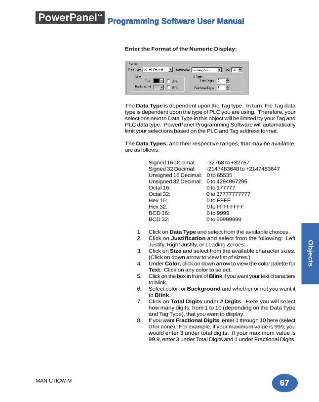
6767676767
Ob
jec
ts
MAN-UTICW-M
Programming Software User ManualProgramming Software User ManualProgramming Software User ManualProgramming Software User ManualProgramming Software User Manual
Enter the Format of the Numeric Display:
The Data Type is dependent upon the Tag type. In turn, the Tag datatype is dependent upon the type of PLC you are using. Therefore, yourselections next to Data Type in this object will be limited by your Tag andPLC data type. PowerPanel Programming Software will automaticallylimit your selections based on the PLC and Tag address format.
The Data Types, and their respective ranges, that may be available,are as follows:
Signed 16 Decimal: -32768 to +32767Signed 32 Decimal: -2147483648 to +2147483647Unsigned 16 Decimal: 0 to 65535Unsigned 32 Decimal: 0 to 4294967295Octal 16: 0 to 177777Octal 32: 0 to 37777777777Hex 16: 0 to FFFFHex 32: 0 to FFFFFFFFBCD 16: 0 to 9999BCD 32: 0 to 99999999
1. Click on Data Type and select from the available choices.2. Click on Justification and select from the following: Left
Justify, Right Justify, or Leading Zeroes.3. Click on Size and select from the available character sizes.
(Click on down arrow to view list of sizes.)4. Under Color, click on down arrow to view the color palette for
Text. Click on any color to select.5. Click on the box in front of Blink if you want your text characters
to blink.6. Select color for Background and whether or not you want it
to Blink.7. Click on Total Digits under # Digits. Here you will select
how many digits, from 1 to 10 (depending on the Data Typeand Tag Type), that you want to display.
8. If you want Fractional Digits, enter 1 through 10 here (select0 for none). For example, if your maximum value is 999, youwould enter 3 under total digits. If your maximum value is99.9, enter 3 under Total Digits and 1 under Fractional Digits.
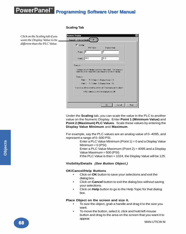
6868686868
Ob
jec
ts
MAN-UTICW-M
Programming Software User ManualProgramming Software User ManualProgramming Software User ManualProgramming Software User ManualProgramming Software User Manual
Scaling Tab
Under the Scaling tab, you can scale the value in the PLC to anothervalue on the Numeric Display. Enter Point 1 (Minimum Value) andPoint 2 (Maximum) PLC Values. Scale these values by entering theDisplay Value Minimum and Maximum.
For example, say the PLC values are an analog value of 0–4095, andrepresent a range of 0–500 PSI.
Enter a PLC Value Minimum (Point 1) = 0 and a Display ValueMinimum = 0 (PSI)Enter a PLC Value Maximum (Point 2) = 4095 and a DisplayValue Maximum = 500 (PSI)If the PLC Value is then = 1024, the Display Value will be 125.
Visibility/Details (See Button Object.)
OK/Cancel/Help Buttons• Click on OK button to save your selections and exit the
dialog box.• Click on Cancel button to exit the dialog box without saving
your selections.• Click on Help button to go to the Help Topic for that dialog
box.
Place Object on the screen and size it.• To size the object, grab a handle and drag it to the size you
want.• To move the button, select it, click and hold left mouse
button and drag to the area on the screen that you want it toappear.
Click on the Scaling tab if youwant the Display Value to bedifferent than the PLC Value.
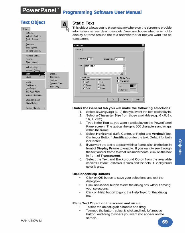
6969696969
Ob
jec
ts
MAN-UTICW-M
Programming Software User ManualProgramming Software User ManualProgramming Software User ManualProgramming Software User ManualProgramming Software User Manual
TTTTTeeeeext Objectxt Objectxt Objectxt Objectxt Object Static TextThis object allows you to place text anywhere on the screen to provideinformation, screen description, etc. You can choose whether or not todisplay a frame around the text and whether or not you want it to betransparent.
Under the General tab you will make the following selections:1. Select a Language (1–9) that you want the text to display in.2. Select a Character Size from those available (e.g., 6 x 8, 8 x
16, 8 x 32).3. Type in the Text as you want it to display on the PowerPanel
Panel screen. The text can be up to 500 characters and wrapswithin the frame.
4. Select Horizontal (Left, Center, or Right) and Vertical (Top,Center, or Bottom) Justification for the text. Default for bothis "Center".
5. If you want the text to appear within a frame, click on the box infront of Display Frame to enable. If you want to see throughthe text and/or frame to what lies underneath, click on the boxin front of Transparent.
6. Select the Text and Background Color from the availablechoices. Default Text color is black and the default Backgroundcolor is gray.
OK/Cancel/Help Buttons• Click on OK button to save your selections and exit the
dialog box.• Click on Cancel button to exit the dialog box without saving
your selections.• Click on Help button to go to the Help Topic for that dialog
box.
Place Text Object on the screen and size it.• To size the object, grab a handle and drag.• To move the button, select it, click and hold left mouse
button, and drag to where you want it to appear on thescreen.
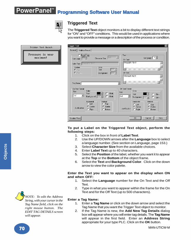
7070707070
Ob
jec
ts
MAN-UTICW-M
Programming Software User ManualProgramming Software User ManualProgramming Software User ManualProgramming Software User ManualProgramming Software User Manual
Triggered Text
The Triggered Text object monitors a bit to display different text stringsfor “ON” and “OFF” conditions. This would be used in applications whereyou want to provide a message or a description of the process or condition.
To put a Label on the Triggered Text object, perform thefollowing steps:
1. Click on the box in front of Label Text.2. Use the UP/DOWN arrows after the Language box to select
a language number. (See section on Language, page 153.)3. Select Character Size from the available choices.4. Enter Label Text up to 40 characters.5. Select the Position of the label, whether you want it to appear
at the Top or the Bottom of the object frame.6. Select the Text and Background Color. Click on the down
arrow to view the color palette.
Enter the Text you want to appear on the display when ONand when OFF:
1. Select the Language number for the On Text and the OffText.
2. Type in what you want to appear within the frame for the OnText and for the Off Text (up to 500 characters).
Enter a Tag Name:1. Enter a Tag Name or click on the down arrow and select the
Tag Name that you want the Trigger Text object to monitor.2. If the Tag Name is new, the Add New Tag Details dialog
box will appear where you will enter tag details. The Tag Namewill appear in the first field. Enter an Address Stringappropriate for your type PLC. Click on the OK button.
NOTE: To edit the AddressString, with your cursor in theTag Name field, click on theright mouse button. TheEDIT TAG DETAILS screenwill appear.
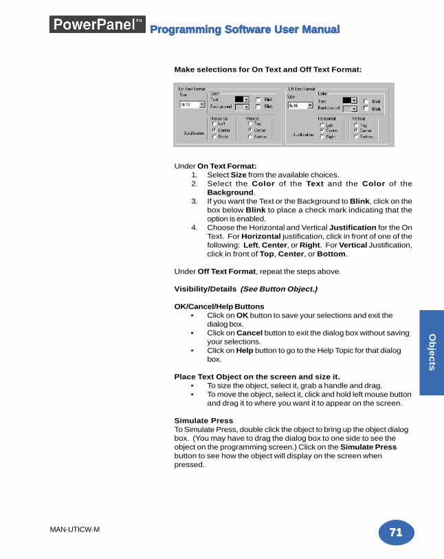
7171717171
Ob
jec
ts
MAN-UTICW-M
Programming Software User ManualProgramming Software User ManualProgramming Software User ManualProgramming Software User ManualProgramming Software User Manual
Make selections for On Text and Off Text Format:
Under On Text Format:1. Select Size from the available choices.2. Select the Color of the Text and the Color of the
Background.3. If you want the Text or the Background to Blink, click on the
box below Blink to place a check mark indicating that theoption is enabled.
4. Choose the Horizontal and Vertical Justification for the OnText. For Horizontal justification, click in front of one of thefollowing: Left, Center, or Right. For Vertical Justification,click in front of Top, Center, or Bottom.
Under Off Text Format, repeat the steps above.
Visibility/Details (See Button Object.)
OK/Cancel/Help Buttons• Click on OK button to save your selections and exit the
dialog box.• Click on Cancel button to exit the dialog box without saving
your selections.• Click on Help button to go to the Help Topic for that dialog
box.
Place Text Object on the screen and size it.• To size the object, select it, grab a handle and drag.• To move the object, select it, click and hold left mouse button
and drag it to where you want it to appear on the screen.
Simulate PressTo Simulate Press, double click the object to bring up the object dialogbox. (You may have to drag the dialog box to one side to see theobject on the programming screen.) Click on the Simulate Pressbutton to see how the object will display on the screen whenpressed.
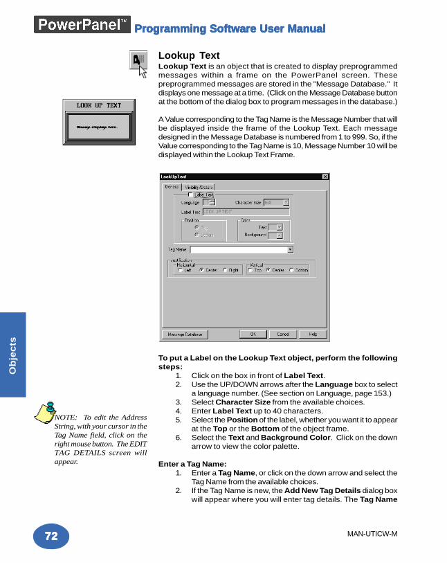
7272727272
Ob
jec
ts
MAN-UTICW-M
Programming Software User ManualProgramming Software User ManualProgramming Software User ManualProgramming Software User ManualProgramming Software User Manual
Lookup TextLookup Text is an object that is created to display preprogrammedmessages within a frame on the PowerPanel screen. Thesepreprogrammed messages are stored in the "Message Database." Itdisplays one message at a time. (Click on the Message Database buttonat the bottom of the dialog box to program messages in the database.)
A Value corresponding to the Tag Name is the Message Number that willbe displayed inside the frame of the Lookup Text. Each messagedesigned in the Message Database is numbered from 1 to 999. So, if theValue corresponding to the Tag Name is 10, Message Number 10 will bedisplayed within the Lookup Text Frame.
To put a Label on the Lookup Text object, perform the followingsteps:
1. Click on the box in front of Label Text.2. Use the UP/DOWN arrows after the Language box to select
a language number. (See section on Language, page 153.)3. Select Character Size from the available choices.4. Enter Label Text up to 40 characters.5. Select the Position of the label, whether you want it to appear
at the Top or the Bottom of the object frame.6. Select the Text and Background Color. Click on the down
arrow to view the color palette.
Enter a Tag Name:1. Enter a Tag Name, or click on the down arrow and select the
Tag Name from the available choices.2. If the Tag Name is new, the Add New Tag Details dialog box
will appear where you will enter tag details. The Tag Name
NOTE: To edit the AddressString, with your cursor in theTag Name field, click on theright mouse button. The EDITTAG DETAILS screen willappear.
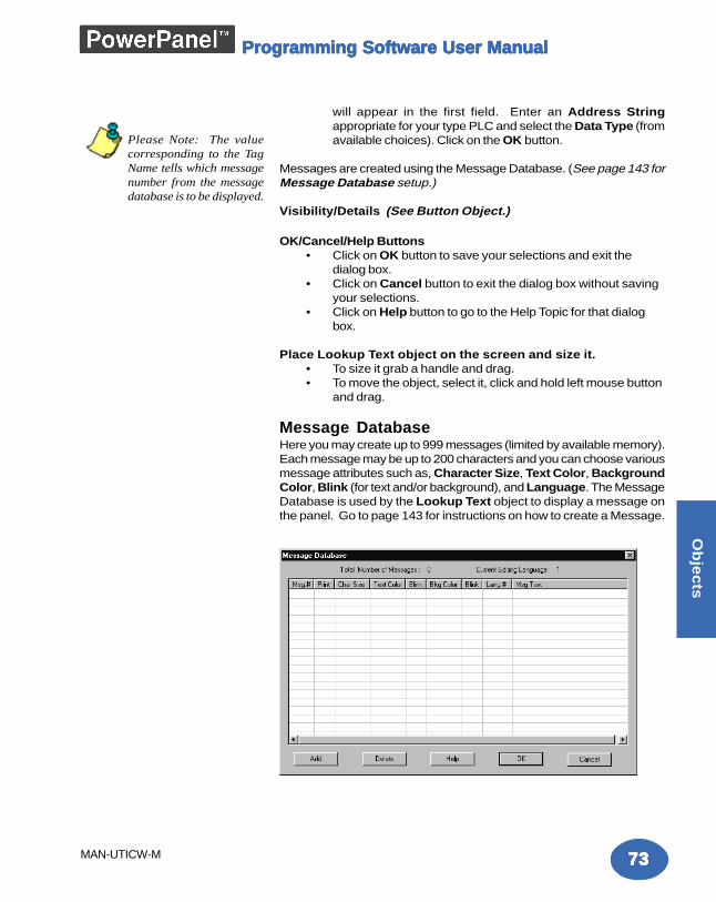
7373737373
Ob
jec
ts
MAN-UTICW-M
Programming Software User ManualProgramming Software User ManualProgramming Software User ManualProgramming Software User ManualProgramming Software User Manual
will appear in the first field. Enter an Address Stringappropriate for your type PLC and select the Data Type (fromavailable choices). Click on the OK button.
Messages are created using the Message Database. (See page 143 forMessage Database setup.)
Visibility/Details (See Button Object.)
OK/Cancel/Help Buttons• Click on OK button to save your selections and exit the
dialog box.• Click on Cancel button to exit the dialog box without saving
your selections.• Click on Help button to go to the Help Topic for that dialog
box.
Place Lookup Text object on the screen and size it.• To size it grab a handle and drag.• To move the object, select it, click and hold left mouse button
and drag.
Message DatabaseHere you may create up to 999 messages (limited by available memory).Each message may be up to 200 characters and you can choose variousmessage attributes such as, Character Size, Text Color, BackgroundColor, Blink (for text and/or background), and Language. The MessageDatabase is used by the Lookup Text object to display a message onthe panel. Go to page 143 for instructions on how to create a Message.
Please Note: The valuecorresponding to the TagName tells which messagenumber from the messagedatabase is to be displayed.
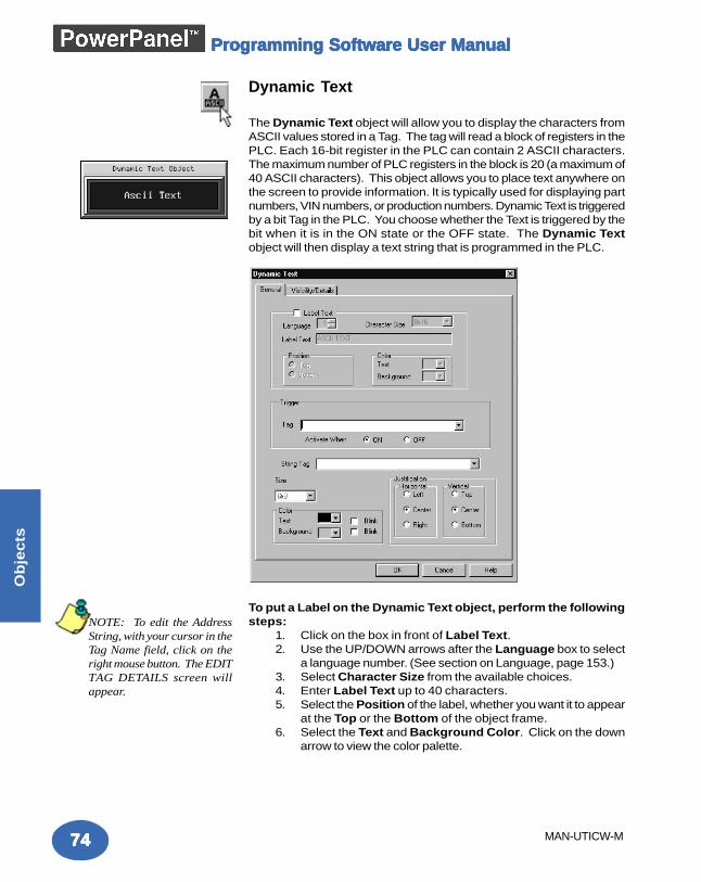
7474747474
Ob
jec
ts
MAN-UTICW-M
Programming Software User ManualProgramming Software User ManualProgramming Software User ManualProgramming Software User ManualProgramming Software User Manual
Dynamic Text
The Dynamic Text object will allow you to display the characters fromASCII values stored in a Tag. The tag will read a block of registers in thePLC. Each 16-bit register in the PLC can contain 2 ASCII characters.The maximum number of PLC registers in the block is 20 (a maximum of40 ASCII characters). This object allows you to place text anywhere onthe screen to provide information. It is typically used for displaying partnumbers, VIN numbers, or production numbers. Dynamic Text is triggeredby a bit Tag in the PLC. You choose whether the Text is triggered by thebit when it is in the ON state or the OFF state. The Dynamic Textobject will then display a text string that is programmed in the PLC.
To put a Label on the Dynamic Text object, perform the followingsteps:
1. Click on the box in front of Label Text.2. Use the UP/DOWN arrows after the Language box to select
a language number. (See section on Language, page 153.)3. Select Character Size from the available choices.4. Enter Label Text up to 40 characters.5. Select the Position of the label, whether you want it to appear
at the Top or the Bottom of the object frame.6. Select the Text and Background Color. Click on the down
arrow to view the color palette.
NOTE: To edit the AddressString, with your cursor in theTag Name field, click on theright mouse button. The EDITTAG DETAILS screen willappear.
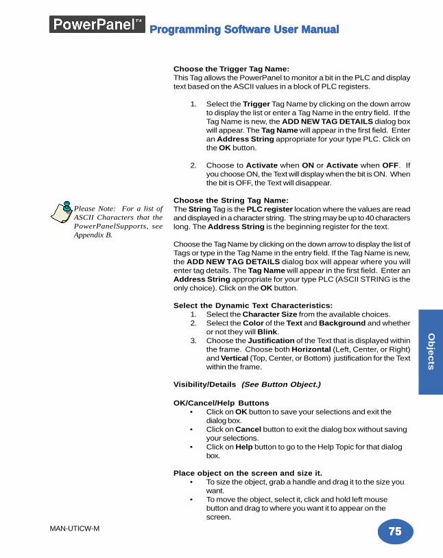
7575757575
Ob
jec
ts
MAN-UTICW-M
Programming Software User ManualProgramming Software User ManualProgramming Software User ManualProgramming Software User ManualProgramming Software User Manual
Choose the Trigger Tag Name:This Tag allows the PowerPanel to monitor a bit in the PLC and displaytext based on the ASCII values in a block of PLC registers.
1. Select the Trigger Tag Name by clicking on the down arrowto display the list or enter a Tag Name in the entry field. If theTag Name is new, the ADD NEW TAG DETAILS dialog boxwill appear. The Tag Name will appear in the first field. Enteran Address String appropriate for your type PLC. Click onthe OK button.
2. Choose to Activate when ON or Activate when OFF. Ifyou choose ON, the Text will display when the bit is ON. Whenthe bit is OFF, the Text will disappear.
Choose the String Tag Name:The String Tag is the PLC register location where the values are readand displayed in a character string. The string may be up to 40 characterslong. The Address String is the beginning register for the text.
Choose the Tag Name by clicking on the down arrow to display the list ofTags or type in the Tag Name in the entry field. If the Tag Name is new,the ADD NEW TAG DETAILS dialog box will appear where you willenter tag details. The Tag Name will appear in the first field. Enter anAddress String appropriate for your type PLC (ASCII STRING is theonly choice). Click on the OK button.
Select the Dynamic Text Characteristics:1. Select the Character Size from the available choices.2. Select the Color of the Text and Background and whether
or not they will Blink.3. Choose the Justification of the Text that is displayed within
the frame. Choose both Horizontal (Left, Center, or Right)and Vertical (Top, Center, or Bottom) justification for the Textwithin the frame.
Visibility/Details (See Button Object.)
OK/Cancel/Help Buttons• Click on OK button to save your selections and exit the
dialog box.• Click on Cancel button to exit the dialog box without saving
your selections.• Click on Help button to go to the Help Topic for that dialog
box.
Place object on the screen and size it.• To size the object, grab a handle and drag it to the size you
want.• To move the object, select it, click and hold left mouse
button and drag to where you want it to appear on thescreen.
Please Note: For a list ofASCII Characters that thePowerPanelSupports, seeAppendix B.
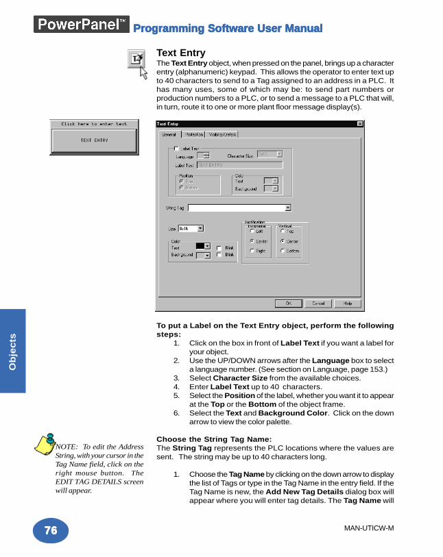
7676767676
Ob
jec
ts
MAN-UTICW-M
Programming Software User ManualProgramming Software User ManualProgramming Software User ManualProgramming Software User ManualProgramming Software User Manual
Text EntryThe Text Entry object, when pressed on the panel, brings up a characterentry (alphanumeric) keypad. This allows the operator to enter text upto 40 characters to send to a Tag assigned to an address in a PLC. Ithas many uses, some of which may be: to send part numbers orproduction numbers to a PLC, or to send a message to a PLC that will,in turn, route it to one or more plant floor message display(s).
To put a Label on the Text Entry object, perform the followingsteps:
1. Click on the box in front of Label Text if you want a label foryour object.
2. Use the UP/DOWN arrows after the Language box to selecta language number. (See section on Language, page 153.)
3. Select Character Size from the available choices.4. Enter Label Text up to 40 characters.5. Select the Position of the label, whether you want it to appear
at the Top or the Bottom of the object frame.6. Select the Text and Background Color. Click on the down
arrow to view the color palette.
Choose the String Tag Name:The String Tag represents the PLC locations where the values aresent. The string may be up to 40 characters long.
1. Choose the Tag Name by clicking on the down arrow to displaythe list of Tags or type in the Tag Name in the entry field. If theTag Name is new, the Add New Tag Details dialog box willappear where you will enter tag details. The Tag Name will
NOTE: To edit the AddressString, with your cursor in theTag Name field, click on theright mouse button. TheEDIT TAG DETAILS screenwill appear.
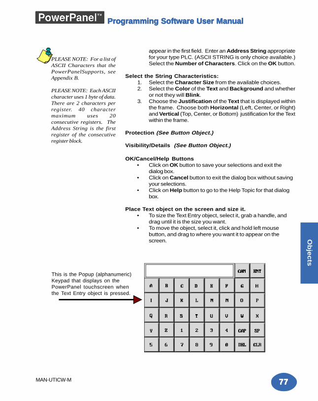
7777777777
Ob
jec
ts
MAN-UTICW-M
Programming Software User ManualProgramming Software User ManualProgramming Software User ManualProgramming Software User ManualProgramming Software User Manual
appear in the first field. Enter an Address String appropriatefor your type PLC. (ASCII STRING is only choice available.)Select the Number of Characters. Click on the OK button.
Select the String Characteristics:1. Select the Character Size from the available choices.2. Select the Color of the Text and Background and whether
or not they will Blink.3. Choose the Justification of the Text that is displayed within
the frame. Choose both Horizontal (Left, Center, or Right)and Vertical (Top, Center, or Bottom) justification for the Textwithin the frame.
Protection (See Button Object.)
Visibility/Details (See Button Object.)
OK/Cancel/Help Buttons• Click on OK button to save your selections and exit the
dialog box.• Click on Cancel button to exit the dialog box without saving
your selections.• Click on Help button to go to the Help Topic for that dialog
box.
Place Text object on the screen and size it.• To size the Text Entry object, select it, grab a handle, and
drag until it is the size you want.• To move the object, select it, click and hold left mouse
button, and drag to where you want it to appear on thescreen.
This is the Popup (alphanumeric)Keypad that displays on thePowerPanel touchscreen whenthe Text Entry object is pressed.
PLEASE NOTE: For a list ofASCII Characters that thePowerPanelSupports, seeAppendix B.
PLEASE NOTE: Each ASCIIcharacter uses 1 byte of data.There are 2 characters perregister. 40 charactermaximum uses 20consecutive registers. TheAddress String is the firstregister of the consecutiveregister block.
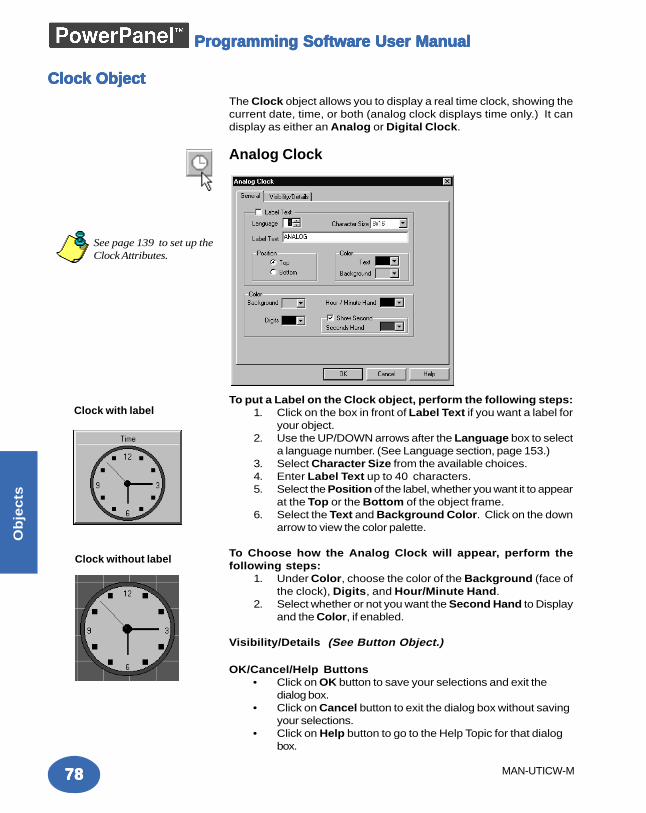
7878787878
Ob
jec
ts
MAN-UTICW-M
Programming Software User ManualProgramming Software User ManualProgramming Software User ManualProgramming Software User ManualProgramming Software User Manual
Clock ObjectClock ObjectClock ObjectClock ObjectClock ObjectThe Clock object allows you to display a real time clock, showing thecurrent date, time, or both (analog clock displays time only.) It candisplay as either an Analog or Digital Clock.
Analog Clock
To put a Label on the Clock object, perform the following steps:1. Click on the box in front of Label Text if you want a label for
your object.2. Use the UP/DOWN arrows after the Language box to select
a language number. (See Language section, page 153.)3. Select Character Size from the available choices.4. Enter Label Text up to 40 characters.5. Select the Position of the label, whether you want it to appear
at the Top or the Bottom of the object frame.6. Select the Text and Background Color. Click on the down
arrow to view the color palette.
To Choose how the Analog Clock will appear, perform thefollowing steps:
1. Under Color, choose the color of the Background (face ofthe clock), Digits, and Hour/Minute Hand.
2. Select whether or not you want the Second Hand to Displayand the Color, if enabled.
Visibility/Details (See Button Object.)
OK/Cancel/Help Buttons• Click on OK button to save your selections and exit the
dialog box.• Click on Cancel button to exit the dialog box without saving
your selections.• Click on Help button to go to the Help Topic for that dialog
box.
Clock with label
Clock without label
See page 139 to set up theClock Attributes.
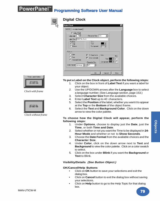
7979797979
Ob
jec
ts
MAN-UTICW-M
Programming Software User ManualProgramming Software User ManualProgramming Software User ManualProgramming Software User ManualProgramming Software User Manual
Digital Clock
To put a Label on the Clock object, perform the following steps:1. Click on the box in front of Label Text if you want a label for
your object.2. Use the UP/DOWN arrows after the Language box to select
a language number. (See Language section, page 153.)3. Select Character Size from the available choices.4. Enter Label Text up to 40 characters.5. Select the Position of the label, whether you want it to appear
at the Top or the Bottom of the object frame.6. Select the Text and Background Color. Click on the down
arrow to view the color palette.
To choose how the Digital Clock will appear, perform thefollowing steps:
1. Under Options, choose to display just the Date, just theTime, or both Time and Date.
2. Select whether or not you want the Time to be displayed in 24-Hour Mode and whether or not to Show Seconds.
3. Choose the Date Format from the available choices and theCharacter Size.
4. Under Color, click on the down arrow next to Text andBackground to view the color palette. Click on a color swatchto select.
5. Click on the box under Blink if you want the Background orText to Blink.
Visibility/Details (See Button Object.)
OK/Cancel/Help Buttons• Click on OK button to save your selections and exit the
dialog box.• Click on Cancel button to exit the dialog box without saving
your selections.• Click on Help button to go to the Help Topic for that dialog
box.
Clock with frame
Clock without frame
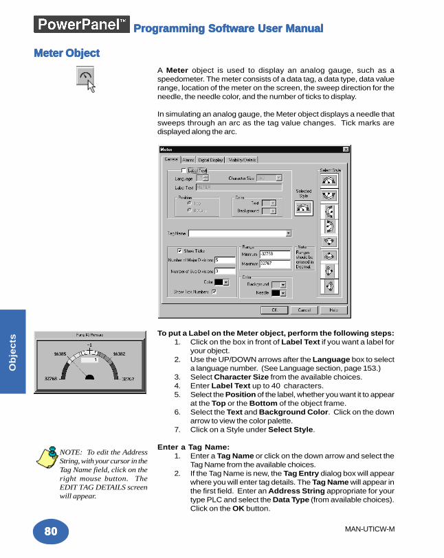
8080808080
Ob
jec
ts
MAN-UTICW-M
Programming Software User ManualProgramming Software User ManualProgramming Software User ManualProgramming Software User ManualProgramming Software User Manual
Meter ObjectMeter ObjectMeter ObjectMeter ObjectMeter ObjectA Meter object is used to display an analog gauge, such as aspeedometer. The meter consists of a data tag, a data type, data valuerange, location of the meter on the screen, the sweep direction for theneedle, the needle color, and the number of ticks to display.
In simulating an analog gauge, the Meter object displays a needle thatsweeps through an arc as the tag value changes. Tick marks aredisplayed along the arc.
To put a Label on the Meter object, perform the following steps:1. Click on the box in front of Label Text if you want a label for
your object.2. Use the UP/DOWN arrows after the Language box to select
a language number. (See Language section, page 153.)3. Select Character Size from the available choices.4. Enter Label Text up to 40 characters.5. Select the Position of the label, whether you want it to appear
at the Top or the Bottom of the object frame.6. Select the Text and Background Color. Click on the down
arrow to view the color palette.7. Click on a Style under Select Style.
Enter a Tag Name:1. Enter a Tag Name or click on the down arrow and select the
Tag Name from the available choices.2. If the Tag Name is new, the Tag Entry dialog box will appear
where you will enter tag details. The Tag Name will appear inthe first field. Enter an Address String appropriate for yourtype PLC and select the Data Type (from available choices).Click on the OK button.
NOTE: To edit the AddressString, with your cursor in theTag Name field, click on theright mouse button. TheEDIT TAG DETAILS screenwill appear.
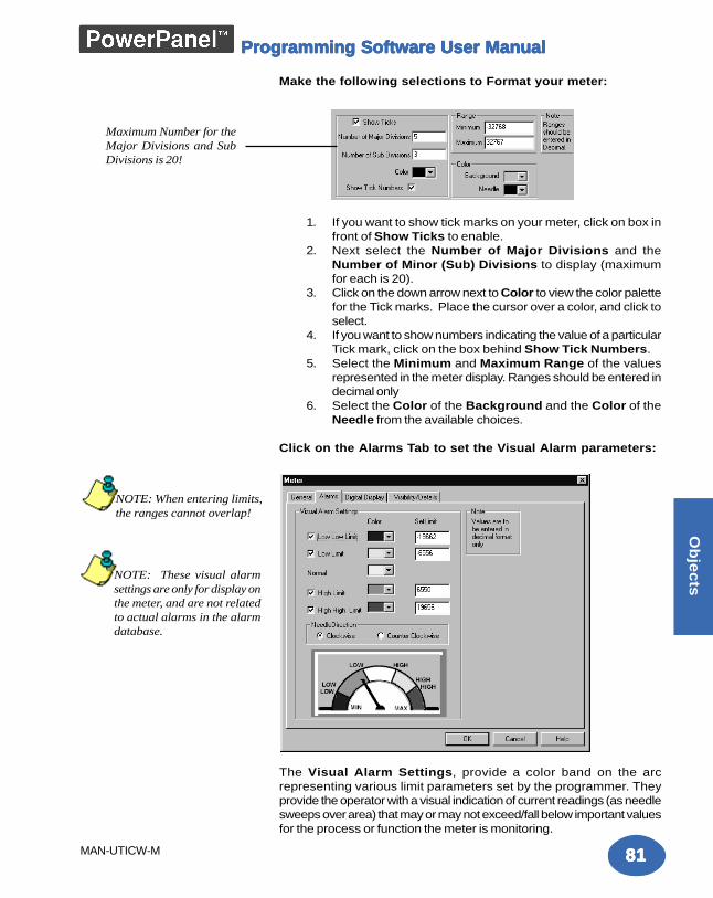
8181818181
Ob
jec
ts
MAN-UTICW-M
Programming Software User ManualProgramming Software User ManualProgramming Software User ManualProgramming Software User ManualProgramming Software User Manual
Make the following selections to Format your meter:
1. If you want to show tick marks on your meter, click on box infront of Show Ticks to enable.
2. Next select the Number of Major Divisions and theNumber of Minor (Sub) Divisions to display (maximumfor each is 20).
3. Click on the down arrow next to Color to view the color palettefor the Tick marks. Place the cursor over a color, and click toselect.
4. If you want to show numbers indicating the value of a particularTick mark, click on the box behind Show Tick Numbers.
5. Select the Minimum and Maximum Range of the valuesrepresented in the meter display. Ranges should be entered indecimal only
6. Select the Color of the Background and the Color of theNeedle from the available choices.
Click on the Alarms Tab to set the Visual Alarm parameters:
The Visual Alarm Settings, provide a color band on the arcrepresenting various limit parameters set by the programmer. Theyprovide the operator with a visual indication of current readings (as needlesweeps over area) that may or may not exceed/fall below important valuesfor the process or function the meter is monitoring.
Maximum Number for theMajor Divisions and SubDivisions is 20!
NOTE: These visual alarmsettings are only for display onthe meter, and are not relatedto actual alarms in the alarmdatabase.
NOTE: When entering limits,the ranges cannot overlap!
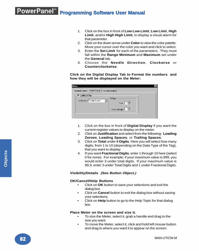
8282828282
Ob
jec
ts
MAN-UTICW-M
Programming Software User ManualProgramming Software User ManualProgramming Software User ManualProgramming Software User ManualProgramming Software User Manual
1. Click on the box in front of Low Low Limit, Low Limit, HighLimit, and/or High High Limit, to display a visual alarm forthat parameter.
2. Click on the down arrow under Color to view the color palette.Move your cursor over the color you want and click to select.
3. Enter the Set Limit for each of the parameters. They mustfall within the Range Minimum and Maximum set underthe General tab.
4. Choose the Needle Direction, Clockwise orCounterclockwise.
Click on the Digital Display Tab to Format the numbers andhow they will be displayed on the Meter:
1. Click on the box in front of Digital Display if you want thecurrent register values to display on the meter.
2. Click on Justification and select from the following: LeadingZeroes, Leading Spaces, or Trailing Spaces.
3. Click on Total under # Digits. Here you will select how manydigits, from 1 to 10 (depending on the Data Type of the Tag),that you want to display.
4. If you want Fractional Digits, enter 1 through 10 here (select0 for none). For example, if your maximum value is 999, youwould enter 3 under total digits. If your maximum value is99.9, enter 3 under Total Digits and 1 under Fractional Digits.
Visibility/Details (See Button Object.)
OK/Cancel/Help Buttons• Click on OK button to save your selections and exit the
dialog box.• Click on Cancel button to exit the dialog box without saving
your selections.• Click on Help button to go to the Help Topic for that dialog
box.
Place Meter on the screen and size it.• To size the Meter, select it, grab a handle and drag to the
size you want.• To move the Meter, select it, click and hold left mouse button
and drag to where you want it to appear on the screen.
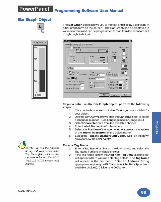
8383838383
Ob
jec
ts
MAN-UTICW-M
Programming Software User ManualProgramming Software User ManualProgramming Software User ManualProgramming Software User ManualProgramming Software User Manual
Bar Graph ObjectBar Graph ObjectBar Graph ObjectBar Graph ObjectBar Graph ObjectThe Bar Graph object allows you to monitor and display a tag value ina bar graph form on the screen. The Bar Graph can be displayed invarious formats and can be programmed to read from top to bottom, leftto right, right to left, etc.
To put a Label on the Bar Graph object, perform the followingsteps:
1. Click on the box in front of Label Text if you want a label foryour object.
2. Use the UP/DOWN arrows after the Language box to selecta language number. (See Language section, page 153.)
3. Select Character Size from the available choices.4. Enter Label Text up to 40 characters.5. Select the Position of the label, whether you want it to appear
at the Top or the Bottom of the object frame.6. Select the Text and Background Color. Click on the down
arrow to view the color palette.
Enter a Tag Name:1. Enter a Tag Name or click on the down arrow and select the
Tag Name from the available choices.2. If the Tag Name is new, the Add New Tag Details dialog box
will appear where you will enter tag details. The Tag Namewill appear in the first field. Enter an Address Stringappropriate for your type PLC and select the Data Type (fromavailable choices). Click on the OK button.
NOTE: To edit the AddressString, with your cursor in theTag Name field, click on theright mouse button. The EDITTAG DETAILS screen willappear.
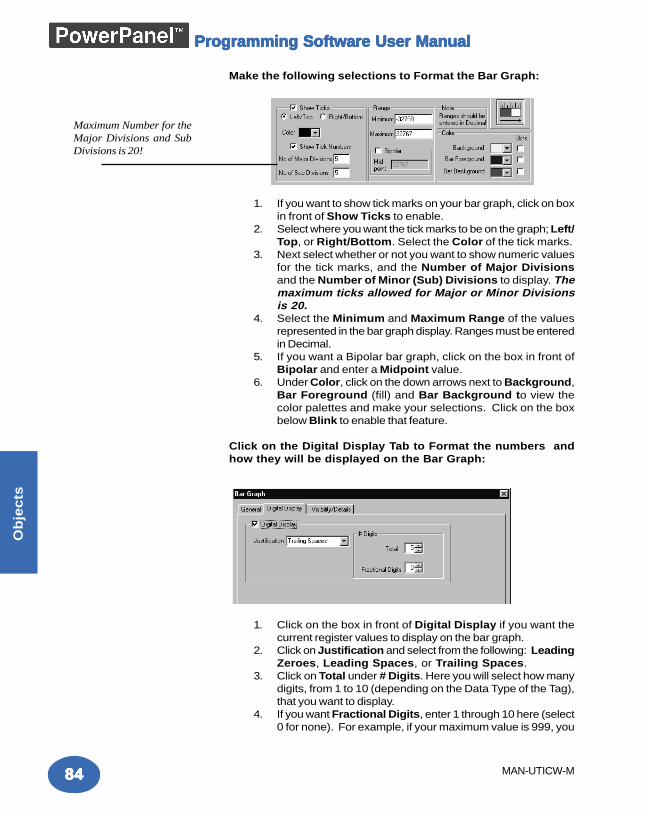
8484848484
Ob
jec
ts
MAN-UTICW-M
Programming Software User ManualProgramming Software User ManualProgramming Software User ManualProgramming Software User ManualProgramming Software User Manual
Make the following selections to Format the Bar Graph:
1. If you want to show tick marks on your bar graph, click on boxin front of Show Ticks to enable.
2. Select where you want the tick marks to be on the graph; Left/Top, or Right/Bottom. Select the Color of the tick marks.
3. Next select whether or not you want to show numeric valuesfor the tick marks, and the Number of Major Divisionsand the Number of Minor (Sub) Divisions to display. Themaximum ticks allowed for Major or Minor Divisionsis 20.
4. Select the Minimum and Maximum Range of the valuesrepresented in the bar graph display. Ranges must be enteredin Decimal.
5. If you want a Bipolar bar graph, click on the box in front ofBipolar and enter a Midpoint value.
6. Under Color, click on the down arrows next to Background,Bar Foreground (fill) and Bar Background to view thecolor palettes and make your selections. Click on the boxbelow Blink to enable that feature.
Click on the Digital Display Tab to Format the numbers andhow they will be displayed on the Bar Graph:
1. Click on the box in front of Digital Display if you want thecurrent register values to display on the bar graph.
2. Click on Justification and select from the following: LeadingZeroes, Leading Spaces, or Trailing Spaces.
3. Click on Total under # Digits. Here you will select how manydigits, from 1 to 10 (depending on the Data Type of the Tag),that you want to display.
4. If you want Fractional Digits, enter 1 through 10 here (select0 for none). For example, if your maximum value is 999, you
Maximum Number for theMajor Divisions and SubDivisions is 20!
8585858585
Ob
jec
ts
MAN-UTICW-M
Programming Software User ManualProgramming Software User ManualProgramming Software User ManualProgramming Software User ManualProgramming Software User Manual
would enter 3 under total digits. If your maximum value is99.9, enter 3 under Total Digits and 1 under Fractional Digits.
Visibility/Details (See Button Object.)
OK/Cancel/Help Buttons• Click on OK button to save your selections and exit the
dialog box.• Click on Cancel button to exit the dialog box without saving
your selections.• Click on Help button to go to the Help Topic for that dialog
box.
Place Bar Graph on the screen and size it.• To size the Bar Graph, grab a handle and drag to size you
want.• To move the Line Graph, select it, click and hold left mouse
button, and drag to where you want it to appear on thescreen.
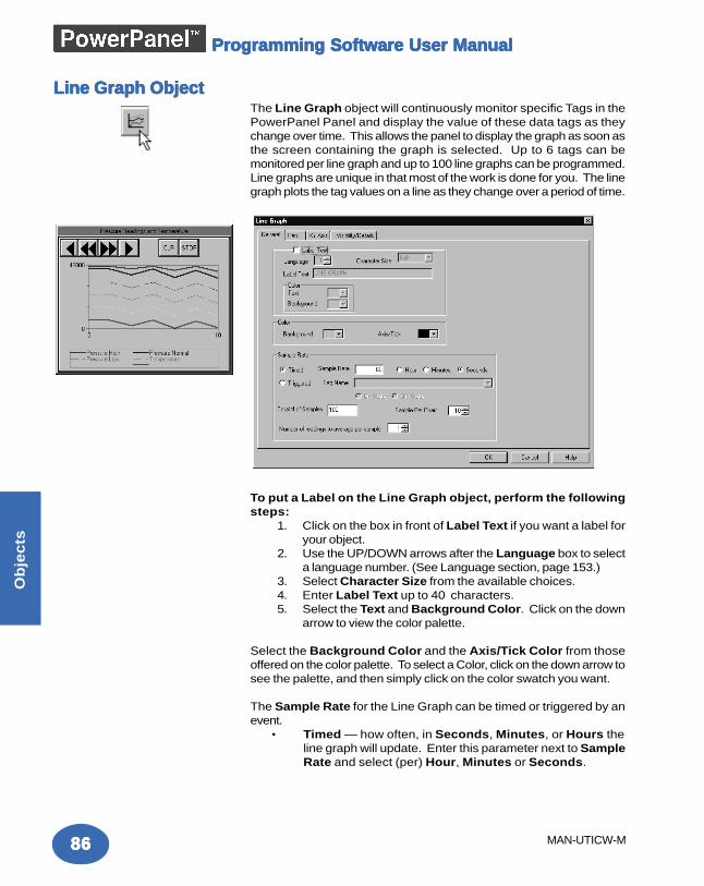
8686868686
Ob
jec
ts
MAN-UTICW-M
Programming Software User ManualProgramming Software User ManualProgramming Software User ManualProgramming Software User ManualProgramming Software User Manual
Line Graph ObjectLine Graph ObjectLine Graph ObjectLine Graph ObjectLine Graph ObjectThe Line Graph object will continuously monitor specific Tags in thePowerPanel Panel and display the value of these data tags as theychange over time. This allows the panel to display the graph as soon asthe screen containing the graph is selected. Up to 6 tags can bemonitored per line graph and up to 100 line graphs can be programmed.Line graphs are unique in that most of the work is done for you. The linegraph plots the tag values on a line as they change over a period of time.
To put a Label on the Line Graph object, perform the followingsteps:
1. Click on the box in front of Label Text if you want a label foryour object.
2. Use the UP/DOWN arrows after the Language box to selecta language number. (See Language section, page 153.)
3. Select Character Size from the available choices.4. Enter Label Text up to 40 characters.5. Select the Text and Background Color. Click on the down
arrow to view the color palette.
Select the Background Color and the Axis/Tick Color from thoseoffered on the color palette. To select a Color, click on the down arrow tosee the palette, and then simply click on the color swatch you want.
The Sample Rate for the Line Graph can be timed or triggered by anevent.
• Timed — how often, in Seconds, Minutes, or Hours theline graph will update. Enter this parameter next to SampleRate and select (per) Hour, Minutes or Seconds.
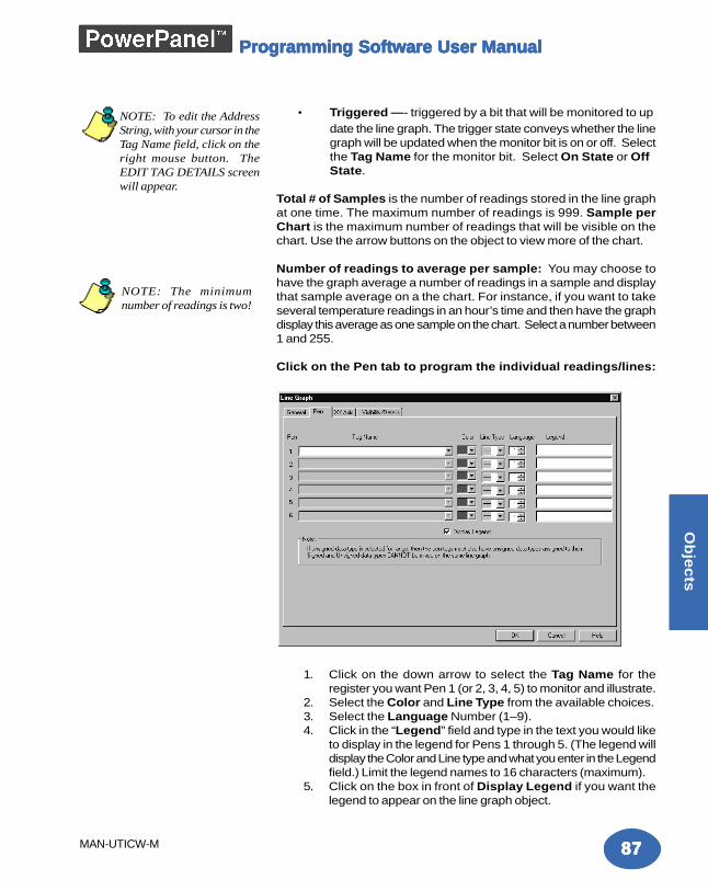
8787878787
Ob
jec
ts
MAN-UTICW-M
Programming Software User ManualProgramming Software User ManualProgramming Software User ManualProgramming Software User ManualProgramming Software User Manual
• Triggered —- triggered by a bit that will be monitored to update the line graph. The trigger state conveys whether the linegraph will be updated when the monitor bit is on or off. Selectthe Tag Name for the monitor bit. Select On State or OffState.
Total # of Samples is the number of readings stored in the line graphat one time. The maximum number of readings is 999. Sample perChart is the maximum number of readings that will be visible on thechart. Use the arrow buttons on the object to view more of the chart.
Number of readings to average per sample: You may choose tohave the graph average a number of readings in a sample and displaythat sample average on a the chart. For instance, if you want to takeseveral temperature readings in an hour’s time and then have the graphdisplay this average as one sample on the chart. Select a number between1 and 255.
Click on the Pen tab to program the individual readings/lines:
1. Click on the down arrow to select the Tag Name for theregister you want Pen 1 (or 2, 3, 4, 5) to monitor and illustrate.
2. Select the Color and Line Type from the available choices.3. Select the Language Number (1–9).4. Click in the “Legend” field and type in the text you would like
to display in the legend for Pens 1 through 5. (The legend willdisplay the Color and Line type and what you enter in the Legendfield.) Limit the legend names to 16 characters (maximum).
5. Click on the box in front of Display Legend if you want thelegend to appear on the line graph object.
NOTE: The minimumnumber of readings is two!
NOTE: To edit the AddressString, with your cursor in theTag Name field, click on theright mouse button. TheEDIT TAG DETAILS screenwill appear.
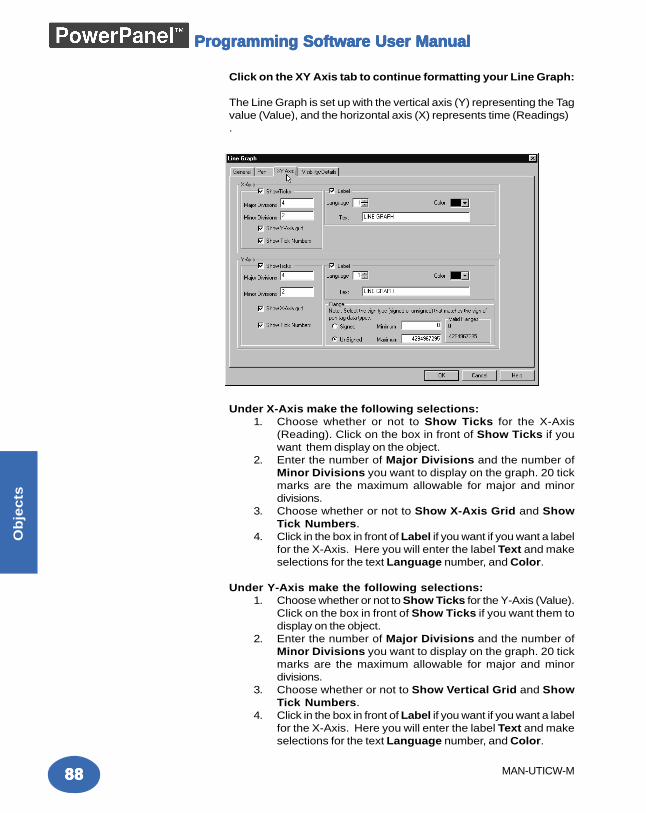
8888888888
Ob
jec
ts
MAN-UTICW-M
Programming Software User ManualProgramming Software User ManualProgramming Software User ManualProgramming Software User ManualProgramming Software User Manual
Click on the XY Axis tab to continue formatting your Line Graph:
The Line Graph is set up with the vertical axis (Y) representing the Tagvalue (Value), and the horizontal axis (X) represents time (Readings).
Under X-Axis make the following selections:1. Choose whether or not to Show Ticks for the X-Axis
(Reading). Click on the box in front of Show Ticks if youwant them display on the object.
2. Enter the number of Major Divisions and the number ofMinor Divisions you want to display on the graph. 20 tickmarks are the maximum allowable for major and minordivisions.
3. Choose whether or not to Show X-Axis Grid and ShowTick Numbers.
4. Click in the box in front of Label if you want if you want a labelfor the X-Axis. Here you will enter the label Text and makeselections for the text Language number, and Color.
Under Y-Axis make the following selections:1. Choose whether or not to Show Ticks for the Y-Axis (Value).
Click on the box in front of Show Ticks if you want them todisplay on the object.
2. Enter the number of Major Divisions and the number ofMinor Divisions you want to display on the graph. 20 tickmarks are the maximum allowable for major and minordivisions.
3. Choose whether or not to Show Vertical Grid and ShowTick Numbers.
4. Click in the box in front of Label if you want if you want a labelfor the X-Axis. Here you will enter the label Text and makeselections for the text Language number, and Color.
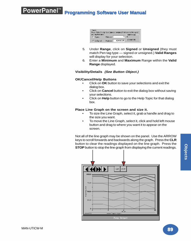
8989898989
Ob
jec
ts
MAN-UTICW-M
Programming Software User ManualProgramming Software User ManualProgramming Software User ManualProgramming Software User ManualProgramming Software User Manual
5. Under Range, click on Signed or Unsigned (they mustmatch Pen tag type — signed or unsigned.) Valid Rangeswill display for your selection.
6. Enter a Minimum and Maximum Range within the ValidRange displayed.
Visibility/Details (See Button Object.)
OK/Cancel/Help Buttons• Click on OK button to save your selections and exit the
dialog box.• Click on Cancel button to exit the dialog box without saving
your selections.• Click on Help button to go to the Help Topic for that dialog
box.
Place Line Graph on the screen and size it.• To size the Line Graph, select it, grab a handle and drag to
the size you want.• To move the Line Graph, select it, click and hold left mouse
button and drag to where you want it to appear on thescreen.
Not all of the line graph may be shown on the panel. Use the ARROWkeys to scroll forwards and backwards along the graph. Press the CLRbutton to clear the readings displayed on the line graph. Press theSTOP button to stop the line graph from displaying the current readings.
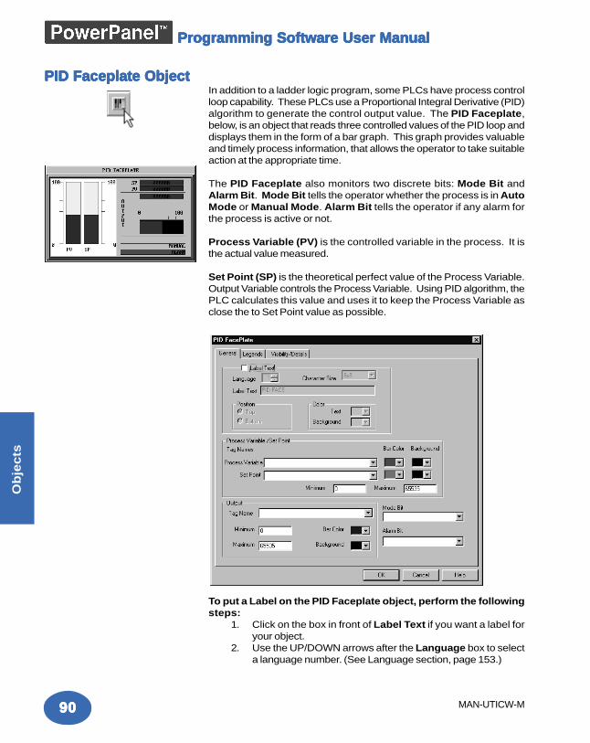
9090909090
Ob
jec
ts
MAN-UTICW-M
Programming Software User ManualProgramming Software User ManualProgramming Software User ManualProgramming Software User ManualProgramming Software User Manual
PID Faceplate ObjectPID Faceplate ObjectPID Faceplate ObjectPID Faceplate ObjectPID Faceplate ObjectIn addition to a ladder logic program, some PLCs have process controlloop capability. These PLCs use a Proportional Integral Derivative (PID)algorithm to generate the control output value. The PID Faceplate,below, is an object that reads three controlled values of the PID loop anddisplays them in the form of a bar graph. This graph provides valuableand timely process information, that allows the operator to take suitableaction at the appropriate time.
The PID Faceplate also monitors two discrete bits: Mode Bit andAlarm Bit. Mode Bit tells the operator whether the process is in AutoMode or Manual Mode. Alarm Bit tells the operator if any alarm forthe process is active or not.
Process Variable (PV) is the controlled variable in the process. It isthe actual value measured.
Set Point (SP) is the theoretical perfect value of the Process Variable.Output Variable controls the Process Variable. Using PID algorithm, thePLC calculates this value and uses it to keep the Process Variable asclose the to Set Point value as possible.
To put a Label on the PID Faceplate object, perform the followingsteps:
1. Click on the box in front of Label Text if you want a label foryour object.
2. Use the UP/DOWN arrows after the Language box to selecta language number. (See Language section, page 153.)
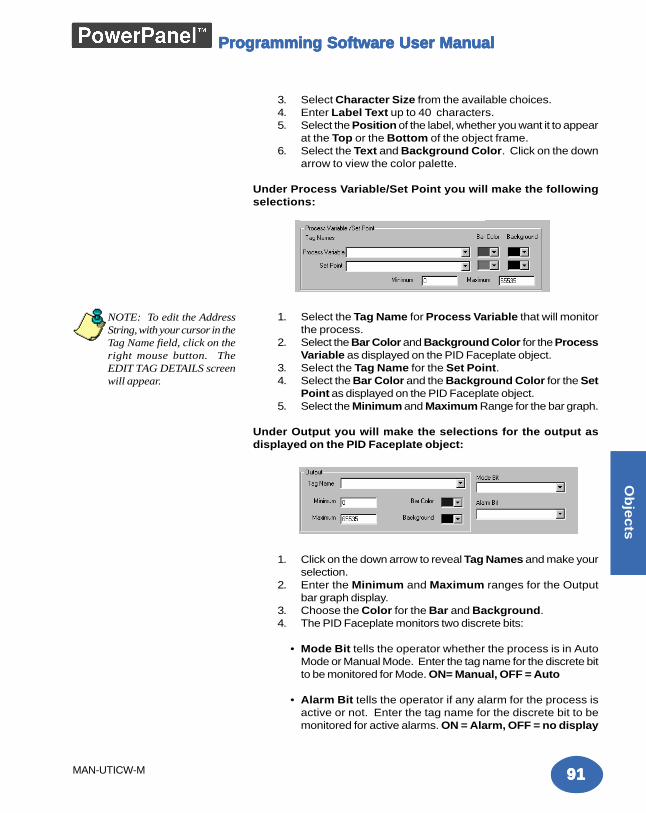
9191919191
Ob
jec
ts
MAN-UTICW-M
Programming Software User ManualProgramming Software User ManualProgramming Software User ManualProgramming Software User ManualProgramming Software User Manual
3. Select Character Size from the available choices.4. Enter Label Text up to 40 characters.5. Select the Position of the label, whether you want it to appear
at the Top or the Bottom of the object frame.6. Select the Text and Background Color. Click on the down
arrow to view the color palette.
Under Process Variable/Set Point you will make the followingselections:
1. Select the Tag Name for Process Variable that will monitorthe process.
2. Select the Bar Color and Background Color for the ProcessVariable as displayed on the PID Faceplate object.
3. Select the Tag Name for the Set Point.4. Select the Bar Color and the Background Color for the Set
Point as displayed on the PID Faceplate object.5. Select the Minimum and Maximum Range for the bar graph.
Under Output you will make the selections for the output asdisplayed on the PID Faceplate object:
1. Click on the down arrow to reveal Tag Names and make yourselection.
2. Enter the Minimum and Maximum ranges for the Outputbar graph display.
3. Choose the Color for the Bar and Background.4. The PID Faceplate monitors two discrete bits:
• Mode Bit tells the operator whether the process is in AutoMode or Manual Mode. Enter the tag name for the discrete bitto be monitored for Mode. ON= Manual, OFF = Auto
• Alarm Bit tells the operator if any alarm for the process isactive or not. Enter the tag name for the discrete bit to bemonitored for active alarms. ON = Alarm, OFF = no display
NOTE: To edit the AddressString, with your cursor in theTag Name field, click on theright mouse button. TheEDIT TAG DETAILS screenwill appear.
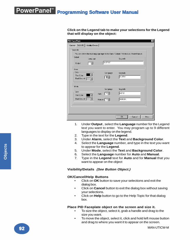
9292929292
Ob
jec
ts
MAN-UTICW-M
Programming Software User ManualProgramming Software User ManualProgramming Software User ManualProgramming Software User ManualProgramming Software User Manual
Click on the Legend tab to make your selections for the Legendthat will display on the object:
1. Under Output , select the Language number for the Legendtext you want to enter. You may program up to 9 differentlanguages to display on the legend.
2. Type in the text for the Legend.3. Under Alarm, select the Text and Background Color.4. Select the Language number, and type in the text you want
to appear for the Legend.5. Under Mode, select the Text and Background Color.6. Select the Language number for Auto and Manual.7. Type in the Legend text for Auto and for Manual that you
want to appear on the object
Visibility/Details (See Button Object.)
OK/Cancel/Help Buttons• Click on OK button to save your selections and exit the
dialog box.• Click on Cancel button to exit the dialog box without saving
your selections.• Click on Help button to go to the Help Topic for that dialog
box.
Place PID Faceplate object on the screen and size it.• To size the object, select it, grab a handle and drag to the
size you want.• To move the object, select it, click and hold left mouse button
and drag to where you want it to appear on the screen.
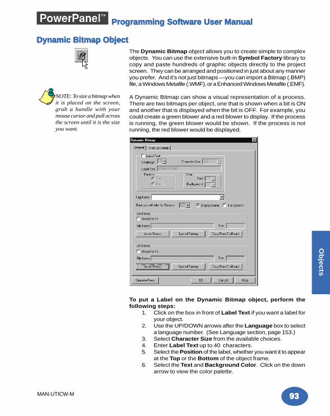
9393939393
Ob
jec
ts
MAN-UTICW-M
Programming Software User ManualProgramming Software User ManualProgramming Software User ManualProgramming Software User ManualProgramming Software User Manual
The Dynamic Bitmap object allows you to create simple to complexobjects. You can use the extensive built-in Symbol Factory library tocopy and paste hundreds of graphic objects directly to the projectscreen. They can be arranged and positioned in just about any manneryou prefer. And it’s not just bitmaps —you can import a Bitmap (.BMP)file, a Windows Metafile (.WMF), or a Enhanced Windows Metafile (.EMF).
A Dynamic Bitmap can show a visual representation of a process.There are two bitmaps per object, one that is shown when a bit is ONand another that is displayed when the bit is OFF. For example, youcould create a green blower and a red blower to display. If the processis running, the green blower would be shown. If the process is notrunning, the red blower would be displayed.
To put a Label on the Dynamic Bitmap object, perform thefollowing steps:
1. Click on the box in front of Label Text if you want a label foryour object.
2. Use the UP/DOWN arrows after the Language box to selecta language number. (See Language section, page 153.)
3. Select Character Size from the available choices.4. Enter Label Text up to 40 characters.5. Select the Position of the label, whether you want it to appear
at the Top or the Bottom of the object frame.6. Select the Text and Background Color. Click on the down
arrow to view the color palette.
Dynamic Bitmap ObjectDynamic Bitmap ObjectDynamic Bitmap ObjectDynamic Bitmap ObjectDynamic Bitmap Object
NOTE: To size a bitmap whenit is placed on the screen,grab a handle with yourmouse cursor and pull acrossthe screen until it is the sizeyou want.
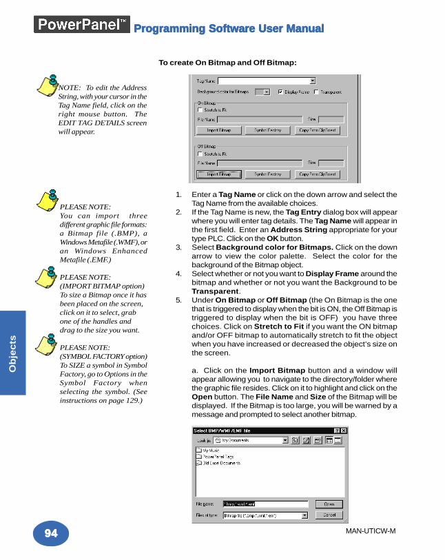
9494949494
Ob
jec
ts
MAN-UTICW-M
Programming Software User ManualProgramming Software User ManualProgramming Software User ManualProgramming Software User ManualProgramming Software User Manual
To create On Bitmap and Off Bitmap:
1. Enter a Tag Name or click on the down arrow and select theTag Name from the available choices.
2. If the Tag Name is new, the Tag Entry dialog box will appearwhere you will enter tag details. The Tag Name will appear inthe first field. Enter an Address String appropriate for yourtype PLC. Click on the OK button.
3. Select Background color for Bitmaps. Click on the downarrow to view the color palette. Select the color for thebackground of the Bitmap object.
4. Select whether or not you want to Display Frame around thebitmap and whether or not you want the Background to beTransparent.
5. Under On Bitmap or Off Bitmap (the On Bitmap is the onethat is triggered to display when the bit is ON, the Off Bitmap istriggered to display when the bit is OFF) you have threechoices. Click on Stretch to Fit if you want the ON bitmapand/or OFF bitmap to automatically stretch to fit the objectwhen you have increased or decreased the object’s size onthe screen.
a. Click on the Import Bitmap button and a window willappear allowing you to navigate to the directory/folder wherethe graphic file resides. Click on it to highlight and click on theOpen button. The File Name and Size of the Bitmap will bedisplayed. If the Bitmap is too large, you will be warned by amessage and prompted to select another bitmap.
NOTE: To edit the AddressString, with your cursor in theTag Name field, click on theright mouse button. TheEDIT TAG DETAILS screenwill appear.
PLEASE NOTE:You can import threedifferent graphic file formats:a Bitmap file (.BMP), aWindows Metafile (.WMF), oran Windows EnhancedMetafile (.EMF.)
PLEASE NOTE:(IMPORT BITMAP option)To size a Bitmap once it hasbeen placed on the screen,click on it to select, grabone of the handles anddrag to the size you want.
PLEASE NOTE:(SYMBOL FACTORY option)To SIZE a symbol in SymbolFactory, go to Options in theSymbol Factory whenselecting the symbol. (Seeinstructions on page 129.)
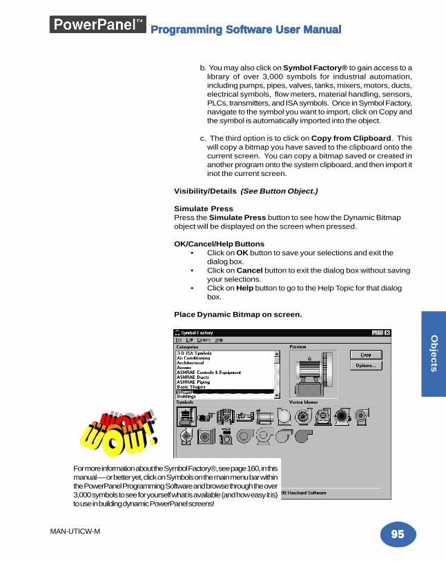
9595959595
Ob
jec
ts
MAN-UTICW-M
Programming Software User ManualProgramming Software User ManualProgramming Software User ManualProgramming Software User ManualProgramming Software User Manual
b. You may also click on Symbol Factory® to gain access to alibrary of over 3,000 symbols for industrial automation,including pumps, pipes, valves, tanks, mixers, motors, ducts,electrical symbols, flow meters, material handling, sensors,PLCs, transmitters, and ISA symbols. Once in Symbol Factory,navigate to the symbol you want to import, click on Copy andthe symbol is automatically imported into the object.
c. The third option is to click on Copy from Clipboard. Thiswill copy a bitmap you have saved to the clipboard onto thecurrent screen. You can copy a bitmap saved or created inanother program onto the system clipboard, and then import itinot the current screen.
Visibility/Details (See Button Object.)
Simulate PressPress the Simulate Press button to see how the Dynamic Bitmapobject will be displayed on the screen when pressed.
OK/Cancel/Help Buttons• Click on OK button to save your selections and exit the
dialog box.• Click on Cancel button to exit the dialog box without saving
your selections.• Click on Help button to go to the Help Topic for that dialog
box.
Place Dynamic Bitmap on screen.
For more information about the Symbol Factory®, see page 160, in thismanual — or better yet, click on Symbols on the main menu bar withinthe PowerPanel Programming Software and browse through the over3,000 symbols to see for yourself what is available (and how easy it is)to use in building dynamic PowerPanel screens!
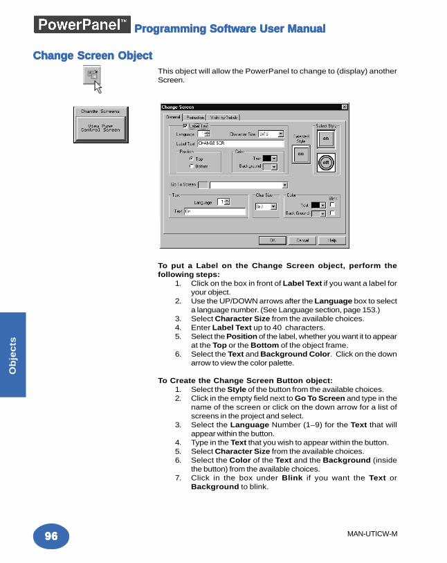
9696969696
Ob
jec
ts
MAN-UTICW-M
Programming Software User ManualProgramming Software User ManualProgramming Software User ManualProgramming Software User ManualProgramming Software User Manual
Change Screen ObjectChange Screen ObjectChange Screen ObjectChange Screen ObjectChange Screen ObjectThis object will allow the PowerPanel to change to (display) anotherScreen.
To put a Label on the Change Screen object, perform thefollowing steps:
1. Click on the box in front of Label Text if you want a label foryour object.
2. Use the UP/DOWN arrows after the Language box to selecta language number. (See Language section, page 153.)
3. Select Character Size from the available choices.4. Enter Label Text up to 40 characters.5. Select the Position of the label, whether you want it to appear
at the Top or the Bottom of the object frame.6. Select the Text and Background Color. Click on the down
arrow to view the color palette.
To Create the Change Screen Button object:1. Select the Style of the button from the available choices.2. Click in the empty field next to Go To Screen and type in the
name of the screen or click on the down arrow for a list ofscreens in the project and select.
3. Select the Language Number (1–9) for the Text that willappear within the button.
4. Type in the Text that you wish to appear within the button.5. Select Character Size from the available choices.6. Select the Color of the Text and the Background (inside
the button) from the available choices.7. Click in the box under Blink if you want the Text or
Background to blink.
9797979797
Ob
jec
ts
MAN-UTICW-M
Programming Software User ManualProgramming Software User ManualProgramming Software User ManualProgramming Software User ManualProgramming Software User Manual
Protection (See Button Object.)
Visibility/Details (See Button Object.)
OK/Cancel/Help Buttons• Click on OK button to save your selections and exit the
dialog box.• Click on Cancel button to exit the dialog box without saving
your selections.• Click on Help button to go to the Help Topic for that dialog
box.
Place Change Screen Button on the screen and size it.• To size the button, select it, grab a handle and drag to the
size you want.• To move the button, select it, click and hold left mouse
button and drag to where you want it to appear on thescreen.
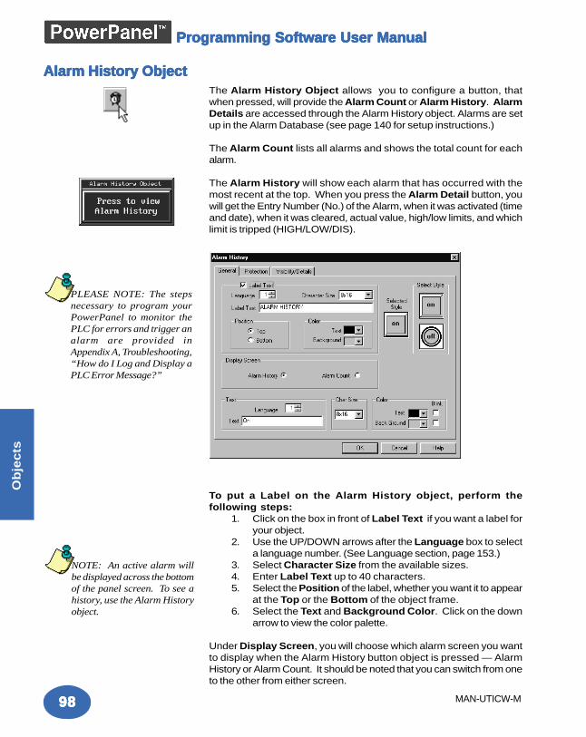
9898989898
Ob
jec
ts
MAN-UTICW-M
Programming Software User ManualProgramming Software User ManualProgramming Software User ManualProgramming Software User ManualProgramming Software User Manual
Alarm History ObjectAlarm History ObjectAlarm History ObjectAlarm History ObjectAlarm History ObjectThe Alarm History Object allows you to configure a button, thatwhen pressed, will provide the Alarm Count or Alarm History. AlarmDetails are accessed through the Alarm History object. Alarms are setup in the Alarm Database (see page 140 for setup instructions.)
The Alarm Count lists all alarms and shows the total count for eachalarm.
The Alarm History will show each alarm that has occurred with themost recent at the top. When you press the Alarm Detail button, youwill get the Entry Number (No.) of the Alarm, when it was activated (timeand date), when it was cleared, actual value, high/low limits, and whichlimit is tripped (HIGH/LOW/DIS).
To put a Label on the Alarm History object, perform thefollowing steps:
1. Click on the box in front of Label Text if you want a label foryour object.
2. Use the UP/DOWN arrows after the Language box to selecta language number. (See Language section, page 153.)
3. Select Character Size from the available sizes.4. Enter Label Text up to 40 characters.5. Select the Position of the label, whether you want it to appear
at the Top or the Bottom of the object frame.6. Select the Text and Background Color. Click on the down
arrow to view the color palette.
Under Display Screen, you will choose which alarm screen you wantto display when the Alarm History button object is pressed — AlarmHistory or Alarm Count. It should be noted that you can switch from oneto the other from either screen.
PLEASE NOTE: The stepsnecessary to program yourPowerPanel to monitor thePLC for errors and trigger analarm are provided inAppendix A, Troubleshooting,“How do I Log and Display aPLC Error Message?”
NOTE: An active alarm willbe displayed across the bottomof the panel screen. To see ahistory, use the Alarm Historyobject.
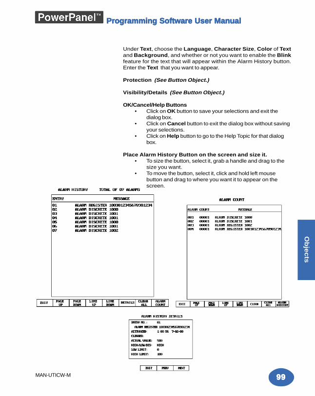
9999999999
Ob
jec
ts
MAN-UTICW-M
Programming Software User ManualProgramming Software User ManualProgramming Software User ManualProgramming Software User ManualProgramming Software User Manual
Under Text, choose the Language, Character Size, Color of Textand Background, and whether or not you want to enable the Blinkfeature for the text that will appear within the Alarm History button.Enter the Text that you want to appear.
Protection (See Button Object.)
Visibility/Details (See Button Object.)
OK/Cancel/Help Buttons• Click on OK button to save your selections and exit the
dialog box.• Click on Cancel button to exit the dialog box without saving
your selections.• Click on Help button to go to the Help Topic for that dialog
box.
Place Alarm History Button on the screen and size it.• To size the button, select it, grab a handle and drag to the
size you want.• To move the button, select it, click and hold left mouse
button and drag to where you want it to appear on thescreen.
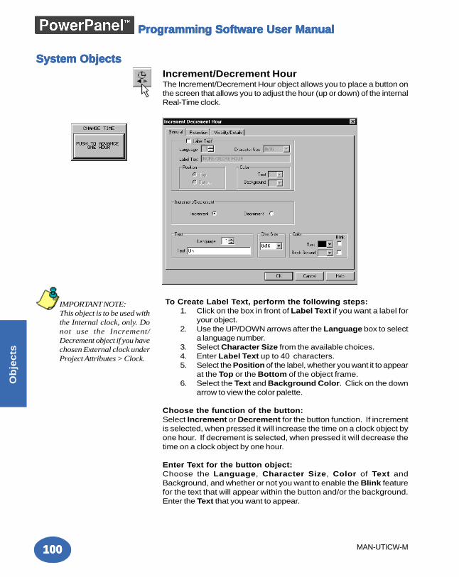
100100100100100
Ob
jec
ts
MAN-UTICW-M
Programming Software User ManualProgramming Software User ManualProgramming Software User ManualProgramming Software User ManualProgramming Software User Manual
System ObjectsSystem ObjectsSystem ObjectsSystem ObjectsSystem ObjectsIncrement/Decrement HourThe Increment/Decrement Hour object allows you to place a button onthe screen that allows you to adjust the hour (up or down) of the internalReal-Time clock.
To Create Label Text, perform the following steps:1. Click on the box in front of Label Text if you want a label for
your object.2. Use the UP/DOWN arrows after the Language box to select
a language number.3. Select Character Size from the available choices.4. Enter Label Text up to 40 characters.5. Select the Position of the label, whether you want it to appear
at the Top or the Bottom of the object frame.6. Select the Text and Background Color. Click on the down
arrow to view the color palette.
Choose the function of the button:Select Increment or Decrement for the button function. If incrementis selected, when pressed it will increase the time on a clock object byone hour. If decrement is selected, when pressed it will decrease thetime on a clock object by one hour.
Enter Text for the button object:Choose the Language, Character Size, Color of Text andBackground, and whether or not you want to enable the Blink featurefor the text that will appear within the button and/or the background.Enter the Text that you want to appear.
IMPORTANT NOTE:This object is to be used withthe Internal clock, only. Donot use the Increment/Decrement object if you havechosen External clock underProject Attributes > Clock.
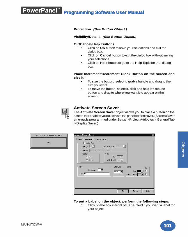
101101101101101
Ob
jec
ts
MAN-UTICW-M
Programming Software User ManualProgramming Software User ManualProgramming Software User ManualProgramming Software User ManualProgramming Software User Manual
Protection (See Button Object.)
Visibility/Details (See Button Object.)
OK/Cancel/Help Buttons• Click on OK button to save your selections and exit the
dialog box.• Click on Cancel button to exit the dialog box without saving
your selections.• Click on Help button to go to the Help Topic for that dialog
box.
Place Increment/Decrement Clock Button on the screen andsize it.
• To size the button, select it, grab a handle and drag to thesize you want.
• To move the button, select it, click and hold left mousebutton and drag to where you want it to appear on thescreen.
Activate Screen SaverThe Activate Screen Saver object allows you to place a button on thescreen that enables you to activate the panel screen saver. (Screen Savertime-out is programmed under Setup > Project Attributes > General Tab> Display Saver.)
To put a Label on the object, perform the following steps:1. Click on the box in front of Label Text if you want a label for
your object.
102102102102102
Ob
jec
ts
MAN-UTICW-M
Programming Software User ManualProgramming Software User ManualProgramming Software User ManualProgramming Software User ManualProgramming Software User Manual
2. Use the UP/DOWN arrows after the Language box to selecta language number. (See Language section, page 153.)
3. Select Character Size from the available choices.4. Enter Label Text up to 40 characters.5. Select the Position of the label, whether you want it to appear
at the Top or the Bottom of the object frame.6. Select the Text and Background Color. Click on the down
arrow to view the color palette.
Enter Text for the button object:Choose the Language, Character Size, Color of Text and Background,and whether or not you want to enable the Blink feature for the text thatwill appear within the button. Enter the Text that you want to appear.
Protection (See Button Object.)
Visibility/Details (See Button Object.)
OK/Cancel/Help Buttons• Click on OK button to save your selections and exit the
dialog box.• Click on Cancel button to exit the dialog box without saving
your selections.• Click on Help button to go to the Help Topic for that dialog
box.
Place Screen Saver Button on the screen and size it.• To size the button, select it, grab a handle and drag to the
size you want.• To move the button, select it, click and hold left mouse
button and drag to where you want it to appear on thescreen.
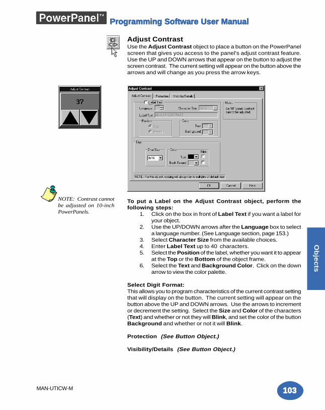
103103103103103
Ob
jec
ts
MAN-UTICW-M
Programming Software User ManualProgramming Software User ManualProgramming Software User ManualProgramming Software User ManualProgramming Software User Manual
Adjust ContrastUse the Adjust Contrast object to place a button on the PowerPanelscreen that gives you access to the panel's adjust contrast feature.Use the UP and DOWN arrows that appear on the button to adjust thescreen contrast. The current setting will appear on the button above thearrows and will change as you press the arrow keys.
To put a Label on the Adjust Contrast object, perform thefollowing steps:
1. Click on the box in front of Label Text if you want a label foryour object.
2. Use the UP/DOWN arrows after the Language box to selecta language number. (See Language section, page 153.)
3. Select Character Size from the available choices.4. Enter Label Text up to 40 characters.5. Select the Position of the label, whether you want it to appear
at the Top or the Bottom of the object frame.6. Select the Text and Background Color. Click on the down
arrow to view the color palette.
Select Digit Format:This allows you to program characteristics of the current contrast settingthat will display on the button. The current setting will appear on thebutton above the UP and DOWN arrows. Use the arrows to incrementor decrement the setting. Select the Size and Color of the characters(Text) and whether or not they will Blink, and set the color of the buttonBackground and whether or not it will Blink.
Protection (See Button Object.)
Visibility/Details (See Button Object.)
NOTE: Contrast cannotbe adjusted on 10-inchPowerPanels.
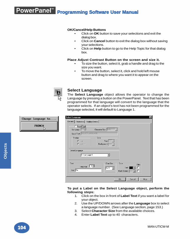
104104104104104
Ob
jec
ts
MAN-UTICW-M
Programming Software User ManualProgramming Software User ManualProgramming Software User ManualProgramming Software User ManualProgramming Software User Manual
OK/Cancel/Help Buttons• Click on OK button to save your selections and exit the
dialog box.• Click on Cancel button to exit the dialog box without saving
your selections.• Click on Help button to go to the Help Topic for that dialog
box.
Place Adjust Contrast Button on the screen and size it.• To size the button, select it, grab a handle and drag to the
size you want.• To move the button, select it, click and hold left mouse
button and drag to where you want it to appear on thescreen.
Select LanguageThe Select Language object allows the operator to change theLanguage by pressing a button on the PowerPanel. Text that has beenprogrammed for that language will convert to the language that theoperator selects. If an object's text has not been programmed for thelanguage selected, it will default to Language 1.
To put a Label on the Select Language object, perform thefollowing steps:
1. Click on the box in front of Label Text if you want a label foryour object.
2. Use the UP/DOWN arrows after the Language box to selecta language number. (See Language section, page 153.)
3. Select Character Size from the available choices.4. Enter Label Text up to 40 characters.
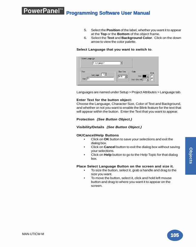
105105105105105
Ob
jec
ts
MAN-UTICW-M
Programming Software User ManualProgramming Software User ManualProgramming Software User ManualProgramming Software User ManualProgramming Software User Manual
5. Select the Position of the label, whether you want it to appearat the Top or the Bottom of the object frame.
6. Select the Text and Background Color. Click on the downarrow to view the color palette.
Select Language that you want to switch to.
Languages are named under Setup > Project Attributes > Language tab.
Enter Text for the button object:Choose the Language, Character Size, Color of Text and Background,and whether or not you want to enable the Blink feature for the text thatwill appear within the button. Enter the Text that you want to appear.
Protection (See Button Object.)
Visibility/Details (See Button Object.)
OK/Cancel/Help Buttons• Click on OK button to save your selections and exit the
dialog box.• Click on Cancel button to exit the dialog box without saving
your selections.• Click on Help button to go to the Help Topic for that dialog
box.
Place Select Language Button on the screen and size it.• To size the button, select it, grab a handle and drag to the
size you want.• To move the button, select it, click and hold left mouse
button and drag to where you want it to appear on thescreen.
106106106106106
Ob
jec
ts
MAN-UTICW-M
Programming Software User ManualProgramming Software User ManualProgramming Software User ManualProgramming Software User ManualProgramming Software User Manual
This page intentionally left blank.
Main PrMain PrMain PrMain PrMain Programming Screenogramming Screenogramming Screenogramming Screenogramming Screen
In this chapter....— Title Bar— Main Menu Bar— Standard Tool Bar— Object Tool Bar— Draw Tool Bar— Panel Tool Bar— Status Bar— 3 Easy Steps— Programming Screen— Project Screens Explorer View
55555
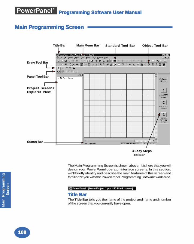
108108108108108
Mai
n P
rog
ram
min
g S
cree
n
Programming Software User ManualProgramming Software User ManualProgramming Software User ManualProgramming Software User ManualProgramming Software User Manual
The Main Programming Screen is shown above. It is here that you willdesign your PowerPanel operator interface screens. In this section,we’ll briefly identify and describe the main features of this screen andfamiliarize you with the PowerPanel Programming Software work area.
Title BarTitle BarTitle BarTitle BarTitle BarThe Title Bar tells you the name of the project and name and numberof the screen that you currently have open.
Main Programming ScreenMain Programming ScreenMain Programming ScreenMain Programming ScreenMain Programming Screen
Title Bar Main Menu Bar Standard Tool Bar Object Tool Bar
Draw Tool Bar
Panel Tool Bar
Status Bar
3 Easy StepsTool Bar
Project ScreensExplorer View
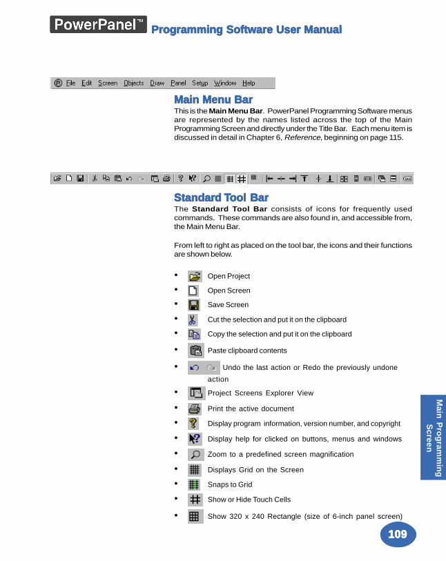
109109109109109
Main
Pro
gram
min
gS
creen
Programming Software User ManualProgramming Software User ManualProgramming Software User ManualProgramming Software User ManualProgramming Software User Manual
Main Menu BarMain Menu BarMain Menu BarMain Menu BarMain Menu BarThis is the Main Menu Bar. PowerPanel Programming Software menusare represented by the names listed across the top of the MainProgramming Screen and directly under the Title Bar. Each menu item isdiscussed in detail in Chapter 6, Reference, beginning on page 115.
StandarStandarStandarStandarStandard d d d d TTTTTool Barool Barool Barool Barool BarThe Standard Tool Bar consists of icons for frequently usedcommands. These commands are also found in, and accessible from,the Main Menu Bar.
From left to right as placed on the tool bar, the icons and their functionsare shown below.
• Open Project
• Open Screen
• Save Screen
• Cut the selection and put it on the clipboard
• Copy the selection and put it on the clipboard
• Paste clipboard contents
• Undo the last action or Redo the previously undone
action
• Project Screens Explorer View
• Print the active document
• Display program information, version number, and copyright
• Display help for clicked on buttons, menus and windows
• Zoom to a predefined screen magnification
• Displays Grid on the Screen
• Snaps to Grid
• Show or Hide Touch Cells
• Show 320 x 240 Rectangle (size of 6-inch panel screen)
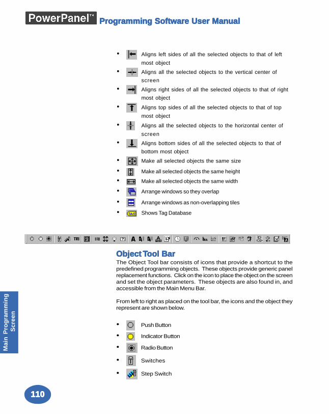
110110110110110
Mai
n P
rog
ram
min
g S
cree
n
Programming Software User ManualProgramming Software User ManualProgramming Software User ManualProgramming Software User ManualProgramming Software User Manual
• Aligns left sides of all the selected objects to that of left
most object
• Aligns all the selected objects to the vertical center of
screen
• Aligns right sides of all the selected objects to that of right
most object
• Aligns top sides of all the selected objects to that of top
most object
• Aligns all the selected objects to the horizontal center of
screen
• Aligns bottom sides of all the selected objects to that of
bottom most object
• Make all selected objects the same size
• Make all selected objects the same height
• Make all selected objects the same width
• Arrange windows so they overlap
• Arrange windows as non-overlapping tiles
• Shows Tag Database
Object Object Object Object Object TTTTTool Barool Barool Barool Barool BarThe Object Tool bar consists of icons that provide a shortcut to thepredefined programming objects. These objects provide generic panelreplacement functions. Click on the icon to place the object on the screenand set the object parameters. These objects are also found in, andaccessible from the Main Menu Bar.
From left to right as placed on the tool bar, the icons and the object theyrepresent are shown below.
• Push Button
• Indicator Button
• Radio Button
• Switches
• Step Switch
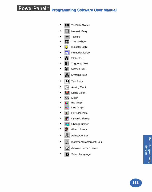
111111111111111
Main
Pro
gram
min
gS
creen
Programming Software User ManualProgramming Software User ManualProgramming Software User ManualProgramming Software User ManualProgramming Software User Manual
• Tri-State Switch
• Numeric Entry
• Recipe
• Thumbwheel
• Indicator Light
• Numeric Display
• Static Text
• Triggered Text
• Lookup Text
• Dynamic Text
• Text Entry
• Analog Clock
• Digital Clock
• Meter
• Bar Graph
• Line Graph
• PID Face Plate
• Dynamic Bitmap
• Change Screen
• Alarm History
• Adjust Contrast
• Increment/Decrement Hour
• Activate Screen Saver
• Select Language
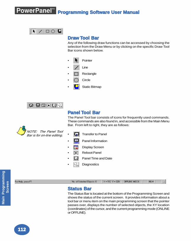
112112112112112
Mai
n P
rog
ram
min
g S
cree
n
Programming Software User ManualProgramming Software User ManualProgramming Software User ManualProgramming Software User ManualProgramming Software User Manual
DraDraDraDraDraw w w w w TTTTTool Barool Barool Barool Barool BarAny of the following draw functions can be accessed by choosing theselection from the Draw Menu or by clicking on the specific Draw ToolBar icons shown below.
• Pointer
• Line
• Rectangle
• Circle
• Static Bitmap
PPPPPanel anel anel anel anel TTTTTool Barool Barool Barool Barool BarThe Panel Tool bar consists of icons for frequently used commands.These commands are also found in, and accessible from the Main MenuBar. From left to right, they are as follows:
• Transfer to Panel
• Panel Information
• Display Screen
• Reboot Panel
• Panel Time and Date
• Diagnostics
Status BarStatus BarStatus BarStatus BarStatus BarThe Status Bar is located at the bottom of the Programming Screen andshows the status of the current screen. It provides information about atool bar or menu item on the main programming screen that the pointerpasses over, displays the number of selected objects, the XY location(coordinates) of the cursor, and the current programming mode (ONLINEor OFFLINE).
NOTE: The Panel ToolBar is for on-line editing.
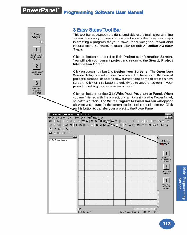
113113113113113
Main
Pro
gram
min
gS
creen
Programming Software User ManualProgramming Software User ManualProgramming Software User ManualProgramming Software User ManualProgramming Software User Manual
3 Easy Steps 3 Easy Steps 3 Easy Steps 3 Easy Steps 3 Easy Steps TTTTTool Barool Barool Barool Barool BarThis tool bar appears on the right hand side of the main programmingscreen. It allows you to easily navigate to one of the three main stepsin creating a program for your PowerPanel using the PowerPanelProgramming Software. To open, click on Edit > Toolbar > 3 EasySteps.
Click on button number 1 to Exit Project to Information Screen.You will exit your current project and return to the Step 1, ProjectInformation Screen.
Click on button number 2 to Design Your Screens. The Open NewScreen dialog box will appear. You can select from one of the currentproject’s screens, or enter a new number and name to create a newscreen. Click on this button to quickly go to another screen in yourproject for editing, or create a new screen.
Click on button number 3 to Write Your Program to Panel. Whenyou are finished with the project, or want to test it on the PowerPanel,select this button. The Write Program to Panel Screen will appearallowing you to transfer the current project to the panel memory. Clickon this button to transfer your project to the PowerPanel.
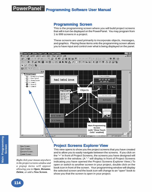
114114114114114
Mai
n P
rog
ram
min
g S
cree
n
Programming Software User ManualProgramming Software User ManualProgramming Software User ManualProgramming Software User ManualProgramming Software User Manual
Programming ScreenProgramming ScreenProgramming ScreenProgramming ScreenProgramming ScreenThis is the programming screen where you will build project screensthat will in turn be displayed on the PowerPanel. You may program from1 to 999 screens in a project.
These screens are used primarily to incorporate objects, messages,and graphics. Placing these items onto the programming screen allowsyou to have input and control over what is being displayed on the panel.
Objects
Main ProgrammingScreen
(with “Show TouchCells” enabled)
PrPrPrPrProject Screens Explorer oject Screens Explorer oject Screens Explorer oject Screens Explorer oject Screens Explorer VieVieVieVieViewwwwwThis view opens to show you the project screens that you have createdand to allow you to easily navigate between the screens. If you click onthe “+” in front of Project Screens, the screens you have designed willcascade in the window. (A “-” will display in front of Project Screensindicating you have opened the Project Screens Explorer View.) Toopen or switch to another screen in your project, double click on thebook icon in front of the screen. Your programming window will displaythe selected screen and the book icon will change to an “open” book toshow you that the screen is open in your project.
Right click your mouse anywherein the project screens window anda popup menu will appearallowing you to Open, Rename,Delete, or add a New Screen.
ReferenceReferenceReferenceReferenceReference
In this chapter....— File Menu— Edit Menu— Screen Menu— Draw Menu— Panel Menu— Setup Menu— Window Menu— Help Menu— Right Click Menus— Symbol Factory
66666
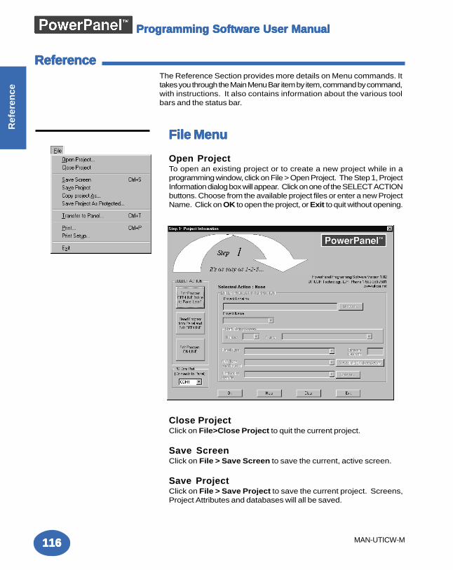
Programming Software User ManualProgramming Software User ManualProgramming Software User ManualProgramming Software User ManualProgramming Software User Manual
116116116116116
Ref
eren
ce
MAN-UTICW-M
File MenuFile MenuFile MenuFile MenuFile Menu
Open ProjectTo open an existing project or to create a new project while in aprogramming window, click on File > Open Project. The Step 1, ProjectInformation dialog box will appear. Click on one of the SELECT ACTIONbuttons. Choose from the available project files or enter a new ProjectName. Click on OK to open the project, or Exit to quit without opening.
Close ProjectClick on File>Close Project to quit the current project.
Save ScreenClick on File > Save Screen to save the current, active screen.
Save ProjectClick on File > Save Project to save the current project. Screens,Project Attributes and databases will all be saved.
The Reference Section provides more details on Menu commands. Ittakes you through the Main Menu Bar item by item, command by command,with instructions. It also contains information about the various toolbars and the status bar.
ReferenceReferenceReferenceReferenceReference
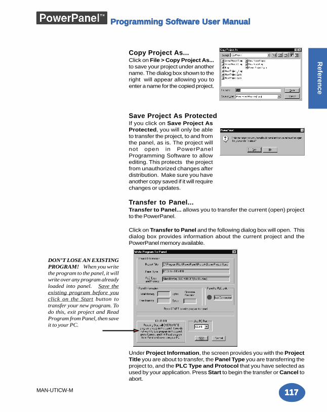
Programming Software User ManualProgramming Software User ManualProgramming Software User ManualProgramming Software User ManualProgramming Software User Manual
117117117117117
Referen
ce
MAN-UTICW-M
Copy Project As...Click on File > Copy Project As...to save your project under anothername. The dialog box shown to theright will appear allowing you toenter a name for the copied project.
Save Project As ProtectedIf you click on Save Project AsProtected, you will only be ableto transfer the project, to and fromthe panel, as is. The project willnot open in PowerPanelProgramming Software to allowediting. This protects the projectfrom unauthorized changes afterdistribution. Make sure you haveanother copy saved if it will requirechanges or updates.
Transfer to Panel...Transfer to Panel... allows you to transfer the current (open) projectto the PowerPanel.
Click on Transfer to Panel and the following dialog box will open. Thisdialog box provides information about the current project and thePowerPanel memory available.
Under Project Information, the screen provides you with the ProjectTitle you are about to transfer, the Panel Type you are transferring theproject to, and the PLC Type and Protocol that you have selected asused by your application. Press Start to begin the transfer or Cancel toabort.
DON’T LOSE AN EXISTINGPROGRAM! When you writethe program to the panel, it willwrite over any program alreadyloaded into panel. Save theexisting program before youclick on the Start button totransfer your new program. Todo this, exit project and ReadProgram from Panel, then saveit to your PC.
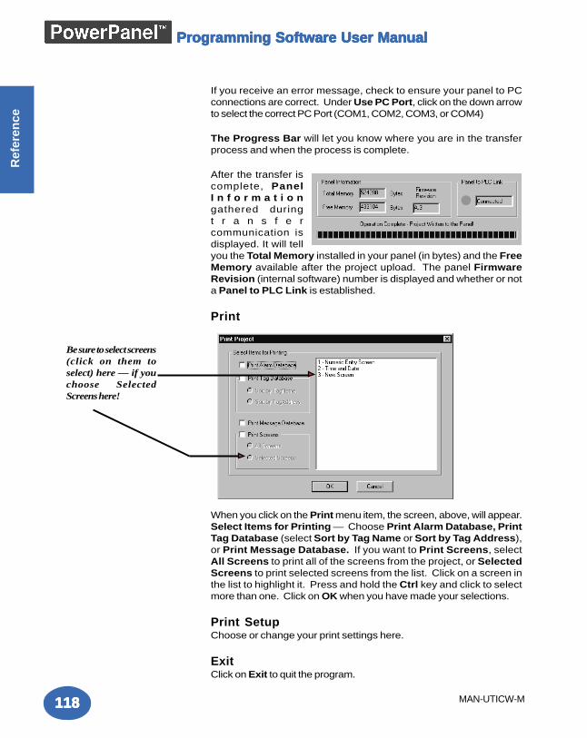
Programming Software User ManualProgramming Software User ManualProgramming Software User ManualProgramming Software User ManualProgramming Software User Manual
118118118118118
Ref
eren
ce
MAN-UTICW-M
If you receive an error message, check to ensure your panel to PCconnections are correct. Under Use PC Port, click on the down arrowto select the correct PC Port (COM1, COM2, COM3, or COM4)
The Progress Bar will let you know where you are in the transferprocess and when the process is complete.
After the transfer iscomplete, PanelI n f o r m a t i o ngathered duringt r a n s f e rcommunication isdisplayed. It will tellyou the Total Memory installed in your panel (in bytes) and the FreeMemory available after the project upload. The panel FirmwareRevision (internal software) number is displayed and whether or nota Panel to PLC Link is established.
When you click on the Print menu item, the screen, above, will appear.Select Items for Printing — Choose Print Alarm Database, PrintTag Database (select Sort by Tag Name or Sort by Tag Address),or Print Message Database. If you want to Print Screens, selectAll Screens to print all of the screens from the project, or SelectedScreens to print selected screens from the list. Click on a screen inthe list to highlight it. Press and hold the Ctrl key and click to selectmore than one. Click on OK when you have made your selections.
Print SetupChoose or change your print settings here.
ExitClick on Exit to quit the program.
Be sure to select screens(click on them toselect) here — if youchoose SelectedScreens here!
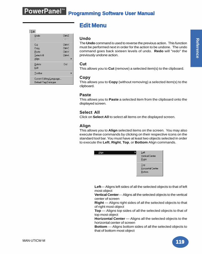
Programming Software User ManualProgramming Software User ManualProgramming Software User ManualProgramming Software User ManualProgramming Software User Manual
119119119119119
Referen
ce
MAN-UTICW-M
Edit MenuEdit MenuEdit MenuEdit MenuEdit Menu
UndoThe Undo command is used to reverse the previous action. This functionmust be performed next in order for the action to be undone. The undocommand goes back sixteen levels of undo. Redo will "redo" thepreviously undone action.
CutThis allows you to Cut (remove) a selected item(s) to the clipboard.
CopyThis allows you to Copy (without removing) a selected item(s) to theclipboard.
PasteThis allows you to Paste a selected item from the clipboard onto thedisplayed screen.
Select AllClick on Select All to select all items on the displayed screen.
AlignThis allows you to Align selected items on the screen. You may alsoexecute these commands by clicking on their respective icons on thestandard tool bar. You must have at least two objects selected in orderto execute the Left, Right, Top, or Bottom Align commands.
Left— Aligns left sides of all the selected objects to that of leftmost objectVertical Center— Aligns all the selected objects to the verticalcenter of screenRight — Aligns right sides of all the selected objects to thatof right most objectTop — Aligns top sides of all the selected objects to that oftop most objectHorizontal Center — Aligns all the selected objects to thehorizontal center of screenBottom — Aligns bottom sides of all the selected objects tothat of bottom most object
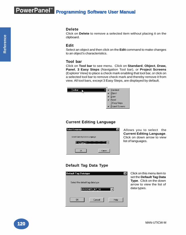
Programming Software User ManualProgramming Software User ManualProgramming Software User ManualProgramming Software User ManualProgramming Software User Manual
120120120120120
Ref
eren
ce
MAN-UTICW-M
DeleteClick on Delete to remove a selected item without placing it on theclipboard.
EditSelect an object and then click on the Edit command to make changesto an object's characteristics.
Tool barClick on Tool bar to see menu. Click on Standard, Object, Draw,Panel, 3 Easy Steps (Navigation Tool bar), or Project Screens(Explorer View) to place a check mark enabling that tool bar, or click ona selected tool bar to remove check mark and thereby remove it fromview. All tool bars, except 3 Easy Steps, are displayed by default.
Current Editing Language
Allows you to select theCurrent Editing Language.Click on down arrow to viewlist of languages.
Default Tag Data Type
Click on this menu item toset the Default Tag DataType. Click on the downarrow to view the list ofdata types.
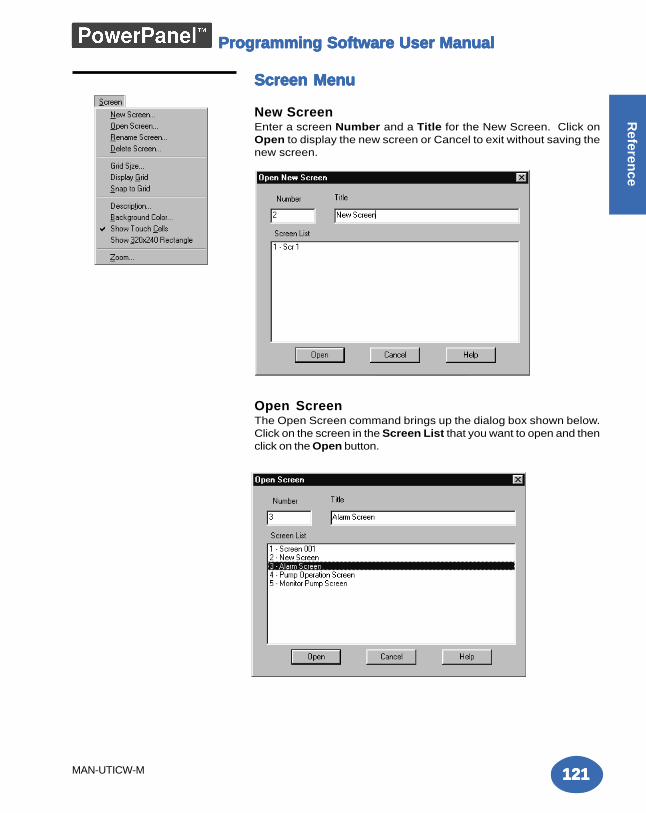
Programming Software User ManualProgramming Software User ManualProgramming Software User ManualProgramming Software User ManualProgramming Software User Manual
121121121121121
Referen
ce
MAN-UTICW-M
Screen MenuScreen MenuScreen MenuScreen MenuScreen Menu
New ScreenEnter a screen Number and a Title for the New Screen. Click onOpen to display the new screen or Cancel to exit without saving thenew screen.
Open ScreenThe Open Screen command brings up the dialog box shown below.Click on the screen in the Screen List that you want to open and thenclick on the Open button.
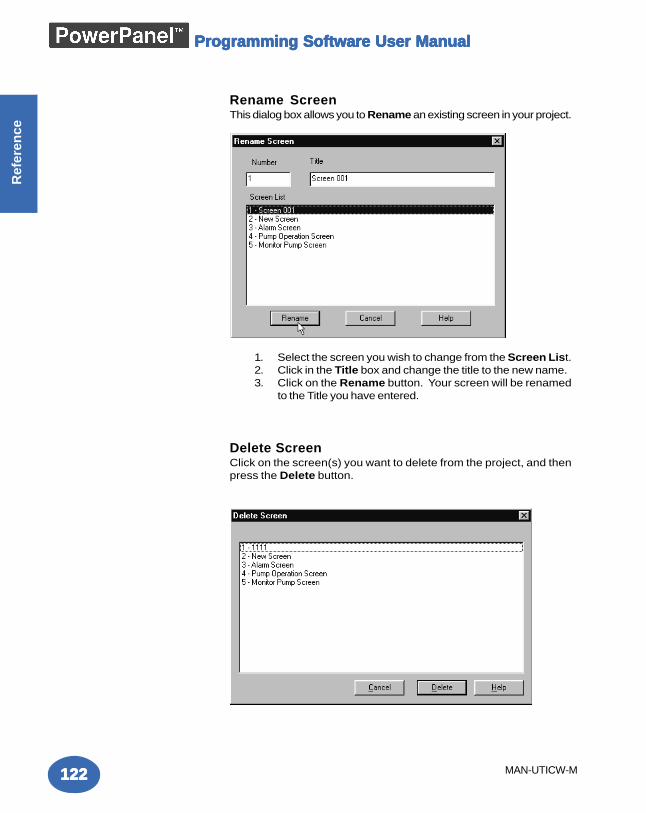
Programming Software User ManualProgramming Software User ManualProgramming Software User ManualProgramming Software User ManualProgramming Software User Manual
122122122122122
Ref
eren
ce
MAN-UTICW-M
Rename ScreenThis dialog box allows you to Rename an existing screen in your project.
1. Select the screen you wish to change from the Screen List.2. Click in the Title box and change the title to the new name.3. Click on the Rename button. Your screen will be renamed
to the Title you have entered.
Delete ScreenClick on the screen(s) you want to delete from the project, and thenpress the Delete button.
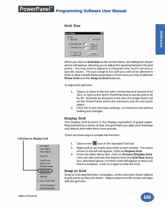
Programming Software User ManualProgramming Software User ManualProgramming Software User ManualProgramming Software User ManualProgramming Software User Manual
123123123123123
Referen
ce
MAN-UTICW-M
Grid Size
When you click on Grid Size on the Screen Menu, the dialog box shownabove will appear, allowing you to adjust the spacing between the gridpoints. You may want to adjust to a character size, touch cell size orspecific values. The size range is 3 to 100 (you will not be allowed toenter a value outside these parameters.) From here you may enable theShow Grid and the Snap to Grid features.
To adjust the grid size:
1. Type in a value in the box after Horizontal and Vertical GridSize, or click on the Set to TouchPad Size to set the grid to 40by 40. 40 pixels by 40 pixels is the size of a single touch cellon the PowerPanel and is the minimum size for any touchobject.
2. Click OK to exit and save settings, or Cancel to exit withoutmaking any changes.
Display GridThe Display Grid function is the display equivalent of graph paper.Represented by a series of dots, the grid helps you align your drawingsand objects and make them more precise.
There are three ways to enable this function:
1. Click on the icon in the Standard Tool bar.
2. Right click on an empty area of the screen window. The menushown to the left will appear. Click on Display Grid.
3. From the Main Menu Bar, click on Screen>Display Grid.(You can also activate this feature from the Grid Size dialogbox, described above.) A check mark will appear to show youthat it is enabled. Click on it again to hide the Grid.
Snap to GridSnap to Grid attaches lines, rectangles, circles and other drawn objectsto grid points as they are drawn. Objects placed on the screen will alignwith the grid also.
Click here to Display Grid
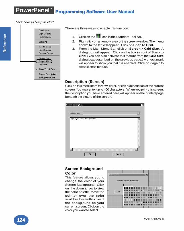
Programming Software User ManualProgramming Software User ManualProgramming Software User ManualProgramming Software User ManualProgramming Software User Manual
124124124124124
Ref
eren
ce
MAN-UTICW-M
There are three ways to enable this function:
1. Click on the icon in the Standard Tool bar.
2. Right click on an empty area of the screen window. The menushown to the left will appear. Click on Snap to Grid.
3. From the Main Menu Bar, click on Screen > Grid Size. Adialog box will appear. Click on the box in front of Snap toGrid. (You can also activate this feature from the Grid Sizedialog box, described on the previous page.) A check markwill appear to show you that it is enabled. Click on it again todisable snap feature.
Description (Screen)Click on this menu item to view, enter, or edit a description of the currentscreen You may enter up to 400 characters. When you print this screen,the description you have entered here will appear on the printed pagebeneath the picture of the screen.
Screen BackgroundColorThis feature allows you tochange the color of yourScreen Background. Clickon the down arrow to viewthe color palette. Move thepointer over the colorswatches to view the color ofthe background on yourcurrent screen. Click on thecolor you want to select.
Click here to Snap to Grid
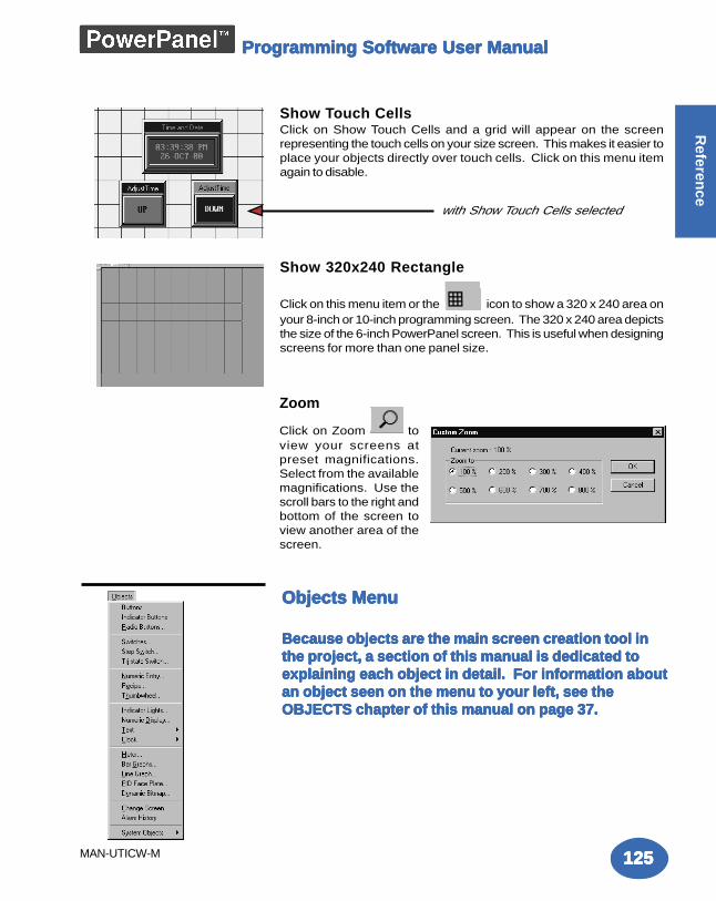
Programming Software User ManualProgramming Software User ManualProgramming Software User ManualProgramming Software User ManualProgramming Software User Manual
125125125125125
Referen
ce
MAN-UTICW-M
Show Touch CellsClick on Show Touch Cells and a grid will appear on the screenrepresenting the touch cells on your size screen. This makes it easier toplace your objects directly over touch cells. Click on this menu itemagain to disable.
Show 320x240 Rectangle
Click on this menu item or the icon to show a 320 x 240 area onyour 8-inch or 10-inch programming screen. The 320 x 240 area depictsthe size of the 6-inch PowerPanel screen. This is useful when designingscreens for more than one panel size.
Objects MenuObjects MenuObjects MenuObjects MenuObjects Menu
Because objects are the main screen creation tool inBecause objects are the main screen creation tool inBecause objects are the main screen creation tool inBecause objects are the main screen creation tool inBecause objects are the main screen creation tool inthe project, a section of this manual is dedicated tothe project, a section of this manual is dedicated tothe project, a section of this manual is dedicated tothe project, a section of this manual is dedicated tothe project, a section of this manual is dedicated toexplaining each object in detail. For information aboutexplaining each object in detail. For information aboutexplaining each object in detail. For information aboutexplaining each object in detail. For information aboutexplaining each object in detail. For information aboutan object seen on the menu to your left, see thean object seen on the menu to your left, see thean object seen on the menu to your left, see thean object seen on the menu to your left, see thean object seen on the menu to your left, see theOBJECTS chapter of this manual on page 37.OBJECTS chapter of this manual on page 37.OBJECTS chapter of this manual on page 37.OBJECTS chapter of this manual on page 37.OBJECTS chapter of this manual on page 37.
with Show Touch Cells selected
Zoom
Click on Zoom
toview your screens atpreset magnifications.Select from the availablemagnifications. Use thescroll bars to the right andbottom of the screen toview another area of thescreen.
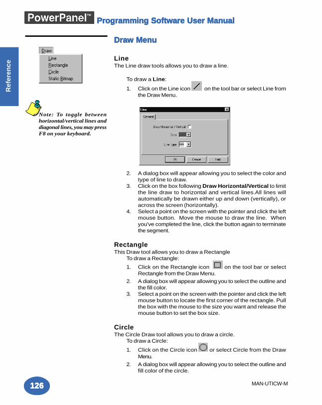
Programming Software User ManualProgramming Software User ManualProgramming Software User ManualProgramming Software User ManualProgramming Software User Manual
126126126126126
Ref
eren
ce
MAN-UTICW-M
Draw MenuDraw MenuDraw MenuDraw MenuDraw Menu
LineThe Line draw tools allows you to draw a line.
To draw a Line:
1. Click on the Line icon on the tool bar or select Line fromthe Draw Menu.
2. A dialog box will appear allowing you to select the color andtype of line to draw.
3. Click on the box following Draw Horizontal/Vertical to limitthe line draw to horizontal and vertical lines.All lines willautomatically be drawn either up and down (vertically), oracross the screen (horizontally).
4. Select a point on the screen with the pointer and click the leftmouse button. Move the mouse to draw the line. Whenyou've completed the line, click the button again to terminatethe segment.
RectangleThis Draw tool allows you to draw a Rectangle
To draw a Rectangle:
1. Click on the Rectangle icon on the tool bar or selectRectangle from the Draw Menu.
2. A dialog box will appear allowing you to select the outline andthe fill color.
3. Select a point on the screen with the pointer and click the leftmouse button to locate the first corner of the rectangle. Pullthe box with the mouse to the size you want and release themouse button to set the box size.
CircleThe Circle Draw tool allows you to draw a circle.
To draw a Circle:
1. Click on the Circle icon or select Circle from the DrawMenu.
2. A dialog box will appear allowing you to select the outline andfill color of the circle.
Note: To toggle betweenhorizontal/vertical lines anddiagonal lines, you may pressF8 on your keyboard.
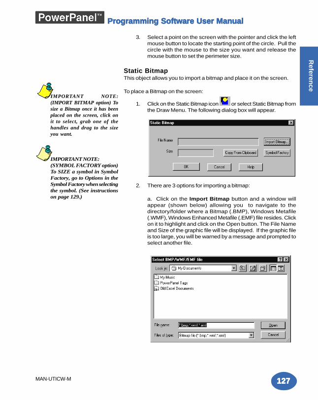
Programming Software User ManualProgramming Software User ManualProgramming Software User ManualProgramming Software User ManualProgramming Software User Manual
127127127127127
Referen
ce
MAN-UTICW-M
3. Select a point on the screen with the pointer and click the leftmouse button to locate the starting point of the circle. Pull thecircle with the mouse to the size you want and release themouse button to set the perimeter size.
Static BitmapThis object allows you to import a bitmap and place it on the screen.
To place a Bitmap on the screen:
1. Click on the Static Bitmap icon or select Static Bitmap fromthe Draw Menu. The following dialog box will appear.
2. There are 3 options for importing a bitmap:
a. Click on the Import Bitmap button and a window willappear (shown below) allowing you to navigate to thedirectory/folder where a Bitmap (.BMP), Windows Metafile(.WMF), Windows Enhanced Metafile (.EMF) file resides. Clickon it to highlight and click on the Open button. The File Nameand Size of the graphic file will be displayed. If the graphic fileis too large, you will be warned by a message and prompted toselect another file.
IMPORTANT NOTE:(IMPORT BITMAP option) Tosize a Bitmap once it has beenplaced on the screen, click onit to select, grab one of thehandles and drag to the sizeyou want.
IMPORTANT NOTE:(SYMBOL FACTORY option)To SIZE a symbol in SymbolFactory, go to Options in theSymbol Factory when selectingthe symbol. (See instructionson page 129.)
Programming Software User ManualProgramming Software User ManualProgramming Software User ManualProgramming Software User ManualProgramming Software User Manual
128128128128128
Ref
eren
ce
MAN-UTICW-M
b. You may also click on Symbol Factory® to gain access toa library of over 3,000 symbols for industrial automation,including pumps, pipes, valves, tanks, mixers, motors, ducts,electrical symbols, flow meters, material handling, sensors,PLC's, transmitters, and ISA symbols. Once in Symbol Factorynavigate to the symbol you want to import, click on Copy andthe symbol is automatically imported into the object. (See nextpage, 129, for sizing a bitmap in Symbol Factory.)
c. The third option is to click on Copy from Clipboard. Thiswill copy a bitmap you have saved to the clipboard onto thecurrent screen. You can copy a bitmap saved or created inanother program onto the system clipboard, and then import itinto the current screen.
3. Click OK to import the bitmap, or Cancel to quit.
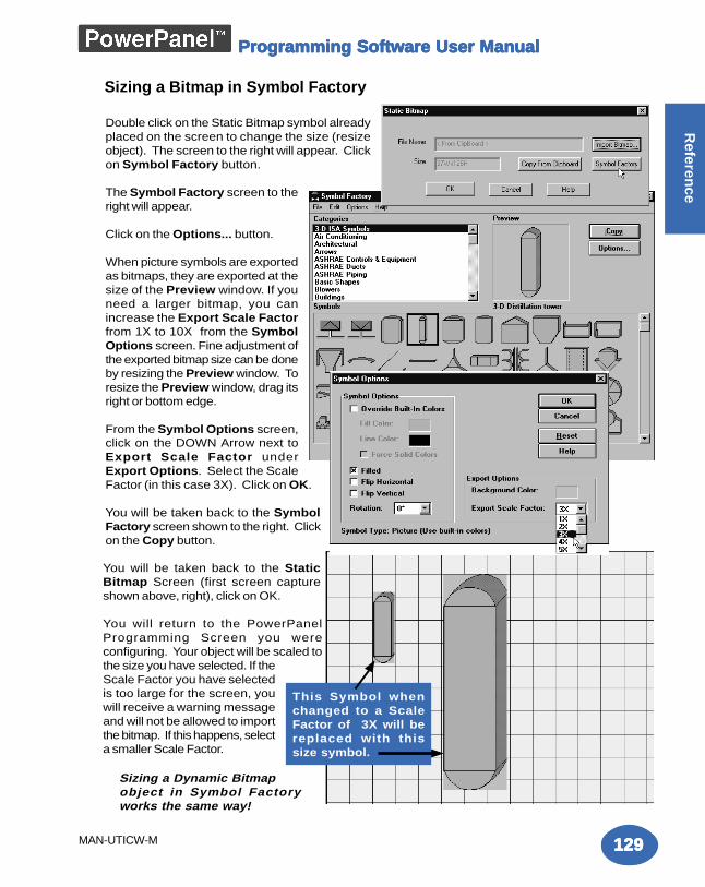
Programming Software User ManualProgramming Software User ManualProgramming Software User ManualProgramming Software User ManualProgramming Software User Manual
129129129129129
Referen
ce
MAN-UTICW-M
Sizing a Bitmap in Symbol Factory
Double click on the Static Bitmap symbol alreadyplaced on the screen to change the size (resizeobject). The screen to the right will appear. Clickon Symbol Factory button.
The Symbol Factory screen to theright will appear.
Click on the Options... button.
When picture symbols are exportedas bitmaps, they are exported at thesize of the Preview window. If youneed a larger bitmap, you canincrease the Export Scale Factorfrom 1X to 10X from the SymbolOptions screen. Fine adjustment ofthe exported bitmap size can be doneby resizing the Preview window. Toresize the Preview window, drag itsright or bottom edge.
From the Symbol Options screen,click on the DOWN Arrow next toExport Scale Factor underExport Options. Select the ScaleFactor (in this case 3X). Click on OK.
You will be taken back to the SymbolFactory screen shown to the right. Clickon the Copy button.
This Symbol whenchanged to a ScaleFactor of 3X will bereplaced with thissize symbol.
Sizing a Dynamic Bitmapobject in Symbol Factoryworks the same way!
You will be taken back to the StaticBitmap Screen (first screen captureshown above, right), click on OK.
You will return to the PowerPanelProgramming Screen you wereconfiguring. Your object will be scaled tothe size you have selected. If theScale Factor you have selectedis too large for the screen, youwill receive a warning messageand will not be allowed to importthe bitmap. If this happens, selecta smaller Scale Factor.
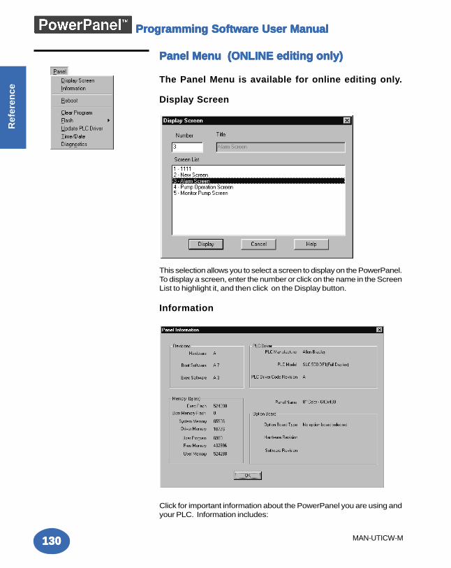
Programming Software User ManualProgramming Software User ManualProgramming Software User ManualProgramming Software User ManualProgramming Software User Manual
130130130130130
Ref
eren
ce
MAN-UTICW-M
Panel Menu (ONLINE editing only)Panel Menu (ONLINE editing only)Panel Menu (ONLINE editing only)Panel Menu (ONLINE editing only)Panel Menu (ONLINE editing only)
The Panel Menu is available for online editing only.
Display Screen
This selection allows you to select a screen to display on the PowerPanel.To display a screen, enter the number or click on the name in the ScreenList to highlight it, and then click on the Display button.
Information
Click for important information about the PowerPanel you are using andyour PLC. Information includes:
Programming Software User ManualProgramming Software User ManualProgramming Software User ManualProgramming Software User ManualProgramming Software User Manual
131131131131131
Referen
ce
MAN-UTICW-M
Revisions:Hardware: This is the revision of the PowerPanel unit.Boot Software: This is internal panel firmware used topower-up the panel.Exec Software: This is also internal firmware, used to displaypanel information and allow panel adjustments to the internalclock, Contrast adjustment, and testing of the Touch cells andDisplay.
Memory (bytes):Exec Flash: This will let you know if the PowerPanel has aFlash Memory card installed. (It will say 0 if not installed.)This feature allows you to back up your program from thepanel itself. There are two available memory sizes — 512Kand 1 MEG. Once the program is backed up onto the card,you can use it to load the program into different units — noprogramming computer is necessary.User Memory Flash: This will let you know how muchFLASH memory you have available.System Memory: This tells you how much RAM memoryyou have installed in your panel.Driver Memory: This is the PLC Driver memory that isavailable.User Program: This is the size of the program that youcurrently have loaded into your PowerPanel.Free Memory: This is the RAM memory that you have left touse in the PowerPanel.User Memory: This is the total RAM Memory available foruse in the PowerPanel.
PLC Driver:PLC Manufacturer, PLC Model, PLC Driver CodeRevision: This provides information about the type of PLCyou are using.
Panel Name: A description of the panel model is provided.
Option Board:Option Board Type: This tells you if you have an optionboard installed and the type.Hardware Revision: Current hardware (board revision)Software Revision: Current software.
RebootClick here to reboot the PowerPanel.
Clear ProgramClick here to Clear the current user program from the panel.
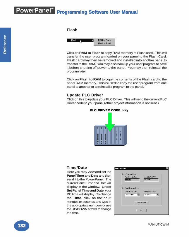
Programming Software User ManualProgramming Software User ManualProgramming Software User ManualProgramming Software User ManualProgramming Software User Manual
132132132132132
Ref
eren
ce
MAN-UTICW-M
Flash
Click on RAM to Flash to copy RAM memory to Flash card. This willtransfer the user program loaded on your panel to the Flash Card.Flash card may then be removed and installed into another panel totransfer to the RAM. You may also backup your user program to saveit before shutting off power to the panel. You may then reinstall theprogram later.
Click on Flash to RAM to copy the contents of the Flash card to thepanel RAM memory. This is used to copy the user program from onepanel to another or to reinstall a program to the panel.
Update PLC DriverClick on this to update your PLC Driver. This will send the current PLCDriver code to your panel (other project information is not sent.)
Time/DateHere you may view and set thePanel Time and Date and thensend it to the PowerPanel. Thecurrent Panel Time and Date willdisplay in the window. UnderSet Panel Time and Date, yourPC time will display. To changethe Time, click on the hour,minutes or seconds and type inthe appropriate numbers or usethe UP/DOWN arrows to changethe time.
PLC DRIVER CODE onlyPLC DRIVER CODE onlyPLC DRIVER CODE onlyPLC DRIVER CODE onlyPLC DRIVER CODE only
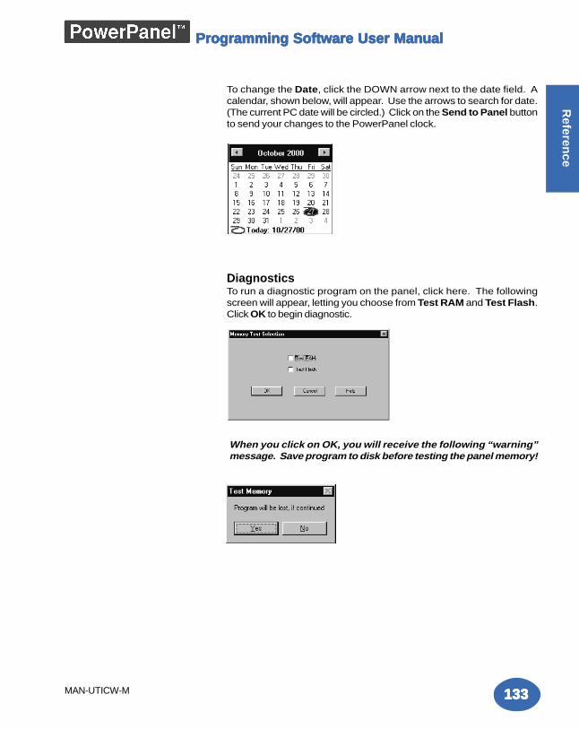
Programming Software User ManualProgramming Software User ManualProgramming Software User ManualProgramming Software User ManualProgramming Software User Manual
133133133133133
Referen
ce
MAN-UTICW-M
To change the Date, click the DOWN arrow next to the date field. Acalendar, shown below, will appear. Use the arrows to search for date.(The current PC date will be circled.) Click on the Send to Panel buttonto send your changes to the PowerPanel clock.
DiagnosticsTo run a diagnostic program on the panel, click here. The followingscreen will appear, letting you choose from Test RAM and Test Flash.Click OK to begin diagnostic.
When you click on OK, you will receive the following “warning”message. Save program to disk before testing the panel memory!
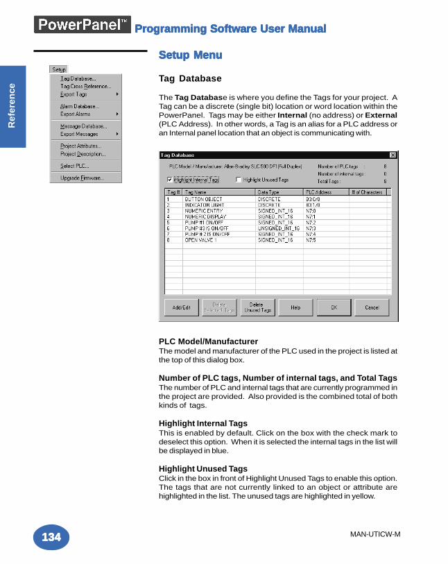
Programming Software User ManualProgramming Software User ManualProgramming Software User ManualProgramming Software User ManualProgramming Software User Manual
134134134134134
Ref
eren
ce
MAN-UTICW-M
Setup MenuSetup MenuSetup MenuSetup MenuSetup Menu
Tag Database
The Tag Database is where you define the Tags for your project. ATag can be a discrete (single bit) location or word location within thePowerPanel. Tags may be either Internal (no address) or External(PLC Address). In other words, a Tag is an alias for a PLC address oran Internal panel location that an object is communicating with.
PLC Model/ManufacturerThe model and manufacturer of the PLC used in the project is listed atthe top of this dialog box.
Number of PLC tags, Number of internal tags, and Total TagsThe number of PLC and internal tags that are currently programmed inthe project are provided. Also provided is the combined total of bothkinds of tags.
Highlight Internal TagsThis is enabled by default. Click on the box with the check mark todeselect this option. When it is selected the internal tags in the list willbe displayed in blue.
Highlight Unused TagsClick in the box in front of Highlight Unused Tags to enable this option.The tags that are not currently linked to an object or attribute arehighlighted in the list. The unused tags are highlighted in yellow.
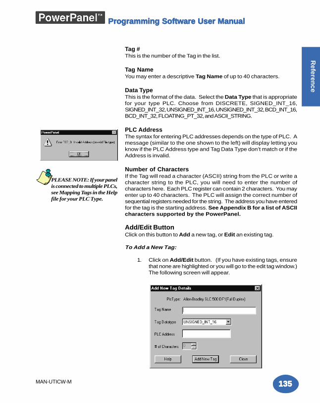
Programming Software User ManualProgramming Software User ManualProgramming Software User ManualProgramming Software User ManualProgramming Software User Manual
135135135135135
Referen
ce
MAN-UTICW-M
Tag #This is the number of the Tag in the list.
Tag NameYou may enter a descriptive Tag Name of up to 40 characters.
Data TypeThis is the format of the data. Select the Data Type that is appropriatefor your type PLC. Choose from DISCRETE, SIGNED_INT_16,SIGNED_INT_32, UNSIGNED_INT_16, UNSIGNED_INT_32, BCD_INT_16,BCD_INT_32, FLOATING_PT_32, and ASCII_STRING.
PLC AddressThe syntax for entering PLC addresses depends on the type of PLC. Amessage (similar to the one shown to the left) will display letting youknow if the PLC Address type and Tag Data Type don’t match or if theAddress is invalid.
Number of CharactersIf the Tag will read a character (ASCII) string from the PLC or write acharacter string to the PLC, you will need to enter the number ofcharacters here. Each PLC register can contain 2 characters. You mayenter up to 40 characters. The PLC will assign the correct number ofsequential registers needed for the string. The address you have enteredfor the tag is the starting address. See Appendix B for a list of ASCIIcharacters supported by the PowerPanel.
Add/Edit ButtonClick on this button to Add a new tag, or Edit an existing tag.
To Add a New Tag:
1. Click on Add/Edit button. (If you have existing tags, ensurethat none are highlighted or you will go to the edit tag window.)The following screen will appear.
PLEASE NOTE: If your panelis connected to multiple PLCs,see Mapping Tags in the Helpfile for your PLC Type.
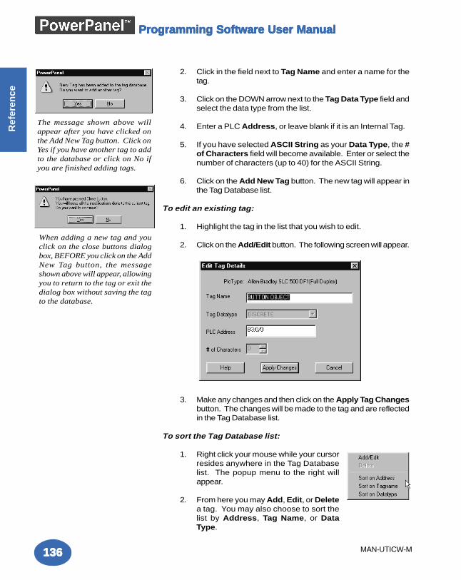
Programming Software User ManualProgramming Software User ManualProgramming Software User ManualProgramming Software User ManualProgramming Software User Manual
136136136136136
Ref
eren
ce
MAN-UTICW-M
2. Click in the field next to Tag Name and enter a name for thetag.
3. Click on the DOWN arrow next to the Tag Data Type field andselect the data type from the list.
4. Enter a PLC Address, or leave blank if it is an Internal Tag.
5. If you have selected ASCII String as your Data Type, the #of Characters field will become available. Enter or select thenumber of characters (up to 40) for the ASCII String.
6. Click on the Add New Tag button. The new tag will appear inthe Tag Database list.
To edit an existing tag:
1. Highlight the tag in the list that you wish to edit.
2. Click on the Add/Edit button. The following screen will appear.
3. Make any changes and then click on the Apply Tag Changesbutton. The changes will be made to the tag and are reflectedin the Tag Database list.
To sort the Tag Database list:
1. Right click your mouse while your cursorresides anywhere in the Tag Databaselist. The popup menu to the right willappear.
2. From here you may Add, Edit, or Deletea tag. You may also choose to sort thelist by Address, Tag Name, or DataType.
The message shown above willappear after you have clicked onthe Add New Tag button. Click onYes if you have another tag to addto the database or click on No ifyou are finished adding tags.
When adding a new tag and youclick on the close buttons dialogbox, BEFORE you click on the AddNew Tag button, the messageshown above will appear, allowingyou to return to the tag or exit thedialog box without saving the tagto the database.
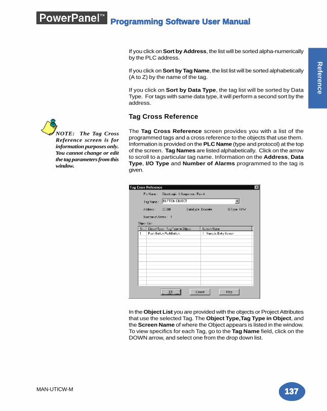
Programming Software User ManualProgramming Software User ManualProgramming Software User ManualProgramming Software User ManualProgramming Software User Manual
137137137137137
Referen
ce
MAN-UTICW-M
If you click on Sort by Address, the list will be sorted alpha-numericallyby the PLC address.
If you click on Sort by Tag Name, the list list will be sorted alphabetically(A to Z) by the name of the tag.
If you click on Sort by Data Type, the tag list will be sorted by DataType. For tags with same data type, it will perform a second sort by theaddress.
Tag Cross Reference
The Tag Cross Reference screen provides you with a list of theprogrammed tags and a cross reference to the objects that use them.Information is provided on the PLC Name (type and protocol) at the topof the screen. Tag Names are listed alphabetically. Click on the arrowto scroll to a particular tag name. Information on the Address, DataType, I/O Type and Number of Alarms programmed to the tag isgiven.
In the Object List you are provided with the objects or Project Attributesthat use the selected Tag. The Object Type,Tag Type in Object, andthe Screen Name of where the Object appears is listed in the window.To view specifics for each Tag, go to the Tag Name field, click on theDOWN arrow, and select one from the drop down list.
NOTE: The Tag CrossReference screen is forinformation purposes only.You cannot change or editthe tag parameters from thiswindow.
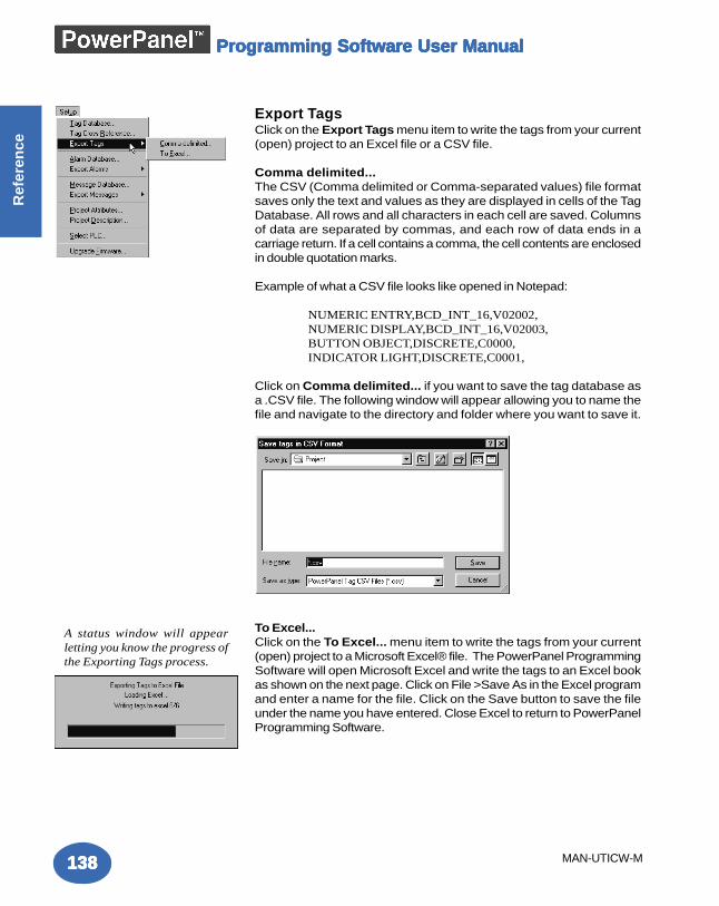
Programming Software User ManualProgramming Software User ManualProgramming Software User ManualProgramming Software User ManualProgramming Software User Manual
138138138138138
Ref
eren
ce
MAN-UTICW-M
Export TagsClick on the Export Tags menu item to write the tags from your current(open) project to an Excel file or a CSV file.
Comma delimited...The CSV (Comma delimited or Comma-separated values) file formatsaves only the text and values as they are displayed in cells of the TagDatabase. All rows and all characters in each cell are saved. Columnsof data are separated by commas, and each row of data ends in acarriage return. If a cell contains a comma, the cell contents are enclosedin double quotation marks.
Example of what a CSV file looks like opened in Notepad:
NUMERIC ENTRY,BCD_INT_16,V02002,NUMERIC DISPLAY,BCD_INT_16,V02003,BUTTON OBJECT,DISCRETE,C0000,INDICATOR LIGHT,DISCRETE,C0001,
Click on Comma delimited... if you want to save the tag database asa .CSV file. The following window will appear allowing you to name thefile and navigate to the directory and folder where you want to save it.
To Excel...Click on the To Excel... menu item to write the tags from your current(open) project to a Microsoft Excel® file. The PowerPanel ProgrammingSoftware will open Microsoft Excel and write the tags to an Excel bookas shown on the next page. Click on File >Save As in the Excel programand enter a name for the file. Click on the Save button to save the fileunder the name you have entered. Close Excel to return to PowerPanelProgramming Software.
A status window will appearletting you know the progress ofthe Exporting Tags process.
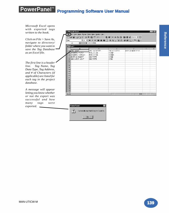
Programming Software User ManualProgramming Software User ManualProgramming Software User ManualProgramming Software User ManualProgramming Software User Manual
139139139139139
Referen
ce
MAN-UTICW-M
Microsoft Excel openswith exported tagswritten to the book.
Click on File > Save As,navigate to directory/folder where you want tosave the Tag Databaseas an Excel file.
The first line is a headerline. Tag Name, TagData Type, Tag Address,and # of Characters (ifapplicable) are listed foreach tag in the projectdatabase.
A message will appearletting you know whetheror not the export wassuccessful and howmany tags wereexported.
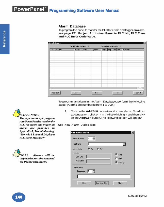
Programming Software User ManualProgramming Software User ManualProgramming Software User ManualProgramming Software User ManualProgramming Software User Manual
140140140140140
Ref
eren
ce
MAN-UTICW-M
Alarm DatabaseTo program the panel to monitor the PLC for errors and trigger an alarm,see page 151, Project Attributes, Panel to PLC tab, PLC Errorand PLC Error Code Value.
To program an alarm in the Alarm Database, perform the followingsteps: (Alarms are numbered from 1 to 999.)
1. Click on the Add/Edit button to add a new alarm. To edit anexisting alarm, click on it in the list to highlight and then clickon the Add/Edit button.The following screen will appear.
PLEASE NOTE:The steps necessary to programyour PowerPanel to monitor thePLC for errors and trigger analarm are provided inAppendix A, Troubleshooting,“How do I Log and Display aPLC Error Message?”
NOTE: Alarms will bedisplayed across the bottom ofthe PowerPanel Screen.
Add New Alarm Dialog Box
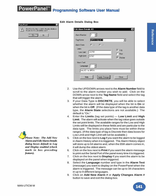
Programming Software User ManualProgramming Software User ManualProgramming Software User ManualProgramming Software User ManualProgramming Software User Manual
141141141141141
Referen
ce
MAN-UTICW-M
2. Use the UP/DOWN arrows next to the Alarm Number field toscroll to the alarm number you wish to add. Click on theDOWN arrow next to the Tag Name field and select the tagthat will trigger the alarm.
3. If your Data Type is DISCRETE, you will be able to selectwhether the alarm will be displayed when the bit is On orwhen the bit is Off. (If the data type of the tag is another datatype, the Alarm State selections are not available.) Thedefault is “On.”
4. Enter the Limits (tag set points) — Low Limit and HighLimit. The alarm will activate when the tag value goes outsidethe set point limits. The available ranges for the Low and HighLimits will be displayed in these fields and are particular to thedata type. The limits you place here must be within theseranges. (If the data type of tag is Discrete then data boxes forLow Limit and High Limit will not be available.)
5. Click on the box next to Log if you want the alarm to be loggedin Alarm History when it is triggered. The Alarm History objectwill store up to 64 alarms and, when the 65th alarm comes in,it will dump the oldest alarm.
6. Click on the box next to Print if you want the alarm messageto print out the Serial Port of the panel every time it is triggered.
7. Click on the box next to Display if you want the alarm to bedisplayed on the panel when triggered.
8. Select the Language number and type in the Alarm Text(message) you want to display on the PowerPanel when thealarm is triggered. The message can be up to 34 charactersin up to 9 different languages.
9. Click on Add New Alarm # or Apply Changes Alarm #button to save and exit the dialog box.
Edit Alarm Details Dialog Box
Please Note: The Add NewAlarm and Edit Alarm Detailsdialog boxes default to Logand Display enabled (checkmark in box precedingfeature).
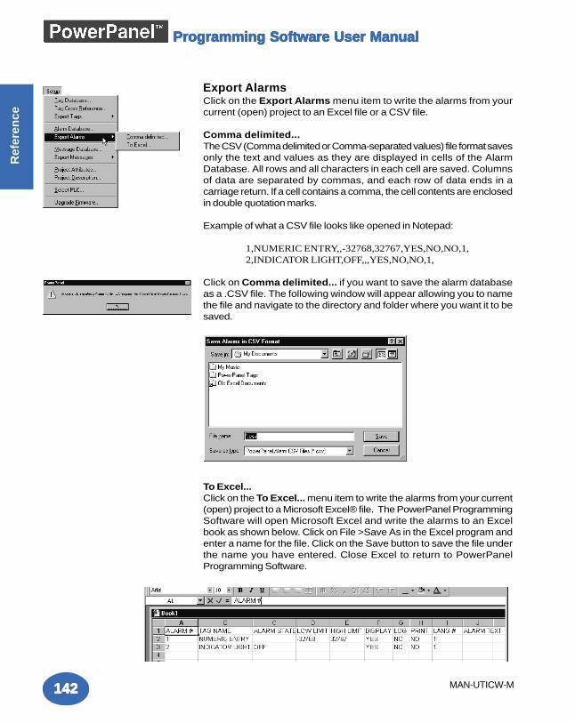
Programming Software User ManualProgramming Software User ManualProgramming Software User ManualProgramming Software User ManualProgramming Software User Manual
142142142142142
Ref
eren
ce
MAN-UTICW-M
Export AlarmsClick on the Export Alarms menu item to write the alarms from yourcurrent (open) project to an Excel file or a CSV file.
Comma delimited...The CSV (Comma delimited or Comma-separated values) file format savesonly the text and values as they are displayed in cells of the AlarmDatabase. All rows and all characters in each cell are saved. Columnsof data are separated by commas, and each row of data ends in acarriage return. If a cell contains a comma, the cell contents are enclosedin double quotation marks.
Example of what a CSV file looks like opened in Notepad:
1,NUMERIC ENTRY,,-32768,32767,YES,NO,NO,1,2,INDICATOR LIGHT,OFF,,,YES,NO,NO,1,
Click on Comma delimited... if you want to save the alarm databaseas a .CSV file. The following window will appear allowing you to namethe file and navigate to the directory and folder where you want it to besaved.
To Excel...Click on the To Excel... menu item to write the alarms from your current(open) project to a Microsoft Excel® file. The PowerPanel ProgrammingSoftware will open Microsoft Excel and write the alarms to an Excelbook as shown below. Click on File >Save As in the Excel program andenter a name for the file. Click on the Save button to save the file underthe name you have entered. Close Excel to return to PowerPanelProgramming Software.
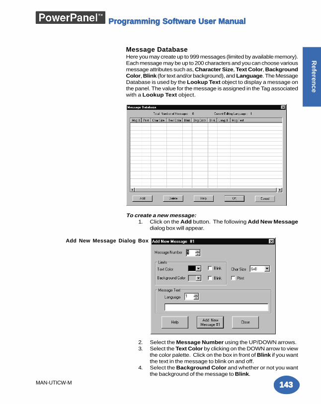
Programming Software User ManualProgramming Software User ManualProgramming Software User ManualProgramming Software User ManualProgramming Software User Manual
143143143143143
Referen
ce
MAN-UTICW-M
Message DatabaseHere you may create up to 999 messages (limited by available memory).Each message may be up to 200 characters and you can choose variousmessage attributes such as, Character Size, Text Color, BackgroundColor, Blink (for text and/or background), and Language. The MessageDatabase is used by the Lookup Text object to display a message onthe panel. The value for the message is assigned in the Tag associatedwith a Lookup Text object.
To create a new message:1. Click on the Add button. The following Add New Message
dialog box will appear.
2. Select the Message Number using the UP/DOWN arrows.3. Select the Text Color by clicking on the DOWN arrow to view
the color palette. Click on the box in front of Blink if you wantthe text in the message to blink on and off.
4. Select the Background Color and whether or not you wantthe background of the message to Blink.
Add New Message Dialog Box
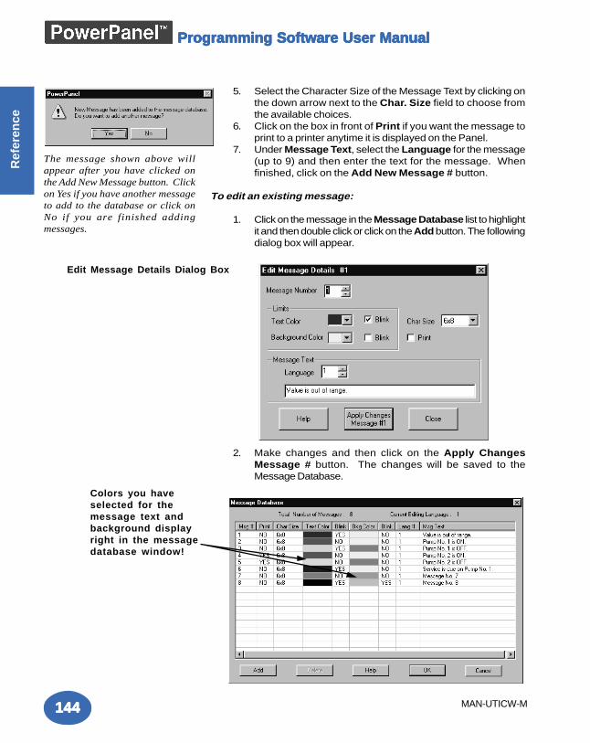
Programming Software User ManualProgramming Software User ManualProgramming Software User ManualProgramming Software User ManualProgramming Software User Manual
144144144144144
Ref
eren
ce
MAN-UTICW-M
5. Select the Character Size of the Message Text by clicking onthe down arrow next to the Char. Size field to choose fromthe available choices.
6. Click on the box in front of Print if you want the message toprint to a printer anytime it is displayed on the Panel.
7. Under Message Text, select the Language for the message(up to 9) and then enter the text for the message. Whenfinished, click on the Add New Message # button.
To edit an existing message:
1. Click on the message in the Message Database list to highlightit and then double click or click on the Add button. The followingdialog box will appear.
2. Make changes and then click on the Apply ChangesMessage # button. The changes will be saved to theMessage Database.
Edit Message Details Dialog Box
Colors you haveselected for themessage text andbackground displayright in the messagedatabase window!
The message shown above willappear after you have clicked onthe Add New Message button. Clickon Yes if you have another messageto add to the database or click onNo if you are finished addingmessages.
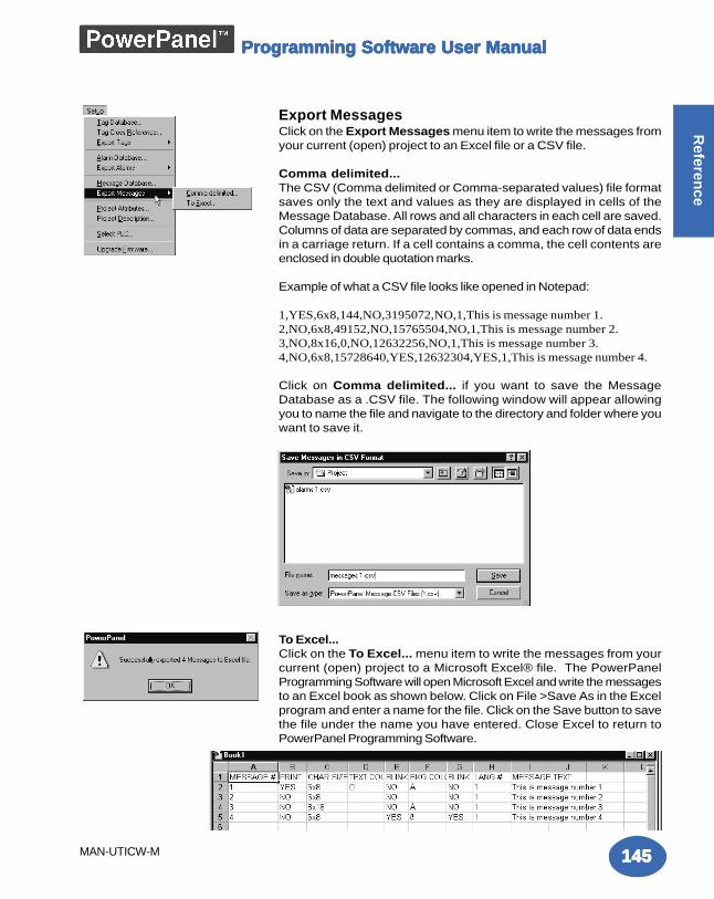
Programming Software User ManualProgramming Software User ManualProgramming Software User ManualProgramming Software User ManualProgramming Software User Manual
145145145145145
Referen
ce
MAN-UTICW-M
Export MessagesClick on the Export Messages menu item to write the messages fromyour current (open) project to an Excel file or a CSV file.
Comma delimited...The CSV (Comma delimited or Comma-separated values) file formatsaves only the text and values as they are displayed in cells of theMessage Database. All rows and all characters in each cell are saved.Columns of data are separated by commas, and each row of data endsin a carriage return. If a cell contains a comma, the cell contents areenclosed in double quotation marks.
Example of what a CSV file looks like opened in Notepad:
1,YES,6x8,144,NO,3195072,NO,1,This is message number 1.2,NO,6x8,49152,NO,15765504,NO,1,This is message number 2.3,NO,8x16,0,NO,12632256,NO,1,This is message number 3.4,NO,6x8,15728640,YES,12632304,YES,1,This is message number 4.
Click on Comma delimited... if you want to save the MessageDatabase as a .CSV file. The following window will appear allowingyou to name the file and navigate to the directory and folder where youwant to save it.
To Excel...Click on the To Excel... menu item to write the messages from yourcurrent (open) project to a Microsoft Excel® file. The PowerPanelProgramming Software will open Microsoft Excel and write the messagesto an Excel book as shown below. Click on File >Save As in the Excelprogram and enter a name for the file. Click on the Save button to savethe file under the name you have entered. Close Excel to return toPowerPanel Programming Software.
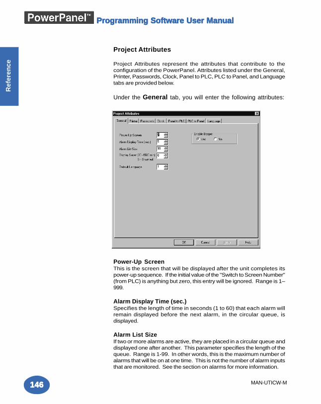
Programming Software User ManualProgramming Software User ManualProgramming Software User ManualProgramming Software User ManualProgramming Software User Manual
146146146146146
Ref
eren
ce
MAN-UTICW-M
Project Attributes
Project Attributes represent the attributes that contribute to theconfiguration of the PowerPanel. Attributes listed under the General,Printer, Passwords, Clock, Panel to PLC, PLC to Panel, and Languagetabs are provided below.
Under the General tab, you will enter the following attributes:
Power-Up ScreenThis is the screen that will be displayed after the unit completes itspower-up sequence. If the initial value of the "Switch to Screen Number"(from PLC) is anything but zero, this entry will be ignored. Range is 1–999.
Alarm Display Time (sec.)Specifies the length of time in seconds (1 to 60) that each alarm willremain displayed before the next alarm, in the circular queue, isdisplayed.
Alarm List SizeIf two or more alarms are active, they are placed in a circular queue anddisplayed one after another. This parameter specifies the length of thequeue. Range is 1-99. In other words, this is the maximum number ofalarms that will be on at one time. This is not the number of alarm inputsthat are monitored. See the section on alarms for more information.
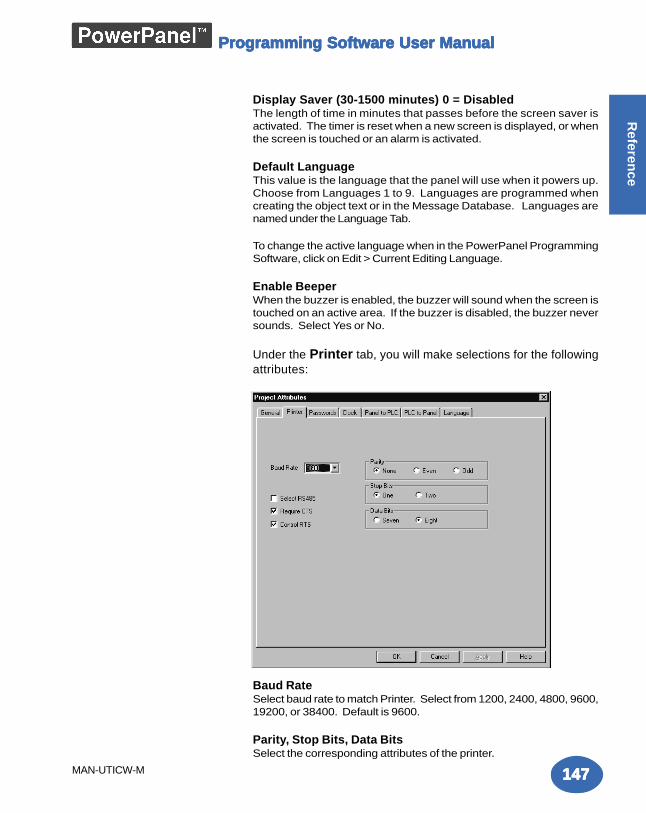
Programming Software User ManualProgramming Software User ManualProgramming Software User ManualProgramming Software User ManualProgramming Software User Manual
147147147147147
Referen
ce
MAN-UTICW-M
Display Saver (30-1500 minutes) 0 = DisabledThe length of time in minutes that passes before the screen saver isactivated. The timer is reset when a new screen is displayed, or whenthe screen is touched or an alarm is activated.
Default LanguageThis value is the language that the panel will use when it powers up.Choose from Languages 1 to 9. Languages are programmed whencreating the object text or in the Message Database. Languages arenamed under the Language Tab.
To change the active language when in the PowerPanel ProgrammingSoftware, click on Edit > Current Editing Language.
Enable BeeperWhen the buzzer is enabled, the buzzer will sound when the screen istouched on an active area. If the buzzer is disabled, the buzzer neversounds. Select Yes or No.
Under the Printer tab, you will make selections for the followingattributes:
Baud RateSelect baud rate to match Printer. Select from 1200, 2400, 4800, 9600,19200, or 38400. Default is 9600.
Parity, Stop Bits, Data BitsSelect the corresponding attributes of the printer.
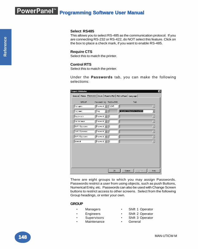
Programming Software User ManualProgramming Software User ManualProgramming Software User ManualProgramming Software User ManualProgramming Software User Manual
148148148148148
Ref
eren
ce
MAN-UTICW-M
Select RS485This allows you to select RS-485 as the communication protocol. If youare connecting RS-232 or RS-422, do NOT select this feature. Click onthe box to place a check mark, if you want to enable RS-485.
Require CTSSelect this to match the printer.
Control RTSSelect this to match the printer.
Under the Passwords tab, you can make the followingselections:
There are eight groups to which you may assign Passwords.Passwords restrict a user from using objects, such as push Buttons,Numerical Entry, etc. Passwords can also be used with Change Screenbuttons to restrict access to other screens. Select from the followingGroup headings, or enter your own.
GROUP• Managers • Shift 1 Operator• Engineers • Shift 2 Operator• Supervisors • Shift 3 Operator• Maintenance • General
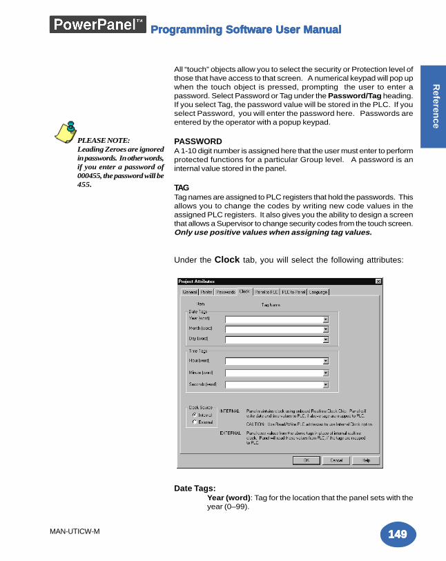
Programming Software User ManualProgramming Software User ManualProgramming Software User ManualProgramming Software User ManualProgramming Software User Manual
149149149149149
Referen
ce
MAN-UTICW-M
All “touch” objects allow you to select the security or Protection level ofthose that have access to that screen. A numerical keypad will pop upwhen the touch object is pressed, prompting the user to enter apassword. Select Password or Tag under the Password/Tag heading.If you select Tag, the password value will be stored in the PLC. If youselect Password, you will enter the password here. Passwords areentered by the operator with a popup keypad.
PASSWORDA 1-10 digit number is assigned here that the user must enter to performprotected functions for a particular Group level. A password is aninternal value stored in the panel.
TAGTag names are assigned to PLC registers that hold the passwords. Thisallows you to change the codes by writing new code values in theassigned PLC registers. It also gives you the ability to design a screenthat allows a Supervisor to change security codes from the touch screen.Only use positive values when assigning tag values.
Under the Clock tab, you will select the following attributes:
Date Tags:Year (word): Tag for the location that the panel sets with theyear (0–99).
PLEASE NOTE:Leading Zeroes are ignoredin passwords. In other words,if you enter a password of000455, the password will be455.
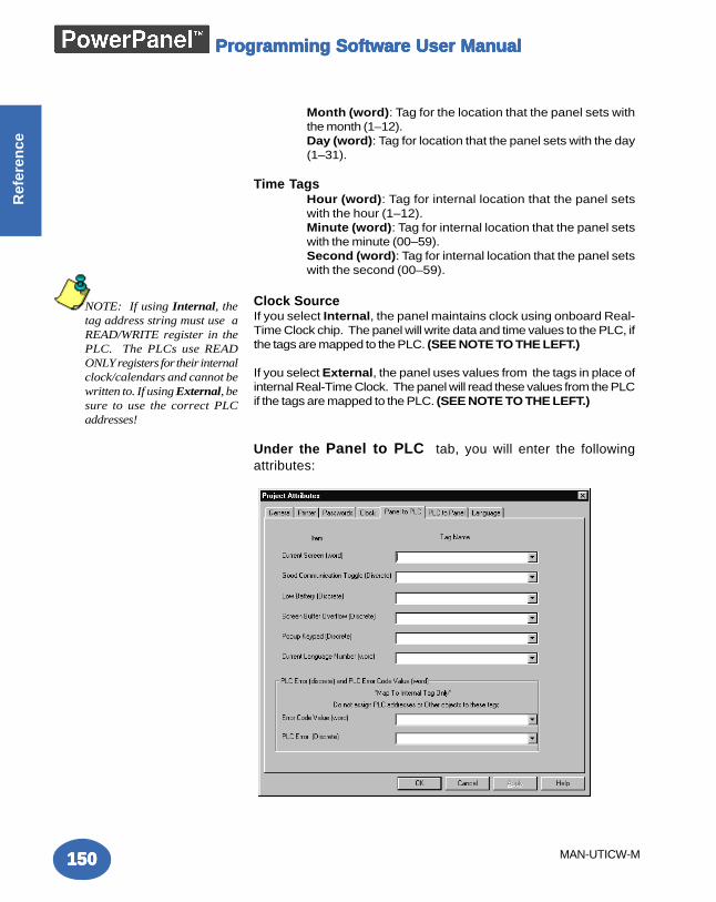
Programming Software User ManualProgramming Software User ManualProgramming Software User ManualProgramming Software User ManualProgramming Software User Manual
150150150150150
Ref
eren
ce
MAN-UTICW-M
Month (word): Tag for the location that the panel sets withthe month (1–12).Day (word): Tag for location that the panel sets with the day(1–31).
Time TagsHour (word): Tag for internal location that the panel setswith the hour (1–12).Minute (word): Tag for internal location that the panel setswith the minute (00–59).Second (word): Tag for internal location that the panel setswith the second (00–59).
Clock SourceIf you select Internal, the panel maintains clock using onboard Real-Time Clock chip. The panel will write data and time values to the PLC, ifthe tags are mapped to the PLC. (SEE NOTE TO THE LEFT.)
If you select External, the panel uses values from the tags in place ofinternal Real-Time Clock. The panel will read these values from the PLCif the tags are mapped to the PLC. (SEE NOTE TO THE LEFT.)
Under the Panel to PLC tab, you will enter the followingattributes:
NOTE: If using Internal, thetag address string must use aREAD/WRITE register in thePLC. The PLCs use READONLY registers for their internalclock/calendars and cannot bewritten to. If using External, besure to use the correct PLCaddresses!
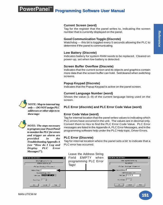
Programming Software User ManualProgramming Software User ManualProgramming Software User ManualProgramming Software User ManualProgramming Software User Manual
151151151151151
Referen
ce
MAN-UTICW-M
Current Screen (word)Tag for the register that the panel writes to, indicating the screennumber that is currently displayed on the panel.
Good Communication Toggle (Discrete)Watchdog — this bit is toggled every 5 seconds allowing the PLC todetermine if the panel is communicating.
Low Battery (Discrete)Indicates battery for system RAM needs to be replaced. Cleared onpower-up, set when low battery is detected.
Screen Buffer Overflow (Discrete)Indicates that the current screen and its objects and graphics containmore data than the screen buffer can hold. Set/cleared when switchingscreens.
Popup Keypad (Discrete)Indicates that the Popup Keypad is active on the panel screen.
Current Language Number (word)Shows the value (1–9) of the current language being used on thescreen.
PLC Error (discrete) and PLC Error Code Value (word)
Error Code Value (word)Tag for internal location that the panel writes values to indicating whichPLC errors have occurred in the unit. The values are in decimal only.Convert them to Hex to find the PLC Error Code Value. PLC Errormessages are listed in the Appendix A, PLC Error Messages, and in theprogramming software help under the PLC Help topic, Driver Errors.
PLC Error (Discrete)Tag for internal location where the panel sets a bit to indicate that aPLC error has occurred.
NOTE: Map to internal tagonly — DO NOT assign PLCaddresses or other objects tothese tags:
Leave the Address StringField EMPTY whenprogramming PLC ErrorTags!
NOTE: The steps necessaryto program your PowerPanelto monitor the PLC for errorsand trigger an alarm areprovided in theTroubleshooting Appendix A(see “How do I Log andDisplay PLC ErrorMessages?”).
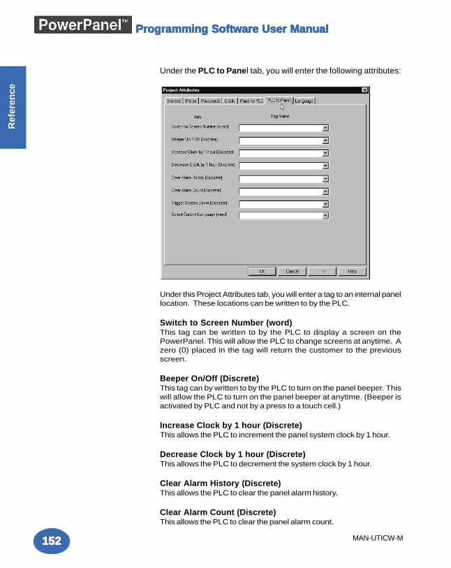
Programming Software User ManualProgramming Software User ManualProgramming Software User ManualProgramming Software User ManualProgramming Software User Manual
152152152152152
Ref
eren
ce
MAN-UTICW-M
Under the PLC to Panel tab, you will enter the following attributes:
Under this Project Attributes tab, you will enter a tag to an internal panellocation. These locations can be written to by the PLC.
Switch to Screen Number (word)This tag can be written to by the PLC to display a screen on thePowerPanel. This will allow the PLC to change screens at anytime. Azero (0) placed in the tag will return the customer to the previousscreen.
Beeper On/Off (Discrete)This tag can by written to by the PLC to turn on the panel beeper. Thiswill allow the PLC to turn on the panel beeper at anytime. (Beeper isactivated by PLC and not by a press to a touch cell.)
Increase Clock by 1 hour (Discrete)This allows the PLC to increment the panel system clock by 1 hour.
Decrease Clock by 1 hour (Discrete)This allows the PLC to decrement the system clock by 1 hour.
Clear Alarm History (Discrete)This allows the PLC to clear the panel alarm history.
Clear Alarm Count (Discrete)This allows the PLC to clear the panel alarm count.
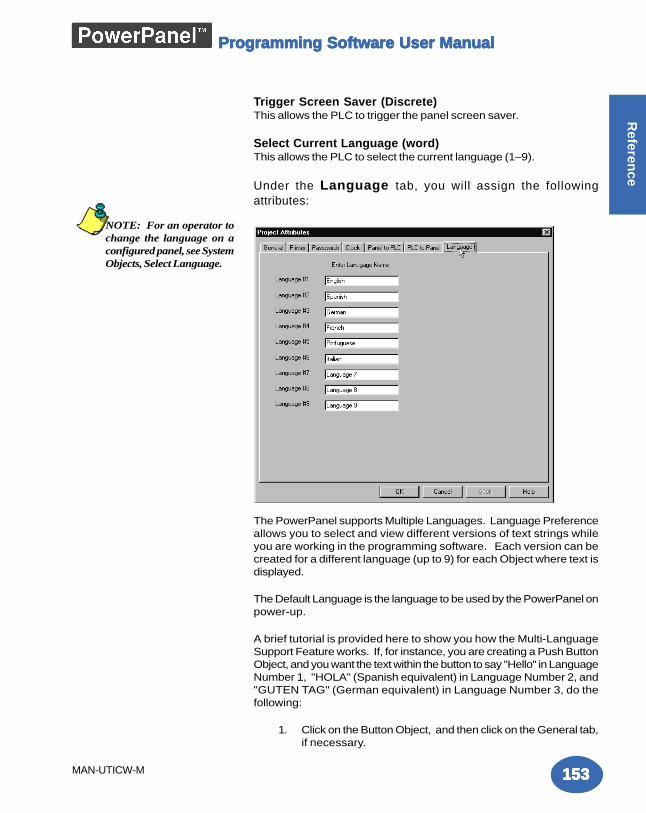
Programming Software User ManualProgramming Software User ManualProgramming Software User ManualProgramming Software User ManualProgramming Software User Manual
153153153153153
Referen
ce
MAN-UTICW-M
Trigger Screen Saver (Discrete)This allows the PLC to trigger the panel screen saver.
Select Current Language (word)This allows the PLC to select the current language (1–9).
Under the Language tab, you will assign the followingattributes:
The PowerPanel supports Multiple Languages. Language Preferenceallows you to select and view different versions of text strings whileyou are working in the programming software. Each version can becreated for a different language (up to 9) for each Object where text isdisplayed.
The Default Language is the language to be used by the PowerPanel onpower-up.
A brief tutorial is provided here to show you how the Multi-LanguageSupport Feature works. If, for instance, you are creating a Push ButtonObject, and you want the text within the button to say "Hello" in LanguageNumber 1, "HOLA" (Spanish equivalent) in Language Number 2, and"GUTEN TAG" (German equivalent) in Language Number 3, do thefollowing:
1. Click on the Button Object, and then click on the General tab,if necessary.
NOTE: For an operator tochange the language on aconfigured panel, see SystemObjects, Select Language.
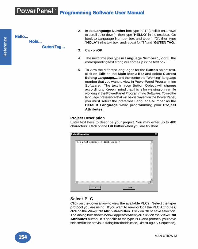
Programming Software User ManualProgramming Software User ManualProgramming Software User ManualProgramming Software User ManualProgramming Software User Manual
154154154154154
Ref
eren
ce
MAN-UTICW-M
2. In the Language Number box type in "1" (or click on arrowsto scroll up or down), then type "HELLO" in the text box. Goback to Language Number box and type in "2", then type"HOLA" in the text box, and repeat for "3" and "GUTEN TAG."
3. Click on OK.
4. The next time you type in Language Number 1, 2 or 3, thecorresponding text string will come up in the text box.
5. To view the different languages for the Button object text,click on Edit on the Main Menu Bar and select CurrentEditing Language..., and then enter the "Working" languagenumber that you want to view in PowerPanel ProgrammingSoftware. The text in your Button Object will changeaccordingly. Keep in mind that this is for viewing only whileworking in the PowerPanel Programming Software. To set thelanguage preference that will be displayed on the PowerPanel,you must select the preferred Language Number as theDefault Language while programming your ProjectAttributes.
Project DescriptionEnter text here to describe your project. You may enter up to 400characters. Click on the OK button when you are finished.
Select PLCClick on the down arrow to view the available PLCs. Select the type/protocol you are using. If you want to View or Edit the PLC Attributes,click on the View/Edit Attributes button. Click on OK to save selection.The dialog box shown below appears when you click on the View/EditAttributes button. It is specific to the type PLC and protocol you haveselected in the previous dialog box (in this case, DirectLogic K-Sequence).
Hello...Hello...Hello...Hello...Hello...Hola...Hola...Hola...Hola...Hola... Guten Guten Guten Guten Guten TTTTTaaaaag...g...g...g...g...
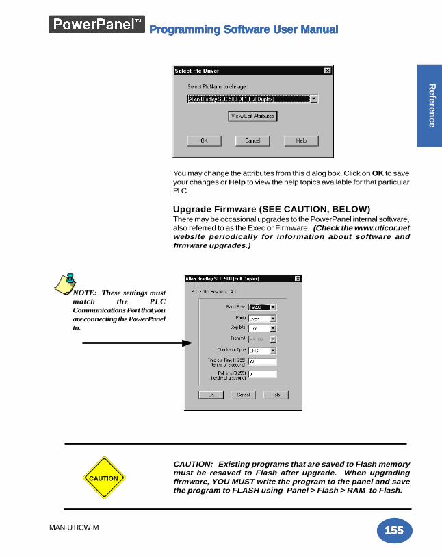
Programming Software User ManualProgramming Software User ManualProgramming Software User ManualProgramming Software User ManualProgramming Software User Manual
155155155155155
Referen
ce
MAN-UTICW-M
You may change the attributes from this dialog box. Click on OK to saveyour changes or Help to view the help topics available for that particularPLC.
Upgrade Firmware (SEE CAUTION, BELOW)There may be occasional upgrades to the PowerPanel internal software,also referred to as the Exec or Firmware. (Check the www.uticor.netwebsite periodically for information about software andfirmware upgrades.)
CAUTION: Existing programs that are saved to Flash memorymust be resaved to Flash after upgrade. When upgradingfirmware, YOU MUST write the program to the panel and savethe program to FLASH using Panel > Flash > RAM to Flash.
NOTE: These settings mustmatch the PLCCommunications Port that youare connecting the PowerPanelto.
CAUTION
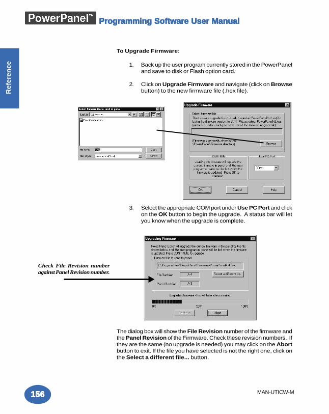
Programming Software User ManualProgramming Software User ManualProgramming Software User ManualProgramming Software User ManualProgramming Software User Manual
156156156156156
Ref
eren
ce
MAN-UTICW-M
To Upgrade Firmware:
1. Back up the user program currently stored in the PowerPaneland save to disk or Flash option card.
2. Click on Upgrade Firmware and navigate (click on Browsebutton) to the new firmware file (.hex file).
3. Select the appropriate COM port under Use PC Port and clickon the OK button to begin the upgrade. A status bar will letyou know when the upgrade is complete.
The dialog box will show the File Revision number of the firmware andthe Panel Revision of the Firmware. Check these revision numbers. Ifthey are the same (no upgrade is needed) you may click on the Abortbutton to exit. If the file you have selected is not the right one, click onthe Select a different file... button.
Check File Revision numberagainst Panel Revision number.
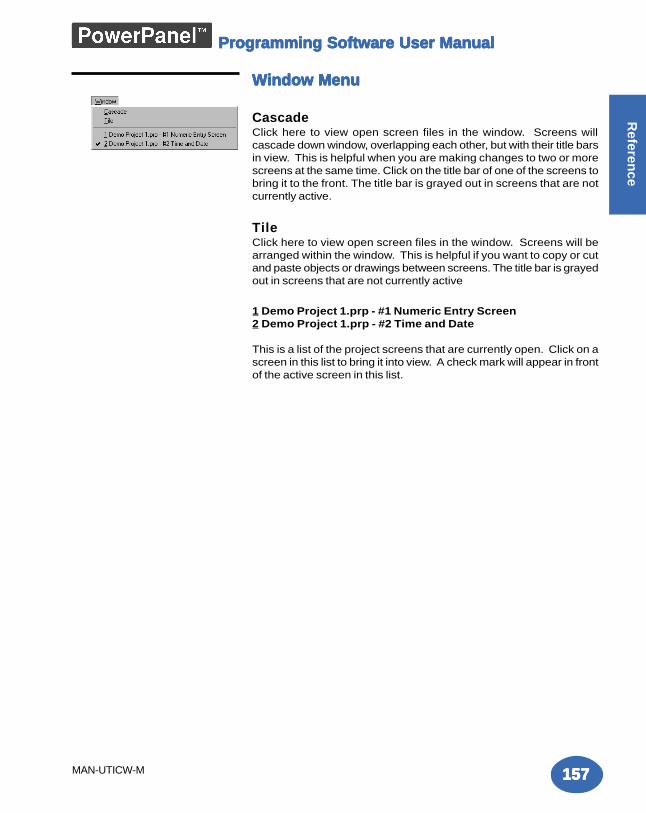
Programming Software User ManualProgramming Software User ManualProgramming Software User ManualProgramming Software User ManualProgramming Software User Manual
157157157157157
Referen
ce
MAN-UTICW-M
Window MenuWindow MenuWindow MenuWindow MenuWindow Menu
CascadeClick here to view open screen files in the window. Screens willcascade down window, overlapping each other, but with their title barsin view. This is helpful when you are making changes to two or morescreens at the same time. Click on the title bar of one of the screens tobring it to the front. The title bar is grayed out in screens that are notcurrently active.
TileClick here to view open screen files in the window. Screens will bearranged within the window. This is helpful if you want to copy or cutand paste objects or drawings between screens. The title bar is grayedout in screens that are not currently active
1 Demo Project 1.prp - #1 Numeric Entry Screen2 Demo Project 1.prp - #2 Time and Date
This is a list of the project screens that are currently open. Click on ascreen in this list to bring it into view. A check mark will appear in frontof the active screen in this list.
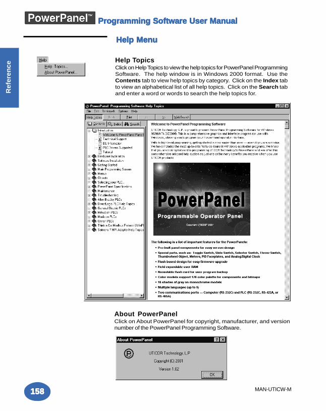
Programming Software User ManualProgramming Software User ManualProgramming Software User ManualProgramming Software User ManualProgramming Software User Manual
158158158158158
Ref
eren
ce
MAN-UTICW-M
Help MenuHelp MenuHelp MenuHelp MenuHelp Menu
Help TopicsClick on Help Topics to view the help topics for PowerPanel ProgrammingSoftware. The help window is in Windows 2000 format. Use theContents tab to view help topics by category. Click on the Index tabto view an alphabetical list of all help topics. Click on the Search taband enter a word or words to search the help topics for.
About PowerPanelClick on About PowerPanel for copyright, manufacturer, and versionnumber of the PowerPanel Programming Software.
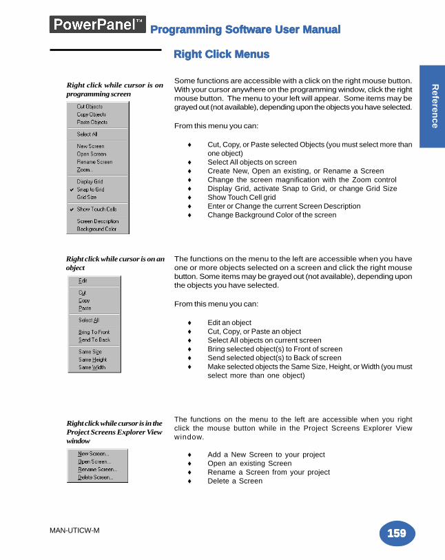
Programming Software User ManualProgramming Software User ManualProgramming Software User ManualProgramming Software User ManualProgramming Software User Manual
159159159159159
Referen
ce
MAN-UTICW-M
Right Click MenusRight Click MenusRight Click MenusRight Click MenusRight Click Menus
Some functions are accessible with a click on the right mouse button.With your cursor anywhere on the programming window, click the rightmouse button. The menu to your left will appear. Some items may begrayed out (not available), depending upon the objects you have selected.
From this menu you can:
♦ Cut, Copy, or Paste selected Objects (you must select more thanone object)
♦ Select All objects on screen♦ Create New, Open an existing, or Rename a Screen♦ Change the screen magnification with the Zoom control♦ Display Grid, activate Snap to Grid, or change Grid Size♦ Show Touch Cell grid♦ Enter or Change the current Screen Description♦ Change Background Color of the screen
The functions on the menu to the left are accessible when you haveone or more objects selected on a screen and click the right mousebutton. Some items may be grayed out (not available), depending uponthe objects you have selected.
From this menu you can:
♦ Edit an object♦ Cut, Copy, or Paste an object♦ Select All objects on current screen♦ Bring selected object(s) to Front of screen♦ Send selected object(s) to Back of screen♦ Make selected objects the Same Size, Height, or Width (you must
select more than one object)
The functions on the menu to the left are accessible when you rightclick the mouse button while in the Project Screens Explorer Viewwindow.
♦ Add a New Screen to your project♦ Open an existing Screen♦ Rename a Screen from your project♦ Delete a Screen
Right click while cursor is onprogramming screen
Right click while cursor is on anobject
Right click while cursor is in theProject Screens Explorer Viewwindow
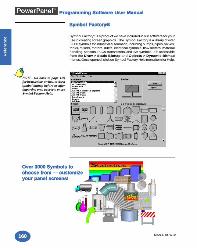
Programming Software User ManualProgramming Software User ManualProgramming Software User ManualProgramming Software User ManualProgramming Software User Manual
160160160160160
Ref
eren
ce
MAN-UTICW-M
Symbol Factory®Symbol Factory®Symbol Factory®Symbol Factory®Symbol Factory®
Over 3000 Symbols toOver 3000 Symbols toOver 3000 Symbols toOver 3000 Symbols toOver 3000 Symbols tochoose from — customizechoose from — customizechoose from — customizechoose from — customizechoose from — customizeyour panel screens!your panel screens!your panel screens!your panel screens!your panel screens!
Symbol Factory® is a product we have included in our software for youruse in creating screen graphics. The Symbol Factory is a library of over3,000 symbols for industrial automation, including pumps, pipes, valves,tanks, mixers, motors, ducts, electrical symbols, flow meters, materialhandling, sensors, PLCs, transmitters, and ISA symbols. It is accessiblefrom the Draw > Static Bitmap and Objects > Dynamic Bitmapmenus. Once opened, click on Symbol Factory Help menu item for Help.
NOTE: Go back to page 129for instructions on how to size asymbol bitmap before or afterimporting onto a screen, or seeSymbol Factory Help.
TTTTTrrrrroubouboubouboubleshootingleshootingleshootingleshootingleshooting
In this Appendix....
— Frequently Asked Questions (FAQs)—Troubleshooting— PowerPanel Error Messages— PowerPanel Programming Software Error Messages
AAAAA
A-2A-2A-2A-2A-2
Ap
pe
nd
ix A
Tro
ub
les
ho
oti
ng
Programming Software User ManualProgramming Software User ManualProgramming Software User ManualProgramming Software User ManualProgramming Software User Manual
FrequentlFrequentlFrequentlFrequentlFrequently Asked Questions (Fy Asked Questions (Fy Asked Questions (Fy Asked Questions (Fy Asked Questions (FAAAAAQs)Qs)Qs)Qs)Qs)
1. How do I format an address string when connecting to multiple PLCs?Simply add the PLC Station Number to the beginning of the address string. (For example, if thePLC Station number is 3 and the address is V2003, enter 3-V2003 for the address string.)
2. Can I change the Data Type of a Tag Name’s assigned Address String (PLCAddress)?Yes, but only if the Tag is used on no more than one object. If it is currently used by more thanone object, you must:
a. assign the other objects to a new or different tag(s)—or delete those objectsb. change the data type of the PLC Address under Setup > Tag Databasec. reassign the other objects to the original tag as necessary
3. Can the Tag Database be exported to other applications?Yes, the Tag Database can be exported. You can export your Tag Database from the PowerPanelto Microsoft Excel® or you can export it as a Comma Separated Value (.CSV) file (also referred toas a Comma delimited file format).
4. How do I convert a project from one panel size to another?Converting a project created on a 6” panel to an 8” or 10” panel requires nothing more thanopening the project with the new size selected. Converting from 8” or 10” to 6” size is best doneby the following procedure:
a. Select Screen > Show 320x240 Rectangle.b. Move all the objects onto the new small 6” grid shown.c. Save the project.d. Open the project again, selecting the new panel size on the Project Information box.
5. Can I use the Power Up Screen selection (under the Project Attributes > Generalmenu) and also use the Switch to Screen Number (under Project Attributes >PLC to Panel)?
Not exactly, because before the panel can actually display the Power Up Screen, it reads fromthe PLC and displays the Switch to Screen Number.
6. Can I place objects anywhere on the screen?There are two types of objects in PowerPanel Editor. One is Touch Objects (pushbutton,switches, numeric entry, etc.) and the other is Display Objects (meter, bar graph, numeric display,line, circle, etc.) Touch Objects will always snap to the touchcell grid by the upper left corner.You can then click on the object to highlight and then resize by clicking on one of the other side orcorner handles and dragging it to the size you want. Ensure that the Snap to Grid feature isturned off if you want the Touch Object to be positioned to within a touchcell area. DisplayObjects may be placed anywhere on the screen.
7. What is a touchcell? A touchcell is the physical area on the panel that defines user selection by touching. A Touch
A-3A-3A-3A-3A-3
Ap
pe
nd
ix A
Tro
ub
les
ho
otin
g
Programming Software User ManualProgramming Software User ManualProgramming Software User ManualProgramming Software User ManualProgramming Software User Manual
Object can contain more than one touchcell, but cannot contain less than one touchcell. On allPowerPanels, the size of a touchcell is 40 x 40 pixels. However, since the screen size differs,the physical size of 40 pixels does as well. On the 6-inch panels, 40 pixels = 0.57". On the 8-inchpanel 40 pixels = 0.52". On the 10-inch panel 40 pixels = 0.41".
8. Can I use the floating point data type with all objects?No, only numeric entry, numeric display and recipe objects support floating point tags. All otherobjects do not support floating point tags.
9. Why do I not see all the discrete tags in a pushbutton object on the Tag Namepulldown?You may have defined tags as discrete but if the PLC addresses assigned to these tags are readonly addresses, then you will not see these tags. The reason is because a pushbutton writesdiscrete data to the PLC address and if a tag is mapped to a Read Only PLC address, thepushbutton is not allowed to write the data.
10. Can I use a label on a vertical Radio button? No, a label is not available for either vertical style Radio button or vertical style Tri-State Switch.
11. How does a Radio button work?A Radio button is assigned to a word (16 bit register) in the PLC. Each bit in the word (of thisassociated tag) corresponds to an individual button of the Radio button object. Only one buttoncan be ON at a time. So, turning one button ON automatically turns all other buttons OFF.
12. What is the initial state of objects when the project is written to the panel?If the object reads from the PLC, it will show the current PLC value. If it writes to the PLC, it willdefault to zero (for OFF).
13. What will be the state of objects if they are mapped to internal tags?Internal tags are initialized to OFF.
14. When I select a group of objects and try to move, all the objects do not move. Why?If you have selected a mix of touch and display objects and try to move this group, you will beable to move only display objects. Remember, touch objects are always snapped to a touchcell,whereas display objects are not necessarily snapped to touchcells. Try moving the touch objectsfirst, then move the display objects.
15. When I have objects at the boundary of the screen, I am not able to move theobjects freely (vertically up/down or Horizontally left/right near the boundary). Whatcan I do to correct this?You can use the PC’s keyboard arrow keys to move objects up or down along the boundary line.

A-4A-4A-4A-4A-4
Ap
pe
nd
ix A
Tro
ub
les
ho
oti
ng
Programming Software User ManualProgramming Software User ManualProgramming Software User ManualProgramming Software User ManualProgramming Software User Manual
16. What is the maximum number of screens that a project can have?The maximum possible is 999. However, the panel’s memory may limit the achievable maximum toa lower number of screens, depending on the complexity of bitmaps and objects.
17. What is the maximum number of alarms that a project can have?The maximum is 999, but there is no limit to how many times each alarm can be used in the panel.
18. What is the maximum number of messages that a project can have?You can define a maximum of 999 messages in a project.
19. Can I insert a 640 x 480 bitmap on a screen?The maximum size of a bitmap that can ever be placed on a screen is 640 x 480 on a 8” or 10”panel. But, the compressed size of bitmap is also a limitation. The PowerPanel uses an RLE(RunLength Encoding) algorithm to compress bitmaps for storage. If this compressed bitmap sizeexceeds 64K bytes, you cannot place the bitmap on the screen.
20. Is it possible to find out whether the compressed bitmap size is less than 64Kbefore trying to insert the bitmap?No, the only sure way to know is to try. An error message will alert you immediately if the 64Ksize is exceeded. Using fewer colors (like 256 vs. 24 bit) will help prevent this problem.
21. Is there a limit to the number of objects that can be placed on a single screen? No, not exactly, but the maximum memory size of a screen is 128K bytes.
A-5A-5A-5A-5A-5
Ap
pe
nd
ix A
Tro
ub
les
ho
otin
g
Programming Software User ManualProgramming Software User ManualProgramming Software User ManualProgramming Software User ManualProgramming Software User Manual
Problem: Panel won’t power up.
Action:1. Connect power to the PowerPanel (24 VDC).2. Apply power while observing the LED in the back of the panel.
a. LED does not light means: NO POWER to unit orpower supply failed. Check power supply or replace.b. LED turns RED and stays RED means: Unit failure,
return for service.c. LED flashes RED and turns GREEN means: normal
operation.(1) the display does not light after 10 seconds, seeDisplay Blank, below.(2) the display lights, normal operation.
Refer to the PowerPanel Programming Software Help topic, or thePowerPanel Hardware Manual chapter on "Connections and Wiring"for more information.
Problem: Cannot communicate with PowerPanelfrom Programming Computer.
Action:1. Check cable, ensure that it is the correct cable and that it is
properly connected at both ends.2. Check panel for power.3. Check to ensure the correct PC COM port is selected in the
PowerPanel Programming Software and that it is available inthe PC.
4. Check the COM1 setting in Setup Mode on the panel.
Refer to the PowerPanel Programming Software Help topic, or thePowerPanel Hardware Manual chapter on "Connections and Wiring"for more information.
Problem: Panel does not communicate with PLC.
Action:1. Check communications cable:
a. Is it the right cable?b. Is it connected?c. Is the cable terminated properly?
2. Check PLC settings:a. Is PLC system powered?b. Is PLC COM Port properly configured?c. If there is a RUN switch on PLC, is it in the term/remote
mode?
TTTTTrrrrroubouboubouboubleshootingleshootingleshootingleshootingleshooting
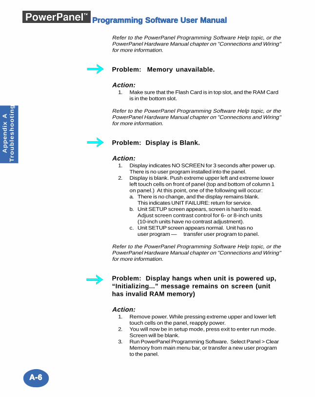
A-6A-6A-6A-6A-6
Ap
pe
nd
ix A
Tro
ub
les
ho
oti
ng
Programming Software User ManualProgramming Software User ManualProgramming Software User ManualProgramming Software User ManualProgramming Software User Manual
Refer to the PowerPanel Programming Software Help topic, or thePowerPanel Hardware Manual chapter on "Connections and Wiring"for more information.
Problem: Memory unavailable.
Action:1. Make sure that the Flash Card is in top slot, and the RAM Card
is in the bottom slot.
Refer to the PowerPanel Programming Software Help topic, or thePowerPanel Hardware Manual chapter on "Connections and Wiring"for more information.
Problem: Display is Blank.
Action:1. Display indicates NO SCREEN for 3 seconds after power up.
There is no user program installed into the panel.2. Display is blank. Push extreme upper left and extreme lower
left touch cells on front of panel (top and bottom of column 1on panel.) At this point, one of the following will occur:a. There is no change, and the display remains blank.
This indicates UNIT FAILURE: return for service.b. Unit SETUP screen appears, screen is hard to read.
Adjust screen contrast control for 6- or 8-inch units(10-inch units have no contrast adjustment).
c. Unit SETUP screen appears normal. Unit has nouser program — transfer user program to panel.
Refer to the PowerPanel Programming Software Help topic, or thePowerPanel Hardware Manual chapter on "Connections and Wiring"for more information.
Problem: Display hangs when unit is powered up,“Initializing...” message remains on screen (unithas invalid RAM memory)
Action:1. Remove power. While pressing extreme upper and lower left
touch cells on the panel, reapply power.2. You will now be in setup mode, press exit to enter run mode.
Screen will be blank.3. Run PowerPanel Programming Software. Select Panel > Clear
Memory from main menu bar, or transfer a new user programto the panel.
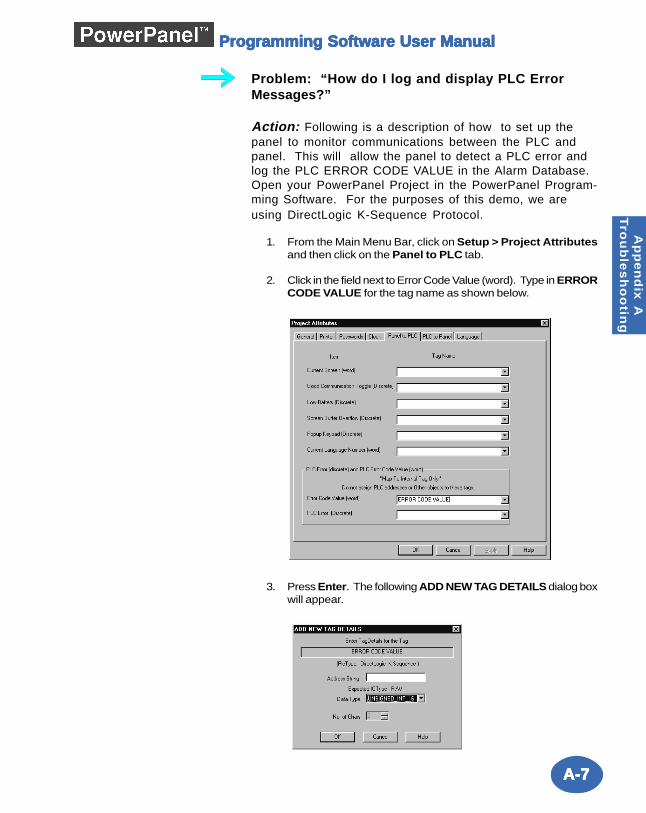
A-7A-7A-7A-7A-7
Ap
pe
nd
ix A
Tro
ub
les
ho
otin
g
Programming Software User ManualProgramming Software User ManualProgramming Software User ManualProgramming Software User ManualProgramming Software User Manual
Problem: “How do I log and display PLC ErrorMessages?”
Action: Following is a description of how to set up thepanel to monitor communications between the PLC andpanel. This will allow the panel to detect a PLC error andlog the PLC ERROR CODE VALUE in the Alarm Database.Open your PowerPanel Project in the PowerPanel Program-ming Software. For the purposes of this demo, we areusing DirectLogic K-Sequence Protocol.
1. From the Main Menu Bar, click on Setup > Project Attributesand then click on the Panel to PLC tab.
2. Click in the field next to Error Code Value (word). Type in ERRORCODE VALUE for the tag name as shown below.
3. Press Enter. The following ADD NEW TAG DETAILS dialog boxwill appear.
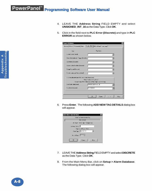
A-8A-8A-8A-8A-8
Ap
pe
nd
ix A
Tro
ub
les
ho
oti
ng
Programming Software User ManualProgramming Software User ManualProgramming Software User ManualProgramming Software User ManualProgramming Software User Manual
4. LEAVE THE Address String FIELD EMPTY and selectUNSIGNED_INT_16 as the Data Type. Click OK.
5. Click in the field next to PLC Error (Discrete) and type in PLCERROR as shown below.
6. Press Enter. The following ADD NEW TAG DETAILS dialog boxwill appear.
7. LEAVE THE Address String FIELD EMPTY and select DISCRETEas the Data Type. Click OK.
8. From the Main Menu Bar, click on Setup > Alarm Database.The following dialog box will appear.
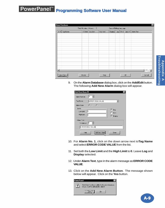
A-9A-9A-9A-9A-9
Ap
pe
nd
ix A
Tro
ub
les
ho
otin
g
Programming Software User ManualProgramming Software User ManualProgramming Software User ManualProgramming Software User ManualProgramming Software User Manual
9. On the Alarm Database dialog box, click on the Add/Edit button.The following Add New Alarm dialog box will appear.
10. For Alarm No. 1, click on the down arrow next toTag Nameand select ERROR CODE VALUE from the list.
11. Set both the Low Limit and the High Limit to 0. Leave Log andDisplay selected.
12. Under Alarm Text, type in the alarm message as ERROR CODEVALUE.
13. Click on the Add New Alarm Button. The message shownbelow will appear. Click on the Yes button.
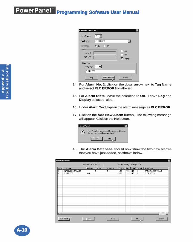
A-10A-10A-10A-10A-10
Ap
pe
nd
ix A
Tro
ub
les
ho
oti
ng
Programming Software User ManualProgramming Software User ManualProgramming Software User ManualProgramming Software User ManualProgramming Software User Manual
14. For Alarm No. 2, click on the down arrow next to Tag Nameand select PLC ERROR from the list.
15. For Alarm State, leave the selection to On. Leave Log andDisplay selected, also.
16. Under Alarm Text, type in the alarm message as PLC ERROR.
17. Click on the Add New Alarm button. The following messagewill appear. Click on the No button.
18. The Alarm Database should now show the two new alarmsthat you have just added, as shown below.
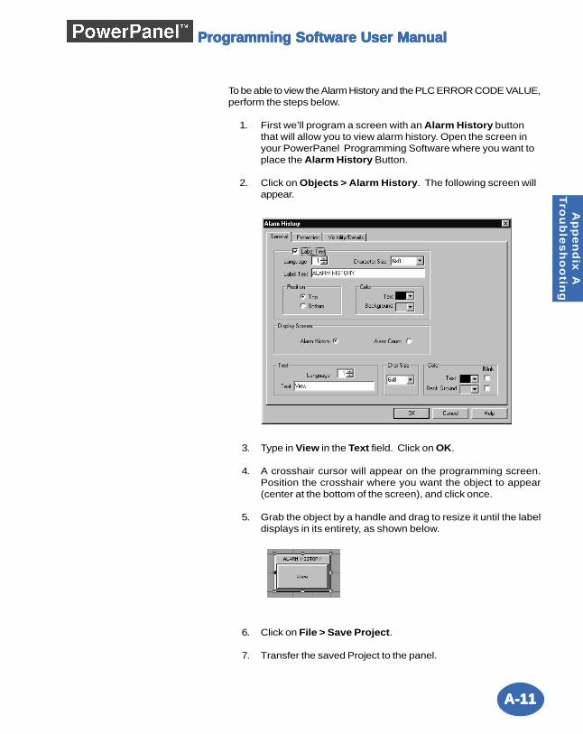
A-11A-11A-11A-11A-11
Ap
pe
nd
ix A
Tro
ub
les
ho
otin
g
Programming Software User ManualProgramming Software User ManualProgramming Software User ManualProgramming Software User ManualProgramming Software User Manual
To be able to view the Alarm History and the PLC ERROR CODE VALUE,perform the steps below.
1. First we’ll program a screen with an Alarm History buttonthat will allow you to view alarm history. Open the screen inyour PowerPanel Programming Software where you want toplace the Alarm History Button.
2. Click on Objects > Alarm History. The following screen willappear.
3. Type in View in the Text field. Click on OK.
4. A crosshair cursor will appear on the programming screen.Position the crosshair where you want the object to appear(center at the bottom of the screen), and click once.
5. Grab the object by a handle and drag to resize it until the labeldisplays in its entirety, as shown below.
6. Click on File > Save Project.
7. Transfer the saved Project to the panel.
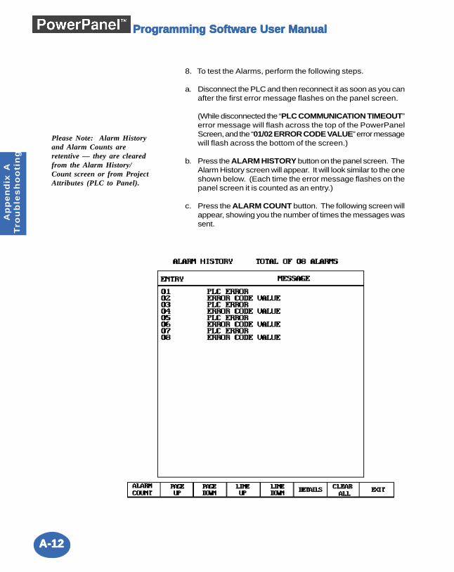
A-12A-12A-12A-12A-12
Ap
pe
nd
ix A
Tro
ub
les
ho
oti
ng
Programming Software User ManualProgramming Software User ManualProgramming Software User ManualProgramming Software User ManualProgramming Software User Manual
8. To test the Alarms, perform the following steps.
a. Disconnect the PLC and then reconnect it as soon as you canafter the first error message flashes on the panel screen.
(While disconnected the “PLC COMMUNICATION TIMEOUT”error message will flash across the top of the PowerPanelScreen, and the “01/02 ERROR CODE VALUE” error messagewill flash across the bottom of the screen.)
b. Press the ALARM HISTORY button on the panel screen. TheAlarm History screen will appear. It will look similar to the oneshown below. (Each time the error message flashes on thepanel screen it is counted as an entry.)
c. Press the ALARM COUNT button. The following screen willappear, showing you the number of times the messages wassent.
Please Note: Alarm Historyand Alarm Counts areretentive — they are clearedfrom the Alarm History/Count screen or from ProjectAttributes (PLC to Panel).
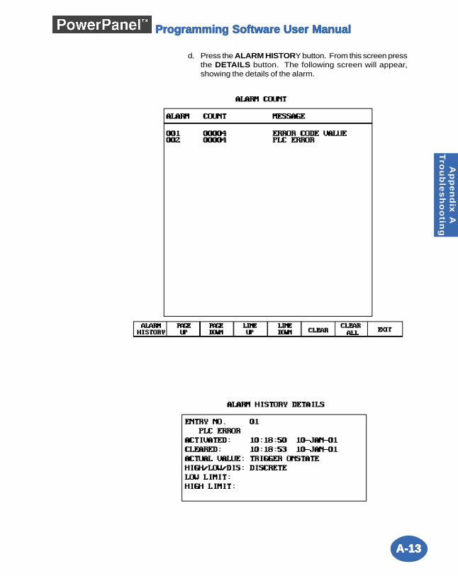
A-13A-13A-13A-13A-13
Ap
pe
nd
ix A
Tro
ub
les
ho
otin
g
Programming Software User ManualProgramming Software User ManualProgramming Software User ManualProgramming Software User ManualProgramming Software User Manual
d. Press the ALARM HISTORY button. From this screen pressthe DETAILS button. The following screen will appear,showing the details of the alarm.
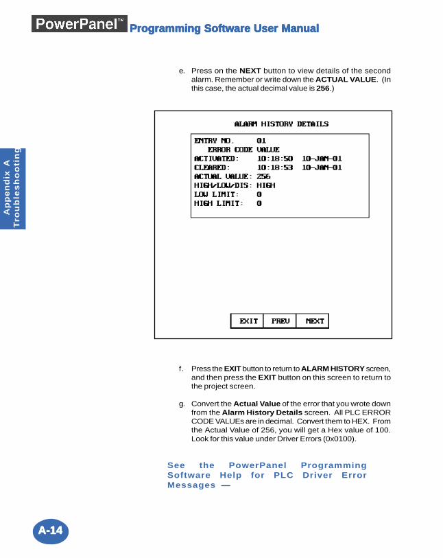
A-14A-14A-14A-14A-14
Ap
pe
nd
ix A
Tro
ub
les
ho
oti
ng
Programming Software User ManualProgramming Software User ManualProgramming Software User ManualProgramming Software User ManualProgramming Software User Manual
e. Press on the NEXT button to view details of the secondalarm. Remember or write down the ACTUAL VALUE. (Inthis case, the actual decimal value is 256.)
f. Press the EXIT button to return to ALARM HISTORY screen,and then press the EXIT button on this screen to return tothe project screen.
g. Convert the Actual Value of the error that you wrote downfrom the Alarm History Details screen. All PLC ERRORCODE VALUEs are in decimal. Convert them to HEX. Fromthe Actual Value of 256, you will get a Hex value of 100.Look for this value under Driver Errors (0x0100).
See the PowerPanel ProgrammingSoftware Help for PLC Driver ErrorMessages —
A-15A-15A-15A-15A-15
Ap
pe
nd
ix A
Tro
ub
les
ho
otin
g
Programming Software User ManualProgramming Software User ManualProgramming Software User ManualProgramming Software User ManualProgramming Software User Manual
PPPPPooooowerPwerPwerPwerPwerPanel Erranel Erranel Erranel Erranel Error Messaor Messaor Messaor Messaor MessagggggesesesesesWRITE QUEUE OVERFLOWThis message indicates that the panel was unable to write all of thetags to the PLC. The panel can queue up to 20 tags to write to the PLC.After the tag is written to the PLC it is removed from the queue. If a writeis attempted while the queue is full then this error message is displayedand the write is ignored.
EXTERNAL CLOCK - OBJECT IGNOREDThis message indicates that the increment/decrement hour system objectwas pressed while the external clock has been selected in the projectattributes. The object can not change the external clock.
RAM TEST FAILEDThis message indicates that the RAM test performed at reset failed. TheRAM in the unit may be unreliable.
VIDEO CHIP TEST FAILEDThis message indicates that the video controller chip did not programcorrectly.
VIDEO RAM TEST FAILEDThis message indicates that the video RAM test performed at resetfailed. The video RAM in the unit may be unreliable.
KEYPAD ENTRY TOO HIGHThis message indicates that the user attempted to enter a value thatwas greater than the maximum value for the numeric keypad. The valueis ignored.
KEYPAD ENTRY TOO LOWThis message indicates that the user attempted to enter a value thatwas less than the minimum value for the numeric keypad. The value isignored.
TAG TYPE VALUE MISMATCHThis message indicates that the object contains a value that is of adifferent type than the object's tag. For example, the value may be asigned value but the tag may be an unsigned value. The object shouldbe edited to contain the correct value type.
INVALID CODEThis message indicates that the user entered an invalid password for aprotected object. The user must enter a valid password. The passwordsare defined in the project attributes.
SCREEN BUFFER OVERFLOWThis message indicates that there are more objects on the screen thanthe panel can display. When a screen is displayed, the panel copies theobjects to a buffer. If the buffer is filled then this message is displayedand any remaining objects are ignored. The amount of memory used byan object is dependent on the type of object, visibility, the label, andstrings used by the object. Some objects should be removed from thescreen.
A-16A-16A-16A-16A-16
Ap
pe
nd
ix A
Tro
ub
les
ho
oti
ng
Programming Software User ManualProgramming Software User ManualProgramming Software User ManualProgramming Software User ManualProgramming Software User Manual
PPPPPooooowerPwerPwerPwerPwerPanel Pranel Pranel Pranel Pranel Programming Software Errogramming Software Errogramming Software Errogramming Software Errogramming Software Error Messaor Messaor Messaor Messaor Messagggggeseseseses
Error Codes
Error Codes are divided into categories and are numbered with prefixes and 3 digits asfollows:
Value Range Errors Vxx_xPLC Conversion Errors Pxx_xTag Errors Txx_xProject Information (Step 1) Errors Ixx_xSaving Errors Sxx_xObject Errors Jxx_xCommunication Errors Cxx_xMiscellaneous Errors Mxx_xBitmap Errors BMP_xx
Value Range Errors (Vxx_x)
Value Errors common to all objects:Error V01_1: Minimum value is not within range.Error V01_2: Maximum value is not within range.Error V01_3: Minimum value is greater than maximum value.Error V01_4: Maximum value is less than minimum value.
Value Errors related to Meter object:Error V02_1: LowLow limit is not within range.Error V02_2: Low limit is not within range.Error V02_3: High limit is not within range.Error V02_4: HighHigh limit is not within range.
Value Errors related to Numeric Entry/Numeric Display.Error V03_1: PLC Value 1 is not within range.Error V03_2: PLC Value 2 is not within range.Error V03_3: Display Value 1 is not within range.Error V03_4: Display Value 2 is not within range.
Value Error related to Bar Graph:Error V04_1: Mid value is not within range.
Value Errors related to PID Faceplate:Error V05_1: Process value (Minimum) is not within range.Error V05_2: Process value (Maximum) is not within range.Error V05_3: Output value (Minimum) is not within range.Error V05_4: Output value (Maximum) is not within range.
A-17A-17A-17A-17A-17
Ap
pe
nd
ix A
Tro
ub
les
ho
otin
g
Programming Software User ManualProgramming Software User ManualProgramming Software User ManualProgramming Software User ManualProgramming Software User Manual
Value Error related to Recipe object:Error V06_1: Value is not within range.
Reason: These errors occur when a value is not within selected tag's data range.Solution: Enter a value that is within the appropriate range.
Valid ranges for various tag data types are:
TAG DATA TYPE MINIMUM MAXIMUMSigned 16 bit -32768 32767Signed 32 bit -2147483648 2147483647Unsigned 16 bit 0 65535Unsigned 32 bit 0 4294967295BCD 16 bit 0 9999BCD 32 bit 0 99999999Floating point -9999999999 9999999999
PLC Conversion Errors (Pxx_x)
Error P01_1: The selected panel type does not support the PLC chosen for the project.Do you want to continue?
Reason: Some PowerPanel s support all of the available PLC drivers and some support onlyDirectLOGIC drivers.Solution: Select an appropriate panel.
Error P02_1: <PLCFrom> is not compatible with <PLCTo>. If you continue, the PLCaddress from each tag will be lost and all the tags will become internal tags. Do youwant to continue?Error P02_2: Change in selected PLC would result in possible loss of tag data. Do youwant to continue?Error P02_3: Unable to convert to <PLCTo>.Error P02_4: Unable to convert PLC Address.
Reason: This error occurs if, after creating a project with addressed tags, an attempt is madeto change to a PLC with a different address format.Solution: When changing PLCs, check the addressing in the PLC manuals to see if they arecompatible. If they are not compatible, then the tag database is no longer valid and theaddresses will have to be reentered.
Error P02_5: Unable to build PLC details structure while converting to < >.Reason: If you try to change PLCs in a previously created project and select "Cancel" in thefirst message window, a second window will appear.Solution: This message window appears to inform the user that no tag addresses werechanged.
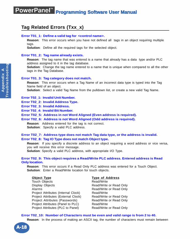
A-18A-18A-18A-18A-18
Ap
pe
nd
ix A
Tro
ub
les
ho
oti
ng
Programming Software User ManualProgramming Software User ManualProgramming Software User ManualProgramming Software User ManualProgramming Software User Manual
Tag Related Errors (Txx_x)
Error T01_1: Define a valid tag for <control name>.Reason: This error occurs when you have not defined all tags in an object requiring multipletags.Solution: Define all the required tags for the selected object.
Error T01_2: Tag name already exists.Reason: The tag name that was entered is a name that already has a data type and/or PLCaddress assigned to it in the tag database.Solution: Change the tag name entered to a name that is unique when compared to all the othertags in the Tag Database.
Error T01_3: Tag category does not match.Reason: This error occurs when a Tag Name of an incorrect data type is typed into the TagName field of an object.Solution: Select a valid Tag Name from the pulldown list, or create a new valid Tag Name.
Error T02_1: Invalid Unit Number.Error T02_2: Invalid Address Type.Error T02_3: Invalid Address.Error T02_4: Invalid Bit Number.Error T02_5: Address in not Word Aligned (Even address is required).Error T02_6: Address is not Word Aligned (Odd address is required).
Reason: Address entered for the tag is not correct.Solution: Specify a valid PLC address.
Error T02_7: Address type does not match Tag data type, or the address is invalid.Error T02_8: Tag IO Type does not match Object type.
Reason: If you specify a discrete address to an object requiring a word address or vice versa,you will receive this error message.Solution: Specify a valid PLC address, with appropriate I/O Type.
Error T02_9: This object requires a Read/Write PLC address. Entered address is ReadOnly location.
Reason: This error occurs if a Read Only PLC address was entered for a Touch Object.Solution: Enter a Read/Write location for touch objects.
Object Type Type of AddressTouch Objects Read/WriteDisplay Objects Read/Write or Read OnlyAlarms Read/Write or Read OnlyProject Attributes (Internal Clock) Read/WriteProject Attributes (External Clock) Read/Write or Read OnlyProject Attributes (Passwords) Read/Write or Read OnlyProject Attributes (Panel to PLC) Read/WriteProject Attributes (PLC to Panel) Read/Write or Read Only
Error T02_10: Number of Characters must be even and valid range is from 2 to 40.Reason: In the process of making an ASCII tag, the number of characters must remain between
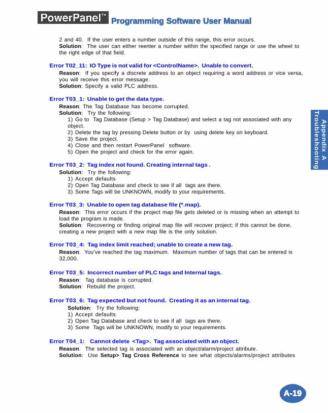
A-19A-19A-19A-19A-19
Ap
pe
nd
ix A
Tro
ub
les
ho
otin
g
Programming Software User ManualProgramming Software User ManualProgramming Software User ManualProgramming Software User ManualProgramming Software User Manual
2 and 40. If the user enters a number outside of this range, this error occurs.Solution: The user can either reenter a number within the specified range or use the wheel tothe right edge of that field.
Error T02_11: IO Type is not valid for <ControlName>. Unable to convert.Reason: If you specify a discrete address to an object requiring a word address or vice versa,you will receive this error message.Solution: Specify a valid PLC address.
Error T03_1: Unable to get the data type.Reason: The Tag Database has become corrupted.Solution: Try the following:
1) Go to Tag Database (Setup > Tag Database) and select a tag not associated with anyobject.2) Delete the tag by pressing Delete button or by using delete key on keyboard.3) Save the project.4) Close and then restart PowerPanel software.5) Open the project and check for the error again.
Error T03_2: Tag index not found. Creating internal tags .Solution: Try the following:
1) Accept defaults2) Open Tag Database and check to see if all tags are there.3) Some Tags will be UNKNOWN, modify to your requirements.
Error T03_3: Unable to open tag database file (*.map).Reason: This error occurs if the project map file gets deleted or is missing when an attempt toload the program is made.Solution: Recovering or finding original map file will recover project; if this cannot be done,creating a new project with a new map file is the only solution.
Error T03_4: Tag index limit reached; unable to create a new tag.Reason: You’ve reached the tag maximum. Maximum number of tags that can be entered is32,000.
Error T03_5: Incorrect number of PLC tags and Internal tags.Reason: Tag database is corrupted.Solution: Rebuild the project.
Error T03_6: Tag expected but not found. Creating it as an internal tag.Solution: Try the following:1) Accept defaults2) Open Tag Database and check to see if all tags are there.3) Some Tags will be UNKNOWN, modify to your requirements.
Error T04_1: Cannot delete <Tag>. Tag associated with an object.Reason: The selected tag is associated with an object/alarm/project attribute.Solution: Use Setup> Tag Cross Reference to see what objects/alarms/project attributes
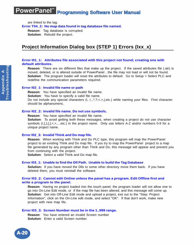
A-20A-20A-20A-20A-20
Ap
pe
nd
ix A
Tro
ub
les
ho
oti
ng
Programming Software User ManualProgramming Software User ManualProgramming Software User ManualProgramming Software User ManualProgramming Software User Manual
are linked to the tag.Error T04_2: No map data found in tag database file named.
Reason: Tag database is corrupted.Solution: Rebuild the project.
Project Information Dialog box (STEP 1) Errors (Ixx_x)
Error I01_1: Attributes file associated with this project not found; creating one withdefault attributes.
Reason: There are six different files that make up the project. If the saved attributes file (.atr) ismoved, deleted, or is altered outside of PowerPanel , the file may not load or will not be found.Solution: The program loader will reset the attributes to default. Go to Setup > Select PLC andredefine the communication parameters required.
Error I02_1: Invalid file name or pathReason: You have specified an invalid file name.Solution: You have to specify a valid file name.Do not include any special characters (\, /,.,*,?,<,>,|,etc.) while naming your files. First charactershould be alphanumeric.
Error I02_2: Invalid file name. Do not use symbols.Reason: You have specified an invalid file name.Solution: To avoid getting both these messages, when creating a project do not use charactersymbols (/,{,},[,],<,>,…etc.) in the project name. Only use letters A-Z and/or numbers 0-9 for aunique project name.
Error I02_3: Invalid Think and Do map file.Reason: When working with Think and Do PLC type, this program will map the PowerPanelproject to an existing Think and Do map file. If you try to map the PowerPanel project to a mapfile generated by any program other than Think and Do, this message will appear and prevent youfrom continuing with the project.Solution: Select a valid Think and Do map file.
Error I03_1: Unable to find the Dll Path. Unable to build the Tag DatabaseSolution: If you have moved the Dlls to some other directory move them back. If you havedeleted them, you must reinstall the software.
Error I03_2: Cannot edit Online unless the panel has a program. Edit Offline first andwrite a program to the panel.
Reason: Having no project loaded into the touch panel, the program loader will not allow one togo into On-Line Edit mode, or if the map file has been altered, and this message will come up.Solution: Get into Off-Line Edit mode and upload a project, exit out to the "Step: ProjectInformation", click on the On-Line edit mode, and select "OK". If that don't work, make newproject with new map file.
Error I03_3: Screen Number must be in the 1..999 range.Reason: You have entered an invalid Screen numberSolution: Enter a valid Screen number.
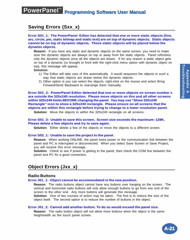
A-21A-21A-21A-21A-21
Ap
pe
nd
ix A
Tro
ub
les
ho
otin
g
Programming Software User ManualProgramming Software User ManualProgramming Software User ManualProgramming Software User ManualProgramming Software User Manual
Saving Errors (Sxx_x)
Error S01_1: The PowerPanel Editor has detected that one or more static objects (line,arc, circle, pie, static bitmap and static text) are on top of dynamic objects. Static objectscannot be on top of dynamic objects. These static objects will be placed below thedynamic objects.
Reason: If you have any static and dynamic objects on the same screen, you need to makesure the dynamic objects are always on top or away from the static objects. Panel refreshesonly the dynamic objects once all the objects are drawn. If for any reason a static object getson top of a dynamic (or brought to front with the right-click menu option with dynamic object ontop), this message will appear.Solution:
1) The Editor will take care of this automatically. It would sequence the objects in such away that static objects are drawn below the dynamic objects.
2) Other option is you can select the objects, right-click on the mouse and select BringForward/Send Backward to rearrange them manually.
Error S01_2: PowerPanel Editor detected that one or more objects on screen number xare outside the 320x240 resolution. Please move objects on this and all other screenswithin 320x240 limits BEFORE changing the panel. You may use “Show 320x240Rectangle” icon to show a 320x240 rectangle. Please ensure on all screens that theobjects are within this rectangle before trying to change to a lower resolution panel.
Solution: Move the objects to within the 320x240 rectangle on all screens.
Error S01_3: Unable to save this screen. Screen size exceeds the maximum: 128K.Please delete a few objects and try to save again.
Solution: Either delete a few of the objects or move the objects to a different screen.
Error S02_1: Unable to save the project to the panel.Reason: When working ONLINE, the panel loses power or the communication link between thepanel and PC is interrupted or disconnected. When you select Save Screen or Save Project,you will receive this error message.Solution: Check to see if power is getting to the panel, then check the COM line between thepanel and PC for a good connection.
Object Errors (Jxx_x)
Radio ButtonsError J01_1: Object cannot be accommodated in the new position.
Reason: The radio buttons object cannot have any buttons over hanging on the screen. Thevertical and horizontal radio buttons will only allow enough buttons to go from one end of thescreen to the other end. Any more buttons will generate this message.Solution: One of two courses of action may be taken. The first is to reduce the size of theobject itself. The second option is to reduce the number of buttons in the object.
Error J01_2: Cannot add another button. To do so would exceed the panel size.Reason: The radio button object will not allow more buttons when the object is the sameheight/width as the touch panel screen.
A-22A-22A-22A-22A-22
Ap
pe
nd
ix A
Tro
ub
les
ho
oti
ng
Programming Software User ManualProgramming Software User ManualProgramming Software User ManualProgramming Software User ManualProgramming Software User Manual
Step SwitchError J02_1: Number of steps: Range is from 2 to 4.
Solution: Enter a number between 2 and 4 or use the wheel next to the box.
Error J02_2: Step Switch x Tag is not Defined. (x being the step number)Reason: The "Tag Name", in the "Step #1" tab, was empty when the "OK" button was selected.Solution: Click on a tag from the drop-down menu for the "Tag Name" box, or type in a valid tagname in the "Tag Name" box, in the tab "Step #1".
ThumbwheelError J03_1: Number of Wheels: Range is from 1 to 5.
Solution: Only enter a number between 1 and 5 into the "Number of Wheels" field, or use thewheel to the right side of the entry field. UNSIGNED DECIMAL format: 5 digits (wheels), HEX: 4digits (wheels)
RecipeError J04_1: At least one valid recipe tag should be defined.
Reason: When creating a recipe button, if there are no tags entered under the "Recipe" tab, thismessage will appear.Solution: Click on the "Recipe" tab and enter a tag in the first box.
Numeric Entry/Numeric DisplayError J05_1: PLC Value 1 is greater than PLC Value 2.
Solution: Enter a value for PLC Value 1 that is less than PLC Value 2.Error J05_2: Display Value 1 is greater than Display Value 2.
Solution: Enter a value for Display Value 1 that is less than Display Value 2.
MeterError J06_1: LowLow limit should be greater than Minimum value.Error J06_2: Low limit should be greater than LowLow limit.Error J06_3: LowLow limit is greater than High limit.Error J06_4: High limit is greater than HighHigh limit.Error J06_5: HighHigh limit is greater than Maximum value.
Reason: You will get above errors when the following rule is not met.Minimum Value < Low Low Limit < Low Limit < High Limit < High High Limit <Maximum ValueSolution: Change the values appropriately.Note: while changing the values of alarm limits, use the following rule of thumb:
• If you are changing the values towards higher values, start from HighHigh limitand go backwards.
• If you are changing the values towards lower values, start from LowLow limit andgo upwards.
Bar GraphError J07_1: Mid value is not in between Minimum and Maximum values.
Reason: You will get above errors when the limits (for alarm) are not within selected tag's datarange.Solution: You need to modify the values so that the values are within appropriate range.
A-23A-23A-23A-23A-23
Ap
pe
nd
ix A
Tro
ub
les
ho
otin
g
Programming Software User ManualProgramming Software User ManualProgramming Software User ManualProgramming Software User ManualProgramming Software User Manual
PID FaceplateError J08_1: Process Variable Tag and Set Point Tag must be of same Data Type.
Solution: Ensure that the Process Variable tag and the Set Point Tag are of the same data type.In other words, if you define a signed tag for Process Variable, define a signed tag for Set Pointtag, also. Always assign the same data tag type to both the Process Variable and Set Point.
Error J08_2: Process value (Maximum) is less than Present value (Minimum).Solution: Ensure that Present value (Maximum) is greater than Present value (Minimum).
Error J08_3: Output value (Minimum) cannot be greater than Present value (Maximum).Solution: Ensure that Output value (Maximum) is greater than Output value (Minimum).
Line GraphError J10_1: At least one valid Pen tag must be defined.
Reason: When using a line graph, there must be a minimum of one tag (signed, unsigned, orBCD) assigned to the Pen entries.Solution: Be sure to assign a minimum of one tag (signed, unsigned, or BCD) to the Pen.
Error J10_2: All Pen tags must be of the same sign type.Reason: The program loader requires that all the Pen tags have the same sign type for each linegraph object. If you assign tags with different sign types (signed 16/32 and unsigned 16/32, orBCD 16/32 and signed 16/32) to the same line graph object, this message will appear.Solution: If you need a line graph that contains a signed tag and an unsigned tag, they will thenrequire multiple line graph objects (one for each individual sign type).
Error J10_3: Pen tags and Range type must be of same sign type.Reason: When assigning tags to the Pen page, they all must be of the same tag type, and thatalso has to agree with the Range type under the XY Axis tab. If one is different from the otherand the "OK" button is selected, this message will appear.Solution: After assigning the Pen tags, (same sign type) go to the XY Axis tab and select theappropriate range type corresponding to the assigned Pen tags (or select the range type beforeassigning any tags to the Pen). Either way, the Pen tags and the Range type must be the samebefore the "OK" button is selected.
Error J10_4: Total number of line graphs must be between 0 and 255.Reason: You will not be able to create more than 255 line graphs in a single screen.
Dynamic Bitmap/Static BitmapError J11_1: Selected file is not a BMP file.
Solution: Select a valid Windows BMP file.
Error J11_2: No Bitmap file was selected. Please select a BMP File.Solution: One of three actions can be taken:
1) Select "Copy from Clipboard" to copy the file name chosen from the Symbol Factory.2) Select "Import Bitmap…" to choose a bitmap from a file somewhere in your computer or off
the network to enter in the "File Name" box.
Error J11_3: Select either ON or OFF bitmap.Reason: Dynamic bitmaps require at least one bitmap to be selected.
A-24A-24A-24A-24A-24
Ap
pe
nd
ix A
Tro
ub
les
ho
oti
ng
Programming Software User ManualProgramming Software User ManualProgramming Software User ManualProgramming Software User ManualProgramming Software User Manual
Error J11_4: Compressed BMP size exceeds the maximum size usable BMP sizeReason: PowerPanels use a Run Length Encoding (RLE) technique to compress Bitmaps fordisplay and saving purposes. The maximum allowable size of a compressed BMP is 64K. If theselected BMP results more than 64K during compression, this error occurs. Even if the bitmapsize is less than the panel's resolution, you may get this error.Solution: You need to select a different BMP. If you would like to use the same bitmap, youneed to reduce the complexity of the bitmap. Although, there is no straight forward way to tellthat a bitmap would result in less than 64K during compression, the following tips might beuseful:
1) Try to have the same color across the bitmap. If you mix lot of color patches, that mayincrease the compressed bitmap size.
2) Try to reduce the font usage in the bitmap.
Error J11_5: Selected BMP files combined must not exceed 64K size. Please select adifferent BMP file.
Reason: There are two BMP files for dynamic bitmap. Both BMP files would be compressedusing RLE technique and combined length of compressed BMPs together should not exceed 64Kin size. If it exceeds, you would get this error.Solution: Select BMPs which do not exceed the 64K size limit.
Error J11_6: Height and Width out of range. BMP’s height must be less than ( h ). BMP’swidth must be less than ( w ).
Reason: 10" and 8" panels support bitmaps no larger than 640 x 480 pixels. Similarly, 6" panelssupport a maximum bitmap size of 320x240 pixels. This error indicates that a bitmap exceeds themaximum size.Solution: Select a bitmap that fits within the above ranges.
Error J11_7: Compressed BMP size exceeds the maximum usable BMP size; unable tosave ON bitmap.Error J11_8: Compressed BMP size exceeds the maximum usable BMP size; unable tosave OFF bitmap.Error J11_9: Compressed BMP size exceeds the maximum usable BMP size; unable tosave Static Bitmap.
Reason: PowerPanel s use a Run Length Encoding (RLE) technique to compress Bitmaps fordisplay and saving purposes. The maximum allowable size of a compressed BMP is 64K. If theselected BMP results more than 64K during compression, this error occurs. Even if the bitmapsize is less than the panel's resolution, you may get this error.Solution: You need to select a different BMP. If you would like to use the same bitmap, youneed to reduce the complexity of the bitmap. Although, there is no straight forward way to tellthat a bitmap would result in less than 64K during compression, the following tips might beuseful:
1) Try to have the same color across the bitmap. If you mix lot of color patches, that mayincrease the compressed bitmap size.
2) Try to reduce the font usage in the bitmap.
Error J11_10: Error in extracting Bitmap for ON button.Solution: Delete the bitmap object and recreate the object again. If you still receive this errormessage, close and then reopen the application and try again.
Error J11_11: Decompression was not successful.Reason: The Project file is corrupted.Solution: If you get this error, you will have to recreate this project.
A-25A-25A-25A-25A-25
Ap
pe
nd
ix A
Tro
ub
les
ho
otin
g
Programming Software User ManualProgramming Software User ManualProgramming Software User ManualProgramming Software User ManualProgramming Software User Manual
Error J11_12: Select Palette failed in Paint DOB.Reason: Resource not available in the system to draw the bitmap.Solution: Close other applications and try to insert the bitmap. If it still does not work, restart thesystem.
MiscellaneousError J12_1: This field cannot be empty.
Solution: Your cursor will be located in the data entry field that requires data entry. Enter anappropriate value.
Communication Errors (Cxx_x)
Port Related ErrorsError C01_1: Unable to open communication port.
Solution: Select another COM port.
Error C01_2: Communications port not found.Reason: No valid communication port is found on the computer.Solution: At least one valid serial communication port should be available for communicationbetween the panel and PC.
Error C01_3: Communications port is being used by some other application. Accessdenied.
Solution: Close the other application and try to communicate from PowerPanel or, if you havean extra serial port, connect the cable to that port and select that extra port for communicationfrom PowerPanel .
Write to Panel Related ErrorsError C02_1: Selected panel does not match connected panel. Write to panel is aborted.
Reason: When writing to the panel, if the panel type selected on the screen "Step 1: ProjectInformation" does not match the panel that the computer and PLC are physically connected to, theprogram loader will not upload project.Solution: Exit the OFF-LINE Editor to the "Step 1: Project Information" screen, and select theappropriate panel type for the connected panel.
Error C02_2: Unable to update PLC driver.Reason: You will receive this error message if communication is not working between theprogramming software and the panel, or if the panel is still trying to communicate with the olddriver and you are attempting to update the driver.Solution: Restart the panel and try communicating with the panel. If you still face this problem,clear memory from panel (using Panel > Clear Memory) and update the PLC driver and then, saveyour project. Ensure that you have the project saved to disk before you do clear memory.
Error C02_3: PLC Attributes could not be written to the Panel.Error C02_4: Tags could not be written to the Panel.Error C02_5: Error in sending Project attributes to panel.Error C02_6: Error in sending screens to panel.Error C02_7: Error in sending alarm database to panel.Error C02_8: Error in sending message database to panel.
A-26A-26A-26A-26A-26
Ap
pe
nd
ix A
Tro
ub
les
ho
oti
ng
Programming Software User ManualProgramming Software User ManualProgramming Software User ManualProgramming Software User ManualProgramming Software User Manual
Solution: Check the connections between the panel and computer. Restart the panel and trycommunicating again.
Error C02_9: Objects are overlapping; project cannot be written to the panel.Reason: Objects are overlapping in one or more screens; you will not be able to save / write tothe panel.Solution: If you get this error, you will see an object highlighted in the screen. The highlightedobject is overlapping another object. Please move the object so that it does not overlap anotherobject ,and send the project again.
Error C02_10: Uploading could not be completed.Solution: Check the connections between the panel and computer. Restart the panel or resavethe project and try communicating again.
Error C02_11: Out of Memory Error.Reason: Flash card is smaller than user RAM size.Solution: Please contact your panel vendor.
ONLINE Programming Communication ErrorsError C03_1: Unable to delete screen from panel.
Reason: If Screen > Delete Screen (on main menu bar) is selected while there is a disruption inthe communication between the panel and computer, this error message is produced.Solution: Check the COM line, power to panel, and COM port used for correct setting andfunction.
Error C03_2: Memory diagnosing failed.Solution: Check connections and COM port settings. Ensure the proper function and powerdistribution of panel (no system faults). If all checks out OK and you are still receiving this errormessage, there maybe a physical problem with the panel's memory.
Error C03_3: Errors in Warm Boot.Reason: Panel is not warm booting.Solution: This could be due to panel not active/communication is not there between PC to panel.Please check the connection between panel to PC. If the problem persists, restart the panel.
Error C03_4: Unable to program User Flash.Error C03_5: Errors in Reading Flash card.
Reason: If the flash card is not set properly / communication is not happening between thepanel and editor, you would get this error.Solution: Check whether the flash card is fit properly in the slot / restart the panel / check thecable for communication.
Error C03_6: Unable to read PLC Attributes from Panel.Error C03_7: Unable to delete screen <screen number> from the panel.Error C03_8: Unable to get Information from Panel. Please check the connectionbetween panel and computer.Error C03_9: Unable to read System Attributes from panel.Error C03_10: Unable to read tags from the panel.
Solution: Check the connection between panel and computer. Restart the panel and trycommunicating again.
A-27A-27A-27A-27A-27
Ap
pe
nd
ix A
Tro
ub
les
ho
otin
g
Programming Software User ManualProgramming Software User ManualProgramming Software User ManualProgramming Software User ManualProgramming Software User Manual
Error C03_11: Testing RAM - failedSolution: If you have a RAM Card installed in the panel, remove this RAM card and redo the test.If the test passes, replace the RAM card with a new RAM card. It the test fails, there is aproblem with the panel. Please contact technical support.
Error C03_12: Testing Flash - failedSolution: Replace the Flash card.
Miscellaneous Errors (Mxx_x)
Error M01_1: Error in memory allocation.Reason: You will get this error if PowerPanel Editor is not able to allocate certain amount ofmemory for doing some operations.Solution: close other applications and try. If you still get this error, save the project and closethe application. Restart your computer and try again.
Error M02_2: Unable to open the Project file (*.ezt).Error M02_3: Unable to open message database file (*.msd).Error M02_4: Unable to open alarm database file (*.alr).Error M02_5: Unable to open PLC attributes file (*.atr).Error M02_6: Unable to open annotations file (*.ano).Error M02_7: Unable to open project options file (*.opt).
Solution: You have renamed your project accidentally while project was open in PowerPanel .Close this project and open it again.
Error M03_1: Unable to create project file (*.ezt).Error M03_2: Unable to create PLC attributes file (*.atr).Error M03_3: Unable to create message database file (*.msd).Error M03_4: Unable to create alarm database file (*.alr).Error M03_5: Unable to create annotation file (*.ano).Error M03_6: Unable to create project options file (*.opt).Error M03_7: Unable to save PLC Attributes file (*.atr).Error M04_1: Unable to create temporary project file (*.ezt).Error M04_2: Unable to create temporary annotations file (*.ano).Error M04_3: Unable to create temporary PLC attributes file (*.atr).
Reason: You might receive these error messages if you are running two instances of thePowerPanel Programming Software, opened a project in one and then gave the same projectname in another to be downloaded from panel.Solution: Give a valid project file name that is not open in any application. If you still face theproblem, close all your applications and run only one instance of PowerPanel and try again.
Error M05_1: Unable to unload.Error M05_2: Unable to load.
Reason: There is a .dll file in the directory that doesn’t belong. The program loader will report thiserror.Solution: Remove the specified file, and reinstall the software.
Error M06_1: Not a PowerPanel .Solution: Connect a PowerPanel to the computer and try to communicate with the panel.
A-28A-28A-28A-28A-28
Ap
pe
nd
ix A
Tro
ub
les
ho
oti
ng
Programming Software User ManualProgramming Software User ManualProgramming Software User ManualProgramming Software User ManualProgramming Software User Manual
Error M06_2: File corrupted; number of bytes in the screen is zero.Error M06_3: Unable to rename the selected screen.Error M06_4: Problems in project checksumError M06_5: Invalid screen checksum
Solution: You need to recreate the project. If this problem persists, please report it totechnical support.
Error M06_6: There are no PLC dlls available in this execution directory.Reason: If you have moved all the PLC dlls from the directory where PowerPanel .exe resides,you will receive this error message.Solution: Reinstall the software
Error M06_7: PLC Dll file being used by this project is not found.Reason: A PLC .dll file has been moved or deleted from the program directory.Solution: Reinstall the software.
Error M06_8: Received checksum is not equal to calculated checksum.Solution: Reinstall software and try again.
Error M06_9: No PLC has been selected.Solution: Reinstall software and try again.
Error M07_1: Invalid Screen Name.Error M07_2: Invalid screen ID , screen ID range is 1..999.
Reason: Valid screen name's length is 1 to 40 characters.Solution: You have to specify a valid screen name. Do not include any special characters (\, /,.,*,?,<,>,|,etc.) while naming your files. First character should be alphanumeric.
Error M08_1: Downloaded project is a protected project. This cannot be edited/viewed inthe editor.”
Reason: Project is write protected.Solution: You will not be able to open this project for viewing / editing purpose. Contact thepeople from whom you got this project.
Error M09_1: System out of memory to run Symbol Factory.”Solution: Restart your system
Error M09_2: Invalid Symbol Factory.exe file.”Solution: Reinstall the software
Error M09_3: Unable to find Symbol Factory application.”Solution: If you have moved symbols directory to some other place, please copy it back.Otherwise, reinstall the software.
A-29A-29A-29A-29A-29
Ap
pe
nd
ix A
Tro
ub
les
ho
otin
g
Programming Software User ManualProgramming Software User ManualProgramming Software User ManualProgramming Software User ManualProgramming Software User Manual
Bitmap Errors (BMP_xx)
Error BMP_1: Unable to display dynamic bitmap objectError BMP_5: Unable to display static bitmap object
Reason: You will receive this message if there is a problem in displaying the bitmap data.Solution: Delete and then reinsert the bitmap object.
Error BMP_2: Unable to read *.wmf fileError BMP_3: Unable to read *.emf fileError BMP_4: Unable to read meta file data from clipboard
Reason: Unable to convert the .wmf/.emf file selected to .bmp.Solution: Check whether you are able to insert this bitmap in another application (e.g., Word).If yes, restart the system and try again.
Error BMP_6: Unable to calculate enhanced meta file dimension, \ntaking default 80Wx80HError BMP_7: Unable to calculate meta file dimension, taking default 80Wx80H
Reason: Editor is unable to calculate enclosing rectangle of the selected .wmf/.emf.
Error BMP_8: Total compressed buffer size of on and off bitmaps must not \n exceed64K; please reduce the size of objectError BMP_9: Compressed buffer size of bitmap must not \nexceed 64K; please reducethe size of object
Solution: Insert a different bitmap / try to reduce the complexity of this bitmap.
Error BMP_10: Unable to calculate static bitmap sizeError BMP_12: Unable to calculate dynamic bitmap size
Reason: Editor is unable to calculate the bitmap size.Solution: Delete the object and try to reinsert the object.
Error BMP_11: Unable to read the project fileSolution: You might get this message when attempting to download a project, or edit a projectonline, that contains bitmaps. If this happens, restart the system and try again.
A-30A-30A-30A-30A-30
Ap
pe
nd
ix A
Tro
ub
les
ho
oti
ng
Programming Software User ManualProgramming Software User ManualProgramming Software User ManualProgramming Software User ManualProgramming Software User Manual
This page intentionally left blank.

ASCII CharactersASCII CharactersASCII CharactersASCII CharactersASCII Characters
In this Appendix....
— Character List
BBBBB
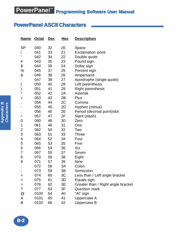
B-2B-2B-2B-2B-2
Ap
pen
dix
BC
har
acte
rsProgramming Software User ManualProgramming Software User ManualProgramming Software User ManualProgramming Software User ManualProgramming Software User Manual
PPPPPooooowerPwerPwerPwerPwerPanel ASCII Characteranel ASCII Characteranel ASCII Characteranel ASCII Characteranel ASCII Charactersssss
Name Octal Dec Hex Description
SP 040 32 20 Space! 041 33 21 Exclamation point“ 042 34 22 Double quote# 043 35 23 Pound sign$ 044 36 24 Dollar sign% 045 37 25 Percent sign& 046 38 26 Ampersand‘ 047 39 27 Apostrophe (single quote)( 050 40 28 Left parenthesis) 051 41 29 Right parenthesis* 052 42 2A Asterisk+ 053 43 2B Plus, 054 44 2C Comma- 055 45 2D Hyphen (minus). 056 46 2E Period (decimal point)/dot/ 057 47 2F Slant (slash)0 060 48 30 Zero1 061 49 31 One2 062 50 32 Two3 063 51 33 Three4 064 52 34 Four5 065 53 35 Five6 066 54 36 Six7 067 55 37 Seven8 070 56 38 Eight9 071 57 39 Nine: 072 58 3A Colon; 073 59 3B Semicolon< 074 60 3C Less than / Left angle bracket= 075 61 3D Equals sign> 076 62 3E Greater than / Right angle bracket? 077 63 3F Question mark@ 0100 64 40 “At” signA 0101 65 41 Uppercase AB 0102 66 42 Uppercase B
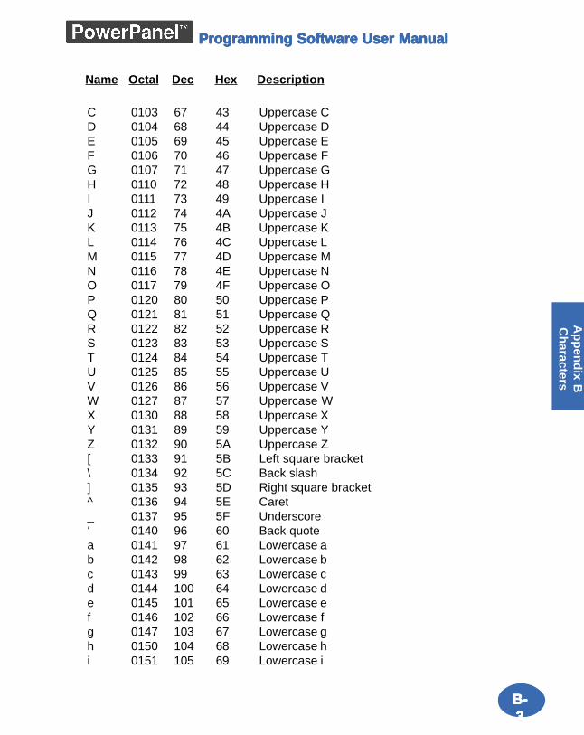
B-B-B-B-B-33333
Ap
pen
dix B
Ch
aracters
Programming Software User ManualProgramming Software User ManualProgramming Software User ManualProgramming Software User ManualProgramming Software User Manual
C 0103 67 43 Uppercase CD 0104 68 44 Uppercase DE 0105 69 45 Uppercase EF 0106 70 46 Uppercase FG 0107 71 47 Uppercase GH 0110 72 48 Uppercase HI 0111 73 49 Uppercase IJ 0112 74 4A Uppercase JK 0113 75 4B Uppercase KL 0114 76 4C Uppercase LM 0115 77 4D Uppercase MN 0116 78 4E Uppercase NO 0117 79 4F Uppercase OP 0120 80 50 Uppercase PQ 0121 81 51 Uppercase QR 0122 82 52 Uppercase RS 0123 83 53 Uppercase ST 0124 84 54 Uppercase TU 0125 85 55 Uppercase UV 0126 86 56 Uppercase VW 0127 87 57 Uppercase WX 0130 88 58 Uppercase XY 0131 89 59 Uppercase YZ 0132 90 5A Uppercase Z[ 0133 91 5B Left square bracket\ 0134 92 5C Back slash] 0135 93 5D Right square bracket^ 0136 94 5E Caret_ 0137 95 5F Underscore‘ 0140 96 60 Back quotea 0141 97 61 Lowercase ab 0142 98 62 Lowercase bc 0143 99 63 Lowercase cd 0144 100 64 Lowercase de 0145 101 65 Lowercase ef 0146 102 66 Lowercase fg 0147 103 67 Lowercase gh 0150 104 68 Lowercase hi 0151 105 69 Lowercase i
Name Octal Dec Hex Description
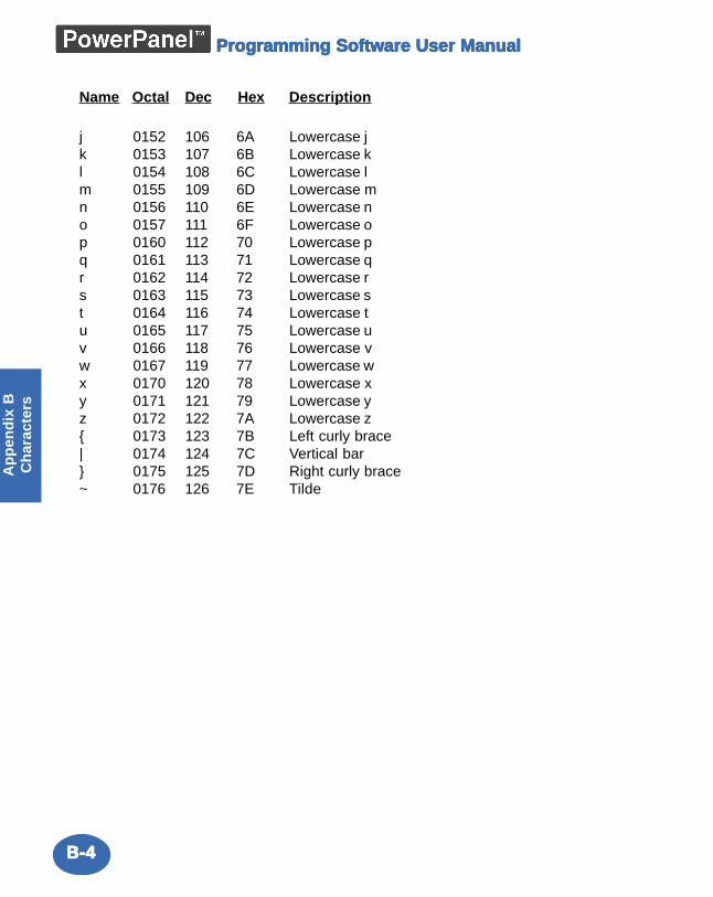
B-4B-4B-4B-4B-4
Ap
pen
dix
BC
har
acte
rsProgramming Software User ManualProgramming Software User ManualProgramming Software User ManualProgramming Software User ManualProgramming Software User Manual
j 0152 106 6A Lowercase jk 0153 107 6B Lowercase kl 0154 108 6C Lowercase lm 0155 109 6D Lowercase mn 0156 110 6E Lowercase no 0157 111 6F Lowercase op 0160 112 70 Lowercase pq 0161 113 71 Lowercase qr 0162 114 72 Lowercase rs 0163 115 73 Lowercase st 0164 116 74 Lowercase tu 0165 117 75 Lowercase uv 0166 118 76 Lowercase vw 0167 119 77 Lowercase wx 0170 120 78 Lowercase xy 0171 121 79 Lowercase yz 0172 122 7A Lowercase z{ 0173 123 7B Left curly brace| 0174 124 7C Vertical bar} 0175 125 7D Right curly brace~ 0176 126 7E Tilde
Name Octal Dec Hex Description
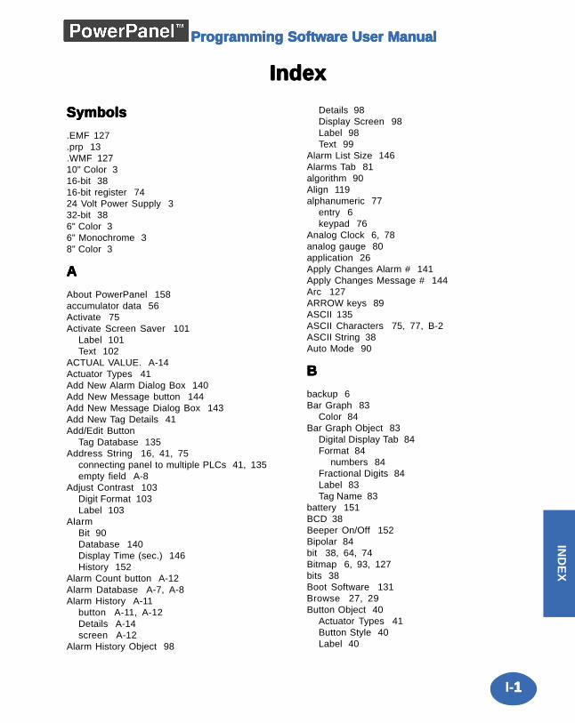
I-11111
Intro
du
ction
IND
EX
Programming Software User ManualProgramming Software User ManualProgramming Software User ManualProgramming Software User ManualProgramming Software User Manual
IndexIndexIndexIndexIndex
SymbolsSymbolsSymbolsSymbolsSymbols
.EMF 127
.prp 13
.WMF 12710" Color 316-bit 3816-bit register 7424 Volt Power Supply 332-bit 386" Color 36" Monochrome 38" Color 3
AAAAA
About PowerPanel 158accumulator data 56Activate 75Activate Screen Saver 101
Label 101Text 102
ACTUAL VALUE. A-14Actuator Types 41Add New Alarm Dialog Box 140Add New Message button 144Add New Message Dialog Box 143Add New Tag Details 41Add/Edit Button
Tag Database 135Address String 16, 41, 75
connecting panel to multiple PLCs 41, 135empty field A-8
Adjust Contrast 103Digit Format 103Label 103
AlarmBit 90Database 140Display Time (sec.) 146History 152
Alarm Count button A-12Alarm Database A-7, A-8Alarm History A-11
button A-11, A-12Details A-14screen A-12
Alarm History Object 98
Details 98Display Screen 98Label 98Text 99
Alarm List Size 146Alarms Tab 81algorithm 90Align 119alphanumeric 77
entry 6keypad 76
Analog Clock 6, 78analog gauge 80application 26Apply Changes Alarm # 141Apply Changes Message # 144Arc 127ARROW keys 89ASCII 135ASCII Characters 75, 77, B-2ASCII String 38Auto Mode 90
BBBBB
backup 6Bar Graph 83
Color 84Bar Graph Object 83
Digital Display Tab 84Format 84
numbers 84Fractional Digits 84Label 83Tag Name 83
battery 151BCD 38Beeper On/Off 152Bipolar 84bit 38, 64, 74Bitmap 6, 93, 127bits 38Boot Software 131Browse 27, 29Button Object 40
Actuator Types 41Button Style 40Label 40
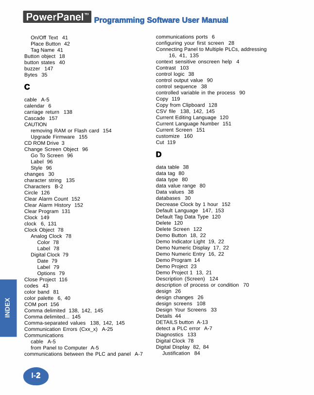
I-22222
IND
EX
Programming Software User ManualProgramming Software User ManualProgramming Software User ManualProgramming Software User ManualProgramming Software User Manual
On/Off Text 41Place Button 42Tag Name 41
Button object 18button states 40buzzer 147Bytes 35
CCCCC
cable A-5calendar 6carriage return 138Cascade 157CAUTION
removing RAM or Flash card 154Upgrade Firmware 155
CD ROM Drive 3Change Screen Object 96
Go To Screen 96Label 96Style 96
changes 30character string 135Characters B-2Circle 126Clear Alarm Count 152Clear Alarm History 152Clear Program 131Clock 149clock 6, 131Clock Object 78
Analog Clock 78Color 78Label 78
Digital Clock 79Date 79Label 79Options 79
Close Project 116codes 43color band 81color palette 6, 40COM port 156Comma delimited 138, 142, 145Comma delimited... 145Comma-separated values 138, 142, 145Communication Errors (Cxx_x) A-25Communications
cable A-5from Panel to Computer A-5
communications between the PLC and panel A-7
communications ports 6configuring your first screen 28Connecting Panel to Multiple PLCs, addressing
16, 41, 135context sensitive onscreen help 4Contrast 103control logic 38control output value 90control sequence 38controlled variable in the process 90Copy 119Copy from Clipboard 128CSV file 138, 142, 145Current Editing Language 120Current Language Number 151Current Screen 151customize 160Cut 119
DDDDD
data table 38data tag 80data type 80data value range 80Data values 38databases 30Decrease Clock by 1 hour 152Default Language 147, 153Default Tag Data Type 120Delete 120Delete Screen 122Demo Button 18, 22Demo Indicator Light 19, 22Demo Numeric Display 17, 22Demo Numeric Entry 16, 22Demo Program 14Demo Project 23Demo Project 1 13, 21Description (Screen) 124description of process or condition 70design 26design changes 26design screens 108Design Your Screens 33Details 44DETAILS button A-13detect a PLC error A-7Diagnostics 133Digital Clock 78Digital Display 82, 84
Justification 84
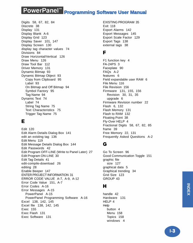
I-33333
Intro
du
ction
IND
EX
Programming Software User ManualProgramming Software User ManualProgramming Software User ManualProgramming Software User ManualProgramming Software User Manual
Digits 58, 67, 82, 84Discrete 38Display 131Display Blank A-6Display Grid 123Display Saver 101, 147Display Screen 130display tag character values 74Divisions 84Draw Horizontal/Vertical 126Draw Menu 126Draw Tool Bar 112Driver Memory 131Dynamic Bitmap 93Dynamic Bitmap Object 93
Copy from Clipboard 95Label 93On Bitmap and Off Bitmap 94Symbol Factory 95Tag Name 94
Dynamic Text 74Label 74String Tag Name 75Text Characteristics 75Trigger Tag Name 75
EEEEE
Edit 120Edit Alarm Details Dialog Box 141edit an existing tag 136Edit Menu 119Edit Message Details Dialog Box 144Edit Passwords 42Edit Program OFF-LINE (Write to Panel Later) 27Edit Program ON-LINE 30Edit Tag Details 41edit-compile-download 26editing 28Enable Beeper 147ENTER PROJECT INFORMATION 31ERROR CODE VALUE A-7, A-9, A-12Error Code Value 151, A-7Error Codes A-16Error Messages A-15
PowerPanel A-15PowerPanel Programming Software A-16
Excel 138, 142, 145Excel file 138, 142, 145Exec 155Exec Flash 131Exec Software 131
EXISTING PROGRAM 35Exit 118Export Alarms 142Export Messages 145Export Scale Factor 129Export Tags 138external tags 38
FFFFF
F1 function key 4FA-24PS 3Faceplate 90FAQs A-2features 6Field expandable user RAM 6File Menu 116File Revision 156Firmware 131, 155, 156
Revision 30, 31, 35upgrade 6
Firmware Revision number 22Flash 6, 132Flash Memory 131Flash to RAM 132Floating Point 38Fly-Over HELP 4Fractional Digits 58, 67, 82, 85frame 39Free Memory 22, 131Frequently Asked Questions A-2
GGGGG
Go To Screen 96Good Communication Toggle 151graphic file
size 127graphical data 5Graphical trending 34Grid Size 123GROUP 43
HHHHH
handle 42Hardware 131HELP 4Help
button 4Menu 158Topics 158windows 4
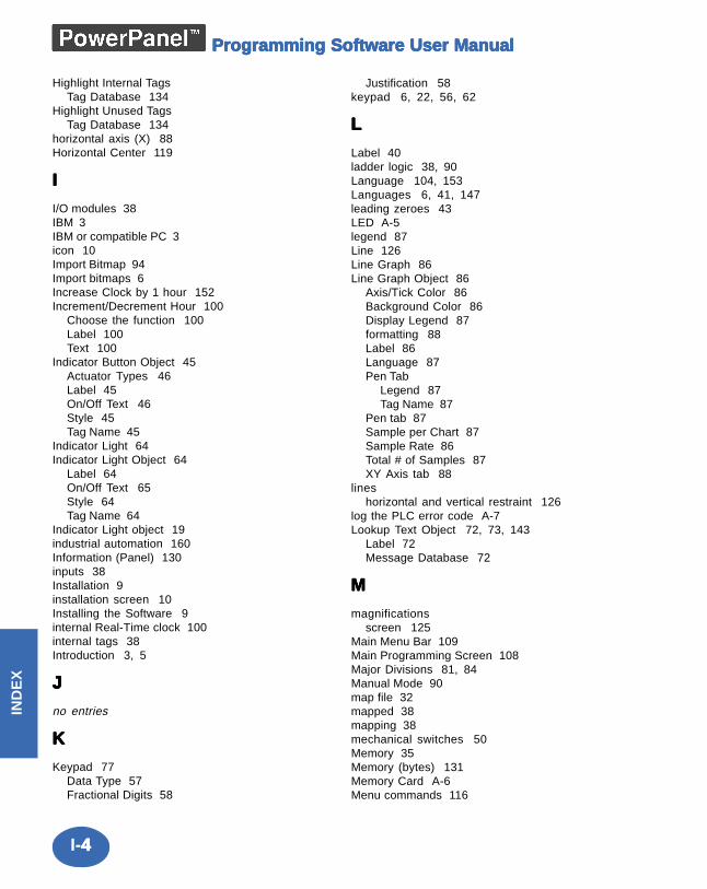
I-44444
IND
EX
Programming Software User ManualProgramming Software User ManualProgramming Software User ManualProgramming Software User ManualProgramming Software User Manual
Highlight Internal TagsTag Database 134
Highlight Unused TagsTag Database 134
horizontal axis (X) 88Horizontal Center 119
IIIII
I/O modules 38IBM 3IBM or compatible PC 3icon 10Import Bitmap 94Import bitmaps 6Increase Clock by 1 hour 152Increment/Decrement Hour 100
Choose the function 100Label 100Text 100
Indicator Button Object 45Actuator Types 46Label 45On/Off Text 46Style 45Tag Name 45
Indicator Light 64Indicator Light Object 64
Label 64On/Off Text 65Style 64Tag Name 64
Indicator Light object 19industrial automation 160Information (Panel) 130inputs 38Installation 9installation screen 10Installing the Software 9internal Real-Time clock 100internal tags 38Introduction 3, 5
JJJJJ
no entries
KKKKK
Keypad 77Data Type 57Fractional Digits 58
Justification 58keypad 6, 22, 56, 62
LLLLL
Label 40ladder logic 38, 90Language 104, 153Languages 6, 41, 147leading zeroes 43LED A-5legend 87Line 126Line Graph 86Line Graph Object 86
Axis/Tick Color 86Background Color 86Display Legend 87formatting 88Label 86Language 87Pen Tab
Legend 87Tag Name 87
Pen tab 87Sample per Chart 87Sample Rate 86Total # of Samples 87XY Axis tab 88
lineshorizontal and vertical restraint 126
log the PLC error code A-7Lookup Text Object 72, 73, 143
Label 72Message Database 72
MMMMM
magnificationsscreen 125
Main Menu Bar 109Main Programming Screen 108Major Divisions 81, 84Manual Mode 90map file 32mapped 38mapping 38mechanical switches 50Memory 35Memory (bytes) 131Memory Card A-6Menu commands 116
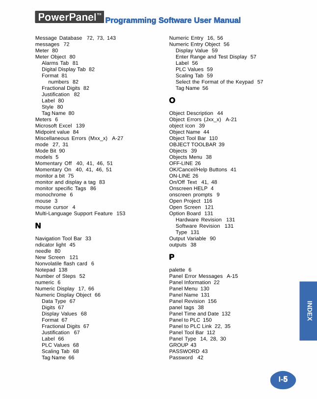
I-55555
Intro
du
ction
IND
EX
Programming Software User ManualProgramming Software User ManualProgramming Software User ManualProgramming Software User ManualProgramming Software User Manual
Message Database 72, 73, 143messages 72Meter 80Meter Object 80
Alarms Tab 81Digital Display Tab 82Format 81
numbers 82Fractional Digits 82Justification 82Label 80Style 80Tag Name 80
Meters 6Microsoft Excel 139Midpoint value 84Miscellaneous Errors (Mxx_x) A-27mode 27, 31Mode Bit 90models 5Momentary Off 40, 41, 46, 51Momentary On 40, 41, 46, 51monitor a bit 75monitor and display a tag 83monitor specific Tags 86monochrome 6mouse 3mouse cursor 4Multi-Language Support Feature 153
NNNNN
Navigation Tool Bar 33ndicator light 45needle 80New Screen 121Nonvolatile flash card 6Notepad 138Number of Steps 52numeric 6Numeric Display 17, 66Numeric Display Object 66
Data Type 67Digits 67Display Values 68Format 67Fractional Digits 67Justification 67Label 66PLC Values 68Scaling Tab 68Tag Name 66
Numeric Entry 16, 56Numeric Entry Object 56
Display Value 59Enter Range and Test Display 57Label 56PLC Values 59Scaling Tab 59Select the Format of the Keypad 57Tag Name 56
OOOOO
Object Description 44Object Errors (Jxx_x) A-21object icon 39Object Name 44Object Tool Bar 110OBJECT TOOLBAR 39Objects 39Objects Menu 38OFF-LINE 26OK/Cancel/Help Buttons 41ON-LINE 26On/Off Text 41, 48Onscreen HELP 4onscreen prompts 9Open Project 116Open Screen 121Option Board 131
Hardware Revision 131Software Revision 131Type 131
Output Variable 90outputs 38
PPPPP
palette 6Panel Error Messages A-15Panel Information 22Panel Menu 130Panel Name 131Panel Revision 156panel tags 38Panel Time and Date 132Panel to PLC 150Panel to PLC Link 22, 35Panel Tool Bar 112Panel Type 14, 28, 30GROUP 43PASSWORD 43Password 42
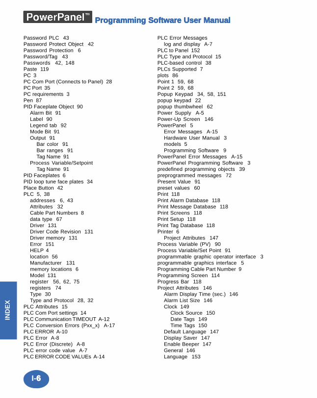
I-66666
IND
EX
Programming Software User ManualProgramming Software User ManualProgramming Software User ManualProgramming Software User ManualProgramming Software User Manual
Password PLC 43Password Protect Object 42Password Protection 6Password/Tag 43Passwords 42, 148Paste 119PC 3PC Com Port (Connects to Panel) 28PC Port 35PC requirements 3Pen 87PID Faceplate Object 90
Alarm Bit 91Label 90Legend tab 92Mode Bit 91Output 91
Bar color 91Bar ranges 91Tag Name 91
Process Variable/SetpointTag Name 91
PID Faceplates 6PID loop tune face plates 34Place Button 42PLC 5, 38
addresses 6, 43Attributes 32Cable Part Numbers 8data type 67Driver 131Driver Code Revision 131Driver memory 131Error 151HELP 4location 56Manufacturer 131memory locations 6Model 131register 56, 62, 75registers 74Type 30Type and Protocol 28, 32
PLC Attributes 15PLC Com Port settings 14PLC Communication TIMEOUT A-12PLC Conversion Errors (Pxx_x) A-17PLC ERROR A-10PLC Error A-8PLC Error (Discrete) A-8PLC error code value A-7PLC ERROR CODE VALUEs A-14
PLC Error Messageslog and display A-7
PLC to Panel 152PLC Type and Protocol 15PLC-based control 38PLCs Supported 7plots 86Point 1 59, 68Point 2 59, 68Popup Keypad 34, 58, 151popup keypad 22popup thumbwheel 62Power Supply A-5Power-Up Screen 146PowerPanel 5
Error Messages A-15Hardware User Manual 3models 5Programming Software 9
PowerPanel Error Messages A-15PowerPanel Programming Software 3predefined programming objects 39preprogrammed messages 72Present Value 91preset values 60Print 118Print Alarm Database 118Print Message Database 118Print Screens 118Print Setup 118Print Tag Database 118Printer 6
Project Attributes 147Process Variable (PV) 90Process Variable/Set Point 91programmable graphic operator interface 3programmable graphics interface 5Programming Cable Part Number 9Programming Screen 114Progress Bar 118Project Attributes 146
Alarm Display Time (sec.) 146Alarm List Size 146Clock 149
Clock Source 150Date Tags 149Time Tags 150
Default Language 147Display Saver 147Enable Beeper 147General 146Language 153
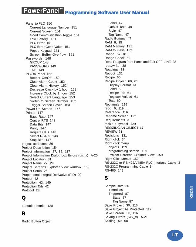
I-77777
Intro
du
ction
IND
EX
Programming Software User ManualProgramming Software User ManualProgramming Software User ManualProgramming Software User ManualProgramming Software User Manual
Panel to PLC 150Current Language Number 151Current Screen 151Good Communication Toggle 151Low Battery 151PLC Error 151PLC Error Code Value 151Popup Keypad 151Screen Buffer Overflow 151
Passwords 148GROUP 148PASSWORD 149TAG 149
PLC to Panel 152Beeper On/Off 152Clear Alarm Count 152Clear Alarm History 152Decrease Clock by 1 hour 152Increase Clock by 1 hour 152Select Current Language 153Switch to Screen Number 152Trigger Screen Saver 153
Power-Up Screen 146Printer 147
Baud Rate 147Control RTS 148Data Bits 147Parity 147Require CTS 148Select RS485 148Stop Bits 147
project attributes 30Project Description 154Project Information 27, 35, 117Project Information Dialog box Errors (Ixx_x) A-20Project Location 31Project Name 27, 29Project Screens Explorer View window 159Project Setup 26Proportional Integral Derivative (PID) 90Protect 42Protection 42, 149Protection Tab 42Protocol 28
QQQQQ
quotation marks 138
RRRRR
Radio Button Object
Label 47On/Off Text 48Style 47Tag Name 47
Radio Buttons 47RAM 6, 35RAM Memory 131RAM to Flash 132Range 57, 81Range Check 59Read Program from Panel and Edit OFF-LINE 28read/write 38Readings 88Reboot 131Recipe 60Recipe Object 60, 61
Display Format 61Label 60Recipe Tab 61Register Values 61Text 60
Rectangle 126redo 6, 119Reference 116Rename Screen 122Requirements 3resize a symbol 129RESIZING AN OBJECT 17REVIEW 31Revisions 131Right click 34Right click menu
objects 159programming screen 159Project Screens Explorer View 159
Right Click Menus 159RS-232C or RS-422A/485A PLC Interface Cable 3RS-232C Programming Cable 3RS-485 148
SSSSS
Sample Rate 86Timed 86Triggered 87
State 87Tag Name 87
Save Project 30, 116Save Project As Protected 117Save Screen 30, 116Saving Errors (Sxx_x) A-21Scaling 59, 68
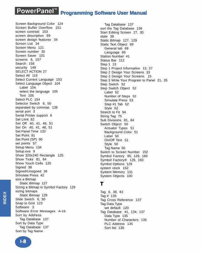
I-88888
IND
EX
Programming Software User ManualProgramming Software User ManualProgramming Software User ManualProgramming Software User ManualProgramming Software User Manual
Screen Background Color 124Screen Buffer Overflow 151screen contrast 103screen description 69screen design features 34Screen List 34Screen Menu 121Screen number 30Screen Saver 101screens 6, 157Search 158security 149SELECT ACTION 27Select All 119Select Current Language 153Select Language Object 104
Label 104select the language 105Text 105
Select PLC 154Selector Switch 6, 50separated by commas 138serial port 3Serial Printer support 6Set Limit 82Set Off 40, 41, 46, 51Set On 40, 41, 46, 51Set Panel Time 132Set Point 91Set Point (SP) 90set points 57Setup Menu 134Setup.exe 9Show 320x240 Rectangle 125Show Ticks 81, 84Show Touch Cells 125Signed 38Signed/Unsigned 38Simulate Press 42size a Bitmap
Static Bitmap 127Sizing a Bitmap in Symbol Factory 129sizing bitmaps
Static Bitmap 129Slide Switch 6, 50Snap to Grid 123Software 3Software Error Messages A-16Sort by Address
Tag Database 137Sort by Data Type
Tag Database 137Sort by Tag Name
Tag Database 137sort the Tag Database 136Start Editing Screen 27, 30state 38Static Bitmap 127, 129Static Text Object 69
General tab 69Language 69
Station Number 41Status Bar 112Step 1 13Step 1 Project Information 13, 27Step 2 Design Your Screens 33Step 2 Design Your Screens. 15Step 3 Write Your Program to Panel 21, 35Step Switch 52Step Switch Object 52
Label 52Number of Steps 52Simulate Press 53Step #1 Tab 52Style 52
Stretch to Fit 94String Tag 75Sub Divisions 81, 84Switch Object 50
Actuator Types 51Background Color 51Label 50On/Off Text 51Style 50Tag Name 50
Switch to Screen Number 152Symbol Factory 95, 129, 160Symbol Factory® 128, 160Symbol Options 129system clock 152System Memory 131System Objects 100
TTTTT
Tag 6, 38, 43Tag # 135Tag Cross Reference 137Tag Data Type
set default 120Tag Database 41, 134, 137
Data Type 135Number of Characters 135PLC Address 135Sort list 136
I-99999
Intro
du
ction
IND
EX
Programming Software User ManualProgramming Software User ManualProgramming Software User ManualProgramming Software User ManualProgramming Software User Manual
Tag Name 135Tag Name 6, 41Tag Related Errors (Txx_x) A-18Tags
Internal, tag database 134tags
internal tag database 134Technical Support 4test A-12Test Flash 133Test RAM 133testing 131Text 105Text Entry 76Text Entry Object
Label 76String Characteristics 77String Tag Name 76
Text Object 69text strings 70theoretical perfect value 90Think-n-Do Map File, 32Throw Switch 50Thumbwheel 62Thumbwheel Object 62
Format 63Label 62Number of Wheels 63Tag Name 62
Thumbwheel Switch 6Tile 157Time and Date 79Time/Date 132Title Bar 108To Excel... 138, 142, 145Toggle 40, 41, 46, 51toggle
between horizontal/vertical lines 126Toggle Switch 6, 50Toolbar 120top slot A-6Touch cells 125, 131touch objects 42transfer 30Transfer to Panel... 117transparent object 69Tri-State Switch 54Tri-State Switch Object 54
Label 54Style 54Tag Names 54Text 55
Trigger Screen Saver 153Trigger Tag 75Triggered Text Object 70
Format 71Label 70Language 70Tag Name 70Text - On and Off 70
Troubleshooting A-5Tutorial 11Tutorial — Configure PLC 12Tutorial — Create a Project 13
UUUUU
unauthorized users 42Undo 6, 119Unsigned 38Update PLC Driver 132Upgrade Firmware 155, 156Use PC Port 118user groups 6User Memory 131User Memory Flash 131User Program 131user program backup 6user-defined 38user-defined frame types 39
VVVVV
Value 88Value Range Errors (Vxx_x) A-16Vector-based graphics 34vertical axis (Y) 88Vertical Center 119VGA display 3view
custom screen magnifications 125View/Edit Attributes 154View/Edit PLC Com Setup 28, 32Visibility 44Visibility Tag 44Visibility/Details 44Visibility/Details Tab 44Visual Alarm Settings 81
WWWWW
Watchdog 151What you need to get started 3Windows 95/98/NT4.0/2000 3
I-1010101010
IND
EX
Programming Software User ManualProgramming Software User ManualProgramming Software User ManualProgramming Software User ManualProgramming Software User Manual
Windows Enhanced Metafile (.EMF) 127Windows Menu 157Windows Metafile (.WMF) 127Windows-based architecture 26wiring diagrams 4word 38Write Program to Panel 21, 35WRITE to a Tag 40
XXXXX
X-Axis 88XY Axis
Label 88Major Divisions 88Minor Divisions 88Show Tick Numbers 88Show Ticks 88Show Vertical Grid 88X-Axis Grid 88
YYYYY
Y-Axis 88Range 89
ZZZZZ
Zoom 125


