Embed Size (px)
Citation preview

Pro/ENGINEER®
Wildfire™ 2.0
Pro/INTERFACE™
Help Topic Collection
Parametric Technology Corporation

Copyright © 2004 Parametric Technology Corporation. All Rights Reserved.
User and training documentation from Parametric Technology Corporation (PTC) is subject to the copyright laws of the
United States and other countries and is provided under a license agreement that restricts copying, disclosure, and use
of such documentation. PTC hereby grants to the licensed user the right to make copies in printed form of this
documentation if provided on software media, but only for internal/personal use and in accordance with the license
agreement under which the applicable software is licensed. Any copy made shall include the PTC copyright notice and
any other proprietary notice provided by PTC. This documentation may not be disclosed, transferred, modified, or
reduced to any form, including electronic media, or transmitted or made publicly available by any means without the
prior written consent of PTC and no authorization is granted to make copies for such purposes.
Information described herein is furnished for general information only, is subject to change without notice, and should
not be construed as a warranty or commitment by PTC. PTC assumes no responsibility or liability for any errors or
inaccuracies that may appear in this document.
The software described in this document is provided under written license agreement, contains valuable trade secrets
and proprietary information, and is protected by the copyright laws of the United States and other countries. It may not
be copied or distributed in any form or medium, disclosed to third parties, or used in any manner not provided for in the
software licenses agreement except with written prior approval from PTC. UNAUTHORIZED USE OF SOFTWARE
OR ITS DOCUMENTATION CAN RESULT IN CIVIL DAMAGES AND CRIMINAL PROSECUTION.
Registered Trademarks of Parametric Technology Corporation or a Subsidiary Advanced Surface Design, Behavioral Modeling, CADDS, Computervision, CounterPart, EPD, EPD.Connect,
Expert Machinist, Flexible Engineering, HARNESSDESIGN, Info*Engine, InPart, MECHANICA, Optegra,
Parametric Technology, Parametric Technology Corporation, PartSpeak, PHOTORENDER, Pro/DESKTOP, Pro/E,
Pro/ENGINEER, Pro/HELP, Pro/INTRALINK, Pro/MECHANICA, Pro/TOOLKIT, Product First, PTC, PT/Products,
Shaping Innovation, and Windchill.
Trademarks of Parametric Technology Corporation or a Subsidiary 3DPAINT, Associative Topology Bus, AutobuildZ, CDRS, Create � Collaborate � Control, CV, CVact, CVaec,
CVdesign, CV-DORS, CVMAC, CVNC, CVToolmaker, DataDoctor, DesignSuite, DIMENSION III, DIVISION,
e/ENGINEER, eNC Explorer, Expert MoldBase, Expert Toolmaker, GRANITE, ISSM, KDiP,
Knowledge Discipline in Practice, Knowledge System Driver, ModelCHECK, MoldShop, NC Builder, Pro/ANIMATE,
Pro/ASSEMBLY, Pro/CABLING, Pro/CASTING, Pro/CDT, Pro/CMM, Pro/COLLABORATE, Pro/COMPOSITE,
Pro/CONCEPT, Pro/CONVERT, Pro/DATA for PDGS, Pro/DESIGNER, Pro/DETAIL, Pro/DIAGRAM,
Pro/DIEFACE, Pro/DRAW, Pro/ECAD, Pro/ENGINE, Pro/FEATURE, Pro/FEM-POST, Pro/FICIENCY,
Pro/FLY-THROUGH, Pro/HARNESS, Pro/INTERFACE, Pro/LANGUAGE, Pro/LEGACY, Pro/LIBRARYACCESS,
Pro/MESH, Pro/Model.View, Pro/MOLDESIGN, Pro/NC-ADVANCED, Pro/NC-CHECK, Pro/NC-MILL,
Pro/NCPOST, Pro/NC-SHEETMETAL, Pro/NC-TURN, Pro/NC-WEDM, Pro/NC-Wire EDM,
Pro/NETWORK ANIMATOR, Pro/NOTEBOOK, Pro/PDM, Pro/PHOTORENDER, Pro/PIPING,
Pro/PLASTIC ADVISOR, Pro/PLOT, Pro/POWER DESIGN, Pro/PROCESS, Pro/REPORT, Pro/REVIEW,
Pro/SCAN-TOOLS, Pro/SHEETMETAL, Pro/SURFACE, Pro/VERIFY, Pro/Web.Link, Pro/Web.Publish,
Pro/WELDING, Product Development Means Business, ProductView, PTC Precision, Shrinkwrap,
Simple � Powerful � Connected, The Product Development Company, The Way to Product First, Wildfire,
Windchill DynamicDesignLink, Windchill PartsLink, Windchill PDMLink, Windchill ProjectLink, and
Windchill SupplyLink.
Patents of Parametric Technology Corporation or a Subsidiary Registration numbers and issue dates follow. Additionally, equivalent patents may be issued or pending outside of the
United States. Contact PTC for further information. 6,665,569 B1 16-December-2003
6,625,607 B1 23-September-2003
6,580,428 B1 17-June-2003
GB2354684B 02-July-2003
GB2384125 15-October-2003
GB2354096 12-November-2003
6,608,623 B1 19 August 2003
GB2353376 05-November-2003
GB2354686 15-October-2003
6,545,671 B1 08-April-2003
GB2354685B 18-June-2003
6,608,623 B1 19 August 2003
6,473,673 B1 29-October-2002
GB2354683B 04-June-2003
6,447,223 B1 10-Sept-2002
6,308,144 23-October-2001
5,680,523 21-October-1997
5,838,331 17-November-1998
4,956,771 11-September-1990
5,058,000 15-October-1991
5,140,321 18-August-1992
5,423,023 05-June-1990
4,310,615 21-December-1998
4,310,614 30-April-1996
4,310,614 22-April-1999
5,297,053 22-March-1994
5,513,316 30-April-1996
5,689,711 18-November-1997
5,506,950 09-April-1996
5,428,772 27-June-1995
5,850,535 15-December-1998
5,557,176 09-November-1996
5,561,747 01-October-1996
Third-Party Trademarks
Adobe is a registered trademark of Adobe Systems. Advanced ClusterProven, ClusterProven, and the ClusterProven
design are trademarks or registered trademarks of International Business Machines Corporation in the United States
and other countries and are used under license. IBM Corporation does not warrant and is not responsible for the
operation of this software product. AIX is a registered trademark of IBM Corporation. Allegro, Cadence, and Concept
are registered trademarks of Cadence Design Systems, Inc. Apple, Mac, Mac OS, and Panther are trademarks or
registered trademarks of Apple Computer, Inc. AutoCAD and Autodesk Inventor are registered trademarks of
Autodesk, Inc. Baan is a registered trademark of Baan Company. CADAM and CATIA are registered trademarks of
Dassault Systemes. COACH is a trademark of CADTRAIN, Inc. DOORS is a registered trademark of Telelogic AB.
FLEXlm is a trademark of Macrovision Corporation. Geomagic is a registered trademark of Raindrop Geomagic, Inc.
EVERSYNC, GROOVE, GROOVEFEST, GROOVE.NET, GROOVE NETWORKS, iGROOVE, PEERWARE, and
the interlocking circles logo are trademarks of Groove Networks, Inc. Helix is a trademark of Microcadam, Inc.
HOOPS is a trademark of Tech Soft America, Inc. HP-UX is a registered trademark and Tru64 is a trademark of the
Hewlett-Packard Company. I-DEAS, Metaphase, Parasolid, SHERPA, Solid Edge, and Unigraphics are trademarks or
registered trademarks of Electronic Data Systems Corporation (EDS). InstallShield is a registered trademark and
service mark of InstallShield Software Corporation in the United States and/or other countries. Intel is a registered
trademark of Intel Corporation. IRIX is a registered trademark of Silicon Graphics, Inc. LINUX is a registered
trademark of Linus Torvalds. MatrixOne is a trademark of MatrixOne, Inc. Mentor Graphics and Board Station are
registered trademarks and 3D Design, AMPLE, and Design Manager are trademarks of Mentor Graphics Corporation.
MEDUSA and STHENO are trademarks of CAD Schroer GmbH. Microsoft, Microsoft Project, Windows, the
Windows logo, Windows NT, Visual Basic, and the Visual Basic logo are registered trademarks of
Microsoft Corporation in the United States and/or other countries. Netscape and the Netscape N and Ship's Wheel
logos are registered trademarks of Netscape Communications Corporation in the U.S. and other countries. Oracle is a
registered trademark of Oracle Corporation. OrbixWeb is a registered trademark of IONA Technologies PLC. PDGS is
a registered trademark of Ford Motor Company. RAND is a trademark of RAND Worldwide. Rational Rose is a
registered trademark of Rational Software Corporation. RetrievalWare is a registered trademark of Convera
Corporation. RosettaNet is a trademark and Partner Interface Process and PIP are registered trademarks of
“RosettaNet,” a nonprofit organization. SAP and R/3 are registered trademarks of SAP AG Germany. SolidWorks is a
registered trademark of SolidWorks Corporation. All SPARC trademarks are used under license and are trademarks or
registered trademarks of SPARC International, Inc. in the United States and in other countries. Products bearing
SPARC trademarks are based upon an architecture developed by Sun Microsystems, Inc. Sun, Sun Microsystems, the
Sun logo, Solaris, UltraSPARC, Java and all Java based marks, and “The Network is the Computer” are trademarks or
registered trademarks of Sun Microsystems, Inc. in the United States and in other countries. TIBCO, TIBCO Software,
TIBCO ActiveEnterprise, TIBCO Designer, TIBCO Enterprise for JMS, TIBCO Rendezvous, TIBCO Turbo XML,
TIBCO Business Works are the trademarks or registered trademarks of TIBCO Software Inc. in the United States and
other countries. WebEx is a trademark of WebEx Communications, Inc.
Third-Party Technology Information Certain PTC software products contain licensed third-party technology: Rational Rose 2000E is copyrighted software
of Rational Software Corporation. RetrievalWare is copyrighted software of Convera Corporation. VisTools library is
copyrighted software of Visual Kinematics, Inc. (VKI) containing confidential trade secret information belonging to
VKI. HOOPS graphics system is a proprietary software product of, and is copyrighted by, Tech Soft America, Inc.
G-POST is copyrighted software and a registered trademark of Intercim. VERICUT is copyrighted software and a
registered trademark of CGTech. Pro/PLASTIC ADVISOR is powered by Moldflow technology. Moldflow is a
registered trademark of Moldflow Corporation. The JPEG image output in the Pro/Web.Publish module is based in part
on the work of the independent JPEG Group. DFORMD.DLL is copyrighted software from Compaq Computer
Corporation and may not be distributed. METIS, developed by George Karypis and Vipin Kumar at the University of
Minnesota, can be researched at http://www.cs.umn.edu/~karypis/metis. METIS is © 1997 Regents of the University of
Minnesota. LightWork Libraries are copyrighted by LightWork Design 1990–2001. Visual Basic for Applications and
Internet Explorer is copyrighted software of Microsoft Corporation. Parasolid © Electronic Data Systems (EDS).
Windchill Info*Engine Server contains IBM XML Parser for Java Edition and the IBM Lotus XSL Edition. Pop-up
calendar components Copyright © 1998 Netscape Communications Corporation. All Rights Reserved.
TECHNOMATIX is copyrighted software and contains proprietary information of Technomatix Technologies Ltd.
Technology "Powered by Groove" is provided by Groove Networks, Inc. Technology "Powered by WebEx" is provided
by WebEx Communications, Inc. Oracle 8i run-time and Oracle 9i run-time, Copyright © 2002–2003 Oracle
Corporation. Oracle programs provided herein are subject to a restricted use license and can only be used in
conjunction with the PTC software they are provided with. Apache Server, Tomcat, Xalan, and Xerces are technologies
developed by, and are copyrighted software of, the Apache Software Foundation (http://www.apache.org) – their use is
subject to the terms and limitations at: http://www.apache.org/LICENSE.txt. Acrobat Reader is copyrighted software of
Adobe Systems Inc. and is subject to the Adobe End-User License Agreement as provided by Adobe with those
products. UnZip (© 1990-2001 Info-ZIP, All Rights Reserved) is provided “AS IS” and WITHOUT WARRANTY OF
ANY KIND. For the complete Info-ZIP license see ftp://ftp.info-zip.org/pub/infozip/license.html. Gecko and Mozilla
components are subject to the Mozilla Public License Version 1.1 at http://www.mozilla.org/MPL. Software distributed
under the MPL is distributed on an "AS IS" basis, WITHOUT WARRANTY OF ANY KIND, either expressed or
implied. See the MPL for the specific language governing rights and limitations. The Java™ Telnet Applet

(StatusPeer.java, TelnetIO.java, TelnetWrapper.java, TimedOutException.java), Copyright © 1996, 97 Mattias L.
Jugel, Marcus Meißner, is redistributed under the GNU General Public License. This license is from the original
copyright holder and the Applet is provided WITHOUT WARRANTY OF ANY KIND. You may obtain a copy of the
source code for the Applet at http://www.mud.de/se/jta (for a charge of no more than the cost of physically performing
the source distribution), by sending e-mail to [email protected] or [email protected]—you are allowed to choose either
distribution method. The source code is likewise provided under the GNU General Public License. GTK+The GIMP
Toolkit are licensed under the GNU LGPL. You may obtain a copy of the source code at http://www.gtk.org, which is
likewise provided under the GNU LGPL. zlib software Copyright © 1995-2002 Jean-loup Gailly and Mark Adler.
OmniORB is distributed under the terms and conditions of the GNU General Public License and GNU Library General
Public License. The Java Getopt.jar, copyright 1987-1997 Free Software Foundation, Inc.; Java Port copyright 1998 by
Aaron M. Renn ([email protected]), is redistributed under the GNU LGPL. You may obtain a copy of the
source code at http://www.urbanophile.com/arenn/hacking/download.html. The source code is likewise provided under
the GNU LGPL. Mozilla Japanese localization components are subject to the Netscape Public License Version 1.1 (at
http://www.mozilla.org/NPL). Software distributed under NPL is distributed on an "AS IS" basis, WITHOUT
WARRANTY OF ANY KIND, either expressed or implied (see the NPL for the specific language governing rights and
limitations). The Original Code is Mozilla Communicator client code, released March 31, 1998 and the Initial
Developer of the Original Code is Netscape Communications Corporation. Portions created by Netscape are Copyright
© 1998 Netscape Communications Corporation. All Rights Reserved. Contributors: Kazu Yamamoto
([email protected]), Ryoichi Furukawa ([email protected]), Tsukasa Maruyama ([email protected]), Teiji Matsuba
UNITED STATES GOVERNMENT RESTRICTED RIGHTS LEGEND
This document and the software described herein are Commercial Computer Documentation and Software, pursuant to
FAR 12.212(a)-(b) (OCT’95) or DFARS 227.7202-1(a) and 227.7202-3(a) (JUN’95), is provided to the US
Government under a limited commercial license only. For procurements predating the above clauses, use, duplication,
or disclosure by the Government is subject to the restrictions set forth in subparagraph (c)(1)(ii) of the Rights in
Technical Data and Computer Software Clause at DFARS 252.227-7013 (OCT’88) or Commercial Computer
Software-Restricted Rights at FAR 52.227-19(c)(1)-(2) (JUN’87), as applicable. 012304
Parametric Technology Corporation, 140 Kendrick Street, Needham, MA 02494 USA
v
Table Of Contents Pro/ENGINEER Interface .................................................................................. 1
About Data Exchange in Pro/ENGINEER .......................................................... 1
Workflows ................................................................................................ 1
Using Pro/ENGINEER Interface....................................................................... 2
About Interface Capabilities........................................................................ 2
Configuring Pro/ENGINEER Interface .............................................................. 9
About Configuring Pro/ENGINEER Interface .................................................. 9
To Set Configuration Options for Pro/ENGINEER Interface............................... 9
About Configuring the Export of Pro/ENGINEER Models to IGES, Parasolid, and
STEP ....................................................................................................... 9
acis_out_version......................................................................................10
adobe_distiller .........................................................................................10
allow_4dnav_export .................................................................................10
atb_ident_cadds_files ...............................................................................10
auto_associate_dimensions .......................................................................10
cadam_line_weights .................................................................................11
cadds_import_layer..................................................................................11
catia_out_to_existing_model .....................................................................11
cdt_transfer_details..................................................................................11
cgm_inc_pad_byte_in_length ....................................................................12
cgm_use_enum_in_real_spec ....................................................................12
cgm_use_reversed_ieee_floats ..................................................................12
copy_dxf_dim_pict ...................................................................................12
direct_vrml .............................................................................................12
dwg_export_format..................................................................................12
dxf_block_to_pro_symbol .........................................................................12
dxf_export_format ...................................................................................13
dxf_export_mapping_file...........................................................................13
dxf_in_faceted_brep.................................................................................13
dxf_out_comments...................................................................................13
Table Of Contents
vi
dxf_out_drawing_scale .............................................................................13
dxf_out_scale_views ................................................................................13
dxf_out_sep_dim_w_breaks ......................................................................14
dxf_out_stroke_text .................................................................................14
dxfio_in_sjis ............................................................................................14
edge_display_quality ................................................................................14
enable_cadra_export ................................................................................14
explode_iges_dimension_note ...................................................................14
export_3d_force_default_naming ...............................................................15
export_to_shipit.......................................................................................15
extend_cvpath.........................................................................................15
fix_autocad_iges_text_scale ......................................................................15
fix_boundaries_on_import.........................................................................15
fix_catia_iges_sym_note...........................................................................16
fix_imported_set_view_orient ....................................................................16
graphics..................................................................................................16
iges_clip_view_ent ...................................................................................16
iges_clip_view_note .................................................................................16
iges_export_dwg_views ............................................................................16
iges_in_106_f2_as_spline .........................................................................17
iges_in_assoc_dim_geom_21 ....................................................................17
iges_in_dwg_color ...................................................................................17
iges_in_dwg_line_font ..............................................................................17
iges_in_group_to_dwg_layer .....................................................................18
iges_note_disp ........................................................................................18
iges_out_all_srfs_as.................................................................................18
iges_out_assembly_default_mode ..............................................................18
iges_out_catia_gdt_width .........................................................................18
iges_out_catia_notes................................................................................19
iges_out_dwg_color..................................................................................19
iges_out_dwg_line_font ............................................................................19
Table Of Contents
vii
iges_out_ent_as_bspline...........................................................................19
iges_out_jamais_compliant .......................................................................19
iges_out_mil_d_28000 .............................................................................19
iges_out_spl_crvs_as_126 ........................................................................20
iges_out_spl_srfs_as_128 .........................................................................20
iges_out_start_note .................................................................................20
iges_out_symbol_entity ............................................................................20
iges_out_trim_curve_deviation ..................................................................20
iges_out_trim_xyz ...................................................................................20
iges_out_trm_srfs_as_143 ........................................................................20
iges_zero_view_disp.................................................................................20
interface_quality ......................................................................................21
intf_cadds_version ...................................................................................21
intf_collapse_geom ..................................................................................21
intf_in_arclength_reparam ........................................................................21
intf_in_blanked_entities ............................................................................22
intf_in_dwg_pnt_ent ................................................................................22
intf_in_dwg_view.....................................................................................22
intf_in_extract_profiles .............................................................................22
intf_in_granite_direct_enable ....................................................................23
intf_in_layer_asm_dialog ..........................................................................23
intf_in_surf_boundary_pref .......................................................................23
intf_in_treat_polyline_as...........................................................................23
intf_in_use_template_models ....................................................................23
intf_out_as_bezier ...................................................................................24
intf_out_assign_names .............................................................................24
intf_out_auto_layer_ids ............................................................................24
intf_out_blanked_entities ..........................................................................24
intf_out_cat_start_model ..........................................................................25
intf_out_layer..........................................................................................25
intf_out_layer_rename_table .....................................................................25
Table Of Contents
viii
intf_out_max_bspl_degree ........................................................................25
intf_out_text_length.................................................................................25
intf_use_variable_size ..............................................................................26
intf2d_fit_incompatible_data .....................................................................26
intf2d_iges_out_hatch ..............................................................................26
intf2d_in_acad_ignore_3d .........................................................................26
intf2d_in_create_multiline_note .................................................................27
intf2d_in_iges_hatch_bnd_layer.................................................................27
intf2d_out_acad_mtext.............................................................................27
intf2d_out_acad_text_align .......................................................................28
intf2d_out_cgm_ver .................................................................................28
intf2d_out_enhanced_ents ........................................................................28
intf2d_out_open_log_window ....................................................................28
intf2d_out_pnt_ent ..................................................................................29
intf3d_ideas_import_filter .........................................................................29
intf3d_ideas_install_dir .............................................................................29
intf3d_ideas_run_command ......................................................................29
intf3d_in_close_open_boundaries...............................................................29
intf3d_in_enable_layer_join.......................................................................30
intf3d_in_include_items ............................................................................30
intf3d_out_cat2_ident_crv.........................................................................30
intf3d_out_cat2_ident_pt ..........................................................................30
intf3d_out_cat2_infinity ............................................................................31
intf3d_out_cat2_model_sz ........................................................................31
intf3d_out_cat2_sag.................................................................................31
intf3d_out_cat2_step................................................................................31
intf3d_out_datums_by_default ..................................................................31
intf3d_out_default_option .........................................................................32
intf3d_out_extend_surface ........................................................................32
intf3d_out_force_surf_normals ..................................................................32
intf3d_out_surface_deviation.....................................................................32
Table Of Contents
ix
intf3d_parasolid_export_schema................................................................33
intf3d_ug_install_dir.................................................................................34
medusa_2d_config_file .............................................................................35
pdf_plot_config........................................................................................35
pen_slew ................................................................................................35
plot_file_dir.............................................................................................35
plotter ....................................................................................................35
plotter_command.....................................................................................35
pro_gplug_dir ..........................................................................................36
pro_stheno_command ..............................................................................36
pro_plot_config_dir ..................................................................................36
put_iges_drawing_entity ...........................................................................36
read_vda_in_pset_as_spline......................................................................36
recompute_iges_dim_value .......................................................................36
search_path ............................................................................................37
shade_surface_feat ..................................................................................37
step_appearance_layer_groups..................................................................37
step_export_ap214_asm_def_mode ...........................................................38
step_export_dwg_views............................................................................38
step_export_format..................................................................................38
step_in_style_bndry_as_fill_area ...............................................................39
system_iges_header_file...........................................................................39
tablet_device_name .................................................................................39
tiff_compression ......................................................................................39
tiff_type..................................................................................................39
topobus_enable .......................................................................................39
try_g2_fix_on_import ...............................................................................39
use_cadam_plot_data...............................................................................39
use_export_2d_dialog ..............................................................................40
use_iges_font_1003 .................................................................................40
use_iges_kanji_font_2001.........................................................................40
Table Of Contents
x
user_iges_header_file...............................................................................40
vda_header .............................................................................................41
vrml_anchor_url ......................................................................................41
vrml_background_color.............................................................................41
vrml_explode_lines ..................................................................................41
vrml_export_resolution.............................................................................41
vrml_export_version ................................................................................42
vrml_file_duplicate_material......................................................................42
vrml_multiple_views.................................................................................42
vrml_parameters .....................................................................................42
vrml_simprep_export ...............................................................................42
wf_keep_analyt_srf ..................................................................................43
www_add_aux_frame ...............................................................................43
www_export_geometry_as ........................................................................43
www_tree_location...................................................................................43
Working with Imported Geometry .................................................................44
Basic Methods .........................................................................................44
Redefining Imported Features....................................................................47
Working with Imported Faceted Geometry...................................................50
Exporting and Importing Layer Information .................................................53
Working with Data Exchange Formats............................................................55
About Importing and Appending Files..........................................................55
About Exporting Files from Pro/ENGINEER ...................................................56
About Drawing Sheet Size .........................................................................56
About Custom Start Part and Assembly Template Files ..................................56
ACIS ......................................................................................................57
Adobe Illustrator Curves ...........................................................................57
CADAM and CPTR Neutral Files...................................................................59
CADDS 5.................................................................................................64
CATIA.....................................................................................................70
CDRS .....................................................................................................86
Table Of Contents
xi
CGM.......................................................................................................87
COSMOS Geometry ..................................................................................89
DXF and DWG..........................................................................................90
Granite-based Files ................................................................................106
ICEM ....................................................................................................107
I-DEAS .................................................................................................108
IGES ....................................................................................................112
MEDUSA ...............................................................................................139
Motion Envelope ....................................................................................142
Neutral Files ..........................................................................................142
Parasolid...............................................................................................161
PATRAN ................................................................................................163
PDF......................................................................................................164
Pro/DESKTOP ........................................................................................165
ProductView ..........................................................................................169
SET......................................................................................................171
STEP ....................................................................................................174
STHENO/PRO.........................................................................................184
Supertab Geometry ................................................................................187
Tessellated Files.....................................................................................188
TIFF (Snapshot) Files and Shaded Images .................................................199
Unigraphics ...........................................................................................202
VDA .....................................................................................................206
Using Pro/BATCH Utilities...........................................................................208
About Pro/BATCH...................................................................................208
About Distributed Pro/BATCH...................................................................209
Example: .pro_batch.log#file...................................................................209
To Enter Pro/BATCH and Set Preferences (Basic Steps) ...............................209
To Schedule the Start of the Batch Process................................................210
To Upgrade a File to the Version of the Current Release ..............................210
To Create a New BATCH File ....................................................................210
Table Of Contents
xii
To Complete the Set Option - cgm Dialog Box............................................211
To Complete the Set Option - plot Dialog Box ............................................211
To Complete the Set Option - stl Dialog Box ..............................................212
To Complete the Set Option - vrml Dialog Box ...........................................212
To Complete the Set Option Dialog Box for IGES, DXF, SET, VDA, or STEP.....213
Configuration File Options Used by Pro/BATCH ...........................................213
Outputting to Other Formats Through Pro/BATCH .......................................214
Importing from CADAM with Pro/BATCH....................................................215
Using a Pro/BATCH Command File...............................................................215
About Pro/BATCH Command Files.............................................................215
To Create a New Command File ...............................................................215
To Execute a Command File Immediately After It Is Created ........................216
To Run an Existing Command File.............................................................216
To Upgrade Files ....................................................................................217
To Create a Plot File After Creating a New Pro/BATCH Command File ............217
Example: Creating and Running a Plot File of a Drawing ..............................217
To Export to STL ....................................................................................220
To Export to VRML .................................................................................220
To Export to IGES, DXF, SET, VDA, or STEP...............................................220
Importing Proprietary Surface with Pro/TOOLKIT...........................................221
About Using Pro/TOOLKIT to Import Proprietary Surfaces ............................221
To Import a Foreign Surface ....................................................................221
Working with Pro/WEB PUBLISH .................................................................221
About Pro/WEB PUBLISH.........................................................................221
To Create a WEB Publication....................................................................222
Naming Conventions for Publication-Related Files and 2D Model Views ..........222
Types of Data Extracted..........................................................................223
To Prepare a Model for Export..................................................................224
Additional Model Parameters....................................................................224
To Export Process Data from Pro/ENGINEER ..............................................225
Viewing an Assembly Process Publication...................................................225
Table Of Contents
xiii
Viewing a Manufacturing Process Publication..............................................227
Viewing an Assembly Publication ..............................................................229
Customizing Publication Sites...................................................................230
Working with Digitized Input ......................................................................232
About Digitized Input..............................................................................232
To Import Data from the Digitizing Tablet..................................................232
Summary of Tablet Options .....................................................................233
To Enter Scale Mode...............................................................................234
Scale Mode............................................................................................235
To Calibrate the Tablet............................................................................235
Calibration Mode ....................................................................................236
To Create a Chain of Straight Line Segments .............................................236
Digitizing Input ......................................................................................236
Tip: Converting Chains Using Explicit Commands........................................236
To Delete a Point ...................................................................................236
To Digitize Points ...................................................................................237
To Delete a Chain...................................................................................237
To Join Two Chains.................................................................................237
To Convert a Chain.................................................................................237
To Configure your IBM RS/6000 to Recognize the Calcomp ..........................237
To Configure the Tablet...........................................................................238
To Troubleshoot Problems That Occur when Digitizing .................................239
Index.........................................................................................................241

1
Pro/ENGINEER Interface
About Data Exchange in Pro/ENGINEER
Using direct data exchange and industry-standard translators, you can share and
reuse engineering data by importing geometry to Pro/ENGINEER and exporting
geometry from Pro/ENGINEER. Pro/ENGINEER has direct geometry translators for
ACIS, Adobe Illustrator, CADDS 5, CATIA, CDRS, ICEM, I-DEAS, Parasolid, PDF,
Pro/PHOTORENDER, CADAM, MEDUSA (3D ASCII format), Unigraphics, and AutoCAD
DXF/DWG.
Industry-standard translators in Pro/ENGINEER support the following data formats:
IGES, STEP (AP202, AP203, AP214 - including Associative Drafting), SET, VDA, ECAD
(IDS 2.0, 3.0), CGM, COSMOS/M, PATRAN and SUPERTAB geometry files, SLA, CGM
(MILSPEC MIL-D-28003A), JPECT, TOFF, ProductView, RENDER, STL, VRML,
INVENTOR, ACIS, STHENO/PRO, and XPATCH.
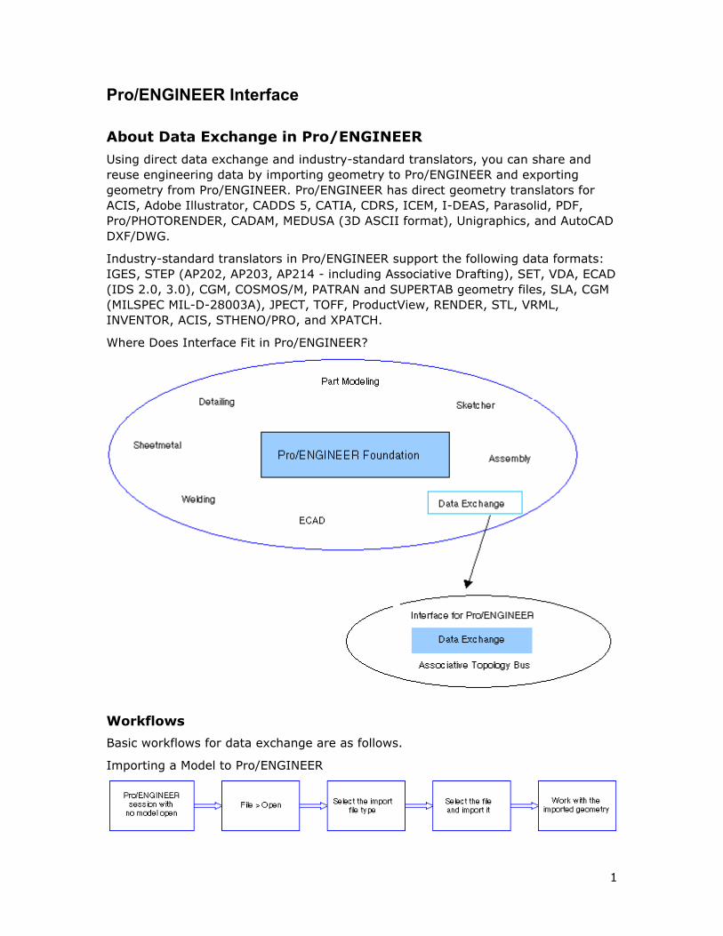
Where Does Interface Fit in Pro/ENGINEER?
Workflows
Basic workflows for data exchange are as follows.
Importing a Model to Pro/ENGINEER
Pro/INTERFACE - Help Topic Collection
2
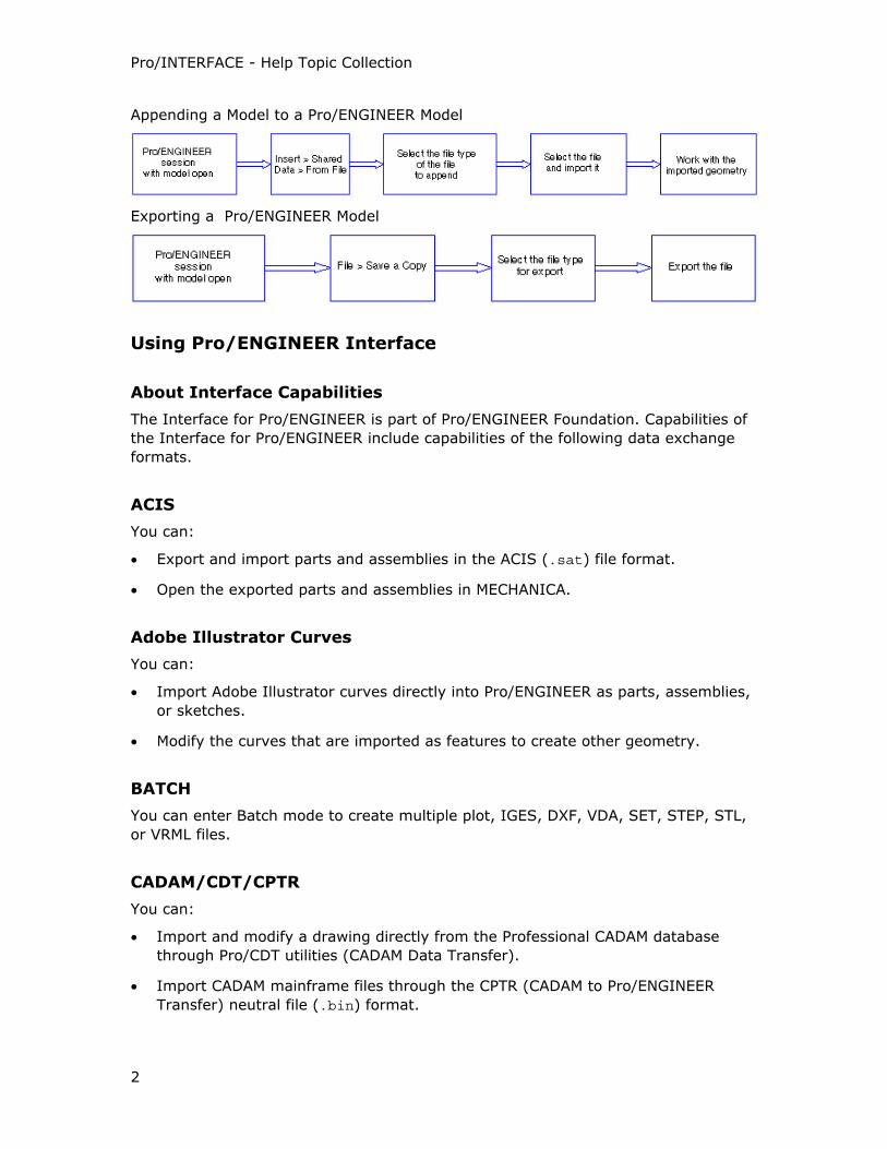
Appending a Model to a Pro/ENGINEER Model
Exporting a Pro/ENGINEER Model
Using Pro/ENGINEER Interface
About Interface Capabilities
The Interface for Pro/ENGINEER is part of Pro/ENGINEER Foundation. Capabilities of
the Interface for Pro/ENGINEER include capabilities of the following data exchange
formats.
ACIS
You can:
• Export and import parts and assemblies in the ACIS (.sat) file format.
• Open the exported parts and assemblies in MECHANICA.
Adobe Illustrator Curves
You can:
• Import Adobe Illustrator curves directly into Pro/ENGINEER as parts, assemblies,
or sketches.
• Modify the curves that are imported as features to create other geometry.
BATCH
You can enter Batch mode to create multiple plot, IGES, DXF, VDA, SET, STEP, STL,
or VRML files.
CADAM/CDT/CPTR
You can:
• Import and modify a drawing directly from the Professional CADAM database
through Pro/CDT utilities (CADAM Data Transfer).
• Import CADAM mainframe files through the CPTR (CADAM to Pro/ENGINEER
Transfer) neutral file (.bin) format.
Pro/ENGINEER Interface
3
CADDS 5
You can:
• Import CADDS parts and assemblies into Pro/ENGINEER.
• Export Pro/ENGINEER parts and assemblies to native CADDS format.
For Associative Topology Bus (ATB)-enabled CADDS 5, see the Help on Associative
Topology Bus.
CATIA
Pro/ENGINEER supports CATIA versions 4 and 5. You need separate licenses for data
exchange between Pro/ENGINEER and each of these versions of CATIA. You can
export and import both part and assembly models between Pro/ENGINEER and
CATIA version 4. You can only import CATIA version 5 part models to Pro/ENGINEER.
You can export and import to Pro/ENGINEER the following file types:
• CATIA V4 .model
• CATIA V4 ProGEO .model
• CATIA V4 Model export (*.exp)
• CATIA V4 Session (assembly) *.session
• CATIA V5 CATPart (part), revision 6 and later
CATIA is an ATB-enabled application. To know more about the ATB capabilities, see
the Help on Associative Topology Bus.
CDRS
You can exchange data between CDRS and Pro/ENGINEER using File > Open or
Insert > Shared Data > From File. Industrial design surfaces are created in CDRS
and imported to Pro/ENGINEER for downstream and structural design and creation of
engineering deliverables. For information on ATB-enabled CDRS, see the Help on
Associative Topology Bus.
Computer Graphics Metafile (CGM)
CGM provides a vector-based 2D image file format for the storage and retrieval of
graphics information.
You can:
• Export graphical information to the CGM format in Part, Assembly, and Drawing
modes.
• Import a CGM file into a drawing, format, layout, or diagram.
COSMOS
COSMOS/M files are ASCII text files. You can:
Pro/INTERFACE - Help Topic Collection
4
• Use COSMOS geometry to create a neutral file that can be read by COSMOS/M
(COSMOS/M is the name of a FEM solver from SRAC).
• Rename COSMOS files and modify them using standard operating system
commands.
Data Exchange Format (DXF) and DWG
You can import a DXF file and modify the resulting drawing or create design models
and construct features. A DXF file can contain 2D or 3D geometry. You can:
• Import and export 2D DWG files to and from products such as AutoCAD.
• Use the DXF files containing 3D geometry to import parts, assemblies,
components, and features. Tessellated data and embedded exact ACIS data
contained in the DXF files are also imported.
Electrical Computer-Aided Design (ECAD)
You can use the ECAD option to exchange information between Pro/ENGINEER and
ECAD systems.
ICEM
You can create Pro/ENGINEER models by importing ICEM Surf models. ICEM surface,
when imported into Pro/ENGINEER or appended to models in Pro/ENGINEER, create
import IN features.
I-DEAS
You can import to Pro/ENGINEER I-DEAS file types .mf1 and .pkg and selectively
filter the part and assembly design models contained in these files during import.
This interface is not included in Pro/ENGINEER Foundation and requires a licensed
installation. Pro/ENGINEER supports I-DEAS version 10.0.
Initial Graphics Exchange Specification (IGES)
You can:
• Export drawing, drawing format, layout, part, and assembly data in IGES format.
• Export part data using B-Spline representation for all surfaces and automatically
initiate post-processing of the IGES file using a program that you supply.
• Import IGES files containing drawing data into drawings, formats, and layouts
and modify the resulting product.
• Group model edges in a drawing for export through the IGES format to allow
other systems that support IGES groups to see the model edges as a single
collection of entities.
• Import IGES files containing drawing, sketch, and part data into all modes of
Pro/ENGINEER.
Pro/ENGINEER Interface
5
Image Files
You can:
• Print shaded images to a PostScript printer.
• Export TIFF, JPEG, and EPS files.
• Import and export CGM picture files.
• Import TIFF images into Drawing mode.
MEDUSA
You can:
• Export Pro/DETAIL drawings to MEDUSA as MEDUSA sheets.
• Import MEDUSA sheets into Pro/ENGINEER.
• Export solid model information about parts and assemblies to MEDUSA as
tessellated data. MEDUSA exports to an ASCII-based *.asc file.
• Import tessellated MEDUSA *.asc files.
Neutral Files
You can use:
• The Neutral option to create or import a formatted text file (NEUTRAL file)
containing information such as model topology, relations, and attributes about
parts and assemblies created with Pro/ENGINEER.
• The NEUTRAL file to create interfaces with other programs.
• The Neutral file format to collaboratively share data created in Pro/ENGINEER
with the earlier versions of Pro/ENGINEER.
The Neutral file format is ATB-enabled. For information, see the Help on Associative
Topology Bus.
Parasolid
You can export Pro/ENGINEER parts and assemblies to Parasolid and import 3D
geometry into Pro/ENGINEER from a Parasolid-based CAD system in the Parasolid
format.
PATRAN
You can export a file from part data that can be read by PATRAN software systems.
This file is formatted according to the specifications of a PATRAN database file. The
PATRAN file contains mathematical definitions of items such as surface data that
bounds a solid. Pro/ENGINEER does not accept files from PATRAN systems as input.
Pro/INTERFACE - Help Topic Collection
6
Portable Document Format (PDF)
You can export 2D Pro/ENGINEER drawings, formats, and layouts directly to PDF
using Adobe Distiller.
Note: Pro/ENGINEER supports PDF on the Windows platform only.
PHOTORENDER
You can create photorealistic images of Pro/ENGINEER, Pro/NOTEBOOK, and
Pro/CDRS models through the Neutral file format.
Pro/DESKTOP
You can open in Pro/ENGINEER Pro/DESKTOP native .des part files of Pro/DESKTOP
V7 and higher and native .des assembly files of Pro/DESKTOP V8 and higher. You
can also open the Pro/DESKTOP to Pro/ENGINEER export format, .pdt files, from
any version of Pro/DESKTOP. The .pdt format only supports parts. Pro/DESKTOP
.pdt files, version 2001 or higher, support Conceptual Engineering Data (CED)
transfer.
Because native Pro/DESKTOP V7 and higher .des files are Granite-based, you can
open them with the Granite 'direct open' method which is the default or the standard
import method.
Pro/DESKTOP is an ATB-enabled format. For more information, see the Help on
Associative Topology Bus.
ProductView
You can:
• Export a part, assembly, or drawing to the ProductView format.
• Import from ProductView facet parts and assembly structures.
Pro/ENGINEER supports ProductView version 6.0.
Scan Data
You can digitize from a tablet to create point, line, and arc data from existing
drawings and layouts for import into Pro/ENGINEER.
Standard for Exchange and Transfer (SET)
You can:
• Import and modify a drawing that contains SET files.
• Import SET part and drawing files, including formats and layouts.
• Export SET part data (curve and surface data and coordinate systems) and SET
drawing data (2D geometry, text, and dimensions).
Pro/ENGINEER Interface
7
Shrinkwrap
You can give each Shrinkwrap model a name and store it as a separate
Pro/ENGINEER part.
STEP
You can:
• Exchange complete product definition between heterogeneous computer-aided
design, engineering, and manufacturing systems through the Standard for the
Exchange of Product Model Data (STEP) format.
• Import and export STEP Associative Drafting Data (AP214).
STHENO/PRO
STHENO/PRO provides early 2D concept sketching and extensive capabilities for
production detailing of drawings created in Pro/ENGINEER. In the integrated mode of
STHENO/PRO, you can:
• Alternate or work with multiple Pro/ENGINEER drawing sheets.
• Transfer Pro/ENGINEER drawing information to STHENO/PRO.
• Add information and still return to the original sheet of a Pro/ENGINEER drawing
for further modification.
You can also exchange data between Pro/ENGINEER and STHENO/PRO in the .tsh
file format through the export, import, and append operations.
Supertab
You can export an I-DEAS Supertab file from part data that can be read by Supertab
software systems. This file is formatted according to the specifications of a Supertab
universal file. The Supertab file contains mathematical definitions of items such as
surface data that bound a solid. Pro/ENGINEER does not accept universal files from
Supertab systems.
Tessellated Data
You can create tessellated files by exporting to STL, Render, OptegraVis, Xpatch,
CatiaFacets (Catia Mock-Up), MEDUSA, Pro/CONCEPT, or Inventor. The dialog box
that opens before you export your files allows you to specify tessellation parameters.
You can:
• Import and export STL files that enable Pro/ENGINEER part and assembly
geometry to be read by stereolithography or rendering programs. STL files
represent the surfaces of a solid model as a group of small planar polygons.
• Create a RENDER file that enables Pro/ENGINEER part and assembly geometry to
be read by rendering programs. RENDER files contain curved surface element
definition and color to produce high-quality shaded images. These files are
incompatible with stereolithography programs.
Pro/INTERFACE - Help Topic Collection
8
• Export part and assembly information that can be read by IRIS Inventor, a 3D
graphics toolkit by Silicon Graphics.
• Export the geometry of part and assembly models for use with Pro/CONCEPT
through the Wavefront .obj files.
• Export a tessellated file to use in Optegra Visualizer software.
• Import and export tessellated MEDUSA .asc files.
• Import and export files in VRML format.
• Import and export files in Catia Mock-Up format.
• Export a tessellated model for use in the Xpatch Radar Cross Section analysis
software.
TIFF
TIFF supports the interface of digital image data between systems with different
architectures. You can use TIFF to store graphical and textual information in a
bitmap format and later exchange it between Pro/ENGINEER and different application
programs on X Windows on UNIX or GDI on Windows NT.
Pro/ENGINEER supports the export and import of TIFF in all graphics modes.
Unigraphics
You can exchange data between Unigraphics and Pro/ENGINEER through the file
import, export, append, and assemble operations. The data can consist of solid
geometry, quilts, layers, colors, assembly structures, and units.
Pro/ENGINEER supports Unigraphics Release 18.0 and 19.0 (NX). The Unigraphics
interface is not included in Pro/ENGINEER Foundation and requires a licensed
installation. You must use the intf3d_ug_install_dir configuration option to
identify the location of the Unigraphics installation.
Unigraphics is an ATB-enabled file format.
VDA
You can transfer part geometry between computer systems by importing and
exporting through the VDA Surface Data Interface available with Pro/ENGINEER
Interface.
Note: Pro/ENGINEER only supports the default fonts in 2D import and export for
most formats. In DWG and DXF formats, Pro/ENGINEER supports the default fonts
for export and the default and IGES-1003 fonts for import to DWG files.
Pro/ENGINEER supports VDA Version 2.0.
Pro/ENGINEER Interface
9
Configuring Pro/ENGINEER Interface
About Configuring Pro/ENGINEER Interface
You can customize the way Pro/ENGINEER Interface operates for data exchange by
specifying config.pro configuration file options and their values in the Options
dialog box (Tools > Options).
Pro/ENGINEER Interface Help provides a list of configuration options arranged in
alphabetical order. Each option contains the following information:
• Configuration option name.
• Default and available variables or values. All default values are in italic.
• Brief description and notes describing the configuration option.
To Set Configuration Options for Pro/ENGINEER Interface
1. Click Tools > Options. The Options dialog box opens.
2. Click the Show only options loaded from file check box to see currently
loaded configuration options or clear this check box to see all configuration
options.
3. Select the configuration option from the list or type the configuration option
name in the Option box.
4. In the Value box type or select a value.
Note: The default value is followed by an asterisk (*).
5. Click Add/Change. The configuration option and its value appear in the list. A
green status icon confirms the change.
6. When you finish configuring, click Apply or OK.
Note: It is recommended that you set the configuration options for a particular file
format before starting a data exchange operation.
About Configuring the Export of Pro/ENGINEER Models to IGES, Parasolid, and STEP
You can use separate configuration files to customize the export of Pro/ENGINEER
models to the IGES, Parasolid, and STEP formats. Set up configuration options that
are specific to the default export setup for IGES, Parasolid, or STEP in the iges_config.pro, parasolid_config.pro, or the step_config.pro configuration
files, respectively.
These configuration files must exist in the Pro/ENGINEER startup directory so that
Pro/ENGINEER uses the settings in these files during the export of Pro/ENGINEER
models to the IGES, Parasolid, and STEP formats.
Use Options on the Export IGES, Export Parasolid, or Export STEP dialog boxes
to change the configuration option settings in the iges_config.pro,
Pro/INTERFACE - Help Topic Collection
10
parasolid_config.pro, or the step_config.pro configuration files, respectively, at
runtime. To see the valid options in these configuration files, press F4 in a cell of the
first column of the Pro/TABLE. Modify the configuration options in the dialog box that
opens.
You can also click Find in the Options dialog box and use the Find Option dialog
box to see the valid options. Access the Options dialog box by clicking Tools >
Options.
acis_out_version
4, 5
Controls the version of the ACIS file when you export a Pro/ENGINEER part or
assembly to the ACIS format.
adobe_distiller
<adobe distiller command path>
Sets the path to the Adobe Distiller executable file. By default, the executable file is
acrodist.exe. For example, the value can be c:\program files\adobe\acrobat 6.0\distillr\acrodist.exe.
allow_4dnav_export
yes, no
yes—Exports to VRML consistent with CATIA's 4D Navigator.
atb_ident_cadds_files
yes, no
Controls the display of CADDS models as file or directory icons in the File Open
dialog box.
Note: CADDS 5 models are directories and not individual files.
• no—Displays CADDS models as folder icons in the File Open dialog box for All
Files (*) selected in the Type box. For CADDS5 selected as the file type in the
Type box, CADDS 5 models are displayed as file icons. You can open CADDS 5
files only when you explicitly set the file type as CADDS5.
• yes—Displays CADDS 5 models as file icons for both CADDS5 and All Files (*)
selected as the file type in the Type box. You can open CADDS 5 files for any of
these filters. CADDS 5 models are not displayed when you set other format-
specific filters.
auto_associate_dimensions
yes, no
Pro/ENGINEER Interface
11
Associates imported DXF, DWG, and IGES dimensions with the corresponding
imported geometry when set with the associative_dimensioning drawing setup
option set to yes.
This configuration option is available as the Create Associative Dimensions option
in the Import DXF, Import DWG, and Import IGES dialog boxes.
cadam_line_weights
light, medium, heavy
Defines the line width of entities in Pro/ENGINEER to plot drawings with line weights
that are consistent. The default values for these weights are:
• Light—.2
• Medium—.3
• Heavy—.5
Set the configuration option as shown in the example to plot a drawing with imported
CPTR data and use default line weights:
cadam_line_weights .2 .3 .5
cadds_import_layer
yes, no
Maps CADDS 5 layers to Pro/ENGINEER layers during import from CADDS 5 to
Pro/ENGINEER.
catia_out_to_existing_model
append, overwrite
Controls conflict resolution if the selected CATIA model already exists.
• append—Appends the exported data to the existing CATIA file.
• overwrite—The exported file overwrites the existing CATIA file.
cdt_transfer_details
no, yes
Determines the dittos in a CADAM drawing when importing the CADAM drawing.
• no—Places details (dittos) associated with the CADAM drawing on the current
Pro/ENGINEER drawing sheet. No extra sheets are added.
• yes—Converts details associated with the CADAM drawing to additional sheets on
the Pro/ENGINEER drawing. The drawing has as many sheets added as dittos
transferred.
Pro/INTERFACE - Help Topic Collection
12
cgm_inc_pad_byte_in_length
yes, no
Enables a metafile to be processed by the Micrographic CGM converter.
cgm_use_enum_in_real_spec
yes, no
Enables a metafile to be viewed in Advanced Technology Center’s For Review.
cgm_use_reversed_ieee_floats
yes, no
Enables a metafile to be viewed in Advanced Technology Center’s For Review.
copy_dxf_dim_pict
yes, no, as_symbol
Determines the import of dimension definitions. This configuration option is available
as Import Dimensions in the Import DXF and Import DWG dialog boxes.
• yes—Ignores the dimension definition and only imports the blocks as separate
entities. The dimensions look like dimensions in AutoCAD.
• no—Creates dimensions in Pro/ENGINEER according to DIMENSION entity and the
entities from the block.
• as_symbol—Ignores the dimension definition and imports blocks as
Pro/ENGINEER symbols. The dimensions look like dimensions in AutoCAD.
direct_vrml
yes, no
Controls the appearance of VRML Converter on the File menu.
• yes—VRML Converter appears on the File menu, allowing you to use the Direct
VRML export functionality.
• no—VRML Converter does not appear on the File menu.
dwg_export_format
12, 13, 14, 2000
Enables you to select the DWG file version to which you want to export a
Pro/ENGINEER drawing.
dxf_block_to_pro_symbol
yes, no
Pro/ENGINEER Interface
13
Controls the import of blocks and block instances. Block instances are imported as
separate symbols. This configuration option is available as the Import Blocks As
Symbols option in the Import DXF dialog box.
yes—Imports blocks as Pro/ENGINEER symbols.
dxf_export_format
12, 13, 14, 2000
Enables you to select the DXF file version to which you want to export a
Pro/ENGINEER drawing.
dxf_export_mapping_file
Specifies the DXF export mapping file. Specify the absolute or relative path to the
file.
dxf_in_faceted_brep
yes, no
Determines the type of geometry that is imported from a 3D DXF file.
• yes—Imports the geometry of the 3D DXF file as faceted or ACIS exact data.
• no—Imports the faceted wireframe 3D geometry in the DXF file.
dxf_out_comments
yes, no
Controls the creation of comment lines in the DXF file.
yes—Creates comment lines in the DXF file.
dxf_out_drawing_scale
yes, no
Specifies whether to export the drawing scale to the DXF or DWG file.
• yes—Includes a scale factor, DIMLFAC, in the exported DXF or DWG file to be
read by AutoCAD.
• no—Exports without using a scale for the drawing.
dxf_out_scale_views
yes, no
Specifies whether to scale drawing views when exporting to the DXF or DWG file
format.
• yes—Rescales the entire drawing such that the main view scale is 1:1 before
export.
Pro/INTERFACE - Help Topic Collection
14
• no—Exports without rescaling the drawing.
dxf_out_sep_dim_w_breaks
yes, no
Determines how the dimensions and entities are exported.
yes—Exports dimensions with breaks on witness lines so that entities are separated
and the original picture is preserved.
dxf_out_stroke_text
yes, no
Controls the export of text as stroked out or not.
• yes—Strokes out text in DXF or DWG export. Text that is stroked out is
converted to lines and dots.
• no—Does not stroke out text.
dxfio_in_sjis
yes, no
Determines whether SJIS is supported when importing and exporting DXF files in
Japanese. SJIS is Japanese character encoding.
edge_display_quality
normal, high, very_high, low
Controls the display quality of an edge for wireframe and hidden-line removal.
• normal—Provides a normal quality of edge display.
• high—Improves the display quality by increasing tessellation by a factor of 2.
• very_high—Improves the display quality by increasing tessellation by a factor of
3.
• low—Decreases tessellation compared to the normal, speeding up the display of
an object.
enable_cadra_export
yes, no
Enables the CADRA option in the EXPORT menu. This enables the creation of a
CADRA-specific IGES file.
explode_iges_dimension_note
yes, no
Pro/ENGINEER Interface
15
Controls the display of dimensions when importing an IGES drawing file.
• yes—Explodes each IGES dimension into two entities. An independent note
contains the dimension text and another dimension with an empty note.
• no—Treats dimensions as in the original file.
export_3d_force_default_naming
yes, no
Determines whether to use Pro/ENGINEER file names when exporting to STEP.
• yes—Uses Pro/ENGINEER file names when exporting to STEP. You must accept
the default file name. Does not prompt you to specify a file name before
continuing with the export.
• no—Prompts you for the name of each STEP file.
export_to_shipit
yes, no
Enables Ship-it interface export.
extend_cvpath
<path name>
Adds paths to the CVPATH environment variable during your Pro/ENGINEER session.
The CVPATH environment variable defines the default paths to search for CADDS
models.
Pro/ENGINEER searches for CADDS components in the current working directory or
uses the CVPATH environment variable with the extend_cvpath configuration option
as a reference for locating components in other directories.
fix_autocad_iges_text_scale
yes, no
Fixes scaling problems for AutoCAD releases earlier than Release 10.
yes—Corrects AutoCAD scaling problems.
fix_boundaries_on_import
yes, no
Controls the fixing of boundaries of imported surfaces.
• yes—Fixes boundaries by zipping gaps and correcting tangency.
• no—Does not fix boundaries.
Pro/INTERFACE - Help Topic Collection
16
fix_catia_iges_sym_note
yes, no
Corrects a problem caused by multiple rotations of a note in a CATIA IGES file.
yes—Rectifies discrepancies caused by multiple rotations of a note in a CATIA IGES
file.
fix_imported_set_view_orient
yes, no
Sets the view characteristics for imported CATIA SET files.
• yes—Imports files with translated views.
• no—Imports files without translated views.
graphics
gl, opengl, starbase, xgl, x_windows
Sets the optional graphics environment used by certain platforms for running
Pro/ENGINEER.
To import files in snapshot TIFF format into Pro/ENGINEER, ensure that graphics is
set to x_windows on UNIX and win32_gdi on Windows.
iges_clip_view_ent
yes, no
Detemines whether IGES entities are clipped with respect to IGES views.
• yes—Clips entities outside the view outline.
• no—Does not clip entities.
iges_clip_view_note
no_clip, full_clip, partial_clip
Determines whether IGES notes are clipped with respect to the IGES views.
• no_clip—Does not clip notes.
• full_clip—Clips only notes completely outside the view outline.
• partial_clip—Clips notes that are even partially outside the view outline.
iges_export_dwg_views
yes, no
Determines the export of drawing-view information.
Pro/ENGINEER Interface
17
• yes—Exports drawing-view information.
• no—Does not export drawing-view information.
iges_in_106_f2_as_spline
yes, no
Determines how the IGES Copious Data Entity is imported into Pro/ENGINEER.
• no—Imports IGES Copious Data Entity (type 106, form 2) as a set of points in 3D
space.
• yes—Imports IGES Copious Data Entity as a 3D spline.
iges_in_assoc_dim_geom_21
yes, no
Determines whether associative dimensions imported from IGES remain associative
on import.
• yes—Processes the Associativity Instance entity (type 402, form 21) during
import when the associative_dimensioning drawing setup option is set to yes.
• no—Imported dimensions do not retain associativity.
iges_in_dwg_color
yes, no
Determines the import of RGB information in the IGES files. The color-definition
entities in the IGES files are either imported or ignored. This configuration option is
available as Import User Colors in the Import IGES dialog box.
• yes—Imports RGB information. The color-definition entities in the IGES files are
imported to the drawings as user-defined colors. All entities using the color-
definition entities are set to use the user-defined colors.
• no—Ignores the color-definition entities in the IGES files. All entities referencing
these colors are set to use the assigned color in the color-definition entity.
iges_in_dwg_line_font
yes, no
Controls the import of user-defined line fonts. This configuration option is available
as Import User Line Fonts in the Import IGES dialog box.
• yes—Gives default names to user-defined line styles that do not have names.
The names are in the order IGES_1, IGES_2, and so on.
• no—Imports the user-defined line fonts as a solid line font.
Pro/INTERFACE - Help Topic Collection
18
iges_in_group_to_dwg_layer
yes, no
Determines the conversion of an IGES group to drawing layers. This configuration
option is available as Import Groups As Layers in the Import IGES dialog box.
• yes—Converts an IGES group to drawing layers.
• no—Does not convert the IGES group to drawing layers.
iges_note_disp
as_geometry, all_views, no_views, as_is
Determines the action to be taken when IGES note entities do not point to any views
or the drawing entity.
The iges_zero_view_disp configuration option determines the action when IGES
geometry does not point to any views or the drawing entity.
iges_out_all_srfs_as
default, 114, 128
Determines surface types that are exported to the IGES file format.
• default—Exports all surfaces as appropriate IGES surfaces.
• 114—Applies only to representations of surface shape. Trimmed surface entities
(type 144) are exported regardless of this setting.
• 128—Exports all surfaces as IGES B-spline surfaces.
iges_out_assembly_default_mode
flat, one_level, all_levels, all_parts
Specifies the default for export of assemblies through IGES. The optional values are:
• flat—Converts the assembly to a single-level geometric model.
• one_level—Exports only the assembly structure with pointers to component
files.
• all_levels—Exports the assembly structure to a single file and the components
to IGES files.
• all_parts—Exports an assembly to IGES as multiple files containing geometry
information about the assembly components and assembly features, if any.
iges_out_catia_gdt_width
yes, no
yes—Enables the required width of a gtol symbol to be exported to CATIA.
Pro/ENGINEER Interface
19
iges_out_catia_notes
yes, no
yes—Breaks a large note, more than 70 strings, into smaller notes, each producing
an IGES entity.
iges_out_dwg_color
yes, no
Determines the export of RGB information and the user-defined colors in the drawing
to the IGES file format.
• yes—Enables the export of RGB information to IGES files. The user-defined colors
in the drawing are exported to an IGES file as color-definition entities. All entities
using these colors have a pointer to the corresponding color-definition entity in
the IGES file.
• no—Ignores the user-defined colors in the drawing when exporting IGES file. All
entities using these colors are set to use the white color in the IGES file.
iges_out_dwg_line_font
yes, no
Controls the export of user-defined line fonts through IGES.
no—Exports all geometry as solid fonts.
iges_out_ent_as_bspline
true, false
Controls the export of geometric entities in drawings to IGES files.
• true—Exports geometric entities other than lines or arcs as third-degree B-
splines.
• false—Does not export entities as third-degree B-splines.
iges_out_jamais_compliant
yes, no
• yes—Specifies IGES output with special JAMA-IS subset specification, compliant
with version 1.02 of JAMA-IS (Japan Automobile Manufacturers Association IGES
Subset Specification).
• no—Specifies normal IGES.
iges_out_mil_d_28000
yes, no
yes—Specifies the IGES output that uses the MIL-D-28000 entity subset.
Pro/INTERFACE - Help Topic Collection
20
iges_out_spl_crvs_as_126
yes, no
Converts part geometry spline curves to IGES entity 126 (B-spline) when creating an
IGES file.
iges_out_spl_srfs_as_128
yes, no
Converts part geometry spline surfaces to IGES entity 128 (B-spline) when creating
an IGES file.
iges_out_start_note
yes, no
yes—Exports the text specified by the system_iges_header_file and the
user_iges_header_file as a note on the drawing.
Use the put_iges_drawing_entity configuration option to control the placement of
the note.
iges_out_symbol_entity
yes, no
Exports a drawing symbol as an IGES general symbol entity, IGES type number 228
(yes) or as its component entities, notes, and lines.
iges_out_trim_curve_deviation
value, current accuracy
Sets the maximum value for the distance between an XYZ trimming boundary curve
and the underlying surface of a trimmed surface.
iges_out_trim_xyz
yes, no
Determines whether XYZ data is exported in addition to UV data for trimmed
surfaces.
iges_out_trm_srfs_as_143
yes, no
yes—Exports surfaces to IGES entities 141 and 143. This overrides the
iges_out_trm_xyz option.
iges_zero_view_disp
all_views, no_views, as_is
Pro/ENGINEER Interface
21
Determines the action when IGES geometry does not point to any views or the
drawing entity.
• all_views—Creates a copy of the entity for each view using view transformation.
• no_views—Does not create the entity.
• as_is—Creates the entity only once, using its own view transformation
information.
interface_quality
0, 1, 2, 3
Determines the amount of work performed when checking for overlapping lines in a
plot or a 2D export file, such as IGES.
• 0—Dumps lines in the interface without checking for overlapping lines or
collecting lines of the same pen color.
• 1—Does not check for overlapping lines, but collects lines of the same pen color
for plotting.
• 2—Partially checks edges with two vertices and collects lines of the same pen
color for plotting.
• 3—Completely checks all the edges against each other, regardless of the number
of vertices, fonts, or colors. Lines of the same pen color are collected for plotting.
intf_cadds_version
12 , 13
Controls the version of a CADDS 5 file when exporting a Pro/ENGINEER part or
assembly to CADDS 5. Allows Pro/ENGINEER to switch between the default and the
alternate CADDS 5 converter version for the interface with CADDS 5.
Set this option at initial startup or runtime using Tools > Options.
intf_collapse_geom
yes, no
yes—Collapses the Pro/ENGINEER parametric surface into the import feature.
intf_in_arclength_reparam
yes, no
• yes—During import, the system attempts to reparameterize nonanalytical
surfaces whose parameterization differs significantly from arc length. The
nonanalytical surfaces that are reparameterized are:
o Tabulated Cylinders
o Surfaces of Revolution
Pro/INTERFACE - Help Topic Collection
22
o Ruled Surfaces
o Spline Surfaces
o B-spline Surfaces
o no—No attempt is made to apply this arc length reparameterization.
intf_in_blanked_entities
yes, no
Filters the import of entities based on their blank status in the import file.
• yes—Imports the entity to Pro/ENGINEER and places it on a layer called
INTF_BLANK.
• no—Does not import blanked entities.
intf_in_dwg_pnt_ent
yes, no
Converts an IGES or DXF point entity to a drawing point. This configuration option is
available as Import Points in the Import DXF, Import DWG, and Import IGES
dialog boxes.
intf_in_dwg_view
3D_views, 2D_views, no
Determines whether associativity within an IGES view is preserved when an IGES
drawing is imported to Pro/ENGINEER. This configuration option is available as
VIEWS in the Import IGES dialog box.
• 3D_views—Creates 3D views when a 3D model exists in the file.
• 2D_views—Imported IGES views work as 2D views.
• no—Imported IGES views are exploded and become unrelated.
intf_in_extract_profiles
none, comp, all
Controls the conversion of planar composite curves to datum curves for feature
creation. This is when you import an IGES, STEP, or CATIA file containing planar
composite curves into a Pro/ENGINEER part or assembly.
• none—Does not extract profile curves during import.
• compΙmports only planar composite curves.
• allImports all planar curves.
Pro/ENGINEER Interface
23
intf_in_granite_direct_enable
yes, no
Allows you to choose the method of opening Granite-based file formats in
Pro/ENGINEER. The method of directly opening the Granite-based file formats as
Pro/ENGINEER models is the default. The direct open method preserves the feature-
structure of the Granite file in the resultant Pro/ENGINEER file though these features
are 'read-only' in Pro/ENGINEER.
• yes—Directly opens a Granite-based file in Pro/ENGINEER as a Pro/ENGINEER
model with read-only features or components, or both.
• no—Imports a Granite-based file into Pro/ENGINEER using the standard import
method, that is, as import features or components, or both. You can edit the
import features or components.
intf_in_layer_asm_dialog
yes, no
• yes—Opens a dialog box to control the import of both layers and assemblies.
• no—Does not control the import of layers and assemblies.
intf_in_surf_boundary_pref
uv, xyz
Determines which data set to use during the import. In all interfaces that handle a
3D surface, trimming of the edges of faces are represented redundantly using both
UV and XYZ edges.
intf_in_treat_polyline_as
single_polyline, single_spline, set_of_curves
Enables you to choose the representation of imported independent XYZ polylines.
The system interprets the imported polylines based on the option selected and
displays them accordingly.
• single_polyline—Displays the polyline as a curve that can be selected as a
single polyline.
• single_spline—Displays the polyline as a single smooth curve.
• set_of_curves—Displays the polyline as a set of smooth curves connected by
lines and splines, depending on the entity imported.
intf_in_use_template_models
yes, no
Determines the use of start part and start assembly template files when importing
data. Templates are not applied to data that is appended to existing models.
Pro/INTERFACE - Help Topic Collection
24
Use template_solidpart and template_designasm configuration options to locate
these templates.
yes—Pro/ENGINEER imports the new part or assembly from other file formats into
the default start part and start assembly template files.
intf_out_as_bezier
Exports B-splines as Bezier surfaces.
intf_out_assign_names
no_name, user_name, id_name
Determines how entity names are handled when an object is exported to the STEP
format from the Part or Assembly mode. You can assign a name to an entity in a
STEP file before export. You can give unique names to Pro/ENGINEER datum points,
datum axes, datum curves, surfaces, edges, and quilts.
The receiving system can use this information to identify entities or reference these
names in other programs that read STEP data. The entity name propagates to all
entities used to define the top-level entity name in Pro/ENGINEER. For example, a
surface named topsurf would also have boundary curves named topsurf.
• no_name—Does not export entity names, a null value appears.
• user_name—You can assign names for the STEP entities. Use Setup > Name to
name the entities. These names override the ID names.
• id_name—Assigns unique names consisting of the Pro/ENGINEER internal ID
number to STEP entities.
intf_out_auto_layer_ids
yes, no
• yes—Automatically assigns interface IDs for layers not assigned IDs during
export.
• no—Does not assign interface IDs for layers not assigned IDs during export.
intf_out_blanked_entities
yes, no
Controls the export of blanked layers. Filters export of entities based on their blank
status.
• yes—Exports entities on blanked layers.
• no—Does not export entities on blanked layers. The entities on blanked layers are
ignored.
Pro/ENGINEER Interface
25
intf_out_cat_start_model
path to the CATIA .model start parts file
Controls the use of the attributes or parameters defined in the CATIA .model custom
or predefined start parts file when you export a Pro/ENGINEER part or assembly to
CATIA.
• When you specify the path to the CATIA .model start parts file, Pro/ENGINEER
parts and assemblies use the model parameter values defined in the CATIA
.model start parts template files.
• When you do not specify the path to the CATIA .model start parts file,
Pro/ENGINEER parts and assemblies use the default model parameter values.
intf_out_layer
block_layer, part_layer, none
• block_layer—Exports components (parts), symbols, groups (for each view), and
tables of Pro/ENGINEER drawings as AutoCAD blocks.
• part_layer—Exports data from Pro/ENGINEER drawings to DXF and DWG
format.
• none—Exports Pro/ENGINEER drawings in DXF and DWG format without creating
blocks or mapping layers and line styles.
intf_out_layer_rename_table
Enables you to assign interface IDs to layers during export.
intf_out_max_bspl_degree
integer (range 3 - 16)
Controls the maximum degree of the exported B-spline surfaces when exporting
through the IGES format.
Planar surfaces are not controlled by any configuration option and are exported to
IGES as B-spline surfaces of degree 1 by 1.
intf_out_text_length
as_is, full_size, adjusted
Sets the text length in the exported 2D file.
• as_is—The width of each character is the width of the strokes.
• full_size—The width of each character is the width of the character text box.
• adjusted—Adjusts spacing so that no extra space is left and the end or start
character does not overlap.
Pro/INTERFACE - Help Topic Collection
26
intf_use_variable_size
yes, no
Controls the size of the drawing sheet, depending on whether the imported drawing
sheet size varies from the standard Pro/ENGINEER drawing sheet size and the
drawing sheet size information contained in the imported files of the IGES, STEP,
DXF, DWG, MEDUSA, STHENO/PRO, CADAM, and CGM formats.
For a DXF drawing file with multiple drawing sheets of variable size that is imported
as a single drawing with multiple sheets, the variable sizes of the imported drawing
sheets are maintained in Pro/ENGINEER.
• yes—Creates drawing sheets of different but appropriate sizes when the drawing
sheet sizes vary from the standard Pro/ENGINEER drawing sheet size. The
variable drawing sheet sizes are created depending on the drawing sheet size
information specified in the imported files.
• no—Places the imported drawing on the standard-size drawing sheet in
Pro/ENGINEER. For a DXF file with multiple drawing sheets of variable sizes, for
each sheet of the drawing, a standard-size drawing sheet that is nearest in size
to the original drawing sheet is created in Pro/ENGINEER.
This configuration option is available as Create Variable Sheet Size in the Import
DXF, Import DWG, and Import IGES dialog boxes.
intf2d_fit_incompatible_data
yes, no
Controls the compatibility between 2D external formats and Pro/ENGINEER.
yes—Fixes compatibility problems between 2D external formats, such as IGES and
DXF, and Pro/ENGINEER.
intf2d_iges_out_hatch
yes, no
Determines how cross hatches in 2D IGES files are exported. Cross hatches are
exported as separate single geometric entities or as IGES Element Type 230.
• yes—Exports draft cross hatches as IGES Element 230. That is, a sectioned area
is created for each draft cross hatch.
• no—Exports draft cross hatches as separate single geometric entities or
independent lines.
intf2d_in_acad_ignore_3d
yes, no
Allows you to skip the 3D solid entities in the 3D DXF or DWG files imported into
Pro/ENGINEER in the Drawing mode.
Pro/ENGINEER Interface
27
• yes—Ignores the 3D solid entities in the 3D DXF or DWG files imported into
Pro/ENGINEER in the Drawing mode and processes the 2D draft entities.
• no—Processes the 3D solid entities along with the 2D entities in the 3D DXF or
DWG files imported into Pro/ENGINEER in the Drawing mode and creates
assemblies with the 3D data.
This configuration option is available as the Import 3DSOLID entities option on
the Import DXF and Import DWG dialog boxes.
intf2d_in_create_multiline_note
yes, no
Controls the conversion of multiple-line text for all 2D file formats, except SET and
CADAM, to a single multiple-line note or multiple single-line notes. If each line of the
text in the imported file is of a different font, you can preserve the original fonts in
the multiple-line notes.
• yes—Creates a single multiple-line note with the default style settings. Style
settings of the notes are ignored during import.
• no—Creates multiple single-line notes with the original fonts and styles.
This configuration option is available as the Create multi-line text option in the
Import DXF, Import DWG, and Import IGES dialog boxes.
intf2d_in_iges_hatch_bnd_layer
yes, no
Determines whether to place the boundary lines of sectioned areas on a single layer
when hatches are included in the IGES file that you are importing to Pro/ENGINEER.
You can place the boundary lines of the hatches on a layer in Pro/ENGINEER and
change the import layer display status to Blank so that the boundary lines are not
visible after the import of the IGES file.
• yes—Places boundary lines of sectioned areas from the IGES file on a layer
named IGES_HATCH_BOUNDARY.
• no—Does not place boundary lines of sectioned areas on a layer.
intf2d_out_acad_mtext
yes, no
Controls the export of multiple-line notes to the DXF and DWG file formats as a
single MTEXT entity or as multiple TEXT entities.
• yes—Converts the multiple-line text notes in the Pro/ENGINEER drawing to a
single MTEXT entity in the DXF or DWG file.
• no—Converts the multiple-line text notes in the Pro/ENGINEER drawing to
multiple text entities in the DXF or DWG file.
Pro/INTERFACE - Help Topic Collection
28
This configuration option is available as the Export multi-line note as MTEXT
option in the Export Environment for DXF and the Export Environment for
DWG dialog boxes.
intf2d_out_acad_text_align
as_is, fit
Controls the alignment of text exported to the DXF and DWG file formats. You can
export text as is or with the FIT alignment.
• as_is—Exports text in notes as is. The original alignment of text in the notes is
preserved.
• fit—Exports a note with text stretched or squeezed to fill or fit the space
between the start and end points of the note.
This configuration option is available as the Text Alignment option in the Export
Environment for DXF and the Export Environment for DWG dialog boxes.
intf2d_out_cgm_ver
1, 3
Determines the CGM version for export.
3—Exports all curves, except lines and arcs, as Non-Uniform B-splines or Non-
Uniform Rational B-splines (NURBS). Notes are exported as text entities.
intf2d_out_enhanced_ents
spline_and_hatch, spline, hatch, none
Controls the export of polylines, lines, and arcs, or hatch and spline entities to a
DWG or DXF file.
• spline_and_hatch—Exports splines and hatches.
• spline_only—Exports splines.
• hatch_only—Exports hatches.
• none—Does not export any enhanced entity.
intf2d_out_open_log_window
yes, no
Controls the display of the log file created during the export of drawing data using
the DXF, DWG, or the IGES file format. The log file contains details such as the file
version, the configuration option settings, the assembly structure representation as
blocks or layers, text as is or as geometric entities, and so on.
yes—You can view and verify the information, edit, and save the log file in an
Information window.
Pro/ENGINEER Interface
29
intf2d_out_pnt_ent
no, yes
Exports points of a drawing in the DXF, DWG, or the IGES file format as is or as
shapes.
intf3d_ideas_import_filter
yes, no
Controls the display of the Layer Import Options dialog box during the import of
the I-DEAS .mf1 and .pkg files. Use the Layer Import Options dialog box to filter
or selectively import the part and assembly models contained in these files.
• yes—Opens the Layer Import Options dialog box with which you can
selectively import the parts and assemblies from the .mf1 and .pkg files.
• no—Does not open the Layer Import Options dialog box during the import of
the .mf1 and .pkg files.
intf3d_ideas_install_dir
path to the I-DEAS loadpoint
Points to the I-DEAS installation. Specify the full path to the installation.
Note: If this configuration option does not point to the location of the I-DEAS
installation, a dialog box with a warning prompts you to define the full path to the I-
DEAS installation when you select the .mf1 or the .pkg file type for import in the
File > Open dialog box.
intf3d_ideas_run_command
ideas
Specifies the startup command for I-DEAS. This configuration option is set to the
value, ideas, by default.
If the I-DEAS startup command, as specified by this configuration option, is not
found in the system path, an error appears in the Pro/ENGINEER message window
stating that the I-DEAS startup command is not in the system path. The message
prompts you to use this configuration option to set the startup command as I-DEAS.
intf3d_in_close_open_boundaries
yes, no
Controls fixing of open boundaries on imported surfaces. Attempts to close open
boundaries of surface patches when trimming of boundaries during import fails.
• yes—Closes open trimming boundaries of imported surfaces by connecting the
end-points of existing boundaries.
• no—Leaves boundaries untrimmed.
Pro/INTERFACE - Help Topic Collection
30
intf3d_in_enable_layer_join
yes, no
Determines how surface geometry is joined during import.
• no—Joins surfaces as the geometry is loaded from the file. No layering
information is captured in the imported feature.
• yes—Joins surfaces by layer. Groups imported surfaces according to originally
imported layers. Pro/ENGINEER first joins surfaces within groups corresponding
to the imported layers. The rest of the geometry is joined later. This kind of
joining reduces topological ambiguity in imported data.
intf3d_in_include_items
srfs, crvs, pnts, crv_pnts, srfs_crvs, srfs_pnts, srfs_crvs_pnts
Specifies what entity types you want to import from a file.
• srfs—Imports only surfaces.
• crvs—Imports only curves.
• pnts—Imports only points.
• crvs_pnts—Imports curves and points.
• srfs_crvs—Imports surfaces and curves.
• srfs_pnts—Imports surfaces and points.
• srfs_crvs_pnts—Imports surfaces, curves, and points.
intf3d_out_cat2_ident_crv
-1.000000
Corresponds to the tolerance curve parameter of the Pro/ENGINEER model. Set this
configuration option before you export the Pro/ENGINEER model to CATIA.
The tolerance value that you specify for this option is based on the correlation
between a standard Model Size and the parameter. Set any value or set the
recommended value that is based on a standard Model Size of 10000.
intf3d_out_cat2_ident_pt
-1.000000
Corresponds to the tolerance point parameter of the Pro/ENGINEER model. Set this
configuration option before you export the Pro/ENGINEER model to CATIA.
Base the tolerance value on the correlation between a standard Model Size and the
parameter. Set any value or set the recommended value that is based on a standard
Model Size of 10000.
Pro/ENGINEER Interface
31
intf3d_out_cat2_infinity
-1.000000
Corresponds to the tolerance line parameter of the Pro/ENGINEER model. Set this
configuration option before you export the Pro/ENGINEER model to CATIA.
The tolerance value that you specify for this option is based on the correlation
between a standard Model Size and the parameter. Set any value or set the
recommended value that is based on a standard Model Size of 10000.
intf3d_out_cat2_model_sz
-1.000000
Corresponds to the model size model parameter of a Pro/ENGINEER part before you
export the part to CATIA. Set this configuration option before you export the
Pro/ENGINEER model to CATIA to ensure the accuracy of the model size in the
exported part.
The tolerance values that you specify correspond to the model parameters and are
based on the correlation between a standard Model Size and the parameters. Set any
value or the recommended value that is based on a standard Model Size. The default
values for the parameter is based on the standard Model Size of 10000.
intf3d_out_cat2_sag
-1.000000
Corresponds to the tolerance sag parameter of the Pro/ENGINEER model. Set this
configuration option before you export the Pro/ENGINEER model to CATIA.
The tolerance value that you specify for this option is based on the correlation
between a standard Model Size and the parameter. Set any value or the
recommended value that is based on a standard Model Size of 10000.
intf3d_out_cat2_step
-1.000000
Corresponds to the tolerance distance parameter of the Pro/ENGINEER model. Set
this configuration option before you export the Pro/ENGINEER model to CATIA.
The tolerance value that you specify for this option is based on the correlation
between a standard Model Size and the parameter. Set any value or the
recommended value that is based on a standard Model Size of 10000.
intf3d_out_datums_by_default
yes, no
Determines whether datum curves are included when exporting IGES files in Batch
mode.
Pro/INTERFACE - Help Topic Collection
32
• yes—Includes datum curve information.
• no—Does not include datum curve information.
intf3d_out_default_option
wireframe, surfaces, wireframe_surfaces
Determines the type of information included when exporting IGES files in Batch
mode.
• wireframe—Wireframe only.
• surfaces—Surface quilts only.
• wireframe_surfaces—Wireframe and surface quilts.
intf3d_out_extend_surface
yes, no
Specifies how surfaces are handled for exporting files to other systems.
• yes—Extends surfaces until they intersect.
• no—Exports surfaces as they are, with no extension.
intf3d_out_force_surf_normals
yes, no
Controls normals of nonanalytic surfaces.
VDA always forces surface normals. Although this option facilitates data exchange
with CATIA, it may also facilitate other receiving CAD systems.
• yes—Forces the surface normals to point in a consistent direction.
• no—Does not force the surface normals to point in a consistent direction.
intf3d_out_surface_deviation
-1.000000
Enables you to set a maximum allowed deviation between the original and the
resulting surfaces during the conversion of Pro/ENGINEER surfaces to spline
surfaces. For example, for IGES this conversion occurs only when the
iges_out_all_srfs_as option is set to 114. For CATIA and VDA, this conversion
always occurs.
Setting the maximum deviation enables you to convert surfaces with a better
approximation than by using the current accuracy of the model.
Specify a positive value in the current model units to set the deviation. If the value
that you specify is outside the accepted range, the system uses the default model
accuracy.
Pro/ENGINEER Interface
33
intf3d_parasolid_export_schema
SCH_10004
Allows you to set the export schema when exporting Pro/ENGINEER parts and
assemblies to the Parasolid format. The values for the export schema range between
SCH_3000 and SCH_13006.
Set the value of intf3d_parasolid_export_schema to any of the following schema:
• SCH_13006
• SCH_13005
• SCH_12103
• SCH_12102
• SCH_12006
• SCH_11004
• SCH_11003
• SCH_10100
• SCH_10004
• SCH_10002
• SCH_9100
• SCH_9008
• SCH_9003
• SCH_9001
• SCH_8101
• SCH_8008
• SCH_8005
• SCH_8002
• SCH_8000
• SCH_7016
• SCH_7015
• SCH_7014
• SCH_7007
• SCH_7002
• SCH_6021
• SCH_6020
Pro/INTERFACE - Help Topic Collection
34
• SCH_5059
• SCH_5058
• SCH_5057
• SCH_5056
• SCH_5054
• SCH_5053
• SCH_5051
• SCH_5050
• SCH_5049
• SCH_5041
• SCH_5033
• SCH_5032
• SCH_5031
• SCH_5030
• SCH_5021
• SCH_5015
• SCH_4039
• SCH_4035
• SCH_4032
• SCH_4031
• SCH_4030
• SCH_4022
• SCH_4011
• SCH_3000
• SCH_210_1012
intf3d_ug_install_dir
path to Unigraphics loadpoint
Specifies the path to the Unigraphics loadpoint directory. Specify the absolute path.
If you have not set this configuration option, then when you attempt to import or
export a Unigraphics .prt file with the Unigraphics File (*.prt) file type set, a
warning in the Pro/ENGINEER window prompts you to use this configuration option to
define the location of the Unigraphics installation.
Pro/ENGINEER Interface
35
medusa_2d_config_file
Specifies the MEDUSA 2D Interface configuration file. Use the absolute or relative
path to the file.
pdf_plot_config
Set the Portable Compiled Format (PCF) filename to be used when saving to PDF. For
example, pdf_A4.pcf.
The PCF file uses the Adobe Distiller settings such as plot resolution, color, fonts and
various other settings defined in the Adobe Distiller user interface, to generate the
PDF.
Pro/ENGINEER looks for the PCF file, first in the working directory, and then in the
directory specified by the pro_plot_config_dir configuration option.
If the configuration option is not set, or if Pro/ENGINEER cannot find the PCF file
specified by the pdf_plot_config configuration option, or the plotter value in the
PCF file is not set, then the default POSTSCRIPT setting for PDF export is used.
pen_slew
Sets the pen speed for the x- and y- directions for plotters that are compatible with
this option.
plot_file_dir
<directory name>
Specifies the directory to which plot files are written. Use the full path to avoid
problems. For example, /home/users/plotfiles.
plotter
<desired plotter name>
Establishes the default plotter if the plotter name is specified when making plot files.
plotter_command
windows_print_manager, print /d:\\print_server_name\printer_share_name,
copy %1 \\printer_server_name\printer_share_name
Sets the command that you are using to start a plot on your system. For Windows,
the windows_print_manager option configures Pro/ENGINEER to plot to a recognized
device in the Windows print manager.
The windows_print_manager plotter command, used to plot directly from
Pro/ENGINEER on Windows, does not work in Pro/BATCH.
Pro/INTERFACE - Help Topic Collection
36
pro_gplug_dir
<directory name>
Specifies the directory in which Granite application plugins are located. Use the full
path to avoid problems.
pro_stheno_command
Points to the STHENO/PRO application startup command, sthenolaunch.exe, before
starting STHENO/PRO from within Pro/ENGINEER.
Note: Exit Pro/ENGINEER if the pro_stheno_command configuration option is not set
or the STHENO/PRO user interface elements are not visible or accessible. Set the
pro_stheno_command configuration option so that it points to the STHENO/PRO
application startup command and start Pro/ENGINEER again.
pro_plot_config_dir
<directory name>
Sets the directory of your user-defined plotter configuration file. Use the full path to
avoid problems. For example, /home/users/plot_dir.
put_iges_drawing_entity
yes, no
Specifies whether or not to suppress the output of the IGES drawing entity, #404, to
the IGES file.
no—The drawing entity is not output.
read_vda_in_pset_as_spline
yes, no
Specifies whether a VDA Pset entity is being imported to Pro/ENGINEER as a spline
and controls the data point sets imported from a VDA file.
• yes—Imports data points as spline curves.
• no—Does not import data point sets as spline curves.
recompute_iges_dim_value
yes, no
Determines whether to recompute associative dimensions on import of an IGES file.
• yes—Instead of the IGES dimension text, the actual recomputed dimension value
appears with the imported dimension.
• no—The IGES dimension text appears with the imported dimensions.
Pro/ENGINEER Interface
37
search_path
directory paths
Specifies a list of directories to search, in the order listed, for object or file retrieval.
These directories, along with the current (working) directory and any directories
specified in the search.pro file make up Pro/ENGINEER’s search path.
The directory paths can be relative or absolute. You can use special characters, such
as ".." in UNIX and Windows, in specifying a relative path name.
Relative path names are initially resolved relative to the startup directory. If you
subsequently reload the configuration file, the system reevaluates the paths relative
to the current (working) directory and appends the new directories, if any, to the
search path (the previous path remains in place). Therefore, specify the full paths to
avoid problems if you change the working directory or use the same configuration
file in another startup directory.
The option can have several paths on a single line separated by commas,
semicolons, or spaces. Use consistently the delimiter you choose. The option can
appear any number of times in the configuration file. It is, therefore, not necessary
to have more than one path to a line. If objects with the same name are stored in
more than one search path, the system retrieves the first one that it finds,
regardless of the object that is the most recent.
Search paths can also include previously-defined environment variables. Begin the
variable with $ in the search-path definition. For example, the environment variable
OBJ_TYPE is used as follows:
search_path /partlib/$OBJ_TYPE/objs
When defining a search path in the Windows operating system, precede the
backslash with another formatting character.
shade_surface_feat
yes, no
Controls the shading of surface features.
• yes—Shades surfaces.
• no—Does not display surface features with shading.
step_appearance_layer_groups
no, yes
Enables the generation of appearances, layers, and groups for STEP AP214 and STEP
AP20.
• no—Enables the generation of appearances, layers, and groups for STEP standard
AP214.
• yes—Enables the generation of appearances, layers, and groups for STEP
standard AP20. Maintains layer export and import consistency between AP203
and AP214.
Pro/INTERFACE - Help Topic Collection
38
step_export_ap214_asm_def_mode
single_file, separate_parts_only, separate_all_objects
Determines the file format of Pro/ENGINEER assemblies exported to STEP. All options
generate an assembly-level STEP file.
step_export_dwg_views
as_3d_views, as_3d_views_assoc_draft, no
Determines how 3D model geometry is to be exported to a DWG file.
• as_3d_views—Exports 3D model geometry with its associative views.
• as_3d_views_assoc_draft—Exports 3D model geometry with its associative
views and view-related annotations.
• no—Exports only 2D representations of the 3D models.
step_export_format
ap203_is (the default in 3D mode), ap214_cd (the default in drawing mode),
ap202_is, 203_is_ext, ap214_dis, ap209_dis, ap214_is
Determines the format when you export 3D model and drawing data to STEP.
• ap203_is—Exports a 3D model using the ISO 10303 AP203IS STEP application
protocol and conformance class.
• ap214_cd—Exports the drawing using the AP214CD2 STEP application protocol
and conformance class. Formats the output with geometry that meets the
specification for the schema for AP214 cc1.
• ap202_is—Exports the drawing using the AP202IS STEP application protocol and
conformance class.
• 203_is_ext—Exported file includes AP203 validation properties by default. To
include AP203 extensions by default in the file that you are exporting to STEP,
set the step_export_format configuration option to 203_is_ext. Setting
step_export_format to 203_is_ext, exports data to a STEP file that conforms to
the International Standard of STEP with the following extensions:
o cla—Colors and layers
o gvp—Geometric Validation
o ast—Associative Text
• ap214_dis—Exports the drawing using the AP214DIS STEP application protocol
and conformance class. Validation properties are also exported.
• ap209_dis—Exports the 3D model using the AP209DIS STEP application protocol
and conformance. Edges, boundary conditions, constraints, loads, mesh, and mid
planes data are not supported for export.
Pro/ENGINEER Interface
39
• ap214_is—Exports the 3D model using the AP214IS STEP application protocol
and conformance class.
step_in_style_bndry_as_fill_area
yes, no
Provides colors support for importing Unigraphics STEP files. Valid only when
importing STEP files.
yes—Provides colors support for importing Unigraphics STEP files.
system_iges_header_file
<filename>
Inserts a specified text file into the Start section of the IGES files. When used with
user_iges_header_file, the system text appears first.
tablet_device_name
device name, calcomp
Specifies the name of a digitizing tablet.
tiff_compression
none, G4
Determines whether or not to export to TIFF as compressed files using G4
compression.
tiff_type
palette, rgb, grayscale, mono
Determines the type of TIFF items that are exported.
topobus_enable
yes, no
yes—Enables Associative Topology Bus (ATB) functionality.
try_g2_fix_on_import
yes, no
Cleans and smooths noise in B-Spline surfaces before converting the B-Spline
surfaces to Pro/ENGINEER surfaces.
use_cadam_plot_data
yes, no
Pro/INTERFACE - Help Topic Collection
40
Determines whether the information in the Plot Axis System element must be taken
into account when importing a CADAM drawing.
• yes—If the drawing being imported contains the Plot Axis System element, then
the system asks you to define the format based on the Plot Axis System. If you
answer Y, the system selects the format with respect to the height, width and
origin, as defined by the Plot Axis System. If you answer N, the system
determines the format in the same way that it does for regular CADAM files.
• no—The system ignores the Plot Axis System element.
use_export_2d_dialog
yes, no
Opens or does not open the Export Environment for DXF, the Export
Environment for DWG, or the Export Environment for IGES dialog box.
yes—The Export Environment for DXF, the Export Environment for DWG, or
the Export Environment for IGES dialog box with options specific to the respective
file types opens.
use_iges_font_1003
yes, no
Disables the use of IGES font 1003.
no—Font sets 1001 and 1002 are used first.
use_iges_kanji_font_2001
yes, no
Determines whether to convert Kanji notes in Pro/ENGINEER to IGES Kanji notes
(font code) when exporting.
• yes—Converts Kanji notes to IGES Kanji notes.
• no—Converts using Font 1.
When importing, Kanji notes are converted to Pro/ENGINEER Kanji regardless of the
value for this option.
user_iges_header_file
<filename>
Inserts the specified text file in the Start section of the IGES file. You can use valid
parametric note symbols to be replaced during the export in this file. For example, in
the text file you can use &dwg_name which is replaced by the actual drawing name
when a drawing is exported. Similarly, &model_name is replaced with the part or
assembly name when exporting from these modes.
Use the full path to avoid problems, for example, /home/users/iges_header_file.
Pro/ENGINEER Interface
41
vda_header
<filename>
Specifies the complete file name of the text file containing VDA header information.
If you intend to use the same header for all VDA files, specify the full pathname, for
example, /home/users/library/vda_head.txt.
vrml_anchor_url
name, full_name, base_name, proe_name, default
Enables you to place an anchor on a specified VRML component during the export to
VRML. The keywords are optional.
• name—Uses the VRML file name without the extension.
• full_name—Uses the VRML file name with the extension.
• base_name—Uses the Pro/ENGINEER object name without the extension.
• proe_name—Uses the Pro/ENGINEER object name with the extension.
• default—Produces an empty WWW anchor for VRML export or produces the
database as it was done for VRML export in Pro/PROCESS.
vrml_background_color
yes, no
Controls the export of a model to the VRML format with or without Pro/ENGINEER
background color.
• yes—Exports a model to VRML with Pro/ENGINEER background color.
• no—Does not export a model to VRML with Pro/ENGINEER background color.
vrml_explode_lines
yes, no
Exports a model to the VRML format with or without the explode lines.
• yes—Exports a model to VRML with explode lines with assembly or assembly
process data.
• no—Does not export a model to VRML with explode lines with assembly or
assembly process data.
vrml_export_resolution
high, medium, low
Controls the number of levels of detail (LODs) in models exported to the VRML
format.
Pro/INTERFACE - Help Topic Collection
42
• high—Up to 10 levels of detail. The highest level, Level 10, has the same
resolution as a Pro/ENGINEER model.
• medium—Up to 9 levels of detail. The highest level, Level 9, is one level below
that of the Pro/ENGINEER model.
• low—Up to 5 levels of detail. The highest possible level, Level 8, is two levels
below that of the Pro/ENGINEER model.
Note: The level of detail (LOD) in a Pro/ENGINEER model is Level 10.
vrml_export_version
1.0, 2.0
Controls the VRML version for export.
vrml_file_duplicate_material
yes, no
Controls the retention of component colors.
• yes—Ensures that the model components retain their true color.
• no—In some viewers, component colors may not be consistent.
vrml_multiple_views
all, none, top
Determines the views that are exported to the VRML file.
• all—Exports all view names to the VRML database.
• top—Exports only the top assembly view names to the VRML database.
• none—Does not export views to the VRML database.
vrml_parameters
designated, all, none
Determines the parameters exported for the part.
• designated—Exports designated parameters and dimensions.
• all—Exports all user-parameters.
• none—Does not export user-parameter data.
vrml_simprep_export
yes, no
Determines if the in-session top assembly simplified representations are exported to
the package files.
Pro/ENGINEER Interface
43
• yes—Specifies direct and in-memory export of the top assembly simplified
representation to the Pro/FLY-THROUGH package (.pkg) files.
• no—Does not export the simplified representations.
wf_keep_analyt_srf
yes, no
Preserves analytical surfaces, such as flat surfaces, cylinders, and cones, by an
automatic cleanup operation and creates their edges by intersection.
www_add_aux_frame
yes, no
Customizes the output so that you have an additional frame for each step of the
process or for an assembly publication.
• yes—Pro/ENGINEER creates an auxiliary aux.html file for the assembly process-
in each step00 directory to be replaced by your own <filename>.html file
• no—Does not create the auxiliary file.
www_export_geometry_as
cgm_vrml, all, jpg_vrml, vrml, cgm, jpg
Specifies the output format to one of the values:
• cgm_vrml—Formats ouput data to CGM and VRML.
• all—Formats output data to CGM, JPG, and VRML.
• jpg_vrml—Formats output data to JPG and VRML.
• vrml—Formats output data to VRML only.
• cgm—Formats output data to CGM and VRML. Sets up the site to show only CGM.
• jpg—Formats output data to JPG and VRML. Sets up the site to show only JPG.
www_tree_location
out, in
Specifies the location of the model tree in the browser window.
• out—Opens the model tree in a separate window.
• in—Includes the model tree in the Web page and removes the Tree checkbox
from the control panel.
Pro/INTERFACE - Help Topic Collection
44
Working with Imported Geometry
Basic Methods
About Working with Imported Geometry
Working with imported data depends on the number of changes to the geometry
expected, the type of features to be added, and information about the geometry
required for the design.
Imported data consists of 2D or 3D wireframe, 3D surface, or a combination of data
types. Importing a geometry file from another CAD system adds an imported feature
to a Pro/ENGINEER model.
After you incorporate a feature into the Pro/ENGINEER model, you can:
• Add other features.
• Use reference dimensions to annotate the imported feature.
• Create and dimension a drawing of the imported geometry.
• Make a solid Pro/ENGINEER feature from the imported geometry depending on
the type of imported geometry and the way it is to be used.
Examples: Methods of Working with Imported Geometry
Methods of working with imported geometry follow:
Use the Geometry as Imported
You can use the imported geometry as is with standard parts that do not change
because:
• They come from a standard library, for example, bolts or brackets from a library
of existing parts.
• The part is the responsibility of another department or company, for example, a
style surface from the Industrial Design department.
You can:
• Use the imported geometry as the basis for additional features.
• Replace geometry with updated versions.
• Place the imported geometry in assemblies.
• Reference the imported geometry for component creation or placement, or both,
component creation and placement.
• Place the imported geometry in a drawing.
If you must modify geometry extensively or often, you can modify the imported
entities nonparametrically or parametrically to recreate the entire model.
Pro/ENGINEER Interface
45
Modify Geometry Nonparametrically
Changes such as altering the bend angle of a wireframe bracket or moving a snap
mount on a surface model are straightforward. If the geometry does not require
frequent updating, parametric behavior may not be necessary. You can use the
geometry as imported or as is with standard parts.
Recreate Entire Model Parametrically
You can recreate the entire part. This way, the entire part is parametric, with the
advantages of associativity capturing design intent, and feature-based design.
Create or Recreate Important Geometry Only
If you have to modify certain portions of the geometry often, you can recreate only
those portions or create solid features based on only some of the geometry. For
example, a Legacy part used as a housing for electronics may need to attach to
many different versions of the product. Recreating the geometry of the snap mounts
only provides parametric functionality, like placement based on product version and
family table functionality, for only the important geometry that changes often.
About Wireframe Data
When only wireframe data is available, or when data is inaccurate so that surface
information cannot be imported, you can construct a solid model of the entire part or
create solid features based on important geometry only, using the wireframe as a
reference.
To create solid geometry from a wireframe, you can:
• Create datum planes through the wireframe entities and use the entities as
references when creating the features.
You may choose not to create solid geometry for the entire imported part.
• Create datum curves on top of wireframe entities and use the datum curves as
boundaries for creating surfaces.
You can also export the wireframe associated with a solid model, including any
visible surface quilts, into a single file. You can place a wireframe on a layer and
blank it, if required.
If the imported wireframe geometry contains gaps between entities, use Pro/LEGACY
to repair the problems.
To Create a Solid Model from a Wireframe
1. Click Insert > Model Datum > Plane to create datum planes for sketching
references through the wireframe entities. The DATUM PLANE menu appears.
2. Click Through. Select references.
3. Click GEOM TOOLS > Use Edge to construct solid features by sketching.
Pro/INTERFACE - Help Topic Collection
46
Note: To remove parent-child dependency between Pro/ENGINEER features and
the imported feature, remove the alignment of geometric entities created using
Use Edge. Dimension the entities relative to the default datums and to each
other.
4. Place the wireframe on a layer and blank the layer.
About Surface Data
It is best to import solid models from second generation CAD systems into
Pro/ENGINEER as surfaces.
You can construct a solid from the imported surface data in several ways depending
on the information available in the imported feature. A solid can be created
automatically out of the imported data during the import process if Pro/ENGINEER
has sufficient data, for example, closed quilts. The system tries to create a solid
protrusion if the imported data contains closed quilts. The Choose Solid Options
and Placement dialog box opens when closed quilts are imported into existing solid
part geometry.
If the imported geometry contains surfaces that are not connected, the imported
feature appears as a collection of quilts or a quilt with gaps. After import, convert the
imported feature into a solid.
To Generate a Solid Using Surface Data
When all surfaces in the imported data are not joined automatically,
1. Select the feature in the Model Tree.
2. Right-click. A shortcut menu appears.
3. Click Edit Definition on the shortcut menu.
4. Click Geometry > Heal Geometry > Manual to redefine the imported feature
and rejoin the quilts.
5. If you cannot join the remaining surface edges to create a closed volume, use
one of the strategies for working with problem geometry.
6. After defining a single closed volume, click Edit > Solidify to create the solid
feature.
7. If the imported feature is displayed as an open quilt that cannot enclose a single
volume, click Edit > Solidify to create a thin solid.
To Assure the Accuracy of Imported Data
1. Set the configuration options according to your requirements.
2. Import the file with the default accuracy to determine the appropriate absolute
accuracy.
3. Import the file again, specifying the absolute accuracy value that best suits the
geometry.
Pro/ENGINEER Interface
47
Configuration Options for Imported Geometry
When you import and export geometry, you must specify in the config.pro file any
configuration options affecting the transfer, and load the config.pro file into
Pro/ENGINEER before transfer to ensure appropriate conversion behavior.
Before you import geometry from another CAD system, set the following
configuration options:
• intf3d_in_close_open_boundaries
• try_g2_fix_on_import
• intf_collapse_geom
• wf_keep_anlyt_srf
• intf3d_in_enable_layer_join
• intf_in_surf_boundary_pref
Redefining Imported Features
About Redefining Imported Features
You can replace an imported feature with an import file, even if there is no one-to-
one correspondence between the existing entities and the entities replacing them,
using Geometry > Reload File. Select the imported feature in the Model Tree,
right-click, and select Edit Definition on the shortcut menu.
You are prompted to pair all entities of the import feature referenced by other part
and assembly features, both internal and external to the part. The edges, surfaces,
and quilts are highlighted. You can use the external references for geometrical
properties (for example, surface copies or composite datum curves) or spatial
locators (for example, mating, aligning, or inserting), or both, geometrical properties
and spatial locators.
You can set the correspondence between the referenced entities for all types of
imported geometry using the IMPORT PAIRS, SET PAIRS, and REROUTE FEAT
menus.
When replacing imported features,
• Use Srf Analysis to perform surface analysis on the original feature, especially
when importing a CDRS IN feature.
• To redefine an imported feature from a file referenced externally in an assembly,
set reference pairs manually with Set Pairs. You can set up pairs between
references in the existing and the new imported feature. Some pairs are located
automatically.
• Use Auto Prompt and All Children. These options step through each of the
referenced entities to establish pairs for the new feature.
• Use Set Pairs only if the regeneration still fails after using Auto Prompt to find
all missing references, and set appropriate pairs.
Pro/INTERFACE - Help Topic Collection
48
• Use the REROUTE FEAT menu to check the validity of the referenced pair only
for the failed feature. Use All Children to check the validity of the reference
pairs for all features.
• Do not pair the old references during initial pairing because each of the features
referencing the old references can fail. Instead, pair the old references with the
new references appropriate for that feature.
• You cannot roll back to features that existed before the imported feature using
Roll Back. When you roll back a part to the imported feature, you can flip the
direction of the feature to match the reference pairs for the direction of curves or
the surface normal.
• Use Current Feat only when a reference in the old imported feature splits into
many in the new imported feature, and you want to reference different
references for different features in the new part. Each feature must map into a
single correspondence.
• When redefinition is complete and regeneration successful, the old imported
feature is regenerated and replaced with the new one. During the regeneration,
you can click Quit on the SET PAIRS menu to delete the new feature and
restore the original feature.
To Add a New Surface to an Existing Feature
1. Right-click to select the feature you want to redefine from the Model Tree. A
shortcut menu appears.
2. Click Edit Definition.
3. Click Geometry > Reload File. The File Open dialog box opens.
4. Click the file type you want to import in the Type box. Files of the selected type
located in the working directory are listed.
5. Select the file you want or browse to find the file.
6. Click Open. The Layer Import Options dialog box opens.
7. Close the Information window if it opens.
8. Make changes in the Layer Import Options dialog box as is necessary.
9. Click OK.
10. The Choose Solid Options and Placement dialog box opens.
11. Complete the dialog box and click OK.
o The file with the data you want to reimport opens.
o A Pro/ENGINEER window shows the original file.
o The selected file appears in the main Pro/ENGINEER window.
o The IMPT FILE menu appears with the following:
Pro/ENGINEER Interface
49
Replace All—Replaces the entire feature with the new import file.
Replace—Replaces selected parts of the feature with a new import file.
Add—Adds a new import file to the existing feature.
12. Click Add on the IMPT FILE menu.
13. Click Done on the IMPT FILE menu.
o The existing feature is displayed in the main Pro/ENGINEER window with
the new import file added to this feature.
o The Pro/ENGINEER window that displayed the original file closes.
To Replace an Imported Feature
1. Add a new surface to an existing feature.
2. Click Replace All on the IMPT FILE menu.
3. Set up the new reference pairs by selecting commands on the IMPORT PAIRS
menu which are as follows:
o Srf Analysis—Displays the CHOOSE REPL menu.
o Ref Info—Displays the COMP REFS menu with the following:
Existing—Shows common references in the original and new features.
New—Shows references in the new feature that are not present in the
original feature.
Missing—Shows references in the original feature that are not present in
the new feature.
The SRF REFS menu appears when you click Existing, New, or Missing.
You can then show the pairs of references by clicking Next and Previous.
o Roll Back—Rolls back the parts to any feature before setting pairs.
o Set Pairs—Displays the SET PAIRS menu with the following options:
Old Ref—Selects an old reference from one of the pairs that is located. To
accept the corresponding new reference, click Default Ref.
Default Ref—Accepts the default references that is selected.
New Ref—Selects a new reference.
Skip—Skips pairing an old reference.
o Auto Prompt—Finds the references in the existing imported feature
referenced by other features (these must be paired). You are prompted to
select corresponding references in the new imported feature.
4. Click Done. The part is regenerated.
Pro/INTERFACE - Help Topic Collection
50
5. If the regeneration fails because of missing references, use the IMPORT PAIRS
and the REROUTE FEAT menus to specify additional pairs.
When redefinition is complete and regeneration successful, the old imported
feature is regenerated and replaced with the new one.
During the regeneration, click Quit on the SET PAIRS menu to delete the new
feature and restore the original feature.
To Replace Part of an Existing Feature
1. Add a new surface to an existing feature.
2. Click Replace on the IMPT FILE menu. The CHOOSE REPL menu appears.
3. Select one of the commands on the CHOOSE REPL menu. The REPLACE ENTS
menu appears. All types of entities are checked for replacement.
4. Select one of the following types of entities for replacement on the REPLACE
ENTS menu:
o Point
o Datum Plane
o Curve
o Surface
5. Click Done. The system prompts you through the import process. After
redefinition is complete and regeneration successful, the selected part of the
feature is deleted and replaced with the new one.
Working with Imported Faceted Geometry
About Working with Imported Faceted Geometry
The tessellated files that are imported from STL, VRML, STEP, and MEDUSA contain
faceted geometry.
You can use the imported faceted data in Pro/ENGINEER to:
• Calculate mass properties and measurements such as distance, length, angle,
and area.
• Create datum features by referencing the faces, edges, and vertices of the
faceted data.
You can select and reference imported faceted geometric entities just as you select
and reference regular or exact geometry to create or redefine datum features such
as points, planes, and axes.
The geometry is static and is an imported feature. Faceted geometric entities do not
have permanent entity IDs as exact geometric entities. Referencing faceted data
does not create parent-child relationships in the way that referencing exact geometry
Pro/ENGINEER Interface
51
does. The datum features remain at the same absolute location or orientation in the
part they are created even if the faceted data is modified or moved.
There is no association between the faceted data and the datum features created by
referencing the faceted data.
Note: The datum features are frozen in the model space of the parent model.
Therefore, for an assembly with faceted component models, to update the datums
with the faceted component location, create the datums in the context of the faceted
component model. That is, activate the component and create the datum. The
datums do not update to changes in the faceted geometry, but they update to
changes in the component model location.
About Using Imported Faceted Geometry for Datum Creation
You can reference faces, edges, and vertices of the faceted data for the creation of
datum features such as planes and axis. You can use facet geometry or a
combination of facet and exact geometry as reference for the creation of datum
features.
Create datum features referencing facet geometry as follows:
• Datum plane—Facet vertices, facet edges, and facet faces
• Standard datum point—Only facet vertices
• Field datum point—Only facet faces
• Datum axis—Facet faces, facet edges, and vertices
You can use normal, parallel, through, offset, and angular constraints for faceted
references. If angle or offset constraints are used, you can only set the initial offset
value or specify the initial angle. You cannot modify or change the angle or the offset
value after the datum feature is created because the reference data is internally
frozen at the initial creation location and the angle or offset parameters are not
actually created.
There is no association between the faceted data and the datum features created by
referencing the faceted data. The datum features are independent of the faceted
geometric references and do not fail even if you delete the faceted data from the
part, suppress, or redefine it.
References to faceted geometry are not stored or maintained in the feature. Any
reference made to the faceted geometry creates an internally frozen reference that
does not change. You can redefine, but not reroute, faceted references. During
redefinition, all faceted references appear as frozen references that can be removed
and replaced as required. For a combination of exact and faceted geometric
references, you can edit the exact-geometry references and not the facet-geometry
references. You can delete facet references and select new facet references when
editing the definition of datum features.
Pro/INTERFACE - Help Topic Collection
52
About Creating Datum Axis Referencing Imported Faceted Geometry
You can create datum axis referencing faces, edges, and vertices as follows:
• Through a facet edge.
• Normal to a facet face. The datum axis is created at the point of selection, similar
to a field point.
• Through two facet vertices.
• Through two facet faces.
• Through any combination of facet and exact geometric reference for the
reference combinations listed above, for instance, through a facet vertex and a
native vertex.
Creating Datum Points
You can create standard datum points at any facet vertex. Field datum points can be
created on any facet face and are positioned at the pick locations.
About Creating Datum Planes Referencing Imported Faceted Geometry
You can create datum planes referencing imported faceted geometry or a
combination of faceted and exact geometry as follows:
• Through a facet face.
• Offset from a facet face.
• Parallel to a facet face and through a facet vertex.
• Normal to a facet face and through two facet vertices.
• Normal to a facet face and through a facet edge.
• Through two parallel facet edges.
• Through a facet edge and a facet vertex.
• Through two facet vertices and angled to a facet face.
• Through three facet vertices.
• Through any combination of facet and exact geometric references for the
combinations already listed, for instance, through two facet vertices and one real
datum point.
About the Analysis of Imported Faceted Data
You can reference faces, edges, and vertices of the faceted data for the creation of
datum features. You can also calculate the mass properties of faceted data and use
faceted data for measurements.
Pro/ENGINEER Interface
53
You can use:
• Analysis > Model Analysis to analyze the mass properties of faceted data using
the Model Analysis dialog box.
• Analysis > Measure to reference faces, edges, and vertices of the faceted data,
create analysis features, and for measurements.
You can use the following measurement options on the Measure dialog box that
opens when you click Analysis > Measure:
• Curve Length—Measures the length of the selected faceted edge. Use Facet
Edge.
• Distance—Measures the distance with respect to the first reference entity
selected. Select facet faces, facet edges, and facet vertices for distance
measurement. Use Facet Face, Facet Edge, and Facet Vertex.
• Angle—Measures the angle between two selected entities. Select facet faces and
facet edges for angle measurements. Use Facet Face and Facet Edge.
• Surface Area—Measures the entire surface area of an individual faceted feature.
Select individual faceted B-reps. You cannot select single or groups of facet faces.
You can only select the entire faceted B-rep of the import feature. Use Facet.
You must select valid faceted references in any combination for the calculation of
distance and angle measurements. You can also mix faceted references with exact
geometric references. For example, you can measure the distance between a facet
face and a datum plane or a solid surface.
Note: For distance measurements, the facet faces and facet edges are treated as
infinite planes and axes. A distance measurement between any nonparallel facet
faces or nonparallel and coplanar facet edges returns a value of zero. This is different
from the behavior when selecting finite surfaces and edges of exact geometry
because these entities are treated as finite for the measurements (that is, unless
they physically touch, the distance between them is not zero).
Exporting and Importing Layer Information
About Exporting Layer Information
You can export and import layers. To export layers, you can:
• Specify the layer IDs using Specify Id in the SETUP LAYER menu if the kind of
export does not support named layers.
• Specify the layer name.
Some kinds of export support a single layer per entity. If an entity resides on more
than one layer, only the highest layer ID (assigned the largest number) is exported
as the layer of the entity.
The layer name for an entity read from the Neutral format is INTF <nnn>, where
<nnn> is the layer ID.
Pro/INTERFACE - Help Topic Collection
54
You can export layer information for detail entities in the Drawing mode. However,
the system does not output entities on blanked layers to the Neutral file.
If objects such as quilts, datum curves, and so on, have a blanked layer status,
these objects are exported with their information blanked without altering the
geometry of the model.
If assembly components are assigned individual layers in Pro/ENGINEER when you
export assemblies to IGES in the flat mode:
• Interface IDs of layers are output as IGES levels. In an IGES file, assembly
components are associated with levels instead of layers.
• If an assembly component is placed on a layer and blanked, all geometric entities
of the blanked component are marked as invisible in an IGES file.
• If an assembly has a subassembly, to output layer information of the
subassembly when the top-level assembly is output to IGES, you can assign a
layer to the subassembly. At the subassembly level, place all the components of
the subassembly on this layer, and assign an interface ID to the layer.
About Layer Export Status
You can:
• Select multiple layers and change their layer export status to the layer export
status of a single selected layer.
• Export layers as numeric IDs or names.
• Provide an automated mechanism for placing assembly components on layers.
• Express an assembly structure by placing components on individual layers.
Not all of the Neutral file formats support layers with both IDs or names. The
following table shows the layering functions that some of the file formats support.
The Choose Layers dialog box lists these functions as follows:
IGES VDA STEP
AP214_CD
CATIA
Layer IDs supported not
supported
not
supported
supported
Layer Names supported supported
(entity type
set)
supported not
supported
Entities on
Multi-Layers
supported not
supported
supported not
supported
Blanked
Layers
supported not
supported
supported not
supported
(emulated)
Pro/ENGINEER Interface
55
Assembly
Components
supported supported supported supported
For a part, the IGES and VDA formats support the export of sublayers. When
exporting to STEP, entities on sublayers are placed on the top-level layers.
When exporting an assembly, if you change the layer export status of any one layer
in the Choose Layers dialog box, all layers of the part reflect the same layer status.
About Controlling the Import and Export of Layers
You can control the import and export of layers and their entities during data
transfer between Pro/ENGINEER and other CAD systems such as IGES, STEP, SET,
VDA, CATIA, and Neutral.
You can set the import or export status of a given layer to one of the following:
• Blank—Marks as not visible the layers that are blanked. The entities residing on
the blanked layers do not appear in the imported or exported model or assembly
components.
Note: When exporting layers, if you set the value of the
intf_out_blanked_entities configuration option to no, blanked layers are not
included for export.
• Show—Displays the layers with their entities. Τhe layers with the entities are
visible in the exported or imported model and assembly components.
• Ignore—Does not import or export the ignored layers. The ignored layers are not
present in the imported or exported model or assembly components. However,
the geometry residing on these layers is imported and exported. The geometry is
not assigned layers or it is assigned the default layer in the imported or exported
model.
• Skip—Does not import or export the skipped layers and their associated
geometry.
To set a large number of layers to the same import status with a single setting,
select all the layers you want to change using the standard CONTROL and SHIFT key
multiple selection mechanism. After selecting the required layers, change the layer
display status of one of the selected layers (the selected layers are highlighted) to
the required status. This automatically updates the status of all the selected layers to
the same status setting without you having to individually change the status of each
layer.
Working with Data Exchange Formats
About Importing and Appending Files
You can create a Pro/ENGINEER model or drawing by importing a file using File >
Open. To append a Pro/ENGINEER model or drawing with an imported file, use
Insert > Shared Data > From File.
Pro/INTERFACE - Help Topic Collection
56
You can directly assemble imported files as new components of an existing
Pro/ENGINEER assembly using Insert > Component > Assemble.
About Exporting Files from Pro/ENGINEER
You can export a Pro/ENGINEER model or drawing using File > Save a Copy.
About Drawing Sheet Size
The imported drawings are placed on the standard-size drawing sheet format in
Pro/ENGINEER when the drawing sheet size of the imported drawings match the
standard Pro/ENGINEER drawing sheet size.
For drawings in the IGES, STEP, DXF, DWG, MEDUSA, STHENO/PRO, CADAM, and
CGM file formats, when the drawing sheet sizes vary from the standard
Pro/ENGINEER drawing sheet size, drawing sheets of different sizes are automatically
created in Pro/ENGINEER. This depends on the sheet size information contained in
the imported file formats.
If the imported file does not contain the drawing sheet size information, the imported
drawing is placed on a standard Pro/ENGINEER drawing sheet whose size is closest
to the outline of the imported file.
When you import a DXF drawing file consisting of multiple drawing sheets of variable
size, a single drawing is created in Pro/ENGINEER with multiple sheets corresponding
to the number of drawing sheets contained in the DXF file. The variable sizes of the
drawing sheets are maintained in Pro/ENGINEER or for each sheet of the drawing, a
standard-size drawing sheet that is nearest in size to the original drawing sheet is
created in Pro/ENGINEER.
About Custom Start Part and Assembly Template Files
You can import parts and assemblies into custom start part and assembly template
files so that the imported models contain the predefined template information, such
as datums, layers, saved views, and parameters as well as the imported geometry.
You must set the value of the intf_in_use_template_models configuration option
to yes to use start part and assembly template files when importing parts and
assemblies through File > Open.
By default, Pro/ENGINEER uses the standard predefined start part and template files
for import. However, if the template_solidpart and template_designasm
configuration options are set to specify the path and name of the customized start
part and assembly template files, these files are used when importing the part and
assembly models.
If custom start part or start assembly template files are designated in the
config.pro file, Pro/ENGINEER confirms the existence of these custom template
files before performing the import. If Pro/ENGINEER cannot locate them, you are
prompted whether to continue with the import. If you choose to continue,
Pro/ENGINEER performs the import without using any template files.
Note: It is recommended that the custom start part template files contain only
datum geometry.
Pro/ENGINEER Interface
57
ACIS
To Import a Part or Assembly from ACIS
1. Click File > Open. The File Open dialog box opens.
2. Select ACIS File (*.sat) in the Type box. The ACIS files in the working directory
are listed.
3. Click the name of the file you want to import or browse to find the file.
4. Click Open. The Import New Model dialog box opens.
5. Click Part or Assembly.
6. Click OK in the Import New Model dialog box.
To Export a Part or Assembly to ACIS
1. Open a part or assembly.
2. Click File > Save a Copy. The Save a Copy dialog box opens.
3. Select ACIS File (*.sat) in the Type box.
4. Accept the default name in the New Name box or type a new model or assembly
name for the export.
5. Click OK. The Export ACIS dialog box opens.
6. Select the entities to export under Export.
o Solids—Generates solids.
o Shells—Generates shells.
7. Click Customize Layers in the Export ACIS dialog box. The Choose Layers
dialog box opens.
8. Set the layer export status of a single layer or multiple layers. Click OK in the
Choose Layers dialog box.
9. Use the default coordinate system or select or create a coordinate system for the
part or assembly.
10. Click OK. If you are exporting an assembly, the system creates a file with the
name <name>_asm.sat.
Adobe Illustrator Curves
About Importing Adobe Illustrator Curves
You can import Adobe Illustrator curves directly into Pro/ENGINEER as parts,
assemblies, or sketches.
The following entities are ignored during the import of the Adobe Illustrator Curves:
Pro/INTERFACE - Help Topic Collection
58
• Color
• Fill
• Outline
• Grouping information
Note: You cannot import the Adobe Illustrator curves (file type *.ai) in the 2D
modes, such as drawing, layout, diagram, and report.
To Import a Part, Assembly, or Sketch with Adobe Illustrator Curves
1. Click File > Open. The File Open dialog box opens.
2. Select Adobe Illustrator (*.ai) in the Type box. The Adobe Illustrator files in
the working directory are listed.
3. Select the file you want to import or browse to find the file.
4. Click Open. The Import New Model dialog box opens.
5. Select Part, Assembly, or Sketch.
6. Click OK in the Import New Model dialog box.
To Append a Part with Adobe Illustrator Curves to an Existing Model
1. Click Insert > Shared Data > From File to append a file with Adobe Illustrator
curves as a part to an existing Pro/ENGINEER model.
Click Insert > Component > Assemble to assemble a file into an existing
assembly.
The File Open dialog box opens.
2. Select Adobe Illustrator (*.ai) in the Type box. The Adobe Illustrator files in
the working directory are listed.
3. Select the file you want to append or browse to find the file. The Choose Solid
Options and Placement dialog box opens.
The Component Placement dialog box opens if you are assembling a part
component into an existing assembly.
4. Accept the default coordinate system location or select a coordinate system to
position the geometry in the Choose Solid Options and Placement dialog box
or the Component Placement dialog box.
5. Click OK in the Choose Solid Options and Placement dialog box or the
Component Placement dialog box.
Pro/ENGINEER Interface
59
CADAM and CPTR Neutral Files
Importing CADAM Files
About Importing CADAM Files
You can use Pro/CDT to import Professional CADAM drawings containing draft entities
and text into Pro/ENGINEER in addition to CADAM mainframe files in the CPTR-
Neutral file format (*.bin). Pro/CDT, an optional Pro/ENGINEER module, provides
the interface between Professional CADAM and Pro/ENGINEER.
You can directly transfer CADAM drawings when both CADAM and Pro/CDT are
running on the same IBM RS/6000 machine. You can also import CADAM drawings
by processing a CADAM file on one machine and retrieving it on a Pro/ENGINEER
workstation. Install the Pro/ENGINEER pro_from_cdm utility on the same IBM
RS/6000 workstation on which CADAM is running to process the CADAM file.
Using File > Open, you can directly import the Professional CADAM database.
Pro/ENGINEER uses the default drawing setup information to determine how to
handle dimensions and text. You can create a drawing setup file using the CADAM
data setup information. For example, if CADAM data uses ISO parallel-type
dimensioning, you can set the text_orientation drawing setup file option to
parallel.
You can use Pro/DETAIL or Pro/LEGACY to modify the drawing imported from
CADAM.
To Directly Import a CADAM Drawing
1. Click File > Open. The File Open dialog box opens.
2. Click CADAM Database in the Look In box.
Note: No list of files appears for the CADAM Database. You must know the full
name of the file that you want to import.
3. Select Cadam Direct (*.ext) in the Type box.
4. Type the full path for the CADAM drawing that you want to import in the Name
box.
Note: The full path must include all spaces. For example,
/CADAM/DRAWINGS/cad/cadam drawings/D cadam std inch
5. Click Open to append the CADAM file.
o If the drawing sheet size varies from the standard Pro/ENGINEER drawing
sheet size, a drawing sheet of appropriate size to fit the drawing, depending
on the sheet size information contained in the file, is automatically created
in Pro/ENGINEER.
o If the drawing sheet size matches the standard Pro/ENGINEER drawing
sheet size, the drawing is placed on the standard size drawing sheet.
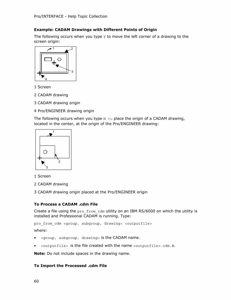
Pro/INTERFACE - Help Topic Collection
60
Example: CADAM Drawings with Different Points of Origin
The following occurs when you type Y to move the left corner of a drawing to the
screen origin:
1 Screen
2 CADAM drawing
3 CADAM drawing origin
4 Pro/ENGINEER drawing origin
The following occurs when you type N to place the origin of a CADAM drawing,
located in the center, at the origin of the Pro/ENGINEER drawing:
1 Screen
2 CADAM drawing
3 CADAM drawing origin placed at the Pro/ENGINEER origin
To Process a CADAM .cdm File
Create a file using the pro_from_cdm utility on an IBM RS/6000 on which the utility is
installed and Professional CADAM is running. Type:
pro_from_cdm <group, subgroup, drawing> <outputfile>
where:
• <group, subgroup, drawing> is the CADAM name.
• <outputfile> is the file created with the name <outputfile>.cdm.#.
Note: Do not include spaces in the drawing name.
To Import the Processed .cdm File
Pro/ENGINEER Interface
61
1. Copy the processed .cdm file to a Pro/ENGINEER workstation.
2. Click File > Open. The File Open dialog box opens.
3. Select CADAM (*.cdm) in the Type box.
4. Select the CADAM file you want to import from the list of available files, or type
the name in the Name box.
5. Click Open. The Import New Model dialog box opens.
6. Complete the dialog box and click OK.
Importing Entities and Layers
The following table lists the entities and the layers on which they are placed when
you import CADAM files to Pro/ENGINEER. Note that <cadamoverlayname> is the
name of the overlay specified in CADAM.
Entity Layer on Which Entity Is Placed
cadam_xyz_point points_cdt_layer
cadam_2d_point points_cdt_layer
cadam_nc nc_style_cdt_layer
cadam_overlay <cadamoverlayname>_olay
Tip: Transferring CADAM Dittos
A CADAM ditto is a separate part that you can instance at any point in a drawing.
The instance can have any scale, angle of revolution, and hatches. A ditto instance
exists as a set of independent entities in an imported drawing. These entities do not
recognize the source of the ditto and are similar to other entities that are not part of
any other ditto in the CADAM drawing.
You can use the cdt_transfer_details configuration option to determine the dittos
in a CADAM drawing. When set to yes, the details associated with a CADAM drawing
are converted to additional sheets on the drawing.
Importing CPTR-Neutral Format Files
About Importing CPTR-Neutral Format Files
You can import CADAM mainframe files using the CPTR-Neutral file format (*.bin)
besides importing CADAM drawing files. A converter supplied by Integrated Industrial
Information, Inc., CPTR, converts CADAM mainframe data to the CPTR-Neutral
format by way of ACCESS:IUE. Using Pro/CDT, the optional Pro/ENGINEER module
that provides the interface between Professional CADAM and Pro/ENGINEER, .you
can then import a CPTR-Neutral file into Pro/ENGINEER.
You can import a CPTR-Neutral file in either of the following ways:
Pro/INTERFACE - Help Topic Collection
62
• Directly on a computer that has Pro/CDT and pro_from_cptr installed.
• Process the CPTR-Neutral file on one machine and retrieve it on another machine
by:
o Running the Pro/ENGINEER pro_from_cptr utility to convert the the CPTR-Neutral (*.bin) file into a .cdm file .that can be read by Pro/CDT.
o Importing the .cdm file into Pro/ENGINEER.
Note: Import of the CPTR-Neutral file format is not supported on Linux.
CADAM Font Table characters (ITYPE 1060) are supported as instances of user-
defined Pro/ENGINEER symbols. A CPTR-Neutral file can contain the CADAM element,
Plot Axis System (ITYPE 960), defining the format and positioning of a CADAM
drawing in Pro/ENGINEER.
The use_cadam_plot_data configuration option specifies whether to define the
information in the Plot Axis System element when you import a CADAM drawing into
Pro/ENGINEER. If the option is set to no (the default), the system ignores it. If it is
set to yes, and the imported drawing contains the Plot Axis System element, you are
asked if you want to define the format based on the Plot Axis System.
• Type Y, to select the format based on the height, width, and origin defined by the
Plot Axis System element.
• Type N to select the format of the regular CADAM files.
You can use the cadam_line_weights configuration option to define the line width of
entities and plot drawings with correct line weights that are consistent with a
standard.
To Directly Import a CPTR-Neutral File
1. Click File > Open. The File Open dialog box opens.
2. Select CADAM CPTR Neutral (*.bin) in the Type box.
3. Select the CADAM file you want to import from the list of available files, or type
the name in the Name box.
4. Click Open. The Import New Model dialog box opens.
5. Complete the dialog box and click OK.
If you set the use_cadam_plot_data configuration option to yes, and the
imported drawing contains the Plot Axis Syst Step 7em element, you are
prompted to define the format based on the Plot Axis System.
6. Type Y, to complete the import process or type N if the imported drawing does
not use the Plot Axis System.
If the imported drawing is larger than the selected standard size format, you are
prompted to scale down the drawing to fit the format.
7. Type Y to scale the drawing.
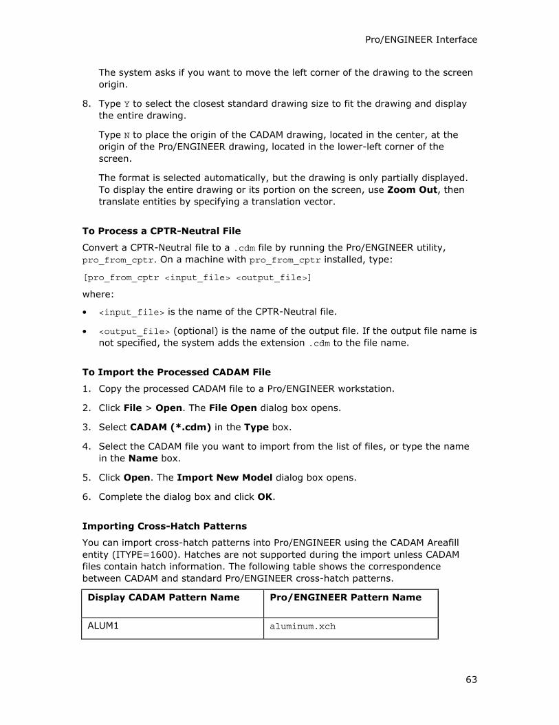
Pro/ENGINEER Interface
63
The system asks if you want to move the left corner of the drawing to the screen
origin.
8. Type Y to select the closest standard drawing size to fit the drawing and display
the entire drawing.
Type N to place the origin of the CADAM drawing, located in the center, at the
origin of the Pro/ENGINEER drawing, located in the lower-left corner of the
screen.
The format is selected automatically, but the drawing is only partially displayed.
To display the entire drawing or its portion on the screen, use Zoom Out, then
translate entities by specifying a translation vector.
To Process a CPTR-Neutral File
Convert a CPTR-Neutral file to a .cdm file by running the Pro/ENGINEER utility,
pro_from_cptr. On a machine with pro_from_cptr installed, type:
[pro_from_cptr <input_file> <output_file>]
where:
• <input_file> is the name of the CPTR-Neutral file.
• <output_file> (optional) is the name of the output file. If the output file name is
not specified, the system adds the extension .cdm to the file name.
To Import the Processed CADAM File
1. Copy the processed CADAM file to a Pro/ENGINEER workstation.
2. Click File > Open. The File Open dialog box opens.
3. Select CADAM (*.cdm) in the Type box.
4. Select the CADAM file you want to import from the list of files, or type the name
in the Name box.
5. Click Open. The Import New Model dialog box opens.
6. Complete the dialog box and click OK.
Importing Cross-Hatch Patterns
You can import cross-hatch patterns into Pro/ENGINEER using the CADAM Areafill
entity (ITYPE=1600). Hatches are not supported during the import unless CADAM
files contain hatch information. The following table shows the correspondence
between CADAM and standard Pro/ENGINEER cross-hatch patterns.
Display CADAM Pattern Name Pro/ENGINEER Pattern Name
ALUM1 aluminum.xch
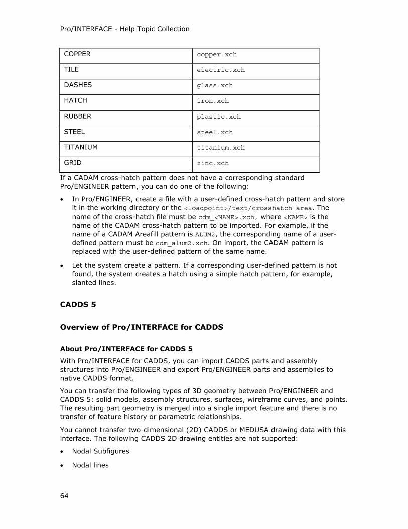
Pro/INTERFACE - Help Topic Collection
64
COPPER copper.xch
TILE electric.xch
DASHES glass.xch
HATCH iron.xch
RUBBER plastic.xch
STEEL steel.xch
TITANIUM titanium.xch
GRID zinc.xch
If a CADAM cross-hatch pattern does not have a corresponding standard
Pro/ENGINEER pattern, you can do one of the following:
• In Pro/ENGINEER, create a file with a user-defined cross-hatch pattern and store
it in the working directory or the <loadpoint>/text/crosshatch area. The
name of the cross-hatch file must be cdm_<NAME>.xch, where <NAME> is the
name of the CADAM cross-hatch pattern to be imported. For example, if the
name of a CADAM Areafill pattern is ALUM2, the corresponding name of a user-
defined pattern must be cdm_alum2.xch. On import, the CADAM pattern is
replaced with the user-defined pattern of the same name.
• Let the system create a pattern. If a corresponding user-defined pattern is not
found, the system creates a hatch using a simple hatch pattern, for example,
slanted lines.
CADDS 5
Overview of Pro/INTERFACE for CADDS
About Pro/INTERFACE for CADDS 5
With Pro/INTERFACE for CADDS, you can import CADDS parts and assembly
structures into Pro/ENGINEER and export Pro/ENGINEER parts and assemblies to
native CADDS format.
You can transfer the following types of 3D geometry between Pro/ENGINEER and
CADDS 5: solid models, assembly structures, surfaces, wireframe curves, and points.
The resulting part geometry is merged into a single import feature and there is no
transfer of feature history or parametric relationships.
You cannot transfer two-dimensional (2D) CADDS or MEDUSA drawing data with this
interface. The following CADDS 2D drawing entities are not supported:
• Nodal Subfigures
• Nodal lines
Pro/ENGINEER Interface
65
• Text
• Drawings
• Views
• Dimensions
• Labels
Note: You can use the CADDS 5 interface options only on the Silicon Graphics, Sun,
or Hewlett-Packard platforms.
Associative Topology Bus and CADDS 5
CADDS 5 is an ATB-enabled data exchange format. ATB allows the associative
update of imported data when changes are made to the native CADDS 5 data.
For information, see the Help on Associative Topology Bus.
About Defining Components by Path Location
In CADDS 5, you can define components of assemblies by explicitly building their
path locations into the component. For each CADDS 5 assembly component node,
you can designate a model by one of the following methods:
• Model name only, such as part1, where the CADDS 5 component must exist in a
valid search path.
• Path location and model name, such as /proj1/revision3/part1, where the
entire directory structure must exist in a valid search path.
For example, when the component model designation for a Concurrent Assembly
Mock-up (CAMU) assembly node is /proj1/revision3/part1 and your
Pro/ENGINEER session is set up as follows:
• The CVPATH environment variable is set to /home/user1/old-parts
• The extend_cvpath configuration option is set to /home/user1/new-parts
The following are valid locations for the imported part1 CADDS 5 model:
• /proj1/revision3/part1
• /home/user1/old-parts/proj1/revision3/part1
• /home/user1/new-parts/proj1/revision3/part1
The embedded path of the component model definition must start relative to a
defined search path or be a complete system path such as
/proj1/revision3/part1. You cannot find part1 in /home/user1/old-parts/part1
or in /home/user1/new-parts/part1. Pro/ENGINEER searches for
/proj1/revision3/part1 in the defined search path, not part1 alone.
If the component designation of the CAMU node is the CADDS 5 model name only
(part1), then both /home/user1/old-parts/part1 and /home/user1/new-parts/part1 are valid locations.
Pro/INTERFACE - Help Topic Collection
66
About Setting the CVPATH Environment Variable
The CVPATH environment variable is used by the CADDS 5 translator to define the
following:
• Search paths for locating components of CADDS 5 Concurrent Assembly Mock-Up
(CAMU) assemblies selected for import.
• Search paths for locating CADDS 5 part or assembly reference models when
using Associative Topology Bus (ATB) Check Status and Update commands.
• Location on the hard disk where CADDS 5 models exported from Pro/ENGINEER
is written.
You must set the CVPATH environment variable before you start your Pro/ENGINEER
session to define the default paths for the CADDS models. Use the extend_cvpath configuration option to add additional paths to the CVPATH definition during a
Pro/ENGINEER session using Tools > Options. These additional paths are added to
the end of the existing CVPATH environment variable setting.
Note: The extend_cvpath configuration option setting does not actually change the
CVPATH environment variable setting. The search paths are added during runtime of
the Pro/ENGINEER session.
You can set as many directory paths as you want. Use the following conventions
when setting the CVPATH:
• Paths may be relative to the Pro/ENGINEER startup directory, or absolute paths
of the hard drive.
• The paths are contained within single quotes.
• Each path is separated by a colon (:).
• The paths are defined in the required search order. When searching for CAMU
assembly component models or ATB reference models, the search starts with the
first path and traverses the paths sequentially until the model is located.
• You can assign the =C to the creation directory of the CADDS 5 export files in the
CVPATH. The creation directory is where the CADDS models from Pro/ENGINEER
are created on export.
Note: The creation directory overrides the Save a Copy dialog box setting. The
export location set in the Save a Copy directory is ignored for the CADDS 5
format.
An example of how to set the CVPATH environment variable follows:
setenv CVPATH '<path1>=C:<path2>:<path>:...<pathx>'
The =C after the <path1> in the example, indicates that this path is the creation
directory.
Pro/ENGINEER searches for CADDS components in the current working directory or
uses the CVPATH environment variable for locating components in other directories.
The additional paths, added to the end of the existing CVPATH environment variable
setting, are not searched until after the paths set in the actual environment variable

Pro/ENGINEER Interface
67
are searched. You cannot set the creation directory with the extend_cvpath configuration option.
To retrieve a CADDS assembly in Pro/ENGINEER, you must make sure that the
CVPATH is set to the appropriate directories. When importing a CADDS 5 assembly, if
the existing part or subassembly components are stored in different directories,
designate each directory in the path for a successful import. Otherwise, an assembly
with empty Translated Image Model (TIM) parts is created.
Note: If the CVPATH environment variable is not explicitly set, Pro/ENGINEER uses
the default setting of a single search path according to the current working directory
in Pro/ENGINEER. This directory is also used as the CADDS 5 export creation
directory.
About the ODB_DAEMON Process
When you import a CADDS 5 Concurrent Assembly Mock-Up (CAMU) assembly or
export a Pro/ENGINEER assembly to the CADDS 5 format, an ODB_DAEMON process is
started. This process is not started or required for the import and export of a CADDS
5 part.
This process is generally not killed after the import of a CAMU assembly or the
export of a Pro/ENGINEER assembly to the CADDS 5 format. It is directly linked to
the CADDS 5 converter version and the specific geometric libraries required for the
import of a CAMU assembly or the export of a Pro/ENGINEER assembly to the CADDS
5 format. If an ODB_DAEMON process is already running, then the existing ODB_DAEMON
process is used during the import or the export of the assembly instead of starting a
new ODB_DAEMON process.
Because multiple converter versions for CADDS 5 exist, and you can switch between
these converter versions using the intf_cadds_version configuration option, you
must check if an ODB_DAEMON process exists and is running before you import or
export the assembly. If the version of the CADDS 5 converter, to which the existing
ODB_DAEMON process is linked, does not match the converter version which is
currently set by the intf_cadds_version configuration option, the import or export
of the assembly fails. To avoid this, kill all existing ODB_DAEMON processes and start a
new ODB_DAEMON process before you import the CAMU assembly or export the
Pro/ENGINNER assembly to the CADDS 5 format.
Note: The ODB_DAEMON process continues to run even when you exit the
Pro/ENGINEER session and can affect the behavior of Pro/ENGINEER sessions in the
future unless you kill the ODB_DAEMON process after the import or export of the
assembly.
About the Name Service
The Name Service is a process that is used by Pro/ENGINEER and invoked when
Pro/ENGINEER starts. It must be running as follows for the CADDS 5 converter to
work successfully:
<Pro/E Loadpoint>/<Platform Type>/obj/nmsd -timeout 300
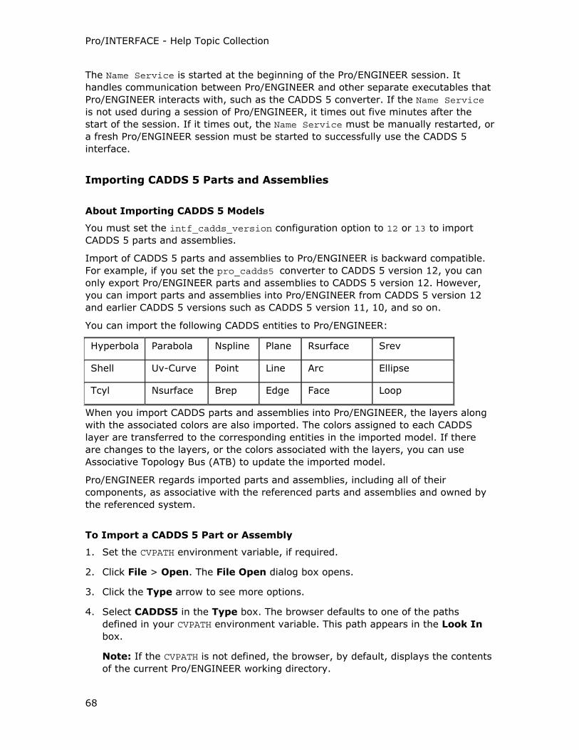
Pro/INTERFACE - Help Topic Collection
68
The Name Service is started at the beginning of the Pro/ENGINEER session. It
handles communication between Pro/ENGINEER and other separate executables that
Pro/ENGINEER interacts with, such as the CADDS 5 converter. If the Name Service
is not used during a session of Pro/ENGINEER, it times out five minutes after the
start of the session. If it times out, the Name Service must be manually restarted, or
a fresh Pro/ENGINEER session must be started to successfully use the CADDS 5
interface.
Importing CADDS 5 Parts and Assemblies
About Importing CADDS 5 Models
You must set the intf_cadds_version configuration option to 12 or 13 to import
CADDS 5 parts and assemblies.
Import of CADDS 5 parts and assemblies to Pro/ENGINEER is backward compatible.
For example, if you set the pro_cadds5 converter to CADDS 5 version 12, you can
only export Pro/ENGINEER parts and assemblies to CADDS 5 version 12. However,
you can import parts and assemblies into Pro/ENGINEER from CADDS 5 version 12
and earlier CADDS 5 versions such as CADDS 5 version 11, 10, and so on.
You can import the following CADDS entities to Pro/ENGINEER:
Hyperbola Parabola Nspline Plane Rsurface Srev
Shell Uv-Curve Point Line Arc Ellipse
Tcyl Nsurface Brep Edge Face Loop
When you import CADDS parts and assemblies into Pro/ENGINEER, the layers along
with the associated colors are also imported. The colors assigned to each CADDS
layer are transferred to the corresponding entities in the imported model. If there
are changes to the layers, or the colors associated with the layers, you can use
Associative Topology Bus (ATB) to update the imported model.
Pro/ENGINEER regards imported parts and assemblies, including all of their
components, as associative with the referenced parts and assemblies and owned by
the referenced system.
To Import a CADDS 5 Part or Assembly
1. Set the CVPATH environment variable, if required.
2. Click File > Open. The File Open dialog box opens.
3. Click the Type arrow to see more options.
4. Select CADDS5 in the Type box. The browser defaults to one of the paths
defined in your CVPATH environment variable. This path appears in the Look In
box.
Note: If the CVPATH is not defined, the browser, by default, displays the contents
of the current Pro/ENGINEER working directory.
Pro/ENGINEER Interface
69
5. Click the Look In arrow to display a list of the paths defined in the CVPATH
environment variable.
6. Select the path from which you want to import a part or assembly.
7. Double-click the name of the CADDS part or assembly you want to import.
8. The Import New Model dialog box opens. Part or Assembly is automatically
selected.
9. Type a name for the imported part or assembly or accept the default name in the
Name box.
10. Click OK.
Exporting from Pro/ENGINEER to CADDS 5
About Exporting to CADDS 5
When you export a part or assembly from Pro/ENGINEER to CADDS 5, you are
working in the Explicit mode of CADDS, an industry-standard CAD/CAM design
environment. The Explicit mode allows you to access the various CADDS
applications.
Edge and surface definitions are transferred from Pro/ENGINEER to CADDS 5 in their
exact geometric form using the Non Uniform Rational B-Splines (NURBS)
mathematical description.
Execute File
When you export an assembly from Pro/ENGINEER to CADDS 5, an execute file
named <export model name>-exec is created. When you run the execute file with
CADDS 5, it creates:
• Default drawings and views for the exported CADDS models.
• Temporary view files (tvfs) that you can use to view CADDS parts in an
assembly.
• If Associative Topology Bus is enabled when you are exporting an assembly, and
the assembly contains cabling geometry, the execute file converts this exported
cable data to CADDS 5 cables.
To Export a Part or Assembly to CADDS 5
1. Click File > Save a Copy. The Save a Copy dialog box opens.
2. Select CADDS5 in the Type box. The existing Pro/ENGINEER model name
without the extension appears in the New Name box.
3. Accept the default name or type a new model name in the New Name box.
4. Click OK. The Pro/ENGINEER part or assembly is exported to CADDS 5 in the
Explicit format.
Pro/INTERFACE - Help Topic Collection
70
CATIA
Overview of Licenses and Translators
About CATIA Versions, Licenses, and Translators
Pro/ENGINEER supports CATIA versions 4 and 5. The licenses required for the
exchange of data between these versions of CATIA and Pro/ENGINEER are as
follows:
• CATIA II Interface license for CATIA V4
• The CATIA V5 interface license (intf_for_catia_v5)
Importing and Exporting CATIA V4 Files
The CATIA V4 translators that are available in Pro/ENGINEER are as follows. The one
which is used depends on the availability of the CATIA II Interface license:
• Interface for CATIA II with ATB when the CATIA II Interface license is available
• Pro/INTERFACE for CATIA when the CATIA II Interface license is not available
The availability of the CATIA II Interface license also determines whether CATIA V4
models imported into Pro/ENGINEER are ATB-enabled or not.
Note: Associative Topology Bus (ATB) functionality does not support the
Pro/INTERFACE for CATIA translator.
The Interface for CATIA II with ATB
If you have the CATIA II Interface license, the Interface for CATIA II with ATB
translator is used by default for the direct import and export of CATIA V4 files. CATIA
V4 parts and assemblies imported to Pro/ENGINEER with ATB enabled can be
associatively updated to changes in the native CATIA models with the Interface for
CATIA II with ATB. For more information, see the Help module, Associative Topology
Bus.
Note: You must purchase the CATIA II Interface license to use the ATB capabilities
on the CATIA V4 models imported to Pro/ENGINEER.
Pro/INTERFACE for CATIA
If you do not have the CATIA II Interface license, Pro/INTERFACE for CATIA is used
for the direct, one-step import and export operations. Pro/INTERFACE for CATIA does
not support ATB. You cannot associatively update geometry imported with the
Pro/INTERFACE for CATIA translator to changes in the original, native CATIA models.
Importing CATIA V5 Files
You must purchase the CATIA V5 interface license, intf_for_catia_V5, to import
CATIA V5 part files (*.CATPart) to Pro/ENGINEER. You can only import CATIA V5 R6
and higher *.CATPart files to Pro/ENGINEER.
Pro/ENGINEER Interface
71
The CATIA V5 interface supports ATB. You can associatively update CATIA V5
geometry imported with the topobus_enable configuration option set to yes.
About Interface for CATIA II with ATB
The Interface for CATIA II with ATB is used by default to exchange geometry
between Pro/ENGINEER and CATIA when the Interface for CATIA II with ATB license
is available. The Interface for CATIA II with ATB does not require a CATIA installation
and does not use the CATIA CATGEO API. It is supported on Sun, HP, SGI, and
Windows.
The Interface for CATIA II with ATB supports the following:
• Import and export of CATIA V4 Model (*.model) files
• Import of CATIA V4 Model (*.exp) and CATIA V4 Session (*.session) files
• Model Space parameter configuration options
• Export to CATIA start parts
• Export of faceted data
• Import of CATIA layer filters
About Pro/INTERFACE for CATIA
Pro/INTERFACE for CATIA comes free with Pro/ENGINEER Foundation. This translator
requires a CATIA installation to perform a complete transfer of data between
Pro/ENGINEER and CATIA and uses the CATIA CATGEO API. It is supported on Sun,
HP, SGI, and IBM (32-bit only) workstations.
Geometry is transferred between Pro/ENGINEER and CATIA by the following
methods:
• One-step or the direct method
• Two-step or the indirect method
Regardless of whether you are using the one-step or the two-step method of data
exchange or whether CATIA and Pro/ENGINEER are on the same workstation, the
following utilities are used during file conversion:
• pro_from_cat4
• progeo_to_cat4
When CATIA and Pro/ENGINEER reside on different machines, you must copy the
Pro/INTERFACE for CATIA utilities on a workstation which has CATIA installed and
has access to CATIA licenses.
Pro/INTERFACE for CATIA does not support Associative Topology Bus (ATB).
Pro/INTERFACE - Help Topic Collection
72
About the Methods of Data Exchange Between Pro/ENGINEER and CATIA V4
With the Pro/INTERFACE for CATIA translator, data exchange between
Pro/ENGINEER and CATIA V4 follows a one-step or a two-step method. CATIA and
Pro/ENGINEER can reside on different workstations or on the same workstation.
Two-Step or the Indirect Method
You must have CATIA 4.2.0 on an IBM RS/6000, SGI, Sun, or Hewlett Packard
workstation and Pro/ENGINEER on any other workstation. Pro/INTERFACE for CATIA
must be available on the CATIA workstation.
Data exchange between Pro/ENGINEER and CATIA V4 involves the conversion of
Pro/ENGINEER and CATIA V4 files to the intermediate .ct file format. You must
manually start the pro_from_cat4 and progeo_to_cat4 utilities as a catusr to
complete the file conversion. The pro_from_cat4 and progeo_to_cat4 utilities must
be available on the workstation with CATIA installed and are used as described:
• pro_from_cat4—For import of CATIA V4 files to Pro/ENGINEER
• progeo_to_cat4—For export of Pro/ENGINEER files to CATIA V4
The pro_from_cat4 utility converts the CATIA V4 .model file to a .ct file when you
import CATIA V4 files to Pro/ENGINEER. After the conversion, you must copy the .ct
file to the Pro/ENGINEER workstation.
For export, create the .ct file on the Pro/ENGINEER workstation and then copy the
.ct file to the CATIA workstation. Use the progeo_to_cat4 utility to convert the .ct
file to a .model file.
To use the utility progeo_to_cat4, CATIA solids must be available on the receiving
side. You can run this utility in default mode or user input mode.
One-Step or the Direct Method
You must have Pro/ENGINEER and CATIA 4.2.0 running on the same IBM RS6000,
SGI, Sun, or Hewlett Packard workstation.
The CATIA V4 .model files are automatically converted to .ct files for import and the
.ct files are automatically converted to .model files during the export. The
pro_from_cat4 and progeo_to_cat4 utilities are used during file conversion when
you select CATIA V4 ProGEO Model (*.model) from the Type list during import and
export. You must run Pro/ENGINEER as a catusr. The system extracts data directly
from the CATIA database.
Using Interface for CATIA II with ATB
About Importing from CATIA Using Interface for CATIA II with ATB
You can import the following types of CATIA files:
• CATIA V4 Model (*.model) part or assembly files
Pro/ENGINEER Interface
73
• CATIA V4 Session (*.session) assembly files
• CATIA V4 Model (*.exp) export files
You can filter and selectively import the .model files from the CATIA V4 Model .exp
file. The .model files within a *.exp file are imported as part components of a native
assembly in Pro/ENGINEER.
Note: You cannot create a single independent part from a .model file of a .exp file
unless the .exp export file contains a single .model file which is automatically
imported as a part.
You can import a CATIA V4 model with dittos as an assembly or a part. Dittos are
used to represent assembly structures. Therefore, the default import model type for
models with dittos is assembly.
You can open CATIA V4 files as new part or assembly models or append them to
existing models in Pro/ENGINEER.
CATIA supports Associative Topology Bus (ATB). CATIA models, except .exp files,
are imported as Translated Image Models (TIMs). Only CATIA files imported as new
models using File > Open or assembled as a new component of an existing
Pro/ENGINEER assembly are ATB-enabled. CATIA import features that are inserted
as features to existing Pro/ENGINEER part files are not ATB-enabled.
You can use the ATB capability to update the imported geometry associatively when
there are changes in the CATIA reference files. For information on ATB, see the Help
on Associative Topology Bus.
Entities Supported for Import with Interface for CATIA II with ATB
You can import the following CATIA entities to Pro/ENGINEER:
• Faces
• Surfaces
• 2D entities (lines, circles, curves, and so on)
• Model edges
• Composite curves
• Points
• 3-axis entities (imported as coordinate systems)
• Datum planes
• Layers
• Layer filters
Importing CATIA V4 Models with Dittos in Assembly Mode
When you import a CATIA V4 model with dittos in the Assembly mode, model data is
transferred to Pro/ENGINEER according to the following rules:
Pro/INTERFACE - Help Topic Collection
74
• You are prompted for the name of the assembly in Pro/ENGINEER. The CATIA V4
model is then imported into this assembly.
• For the Master Workspace, a subassembly with the name of the CATIA V4 model
is created. In addition, a part file containing geometry that exists directly in the
Master Workspace is created and named as the Master Workspace.
• If the Master Workspace or any other Detail Workspace does not reference the
geometry, this Detail Workspace is ignored.
• For each Detail Workspace used in the Master Workspace, that is not used in any
other Detail Workspace, a part file with the name of this Detail Workspace is
created.
• For each Detail Workspace used in the Master Workspace that contains dittos, a
subassembly with the name of the Detail Workspace is created. If the Detail
Workspace contains additional geometry that is not from a ditto, this geometry is
stored in a part file as a component of the subassembly with the name of the
Detail Workspace.
• Each part component of the assembly is imported with the layer filters of the
CATIA V4 master model.
Importing CATIA V4 Models with Dittos in Part Mode
You can import CATIA V4 models with dittos in Part and Assembly modes.
When you import a CATIA V4 model in the Part mode, the resulting part file contains
the merged geometry of all its workspaces.
To Import a CATIA V4 Model File Using Interface for CATIA II with ATB
1. Click File > Open. The File Open dialog box opens.
2. Select CATIA V4 Model (.model, .exp) in the Type box.
3. Select the CATIA V4 file you want to import from the list of available files or
browse to find the CATIA file.
4. Click Open. The Import New Model dialog box opens.
5. Click OK.
To Append a CATIA V4 File to an Existing Model Using Interface for CATIA II with ATB
1. Click Insert > Shared Data > From File. The File Open dialog box opens.
2. Select CATIA V4 Model (*.model, *.exp) in the Type box.
3. Select the CATIA V4 file you want to import from the list of available files or
browse to find the file.
4. Click Open. The Choose Solid Options and Placement dialog box opens.
Pro/ENGINEER Interface
75
5. If the target model contains coordinate systems, select one to locate the
geometry of the import feature or select the default location.
6. If you are appending file to a Pro/ENGINEER part file with solid geometry, select
Protrusion, Cut, or Surfaces to add to the solid geometry, subtract from the
solid geometry, or represent the imported geometry as surfaces, leaving the solid
geometry unchanged, respectively.
7. Click OK.
To Selectively Import Model Data of a CATIA V4 Export .exp File
1. Click File > Open. The File Open dialog box opens.
2. Select CATIA V4 Model (.model, .exp) in the Type box.
3. Select the CATIA *.exp file you want to import from the list of available files or
browse to find the file.
4. Click Open. The Import New Model dialog box opens. Assembly is
automatically selected by default.
Note: You can import the .model files within a *.exp file only as part
components of a native Pro/ENGINEER assembly.
5. Click OK. The Layer Import Options dialog box opens. It lists each .model file
contained within the .exp file. By default, the layer import status of all the
.model files is Show.
6. To filter models that you do not require, select the model from the layer tree and
set its import status to Skip.
7. Click OK. The .model files with their import status set to Show are imported.
About Importing a CATIA V4 Model with Layers and Layer Filters Using Interface for CATIA II with ATB
You can import a CATIA V4 model along with its layers and layer filters to
Pro/ENGINEER and use the display status of the imported CATIA layers and the layer
filters to selectively import geometry from the CATIA layers.
The layer filters of the imported CATIA V4 model are converted to master layers in
Pro/ENGINEER. All layers assigned to a layer filter in CATIA are assigned to the
corresponding master layer in Pro/ENGINEER. The association of the master layers
with their assigned layers in Pro/ENGINEER is the same as the corresponding
association of the layer filters with their assigned layers in CATIA. The master layers
and their layers in Pro/ENGINEER retain the original names of the layer filters and
their layers in CATIA.
Note: If Associative Topology Bus is active, you cannot filter layers when you import
CATIA V4 models.
Pro/INTERFACE - Help Topic Collection
76
About Using Layer Display Status for Selective Import of CATIA V4 Geometry
You can use the display status of the imported CATIA layers and the layer filters to
display or hide the imported entities residing on these layers and selectively import
geometry from the CATIA layers. Use the Layer Import Options dialog box to set
the initial display status of the imported layers and filter geometry residing on the
layers.
At any given time, you can only set the display status of the active layer filter. If you
save the setting of the active layer filter in the CATIA V4 model file before import, by
default, the display status of the active master layer in Pro/ENGINEER is Isolate. All
layers assigned to this master layer are displayed in Pro/ENGINEER.
About Exporting to CATIA V4 Using Interface for CATIA II with ATB
You can export exact surface and solid geometry to a CATIA V4 Model .model file.
You can also export facet data and datum entities, such as points and curves of the
Pro/ENGINEER part or assembly.
You can use the Export CATIA dialog box to customize the export of a
Pro/ENGINEER model to CATIA. You may choose to export exact solid geometry as
wireframe edges, surfaces, shells, or solids, depending on type of representation you
want to export. You can also include or exclude facet geometryand datum entities.
When exporting an assembly, you may also choose one of the following for the
exported assembly structure:
• Flat—Exports the assembly to a single master workspace of a CATIA V4 Model
.model file. Each assembly component is exported as a separate volume. All the
volumes of the assembly merge into a single master workspace. This is the
default behavior.
• Dittos—Preserves the structure of multiple-level assemblies in the CATIA V4
Model .model file. The Pro/ENGINEER assembly components are exported as
CATIA dittos or volumes with a workspace for each volume into a single CATIA V4
Model .model file.
If the CATIA V4 model selected for export already exists, use the
catia_out_to_existing_model configuration option to control conflict resolution.
You can append data to the existing CATIA V4 model or overwrite the existing
model.
To Export to CATIA V4 Using Interface for CATIA II with ATB
1. In an open part or assembly, click File > Save a Copy. The Save a Copy dialog
box opens.
2. Select CATIA V4 Model (*.model) in the Type box.
3. Accept the default name in the New Name box or type a new model name for
the export.
4. Click OK. The Export CATIA dialog box opens.
Pro/ENGINEER Interface
77
5. Complete the Export CATIA dialog box to specify the structure and contents of
the output file.
If you are exporting an assembly, select Flat or Dittos from the File Structure
list to specify the structure of the assembly.
6. Click Customize Layers from the Export CATIA dialog box to export layers.
The Choose Layers dialog box opens.
7. Click Auto ID to manually assign layer IDs to layers that you want to export, but
do not currently have IDs.
You can use the Choose Layers dialog box to skip geometry on certain layers.
8. Click OK in the Choose Layers dialog box.
9. Click OK in the Export CATIA dialog box.
About CATIA Start Parts
You can use custom CATIA V4 .model start parts when exporting Pro/ENGINEER
parts or assemblies to the CATIA V4 .model file format. The custom start-part
template files define nongeometric entities such as workspace, views, layers, fonts,
colors, graphic standards, tolerance, and other parameters.
The attributes of the start parts are applied to the exported CATIA V4 .model files.
The following parameters from the CATIA start-part template file are copied to the
Pro/ENGINEER models:
• Graphics standards
• Colors
• Tolerances
• Thickness
• Model comments
• Initial view plane
• Project file information
To access and use the CATIA start-part template files the
intf_out_cat_start_model configuration option must be set to the path of the
CATIA start .model file. If the start parts are missing, the exported CATIA V4 .model
files use the default model parameter values.
About Controlling Model Space Parameters When Exporting to CATIA
For the exported CATIA V4 .model file to open correctly in CATIA, you must ensure
the accuracy of the geometric data in the exported file by setting accuracy values.
Explicitly set these values in the exported .model file through the following
configuration options:
• intf3d_out_cat2_model_sz
Pro/INTERFACE - Help Topic Collection
78
• intf3d_out_cat2_ident_crv
• intf3d_out_cat2_ident_pt
• intf3d_out_cat2_infinity
• intf3d_out_cat2_sag
• intf3d_out_cat2_step
You can set any value or the recommended value that is based on a standard Model
Size. The recommended tolerance values are based on the correlation between a
standard Model Size and the parameters.
If you assign values other than the recommended values and open the exported
Pro/ENGINEER part in CATIA, an error message displays the current tolerance value
against the recommended values.
The following table shows the configuration options with their values in CATIA for the
corresponding parameters in Pro/ENGINEER and CATIA. The default values for the
parameters are based on the standard Model Size of 10000.
Parameter in
Pro/ENGINEE
R
Model Data
in CATIA
Configuration Option Recommended
Values in
CATIA
Model Size Model Size intf3d_out_cat2_model_sz 10000
Tolerance
Curve
Identical
Curve
intf3d_out_cat2_ident_crv 0.1
Tolerance
Point
Intersection
Projection
intf3d_out_cat2_ident_pt 0.001
Tolerance Line Infinity intf3d_out_cat2_infinity 100000
Tolerance Sag Bending intf3d_out_cat2_sag 0.03
Tolerance
Distance
Step intf3d_out_cat2_step 20
If you set the model space parameter configuration options and also use the CATIA
start parts, the model space parameter values of the designated CATIA start parts
override the values of the configuration options.
Using Pro/INTERFACE for CATIA
To Convert a CATIA .model File to the Neutral .ct Format
Perform the following steps if you do not have Pro/ENGINEER and CATIA on the
same workstation:
1. Copy the pro_from_cat4 utility to the workstation on which CATIA is installed.
2. On the CATIA workstation, run pro_from_cat4 utility using one of two methods:
Pro/ENGINEER Interface
79
Type pro_from_cat4 and interactively specify input values or accept the defaults.
or
Type all inputs in command-line format, as follows:
pro_from_cat4 [-n name] [-d ddname] [-m model_path] [-p project] [-o filename] [-v verbose] [-r revision_number]
Modifiers are similar to those of the progeo_to_cat4 utility. The extension .ct is
appended to the new file if you do not specify the -o <filename> modifier when
executing the utility.
The default is to place the model in the /home/catusr/db directory and to run
the script from the /home/catusr directory.
3. Copy the processed CATIA file to a workstation with Pro/ENGINEER installed.
To Import a Neutral .ct File
1. Copy the processed CATIA file to a workstation with Pro/ENGINEER installed.
2. Click File > Open. The File Open dialog box opens.
3. Select CATIA to/from File (*.ct) in the Type box.
4. Select the CATIA file that you want to import from the list of available files or
type the name in the Name box.
5. Click Open. The Import New Model dialog box opens.
6. Complete the Import New Model dialog box and click OK.
To Append a Neutral .ct File to a Pro/ENGINEER Part
1. Copy the processed CATIA .ct file to a workstation with Pro/ENGINEER installed.
2. Click Insert > Shared Data > From File. The File Open dialog box opens.
3. Select CATIA to/from File (*.ct) in the Type box.
4. Select the CATIA file from the list of available files or browse to find the CATIA
file.
5. Click Open. The Choose Solid Options and Placement dialog box opens.
6. If the target model contains coordinate systems, select a coordinate system to
locate the geometry of the imported feature or select the default location.
7. If you are appending the file to a Pro/ENGINEER part file with solid geometry,
select Protrusion, Cut, or Surfaces to add to the solid geometry, subtract from
the solid geometry, or represent the imported geometry as surfaces, leaving the
solid geometry unchanged, respectively.
8. Click OK.
Pro/INTERFACE - Help Topic Collection
80
To Export a Pro/ENGINEER Model to the .ct Neutral Format
Convert a .ct file to a CATIA .model file with exact solid geometry using the
progeo_to_cat4 utility as follows:
1. In an open part or assembly, click File > Save a Copy. The Save a Copy dialog
box opens.
2. Select CATIA to/from File (*.ct) in the Type box.
3. Accept the default name in the New Name box or type a new model name for
the export.
4. Click OK. The Export CATIA dialog box opens.
5. If you are exporting an assembly, select Flat or Dittos from the File Structure
list to specify the structure of the assembly.
6. To export layers, click Customize Layers from the Export CATIA dialog box.
The Choose Layers dialog box opens.
7. Click Auto ID to assign layer IDs to layers that do not currently have IDs.
8. Make changes to the Choose Layers dialog box and click OK.
9. Click OK in the Export CATIA dialog box to create the intermediate part or
assembly .ct output file.
To Export a Part or Assembly to a .cat Format File
1. In an open part or assembly, click File > Save a Copy. The Save a Copy dialog
box opens.
2. Select CATIA Facets (*.cat) in the Type box.
3. Accept the default name in the New Name box or type a new model name for
the export.
4. Click OK. The Export CATIA dialog box opens.
5. If you are exporting an assembly, select Flat or Dittos from the File Structure
list to specify the structure of the assembly.
6. To export layers, click Customize Layers from the Export CATIA dialog box.
The Choose Layers dialog box opens.
7. Click Auto ID to assign layer IDs to layers that do not currently have IDs.
8. Make changes to the Choose Layers dialog box and click OK.
9. Click OK in the Export CATIA dialog box. You can convert the .cat file to a
CATIA .model file with a Mock-up solid.
To Convert a .ct or .cat Neutral File to the Native CATIA .model Format
1. Copy the exported CATIA file (.ct or .cat) and the appropriate utility,
progeo_to_cat4 or pro_to_cat4, to a machine with CATIA installed.
Pro/ENGINEER Interface
81
2. Run the progeo_to_cat4 utility to convert the .ct file to a .model file with an
exact solid, or the pro_to_cat4 utility to convert the .cat file to a .model file
with a CATIA Mock-up solid.
Note: CATIA solids must be available on the receiving side to use
progeo_to_cat4.
3. To run interactively, type progeo_to_cat4 or pro_to_cat4. You are prompted
for file names and paths.
If you are in the user input mode, type the name of the .ct or .cat file. The file
is converted and placed in the CATIA model file M0000000, unless you specify
another name.
Format of the progeo_to_cat4 Utility
The format for using progeo_to_cat4 to convert the .ct file to a .model file is as
follows:
<progeo_to_cat4> [-n objectname] [-d catia_ddname] [-m catia_model_path] [-p project] [-i filename] [-v verbose] [-size index_size data_size]
where:
• objectname—Name of the CATIA object.
• catia_ddname—CATIA model number (M1).
• catia_model_path—Path for the CATIA model number.
• project—Name of the CATIA project (default is a blank value consisting of six
spaces). If you specify the project name, you automatically specify the
catia_ddname.
• filename—Name of the immediate format file to be converted.
• size—Specific index and data table size for the new CATIA model. If you do not
specify the size, the default values in the CATIA declaration files are used.
About Configuring the Setup for Direct Import and Export Using Pro/INTERFACE for CATIA
The following utilities are used during data exchange between Pro/ENGINEER and
CATIA:
• pro_from_cat4
• progeo_to_cat4
The pro_from_cat4 and progeo_to_cat4 utilities are automatically used during file
conversion when you select CATIA V4 ProGEO Model (*.model) during import and
export from the Type list. The CATIA V4 .model files are automatically converted to
.ct files during the import and the .ct files are automatically converted to CATIA V4
ProGEO .model files during the export. The system extracts data directly from the
CATIA database.
Pro/INTERFACE - Help Topic Collection
82
You must have Pro/ENGINEER and CATIA 4.2.0 running on the same SGI, Sun, or
Hewlett Packard workstation and run Pro/ENGINEER as a catusr.
To Import a CATIA V4 .model File Using Pro/INTERFACE for CATIA
1. Make sure that you have Pro/ENGINEER and CATIA 4.2.0 running on the same
workstation.
2. Run Pro/ENGINEER as a catusr.
3. Click File > Open. The File Open dialog box opens.
4. Select CATIA V4 ProGEO Model (*.model) in the Type box. The browser
displays the contents of the CATIA Database.
5. Select the CATIA V4 .model file you want to import from the list of available files
in the CATIA Database.
6. Click Open. The Import New Model dialog box opens.
7. Select the model type.
8. Type a name for the imported part or assembly or accept the default name in the
Name box.
9. Click OK. The CATIA .model files are automatically converted to .ct files for
import.
To Append a CATIA V4 .model File to a Pro/ENGINEER Part Using Pro/INTERFACE for CATIA
1. Make sure that you have Pro/ENGINEER and CATIA 4.2.0 on the same
workstation. The pro_from_cat4 utility must also be available on the workstation
with CATIA installed.
2. Run Pro/ENGINEER as a catusr.
3. Click Insert > Shared Data > From File. The File Open dialog box opens.
4. Select CATIA V4 ProGEO Model (*.model) in the Type box. The browser
displays the contents of the CATIA Database.
5. Select the CATIA V4 .model file you want to append from the list of available files
or browse to find the CATIA file.
6. Click Open. The Choose Solid Options and Placement dialog box opens.
7. If the target model contains coordinate systems, select a coordinate system to
locate the geometry of the imported feature or select the default location.
8. If you are appending the file to a Pro/ENGINEER part file with solid geometry,
select Protrusion, Cut, or Surfaces to add to the solid geometry, subtract from
the solid geometry, or represent the imported geometry as surfaces, leaving the
solid geometry unchanged, respectively.
9. Click OK.
Pro/ENGINEER Interface
83
To Export a Pro/ENGINEER Model to the CATIA V4 ProGEO .model Format Using Pro/INTERFACE for CATIA
1. In an open part or assembly, click File > Save a Copy. The Save a Copy dialog
box opens.
2. Select CATIA V4 ProGEO Model (*.model) in the Type box. The contents of
the CATIA Database are displayed in the Save A Copy dialog box.
3. Accept the default name in the New Name box or type a new model name for
the export.
4. Click OK. The Export CATIA dialog box opens.
5. Complete the Export CATIA dialog box to specify the structure and contents of
the output file.
If you are exporting an assembly, select Flat or Dittos from the File Structure
list to specify the structure of the assembly.
6. Click Customize Layers from the Export CATIA dialog box to export layers.
The Choose Layers dialog box opens.
7. Click Auto ID to manually assign layer IDs to layers that you want to export, but
do not currently have IDs.
You can use the Choose Layers dialog box to skip geometry on certain layers.
8. Click OK in the Choose Layers dialog box.
9. Click OK in the Export CATIA dialog box. The Pro/ENGINEER model is exported
to the .ct file and automatically converted to the CATIA V4 ProGEO Model .model
format. The .model file is written to the CATIA Database.
Using Interface for CATIA V5
About Importing CATIA V5 Parts to Pro/ENGINEER
You can import CATIA V5 Revision 6 and later part (*.CATPart) files into
Pro/ENGINEER with the CATIA V5 interface license option, intf_for_catia_v5. You
can append the CATPart to an existing Pro/ENGINEER part as an imported feature or
to an existing Pro/ENGINEER assembly as a part component. You can import solids,
surfaces, and datum entities.
The Interface for CATIA V5 translator supports Associative Topology Bus (ATB).
CATIA V5 geometry imported with the topobus_enable configuration option set to
yes can be associatively updated to changes in the native CATIA reference file. For
more information on ATB, see the Help on Associative Topology Bus.
To Import a CATIA V5 Part (CATPart) File
1. Click File > Open. The File Open dialog box opens.
2. Select CATIA V5 CATPart (*.CATPart) in the Type box.
Pro/INTERFACE - Help Topic Collection
84
3. Select the CATIA V5 part file from the list of available files or browse to find the
CATIA V5 file.
4. Click Open. The Import New Model dialog box opens.
5. Type a new import model name in the Name box or accept the default.
6. Click OK.
Note: If the version of the CATPart file is earlier than R6, a part with empty
import features is created. The Pro/ENGINEER window warns you that empty
features are created and asks you to use Info > Geometry Checks to check the
details.
To Append a CATIA V5 Part to a Pro/ENGINEER Part or Assembly
1. Click Insert > Shared Data > From File with a Pro/ENGINEER part or assembly
open. The File Open dialog box opens.
2. Select CATIA V5 CATPart (*.CATPart) in the Type box. The CATIA V5 files in
the working directory are listed.
3. Select the CATIA V5 file from the list of available files or browse to find the file.
4. Click Open. The Choose Solid Options and Placement dialog box opens if you
are appending the CATIA V5 file as an imported feature.
o Accept the default location or select a coordinate system to position the
geometry.
o If the Pro/ENGINEER part contains solid geometry, select Protrusion, Cut,
or Surfaces under Import Data As to add to the solid geometry, subtract
from the solid geometry, or represent the imported geometry as surfaces,
leaving the solid geometry unchanged, respectively.
o Click OK. The CATPart is appended to an existing Pro/ENGINEER part as an
import feature.
5. If you are appending the CATIA V5 file as a part component to an existing
Pro/ENGINEER assembly containing at least one coordinate system, select a
coordinate system in the SEL COORD S menu.
Note: If the version of the CATPart file is earlier than R6, a part or part
component with empty import features is created. The Pro/ENGINEER window
warns you that empty features are created and asks you to use Info >
Geometry Checks to check the details.
To Assemble a CATIA V5 Part in an Existing Assembly
1. Click Insert > Component > Assemble with a Pro/ENGINEER assembly open.
The File Open dialog box opens.
2. Select CATIA V5 CATPart (*.CATPart) in the Type box. The CATIA V5 files in
the working directory are listed.

Pro/ENGINEER Interface
85
3. Select the part file you want to assemble into the existing Pro/ENGINEER
assembly as a part component or browse to find the file.
4. Click Open. The Import New Model dialog box opens. It displays the path to
the CATIA V5 file with the filename.
5. Type a name for the part component or accept the default name in the Name
box.
6. Click OK. The Component Placement dialog box opens.
7. Add placement constraints to position the part or subassembly component.
8. Click OK.
Note: If the version of the CATPart file is earlier than R6, a part component with
empty import features is created. The Pro/ENGINEER window warns you that
empty features are created and asks you to use Info > Geometry Checks to
check the details.
Importing CATPart Files Earlier Than R6
When you import to Pro/ENGINEER, append to Pro/ENGINEER models, or assemble
CATIA V5 part files earlier than revision 6 (R6) into existing Pro/ENGINEER
assemblies:
• The resulting import feature in the new or existing Pro/ENGINEER part is empty.
• A warning in the Pro/ENGINEER window states that empty import features are
created and prompts you to check the details in the Info > Geometry Checks >
Troubleshooter dialog box.
• The Info > Geometry Checks > Troubleshooter dialog box states that the
empty import features are created because Pro/ENGINEER does not support the
import of CATIA V5 files earlier than R6. The Geom Check is added to the empty
import features and you must select an item of the import feature in the
Troubleshooter dialog box to read the details. You are prompted to save the
CATIA V5 files to R6 or higher.
• The import log file in the Information Window shows the version of the imported
CATIA file with other details.
Note: Regeneration removes the Geom Check added to the import features.
Perform one of the following tasks:
• Save the CATIA V5 part files to R6 or higher in CATIA. For best results, save to
CATIA V5 R8 or higher.
• Delete the empty part, part component, or import feature created by the initial
open or insert action.
• Reimport the newly saved version of the CATIA V5 part.
Pro/INTERFACE - Help Topic Collection
86
CDRS
About Importing CDRS Models
CDRS is an Associative Topology Bus (ATB)-enabled format. You can import CDRS
models or append them to models in Pro/ENGINEER to create IN features that are
ATB-enabled.
The following import and append operations create ATB-enabled IN features:
• Opening a CDRS model as a new part with File > Open.
• Assembling a CDRS model as a part component of an existing Pro/ENGINEER
assembly with Insert > Component > Assemble.
• Appending a CDRS model as a new part or part component of an existing
Pro/ENGINEER assembly using Insert > Shared Data > From File.
• Appending a CDRS model as a new feature of an existing Pro/ENGINEER part
using Insert > Shared Data > From File.
The resulting part file has a standard Pro/ENGINEER part icon in the Model Tree, but
the import feature, which is a CDRS IN feature, is represented by an ATB icon.
To Import a CDRS File
1. Click File > Open. The File Open dialog box opens.
2. Select CDRS (*.neu) as the file type in the Type box. Files of the selected type
that are located in your working directory are listed.
3. Browse for the file you want if it is not in your working directory.
4. Double-click the name of the part or assembly you want to import. The Import
New Model dialog box opens.
5. Type a name for the imported part or assembly in the Name box or accept the
default name. Part or Assembly is automatically selected.
6. Click OK. The file is imported as a new model. A new part with a CDRS IN feature
is created.
To Append a CDRS File to a Pro/ENGINEER Model
1. Click Insert > Shared Data > From File in an open part or assembly. The File
Open dialog box opens.
2. Select CDRS (*.neu) as the file type in the Type box. Files of the selected type
that are located in your working directory are listed.
3. Browse for the file you want if it is not in your working directory.
4. Double-click the file you want to add to your model. If one or more coordinate
systems exist, the Choose Solid Options and Placement dialog box opens.
Pro/ENGINEER Interface
87
5. Accept the default coordinate system in the Choose Solid Options and
Placement dialog box or use the selection arrow to select another coordinate
system.
6. Click OK in the Choose Solid Options and Placement dialog box.
CGM
About CGM Files
Computer Graphics Metafile (CGM) is an ISO standard that provides a vector-based
2D image file format for the storage and retrieval of graphics information. CGM is a
device-independent format.
You can export graphical information to the CGM format in Part, Assembly, and
Drawing modes. You can import a CGM file into a drawing, format, layout, or
diagram.
Pro/ENGINEER supports CGM versions 1 and 3 for export and versions 1, 2, 3, and 4
for import.
CGM file formats for all versions are in one of the following encodings:
• Binary
• Cleartext
You can import and export graphical information in CGM binary file format. CGM
Version 1 supports binary and cleartext encodings.
Both, cleartext or ASCII text and metafile in binary (Milspec), generate files in one of
the following units:
• Abstract units (1 unit)
• Metric units (1 inch or 1 cm)
Binary encoding in metric units is the default.
To Export to a CGM File
1. In an open drawing, part, or assembly file, click File > Save a Copy. The Save a
Copy dialog box opens.
2. Select CGM (*.cgm) in the Type box. The existing Pro/ENGINEER model name
without the extension appears in the New Name box.
3. Accept the default name in the New Name box or type a new model name for
the export.
4. Click OK. The Export CGM dialog box opens.
5. Select Abstract Coordinates or accept Metric Coordinates.
6. Select CLEARTEXT (ASCII file) or accept MILSPEC (binary file) from the File
Structure list.
Pro/INTERFACE - Help Topic Collection
88
7. Click OK in the Export CGM dialog box.
To Import a CGM File
1. Click File > Open without a drawing open or click Insert > Shared Data >
From File with a drawing open to append a file to a drawing. The File Open
dialog box opens.
2. Select CGM (*.cgm) in the Type box.
3. Select the CGM file that you want to import from the list of available files or type
the name in the Name box.
4. Click Open. If you are importing a file with CGM data, the Import New Model
dialog box opens.
5. Complete the dialog box and click OK.
Importing a CGM File
You can import a CGM file in binary and cleartext encoding. Binary encoding in
metric units is the default.
When you import a CGM file in metric units, Pro/ENGINEER automatically selects the
appropriate standard drawing size.
If the size of the drawing sheet size varies from the standard Pro/ENGINEER drawing
sheet size, a drawing sheet of a different and variable size from the standard
Pro/ENGINEER drawing sheet size is automatically created in Pro/ENGINEER. This
depends on the drawing sheet size information contained in the imported file.
If the size of the drawing sheet matches the standard Pro/ENGINEER drawing sheet
size, the drawing is placed on the standard drawing sheet in Pro/ENGINEER.
If you do not specify the drawing sheet size in the file, the drawing is created with
the standard Pro/ENGINEER drawing sheet size that is closest to the outline of the
imported file.
CGM Entities Supported for Import
The following is a list of entities you can import:
• Appended text
• Cell array if it contains less that 10,000 cells
• Circle
• Circular arc center
• Circular arc center close
• Circular arc 3 point
• Circular arc 3 point close
Pro/ENGINEER Interface
89
• Disjoint polyline
• Ellipse
• Elliptical arc
• Elliptical arc close
• Hyperbolic arc
• Non Uniform B-Spline
• Non Uniform Rational B-Spline
• Parabolic arc
• Poly Bezier
• Polygon
• polygon set
• Polyline
• Polymarker
• Rectangle
• Restricted text
• Text
COSMOS Geometry
About COSMOS Geometry
You can use COSMOS Geom to create a neutral file that can be read by COSMOS/M
(COSMOS/M is the name of a FEM solver from SRAC).
COSMOS/M files are ASCII text files. The system stores them in the current
directory. You can rename them and modify them using standard operating system
commands. In UNIX, if you create two COSMOS/M files from the same part, the
system overwrites the first one you create unless you rename it.
This option is available only in the Part mode.
To Export to a COSMOS File
1. Click File > Save a Copy in an open part. The Save a Copy dialog box opens.
2. Select Cosmos (*.ntr) in the Type box. The existing Pro/ENGINEER model
name without the extension appears in the New Name box.
3. Accept the default name in the New Name box or type a new model name for
the export.
4. Click OK.
Pro/INTERFACE - Help Topic Collection
90
DXF and DWG
Importing DXF and DWG Drawing Files
About Importing DXF or DWG Drawing Files
You can import drawing data from products such as AutoCAD 2002 using the DXF
and the DWG file formats, versions 2000 or earlier.
When importing these file formats into Pro/ENGINEER, you can set up and modify
configuration options to selectively filter and process data that is specific to the type
of entities these file formats support for import. The Import DXF and the Import
DWG dialog boxes are context sensitive and display these configuration options as
User Interface options with default values in addition to other import options. You
can view and verify the current settings at runtime and revert to original settings, if
necessary.
The new and modified configuration option settings are saved in the
current_session.pro file when you click OK on the Import DXF or the Import
DWG dialog box to complete the import of 2D data from these file formats. The
Import DXF and the Import DWG dialog box display the saved values for these
options as the default values the next time you open the Import DXF or the Import
DWG dialog box in the same session of Pro/ENGINEER.
You can also set these configuring options using Tools > Options, but this method
does not allow you to easily verify and modify the current settings, make sure if the
options are specific to the file type, or revert to the original settings.
You can import DXF files with:
• Blocks as Pro/ENGINEER symbols
• Dimensions as Pro/ENGINEER symbols or as separate entities
• Splines and B-splines
• Xlines as construction lines
• Fonts mapped to fonts in Pro/ENGINEER
• 2D entities and 3D solids where 3D entities are assembled and viewed as
assembly components
• Multiple-line text as a single multiple-line note or as multiple single-line notes
• Hatches as draft hatches
Note: In some instances, tile-like hatches are not imported.
Drawing details, such as views and symbols, especially of assemblies, are structured
as blocks in the DXF files. During import, the DXF block structure is maintained and
each block is grouped into the corresponding symbol definition. You can use the
imported drawing data to create 3D feature-based solid models in Pro/ENGINEER.
Pro/ENGINEER Interface
91
If the DXF drawing file consists of multiple drawing sheets of various sizes, you can
create a single drawing in Pro/ENGINEER with multiple sheets of variable sizes
corresponding to the number of drawing sheets in the DXF file.
You must select more than one layout or drawing sheet for the imported file to
create a multiple-sheet drawing in Pro/ENGINEER. You can either import all the
sheets contained in the DXF file or selectively import one or more specific sheets of
the drawing.
The variable sizes of the drawing sheets are maintained in Pro/ENGINEER. For each
sheet of the drawing, a standard-size drawing sheet that is nearest in size to the
original drawing sheet is created in Pro/ENGINEER.
Import of DXF and DWG files is also supported on Linux.
To Import a DXF or DWG File as a Drawing
1. Click File > Open. The File Open dialog box opens.
2. Select DXF (*.dxf) or DWG (*.dwg) in the Type box. The DXF or DWG files in
the working directory are listed.
3. Select the DXF or DWG file that you want to import or browse to the required file.
4. Click Open. The Import New Model dialog box opens. Drawing is the default.
Note: Assembly is the default when the DXF or DWG file contains at least a
single 3D solid entity. You must explicitly set the model type to Drawing to
import the 3D solid entities along with the 2D entities in the files.
5. Accept the default file name or type a new name.
6. Click OK. The Import DXF or Import DWG dialog box opens.
7. Select one or more layouts or drawing sheets for the imported drawing from the
Space Name layout list. If you select more than one layout, the imported file
creates a multiple-sheet drawing in Pro/ENGINEER.
8. Under Import Dimensions, click one of the following:
o As Dimensions—Imports dimensions as is. This is the default.
o As Separate Entities—Imports the components of dimensions as separate
entities.
o As Symbols—Imports dimensions as Pro/ENGINEER symbols.
9. Select the required import options:
o Create Associative Dimensions—Associates the imported dimensions
with the corresponding geometry.
o Import 3DSOLID entities—Imports 3D solid entities as views of an
assembly.
Note: Import 3DSOLID entities is available only if the imported DXF file
consists of at least a single 3D solid entity.
Pro/INTERFACE - Help Topic Collection
92
o Import Blocks As Symbols—Imports AutoCAD blocks as symbols in
Pro/ENGINEER. For each block instance a separate symbol definition is
used.
o Import Points—Imports DXF or DWG point entities as drawing points.
o Create Variable Sheet Size—Selected by default. Drawing sheets of
different sizes, especially for a multiple-sheet drawing with sheets of
variable size, are created depending on the information contained in the
imported file.
o Create multi-line text—Imports the multiple-line text in the imported file
as a single multiple-line note.
10. Click Font Mapping to map a DXF font to a font in Pro/ENGINEER.
11. Click OK. Configuration options corresponding to the options on the Import DXF
or Import DWG dialog box are added with their current values to the
current_session.pro file.
To Append a DXF or DWG File to a Drawing
1. Open a drawing.
2. Click Insert > Shared Data > From File. The File Open dialog box opens.
3. Select DXF (*.dxf) or DWG (*.dwg) in the Type box. The DXF or DWG files in
the working directory are listed.
4. Select the file that you want to import from the list of files. The Import DXF or
Import DWG dialog box opens.
5. Select a layout or drawing sheet for the imported drawing from the Space Name
layout list.
Note: You cannot select more than one layout for the drawing even if the
appended drawing consists of multiple drawing sheets.
6. Under Import Dimensions, click one of the following:
o As Dimensions—Imports dimensions as is. This is the default.
o As Separate Entities—Imports dimensions as separate entities.
o As Symbols—Imports dimensions as Pro/ENGINEER symbols.
7. Select the required import options:
o Create Associative Dimensions—Associates the imported dimensions
with the corresponding geometry.
o Import 3DSOLID entities—Imports 3D solid entities as views of an
assembly.
Note: Import 3DSOLID entities is available only if the imported DXF file
consists of at least a single 3D solid entity.
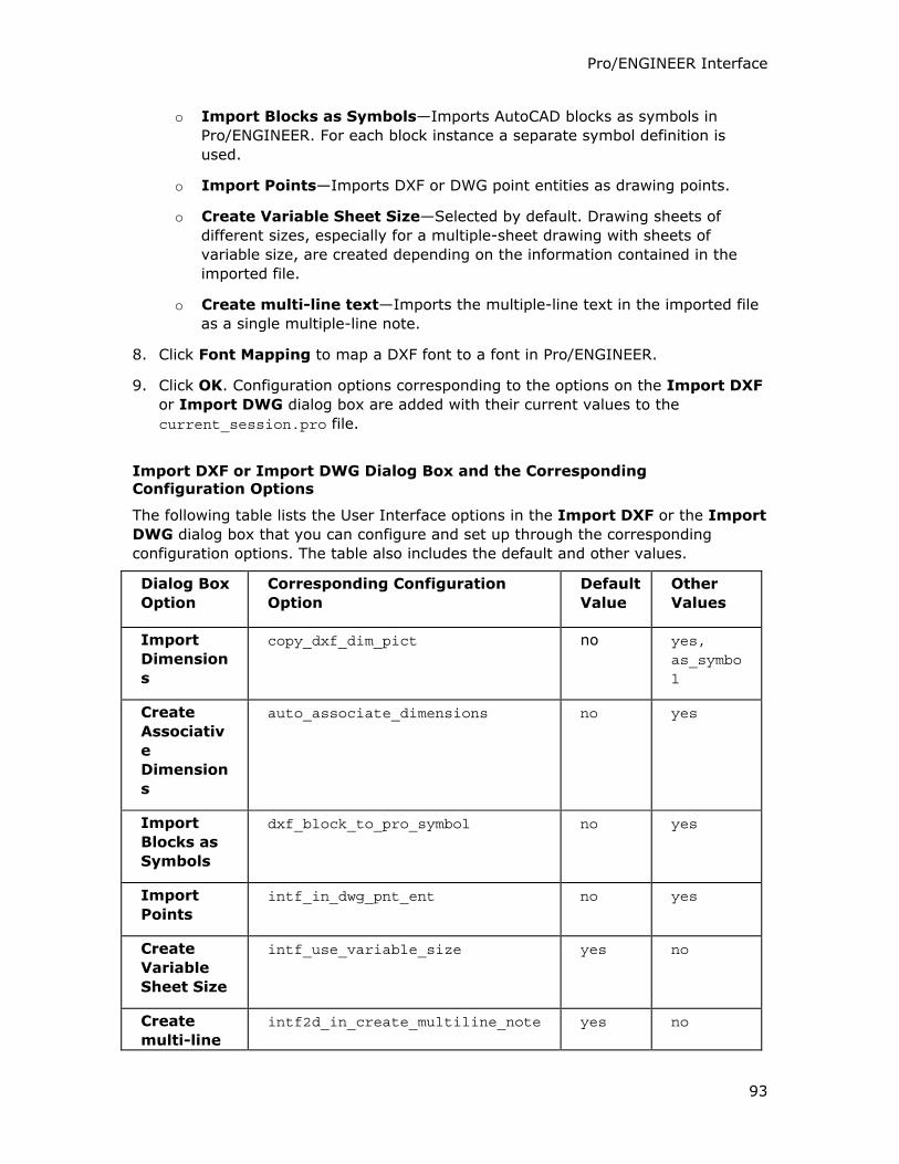
Pro/ENGINEER Interface
93
o Import Blocks as Symbols—Imports AutoCAD blocks as symbols in
Pro/ENGINEER. For each block instance a separate symbol definition is
used.
o Import Points—Imports DXF or DWG point entities as drawing points.
o Create Variable Sheet Size—Selected by default. Drawing sheets of
different sizes, especially for a multiple-sheet drawing with sheets of
variable size, are created depending on the information contained in the
imported file.
o Create multi-line text—Imports the multiple-line text in the imported file
as a single multiple-line note.
8. Click Font Mapping to map a DXF font to a font in Pro/ENGINEER.
9. Click OK. Configuration options corresponding to the options on the Import DXF
or Import DWG dialog box are added with their current values to the
current_session.pro file.
Import DXF or Import DWG Dialog Box and the Corresponding Configuration Options
The following table lists the User Interface options in the Import DXF or the Import
DWG dialog box that you can configure and set up through the corresponding
configuration options. The table also includes the default and other values.
Dialog Box
Option
Corresponding Configuration
Option
Default
Value
Other
Values
Import
Dimension
s
copy_dxf_dim_pict no yes, as_symbol
Create
Associativ
e
Dimension
s
auto_associate_dimensions no yes
Import
Blocks as
Symbols
dxf_block_to_pro_symbol no yes
Import
Points
intf_in_dwg_pnt_ent no yes
Create
Variable
Sheet Size
intf_use_variable_size yes no
Create
multi-line
intf2d_in_create_multiline_note yes no
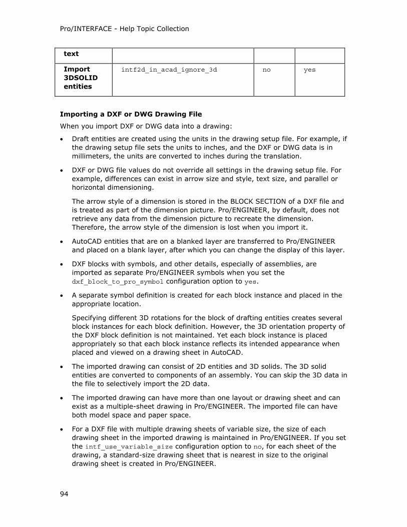
Pro/INTERFACE - Help Topic Collection
94
text
Import
3DSOLID
entities
intf2d_in_acad_ignore_3d no yes
Importing a DXF or DWG Drawing File
When you import DXF or DWG data into a drawing:
• Draft entities are created using the units in the drawing setup file. For example, if
the drawing setup file sets the units to inches, and the DXF or DWG data is in
millimeters, the units are converted to inches during the translation.
• DXF or DWG file values do not override all settings in the drawing setup file. For
example, differences can exist in arrow size and style, text size, and parallel or
horizontal dimensioning.
The arrow style of a dimension is stored in the BLOCK SECTION of a DXF file and
is treated as part of the dimension picture. Pro/ENGINEER, by default, does not
retrieve any data from the dimension picture to recreate the dimension.
Therefore, the arrow style of the dimension is lost when you import it.
• AutoCAD entities that are on a blanked layer are transferred to Pro/ENGINEER
and placed on a blank layer, after which you can change the display of this layer.
• DXF blocks with symbols, and other details, especially of assemblies, are
imported as separate Pro/ENGINEER symbols when you set the
dxf_block_to_pro_symbol configuration option to yes.
• A separate symbol definition is created for each block instance and placed in the
appropriate location.
Specifying different 3D rotations for the block of drafting entities creates several
block instances for each block definition. However, the 3D orientation property of
the DXF block definition is not maintained. Yet each block instance is placed
appropriately so that each block instance reflects its intended appearance when
placed and viewed on a drawing sheet in AutoCAD.
• The imported drawing can consist of 2D entities and 3D solids. The 3D solid
entities are converted to components of an assembly. You can skip the 3D data in
the file to selectively import the 2D data.
• The imported drawing can have more than one layout or drawing sheet and can
exist as a multiple-sheet drawing in Pro/ENGINEER. The imported file can have
both model space and paper space.
• For a DXF file with multiple drawing sheets of variable size, the size of each
drawing sheet in the imported drawing is maintained in Pro/ENGINEER. If you set
the intf_use_variable_size configuration option to no, for each sheet of the
drawing, a standard-size drawing sheet that is nearest in size to the original
drawing sheet is created in Pro/ENGINEER.
Pro/ENGINEER Interface
95
• You can import multiple-line text from a DXF file, with each line of the text in a
different font, as multiple single-line notes or as a single multiple-line note. The
fonts and styles of the multiple-line text are preserved in the single-line notes.
Importing Layers
DXF and DWG file formats support the export and import of layers. Pro/ENGINEER
places the entities imported from DXF or DWG on a layer in the Drawing Mode. The
layer ID of an imported entity in Pro/ENGINEER is the same as its layer ID in the DXF
or DWG file.
Exporting Drawings to DXF and DWG
About Exporting Drawings to DXF or DWG Files
You can export drawing data from Pro/ENGINEER to products such as AutoCAD 2002
using file versions 2000 and earlier of the formats:
• DXF
• DWG
Version 2000 of the DXF and the DWG file formats is the default. Export to the DWG
and DXF file formats is also supported on Linux.
To export a drawing, drawing format, or layout to a DXF or DWG file, you must
create a DXF or DWG file for every sheet of the drawing.
The Export Environment for DXF and the Export Environment for DWG dialog
boxes display options specific to the respective file types and the type of entities
these file types support for export. These options depend on the additional
configuration options that you set and are saved automatically when you click OK or
Export in the Export Environment for DXF or the Export Environment for
DWG dialog box to complete the export to the IGES format.
You can view and verify the current settings at runtime while saving or exporting the
DXF or DWG drawing file. You can modify the configuration options and their values
while saving a copy of the drawing.
The log file created during the export has details about the export such as the file
type version, the configuration options settings, the assembly structure
representation as blocks or layers, export of text as text or geometric entities, and
so on. You can view and verify the information, edit, and save the log file in an
Information Window after the export.
A Pro/ENGINEER:
• Spline or B-spline is exported to the DXF format as a spline.
• Construction line is exported to the DXF format as an XLINE.
• Draft hatch is exported to the DXF format as hatch. Pro/ENGINEER draft hatches
create AutoCAD UDF hatches.
Pro/INTERFACE - Help Topic Collection
96
• Multiple-line note is exported to the DXF and DWG file formats as a single MTEXT
entity or as multiple TEXT entities.
DWG and DXF Blocks
Using the intf_out_layer configuration option, you can export user-defined
symbols and drawing groups through DXF and DWG as blocks, making it is easier to
modify the exported drawings. Two-dimensional representations of individual
components with their drafting entities for each view within an assembly are also
translated as blocks.
To Export to a Drawing, Drawing Format, or Layout File
1. Click File > Save a Copy in a drawing. The Save a Copy dialog box opens.
2. Select DXF (*.dxf) or DWG (*.dwg) in the Type box. The existing
Pro/ENGINEER model name without the extension appears in the New Name
box.
3. Accept the default name or type a new name for the model in the New Name
box.
4. Click OK. The Export Environment for DXF or the Export Environment for
DWG dialog box opens.
5. Select a version for the file type. You can select DXF or DWG versions 12, 13, or
14. DXF or DWG file version 2000 is the default.
6. Select the option specific to the entity-type that you want to export. You can
export the following entities:
o Splines as is or as polylines
o Hatches as is or as separate entities
o Points as is or as shapes
o Notes as text or as strokes or separate geometric entities
o Multiline notes as MText
o Text alignment as is or as fit
o Assemblies as layers or blocks
o Comment lines
o Dimensions lines with breaks on witness lines to separate entities and
dimensions as geometric entities
7. Click Open Log Window. The Information Window displays the Export Log File
with the details of the export.
o Click Edit to edit the Export Log File.
o Click File > Save to save the file.
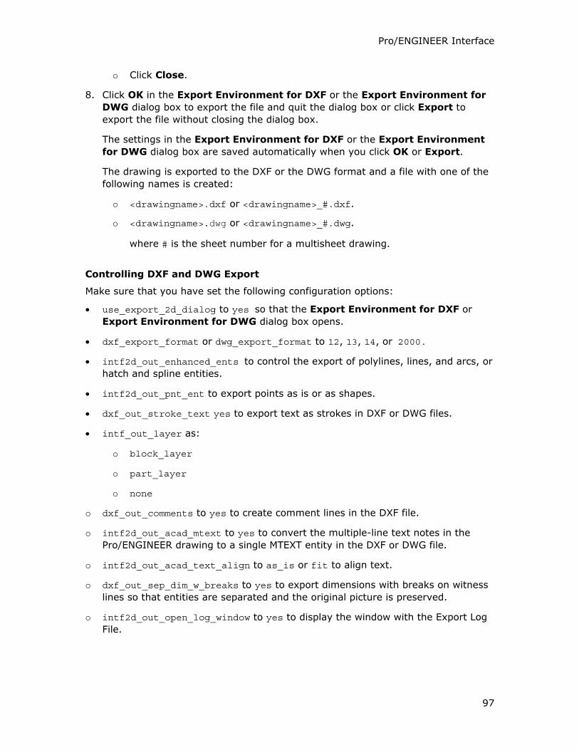
Pro/ENGINEER Interface
97
o Click Close.
8. Click OK in the Export Environment for DXF or the Export Environment for
DWG dialog box to export the file and quit the dialog box or click Export to
export the file without closing the dialog box.
The settings in the Export Environment for DXF or the Export Environment
for DWG dialog box are saved automatically when you click OK or Export.
The drawing is exported to the DXF or the DWG format and a file with one of the
following names is created:
o <drawingname>.dxf or <drawingname>_#.dxf.
o <drawingname>.dwg or <drawingname>_#.dwg.
where # is the sheet number for a multisheet drawing.
Controlling DXF and DWG Export
Make sure that you have set the following configuration options:
• use_export_2d_dialog to yes so that the Export Environment for DXF or
Export Environment for DWG dialog box opens.
• dxf_export_format or dwg_export_format to 12, 13, 14, or 2000.
• intf2d_out_enhanced_ents to control the export of polylines, lines, and arcs, or
hatch and spline entities.
• intf2d_out_pnt_ent to export points as is or as shapes.
• dxf_out_stroke_text yes to export text as strokes in DXF or DWG files.
• intf_out_layer as:
o block_layer
o part_layer
o none
o dxf_out_comments to yes to create comment lines in the DXF file.
o intf2d_out_acad_mtext to yes to convert the multiple-line text notes in the
Pro/ENGINEER drawing to a single MTEXT entity in the DXF or DWG file.
o intf2d_out_acad_text_align to as_is or fit to align text.
o dxf_out_sep_dim_w_breaks to yes to export dimensions with breaks on witness
lines so that entities are separated and the original picture is preserved.
o intf2d_out_open_log_window to yes to display the window with the Export Log
File.
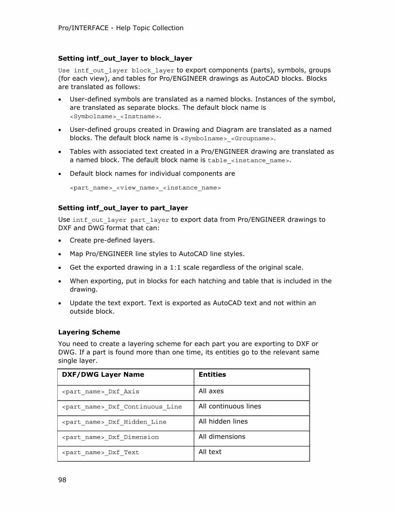
Pro/INTERFACE - Help Topic Collection
98
Setting intf_out_layer to block_layer
Use intf_out_layer block_layer to export components (parts), symbols, groups
(for each view), and tables for Pro/ENGINEER drawings as AutoCAD blocks. Blocks
are translated as follows:
• User-defined symbols are translated as a named blocks. Instances of the symbol,
are translated as separate blocks. The default block name is
<Symbolname>_<Instname>.
• User-defined groups created in Drawing and Diagram are translated as a named
blocks. The default block name is <Symbolname>_<Groupname>.
• Tables with associated text created in a Pro/ENGINEER drawing are translated as
a named block. The default block name is table_<instance_name>.
• Default block names for individual components are
<part_name>_<view_name>_<instance_name>
Setting intf_out_layer to part_layer
Use intf_out_layer part_layer to export data from Pro/ENGINEER drawings to
DXF and DWG format that can:
• Create pre-defined layers.
• Map Pro/ENGINEER line styles to AutoCAD line styles.
• Get the exported drawing in a 1:1 scale regardless of the original scale.
• When exporting, put in blocks for each hatching and table that is included in the
drawing.
• Update the text export. Text is exported as AutoCAD text and not within an
outside block.
Layering Scheme
You need to create a layering scheme for each part you are exporting to DXF or
DWG. If a part is found more than one time, its entities go to the relevant same
single layer.
DXF/DWG Layer Name Entities
<part_name>_Dxf_Axis All axes
<part_name>_Dxf_Continuous_Line All continuous lines
<part_name>_Dxf_Hidden_Line All hidden lines
<part_name>_Dxf_Dimension All dimensions
<part_name>_Dxf_Text All text
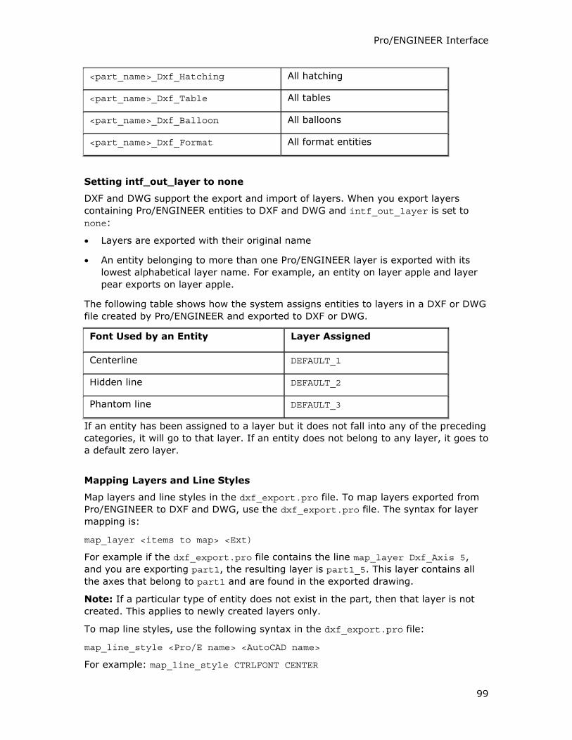
Pro/ENGINEER Interface
99
<part_name>_Dxf_Hatching All hatching
<part_name>_Dxf_Table All tables
<part_name>_Dxf_Balloon All balloons
<part_name>_Dxf_Format All format entities
Setting intf_out_layer to none
DXF and DWG support the export and import of layers. When you export layers
containing Pro/ENGINEER entities to DXF and DWG and intf_out_layer is set to
none:
• Layers are exported with their original name
• An entity belonging to more than one Pro/ENGINEER layer is exported with its
lowest alphabetical layer name. For example, an entity on layer apple and layer
pear exports on layer apple.
The following table shows how the system assigns entities to layers in a DXF or DWG
file created by Pro/ENGINEER and exported to DXF or DWG.
Font Used by an Entity Layer Assigned
Centerline DEFAULT_1
Hidden line DEFAULT_2
Phantom line DEFAULT_3
If an entity has been assigned to a layer but it does not fall into any of the preceding
categories, it will go to that layer. If an entity does not belong to any layer, it goes to
a default zero layer.
Mapping Layers and Line Styles
Map layers and line styles in the dxf_export.pro file. To map layers exported from
Pro/ENGINEER to DXF and DWG, use the dxf_export.pro file. The syntax for layer
mapping is:
map_layer <items to map> <Ext)
For example if the dxf_export.pro file contains the line map_layer Dxf_Axis 5,
and you are exporting part1, the resulting layer is part1_5. This layer contains all
the axes that belong to part1 and are found in the exported drawing.
Note: If a particular type of entity does not exist in the part, then that layer is not
created. This applies to newly created layers only.
To map line styles, use the following syntax in the dxf_export.pro file:
map_line_style <Pro/E name> <AutoCAD name>
For example: map_line_style CTRLFONT CENTER
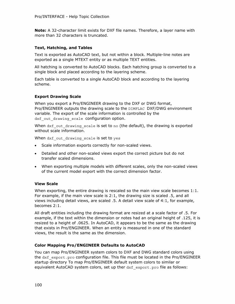
Pro/INTERFACE - Help Topic Collection
100
Note: A 32-character limit exists for DXF file names. Therefore, a layer name with
more than 32 characters is truncated.
Text, Hatching, and Tables
Text is exported as AutoCAD text, but not within a block. Multiple-line notes are
exported as a single MTEXT entity or as multiple TEXT entities.
All hatching is converted to AutoCAD blocks. Each hatching group is converted to a
single block and placed according to the layering scheme.
Each table is converted to a single AutoCAD block and according to the layering
scheme.
Export Drawing Scale
When you export a Pro/ENGINEER drawing to the DXF or DWG format,
Pro/ENGINEER outputs the drawing scale to the DIMFLAC DXF/DWG environment
variable. The export of the scale information is controlled by the
dxf_out_drawing_scale configuration option.
When dxf_out_drawing_scale is set to no (the default), the drawing is exported
without scale information.
When dxf_out_drawing_scale is set to yes
• Scale information exports correctly for non-scaled views.
• Detailed and other non-scaled views export the correct picture but do not
transfer scaled dimensions.
• When exporting multiple models with different scales, only the non-scaled views
of the current model export with the correct dimension factor.
View Scale
When exporting, the entire drawing is rescaled so the main view scale becomes 1:1.
For example, if the main view scale is 2:1, the drawing size is scaled .5, and all
views including detail views, are scaled .5. A detail view scale of 4:1, for example,
becomes 2:1.
All draft entities including the drawing format are resized at a scale factor of .5. For
example, if the text within the dimension or notes had an original height of .125, it is
resized to a height of .0625. In AutoCAD, it appears to be the same as the drawing
that exists in Pro/ENGINEER. When an entity is measured in one of the standard
views, the result is the same as the dimension.
Color Mapping Pro/ENGINEER Defaults to AutoCAD
You can map Pro/ENGINEER system colors to DXF and DWG standard colors using
the dxf_export.pro configuration file. This file must be located in the Pro/ENGINEER
startup directory To map Pro/ENGINEER default system colors to similar or
equivalent AutoCAD system colors, set up ther dxf_export.pro file as follows:
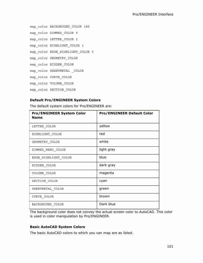
Pro/ENGINEER Interface
101
map_color BACKGROUND_COLOR 186
map_color DIMMED_COLOR 9
map_color LETTER_COLOR 2
map_color HIGHLIGHT_COLOR 1
map_color EDGE_HIGHLIGHT_COLOR 5
map_color GEOMETRY_COLOR
map_color HIDDEN_COLOR
map_color SHEETMETAL _COLOR
map_color CURVE_COLOR
map_color VOLUME_COLOR
map_color SECTION_COLOR
Default Pro/ENGINEER System Colors
The default system colors for Pro/ENGINEER are:
Pro/ENGINEER System Color
Name
Pro/ENGINEER Default Color
LETTER_COLOR yellow
HIGHLIGHT_COLOR red
GEOMETRY_COLOR white
DIMMED_MENU_COLOR light gray
EDGE_HIGHLIGHT_COLOR blue
HIDDEN_COLOR dark gray
VOLUME_COLOR magenta
SECTION_COLOR cyan
SHEETMETAL_COLOR green
CURVE_COLOR brown
BACKGROUND_COLOR Dark blue
The background color does not convey the actual screen color to AutoCAD. This color
is used in color manipulation by Pro/ENGINEER.
Basic AutoCAD System Colors
The basic AutoCAD colors to which you can map are as listed.
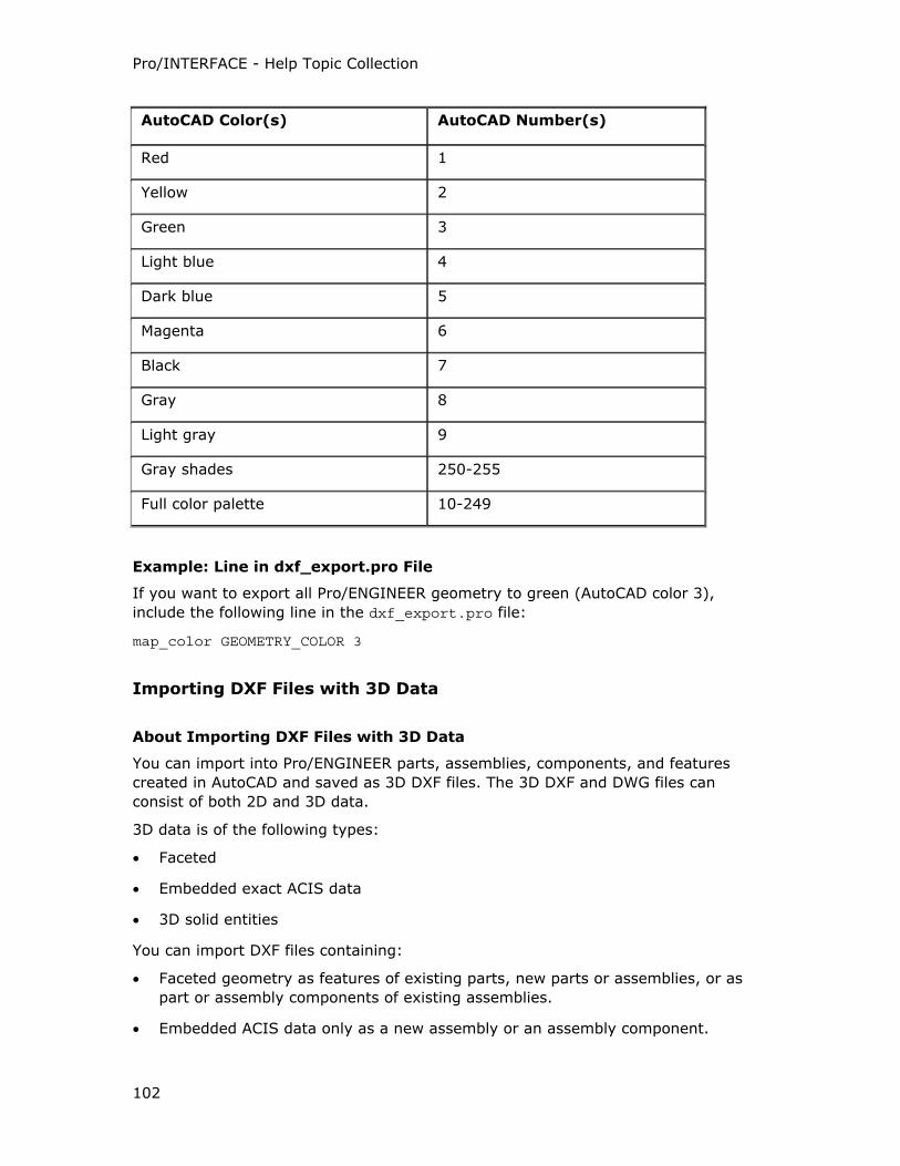
Pro/INTERFACE - Help Topic Collection
102
AutoCAD Color(s) AutoCAD Number(s)
Red 1
Yellow 2
Green 3
Light blue 4
Dark blue 5
Magenta 6
Black 7
Gray 8
Light gray 9
Gray shades 250-255
Full color palette 10-249
Example: Line in dxf_export.pro File
If you want to export all Pro/ENGINEER geometry to green (AutoCAD color 3),
include the following line in the dxf_export.pro file:
map_color GEOMETRY_COLOR 3
Importing DXF Files with 3D Data
About Importing DXF Files with 3D Data
You can import into Pro/ENGINEER parts, assemblies, components, and features
created in AutoCAD and saved as 3D DXF files. The 3D DXF and DWG files can
consist of both 2D and 3D data.
3D data is of the following types:
• Faceted
• Embedded exact ACIS data
• 3D solid entities
You can import DXF files containing:
• Faceted geometry as features of existing parts, new parts or assemblies, or as
part or assembly components of existing assemblies.
• Embedded ACIS data only as a new assembly or an assembly component.
Pro/ENGINEER Interface
103
• A combination of 2D entities and 3D solids as drawings. The 3D solids are
assembled and viewed as components of an assembly after import.
Importing Faceted And Embedded ACIS Data
The default model type in the Import New Model dialog box is Drawing when the
AutoCAD 3D DXF files contain faceted and embedded ACIS data. To import the
faceted data, you must explicitly set the model type to Part or Assembly in the
Import New Model dialog box. Embedded ACIS geometry can only be imported as
a new assembly or an assembly component. Use the imported 3D geometry for
constructing features and creating design models.
Importing 2D entities with 3D Solid Entities
The default model type is set to Assembly in the Import New Model dialog box
when the AutoCAD 3D DXF or DWG file contains at least a single 3D solid entity. You
must explicitly set the model type to Drawing in the Import New Model dialog box
to import the 3D solid entities along with the 2D entities in the files. Entities defined
as ACIS geometry (BODY, REGION) are ignored.
Importing DXF or DWG Files with 3D Solids and 2D Entities as Drawings
When you import a 3D DXF or DWG file that contains 3D solids and 2D entities as a
drawing,
• The 3D solids in the DXF or DWG file create the 3D model in session. The 3D
solids are assembled as components of an assembly.
• The 2D draft entities in the DXF or DWG file create the 2D drawing in session.
• The 3D solids and the 2D entities are placed in model and paper space,
respectively.
• 3D views are created when the 3D solid entities belong to a viewport.
A viewport entity in DXF defines the projection of a model-space object in paper
space.
• A viewport is imported as a 2D view when no 3D solids are attached to the
viewport.
• The 2D entities that belong to the same viewport as the 3D entities are attached
to the 3D views.
• If the DXF or DWG file does not contain 2D data, 3D views are created without
the 2D entities attached to them. If the file consists of only 2D data, only 2D
views are created in Pro/ENGINEER.
• The 3D model is associated with the 2D drawing and this association is
maintained when you build on the 3D model or modify the drawing.
You can skip the solid entities and selectively import the 2D contents using the
intf2d_in_acad_ignore_3d configuration option.
Pro/INTERFACE - Help Topic Collection
104
Note: The intf2d_in_acad_ignore_3d configuration option is available as the
Import 3DSOLID entities option on the Import DXF and the Import DWG dialog
boxes when the 3D DXF or the DWG file contains at least a single solid entity. This
option allows you to imports 3D solid entities as views of an assembly.
Importing AutoCAD 3D DXF Files as Parts
When you import an AutoCAD 3D DXF file as a part with Part selected in the Import
New Model dialog box:
• A single faceted solid is imported as a new part with a faceted solid.
• Multiple faceted solids are also imported as a new part with multiple faceted
solids on separate layers. The imported faceted solids merge into a single faceted
entity in the new part.
If the faceted solids exist as one solid per layer, a flat assembly with one faceted
component per faceted solid is created.
• 3D faces, polygonal mesh, and standard polylines are imported as faceted data,
that is, surfaces or solids. Polylines are imported as wireframe entities. The
imported feature consists of faceted and wireframe entities.
• If the DXF file contains only standard polylines, an import feature with wireframe
entities is created.
• If the DXF file contains embedded exact ACIS data, the embedded exact ACIS
data is skipped.
• If the DXF file contains faceted data, the faceted data is imported.
When you import a feature created in AutoCAD and saved as a DXF file:
• The feature is appended to an existing part as a faceted import feature.
• The embedded exact ACIS data is skipped.
Importing AutoCAD 3D DXF Files as Assemblies or Assembly Components
When you import the AutoCAD 3D DXF file as an assembly with Assembly selected
in the Import New Model dialog box, embedded ACIS data and the faceted data
are imported as separate components with faceted data or exact data.
If the DXF file does not contain embedded ACIS geometry, the assembly created in
Pro/ENGINEER consists of multiple faceted part components with a flat structure. If a
single layer of the DXF file contains multiple faceted solids, a subassembly
representing the layer is created.
If the DXF file contains multiple packets of embedded ACIS data along with faceted
data, a component for each packet of embedded ACIS data and separate
components for the faceted data are created.
When you import a component
• The component is appended to an existing assembly as a faceted component of
the assembly.
Pro/ENGINEER Interface
105
• Embedded ACIS data is appended to an existing assembly as a subassembly
component with separate components for the faceted data and the exact ACIS
data.
• A part component is appended to an existing assembly as a faceted part
component. The ACIS data is skipped.
• A subassembly component is appended to an existing assembly as a subassembly
component with faceted components. The embedded ACIS data creates separate
subassembly components.
Filtering 3D Geometric Data
A 3D DXF file containing faceted solids with a single solid on each layer is imported
as a flat assembly with a single faceted component for each solid.
A 3D DXF file containing faceted solids with multiple solids on each layer is imported
as an assembly with subassemblies representing the layers containing a part
component for each solid on that layer.
You can use the Layer Import Options dialog box to filter faceted data or the
faceted solids.
If faceted solids and embedded ACIS data of the imported assembly exist on
separate layers, you can set the import status of the layers with faceted data to skip
to filter faceted data and import only embedded ACIS data.
To Import an AutoCAD 3D DXF File
1. Click File > Open without a part or an assembly open. The File Open dialog box
opens.
2. Select DXF (*.dxf) in the Type box. The DXF files in the working directory
appear.
3. Select the DXF file you want to import or browse to find the file.
4. Click Open. The Import New Model dialog box opens. The default import type
is Drawing.
Note: Assembly is the default when the DXF file contains at least a single 3D
solid entity.
5. Select Part or Assembly to import the faceted or embedded ACIS geometry.
If the DXF file contains embedded ACIS geometry,you can only import the file as
a new assembly or an assembly component.
Note: Do not import the DXF file with the embedded ACIS geometry as a feature
or a new part.
6. Accept the default name for the part or the assembly or specify a new name.
7. Click OK.
Pro/INTERFACE - Help Topic Collection
106
o If you select Part as the import type, the faceted data merge to form a
single faceted representation in a single import feature.
o If you select Assembly as the import type, the faceted data form part
components of subassemblies represented by layers.
To Append an AutoCAD 3D DXF File to an Existing Part or Assembly
1. Click Insert > Shared Data > From File with a part or assembly open.
Click Insert > Component > Assemble to assemble a DXF file with 3D data
into an existing assembly.
The File Open dialog box opens.
2. Select DXF (*.dxf) in the Type box. The DXF files in the working directory
appear.
3. Select the DXF file you want to append to an existing part or assembly. Browse
to find the file.
4. Click Open. The Import New Model dialog box opens. The default import type
is Drawing.
5. Select Part or Assembly.
6. Accept the default name for the part or the assembly or type a new name.
7. Click OK. The Choose Solid Options and Placement dialog box opens.
The Component Placement dialog box opens if you are assembling the file into
an existing assembly.
8. Accept the default coordinate system or select a coordinate system to position
the appended geometry.
Granite-based Files
About Directly Opening Granite-based Files in Pro/ENGINEER
The method of directly opening Granite-based models, such as Pro/DESKTOP .des
parts and assemblies, as new models in Pro/ENGINEER is the default. For each
feature in the Granite-based model, a corresponding read-only feature is created in
the directly opened model in Pro/ENGINEER. You cannot redefine the features
created in the model or subsequently regenerate the directly-opened model. You can
only reference the imported geometry to create features and components in the
model.
For a directly opened Granite-based file, the feature-structure of the Granite file is
preserved in the resultant Pro/ENGINEER model though these features are read-only
in Pro/ENGINEER. The imported feature-types are represented by their
corresponding icons in the Model Tree. The original item and feature IDs and
configurations that correspond to the family table instances in Pro/ENGINEER are
Pro/ENGINEER Interface
107
preserved in the model. Nongeometric information such as layers, colors, and
parameters are imported. Sketches, datums, and patterns are not supported.
You can append or assemble the directly opened models as part or subassembly
components of existing assemblies in Pro/ENGINEER.
ICEM
About Importing ICEM Surf Models
ICEM is an Associative Topology Bus (ATB)-enabled data exchange format. ICEM
surfaces, when imported into Pro/ENGINEER or appended to models in
Pro/ENGINEER, create ATB-enabled import IN features.
The following import and append operations create ATB-enabled IN features:
• Opening an ICEM model as a new part with File > Open.
• Assembling an ICEM model as a part component of an existing Pro/ENGINEER
assembly with Insert > Component > Assemble.
• Appending an ICEM model as a new part or part component of an existing
Pro/ENGINEER assembly using Insert > Shared Data > From File.
• Appending an ICEM model as a new feature of an existing Pro/ENGINEER part
using Insert > Shared Data > From File.
ATB allows the associative update of imported data when changes are made to the
native ICEM data.
To Import an ICEM File
1. Click File > Open. The File Open dialog box opens.
2. Select ICEM (*.icm) as the file type in the Type box. Files of the selected type
that are located in your working directory are listed.
3. Browse for the file you want if it is not in your working directory.
4. Double-click the name of the part or assembly you want to import. The Import
New Model dialog box opens.
5. Type a name for the imported part or assembly in the Name box or accept the
default name. Part or Assembly is automatically selected, indicating the type of
entity you have selected to import.
6. Click OK. The file is imported as a new model.
To Append an ICEM File to a Pro/ENGINEER Model
1. Click Insert > Shared Data > From File in an open part or assembly. The File
Open dialog box opens.
Pro/INTERFACE - Help Topic Collection
108
2. Select ICEM (*.icm) as the file type in the Type box. Files of the selected type
that are located in your working directory are listed.
3. Browse for the file you want if it is not in your working directory.
4. Double-click the .icm file you want to add to your model. If one or more
coordinate systems exist, the Choose Solid Options and Placement dialog box
opens.
5. Accept the default coordinate system in the Choose Solid Options and
Placement dialog box or use the selection arrow to select another coordinate
system.
6. Click OK in the Choose Solid Options and Placement dialog box.
I-DEAS
About Importing I-DEAS Model and Package Files to Pro/ENGINEER
You can import I-DEAS file types .mf1 (model) and .pkg (package). The .mf1 and
.pkg files are packages of multiple parts and assemblies. You can install I-DEAS and
Pro/ENGINEER on separate workstations. Install Pro/ENGINEER on a server machine
or the local workstation. Install I-DEAS on a local workstation or run it from a server
machine. However, they must be installed on the same platform type. The .mf1
model files can only be imported from within projects of the I-DEAS Project Database
and not from any other location. The .pkg files can be imported from the working
directory or any other location.
You cannot directly open I-DEAS parts and assemblies as individual files in
Pro/ENGINEER. Instead, you can filter a selected .mf1 or .pkg file during import to
pick parts and assemblies to include in the import. The models are imported as
components of a top-level assembly, but this assembly is only a 'package' necessary
for the import process. You can discard this top-level assembly after import is
complete and you have saved the 'component' models.
You cannot append or assemble a .mf1 or a .pkg file to an existing Pro/ENGINEER
part or assembly. You can only access this import file through File > Open. You
cannot redefine the reference file of an imported feature and select a .mf1 or a .pkg
file as the replacement file.
Configuring the I-DEAS Interface
You must ensure the following for the import of I-DEAS files to Pro/ENGINEER:
• I-DEAS installation has the OpenIdeas license.
• On UNIX, the following OpenIdeas libraries exist in the library-path environment
variable where <ideas_loadpoint> specifies the location of the I-DEAS
installation:
o <ideas_loadpoint>/oirun/lib
Pro/ENGINEER Interface
109
o <ideas_loadpoint>/orbix/shlib
o <ideas_loadpoint>/orbix/shlib/default
• For Windows, include <ideas_loadpoint>\oirun\lib and
<ideas_loadpoint>\Iona\bin.
• Use the configuration option, intf3d_ideas_install_dir, to specify the full path
to the I-DEAS loadpoint.
• The following are the platform-specific library-path environment variables:
o SHLIB_PATH for HP
o LD_LIBRARY_PATH for Solaris
o LD_LIBRARYN32_PATH for SGI
o Path for Windows
• Ensure that I-DEAS is installed and the ORBIX daemon is running.
• Ensure that you start Pro/ENGINEER from a directory that does not include a
space in its name or path.
• Use the configuration option, intf3d_ideas_install_dir, to specify the full path
to the I-DEAS loadpoint.
During the import, if the I-DEAS startup command is other than ideas, the
Pro/ENGINEER message window states that the I-DEAS startup command is not in
the system path and cannot be located. Stop the import process and set the value of
the intf3d_ideas_run_command configuration option to ideas.
To Import an I-DEAS Model (*.mf1) File
1. Set the intf3d_ideas_install_dir configuration option to accurately point to
the I-DEAS installation.
Note: Ensure that the intf3d_ideas_run_command configuration option is set to
the I-DEAS startup command, that is the value, ideas.
2. Click File > Open. The File Open dialog box opens.
3. Select I-DEAS Model (*.mf1) in the Type box.
o The I-DEAS Project Database is visible in the Look In box.
o The I-DEAS project folders are displayed.
o I-DEAS part and assembly files have the same .prt and .asm file
extensions as Pro/ENGINEER part and assembly models. They are displayed
as Pro/ENGINEER files in the Open dialog box when the Pro/ENGINEER part
or assembly type filters are set if they conform to the Pro/ENGINEER file-
naming conventions. However, you cannot open them in Pro/ENGINEER.
Note: You can only import .mf1 files from one of the virtual project folders. You
cannot import a .mf1 file found outside the I-DEAS Project Database. To import
Pro/INTERFACE - Help Topic Collection
110
I-DEAS .mf1 files from within the projects of the I-DEAS Project Database, the
part and assembly models of .mf1 files must be submitted to the model file bin.
4. Double-click an I-DEAS project folder and select a .mf1 file.
5. Click Open. The Import New Model dialog box opens. It shows the name of the
.mf1 model file
6. Type a name for the imported file or accept the default name in the Name box.
7. Click OK. The Layer Import Options dialog box opens if you have set the
intf3d_ideas_import_filter configuration option to yes.
o The Layer Import Options dialog box lists the part and assembly models
contained in the .mf1 file.
o The import status of all the models is Show, by default.
8. To filter models that you do not require, set their import status to Skip.
9. Click OK on the Layer Import Options dialog box. Only models with their
import status set to Show are imported.
The selected part and assembly models are imported as components of a top-
level Pro/ENGINEER assembly. You can discard this top-level assembly because it
is only a 'package' that is required for the import of the individual part and
assembly models contained in the .mf1 file.
Note: Part models of the .mf1 file not put into the model file bin are excluded in
the imported assembly.
To Import an I-DEAS Package (*.pkg) File
1. Set the intf3d_ideas_install_dir configuration option to accurately point to
the I-DEAS installation.
Note: Ensure that the intf3d_ideas_run_command configuration option is set to
the I-DEAS startup command, that is the value, ideas.
2. Click File > Open. The File Open dialog box opens.
3. Select I-DEAS Package (*.pkg) in the Type box. By default, a list of .pkg files
in the working directory is displayed.
Note: I-DEAS part and assembly files have the same .prt and .asm file
extensions as Pro/ENGINEER part and assembly models. These I-DEAS .prt and
.asm files are colocated with .pkg files. They are displayed as Pro/ENGINEER files
in the Open dialog box when the Pro/ENGINEER part or assembly type filters are
set if they conform to the Pro/ENGINEER file-naming conventions. However, you
cannot open them in Pro/ENGINEER.
4. Select a .pkg file from the working directory or browse to select a .pkg file from
any other directory.
Pro/ENGINEER Interface
111
Note: If a part or assembly is missing in the .pkg file, an error message in the
Pro/ENGINEER window states that the import has failed and that the data may be
corrupt or incomplete.
5. Click Open. The Import New Model dialog box opens with the file path and
name.
6. Type a name for the imported file or accept the default name in the Name box.
7. Click OK. The Layer Import Options dialog box opens if you have set the
intf3d_ideas_import_filter configuration option to yes.
o The Layer Import Options dialog box lists the part and assembly models
contained in the .pkg file.
o The import status of all the models is Show, by default.
8. To filter models that you do not require, set their import status to Skip.
9. Click OK on the Layer Import Options dialog box. Only models with their
import status set to Show are imported.
The part and assembly models are imported as components of a top-level
Pro/ENGINEER assembly. You can discard this top-level assembly because it is
only a 'package' that is required for the import of the individual part and
assembly models contained in the .pkg file.
Troubleshooting When Importing from I-DEAS
If the import process terminates abnormally, and you see the IDEAS2PROE_*.mf1 temporary model files on disk, ask your I-DEAS administrator to delete the
IDEAS2PROE_*.mf1 files and the _IDEAS2PROE_* libraries under the _IDEAS2PROE_
project to free disk space.
If the import process is abruptly interrupted, check the error*.out file in the
Pro/ENGINEER working directory for details.
If the Pro/ENGINEER message window displays the error that an I-DEAS project or a
library in the I-DEAS project cannot be created, contact your I-DEAS administrator to
make sure that you have the package import permissions.
I-DEAS *.pkg files are platform-dependent, that is, a file generated on Windows
cannot be imported into Pro/ENGINEER on UNIX, and vice versa. If the
Pro/ENGINEER message window states that the *.pkg file selected for import to
Pro/ENGINEER is not compliant on your platform, convert the *.pkg file to the
platform-specific format using the I-DEAS converter available at
<ideas_loadpoint>/bin/hdsconvert.
If you find that the IdeasToPro process is running even after the import has failed or
Pro/ENGINEER has terminated abnormally, kill the IdeasToPro process manually,
start Pro/ENGINEER if required, and import the I-DEAS file again.
Pro/INTERFACE - Help Topic Collection
112
IGES
Importing IGES Files to Drawing Mode
About Importing IGES Data Into a Drawing
The Initial Graphics Exchange Specification (IGES) transfers graphical and textual
information between computer aided design systems. When reading IGES data into a
drawing, note the following:
• You can set up and modify configuration options to selectively filter and process
data that is specific to the type of entities that the IGES file format supports for
import. The Import IGES dialog box is context sensitive and displays these
configuration options as User Interface options with default values in addition to
other import options. You can view and verify the current settings at runtime and
revert to original settings, if necessary. These configuration option settings are
saved to the current_session.pro file when you complete the import of 2D data
from the IGES file. The Import IGES dialog box displays the saved values for
these options as the default values the next time you open Import IGES in the
same session of Pro/ENGINEER.
• When the imported drawing sheets vary in size, drawing sheets of different sizes
are created depending on the information contained in the imported file.
• If the drawing sheet size matches the standard Pro/ENGINEER drawing sheet
size, the drawing is placed on the standard size drawing sheet format in
Pro/ENGINEER.
• If you do not specify the drawing sheet size in the file, the drawing is placed on a
standard Pro/ENGINEER drawing sheet size that is closest to the outline of the
imported file.
• The lower-left corner of the drawing is the origin of draft entities in the drawing.
When the system reads an IGES file into the drawing, it places the file relative to
the drawing origin.
• Draft entities are created using the units specified in the drawing setup file. For
example, if the drawing setup file sets the units to inches, and the units for the
IGES data is in millimeters, the units of the IGES entities are converted to inches
during the translation. For example, 25.4 mm in the IGES file becomes 1 inch in
the drawing.
• Multiple-line text is imported as a single multiple-line note or as multiple single-
line notes with the original fonts.
• Typically, the IGES file values do not override the settings of the drawing setup
options. Arrow size and style, text size, and parallel/horizontal dimensioning are
examples of areas where differences can occur.
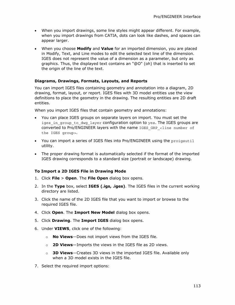
Pro/ENGINEER Interface
113
• When you import drawings, some line styles might appear different. For example,
when you import drawings from CATIA, dots can look like dashes, and spaces can
appear larger.
• When you choose Modify and Value for an imported dimension, you are placed
in Modify, Text, and Line modes to edit the selected text line of the dimension.
IGES does not represent the value of a dimension as a parameter, but only as
graphics. Thus, the displayed text contains an "@O" (oh) that is inserted to set
the origin of the line of the text.
Diagrams, Drawings, Formats, Layouts, and Reports
You can import IGES files containing geometry and annotation into a diagram, 2D
drawing, format, layout, or report. IGES files with 3D model entities use the view
definitions to place the geometry in the drawing. The resulting entities are 2D draft
entities.
When you import IGES files that contain geometry and annotations:
• You can place IGES groups on separate layers on import. You must set the
iges_in_group_to_dwg_layer configuration option to yes. The IGES groups are
converted to Pro/ENGINEER layers with the name IGES_GRP_<line number of the IGES group>.
• You can import a series of IGES files into Pro/ENGINEER using the proigsutil
utility.
• The proper drawing format is automatically selected if the format of the imported
IGES drawing corresponds to a standard size (portrait or landscape) drawing.
To Import a 2D IGES File in Drawing Mode
1. Click File > Open. The File Open dialog box opens.
2. In the Type box, select IGES (.igs, .iges). The IGES files in the current working
directory are listed.
3. Click the name of the 2D IGES file that you want to import or browse to the
required IGES file.
4. Click Open. The Import New Model dialog box opens.
5. Click Drawing. The Import IGES dialog box opens.
6. Under VIEWS, click one of the following:
o No Views—Does not import views from the IGES file.
o 2D Views—Imports the views in the IGES file as 2D views.
o 3D Views—Creates 3D views in the imported IGES file. Available only
when a 3D model exists in the IGES file.
7. Select the required import options:
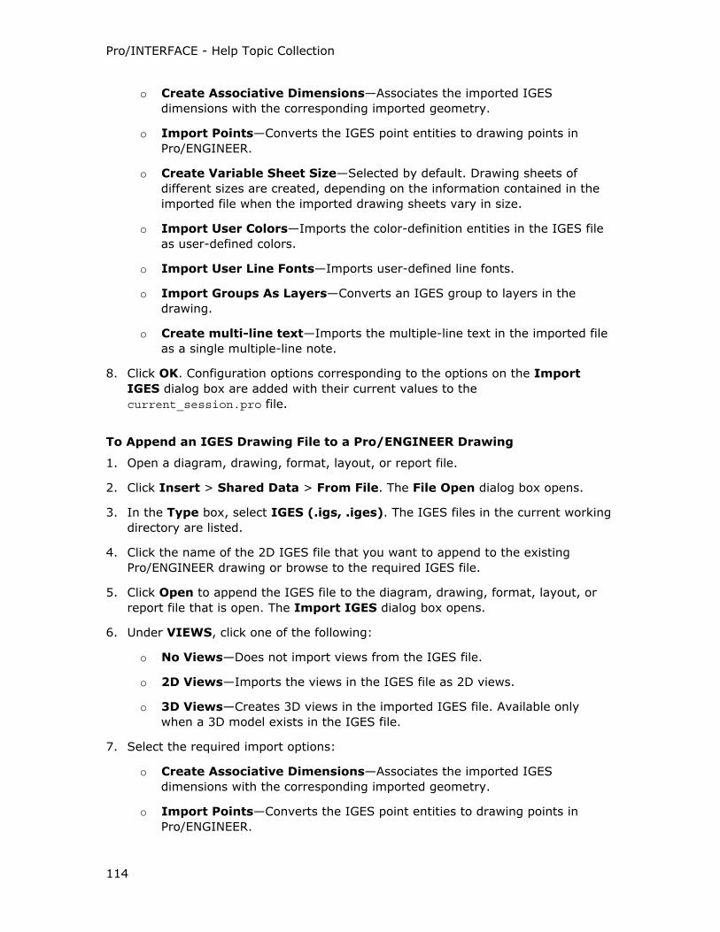
Pro/INTERFACE - Help Topic Collection
114
o Create Associative Dimensions—Associates the imported IGES
dimensions with the corresponding imported geometry.
o Import Points—Converts the IGES point entities to drawing points in
Pro/ENGINEER.
o Create Variable Sheet Size—Selected by default. Drawing sheets of
different sizes are created, depending on the information contained in the
imported file when the imported drawing sheets vary in size.
o Import User Colors—Imports the color-definition entities in the IGES file
as user-defined colors.
o Import User Line Fonts—Imports user-defined line fonts.
o Import Groups As Layers—Converts an IGES group to layers in the
drawing.
o Create multi-line text—Imports the multiple-line text in the imported file
as a single multiple-line note.
8. Click OK. Configuration options corresponding to the options on the Import
IGES dialog box are added with their current values to the
current_session.pro file.
To Append an IGES Drawing File to a Pro/ENGINEER Drawing
1. Open a diagram, drawing, format, layout, or report file.
2. Click Insert > Shared Data > From File. The File Open dialog box opens.
3. In the Type box, select IGES (.igs, .iges). The IGES files in the current working
directory are listed.
4. Click the name of the 2D IGES file that you want to append to the existing
Pro/ENGINEER drawing or browse to the required IGES file.
5. Click Open to append the IGES file to the diagram, drawing, format, layout, or
report file that is open. The Import IGES dialog box opens.
6. Under VIEWS, click one of the following:
o No Views—Does not import views from the IGES file.
o 2D Views—Imports the views in the IGES file as 2D views.
o 3D Views—Creates 3D views in the imported IGES file. Available only
when a 3D model exists in the IGES file.
7. Select the required import options:
o Create Associative Dimensions—Associates the imported IGES
dimensions with the corresponding imported geometry.
o Import Points—Converts the IGES point entities to drawing points in
Pro/ENGINEER.
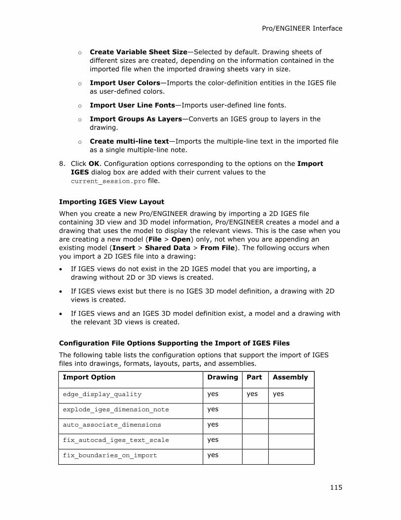
Pro/ENGINEER Interface
115
o Create Variable Sheet Size—Selected by default. Drawing sheets of
different sizes are created, depending on the information contained in the
imported file when the imported drawing sheets vary in size.
o Import User Colors—Imports the color-definition entities in the IGES file
as user-defined colors.
o Import User Line Fonts—Imports user-defined line fonts.
o Import Groups As Layers—Converts an IGES group to layers in the
drawing.
o Create multi-line text—Imports the multiple-line text in the imported file
as a single multiple-line note.
8. Click OK. Configuration options corresponding to the options on the Import
IGES dialog box are added with their current values to the
current_session.pro file.
Importing IGES View Layout
When you create a new Pro/ENGINEER drawing by importing a 2D IGES file
containing 3D view and 3D model information, Pro/ENGINEER creates a model and a
drawing that uses the model to display the relevant views. This is the case when you
are creating a new model (File > Open) only, not when you are appending an
existing model (Insert > Shared Data > From File). The following occurs when
you import a 2D IGES file into a drawing:
• If IGES views do not exist in the 2D IGES model that you are importing, a
drawing without 2D or 3D views is created.
• If IGES views exist but there is no IGES 3D model definition, a drawing with 2D
views is created.
• If IGES views and an IGES 3D model definition exist, a model and a drawing with
the relevant 3D views is created.
Configuration File Options Supporting the Import of IGES Files
The following table lists the configuration options that support the import of IGES
files into drawings, formats, layouts, parts, and assemblies.
Import Option Drawing Part Assembly
edge_display_quality yes yes yes
explode_iges_dimension_note yes
auto_associate_dimensions yes
fix_autocad_iges_text_scale yes
fix_boundaries_on_import yes
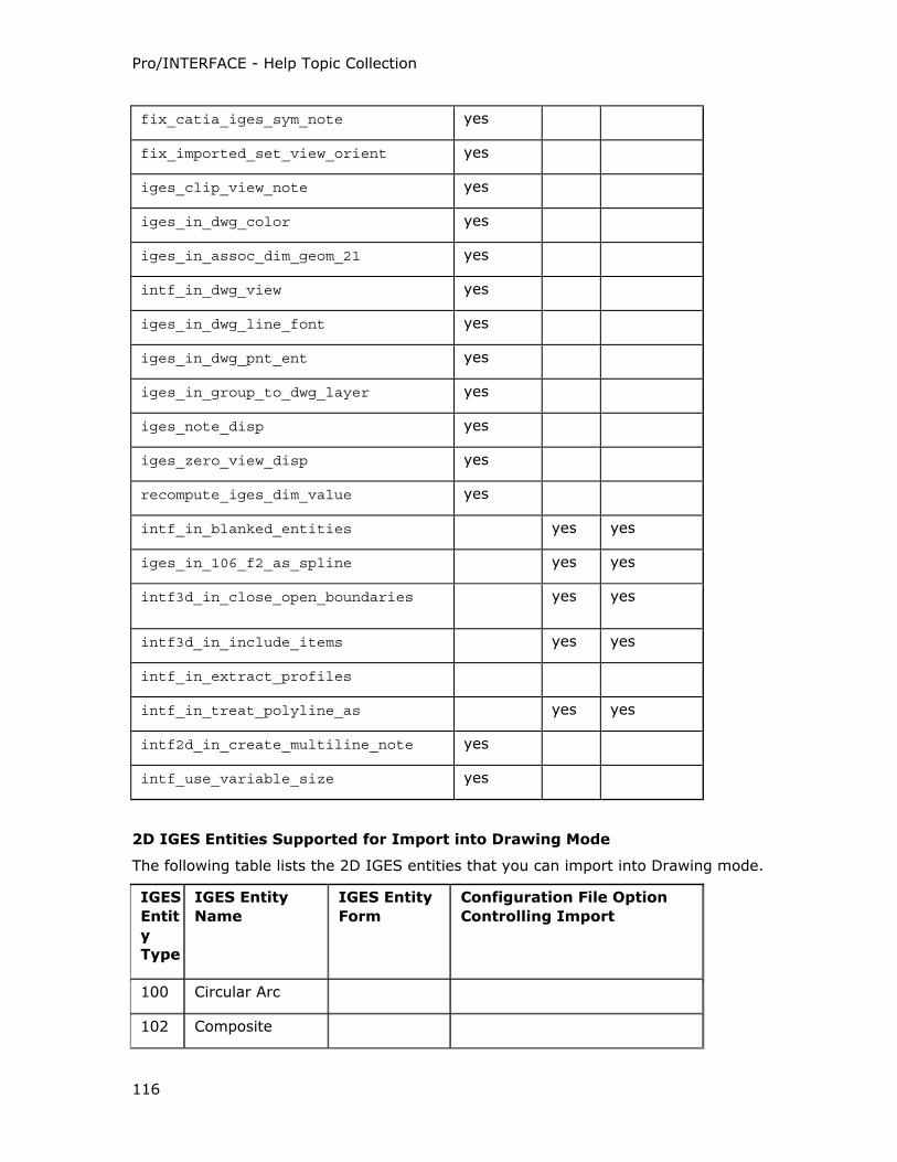
Pro/INTERFACE - Help Topic Collection
116
fix_catia_iges_sym_note yes
fix_imported_set_view_orient yes
iges_clip_view_note yes
iges_in_dwg_color yes
iges_in_assoc_dim_geom_21 yes
intf_in_dwg_view yes
iges_in_dwg_line_font yes
iges_in_dwg_pnt_ent yes
iges_in_group_to_dwg_layer yes
iges_note_disp yes
iges_zero_view_disp yes
recompute_iges_dim_value yes
intf_in_blanked_entities yes yes
iges_in_106_f2_as_spline yes yes
intf3d_in_close_open_boundaries yes yes
intf3d_in_include_items yes yes
intf_in_extract_profiles
intf_in_treat_polyline_as yes yes
intf2d_in_create_multiline_note yes
intf_use_variable_size yes
2D IGES Entities Supported for Import into Drawing Mode
The following table lists the 2D IGES entities that you can import into Drawing mode.
IGES
Entit
y
Type
IGES Entity
Name
IGES Entity
Form
Configuration File Option
Controlling Import
100 Circular Arc
102 Composite
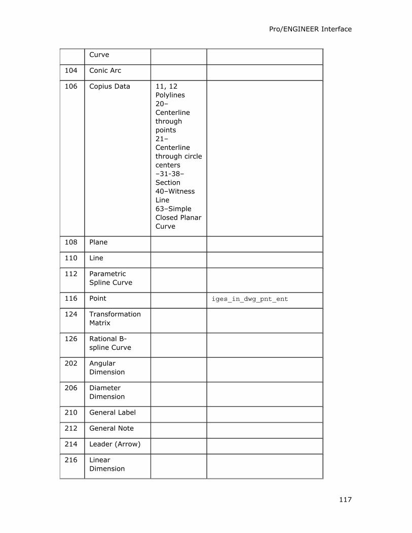
Pro/ENGINEER Interface
117
Curve
104 Conic Arc
106 Copius Data 11, 12
Polylines
20–
Centerline
through
points
21–
Centerline
through circle
centers
–31-38–
Section
40–Witness
Line
63–Simple
Closed Planar
Curve
108 Plane
110 Line
112 Parametric
Spline Curve
116 Point iges_in_dwg_pnt_ent
124 Transformation
Matrix
126 Rational B-
spline Curve
202 Angular
Dimension
206 Diameter
Dimension
210 General Label
212 General Note
214 Leader (Arrow)
216 Linear
Dimension
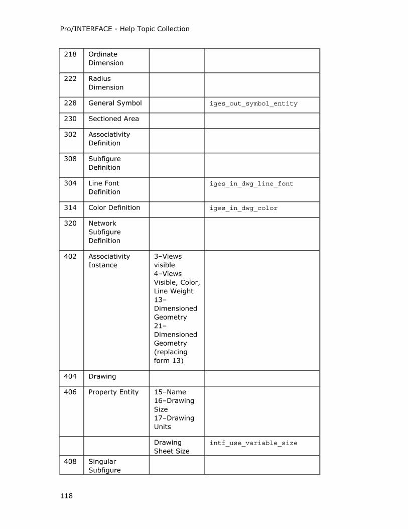
Pro/INTERFACE - Help Topic Collection
118
218 Ordinate
Dimension
222 Radius
Dimension
228 General Symbol iges_out_symbol_entity
230 Sectioned Area
302 Associativity
Definition
308 Subfigure
Definition
304 Line Font
Definition
iges_in_dwg_line_font
314 Color Definition iges_in_dwg_color
320 Network
Subfigure
Definition
402 Associativity
Instance
3–Views
visible
4–Views
Visible, Color,
Line Weight
13–
Dimensioned
Geometry
21–
Dimensioned
Geometry
(replacing
form 13)
404 Drawing
406 Property Entity 15–Name
16–Drawing
Size
17–Drawing
Units
Drawing
Sheet Size
intf_use_variable_size
408 Singular
Subfigure
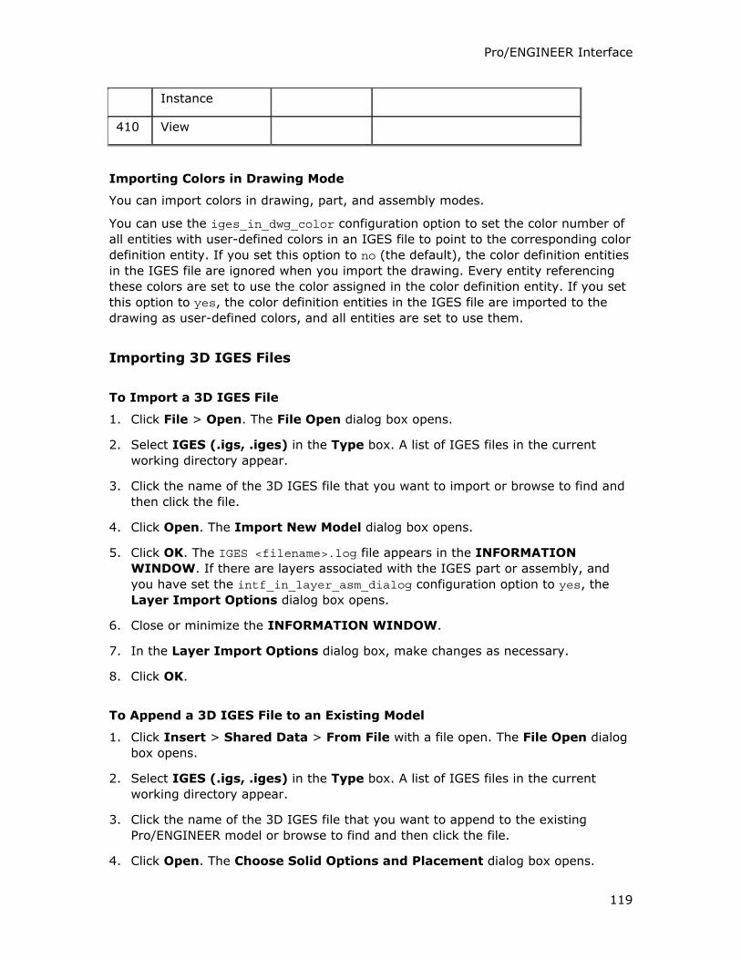
Pro/ENGINEER Interface
119
Instance
410 View
Importing Colors in Drawing Mode
You can import colors in drawing, part, and assembly modes.
You can use the iges_in_dwg_color configuration option to set the color number of
all entities with user-defined colors in an IGES file to point to the corresponding color
definition entity. If you set this option to no (the default), the color definition entities
in the IGES file are ignored when you import the drawing. Every entity referencing
these colors are set to use the color assigned in the color definition entity. If you set
this option to yes, the color definition entities in the IGES file are imported to the
drawing as user-defined colors, and all entities are set to use them.
Importing 3D IGES Files
To Import a 3D IGES File
1. Click File > Open. The File Open dialog box opens.
2. Select IGES (.igs, .iges) in the Type box. A list of IGES files in the current
working directory appear.
3. Click the name of the 3D IGES file that you want to import or browse to find and
then click the file.
4. Click Open. The Import New Model dialog box opens.
5. Click OK. The IGES <filename>.log file appears in the INFORMATION
WINDOW. If there are layers associated with the IGES part or assembly, and
you have set the intf_in_layer_asm_dialog configuration option to yes, the
Layer Import Options dialog box opens.
6. Close or minimize the INFORMATION WINDOW.
7. In the Layer Import Options dialog box, make changes as necessary.
8. Click OK.
To Append a 3D IGES File to an Existing Model
1. Click Insert > Shared Data > From File with a file open. The File Open dialog
box opens.
2. Select IGES (.igs, .iges) in the Type box. A list of IGES files in the current
working directory appear.
3. Click the name of the 3D IGES file that you want to append to the existing
Pro/ENGINEER model or browse to find and then click the file.
4. Click Open. The Choose Solid Options and Placement dialog box opens.
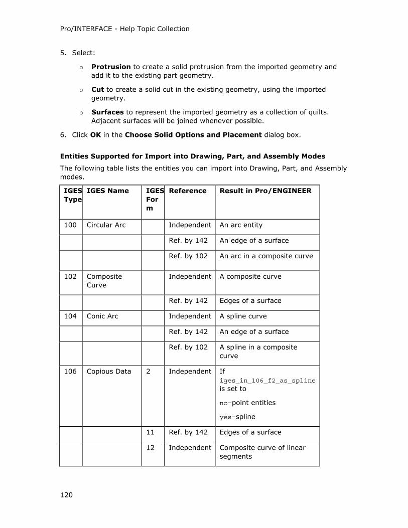
Pro/INTERFACE - Help Topic Collection
120
5. Select:
o Protrusion to create a solid protrusion from the imported geometry and
add it to the existing part geometry.
o Cut to create a solid cut in the existing geometry, using the imported
geometry.
o Surfaces to represent the imported geometry as a collection of quilts.
Adjacent surfaces will be joined whenever possible.
6. Click OK in the Choose Solid Options and Placement dialog box.
Entities Supported for Import into Drawing, Part, and Assembly Modes
The following table lists the entities you can import into Drawing, Part, and Assembly
modes.
IGES
Type
IGES Name IGES
For
m
Reference Result in Pro/ENGINEER
100 Circular Arc Independent An arc entity
Ref. by 142 An edge of a surface
Ref. by 102 An arc in a composite curve
102 Composite
Curve
Independent A composite curve
Ref. by 142 Edges of a surface
104 Conic Arc Independent A spline curve
Ref. by 142 An edge of a surface
Ref. by 102 A spline in a composite
curve
106 Copious Data 2 Independent If
iges_in_106_f2_as_spline
is set to
no–point entities
yes–spline
11 Ref. by 142 Edges of a surface
12 Independent Composite curve of linear
segments
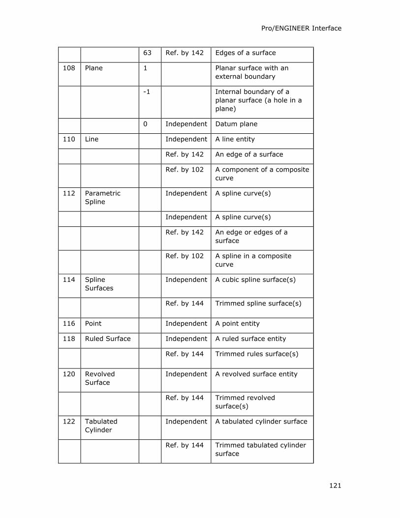
Pro/ENGINEER Interface
121
63 Ref. by 142 Edges of a surface
108 Plane 1 Planar surface with an
external boundary
-1 Internal boundary of a
planar surface (a hole in a
plane)
0 Independent Datum plane
110 Line Independent A line entity
Ref. by 142 An edge of a surface
Ref. by 102 A component of a composite
curve
112 Parametric
Spline
Independent A spline curve(s)
Independent A spline curve(s)
Ref. by 142 An edge or edges of a
surface
Ref. by 102 A spline in a composite
curve
114 Spline
Surfaces
Independent A cubic spline surface(s)
Ref. by 144 Trimmed spline surface(s)
116 Point Independent A point entity
118 Ruled Surface Independent A ruled surface entity
Ref. by 144 Trimmed rules surface(s)
120 Revolved
Surface
Independent A revolved surface entity
Ref. by 144 Trimmed revolved
surface(s)
122 Tabulated
Cylinder
Independent A tabulated cylinder surface
Ref. by 144 Trimmed tabulated cylinder
surface
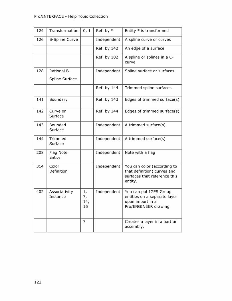
Pro/INTERFACE - Help Topic Collection
122
124 Transformation 0, 1 Ref. by * Entity * is transformed
126 B-Spline Curve Independent A spline curve or curves
Ref. by 142 An edge of a surface
Ref. by 102 A spline or splines in a C-
curve
128 Rational B-
Spline Surface
Independent Spline surface or surfaces
Ref. by 144 Trimmed spline surfaces
141 Boundary Ref. by 143 Edges of trimmed surface(s)
142 Curve on
Surface
Ref. by 144 Edges of trimmed surface(s)
143 Bounded
Surface
Independent A trimmed surface(s)
144 Trimmed
Surface
Independent A trimmed surface(s)
208 Flag Note
Entity
Independent Note with a flag
314 Color
Definition
Independent
You can color (according to
that definition) curves and
surfaces that reference this
entity.
402 Associativity
Instance
1,
7,
14,
15
Independent You can put IGES Group
entities on a separate layer
upon import in a
Pro/ENGINEER drawing.
7 Creates a layer in a part or
assembly.
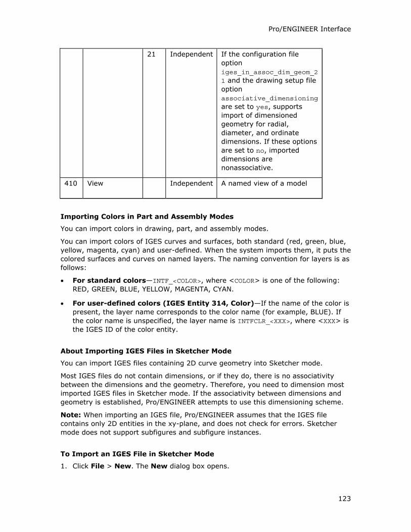
Pro/ENGINEER Interface
123
21 Independent If the configuration file
option
iges_in_assoc_dim_geom_21 and the drawing setup file
option
associative_dimensioning
are set to yes, supports
import of dimensioned
geometry for radial,
diameter, and ordinate
dimensions. If these options
are set to no, imported
dimensions are
nonassociative.
410 View Independent A named view of a model
Importing Colors in Part and Assembly Modes
You can import colors in drawing, part, and assembly modes.
You can import colors of IGES curves and surfaces, both standard (red, green, blue,
yellow, magenta, cyan) and user-defined. When the system imports them, it puts the
colored surfaces and curves on named layers. The naming convention for layers is as
follows:
• For standard colors—INTF_<COLOR>, where <COLOR> is one of the following:
RED, GREEN, BLUE, YELLOW, MAGENTA, CYAN.
• For user-defined colors (IGES Entity 314, Color)—If the name of the color is
present, the layer name corresponds to the color name (for example, BLUE). If
the color name is unspecified, the layer name is INTFCLR_<XXX>, where <XXX> is
the IGES ID of the color entity.
About Importing IGES Files in Sketcher Mode
You can import IGES files containing 2D curve geometry into Sketcher mode.
Most IGES files do not contain dimensions, or if they do, there is no associativity
between the dimensions and the geometry. Therefore, you need to dimension most
imported IGES files in Sketcher mode. If the associativity between dimensions and
geometry is established, Pro/ENGINEER attempts to use this dimensioning scheme.
Note: When importing an IGES file, Pro/ENGINEER assumes that the IGES file
contains only 2D entities in the xy-plane, and does not check for errors. Sketcher
mode does not support subfigures and subfigure instances.
To Import an IGES File in Sketcher Mode
1. Click File > New. The New dialog box opens.
Pro/INTERFACE - Help Topic Collection
124
2. Click Sketch.
3. Click OK to open a file in Sketcher mode.
4. Click Sketch > Data from File. The File Open dialog box opens.
5. Select the IGES file you want to import from the list of available files.
6. Click Open to create the IGES file.
7. After the system displays the 2D entities in your Sketcher mode window, you can
add or delete entities and dimensions.
Exporting from Drawing Mode to IGES
About Exporting to IGES
Before you export data to IGES files, determine which IGES entities the receiving
system can receive, then use the appropriate configuration file options to export that
data type.
The Export Environment for IGES dialog box opens if the use_export_2d_dialog
configuration option is set to the default value yes. The options on the Export
Environment for IGES dialog box depend on the additional configuration options
that you have set. These option settings are saved automatically when you export
the drawing to the IGES format.
You can view and verify the current settings during runtime while saving or exporting
the drawing file. You can modify the configuration options and their values while
saving a copy of the drawing.
The log file created during the export has details about the export such as the IGES
version, the configuration options and their values, and so on. You can view and
verify the information, edit, and save the log file after the export.
The log file is created in the same directory as the target *.iges file and is named:
• igesout.log.#—For a drawing file
• <name>_out.log.#—For a part or assembly file
You can create multiple IGES files in a single session using Pro/BATCH.
Note: IGES does not support all of the special characters that Pro/ENGINEER
supports. Therefore, when you export to the IGES file, some characters are not
visible. When you export special symbols that are not supported by IGES, the
receiving system draws these symbols in strokes. For example, clipped dimensions
with two arrowheads are exported with only one arrowhead.
You must create an IGES file for every sheet of the drawing.
IGES Version in Output Files
The header of an IGES file contains the code for IGES version 5.2. If the receiving
system does not accept 5.2, you can edit the header so that it contains the most
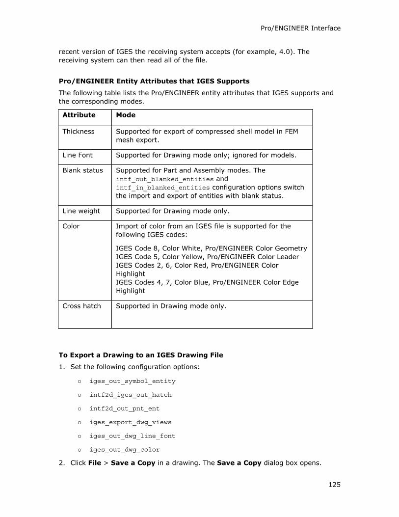
Pro/ENGINEER Interface
125
recent version of IGES the receiving system accepts (for example, 4.0). The
receiving system can then read all of the file.
Pro/ENGINEER Entity Attributes that IGES Supports
The following table lists the Pro/ENGINEER entity attributes that IGES supports and
the corresponding modes.
Attribute Mode
Thickness Supported for export of compressed shell model in FEM
mesh export.
Line Font Supported for Drawing mode only; ignored for models.
Blank status Supported for Part and Assembly modes. The
intf_out_blanked_entities and
intf_in_blanked_entities configuration options switch
the import and export of entities with blank status.
Line weight Supported for Drawing mode only.
Color Import of color from an IGES file is supported for the
following IGES codes:
IGES Code 8, Color White, Pro/ENGINEER Color Geometry
IGES Code 5, Color Yellow, Pro/ENGINEER Color Leader
IGES Codes 2, 6, Color Red, Pro/ENGINEER Color
Highlight
IGES Codes 4, 7, Color Blue, Pro/ENGINEER Color Edge
Highlight
Cross hatch Supported in Drawing mode only.
To Export a Drawing to an IGES Drawing File
1. Set the following configuration options:
o iges_out_symbol_entity
o intf2d_iges_out_hatch
o intf2d_out_pnt_ent
o iges_export_dwg_views
o iges_out_dwg_line_font
o iges_out_dwg_color
2. Click File > Save a Copy in a drawing. The Save a Copy dialog box opens.
Pro/INTERFACE - Help Topic Collection
126
3. Select IGES (.igs) in the Type box.
4. Accept the default name in the New Name box or type a new model name for
the export.
5. Click OK. The Export Environment for IGES dialog box opens.
6. Select the options specific to the type of entity you want to export. You can
export the following entities:
o Splines as is or as polylines
o Cross hatches as separate single geometric entities or as IGES Element
Type 230.
If you set the intf2d_iges_out_hatch configuration option to yes, IGES
Element Type 230, that is, a sectioned area, is created for each cross
hatch.
o Symbols as is or as separated entities.
o Points as is or as shapes.
Note: By specifying the interface quality, you can determine if an IGES
drawing file contains overlapping entities.
o Views
o Line fonts as is or as solid lines
o Colors as is or as white
7. Click Open Log Window. The Information Window displays the log file with
details of the export.
8. In the Information Window, click Edit to edit the log file.
9. Click File > Save to save the file.
10. Click Close.
11. Click OK in the Export Environment for IGES dialog box to export the file and
quit the dialog box or click Export to export the file without closing the dialog
box.
o The settings in the Export Environment for IGES dialog box are
automatically saved.
o The drawing is exported and a file named <drawingname>.igs or <drawingname>_#.igs is created, where # is the sheet number for a multi-
sheet drawing.
IGES Entities Supported for Export from Drawing Mode
The following table lists the 2D IGES entities that you can export in Drawing mode.
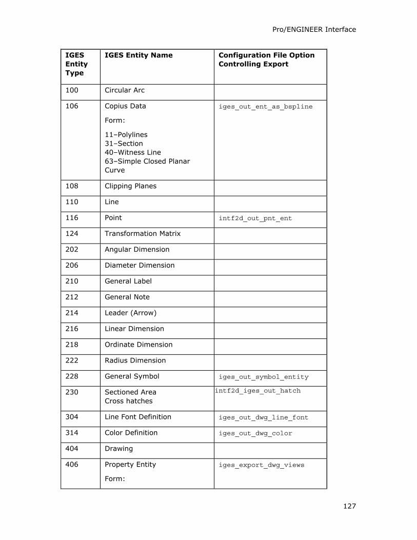
Pro/ENGINEER Interface
127
IGES
Entity
Type
IGES Entity Name Configuration File Option
Controlling Export
100 Circular Arc
106 Copius Data
Form:
11–Polylines
31–Section
40–Witness Line
63–Simple Closed Planar
Curve
iges_out_ent_as_bspline
108 Clipping Planes
110 Line
116 Point intf2d_out_pnt_ent
124 Transformation Matrix
202 Angular Dimension
206 Diameter Dimension
210 General Label
212 General Note
214 Leader (Arrow)
216 Linear Dimension
218 Ordinate Dimension
222 Radius Dimension
228 General Symbol iges_out_symbol_entity
230 Sectioned Area
Cross hatches
intf2d_iges_out_hatch
304 Line Font Definition iges_out_dwg_line_font
314 Color Definition iges_out_dwg_color
404 Drawing
406 Property Entity
Form:
iges_export_dwg_views
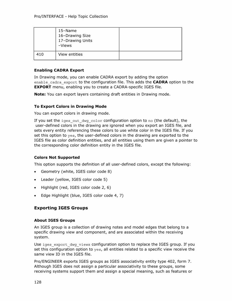
Pro/INTERFACE - Help Topic Collection
128
15–Name
16–Drawing Size
17–Drawing Units
–Views
410 View entities
Enabling CADRA Export
In Drawing mode, you can enable CADRA export by adding the option
enable_cadra_export to the configuration file. This adds the CADRA option to the
EXPORT menu, enabling you to create a CADRA-specific IGES file.
Note: You can export layers containing draft entities in Drawing mode.
To Export Colors in Drawing Mode
You can export colors in drawing mode.
If you set the iges_out_dwg_color configuration option to no (the default), the
user-defined colors in the drawing are ignored when you export an IGES file, and
sets every entity referencing these colors to use white color in the IGES file. If you
set this option to yes, the user-defined colors in the drawing are exported to the
IGES file as color definition entities, and all entities using them are given a pointer to
the corresponding color definition entity in the IGES file.
Colors Not Supported
This option supports the definition of all user-defined colors, except the following:
• Geometry (white, IGES color code 8)
• Leader (yellow, IGES color code 5)
• Highlight (red, IGES color code 2, 6)
• Edge Highlight (blue, IGES color code 4, 7)
Exporting IGES Groups
About IGES Groups
An IGES group is a collection of drawing notes and model edges that belong to a
specific drawing view and component, and are associated within the receiving
system.
Use iges_export_dwg_views configuration option to replace the IGES group. If you
set this configuration option to yes, all entities related to a specific view receive the
same view ID in the IGES file.
Pro/ENGINEER exports IGES groups as IGES associativity entity type 402, form 7.
Although IGES does not assign a particular associativity to these groups, some
receiving systems support them and assign a special meaning, such as features or
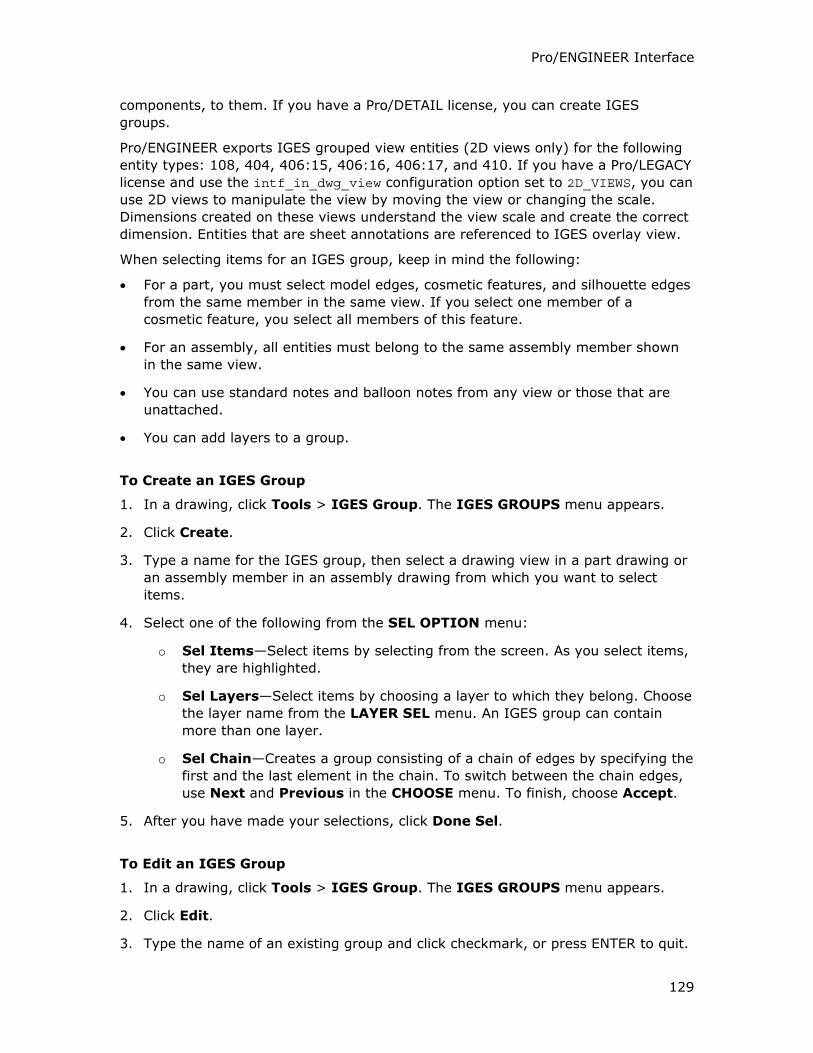
Pro/ENGINEER Interface
129
components, to them. If you have a Pro/DETAIL license, you can create IGES
groups.
Pro/ENGINEER exports IGES grouped view entities (2D views only) for the following
entity types: 108, 404, 406:15, 406:16, 406:17, and 410. If you have a Pro/LEGACY
license and use the intf_in_dwg_view configuration option set to 2D_VIEWS, you can
use 2D views to manipulate the view by moving the view or changing the scale.
Dimensions created on these views understand the view scale and create the correct
dimension. Entities that are sheet annotations are referenced to IGES overlay view.
When selecting items for an IGES group, keep in mind the following:
• For a part, you must select model edges, cosmetic features, and silhouette edges
from the same member in the same view. If you select one member of a
cosmetic feature, you select all members of this feature.
• For an assembly, all entities must belong to the same assembly member shown
in the same view.
• You can use standard notes and balloon notes from any view or those that are
unattached.
• You can add layers to a group.
To Create an IGES Group
1. In a drawing, click Tools > IGES Group. The IGES GROUPS menu appears.
2. Click Create.
3. Type a name for the IGES group, then select a drawing view in a part drawing or
an assembly member in an assembly drawing from which you want to select
items.
4. Select one of the following from the SEL OPTION menu:
o Sel Items—Select items by selecting from the screen. As you select items,
they are highlighted.
o Sel Layers—Select items by choosing a layer to which they belong. Choose
the layer name from the LAYER SEL menu. An IGES group can contain
more than one layer.
o Sel Chain—Creates a group consisting of a chain of edges by specifying the
first and the last element in the chain. To switch between the chain edges,
use Next and Previous in the CHOOSE menu. To finish, choose Accept.
5. After you have made your selections, click Done Sel.
To Edit an IGES Group
1. In a drawing, click Tools > IGES Group. The IGES GROUPS menu appears.
2. Click Edit.
3. Type the name of an existing group and click checkmark, or press ENTER to quit.
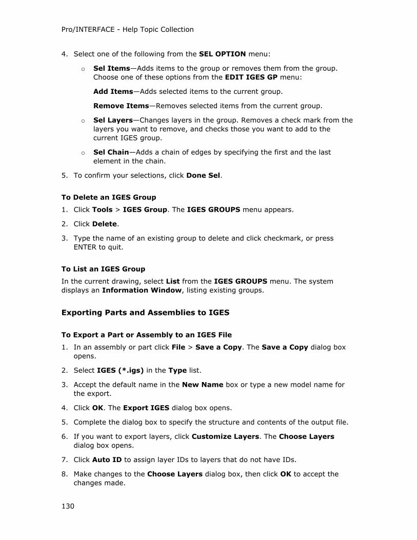
Pro/INTERFACE - Help Topic Collection
130
4. Select one of the following from the SEL OPTION menu:
o Sel Items—Adds items to the group or removes them from the group.
Choose one of these options from the EDIT IGES GP menu:
Add Items—Adds selected items to the current group.
Remove Items—Removes selected items from the current group.
o Sel Layers—Changes layers in the group. Removes a check mark from the
layers you want to remove, and checks those you want to add to the
current IGES group.
o Sel Chain—Adds a chain of edges by specifying the first and the last
element in the chain.
5. To confirm your selections, click Done Sel.
To Delete an IGES Group
1. Click Tools > IGES Group. The IGES GROUPS menu appears.
2. Click Delete.
3. Type the name of an existing group to delete and click checkmark, or press
ENTER to quit.
To List an IGES Group
In the current drawing, select List from the IGES GROUPS menu. The system
displays an Information Window, listing existing groups.
Exporting Parts and Assemblies to IGES
To Export a Part or Assembly to an IGES File
1. In an assembly or part click File > Save a Copy. The Save a Copy dialog box
opens.
2. Select IGES (*.igs) in the Type list.
3. Accept the default name in the New Name box or type a new model name for
the export.
4. Click OK. The Export IGES dialog box opens.
5. Complete the dialog box to specify the structure and contents of the output file.
6. If you want to export layers, click Customize Layers. The Choose Layers
dialog box opens.
7. Click Auto ID to assign layer IDs to layers that do not have IDs.
8. Make changes to the Choose Layers dialog box, then click OK to accept the
changes made.
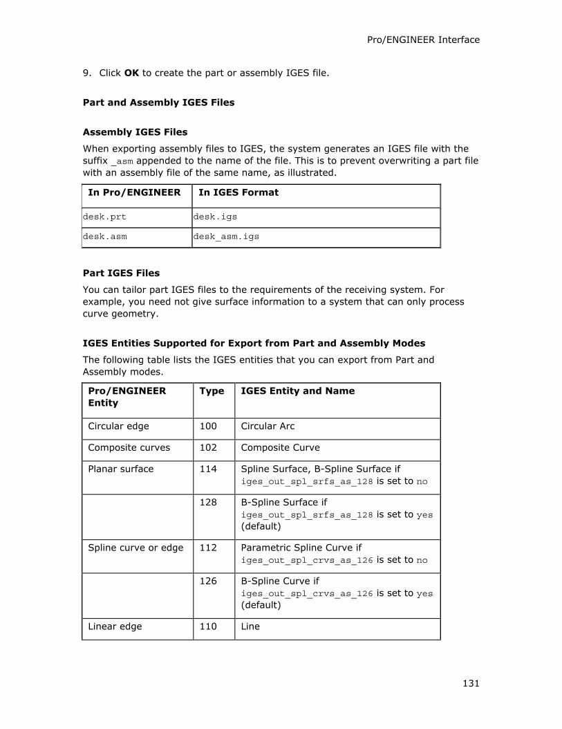
Pro/ENGINEER Interface
131
9. Click OK to create the part or assembly IGES file.
Part and Assembly IGES Files
Assembly IGES Files
When exporting assembly files to IGES, the system generates an IGES file with the
suffix _asm appended to the name of the file. This is to prevent overwriting a part file
with an assembly file of the same name, as illustrated.
In Pro/ENGINEER In IGES Format
desk.prt desk.igs
desk.asm desk_asm.igs
Part IGES Files
You can tailor part IGES files to the requirements of the receiving system. For
example, you need not give surface information to a system that can only process
curve geometry.
IGES Entities Supported for Export from Part and Assembly Modes
The following table lists the IGES entities that you can export from Part and
Assembly modes.
Pro/ENGINEER
Entity
Type IGES Entity and Name
Circular edge 100 Circular Arc
Composite curves 102 Composite Curve
Planar surface 114 Spline Surface, B-Spline Surface if
iges_out_spl_srfs_as_128 is set to no
128 B-Spline Surface if iges_out_spl_srfs_as_128 is set to yes
(default)
Spline curve or edge 112 Parametric Spline Curve if
iges_out_spl_crvs_as_126 is set to no
126 B-Spline Curve if
iges_out_spl_crvs_as_126 is set to yes
(default)
Linear edge 110 Line
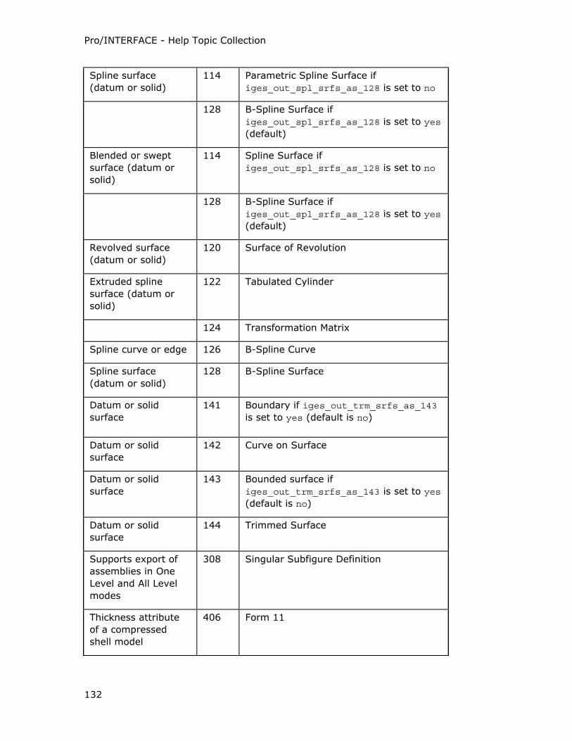
Pro/INTERFACE - Help Topic Collection
132
Spline surface
(datum or solid)
114 Parametric Spline Surface if
iges_out_spl_srfs_as_128 is set to no
128 B-Spline Surface if iges_out_spl_srfs_as_128 is set to yes
(default)
Blended or swept
surface (datum or
solid)
114 Spline Surface if
iges_out_spl_srfs_as_128 is set to no
128 B-Spline Surface if
iges_out_spl_srfs_as_128 is set to yes
(default)
Revolved surface
(datum or solid)
120 Surface of Revolution
Extruded spline
surface (datum or
solid)
122 Tabulated Cylinder
124 Transformation Matrix
Spline curve or edge 126 B-Spline Curve
Spline surface
(datum or solid)
128 B-Spline Surface
Datum or solid
surface
141 Boundary if iges_out_trm_srfs_as_143
is set to yes (default is no)
Datum or solid
surface
142 Curve on Surface
Datum or solid
surface
143 Bounded surface if
iges_out_trm_srfs_as_143 is set to yes
(default is no)
Datum or solid
surface
144 Trimmed Surface
Supports export of
assemblies in One
Level and All Level
modes
308 Singular Subfigure Definition
Thickness attribute
of a compressed
shell model
406 Form 11
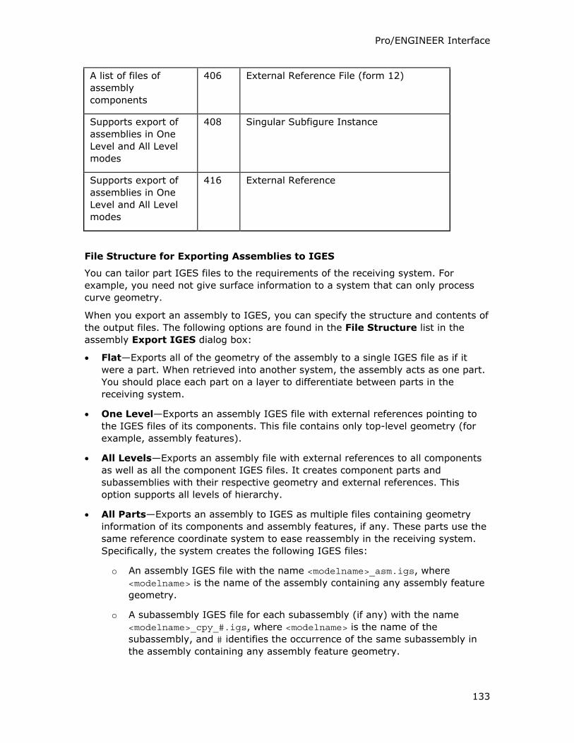
Pro/ENGINEER Interface
133
A list of files of
assembly
components
406 External Reference File (form 12)
Supports export of
assemblies in One
Level and All Level
modes
408 Singular Subfigure Instance
Supports export of
assemblies in One
Level and All Level
modes
416 External Reference
File Structure for Exporting Assemblies to IGES
You can tailor part IGES files to the requirements of the receiving system. For
example, you need not give surface information to a system that can only process
curve geometry.
When you export an assembly to IGES, you can specify the structure and contents of
the output files. The following options are found in the File Structure list in the
assembly Export IGES dialog box:
• Flat—Exports all of the geometry of the assembly to a single IGES file as if it
were a part. When retrieved into another system, the assembly acts as one part.
You should place each part on a layer to differentiate between parts in the
receiving system.
• One Level—Exports an assembly IGES file with external references pointing to
the IGES files of its components. This file contains only top-level geometry (for
example, assembly features).
• All Levels—Exports an assembly file with external references to all components
as well as all the component IGES files. It creates component parts and
subassemblies with their respective geometry and external references. This
option supports all levels of hierarchy.
• All Parts—Exports an assembly to IGES as multiple files containing geometry
information of its components and assembly features, if any. These parts use the
same reference coordinate system to ease reassembly in the receiving system.
Specifically, the system creates the following IGES files:
o An assembly IGES file with the name <modelname>_asm.igs, where
<modelname> is the name of the assembly containing any assembly feature
geometry.
o A subassembly IGES file for each subassembly (if any) with the name
<modelname>_cpy_#.igs, where <modelname> is the name of the
subassembly, and # identifies the occurrence of the same subassembly in
the assembly containing any assembly feature geometry.
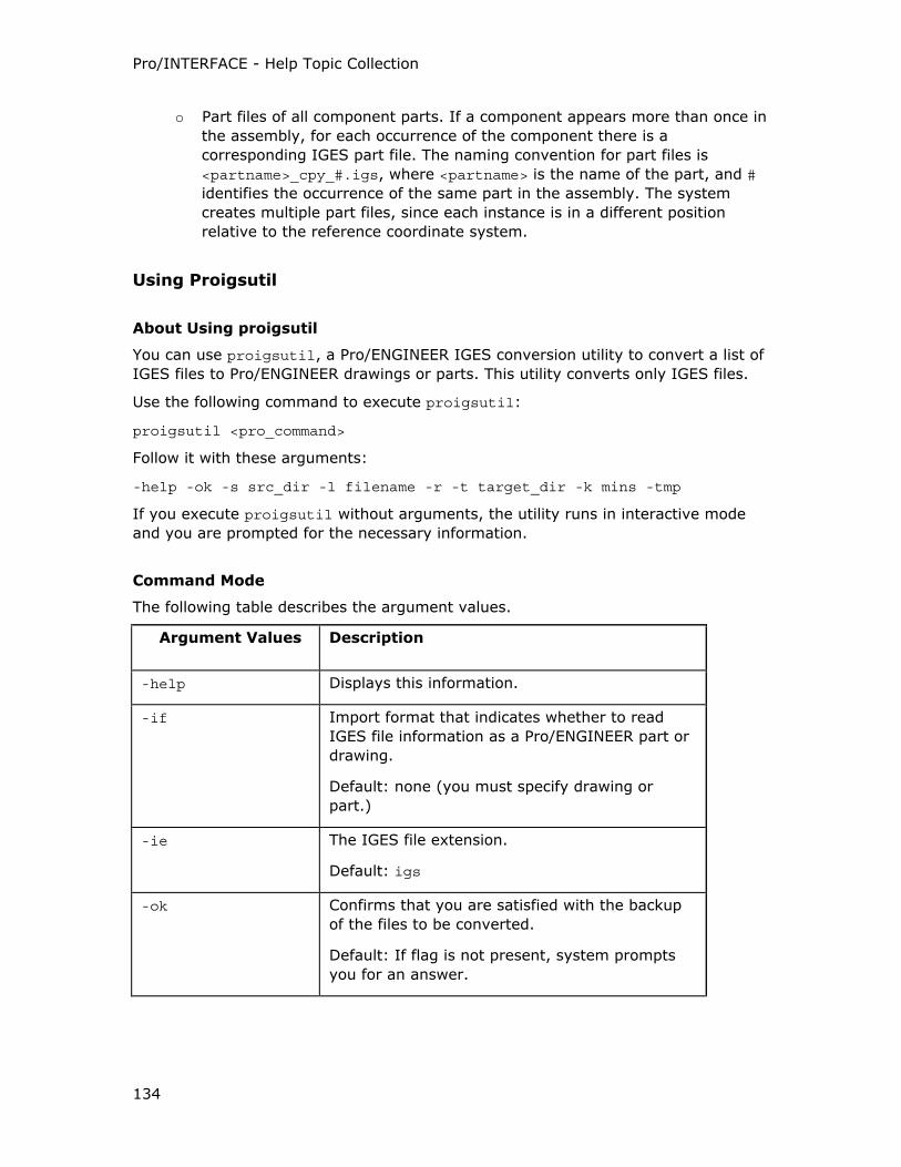
Pro/INTERFACE - Help Topic Collection
134
o Part files of all component parts. If a component appears more than once in
the assembly, for each occurrence of the component there is a
corresponding IGES part file. The naming convention for part files is
<partname>_cpy_#.igs, where <partname> is the name of the part, and #
identifies the occurrence of the same part in the assembly. The system
creates multiple part files, since each instance is in a different position
relative to the reference coordinate system.
Using Proigsutil
About Using proigsutil
You can use proigsutil, a Pro/ENGINEER IGES conversion utility to convert a list of
IGES files to Pro/ENGINEER drawings or parts. This utility converts only IGES files.
Use the following command to execute proigsutil:
proigsutil <pro_command>
Follow it with these arguments:
-help -ok -s src_dir -l filename -r -t target_dir -k mins -tmp
If you execute proigsutil without arguments, the utility runs in interactive mode
and you are prompted for the necessary information.
Command Mode
The following table describes the argument values.
Argument Values Description
-help Displays this information.
-if Import format that indicates whether to read
IGES file information as a Pro/ENGINEER part or
drawing.
Default: none (you must specify drawing or
part.)
-ie The IGES file extension.
Default: igs
-ok Confirms that you are satisfied with the backup
of the files to be converted.
Default: If flag is not present, system prompts
you for an answer.
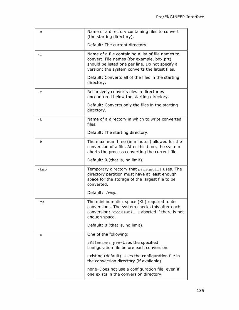
Pro/ENGINEER Interface
135
-s Name of a directory containing files to convert
(the starting directory).
Default: The current directory.
-l Name of a file containing a list of file names to
convert. File names (for example, box.prt)
should be listed one per line. Do not specify a
version; the system converts the latest files.
Default: Converts all of the files in the starting
directory.
-r Recursively converts files in directories
encountered below the starting directory.
Default: Converts only the files in the starting
directory.
-t Name of a directory in which to write converted
files.
Default: The starting directory.
-k The maximum time (in minutes) allowed for the
conversion of a file. After this time, the system
aborts the process converting the current file.
Default: 0 (that is, no limit).
-tmp Temporary directory that proigsutil uses. The
directory partition must have at least enough
space for the storage of the largest file to be
converted.
Default: /tmp.
-ms The minimum disk space (Kb) required to do
conversions. The system checks this after each
conversion; proigsutil is aborted if there is not
enough space.
Default: 0 (that is, no limit).
-c One of the following:
<filename>.pro–Uses the specified
configuration file before each conversion.
existing (default)–Uses the configuration file in
the conversion directory (if available).
none–Does not use a configuration file, even if
one exists in the conversion directory.
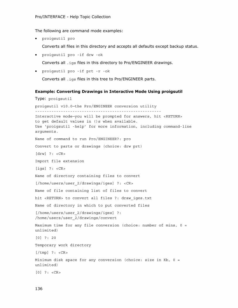
Pro/INTERFACE - Help Topic Collection
136
The following are command mode examples:
• proigsutil pro
Converts all files in this directory and accepts all defaults except backup status.
• proigsutil pro -if drw -ok
Converts all .igs files in this directory to Pro/ENGINEER drawings.
• proigsutil pro -if prt -r -ok
Converts all .igs files in this tree to Pro/ENGINEER parts.
Example: Converting Drawings in Interactive Mode Using proigsutil
Type: proigsutil
proigsutil v10.0—the Pro/ENGINEER conversion utility
------------------------------------------------------
Interactive mode—you will be prompted for answers, hit <RETURN>
to get default values in ()s when available.
Use ‘proigsutil -help’ for more information, including command-line arguments.
Name of command to run Pro/ENGINEER?: pro
Convert to parts or drawings (choice: drw prt)
[drw] ?: <CR>
Import file extension
[igs] ?: <CR>
Name of directory containing files to convert
[/home/users/user_2/drawings/iges] ?: <CR>
Name of file containing list of files to convert
hit <RETURN> to convert all files ?: draw_iges.txt
Name of directory in which to put converted files
[/home/users/user_2/drawings/iges] ?: /home/users/user_2/drawings/convert
Maximum time for any file conversion (choice: number of mins, 0 = unlimited)
[0] ?: 20
Temporary work directory
[/tmp] ?: <CR>
Minimum disk space for any conversion (choice: size in Kb, 0 = unlimited)
[0] ?: <CR>
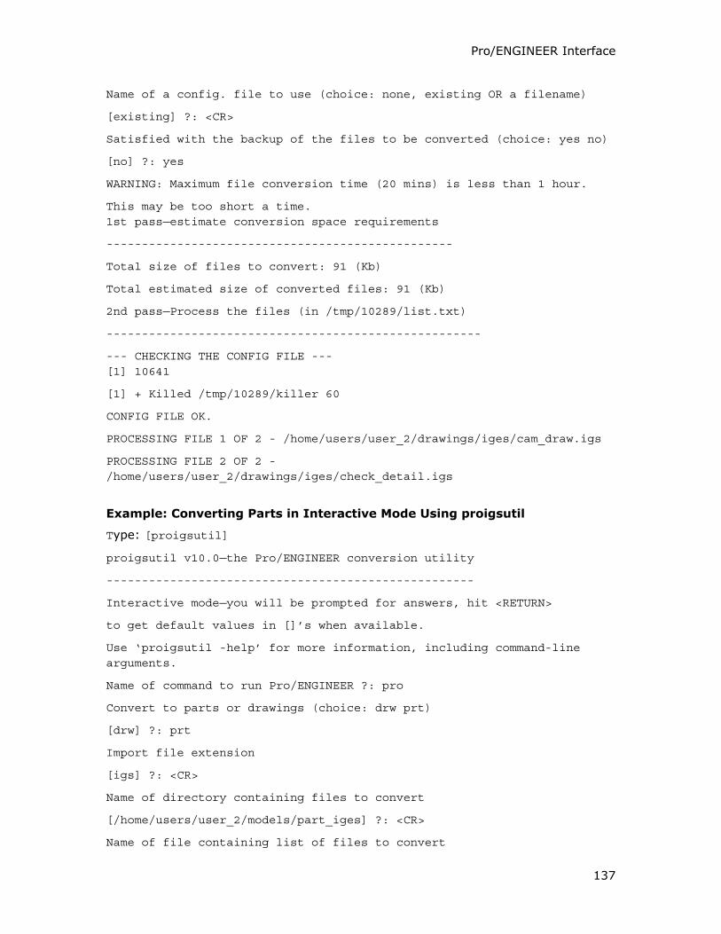
Pro/ENGINEER Interface
137
Name of a config. file to use (choice: none, existing OR a filename)
[existing] ?: <CR>
Satisfied with the backup of the files to be converted (choice: yes no)
[no] ?: yes
WARNING: Maximum file conversion time (20 mins) is less than 1 hour.
This may be too short a time.
1st pass—estimate conversion space requirements
-------------------------------------------------
Total size of files to convert: 91 (Kb)
Total estimated size of converted files: 91 (Kb)
2nd pass—Process the files (in /tmp/10289/list.txt)
-----------------------------------------------------
--- CHECKING THE CONFIG FILE ---
[1] 10641
[1] + Killed /tmp/10289/killer 60
CONFIG FILE OK.
PROCESSING FILE 1 OF 2 - /home/users/user_2/drawings/iges/cam_draw.igs
PROCESSING FILE 2 OF 2 - /home/users/user_2/drawings/iges/check_detail.igs
Example: Converting Parts in Interactive Mode Using proigsutil
Type: [proigsutil]
proigsutil v10.0—the Pro/ENGINEER conversion utility
----------------------------------------------------
Interactive mode—you will be prompted for answers, hit <RETURN>
to get default values in []’s when available.
Use ‘proigsutil -help’ for more information, including command-line arguments.
Name of command to run Pro/ENGINEER ?: pro
Convert to parts or drawings (choice: drw prt)
[drw] ?: prt
Import file extension
[igs] ?: <CR>
Name of directory containing files to convert
[/home/users/user_2/models/part_iges] ?: <CR>
Name of file containing list of files to convert
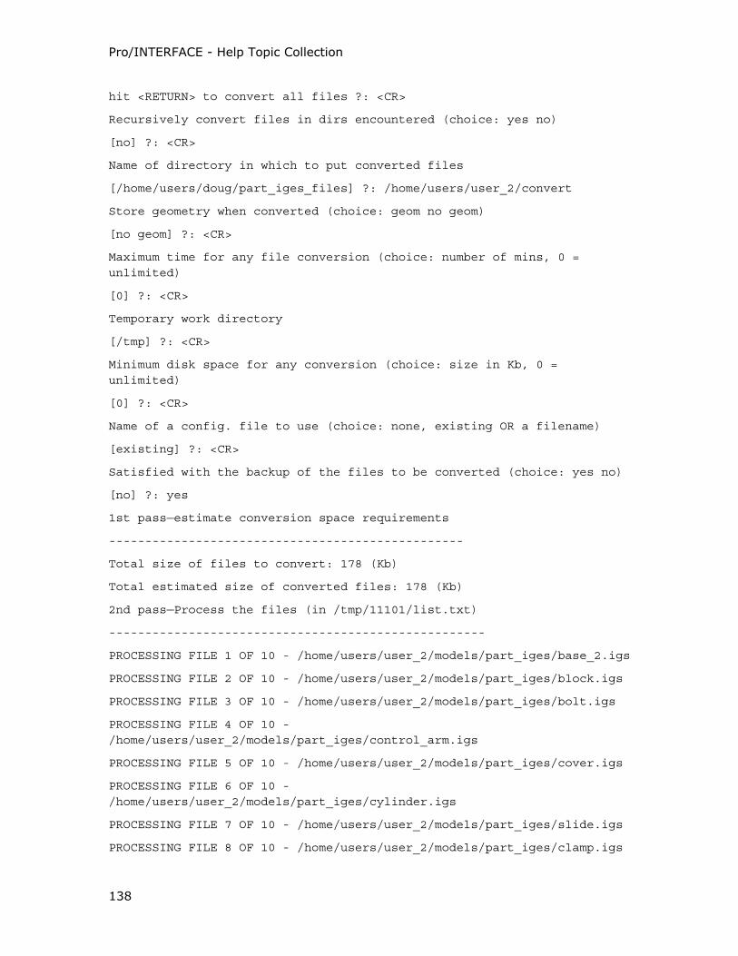
Pro/INTERFACE - Help Topic Collection
138
hit <RETURN> to convert all files ?: <CR>
Recursively convert files in dirs encountered (choice: yes no)
[no] ?: <CR>
Name of directory in which to put converted files
[/home/users/doug/part_iges_files] ?: /home/users/user_2/convert
Store geometry when converted (choice: geom no geom)
[no geom] ?: <CR>
Maximum time for any file conversion (choice: number of mins, 0 = unlimited)
[0] ?: <CR>
Temporary work directory
[/tmp] ?: <CR>
Minimum disk space for any conversion (choice: size in Kb, 0 = unlimited)
[0] ?: <CR>
Name of a config. file to use (choice: none, existing OR a filename)
[existing] ?: <CR>
Satisfied with the backup of the files to be converted (choice: yes no)
[no] ?: yes
1st pass—estimate conversion space requirements
-------------------------------------------------
Total size of files to convert: 178 (Kb)
Total estimated size of converted files: 178 (Kb)
2nd pass—Process the files (in /tmp/11101/list.txt)
----------------------------------------------------
PROCESSING FILE 1 OF 10 - /home/users/user_2/models/part_iges/base_2.igs
PROCESSING FILE 2 OF 10 - /home/users/user_2/models/part_iges/block.igs
PROCESSING FILE 3 OF 10 - /home/users/user_2/models/part_iges/bolt.igs
PROCESSING FILE 4 OF 10 - /home/users/user_2/models/part_iges/control_arm.igs
PROCESSING FILE 5 OF 10 - /home/users/user_2/models/part_iges/cover.igs
PROCESSING FILE 6 OF 10 - /home/users/user_2/models/part_iges/cylinder.igs
PROCESSING FILE 7 OF 10 - /home/users/user_2/models/part_iges/slide.igs
PROCESSING FILE 8 OF 10 - /home/users/user_2/models/part_iges/clamp.igs
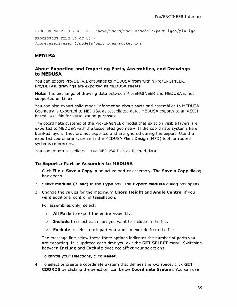
Pro/ENGINEER Interface
139
PROCESSING FILE 9 OF 10 - /home/users/user_2/models/part_iges/pin.igs
PROCESSING FILE 10 OF 10 - /home/users/user_2/models/part_iges/socket.igs
MEDUSA
About Exporting and Importing Parts, Assemblies, and Drawings to MEDUSA
You can export Pro/DETAIL drawings to MEDUSA from within Pro/ENGINEER.
Pro/DETAIL drawings are exported as MEDUSA sheets.
Note: The exchange of drawing data between Pro/ENGINEER and MEDUSA is not
supported on Linux.
You can also export solid model information about parts and assemblies to MEDUSA.
Geometry is exported to MEDUSA as tessellated data. MEDUSA exports to an ASCII-
based .asc file for visualization purposes.
The coordinate systems of the Pro/ENGINEER model that exist on visible layers are
exported to MEDUSA with the tessellated geometry. If the coordinate systems lie on
blanked layers, they are not exported and are ignored during the export. Use the
exported coordinate systems in the MEDUSA Plant Design (MPD) tool for routed
systems references.
You can import tessellated .asc MEDUSA files as faceted data.
To Export a Part or Assembly to MEDUSA
1. Click File > Save a Copy in an active part or assembly. The Save a Copy dialog
box opens.
2. Select Medusa (*.asc) in the Type box. The Export Medusa dialog box opens.
3. Change the values for the maximum Chord Height and Angle Control if you
want additional control of tessellation.
For assemblies only, select:
o All Parts to export the entire assembly.
o Include to select each part you want to include in the file.
o Exclude to select each part you want to exclude from the file.
The message line below these three options indicates the number of parts you
are exporting. It is updated each time you exit the GET SELECT menu. Switching
between Include and Exclude does not affect your selections.
To cancel your selections, click Reset.
4. To select or create a coordinate system that defines the xyz space, click GET
COORDS by clicking the selection icon below Coordinate System. You can use
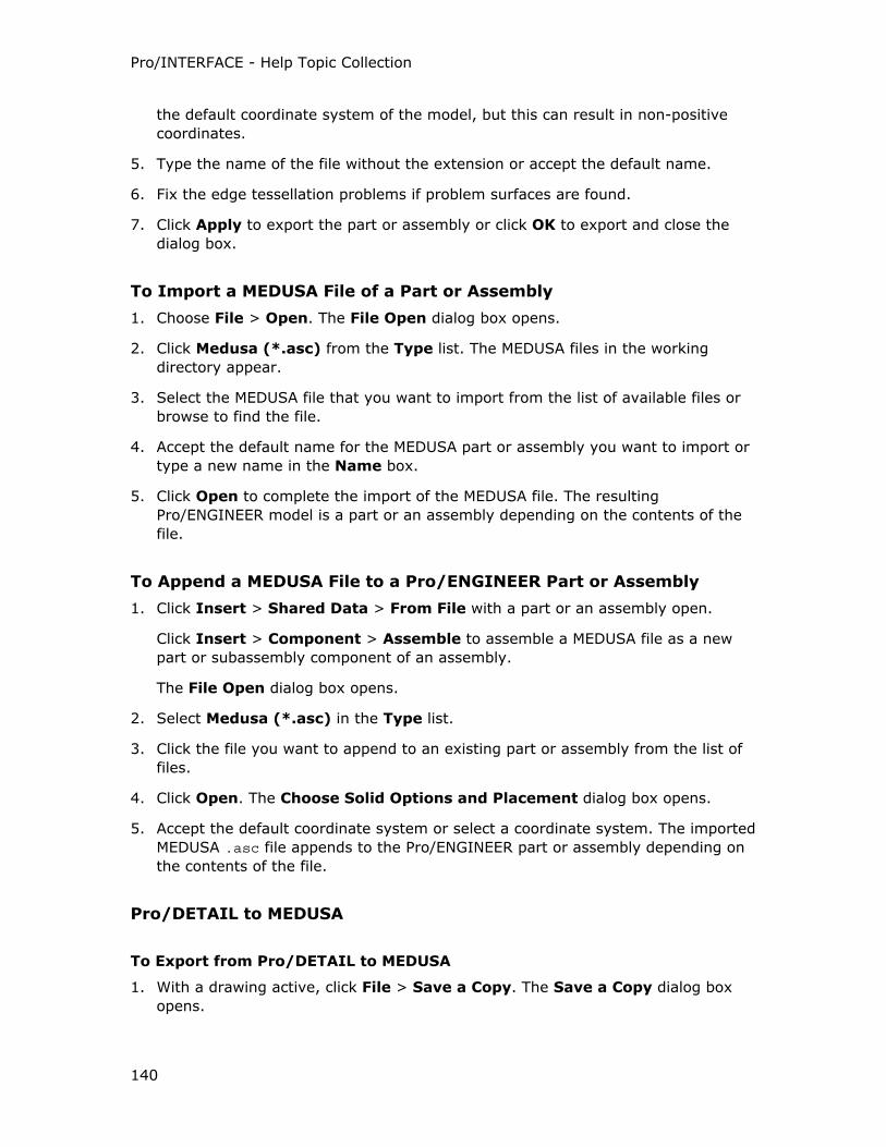
Pro/INTERFACE - Help Topic Collection
140
the default coordinate system of the model, but this can result in non-positive
coordinates.
5. Type the name of the file without the extension or accept the default name.
6. Fix the edge tessellation problems if problem surfaces are found.
7. Click Apply to export the part or assembly or click OK to export and close the
dialog box.
To Import a MEDUSA File of a Part or Assembly
1. Choose File > Open. The File Open dialog box opens.
2. Click Medusa (*.asc) from the Type list. The MEDUSA files in the working
directory appear.
3. Select the MEDUSA file that you want to import from the list of available files or
browse to find the file.
4. Accept the default name for the MEDUSA part or assembly you want to import or
type a new name in the Name box.
5. Click Open to complete the import of the MEDUSA file. The resulting
Pro/ENGINEER model is a part or an assembly depending on the contents of the
file.
To Append a MEDUSA File to a Pro/ENGINEER Part or Assembly
1. Click Insert > Shared Data > From File with a part or an assembly open.
Click Insert > Component > Assemble to assemble a MEDUSA file as a new
part or subassembly component of an assembly.
The File Open dialog box opens.
2. Select Medusa (*.asc) in the Type list.
3. Click the file you want to append to an existing part or assembly from the list of
files.
4. Click Open. The Choose Solid Options and Placement dialog box opens.
5. Accept the default coordinate system or select a coordinate system. The imported
MEDUSA .asc file appends to the Pro/ENGINEER part or assembly depending on
the contents of the file.
Pro/DETAIL to MEDUSA
To Export from Pro/DETAIL to MEDUSA
1. With a drawing active, click File > Save a Copy. The Save a Copy dialog box
opens.
Pro/ENGINEER Interface
141
2. Select Medusa (s.*) in the Type box.
3. Accept the default export file name or type a new name.
4. Click OK to create the MEDUSA file.
Mapping Pro/DETAIL Information to MEDUSA
The following occurs when you export a Pro/DETAIL sheet to MEDUSA:
• Exported Pro/ENGINEER grouped entities create MEDUSA clumps. Grouped
entities include hatching, tables, user-defined symbols, groups, and part and
assembly components.
• Entity layer information is mapped.
• Parametric notes are mapped to MEDUSA text with their attributes.
• The model name is mapped to a sheet attribute.
Importing MEDUSA Drawings
To Import a MEDUSA File with Drawing Data
1. Click File > Open. The File Open dialog box opens.
2. Select Medusa (s.*, *.she) in the Type box. MEDUSA files in the working
directory appear.
3. Select the MEDUSA file you want to import or browse to find the file.
4. Click Open. The Import New Model dialog box opens. Drawing is the default.
5. Accept the default file name or type a new name.
6. Click OK.
To Append a MEDUSA Drawing File to a Pro/ENGINEER Drawing
1. Click Insert > Shared Data > From File. The File Open dialog box opens.
2. Select Medusa (s.*, *.she) in the Type box.
3. Select the file you want to import from the list of files.
4. Click Open.
5. Scale the appended drawing file to fit the format, move the appended drawing
file origin to the lower-left corner, or accept the default location.
Pro/INTERFACE - Help Topic Collection
142
Motion Envelope
To Export to Motion Envelope
1. In an open assembly, click File > Save a Copy. The Save a Copy dialog box
opens.
2. Select Motion Envlp in the Type box.
3. Accept the default name in the New Name box or type a new model name for
the export.
4. Click OK. The Create Motion Envelope dialog box and the Open dialog box
open. In the Open dialog box, Frames file (*.fra) appears in the Type box.
5. Select the Frames file you want to open from the list of available files or browse
to find the Frames file. The Open dialog box closes.
Note: Frames files are created in the Mechanical Design application.
6. Complete the Create Motion Envelope dialog box and click Create.
Neutral Files
Overview of Part and Assembly Neutral Files
About Part and Assembly Neutral Files
A Neutral file is a formatted text file containing information about parts and
assemblies created in Pro/ENGINEER. To retain the feature-based design of the part,
provide topology, geometry, symbolic parameters and their corresponding values.
Pro/ENGINEER formats part geometry data so that other software systems can easily
read it and a wide variety of applications can use it. You can create neutral files from
parts and assemblies.
Part Neutral files contain information about the part geometry and the features of
the part. Assembly Neutral files contain information about how the parts and
subassemblies are placed in the assembly and general information about the
component parts. When you create a Neutral file from an assembly, the system
generates a Neutral file for each component part, and the assembly Neutral file
contains a list of the individual part file names.
If the Pro/ENGINEER part or assembly has faceted data, the faceted data is
exported to the Neutral file format.
The Neutral file contains information about parts and assemblies which is not
supported by IGES (such as attributes). With a Neutral file, you can access this
information and use it to create interfaces with other programs.
You cannot open in the earlier versions of Pro/ENGINEER parts and assemblies
created in the current version of Pro/ENGINEER. However, you can use the Neutral
file format to collaboratively share data with the earlier versions of Pro/ENGINEER.
See the Help module Associative Topology Bus for more information.
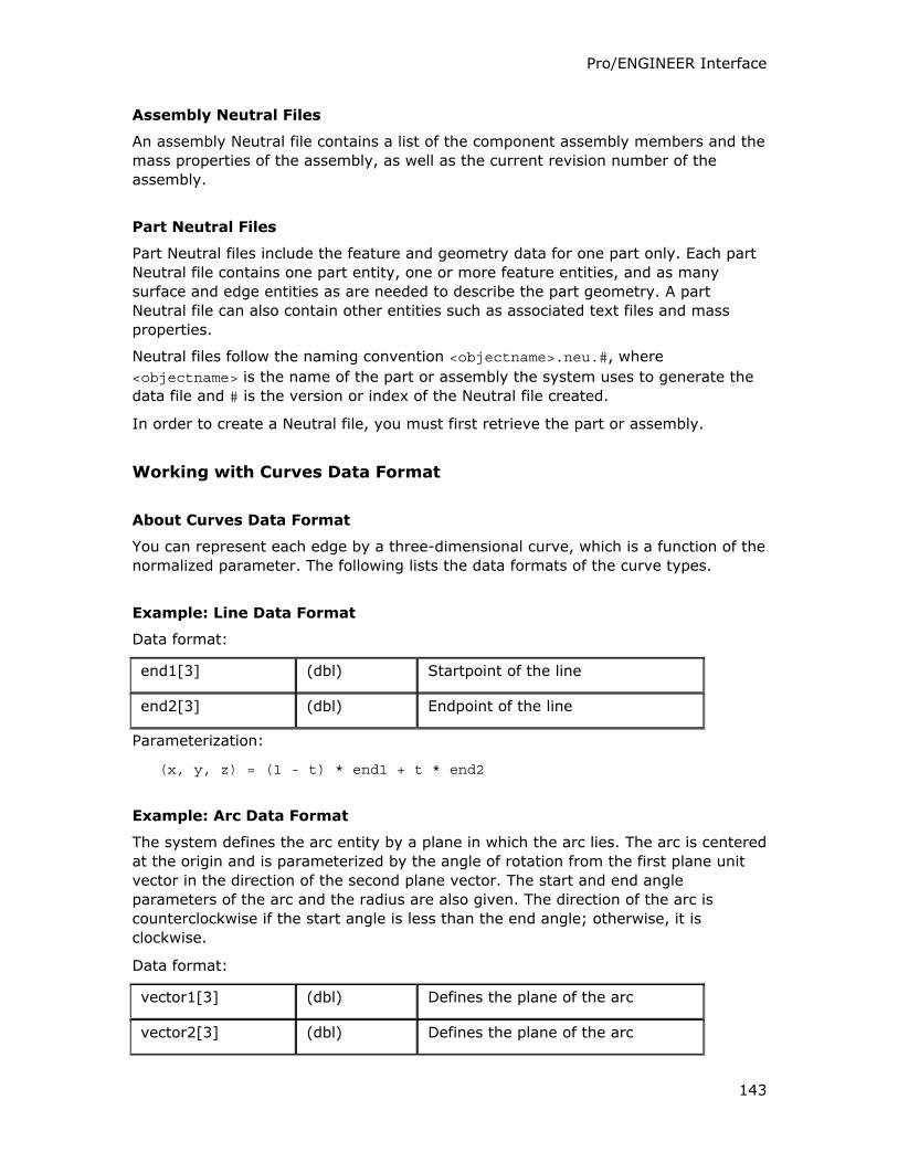
Pro/ENGINEER Interface
143
Assembly Neutral Files
An assembly Neutral file contains a list of the component assembly members and the
mass properties of the assembly, as well as the current revision number of the
assembly.
Part Neutral Files
Part Neutral files include the feature and geometry data for one part only. Each part
Neutral file contains one part entity, one or more feature entities, and as many
surface and edge entities as are needed to describe the part geometry. A part
Neutral file can also contain other entities such as associated text files and mass
properties.
Neutral files follow the naming convention <objectname>.neu.#, where
<objectname> is the name of the part or assembly the system uses to generate the
data file and # is the version or index of the Neutral file created.
In order to create a Neutral file, you must first retrieve the part or assembly.
Working with Curves Data Format
About Curves Data Format
You can represent each edge by a three-dimensional curve, which is a function of the
normalized parameter. The following lists the data formats of the curve types.
Example: Line Data Format
Data format:
end1[3] (dbl) Startpoint of the line
end2[3] (dbl) Endpoint of the line
Parameterization:
(x, y, z) = (1 - t) * end1 + t * end2
Example: Arc Data Format
The system defines the arc entity by a plane in which the arc lies. The arc is centered
at the origin and is parameterized by the angle of rotation from the first plane unit
vector in the direction of the second plane vector. The start and end angle
parameters of the arc and the radius are also given. The direction of the arc is
counterclockwise if the start angle is less than the end angle; otherwise, it is
clockwise.
Data format:
vector1[3] (dbl) Defines the plane of the arc
vector2[3] (dbl) Defines the plane of the arc
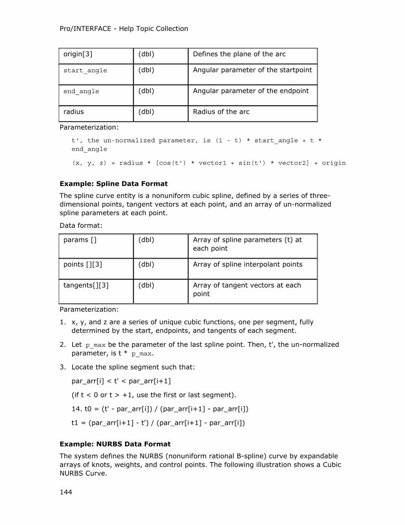
Pro/INTERFACE - Help Topic Collection
144
origin[3] (dbl) Defines the plane of the arc
start_angle (dbl) Angular parameter of the startpoint
end_angle (dbl) Angular parameter of the endpoint
radius (dbl) Radius of the arc
Parameterization:
t', the un-normalized parameter, is (1 - t) * start_angle + t * end_angle
(x, y, z) = radius * [cos(t') * vector1 + sin(t') * vector2] + origin
Example: Spline Data Format
The spline curve entity is a nonuniform cubic spline, defined by a series of three-
dimensional points, tangent vectors at each point, and an array of un-normalized
spline parameters at each point.
Data format:
params [] (dbl) Array of spline parameters (t) at
each point
points [][3] (dbl) Array of spline interpolant points
tangents[][3] (dbl) Array of tangent vectors at each
point
Parameterization:
1. x, y, and z are a series of unique cubic functions, one per segment, fully
determined by the start, endpoints, and tangents of each segment.
2. Let p_max be the parameter of the last spline point. Then, t', the un-normalized
parameter, is t * p_max.
3. Locate the spline segment such that:
par_arr[i] < t' < par_arr[i+1]
(if t < 0 or t > +1, use the first or last segment).
14. t0 = (t' - par_arr[i]) / (par_arr[i+1] - par_arr[i])
t1 = (par_arr[i+1] - t') / (par_arr[i+1] - par_arr[i])
Example: NURBS Data Format
The system defines the NURBS (nonuniform rational B-spline) curve by expandable
arrays of knots, weights, and control points. The following illustration shows a Cubic
NURBS Curve.
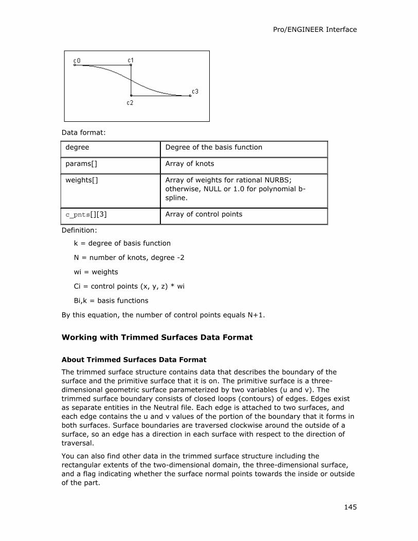
Pro/ENGINEER Interface
145
Data format:
degree Degree of the basis function
params[] Array of knots
weights[] Array of weights for rational NURBS;
otherwise, NULL or 1.0 for polynomial b-
spline.
c_pnts[][3] Array of control points
Definition:
k = degree of basis function
N = number of knots, degree -2
wi = weights
Ci = control points (x, y, z) * wi
Bi,k = basis functions
By this equation, the number of control points equals N+1.
Working with Trimmed Surfaces Data Format
About Trimmed Surfaces Data Format
The trimmed surface structure contains data that describes the boundary of the
surface and the primitive surface that it is on. The primitive surface is a three-
dimensional geometric surface parameterized by two variables (u and v). The
trimmed surface boundary consists of closed loops (contours) of edges. Edges exist
as separate entities in the Neutral file. Each edge is attached to two surfaces, and
each edge contains the u and v values of the portion of the boundary that it forms in
both surfaces. Surface boundaries are traversed clockwise around the outside of a
surface, so an edge has a direction in each surface with respect to the direction of
traversal.
You can also find other data in the trimmed surface structure including the
rectangular extents of the two-dimensional domain, the three-dimensional surface,
and a flag indicating whether the surface normal points towards the inside or outside
of the part.
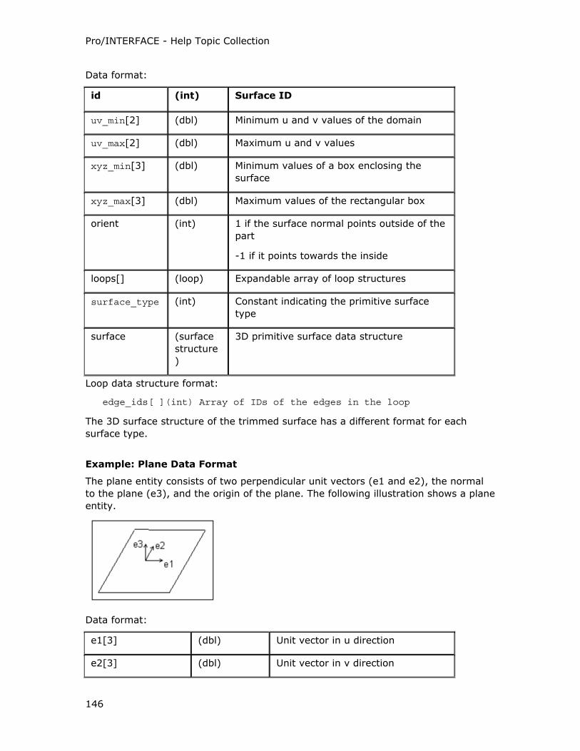
Pro/INTERFACE - Help Topic Collection
146
Data format:
id (int) Surface ID
uv_min[2] (dbl) Minimum u and v values of the domain
uv_max[2] (dbl) Maximum u and v values
xyz_min[3] (dbl) Minimum values of a box enclosing the
surface
xyz_max[3] (dbl) Maximum values of the rectangular box
orient (int) 1 if the surface normal points outside of the
part
-1 if it points towards the inside
loops[] (loop) Expandable array of loop structures
surface_type (int) Constant indicating the primitive surface
type
surface (surface
structure
)
3D primitive surface data structure
Loop data structure format:
edge_ids[ ](int) Array of IDs of the edges in the loop
The 3D surface structure of the trimmed surface has a different format for each
surface type.
Example: Plane Data Format
The plane entity consists of two perpendicular unit vectors (e1 and e2), the normal
to the plane (e3), and the origin of the plane. The following illustration shows a plane
entity.
Data format:
e1[3] (dbl) Unit vector in u direction
e2[3] (dbl) Unit vector in v direction
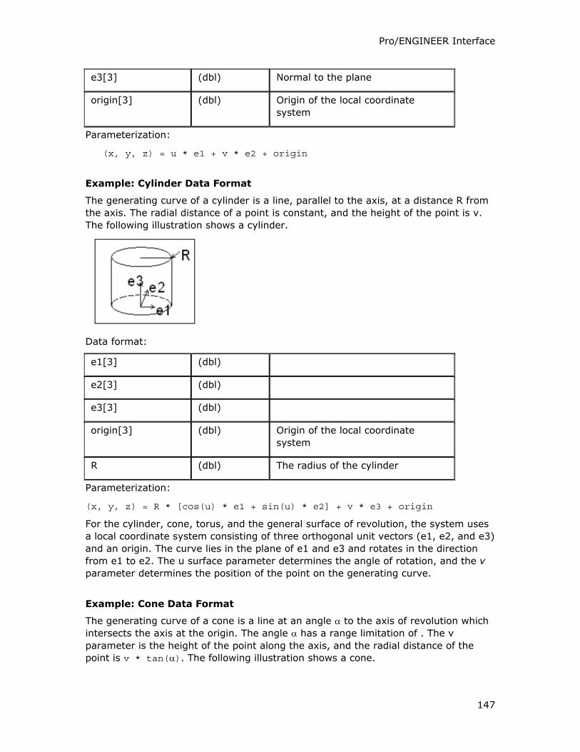
Pro/ENGINEER Interface
147
e3[3] (dbl) Normal to the plane
origin[3] (dbl) Origin of the local coordinate
system
Parameterization:
(x, y, z) = u * e1 + v * e2 + origin
Example: Cylinder Data Format
The generating curve of a cylinder is a line, parallel to the axis, at a distance R from
the axis. The radial distance of a point is constant, and the height of the point is v.
The following illustration shows a cylinder.
Data format:
e1[3] (dbl)
e2[3] (dbl)
e3[3] (dbl)
origin[3] (dbl) Origin of the local coordinate
system
R (dbl) The radius of the cylinder
Parameterization:
(x, y, z) = R * [cos(u) * e1 + sin(u) * e2] + v * e3 + origin
For the cylinder, cone, torus, and the general surface of revolution, the system uses
a local coordinate system consisting of three orthogonal unit vectors (e1, e2, and e3)
and an origin. The curve lies in the plane of e1 and e3 and rotates in the direction
from e1 to e2. The u surface parameter determines the angle of rotation, and the v
parameter determines the position of the point on the generating curve.
Example: Cone Data Format
The generating curve of a cone is a line at an angle α to the axis of revolution which
intersects the axis at the origin. The angle α has a range limitation of . The v
parameter is the height of the point along the axis, and the radial distance of the
point is v * tan(α). The following illustration shows a cone.
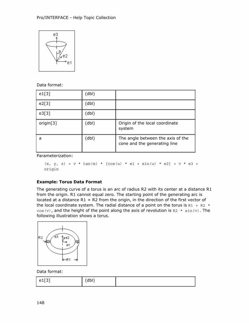
Pro/INTERFACE - Help Topic Collection
148
Data format:
e1[3] (dbl)
e2[3] (dbl)
e3[3] (dbl)
origin[3] (dbl) Origin of the local coordinate
system
a (dbl) The angle between the axis of the
cone and the generating line
Parameterization:
(x, y, z) = v * tan(α) * [cos(u) * e1 + sin(u) * e2] + v * e3 +
origin
Example: Torus Data Format
The generating curve of a torus is an arc of radius R2 with its center at a distance R1
from the origin. R1 cannot equal zero. The starting point of the generating arc is
located at a distance R1 + R2 from the origin, in the direction of the first vector of
the local coordinate system. The radial distance of a point on the torus is R1 + R2 * cos(v), and the height of the point along the axis of revolution is R2 * sin(v). The
following illustration shows a torus.
Data format:
e1[3] (dbl)
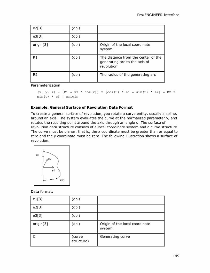
Pro/ENGINEER Interface
149
e2[3] (dbl)
e3[3] (dbl)
origin[3] (dbl) Origin of the local coordinate
system
R1 (dbl) The distance from the center of the
generating arc to the axis of
revolution
R2 (dbl) The radius of the generating arc
Parameterization:
(x, y, z) = (R1 + R2 * cos(v)) * [cos(u) * e1 + sin(u) * e2] + R2 * sin(v) * e3 + origin
Example: General Surface of Revolution Data Format
To create a general surface of revolution, you rotate a curve entity, usually a spline,
around an axis. The system evaluates the curve at the normalized parameter v, and
rotates the resulting point around the axis through an angle u. The surface of
revolution data structure consists of a local coordinate system and a curve structure
The curve must be planar; that is, the x coordinate must be greater than or equal to
zero and the y coordinate must be zero. The following illustration shows a surface of
revolution.
Data format:
e1[3] (dbl)
e2[3] (dbl)
e3[3] (dbl)
origin[3] (dbl) Origin of the local coordinate
system
C (curve
structure)
Generating curve
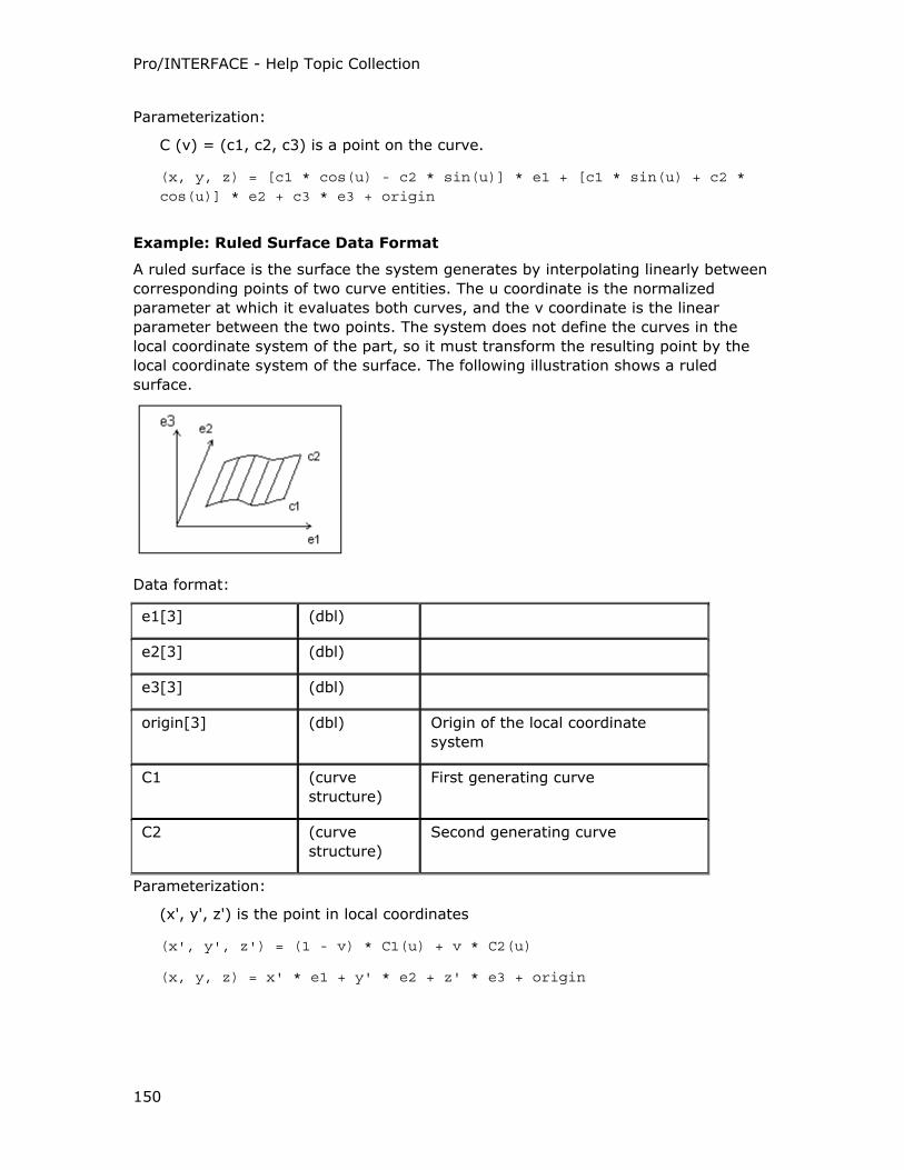
Pro/INTERFACE - Help Topic Collection
150
Parameterization:
C (v) = (c1, c2, c3) is a point on the curve.
(x, y, z) = [c1 * cos(u) - c2 * sin(u)] * e1 + [c1 * sin(u) + c2 * cos(u)] * e2 + c3 * e3 + origin
Example: Ruled Surface Data Format
A ruled surface is the surface the system generates by interpolating linearly between
corresponding points of two curve entities. The u coordinate is the normalized
parameter at which it evaluates both curves, and the v coordinate is the linear
parameter between the two points. The system does not define the curves in the
local coordinate system of the part, so it must transform the resulting point by the
local coordinate system of the surface. The following illustration shows a ruled
surface.
Data format:
e1[3] (dbl)
e2[3] (dbl)
e3[3] (dbl)
origin[3] (dbl) Origin of the local coordinate
system
C1 (curve
structure)
First generating curve
C2 (curve
structure)
Second generating curve
Parameterization:
(x', y', z') is the point in local coordinates
(x', y', z') = (1 - v) * C1(u) + v * C2(u)
(x, y, z) = x' * e1 + y' * e2 + z' * e3 + origin
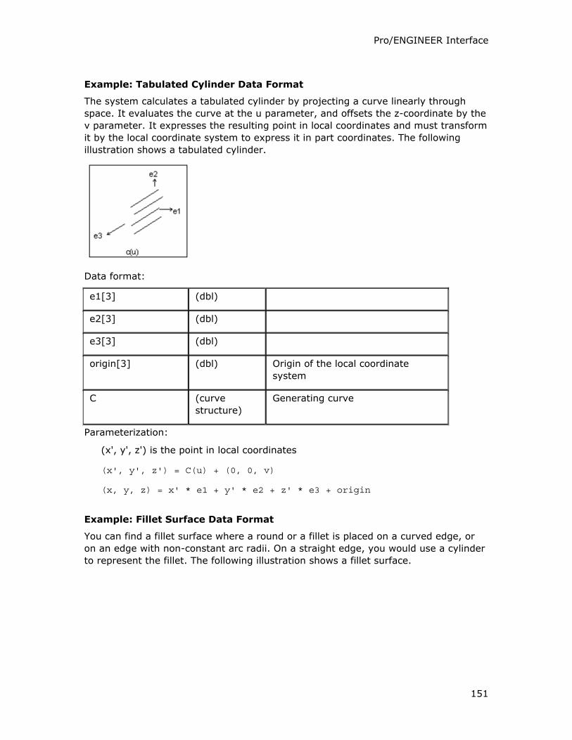
Pro/ENGINEER Interface
151
Example: Tabulated Cylinder Data Format
The system calculates a tabulated cylinder by projecting a curve linearly through
space. It evaluates the curve at the u parameter, and offsets the z-coordinate by the
v parameter. It expresses the resulting point in local coordinates and must transform
it by the local coordinate system to express it in part coordinates. The following
illustration shows a tabulated cylinder.
Data format:
e1[3] (dbl)
e2[3] (dbl)
e3[3] (dbl)
origin[3] (dbl) Origin of the local coordinate
system
C (curve
structure)
Generating curve
Parameterization:
(x', y', z') is the point in local coordinates
(x', y', z') = C(u) + (0, 0, v)
(x, y, z) = x' * e1 + y' * e2 + z' * e3 + origin
Example: Fillet Surface Data Format
You can find a fillet surface where a round or a fillet is placed on a curved edge, or
on an edge with non-constant arc radii. On a straight edge, you would use a cylinder
to represent the fillet. The following illustration shows a fillet surface.
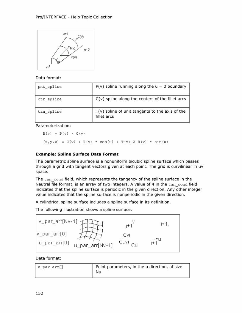
Pro/INTERFACE - Help Topic Collection
152
Data format:
pnt_spline P(v) spline running along the u = 0 boundary
ctr_spline C(v) spline along the centers of the fillet arcs
tan_spline T(v) spline of unit tangents to the axis of the
fillet arcs
Parameterization:
R(v) = P(v) - C(v)
(x,y,z) = C(v) + R(v) * cos(u) + T(v) X R(v) * sin(u)
Example: Spline Surface Data Format
The parametric spline surface is a nonuniform bicubic spline surface which passes
through a grid with tangent vectors given at each point. The grid is curvilinear in uv
space.
The tan_cond field, which represents the tangency of the spline surface in the
Neutral file format, is an array of two integers. A value of 4 in the tan_cond field
indicates that the spline surface is periodic in the given direction. Any other integer
value indicates that the spline surface is nonperiodic in the given direction.
A cylindrical spline surface includes a spline surface in its definition.
The following illustration shows a spline surface.
Data format:
u_par_arr[] Point parameters, in the u direction, of size
Nu
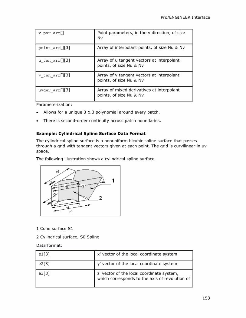
Pro/ENGINEER Interface
153
v_par_arr[] Point parameters, in the v direction, of size
Nv
point_arr[][3] Array of interpolant points, of size Nu & Nv
u_tan_arr[][3] Array of u tangent vectors at interpolant
points, of size Nu & Nv
v_tan_arr[][3] Array of v tangent vectors at interpolant
points, of size Nu & Nv
uvder_arr[][3] Array of mixed derivatives at interpolant
points, of size Nu & Nv
Parameterization:
• Allows for a unique 3 & 3 polynomial around every patch.
• There is second-order continuity across patch boundaries.
Example: Cylindrical Spline Surface Data Format
The cylindrical spline surface is a nonuniform bicubic spline surface that passes
through a grid with tangent vectors given at each point. The grid is curvilinear in uv
space.
The following illustration shows a cylindrical spline surface.
1 Cone surface S1
2 Cylindrical surface, S0 Spline
Data format:
e1[3] x' vector of the local coordinate system
e2[3] y' vector of the local coordinate system
e3[3] z' vector of the local coordinate system,
which corresponds to the axis of revolution of
Pro/INTERFACE - Help Topic Collection
154
the surface
origin[3] Origin of the local coordinate system
splsrf Spline surface data structure
The spline surface data structure contains the following fields:
u_par_arr[] Point parameters, in the u direction, of size
Nu
v_par_arr[] Point parameters, in the v direction, of size
Nv
point_arr[][3] Array of points, in cylindrical coordinates, of
size, Nu & Nv. The array components are as
follows:
point_arr[i][0]—Radius
point_arr[i][1]—Theta
point_arr[i][2]—Z
u_tan_arr[][3] Array of u tangent vectors in cylindrical
coordinates, of size Nu & Nv
v_tan_arr[][3] Array of v tangent vectors in cylindrical
coordinates, of size Nu & Nv
uvder_arr[][3] Array of mixed derivatives in cylindrical
coordinates, of size Nu & Nv
Engineering Notes
If the surface is represented in cylindrical coordinates (r, theta, z), the local
coordinate system values (x', y', z') are interpreted as follows:
• x' = r cos (theta)
• y' = r sin (theta)
• z' = z
You can obtain a cylindrical spline surface, for example, by creating a smooth
rotational blend (shown in the figure on the previous page). In some cases, you can
replace a cylindrical spline surface with a surface such as a plane, cylinder, or cone.
The illustration in Cylindrical Spline Surface on page 5 - 40, shows the cylindrical
spline surface S1 replaced with a cone (r1=r2, r3=r4, and r1r3). If you cannot
replace it (such as for the surface S0 in the illustration Cylindrical Spline Surface
(ra≠rb or rc≠rd)), leave it as a cylindrical spline surface representation.
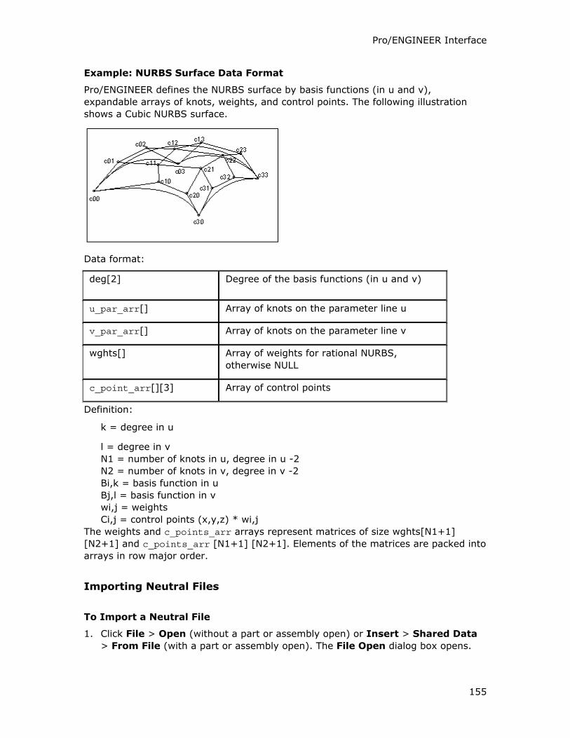
Pro/ENGINEER Interface
155
Example: NURBS Surface Data Format
Pro/ENGINEER defines the NURBS surface by basis functions (in u and v),
expandable arrays of knots, weights, and control points. The following illustration
shows a Cubic NURBS surface.
Data format:
deg[2] Degree of the basis functions (in u and v)
u_par_arr[] Array of knots on the parameter line u
v_par_arr[] Array of knots on the parameter line v
wghts[] Array of weights for rational NURBS,
otherwise NULL
c_point_arr[][3] Array of control points
Definition:
k = degree in u
l = degree in v
N1 = number of knots in u, degree in u -2
N2 = number of knots in v, degree in v -2
Bi,k = basis function in u
Bj,l = basis function in v
wi,j = weights
Ci,j = control points (x,y,z) * wi,j
The weights and c_points_arr arrays represent matrices of size wghts[N1+1]
[N2+1] and c_points_arr [N1+1] [N2+1]. Elements of the matrices are packed into
arrays in row major order.
Importing Neutral Files
To Import a Neutral File
1. Click File > Open (without a part or assembly open) or Insert > Shared Data
> From File (with a part or assembly open). The File Open dialog box opens.
Pro/INTERFACE - Help Topic Collection
156
2. Select Neutral (*.neu) in the Type box. Neutral files in the working directory
appear.
3. Click the Neutral file you want to import from the list of available files or browse
to find and then click the Neutral file.
4. Click Open. The Choose Solid Options and Placement dialog box opens.
5. Accept the default coordinate system or select a coordinate system.
6. Click Protrusion, Cut, or Surfaces.
7. Click OK to import the file.
Part Entity Data Format
Each part entity has a list of the surfaces, edges, features, and dimensions
associated with it, and the names of any files that contain information related to the
part, such as dimension tables, assemblies which include the part, or drawing files.
Data Format:
• surfaces [ ]
• quilts [ ]
• edges [ ]
• datum_curves [ ]
• datum_planes [ ]
• coord_systems [ ]
• attributes [ ]
• layers [ ]
• dimensions [ ]
• features [ ]
• geometric_tolerances [ ]
• colors [ ]
• views [ ]
• xsecs [ ]
• accuracy [ ]
Format of Neutral Files
A Neutral file consists of lines of ASCII text. The format has the following elements:
• A line beginning with the character # is a comment.
• A line not beginning with the character # is of the form:
Pro/ENGINEER Interface
157
o level field value
o where:
o level is an integer
o field is a name
o value is a string that can be present
• A field must be one of the following:
o The name of a simple data type (integer, string, real, and so on)
o The name of an array
o The name of a structure
o The name of a pointer to a structure
• All the fields on a particular level belong to the same parent.
• When value is present at a certain level and begins with the left square bracket
character ([), or consists of a series of digits separated by commas, it indicates
that field is an array of dimension [n]([m] ...). The array element values are
contained on the lines level+1 up to the next line starting with level again.
o For one-dimensional arrays, only one line is at the higher level whose value
is a string of element values separated by commas.
o The notation< n*m> indicates the following <n> elements each have the
value <m>.
• When value is present at a certain level (and is not the string ->), this is the
value to be assigned to field.
• When value is absent at a certain level, this indicates that field is a structure.
Immediate elements of the aggregate are contained on lines level+1 up to next
line starting with level again.
• The line whose field is the string ugc_xar_len is a special case indicating that the
next line begins the description of an array of length value.
• When value is the string ->, this indicates that field is a pointer to an aggregate
whose elements follow.
• The special value string NULL indicates that the field is a pointer whose value is
null.
Edge Entity Data Format
The edge entity contains data about the boundary between two trimmed surfaces.
This data includes the IDs of the two surfaces, the direction of the edge with respect
to the clockwise boundary traversal of the surfaces, and the uv points of the
boundary segment represented by the edge in each surface. The uv points are in
groups of four. The first pair of points is the u- and v-coordinates of the edge in
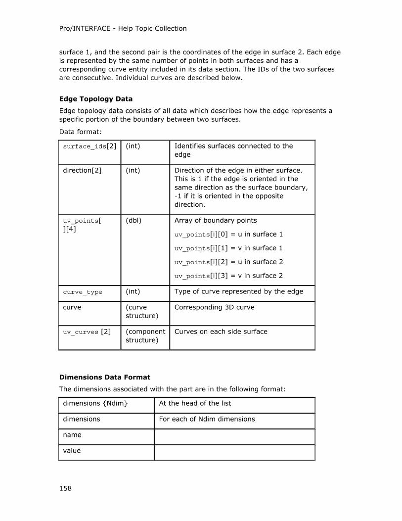
Pro/INTERFACE - Help Topic Collection
158
surface 1, and the second pair is the coordinates of the edge in surface 2. Each edge
is represented by the same number of points in both surfaces and has a
corresponding curve entity included in its data section. The IDs of the two surfaces
are consecutive. Individual curves are described below.
Edge Topology Data
Edge topology data consists of all data which describes how the edge represents a
specific portion of the boundary between two surfaces.
Data format:
surface_ids[2] (int) Identifies surfaces connected to the
edge
direction[2] (int) Direction of the edge in either surface.
This is 1 if the edge is oriented in the
same direction as the surface boundary,
-1 if it is oriented in the opposite
direction.
uv_points[
][4]
(dbl) Array of boundary points
uv_points[i][0] = u in surface 1
uv_points[i][1] = v in surface 1
uv_points[i][2] = u in surface 2
uv_points[i][3] = v in surface 2
curve_type (int) Type of curve represented by the edge
curve (curve
structure)
Corresponding 3D curve
uv_curves [2] (component
structure)
Curves on each side surface
Dimensions Data Format
The dimensions associated with the part are in the following format:
dimensions {Ndim} At the head of the list
dimensions For each of Ndim dimensions
name
value
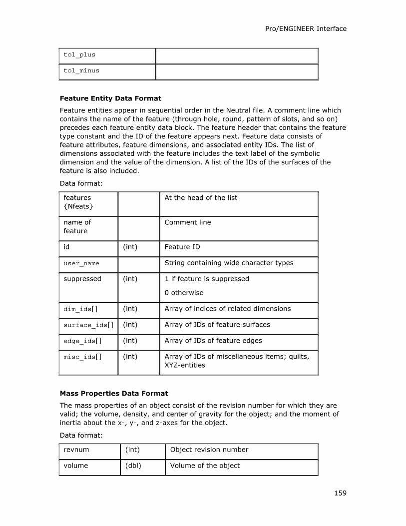
Pro/ENGINEER Interface
159
tol_plus
tol_minus
Feature Entity Data Format
Feature entities appear in sequential order in the Neutral file. A comment line which
contains the name of the feature (through hole, round, pattern of slots, and so on)
precedes each feature entity data block. The feature header that contains the feature
type constant and the ID of the feature appears next. Feature data consists of
feature attributes, feature dimensions, and associated entity IDs. The list of
dimensions associated with the feature includes the text label of the symbolic
dimension and the value of the dimension. A list of the IDs of the surfaces of the
feature is also included.
Data format:
features
{Nfeats}
At the head of the list
name of
feature
Comment line
id (int) Feature ID
user_name String containing wide character types
suppressed (int) 1 if feature is suppressed
0 otherwise
dim_ids[] (int) Array of indices of related dimensions
surface_ids[] (int) Array of IDs of feature surfaces
edge_ids[] (int) Array of IDs of feature edges
misc_ids[] (int) Array of IDs of miscellaneous items; quilts,
XYZ-entities
Mass Properties Data Format
The mass properties of an object consist of the revision number for which they are
valid; the volume, density, and center of gravity for the object; and the moment of
inertia about the x-, y-, and z-axes for the object.
Data format:
revnum (int) Object revision number
volume (dbl) Volume of the object
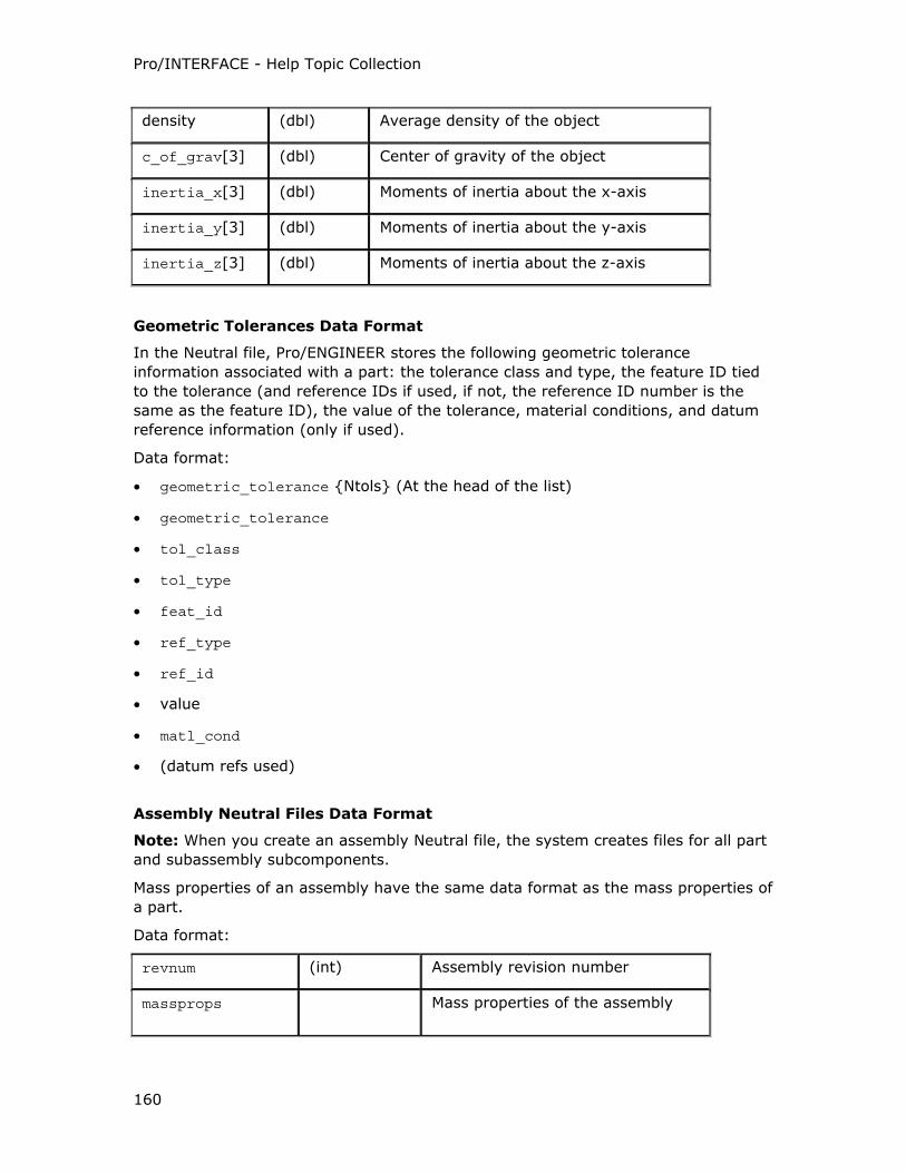
Pro/INTERFACE - Help Topic Collection
160
density (dbl) Average density of the object
c_of_grav[3] (dbl) Center of gravity of the object
inertia_x[3] (dbl) Moments of inertia about the x-axis
inertia_y[3] (dbl) Moments of inertia about the y-axis
inertia_z[3] (dbl) Moments of inertia about the z-axis
Geometric Tolerances Data Format
In the Neutral file, Pro/ENGINEER stores the following geometric tolerance
information associated with a part: the tolerance class and type, the feature ID tied
to the tolerance (and reference IDs if used, if not, the reference ID number is the
same as the feature ID), the value of the tolerance, material conditions, and datum
reference information (only if used).
Data format:
• geometric_tolerance {Ntols} (At the head of the list)
• geometric_tolerance
• tol_class
• tol_type
• feat_id
• ref_type
• ref_id
• value
• matl_cond
• (datum refs used)
Assembly Neutral Files Data Format
Note: When you create an assembly Neutral file, the system creates files for all part
and subassembly subcomponents.
Mass properties of an assembly have the same data format as the mass properties of
a part.
Data format:
revnum (int) Assembly revision number
massprops Mass properties of the assembly
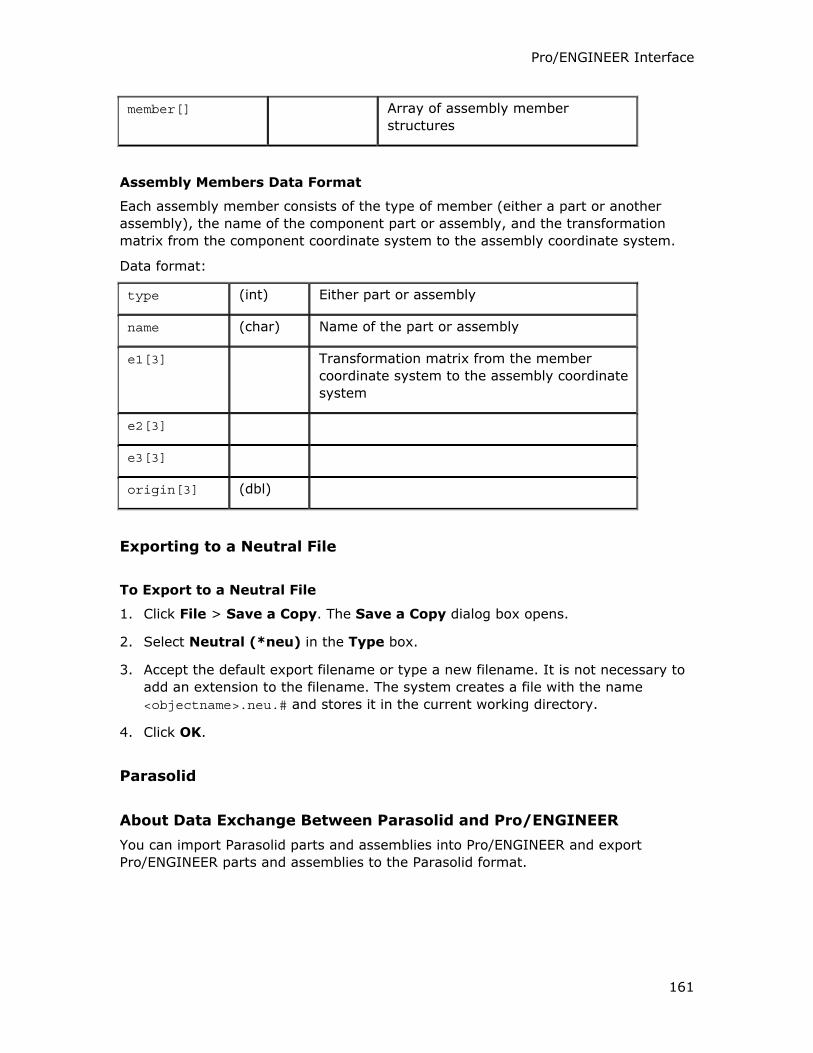
Pro/ENGINEER Interface
161
member[] Array of assembly member
structures
Assembly Members Data Format
Each assembly member consists of the type of member (either a part or another
assembly), the name of the component part or assembly, and the transformation
matrix from the component coordinate system to the assembly coordinate system.
Data format:
type (int) Either part or assembly
name (char) Name of the part or assembly
e1[3] Transformation matrix from the member
coordinate system to the assembly coordinate
system
e2[3]
e3[3]
origin[3] (dbl)
Exporting to a Neutral File
To Export to a Neutral File
1. Click File > Save a Copy. The Save a Copy dialog box opens.
2. Select Neutral (*neu) in the Type box.
3. Accept the default export filename or type a new filename. It is not necessary to
add an extension to the filename. The system creates a file with the name
<objectname>.neu.# and stores it in the current working directory.
4. Click OK.
Parasolid
About Data Exchange Between Parasolid and Pro/ENGINEER
You can import Parasolid parts and assemblies into Pro/ENGINEER and export
Pro/ENGINEER parts and assemblies to the Parasolid format.
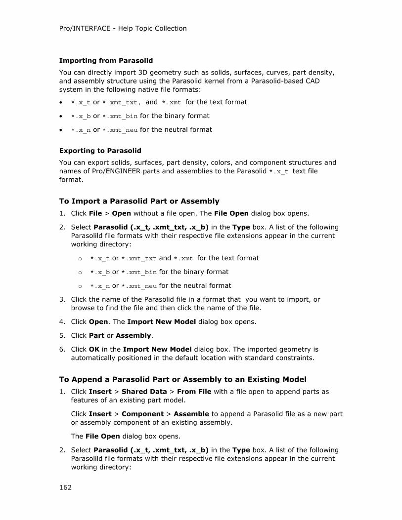
Pro/INTERFACE - Help Topic Collection
162
Importing from Parasolid
You can directly import 3D geometry such as solids, surfaces, curves, part density,
and assembly structure using the Parasolid kernel from a Parasolid-based CAD
system in the following native file formats:
• *.x_t or *.xmt_txt, and *.xmt for the text format
• *.x_b or *.xmt_bin for the binary format
• *.x_n or *.xmt_neu for the neutral format
Exporting to Parasolid
You can export solids, surfaces, part density, colors, and component structures and
names of Pro/ENGINEER parts and assemblies to the Parasolid *.x_t text file
format.
To Import a Parasolid Part or Assembly
1. Click File > Open without a file open. The File Open dialog box opens.
2. Select Parasolid (.x_t, .xmt_txt, .x_b) in the Type box. A list of the following
Parasolild file formats with their respective file extensions appear in the current
working directory:
o *.x_t or *.xmt_txt and *.xmt for the text format
o *.x_b or *.xmt_bin for the binary format
o *.x_n or *.xmt_neu for the neutral format
3. Click the name of the Parasolid file in a format that you want to import, or
browse to find the file and then click the name of the file.
4. Click Open. The Import New Model dialog box opens.
5. Click Part or Assembly.
6. Click OK in the Import New Model dialog box. The imported geometry is
automatically positioned in the default location with standard constraints.
To Append a Parasolid Part or Assembly to an Existing Model
1. Click Insert > Shared Data > From File with a file open to append parts as
features of an existing part model.
Click Insert > Component > Assemble to append a Parasolid file as a new part
or assembly component of an existing assembly.
The File Open dialog box opens.
2. Select Parasolid (.x_t, .xmt_txt, .x_b) in the Type box. A list of the following
Parasolild file formats with their respective file extensions appear in the current
working directory:
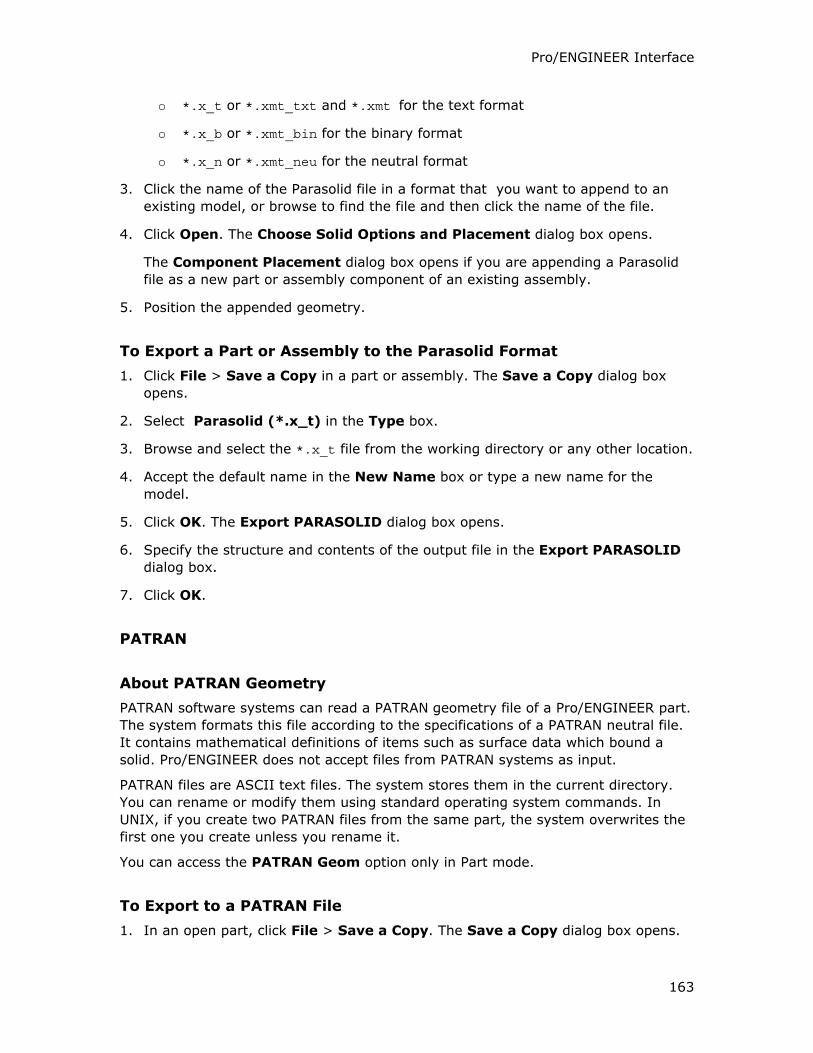
Pro/ENGINEER Interface
163
o *.x_t or *.xmt_txt and *.xmt for the text format
o *.x_b or *.xmt_bin for the binary format
o *.x_n or *.xmt_neu for the neutral format
3. Click the name of the Parasolid file in a format that you want to append to an
existing model, or browse to find the file and then click the name of the file.
4. Click Open. The Choose Solid Options and Placement dialog box opens.
The Component Placement dialog box opens if you are appending a Parasolid
file as a new part or assembly component of an existing assembly.
5. Position the appended geometry.
To Export a Part or Assembly to the Parasolid Format
1. Click File > Save a Copy in a part or assembly. The Save a Copy dialog box
opens.
2. Select Parasolid (*.x_t) in the Type box.
3. Browse and select the *.x_t file from the working directory or any other location.
4. Accept the default name in the New Name box or type a new name for the
model.
5. Click OK. The Export PARASOLID dialog box opens.
6. Specify the structure and contents of the output file in the Export PARASOLID
dialog box.
7. Click OK.
PATRAN
About PATRAN Geometry
PATRAN software systems can read a PATRAN geometry file of a Pro/ENGINEER part.
The system formats this file according to the specifications of a PATRAN neutral file.
It contains mathematical definitions of items such as surface data which bound a
solid. Pro/ENGINEER does not accept files from PATRAN systems as input.
PATRAN files are ASCII text files. The system stores them in the current directory.
You can rename or modify them using standard operating system commands. In
UNIX, if you create two PATRAN files from the same part, the system overwrites the
first one you create unless you rename it.
You can access the PATRAN Geom option only in Part mode.
To Export to a PATRAN File
1. In an open part, click File > Save a Copy. The Save a Copy dialog box opens.
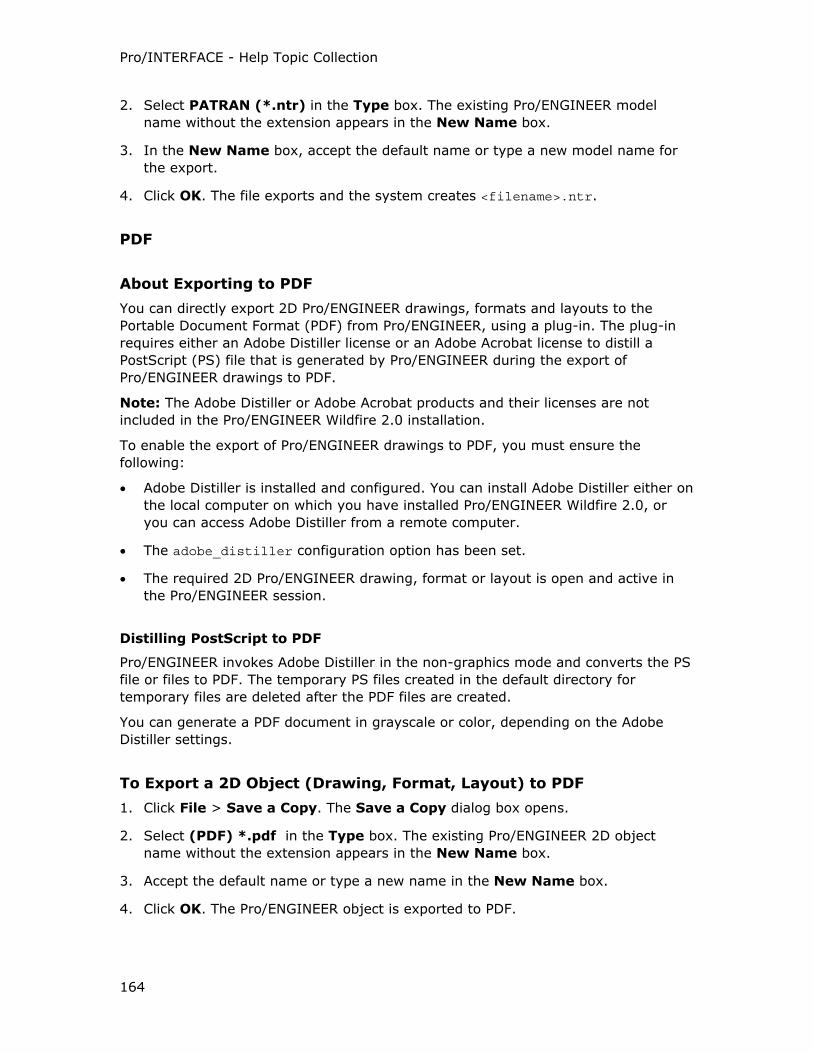
Pro/INTERFACE - Help Topic Collection
164
2. Select PATRAN (*.ntr) in the Type box. The existing Pro/ENGINEER model
name without the extension appears in the New Name box.
3. In the New Name box, accept the default name or type a new model name for
the export.
4. Click OK. The file exports and the system creates <filename>.ntr.
About Exporting to PDF
You can directly export 2D Pro/ENGINEER drawings, formats and layouts to the
Portable Document Format (PDF) from Pro/ENGINEER, using a plug-in. The plug-in
requires either an Adobe Distiller license or an Adobe Acrobat license to distill a
PostScript (PS) file that is generated by Pro/ENGINEER during the export of
Pro/ENGINEER drawings to PDF.
Note: The Adobe Distiller or Adobe Acrobat products and their licenses are not
included in the Pro/ENGINEER Wildfire 2.0 installation.
To enable the export of Pro/ENGINEER drawings to PDF, you must ensure the
following:
• Adobe Distiller is installed and configured. You can install Adobe Distiller either on
the local computer on which you have installed Pro/ENGINEER Wildfire 2.0, or
you can access Adobe Distiller from a remote computer.
• The adobe_distiller configuration option has been set.
• The required 2D Pro/ENGINEER drawing, format or layout is open and active in
the Pro/ENGINEER session.
Distilling PostScript to PDF
Pro/ENGINEER invokes Adobe Distiller in the non-graphics mode and converts the PS
file or files to PDF. The temporary PS files created in the default directory for
temporary files are deleted after the PDF files are created.
You can generate a PDF document in grayscale or color, depending on the Adobe
Distiller settings.
To Export a 2D Object (Drawing, Format, Layout) to PDF
1. Click File > Save a Copy. The Save a Copy dialog box opens.
2. Select (PDF) *.pdf in the Type box. The existing Pro/ENGINEER 2D object
name without the extension appears in the New Name box.
3. Accept the default name or type a new name in the New Name box.
4. Click OK. The Pro/ENGINEER object is exported to PDF.
Pro/ENGINEER Interface
165
Note: The PDF file is written to the location you specify. If the specified location
is either a Windchill workspace or a remote location, the file is created locally by
the distiller, and then copied into the specified location.
5. Alternatively, you can also click to save the 2D object in the active window
to a PDF file. The PDF file is saved in the Pro/ENGINEER working directory.
or
Click to send the 2D object in the active window as a PDF file, through e-
mail.
or
a. Click File > Print. The Print dialog box opens.
b. Click .
c. Select Adobe Color PDF to generate a PDF based on generic color
PostScript format, or select Adobe PDF to generate a PDF based on
generic PostScript format.
d. Click OK.
Pro/DESKTOP
About Importing Pro/DESKTOP Models
The method of directly opening native .des part files of Pro/DESKTOP V7 and higher
and native .des assembly files of Pro/DESKTOP V8 and higher as new models in
Pro/ENGINEER is the default. For each feature in the Pro/DESKTOP model, a
corresponding read-only feature is created in the directly-opened model in
Pro/ENGINEER.
The feature-structure of the Pro/DESKTOP .des file is preserved in the resultant
Pro/ENGINEER file. The item and feature IDs and configurations in Pro/DESKTOP that
correspond to the family table instances in Pro/ENGINEER are preserved in the
model. Pro/DESKTOP feature-types that are not supported in Pro/ENGINEER, such as
taper-extrusions, do not have the corresponding feature-types in Pro/ENGINEER and
are represented by the native Pro/DESKTOP feature icons in the Model Tree.
Note: You must explicitly set the intf_in_granite_direct_enable configuration
option to no to import the .des Pro/DESKTOP files to Pro/ENGINEER as import IN
features. Unlike the features created by the directly-opened Pro/DESKTOP .des
models that are read-only, you can modify and regenerate, if necessary, the import
IN features and append them to existing Pro/ENGINEER parts.
Regardless of whether intf_in_granite_direct_enable is set to yes or no, you can
import only part files of the Pro/DESKTOP .pdt file format as import IN features.
Opening Pro/DESKTOP 2001 or higher *.pdt files as new models in Pro/ENGINEER
create import IN features within Conceptual Engineering Data (CED) groups.
Pro/INTERFACE - Help Topic Collection
166
Pro/DESKTOP .des and .pdt files create import IN features for the following import
and append operations:
• Opening a Pro/DESKTOP model as a new part with File > Open.
• Assembling a Pro/DESKTOP model as a part component of an existing
Pro/ENGINEER assembly with Insert > Component > Assemble.
• Appending a Pro/DESKTOP model as a new part or part component of an existing
Pro/ENGINEER assembly using Insert > Shared Data > From File.
• Appending a Pro/DESKTOP model as a new feature of an existing Pro/ENGINEER
part using Insert > Shared Data > From File.
If you set the topobus_enable configuration option to yes before directly opening or
importing the Pro/DESKTOP files into Pro/ENGINEER,
• The directly-opened .des Pro/DESKTOP models create Translated Image Models
(TIMs) that are ATB-enabled at the model level.
• The standard import method creates IN features that are ATB-enabled at the
feature level.
Import of Native .des Pro/DESKTOP Files
Native .des Pro/DESKTOP files create a 'group' when you import them as new parts.
This 'group' is different from the CED group because this 'group' does not contain the
datum planes and datum curves. You can use the Associative Topology Bus (ATB)
functionality to update the IN features within this group.
About Conceptual Engineering Data (CED) Groups
Conceptual Engineering Data (CED) groups are created when you import Granite-
based .pdt Pro/DESKTOP files to create new models.
Note: Not all .pdt Pro/DESKTOP files create CED groups. Only Pro/DESKTOP 2001
Granite-based .pdt files, created when you export the Pro/DESKTOP file from within
Pro/DESKTOP 2001 or higher to the Pro/ENGINEER 2001 format, create CED groups.
Pro/DESKTOP .pdt files create CED groups in the following operations:
• File > Open
• Insert > Component > Assemble
• Insert > Shared Data > From File into an existing Pro/ENGINEER assembly
A CED group import is different from the standard import of a Pro/DESKTOP .pdt
file. A CED group import extracts the sketch plane and profile data from the import
feature and constructs native Pro/ENGINEER datum planes and datum curve features
from the extracted sketch plane and profile data. The dimensions and constraints
used to constrain the profiles in the original Pro/DESKTOP part are used to construct
the Pro/ENGINEER curve features. The Pro/DESKTOP IN feature, consisting of only
the solid or surface data, and these datum planes and curves, comprise the 'group'
called Conceptual Engineering Data (CED).
Pro/ENGINEER Interface
167
You can associatively update the entire CED group to changes in the original
reference .pdt file, but you cannot use the Associative Topology Bus (ATB) Update
function to update the CED groups. Instead, you can use Edit Definition on the CED
group in the Model Tree and the GROUP HEAD dialog box that opens to update the
CED group with datum planes and datum curves. You need not set the
topobus_enable configuration option to yes to update CED groups.
You can also convert the CED groups or the IN features into standard independent
groups or features using Make group independent on the GROUP HEAD dialog
box.
To Open a Pro/DESKTOP File in Pro/ENGINEER
1. Click File > Open to open a Pro/DESKTOP file as a new model in Pro/ENGINEER.
The File Open dialog box opens.
2. Select one of the following in the Type box:
o Pro/Desktop (*.pdt)
o Pro/DESKTOP Direct (*.des)
Files of the selected type that are located in your working directory are listed.
3. Browse for the required file if it is not in your working directory.
4. Double-click the name of the part or assembly that you want to import.
5. Click Open.
o By default, Pro/DESKTOP .des files directly open as new models,
maintaining the original Granite feature history as read-only features
because they are Granite-based.
o If intf_in_granite_direct_enable is set to no, Pro/DESKTOP .des files
are opened with standard import functionality and the model geometry or
the component model stored in a single import feature.
o Pro/DESKTOP .pdt part files create import IN features even if
intf_in_granite_direct_enable is set to yes.
To Append a Pro/DESKTOP File to a Pro/ENGINEER Model
1. Open a Pro/ENGINEER part or assembly.
2. Click Insert > Shared Data > From File. The File Open dialog box opens.
3. Select one of the following in the Type box:
o Pro/Desktop (*.pdt)
o Pro/DESKTOP Direct (*.des)
Files of the selected type that are located in your working directory are listed.
4. Browse for the required file if it is not in your working directory.
Pro/INTERFACE - Help Topic Collection
168
5. Double-click the .pdt or the .des file that you want to add to your model. If one
or more coordinate systems exist in the Pro/ENGINEER file, the Choose Solid
Options and Placement dialog box opens.
6. Accept the default coordinate system in the Choose Solid Options and
Placement dialog box or use the selection arrow to select another coordinate
system.
7. Click to select Protrusion, Cut, or Surfaces as the imported feature when
appending a Pro/DESKTOP file to an existing part with solid geometry.
8. Click OK. The Pro/DESKTOP file is appended as a new component to a
Pro/ENGINEER assembly model or as a protrusion, cut, or quilt to a
Pro/ENGINEER part model.
To Assemble a Pro/DESKTOP File Into an Existing Assembly
1. Click Insert > Component > Assemble to assemble a Pro/DESKTOP .des
model as a part or subassembly component of an existing Pro/ENGINEER
assembly. The File Open dialog box opens.
2. Select one of the following in the Type box:
o Pro/Desktop (*.pdt)
o Pro/DESKTOP Direct (*.des)
Files of the selected type that are located in your working directory are listed.
3. Browse for the required file if it is not in your working directory.
4. Double-click the file that you want to assemble as a part or subassembly
component of an existing Pro/ENGINEER assembly. The Component Placement
dialog box opens.
5. Position or constrain, or position and constrain, the imported component into the
assembly.
6. Click OK in the Component Placement dialog box.
To Update a Conceptual Engineering Data (CED) Group
1. Select a Conceptual Engineering Data (CED) Group header containing the
Pro/DESKTOP import IN feature and the associated curve and datum features
from the Model Tree.
2. Right-click. The shortcut menu appears.
3. Click Edit Definition. The GROUP HEAD dialog box opens.
4. Click Update geomtools model.
5. Click OK.
Pro/ENGINEER Interface
169
ProductView
About Data Exchange Between ProductView and Pro/ENGINEER
You can export a Pro/ENGINEER part, assembly, or drawing to one of the following
ProductView file types:
• Viewable .ol files that represent parts and part components of an assembly.
• Structure .ed files that contain product structure, component position,
orientation, and meta data (part- and assembly-level parameter) information.
• Drawing .plt plot files that are stored in the HPGL2 format.
Drawings exported to ProductView create a .plt plot file and a .ed structure
file. The .ed file contains the meta data information.
You can import the following data from the .ol, .ed, and .edz ProductView file
formats:
• Facet geometry (surfaces and solids)
• Datum geometry (curves, datum planes, datum points, and so on)
• Colors
ProductView .edz files are the zipped files of the .ed format and are unzipped by the
system before import.
Note: ProductView import is not supported on Linux.
To Export a Drawing, Part, or Assembly to a ProductView File Type
1. Click File > Save a Copy. The Save a Copy dialog box opens.
2. Select ProductView and one of the following ProductView file types in the Type
box to export the part, assembly, or drawing to ProductView:
o Viewable as .ol
o Structures as .ed
o Drawings as .plt
3. Accept the default export file name in the New Name box or type a new name.
4. Click OK.
To Import a ProductView .ol or .ed File into Pro/ENGINEER
1. Click File > Open. The File Open dialog box opens.
2. Select ProductView (.ol, .ed, .edz) as the file type in the Type box.
3. Select the ProductView file that you want to import from the list of available files
or browse to find the file.
Pro/INTERFACE - Help Topic Collection
170
4. Click Open. A part or an assembly is created depending on the file type you have
selected.
o ProductView .ol files create parts.
o ProductView .ed and .edz files create assemblies.
To Append a ProductView Part or Assembly to an Existing Model
1. Click Insert > Shared Data > From File with a part or assembly file open. The
File Open dialog box opens.
2. Select ProductView (.ol, .ed, .edz) in the Type box. A list of the .ol and .ed
ProductView file formats with their respective file extensions appear in the
current working directory.
3. Click the ProductView file or browse to find the file and then click the name of the
file.
4. Click Open. The Choose Solid Options and Placement dialog box opens.
5. Accept the default coordinate system location or select a coordinate system to
position the geometry.
6. If you are inserting a feature into a Pro/ENGINEER part that consists of solid
geometry, select
o Protrusion or Cut to add or subtract the imported geometry from the
existing solid.
o Surfaces to insert the imported geometry as a collection of quilts that does
not affect the existing solid.
7. Click OK.
o ProductView .ol files append as features to the existing part models.
o ProductView .ed files append as part components to existing assemblies.
To Assemble a ProductView Part or Assembly into an Existing Assembly
1. Click Insert > Component > Assemble with an assembly open. The File Open
dialog box opens.
2. Select ProductView (.ol, .ed, .edz) in the Type box. A list of the .ol and .ed
ProductView files with their respective file extensions appear in the current
working directory.
3. Click a ProductView file or browse to find the file and then click the name of the
file.
4. Click Open. The Component Placement dialog box opens.
5. Add placement constraints to position the part or subassembly component.
Pro/ENGINEER Interface
171
6. Click OK.
o ProductView .ol files are assembled as new part components.
o ProductView .ed files are assembled as subassembly components
SET
Overview of SET Files
About SET Files
The Standard for Exchange and Transfer (SET) transfers graphics and textual
information between computer systems. Pro/ENGINEER supports SET Version 89-06.
In SET files, parts and drawings are constructed differently from the way they are
constructed in Pro/ENGINEER. There is seldom a one-to-one correspondence
between the number and type of entities composing an object in Pro/ENGINEER and
the number and type of entities composing the same object in a SET file. This is
especially true for parts with blended and swept features.
If you need more information about the use of SET files, see Data Exchange and
Transfer Standard Specification (SET), Z 68-300 Version 89-06.
Export/Import of Layers
SET supports the export and import of layers. To export layers to SET from
Pro/ENGINEER, you must specify the layer IDs using the Specify Id option in the
Setup Layer menu.
The system exports the layer ID of a drawing entity (geometry, dimension, or note)
to a SET file along with the entity. Pro/ENGINEER supports only a single layer per
entity through interface files, so if an entity resides in more than one layer, it exports
only the highest layer ID (assigned the largest number) as the entity’s layer. The
system assigns entities with layers read in from SET to a layer in Drawing mode. The
layer name of an entity read from SET is INTF_<nnn>, where <nnn> is the layer ID.
Controlling the Output of Blanked Layers
Set the intf_out_blanked_entities configuration option to control the output of
blanked layers.
Importing SET Files
To Import a SET File into an Existing Part or Assembly
Note: It is a good practice to create default datum planes before importing SET
data.
1. Create or retrieve a model.
At least one feature must exist in the model.
Pro/INTERFACE - Help Topic Collection
172
2. Click Insert > Shared Data > From File. The File Open dialog box opens.
3. Select SET (*.set) in the Type box. SET files in the working directory appear.
4. Click the name of the SET file you want or browse to find and then click the SET
file.
5. Click Open. The SET Import Log file appears in the INFORMATION WINDOW.
The Choose Solid Options and Placement dialog box opens.
6. Accept the default coordinate system or select a coordinate system.
7. Click Protrusion, Cut, or Surfaces.
8. Click OK to import the file.
Importing SET Files
The system creates a log file with a name < model_name>.log in your working
directory whenever you import a SET model into Pro/ENGINEER. This file contains a
summary of SET import processing. You can replace an imported feature with a new
import file without having a one-to-one correspondence between existing entities
and the replacement entities.
If the SET file contains the necessary topology for surface connection, you can create
a solid using Use Quilt from the Solid Opts menu. If imported files do not have
information on surface connection, you can join surfaces in several ways.
Part and Assembly SET Files
When a SET file contains 3D geometry, surface data, and topology, you can import it
into a part or assembly to create a nonparametric feature. You cannot modify this
feature, but you can add features to the model. If no topology for surfaces exists,
even if surface data is present, only a wireframe representation is constructed.
To Import a SET File into a Drawing
1. Create or retrieve a drawing, format, or layout.
2. Click Insert > Shared Data > From File. The File Open dialog box opens.
3. Select SET (*.set) in the Type box. Set files in the working directory appear.
4. Click the filename of a SET file, or browse for the SET file you want.
5. Depending on the size of the imported drawing, the following can happen:
o If the imported drawing is of a different size than the Pro/ENGINEER
drawing, the system prompts you to scale the imported geometry to fit the
format. If you type [N], it asks you if you want to move the origin of the
imported drawing to the lower-left corner of the format.
Note: If you did not scale the imported geometry to fit the selected
drawing size, you can later replace the drawing format with one of a more
appropriate size.
Pro/ENGINEER Interface
173
o If the imported drawing is of the same size as the Pro/ENGINEER drawing,
the system automatically places the origin of the imported drawing at the
lower-left corner (format origin). In this case, no prompt appears.
To Create a Part or Assembly by Importing SET Data
1. Click File > Open. The File Open dialog box opens.
2. Select SET (*.set) in the Type box. SET files in the working directory appear.
3. Click the name of the SET file you want or browse to find the file, and then click
the SET file.
4. Click Open. The Import New Model dialog box opens.
5. Click Part or Assembly to indicate the type of model.
6. Accept the default name or assign a new name.
7. Click OK. The SET Import Log File appears in the Information Window. The SET
data is imported and the new part or assembly is created.
Exporting to SET
To Export a Part or Drawing to a SET File
1. With the part or drawing active, click File > Save a Copy. The Save a Copy
dialog box opens.
2. Select SET (*.set) in the Type box.
3. Accept the default name in the New Name box or type a new model name for
the export.
4. Click OK. The Export SET dialog box opens.
5. When exporting a part, create or select a coordinate system.
6. Click OK.
Exporting Through SET
All SET files created in Pro/ENGINEER follow the naming convention
<objectname>.set, where <objectname> is the name of the currently active part or
drawing. If a multisheet drawing is active, the name defaults to
<drawingname>_#.set, where # is the current sheet number. You must create a SET
file for each sheet of the drawing.
To Export an Assembly to a SET File
1. With the assembly active, click File > Save a Copy. The Save a Copy dialog
box opens.
2. Select SET (*.set) in the Type box.
Pro/INTERFACE - Help Topic Collection
174
3. Accept the default name in the New Name box or type a new model name for
the export.
4. Click OK. The Export SET dialog box opens.
5. Create or select a coordinate system.
6. Specify if you want to output the assembly as one assembly file with internal
references or as an assembly file with external references to component files by
selecting Internal ref or External ref.
7. Click OK. The assembly exports to a SET file.
Note: SET does not support all special characters supported by Pro/ENGINEER.
Therefore, when you export to the SET file some characters may not appear.
STEP
Overview of STEP Files
About STEP Files
Through STEP (Standard for the Exchange of Product Model Data), you can exchange
complete product definitions between heterogeneous computer-aided design,
engineering, and manufacturing systems. You can export the combined surface and
solid data, and faceted geometry that is in accordance with AP203 and AP214 STEP
multiple shape reps and hybrid models. You can export and import:
• Drawings that are in accordance with AP202DIS of the ISO 10303 STEP format.
• Parts and assemblies that are in accordance with AP203IS, AP214CD, AP214IS,
and AP214DIS formats.
• Geometry in accordance with the STEP AP209 format.
STEP Format
STEP is an international standard, defined in publications produced by the U.S.
Product Data Association (US PRO) IGES/PDES Organization. The complete set of
specifications for STEP is referred to as ISO 10303.
The STEP format is organized as a series of documents (referred to as parts in STEP
terminology), with each part published separately. Application Protocols (APs), which
reference generic parts of ISO 10303, are produced to meet specific data exchange
requirements for a particular application. AP202, AP203, and AP214 have reached
the status of an International Standard (IS) version. Other APs include AP202DIS,
AP209DIS and AP214DIS (Draft International Standard), and AP214 CD II
(Committee Draft).
Products supporting STEP can implement this interface using different levels of data
transfer. Each level provides various mechanisms to store, accept, and pass product
definition data between heterogeneous systems in a consistent and standardized
way.
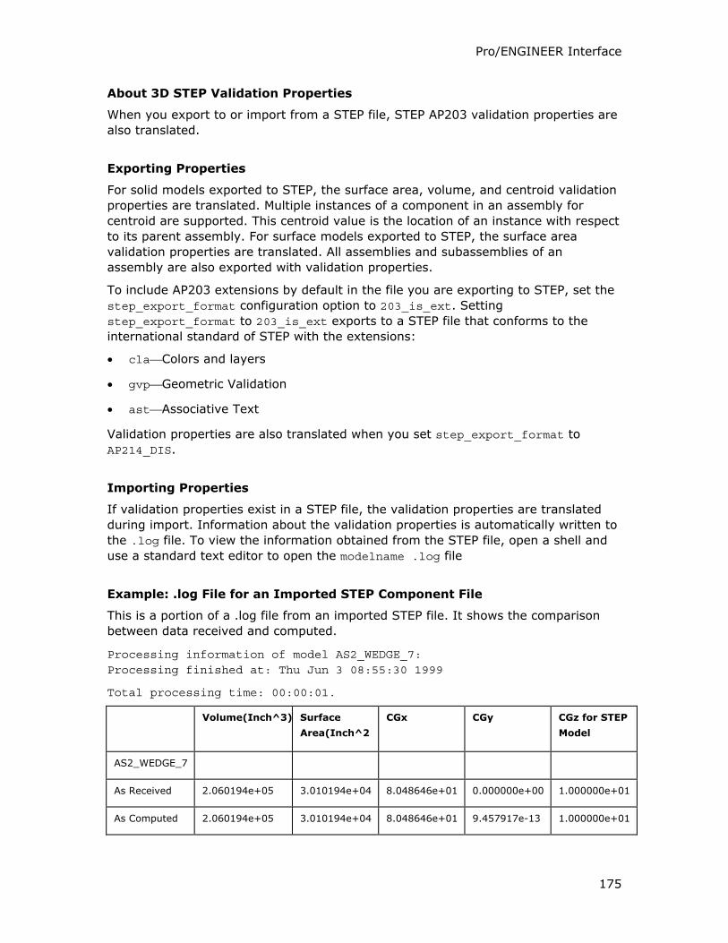
Pro/ENGINEER Interface
175
About 3D STEP Validation Properties
When you export to or import from a STEP file, STEP AP203 validation properties are
also translated.
Exporting Properties
For solid models exported to STEP, the surface area, volume, and centroid validation
properties are translated. Multiple instances of a component in an assembly for
centroid are supported. This centroid value is the location of an instance with respect
to its parent assembly. For surface models exported to STEP, the surface area
validation properties are translated. All assemblies and subassemblies of an
assembly are also exported with validation properties.
To include AP203 extensions by default in the file you are exporting to STEP, set the
step_export_format configuration option to 203_is_ext. Setting
step_export_format to 203_is_ext exports to a STEP file that conforms to the
international standard of STEP with the extensions:
• claColors and layers
• gvpGeometric Validation
• astAssociative Text
Validation properties are also translated when you set step_export_format to
AP214_DIS.
Importing Properties
If validation properties exist in a STEP file, the validation properties are translated
during import. Information about the validation properties is automatically written to
the .log file. To view the information obtained from the STEP file, open a shell and
use a standard text editor to open the modelname .log file
Example: .log File for an Imported STEP Component File
This is a portion of a .log file from an imported STEP file. It shows the comparison
between data received and computed.
Processing information of model AS2_WEDGE_7: Processing finished at: Thu Jun 3 08:55:30 1999
Total processing time: 00:00:01.
Volume(Inch^3) Surface
Area(Inch^2
CGx CGy CGz for STEP
Model
AS2_WEDGE_7
As Received 2.060194e+05 3.010194e+04 8.048646e+01 0.000000e+00 1.000000e+01
As Computed 2.060194e+05 3.010194e+04 8.048646e+01 9.457917e-13 1.000000e+01
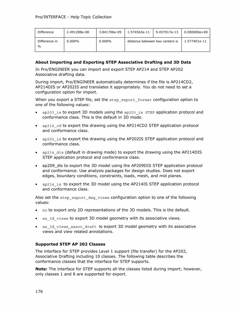
Pro/INTERFACE - Help Topic Collection
176
Difference 2.491288e-08 3.841706e-09 1.574563e-11 9.457917e-13 0.000000e+00
Difference in
%
0.000% 0.000% distance between two centers is 1.577401e-11
About Importing and Exporting STEP Associative Drafting and 3D Data
In Pro/ENGINEER you can import and export STEP AP214 and STEP AP202
Associative drafting data.
During import, Pro/ENGINEER automatically determines if the file is AP214CD2,
AP214DIS or AP202IS and translates it appropriately. You do not need to set a
configuration option for import.
When you export a STEP file, set the step_export_format configuration option to
one of the following values:
• ap203_is to export 3D models using the ap203_is STEP application protocol and
conformance class. This is the default in 3D mode.
• ap214_cd to export the drawing using the AP214CD2 STEP application protocol
and conformance class.
• ap202_is to export the drawing using the AP202IS STEP application protocol and
conformance class.
• ap214_dis (default in drawing mode) to export the drawing using the AP214DIS
STEP application protocol and conformance class.
• ap209_dis to export the 3D model using the AP209DIS STEP application protocol
and conformance. Use analysis packages for design studies. Does not export
edges, boundary conditions, constraints, loads, mesh, and mid planes.
• ap214_is to export the 3D model using the AP214IS STEP application protocol
and conformance class.
Also set the step_export_dwg_views configuration option to one of the following
values:
• no to export only 2D representations of the 3D models. This is the default.
• as_3d_views to export 3D model geometry with its associative views.
• as_3d_views_assoc_draft to export 3D model geometry with its associative
views and view related annotations.
Supported STEP AP 202 Classes
The interface for STEP provides Level 1 support (file transfer) for the AP202,
Associative Drafting including 10 classes. The following table describes the
conformance classes that the interface for STEP supports.
Note: The interface for STEP supports all the classes listed during import; however,
only classes 1 and 8 are supported for export.
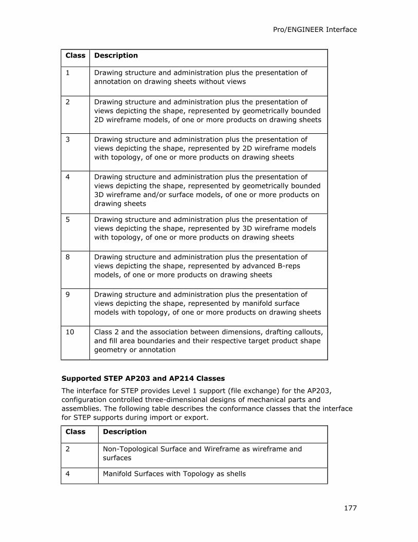
Pro/ENGINEER Interface
177
Class Description
1 Drawing structure and administration plus the presentation of
annotation on drawing sheets without views
2 Drawing structure and administration plus the presentation of
views depicting the shape, represented by geometrically bounded
2D wireframe models, of one or more products on drawing sheets
3 Drawing structure and administration plus the presentation of
views depicting the shape, represented by 2D wireframe models
with topology, of one or more products on drawing sheets
4 Drawing structure and administration plus the presentation of
views depicting the shape, represented by geometrically bounded
3D wireframe and/or surface models, of one or more products on
drawing sheets
5 Drawing structure and administration plus the presentation of
views depicting the shape, represented by 3D wireframe models
with topology, of one or more products on drawing sheets
8 Drawing structure and administration plus the presentation of
views depicting the shape, represented by advanced B-reps
models, of one or more products on drawing sheets
9 Drawing structure and administration plus the presentation of
views depicting the shape, represented by manifold surface
models with topology, of one or more products on drawing sheets
10 Class 2 and the association between dimensions, drafting callouts,
and fill area boundaries and their respective target product shape
geometry or annotation
Supported STEP AP203 and AP214 Classes
The interface for STEP provides Level 1 support (file exchange) for the AP203,
configuration controlled three-dimensional designs of mechanical parts and
assemblies. The following table describes the conformance classes that the interface
for STEP supports during import or export.
Class Description
2 Non-Topological Surface and Wireframe as wireframe and
surfaces
4 Manifold Surfaces with Topology as shells
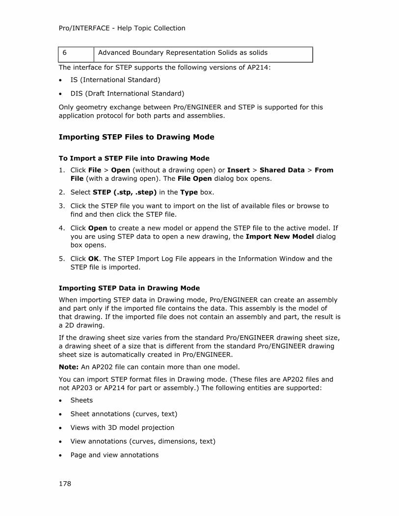
Pro/INTERFACE - Help Topic Collection
178
6 Advanced Boundary Representation Solids as solids
The interface for STEP supports the following versions of AP214:
• IS (International Standard)
• DIS (Draft International Standard)
Only geometry exchange between Pro/ENGINEER and STEP is supported for this
application protocol for both parts and assemblies.
Importing STEP Files to Drawing Mode
To Import a STEP File into Drawing Mode
1. Click File > Open (without a drawing open) or Insert > Shared Data > From
File (with a drawing open). The File Open dialog box opens.
2. Select STEP (.stp, .step) in the Type box.
3. Click the STEP file you want to import on the list of available files or browse to
find and then click the STEP file.
4. Click Open to create a new model or append the STEP file to the active model. If
you are using STEP data to open a new drawing, the Import New Model dialog
box opens.
5. Click OK. The STEP Import Log File appears in the Information Window and the
STEP file is imported.
Importing STEP Data in Drawing Mode
When importing STEP data in Drawing mode, Pro/ENGINEER can create an assembly
and part only if the imported file contains the data. This assembly is the model of
that drawing. If the imported file does not contain an assembly and part, the result is
a 2D drawing.
If the drawing sheet size varies from the standard Pro/ENGINEER drawing sheet size,
a drawing sheet of a size that is different from the standard Pro/ENGINEER drawing
sheet size is automatically created in Pro/ENGINEER.
Note: An AP202 file can contain more than one model.
You can import STEP format files in Drawing mode. (These files are AP202 files and
not AP203 or AP214 for part or assembly.) The following entities are supported:
• Sheets
• Sheet annotations (curves, text)
• Views with 3D model projection
• View annotations (curves, dimensions, text)
• Page and view annotations
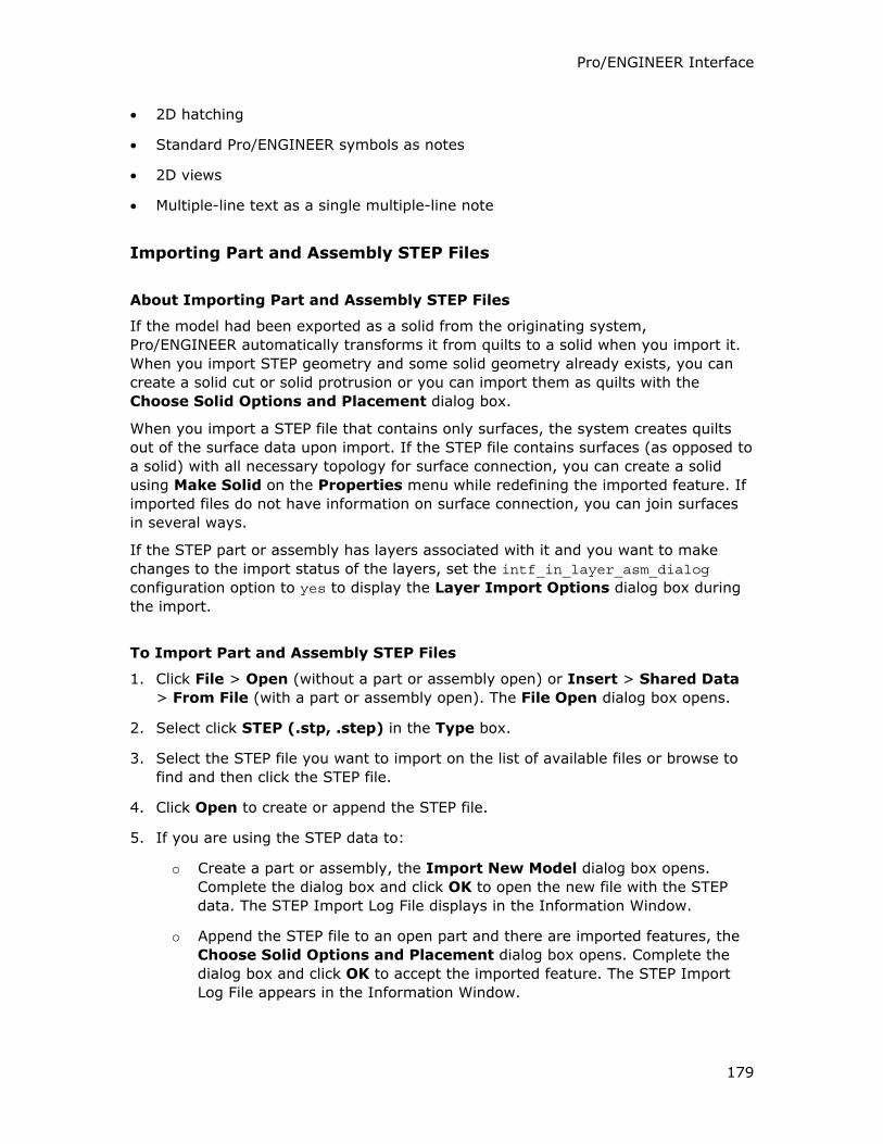
Pro/ENGINEER Interface
179
• 2D hatching
• Standard Pro/ENGINEER symbols as notes
• 2D views
• Multiple-line text as a single multiple-line note
Importing Part and Assembly STEP Files
About Importing Part and Assembly STEP Files
If the model had been exported as a solid from the originating system,
Pro/ENGINEER automatically transforms it from quilts to a solid when you import it.
When you import STEP geometry and some solid geometry already exists, you can
create a solid cut or solid protrusion or you can import them as quilts with the
Choose Solid Options and Placement dialog box.
When you import a STEP file that contains only surfaces, the system creates quilts
out of the surface data upon import. If the STEP file contains surfaces (as opposed to
a solid) with all necessary topology for surface connection, you can create a solid
using Make Solid on the Properties menu while redefining the imported feature. If
imported files do not have information on surface connection, you can join surfaces
in several ways.
If the STEP part or assembly has layers associated with it and you want to make
changes to the import status of the layers, set the intf_in_layer_asm_dialog
configuration option to yes to display the Layer Import Options dialog box during
the import.
To Import Part and Assembly STEP Files
1. Click File > Open (without a part or assembly open) or Insert > Shared Data
> From File (with a part or assembly open). The File Open dialog box opens.
2. Select click STEP (.stp, .step) in the Type box.
3. Select the STEP file you want to import on the list of available files or browse to
find and then click the STEP file.
4. Click Open to create or append the STEP file.
5. If you are using the STEP data to:
o Create a part or assembly, the Import New Model dialog box opens.
Complete the dialog box and click OK to open the new file with the STEP
data. The STEP Import Log File displays in the Information Window.
o Append the STEP file to an open part and there are imported features, the
Choose Solid Options and Placement dialog box opens. Complete the
dialog box and click OK to accept the imported feature. The STEP Import
Log File appears in the Information Window.
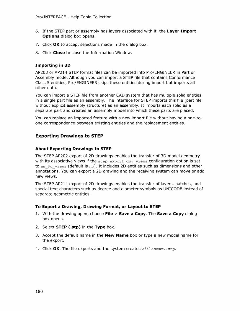
Pro/INTERFACE - Help Topic Collection
180
6. If the STEP part or assembly has layers associated with it, the Layer Import
Options dialog box opens.
7. Click OK to accept selections made in the dialog box.
8. Click Close to close the Information Window.
Importing in 3D
AP203 or AP214 STEP format files can be imported into Pro/ENGINEER in Part or
Assembly mode. Although you can import a STEP file that contains Conformance
Class 5 entities, Pro/ENGINEER skips these entities during import but imports all
other data.
You can import a STEP file from another CAD system that has multiple solid entities
in a single part file as an assembly. The interface for STEP imports this file (part file
without explicit assembly structure) as an assembly. It imports each solid as a
separate part and creates an assembly model into which these parts are placed.
You can replace an imported feature with a new import file without having a one-to-
one correspondence between existing entities and the replacement entities.
Exporting Drawings to STEP
About Exporting Drawings to STEP
The STEP AP202 export of 2D drawings enables the transfer of 3D model geometry
with its associative views if the step_export_dwg_views configuration option is set
to as_3d_views (default is no). It includes 2D entities such as dimensions and other
annotations. You can export a 2D drawing and the receiving system can move or add
new views.
The STEP AP214 export of 2D drawings enables the transfer of layers, hatches, and
special text characters such as degree and diameter symbols as UNICODE instead of
separate geometric entities.
To Export a Drawing, Drawing Format, or Layout to STEP
1. With the drawing open, choose File > Save a Copy. The Save a Copy dialog
box opens.
2. Select STEP (.stp) in the Type box.
3. Accept the default name in the New Name box or type a new model name for
the export.
4. Click OK. The file exports and the system creates <filename>.stp.
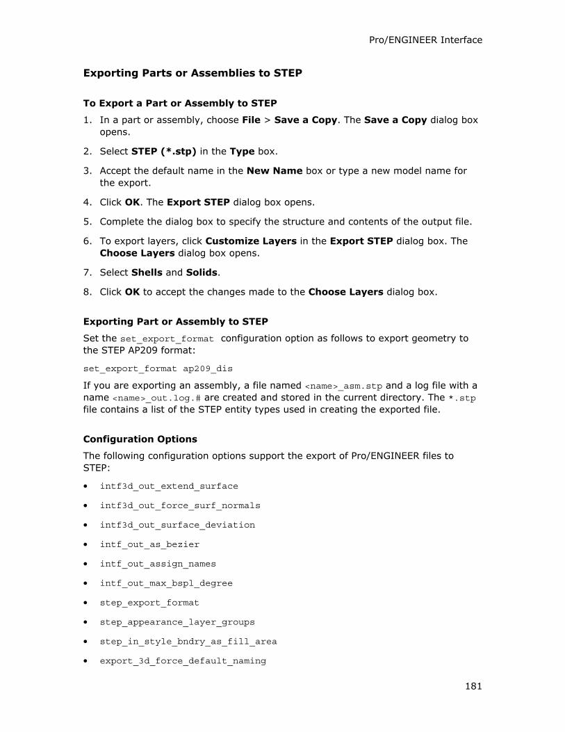
Pro/ENGINEER Interface
181
Exporting Parts or Assemblies to STEP
To Export a Part or Assembly to STEP
1. In a part or assembly, choose File > Save a Copy. The Save a Copy dialog box
opens.
2. Select STEP (*.stp) in the Type box.
3. Accept the default name in the New Name box or type a new model name for
the export.
4. Click OK. The Export STEP dialog box opens.
5. Complete the dialog box to specify the structure and contents of the output file.
6. To export layers, click Customize Layers in the Export STEP dialog box. The
Choose Layers dialog box opens.
7. Select Shells and Solids.
8. Click OK to accept the changes made to the Choose Layers dialog box.
Exporting Part or Assembly to STEP
Set the set_export_format configuration option as follows to export geometry to
the STEP AP209 format:
set_export_format ap209_dis
If you are exporting an assembly, a file named <name>_asm.stp and a log file with a
name <name>_out.log.# are created and stored in the current directory. The *.stp
file contains a list of the STEP entity types used in creating the exported file.
Configuration Options
The following configuration options support the export of Pro/ENGINEER files to
STEP:
• intf3d_out_extend_surface
• intf3d_out_force_surf_normals
• intf3d_out_surface_deviation
• intf_out_as_bezier
• intf_out_assign_names
• intf_out_max_bspl_degree
• step_export_format
• step_appearance_layer_groups
• step_in_style_bndry_as_fill_area
• export_3d_force_default_naming
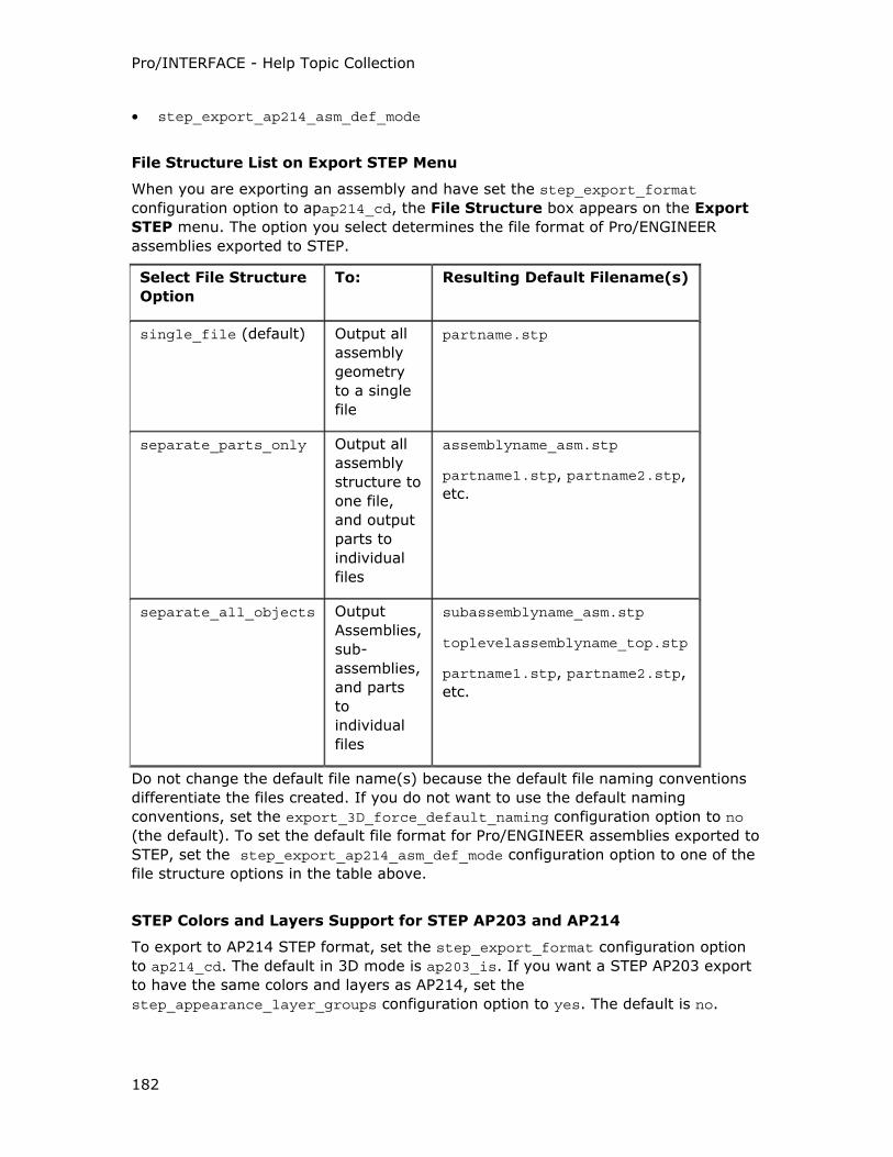
Pro/INTERFACE - Help Topic Collection
182
• step_export_ap214_asm_def_mode
File Structure List on Export STEP Menu
When you are exporting an assembly and have set the step_export_format
configuration option to apap214_cd, the File Structure box appears on the Export
STEP menu. The option you select determines the file format of Pro/ENGINEER
assemblies exported to STEP.
Select File Structure
Option
To: Resulting Default Filename(s)
single_file (default) Output all
assembly
geometry
to a single
file
partname.stp
separate_parts_only Output all
assembly
structure to
one file,
and output
parts to
individual
files
assemblyname_asm.stp
partname1.stp, partname2.stp,
etc.
separate_all_objects Output
Assemblies,
sub-
assemblies,
and parts
to
individual
files
subassemblyname_asm.stp
toplevelassemblyname_top.stp
partname1.stp, partname2.stp,
etc.
Do not change the default file name(s) because the default file naming conventions
differentiate the files created. If you do not want to use the default naming
conventions, set the export_3D_force_default_naming configuration option to no
(the default). To set the default file format for Pro/ENGINEER assemblies exported to
STEP, set the step_export_ap214_asm_def_mode configuration option to one of the
file structure options in the table above.
STEP Colors and Layers Support for STEP AP203 and AP214
To export to AP214 STEP format, set the step_export_format configuration option
to ap214_cd. The default in 3D mode is ap203_is. If you want a STEP AP203 export
to have the same colors and layers as AP214, set the
step_appearance_layer_groups configuration option to yes. The default is no.
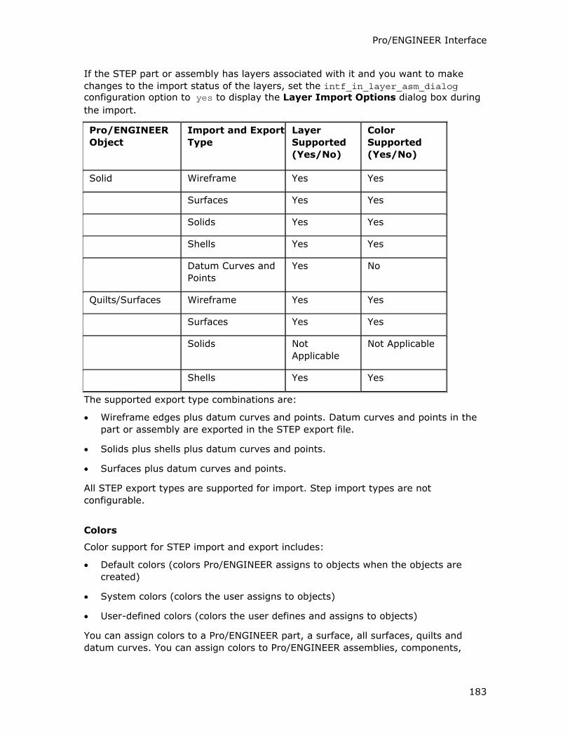
Pro/ENGINEER Interface
183
If the STEP part or assembly has layers associated with it and you want to make
changes to the import status of the layers, set the intf_in_layer_asm_dialog configuration option to yes to display the Layer Import Options dialog box during
the import.
Pro/ENGINEER
Object
Import and Export
Type
Layer
Supported
(Yes/No)
Color
Supported
(Yes/No)
Solid Wireframe Yes Yes
Surfaces Yes Yes
Solids Yes Yes
Shells Yes Yes
Datum Curves and
Points
Yes No
Quilts/Surfaces Wireframe Yes Yes
Surfaces Yes Yes
Solids Not
Applicable
Not Applicable
Shells Yes Yes
The supported export type combinations are:
• Wireframe edges plus datum curves and points. Datum curves and points in the
part or assembly are exported in the STEP export file.
• Solids plus shells plus datum curves and points.
• Surfaces plus datum curves and points.
All STEP export types are supported for import. Step import types are not
configurable.
Colors
Color support for STEP import and export includes:
• Default colors (colors Pro/ENGINEER assigns to objects when the objects are
created)
• System colors (colors the user assigns to objects)
• User-defined colors (colors the user defines and assigns to objects)
You can assign colors to a Pro/ENGINEER part, a surface, all surfaces, quilts and
datum curves. You can assign colors to Pro/ENGINEER assemblies, components,
Pro/INTERFACE - Help Topic Collection
184
assembly surfaces, assembly quilts and assembly datum curves. There can be a
different color assignment for each instance of the same part.
Layers
Layer support for STEP maintains the layer names and their contents represented as
the chosen STEP import and export type.
STHENO/PRO
About STHENO/PRO
STHENO/PRO provides a high level of 2D drafting capability for Pro/ENGINEER
drawings. You can start STHENO/PRO in the standalone mode or the integrated
mode with Pro/ENGINEER. Even without a STHENO/PRO license, you can transfer
data between STHENO/PRO and Pro/ENGINEER in the .tsh file format through the
File > Save a Copy, File > Open, and Insert > Shared Data > From File menu
operations of export, import, and append.
The integrated mode provides an environment where you can work with multiple
Pro/ENGINEER drawings sheets. With a STHENO/PRO license, and a Pro/ENGINEER
drawing sheet open, click Applications > Stheno to start STHENO/PRO in the
integrated mode. Pro/ENGINEER and STHENO/PRO run simultaneously and
independently on the same host. However, at any given time, only one application is
active.
The Pro/ENGINEER drawing sheet is transferred to STHENO/PRO and is read only.
However, you can use the suite of drafting tools that STHENO/PRO provides to
perform the following sketching and 2D detailing operations:
• Create conceptual sketches
• Merge the Pro/ENGINEER drawing sheet with STHENO/PRO drawings created
previously
• Add 2D drawing views
• Select the drawing sheet for reference dimensioning, alignment, and copy
When you exit STHENO/PRO, the additional information is transferred to
Pro/ENGINEER as a 2D drawing view. This additional information is placed on the
original drawing sheet, reestablishing access to the Pro/ENGINEER drawing and the
parametric feature-based model.
To Start STHENO/PRO in Integrated Mode
1. Define the stheno_root global environment variable to point to the root directory
of STHENO/PRO.
2. Set the pro_stheno_command configuration option to point to the STHENO/PRO
startup command, sthenolaunch.exe.
3. Open a Pro/ENGINEER drawing.
Pro/ENGINEER Interface
185
4. Click Applications > Stheno.
If no license is available, click OK to continue working on the open drawing in
Pro/ENGINEER.
If STHENO/PRO fails to start,
o Verify that the stheno_root global environment variable and
pro_stheno_command configuration option are correctly set.
o Exit Pro/ENGINEER and restart it again.
Note: Exiting Pro/ENGINEER closes STHENO/PRO.
Global Environment Variable for STHENO/PRO
STHENO/PRO application startup command, sthenolaunch.exe, finds the location of
STHENO/PRO through the stheno_root global environment variable.
Define stheno_root to point to the root directory of STHENO/PRO in the
Environment Variables dialog box from System Properties in the Control Panel.
About Workflow in Integrated Mode
A typical workflow between Pro/ENGINEER and STHENO/PRO follows:
Start Pro/ENGINEER
• Open a Pro/ENGINEER drawing sheet.
• Start STHENO/PRO in integrated mode. The Pro/ENGINEER session suspends and
the drawing sheet opens in the STHENO/PRO window.
Work in STHENO/PRO on the Drawing Sheet
• Perform reference dimensioning, aligning, copying, and moving.
• Save the drawing sheet. The system by default saves the drawing sheet with the
.tsh extension and the drawing sheet number and stores it in the working
directory of Pro/ENGINEER.
• Exit STHENO/PRO to resume work in Pro/ENGINEER. You must accept or reject
the changes made in STHENO/PRO and choose whether to import the .tsh
drawing file.
Note: If you import the .tsh drawing file, data in the STHENO/PRO window
replaces the STHENO/PRO data in the active Pro/ENGINEER drawing, providing
the drawings have the same sheet number.
Resume Work in Pro/ENGINEER
• Modify the imported .tsh drawing or the .drw Pro/ENGINEER drawing file.
• Change the drawing sheets within multiple sheet drawings.
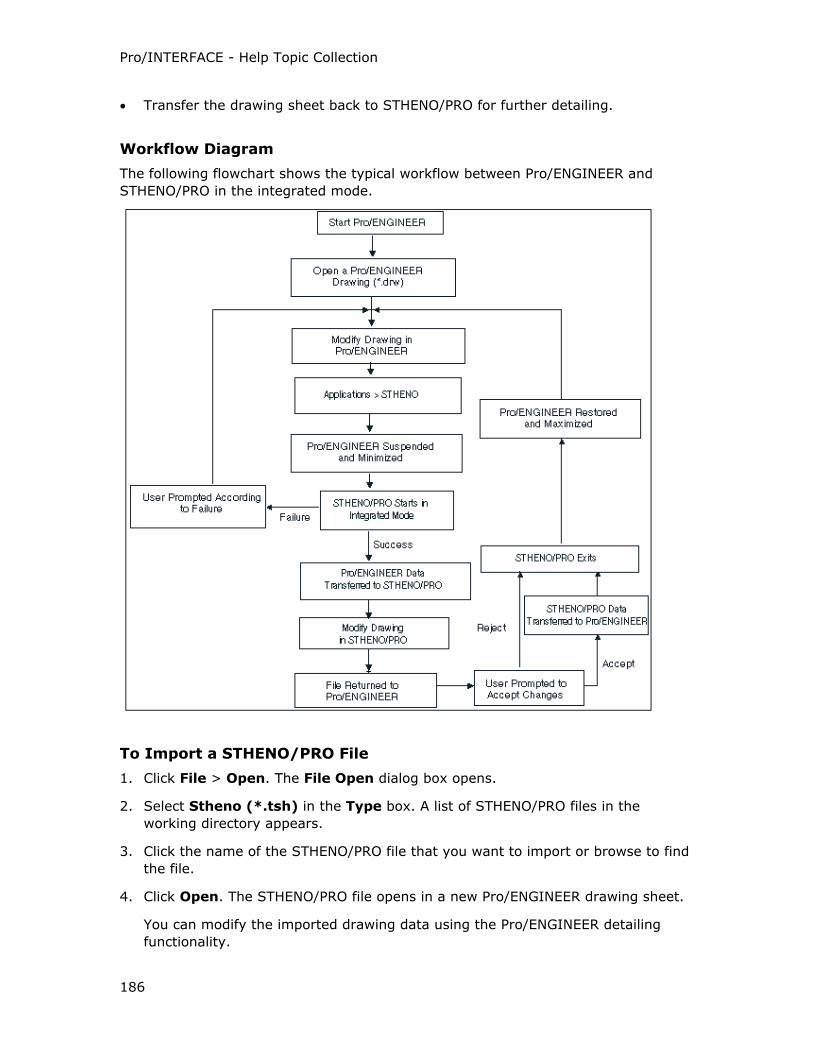
Pro/INTERFACE - Help Topic Collection
186
• Transfer the drawing sheet back to STHENO/PRO for further detailing.
Workflow Diagram
The following flowchart shows the typical workflow between Pro/ENGINEER and
STHENO/PRO in the integrated mode.
To Import a STHENO/PRO File
1. Click File > Open. The File Open dialog box opens.
2. Select Stheno (*.tsh) in the Type box. A list of STHENO/PRO files in the
working directory appears.
3. Click the name of the STHENO/PRO file that you want to import or browse to find
the file.
4. Click Open. The STHENO/PRO file opens in a new Pro/ENGINEER drawing sheet.
You can modify the imported drawing data using the Pro/ENGINEER detailing
functionality.
Pro/ENGINEER Interface
187
To Append a STHENO/PRO File to an Existing Drawing File
1. With a Pro/ENGINEER drawing file open, click Insert > Shared Data > From
File. The File Open dialog box opens.
2. Select Stheno (*.tsh) in the Type box. A list of STHENO/PRO files in the
working directory appears.
3. Click the name of the STHENO/PRO file that you want to append to the
Pro/ENGINEER drawing file or browse to find the file.
4. Click Open. The imported .tsh drawing file is appended to the Pro/ENGINEER
drawing file.
To Export a Pro/ENGINEER Drawing Sheet to STHENO/PRO
1. Open a drawing and click File > Save a Copy. The Save a Copy dialog box
opens.
2. Select Stheno (*.tsh) in the Type box.
3. Accept the default drawing name in the New Name box or type a new name for
the drawing sheet.
4. Click OK.
You can continue working on the active drawing in Pro/ENGINEER.
Supertab Geometry
About Supertab Geometry
You can use the SUPRTB Geom option to create an I-DEAS Supertab file from part
data that can be read by Supertab software system. The system formats this file
according to the specifications of a Supertab universal file. It contains mathematical
definitions of items such as surface data which bound a solid. Pro/ENGINEER does
not accept universal files from Supertab systems as input.
Supertab files are ASCII text files. The system stores them in the current directory.
You can rename or modify them using standard operating system commands. In
UNIX, if you create two Supertab files from the same part, the system overwrites the
first one you create unless you rename it.
Note: If you read in the Pro/ENGINEER Supertab file into Geomod, the Geomod
software issues a warning for entity #428. You must ignore this warning since
Geomod does not use the entity.
You can output a Pro/ENGINEER assembly to Supertab in the same way you output
parts.
To Export to a Supertab Universal File
1. In an open part, click File > Save a Copy. The Save a Copy dialog box opens.
Pro/INTERFACE - Help Topic Collection
188
2. Select SuperTab (*.unv) in the Type box. The existing Pro/ENGINEER model
name without the extension appears in the New Name box.
3. Accept the default name in the New Name box or type a new model name for
the export.
4. Click OK. The file exports and the system creates <filename>.unv.
Tessellated Files
About Tessellated Files
You can export solid model information about parts and assemblies in the following
formats: STL (Stereolithography Apparatus), RENDER, Inventor, VRML, OptegraVis,
Xpatch, MEDUSA, CatiaFacets (also referred to as Catia Mock-Up), and
Pro/CONCEPT.
STL is used for a variety of purposes, the primary one is rapid prototyping.
The RENDER format creates information used to produce high-quality shaded images
of Pro/ENGINEER solid models.
Inventor format creates information that can be read by IRIS Inventor, a 3D
graphics toolkit by Silicon Graphics.
MEDUSA exports to an ASCII-based .asc file. The coordinate systems of the
Pro/ENGINEER model that exist on visible layers are exported to MEDUSA with the
tessellated geometry.
You can import tessellated files from STL, VRML, DXF, and MEDUSA using File >
Open to create new Pro/ENGINEER models or use Insert > Shared Data > From
File to append the files to existing Pro/ENGINEER models.
The tessellated files are imported as faceted data.
Pro/CONCEPT
Pro/ENGINEER outputs the geometry of models for use with Pro/CONCEPT through
Wavefront .obj files. Wavefront .obj files represent geometric information in the
form of a triangle of models and quilts. You can output to Pro/CONCEPT in Part and
Assembly modes.
File Format
STL and RENDER files represent the surfaces of a solid model as groups of small
polygons.
RENDER differs from STL in two respects. RENDER files include:
• The entity color
• A surface normal at each vertex of a polygon element
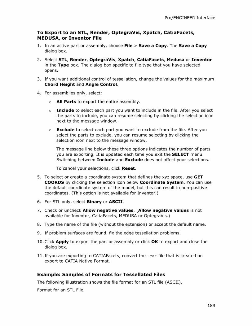
Pro/ENGINEER Interface
189
To Export to an STL, Render, OptegraVis, Xpatch, CatiaFacets, MEDUSA, or Inventor File
1. In an active part or assembly, choose File > Save a Copy. The Save a Copy
dialog box.
2. Select STL, Render, OptegraVis, Xpatch, CatiaFacets, Medusa or Inventor
in the Type box. The dialog box specific to file type that you have selected
opens.
3. If you want additional control of tessellation, change the values for the maximum
Chord Height and Angle Control.
4. For assemblies only, select:
o All Parts to export the entire assembly.
o Include to select each part you want to include in the file. After you select
the parts to include, you can resume selecting by clicking the selection icon
next to the message window.
o Exclude to select each part you want to exclude from the file. After you
select the parts to exclude, you can resume selecting by clicking the
selection icon next to the message window.
The message line below these three options indicates the number of parts
you are exporting. It is updated each time you exit the SELECT menu.
Switching between Include and Exclude does not affect your selections.
To cancel your selections, click Reset.
5. To select or create a coordinate system that defines the xyz space, use GET
COORDS by clicking the selection icon below Coordinate System. You can use
the default coordinate system of the model, but this can result in non-positive
coordinates. (This option is not available for Inventor.)
6. For STL only, select Binary or ASCII.
7. Check or uncheck Allow negative values. (Allow negative values is not
available for Inventor, CatiaFacets, MEDUSA or OptegraVis.)
8. Type the name of the file (without the extension) or accept the default name.
9. If problem surfaces are found, fix the edge tessellation problems.
10. Click Apply to export the part or assembly or click OK to export and close the
dialog box.
11. If you are exporting to CATIAFacets, convert the .cat file that is created on
export to CATIA Native Format.
Example: Samples of Formats for Tessellated Files
The following illustration shows the file format for an STL file (ASCII).
Format for an STL File
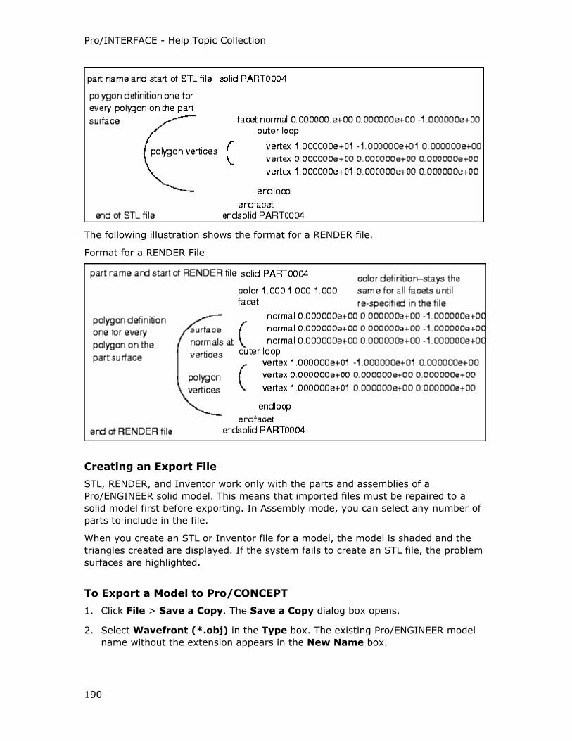
Pro/INTERFACE - Help Topic Collection
190
The following illustration shows the format for a RENDER file.
Format for a RENDER File
Creating an Export File
STL, RENDER, and Inventor work only with the parts and assemblies of a
Pro/ENGINEER solid model. This means that imported files must be repaired to a
solid model first before exporting. In Assembly mode, you can select any number of
parts to include in the file.
When you create an STL or Inventor file for a model, the model is shaded and the
triangles created are displayed. If the system fails to create an STL file, the problem
surfaces are highlighted.
To Export a Model to Pro/CONCEPT
1. Click File > Save a Copy. The Save a Copy dialog box opens.
2. Select Wavefront (*.obj) in the Type box. The existing Pro/ENGINEER model
name without the extension appears in the New Name box.
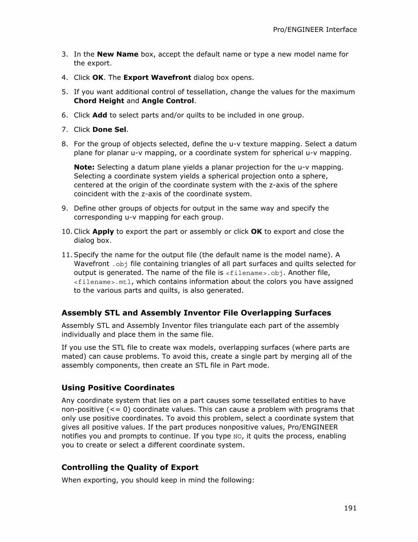
Pro/ENGINEER Interface
191
3. In the New Name box, accept the default name or type a new model name for
the export.
4. Click OK. The Export Wavefront dialog box opens.
5. If you want additional control of tessellation, change the values for the maximum
Chord Height and Angle Control.
6. Click Add to select parts and/or quilts to be included in one group.
7. Click Done Sel.
8. For the group of objects selected, define the u-v texture mapping. Select a datum
plane for planar u-v mapping, or a coordinate system for spherical u-v mapping.
Note: Selecting a datum plane yields a planar projection for the u-v mapping.
Selecting a coordinate system yields a spherical projection onto a sphere,
centered at the origin of the coordinate system with the z-axis of the sphere
coincident with the z-axis of the coordinate system.
9. Define other groups of objects for output in the same way and specify the
corresponding u-v mapping for each group.
10. Click Apply to export the part or assembly or click OK to export and close the
dialog box.
11. Specify the name for the output file (the default name is the model name). A
Wavefront .obj file containing triangles of all part surfaces and quilts selected for
output is generated. The name of the file is <filename>.obj. Another file,
<filename>.mtl, which contains information about the colors you have assigned
to the various parts and quilts, is also generated.
Assembly STL and Assembly Inventor File Overlapping Surfaces
Assembly STL and Assembly Inventor files triangulate each part of the assembly
individually and place them in the same file.
If you use the STL file to create wax models, overlapping surfaces (where parts are
mated) can cause problems. To avoid this, create a single part by merging all of the
assembly components, then create an STL file in Part mode.
Using Positive Coordinates
Any coordinate system that lies on a part causes some tessellated entities to have
non-positive (<= 0) coordinate values. This can cause a problem with programs that
only use positive coordinates. To avoid this problem, select a coordinate system that
gives all positive values. If the part produces nonpositive values, Pro/ENGINEER
notifies you and prompts to continue. If you type NO, it quits the process, enabling
you to create or select a different coordinate system.
Controlling the Quality of Export
When exporting, you should keep in mind the following:
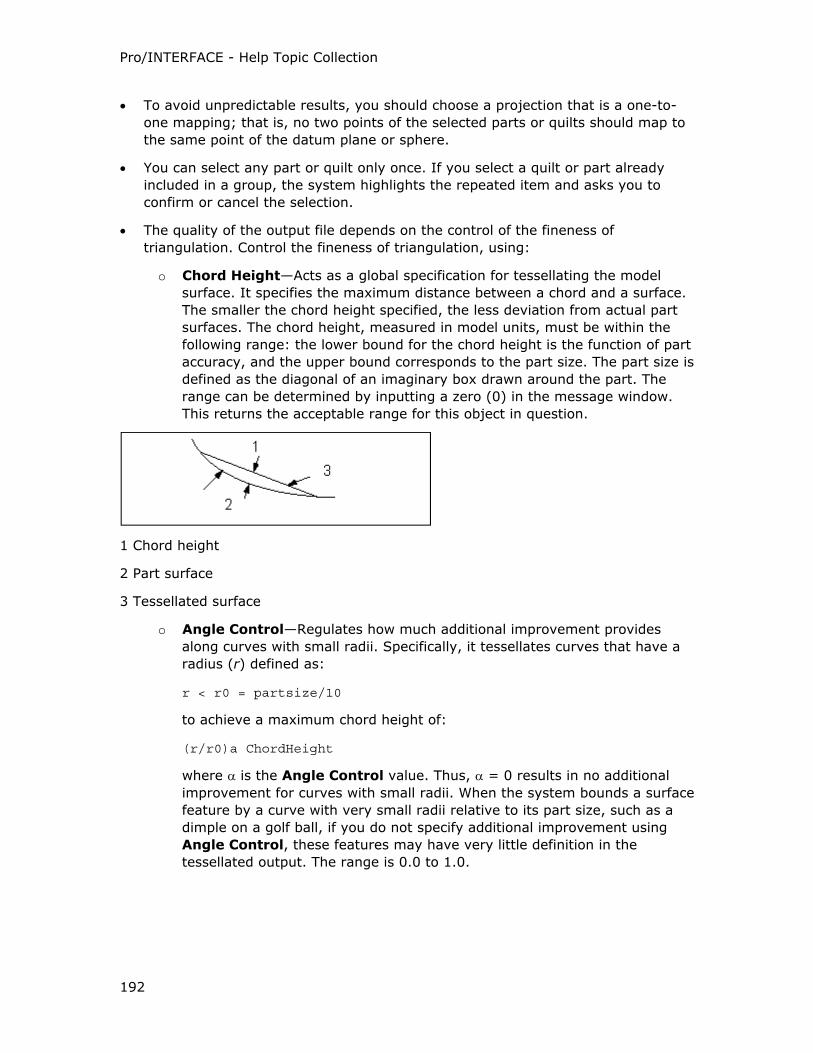
Pro/INTERFACE - Help Topic Collection
192
• To avoid unpredictable results, you should choose a projection that is a one-to-
one mapping; that is, no two points of the selected parts or quilts should map to
the same point of the datum plane or sphere.
• You can select any part or quilt only once. If you select a quilt or part already
included in a group, the system highlights the repeated item and asks you to
confirm or cancel the selection.
• The quality of the output file depends on the control of the fineness of
triangulation. Control the fineness of triangulation, using:
o Chord Height—Acts as a global specification for tessellating the model
surface. It specifies the maximum distance between a chord and a surface.
The smaller the chord height specified, the less deviation from actual part
surfaces. The chord height, measured in model units, must be within the
following range: the lower bound for the chord height is the function of part
accuracy, and the upper bound corresponds to the part size. The part size is
defined as the diagonal of an imaginary box drawn around the part. The
range can be determined by inputting a zero (0) in the message window.
This returns the acceptable range for this object in question.
1 Chord height
2 Part surface
3 Tessellated surface
o Angle Control—Regulates how much additional improvement provides
along curves with small radii. Specifically, it tessellates curves that have a
radius (r) defined as:
r < r0 = partsize/10
to achieve a maximum chord height of:
(r/r0)a ChordHeight
where α is the Angle Control value. Thus, α = 0 results in no additional
improvement for curves with small radii. When the system bounds a surface
feature by a curve with very small radii relative to its part size, such as a
dimple on a golf ball, if you do not specify additional improvement using
Angle Control, these features may have very little definition in the
tessellated output. The range is 0.0 to 1.0.
Pro/ENGINEER Interface
193
In-Session and Direct VRML Export
About In-Session and Direct Import and Export to VRML
Exporting Pro/ENGINEER parts and assemblies to the VRML format produces a
database of VRML files that contain assembly structure, part and assembly names,
and geometrical data representing Pro/ENGINEER parts.
It is recommended that you use the in-session export to accommodate maximum
model detail.
Pro/ENGINEER allows you to export part and assembly files into VRML 1.0, VRML 2.0,
and the ISO Standards file format directly (File > VRML Converter) or in-session
(File > Save a Copy).
You can import or append VRML 1.0, VRML 2.0, and the ISO Standards file format
assembly files using the options File > Open or Insert > Shared Data > From
File. If you are importing formatted assemblies, merge the assemblies before they
are converted as part files.
You can view VRML in Pro/FLY-THROUGH and Pro/Model.View products and in other
viewers complying with the VRML 1.0, VRML 2.0, and the ISO Standards
specifications. To export assembly surfaces, quilts, and welding features to the VRML
format, the shade_surface_feat configuration option must be set to the default
value yes.
VRML 2.0 supports "Moving World" through the design animation package.
Considerations when Exporting an Active Part or Assembly
Consider the following if you are exporting an active part or assembly is an in-
session export to VRML:
• Regular assembly features are supported only in an in-session export.
• Simplified representations that are currently displayed are supported only in the
in-session export. See the vrml_simprep_export configuration option for more
information.
• The export of cabling data is supported only in the in-session export. The
software supports Harness and Cabling components only if you set the
environment variable to Thick Cable.
• Use the in-session export to export components that have a sublayer in the
DISPLAY status.
• Export assembly features and exploded states. Only the active exploded state
can be exported.
• Export simplified representations with replaced components as a package file.
Note: Only simplified representations with DEFAULT RULE INCLUDE (master rep)
and EXCLUDE RULE for selected components are exported to package files.
• Export a currently displayed simp. rep.
Pro/INTERFACE - Help Topic Collection
194
Considerations for In-Session and Direct VRML Export
Consider the following information:
• Both in-session and direct VRML export support assembly surfaces and family
table instances and retrieval into Pro/ENGINEER.
• You can export simplified representations when the vrml_simprep_export
configuration option is set to yes. Only simplified reps with the DEFAULT RULE
INCLUDE (master rep) and EXCLUDE RULE for selected components are exported
to package files using either the direct or in-session export.
• When exporting assembly features such as exploded states:
o You can export a Pro/ENGINEER assembly in the exploded state or in the
unexploded state (with exploded features defined).You can use the
exploded state for demonstrations and to create images for documentation.
o If an assembly is exploded at least once during a Pro/ENGINEER session,
the exploded data is exported into VRML.
Considerations when Exporting an Inactive Part or Assembly
Exporting an inactive part or assembly is a direct transfer. Consider the following if
you are using this method of export to VRML:
• If you make changes to a subassembly, but do not regenerate the large assembly
before the direct export, the changes are not reflected in Pro/FLY-THROUGH.
• The direct export is designed for assemblies that are too large or impossible to
retrieve (hardware dependent).
• Use Instance accelerator files to improve the export quality when you use the
direct transfer export method.
To Prepare the Exploded State for Export
1. In Pro/ENGINEER, retrieve the assembly.
2. Click View > Explode > Explode View to apply the explode state.
Note: If you want to export the assembly in the unexploded state, after you
have applied the explode state, use Unexplode View.
3. Export the active assembly.
About the Direct Export Method
The direct export method exports an assembly without retrieving the whole model
into memory. Instead, subsets of the model are exported, enabling the export of
very large and memory-intensive models. By the end of the direct export process, no
parts of the model remain in memory. If changes are made to a subassembly, but
the large assembly is not regenerated before the direct export, the changes are not
reflected in the model in Pro/FLY-THROUGH. The direct export is designed for large
assemblies that are too large or impossible to retrieve (hardware dependent).
Pro/ENGINEER Interface
195
Note: If the direct export is used on very large assemblies, you may get draft quality
and an inaccurate model representation.
Use the direct export method for an inactive part or assembly.
To Use the Direct Export
1. Set the direct_vrml configuration option to yes. VRML Converter appears on
the File menu.
2. Click File > VRML Converter. The Direct VRML Export dialog box opens.
3. Click Browse (next to Object Name) to search for the object that you want to
export. The Source for Direct VRML Conversion dialog box opens.
4. Select the name of the file you want to convert to VRML format or browse first to
find the file and then click the name. The Source for Direct VRML Conversion
dialog box closes and the Direct VRML Export dialog box opens. The file name
and path appear in the Object Name box.
5. Accept the default Output Path or click Browse to find and then select another
output path. If you browse for an output path, the Select Working Directory
dialog box opens.
6. Click the output directory for the VRML file.
7. Click OK. The Select Working Directory dialog box closes and the Direct
VRML Export dialog box opens. The path name is specified in the Output Path
box.
8. If you want to change the default settings for the export quality, parameters, or
views, click Setup. The VRML Export Setup dialog box opens.
9. Make changes to the VRML Export Setup dialog box.
10. Click OK to export the inactive model into VRML format files in the specified
folder.
You can use Pro/BATCH to create VRML databases with either direct or in-session
export.
VRML Files
For each Pro/ENGINEER part and assembly file, a corresponding VRML file is created.
For each part file, a number of VRML level-of-detail (LOD) files are created.
An object is represented graphically by many shaded triangles that make up its form
and shape (tessellated format). An LOD is a particular graphical representation that
consists of faceted surfaces made up of a certain number of triangles. Multiple levels
of files are produced by VRML export, each with a different number of triangles. The
more triangles that describe the model, the more detail you see.
The system writes the VRML files to the current Pro/ENGINEER working directory.
The software creates the following naming conventions between Pro/ENGINEER files
and the assembly and part VRML files:
Pro/INTERFACE - Help Topic Collection
196
<assembly_name>.asm exports to <assembly_name>_a.wrl
<part_name>.prt exports to <part_name>_p.wrl
• When simplified representations are exported assemblies that have a non-
occurring component, they are named:
<assembly_name>.asm exports to <assembly_name>_s#.wrl
• When an assembly feature has intersecting components, they are named (part
and assembly are modified):
<assembly_name>.asm exports to <component_name>_af#_a.wrl
<part_name>.prt exports to <component_name>_af#_p.wrl
Use the direct export to export components that have a sub layer in DISPLAY
status.
The LOD files for each part have the following naming conventions between
Pro/ENGINEER files and the LOD VRML files:
<part_name>.prt exports to <part_name>_pr#.wrl
where:
# is the number of the particular VRML file. The smaller the number, the greater the
LOD in the file.
Note: You can retrieve the <part_name>_pr#.wrl files individually into Pro/FLY-
THROUGH.
To Use the In-Session Export
1. Click File > Save a Copy. The Save a Copy dialog box opens.
2. Select VRML (*.wrl) in the Type box. The existing Pro/ENGINEER model name
without the extension appears in the New Name box.
3. In the New Name box, accept the default name or type a new model name for
the export.
4. Click OK. The VRML Export Setup dialog box opens.
5. Make changes to the VRML Export Setup dialog box and click OK to export the
active model into VRML format files in the specified folder.
To Import to VRML Format
1. Click File > Open without a part or assembly open or Insert > Shared Data >
From File with a part or assembly open.
Click Insert > Component > Assemble to assemble a component into an
existing assembly or assemble an assembly as a subassembly component.
The File Open dialog box opens.
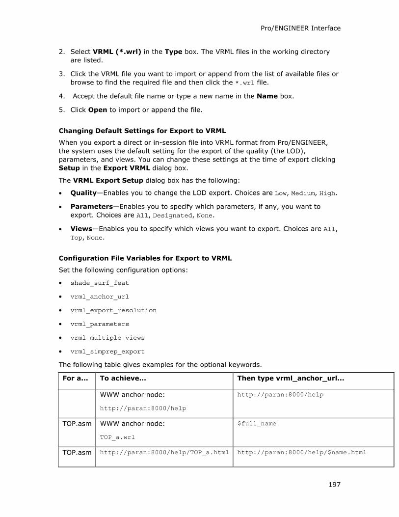
Pro/ENGINEER Interface
197
2. Select VRML (*.wrl) in the Type box. The VRML files in the working directory
are listed.
3. Click the VRML file you want to import or append from the list of available files or
browse to find the required file and then click the *.wrl file.
4. Accept the default file name or type a new name in the Name box.
5. Click Open to import or append the file.
Changing Default Settings for Export to VRML
When you export a direct or in-session file into VRML format from Pro/ENGINEER,
the system uses the default setting for the export of the quality (the LOD),
parameters, and views. You can change these settings at the time of export clicking
Setup in the Export VRML dialog box.
The VRML Export Setup dialog box has the following:
• Quality—Enables you to change the LOD export. Choices are Low, Medium, High.
• Parameters—Enables you to specify which parameters, if any, you want to
export. Choices are All, Designated, None.
• Views—Enables you to specify which views you want to export. Choices are All,
Top, None.
Configuration File Variables for Export to VRML
Set the following configuration options:
• shade_surf_feat
• vrml_anchor_url
• vrml_export_resolution
• vrml_parameters
• vrml_multiple_views
• vrml_simprep_export
The following table gives examples for the optional keywords.
For a... To achieve... Then type vrml_anchor_url...
WWW anchor node:
http://paran:8000/help
http://paran:8000/help
TOP.asm WWW anchor node:
TOP_a.wrl
$full_name
TOP.asm http://paran:8000/help/TOP_a.html http://paran:8000/help/$name.html
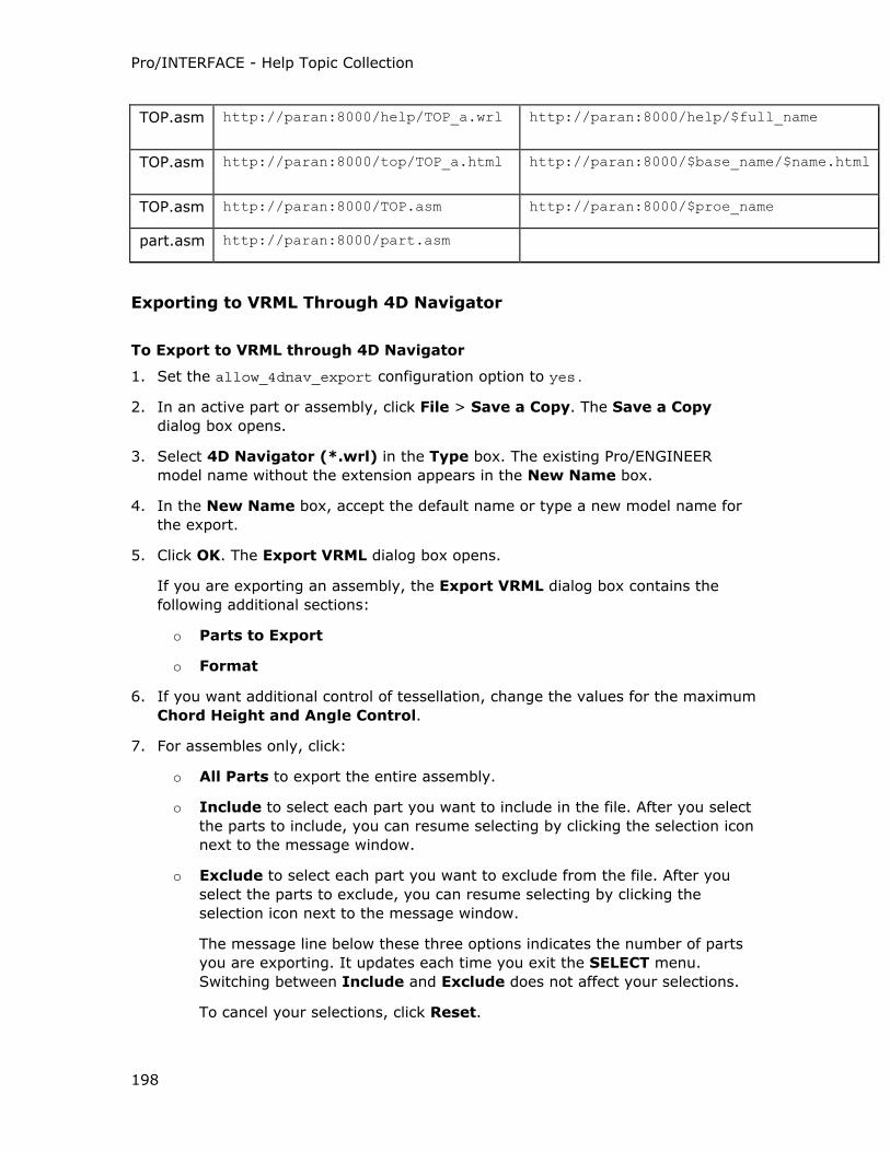
Pro/INTERFACE - Help Topic Collection
198
TOP.asm http://paran:8000/help/TOP_a.wrl http://paran:8000/help/$full_name
TOP.asm http://paran:8000/top/TOP_a.html http://paran:8000/$base_name/$name.html
TOP.asm http://paran:8000/TOP.asm http://paran:8000/$proe_name
part.asm http://paran:8000/part.asm
Exporting to VRML Through 4D Navigator
To Export to VRML through 4D Navigator
1. Set the allow_4dnav_export configuration option to yes.
2. In an active part or assembly, click File > Save a Copy. The Save a Copy
dialog box opens.
3. Select 4D Navigator (*.wrl) in the Type box. The existing Pro/ENGINEER
model name without the extension appears in the New Name box.
4. In the New Name box, accept the default name or type a new model name for
the export.
5. Click OK. The Export VRML dialog box opens.
If you are exporting an assembly, the Export VRML dialog box contains the
following additional sections:
o Parts to Export
o Format
6. If you want additional control of tessellation, change the values for the maximum
Chord Height and Angle Control.
7. For assembles only, click:
o All Parts to export the entire assembly.
o Include to select each part you want to include in the file. After you select
the parts to include, you can resume selecting by clicking the selection icon
next to the message window.
o Exclude to select each part you want to exclude from the file. After you
select the parts to exclude, you can resume selecting by clicking the
selection icon next to the message window.
The message line below these three options indicates the number of parts
you are exporting. It updates each time you exit the SELECT menu.
Switching between Include and Exclude does not affect your selections.
To cancel your selections, click Reset.
Pro/ENGINEER Interface
199
8. For assemblies only, click:
o FLAT to export a single VRML file for the assembly. Geometry in this file is
split into multiple parts. For instance parts, each instance is included in the
file in its correct position.
o ALL PARTS to export each part in a separate VRML file. Each part is placed
in its appropriate position and orientation in the assembly space.
9. To select or create a coordinate system that defines the xyz space, click the
selection icon below Coordinate System to access the GET COORDS menu. You
can use the default coordinate system of the model, but this can result in non-
positive coordinates.
10. In the File name box, type the name of the file (without the extension) or accept
the default name.
11. Click Apply to export the part or assembly or click OK to export and close the
dialog box.
TIFF (Snapshot) Files and Shaded Images
Overview of TIFF Files
About TIFF Files
TIFF supports the interface of digital image data between systems with different
architectures. Pro/ENGINEER supports the export and import of TIFF in all graphics
modes.
You can use TIFF to store graphical and textual information in a bitmap format and
later exchange it between Pro/ENGINEER and different application programs on X
Windows on UNIX or GDI on NT. Pro/ENGINEER supports TIFF in Palette color (level
3) mode, making color images available. RGB TIFF can be exported on machines
capable of exporting RGB TIFF (machines that run a STARBASE or OPEN GL graphics
mode). You can import files in snapshot TIFF format into Pro/ENGINEER only in the
Drawing mode.
Importing TIFF Files
To Import a TIFF File
1. Make sure the graphics configuration option is set to x_windows on UNIX
platforms and win32_gdi on Windows.
2. Click Insert > Shared Data > From File in an open drawing. The File Open
dialog box opens.
3. Select TIFF (*.tif) in the Type box.
4. Select the file name from the list of available files.
Pro/INTERFACE - Help Topic Collection
200
5. Click Open to import the TIFF file into the drawing.
Considerations when Importing a TIFF File
When you import a TIFF bitmap file into the current drawing:
• The entire image becomes a single entity in Pro/ENGINEER.
• The drawing file is very large when you store it.
• You can manipulate it as you would manipulate normal entities.
• You can print TIFF images imported into a drawing.
• You cannot modify the imported graphics in any way.
Exporting TIFF (Snapshot) Files and Shaded Images
About Exporting a TIFF (Snapshot), TIFF, EPS, or JPEG File
Exporting Shaded Images
You can export wireframe and shaded images in the following formats:
• TIFF
• Shaded Image
• EPS
• JPEG
TIFF and JPEG files are supported by the WWW browser.
You can change the image size, resolution, and depth when you export with TIFF,
EPS, or JPEG. When you export with Shaded Image, you export the image based on
the current Pro/ENGINEER parameters.
TIFF files are stored in bitmap format and relate to the number of pixels in the
image, not the dpi (dots per inch). When you use Variable as the size, specify the
height and width, and change to a higher resolution, these values do not necessarily
represent the actual size of the image.
For example, if you have a 4 inch by 4 inch picture and you output the image at 100
dpi, the image size is 400 by 400 pixels. But if you output the image at 200 dpi, the
image size is 800 by 800 pixels. A higher resolution increases the size of the image
size.
Use 24-bit RGB to print or export an image with textures. The textures are ignored
unless the image uses a 24-bit RGB.
Procedures for Exporting
When exporting to TIFF, Pro/ENGINEER works as a scanner recording the current
screen image in bitmaps. An output file represents a snapshot of the entire screen.
Pro/ENGINEER Interface
201
You can export files to TIFF (Snapshot) from Part, Assembly, and Drawing modes.
TIFF (Snapshot) is the only image to which you can export a drawing file. TIFF files
have the extension .tif.
To Export to a TIFF (Snapshot) File
1. Click File > Save a Copy in an open drawing, part, or assembly file. The Save a
Copy dialog box opens.
2. Select TIFF (Snapshot) (*.tif) in the Type box.
3. If you want to change the name of the exported image from the current file
name, type the new name in the New Name box.
4. Click OK. The Message Pop Current Window appears in the Pro/ENGINEER
window.
5. Click Yes to export the TIFF file.
To Export a Shaded Image
1. In an open part, or assembly file, click File > Save a Copy. The Save a Copy
dialog box opens.
2. Select Shaded Image (*.shd) in the Type box.
3. If you want to change the name of the exported image from the current file
name, type the new name in the New Name box.
4. Click OK to export the shaded image. The system adds the extension for the
shaded image (.shd).
To Export a TIFF, EPS, or JPEG File
1. Click File > Save a Copy in an open part, or assembly file. The Save a Copy
dialog box opens.
2. Select TIFF (*.tif), EPS (*.eps), or JPEG (*.jpg) in the Type box.
3. If you want to change the name of the exported image from the current file
name, type the new name in the New Name box.
4. Click OK. The Shaded Image Configuration dialog box opens.
5. Complete the dialog box to specify the dimensions and resolution to use.
6. Click OK to export the file. The system adds the .tif, .eps, or .jpg extension.
Shade Image Configuration Dialog Box
Size—Click the Size arrow to see a list of standard size options and a Variable
option and click the size of your choice.
Height—Available only if you click Variable from the Size List. Type a custom
height dimension.
Pro/INTERFACE - Help Topic Collection
202
Width—Available only if you click Variable from the Size list. Type a custom width
dimension.
Top Margin—Available only if you click Variable from the Size List. Type a custom
top margin dimension.
Left Margin—Available only if you click Variable from the Size List. Type a custom
left margin dimension
Units—Available only if you click Variable from the Size List. Click Millimeters or
Inches.
DPI—Determines the resolution output of the image. Click the DPI arrow to see a
list of DPI values and click the DPI of your choice.
Image Depth—Click the Image Depth arrow to see a list of image depth values
and click the image depth of your choice.
Unigraphics
About Data Exchange Between Unigraphics and Pro/ENGINEER
You can import Unigraphics .prt files as parts and assemblies into Pro/ENGINEER
and export Pro/ENGINEER parts and assemblies as Unigraphics .prt files. The
Unigraphics interface requires a license and an installation of Unigraphics and
Pro/ENGINEER on separate workstations or on the same workstation. Install
Unigraphics and Pro/ENGINEER on a local workstation or run them from a server
machine over the network. However, they must be on the same platform type.
With the Unigraphics interface, you can import and export Unigraphics and
Pro/ENGINEER parts, assemblies, part-level layers, and model units.
Unigraphics supports Associative Topology Bus (ATB). See the Help on Associative
Topology Bus.
Environment Variables for the Unigraphics Interface
You must set the following environment variables before starting Pro/ENGINEER:
• UGII_LICENSE_FILE <path to the license server for the Unigraphics installation or the node-locked license file>
• UGII_BASE_DIR <path to the Unigraphics installation directory>
• UGII_ROOT_DIR <path to the Unigraphics installation directory/bin>
for UNIX and <path to the Unigraphics installation directory/ugii> for
Windows
The Unigraphics interface requires these environment variables to be set in addition
to the UG/Open runtime license and the installation of Unigraphics either on the
workstation on which Pro/ENGINEER is installed or accessed over the network.
Pro/ENGINEER Interface
203
To Import a Unigraphics Part or Assembly to Pro/ENGINEER
1. Set the intf3d_ug_install_dir configuration option to accurately point to the
Unigraphics installation.
Note: If you have not set the intf3d_ug_install_dir configuration option
properly, the file open operation is aborted.
2. Click File > Open. The File Open dialog box opens.
3. Select Unigraphics File (*.prt) in the Type box.
o By default, the Unigraphics .prt files in the working directory are displayed
as plain file icons.
o Pro/ENGINEER .prt files are not displayed.
Note: When you select Pro/ENGINEER Files (*.prt, *.asm, *.drw, ....)
or Part (*.prt) in the Type box, Unigraphics files are listed with the
Pro/ENGINEER part file icons. When you select a Unigraphics file with one of
these types set, a warning in the Pro/ENGINEER window states that the
selected file is of Unigraphics origin. It prompts you to select Unigraphics
File (*.prt) in the Type box.
4. Select a Unigraphics .prt file from the current directory or browse to select the
Unigraphics file from another location.
o The Import New Model dialog box opens.
o Model type is automatically set to Part or Assembly based on the contents
of the selected file. You can override the default setting of Part and change
it to Assembly, but you cannot change a default setting of Assembly to
Part.
o For parts, the generic import name is generated for the import model
name. The import model cannot be given the same name as the
Unigraphics file because Unigraphics and Pro/ENGINEER share the same file
extension.
5. Click OK.
o The import log file appears in the Information Window with details of the
import.
o The import model is created.
To Append a Unigraphics File to a Pro/ENGINEER Model
1. Set the intf3d_ug_install_dir configuration option to accurately point to the
Unigraphics installation.
Note: If you have not set the intf3d_ug_install_dir configuration option
properly, the file append operation is aborted.
2. Open a Pro/ENGINEER part or assembly.
Pro/INTERFACE - Help Topic Collection
204
3. Click Insert > Shared Data > From File. The File Open dialog box opens.
4. Select Unigraphics File (*.prt) in the Type box.
o By default, the Unigraphics .prt files in the working directory are displayed
as plain file icons.
o Pro/ENGINEER .prt files are not displayed.
Note: Unigraphics .prt files are not displayed if you select All Files (*) in
the Type box.
5. Select a Unigraphics .prt file from the current directory or browse to select the
Unigraphics file from another location.
o The Choose Solid Options and Placement dialog box opens if you are
appending the Unigraphics file as a part.
o Accept the default coordinate system in the Choose Solid Options and
Placement dialog box or use the selection arrow to select another
coordinate system to locate the Unigraphics data.
o If the Pro/ENGINEER part file already contains solid geometry, specify
Protrusion, Cut, or Surfaces in the Choose Solid Options and
Placement dialog box to create a protrusion or cut from the imported
geometry or represent the geometry as a collection of quilts.
o Click OK in the Choose Solid Options and Placement dialog box. The
Unigraphics *.prt file is appended as a protrusion, cut, or quilt to the
Pro/ENGINEER part.
6. If you are appending the Unigraphics file as a part component to an existing
Pro/ENGINEER assembly containing at least one coordinate system, select a
coordinate system in the SEL COORD S menu. The Unigraphics *.prt file is
appended as a new component to the Pro/ENGINEER assembly.
To Assemble a Unigraphics File into a Pro/ENGINEER Assembly Model
1. Set the intf3d_ug_install_dir configuration option to accurately point to the
Unigraphics installation.
Note: If you have not set the intf3d_ug_install_dir configuration option
properly, the file assemble operation is aborted.
2. Open a Pro/ENGINEER assembly.
3. Click Insert > Component > Assemble. The File Open dialog box opens.
4. Select Unigraphics File (*.prt) in the Type box.
o By default, the Unigraphics .prt files in the working directory are displayed
as plain file icons.
o Pro/ENGINEER .prt files are not displayed.
Pro/ENGINEER Interface
205
Note: When you select Pro/ENGINEER Files (*.prt, *.asm, *.drw, ....)
or Part (*.prt) in the Type box, Unigraphics files are listed with the
Pro/ENGINEER part file icons. When you select a Unigraphics file with one of
these types set, a warning states that the selected file is of Unigraphics
origin. It prompts you to select Unigraphics File (*.prt) in the Type box.
Unigraphics .prt files are not displayed if you select All Files (*) in the
Type box.
5. Select a Unigraphics .prt file from the current directory or browse to select the
Unigraphics file from another location.
6. The Component Placement dialog box opens.
7. Accept the default coordinate system location or select a coordinate system to
position the geometry.
8. Package the imported part or subassembly component into the assembly or add
associative placement constraints.
9. Click OK in the Component Placement dialog box.
To Export a Pro/ENGINEER Part or Assembly to Unigraphics
1. Set the intf3d_ug_install_dir configuration option to accurately point to the
Unigraphics installation.
2. With part or assembly open, click File > Save a Copy. The Save a Copy dialog
box opens.
3. Select Unigraphics File (*.prt) in the Type box. The Save a Copy dialog box
displays the existing Unigraphics file in the working directory.
4. Browse to select a location for the file after export. Existing Unigraphics .prt files
in the directory are displayed.
5. Accept the default name with the extension, _ug_prt or _ug_asm that is
automatically added to the exported part or assembly name, respectively, in the
New Name box or type a new name for the exported model.
6. Click OK in the Save a Copy dialog box.
Note: If you have not set the intf3d_ug_install_dir configuration option to
point to the Unigraphics installation directory, a warning in the Pro/ENGINEER
window prompts you to specify the location of the Unigraphics installation.
o The Pro/ENGINEER file is exported to the location you have specified.
o For an assembly, the exported component model files are named after the
corresponding Pro/ENGINEER component model name with the extensions,
_ug_prt and _ug_asm, depending on the model type.
Pro/INTERFACE - Help Topic Collection
206
VDA
Importing VDA Files
To Create a Part by Importing VDA Data
1. Click File > Open when creating a part. The File Open dialog box opens.
2. Select VDA (*.vda) in the Type box. VDA files in the working directory appear.
3. Select the VDA file you want to import from the list of available files or browse to
find the VDA file.
4. Click Open.
5. The Import New Model dialog box opens. Accept the default file name or type a
new name.
6. Click OK. A .log file appears in the INFORMATION WINDOW. The file is
processed. The part is created automatically, placing at the VDA data origin a
coordinate system named after the VDA file name.
To Import a VDA File as a New Feature into an Existing Part
1. Create or retrieve a part (at least one feature has to exist).
2. Click Insert > Shared Data > From File. The File Open dialog box opens.
3. Select VDA (*.vda) in the Type box.
4. Click the VDA file you want to import from the list of available files or browse to
find the VDA file.
5. Click Open.
6. The Information Window and the Choose Solid Options and Placement dialog
box open.
7. In the Choose Solid Options and Placement dialog box, create or select a
coordinate system to locate the VDA data.
8. Click OK. The feature is created.
Importing Through VDA
A log file is created in your working directory with the name <model_name>.log
when you import a VDA model into Pro/ENGINEER. This file contains a summary of
the VDA import process.
Pro/ENGINEER can read a VDA file into an existing part, or you can use the VDA data
to create a new part. The type of features that the VDA file creates depends on the
data available. It creates solid features only if you provide a topologically complete
description using the VDA entities TOP, FACE, CONS, and CURVE.
Pro/ENGINEER Interface
207
You can set the read_vda_in_pset_as_spline configuration option to control the
data point sets imported from a VDA file.
You can replace an imported feature with a new import file without having a one-to-
one correspondence between existing entities and the replacement entities.
If the VDA file contains information for surface connection, you can create a solid
using Join Surfs on the Properties menu. If imported files do not have information
on surface connection, you can join surfaces in several ways.
Exporting to VDA
To Export a Part or Assembly to a VDA File
1. Click File > Save a Copy with the assembly active. The Save a Copy dialog box
opens.
2. Select VDA (*.vda) in the Type box.
3. Accept the default name in the New Name box or type a new model name for
the export.
4. Click OK. The Export VDA dialog box opens.
5. Under Export, indicate the type of entities to export by selecting the following:
o Wireframe—Outputs part edges only.
o Surfaces—Outputs all part surfaces and surface boundaries.
o Datum Curves and Points—Outputs datum entities.
6. Specify the structure and contents of the output file.
7. If you want to export layers, click Customize Layers in the Export VDA dialog
box. The Choose Layers dialog box opens.
8. Click Auto ID to assign layer IDs to layers that do not have IDs.
9. Make changes to the Choose Layers dialog box and click OK to accept the
changes made.
Pro/ENGINEER creates the VDA data file. The origin of the data defaults to the
assembly origin. When the file has been created, you are notified.
Exporting to VDA
Before creating a VDA file, you may want to establish a standard VDA file header.
The system enters the VDA version, sender’s name, and date automatically. The
sender's name is the user’s login ID. To fill in the other information, create a header
file and specify its name using the vda_header <filename> configuration option
complete with the extension, if any.
All VDA files created in Pro/ENGINEER follow the naming convention
<objectname>.vda, where <objectname> is the name of the currently active
Pro/INTERFACE - Help Topic Collection
208
assembly. In UNIX, if you create two VDA files from the same object, the first VDA
file is overwritten by the file you create unless you rename it.
Using Pro/BATCH Utilities
About Pro/BATCH
The Pro/BATCH user interface enables you to define your batch session and schedule
the execution of the command file.
You can upgrade files from a previous release of Pro/ENGINEER to the current
version of Pro/ENGINEER.
Pro/BATCH enables you to enter batch mode to create multiple plot files, or export to
other formats. Using the interface, or a command file that you create, Pro/ENGINEER
retrieves the appropriate objects and creates the specified export files for them. You
can also import CADAM data into Pro/ENGINEER using Pro/BATCH.
The proigsutil conversion utility enables you to convert a number of IGES files
into parts or drawings.
Batch mode takes a list of objects from which to create files, retrieves the objects,
and creates the files without any further interaction.
When running Pro/BATCH with the interface or the command line,
• License requirements and available modules remain the same as for a regular
Pro/ENGINEER session.
• Pro/BATCH does not remove a version number from an input file. If you supply a
version number, the system uses the file with that version number; if no version
number is supplied, the latest version of a file is used.
• The configuration file in the working directory, home directory, loadpoint
directory, or startup directory is used when executing a command file. The
configuration file settings define the Pro/ENGINEER environment and specify
options that are required to perform a specific task (for example, plotting or
exporting to IGES, DXF, or VDA).
• The configuration settings remain the same for all files created from the same
batch job. Because the system also uses search paths defined in the
configuration file, objects need not reside in the current directory.
When running Pro/BATCH with the command line,
• If you press ENTER, the system accepts the default value given within the
brackets ([ ]).
• To exit Pro/BATCH while creating a command line, type QUIT + ENTER + ENTER.
A log file is created for each Pro/BATCH session. The log contains all of the executed
commands as well as the exit code for the command (SUCCESS or FAILURE).
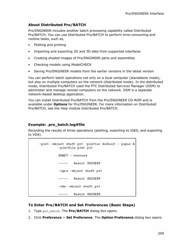
Pro/ENGINEER Interface
209
About Distributed Pro/BATCH
Pro/ENGINEER includes another batch processing capability called Distributed
Pro/BATCH. You can use Distributed Pro/BATCH to perform time-consuming and
routine tasks, such as,
• Plotting and printing
• Importing and exporting 2D and 3D data from supported interfaces
• Creating shaded images of Pro/ENGINEER parts and assemblies
• Checking models using ModelCHECK
• Saving Pro/ENGINEER models from the earlier versions in the latest version
You can perform batch operations not only on a local computer (standalone mode),
but also on multiple computers on the network (distributed mode). In the distributed
mode, Distributed Pro/BATCH used the PTC Distributed Services Manager (DSM) to
administer and manage remote computers on the network. DSM is a separate
network-based desktop application.
You can install Distributed Pro/BATCH from the Pro/ENGINEER CD-ROM and is
available under Options for Pro/ENGINEER. For more information on Distributed
Pro/BATCH, see the Help module Distributed Pro/BATCH.
Example: .pro_batch.log#file
Recording the results of three operations (plotting, exporting to IGES, and exporting
to VDA).
To Enter Pro/BATCH and Set Preferences (Basic Steps)
1. Type pro_batch. The Pro/BATCH dialog box opens.
2. Click Preference > Set Preference. The Option Preference dialog box opens.
Pro/INTERFACE - Help Topic Collection
210
3. Click the General tab. Set the default action for all the objects that you add to
the Pro/BATCH dialog box
4. In the Default Action box, select a default action.
The Option Preference dialog box settings are saved in your home directory
when you close the main window.
Note: If you include objects for plotting in the batch file, you must enter the
Plotter Command on the Plot page.
5. Click other tabs for which you want to enter information.
6. Click OK to close the dialog box.
To Schedule the Start of the Batch Process
1. Before exiting the Pro/BATCH dialog box, click Schedule > Start the task. The
Schedule dialog box opens.
2. In the hour(s) box, click the arrows to select the number of hours.
3. Click OK.
Note: To run the batch file immediately, use the default of zero hours.
At the scheduled time, Pro/BATCH starts processing and creates the following
files in your current working directory:
o Object output files (for example, <object>.plt, <object>.iges)
o The pro_batch_list.txt file listing all object output files
o The pro_batch.log.# file recording the results of the execution.
To Upgrade a File to the Version of the Current Release
1. On the menu, click upgrade.
2. Schedule the start of the batch process.
To Create a New BATCH File
1. Type pro_batch. The Pro/BATCH dialog box opens.
2. In the Batch File box, type the name of the new batch file.
3. In the Pro/Engineer Command box, type the Pro/ENGINEER command to run
the batch file.
4. Click File > Browse. The File Browser dialog box opens.
5. In the Filter list, select a file type. A list of all the files of the type selected
appears.
Pro/ENGINEER Interface
211
6. From the list of files, select the name of the file you want to include in the batch
file and click Add Objects. The file appears in the Pro/BATCH dialog box.
Repeat steps 5and 6 for all the files that you want to add to the batch file.
7. Click Close Browser.
8. Select the name of the file that you want to set up for a particular process in your
Pro/BATCH dialog box. Do either of the following:
o Click Options > Set Action.
o Right-click. A shortcut menu appears. Click Set Action.
A menu appears with the following:
o plot
o stl
o iges
o vda
o step
o dxf
o cgm
o clfile
o vrml
o upgrade
To Complete the Set Option - cgm Dialog Box
1. From the menu, click cgm.
2. Click Options > Set Option. The Set Option - cgm dialog box opens.
3. Click Cleartext or Milspec for the export type of the cgm file.
4. Click Abstract or Metric for the type of scale value.
5. In the Output Filename box, type the output file name for the cgm file.
6. Click OK to define the setting for the cgm file. The option changes from default to
user-defined in the Pro/BATCH dialog box.
7. Click File > Save or File > Save As.
8. Schedule the start of the batch process.
To Complete the Set Option - plot Dialog Box
1. From the menu, click plot.
Pro/INTERFACE - Help Topic Collection
212
2. Click Options > Set Option. The Set Option - plot dialog box opens.
3. In the Plotter list, select the plotter of your choice.
4. In the Paper Size box, select the necessary paper size for the plot.
5. In the Output Quality box, select a value. The value you select for quality
supersedes the setting for interface_quality in your configuration file.
6. In the User Scale box, type a value for the scale you want.
7. Click Pen Slew or No Pen Slew. If you select Pen Slew, specify the pen speed.
8. Click Segment or Labeled.
9. If your drawing has multiple sheets, select the page range to plot.
10. Click the type of output file and type the name of the plot file you are creating in
the Filename box.
11. Click OK to define the setting for the plot file. The Option changes from default to
user-defined in the Pro/BATCH dialog box.
12. Choose File > Save or File > Save a Copy.
13. Schedule the start of the batch process.
Note: The printer command in the Option Preference dialog box must be set.
To Complete the Set Option - stl Dialog Box
1. From the menu, click stl.
2. Click Options > Set Option. The Set Option - stl dialog box opens.
3. Click binary or ascii for the output of the stl file.
4. In the Output Quality list, select a value for the output quality of the file.
5. In the Filename box, type a file name for the stl file.
6. Click OK to define the setting for the type of stl file output. The Option changes
from default to user-defined in the Pro/BATCH dialog box.
7. Click File > Save or File > Save a Copy.
8. Schedule the start of the batch process.
To Complete the Set Option - vrml Dialog Box
1. From the menu, click vrml.
2. Click Options > Set Option. The Set Option - vrml dialog box opens.
3. Click In Session Export or Direct Export.
4. In the Output Path box, type the path for the vrml file. For example:
Pro/ENGINEER Interface
213
-vrml -object <object name> -out_path <path> [-direct y]
where:
<object name>—A part or assembly, such as wheel_1.prt or engine_u.asm.2.
<path>—Path to optionally divert wrl files to specified location.
[-direct y]—A direct export.
5. Click OK to define the setting for the vrml file. The option changes from default
to user-defined in the Pro/BATCH dialog box.
6. Click File > Save or File > Save a Copy.
7. Schedule the start of the batch process.
To Complete the Set Option Dialog Box for IGES, DXF, SET, VDA, or STEP
1. Click iges, set, vda, step, or dxf.
2. Click Options > Set Option. The Set Option dialog box opens for the selected
file type.
Note: If you are creating a DXF file, you can only export a drawing.
3. Click OK to define the setting for the specified file type. The option changes from
default to user-defined in the Pro/BATCH dialog box.
4. Click File > Save or File > Save a Copy.
5. Schedule the start of the batch process.
Configuration File Options Used by Pro/BATCH
Pro/BATCH recognizes the following configuration options:
• search_path
• pro_plot_config_dir—The .pcf file not in the working directory.
• plot_file_dir—The output directory into which the plot files are placed instead
of the current directory by default.
• plotter_command—The command defined to plot the output files.
Using a Plotter Configuration File When Plotting with Pro/BATCH
If you want to use a plotter configuration file to specify plotting options, type the
name of the file (that is, <filename>.pcf) when prompted to specify an output
device. The system uses the plotting options defined in the .pcf file and does not
prompt you for them. The following plotter configuration file options are valid in
Pro/BATCH:
• interface_quality
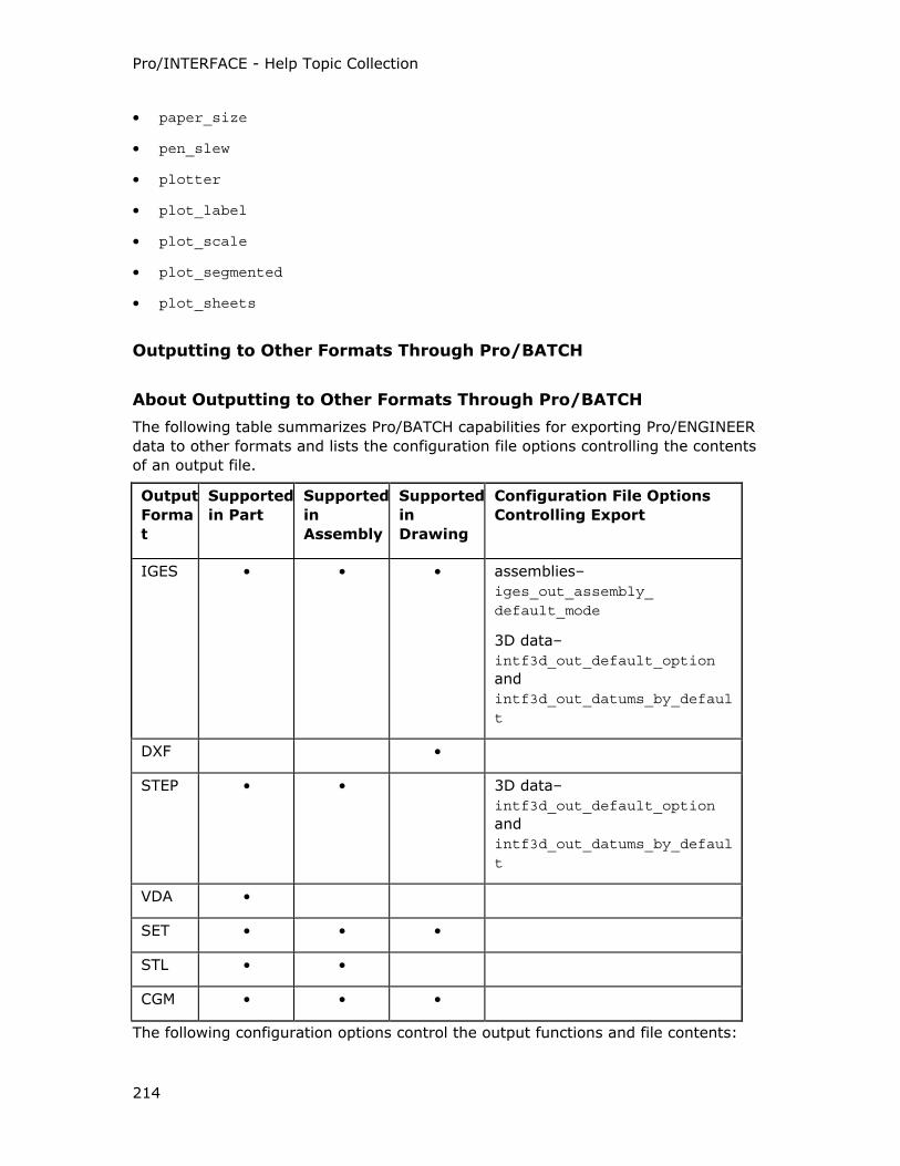
Pro/INTERFACE - Help Topic Collection
214
• paper_size
• pen_slew
• plotter
• plot_label
• plot_scale
• plot_segmented
• plot_sheets
Outputting to Other Formats Through Pro/BATCH
About Outputting to Other Formats Through Pro/BATCH
The following table summarizes Pro/BATCH capabilities for exporting Pro/ENGINEER
data to other formats and lists the configuration file options controlling the contents
of an output file.
Output
Forma
t
Supported
in Part
Supported
in
Assembly
Supported
in
Drawing
Configuration File Options
Controlling Export
IGES • • • assemblies–
iges_out_assembly_ default_mode
3D data–
intf3d_out_default_option
and
intf3d_out_datums_by_default
DXF •
STEP • • 3D data–
intf3d_out_default_option
and
intf3d_out_datums_by_default
VDA •
SET • • •
STL • •
CGM • • •
The following configuration options control the output functions and file contents:
Pro/ENGINEER Interface
215
• intf3d_out_default_option
• intf3d_out_datums_by_default
• iges_out_assembly_default_mode
Importing from CADAM with Pro/BATCH
About Importing from CADAM with Pro/BATCH
You can import CADAM drawings with Pro/BATCH if you specify cadamin when
creating an executable. You are prompted to specify the following:
• Group name
• Subgroup name
• CADAM drawing name
• Pro/ENGINEER drawing name (default is the CADAM drawing name)
The name for the Pro/ENGINEER drawing cannot have spaces. If spaces are
detected, you are prompted to specify a new name.
After you have specified all necessary data, the system adds a -cadamin to the batch
file. The general form of the command is as follows:
-cadamin -grp_nam <group> -sgrp_nam <subgroup> -dwg_nam <name> -pro_dwg_name
When modifying the executable, you must type the arguments "-grp_nam", "-sgrp_nam", and "-dwg_nam" with quotes.
Using a Pro/BATCH Command File
About Pro/BATCH Command Files
The command file is a list of objects that you use to create a plot file or to export to
other formats. Each line in the command file includes the name of an object to be
exported.
Executing a Command File
Executing a command file creates the files for the objects specified in the command
file. It also creates the pro_batch_list.txt file containing a list of all the files
successfully created. You can use the resulting file within a script to plot all of the
plot files automatically with a single command. You can control hidden lines and
datum display in batch mode through your configuration file.
To Create a New Command File
1. Type pro_batch -text <pro_command>. A message appears asking if you want
to run an existing command file
Pro/INTERFACE - Help Topic Collection
216
2. Type no.
3. In the Command File box, type a command file name. If you type the name of
an existing command file, a message appears asking if you want to overwrite the
existing file. Type no if you want to use a different command file name.
4. Type the name of the type of command line you are creating (for example, plot,
STL, DXF, or IGES).
5. Depending on your task, use the appropriate procedure.
To Execute a Command File Immediately After It Is Created
1. Create new command files as required.
2. When the message appears asking if you want to create another command line
type no.
3. Type YES to execute the batch command file. A message appears asking if you
want to plot the output files.
4. Do one of the following
o Press ENTER to accept no, the default
o Type a new system command (for example, laser)
o Type the default plotter_command if the plotter_command is specified in
the config.pro file.
Note: The plotter command or system command plots all output files created in
the pro_batch_list.txt file.
Pro/BATCH starts processing, and creates the following files in your current
working directory:
o Object output files (<object>.plt, <object>.iges)
o The pro_batch_list.txt file listing all object output files
o The pro_batch.log.# file recording the results of the execution
To Run an Existing Command File
1. Type pro_batch. The Pro/BATCH dialog box opens.
2. Click File > Open. The File Open dialog box opens.
3. Select the batch file that you want to run.
4. Click Open. The batch file name and the objects in the batch file appear in the
appropriate areas in the Pro/BATCH dialog box.
5. In the Pro/Engineer Command box, type the command.
6. Schedule the start of the batch process.
Pro/ENGINEER Interface
217
To Upgrade Files
1. Create a new command file.
2. Type the object file name.
To Create a Plot File After Creating a New Pro/BATCH Command File
1. Type the name of the object to plot.
2. Type the plotter name, for example, PostScript, or the name of the plotter configuration file to use, for example, <filename>.pcf. If you are using a plotter
configuration file, you supply only the information not defined in the plotter
configuration file.
3. Specify the required values as messages appear asking you for the following
information:
o Paper size
o Output quality
o User scale
o Pen slewing
o Page range
o Segmented output
o Labeled plot
4. When the message appears asking if you want to create a new plot file, type yes
or type no to specify the name of an existing plot file.
If the drawing has multiple sheets, a message appears asking if you want to
create separate sheets.
5. Type no to append all of the sheets to a single plot file or type yes to create a
separate plot file for each sheet of the drawing.
6. Type the name of the plot file to create.
7. At the prompt, type yes to export another file or type no to execute the
command file. Pro/BATCH displays the contents of the line added to your
command file.
Example: Creating and Running a Plot File of a Drawing
In the following example, Pro/BATCH creates a command file for plotting a drawing.
Without exiting Pro/BATCH mode, the system immediately executes the command
file. After the execution is completed, it sends the created plot file to a specified
printer.
Type: pro_batch -text <pro_command>
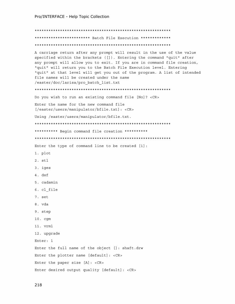
Pro/INTERFACE - Help Topic Collection
218
***********************************************************
************************ Batch File Execution *************
***********************************************************
A carriage return after any prompt will result in the use of the value specified within the brackets ([]). Entering the command "quit" after any prompt will allow you to exit. If you are in command file creation, "quit" will return you to the Batch File Execution level. Entering "quit" at that level will get you out of the program. A list of intended file names will be created under the name /easter/doc/larisa/pro_batch_list.txt
***********************************************************
Do you wish to run an existing command file [No]? <CR>
Enter the name for the new command file [/easter/users/manipulator/bfile.txt]: <CR>
Using /easter/users/manipulator/bfile.txt.
***********************************************************
********** Begin command file creation **********
***********************************************************
Enter the type of command line to be created [1]:
1. plot
2. stl
3. iges
4. dxf
5. cadamin
6. cl_file
7. set
8. vda
9. step
10. cgm
11. vrml
12. upgrade
Enter: 1
Enter the full name of the object []: shaft.drw
Enter the plotter name [default]: <CR>
Enter the paper size [A]: <CR>
Enter desired output quality [default]: <CR>
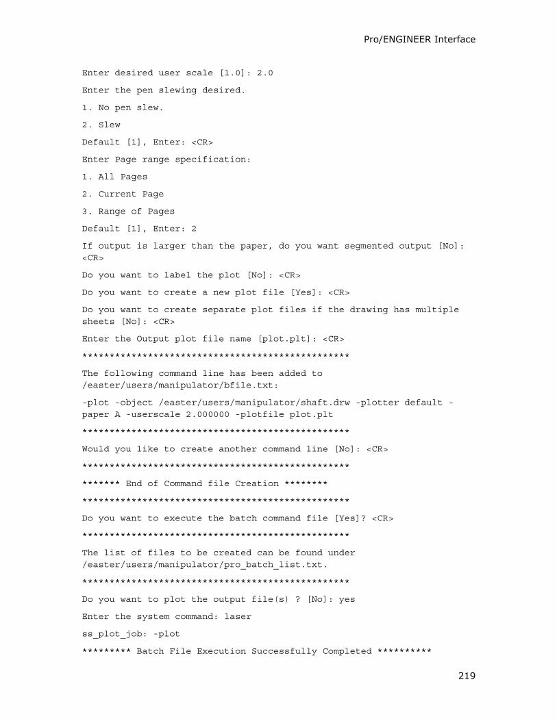
Pro/ENGINEER Interface
219
Enter desired user scale [1.0]: 2.0
Enter the pen slewing desired.
1. No pen slew.
2. Slew
Default [1], Enter: <CR>
Enter Page range specification:
1. All Pages
2. Current Page
3. Range of Pages
Default [1], Enter: 2
If output is larger than the paper, do you want segmented output [No]: <CR>
Do you want to label the plot [No]: <CR>
Do you want to create a new plot file [Yes]: <CR>
Do you want to create separate plot files if the drawing has multiple sheets [No]: <CR>
Enter the Output plot file name [plot.plt]: <CR>
*************************************************
The following command line has been added to /easter/users/manipulator/bfile.txt:
-plot -object /easter/users/manipulator/shaft.drw -plotter default -paper A -userscale 2.000000 -plotfile plot.plt
*************************************************
Would you like to create another command line [No]: <CR>
*************************************************
******* End of Command file Creation ********
*************************************************
Do you want to execute the batch command file [Yes]? <CR>
*************************************************
The list of files to be created can be found under /easter/users/manipulator/pro_batch_list.txt.
*************************************************
Do you want to plot the output file(s) ? [No]: yes
Enter the system command: laser
ss_plot_job: -plot
********* Batch File Execution Successfully Completed **********
Pro/INTERFACE - Help Topic Collection
220
To Export to STL
1. Specify the name of the model to export to STL.
2. Specify the required values as messages appear asking you for the following
information:
o Binary or ASCII output format for the stl file.
o Output quality of the file.
o Name for the stl file.
3. Type yes to export another file or no to execute the command file.
To Export to VRML
1. Create a file to use the Pro/BATCH option commands.
In the VRML Export option, a separate line appears for each unique database.
2. Type one of the following commands:
o For a direct export, type:
-vrml -object <object name> -out_path <path> -direct <y>
o For an in-session export, type:
-vrml -object <object name [-out_path <path> -direct <n>
where:
<object name>—Indicates a part or assembly, such as wheel_1.prt or
engine_u.asm.2.
-out_path <path>—Indicates the path to optionally divert .wrl files to a
specified location.
-direct <y or n>—The y indicates a direct export and the n indicates an
in-session export for the batch process
3. Type the following command to execute the Pro/BATCH option:
PROE_COMMAND 0 0 3 -batchfile [file_name]
To Export to IGES, DXF, SET, VDA, or STEP
1. Type the name of the model to export. The contents of the additional line in the
command file appears.
2. Type yes to export another file or type no to execute the command file.
Note: If you are creating a DXF file, you can only export a drawing.
Pro/ENGINEER Interface
221
Importing Proprietary Surface with Pro/TOOLKIT
About Using Pro/TOOLKIT to Import Proprietary Surfaces
With Pro/TOOLKIT, you can import proprietary surfaces into Pro/ENGINEER. These
imported surfaces are treated by the system as a special type of surface feature.
One of the possible applications of a proprietary surface is surface replacement,
when solid surfaces are replaced with a Pro/TOOLKIT surface. After the proprietary
surface is incorporated into the part geometry, all other geometric operations, such
as Offset, Cut, and Round, are available for the surface.
Note: A model containing a proprietary surface can be retrieved, manipulated, or
saved only with Pro/TOOLKIT.
Before a surface is imported, a coordinate system must be present in the part for the
surface to reference.
To Import a Foreign Surface
1. In a part, click Insert > Advanced > Blend From File > Surface.
2. Select the class of the surface from the SURF CLASS menu. This menu lists all
the classes that have been properly defined in Pro/TOOLKIT.
3. Type the name of the surface.
4. Select from the namelist menu the name of the coordinate system that the
surface will reference.
If imported geometry uses dimension units different from those of the current model,
those units are converted to the units of the current model.
With Pro/SURFACE, you can create nonsolid surfaces using some of the same
techniques you use when you are creating solid geometry, as well as more
sophisticated surface modeling methods. With Interface for Pro/ENGINEER, you can
import surfaces from other CAD systems.
Working with Pro/WEB PUBLISH
About Pro/WEB PUBLISH
Pro/WEB PUBLISH enables you to:
• Create a paperless environment that reduces the cost of creating and plotting
drawings.
• Extend the access to data to all parts of an organization.
The publishing tools enable you to export and then view in HTML, VRML, CGM, and
JPEG formats the following on the Web browser:
• Assembly models and data
Pro/INTERFACE - Help Topic Collection
222
• Assembly processes including graphical and textural information for each process
step
• Manufacturing processes including graphical and textural information for each
process step
Process and assembly information that you view in the browser reflects the process
data extracted programmatically from Pro/ENGINEER.
All publications that you create with Pro/WEB PUBLISH are view-only. After creating
a publication, it is independent from the original assembly or process plan. If you
make changes to the model in Pro/ENGINEER, you must recreate the publication to
reflect the latest changes.
Requirements for Viewing a Publication
The requirements for viewing a publication are as follows:
• A procgi server application must be installed on your Web server. See the
Pro/ENGINEER Installation and Administration Guide for information on individual
server installation instructions.
• You can use Netscape Browser 3.0 (or higher) or Microsoft Explorer 3.0 (or
higher). The browser must support HTML, JavaScript, and Java, as well as VRML,
CGM, and JPEG, either inherently or with plug-ins or helper applications. The Web
browser must also support frames.
Supported Graphics Formats
Pro/WEB PUBLISH supports the following graphics formats:
• JPEG (Joint Photographic Experts Group)—Raster-based 2D image format.
This is the default format.
• CGM (Computer Graphics Metafile)—Vector-based 2D image format.
• VRML (Virtual Reality Modeling Language)—Web-based language used to
describe the layout of 3D objects and environments.
To Create a WEB Publication
1. Export a Pro/ENGINEER assembly or process plan in WWW formats. The system
creates a publication directory with all publication-related files.
2. Place publication directories for assemblies or process plans in the Web server’s
documentation root directory.
3. Use a suitable Web browser to view the publication.
Naming Conventions for Publication-Related Files and 2D Model Views
For each publication, the following files are generated:
Pro/ENGINEER Interface
223
Publication Publication Directory and Related Files
Assembly
Process
<PROCESSNAME>_PRS_WWW directory, which includes:
Top-level .html files
A directory for each process step, which contains
.html, .vrml, .cgm, and .jpg files for that step
Assembly <ASSEMBLYNAME>_ASM_WWW directory, which includes
.html, .vrml, .cgm, and .jpg files
Manufacturing
Process
<PROCESSNAME>_PRS_WWW directory, which includes:
Top-level .html files
A directory for each process step, which contains
.html, .vrml, .cgm, and .jpg files for that step
If you want a particular assembly view to appear as the default orientation for 2D
model display, create a view with the name WEB_DEFAULT. This view becomes the
default view orientation for all process steps. If you have not created the
WEB_DEFAULT view, the last saved orientation of the model is used as the default
view with the name default.
To export step-specific views, create named views according to the following naming
convention: step#_<user_defined_view>. When you are viewing the publication,
the view name appears as <user_defined_view> without the step# prefix. Note that
within the publication, different steps can have the same view names.
Types of Data Extracted
When you create a publication, the system extracts data from your assembly or
process. The following table shows the type of data extracted for each of the
publishing tools.
Publication Type of Data
Assembly Process Part lists
2D and 3D model representations
Model parameters that you include in the assembly
Model tree
Step parameters, including Step #, Step type, and
Step description; time estimate and cost estimate (if
defined)
Pro/INTERFACE - Help Topic Collection
224
Assembly Part lists
2D and 3D model representations
Model parameters that you include in the assembly
Model tree
Manufacturing
Process
2D and 3D representations for each step showing
the workcell/workpiece and the material removal
(where appropriate)
Step/MFG parameters (buttons to call up a browser
screen to view additional information)
Operations/Steps tree
Model tree
To Prepare a Model for Export
1. If you want a publication to contain several JPEG or CGM orientations of an
assembly, create named views in Assembly mode before you export the
assembly. Otherwise, the only available CGM representation is the default view of
the assembly.
2. Set configuration options to customize the Pro/WEB PUBLISH output or to
configure VRML data.
o www_export_geometry_as
o www_tree_location
o www_add_aux_frame
o vrml_explode_lines
o vrml_background_color
o vrml_file_duplicate_material
o vrml_multiple_views
o vrml_export_resolution
3. To list additional model or manufacturing parameters, add them to the model
before exporting the model.
Additional Model Parameters
You can specify model parameters for export in Pro/ENGINEER using the Model Tree
tool. Add the model parameters to the Model Tree columns that contain the model
parameters to export.
Pro/ENGINEER Interface
225
Alternatively, you can create a conf_www.tbl file and place it in the current working
directory. In the conf_www.tbl file, list the parameters to include in the designated
order. The following is a sample of a conf_www.tbl file.
Ref#
Qty
Name
COST
VENDOR
WEIGHT
To Export Process Data from Pro/ENGINEER
1. In Pro/ENGINEER, retrieve the assembly process, assembly, or manufacturing
process that you want to export.
2. Configure the Model Tree to display the model parameters to export.
3. Click File > Save a Copy. The Save a Copy dialog box opens.
4. In the Type box, select WWW.
The system creates a publication directory and stores all publication-related files
in this directory. If the name of the publication is the same as that of an existing
publication in the current directory, a message appears asking if you want to
overwrite it. Pro/ENGINEER exports all user-defined views, and the default view
of the assembly process, assembly, or manufacturing process.
Viewing an Assembly Process Publication
About Viewing an Assembly Process Publication
You can browse the assembly process information on the Web in a step-by-step
format. Frames appear containing the following information for the current step:
• Description of the current step
• Table of parts to be assembled in the current step
• 2D or 3D graphical display of the assembly at the current step
• Model tree (optional)
• Control panel
Step Parameters
The title of the frame describing the step indicates the step number and type of step.
The contents of the frame include the step description, time estimate, and cost
estimate (if defined).
Pro/INTERFACE - Help Topic Collection
226
The step description includes the information that the process planner entered while
in Pro/PROCESS for ASSEMBLIES. This can consist of procedural information (for
example, a list of instructions), the purpose of the step, and any other relevant
comments.
Part List
In part list frame, a table listing parts to assemble in the current step and any
fixtures or tools required to perform the step, appears. By default, the part list table
consists of the following items:
• Reference number
• Model name
• Quantity
The table also lists the additional parameters you include in the model when
preparing the process for export. The additional information can include the part type
(for example, standard component, cable, pipe, or fixture), inventory location,
parameter name, and parameter value. Additional parameters that you include in the
assembly process appear in the part table for all steps.
Click the name of the part in the table to open a window in which the VRML model of
that part appears.
Step Navigation Control Buttons
The control buttons for navigating through the assembly process include:
• Prev—Show information about the previous assembly process step.
• Next—Show information about the next assembly process step.
• Step 1—A menu for selecting a step in any order appears. The name of the step
appears next to the step (if you defined the name in the assembly process using
Setup/Name).
Graphics Frame
The graphics frame shows the assembly, including parts to assemble in the current
step. When you open a publication, default 2D JPG assembly view appears in the
frame. Click 2D JPG to open the window and select the graphics format you want:
2D JPG, 2D CGM, or 3D VRML. The choices depend on the graphics formats
selected for the export.
If your publication contains multiple 2D model views, click View:default and select
the view you want from the list.
Depending on how the step is defined in Pro/PROCESS for ASSEMBLIES, a VRML
model can show a model in its exploded state as a simplified representation, or as a
full representation. You can pan, zoom, or spin a 3D model by using the VRML viewer
controls.
Pro/ENGINEER Interface
227
When you drag the mouse over a VRML part, the part name appears. Click the part
name in the part list or model tree, to open a window in which the VRML model of
that part appears.
Typically, you can zoom or pan only a 2D CGM model. Note that 2D view
manipulation tools depend on the plug-in or helper application that you use.
Viewing the Model Tree
To view a model tree, click Tree. Parts up to and including the current step in
hierarchical order, appear with a tree in a new window. To close the window, click
Tree again. If the tree window remains open while you move to another step, the
tree updates accordingly.
By default, the tree is in a collapsed state. To expand or collapse the tree click the
icon next to the assembly or subassembly name.
The number of instances of a part or subassembly within a higher-level assembly
appears in parentheses next to the component name.
Viewing a Manufacturing Process Publication
About Viewing a Manufacturing Process Publication
You can browse the manufacturing process information on the Web in a step-by-step
format. Frames appear containing the following information for the current step:
• Description of the current step
• Table of operations and steps for the manufacturing process
• Control panel
• 2D or 3D graphical display of the assembly at the current step
Step Parameters
The title of the frame describing the step indicates the step number and type of step.
The contents of the frame include the step description, time estimate, and cost
estimate (if defined). It also contains links to details about the step.
The step description reflects the information that the process planner specified while
in Pro/PROCESS for MFG. This can consist of procedural information (for example, a
list of instructions), the purpose of the step, and any other relevant comments.
When you select any of the following, a separate window containing information
opens:
• Operation Parameters
Click Operation Parameters in the step parameters frame and a separate
window opens with information based on the operation parameters for the step.
• Step MFG Parameters
Pro/INTERFACE - Help Topic Collection
228
Click Step MFG Parameters in the step parameters frame and a separate
window opens with information based on the step manufacturing parameters for
the step.
• Tool Information
Click Tool Information in the step parameters frame and a separate window
opens with information based on the tool information for the step. If a tool path
is associated with the step, it appears along with the tool table information.
Note: Tool information is available only if a tool is defined for the selected step.
• WorkCell Parameters
Click WorkCell Parameters in the step parameters frame and a separate
window opens with information based on the work cell parameters for the step.
• NC Seq. Parameters
When you choose NC Seq. Parameters from the step parameters frame, a
separate browser screen opens with information based on the NC sequence
parameters for the step.
Note: NC Sequence parameters are available only if NC sequences are defined
for the selected step.
• BOM Report
Click BOM Report from the step parameters frame, a separate browser screen
opens with the bill of materials (BOM) for the step
• Operations/Steps List
The operations/steps frame displays an operations/steps list, showing the parts
and steps in the manufacturing process. You can choose from the
Operations/Steps tree to view the selected step.
Step Navigation Control Buttons
The control buttons for navigating through the manufacturing process include:
• Prev—Show information about the previous manufacturing process step.
• Next—Show information about the next manufacturing process step.
• Step 1—Display a pop-up menu for selecting a step in any order. The name of
the step appears next to the step (if you have defined the name in the
manufacturing process using Setup/Name).
Graphics Frame
The graphics frame shows the assembly, including parts to be assembled in the
current step. When you open a publication, the frame displays a default 2D JPG
assembly view. By clicking the 2D JPG control button, you open the pop-up window,
which enables you to select the desired graphics format: 2D JPG, 2D CGM, or 3D
Pro/ENGINEER Interface
229
VRML. The choices depend on the graphics formats that were selected for the
export.
If your publication contains multiple 2D model views, you can select the required
view by clicking the View:default button and choosing a view from the list.
Depending on how the step was defined in Pro/PROCESS for Manufacturing, a VRML
model can show a model in its exploded state, as a simplified representation, or as a
full representation. You can pan, zoom, or spin a 3D model by using the VRML viewer
controls.
For a VRML model, when you move the mouse pointer over a part, the part name
appears at the mouse pointer. By clicking the part name in the part list or model
tree, you can open a window displaying the VRML model of that part.
Typically, you can zoom or pan only a 2D CGM model. Note that 2D view
manipulation tools depend on the plug-in or helper application that you use.
Viewing the Model Tree
To view a model tree, click the Tree button in the control panel. This opens a
window with a tree, which displays parts up to and including the current step in
hierarchical order. To close the window, click the Tree button again. If the tree
window remains open while you move to another step, the tree is updated
accordingly.
By default, the tree is in a collapsed state. By clicking the icon next to the
assembly/subassembly name, you can expand or collapse the tree.
The number of instances of a part or subassembly within a higher-level assembly
appears in parentheses next to the component name.
Viewing an Assembly Publication
About Viewing an Assembly Publication
The browser screen is divided into frames: the table of parts in that assembly,
graphics window, and control buttons.
Part Table
The part table includes the following columns:
• System-generated reference number for each part
• Part name
• Total number of parts in the assembly
• Additional part parameters that you designated for export
By clicking the name of a part, you open a separate window, displaying that part in
the VRML format.
Pro/INTERFACE - Help Topic Collection
230
Graphics Frame
When you open a publication, the graphics frame shows a default 2D JPG assembly
view. By clicking the 2D JPG control button, you open the pop-up window, which lets
you select the desired graphics format: 2D JPG, 2D CGM, or 3D VRML. The choices
depend on the graphics formats that were selected for the export.
If your publication contains more than one 2D model view, you can select the desired
view by clicking the View:default button and selecting a view from the list.
Depending on how the model was defined in Pro/ENGINEER, a VRML model can show
a model in its exploded state, as a simplified representation, or as a full
representation. You can pan, zoom, or spin your 3D model by using the VRML viewer
controls. When you move the mouse pointer over a part, the part name appears at
the mouse pointer. By clicking the part name, you can open a window displaying the
VRML model of that part.
Typically, you can zoom, rotate (in the screen plane), or pan a 2D model. Note that
2D JPG view manipulation tools depend on the plug-in or helper application that you
use.
Button Panel
The button panel contains up to three buttons, depending on the graphics formats
that have been selected for export. The control buttons are:
• Button for displaying the pop-up menu to select the graphics format (2D JPG is
the default option). This button is absent if only one graphics format was
exported.
• Button for displaying the pop-up menu to select a 2D view to be displayed. This
button is absent if only VRML was exported.
• Tree button, which opens a model tree window.
Viewing the Model Tree
To view a model tree, click the Tree button in the control panel. By default, the tree
is in a collapsed state. By clicking the icon next to the assembly/subassembly name,
you can expand or collapse the tree.
The number of instances of a part or subassembly within a higher-level assembly
appears in parentheses next to the component name.
Customizing Publication Sites
About Customizing Publication Sites
In addition to customizing the Pro/WEB PUBLISH output through configuration
options, the Web administrator can customize your publication sites by editing the
index.html file in the publication directory so as to change some of the frame
names or add more frames with a specific name. Once the index.html file is tailored
Pro/ENGINEER Interface
231
to your company requirements, the Web administrator can use that customized
index.html file to set up other publication sites.
You can customize the following aspects of the publication:
• Select formats to use for model representation
• Add an additional frame to include the model tree inside the Web page
• Add additional frames, including step-specific frames
Note: Do not remove the PRO_WEB_PANEL frame from the index.html file.
Without that frame you cannot load the publication into the Web browser.
To Set Formats for Assembly Representations
If you export an assembly or assembly process data in all supported formats (that is,
if the www_export_geometry_as configuration option is set to all), you can edit the
index.html file to limit the model representations to the particular ones you need.
To do so, edit the following line in the index.html file:
<"frame name="PRO_WEB_ALL" src="dummy.html"
and replace the frame name PRO_WEB_ALL with one of the following names:
• PRO_WEB_CGM_VRML—to view CGM and VRML
• PRO_WEB_VRML—to view VRML only
• PRO_WEB_CGM—to view CGM only
• PRO_WEB_JPG—to view JPEG only
• PRO_WEB_JPG_VRML—to view JPEG and VRML
To Include the Tree Tool in the Web Page
You can include the model tree in the main browser window by setting the
www_tree_location configuration option when exporting an assembly or assembly
process data. Alternatively, you can edit the index.html file and add an additional
frame with the name JAVABOM as follows:
<"frame name="PRO_PUBLISH_JAVABOM"src="dummy.html"
To Add a Step-Specific Frame
You can add an additional frame to one or several process steps, and use that frame
to provide any relevant information about the model.
1. Before exporting data in Web formats, set the www_add_aux_frame configuration
option to yes.
2. Add the <filename>.html file to each step directory where you want to include
an additional frame. The contents of the <filename>.html file can be different
for each step.
Pro/INTERFACE - Help Topic Collection
232
3. Edit the top-level index.html file to reference the <filename>.html file by
changing the frame name PRO_WEB_AUX_step to PRO_WEB_AUX_<filename>.
Adding Additional Frames
The Web administrator can add several customized frames (for example, a mail icon,
title, or company logo) to an assembly process or assembly publication.
Note: When you add an additional frame to an assembly publication, place the
<filename>.html file in the same directory as the index.html file.
Example: Adding a Different Video for Each Process Step
To add a different video for each process step, specify the name of the frame as
PRO_PUBLISH_AUX_VIDEO_FRAME and add a VIDEO_FRAME.html file to each step
directory. The contents of the VIDEO_FRAME.html might vary for each step.
Working with Digitized Input
About Digitized Input
Digitizing from a tablet enables you to create point, line, and arc data from existing
drawings and layouts for import to Pro/ENGINEER.
Pro/ENGINEER supports the following tablets for digitizing data on an IBM RS/6000
workstation only:
• Calcomp 33240
• Calcomp 95602
To Import Data from the Digitizing Tablet
1. Create a drawing of the appropriate size.
2. Click File > Open. The File Open dialog box opens.
3. Select Tablet in the Type box. As you enter Digitizing mode, icons for all of the
Pro/ENGINEER windows are created, and a window displays the results of the
digitizing input.
4. Specify the scale and units for the imported data.
5. Calibrate the tablet so that the software can account for stretch, warpage, or tilt
of the drawing being digitized.
6. Begin digitizing data after a crosshair appears to show the location of the puck on
the tablet.
You can return to any one of the other modes to recalibrate or rescale the digitized
data at any time.
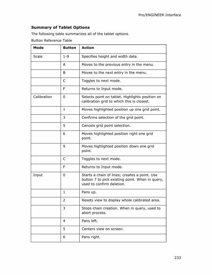
Pro/ENGINEER Interface
233
Summary of Tablet Options
The following table summarizes all of the tablet options.
Button Reference Table
Mode Button Action
Scale 1-9 Specifies height and width data.
A Moves to the previous entry in the menu.
B Moves to the next entry in the menu.
C Toggles to next mode.
F Returns to Input mode.
Calibration 0 Selects point on tablet. Highlights position on
calibration grid to which this is closest.
1 Moves highlighted position up one grid point.
3 Confirms selection of the grid point.
5 Cancels grid point selection.
6 Moves highlighted position right one grid
point.
9 Moves highlighted position down one grid
point.
C Toggles to next mode.
F Returns to Input mode.
Input 0 Starts a chain of lines; creates a point. Use
button 7 to pick existing point. When in query,
used to confirm deletion.
1 Pans up.
2 Resets view to display whole calibrated area.
3 Stops chain creation. When in query, used to
abort process.
4 Pans left.
5 Centers view on screen.
6 Pans right.
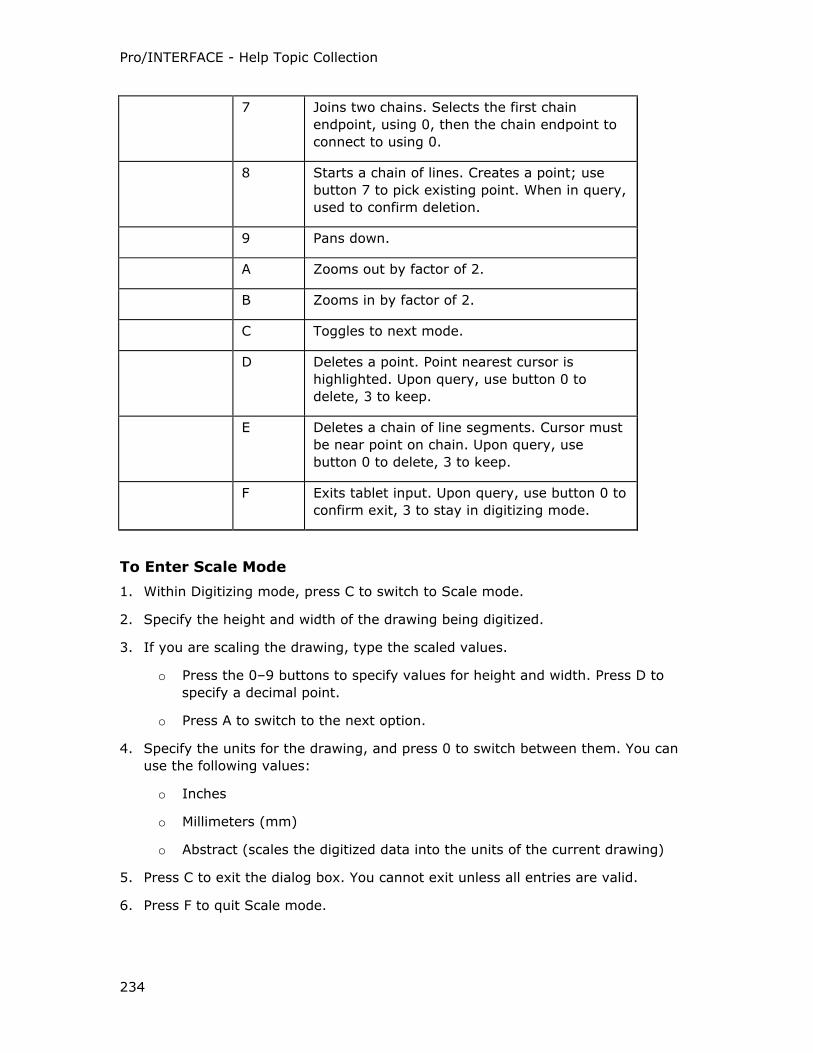
Pro/INTERFACE - Help Topic Collection
234
7 Joins two chains. Selects the first chain
endpoint, using 0, then the chain endpoint to
connect to using 0.
8 Starts a chain of lines. Creates a point; use
button 7 to pick existing point. When in query,
used to confirm deletion.
9 Pans down.
A Zooms out by factor of 2.
B Zooms in by factor of 2.
C Toggles to next mode.
D Deletes a point. Point nearest cursor is
highlighted. Upon query, use button 0 to
delete, 3 to keep.
E Deletes a chain of line segments. Cursor must
be near point on chain. Upon query, use
button 0 to delete, 3 to keep.
F Exits tablet input. Upon query, use button 0 to
confirm exit, 3 to stay in digitizing mode.
To Enter Scale Mode
1. Within Digitizing mode, press C to switch to Scale mode.
2. Specify the height and width of the drawing being digitized.
3. If you are scaling the drawing, type the scaled values.
o Press the 0–9 buttons to specify values for height and width. Press D to
specify a decimal point.
o Press A to switch to the next option.
4. Specify the units for the drawing, and press 0 to switch between them. You can
use the following values:
o Inches
o Millimeters (mm)
o Abstract (scales the digitized data into the units of the current drawing)
5. Press C to exit the dialog box. You cannot exit unless all entries are valid.
6. Press F to quit Scale mode.
Pro/ENGINEER Interface
235
Scale Mode
In Scale mode, you can specify the height and width of the area being digitized, and
the units of the digitized data. This input enables you to scale data, or convert it
automatically to different units. For example, if the drawing on the tablet is a C-size drawing, and you want to scale it to an A-size, for height type [8.5], and for width
type [11]. The digitized data is scaled down from the C-size dimensions to fit the A-
size sheet. Similarly, you can scale up digitized data.
To Calibrate the Tablet
1. Place the drawing on the tablet.
2. Attach the tablet firmly to prevent it from shifting during digitizing. If it shifts, no
existing data is lost, but you must calibrate the tablet again.
3. Press C to switch to Calibration mode.
4. Press A to select the calibration type.
5. Select Simple for linear stretch in both horizontal and vertical directions.
6. Digitize the lower-left, upper-left, and lower-right corners (the minimum needed
to locate the drawing on the tablet).
7. Select Mesh for warpage or nonlinear stretch of the drawing.
8. Specify the number of horizontal and vertical points to calibrate.
9. Press C to show the appropriate calibration type in the dialog box. If you select
Mesh, specify the number of points in the vertical and horizontal direction
pressing the 0–9 buttons to specify values for height and width. Press D to
specify a decimal point.
10. Specify the number of horizontal and vertical points to calibrate. The most simple
(2 points in each direction) enables linear stretch in both horizontal and vertical
directions.
11. Digitize the points for three corners of the drawing first. Press 0 to pick the point.
One of the grid points that is closest to the cursor highlights. If this is the correct
grid point, press 0 to confirm or 3 to cancel. If you need to select another grid
point instead, move the highlight to another grid point.
12. If you select Mesh calibration, a grid pattern appears on the screen delineating
the corners of each calibration area.
13. Press 0 to pick a calibration mark on your drawing. One of the grid points that is
closest to the cursor highlights. If this is the correct grid point, press 0 to confirm
or 3 to cancel. If you need to select another grid point instead, move the
highlight to another grid point.
14. Continue to calibrate all areas.
15. Press C to switch to the next mode.
Pro/INTERFACE - Help Topic Collection
236
Calibration Mode
In Calibration mode, you can set up the tablet to create accurate input data from any
source drawing. Calibrating the tablet to a drawing can compensate for warpage or
tilt when the drawing is placed on the tablet. To calibrate a drawing, you can specify
an area on the drawing and confirm its location on the screen. You can specify one
large area (the entire drawing), for drawings that are in perfect shape, or any
number of user-specified equal areas to calibrate smaller portions of the drawing to
limit the effects of warpage.
To Create a Chain of Straight Line Segments
1. Press 0 to start the chain.
2. With the puck crosshairs located at the start of the line, press 0. As you move the
crosshair to each new location, the next line in the chain rubberbands.
3. Continue to add points to the chain pressing 0.
4. When you have digitized the last point in the chain, press 3. The chain is
examined to determine if it can be converted into a single line or arc.
5. As it highlights each segment, press 0 to convert that portion of the chain or
press 3 to cancel the conversion.
You can convert the chain in small portions, or you can continue to cancel the
conversion of each segment until the entire chain is highlighted. If you accept
pressing 0, the entire chain is converted into a line or arc.
Digitizing Input
All input is displayed on the screen during the digitizing process. You can pan/zoom
while digitizing during all Input mode functions to easily verify the data as you create
it.
Scaling capability is also available at any time. The digitized points in the tablet
coordinates are maintained. Therefore, changing the scale does not alter the real
coordinates of the existing digitized data.
Tip: Converting Chains Using Explicit Commands
You can also convert chains after modifying them or through explicit commands. The
chain color is black if it is a polyline of straight segments, and purple if it is a
segment of chain converted to an arc.
To Delete a Point
You can delete a single point or a point in a chain pressing D in the Input mode.
When the point is defining a chain, the adjacent chain segments are deleted, and if it
is in the middle of a chain, it breaks the chain into two.
1. Place the cursor near the point to delete and press D. The point highlights in red.
2. Press 0 to confirm deletion or press 3 to abort.
Pro/ENGINEER Interface
237
To Digitize Points
You can digitize a single point or create a chain of straight line segments.
To digitize a single point, press 0 twice, and then press 3.
To Delete a Chain
1. Place the cursor near a point on the chain to delete and press E. The chain
highlights in red.
2. Press 0 to confirm deletion or press 3 to abort.
To Join Two Chains
You can join chains created at different times, or broken by deleting points in the
middle of them.
1. Place the cursor on an endpoint of a chain and press 0. The point highlights and
you are prompted to select another chain endpoint. To abort joining the chains,
press 3.
2. Move the cursor to an endpoint of the other chain. Press 0. The two chains
become one with a new line segment between the two selected endpoints.
To Convert a Chain
You can convert a chain to an arc or a single straight line pressing 8 in Input mode.
This enables you to digitize a number of points to approximate an arc, or for a long
line when necessary to account for warpage. Then convert the chain into exact
entities.
You can convert a green chain to a line, and a purple chain to an arc.
1. Place the cursor near a point on the chain to convert, press 8.
2. From the menu, select Arc or Line.
To Configure your IBM RS/6000 to Recognize the Calcomp
1. Connect the Calcomp tablet to the IBM RS/6000 serial port.
2. Login as root to configure the serial port.
3. Type [smit] at the prompt to run the System Management Interface Tool.
4. When the SMIT window appears, select Devices.
5. Select TTY from the Devices listing.
6. When the TTY listing appears, check to see which devices are already defined,
then modify or create a device for the Calcomp tablet. To do this, add the device.
Click Add a TTY.
7. Select tty rs232 Asynchronous Terminal.
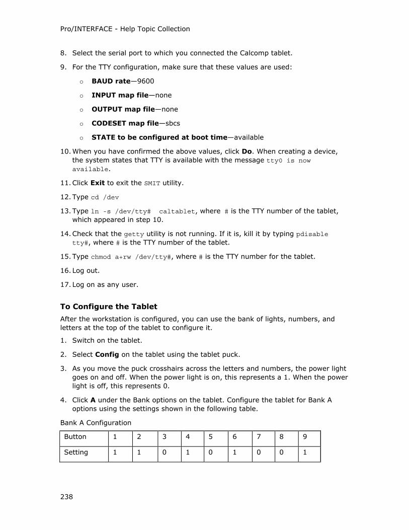
Pro/INTERFACE - Help Topic Collection
238
8. Select the serial port to which you connected the Calcomp tablet.
9. For the TTY configuration, make sure that these values are used:
o BAUD rate—9600
o INPUT map file—none
o OUTPUT map file—none
o CODESET map file—sbcs
o STATE to be configured at boot time—available
10. When you have confirmed the above values, click Do. When creating a device,
the system states that TTY is available with the message tty0 is now available.
11. Click Exit to exit the SMIT utility.
12. Type cd /dev
13. Type ln -s /dev/tty# caltablet, where # is the TTY number of the tablet,
which appeared in step 10.
14. Check that the getty utility is not running. If it is, kill it by typing pdisable tty#, where # is the TTY number of the tablet.
15. Type chmod a+rw /dev/tty#, where # is the TTY number for the tablet.
16. Log out.
17. Log on as any user.
To Configure the Tablet
After the workstation is configured, you can use the bank of lights, numbers, and
letters at the top of the tablet to configure it.
1. Switch on the tablet.
2. Select Config on the tablet using the tablet puck.
3. As you move the puck crosshairs across the letters and numbers, the power light
goes on and off. When the power light is on, this represents a 1. When the power
light is off, this represents 0.
4. Click A under the Bank options on the tablet. Configure the tablet for Bank A
options using the settings shown in the following table.
Bank A Configuration
Button 1 2 3 4 5 6 7 8 9
Setting 1 1 0 1 0 1 0 0 1
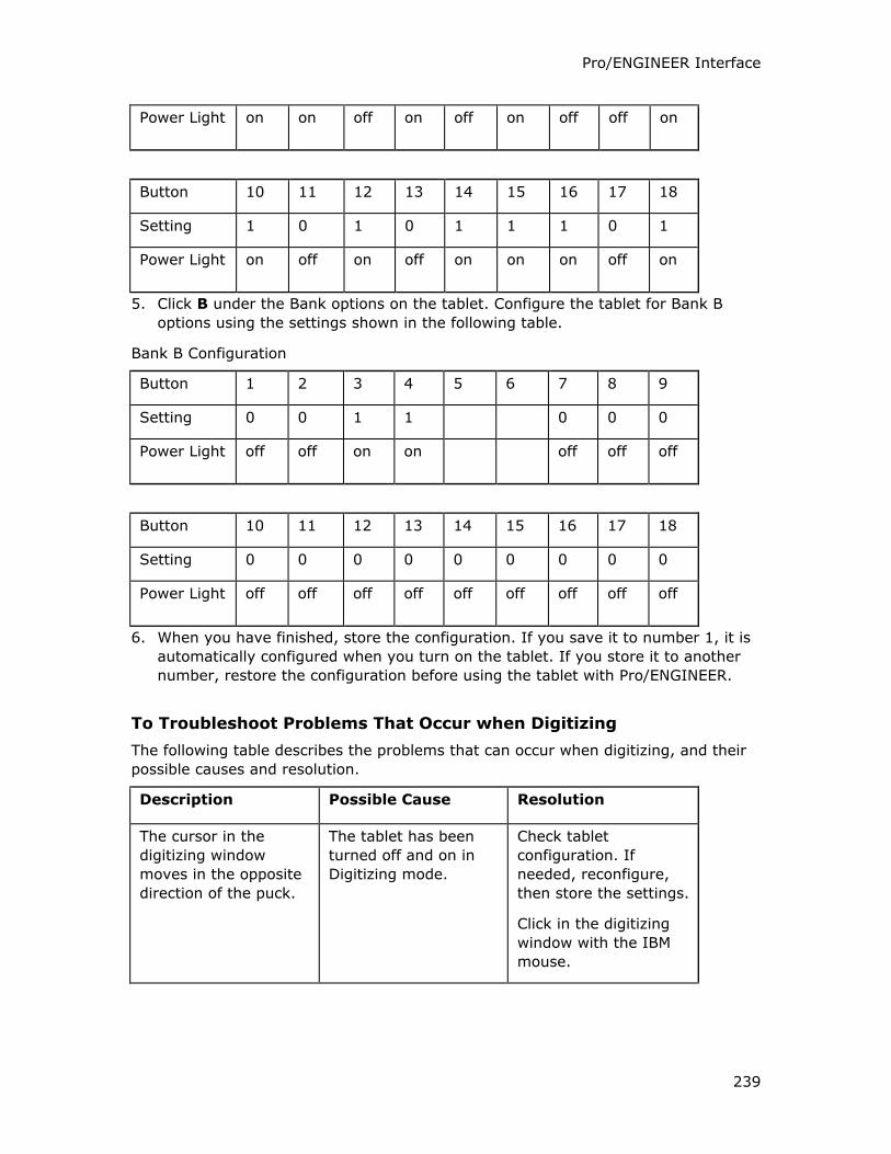
Pro/ENGINEER Interface
239
Power Light on on off on off on off off on
Button 10 11 12 13 14 15 16 17 18
Setting 1 0 1 0 1 1 1 0 1
Power Light on off on off on on on off on
5. Click B under the Bank options on the tablet. Configure the tablet for Bank B
options using the settings shown in the following table.
Bank B Configuration
Button 1 2 3 4 5 6 7 8 9
Setting 0 0 1 1 0 0 0
Power Light off off on on off off off
Button 10 11 12 13 14 15 16 17 18
Setting 0 0 0 0 0 0 0 0 0
Power Light off off off off off off off off off
6. When you have finished, store the configuration. If you save it to number 1, it is
automatically configured when you turn on the tablet. If you store it to another
number, restore the configuration before using the tablet with Pro/ENGINEER.
To Troubleshoot Problems That Occur when Digitizing
The following table describes the problems that can occur when digitizing, and their
possible causes and resolution.
Description Possible Cause Resolution
The cursor in the
digitizing window
moves in the opposite
direction of the puck.
The tablet has been
turned off and on in
Digitizing mode.
Check tablet
configuration. If
needed, reconfigure,
then store the settings.
Click in the digitizing
window with the IBM
mouse.
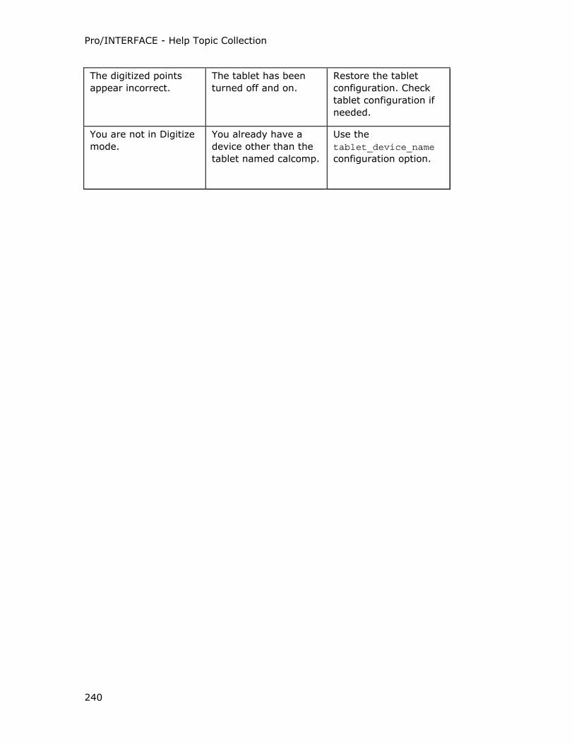
Pro/INTERFACE - Help Topic Collection
240
The digitized points
appear incorrect.
The tablet has been
turned off and on.
Restore the tablet
configuration. Check
tablet configuration if
needed.
You are not in Digitize
mode.
You already have a
device other than the
tablet named calcomp.
Use the
tablet_device_name configuration option.
241
Index
A
ACIS
exporting parts and assemblies.... 57
importing parts and assemblies ... 57
ACIS....................................1, 2, 57
Adobe Illustrator Curves
importing as datum curves.....57, 58
Adobe Illustrator Curves ....... 2, 57, 58
Assembly process publication
viewing .................................. 225
Assembly process publication ....... 225
ATB-enabled formats
CADDS 5 .................................. 64
CATIA V4.............................70, 71
CATIA V5.............................70, 83
CDRS ....................................... 86
ICEM...................................... 107
Pro/DESKTOP .......................... 165
Unigraphics..........................2, 202
ATB-enabled formats . 64, 71, 86, 107,
165
B
Batch
Distributed Pro/BATCH in distributed
mode ........................... 208, 209
using Distributed Pro/BATCH ..... 208
using Pro/BATCH overview ........ 208
Batch ........................................ 208
batch file
using Pro/BATCH to create ........ 210
batch file....................................210
C
CADAM
.cdm file....................................60
imported entity layers .................61
importing CADAM drawing directly 59
importing from using Pro/BATCH 215
importing overview.....................59
importing the processed .cdm file .60
processing.................................60
CADAM ..................... 59, 60, 61, 215
CADDS 5
execute file for export .................69
exporting ............................ 64, 69
importing layers and colors..........64
importing part or assembly.... 64, 68
Pro/INTERFACE for CADDS 5
overview ................................64
setting CVPATH ...............15, 65, 66
starting Name Service.................67
switching converter versions .. 21, 67
updating with ATB ................ 64, 68
using extend_cvpath configuration
option .........................15, 65, 66
using the ODB_DAEMON process ..67
CADDS 5...........................64, 68, 69
CADRA
enabling export ........................128
CADRA.......................................128
CATIA
Pro/INTERFACE - Help Topic Collection
242
appending a .ct file .................... 79
appending CATIA V4 ProGEO.model
file ........................................ 82
appending CATParts to
Pro/ENGINEER assembly .......... 84
appending native CATIA V4 .model
file ........................................ 74
CATIA II Interface license ......70, 71
configuring Pro/INTERFACE for
CATIA for direct exchange ...72, 81
converting .cat file to .model format
............................................ 80
converting .ct file to .model format
............................................ 80
converting .model file to .ct format
............................................ 78
entities supported for import ....... 73
exporting dittos ......................... 76
exporting to .cat format.............. 80
exporting to .ct format ............... 80
Exporting to CATIA V4................ 76
exporting to CATIA V4 ProGEO
.model format.............. 71, 72, 83
exporting using Pro/INTERFACE for
CATIA.................................... 83
importing .model file using
Pro/INTERFACE for CATIA ........ 82
importing a .ct file ..................... 79
importing CATIA .model files ....... 74
importing CATIA V4 .exp files .71, 75
importing CATIA V5 CATPart ..70, 83
importing CATPart earlier than R683,
84, 85
importing layers and layer filters. 71,
73, 75
importing models with dittos in
Assembly mode.......................73
importing part with empty features
..................................83, 84, 85
importing processed .ct file.... 74, 79
intf_for_catia_V5 license ....... 70, 83
licenses............................... 70, 71
methods of data exchange..... 72, 81
model space parameter
configuration options.....30, 31, 77
processing a CATIA native .model
file for import..........................78
specifying model space parameters
.............................................77
start parts attributes...................77
translators........................... 70, 71
using custom start parts..............77
using display status of layer filters
....................................... 75, 76
using Interface for CATIA II with ATB
....................................... 70, 71
using one-step direct method. 72, 81
using Pro/INTERFACE for CATIA ..70,
71
using pro_from_cat4........70, 72, 78
using proegeo_to_cat4.......... 72, 80
using two-step indirect method ....72
using utilities ............ 72, 78, 80, 81
versions ....................................70
CATIA.........72, 73, 74, 76, 78, 79, 80
CatiaFacets command
EXPORT menu..........................189
CatiaFacets command..................189
CDRS
Index
243
appending a file to existing model 86
creating ATB-enabled IN features. 86
importing a CDRS file ................. 86
CDRS.......................................... 86
CED groups
creating from Pro/DESKTOP import
................................... 165, 166
updating.......................... 166, 168
CED groups .....................2, 165, 166
CGM
binary encoding in metric units ... 87,
88
drawing sheet size ................56, 88
encodings ............................87, 88
entities supported for import ....... 88
exporting.................................. 87
importing.................................. 88
overview of files ........................ 87
set option in Pro/BATCH............ 211
units ...................................87, 88
CGM ...............................87, 88, 211
colors
AutoCAD system...................... 101
color mapping to AutoCAD ........ 100
default system Pro/ENGINEER ... 101
colors................................. 100, 101
configuration options
setting for 2D and 3D interface ...... 9
configuration options....................... 9
COSMOS
overview of geometry................. 89
COSMOS ..................................... 89
COSMOS Geom
EXPORT menu............................89
COSMOS Geom.............................89
curves data format
Neutral file ..............................143
curves data format ......................143
custom start parts and assembly
templates
using when importing .................56
custom start parts and assembly
templates..................................56
CVPATH
environment variable ..................66
CVPATH .......................................66
D
data
types extracted for a publication.223
data ..........................................223
digitizing tablet
calibrating ...............................235
importing ................................232
input ......................................232
options ...................................233
digitizing tablet ............ 232, 233, 235
dimflac
environment variable ................100
dimflac ......................................100
drawing sheet size
standard ...................................56
variable.....................................56
drawing sheet size ..... 56, 88, 94, 112
DWG
Pro/INTERFACE - Help Topic Collection
244
configuring options for import.90, 93
drawing sheet size ..................... 94
export log file ............................ 95
export options dialog box.......95, 96
export specific options ...........95, 96
exporting drawing scale ............ 100
exporting multiline notes . 27, 95, 96
exporting to versions 13, 13, 14,
2000 ..................................... 95
ignoring 3D solids ............... 26, 103
importing 2D entities and 3D solids
........................ 90, 91, 102, 103
importing from AutoCAD 2002 ..... 90
importing multiline text .. 27, 90, 91,
92, 94
importing versions 12, 13, 14, 2000
............................................ 90
layering scheme when exporting .. 98
mapping layers.......................... 98
mapping line style...................... 98
using 2D import dialog box ...90, 91,
92
view scale................................. 98
DWG....................... 90, 98, 100, 102
DWG command
EXPORT menu ........................... 96
DWG command ............................ 96
DXF
appending 3D DXF files...... 102, 106
AutoCAD saved as 3D DXF Files 102,
104
configuring options for import.90, 93
creating multiple-sheet drawings .26,
56, 90, 91, 92, 94
export log file ............................95
export options dialog box .95, 96, 97
exporting drawing scale ............100
exporting multiline notes .27, 95, 96,
99
exporting to using a Pro/BATCH
command file ........................220
exporting to versions 12, 13, 14,
2000.............................. 95, 180
filtering faceted data.................105
ignoring 3D solids............... 26, 103
importing 2D blocks.............. 90, 94
importing 2D entities and 3D solids
.........................91, 92, 102, 103
importing 3D DXF files as assemblies
............................ 102, 104, 105
importing 3D DXF files as parts .102,
104, 105
importing 3D geometry90, 102, 104,
105
importing dimensions............ 90, 94
importing drawing data ....90, 91, 94
importing embedded exact ACIS 3D
geometry ......... 90, 102, 104, 105
importing faceted data . 90, 102, 104
importing from AutoCAD 2002 .....90
importing multiline text ...27, 90, 91,
92, 94
importing using the 2D dialog box90,
91, 92, 93
importing versions 12, 13, 14, 2000
.............................................90
importing viewports ..................103
Index
245
layering scheme when exporting .. 98
mapping layers.......................... 98
mapping line style...................... 98
set option in Pro/BATCH............ 213
view scale................................. 98
DXF .......................98, 100, 213, 220
DXF command
EXPORT menu ........................... 96
DXF command.............................. 96
dxf_export.pro ........................... 100
E
environment variable
CVPATH......................... 15, 65, 66
dimflac ................................... 100
environment variable ............. 66, 100
EPS
exporting................................ 200
EPS .......................................... 200
F
feature
adding a new surface in an imported
file ........................................ 48
replacing an imported................. 49
replacing part of an imported ...... 50
feature........................47, 48, 49, 50
Fix Bndries command
MANUAL REPAIR menu ............... 46
Fix Bndries command.................... 46
G
geometry
overview of COSMOS.................. 89
overview of PATRAN .................163
overview of Supertab ................187
geometry ...................... 89, 163, 187
Granite-based file formats
creating CED groups ..........165, 166
creating import IN features. 23, 165,
166, 167
creating read-only features. 23, 106,
165
direct opening of models .... 23, 106,
165, 167
importing models . 23, 165, 167, 168
Pro/DESKTOP .des and .pdt files 106,
165, 167
Granite-based file formats23, 106, 165
I
ICEM surfaces
appending to existing models.....107
creating ATB-enabled IN features107
importing ................................107
ICEM surfaces.............................107
I-DEAS
configuring ..............................108
filtering parts and assemblies......29,
108, 109, 110
import terminating abruptly .......111
importing .mf1 files ..................109
importing .pkg files...................110
OpenIdeas libraries...................108
OpenIdeas license ....................108
platform support ......................... 2
specifying loadpoint ..................108
specifying startup command ........29
Pro/INTERFACE - Help Topic Collection
246
troubleshooting when importing 110,
111
I-DEAS...................................... 108
IGES
2D entities supported for import into
drawing mode....................... 116
about iges_config.pro file .............. 9
configuration options supporting
import .......................... 112, 115
configuring export........................ 9
creating a drawing file .............. 125
drawing sheet size ..... 112, 115, 116
enabling CADRA export............. 128
entities supported for export ..... 131
entities supported for export from
Drawing mode ...................... 126
entities supported for import ..... 120
entity attributes supported........ 125
export log file ................... 124, 125
export options dialog box... 124, 125
exporting colors in drawing mode128
exporting cross hatch ........ 125, 126
exporting to using a Pro/BATCH
command file........................ 220
file structure for exporting
assemblies to ....................... 133
format for assembly files........... 131
groups overview ...................... 128
importing a 3D file ................... 119
importing colors in Drawing mode
.......................................... 119
importing colors in Part and
Assembly modes ................... 123
importing in Sketcher mode ...... 123
importing into a drawing ...........112
importing multiline text27, 112, 113,
114
importing using 2D dialog box...112,
113, 114
set option in Pro/BATCH ............213
IGES ....112, 115, 116, 119, 120, 123,
125, 126, 128, 131, 133, 213, 220
IGES command
EXPORT menu...................125, 130
IGES command....................125, 130
IGES Group
creating ..................................129
editing ....................................129
IGES Group ................................129
IGES View Layout
importing ................................115
IGES View Layout........................115
imported data
assuring accuracy.......................46
imported data...............................46
imported faceted geometry
analysis and referencing........ 51, 52
calculating mass properties.... 50, 52
creating analysis features ............52
creating datum axis ....................52
creating datum features ..............51
creating datum planes.................52
creating datum points ........... 51, 52
measuring angle ........................52
measuring curve length...............52
measuring distance.....................52
Index
247
measuring surface area .............. 52
referencing for datum creation51, 52
referencing mix of facet and exact
geometry ..........................51, 52
using constraints ....................... 51
using for measurements ........50, 52
imported faceted geometry . 50, 51, 52
imported feature
converting to a solid................... 46
redefining ................................. 47
replacing .................................. 49
imported feature ............... 46, 47, 49
imported geometry
overview................................... 44
imported geometry ....................... 44
importing Cross-Hatch Patterns ...... 63
IN features
contained within CED groups ..... 166
creating from CDRS ................... 86
creating from ICEM Surf models. 107
creating from Pro/DESKTOP import
.......................................... 165
updating.......................... 166, 168
IN features ................................ 165
index.html
adding a step-specific frame...... 231
editing to limit model
representations..................... 231
including a model tree .............. 231
Integrated mode
flowchart ............................. 186
starting Stheno/PRO.............. 184
workflow ..............................185
Integrated mode ...............184, 185
index.html .................................231
Interface
overview .................................... 2
Interface....................................... 2
Interface for CATIA II with ATB
overview ...................................71
Interface for CATIA II with ATB .......71
Inventor command
EXPORT menu..........................189
Inventor command......................189
J
JPEG
exporting ................................201
exporting overview ...................200
JPEG ..................................200, 201
L
layer information
controlling the import and export for
3D models ..............................55
exporting overview .....................53
layer information..................... 53, 55
layers
controlling by manipulating layer
status ....................................55
export status overview................54
exporting to DXF and DWG ..........99
exporting to SET ......................171
importing from SET ..................171
multiple selection .......................55
layers ............................. 54, 99, 171
Pro/INTERFACE - Help Topic Collection
248
M
manufacturing process publication
viewing .................................. 227
manufacturing process publication 227
MEDUSA
appending a drawing file to a
drawing ............................... 141
appending to a Pro/ENGINEER part
.......................................... 140
exporting a drawing ................. 140
exporting coordinate systems ... 139,
188
exporting solid geometry .......... 139
exporting tessellated data .. 139, 188
importing a drawing .....35, 139, 141
importing part or assembly file .. 140
mapping drawing information .... 141
MEDUSA............................. 139, 188
Motion Envelop
exporting to Motion Envelop ...... 142
Motion Envelop........................... 142
N
naming conventions
2D model views ....................... 222
Publication-Related files............ 222
SET........................................ 173
naming conventions ............. 173, 222
Neutral command
EXPORT menu ......................... 161
Neutral command ....................... 161
Neutral file
arc data format ....................... 143
assembly data format ...............160
assembly members data format .161
cone data format......................147
curves data format ...................143
cylinder data format .................147
cynlindrical surface data format..153
dimensions data format.............158
edge entity data format.............157
feature entity data format .........159
fillet surface data format ...........151
format of.................................156
general surface of revolution data
format..................................149
geometric tolerances data format160
importing ................................155
line data format .......................143
mass properties data format ......159
NURBS data format ..................144
NURBS surface data format .......155
overview .................................142
part entity data format..............156
plane data format.....................146
ruled surface data format ..........150
sharing data collaboratively in
Pro/ENGINEER ......................142
spline data format ....................144
spline surface data format .........152
supporting cross-release
interoperability......................142
tabulated cylinder data format ...151
torus data format .....................148
trimmed surfaces data format ....145
Index
249
Neutral file....142, 143, 144, 145, 146,
147, 148, 149, 150, 151, 152, 153,
155, 156, 157, 158, 159, 160, 161
O
OptegraVis command
EXPORT menu ......................... 189
OptegraVis command .................. 189
P
Parasolid
appending to existing model...... 162
configuring export........... 9, 33, 163
exporting Pro/ENGINEER models2, 9,
33, 161, 163
exporting using schema.............. 33
file formats and extensions 161, 162
importing part or assembly 161, 162
using Parasolid kernel............... 161
Parasolid .........................2, 161, 162
PATRAN
overview of geometry............... 163
PATRAN..................................... 163
PATRAN Geom command
EXPORT menu ......................... 163
PATRAN Geom command ............. 163
plot file
creating after creating a Pro/BATCH
command file........................ 217
plot file ..................................... 217
Pro/BATCH
configuration options................ 213
creating a new batch file........... 210
entering ................................. 209
importing from CADAM overview 215
outputting to other formats........214
overview .................................208
scheduling start of batch process 210
setting preferences...................209
Pro/BATCH ... 208, 209, 210, 213, 214,
215
Pro/BATCH command file
creating ..................................215
executing immediately in Pro/BATCH
...........................................216
overview .................................215
running an existing...................216
Pro/BATCH command file ......215, 216
Pro/CONCEPT
EXPORT menu..........................190
Pro/CONCEPT ......................188, 190
Pro/DESKTOP
appending .des and .pdt files ....165,
167
assembling .des model into
assembly..............................168
creating CED groups ...... 2, 165, 166
creating IN features...........165, 167
creating read-only features. 23, 165,
167
directly opening .des files 2, 23, 165,
167
importing .des and pdt files .. 2, 165,
167
importing native .des files .... 2, 165,
166
Pro/DESKTOP ......................... 2, 165
Pro/INTERFACE for CADDS 5
Pro/INTERFACE - Help Topic Collection
250
overview................................... 64
Pro/INTERFACE for CADDS 5.......... 64
Pro/INTERFACE for CATIA
overview................................... 71
Pro/INTERFACE for CATIA .............. 71
Pro/WEB PUBLISH
configuration options for export . 224
customize by setting formats..... 231
customizing publication sites
overview.............................. 230
editing index.html.................... 231
overview................................. 221
viewing a manufacturing process
publication ........................... 227
viewing an assembly publication 229
Pro/WEB PUBLISH 221, 224, 227, 229,
230, 231
ProductView
exporting.............................2, 169
file types ................................ 169
importing......................... 169, 170
ProductView............................... 169
proigsutil
overview................................. 134
proigsutil ................................... 134
Publication-Related files
naming conventions ................. 222
Publication-Related files............... 222
R
Render command
EXPORT menu ......................... 189
Render command ....................... 189
S
scale mode
entering from digitizing mode ....234
scale mode.................................234
SET
.log file ...................................172
creating a part or assembly .......173
creating a part or drawing file ....173
creating an assembly file ...........173
exporting to using a Pro/BATCH
command file ........................220
importing file into a drawing ......172
importing to an existing part or
assembly..............................171
naming conventions..................173
overview .................................171
set option in Pro/BATCH ............213
SET .............. 171, 172, 173, 213, 220
SET command
EXPORT menu..........................173
SET command ............................173
shaded image
exporting ................................201
shaded image .............................201
shaded images
exporting overview ...................200
shaded images ...........................200
Snapshot TIFF
overview .................................199
Snapshot TIFF ............................199
STEP
Index
251
3D validation properties overview
.......................................... 175
AP202 supported classes........... 176
colors and layers support .......... 182
configuration options................ 181
configuring export........................ 9
drawing sheet size ................... 178
exporting a part or assembly.... 174,
181
exporting drawing.................... 180
exporting drawing format.......... 180
exporting facet geometry.......... 181
exporting geometry.................. 174
exporting layout ...................... 180
exporting STEP associative drafting
data .................................... 176
exporting to AP209 format . 174, 181
exporting to using a Pro/BATCH
command file........................ 220
file format for exporting assemblies
to ....................................... 182
file structure list ...................... 182
importing 3D files .................... 180
importing into Drawing mode .... 178
importing multiline text ............ 178
importing part and assembly files
................................... 174, 179
importing STEP associative drafting
data .................................... 176
set option in Pro/BATCH............ 213
step_config.pro file ...................... 9
supported AP203 classes........... 177
using analysis packages............ 174
using formats ............. 38, 174, 176
STEP ....174, 175, 176, 177, 178, 179,
180, 181, 182, 213, 220
STEP command
EXPORT menu...................180, 181
STEP command....................180, 181
STHENO/PRO
appending a STHENO/PRO file....187
application startup command ......36,
184, 185
capabilities .......................... 2, 184
configuration option............ 36, 184
exporting to STHENO/PRO .........187
global environment variable 184, 185
importing to Pro/ENGINEER .......186
starting in integrated mode........184
workflow ..........................185, 186
STHENO/PRO.......................184, 185
STL
exporting to using a Pro/BATCH
command file ........................220
set option in Pro/BATCH ............212
STL ....................................212, 220
STL command
EXPORT menu..........................189
STL command.............................189
Supertab
overview of geometry ...............187
Supertab....................................187
SUPRTB Geom command
EXPORT menu..........................187
SUPRTB Geom command..............187
Pro/INTERFACE - Help Topic Collection
252
surfaces
adding to an existing feature in an
imported file........................... 48
overlapping............................. 191
using Pro/TOOLKIT to import..... 221
surfaces ........................48, 191, 221
T
tablet
see digitizing tablet .................. 232
tablet........................................ 232
tessellated files
controlling the quality of export . 191
overview................................. 188
tessellated files ................... 188, 191
TIFF
exporting................................ 201
importing into Drawing mode .... 199
TIFF................................... 199, 201
TIFF (Snapshot)
exporting................................ 201
exporting overview .................. 200
overview................................. 199
TIFF (Snapshot) ........... 199, 200, 201
tree tool
included in web page................ 231
tree tool .................................... 231
trimmed surfaces data format
Neutral file.............................. 145
trimmed surfaces data format ...... 145
U
Unigraphics
about export and import............202
appending Unigraphics parts and
assemblies............................203
assembling a Unigraphics model.204
environment variables required ..202
exporting Pro/ENGINEER models to
Unigraphics...........................205
importing Unigraphics parts and
assemblies............................203
installing and licensing .....2, 34, 202
versions supported ...................... 2
Unigraphics ............................ 2, 202
V
variable drawing sheet size
importing CADAM drawings.... 56, 59
importing CGM files .............. 56, 88
importing DXF andDWG drawings .94
importing IGES drawing files......112
importing STEP files..................178
importing using variable sheet size
.............................................56
variable drawing sheet size.............56
VDA
creating a part .........................206
creating part or assembly file .....207
exporting to using a Pro/BATCH
command file ........................220
importing as new feature...........206
set option in Pro/BATCH ............213
VDA .................... 206, 207, 213, 220
VDA command
EXPORT menu..........................207
VDA command............................207
Index
253
VRML
exporting directly..................... 195
exporting using a Pro/BATCH
command file........................ 220
importing and exporting to ISO
version ................................ 193
set option in Pro/BATCH............ 212
supporting Moving World .......... 193
types of export ........................ 193
VRML ...................193, 195, 212, 220
VRML command
EXPORT menu ......................... 196
VRML command ..........................196
W
WEB Publication
creating ..................................222
WEB Publication ..........................222
WWW command
EXPORT menu..........................225
WWW command..........................225
X
XPatch command
EXPORT menu..........................189
XPatch command ........................189


