Embed Size (px)
Citation preview
�����������������
Citation: Deng, X.; Hoo, M.S.; Cheah,
Y.W.; Tran, L.Q.N. Processing and
Mechanical Properties of Basalt
Fibre-Reinforced Thermoplastic
Composites. Polymers 2022, 14, 1220.
https://doi.org/10.3390/
polym14061220
Academic Editor: Fabrizio Sarasini
Received: 3 February 2022
Accepted: 8 March 2022
Published: 17 March 2022
Publisher’s Note: MDPI stays neutral
with regard to jurisdictional claims in
published maps and institutional affil-
iations.
Copyright: © 2022 by the authors.
Licensee MDPI, Basel, Switzerland.
This article is an open access article
distributed under the terms and
conditions of the Creative Commons
Attribution (CC BY) license (https://
creativecommons.org/licenses/by/
4.0/).
polymers
Article
Processing and Mechanical Properties of Basalt Fibre-ReinforcedThermoplastic CompositesXinying Deng 1,* , Ming Shun Hoo 1,2, Yi Wen Cheah 1 and Le Quan Ngoc Tran 1
1 Singapore Institute of Manufacturing Technology, Agency for Science, Technology and Research (A*STAR),Singapore 138634, Singapore; [email protected] (M.S.H.); [email protected] (Y.W.C.);[email protected] (L.Q.N.T.)
2 School of Materials Science and Engineering, Nanyang Technological University, Singapore 639798, Singapore* Correspondence: [email protected]
Abstract: Basalt fibre is derived from volcanic rocks and has similar mechanical properties as glassfibre. However, poor fibre-matrix compatibility and processing issues are the main factors that haverestricted the mechanical performance of basalt fibre-reinforced thermoplastic composites (BFRTP).In this work, basalt continuous fibre composites with polypropylene (PP) and polycarbonate (PC)matrices were studied. The composites were processed by compression moulding, and a processingstudy was conducted to achieve good quality composites. For the BF-PC composites, the optimisationof material preparation and processing steps allowed the polymer to impregnate the fibres withminimal fibre movements, hence improving impregnation and mechanical properties. For BF-PPcomposites, a compatibiliser was required to improve fibre-matrix compatibility. The compatibilisersignificantly improved the tensile and impact strength values for short BF-PP composites and contin-ued to increase at 40 wt%. Furthermore, the analytical modelling of the Young’s moduli indicatedthat the induced fibre orientation during processing for short BF-PP composites and unidirectional(UD) BF-PC composites had better stress transfer than that of UD BF-PP composites.
Keywords: thermoplastic composite processing; basalt; mechanical properties
1. Introduction
Basalt fibre is a bio-derived mineral fibre from volcanic rocks and has several advan-tages, such as good chemical resistance and mechanical properties [1–6]. Basalt fibre hassimilar tensile properties as glass fibres and has a higher maximum service temperaturethan glass and carbon fibres, as shown in Table 1. This enables basalt fibre composites tobe a viable and sustainable alternative to glass fibre composites for structural applications.Moreover, it has a higher maximum service temperature and good chemical resistance,which makes it suitable for applications in harsh environments, such as composite pipesfor the oil and gas industries or chemical storage tanks [1].
Basalt fibre has been studied by several scientists to explore the fibre used as reinforce-ment for polymer composites [2,3,7–11]. With good mechanical properties in combinationwith high temperature and alkaline resistance, basalt fibre is a good candidate for com-posites with thermoset matrices such as epoxy and polyester. Arshad et al. [7] reportedepoxy hybrid composites having a high resistance to changes in temperature and signif-icant enhanced mechanical performance. Basalt fibre reinforced epoxy composites alsodemonstrated higher resistance to aging in alkaline medium and heat than those of glassfibre epoxy composites based on E-glass and S-glass fibres, while the mechanical propertiesof the basalt fibre composites are closer to those that of S-glass composites and greater thanthose of E-glass composites. These properties are connected to the high adhesion betweenthe basalt fibres and epoxy [8].
With increasing demand for lightweight, sustainable materials for metal-replacementin various industries, the global thermoplastic composite market has been projected to
Polymers 2022, 14, 1220. https://doi.org/10.3390/polym14061220 https://www.mdpi.com/journal/polymers
Polymers 2022, 14, 1220 2 of 16
reach USD 16.3 billion by 2023 [12]. Thermoplastic composites can be recycled and welded,allowing composites to be part of a circular economy and also offer the possibility offorming large composite structures in a shorter timeframe [13–15]. However, the researchfor thermoplastic composites is less established than that for thermoset composites dueto issues such as fibre-matrix compatibility, high processing temperatures, and processingdifficulty [13–16]. Regarding basalt fibre reinforced thermoplastics BFRTP), most of studieshave been focused on short basalt fibre composites with thermoplastic matrices includingpolypropylene (PP), polypropylene/poly(butylene terephthalate) and poly(vinylidenefluoride)/poly(methyl methacrylate) blends for manufacturing with injection mouldingprocess [2–4,16–18]. The mechanical properties of the short-fibre composites were limitedby the loading of the fibres, in which the fibre loading was recommended at lower than 20%wt. There are also limited fundamental studies to understand the potential of basalt fibrethermoplastic composites by looking into the performance of unidirectional continuousfibre composites for better design for application of the composites.
Table 1. Properties of basalt fibre with glass and carbon fibres [5,6].
Basalt E-Glass S-Glass Carbon
Density 2.63–3.05 2.54–2.62 2.46–2.54 1.78Tensile strength 3000–4840 3100–3800 4020–4830 3500–6000
Elastic modulus (GPa) 79.3–110 72.5–78 83–91 230–600Elongation at break 3.1–3.2 4.7 5.3–5.6 1.5–2.0
Maximum service temperature (◦C) 650 380 300 500
Other aspects include fibre-matrix compatibility and adhesion. The sizing of commer-cial continuous basalt fibre was developed for epoxy applications, limiting its mechanicalperformance. Attempts have been made to improve the fibre-matrix adhesion through theuse of different compatibilisers or sizing agents [18,19]. Russo et al. [19] showed that the useof polypropylene-graft-maleic anhydride improved the flexural and impact performance ofcontinuous BF-PP composites. However, the highest flexural strength value achieved was81.1 MPa, which was significantly lower than the expected strength values of continuousglass fibre thermoplastic composites. This could be due to lower fibre volume fraction orcomposite quality issues, which were not investigated in the study. Therefore, there is aneed to understand the processing of the continuous basalt fibre thermoplastic compositesin order to achieve a good quality composite with the consistent and good mechanicalperformance required for structural applications.
In the present study, a processing study was conducted for the continuous basalt fibrethermoplastic composites to resolve fibre spreading issues and improve matrix impreg-nation. Basalt fibre is typically sized for epoxy polymers; therefore, polypropylene-graft-maleic anhydride was used as a compatibiliser to improve the fibre-matrix adhesion forbasalt fibre-polypropylene (BF-PP) composites. Tensile properties, degree of impregnation,and fibre volume fraction were characterised. Additionally, the effect of compatibiliser onthe tensile and impact properties of short BF-PP composites was also studied. Analyticalmodels were used to predict the Young’s modulus values for the short and continuous fibrecomposites, and the predictions will be compared to the experimental results.
2. Materials and Methods2.1. Materials2.1.1. Fibre
The basalt fibre used in this study was in the form of unidirectional (UD) basalt fabric,provided by Sure New Material (Zhejiang) Co. Ltd. (Tongxiang, China). The UD fabric hada linear density of 400 Tex and a thickness of 0.243 mm. The short basalt fibre was cut fromthis fabric to approximately 10 mm length before further processing.
Polymers 2022, 14, 1220 3 of 16
2.1.2. Polymer
Commercial grade polycarbonate (PC) film supplied by Pacco Chemical (S) Pte Ltd.(Singapore) was used in this study. The PC film has average thickness of 0.1 mm anddensity of 1.2 g/cm3.
Polypropylene (PP) pellets, Cosmoplene, Y101E grade, were provided by The Poly-olefin Company Pte. Ltd. (Singapore) and were used in compounding process and to makethe PP film using the press at 250 ◦C. The PP film had average thickness of 0.1 mm to0.2 mm and density of 0.90 g/cm3.
2.1.3. Compatibiliser
Polypropylene-graft-maleic anhydride (MAPP) pellets were utilised to improve fibre-matrix adhesion in basalt fibre reinforced PP composites, which were supplied by Sigma-Aldrich, (St. Louis, MO, USA). The MAPP has 8 wt% to 10 wt% of grafted maleic anhydride,melting point of 156 ◦C and density of 0.934 g/mL at 25 ◦C.
2.2. Composite Processing2.2.1. Processing of UD Basalt Fibre Composites by Compression Moulding
UD basalt fibre composites with both PC and PP were prepared using a stack offibre fabrics and polymer films under compression moulding process. Layers of filmand basalt fabric were cut and stacked in alternate sequence before being placed in arectangular picture frame mould with inner dimensions of 250 mm by 150 mm or a squarepicture frame mould with inner dimensions of 200 mm by 200 mm. The basalt fabric andPP film were used without any pretreatment, but PC film was dried overnight at 80 ◦C.The compression moulding process was conducted using the P500 Collin hot press. Ingeneral, the composites went through a pre-consolidation phase to allow time for thematrix to impregnate the fibres, before going into the consolidation phase, cooled downto room temperature and followed by composite demoulding. The parameters for thepre-consolidation and consolidation phases for the BF-PC and BF-PP composites weresummarised in Table 2. In this paper, the parameters for the consolidation phase were keptconstant for most of the samples except for two BF-PC samples.
Table 2. Processing parameters for BF-PC and BF-PP composites.
MatrixPre-Consolidation Consolidation
Temperature (◦C) Time (min) Pressure (bar) Temperature (◦C) Time (min) Pressure (bar)
PC 170 or 260 or 280 5 0.5 220 30 5PP 170 or 210 or 250 2 0.5 160 30 2
PC, 10 bar 170 5 0.5 220 30 10PC, 240 ◦C 170 5 0.5 240 30 5
PP was provided as pellets and was processed into films using hot pressing process.Hot press, 500P, from Collin (Ebersberg, Germany) was used to make the PP film (with andwithout compatibiliser) at 250 ◦C. For the PP film with compatibiliser, prior to the makingof the film, a compounding process was required. 3 wt% of MAPP was pre-mixed with PPpellets before the compounding process. Compounding of the materials was conductedusing a twin-screw extruder, Micro 27, from Leistritz (Nuremberg, Germany), at 100 rpmwith a temperature profile ranging from 150 ◦C to 170 ◦C.
2.2.2. Short Fibre Composite Processing
BF-PP short-fibre composites were compounded at fibre loadings of 20 wt%, 30 wt%,and 40 wt%. The BF and PP pellets were used as received and appropriate amount of BFand PP pellets were weighed and pre-mixed before compounding process. Compoundingof the materials was carried out using a lab-scale twin-screw extruder, HAAKETM Mini-lab 2, from Thermo Fisher Scientific (Waltham, MA, USA), at 200 ◦C and 65 rpm. The
Polymers 2022, 14, 1220 4 of 16
compounded samples were then injection moulded using a lab-scale injection mouldingmachine, HAAKETM Minijet, from Thermo Fisher Scientific (Waltham, MA, USA). Aninjection temperature of 200 ◦C, injection pressure of 150 bar for 20 s and post pressure of100 bar post pressure for 10 s were used to obtain the specimens required for tensile andimpact tests.
2.3. Characterisation Methods2.3.1. Polymer Flow Measurement
Melt flow index (MFI) of the studied polymers were determined for setting processconditions of the composites. The MFI was characterised using the melt flow tester, CEASTMF20, from Instron (Turin, Italy) and in accordance with ASTM D1238 [20]. The MFIanalysis for PP was conducted at temperatures from 170 ◦C, 190 ◦C, 210 ◦C, 230 ◦C, and250 ◦C with a 2.16 kg weight. The MFI versus temperature graph for PP was then plottedto determine the relationship between the MFI and temperature of the PP matrix. The MFIanalysis of PC matrix was conducted at temperatures of 220 ◦C, 240 ◦C, 260 ◦C, 280 ◦C, and300 ◦C with a 1.2 kg weight.
2.3.2. Measurement of Fibre Volume Fraction of Composites
The fibre volume fraction of the continuous and short-fibre composites was measuredusing the thermogravimetric analyser (TGA), TGA Q500, from TA instruments (New Castle,DE, USA). 10 mg to 20 mg of each specimen were tested from room temperature to 800 ◦Cat a ramp rate of 10 ◦C per min. At least three tests were conducted for each sample.
Analysis was conducted using TA Universal Analysis (New Castle, DE, USA). As BFdo not burn off in air even at 800 ◦C, though PP burns off cleanly, the remaining weightfraction at 800 ◦C correspond to the weight fraction of the BF in BF-PP composites.
2.3.3. Mechanical Tests
The tensile tests were conducted using the Universal Testing Machine 5982 fromInstron (Norwood, MA, USA), with non-contacting video extensometer, AVE, for strainmeasurement, and in accordance with ASTM D3039 [21] and ISO 527 [22] for continuousfibre composites, and polymer and short-fibre composites, respectively. A minimum of5 specimens were tested for each sample. For the continuous fibre composites, the nominalspecimen dimension was 150 mm by 15 mm by 1 mm or 2 mm and emery cloth was usedto improve the grip during testing. A cross head speed of 2 mm/min was used. Forthe polymer and short-fibre composites, the specimen type used was 1BA. A crossheadspeed of 5 mm/min was used for PP polymer and 2 mm/min was used for the short-fibre composites.
Flexural test was performed using the Universal Testing Machine 5982 from Instron(Norwood, MA, USA)in accordance with ASTM D790 [23] and a minimum of 5 specimenswere tested per sample. The nominal specimen dimension was 60 mm by 12.7 mm by 1 mmand a span of 26 mm was used. Flexural test was not reported for BF-PP composite as thesamples did not break.
Izod impact test was conducted using Pendulum Impact Tester, HIT25P from Zwick-Roell (Ulm, Germany) and in accordance with ASTM D256 [24]. The specimens werenotched and had a nominal dimension of 63.5 mm by 12.7 mm by 3 mm. A minimum of10 specimens were tested for each sample.
2.3.4. Investigation of Composite Quality by Microscopic and FESEM Images
The quality of produced composites was characterised using microscopic images oftheir cross-sections. The composite cross-sections were cut and mounted in a resin block.A surface preparation process including grinding and polishing was conducted for themounted composite samples to achieve clean surfaces that were ready for analysis undera microscope.
Polymers 2022, 14, 1220 5 of 16
Microscopic analysis of the mounted composites was performed using GX51 invertedoptical microscope with DP72 attachment from Olympus (Tokyo, Japan), and AnalysisProsoftware by Olympus (Tokyo, Japan).
For analysis under field emission scanning electron microscope (FESEM), Gold SputterCoater, EM ACE200, from Leica (Vienna, Austria) was used to coat the surface of thesamples before imaging using the FESEM. The samples are secured to the rotating holderof the sputter holder using carbon tape and undergo platinum sputtering for 60 s. Aftersputter coating the samples, the samples are secured to the sample holder of the FESEMand taped with copper tape at the corners to increase sample conductivity. The sampleswere then imaged using the FESEM, Ultra Plus from Carl Zeiss (Oberkochen, Germany)using different magnifications to observe differences in the fibre-matrix interactions ofeach sample.
2.4. Sample Annotation
The samples in this paper are described in the following manner, as shown in Table 3.For example, the BF-PC composite that was processed at pre-consolidation temperatureof 170 ◦C with no variation in consolidation parameters, i.e., 220 ◦C and 5 bar, is denotedas ‘PC-170’. The BF-PC composite that was processed at pre-consolidation temperature of170 ◦C and with variation in consolidation temperature, i.e., 240 ◦C instead of 220 ◦C, isdenoted as ‘PC-170, 240’.
Table 3. BF continuous fibre composites in this paper.
Matrix Pre-ConsolidationTemperature
ConsolidationParameters Variation Notation Used
PC
170 - PC-170260 - PC-260280 - PC-280170 240 ◦C PC-170, 240170 10 bar PC-170, 10 bar
PP 170 - PP-170210 - PP-210250 - PP-250
PP with compatibiliser 170 - PP-170-c
3. Results3.1. Process Optimisation for UD Basalt Fibre PC Composites
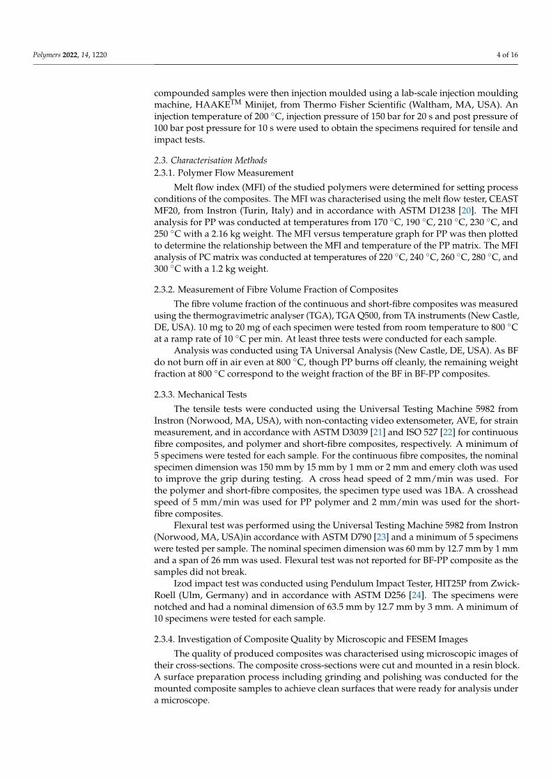
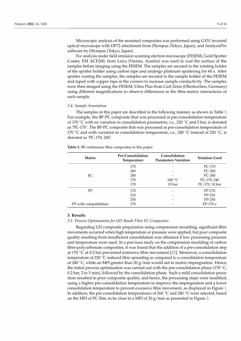
Regarding UD composite preparation using compression moulding, significant fibremovements occurred when high temperature or pressure were applied, but poor compositequality resulting from insufficient consolidation was obtained if low processing pressureand temperature were used. In a previous study on the compression moulding of carbonfibre-polycarbonate composites, it was found that the addition of a pre-consolidation stepat 170 ◦C at 0.2 bar prevented extensive fibre movement [25]. Moreover, a consolidationtemperature of 220 ◦C reduced fibre spreading as compared to a consolidation temperatureof 240 ◦C, while an MFI greater than 20 g/min would aid in matrix impregnation. Hence,the initial process optimisation was carried out with the pre-consolidation phase (170 ◦C,0.2 bar, 2 to 5 min), followed by the consolidation phase. Such a mild consolidation proce-dure resulted in poor composite quality, and hence, the processing steps were modified,using a higher pre-consolidation temperature to improve the impregnation and a lowerconsolidation temperature to prevent excessive fibre movement, as displayed in Figure 1.In addition, the pre-consolidation temperatures of 260 ◦C and 280 ◦C were selected, basedon the MFI of PC film, to be close to a MFI of 20 g/min as presented in Figure 2.
Polymers 2022, 14, 1220 6 of 16
Polymers 2022, 13, x FOR PEER REVIEW 6 of 18
3. Results 3.1. Process Optimisation for UD Basalt Fibre PC Composites
Regarding UD composite preparation using compression moulding, significant fibre movements occurred when high temperature or pressure were applied, but poor compo-site quality resulting from insufficient consolidation was obtained if low processing pres-sure and temperature were used. In a previous study on the compression moulding of carbon fibre-polycarbonate composites, it was found that the addition of a pre-consolida-tion step at 170 °C at 0.2 bar prevented extensive fibre movement [25]. Moreover, a con-solidation temperature of 220 °C reduced fibre spreading as compared to a consolidation temperature of 240 °C, while an MFI greater than 20 g/min would aid in matrix impreg-nation. Hence, the initial process optimisation was carried out with the pre-consolidation phase (170 °C, 0.2 bar, 2 to 5 min), followed by the consolidation phase. Such a mild con-solidation procedure resulted in poor composite quality, and hence, the processing steps were modified, using a higher pre-consolidation temperature to improve the impregna-tion and a lower consolidation temperature to prevent excessive fibre movement, as dis-played in Figure 1. In addition, the pre-consolidation temperatures of 260 °C and 280 °C were selected, based on the MFI of PC film, to be close to a MFI of 20 g/min as presented in Figure 2.
(a) (b)
Figure 1. Illustration of (a) the conventional compression moulding process and (b) the modified compression moulding process.
Figure 2. MFI of polycarbonate film against temperature.
There was a significant number of voids, particularly between the fibre bundles for the undried BF-PC composite processed at a lower pre-consolidation temperature, as highlighted in the circles in Figure 3a. Higher pre-consolidation temperature and drying
0
50
100
150
200
250
0 20 40 60 80
Tem
pera
ture
(°C)
Time (min)
0
50
100
150
200
250
0 20 40 60 80
Tem
pera
ture
(°C)
Time (min)
0
10
20
30
40
50
200 220 240 260 280 300
MFI
(g/1
0m
in)
Temperature (°C)
Figure 1. Illustration of (a) the conventional compression moulding process and (b) the modifiedcompression moulding process.
Polymers 2022, 13, x FOR PEER REVIEW 6 of 18
3. Results 3.1. Process Optimisation for UD Basalt Fibre PC Composites
Regarding UD composite preparation using compression moulding, significant fibre movements occurred when high temperature or pressure were applied, but poor compo-site quality resulting from insufficient consolidation was obtained if low processing pres-sure and temperature were used. In a previous study on the compression moulding of carbon fibre-polycarbonate composites, it was found that the addition of a pre-consolida-tion step at 170 °C at 0.2 bar prevented extensive fibre movement [25]. Moreover, a con-solidation temperature of 220 °C reduced fibre spreading as compared to a consolidation temperature of 240 °C, while an MFI greater than 20 g/min would aid in matrix impreg-nation. Hence, the initial process optimisation was carried out with the pre-consolidation phase (170 °C, 0.2 bar, 2 to 5 min), followed by the consolidation phase. Such a mild con-solidation procedure resulted in poor composite quality, and hence, the processing steps were modified, using a higher pre-consolidation temperature to improve the impregna-tion and a lower consolidation temperature to prevent excessive fibre movement, as dis-played in Figure 1. In addition, the pre-consolidation temperatures of 260 °C and 280 °C were selected, based on the MFI of PC film, to be close to a MFI of 20 g/min as presented in Figure 2.
(a) (b)
Figure 1. Illustration of (a) the conventional compression moulding process and (b) the modified compression moulding process.
Figure 2. MFI of polycarbonate film against temperature.
There was a significant number of voids, particularly between the fibre bundles for the undried BF-PC composite processed at a lower pre-consolidation temperature, as highlighted in the circles in Figure 3a. Higher pre-consolidation temperature and drying
0
50
100
150
200
250
0 20 40 60 80
Tem
pera
ture
(°C)
Time (min)
0
50
100
150
200
250
0 20 40 60 80
Tem
pera
ture
(°C)
Time (min)
0
10
20
30
40
50
200 220 240 260 280 300
MFI
(g/1
0m
in)
Temperature (°C)
Figure 2. MFI of polycarbonate film against temperature.
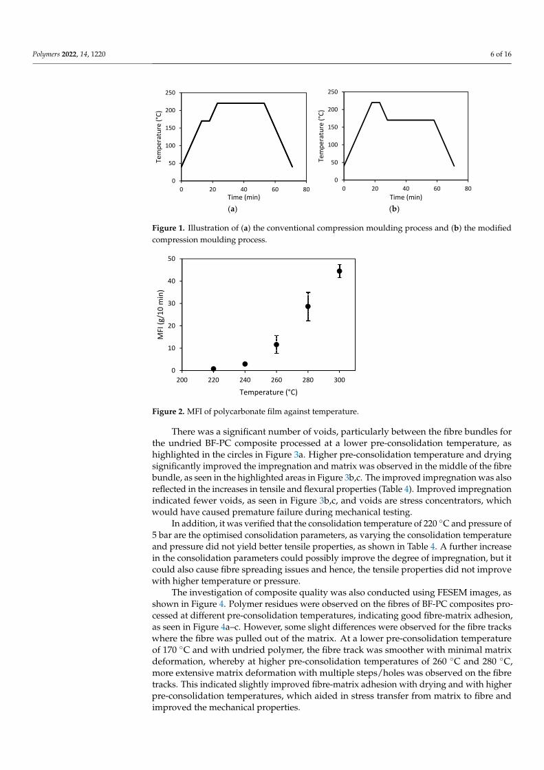
There was a significant number of voids, particularly between the fibre bundles forthe undried BF-PC composite processed at a lower pre-consolidation temperature, ashighlighted in the circles in Figure 3a. Higher pre-consolidation temperature and dryingsignificantly improved the impregnation and matrix was observed in the middle of the fibrebundle, as seen in the highlighted areas in Figure 3b,c. The improved impregnation was alsoreflected in the increases in tensile and flexural properties (Table 4). Improved impregnationindicated fewer voids, as seen in Figure 3b,c, and voids are stress concentrators, whichwould have caused premature failure during mechanical testing.
In addition, it was verified that the consolidation temperature of 220 ◦C and pressure of5 bar are the optimised consolidation parameters, as varying the consolidation temperatureand pressure did not yield better tensile properties, as shown in Table 4. A further increasein the consolidation parameters could possibly improve the degree of impregnation, but itcould also cause fibre spreading issues and hence, the tensile properties did not improvewith higher temperature or pressure.
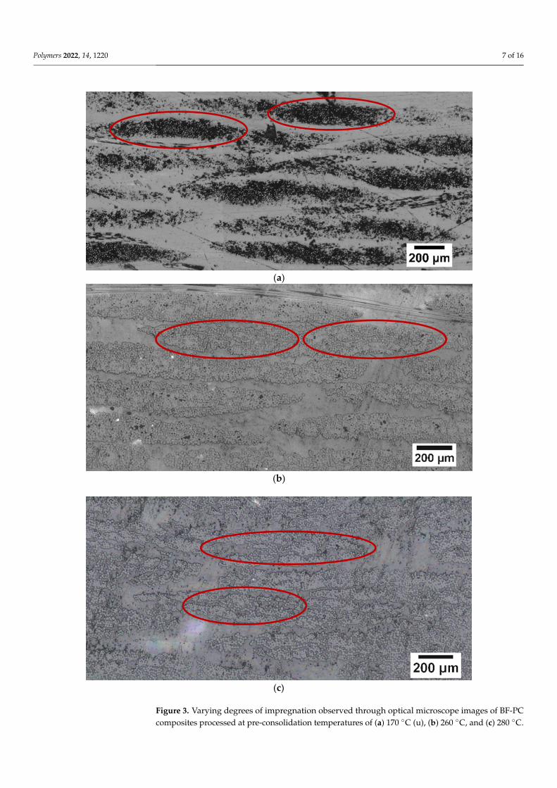
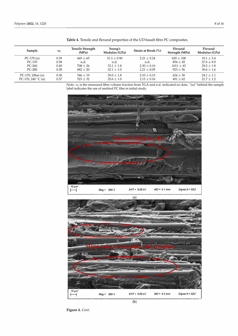
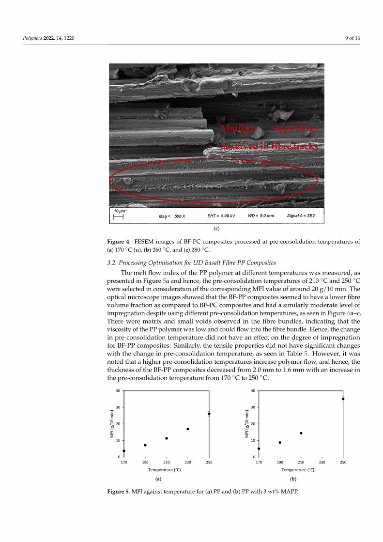
The investigation of composite quality was also conducted using FESEM images, asshown in Figure 4. Polymer residues were observed on the fibres of BF-PC composites pro-cessed at different pre-consolidation temperatures, indicating good fibre-matrix adhesion,as seen in Figure 4a–c. However, some slight differences were observed for the fibre trackswhere the fibre was pulled out of the matrix. At a lower pre-consolidation temperatureof 170 ◦C and with undried polymer, the fibre track was smoother with minimal matrixdeformation, whereby at higher pre-consolidation temperatures of 260 ◦C and 280 ◦C,more extensive matrix deformation with multiple steps/holes was observed on the fibretracks. This indicated slightly improved fibre-matrix adhesion with drying and with higherpre-consolidation temperatures, which aided in stress transfer from matrix to fibre andimproved the mechanical properties.
Polymers 2022, 14, 1220 7 of 16
Polymers 2022, 13, x FOR PEER REVIEW 7 of 18
significantly improved the impregnation and matrix was observed in the middle of the fibre bundle, as seen in the highlighted areas in Figure 3b,c. The improved impregnation was also reflected in the increases in tensile and flexural properties (Table 4). Improved impregnation indicated fewer voids, as seen in Figure 3b,c, and voids are stress concen-trators, which would have caused premature failure during mechanical testing.
In addition, it was verified that the consolidation temperature of 220 °C and pressure of 5 bar are the optimised consolidation parameters, as varying the consolidation temper-ature and pressure did not yield better tensile properties, as shown in Table 4. A further increase in the consolidation parameters could possibly improve the degree of impregna-tion, but it could also cause fibre spreading issues and hence, the tensile properties did not improve with higher temperature or pressure.
(a)
(b)
Polymers 2022, 13, x FOR PEER REVIEW 8 of 18
(c)
Figure 3. Varying degrees of impregnation observed through optical microscope images of BF-PC composites processed at pre-consolidation temperatures of (a) 170 °C (u), (b) 260 °C, and (c) 280 °C.
Table 4. Tensile and flexural properties of the UD basalt fibre PC composites.
Sample vF Tensile
Strength (MPa)
Young’s Modulus
(GPa)
Strain at Break
(%)
Flexural Strength
(MPa)
Flexural Modulus
(GPa) PC-170 (u) 0.39 669 ± 65 31.3 ± 0.90 2.21 ± 0.24 629 ± 108 19.1 ± 3.4
PC-170 0.38 n.d. n.d. n.d. 854 ± 45 27.6 ± 0.9 PC-260 0.40 708 ± 26 33.1 ± 1.8 2.30 ± 0.10 1011 ± 43 29.2 ± 1.8 PC-280 0.38 682 ± 20 32.1 ± 1.0 2.21 ± 0.05 923 ± 56 30.6 ± 1.6
PC-170, 10bar (u) 0.38 546 ± 19 30.0 ± 1.8 2.10 ± 0.13 624 ± 50 24.1 ± 1.1 PC-170, 240 °C (u) 0.37 523 ± 32 25.6 ± 1.0 2.13 ± 0.16 491 ± 62 21.7 ± 1.2 Note: vF is the measured fibre volume fraction from TGA and n.d. indicated no data. “(u)” behind the sample label indicates the use of undried PC film in initial study.
The investigation of composite quality was also conducted using FESEM images, as shown in Figure 4. Polymer residues were observed on the fibres of BF-PC composites processed at different pre-consolidation temperatures, indicating good fibre-matrix adhe-sion, as seen in Figure 4a–c. However, some slight differences were observed for the fibre tracks where the fibre was pulled out of the matrix. At a lower pre-consolidation temper-ature of 170 °C and with undried polymer, the fibre track was smoother with minimal matrix deformation, whereby at higher pre-consolidation temperatures of 260 °C and 280 °C, more extensive matrix deformation with multiple steps/holes was observed on the fibre tracks. This indicated slightly improved fibre-matrix adhesion with drying and with higher pre-consolidation temperatures, which aided in stress transfer from matrix to fibre and improved the mechanical properties.
Figure 3. Varying degrees of impregnation observed through optical microscope images of BF-PCcomposites processed at pre-consolidation temperatures of (a) 170 ◦C (u), (b) 260 ◦C, and (c) 280 ◦C.
Polymers 2022, 14, 1220 8 of 16
Table 4. Tensile and flexural properties of the UD basalt fibre PC composites.
Sample vFTensile Strength
(MPa)Young’s
Modulus (GPa) Strain at Break (%) FlexuralStrength (MPa)
FlexuralModulus (GPa)
PC-170 (u) 0.39 669 ± 65 31.3 ± 0.90 2.21 ± 0.24 629 ± 108 19.1 ± 3.4PC-170 0.38 n.d. n.d. n.d. 854 ± 45 27.6 ± 0.9PC-260 0.40 708 ± 26 33.1 ± 1.8 2.30 ± 0.10 1011 ± 43 29.2 ± 1.8PC-280 0.38 682 ± 20 32.1 ± 1.0 2.21 ± 0.05 923 ± 56 30.6 ± 1.6
PC-170, 10bar (u) 0.38 546 ± 19 30.0 ± 1.8 2.10 ± 0.13 624 ± 50 24.1 ± 1.1PC-170, 240 ◦C (u) 0.37 523 ± 32 25.6 ± 1.0 2.13 ± 0.16 491 ± 62 21.7 ± 1.2
Note: vF is the measured fibre volume fraction from TGA and n.d. indicated no data. “(u)” behind the samplelabel indicates the use of undried PC film in initial study.
Polymers 2022, 13, x FOR PEER REVIEW 9 of 18
(a)
(b)
Figure 4. Cont.
Polymers 2022, 14, 1220 9 of 16Polymers 2022, 13, x FOR PEER REVIEW 10 of 18
(c)
Figure 4. FESEM images of BF-PC composites processed at pre-consolidation temperatures of (a) 170 °C (u), (b) 260 °C, and (c) 280 °C.
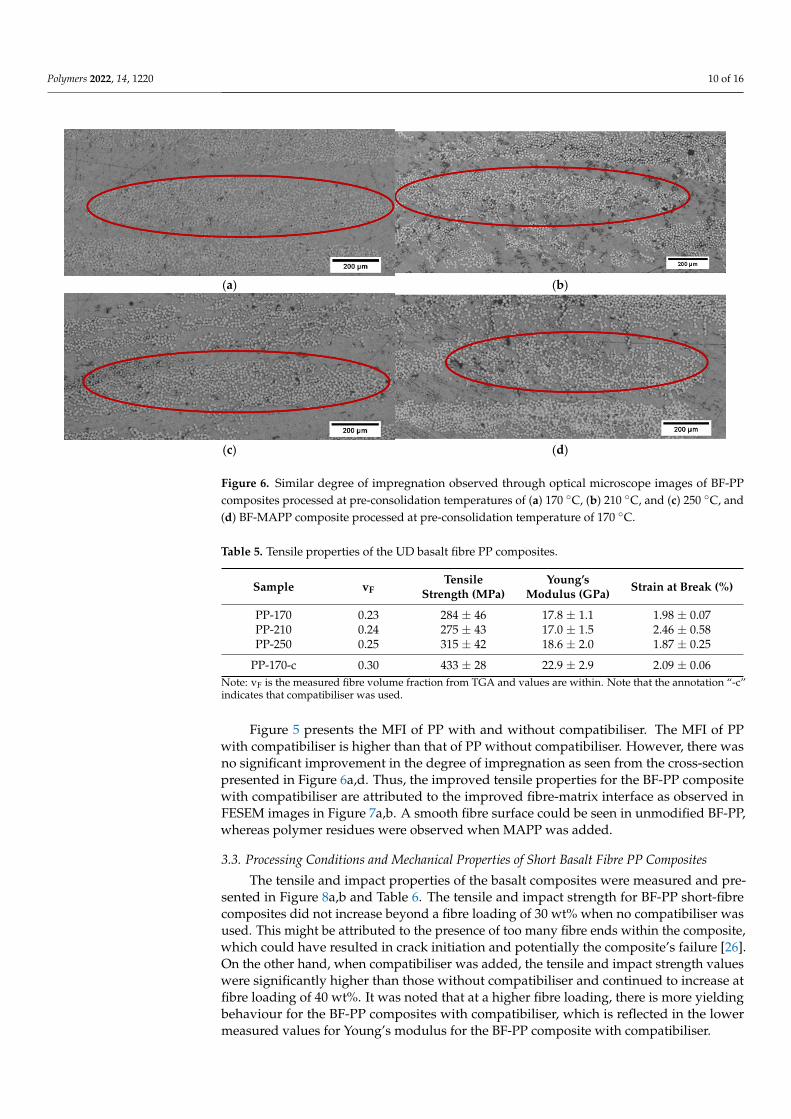
3.2. Processing Optimisation for UD Basalt Fibre PP Composites The melt flow index of the PP polymer at different temperatures was measured, as
presented in Figure 5a and hence, the pre-consolidation temperatures of 210 °C and 250 °C were selected in consideration of the corresponding MFI value of around 20 g/10 min. The optical microscope images showed that the BF-PP composites seemed to have a lower fibre volume fraction as compared to BF-PC composites and had a similarly moderate level of impregnation despite using different pre-consolidation temperatures, as seen in Figure 6a–c. There were matrix and small voids observed in the fibre bundles, indicating that the viscosity of the PP polymer was low and could flow into the fibre bundle. Hence, the change in pre-consolidation temperature did not have an effect on the degree of im-pregnation for BF-PP composites. Similarly, the tensile properties did not have significant changes with the change in pre-consolidation temperature, as seen in Table 5. However, it was noted that a higher pre-consolidation temperatures increase polymer flow, and hence, the thickness of the BF-PP composites decreased from 2.0 mm to 1.6 mm with an increase in the pre-consolidation temperature from 170 °C to 250 °C.
Figure 5 presents the MFI of PP with and without compatibiliser. The MFI of PP with compatibiliser is higher than that of PP without compatibiliser. However, there was no significant improvement in the degree of impregnation as seen from the cross-section pre-sented in Figure 6a,d. Thus, the improved tensile properties for the BF-PP composite with compatibiliser are attributed to the improved fibre-matrix interface as observed in FESEM images in Figure 7a,b. A smooth fibre surface could be seen in unmodified BF-PP, whereas polymer residues were observed when MAPP was added.
Figure 4. FESEM images of BF-PC composites processed at pre-consolidation temperatures of(a) 170 ◦C (u), (b) 260 ◦C, and (c) 280 ◦C.
3.2. Processing Optimisation for UD Basalt Fibre PP Composites
The melt flow index of the PP polymer at different temperatures was measured, aspresented in Figure 5a and hence, the pre-consolidation temperatures of 210 ◦C and 250 ◦Cwere selected in consideration of the corresponding MFI value of around 20 g/10 min. Theoptical microscope images showed that the BF-PP composites seemed to have a lower fibrevolume fraction as compared to BF-PC composites and had a similarly moderate level ofimpregnation despite using different pre-consolidation temperatures, as seen in Figure 6a–c.There were matrix and small voids observed in the fibre bundles, indicating that theviscosity of the PP polymer was low and could flow into the fibre bundle. Hence, the changein pre-consolidation temperature did not have an effect on the degree of impregnationfor BF-PP composites. Similarly, the tensile properties did not have significant changeswith the change in pre-consolidation temperature, as seen in Table 5. However, it wasnoted that a higher pre-consolidation temperatures increase polymer flow, and hence, thethickness of the BF-PP composites decreased from 2.0 mm to 1.6 mm with an increase inthe pre-consolidation temperature from 170 ◦C to 250 ◦C.
Polymers 2022, 13, x FOR PEER REVIEW 11 of 18
(a) (b)
Figure 5. MFI against temperature for (a) PP and (b) PP with 3 wt% MAPP.
(a) (b)
(c) (d)
Figure 6. Similar degree of impregnation observed through optical microscope images of BF-PP composites processed at pre-consolidation temperatures of (a) 170 °C, (b) 210 °C, and (c) 250 °C, and (d) BF-MAPP composite processed at pre-consolidation temperature of 170 °C.
Table 5. Tensile properties of the UD basalt fibre PP composites.
Sample vF Tensile Strength
(MPa) Young’s Modulus
(GPa) Strain at Break
(%) PP-170 0.23 284 ± 46 17.8 ± 1.1 1.98 ± 0.07 PP-210 0.24 275 ± 43 17.0 ± 1.5 2.46 ± 0.58 PP-250 0.25 315 ± 42 18.6 ± 2.0 1.87± 0.25
PP-170-c 0.30 433 ± 28 22.9 ± 2.9 2.09 ± 0.06 Note: vF is the measured fibre volume fraction from TGA and values are within. Note that the an-notation “-c” indicates that compatibiliser was used.
0
10
20
30
40
170 190 210 230 250
MFI
(g/1
0m
in)
Temperature (°C)
0
10
20
30
40
170 190 210 230 250
MFI
(g/1
0m
in)
Temperature (°C)
Figure 5. MFI against temperature for (a) PP and (b) PP with 3 wt% MAPP.
Polymers 2022, 14, 1220 10 of 16
Polymers 2022, 13, x FOR PEER REVIEW 11 of 18
(a) (b)
Figure 5. MFI against temperature for (a) PP and (b) PP with 3 wt% MAPP.
(a) (b)
(c) (d)
Figure 6. Similar degree of impregnation observed through optical microscope images of BF-PP composites processed at pre-consolidation temperatures of (a) 170 °C, (b) 210 °C, and (c) 250 °C, and (d) BF-MAPP composite processed at pre-consolidation temperature of 170 °C.
Table 5. Tensile properties of the UD basalt fibre PP composites.
Sample vF Tensile Strength
(MPa) Young’s Modulus
(GPa) Strain at Break
(%) PP-170 0.23 284 ± 46 17.8 ± 1.1 1.98 ± 0.07 PP-210 0.24 275 ± 43 17.0 ± 1.5 2.46 ± 0.58 PP-250 0.25 315 ± 42 18.6 ± 2.0 1.87± 0.25
PP-170-c 0.30 433 ± 28 22.9 ± 2.9 2.09 ± 0.06 Note: vF is the measured fibre volume fraction from TGA and values are within. Note that the an-notation “-c” indicates that compatibiliser was used.
0
10
20
30
40
170 190 210 230 250
MFI
(g/1
0m
in)
Temperature (°C)
0
10
20
30
40
170 190 210 230 250
MFI
(g/1
0m
in)
Temperature (°C)
Figure 6. Similar degree of impregnation observed through optical microscope images of BF-PPcomposites processed at pre-consolidation temperatures of (a) 170 ◦C, (b) 210 ◦C, and (c) 250 ◦C, and(d) BF-MAPP composite processed at pre-consolidation temperature of 170 ◦C.
Table 5. Tensile properties of the UD basalt fibre PP composites.
Sample vFTensile
Strength (MPa)Young’s
Modulus (GPa) Strain at Break (%)
PP-170 0.23 284 ± 46 17.8 ± 1.1 1.98 ± 0.07PP-210 0.24 275 ± 43 17.0 ± 1.5 2.46 ± 0.58PP-250 0.25 315 ± 42 18.6 ± 2.0 1.87 ± 0.25
PP-170-c 0.30 433 ± 28 22.9 ± 2.9 2.09 ± 0.06Note: vF is the measured fibre volume fraction from TGA and values are within. Note that the annotation “-c”indicates that compatibiliser was used.
Figure 5 presents the MFI of PP with and without compatibiliser. The MFI of PPwith compatibiliser is higher than that of PP without compatibiliser. However, there wasno significant improvement in the degree of impregnation as seen from the cross-sectionpresented in Figure 6a,d. Thus, the improved tensile properties for the BF-PP compositewith compatibiliser are attributed to the improved fibre-matrix interface as observed inFESEM images in Figure 7a,b. A smooth fibre surface could be seen in unmodified BF-PP,whereas polymer residues were observed when MAPP was added.
3.3. Processing Conditions and Mechanical Properties of Short Basalt Fibre PP Composites
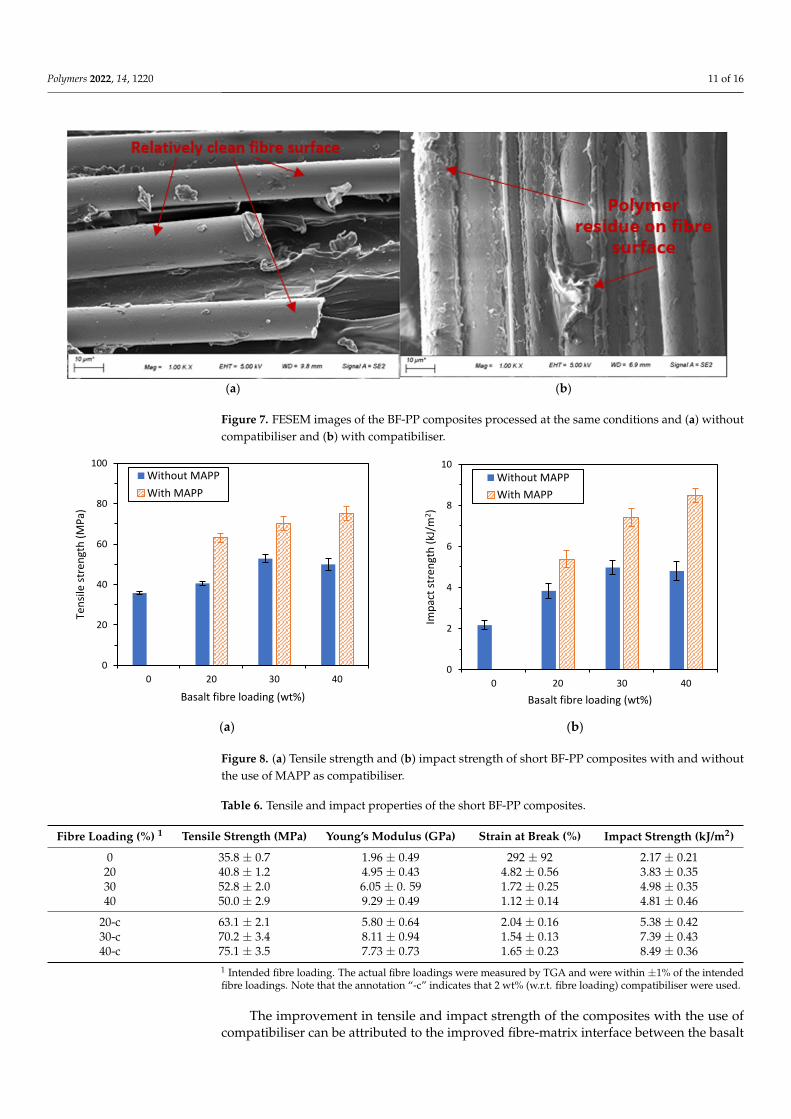
The tensile and impact properties of the basalt composites were measured and pre-sented in Figure 8a,b and Table 6. The tensile and impact strength for BF-PP short-fibrecomposites did not increase beyond a fibre loading of 30 wt% when no compatibiliser wasused. This might be attributed to the presence of too many fibre ends within the composite,which could have resulted in crack initiation and potentially the composite’s failure [26].On the other hand, when compatibiliser was added, the tensile and impact strength valueswere significantly higher than those without compatibiliser and continued to increase atfibre loading of 40 wt%. It was noted that at a higher fibre loading, there is more yieldingbehaviour for the BF-PP composites with compatibiliser, which is reflected in the lowermeasured values for Young’s modulus for the BF-PP composite with compatibiliser.
Polymers 2022, 14, 1220 11 of 16Polymers 2022, 13, x FOR PEER REVIEW 12 of 18
(a) (b)
Figure 7. FESEM images of the BF-PP composites processed at the same conditions and (a) without compatibiliser and (b) with compatibiliser.
3.3. Processing Conditions and Mechanical Properties of Short Basalt Fibre PP Composites The tensile and impact properties of the basalt composites were measured and pre-
sented in Figure 8a,b and Table 6. The tensile and impact strength for BF-PP short-fibre composites did not increase beyond a fibre loading of 30 wt% when no compatibiliser was used. This might be attributed to the presence of too many fibre ends within the compo-site, which could have resulted in crack initiation and potentially the composite’s failure [26]. On the other hand, when compatibiliser was added, the tensile and impact strength values were significantly higher than those without compatibiliser and continued to in-crease at fibre loading of 40 wt%. It was noted that at a higher fibre loading, there is more yielding behaviour for the BF-PP composites with compatibiliser, which is reflected in the lower measured values for Young’s modulus for the BF-PP composite with compatibiliser.
(a) (b)
Figure 8. (a) Tensile strength and (b) impact strength of short BF-PP composites with and without the use of MAPP as compatibiliser.
Table 6. Tensile and impact properties of the short BF- PP composites.
0
20
40
60
80
100
0 20 30 40
Tens
ile st
reng
th (M
Pa)
Basalt fibre loading (wt%)
Without MAPPWith MAPP
0
2
4
6
8
10
0 20 30 40
Impa
ct st
reng
th (k
J/m
2 )
Basalt fibre loading (wt%)
Without MAPPWith MAPP
Figure 7. FESEM images of the BF-PP composites processed at the same conditions and (a) withoutcompatibiliser and (b) with compatibiliser.
Polymers 2022, 13, x FOR PEER REVIEW 12 of 18
(a) (b)
Figure 7. FESEM images of the BF-PP composites processed at the same conditions and (a) without
compatibiliser and (b) with compatibiliser.
3.3. Processing Conditions and Mechanical Properties of Short Basalt Fibre PP Composites
The tensile and impact properties of the basalt composites were measured and pre-
sented in Figure 8a,b and Table 6. The tensile and impact strength for BF-PP short-fibre
composites did not increase beyond a fibre loading of 30 wt% when no compatibiliser was
used. This might be attributed to the presence of too many fibre ends within the compo-
site, which could have resulted in crack initiation and potentially the composite’s failure
[26]. On the other hand, when compatibiliser was added, the tensile and impact strength
values were significantly higher than those without compatibiliser and continued to in-
crease at fibre loading of 40 wt%. It was noted that at a higher fibre loading, there is more
yielding behaviour for the BF-PP composites with compatibiliser, which is reflected in the
lower measured values for Young’s modulus for the BF-PP composite with compatibiliser.
(a) (b)
Figure 8. (a) Tensile strength and (b) impact strength of short BF-PP composites with and without
the use of MAPP as compatibiliser.
Table 6. Tensile and impact properties of the short BF- PP composites.
0
20
40
60
80
100
0 20 30 40
Ten
sile
str
engt
h (
MP
a)
Basalt fibre loading (wt%)
Without MAPP
With MAPP
0
2
4
6
8
10
0 20 30 40
Imp
act
stre
ngt
h (
kJ/m
2)
Basalt fibre loading (wt%)
Without MAPP
With MAPP
Figure 8. (a) Tensile strength and (b) impact strength of short BF-PP composites with and withoutthe use of MAPP as compatibiliser.
Table 6. Tensile and impact properties of the short BF-PP composites.
Fibre Loading (%) 1 Tensile Strength (MPa) Young’s Modulus (GPa) Strain at Break (%) Impact Strength (kJ/m2)
0 35.8 ± 0.7 1.96 ± 0.49 292 ± 92 2.17 ± 0.2120 40.8 ± 1.2 4.95 ± 0.43 4.82 ± 0.56 3.83 ± 0.3530 52.8 ± 2.0 6.05 ± 0. 59 1.72 ± 0.25 4.98 ± 0.3540 50.0 ± 2.9 9.29 ± 0.49 1.12 ± 0.14 4.81 ± 0.46
20-c 63.1 ± 2.1 5.80 ± 0.64 2.04 ± 0.16 5.38 ± 0.4230-c 70.2 ± 3.4 8.11 ± 0.94 1.54 ± 0.13 7.39 ± 0.4340-c 75.1 ± 3.5 7.73 ± 0.73 1.65 ± 0.23 8.49 ± 0.36
1 Intended fibre loading. The actual fibre loadings were measured by TGA and were within ±1% of the intendedfibre loadings. Note that the annotation “-c” indicates that 2 wt% (w.r.t. fibre loading) compatibiliser were used.
The improvement in tensile and impact strength of the composites with the use ofcompatibiliser can be attributed to the improved fibre-matrix interface between the basalt
Polymers 2022, 14, 1220 12 of 16
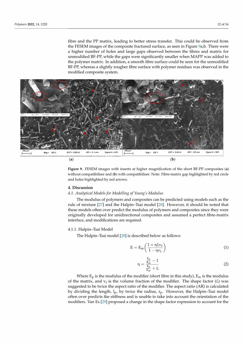
fibre and the PP matrix, leading to better stress transfer. This could be observed fromthe FESEM images of the composite fractured surface, as seen in Figure 9a,b. There werea higher number of holes and large gaps observed between the fibres and matrix forunmodified BF-PP, while the gaps were significantly smaller when MAPP was added tothe polymer matrix. In addition, a smooth fibre surface could be seen for the unmodifiedBF-PP, whereas a slightly rougher fibre surface with polymer residues was observed in themodified composite system.
Polymers 2022, 13, x FOR PEER REVIEW 13 of 18
Fibre Loading (%) 1
Tensile Strength (MPa)
Young’s Modulus (GPa)
Strain at Break (%)
Impact Strength (kJ/m2)
0 35.8 ± 0.7 1.96 ± 0.49 292 ± 92 2.17 ± 0.21 20 40.8 ± 1.2 4.95 ± 0.43 4.82 ± 0.56 3.83 ± 0.35 30 52.8 ± 2.0 6.05 ± 0. 59 1.72 ± 0.25 4.98 ± 0.35 40 50.0 ± 2.9 9.29 ± 0.49 1.12 ± 0.14 4.81 ± 0.46
20-c 63.1 ± 2.1 5.80 ± 0.64 2.04 ± 0.16 5.38 ± 0.42 30-c 70.2 ± 3.4 8.11 ± 0.94 1.54 ± 0.13 7.39 ± 0.43 40-c 75.1 ± 3.5 7.73 ± 0.73 1.65 ± 0.23 8.49 ± 0.36
1 Intended fibre loading. The actual fibre loadings were measured by TGA and were within ±1% of the intended fibre loadings. Note that the annotation “-c” indicates that 2 wt% (w.r.t. fibre loading) compatibiliser were used.
The improvement in tensile and impact strength of the composites with the use of compatibiliser can be attributed to the improved fibre-matrix interface between the basalt fibre and the PP matrix, leading to better stress transfer. This could be observed from the FESEM images of the composite fractured surface, as seen in Figure 9a,b. There were a higher number of holes and large gaps observed between the fibres and matrix for un-modified BF-PP, while the gaps were significantly smaller when MAPP was added to the polymer matrix. In addition, a smooth fibre surface could be seen for the unmodified BF-PP, whereas a slightly rougher fibre surface with polymer residues was observed in the modified composite system.
(a) (b)
Figure 9. FESEM images with inserts at higher magnification of the short BF-PP composites (a) with-out compatibiliser and (b) with compatibiliser. Note: Fibre-matrix gap highlighted by red circle and holes highlighted by red arrows.
4. Discussion 4.1. Analytical Models for Modelling of Young’s Modulus
The modulus of polymers and composites can be predicted using models such as the rule of mixture [27] and the Halpin–Tsai model [28]. However, it should be noted that these models often over predict the modulus of polymers and composites since they were originally developed for unidirectional composites and assumed a perfect fibre-matrix in-terface, and modifications are required.
4.1.1. Halpin–Tsai Model
Figure 9. FESEM images with inserts at higher magnification of the short BF-PP composites (a)without compatibiliser and (b) with compatibiliser. Note: Fibre-matrix gap highlighted by red circleand holes highlighted by red arrows.
4. Discussion4.1. Analytical Models for Modelling of Young’s Modulus
The modulus of polymers and composites can be predicted using models such as therule of mixture [27] and the Halpin–Tsai model [28]. However, it should be noted thatthese models often over predict the modulus of polymers and composites since they wereoriginally developed for unidirectional composites and assumed a perfect fibre-matrixinterface, and modifications are required.
4.1.1. Halpin–Tsai Model
The Halpin–Tsai model [28] is described below as follows:
E = Em
(1 + ηξvf1 − ηvf
)(1)
η =
EpEm
− 1EpEm
+ ξ(2)
Where Ep is the modulus of the modifier (short fibre in this study), Em is the modulusof the matrix, and vf is the volume fraction of the modifier. The shape factor (ξ) wassuggested to be twice the aspect ratio of the modifier. The aspect ratio (AR) is calculatedby dividing the length, lp, by twice the radius, rp. However, the Halpin–Tsai modeloften over predicts the stiffness and is unable to take into account the orientation of themodifiers. Van Es [29] proposed a change in the shape factor expression to account for the
Polymers 2022, 14, 1220 13 of 16
random orientation of rod-like modifiers, such that the modulus of the modified polymeror composite is given by the following:
E = 0.184 E// + 0.816 ET (3)
where the modulus parallel to the loading direction (E//) and the modulus transverse tothe loading direction (ET) moduli are calculated using Equation (1) with ξ = 2 for ET andξ = (0.5AR)1.8 for E//. This will be referred to as the Halpin–Tsai (random) model.
4.1.2. Rule of Mixtures
Fibre reinforced materials that possess high mechanical properties are typically basedupon carbon and glass fibres, and the reinforcement effect depends on the length, distribu-tion, orientation, type, processing, and interfacial compatibility of the fibres.
The elastic modulus of the composite system can be derived from the rule of mixtures(ROM) and is given by the following [27]:
E = EFvF + Emvm (4)
where EF and Em are the elastic modulus of the fibre and the matrix, respectively, and vFand vm are the volume fraction of the fibre and matrix, respectively.
4.2. Young Modulus of Short Basalt Fibre PP Composites
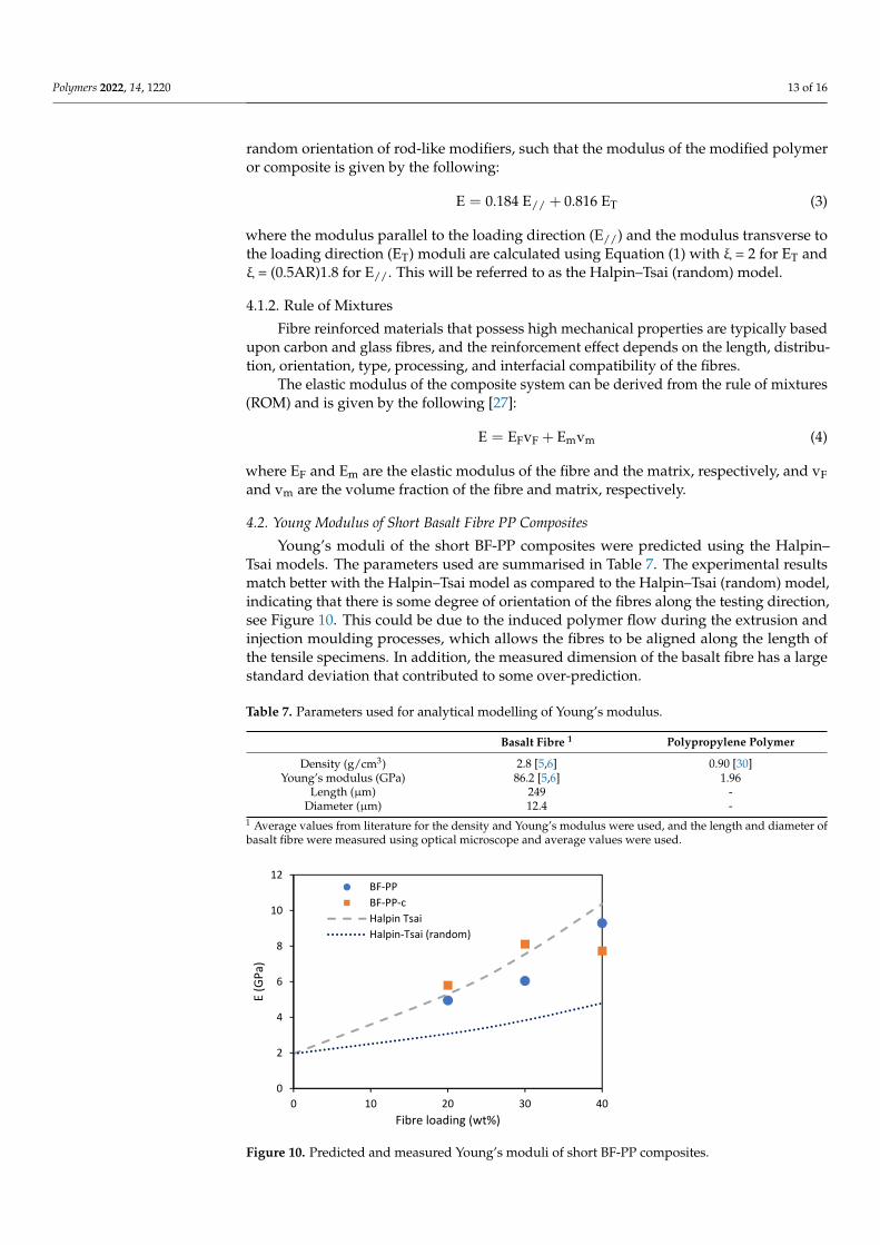
Young’s moduli of the short BF-PP composites were predicted using the Halpin–Tsai models. The parameters used are summarised in Table 7. The experimental resultsmatch better with the Halpin–Tsai model as compared to the Halpin–Tsai (random) model,indicating that there is some degree of orientation of the fibres along the testing direction,see Figure 10. This could be due to the induced polymer flow during the extrusion andinjection moulding processes, which allows the fibres to be aligned along the length ofthe tensile specimens. In addition, the measured dimension of the basalt fibre has a largestandard deviation that contributed to some over-prediction.
Table 7. Parameters used for analytical modelling of Young’s modulus.
Basalt Fibre 1 Polypropylene Polymer
Density (g/cm3) 2.8 [5,6] 0.90 [30]Young’s modulus (GPa) 86.2 [5,6] 1.96
Length (µm) 249 -Diameter (µm) 12.4 -
1 Average values from literature for the density and Young’s modulus were used, and the length and diameter ofbasalt fibre were measured using optical microscope and average values were used.
Polymers 2022, 13, x FOR PEER REVIEW 15 of 18
Figure 10. Predicted and measured Young’s moduli of short BF-PP composites.
4.3. Young Modulus of UD Basalt Fibre Composites The Young’s moduli of the UD composites were predicted using the rule of mixtures
and the parameters used were the same as those of the BF-PP short-fibre composite. The density and Young’s modulus of polycarbonate were taken to be 1.2 g/cm3 and 2.3 GPa [31], and the parameters used for basalt fibre and polypropylene were summarised in Ta-ble 7.
The experimental Young’s modulus values reached at least 69% and 81% of the the-oretical values for BF-PP and BF-PC composites, respectively, as shown in Table 8. This indicated BF-PC composites had better stress transfer than BF-PP composites. It was noted that the efficiency factor for BF-PP composites did not differ with the use of the compati-biliser, which may be due to the reduction of Young’s modulus of the matrix by the com-patibiliser that would affect the value of the theoretical Young’s modulus. This could be further enhanced by refinement of the pre-consolidation process parameters and with fur-ther advancement in compatibiliser technology.
Table 8. Predicted and measured Young’s moduli of UD BF-PP and BF-PC composites.
Sample vF Experimental
Young’s Modulus (GPa)
Theoretical Young’s Modulus
(GPa)
Efficiency Factor 1
(%) PP-170 0.23 17.8 ± 1.1 23.1 77 PP-210 0.24 17.0 ± 1.5 24.5 69 PP-250 0.25 18.6 ± 2.0 25.5 73
PP-170-c 0.30 22.9 ± 2.9 29.9 76 PC-170 (u) 0.39 31.3 ± 0.90 38.7 81
PC-260 0.40 33.0 ± 1.8 39.2 84 PC-280 0.38 32.1 ± 1.0 37.3 86
1 Efficiency factor is defined as the ratio of experimental Young’s modulus to theoretical Young’s modulus, expressed in percentage.
4.4. Tensile Strength of Basalt Fibre Composites The tensile strengths of the BF-PC and BF-PP composites in this study were plotted
against the tensile strengths of BF and GF composites in different matrices, which were reported by other researchers, as shown in Figure 11. As compared to BF and glass fibre (GF) thermoset composites, the studied BF-PC thermoplastic composite could achieve comparable mechanical properties. These BFRTP could be a bio-derived alternative to GF
0
2
4
6
8
10
12
0 10 20 30 40
E (G
Pa)
Fibre loading (wt%)
BF-PPBF-PP-cHalpin TsaiHalpin-Tsai (random)
Figure 10. Predicted and measured Young’s moduli of short BF-PP composites.
Polymers 2022, 14, 1220 14 of 16
4.3. Young Modulus of UD Basalt Fibre Composites
The Young’s moduli of the UD composites were predicted using the rule of mixturesand the parameters used were the same as those of the BF-PP short-fibre composite. Thedensity and Young’s modulus of polycarbonate were taken to be 1.2 g/cm3 and 2.3 GPa [31],and the parameters used for basalt fibre and polypropylene were summarised in Table 7.
The experimental Young’s modulus values reached at least 69% and 81% of the the-oretical values for BF-PP and BF-PC composites, respectively, as shown in Table 8. Thisindicated BF-PC composites had better stress transfer than BF-PP composites. It wasnoted that the efficiency factor for BF-PP composites did not differ with the use of thecompatibiliser, which may be due to the reduction of Young’s modulus of the matrix by thecompatibiliser that would affect the value of the theoretical Young’s modulus. This couldbe further enhanced by refinement of the pre-consolidation process parameters and withfurther advancement in compatibiliser technology.
Table 8. Predicted and measured Young’s moduli of UD BF-PP and BF-PC composites.
Sample vFExperimental Young’s
Modulus (GPa)Theoretical Young’s
Modulus (GPa)Efficiency Factor 1
(%)
PP-170 0.23 17.8 ± 1.1 23.1 77PP-210 0.24 17.0 ± 1.5 24.5 69PP-250 0.25 18.6 ± 2.0 25.5 73
PP-170-c 0.30 22.9 ± 2.9 29.9 76
PC-170 (u) 0.39 31.3 ± 0.90 38.7 81PC-260 0.40 33.0 ± 1.8 39.2 84PC-280 0.38 32.1 ± 1.0 37.3 86
1 Efficiency factor is defined as the ratio of experimental Young’s modulus to theoretical Young’s modulus,expressed in percentage.
4.4. Tensile Strength of Basalt Fibre Composites
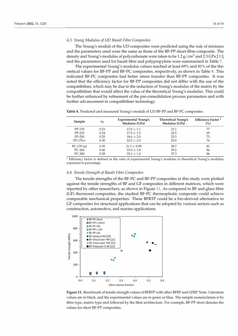
The tensile strengths of the BF-PC and BF-PP composites in this study were plottedagainst the tensile strengths of BF and GF composites in different matrices, which werereported by other researchers, as shown in Figure 11. As compared to BF and glass fibre(GF) thermoset composites, the studied BF-PC thermoplastic composite could achievecomparable mechanical properties. These BFRTP could be a bio-derived alternative toGF composites for structural applications that can be adopted by various sectors such asconstruction, automotive, and marine applications.
Polymers 2022, 13, x FOR PEER REVIEW 16 of 18
composites for structural applications that can be adopted by various sectors such as con-
struction, automotive, and marine applications.
Figure 11. Benchmark of tensile strength values of BFRTP with other BFRP and GFRP. Note: Liter-
ature values are in black, and the experimental values are in green or blue. The sample nomenclature
is by fibre type, matrix type and followed by the fibre architecture. For example, BF-PP short denotes
the values for short BF-PP composites.
5. Conclusions
Basalt continuous fibre composites with Polypropylene (PP) and Polycarbonate (PC)
matrices were fabricated using a compression moulding process and process optimisation
was conducted to resolve the fibre spreading issues and improve fibre-matrix impregna-
tion. Drying is critical for BF-PC composites and the modified procedure with a higher
pre-consolidation temperature enabled good matrix impregnation into the basalt fibres
with minimal fibre movements. For BF-PP composites, a compatibiliser was required to
improve fibre-matrix compatibility and improve the tensile strength. Moreover, it was
found that the tensile and impact properties for BF-PP short-fibre composites did not in-
crease beyond a fibre loading of 30 wt% if no compatibiliser was used, but the values
continued to increase at 40 wt% with the use of compatibiliser. When benchmarked
against BF and glass fibre (GF) thermoset composites, a lower fibre volume fraction was
obtained for the BFRTP, but the BF-PC composites could achieve comparable mechanical
properties. Analytical modelling of the Young’s moduli of the BF-PP short-fibre compo-
sites was predicted with the Halpin-Tsai model as compared to the Halpin-Tsai (random)
model, indicating induced fibre orientation along the testing direction during processing
for short BF-PP composites. The experimental Young’s modulus values reached at least
69% and 81% of the theoretical values for BF-PP and BF-PC composites, respectively,
which indicated that BF-PC composites had better stress transfer than BF-PP composites.
This study lays the foundation for the processing and basic mechanical properties of basalt
fibre thermoplastic composites with PC and PP as the polymer matrix and contributes to
the working knowledge of BFRTP for potential future applications in various sectors such
as construction, aerospace, and marine.
Author Contributions: X.D.—Conceptualisation, basalt fibre composite analysis and analytical
modelling, and writing; L.Q.N.T.—Interface investigation, and writing review and editing;
Y.W.C.—Composite processing; M.S.H.—Composite fabrication and testing. All authors have read
and agreed to the published version of the manuscript.
0
200
400
600
800
1000
0.0 0.1 0.2 0.3 0.4 0.5 0.6
Ten
sile
str
engt
h (
MP
a)
Fibre volume fraction
BF-PP shortBF-PP-c shortBF-PC UDBF-PP-c UDBF-PP UDBF-Epoxy 0.90 [20]BF-Vinyl ester PW [21]GF-Vinyl ester PW [21]BF-Polyester 0.90 [22]
Figure 11. Benchmark of tensile strength values of BFRTP with other BFRP and GFRP. Note: Literaturevalues are in black, and the experimental values are in green or blue. The sample nomenclature is byfibre type, matrix type and followed by the fibre architecture. For example, BF-PP short denotes thevalues for short BF-PP composites.
Polymers 2022, 14, 1220 15 of 16
5. Conclusions
Basalt continuous fibre composites with Polypropylene (PP) and Polycarbonate (PC)matrices were fabricated using a compression moulding process and process optimisationwas conducted to resolve the fibre spreading issues and improve fibre-matrix impregnation.Drying is critical for BF-PC composites and the modified procedure with a higher pre-consolidation temperature enabled good matrix impregnation into the basalt fibres withminimal fibre movements. For BF-PP composites, a compatibiliser was required to improvefibre-matrix compatibility and improve the tensile strength. Moreover, it was found that thetensile and impact properties for BF-PP short-fibre composites did not increase beyond afibre loading of 30 wt% if no compatibiliser was used, but the values continued to increaseat 40 wt% with the use of compatibiliser. When benchmarked against BF and glass fibre (GF)thermoset composites, a lower fibre volume fraction was obtained for the BFRTP, but the BF-PC composites could achieve comparable mechanical properties. Analytical modelling ofthe Young’s moduli of the BF-PP short-fibre composites was predicted with the Halpin-Tsaimodel as compared to the Halpin-Tsai (random) model, indicating induced fibre orientationalong the testing direction during processing for short BF-PP composites. The experimentalYoung’s modulus values reached at least 69% and 81% of the theoretical values for BF-PPand BF-PC composites, respectively, which indicated that BF-PC composites had betterstress transfer than BF-PP composites. This study lays the foundation for the processingand basic mechanical properties of basalt fibre thermoplastic composites with PC and PPas the polymer matrix and contributes to the working knowledge of BFRTP for potentialfuture applications in various sectors such as construction, aerospace, and marine.
Author Contributions: X.D.—Conceptualisation, basalt fibre composite analysis and analyticalmodelling, and writing; L.Q.N.T.—Interface investigation, and writing review and editing; Y.W.C.—Composite processing; M.S.H.—Composite fabrication and testing. All authors have read and agreedto the published version of the manuscript.
Funding: This research received the financial support from the Agency for Science, Technology and Re-search (A*STAR) under the Science and Engineering Research Council (SERC) grant number A19C9a0044,and the in-house core funding from Singapore Institute of Manufacturing Technology, A*STAR.
Institutional Review Board Statement: Not applicable.
Informed Consent Statement: Not applicable.
Data Availability Statement: The data presented in this study are available on request from thecorresponding author.
Acknowledgments: The authors would like to acknowledge the other interns who have contributedin parts of the technical support for the paper.
Conflicts of Interest: The authors declare no conflict of interest. The funders had no role in the designof the study; in the collection, analyses, or interpretation of data; in the writing of the manuscript, orin the decision to publish the results.
References1. Wei, B.; Cao, H.; Song, S. Tensile behavior contrast of basalt and glass fibers after chemical treatment. Mater. Des. 2010, 31,
4244–4250. [CrossRef]2. Fiore, V.; Scalici, T.; Di Bella, G.; Valenza, A. A review on basalt fibre and its composites. Compos. Part B Eng. 2015, 74, 74–94.
[CrossRef]3. Monaldo, E.; Nerilli, F.; Vairo, G. Basalt-Based Fiber-Reinforced Materials and Structural Applications in Civil Engineering.
Compos. Struct. 2019, 214, 246–263. [CrossRef]4. Kufel, A.; Praa, S.; Kuciel, S. Basalt/Glass Fiber Polypropylene Hybrid Composites: Mechanical Properties at Different Tem-
peratures and under Cyclic Loading and Micromechanical Modelling. Materials 2021, 14, 5574. [CrossRef] [PubMed]5. Li, Z.; Ma, J.; Ma, H.; Xu, X. Properties and Applications of Basalt Fiber and Its Composites. IOP Conf. Ser. Earth Environ. Sci.
2018, 186, 012052. [CrossRef]6. Technical Datasheet for Basalt Fibers. Lance Brown Import-Export (LBIE). Available online: http://www.lbie.com/PDF/n3011.pdf
(accessed on 5 January 2021).
Polymers 2022, 14, 1220 16 of 16
7. Arshad, M.N.; Mohit, H.; Sanjay, M.R.; Siengchin, S.; Khan, A.; Alotaibi, M.M.; Asiri, A.M.; Rub, M.A. Effect of coir fiber andTiC nanoparticles on basalt fiber reinforced epoxy hybrid composites: Physico–mechanical characteristics. Cellulose 2021, 28,3451–3471. [CrossRef]
8. Dalinkevich, A.A.; Gumargalieva, K.Z.; Marakhovsky, S.S.; Soukhanov, A.V. Modern Basalt Fibrous Materials and BasaltFiber-Based Polymeric Composites. J. Nat. Fibers 2009, 6, 248–271. [CrossRef]
9. Swentek, I.; Thompson, J.; Meirson, G.; Ugresic, V.; Henning, F. Comparison of Basalt, Glass and Composites using the HighPressure Resin Transfer Molding Process. In Proceedings of the SPE Automotive Composites Conference & Exhibition, Novi, MI,USA, 7–9 September 2016.
10. Erlendsson, J.O. Continuous Basalt Fiber as Reinforcement Material in Polyester Resin. Master’s Thesis, Reykjavik University,Reykjavik, Iceland, 2012.
11. Bhat, T.; Chevali, V.; Liu, X.; Feih, S.; Mouritz, A. Fire structural resistance of basalt fibre composite. Compos. Part A Appl. Sci. Manuf.2015, 71, 107–115. [CrossRef]
12. Global Thermoplastic Composites Market Report 2019: Trends, Forecast and Competitive Analysis 2012–2023. Availableonline: https://www.prnewswire.com/news-releases/global-thermoplastic-composites-market-report-2019-trends-forecast-and-competitive-analysis-2012-2023-300794087.html (accessed on 26 December 2021).
13. Martin, I.; Del Castillo, D.S.; Fernandez, A.; Güemes, A. Advanced Thermoplastic Composite Manufacturing by In-Situ Consoli-dation: A Review. J. Compos. Sci. 2020, 4, 149. [CrossRef]
14. Vaidya, U.K.; Chawla, K.K. Processing of fibre reinforced thermoplastic composites. Int. Mater. Rev. 2008, 53, 185–218. [CrossRef]15. Reis, J.P.; De Moura, M.; Samborski, S. Thermoplastic Composites and Their Promising Applications in Joining and Repair
Composites Structures: A Review. Materials 2020, 13, 5832. [CrossRef] [PubMed]16. Russo, P.; Simeoli, G.; Cimino, F.; Papa, I.; Ricciardi, M.R.; Lopresto, V. Impact Damage Behavior of Vinyl Ester-, Epoxy-, and
Nylon 6-Based Basalt Fiber Composites. J. Mater. Eng. Perform. 2019, 28, 3256–3266. [CrossRef]17. Song, J.; Liu, J.; Zhang, H.; Yang, W.; Chen, L.; Zhong, Y.; Ma, C. PVDF/PMMA/Basalt fiber composites: Morphology, melting
and crystallization, structure, mechanical properties, and heat resistance. J. Appl. Polym. Sci. 2014, 131. [CrossRef]18. Jenkins, P.G.; Yang, L.; Thomason, J.L. Investigation of the effect of sizing on the tensile and interface properties of continuous
basalt fibre and polypropylene. In Proceedings of the 18th European Conference on Composite Materials (ECCM-18), Athens,Greece, 25–28 June 2018.
19. Russo, P.; Papa, I.; Pagliarulo, V.; LoPresto, V. Polypropylene/Basalt Fabric Laminates: Flexural Properties and Impact DamageBehavior. Polymers 2020, 12, 1079. [CrossRef] [PubMed]
20. ASTM D1238; Standard Test Methods for Melt Flow Rates of Thermoplastics by Extrusion Plastometer. ASTM International: WestConshohocken, PA, USA, 2013.
21. ASTM D3039; Standard Test Methods for Tensile Properties of Polymer Matrix Composite Materials. ASTM International: WestConshohocken, PA, USA, 2017.
22. ISO 527; Plastics—Determination of Tensile Properties. International Organization for Standardization: Geneva, Switzerland, 2019.23. ASTM D790; Standard Test Methods for Flexural Properties of Unreinforced and Reinforced Plastics and Electrical Insulating
Materials. ASTM International: West Conshohocken, PA, USA, 2017.24. ASTM D256; Standard Test Methods for Determining the Izod Pendulum Impact Resistance of Plastics. ASTM International:
West Conshohocken, PA, USA, 2018.25. Teo, W.S.; Wong, J.C.N. Singapore Industry Composites Programme (WP3); SIMTech Internal Project Report; Singapore Institute of
Manufacturing Technology (SIMTech): Singapore, 2019.26. Samal, S.K.; Mohanty, S.; Nayak, S.K. Banana/glass fiber-reinforced polypropylene hybrid composites: Fabrication and per-
formance evaluation. Polym. Plast. Technol. Eng. 2009, 48, 397–414. [CrossRef]27. Hull, D.; Clyne, T. An Introduction to Composite Materials; Cambridge University Press: New York, NY, USA, 1996.28. Halpin, J.C.; Kardos, J.L. The Halpin-Tsai equations: A review. Polym. Eng. Sci. 1976, 16, 344–352.29. Van Es, M. Polymer-Clay Nanocomposites. PhD Thesis, Delft University of Technology, Delf, The Netherlands, 2001.30. Technical Datasheet for Cosmoplene®Y101E. The Polyolefin Company (Singapore) Pte. Ltd. Available online: https://www.tpc.
com.sg/TPC/Pdf/TS/Y101E%20(Homo%20PP).pdf (accessed on 26 December 2021).31. Technical Datasheet for Glastic®PC Film & Sheet. i-Components. Available online: http://www.i-components.co.kr/pdf/
DATA%20Sheet-CCL+.pdf (accessed on 5 January 2021).