Embed Size (px)
Citation preview
EXNER PROCESS EQUIPMENT
EXTRACT
Process retractable holder Technical information
All brand and product names are trademarks of the company EXNER PROZESS EQUIPMENT Copyright notice Distributed by: EXNER PROCESS EQUIPMENT GMBH Industriestr. 6A 76275 Ettlingen Distribution date: 2013-06-12 © 2007, Dipl.-Ing. Detlef Exner Version: 10.06.2013 File: EXtract TI eng 130610 All rights reserved, including the translation. The reproduction of the content of the present operation manual is subject to prior written approval of EXNER PROCESS EQUIPMENT GMBH, Ettlingen. All technical information, drawings, etc. are subject to the protection of the copyright law. Technical modifications reserved. Printed on paper of chlorine and acid-free pulp.
Table of contents
III
Table of contents
1 Product description .............................................................................. 5
1.1 EXTRACT automatic retractable holder ............................................................ 5
1.2 Process integration ...................................................................................... 6
2 Special functions .................................................................................. 9
2.1 Adjusting the protection cage ....................................................................... 9
2.2 Installing the pneumatic tubes ..................................................................... 9
2.3 Installing the sensor .................................................................................. 10
2.4 Checking wetted sealings ........................................................................... 11
3 Technical specifications ..................................................................... 13
3.1 Standards ................................................................................................. 13
3.2 Material properties .................................................................................... 13
3.3 Cleaning ports ........................................................................................... 13
3.4 Sensors .................................................................................................... 14
3.5 Pneumatic equipment ................................................................................ 14
3.6 Dimensions ............................................................................................... 15
3.7 Ambient conditions .................................................................................... 17
3.8 Process conditions EXTRACT 810/811 / 830 ................................................... 18
3.9 Process conditions EXTRACT 820/821 ........................................................... 18
3.10 Ordering structure EXTRACT 810 .................................................................. 19
3.11 Ordering structure EXTRACT 811 .................................................................. 20
3.12 Ordering structure EXTRACT 820 .................................................................. 21
3.13 Ordering structure EXTRACT 821 .................................................................. 22
3.14 Ordering structure EXTRACT 830 .................................................................. 23
4 Parts and accessories ......................................................................... 25
5 Certificates ......................................................................................... 27
5.1 Atex certificate 810/811 820/821 ............................................................... 27

5
1 Product description
1.1 EXTRACT automatic retractable holder
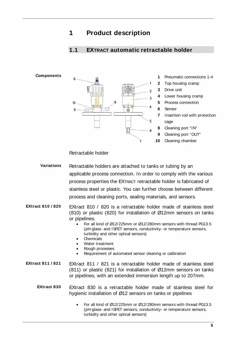
1 Pneumatic connections 1-4
2 Top housing cramp
3 Drive unit
4 Lower housing cramp
5 Process connection
6 Sensor
7 Insertion rod with protection
cage
8 Cleaning port “IN”
9 Cleaning port “OUT”
10 Cleaning chamber
Retractable holder
Retractable holders are attached to tanks or tubing by an
applicable process connection. In order to comply with the various
process properties the EXTRACT retractable holder is fabricated of
stainless steel or plastic. You can further choose between different
process and cleaning ports, sealing materials, and sensors.
EXtract 810 / 820 is a retractable holder made of stainless steel (810) or plastic (820) for installation of Ø12mm sensors on tanks or pipelines.
For all kind of Ø12/225mm or Ø12/280mm sensors with thread PG13.5 (pH-glass- and ISFET sensors, conductivity- or temperature sensors, turbidity and other optical sensors)
Chemicals Water treatment Rough processes Requirement of automated sensor cleaning or calibration
EXtract 811 / 821 is a retractable holder made of stainless steel (811) or plastic (821) for installation of Ø12mm sensors on tanks or pipelines, with an extended immersion length up to 207mm. EXtract 830 is a retractable holder made of stainless steel for hygienic installation of Ø12 sensors on tanks or pipelines
For all kind of Ø12/225mm or Ø12/280mm sensors with thread PG13.5 (pH-glass- and ISFET sensors, conductivity- or temperature sensors, turbidity and other optical sensors)
Components
Variations
EXtract 810 /820
EXtract 811 /821
EXtract 830
1 Product description
6
Food Pharmaceuticals Requirement of automated sensor cleaning or calibration
Compressed air is supplied via the pneumatic connections on the
drive unit. The drive unit inserts the insertion rod in the process
medium up to the maximal insertion depth. For safety reasons this
is only possible with a sensor installed.
When reaching the final position of the “measuring” position, the
control receives a pneumatic position signal. In this position the
sensor head is immersed in the drive unit and cannot be removed.
The sensor measures the chemical or physical properties of the
process liquid.
Cleaning, rinsing and calibration of the sensor is possible while the
process is running. For this purpose the holder must be moved to
the “service” position. Another pneumatic position signal is caused
when the final position is reached. In the “service” position the
insertion rod seals the cleaning chamber against the process to
prevent leakage of process liquid. The required liquid is introduced
into the cleaning chamber via the cleaning port “IN” and
subsequently drained via the cleaning port “OUT”.
1.2 Process integration
The EXTRACT retractable holder can be operated by the automatic
control EXMATIC. It optimally matches the functions of the holder.
The retractable holder inserts a sensor in the process liquid
transmitting its measuring results to a transmitter.
The external control and the transmitter can be connected to a
process control. The measuring and cleaning intervals are then
controlled automatically according to the measuring results.
Drive
Measuring
Service
Control
Transmitter
Process control
1 Product description
7
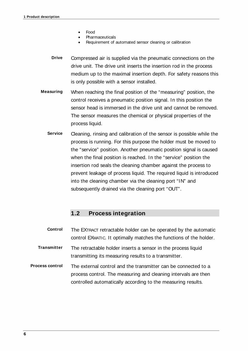
Process flow
The choice of the applicable holder is subject to the pressure and
temperature conditions of the process. The retractable holder of
stainless steel can be used for a pressure of up to 16 bar and the
plastic model up to 10 bar according to the temperature. The
process temperature should be between -10° and 140°C.
Observe pressure and temperature charts
The operation of the holder is generally possible in any position.
The reliability of the measuring results depends on the properties
of the selected sensor.
Prozessleitsystem
Steuerung
Transmitter
Zulauf
Ablauf
Pressure
Temperature
!!! Installation
position

9
2 Special functions
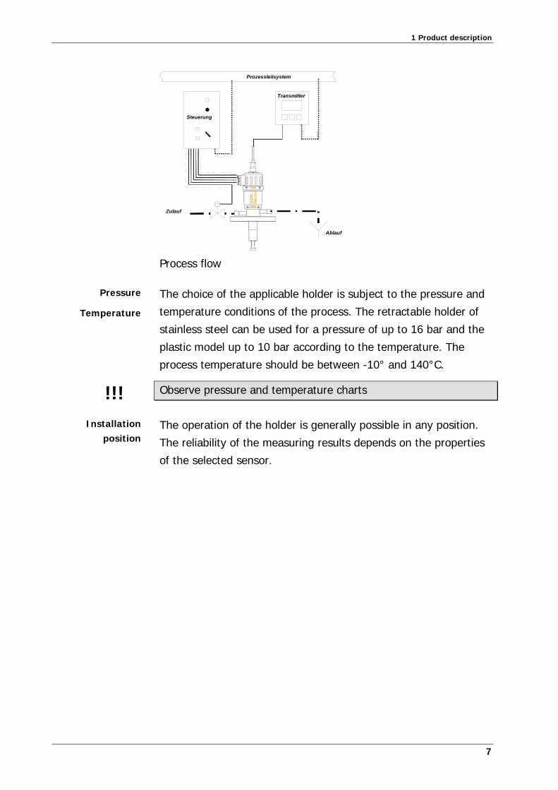
2.1 Adjusting the protection cage
A protection cage is fitted to the lower end of the insertion rod
and can be adjusted with the flow direction. The symbol on the
drive unit cylinder indicates the position of the opening in the
insertion rod. If the symbol is parallel to the flow direction the
insertion rod is fully flown through. If the symbols are vertical to
the flow the sensor is fully protected from direct flow. The
insertion rod can be adjusted in any intermediate position.
A Sensor maximally streamed
B Sensor minimally streamed
Protection cage Symbol
2.2 Installing the pneumatic tubes
The EXTRACT retractable holder is operated with compressed air.
The extension of the cylinder of the drive unit is fitted with four
compressed air connections.
☑
2 Special functions
10
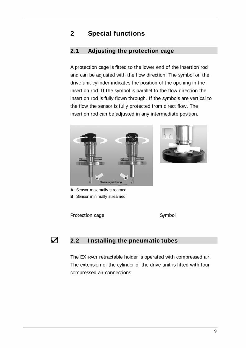
Pneumatic connections 1 - 4
You will need:
2 pneumatic tubes = 4mm
2 pneumatic tubes = 6mm.
Observe the functions of the pneumatic connections!
1. Connection 1: Air supply “measuring” position.
2. Connection 2: Reply “measuring” position.
3. Connection 3: Air supply “service” position
4. Connection 4: Reply “service” position
Use the external control to move the retractable holder from the “service” position to the “measuring” position and vice versa.
2.3 Installing the sensor
Sensors with a diameter of 12mm and a connection thread PG
13.5 must be used in the EXTRACT retractable holder.
The length of the sensor depends on the sensor type and the
selected holder.
2 Special functions
11
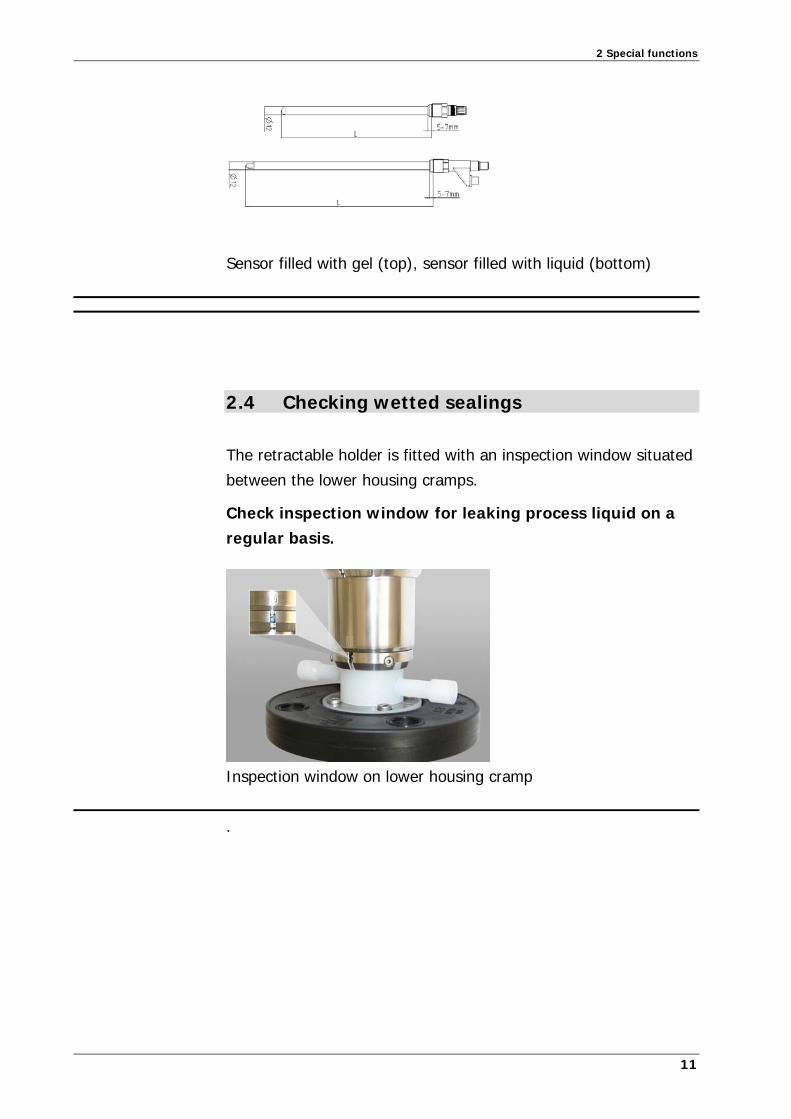
Sensor filled with gel (top), sensor filled with liquid (bottom)
2.4 Checking wetted sealings
The retractable holder is fitted with an inspection window situated
between the lower housing cramps.
Check inspection window for leaking process liquid on a regular basis.
Inspection window on lower housing cramp
.

13
3 Technical specifications
3.1 Standards
Pressure equipment directive
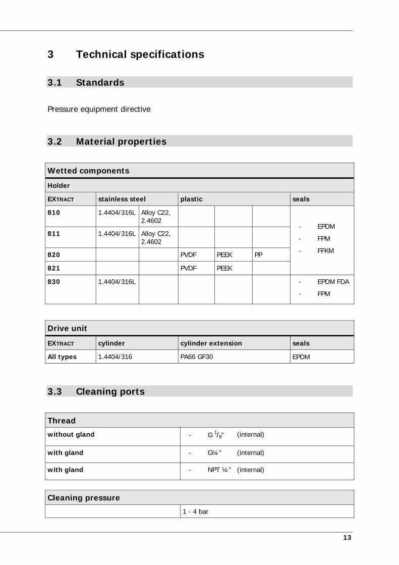
3.2 Material properties
Wetted components
Holder
EXTRACT stainless steel plastic seals
810 1.4404/316L Alloy C22, 2.4602
- EPDM
- FPM
- FFKM
811 1.4404/316L Alloy C22, 2.4602
820 PVDF PEEK PP
821 PVDF PEEK
830 1.4404/316L - EPDM FDA
- FPM
Drive unit
EXTRACT cylinder cylinder extension seals
All types 1.4404/316 PA66 GF30 EPDM
3.3 Cleaning ports
Thread
without gland - G 1/8" (internal)
with gland - G¼" (internal)
with gland - NPT ¼" (internal)
Cleaning pressure
1 - 4 bar
l specifications
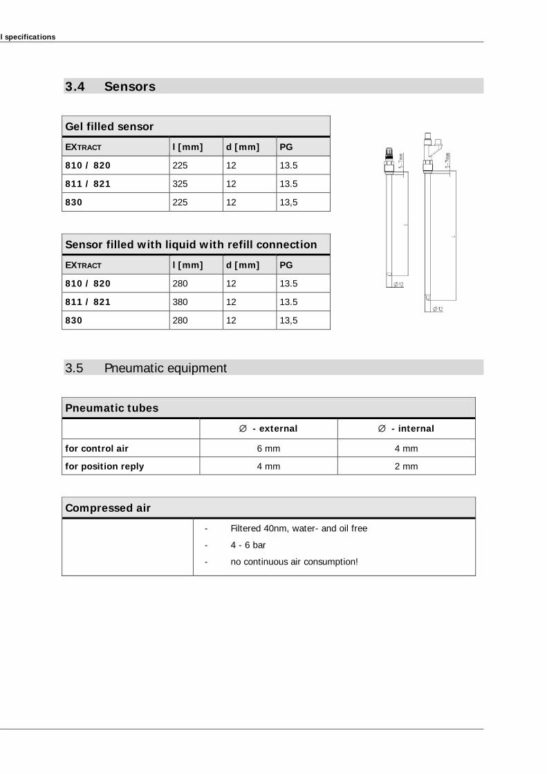
3.4 Sensors
Gel filled sensor
EXTRACT l [mm] d [mm] PG
810 / 820 225 12 13.5
811 / 821 325 12 13.5
830 225 12 13,5
Sensor filled with liquid with refill connection
EXTRACT l [mm] d [mm] PG
810 / 820 280 12 13.5
811 / 821 380 12 13.5
830 280 12 13,5
3.5 Pneumatic equipment
Pneumatic tubes
- external - internal
for control air 6 mm 4 mm
for position reply 4 mm 2 mm
Compressed air
- Filtered 40nm, water- and oil free
- 4 - 6 bar
- no continuous air consumption!
3 Technical specifications
15
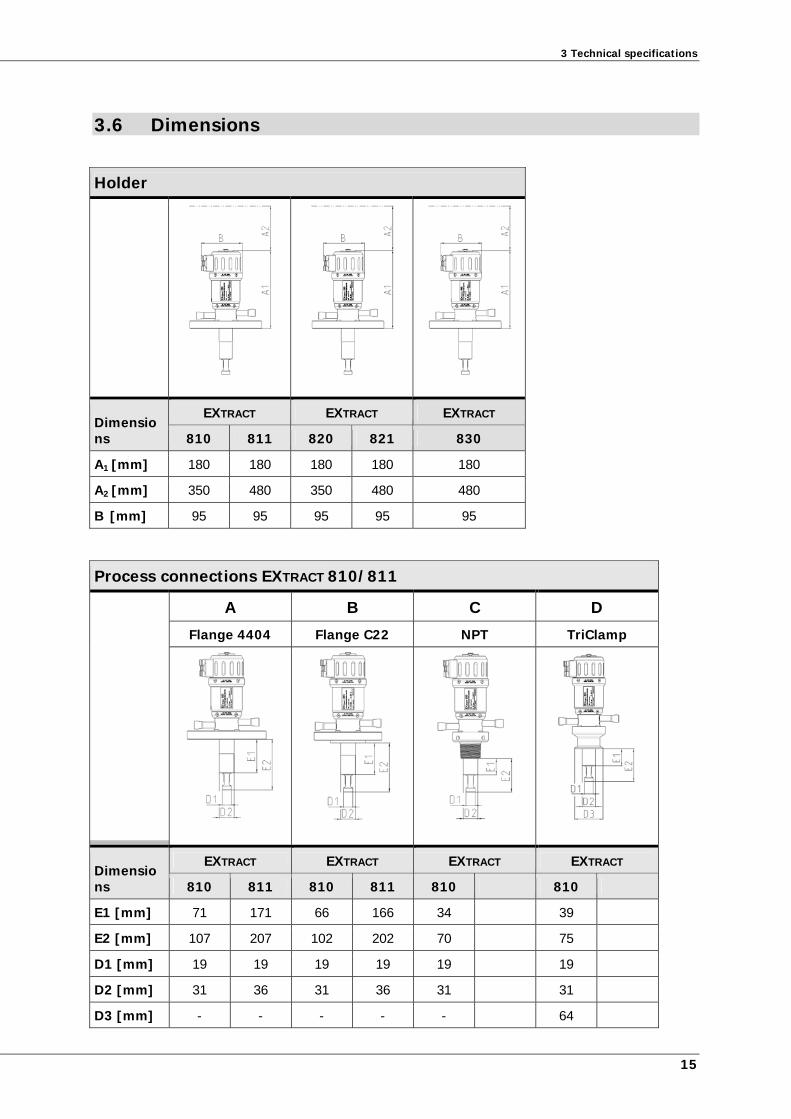
3.6 Dimensions
Holder
Dimensions
EXTRACT EXTRACT EXTRACT
810 811 820 821 830
A1 [mm] 180 180 180 180 180
A2 [mm] 350 480 350 480 480
B [mm] 95 95 95 95 95
Process connections EXTRACT 810/811
A B C D
Flange 4404 Flange C22 NPT TriClamp
Dimensions
EXTRACT EXTRACT EXTRACT EXTRACT
810 811 810 811 810 810
E1 [mm] 71 171 66 166 34 39
E2 [mm] 107 207 102 202 70 75
D1 [mm] 19 19 19 19 19 19
D2 [mm] 31 36 31 36 31 31
D3 [mm] - - - - - 64
l specifications
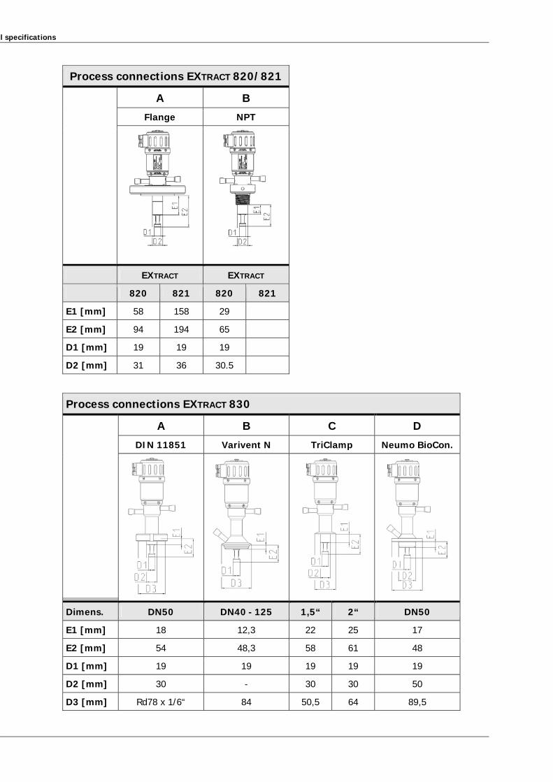
Process connections EXTRACT 820/821
A B
Flange NPT
EXTRACT EXTRACT
820 821 820 821
E1 [mm] 58 158 29
E2 [mm] 94 194 65
D1 [mm] 19 19 19
D2 [mm] 31 36 30.5
Process connections EXTRACT 830
A B C D
DIN 11851 Varivent N TriClamp Neumo BioCon.
Dimens. DN50 DN40 - 125 1,5“ 2“ DN50
E1 [mm] 18 12,3 22 25 17
E2 [mm] 54 48,3 58 61 48
D1 [mm] 19 19 19 19 19
D2 [mm] 30 - 30 30 50
D3 [mm] Rd78 x 1/6“ 84 50,5 64 89,5
3 Technical specifications
17
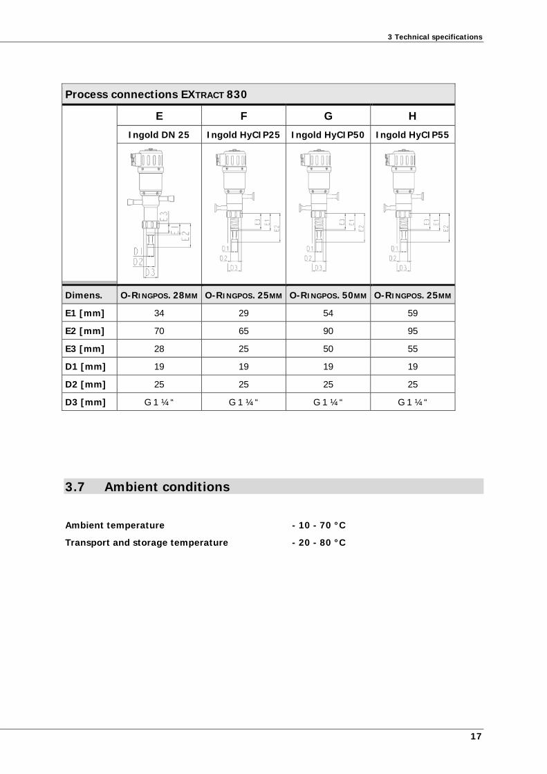
Process connections EXTRACT 830
E F G H
Ingold DN 25 Ingold HyCIP25 Ingold HyCIP50 Ingold HyCIP55
Dimens. O-RINGPOS. 28MM O-RINGPOS. 25MM O-RINGPOS. 50MM O-RINGPOS. 25MM
E1 [mm] 34 29 54 59
E2 [mm] 70 65 90 95
E3 [mm] 28 25 50 55
D1 [mm] 19 19 19 19
D2 [mm] 25 25 25 25
D3 [mm] G 1 ¼“ G 1 ¼“ G 1 ¼“ G 1 ¼“
3.7 Ambient conditions
Ambient temperature - 10 - 70 °C
Transport and storage temperature - 20 - 80 °C
l specifications
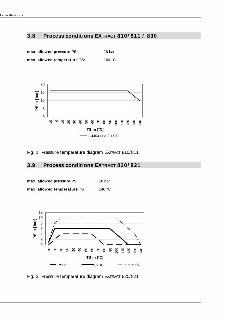
3.8 Process conditions EXTRACT 810/811 / 830
max. allowed pressure PS: 16 bar
max. allowed temperature TS: 140 °C
0
5
10
15
20
-10 0 10 20 30 40 50 60 70 80 90 100
110
120
130
140
TS in [°C]
PS
in [
bar]
1.4404 und 2.4602
Fig. 1: Pressure temperature diagram EXTRACT 810/811
3.9 Process conditions EXTRACT 820/821
max. allowed pressure PS 10 bar
max. allowed temperature TS 140 °C
0
2
46
8
10
12
-10 0 10 20 30 40 50 60 70 80 90 100
110
120
130
140
TS in [°C]
PS
in [
bar]
PP PVDF PEEK
Fig. 2: Pressure temperature diagram EXTRACT 820/821
3 Technical specifications
19
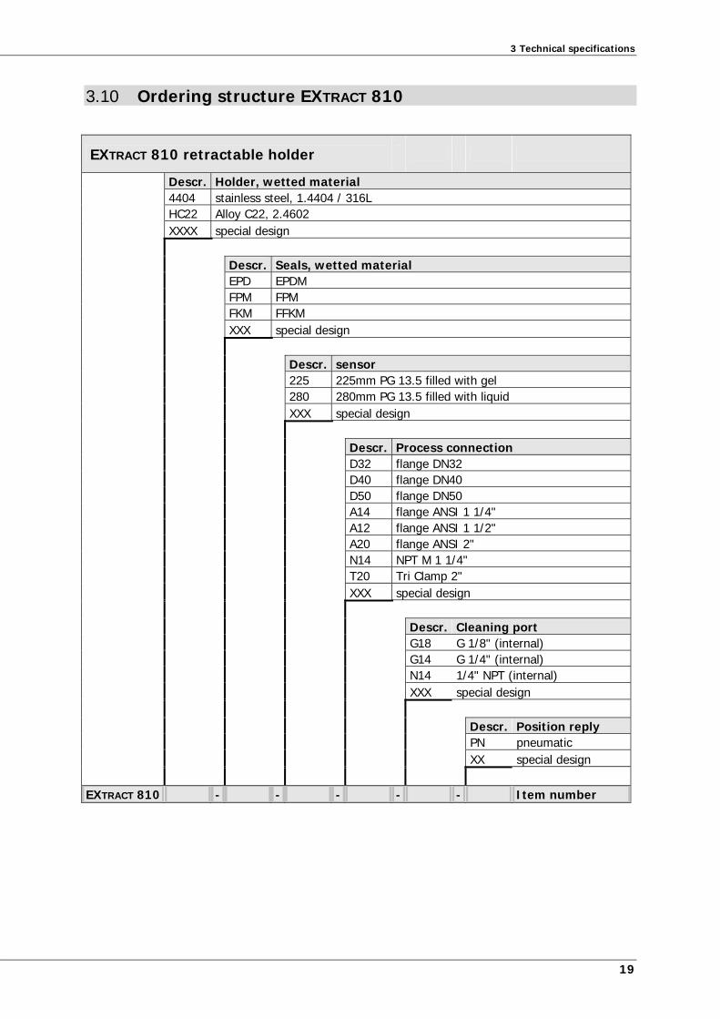
3.10 Ordering structure EXTRACT 810
EXTRACT 810 retractable holder
Descr. Holder, wetted material 4404 stainless steel, 1.4404 / 316L HC22 Alloy C22, 2.4602 XXXX special design Descr. Seals, wetted material EPD EPDM FPM FPM FKM FFKM XXX special design Descr. sensor 225 225mm PG 13.5 filled with gel 280 280mm PG 13.5 filled with liquid XXX special design Descr. Process connection D32 flange DN32 D40 flange DN40 D50 flange DN50 A14 flange ANSI 1 1/4" A12 flange ANSI 1 1/2" A20 flange ANSI 2" N14 NPT M 1 1/4" T20 Tri Clamp 2" XXX special design Descr. Cleaning port G18 G 1/8" (internal) G14 G 1/4" (internal) N14 1/4" NPT (internal) XXX special design Descr. Position reply PN pneumatic XX special design
EXTRACT 810 - - - - - Item number
l specifications
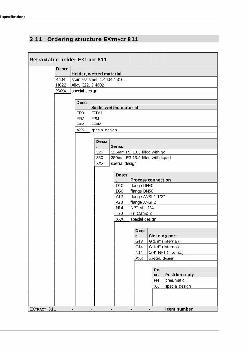
3.11 Ordering structure EXTRACT 811
Retractable holder EXtract 811
Descr. Holder, wetted material
4404 stainless steel, 1.4404 / 316L HC22 Alloy C22, 2.4602 XXXX special design
Descr. Seals, wetted material
EPD EPDM FPM FPM FKM FFKM XXX special design
Descr. Sensor
325 325mm PG 13.5 filled with gel 380 380mm PG 13.5 filled with liquid XXX special design
Descr. Process connection
D40 flange DN40 D50 flange DN50 A12 flange ANSI 1 1/2" A20 flange ANSI 2" N14 NPT M 1 1/4" T20 Tri Clamp 2" XXX special design
Descr. Cleaning port
G18 G 1/8" (internal) G14 G 1/4" (internal) N14 1/4" NPT (internal) XXX special design
Descr. Position reply
PN pneumatic XX special design EXTRACT 811 - - - - - Item number
3 Technical specifications
21
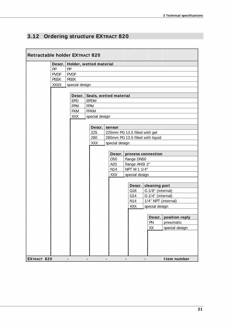
3.12 Ordering structure EXTRACT 820
Retractable holder EXTRACT 820
Descr. Holder, wetted material PP PP PVDF PVDF PEEK PEEK XXXX special design Descr. Seals, wetted material EPD EPDM FPM FPM FKM FFKM XXX special design Descr. sensor 225 225mm PG 13.5 filled with gel 280 280mm PG 13.5 filled with liquid XXX special design Descr. process connection D50 flange DN50 A20 flange ANSI 2" N14 NPT M 1 1/4" XXX special design Descr. cleaning port G18 G 1/8" (internal) G14 G 1/4" (internal) N14 1/4" NPT (internal) XXX special design Descr. position reply PN pneumatic XX special design EXTRACT 820 - - - - - Item number
l specifications
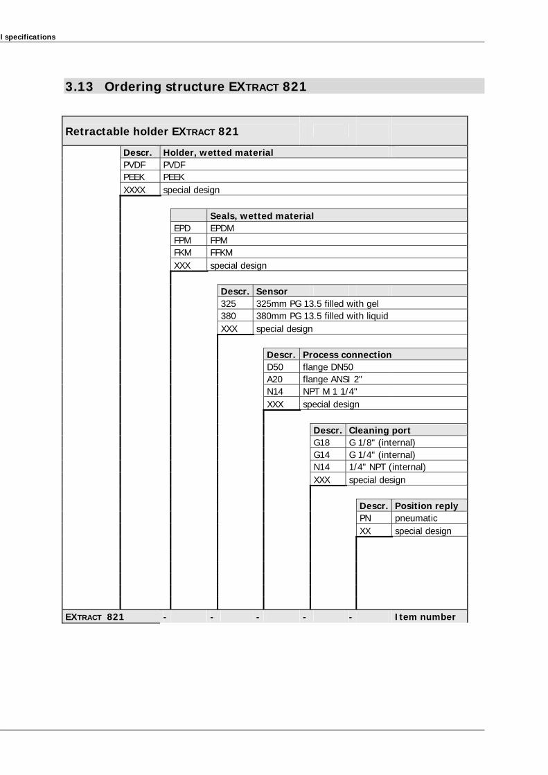
3.13 Ordering structure EXTRACT 821
Retractable holder EXTRACT 821
Descr. Holder, wetted material PVDF PVDF PEEK PEEK XXXX special design Seals, wetted material EPD EPDM FPM FPM FKM FFKM XXX special design Descr. Sensor 325 325mm PG 13.5 filled with gel 380 380mm PG 13.5 filled with liquid XXX special design Descr. Process connection D50 flange DN50 A20 flange ANSI 2" N14 NPT M 1 1/4" XXX special design Descr. Cleaning port G18 G 1/8" (internal) G14 G 1/4" (internal) N14 1/4" NPT (internal) XXX special design Descr. Position reply PN pneumatic XX special design EXTRACT 821 - - - - - Item number
3 Technical specifications
23
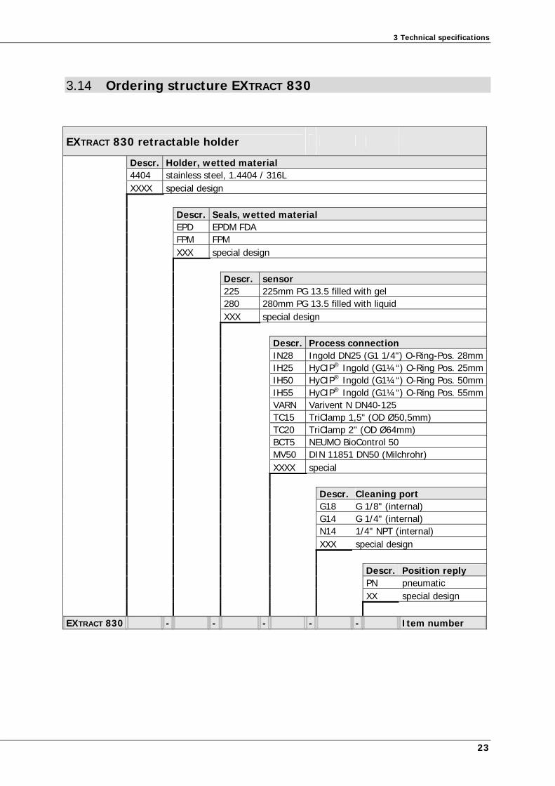
3.14 Ordering structure EXTRACT 830
EXTRACT 830 retractable holder
Descr. Holder, wetted material 4404 stainless steel, 1.4404 / 316L XXXX special design Descr. Seals, wetted material EPD EPDM FDA FPM FPM XXX special design Descr. sensor 225 225mm PG 13.5 filled with gel 280 280mm PG 13.5 filled with liquid XXX special design Descr. Process connection IN28 Ingold DN25 (G1 1/4") O-Ring-Pos. 28mm IH25 HyCIP® Ingold (G1¼“) O-Ring Pos. 25mm IH50 HyCIP® Ingold (G1¼“) O-Ring Pos. 50mm IH55 HyCIP® Ingold (G1¼“) O-Ring Pos. 55mm VARN Varivent N DN40-125 TC15 TriClamp 1,5" (OD Ø50,5mm) TC20 TriClamp 2" (OD Ø64mm) BCT5 NEUMO BioControl 50 MV50 DIN 11851 DN50 (Milchrohr) XXXX special Descr. Cleaning port G18 G 1/8" (internal) G14 G 1/4" (internal) N14 1/4" NPT (internal) XXX special design Descr. Position reply PN pneumatic XX special design
EXTRACT 830 - - - - - Item number

25
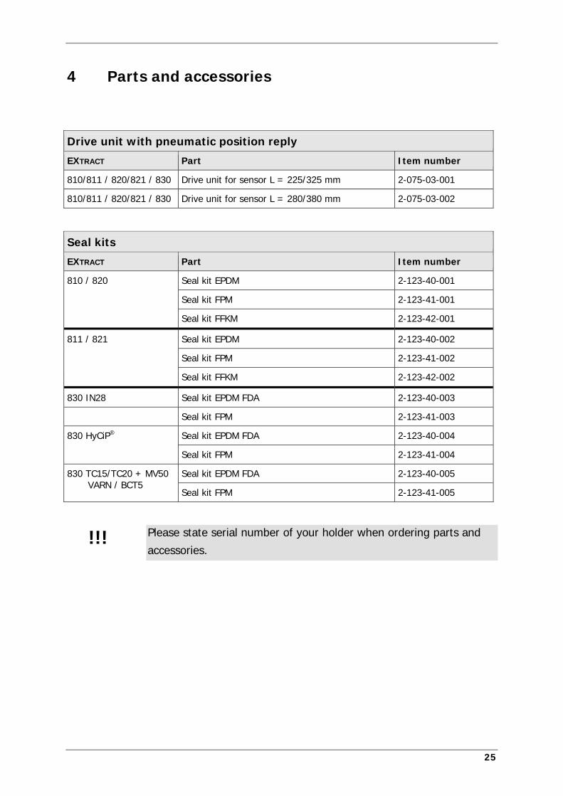
4 Parts and accessories
Drive unit with pneumatic position reply
EXTRACT Part Item number
810/811 / 820/821 / 830 Drive unit for sensor L = 225/325 mm 2-075-03-001
810/811 / 820/821 / 830 Drive unit for sensor L = 280/380 mm 2-075-03-002
Seal kits
EXTRACT Part Item number
810 / 820 Seal kit EPDM 2-123-40-001
Seal kit FPM 2-123-41-001
Seal kit FFKM 2-123-42-001
811 / 821 Seal kit EPDM 2-123-40-002
Seal kit FPM 2-123-41-002
Seal kit FFKM 2-123-42-002
830 IN28 Seal kit EPDM FDA 2-123-40-003
Seal kit FPM 2-123-41-003
830 HyCiP® Seal kit EPDM FDA 2-123-40-004
Seal kit FPM 2-123-41-004
830 TC15/TC20 + MV50 VARN / BCT5
Seal kit EPDM FDA 2-123-40-005
Seal kit FPM 2-123-41-005
Please state serial number of your holder when ordering parts and
accessories. !!!

27
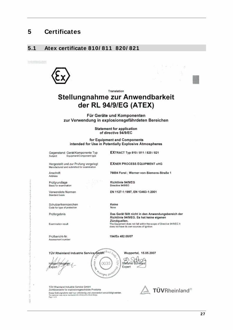
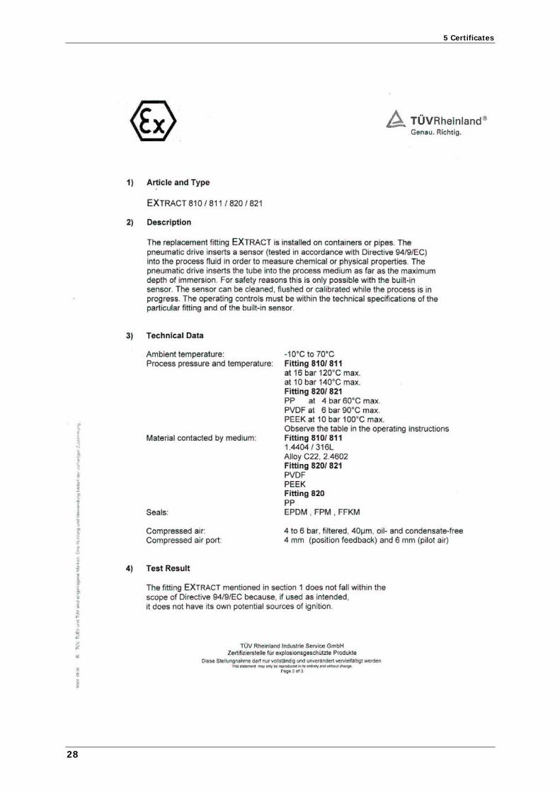
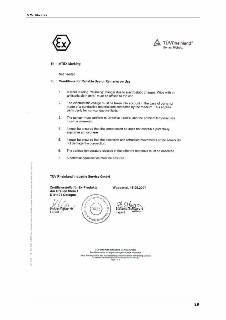
5 Certificates
5.1 Atex certificate 810/811 820/821
5 Certificates
28
5 Certificates
29


