Embed Size (px)
Citation preview

OPERATOR´S MANUAL
PRIMO HT1/2020
20
Tractor is Zetor. Since 1946.
1/20201/2020
ZETOR
This Operator’s Manual for the Zetor tractors, which we are presenting to you will help you to become familiar with the operation and maintenance of your new tractor. Although many of you have rich experience with the operation of other tractors, please, read the information contained in this Operator’s Manual very carefully. In the Manual you will find a lot of new information and get a perfect overview of how to use the tractor with maximum efficiency during various kinds of work. If you observe the rules of tractor operation and maintenance and driving safety, your new tractor will become your reliable and long-term friend. The manufacturer of the tractor wishes you thousands of hours of satisfactory work.
ZETOR Brno
The technical specifications and information about the design, equipment, material and appearance are valid at the time of print. The manufacturer reserves the right to implement changes.
The instructions for use are a part of the machine.
Printing errors reserved
1

2

Location of serial numbers .............................................................................................................................. 7 Product Warranty ........................................................................................................................................... 7
About this manual ............................................................................................................................................ 9 Rops (roll over protection structures) .......................................................................................................... 11
Roll-Over Protection Structure (ROPS) ....................................................................................................... 11 ROPS damage ............................................................................................................................................ 12 Sliding Seat.................................................................................................................................................. 13 How to adjust the seat ................................................................................................................................. 13
Safety instructions ......................................................................................................................................... 15 Introduction to safety information ................................................................................................................ 15 Signal words ................................................................................................................................................ 15 Introduction to safety instructions Introduction to safety instructions .......................................................... 15 Protection children ....................................................................................................................................... 15 Use of rops and seat belt ............................................................................................................................ 16 Precaution to avoid tipping .......................................................................................................................... 16 Safe parking of the tractor ........................................................................................................................... 16 Keep riders off tractor .................................................................................................................................. 16 Handle fuel safely-avoid fires ...................................................................................................................... 17 Stay clear of rotating shafts ......................................................................................................................... 17 Always use safety lights and devices .......................................................................................................... 17 Practice safe maintenance .......................................................................................................................... 18 Avoid high-pressure fluids ........................................................................................................................... 18 Prevent battery explosions .......................................................................................................................... 18 Prevent acid burns ....................................................................................................................................... 19 Battery disconnect ....................................................................................................................................... 19 Service tractor safely ................................................................................................................................... 19 Work in ventilated area ................................................................................................................................ 20 Tractor runaway ........................................................................................................................................... 20 Safety starter switch .................................................................................................................................... 20 Safe operation of your tractor ...................................................................................................................... 21 Safety Tips During Maintenance ................................................................................................................. 21 Mounting and demounting implements ....................................................................................................... 22 The following precautions are suggested to help prevent accidents .......................................................... 23 Diesel fuel .................................................................................................................................................... 25 DO'S AND DON'T'S ..................................................................................................................................... 26 DO'S-for better performance ....................................................................................................................... 26 Don'ts - for safe operation .......................................................................................................................... 27
General informations ...................................................................................................................................... 29 Exterior view ................................................................................................................................................ 29 Warning Symbols ........................................................................................................................................ 32
Tractor controls .............................................................................................................................................. 37 Instruments and Switches ........................................................................................................................... 37 Main Switch ................................................................................................................................................. 38 Tachometer.................................................................................................................................................. 39 Hour Meter ................................................................................................................................................... 39 Fuel Gauge .................................................................................................................................................. 39 Coolant Temperature Indicator Light ........................................................................................................... 40 Combined Switch ......................................................................................................................................... 41 Warning Lights Switch ................................................................................................................................. 41 Indicator Lights ............................................................................................................................................ 42 PTO ON / OFF Switch ................................................................................................................................. 45 Cruise Control Switch .................................................................................................................................. 45 Controls Operation ...................................................................................................................................... 46 Throttle Lever .............................................................................................................................................. 47 Brake Pedal ................................................................................................................................................. 47 Control Pedals ............................................................................................................................................. 48 Travel Speed ............................................................................................................................................... 48 Parking Brake Pedal .................................................................................................................................... 48 Reduced and Road Gears Shift Lever ........................................................................................................ 49 Differential lock pedal .................................................................................................................................. 50 Front Axle Drive Shift Lever (4WD) ............................................................................................................. 51 Seat and Seat Belt ....................................................................................................................................... 52 Pto ............................................................................................................................................................... 53
CONTENTS
3

Tips for using the steering wheel with power steering ................................................................................ 53 Implement Lifting Control System ............................................................................................................... 54 Implement Lowering Speed Control Dial ..................................................................................................... 55 Cruise Control .............................................................................................................................................. 56
Mower deck ..................................................................................................................................................... 57 Preface ........................................................................................................................................................ 57 Help with Manual Use .................................................................................................................................. 57 Use of the Machine ...................................................................................................................................... 57 Mower Deck ................................................................................................................................................. 58 Operation in General ................................................................................................................................... 59 Operation on the Slope ................................................................................................................................ 60 Transport ..................................................................................................................................................... 60 Operation (1) ............................................................................................................................................... 61 Operation (2) ............................................................................................................................................... 62 Maintenance (1) ........................................................................................................................................... 63 Maintenance (2) ........................................................................................................................................... 64 Table of fillings change and service intervals .............................................................................................. 64 Safety Labels ............................................................................................................................................... 65 Information Labels ....................................................................................................................................... 66 Technical data of the middle mower deck ................................................................................................... 68 Lubrication ................................................................................................................................................... 70 Mower Deck Adjustment .............................................................................................................................. 71 Universal joint .............................................................................................................................................. 72 Rear Link ..................................................................................................................................................... 73 Front Link ..................................................................................................................................................... 73 Front Link Assembly .................................................................................................................................... 74 Mower Deck Settings ................................................................................................................................... 75 Link Settings ................................................................................................................................................ 76 Front and Rear Cutting Height Adjustment ................................................................................................. 78 Left and Right Cutting Height Adjustment ................................................................................................... 79 Fasteners torque table (ISO) ....................................................................................................................... 80 Parts Replacement ...................................................................................................................................... 81 Blade Disassembly ...................................................................................................................................... 81 Blade Installation ......................................................................................................................................... 81 Belt Replacement ........................................................................................................................................ 82 Belt Replacement ........................................................................................................................................ 82 Transmission ............................................................................................................................................... 83
Operation ......................................................................................................................................................... 85 How to Start the Engine ............................................................................................................................... 85 Switching the Engine Off ............................................................................................................................. 85 Switching Off ............................................................................................................................................... 85 Engine Idling ................................................................................................................................................ 86 Engine Idling in General .............................................................................................................................. 86 Run-in .......................................................................................................................................................... 86 Driving Off, Shifting and Driving .................................................................................................................. 87 Driving Off .................................................................................................................................................... 87 Parking ......................................................................................................................................................... 87 Driving on a Slope ....................................................................................................................................... 87 Driving Off on a Steep Slope ....................................................................................................................... 87 Tips for Driving on a Slope .......................................................................................................................... 88 Precautions when Entering / Exiting a Field ................................................................................................ 88 Loading on Truck / Unloading...................................................................................................................... 88 Precautions when Driving on the Road ....................................................................................................... 89 Operation Check while Driving .................................................................................................................... 89 Engine Oil Pressure ..................................................................................................................................... 89 Coolant ........................................................................................................................................................ 89
Workflow .......................................................................................................................................................... 91 Maintenance .................................................................................................................................................... 93
Covers Opening ........................................................................................................................................... 93 Hood Opening ............................................................................................................................................. 93 Checked Items ............................................................................................................................................. 94 Checked Items ............................................................................................................................................. 94 Check and Change of Coolant .................................................................................................................... 95
CONTENTS
4

Check and Change of Engine Coolant ........................................................................................................ 95 Cleaning the Radiator and Radiator Grilles ................................................................................................. 96 Oil Check and Replacement ........................................................................................................................ 96 Engine Oil and Replacement ....................................................................................................................... 96 Transmission Fluid Check and Change ...................................................................................................... 98 Front Axle Oil Check and Change ............................................................................................................. 100 Filter and Element Replacement ............................................................................................................... 101 Transmission Fluid Filter Element Replacement ....................................................................................... 101 Cleaning the Transmission Fluid Dirt Trap ................................................................................................ 101 Oil filter Element Replacement .................................................................................................................. 102 Fuel System ............................................................................................................................................... 103 Check and Cleaning of the Air Filter .......................................................................................................... 104 Vacuum Valve Cleaning ............................................................................................................................ 104 Air Filter Cleaning ...................................................................................................................................... 104 Air Filter Replacement ............................................................................................................................... 104 Lubrication Points ...................................................................................................................................... 105 Lubricating Arm ......................................................................................................................................... 105 Hoses Check ............................................................................................................................................. 105 Electric System Check ............................................................................................................................... 105 Battery Check and Charging ..................................................................................................................... 105 Recharge ................................................................................................................................................... 106 Starting with an External Battery ............................................................................................................... 106 Electric Connection Check ........................................................................................................................ 107 Fuse Check and Replacement .................................................................................................................. 107 Fuse Box .................................................................................................................................................... 107 High Capacity Fuse (50 A) ........................................................................................................................ 108 Light Bulb Replacement ............................................................................................................................ 108 Check and Adjustment of Parts ................................................................................................................. 109 Check and Adjustment of Brake Pedal ...................................................................................................... 109 Brake Pedal Play ....................................................................................................................................... 109 Check and Adjustment of the Fan Belt ...................................................................................................... 110 Check of Fuel Hose (Main Fuel Filter) ....................................................................................................... 110 Check of Air Filter Hose ............................................................................................................................. 111 Check of Radiator Hose ............................................................................................................................ 111 Tire Inflation Pressure ............................................................................................................................... 112 Checks and Service ................................................................................................................................... 113 General Information ................................................................................................................................... 113 Periodical Check and Service Table ......................................................................................................... 114 Fuel, oil and fluid specification diagram. ................................................................................................... 115 Recommended ZETOR service fillings ..................................................................................................... 116
Storage and disposal ................................................................................................................................... 117 Tractor Storage .......................................................................................................................................... 117 Short-term Storage .................................................................................................................................... 117 Long-term Storage ..................................................................................................................................... 117 Use after a Long Downtime ....................................................................................................................... 118 Use and Disposal ...................................................................................................................................... 118
Troubleshooting ........................................................................................................................................... 119 Engine Faults ............................................................................................................................................. 119 Engine Faults ............................................................................................................................................. 120 Engine Faults ............................................................................................................................................. 121 Brake system faults ................................................................................................................................... 122 Steering system faults ............................................................................................................................... 122 Hydraulic system faults .............................................................................................................................. 123 Electrical system faults .............................................................................................................................. 124
Appendix ....................................................................................................................................................... 125 Index ............................................................................................................................................................... 129
CONTENTS
5

6
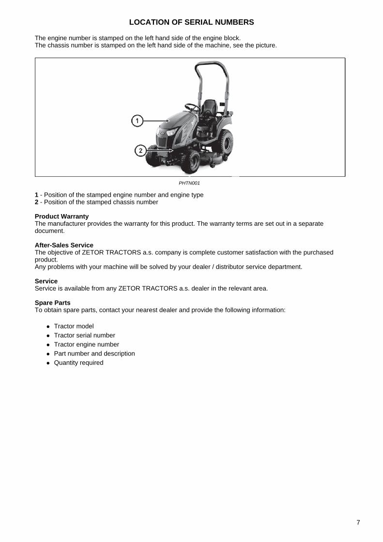
The engine number is stamped on the left hand side of the engine block.The chassis number is stamped on the left hand side of the machine, see the picture.
PHTN001
1 - Position of the stamped engine number and engine type 2 - Position of the stamped chassis number
Product WarrantyThe manufacturer provides the warranty for this product. The warranty terms are set out in a separate document.
After-Sales ServiceThe objective of ZETOR TRACTORS a.s. company is complete customer satisfaction with the purchased product.Any problems with your machine will be solved by your dealer / distributor service department.
ServiceService is available from any ZETOR TRACTORS a.s. dealer in the relevant area.
Spare PartsTo obtain spare parts, contact your nearest dealer and provide the following information:
Tractor model Tractor serial number Tractor engine number Part number and description Quantity required
LOCATION OF SERIAL NUMBERS
7

NOTES
8

This manual has been prepared to assist you in following / adopting the correct procedure for running-in operation and maintenance of your new ZETOR Tractor.
Your tractor has been designed and built to provide maximum performance, low fuel consumption and ease of use. To maintain the condition and ensure trouble-free performance, it is important that maintenance is performed at the recommended intervals as described in this manual.
Read this Manual carefully and keep it in a convenient place for future reference.
If at any time you require advice concerning your Tractor, do not hesitate to contact your Authorized ZETOR dealer / Distributor. He has trained personnel, genuine parts and necessary equipments to undertake all your service requirements.
All data given in this book is subject to production variations. Dimensions & weight are approximate only and the illustrations do not necessarily show Tractors in standard condition.
For exact information about any particular Tractor, please consult your ZETOR dealer / Distributor.
ABOUT THIS MANUAL
9

NOTES
10
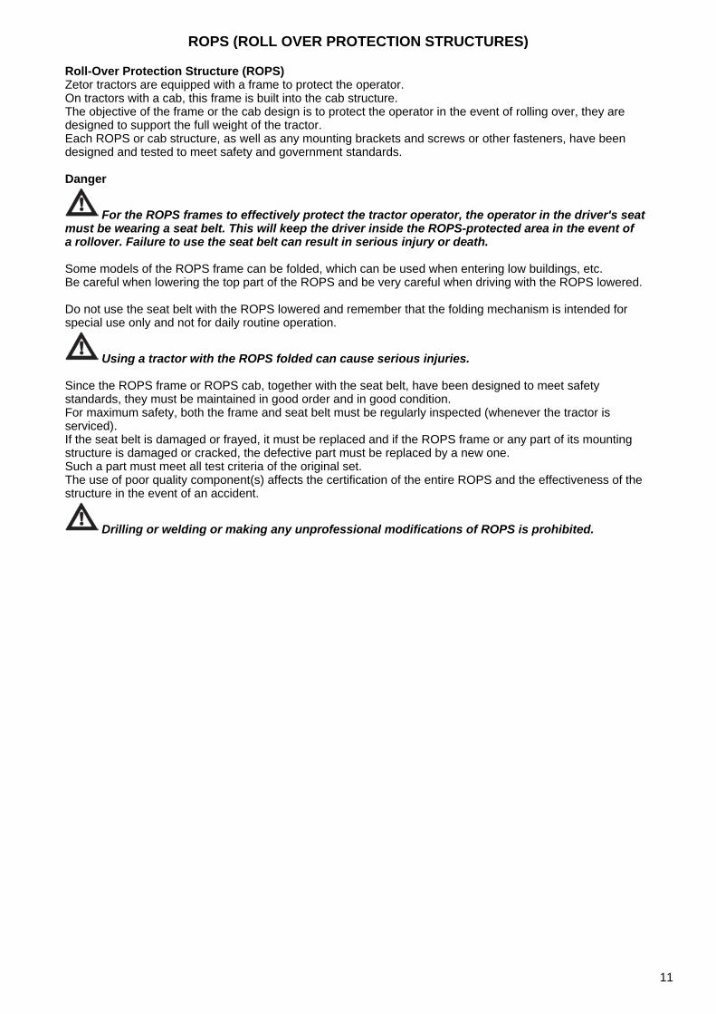
Roll-Over Protection Structure (ROPS)Zetor tractors are equipped with a frame to protect the operator. On tractors with a cab, this frame is built into the cab structure. The objective of the frame or the cab design is to protect the operator in the event of rolling over, they are designed to support the full weight of the tractor. Each ROPS or cab structure, as well as any mounting brackets and screws or other fasteners, have been designed and tested to meet safety and government standards.
Danger
For the ROPS frames to effectively protect the tractor operator, the operator in the driver's seat must be wearing a seat belt. This will keep the driver inside the ROPS-protected area in the event of a rollover. Failure to use the seat belt can result in serious injury or death.
Some models of the ROPS frame can be folded, which can be used when entering low buildings, etc. Be careful when lowering the top part of the ROPS and be very careful when driving with the ROPS lowered.
Do not use the seat belt with the ROPS lowered and remember that the folding mechanism is intended for special use only and not for daily routine operation.
Using a tractor with the ROPS folded can cause serious injuries.
Since the ROPS frame or ROPS cab, together with the seat belt, have been designed to meet safety standards, they must be maintained in good order and in good condition. For maximum safety, both the frame and seat belt must be regularly inspected (whenever the tractor is serviced).If the seat belt is damaged or frayed, it must be replaced and if the ROPS frame or any part of its mounting structure is damaged or cracked, the defective part must be replaced by a new one. Such a part must meet all test criteria of the original set. The use of poor quality component(s) affects the certification of the entire ROPS and the effectiveness of the structure in the event of an accident.
Drilling or welding or making any unprofessional modifications of ROPS is prohibited.
ROPS (ROLL OVER PROTECTION STRUCTURES)
11
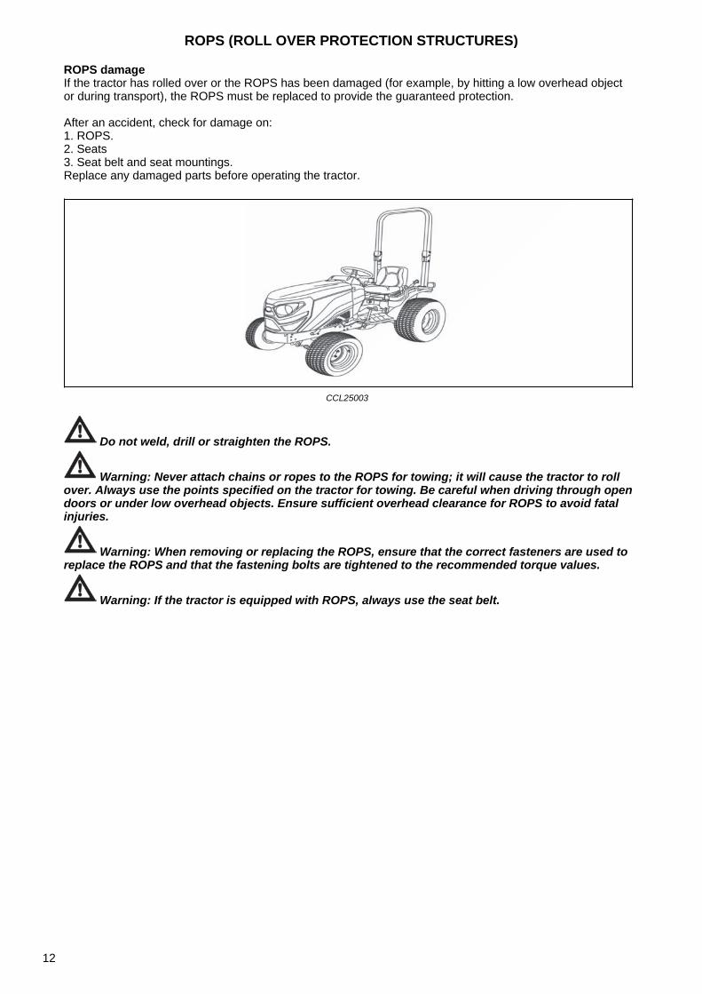
ROPS damageIf the tractor has rolled over or the ROPS has been damaged (for example, by hitting a low overhead object or during transport), the ROPS must be replaced to provide the guaranteed protection.
After an accident, check for damage on: 1. ROPS. 2. Seats 3. Seat belt and seat mountings. Replace any damaged parts before operating the tractor.
CCL25003
Do not weld, drill or straighten the ROPS.
Warning: Never attach chains or ropes to the ROPS for towing; it will cause the tractor to roll over. Always use the points specified on the tractor for towing. Be careful when driving through open doors or under low overhead objects. Ensure sufficient overhead clearance for ROPS to avoid fatal injuries.
Warning: When removing or replacing the ROPS, ensure that the correct fasteners are used to replace the ROPS and that the fastening bolts are tightened to the recommended torque values.
Warning: If the tractor is equipped with ROPS, always use the seat belt.
ROPS (ROLL OVER PROTECTION STRUCTURES)
12
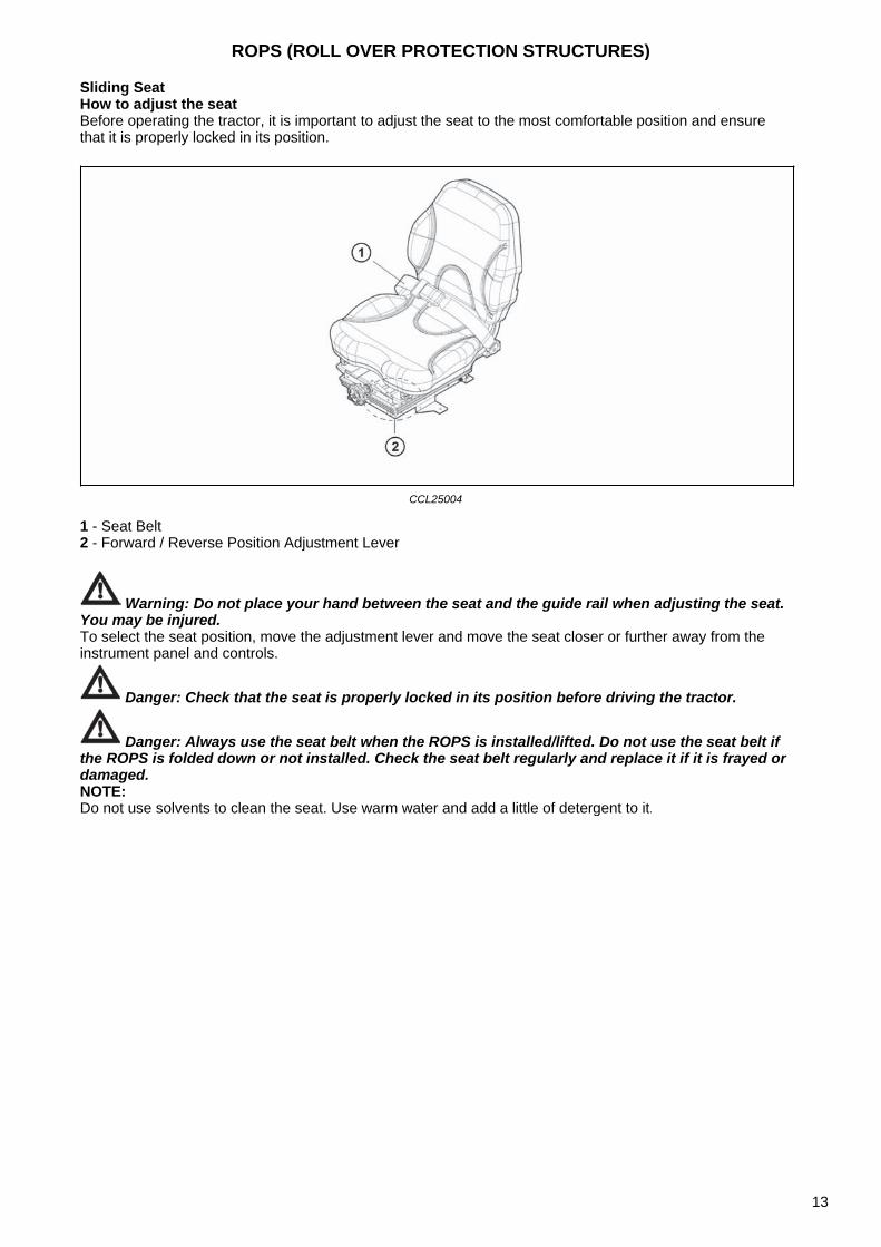
Sliding SeatHow to adjust the seatBefore operating the tractor, it is important to adjust the seat to the most comfortable position and ensure that it is properly locked in its position.
CCL25004
1 - Seat Belt 2 - Forward / Reverse Position Adjustment Lever
Warning: Do not place your hand between the seat and the guide rail when adjusting the seat. You may be injured.To select the seat position, move the adjustment lever and move the seat closer or further away from the instrument panel and controls.
Danger: Check that the seat is properly locked in its position before driving the tractor.
Danger: Always use the seat belt when the ROPS is installed/lifted. Do not use the seat belt if the ROPS is folded down or not installed. Check the seat belt regularly and replace it if it is frayed or damaged.NOTE:Do not use solvents to clean the seat. Use warm water and add a little of detergent to it.
ROPS (ROLL OVER PROTECTION STRUCTURES)
13

NOTES
14
Introduction to safety information
This symbol means ATTENTION! YOUR SAFETY IS INVOLVED. The message that follows the symbol contains important information about safety. Carefully read the message.
Signal words
Danger
Warning
Caution
A signal word - DANGER, WARNING OR CAUTION - is used with safety alert symbol. DANGER identifies the most serious hazards. Safety signs with signal Word - DANGER OR WARNING - are typically near specific hazards. General precautions are listed on CAUTION safety signs.
Introduction to safety instructions Introduction to safety instructions
Protection children
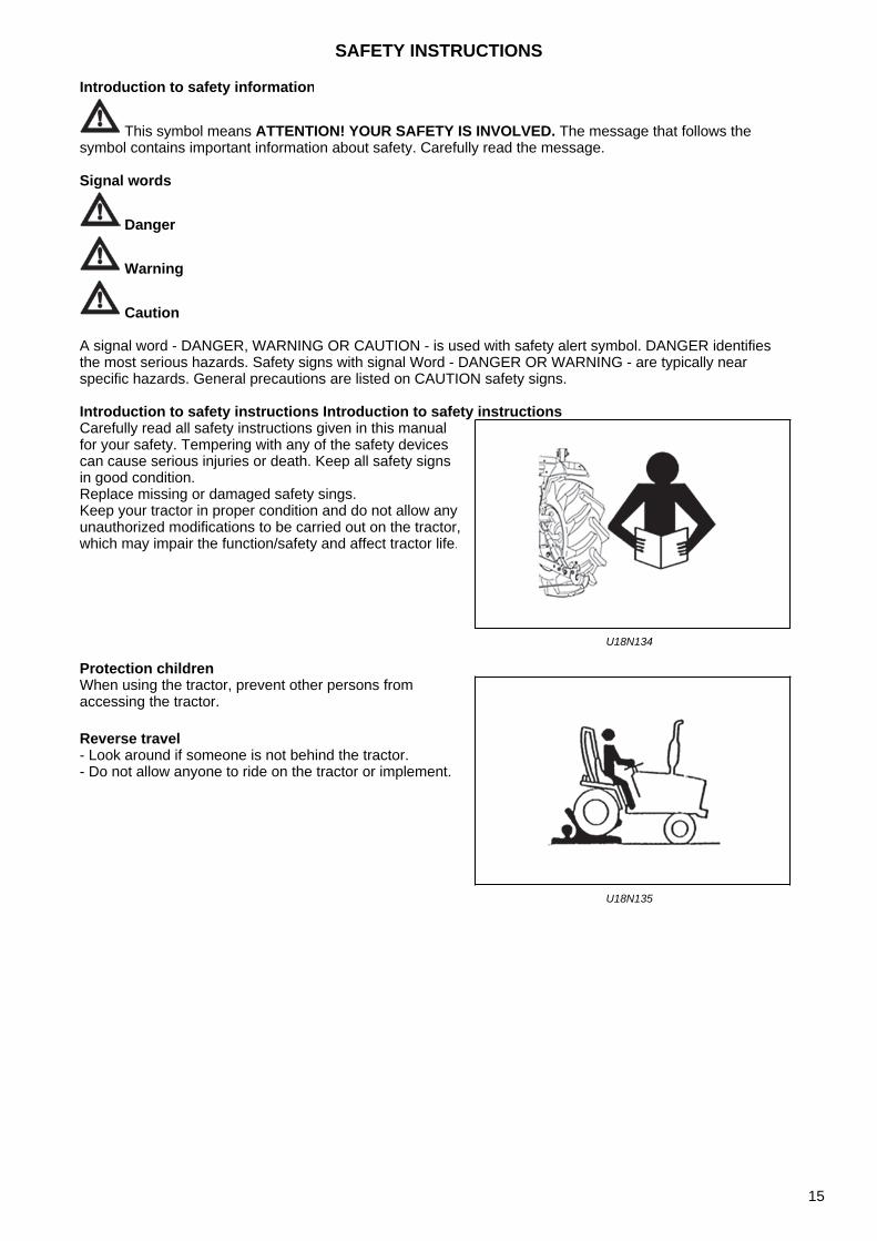
Carefully read all safety instructions given in this manual for your safety. Tempering with any of the safety devices can cause serious injuries or death. Keep all safety signs in good condition.Replace missing or damaged safety sings.Keep your tractor in proper condition and do not allow any unauthorized modifications to be carried out on the tractor, which may impair the function/safety and affect tractor life.
U18N134
When using the tractor, prevent other persons from accessing the tractor.
Reverse travel - Look around if someone is not behind the tractor. - Do not allow anyone to ride on the tractor or implement.
U18N135
SAFETY INSTRUCTIONS
15
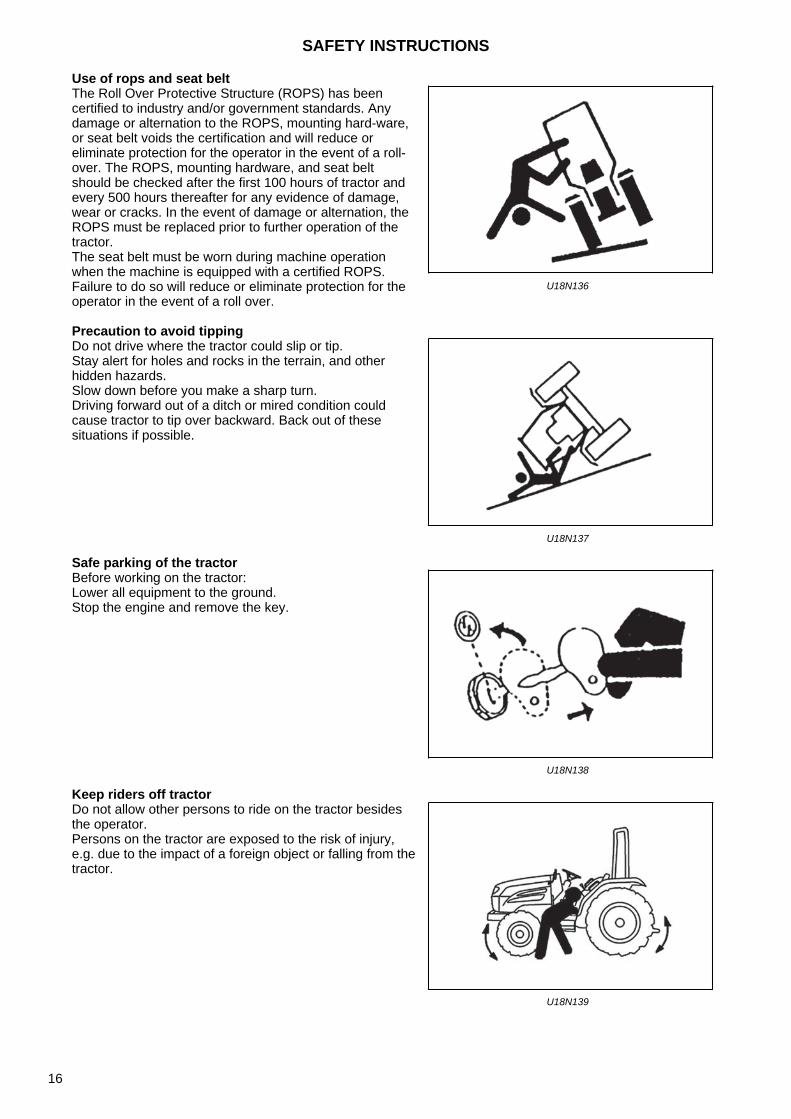
Use of rops and seat belt
Precaution to avoid tipping
Safe parking of the tractor
Keep riders off tractor
The Roll Over Protective Structure (ROPS) has been certified to industry and/or government standards. Any damage or alternation to the ROPS, mounting hard-ware, or seat belt voids the certification and will reduce or eliminate protection for the operator in the event of a roll-over. The ROPS, mounting hardware, and seat belt should be checked after the first 100 hours of tractor and every 500 hours thereafter for any evidence of damage, wear or cracks. In the event of damage or alternation, the ROPS must be replaced prior to further operation of the tractor.The seat belt must be worn during machine operation when the machine is equipped with a certified ROPS.Failure to do so will reduce or eliminate protection for the operator in the event of a roll over.
U18N136
Do not drive where the tractor could slip or tip.Stay alert for holes and rocks in the terrain, and other hidden hazards.Slow down before you make a sharp turn.Driving forward out of a ditch or mired condition could cause tractor to tip over backward. Back out of these situations if possible.
U18N137
Before working on the tractor:Lower all equipment to the ground.Stop the engine and remove the key.
U18N138
Do not allow other persons to ride on the tractor besides the operator. Persons on the tractor are exposed to the risk of injury, e.g. due to the impact of a foreign object or falling from thetractor.
U18N139
SAFETY INSTRUCTIONS
16

Handle fuel safely-avoid fires
Stay clear of rotating shafts
Always use safety lights and devices
Handle fuel with care; it is highly flammable. Do not refuel the tractor while smoking or near open flame or sparks.Always stop engine before refueling tractors.Always keep your tractor clean of accumulated grease, and debris. Always clean up spilled fuel.
U18N140
Entanglement in rotating shaft can cause serious injury or death.Keep PTO shield in place at all times.Wear close fitting clothing. Stop the engine and be sure PTO drive is stopped before making adjustments, connections, or cleaning out PTO driven equipment.
U18N141
Use of hazard warning lights and turn signals are recommended when towing equipment on public roads unless prohibited by state or local regulations.Use slow moving vehicle (SMV) sign when driving on public road during both day & night time, unless prohibited by low.
U18N142
SAFETY INSTRUCTIONS
17
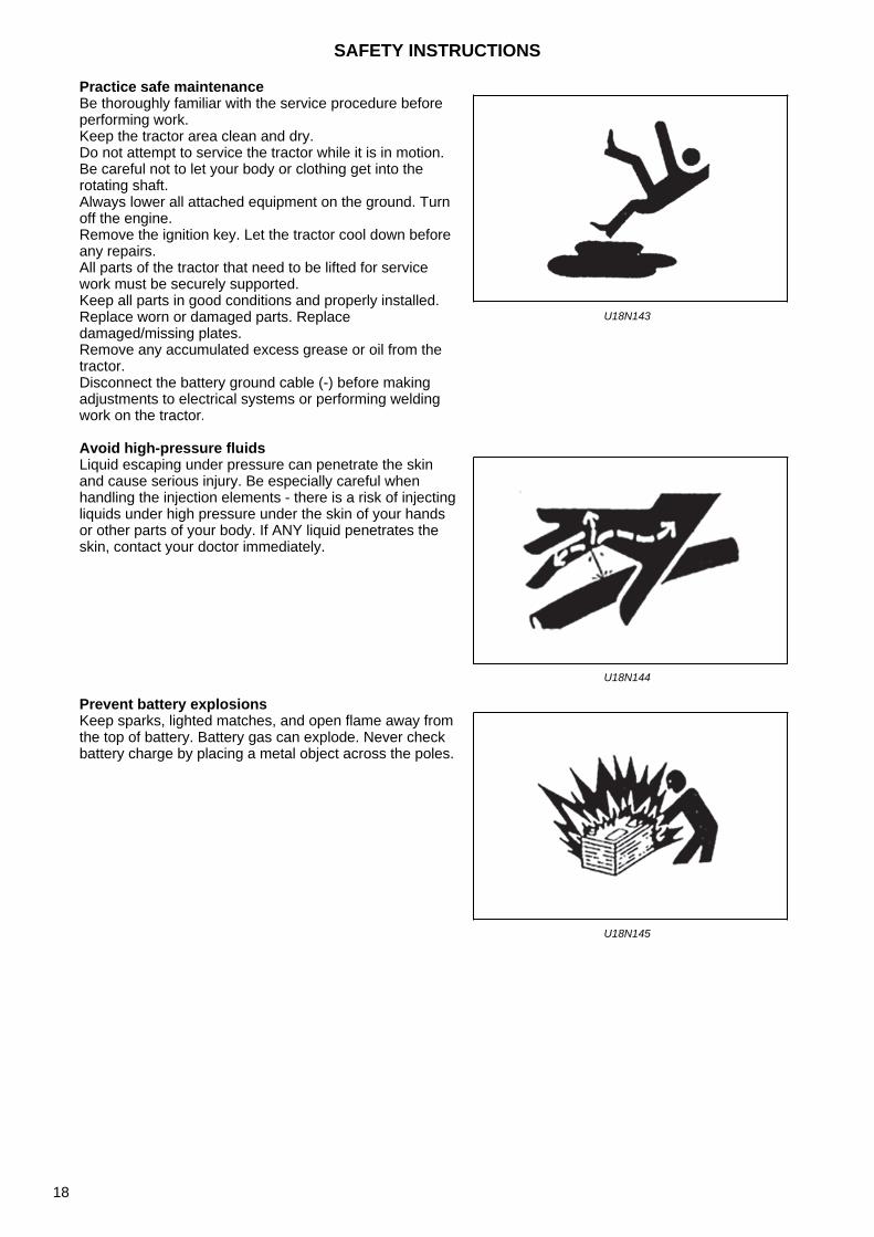
Practice safe maintenance
Avoid high-pressure fluids
Prevent battery explosions
Be thoroughly familiar with the service procedure before performing work. Keep the tractor area clean and dry. Do not attempt to service the tractor while it is in motion. Be careful not to let your body or clothing get into the rotating shaft. Always lower all attached equipment on the ground. Turn off the engine. Remove the ignition key. Let the tractor cool down before any repairs. All parts of the tractor that need to be lifted for service work must be securely supported. Keep all parts in good conditions and properly installed. Replace worn or damaged parts. Replace damaged/missing plates. Remove any accumulated excess grease or oil from the tractor. Disconnect the battery ground cable (-) before making adjustments to electrical systems or performing welding work on the tractor.
U18N143
Liquid escaping under pressure can penetrate the skin and cause serious injury. Be especially careful when handling the injection elements - there is a risk of injecting liquids under high pressure under the skin of your hands or other parts of your body. If ANY liquid penetrates the skin, contact your doctor immediately.
U18N144
Keep sparks, lighted matches, and open flame away from the top of battery. Battery gas can explode. Never check battery charge by placing a metal object across the poles.
U18N145
SAFETY INSTRUCTIONS
18
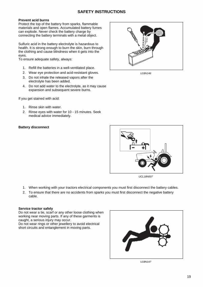
Prevent acid burns
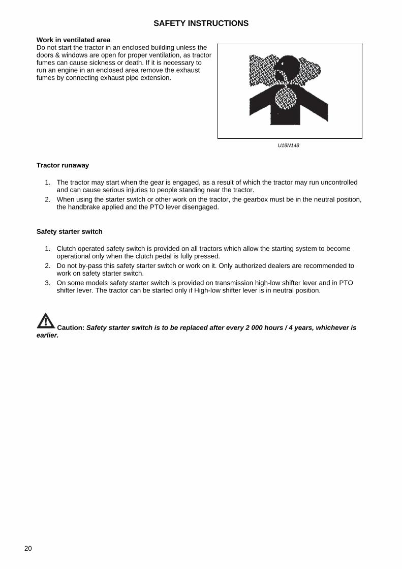
1. When working with your tractors electrical components you must first disconnect the battery cables. 2. To ensure that there are no accidents from sparks you must first disconnect the negative battery
cable.
Service tractor safely
Protect the top of the battery from sparks, flammable materials and open flames. Accumulated battery fumes can explode. Never check the battery charge by connecting the battery terminals with a metal object.
Sulfuric acid in the battery electrolyte is hazardous to health. It is strong enough to burn the skin, burn through the clothing and cause blindness when it gets into the eyes. To ensure adequate safety, always:
1. Refill the batteries in a well-ventilated place. 2. Wear eye protection and acid-resistant gloves. 3. Do not inhale the released vapors after the
electrolyte has been added. 4. Do not add water to the electrolyte, as it may cause
expansion and subsequent severe burns.
If you get stained with acid:
1. Rinse skin with water. 2. Rinse eyes with water for 10 - 15 minutes. Seek
medical advice immediately.
U18N146
Battery disconnect
UCL18N007
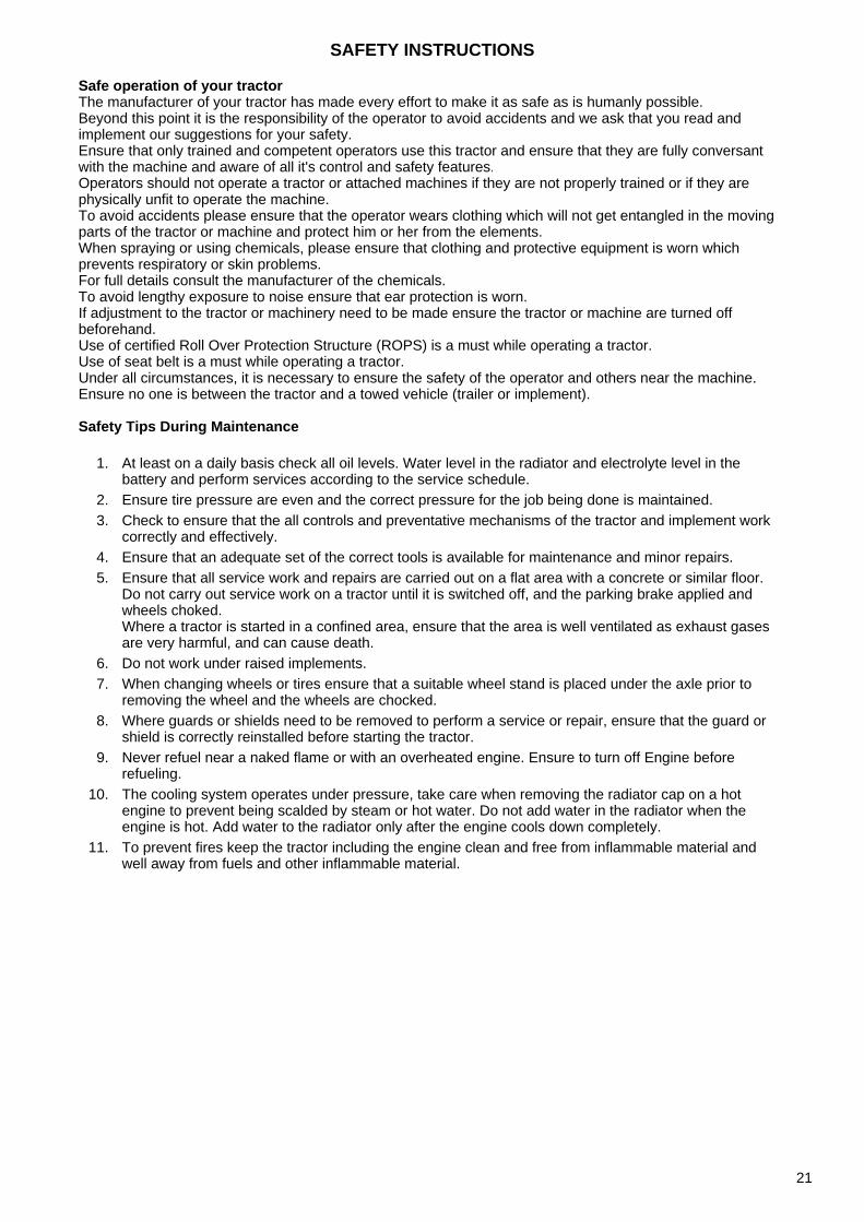
Do not wear a tie, scarf or any other loose clothing when working near moving parts. If any of these garments is caught, a serious injury may occur. Do not wear rings or other jewellery to avoid electrical short circuits and entanglement in moving parts.
U18N147
SAFETY INSTRUCTIONS
19
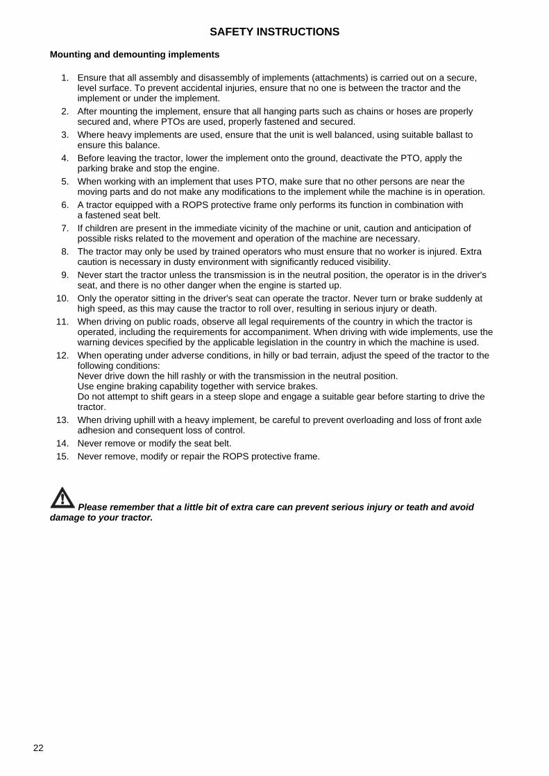
Work in ventilated area
Tractor runaway
1. The tractor may start when the gear is engaged, as a result of which the tractor may run uncontrolled and can cause serious injuries to people standing near the tractor.
2. When using the starter switch or other work on the tractor, the gearbox must be in the neutral position, the handbrake applied and the PTO lever disengaged.
Safety starter switch
1. Clutch operated safety switch is provided on all tractors which allow the starting system to become operational only when the clutch pedal is fully pressed.
2. Do not by-pass this safety starter switch or work on it. Only authorized dealers are recommended to work on safety starter switch.
3. On some models safety starter switch is provided on transmission high-low shifter lever and in PTO shifter lever. The tractor can be started only if High-low shifter lever is in neutral position.
Caution: Safety starter switch is to be replaced after every 2 000 hours / 4 years, whichever is earlier.
Do not start the tractor in an enclosed building unless the doors & windows are open for proper ventilation, as tractorfumes can cause sickness or death. If it is necessary to run an engine in an enclosed area remove the exhaust fumes by connecting exhaust pipe extension.
U18N148
SAFETY INSTRUCTIONS
20
Safe operation of your tractorThe manufacturer of your tractor has made every effort to make it as safe as is humanly possible.Beyond this point it is the responsibility of the operator to avoid accidents and we ask that you read and implement our suggestions for your safety.Ensure that only trained and competent operators use this tractor and ensure that they are fully conversant with the machine and aware of all it's control and safety features.Operators should not operate a tractor or attached machines if they are not properly trained or if they are physically unfit to operate the machine.To avoid accidents please ensure that the operator wears clothing which will not get entangled in the moving parts of the tractor or machine and protect him or her from the elements.When spraying or using chemicals, please ensure that clothing and protective equipment is worn which prevents respiratory or skin problems.For full details consult the manufacturer of the chemicals.To avoid lengthy exposure to noise ensure that ear protection is worn.If adjustment to the tractor or machinery need to be made ensure the tractor or machine are turned off beforehand.Use of certified Roll Over Protection Structure (ROPS) is a must while operating a tractor.Use of seat belt is a must while operating a tractor.Under all circumstances, it is necessary to ensure the safety of the operator and others near the machine.Ensure no one is between the tractor and a towed vehicle (trailer or implement).
Safety Tips During Maintenance
1. At least on a daily basis check all oil levels. Water level in the radiator and electrolyte level in thebattery and perform services according to the service schedule.
2. Ensure tire pressure are even and the correct pressure for the job being done is maintained.3. Check to ensure that the all controls and preventative mechanisms of the tractor and implement work
correctly and effectively.4. Ensure that an adequate set of the correct tools is available for maintenance and minor repairs.5. Ensure that all service work and repairs are carried out on a flat area with a concrete or similar floor.
Do not carry out service work on a tractor until it is switched off, and the parking brake applied andwheels choked.Where a tractor is started in a confined area, ensure that the area is well ventilated as exhaust gasesare very harmful, and can cause death.
6. Do not work under raised implements.7. When changing wheels or tires ensure that a suitable wheel stand is placed under the axle prior to
removing the wheel and the wheels are chocked.8. Where guards or shields need to be removed to perform a service or repair, ensure that the guard or
shield is correctly reinstalled before starting the tractor.9. Never refuel near a naked flame or with an overheated engine. Ensure to turn off Engine before
refueling.10. The cooling system operates under pressure, take care when removing the radiator cap on a hot
engine to prevent being scalded by steam or hot water. Do not add water in the radiator when theengine is hot. Add water to the radiator only after the engine cools down completely.
11. To prevent fires keep the tractor including the engine clean and free from inflammable material andwell away from fuels and other inflammable material.
SAFETY INSTRUCTIONS
21
Mounting and demounting implements
1. Ensure that all assembly and disassembly of implements (attachments) is carried out on a secure, level surface. To prevent accidental injuries, ensure that no one is between the tractor and the implement or under the implement.
2. After mounting the implement, ensure that all hanging parts such as chains or hoses are properly secured and, where PTOs are used, properly fastened and secured.
3. Where heavy implements are used, ensure that the unit is well balanced, using suitable ballast to ensure this balance.
4. Before leaving the tractor, lower the implement onto the ground, deactivate the PTO, apply the parking brake and stop the engine.
5. When working with an implement that uses PTO, make sure that no other persons are near the moving parts and do not make any modifications to the implement while the machine is in operation.
6. A tractor equipped with a ROPS protective frame only performs its function in combination with a fastened seat belt.
7. If children are present in the immediate vicinity of the machine or unit, caution and anticipation of possible risks related to the movement and operation of the machine are necessary.
8. The tractor may only be used by trained operators who must ensure that no worker is injured. Extra caution is necessary in dusty environment with significantly reduced visibility.
9. Never start the tractor unless the transmission is in the neutral position, the operator is in the driver's seat, and there is no other danger when the engine is started up.
10. Only the operator sitting in the driver's seat can operate the tractor. Never turn or brake suddenly at high speed, as this may cause the tractor to roll over, resulting in serious injury or death.
11. When driving on public roads, observe all legal requirements of the country in which the tractor is operated, including the requirements for accompaniment. When driving with wide implements, use the warning devices specified by the applicable legislation in the country in which the machine is used.
12. When operating under adverse conditions, in hilly or bad terrain, adjust the speed of the tractor to the following conditions: Never drive down the hill rashly or with the transmission in the neutral position. Use engine braking capability together with service brakes. Do not attempt to shift gears in a steep slope and engage a suitable gear before starting to drive the tractor.
13. When driving uphill with a heavy implement, be careful to prevent overloading and loss of front axle adhesion and consequent loss of control.
14. Never remove or modify the seat belt. 15. Never remove, modify or repair the ROPS protective frame.
Please remember that a little bit of extra care can prevent serious injury or teath and avoid damage to your tractor.
SAFETY INSTRUCTIONS
22
The following precautions are suggested to help prevent accidentsThe best operator is the careful operator. Most accidents can be prevented by observing certain safety measures. Before using the tractor, read the following measures and observe them to avoid accidents. The tractor may only be operated by authorized persons who are properly trained for this operation.
Tractor
1. Read the operating and maintenance manual of the machine carefully before operating the tractor. Insufficient knowledge of machine operation can lead to accidents.
2. For safe operation, use an approved protective structure and seat belt. Roll-over of a tractor without a protective structure can result in serious injuries or even death.
3. Do not remove the roll-over protective structure (ROPS). Always use the seat belt. 4. The laminated roof of the tractor cab does not provide protection against the breakthrough of external
objects with higher weight. 5. To avoid falling while entering and leaving the cab, keep the stairs and platform clean, free of mud
and oil. 6. Do not allow anyone other than the operator to ride on the tractor. There is no safe seat or approved
passenger seat on the tractor. 7. Replace any missing, illegible or damaged safety signs. 8. Keep safety signs clean, free of dirt and grease.
Tractor service
1. For your safety, keep the tractor in good operating conditions. An inadequately maintained tractor can be dangerous.
2. Stop the engine before servicing the tractor. 3. The cooling system operates under pressure. If the engine and its cooling system are hot, it is
dangerous to remove the cap. Turn the cap slowly to the stop, then let the pressure escape before removing the cap.
4. Do not smoke while refueling the tractor. Never refuel the machine near an open flame. 5. The fuel in the injection system is under high pressure and can penetrate the skin. Unqualified
persons must not disassemble or modify the fuel pump, injectors, nozzles or other parts of the fuel injection system. Failure to follow these instructions may result in serious injuries.
6. To prevent fire or explosion, keep the battery and the cold start devices away from open flames.
7. Do not change or modify anything on the tractor and do not allow anyone to change or modify anything on the tractor or any part of the tractor or its function.
Tractor Operation
1. Before starting the tractor, apply the parking brake, set the PTO switch to the 'OFF' position, move the hydraulic control levers to neutral, the remote control levers to neutral (if fitted), and the transmission to neutral.
2. Do not start the engine or operate the tractor when standing next to the tractor. Always sit in the driver's seat when the engine is running or when operating the controls.
3. Starter safety switch. A safety switch is mounted on the tractor to prevent the tractor from starting accidentally. The tractor's starter system is connected via this switch, which only closes when the brake pedal is depressed. On some models, the reverse lever and the PTO button must also be in the neutral position to close the starter circuit. Do not by-pass the starter safety switch. If the starter safety switch is defective, consult your Zetor tractor dealer/distributor.
4. Avoid accidental contact with the shift lever while the engine is running. Such contact can cause the tractor to move.
5. Do not get off or get on the tractor while it is in motion. 6. Before leaving the tractor, stop the engine, remove the ignition key and apply the parking brake. 7. Do not operate the tractor in an enclosed building without adequate ventilation. Exhaust gases can
cause death. 8. Do not park the tractor on a steep slope. 9. If the power steering or engine stops working, stop the tractor immediately.
SAFETY INSTRUCTIONS
23

10. Tow only using the swinging bar or the lower link bar in the lower position. Use only the draw bar pin, which is secured in the correct position. Towing using the tractor's rear axle carriers or any point above the rear axle can cause the front part of the tractor to lift.
11. If the front part of the tractor tends to lift when heavy working implement is attached to the three-point hitch, install the front ballast weights or front wheel weights. Do not operate a tractor with insufficiently weighted front part.
12. Always use the hydraulic position control lever when attaching the implement and transporting the implement. Make sure that the hydraulic couplers are properly mounted and that they will disconnect safely in case of accidental detachment of implement.
13. Do not leave the implement in the lifted position. 14. Use the beacon, turn signal lights and slow moving vehicle (SMV) signs when driving on public roads
during both day and night time, unless prohibited by law. 15. Dim the tractor lights when meeting approaching vehicles at night. Make sure that the lights are
adjusted to avoid dazzling the eyes of the oncoming vehicle driver.
Tractor control
1. Watch where you drive,especially at the ends of the rows, the headlands, on the roads, around the trees and at obstacles hanging low to ground.
2. To prevent the tractor from rolling over, drive the tractor at a safe speed, especially when driving on uneven ground, when driving over ditches or slopes, and when turning in corners of areas and parcels.
3. When driving on the road, do not disconnect the two brake pedals of the tractor from each other to ensure better braking.
4. When driving downhill, shift the same gear in the tractor as uphill. Do not drive downhill with the engine stopped or idling.
5. For safety reasons, any towed vehicle and/or trailer, the weight of which exceeds the maximum towed weight, must be fitted with its own brakes.
6. If the tractor gets stuck or its tires are frozen to the ground, try to reverse to prevent the tractor from rolling over.
Always make sure you have enough space above you, especially when transporting the tractor.
SAFETY INSTRUCTIONS
24
Operating the PTO
1. When you operate the PTO-powered attachments, stop the engine and wait for the PTO to stop before you leave the tractor and disconnect the equipment.
2. Do not wear loose clothing when operating the PTO or near rotating parts of the connected implement.
3. When operating PTO-driven stationary equipment, always secure the tractor with the tractor parking brake and secure the rear wheels from the front and rear side with wedges.
4. To avoid injury, always cover the PTO outlet. Do not clean, modify or repair the PTO-driven equipment while the tractor engine is running.
Always make sure that the main PTO cover is installed and always install the PTO end piece cover whenever the PTO is not in use.Diesel fuel
1. Keep the equipment clean and properly maintained. 2. Under no circumstances should gasoline, alcohol or blended fuels be added to diesel fire or explosive
hazard. Such blends are more explosive than pure gasoline. In a closed container, such as a fuel tank. DO NOT USE THESE BLENDS.
3. Never remove the fuel cap or refuel the tractor with the engine running. 4. Do not smoke while refueling or when standing near fuel. 5. Maintain control of the fuel filler pipe when filling the tank. 6. Do not fill the fuel tank to capacity. Allow room for expansion. 7. Wipe up spilled fuel immediately. 8. Always tighten the fuel cap securely. 9. If the original fuel tank cap is lost, replace it with genuine cap. A none approved cap may not be safe.
10. Do not drive equipment near open fire. 11. Never use fuel for cleaning purpose. 12. Arrange fuel purchases so that winter grade fuel are not held over and used in the spring.
Note: It is suggested that after repairs if any of the safety decal/sign is peeled/defaced, the same may be replaced immediately in interest of your safety.
Diesel complies with EN 590 standard
IMPORTANT NOTE!By using motor oil with elevated sulphur content, the service life of diesel particle filter can be significantly reduced.
SAFETY INSTRUCTIONS
25

DO'S AND DON'T'S
DO'S-for better performance
YES Ensure that protective covers are returned immediately and they are in good conditions.
YES Read all operating instructions before operating the tractor
YES Perform all maintenance tasks completely and without error.
YES Keep the air filter clean.
YES Ensure that lubricating oils of the appropriate standard and quality are used and that they are refilled and changed at recommended intervals.
YES After replacing the filter elements, install new sealing rings.
YES Observe the warning light on the oil pressure gauge and if it lights up, check immediately for any abnormality.
YES Make sure the radiator is always filled with clean water and use antifreeze in cold weather. Drain the system only in case of emergency and refill before starting the engine.
YES Ensure the transmission is in the neutral position before starting the engine.
YES Store all fuel in clean environment and use a filter when filling the tank.
YES Perform minor adjustments and repairs as soon as necessary.
YES Allow engine to cool before removing radiator filler cap and adding water; remove the radiator cap slowly.
YES Engage a lower gear when going downhill steep slopes.
YES Connect the brake pedals together when driving on the road.
YES If the draft control lever is not in use, keep it in the lower limit position.
SAFETY INSTRUCTIONS
26
Don'ts - for safe operation
DO NOT USE the engine with the air filter disconnected.
DO NOT START the tractor in a closed building without proper ventilation
DO NOT OPERATE the tractor or engine during lubrication or cleaning
DO NOT LET the diesel fuel tank run out completely, otherwise the system will need to be bled.
DO NOT INTERFERE with the engine injection pump. The warranty is void if the seal is broken
DO NOT LET the engine idle for a long time.
DO NOT RUN the engine if all cylinders do not work.
DO NOT DRIVE with the clutch or brake pedal depressed. This leads to excessive wear of the brake lining, clutch-driven elements and clutch release bearing.
DO NOT USE independent brakes to turn while driving on the road or at high speed.
DO NOT REFILL the fuel in the tractor with the running engine.
DO NOT SET the hydraulic control levers beyond the upper stop limit.
DO NOT USE the draft control lever to lift implements.
DO NOT START the engine with the PTO engaged.
DO NOT USE the hand throttle control lever while driving on the road.
DO NOT MOVE the hydraulic levers backwards.
SAFETY INSTRUCTIONS
27

NOTES
28
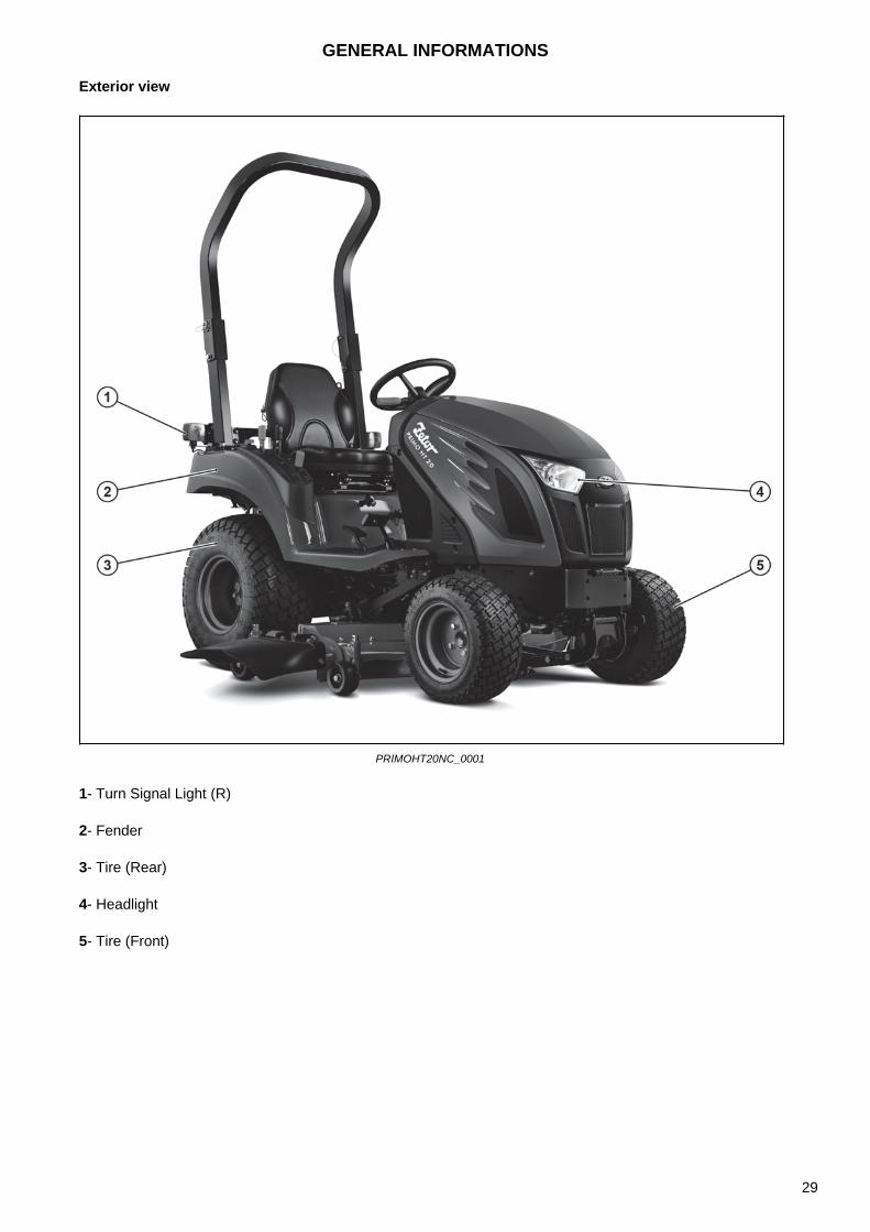
Exterior view
PRIMOHT20NC_0001
1- Turn Signal Light (R)
2- Fender
3- Tire (Rear)
4- Headlight
5- Tire (Front)
GENERAL INFORMATIONS
29

PRIMOHT20NC_0002
1-Steering Wheel
2- Hood
3- Headlight
4- Muffler
5- Turn Signal Light (L)
GENERAL INFORMATIONS
30

PRIMOHT20NC_0003
1- Brake Light
2 - Turn Signal Light
GENERAL INFORMATIONS
31
Warning Symbols
Safety labels are placed on the tractor to work safely with the machine. Do not forget to read them and follow the instructions.
Keep safety labels clean and undamaged at all times.
If the safety label on the machine is dirty, wash it with soapy water and wipe with a soft cloth. Neveruse a solution such as thinner or acetone, as these may erase inscriptions or images.
When washing with a high-pressure water stream, detachment may occur.
Do not use a direct stream of high-pressure water to clean the labels.
If the safety label is damaged or lost, order a new one immediately and place it on the machine.
When attaching the new label, clean the place with water, so that the label can be properly attached,and wait for the surface to dry. Then attach the label.Each label has an order number at the bottom.
When replacing the part on which the label is located, place a new label on the new part.
GENERAL INFORMATIONS
32
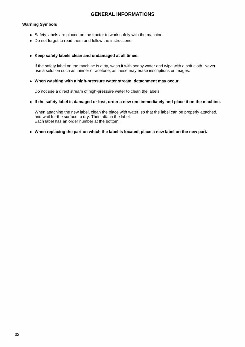
PRIMOHT20NC_0004
1- U.S. Environmental Protection Agency EPA Regulation - Use low sulfur fuel2 - WARNING - Do not refuel the tractor if you are smoking or if there is an open fire or spark nearby. Alwaysstop the engine before refuelling.3 - WARNING - Start the engine only when you are sitting in the driver's seat. If the safety start switch isbypassed, the engine can be started with the gear engaged.Do not connect or short-circuit the leads on the starter coil.Connect the auxiliary power cables as indicated on the battery plate and in the operating and maintenancemanual.Starting with the gear engaged will cause the tractor to start driving and can result in serious injury.4- WARNING - Always apply the parking brake when parking. Failure to follow this instruction may result inaccidents and injuries.5- WARNING - Extensions, alterations, cracks, damage or corrosion to this structure may adversely affectthe functionality of the ROPS.6- The tractor may unexpectedly overturn much faster than the driver is able to jump out of it.
1. Never operate a tractor without a ROPS protective frame.2. Always use the seat belt at the same time as the protective frame.3. Do not pull the top of the protective frame towards the rear, the tractor may overturn.4. Do not operate the tractor on steep slopes or in off-road gradients.5. Do not turn sharply when driving at high speed.
7- Always hold the steering wheel while driving.8- WARNING - There is a risk of injury or death if the tractor is used with a protective structure folded down.Only use a tractor with a folded protection frame when absolutely necessary.Do not use the seat belt when operating the tractor with the protection frame folded down.
GENERAL INFORMATIONS
33
PRIMOHT20NC_0005
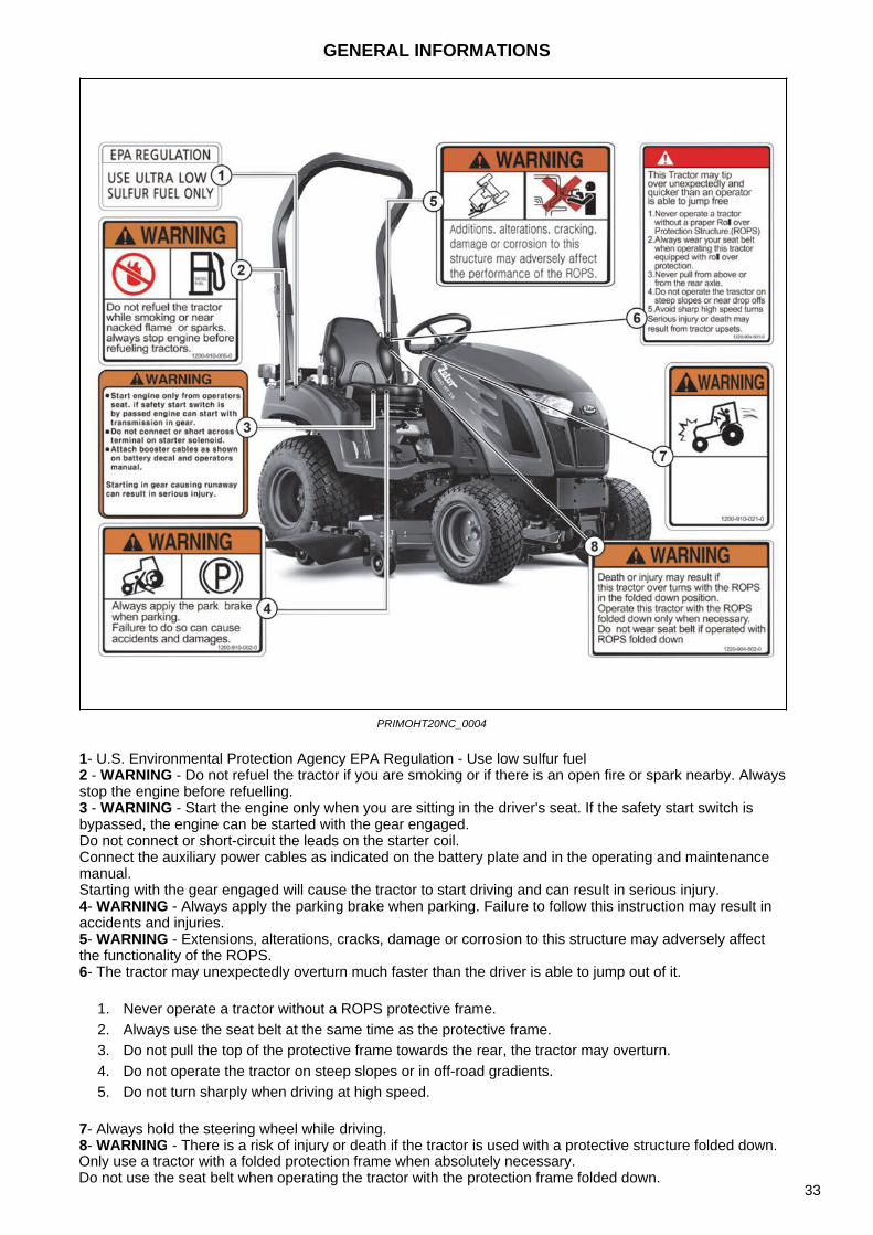
1 - Work in ventilated area2 - Operation and maintenance manual3 - WARNING - Do not open the radiator cap while the engine is hot. There is a risk of injury by hot steam.4 - WARNING - Keep your hands and clothes away from the rotating fan and drive belts to prevent serious injury.5 - WARNING - To prevent burns, do not touch while the system is hot.6 - Depress the main brake pedal and at the same time secure the parking brake lever.7 - WARNING - Always turn the controller to the right locked SLOW (LOCK) position.
1. When you drive on the road.2. When you change the blades of the mower.3. When you adjust the mower.
Sudden lowering of the mower can cause serious injuries or death.
8 - Differential lock9 - WARNING - Never turn on the differential lock when driving fast or driving on the road. This may cause the tractor to roll over and cause injuries.10 - DANGER - Only the driver may ride on the tractor.11 - WARNING - Always fasten your seat belts.
GENERAL INFORMATIONS
34
PRIMOHT20NC_0006
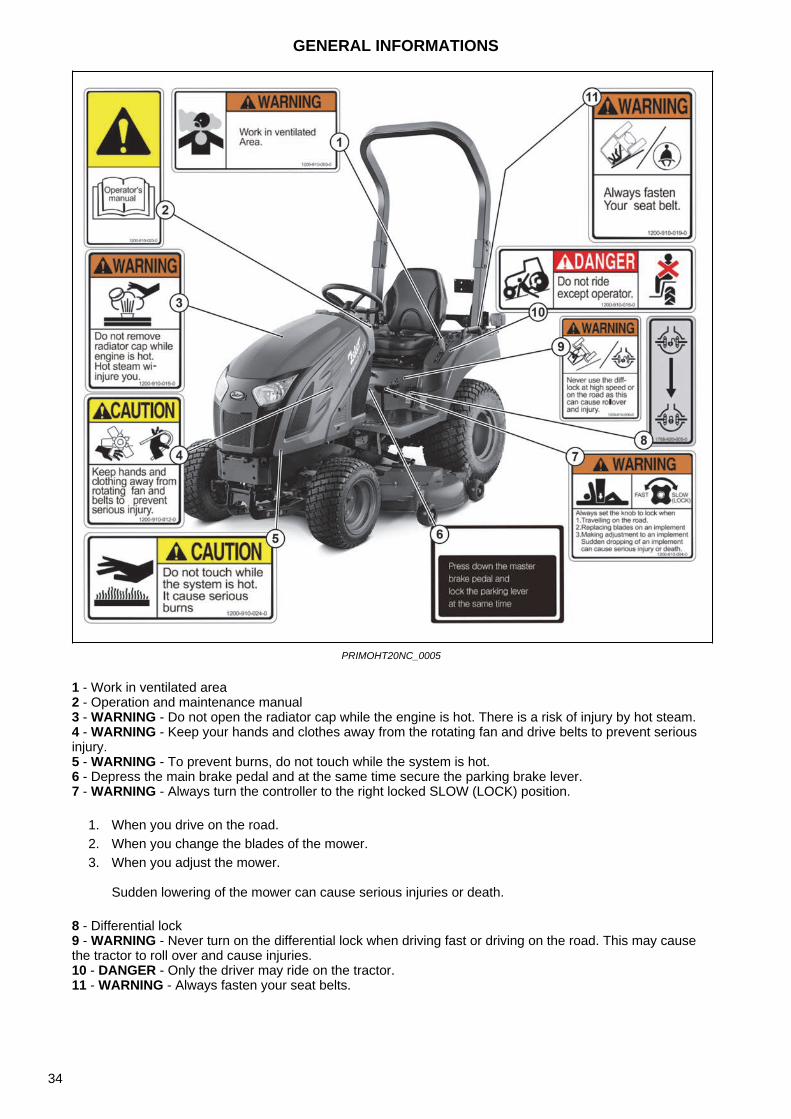
1 - Beware of the rotary output drive, contact with it can cause fatal injuries. Use protective shields provided for additional equipment.
2 - WARNING - Connect the additional tools or trailers to the tractor only with the prescribed draw bars or hitches.
3 - WARNING - Prolonged exposure to noise can cause hearing damage and loss. Use ear protection (headphones, earplugs).
GENERAL INFORMATIONS
35

NOTES
36
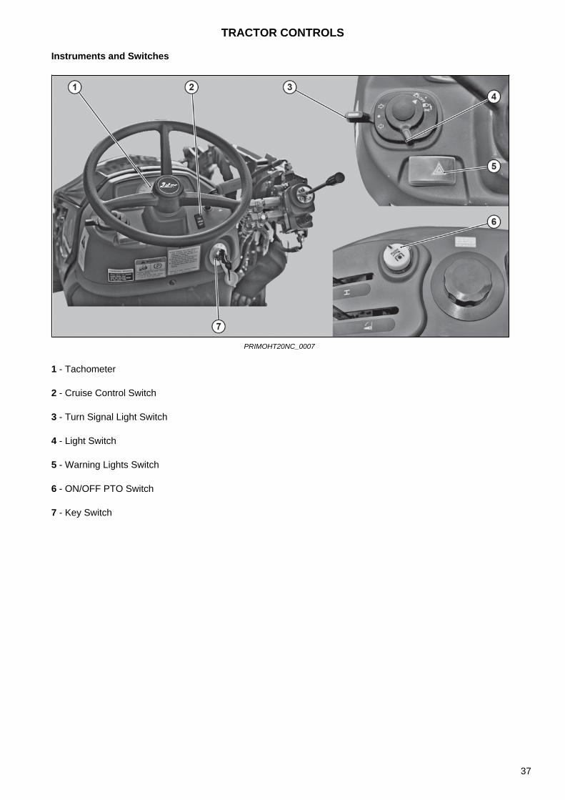
Instruments and Switches
PRIMOHT20NC_0007
1 - Tachometer
2 - Cruise Control Switch
3 - Turn Signal Light Switch
4 - Light Switch
5 - Warning Lights Switch
6 - ON/OFF PTO Switch
7 - Key Switch
TRACTOR CONTROLS
37
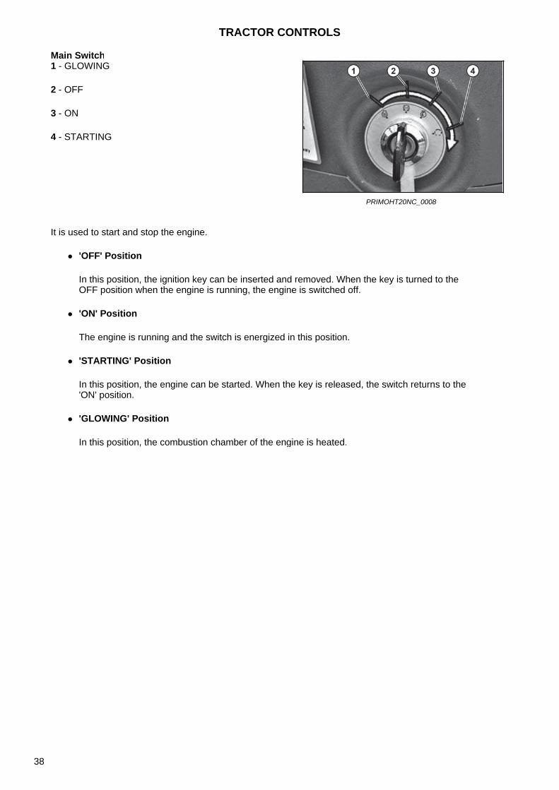
Main Switch
It is used to start and stop the engine.
'OFF' Position
In this position, the ignition key can be inserted and removed. When the key is turned to theOFF position when the engine is running, the engine is switched off.
'ON' Position
The engine is running and the switch is energized in this position.
'STARTING' Position
In this position, the engine can be started. When the key is released, the switch returns to the'ON' position.
'GLOWING' Position
In this position, the combustion chamber of the engine is heated.
1 - GLOWING
2 - OFF
3 - ON
4 - STARTING
PRIMOHT20NC_0008
TRACTOR CONTROLS
38
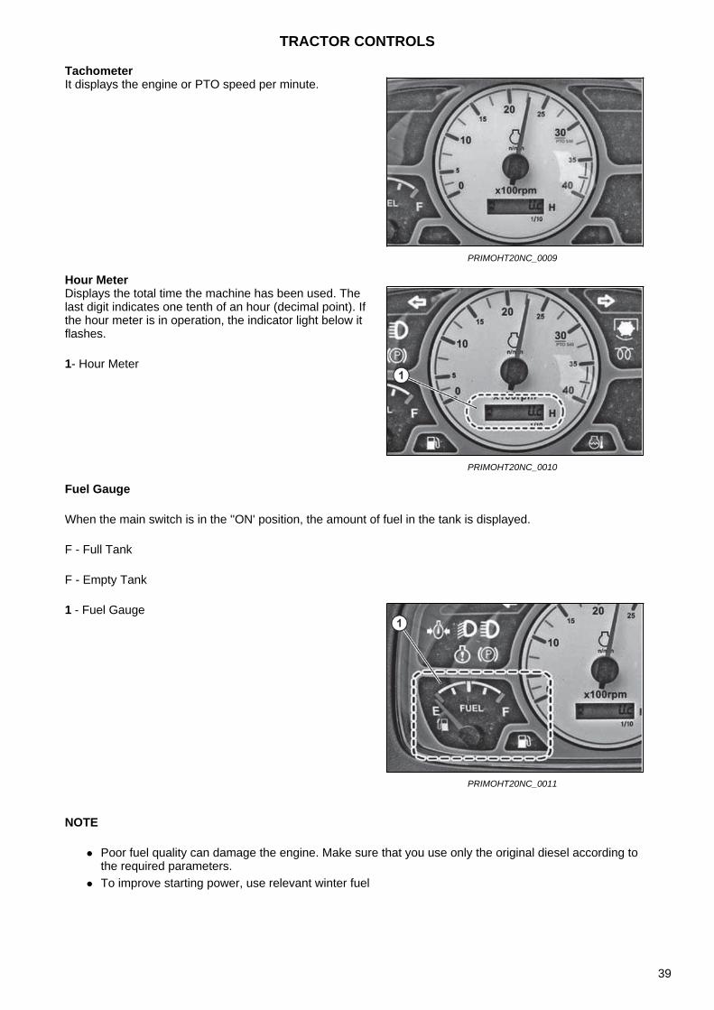
Tachometer
Hour Meter
Fuel Gauge
When the main switch is in the ''ON' position, the amount of fuel in the tank is displayed.
F - Full Tank
F - Empty Tank
NOTE
Poor fuel quality can damage the engine. Make sure that you use only the original diesel according tothe required parameters.
To improve starting power, use relevant winter fuel
It displays the engine or PTO speed per minute.
PRIMOHT20NC_0009
Displays the total time the machine has been used. The last digit indicates one tenth of an hour (decimal point). If the hour meter is in operation, the indicator light below it flashes.
1- Hour Meter
PRIMOHT20NC_0010
1 - Fuel Gauge
PRIMOHT20NC_0011
TRACTOR CONTROLS
39

Coolant Temperature Indicator Light
When the main switch is
in the ''ON'' position, the coolant temperature is displayed. If the indicator is in the ''H'' red area while driving, the coolant is overheated. In this case, stop and take all necessary steps referred to in the troubleshooting instructions.See ''Troubleshooting''.
NOTE
If the engine speed is increased quickly, the engine may be damaged.
1 - Coolant Temperature Indicator Light
PRIMOHT20NC_0012
TRACTOR CONTROLS
40

Combined Switch
(1) Light Switch Control
The light switch can be operated when the main switch is in the ''ON' position.
Warning: The high beam lights can dazzle the driver in the opposite direction, which can lead to an unexpected traffic accident.
(2) Turn Signal Light Control
The turn signal lights can be operated when the main switch is in the ''ON' position.
Turning leftTurn the turn signal light switch counterclockwise. Then the left turn signal light and the left turn signalindicator light on the instrument panel flash.
Turning rightTurn the turn signal light switch clockwise. Then the right turn signal light and the right turn signalindicator light on the instrument panel flash.
NOTE
This lever does not automatically return to the neutral position. Therefore, it must be returned to theneutral position after turning.
Warning Lights Switch1 - Warning Lights Switch
1- Turn Signal Light Switch
2- Turn Signal Light (R)
3- Turn Signal Light (L)
4- Light Switch
PRIMOHT20NC_0013
[OFF] - All lights OFF- Instrument lights, tail lights and low beam lights are ON.
- Instrument lights, tail lights and high beam lights are ON.
This switch can be used to warn other vehicles in the event of a tractor breakdown when driving on public roads.When the switch is pressed, the left and right warning lights start flashing. Press the switch again to turn off the lights.
PRIMOHT20NC_0014
TRACTOR CONTROLS
41

Indicator Lights
PRIMOHT20NC_0015
1- Engine Oil Pressure Warning Light
2- Low Beam Light
3- Left Turn Signal Indicator Light
4- Right Turn Signal Indicator Light
5- PTO Indicator Light
6- Cruise Control Indicator Light
7- Charge Warning Light
8- Preheating Indicator Light
9- Water Temperature Warning Light
10- Fuel Level Warning Light
11- Parking Indicator Light
12- Engine Warning Light
TRACTOR CONTROLS
42
NOTE
If the charge light comes on while driving, the battery is not properly charged. Therefore, turn off allunnecessary electrical equipment and have the vehicle checked immediately at your service center.
Turn Signal Lights Indicator
This light is used to indicate the intended direction of the turn. When the turn signal light switch is pulled down, the turn signal light for turning left begins to flash. When the turn signal light switch is pulled upwards, the turn signal light for turning right begins to flash. These lights also work when the warning lights are switched on.
Low Beam Light Indicator
It comes on when the low beam lights are switched on.
Fuel Level Warning Light
If the fuel gauge needle points to ''E'' while driving, the warning light will come on, indicating that there are approximately 5 liters of fuel left in the tank.
PTO Indicator Light
It comes on when the PTO is rotating.
Handbrake Indicator Light
It comes on when the parking brake is applied.
Preheating Indicator Light
It comes on when the engine preheating function is activated. It goes out when the preheating is completed.
Charge Warning Light
It comes on when the main switch is switched to the ''ON' position and goes out as soon as the engine is started.
TRACTOR CONTROLS
43

NOTE
When the oil pressure warning light comes on, it indicates a malfunction in the lubrication system.Immediately check the engine oil and, if necessary, have the vehicle repaired by the service center.
NOTE
If the coolant warning light comes on, it is overheated, check it.
Notice: If the engine warning light is on, make sure that the operator drives the tractor only if normal engine speed is reached. Failure to follow this instruction may result in reduced performance and an accident caused by a system error.
(8) Engine oil pressure warning light It comes on if the engine oil pressure is insufficientwhile driving.
Water Temperature Warning Light
If this light comes on, the coolant is overheated.
Engine Warning Light. If it comes on, there is an engine failure.
(11) Cruise Control Indicator Light
This light is on when cruise control is on.
TRACTOR CONTROLS
44

PTO ON / OFF Switch
The PTO ON/OFF switch is located on the right side of the instrument panel and can be easily identified using the integrated yellow indicator light.
When the switch is switched on by pressing, the PTO indicator light comes on to indicate that the switch and PTO are in the ON position.
If the switch is pressed again, the indicator light goes out to indicate that the PTO is OFF.
PTO Operation Indicator Light
ON - The power take-off is rotating. OFF - The power take-off is stopped.
Cruise Control SwitchWhen the switch is pressed to the ON position, the cruise control is switched on and the switch light and the indicator light on the instrument panel are on. When the switch is pressed to the OFF position or the brake pedal is depressed, the cruise control and the lights are switched OFF.
1 - PTO ON / OFF Switch
PRIMOHT20NC_0027
1 - PTO Operation Indicator Light
PRIMOHT20NC_0028
1 - Cruise Control Switch
PRIMOHT20NC_0029
TRACTOR CONTROLS
45
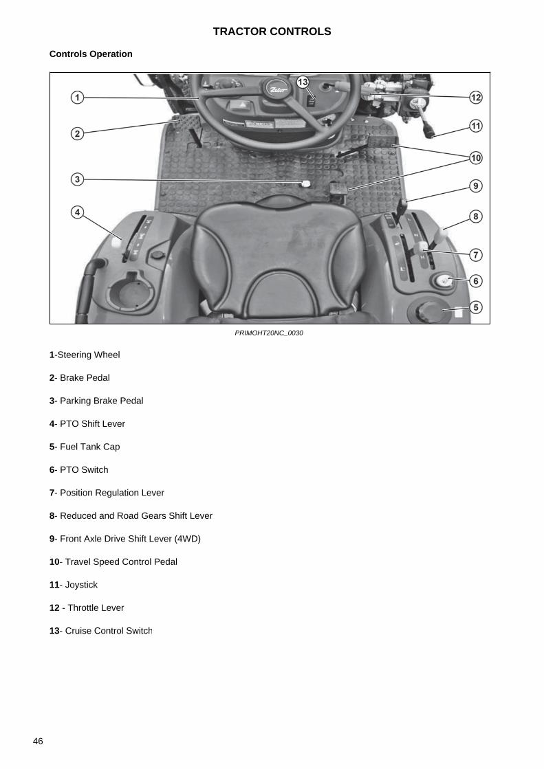
Controls Operation
PRIMOHT20NC_0030
1-Steering Wheel
2- Brake Pedal
3- Parking Brake Pedal
4- PTO Shift Lever
5- Fuel Tank Cap
6- PTO Switch
7- Position Regulation Lever
8- Reduced and Road Gears Shift Lever
9- Front Axle Drive Shift Lever (4WD)
10- Travel Speed Control Pedal
11- Joystick
12 - Throttle Lever
13- Cruise Control Switch
TRACTOR CONTROLS
46
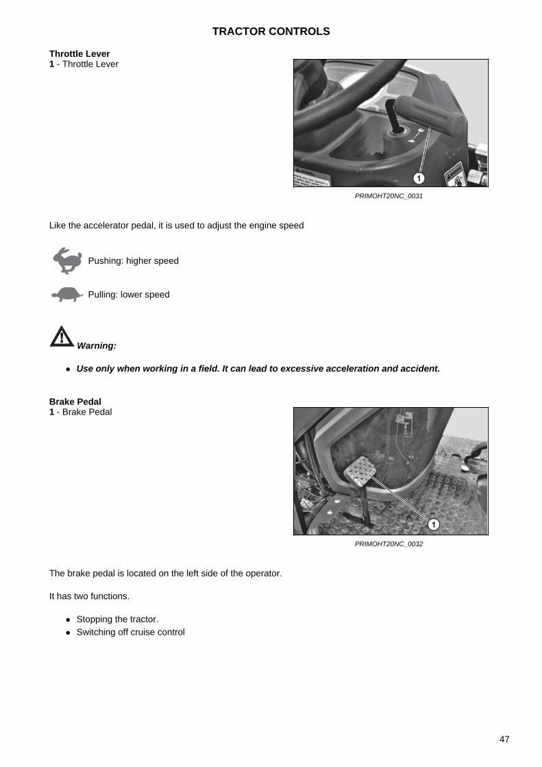
Throttle Lever
Like the accelerator pedal, it is used to adjust the engine speed
Warning:
Use only when working in a field. It can lead to excessive acceleration and accident.
Brake Pedal
The brake pedal is located on the left side of the operator.
It has two functions.
Stopping the tractor. Switching off cruise control
1 - Throttle Lever
PRIMOHT20NC_0031
Pushing: higher speed
Pulling: lower speed
1 - Brake Pedal
PRIMOHT20NC_0032
TRACTOR CONTROLS
47
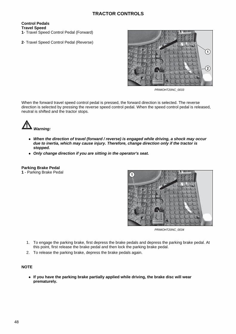
Control PedalsTravel Speed
When the forward travel speed control pedal is pressed, the forward direction is selected. The reverse direction is selected by pressing the reverse speed control pedal. When the speed control pedal is released, neutral is shifted and the tractor stops.
Warning:
When the direction of travel (forward / reverse) is engaged while driving, a shock may occurdue to inertia, which may cause injury. Therefore, change direction only if the tractor isstopped.
Only change direction if you are sitting in the operator's seat.
Parking Brake Pedal
1. To engage the parking brake, first depress the brake pedals and depress the parking brake pedal. Atthis point, first release the brake pedal and then lock the parking brake pedal.
2. To release the parking brake, depress the brake pedals again.
NOTE
If you have the parking brake partially applied while driving, the brake disc will wearprematurely.
1- Travel Speed Control Pedal (Forward)
2- Travel Speed Control Pedal (Reverse)
PRIMOHT20NC_0033
1 - Parking Brake Pedal
PRIMOHT20NC_0034
TRACTOR CONTROLS
48
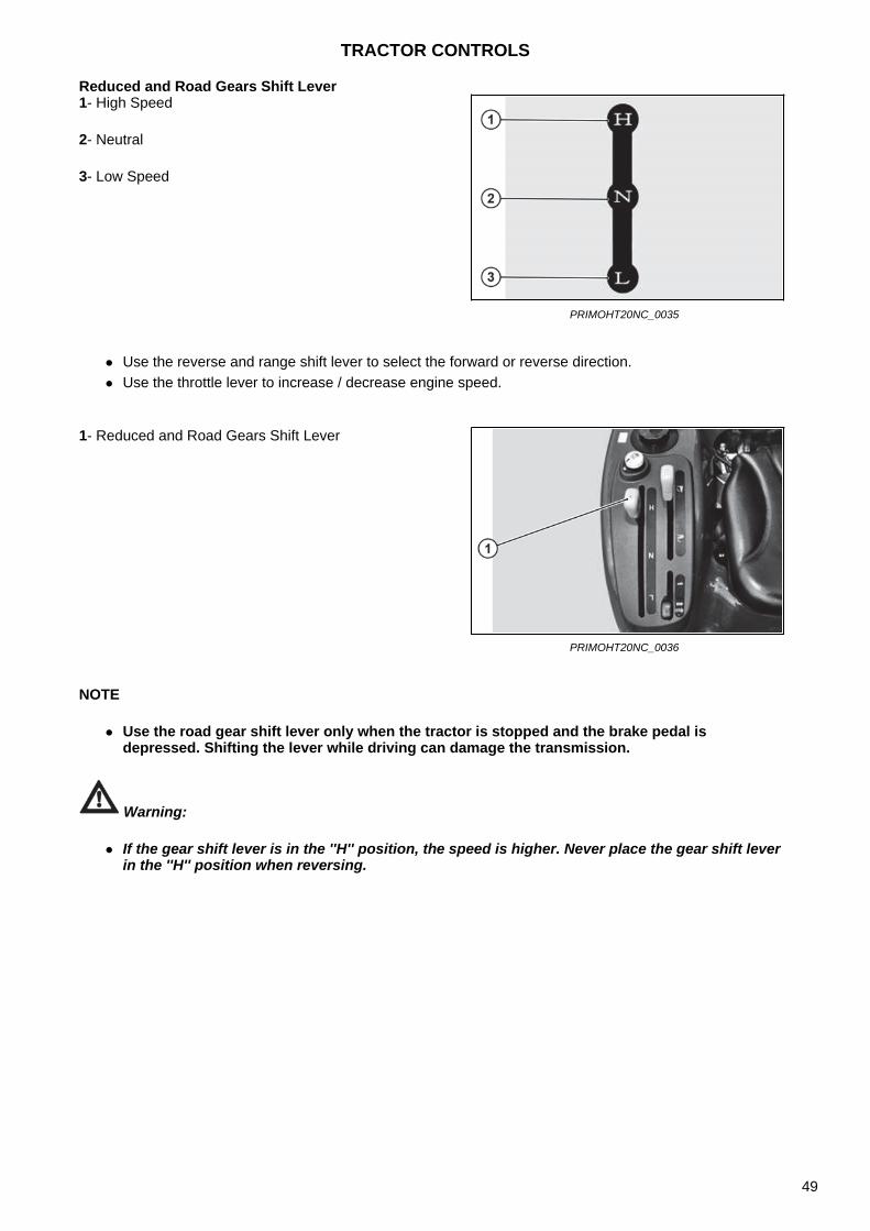
Reduced and Road Gears Shift Lever
Use the reverse and range shift lever to select the forward or reverse direction. Use the throttle lever to increase / decrease engine speed.
NOTE
Use the road gear shift lever only when the tractor is stopped and the brake pedal isdepressed. Shifting the lever while driving can damage the transmission.
Warning:
If the gear shift lever is in the ''H'' position, the speed is higher. Never place the gear shift leverin the ''H'' position when reversing.
1- High Speed
2- Neutral
3- Low Speed
PRIMOHT20NC_0035
1- Reduced and Road Gears Shift Lever
PRIMOHT20NC_0036
TRACTOR CONTROLS
49
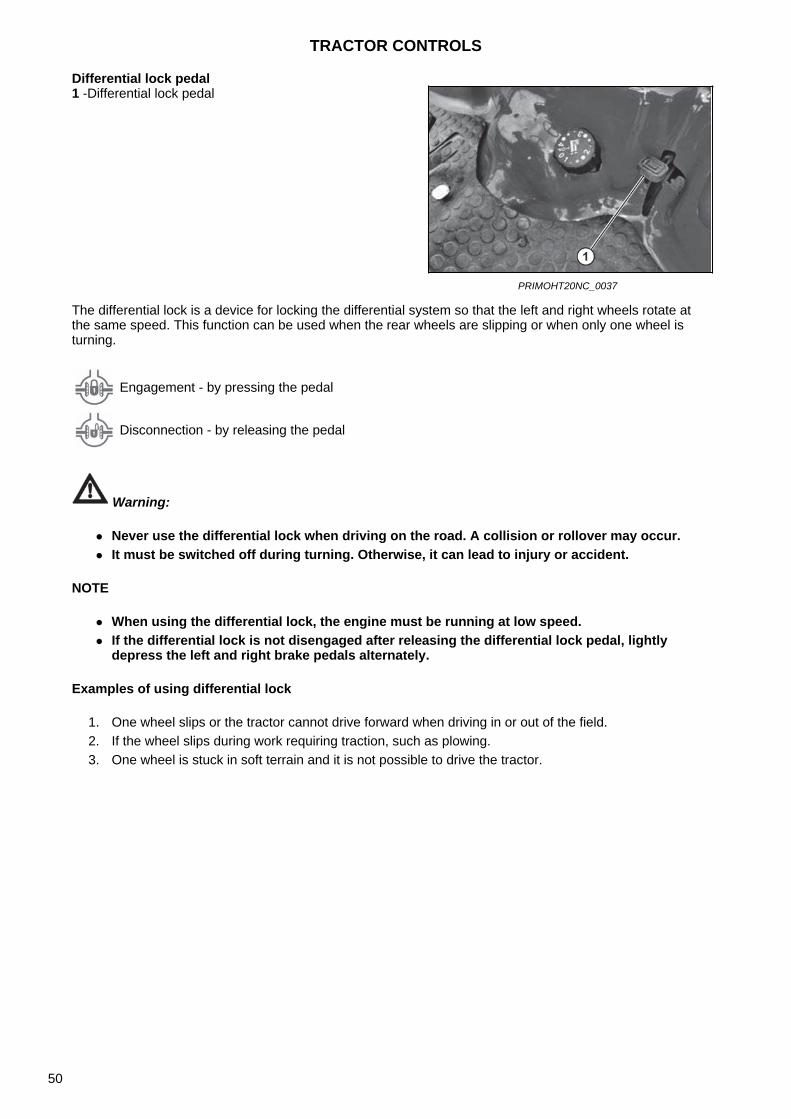
Differential lock pedal
The differential lock is a device for locking the differential system so that the left and right wheels rotate at the same speed. This function can be used when the rear wheels are slipping or when only one wheel is turning.
Warning:
Never use the differential lock when driving on the road. A collision or rollover may occur. It must be switched off during turning. Otherwise, it can lead to injury or accident.
NOTE
When using the differential lock, the engine must be running at low speed. If the differential lock is not disengaged after releasing the differential lock pedal, lightly
depress the left and right brake pedals alternately.
Examples of using differential lock
1. One wheel slips or the tractor cannot drive forward when driving in or out of the field.2. If the wheel slips during work requiring traction, such as plowing.3. One wheel is stuck in soft terrain and it is not possible to drive the tractor.
1 -Differential lock pedal
PRIMOHT20NC_0037
Engagement - by pressing the pedal
Disconnection - by releasing the pedal
TRACTOR CONTROLS
50
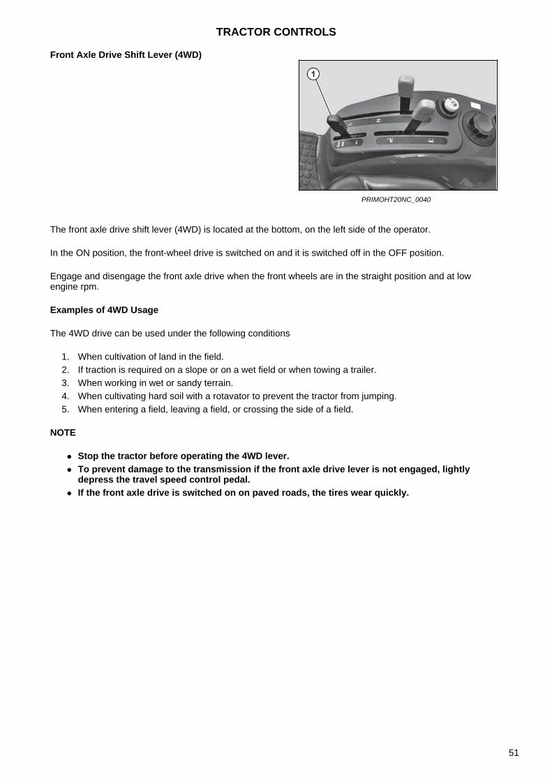
Front Axle Drive Shift Lever (4WD)
The front axle drive shift lever (4WD) is located at the bottom, on the left side of the operator.
In the ON position, the front-wheel drive is switched on and it is switched off in the OFF position.
Engage and disengage the front axle drive when the front wheels are in the straight position and at low engine rpm.
Examples of 4WD Usage
The 4WD drive can be used under the following conditions
1. When cultivation of land in the field.2. If traction is required on a slope or on a wet field or when towing a trailer.3. When working in wet or sandy terrain.4. When cultivating hard soil with a rotavator to prevent the tractor from jumping.5. When entering a field, leaving a field, or crossing the side of a field.
NOTE
Stop the tractor before operating the 4WD lever. To prevent damage to the transmission if the front axle drive lever is not engaged, lightly
depress the travel speed control pedal. If the front axle drive is switched on on paved roads, the tires wear quickly.
PRIMOHT20NC_0040
TRACTOR CONTROLS
51
Seat and Seat Belt
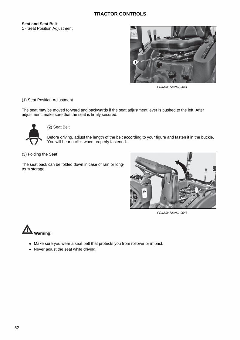
(1) Seat Position Adjustment
The seat may be moved forward and backwards if the seat adjustment lever is pushed to the left. After adjustment, make sure that the seat is firmly secured.
Warning:
Make sure you wear a seat belt that protects you from rollover or impact. Never adjust the seat while driving.
1 - Seat Position Adjustment
PRIMOHT20NC_0041
(2) Seat Belt
Before driving, adjust the length of the belt according to your figure and fasten it in the buckle. You will hear a click when properly fastened.
(3) Folding the Seat
The seat back can be folded down in case of rain or long-term storage.
PRIMOHT20NC_0043
TRACTOR CONTROLS
52
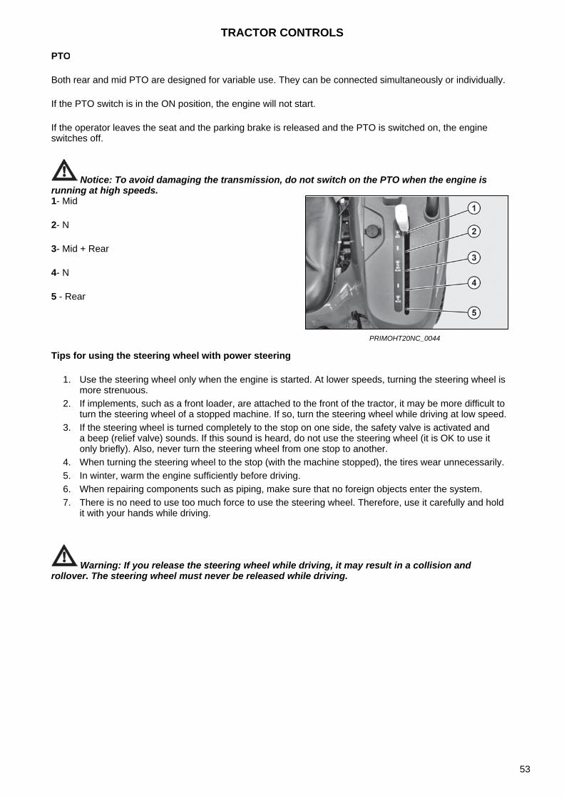
PTO
Both rear and mid PTO are designed for variable use. They can be connected simultaneously or individually.
If the PTO switch is in the ON position, the engine will not start.
If the operator leaves the seat and the parking brake is released and the PTO is switched on, the engine switches off.
Notice: To avoid damaging the transmission, do not switch on the PTO when the engine is running at high speeds.
Tips for using the steering wheel with power steering
1. Use the steering wheel only when the engine is started. At lower speeds, turning the steering wheel ismore strenuous.
2. If implements, such as a front loader, are attached to the front of the tractor, it may be more difficult toturn the steering wheel of a stopped machine. If so, turn the steering wheel while driving at low speed.
3. If the steering wheel is turned completely to the stop on one side, the safety valve is activated anda beep (relief valve) sounds. If this sound is heard, do not use the steering wheel (it is OK to use itonly briefly). Also, never turn the steering wheel from one stop to another.
4. When turning the steering wheel to the stop (with the machine stopped), the tires wear unnecessarily.5. In winter, warm the engine sufficiently before driving.6. When repairing components such as piping, make sure that no foreign objects enter the system.7. There is no need to use too much force to use the steering wheel. Therefore, use it carefully and hold
it with your hands while driving.
Warning: If you release the steering wheel while driving, it may result in a collision and rollover. The steering wheel must never be released while driving.
1- Mid
2- N
3- Mid + Rear
4- N
5 - Rear
PRIMOHT20NC_0044
TRACTOR CONTROLS
53
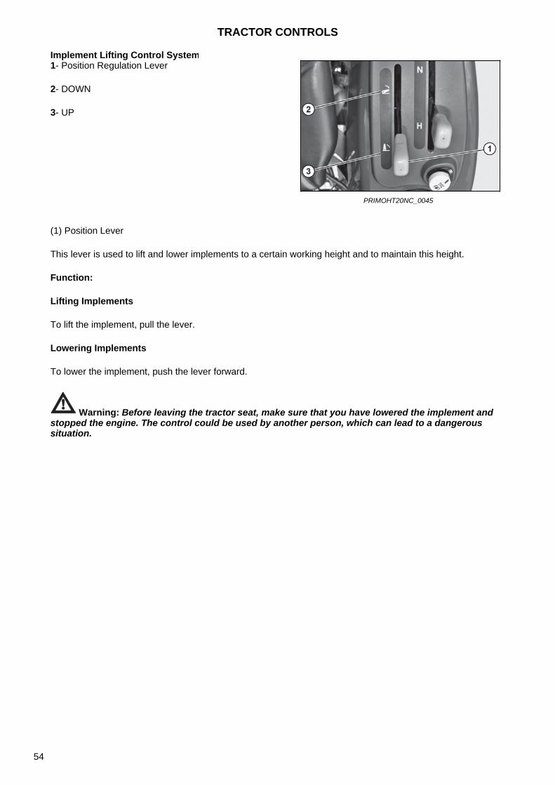
Implement Lifting Control System
(1) Position Lever
This lever is used to lift and lower implements to a certain working height and to maintain this height.
Function:
Lifting Implements
To lift the implement, pull the lever.
Lowering Implements
To lower the implement, push the lever forward.
Warning: Before leaving the tractor seat, make sure that you have lowered the implement and stopped the engine. The control could be used by another person, which can lead to a dangerous situation.
1- Position Regulation Lever
2- DOWN
3- UP
PRIMOHT20NC_0045
TRACTOR CONTROLS
54
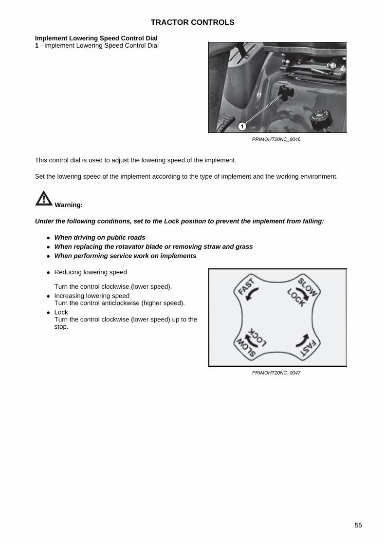
Implement Lowering Speed Control Dial
This control dial is used to adjust the lowering speed of the implement.
Set the lowering speed of the implement according to the type of implement and the working environment.
Warning:
Under the following conditions, set to the Lock position to prevent the implement from falling:
When driving on public roads When replacing the rotavator blade or removing straw and grass When performing service work on implements
1 - Implement Lowering Speed Control Dial
PRIMOHT20NC_0046
Reducing lowering speed
Turn the control clockwise (lower speed). Increasing lowering speed
Turn the control anticlockwise (higher speed). Lock
Turn the control clockwise (lower speed) up to thestop.
PRIMOHT20NC_0047
TRACTOR CONTROLS
55
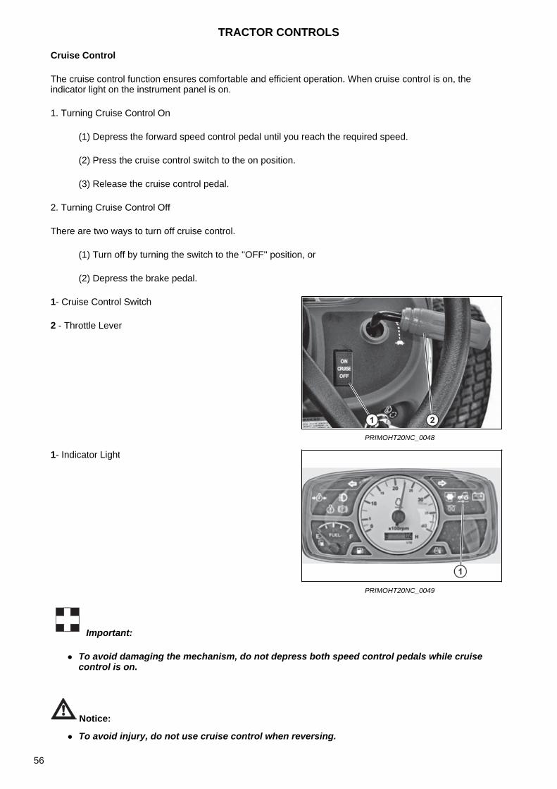
Cruise Control
The cruise control function ensures comfortable and efficient operation. When cruise control is on, the indicator light on the instrument panel is on.
1. Turning Cruise Control On
(1) Depress the forward speed control pedal until you reach the required speed.
(2) Press the cruise control switch to the on position.
(3) Release the cruise control pedal.
2. Turning Cruise Control Off
There are two ways to turn off cruise control.
(1) Turn off by turning the switch to the ''OFF'' position, or
(2) Depress the brake pedal.
Important:
To avoid damaging the mechanism, do not depress both speed control pedals while cruisecontrol is on.
Notice:
1- Cruise Control Switch
2 - Throttle Lever
PRIMOHT20NC_0048
1- Indicator Light
PRIMOHT20NC_0049
To avoid injury, do not use cruise control when reversing.
TRACTOR CONTROLS
56
Preface
This manual is an integral part of the machine.
Before operating the machine, all users must read this manual and they must have access to this manual at all times.
The purpose of this manual is to provide information on the safe and proper use of the machine, and the owner or any person operating the machine must read it before using the machine.
Through this manual and the information provided by our dealers, we want to ensure the safe operation of this machine.
As the operation itself is beyond the control of Mahindra company, its distributors or its dealers, no liability is accepted for any injury or damage caused by improper operation of this machine.
Help with Manual Use
If you need help with the use of this manual or you need to solve problems that are not included in this manual, contact your dealer.
If you need additional copies of this manual, you can purchase them from your dealer.
If you need a copy in a foreign language, contact your dealer to find out the availability of the manual in the required language.
Use of the Machine
This machine is designed exclusively for use for normal lawn mowing activities. Any other use is considered to be contrary to the intended use.
The manufacturer accepts no liability for damage or injury caused by such unauthorized use; the risks connected with such use are borne solely by the user.
Strict compliance with the operating, service and repair conditions specified by the manufacturer is also a basic condition for use in accordance with the intended purpose.
The machine must be operated, repaired and serviced only by persons who are familiar with all its specific characteristics and with the relevant safety rules (injury prevention). Accident prevention regulations, all other generally accepted occupational safety and health regulations and road traffic regulations must always be observed.
Adjusting the fuel supply beyond the published production specifications or other excessive power increase shall result in the loss of the warranty for this machine.
Any arbitrary modifications made to this machine relieve the manufacturer of the responsibility for any consequential damage or injury.
MOWER DECK
57
Tractor
1. Before using this machine, it is necessary to read, understand and follow all instructions set out in themanual and on the machine. Failure to do so may result in serious injury or death and damage to themachine. Keep this manual in a safe place for future and regular references and service parts orders.
2. It is necessary to read and understand all safety measures in the tractor operating manual.3. The machine can only be operated by responsible operators familiar with the instructions. They must
know the controls and know how to quickly stop the tractor engine and the machine in an emergencysituation.
4. The tractor must be equipped with a roll-over protection structure (ROPS) and when working with themachine, the operator must wear a fastened seat belt and the ROPS folding system must be securedin the position up. Falling off the tractor or its rollover can result in death due to running over orcrushing.
5. When working with a tractor equipped with a protective structure (ROPS), the operator must alwaysbe secured with a seat belt.
6. Use personal protective equipment (PPE), such as eye, ear, respiratory, head, hair, hand, and foot(and other) protection, when operating, maintaining, or repairing the equipment. Avoid wearing looseclothing or jewelry that could get caught and tangled in moving parts.
7. Stop the tractor, engage neutral, apply the parking brake, lower the mower deck, stop moving parts,remove the ignition key to prevent unauthorized use of the machine.
8. Never leave the rotating blade, the machine in motion or the engine running when leaving the tractoroperator's seat.
9. When getting on and off the tractor, use the fender and step handles to prevent falls. Keep the stepsand operator platform clean and free of grass clippings.
10. Drive and turn the tractor only at low speeds. Avoid unpredictable maneuvers and excessive speed.11. Always keep a gear shifted when driving down the slope.12. Do not cut near cliffs, ditches or embankments. If the wheel goes along the edge of the ditch or falls,
the tractor can overturn suddenly.13. When working on slopes, install weights in the wheels to improve the stability of the machine. When
working on the slopes, pay special attention to stability.14. Only the operator may ride on the tractor.15. Use extreme caution when loading the tractor on a trailer or truck, and when unloading it.
Mower Deck
1. Do not use the mower deck unless it is properly attached to the tractor. Failure to follow thisinstruction may result in serious injury or death and damage to the equipment.
2. Make sure that the locking spring on the shaft slips freely and make sure that the guides are firmlyseated in the PTO shaft groove.
3. All protective equipment and covers must be safely installed in place.4. Never use the mower deck when the deflector is in the raised position.5. When hitting a foreign object, stop the tractor immediately. Get out of the machine and check it.
Before continuing to work, check the machine and repair it in case of damage.6. If you need to clean a clogged grass spreading chute, adjust its setting or remove grass or grass
clippings from the mower deck, stop the tractor using the proper procedure and wait until the movingblade of the mower deck has come to a complete stop.
7. Before working with the tractor, make sure that all fasteners are properly fastened and tightened. Seethe technical data in the torque table in this manual and tractor operating manual. If the table is notavailable, request values from your dealer.
8. Never adjust the cutting height when the tractor is in operation.9. Make sure that all safety labels are properly affixed, that they are clean, free of grass clippings and
that they are legible. If they are damaged or worn, replace them.10. Wear gloves when installing the belt. Make sure that your fingers are not caught between the belt and
the pulleys.11. Be careful when mounting or removing the belt from the spring tensioning system. Energy is stored in
the springs when tensioning and their sudden release can cause injuries.
MOWER DECK
58
Operation in General
1. Get familiar with the controls. Read these operator´s manual and the manual provided with your tractor.Learn how to quickly stop a tractor, engine and mower deck in an emergency situation.
2. Ensure sufficient ground clearance before driving under power lines, bridges, tree branches, or whenleaving or entering a building. These situations can cause the operator to be pushed or pulled out of thetractor operator's seat, which could result in serious injury or death.
3. Do not place your hands or feet under the mower deck or near rotating parts.
4. Always wear protective goggles with side shields or safety goggles during operation.
5. Remove objects such as stones, toys, wires, etc. from the area to be mowed, which could be hit andthrown away by the mower blades.An object thrown by the mower deck can be thrown in any direction and can cause injury to the operator orbystanders. If you want to avoid injury, make sure that the persons in the vicinity, children and pets are atleast 25 meters from the tractor during operation. If a person enters the safety zone, stop the operation.
6. During operation, pay attention to hidden hazards in the area you are mowing.
7. Turn off the mower deck before shifting reverse gear and reversing. Always look down and behind beforeand during reversing.
8. Always switch off the mower deck blades when driving across gravel roads, sidewalks or roads.
9. Observe traffic when working near roads or crossing roads.
10. Never direct the grass discharge towards people, animals or objects.
11. To eliminate injuries caused by clippings, never switch on the mower deck when it is raised to thetransport position.
12. Passengers, except for the driver, are not permitted on the tractor.
13. Use the machine only in daylight or in good artificial light
14. Do not try to mow grass that is too tall, dry grass or piles of dry leaves. Cuttings may accumulate on themower deck or enter the tractor exhaust and cause a fire.
MOWER DECK
59
Operation on the Slope
Warning:
Slopes are a major factor in losing control of a machine and rollover, which can result in serious injury or death. Driving on slopes requires extreme caution. If the inclination of the slope is greater than 15 degrees, it is not possible to use the tractor, this could result in serious injury or death.
1. When working on slopes, install weights in the wheels to improve the stability of the machine. Whenworking on the slopes, pay special attention to stability.
2. Be extremely careful on the slopes and reduce travel speed.3. Do not stop, start or suddenly change direction on the slopes. If the tractor loses traction, stop the
machine and continue slowly straight down the slope.4. To avoid losing control and rollover of the tractor, always mow grass when driving up or down the
slope, never mow when driving across the slope.5. Do not use or transport the machine on steep slopes.6. Do not use the machine for mowing wet grass. Reduced traction can cause the machine to slip on the
slope.7. Always keep a gear shifted when driving down the slope.
Transport
1. Always lock the mower deck in the lifted position before transporting the tractor.2. Passengers, except for the driver, are not permitted on the tractor.3. When driving on the road, use the lighting of accessories and equipment to alert the drivers of other
vehicles. Check and follow local regulations.4. Make sure that the slow vehicle symbol is clearly visible at the rear of the vehicle. If the slow-moving
vehicle sign is worn, faded or damaged, replace it immediately.5. Be extra careful and reduce speed when transporting in poor conditions, when turning or on roads
with a higher inclination.6. Do not use the PTO during transport.
MOWER DECK
60

Operation (1)
Warning:
To eliminate injuries, make sure that the deflector chute is installed and works properly. Neveruse the mower deck unit without a chute or with the chute raised.
To eliminate injuries, never direct the discharge of the mowed grass on people in the vicinityand ensure that no one is in the vicinity of the machine during operation.
Notice:
To eliminate injuries and damage to the device, tighten after the first hour of operation allfasteners, including the fasteners of blades and spindles.
The operator is responsible for the safe operation of the tractor.
Before starting operation, the operator must be familiar with all tractor controls, their functions and how to control them, and all safety features.
The tractor is designed for final cut mowing.
Only the operator may drive on the mower. Under no circumstances may anyone other than the operator be present on the tractor.
The cutting height of the mower deck is adjusted by adjusting the position of the hitch pin at the rear of the three-point hitch and allows the hitch pin to rest on the drawbar. For the correct setting, see the ''Adjusting the Cutting Height'' chapter in this manual.
Lawn anti-scalp wheels on both sides of the mower deck are used for guidance while mowing.
When mowing, adjust the mower deck so that the anti-scalp wheel overlaps the edges of the previously mowed lawn. This guarantees full coverage of the area to be mowed.
When mowing, the tractor engine must run at the recommended speed.
Do not mow at high travel speed. Operating the mower deck at the recommended engine speed will ensure adequate blade speed for efficient mowing and grass removal from the mower deck.
For best results, it is recommended that during the first two passes around the area to be mowed, the discharge chute is directed towards the center. After completing the first two passes, turn the direction, the discharge chute should be directed outwards. This will ensure a better look of your lawn.
The sharpness of the blades affects the appearance of the cut surface. Blunt or damaged blades will cause the appearance of the lawn to look ripped rather than cleanly mowed.
Do not mow the grass too short. Short grass supports weed growth and yellowing in dry weather.
In the heat and dry season, let the grass grow longer. Longer grass reduces heat accumulation, retains the necessary moisture and protects the grass from heat damage.
Mow often. Do not allow the lawn to be tall. Mowing areas with tall grass may require pre-mowing the lawn to the maximum cutting height. After mowing to the maximum cutting height, you can mow the area again with the mower deck set to the requested cutting height.
MOWER DECK
61

Operation (2)
Warning:
To eliminate injuries, make sure that the deflector chute is installed and works properly. Neveruse the mower deck unit without a chute or with the chute raised.
To eliminate injuries, never direct the discharge of the mowed grass on people in the vicinityand ensure that no one is in the vicinity of the machine during operation.
Notice:
To eliminate injuries and damage to the device, tighten after the first hour of operation allfasteners, including the fasteners of blades and spindles.
At certain times of the year and under certain conditions, the tractor may leave stripes of uncut grass.
The main cause is tall grass and weeds. Under these conditions, it may be necessary to mow the lawn once more to achieve an even cut.
Cutting a large proportion of the length of grass blades at once can damage and weaken the plant's growth system.
A good guide is the one-third rule: do not cut more than one-third of the height of the grass and never more than 2.5 cm.
Mow the grass if it is between 7.5 and 10 cm tall.
The time of day and the condition of the grass will affect the result of mowing.
Mow at a time when the grass is cold and dry. The most ideal mowing conditions are in the late afternoon or early evening.
MOWER DECK
62

Maintenance (1)
1. Protect your eyes, wear safety goggles.2. Never start the tractor inside an enclosed area. The exhaust gases of the engine can be fatal.3. Always lock the mower deck in the lifted position before maintenance and service.4. Before performing any service work, make sure that the hoists, jacks and stands are in good condition
and their dimensions are sufficient to be used to support the tractor.5. Do not work under the tractor unless it is secured by means of a hoist or jack.
Never place body parts under the implement or moving parts, even when the tractor is stopped.Leakage of the hydraulic system, failure of the hydraulic system, mechanical failure or movement ofthe control lever can cause tractor parts to fall or rotate unexpectedly and can cause serious injury ordeath.
6. To eliminate injuries, do not set up, service, clean or remove the tractor blockage when the engine isrunning.
7. Check the mower deck blades frequently.
They must be sharp and free of scratches, cracks and must be securely attached.8. Do not handle the mower deck blades with bare hands. Wear leather gloves or wrap the blades,
where they will be held. Improper handling can lead to serious injury.9. Your dealer can supply original spare blades. Non-genuine blades may not meet the specifications of
the original equipment and their use may be dangerous.10. To reduce the risk of fire, keep the tractor free of grass, leaves or clippings.
Clippings accumulated on the mower deck or their contact with the tractor exhaust can cause a fire.11. Never interfere with safety devices.
Check their proper functioning regularly. Use all covers as described in this manual.12. It is not recommended to use pressure cleaning to clean the tractor assembly. High-pressure water
can cause damage to spindles, pulleys, belts or bearings that shorten their service life and reduceuptime.
MOWER DECK
63
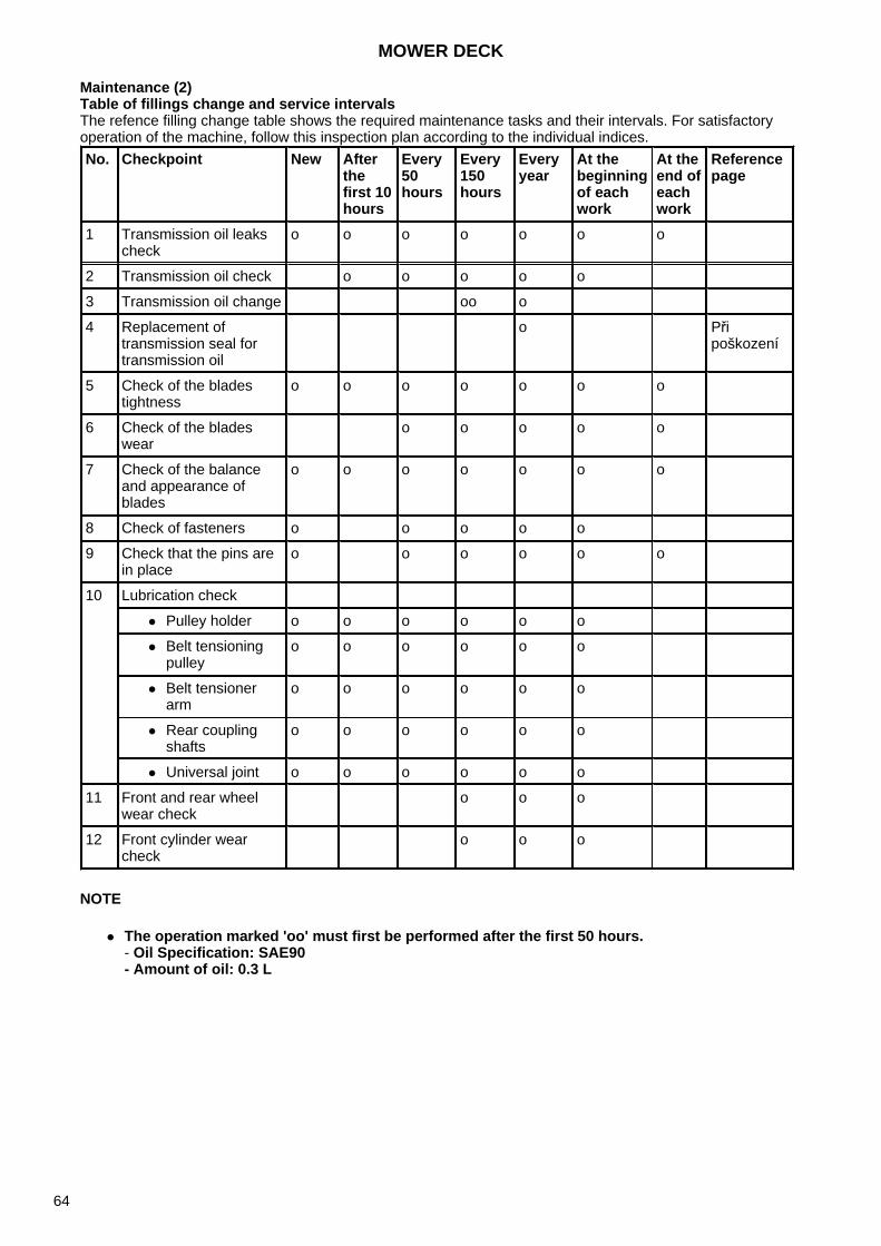
Maintenance (2)Table of fillings change and service intervalsThe refence filling change table shows the required maintenance tasks and their intervals. For satisfactory operation of the machine, follow this inspection plan according to the individual indices.
NOTE
The operation marked 'oo' must first be performed after the first 50 hours.- Oil Specification: SAE90- Amount of oil: 0.3 L
No. Checkpoint New After the first 10 hours
Every 50 hours
Every 150 hours
Every year
At the beginning of each work
At the end of each work
Reference page
1 Transmission oil leaks check
o o o o o o o
2 Transmission oil check o o o o o
3 Transmission oil change oo o
4 Replacement of transmission seal for transmission oil
o Při poškození
5 Check of the blades tightness
o o o o o o o
6 Check of the blades wear
o o o o o
7 Check of the balance and appearance of blades
o o o o o o o
8 Check of fasteners o o o o o
9 Check that the pins are in place
o o o o o o
10 Lubrication check
Pulley holder o o o o o o
Belt tensioningpulley
o o o o o o
Belt tensionerarm
o o o o o o
Rear couplingshafts
o o o o o o
Universal joint o o o o o o
11 Front and rear wheel wear check
o o o
12 Front cylinder wear check
o o o
MOWER DECK
64
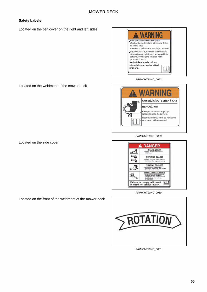
Safety Labels
Located on the belt cover on the right and left sides
PRIMOHT20NC_0052
Located on the weldment of the mower deck
PRIMOHT20NC_0053
Located on the side cover
PRIMOHT20NC_0050
Located on the front of the weldment of the mower deck
PRIMOHT20NC_0051
MOWER DECK
65
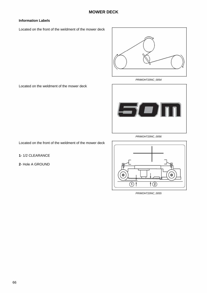
Information Labels
Located on the front of the weldment of the mower deck
PRIMOHT20NC_0054
Located on the weldment of the mower deck
PRIMOHT20NC_0056
Located on the front of the weldment of the mower deck
1- 1/2 CLEARANCE
2- Hole A GROUND
PRIMOHT20NC_0055
MOWER DECK
66
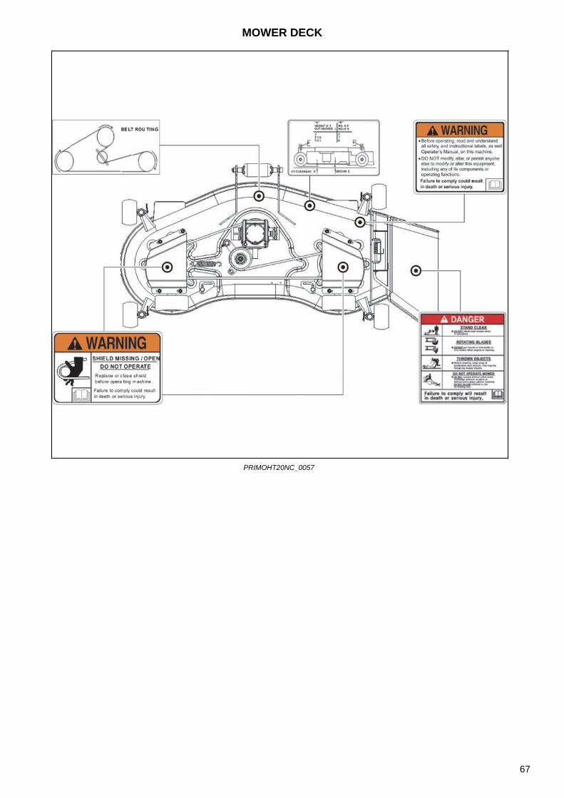
PRIMOHT20NC_0057
MOWER DECK
67
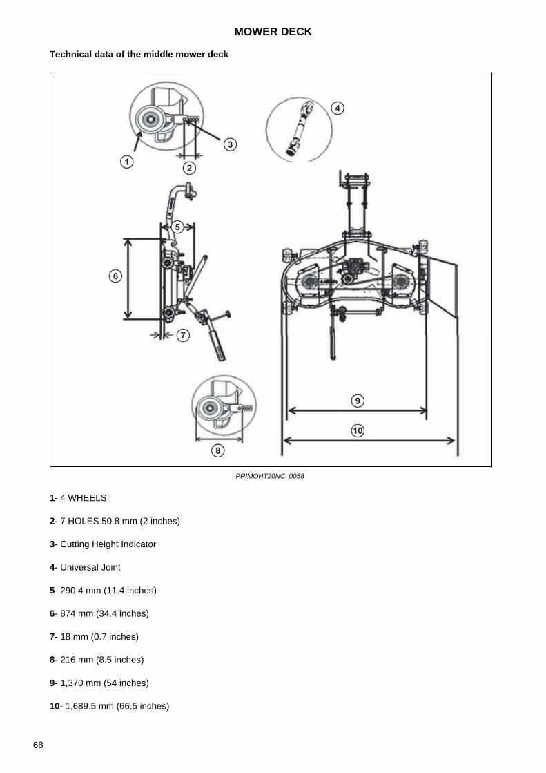
Technical data of the middle mower deck
PRIMOHT20NC_0058
1- 4 WHEELS
2- 7 HOLES 50.8 mm (2 inches)
3- Cutting Height Indicator
4- Universal Joint
5- 290.4 mm (11.4 inches)
6- 874 mm (34.4 inches)
7- 18 mm (0.7 inches)
8- 216 mm (8.5 inches)
9- 1,370 mm (54 inches)
10- 1,689.5 mm (66.5 inches)
MOWER DECK
68
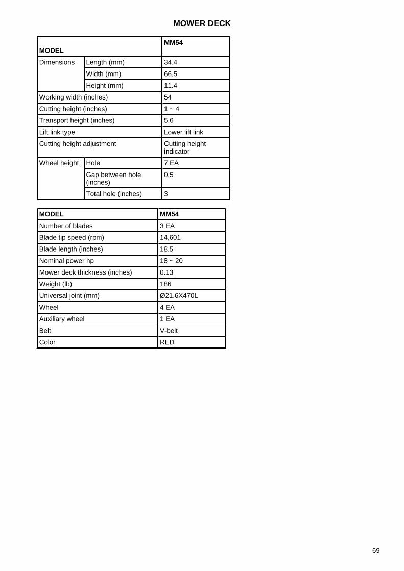
MODELMM54
Dimensions Length (mm) 34.4
Width (mm) 66.5
Height (mm) 11.4
Working width (inches) 54
Cutting height (inches) 1 ~ 4
Transport height (inches) 5.6
Lift link type Lower lift link
Cutting height adjustment Cutting height indicator
Wheel height Hole 7 EA
Gap between hole (inches)
0.5
Total hole (inches) 3
MODEL MM54Number of blades 3 EA
Blade tip speed (rpm) 14,601
Blade length (inches) 18.5
Nominal power hp 18 ~ 20
Mower deck thickness (inches) 0.13
Weight (lb) 186
Universal joint (mm) Ø21.6X470L
Wheel 4 EA
Auxiliary wheel 1 EA
Belt V-belt
Color RED
MOWER DECK
69
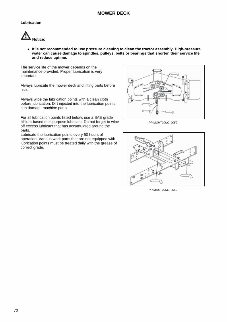
Lubrication
Notice:
It is not recommended to use pressure cleaning to clean the tractor assembly. High-pressurewater can cause damage to spindles, pulleys, belts or bearings that shorten their service lifeand reduce uptime.
The service life of the mower depends on the maintenance provided. Proper lubrication is very important.
Always lubricate the mower deck and lifting parts before use.
Always wipe the lubrication points with a clean cloth before lubrication. Dirt injected into the lubrication points can damage machine parts.
For all lubrication points listed below, use a SAE grade lithium-based multipurpose lubricant. Do not forget to wipe off excess lubricant that has accumulated around the parts.
PRIMOHT20NC_0059
Lubricate the lubrication points every 50 hours of operation. Various work parts that are not equipped with lubrication points must be treated daily with the grease of correct grade.
PRIMOHT20NC_0060
MOWER DECK
70
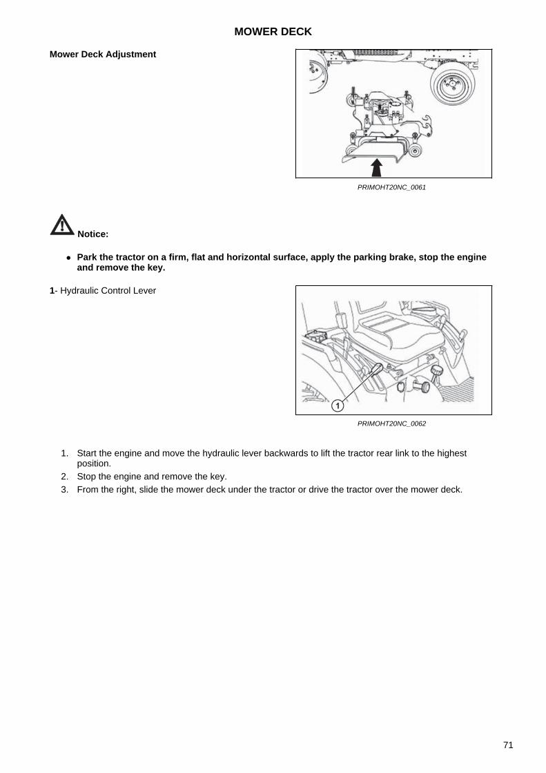
Notice:
Park the tractor on a firm, flat and horizontal surface, apply the parking brake, stop the engineand remove the key.
1. Start the engine and move the hydraulic lever backwards to lift the tractor rear link to the highestposition.
2. Stop the engine and remove the key.3. From the right, slide the mower deck under the tractor or drive the tractor over the mower deck.
Mower Deck Adjustment
PRIMOHT20NC_0061
1- Hydraulic Control Lever
PRIMOHT20NC_0062
MOWER DECK
71
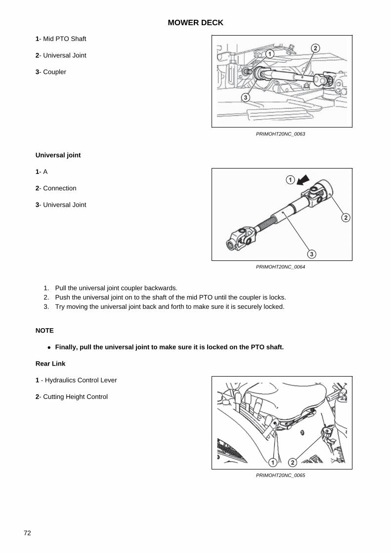
Universal joint
1. Pull the universal joint coupler backwards.2. Push the universal joint on to the shaft of the mid PTO until the coupler is locks.3. Try moving the universal joint back and forth to make sure it is securely locked.
NOTE
Finally, pull the universal joint to make sure it is locked on the PTO shaft.
Rear Link
1- Mid PTO Shaft
2- Universal Joint
3- Coupler
PRIMOHT20NC_0063
1- A
2- Connection
3- Universal Joint
PRIMOHT20NC_0064
1 - Hydraulics Control Lever
2- Cutting Height Control
PRIMOHT20NC_0065
MOWER DECK
72
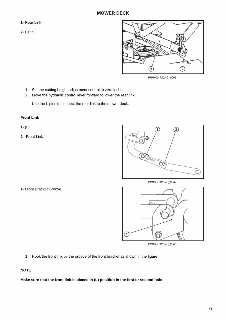
1. Set the cutting height adjustment control to zero inches.2. Move the hydraulic control lever forward to lower the rear link.
Use the L pins to connect the rear link to the mower deck.
Front Link
1. Hook the front link by the groove of the front bracket as shown in the figure.
NOTE
Make sure that the front link is placed in (L) position in the first or second hole.
1- Rear Link
2- L Pin
PRIMOHT20NC_0066
1- (L)
2 - Front Link
PRIMOHT20NC_0067
1- Front Bracket Groove
PRIMOHT20NC_0068
MOWER DECK
73
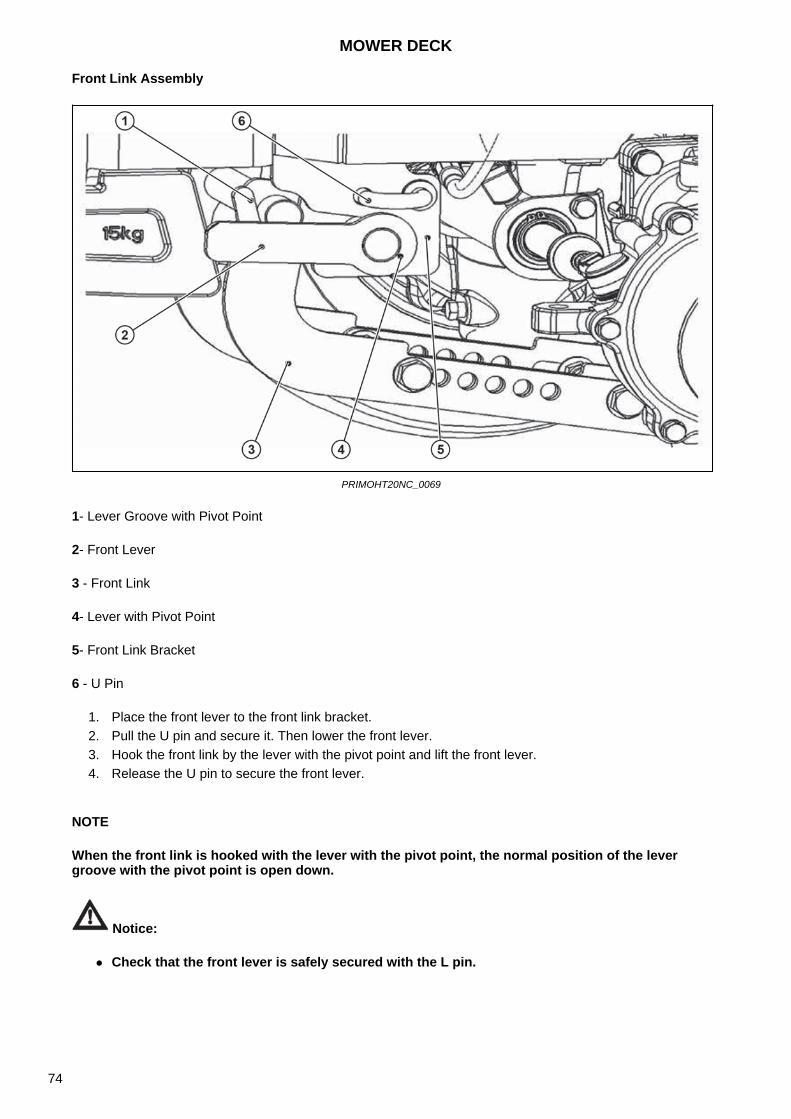
Front Link Assembly
PRIMOHT20NC_0069
1- Lever Groove with Pivot Point
2- Front Lever
3 - Front Link
4- Lever with Pivot Point
5- Front Link Bracket
6 - U Pin
1. Place the front lever to the front link bracket.2. Pull the U pin and secure it. Then lower the front lever.3. Hook the front link by the lever with the pivot point and lift the front lever.4. Release the U pin to secure the front lever.
NOTE
When the front link is hooked with the lever with the pivot point, the normal position of the lever groove with the pivot point is open down.
Notice:
Check that the front lever is safely secured with the L pin.
MOWER DECK
74
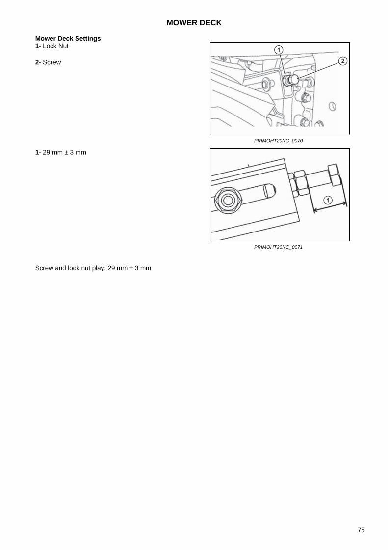
Mower Deck Settings
Screw and lock nut play: 29 mm ± 3 mm
1- Lock Nut
2- Screw
PRIMOHT20NC_0070
1- 29 mm ± 3 mm
PRIMOHT20NC_0071
MOWER DECK
75
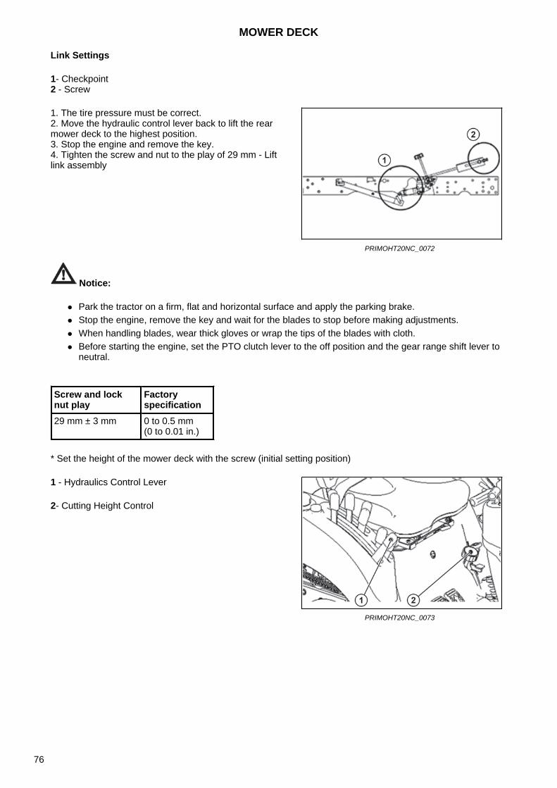
Link Settings
1- Checkpoint2 - Screw
Notice:
Park the tractor on a firm, flat and horizontal surface and apply the parking brake. Stop the engine, remove the key and wait for the blades to stop before making adjustments. When handling blades, wear thick gloves or wrap the tips of the blades with cloth. Before starting the engine, set the PTO clutch lever to the off position and the gear range shift lever to
neutral.
* Set the height of the mower deck with the screw (initial setting position)
1. The tire pressure must be correct.2. Move the hydraulic control lever back to lift the rearmower deck to the highest position.3. Stop the engine and remove the key.4. Tighten the screw and nut to the play of 29 mm - Liftlink assembly
PRIMOHT20NC_0072
Screw and lock nut play
Factory specification
29 mm ± 3 mm 0 to 0.5 mm (0 to 0.01 in.)
1 - Hydraulics Control Lever
2- Cutting Height Control
PRIMOHT20NC_0073
MOWER DECK
76
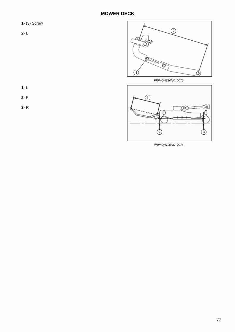
1- (3) Screw
2- L
PRIMOHT20NC_0075
1- L
2- F
3- R
PRIMOHT20NC_0074
MOWER DECK
77
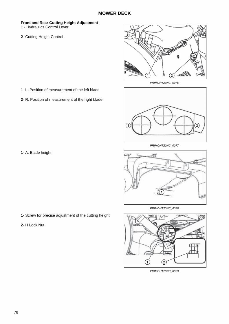
Front and Rear Cutting Height Adjustment1 - Hydraulics Control Lever
2- Cutting Height Control
PRIMOHT20NC_0076
1- L: Position of measurement of the left blade
2- R: Position of measurement of the right blade
PRIMOHT20NC_0077
1- A: Blade height
PRIMOHT20NC_0078
1- Screw for precise adjustment of the cutting height
2- H Lock Nut
PRIMOHT20NC_0079
MOWER DECK
78
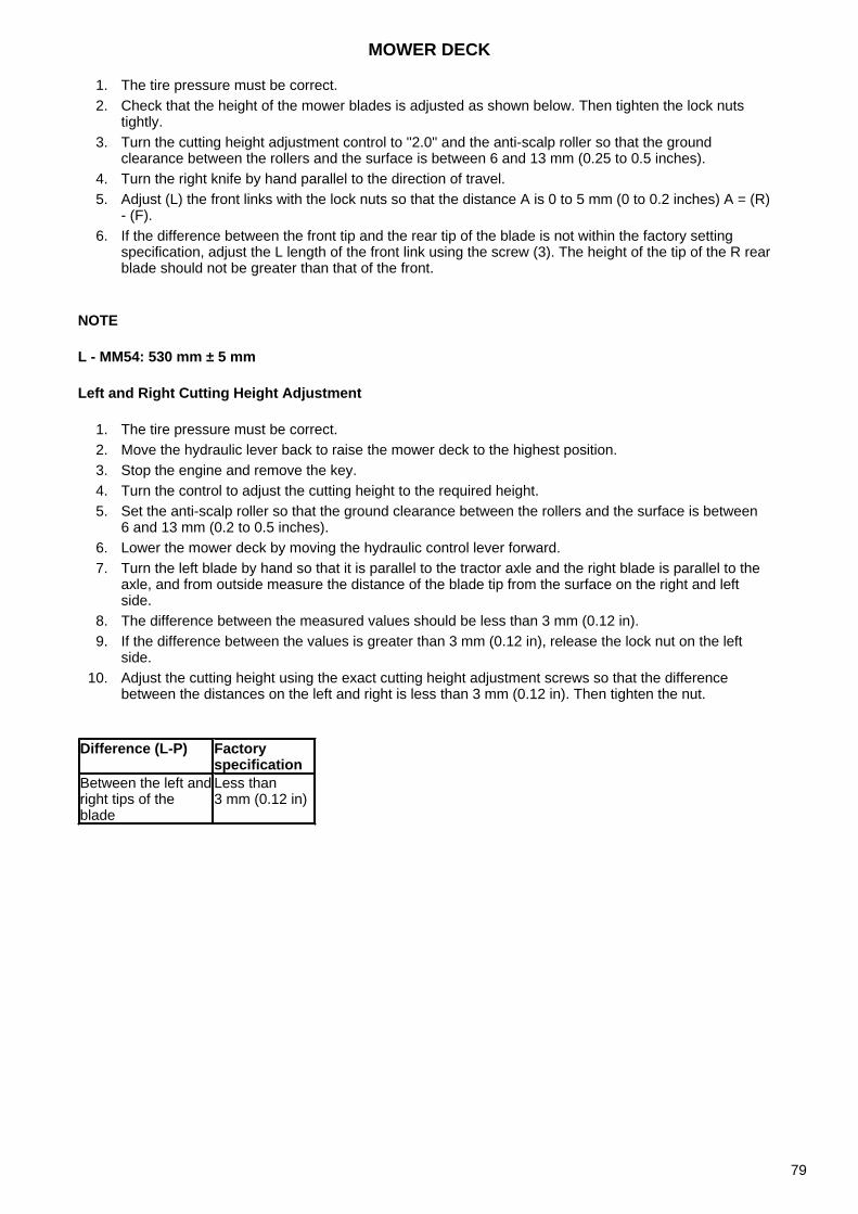
1. The tire pressure must be correct.2. Check that the height of the mower blades is adjusted as shown below. Then tighten the lock nuts
tightly.3. Turn the cutting height adjustment control to ''2.0'' and the anti-scalp roller so that the ground
clearance between the rollers and the surface is between 6 and 13 mm (0.25 to 0.5 inches).4. Turn the right knife by hand parallel to the direction of travel.5. Adjust (L) the front links with the lock nuts so that the distance A is 0 to 5 mm (0 to 0.2 inches) A = (R)
- (F).6. If the difference between the front tip and the rear tip of the blade is not within the factory setting
specification, adjust the L length of the front link using the screw (3). The height of the tip of the R rearblade should not be greater than that of the front.
NOTE
L - MM54: 530 mm ± 5 mm
Left and Right Cutting Height Adjustment
1. The tire pressure must be correct.2. Move the hydraulic lever back to raise the mower deck to the highest position.3. Stop the engine and remove the key.4. Turn the control to adjust the cutting height to the required height.5. Set the anti-scalp roller so that the ground clearance between the rollers and the surface is between
6 and 13 mm (0.2 to 0.5 inches).6. Lower the mower deck by moving the hydraulic control lever forward.7. Turn the left blade by hand so that it is parallel to the tractor axle and the right blade is parallel to the
axle, and from outside measure the distance of the blade tip from the surface on the right and leftside.
8. The difference between the measured values should be less than 3 mm (0.12 in).9. If the difference between the values is greater than 3 mm (0.12 in), release the lock nut on the left
side.10. Adjust the cutting height using the exact cutting height adjustment screws so that the difference
between the distances on the left and right is less than 3 mm (0.12 in). Then tighten the nut.
Difference (L-P) Factory specification
Between the left and right tips of the blade
Less than 3 mm (0.12 in)
MOWER DECK
79

Fasteners torque table (ISO)
NOTE
If no special torques are specified, use these tightening torques. The values are for UNF threaded bolts, plated or unplated, according to the supplier's delivery. Fasteners can be dry or lubricated with normal engine oil. The values do not apply if graphite, moly-disulfide or other high-pressure lubricant is used.ISO class number 8.8 10.9 12.9
Screw head identification (see Note 1)
Screw sizeLB FT nM LB FT nM LB FT nMMin MAX Min MAX Min MAX Min MAX Min MAX Min MAX
M4 2 3 3 4 3 4 4 5 Due to the low flexibility of these fasteners, the tightening torque range must be determined individually for each application.
In general, the tightening torque ranges specified for Class 10.9 fasteners can be safely applied to Fasteners 12.9
* M14 is not the preferredsize
M5 5 6 6.5 8 7 8 7.5 11
M6 8 9 10.5 12 11 13 15 17.5
M8 19 23 26 31 27 32 27 43
M10 38 45 52 61 54 64 73 87
M12 66 79 90 75 93 112 125 150
*M14 106 127 144 172 149 179 200 245
M16 160 200 217 271 230 280 310 380
M20 320 380 434 515 450 540 610 730
M24 500 600 675 815 780 940 1,050 1,275
M30 920 1,100 1,250 1,500 1,470 1,770 2,000 2,400
M36 1,600 1,950 2,175 2,600 2,580 3,090 3,500 4,200
MOWER DECK
80
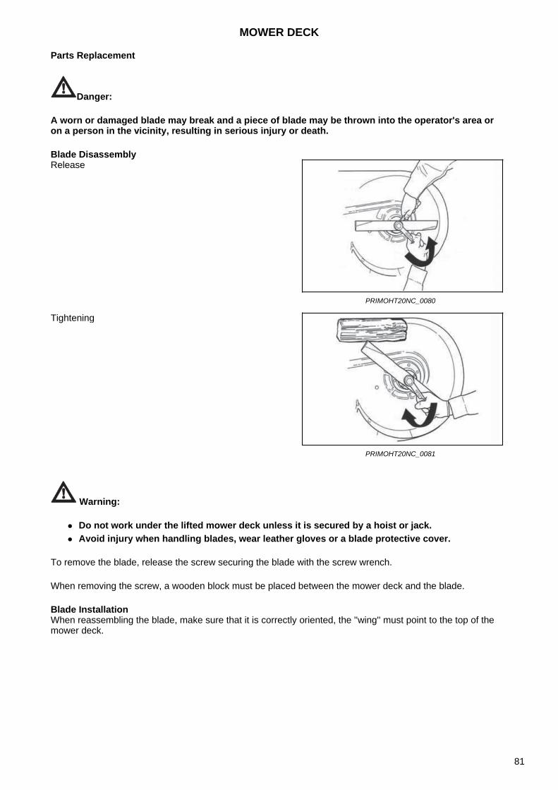
Parts Replacement
Danger:
A worn or damaged blade may break and a piece of blade may be thrown into the operator's area or on a person in the vicinity, resulting in serious injury or death.
Blade Disassembly
Warning:
Do not work under the lifted mower deck unless it is secured by a hoist or jack. Avoid injury when handling blades, wear leather gloves or a blade protective cover.
To remove the blade, release the screw securing the blade with the screw wrench.
When removing the screw, a wooden block must be placed between the mower deck and the blade.
Blade InstallationWhen reassembling the blade, make sure that it is correctly oriented, the ''wing'' must point to the top of the mower deck.
Release
PRIMOHT20NC_0080
Tightening
PRIMOHT20NC_0081
MOWER DECK
81
Belt Replacement
The mower deck belts must be replaced after every 200 hours of operation or if the belts show signs of wear, breakage or other damage.
Remove the fasteners that secure the left/right belt cover to the mower deck.
Notice:
The tensioning arm and tension pulley are under spring tension. Be careful when handling the tension arm assembly to avoid possible injury.
Insert the ''breaker bar'' into the square hole in the tensioning arm. Carefully push the tensioning arm to the left, away from the discharge hole, to release the tension of the belt. Remove the belt from the right spindle pulley, then carefully release the tensioning arm.
Remove the belt from the center spindle pulley.
Remove the belt from the first fixed tensioning pulley.
Remove the belt from the left spindle pulley.
Remove the belt from the tensioning arm pulley.
Remove the belt from the transmission pulley.
Remove the belt from the second tensioning pulley.
Remove the belt from the mower deck and discard.
Belt Replacement
Guide the belt 'back side' around the fixed tensioning pulley near the transmission.
Guide the belt around the transmission pulley.
Guide the belt around the tensioning arm pulley. The ''back side'' of the belt will be the contact point with the arm pulley.
Guide the belt around the left spindle pulley.
Guide the ''back side'' of the belt around the fixed tensioning pulley near the central spindle.
Guide the belt around the center spindle pulley.
Make sure that the belt is properly placed in each pulley, then insert the ''breaker bar'' into the square hole of the tensioning arm. Carefully push the tensioning arm to the left, away from the discharge hole, and release the tension. Place the belt on the right spindle pulley, then carefully release the tensioning arm.
Reassemble the left and right belt cover on the mower deck.
MOWER DECK
82

Transmission
Notice:
Prior to operation, make sure that the transmission contains the correct amount of oil. If the oil level is too low or too high, the transmission damage may occur or injury may occur.
The oil level must always be checked after 24 hours of operation. After the initial 50 hours of operation, drain the oil and top up the required amount. After that, the oil should be changed every 250 hours of operation.
The drain plug is located on the transmission side opposite the fixed tensioning pulley.
Correct oil level to the center line of the drive shaft.
MOWER DECK
83

NOTES
84
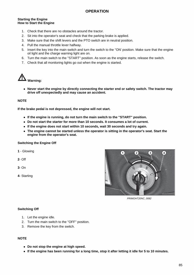
Starting the EngineHow to Start the Engine
1. Check that there are no obstacles around the tractor.2. Sit into the operator's seat and check that the parking brake is applied.3. Make sure that the shift levers and the PTO switch are in neutral position.4. Pull the manual throttle lever halfway.5. Insert the key into the main switch and turn the switch to the ''ON' position. Make sure that the engine
oil light and the charge warning light are on.6. Turn the main switch to the ''START'' position. As soon as the engine starts, release the switch.7. Check that all monitoring lights go out when the engine is started.
Warning:
Never start the engine by directly connecting the starter end or safety switch. The tractor maydrive off unexpectedly and may cause an accident.
NOTE
If the brake pedal is not depressed, the engine will not start.
If the engine is running, do not turn the main switch to the ''START'' position. Do not start the starter for more than 10 seconds. It consumes a lot of current. If the engine does not start within 10 seconds, wait 30 seconds and try again. The engine cannot be started unless the operator is sitting in the operator's seat. Start the
engine from the operator's seat.
Switching the Engine Off
Switching Off
1. Let the engine idle.2. Turn the main switch to the ''OFF'' position.3. Remove the key from the switch.
NOTE
Do not stop the engine at high speed. If the engine has been running for a long time, stop it after letting it idle for 5 to 10 minutes.
1 - Glowing
2- Off
3- On
4- Starting
PRIMOHT20NC_0082
OPERATION
85
Engine Idling
Engine Idling in General
After starting the engine, let the engine idle for 5 to 10 minutes to get the oil to all its parts.
NOTE
If the engine is loaded immediately after starting, it may stop and get damaged. First, let theengine idle.
Failure to idle the engine may result in:- Hydraulic pump seizure- Hydraulic system failure.
Warning:
Make sure the parking brake is applied when the engine is idling. Never let the engine idle in a poorly ventilated area. This can cause carbon monoxide
poisoning.
The hydraulic oil in this vehicle is also used as a transmission fluid.
If the winter temperatures are low, the oil cools down, its viscosity rises. The hydraulic pump cannot suck in the oil, which causes a malfunction.
In winter, start idling the engine according to the following instructions:
Run-in
During the first 50 hours of use of the machine, follow the instructions below:
1. Eliminate sudden start and sudden stop.2. Avoid driving at excessive speed and excessive load.3. Only drive the tractor if the engine has warmed up sufficiently.4. Do not idle the engine at maximum speed.5. After 50 hours of operation, check all parts and liquids.6. To refill and replace engine oil, see Maintenance chapter.
Temperature Idling time0 °C or higher (32 °F or higher)
At least 10 min
0 ~ -10 °C (32 ° F ~ -50 ° F)
10 ~ 20 min
-10 ~ -20 °C(-50 °F ~ -68 °F)
20 ~ 30 min
-20 °C or less(-68 °F or less)
At least 30 min
OPERATION
86
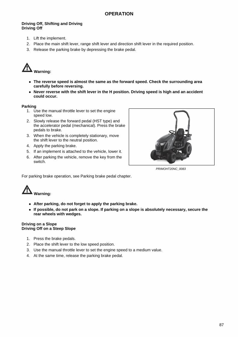
Driving Off, Shifting and DrivingDriving Off
1. Lift the implement.2. Place the main shift lever, range shift lever and direction shift lever in the required position.3. Release the parking brake by depressing the brake pedal.
Warning:
The reverse speed is almost the same as the forward speed. Check the surrounding areacarefully before reversing.
Never reverse with the shift lever in the H position. Driving speed is high and an accidentcould occur.
Parking
For parking brake operation, see Parking brake pedal chapter.
Warning:
After parking, do not forget to apply the parking brake. If possible, do not park on a slope. If parking on a slope is absolutely necessary, secure the
rear wheels with wedges.
Driving on a SlopeDriving Off on a Steep Slope
1. Press the brake pedals.2. Place the shift lever to the low speed position.3. Use the manual throttle lever to set the engine speed to a medium value.4. At the same time, release the parking brake pedal.
1. Use the manual throttle lever to set the enginespeed low.
2. Slowly release the forward pedal (HST type) andthe accelerator pedal (mechanical). Press the brakepedals to brake.
3. When the vehicle is completely stationary, movethe shift lever to the neutral position.
4. Apply the parking brake.5. If an implement is attached to the vehicle, lower it.6. After parking the vehicle, remove the key from the
switch.
PRIMOHT20NC_0083
OPERATION
87
Tips for Driving on a Slope
1. Place the main shift lever in a low-speed position on the slope to avoid stopping the engine.2. Keep the speed low when driving downhill.
NOTE
If the needle on the coolant temperature gauge points to ''H'', the engine has overheated. If youcontinue to drive in this situation, serious damage to the engine components may occur. Takeappropriate action immediately.
Precautions when Entering / Exiting a Field
1. Check that the left and right brake pedals are connected.2. If there is a deep edge in the field, it is dangerous to enter/exit it.
Use ramps.3. Move perpendicularly to the edge.4. When leaving the field, lower the implement so that the front wheels cannot be lifted.5. To use full power, it is recommended to reverse into the field.
Warning:
When working on a slope, make sure to maintain the stability of the tractor. It may be lost andthe machine may roll over.
It is very dangerous to carry a person as a counter-weight on the front part of the tractor.
For detailed information on measures, see Safety Instructions for Users chapter.
Loading on Truck / Unloading
1. Reverse when loading the tractor on the truck.2. Extreme care must be taken when using the ramp.3. If the engine stops on the ramp, immediately depress the brake pedals and slowly release them to
drive the tractor on the ground. Then start the engine again and drive on the ramp.
OPERATION
88
Precautions when Driving on the Road
1. When changing direction on the road, use turn signal lights to inform other drivers of your intention.2. If you meet a vehicle in the opposite direction in the dark, use the low beam lights.3. Check that the left and right brake pedals are connected.4. When driving at night, switch off the work lights.5. Drive safely.6. Under no circumstances may another person be driving on the tractor except for the operator.
Warning:
If you drive on the road with implements attached, the front of the tractor tends to lift and itmay not be possible to drive the machine properly.
Operation Check while DrivingCheck that all components work properly while driving.Engine Oil Pressure
Coolant
If the coolant gauge needle points to ''H'', stop the engine and check the following:
Radiator coolant Radiator fins for clogging Fan belt for looseness
If necessary, have the vehicle checked by the service center.
NOTE
When the coolant temperature warning light comes on, the engine is overheated. If the enginecontinues to run under this circumstances, serious damage to the engine components mayoccur. Take appropriate action immediately.
If the engine oil level warning light comes on while driving, it may indicate a fault in the lubrication system. Immediately check the engine oil and, if necessary, have the vehicle checked by the service center.
If the battery charge warning light comes on while driving, the battery is not charged properly. In this case, check the condition of the battery and have it checked by a workshop if necessary.
OPERATION
89

NOTES
90
Safety measures for handling implements
1. When connection and disconnecting implements to the tractor, make sure that there are no peoplebetween the tractor and the implement or around the tractor and implements.
2. Only connect and disconnect implements on a safe and flat surface.3. When installing heavy implements, install weights on the front of the tractor.4. When adjusting the implement, apply the parking brake beforehand, stop the engine, and set the PTO
switch to the OFF position.5. Use only towing equipment to tow anything.
Warning:
Carefully read the instructions on the implement's warning labels before starting work. To eliminate injuries caused by improper use of the implement, read the implement's operating
instructions carefully and perform the work safely and carefully. Installing an improper implement can lead to injury. Only install implements specified by the
manufacturer.
WORKFLOW
91

NOTES
92
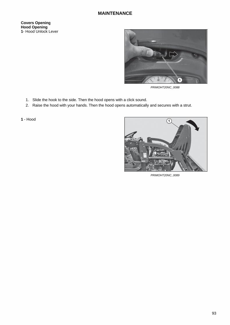
Covers OpeningHood Opening
1. Slide the hook to the side. Then the hood opens with a click sound.2. Raise the hood with your hands. Then the hood opens automatically and secures with a strut.
1- Hood Unlock Lever
PRIMOHT20NC_0088
1 - Hood
PRIMOHT20NC_0089
MAINTENANCE
93
Checked Items
To prevent any possible malfunctions, some items must be checked daily.
Check before driving.
Checked Items
Check the individual parts in the following order:
1. Check the parts that had a malfunction the previous day.2. Walk around the tractor and check:
- Proper operation of lights and their possible damage- Proper tire inflation, whether they have cracks, are damaged or worn- Whether the screws and nuts on moving parts are not loose- Transmission fluid level- Implement connection condition
3. Open the hood and check:- Engine oil level- Radiator coolant level- Fan belt, whether it is not loose or damaged
4. Sit in the operator's seat, turn the main switch to the ''ON' position and check:- Proper operation of the fuel gauge- Fuel level- Flashing of the engine oil and charging warning lights- Turn signal lights- Proper operation of horn- Brake pedal play
5. Start the engine, drive slowly with the tractor and check:- Emissions color- Brake pedal proper operation- Individual brake pedals proper operation- Steering wheel in terms of control effort and vibrations- Coolant gauge proper operation- Hydraulic control of the three-point hitch
MAINTENANCE
94
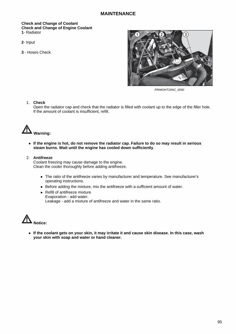
Check and Change of CoolantCheck and Change of Engine Coolant
1. CheckOpen the radiator cap and check that the radiator is filled with coolant up to the edge of the filler hole.If the amount of coolant is insufficient, refill.
Warning:
If the engine is hot, do not remove the radiator cap. Failure to do so may result in serioussteam burns. Wait until the engine has cooled down sufficiently.
2. AntifreezeCoolant freezing may cause damage to the engine.Clean the cooler thoroughly before adding antifreeze.
The ratio of the antifreeze varies by manufacturer and temperature. See manufacturer'soperating instructions.
Before adding the mixture, mix the antifreeze with a sufficient amount of water. Refill of antifreeze mixture
Evaporation - add water.Leakage - add a mixture of antifreeze and water in the same ratio.
Notice:
If the coolant gets on your skin, it may irritate it and cause skin disease. In this case, washyour skin with soap and water or hand cleaner.
1- Radiator
2- Input
3 - Hoses Check
PRIMOHT20NC_0090
MAINTENANCE
95
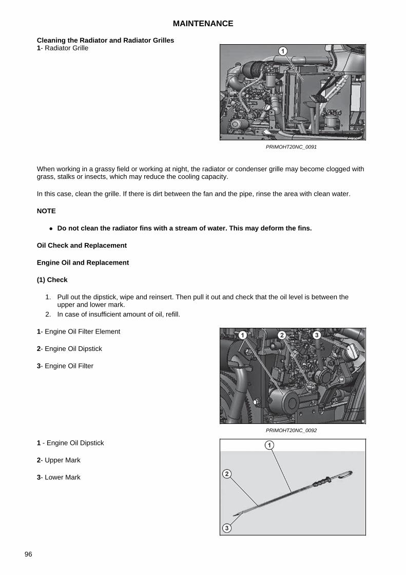
Cleaning the Radiator and Radiator Grilles
When working in a grassy field or working at night, the radiator or condenser grille may become clogged with grass, stalks or insects, which may reduce the cooling capacity.
In this case, clean the grille. If there is dirt between the fan and the pipe, rinse the area with clean water.
NOTE
Do not clean the radiator fins with a stream of water. This may deform the fins.
Oil Check and Replacement
Engine Oil and Replacement
(1) Check
1. Pull out the dipstick, wipe and reinsert. Then pull it out and check that the oil level is between theupper and lower mark.
2. In case of insufficient amount of oil, refill.
1- Radiator Grille
PRIMOHT20NC_0091
1- Engine Oil Filter Element
2- Engine Oil Dipstick
3- Engine Oil Filter
PRIMOHT20NC_0092
1 - Engine Oil Dipstick
2- Upper Mark
3- Lower Mark
MAINTENANCE
96
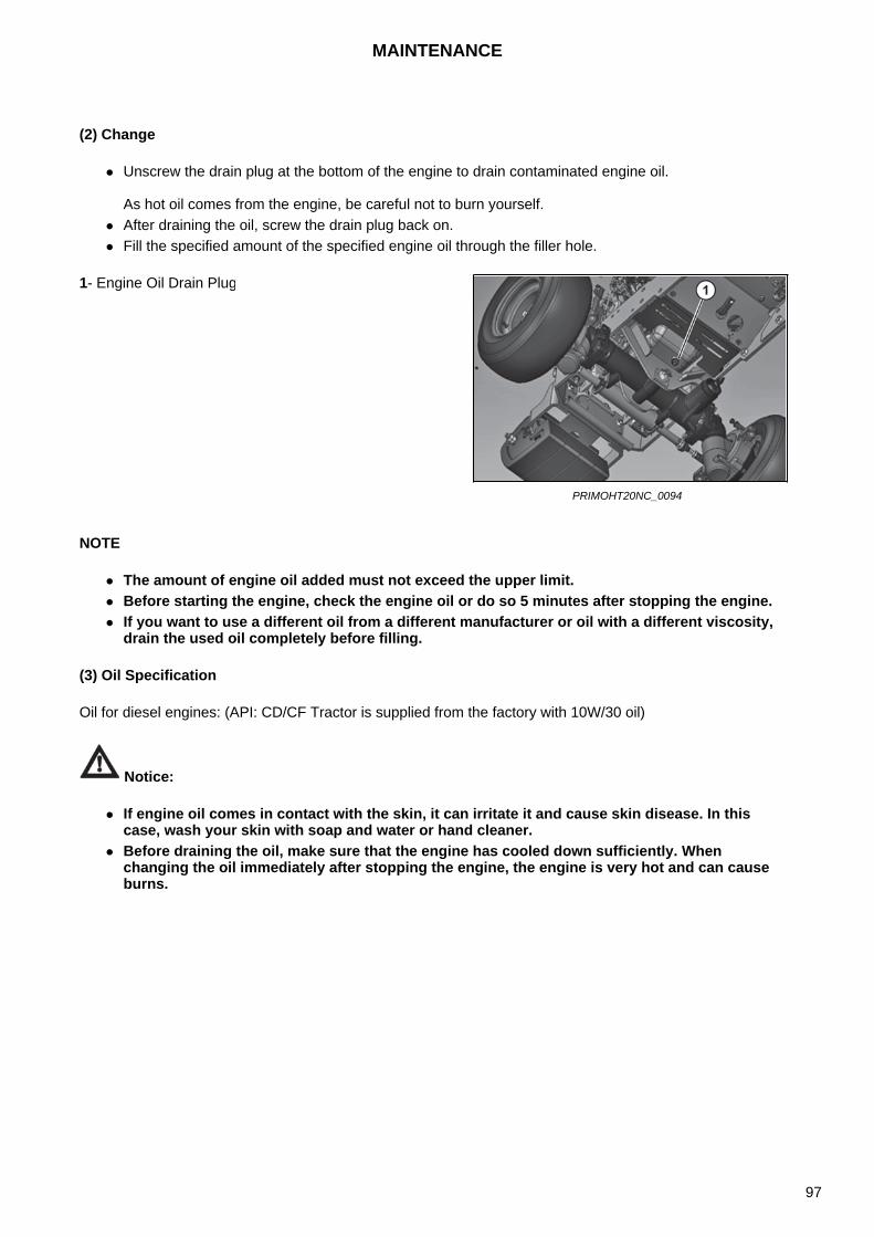
(2) Change
Unscrew the drain plug at the bottom of the engine to drain contaminated engine oil.
As hot oil comes from the engine, be careful not to burn yourself. After draining the oil, screw the drain plug back on. Fill the specified amount of the specified engine oil through the filler hole.
NOTE
The amount of engine oil added must not exceed the upper limit. Before starting the engine, check the engine oil or do so 5 minutes after stopping the engine. If you want to use a different oil from a different manufacturer or oil with a different viscosity,
drain the used oil completely before filling.
(3) Oil Specification
Oil for diesel engines: (API: CD/CF Tractor is supplied from the factory with 10W/30 oil)
Notice:
If engine oil comes in contact with the skin, it can irritate it and cause skin disease. In thiscase, wash your skin with soap and water or hand cleaner.
Before draining the oil, make sure that the engine has cooled down sufficiently. Whenchanging the oil immediately after stopping the engine, the engine is very hot and can causeburns.
1- Engine Oil Drain Plug
PRIMOHT20NC_0094
MAINTENANCE
97
Transmission Fluid Check and Change
(1) Check
Check with the engine stopped.
1. Check the transmission fluid through the sight glass to see if the level is between the upper and lowermark.
2. In case of insufficient amount of oil, refill.
1- Transmission Fluid Filler
PRIMOHT20NC_0095
1- Upper Mark
2- Lower Mark
PRIMOHT20NC_0096
MAINTENANCE
98
(2) Change
1. Unscrew the drain plug at the bottom of the transmission and drain the dirty transmission fluid. As hotfluid comes from the engine first, be careful not to burn yourself.
2. After draining the fluid, tighten the transmission fluid drain plug.3. Fill the specified amount of the specified transmission fluid through the filler.
NOTE
The amount of liquid added must not exceed the upper limit. Check the liquid before starting the engine or at least 5 minutes after stopping it. If you want to use a different fluid from a different manufacturer or fluid with a different
viscosity, drain the used fluid completely before filling.
Notice:
If transmission fluid comes in contact with the skin, it can irritate it and cause skin disease. Inthis case, wash your skin with soap and water or hand cleaner.
1 - Drain Plug
PRIMOHT20NC_0097
MAINTENANCE
99
Front Axle Oil Check and Change
(1) Check
1. Pull out the dipstick, wipe and reinsert. Then pull it out and check that the oil level is between theupper and lower mark.
2. In case of insufficient amount of oil, refill.3. There is one drain hole on each side of the front axle.
(2) Change
1. To drain the engine oil, unscrew the drain plugs at the bottom of the axle and the left / right finaldrives. As hot fluid comes from the engine first, be careful not to burn yourself.
2. After draining the oil, screw the drain plug back on.3. Fill the specified amount of the specified oil through the filler hole.
NOTE
The amount of front axle oil added must not exceed the upper limit. Check the front axle oil before starting the engine or at least 5 minutes after stopping it. If you want to use a different oil from a different manufacturer or oil with a different viscosity,
drain the used oil completely before filling.
Notice:
If oil comes in contact with the skin, it can irritate it and cause skin disease. In this case, washyour skin with soap and water or hand cleaner.
Before draining the oil, make sure that the engine has cooled down sufficiently. Whenchanging the oil immediately after stopping the engine, the engine is very hot and can causeburns.
1- Front-Wheel Axle Oil Filler2 - Front Axle Oil Drain Plug
PRIMOHT20NC_0098
1- Upper Mark2- Lower Mark3- Level Dipstick
PRIMOHT20NC_0099
MAINTENANCE
100
Filter and Element ReplacementTransmission Fluid Filter Element Replacement
1. The hydraulic oil filter is located under the floor.2. Remove the hydraulic oil filter element by turning it counterclockwise using the wrench.3. Apply a thin layer of oil to the O-ring of the new element and install the new element by hand
tightening.As soon as the housing touches the sealing surface, turn it approximately by 2/3 turn with a wrench.
4. Fill the hydraulic oil to the specified level.5. Check the oil level again using the dipstick. If the amount is still insufficient, add up.
Cleaning the Transmission Fluid Dirt Trap
1. When changing the transmission fluid, clean it with diesel.2. Unscrew the filter body holder from the lower right part of the transmission and carefully pull out the
filter with pliers.
1- HST Filter
PRIMOHT20NC_0100
1 - Dirt Trap
PRIMOHT20NC_0101
1- Pliers
PRIMOHT20NC_0102
MAINTENANCE
101
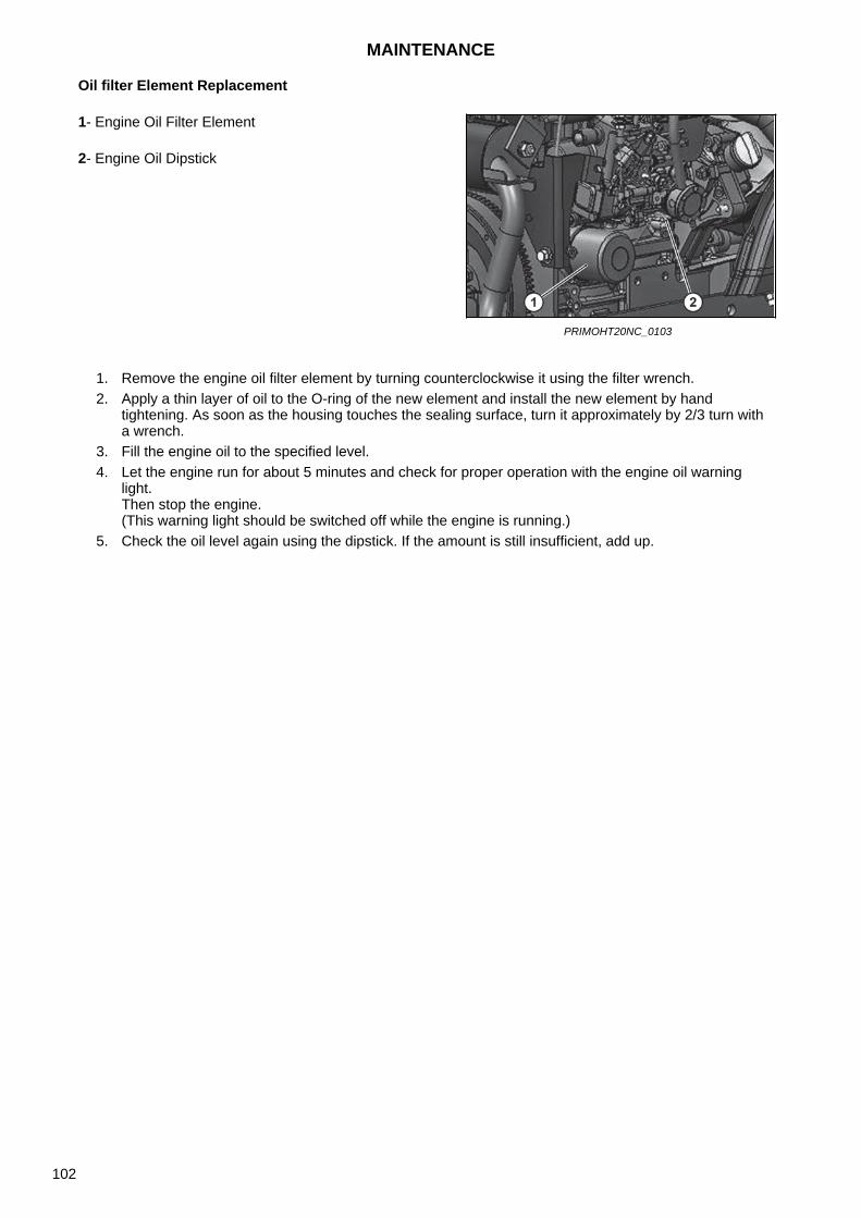
Oil filter Element Replacement
1. Remove the engine oil filter element by turning counterclockwise it using the filter wrench.2. Apply a thin layer of oil to the O-ring of the new element and install the new element by hand
tightening. As soon as the housing touches the sealing surface, turn it approximately by 2/3 turn witha wrench.
3. Fill the engine oil to the specified level.4. Let the engine run for about 5 minutes and check for proper operation with the engine oil warning
light.Then stop the engine.(This warning light should be switched off while the engine is running.)
5. Check the oil level again using the dipstick. If the amount is still insufficient, add up.
1- Engine Oil Filter Element
2- Engine Oil Dipstick
PRIMOHT20NC_0103
MAINTENANCE
102
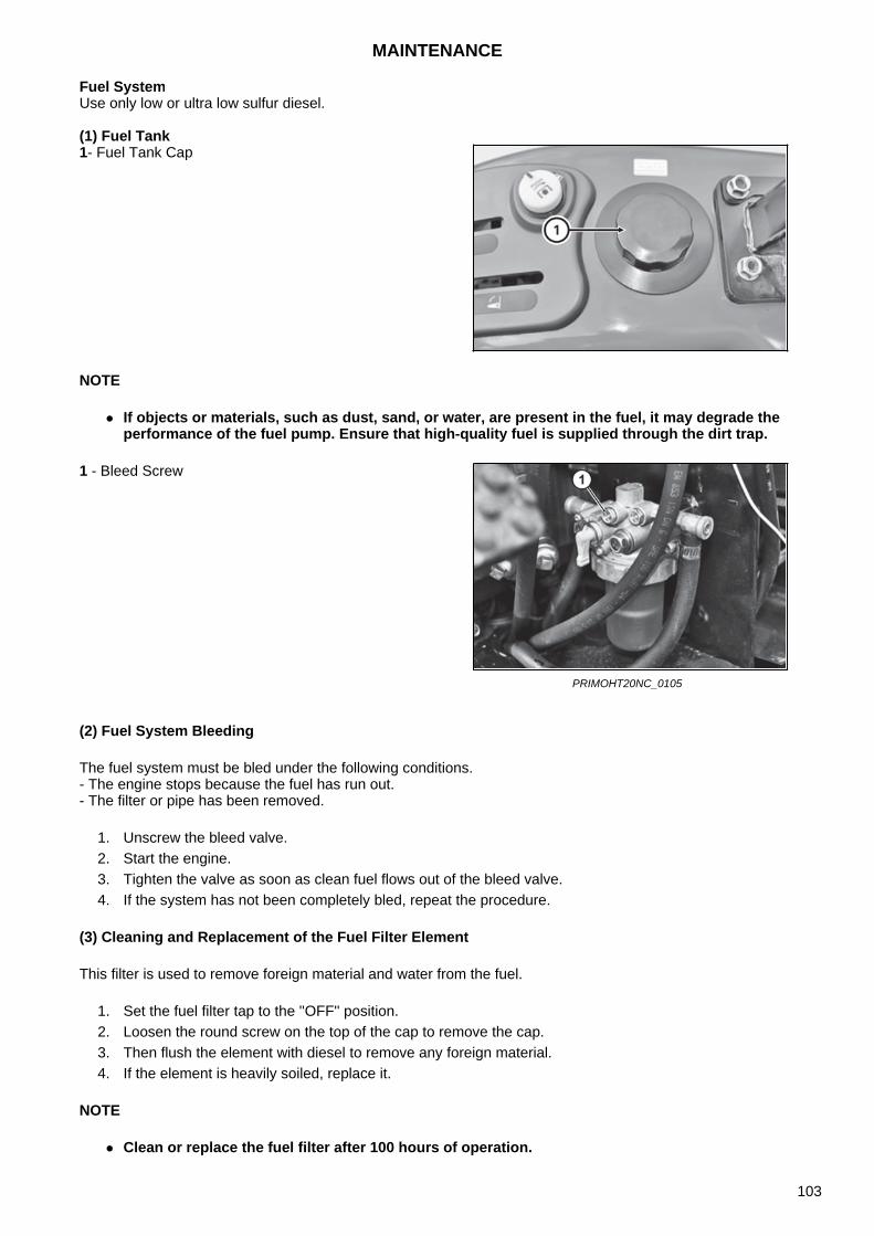
Fuel SystemUse only low or ultra low sulfur diesel.
(1) Fuel Tank
NOTE
If objects or materials, such as dust, sand, or water, are present in the fuel, it may degrade theperformance of the fuel pump. Ensure that high-quality fuel is supplied through the dirt trap.
(2) Fuel System Bleeding
The fuel system must be bled under the following conditions.- The engine stops because the fuel has run out.- The filter or pipe has been removed.
1. Unscrew the bleed valve.2. Start the engine.3. Tighten the valve as soon as clean fuel flows out of the bleed valve.4. If the system has not been completely bled, repeat the procedure.
(3) Cleaning and Replacement of the Fuel Filter Element
This filter is used to remove foreign material and water from the fuel.
1. Set the fuel filter tap to the ''OFF'' position.2. Loosen the round screw on the top of the cap to remove the cap.3. Then flush the element with diesel to remove any foreign material.4. If the element is heavily soiled, replace it.
NOTE
Clean or replace the fuel filter after 100 hours of operation.
1- Fuel Tank Cap
1 - Bleed Screw
PRIMOHT20NC_0105
MAINTENANCE
103
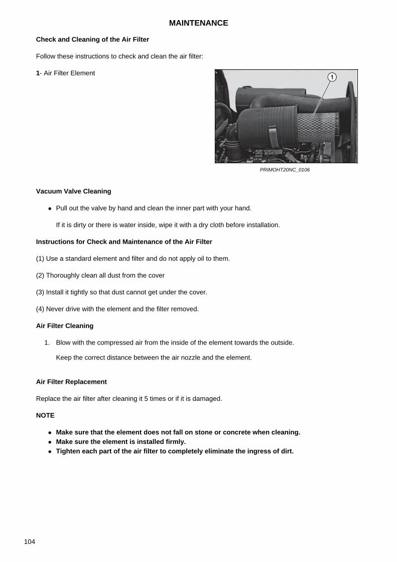
Check and Cleaning of the Air Filter
Follow these instructions to check and clean the air filter:
Vacuum Valve Cleaning
Pull out the valve by hand and clean the inner part with your hand.
If it is dirty or there is water inside, wipe it with a dry cloth before installation.
Instructions for Check and Maintenance of the Air Filter
(1) Use a standard element and filter and do not apply oil to them.
(2) Thoroughly clean all dust from the cover
(3) Install it tightly so that dust cannot get under the cover.
(4) Never drive with the element and the filter removed.
Air Filter Cleaning
1. Blow with the compressed air from the inside of the element towards the outside.
Keep the correct distance between the air nozzle and the element.
Air Filter Replacement
Replace the air filter after cleaning it 5 times or if it is damaged.
NOTE
Make sure that the element does not fall on stone or concrete when cleaning. Make sure the element is installed firmly. Tighten each part of the air filter to completely eliminate the ingress of dirt.
1- Air Filter Element
PRIMOHT20NC_0106
MAINTENANCE
104
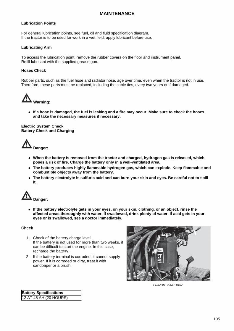
Lubrication Points
For general lubrication points, see fuel, oil and fluid specification diagram.If the tractor is to be used for work in a wet field, apply lubricant before use.
Lubricating Arm
To access the lubrication point, remove the rubber covers on the floor and instrument panel.Refill lubricant with the supplied grease gun.
Hoses Check
Rubber parts, such as the fuel hose and radiator hose, age over time, even when the tractor is not in use. Therefore, these parts must be replaced, including the cable ties, every two years or if damaged.
Warning:
If a hose is damaged, the fuel is leaking and a fire may occur. Make sure to check the hosesand take the necessary measures if necessary.
Electric System CheckBattery Check and Charging
Danger:
When the battery is removed from the tractor and charged, hydrogen gas is released, whichposes a risk of fire. Charge the battery only in a well-ventilated area.
The battery produces highly flammable hydrogen gas, which can explode. Keep flammable andcombustible objects away from the battery.
The battery electrolyte is sulfuric acid and can burn your skin and eyes. Be careful not to spillit.
Danger:
If the battery electrolyte gets in your eyes, on your skin, clothing, or an object, rinse theaffected areas thoroughly with water. If swallowed, drink plenty of water. If acid gets in youreyes or is swallowed, see a doctor immediately.
Check
1. Check of the battery charge levelIf the battery is not used for more than two weeks, itcan be difficult to start the engine. In this case,recharge the battery.
2. If the battery terminal is corroded, it cannot supplypower. If it is corroded or dirty, treat it withsandpaper or a brush.
PRIMOHT20NC_0107
Battery Specifications12 AT 45 AH (20 HOURS)
MAINTENANCE
105
Recharge
1. Turn the ignition switch to the 'OFF' position and disconnect the battery from the tractor.2. Recharge the battery in a well-ventilated area.3. Charge the battery in the normal way, do not use fast-charging.4. Turn the charging switch to the OFF position and connect correctly the cables to the negative and
positive terminals of the battery.5. When using the charger, the charging current should be less than 10 A.
Starting with an External Battery
Warning:
Do not forget to connect the positive terminal first and connect the negative terminal to theengine body of the tractor with the discharged battery.
1- Negative (-) Terminal (Black)
2- Positive (+) Terminal (Red)
PRIMOHT20NC_0108
1. Turn off all electrical equipment.2. Use a jump lead to connect the positive terminal of
a normal battery to the positive terminal of thedischarged battery.
3. Use a jump lead to connect the negative terminal ofthe charged battery to the tractor engine body ofthe tractor with the discharged battery.
4. First start the engine of the vehicle with the chargedbattery.Then start the engine of the tractor with thedischarged battery.
5. When the engine is started, disconnect thenegative terminal first.Then disconnect the positive cable.
6. Charge the discharged battery after starting theengine for approximately 30 minutes.
PRIMOHT20NC_0109
MAINTENANCE
106
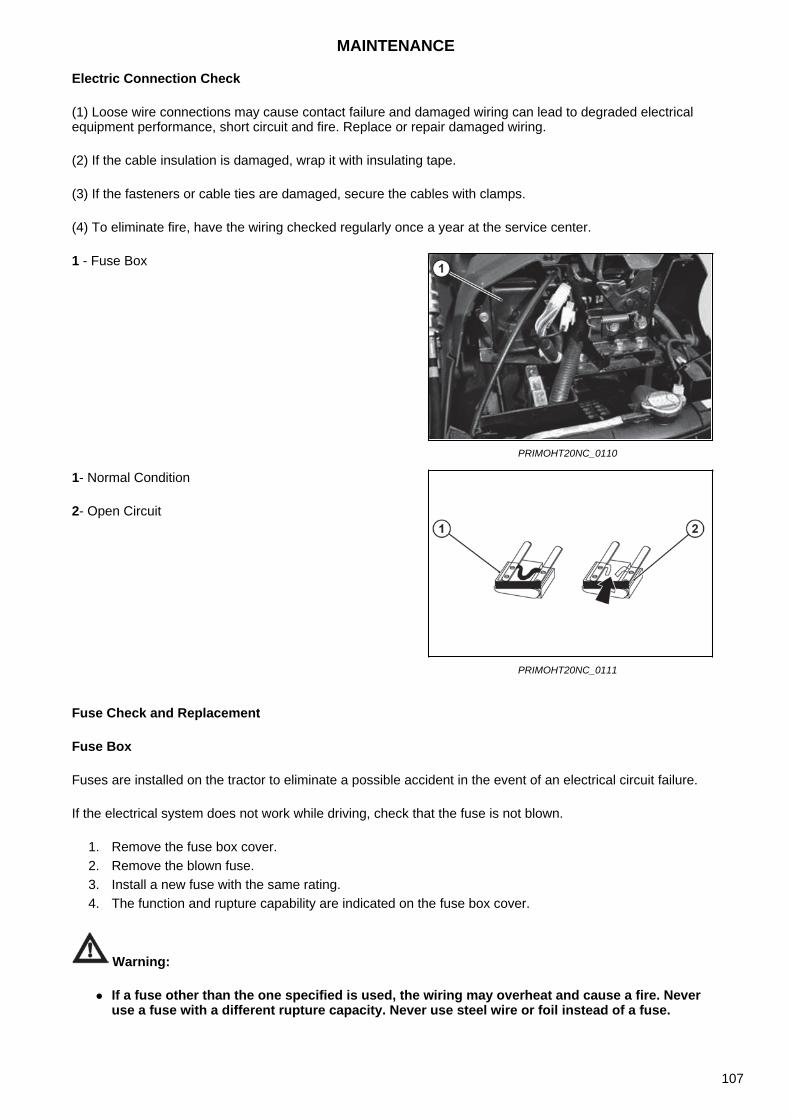
Electric Connection Check
(1) Loose wire connections may cause contact failure and damaged wiring can lead to degraded electricalequipment performance, short circuit and fire. Replace or repair damaged wiring.
(2) If the cable insulation is damaged, wrap it with insulating tape.
(3) If the fasteners or cable ties are damaged, secure the cables with clamps.
(4) To eliminate fire, have the wiring checked regularly once a year at the service center.
Fuse Check and Replacement
Fuse Box
Fuses are installed on the tractor to eliminate a possible accident in the event of an electrical circuit failure.
If the electrical system does not work while driving, check that the fuse is not blown.
1. Remove the fuse box cover.2. Remove the blown fuse.3. Install a new fuse with the same rating.4. The function and rupture capability are indicated on the fuse box cover.
Warning:
If a fuse other than the one specified is used, the wiring may overheat and cause a fire. Neveruse a fuse with a different rupture capacity. Never use steel wire or foil instead of a fuse.
1 - Fuse Box
PRIMOHT20NC_0110
1- Normal Condition
2- Open Circuit
PRIMOHT20NC_0111
MAINTENANCE
107
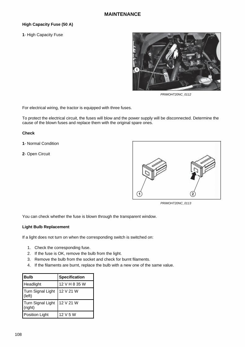
High Capacity Fuse (50 A)
For electrical wiring, the tractor is equipped with three fuses.
To protect the electrical circuit, the fuses will blow and the power supply will be disconnected. Determine the cause of the blown fuses and replace them with the original spare ones.
Check
You can check whether the fuse is blown through the transparent window.
Light Bulb Replacement
If a light does not turn on when the corresponding switch is switched on:
1. Check the corresponding fuse.2. If the fuse is OK, remove the bulb from the light.3. Remove the bulb from the socket and check for burnt filaments.4. If the filaments are burnt, replace the bulb with a new one of the same value.
1- High Capacity Fuse
PRIMOHT20NC_0112
1- Normal Condition
2- Open Circuit
PRIMOHT20NC_0113
Bulb SpecificationHeadlight 12 V H 8 35 W
Turn Signal Light (left)
12 V 21 W
Turn Signal Light (right)
12 V 21 W
Position Light 12 V 5 W
MAINTENANCE
108
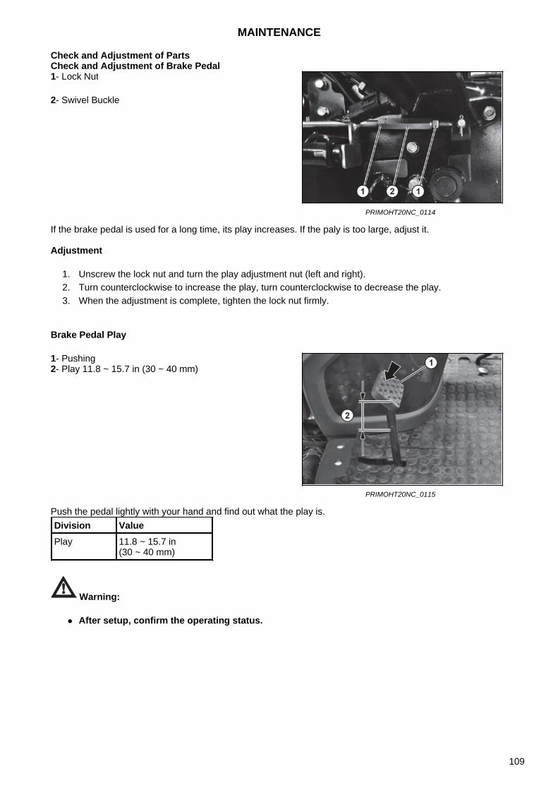
Check and Adjustment of PartsCheck and Adjustment of Brake Pedal
If the brake pedal is used for a long time, its play increases. If the paly is too large, adjust it.
Adjustment
1. Unscrew the lock nut and turn the play adjustment nut (left and right).2. Turn counterclockwise to increase the play, turn counterclockwise to decrease the play.3. When the adjustment is complete, tighten the lock nut firmly.
Brake Pedal Play
Push the pedal lightly with your hand and find out what the play is.
Warning:
After setup, confirm the operating status.
1- Lock Nut
2- Swivel Buckle
PRIMOHT20NC_0114
1- Pushing2- Play 11.8 ~ 15.7 in (30 ~ 40 mm)
PRIMOHT20NC_0115
Division ValuePlay 11.8 ~ 15.7 in
(30 ~ 40 mm)
MAINTENANCE
109
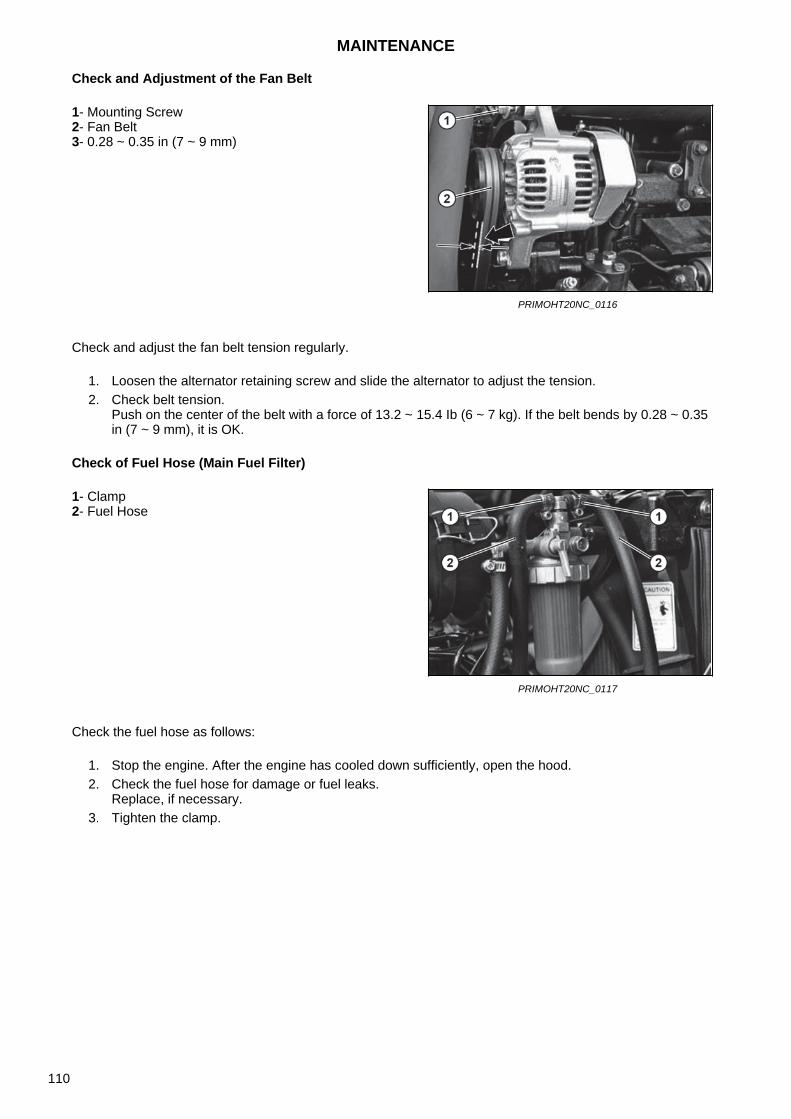
Check and Adjustment of the Fan Belt
Check and adjust the fan belt tension regularly.
1. Loosen the alternator retaining screw and slide the alternator to adjust the tension.2. Check belt tension.
Push on the center of the belt with a force of 13.2 ~ 15.4 Ib (6 ~ 7 kg). If the belt bends by 0.28 ~ 0.35in (7 ~ 9 mm), it is OK.
Check of Fuel Hose (Main Fuel Filter)
Check the fuel hose as follows:
1. Stop the engine. After the engine has cooled down sufficiently, open the hood.2. Check the fuel hose for damage or fuel leaks.
Replace, if necessary.3. Tighten the clamp.
1- Mounting Screw2- Fan Belt3- 0.28 ~ 0.35 in (7 ~ 9 mm)
PRIMOHT20NC_0116
1- Clamp2- Fuel Hose
PRIMOHT20NC_0117
MAINTENANCE
110
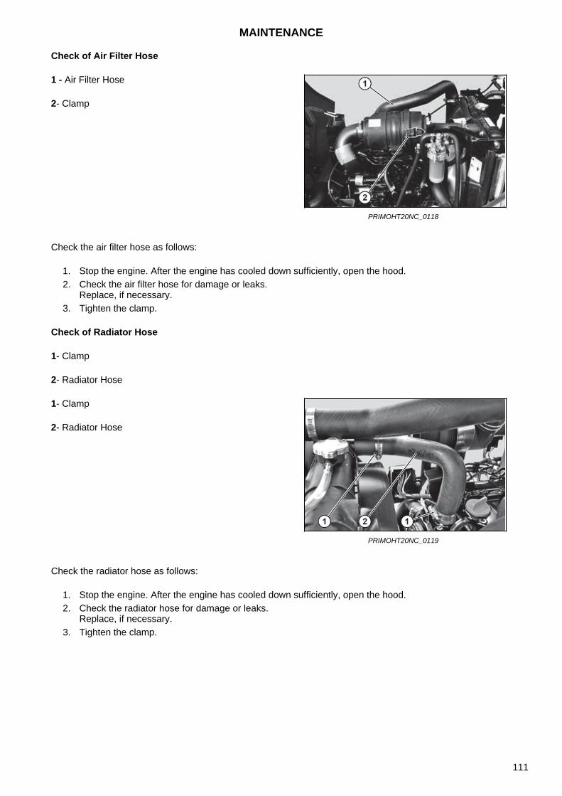
Check of Air Filter Hose
Check the air filter hose as follows:
1. Stop the engine. After the engine has cooled down sufficiently, open the hood.2. Check the air filter hose for damage or leaks.
Replace, if necessary.3. Tighten the clamp.
Check of Radiator Hose
1- Clamp
2- Radiator Hose
Check the radiator hose as follows:
1. Stop the engine. After the engine has cooled down sufficiently, open the hood.2. Check the radiator hose for damage or leaks.
Replace, if necessary.3. Tighten the clamp.
1 - Air Filter Hose
2- Clamp
PRIMOHT20NC_0118
1- Clamp
2- Radiator Hose
PRIMOHT20NC_0119
MAINTENANCE
111
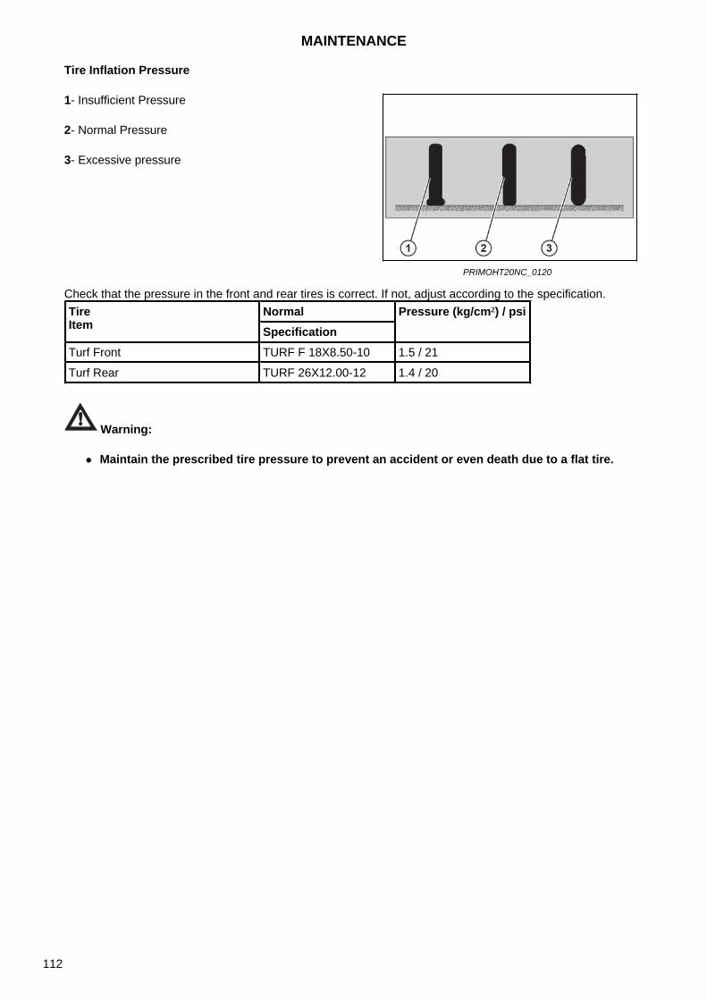
Tire Inflation Pressure
Check that the pressure in the front and rear tires is correct. If not, adjust according to the specification.
Warning:
Maintain the prescribed tire pressure to prevent an accident or even death due to a flat tire.
1- Insufficient Pressure
2- Normal Pressure
3- Excessive pressure
PRIMOHT20NC_0120
Tire Item
Normal Pressure (kg/cm²) / psiSpecification
Turf Front TURF F 18X8.50-10 1.5 / 21
Turf Rear TURF 26X12.00-12 1.4 / 20
MAINTENANCE
112

Checks and ServiceGeneral InformationThis section provides detailed information about the service procedures necessary to maintain trouble-free operation of the machine. Specific values for individual tasks can be found in the attached table.
Service Inspections Service inspections are performed as follows: The first service inspection when the hour meter is at a maximum of 50 hours of operation, but no later than within 6 months from the commissioning of the tractor. The second service inspection after another 450 hours of operation (with a maximum of 500 hours of operation), but no later than 12 months after the first service inspection. Further service inspections always after another 500 hours of operation, but no later than 12 months from the previous service inspection.
Engine Oil and Filter Change The first change of the engine oil when the hour meter is at a maximum of 50 hours of operation, but no later than within 6 months from the commissioning of the tractor. The second change of the engine oil after another 200 hours of operation (with a maximum of 250 hours of operation), but no later than 12 months after the first service inspection. Further engine oil changes, always after another 250 hours of operation, but no later than 12 months after the previous service inspection.
Performing service inspections is part of tractor maintenance. Authorized Zetor services will provide you with professional inspections according to the manufacturer's instructions.
MAINTENANCE
113
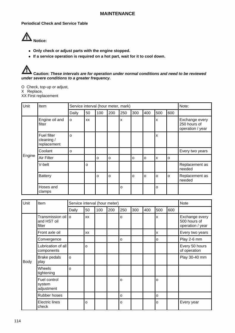
Periodical Check and Service Table
Notice:
Only check or adjust parts with the engine stopped. If a service operation is required on a hot part, wait for it to cool down.
Caution: These intervals are for operation under normal conditions and need to be reviewed under severe conditions to a greater frequency.
O Check, top-up or adjust, X Replace, XX First replacement
Unit Item Service interval (hour meter, mark) Note:
Daily 50 100 200 250 300 400 500 600
Engine
Engine oil and filter
o xx x x Exchange every 250 hours of operation / year
Fuel filter cleaning / replacement
o x
Coolant o Every two years
Air Filter o o o o x o
V-belt o Replacement as needed
Battery o o o o o o Replacement as needed
Hoses and clamps
o o
Unit Item Service interval (hour meter) Note
Daily 50 100 200 250 300 400 500 600
Body
Transmission oil and HST oil filter
o xx o x Exchange every 500 hours of operation / year
Front axle oil xx x Every two years
Convergence o o Play 2-6 mm
Lubrication of all components
o Every 50 hours of operation
Brake pedals play
o Play 30-40 mm
Wheels tightening
o
Fuel control system adjustment
o o
Rubber hoses o o
Electric lines check
o o o Every year
MAINTENANCE
114
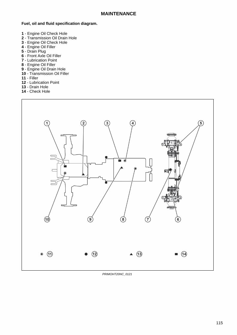
Fuel, oil and fluid specification diagram.
1 - Engine Oil Check Hole 2 - Transmission Oil Drain Hole 3 - Engine Oil Check Hole 4 - Engine Oil Filler 5 - Drain Plug 6 - Front Axle Oil Filler 7 - Lubrication Point 8 - Engine Oil Filler 9 - Engine Oil Drain Hole 10 - Transmission Oil Filler 11 - Filler 12 - Lubrication Point 13 - Drain Hole 14 - Check Hole
PRIMOHT20NC_0121
MAINTENANCE
115
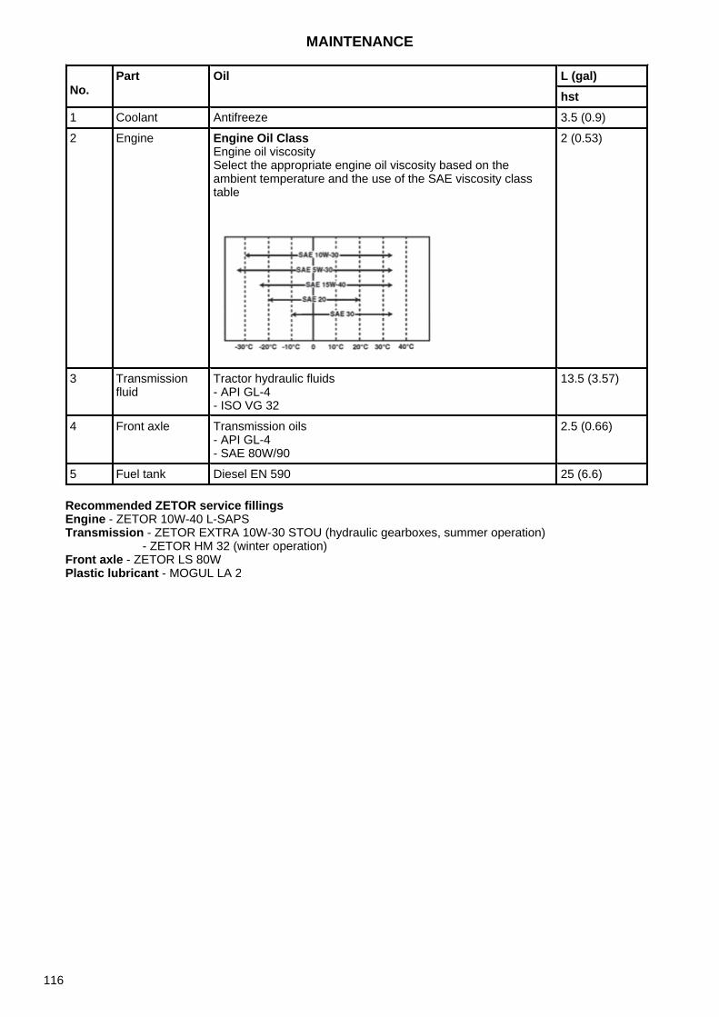
Recommended ZETOR service fillingsEngine - ZETOR 10W-40 L-SAPS Transmission - ZETOR EXTRA 10W-30 STOU (hydraulic gearboxes, summer operation)
- ZETOR HM 32 (winter operation)Front axle - ZETOR LS 80WPlastic lubricant - MOGUL LA 2
No.Part Oil L (gal)
hst1 Coolant Antifreeze 3.5 (0.9)
2 Engine Engine Oil Class Engine oil viscosity Select the appropriate engine oil viscosity based on the ambient temperature and the use of the SAE viscosity class table
2 (0.53)
3 Transmission fluid
Tractor hydraulic fluids - API GL-4- ISO VG 32
13.5 (3.57)
4 Front axle Transmission oils - API GL-4- SAE 80W/90
2.5 (0.66)
5 Fuel tank Diesel EN 590 25 (6.6)
MAINTENANCE
116
Tractor Storage
Short-term Storage
(1) Store the tractor after it has been cleaned. Clean the tractor especially carefully after working withharrows or working in a wet field.
(2) Make sure you have lowered the implement.
(3) If possible, store the tractor indoors.
(4) If you store the tractor outdoors, cover it.
(5) For better starting, it is recommended to remove the battery from the tractor in winter and store it indoors.
(6) If the outside temperature is below 0 ° C, add antifreeze or drain the coolant completely to prevent theengine from freezing and cracking.
(7) Remove the key and store it in a separate place.
Long-term Storage
Clean the tractor thoroughly and store it as follows:
(1) Change the engine oil with a new one and let the engine run for 5 minutes so that the oil is evenlydistributed in all parts.
(2) Drain the coolant from the radiator.Place a '' No coolant '' sign on the steering wheel.If the coolant contains antifreeze, it is not necessary to drain it.
(3) Add oil, fluid and fuel to the individual parts according to the maintenance table.
(4) Apply a thin layer of oil to parts of the body that are susceptible to rusting. (5) Check the tightening ofindividual screws and nuts, tighten if necessary.
(6) Set the tire pressure to be slightly higher than the specifications.
(7) Remove the weights. Disconnect or lower the implement.
(8) Support the rear wheels with wedges.
(9) Remove the battery from the tractor or switch off the power switch.
(10) To protect the tires, place wooden blocks under them.
(11) Recharge the battery every 2 months during long-term storage.
(12) To protect against rain or snow, store the tractor in a dry place, cover the vehicle body.
STORAGE AND DISPOSAL
117
Use after a Long Downtime
Storage
After long-term storage, it is recommended to follow the instructions below when using the tractor.
(1) Check the tractor thoroughly before driving.
(2) To maintain good performance and long service life, let the engine idle for about 30 minutes after starting.
NOTE
To lubricate the engine, run the engine once a month for 5 to 10 minutes at 1,500 to 2,000 rpm. Remove the key from the tractor and store it on outside the vehicle.
Notice:
If the battery remains connected to the tractor, switch off the power switch. If rodents have damaged the wiring, a short circuit can cause a fire.
Use and Disposal
To protect the environment, it is recommended to:
(1) Avoid overloading, which can lead to partial combustion and can produce air pollutant emissions.
(2) When changing the oil, including engine oil, transmission fluid, hydraulic oil and coolant, be careful not tospill the fluids. Dispose the used oil in accordance with applicable law.Used oil should be handled with care and disposed of properly, as it may contaminate soil and water.
(3) If the machine has reached the end of its service life, do not ignore it or dispose of the machine yourself,but contact your dealer so that the machine can be disposed of in accordance with the law by an authorizedservice provider.
STORAGE AND DISPOSAL
118
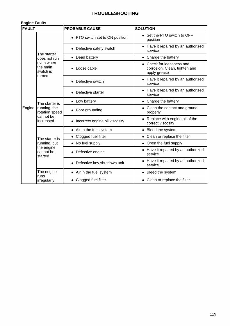
Engine FaultsFAULT PROBABLE CAUSE SOLUTION
Engine
The starter does not run even when the main switch is turned
PTO switch set to ON position Set the PTO switch to OFFposition
Defective safety switch Have it repaired by an authorizedservice
Dead battery Charge the battery
Loose cable Check for looseness and
corrosion. Clean, tighten andapply grease
Defective switch Have it repaired by an authorizedservice
Defective starter Have it repaired by an authorizedservice
The starter is running, the rotation speed cannot be increased
Low battery Charge the battery
Poor grounding Clean the contact and groundproperly
Incorrect engine oil viscosity Replace with engine oil of thecorrect viscosity
The starter is running, but the engine cannot be started
Air in the fuel system Bleed the system
Clogged fuel filter Clean or replace the filter
No fuel supply Open the fuel supply
Defective engine Have it repaired by an authorizedservice
Defective key shutdown unit Have it repaired by an authorizedservice
The engine runs irregularly
Air in the fuel system Bleed the system
Clogged fuel filter Clean or replace the filter
TROUBLESHOOTING
119

Engine FaultsFAULT PROBABLE CAUSE SOLUTION
Engine
The engine runs irregularly
Clogged injectionnozzle
Have it repaired by an authorizedservice
Fuel leak from pipes Tighten the clamp, replace the pipeand attach the copper washer
Poor fuel injectionquality
Have it repaired by an authorizedservice
Engine stops at low speed
Defective injectionpump
Have it repaired by an authorizedservice
Incorrect engine valveplay
Have it repaired by an authorizedservice
Low idle speed Set to standard speed
Defective nozzle Have it repaired by an authorizedservice
Engine overruns
Limited regulator Have it repaired by an authorizedservice
Oil level increasing Have it repaired by an authorizedservice
Engine suddenly stops
Low fuel level Refuel and bleed the system
Defective nozzle Have it repaired by an authorizedservice
Engine seizures due toinsufficient oil or poorlubrication
Have it repaired by an authorizedservice
The engine is overheated
Insufficient coolantamount
Refill coolant
Damaged fan belt Replace belt
Clogged radiator Clean the radiator
Insufficient amount ofengine oil
Check and refill
TROUBLESHOOTING
120
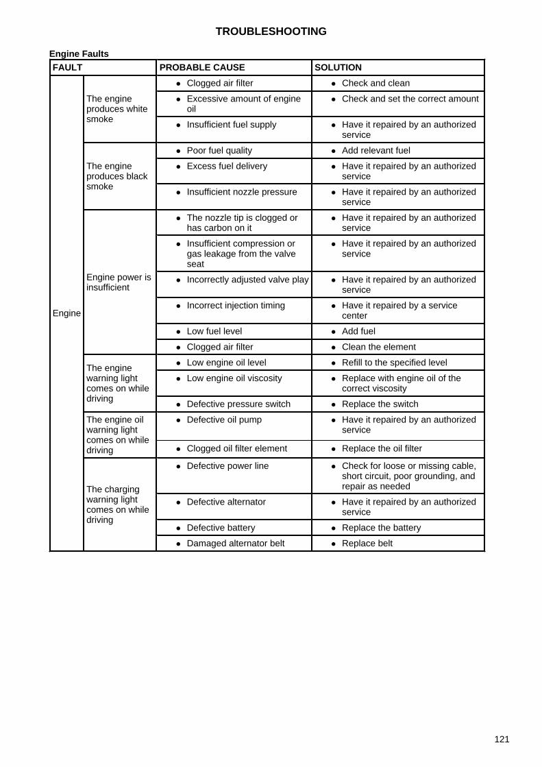
Engine FaultsFAULT PROBABLE CAUSE SOLUTION
Engine
The engine produces white smoke
Clogged air filter Check and clean
Excessive amount of engineoil
Check and set the correct amount
Insufficient fuel supply Have it repaired by an authorizedservice
The engine produces black smoke
Poor fuel quality Add relevant fuel
Excess fuel delivery Have it repaired by an authorizedservice
Insufficient nozzle pressure Have it repaired by an authorizedservice
Engine power is insufficient
The nozzle tip is clogged orhas carbon on it
Have it repaired by an authorizedservice
Insufficient compression orgas leakage from the valveseat
Have it repaired by an authorizedservice
Incorrectly adjusted valve play Have it repaired by an authorizedservice
Incorrect injection timing Have it repaired by a servicecenter
Low fuel level Add fuel
Clogged air filter Clean the element
The engine warning light comes on while driving
Low engine oil level Refill to the specified level
Low engine oil viscosity Replace with engine oil of thecorrect viscosity
Defective pressure switch Replace the switch
The engine oil warning light comes on while driving
Defective oil pump Have it repaired by an authorizedservice
Clogged oil filter element Replace the oil filter
The charging warning light comes on while driving
Defective power line Check for loose or missing cable,short circuit, poor grounding, andrepair as needed
Defective alternator Have it repaired by an authorizedservice
Defective battery Replace the battery
Damaged alternator belt Replace belt
TROUBLESHOOTING
121
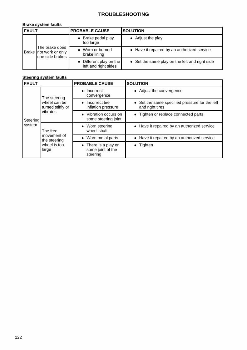
Brake system faults
Steering system faults
FAULT PROBABLE CAUSE SOLUTION
BrakeThe brake does not work or only one side brakes
Brake pedal playtoo large
Adjust the play
Worn or burnedbrake lining
Have it repaired by an authorized service
Different play on theleft and right sides
Set the same play on the left and right side
FAULT PROBABLE CAUSE SOLUTION
Steering system
The steering wheel can be turned stiffly or vibrates
Incorrectconvergence
Adjust the convergence
Incorrect tireinflation pressure
Set the same specified pressure for the leftand right tires
Vibration occurs onsome steering joint
Tighten or replace connected parts
The free movement of the steering wheel is too large
Worn steeringwheel shaft
Have it repaired by an authorized service
Worn metal parts Have it repaired by an authorized service
There is a play onsome joint of thesteering
Tighten
TROUBLESHOOTING
122

Hydraulic system faultsFAULT PROBABLE CAUSE SOLUTION
Hydraulic system
Oil leaks from pipes or hoses
Loose clamp Tighten
Cracked pipes Have it repaired by anauthorized service
Hydraulic pressure cannot be reduced
Lowering speed control leverin stop position
Set it to the lowering position
Defective valve Have it repaired by anauthorized service
Damaged cylinder Have it repaired by anauthorized service
Damaged and trapped rotatingpart of the lifting shaft
Have it repaired by anauthorized service
Hydraulic pressure cannot be increased
Insufficient engine speed Set the speed to 1,000 to1,500 rpm
Insufficient transmission fluidamount
Refill to the specified level
Air is sucked into the intakemanifold
Tighten the connections If anypipe or hose is cracked or theseal is damaged, replace it
Oil filter plugged Clean
Faulty hydraulic pump Have it repaired by anauthorized service
Defective valve Have it repaired by anauthorized service
Damaged cylinder Have it repaired by anauthorized service
TROUBLESHOOTING
123

Electrical system faultsFAULT PROBABLE CAUSE SOLUTION
Electrical System
The battery is not charging
Blown fuse Check the power lines and replace thedefective fuse
Defective powerline
Check for loose or missing cable, shortcircuit, poor grounding, and repair asneeded
Defectivealternator
Have it repaired by an authorized service
Loose or damagedalternator belt
Adjust the belt preload or replace thecracked belt
Batterymalfunction
Check that the terminals are not loose orcorroded, or that there is a sufficientamount of electrolyte and take thenecessary measures
The lights are not bright enough
Low batterycharge level
Recharge the battery
Poor contact onpower lines
Check the grounding, clean and tightenclamps
The light does not come on
Burnt out light bulb Replace the bulb
Blown fuse Check the power lines and replace thefuse
Bad contact Check the grounding and clean theclamps
The turn signal light does not flash
Burnt out light bulb Replace the bulb
Defective lightinterrupter
Replace
Bad contact Check the grounding and clean theclamps
The work light does not come on
Burnt out light bulb Replace the bulb
Bad contact Check the grounding and clean theclamps
TROUBLESHOOTING
124
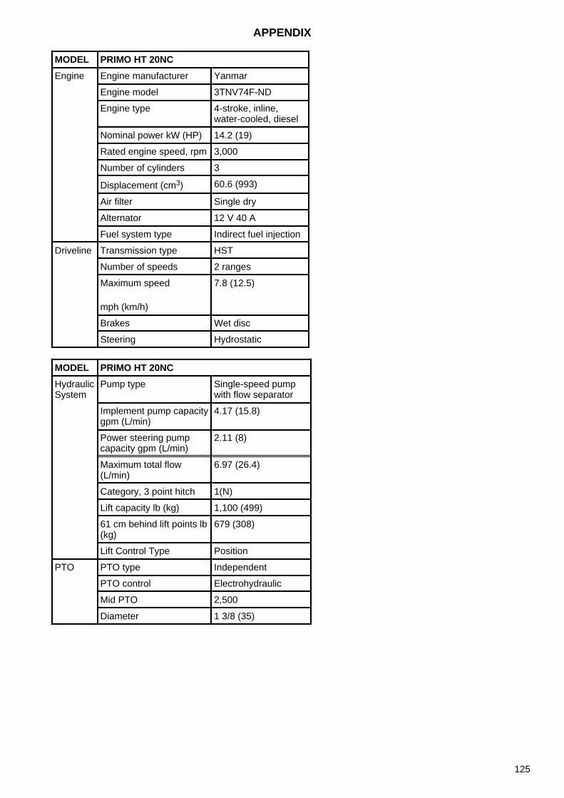
MODEL PRIMO HT 20NCEngine Engine manufacturer Yanmar
Engine model 3TNV74F-ND
Engine type 4-stroke, inline,water-cooled, diesel
Nominal power kW (HP) 14.2 (19)
Rated engine speed, rpm 3,000
Number of cylinders 3
Displacement (cm3) 60.6 (993)
Air filter Single dry
Alternator 12 V 40 A
Fuel system type Indirect fuel injection
Driveline Transmission type HST
Number of speeds 2 ranges
Maximum speed
mph (km/h)
7.8 (12.5)
Brakes Wet disc
Steering Hydrostatic
MODEL PRIMO HT 20NCHydraulic System
Pump type Single-speed pump with flow separator
Implement pump capacity gpm (L/min)
4.17 (15.8)
Power steering pump capacity gpm (L/min)
2.11 (8)
Maximum total flow (L/min)
6.97 (26.4)
Category, 3 point hitch 1(N)
Lift capacity lb (kg) 1,100 (499)
61 cm behind lift points lb (kg)
679 (308)
Lift Control Type Position
PTO PTO type Independent
PTO control Electrohydraulic
Mid PTO 2,500
Diameter 1 3/8 (35)
APPENDIX
125
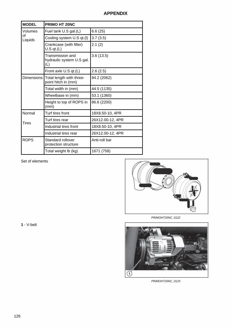
MODEL PRIMO HT 20NCVolumes of Liquids
Fuel tank U.S gal.(L) 6.6 (25)
Cooling system U.S qt.(l) 3.7 (3.5)
Crankcase (with filter) U.S qt.(L)
2.1 (2)
Transmission and hydraulic system U.S gal.(L)
3.6 (13.5)
Front axle U.S qt.(L) 2.6 (2.5)
Dimensions Total length with three-point hitch in (mm)
94.2 (2062)
Total width in (mm) 44.5 (1135)
Wheelbase in (mm) 53.1 (1360)
Height to top of ROPS in (mm)
86.6 (2200)
Normal
Tires
Turf tires front 18X8.50-10, 4PR
Turf tires rear 26X12.00-12, 4PR
Industrial tires front 18X8.50-10, 4PR
Industrial tires rear 26X12.00-12, 4PR
ROPS Standard rollover protection structure
Anti-roll bar
Total weight lb (kg) 1671 (758)
Set of elements
PRIMOHT20NC_0122
1 - V-belt
PRIMOHT20NC_0123
APPENDIX
126
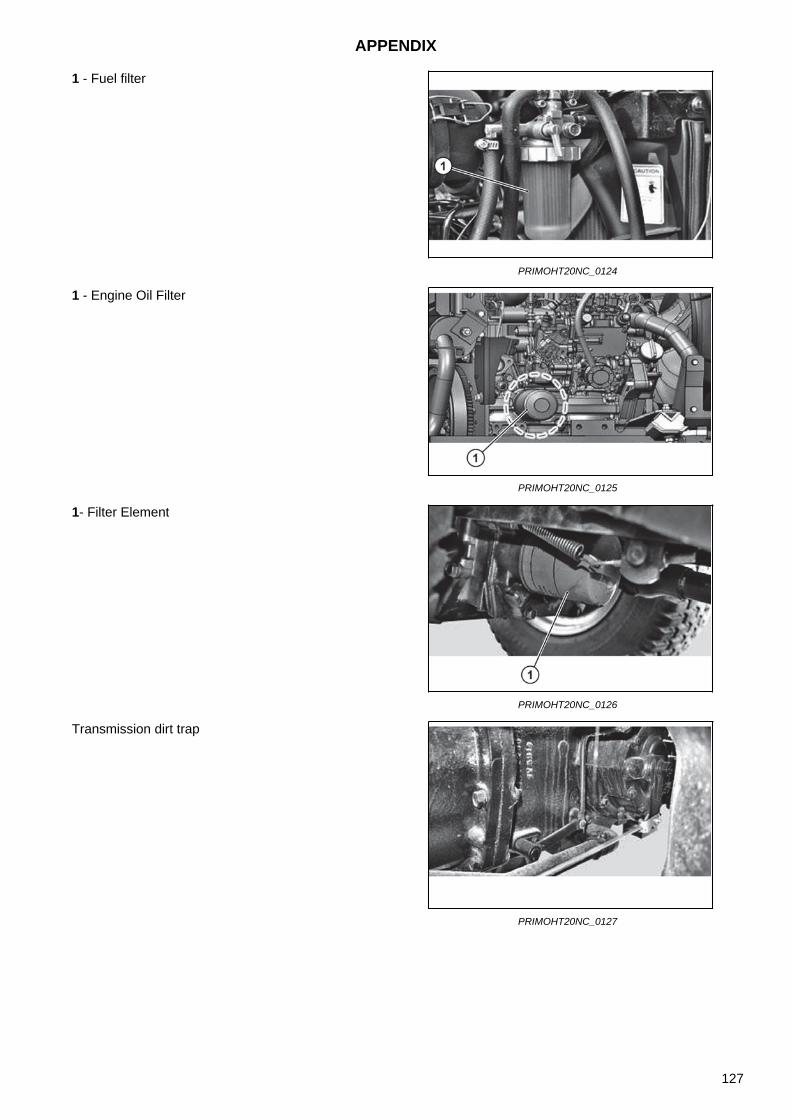
1 - Fuel filter
PRIMOHT20NC_0124
1 - Engine Oil Filter
PRIMOHT20NC_0125
1- Filter Element
PRIMOHT20NC_0126
Transmission dirt trap
PRIMOHT20NC_0127
APPENDIX
127

NOTES
128

A About this manual 9 Air Filter Cleaning 104 Air Filter Replacement 104 Always use safety lights and devices 17 Appendix 125 Avoid high-pressure fluids 18
B Battery disconnect 19 Battery Check and Charging 105 Belt Replacement 82 Belt Replacement 82 Blade Disassembly 81 Blade Installation 81 Brake Pedal 47 Brake Pedal Play 109 Brake system faults 122
C Check and Adjustment of Brake Pedal 109 Check and Adjustment of Parts 109 Check and Adjustment of the Fan Belt 110 Check and Cleaning of the Air Filter 104 Check and Change of Coolant 95 Check and Change of Engine Coolant 95 Check of Air Filter Hose 111 Check of Fuel Hose (Main Fuel Filter) 110 Check of Radiator Hose 111 Checked Items 94 Checked Items 94 Checks and Service 113 Cleaning the Radiator and Radiator Grilles 96 Cleaning the Transmission Fluid Dirt Trap 101 Combined Switch 41 Control Pedals 48 Controls Operation 46 Coolant 89 Coolant Temperature Indicator Light 40 Covers Opening 93 Cruise Control 56 Cruise Control Switch 45
D Diesel fuel 25 Differential lock pedal 50 Don'ts - for safe operation 27 DO'S AND DON'T'S 26 DO'S-for better performance 26 Driving Off 87 Driving Off on a Steep Slope 87 Driving Off, Shifting and Driving 87 Driving on a Slope 87
E Electric Connection Check 107 Electric System Check 105 Electrical system faults 124 Engine Faults 119 Engine Faults 120 Engine Faults 121 Engine Idling 86 Engine Idling in General 86 Engine Oil and Replacement 96 Engine Oil Pressure 89 Exterior view 29
F Fasteners torque table (ISO) 80 Filter and Element Replacement 101 Front and Rear Cutting Height Adjustment 78 Front Axle Drive Shift Lever (4WD) 51 Front Axle Oil Check and Change 100 Front Link 73 Front Link Assembly 74 Fuel Gauge 39 Fuel System 103 Fuel, oil and fluid specification diagram. 115 Fuse Box 107 Fuse Check and Replacement 107
G General Information 113 General informations 29
H Handle fuel safely-avoid fires 17 Help with Manual Use 57 High Capacity Fuse (50 A) 108 Hood Opening 93 Hoses Check 105 Hour Meter 39 How to adjust the seat 13 How to Start the Engine 85 Hydraulic system faults 123
I Implement Lifting Control System 54 Implement Lowering Speed Control Dial 55 Indicator Lights 42 Information Labels 66 Instruments and Switches 37 Introduction to safety information 15 Introduction to safety instructions Introduction to safety instructions 15
K Keep riders off tractor 16
L Left and Right Cutting Height Adjustment 79 Light Bulb Replacement 108 Link Settings 76 Loading on Truck / Unloading 88 Location of serial numbers 7 Long-term Storage 117 Lubricating Arm 105 Lubrication 70 Lubrication Points 105
M Main Switch 38 Maintenance 93 Maintenance (1) 63 Maintenance (2) 64 Mounting and demounting implements 22 Mower deck 57 Mower Deck 58 Mower Deck Adjustment 71 Mower Deck Settings 75
O Oil filter Element Replacement 102 Oil Check and Replacement 96 Operation 85 Operation (1) 61 Operation (2) 62 Operation Check while Driving 89 Operation in General 59 Operation on the Slope 60
P Parking 87 Parking Brake Pedal 48 Parts Replacement 81 Periodical Check and Service Table 114 Practice safe maintenance 18 Precaution to avoid tipping 16 Precautions when Driving on the Road 89 Precautions when Entering / Exiting a Field 88 Preface 57 Prevent acid burns 19 Prevent battery explosions 18 Product Warranty 7 Protection children 15 Pto 53 PTO ON / OFF Switch 45
R Rear Link 73 Recommended ZETOR service fillings 116 Reduced and Road Gears Shift Lever 49 Recharge 106
INDEX
129

Roll-Over Protection Structure (ROPS) 11 Rops (roll over protection structures) 11 ROPS damage 12 Run-in 86
S Safe operation of your tractor 21 Safe parking of the tractor 16 Safety instructions 15 Safety Labels 65 Safety starter switch 20 Safety Tips During Maintenance 21 Seat and Seat Belt 52 Service tractor safely 19 Short-term Storage 117 Signal words 15 Sliding Seat 13 Starting with an External Battery 106 Stay clear of rotating shafts 17 Steering system faults 122 Storage and disposal 117 Switching Off 85 Switching the Engine Off 85
T Table of fillings change and service intervals 64 Tachometer 39 Technical data of the middle mower deck 68 The following precautions are suggested to help prevent accidents 23
Throttle Lever 47 Tips for Driving on a Slope 88 Tips for using the steering wheel with power steering 53 Tire Inflation Pressure 112 Tractor controls 37 Tractor runaway 20 Tractor Storage 117 Transmission 83 Transmission Fluid Filter Element Replacement 101 Transmission Fluid Check and Change 98 Transport 60 Travel Speed 48 Troubleshooting 119
U Universal joint 72 Use after a Long Downtime 118 Use and Disposal 118 Use of rops and seat belt 16 Use of the Machine 57
V Vacuum Valve Cleaning 104
W Warning Lights Switch 41 Warning Symbols 32 Work in ventilated area 20 Workflow 91
INDEX
130

131

Operator's manual Primo HT 20
Edition: 1-100-2020 Publication No.: 222.213.574 09/2020 ZETOR TRACTORS a.s. Department of Technical Documentation Trnkova 111 628 00 Brno
132