Embed Size (px)
Citation preview

1SCIEntIFIC REPoRTS | 7: 16396 | DOI:10.1038/s41598-017-16732-4
www.nature.com/scientificreports
Preparation of ZnS@In2S3 Core@shell Composite for Enhanced Photocatalytic Degradation of Gaseous o-Dichlorobenzene under Visible LightBaojun Liu1,2, Xia Hu1, Xinyong Li3, Ying Li2, Chang Chen2 & Kwok-ho Lam 2
In this study, novel ZnS@In2S3 core@shell hollow nanospheres were fabricated by a facile refluxing method for the first time, and the formation mechanism of hollow structure with interior architecture was discussed based on ion-exchange Ostwald ripening. As the photocatalytic material for degradation of gaseous o-Dichlorobenzene (o-DCB), the as-synthesized core@shell hollow nanospheres were found to show significantly enhanced catalytic performance for effective separation of photo-generated charges. Moreover, the mechanisms of enhanced activity were elucidated by band alignment and unique configuration. Such photocatalyst would meet the demands for the control of persistent organic pollutant (POPs) in the atmospheric environment.
Zinc sulphide (ZnS) semiconductor, as an important II-VI binary chalcogenide, has attracted much attention due to its wide potential applications in many fields1–3. For example, ZnS materials possess photocatalytic properties for pollutant control and photosynthesis process4–6. However, its wide band gap and high recombination rate of photo-generated charges often lead to low quantum yield in the photocatalytic reactions. To address the key issue of low quantum yield, many methods, such as noble metal deposition7,8, element doping9 and semiconductor coupling10,11, have been extensively studied and applied in recent years12–15. Among these approaches, coupling with other semiconductors for forming the composites is one of the most effective ways to improve the separation efficiency of photo-generated charges, which could also take full advantage of solar spectrum, compared with the individual material16,17.
At present, indium sulphide (In2S3) material, a III-VI group sulphide, is a semiconductor with a bandgap of 2.0–2.3 eV and would show excellent optical property, especially, a wide response to the solar spectrum18,19. More importantly, the conduction band (CB) of In2S3 is composed of d, s and p orbitals, while the valence band (VB) consists of S 3p orbitals, which are much more negative than O 2p orbitals3. The characteristics of band edges could lead to the reduction reactions more available. In spite of these advantages of In2S3, it is obvious that the strong light-etching phenomenon and low charge-migration efficiency would prevent it from practical applications as an individual component20,21. Thus, the coupling of In2S3 with ZnS material for forming hetero-geneous structures should be beneficial for effective separation and transfer of photo-induced carriers. In addi-tion, since the hollow structure can modulate the index of refraction, enhance intensity of light scattering, and provide more active sites for substances adsorption and facilitate diffusion between substances and materials22–24, the hollow-structured catalysts could improve the photocatalytic efficiency significantly. Generally, the shells of hollow structure are accumulated by a large quantity of nanoparticles, which could leave a large number of porous channels in the framework, so oxygen and reactants could permeate through the shells for much efficient reactions23,25,26.
1College of Resource and Environmental Engineering, Guizhou University, Guiyang, 550025, China. 2Department of Electrical Engineering, The Hong Kong Polytechnic University, Hung Hom, Kowloon, Hong Kong, China. 3State Key Laboratory of Fine Chemicals, Key Laboratory of Industrial Ecology and Environmental Engineering (MOE), School of Environmental Science and Technology, Dalian University of Technology, Dalian, 116024, China. Correspondence and requests for materials should be addressed to K.-h.L. (email: [email protected])
Received: 31 May 2017
Accepted: 16 November 2017
Published: xx xx xxxx
OPEN
www.nature.com/scientificreports/
2SCIEntIFIC REPoRTS | 7: 16396 | DOI:10.1038/s41598-017-16732-4
Based on the above analysis, ZnS@In2S3 core@shell hollow nanospheres have been proposed in this work as high-efficient hollow composite nanomaterials for photocatalytic applications. Herein, the ZnS@In2S3 core@shell hollow nanospheres have been prepared by an anion-exchange reaction for the first time and then applied to pho-tocatalytic degradation of gaseous o-Dichlorobenzene (o-DCB) under visible-light irradiation. o-DCB, as one of the typical persistent organic pollutants (POPs), has raised wide attention for their carcinogenicity, high toxicity and bioaccumulation in the environment27,28. It is obvious that the coupling of ZnS with In2S3 is a promising strat-egy to enhance the photocatalytic activity for pollutant elimination. Furthermore, the enhancement mechanism of photocatalytic performance for the ZnS@In2S3 core@shell hollow spheres has been discussed in detail.
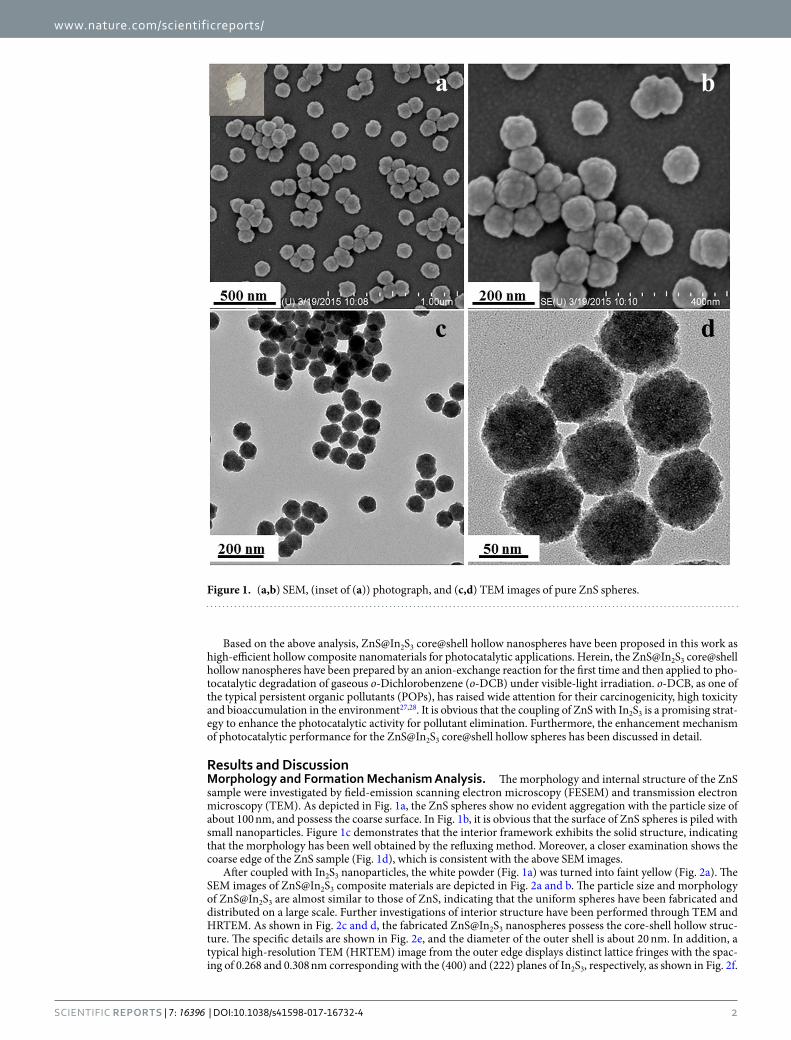
Results and DiscussionMorphology and Formation Mechanism Analysis. The morphology and internal structure of the ZnS sample were investigated by field-emission scanning electron microscopy (FESEM) and transmission electron microscopy (TEM). As depicted in Fig. 1a, the ZnS spheres show no evident aggregation with the particle size of about 100 nm, and possess the coarse surface. In Fig. 1b, it is obvious that the surface of ZnS spheres is piled with small nanoparticles. Figure 1c demonstrates that the interior framework exhibits the solid structure, indicating that the morphology has been well obtained by the refluxing method. Moreover, a closer examination shows the coarse edge of the ZnS sample (Fig. 1d), which is consistent with the above SEM images.
After coupled with In2S3 nanoparticles, the white powder (Fig. 1a) was turned into faint yellow (Fig. 2a). The SEM images of ZnS@In2S3 composite materials are depicted in Fig. 2a and b. The particle size and morphology of ZnS@In2S3 are almost similar to those of ZnS, indicating that the uniform spheres have been fabricated and distributed on a large scale. Further investigations of interior structure have been performed through TEM and HRTEM. As shown in Fig. 2c and d, the fabricated ZnS@In2S3 nanospheres possess the core-shell hollow struc-ture. The specific details are shown in Fig. 2e, and the diameter of the outer shell is about 20 nm. In addition, a typical high-resolution TEM (HRTEM) image from the outer edge displays distinct lattice fringes with the spac-ing of 0.268 and 0.308 nm corresponding with the (400) and (222) planes of In2S3, respectively, as shown in Fig. 2f.
Figure 1. (a,b) SEM, (inset of (a)) photograph, and (c,d) TEM images of pure ZnS spheres.

www.nature.com/scientificreports/
3SCIEntIFIC REPoRTS | 7: 16396 | DOI:10.1038/s41598-017-16732-4
Based on the details of SEM and TEM images, one of most possible formation mechanisms of ZnS@In2S3 core@shell hollow nanospheres is illustrated in Fig. 3. It is known that the pyrrolidon ring of the capping agent PVP possesses the strong interaction with Zn2+, which could prevent the agglomeration of ZnS nanoparticles through the repulsive forces among the polyvinyl groups10. After added TAA, the S2− ions are released from TAA in the aqueous solution when heated to 100 °C, and then react with Zn2+ to form ZnS tiny nanocrystals. To min-imize the surface energy, these nanocrystals tend to form into solid spheres by the self-assembled method29. As a result, the ZnS solid spheres composed of small grains exhibited greater coarseness. As the surface charge of ZnS materials was negative in aqueous solutions, the In3+ ions would attach on the surface of ZnS spheres through the electrostatic attraction. Subsequently, the In2S3 nanoparticles will be formed on the surface of ZnS crystals via interfacial diffusion10, which would form the core@shell ZnS@In2S3 structure. Obviously, it is believed that the difference of solubility products (Ksp) of ZnS (1.6 × 10⁻²⁴) and In2S3 (6.3 × 10−36) is the main driving force for the formation of ZnS@In2S3 composite29,30. At last, after adding TAA again, the S2− concentration in the solution
Figure 2. (a,b) SEM, (inset of (a)) photograph, (c–e) TEM and (f) HRTEM images of ZnS@In2S3 core@shell hollow spheres.
Figure 3. Schematic growth mechanism of the ZnS@In2S3 core@shell hollow spheres.

www.nature.com/scientificreports/
4SCIEntIFIC REPoRTS | 7: 16396 | DOI:10.1038/s41598-017-16732-4
environment is much higher than that in the composites such that the S2− ions of ZnS are hardly to diffuse outside, and so the yolk@shell structure is formed. In the post-heating process, the yolk@shell structure would contract to form the core@shell hollow structure due to the instability.
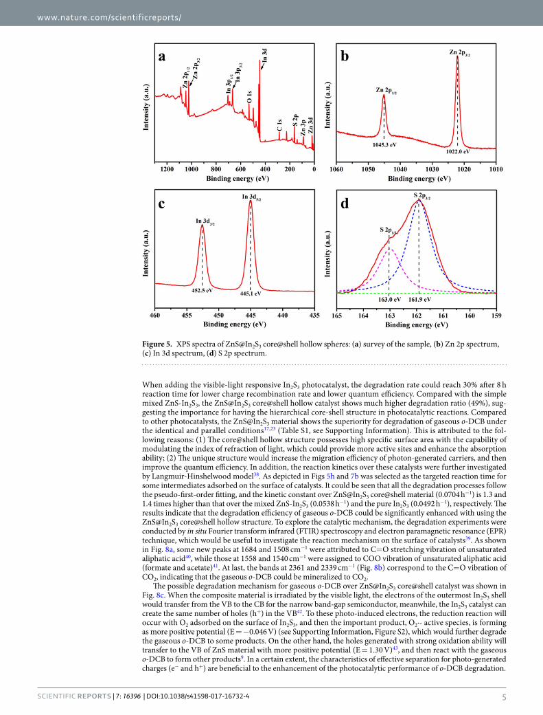
Physicochemical property characterization. The XRD pattern of the ZnS@In2S3 core@shell spheres is shown in Fig. 4. For the ZnS sample, the characteristic peaks, appearing at 2θ: 28.6°, 47.6° and 56.5° would be assigned to the diffraction patterns of (111), (220) and (311) of ZnS cube phase given in JCPDS (65–0309) (space group: F-43m (216)), respectively, and no other peaks of impurities were detected. After coupled with In2S3 to form the ZnS@In2S3 structure, the composite exhibits extra diffraction peaks at 2θ: 51.6° and 56.0°, which correspond to the (112) and (201) plane reflections of the hexagonal phase In2S3 given in JCPDS (33-0623) (space group: P-3m1(164)), respectively. This indicates that the core@shell composite structure was fabricated by coupling ZnS with In2S3. Moreover, in order to further confirm the surface components and chemical states of ZnS@In2S3 structures, the composite was evaluated by XPS and the results are shown in Fig. 5. From the survey spectrum, it could be seen that the composite material contains Zn, In, S, O, and C elements, and the O element is from the adsorption of H2O on the surface of catalyst or residual substances after calcination31. In addition, the C element at the binding energy of 284.6 eV is from allogenic substances or referencing spectra32. In Fig. 5b, there are two characteristic peaks at 1045.3 eV and 1022.0 eV for Zn 2p1/2 and Zn2p3/2, respectively, which are assigned to Zn2+33. Meanwhile, the bands at 425.5 eV and 445.1 eV are ascribed to the spectrum of In3+34. Due to its asymmetry of XPS spectrum of S 2p, two evident peaks located at 163.0 eV and 161.9 eV are deconvoluted in Fig. 5d, which are attributed to S2− 17,34.
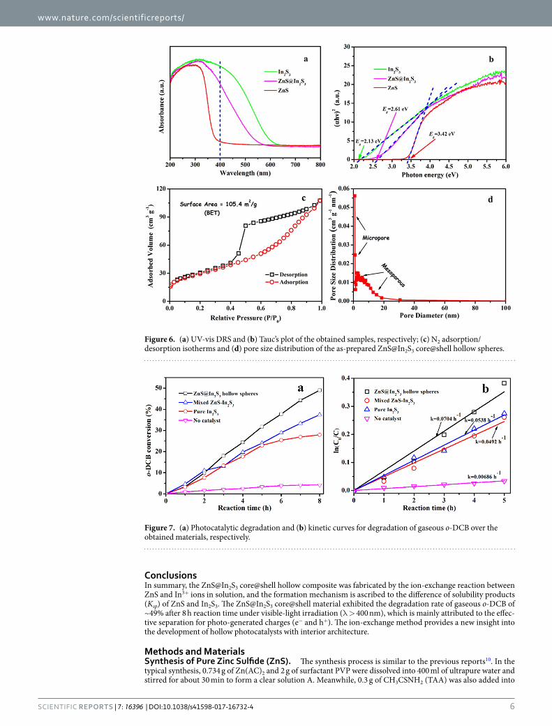
The optical response properties of the catalytic materials obtained were investigated by UV-vis diffuse reflec-tion spectra (DRS). From Fig. 6a, it is obvious that the pure ZnS shows no evident absorption peak in the region of visible light (400–550 nm), whereas the adsorption edge of the ZnS@In2S3 composite significantly extend to the visible light region, suggesting that the composite exhibits the enhanced absorption ability under the visible-light irradiation. Furthermore, the band gap Eg values are calculated by estimating the intercept of the tangent at the Tauc’s plots35. As depicted in Fig. 6b, the band gap of the ZnS@In2S3 material was calculated to be 2.61 eV, showing that the electrons could transfer under visible-light illumination. Regarding of the lower recombination rate of photo-generated charges with the addition of In2S3, the photocurrent and electrochemical impedance spectros-copy (EIS) of ZnS and ZnS@In2S3 composite were tested under visible light in the electrochemical workstation. As shown in Figure S1a (see Supporting Information), the ZnS@In2S3 has much higher transient photocurrent than the ZnS that did not respond to visible light, indicating that the ZnS@In2S3 has higher efficiency of photo-induced charge separation. In addition, Figure S1b exhibits the EIS Nyquist plots of the ZnS and ZnS@In2S3 electrodes under visible-light illumination in the Na2SO4 electrolyte. Usually, a smaller radius of the arc on the EIS Nyquist plot represents the faster charge-transfer speed36,37. After coupling with In2S3, the impedance radius of the ZnS electrode reduced significantly, which implies that the ZnS@In2S3 structure has good response to visible light, so as to effectively improve the separation of photon-generated charges and accelerate the photo-induced charge transfer.
As the pore size and the corresponding specific surface area of ZnS@In2S3 core@shell spheres play important roles in enhancing the photocatalytic performance, the N2 adsorption/desorption isotherms were investigated. As shown in Fig. 6c, the typical IV isotherms with a H1 hysteresis loop were obtained. Besides, the pore size distribution was in the regions of mesoporous and micropore structures (shown in Fig. 6d). Moreover, the spe-cific surface area of the ZnS@In2S3 core@shell structure was about 105.4 m2 g−1. Compared to the mixed sulfides (66.2 m2 g−1), the core-shell structure showed much larger surface, to some extent, which could promote the degradation efficiency.
The performance and mechanism of degradation gaseous o-DCB. Fig. 7a illustrates the photocata-lytic performance for gaseous o-DCB degradation over all the samples obtained under visible light (λ > 400 nm). It was found that the substrate could hardly be decomposed as persistent organic pollutant without catalysts.
Figure 4. XRD patterns of pure ZnS and ZnS@In2S3 core@shell hollow spheres.
www.nature.com/scientificreports/
5SCIEntIFIC REPoRTS | 7: 16396 | DOI:10.1038/s41598-017-16732-4
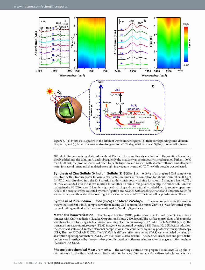
When adding the visible-light responsive In2S3 photocatalyst, the degradation rate could reach 30% after 8 h reaction time for lower charge recombination rate and lower quantum efficiency. Compared with the simple mixed ZnS-In2S3, the ZnS@In2S3 core@shell hollow catalyst shows much higher degradation ratio (49%), sug-gesting the importance for having the hierarchical core-shell structure in photocatalytic reactions. Compared to other photocatalysts, the ZnS@In2S3 material shows the superiority for degradation of gaseous o-DCB under the identical and parallel conditions17,23 (Table S1, see Supporting Information). This is attributed to the fol-lowing reasons: (1) The core@shell hollow structure possesses high specific surface area with the capability of modulating the index of refraction of light, which could provide more active sites and enhance the absorption ability; (2) The unique structure would increase the migration efficiency of photon-generated carriers, and then improve the quantum efficiency. In addition, the reaction kinetics over these catalysts were further investigated by Langmuir-Hinshelwood model38. As depicted in Figs 5h and 7b was selected as the targeted reaction time for some intermediates adsorbed on the surface of catalysts. It could be seen that all the degradation processes follow the pseudo-first-order fitting, and the kinetic constant over ZnS@In2S3 core@shell material (0.0704 h−1) is 1.3 and 1.4 times higher than that over the mixed ZnS-In2S3 (0.0538 h−1) and the pure In2S3 (0.0492 h−1), respectively. The results indicate that the degradation efficiency of gaseous o-DCB could be significantly enhanced with using the ZnS@In2S3 core@shell hollow structure. To explore the catalytic mechanism, the degradation experiments were conducted by in situ Fourier transform infrared (FTIR) spectroscopy and electron paramagnetic resonance (EPR) technique, which would be useful to investigate the reaction mechanism on the surface of catalysts39. As shown in Fig. 8a, some new peaks at 1684 and 1508 cm−1 were attributed to C=O stretching vibration of unsaturated aliphatic acid40, while those at 1558 and 1540 cm−1 were assigned to COO vibration of unsaturated aliphatic acid (formate and acetate)41. At last, the bands at 2361 and 2339 cm−1 (Fig. 8b) correspond to the C=O vibration of CO2, indicating that the gaseous o-DCB could be mineralized to CO2.
The possible degradation mechanism for gaseous o-DCB over ZnS@In2S3 core@shell catalyst was shown in Fig. 8c. When the composite material is irradiated by the visible light, the electrons of the outermost In2S3 shell would transfer from the VB to the CB for the narrow band-gap semiconductor, meanwhile, the In2S3 catalyst can create the same number of holes (h+) in the VB42. To these photo-induced electrons, the reduction reaction will occur with O2 adsorbed on the surface of In2S3, and then the important product, O2·- active species, is forming as more positive potential (E = −0.046 V) (see Supporting Information, Figure S2), which would further degrade the gaseous o-DCB to some products. On the other hand, the holes generated with strong oxidation ability will transfer to the VB of ZnS material with more positive potential (E = 1.30 V)43, and then react with the gaseous o-DCB to form other products9. In a certain extent, the characteristics of effective separation for photo-generated charges (e− and h+) are beneficial to the enhancement of the photocatalytic performance of o-DCB degradation.
Figure 5. XPS spectra of ZnS@In2S3 core@shell hollow spheres: (a) survey of the sample, (b) Zn 2p spectrum, (c) In 3d spectrum, (d) S 2p spectrum.
www.nature.com/scientificreports/
6SCIEntIFIC REPoRTS | 7: 16396 | DOI:10.1038/s41598-017-16732-4
ConclusionsIn summary, the ZnS@In2S3 core@shell hollow composite was fabricated by the ion-exchange reaction between ZnS and In3+ ions in solution, and the formation mechanism is ascribed to the difference of solubility products (Ksp) of ZnS and In2S3. The ZnS@In2S3 core@shell material exhibited the degradation rate of gaseous o-DCB of ~49% after 8 h reaction time under visible-light irradiation (λ > 400 nm), which is mainly attributed to the effec-tive separation for photo-generated charges (e− and h+). The ion-exchange method provides a new insight into the development of hollow photocatalysts with interior architecture.
Methods and MaterialsSynthesis of Pure Zinc Sulfide (ZnS). The synthesis process is similar to the previous reports10. In the typical synthesis, 0.734 g of Zn(AC)2 and 2 g of surfactant PVP were dissolved into 400 ml of ultrapure water and stirred for about 30 min to form a clear solution A. Meanwhile, 0.3 g of CH3CSNH2 (TAA) was also added into
Figure 6. (a) UV-vis DRS and (b) Tauc’s plot of the obtained samples, respectively; (c) N2 adsorption/desorption isotherms and (d) pore size distribution of the as-prepared ZnS@In2S3 core@shell hollow spheres.
Figure 7. (a) Photocatalytic degradation and (b) kinetic curves for degradation of gaseous o-DCB over the obtained materials, respectively.
www.nature.com/scientificreports/
7SCIEntIFIC REPoRTS | 7: 16396 | DOI:10.1038/s41598-017-16732-4
200 ml of ultrapure water and stirred for about 15 min to form another clear solution B. The solution B was then slowly added into the solution A, and subsequently the mixture was continuously stirred in an oil bath at 100 °C for 2 h. At last, the products were collected by centrifugation and washed with absolute ethanol and ultrapure water for several times, and then dried overnight in a vacuum oven at 60 °C. The while powder was collected.
Synthesis of Zinc Sulfide @ Indium Sulfide (ZnS@In2S3). 0.097 g of as-prepared ZnS sample was dissolved with ultrapure water to form a clear solution under ultra-sonication for about 5 min. Then, 0.3 g of In(NO3)3 was dissolved into the ZnS solution under continuously stirring for about 15 min, and later 0.075 g of TAA was added into the above solution for another 15 min stirring. Subsequently, the mixed solution was maintained at 80 °C for about 1 h under vigorously stirring and then naturally cooled down to room temperature. At last, the products were collected by centrifugation and washed with absolute ethanol and ultrapure water for several times, and then also dried overnight in a vacuum oven at 60 °C. The faint yellow powder was collected.
Synthesis of Pure Indium Sulfide (In2S3) and Mixed ZnS-In2S3. The reaction process is the same as the synthesis of ZnS@In2S3 composite without adding ZnS solution. The mixed ZnS-In2S3 was fabricated by the manual milling method with the aforementioned ZnS and In2S3 particles.
Materials Characterization. The X-ray diffraction (XRD) patterns were performed by an X-Ray diffrac-tometer with Cu Kα radiation (Rigaku Corporation D/max-2400, Japan). The surface morphology of the samples was characterized by using a field emission scanning electron microscope (FESEM, Hitachi SU8010, Japan). The transmission electron microscopy (TEM) images were captured by using a FEI Tecnai G20 (USA). In addition, the chemical states and surface elements compositions were conducted by X-ray photoelectron spectroscopy (XPS, Thermo ESCALAB 250XI). The UV-Visible diffuse reflection spectra (DRS) were recorded by using an absorption spectrophotometer (JASCO, UV-550) from 200 to 800 nm. The specific surface area and pore distri-bution were investigated by nitrogen adsorption/desorption isotherms using an automated gas sorption analyzer (Autosorb-IQ, USA).
Photoelectrochemical Measurements. The working electrode was prepared as follows: 0.01 g photo-catalyst was mixed with ethanol under ultra-sonication for about 5 minutes, and the dissolved solution was then
Figure 8. (a) In situ FTIR spectra in the different wavenumber regions, (b) their corresponding time-domain IR spectra, and (c) Schematic mechanism for gaseous o-DCB degradation over ZnS@In2S3 core-shell spheres.

www.nature.com/scientificreports/
8SCIEntIFIC REPoRTS | 7: 16396 | DOI:10.1038/s41598-017-16732-4
coated onto a piece of an indium-tin oxide glass (2 × 4 cm2) dropwise. The as-prepared electrode was dried and treated at 200 °C for about 1 hour in the N2 atmosphere. All electrodes had similar film thicknesses. Photocurrents and electrochemical impedance spectra (EIS) were measured by the electrochemical workstation (CHI760c) in a standard three electrode system using the prepared sample film as the working electrode, Ag/AgCl as the ref-erence electrode, and the Pt flake as the counter electrode. Finally, a 500 W Xenon lamp with a UV-cut off filter (λ > 400 nm) was served as a visible-light source to irradiate the working electrodes, and 0.5 M Na2SO4 solution was used as the electrolyte.
The Evaluation of Photocatalytic Degradation. To evaluate the photocatalytic performance of the as-prepared catalysts, the degradation efficiency of gaseous o-DCB was conducted in a home-built quartz reac-tion cell with the volume of about 130 mL31. First, the catalyst (0.02 g) pressed into the circular pieces was fixed to the holder and then the micro-reactor was sealed up immediately. Then, the gaseous pollutant was intro-duced into the reaction cell by injecting liquid o-DCB (5 µL) with a micro syringe. After an hour in the dark, the o-DCB was completely evaporated to gaseous pollution that could reach the adsorption equilibrium on the sur-face of catalysts. At that moment, the concentration of o-DCB was designated as the initial value, and the light (A 500 W Xenon lamp) equipped with a UV-cut off filter (λ > 400 nm) was turned on. Finally, in situ IR spectra were recorded by FTIR (Bruker VERTEX 70) in the region of 2400 and 1700 cm−1, and the concentrations of gaseous o-DCB were calculated in the reaction process according to the previous report17.
References 1. Fang, X. S. et al. Temperature-controlled catalytic growth of ZnS nanostructures by the evaporation of ZnS nanopowders. Adv.
Funct. Mater. 15, 63–68 (2005). 2. Fang, X. S. et al. ZnS nanostructures: From synthesis to applications. Prog. Mater. Sci. 56, 175–287 (2011). 3. Zhang, K. & Guo, L. J. Metal sulphide semiconductors for photocatalytic hydrogen production. Catal. Sci. Technol. 3, 1672–1690
(2013). 4. Yu, X. X., Yu, J. G., Cheng, B. & Huang, B. B. One-pot template-free synthesis of monodisperse zinc sulfide hollow spheres and their
photocatalytic properties. Chem. Eur. J. 15, 6731–6739 (2009). 5. Huo, F. et al. Phase- and size-controllable synthesis with efficient photocatalytic activity of ZnS nanoparticles. J. Mater. Sci. 52,
5626–5633 (2017). 6. Porta, F. A. L. et al. An experimental and theoretical investigation on the optical and photocatalytic properties of ZnS nanoparticles.
J. Phys. Chem. Solids 103, 179–189 (2017). 7. Choi, Y. I. et al. Fabrication of ZnO, ZnS, Ag-ZnS, and Au-ZnS microspheres for photocatalytic activities, CO oxidation and
2-hydroxyterephthalic acid synthesis. J. Alloys Compd. 675, 46–56 (2016). 8. Huang, L. et al. Controlled synthesis and flexible self-assembly of monodisperse Au@semiconductor core/shell hetero-nanocrystals
into diverse superstructures. Chem. Mater. 29, 2355–2363 (2017). 9. Zhao, W. H. et al. Optical and magnetic properties of Co and Ni co-doped ZnS nanorods prepared by hydrothermal method. J.
Alloys Compd. 698, 754–760 (2017). 10. Hu, X. J. et al. Controlled growth from ZnS nanoparticles to ZnS-CdS nanoparticle hybrids with enhanced photoactivity. Adv. Funct.
Mater. 25, 445–454 (2014). 11. Zhang, J. et al. Constructing a novel n-p-n dual heterojunction between anatase TiO2 nanosheets with coexposed {101}, {001} facets
and porous ZnS for enhancing photocatalytic activity. J. Phys. Chem. C 121, 6133–6140 (2017). 12. Maeda, K. & Domen, K. Development of novel photocatalyst and cocatalyst materials for water splitting under visible light. Bull.
Chem. Soc. Jpn. 89, 627–648 (2016). 13. Abe, H., Liu, J. & Ariga, K. Catalytic nanoarchitectonics for environmentally compatible energy generation. Mater. Today 19, 12–18
(2016). 14. Daisuke, F. et al. Decomposition of gas-phase organic pollutants over nanocrystalline tungsten oxide photocatalysts under visible-
light irradiation. Bull. Chem. Soc. Jpn. 90, 885–892 (2017). 15. Wen, J. Q. et al. A review on g-C3N4 based photocatalysts. Appl. Surf. Sci. 391, 72–123 (2017). 16. Colmenares, J. C. & Luque, R. Heterogeneous photocatalytic nanomaterials: Prospects and challenges in selective transformations
of biomass-derived compounds. Chem. Soc. Rev. 43, 765–778 (2014). 17. Liu, B. J. et al. Preparation of AgInS2/TiO2 composites for enhanced photocatalytic degradation of gaseous o-dichlorobenzene under
visible light. Appl. Catal. B: Environ. 185, 1–10 (2016). 18. Rengaraj, S. et al. Self-assembled mesoporous hierarchical-like In2S3 hollow microspheres composed of nanofibers and nanosheets
and their photocatalytic activity. Langmuir 27, 5534–5541 (2011). 19. Gao, W. W. et al. In2S3 nanomaterial as a broadband spectrum photocatalyst to display significant activity. Appl. Catal. B: Environ.
176-177, 83–90 (2015). 20. Raquel, L. et al. V-substituted In2S3: An intermediate band material with photocatalytic activity in the whole visible light range. J.
Mater. Chem. A 2, 8236–8245 (2014). 21. Zhou, J. et al. Growth rate controlled synthesis of hierarchical Bi2S3/In2S3 core/shell microspheres with enhanced photocatalytic
activity. Sci. Rep. 4, 4027 (2015). 22. Lou, X. W., Archer, L. A. & Yang, Z. C. Hollow micro-/nanostructures: Synthesis and applications. Adv. Mater. 20, 3987–4019 (2008). 23. Liu, B. J. et al. Insight into the mechanism of photocatalytic degradation of gaseous o-dichlorobenzene over flower-type V2O5 hollow
spheres. J. Mater. Chem. A 3, 15163–15170 (2015). 24. Liu, B. J. et al. Self-templated formation of ZnFe2O4 double-shelled hollow microspheres for photocatalytic degradation of gaseous
o-dichlorobenzene. J. Mater. Chem. A 5, 8909–8915 (2017). 25. Qi, J. et al. Multi-shelled hollow micro-/nanostructures. Chem. Soc. Rev. 44, 6749–6773 (2015). 26. Yu, L. et al. Self-templated formation of hollow structures for electrochemical energy applications. Acc. Chem. Res. 50, 293–301
(2017). 27. Aristizabal, B. H. et al. In situ FTIR study of the adsorption and reaction of ortho-dichlorobenzene on Pd-Co sulfated zirconia
catalysts. J. Catal. 258, 95–102 (2008). 28. Sobek, A. et al. Aerosol-water distribution of PCDD/Fs and PCBs in the baltic sea region. Environ. Sci. Technol. 47, 781–789 (2013). 29. Yu, J. G., Zhang, J. & Liu, S. W. Ion-exchange synthesis and enhanced visible-light photoactivity of CuS/ZnS nanocomposite hollow
spheres. J. Phys. Chem. C 114, 13642–13649 (2010). 30. Yu, H. G. et al. Template-free hydrothermal synthesis of CuO/Cu2O composite hollow microspheres. Chem. Mater. 19, 4327–4334
(2007). 31. Liu, B. J. et al. Photocatalytic degradation of gaseous toluene with multiphase TixZr1−xO2 synthesized via co-precipitation route. J.
Colloid Interf. Sci. 438, 1–6 (2015).

www.nature.com/scientificreports/
9SCIEntIFIC REPoRTS | 7: 16396 | DOI:10.1038/s41598-017-16732-4
32. Li, X. Y. et al. A general, one-step and template-free synthesis of sphere-like zinc ferrite nanostructures with enhanced photocatalytic activity for dye degradation. J. Colloid Interf. Sci. 358, 102–108 (2011).
33. Hou, Y. et al. Electrochemical method for synthesis of a ZnFe2O4/TiO2 composite nanotube array modified electrode with enhanced photoelectrochemical activity. Adv. Funct. Mater. 20, 2165–2174 (2010).
34. Liu, Z. P. et al. Facile synthesis of AgInS2 hierarchical flowerlike nanoarchitectures composed of ultrathin nanowires. Nanoscale 5, 1570–1575 (2013).
35. Li, C. et al. Controlled fabrication of BiFeO3 uniform microcrystals and their magnetic and photocatalytic behaviors. J. Phys. Chem. C 114, 2903–2908 (2010).
36. Zhang, Z., Yu, Y. & Wang, P. Hierarchical top-porous/bottom-tubular TiO2 nanostructures decorated with Pd nanoparticles for efficient photoelectrocatalytic decomposition of synergistic pollutants. ACS Appl. Mater. Interfaces 4, 990–996 (2012).
37. Ke, J. et al. Facile assembly of Bi2O3/Bi2S3/MoS2 n-p heterojunction with layered n-Bi2O3 and p-MoS2 for enhanced photocatalytic water oxidation and pollutant degradation. Appl. Catal. B: Environ. 200, 47–55 (2017).
38. Dhaouadi, A. & Adhoum, N. Heterogeneous catalytic wet peroxide oxidation of paraquat in the presence of modified activated carbon. Appl. Catal. B: Environ. 97, 227–235 (2010).
39. Liu, J. et al. Mechanistic investigation of the enhanced NH3-SCR on cobalt-decorated Ce-Ti mixed oxide: In situ FTIR analysis for structure-activity correlation. Appl. Catal. B: Environ. 200, 297–308 (2017).
40. Lichtenberger, J. & Amiridis, M. D. Catalytic oxidation of chlorinated benzenes over V2O5/TiO2 catalysts. J. Catal. 223, 296–308 (2004).
41. Korhonen, S. T. et al. In situ characterization of carbonaceous deposits formed on chromia/zirconia during isobutane dehydrogenation. Catal. Today 112, 37–39 (2006).
42. Bezryadin, N. N. et al. Position of the Fermi level on an indium arsenide surface treated in sulfur vapor. Semiconductors 33, 1301–1303 (1999).
43. Van Ruyven, L. J. & Williams, F. E. Valence-band bending to the fermi level and radiative recombination in ZnS with liquid electrodes. Phys. Rev. Lett. 16, 889–890 (1966).
AcknowledgementsThis work was supported financially by the Major Program of the National Natural Science Foundation of China (No. 21590813), the National Nature Science Foundation of China (No. 21377015 and 21577012), the Key Laboratory of Industrial Ecology and Environmental Engineering, China Ministry of Education, and the Hong Kong Polytechnic University (1-ZVGH, G-YW2J).
Author ContributionsX.Y.L. and B.J.L. conceived the experiments. B.J.L. and X.H. prepared the samples, wrote the manuscript and drew all the Figs (1–8). X.Y.L., X.H., C.C., Y.L., K.H.L. contributed to the analysis and discussion of the results. All authors reviewed the manuscript.
Additional InformationSupplementary information accompanies this paper at https://doi.org/10.1038/s41598-017-16732-4.Competing Interests: The authors declare that they have no competing interests.Publisher's note: Springer Nature remains neutral with regard to jurisdictional claims in published maps and institutional affiliations.
Open Access This article is licensed under a Creative Commons Attribution 4.0 International License, which permits use, sharing, adaptation, distribution and reproduction in any medium or
format, as long as you give appropriate credit to the original author(s) and the source, provide a link to the Cre-ative Commons license, and indicate if changes were made. The images or other third party material in this article are included in the article’s Creative Commons license, unless indicated otherwise in a credit line to the material. If material is not included in the article’s Creative Commons license and your intended use is not per-mitted by statutory regulation or exceeds the permitted use, you will need to obtain permission directly from the copyright holder. To view a copy of this license, visit http://creativecommons.org/licenses/by/4.0/. © The Author(s) 2017


