Embed Size (px)
Citation preview

Click here to Continue

Power Transmission and Motion Control
ffirs.fm Page i Monday, July 18, 2005 8:54 PM

ffirs.fm Page ii Monday, July 18, 2005 8:54 PM

Power Transmission and Motion Control
(PTMC 2005)
Edited by
Dr D N Johnston Workshop Organizer
Professor C R Burrows Director
and
Professor K A Edge Deputy Director
Centre for Power Transmission and Motion Control University of Bath, UK
ffirs.fm Page iii Monday, July 18, 2005 8:54 PM

Copyright © With The Centre for Power Transmission and Motion Control
Email (for orders and customer service enquiries): [email protected] Visit our Home Page on www.wiley.com
All Rights Reserved. No part of this publication may be reproduced, stored in a retrieval system or transmitted in any form or by any means, electronic, mechanical, photocopying, recording, scanning or otherwise, except under the terms of the Copyright, Designs and Patents Act 1988 or under the terms of a licence issued by the Copyright Licensing Agency Ltd, 90 Tottenham Court Road, London W1T 4LP, UK, without the permission in writing of the Publisher. Requests to the Publisher should be addressed to the Permissions Department, John Wiley & Sons Ltd, The Atrium, Southern Gate, Chichester, West Sussex PO19 8SQ, England, or emailed to [email protected], or faxed to ( +44) 1243 770620.
Designations used by companies to distinguish their products are often claimed as trademarks. All brand names and product names used in this book are trade names, service marks, trademarks or registered trademarks of their respective owners. The Publisher is not associated with any product or vendor mentioned in this book.
This publication is designed to provide accurate and authoritative information in regard to the subject matter covered. It is sold on the understanding that the Publisher is not engaged in rendering professional services. If professional advice or other expert assistance is required, the services of a competent professional should be sought.
Other Wiley Editorial Offices
John Wiley & Sons Inc., 111 River Street, Hoboken, NJ 07030, USA
Jossey-Bass, 989 Market Street, San Francisco, CA 94103-1741, USA
Wiley-VCH Verlag GmbH, Boschstr. 12, D-69469 Weinheim, Germany
John Wiley & Sons Australia Ltd, 42 McDougall Street, Milton, Queensland 4064, Australia
John Wiley & Sons (Asia) Pte Ltd, 2 Clementi Loop #02-01, Jin Xing Distripark, Singapore 129809
John Wiley & Sons Canada Ltd, 22 Worcester Road, Etobicoke, Ontario, Canada M9W 1L1
Wiley also publishes its books in a variety of electronic formats. Some content that appears in print may not be available in electronic books.
British Library Cataloguing in Publication Data
A catalogue record for this book is available from the British Library
ISBN-13 978-0-470-01677-0 ISBN-10 0-470-01677-9
Printed and bound in Great Britain by Antony Rowe Ltd, Chippenham, WiltshireThis book is printed on acid-free paper responsibly manufactured from sustainable forestry in which at least two trees are planted for each one used for paper production.
ffirs.fm Page iv Monday, July 18, 2005 8:54 PM

Contents
Preface ix
Systems and Control
A high performance force control system for dynamic loading of fast moving actuators 3
G Jacazio and G Balossini
Knowledge based tools for the design of servo-hydraulic closed loop control 17M Liermann and H Murrenhoff
Low-order robust controller for flexible hydraulic manipulators 29M Linjama and T Virvalo
Hybrid control with on/off electropneumatic standard valve for tracking positioning 45X Legrand, M Smaoui, X Brun, D Thomasset, J-M Retif and X-F Lin Shi
Comparing different control strategies of timber sawing process 59T Virvalo and J Inberg
Closed-loop velocity control for an electrohydraulic impact test system 75A R Plummer
Pressure peak phenomenon in digital hydraulic systems – a theoretical study 91A Laamanen, M Linjama and M Vilenius
Water Hydraulic Systems
Control of water hydraulic manipulator with proportional valves 107H Sairiala, K T Koskinen and M Vilenius
Development of a novel water hydraulic vane actuator applied for control of a two-links test manipulator 117
F Conrad and F Roli
Fault Analysis and Diagnosis
Analysis of fault tolerance of digital hydraulic valve system 133L Siivonen, M Linjama and M Vilenius
Experiences on combining fault tree analysis and failure mode, effects and criticality analysis for fault diagnosis of hydrostatic transmission 147
H Rusanen, T Koivula and J Rinkinen
ftoc.fm Page v Wednesday, July 20, 2005 9:16 PM

vi Contents
System Modelling and Simulation
Model identification of the electrohydraulic actuator for small signal inputs 163E Sampson, S Habibi, Y Chinniah and R Burton
An efficient numerical method for solving the dynamic equations of complex fluid power systems 179
S Esqué and A Ellman
Dynamic modelling of a pilot-operated pressure relief valve 193C Hös and L Kullmann
Component Design and Analysis
A computer aided conceptual design method for hydraulic components 209B Steiner and R Scheidl
Determining the steady state flow forces in a rim spool valve using CFD analysis 223N Okungbowa, D Bergstrom and R Burton
Design of valve solenoids using the method of finite elements 243A Schultz
Virtual design of high dynamic pneumatic valves 255M Fiedler, F Rüdiger and S Helduser
Smart fluids
A micro artificial muscle actuator using electro-conjugate fluid 269K Takemura, S Yokota and K Edamura
A magneto-rheological valve-integrated cylinder and its application 277K Yoshida, T Soga, S Yokota, M Kawachi and K Edamura
Systematic experimental studies and computational perspectives of the non-linear squeeze mode behaviour of magneto-rheological fluids 291
N Gstöttenbauer, A Kainz, B Manhartsgruber and R Scheidl
Vehicle systems
An adaptable hydraulic system for tractors 307T Fedde, T Lang and H-H Harms
Design of a hybrid vehicle powertrain using an inverse methodology 317E Bideaux, J Laffite, A Derkaoui, W Marquis-Favre, S Scavarda, and F Guillemard
CPS hybrid vehicle with flywheel for energy storage 333S-K Lee, K Ichiryu, K Kawamura, S Ikeo, E Koyabu, K Ito and H Shimoyama
Pneumatics
Bilateral control of multi DOFs forceps using a pneumatic servo system 351K Kawashima, K Tadano and T Kagawa
ftoc.fm Page vi Wednesday, July 20, 2005 9:16 PM

Contents vii
Experimental identification and validation of a pneumatic positioning servo-system 365M Sorli, S Pastorelli, G Figliolini and P Rea
Performances of cam-follower systems with pneumatic return spring 379S Pastorelli, A Almondo and M Sorli
Motion simulator with 3 D.o.F pneumatically actuated 395G Mattiazzo, S Pastorelli and M Sorli
Fluid Dynamics and Noise
Elucidation of the noise generating mechanism produced by a hydrodynamic source associated with cavitation in an oil hydraulic valve orifice 409
E Kojima, T Yamazaki, A Terada and K A Edge
An experimental result on the measurement of concentrated flow resistances 427B Manhartsgruber
The dynamics of hydraulic fluids – significance, differences and measuring 437J-P Karjalainen, R Karjalainen, K Huhtala and M Vilenius
Measurements of elastohydrodynamic pressure field in the gap between piston and cylinder 451
M Ivantysynova, C Huang and R Behr
Authors’ Index 467
ftoc.fm Page vii Wednesday, July 20, 2005 9:16 PM

ftoc.fm Page viii Wednesday, July 20, 2005 9:16 PM

Preface
The Power Transmission and Motion Control Workshop was held on 7–9 September 2005and is the latest in a series which has been held annually at the University of Bath since 1988.The event had a strong international flavour with authors from 11 countries. All papers havebeen thoroughly reviewed. The focus of the papers is principally on motion control systems,with particular emphasis on hydraulic and pneumatic systems and components, includingwater hydraulics and ‘smart’ fluids.
As ever, we are very grateful to the authors for their contributions. Without the continuedsupport and enthusiasm of authors, reviewers, delegates and staff, it would not be possible tomaintain such a long-running and successful series of events.
Special thanks are also due to Jane Phippen and Barbara Terry for their considerableassistance in compiling the material for this book and for organising and ensuring thesmooth running of the event. We are also grateful for the support and understanding of staffat John Wiley and Sons, Ltd.
Dr D N Johnston, Workshop OrganiserProfessor C R Burrows, Director
Professor K A Edge, Deputy DirectorCentre for Power Transmission and Motion Control
Bath, September 2005
fpref.fm Page ix Monday, July 18, 2005 8:55 PM

fpref.fm Page x Monday, July 18, 2005 8:55 PM

Systems and Control
c01.fm Page 1 Monday, July 18, 2005 7:56 PM

c01.fm Page 2 Monday, July 18, 2005 7:56 PM

Power Transmission and Motion Control 2005 Edited by C. R. Burrows, K. A. Edge and D. N. Johnston© With The Centre for Power Transmission and Motion Control
c01.fm Page 3 Monday, July 18, 2005 7:56 PM

4 Power Transmission and Motion Control 2005
+
–
V1
Supply
Return
p1
Output force
Pressure controlvalves
p2
+
–
c01.fm Page 4 Monday, July 18, 2005 7:56 PM

A high performance force control system for dynamic loading of fast moving actuators 5
V
Supply
Return
Output force
Flow controlservovalve
–
+
Force transducer
Control law
Controllaw
–
Fc V 1
–
GQQ
1/GP
+–
kL
2/sC
A
AF δp
sm
+
–
1
Servovalve
Force transducer
G(s)12ζV
ss
2
σ 2V σV
+ +
12ζRss
2
σR
+ +σR
2
+
y
c01.fm Page 5 Monday, July 18, 2005 7:56 PM

6 Power Transmission and Motion Control 2005
c01.fm Page 6 Monday, July 18, 2005 7:56 PM

A high performance force control system for dynamic loading of fast moving actuators 7
c01.fm Page 7 Monday, July 18, 2005 7:56 PM

8 Power Transmission and Motion Control 2005
Controllaw
+–
Fc V
+–
+–
+
–
y�
Servovalve
Force transducer
+
+
a(τ′s + 1)
V ′
G(s) GQQ
1/GP
kL
2/sC
A
1
1
AFδp
sm
12ζV
ss
2
σ 2V σV
+ +
12ζRss
2
σR
+ +σR
2
c01.fm Page 8 Monday, July 18, 2005 7:56 PM

A high performance force control system for dynamic loading of fast moving actuators 9
c01.fm Page 9 Monday, July 18, 2005 7:56 PM

10 Power Transmission and Motion Control 2005
c01.fm Page 10 Monday, July 18, 2005 7:56 PM

A high performance force control system for dynamic loading of fast moving actuators 11
Angular positiontransducer
Flight controlactuator
Adjustablemass
Torsion bar
Hingeaxis
Leverarm
Loadcell Load actuator,
inclusive ofspeed trans-ducer
c01.fm Page 11 Monday, July 18, 2005 7:56 PM

12 Power Transmission and Motion Control 2005
c01.fm Page 12 Monday, July 18, 2005 7:56 PM

A high performance force control system for dynamic loading of fast moving actuators 13
+
–
GF (s)
sGX (s)
sGI
(s) +
–
+
–
ABS
FCOM
+
+KX1
HP (s) sHD(s)
X+
–
Y
F(FACT)
Gy(s)
V
FACT
actuatorspeed
servovalvecommand
+
y
c01.fm Page 13 Monday, July 18, 2005 7:56 PM

14 Power Transmission and Motion Control 2005
Load
[N]
Time [s]S
urfa
ce a
ngle
[°]
c01.fm Page 14 Monday, July 18, 2005 7:56 PM

A high performance force control system for dynamic loading of fast moving actuators 15
–2000
–1000
0
0 1 2 3 4 5 6 7 8 9 10
1000
2000
3000
4000
5000
6000
7000
Load Set(N) Load Fbk(N) Servo Cmd(%)
Servo cmd (%)
Load
[N]
Time [s]
c01.fm Page 15 Monday, July 18, 2005 7:56 PM

c01.fm Page 16 Monday, July 18, 2005 7:56 PM

Power Transmission and Motion Control 2005 Edited by C. R. Burrows, K. A. Edge and D. N. Johnston© With The Centre for Power Transmission and Motion Control
c02.fm Page 17 Monday, July 18, 2005 7:58 PM

18 Power Transmission and Motion Control 2005
c02.fm Page 18 Monday, July 18, 2005 7:58 PM

Knowledge based tools for the design of servo-hydraulic closed loop control 19
c02.fm Page 19 Monday, July 18, 2005 7:58 PM

20 Power Transmission and Motion Control 2005
c02.fm Page 20 Monday, July 18, 2005 7:58 PM

Knowledge based tools for the design of servo-hydraulic closed loop control 21
c02.fm Page 21 Monday, July 18, 2005 7:58 PM

22 Power Transmission and Motion Control 2005
c02.fm Page 22 Monday, July 18, 2005 7:58 PM

Knowledge based tools for the design of servo-hydraulic closed loop control 23
c02.fm Page 23 Monday, July 18, 2005 7:58 PM

24 Power Transmission and Motion Control 2005
c02.fm Page 24 Monday, July 18, 2005 7:58 PM

Knowledge based tools for the design of servo-hydraulic closed loop control 25
c02.fm Page 25 Monday, July 18, 2005 7:58 PM

26 Power Transmission and Motion Control 2005
c02.fm Page 26 Monday, July 18, 2005 7:58 PM

Knowledge based tools for the design of servo-hydraulic closed loop control 27
c02.fm Page 27 Monday, July 18, 2005 7:58 PM

28 Power Transmission and Motion Control 2005
c02.fm Page 28 Monday, July 18, 2005 7:58 PM

Power Transmission and Motion Control 2005 Edited by C. R. Burrows, K. A. Edge and D. N. Johnston© With The Centre for Power Transmission and Motion Control
c03.fm Page 29 Monday, July 18, 2005 7:59 PM

30 Power Transmission and Motion Control 2005
c03.fm Page 30 Monday, July 18, 2005 7:59 PM

Low-order robust controller for flexible hydraulic manipulators 31
Link 2(2890 mm)
Link 3(2050 mm)
Cylinder 1(100/56–535)
Cylinder 2(100/56–780)
Joint 2Strain gauge
Link 1(1315 mm)
Joint 1
c03.fm Page 31 Monday, July 18, 2005 7:59 PM

32 Power Transmission and Motion Control 2005
0 2 4 6 8
0.15
0.20
0.25
0.30
y 1 a
nd y
2 (m
)F
1 an
d F
2 (k
N)
u 1 a
nd u
2 (–
)
Time (s)
0 2 4 6 8Time (s)
0 2 4 6 8Time (s)
0 2 4 6 8
Time (s)
y1
F1
F2
y2 –0.5
0.0
0.5
100
–50
0
50
100
20
40
60
80
100
120
Str
ess
(MP
a)
u1
u2
c03.fm Page 32 Monday, July 18, 2005 7:59 PM

Low-order robust controller for flexible hydraulic manipulators 33
0 1 2 3 0 1 2 3–5
0
5
10
15
20Step: u1 = 12 %
Step: u2 = –12 % Step: u2 = –12 %
Step: u1 = 12 %
dy1/
dt (
mm
/s)
dy1/
dt (
mm
/s)
dy2/
dt (
mm
/s)
dy2/
dt (
mm
/s)
–5
0
5
0 1 2 3–3
–2
–1
0
1
2
3
Time (s)0 1 2 3
–20
–15
–10
–5
0
5
Time (s)
c03.fm Page 33 Monday, July 18, 2005 7:59 PM

34 Power Transmission and Motion Control 2005
–0.5 0 0.5 1
–2.5
–2.0
–1.5
–1.0
–0.5
0.0
Contour plot of ω1 (rad/s)
6
810
10
12
12
12
14
14
14
16 16
16
1818
θ2 (rad)
θ 3 (
rad)
c03.fm Page 34 Monday, July 18, 2005 7:59 PM

Low-order robust controller for flexible hydraulic manipulators 35
r e uK(s) G(s)+
++
–
y
ΔM (s)
(b)
r e uK(s) G(s)
d
y+
+–
(a)
+
c03.fm Page 35 Monday, July 18, 2005 7:59 PM

36 Power Transmission and Motion Control 2005
c03.fm Page 36 Monday, July 18, 2005 7:59 PM

Low-order robust controller for flexible hydraulic manipulators 37
–0.5 0 0.5 1
–2.5
–2.0
–1.5
–1.0
–0.5
0.0
Contour plot or Kcr (s–1)
1.7 1.71.8 1.8
1.9 1.9
1.9 1.9
2
2
2
2.1
2.12.1
2.2
2.3
2
θ2 (rad)
θ 3 (
rad)
2.2
100 102
100 102
–100
–50
0
Greatest singular value of T
Sin
gula
r va
lue
(dB
)
–20
–10
0
10Greatest singular value of S
Sin
gula
r va
lue
(dB
)
Frequency (rad/s)
c03.fm Page 37 Monday, July 18, 2005 7:59 PM

38 Power Transmission and Motion Control 2005
c03.fm Page 38 Monday, July 18, 2005 7:59 PM

Low-order robust controller for flexible hydraulic manipulators 39
–0.5 0 0.5 1
–2.5
–2.0
–1.5
–1.0
–0.5
0.0
5
10
10
15
15
15 15
20
20
20
25
25
25
3030
35 30
θ2 (rad)
θ 3 (
rad)
Contour plot or Kcr (s–1)
100 102–150
–100
–50
0
Greatest singular value of T
Sin
gula
r va
lue
(dB
)
100 102–30
–20
–10
0
10Greatest singular value of S
Sin
gula
r va
lue
(dB
)
Frequency (rad/s)
c03.fm Page 39 Monday, July 18, 2005 7:59 PM

40 Power Transmission and Motion Control 2005
0 5 10 15 20 25515
520
525
530
535
y 1 (m
m)
0 5 10 15 20 250
5
10
15
20
y 2 (m
m)
0 5 10 15 20 25
–0.10
–0.05
0.00
0.05
0.10
0.15
Time (s)
u 1 a
nd u
2 (–
)
0 5 10 15 20 25–20
0
20
40
60
80
Time (s)
F1
and
F2
(kN
)
c03.fm Page 40 Monday, July 18, 2005 7:59 PM

Low-order robust controller for flexible hydraulic manipulators 41
0 5 10 15 20 25515
520
525
530
535
0 5 10 15 20 250
5
10
15
20
0 5 10 15 20 25–0.2
–0.1
0.0
0.1
0.2
Time (s)0 5 10 15 20 25
–20
0
20
40
60
80
Time (s)
y 1 (m
m)
y 2 (m
m)
u 1 a
nd u
2 (–
)
F1
and
F2
(kN
)
c03.fm Page 41 Monday, July 18, 2005 7:59 PM

42 Power Transmission and Motion Control 2005
c03.fm Page 42 Monday, July 18, 2005 7:59 PM

Low-order robust controller for flexible hydraulic manipulators 43
c03.fm Page 43 Monday, July 18, 2005 7:59 PM

c03.fm Page 44 Monday, July 18, 2005 7:59 PM

Power Transmission and Motion Control 2005 Edited by C. R. Burrows, K. A. Edge and D. N. Johnston© With The Centre for Power Transmission and Motion Control
c04.fm Page 45 Monday, July 18, 2005 7:59 PM

46 Power Transmission and Motion Control 2005
c04.fm Page 46 Monday, July 18, 2005 7:59 PM

Hybrid control with on/off electropneumatic standard valve for tracking positioning 47
DSP controller
carriage
pN y
UP UN
pS
pP
c04.fm Page 47 Monday, July 18, 2005 7:59 PM

48 Power Transmission and Motion Control 2005
c04.fm Page 48 Monday, July 18, 2005 7:59 PM

Hybrid control with on/off electropneumatic standard valve for tracking positioning 49
c04.fm Page 49 Monday, July 18, 2005 7:59 PM

50 Power Transmission and Motion Control 2005
c04.fm Page 50 Monday, July 18, 2005 7:59 PM

Hybrid control with on/off electropneumatic standard valve for tracking positioning 51
c04.fm Page 51 Monday, July 18, 2005 7:59 PM

52 Power Transmission and Motion Control 2005
c04.fm Page 52 Monday, July 18, 2005 7:59 PM

Hybrid control with on/off electropneumatic standard valve for tracking positioning 53
c04.fm Page 53 Monday, July 18, 2005 7:59 PM

54 Power Transmission and Motion Control 2005
c04.fm Page 54 Monday, July 18, 2005 7:59 PM

Hybrid control with on/off electropneumatic standard valve for tracking positioning 55
c04.fm Page 55 Monday, July 18, 2005 7:59 PM

56 Power Transmission and Motion Control 2005
c04.fm Page 56 Monday, July 18, 2005 7:59 PM

Hybrid control with on/off electropneumatic standard valve for tracking positioning 57
c04.fm Page 57 Monday, July 18, 2005 7:59 PM

c04.fm Page 58 Monday, July 18, 2005 7:59 PM

Power Transmission and Motion Control 2005 Edited by C. R. Burrows, K. A. Edge and D. N. Johnston© With The Centre for Power Transmission and Motion Control
c05.fm Page 59 Monday, July 18, 2005 8:00 PM

60 Power Transmission and Motion Control 2005
front delimbing knife
front delimbing knifefeeding roller
feeding roller
feeding roller
rear delimbingknife
rear delimbingknife
saw bar
saw motor
c05.fm Page 60 Monday, July 18, 2005 8:00 PM

Comparing different control strategies of timber sawing process 61
c05.fm Page 61 Monday, July 18, 2005 8:00 PM

62 Power Transmission and Motion Control 2005
c05.fm Page 62 Monday, July 18, 2005 8:00 PM

Comparing different control strategies of timber sawing process 63
0.0 0.5 1.0 1.5 2.0 2.5 3.0 3.5 4.00
10002000300040005000
6000700080009000
10000CHAIN SAW, MEASURED/SIMULATED
TIME [s]
MO
TO
R S
PE
ED
[r/
min
]
0.0 0.5 1.0 1.5 2.0 2.5 3.0 3.5 4.0–20
020406080
100120140160180200
220CHAIN SAW, MEASURED/SIMULATED
TIME [s]
PR
ES
SU
RE
p1
[bar
]
0.0 0.5 1.0 1.5 2.0 2.5 3.0 3.5 4.0–10
0
10
20
30
40
50
60
70
80
90CHAIN SAW, MEASURED/SIMULATED
TIME [s]
PR
ES
SU
RE
p2
[bar
]
0.0 0.5 1.0 1.5 2.0 2.5 3.0 3.5 4.025
50
75
100
125
150
175
200
225
250
275CHAIN SAW, MEASURED/SIMULATED
TIME [s]
PU
MP
PR
ES
SU
RE
[bar
]
c05.fm Page 63 Monday, July 18, 2005 8:00 PM

64 Power Transmission and Motion Control 2005
c05.fm Page 64 Monday, July 18, 2005 8:00 PM

Comparing different control strategies of timber sawing process 65
c05.fm Page 65 Monday, July 18, 2005 8:00 PM

66 Power Transmission and Motion Control 2005
c05.fm Page 66 Monday, July 18, 2005 8:00 PM

Comparing different control strategies of timber sawing process 67
c05.fm Page 67 Monday, July 18, 2005 8:00 PM

68 Power Transmission and Motion Control 2005
c05.fm Page 68 Monday, July 18, 2005 8:00 PM

Comparing different control strategies of timber sawing process 69
c05.fm Page 69 Monday, July 18, 2005 8:00 PM

70 Power Transmission and Motion Control 2005
c05.fm Page 70 Monday, July 18, 2005 8:00 PM

Comparing different control strategies of timber sawing process 71
c05.fm Page 71 Monday, July 18, 2005 8:00 PM

72 Power Transmission and Motion Control 2005
c05.fm Page 72 Monday, July 18, 2005 8:00 PM

Comparing different control strategies of timber sawing process 73
c05.fm Page 73 Monday, July 18, 2005 8:00 PM

74 Power Transmission and Motion Control 2005
c05.fm Page 74 Monday, July 18, 2005 8:00 PM

Power Transmission and Motion Control 2005 Edited by C. R. Burrows, K. A. Edge and D. N. Johnston© With The Centre for Power Transmission and Motion Control
c06.fm Page 75 Monday, July 18, 2005 8:02 PM

76 Power Transmission and Motion Control 2005
c06.fm Page 76 Monday, July 18, 2005 8:02 PM

Closed-loop velocity control for an electrohydraulic impact test system 77
Pac
Pressure P2
Volume V2
Q1
A
A
y
M
Pressure P1
Volume V1
Pr
Q2
X
Ps
Impactor
c06.fm Page 77 Monday, July 18, 2005 8:02 PM

78 Power Transmission and Motion Control 2005
c06.fm Page 78 Monday, July 18, 2005 8:02 PM

Closed-loop velocity control for an electrohydraulic impact test system 79
c06.fm Page 79 Monday, July 18, 2005 8:02 PM

80 Power Transmission and Motion Control 2005
Actuatorvelocity
Inverse actuatormodel
Valve model
+ –
Targetvelocity
Valveand
actuator
K
+
+
Commandprofile
generation
Commandvelocityprofile
n
2e
–sD
s
2 + 2 nS +n
2
s1
Controller Hydraulic/mechanical
system
2 r s + 1s
2+ nrnr 2b
1 1⎛⎝
⎞⎠
c06.fm Page 80 Monday, July 18, 2005 8:02 PM

Closed-loop velocity control for an electrohydraulic impact test system 81
+ –
+
+
1b(y,ÿ )
Valve &actuator
PositionVelocityAcceleration
+
1/s
s
K
Commandprofile
generation
Velocity
2r nrAccelerationJerk
n
2e
–sD
s
2 + 2 nS +n
2
1 nr2
Cmd motion
CommandSignal
motion valve drive (m/s)
Inverse actuator model Inv calib
Controllergain
valve (m/s)
changefrom m/s
valve
K–
m to mm
Scope1
velpos
Scope2
Rig
1/gain
LVDT pos
piston accel
Cylinder accel
Piston vel
Spool motion Velocity
Velocity generation
Position
AccelerationValve model
++
+ –
–K–
c06.fm Page 81 Monday, July 18, 2005 8:02 PM

82 Power Transmission and Motion Control 2005
c06.fm Page 82 Monday, July 18, 2005 8:02 PM

Closed-loop velocity control for an electrohydraulic impact test system 83
c06.fm Page 83 Monday, July 18, 2005 8:02 PM

84 Power Transmission and Motion Control 2005
c06.fm Page 84 Monday, July 18, 2005 8:02 PM

Closed-loop velocity control for an electrohydraulic impact test system 85
c06.fm Page 85 Monday, July 18, 2005 8:02 PM

86 Power Transmission and Motion Control 2005
c06.fm Page 86 Monday, July 18, 2005 8:02 PM

Closed-loop velocity control for an electrohydraulic impact test system 87
c06.fm Page 87 Monday, July 18, 2005 8:02 PM

88 Power Transmission and Motion Control 2005
c06.fm Page 88 Monday, July 18, 2005 8:02 PM

Closed-loop velocity control for an electrohydraulic impact test system 89
c06.fm Page 89 Monday, July 18, 2005 8:02 PM

c06.fm Page 90 Monday, July 18, 2005 8:02 PM

Power Transmission and Motion Control 2005 Edited by C. R. Burrows, K. A. Edge and D. N. Johnston© With The Centre for Power Transmission and Motion Control
c07.fm Page 91 Monday, July 18, 2005 8:03 PM

92 Power Transmission and Motion Control 2005
1Q 8Q4Q2Q
Inlet
Outlet
n = 4
c07.fm Page 92 Monday, July 18, 2005 8:03 PM

Pressure peak phenomenon in digital hydraulic systems – a theoretical study 93
n = 4n = 4
n = 4n = 4n = 4n = 4
mm
c07.fm Page 93 Monday, July 18, 2005 8:03 PM

94 Power Transmission and Motion Control 2005
c07.fm Page 94 Monday, July 18, 2005 8:03 PM

Pressure peak phenomenon in digital hydraulic systems – a theoretical study 95
KB
τ
Time
KA
Ope
ning
of
the
DF
CU
Lx
pΛ
ps pt
n = 4
x(=v)
mpB
KB
QBQΛ
KΛ
c07.fm Page 95 Monday, July 18, 2005 8:03 PM

96 Power Transmission and Motion Control 2005
c07.fm Page 96 Monday, July 18, 2005 8:03 PM

Pressure peak phenomenon in digital hydraulic systems – a theoretical study 97
c07.fm Page 97 Monday, July 18, 2005 8:03 PM

98 Power Transmission and Motion Control 2005
c07.fm Page 98 Monday, July 18, 2005 8:03 PM

Pressure peak phenomenon in digital hydraulic systems – a theoretical study 99
c07.fm Page 99 Monday, July 18, 2005 8:03 PM

100 Power Transmission and Motion Control 2005
c07.fm Page 100 Monday, July 18, 2005 8:03 PM

Pressure peak phenomenon in digital hydraulic systems – a theoretical study 101
c07.fm Page 101 Monday, July 18, 2005 8:03 PM

102 Power Transmission and Motion Control 2005
c07.fm Page 102 Monday, July 18, 2005 8:03 PM

Pressure peak phenomenon in digital hydraulic systems – a theoretical study 103
c07.fm Page 103 Monday, July 18, 2005 8:03 PM

104 Power Transmission and Motion Control 2005
c07.fm Page 104 Monday, July 18, 2005 8:03 PM

Water Hydraulic Systems
c08.fm Page 105 Monday, July 18, 2005 8:04 PM

c08.fm Page 106 Monday, July 18, 2005 8:04 PM

Power Transmission and Motion Control 2005 Edited by C. R. Burrows, K. A. Edge and D. N. Johnston© With The Centre for Power Transmission and Motion Control
c08.fm Page 107 Monday, July 18, 2005 8:04 PM

108 Power Transmission and Motion Control 2005
Trajectorygeneration
Inversekinematics
x1ref U1
U2 F2Hydraulics Mechanics
PositionF1
x2ref
x2
x1
Postioncontroller
Ref pos.
c08.fm Page 108 Monday, July 18, 2005 8:04 PM

Control of water hydraulic manipulator with proportional valves 109
O3
O2 T
B
F
S
L1 = BF
Tx = FO3
Ty = TO3
Sx = SO2
Sy = BO2
92,5 mm
1540 mm
203,6 mm
2263,1 m
1600 mm
c08.fm Page 109 Monday, July 18, 2005 8:04 PM

110 Power Transmission and Motion Control 2005
Tilt cylinder
Lift
cylin
der
M
pS = 50 bar
θ
c08.fm Page 110 Monday, July 18, 2005 8:04 PM

Control of water hydraulic manipulator with proportional valves 111
0.0 0.5 1.0 1.5 2.0 2.5 3.00.0
0.5
1.0
1.5
2.0
2.5
3.0
3.5
x[m]
y[m
]
Working area
c08.fm Page 111 Monday, July 18, 2005 8:04 PM

112 Power Transmission and Motion Control 2005
0 2 4 6 8 10 12 14 16 18 200
20
40
The
ta1
[deg
]
0 2 4 6 8 10 12 14 16 18 20 –120
–100
–80
The
ta2
[deg
]
0 2 4 6 8 10 12 14 16 18 20 –1
0
1
Time [s]
Err
or [d
eg]
1.4 1.6 1.8 2.0 2.20.8
1.0
1.2
1.4
1.6
x[m]
y[m
]
–20 –10 0 10 20–10
–5
0
5
10
error x[mm]
erro
r y[
mm
]
PositionReference
c08.fm Page 112 Monday, July 18, 2005 8:04 PM

Control of water hydraulic manipulator with proportional valves 113
0 2 4 6 8 10 12 14 16 18 20 –0.4
–0.2
0.0
0.2
0.4
v lif
t [m
m/s
]
0 2 4 6 8 10 12 14 16 18 20 –0.4
–0.2
0.0
0.2
0.4
v til
t [m
m/s
]
Time [s]
c08.fm Page 113 Monday, July 18, 2005 8:04 PM

114 Power Transmission and Motion Control 2005
c08.fm Page 114 Monday, July 18, 2005 8:04 PM

Control of water hydraulic manipulator with proportional valves 115
c08.fm Page 115 Monday, July 18, 2005 8:04 PM

c08.fm Page 116 Monday, July 18, 2005 8:04 PM

Power Transmission and Motion Control 2005 Edited by C. R. Burrows, K. A. Edge and D. N. Johnston© With The Centre for Power Transmission and Motion Control
c09.fm Page 117 Monday, July 18, 2005 8:06 PM

118 Power Transmission and Motion Control 2005
c09.fm Page 118 Monday, July 18, 2005 8:06 PM

Development of a novel water hydraulic vane actuator 119
PA PB
Port B
Port A
Vane
Externalsheel
Side PEEKsealing
Shaft
PEEKsealing
c09.fm Page 119 Monday, July 18, 2005 8:06 PM

120 Power Transmission and Motion Control 2005
c09.fm Page 120 Monday, July 18, 2005 8:06 PM

Development of a novel water hydraulic vane actuator 121
c09.fm Page 121 Monday, July 18, 2005 8:06 PM

122 Power Transmission and Motion Control 2005
c09.fm Page 122 Monday, July 18, 2005 8:06 PM

Development of a novel water hydraulic vane actuator 123
c09.fm Page 123 Monday, July 18, 2005 8:06 PM

124 Power Transmission and Motion Control 2005
c09.fm Page 124 Monday, July 18, 2005 8:06 PM

Development of a novel water hydraulic vane actuator 125
c09.fm Page 125 Monday, July 18, 2005 8:06 PM

126 Power Transmission and Motion Control 2005
c09.fm Page 126 Monday, July 18, 2005 8:06 PM

Development of a novel water hydraulic vane actuator 127
c09.fm Page 127 Monday, July 18, 2005 8:06 PM

128 Power Transmission and Motion Control 2005
c09.fm Page 128 Monday, July 18, 2005 8:06 PM

Development of a novel water hydraulic vane actuator 129
c09.fm Page 129 Monday, July 18, 2005 8:06 PM

c09.fm Page 130 Monday, July 18, 2005 8:06 PM

Fault Analysis and Diagnosis
c10.fm Page 131 Monday, July 18, 2005 8:07 PM

c10.fm Page 132 Monday, July 18, 2005 8:07 PM

Power Transmission and Motion Control 2005 Edited by C. R. Burrows, K. A. Edge and D. N. Johnston© With The Centre for Power Transmission and Motion Control
c10.fm Page 133 Monday, July 18, 2005 8:07 PM

134 Power Transmission and Motion Control 2005
Actuator (A)
Actuator (B)
Tank (T)Pump (P)
n
nn
n
n
Qmax = (2n – 1)*Qn1
2C *Qn1 21 *Qn1 2n – 1 *Qn1
c10.fm Page 134 Monday, July 18, 2005 8:07 PM

Analysis of fault tolerance of digital hydraulic valve system 135
c10.fm Page 135 Monday, July 18, 2005 8:07 PM

136 Power Transmission and Motion Control 2005
0 10 20 300.0
0.5
1.0No faults
Fau
lty o
peni
ng
0 10 20 300.0
0.5
1.0
Cor
rect
ed o
peni
ng
0 10 20 30
Fault in Valve 1
0 5 10 15
0 10 20 30
Fault in Valve 2
0 5 10 15
0 10 20 30
Fault in Valve 3
0 5 10 15
0 10 20 30
Fault in Valve 4
0 5 10 15
0 10 20 30
Fault in Valve 5
0 5 10 15
c10.fm Page 136 Monday, July 18, 2005 8:07 PM

Analysis of fault tolerance of digital hydraulic valve system 137
Actuator (A)
Actuator (B)
Actuator (A)
Actuator (B)
Tank (T)Pump (P)
The opening combination of oneor more extra valves are switched
to compensate the fault in flowfrom port P to port B. The correction
Qc is done with tank side DFCU.
One or more on/off valve(s) with flow rate QF is/are acting faulty
Desired flow = QReal flow = Q
Tank (T)Pump (P)
QPAQPA
QAT
QPBQPB + QF
QPBQPB + QF
QBT + QC
QAT
QPAQPA
QAT
QAT
QBTQBT
nn
nn
nn
nn
QBT + QC
c10.fm Page 137 Monday, July 18, 2005 8:07 PM

138 Power Transmission and Motion Control 2005
0.0
0.5
1.0Fault in Valve 1 (open)
Flo
w r
ate
0.0
0.5
1.0Correction with another DFCU
0.0
0.5
1.0Corrected flow rate to actuator
0.0
0.5
1.0Fault in Valve 2 (open)
Flo
w r
ate
0.0
0.5
1.0
0.0
0.5
1.0
0.0
0.5
1.0Fault in Valve 3 (open)
Flo
w r
ate
0.0
0.5
1.0
0.0
0.5
1.0
0.0
0.5
1.0Fault in Valve 4 (open)
Flo
w r
ate
0.0
0.5
1.0
0.0
0.5
1.0
0 5 10 15 20 25 300.0
0.5
1.0Fault in Valve 5 (open)
Flo
w r
ate
Opening combination0 5 10 15 20 25 30
0.0
0.5
1.0
Opening combination0 5 10 15 20 25 30
0.0
0.5
1.0
Opening combination
c10.fm Page 138 Monday, July 18, 2005 8:07 PM

Analysis of fault tolerance of digital hydraulic valve system 139
pP
pB
pTn
n
c10.fm Page 139 Monday, July 18, 2005 8:07 PM

140 Power Transmission and Motion Control 2005
Digital HydraulicValve System
150 kg200 kg 50 kg
40001650
2 × 63/36-200
25 Mpa
25 Mpa
7.5 Mpa
41, 5 Mpa
pu
pu
n = 5n = 5
n = 5n = 5
c10.fm Page 140 Monday, July 18, 2005 8:07 PM

Analysis of fault tolerance of digital hydraulic valve system 141
50
100
150P
ositi
on [m
m] Normal (24 VDC) Reduced voltage (15 VDC)
–0.2
0
0.2
Vel
ocity
[m/s
]
MeasuredReference
0
5
10
Pre
ssur
e [M
Pa]
pSpApB
0 2 4 60
10
20
30
DF
CU
Sta
te
Time [s]
0 2 4 6
Time [s]
P→A A→T P→BB→T
c10.fm Page 141 Monday, July 18, 2005 8:07 PM

142 Power Transmission and Motion Control 2005
50
100
150
Pos
ition
[mm
]Fault in valve 2, undetected
– 0.2
0
0.2
Vel
ocity
[m/s
]
0
5
10
Pre
ssur
e [M
Pa]
0 2 4 60
10
20
30
DF
CU
Sta
te
Time [s]
Fault in valve 2, detected
0 2 4 6Time [s]
MeasuredReference
pSpApB
P→A
A→T
P→B
B→T
c10.fm Page 142 Monday, July 18, 2005 8:07 PM

Analysis of fault tolerance of digital hydraulic valve system 143
50
100
150
Pos
ition
[mm
] Fault in valve 4, undetected
–0.2
0
0.2
Vel
ocity
[m/s
]
0
5
10
Pre
ssur
e [M
Pa]
0 2 4 60
10
20
30
DF
CU
Sta
te
Time [s]
Fault in valve 4, detected
0 2 4 6Time [s]
MeasuredReference
pSpApB
P→AA→TP→BB→T
c10.fm Page 143 Monday, July 18, 2005 8:07 PM

144 Power Transmission and Motion Control 2005
50
100
150P
ositi
on [m
m]
Fault in valve 5, undetected Fault in valve 5, detected
–0.2
0
0.2
Vel
ocity
[m/s
]
MeasuredReference
0
5
10
Pre
ssur
e [M
Pa]
pSpApB
0 2 4 60
10
20
30
DF
CU
Sta
te
Time [s]0 2 4 6
Time [s]
P→A
A→T
P→B
B→T
c10.fm Page 144 Monday, July 18, 2005 8:07 PM

Analysis of fault tolerance of digital hydraulic valve system 145
c10.fm Page 145 Monday, July 18, 2005 8:07 PM

146 Power Transmission and Motion Control 2005
c10.fm Page 146 Monday, July 18, 2005 8:07 PM

Power Transmission and Motion Control 2005 Edited by C. R. Burrows, K. A. Edge and D. N. Johnston© With The Centre for Power Transmission and Motion Control
c11.fm Page 147 Monday, July 18, 2005 8:08 PM

148 Power Transmission and Motion Control 2005
c11.fm Page 148 Monday, July 18, 2005 8:08 PM

Experiences on combining fault tree analysis and failure mode 149
M
PumpPrime mover
Auxiliary pump
Filter
Flushing
Cooler
High pressure
relief valves
Motor
LoadPRV
Pressure selection valve
c11.fm Page 149 Monday, July 18, 2005 8:08 PM

150 Power Transmission and Motion Control 2005
c11.fm Page 150 Monday, July 18, 2005 8:08 PM

Experiences on combining fault tree analysis and failure mode 151
c11.fm Page 151 Monday, July 18, 2005 8:08 PM
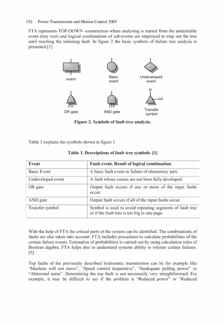
152 Power Transmission and Motion Control 2005
event
OR gate AND gate Transfersymbol
in
out
Basicevent
Undevelopedevent
c11.fm Page 152 Monday, July 18, 2005 8:08 PM

Experiences on combining fault tree analysis and failure mode 153
Machine willnot Move
No flow fromhydraulic
pump
No adequatetorque from
hydraulic motor
Control unitinoperative
Control pistonis not moving
No flow fromvalve
Stuckclosed
Increasedmechanical
losses
Faultybearings
Pistonshoefailure
Increasedmechanical
losses
Faultybearings
Pistonshoefailure
Cloggedorifices
Contami-nation
Gearboxbreakdown
Electronicalcontrol system
inoperative
Wear invalveplate
Wear invalveplate
Brokendiesel engine
Brakes are ON
ParkingBrake will not
releaseWork Brake
is ON DisplacementControl is
inoperative (toosmall
displacement)
InadequateBoost
Pressure
InadequateBoost Pressure
Brokencouplingbetween
Diesel andPump
Contami-nation
Faultywiring or
plugs
No controlcurrent
BrokenSolenoid
Leak outof cylinder
Leakage
Internal leak
Mechanicalbreakdown
ToToo Small
Displacement
Toodemanding
drivingconditions
NoDriving Direction
Selected
c11.fm Page 153 Monday, July 18, 2005 8:08 PM

154 Power Transmission and Motion Control 2005
c11.fm Page 154 Monday, July 18, 2005 8:08 PM

Experiences on combining fault tree analysis and failure mode 155
Machine Will NotMove
Use DieselDiagnostics
NO alarms
OK!
Set-Upparameters
Check Alarms inCabin
Alarms ACTIVEConsult
OperatorsManual
Check parameters Not OK!
Check DieselEngine Not OK!
OK!
Check Visual Leaks LeakagesVisible
Locate andRepair
No Leaks!
Check theOperation of Parkand Work Brakes
Not OK!Check the Parkand Work Brake
Valves
Check that DrivingDirection is Active Activate
Check that BrakesAre not Active Release
Not ACTIVE
ACTIVE
OK!
OK!
OK!
c11.fm Page 155 Monday, July 18, 2005 8:08 PM

156 Power Transmission and Motion Control 2005
Check Plugs andWiring
OK
Check Plugs andWiring
CheckHydraulic Pump
OK
Increased Losses ofMotor
MechanicalDamage in Pump
Mechanical damagein displacementcontrolling parts
Not OK Adjust orReplace
OK
OK
Check Control Currents at PumpSolenoids (leds or
currentmeasurement)
Not OK
Check BoostPressure
<30 barSee
Diagramfor
Boost PressureCheck-up
OK
OK
Pressures OKMeasure Pressurein Main Lines
Pressures too Low
OK
Pressuretoo low
Check PressureDifference of
Control CylinderChambers(min 6 bar)
Replace ControlValve
Replace Pump
CheckHydraulic Motor
Check Rotation ofthe Shaft Speedometer > 0 km/h Breakdown in
mechanical gearbox
Speedometer = 0 km/h
CheckDisplacement ofMotor (eg. Fromcontrol pressure)
Not MAX
MAX
Replace Motor
Check MotorDisplacement
Control CurrentNot OK
CheckControl Valve
Check ConstantPressure Valve
Adjust orReplaceNot OK
OK
Replace Motor
Check DrivingConditions (terrain)
OK
Too demanding Pulling Power ofMachine Insufficient
Adjust openingpressures
Check PressureRelief and Cut-off
Valves Settings too Low
c11.fm Page 156 Monday, July 18, 2005 8:08 PM

Experiences on combining fault tree analysis and failure mode 157
c11.fm Page 157 Monday, July 18, 2005 8:08 PM

158 Power Transmission and Motion Control 2005
c11.fm Page 158 Monday, July 18, 2005 8:08 PM

Experiences on combining fault tree analysis and failure mode 159
c11.fm Page 159 Monday, July 18, 2005 8:08 PM

c11.fm Page 160 Monday, July 18, 2005 8:08 PM

System Modelling and Simulation
c12.fm Page 161 Monday, July 18, 2005 8:10 PM

c12.fm Page 162 Monday, July 18, 2005 8:10 PM

Power Transmission and Motion Control 2005 Edited by C. R. Burrows, K. A. Edge and D. N. Johnston© With The Centre for Power Transmission and Motion Control
c12.fm Page 163 Monday, July 18, 2005 8:10 PM

164 Power Transmission and Motion Control 2005
c12.fm Page 164 Monday, July 18, 2005 8:10 PM

Model identification of the electrohydraulic actuator for small signal inputs 165
c12.fm Page 165 Monday, July 18, 2005 8:10 PM

166 Power Transmission and Motion Control 2005
c12.fm Page 166 Monday, July 18, 2005 8:10 PM

Model identification of the electrohydraulic actuator for small signal inputs 167
c12.fm Page 167 Monday, July 18, 2005 8:10 PM

168 Power Transmission and Motion Control 2005
c12.fm Page 168 Monday, July 18, 2005 8:10 PM

Model identification of the electrohydraulic actuator for small signal inputs 169
0.000
0.005
0.010
0.015
0.020
0.025
–1.0 –0.8 –0.6 –0.4 –0.2 0.0 0.2 0.4 0.6 0.8 1.0Input, V
Gai
n, m
/s/V
c12.fm Page 169 Monday, July 18, 2005 8:10 PM

170 Power Transmission and Motion Control 2005
c12.fm Page 170 Monday, July 18, 2005 8:10 PM

Model identification of the electrohydraulic actuator for small signal inputs 171
100 101 102 103–160
–140
–120
–100
–80
–60
–40
–20
Gai
n, d
B
Frequency, Hz
0
–20–40–60–80
–100–120–140–160
Gai
n, d
B
100
101
102 00.2
0.40.6
0.81
Input VoltageFrequency, Hz
c12.fm Page 171 Monday, July 18, 2005 8:10 PM

172 Power Transmission and Motion Control 2005
c12.fm Page 172 Monday, July 18, 2005 8:10 PM

Model identification of the electrohydraulic actuator for small signal inputs 173
100 101 102 103–120
–110
–100
–90
–80
–70
–60
–50
–40
–30
–20
Gai
n, d
B
Frequency, Hz
0
–20
–40
–60
–80
–100
–120
–140
–160
Gai
n, d
B
100
101
102Frequency, HzInput Voltage
00.2
0.40.6
0.81.0
c12.fm Page 173 Monday, July 18, 2005 8:10 PM

174 Power Transmission and Motion Control 2005
c12.fm Page 174 Monday, July 18, 2005 8:10 PM

Model identification of the electrohydraulic actuator for small signal inputs 175
c12.fm Page 175 Monday, July 18, 2005 8:10 PM

176 Power Transmission and Motion Control 2005
c12.fm Page 176 Monday, July 18, 2005 8:10 PM

Model identification of the electrohydraulic actuator for small signal inputs 177
c12.fm Page 177 Monday, July 18, 2005 8:10 PM

c12.fm Page 178 Monday, July 18, 2005 8:10 PM

Power Transmission and Motion Control 2005 Edited by C. R. Burrows, K. A. Edge and D. N. Johnston© With The Centre for Power Transmission and Motion Control
c13.fm Page 179 Monday, July 18, 2005 8:12 PM

180 Power Transmission and Motion Control 2005
c13.fm Page 180 Monday, July 18, 2005 8:12 PM
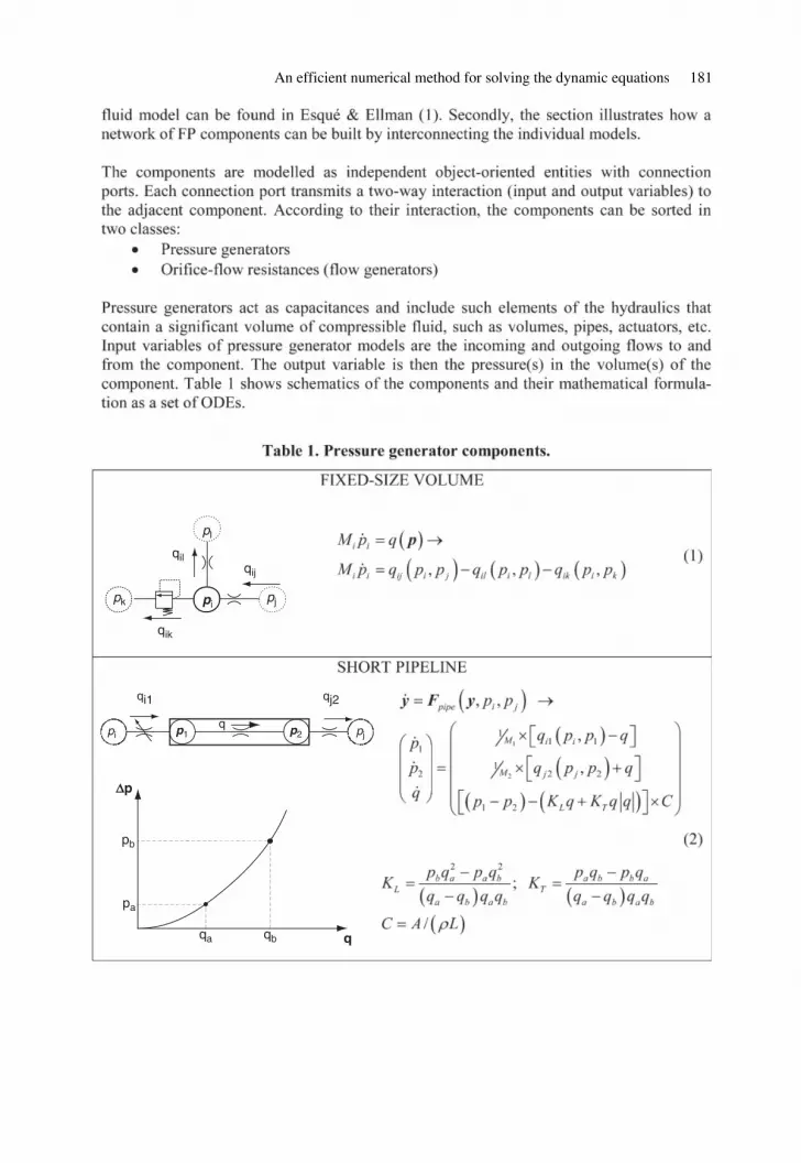
An efficient numerical method for solving the dynamic equations 181
pipjpk
pl
qij
qik
qil
p1 p2 pjpiq
qj2qi1
q
Δp
pa
pb
qa qb
c13.fm Page 181 Monday, July 18, 2005 8:12 PM

182 Power Transmission and Motion Control 2005
pi pj
pA pB
x, x.
qiA qjB
p1 p2
qorif
c13.fm Page 182 Monday, July 18, 2005 8:12 PM

An efficient numerical method for solving the dynamic equations 183
pin pout
pref
qprv
p3
x, x.
p2
p1
qext
p1 q12
p2 q12
q2t
p2
q1t
p2
q23
p1
M1 × (qext – qprv (y1) – qorif (y1, y2))
M2 × (qorif (y1, y2) – qorif (y2, y3) – qorif (y2))
M3 (y4) × (qorif (y2, y3) – Ay5)
y5
m –1
× (y3A – Fµ (y5) – Fg)
y1
y2
y3
y4
y5
=
c13.fm Page 183 Monday, July 18, 2005 8:12 PM

184 Power Transmission and Motion Control 2005
c13.fm Page 184 Monday, July 18, 2005 8:12 PM

An efficient numerical method for solving the dynamic equations 185
c13.fm Page 185 Monday, July 18, 2005 8:12 PM

186 Power Transmission and Motion Control 2005
c13.fm Page 186 Monday, July 18, 2005 8:12 PM

An efficient numerical method for solving the dynamic equations 187
c13.fm Page 187 Monday, July 18, 2005 8:12 PM

188 Power Transmission and Motion Control 2005
c13.fm Page 188 Monday, July 18, 2005 8:12 PM

An efficient numerical method for solving the dynamic equations 189
c13.fm Page 189 Monday, July 18, 2005 8:12 PM

190 Power Transmission and Motion Control 2005
c13.fm Page 190 Monday, July 18, 2005 8:12 PM

An efficient numerical method for solving the dynamic equations 191
c13.fm Page 191 Monday, July 18, 2005 8:12 PM

c13.fm Page 192 Monday, July 18, 2005 8:12 PM

Power Transmission and Motion Control 2005 Edited by C. R. Burrows, K. A. Edge and D. N. Johnston© With The Centre for Power Transmission and Motion Control
c14.fm Page 193 Monday, July 18, 2005 8:13 PM

194 Power Transmission and Motion Control 2005
pilot stagepoppet valve
Pout
Qout
Q1 P1
P1
Pin
Xsp
Pout
Channel 2
main stagespool valve
XplQpl
P2 Orifice 2
output port input port port fordirect opening
Orifice 3
p3
Channel 1
Orifice 1
c14.fm Page 194 Monday, July 18, 2005 8:13 PM

Dynamic modelling of a pilot-operated pressure relief valve 195
c14.fm Page 195 Monday, July 18, 2005 8:13 PM

196 Power Transmission and Motion Control 2005
c14.fm Page 196 Monday, July 18, 2005 8:13 PM

Dynamic modelling of a pilot-operated pressure relief valve 197
0 5 10 15 20 25 30 35 400.0
0.5
1.0
1.5
2.0
2.5
p1– p2 [bar]
Q [l
/min
]
x = 0.1mmx = 0.2mmx = 0.3mmx = 0.4mmx = 0.5mmCd meanCd Borutzky
0 500 1000 15000.0
0.1
0.2
0.3
0.4
0.5
0.6
0.7
0.8
Re[–]
Cd[
–]
x=0.1mmx=0.2mmx=0.3mmx=0.4mmx=0.5mmBorutzky
c14.fm Page 197 Monday, July 18, 2005 8:13 PM

198 Power Transmission and Motion Control 2005
c14.fm Page 198 Monday, July 18, 2005 8:13 PM

Dynamic modelling of a pilot-operated pressure relief valve 199
0 5 10 15 20 25 30 35 400.0
0.5
1.0
1.5
2.0
2.5
p2–pout [bar]
Q [l
/min
]
x = 0.1 mmx = 0.2 mmx = 0.3 mmx = 0.4 mmx = 0.5 mm
0.025 0.05 0.075 0.1 0.15 0.2105
104
103
102
e[–]
Ξ[–]
c14.fm Page 199 Monday, July 18, 2005 8:13 PM

200 Power Transmission and Motion Control 2005
x
l0
l
H
r2,in
r2,outh
y
r1,in
r1,outα
c14.fm Page 200 Monday, July 18, 2005 8:13 PM

Dynamic modelling of a pilot-operated pressure relief valve 201
c14.fm Page 201 Monday, July 18, 2005 8:13 PM

202 Power Transmission and Motion Control 2005
0 5 10 150.0
0.2
0.4
0.6
0.8
1.0
1.2
1.4
1.6
1.8
2.0
Δ p [bar]
Fv
[N]
x = 0.1 mmx = 0.2 mmx = 0.3 mmx = 0.4 mmx = 0.5 mm
0 5 10 15 20 25 30 35 40–20
0
20
40
60
80
100
120
140
Δ p [bar]
Fp
[N]
x = 0.1 mmx = 0.2 mmx = 0.3 mmx = 0.4 mmx = 0.5 mm
c14.fm Page 202 Monday, July 18, 2005 8:13 PM

Dynamic modelling of a pilot-operated pressure relief valve 203
c14.fm Page 203 Monday, July 18, 2005 8:13 PM

204 Power Transmission and Motion Control 2005
L4 = 2.42 m
L3 = 3.74 m
L2 = 1.6 m m = 208 kg
L1 = 1.45 m
Qout
p2
p1
Xm
L 0
c14.fm Page 204 Monday, July 18, 2005 8:13 PM

Dynamic modelling of a pilot-operated pressure relief valve 205
0.2 0.3 0.4 0.5 0.6 0.7
0.2 0.3 0.4 0.5 0.6 0.7
0.2 0.3 0.4 0.5 0.6 0.7
0.2 0.3 0.4 0.5 0.6 0.7
0.2 0.3 0.4 0.5 0.6 0.7
150
200
250
xm [m
m]
0
50
100
p 1 [b
ar]
simulationmeasurement
0
10
20
30
p 2 [b
ar]
0
20
40
Qou
t [l/m
in]
0.10.00.10.2
t [s]
x [m
m]
simulationmeasurement
simulationmeasurement
main spoolpilot
c14.fm Page 205 Monday, July 18, 2005 8:13 PM

206 Power Transmission and Motion Control 2005
c14.fm Page 206 Monday, July 18, 2005 8:13 PM

Component Design and Analysis
c15.fm Page 207 Monday, July 18, 2005 8:15 PM

c15.fm Page 208 Monday, July 18, 2005 8:15 PM

Power Transmission and Motion Control 2005 Edited by C. R. Burrows, K. A. Edge and D. N. Johnston© With The Centre for Power Transmission and Motion Control
c15.fm Page 209 Monday, July 18, 2005 8:15 PM

210 Power Transmission and Motion Control 2005
defineproblem
findsolution
describesolution
estimatesolution
specification modelling
functional modelling
principle modelling
shape modelling
mod
ellin
g le
vel
c15.fm Page 210 Monday, July 18, 2005 8:15 PM

A computer aided conceptual design method for hydraulic components 211
c15.fm Page 211 Monday, July 18, 2005 8:15 PM

212 Power Transmission and Motion Control 2005
A
PFME
A1
A3
1
2
T
X
c15.fm Page 212 Monday, July 18, 2005 8:15 PM

A computer aided conceptual design method for hydraulic components 213
v
2nd Newtonaxiom
Constantpressuresource
Pressureforce
Flow rate ofa conical seat
valve
Orifice law Pressurebuild up in a
variablevolume
a x x,v
F
ID:2
ID:8ID:6ID:3ID:1
ID:14
m
p2
p1
p1p2 Q
Q1 Q2
Q
c15.fm Page 213 Monday, July 18, 2005 8:15 PM

214 Power Transmission and Motion Control 2005
c15.fm Page 214 Monday, July 18, 2005 8:15 PM

A computer aided conceptual design method for hydraulic components 215
c15.fm Page 215 Monday, July 18, 2005 8:15 PM

216 Power Transmission and Motion Control 2005
c15.fm Page 216 Monday, July 18, 2005 8:15 PM

A computer aided conceptual design method for hydraulic components 217
c15.fm Page 217 Monday, July 18, 2005 8:15 PM

218 Power Transmission and Motion Control 2005
d6
d7
d7/2
d 7/4
V014
Q9
Q7
Q8
p15F3
m1
p14
p2
h 6 =
d6
+ x
N6
xN6
F4 + F5 + F17
c15.fm Page 218 Monday, July 18, 2005 8:15 PM

A computer aided conceptual design method for hydraulic components 219
1 1.02 1.04 1.06 1.08 1.1 1.12 1.14 1.16 1.18 1.20.074
0.076
0.078
0.080
0.082
0.084
0.086
β
τ
c15.fm Page 219 Monday, July 18, 2005 8:15 PM

220 Power Transmission and Motion Control 2005
c15.fm Page 220 Monday, July 18, 2005 8:15 PM

A computer aided conceptual design method for hydraulic components 221
c15.fm Page 221 Monday, July 18, 2005 8:15 PM

c15.fm Page 222 Monday, July 18, 2005 8:15 PM

Power Transmission and Motion Control 2005 Edited by C. R. Burrows, K. A. Edge and D. N. Johnston© With The Centre for Power Transmission and Motion Control
c16.fm Page 223 Monday, July 18, 2005 8:16 PM

224 Power Transmission and Motion Control 2005
c16.fm Page 224 Monday, July 18, 2005 8:16 PM

Determining the steady state flow forces in a rim spool valve using CFD analysis 225
c16.fm Page 225 Monday, July 18, 2005 8:16 PM

226 Power Transmission and Motion Control 2005
c16.fm Page 226 Monday, July 18, 2005 8:16 PM

Determining the steady state flow forces in a rim spool valve using CFD analysis 227
Rod Rod
Land Land Land RimLand
td
xv
c16.fm Page 227 Monday, July 18, 2005 8:16 PM

228 Power Transmission and Motion Control 2005
c
V1
V2
FAFB
Fsleeve
Frod
n1
Q1
PA PB
Q2
xv
A B
τsleeve
τrod
y
x n2
n = –in = i
θ
c16.fm Page 228 Monday, July 18, 2005 8:16 PM

Determining the steady state flow forces in a rim spool valve using CFD analysis 229
c16.fm Page 229 Monday, July 18, 2005 8:16 PM

230 Power Transmission and Motion Control 2005
3.2
18
1.81.8 6.8
a
b
c
d
e
f
g
h
i
j
k
lxv
11.15
c16.fm Page 230 Monday, July 18, 2005 8:16 PM

Determining the steady state flow forces in a rim spool valve using CFD analysis 231
Inlet port mesh Outlet port mesh
c16.fm Page 231 Monday, July 18, 2005 8:16 PM

232 Power Transmission and Motion Control 2005
c16.fm Page 232 Monday, July 18, 2005 8:16 PM

Determining the steady state flow forces in a rim spool valve using CFD analysis 233
c16.fm Page 233 Monday, July 18, 2005 8:16 PM

234 Power Transmission and Motion Control 2005
c16.fm Page 234 Monday, July 18, 2005 8:16 PM

Determining the steady state flow forces in a rim spool valve using CFD analysis 235
c16.fm Page 235 Monday, July 18, 2005 8:16 PM

236 Power Transmission and Motion Control 2005
P 1 = 1.2MPa P 2 = 2.4MPa
Ps = 3.45MPa
Ps = 3.45MPa
c16.fm Page 236 Monday, July 18, 2005 8:16 PM

Determining the steady state flow forces in a rim spool valve using CFD analysis 237
c16.fm Page 237 Monday, July 18, 2005 8:16 PM

238 Power Transmission and Motion Control 2005
c16.fm Page 238 Monday, July 18, 2005 8:16 PM

Determining the steady state flow forces in a rim spool valve using CFD analysis 239
c16.fm Page 239 Monday, July 18, 2005 8:16 PM

240 Power Transmission and Motion Control 2005
c16.fm Page 240 Monday, July 18, 2005 8:16 PM

Determining the steady state flow forces in a rim spool valve using CFD analysis 241
c16.fm Page 241 Monday, July 18, 2005 8:16 PM

c16.fm Page 242 Monday, July 18, 2005 8:16 PM

Power Transmission and Motion Control 2005 Edited by C. R. Burrows, K. A. Edge and D. N. Johnston© With The Centre for Power Transmission and Motion Control
c17.fm Page 243 Monday, July 18, 2005 8:18 PM

244 Power Transmission and Motion Control 2005
c17.fm Page 244 Monday, July 18, 2005 8:18 PM

Design of valve solenoids using the method of finite elements 245
c17.fm Page 245 Monday, July 18, 2005 8:18 PM

246 Power Transmission and Motion Control 2005
c17.fm Page 246 Monday, July 18, 2005 8:18 PM

Design of valve solenoids using the method of finite elements 247
0
5
10
15
20
25
0 0.2 0.4 0.6 0.8 1.0 1.2x[mm]
F[N
]
c17.fm Page 247 Monday, July 18, 2005 8:18 PM

248 Power Transmission and Motion Control 2005
–0.2
–0.1
0
0.1
0.2
0.3
0.4
0.5
0.6
0.7
0.8
0.9
1.0
1.1
1.2
0 0.001 0.002 0.003 0.004 0.005 0.006 0.007 0.008 0.009 0.01 0.011 0.012
t[s]
x[m
m]
–0.2
0
0.2
0.4
0.6
0.8
1.0
1.2
I[A]
c17.fm Page 248 Monday, July 18, 2005 8:18 PM

Design of valve solenoids using the method of finite elements 249
c17.fm Page 249 Monday, July 18, 2005 8:18 PM

250 Power Transmission and Motion Control 2005
c17.fm Page 250 Monday, July 18, 2005 8:18 PM

Design of valve solenoids using the method of finite elements 251
5
0
10
F[N
]
0
5
10
15
20
0
5
10
15
20
25
30
–0.2 0.0 0.2 0.4 0.6 0.8 1.0 1.2 1.4 1.6
–0.2 0.0 0.2 0.4 0.6 0.8 1.0 1.2 1.4 1.6 –0.2 0.0 0.2 0.4 0.6 0.8 1.0 1.2 1.4 1.6
–0.2 0.0 0.2 0.4 0.6 0.8 1.0 1.2 1.4 1.6x[mm]
x[mm] x[mm]
x[mm]
F[N
]
0
5
10
15
20
25
30
35
40
I = 0,397 AF_axial696F_radial696F696_ad2
I = 0,132 AF_axial232F_radial232F232_ad2
I = 0,264 A
F_axial464
F_radial464
F464_ad2
I = 0,527 A
F_axial928
F_radial928
F968_ad2
c17.fm Page 251 Monday, July 18, 2005 8:18 PM
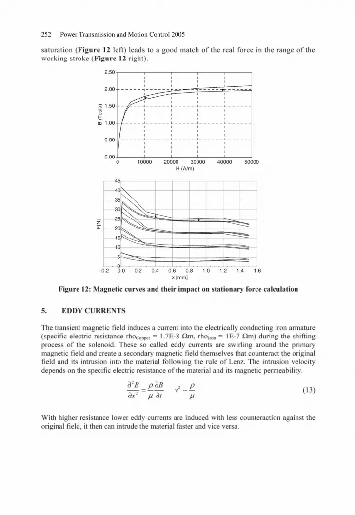
252 Power Transmission and Motion Control 2005
2.50
2.00
1.50
1.00
0.50
0.000 10000 20000 30000 40000 50000
B (
Tes
la)
H (A/m)
x [mm]
F[N
]
45
40
35
30
25
20
15
10
5
0–0.2 0.0 0.2 0.4 0.6 0.8 1.0 1.2 1.4 1.6
c17.fm Page 252 Monday, July 18, 2005 8:18 PM

Design of valve solenoids using the method of finite elements 253
0.7
0.6
0.5
0.4
0.3
0.2
0.1
0
0.7
0.6
0.5
0.4
0.3
0.2
0.1
00 0.001 0.002 0.003 0.004 0.005
–0.1 –0.1
X[m
m]
t[s]
2.1 ms <– 2.3 ms
I[A]
–0.001
c17.fm Page 253 Monday, July 18, 2005 8:18 PM

254 Power Transmission and Motion Control 2005
c17.fm Page 254 Monday, July 18, 2005 8:18 PM

Power Transmission and Motion Control 2005 Edited by C. R. Burrows, K. A. Edge and D. N. Johnston© With The Centre for Power Transmission and Motion Control
c18.fm Page 255 Monday, July 18, 2005 8:19 PM

256 Power Transmission and Motion Control 2005
Pressure range: 0…10 bar
Nominal value: DC 0…10 V
630 1/minRated flow Qn 6 5 at p = 10 bar at 1:
c18.fm Page 256 Monday, July 18, 2005 8:19 PM

Virtual design of high dynamic pneumatic valves 257
servo-solenoidspool
control edge 2–3
body
spring
armature
control range 1 (p12)control edge 1–2
x
wp
p2
electronic
UM
10 bar
10 V
US=24V
control range 2 (p23)
sealing
sealing
exhaust connection (p3)
working air connection (p2)
FM
FPFS
1
3
2
compressed air connection (p1)
c18.fm Page 257 Monday, July 18, 2005 8:19 PM

258 Power Transmission and Motion Control 2005
solenoid
valve mechanics valve pneumatic
solenoid pneumatic
xA A
A
x
UM
xA x
xS
FS
FStr
pB = p1
magnetic force FM
magnetic voltage
pressure force
flow force damping force FMD
friction force FR
spring- and damping force FC + FD
mS mA
weight force FG
pM1
VM1
pM2
VM2
pM3
VM3
pM4
VM4
power supply and control
USoll
UB
UIst
xA
p1
p2
p3xS
xA
A
AFM + Fg,A – (FS1 + FD) = mA .
pressure force
spring force
magnetic force
weight force
SFS1 + FD + Fg,S – (FS2 + FR + Fp + FF) = mS .
damping force
friction force
flow force
xA
xS
mA
mS
gFM
FS1+FD
FS2 + FR + Fp
FF
c18.fm Page 258 Monday, July 18, 2005 8:19 PM

Virtual design of high dynamic pneumatic valves 259
(1)
(2)
xA
pa, Va pc, Vc
pe, Ve
pg, Vg xS
pi, Vi
pk, Vk
Cb, bb
Cd, bd Cf, bf
Ch, bh
Cj, bj
Cl, bl
Cn,bn Cp,bp
Cr,br
pm, Vm
po, Vo
pq, Vq ps, Vs
(1)
(2)
(3)
(3)
a c e g
i k
m
oq
S
c18.fm Page 259 Monday, July 18, 2005 8:19 PM

260 Power Transmission and Motion Control 2005
RSp
UL
IM
UM
RmE (φ)
Rm
L (x
A)
IM
xA
USp VmE
VmLUM
ΦΦ
Θ
c18.fm Page 260 Monday, July 18, 2005 8:19 PM

Virtual design of high dynamic pneumatic valves 261
c18.fm Page 261 Monday, July 18, 2005 8:19 PM

262 Power Transmission and Motion Control 2005
description of iron and air resistance
coil resistance
US
UR–
IM
FM
xA
c18.fm Page 262 Monday, July 18, 2005 8:19 PM

Virtual design of high dynamic pneumatic valves 263
c18.fm Page 263 Monday, July 18, 2005 8:19 PM

264 Power Transmission and Motion Control 2005
c18.fm Page 264 Monday, July 18, 2005 8:19 PM

Virtual design of high dynamic pneumatic valves 265
c18.fm Page 265 Monday, July 18, 2005 8:19 PM

c18.fm Page 266 Monday, July 18, 2005 8:19 PM

Smart fluids
c19.fm Page 267 Monday, July 18, 2005 8:20 PM

c19.fm Page 268 Monday, July 18, 2005 8:20 PM

Power Transmission and Motion Control 2005 Edited by C. R. Burrows, K. A. Edge and D. N. Johnston© With The Centre for Power Transmission and Motion Control
c19.fm Page 269 Monday, July 18, 2005 8:20 PM

270 Power Transmission and Motion Control 2005
c19.fm Page 270 Monday, July 18, 2005 8:20 PM

A micro artificial muscle actuator using electro-conjugate fluid 271
Fiber
x
yz
z
(a) Side view (b) Top view
x
y
c19.fm Page 271 Monday, July 18, 2005 8:20 PM

272 Power Transmission and Motion Control 2005
Needle electrode (φ 0.13,Tungsten)
Ring electrode (inner φ 0.3,Brass)
Needle mount (Brass)
Electrode spacer (polyetherimide)
Electrode (Tungsten)
Ga
p:
0.2
Electrode guide (polyetherimide)
Jet generator
5m m
c19.fm Page 272 Monday, July 18, 2005 8:20 PM

A micro artificial muscle actuator using electro-conjugate fluid 273
c19.fm Page 273 Monday, July 18, 2005 8:20 PM

274 Power Transmission and Motion Control 2005
c19.fm Page 274 Monday, July 18, 2005 8:20 PM

A micro artificial muscle actuator using electro-conjugate fluid 275
c19.fm Page 275 Monday, July 18, 2005 8:20 PM

276 Power Transmission and Motion Control 2005
c19.fm Page 276 Monday, July 18, 2005 8:20 PM

Power Transmission and Motion Control 2005 Edited by C. R. Burrows, K. A. Edge and D. N. Johnston© With The Centre for Power Transmission and Motion Control
c20.fm Page 277 Monday, July 18, 2005 8:20 PM

278 Power Transmission and Motion Control 2005
Tank
Constant pressurefrom pump
Rubber bellows
Force
Piston Cylinder
Linearbearing
RestrictionA
MR valve
A
N S
c20.fm Page 278 Monday, July 18, 2005 8:20 PM

A magneto-rheological valve-integrated cylinder and its application 279
w = 6.4 mm
N
S
N
S
MRfluid h
= 3
.0 m
m
ElectromagnetN = 450l = 9.6 mm
c20.fm Page 279 Monday, July 18, 2005 8:20 PM

280 Power Transmission and Motion Control 2005
MRF-AS7MRF-AS8MRF-BL7
0.50.0 1.0 1.5 2.0Applied current [A]
80
60
40
20
Diff
eren
tial p
ress
ure
ΔP
[kP
a]
Fluid temp.: 241 ± 1 °C
MRF-BS7
0
c20.fm Page 280 Monday, July 18, 2005 8:20 PM

A magneto-rheological valve-integrated cylinder and its application 281
0.0 0.5 1.0 1.5 2.0 2.50.0
0.2
0.4
0.6
0.8
Mag
netic
flux
den
sity
[T]
Applied current [A]
MRF-AS7MRF-AS8MRF-BL7MRF-BS7MRF-132LDWithoutMR fluid
c20.fm Page 281 Monday, July 18, 2005 8:20 PM

282 Power Transmission and Motion Control 2005
M
Accumulator
Throttle valve
P1P2
3
MR cylinder
M
P1P2
3
1Ω
Potentiometer
M
P1P2
P3Δ P = P2 – P3
V
A
MR fluid power source
Piston(Soft magnetic iron)
N
N
S
S
MR fluid
Cylinder
Restriction
Tank
Electromagnet(160turns)
SpecificationsSupply pressure: 1MPa Maximum force: 1kN(1A) Stroke: 60mm
Particle diameter: 2.7μm Base viscosity: 60mPa·s MR effect coefficient: 41kPa/T
500
785
Diaphragmpump 10
2
φ58
φ74
5
0
10
15
200.0
0.1
0.2
0.3
0.4
0.5
Temp.: 38 – 41[°]
Dif
fere
ntia
l pre
ssur
e Δ
P [
MPa
]
Applied current [A]
0.0 0.5 1.0 1.5
Join
t ang
le [
°]Spring
c20.fm Page 282 Monday, July 18, 2005 8:20 PM
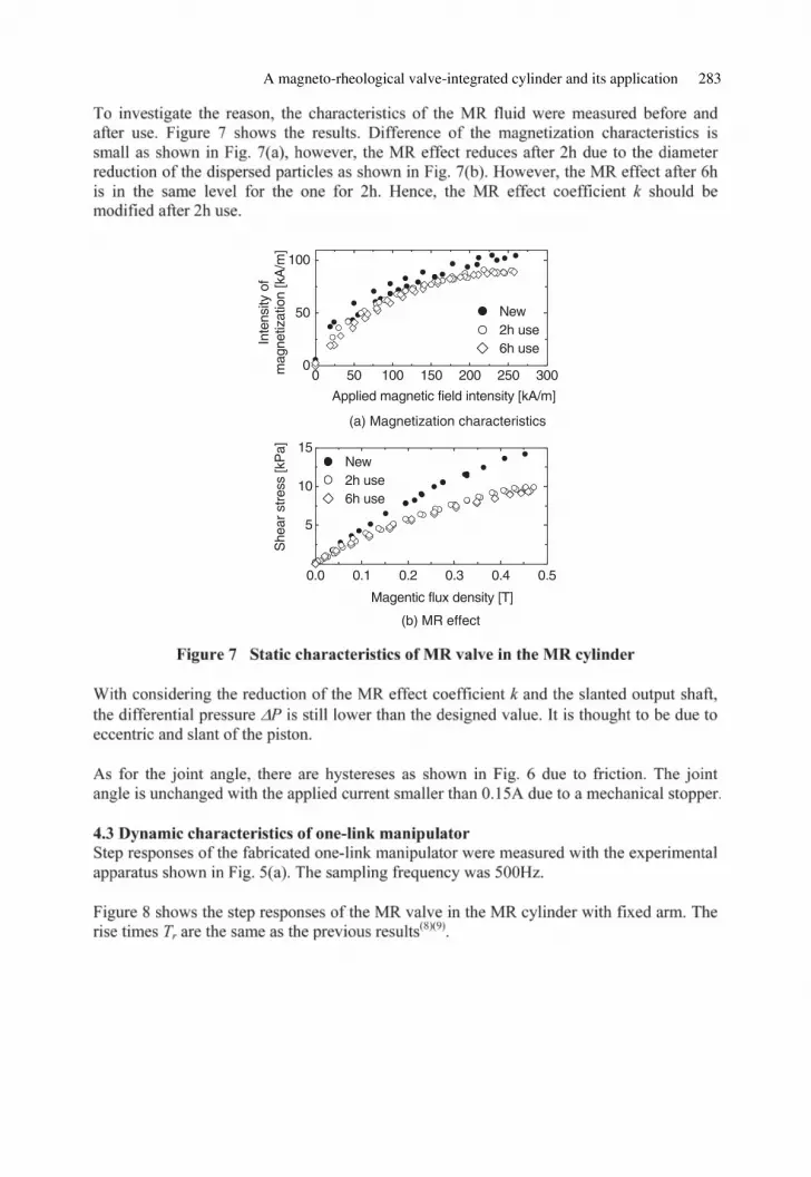
A magneto-rheological valve-integrated cylinder and its application 283
0 50 100 150 200 250 3000
50
100
5
10
15
New2h use6h use
6h use
She
ar s
tres
s [k
Pa]
(a) Magnetization characteristics
0.0 0.1 0.2 0.3 0.4 0.5
Inte
nsity
of
mag
netiz
atio
n [k
A/m
]
Applied magnetic field intensity [kA/m]
New2h use
Magentic flux density [T]
(b) MR effect
c20.fm Page 283 Monday, July 18, 2005 8:20 PM

284 Power Transmission and Motion Control 2005
0.00.2
0.3
0.4
0.0 0.2 0.4 0.6 0.8 1.0 1.00.0 0.2 0.4 0.6 0.8
0.0
0.5
1.0
1.5
App
lied
curr
ent [
A]
Tr = 0.04s
Tr = 0.03s
Time [s]
Diff
eren
tial p
ress
ure
Δ P
[M
Pa]
Tr = 0.04s
Tr = 0.04s
0.00.2
0.3
0.4
10
0.00
0.2 0.4 0.6 0.8 0.0 0.2 0.4 0.6 0.8
15
20
25
0.0
0.5
1.0
1.5
2.0
App
lied
curr
ent
[A]
Tr = 0.28 s
Tr = 0.40 s
Diff
eren
tial p
ress
ure
Δ P
[M
Pa]
Tr = 0.22 s
Tr = 0.36 s
Time [s]
Join
t an
gle
[°]
Tr = 0.16 s
Tr = 0.17 s
Tr = 0.14 s
Tr = 0.19 s
c20.fm Page 284 Monday, July 18, 2005 8:20 PM

A magneto-rheological valve-integrated cylinder and its application 285
12.00.0
0.0 0.1 0.2 0.3 0.4 0.5 0.0 0.1 0.2 0.3 0.4 0.5
Tr = 0.37s
(a) Supply pressure 0.7MPa
Tr = 0.30sTr = 0.14s
14.016.018.020.00.0
0.25
0.30
0.35
0.40
Diff
eren
tial p
ress
ure
ΔP
[MP
a]
Max. flow rate
Tr = 0.20s
Time [s]
Join
t ang
le [°
]
Time [s]
0.0 0.1 0.2 0.3 0.4 0.5 0.0 0.1 0.2 0.3 0.4 0.5
Tr = 0.28s Tr = 0.16s
Tr = 0.14sTr = 0.22s
(b) Supply pressure 1.0MPa
Max. flow rate
12.00.0
14.016.018.020.00.0
0.25
0.30
0.35
0.40
Diff
eren
tial p
ress
ure
ΔP
[MP
a]Jo
int a
ngle
[°]
Time [s]
Tr = 0.21s
Tr = 0.16s Tr = 0.13s
Tr = 0.17s
0.0 0.1 0.2 0.3 0.4 0.5 0.0 0.1 0.2 0.3 0.4 0.5
(c) Supply pressure 1.8MPa
Max. flow rate12.00.0
14.016.018.020.00.0
0.25
0.30
0.35
0.40
Diff
eren
tial p
ress
ure
ΔP
[MP
a]Jo
int a
ngle
[°]
c20.fm Page 285 Monday, July 18, 2005 8:20 PM

286 Power Transmission and Motion Control 2005
M
PsP1
P2
P4
A
Amp
M
PsP1
P4
A
Amp
M
A
Potentiometer
Ps
P1
P4P3
P2
Amp
Amp
Amp
V2
V1
A
V3
V4
A A
Amp
0.55m
1.0m
<1st link> <2nd link>
Guideφ 55
φ 65
φ 53.5φ 43.5
336
153
424
122
MR cylinder
Diaphragm pump
MR cylinder
c20.fm Page 286 Monday, July 18, 2005 8:20 PM

A magneto-rheological valve-integrated cylinder and its application 287
0.0 0.5 1.0 1.50.0
0.2
0.4
0.6
0.8
1.0
Ps = 0.9-1.1 MPaTemp.: 25–29°CD
iffer
entia
l pre
ssur
eP
2 [M
Pa]
Applied current [A]
Theoretical(h = 0.8 mm)
0.0
0.5
1.00.0
0.5
1.0
1.5
Tr = 0.13s
Tr = 0.10s
Tr = 0.04s
Tr = 0.05s
App
lied
curr
ent [
A]
Time [s]
0.0 0.1 0.2 0.3 0.40.0 0.1 0.2 0.3 0.4Diff
eren
tial p
ress
ure
ΔP
2 [M
Pa]
Temp.: 25°C
c20.fm Page 287 Monday, July 18, 2005 8:20 PM

288 Power Transmission and Motion Control 2005
eu
Referencejoint angleθ2r θ2+
i1
i2
i1
i2
MR cylinder 1
MR cylinder 2
Arm withchain/sprocket
Potentiometer
Kp +kis
I0
I0
u
u
o
o
Joint angle+
– –
0 20 2–15
–10
–5
0
5
10
15
Tr = 0.11s
Tr = 0.20s
Tr = 0.38s
Tr = 0.14s
Tr = 0.23s
Tr = 0.43s
Join
t ang
le θ
2 [°
]
Time [s]
Temp. 28–30°C
1 1
c20.fm Page 288 Monday, July 18, 2005 8:20 PM

A magneto-rheological valve-integrated cylinder and its application 289
0 20 2
–20
–10
0
10
20
Tr = 0.09s
Tr = 0.14s
Tr = 0.24s
Tr = 0.14s
Tr = 0.19s
Tr = 0.40s
Join
t ang
le θ
2 [°
]
Time [s]
Temp. 28–30°C
1 1
c20.fm Page 289 Monday, July 18, 2005 8:20 PM

c20.fm Page 290 Monday, July 18, 2005 8:20 PM

Power Transmission and Motion Control 2005 Edited by C. R. Burrows, K. A. Edge and D. N. Johnston© With The Centre for Power Transmission and Motion Control
c21.fm Page 291 Monday, July 18, 2005 8:21 PM

292 Power Transmission and Motion Control 2005
BBB
v
a) b)
v v
c)
c21.fm Page 292 Monday, July 18, 2005 8:21 PM

Systematic experimental studies and computational perspectives 293
piston (rotational degree of freedom)
MR - f luid
coil
connection to hydraulic drive(translational degree of freedom)with integrated force & torque measurement
air pressure supply
sealing
c21.fm Page 293 Monday, July 18, 2005 8:21 PM

294 Power Transmission and Motion Control 2005
c21.fm Page 294 Monday, July 18, 2005 8:21 PM

Systematic experimental studies and computational perspectives 295
5 10 154.8
4.9
5.0
5.1
5.2
t[s] t[s]
t[s]
gap
thic
knes
s x[
mm
]Graph A
5 10 15
F[N
]
Graph B
5 10 15
50
100
150
200
250
300
B[m
T]
Graph C
4.8 4.9 5.0 5.1 5.2
–1000
0
1000
2000
–1000
0
1000
2000
gap thickness x[mm]
F[N
]
Graph D
c21.fm Page 295 Monday, July 18, 2005 8:21 PM

296 Power Transmission and Motion Control 2005
3 4 5 6 7
–50
0
50
gap thickness x[mm]F
[N]
B = 0mT, ampl = 2mm, f = 0.2Hz
c21.fm Page 296 Monday, July 18, 2005 8:21 PM

Systematic experimental studies and computational perspectives 297
–1000
0
1000
2000
4 5 6
20001000
–10000
–20000
2000
40003000
4 5 6 4 5 6
1.7mm 1.7mm1.7mm
4 5 6
–1000
0
1000
–2000
2000
0
400020001000
–10000
3000
4 5 6 4 5 6
1.5mm 1.5mm1.5mm
4.0 4.5 5.0 5.5 6.0
–1000
0
1000
–2000
2000
0
400020001000
–10000
3000
3000
4.0 4.5 5.0 5.5 6.0 4.0 4.5 5.0 5.5 6.0
1.2mm 1.2mm1.2mm
–1000
0
1000
4.5 5.0 5.5–2000
2000
0
400020001000
–1000
4.5 5.0 5.5
0
4.5 5.0 5.5
0.7mm 0.7mm0.7mm
–1000
0
1000
4.0 4.5 5.0 5.5 6.0–2000
2000
0
400020001000
–1000
0
4.0 4.5 5.0 5.5 6.0 4.0 4.5 5.0 5.5 6.0
1mm 1mm1mm
–1000
0
1000
4.5 5.0 5.5
2000
–2000
0
20001000
–1000
0
4.5 5.0 5.5 4.5 5.0 5.5
0.5mm 0.5mm0.5mm
–1000
0
1000
4.8 4.9 5.0 5.1 5.2–2000
2000
0
2000
1000
–1000
0
4.8 4.9 5.0 5.1 5.2
0.2mm 0.2mm0.2mm
4.8 4.9 5.0 5.1 5.2
–1000
0
1000
4.90 4.95 5.00 5.05 5.10
–1000
10002000
0
1000
–1000
0
4.90 4.95 5.00 5.05 5.10
0.1mm 0.1mm0.1mm
4.90 4.95 5.00 5.05 5.10
–500
0
500
4.98 4.99 5.00 5.01 5.02
–1000
500
–500
0500
–500
0
4.98 5.00 5.02
0.025mm 0.025mm0.025mm
4.98 5.00 5.02
3 4 5 6 7
–1000
0
1000
2000B = 200mT, f = 0.2Hz F[N] vs x[mm]
3 4 5 6 7–2000
0
2000
4000
–20000
2000
60004000
B = 300mT, f = 0.2Hz F[N] vs x[mm]
3 4 5 6 7
B = 400mT, f = 0.2Hz F[N] vs x[mm]
2mm 2mm2mm
c21.fm Page 297 Monday, July 18, 2005 8:21 PM

298 Power Transmission and Motion Control 2005
pressure[MPa]
atmosphericpressure
0 (cavitation)0
rising cavitation area
rising pressure drop
piston radius [mm]75
c21.fm Page 298 Monday, July 18, 2005 8:21 PM

Systematic experimental studies and computational perspectives 299
4.8 4.9 5.0 5.1 5.2–2000
0
2000
F[N
]
F[N
]
B = 400mT, ampl = 0.2mm
3 4 5 6 7–2000
0
2000
4000
6000
B = 400mT, ampl = 2mm
atmospheric pressure (AP) atmospheric pressure (AP)
–2000
0
2000
gap thickness x[mm]
4.8 4.9 5.0 5.1 5.2
F[N
]
–2000
0
2000
4000
6000
gap thickness x[mm]
3 4 5 6 7
F[N
]
AP + 0,85bar AP + 0,85bar
–2000
0
2000
gap thickness x[mm]
4.8 4.9 5.0 5.1 5.2
F[N
]
–2000
0
2000
4000
6000
gap thickness x[mm]
3 4 5 6 7
F[N
]
AP + 1,4bar AP + 1,4bar
gap thickness x[mm]
4.8 4.9 5.0 5.1 5.2gap thickness x[mm]
F[N
]
–2000
0
2000
–4000
4000
6000
gap thickness x[mm]
3 4 5 6 7gap thickness x[mm]
–2000
0
2000
F[N
]
AP + 2bar AP + 2bar
c21.fm Page 299 Monday, July 18, 2005 8:21 PM

300 Power Transmission and Motion Control 2005
4 5 6
–1000
0
1000
2000
3000
gap thickness x [mm]
F[N
]F
[N]
B = 300 mT, ampl = 1.5 mm, initial
B = 300 mT, ampl = 0.1 mm, initial
B = 300 mT, ampl = 1.5 mm, steady
4.90 4.95 5.00 5.05 5.10
–1000
–500
0
500
1000
1500
4.90 4.95 5.00 5.05 5.10
–1000
–500
0
500
1000
1500
B = 300 mT, ampl = 0.1 mm, steady
4 5 6
–1000
0
1000
2000
3000
gap thickness x [mm]
gap thickness x [mm] gap thickness x [mm]
F[N
]F
[N]
0,2 Hz0,4 Hz0,6 Hz0,8 Hz1,0 Hz
0,2 Hz0,4 Hz0,6 Hz0,8 Hz1,0 Hz
0,2 Hz0,4 Hz0,6 Hz0,8 Hz1,0 Hz
0,2 Hz0,4 Hz0,6 Hz0,8 Hz1,0 Hz
c21.fm Page 300 Monday, July 18, 2005 8:21 PM

Systematic experimental studies and computational perspectives 301
c21.fm Page 301 Monday, July 18, 2005 8:21 PM

302 Power Transmission and Motion Control 2005
c21.fm Page 302 Monday, July 18, 2005 8:21 PM

Systematic experimental studies and computational perspectives 303
c21.fm Page 303 Monday, July 18, 2005 8:21 PM

304 Power Transmission and Motion Control 2005
c21.fm Page 304 Monday, July 18, 2005 8:21 PM

Vehicle systems
c22.fm Page 305 Monday, July 18, 2005 8:22 PM

c22.fm Page 306 Monday, July 18, 2005 8:22 PM

Power Transmission and Motion Control 2005 Edited by C. R. Burrows, K. A. Edge and D. N. Johnston© With The Centre for Power Transmission and Motion Control
c22.fm Page 307 Monday, July 18, 2005 8:22 PM

308 Power Transmission and Motion Control 2005
c22.fm Page 308 Monday, July 18, 2005 8:22 PM

An adaptable hydraulic system for tractors 309
c22.fm Page 309 Monday, July 18, 2005 8:22 PM

310 Power Transmission and Motion Control 2005
c22.fm Page 310 Monday, July 18, 2005 8:22 PM

An adaptable hydraulic system for tractors 311
c22.fm Page 311 Monday, July 18, 2005 8:22 PM

312 Power Transmission and Motion Control 2005
c22.fm Page 312 Monday, July 18, 2005 8:22 PM

An adaptable hydraulic system for tractors 313
c22.fm Page 313 Monday, July 18, 2005 8:22 PM

314 Power Transmission and Motion Control 2005
c22.fm Page 314 Monday, July 18, 2005 8:22 PM

An adaptable hydraulic system for tractors 315
c22.fm Page 315 Monday, July 18, 2005 8:22 PM

316 Power Transmission and Motion Control 2005
c22.fm Page 316 Monday, July 18, 2005 8:22 PM

Power Transmission and Motion Control 2005 Edited by C. R. Burrows, K. A. Edge and D. N. Johnston© With The Centre for Power Transmission and Motion Control
c23.fm Page 317 Monday, July 18, 2005 8:23 PM

318 Power Transmission and Motion Control 2005
c23.fm Page 318 Monday, July 18, 2005 8:23 PM

Design of a hybrid vehicle powertrain using an inverse methodology 319
c23.fm Page 319 Monday, July 18, 2005 8:23 PM

320 Power Transmission and Motion Control 2005
c23.fm Page 320 Monday, July 18, 2005 8:23 PM

Design of a hybrid vehicle powertrain using an inverse methodology 321
Load ≡Vehicle
VvehSeDf
e = 01
R : Faero(Vveh)
R : Froll(Vveh, .)d
Vveh
d0
I : Mveh
Vveh
End of a Power supplying lineor of power modulation line
Vehicle model
≡
Fveh
∫
Power supplying line
Power modulation lines
Gearbox
Gearbox
MTF
ugear ugear
c23.fm Page 321 Monday, July 18, 2005 8:23 PM

322 Power Transmission and Motion Control 2005
ud
Xeng
ud
Teng Tmax(Ud)
Tloss
e = 0 f = 0
Xeng
MSe
Dfse : Teng
Engine elementary model
MR : Rmot(udt, ωeng) I : Jeng
DeSf : ωeng
Teng
Teng
Engine
fcsn(Teng, ωeng)
fcsn(Teng, ωeng)
ωeng ωeng
ωeng End of Powermodulationline 2
1 1 10.....
Power modulation line 1 Power supplying line
ud
Tengωeng
fcsn(Cengt, ωeng)
x
Vveh
u?? u??
Power modulation lines
Power supplying line
?? LoadEngine
c23.fm Page 322 Monday, July 18, 2005 8:23 PM

Design of a hybrid vehicle powertrain using an inverse methodology 323
Engine
ugearud
uelElectrical
Motor
J Gearbox Vehicle
Pump
upump uhmotud
HydraulicMotor
VechicleEngine
c23.fm Page 323 Monday, July 18, 2005 8:23 PM

324 Power Transmission and Motion Control 2005
ugearud
uel
J VehicleGearboxEngine
ElectricalMotor
c23.fm Page 324 Monday, July 18, 2005 8:23 PM

Design of a hybrid vehicle powertrain using an inverse methodology 325
c23.fm Page 325 Monday, July 18, 2005 8:23 PM

326 Power Transmission and Motion Control 2005
c23.fm Page 326 Monday, July 18, 2005 8:23 PM

Design of a hybrid vehicle powertrain using an inverse methodology 327
engine gearbox Vehicle
electricalmotor
ud
d0
uRMR : RMth(ud,ωeng) I : Jeng
DeDf 1 1 10 0Teng
e = 0 f = 0ωengTeng
MSeSf MSeSf DeDf De :TvehDf :Vveh
R : Faéro(Vveh)
R : Froul(Vveh, . )
I : Mveh
ωeng Teng
fcsn(Teng, ωeng)
fass(Tveh,Teng) = (fass,Vveh)xeng
ωMthMTF MSeSF
Tel ωel
1 e = 0
d
αass
∫
Vcycle (t)
c23.fm Page 327 Monday, July 18, 2005 8:23 PM

328 Power Transmission and Motion Control 2005
0
ECE road cycle
20 40 60 80 100 120 140 160 180 200–5
–4
–3
–2
–1
0
1
2
3
4
550
40
30
20
10
0
–10
–20
–30
–40
–50
Veh
icle
spe
ed (
km/h
)
Time (s)
Veh
icle
acc
eler
atio
n (m
/s2 )
Vehicle acceleration
Vehicle speed
1.0 1.5
Engine Characteristics
Sup
plie
d E
ngin
e T
orqu
e (N
m)
Iso - Fuel consumption
Power at Iso - Fuel consumption
Eng
ine
Pow
er (
kW)
2.0 2.5 3.0 3.5 4.0 4.5 5.00
1
2
3
4
5
6
7
8
9
10
41/100km
51/100km61/100km
11
12
0
10
20
30
40
50
60
70
80
90
100
110
120
Engine speed (1000 rpm)
c23.fm Page 328 Monday, July 18, 2005 8:23 PM

Design of a hybrid vehicle powertrain using an inverse methodology 329
0 5 10 15
Assistance Strategy
Strategy 2
Strategy 1
Ass
ista
nce
degr
ee
Vehicle speed (km/h)
20 25 30 35 40 45 50
0.9
1.0
0.8
0.7
0.6
0.5
0.4
0.3
0.2
0.1
0
c23.fm Page 329 Monday, July 18, 2005 8:23 PM

330 Power Transmission and Motion Control 2005
Engine Power
Strategy 2
Strategy 1
Engine limitation for thegiven consumption
(saturation)
Time (s)
Time (s)
Time (s)
60
50
40
30
20
10
0
Veh
icle
spe
ed (
km/h
)
60
50
40
30
20
10
0
Veh
icle
spe
ed (
km/h
)
60
50
40
30
20
10
0
Veh
icle
spe
ed (
km/h
)
Electrical Motor Power
Strategy 1
Strategy 2
Transmission ratio + CVT
Strategy 2
Strategy 1
0 20 40 60 80 100 120 140 160 180 200
0 20 40 60 80 100 120 140 160 180 200
0 20 40 60 80 100 120 140 160 180 200
0
1
2
3
4
5
6
7
8
9
10
11
12
Eng
ine
pow
er (
kW)
0
1
2
3
4
5
6
7
8
9
10
11
12
Ele
ctric
al M
otor
pow
er (
kW)
0
5
10
15
20
25
30
35
40
45
50
55
60
Tra
nsm
issi
on r
atio
or
v100
0 (k
m/h
/ 10
00 r
pm)
c23.fm Page 330 Monday, July 18, 2005 8:23 PM

Design of a hybrid vehicle powertrain using an inverse methodology 331
c23.fm Page 331 Monday, July 18, 2005 8:23 PM

332 Power Transmission and Motion Control 2005
c23.fm Page 332 Monday, July 18, 2005 8:23 PM

Power Transmission and Motion Control 2005 Edited by C. R. Burrows, K. A. Edge and D. N. Johnston© With The Centre for Power Transmission and Motion Control
c24.fm Page 333 Monday, July 18, 2005 8:25 PM

334 Power Transmission and Motion Control 2005
c24.fm Page 334 Monday, July 18, 2005 8:25 PM

CPS hybrid vehicle with flywheel for energy storage 335
(a) Accelerating (b) Braking
pump/motor is usedas pump
pump / motor is usedas motor
Runrotation direction
AD
AD5430
Flywheel
DA
Relief Valve
Servo Valve
Servo Valve
A4VGPump/Moto
A4VGPump/Moto
Pressure Transducer
Servo Valve
Accumulato
Accumulato
FFC
Relief Valve
ClutchENGIN
FFC Pump/Motor
c24.fm Page 335 Monday, July 18, 2005 8:25 PM

336 Power Transmission and Motion Control 2005
Flywheel
Energy offlywheel Engine
Flywheel
Flywheel
Engine
RunStopRun
Supplyenergyto flywheel
Energy offlywheelEngine
Supplyenergyfrom flywheelto shaft
Supply energyfrom engine toshaft and flywheel
FFC Pump/Motor
FFCPump/Motor
FFC Pump/Motor FFC Pump/Motor
FFCPump/Motor
FFCPump/Motor
c24.fm Page 336 Monday, July 18, 2005 8:25 PM

CPS hybrid vehicle with flywheel for energy storage 337
0
8000
7000
6000
5000
4000
3000
2000
1000
9000
10000
0 20 40 60 80 100 120 140
Time[s]
Fly
whe
el S
peed
[rpm
]
nomal type flywheel rpmoverdrived type flywheel rpm
c24.fm Page 337 Monday, July 18, 2005 8:25 PM

338 Power Transmission and Motion Control 2005
0
500
1000
1500
2000
2500
0 5 10 15 20 25 30 35 40
Time[s]
Fly
whe
el S
peed
[rpm
] (a) without clutch(b) with clutch
(a)
(b)
0
1000
2000
3000
4000
5000
6000
7000
8000
9000
10000
0 10 20 30 40 50 60
Fly
whe
el S
peed
[rpm
]
0
5
10
15
20
25
0 10 20 30 40 50 60
Time[s]
Veh
icle
Spe
ed[K
m/h
]
0
500
1000
1500
2000
2500
3000
3500
0 10 20 30 40
Fly
whe
el S
peed
[Km
]
0
5
10
15
20
25
0 10 20 30 40
Time[s]
Veh
icle
Spe
ed[K
m]
c24.fm Page 338 Monday, July 18, 2005 8:25 PM

CPS hybrid vehicle with flywheel for energy storage 339
+Kp G(s) ×Ddr
Psys
ifr /R
Tdr +
Load Torque
– Fdr +–
Resistance
1/m1s–
VehicleSpeedReference
Speed
Kp; Proportional gain for speed control, Ddr ; Displacement of P/M, Tdr
; Hydraulic torque,ifr
; Final reduction ratio, R ; Radius of the tire, m; Mass of the vehicle
0
5
10
15
20
25
0 10 20 30 40 50 60 700
5
10
15
2025
30
35
40
45
0 10 20 30 40 50 60 70 80
Time [s]
Reference SpeedVehicle Speed
Reference SpeedVehicle Speed
Spe
ed [k
m/h
]
Spe
ed [k
m/h
]
(a) Speed Control Performance at 20(km/h) (b) Speed Control Performance at 40(km/h)
c24.fm Page 339 Monday, July 18, 2005 8:25 PM

340 Power Transmission and Motion Control 2005
c24.fm Page 340 Monday, July 18, 2005 8:25 PM

CPS hybrid vehicle with flywheel for energy storage 341
Experimental(5MPa)
Tor
que
loss
(N
m)
FFC motor rotational speed (rad/s)
Experimental(10MPa)
Calculated(10MPa)Calculated(5MPa)
7
6
5
4
3
2
1
00 50 100 150 200
c24.fm Page 341 Monday, July 18, 2005 8:25 PM

342 Power Transmission and Motion Control 2005
A
0
5
10
15
20
25
30
0 10 20 30 40 50 60
SimulationExperiment
0
500
1000
1500
2000
2500
3000
3500
4000
0
500
1000
1500
2000
2500
3000
3500
0
5
10
15
20
25
Pre
ssur
e [M
Pa]
Eng
ine
Spe
ed [r
pm]
Veh
icle
Spe
ed [k
m/h
]
Time [s]
0 10 20 30 40 50 60
Time [s]
0 10 20 30 40 50 60
Time [s]
0 10 20 30 40 50 60
Time [s]
B
Fly
whe
el S
peed
[rpm
]
0
5
10
15
20
25
0 10 20 30 40 50 60 70 0 10 20 30 40 50 60 70 80
simulationexperiment
Time [s] Time [s]
05
1015202530354045
simulationexperiment
Veh
icle
Spe
ed [k
m/h
]
Veh
icle
Spe
ed [k
m/h
]
c24.fm Page 342 Monday, July 18, 2005 8:25 PM

CPS hybrid vehicle with flywheel for energy storage 343
0
10
20
30
0 20 40 60 80 100 120 140
Pre
ssur
e [M
Pa]
0
2000
4000
0 20 40 60 80 100 120 140
FW
Spe
ed[r
pm]
0
1000
2000
3000
0 20 40 60 80 100 120 140
EG
Spe
ed[r
pm]
0
20
40
0 20 40 60 80 100 120 140Veh
icle
Spe
ed[k
m/h
]
–1
0
1
0 20 40 60 80 100 120 140
Time[s]
Dis
plac
emen
t
c24.fm Page 343 Monday, July 18, 2005 8:25 PM

344 Power Transmission and Motion Control 2005
(a) Proportional type (b) On-off type
Displacement[%]
100
–100
Psy
Pnom
ΔP
Displacement[%]
100
–100
Psy
Pnom
ΔP
0 20 40 60 80 100 120 140
0 20 40 60 80 100 120 140
0 20 40 60 80 100 120 140
0 20 40 60 80 100 120 140
0 20 40 60 80 100 120 140
0
10
20
30
Pre
ssur
e [M
Pa]
0
2000
4000
FW
Spe
ed[r
pm]
0
1000
2000
3000
EG
Spe
ed[r
pm]
0
20
40
Veh
icle
Spe
ed[k
m/h
]
–1
0
1
Time[s]
Dis
plac
emen
t
c24.fm Page 344 Monday, July 18, 2005 8:25 PM

CPS hybrid vehicle with flywheel for energy storage 345
0
10
20
30
Pre
ssur
e [M
Pa]
0
2000
4000
FW
Spe
ed[r
pm]
0
1000
2000
3000
EG
Spe
ed[r
pm]
0
20
40
Veh
icle
Spe
ed[k
m/h
]
0 20 40 60 80 100 120 140
0 20 40 60 80 100 120 140
0 20 40 60 80 100 120 140
0 20 40 60 80 100 120 140
0 20 40 60 80 100 120 140
0 20 40 60 80 100 120 140
–1
0
1
Time[s]
Dis
plac
emen
t
0 20 40 60 80 100 120 140
0 20 40 60 80 100 120 140
0 20 40 60 80 100 120 140
0 20 40 60 80 100 120 140
0 20 40 60 80 100 120 140
0
10
20
30
Pre
ssur
e [M
Pa]
0
2000
4000
FW
Spe
ed[r
pm]
0
1000
2000
3000
EG
Spe
ed[r
pm]
0
20
40
Veh
icle
Spe
ed[k
m/h
]
–1
0
1
Time[s]
Dis
plac
emen
t
c24.fm Page 345 Monday, July 18, 2005 8:25 PM

346 Power Transmission and Motion Control 2005
c24.fm Page 346 Monday, July 18, 2005 8:25 PM

CPS hybrid vehicle with flywheel for energy storage 347
c24.fm Page 347 Monday, July 18, 2005 8:25 PM

c24.fm Page 348 Monday, July 18, 2005 8:25 PM

Pneumatics
c25.fm Page 349 Monday, July 18, 2005 8:36 PM

c25.fm Page 350 Monday, July 18, 2005 8:36 PM

Power Transmission and Motion Control 2005 Edited by C. R. Burrows, K. A. Edge and D. N. Johnston© With The Centre for Power Transmission and Motion Control
c25.fm Page 351 Monday, July 18, 2005 8:36 PM

352 Power Transmission and Motion Control 2005
c25.fm Page 352 Monday, July 18, 2005 8:36 PM

Bilateral control of multi DOFs forceps using a pneumatic servo system 353
c25.fm Page 353 Monday, July 18, 2005 8:36 PM

354 Power Transmission and Motion Control 2005
c25.fm Page 354 Monday, July 18, 2005 8:36 PM
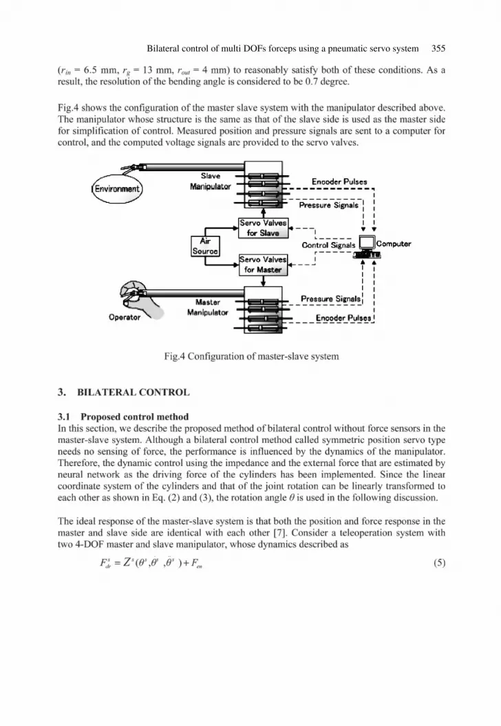
Bilateral control of multi DOFs forceps using a pneumatic servo system 355
c25.fm Page 355 Monday, July 18, 2005 8:36 PM

356 Power Transmission and Motion Control 2005
c25.fm Page 356 Monday, July 18, 2005 8:36 PM

Bilateral control of multi DOFs forceps using a pneumatic servo system 357
c25.fm Page 357 Monday, July 18, 2005 8:36 PM

358 Power Transmission and Motion Control 2005
c25.fm Page 358 Monday, July 18, 2005 8:36 PM

Bilateral control of multi DOFs forceps using a pneumatic servo system 359
c25.fm Page 359 Monday, July 18, 2005 8:36 PM

360 Power Transmission and Motion Control 2005
c25.fm Page 360 Monday, July 18, 2005 8:36 PM

Bilateral control of multi DOFs forceps using a pneumatic servo system 361
c25.fm Page 361 Monday, July 18, 2005 8:36 PM
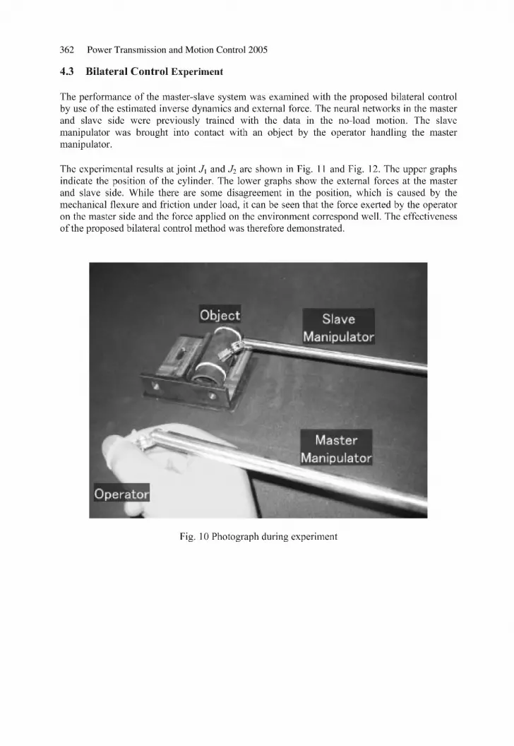
362 Power Transmission and Motion Control 2005
c25.fm Page 362 Monday, July 18, 2005 8:36 PM

Bilateral control of multi DOFs forceps using a pneumatic servo system 363
c25.fm Page 363 Monday, July 18, 2005 8:36 PM

364 Power Transmission and Motion Control 2005
c25.fm Page 364 Monday, July 18, 2005 8:36 PM

Power Transmission and Motion Control 2005 Edited by C. R. Burrows, K. A. Edge and D. N. Johnston© With The Centre for Power Transmission and Motion Control
c26.fm Page 365 Monday, July 18, 2005 8:37 PM

366 Power Transmission and Motion Control 2005
A/D PLCD/A
Lab-ViewData-Acquisition-System
P1 P2
G1 G2
PS
PVPV
VREF
VF/BVSET
x,x,x...
A FE
c26.fm Page 366 Monday, July 18, 2005 8:37 PM

Experimental identification and validation of a pneumatic positioning servo-system 367
10–1 100 101–60
–40
–20
0
20
Am
plitu
de [d
B]
10–1 100 101–400
–300
–200
–100
0
phas
e [d
eg]
frequency [Hz]
Amp 0.7 VAmp 1 VAmp 1.4 VAmp 2 V
10–1 100 101–60
–40
–20
0
20
Am
plitu
de [d
B]
10–1 100 101–400
–300
–200
–100
0
phas
e [d
eg]
frequency [Hz]
Amp 0.7 VAmp 1 VAmp 1.4 VAmp 2 V
c26.fm Page 367 Monday, July 18, 2005 8:37 PM

368 Power Transmission and Motion Control 2005
0 0.1 0.2 0.3 0.4 0.50
1
2
3
4
5
6
7
time [s]
volta
ge s
igna
ls
VSETVREF VF/B
VP 1VP 2
0.0 0.1 0.2 0.3 0.4 0.50
1
2
3
4
5
6
7
time [s]
volta
ge s
igna
ls
VSET VREF VF/B
VP 1
VP 2
0 0.1 0.2 0.3 0.4 0.50
1
2
3
4
5
6
7
time [s]
volta
ge s
igna
ls
VSET VREFVF/B
VP 1VP 2
0 0.1 0.2 0.3 0.4 0.50
1
2
3
4
5
6
7
time [s]
volta
ge s
igna
ls
VSET VREFVF/BVP1 VP 2
c26.fm Page 368 Monday, July 18, 2005 8:37 PM

Experimental identification and validation of a pneumatic positioning servo-system 369
GCe –+
REGULATOR
P1 P2
G1 G2
PS
PVPV
VREF
VF/B
XSETKSET
VSET
x,x,x...
A FE
c26.fm Page 369 Monday, July 18, 2005 8:37 PM

370 Power Transmission and Motion Control 2005
P1 P2
G1 G2
A FE
GCe VSET–+
REGULATOR
VF/B
PS PV PS PV
VREF2
VREF1
V1 V2
α
x,x,x...
e VSET
VREF1
VREF2
– +
VF/B
POSITIONTRANSDUCER
REGULATOR
VALVE 1
VALVE 2
CHAMBER 1
CHAMBER 2
RODEQUILIBRIUM
G1
G2
P1
P2
x
P1
P2
x
x
x
FE
c26.fm Page 370 Monday, July 18, 2005 8:37 PM

Experimental identification and validation of a pneumatic positioning servo-system 371
–4
–2
0
2
4
12
34
56
7× 105
× 10–8
–0.03
–0.02
–0.01
0
0.01
0.02
0.03
P1 [Pa]C [m3/sPa ANR]
G [k
g/s]
c26.fm Page 371 Monday, July 18, 2005 8:37 PM

372 Power Transmission and Motion Control 2005
c26.fm Page 372 Monday, July 18, 2005 8:37 PM

Experimental identification and validation of a pneumatic positioning servo-system 373
c26.fm Page 373 Monday, July 18, 2005 8:37 PM

374 Power Transmission and Motion Control 2005
c26.fm Page 374 Monday, July 18, 2005 8:37 PM

Experimental identification and validation of a pneumatic positioning servo-system 375
c26.fm Page 375 Monday, July 18, 2005 8:37 PM

376 Power Transmission and Motion Control 2005
VS
ET +
KS
ET
–G
C
e
KG
C2
KG
R2
RT
nA
1(x 0
+ x
r)
RT
nA
2(x 0
– x
r)
1/s
++ ++ +
C2
G2
1/s
A2
FF
PV
(A1
− A
2)+
+ +
FE
+ ––+–
P2
mx&&
&& xx
KT
P
KG
C1
RT
P1r
A1
RT
P2r
A2
++ ++–
G1
C1
1/s P
2
A1
P1
P1
x&x&
&
&
&
VF
/B
KG
P2
KG
R1
1/m
x
KG
P1
1/s
x SE
T
α
γ
2K
v 2
σ n2
++
s22 σ n2
2ξ2 σ
n2s
22K
v 1
σ n1
++
s 22 σ n1
2ξ1 σ
n1s
2
c26.fm Page 376 Monday, July 18, 2005 8:37 PM

Experimental identification and validation of a pneumatic positioning servo-system 377
VSET + KSET –
xSET Gce
sKOLF
KOLV +– x
KTP
VF /B
1s
FE
2ξA σAs+ +s2 2σA
2σA
2ξ σns+ +s2 2σn
2σn
10–1 100 101 102
10–1 100 101 102
–40
–20
0
20
40
| V(F
/B)
/e| [
dB]
–300
–250
–200
–150
–100
–50
frequency [hz]
phas
e [d
eg]
Open Loop linOpen Loop exp amp 2V
–30
–20
–10
0
10
|X(S
ET
)/ X
| [dB
]
–400
–300
–200
–100
0
frequency [hz]
phas
e [d
eg]
10–1 100 101 102
10–1 100 101 102
Closed Loop linClosed Loop exp amp 2V
c26.fm Page 377 Monday, July 18, 2005 8:37 PM

378 Power Transmission and Motion Control 2005
c26.fm Page 378 Monday, July 18, 2005 8:37 PM

Power Transmission and Motion Control 2005 Edited by C. R. Burrows, K. A. Edge and D. N. Johnston© With The Centre for Power Transmission and Motion Control
c27.fm Page 379 Monday, July 18, 2005 8:38 PM

380 Power Transmission and Motion Control 2005
(a) (b)
u
h
ωc
u
Fc
FS1 Mu
cu
c27.fm Page 380 Monday, July 18, 2005 8:38 PM

Performances of cam-follower systems with pneumatic return spring 381
c27.fm Page 381 Monday, July 18, 2005 8:38 PM

382 Power Transmission and Motion Control 2005
(a) (b)
FS1FS1
u1
u2
u1
u2
lSplSm
FS2FS2
Q1
Q2
p1
p2
z
c27.fm Page 382 Monday, July 18, 2005 8:38 PM

Performances of cam-follower systems with pneumatic return spring 383
c27.fm Page 383 Monday, July 18, 2005 8:38 PM

384 Power Transmission and Motion Control 2005
c27.fm Page 384 Monday, July 18, 2005 8:38 PM

Performances of cam-follower systems with pneumatic return spring 385
c27.fm Page 385 Monday, July 18, 2005 8:38 PM

386 Power Transmission and Motion Control 2005
c27.fm Page 386 Monday, July 18, 2005 8:38 PM

Performances of cam-follower systems with pneumatic return spring 387
c27.fm Page 387 Monday, July 18, 2005 8:38 PM

388 Power Transmission and Motion Control 2005
c27.fm Page 388 Monday, July 18, 2005 8:38 PM

Performances of cam-follower systems with pneumatic return spring 389
c27.fm Page 389 Monday, July 18, 2005 8:38 PM

390 Power Transmission and Motion Control 2005
c27.fm Page 390 Monday, July 18, 2005 8:38 PM

Performances of cam-follower systems with pneumatic return spring 391
R0 Vr reservoir
pneumaticspring
orifice
pneumatic line digitalvalves
follower
c27.fm Page 391 Monday, July 18, 2005 8:38 PM

392 Power Transmission and Motion Control 2005
c27.fm Page 392 Monday, July 18, 2005 8:38 PM

Performances of cam-follower systems with pneumatic return spring 393
c27.fm Page 393 Monday, July 18, 2005 8:38 PM

394 Power Transmission and Motion Control 2005
c27.fm Page 394 Monday, July 18, 2005 8:38 PM

Power Transmission and Motion Control 2005 Edited by C. R. Burrows, K. A. Edge and D. N. Johnston© With The Centre for Power Transmission and Motion Control
c28.fm Page 395 Monday, July 18, 2005 8:39 PM

396 Power Transmission and Motion Control 2005
c28.fm Page 396 Monday, July 18, 2005 8:39 PM

Motion simulator with 3 d.o.f. pneumatically actuated 397
limb L1
limb L2
limb L3
moving platform
fixed base
joint Jm2
joint Jf1
joint Jf2
joint Jf3
joint Jm3
joint Jm1
z
MP1
MP2 MP3
FP1
FP2
FP3
r
r
x0
y0
z0
xm
ym
zm
χ
ψ ϑ
ϑ
η
η
ρ
ρ
c28.fm Page 397 Monday, July 18, 2005 8:39 PM

398 Power Transmission and Motion Control 2005
c28.fm Page 398 Monday, July 18, 2005 8:39 PM

Motion simulator with 3 d.o.f. pneumatically actuated 399
2
P 1
x1
V
K T
+ _
P S
P V
K SE
1
P 2
1
x1
V
V 1
e
K T
GV SET
V
+ _
P S
V
K
Inverse
Kinematics
xSET1
[z ψ χ]SET
xSET1
xSET2
xSET3
x1
[z ψ χ]
x1
x2
x3
FE1
FE2
FE3
G2
G1
P2
P1
x1
VREF1
V1
e
KTP
GC VSET1
VFB1
+ _
FE
PS
PV
KSET
xFB1
c28.fm Page 399 Monday, July 18, 2005 8:39 PM

400 Power Transmission and Motion Control 2005
heave middle height heave middle height& pitch –30°
heave middle height& roll +30°
c28.fm Page 400 Monday, July 18, 2005 8:39 PM

Motion simulator with 3 d.o.f. pneumatically actuated 401
zC
V1
V2
V3
VB3
VB2
VB1
requiredplatformposition
visually acquired platform position
CommandConsole
VREF1
VREF2
VREF3
x1 x2 x3VBRK
Em.sign.
Pos.sign.
xSET2
xSET3
xSET1
zSET
Control Hardware
GC1Position
Management
Emergency
Management
Inverse
Kinematics
JointsSafety
Algorithm
GC2
GC3
ψSETψC
χSETχC
c28.fm Page 401 Monday, July 18, 2005 8:39 PM

402 Power Transmission and Motion Control 2005
(a) (b)
c28.fm Page 402 Monday, July 18, 2005 8:39 PM

Motion simulator with 3 d.o.f. pneumatically actuated 403
4 5 6 7 8 9–4
–2
0
2
4
6
time [s]
volta
ge s
igna
l [V
]
4 5 6 7 8 9–4
–2
0
2
4
6
time [s]
volta
ge s
igna
l [V
]
VSET
VFBs.
VFBe.
VREFs. VREF
e.
VSET
VFBs. VFB
e.
VREFe.VREF s.
(a) (b)
c28.fm Page 403 Monday, July 18, 2005 8:39 PM

404 Power Transmission and Motion Control 2005
LOAD DATA0 kg
LOAD DATA30 kg
LOADSERVO-SYSTEM
DATAPA
PS
PV
Vrif
PB
GA
GB
acq
VALVE
Ktp
TRANSDUCER
DATAACQ
REFERENCE
Pv
Ps
PLOT
x_offsetOFFSET
F_e
FORCE
EDITDATA
G1
F
G2
P1
a
v
x
P2
CYLINDER
V_SET
V_F/B
V_REF
acq
CONTROLLER
F
V_SET
x
x
0.1 1
–40
–20
0
Gai
n [d
B]
0.1 1
–300
–200
–100
frequency [Hz]
Pha
se [d
eg]
expsim
0.1 1
–40
–20
0
Gai
n [d
B]
0.1 1
–300
–200
–100
0
frequency [Hz]
Pha
se [d
eg]
expsim
(a) (b)
c28.fm Page 404 Monday, July 18, 2005 8:39 PM

Motion simulator with 3 d.o.f. pneumatically actuated 405
0.1 1
–40
–20
0
Gai
n [d
B]
0.1 1
–300
–200
–100
frequency [Hz]
Pha
se [d
eg]
expsim
0.1 1
–40
–20
0
Gai
n [d
B]
0.1 1
–300
–200
–100
0
frequency [Hz]
Pha
se [d
eg]
expsim
(a) (b)
c28.fm Page 405 Monday, July 18, 2005 8:39 PM

406 Power Transmission and Motion Control 2005
c28.fm Page 406 Monday, July 18, 2005 8:39 PM

Fluid Dynamics and Noise
c29.fm Page 407 Monday, July 18, 2005 8:45 PM

c29.fm Page 408 Monday, July 18, 2005 8:45 PM

Power Transmission and Motion Control 2005 Edited by C. R. Burrows, K. A. Edge and D. N. Johnston© With The Centre for Power Transmission and Motion Control
c29.fm Page 409 Monday, July 18, 2005 8:45 PM

410 Power Transmission and Motion Control 2005
c29.fm Page 410 Monday, July 18, 2005 8:45 PM

Elucidation of the noise generating mechanism 411
P.T. : Pressure transducer
P.A. : Piezo electric accelerometer
C.M. : Condenser microphone
Downstream pipe
Needle valve
P.T.(pu) Orifice plate
P.T.( pd 1) P.T.( pd 2 )
P.A. C.M.
Block Test device holder
pu pd
Block
c29.fm Page 411 Monday, July 18, 2005 8:45 PM

412 Power Transmission and Motion Control 2005
(b) pd = 0.25Mpa(a) pd = 0.15Mpa
(c) pd = 0.35Mpa (d) pd = 0.45Mpa
p d1
= [M
Pa]
–0.1
0
0.1
0.2
0.3
0.4
0.09MPa
0.15MPa
0.25MPa
0.35MPa
r [mm]
0 2.0 4.0 6.0 8.0 9.8
p d1
[MP
a]
–0.1
0
0.1
0.2
0.3
0.4
0.5
0 20 40 60 80 100
z [mm]
0.09MPa
0.15MPa
0.25MPa
0.35MPa
(a) radial direction (z = 7mm) (b) axial direction (r = 9.8mm)
pd = 0.45MPa pd = 0.45MPa
c29.fm Page 412 Monday, July 18, 2005 8:45 PM

Elucidation of the noise generating mechanism 413
p d1
= [M
Pa]
0 5 10 15 20f [kHz]
f [kHz]
f [kHz]
(a)
0
0.01
0.02
0.03
0
50
100
150a
[m/s
2 ]
0 5 10 15 20
(b)
0
0.2
0.4
0.6
s [P
a]
0 5 10 15 20
(c)
0
0.01
0.02
0.03
p d1
[MP
a]p d
2 [M
Pa]
p d1
[MP
a]p d
2 [M
Pa]
f [kHz]0 2 104 6 8
0
0.01
0.02
0.03
0
0.01
0.02
0.03
f [kHz]0 2 104 6 8
f [kHz]0 2 104 6 8
f [kHz]0
02 104 6 8
0.01
0.02
0.03
(a) with cavitation (pd = 0.15MPa) (b) without cavitation (pd = 1.2Mpa)
c29.fm Page 413 Monday, July 18, 2005 8:45 PM

414 Power Transmission and Motion Control 2005
z
O
y
x
x
y
z
(a) Bending mode (B-3)
(b) Torsional mode (T-2)
(c) Longitudinal mode (L-2)
c29.fm Page 414 Monday, July 18, 2005 8:45 PM

Elucidation of the noise generating mechanism 415
c29.fm Page 415 Monday, July 18, 2005 8:45 PM

416 Power Transmission and Motion Control 2005
x-z plane x-y plane
(a) 1st mode (f =18351Hz)
x-z plane x-y plane
(b) 2nd mode (f =18367Hz)
c29.fm Page 416 Monday, July 18, 2005 8:45 PM

Elucidation of the noise generating mechanism 417
c29.fm Page 417 Monday, July 18, 2005 8:45 PM

418 Power Transmission and Motion Control 2005
(a) distributed force model (b) lumped (single point) force model
2.275
x
y
o
1.0 1.01.0
0.9
0.9
0.9
0.9
0.9
0.9
0.8
0.8
0.8
0.7
0.8
0.8
0.8
0.70.6
0.7
0.7
0.60.6
0.50.6
x
y
o
c29.fm Page 418 Monday, July 18, 2005 8:45 PM

Elucidation of the noise generating mechanism 419
10–10
10–9
10–8
10–7
10–6
10–10
10–9
10–8
10–7
10–6
|Hn(
f )| [
m/N
]|H
n(f )
| [m
/N]
f [kHz]
L1 L2 L3
B1
B2B3
B4 B5 B6 B7 B8 B9 B10 B11 B12 B13
0 1064 82
(a) zf = 20mm
f [kHz]
L1L2 L3
B1
B2B3
B4B5
B6 B7 B8 B9 B10 B11 B12 B13
0 1064 82
(b) zf = 40mm
c29.fm Page 419 Monday, July 18, 2005 8:45 PM

420 Power Transmission and Motion Control 2005
1.0
1.0
o x
y
10–11
10–10
10–9
10–8
10–7
|Hn(
f ) | [
m/N
]
f [kHz]
B1B2
B3 B4 B5 B6B7 B8 B9 B10 B11
L1 L2 L3
T1T2
T3T4 T5
0 1064 82
c29.fm Page 420 Monday, July 18, 2005 8:45 PM

Elucidation of the noise generating mechanism 421
(a) pd = 0.1MPa (b) pd = 0.2MPa
B13
B12
B3
f [kHz] f [kHz]
f [kHz]f [kHz]
0 2 104 6 8
0
0.1
0.2
0.3
0.4
s [P
a]
B4B5
B6
B7 B8 B9
B11
B10
B13
B3
B12
0
20
40
60
B5
B6B7
B8
B9
B11B10B13
B12
B4
0 2 104 6 8
0 2 104 6 8 0 2 104 6 80
0.1
0.2
0.3
0.4
s [P
a]
B4B6
B7B8
B9B11
B10
B13
B12
B3 B5
0
20
40
60
a [m
/s2 ]
a [m
/s2 ]
B5
B6
B7B8
B9B11B10
(a) pd = 0.1MPa (b) pd = 0.2MPa
0
20
40
60
0 2 104 6 8
0 2 104 6 8
B4
B6B5B3
B2
0
0.1
0.2
0.3
0.4B4
B6
B5B3
B2
0
20
40
60
B4
B6B5
B3
0 2 104 6 8
B2
0
0.1
0.2
0.3
0.4
B4
B6
B5B3
0 2 104 6 8
B2
f [kHz]
f [kHz]f [kHz]
f [kHz]
s [P
a]
a [m
/s2 ]
a [m
/s2 ]
s [P
a]
c29.fm Page 421 Monday, July 18, 2005 8:45 PM

422 Power Transmission and Motion Control 2005
c29.fm Page 422 Monday, July 18, 2005 8:45 PM

Elucidation of the noise generating mechanism 423
0
0.01
0.02
0.03
p d1
[MP
a]
0 2 104 6 8
0 2 104 6 8
0 2 104 6 8
(a)
0
25
50
75
100a
[m/s
2 ]
0
0.1
0.2
0.3
0.4
s [P
a]
f [kHz]
f [kHz]
f [kHz]
(c)
(b)
10–10
10–9
10–8
10–7
10–6
f [kHz]
0 1064 82
Vib
ratio
n am
plitu
de [m
]
B1
B3 B5
B7
B9B11
B13
c29.fm Page 423 Monday, July 18, 2005 8:45 PM

424 Power Transmission and Motion Control 2005
c29.fm Page 424 Monday, July 18, 2005 8:45 PM

Elucidation of the noise generating mechanism 425
c29.fm Page 425 Monday, July 18, 2005 8:45 PM

c29.fm Page 426 Monday, July 18, 2005 8:45 PM

Power Transmission and Motion Control 2005 Edited by C. R. Burrows, K. A. Edge and D. N. Johnston© With The Centre for Power Transmission and Motion Control
c30.fm Page 427 Monday, July 18, 2005 8:49 PM

428 Power Transmission and Motion Control 2005
c30.fm Page 428 Monday, July 18, 2005 8:49 PM

An experimental result on the measurement of concentrated flow resistances 429
VP
VP
VP
p1
VP
p2
p0
PZT actuator
lower chamberpressurecontrol
upper chamber & pipepressurecontrol
VP
c30.fm Page 429 Monday, July 18, 2005 8:49 PM

430 Power Transmission and Motion Control 2005
c30.fm Page 430 Monday, July 18, 2005 8:49 PM

An experimental result on the measurement of concentrated flow resistances 431
c30.fm Page 431 Monday, July 18, 2005 8:49 PM

432 Power Transmission and Motion Control 2005
p p
p
aF
R1 R2 R2 R2 R2
L
p0 p0,1 p1,1 p1,2p1 p2,1 p2
c30.fm Page 432 Monday, July 18, 2005 8:49 PM

An experimental result on the measurement of concentrated flow resistances 433
c30.fm Page 433 Monday, July 18, 2005 8:49 PM

434 Power Transmission and Motion Control 2005
c30.fm Page 434 Monday, July 18, 2005 8:49 PM

An experimental result on the measurement of concentrated flow resistances 435
500 1000 1500 2000 2500
500 1000 1500 2000 2500
0.1
0.2
0.3
0.4
0.5
|p0|
[mba
r/sq
rt(H
z)]
0.1
0.2
0.3
0.4
0.5
|p1|
[mba
r/sq
rt(H
z)]
f [Hz]
measuredcomputed from a and p2
measured
computed from a and p2
c30.fm Page 435 Monday, July 18, 2005 8:49 PM

436 Power Transmission and Motion Control 2005
c30.fm Page 436 Monday, July 18, 2005 8:49 PM

Power Transmission and Motion Control 2005 Edited by C. R. Burrows, K. A. Edge and D. N. Johnston© With The Centre for Power Transmission and Motion Control
c31.fm Page 437 Monday, July 18, 2005 8:50 PM

438 Power Transmission and Motion Control 2005
c31.fm Page 438 Monday, July 18, 2005 8:50 PM

The dynamics of hydraulic fluids – significance, differences and measuring 439
c31.fm Page 439 Monday, July 18, 2005 8:50 PM

440 Power Transmission and Motion Control 2005
c31.fm Page 440 Monday, July 18, 2005 8:50 PM

The dynamics of hydraulic fluids – significance, differences and measuring 441
c31.fm Page 441 Monday, July 18, 2005 8:50 PM

442 Power Transmission and Motion Control 2005
c31.fm Page 442 Monday, July 18, 2005 8:50 PM

The dynamics of hydraulic fluids – significance, differences and measuring 443
The Measured Speed of Sound with Linear Regression, 40C
1200
1250
1300
1350
1400
1450
1500
1550
0 100 200 300 400 500 600 700bar
m/s
Mineral oilPine oilHF-EHigh VIMotor oil
c31.fm Page 443 Monday, July 18, 2005 8:50 PM

444 Power Transmission and Motion Control 2005
The Measured Speed of Sound with Linear Regression, 70C
1200
1250
1300
1350
1400
1450
1500
1550
0 100 200 300 400 500 600 700
bar
m/s
Mineral oilPine oilHF-EHigh VIMotor oil
The Measured Bulk Moduli with Linear Regression, 40C
1500
1600
1700
1800
1900
2000
2100
2200
2300
0 100 200 300 400 500 600 700bar
MP
a
Mineral oilPine oilHF-EHigh VIEngine oil
c31.fm Page 444 Monday, July 18, 2005 8:50 PM

The dynamics of hydraulic fluids – significance, differences and measuring 445
The Measured Bulk Moduli with Linear Regression, 70C
1500
1400
1300
1600
1700
1800
1900
2000
2100
2200
0 100 200 300 400 500 600 700
bar
MP
a
Mineral oilPine oilHF-EHigh VIEngine oil
The Measured Densities with Linear Regression, 40C
860
870
880
890
900
910
920
930
940
950
0 100 200 300 400 500 600 700
bar
kg/m
3
Mineral oilPine oilHF-EHigh VIMotor oil
c31.fm Page 445 Monday, July 18, 2005 8:50 PM

446 Power Transmission and Motion Control 2005
The Measured Densities with Linear Regression, 70C
860
850
840
870
880
890
900
910
920
930
0 100 200 300 400 500 600 700
bar
kg/m
3
Mineral oilPine oilHF-EHigh VIMotor oil
c31.fm Page 446 Monday, July 18, 2005 8:50 PM

The dynamics of hydraulic fluids – significance, differences and measuring 447
Bulk modulus/ISO VG 46 Mineral oil, 40C
1400
1500
1600
1700
1800
1900
2000
2100
2200
2300
2400
0 100 200 300 400 500 600 700bar
MP
a
MeasuredB_siB_saB_tiB_ta
c31.fm Page 447 Monday, July 18, 2005 8:50 PM

448 Power Transmission and Motion Control 2005
Density/ISO VG 46 Mineral oil, 40C
860
865
870
875
880
885
890
895
900
0 100 200 300 400 500 600 700bar
kg/m
3 MeasuredCalculated
Bulk modulus/ISO VG 46 Pine oil, 40C
1400
1500
1600
1700
1800
1900
2000
2100
2200
2300
2400
0 100 200 300 400 500 600 700
bar
MP
a
MeasuredB_siB_saB_tiB_ta
Density/ISO VG 46 Pine oil, 40C
910
915
920
925
930
935
940
945
950
0 100 200 300 400 500 600 700bar
kg/m
3 MeasuredCalculated
c31.fm Page 448 Monday, July 18, 2005 8:50 PM

The dynamics of hydraulic fluids – significance, differences and measuring 449
Bulk modulus/ISO VG 46 Synthetic HF-E, 40C
1400
1500
1600
1700
1800
1900
2000
2100
2200
2300
2400
0 100 200 300 400 500 600 700bar
MP
aMeasuredB_siB_saB_tiB_ta
Density/ISO VG 46 Synthetic HF-E, 40C
910
915
920
925
930
935
940
945
950
0 100 200 300 400 500 600 700bar
kg/m
3 MeasuredCalculated
c31.fm Page 449 Monday, July 18, 2005 8:50 PM

450 Power Transmission and Motion Control 2005
c31.fm Page 450 Monday, July 18, 2005 8:50 PM

Power Transmission and Motion Control 2005 Edited by C. R. Burrows, K. A. Edge and D. N. Johnston© With The Centre for Power Transmission and Motion Control
c32.fm Page 451 Monday, July 18, 2005 8:51 PM

452 Power Transmission and Motion Control 2005
c32.fm Page 452 Monday, July 18, 2005 8:51 PM

Measurements of elastohydrodynamic pressure field 453
Cylinder block
Piston
SlipperGapBushing
Gap length, y/ymax Gap circumference [° ]
unwrapped gap
600
400
200
00 0.2 0.4 0.6 0.8
ϕ = 12°
20
0
30
xy
1 400300
200100
0Pre
ssur
e [b
ar]
c32.fm Page 453 Monday, July 18, 2005 8:51 PM

454 Power Transmission and Motion Control 2005
c32.fm Page 454 Monday, July 18, 2005 8:51 PM

Measurements of elastohydrodynamic pressure field 455
Pressure sensor
∅0,2
30
M6
Cylinder block
Gap
Piston
v20
0,5
Location of pressure sensors
1
76
89
5 43
21
unwrapped gap
Gap length [mm]
Gap circumference [˚]
28,66
26,16
25,66 23,66
20,66
14,33
8,05,0
3,0
2,50 0
315
270
225
180
135
90
45
0
c32.fm Page 455 Monday, July 18, 2005 8:51 PM

456 Power Transmission and Motion Control 2005
12
3
Sensor position
Cylinder
Sensor holes
bush
ing
Cylinder block
ThermocouplePressure sensor
BoreSurface
Swash plate
Cylinder
Pressure sensor
450 bar
20 bar
(3)(1)
3D
β
n
(2)
UP
T
Q
U
U
UP
UP
UP
UT
T
Q
U
U
Thermocouples
Pressure sensor
Thermocouple
Incremental encoder
Thermocouple
Piston
c32.fm Page 456 Monday, July 18, 2005 8:51 PM

Measurements of elastohydrodynamic pressure field 457
Flansch
Swash plate
Shaft seal
Bearing cover
Incremental encoder
Piston/slipperTemperature sensor
Pressure sensor
Cylinder block
Interlock
Check valve
Port
Retainer pin
Fixed discRetainer ringgroove
Pressure sensorThermocouple
DetentCylinder block
Sensor cable connection
c32.fm Page 457 Monday, July 18, 2005 8:51 PM

458 Power Transmission and Motion Control 2005
Rotating angle ϕ
Trigger
Swash plateEncoder
PCI DAS4020/12 PC
Channel 0TTL Signal
AT
β
HD NDHD NDHD ND
TTL Signal
Impuls
0
0
0 180 360...
3zU2zUzU
ITIT AT
IT Reference markAT IT
Vol
tage
c32.fm Page 458 Monday, July 18, 2005 8:51 PM

Measurements of elastohydrodynamic pressure field 459
c32.fm Page 459 Monday, July 18, 2005 8:51 PM

460 Power Transmission and Motion Control 2005
case pressurepressure sensor no.1pressure sensor no.2
pressure sensor no.3
pressure sensor no.5
pressure sensor no.6
pressure sensor no.8
pressure sensor no.9
pressure cylinder chamber
180° rotation angle of driveshaft
300
250
200
150
00
0.2
0.6
0.8
1300
200
100
circumference [deg]
0
Pre
ssur
e [b
ar]
180 measurement pointsover circumference
c32.fm Page 460 Monday, July 18, 2005 8:51 PM

Measurements of elastohydrodynamic pressure field 461
c32.fm Page 461 Monday, July 18, 2005 8:51 PM

462 Power Transmission and Motion Control 2005
c32.fm Page 462 Monday, July 18, 2005 8:51 PM

Measurements of elastohydrodynamic pressure field 463
Gap length [mm]
Gap circumference [˚]500.2
0.4
0.6
0.8
52
54
56
58
Tem
p [°
C]
60
62
100150
200250
Δρ = 250 bar
300350
53
54
55
56
57
58
59
60
61
62
c32.fm Page 463 Monday, July 18, 2005 8:51 PM

464 Power Transmission and Motion Control 2005
c32.fm Page 464 Monday, July 18, 2005 8:51 PM

Measurements of elastohydrodynamic pressure field 465
c32.fm Page 465 Monday, July 18, 2005 8:51 PM

c32.fm Page 466 Monday, July 18, 2005 8:51 PM

Power Transmission and Motion Control 2005 Edited by C. R. Burrows, K. A. Edge and D. N. Johnston© With The Centre for Power Transmission and Motion Control
Authors’ Index
AAlmondo, A., 379
BBalossini, Gualtiero, 3 Behr, Robert, 451 Bergstrom, Don, 223 Bideaux, E., 317 Brun, Xavier, 45 Burton, Richard, 163, 223
CChinniah, Yuvin, 163 Conrad, Finn, 117
DDerkaoui, A., 317
EEdamura, Kazuya, 269, 277 Ellman, A., 179 Esqué, S., 179
FFedde, T., 307 Fiedler, M., 255 Figliolini, Giorgio, 365
GGstöttenbauer, Norbert, 291 Guillemard, F., 317
HHabibi, Saeid, 163 Harms, H-H., 307 Helduser, S., 255 Hös, Csaba, 193 Huang, Changchun, 451 Huhtala, K., 437
IIchiryu, K., 333 Ikeo, S., 333 Inberg, Juha, 59 Ito, K., 333 Ivantysynova, Monika, 451
JJacazio, Giovanni, 3
KKagawa, Toshiharu, 351 Kainz, Alexander, 291 Karjalainen, J-P., 437 Karjalainen, R., 437 Kawachi, Masashi, 277 Kawamura, K., 333 Kawashima, Kenji, 351 Koivula, Timo, 147 Kojima, E., 409 Koskinen, Kari T., 107 Koyabu, E., 333 Kullmann, László, 193
LLaamanen, Arto, 91 Laffite, J., 317 Lang, T., 307 Lee, S., 333 Legrand, Xavier, 45 Liermann, Matthias, 17 Lin Shi, Xue-Fang, 45 Linjama, Matti, 29, 91, 133
MManhartsgruber, Bernhard, 291, 427 Marquis-Favre, W., 317 Mattiazzo, G., 395 Murrenhoff, Hubertus, 17
bindex.fm Page 467 Wednesday, July 20, 2005 12:36 PM

468 Authors’ Index
OOkungbowa, Norense, 223
PPastorelli, Stefano, 365, 379 Plummer, A.R., 75
RRea, Pierluigi, 365 Retif, Jean-Marie, 45 Rinkinen, Jari, 147 Roli, Francesco, 117 Rüdiger, F., 255 Rusanen, Heikki, 147
SSairiala, Harri, 107 Sampson, Eric, 163 Scavarda, S., 317 Scheidl, R., 209, 291 Schultz, Albert, 243
Shimoyama, H., 333 Siivonen, Lauri, 133 Smaoui, Mohamed, 45 Soga, Tsutomu, 277 Sorli, Massimo, 365, 379 Steiner, B., 209
TTadano, Kotaro, 351 Takemura, Kenjiro, 269 Terada, A., 409 Thomasset, Daniel, 45
VVilenius, Matti, 91, 107, 133, 437 Virvalo, Tapio, 29, 59
YYamazaki, T., 409 Yokota, Shinichi, 269, 277 Yoshida, Kazuhiro, 277
bindex.fm Page 468 Wednesday, July 20, 2005 12:36 PM

bindex.fm Page 469 Wednesday, July 20, 2005 12:36 PM

bindex.fm Page 470 Wednesday, July 20, 2005 12:36 PM