Embed Size (px)
Citation preview
Chapter 6
Power Factor Improvement
The cosine of angle between voltage and current in an a.c. circuit is known
as power factor.
Most of the loads (e.g. induction motors, arc lamps) are inductive in nature
and hence have low lagging power factor. The low power factor is highly
undesirable as it causes an increase in current, resulting in additional losses of
active power in all the elements of power system from power station generator
down to the utilization devices. In order to ensure most favorable conditions for a
supply system from engineering and economic standpoint, it is important to have
power factor as close to unity as possible.
Power Triangle: OA = VI cos φ and represents the active power,(P) in watts or kW.
AB = VI sin φ and represents the reactive power, (Q) in VAR or kVAR.
OB = VI and represents the apparent power, (S) in VA or kVA.
(i) The apparent power (S) in an a.c. circuit has two components viz., active (P)
and reactive power (Q) at right angles to each other.
OB2 = OA2 + AB2
or S2 = P2 + Q2
(ii) Power factor, cos φ =𝑂𝐴
𝑂𝐵=
P
S=
𝑘𝑊
𝑘𝑉𝐴
Q=VI sinᵩ
P=VI cosᵩ
ᵩ
lagging power factor Leading power factor
Chapter 6
(iii)The lagging reactive power is responsible for the low power factor. It is clear
from the power triangle that smaller the reactive power component, the higher is
the power factor of the circuit.
kVAR = kVA sin φ = 𝑘𝑊
cos 𝜑 sin 𝜑
kVAR = kW tan φ
(iv) For leading power factor, the power triangle becomes reversed. This fact
provides a key to the power factor improvement. If a device taking leading
reactive power (e.g. capacitor) is connected in parallel with the load, then the
lagging reactive power of the load will be partly neutralised, thus improving the
power factor of the load.
(v) The power factor of a circuit can be defined in one of the following three
ways:
(a) Power factor = cos φ = cosine of angle between V and I.
(b) Power factor = 𝑅
𝑍=
𝑅𝑒𝑠𝑖𝑠𝑡𝑜𝑟
𝐼𝑚𝑝𝑒𝑑𝑎𝑛𝑐𝑒 .
(c) Power factor = 𝑉𝐼 cos 𝜑
𝑉𝐼=
𝐴𝑐𝑡𝑖𝑣𝑒 𝑝𝑜𝑤𝑒𝑟
𝐴𝑝𝑝𝑎𝑟𝑒𝑛𝑡 𝑝𝑜𝑤𝑒𝑟
(vi) The reactive power is neither consumed in the circuit nor does it do any
useful work. It merely flows back and forth in both directions in the circuit. A
wattmeter does not measure reactive power.
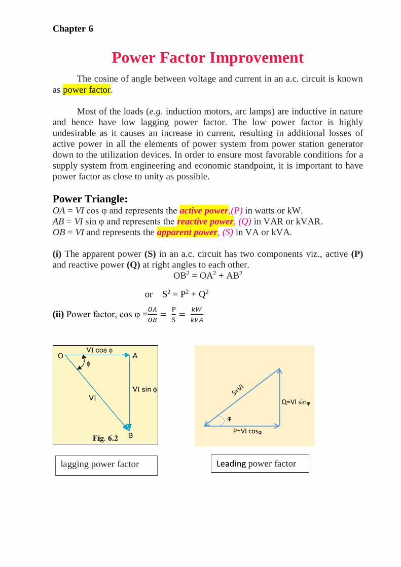
Example:
Suppose a circuit draws a current of 10 A at a voltage of 200 V and its p.f. is 0·8
lagging.
Apparent power, S = VI = 200 × 10 = 2000 VA.
Active power, P = VI cos φ = 200 × 10 × 0·8 = 1600 W.
Reactive power Q = VI sin φ = 200 × 10 × 0·6 = 1200 VAR.
Apparent power, S= 2000VA
Active power, P= 1600W Reactive power, Q=1200VAR
useful work does no useful work
Chapter 6
The circuit receives an apparent power of 2000 VA and is able to convert
only 1600 watts into active power. The reactive power is 1200 VAR and does no
useful work. It merely flows into and out of the circuit periodically. In fact,
reactive power is a liability on the source because the source has to supply the
additional current (i.e., I sin φ).
*Disadvantages of Low Power Factor:
The power factor plays an importance role in a.c. circuits since power
consumed depends upon this factor.
P = VL IL cos φ (For single phase supply)
∴ 𝐼𝐿 =𝑃
𝑉𝐿 cos 𝜑 ……………………………. (i)
P =√3 VL IL cos φ (For 3 phase supply)
∴ 𝐼𝐿 =𝑃
√3𝑉𝐿 cos 𝜑 …………………………... (ii)
It is clear from above that for fixed power and voltage, the load current is
inversely proportional to the power factor. Lower the power factor, higher is the
load current and vice-versa. A power factor less than unity results in the
following disadvantages:
(i) Large kVA rating of equipment. The electrical machinery (e.g.,
alternators, transformers, switchgear) is always rated in *kVA.
kVA= 𝑘𝑊
cos 𝜑
It is clear that kVA rating of the equipment is inversely proportional to
power factor. The smaller the power factor, the larger is the kVA rating.
Therefore, at low power factor, the kVA rating of the equipment has to be made
more, making the equipment larger and expensive.
i.e Cosφ α 1
kVA
(ii) Greater conductor size. To transmit or distribute a fixed amount of power
at constant voltage, the conductor will have to carry more current at low power
factor. This necessitates large conductor size.
Chapter 6
For example, take the case of a single phase a.c. motor having an input of 10 kW
on full load, the terminal voltage being 250 V. At unity p.f., the input full load
current would be 10,000/250 = 40 A. At 0·8 p.f; the kVA input would be 10/0·8 =
12·5 and the current input 12,500/250 = 50 A. If the motor is worked at a low
power factor of 0·8, the cross-sectional area of the supply cables and motor
conductors would have to be based upon a current of 50 A instead of 40 A which
would be required at unity power factor.
(iii)Large copper losses. The large current at low power factor causes more I2R
losses in all the elements of the supply system. This results in poor efficiency.
(iv)Poor voltage regulation. The large current at low lagging power factor
causes greater voltage drops in alternators, transformers, transmission lines and
distributors. This results in the decreased voltage available at the supply end, thus
impairing the performance of utilisation devices. In order to keep the receiving
end voltage within permissible limits, extra equipment (i.e., voltage regulators) is
required.
The above discussion leads to the conclusion that low power factor is an
objectionable feature in the supply system
Causes of Low Power Factor Low power factor is undesirable from economic point of view. Normally, the
power factor of the whole load on the supply system in lower than 0·8. The
following are the causes of low power factor:
(i) Most of the a.c. motors are of induction type (1φ and 3φ induction motors)
which have low lagging power factor. These motors work at a power factor which
is extremely small on light load (0·2 to 0·3) and rises to 0·8 or 0·9 at full load.
(iii) Arc lamps, electric discharge lamps and industrial heating furnaces operate
at low lagging power factor.
(iv) The load on the power system is varying; being high during morning and
evening and low at other times. During low load period, supply voltage is
increased which increases the magnetization current. This results in the decreased
power factor.
Power Factor Improvement:
The low power factor is mainly due to the fact that most of the power loads
are inductive and, therefore, take lagging currents. In order to improve the power
factor, some device taking leading power should be connected in parallel with the
Chapter 6
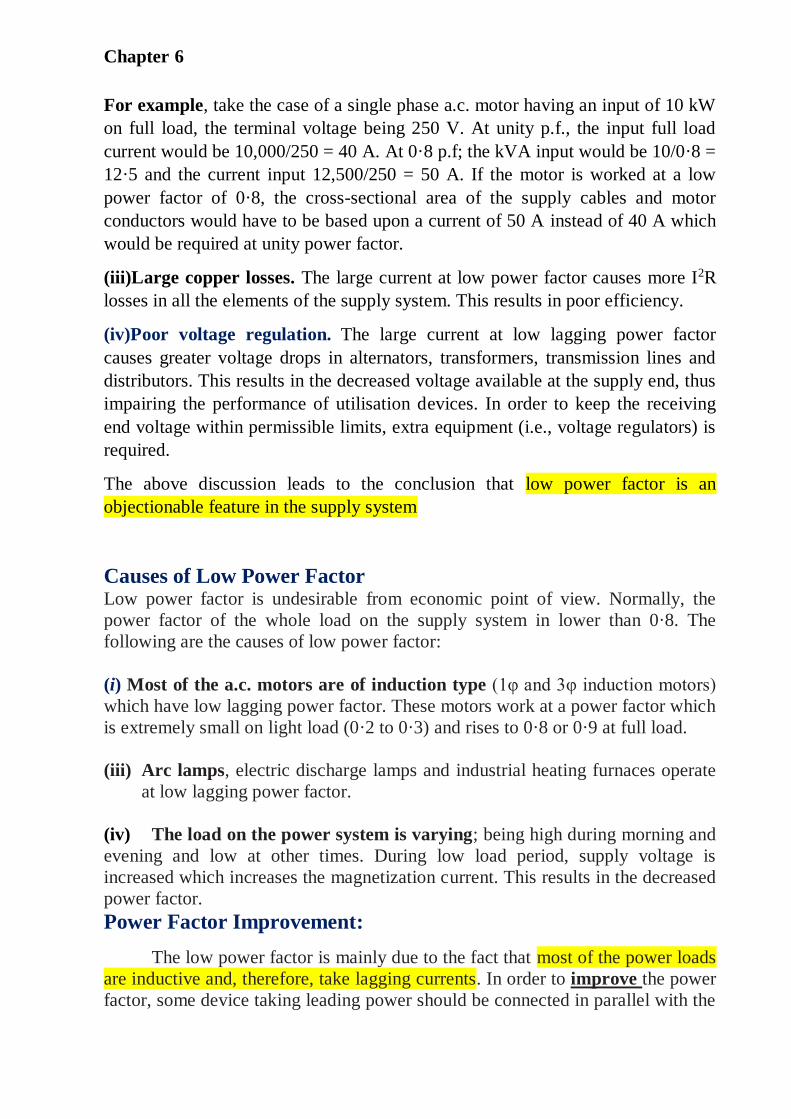
load. One of such devices can be a capacitor. The capacitor draws a leading
current and partly or completely neutralises the lagging reactive component of
load current. This raises the power factor of the load.
Illustration. To illustrate the power factor improvement by a capacitor, consider
a single *phase load taking lagging current I at a power factor cos φ1 as shown in
Fig. 6.3.
The capacitor C is connected in parallel with the load. The capacitor draws
current IC which leads the supply voltage by 90o. The resulting line current I′ is
the phasor sum of I and IC and its angle of lag is φ2 as shown in the phasor
diagram of Fig. 6.3. (iii). It is clear that φ2 is less than φ1, so that cos φ2 is greater
than cos φ1. Hence, the power factor of the load is improved. The following
points are worth noting:
(i) The circuit current I ′ after p.f. correction is less than the original circuit
current I.
(ii) The active or wattful component remains the same before and after p.f.
correction because only the lagging reactive component is reduced by the
capacitor.
∴ I cos φ1 = I ′ cos φ2
(iii) The lagging reactive component is reduced after p.f. improvement and is
equal to the difference between lagging reactive component of load (I sin φ1) and
capacitor current (IC) i.e.,
I ′ sin φ2 = I sin φ1 − IC
(iv) As I cos φ1 = I ′ cos φ2
∴ VI cos φ1 = VI ′ cos φ2 [Multiplying by V]
Therefore, active power (kW) remains unchanged due to power factor
improvement.
(v) I ′ sin φ2 = I sin φ1 − IC
∴ VI ′ sin φ2 = VI sin φ1 − VIC [Multiplying by V]
i.e., Net kVAR after p.f. correction =
[Lagging kVAR before p.f. correction − leading kVAR of equipment].
Chapter 6
Power Factor Improvement Equipment*
Normally, the power factor of the whole load on a large generating station
is in the region of 0·8 to 0·9. However, sometimes it is lower and in such cases it
is generally desirable to take special steps to improve the power factor. This can
be achieved by the following equipment:
1. Static capacitors.
2. Synchronous condenser.
3. Phase advancers.
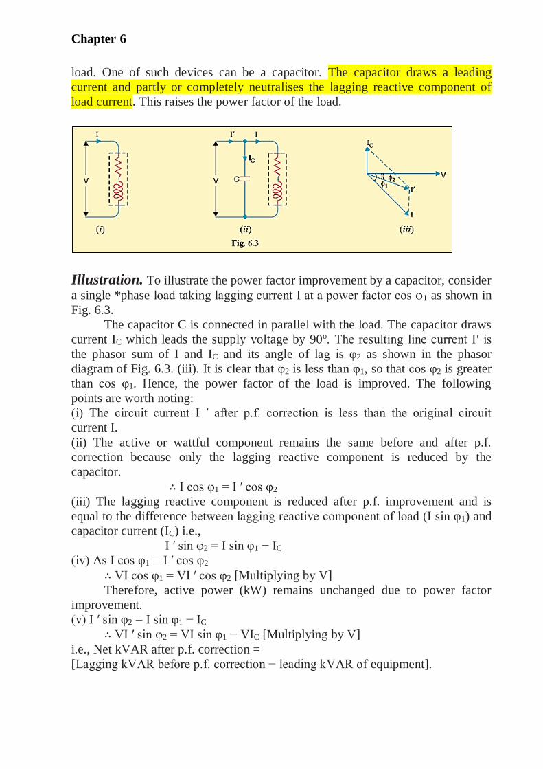
1. Static capacitor. The power factor can be improved by connecting
capacitors in parallel with the equipment operating at lagging power factor.
The capacitor (generally known as static capacitor) draws a leading current
and partly or completely neutralises the lagging reactive component of load
current. This raises the power factor of the load.
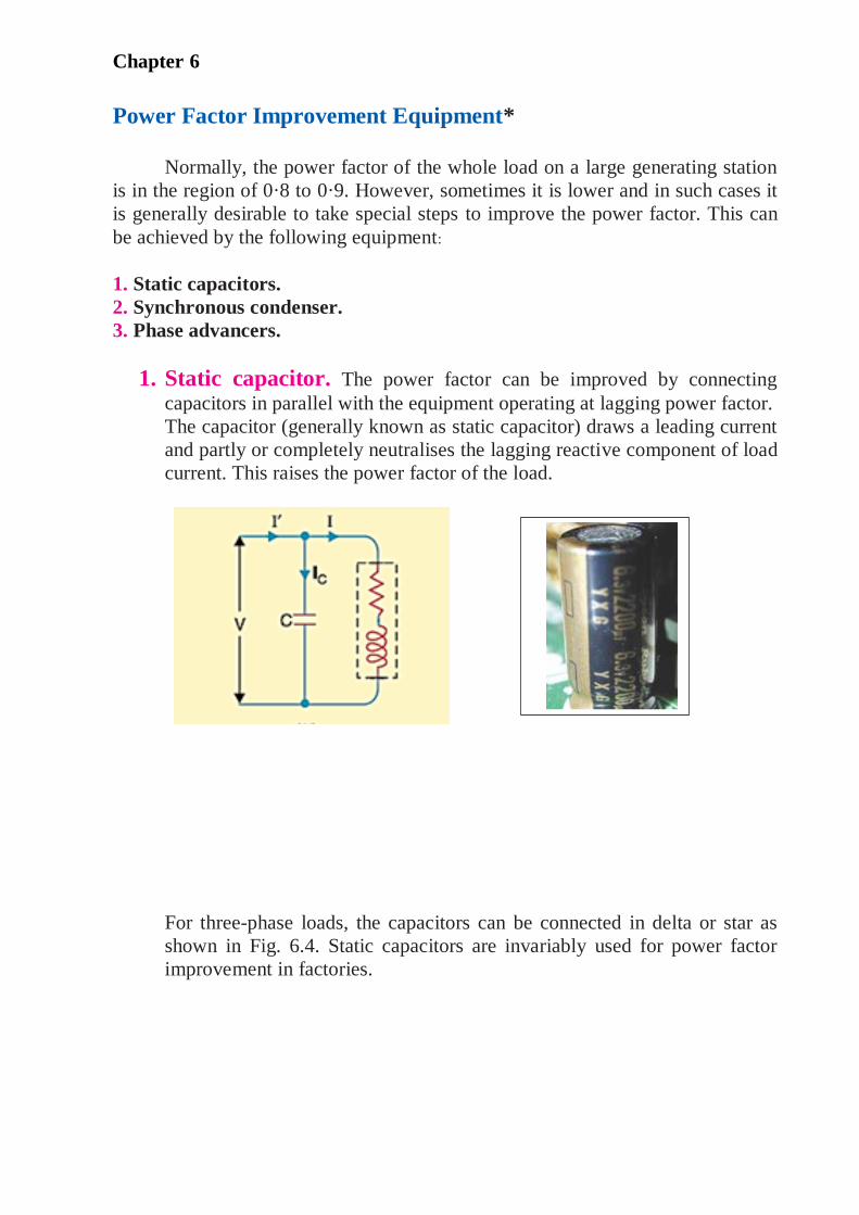
For three-phase loads, the capacitors can be connected in delta or star as
shown in Fig. 6.4. Static capacitors are invariably used for power factor
improvement in factories.
Chapter 6
2. Synchronous condenser. A synchronous motor takes a leading current
when over-excited and, therefore, behaves as a capacitor. An over-excited
synchronous motor running on no load is known as synchronous condenser.
When such a machine is connected in parallel with the supply, it takes a leading
current which partly neutralises the lagging reactive component of the load. Thus
the power factor is improved.
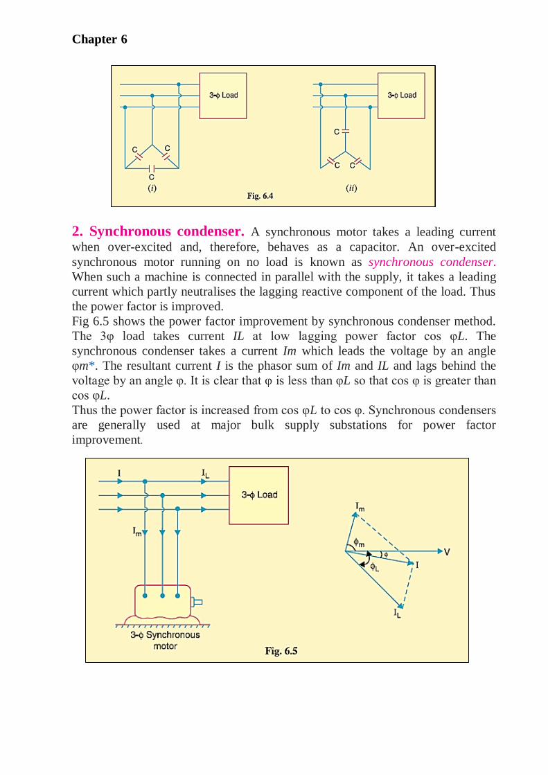
Fig 6.5 shows the power factor improvement by synchronous condenser method.
The 3φ load takes current IL at low lagging power factor cos φL. The
synchronous condenser takes a current Im which leads the voltage by an angle
φm*. The resultant current I is the phasor sum of Im and IL and lags behind the
voltage by an angle φ. It is clear that φ is less than φL so that cos φ is greater than
cos φL.
Thus the power factor is increased from cos φL to cos φ. Synchronous condensers
are generally used at major bulk supply substations for power factor
improvement.
Chapter 6
Q. Compare between the mechanism of improving power factor with
static capacitor and Synchronous motor
static capacitor Synchronous motor
The p.f. improvement by switching
on the capacitors in various
groupings
The p.f. improvement by varying the
field excitation
Q. What are the similarity states between a synchronous motor and
capacitor?
synchronous motor takes a leading current when over-excited and, therefore,
behaves as a capacitor
Q. At what conditions an synchronous motor is known as synchronous
condenser?
1. when an Synchronous motor is an over-excited and takes a leading current .
2. when synchronous motor running on no load.
Calculations of Power Factor Correction
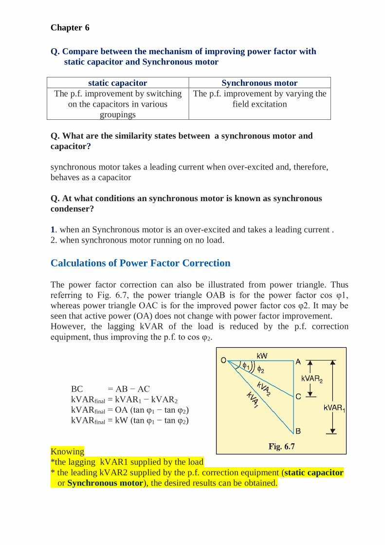
The power factor correction can also be illustrated from power triangle. Thus
referring to Fig. 6.7, the power triangle OAB is for the power factor cos φ1,
whereas power triangle OAC is for the improved power factor cos φ2. It may be
seen that active power (OA) does not change with power factor improvement.
However, the lagging kVAR of the load is reduced by the p.f. correction
equipment, thus improving the p.f. to cos φ2.
BC = AB − AC
kVARfinal = kVAR1 − kVAR2
kVARfinal = OA (tan φ1 − tan φ2)
kVARfinal = kW (tan φ1 − tan φ2)
Knowing
*the lagging kVAR1 supplied by the load
* the leading kVAR2 supplied by the p.f. correction equipment (static capacitor
or Synchronous motor), the desired results can be obtained.
Chapter 6
Example
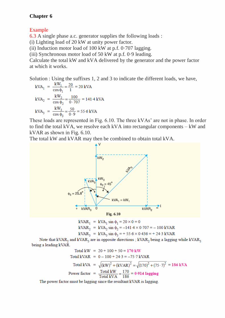
6.3 A single phase a.c. generator supplies the following loads :
(i) Lighting load of 20 kW at unity power factor.
(ii) Induction motor load of 100 kW at p.f. 0·707 lagging.
(iii) Synchronous motor load of 50 kW at p.f. 0·9 leading.
Calculate the total kW and kVA delivered by the generator and the power factor
at which it works.
Solution : Using the suffixes 1, 2 and 3 to indicate the different loads, we have,
These loads are represented in Fig. 6.10. The three kVAs’ are not in phase. In order
to find the total kVA, we resolve each kVA into rectangular components – kW and
kVAR as shown in Fig. 6.10.
The total kW and kVAR may then be combined to obtain total kVA.

Chapter 6