Embed Size (px)
Citation preview
Power-Efficient Routing Algorithm for Torus NoCs
D. Rahmati, A. E. Kiasari1, H. Sarbazi-Azad1 and S. Hessabi
Department of Computer Engineering, Sharif University1IPM School of Computer Science, Tehran, Iran
E-mail : {d_rahmati,kiasari}@ce.sharif.edu, {azad,hessabi}@sharif.edu
ABSTRACTModern System-on-Chip (SoC) architectures use Network-on-Chip (NoC) for high-speed inter-nodecommunication. NoC with torus interconnection topology is now popular due to its low dimensionand simple structure. Torus NoC is very similar to the mesh NoC from a structural point of view, buthas rather smaller diameter that makes it a suitable choice for NoCs. For a routing algorithm to bedeadlock-free in a torus NoC at least two virtual channels should be used to avoid channel dependency,while mesh NoC can handle deadlock freedom using only one virtual channel. In this paper, we proposea novel approach on designing routing algorithms for mesh and torus NoCs. Also a deadlock freerouting algorithm is proposed for Torus NoC that uses only one virtual channel per physical channelresulting in lower power consumption because of reduced hardware complexity and with no significantperformance degradation. The algorithm works within a dimension and is applied to all dimensionsindividually for XY routing and various turn based deterministic routing algorithms like west first,north last and negative first. We have proved efficiency of the algorithm using simulation resultsobtained from synthesis of our implemented VHDL Register Transfer Level (RTL) model of NoC.
Keywords: SoC, NoC, Torus, Mesh, Performance, Power Consumption, Routing, Virtual Channel,Deadlock, VHDL RTL model.
1. INTRODUCTIONThe simplest and hence widely used routing algorithmfor the mesh NoCs is XY routing [1,2,3,8]. In thisalgorithm the packet is routed across the X axis andthen across the Y axis until it reaches the destinationnode as shown in Fig.1. Since there are no wraparoundlinks to connect the first and last nodes in eachdimension, XY routing algorithm is deadlock freeusing only one virtual channel.
However, applying XY routing for the torus NoCmay cause deadlock as a result of the channeldependency in each dimension between differentmessages [8]. By using more than one virtual channelthere will be the flexibility of designing differentdeadlock free routing algorithms in the cost of
hardware complexity, more area, and thus higherpower consumption. Power consumption is the mostimportant factor in the design and implementation ofNoC architectures, while performance (networklatency and throughput) is the key factor inmulticomputer networks.In order to have a deadlock-free routing algorithm in the torus NoC, there shouldbe at least two virtual channels to break the cyclicchannel dependency, caused by wraparound links, intoa spiral [4, 8, 10]. This is not the case when meshNoCs are used without wrap-around links and thusrequiring only one virtual channel. It is also shownthat the number of virtual channels has a crucial effecton power consumed by the NoC [5, 6, 12].
In this paper, we first introduce IRN(Interconnection Routing Notation), a map-based

212 • IC3–2008 UFL & JIITU
systematic approach on designing routing algorithmsfor mesh and torus NoCs. This notation is alsoextendable for other interconnection topologies. Wethen use IRN and propose a deadlock free routingalgorithm called TRANC (Torus Routing Algorithmfor NoC) for the torus NoC that uses only one virtualchannel.
The proposed routing algorithm enjoys the lowpower consumption of a mesh NoC while possessinga good performance (near a torus NoC). It evenexhibits better performance for light traffic becauseof a zero switching time between virtual channelscompared to a torus NoC using two virtual channelsto implement XY routing. There is a slight decreasein the performance of TRANC for heavy traffics andnear the saturation point of the NoC when comparedto XY routing in the trous NoC. However, asmentioned before, power consumption is a dominantfactor when comparing routing algorithms in NoCs,since the network rarely works near its saturation pointof operation.
2. ROUTING IN THE MESH AND TORUSNOCS
An n × n mesh or torus NoC consists of n2 nodesarranged in a two-dimensional grid structure. Eachnode is addressed using an (x,y) tuple and has aneighboring node in the increasing and decreasingdirections (positive and negative directions) in eachdimension. The first node and the last node of eachdimension are linked using a wraparound link in thetorus NoC, while such a wraparound link does notexist in the mesh NoC. Fig. 1 shows a 4x4 mesh NoCand a 4x4 torus NoC. Each node in the networkconsists of two parts: IP and Router. Usually, the wholesystem (called SoC) except for the IPs is called theNoC.
2.1 Node structure in mesh and torus NoCsA cycle accurate and synthesizable VHDL hardwaremodel for NoCs has been implemented and severaldifferent topologies like mesh and torus have beentested based on it. The top most shared component inthis hardware model is the NoC node in which IP and
router are its main components. Fig. 2 shows thenode structure in the implemented model.
The IP can be a processor with some localmemory, or any other module that can send/receivepackets over the network. In our implementation itgenerates packets based on a traffic model likeuniform distribution for packet destinations. Also eachIP generates packets on intervals based on a Poissondistribution.
The router has five input and five output channels.A node uses four inputs and four output channels toconnect to its neighboring nodes; two per dimension,one in each direction. The remaining channels are usedby the IP to inject/eject messages to/from the network,
Fig. 1: A 4x4 torus NoC (Top) and a 4x4 mesh NoC(Bottom)
0,0 0,1 0,2 0,3
1,0 1,1 1,2 1,3
2,0 2,1 2,2 2,3
3,0 3,1 3,2 3,3
IP IP IP IP
IP IP IP IP
IP IP IP IP
IP IP IP IP
0,0 0,1 0,2 0,3
1,0 1,1 1,2 1,3
2,0 2,1 2,2 2,3
3,0 3,1 3,2 3,3
IP IP IP IP
IP IP IP IP
IP IP IP IP
IP IP IP IP
Selected Channel
Destination
Source
Power-Efficient Routing Algorithm for Torus NoCs 213
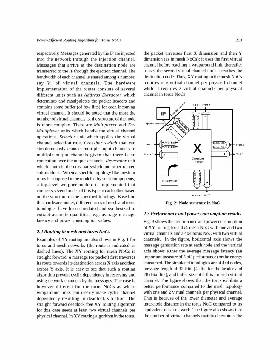
respectively. Messages generated by the IP are injectedinto the network through the injection channel.Messages that arrive at the destination node aretransferred to the IP through the ejection channel. Thebandwidth of each channel is shared among a number,say V, of virtual channels. The hardwareimplementation of the router consists of severaldifferent units such as Address Extractor whichdetermines and manipulates the packet headers andcontains some buffer (of few flits) for each incomingvirtual channel. It should be noted that the more thenumber of virtual channels is, the structure of the nodeis more complex. There are Multiplexer and De-Multiplexer units which handle the virtual channeloperations, Selector unit which applies the virtualchannel selection rule, Crossbar switch that cansimultaneously connect multiple input channels tomultiple output channels given that there is nocontention over the output channels. Reservator unitwhich controls the crossbar switch and other relatedsub-modules. When a specific topology like mesh ortorus is supposed to be modeled by such components,a top-level wrapper module is implemented thatconnects several nodes of this type to each other basedon the structure of the specified topology. Based onthis hardware model, different cases of mesh and torustopologies have been simulated and synthesized toextract accurate quantities, e.g. average messagelatency and power consumption values.
2.2 Routing in mesh and torus NoCsExamples of XY-routing are also shown in Fig. 1 fortorus and mesh networks (the route is indicated asdashed lines). The XY routing for mesh NoCs isstraight forward: a message (or packet) first traversesits route towards its destination across X axis and thenacross Y axis. It is easy to see that such a routingalgorithm prevent cyclic dependency in reserving andusing network channels by the messages. The case ishowever different for the torus NoCs as wherewraparound links can clearly make cyclic channeldependency resulting in deadlock situation. Thestraight forward deadlock free XY routing algorithmfor this case needs at least two virtual channels perphysical channel. In XY routing algorithm in the torus,
Fig. 2: Node structure in NoC
2.3 Performance and power consumption resultsFig. 3 shows the performance and power consumptionof XY routing for a 4x4 mesh NoC with one and twovirtual channels and a 4x4 torus NoC with two virtualchannels. In the figure, horizontal axis shows themessage generation rate at each node and the verticalaxis shows either the average message latency (animportant measure of NoC performance) or the energyconsumed. The simulated topologies are of 4x4 nodes,message length of 32 flits (4 flits for the header and28 data flits), and buffer size of 4 flits for each virtualchannel. The figure shows that the torus exhibits abetter performance compared to the mesh topologywith one and 2 virtual channels per physical channel.This is because of the lower diameter and averageinter-node distance in the torus NoC compared to itsequivalent mesh network. The figure also shows thatthe number of virtual channels mainly determines the
the packet traverses first X dimension and then Ydimension (as in mesh NoCs); it uses the first virtualchannel before reaching a wraparound link, thereafterit uses the second virtual channel until it reaches thedestination node. Thus, XY routing in the mesh NoCsrequires one virtual channel per physical channelwhile it requires 2 virtual channels per physicalchannel in torus NoCs.
Reservator
Addr. Ext.
Addr. Ext.
Addr
. Ext
.
Add
r. E
xt.
Add
r. E
xt.
Addr
. Ext
.
x Crossbar Switch
Addr. Ext.
Addr. Ext.From X +
From Y +
From Y _
From X _
To X +
To Y +
To Y _
To X _
Injection c
hannel
Addr . Ext.
Addr. Ext.
Ejection channel
IP
Reservator
Addr. Ext.
Addr. Ext.
Addr. Ext.
Addr. Ext.
Addr
. Ext
.
Add
r. E
xt.
Add
r. E
xt.
Addr
. Ext
.
x Crossbar Switch
Addr. Ext.
Addr. Ext.From X +
From Y +
From Y _
From X _
To X +
To Y +
To Y _
To X _
Injection c
hannel
Addr . Ext.
Addr. Ext.
Ejection channel
IP

214 • IC3–2008 UFL & JIITU
power consumption of the network and the torus NoCwith two virtual channels has a larger amount ofdissipated power due to the complexity of the switchand higher buffering requirement and extrawraparound links.
3. INTERCONNECTION ROUTINGNOTATION (IRN)
We propose a new notation to extract new routingalgorithms for torus and mesh NoCs. This notationcan also be extended to other interconnectiontopologies. By using this notation, it is possible tohave better understanding and formulation of routingalgorithms for interconnection networks. Consider theXY routing algorithm for the 4x4 mesh network withone virtual channel per physical channel (as shownin Fig. 1). The IRN Map and IRN Graph for this
algorithm are shown in Fig. 4. In XY routingalgorithm, a packet first traverses the X axis and thencontinues its journey towards its destination along Yaxis. The IRN notation only explores the rule ofmovement through one axis (current axis ordimension). First row of the IRN Graph shows that ifthe source and destination nodes for a packet areadjacent across a dimension, then the packet movestowards the destination node directly with one step.The other rows show the direction of movements fordistances more than one hop, individually for all nodelocations at a dimension. Corresponding to the IRNGraph, the IRN Map in each row shows the directionthat the packet should traverse when it is in a specifiedlocation to cross the network to get closer to thedestination. As shown in the figure, all the movementsover the diameter of the map (or matrix), which meansthe packet should go from a smaller index to a biggerindex, have a ‘+’ sign. This sign indicates movementin the positive direction of that dimension; similarlythe ‘-’ sign is used in the lower part of the map.
Fig. 5 shows the notation for the proposed routingalgorithm in the torus network but with only onevirtual channel. At the first row of the IRN Graph thewraparound link is shown. Because of using wraparound links, a packet may reach its destination usingpositive or negative directions; but for a routingalgorithm to be deadlock free only one of thedirections should be selected. The plus and minussymbols with the circles refer to movements on thefirst row of IRN map in which it is not reasonable toselect the opposite direction to reach the destination.Therefore, we suppose these moves are always
Fig. 3: Performance and power consumption of XYrouting in a 4x4 mesh with one and two virtual
channels and 4x4 torus with two virtual channels
50
60
70
80
90
0 0.003 0.006 0.009 0.012 0.015 0.018
Message Generation Rate ( )
Aver
age
Mes
sage
Lat
ency
(cyc
les)
Torus4x4-2vi-Det
Mesh4x4-1vi-Det
Mesh4x4-2vi-Det
456789
10111213
0 0.003 0.006 0.009 0.012 0.015 0.018
Message Generation Rate ( )
Powe
r (m
w)
Torus4x4-2vi-Det
Mesh4x4-1vi-DetMesh4x4-2vi-Det
Fig. 4: The IRN Map and Graph for a 4 × 4 meshusing XY Routing
0 1 2 3ToFrom
0
1
2
3
0
From 0
From 1
From 2
From 3
1 2 3Adjacent Moves
0 1 2 3
0 1 2 3
0 1 2 3
0 1 2 3
Power-Efficient Routing Algorithm for Torus NoCs 215
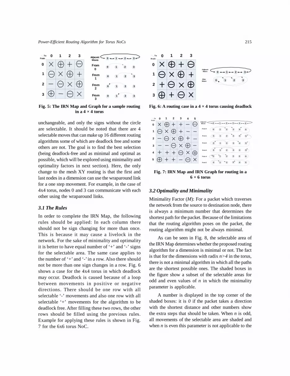
unchangeable, and only the signs without the circleare selectable. It should be noted that there are 4selectable moves that can make up 16 different routingalgorithms some of which are deadlock free and someothers are not. The goal is to find the best selection(being deadlock-free and as minimal and optimal aspossible, which will be explored using minimality andoptimality factors in next section). Here, the onlychange to the mesh XY routing is that the first andlast nodes in a dimension can use the wraparound linkfor a one step movement. For example, in the case of4x4 torus, nodes 0 and 3 can communicate with eachother using the wraparound links.
3.1 The RulesIn order to complete the IRN Map, the followingrules should be applied: In each column thereshould not be sign changing for more than once.This is because it may cause a livelock in thenetwork. For the sake of minimality and optimalityit is better to have equal number of ‘+’ and ‘-’ signsfor the selectable area. The same case applies tothe number of ‘+’ and ‘-’ in a row. Also there shouldnot be more than one sign changes in a row. Fig. 6shows a case for the 4x4 torus in which deadlockmay occur. Deadlock is caused because of a loopbetween movements in posit ive or negativedirections. There should be one row with allselectable ‘-’ movements and also one row with allselectable ‘+’ movements for the algorithm to bedeadlock free. After filling these two rows, the otherrows should be filled using the previous rules.Example for applying these rules is shown in Fig.7 for the 6x6 torus NoC.
3.2 Optimality and MinimalityMinimality Factor (M): For a packet which traversesthe network from the source to destination node, thereis always a minimum number that determines theshortest path for the packet. Because of the limitationsthat the routing algorithm poses on the packet, therouting algorithm might not be always minimal.
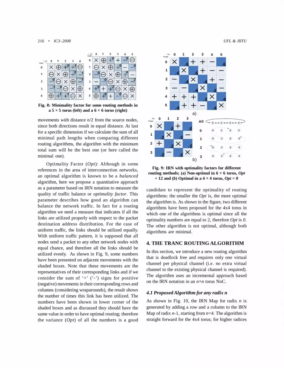
As can be seen in Fig. 8, the selectable area ofthe IRN Map determines whether the proposed routingalgorithm for a dimension is minimal or not. The factis that for the dimensions with radix n>4 in the torus,there is not a minimal algorithm in which all the pathsare the shortest possible ones. The shaded boxes inthe figure show a subset of the selectable areas forodd and even values of n in which the minimalityparameter is applicable.
A number is displayed in the top corner of theshaded boxes: it is 0 if the packet takes a directionwith the shortest distance and other numbers showthe extra steps that should be taken. When n is odd,all movements of the selectable area are shaded andwhen n is even this parameter is not applicable to the
Fig. 5: The IRN Map and Graph for a sample routingin a 4 × 4 torus
0 1 2 3ToFrom
0
1
2
3
0
From0
From1
From2
From3
1 2 3Adjacent Moves
0 1 2 3
0 1 2 3
0 1 2 3
0 1 2 3
Fig. 6: A routing case in a 4 × 4 torus causing deadlock
0 1 2 3ToFrom
0
1
2
3
0 1 2 3
0 1 2 3Adjacent
Moves
Other Moves
Fig. 7: IRN Map and IRN Graph for routing in a6 × 6 torus
0 1 2 3ToFrom
0
1
2
3
0 1 2
0 1 2
0 1 2
0 1 2
0 1 2
v
0 1 2
4
4
4
4
4
4
3
3
3
3
3
3
4
4 v
5
5 v
5
5
5
5
5
5
0 1 2 4 53
From 0
From 1
From 2
From 3
Adjacent Moves
From 5
From 4
216 • IC3–2008 UFL & JIITU
movements with distance n/2 from the source nodes,since both directions result in equal distance. At lastfor a specific dimension if we calculate the sum of allminimal path lengths when comparing differentrouting algorithms, the algorithm with the minimumtotal sum will be the best one (or here called theminimal one).
Optimality Factor (Opt): Although in somereferences in the area of interconnection networks,an optimal algorithm is known to be a balancedalgorithm, here we propose a quantitative approachas a parameter based on IRN notation to measure thequality of traffic balance or optimality factor. Thisparameter describes how good an algorithm canbalance the network traffic. In fact for a routingalgorithm we need a measure that indicates if all thelinks are utilized properly with respect to the packetdestination address distribution. For the case ofuniform traffic, the links should be utilized equally.With uniform traffic pattern, it is supposed that allnodes send a packet to any other network nodes withequal chance, and therefore all the links should beutilized evenly. As shown in Fig. 9, some numbershave been presented on adjacent movements with theshaded boxes. Note that these movements are therepresentatives of their corresponding links and if weconsider the sum of ‘+’ (‘-’) signs for positive(negative) movements in their corresponding rows andcolumns (considering wraparounds), the result showsthe number of times this link has been utilized. Thenumbers have been shown in lower corner of theshaded boxes and as discussed they should have thesame value in order to have optimal routing; thereforethe variance (Opt) of all the numbers is a good
candidate to represent the optimality of routingalgorithms: the smaller the Opt is, the more optimalthe algorithm is. As shown in the figure, two differentalgorithms have been proposed for the 4x4 torus inwhich one of the algorithms is optimal since all theoptimality numbers are equal to 2, therefore Opt is 0.The other algorithm is not optimal, although bothalgorithms are minimal.
4. THE TRANC ROUTING ALGORITHMIn this section, we introduce a new routing algorithmthat is deadlock free and requires only one virtualchannel per physical channel (i.e. no extra virtualchannel to the existing physical channel is required).The algorithm uses an incremental approach basedon the IRN notation in an n×n torus NoC.
4.1 Proposed Algorithm for any radix nAs shown in Fig. 10, the IRN Map for radix n isgenerated by adding a row and a column to the IRNMap of radix n-1, starting from n=4. The algorithm isstraight forward for the 4x4 torus; for higher radices
Fig. 8: Minimality factor for some routing methods ina 5 × 5 torus (left) and a 6 × 6 torus (right)
Fig. 9: IRN with optimality factors for differentrouting methods; (a) Non-optimal in 6 × 6 torus, Opt
= 12 and (b) Optimal in a 4 × 4 torus, Opt = 0
0
0
1
2
3
1 2 3All
0 1 2 3
0 1 2 3
0 1 2 3
0 1 2 3
0 1 2 3ToFrom
0
1
2
3 v
22
2
2
2
2
2
2
0 1 2 3ToFrom
0
1
2
3 v
4
4 v
5
5 v
5
4
2
4
5
4
4
2
4
5
4
5
a)
b)

Power-Efficient Routing Algorithm for Torus NoCs 217
it is enough to add a row and a column as shown inFig. 10. In order to complete the new row it is enoughto fill the right most two boxes with ‘-’ signs and otherswith ‘+’ signs. Again for completing the new columnit is enough to fill the two lower boxes with ‘+’ signsand others with ‘-’ signs. When two or more of themoves described in IRN Graph happensimultaneously, they may form a situation where someof the packets are waiting for other ones to free thepath. In this situation, there is a packet contention.When the contention starts from a packet and lastswith the same packet, such that no activity is possiblefor the packets, it is said that a deadlock situation hasoccurred. A routing algorithm that never causes adeadlock situation is called a deadlock free routingalgorithm.
The TRANC algorithm is a deadlock free routingalgorithm. The intuitive justification that it isdeadlock free is extracted from the IRN Map andGraph in Fig. 7. As discussed before, there is not apositive movement of more than one step from node3, and therefore the positive loop is broken in thenetwork. The same is correct for negativemovements, as there are not any negative movementsof more than one step from node 4 to other nodesand therefore the negative loops also are broken.There is mathematical justification that TRANC isdeadlock free, that we do not present it here.Furthermore the justification is also supported by
the extensive simulation experiments we haverealized for different scenarios. As discussed beforefor the dimensions with radix n>4, TRANC is notfully optimal and fully minimal but with goodoptimality and minimality factors for differentradices. The reason is that each packet traverses theshortest possible path to reach the destination whichignores deadlock, not the shortest physical pathwhich potentially causes a deadlock. Also the usageof wraparound links is not balanced compared toother links because of the rules that have been appliedto the algorithm. It is possible to use a differentapproach for different radices based on IRN that mayresult in better optimality and minimality factors butjustification of deadlock freedom for each radixshould be done separately. We ignore this approachfor the sake of present discussion.
In Fig. 12, a pseudo code for TRANC algorithmis given. As can be seen in the code, the complexityof the hardware that utilizes this algorithm comparedto the classic XY routing algorithm includes the extracomparisons that should be done with n-1, n-2 and n-
Fig. 10: The proposed IRN Map representing theTRANC routing algorithm in an n × n torus.
0 1 2 3ToFrom
0
1
2
3
4
4
5
5
6
6
v
v
v
v
7
7
Torus 4x4Torus 5x5
Torus 6x6Torus 7x7
Torus 8x8
0
1
2
3
4
5
6
0
1
2
3
4
5
0
1
2
3
4
0
1
2
3
0 1 2 3 4 5 6
0 1 2 3 4 5
0 1 2 3 4
0 1 2 3
Fig. 11: The average inter-node distance and diameterusing TRANC and XY routing algorithms
2
2.5
3
3.5
4
4.5
5
5.5
6
6.5
4 5 6 7 8 9 10
Radix (n)
Ave
rag
e D
ista
nce
Torus (n x n): TRANC Rout ing
Torus (n x n): XY Routing
0123456789
10
4 5 6 7 8 9 10Radix (n)
Diam
eter
Torus(n x n): TRANC Routing
Torus(n x n): XY Routing
2
2.5
3
3.5
4
4.5
5
5.5
6
6.5
4 5 6 7 8 9 10
Radix (n)
Ave
rag
e D
ista
nce
Torus (n x n): TRANC Rout ing
Torus (n x n): XY Routing
0123456789
10
4 5 6 7 8 9 10Radix (n)
Diam
eter
Torus(n x n): TRANC Routing
Torus(n x n): XY Routing
218 • IC3–2008 UFL & JIITU
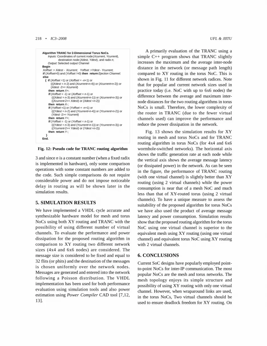
3 and since n is a constant number (when a fixed radixis implemented in hardware), only some comparisonoperations with some constant numbers are added tothe code. Such simple comparisons do not requireconsiderable power and do not impose noticeabledelay in routing as will be shown later in thesimulation results.
5. SIMULATION RESULTSWe have implemented a VHDL cycle accurate andsynthesizable hardware model for mesh and torusNoCs using both XY routing and TRANC with thepossibility of using different number of virtualchannels. To evaluate the performance and powerdissipation for the proposed routing algorithm incomparison to XY routing two different networksizes (4x4 and 6x6 nodes) are considered. Themessage size is considered to be fixed and equal to32 flits (or phits) and the destination of the messagesis chosen uniformly over the network nodes.Messages are generated and entered into the networkfollowing a Poisson distribution. The VHDLimplementation has been used for both performanceevaluation using simulation tools and also powerestimation using Power Compiler CAD tool [7,12,13].
Fig. 12: Pseudo code for TRANC routing algorithm
Algorithm TRANC for 2-Dimensional Torus NoCs. Inputs: Coordinates of current node (Xcurrent, Ycurrent),
destination node (Xdest, Ydest), and radix n;Output: Selected output Channel
BeginXoffset := Xdest - Xcurrent; Yoffset :=Ydest - Ycurrent;if (Xoffset=0) and (Yoffset !=0) then return Ejection Channel; else { if (Xoffset =1) or (Xoffset = -n+1) or (((Xdest = n-2) and (Xcurrent=n-4)) or (Xcurrent=n-2)) or (Xdest -2>= Xcurrent) then return X+; if (Xoffset = -1) or (Xoffset = n-1) or (((Xdest = n-3) and (Xcurrent=n-1)) or (Xcurrent=n-3)) or ((Xcurrent-2>= Xdest) or (Xdest =n-2)) then return X-; if (Yoffset =1) or (Yoffset = -n+1) or (((Ydest = n-2) and (Ycurrent=n-4)) or (Ycurrent=n-2)) or (Ydest -2>= Ycurrent) then return Y+; if (Yoffset = -1) or (Yoffset = n-1) or (((Ydest = n-3) and (Ycurrent=n-1)) or (Ycurrent=n-3)) or ((Ycurrent-2>= Ydest) or (Ydest =n-2)) then return Y-; }End.
A primarily evaluation of the TRANC using asimple C++ program shows that TRANC slightlyincreases the maximum and the average inter-nodedistance in the network (or message path length)compared to XY routing in the torus NoC. This isshown in Fig. 11 for different network radices. Notethat for popular and current network sizes used inpractice today (i.e. NoC with up to 6x6 nodes) thedifference between the average and maximum inter-node distances for the two routing algorithms in torusNoCs is small. Therefore, the lower complexity ofthe router in TRANC (due to the fewer virtualchannels used) can improve the performance andreduce the power dissipation in the network.
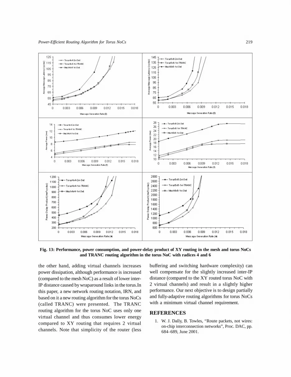
Fig. 13 shows the simulation results for XYrouting in mesh and torus NoCs and for TRANCrouting algorithm in torus NoCs (for 4x4 and 6x6wormhole-switched networks). The horizontal axisshows the traffic generation rate at each node whilethe vertical axis shows the average message latency(or dissipated power) in the network. As can be seenin the figure, the performance of TRANC routing(with one virtual channel) is slightly better than XYrouting (using 2 virtual channels) while the powerconsumption is near that of a mesh NoC and muchless than that of XY-routed torus (using 2 virtualchannels). To have a unique measure to assess thesuitability of the proposed algorithm for torus NoCswe have also used the product of average messagelatency and power consumption. Simulation resultsshow that the proposed routing algorithm for the torusNoC using one virtual channel is superior to theequivalent mesh using XY routing (using one virtualchannel) and equivalent torus NoC using XY routingwith 2 virtual channels.
6. CONCLUSIONSCurrent SoC designs have popularly employed point-to-point NoCs for inter-IP communication. The mostpopular NoCs are the mesh and torus networks. Themesh topology enjoys its simple structure andpossibility of using XY routing with only one virtualchannel. However, when wraparound links are used,in the torus NoCs, Two virtual channels should beused to ensure deadlock freedom for XY routing. On
Power-Efficient Routing Algorithm for Torus NoCs 219
Fig. 13: Performance, power consumption, and power-delay product of XY routing in the mesh and torus NoCs
and TRANC routing algorithm in the torus NoC with radices 4 and 6
the other hand, adding virtual channels increasespower dissipation, although performance is increased(compared to the mesh NoC) as a result of lower inter-IP distance caused by wraparound links in the torus.Inthis paper, a new network routing notation, IRN, andbased on it a new routing algorithm for the torus NoCs(called TRANC) were presented. The TRANCrouting algorithm for the torus NoC uses only onevirtual channel and thus consumes lower energycompared to XY routing that requires 2 virtualchannels. Note that simplicity of the router (less
buffering and switching hardware complexity) canwell compensate for the slightly increased inter-IPdistance (compared to the XY routed torus NoC with2 virtual channels) and result in a slightly higherperformance. Our next objective is to design partiallyand fully-adaptive routing algorithms for torus NoCswith a minimum virtual channel requirement.
REFERENCES1. W. J. Dally, B. Towles, “Route packets, not wires:
on-chip interconnection networks”, Proc. DAC, pp.684–689, June 2001.

220 • IC3–2008 UFL & JIITU
2. R. V. Boppana, S. Chalasani, “A framework fordesigning deadlock-free wormhole routingalgorithms”, IEEE Transactions on Parallel andDistributed Systems (TPDS), 7(2): 169-183, 1996.
3. C. J. Glass, L. M. Ni, “The turn model for adaptiverouting”, Proceedings of the InternationalSymposium on Computer Architecture (ISCA), pp.278-287, 1992.
4. A. Singh, W. J. Dally, A. K. Gupta, B. Towles,“GOAL: A Load-balanced Adaptive RoutingAlgorithm for Torus Networks”, in Proc. of theInternational Symp. on Comp. Arch., pp. 194-205,June, 2003.
5. Terry T. Ye, Luca Benini, Giovanni De Micheli,”Analysis of Power Consumption on Switch Fabricsin Network Routers”, In Proceedings of DAC, 2002.
6. H-S Wang, L-S Peh, S. Malik, ”Orion: A Power-Performance Simulator for InterconnectionNetwork”, In International Symposium onMicroarchitecture, Istanbul, Turkey, November2002.
7. D. L. Liu, C. Svensson, “Power consumptionestimation in CMOS VLSI chips”, IEEE Journal ofSolid-State Circuits, 29(6): 663-670, 1994.
8. W. J. Dally, H. Aoki, “Deadlock-Free AdaptiveRouting in Multicomputer Networks Using VirtualChannels”, IEEE ransactions on Parallel andDistributed Systems, 4(4):466–475, April 1993.
9. Jae H. Kim, Ziqiang Liu, Andrew A. Chien,“Compressionless Routing: A Framework forAdaptive and Fault-tolerant Routing”, IEEETransactions on Parallel and Distributed Systems1996.
10. W.J. Dally, C.L. Seitz, “Deadlock-free messagerouting in multiprocessor interconnectionnetworks”, IEEE Transactions on Computers, vol.C-36, no. 5, pp. 547-553, May 1987.
11. W. J. Dally, C. Seitz, “The torus routing chip”, InDistributed Computing, pages 187 196, 1986.
12. N. Banerjee, P. Vellanki, K. S. Chatha, “A Powerand Performance Model for Network-on-ChipArchitectures”, In Proceedings of DATE, Paris,France, February 2004.
13. K. Srinivasan, K. S. Chatha, “ISIS : A GeneticAlgorithm based Technique for Custom On-ChipInterconnection Network Synthesis”, In Proceedingsof the 18th International Conference on VLSIDesign (VLSID’05)


