Embed Size (px)
Citation preview
Power Allocation and Self-Scheduling forCooperative Transmission Using Opportunistic
Large ArraysAravind Kailas
Georgia Institute of TechnologyEmail: [email protected]
Lakshmi ThanayankizilGeorgia Institute of Technology
Email: [email protected]
Mary Ann IngramGeorgia Institute of Technology
Email: [email protected]
Abstract—This paper introduces methods for broadcastingand upstream routing in ad hoc networks that use a formof cooperative diversity called opportunistic large arrays(OLAs). By “limiting the flood,” each method saves morethan half the energy compared to OLA-flooding, withoutrequiring GPS, individual node addressing, or inter-nodeinteraction. OLAs form in “levels,” and we present a simple,distributed way for a node to learn its level. In the broadcastmethod, called OLA-T, a node compares its received power toa prescribed threshold to decide if it should forward. A moreenergy-efficient variation, OLA-VT, optimizes the thresholdsas a function of level. The upstream routing method appliesto the wireless sensor network topology. The OLA concentricrouting algorithm (OLACRA) exploits the concentric shapesof the OLAs to guide the message upstream to the collectionnode. Enhancements to OLACRA are considered to furtherimprove energy savings and reliability.
I. INTRODUCTION
The requirement for energy efficiency in battery-powered wireless terminals is of paramount importanceand pervades all aspects of the system design. Energymanagement solutions, which can be adopted at thedifferent layers of the protocol stack to enhance energyefficiency of the system, can be broadly categorized intobattery management, transmission power managementand system power management [1]. This paper presentsa distributed cross-layer approach to transmission powermanagement, based on a physical layer that uses coop-erative transmission.
Cooperative transmissions have diversity benefits thatincrease received SNR and save energy [2]. In [10],significant energy savings were leveraged as a result of
The authors gratefully acknowledge support for this research fromthe National Science Foundation under grant # 0313005.
All three authors are with the School of Electrical and ComputerEngineering, Georgia Institute of Technology, Atlanta, GA 30332-0250, USA
a type of cooperative transmission called OpportunisticLarge Array (OLA). In an OLA setup, nodes behavewithout coordination between each other, but they nat-urally fire together in response to energy received froma single source or another OLA [6]. Each node has justone antenna, however because the nodes are separated inspace, they collectively provide diversity protection frommulti-path fading.
In [13], a centralized OLA broadcasting scheme isproposed that requires knowledge of the individual chan-nel gains and that uses power allocation and schedulingto minimize total power consumption. For a dense net-work though, this requirement vanishes. The authors in[13] found an optimal trivial schedule for a dense OLAnetwork that allocates power and order of transmissionaccording to node distance from the source.
In [11], a node is assumed to know its geographicallocation to limit node participation. In the RelativeNeighbor Graph (RNG) Relay Subset Protocol [16], onlya subset of nodes relay the message from the source.Pairs of nodes are assumed to be able to evaluate thedistance between them with integration of a positioningsystem or a signal strength measure. As a result, thenetwork overhead goes up with the network density forthis protocol. In [7], a couple of nodes are initiallyconfigured to transmit beacons to estimate node loca-tions. This algorithm doesn’t require Global PositionSystem (GPS) information. Connectivity-based locationestimation schemes have been developed for wireless adhoc networks that gather neighborhood relations by eachuser through message exchanges over a wireless ad hocnetwork to estimate the locations of hosts [8].
Two simple strategies are proposed in our paper toreduce the energy consumption for OLA transmissions.These strategies achieve energy efficiency by only lettinga subset of the total nodes in a level transmit and
this subset determination requires no central control andcoordination between nodes; in other words, the nodesself-select themselves for relaying. The first strategy,OLA-Threshold (OLA-T), is generally applicable to allOLA transmissions and achieves energy savings of about50% compared to the OLA-flooding described in [9].An OLA-T approach with level-dependent self-selectioncriteria, called the OLA-Variable Threshold (OLA-VT)which yields further energy savings, is also introducedin this paper. OLA-T and OLA-VT can both be shownto be suboptimal trivial schedules [13], with the virtuesof simple implementation and good performance. Whilethe OLA-T strategies are applicable to all OLA trans-missions, a second strategy called the OLA ConcentricRouting Algorithm (OLACRA) is an upstream routingmethod that is appropriate for wireless sensor networks(WSNs) that use OLA transmission. OLACRA takesadvantage of the topology of a WSN, which is charac-terized by a sink, or fusion node in the center of a large,dense deployment of low-cost, energy-constrained nodes.OLACRA requires only that a node remembers its OLAindex from a previous down link transmission and thatit relays any packet at most once. Variants of OLACRAthat greatly enhance the upstream connectivity calledOLACRA-FT and OLACRA-VFT are also presented.Like OLA-T, OLACRA and its variants require neithercentralized control nor coordination among nodes todecide which node will relay.
Finally, an important feature that all the proposedschemes inherit from basic OLA is that no individualnodes are addressed. This makes the protocols scalablewith node density.
II. SYSTEM MODEL
Half-duplex nodes are assumed to be distributed uni-formly and randomly over a continuous area with av-erage density ρ. For simplicity, the deterministic model[9] is assumed, which means that the power received ata node is the sum of the powers from each of the nodetransmissions. This model implies node transmissions areorthogonal. However, because non-orthogonal transmis-sions also produce similarly shaped OLAs [9], OLA-Tand OLACRA should work for them as well. We assumea node can decode and forward (DF) a message withouterror when its received signal-to-noise ratio (SNR) isgreater than or equal to a modulation-dependent thresh-old [9]. Assumption of unit noise variance transformsthe SNR threshold to a received power criterion, whichis denoted as the decoding threshold τd. Let the sourcepower be Ps and the relay transmit power be denoted
Pr, and let the relay transmit power per unit area bedenoted by Pr = ρPr. For a fixed Pr, there exists amaximum value of τd such that the relayed signal willbe propagated in a sustained manner by concentric OLAs[9].
The loss function in cartesian coordinates is given byl(x, y) = (x2 + y2)−1, where (x, y) are the normalizedcoordinates at the receiver. As in [9], distance d isnormalized by a reference distance. Transmit power pis the received power at d = 1. Received power froma node distance away is pr = min( p
d2 , p) [9]. Theaggregate path-loss from a circular disc of radius x at
an arbitrary point p is given by f(x, p) =∫ x
0
∫ 2π
0l(p−
r cos θ, r sin θ)rdrdθ [9].
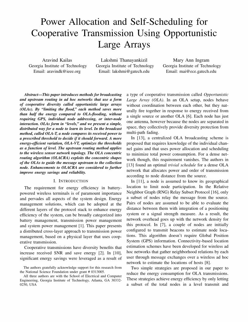
Fig. 1. (a) OLA-T; (b) OLA flooding and OLACRA; (c) lim-ited upstream flooding (OLACRA-FT); (d) OLACRA-VFT (UpstreamSource in DLn−1)
III. ENERGY-EFFICIENT BROADCAST FOR THE
DOWNLINK
A. OLA-T
Energy efficiency of OLAs can be improved prevent-ing the nodes whose transmissions have a negligibleeffect on the formation of the next OLA from partic-ipating in the relaying. By definition, a node is nearthe forward boundary if it can only barely decode themessage. The state of barely decoding can be determinedin practice by measuring the average length of the errorvector (the distance between the received and detectedpoints in signal space), conditioned on a successful CRCcheck. On the other hand, a node that receives muchmore power than is necessary for decoding is morelikely to be near the source of the message. The OLA-Tmethod is simply OLA with the additional transmission
criterion that the node’s received SNR must be less thana specified transmission threshold, τb. The differencebetween the two thresholds is given by τb − τd = ε.
B. Analysis of OLA-T Broadcast
Formation of the downstream OLAs are a result of thetransmitting strips in Fig. 1(a), where the nodes in eachlevel are represented by hatched regions while the greyshaded regions refer to the subset of transmitting nodesat each level. The source is assumed to be at the center.The behavior of the OLA radii and energy consumptionas a function of the OLA level, k are analyzed using theclosed-form expressions for the OLA-T boundaries forthe squared-distance path-loss model have been derivedfor the broadcast scenario, by slightly modifying thecontinuum approach in [9], which assumes relay trans-missions are orthogonal and not faded.
Let the outer radius and inner boundary radius forthe k-th OLA ring be denoted as rd,k and rb,k. Theboundaries can be found recursively using
Pr [f(rd,k, rj,k+1)− f(rb,k, rj,k+1)] = τj , j ∈ {b, d}.
The problem is then cast as a difference equation. From[18], using the initial conditions, r0 = 0, rd,1 =
√Ps
τd,
and rb,1 =√
Ps
τb; the definitions for the k-th OLA are
given by
r2d,k =
ηk1 − ηk
2
A1 −A2, r2
b,k =ζk1 − ζk
2
A1 −A2, (1)
where a few more terms as a function of α, β, and theinitial conditions are introduced and given by
A1 = α− β, A2 = 1,
ηki =
[(Ai + β)
Ps
τd− α
Ps
τb
](Ai)k−1,
ζki =
[(1 + β)
Ps
τd+ (Ai − α− 1)
Ps
τb
](Ai)k−1, i ∈ {1, 2},
where
α = exp
(τd
πPr
), β = exp
(τb
πPr
).
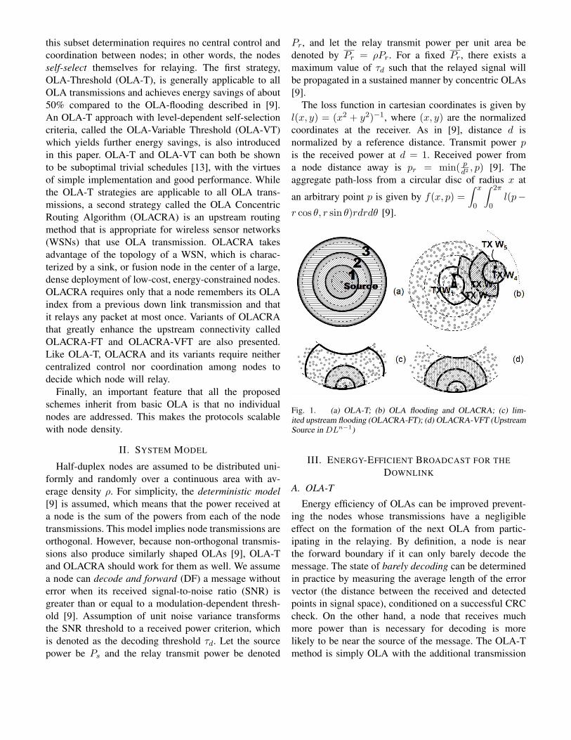
The radii for the OLAs have been plotted in Fig.2. asfunctions of the downstream OLA index given by (1).One can see that in the scenario where network broadcastfails, the radii converge to a value, as does the sequenceof the square of the radii. On the other hand, wherenetwork broadcast is achieved, the radii has a highestvalue that is level-dependent or k-dependent. Note thatthis figure is on logarithmic scale. The no-broadcast case
Fig. 2. rd,k, rb,k Versus k
refers to a choice of ε = 0.2 and the broadcast casecorresponds to an ε = 0.8.
The energy consumed by the first L levels in relayingthe message in this multi-hop wireless network for acontinuum case is mathematically expressed, in energy
units, as ξL = PrTs
L∑k=1
π(r2d,k − r2
b,k), where Ts is the
length of the message in time units. Substituting for theradii, we have
ξL = PrTs
[ξ1
A1 −A2
]L∑
k=1
2∑i=1
(−1)i−1(Ai − 1)Ak−1i .
(2)As τb → ∞ (or high values of ε), the transmitting stripgrows in thickness and the energy consumption asymp-totically approaches the Basic OLA described in [9].Thus, the energy consumption increases with increasingε. On the other hand, as τb → τd, one would expect thetransmitting strips to start thinning out. In other words,for lower values of ε, the two thresholds become closeand the set of boundary nodes that transmit decreases.And with a little bit of analysis, it follows from (2) thatξL → 0, which is indicative of OLA formations dyingout and a failure in the network broadcast operation.
We can express the fraction of transmission energysaved (FES) for OLA-T relative to Basic OLA as
FES = 1−
L∑k=1
(r2d,k − r2
b,k
)r2d,L
. (3)
C. OLA-VT
The approach till now has involved just a single fixedε for the whole wireless system. A drawback of thisapproach is that the radii growth is polynomial and theOLA rings keep growing bigger, expending more energythan is needed, to cover a given network area. In thissection, a level-dependent threshold that maximizes theFES achieving network broadcast is introduced and willbe referred to as OLA-Variable Threshold (OLA-VT).
The Genetic Algorithm (GA) is adopted to determinethe {εk} that yields the maximum FES and their corre-sponding optimal FES values are contrasted to those offixed-ε systems. The input to the GA is a specification ofthe number of OLA levels (length of the {εk} sequence).The problem statement then becomes one of maximizingthe FES for the fixed network subject to covering thenetwork. Depending on the objective (and the definitionof the penalty function in the GA) the choices for {εk}changes.
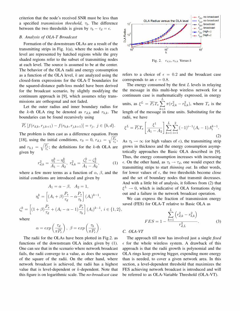
Fig. 3. FES Comparisons for Variable εk Versus Fixed ε
1) Constraint Type 1: Double Difference Criterion:The behavior of the radii with respect to the OLAindex suggest that a negative second derivative can beused to detect a broadcast failure. In fact, it can beshown that the radii for both OLA and OLA-T suc-cessful broadcasts have a faster than linear growth withOLA index. We define double difference (DD) whichas (rd,k+2 − rd,k+1) − (rd,k+1 − rd,k) and ConstraintType 1 is that this double difference is not negativefor any k value under consideration. Fig.3 plots theFES as a function of network radius. For each curve,consecutive symbols correspond to the radii sequence{rd,1, rb,2, rd,2, rb,3, . . .}. Since the FES is a function ofwhole levels and not partial levels, we just define the FESfor rb,i to be equal to the FES for rd,(i−1). The first pointthus represents the energy at rd,1, since the FES at rb,1
is zero. This enables us to see the step sizes and OLAwidths for these network examples. The top 2 curves,which nearly overlay with each other, correspond to thevariable epsilon case. The parameter for these two curvesis the total number of levels. We observe that the stepsizes are small and a higher number of levels correspondsto a larger network, for example, 20 levels correspondsto a network of radius approximately equal to 9, while 10levels has a radius of only about 5. We also observe that
the FES varies from 0.6 to 0.85 depending on networksize. The bottom three curves correspond to the case ofεk = ε for all k. These curves also correspond to thenumber of steps fixed at 10. We observe that the stepsize starts large and decreases with network radius. Thefixed-epsilon cases clearly have lower FES values thanthe variable epsilon cases, and lower values of epsilonhave higher FES. One also notes that for large networks(theoretically, as network radius → ∞), the FES gainssaturate.
2) Constraint Type 2: Barely Broadcasting: WhileConstraint Type 1 was tailor-made for a very large net-work (an infinite network, in theory), Constraint Type 2guarantees that a fixed-size network is just barely floodedwith a high system FES. The key difference is that thealgorithm checks if the radius of the last OLA level isgreater than the specified network radius. To generatethis plot, a network size of 25 was assumed. As anexample, for the 20-level case, the algorithm maximizedthe system FES with the constraint that rd,20 > 25.
3) Discussion: The GA gives a sequence of {εk}that maximizes FES while flooding the given network.Having a level-dependent parameter yields significantenergy savings compared to the OLA-flood. With Con-straint Type 1, the FES versus network radius plot isa decreasing function. This behavior is expected as thesmaller the steps one would take, higher would be theFES for the system. A shortcoming with this approachwould be the time required (or the number of stepsrequired) to achieve broadcast over a network. WithConstraint Type 2, the objective was to just barely flooda given network while maximizing the system FES. Sothe GA picks an optimum combination of {εk} thatachieves this goal. A general trend with this method islittle steps initially followed by big steps as it reaches thenetwork boundary. This explains the dips in the curvesfor Constraint Type 2 in Fig.3. From Fig.3, it can alsobe inferred that as ε increases FES decreases. Also, asthe number of steps increases the FES for the systemincreases, for a fixed network radius. That is why theenergy savings are higher for a network with 20 stepscompared to just 10 steps.
IV. ENERGY-EFFICIENT UPSTREAM ROUTING
A. OLACRA
For upstream transmission in WSNs which use OLAtransmission, the state of art routing protocols is flood-ing. But this is not energy efficient as most of theupstream traffic is not broadcast and is intended tobe received only at the Sink. A method to limit the
flood by making the transmissions propagate in a stripwas proposed in [11], where the flood was limited byexploiting Global Position System (GPS) information,which might not be possible in Sensors. In [17], [18],the OLACRA algorithm was proposed by the authors as away to limit the flood and save energy, without requiringGPS information. In this section, we review OLACRAand its variant OLACRA-FT. Then we introduce a moreenergy efficient version, OLACRA-VFT, which uses avariable relay power.
OLACRA depends on an initialization phase to helpnodes decide if they should relay an upstream trans-mission. In the initialization phase, the sink transmitswith waveforms or preambles W1 with power Psink.Downstream Level 1 or DL1 nodes are those that canDF the sink transmission, except they retransmit usinga different waveform W2. This change of waveformdistinguishes our approach from previous OLA works.Sensor nodes that can DF the signal at W2 and whichhave not relayed this message before will repeat the mes-sage with waveform W3 and join DL2. This continuesuntil each node is indexed or identified with a particularlevel. Routing information may be signaled purely byfrequency modulation, which has the advantage that asimple filtering and energy detection is all that is neededto route the message. We also note that the waveforms,frequencies or preambles could be reused after a fewlevels.
For upstream communication, a source node inDLn−1 transmits using Wn. Any node that can DF at Wn
will repeat at Wn−1 if (1) it is identified to be in DLn orDLn−1, and (2) it has not repeated the message before.The authors had considered alternate lower performingschemes in [17], [18] where ganging of: (1) Single-level(DLn), and (2) Three levels (DLn, DLn−1, DLn−2)were studied. Ganging all levels is the OLA floodingapproach of [9]. For a given message, to ensure that OLApropagation goes upstream or downstream as desired, butnot both, a preamble bit is required. We shall refer tothe n-th upstream OLA as ULn, where UL1 containsthe source transmitter. In Fig.1(a) for example, UL1 isindicated by the solid circle and UL4 contains the sinkin the middle of the network. For OLACRA, the forwardboundary of ULn divides the nodes of ULn from thosethat are eligible to be in ULn+1.
B. OLACRA-T
As in OLA-T, energy can be saved in OLACRA ifonly the nodes near the upstream forward boundaryare allowed to transmit. In OLACRA-T, nodes will not
participate in an upstream transmission unless they meetthe criteria for OLACRA and their received signal poweris less than a specified threshold.
C. Limitations of OLACRA and OLACRA-T
The protocols might fail in the upstream if the up-stream source node is located far away from the Sink.This is because the thickness of the ring grows with thelevel index as shown Fig.2. The problem happens whenthere is a large gap between the boundary of UL1 and thedownstream rear boundary of DLn−1. The following arethe possible ways to enhance the upstream connectivity.
1) Increase the power of the source node for theupstream transmission: While effective, this approachis not practical because any node could be a source,therefore all nodes would require the expensive capa-bility of higher power transmission. Similar effect canbe obtained by reducing the required decoding thresholdi.e data rate. This technique would not be suitable forcommunication systems that have strict delay require-ments.
2) Limit the step-size of the downstream OLAs:We observe that the step size in OLA-T depends onthe ratio Pr
τ and ε. Therefore the increase in step-sizewith level index can be limited by (1) reducing relaypower, Pr, (2) increasing decoding threshold, τd, or(3) reducing ε. Reduced step size means more levels arerequired to cover the same network area. So this methodwould be unsuitable for delay intolerant traffic. Anotherdisadvantage of step size reduction is that for a low nodedensity too slender an OLA may not have any nodes in it,whereas there will always be power with the continuumassumption.
3) OLACRA-FT: Allow OLA or OLA-T floodingin just the first upstream level (i.e; allow all nodesin DLn−1 that can decode a message to forward themessage if they haven’t forwarded that message before)until an OLA meets the downstream rear boundary ofDLn−1. We call this variation OLACRA-FT. The worstcase number of broadcast OLAs required to meet thedownstream rear boundary of DLn−1 can be known apriori as a function of the downstream level index. Forexample, in Fig.1(c), three upstream broadcast OLAsare needed to meet the downstream rear boundary ofDLn−1. The union of the upstream decoding nodes (e.g.all three shaded areas in Fig.1(c)) in DLn−1, are thenconsidered an extended source. Next, the extended sourcebehaves as if it were a single source node in an OLACRAupstream transmission; this means that all the nodes inthe extended source repeat the message together, and this
collective transmission uses the same waveform as woulda source node under the OLACRA protocol. To saveenergy, the nodes in the extended source that transmittedin the downstream transmission could be commanded tonot transmit in the extended source transmission; in otherwords, those nodes that were near the forward boundaryin the downstream would be near the rear boundary inthe upstream, and therefore will not make a significantcontribution in forming the next upstream OLA. In orderfor the nodes to know when it is time to transmit as anextended source, a different waveform is used, similarto the network initialization phase of OLACRA, in thisupstream flooding phase.
D. OLACRA-VFT
The energy efficiency of OLACRA-FT can be en-hanced by optimizing the relay power of the initialOLA flood levels in the upstream (OLACRA-FT withvariable relay power: OLACRA-VFT). Consider the casein Fig.1(c) where the boundary of the third OLA floodlevel is just before the downstream rear boundary ofDLn−1 . Here the upstream source node would doan OLA flood for 3 levels as required by OLACRA-FT making the width of the extended source reallylarge, thereby making the scheme energy inefficient. Theskinniest strip width which corresponds to the largestenergy savings is obtained when the boundary of the lastOLA upstream flood level is just above the downstreamrear boundary of DLn−1 as in Fig.1(d). Since the radiidepends on relay power, this can be achieved by varyingthe relay power of the initial OLA flooding stages, Prf ,to have the last upstream OLA flood boundary be asclose to the downstream rear boundary of DLn−1 aspossible. Similar result can be obtained by varying thetransmission threshold, τf , or by using a combination ofboth.
While both methods try to vary the radii of theflood levels, they achieve it in different ways. Whilereducing relay power increases the number of levelsrequired to reach DLn−1 thereby making more numberof nodes transmit at a lower power, decreasing trans-mission threshold would decrease the number of nodestransmitting but the transmission is at a higher powerrelative to the former. OLACRA-VFT has been done inthis paper by optimizing the relay power of the floodlevels, Prf . Note that the transmission threshold for theinitial OLA flooding stages in the upstream transmissionis fixed in this case and that only nodes in these floodingstages transmit using the optimized relay power Prf .The downstream OLA levels and the OLACRA levels
in upstream use relay power Pr as defined in earliersections.
E. Simulation Results
Closed form analytical results are possible for thedownstream broadcast scenario because of the simplegeometry. However the same is not true for upstreamusing OLACRA and its variations because of the gener-ally irregular shapes of the upstream OLAs. At the timeof this writing, only Monte Carlo simulation is availableto demonstrate the validity of the OLACRA protocol andits variants.
Each Monte Carlo trial had 2000 nodes uniformly andrandomly distributed in a circular field of radius 17 withthe Sink located at the center. The downstream levelswere established using OLA-T with source power Ps =3, relay power Pr = 0.5 and εk = ε = 1.5. For upstreamrouting using OLACRA, the source node was locatedat a radius 13 with Ps = 1.5. A relay power of 1 wasassumed for upstream routing. ε = 1.5 was just used forthe flooding stage and the ε on the horizontal axis wasused for the other upstream levels. The relay power forthe flooding stage in OLACRA-VFT, Prf was 0.6. Forall the results in this section, the decoding threshold was1 and 400 Monte Carlo trials were performed.
In Fig.4 the right Y-axis corresponds to the FES underOLACRA, for different values of ε while the left Y-axis shows the probability that the message has beensuccessfully decoded at the Sink, also versus ε. Weobserved a maximum FES of around 0.86 for OLACRA-T(no flooding) with Ps = 1.5 for ε = 0.5; however, theprobability of reaching the sink was less than 0.5 for allvalues of ε. OLACRA-FT had the highest probability ofsuccessful message decoding at the Sink for all valuesof ε but the FES was only 0.55 for ε = 1.5. OLACRA-T with the high source power of 6 and OLACRA-VFT had probability of successful message decoding atthe Sink comparable to OLACRA-FT, and at the sametime had a higher FES than OLACRA-FT. OLACRA-T with the high source power had an FES of 0.61and the probability of successful message decoding atthe Sink was close to 0.9 for ε = 1.5. OLACRA-VFT performs similarly (FES=0.66 and probability ofsuccessful message decoding at the Sink of about 0.9for ε = 1.5) but it achieved this with a much lowerPs = 1.5. We observe that though OLACRA-VFT had ahigh probability of successful message decoding at theSink, it was not as high as OLACRA-FT or OLACRA-Twith Ps = 6. This was because OLACRA-VFT achieveda higher energy efficiency by making the step sizes in
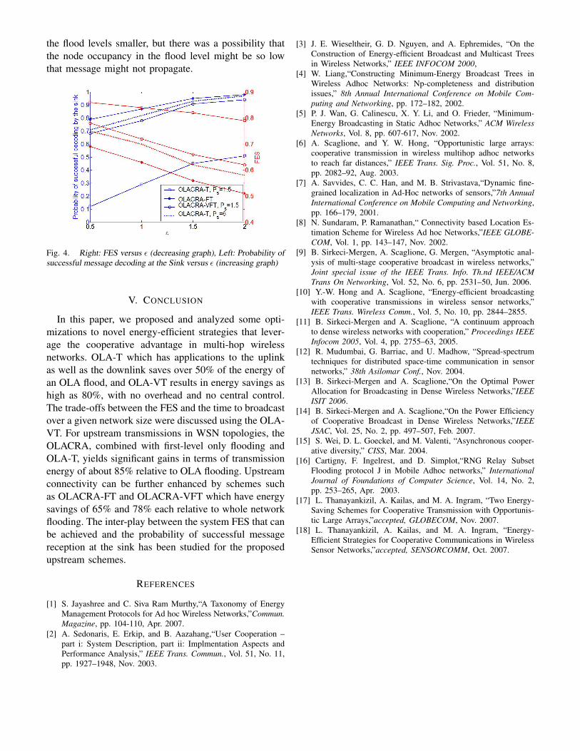
the flood levels smaller, but there was a possibility thatthe node occupancy in the flood level might be so lowthat message might not propagate.
Fig. 4. Right: FES versus ε (decreasing graph), Left: Probability ofsuccessful message decoding at the Sink versus ε (increasing graph)
V. CONCLUSION
In this paper, we proposed and analyzed some opti-mizations to novel energy-efficient strategies that lever-age the cooperative advantage in multi-hop wirelessnetworks. OLA-T which has applications to the uplinkas well as the downlink saves over 50% of the energy ofan OLA flood, and OLA-VT results in energy savings ashigh as 80%, with no overhead and no central control.The trade-offs between the FES and the time to broadcastover a given network size were discussed using the OLA-VT. For upstream transmissions in WSN topologies, theOLACRA, combined with first-level only flooding andOLA-T, yields significant gains in terms of transmissionenergy of about 85% relative to OLA flooding. Upstreamconnectivity can be further enhanced by schemes suchas OLACRA-FT and OLACRA-VFT which have energysavings of 65% and 78% each relative to whole networkflooding. The inter-play between the system FES that canbe achieved and the probability of successful messagereception at the sink has been studied for the proposedupstream schemes.
REFERENCES
[1] S. Jayashree and C. Siva Ram Murthy,“A Taxonomy of EnergyManagement Protocols for Ad hoc Wireless Networks,”Commun.Magazine, pp. 104-110, Apr. 2007.
[2] A. Sedonaris, E. Erkip, and B. Aazahang,“User Cooperation –part i: System Description, part ii: Implmentation Aspects andPerformance Analysis,” IEEE Trans. Commun., Vol. 51, No. 11,pp. 1927–1948, Nov. 2003.
[3] J. E. Wieseltheir, G. D. Nguyen, and A. Ephremides, “On theConstruction of Energy-efficient Broadcast and Multicast Treesin Wireless Networks,” IEEE INFOCOM 2000,
[4] W. Liang,“Constructing Minimum-Energy Broadcast Trees inWireless Adhoc Networks: Np-completeness and distributionissues,” 8th Annual International Conference on Mobile Com-puting and Networking, pp. 172–182, 2002.
[5] P. J. Wan, G. Calinescu, X. Y. Li, and O. Frieder, “Minimum-Energy Broadcasting in Static Adhoc Networks,” ACM WirelessNetworks, Vol. 8, pp. 607-617, Nov. 2002.
[6] A. Scaglione, and Y. W. Hong, “Opportunistic large arrays:cooperative transmission in wireless multihop adhoc networksto reach far distances,” IEEE Trans. Sig. Proc., Vol. 51, No. 8,pp. 2082–92, Aug. 2003.
[7] A. Savvides, C. C. Han, and M. B. Strivastava,“Dynamic fine-grained localization in Ad-Hoc networks of sensors,”7th AnnualInternational Conference on Mobile Computing and Networking,pp. 166–179, 2001.
[8] N. Sundaram, P. Ramanathan,“ Connectivity based Location Es-timation Scheme for Wireless Ad hoc Networks,”IEEE GLOBE-COM, Vol. 1, pp. 143–147, Nov. 2002.
[9] B. Sirkeci-Mergen, A. Scaglione, G. Mergen, “Asymptotic anal-ysis of multi-stage cooperative broadcast in wireless networks,”Joint special issue of the IEEE Trans. Info. Th.nd IEEE/ACMTrans On Networking, Vol. 52, No. 6, pp. 2531–50, Jun. 2006.
[10] Y.-W. Hong and A. Scaglione, “Energy-efficient broadcastingwith cooperative transmissions in wireless sensor networks,”IEEE Trans. Wireless Comm., Vol. 5, No. 10, pp. 2844–2855.
[11] B. Sirkeci-Mergen and A. Scaglione, “A continuum approachto dense wireless networks with cooperation,” Proceedings IEEEInfocom 2005, Vol. 4, pp. 2755–63, 2005.
[12] R. Mudumbai, G. Barriac, and U. Madhow, “Spread-spectrumtechniques for distributed space-time communication in sensornetworks,” 38th Asilomar Conf., Nov. 2004.
[13] B. Sirkeci-Mergen and A. Scaglione,“On the Optimal PowerAllocation for Broadcasting in Dense Wireless Networks,”IEEEISIT 2006.
[14] B. Sirkeci-Mergen and A. Scaglione,“On the Power Efficiencyof Cooperative Broadcast in Dense Wireless Networks,”IEEEJSAC, Vol. 25, No. 2, pp. 497–507, Feb. 2007.
[15] S. Wei, D. L. Goeckel, and M. Valenti, “Asynchronous cooper-ative diversity,” CISS, Mar. 2004.
[16] Cartigny, F. Ingelrest, and D. Simplot,“RNG Relay SubsetFlooding protocol J in Mobile Adhoc networks,” InternationalJournal of Foundations of Computer Science, Vol. 14, No. 2,pp. 253–265, Apr. 2003.
[17] L. Thanayankizil, A. Kailas, and M. A. Ingram, “Two Energy-Saving Schemes for Cooperative Transmission with Opportunis-tic Large Arrays,”accepted, GLOBECOM, Nov. 2007.
[18] L. Thanayankizil, A. Kailas, and M. A. Ingram, “Energy-Efficient Strategies for Cooperative Communications in WirelessSensor Networks,”accepted, SENSORCOMM, Oct. 2007.


