Embed Size (px)
Citation preview
PERGAMON Carbon 37 (1999) 1909–1918
Pore structure alteration of porous carbon by catalytic cokedeposition
*I. Prasetyo, D.D. DoDepartment of Chemical Engineering, University of Queensland, Brisbane, Queensland 4072, Australia
Received 31 July 1998; accepted 19 February 1999
Abstract
The feasibility of preparing Carbon Molecular Sieve (CMS) by tailoring pore structure of activated carbon under catalyticcracking of benzene has been examined. In this method, benzene vapour was cracked over metal-impregnated activatedcarbon particles at 523–773 K. Among the metal catalysts tested, only cobalt exhibited significant cracking activity towardbenzene. In this range of temperature coke was originated on the metal surface only, therefore an excessive coke depositionas indicated in non-catalytic process was not observed. The amount of coke and the site of deposition in the pore networkwere determined to some extent by the metal loading as well as the rate of benzene cracking. Raman spectra indicated thatthe coke produced was less amorphous than those produced in non-catalytic processes. Only a small loss in microporevolume and surface area was observed after the coke deposition process. The CMS produced was tested for its adsorptioncharacteristics of carbon dioxide and methane. The improvement in the CO /CH kinetic selectivity was observed.2 4
1999 Elsevier Science Ltd. All rights reserved.
Keywords: A. Activated carbon; B. Cracking; C. Raman spectroscopy; D. Adsorption properties, Diffusion
1. Introduction either widening the small pores by partial gasification [1]or narrowing the large pores by carbon deposition [2–6].
Intensive research in activated carbon has contributed In the pore narrowing technique, cracking of hydro-important developments into new aspects of using acti- carbon molecules is usually employed to facilitate thevated carbon in chemical industries. One of the most deposition of carbon over the pore mouth of the micropore.important advances is the use of ‘‘modified’’ activated Due to their uncontrolled deposition, carbon from crackingcarbon as a ‘‘molecular sieve’’ in separation processes. process will deposit on any surface in the pores of theDue to its specific pore structure, this new type of activated carbon precursor. Therefore, the carbon deposits maycarbon can provide more selective properties than conven- block the available small pores and lead to the decrease oftional activated carbon in adsorbing molecule from a adsorption capacity of the CMS [6].gaseous mixture. With the pore size in the range of To control the deposition of the carbon from themolecular dimension, a small difference in size of mole- cracking process, an alternative method is developed incules to be adsorbed will lead to a large difference in this study. The phenomenon of catalyst deactivation bymicropore diffusivities due to the activation energy re- carbon deposition during the cracking process is adopted toquired for diffusion. develop the process of pore structure modification by
Efforts on pore structure alteration of porous carbon to carbon deposition technique for CMS preparation. In fact,generate pore constriction leading to the sieving properties the use of catalyst in cracking of hydrocarbon molecules ishave been performed by various research groups. The very common in a modern oil refinery to produce shortertailoring technique developed to create pore constriction is chain fraction such as gasoline from long chain hydro-
carbons. In general, the mechanism of this heterogeneouscatalytic process is as follows. The reacting species diffusethrough the pore network of solid catalyst support, adsorb*Corresponding author. Tel.: 161-7-3365-4154; fax: 161-7-chemically onto the surface of catalyst site where they are3365-2789.
E-mail address: [email protected] (D.D. Do) reacted, and then the products and unreacted reactants
0008-6223/99/$ – see front matter 1999 Elsevier Science Ltd. All rights reserved.PI I : S0008-6223( 99 )00065-2
1910 I. Prasetyo, D.D. Do / Carbon 37 (1999) 1909 –1918
diffuse back to the bulk fluid phase. During the cracking likely to be originated in gas phase as well [7,8], resultingreaction, which takes place on the surface of catalytic sites, in amorphous carbon.the undesired carbon (bulky aromatic compound) will The first part of the present work describes the be-deposit and cover the surface of the catalyst sites and haviour of cobalt metal catalyst with regard to its activitiesdeactivate them. The catalyst distributed within the pore in cracking benzene, while the second part discusses thenetwork of the carbon host will assist the coke from the characteristics of the pore constriction generated particu-cracking process to deposit on the specific site of the larly with regard to the sieving properties.carbon pores. Coke residing on the edge of the pore mouthwill reduce the size of the pore mouth and create poreconstrictions.
2. ExperimentalThe carbon resulting from the hydrocarbon cracking
process can be found in a number of different structures2.1. CMS Preparation
ranging from amorphous to crystalline form depend on theway the carbon is originated. The term carbon is used to
Impregnation method was used to disperse the metaldescribe a wide variety of solid residues (with empirical
catalysts throughout the pore mouth of porous carbon hostformula approximately C H ) which is formed during thex y to create sites for subsequent coke deposition. The acti-pyrolysis. The overall deposit of this hydrogen-deficient
vated carbon used in this work was Ajax type 976 (1 /16carbonaceous material is called coke. Several hydrocar-
inch pellets) supplied by Ajax Chemicals, Australia. Itsbons are known to be very effective as coke precursors,
detailed physical properties was previously reported bysuch as acetylenic compounds, diolefins, aromatics, and
Gray [10].olefins [7]. The formation of coke under hydrocarboncracking condition is very complex, it involves molecularand free radical chain reactions, simultaneous decomposi- 2.1.1. Metal catalyst impregnationtion and polymerisation, as well as phase change from gas The metal catalysts were impregnated onto the Ajaxto liquid to solid. At high cracking temperatures, coke is activated carbon by incipient wetness technique. The metalproduced by a sequence of reaction that starts with free salt employed were cobalt nitrate, nickel nitrate, ironradical chain reactions in the gas phase, leading to a wide nitrate and cerium nitrate. Metal salts of nitrates arevariety of hydrocarbon formation. The tar droplets (poly- suitable for this purpose, because they leave no appreciablecyclic aromatic) which are formed in the gas phase residue (after ignition and evaporation) except the metallicimpinge on the solid surfaces. Some of the tars adhere to oxide [11]. Isopropyl alcohol, instead of water, was used tothe surface and others rebound back into the gas phase. dilute the metal nitrates since activated carbon is hydro-Those that adhere to the surface are converted to coke phobic. Polar solvent such as water is not a good choice,deposits by dehydrogenation reactions in two different otherwise the carbon will not be wetted and it will lead toforms [7]. The droplets which wet the solid surface will poor dispersion of metal. In this case, the metal catalystform film coke and the unwetting tars will form globular will be mostly located at the external surface of the pellet,coke. Meanwhile, the tars which are dehydrogenated in the with a non-uniform distribution [12].gas phase will convert to fluffy coke. In the presence of The activated carbon particles were placed in a suitablecatalyst, coke may be originated in the gas phase and/or vessel and heated at up to 523 K under vacuum for 3 h.on the metallic surface. Usually, at temperature 623–848 K The samples were then cooled in vacuo to room tempera-it is mostly formed by catalytic reactions [8] and at higher ture before a volume of metal salt solution which wastemperatures (1073–1173 K) coke formed by gas phase essentially equivalent to the pore volume of the carbon wasreactions is dominant [7]. The surface process appears to introduced into the carbon bed to reach the point ofbe the controlling factor in determining the crystallinity of incipient wetness. By this method, most of the solutionthe carbon formed during the pyrolysis. Therefore, by was occluded within the carbon pores. The loading ofemploying catalyst for pore tailoring technique in CMS metal can be varied by using solutions of differentpreparation by a carbon deposition process, non-amor- concentration.phous carbon is expected to be produced during the After the impregnation process, the samples were driedcracking of the hydrocarbon. at room temperature for overnight and then at 363 K for 6
Another advantage of using catalysts in CMS prepara- h, after which the samples were heated at 378 K overnighttion is that the temperature of the cracking can be reduced. under a reduced pressure. The catalyst-impregnated carbonExploratory work on catalytic cracking of hydrocarbon for particles then were placed in the reactor and calcined inpore structure modification was initiated by Verma and situ in nitrogen flow (100 cc /min) at atmospheric pressureWalker [9]. They pyrolized propylene over nickel-im- for 16 h at temperature between 463 and 623 K [13] topregnated activated carbon 823–973 K to modify the pore decompose the metal salt. The weight loss during thestructure of microporous carbon for separation of oxygen heating was due to the removal of water and decomposi-and argon. At these temperatures, however, the coke is tion of metal salt.
I. Prasetyo, D.D. Do / Carbon 37 (1999) 1909 –1918 1911
2.1.2. Catalyst activation programmable temperature controller. Benzene was fedThe cracking reaction was carried out under atmospheric into the reactor by bubbling nitrogen gas through a column
pressure in a U-shape quartz tubular reactor (0.9 cm OD) of benzene liquid and pre-heating the benzene-laden gaswith an internal frit to support the activated carbon prior entering the reactor. Benzene concentration wasparticles. About 1.5 g metal catalyst impregnated activated controlled by adjusting the bubbler temperature. Feed flowcarbon particles were placed in the reactor. Since some rate was controlled by metering needle valve and cali-gasification of the carbon by hydrogen may take place brated by soap-bubble flow meter. Benzene-laden gas
22during activation (reduction) of the metal catalysts, the (nitrogen) of ca. 2.25310 gmol / l was passed throughprocess was conducted by temperature-programmed reduc- the bed of metal-loaded AC in the reactor at the rate of 10tion method [13]. This was carried out in situ under ml /min.hydrogen atmosphere (50 cc /min). The following tempera- During the course of a run, the concentration of benzeneture steps were applied: linear increase from room tem- in reactor feed and effluent was determined periodically byperature to 393 K for 0.5 h, then heating to 533 K and an on-line Perkin Elmer AutoSystem Gas Chromatographyholding at this temperature for another 0.5 h, followed by unit provided with a packed column (10% AT-1000 on12 h at 673 K and evacuation at that temperature. The chromosorb WAW, 80/100) and a Flame Ionisation Detec-hydrogen consumed and methane generated was monitored tor (FID). The peak areas were determined by an elec-with a gas chromatograph equipped with a thermal con- tronic Hewlett-Packard 3394 A Integrator). Blank experi-ductivity cell. Hydrogen was obtained from BOC Gases- ment was performed to check undesired pore structureAustralia. It was further purified with a catalytic hydrogen alteration during the process by treating the virgin acti-purifier unit from Engelhard Industries, and the water vated carbon in the same way. Prior to each run of carbonvapour impurity was removed by a molecular sieves unit 4 deposition experiment, the catalyst was heated to 723 K inA (1/8 inch pellets). flowing hydrogen for 3 h and then evacuated at that
temperature and decreased / increased to the desired re-2.1.3. Coke deposition action temperature before they were exposed with hydro-
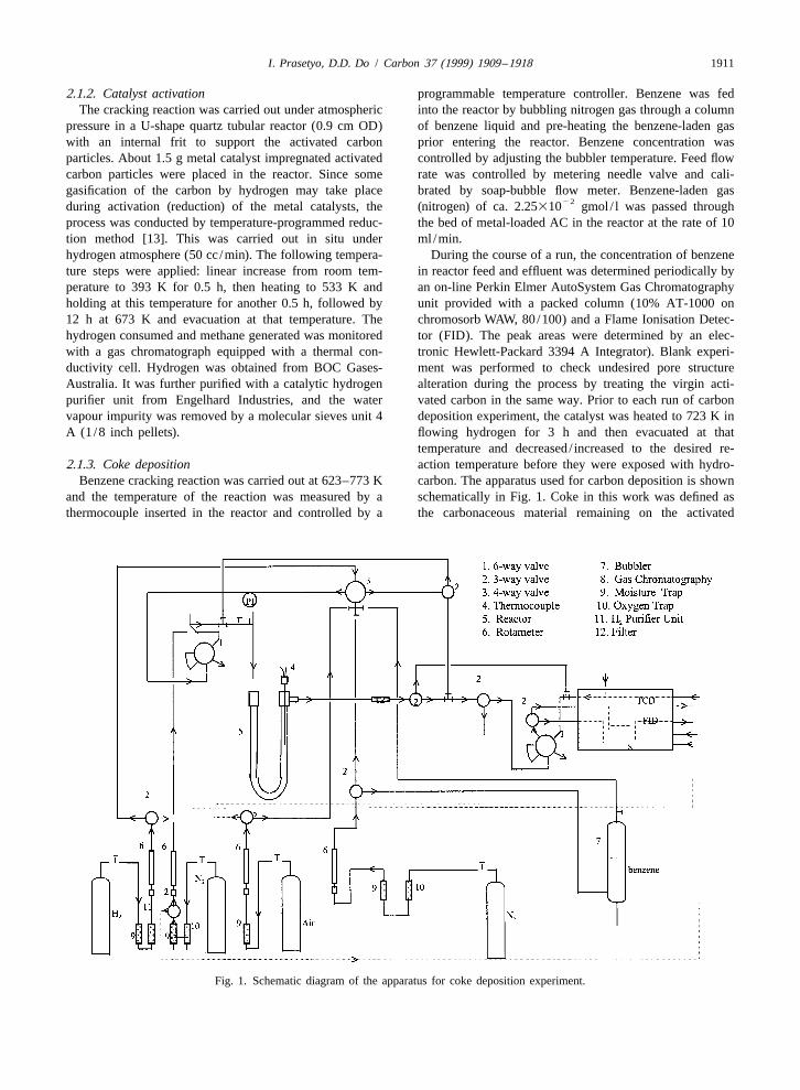
Benzene cracking reaction was carried out at 623–773 K carbon. The apparatus used for carbon deposition is shownand the temperature of the reaction was measured by a schematically in Fig. 1. Coke in this work was defined asthermocouple inserted in the reactor and controlled by a the carbonaceous material remaining on the activated
Fig. 1. Schematic diagram of the apparatus for coke deposition experiment.
1912 I. Prasetyo, D.D. Do / Carbon 37 (1999) 1909 –1918
carbon (AC) host after the cracking process was termi- R is the gas constant, and T is temperature of the system.g
nated, the system was hold for 1 h at the operating The transport coefficient (D ) and equilibrium parameterapp
temperature, and the reactor was purged with nitrogen at b are defined as below:373 K to remove unreacted feed and volatile products.
´ D 1 (1 2 ´ )KDm p m s]]]]]]D 5 (2)app ´ 1 (1 1 ´ )Km m2.2. CMS Characterisation
V m ´ 1 (1 1 ´ )Kapp p m m] ] ]]]]F Gb 5 5 (3)S D2.2.1. Equilibrium characterisation V r Vp
Adsorption capacity tests were carried out using thevolumetric method at a constant temperature of 373 K. All with D and D being pore and surface diffusivities,p s
CMS samples were first degassed at 523 K for overnight respectively, K is Henry constant, m is mass of particlep25until the static pressure in the system was at least 10 (g), ´ is the particle porosity, and r is particle densitym p
torr. The data obtained is presented as an adsorption (g /cc). The eigenvalues l are obtained from the followingisotherm curve, and the comparison of the uptake capacity transcendental equation:of the sorbents for methane and carbon dioxide up to 100
b tan(l) 1 l 5 0 (4)torr equilibrium pressure is carried out.The pore size distribution of the active carbon before
and after modification were determined by a molecular3. Results and discussionprobe approach. All active carbon samples were first
degassed at 523 K for overnight to a static pressure of25 The experimental work was carried out to illustrate the10 torr. The samples were exposed to organic vapours
role of catalysts and cracking temperature in determiningwith the following molecular size: 0.37 nm (CS ); 0.49 nm2 the extent of coke deposition. Benzene was selected as the(i-C H ); 0.6 nm (CCl ) at 303 K and a relative pressure5 12 4 coke precursor since it has already been studied extensive-(P/P ) of 0.5.s ly in CMS preparation, allowing the comparison of thenon-catalytic and catalytic coke deposition. The cracking
2.2.2. Dynamics characterisationtemperature range 623–773 K was selected to elucidate the
The kinetics of gas uptake measurement tests werecatalytic effect of metal catalysts both in the decomposi-
performed in a semi-batch constant molar flow rate ad-tion of benzene and in the process of coke deposition.
sorber (CMF technique). The detail of the experimentalMoreover, at temperature range 623–773 K, the activated
procedure of this technique was described in our previouscarbon host (AC) was expected not to be sintered and the
study [14]. The CMF apparatus essentially consists of twocoke not to be originated in the gas phase.
sections, the reservoir and adsorption sections, separatedThe search for a suitable catalyst for benzene cracking
by a variable leak valve (Varian model 951-5106), whichwas the first step in the development of pore structure
accurately controls the low flow of adsorbate from thealteration process followed by determination of coke1reservoir section to the adsorption section. At t50 , adeposition rate and characterisation of the CMS in terms of29constant molar flow rate of about 6310 gmol / s ofpore structure, type of carbon deposit, adsorption capacity,
adsorbate from the reservoir was introduced into theand sieving properties. Several peaks were detected by the
adsorber, and the pressure was monitored and recorded bygas chromatography when benzene-laden gas was passed
a PC. The increase in pressure in the adsorber is dictatedthrough the bed of cobalt-loaded AC particles at 623–773
by the rate of supply of adsorbate and the rate ofK. Nickel, iron and cerium have been examined for their
adsorption into the particle. This pressure rise versus timeactivity to crack benzene as well, but there was only a
is given by the following equation [15]:benzene peak detected by the gas chromatography and nocoke was found. Only cobalt was observed to exhibit2~ ~(Nt)R T /V NR Tb Rg gcracking activity at 623–773 K.]]] ]]]]]]]]]]P 5 1 2 V(1 1 b ) (s 1 1)(s 1 3)D(1 1 b ) app
2~ 3.1. The process of coke deposition in cobalt-loadedNR T RgS D]] ]]2 2(1 1 s)bF GS D activated carbonV Dapp
2 2` exp[2l (D t /R )] Coke or hydrogen-deficient carbonaceous material de-n app]]]]]]]]3O (1)2 2 2 2 2 posited during hydrocarbon cracking can be formed onl [(1 1 s) b 1 (1 1 s) b 1 l ]n50 n n
metallic and acidic catalysts [16,17]. Since the solidwhere P and V are bulk pressure (torr) and volume (cc) of surface of AC has low surface acidity and the temperaturethe adsorption system respectively, s is particle shape employed in the present work was relatively low, the cokefactor (for slab, s50), R is half of the slab length (R5 formation from benzene could be attributed to the cobalt
~0.53L), N5molar flow rate (mole /s), t is uptake time (s), metal surface only. To correlate coke formation with the
I. Prasetyo, D.D. Do / Carbon 37 (1999) 1909 –1918 1913
nature of AC host and to check undesired pore structurealteration of the AC during the process, unloaded AC wastested with benzene over the same temperature range623–773 K. There was no coke formation observed in theAC and no indication of pore structure alteration duringthe thermal process. The evidence indicates that the surfaceof AC alone was not responsible for extensive cokeformation and that coke from thermal cracking was notformed under the cracking temperature employed.
Unlike open-chain molecules, benzene molecule issymmetrical and three double bonds in benzene aredelocalised around the hexagonal benzene skeleton, whichmakes benzene a very stable species. The energy todecompose benzene molecule into C atoms and H atoms isgreater than just as a sum of bond energies of C–H, C–Cand C5C as in olefins, because in order to decompose thearomatic ring, the delocalisation energy must first beovercome [18]. Therefore, the benzene molecule has to besubject to temperature as high as 1073 K to be cracked inthe absence of catalyst [2,3]. The role of cobalt catalyst in
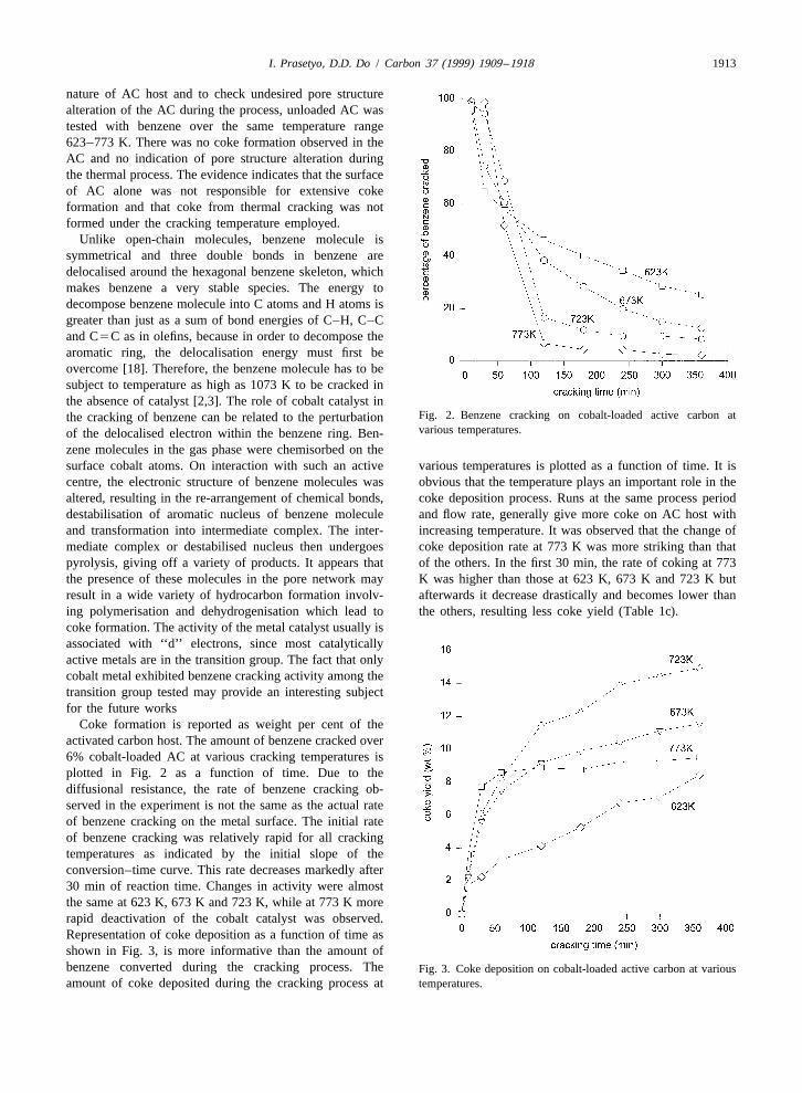
Fig. 2. Benzene cracking on cobalt-loaded active carbon atthe cracking of benzene can be related to the perturbationvarious temperatures.of the delocalised electron within the benzene ring. Ben-
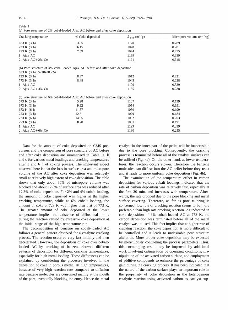
zene molecules in the gas phase were chemisorbed on thesurface cobalt atoms. On interaction with such an active various temperatures is plotted as a function of time. It iscentre, the electronic structure of benzene molecules was obvious that the temperature plays an important role in thealtered, resulting in the re-arrangement of chemical bonds, coke deposition process. Runs at the same process perioddestabilisation of aromatic nucleus of benzene molecule and flow rate, generally give more coke on AC host withand transformation into intermediate complex. The inter- increasing temperature. It was observed that the change ofmediate complex or destabilised nucleus then undergoes coke deposition rate at 773 K was more striking than thatpyrolysis, giving off a variety of products. It appears that of the others. In the first 30 min, the rate of coking at 773the presence of these molecules in the pore network may K was higher than those at 623 K, 673 K and 723 K butresult in a wide variety of hydrocarbon formation involv- afterwards it decrease drastically and becomes lower thaning polymerisation and dehydrogenisation which lead to the others, resulting less coke yield (Table 1c).coke formation. The activity of the metal catalyst usually isassociated with ‘‘d’’ electrons, since most catalyticallyactive metals are in the transition group. The fact that onlycobalt metal exhibited benzene cracking activity among thetransition group tested may provide an interesting subjectfor the future works
Coke formation is reported as weight per cent of theactivated carbon host. The amount of benzene cracked over6% cobalt-loaded AC at various cracking temperatures isplotted in Fig. 2 as a function of time. Due to thediffusional resistance, the rate of benzene cracking ob-served in the experiment is not the same as the actual rateof benzene cracking on the metal surface. The initial rateof benzene cracking was relatively rapid for all crackingtemperatures as indicated by the initial slope of theconversion–time curve. This rate decreases markedly after30 min of reaction time. Changes in activity were almostthe same at 623 K, 673 K and 723 K, while at 773 K morerapid deactivation of the cobalt catalyst was observed.Representation of coke deposition as a function of time asshown in Fig. 3, is more informative than the amount ofbenzene converted during the cracking process. The Fig. 3. Coke deposition on cobalt-loaded active carbon at variousamount of coke deposited during the cracking process at temperatures.
1914 I. Prasetyo, D.D. Do / Carbon 37 (1999) 1909 –1918
Table 1(a) Pore structure of 2% cobal-loaded Ajax AC before and after coke deposition
2 3Cracking temperature % Coke deposited S (m /g) Micropore volume (cm /g)BET
673 K (3 h) 3.85 1120 0.289723 K (3 h) 6.15 1078 0.281773 K (3 h) 7.69 1044 0.2751. Ajax AC 1199 0.3392. Ajax AC12% Co 1191 0.315
(b) Pore structure of 4% cobal-loaded Ajax AC before and after coke deposition673 K (3 h)6.5210420.224723 K (3 h) 8.87 1012 0.221773 K (3 h) 8.48 1045 0.2281. Ajax AC 1199 0.3392. Ajax AC14% Co 1185 0.288
(c) Pore structure of 6% cobal-loaded Ajax AC before and after coke deposition573 K (3 h) 5.28 1107 0.199673 K (3 h) 9.92 1054 0.191673 K (6 h 11.57 1050 0.199723 K (3 h) 12.31 1029 0.184723 K (6 h) 14.95 1002 0.203773 K (3 h) 8.78 1061 0.1911. Ajax AC 1199 0.3392. Ajax AC16% Co 1180 0.255
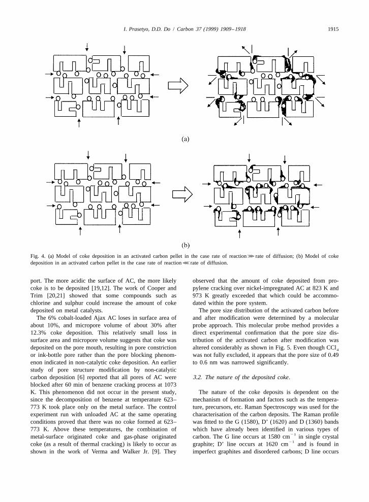
Data for the amount of coke deposited on CMS pre- catalyst in the inner part of the pellet will be inaccessiblecursors and the comparison of pore structure of AC before due to the pore blocking. Consequently, the crackingand after coke deposition are summarised in Table 1a, b process is terminated before all of the catalyst surfaces canand c for various metal loadings and cracking temperatures be utilised (Fig. 4a). On the other hand, at lower tempera-after 3 and 6 h of coking process. The important aspect tures, the reaction occurs slower. Therefore the benzeneobserved here is that the loss in surface area and micropore molecules can diffuse into the AC pellet before they reactvolume of the AC after coke deposition was relatively and it leads to more uniform coke deposition (Fig. 4b).small at relatively high extent of coke deposition. The table The examination of the temperature effect in carbonshows that only about 30% of micropore volume was deposition for various cobalt loadings indicated that theblocked and about 12.8% of surface area was reduced after rate of carbon deposition was relatively fast, especially at12.3% of coke deposition. For 2% and 4% cobalt loading, the first 30 min, and increases with temperature. After-the amount of coke deposited was higher at the higher wards, the rate dropped due to the pore blocking and metalcracking temperature, while at 6% cobalt loading, the surface covering. Therefore, as far as pore tailoring isamount of coke at 723 K was higher than that of 773 K. concerned, low rate of cracking reaction seems to be moreThe greater amount of coke deposited at the lower preferable than high rate cracking reaction. As indicated intemperature implies the existence of diffusional limits coke deposition of 6% cobalt-loaded AC at 773 K, theduring the reaction caused by excessive coke deposition at carbon deposition was terminated before all of the metalthe initial stage of the high temperature run. catalyst was utilised. This fact implies that at higher rate of
The decomposition of benzene on cobalt-loaded AC cracking reaction, the coke deposition is more difficult tofollows a general pattern observed for a catalytic cracking be controlled and it leads to undesirable pore structureprocess. The reaction occurred very fast initially and then alteration. More proper coke deposition may be expecteddecelerated. However, the deposition of coke over cobalt- by meticulously controlling the process parameters. Thus,loaded AC by cracking of benzene showed different this encouraging result may be improved by additionalpatterns of deposition for different cracking temperatures, work involving optimisation of operating conditions, ma-especially for high metal loading. These differences can be nipulation of the activated carbon surface, and employmentexplained by considering the processes involved in the of additive compounds to enhance the percentage of cokedeposition of coke in porous media. At high temperatures, gain during the cracking process. It has been indicated thatbecause of very high reaction rate compared to diffusion the nature of the carbon surface plays an important role inrate benzene molecules are consumed mainly at the mouth the propensity of coke deposition in the heterogenousof the pore, eventually blocking the entry. Hence the metal catalytic reaction using activated carbon as catalyst sup-
I. Prasetyo, D.D. Do / Carbon 37 (1999) 1909 –1918 1915
Fig. 4. (a) Model of coke deposition in an activated carbon pellet in the case rate of reaction?rate of diffusion; (b) Model of cokedeposition in an activated carbon pellet in the case rate of reactionDrate of diffusion.
port. The more acidic the surface of AC, the more likely observed that the amount of coke deposited from pro-coke is to be deposited [19,12]. The work of Cooper and pylene cracking over nickel-impregnated AC at 823 K andTrim [20,21] showed that some compounds such as 973 K greatly exceeded that which could be accommo-chlorine and sulphur could increase the amount of coke dated within the pore system.deposited on metal catalysts. The pore size distribution of the activated carbon before
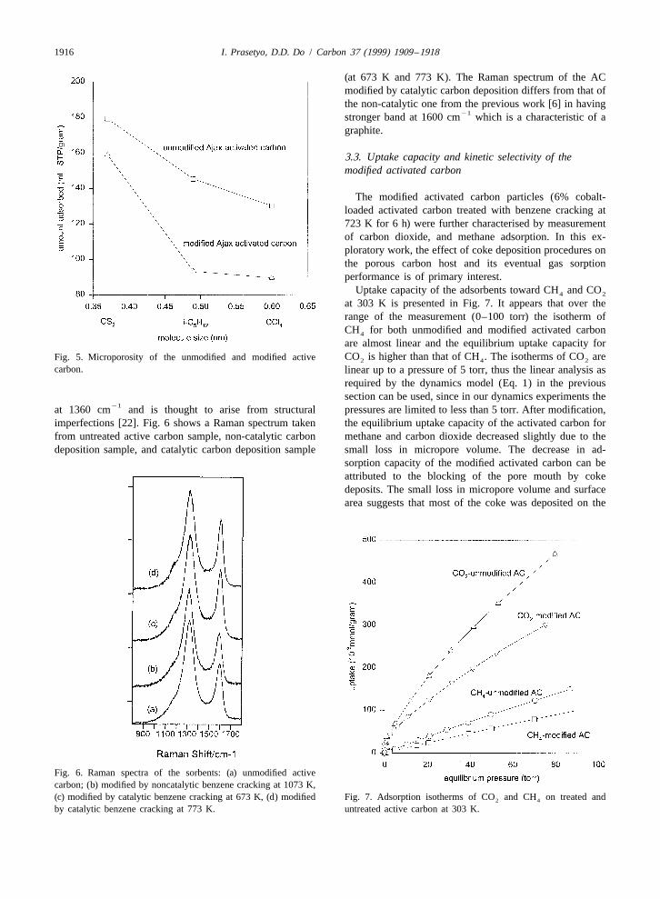
The 6% cobalt-loaded Ajax AC loses in surface area of and after modification were determined by a molecularabout 10%, and micropore volume of about 30% after probe approach. This molecular probe method provides a12.3% coke deposition. This relatively small loss in direct experimental confirmation that the pore size dis-surface area and micropore volume suggests that coke was tribution of the activated carbon after modification wasdeposited on the pore mouth, resulting in pore constriction altered considerably as shown in Fig. 5. Even though CCl4
or ink-bottle pore rather than the pore blocking phenom- was not fully excluded, it appears that the pore size of 0.49enon indicated in non-catalytic coke deposition. An earlier to 0.6 nm was narrowed significantly.study of pore structure modification by non-catalyticcarbon deposition [6] reported that all pores of AC were 3.2. The nature of the deposited coke.blocked after 60 min of benzene cracking process at 1073K. This phenomenon did not occur in the present study, The nature of the coke deposits is dependent on thesince the decomposition of benzene at temperature 623– mechanism of formation and factors such as the tempera-773 K took place only on the metal surface. The control ture, precursors, etc. Raman Spectroscopy was used for theexperiment run with unloaded AC at the same operating characterisation of the carbon deposits. The Raman profileconditions proved that there was no coke formed at 623– was fitted to the G (1580), D’ (1620) and D (1360) bands773 K. Above these temperatures, the combination of which have already been identified in various types of
21metal-surface originated coke and gas-phase originated carbon. The G line occurs at 1580 cm in single crystal21coke (as a result of thermal cracking) is likely to occur as graphite; D’ line occurs at 1620 cm and is found in
shown in the work of Verma and Walker Jr. [9]. They imperfect graphites and disordered carbons; D line occurs
1916 I. Prasetyo, D.D. Do / Carbon 37 (1999) 1909 –1918
(at 673 K and 773 K). The Raman spectrum of the ACmodified by catalytic carbon deposition differs from that ofthe non-catalytic one from the previous work [6] in having
21stronger band at 1600 cm which is a characteristic of agraphite.
3.3. Uptake capacity and kinetic selectivity of themodified activated carbon
The modified activated carbon particles (6% cobalt-loaded activated carbon treated with benzene cracking at723 K for 6 h) were further characterised by measurementof carbon dioxide, and methane adsorption. In this ex-ploratory work, the effect of coke deposition procedures onthe porous carbon host and its eventual gas sorptionperformance is of primary interest.
Uptake capacity of the adsorbents toward CH and CO4 2
at 303 K is presented in Fig. 7. It appears that over therange of the measurement (0–100 torr) the isotherm ofCH for both unmodified and modified activated carbon4
are almost linear and the equilibrium uptake capacity forCO is higher than that of CH . The isotherms of CO areFig. 5. Microporosity of the unmodified and modified active 2 4 2
carbon. linear up to a pressure of 5 torr, thus the linear analysis asrequired by the dynamics model (Eq. 1) in the previoussection can be used, since in our dynamics experiments the
21at 1360 cm and is thought to arise from structural pressures are limited to less than 5 torr. After modification,imperfections [22]. Fig. 6 shows a Raman spectrum taken the equilibrium uptake capacity of the activated carbon forfrom untreated active carbon sample, non-catalytic carbon methane and carbon dioxide decreased slightly due to thedeposition sample, and catalytic carbon deposition sample small loss in micropore volume. The decrease in ad-
sorption capacity of the modified activated carbon can beattributed to the blocking of the pore mouth by cokedeposits. The small loss in micropore volume and surfacearea suggests that most of the coke was deposited on the
Fig. 6. Raman spectra of the sorbents: (a) unmodified activecarbon; (b) modified by noncatalytic benzene cracking at 1073 K,(c) modified by catalytic benzene cracking at 673 K, (d) modified Fig. 7. Adsorption isotherms of CO and CH on treated and2 4
by catalytic benzene cracking at 773 K. untreated active carbon at 303 K.
I. Prasetyo, D.D. Do / Carbon 37 (1999) 1909 –1918 1917
pore mouth and slightly reduce the size of the poreconstriction. The equilibria of methane and carbon dioxideon the activated carbon were performed at three differenttemperatures (at 293, 303, 323 K) to obtain the heat ofadsorption by van’t Hoff equation. The affinity of theadsorbent toward the adsorbate is characterised by theHenry constant, and the results are summarised in Table 2.
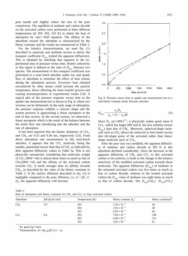
For the kinetics characterisation, we used Eq. (1)described in materials and methods section to derive thetransport coefficient D (called the apparent diffusivity).app
This is obtained by matching that equation to the ex-perimental data of pressure versus time. Kinetic selectivityin this report is defined as the ratio of D between twoapp
species. The measurement of this transport coefficient wasperformed in a semi batch adsorber under low and steadyflow of adsorbate to minimise the effect of heat releaseduring the adsorption process. Excessive heat releasedencountered by other means could increase the particletemperature, hence affecting the mass transfer process andcausing misinterpretation of experimental results [14]. Atypical plot of the pressure response versus time in the Fig. 8. Pressure versus time in uptake rate measurement test in a
semi-batch constant molar flowrate adsorber.uptake rate measurement test is shown in Fig. 8, where twosections can be delineated. In the early stage of adsorption,the pressure response exhibits a concave shape and the ´ Dm p
]]]]system pressure is approaching a linear asymptote at the D 5 (5)app ´ 1 (1 2 ´ )Km mend of that section. In the second section, we observed a0.5linear asymptote which is the result of the balance between Since D a(1 /MW ) , it physically makes good sense ifp
the molar flow rate introducing into the adsorber and the CO , which has larger MW and K, has less mobility (lower2rate of adsorption. D ) than that of CH Moreover, spherical-shape mole-app 4.
It has been reported that the kinetic diameters of CO , cule such as CH allows the molecule to have better access2 4
and CH are 0.33 and 0.38 nm, respectively [23]. From into slit-shape pores of the activated rather than linear-4
direct adsorption rate measurement in this semi-batch shape molecule such as CO .2
adsorber, it appears that the CO molecule, being the After the pore size was modified, the apparent diffusivi-2
smaller, penetrated slower than that of CH as indicated by ty of methane and carbon dioxide at 303 K in this4
their apparent diffusivity values in Table 3a. This is not adsorbent declined considerably. Since the decrease in thephysically unexpected, considering that molecular weight apparent diffusivity of CH and CO in this activated4 2
of CO (MW544) is almost three times as much as that of carbon is not uniform, it leads to the change in the kinetics2
CH (MW516) and the affinity of the activated carbon selectivity of the modified activated carbon towards those4
towards CO is much stronger than its affinity towards molecules. The apparent diffusivity (D ) of methane in2 app
CH , as described by the value of the Henry constants in the untreated activated carbon was five times as much as4
Table 2. If the surface diffusion described in Eq. (2) is that of carbon dioxide, whereas in the treated activatednegligible compared to the pore diffusion, i.e. (12)D < carbon the D value of methane was eight times as muchs app
D , the apparent diffusivity will become: as that of carbon dioxide. The D (CH ) /D (CO )p app 4 app 2
Table 2Heat of adsorption and Henry constants for CH and CO in Ajax activated carbon4 2
a bAdsorbate DH (kcal /mol) Temperature (K) Henry constant, K Henry constant,KP
26CH 5.9 293 2.24310 44426303 1.91310 3926323 0.93310 2026CO 6.4 293 7.60310 148226303 6.00310 12126323 2.81310 61
a In: gmol /(g3torr).b Dimensionless, K5(K r RT ) /(12´).p p
1918 I. Prasetyo, D.D. Do / Carbon 37 (1999) 1909 –1918
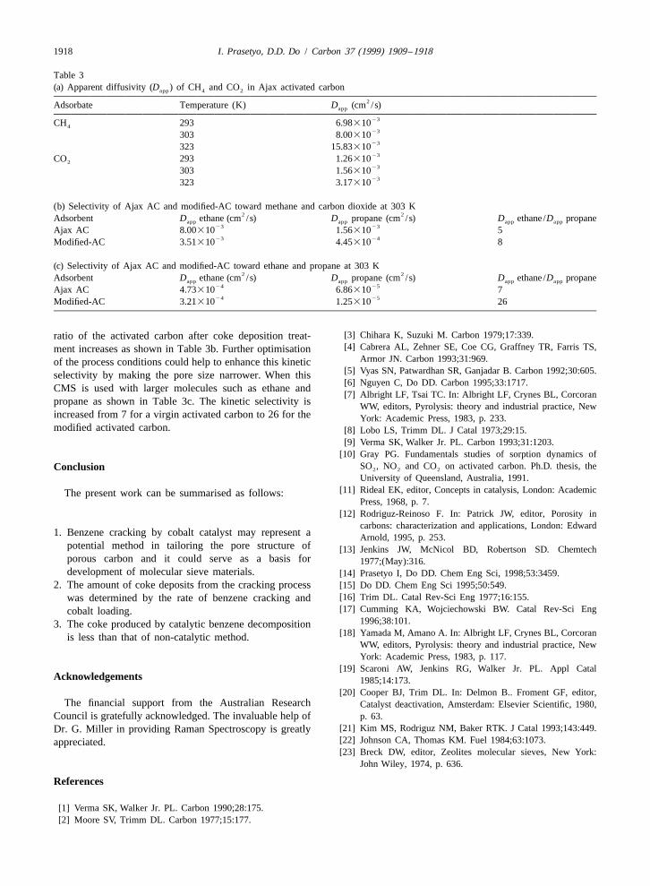
Table 3(a) Apparent diffusivity (D ) of CH and CO in Ajax activated carbonapp 4 2
2Adsorbate Temperature (K) D (cm /s)app
23CH 293 6.98310423303 8.0031023323 15.8331023CO 293 1.26310223303 1.5631023323 3.17310
(b) Selectivity of Ajax AC and modified-AC toward methane and carbon dioxide at 303 K2 2Adsorbent D ethane (cm /s) D propane (cm /s) D ethane /D propaneapp app app app
23 23Ajax AC 8.00310 1.56310 523 24Modified-AC 3.51310 4.45310 8
(c) Selectivity of Ajax AC and modified-AC toward ethane and propane at 303 K2 2Adsorbent D ethane (cm /s) D propane (cm /s) D ethane /D propaneapp app app app
24 25Ajax AC 4.73310 6.86310 724 25Modified-AC 3.21310 1.25310 26
[3] Chihara K, Suzuki M. Carbon 1979;17:339.ratio of the activated carbon after coke deposition treat-[4] Cabrera AL, Zehner SE, Coe CG, Graffney TR, Farris TS,ment increases as shown in Table 3b. Further optimisation
Armor JN. Carbon 1993;31:969.of the process conditions could help to enhance this kinetic[5] Vyas SN, Patwardhan SR, Ganjadar B. Carbon 1992;30:605.selectivity by making the pore size narrower. When this[6] Nguyen C, Do DD. Carbon 1995;33:1717.CMS is used with larger molecules such as ethane and[7] Albright LF, Tsai TC. In: Albright LF, Crynes BL, Corcoran
propane as shown in Table 3c. The kinetic selectivity is WW, editors, Pyrolysis: theory and industrial practice, Newincreased from 7 for a virgin activated carbon to 26 for the York: Academic Press, 1983, p. 233.modified activated carbon. [8] Lobo LS, Trimm DL. J Catal 1973;29:15.
[9] Verma SK, Walker Jr. PL. Carbon 1993;31:1203.[10] Gray PG. Fundamentals studies of sorption dynamics of
SO , NO and CO on activated carbon. Ph.D. thesis, theConclusion 2 2 2
University of Queensland, Australia, 1991.[11] Rideal EK, editor, Concepts in catalysis, London: AcademicThe present work can be summarised as follows:
Press, 1968, p. 7.[12] Rodriguz-Reinoso F. In: Patrick JW, editor, Porosity in
carbons: characterization and applications, London: Edward1. Benzene cracking by cobalt catalyst may represent a Arnold, 1995, p. 253.
potential method in tailoring the pore structure of [13] Jenkins JW, McNicol BD, Robertson SD. Chemtechporous carbon and it could serve as a basis for 1977;(May):316.development of molecular sieve materials. [14] Prasetyo I, Do DD. Chem Eng Sci, 1998;53:3459.
2. The amount of coke deposits from the cracking process [15] Do DD. Chem Eng Sci 1995;50:549.[16] Trim DL. Catal Rev-Sci Eng 1977;16:155.was determined by the rate of benzene cracking and[17] Cumming KA, Wojciechowski BW. Catal Rev-Sci Engcobalt loading.
1996;38:101.3. The coke produced by catalytic benzene decomposition[18] Yamada M, Amano A. In: Albright LF, Crynes BL, Corcoranis less than that of non-catalytic method.
WW, editors, Pyrolysis: theory and industrial practice, NewYork: Academic Press, 1983, p. 117.
[19] Scaroni AW, Jenkins RG, Walker Jr. PL. Appl CatalAcknowledgements 1985;14:173.
[20] Cooper BJ, Trim DL. In: Delmon B.. Froment GF, editor,The financial support from the Australian Research Catalyst deactivation, Amsterdam: Elsevier Scientific, 1980,
Council is gratefully acknowledged. The invaluable help of p. 63.[21] Kim MS, Rodriguz NM, Baker RTK. J Catal 1993;143:449.Dr. G. Miller in providing Raman Spectroscopy is greatly[22] Johnson CA, Thomas KM. Fuel 1984;63:1073.appreciated.[23] Breck DW, editor, Zeolites molecular sieves, New York:
John Wiley, 1974, p. 636.
References
[1] Verma SK, Walker Jr. PL. Carbon 1990;28:175.[2] Moore SV, Trimm DL. Carbon 1977;15:177.