Embed Size (px)
Citation preview

9023655 - 4th edition - May 2006
Page 1 of 86
D
Polytron
Transmitter IR Ex, IR Ex ...
Instructions for Use
001
23
65
5_0
4.e
ps

Contents
Page 2 of 86
9023655 - 4th edition - May 2006
Contents
For Your Safety
. . . . . . . . . . . . . . . . . . . . . . . . . . . . . . . . . . . . . . . . . . . . . . . . . . . . . . . . . . . . . . . . . . . . . . . . . . . . . . . . . . . . . . . . . . . . . . 4
Intended Use
. . . . . . . . . . . . . . . . . . . . . . . . . . . . . . . . . . . . . . . . . . . . . . . . . . . . . . . . . . . . . . . . . . . . . . . . . . . . . . . . . . . . . . . . . . . . . . . . 5
EC type test certificate in accordance with Directive 94/9/EC . . . . . . . . . . . . . . . . . . . . . . . . . . . . . . . . . . . . . . . . . . . . . . . . . . . . . . . 7
Design
. . . . . . . . . . . . . . . . . . . . . . . . . . . . . . . . . . . . . . . . . . . . . . . . . . . . . . . . . . . . . . . . . . . . . . . . . . . . . . . . . . . . . . . . . . . . . . . . . . . . . 10
Installing transmitter
. . . . . . . . . . . . . . . . . . . . . . . . . . . . . . . . . . . . . . . . . . . . . . . . . . . . . . . . . . . . . . . . . . . . . . . . . . . . . . . . . . . . . . . . 12
Transmitter IR Ex, IR Ex ES, IR Ex HC . . . . . . . . . . . . . . . . . . . . . . . . . . . . . . . . . . . . . . . . . . . . . . . . . . . . . . . . . . . . . . . . . . . . . . . . . . . 12
Transmitter IR Ex IL . . . . . . . . . . . . . . . . . . . . . . . . . . . . . . . . . . . . . . . . . . . . . . . . . . . . . . . . . . . . . . . . . . . . . . . . . . . . . . . . . . . . . . . . . . . 13Installation of NPT pipe connections . . . . . . . . . . . . . . . . . . . . . . . . . . . . . . . . . . . . . . . . . . . . . . . . . . . . . . . . . . . . . . . . . . . . . . . . 13Installation with hard pipe connections . . . . . . . . . . . . . . . . . . . . . . . . . . . . . . . . . . . . . . . . . . . . . . . . . . . . . . . . . . . . . . . . . . . . . . 14Mounting to a wall . . . . . . . . . . . . . . . . . . . . . . . . . . . . . . . . . . . . . . . . . . . . . . . . . . . . . . . . . . . . . . . . . . . . . . . . . . . . . . . . . . . . . . . . 14Using the maintenance opening for gas inlet in diffusion operation . . . . . . . . . . . . . . . . . . . . . . . . . . . . . . . . . . . . . . . . . . . . . . 15Installing gas path with shut-off valves for calibration . . . . . . . . . . . . . . . . . . . . . . . . . . . . . . . . . . . . . . . . . . . . . . . . . . . . . . . . . . 15
Mounting IR Ex display unit . . . . . . . . . . . . . . . . . . . . . . . . . . . . . . . . . . . . . . . . . . . . . . . . . . . . . . . . . . . . . . . . . . . . . . . . . . . . . . . . . . . . 16
Mounting IR junction box . . . . . . . . . . . . . . . . . . . . . . . . . . . . . . . . . . . . . . . . . . . . . . . . . . . . . . . . . . . . . . . . . . . . . . . . . . . . . . . . . . . . . . 16
Electrical connections
. . . . . . . . . . . . . . . . . . . . . . . . . . . . . . . . . . . . . . . . . . . . . . . . . . . . . . . . . . . . . . . . . . . . . . . . . . . . . . . . . . . . . . 17Connecting the transmitter to the central controller . . . . . . . . . . . . . . . . . . . . . . . . . . . . . . . . . . . . . . . . . . . . . . . . . . . . . . . . . . . . 17Connecting transmitter and remote IR Ex display unit . . . . . . . . . . . . . . . . . . . . . . . . . . . . . . . . . . . . . . . . . . . . . . . . . . . . . . . . . . 20Connecting transmitter and IR junction box for hand-held terminal IR . . . . . . . . . . . . . . . . . . . . . . . . . . . . . . . . . . . . . . . . . . . . 21After connecting electrical installation: . . . . . . . . . . . . . . . . . . . . . . . . . . . . . . . . . . . . . . . . . . . . . . . . . . . . . . . . . . . . . . . . . . . . . . 21
Accessories . . . . . . . . . . . . . . . . . . . . . . . . . . . . . . . . . . . . . . . . . . . . . . . . . . . . . . . . . . . . . . . . . . . . . . . . . . . . . . . . . . . . . . . . . . . . . . . . . 22Removing dust filter . . . . . . . . . . . . . . . . . . . . . . . . . . . . . . . . . . . . . . . . . . . . . . . . . . . . . . . . . . . . . . . . . . . . . . . . . . . . . . . . . . . . . . 23Fitting splash guard . . . . . . . . . . . . . . . . . . . . . . . . . . . . . . . . . . . . . . . . . . . . . . . . . . . . . . . . . . . . . . . . . . . . . . . . . . . . . . . . . . . . . . . 23Connecting tubing for remote calibration . . . . . . . . . . . . . . . . . . . . . . . . . . . . . . . . . . . . . . . . . . . . . . . . . . . . . . . . . . . . . . . . . . . . 23
Initial Operation
. . . . . . . . . . . . . . . . . . . . . . . . . . . . . . . . . . . . . . . . . . . . . . . . . . . . . . . . . . . . . . . . . . . . . . . . . . . . . . . . . . . . . . . . . . . . 24
Measurement . . . . . . . . . . . . . . . . . . . . . . . . . . . . . . . . . . . . . . . . . . . . . . . . . . . . . . . . . . . . . . . . . . . . . . . . . . . . . . . . . . . . . . . . . . . . . . . . 24
Maintenance Intervals
. . . . . . . . . . . . . . . . . . . . . . . . . . . . . . . . . . . . . . . . . . . . . . . . . . . . . . . . . . . . . . . . . . . . . . . . . . . . . . . . . . . . . . . 26
Maintenance
. . . . . . . . . . . . . . . . . . . . . . . . . . . . . . . . . . . . . . . . . . . . . . . . . . . . . . . . . . . . . . . . . . . . . . . . . . . . . . . . . . . . . . . . . . . . . . . 28
Replacing dust filter . . . . . . . . . . . . . . . . . . . . . . . . . . . . . . . . . . . . . . . . . . . . . . . . . . . . . . . . . . . . . . . . . . . . . . . . . . . . . . . . . . . . . . . . . . 28
Cleaning the optical system . . . . . . . . . . . . . . . . . . . . . . . . . . . . . . . . . . . . . . . . . . . . . . . . . . . . . . . . . . . . . . . . . . . . . . . . . . . . . . . . . . . . 29
Menu Navigation
. . . . . . . . . . . . . . . . . . . . . . . . . . . . . . . . . . . . . . . . . . . . . . . . . . . . . . . . . . . . . . . . . . . . . . . . . . . . . . . . . . . . . . . . . . . . 31
Menu structure . . . . . . . . . . . . . . . . . . . . . . . . . . . . . . . . . . . . . . . . . . . . . . . . . . . . . . . . . . . . . . . . . . . . . . . . . . . . . . . . . . . . . . . . . . . . . . . 32
Entering password . . . . . . . . . . . . . . . . . . . . . . . . . . . . . . . . . . . . . . . . . . . . . . . . . . . . . . . . . . . . . . . . . . . . . . . . . . . . . . . . . . . . . . . . . . . 34Entering Numbers . . . . . . . . . . . . . . . . . . . . . . . . . . . . . . . . . . . . . . . . . . . . . . . . . . . . . . . . . . . . . . . . . . . . . . . . . . . . . . . . . . . . . . . . 35Entering Text . . . . . . . . . . . . . . . . . . . . . . . . . . . . . . . . . . . . . . . . . . . . . . . . . . . . . . . . . . . . . . . . . . . . . . . . . . . . . . . . . . . . . . . . . . . . 35Entering Decisions . . . . . . . . . . . . . . . . . . . . . . . . . . . . . . . . . . . . . . . . . . . . . . . . . . . . . . . . . . . . . . . . . . . . . . . . . . . . . . . . . . . . . . . 35Entering Options . . . . . . . . . . . . . . . . . . . . . . . . . . . . . . . . . . . . . . . . . . . . . . . . . . . . . . . . . . . . . . . . . . . . . . . . . . . . . . . . . . . . . . . . . 36Handling Messages . . . . . . . . . . . . . . . . . . . . . . . . . . . . . . . . . . . . . . . . . . . . . . . . . . . . . . . . . . . . . . . . . . . . . . . . . . . . . . . . . . . . . . 36

9023655 - 4th edition - May 2006
Page 3 of 86
Contents
Maintenance Menu . . . . . . . . . . . . . . . . . . . . . . . . . . . . . . . . . . . . . . . . . . . . . . . . . . . . . . . . . . . . . . . . . . . . . . . . . . . . . . . . . . . . . . . . . . . 37Calibrating zero point . . . . . . . . . . . . . . . . . . . . . . . . . . . . . . . . . . . . . . . . . . . . . . . . . . . . . . . . . . . . . . . . . . . . . . . . . . . . . . . . . . . . . 37Calibrating sensitivity . . . . . . . . . . . . . . . . . . . . . . . . . . . . . . . . . . . . . . . . . . . . . . . . . . . . . . . . . . . . . . . . . . . . . . . . . . . . . . . . . . . . . . 38Configuring the calibration signal . . . . . . . . . . . . . . . . . . . . . . . . . . . . . . . . . . . . . . . . . . . . . . . . . . . . . . . . . . . . . . . . . . . . . . . . . . . 40Checking 4 to 20 mA analog interface . . . . . . . . . . . . . . . . . . . . . . . . . . . . . . . . . . . . . . . . . . . . . . . . . . . . . . . . . . . . . . . . . . . . . . . 41Display warnings . . . . . . . . . . . . . . . . . . . . . . . . . . . . . . . . . . . . . . . . . . . . . . . . . . . . . . . . . . . . . . . . . . . . . . . . . . . . . . . . . . . . . . . . . 41Display errors . . . . . . . . . . . . . . . . . . . . . . . . . . . . . . . . . . . . . . . . . . . . . . . . . . . . . . . . . . . . . . . . . . . . . . . . . . . . . . . . . . . . . . . . . . . . 42Display sensor temperature . . . . . . . . . . . . . . . . . . . . . . . . . . . . . . . . . . . . . . . . . . . . . . . . . . . . . . . . . . . . . . . . . . . . . . . . . . . . . . . . 44Adjust pre-amplification . . . . . . . . . . . . . . . . . . . . . . . . . . . . . . . . . . . . . . . . . . . . . . . . . . . . . . . . . . . . . . . . . . . . . . . . . . . . . . . . . . . . 44Setting H
2
O offset . . . . . . . . . . . . . . . . . . . . . . . . . . . . . . . . . . . . . . . . . . . . . . . . . . . . . . . . . . . . . . . . . . . . . . . . . . . . . . . . . . . . . . . . 45Calibrating analog output . . . . . . . . . . . . . . . . . . . . . . . . . . . . . . . . . . . . . . . . . . . . . . . . . . . . . . . . . . . . . . . . . . . . . . . . . . . . . . . . . . 45Display software-specific information . . . . . . . . . . . . . . . . . . . . . . . . . . . . . . . . . . . . . . . . . . . . . . . . . . . . . . . . . . . . . . . . . . . . . . . . 46Testing the display . . . . . . . . . . . . . . . . . . . . . . . . . . . . . . . . . . . . . . . . . . . . . . . . . . . . . . . . . . . . . . . . . . . . . . . . . . . . . . . . . . . . . . . . 47
Configuration Menu . . . . . . . . . . . . . . . . . . . . . . . . . . . . . . . . . . . . . . . . . . . . . . . . . . . . . . . . . . . . . . . . . . . . . . . . . . . . . . . . . . . . . . . . . . 48Changing gas configuration . . . . . . . . . . . . . . . . . . . . . . . . . . . . . . . . . . . . . . . . . . . . . . . . . . . . . . . . . . . . . . . . . . . . . . . . . . . . . . . . 48Entering temperature coefficients A0 to A2 and their check sums . . . . . . . . . . . . . . . . . . . . . . . . . . . . . . . . . . . . . . . . . . . . . . . . 50Configuring fault signal . . . . . . . . . . . . . . . . . . . . . . . . . . . . . . . . . . . . . . . . . . . . . . . . . . . . . . . . . . . . . . . . . . . . . . . . . . . . . . . . . . . . 51Configuring zero clamping (positive values) . . . . . . . . . . . . . . . . . . . . . . . . . . . . . . . . . . . . . . . . . . . . . . . . . . . . . . . . . . . . . . . . . . . 51Changing password for the maintenance menu . . . . . . . . . . . . . . . . . . . . . . . . . . . . . . . . . . . . . . . . . . . . . . . . . . . . . . . . . . . . . . . 52Changing password for configuration menu . . . . . . . . . . . . . . . . . . . . . . . . . . . . . . . . . . . . . . . . . . . . . . . . . . . . . . . . . . . . . . . . . . 52Changing the language . . . . . . . . . . . . . . . . . . . . . . . . . . . . . . . . . . . . . . . . . . . . . . . . . . . . . . . . . . . . . . . . . . . . . . . . . . . . . . . . . . . . 53Switching measured value display on and off . . . . . . . . . . . . . . . . . . . . . . . . . . . . . . . . . . . . . . . . . . . . . . . . . . . . . . . . . . . . . . . . . 53Configuring warning signal . . . . . . . . . . . . . . . . . . . . . . . . . . . . . . . . . . . . . . . . . . . . . . . . . . . . . . . . . . . . . . . . . . . . . . . . . . . . . . . . . 54Configuring a special gas name . . . . . . . . . . . . . . . . . . . . . . . . . . . . . . . . . . . . . . . . . . . . . . . . . . . . . . . . . . . . . . . . . . . . . . . . . . . . . 55
Technical Data
. . . . . . . . . . . . . . . . . . . . . . . . . . . . . . . . . . . . . . . . . . . . . . . . . . . . . . . . . . . . . . . . . . . . . . . . . . . . . . . . . . . . . . . . . . . . . . 56Overview . . . . . . . . . . . . . . . . . . . . . . . . . . . . . . . . . . . . . . . . . . . . . . . . . . . . . . . . . . . . . . . . . . . . . . . . . . . . . . . . . . . . . . . . . . . . . . . . 56Transmitter performance IR Ex and IR Ex IL . . . . . . . . . . . . . . . . . . . . . . . . . . . . . . . . . . . . . . . . . . . . . . . . . . . . . . . . . . . . . . . . . . . 58Transmitter performance IR Ex ES . . . . . . . . . . . . . . . . . . . . . . . . . . . . . . . . . . . . . . . . . . . . . . . . . . . . . . . . . . . . . . . . . . . . . . . . . . . 60Transmitter performance IR Ex FP and IR Ex FP IL . . . . . . . . . . . . . . . . . . . . . . . . . . . . . . . . . . . . . . . . . . . . . . . . . . . . . . . . . . . . . 61Transmitter performance IR Ex HC . . . . . . . . . . . . . . . . . . . . . . . . . . . . . . . . . . . . . . . . . . . . . . . . . . . . . . . . . . . . . . . . . . . . . . . . . . 61
Cross sensitivities . . . . . . . . . . . . . . . . . . . . . . . . . . . . . . . . . . . . . . . . . . . . . . . . . . . . . . . . . . . . . . . . . . . . . . . . . . . . . . . . . . . . . . . . . . . . 62IR Ex HC cross sensitivities . . . . . . . . . . . . . . . . . . . . . . . . . . . . . . . . . . . . . . . . . . . . . . . . . . . . . . . . . . . . . . . . . . . . . . . . . . . . . . . . 62Measuring, using cross sensitivities (IR Ex HC) . . . . . . . . . . . . . . . . . . . . . . . . . . . . . . . . . . . . . . . . . . . . . . . . . . . . . . . . . . . . . . . . 62IR Ex ES cross sensitivities . . . . . . . . . . . . . . . . . . . . . . . . . . . . . . . . . . . . . . . . . . . . . . . . . . . . . . . . . . . . . . . . . . . . . . . . . . . . . . . . . 63
Measuring other hydrocarbons . . . . . . . . . . . . . . . . . . . . . . . . . . . . . . . . . . . . . . . . . . . . . . . . . . . . . . . . . . . . . . . . . . . . . . . . . . . . . . . . . 64
Dimensions . . . . . . . . . . . . . . . . . . . . . . . . . . . . . . . . . . . . . . . . . . . . . . . . . . . . . . . . . . . . . . . . . . . . . . . . . . . . . . . . . . . . . . . . . . . . . . . . . 65Polytron IR Ex and IR Ex ES transmitters . . . . . . . . . . . . . . . . . . . . . . . . . . . . . . . . . . . . . . . . . . . . . . . . . . . . . . . . . . . . . . . . . . . . . 65Polytron IR Ex IL transmitter . . . . . . . . . . . . . . . . . . . . . . . . . . . . . . . . . . . . . . . . . . . . . . . . . . . . . . . . . . . . . . . . . . . . . . . . . . . . . . . . 66Polytron IR Ex HC transmitter . . . . . . . . . . . . . . . . . . . . . . . . . . . . . . . . . . . . . . . . . . . . . . . . . . . . . . . . . . . . . . . . . . . . . . . . . . . . . . . 67Polytron IR Ex display unit . . . . . . . . . . . . . . . . . . . . . . . . . . . . . . . . . . . . . . . . . . . . . . . . . . . . . . . . . . . . . . . . . . . . . . . . . . . . . . . . . . 68Polytron IR junction box . . . . . . . . . . . . . . . . . . . . . . . . . . . . . . . . . . . . . . . . . . . . . . . . . . . . . . . . . . . . . . . . . . . . . . . . . . . . . . . . . . . . 68
Measurement Principle
. . . . . . . . . . . . . . . . . . . . . . . . . . . . . . . . . . . . . . . . . . . . . . . . . . . . . . . . . . . . . . . . . . . . . . . . . . . . . . . . . . . . . . 69
Order List
. . . . . . . . . . . . . . . . . . . . . . . . . . . . . . . . . . . . . . . . . . . . . . . . . . . . . . . . . . . . . . . . . . . . . . . . . . . . . . . . . . . . . . . . . . . . . . . . . . 71
EC-Type Examination Certificate DMT 02 ATEX E 178X
. . . . . . . . . . . . . . . . . . . . . . . . . . . . . . . . . . . . . . . . . . . . . . . . . . . . . . . . . 73
IECEx - Approval
. . . . . . . . . . . . . . . . . . . . . . . . . . . . . . . . . . . . . . . . . . . . . . . . . . . . . . . . . . . . . . . . . . . . . . . . . . . . . . . . . . . . . . . . . . . . 77
Declaration of Conformity
. . . . . . . . . . . . . . . . . . . . . . . . . . . . . . . . . . . . . . . . . . . . . . . . . . . . . . . . . . . . . . . . . . . . . . . . . . . . . . . . . . . . 81
Index
. . . . . . . . . . . . . . . . . . . . . . . . . . . . . . . . . . . . . . . . . . . . . . . . . . . . . . . . . . . . . . . . . . . . . . . . . . . . . . . . . . . . . . . . . . . . . . . . . . . . . . 82

For Your Safety
Page 4 of 86
9023655 - 4th edition - May 2006
For Your Safety
Strictly follow the instructions for use
Any use of the transmitter requires full understanding and strict observation of these instructions.The Polytron Transmitter IR Ex operating manual contains instructions on commis-sioning, maintenance, inspection and verification of operability, particularly with regard to safety.The transmitter is only to be used for the purposes specified here.
Maintenance
Repair of the transmitter may only be carried out by trained service personnel.We recommend that a service contract is obtained with DrägerService and that all repairs are also carried out by them.Only authentic Dräger spare parts may be used for maintenance.Observe chapter "Maintenance Intervals".
Use in areas subject to explosion hazards
Equipment or components which have been tested and approved according to national or European regulations on electrical equipment in areas subject to explosion hazards, and the national mining regulations, may be used only under the conditions specified in the approval.Modifications of components or the use of faulty or incomplete parts are not permitted.In case of repairs to equipment or components of this type, the national regulations must be observed.
Liability for proper function or damage
The liability for the proper function of the transmitter is irrevocably transferred to the owner or operator to the extent that the transmitter is serviced or repaired by personnel not employed or authorized by DrägerService or if the transmitter is used in a manner not conforming to its intended use.Dräger cannot be held responsible for damage caused by non-compliance with the recommendations given above.The warranty and liability provisions of the terms of sale and delivery of Dräger are likewise not modified by the recommendations given above.
Dräger Safety AG & Co. KGaA

9023655 - 4th edition - May 2006
Page 5 of 86
Intended Use
Intended Use
— For stationary, continuous monitoring of selectable gas mixtures containing hydrocarbons by infra-red absorption at wavelength 3.4 μm (IR Ex ES: 3.3 μm).
— With a 4 mA to 20 mA analog output with 3 or 4 wire connection for easy replacement of catalytic transmitters, for instance.
—
IR Ex IL and IR Ex FP IL:
Gas-tight connection to the optical system of the transmitter for in-situ measurement under atmospheric pressure.
—
IR Ex HC and IR Ex FP:
Not suitable for detecting ethene (ethylene) and methane.
Possible configuration for groups of substances:
●
methane (not IR Ex FP, IR Ex FP IL, IR Ex HC)
●
ethene (ethylene) (not IR Ex FP, IR Ex FP IL, IR Ex HC)
●
propane
— Measuring ranges may be selected without restrictions.The measuring ranges can be selected, depending on the transmitter type and the selected substance groups (category):
IR Ex FP and IR Ex FP IL transmitters:
These models differ from the IR Ex and IR Ex IL versions by their very quick response time to propane.However, these models cannot be configured for methane or ethene, nor is the % by vol. measuring range configurable.The same technical data and measuring properties apply to these versions as stated for IR Ex or IR Ex IL in the propane substance group, unless otherwise stated.
Transmitter type Methane Ethene (Ethylene) Propane
IR Ex and IR Ex IL
IL = InLine20 ... 100 % LEL
0.8 ... 5 %V/V5 ... 100 %V/V
1)
1)
with limited accuracy of measurement (see page 58)
80 ... 100 % LEL1.8 ... 2.3 %V/V
– – –
5 ... 100 % LEL0.1 ... 1.7 %V/V
1000 ... 9999 ppm
IR Ex ES
2)
ES = Enhanced Sensitivity
2)
Not evaluated in the 1
st
supplement to EC type test certificate DMT 02 ATEX E 0178X.
20 ... 100 % LEL1 ... 10 %V/V
– – –
40 ... 100 % LEL1 ... 10 %V/V
– – –
20 ... 100 % LEL0.34 ... 10 %V/V
3000 ... 9999 ppm
IR Ex HC
2)
HC = High Concentration– – –– – –– – –
– – –– – –– – –
100 % LEL1 ... 100 %V/V
IR Ex FP, IR Ex FP IL
2)
FP = Fast Propane– – –– – –– – –
– – –– – –– – –
5 ... 100 % LEL– – –
1000 ... 9999 ppm

Intended Use
Page 6 of 86
9023655 - 4th edition - May 2006
The transmitter is not intended for use in corrosive atmospheres, particularly containing hydrogen chloride or wet gas mixtures or in gas mixtures possibly releasing hydrogen chloride.Note, in particular, that the transmitters described in these Instructions for Use must not be operated in oxygen-enriched atmospheres.
Transmitter with measurement function for explosion protection according to 94/9/EC
The transmitters Polytron IR Ex and Polytron IR Ex IL with measuring ranges 0 to 20 % LEL methane, 0 to 100 % LEL methane, 0 to 100 % by vol. methane and 0 to 100 % LEL propane have undergone a qualification test according to EN 50054, EN 50057 and EN 50058 and have been certified in the 1
st
supplement to the EC type test certificate DMT 02 ATEX E 0178 X as suitable for use as transmitters with a measurement function for explosion protection in accordance with Directive 94/9/EC.The following special conditions must be observed for safe use when using as transmitters with a measurement function for explosion protection:
Measuring range 0 to 100 % by vol. methane:
When operating in the measuring range 0 to 100 % by vol. methane, the transmitter should be calibrated if the ambient temperature is below –10
o
C. If the transmitter was calibrated below –10
o
C, the transmitter should be recalibrated if a temperature of –10
o
C is exceeded.
Measuring range 0 to 20 % LEL methane:
If the transmitter IR Ex or IR Ex IL is operated in the measuring range 0 to 20 % LEL methane at high ambient temperatures, particular attention must be paid to the influence of moisture (see Technical Data on page 58). In such cases it is advisable to use a wet calibration gas or to allow for the effect of moisture when setting the alarm limits.
Polytron IR Ex IL volume flow
The volume flow for the Polytron IR Ex IL should be set taking into account the response times (see Technical Data on page 59).
Undervoltage
The minimum operating voltage for all the transmitters described here is 13 V. At operating voltages between 10 and 13 V, the sensor behaviour is undefined and may cause false alarms at the central controller. Below 10 V the transmitter will reliably switch off.
In conjunction with a central controller (such as Polytron):
— Warning before potentially explosive concentrations are reached.— Automatic initiation of countermeasures to prevent the risk of explosion.— Warning of transmitter faults; display of maintenance measures required.— Special calibration mode (blocking of alarm triggering, one-man calibration).
The transmitter uses state-of-the-art microprocessor technology and infra-red absorption technology with no moving parts – Description: see "Measuring Principle", page 69.

9023655 - 4th edition - May 2006
Page 7 of 86
Intended Use
EC type test certificate in accordance with Directive 94/9/EC
Device description acc. to 94/9/EG and IECEx:
Remark:The ex-approval is valid for different types and shapes of the IR * (e.g. different interference filters or cuvettes). The device description is indicating the different types and shapes by additional abbreviations, separated by a comma, e.g. "Polytron IR NDF, Ex IL".
Transmitter: Dräger Safety, D-23560 Lübeck, GermanyType Polytron IR *
II 2G EEx me [ib] d IIB + H
2
T4 –40
o
C
≥
T
a
≥
+65
o
CDMT 02 ATEX E 178 XCE-0158, year of manufacturing by serial number
1)
1)
The year of manufacturing is coded by the third capital letter of the serial number on the type plate: S = 2002, T = 2003, U = 2004, W = 2005, X = 2006, Y = 2007, Z = 2008, A = 2009, B = 2010, C = 2011, etc.Example: Serial number: ARSH-0054, the 3rd capital letter is S, so the year of manufacturing is 2002.
Ex me [ib] d IIB + H
2
T4–20
o
C
≤
T
a
≤
+55
o
CIECEx BVS 05.0007
Display box: Dräger Safety, D-23560 Lübeck, GermanyType Polytron IR Displaybox
II 2G EEx ib IIC T4 –40
o
C
≥
T
a
≥
+65
o
CDMT 02 ATEX E 178 XCE-0158, year of manufacturing by serial number
1)
Ex ib IIC T4–40
o
C
≤
T
a
≤
+65
o
CIECEx BVS 05.0007
Hand held terminal: Dräger Safety, D-23560 Lübeck, GermanyType Polytron IR HHT
II 2G EEx ib IIC T4 –40
o
C
≥
T
a
≥
+65
o
CDMT 02 ATEX E 178 XCE-0158, year of manufacturing by serial number
1)
____________
Ex ib IIC T4–40
o
C
≤
T
a
≤
+65
o
CIECEx BVS 05.0007

Intended Use
Page 8 of 86
9023655 - 4th edition - May 2006
Differentiation of the transmitter Polytron IR *
the asterik in the type description allows to differentiate between different versions or devices belonging to the gas detection transmitter. The following versions/devices are possible:
The transmitter Polytron IR with its versions NDF and NDH is intended to be used for the detection of flammable gases and vapours under atmospheric conditions. The non-intrinsically safe power supply and signal transmission is realized by either one 3-core- or two 2-core-cables, which have to be connected to the terminals K1, K2, K3 and K4 placed in an "e"-terminal box (explosion protection increased safety "e").The intrinsically safe output circuit of the transmitters Polytron IR NDF or Polytron IR NDH can be connected by a cable (length max. 50 meters) to either the display box (Polytron IR Display box) or the hand held terminal (Polytron IR HHT).The rating of the cable must not exceed the max. inductivity and capacity of L
o
= 100 μH resp. C
o
= 100 nF.
The transmitter Polytron IR, the versions Polytron IR NDF and Polytron IR NDH, the Polytron IR Display box and the hand held terminal Polytron IR HHT are associated to the device category
II 2G
and approved to be used in potentially explosive atmospheres zone 1and zone 2.
Type Polytron IR Transmitter with display and sensorATEX: II 2G EEx me [ib] d IIB + H
2
T4IECEx: Ex me [ib] d IIB + H
2
T4Type Polytron IR NDF Transmitter without display, with sensor and terminals
(K11, K12 und K13) for an intrinsically safe output circuitATEX: II 2G EEx me [ib] d IIB + H
2
T4IECEx: Ex me [ib] d IIB + H
2
T4Type Polytron IR NDH Transmitter without display, with sensor and connector
for an intrinsically safe output circuitATEX: II 2G EEx me [ib] d IIB + H
2
T4IECEx: Ex me [ib] d IIB + H
2
T4Type Polytron IR Display box Display box without transmitter
ATEX: II 2G EEx ib IIC T4IECEx: Ex ib IIC T4
Type Polytron IR HHT Hand held terminalATEX: II 2G EEx ib IIC T4IECEx: Ex ib IIC T4

9023655 - 4th edition - May 2006
Page 9 of 86
Intended Use
Safety-relevant parameters:
The following max. values for the non-intrinsically safe power supply and signal transmission are valid for Polytron IR, Polytron IR NDF and Polytron IR NDH (terminals K1, K2, K3 and K4):
Environmental conditions:
Max. DC-voltage U
m
32 V DCMax. AC-voltage U
m
250 V AC
operation: –40 to +65
oC 1)
–20 to +55 oC 1) (only applies to transmitters, concerning IECEx approval)700 hPa to 1300 hPa(in potentially explosive atmospheres: 800 to 1100 hPa)0 to 100 % rel. humidity, non condensing 2)
1) The given temperatures are min. and max. temperatures concerning the explosion protection approval. Concerning the measuring performance the temperature range might be smaller, e.g. for the detection of ethene: –25 to +50 oC.
2) IR Ex HC: 0 to 95 % rel. humidity
during storage: –40 to +65 oC700 hPa to 1300 hPa0 to 100 % rel. humidity, non condensing 2)
IP-rating acc. EN 60 529:____________
IP 65

Design
Page 10 of 86 9023655 - 4th edition - May 2006
Design
The modular design allows several assembly options:
Transmitter IR Ex ... Standardwith display and keypad:
— for transmitters which are easily accessible to the operator.The transmitter is operated directly via a built-in display and keypad.
Transmitter IR Ex ... NDF(Non-Display, Fixed Connection) without display and with fixed connection for remote IR Ex display unit:
— for transmitters which are not easily accessible to the operator.The stationary, fixed display unit is connected to the transmitter via a 3-wire cable not longer than 30 m.The transmitter is operated via the display and keypad of the remote display unit.
Polytron IR Ex
ESC
Polytron IR Ex
ESC
Polytron IR Ex
ESC
IR Ex, IR Ex ES IR Ex IL IR Ex HC
00
22
36
55
_04
.eps
Polytron IR Ex
ESC
Polytron IR Ex
Polytron IR Ex
ESC
Polytron IR Ex
Polytron IR Ex
ESC
Polytron IR Ex
IR Ex, IR Ex ES IR Ex IL IR Ex HC
00
32
36
55
_04
.eps

9023655 - 4th edition - May 2006 Page 11 of 86
Design
Transmitter IR Ex ... NDH(Non-Display Hand-held Terminal) without display and with plug connection for hand-held terminal IR:
— for transmitters which are easily accessible to the operator.— The transmitter is operated via the hand-held terminal using the plug connection.
Transmitter IR Ex ... NDF(Non-Display, Fixed Connection) without display and operated via a hand-held terminal IR fitted to the IR junction box:
— for transmitters which are not easily accessible to the operator.The stationary, fixed IR junction box is connected to the transmitter via a 3-wire cable not longer than 30 m. The hand-held terminal can be connected to the IR junction box during operation via a three-pin plug.The transmitter is operated via the display and keypad on the hand-held terminal.
IR Ex, IR Ex ES IR Ex IL IR Ex HC
047
23
65
5_0
4.e
ps
IR Ex, IR Ex ES IR Ex IL IR Ex HC
D Polytron IR
ESC
D Polytron IR
ESC
D Polytron IR
ESC
04
82
36
55
_04
.eps

Installing transmitter
Page 12 of 86 9023655 - 4th edition - May 2006
Installing transmitter
● Select installation point according to local regulations.
● Observe the regulations concerning electrical equipment in potentially explosive atmospheres (ElexV) and the conditions of admission.
— Keep well clear of extraneous factors such as flooding water, oil etc. as well as any chance of mechanical damage.
— Mount in a place where there is little vibration and minimum changes of temperature (no direct sunlight).
Transmitter IR Ex, IR Ex ES, IR Ex HC
— Observe air movement/draft!The transmitter must be installed in a current of air and always be between possible emission or concentration points and possible sources of ignition.
— Pay attention to density of gas!For gases whose density is lower than air, such as methane, the transmitter must be mounted above any possible leakage point, or at the highest point at which large concentrations of gases can be found.For gases and vapours with a density higher than air, the transmitter must be installed below any possible leakage point or at the lowest point at which these gases and vapours can be found.
Removing cover:● Remove four screws, carefully lift off cover.
Polytron IR Ex
ESC
010
23
65
5_0
4.e
ps
9023655 - 4th edition - May 2006 Page 13 of 86
Installing transmitter
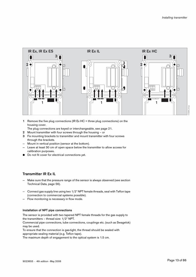
1 Remove the five plug connections (IR Ex HC = three plug connections) on the housing cover.The plug connections are keyed or interchangeable, see page 21.
2 Mount transmitter with four screws through the housing – or3 Fix mounting brackets to transmitter and mount transmitter with four screws
through the brackets.— Mount in vertical position (sensor at the bottom).— Leave at least 30 cm of open space below the transmitter to allow access for
calibration purposes.● Do not fit cover for electrical connections yet.
Transmitter IR Ex IL
— Make sure that the pressure range of the sensor is always observed (see section Technical Data, page 56).
— Connect gas supply line using two 1/2" NPT female threads, seal with Teflon tape (connection to commercial systems possible).
— Flow monitoring is necessary in flow mode.
Installation of NPT pipe connections
The sensor is provided with two tapered NPT female threads for the gas supply to the transmitters – thread size: 1/2" NPT.Commercial pipe connections, tube connections, couplings etc. (such as Swagelok) may be used.To ensure that the connection is gas-tight, the thread should be sealed with appropriate sealing material (e.g. Teflon tape). The maximum depth of engagement to the optical system is 1.5 cm.
3
2
1 1
3
2
1
IR Ex, IR Ex ES IR Ex IL IR Ex HC
3
0112
36
55
_04
.eps

Installing transmitter
Page 14 of 86 9023655 - 4th edition - May 2006
Installation with hard pipe connections
● Protect the transmitter against mechanical damage.● Observe dead weight of the transmitter.
Installation for in-line operation● For calibration of the transmitter the gas supply line should be equipped with
3-way valves with shut-off capability.
Installation for diffusion operation— Use of the maintenance opening, page 15.
Mounting to a wall
● Gas supply must be flexible – tubing, flexible gas-tight conduit etc.
00
42
36
55
_04
.eps
00
52
36
55
_04
.eps
00
62
36
55
_04
.eps

9023655 - 4th edition - May 2006 Page 15 of 86
Installing transmitter
1 Attach to holding plate using appropriate spacers.— Mount in vertical position (sensor at the bottom).
Using the maintenance opening for gas inlet in diffusion operation
A sealing plug (maintenance opening) is provided at the rear of the sensor for maintenance and inspection of the optical system.Thread size: G 3/4This maintenance opening can be used for diffusion operation:
● Screw gas supply connecting piece with G 3/4 male thread to maintenance opening.
● Make sure that the connecting piece between sensor and the duct to be monitored is as short as possible.
● Seal the two NPT openings with an appropriate sealing plug.● Make sure that the transmitter is protected against mechanical damage.● Observe dead weight of the transmitter.
The response time of the instrument may be considerably increased when the maintenance opening is used as gas inlet.
Installing gas path with shut-off valves for calibration
especially in case of pipe installation, the gas path should have shut-off valves.Then the maintenance opening is used as gas inlet during calibration.
Polytron IR Ex
ESC
1
007
23
65
5_0
4.e
ps0
08
23
65
5_0
4.e
ps0
09
23
65
5_0
4.e
ps

Installing transmitter
Page 16 of 86 9023655 - 4th edition - May 2006
Mounting IR Ex display unit
Remove cover:● Remove four screws, lift off cover.1 Mount display unit with four screws through the housing –
or2 fix mounting brackets to display unit and mount display unit with four screws
through the brackets.
Mounting IR junction box
Remove cover:● Remove four screws, lift off cover.1 Mount IR junction box with four screws through the housing –
or2 fix mounting brackets to IR junction box and mount IR junction box with four
screws through the brackets.
2
1
012
23
65
5_0
4.e
ps
2
1
013
23
65
5_0
4.e
ps

9023655 - 4th edition - May 2006 Page 17 of 86
Electrical connections
Electrical connections
— Routing and connecting the electrical installation must only be done by trained personnel, observing appropriate regulations –use 2, 3 or multi-core, screened cable (braided screen, cover ≥80 %,).
— When installing the transmitter, proper grounding has to be ensured.— Covers of transmitter (display unit, IR junction box) should not be put back on yet.
On the transmitter:1 Remove two screws from the terminal cover.2 Remove terminal cover.— Connect according to the applicable procedure below.
When using 4-wire-connection:● Remove blind plug on transmitter.3 Screw second cable gland (accessory, see Order List) into housing and secure
with nut.
Remarks concerning the cable glands:— The cable glands are part of the ex-approved transmitter and must be purchased
at Dräger Safety AG & Co. KGaA exclusively (see "Order list", page 72). Other cables glands must not be used, otherwise the ex-approval is infringed.
— The cable glands are only approved to be used for fixed installation.— The cable gland is suitable for cable diameters of 6 to 12 mm.
For cable diameters of 13 to 15 mm the cable gland must be replaced by Dräger cable gland (part-no. 83 11 370) without the inner of the two rings.
Connecting the transmitter to the central controller
● Connect to the central controller using screened cable (braided screen, cover ≥80 %, maximum outside diameter 15 mm).
1
1
2
014
23
65
5_0
4.e
ps
3
015
23
65
5_0
4.e
ps

Electrical connections
Page 18 of 86 9023655 - 4th edition - May 2006
3-wire connection:— The cable resistance per core for the connection to transmitter terminals K1 and K3 must not exceed:
Rmax = (U0[V] – 13) x 2 Ω per core (e.g. 22 Ω per core at 24.0 V)U0 is the power supply at the central controller.
— The cable resistance for the connection to the transmitter terminal K4 must not exceed 450 Ω (individual internal resistance of the central controller).
● Connect screen to terminal E of the transmitter.— Ground the transmitter via external terminal, but do not ground screen at the central controller or do not ground transmitter
via external terminal, but ground screen in the central controller.
K1K3K4 E
K1K3K4EK1
K3K4 E
IR Ex, IR Ex ES
IR Ex IL
IR Ex HC
K1K3K4 E
Supply unit24 V ±20 % , 0.3 A
+ 24 V 0 V
0 V
4...20 mA
Central controller01
82
36
55
_04
_en.
eps

9023655 - 34th edition - May 2006 Page 19 of 86
Electrical connections
4-wire connection— The cable resistance per core for the connection to transmitter terminals K1 and K2 must not exceed:
Rmax = (U0[V] – 13) x 2 Ω per core (e.g. 22 Ω per core at 24.0 V)U0 is the power supply at the central controller.
— The cable resistance per core for the connection to the transmitter terminal K3 and K4 must not exceed 350 Ω individual internal resistance of central controller).
● Connect screen to terminal E of the transmitter.— Ground the transmitter via external terminal, but do not ground screen in the central controller or do not ground transmitter
via external terminal, but ground screen in the central controller.
K1
K3K4
E
K2
K3K4E
EK1K2
0 V
Supply unit24 V ±20 % , 0.3 A
+ 24 V 0 V
4...20 mA
Central controller
IR Ex, IR Ex ES
IR Ex IL
IR Ex HC
K1
K3K4
E
K2
K1
K3K4
E
K2
019
23
65
5_0
4_e
n.ep
s

Electrical connections
Page 20 of 86 9023655 - 4th edition - May 2006
Connecting transmitter and remote IR Ex display unit
— Intrinsically safe circuit; observe regulations applicable regarding routing.— The length of the cable must not exceed 30 m. — The following cable specifications must not be exceeded: Lmax = 100 μH, Cmax = 100 nF
1 All three cables must be looped through the ferrite core once, following the same direction.● Connect screen to terminal E of the transmitter and terminal E of the display unit.
K1K2K3
K13K11K12
K12
K11 K13
K1
K2
K3
E
E
E
E
1
02
02
36
55
_04
_de.
eps

9023655 - 4th edition - May 2006 Page 21 of 86
Electrical connections
Connecting transmitter and IR junction box for hand-held terminal IR
— Intrinsically safe circuit; observe regulations applicable regarding routing.— The length of the cable used should not exceed 30 m. — The following cable specifications must not be exceeded:
Lmax = 100 μH, Cmax = 100 nF● Connect screen to terminal E in transmitter.
After connecting electrical installation:
1 Screw terminal cover back on to transmitter, two screws.● Reconnect five plug connections (IR Ex HC = three plug connections) on the
housing cover,where:
2 Sensor cable (7-pin plug)
Not IR Ex HC:3 Heater cable (2-pin socket). Polarity does not matter.4 Heater cable (2-pin socket). Polarity does not matter.
These heater cables are interchangeable.
5 Supply cable6 Cable to infra-red source (3-pin socket). Polarity does not matter .
Note: if cable 6 (infra-red source) is connected when the power supply is switched on, the infra-red source may switch off. In this case, disconnect plug 5 (supply cable) from the printed board for about 10 seconds.Then reconnect plug 5.
K1
K2
K3
K1 K2 K3
K13K11K12
K13
K12
K11E
E
021
23
65
5_0
4.e
ps
2
1
5 63 4
02
22
36
55
_04
.eps

Electrical connections
Page 22 of 86 9023655 - 4th edition - May 2006
Screw all housing covers back on transmitter, the remote display unit and on to the IR junction box:
● Each housing cover is secured with four screws – do not pinch any cables!
Accessories
IR Ex, IR Ex ES only
The transmitter comes with a dust filter for protection against dust, splash water and salt mist.To ensure optimum sensor functioning under various operating conditions the following configurations and accessories are recommended:
Factory installed dust filterRecommended for indoor applications without direct exposure to water – class of protection: IP 63.Since the self-test of the transmitter cannot detect any build-up of deposit on the dust filter, it is necessary to visually inspect the dust filter on a regular basis.It is possible to remote-calibrate the transmitter – connect tubing for remote calibration, page 23.NOTE: A calibration adapter is required for calibrating at wind speeds exceeding 1.5 m/s (300 ft/min).
Dust filter, removedEnsures extremely short response times – see response times in "Technical Data", page 58.Only recommended for dust-free indoor applications – class of protection: IP 53.Remove dust filter, page 23.The self-test of the transmitter can automatically detect build-up of deposit on the optical system.It is not possible to remote-calibrate the transmitter.A calibration adapter is required for calibrating the sensor.
Dust filter and splash guard fittedSuitable for applications with splashwater or water jets – class of protection: IP 65.Fit splash guard, page 23.Since the self-test of the transmitter cannot detect any build-up of deposit on the dust filter, it is necessary to visually inspect the dust filter on a regular basis. For this, the splash guard has to be removed.It is possible to remote-calibrate the transmitter – connect tubing for remote calibration, page 23.NOTE: A calibration adapter is required for calibrating at wind speeds exceeding 1.5 m/s (300 ft/min). For this, the splash guard has to be removed.
Polytron IR Ex
ESC
02
32
36
55
_04
.eps

9023655 - 4th edition - May 2006 Page 23 of 86
Electrical connections
Removing dust filter
1 Loosen screw on protective screen.2 Twist protective screen and pull off to the right.3 Hold dust filter in the hand and pull off to the right, gently twisting back and forth.2 Fit protective screen again and secure it with the screw.
Fitting splash guard
Accessory, order separately
● Slide support plate from front on to sensor base.
● Slide splash guard onto sensor until it fits into support plate.● Secure splash guard with 2 screws.
Connecting tubing for remote calibration
● Fit tubing from gas supply system to the gas inlet at the sensor and secure. The fitted dust filter is absolutely necessary for remote calibration.
1
3
2
024
23
65
5_0
4.e
ps0
25
23
65
5_0
4.e
ps0
26
23
65
5_0
4.e
ps0
272
36
55
_04
.eps

Initial Operation
Page 24 of 86 9023655 - 4th edition - May 2006
Initial Operation
● Switch on power supply.
● Analog Output:— Fault signal for approx. 30 seconds; after that normal operation (see
Measurement)
Display on transmitter (display unit, hand-held terminal):— for 30 seconds display »SYSTEM TEST AND INITIALIZATION«, after that normal
operation (see Measurement).
● Check zero point calibration; calibrate zero point, if necessary – see "Operating Functions for Maintenance and Configuration", page 37.
● Check analog output – see "Operating Functions for Maintenance and Configuration", page 41.
● Check that displayed value on transmitter (display unit, hand-held terminal) and central controller match.If necessary:Calibrate analog output – see "Operating Functions for Maintenance and Configuration", page 45.
The transmitters are factory calibrated and configured (see label on transmitter).Changing configuration – see "Operating Functions for Maintenance and Configuration", page 48.
Measurement
— The current output of the transmitter during normal operation is between 4 and 20 mA and is proportional to the detected concentration.
— Polytron IR Ex transmitter uses different current values to indicate various modes of operation.:
— If values fall below the measuring range, a current with a minimum of 3.5 mA flows through the output.
Note:As the transmitter briefly (approx. 100 ms) delivers current of up to 12 mA to the central controller when the power supply is switched on, the alarm limits set at the central controller may be exceeded.
Meaning: Current at configurationFault signal 3 mA
Current at configurationFault signal 1 mA
Fault ≤3 mA 1 ±0.2 mA
Warning (maintenance required) 10 s measuring signal and 3 s calibration signal
10 s measuring signal and 3 s 2 ± 0.2 mA or 2 ± 0.2 mA constant
Calibration signal 2 to 5 mA oscillating at 1 Hz 3 ±0.2 mA
Zero point 4 mA 4 mA
Full scale of measuring range 20 mA 20 mA
Measuring range exceeded >20 mA >20 mA

9023655 - 4th edition - May 2006 Page 25 of 86
Initial Operation
— Display on transmitter (display unit, hand-held terminal):measured value, measurement unit and gas type, e.g.
During measurement the following special symbols may be displayed:
— When the set measurement range has been exceeded: » Y Y Y Y «, e.g.:
— When there is a warning or some information » i «, e.g.:Display of warning or information in plain text – see "Operating Functions for Maintenance and Configuration", page 41.
— When there is an instrument fault » F «, e.g.:
— Display of error code during measurement:Press and hold down the [ ESC ] key, display e.g.:
— Display of error messages in maintenance menu, see "Operating Functions for Maintenance and Configuration", page 42.Error messages are reset automatically when the cause is removed.
— If calibration signal is transmitted to central controller instead of a measured value, » Z «, e.g.:
To switch calibration signal on and off, see "Operating Functions for Maintenance and Configuration", page 40.
0.0 % LELPROPANE
Y Y Y Y % LELPROPANE
0.0 % LEL iPROPANE
_ _ _ _ % LEL FPROPANE
ERROR-CODE F [ 00 02 00 0A ]
0.0 % LEL ZPROPANE

Maintenance Intervals
Page 26 of 86 9023655 - 4th edition - May 2006
Maintenance Intervals
● EN 50073 and the national regulations in the country of use must be observed.
Daily● Visual check to determine readiness for operation.
Immediately before operation● Check zero calibration, page 37.● Check analog output, page 41.● Check that displayed value on transmitter (display unit, hand-held terminal)
and central controller match.If there is a deviation:Calibrate analog output, page 45.
At regular intervals,as specified by persons responsible for the maintenance of the gas warning system, recommendation: every six months:● Check zero point and sensitivity calibration, page 37 to page 38.
● It is possible to extend the recommended calibration interval to more than 6 months provided that:After a maximum period of use of 6 months it must be checked if (in this particular application) the gas supply to the optical system may be blocked due to e.g. dust or oil. If the operation of the device is not affected by such effects the calibration interval may be extended to a maximum of 12 months.
When using the transmitter for methane measurement in the 0 to 20 % LEL range, if the average operating temperatures vary greatly (e.g. by more than 20 K seasonally), it should be recalibrated at the different average operating temperatures in order to comply with the error limits according to EN 50057.
It is only possible to extend the calibration interval if no blocking of the gas supply to the optical system due to e.g. dust or oil can happen in this particular application during the period between two calibrations.
Every six months● Check output interface, page 41.
Check that display on transmitter (display unit, hand-held terminal) and central controller match.If there is deviation:Calibrate analog output, page 45.
● Check dust filter; replace if necessary (not IR Ex IL), page 28.

9023655 - 4th edition - May 2006 Page 27 of 86
Maintenance Intervals
Annually● Inspection by trained personnel.
The inspection intervals in each individual case are subject to technical safety considerations, engineering processes and the technical requirements for the equipment.We recommend a contract with DrägerService which also covers repairs.

Maintenance
Page 28 of 86 9023655 - 4th edition - May 2006
Maintenance
Replacing dust filter
IR Ex and IR Ex ES transmittersWhen fitted, disconnect splash guard:
● Unscrew 2 screws on splash guard.● Remove splash guard.
1 Loosen screw on protective screen slightly.2 Twist protective screen and pull off to the right3 Hold dust filter in the hand and pull off to the right, gently twisting back and forth.● Push new dust filter over sensor gently twisting back and forth –
the dust filter must not get torn!● Put protective screen back in place and secure with screw.● Fit splash guard back.
02
82
36
55
_04
.eps
1
3
2
02
92
36
55
_04
.eps

9023655 - 4th edition - May 2006 Page 29 of 86
Maintenance
Cleaning the optical system
IR Ex and IR Ex ES transmittersThe dust filter protects the optical system on the IR Ex Dräger sensor against build-up of deposit. The mirrors and lenses have to be cleaned if the transmitter gives an appropriate warning.
● In order to suppress a false alarm while cleaning the optical system: Set calibration signal: menu item »CALIBRATION SIGNAL«, »ON«, page 40.
● To remove splash guard and dust filter, proceed like previously described "Replace dust filter", page 28.
● Blow off any loose particles with clean, dry air.● Rinse optical system with distilled water – if necessary clean with alcohol or
mild detergent – when heavily soiled clean with a lint-free soft cloth.
● Fit new dust filter.● Put protective screen back in place and tighten screw.● Put splash guard back in place.
03
02
36
55
_04
.eps
03
22
36
55
_04
.eps

Maintenance
Page 30 of 86 9023655 - 4th edition - May 2006
IR Ex IL transmitterIt is absolutely necessary to protect the optical system from particles and aerosols by preparing the sample gas appropriately.When there is build-up of deposit on the optical system, the transmitter gives a warning.
● In order to suppress a false alarm while cleaning the optical system: Set calibration signal: menu item »CALIBRATION SIGNAL«, »ON«, page 40.
● Open maintenance plug at rear of optical system – if necessary, remove transmitter from installation.
● Blow off any loose particles in the optical system with clean, dry air (do not exceed the maximum pressure of the optical system).
● Rinse optical system with distilled water – if necessary, clean with alcohol or mild detergent.Vent out excess alcohol or cleaning liquid or let them dry.
● Check the result of the cleaning process with special mirror, if necessary repeat cleaning procedure.
● Re-install maintenance plug, if necessary replace gasket. Re-install transmitter.
IR Ex, IR Ex ES and IR Ex IL transmitters:
After cleaning the optical system:● The amplification of the sensor signal has to be adjusted:
menu item »PREAMPLIFIER ADJ.«, page 44.● Perform zero point calibration: menu item »CALIBR. ZERO«, page 37.● Carry out sensitivity calibration:
menu item »CALIBR.SENSITIVITY«, page 38.
● Cancel calibration signal: menu item »CALIBRATION SIGNAL«, »OFF«, page 40.● Return to measurement mode, page 34.
03
32
36
55
_04
.eps

9023655 - 4th edition - May 2006 Page 31 of 86
Menu Navigation
Menu Navigation
There are six keys on the transmitter (display unit, hand-held terminal):— four cursor keys [ q ], [ l ], [ k ], [ j ],— one Escape key [ ESC ]— one Enter key [ u ].
to change between:— menu items / functions— numbers / letters at the position of the cursor — default valuesuse [ q ], [ l ] keys
to change the position of the cursor:use [ k ], [ j ] keys
to acknowledge:— inputs— messagesuse [ u ] key
use [ ESC ] key to:— return to previous menu— exit a function without accepting changes
Polytron IR Ex
ESC
Polytron IR Ex
ESC
Polytron IR Ex
ESC
IR Ex, IR Ex ES IR Ex IL IR Ex HC
03
42
36
55
_04
.eps

Menu Navigation
Page 32 of 86 9023655 - 4th edition - May 2006
Menu structure
There are two main submenus in the menu structure:MAINTENANCE and CONFIGURATION.
NOTESince maintenance might be performed by staff other than those who configure the system, the instrument has a different password to access each group of functions. However, the password for the submenu configuration also gives the user access to the submenu maintenance.
The default settings of the passwords are:
To change a password see page 52, Changing the Password.
Maintenance MenuThis level gives access to a number of functions for regular maintenance of the transmitter. It is suggested that access be given to service department personnel.Maintenance Menu, page 37
Configuration MenuThis level allows the user to change sensor parameters and to configure the transmitter. It is suggested that access be given to authorized personnel in the measurement and control or health and safety departments. Both the maintenance and the configuration menus can be accessed with the configuration password.Configuration Menu, page 48
MAINTENANCE 1
CONFIGURATION 2

9023655 - 4th edition - May 2006 Page 33 of 86
Menu Navigation
Menu Structure:
MENU:MEASUREMENT:
Password for»MAINTENANCE«
Password for»CONFIGURATION«
MENU:MAINTENANCE:
MENU:CONFIGURATION:
MAINTENANCE:CALIBR. ZERO
CONFIGURATION:GAS CONFIGURATION
MAINTENANCE:CALIBR. SENSITIVITY
CONFIGURATION:TEMP-COEFFICIENT
1)
1) On the IR Ex HC transmitter, this function is carried out solely by DrägerService in the case of sensor replacement.
MAINTENANCE:CALIBRATION-SIGNAL
CONFIGURATION:FAULT SIGNAL
MAINTENANCE:TEST 4-20 mA
CONFIGURATION:ZERO CLAMPING
MAINTENANCE:SHOW WARNINGS
CONFIGURATION:PASSWORD MAINTENANCE
MAINTENANCE:SHOW ERRORS
CONFIGURATION:PASSWORD CONFIG.
MAINTENANCE:SHOW SENSOR-TEMP.
CONFIGURATION:LANGUAGE
MAINTENANCE:PREAMPLFIER ADJ.
CONFIGURATION:DISPLAY
MAINTENANCE:H2O-OFFSET
CONFIGURATION:WARNINGS
MAINTENANCE:CALIBR. 4-20 mA
CONFIGURATION:SPECIAL GAS NAME
MAINTENANCE:SOFTWARE-INFO
MAINTENANCE:DISPLAY TEST
page 37 page 48
page 38 page 50
page 40 page 51
page 41 page 51
page 41 page 52
page 42 page 52
page 44 page 53
page 44 page 53
page 45 page 54
page 45 page 55
page 46
page 47

Menu Navigation
Page 34 of 86 9023655 - 4th edition - May 2006
Entering password
— Display during normal measurement, e.g.:
● Press [ u ] key.
Enter password:— to change number/letter use [ q ] and [ l ] keys.— to change the position of the cursor use the [ j ] key and enter next number/letter.Continue until all numbers/letters of the password are entered: e.g. the default password for maintenance:● Press [ u ] key, instrument changes to menu mode:
The default settings of the passwords are:
To change a password see page 52, Changing the Password.
NOTEThe instrument will continue to monitor the concentration and give a 4 to 20 mA output while navigating through and executing most of the submenu features.
— Depending on the hierarchy level of the password, access for the following menus can be selected, using [ q ] or [ l ] key.Selection: MEASUREMENT, MAINTENANCE or CONFIGURATION
● Press [ q ] or [ l ] key to change the menu.● Press [ u ] key, to select the menu, e.g.:
● Use [ q ] or [ l ] keys, to navigate within the submenus, e.g.:
● Press [ u ] key, to access a function , e.g.:
The different functions in the maintenance and configuration menus are described in detail below.
● Press [ ESC ] key – to return to the next higher menu level, e.g.:
When pressing the [ ESC ] key several times, the instrument will go to the top level (measurement menu).
● To return to the measurement mode, press the [ u ] key once, and the instrument will display the currently detected value, e.g.:
MAINTENANCE 1
CONFIGURATION 2
0.0 % LELPROPANE
PASSWORD ? _
PASSWORD 1
MENU: MEASUREMENT:
MENU: MAINTENANCE
MAINTENANCE: CALIBR. ZERO
MAINTENANCE: SHOW SENSOR-TEMP
SENSOR-TEMPERATURE: 20.4 DEGREES
MAINTENANCE: SHOW SENSOR-TEMP
MENU: MEASUREMENT:
0.0 % LELPROPANE

9023655 - 4th edition - May 2006 Page 35 of 86
Menu Navigation
Entering Numbers
For some of the functions it is necessary to enter numbers. Whenever such an entry is required, the end of the first line in the display will show a question mark. At the same time the second line displays the last entry with a blinking cursor under one of the numbers, e.g.:
● Use the [ k ] or [ j ] keys, to change the position of the cursor. It will skip over any decimal point.
● Use the [ q ] or [ l ] keys, to change the number at the position of the cursor.Entries which do not make sense, such as » .1 «, » -2-.22 «, »-.3«, »44.-4« will not accepted.Keeping a key pressed is regarded as repeated activation of that key.
● Press [ u ] key, the number set is accepted and verified whether it is within the permissable range.If the number entered is outside the permissible range a message will be shown.
● Press [ u ] key, to acknowledge the message – the number set previously will be shown.
Entering Text
For some of the functions it is necessary to enter text. Whenever such an entry is required, the end of the first line in the display will show a question mark. At the same time the second line displays the last entry with a blinking cursor under the last letter of the text, e.g.:Exception: when entering a password while in measurement no text will be displayed. The second line is blank.
● Use the [ k ] or [ j ] keys, to change position of the cursor.● Use the [ q ] or [ l ] keys, to change the letter at position of the cursor.
Pressing the [ q ] or [ l ] key before pressing the [ k ] or [ j ] key will delete the whole text.
Keeping a key pressed, this is regarded as repeated activation of that key.
● Press [ u ] key, to accept the entry.
Entering Decisions
For some of the functions it is necessary to enter a decision. Whenever such an entry is required, the end of the first line in the display will show a question mark. At the same time the second line displays the options. They are separated by » / «. The cursor is on the "safe" position, where no changes would be accepted, e.g.:
● Press [ k ] key, to change the position of the cursor.● Press [ u ] key, to accept the decision.
CALIBR. GAS CONC. ? 40.0 % LEL
PASSWORD ? DAVID
100 % CORRECT ? Y / N

Menu Navigation
Page 36 of 86 9023655 - 4th edition - May 2006
Entering Options
For some of the functions it might be necessary to choose an option. Whenever such a situation occurs, the first line in the display will show a question mark. At the same time, the second line shows the last selection. The cursor is not shown, e.g.:
● Use the [ q ] or [ l ] key, to select a different option, e.g.:Keeping a key pressed, this is regarded as repeated activation of that key.
● Press [ u ] key, to accept the selected option.
Handling Messages
Within some functions, messages are issued. They are identified by an exclamation point at the end of the text, e.g.:
● Press [ u ] key, to acknowledge the message.
DISPLAY ? ON
DISPLAY ? OFF
INPUT VALUE TOO LARGE !

9023655 - 4th edition - May 2006 Page 37 of 86
Menu Navigation
Maintenance Menu
The maintenance menu contains all functions which are necessary for regular maintenance of the transmitter.
Calibrating zero point
When this function is activated, the 4 to 20 mA output changes from concentration to the calibration signal.
Zero gas:Nitrogen or alternatively synthetic air (compressed air) with a hydrocarbon content under 50 ppm may be used to calibrate the zero point.When using ambient air to calibrate the zero point, it is important to ensure that there are no hydrocarbons in the vicinity of the transmitter.
IR Ex, IR Ex ES1 In still air and with a dust filter fitted: apply zero gas to the gas connector into
the sensor at a flow of approx. 3 L/min (not evaluated in the 1st supplement to EC type test certificate DMT 02 ATEX E 0178X).or
2 Attach calibration adapter 68 08 667 and apply zero gas to the sensor at a flow of approx. 0.5 L/min.
IR Ex IL● Apply zero gas into the sensor at a flow of approx. 0.5 L/min.
IR Ex HC— With adapter 68 09 240 and calibration adapter 68 06 978● Apply zero gas to the calibration adapter at a flow of approx. 0.5 L/min.
Note:As the zero point can be set even with very low calibration gas concentrations, zero gas should never be confused with calibration gas.
ESC
2
1
03
52
36
55
_04
.eps
03
62
36
55
_04
.eps
68 09 240
037
23
65
5_0
4.e
ps

Menu Navigation
Page 38 of 86 9023655 - 4th edition - May 2006
All transmitters● Select function.
● Press [ u ] key to access the function, display:● Apply zero gas to sensor.● Press [ u ] key to acknowledge the message.● Wait until the displayed value stabilizes (up to 3 minutes), confirm decision
with "yes" (Y)● Press [ u ] key● Press [ u ] key to acknowledge the message.
Tolerances:
IR Ex, IR Ex ES, IR Ex IL
IR Ex, IR Ex IL, full scale of range 5 to 100 % by vol. methane: ± 0.1 % by vol
IR Ex HC: ±1 % LEL
If display of new measured value is within tolerance:● Confirm decision with "yes" (Y).● Press [ u ] key.● Stop flow through sensor, confirm decision with "yes" (Y).● Wait for current measured value to drop below the alarm limit set at the central
controller and confirm decision with "yes" (Y).● Press [ u ] key.
If display of new measured value is not within tolerance:● Clean optical system (page 29) and repeat the procedure.
Calibrating sensitivity
When this function is activated, the 4 to 20 mA output changes from the concentration to the calibration signal.
Calibration gas:Use standard calibration gas (such as 40 % LEL methane in air or nitrogen with a full scale of range of 100 % LEL methane) to calibrate sensitivity. The concentration of other hydrocarbons in the calibration gas should be less than 50 ppm.The calibration gas concentration can be between 10 % and 100 % of the full scale of measurement, but should if possible be between 40 % and 70 % of the full scale of measurement.
% LEL % by vol. ppm
Methane: ±0.2 ±0.01 - - -
Ethene: ±0.6 ±0.01 - - -
Propane: ±0.1 ±0.01 ±10
MAINTENANCE: CALIBR. ZERO
APPLY NITROGENTO SENSOR !
VALUE CONSTANT ? 2.05 Y / N
NEW CALIBRATION- FACTOR STORED !
VALUE OK ? 0.03 Y / N
STOP GAS FLOW ? Y / N

9023655 - 4th edition - May 2006 Page 39 of 86
Menu Navigation
● Pay attention to expiration date of the calibration gas cylinder.— Cross calibration for gases and vapours: see page 64● Follow correct sequence. Firsts check zero point and, if correction is necessary,
immediately check sensitivity and calibrate, if necessary.Never calibrate sensitivity before zero point.
— Please pay attention to the information about cross sensitivity to humidity in the section "Technical Data" for ethene, page 58.
IR Ex, IR Ex ES1 In still air and with a dust filter fitted: apply calibration gas to the gas connector
into the sensor at a flow of approx. 3 L/min (not evaluated in the 1st supplement to EC type test certificate DMT 02 ATEX E 0178X).or
2 Attach calibration adapter 68 08 667 and apply calibration gas to the sensor at a flow of approx. 0.5 L/min.
IR Ex IL● Apply calibration gas into the sensor at a flow of approx. 0.5 L/min.
IR Ex HC— With adapter 68 09 240 and calibration adapter 68 06 978, vent calibration
gas safely to the outside via a tube.● Apply calibration gas through the calibration adapter at a flow of approx.
0.5 L/min.
Note:The calibration gas concentration should not be below 14 % LEL methane for a full scale of measurement of 20 % LEL methane (IR Ex, IR Ex IL).
Caution:Never inhale calibration gas. Health hazard.Refer to appropriate Material Safety Data Sheets for handling calibration gas.
ESC
2
1
03
52
36
55
_04
.eps
03
62
36
55
_04
.eps
68 09 240
037
23
65
5_0
4.e
ps

Menu Navigation
Page 40 of 86 9023655 - 4th edition - May 2006
All transmitters● Select function.
● Press [ u ] key to access the function, display:● Use the cursor keys to enter the actual concentration of calibration gas. The
concentration used for the last calibration will be shown.● Apply calibration gas to sensor.● Press [ u ] key to acknowledge the message.● Wait for measured value to stabilize (up to 3 minutes), then confirm decision
with "yes" (Y).● Press [ u ] key.
● Press [ u ] key to acknowledge the message.
Tolerances:IR Ex, IR Ex ES, IR Ex IL: ±2 % of concentration of calibration gasIR Ex HC: ±1 % of concentration of calibration gas
If the display of the new measured value is within tolerance:● Confirm decision with "yes" (Y).● Press [ u ] key.● Stop gas flow to sensor.● Confirm decision with "yes" (Y).
If the display of the new measured value is not within tolerance:● Clean optical system (page 29) and repeat the procedure.
Configuring the calibration signal
This function is used to switche the calibration signal on, e.g. at maintenance.
If the calibration signal is activated the » Z « symbol is displayed in the upper right corner of the display.
● Select function.
● Press [ u ] key, to access the function and display the configuration:
● Use the [ q ] or [ l ] key to select "ON" or "OFF".● Press [ u ] key to accept the selection and exit the function.
MAINTENANCE: CALIBR. SENSITIVITY
CALIBR. GAS CONC. ? 40.0 % LEL
APPLY TO SENSOR40 % LEL !
VALUE CONSTANT ? 35.8 Y / N
NEW CALIBRATION- FACTOR STORED !
VALUE OK ? 39.8 Y / N
STOP GAS FLOW ? Y / N
MAINTENANCE: CALIBRATION-SIGNAL
CALIBRATION-SIGNAL ? OFF

9023655 - 4th edition - May 2006 Page 41 of 86
Menu Navigation
Checking 4 to 20 mA analog interface
This submenu allows the user to check the 4 to 20 mA output and its connection to the controller (e.g. to check the tripping of alarms).The analog output of the transmitter can be set to any value within a range of 1.0 to 24.0 mA.It is important to end the »Checking the interface« function correctly as described, to ensure that the transmitter delivers the gas concentration at the output again.Alternatively, instead of performing this test, the voltage can be measured across the measuring points X2 (see calibrating output interface, page 45).Where the values set for the current do not match the measured current, the output interface must be calibrated, page 45.
● Select function.● Press [ u ] key to access the function:
● Inhibit alarms at central controller, confirm decision with "yes" (Y).● Press [ u ] key:
The current output will be set to 4 mA. The current output can be changed in steps of 0.1 mA:
● Use the [ q ] or [ l ] key to change the value.Keeping a key pressed is regarded as repeated activation of that key.After 3 seconds the value will change in steps of 1 mA.
● Press [ u ] or [ ESC ] key to leave the function:● Enablen alarms at central controller, confirm decision with "yes" (Y) ● Press [ u ] key.
Display warnings
This function is used to display any warning in plain text.If there is a warning message available, the » i « symbol will be displayed in the upper right hand corner of the display.Warning messages offer an opportunity for the operator to perform preventive maintenance.
● Select function.● Press [ u ] key to access the function:
● Press [ u ] key.The function terminates.
MAINTENANCE: TEST 4-20 mA
ALARM DISABLED ? Y / N
CURRENT VALUE ? 4.0 mA
ALARM ENABLED ? Y / N
MAINTENANCE: SHOW WARNINGS

Menu Navigation
Page 42 of 86 9023655 - 4th edition - May 2006
Possible warning message:
Cause:The signals of the detectors are too small.Remedy:Clean optical system (not IR Ex HC), see Maintenance, page 28. Set pre-amplification, page 44.Calibrate zero point and sensitivity, page 37 to page 38.
Display errors
This function is used to identify an error by a code.If there is a error message available, the » F « symbol will be displayed in the upper right hand corner of the display.
● Select function.● Press [ u ] key to access the function:
● Press [ u ] key to display the next message. The function automatically terminates if there are no more message.
Possible error messages:» ERROR-CODE 1 «to» ERROR-CODE 17 «see Table.
Error code Cause Remedy
ERROR CODE 1 Internal electronics fault Call DrägerService for repair.
ERROR CODE 2 The signals of the detectors are too small Clean optical system, see page 29.Set pre-amplification, page 44.Then calibrate zero point and sensitivity, page 37.If operating in fine dust or corrosive atmospheres, call in DrägerService to check the condition of the sensor if necessary.
ERROR CODE 3 Internal electronics fault Call DrägerService for repair
ERROR CODE 4 Internal electronics fault Call DrägerService for repair
ERROR CODE 5 Gas type 1), temperature coefficient or check sum do not match
1) not IR Ex HC transmitter.
Check1) temperature coefficient and check sum, page 48.
ERROR CODE 6 Internal electronics fault Call DrägerService for repair
IR-BEAMREDUCTION !
MAINTENANCE: SHOW ERRORS
ERROR-CODE1 !

9023655 - 4th edition - May 2006 Page 43 of 86
Menu Navigation
Error code Cause Remedy
ERROR CODE 7 Internal electronics fault Call DrägerService for repair
ERROR CODE 8 Internal electronics fault Call DrägerService for repair
ERROR CODE 9 Temperature measurement is faulty Check connection of sensor plug, page 21.
ERROR CODE 10 Signal of reference detector too low Check connection of sensor plug, page 21.Check infra-red source (plug)page 211).Clean optical system, see page 291).Set pre-amplification, page 44.Then calibrate zero point and sensitivity, page 37.If operating in fine dust or corrosive atmospheres, call in DrägerService to check the condition of the sensor if necessary.
ERROR CODE 11 1)
1) not transmitter IR Ex HC.
Heater not connected Connect heater cable correctly, page 21.
ERROR CODE 12 Signal of reference detector outside permissible range
Set pre-amplification, page 44, and calibrate zero point and sensitivity, page 37.
ERROR CODE 13 Signal of measuring detector outside permissible range
Set pre-amplification, page 44, and calibrate zero point and sensitivity, page 37.
ERROR CODE 14 Signal of measuring detector too high Set pre-amplification, page 44, and calibrate zero point and sensitivity, page 37.
ERROR CODE 15 Signal of reference detector too high Set pre-amplification, page 44, and calibrate zero point and sensitivity, page 37.
ERROR CODE 16 Transmitter has calculated a high negative concentration
Check connection of sensor plug, page 21.Set pre-amplification, page 44, and calibrate zero point and sensitivity, page 37.

Menu Navigation
Page 44 of 86 9023655 - 4th edition - May 2006
Display sensor temperature
This function is used to display the actual sensor temperature.
● Select function.
● Press [ u ] key to access function:
● Press [ u ] or [ ESC ] key to end the function.
Adjust pre-amplification
This function is used to optimize signal pre-amplification.This must be followed, for instance, after cleaning the optical system.IR Ex HC transmitter: DrägerService only.When this function is activated, the 4 to 20 mA output changes to the maintenance/calibration signal.
● Apply synthetic air or nitrogen, free from hydrocarbon gases or vapours, to the sensor (see page 37).
● Select function.
● Press [ u ] key to access the function –display shows the current pre-amplification factors, e.g.:
● Press [ u ] key, the best pre-amplification is determined (takes about 20 seconds). Display:
Then new pre-amplification factors are displayed, e.g.:
● Press [ u ] key to access the Delay function.The current delay values are displayed, e.g.:
● Press [ u ] key to determine and display the new delay values, e.g.:
● Press [ u ] key to save the new delay values.
● Press [ u ] key to end the function.
Note:The zero point and sensitivity should be calibrated after adjusting the pre-amplification.
MAINTENANCE: SHOW SENSOR-TEMP.
SENSOR-TEMPERATURE: 20.4 DEGREES
MAINTENANCE: PREAMPLIFIER ADJ.
OLD PREAMPL FACTORS: REF: 1 SIG: 4
SEARCHING FORPREAMP FACTORS !
NEW PREAMPL FACTORS: REF: 5 SIG: 5
OLD DELAY-VALUES: REF: 42 SIG: 43
NEW DELAY-VALUES: REF: 42 SIG: 45

9023655 - 4th edition - May 2006 Page 45 of 86
Menu Navigation
Setting H2O offset
This function is not used with the IR Ex HC transmitter.
When using the transmitter in the ethene gas category, the IR sensor may have a cross-sensitivity to water vapour. This can be corrected by using a wet zero gas and entering a numerical value (–99 to +100). The measured value will then automatically be corrected by this offset.Apply wet zero gas with a humidity corresponding to the typical humidity of the gas to be measured to the sensor and wait for the measured value to stabilize (up to 3 minutes). Read the average value of the display (H2O offset) in % LEL, round to an integer and enter the value as the H2O offset.
● Select function.
● Press [ u ] key to access the function.
● Press [ q ] or [ l ] key to enter the rounded value as the H2O offset.
● Press [ u ] key to confirm the value.
● Press [ u ] key to save the value. Display:
● Press [ u ] key to end the function.
Calibrating analog output
This function is used to calibrate the analog output of the transmitter.It is important to end the »Calibrating the interface« function correctly as described, to ensure that the transmitter delivers the gas concentration at the output again.
● Select function.● Press [ u ] key, to access the function:
● Inhibit alarms at central controller, confirm decision with "yes" (Y)
● Press [ u ] key:
MAINTENANCE: H2O-OFFSET
H2O-OFFSET ? 0 % LEL
H2O-OFFSET STORED !
MAINTENANCE: CALIBR. 4-20 mA
ALARM DISABLED ? Y / N
MEASURE REALVALUE AT X2 !

Menu Navigation
Page 46 of 86 9023655 - 4th edition - May 2006
● Remove cover of the transmitter, see page 12.● Measure voltage across measuring points X2.
Conversion to current: I = UX2 ÷ 10 Ω
Acknowledge message.● Press [ u ] key:
● Enter measured voltage – acknowledge entry● Press [ u ] key:
Acknowledge message● Press [ u ] key:
Confirm the value● Press [ u ] key:
● Enter measured voltage – acknowledge entry● Press [ u ] key:
Acknowledge message.● Press [ u ] key:
Confirm the value● Press [ u ] key:● Enable alarms at central controller, confirm decision with "yes" (Y).● Press [ u ] key:
Display software-specific information
This function contains all information related to the transmitter software:part number, version number and check sum.
● Select function.● Press [ u ] key to access the function.
● Press [ u ] key to display the part number, version number and check sum, e.g.:
● Press [ u ] key to end the function.
X2
mV
03
82
36
55
_04
.eps
40 mV REAL VALUE 42.7
NEW CALIBRATION- FACTOR STORED !
40 mV VALUE OK ? Y/ N
200 mV REAL VALUE 196.2
NEW CALIBRATION- FACTOR STORED !
200 mV VALUE OK ? Y / N
ALARM ENABLED ? Y / N
MAINTENANCE: SOFTWARE-INFO
8315123 REV. 1.0 CHECKSUM : 12345 !

9023655 - 4th edition - May 2006 Page 47 of 86
Menu Navigation
Testing the display
This function is used to check each pixel of the LC-display.
● Select function.
● Press [ u ] key to access the function:
● Press [ u ] key to obtain informations how to start and end the display test:
● Press [ u ] key to observe the alternatively activated pixels of the display. Faulty pixels can by identified.Display test keeps being activated until [ESC] key is pressed.
● Press [ESC] key to end the function.
MAINTENANCE: DISPLAY TEST
DISPLAY TEST ON: ENTER OFF: ESC

Menu Navigation
Page 48 of 86 9023655 - 4th edition - May 2006
Configuration Menu
The configuration menu contains all functions which are necessary to configurethe transmitter to application specific requirements. (Menu Structure, page 32).
Changing gas configuration
This function is used to change gas type, engineering units and measuring range.Engineering units and the measuring range can be set to any value within the specified limits
When changing the engineering unit between % LEL and a volumetric unit (% by vol. or ppm) without recalibrating the sensitivity, a conversion factor is used, see table below:
When this conversion factor cannot be used (e.g. for measuring fuel in the propane gas category), the sensitivity must be recalibrated after changing the engineering unit.
● Enter conversion factor for the gas to be measured (e.g. 2.3 % by vol. for ethene).
Especially if high gas or vapour concentrations should be monitored, it is recommended to recalibrate sensitivity after the range has been changed.
When changing the gas type all temperature coefficients and the check sum must be changed accordingly, otherwise the linearization of the detector signal will not work properly. Then, zero point and sensitivity must be calibrated.If the temperature coefficients and the check sums do not correspond to the gas type, the transmitter will go into error.
Gas type Conversion factor 1)
1) EN 61779-1, addendum A
Adjustment range
Methane 4.4 % by vol. corresponds to 100 % LEL 4.4 – 5.0 % by vol.
Ethene 2.3 % by vol. corresponds to 100 % LEL 2.3 – 2.7 % by vol.
Propane 1.7 % by vol. corresponds to 100 % LEL 1.7 – 2.1 % by vol.
100 % LEL = ?: 2.30

9023655 - 4th edition - May 2006 Page 49 of 86
Menu Navigation
When changing the gas type, the following steps must be taken:1 Switch calibration signal on, page 402 Change gas configuration, page 483 Change temperature coefficient, page 504 Calibrate zero point, page 375 Calibrate sensitivity, page 386 Switch calibration signal off, page 40.
This procedure will prevent incorrect values on the analog output.
● Select function.
● Press [ u ] key, to access the function.● The current configuration is displayed, e.g.:
● Press [ u ] key,
● Use the [ q ] or [ l ] key to select the gas type (e.g. ETHENE)● Press [ u ] key.● Use the [ q ] or [ l ] key to select the engineering unit (e.g. VOL.%)
● Press [ u ] key.● Use the [ q ] or [ l ] keys to set the measurement range (e.g. 2.3 % by vol.):
● Press [ u ] key, to confirm the gas type with "yes" (Y):
● Press [ u ] key, confirm the measuring range and engineering unit with "yes" (Y):
● Press [ u ] key:
● Press [ u ] key to end the function.
CONFIGURATION: GAS CONFIGURATION:
CONFIG.: 100 % LEL METHANE
Gas ? ETHENE
MEASUREMENT UNIT ? VOL. %
MEASUREMENT RANGE ? 2.3
CONFIG. OK ? ETHENE Y/ N
CONFIG. OK ? 2.3 VOL. % Y / N
NEW CONFIGURATION STORED !

Menu Navigation
Page 50 of 86 9023655 - 4th edition - May 2006
Entering temperature coefficients A0 to A2 and their check sums
IR Ex HC transmitter:This function is only used by DrägerServiceafter sensor replacement.
All other transmitters:This function is used after changing the gas type or sensor replacement. The temperature coefficients A0, A1 and A2 and the check sum have to be entered. The temperature coefficients A0 to A2 and the check sum must match with the gas type. Faulty operation will occur when this is not the case. The temperature coefficients and check sum for the different gas types can be found on the label on the side of the sensor.
● Select function.● Press [ u ] key, to access the function.
The current temperature coefficient A0 is displayed, e.g.:Enter appropriate value A0 for the gas type, see label on the side of the sensor.
● Press [ u ] key, to accept value and to display the current temperature coefficient A1, e.g.:Enter appropriate value A1 for the gas type, see label on the side of the sensor.
● Press [ u ] key, to accept value and to display the current temperature coefficient A2t, e.g.:Enter appropriate value A2 for the gas type, see label on the side of the sensor.
● Press [ u ] key, to accept value and to display the check sum, e.g.:Enter apropriate check sum for the gas type, see label on the side of the sensor.
● Press [ u ] key, to display the new values, e.g.: ● Press [ u ] key, to confirm the values with "yes" (Y).
● Press [ u ] key to end the function.
CONFIGURATION: TEMP-COEFFICIENT
Ex-Sensor Polytron IR 68 08 XXXDräger Safety Fabr.–Nr.Methan: –6 / +16 / +2 / 2032Ethen: –47 / +22 / +2 / 2006Propan: +15 / –7 / +2 / 2009
Temperature coefficient A0
Temperature coefficient A1
Check sum
Temperature coefficient A2
03
92
36
55
_04
_en.
eps
CONFIGURATION: TEMP-COEFFICIENT
COEFFICIENT A0 ? –6
COEFFICIENT A1 ? +16
COEFFICIENT A2 ? +2
TC-CHECKSUM ? 2032
INPUT CORRECT ? –6 +16 +2 2032 Y / N

9023655 - 4th edition - May 2006 Page 51 of 86
Menu Navigation
Configuring fault signal
This function is used to configure the fault signal of the transmitter’s analog output. Depending on the fault signal also the calibration signal and the warning signal is changed.
Fault 3 mA (default setting):A transmitter fault is indicated by a current of ≤3 mA.The calibration signal is 1-Hz-pulsed signal between 2 and 5 mA.
Fault 1 mA:A transmitter fault is indicated by a current of 1 ±0.2 mA.The calibration signal is a constant current of 3 ±0.2 mA.
After having configured the fault signal the warning signal is always switched off and has to be switched on or newly configured if necessary (see page 54).
● Select function.● Press [ u ] key to access function:
● Use the [ q ] or [ l ] key to select the setting 1 MA or 3 MA:
● Press [ u ] key to save the new selected setting.Additionally there will be a hint that the warning signal is now switched off.
● Press [ u ] key to end the function.
Configuring zero clamping (positive values)
This function is used to enter a zero clamping (positive values) in cases where a small background concentration is present which could cause a ‘noisy’ zero signal. The clamping can be changed in steps of 1 % between 0 and 5 % of full scale (FS).The default setting is 0 % meaning the zero clmping is switched off.
● Select function.
● Press [ u ] key, to access the function and display the current configuration, e.g.:
● Use the [ q ] or [ l ] key to select a value for the zero clamping, display e.g.:
● Press [ u ] key to save the new value, display:
● Press [ u ] key to end the function.
CONFIGURATION: FAULT SIGNAL
FAULT SIGNAL ? 1 MA
WARNING SIGNAL OFF !
CONFIGURATION: ZERO CLAMPING
ZERO CLAMPING 2 % FS = ZERO
ZERO CLAMPING 1 % FS = ZERO
ZERO CLAMPING STORED

Menu Navigation
Page 52 of 86 9023655 - 4th edition - May 2006
Changing password for the maintenance menu
This function is used to change the password for the »MAINTENANCE« menu.The default setting is "1".
If the default password has been changed, but it got lost:● Call DrägerService.
● Select function.
● Press [ u ] key, to access the function.The current password is displayed, e.g.:
● Enter a new password of up to six characters using the cursor keys, e.g.:
● Press [ u ] key, to save the new password.
● Press [ u ] key to end the function.
Changing password for configuration menu
This function is used to change the password for the »CONFIGURATION« menu.The default setting is "2".
If the default password has been changed, but it got lost:● Call DrägerService.
● Select function.
● Press [ u ] key, to access the function.The current password is displayed, e.g.:
● Enter a new password of up to six characters using the cursor keys, e.g.:
● Press [ u ] key, to save the new password.
● Press [ u ] key to end the function.
CONFIGURATION: PASSWORD MAINTEN.
PASSWORD ? 1
PASSWORD ? DAVID
CONFIGURATION: PASSWORD CONFIG.
PASSWORD ? 2
PASSWORD ? PAUL

9023655 - 4th edition - May 2006 Page 53 of 86
Menu Navigation
Changing the language
This function is used to change the language of the menu-dialog.The following languages are available: German, English, French and Spanish.
● Select function.
● Press [ u ] key, to access the function.The current language setting is displayed, e.g.:
● Use the [ q ] or [ l ] key to select a different language, display e.g.:
● Press [ u ] key, to accept the selected language.
● Press [ u ] key to end the function.
Switching measured value display on and off
This function is used to switch the display of the actual gas concentration, in measurement mode, "ON" or "OFF".When the display of the actual gas concentration is switched off, the display will only read the engineering units and the type of gas. Only the display of the actual gas concentration is suppressed. This has no influence on the analog output.
● Select function.
● Press [ u ] key, to access the function and display the current configuration, e.g.:
● Use the [ q ] or [ l ] key to select "ON" or "OFF".
● Press [ u ] key to accept the selection.
● Press [ u ] key to end the function.
CONFIGURATION: LANGUAGE
LANGUAGE ? ENGLISH
SPRACHE ? DEUTSCH
CONFIGURATION: DISPLAY
DISPLAY ? ON
DISPLAY ? OFF

Menu Navigation
Page 54 of 86 9023655 - 4th edition - May 2006
Configuring warning signal
This function is used to configure the warning signal on the analog output.
The following types can be selected:
»OFF«No warning signal on the analog output (default setting). Depending on the configuration of the fault signal the following warning signals can be selected:
Fault signal 1 mA:»2 mA every 10 s«When a warning condition has been recognized periodically the actual concentration is output for 10 seconds followed by a constant current of 2 ±0.2 mA for 3 seconds.
»2 mA steady«When a warning condition has been recognized a current of 2 ±0.2 mA is output.
Fault signal 3 mA:»Calsignal every 10 s«When a warning condition has been recognized periodically the actual concentration is output for 10 seconds followed by the calibration signal for 3 seconds (the calibration signal is a 1-Hz-pulsed signal between 2 and 5 mA).
● Select function.
● Press [ u ] key to access the function and display the current setting, e.g.:
● Use the [ q ] or [ l ] key to select a setting:● Press [ u ] key to save the new selected setting.
● Press [ u ] key to end the function.
CONFIGURATION: WARNINGS
WARNING SIGNAL ? OFF
WARNING SIGNAL ? CALSIGNAL EVERY 10 S

9023655 - 4th edition - May 2006 Page 55 of 86
Menu Navigation
Configuring a special gas name
When calibrating for target gases other than methane, propane or ethene, the gas name can be changed in the display with the assistance of this function.
● Select function.
● Press [ u ] key.
● Use the [ q ] or [ l ] key to select » DEFAULT GAS NAME « or » SPECIAL GAS NAME «.
● » DEFAULT GAS NAME « reactivates the default text (methane, propane or ethene).
● A name of up to 11 characters can be input under » SPECIAL GAS NAME «.
● On completion of input, press [ u ] key.
● The message » SPECIAL GAS NAME ENABLED! « appears.
● Press [ u ] key to end the function.
CONFIGURATION: SPECIAL GAS NAME
GAS NAME ? DEFAULT GAS NAME
GAS NAME ? SPECIAL GAS NAME
SPECIAL GAS NAME ? BUTADIENE
SPECIAL GAS NAME ? ENABLED !

Technical Data
Page 56 of 86 9023655 - 4th edition - May 2006
Technical Data
Overview
See page 5 for adjustable full scale of measuring range.
Transmitter type Linearity and temperature compensation Digital display resolutionIR Ex und IR Ex IL configurable:
1 Methane2 Ethene3 Propane (also for other gases and vapours,
such as butane and ethane)
0.1 % LEL0.01 % vol. or 10 ppm
IR Ex ES
IR Ex HC 1 Propane 0.1 % LELIR Ex FP, IR Ex FP IL 1 Propane 0.1 % LEL or 10 ppm
Signal transfer to central controllerMeasurement current: 4 to 22 mAExceeding measuring range: 20 to 22 mATransmitter fault: ≤3 mA 1)
1) factory setting
Calibration signal: between 2 and 5 mA, 1 Hz modulation 1)
Options which can be selected:— Warning: 3-second calibration signal every 10 seconds 1)
Electrical dataOperating voltage: 13 V to 30 VPower input: 4 W (IR Ex HC: <2 W)Cable entry: Pg 13.5 – cable diameter 6 to 12 mmWire cross-section: 0.5 to 1.5 mm2
WeighttTransmitter: 1.9 kg (IR Ex IL: 3.5 kg)Display unit: 1.0 kgJunction box: 0.3 kgHand-held terminal: 0.35 kg
IR Ex IL, optical systemConnection to the optical system: 2 x 1/2" NPT female thread
1 x G 3/4thread length 15 mm
Burst pressure: 3000 hPaMaximum permissible difference in pressure between interior of the optical system and ambient pressure: ±300 hPaLeakage: ≤5 . 10–5 mL/hPa/s

9023655 - 4th edition - May 2006 Page 57 of 86
Technical Data
Environmental parametersduring operation IR Ex, IR Ex ES, IR Ex IL: –25 to 65 oC 1)
1) For ethene measuring ranges: max. 50 oC. Warm-up time at temperatures between –20 and –25 oC: approx. 2 hours. No display function at temperatures below –20 oC.
IR Ex HC: –25 to 50 oC700 to 1300 hPa 2)
2) The technical data are valid for climatic pressure changes of ±30 hPa.
IR Ex, IR Ex ES, IR Ex IL: 0 to 100 % r.h. (non condensing)IR Ex HC: 0 to 95 % r.h.
during storage –40 to 65 oC700 to 1300 hPaIR Ex, IR Ex ES, IR Ex IL: 0 to 100 % r.h.IR Ex HC: 0 to 95 % r.h.
Classification: IP 65Approval:
Transmitter: II 2G EEx me [ib] d IIB + H2 T4 –40 oC ≥ Ta ≥ +65 oCDMT 02 ATEX E 178 XCE marking with notified body No. Year of construction by serial number3)
3) The year of construction is indicated by the third letter of the serial number on the type plate: S = 2002, T = 2003, U = 2004,W = 2005, X = 2006, Y = 2007, Z = 2008, A = 2009, B = 2010, C = 2011, etc.Example: serial number ARSH-0054, the third letter is S, so the year of construction is 2002.
Ex me [ib] d IIB + H2 T4–20 oC ≤ Ta ≤ +55 oCIECEx BVS 05.0007
Display unit: II 2G EEx ib IIC T4 –40 oC ≥ Ta ≥ +65 oCDMT 02 ATEX E 178 XCE marking with notified body No. Year of construction by serial number1)
Ex ib IIC T4–40 oC ≤ Ta ≤ +65 oCIECEx BVS 05.0007
Operating device: II 2G EEx ib IIC T4 –40 oC ≥ Ta ≥ +65 oCDMT 02 ATEX E 178 XCE marking with notified body No. Year of construction by serial number1)
Ex ib IIC T4–40 oC ≤ Ta ≤ +65 oCIECEx BVS 05.0007
CE marking: Electromagnetic compatibility (Directive 89/336/EEC)The maximum error is < twice repeatability at zero point in frequency range 1 GHz.

Technical Data
Page 58 of 86 9023655 - 4th edition - May 2006
Transmitter performance IR Ex and IR Ex IL
The following measurement data still apply to the measuring ranges and gases listed:
Type of gas Methane Propane Ethene 1)
1) not evaluated in the 1st supplement to EC type test certificate DMT 02 ATEX E 0178X.
Full scale of range 20 % LEL 100 % LEL 100 % by vol. 100 % LEL 100 % LELConcentration of calibration gas 10 % LEL 50 % LEL 54 % by vol. 50 % LEL 54 % LELValues in % LEL % LEL % by vol. % LEL % LELLinearity error, max.: ±2.0 ±0.9 ±4.0 ±1.8 ±1.6Repeatability (DIN 1319)— zero point: ±1.0 ±1.0 ±0.2 ±0.15 ±0.5— calibration gas: ±1.0 ±1.0 ±0.4 ±0.2 ±1.0Long-term drift, 6 months— zero point errors, max.: ±0.1 ±0.3 ±0.1 ±0.1 ±1.2— calibration gas errors, max.: ±0.1 ±4.5 ±0.4 ±0.6 ±4.4Effect of temperature (–25 to +55 oC)Errors with respect to 20 oC, max.:— zero point: ±1.4 ±1.0 ±1.0 ±1.0 ±13.0— calibration gas: ±2.6 ±4.5 ±7.0 2)
2) for –15 oC to +55 oC; below –15 oC: < 11.0 (display increase).
±3.0 ±14.0Effect of pressure (950 to 1100 hPa)Errors with respect to 1013 hPa, max.:— zero point: ±0.1 ±0.1 ±0.1 ±0.1 ±0.1— calibration gas: ±1.2 ±4.5 ±4.2 ±2.3 ±2.8Effect of humidity (5 to 95 % r.h., 40 oC),Errors with respect to 55 % r.h., max.:— zero point: ±0.8 ±0.6 ±0.1 ±0.3 ±3.8 3)
3) When delivered, the transmitter is preset for the effect of humidity in the gas type "ethene". This compensation can be performed again when the sensor has been exchanged or the transmitter reconfigured to ethene.However, since this calibration has to be carried out with dry calibration gas from gas cylinders, a transient fault message (error code 16) may occur after exiting the calibration menu when calibrating the zero point in the gas type "ethene". This error message disappears within the response time of the transmitter.Due to the humidity compensation in this measuring range, the exposure to dry calibration gas will result in a display possibly deviating from the true concentration value by ±5 % LEL.
— calibration gas: ±1.7 ±1.3 ±0.7 ±1.7 ±1.9 3)
IR Ex: Effect of flow up to 6 m/s no effect
IR Ex: Response time at 25 oC:
Flow rate: in still air0 m/s
in moving air 1)
>1 m/s
1) not evaluated in the 1st supplement to EC type test certificate DMT 02 ATEX E 0178X
t50 t90 t90
without dust filter < 5 s < 6 s < 3 s
with dust filter < 23 s < 52 s < 15 s
with dust filter and splash guard < 36 s < 110 s < 30 s

9023655 - 34th edition - May 2006 Page 59 of 86
Technical Data
IR Ex IL: Response time at 25 oC:
Volume flow Time t50 Time t90 Volume flow Time t50 Time t90
0.1 L/min 35 s 97 s 1 L/min 10 s 17 s
0.2 L/min 24 s 68 s 3 L/min 9 s 12 s
0.3 L/min 20 s 51 s 5 L/min 8 s 11 s
0.4 L/min 16 s 35 s 10 L/min 7 s 10 s
0.5 L/min 13 s 26 s

Technical Data
Page 60 of 86 9023655 - 4th edition - May 2006
Transmitter performance IR Ex ES
(not evaluated in the 1st supplement to EC type test certificate DMT 02 ATEX E 0178X).
Type of gas Methane Propane Ethene
Full scale of range 100 % LEL 10 % by vol. 100 % LEL 10 % by vol. 100 % LEL 10 % by vol.
Concentration of calibration gas 50 % LEL 10 % by vol. 50 % LEL 10 % by vol. 50 % LEL 10 % by vol.
Values in % LEL % by vol. % LEL % by vol. % LEL % by vol.
Linearity error, max.: ±3.0 ±2.0 ±3.0
Repeatability (DIN 1319)
— zero point: ±1.0 ±0.5 ±1.0
— calibration gas: ±1.0 ±0.2 ±1.0 ±0.7 ±2.0 ±0.3
Long-term drift, 6 months
— zero point errors, max.: ±0.5 ±1.0 ±1.0
— calibration gas errors, max.: ±5.0 ±7.0 ±8.0 ±0.5
Effect of temperature (–25 to +55 oC)Errors with respect to 20 oC, max.:
— zero point: 1)
1) figures per Kelvin
±0.1 ±0.1 ±0.1
— calibration gas: *) ±0.5 ±0.1 ±0.3 ±0.03 ±0.1 ±0.01
Effect of pressure (950 to 1100 hPa)Errors with respect to 1013 hPa, max.:
— zero point: ±0.1 ±0.1 ±0.1
— calibration gas: ±5.0 ±5.0 ±3.0
Effect of humidity (5 to 95 % r.h., 40 oC),Errors with respect to 55 % r.h., max.:
— zero point: ±1.5 ±2.0 ±2.0
— calibration gas: ±5.0 ±4.0 ±5.0
Response time t90 at 25 oC:
— without dust filter < 3 s in moving air (> 1 m/s), < 5 s in still air
— with dust filter: < 15 s in moving air (>1 m/s), <30 s in still air
— with dust filter and splash guard: < 30 s in moving air (>1 m/s), <60 s in still air
Effect of flow up to 6 m/s: no effect

9023655 - 4th edition - May 2006 Page 61 of 86
Technical Data
Transmitter performance IR Ex FP and IR Ex FP IL
(not evaluated in the 1st supplement to EC type test certificate DMT 02 ATEX E 0178X).The transmitter performance corresponds to that of IR Ex or IR Ex IL for the measuring range 0 to 100 % LEL propane, except for the response time:
Transmitter performance IR Ex HC
(not evaluated in the 1st supplement to EC type test certificate DMT 02 ATEX E 0178X).
Response time at 25 oC and gas change without delay:
— t50 420 ms
— t90 950 ms
Gas type Propane
Full scale of measuring range 100 % LEL
Linearity error, max.: ±4.0 % LEL
Repeatability (DIN 1319)
— zero point: ±0.8 % LEL
— 50 % LEL: ±1.0 % LEL
Long-term drift, 6 months
— zero point errors, max.: ±1.0 % LEL / month
— errors at 50 % LEL, max.: ±2.0 % LEL / month
Effect of temperature (–25 to +50 oC)Errors with respect to 20 oC, max.:
— zero point: ±0.05 % LEL / K
— 50 % LEL: ±0.1 % LEL / K
Effect of pressure, max.at 950 to 1100 hPa: ±0.1 % of measured value / hPa
Effect of humidity, max. at 0 to 95 % r.h., 40 oC:
— zero point: ±0.01 % LEL / % r.h.
— 50 % LEL: ±0.02 % LEL / % r.h.
Response time t90 at 25 oC <45 s
Effect of flow up to 6 m/s: no effect

Technical Data
Page 62 of 86 9023655 - 4th edition - May 2006
Cross sensitivities
(not evaluated in the 1st supplement to EC type test certificate DMT 02 ATEX E 0178X).
IR Ex HC cross sensitivities
when calibrated with propaneThe values shown in the table are approximate values. The table does not claim to be complete. The sensor may also be sensitive to other gases. Concentration of target-gas 50 % LEL.
Measuring, using cross sensitivities (IR Ex HC)
for calibration with propaneThe displayed values may differ by ± 10 %.For calibration with the target gas or vapour a higher linearity error is to be observed.Concentration of calibration gas 50 % LEL.
Gas / Vapour Chemical symbol Display in % LEL propane1)
1) Effect on measured values in mixtures with hydrocarbons (e.g. in ambient air) proportional to displacement (partial pressure measurement).
Acetone (CH3)2CO < 10Benzene C6H12 < 2Butadiene CH2CHCHCH2 < 4Ethene C2H4 < 4Ethine C2H2 < 1Ethyl acetate CH3COOC2H5 < 25Methane CH4 < 16Methylethylketone CH3COC2H5 < 25Toluene C6H5CH3 < 10Xylene C6H4(CH3)2 < 17
Gas / Vapour Chemical symbol Display in % LEL propane
i-Butane (CH3)3CH 66n-Butane C4H10 56Cyclohexane C6H12 49Cyclopentane C5H10 57Dimethyl ether (CH3)2O 65Acetic acid CH3COOH 87Ethane C2H6 41Ethanol C2H5OH 51n-Heptane C7H16 55n-Hexane C6H14 39Methanol CH3OH 50Nonane C9H20 41Octane C8H18 46Pentane C5H12 51Propane C3H8 50i-Propanol (CH3)2CHOH 38n-Propanol C3H7OH 47

9023655 - 4th edition - May 2006 Page 63 of 86
Technical Data
IR Ex ES cross sensitivities
when calibrated with propaneThe values shown in the table are approximate values and may deviate by ± 30 %.The table does not claim to be complete. The sensor may also be sensitive to other gases. Concentration of target gas 20 % LEL.The conversion factors between % by vol. and LEL used in the tables are listed on page 48.
Process applicationNot IR Ex IL transmitter!Using the transmitter in a process applications continuous exposure to high concentrations with certain hydrocarbons: on request.
Gas / Vapour Chemical symbol Display of Polytron IR Ex ES in % LEL
Acetone CH3COCH3 12
Benzene C6H6 11
Ethene C2H4 8
Ethanol C2H5OH 31
Ethylacetate CH3COOC2H5 25
Hexane C6H14 15
i-Propanol (CH3)2CHOH 23
Methane CH4 19
Methanol CH3OH 47
Methylethylketone CH3COC2H5 17
Pentane C5H12 23
Propane C3H8 20
Toluene C6H5CH3 15
o-Xylene C6H4(CH3)2 13

Technical Data
Page 64 of 86 9023655 - 4th edition - May 2006
Measuring other hydrocarbons
DrägerService offers cross-calibration with standard calibration gases to calibrate the Polytron transmitter IR Ex or IR Ex IL for vaporous substances. The response times for vapours of solvents may deviate from the values listed in the Technical Data when a dust filter is used, when the values may be considerably higher.
Explanation of Table ContentsThe lower explosion limits (LEL) quoted are based on standard EN 61779–1, addendum A (2000 edition).To cross-calibrate the transmitter to the substance shown in column 1 of the table:● Change the configuration of the gas type according to column 4 – see Changing gas configuration, page 48.● First calibrate zero point, page 34, then calibrate sensitivity, page 38.
The gas to be used for cross calibration must have a concentration as listed in columns 5 and 6. Enter the value for cross calibration listed in column 7 instead of the actual concentration. The concentration gas may not deviate by more than ±5 % from the concentration listed in column 6. The value for cross calibration in column 7 must be adapted with the same relative deviation. Example: Cross calibration to dimethyl ether with 0.88 % by vol. propane – corrected value for cross calibration = 0.88 divided by 0.85 multiplied by 37.1 = 38.4 % LEL
● In comparison to the information in the chapter "Technical Data" the linearity error will be higher – the values listed in column 8 are applicable to the range of up to 50 % LEL.In case that alarm thresholds should be set beyond 50 % LEL, cross calibration is no longer permissible.
● Cross calibration for other gases and vapours available upon request.
Gas / vapour to be monitored
Chemical symbol
LEL in % by vol.
Type of gas /
configura-tion
Cross-calibration
gas
Concentration of cross-calibr.
gas given in % by vol.
Value for cross cali-
bration given in % LEL
Linearity tolerance
up to 50 % LEL given in % LEL
Acetone CH3COCH3 2.5 Ethene Methane 1.99 33.7 3
2-Butanone (MEK) CH3COC2H5 1.8 Propane Propane 0.38 53.2 3
i-Butane (CH3)3CH 1.3 Propane Propane 0.85 65.0 4
n-Butene C4H10 1.4 Propane Propane 0.85 50.9 4
n-Butene C4H8 1.6 Propane Propane 0.48 52.6 4
n-Butyl acetate CH3COOC4H10 1.3 Propane Propane 0.48 42.7 3
Cyclohexane C6H12 1.2 Propane Propane 0.38 33.5 8
Cyclopentane C5H10 1.4 Propane Propane 0.85 46.2 4
Dimethyl ether CH3OCH3 2.7 Propane Propane 0.85 37.1 3
Ethanol C2H5OH 3.1 Propane Propane 0.85 44.6 2
Ethyl acetate CH3COOC2H5 2.2 Propane Propane 0.38 47.5 4
Methanol CH3OH 5.5 Propane Propane 0.85 35.2 2
Methyl-i-butyl ketone (CH3)2CHCH2COCH3 1.2 Propane Propane 0.48 46.5 3
n-Octane C8H18 0.8 Propane Propane 0.85 57.4 4
n-Pentane C5H12 1.4 Propane Propane 0.85 43.6 4
i-Propanol (CH3)2CHOH 2.0 Propane Propane 0.85 70.2 1
Propene C3H6 2.0 Propane Propane 0.29 57.0 5
Toluene C6H5CH3 1.1 Ethene Methane 1.99 40.3 4
Xylene C6H5(CH3)2 1.0 Propane Propane 0.29 59.7 7
Actrel 1156 Hydrocarbon compound 0.6 Propane Propane 0.85 1)
1) The Polytron IR Ex IL transmitters for monitoring of the three hydrocarbon compounds listed are special versions where the cross-calibration values for each instance of the three hydrocarbon compounds are shown on an additional sticker on the sensor.
3
Actrel 3356 D Hydrocarbon compound 0.6 Propane Propane 0.85 1) 3
Shellsol TK Hydrocarbon compound 0.6 Propane Propane 0.85 1) 3

9023655 - 4th edition - May 2006 Page 65 of 86
Technical Data
Dimensions
Polytron IR Ex and IR Ex ES transmitters
106
2258215
2
145
103
120
120
04
02
36
55
_04
.eps

Technical Data
Page 66 of 86 9023655 - 4th edition - May 2006
Polytron IR Ex IL transmitter
154
20082
174
145
112
120
120
D Polytron IR Ex
ESC
041
23
65
5_0
4.e
ps

9023655 - 4th edition - May 2006 Page 67 of 86
Technical Data
Polytron IR Ex HC transmitter
106
145
2058215
2
103
120
120
04
22
36
55
_04
.eps

Technical Data
Page 68 of 86 9023655 - 4th edition - May 2006
Polytron IR Ex display unit
Polytron IR junction box
106
120
152
103
120
170
82
04
32
36
55
_04
.eps
68
80
95 45
58
75 108
04
42
36
55
_04
.eps

9023655 - 4th edition - May 2006 Page 69 of 86
Measurement Principle
Measurement Principle
The Polytron IR Ex, IR Ex ES, IR Ex IL and IR Ex HC transmitters are suitable for the measurement of the concentration of hydrocarbons in ambient air, by the absorption of infra-red radiation.
Infra-red technology is distinguished from other sensing techniques by:— Accuracy of display for concentrations above the lower explosion limit
(not IR Ex HC),— reduced maintenance requirements because of increased long-term stability,— fail safe,— not influence of changing flow,— not influence of polymerizing and/or corrosive substances and catalytic poisons— measurement sensitivity unimpaired in low-oxygen and/or oxygen-free mixtures,— no sensitivity to ethine, hydrogen and carbon disulphide.
The microprocessor technology allows:— Recognition of transmitter faults and warnings via the display and analog output,— special calibration mode to suppress alarms in the central controller during
maintenance work (one-man calibration),— temperature compensation instead of energy consuming thermostats,— engineering unit to be displayedcan be selected (not IR Ex HC),— measuring range selectable (not IR Ex HC).
IR Ex, IR Ex ES, IR Ex IL:The ambient air to be monitored diffuses into the optical system. An infra-red light source produces a broad band of modulated radiation (visible part of the light can be seen as a blinking light). The radiation passes three times through the optical system, and is focused on to the detectors through the outlet window. Two spherical mirrors ensure an auto-focussing optical path. In order to prevent condensation of humidity the mirrors are heated.Hydrocarbons in the gas mixture in the optical system air cause the radiation to be absorbed at the measuring wave length and, therefore, the intensity is reduced at the detector. The stability of the zero point is guaranteed by a reference detector which compensates the effects of build-up of deposit on the mirrors and windows as well as possible fluctuations of intensity in the infra-red light source.
Operating principle1 Infrared light source2 Reference detector3 Interference filter4 Measuring detector5 Beam splitter6 Mirror7 Sample gas
1 2
45
676
3
04
52
36
55
_04
.eps

Measurement Principle
Page 70 of 86 9023655 - 4th edition - May 2006
IR Ex HC:The ambient air to be monitored diffuses or is pumped into the optical system. A replaceable dust filter protects the optical system against dust and dirt. From the infra-red source broad-banded radiation passes through a window into the optical system, is reflected on the spherical mirror and focused, passes through another window and hits a beam splitter. The radiation transmitted by the beam splitter passes through a narrow-band interference filter, (measuring wavelength) into the measuring detector. The radiation reflected by the beam splitter passes through another interference filter (reference wavelength) into the reference detector.Hydrocarbons in the gas mixture in the optical system cause the radiation to be absorbed at the measuring wave length and, therefore, the intensity is reduced at the detector. The stability of the zero point is guaranteed by a reference detector which compensates the effects of build-up of deposit on the mirrors and windows as well as possible fluctuations of intensity in the infra-red light source.
Operating principle1 Infrared source2 Window3 Cuvette4 Mirror5 Window6 Beam splitter7 Measurement filter8 Measurement detector9 Reference filter10 Reference detector
3 5
2
1
9
10
78
4
60
46
23
65
5_0
4.e
ps

9023655 - 4th edition - May 2006 Page 71 of 86
Order List
Order List
Name and description Order-Nr.
IR Ex Polytron transmitterwith built-in display and keypad
83 16 030
IR Ex NDF Polytron transmitterwithout display and keypad,with cable inlet for remote display unit
83 16 031
IR Ex NDH Polytron transmitterwithout display and keypad,with plug connector for hand-held terminal
83 16 032
IR Ex IL Polytron transmitterwith built-in display and keypad
83 16 053
IR Ex IL NDF Polytron transmitterwithout display and keypad,with cable inlet for remote display unit
83 16 054
IR Ex IL NDH Polytron transmitterwithout display and keypad,with plug connector for hand-held terminal
83 16 055
IR Ex ES Polytron transmitterwith built-in display and keypad
83 16 060
IR Ex ES NDF Polytron transmitterwithout display and keypad,with cable inlet for remote display unit
83 16 061
IR Ex ES NDH Polytron transmitterwithout display and keypad,with plug connector for hand-held terminal
83 16 062
IR Ex FP Polytron transmitterwith built-in display and keypad
83 16 057
IR Ex FP IL Polytron transmitterwith built-in display and keypad
83 16 052
IR Ex HC Polytron transmitterwith built-in display and keypad
83 16 034
IR Ex HC NDF Polytron transmitterwithout display and keypad,with cable inlet for remote display unit
83 16 035
IR Ex HC NDH Polytron transmitterwithout display and keypad,with plug connector for hand-held terminal
83 16 036

Order List
Page 72 of 86 9023655 - 4th edition - May 2006
IR Ex display unitwith cable inlet
83 16 033
IR junction boxwith plug connector for hand-held terminal
83 12 596
IR hand-held terminal 83 12 580
Accessories
Splash guard (IR Ex, IR Ex ES) 68 08 671
Protective screen for sensor (IR Ex, IR Ex ES) 68 08 906
Cable gland for second connecting cable (for 13 to 15 mm cable diameter)
83 11 370
Cable gland for second connecting cable(for 6 to 12 mm cable diameter)
83 16 563
Calibration accessories
Calibration adapter (IR Ex, IR Ex ES) 68 08 667
Adapter (stainless steel) IR Ex HC (for calibration) 68 09 240
Calibration adapter (IR Ex HC) 68 06 978
Replacement parts
Dust filter (IR Ex, IR Ex ES) 68 08 516
Filter disc (IR Ex HC)packing qty. 10
68 09 241
Name and description Order-Nr.

9023655 - 34th edition - May 2006 Page 73 of 86
EC-Type Examination Certificate DMT 02 ATEX E 178X
EC-Type Examination Certificate DMT 02 ATEX E 178X

EC-Type Examination Certificate DMT 02 ATEX E 178X
Page 74 of 86 9023655 - 4th edition - May 2006

9023655 - 34th edition - May 2006 Page 75 of 86
EC-Type Examination Certificate DMT 02 ATEX E 178X
EC-Type Examination Certificate DMT 02 ATEX E 178X
Page 76 of 86 9023655 - 4th edition - May 2006

9023655 - 4th edition - May 2006 Page 77 of 86
IECEx - Approval
IECEx - Approval

IECEx - Approval
Page 78 of 86 9023655 - 4th edition - May 2006

9023655 - 4th edition - May 2006 Page 79 of 86
IECEx - Approval

IECEx - Approval
Page 80 of 86 9023655 - 4th edition - May 2006

9023655 - 4th edition - May 2006 Page 81 of 86
Declaration of Conformity
Declaration of Conformity

Index
Page 82 of 86 9023655 - 4th edition - May 2006
Index
Accessories . . . . . . . . . . . . . . . . . . . . . . . . . . . . . . . . . . . . . . . . . . . . . . . . . . . . . . 22, 72Adjust pre-amplification . . . . . . . . . . . . . . . . . . . . . . . . . . . . . . . . . . . . . . . . . . . . . . . . 44After connecting electrical installation . . . . . . . . . . . . . . . . . . . . . . . . . . . . . . . . . . . 21Air movement/draft . . . . . . . . . . . . . . . . . . . . . . . . . . . . . . . . . . . . . . . . . . . . . . . . . . . 12Analog Output . . . . . . . . . . . . . . . . . . . . . . . . . . . . . . . . . . . . . . . . . . . . . . . . . . . . . . . 24Approval . . . . . . . . . . . . . . . . . . . . . . . . . . . . . . . . . . . . . . . . . . . . . . . . . . . . . . . . . . . . . 57
Calibrating analog output . . . . . . . . . . . . . . . . . . . . . . . . . . . . . . . . . . . . . . . . . . . . . . 45Calibrating sensitivity . . . . . . . . . . . . . . . . . . . . . . . . . . . . . . . . . . . . . . . . . . . . . . . . . . 38Calibrating zero point . . . . . . . . . . . . . . . . . . . . . . . . . . . . . . . . . . . . . . . . . . . . . . . . . 37Calibration accessories . . . . . . . . . . . . . . . . . . . . . . . . . . . . . . . . . . . . . . . . . . . . . . . . 72Calibration interval . . . . . . . . . . . . . . . . . . . . . . . . . . . . . . . . . . . . . . . . . . . . . . . . . . . . 26Calibration signal . . . . . . . . . . . . . . . . . . . . . . . . . . . . . . . . . . . . . . . . . . . . . . . . . . . . . 25CE marking . . . . . . . . . . . . . . . . . . . . . . . . . . . . . . . . . . . . . . . . . . . . . . . . . . . . . . . . . . 57Changing gas configuration . . . . . . . . . . . . . . . . . . . . . . . . . . . . . . . . . . . . . . . . . . . . 48Changing password for the configuration menu . . . . . . . . . . . . . . . . . . . . . . . . . . . 52Changing password for the maintenance menu . . . . . . . . . . . . . . . . . . . . . . . . . . . 52Changing the engineering unit . . . . . . . . . . . . . . . . . . . . . . . . . . . . . . . . . . . . . . . . . . 48Changing the gas type . . . . . . . . . . . . . . . . . . . . . . . . . . . . . . . . . . . . . . . . . . . . . . . . . 48Changing the language . . . . . . . . . . . . . . . . . . . . . . . . . . . . . . . . . . . . . . . . . . . . . . . . 53Classification . . . . . . . . . . . . . . . . . . . . . . . . . . . . . . . . . . . . . . . . . . . . . . . . . . . . . . . . 57Cleaning the optical system . . . . . . . . . . . . . . . . . . . . . . . . . . . . . . . . . . . . . . . . . . . . 29Configuration Menu . . . . . . . . . . . . . . . . . . . . . . . . . . . . . . . . . . . . . . . . . . . . . . . 32, 48Configuring a special gas name . . . . . . . . . . . . . . . . . . . . . . . . . . . . . . . . . . . . . . . . . 55Configuring status signals . . . . . . . . . . . . . . . . . . . . . . . . . . . . . . . . . . . . . . . . . . . . . 51Configuring the calibration signal . . . . . . . . . . . . . . . . . . . . . . . . . . . . . . . . . . . . . . . 40Configuring warning signal . . . . . . . . . . . . . . . . . . . . . . . . . . . . . . . . . . . . . . . . . . . . . 54Configuring zero clamping . . . . . . . . . . . . . . . . . . . . . . . . . . . . . . . . . . . . . . . . . . . . . 51Connect versions with 4 wires . . . . . . . . . . . . . . . . . . . . . . . . . . . . . . . . . . . . . . . . . . 17Connecting the transmitter to the central controller . . . . . . . . . . . . . . . . . . . . . . . . 17Connecting transmitter and IR junction box . . . . . . . . . . . . . . . . . . . . . . . . . . . . . . . 21Connecting transmitter and remote IR Ex display unit . . . . . . . . . . . . . . . . . . . . . . 20Connecting tubing for remote calibration . . . . . . . . . . . . . . . . . . . . . . . . . . . . . . . . . 23Conversion factor . . . . . . . . . . . . . . . . . . . . . . . . . . . . . . . . . . . . . . . . . . . . . . . . . . . . . 48Cross sensitivities . . . . . . . . . . . . . . . . . . . . . . . . . . . . . . . . . . . . . . . . . . . . . . . . . . . . 62Cursor keys . . . . . . . . . . . . . . . . . . . . . . . . . . . . . . . . . . . . . . . . . . . . . . . . . . . . . . . . . . 31
Density of gas . . . . . . . . . . . . . . . . . . . . . . . . . . . . . . . . . . . . . . . . . . . . . . . . . . . . . . . . 12Design . . . . . . . . . . . . . . . . . . . . . . . . . . . . . . . . . . . . . . . . . . . . . . . . . . . . . . . . . . . . . . 10Dimensions . . . . . . . . . . . . . . . . . . . . . . . . . . . . . . . . . . . . . . . . . . . . . . . . . . . . . . . . . . 65Display errors . . . . . . . . . . . . . . . . . . . . . . . . . . . . . . . . . . . . . . . . . . . . . . . . . . . . . . . . 42Display sensor temperature . . . . . . . . . . . . . . . . . . . . . . . . . . . . . . . . . . . . . . . . . . . . 44Display software-specific information . . . . . . . . . . . . . . . . . . . . . . . . . . . . . . . . . . . . 46Display warnings . . . . . . . . . . . . . . . . . . . . . . . . . . . . . . . . . . . . . . . . . . . . . . . . . . . . . 41Dust filter and splash guard fitted . . . . . . . . . . . . . . . . . . . . . . . . . . . . . . . . . . . . . . . 22Dust filter, removed . . . . . . . . . . . . . . . . . . . . . . . . . . . . . . . . . . . . . . . . . . . . . . . . . . . 22

9023655 - 4th edition - May 2006 Page 83 of 86
Index
EC-Type Examination Certificate . . . . . . . . . . . . . . . . . . . . . . . . . . . . . . . . . . . . . . . . . 73Electrical data . . . . . . . . . . . . . . . . . . . . . . . . . . . . . . . . . . . . . . . . . . . . . . . . . . . . . . . . 56Enter key . . . . . . . . . . . . . . . . . . . . . . . . . . . . . . . . . . . . . . . . . . . . . . . . . . . . . . . . . . . . . 31Entering decisions . . . . . . . . . . . . . . . . . . . . . . . . . . . . . . . . . . . . . . . . . . . . . . . . . . . . 35Entering Numbers . . . . . . . . . . . . . . . . . . . . . . . . . . . . . . . . . . . . . . . . . . . . . . . . . . . . . 35Entering Options . . . . . . . . . . . . . . . . . . . . . . . . . . . . . . . . . . . . . . . . . . . . . . . . . . . . . . 36Entering password . . . . . . . . . . . . . . . . . . . . . . . . . . . . . . . . . . . . . . . . . . . . . . . . . . . . 34Entering temperature coefficients A0 to A2 and their check sums . . . . . . . . . . . . 50Entering text . . . . . . . . . . . . . . . . . . . . . . . . . . . . . . . . . . . . . . . . . . . . . . . . . . . . . . . . . . 35Environmental parameters . . . . . . . . . . . . . . . . . . . . . . . . . . . . . . . . . . . . . . . . . . . . . . 57Error codes . . . . . . . . . . . . . . . . . . . . . . . . . . . . . . . . . . . . . . . . . . . . . . . . 25, 42, 43Escape key . . . . . . . . . . . . . . . . . . . . . . . . . . . . . . . . . . . . . . . . . . . . . . . . . . . . . . . . . . . 31
Factory installed dust filter . . . . . . . . . . . . . . . . . . . . . . . . . . . . . . . . . . . . . . . . . . . . . . 22Fitting splash guard . . . . . . . . . . . . . . . . . . . . . . . . . . . . . . . . . . . . . . . . . . . . . . . . . . . . 23For Your Safety . . . . . . . . . . . . . . . . . . . . . . . . . . . . . . . . . . . . . . . . . . . . . . . . . . . . . . . . 4
Gas inlet in diffusion operation . . . . . . . . . . . . . . . . . . . . . . . . . . . . . . . . . . . . . . . . . . 15Group of maintenance functions . . . . . . . . . . . . . . . . . . . . . . . . . . . . . . . . . . . . . . . . . 37Groups of substances . . . . . . . . . . . . . . . . . . . . . . . . . . . . . . . . . . . . . . . . . . . . . . . . . . 5
Handling Messages . . . . . . . . . . . . . . . . . . . . . . . . . . . . . . . . . . . . . . . . . . . . . . . . . . . 36
Infra-red technology . . . . . . . . . . . . . . . . . . . . . . . . . . . . . . . . . . . . . . . . . . . . . . . . . . . 69Initial Operation . . . . . . . . . . . . . . . . . . . . . . . . . . . . . . . . . . . . . . . . . . . . . . . . . . . . . . . 24Inspection . . . . . . . . . . . . . . . . . . . . . . . . . . . . . . . . . . . . . . . . . . . . . . . . . . . . . . . . . . . . 27Installation for diffusion operation . . . . . . . . . . . . . . . . . . . . . . . . . . . . . . . . . . . . . . . . 14Installation for flow operation . . . . . . . . . . . . . . . . . . . . . . . . . . . . . . . . . . . . . . . . . . . 14Installation point . . . . . . . . . . . . . . . . . . . . . . . . . . . . . . . . . . . . . . . . . . . . . . . . . . . . . . 12Installation with inflexible tube connections . . . . . . . . . . . . . . . . . . . . . . . . . . . . . . . 14Installing electrical connections . . . . . . . . . . . . . . . . . . . . . . . . . . . . . . . . . . . . . . . . . 17Installing gas path for calibration . . . . . . . . . . . . . . . . . . . . . . . . . . . . . . . . . . . . . . . . 15Installing transmitter . . . . . . . . . . . . . . . . . . . . . . . . . . . . . . . . . . . . . . . . . . . . . . . . . . . 12Instrument fault . . . . . . . . . . . . . . . . . . . . . . . . . . . . . . . . . . . . . . . . . . . . . . . . . . . . . . . 25Intended Use . . . . . . . . . . . . . . . . . . . . . . . . . . . . . . . . . . . . . . . . . . . . . . . . . . . . . . . . . . 5
Maintenance . . . . . . . . . . . . . . . . . . . . . . . . . . . . . . . . . . . . . . . . . . . . . . . . . . . . . . . . . . 28Maintenance Intervals . . . . . . . . . . . . . . . . . . . . . . . . . . . . . . . . . . . . . . . . . . . . . . . . . . 26Maintenance Menu . . . . . . . . . . . . . . . . . . . . . . . . . . . . . . . . . . . . . . . . . . . . . . . . . . . . 32Maintenance opening . . . . . . . . . . . . . . . . . . . . . . . . . . . . . . . . . . . . . . . . . . . . . . . . . . 15Maintenance plug . . . . . . . . . . . . . . . . . . . . . . . . . . . . . . . . . . . . . . . . . . . . . . . . . . . . . 30Measurement . . . . . . . . . . . . . . . . . . . . . . . . . . . . . . . . . . . . . . . . . . . . . . . . . . . . . . . . . 24Measurement Principle . . . . . . . . . . . . . . . . . . . . . . . . . . . . . . . . . . . . . . . . . . . . . . . . . 69Measuring other hydrocarbons . . . . . . . . . . . . . . . . . . . . . . . . . . . . . . . . . . . . . . . . . . 64Measuring ranges . . . . . . . . . . . . . . . . . . . . . . . . . . . . . . . . . . . . . . . . . . . . . . . . . . . . . . 5Menu structure . . . . . . . . . . . . . . . . . . . . . . . . . . . . . . . . . . . . . . . . . . . . . . . . . . . . . . . . 32Microprocessor technology . . . . . . . . . . . . . . . . . . . . . . . . . . . . . . . . . . . . . . . . . . . . . 69Models differ from the IR Ex and IR ExIL versions . . . . . . . . . . . . . . . . . . . . . . . . . . . 5Mounting IR Ex display unit . . . . . . . . . . . . . . . . . . . . . . . . . . . . . . . . . . . . . . . . . . . . . 16Mounting IR junction box . . . . . . . . . . . . . . . . . . . . . . . . . . . . . . . . . . . . . . . . . . . . . . . 16Mounting to a wall . . . . . . . . . . . . . . . . . . . . . . . . . . . . . . . . . . . . . . . . . . . . . . . . . . . . . 14

Index
Page 84 of 86 9023655 - 4th edition - May 2006
NPT pipe connections . . . . . . . . . . . . . . . . . . . . . . . . . . . . . . . . . . . . . . . . . . . . . . . . . 13
Operating Functions for Maintenance and Configuration . . . . . . . . . . . . . . . . . . . 31Operating principle . . . . . . . . . . . . . . . . . . . . . . . . . . . . . . . . . . . . . . . . . . . . . . . . . . . 69Operating voltage . . . . . . . . . . . . . . . . . . . . . . . . . . . . . . . . . . . . . . . . . . . . . . . . . . . . . 56Order List . . . . . . . . . . . . . . . . . . . . . . . . . . . . . . . . . . . . . . . . . . . . . . . . . . . . . . . . . . . 71
Password for »CONFIGURATION« menu . . . . . . . . . . . . . . . . . . . . . . . . . . . . 32, 34Password for »MAINTENANCE« menu . . . . . . . . . . . . . . . . . . . . . . . . . . . . . . . 32, 34Place to mount . . . . . . . . . . . . . . . . . . . . . . . . . . . . . . . . . . . . . . . . . . . . . . . . . . . . . . . 12Possible error messages . . . . . . . . . . . . . . . . . . . . . . . . . . . . . . . . . . . . . . . . . . . . . . . 42Possible warning messages . . . . . . . . . . . . . . . . . . . . . . . . . . . . . . . . . . . . . . . . . . . . 42Power input . . . . . . . . . . . . . . . . . . . . . . . . . . . . . . . . . . . . . . . . . . . . . . . . . . . . . . . . . . 56Process application . . . . . . . . . . . . . . . . . . . . . . . . . . . . . . . . . . . . . . . . . . . . . . . . . . . 63Protective screen . . . . . . . . . . . . . . . . . . . . . . . . . . . . . . . . . . . . . . . . . . . . . . . . . . . . . 28
Removing cover . . . . . . . . . . . . . . . . . . . . . . . . . . . . . . . . . . . . . . . . . . . . . . . . . . . . . . 12Removing dust filter . . . . . . . . . . . . . . . . . . . . . . . . . . . . . . . . . . . . . . . . . . . . . . . . . . . 23Replacement parts . . . . . . . . . . . . . . . . . . . . . . . . . . . . . . . . . . . . . . . . . . . . . . . . . . . . 72Replacing dust filter . . . . . . . . . . . . . . . . . . . . . . . . . . . . . . . . . . . . . . . . . . . . . . . . . . . 28
Setting 4 to 20 mA analog interface . . . . . . . . . . . . . . . . . . . . . . . . . . . . . . . . . . . . . 41Setting H2O offset . . . . . . . . . . . . . . . . . . . . . . . . . . . . . . . . . . . . . . . . . . . . . . . . . . . . 45Signal transfer to central controller . . . . . . . . . . . . . . . . . . . . . . . . . . . . . . . . . . . . . . 56Special gas name . . . . . . . . . . . . . . . . . . . . . . . . . . . . . . . . . . . . . . . . . . . . . . . . . . . . . 55Special symbols . . . . . . . . . . . . . . . . . . . . . . . . . . . . . . . . . . . . . . . . . . . . . . . . . . . . . . 25Status signals . . . . . . . . . . . . . . . . . . . . . . . . . . . . . . . . . . . . . . . . . . . . . . . . . . . . . . . . 51Switching measured value display on and off . . . . . . . . . . . . . . . . . . . . . . . . . . . . . 53
Technical Data . . . . . . . . . . . . . . . . . . . . . . . . . . . . . . . . . . . . . . . . . . . . . . . . . . . . . . . 56Transmitter performance . . . . . . . . . . . . . . . . . . . . . . . . . . . . . . . . . . . . . . . . . . . . . . . 58
Versions with 4 wires . . . . . . . . . . . . . . . . . . . . . . . . . . . . . . . . . . . . . . . . . . . . . . . . . . 19
Warning . . . . . . . . . . . . . . . . . . . . . . . . . . . . . . . . . . . . . . . . . . . . . . . . . . . . . . . . . . . . . 25Weight . . . . . . . . . . . . . . . . . . . . . . . . . . . . . . . . . . . . . . . . . . . . . . . . . . . . . . . . . . . . . . 56
Zero clamping . . . . . . . . . . . . . . . . . . . . . . . . . . . . . . . . . . . . . . . . . . . . . . . . . . . . . . . . 51

9023655 - 4th edition - May 2006 Page 85 of 86

Page 86 of 86 9023655 - 4th edition - May 2006
90 23 655 - GA 4675.601 en© Dräger Safety AG & Co. KGaA4th edition - May 2006Subject to alteration
Dräger Safety AG & Co. KGaARevalstraße 1D-23560 LübeckGermanyTel. +49 451 8 82 - 27 94Fax +49 451 8 82 - 49 91www.draeger.com


