Embed Size (px)
Citation preview
University of Groningen
Polyphase decompositions and shift-invariant discrete wavelet transforms in the frequencydomainWink, Alle Meije; Roerdink, Jos B.T.M.
Published in:Signal processing
DOI:10.1016/j.sigpro.2009.11.022
IMPORTANT NOTE: You are advised to consult the publisher's version (publisher's PDF) if you wish to cite fromit. Please check the document version below.
Document VersionPublisher's PDF, also known as Version of record
Publication date:2010
Link to publication in University of Groningen/UMCG research database
Citation for published version (APA):Wink, A. M., & Roerdink, J. B. T. M. (2010). Polyphase decompositions and shift-invariant discrete wavelettransforms in the frequency domain. Signal processing, 90(6), 1779-1787.https://doi.org/10.1016/j.sigpro.2009.11.022
CopyrightOther than for strictly personal use, it is not permitted to download or to forward/distribute the text or part of it without the consent of theauthor(s) and/or copyright holder(s), unless the work is under an open content license (like Creative Commons).
Take-down policyIf you believe that this document breaches copyright please contact us providing details, and we will remove access to the work immediatelyand investigate your claim.
Downloaded from the University of Groningen/UMCG research database (Pure): http://www.rug.nl/research/portal. For technical reasons thenumber of authors shown on this cover page is limited to 10 maximum.
Download date: 12-11-2019
brought to you by COREView metadata, citation and similar papers at core.ac.uk
provided by University of Groningen
ARTICLE IN PRESS
Contents lists available at ScienceDirect
Signal Processing
Signal Processing 90 (2010) 1779–1787
0165-16
doi:10.1
� Cor
E-m
roerdin
journal homepage: www.elsevier.com/locate/sigpro
Polyphase decompositions and shift-invariant discrete wavelettransforms in the frequency domain
Alle Meije Wink a, Jos B.T.M. Roerdink b,�
a Imaging Sciences Department and MRC Clinical Sciences Centre, Hammersmith Campus, Imperial College London, UKb Institute for Mathematics and Computing Science, University of Groningen, The Netherlands
a r t i c l e i n f o
Article history:
Received 29 June 2009
Received in revised form
30 October 2009
Accepted 12 November 2009Available online 26 November 2009
Keywords:
Polyphase decomposition
Frequency domain implementation
Shift-invariant discrete wavelet transform
84/$ - see front matter & 2009 Elsevier B.V. A
016/j.sigpro.2009.11.022
responding author. Tel.: +31 50 3633931; fax
ail addresses: [email protected] (
[email protected] (J.B.T.M. Roerdink).
a b s t r a c t
Given a signal and its Fourier transform, we derive formulas for its polyphase
decomposition in the frequency domain and for the reconstruction from the polyphase
representation back to the Fourier representation. We present two frequency-domain
implementations of the shift-invariant periodic discrete wavelet transform (SI-DWT)
and its inverse: one that is based on frequency-domain polyphase decomposition and a
more efficient ‘direct’ implementation, based on a reorganisation of the �a trous
algorithm.
We analyse the computational complexities of both algorithms, and compare them
to existing time-domain and frequency domain implementations of the SI-DWT. We
experimentally demonstrate the reduction in computation time achieved by the direct
frequency domain implementation of the SI-DWT for wavelet filters with non-compact
support.
& 2009 Elsevier B.V. All rights reserved.
1. Introduction
The discrete wavelet transform (DWT) is extensivelyused in signal processing applications. Some versions ofthe DWT have been implemented in the frequency domain,see e.g., [7,9,10,12,13]. Westenberg and Roerdink used thisFourier implementation of the DWT for a frequencydomain implementation of the wavelet X-ray transform[14]. A problem of the original DWT is that it is not shift-invariant, i.e., the DWT of a shifted signal cannot be foundby shifting the DWT coefficients.
A shift-invariant discrete wavelet transform (SI-DWT)was introduced independently by Holschneider and Shen-sa [3,8], who called it the �a trous algorithm, and by Coifmanand Donoho [2], who called it cycle spinning. This algorithmis based on computing the wavelet coefficients for allpossible circularly shifted copies of the input signal.
ll rights reserved.
: +31 50 3633800.
A.M. Wink), j.b.t.m.
Extensions of the standard DWT have been proposedwhich are approximately shift-invariant [4]; its imple-mentation in the Fourier domain is considered in [6]. Herewe consider the frequency domain implementation of theexactly shift-invariant DWT.
Making the wavelet transform shift-invariant requires alarge number of additional computations. For this reason,high-speed hardware implementations have been pro-posed [1]. The Rice Wavelet Toolbox [www.dsp.rice.edu/software/RWT] (RWT) contains an implementation of theSI-DWT that is based on the time-domain FWT. Anotherway to speed up computation of the SI-DWT similarly tothe DWT, is doing the convolutions in the Fourier domain.A frequency domain SI-DWT is more efficient than thetime-domain implementation for filters that have non-compact support. Such implementations have been con-sidered in the past, notably by Rioul and Duhamel [7],based on polyphase decompositions. Their method, hen-ceforth referred to as the RD algorithm, performs theconvolution steps of the SI-DWT in the Fourier domain,while computing the downsampling and shift operationsin the time domain, for all J levels (octaves) of the wavelet
ARTICLE IN PRESS
A.M. Wink, J.B.T.M. Roerdink / Signal Processing 90 (2010) 1779–17871780
decomposition. This requires a large number of forwardand backward FFT steps for each level of the waveletdecomposition, and leads to an algorithm which is some-what complex to implement. The RD algorithm is targetedtowards handling very long (potentially infinite) datasequences, and processes the data by dividing it intoblocks and performing the required operations (Fouriertransform, complex multiplication, downsampling) oneach block at a time. Furthermore, the RD algorithmcomputes the aperiodic SI-DWT. Rioul and Duhamel [7]describe an extension of the RD algorithm, based on theVetterli algorithm [11], which gathers a certain number J0
(where J0o J) of consecutive octaves in one step byperforming the subsampling in the frequency domain,thus avoiding subsequent forward and backward FFTs.
The goal of this paper is to present a simple andefficient alternative to the RD frequency domain imple-mentation for the case of the periodic SI-DWT. Ouralgorithm for the SI-DWT, called the ‘direct’ implementa-tion, employs all upsampling and downsampling of signalsin the frequency domain, for arbitrary sampling factors andsignal shifts. It uses only a single initial FFT and one finalIFFT; all other steps consist of simple copying and multi-plications of matrix elements. In that sense, our approachis equivalent to application of the Vetterli algorithm for all
octaves, i.e., J0 ¼ J. We describe another SI-DWT imple-mentation using explicit polyphase decompositions (the‘polyphase’ implementation), and show that the directimplementation has superior efficiency. Although theessential ingredients of the direct implementation havebeen known for a long time, the simple algorithmpresented here has, to the best of our knowledge, notbeen described before. The algorithm can be easilyextended to higher dimensions by using tensor productwavelet bases.
We analyse the time complexity of the direct andpolyphase methods and compare them to the RD algorithm(slightly modified for periodic DWTs) and the time-domainSI-DWT, using non-compact filters (i.e., with length N). Fora fixed J, the time-domain implementation of the SI-DWTis quadratic in N. The frequency domain implementationsare all order N log2 N, of which the RD and directalgorithms are faster, and of those two the direct algorithmis most efficient.
For large N the speed gain of the direct algorithm overthe RD method equals 3J=ðJþ2Þ. Although this is not anorder of magnitude difference, it is a noticeable improve-ment for processing large data sets. An example is waveletanalysis of functional magnetic resonance imaging (fMRI)data, which actually prompted our interest in efficientSI-DWT implementations. Here the SI-DWT is computedfor each time series in a sequence of image volumes. Aseach volume consists of several millions of data points, thismeans computing millions of SI-DWTs [15]. The directalgorithm proposed in this paper significantly reducescomputation time for long wavelet filters.
The organisation of this paper is as follows. Section 2.1summarises the polyphase decomposition and mono-phase reconstruction in the frequency domain. Section 3reviews the shift-invariant wavelet transform (SI-DWT)and Section 4 presents the three frequency domain
implementations. The complexity analysis is carried outin Section 5. Conclusions are drawn in Section 6.
2. Polyphase decomposition in the frequency domain
2.1. Upsampling and downsampling
Implementations of the DWT by the fast wavelettransform (FWT) use the convolution operator, as well asup/downsampling by a factor of 2. Downsampling corre-sponds to biphase decomposition, and discarding thesecond phase. These operations can all be implementedin the Fourier domain [12,14].
It has been shown [14] that given the Z-transform X½z� ofa discrete signal xðnÞ of length N, the even and odd samples
of a signal x are given by Xeven½z� ¼ 1
2 ðX½z1=2�þX½-z1=2�Þ and
Xodd½z� ¼ 1
2 z1=2ðX½z1=2�-X½-z1=2�Þ, respectively. The Z-trans-
form of the signal upsampled by a factor 2 is given by
Xup;2½z� ¼X½z2�. On the unit circle in the complex plane, the
Z-transform X½e2pik=N� coincides with the element
XðkÞ ¼PN-1
n ¼ 0 xðnÞe-2pik n=N of the discrete Fourier transform
(DFT) of x.
2.2. Polyphase decomposition and monophase reconstruction
Here we consider a more general subsampling schemewhich decomposes a signal into Q phases, where all phasesare retained. A discrete signal xðnÞ can be subsampled by afactor Q 2 Nþ in Q different ways (if Q is a divisor of N) byshifting the signal over 0; . . . ;Q-1 positions, respectively.The signal is then in its polyphase form; we will refer to theoperation above as the polyphase decomposition. The originalsignal is retrieved via the monophase reconstruction, whichinterleaves the Q signals after upsampling by a factor Q.
Given a signal xðnÞ of length N¼ 2m, m 2 Nþ and anumber Q that is a divisor of N, the polyphase decomposition
is defined as
xQ ;0 ¼ ðxð0Þ; xðQ Þ; xð2Q Þ; . . . ; xðN-Q ÞÞ;
xQ ;1 ¼ ðxð1Þ; xðQþ1Þ; xð2Qþ1Þ; . . . ; xðN-Qþ1ÞÞ
and so on, splitting x into phase components xQ ;q as follows:
xQ ;qðnÞ ¼ xðQ nþqÞ; q¼ 0;1; . . . ;Q-1; n¼ 0;1; . . . ;N=Q-1:
Conversely, the monophase reconstruction
xðnÞ ¼ xQ ;n mod Q ðn div Q Þ; n¼ 0;1; . . . ;N-1 ð1Þ
restores a signal xðnÞ from its polyphase components xQ ;q.That is, to collect the elements xðnÞ: for n¼ 0; . . . ;Q-1, takeelements xQ ;0ð0Þ , xQ ;1ð0Þ; . . . ; xQ ;Q-1ð0Þ; for n¼Q ; . . . ;2Q-1take elements xQ ;0ð1Þ; xQ ;1ð1Þ; . . . ; xQ ;Q-1ð1Þ, and so on.
2.2.1. The Z-transform
The Z-transform of each xQ ;q is denoted by XQ ;q½z�:
XQ ;q½z� ¼
XN=Q-1
n ¼ 0
xðQ nþqÞz-n:
ARTICLE IN PRESS
1 We write djþ1 instead of ~wjðj¼ 0;1; . . .Þ as in [8].
A.M. Wink, J.B.T.M. Roerdink / Signal Processing 90 (2010) 1779–1787 1781
The decomposition of x in Q phases has the Z-transform
X½z� ¼XN-1
n ¼ 0
xðnÞz-n
¼XQ-1
q ¼ 0
XN=Q-1
n0 ¼ 0
xðQ n0 þqÞz-ðQn0 þqÞ
¼XQ-1
q ¼ 0
z-q XQ ;q½zQ �; ð2Þ
which is a generalisation of the equations in [14], and canbe used to represent the relation between the Z-transformand the DFT of a phase component.
Theorem 1. Let xðnÞ be a signal of length N with Z-transform
X½z�. Let xQ ;q denote the signal downsampled by a factor Q and
shifted over index q. Then:
XQ ;q½z� ¼
1
Qzq=Q
XQ-1
‘ ¼ 0
e2pi‘q=Q X½e2pi‘=Q z1=Q �: ð3Þ
Proof. Insert (2) into the sum (denoted SUM) in the right-hand side of (3):
SUM¼XQ-1
‘ ¼ 0
e2pi‘q=Q X e2pi‘=Q z1=Qh i
¼XQ-1
‘ ¼ 0
e2pi‘q=QXQ-1
m ¼ 0
e-2pi‘m=Q z-m=Q XQ ;m½z�
¼XQ-1
m ¼ 0
z-m=Q XQ ;m½z�XQ-1
‘ ¼ 0
e2pi‘ðq-mÞ=Q
|fflfflfflfflfflfflfflffl{zfflfflfflfflfflfflfflffl}Qdq;m
¼ z-q=Q XQ ;q½z�Q ;
where dq;m are Kronecker deltas. This completes theproof. &
2.2.2. The DFT: polyphase decomposition
Let XðkÞ be the N-point DFT of xðnÞ, let XQ ;qðkÞ be theN=Q�point DFT of phase component xQ ;q, i.e.,
XQ ;qðkÞ ¼XQ ;q½eð2pikÞ=ðN=QÞ�
¼XN=Q-1
n ¼ 0
xðQnþqÞe-ð2pik nÞ=ðN=Q Þ; k¼ 0; . . . ;N=Q-1:
ð4Þ
Application of formula (3) to (4) yields
XQ ;qðkÞ ¼1
Qe2pikq=N
XQ-1
‘ ¼ 0
e2pi‘q=Q X½e2piðkþ ‘N=Q Þ=N �:
Using the fact that X½e2pik=N � ¼ XðkÞ, we therefore find thatthe equation which expresses the frequency domainpolyphase decomposition (FPD) is given by
XQ ;qðkÞ ¼1
Qe2pikq=N
XQ-1
‘ ¼ 0
e2pi‘q=Q X kþ‘N
Q
� �: ð5Þ
This formula expresses the DFT coefficients of the phasecomponents XQ ;q in terms of the DFT XðkÞ of signal xðnÞ.
2.2.3. Monophase reconstruction
The frequency domain monophase reconstruction(FMR) transforms the DFT coefficients of the polyphase
components of a signal back into the DFT coefficients of thesignal itself. It is given by the following equation:
XðKÞ ¼XQ-1
q ¼ 0
e-2piqK=NXQ ;qðkÞ; K ¼ kþ‘N
Q; ð6Þ
for k¼ 0; . . . ;N=Q-1, ‘¼ 0; . . . ;Q-1. Its proof is similar toTheorem 1.
3. The shift-invariant discrete wavelet transform
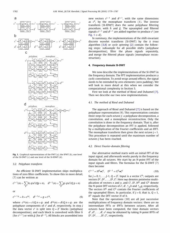
In the wavelet representation, a signal is a superposition oftransient waveforms, which are basis functions of a sequenceof nested function spaces [12]. A multiresolution representa-tion of a discrete signal c0 :¼ ðc0ð0Þ; c0ð1Þ; . . . ; c0ðN-1ÞÞ ismade by repeatedly splitting signals cj (jZ0) into approx-imation cjþ1 and detail djþ1 parts, by filtering with lowpassand bandpass filters h and g, respectively.
The fast wavelet transform (FWT) with filters of lengthL changes a discrete signal of N points to its waveletrepresentation in OðLNÞ time, by recursively downsam-pling cj and dj after filtering. Its inverse upsamples cjþ1 anddjþ1 and filters the upsampled signals with dual filters ~h
and ~g , before adding them together (see Fig. 1a–b). If h andg define an orthogonal wavelet basis, the dual filters aredefined as ~hðnÞ ¼ hð-nÞ and ~gðnÞ ¼ gð-nÞ, x denoting thecomplex conjugate of x.
3.1. Definition of the SI-DWT
We introduce the SI-DWT as defined in Eq. (3.14) ofShensa’s paper [8] describing the �a trous algorithm. Let h; g
be the scaling and wavelet filters of an orthonormal waveletbasis (this will guarantee that perfect reconstruction holds).The definition of the SI-DWT with J levels (octaves) then is1
cjþ1 ¼ ðmQ hÞ � cj; djþ1 ¼ ðmQ gÞ � cj ð7Þ
for Q ¼ 2j; j¼ 0;1; . . . ; J-1. Here, � denotes discrete convolu-tion, and the operation mQ x denotes upsampling of x by afactor Q, i.e., inserting Q-1 zeros between each pair ofelements of x. Input is a vector c0; output are vectorsd1; d2; . . . ; dJ ; cJ . The dj
k are the detail coefficients of theexpansion of c0 and the cJ
k are the approximation coefficientson the coarsest level. If the length of the input signal c0
equals N, then for all levels j the length of cj and dj is N aswell. Many coefficients of the filter after upsampling are zero(�a trous filter¼ filter with holes).
The original signal is reconstructed recursively, startingat level J, by upsampling the dual filters ~h and ~g , followedby the convolution
cj-1 ¼ ðmQ h0Þ � cjþðmQ g0Þ � dj ð8Þ
for Q ¼ 2j; j¼ L; J-1; . . . ;1. Here h0 ¼ ~h=2 and g0 ¼ ~g=2, i.e.,the reconstruction filter coefficients are divided by 2 toaccount for the fact that the data size is not reduced by afactor of 2 in each step, but remains constant [8].
ARTICLE IN PRESS
G 2
2H
G 2
2H
G 2
2H...c0 c1
d1
c2
d2
cJ
Jd
2 H ~
2 G~
+ 2 H ~
2 G~
+ 2 H ~
2 G~
+...cJ
Jd
cJ−1
dJ−1
c1
d1
c0
2j
2j
2j
2j
2j
2j
2j
j2−1
j2−1
z
z
z
z
z
z
H
H
H
G
G
G +
+
z −1
z −1
+
+
+
z −1
z −1
+
z −1
z −1
2j
2j/
2j/
...
G
H0
0
1
2
1
2j
...
2
polyphase
...
...
monophase
2j
2j
2j
j
2j
2j
2j
2
cj cj+1
j+1d
2j
2j
2j
2j
2j
2j
2j
2j H
~
G~
H ~
H ~
G~
G~
G~
H ~
z
z
z
z
z
z
+
+
z −1
z −1
+
+
z −1
z −1
+
z −1
2j/
2j/ + 2/
0
1
2
0
1
2
j2−1
j2−1
...
... ...
...
z −1
polyphase monophase
2j
2j
2j
2j
2j
2j
2j
2j
+
dj+1
cj+1 cj
Fig. 1. Graphical representations of the FWT (a), the IFWT (b), one level
of the SI-DWT (c) and one level of the SI-IDWT (d).
A.M. Wink, J.B.T.M. Roerdink / Signal Processing 90 (2010) 1779–17871782
3.2. Polyphase transform
An efficient SI-DWT implementation skips multiplica-tions of zero filter coefficients. To show this in more detail,(7) can be written as
cjþ1ðnÞ ¼X
p
hð-pÞcjðQpþnÞ; djþ1ðnÞ ¼X
p
gð-pÞcjðQ pþnÞ
or
cjþ1;q ¼ h � cj;q; djþ1;q ¼ g � cj;q; ð9Þ
where cj;qðnÞ ¼ cjðQ nþqÞ and dj;qðnÞ ¼ djðQ nþqÞ are thepolyphase components of cj and dj, respectively. In step j
the data vector cj is split into Q ¼ 2j blocks (polyphasedecomposition), and each block is convolved with filter ~h
(for cjþ1) or with ~g (for djþ1). All blocks are assembled into
new vectors cjþ1 and djþ1, with the same dimensionsas c0, by the monophase transform (1). The inversetransform (SI-IDWT) does the same polyphase filteringprocedure, with ~h and ~g . The upsampled and filteredsignals cjþ1 and djþ1 are added together to produce cj (seeFig. 1 c–d).
In summary, the implementations of the shift-invariantdiscrete wavelet transform (SI-DWT) by the �a trous
algorithm [3,8] or cycle spinning [2] contain the follow-ing steps: subsample for all possible shifts (polyphasedecomposition), filter the phase signals separately,and merge the filtered phase signals (monophase recon-struction).
4. Frequency domain SI-DWT
We now describe the implementations of the SI-DWT inthe frequency domain. The FFT implementation produces acyclic convolution. To avoid wrap-around effects, the signalneeds to be extended by zero elements (zero padding). Wewill look in more detail at this when we consider thecomputational complexity in Section 5.
First we look at the method of Rioul and Duhamel [7].Then we describe our two new implementations.
4.1. The method of Rioul and Duhamel
The approach of Rioul and Duhamel [7] is based on thepolyphase representation (9). This representation containsthree steps for each octave j: a polyphase decomposition, aconvolution, and a monophase reconstruction. Only theconvolution is done in the frequency domain. That is, afterthe polyphase decomposition an FFT is applied, followedby a multiplication of the Fourier coefficients and an IFFT.The monophase transform then gives the next octave jþ1.This procedure is repeated until the maximum number ofoctaves J has been reached.
4.2. Direct Fourier-domain filtering
Our alternative method starts with an initial FFT of theinput signal, and afterwards works purely in the frequencydomain for all octaves. We start by an N-point FFT of theinput signals and filters. The formulas for the SI-DWT (7)then become
Cjþ1 ¼HQ�Cj; Djþ1 ¼ GQ�Cj ð10Þ
for j¼ 0;1; . . . ; J-1, Q ¼ 2j. Input is a vector C0; outputs arevectors D1;D2; . . . ;DJ ;CJ . Here x�y denotes pointwise multi-plication of vectors x and y, and Cj, Dj, HQ and GQ denotethe N-point DFT vectors of cj, dj, mQ h and mQ g, respectively.The vectors HQ and GQ contain the Fourier coefficients ofthe upsampled filters. In particular, if j¼ 0, that is, Q ¼ 1,H1 equals the DFT vector H of h.
Note that the operations (10) are all just successivemultiplications of frequency domain vectors: there are nointermediate FFTs or IFFTs between octaves. After alloctaves have been computed, the time domain vectorsd1;d2; . . . ; dJ , cJ may be obtained by taking N-point IFFTs ofD1;D2; . . . ;DJ ;CJ , respectively.
ARTICLE IN PRESS
A.M. Wink, J.B.T.M. Roerdink / Signal Processing 90 (2010) 1779–1787 1783
Let us consider the elements of the DFT vector HQ inmore detail:
HQ ðkÞ ¼XN-1
n ¼ 0
ðmQ hÞðnÞe-2pikn=N
¼XM-1
m ¼ 0
hðmÞe-2pikmQ=N ¼HðkQ Þ; ð11Þ
for k¼ 0; . . . ;N-1. Here the filter h is assumed to havelength M. Note that the index k in (11) runs from 0 to N-1,
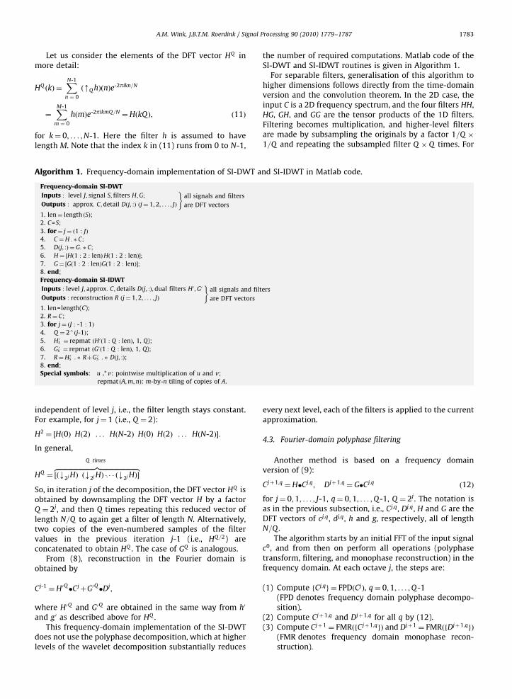
Algorithm 1. Frequency-domain implementation of SI-DWT and SI-IDWT in Matlab code.
Frequency-domain SI-DWT
Inputs : level J; signal S; filters H;G;
Outputs : approx: C;detail Dðj; :Þ ðj¼ 1;2; . . . ; JÞ
)all signals and filters
are DFT vectors
1. len¼ length ðSÞ;
2. C=S;
3. for¼ j¼ ð1 : JÞ
4. C ¼H : � C;
5. Dðj; :Þ ¼ G: � C;
6. H¼ ½Hð1 : 2 : lenÞHð1 : 2 : lenÞ�;
7. G¼ ½Gð1 : 2 : lenÞGð1 : 2 : lenÞ�;
8. end;
Frequency-domain SI-IDWT
Inputs : level J; approx: C;details Dðj; :Þ;dual filters H0 ;G0
Outputs : reconstruction R ðj¼ 1;2; . . . ; JÞ
)all signals and filters
are DFT vectors
1. len=length(C);
2. R¼ C;
3. for j¼ ðJ : -1 : 1Þ
4. Q ¼ 24ðj-1Þ;
5. Hs0 ¼ repmat ðH0ð1 : Q : lenÞ, 1, Q);
6. Gs0 ¼ repmat ðG0ð1 : Q : lenÞ, 1, Q);
7. R¼Hs0 : � RþGs
0 : � Dðj; :Þ;
8. end;
Special symbols: u .* v: pointwise multiplication of u and v;
repmat ðA;m;nÞ: m-by-n tiling of copies of A.
independent of level j, i.e., the filter length stays constant.For example, for j¼ 1 (i.e., Q ¼ 2):
H2 ¼ ½Hð0Þ Hð2Þ . . . HðN-2Þ Hð0Þ Hð2Þ . . . HðN-2Þ�:
In general,
HQ ¼ ½ðk2j HÞ ðk2j HÞ � � � ðk2j HÞ�zfflfflfflfflfflfflfflfflfflfflfflfflfflfflfflfflfflfflfflfflfflffl}|fflfflfflfflfflfflfflfflfflfflfflfflfflfflfflfflfflfflfflfflfflffl{Q times
:
So, in iteration j of the decomposition, the DFT vector HQ isobtained by downsampling the DFT vector H by a factorQ ¼ 2j, and then Q times repeating this reduced vector oflength N=Q to again get a filter of length N. Alternatively,two copies of the even-numbered samples of the filtervalues in the previous iteration j-1 (i.e., HQ=2) areconcatenated to obtain HQ . The case of GQ is analogous.
From (8), reconstruction in the Fourier domain isobtained by
Cj-1 ¼H0Q�CjþG0Q�Dj;
where H0Q and G0Q are obtained in the same way from h0
and g0 as described above for HQ .This frequency-domain implementation of the SI-DWT
does not use the polyphase decomposition, which at higherlevels of the wavelet decomposition substantially reduces
the number of required computations. Matlab code of theSI-DWT and SI-IDWT routines is given in Algorithm 1.
For separable filters, generalisation of this algorithm tohigher dimensions follows directly from the time-domainversion and the convolution theorem. In the 2D case, theinput C is a 2D frequency spectrum, and the four filters HH,HG, GH, and GG are the tensor products of the 1D filters.Filtering becomes multiplication, and higher-level filtersare made by subsampling the originals by a factor 1=Q �
1=Q and repeating the subsampled filter Q � Q times. For
every next level, each of the filters is applied to the currentapproximation.
4.3. Fourier-domain polyphase filtering
Another method is based on a frequency domainversion of (9):
Cjþ1;q ¼H�Cj;q; Djþ1;q ¼ G�Cj;q ð12Þ
for j¼ 0;1; . . . ; J-1, q¼ 0;1; . . . ;Q-1, Q ¼ 2j. The notation isas in the previous subsection, i.e., Cj;q, Dj;q, H and G are theDFT vectors of cj;q, dj;q, h and g, respectively, all of lengthN=Q .
The algorithm starts by an initial FFT of the input signalc0, and from then on perform all operations (polyphasetransform, filtering, and monophase reconstruction) in thefrequency domain. At each octave j, the steps are:
(1)
Compute fCj;qg ¼ FPDðCjÞ, q¼ 0;1; . . . ;Q-1(FPD denotes frequency domain polyphase decompo-sition).(2)
Compute Cjþ1;q and Djþ1;q for all q by (12). (3) Compute Cjþ1 ¼ FMRðfCjþ1;qgÞ and Djþ1 ¼ FMRðfDjþ1;qgÞ(FMR denotes frequency domain monophase recon-struction).
ARTICLE IN PRESS
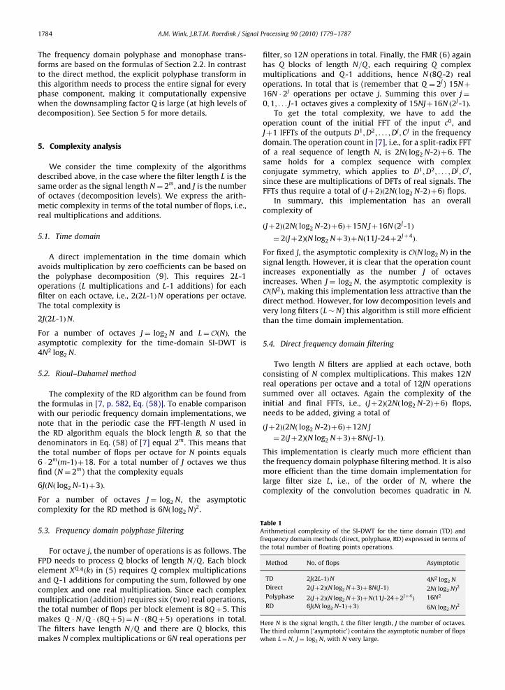
Table 1Arithmetical complexity of the SI-DWT for the time domain (TD) and
frequency domain methods (direct, polyphase, RD) expressed in terms of
the total number of floating points operations.
Method No. of flops Asymptotic
TD 2Jð2L-1ÞN 4N2 log2 N
Direct 2ðJþ2ÞðN log2 Nþ3Þþ8NðJ-1Þ 2Nð log2 NÞ2
Polyphase 2ðJþ2ÞðN log2 Nþ3ÞþNð11J-24þ2Jþ4Þ 16N2
RD 6JðNð log2 N-1Þþ3Þ 6Nð log2 NÞ2
Here N is the signal length, L the filter length, J the number of octaves.
The third column (‘asymptotic’) contains the asymptotic number of flops
when L¼N, J¼ log2 N, with N very large.
A.M. Wink, J.B.T.M. Roerdink / Signal Processing 90 (2010) 1779–17871784
The frequency domain polyphase and monophase trans-forms are based on the formulas of Section 2.2. In contrastto the direct method, the explicit polyphase transform inthis algorithm needs to process the entire signal for everyphase component, making it computationally expensivewhen the downsampling factor Q is large (at high levels ofdecomposition). See Section 5 for more details.
5. Complexity analysis
We consider the time complexity of the algorithmsdescribed above, in the case where the filter length L is thesame order as the signal length N¼ 2m, and J is the numberof octaves (decomposition levels). We express the arith-metic complexity in terms of the total number of flops, i.e.,real multiplications and additions.
5.1. Time domain
A direct implementation in the time domain whichavoids multiplication by zero coefficients can be based onthe polyphase decomposition (9). This requires 2L-1operations (L multiplications and L-1 additions) for eachfilter on each octave, i.e., 2ð2L-1ÞN operations per octave.The total complexity is
2Jð2L-1ÞN:
For a number of octaves J¼ log2 N and L¼OðNÞ, theasymptotic complexity for the time-domain SI-DWT is4N2 log2 N.
5.2. Rioul–Duhamel method
The complexity of the RD algorithm can be found fromthe formulas in [7, p. 582, Eq. (58)]. To enable comparisonwith our periodic frequency domain implementations, wenote that in the periodic case the FFT-length N used inthe RD algorithm equals the block length B, so that thedenominators in Eq. (58) of [7] equal 2m. This means thatthe total number of flops per octave for N points equals6 � 2m
ðm-1Þþ18. For a total number of J octaves we thusfind (N¼ 2m) that the complexity equals
6JðNð log2 N-1Þþ3Þ:
For a number of octaves J¼ log2 N, the asymptoticcomplexity for the RD method is 6Nð log2 NÞ2.
5.3. Frequency domain polyphase filtering
For octave j, the number of operations is as follows. TheFPD needs to process Q blocks of length N=Q . Each blockelement XQ ;qðkÞ in (5) requires Q complex multiplicationsand Q-1 additions for computing the sum, followed by onecomplex and one real multiplication. Since each complexmultiplication (addition) requires six (two) real operations,the total number of flops per block element is 8Qþ5. Thismakes Q � N=Q � ð8Qþ5Þ ¼N � ð8Qþ5Þ operations in total.The filters have length N=Q and there are Q blocks, thismakes N complex multiplications or 6N real operations per
filter, so 12N operations in total. Finally, the FMR (6) againhas Q blocks of length N=Q , each requiring Q complexmultiplications and Q-1 additions, hence N ð8Q-2Þ realoperations. In total that is (remember that Q ¼ 2j) 15Nþ
16N � 2j operations per octave j. Summing this over j¼
0;1; . . . J-1 octaves gives a complexity of 15NJþ16N ð2J-1Þ.To get the total complexity, we have to add the
operation count of the initial FFT of the input c0, andJþ1 IFFTs of the outputs D1;D2; . . . ;DJ ;CJ in the frequencydomain. The operation count in [7], i.e., for a split-radix FFTof a real sequence of length N, is 2Nð log2 N-2Þþ6. Thesame holds for a complex sequence with complexconjugate symmetry, which applies to D1;D2; . . . ;DJ ;CJ ,since these are multiplications of DFTs of real signals. TheFFTs thus require a total of ðJþ2Þð2Nð log2 N-2Þþ6Þ flops.
In summary, this implementation has an overallcomplexity of
ðJþ2Þð2Nð log2 N-2Þþ6Þþ15N Jþ16N ð2J-1Þ
¼ 2ðJþ2ÞðN log2 Nþ3ÞþNð11J-24þ2Jþ4Þ:
For fixed J, the asymptotic complexity is OðN log2 NÞ in thesignal length. However, it is clear that the operation countincreases exponentially as the number J of octavesincreases. When J¼ log2 N, the asymptotic complexity isOðN2Þ, making this implementation less attractive than thedirect method. However, for low decomposition levels andvery long filters (L�N) this algorithm is still more efficientthan the time domain implementation.
5.4. Direct frequency domain filtering
Two length N filters are applied at each octave, bothconsisting of N complex multiplications. This makes 12N
real operations per octave and a total of 12JN operationssummed over all octaves. Again the complexity of theinitial and final FFTs, i.e., ðJþ2Þð2Nð log2 N-2Þþ6Þ flops,needs to be added, giving a total of
ðJþ2Þð2Nð log2 N-2Þþ6Þþ12N J
¼ 2ðJþ2ÞðN log2 Nþ3Þþ8NðJ-1Þ:
This implementation is clearly much more efficient thanthe frequency domain polyphase filtering method. It is alsomore efficient than the time domain implementation forlarge filter size L, i.e., of the order of N, where thecomplexity of the convolution becomes quadratic in N.
ARTICLE IN PRESS
1010
1010
1012
107
105
105101
101100
102
102
103
103
104
104
105101100100
102
102
103 104
104
106
106
108
108
109
1011
N
Com
plex
ity
DirectRioul−DuhamelPolyphaseTime Domain
N
Com
plex
ity
DirectRioul−DuhamelPolyphaseTime Domain
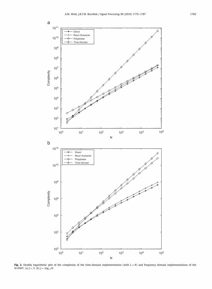
Fig. 2. Doubly logarithmic plot of the complexity of the time-domain implementation (with L¼N) and frequency domain implementations of the
SI-DWT. (a) J¼ 3. (b) J ¼ log2 2N.
A.M. Wink, J.B.T.M. Roerdink / Signal Processing 90 (2010) 1779–1787 1785
ARTICLE IN PRESS
A.M. Wink, J.B.T.M. Roerdink / Signal Processing 90 (2010) 1779–17871786
Frequency domain convolution is unaffected, since it doesnot depend on the filter length.
The direct algorithm has the same asymptotic complex-ity OðNð log2 NÞ2) as the RD method, but with a smallerconstant: for large N the speed gain is a factor of 3J=ðJþ2Þ.For a number of octaves J¼ log2 N, the asymptoticcomplexity of the direct algorithm is 2Nð log2 NÞ2, i.e., afactor of 3 smaller than the RD algorithm.
5.5. Summary
Table 1 shows the complexities of all algorithms, forfilter length N. If the decomposition level J is fixed, the timedomain implementation of the polyphase decomposition isquadratic in N, while the frequency domain implemen-tations are both of order N log2 N. The direct algorithm ismuch more efficient than the polyphase implementation,especially for large J. The direct algorithm is also fasterthan the RD algorithm: for large N the speed gain equals3J=ðJþ2Þ. For the highest possible decomposition level, i.e.,J¼ log2 N, the polyphase frequency domain algorithm hascomplexity OðN2Þ, while the direct and RD algorithms bothhave OðNð log2 NÞ2Þ, the direct algorithm in turn beingthree times faster than the RD algorithm.
A log–log plot of the complexity as a function of the inputlength for decomposition level J¼ 3 and filter length L¼N isshown in Fig. 2. The frequency domain algorithms all scalesimilarly for large N, and the direct method is fastest. Thequadratic scaling of the time-domain implementation isclearly evident from the larger slope of the plot.
5.6. Experimental results
We implemented our direct and polyphase frequency-domain versions of the SI-DWT as Matlab MEX-routinesand compared the computation times with those of thetime-domain implementation provided by the Rice Wave-let Toolbox. No implementation of the RD algorithm wasavailable to us, therefore this method was excluded fromthe experiments. The test was done for a four-levelSI-DWT, once with the Daubechies-4 filter [12], and oncewith the symmetric orthogonal cubic spline wavelet filter[5] (the support of orthogonal spline wavelet filters has thesame size as the signal). For each signal length, 16 384(214) signals were decomposed and reconstructed. Thecomputation times we obtained were in excellent agree-ment with the theoretical complexity estimates. For theDaubechies-4 filter, all algorithms scale linearly in N, butthe polyphase implementation is significantly slower. Forthe cubic spline wavelet, the time-domain implementationscales quadratically, and the direct algorithm is againmuch faster than the polyphase implementation.
6. Conclusion
We have analysed the implementation of the periodicshift-invariant wavelet transform (SI-DWT) and its inversein the time and frequency domain. We have described twofrequency domain implementations, one based on explicitpolyphase decompositions carried out entirely in the
frequency domain (the ‘polyphase’ implementation), andone that employs all upsampling and downsampling ofsignals, for arbitrary sampling factors and signal shifts, inthe frequency domain (the ‘direct’ implementation). Bothmethods only use one initial FFT and one final IFFT, allother steps consist of simple copying and multiplication ofmatrix elements. The implementation of the direct algo-rithm is very simple; explicit (Matlab-like) pseudo-codehas been presented.
We have performed a complexity analysis of ouralgorithms, comparing them to the algorithm by Riouland Duhamel (RD method), which performs the convolu-tion steps of the SI-DWT in the Fourier domain, whilecomputing the downsampling and shift operations in thetime domain, for all octaves of the wavelet decomposition[7]. We found that for long filter lengths (of the order ofthe signal length) the ‘direct’ and RD algorithms are themost efficient, both being of order OðN log2 NÞ. In addition,the direct algorithm is faster than the RD algorithm: forlarge N the speed gain equals 3J=ðJþ2Þ. For high number ofoctaves, i.e., J¼ log2 N, the polyphase frequency domainalgorithm has complexity OðN2Þ, while the direct and RDalgorithms both are of order OðNð log2 NÞ2Þ, the directalgorithm being three times as fast as the RD algorithm. Inapplications like the analysis of fMRI data, where theSI-DWT transform is performed millions of times, a signi-ficant speedup is achieved by using the direct algorithm.
Acknowledgements
This research was part of the project ‘Wavelets andtheir applications’, funded by the Dutch National ScienceFoundation (NWO), Project no. 613.006.570.
References
[1] H.Y. Chuang, D.P. Birch, L.-C. Liu, J.-C. Chien, S.P. Levitan, C.C. Li,A high speed shift-invariant wavelet transform chip for videocompression, in: IEEE Computer Society Annual Symposium on VLSI,April 25–26, 2002.
[2] R.R. Coifman, D.L. Donoho, Translation-invariant denoising, in:A. Antoniadis, G. Oppenheim (Eds.), Wavelet and Statistics, LectureNotes in Statistics, Springer, Berlin, 1995, pp. 125–150.
[3] M. Holschneider, R. Kronland-Martinet, J. Morlet, P. Tchamitchian,A real-time algorithm for signal analysis with the help of the wavelettransform, in: J.M. Combes, A. Grossmann, P. Tchamitchian (Eds.),Wavelets, Time–Frequency Methods and Phase Space, 1989.
[4] N.G. Kingsbury, Complex wavelets for shift invariant analysis andfiltering of signals, Journal of Applied and Computational HarmonicAnalysis 10 (3) (2001) 234–253.
[5] S.G. Mallat, A theory for multiresolution signal decomposition: thewavelet representation, IEEE Transactions on Pattern Analysis andMachine Intelligence 11 (7) (1989) 674–693.
[6] J. Neumann, G. Steidl, Dual-tree complex wavelet transform in thefrequency domain and an application to signal classification,International Journal of Wavelets, Multiresolution and InformationProcessing 3 (1) (2005) 1–23.
[7] O. Rioul, P. Duhamel, Fast algorithms for discrete and continuouswavelet transforms, IEEE Transactions on Information Theory 38 (2)(1992) 486–569.
[8] M.J. Shensa, The discrete wavelet transform: wedding the �a trous andMallat algorithms, IEEE Transactions on Signal Processing 40 (10)(1992) 2464–2482.
[9] G. Strang, T. Nguyen, Wavelets and Filter Banks, Wellesley-Cambridge Press, 1996.
[10] P. Vaidyanathan, Multirate systems and filter banks, Prentice-Hall,Englewood Cliffs, NJ, USA, 1993.
ARTICLE IN PRESS
A.M. Wink, J.B.T.M. Roerdink / Signal Processing 90 (2010) 1779–1787 1787
[11] M. Vetterli, C. Herley, Wavelets and filter banks: relationshipsand new results, in: Proceedings of the International Conferenceon Acoustics, Speech, Signal Processing, Albuquerque, NM, 1990.
[12] M. Vetterli, C. Herley, Wavelets and filter banks: Theory anddesign, IEEE Transactions on Signal Processing 40 (9) (1992)2207–2232.
[13] M. Vetterli, J. Kovacevic, Wavelets and Subband Coding, Prentice-Hall, Englewood Cliffs, NJ, 1995.
[14] M.A. Westenberg, J.B.T.M. Roerdink, Frequency domain volumerendering by the wavelet X-ray transform, IEEE Transactions onImage Processing 9 (7) (2000) 1249–1261.
[15] A.M. Wink, H. Hoogduin, J.B.T.M. Roerdink, Data-driven haemody-namic response function extraction using Fourier-wavelet regu-larised deconvolution, BMC Medical Imaging (8:7), doi:10.1186/1471-2342-8-7. URL /http://www.biomedcentral.com/1471-2342/8/7S.


