Embed Size (px)
Citation preview

2514 IEEE TRANSACTIONS ON PLASMA SCIENCE, VOL. 34, NO. 6, DECEMBER 2006
Plasma-Assisted Combustion of GaseousFuel in Supersonic Duct
Sergey B. Leonov, Dmitry A. Yarantsev, Anatoly P. Napartovich, Member, IEEE, and Igor V. Kochetov
Abstract—The field of plasma-induced ignition and plasma-assisted combustion in high-speed flow is under consideration.Nonequilibrium, unsteady, and nonuniform modes are analyzed asthe most promising in reducing a required extra power. Numericalsimulations of uniform, nonequilibrium, continuous, and pulsedischarge effect on the premixed hydrogen and ethylene–air mix-tures in supersonic flow demonstrate an advantage of such a tech-nique over heating. At the same time, the energetic price occursrather large to be scheme practical. A reduction of the requiredpower deposition and mixing intensification in nonpremixed flowcould be achieved by nonuniform electrical discharges. Experi-mental results on multielectrode discharge maintenance behindwallstep and in the cavity of supersonic flow are presented. Themodel test on hydrogen and ethylene ignition is demonstrated atdirect fuel injection.
Index Terms—Active flameholding, combustion control, elec-trical discharge, plasma-assisted combustion, supersonic flowcontrol.
NOMENCLATURE
M Mach number of the flow.E Electric field strength.Gair, Gf Air and fuel mass flow rate.H Total enthalpy of the flow.I , Ipl Electric current.l, d Length and depth of the cavity.N Concentration of different species.Pst Static pressure in airflow.P0 Stagnation pressure in airflow.Ra, Rcath Resistivity in anode’s or cathode’s circuit.Tg , Tr, Tν , Te Gaseous, rotational, vibrational, and electrons’
temperature.V Velocity of flow.Wcomb, Wpl Deposited power by combustion or plasma.ρ0 Gas density in flow.δ Boundary layer thickness.τ Exposure time.AD, GD Aerodynamic, gas-dynamic.BL Boundary layer.cw Continuous.dc Direct current.
Manuscript received March 7, 2006; revised May 12, 2006. This work wassupported in part by APL/JHU, in part by Program #20 of the Russian Academyof Science, and in part by EOARD under ISTC Project 3057p.
S. B. Leonov and D. A. Yarantsev are with the Institute for High Tem-perature Russian Academy of Sciences, 119991 Moscow, Russia (e-mail:[email protected]; [email protected]).
A. P. Napartovich and I. V. Kochetov are with Troitsk Institute for Innovationand Fusion Research, 142190 Troitsk, Russia (e-mail: [email protected]).
Digital Object Identifier 10.1109/TPS.2006.886089
PWT Pulse wind tunnel.UV Ultraviolet radiation.
I. INTRODUCTION, MOTIVATION, APPROACH
THE MOST popular expectation at present is thatseveral fundamental problems related to the high-speed
combustion could be resolved by an electrical discharge’s ap-plication [1]–[9]. An electrical discharge’s properties stronglydepend on the conditions of excitation, flow parameters, andcharacteristics of supplied electromagnetic power. The analysisof applicable discharge types can be done from the viewpointof plasma-assisted combustion concept [10], which consists ofthree important items: 1) ignition and combustion chemistryenhancement due to heating and active particles generation;2) air–fuel mixing intensification in flow; and 3) flow structuremanagement for flame front stabilization. At least four mech-anisms governing plasma effect on flow structure, ignition, andcombustion processes could be mentioned: 1) fast local ohmicheating of the medium; 2) nonequilibrium excitation anddissociation of air and fuel molecules due to electron collisionsand UV radiation; 3) momentum transfer in electric andmagnetic fields; and 4) shocks/instabilities generation. Thesefactors are important at the discharge’s application for flowparameters and structure control and combustion enforcementunder unfavorable conditions.
Local heating of the medium leads to intensification of thechemical reactions in this area. Discharge excitation affectsthe flow structure, including generation of zones with artificialseparation, when a level of power deposition is sufficiently high[10], [11]. As a result, a local residence time increases, thathelps to maintain an area of nonself-sustained combustion. Theair–fuel mixing is intensified as well.
Active radicals’ generation is due to molecules dissocia-tion and excitation by electrons in electric field, due to UVradiation, and due to more complex processes. Presence ofchemical radicals (for example, O, OH, H, and ON) or vi-brationally/electronically excited molecules can effectively im-prove ignition conditions. If the chain chemical reactions arerealized, the production of even a small amount of activeparticles can lead to a large (synergetic) benefit in total reactionrates, as well as in diminishing the required power input.
All specific types of gas excitation (dissociation, ionization,vibrational, electronic excitation, etc.) affects the reaction ratespositively. Within the base of them are two main physicalmechanisms: electron impact and photo excitation. The first oneis effective at a high magnitude of the reduced electric fieldE/N . The second one is effective at the superheating of the
0093-3813/$20.00 © 2006 IEEE
Authorized licensed use limited to: Anatoly Napartovich. Downloaded on March 22, 2009 at 06:59 from IEEE Xplore. Restrictions apply.

LEONOV et al.: PLASMA-ASSISTED COMBUSTION OF GASEOUS FUEL IN SUPERSONIC DUCT 2515
discharge channel (high intensity of the thermal radiation). Thefirst effect occurs mostly in high-frequency and short-pulseddischarges or at the intensive cooling of the discharge area [11],[12]. The second one could be realized at high values of specificenergy input (several electronvolts per atom/molecule) [13].
Shock wave generation promotes the mixing processes in aheterogeneous medium and initiates chemical reactions due toheating in the shock front zone. Also, there exist various typesof plasma instabilities, for example, “longitudinal–transversal”instability of plasma filament [10], which leads to an intensivesmall-scale mixing in flow. In general, it is impossible toseparate the specific mechanisms of the plasma action becauseof interference between them.
Typical GD conditions are not quite favorable for electricaldischarges’ practical applications: pressure P = 0.1−1 bar andvelocity of the flow V = 100−1000 m/s. Characteristic tem-perature of gas varies from Tg = 300 K for ambient conditionsto Tg ≤ 2 kK for combustion chamber. As a rule, at suchan environment, the plasma of electric discharges appears infilamentary form due to instabilities mostly associated with themechanism of reduced electrical field enhancement in a vicinityof heated plasma channel.
The complete management of the combustion process underany conditions requires a large level of additional energy depo-sition (in a range of the flow enthalpy) that is out of practicalinterest. An idea on how to improve the situation is a smart(intelligent) control of chemical reaction rates and/or manifoldof local ignition centers. The second option is to force thecombustor to work under off-design conditions. It can be atemporal mode when the level of the required electric energy isnot vitally important. Unfortunately, the information availablenow is not sufficient to make a reliable choice of the dischargetype. Our understanding is that there is no versatile solution toa design and method of application of plasma for combustion.Each specific situation has to be considered separately. It isreasonable to analyze separately effects produced by nonequi-librium and nonuniformity of plasmas. It is clear that plasmahas to be generated in situ just in the location of the fuel-oxidizer interaction but not by external device.
This paper consists of two parts united with an idea ofhigh-speed combustion improvement by electrical dischargesmaintained in flow. Section II is actually theoretical andpresents a feasibility stage of experimental project. It demon-strates the effects of nonequilibrium gas excitation on inductiontime and significant difference between ignition of hydrogenand hydrocarbons. Section III is mostly experimental. It an-nounces the data on hydrogen and hydrocarbon fuel ignition/flameholding by nonuniform plasma in supersonic duct underlow-temperature conditions. The experiments were performedin practical GD configuration.
II. GASEOUS FUEL IGNITION BY HOMOGENEOUS
DISCHARGE (CALCULATIONS)
The key parameter commonly used for the evaluation of glowdischarge stability is a product ND, where N is the gas densityand D is the cathode–anode spacing. Up to now, many peopleshare a belief that the existence of classic glow discharge is
Fig. 1. Simplified schematic of the combustion cell.
limited by low-pressure conditions (ND < 3 · 1018 cm−2 forair). Actually, it was shown in [14] and [15] that this upper limitcan be essentially higher, about 8 · 1019 cm−2. Combination ofmoderate requirements to power supply with low sensitivity togas composition makes this technique rather promising for thegeneration of radicals and ignition of premixed oxidizer and afuel. Specific electrode construction, in combination with theappropriate gas flow and distributed ballast resistors, stabilizesthis discharge for many gas mixtures. Experimentally achievedefficiency for energy deposition into the gas is not less than90% [15]. The theoretical model satisfactorily describing theexperimental observations was developed earlier [14], [15].
To model plasma-assisted combustion in a supersonic flow,it is necessary to describe plasma generation and chemicalkinetics essentially dependent on gas temperature. Until now,the existing models are valid either for plasma descriptionor combustion, but not for both. We [16] have developed anumerical model combining the traditional approach of thermalcombustion chemistry with advanced description of the plasmakinetics based on the solution of electron Boltzmann equation.This approach allows us to describe self-consistent stronglynonequilibrium electric discharge in chemically unstable(ignited) gas.
Our model includes an electron Boltzmann equation solvercalculated periodically over specified intervals of time, kineticcode computing equations for charged particles, excited mole-cular states, ion-molecule reactions, and chemical reactions.Besides, a correlation between the voltage applied and theelectric current is found from the electric circuit equation.Effect of chemically active species produced in the dischargeon ignition delay time was studied for conditions of steady-stateglow discharge for mixtures of hydrogen and ethylene with dryair, while effectiveness of pulse-periodic discharge in shorten-ing ignition time was explored for hydrogen–air stoichiometricmixture only.
A simplified schematic of a combustion cell is shown inFig. 1. Calculations were performed for the supersonic flowwith Mach number M = 2.5, static pressure Pst = 1 bar, statictemperature Tg = 700 K, and distance along flow up to 90 cmfor the hydrogen and ethylene mixed with dry air at variedenergy input into the gas flow for stoichiometric compositions.
In numerical simulations, the evolution of a gas plug trans-ported through the discharge region by the flow was followed.First, calculations were done while neglecting gas density varia-tion. Then, more realistic, a pseudo-one-dimensional (1-D) plugflow model was developed, taking into account gas-dynamicfunctions variation along the flow. Mechanisms of the thermalcombustion for mixtures of hydrogen and ethylene with dryair and respective data on rate constants for chemical reactions
Authorized licensed use limited to: Anatoly Napartovich. Downloaded on March 22, 2009 at 06:59 from IEEE Xplore. Restrictions apply.

2516 IEEE TRANSACTIONS ON PLASMA SCIENCE, VOL. 34, NO. 6, DECEMBER 2006
Fig. 2. Variation of the Mach number M along the flow for the stoichiometricmixture H2–air in the cases of discharge and thermal initiations. The reducedinput energy is equal to 270 J/g. The dash-dot line indicates the critical Machnumber M = 1.
Fig. 3. Gas-temperature evolution along flow for variable specific energyinput. C2H4 : O2 : N2 = 1 : 3 : 12, Pst = 1 bar, Tg = 700 K, and flowvelocity V = 1200 m/s.
were taken from KinTech [17]. Special tests confirmed that thepure chemical module predicts ignition times in good agree-ment with the available data.
An effect of nonthermal plasma-ignition initiation is clearlyseen in Fig. 2, where reduction of the Mach number of thesupersonic flow in the rectangular duct induced by hydrogenfueled flame is shown. The comparison is made between situ-ations when the glow discharge excites the gas and the sameenergy (270 J/g) is loaded into gas heating on the same lengthof the duct. Induction length at the thermal ignition is about3.5 times greater than at the glow discharge ignition.
Fig. 3 presents results of numerical simulations of theethylene–dry air mixture ignition initiated by the dc glow dis-charge with variable specific energy input, which was changedby varying the discharge length. The calculations were madeusing an approximation of constant gas density; gas flow veloc-ity is 1200 m/s. As expected, the higher is the energy input, theshorter is the induction length. Fig. 4 summarizes results of ournumerical simulations for H2 and C2H4 fuels. The reductionof the ignition time at discharge initiation in comparison withthermal heating is evident for both mixtures. As expected, thehydrogen requires considerably less value of energy depositionfor the ignition. Fig. 4 illustrates also that the approximation ofconstant gas density (dashed line) reasonably agrees well withthe pseudo-1-D plug flow model (solid line).
Fig. 4. Ignition distances at thermal and discharge initiation for H2 and C2H4
fuels. Pst = 1 bar and T = 700 K. Comparison of the 1-D gas-dynamic modeland constant density approach.
Numerical simulations were made also to evaluate in whatdegree the pulse discharge is more effective for the initiationof the combustion of mixtures fueled by hydrogen. Generallyspeaking, it is clear that pulse discharges can realize higher val-ues of E/N parameter when production of radicals in plasma ismore effective. However, to hold flame in the supersonic duct,it is necessary that the discharge must be operated in a pulse-periodic mode. Reasonably, short-pulse discharges with tech-nically available duration in the range of a few microsecondswere selected for numerical studies. It was assumed that thedischarge area extends uniformly over the gas-dynamic ductsection and occupies a region along the flow. It was found thatthe pulse discharge is indeed more effective (shorter ignitiontime at the same energy input), but the effect is comparativelyweak (about 20% difference in the required average power).
Concluding, the numerical simulations demonstrated astrong acceleration of combustion for H2 and C2H4 fueledmixtures by the glow discharge producing the nonthermalplasma. The required amounts of energy input are evaluated forboth fuels.
III. EXPERIMENTAL FACILITY PWT-50
A deeply renovated experimental facility PWT-50 is usedfor the test of the ethylene ignition by electrical dischargebehind wallstep and in a cavity of high-speed duct [11]. It isbuilt on blow-down scheme with maximal stagnation pressureP0 = 5 bar. The following typical gas-dynamic parameters ofthe test are provided by PWT-50: Mach number in duct M =0.3−0.75 and M = 2; initial static pressure Pst = 0.2−0.8 bar;turbulent BL thickness upstream discharge area is about δ =1 mm; stagnation temperature of the air in described testsTg0 = 300 K; test section dimensions 72 ∗ 60 mm; and steady-stage operation time t = 0.3−0.5 s.
The measuring system includes the system sensors(pressure and temperature), pressure transducers (pressure-distribution measurements), spectroscopic system, opticalsensors, Schlieren system, fast complimentary metal-oxide-semiconductor (CMOS) video cameras, electrical parameterssensors, etc. Data acquisition system includes PC-based indi-vidual devices for pressure-distribution records, video camerascontrol, and spectroscopic and operation parameters’ records.
Authorized licensed use limited to: Anatoly Napartovich. Downloaded on March 22, 2009 at 06:59 from IEEE Xplore. Restrictions apply.

LEONOV et al.: PLASMA-ASSISTED COMBUSTION OF GASEOUS FUEL IN SUPERSONIC DUCT 2517
Fig. 5. (a) Basic scheme of electrodes mounting. (b) Photo of test section. (c) Schemes of pressure tabs arrangement.
The plasma generator was designed and constructed forapplications in high-speed flow on the base of the experimentalresults obtained during the previous study of quasi-dc, pulseperiodic, and modulated radio-frequency discharges [10], [11],[13]. Such electrodes configuration (line near the edge ofthe wallstep and line at the bottom of the separation zone)is described in [18] in details. Fig. 5 presents a scheme ofelectrodes’ mounting [Fig. 5(a)], corresponding photo of realdevice [Fig. 5(b)], and pressure tabs arrangement [Fig. 5(c)] intwo modes: cavity and wallstep. Plasma generator consists oftwo insertions made of refractory insulating material. The firstinsertion is arranged on the edge of backwise wallstep, and thesecond one is located in the bottom of the separation zone. Bothof them are flush mounted, as well as electrodes themselves.Each insertion has the same construction: nine electrodes in tworows arranged on an interlaced manner (4 + 5).
In the first insertion, the first row is applied for the dischargeprimary initiation, whereas the second row contains workinganodes. The first line of electrodes in the second insertion isreserved for extra control of the discharge and the measure-ments of cathode’s voltage drop, the second line is operatedas working cathodes. Such electrodes arrangement allows aquite flexible operation with independent ballast resistivityin anode’s Ra = 1−5 kΩ and cathode’s Rcath = 0.2−2 kΩcircuits. The discharge operates with the following parame-ters: type of discharge—filamentary quasi-continuous; oper-ation time of discharge—tpl = 50−500 ms; current througheach electrode—Ipl1 = 1−4 A; and mean electrical input
power—Wpl = 1−10 kW that is the equivalent averaged gas-temperature elevation in a whole duct less than ∆Tg = 20 K.
The fuel injectors are installed directly on the bottom wallof the test section, as it is shown in Fig. 5. They are attachedto a fuel capacitor, at 5–6 bar of pressure, through fast pulsevalve with electromagnetic (EM) control. The fuel dose andduration of the injection depends on the EM pulses durationand the repetition rate. Minimal dose at the single pulse is about1 mg. Maximal mass flow rate is about Gf = 5 g/s.
IV. DISCHARGE APPEARANCE NEAR BACKWISE
WALLSTEP AND CAVITY [EXPERIMENT AND
COMPUTATIONAL FLUID DYNAMICS (CFD)]
The numerous experiments were done at different conditions:subsonic and supersonic flow; wallstep, long cavity (l/d =6.5), and short cavity (l/d = 3.3); different pressure; dischargecurrent in a range of Ipl = 5−20 A; both polarities; etc. Here,the data for wallstep and cavity in supersonic mode are shownfor typical parameters of electrical discharge.
A. Plasma Filaments Dynamics in High-Speed Flow
The discharge dynamics in flow behind the wallstep and inthe cavity was explored using high-speed digital CMOS camerawith a typical frame rate of 2000 ft/s at 1280 × 250 pixels andtypical exposure τ = 30 µs. As a sample in Fig. 6, two selectedframes are presented for operation in the supersonic mode inthe cavity and behind wallstep, correspondingly.
Authorized licensed use limited to: Anatoly Napartovich. Downloaded on March 22, 2009 at 06:59 from IEEE Xplore. Restrictions apply.
2518 IEEE TRANSACTIONS ON PLASMA SCIENCE, VOL. 34, NO. 6, DECEMBER 2006
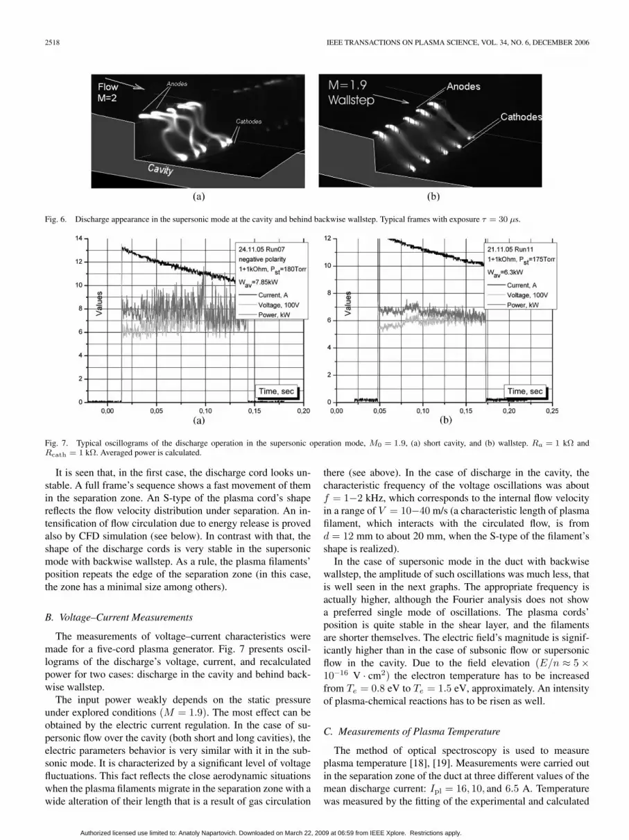
Fig. 6. Discharge appearance in the supersonic mode at the cavity and behind backwise wallstep. Typical frames with exposure τ = 30 µs.
Fig. 7. Typical oscillograms of the discharge operation in the supersonic operation mode, M0 = 1.9, (a) short cavity, and (b) wallstep. Ra = 1 kΩ andRcath = 1 kΩ. Averaged power is calculated.
It is seen that, in the first case, the discharge cord looks un-stable. A full frame’s sequence shows a fast movement of themin the separation zone. An S-type of the plasma cord’s shapereflects the flow velocity distribution under separation. An in-tensification of flow circulation due to energy release is provedalso by CFD simulation (see below). In contrast with that, theshape of the discharge cords is very stable in the supersonicmode with backwise wallstep. As a rule, the plasma filaments’position repeats the edge of the separation zone (in this case,the zone has a minimal size among others).
B. Voltage–Current Measurements
The measurements of voltage–current characteristics weremade for a five-cord plasma generator. Fig. 7 presents oscil-lograms of the discharge’s voltage, current, and recalculatedpower for two cases: discharge in the cavity and behind back-wise wallstep.
The input power weakly depends on the static pressureunder explored conditions (M = 1.9). The most effect can beobtained by the electric current regulation. In the case of su-personic flow over the cavity (both short and long cavities), theelectric parameters behavior is very similar with it in the sub-sonic mode. It is characterized by a significant level of voltagefluctuations. This fact reflects the close aerodynamic situationswhen the plasma filaments migrate in the separation zone with awide alteration of their length that is a result of gas circulation
there (see above). In the case of discharge in the cavity, thecharacteristic frequency of the voltage oscillations was aboutf = 1−2 kHz, which corresponds to the internal flow velocityin a range of V = 10−40 m/s (a characteristic length of plasmafilament, which interacts with the circulated flow, is fromd = 12 mm to about 20 mm, when the S-type of the filament’sshape is realized).
In the case of supersonic mode in the duct with backwisewallstep, the amplitude of such oscillations was much less, thatis well seen in the next graphs. The appropriate frequency isactually higher, although the Fourier analysis does not showa preferred single mode of oscillations. The plasma cords’position is quite stable in the shear layer, and the filamentsare shorter themselves. The electric field’s magnitude is signif-icantly higher than in the case of subsonic flow or supersonicflow in the cavity. Due to the field elevation (E/n ≈ 5 ×10⁻¹⁶ V · cm2) the electron temperature has to be increasedfrom Te = 0.8 eV to Te = 1.5 eV, approximately. An intensityof plasma-chemical reactions has to be risen as well.
C. Measurements of Plasma Temperature
The method of optical spectroscopy is used to measureplasma temperature [18], [19]. Measurements were carried outin the separation zone of the duct at three different values of themean discharge current: Ipl = 16, 10, and 6.5 A. Temperaturewas measured by the fitting of the experimental and calculated
Authorized licensed use limited to: Anatoly Napartovich. Downloaded on March 22, 2009 at 06:59 from IEEE Xplore. Restrictions apply.

LEONOV et al.: PLASMA-ASSISTED COMBUSTION OF GASEOUS FUEL IN SUPERSONIC DUCT 2519
Fig. 8. M = 1.9, discharge is switched on before flow start and switched off in t = 0.17 s. Wav = 5.95−7.2 kW.
Fig. 9. Schlieren photos of the discharge effect on flow structure. Supersonic mode and short cavity. Exposure τ = 1 µs.
spectra of the N2 second positive system (0–0, 0–2, 1–3, and2–4 bands) and of the violet system of CN (388.9 nm). The CNspectrum was observed in the discharge in airflow without fueldue to the natural concentration of CO2, but of course, its inten-sity was much lower than in the case of hydrocarbons injection.
By the analysis of the N2 spectra, the rotational tempera-ture has occurred to be the same for different conditions (fordifferent values of electrical current and for different areas ofthe radiation collection: within the separation zone and in thefreestream just before the wallstep). The value is calculated asTr = 3.0 ± 0.2 kK. Temperature measurements carried out bythe CN spectrum give the following results: Tν = 7.5 ± 0.5 kKand Tr = 7 ± 0.5 kK. Such high values are explained by thefact that the temperature of the exited state of the CN moleculesis measured, whereas rotational temperature by N2 spectrumis measured for the ground state of N2. It is clear that, underconditions of high nonuniformity of the discharge structure,the measured amplitude of temperature poses between maximaland average values. As a result, the different molecular bandscan give different formal temperatures. As an example of sucha measurement, the data for molecular ion of nitrogen N+
2 wereobtained as well. The formalized procedure of temperaturerecalculation gives Tr = 9 ± 3 kK. Now, extra efforts are beingmade to resolve such a discrepancy.
A focal conclusion from these data is that the temperatureof the gas exceeds the value Tg = 3.0 kK locally. At the sametime, the averaged gas-temperature elevation in the cavity is es-timated in value ∆Tg(cav) = 200 K. It means that the discharge
creates a zone with a strong nonhomogeneous distribution ofmain gas parameters.
D. Discharge Effect on Flow Structure
Two methods were utilized mainly to study the dischargeeffect on flow structure behind wallstep and in the cavity: pres-sure measurements and Schlieren visualization. Multichannelspressure recorder was used in the tests. Sensor’s arrangement isshown in Fig. 5(c). The typical data is presented in Fig. 8.
Summarizing the discharge effect on pressure distribution inthe cavity and behind wallstep, it should be considered that, asa rule, the pressure rises noticeably just near the discharge zoneand its distribution occurs to be more smooth in a cavity as awhole.
E. Schlieren Visualization
Schlieren system was adjusted to work in pulse mode offlash-lamp with frame’s frequency f = 100 Hz and the lightflash duration τ = 1 µs. The images are presented in thissection by pairs (discharge OFF/ON) for the operation modeswhen the power deposition is in a range Wpl = 5−7 kW, staticpressure in supersonic M ≈ 1.9 mode Pst = 120−180 torr.
As it can be recognized easily, the discharge effect on flowstructure in the cavity (Fig. 9) and behind the wallstep (Fig. 10)lies in an intensive turbulization of gas in the interaction areasimultaneous with a slight increase of the separation zonevolume.
Authorized licensed use limited to: Anatoly Napartovich. Downloaded on March 22, 2009 at 06:59 from IEEE Xplore. Restrictions apply.

2520 IEEE TRANSACTIONS ON PLASMA SCIENCE, VOL. 34, NO. 6, DECEMBER 2006
Fig. 10. Schlieren photos of the discharge effect on flow structure. Supersonic mode, wallstep. Exposure τ = 1 µs.
Fig. 11. Simulation’s scheme. Isothermal surfaces Tg = 2000 K.
F. Flow Structure Simulation
The 3-D simulations were performed for a better understand-ing on processes associated with a power release near cavityand wallstep, generally, and to estimate the mass flow rate ofthe fuel injection, specifically. In this stage of numerical study,combustion chemistry was not included to the model.
Numerical modeling of flow in experimental duct was basedon the solution of 3-D time-dependent Reynolds averagedNavier–Stokes equations (URANS-method), with the utiliza-tion of the widely used two-equation SST-model of turbulence.Calculation of 3-D turbulent flow in the frame of model of theperfect gas was executed at modeling a heat supply caused bythe dc electric discharge. Calculation was carried out at thelength of the bottom wall of cavity l/d = 6.5. The geometryof the whole channel and areas of thermal power release areshown in Fig. 11. Constant values of velocity V = 317 m/s,total pressure P0 = 105 Pa, and temperature Tg = 250 K werespecified in the initial section of the calculation domain, beinga critical section (throat) of the supersonic nozzle M = 2.Zero gradients of flow parameters in the outlet section of thecalculation domain were fixed. No-slip and adiabatic conditionswere specified on upper, lower, and one lateral walls of theduct, as well as on cavity walls. Symmetry conditions wereused in the median section of the duct to decrease the cal-culation domain which contained 600 000 mesh points. Theresults of the computational analysis were obtained for thepower deposition Wpl = 5 kW that is close to the experi-mental value.
The isothermal surfaces are presented in Fig. 11 for anillustration of the position of the hottest zone in the flowfield.The position of the fuel injectors was defined on the basis of theanalysis of flow structure to guarantee the fuel passage through
Fig. 12. Comparison of the calculated and experimental pressure distributionbehind the wallstep in the supersonic airflow.
these areas. Among the two practical variants: just behind thewallstep or downstream of the bottom electrodes, the secondposition occurs much more effective.
The important issue is a rate of gas exchange between themain flow and separation zone. The calculated values are equal,Gair = 0.0054 kg/s and Gair(Q) = 0.0074 kg/s, respectively,without heat input and with it. A residence time of the gasin the circulation area in configuration with the wallstep wasapproximately three times less than in the cavity. These dataare compatible with the available ones in literature and with theexperimental value on the velocity of gas circulation.
On the base of these data, it can be calculated that the firstapproximation for the required amount of the injected fuel to
Authorized licensed use limited to: Anatoly Napartovich. Downloaded on March 22, 2009 at 06:59 from IEEE Xplore. Restrictions apply.
LEONOV et al.: PLASMA-ASSISTED COMBUSTION OF GASEOUS FUEL IN SUPERSONIC DUCT 2521
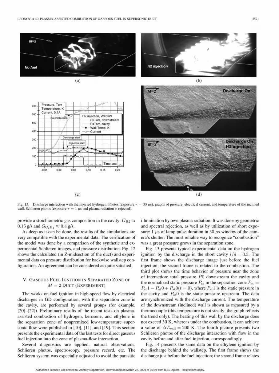
Fig. 13. Discharge interaction with the injected hydrogen. Photos (exposure τ = 30 µs), graphs of pressure, electrical current, and temperature of the inclinedwall. Schlieren photos (exposure τ = 1 µs and plasma radiation is rejected).
provide a stoichiometric gas composition in the cavity: GH2 ≈0.15 g/s and GC2H4 ≈ 0.4 g/s.
As deep as it can be done, the results of the simulations arevery compatible with the experimental data. The verification ofthe model was done by a comparison of the synthetic and ex-perimental Schlieren images, and pressure distribution. Fig. 12shows the calculated (in Z-midsection of the duct) and experi-mental data on pressure distribution for backwise wallstep con-figuration. An agreement can be considered as quite satisfied.
V. GASEOUS FUEL IGNITION IN SEPARATED ZONE OF
M = 2 DUCT (EXPERIMENT)
The works on fuel ignition in high-speed flow by electricaldischarges in GD configuration, with the separation zone inthe cavity, are performed by several groups (for example,[20]–[22]). Preliminary results of the recent tests on plasma-assisted combustion of hydrogen, kerosene, and ethylene inthe separation zone of nonpremixed low-temperature super-sonic flow were published in [10], [11], and [19]. This sectionpresents the experimental data of the last tests for direct gaseousfuel injection into the zone of plasma-flow interaction.
Several diagnostics are applied: natural observations,Schlieren photos, spectroscopy, pressure record, etc. TheSchlieren system was especially adjusted to avoid the parasitic
illumination by own plasma radiation. It was done by geometricand spectral rejection, as well as by utilization of short expo-sure: 1 µs of lamp pulse duration in 30 µs window of the cam-era’s shutter. The most reliable way to recognize “combustion”was a great pressure grows in the separation zone.
Fig. 13 presents typical experimental data on the hydrogenignition by the discharge in the short cavity l/d = 3.3. Thefirst frame shows the discharge image just before the fuelinjection; the second frame is related to the combustion. Thethird plot shows the time behavior of pressure near the zoneof interaction: total pressure P0 downstream the cavity andthe normalized static pressure Pst in the separation zone Pst =Pst1 − Pst0 + Pst0(t = 0), where Pst1 is the static pressure inthe cavity and Pst0 is the static pressure upstream. The dataare synchronized with the discharge current. The temperatureof the downstream (inclined) wall is shown as measured by athermocouple (this temperature is not steady; the graph reflectsthe trend only). The heating of this wall by the discharge doesnot exceed 30 K, whereas under the combustion, it can achievea value of ∆Twall = 200 K. The fourth picture presents twoSchlieren photos of the discharge interaction with flow in thecavity before and after fuel injection, correspondingly.
Fig. 14 presents the same data on the ethylene ignition bythe discharge behind the wallstep. The first frame shows thedischarge just before the fuel injection; the second frame relates
Authorized licensed use limited to: Anatoly Napartovich. Downloaded on March 22, 2009 at 06:59 from IEEE Xplore. Restrictions apply.

2522 IEEE TRANSACTIONS ON PLASMA SCIENCE, VOL. 34, NO. 6, DECEMBER 2006
Fig. 14. Discharge interaction with the injected ethylene. Photos (τ = 30 µs), pressure, and Schlieren photos (τ = 1 µs).
to the situation discharge + fuel. The third plot shows the timebehavior of pressure in the separation zone. The fourth is theSchlieren photo of fuel jet interaction with the discharge.
At a first glance, the situations on natural photos look verysimilar, but actually, there is a principal difference. At hydrogeninjection, the combustion takes place in the cavity as well as ina shear layer, in contrast to the combustion at ethylene injection.It is clearly seen that, in the first case, the pressure step in thecavity is much higher.
That is, two modes of discharge-fuel-flow interaction wereobserved: fuel ignition and combustion just in a cavity andfuel combustion in a shear layer of supersonic freestream. Inthe case of hydrogen injection, the modes were detected both.Under experimental conditions, the ethylene combustion wasdetected in the cavity only.
The hydrogen combustion in the cavity takes place if thepower deposition in the discharge W > 1 kW. If the dischargewas turned off, the combustion in the cavity came to anunstable mode. The increase of hydrogen flow rate over thestoichiometric ratio pushes the combustion above the cavity ifthe power deposition is not less than Wpl = 3 kW. When thethermal power of combustion grew more than Wcomb = 20 kW,a thermal choking of the duct occurred.
It is well known that some widening of the gas-dynamicduct downstream helps to prevent a thermal choking. Fig. 15demonstrates the hydrogen combustion in the shear layer of the
free stream in a configuration with backwise wallstep for thehydrogen mass flow rate increased up to GH2 = 4 g/s. Thereactions were very intensive, without blockage of the super-sonic operation mode. It is well seen how the flow distur-bances are produced by combustion, which occupied almost awhole duct. The discharge switching off destroys this regimeimmediately.
It is clear that the flash of radiation does not reflect thefact of fuel combustion itself. One important feature of thedischarge–fuel interaction is the dramatic growth of radiationintensity from the volume, especially for hydrocarbon fuel.Sometimes, it exceeds a factor 103 of magnitude. This rise tookplace in the continuous spectra and molecular bands CN, C2,and others. In [19], the effect was named as “cyan catastrophe.”For illustration purposes, some results of the spectral measure-ments are shown in Fig. 16 for the ethylene and hydrogeninjection.
The spectral observations prove an important role, whichplays the atomic oxygen produced by the discharge in speedingup the ignition. Fig. 16(b) presents a spectral sequence whenthe discharge is operated slightly before the hydrogen injection.It is seen that the amplitude of the resonant spectral line ofthe atomic oxygen grows in the discharge area and drops atcombustion. Generally, this situation should be analyzed inmore detail to find the quantitative relations between radiationintensity and concentration of the excited atoms.
Authorized licensed use limited to: Anatoly Napartovich. Downloaded on March 22, 2009 at 06:59 from IEEE Xplore. Restrictions apply.

LEONOV et al.: PLASMA-ASSISTED COMBUSTION OF GASEOUS FUEL IN SUPERSONIC DUCT 2523
Fig. 15. Discharge interaction with the injected hydrogen behind the wallstep. Pressure and Schlieren photos (τ = 1 µs).
Fig. 16. Samples of time behavior of the discharge spectrum under (a) ethylene and (b) hydrogen injection. Each spectrum has an exposure of 10 ms.
Of interest is the fact that the discharge switching off leadsto immediate extinction of the hydrogen flame in a free stream,but the combustion in the cavity can be continued. The powerthreshold of hydrogen ignition in shear layer was measured bythe variation of the power deposition. It is about Wpl = 3 kWunder the conditions of the test.
VI. CONCLUSION
Control of ignition in aircraft jet engines is of crucial im-portance for their performance over a wide range of operationparameters such as altitude, flight speed, and thrust. Reduc-tion of ignition delay time, flameholding and flame stabilityimprovement, flame blow-off prevention, and extension of fuelflammability limits are some of the key technical issues in thisfield. In this paper, the extra mechanism (plasma generation inflow) is described as the promising contenders of the mechani-cal methods.
The conception of plasma-assisted combustion has beenformulated. The methods for high-speed combustion controlwere considered: plasma-induced ignition, plasma-intensifiedmixing, and flame-holding by plasma generation. The mainphysical mechanisms of the plasma effect are described.
Numerical simulations by newly formulated plasma-chemical model predicted better efficiency of nonthermal dis-charge technique as compared to heating. Evaluations are madeof the energy deposition required for the ignition of the pre-mixed fuels H2 and C2H4.
The main requirements for the different types of dischargesare listed for maximal effect at minimal power deposition:in situ generation, nonuniform structure, and nonequilib-rium composition. Previously proposed multielectrode quasi-dcdischarge through the separation zone was developed for uti-lization in the cavity and wallstep of the supersonic duct. Thepeculiarities of the filamentary discharge maintenance in high-speed flow under separation were explored experimentally. The
Authorized licensed use limited to: Anatoly Napartovich. Downloaded on March 22, 2009 at 06:59 from IEEE Xplore. Restrictions apply.

2524 IEEE TRANSACTIONS ON PLASMA SCIENCE, VOL. 34, NO. 6, DECEMBER 2006
3-D CFD simulation was performed to predict the criticalparameters for the plasma-ignition experiment.
The results of the model experiments on the ignition ofthe nonpremixed air–fuel (hydrogen and ethylene) streams inhigh-speed low-temperature flow behind a backwise wallstepand in the cavity are presented. The energetic threshold of thehydrogen ignition in shear layer was measured in a value ofWpl = 3 kW for the experimental conditions. It is concludedthat the detection of radiation increase is not a reliable methodof combustion monitoring if an electric discharge is maintained.
The experimental and theoretical efforts for a broader rangeof parameters are planned to be done.
ACKNOWLEDGMENT
The authors would like to thank V. Bityurin for the multiplediscussions regarding CFD efforts, K. Savelkin of IVTAN forthe valuable assistance in the experimental work, V. Sermanovof TsAGI for consulting on high-speed combustion technique,M. Starodubtsev for the CFD efforts.
REFERENCES
[1] G. O. Young, “Synthetic structure of industrial plastics (Book stylewith paper title and editor),” in Plastics, 2nd ed, vol. 3., J. Peters, Ed.New York: McGraw-Hill, 1964, pp. 15–64.
[2] S. Leonov, “Plasma assistance in supersonic combustion,” in Conf.Plasmas Stealth and Flow and Combust. Control, Paris, France,Mar. 31–Apr. 1, 2003. [Online]. Available: http://www.onera.fr/seminaires/plasmas/onera-cnrs-030331.html
[3] D. VanWie, D. Risha, and C. Suchomel, “Research issues resulting froman assessment of technologies for future hypersonic aerospace systems,”presented at the 42th AIAA Aerospace Sciences Meeting and Exhibit,Reno, NV, Jan. 5–8, 2004.
[4] L. Jacobsen, C. Carter, R. Baurie, and T. Jackson, “Plasma-assisted ig-nition in scramjet,” presented at the 41st AIAA Aerospace Meeting andExhibit, Reno, NV, Jan. 6–9, 2003, Paper AIAA-2003-0871.
[5] A. Starikovskii, “Plasma supported combustion,” in Proc. Combust. Inst.,30th Int. Symp. Combust., Chicago, IL, 2004, p. 326. Invited Lecture.
[6] Y. Y. Buriko, V. A. Vinogradov, V. F. Goltsev, and P. J. Waltrup, “Influenceof radical concentration and fuel decomposition on ignition of propane/airmixture,” J. Propuls. Power, vol. 18, no. 5, pp. 1049–1058, 2000.
[7] A. Bao, G. Lou, M. Nishihara, and I. V. Adamovich, “On the mechanismof ignition of premixed CO–air and hydrocarbon–air flows by nonequi-librium RF plasma,” presented at the 43rd AIAA Aerospace Meetingand Exhibit, Reno, NV, Jan. 10–13, 2005, Paper AIAA-2005-1197.
[8] I. Matveev, S. Matveeva, A. Gutsol, and A. Fridman, “Non-equilibriumplasma igniters and pilots for aerospace application,” presented at the43rd AIAA Aerospace Meeting and Exhibit, Reno, NV, Jan. 10–13, 2005,Paper AIAA-2005-1191.
[9] P. Magre, V. Sabel’nikov, D. Teixeira, and A. Vincent-Randonnier, “Effectof a dielectric barrier discharge on the stabilization of a methane–airdiffusion flame,” presented at the 17th Int. Symp. Air-Breathing Engines,Munich, Germany, Sep. 4–9, 2005, Paper ISABE-2005-1147.
[10] S. Leonov and V. Bityurin, “Hypersonic/supersonic flow control byelectro-discharge plasma application,” presented at the 11th AIAA/AAAFInt. Symp. Space Planes and Hypersonic Systems and Technologies,Orléans, France, Sep. 29–Oct. 4, 2002, Paper AIAA-2002-5209.
[11] S. B. Leonov, V. A. Bityurin, D. A. Yarantsev, A. P. Napartovich, andI. V. Kochetov, “Plasma-assisted ignition and mixing in high-speed flow,”in Proc. 8th Int. Symp. Fluid Control, Meas. and Vis., Chengdu, China,Aug. 19–23, 2005, pp. 873–876.
[12] M. Brown, R. Forlines, B. Ganguly, C. Campbell, and F. Egolfopoulos,“Pulsed dc discharge dynamics and radical driven chemistry of ignition,”presented at the 43rd AIAA Aerospace Meeting and Exhibit, Reno, NV,Jan. 10–13, 2005, Paper AIAA-2005-0602.
[13] Y. I. Isaenkov, S. B. Leonov, and D. A. Yarantsev, “Properties of fila-mentary electrical discharge in high-enthalpy flow,” presented at the 43rdAIAA Aerospace Sciences Meeting and Exhibit, Reno, NV, Jan. 10–13,2005, Paper AIAA-2005-0159.
[14] Y. S. Akishev, A. A. Deryugin, I. V. Kochetov, A. P. Napartovich, andN. I. Trushkin, “DC glow discharge in airflow at atmospheric pressure inconnection with waste gases treatment,” J. Phys. D, Appl. Phys., vol. 26,no. 10, pp. 1630–1637, 1993.
[15] Y. S. Akishev, A. A. Deryugin, V. B. Karalnik, I. V. Kochetov, A. P.Napartovich, and N. I. Trushkin, “Numerical simulation and experimentalstudy of an atmospheric-pressure direct-current glow discharge,” PlasmaPhys. Rep., vol. 20, p. 511, 1994.
[16] I. Kochetov, A. Napartovich, and S. Leonov, “Plasma ignition of com-bustion in a supersonic flow of fuel–air mixtures: Simulation problems,”J. High Energy Chem., vol. 40, no. 2, pp. 98–104, 2006.
[17] KINTECH, Kinetic technologies, Chemical Workbench [Online].Available: http://www.kintech.ru
[18] D. A. Yarantsev, V. A. Biturin, and K. V. Savelkin, “Spectroscopicdiagnostics of plasma-assisted combustion in high-speed flow,” pre-sented at the AIAA/CIRA 13th Int. Space Planes and HypersonicSystems and Technologies Conf., Capua, Italy, May 16–20, 2005,Paper AIAA-2005-3396.
[19] S. Leonov, V. Bityurin, K. Savelkin, and D. Yarantsev, “Plasma-inducedignition and plasma-assisted combustion of fuel in high speed flow,”in Proc. 5th Workshop PA and MHD Aerosp. Appl., Moscow, Russia,Apr. 7–10, 2003, pp. 172–185.
[20] V. A. Vinogradov, A. F. Alexandrov, I. B. Timofeev, and I. I. Esakov, “Theeffects of plasma formations on ignition and combustion,” presented at the42nd AIAA Aerospace Meeting and Exhibit, Reno, NV, Jan. 5–8, 2004,Paper AIAA-2004-1356.
[21] J. Liu, F. Wang, L. Lee, N. Theiss, P. Ronney, and M. Gundersen, “Effectof discharge energy and cavity geometry on flame ignition by transientplasma,” presented at the 42nd AIAA Aerospace Meeting and Exhibit,Reno, NV, Jan. 5–8, 2004, Paper AIAA-2004-1011.
[22] S. Williams, S. Popovic, L. Vuskovic, C. D. Carter, L. Jacobsen,S. P. Kuo, D. Bivolaru, S. Corera, M. Kahandawala, and S. Sidhu, “Modeland igniter development for plasma assisted combustion,” presented at the42nd AIAA Aerospace Meeting and Exhibit, Reno, NV, Jan. 5–8, 2004,AIAA-2004-1012.
Sergey B. Leonov was born in Vesyegonsk, Russia,on May 25, 1958. He received the degree fromMoscow State University, Moscow, Russia, in 1981and the Candidate degree in plasma physics fromBaltic State University, Moscow, in 1990.
In 1981, he was an Institute of Atomic PowerStations Scientist, where he worked in the field ofdiagnostics of fusion plasma. After that, in 1985, hejoined GosNII Aviation Systems as a Senior Scientistand worked in the field of plasma generation andgas-dynamics. Since 1998, he has been the head of
laboratory in the Institute for High Temperature Russian Academy of Sciences,Moscow. He has over 80 publications. The main subjects of his interest noware experimental magnetohydrodynamics and plasma aerodynamics, plasma-assisted combustion, plasma diagnostics, gas-dynamics and aerodynamics, andweakly ionized plasma generation.
Dr. Leonov is an Associate Fellow of the American Institute of Aeronauticsand Astronautics.
Dmitry A. Yarantsev was born in Moscow,Russia, on May 20, 1978. He received the degreefrom Moscow Power Engineering Institute (Tech-nical University), in 2001. He is currently workingtoward the Ph.D. degree.
Since 2001, he has been a Researcher with theInstitute for High Temperature Russian Academy ofSciences, Moscow. The main subjects of his inter-est now are high-speed imaging, plasma diagnostics(spectral measurements), and flow diagnostics. Hehas over 15 publications.
Authorized licensed use limited to: Anatoly Napartovich. Downloaded on March 22, 2009 at 06:59 from IEEE Xplore. Restrictions apply.

LEONOV et al.: PLASMA-ASSISTED COMBUSTION OF GASEOUS FUEL IN SUPERSONIC DUCT 2525
Anatoly P. Napartovich (M’03) was born in Ulan-Ude, Russia, on December 1, 1940. He received thedegree from the Moscow Institute of Physics andTechnology, Moscow, Russia, in 1964, the Candidatedegree in plasma physics from the High-TemperatureInstitute, Moscow, in 1969, and the Dr.Sci. degreein plasma physics from Kurchatov Atomic EnergyInstitute, Troitsk, Moscow, in 1980.
In 1967, he joined the Kurchatov Atomic EnergyInstitute. Since 1982, he has been the Head of theKinetics and Optics of the Low-Temperature Plasma
division. He proposed a new type of coupling based on the Talbot effect, whichwas realized in the experiments (Kurchatov prize of 1987). Under his guide,the 3-D diffraction beam propagation code was developed for the description ofmulticore fiber lasers. Inspired by his ideas, an approach to study plasma-opticaldevices based of a detailed kinetic modeling has been developing for yearsand implemented to numerical simulations of gas lasers and discharge lamps,plasma-chemical reactors, and plasma-assisted combustion. Since 1973, he hasbeen delivering lectures on laser physics for students of the Moscow Instituteof Physics and Technology. Since 1984, he has held a part-time position ofProfessor. He has over 400 technical publications and holds 4 patents.
Dr. Napartovich won the State Prize in 1984 for the cycle of works on fast-flow CO2 lasers. He was involved in the creation of an analytical theory ofmolecular vibration kinetics in CO laser, awarded with a Kurchatov prize in1979. He also predicted the instability of the 2π-pulse propagation in two-levelatomic systems, and was awarded the Kurchatov prize of 1984. He is a memberof the Optical Society of America, European Optical Society, The InternationalSociety for Optical Engineering, and Laser Association.
Igor V. Kochetov was born in Kursk, Russia, onJanuary 23, 1951. He received the degree fromthe Department of Radiotechnics and Cybernet-ics, Moscow Institute of Physics and Technology(MIPT), Moscow, Russia, and the Kandidat of Sci-ence degree in radio physics from the same univer-sity, in 1974 and 1977, respectively. His Kandidatdissertation was devoted to the numerical simulationof physical processes in discharge pumped CO laser.
In 1978, he joined Special Design Bureau“Almaz,” Moscow. In 1981, he joined the Branch of
Kurchatov Atomic Energy Institute (now State Research Center of RussianFederation Troitsk Institute for Innovation and Fusion Research), Troitsk,Moscow. After the Kandidat dissertation defense, his research concentratedmainly on the theory of gas discharge and gas lasers. From 1978 to 1993,he held a position of Senior Researcher. Since 1993, he has been the LeadingResearcher. He has over 230 technical publications.
Dr. Kochetov is a recipient of the Award of the Government of the RussianFederation in 1998.
Authorized licensed use limited to: Anatoly Napartovich. Downloaded on March 22, 2009 at 06:59 from IEEE Xplore. Restrictions apply.


