Embed Size (px)
Citation preview
Computer-Aided Design & Applications, 8(4), 2011, 617-631© 2011 CAD Solutions, LLC, http://www.cadanda.com
617
Physically Based Modelling and Simulation to Innovate Socket Design
Giorgio Colombo1, Giancarlo Facoetti2, Roberto Morotti3, and Caterina Rizzi3
1Polytechnic of Milan, [email protected] of Bergamo, [email protected]
3University of Bergamo, [email protected], [email protected]
ABSTRACT
This paper introduces a virtual laboratory to design prosthetic socket, whichintegrates a 3D CAD module, named Socket Modelling Assistant (SMA), specificallydeveloped to create the socket digital model, and a CAE system to analyze the stump-socket interaction. Software tool, named Virtual Socket Lab (VSL), is part of aknowledge-based framework to design lower limb prosthesis centered on digitalmodels of the patient or of his/her anatomical districts. The focus of this paper is onthe definition of an automatic simulation procedure to study the stump-socketinteraction and validate socket design. We first introduce the new design frameworkand main features of VSL. Then, we present a state of art on FE models adopted forresidual lower-limb and prosthetic socket during last two decades highlighting keyissues. Finally, the identified procedure and the integration strategy within SMA aredescribed as well as preliminary results of the experimentation.
Keywords: socket, socket-stump interaction, physics-based modelling and simulation.DOI: 10.3722/cadaps.2011.617-631
1 INTRODUCTION
Prosthesis development process is mainly carried out manually and heavily relies on the orthopedictechnician’s skill and his/her experience. Components, such as foot, knee and tube, are selected fromcommercial catalogues according to patient’s characteristics; while the socket is realized around thepatient’s stump and has to be carefully manufactured to guarantee high quality prosthesis. In fact, thesocket represents the most critical component from which depends the whole prosthesis functionality.Two are the key issues: the patient’s morphology and technicians’ expertise that guides the wholedesign process.
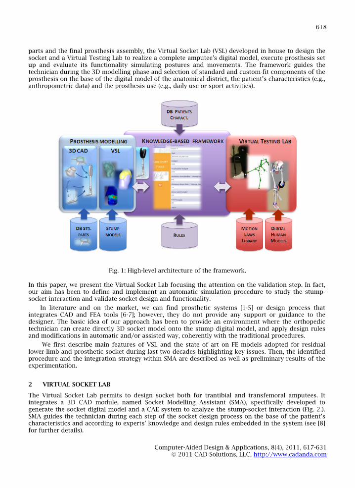
In such a context, we are developing an innovative framework, centered on digital models of thepatient or of his/her anatomical parts, which integrates a set of “assistants” to guide the techniciansduring each design task providing specific knowledge and rules (e.g., dimensioning or selection rulesfor standard parts). The framework, implemented using a commercial KBE system (Ruledesigner®Configurator) is not a simple interface among different software tools but an environment, whichmanages the operations sequence and pilots the appropriate tools for the realization of the specifictask, ensuring a high level of usability and interaction among the system and potential end-users. Itincludes (Fig. 1.): a commercial 3D CAD system to generate the 3D parametric models of the standard
Computer-Aided Design & Applications, 8(4), 2011, 617-631© 2011 CAD Solutions, LLC, http://www.cadanda.com
618
parts and the final prosthesis assembly, the Virtual Socket Lab (VSL) developed in house to design thesocket and a Virtual Testing Lab to realize a complete amputee's digital model, execute prosthesis setup and evaluate its functionality simulating postures and movements. The framework guides thetechnician during the 3D modelling phase and selection of standard and custom-fit components of theprosthesis on the base of the digital model of the anatomical district, the patient’s characteristics (e.g.,anthropometric data) and the prosthesis use (e.g., daily use or sport activities).
Fig. 1: High-level architecture of the framework.
In this paper, we present the Virtual Socket Lab focusing the attention on the validation step. In fact,our aim has been to define and implement an automatic simulation procedure to study the stump-socket interaction and validate socket design and functionality.
In literature and on the market, we can find prosthetic systems [1-5] or design process thatintegrates CAD and FEA tools [6-7]; however, they do not provide any support or guidance to thedesigner. The basic idea of our approach has been to provide an environment where the orthopedictechnician can create directly 3D socket model onto the stump digital model, and apply design rulesand modifications in automatic and/or assisted way, coherently with the traditional procedures.
We first describe main features of VSL and the state of art on FE models adopted for residuallower-limb and prosthetic socket during last two decades highlighting key issues. Then, the identifiedprocedure and the integration strategy within SMA are described as well as preliminary results of theexperimentation.
2 VIRTUAL SOCKET LAB
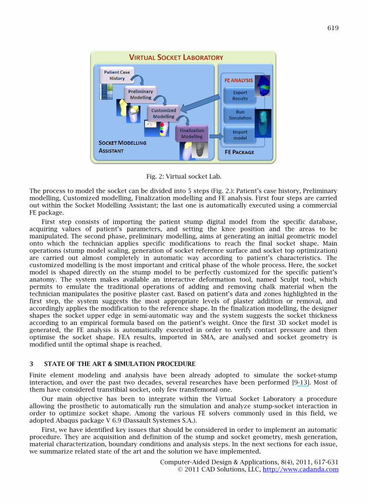
The Virtual Socket Lab permits to design socket both for trantibial and transfemoral amputees. Itintegrates a 3D CAD module, named Socket Modelling Assistant (SMA), specifically developed togenerate the socket digital model and a CAE system to analyze the stump-socket interaction (Fig. 2.).SMA guides the technician during each step of the socket design process on the base of the patient’scharacteristics and according to experts’ knowledge and design rules embedded in the system (see [8]for further details).
Computer-Aided Design & Applications, 8(4), 2011, 617-631© 2011 CAD Solutions, LLC, http://www.cadanda.com
619
Fig. 2: Virtual socket Lab.
The process to model the socket can be divided into 5 steps (Fig. 2.): Patient’s case history, Preliminarymodelling, Customized modelling, Finalization modelling and FE analysis. First four steps are carriedout within the Socket Modelling Assistant; the last one is automatically executed using a commercialFE package.
First step consists of importing the patient stump digital model from the specific database,acquiring values of patient’s parameters, and setting the knee position and the areas to bemanipulated. The second phase, preliminary modelling, aims at generating an initial geometric modelonto which the technician applies specific modifications to reach the final socket shape. Mainoperations (stump model scaling, generation of socket reference surface and socket top optimization)are carried out almost completely in automatic way according to patient’s characteristics. Thecustomized modelling is the most important and critical phase of the whole process. Here, the socketmodel is shaped directly on the stump model to be perfectly customized for the specific patient’sanatomy. The system makes available an interactive deformation tool, named Sculpt tool, whichpermits to emulate the traditional operations of adding and removing chalk material when thetechnician manipulates the positive plaster cast. Based on patient’s data and zones highlighted in thefirst step, the system suggests the most appropriate levels of plaster addition or removal, andaccordingly applies the modification to the reference shape. In the finalization modelling, the designershapes the socket upper edge in semi-automatic way and the system suggests the socket thicknessaccording to an empirical formula based on the patient’s weight. Once the first 3D socket model isgenerated, the FE analysis is automatically executed in order to verify contact pressure and thenoptimise the socket shape. FEA results, imported in SMA, are analysed and socket geometry ismodified until the optimal shape is reached.
3 STATE OF THE ART & SIMULATION PROCEDURE
Finite element modeling and analysis have been already adopted to simulate the socket-stumpinteraction, and over the past two decades, several researches have been performed [9-13]. Most ofthem have considered transtibial socket, only few transfemoral one.
Our main objective has been to integrate within the Virtual Socket Laboratory a procedureallowing the prosthetic to automatically run the simulation and analyze stump-socket interaction inorder to optimize socket shape. Among the various FE solvers commonly used in this field, weadopted Abaqus package V 6.9 (Dassault Systemes S.A.).
First, we have identified key issues that should be considered in order to implement an automaticprocedure. They are acquisition and definition of the stump and socket geometry, mesh generation,material characterization, boundary conditions and analysis steps. In the next sections for each issue,we summarize related state of the art and the solution we have implemented.
Computer-Aided Design & Applications, 8(4), 2011, 617-631© 2011 CAD Solutions, LLC, http://www.cadanda.com
620
3.1 Geometric Models Acquisition and Meshing
The external shape of the residual limb, the internal bones, the socket and the liner, if considered, arefundamental to create the FE model, which reflects the real geometry of the stump and permits tocompute the pressure distribution on limb surface. In fact, it is commonly accepted that themeaningful parameter to evaluate the socket functionality is the contact pressure between residuallimb and socket during patient’s movement.Geometry acquisition and the correct alignments can improve the quality of the simulation and theconvergence of results.
Zheng et al. [11] analyzed possible methods for geometric and biological assessment for residuallimb tissues, while Silver-Thorn et al. [14] identified qualities and limitations for each commontechnique from laser scanner to Magnetic Resonance Imaging. Colombo et al. [7] proposed amethodology to generate a 3D detailed model of the stump integrating data acquired with MagneticResonance Imaging (MRI), Computed Tomography (CT) and laser scanning.
For the acquisition of the stump morphology, we have selected MRI since it is the less invasivetechnique for the patient and permits to obtain a geometric model with reasonable accuracy. Atpresent, the 3D models of the soft tissues and bones are generated using the commercial softwareMimics and, then, imported into the Socket Modelling Assistant to create the 3D socket modelaccording to rules derived from prosthetics’ practice.
Generated models are imported and assembled into Abaqus using iges format: soft tissues andbones as 3D deformable solids while the socket as 3D deformable shell, because socket thickness issignificantly smaller than the other two dimensions.
The bony structure, the soft tissues and the socket are previously aligned using SMA. In ourapproach, bones and soft tissues are merged to create a unique part (the stump) without geometricdiscontinuity, despite the different parts that compose it, and taking into account the real distributionof rigidity. This solution allows us to simplify the real problem and consider the residual limb as acontinuum characterized by two models of different materials. It also prevents to specify the type ofinteraction existing between bones and muscles.
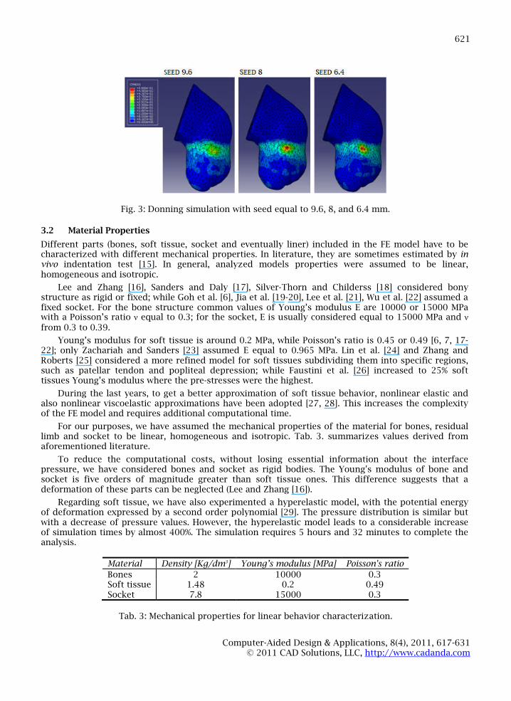
In order to automate the procedure we have adopted a free auto meshing technique. To select theseed value we have performed a sensitive analysis, since the size of the seed mesh influencessimulation times (Tab. 1.) and the conformity requirements of tetrahedral and triangular elements(Tab. 2.) in the residual limb and the socket. We have used explicit elements, which increase their sizein the internal regions, and, precisely, 3-noded triangular (S3R) elements for the socket and 4-nodetetrahedral (C3D4) for the stump. In our test-case, the whole FE model has 5323 nodes and 23460elements. Simulations have been performed using a workstation with Intel Xeon processor at 2.53 GHzand 12.0 GB of DDR3 RAM at 1333MHz.
Fig. 3. shows the pressure map for donning simulation using a seed equal to 9.6, 8, and 6.4 mm.Increasing the mesh detail, the pressure rises in the critical area; however, the values are lower of 50kPa than standard model. This means that a model with a seed equal to 8 mm, used as benchmark,simulates with sufficient accuracy the interaction between socket and stump, without increasingdramatically analysis time.
Seed mesh 9.6 8 (standard) 6.4
Time 1:05 1:28 4:02
Tab. 1: Simulation time for the entire process [h: min].
Tab. 2: Number of nonconforming items in the mesh.
Seed mesh 9.6 8 (standard) 6.4 3.2 Variable Seed
Distorted elements 14 9 6 3 138
Computer-Aided Design & Applications, 8(4), 2011, 617-631© 2011 CAD Solutions, LLC, http://www.cadanda.com
621
Fig. 3: Donning simulation with seed equal to 9.6, 8, and 6.4 mm.
3.2 Material Properties
Different parts (bones, soft tissue, socket and eventually liner) included in the FE model have to becharacterized with different mechanical properties. In literature, they are sometimes estimated by invivo indentation test [15]. In general, analyzed models properties were assumed to be linear,homogeneous and isotropic.
Lee and Zhang [16], Sanders and Daly [17], Silver-Thorn and Childerss [18] considered bonystructure as rigid or fixed; while Goh et al. [6], Jia et al. [19-20], Lee et al. [21], Wu et al. [22] assumed afixed socket. For the bone structure common values of Young’s modulus E are 10000 or 15000 MPawith a Poisson’s ratio ν equal to 0.3; for the socket, E is usually considered equal to 15000 MPa and ν from 0.3 to 0.39.
Young’s modulus for soft tissue is around 0.2 MPa, while Poisson’s ratio is 0.45 or 0.49 [6, 7, 17-22]; only Zachariah and Sanders [23] assumed E equal to 0.965 MPa. Lin et al. [24] and Zhang andRoberts [25] considered a more refined model for soft tissues subdividing them into specific regions,such as patellar tendon and popliteal depression; while Faustini et al. [26] increased to 25% softtissues Young’s modulus where the pre-stresses were the highest.
During the last years, to get a better approximation of soft tissue behavior, nonlinear elastic andalso nonlinear viscoelastic approximations have been adopted [27, 28]. This increases the complexityof the FE model and requires additional computational time.
For our purposes, we have assumed the mechanical properties of the material for bones, residuallimb and socket to be linear, homogeneous and isotropic. Tab. 3. summarizes values derived fromaforementioned literature.
To reduce the computational costs, without losing essential information about the interfacepressure, we have considered bones and socket as rigid bodies. The Young's modulus of bone andsocket is five orders of magnitude greater than soft tissue ones. This difference suggests that adeformation of these parts can be neglected (Lee and Zhang [16]).
Regarding soft tissue, we have also experimented a hyperelastic model, with the potential energyof deformation expressed by a second order polynomial [29]. The pressure distribution is similar butwith a decrease of pressure values. However, the hyperelastic model leads to a considerable increaseof simulation times by almost 400%. The simulation requires 5 hours and 32 minutes to complete theanalysis.
Material Density [Kg/dm3] Young’s modulus [MPa] Poisson's ratio
Bones 2 10000 0.3Soft tissue 1.48 0.2 0.49Socket 7.8 15000 0.3
Tab. 3: Mechanical properties for linear behavior characterization.
Computer-Aided Design & Applications, 8(4), 2011, 617-631© 2011 CAD Solutions, LLC, http://www.cadanda.com
622
3.3 Constraints
Interaction between stump and socket can be modeled as a contact problem at different level ofcomplexity, considering or not friction.
3.3.1 Contact Problem
Zachariah and Sanders [23] compared an automated contact interface model with a gap elementmodel. They found out that automated contact methods have a good behavior, in particular, when theinitial position of the limb in the socket is not known a priori. Lee et al. [21], using the samecomputational model, considered the prosthetic socket and residual limb as two deformable bodies incontact with different shapes and implemented the simulation of the pre-stresses produced bydonning the stump into the socket. Wu et al. [22] adopted the surface-to-surface contact element sinceit is better than the traditional point-to point contact pairs. Colombo et al. [7] adopted an explicit FEcode (LS-DYNA rev. 9.70) that allows managing adequately simulation problems characterized by largedeformations and difficult contact conditions. The choice of an explicit solver allows the use ofmodels that don’t require the definition of contact surfaces.
In our procedure, we simulate the contact conditions between the residual limb and prosthesiswith an automated surface-to-surface contact as Wu et al. [22].
3.3.2 Friction/slip Conditions between the socket and the Stump
In this case, friction means considering the friction coefficient between the skin and differentmaterials, assessing the shear stress and the slipping at the materials interface and estimating theshear stress contribution during load transfer.
First models considered the stump fully connected to the socket as one body; in this case eachpart assumes different mechanical properties [18]. Others considered the stump and the socket as twoseparate bodies with the same surface shape [23].
The magnitude of friction coefficient depends on the condition of the skin. It does not appear tobe significantly influenced by age or gender, and varies considerably in different district regions [30].
Zhang and Roberts [25], to simulate the friction/slip condition between the liner and skin, usedinterface elements to connect them; however, this lead to a poor match between the clinical datacollected and simulations, underestimating the pressures.
Lee et al. [21] assumed that the static and kinetic coefficients of friction were the same andallowed the slippage only when the shear stress exceeded the critical shear stress. During sliding, ifthe shear stress decreases and is lower than the critical shear stress value, sliding ends. For all thematerials tested by Zhang and Mak [31], the average coefficient of friction is equal to 0.46±0.15:silicone has the highest (0.61 ±0.21) while nylon has the lowest (0.37±0.09).
According to Lee et al. [21], we adopted the same model characteristics. It has been defined theinner surface of the socket and the outer surface of the stump respectively as the master and slavesurfaces. Both surfaces are potentially in contact or separated. According to the master-slave contactformulation and hard contact relationship used in Abaqus, donning and adjustment steps are friction-free, while during loading the friction coefficient is equal to 0.46 (Zhang and Mak [31]).
3.4 Boundary Conditions and Analysis Steps
FE analysis requires quantifying and specifying numerically the location of the external forces actingon the structure. Loads can be expressed in terms of strength and as stump movement. The static loadis equivalent to consider only the body weight. When deambulation is simulated, the load fluctuatesover time and can be quasi-static or quasi-dynamic depending whether inertia forces are considered ornot. Usually, load is applied to the knee joint center, which is concentrated in a single node in the bonestructure, or in the distal-end of the socket if the bone structure is fixed. The loads magnitude isestimated according to body weight or through experimental measurements that require the survey ofground reaction forces and joint angles.
In initial models, loads application was done in a single step because they did not consider frictionat the interface and the socket had the same stump shape. In this case, the simulation started with theprosthetic socket already donned. Sanders et al. [17] and Silver-Thorn and Childress [18, 32] applied
Computer-Aided Design & Applications, 8(4), 2011, 617-631© 2011 CAD Solutions, LLC, http://www.cadanda.com
623
loads and moments to the top of the socket; while Zhang et al. [25, 33] used a socket whose innersurface did not coincide with the external stump surface and considered the analysis divided into twosteps, reflecting the two different phases of soft tissue deformation.
Usually the constraints are applied to the socket edge. Sanders et al. [17] assumed the bone andthe knee joint to be zero displacement surfaces, Silver-Thorn and Childress [18] fixed the bones,Zhang et al. [25, 33] assumed the socket as rigid, Goh at al. [6], Lee and Zhang [16], Lee et al. [21] andWu et al. [22] considered the outer socket surface or the outer liner surface, which has the same innersocket shape, as fixed and rigid.
The geometry of FE model, consequently the directions of forces and moments, determinesconsiderably analysis results: the change of the stump posture affects the accuracy of interfaceforecast [34].
We decided to perform simulation in three phases corresponding to the deformation stages of softtissues. The first step replicates the donning of residual limb into the socket and imposes a pre-stresson the stump. Since we do not know these adaptive movements a priori and for computational costs,the donning simulation is performed by fixing the residual limb and moving the socket. Boundaryconditions have been defined as shown in Fig. 4(a).. Socket translation stops according to the length ofthe residual limb. The stump displacements, due to the wearing configuration, cause the pre-stress onthe residual limb.
Then, the adjustment phase follows to achieve a better repositioning of the socket around thestump and to obtain maximum comfort. Here, the socket is free to translate and rotate in differentdirections with the exception of the vertical one, which is kept locked until the load application inorder to prevent elastic recoil due to fit. During these two steps no external load is applied.
In the third and final step, the constant static load, equal to the amputee’s weight, is applied to thecentre of mass of the socket and has vertical direction to simulate single support stance (Fig. 4(b).).
Socket translation and the static load are not applied immediately, but gradually during theanalysis steps to avoid rapid acceleration and high inertia to the masses.
Fig. 4: FE models for residual limb and prosthetic socket: (a) direction of load and boundaries applied,and (b) final configuration.
3.5 Evaluation Parameters
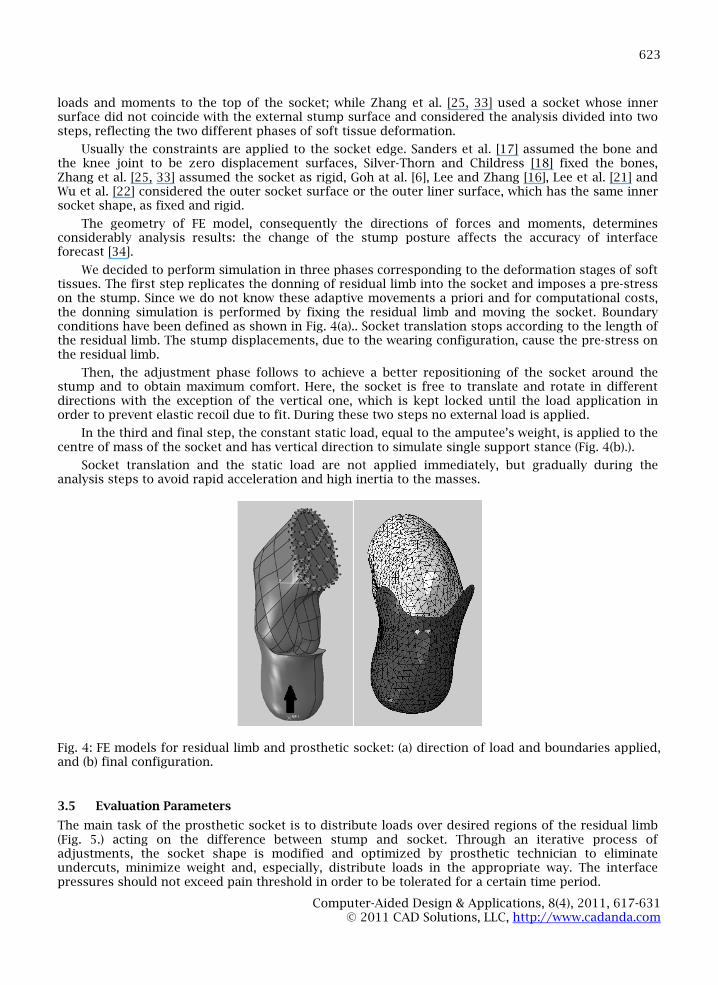
The main task of the prosthetic socket is to distribute loads over desired regions of the residual limb(Fig. 5.) acting on the difference between stump and socket. Through an iterative process ofadjustments, the socket shape is modified and optimized by prosthetic technician to eliminateundercuts, minimize weight and, especially, distribute loads in the appropriate way. The interfacepressures should not exceed pain threshold in order to be tolerated for a certain time period.
Computer-Aided Design & Applications, 8(4), 2011, 617-631© 2011 CAD Solutions, LLC, http://www.cadanda.com
624
Wu et al. [22] and Lee et al. [35] took over and compared the pain threshold, the minimumpressure that induces pain, and pain tolerance, the maximum tolerable pressure without feelingdiscomfort, in different regions of the residual limb through the indentation test, as shown in Tab. 4..
Lee et al. [35] demonstrated that these two parameters depend on the age and detection area, butare independent of the skin thickness. In addition, adjustments of some areas (e.g., patella tendon andpopliteal area) have a significant affects on the pressure in other stump’s regions [18, 33].
The validation of the finite element model can be made comparing the stresses expected withthose empirically measured [25, 34-42].
Fig. 5: Critical areas of transtibial residual limb (In gray the load areas) [25].
Pressure (kPa) Fibula’s head Medial condyle Popliteal depression Distal area Tendon patellar
Pain threshold 599.6±82.6 555.2±132.2 503.2±134.2 396.3±154.5 919.6±161.7Pain tolerance 789.8±143.0 651.0±111.1 866.6±77.3 547.6±109.1 1158.3±203.2
Tab. 4: Pressure pain threshold and pain tolerance in different stump’s regions [22].
4 IMPLEMENTATION
As said, our main goal has been to realize a virtual laboratory where it is possible to optimizesocket shape according to patient’s morphology. For this purpose, we have developed a FE simulationmodule with Python language. It implements the procedure described in Section 3 and integrates SMAwith the commercial FE solver, Abaqus.
Abaqus can be used in two modes: through Abaqus CAE-Graphical User Interface (GUI) or AbaqusScripting Interface. We considered the second tool since it allows bypassing the ABAQUS/CAE GUI andcommunicating directly with the kernel using a script or rather a file containing ABAQUS ScriptingInterface commands. This permits to execute a series of “jobs” without manual intervention. TheABAQUS Scripting Interface is an extension of the object-oriented language called Python and uses thesyntax and operators required by Abaqus. Embedding in the script all the commands to import thegeometries and to define the FE model, it is possible to perform automatically the simulation inAbaqus, launched directly from the Socket Modelling Assistant (SMA).
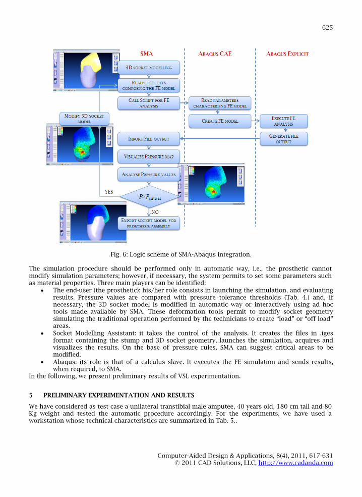
Fig. 6. shows the logic sequence of the operations performed by the script and interactionsbetween SMA and Abaqus.
Computer-Aided Design & Applications, 8(4), 2011, 617-631© 2011 CAD Solutions, LLC, http://www.cadanda.com
625
Fig. 6: Logic scheme of SMA-Abaqus integration.
The simulation procedure should be performed only in automatic way, i.e., the prosthetic cannotmodify simulation parameters; however, if necessary, the system permits to set some parameters suchas material properties. Three main players can be identified:
The end-user (the prosthetic): his/her role consists in launching the simulation, and evaluatingresults. Pressure values are compared with pressure tolerance thresholds (Tab. 4.) and, ifnecessary, the 3D socket model is modified in automatic way or interactively using ad hoctools made available by SMA. These deformation tools permit to modify socket geometrysimulating the traditional operation performed by the technicians to create “load” or “off load”areas.
Socket Modelling Assistant: it takes the control of the analysis. It creates the files in .igesformat containing the stump and 3D socket geometry, launches the simulation, acquires andvisualizes the results. On the base of pressure rules, SMA can suggest critical areas to bemodified.
Abaqus: its role is that of a calculus slave. It executes the FE simulation and sends results,when required, to SMA.
In the following, we present preliminary results of VSL experimentation.
5 PRELIMINARY EXPERIMENTATION AND RESULTS
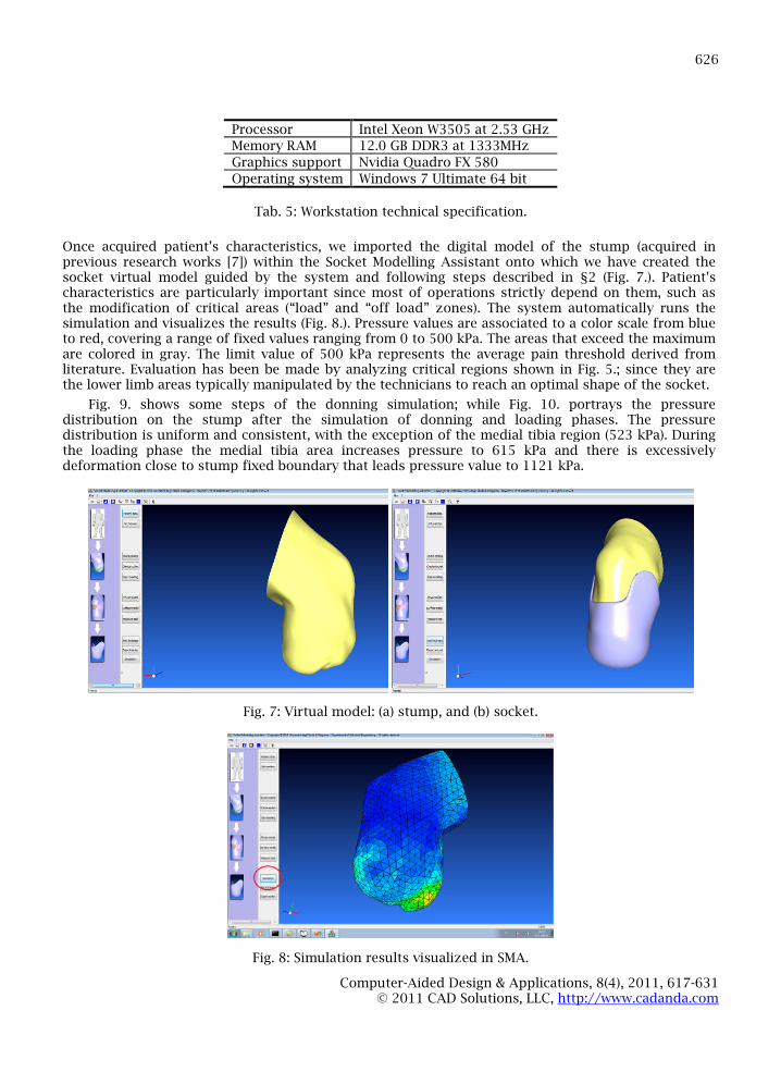
We have considered as test case a unilateral transtibial male amputee, 40 years old, 180 cm tall and 80Kg weight and tested the automatic procedure accordingly. For the experiments, we have used aworkstation whose technical characteristics are summarized in Tab. 5..
Computer-Aided Design & Applications, 8(4), 2011, 617-631© 2011 CAD Solutions, LLC, http://www.cadanda.com
626
Processor Intel Xeon W3505 at 2.53 GHz
Memory RAM 12.0 GB DDR3 at 1333MHz
Graphics support Nvidia Quadro FX 580
Operating system Windows 7 Ultimate 64 bit
Tab. 5: Workstation technical specification.
Once acquired patient’s characteristics, we imported the digital model of the stump (acquired inprevious research works [7]) within the Socket Modelling Assistant onto which we have created thesocket virtual model guided by the system and following steps described in §2 (Fig. 7.). Patient’scharacteristics are particularly important since most of operations strictly depend on them, such asthe modification of critical areas (“load” and “off load” zones). The system automatically runs thesimulation and visualizes the results (Fig. 8.). Pressure values are associated to a color scale from blueto red, covering a range of fixed values ranging from 0 to 500 kPa. The areas that exceed the maximumare colored in gray. The limit value of 500 kPa represents the average pain threshold derived fromliterature. Evaluation has been be made by analyzing critical regions shown in Fig. 5.; since they arethe lower limb areas typically manipulated by the technicians to reach an optimal shape of the socket.
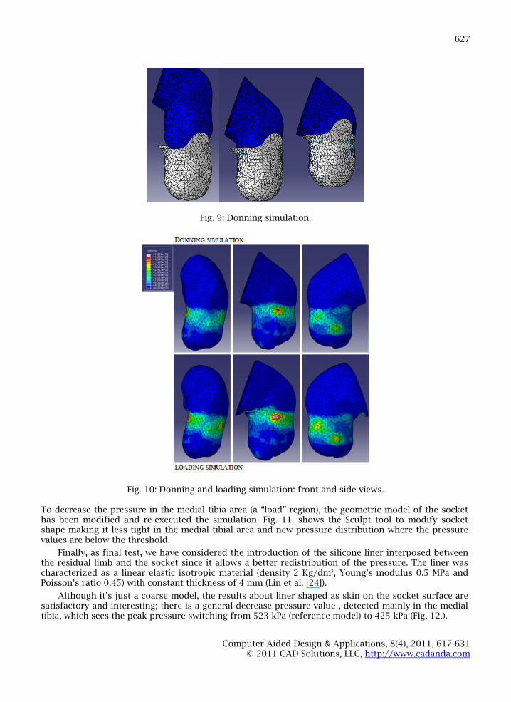
Fig. 9. shows some steps of the donning simulation; while Fig. 10. portrays the pressuredistribution on the stump after the simulation of donning and loading phases. The pressuredistribution is uniform and consistent, with the exception of the medial tibia region (523 kPa). Duringthe loading phase the medial tibia area increases pressure to 615 kPa and there is excessivelydeformation close to stump fixed boundary that leads pressure value to 1121 kPa.
Fig. 7: Virtual model: (a) stump, and (b) socket.
Fig. 8: Simulation results visualized in SMA.
Computer-Aided Design & Applications, 8(4), 2011, 617-631© 2011 CAD Solutions, LLC, http://www.cadanda.com
627
Fig. 9: Donning simulation.
Fig. 10: Donning and loading simulation: front and side views.
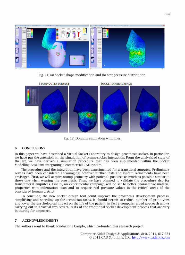
To decrease the pressure in the medial tibia area (a “load” region), the geometric model of the sockethas been modified and re-executed the simulation. Fig. 11. shows the Sculpt tool to modify socketshape making it less tight in the medial tibial area and new pressure distribution where the pressurevalues are below the threshold.
Finally, as final test, we have considered the introduction of the silicone liner interposed betweenthe residual limb and the socket since it allows a better redistribution of the pressure. The liner wascharacterized as a linear elastic isotropic material (density 2 Kg/dm3, Young’s modulus 0.5 MPa andPoisson’s ratio 0.45) with constant thickness of 4 mm (Lin et al. [24]).
Although it’s just a coarse model, the results about liner shaped as skin on the socket surface aresatisfactory and interesting; there is a general decrease pressure value , detected mainly in the medialtibia, which sees the peak pressure switching from 523 kPa (reference model) to 425 kPa (Fig. 12.).
Computer-Aided Design & Applications, 8(4), 2011, 617-631© 2011 CAD Solutions, LLC, http://www.cadanda.com
628
Fig. 11: (a) Socket shape modification and (b) new pressure distribution.
Fig. 12: Donning simulation with liner.
6 CONCLUSIONS
In this paper we have described a Virtual Socket Laboratory to design prosthesis socket. In particular,we have put the attention on the simulation of stump-socket interaction. From the analysis of state ofthe art, we have derived a simulation procedure that has been implemented within the SocketModelling Assistant integrating a commercial CAE system.
The procedure and the integration have been experimented for a transtibial amputee. Preliminaryresults have been considered encouraging; however further tests and system refinements have beenenvisaged. First, we will acquire stump geometry with patient’s postures as much as possible similar tothose one when wearing the prosthesis. Then, we have planned to validate the procedure also fortransfemoral amputees. Finally, an experimental campaign will be set to better characterise materialproperties with indentation tests and to acquire real pressure values in the critical areas of theconsidered human district.
To conclude, the new socket design tool could improve the prosthesis development process,simplifying and speeding up the technician tasks. It should permit to reduce number of prototypesand lower the psychological impact on the life of the patient; in fact a computer aided approach allowscarrying out in a virtual way several tests of the traditional socket development process that are verybothering for amputees.
7 ACKNOWLEDGEMENTS
The authors want to thank Fondazione Cariplo, which co-funded this research project.
629
Computer-Aided Design & Applications, 8(4), 2011, 617-631© 2011 CAD Solutions, LLC, http://www.cadanda.com
REFERENCES
[1] BioScanner, BioShape Software, Digital Socket System, http://biosculptor.com, Finnieston Group.[2] ComfORTAC, OrtenPix-ActiveCurve, www.orten.fr, Orten.[3] Rodin4D CAD/CAM System, www.rodin4d.com, Rodin4D.[4] Autodigitizer, AutoScanner, AutoSculpt, www.infinitycadsystems.com, Infinity CAD Systems.[5] Canfit P&O CAD/CAM System, www.vorum.com, Vorum.[6] Goh, J.C.H.; Lee, P.V.S.; Toh, S.L.; Ooi, C.K.: Development of an integrated CAD–FEA process for
below-knee prosthetic sockets, Clinical Biomechanics, 20(6), 2005, 623–629, DOI:10.1016/j.clinbiomech.2005.02.005.
[7] Colombo, G.; Filippi, S.; Rizzi, C.; Rotini, F.: A new design paradigm for the development ofcustom-fit soft sockets for lower limb prostheses, Computers in Industry, 61(6), 2010, 513–523,DOI: 10.1016/j.compind.2010.03.008.
[8] Facoetti, G.; Gabbiadini, S.; Colombo, G.; Rizzi, C.: Knowledge-based system for guided modellingof sockets for lower limb prostheses, Computer-Aided Design & Applications, 7(5), 2010, 723-737, DOI: 10.3722/cadaps.2010.723-737.
[9] Zhang, M.; Mak, A.F.T.; Roberts, V.C.: Finite element modelling of a residual lower-limb in aprosthetic socket: a survey of the development in the first decade, Medical Engineering & Physics,20(5), 1998, 360-373, ISSN: 1350-4533.
[10] Sewell, P.; Noroozi, S.; Vinney, J.; Andrews S.: Development in the trans-tibial prosthetic socketfitting process: a review of past and present research, Prosthetic and Orthotics International,24(2), 2000, 97-107, ISSN: 0309-3646.
[11] Zheng, Y.D.; Mak, A.F.T.; Leung, A.K.L.: State-of-the-art methods for geometric and biomechanicalassessments of residual limbs: A review, Journal of Rehabilitation Research and Development,38(5), 2001, 487–504, ISSN: 0748-7711.
[12] Mak, A.F.T.; Zhang, M.; Boone, D.A.: State-of-the-art research in lower-limb prostheticbiomechanics socket interface: A review, Journal of Rehabilitation Research and Development,38(2), 2001, 161-174, ISSN: 0748-7711.
[13] Baars, E.C.T.; Geertzen, J.H.B.: Literature review of the possible advantages of silicon liner socketuse in trans-tibial prostheses, Prosthetics and Orthotics International, 29(1), 2005, 27-37, DOI:10.1080/17461550500069612.
[14] Silver-Thorn, M.B.; Steege, J.W.; Childress, D.S.: A review of prosthetic interface stressinvestigation, Journal of Rehabilitation Research and Development, 33(3), 1996, 253–266, ISSN:0007-506X.
[15] Zhang, M.; Zheng, Y.P.; Mak, A.F.T: Estimating the effective Young's modulus of soft tissues fromindentation tests—nonlinear finite element analysis of effects of friction and large deformation,Medical Engineering & Physics, 19(6), 1997, 512–517, ISSN: 1350-4533.
[16] Lee, W.C.C.; Zhang, M.: Using computational simulation to aid in the prediction of socket fit: Apreliminary study, Medical Engineering & Physics, 29(8), 2007, 923-929, DOI:10.1016/j.medengphy.2006.09.008.
[17] Sanders, J.E.; Daly, C.H.: Normal and shear stresses on a residual limb in a prosthetic socketduring ambulation : Comparison of finite element results with experimental measurements,Journal of Rehabilitation Research and Development, 30(2), 1993, 191-204, ISSN: 0007-506X.
[18] Silver-Thorn, M.B.; Childress, D.S.: Parametric analysis using the finite element method toinvestigate prosthetic interface stresses for persons with trans-tibial amputation, Journal ofRehabilitation Research and Development, 33(3), 1996, 227-238, ISSN: 0007-506X.
[19] Jia, X.; Zhang, M.; Lee, W.C.C.: Load transfer mechanics between transtibial prosthetic socket andresidual limb - Dynamic effects, Journal of Biomechanics, 37(9), 2004, 1371–1377, DOI:10.1016/j.jbiomech.2003.12.024.
[20] Jia, X.; Zhang, M.; Li, X.; Lee, W.C.C.: A quasi-dynamic nonlinear finite element model toinvestigate prosthetic interface stresses during walking for trans-tibial amputees, ClinicalBiomechanics, 20(6), 2005, 630-635, DOI: 10.1016/j.clinbiomech.2005.03.001.
[21] Lee, W.C.C.; Zhang, M.; Jia, X.; Cheung, J.M.T.: Finite element modeling of the contact interfacebetween trans-tibial residual limb and prosthetic socket, Medical Engineering & Physics, 26(8),2004, 655–662, DOI: 10.1016/j.medengphy.2004.04.010.
Computer-Aided Design & Applications, 8(4), 2011, 617-631© 2011 CAD Solutions, LLC, http://www.cadanda.com
630
[22] Wu, C.L.; Chang, C.H.; Hsu, A.T.; Lin, C.C.; Chen, S.I.; Chang, G.L.: A proposal for the pre-evaluation protocol of below-knee socket design-integration pain tolerance with finite elementanalysis, Journal of the Chinese Institute of Engineers, 26(6), 2003, 853-860,ISSN: 0253-3839.
[23] Zachariah, S.G.; Sanders, J.E.: Finite element estimates of interface stress in the trans-tibialprosthesis using gap elements are different from those using automated contact, Journal ofBiomechanics, 33(7), 2000. 895–899, ISSN: 0021-9290.
[24] Lin, C.C.; Chang, C.H.; Wu, C.H; Chung, K.C.; Liao, I.L.: Effects of liner stiffness for trans-tibialprosthesis: a finite element contact mode, Medical Engineering & Physics, 26(1), 2004,1-9, DOI:10.1016/s1350-4533(03)00127-9.
[25] Zhang, M.; Roberts, C.: Comparison of computational analysis with clinical measurement ofstresses on below-knee residual limb in a prosthetic socket, Medical Engineering & Physics, 22(9),2000, 607–612, ISSN: 1350-4533.
[26] Faustini, M.C.; Neptune, R.R.; Crawford, R.H.: The quasi-static response of compliant prostheticsockets for transtibial amputees using finite elements methods, Medical Engineering & Physics,28(2), 2006, 114-121, DOI: 10.1016/j.medengphy.2005.04.019.
[27] Tönuk, E.; Silver-Thorn, M.B.: Nonlinear elastic material property estimation of lower extremityresidual limb tissues, IEEE Transactions on Neural Systems and Rehabilitation Engineering, 11(1),2003, 43-53, DOI: 10.1109/tnsre.2003.810436.
[28] Tönuk, E.; Silver-Thorn, M.B.: Nonlinear viscoelastic material estimation of lower extremityresidual limb tissues, Journal of Biomechanical Engineering, 126(2), 2004, 289-300, DOI:10.1115/1.1695575.
[29] Cheung, M., Zhang, J.T.M.: Finite element modeling of human foot and footwear, Proceedings of19th Annual International ABAQUS Users’ Conference, Boston, USA, 2006, 145–159.
[30] Zhang, M.; Turner-Smith, A.R.; Roberts, V.C.; Tanner, A.: Frictional action at lower limb-prostheticsocket interface, Medical Engineering & Physics, 18(3), 1996, 207-214, ISSN: 1350-4533.
[31] Zhang, M.; Mak, A.F.T.: In vivo friction properties of human skin, Prosthetics and OrthoticsInternational , 23(2), 1999, 135-141, ISSN: 0309-3646.
[32] Silver-Thorn, M.B.; Childress, D.S.: Generic, geometric finite element analysis of the trans-tibialresidual limb and prosthetic socket, Journal of Rehabilitation Research & Development, 34(2),1997, 171-186, ISSN: 0748-7711.
[33] Zhang, M.; Lord, M.; Turner-Smith, A.R.; Roberts, V.C.: Development of a non linear finite elementmodeling of the below-knee prosthetic socket interface, Medical Engineering & Physics , 17(8),1995, 559–566, ISSN: 1350-4533.
[34] Zhang, M.; Turner-Smith, A.R.; Tanner, A.; Roberts, V.C.: Clinical investigation of the pressure andshear stress on the trans-tibial stump with a prosthesis, Medical Engineering & Physics, 20(3),1998, 188–198, ISSN: 1350-4533.
[35] Lee, W.C.C.; Zhang, M.; Mak, A.F.T.: Regional differences in pain threshold and tolerance of thetranstibial residual limb: including the effects of age and interface material, Archives of PhysicalMedicine and Rehabilitation, 86(4), 2005, 641-649, DOI: 10.1016/j.apmr.2004.08.005.
[36] Commean, P.K.; Smith, K.E.; Vannier, M.W.: Lower extremity residual limb slippage within theprosthesis, Archives of Physical Medicine and Rehabilitation, 78(5), 1997, 476–485, ISSN: 0003-9993.
[37] Papaioannou, G.; Mitrogiannis, C.; Nianios, G.; Fiedler, G.; Assessment of amputee socket–stump–residual bone kinematics during strenuous activities using Dynamic Roentgen StereogrammetricAnalysis, Journal of Biomechanics, 43(5), 2010, 871-878, DOI: 10.1016/j.jbiomech.2009.11.013.
[38] Convery, P.; Buis, A.W.P.: Conventional patellar-tendon-bearing (PTB) socket/stump interfacedynamic pressure distributions recorded during the prosthetic stance phase of gait of a trans-tibial amputee, Prosthetics and Orthotics International, 22(3), 1998, 193–198, ISSN: 0309-3646.
[39] Convery, P.; Buis, A.W.P.: Socket/stump interface dynamic pressure distribution recorded duringthe prosthetic stance phase of gait of a trans-tibial amputee wearing a hydrocast socket,Prosthetics and Orthotics International, 23(2), 1999, 107-112, ISSN: 0309-3646.
[40] Dou, P.; Jia, X.; Suo, S.; Wang, R.; Zhang, M.: Pressure distribution at the stump/socket interface intranstibial amputees during walking on stairs, slope and non-flat road, Clinical Biomechanics,21(10), 2006, 1067–1073, DOI: 10.1016/j.clinbiomech.2006.06.004.
Computer-Aided Design & Applications, 8(4), 2011, 617-631© 2011 CAD Solutions, LLC, http://www.cadanda.com
631
[41] Goh, J.C.H.; Lee, P.V.S.; Sook, Y.C.: Comparative study between patellar-tendon-bearing andpressure cast prosthetic sockets, Journal of Rehabilitation Research & Development, 41(3B),2004, 491–502, ISSN: 0748-7711.
[42] Dumbleton, T.; Buis, A.W.P.; McFadyen, A.; McHugh, B.F.; McKay, G.; Murray, K.D.; Sexton, S.:Dynamic interface pressure distributions of two transtibial prosthetic socket concepts, Journalof Rehabilitation Research & Development, 46(3), 2009, 405–415, DOI:10.1682/jrrd.2008.01.0015.


![[Modul Konsep Jaringan] Bab 12 Socket Programming](https://img.dokumen.tips/doc/110x75/635a7e6c8521ebfad00d4dea/modul-konsep-jaringan-bab-12-socket-programming.jpg)


