Embed Size (px)
Citation preview
Phase-stepping automatic fringe analysisin holographic moire
Eli Simova Simova and Krassimir Nedialkov Stoev
The phase-stepping technique is used to analyze holographic moir6 patterns. This new applicationpermits the instantaneous determination of phase functions in both moir6 and carrier fringes. Twomodified phase-stepping self-calibrating techniques are proposed and demonstrated on computer-generated noisy moir6 patterns. The techniques do not complicate the holographic moir6 arrangementand do not need auxiliary carrier fringes. A holographic moir6 interferometer that has been adapted forthese phase-stepping techniques is proposed.
Key words: Automatic fringe pattern analysis, phase-stepping interferometry, holographic moire.
1. Introduction
Holographic interferometry has been demonstratedto be a useful technique with applications in opticalmetrology and nondestructive testing. One majorproblem in holographic interferometry is the quanti-tative evaluation of the fringe pattern. After phase-shifting interferometry (PSI) is developed, it is possi-ble to perform easy and fast quantitative evaluationof interferograms.1- 6 In PSI the phase differencebetween the two interfering beams is varied, andmeasurements are made of the intensity distributionacross the image. If the values of the phase shiftsare known, the original phase difference between theinterfering beams can be calculated. Many differentalgorithms have been published for the defermina-tion of a wave-front phase. The number of intensitymeasurements after the phase is shifted also varies:three-, four-, five-frame and scanning phase-shifttechniques. 7 ,8 The phase-stepping technique has al-ready been incorporated in several holographic inter-ferometric methods.9' 10
Holographic moir6 (HM) has also been proved to bea promising tool for in-plane and out-of-plane displace-ment, strain and slope measurements, and nonde-structive testing.'1 -14 However, the interest in this
E. Simova Simova is with the Central Laboratory of OpticalStorage and Processing of Information, Bulgarian Academy ofSciences, P.O. Box 95, 1113 Sofia, Bulgaria; K. N. Stoev is with theInstitute of Nuclear Energy & Nuclear Research, Bulgarian Acad-emy of Sciences, Blvd. Trakia 72, 1784 Sofia, Bulgaria.
Received 17 July 1991.0003-6935/92/285965-10$05.00/0.3 1992 Optical Society of America.
method has declined in the last few years because ofthe difficult and time-consuming quantitative analy-sis of HM patterns. Measurements of one set ofmoir6 fringes yield only one displacement component.Two experiments are necessary to determine sepa-rately the in-plane and out-of-plane displacementcomponents. An auxiliary spatial carrier is usuallyadded so that the moir6 fringes map either thein-plane or the out-of-plane displacements. Imagepreprocessing requires optical or digital filtering ofthe carrier,15 thus some of the information is lost.
Only recently has the conventional three-phase-stepping technique been applied to comparative HMby Rastogi et al. 6 The moir6 fringes and the differ-ence in displacement fields of two nominally identicalspecimens are obtained after numerical subtractionof the wrapped phase functions.
We present two new modifed phase-stepping self-calibrating techniques for the automatic analysis ofHM patterns without the need for auxiliary carrierfringes. The advantage of the proposed techniquesis the instantaneous determination of phase func-tions in both moir6 and carrier interference fringes.The techniques are demonstrated on computer-generated noisy moir6 patterns. We propose anexemplary HM arrangement that has been adaptedfor phase stepping and real-time or double-exposureoperation.
2. Basic Equations in Holographic MoireIntrinsic HM uses dual-beam illumination that issymmetrical to the specimen normal. The intensitydistribution in the double-exposure holographic inter-ferogram that is formed by each object beam after the
1 October 1992 / Vol. 31, No. 28 / APPLIED OPTICS 5965
object is deformed is
I.= I,( xy)I1 + V,(X, y)
X cos[A4J(XY) ± ali], (1)
12i = I2(X, y)1 + V2 (x, y)
X Cos[IA 2(x, y) ± %2 i]}, (2)
where A41,2(x, y) are the phase differences that arerelated to changes in the object when illuminatedwith the corresponding beam; Il,20(x, y) and V1,2(x, y)are the mean intensity and the fringe contrast of eachinterferogram at a given point (x, y), and U-1,2i are thephase steps introduced at the reconstruction. Byequal intensities of the object beams and equal diffrac-tion efficiencies of the reconstructed images bothinterferograms have equal mean intensity and fringecontrast, i.e., I,,(x, y) = 120(x, y) and VI(x, y) = V2(x, y).The moir6 pattern intensity distribution is given by
Ji(x,y) = Ili + I2i = 21 (x,y)
x (1 + V(x,y)cos{[A(,l(x,y)
+ A: 2 (,Y) ± (ali + a2 i)]121
x cos{[A4l(x, Y) - Ak 2(x,Y)
- (ali - a2 i)]1/2). (3)
The relationships between wave-front phases andmeasured surface displacements at normal observa-tion are
(A4, - A+ 2)/2 = (2'rr/X)u sin 0,
(A+, + A42 )/2 = (2,rr/X)w(1 + cos 0), (4)
where 0 is the angle of illumination and u and w arethe in-plane and out-of-plane displacement compo-nents at a given point (x, y). The auxiliary carrier isusually added to the cosine term of the sum so thatmoir6 fringes map the in-plane displacement compo-nent. To visualize the out-of-plane displacementsthe carrier is added to the term of the difference.
In the case of comparative HM interferometry' 4 therelationship between wave-front phases and differ-ences in the surface displacements is given by
(A4, - A4)2 )/2 = rr/X[K zAL(r)]
(Atl + AM2)/2 = 2I/X[K * Lm(r)], (5)
where K = ki - k, is the sensitivity vector; ki and k0are the unit vectors of illumination and observation,Lm(r) is the displacement vector at each point of themaster surface after deformation; L, (r) = Lm (r) +AL(r) is the displacement vector at each point of thetest surface; and AL(r) is the additional displacementintroduced by the flaw in the test surface, whereI AL(r) I << I Lm (r) 1. If both interference patterns areinsufficiently dense to produce visible moir6 fringes,an auxiliary carrier is also added. The quality of the
moir6 fringes depends on the density of the carrierfringes.
3. Phase-Measurement AlgorithmsAccurate calibration of the phase-shifting device inPSI is important for obtaining correct phase stepsbetween data frames. Usually the phase step is notknown exactly, and it varies across the image. Thisproblem is solved by using a self-calibrating algo-rithm that calculates the values of the phase functionafter the actual phase step at each image point isevaluated. The simplest self-calibrating algorithmrequires four measurements.'7 If the original phasedifference is close to multiples of Tr, the uncertainty inthe values of tan(ax) and tan(A4) increases. Thisdifficulty is avoided with a five-phase-stepping tech-nique.' 8"9 It gives smaller errors for large devia-tions of the phase step from a nominal value of 90°.19
A. Modified Self-Calibrating Algorithm I
Here we consider the first modified self-calibratingalgorithm. Since there are at least five unknowns(I., V, a, A1l,, A 2) in Eq. (3), provided that IaI =Ia2 |, at least five phase-stepped moir6 patterns arerequired to solve phase functions At\,, A42, and a.The successive introduction of phase steps [see Eq.(3)] (ali + a2i) = 0, -o, -aL, +(x, +a into (A4, + 042),and (ali - a2i) = 0, -a-, +a, +a, -a into (AzXl - A02)in the reconstructed moir6 pattern leads to
Jo(x,y) = 2I(x,y)j1 + V(x,y)
X COS[(A41 + A4 2)/2]
x cos[(Al - 40/2]);
Jl(x,y) = 2I 0(xy)1 + V(x,y)
X COS[(A41 + A02 - a)/2]
X cos[(A - A4 2 - ax)/2]J;
J2 (x,y) = 2I 0(xy){1 + V(x,y)
X cOs[(A( + A42 - a)/2]
X cos[(A)l - A4 2 + ot)/2]);
J3 (x,y) = 210(x,y)fl + V(x,y)
X cOs[(A^ + A4 2 + a)/2]
x cos[(A'k, - A4 2 + a)/2]1;
J4(x,y) = 2I0(x,y)(1 + V(x,y)
x cos[(41 + A42 + a)/2]
X COS[(A4l1 - 2 - a)/2]).
The phase functions A(\l and A42 are then given by
01 = 2 tan-' [tan(ot/2) 2Jl J+
= 2 ta - tan(-i 2) J2 1 J4-2 nu X ua~ a 2J 0 - (J2 + J4) I1 (7)
5966 APPLIED OPTICS / Vol. 31, No. 28 / 1 October 1992
(6)
where
tan2(a/2)- [(J- - J4 ) - ( 2 - J3 )]an~a2 - 1(J- J 4 ) + (J 2 -JA)
[4Jo - (J1 + J2 + J 3 + J4 )]
X W1 - J3) - 2 - J)(8)
Equations (7) give the most rapid evaluation of bothphase functions: the phase values are available ateach pixel location and concave and convex featuresare unambiguously resolved. The sum and the differ-ence of the phase functions are given by
A4 + A4 2 = 2 tan-' an(a/2) (J1 - J 2) - 4 J3|(J - J2) + (J4 - J3)J
4 - 42 = 2 tan-' tan(a/2) (J1 - 4) 2 _ J3)
(9)
The mean intensity Io(x, y) and the fringe contrastV(x, y) can also be determined from Eqs. (6) and allowone to control the quality of the moir6 patterns and toreduce the noise in the image.9
B. Modified Self-Calibrating Algorithm 11After we introduce successive phase steps (a +a2i) = 0, -a, +, -3, +, +2( - 3), -2(o - 3) into(A1 + 2 ), and ( - a2d = 0, -, +, +, -,
(-2)(4Jocos(a) =
cos() =
2 4JO
J2 (x, y) = 2Io(x, y){1 + V(x, y)
x cos[(A41 + A4 2 + (x)/2]
x cos[(A41 - Ak2 + )/2]),
J3 (x, y) = 2IO(x, y){1 + V(x, y)
x cos[(A 1 + A 2 - )/2]x cos[(A41 - A42 + 13)/2]),
J 4(x,y) = 210(x,y)I1 + V(x,y)
x cos[(A41 + A4 2 + 13)/2]
x cos[(A4 -- - 13)/2]),
J5 (x,y) = 2IO(xy)I1 + V(x,y)
x cos[(A41 + A42 )/2 + ( - )]
x cos[(A41 - A42 )/2 + ( + )]),
J6 (x, y) = 2IO(x, y)I1 + V(x, y)
X COS[(c1 + A42 )/2 - ( - )]x COS[(A41 - A4 2)/2 - (a + p)13, (10)
The phase functions A1\, and A42 are then given by
Azc = tan-' tan(a/2) 2J - (J + J) '
42 = tan' [tan(/2) 2Jo -(J 3 J+ J 4)I (11)
4- Iz Ji (J3 - J4) + (J6 - J5)[2Wo - (J3 + J4)] + (J3 - J4)[2Wo - (J5 + J6)]
2[(Jl- J2 ) - (J 3 - J4 )[2J - (J3 + J4)] + (4Jo - EJi (J 3 - J4 )
4
- Ji) (Ji - J2 ) + (J6 - J5 )[2Jo - (J1 + J 2 )] + (J1 - J2 )[2Jo - (J 5 + J 6 )]i='
2(J1 - J 2 ) - (J3 - J 4 )][2J -4
(J + J 2)] - 4JO - 2 Ji (J 1 - J2 )i=l
(12)
+2(ax + ,B), -2(a + ) into (A+, - A4 2) in the recon-structed HM pattern, the intensity distributions areexpressed by the following equations:
Jo(x, y) = 2(x, y)| + V(x, y)
X COS[(A4 + A 2 )/2]cos[(A/ - 211,
J,(x, y) = 2(x, y) 1 + V(x, y)
X COS[(4 1 + 42 - )/2]
X COS[(41 - A4 2 - a)/2]),
4. Experimental Arrangement
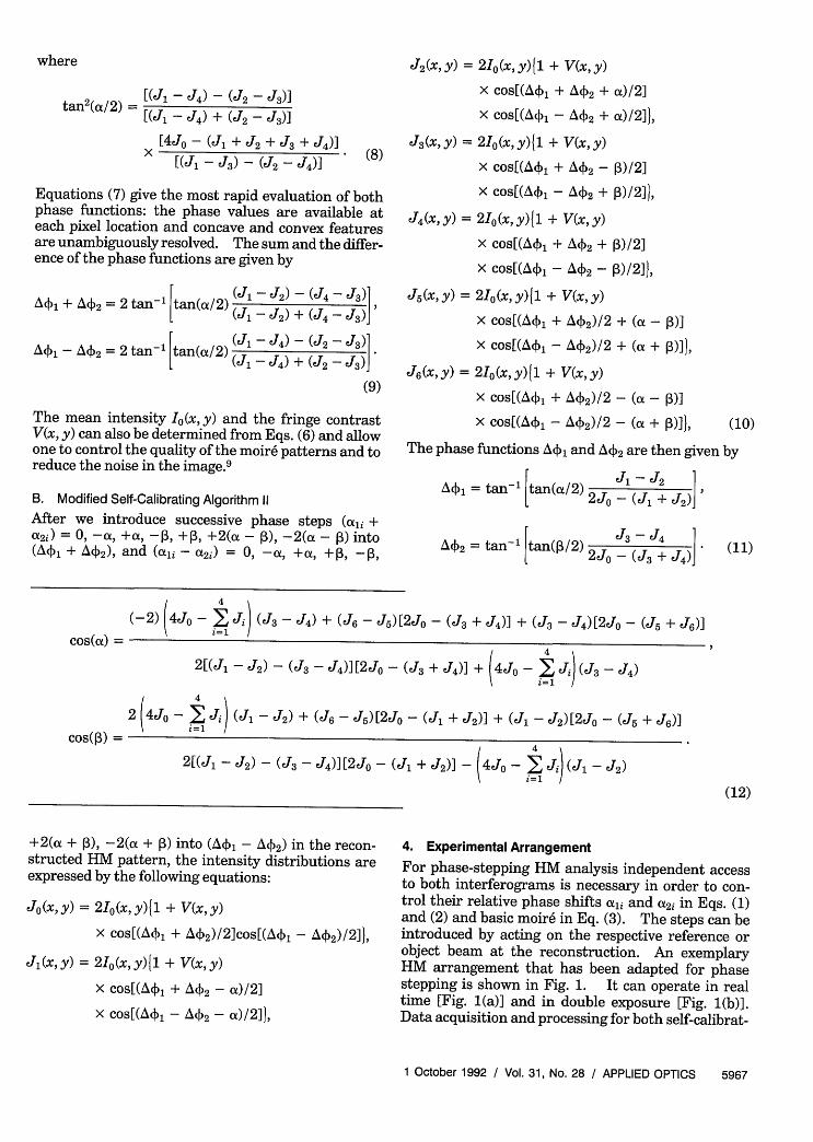
For phase-stepping HM analysis independent accessto both interferograms is necessary in order to con-trol their relative phase shifts ali and at2i in Eqs. (1)and (2) and basic moir6 in Eq. (3). The steps can beintroduced by acting on the respective reference orobject beam at the reconstruction. An exemplaryHM arrangement that has been adapted for phasestepping is shown in Fig. 1. It can operate in realtime [Fig. (a)] and in double exposure [Fig. 1(b)].Data acquisition and processing for both self-calibrat-
1 October 1992 / Vol. 31, No. 28 / APPLIED OPTICS 5967
PS I01 ' \N CCCD TVcamera monitor
U
0 Micro°2 Lens Hlo computer
02 PS plate(a)
PSR, gX<\ CCD TV
camera monitor
MicroLens Holo computer
R2 ( plate
(b
Fig. 1. Holographic moire arrangement that was adapted for thephase-stepping technique: (a) real-time operation; (b) double-exposure operation.
ing algorithms can be carried out with a videosystemand a microcomputer.
For real-time operation the first exposure is madeby illuminating the object with object beams 0, and02. The hologram is processed and then recon-structed by the reference beam. After the object isdeformed, it is illuminated by the same object beams01 and 02. The phase steps can be introduced byacting on the respective object beam [PS in Fig. 1(a)].
For double-exposure HM the independent accessimplies independent recording of each interferogramby using a different reference beam. The interfero-gram that is formed by 0, before and after the objectis deformed is recorded by reference beam R, and 02
is recorded by R2 [i.e., (0,, R1) and (02, R2) in Fig.1(b)]. The hologram is simultaneously reconstructedby both references, as shown in Fig. 1. Except forthe two reference beams the setup is the same as thatused in conventional HM. The phase step can beintroduced by acting on the respective reference witha phase-shifting device [PS in Fig. 1(b)].
For the first self-calibrating algorithm five phase-stepped moir6 patterns are digitally stored. To ob-tain the required intensity distribution in Eqs. (6)successive phase steps can be, e.g., ali = 0, -a, 0, +a,0 in one of the object beams for real time, PS in Fig.1(a) [or in one of the reference beams for doubleexposure, PS in Fig. 1(b)], and a2i = 0, 0, -a, 0, +a inthe other object beam (or reference beam), respec-tively. The stored images are analyzed pointwise byevaluating the actual phase step a by using Eq. (8)and then by calculating the phase functions Akv, andA42 by using Eqs. (7).
A drawback of this technique is that it requires twoequal phase shifts to be introduced into both objectbeams when we operate in real time or both refer-ences when we operate in double exposure. Use ofthe same phase-shifting device that is moved from thefirst to the second object or reference beam, althoughpossible, is inconvenient and is not recommended.Any differences in the phase shifts or their variationacross the image will cause errors in the calculatedphase functions.
This drawback can be avoided by using the secondmodified self-calibrating technique that implies twodifferent phase-shifting devices with unknown phasesteps. The experimental arrangement for real timeand double exposure is the same as that used for thefirst technique. To obtain the intensity distributionin Eqs. (10) seven successive phase-stepped moir6patterns with phase steps, e.g., a1i = 0, -a, +a, 0, 0,+2a, -2a in one of the object beams for real time (orin one of the reference beams for double exposure)and 2 i = 0, 0, 0, -, +1, -213, +23 in the otherobject or reference beam, are introduced. The actualphase steps are evaluated by using Eqs. (12) and thenthe phase functions A4, and A4 2 are calculated fromEqs. (11).
It should be noted that the proposed double-exposure HM technique does not require special at-tention to hologram misalignment or cross reconstruc-tion overlap as in a two-reference-beam holographicinterferometry, 5 because both interference patternsthat form the moir6 fringes are uncorrelated.
5. Computer-Generated Moir6 Pattern Analysis
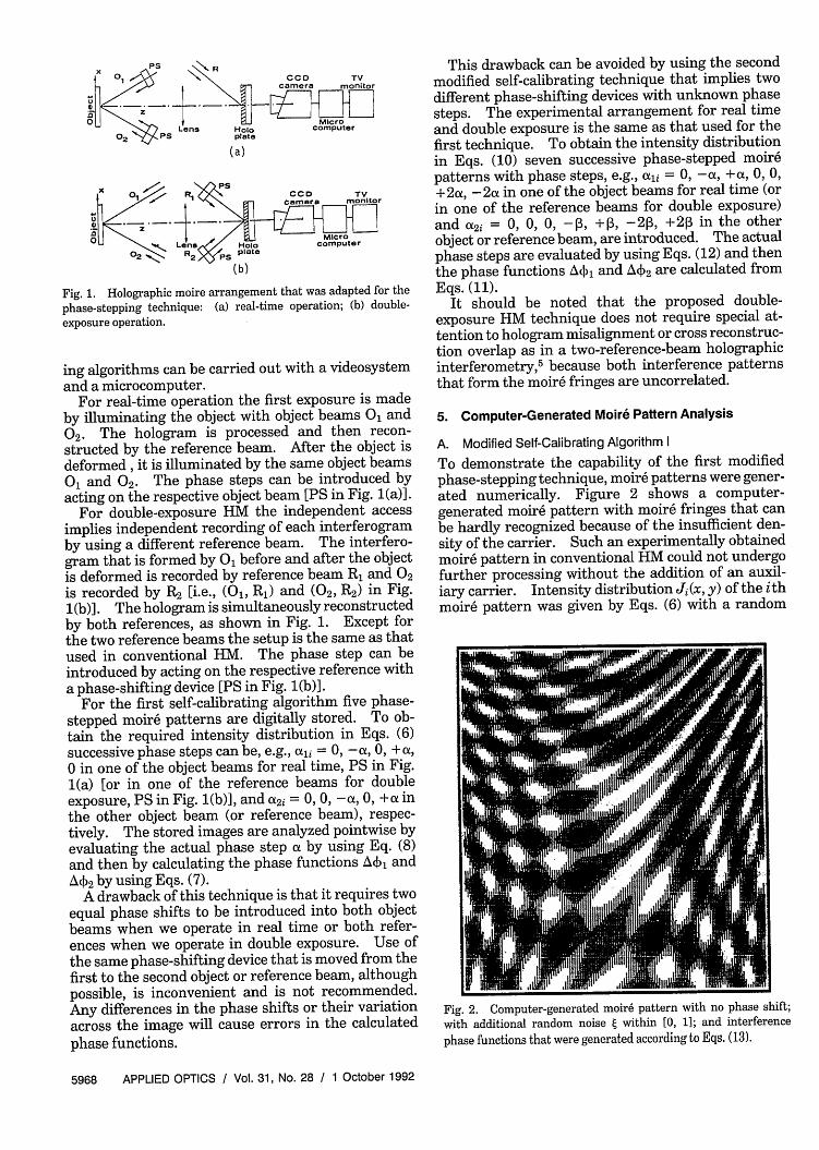
A. Modified Self-Calibrating Algorithm ITo demonstrate the capability of the first modifiedphase-stepping technique, moir6 patterns were gener-ated numerically. Figure 2 shows a computer-generated moir6 pattern with moir6 fringes that canbe hardly recognized because of the insufficient den-sity of the carrier. Such an experimentally obtainedmoir6 pattern in conventional HM could not undergofurther processing without the addition of an auxil-iary carrier. Intensity distribution Ji(x, y) of the ithmoir6 pattern was given by Eqs. (6) with a random
Fig. 2. Computer-generated moir6 pattern with no phase shift;with additional random noise g within [0, 1]; and interference
phase functions that were generated according to Eqs. (13).
5968 APPLIED OPTICS / Vol. 31, No. 28 / 1 October 1992
intensity error e added within [0, 1]. The interfer-ence phase functions A, and A4 2 in Fig. 2 weregenerated according to
A( = a,[-llx + 3y + 0.2(y - a2)2
- 0.3(x - a3 )2 - 0.lxy],
42 = al[+lix - 3y + 0.2(y - a2)2
- 0.3(x - a3)2 - 0.lxy]. (13)
Mean intensity Io and contrast V were generatedaccording to
Io(x,y) = A - A2 exp[-(x - a 3)21/a4 - (y- a3 )2 /a4],
Io(x,y)V(x,y) = A3 + A4 [(x - a 3)2 /a4 + (y - a3)2/a4],
(14)
whereAi and ai were coefficients that scaled the phasefunctions.
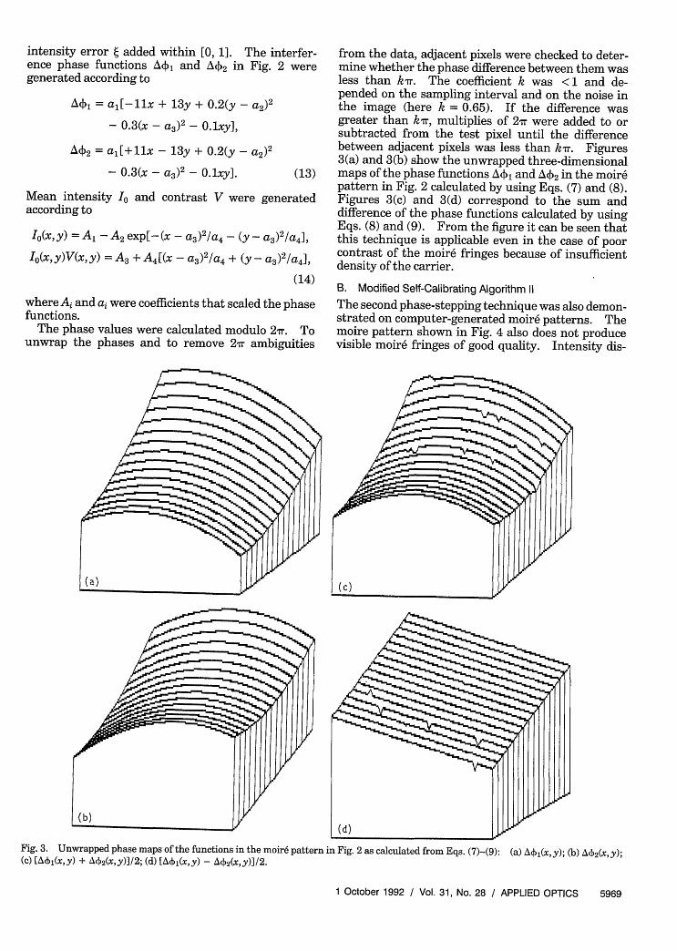
The phase values were calculated modulo 2i. Tounwrap the phases and to remove 2 ambiguities
from the data, adjacent pixels were checked to deter-mine whether the phase difference between them wasless than kr. The coefficient k was <1 and de-pended on the sampling interval and on the noise inthe image (here k = 0.65). If the difference wasgreater than k, multiplies of 2 wr were added to orsubtracted from the test pixel until the differencebetween adjacent pixels was less than kr. Figures3(a) and 3(b) show the unwrapped three-dimensionalmaps of the phase functions A4v, and A4 2 in the moir6pattern in Fig. 2 calculated by using Eqs. (7) and (8).Figures 3(c) and 3(d) correspond to the sum anddifference of the phase functions calculated by usingEqs. (8) and (9). From the figure it can be seen thatthis technique is applicable even in the case of poorcontrast of the moir6 fringes because of insufficientdensity of the carrier.
B. Modified Self-Calibrating Algorithm 11The second phase-stepping technique was also demon-strated on computer-generated moir6 patterns. Themoire pattern shown in Fig. 4 also does not producevisible moir6 fringes of good quality. Intensity dis-
Fig. 3. Unwrapped phase maps of the functions in the moir6 pattern in Fig.2 as calculated from Eqs. (7)-(9): (a) Ai(x,y); (b) AP 2(x,y);(c) [ 1 (x,y) + A'V(X,y)]/2; (d) [A~i(x,y) - A42(X,y)1/2.
1 October 1992 / Vol. 31, No. 28 / APPLIED OPTICS 5969
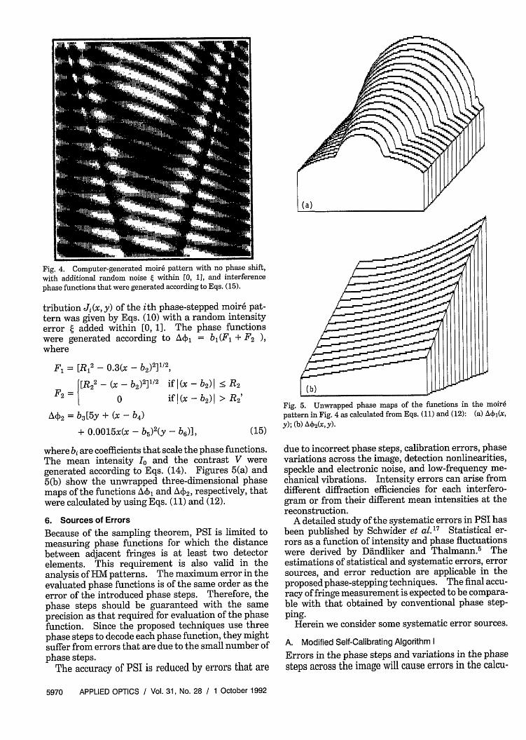
Fig. 4. Computer-generated moir6 pattern with no phase shift,with additional random noise e within [0, 1], and interferencephase functions that were generated according to Eqs. (15).
tribution Ji(x, y) of the ith phase-stepped moir6 pat-tern was given by Eqs. (10) with a random intensityerror e added within [0, 1]. The phase functionswere generated according to A4~, = bl(Fl + F 2 ),where
F, = [R, 2- 0.3(x - b2)2]1/2
|R22 - (x - b2)2 ]1/ 2 if I (x - b2)1
F2 = 0 if (x - b2 )I
42 = b3 [5y + (x - b4)
+ 0.0015x(x - b5)2 (y - b6)],
< R2
> R2'
(15)
where bi are coefficients that scale the phase functions.The mean intensity Io and the contrast V weregenerated according to Eqs. (14). Figures 5(a) and5(b) show the unwrapped three-dimensional phasemaps of the functions A41 and A42 , respectively, thatwere calculated by using Eqs. (11) and (12).
6. Sources of Errors
Because of the sampling theorem, PSI is limited tomeasuring phase functions for which the distancebetween adjacent fringes is at least two detectorelements. This requirement is also valid in theanalysis of HM patterns. The maximum error in theevaluated phase functions is of the same order as theerror of the introduced phase steps. Therefore, thephase steps should be guaranteed with the sameprecision as that required for evaluation of the phasefunction. Since the proposed techniques use threephase steps to decode each phase function, they mightsuffer from errors that are due to the small number ofphase steps.
The accuracy of PSI is reduced by errors that are
| (b) [
Fig. 5. Unwrapped phase maps of the functions in the moirepattern in Fig. 4 as calculated from Eqs. (11) and (12): (a) Aki,(x,y); (b) A42(x,y)-
due to incorrect phase steps, calibration errors, phasevariations across the image, detection nonlinearities,speckle and electronic noise, and low-frequency me-chanical vibrations. Intensity errors can arise fromdifferent diffraction efficiencies for each interfero-gram or from their different mean intensities at thereconstruction.
A detailed study of the systematic errors in PSI hasbeen published by Schwider et al.'7 Statistical er-rors as a function of intensity and phase fluctuationswere derived by Ddndliker and Thalmann. 5 Theestimations of statistical and systematic errors, errorsources, and error reduction are applicable in theproposed phase-stepping techniques. The final accu-racy of fringe measurement is expected to be compara-ble with that obtained by conventional phase step-ping.
Herein we consider some systematic error sources.
A. Modified Self-Calibrating Algorithm I
Errors in the phase steps and variations in the phasesteps across the image will cause errors in the calcu-
5970 APPLIED OPTICS / Vol. 31, No. 28 / 1 October 1992
lated phase functions. We assume an error of E inthe phase steps that were introduced into both inter-ferograms that form the moir6 pattern, i.e., a = at + E,
where is a small quantity. Then the values of thephase step from Eq. (8) and the calculated phasefunctions from Eqs. (7) are given to a first approxima-tion by the relations
tan'2 (ot/2) = tan2 (oa/2)F 2 (E, a, A41, Ac2), (16)
where
F2(Ea, 4 1 , A 2 ) = 1 - E/2 cot(a) + E cot(a/2)
+ E/ 2 cot[A - A4 2 )/2]
+ E/4[cot2 (a/2) + 1]
x tan[(A4 1 + A 2 )/2]
+ E/ 2 cot(a/2)
x tan[(A4 1 - A42 )/2]
x tan[(A(\ + A42 )/2],
tan'(A(,) = tan(A' 1 )F(E, at, A4Nj, A 2)
x {1 + E/2[cot(a) - cot(at/2)]
+ /2 cot(A4 1,) + E/4
x [1 - ot 2(a/2)]tan(A 1)1
(17)
tan'(A42 ) = tan(A4 2)F(E, , A41, A42 )
x 1 + 3 /2E[cot(-) - cot(a/2)]
+ e/2 cot(A4 2 ) + E/4
x [1 - ot 2 (/2)tan(A4 2 )j-
(17')
As can be seen from Eqs. (17) and (17'), inaccuracy inthe phase step generates a complicated quasi-sinusoi-dal error in the evaluated phase functions that de-pends on the values of the phase step as well as on thevalues of both phase functions.
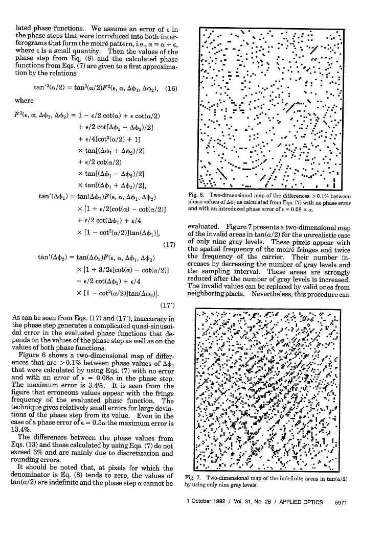
Figure 6 shows a two-dimensional map of differ-ences that are > 0.1% between phase values of A4\jthat were calculated by using Eqs. (7) with no errorand with an error of E = 0.08a in the phase step.The maximum error is 3.4%. It is seen from thefigure that erroneous values appear with the fringefrequency of the evaluated phase function. Thetechnique gives relatively small errors for large devia-tions of the phase step from its value. Even in thecase of a phase error of E = 0.5a_ the maximum error is13.4%.
The differences between the phase values fromEqs. (13) and those calculated by using Eqs. (7) do notexceed 3% and are mainly due to discretization androunding errors.
It should be noted that, at pixels for which thedenominator is Eq. (8) tends to zero, the values oftan(a/2) are indefinite and the phase step cannot be
Fig. 6. Two-dimensional map of the differences > 0.1% betweenphase values of A(\j as calculated from Eqs. (7) with no phase errorand with an introduced phase error of = 0.08 x a.
evaluated. Figure 7 presents a two-dimensional mapof the invalid areas in tan(a/2) for the unrealistic caseof only nine gray levels. These pixels appear withthe spatial frequency of the moir6 fringes and twicethe frequency of the carrier. Their number in-creases by decreasing the number of gray levels andthe sampling interval. These areas are stronglyreduced after the number of gray levels is increased.The invalid values can be replaced by valid ones fromneighboring pixels. Nevertheless, this procedure can
;~~~~~~~
07S~~~~~~~~V
. 5 A
Fi. . Twodimnsina ma of th neiit ra n a(. 2
by d u o nine h~ gray levels. ~ 33 33-le. y .
V J~~~~~~~~ i . . ~ ~ ~ ~ -.. J
'% NJ. 9 . u\C -6 v4 ' N. ' ~
IL 3. -r
T
Fig. 7. Two-dimensional map of the indefinite areas in tan(a/2)by using only nine gray levels.
1 October 1992 / Vol. 31, No. 28 / APPLIED OPTICS 5971
3 \3 *3 �. 33 3.3 3 3 *333 33333 33.3�3 3 3 3 3. 3.3
3 3 33 33 39...
* 3.33 - 39. 9. 3 3 3
* * 9.� � 1 F3 �
33- - 3 3 3 3 3 33 3 3 *3.3 3. 33 3
333333 3
33 �.::33 A�1 333 3 3 3
33333 F...* * 9.9. .33 3 3 3
3 3 3.
3 3 - �3 3 9..33 3 3 3 33 33 33 3 3
9. 33333 3.3 333 3� 39.. 3* 333 133 9.
3 33 �3 3 3 .3. * 333 3 33 3, 3 3 3
.3 19.39. 3� 33 33
3/333333 .3. '�1
3333333339. 3�3 j�3 33 III
cause gross errors in the calculated phase functions.Therefore, tan(a/2) was calculated for each pixel andthen averaged over the whole image, excluding theinvalid values. The mean value of tan(a/2) was usedto calculate the phase functions in Eqs. (7) and (9).So the errors in the evaluated functions were drasti-cally reduced. If phase variation or inhomogeneitiesin the phase-shifting device have to be considered,tan(a/2) can be averaged over areas that are smallcompared with the areas of phase variation. Thevalues of tan(ax/2) can be calculated at each pixel andonly the invalid values or values with gross errors canbe replaced by values averaged over their neighboringpixels.
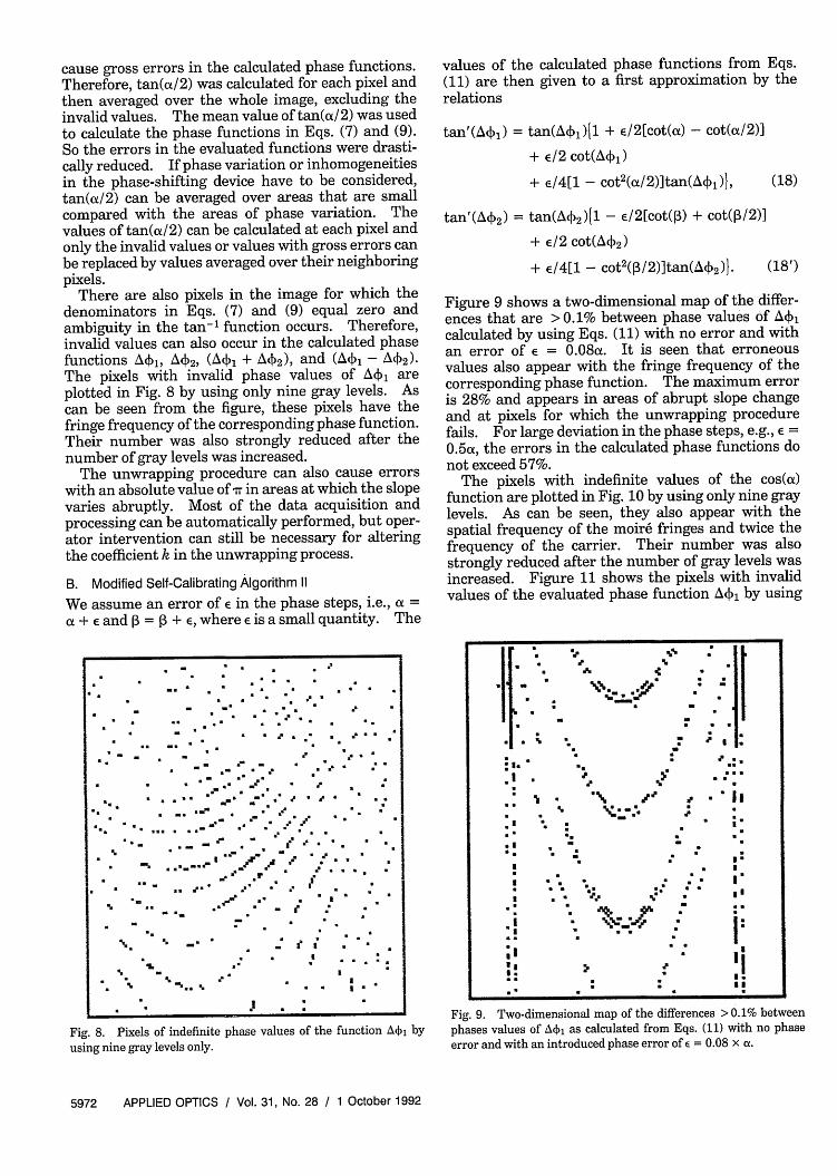
There are also pixels in the image for which thedenominators in Eqs. (7) and (9) equal zero andambiguity in the tan-' function occurs. Therefore,invalid values can also occur in the calculated phasefunctions Atv,, Ab2, (1 + Ak2), and () 1 - 42)-The pixels with invalid phase values of Ackj areplotted in Fig. 8 by using only nine gray levels. Ascan be seen from the figure, these pixels have thefringe frequency of the corresponding phase function.Their number was also strongly reduced after thenumber of gray levels was increased.
The unwrapping procedure can also cause errorswith an absolute value of Tr in areas at which the slopevaries abruptly. Most of the data acquisition andprocessing can be automatically performed, but oper-ator intervention can still be necessary for alteringthe coefficient k in the unwrapping process.
B. Modified Self-Calibrating Algorithm 11
We assume an error of e in the phase steps, i.e., a =a + E and , = P3 + , where E is a small quantity. The
3 33 3 3 3 3 3
- �3 3- . 3 3 33
3 � 333 33333 3
* 3. -3 .3 33 3333 3 - 3- 3 - 3 3 3
3 -- 3 �3 3 3
.,~~333 * ~3 . =.r . .,, * .
3 * _ r - 33
. -w . w .- - l . ''
. _ _ .
9. 3.-.-. : ;
39. :3 *=3 33^
* ;9. 9.
.j 3
Fig. 8. Pixels of indefinite phase values of the function A4j byusing nine gray levels only.
I3: . I.3
values of the calculated phase functions from Eqs.(11) are then given to a first approximation by therelations
tan'(Ak,) = tan(A(,)1 + E/2[cot(a) - cot(oa/2)]
+ e/2 cot(A,)
+ e/4[1 - ot2(a/2)tan(A11)1, (18)
tan'(A42 ) = tan(A 2 )1 - /2[cot() + cot(1/2)]
+ e/2 cot(A'k2 )
+ /4[1 - ot2(p3/2)]tan(A4 2 )1- (18')
Figure 9 shows a two-dimensional map of the differ-ences that are > 0.1% between phase values of Ack,calculated by using Eqs. (11) with no error and withan error of E = 0.08a. It is seen that erroneousvalues also appear with the fringe frequency of thecorresponding phase function. The maximum erroris 28% and appears in areas of abrupt slope changeand at pixels for which the unwrapping procedurefails. For large deviation in the phase steps, e.g., E =
0.5a, the errors in the calculated phase functions donot exceed 57%.
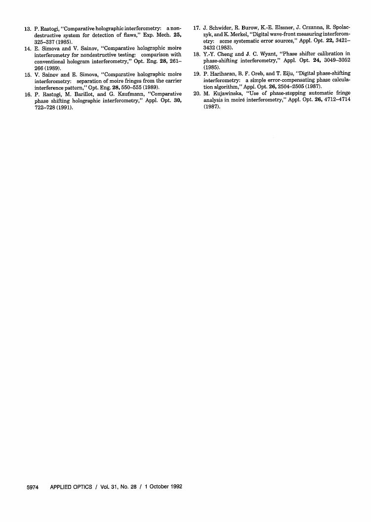
The pixels with indefinite values of the cos(a)function are plotted in Fig. 10 by using only nine graylevels. As can be seen, they also appear with thespatial frequency of the moir6 fringes and twice thefrequency of the carrier. Their number was alsostrongly reduced after the number of gray levels wasincreased. Figure 11 shows the pixels with invalidvalues of the evaluated phase function Ackj by using
.9.
Is. 1
* 1...
J
;I.
*1*I
;l
'.
3.
*:
I3
93
331
I 3 . .
*p . -
ss :I3~I
.*
:- *
* :: Iv . ~1;
Fig. 9. Two-dimensional map of the differences > 0. 1% betweenphases values of A( 1 as calculated from Eqs. (11) with no phaseerror and with an introduced phase error of E = 0.08 x a.
5972 APPLIED OPTICS / Vol. 31, No. 28 / 1 October 1992
.
.
I
:-
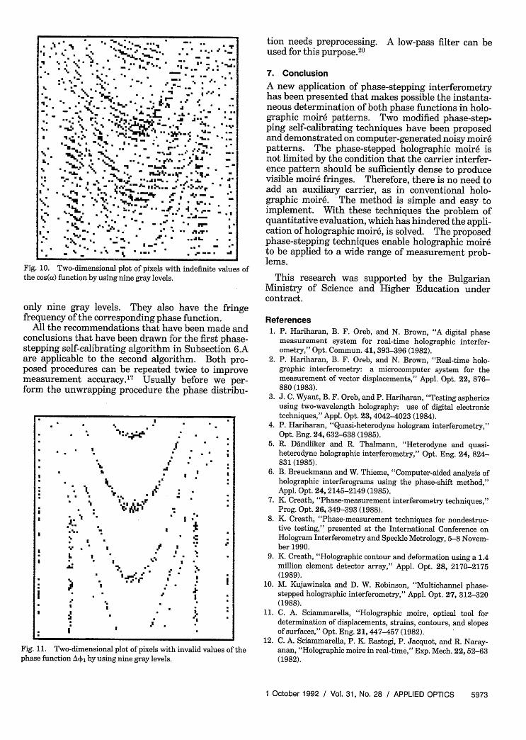
Fig. 10. Two-dimensional plot of pixels with indefinite values ofthe cos(a) function by using nine gray levels.
only nine gray levels. They also have the fringefrequency of the corresponding phase function.
All the recommendations that have been made andconclusions that have been drawn for the first phase-stepping self-calibrating algorithm in Subsection 6.Aare applicable to the second algorithm. Both pro-posed procedures can be repeated twice to improvemeasurement accuracy.' 7 Usually before we per-form the unwrapping procedure the phase distribu-
Fig. 11. Two-dimensional plot of pixels with invalid values of thephase function AO) by using nine gray levels.
tion needs preprocessing. A low-pass filter can beused for this purpose.20
7. Conclusion
A new application of phase-stepping interferometryhas been presented that makes possible the instanta-neous determination of both phase functions in holo-graphic moir6 patterns. Two modified phase-step-ping self-calibrating techniques have been proposedand demonstrated on computer-generated noisy moir6patterns. The phase-stepped holographic moire isnot limited by the condition that the carrier interfer-ence pattern should be sufficiently dense to producevisible moire fringes. Therefore, there is no need toadd an auxiliary carrier, as in conventional holo-graphic moir6. The method is simple and easy toimplement. With these techniques the problem ofquantitative evaluation, which has hindered the appli-cation of holographic moir6, is solved. The proposedphase-stepping techniques enable holographic moir6to be applied to a wide range of measurement prob-lems.
This research was supported by the BulgarianMinistry of Science and Higher Education undercontract.
References1. P. Hariharan, B. F. Oreb, and N. Brown, "A digital phase
measurement system for real-time holographic interfer-ometry," Opt. Commun. 41, 393-396 (1982).
2. P. Hariharan, B. F. Oreb, and N. Brown, "Real-time holo-graphic interferometry: a microcomputer system for themeasurement of vector displacements," Appl. Opt. 22, 876-880 (1983).
3. J. C. Wyant, B. F. Oreb, and P. Hariharan, "Testing asphericsusing two-wavelength holography: use of digital electronictechniques," Appl. Opt. 23, 4042-4023 (1984).
4. P. Hariharan, "Quasi-heterodyne hologram interferometry,"Opt. Eng. 24, 632-638 (1985).
5. R. Dndliker and R. Thalmann, "Heterodyne and quasi-heterodyne holographic interferometry," Opt. Eng. 24, 824-831 (1985).
6. B. Breuckmann and W. Thieme, "Computer-aided analysis ofholographic interferograms using the phase-shift method,"Appl. Opt. 24, 2145-2149 (1985).
7. K. Creath, "Phase-measurement interferometry techniques,"Prog. Opt. 26, 349-393 (1988).
8. K. Creath, "Phase-measurement techniques for nondestruc-tive testing," presented at the International Conference onHologram Interferometry and Speckle Metrology, 5-8 Novem-ber 1990.
9. K. Creath, "Holographic contour and deformation using a 1.4million element detector array," Appl. Opt. 28, 2170-2175(1989).
10. M. Kujawinska and D. W. Robinson, "Multichannel phase-stepped holographic interferometry," Appl. Opt. 27, 312-320(1988).
11. C. A. Sciammarella, "Holographic moire, optical tool fordetermination of displacements, strains, contours, and slopesof surfaces," Opt. Eng. 21, 447-457 (1982).
12. C. A. Sciammarella, P. K. Rastogi, P. Jacquot, and R. Naray-anan, "Holographic moire in real-time," Exp. Mech. 22, 52-63(1982).
1 October 1992 / Vol. 31, No. 28 / APPLIED OPTICS 5973
z -:£3.3 . . . * * * - -.
*. *. == *. *3~. = " - .: * -3
.9 *. - * 33 - .. - *
* - 6 \ 3 6
*. _ * _ * -. P , - -a J. r. _\ L. . .
9.% A
. ~ ~ ~ ~ ~~~~ .!3 "
* 3
. . E ':e' .3 3
. = .= .. I .K. . , 3
' 3D , . * U-
I 3 L39| . *3 ' .
. 'I3
' 39. -- U
-
13. P. Rastogi, "Comparative holographic interferometry: a non-destructive system for detection of flaws," Exp. Mech. 25,325-337 (1985).
14. E. Simova and V. Sainov, "Comparative holographic moireinterferometry for nondestructive testing: comparison withconventional hologram interferometry," Opt. Eng. 28, 261-266 (1989).
15. V. Sainov and E. Simova, "Comparative holographic moireinterferometry: separation of moire fringes from the carrierinterference pattern," Opt. Eng. 28, 550-555 (1989).
16. P. Rastogi, M. Barillot, and G. Kaufmann, "Comparativephase shifting holographic interferometry," Appl. Opt. 30,722-728 (1991).
17. J. Schwider, R. Burow, K.-E. Elssner, J. Crzanna, R. Spolac-zyk, and K. Merkel, "Digital wave-front measuring interferom-etry: some systematic error sources," Appl. Opt. 22, 3421-3432 (1983).
18. Y.-Y. Cheng and J. C. Wyant, "Phase shifter calibration inphase-shifting interferometry," Appl. Opt. 24, 3049-3052(1985).
19. P. Hariharan, B. F. Oreb, and T. Eiju, "Digital phase-shiftinginterferometry: a simple error-compensating phase calcula-tion algorithm," Appl. Opt. 26, 2504-2505 (1987).
20. M. Kujawinska, "Use of phase-stepping automatic fringeanalysis in moir6 interferometry," Appl. Opt. 26, 4712-4714(1987).
5974 APPLIED OPTICS / Vol. 31, No. 28 / 1 October 1992


