Embed Size (px)
Citation preview
Original Article
Journal of Intelligent Material Systemsand Structures2017, Vol. 28(17) 2349–2362� The Author(s) 2017Reprints and permissions:sagepub.co.uk/journalsPermissions.navDOI: 10.1177/1045389X17689942journals.sagepub.com/home/jim
Performance of three transducermounting methods inimpedance-based structural healthmonitoring applications
Ricardo Zanni Mendes da Silveira, Leandro Melo Campeiro andFabricio Guimaraes Baptista
AbstractPiezoelectric transducers are widely used in many nondestructive methods for damage detection in structural healthmonitoring applications. Among the various methods for detecting damage, the electromechanical impedance techniqueis known for using thin and small piezoelectric ceramics operating simultaneously as actuators and sensors. The basicmethod of installing these piezoelectric ceramics in the host structure is using a high-stiffness adhesive such as epoxy orcyanoacrylate glue. However, some studies have proposed alternative methods of transducer mounting, therein aimingto reuse the transducer or allowing for the monitoring of structures under adverse conditions under which the directinstallation of the sensor would not be possible. Thus, the objective of this study is to analyze and compare the perfor-mance of three main mounting methods for metal structures for applications based on the electromechanical impedancetechnique: magnetic mounting, metal-wire-based mounting, and conventional mounting using adhesives. Tests were con-ducted on aluminum beams, and the performances of the three transducer mounting methods were compared usingbasic damage indices and the pencil-lead-break test. The experimental results indicate that the mounting method has asignificant effect on the frequency response and sensitivity for damage detection.
KeywordsPiezoelectric transducer, mounting, electromechanical impedance, damage, structural health monitoring
Introduction
In the modern world, there are many structural systemsthat people use daily such as civil infrastructure andthe various major means of transport. Inevitably, thesestructures suffer aging, which can change their idealoperating conditions or prejudice their safe use. Astructural health monitoring (SHM) system is capableof detecting structural damage and thus improving thesafety of structures and reducing their correspondingmaintenance costs (Bakht and Mufti, 2015; Farrar andWorden, 2013).
A complete SHM system consists of a sensor net-work; a data acquisition (DAQ), storage, and process-ing platform; and a method of detecting damage orchanges in structural behavior. It is desirable for thestructural damage to be detected using a nondestructivemethod (Giurgiutiu, 2013; Waugh, 2016), known asnondestructive evaluation (NDE) or nondestructivetesting (NDT). Numerous methods for the detectionof structural damage, such as acoustic emission
(AE; Ohtsu et al., 2016), Lamb waves (Kim andChattopadhyay, 2015), eddy currents (Arjun et al.,2015), and methods based on fiber optic sensors (Zhaoet al., 2015), have been developed. Among the widerange of available methods, the electromechanicalimpedance (EMI) technique stands out for its use oflow-cost, small, and lightweight piezoelectric transdu-cers operating simultaneously as sensors and actuators(Albakri and Tarazaga, 2017; Na and Park, 2017).
The principle of the EMI technique is based on thepiezoelectric effect (Meitzler et al., 1988). Using thiseffect and by attaching a piezoelectric transducer onto
Universidade Estadual Paulista (UNESP), Faculdade de Engenharia, Bauru,
Brasil.
Corresponding author:
Fabricio Guimaraes Baptista, Unesp-FEB, Departamento de Engenharia
Eletrica, Av. Eng. Luiz Edmundo C. Coube 14-01, 17033-360, Bauru-SP,
Brasil.
Email: [email protected]
the structure to be monitored, a relationship betweenthe electrical properties of the transducer and themechanical properties of the structure is established.Thus, the integrity of the structure can be evaluatedfrom the measurement and analysis of the electricalimpedance of the transducer. Typically, the transducersused in the EMI method are made of thin lead zirco-nate titanate (PZT) ceramics coated on both sides withmetal films serving as electrodes. However, conven-tional PZT ceramics are rigid and brittle, making theirapplication in structures with uneven surface unfeasi-ble. To overcome this drawback, more recently, macro-fiber composite (MFC) transducers were proposed asan alternative (Brunner et al., 2009; Shahab andErturk, 2016). These devices are low-profile, flexible,and durable, making their use in many types of struc-tures feasible.
The transducers play a fundamental role in achievingthe efficient and reliable detection of structural damage.In this regard, various studies have reported the devel-opment and characterization (Cao et al., 2015), appro-priate sizing (Baptista et al., 2011; Baptista and VieiraFilho, 2010b), and correct diagnosis and validation(Overly et al., 2009) of transducers for SHM applica-tions. Equally important is the way in which the trans-ducers are installed in the structure. Therefore, theobjective of this study is to analyze the effects of thetransducer mounting on the detection of damage inSHM applications based on the EMI method.
Usually, the basic procedure for installing a transdu-cer in a structure is using a high-stiffness adhesive suchas epoxy or cyanoacrylate glue. This basic method ofmounting has been widely used and investigated in theliterature such as in the development of electromechani-cal models (Annamdas and Annamdas, 2009; Lianget al., 1994) and analysis of the effects of the adhesivelayer (Moharana and Bhalla, 2015). The direct installa-tion of the transducer in the structure using adhesive,although simple, has the disadvantage of making thetransducer difficult to remove, possibly damaging thetransducer or the structure. Furthermore, the directmounting of the transducer is not always possible instructures under adverse operating conditions. To avoidsuch problems, many researchers have proposed alter-native methods for mounting the transducers.
Na et al. (2012), for example, proposed mountingthe transducer via a magnetic coupling. The authorsfixed the PZT ceramic in a small magnet, which isattached to the structure by magnetic attraction using asecond magnet. The simple solution proposed by theauthors enables the reuse of the transducer and its easyrepositioning in the structure if necessary.
The use of a steel wire for coupling the transducer tothe structure was proposed by Na and Lee (2013). Theauthors attached a PZT patch at the end of a steel wirein the longitudinal direction, and they attached theother end to the surface of the monitored structure.
More recently, Naskar and Bhalla (2016) presented amore detailed experimental and numerical investigationof this mounting method, wherein the steel wire wasreplaced by metal foils with different cross sections.The authors reported a reduction in the sensitivity fordamage detection compared to conventional transducermountings. However, this method has the advantage ofallowing for the monitoring of inaccessible structures,with irregular surfaces or under adverse operating con-ditions (e.g. high temperatures) for which the conven-tional method of transducer mounting would not bepossible. This mounting method is commonly calledmetal-wire-based electromechanical impedance(MWBEMI).
Therefore, in this article, we present a comparativeevaluation of three transducer mounting methods: con-ventional direct mounting, magnetic mounting andMWBEMI. Tests were performed on aluminum beams,and the performances of the three mounting methodswere compared using the pencil-lead-break (PLB) test,the electrical impedance signatures, and the basic dam-age index.
In this study, two damage detection methods wereevaluated. In addition to the conventional EMImethod, where a single transducer operates as both asensor and an actuator, we also tested a variation inthis method called the transfer frequency responsefunction (FRF) method, as reported by Martowiczet al. (2016). In the transfer FRF method, two transdu-cers are used, one operating as the actuator and theother operating as the sensor. Damage detection isbased on the analysis of the FRF signatures obtainedfrom the relation between the excitation and responsesignals from both transducers in the frequency domain.The background of the conventional EMI and transferFRF methods is presented in the next section.
EMI method
As mentioned above, two variants of damage detectionbased on the impedance method were considered in thisstudy: the conventional EMI and the transfer FRF.
Conventional EMI method
The principle of damage detection based on the EMImethod consists of attaching a piezoelectric transducerto the structure to be monitored. Figure 1 shows thebasic configuration used in the conventional EMImethod, where a PZT patch, commonly used as atransducer, is attached to a structure.
According to Figure 1, a measurement system simul-taneously excites the transducer while providing itselectrical impedance ðZEðvÞÞ. Therefore, in the EMImethod, the transducer operates simultaneously as thesensor (direct piezoelectric effect) and the actuator(reverse piezoelectric effect). As is well known, the
2350 Journal of Intelligent Material Systems and Structures 28(17)
deformation of the piezoelectric material occurs in alldirections. However, because the thickness of the PZTpatch is usually very small (a fraction of a millimeter),the deformation in the direction of its thickness (x3 axisin Figure 1) may be disregarded at sufficiently low fre-quency. It is important to note that for measured impe-dances at high frequencies (in the MHz range), alsoknown as thickness-mode EMI, deformations along thethickness of the material can be detected (Kamas andTekkalmaz, 2016).
Furthermore, based on a one-dimensional assump-tion and considering a narrow structure, only a defor-mation in the longitudinal direction (x1 axis in Figure 1)can be considered, disregarding the deformation alongthe x2 axis.
Based on these assumptions, the direct piezoelectriceffect (sensor) and reverse piezoelectric effect (actuator)in the transducer are given by equations (1) and (2),respectively
D3 = d31T1 + eT33E3 ð1Þ
S1 = sE11T1 + d31E3 ð2Þ
where D3 and E3 are the electrical displacement and theelectric field, respectively; T1 and S1 are the mechanicalstress and strain, respectively; and d31, eT
33, and sE11 are
the piezoelectric, dielectric, and elastic compliance con-stants of the piezoelectric material, respectively, wherethe superscripts T and E indicate constant stress andconstant electric field, respectively, and the subscripts 1and 3 represent the axes of the natural coordinate sys-tem of the piezoelectric material under the one-dimensional assumption.
From equations (1) and (2), a one-dimensional elec-tromechanical model (Liang et al., 1994) may bederived to relate the electrical properties of the transdu-cer with the mechanical properties of the structure.Thus, the electrical impedance of a generic transducercalculated using a simplified version of this model isgiven by
ZEðvÞ=1
jvC1� d2
31
sE11e
T33
ZSðvÞZSðvÞ+ ZPðvÞ
� ��1
ð3Þ
where ZEðvÞ is the electrical impedance of the transdu-cer at angular frequency v, which should vary withinan appropriate range provided by the measuring sys-tem; ZPðvÞ is the mechanical impedance of the transdu-cer; ZSðvÞ is the mechanical impedance of themonitored structure; C is the static capacitance of thetransducer; and j is the unit imaginary number.
Structural damage, such as cracks, corrosion, andthe loosening of connections, causes variations in themechanical impedance of the structure. According toequation (3), any variation in the mechanical impe-dance of the structure ðZSðvÞÞ causes a correspondingchange in the electrical impedance of the transducerðZEðvÞÞ, known as EMI. Therefore, the structuralhealth can be monitored by measuring and analyzingthe electrical impedance of the transducer, which iseasy to perform.
The measurement of the electrical impedance of thetransducer may be performed using a commercial impe-dance analyzer. However, many researchers haveproposed alternative measurement systems based ontime-domain (Vieira Filho et al., 2011) or frequency-domain (Cortez et al., 2013; Kaur et al., 2016; Maruoet al., 2015) analysis. In this study, the electrical impe-dance was measured using the alternative system pro-posed by Baptista and Vieira Filho (2009), which isbased on a multifunctional DAQ device controlled by acomputer running appropriate software and drivers forthe utilized DAQ model. The basic configuration ofthis system is shown in Figure 2.
As seen in Figure 2, the DAQ device must have atleast one analog output for providing the excitation sig-nal (x(t)) through the digital-to-analog converter (DAC)and one analog input for the acquisition of the responsesignal (y(t)) from the transducer through the analog-to-digital converter (ADC). The signals x[n] and y[n] arethe digital forms of the excitation and response signals,respectively, which are processed in the computer. Theconnection between the DAQ device and the computeris achieved via a standard bus such as universal serialbus (USB), peripheral component interconnect (PCI),and peripheral component interconnect express (PCIe).The transducer is connected through a resistor RS.
The impedance of the analog input (ZIN) may beignored if it is sufficiently high compared with the
Figure 1. Basic configuration used in the conventional EMImethod.
Figure 2. Measurement system used in the conventional EMImethod.
da Silveira et al. 2351
impedance of the transducer. In addition, the wiringresistance can also be disregarded for short connec-tions. Based on these considerations, the electricalimpedance of the transducer can be calculated as
ZEðvÞ=RS
HðvÞ1� HðvÞ ð4Þ
where HðvÞ is the FRF, taking the excitation signal(x[n]) as input and the response signal (y[n]) as output,which is calculated as follows
HðvÞ= SxyðvÞSxxðvÞ
ð5Þ
where SxyðvÞ is the crossed power spectrum betweenthe excitation signal (x[n]) and the response signal (y[n])and SxxðvÞ is the auto power spectrum of the excitationsignal, which are given by
SxyðvÞ=X ðvÞY �ðvÞ
Nð6Þ
SxxðvÞ=X ðvÞX �ðvÞ
Nð7Þ
where X ðvÞ and Y ðvÞ are the discrete Fourier trans-form (DFT) of the excitation signal (x[n]) and theresponse signal (y[n]), respectively, computed using thefast Fourier transform (FFT) algorithm; X �ðvÞ andY �ðvÞ denote the complex conjugates; and N is thelength of the signals.
It is important to note that in this measuringmethod, the amplitude voltage of the transducer (y(t))is not constant; rather, it decreases with increasing fre-quency due to the capacitive reactance of the transdu-cer ð1=jvCÞ, as shown in equation (3). From theelectrical point of view, this does not affect the mea-sured value of the impedance because the FRF ðHðvÞÞdoes not depend on the signal amplitude, ensuringaccurate measurements (Baptista and Vieira Filho,2009). However, in the EMI technique, the impedancesignatures consist of resonance peaks related to themonitored structure that can be affected by the signalamplitude, thereby altering the sensitivity to damage,especially in large structures.
Therefore, special attention is required in choosingthe resistor RS in Figure 2 and the frequency band, par-ticularly in the impedance measurements for detectingdamage in large structures or in research that proposesto investigate the effects of the amplitude of the excita-tion signal. In these cases, the amplitude of the excita-tion signal must be as constant as possible, which canbe achieved using a small resistor and performing theimpedance measurement in narrow frequency bands.
Typically, the FRF is obtained by taking an averageof several measurements. The excitation signal must bedynamic, such as a chirp signal, with the same fre-quency range desired for the electrical impedance
signatures. The transducer is usually bonded to thehost structure using an adhesive such as epoxy or cya-noacrylate glue. In this study, the impedance signatureswere obtained from measurements of specimens towhich the piezoelectric transducers were mounted usingthe three above-described mounting methods. In addi-tion, the mounting methods were also analyzed fordamage detection based on the transfer FRF method.In this method, two transducers are used, one operatingas the actuator and the other as the sensor, as shown inthe following section.
Transfer FRF method
In contrast to the conventional EMI method, which isknown for using a single transducer, the transfer FRFmethod uses at least two transducers, each operatingseparately as an actuator and a sensor. Therefore, theinput and output signals of the FRF are obtained at dif-ferent points of the structure.
This method is particularly useful for detecting dam-age located between the two transducers. For example,Martowicz et al. (2016) used this method to monitor abolted pipeline connection. The authors bonded pairsof PZT patches in steel washers to obtain the transferFRFs to detect and quantify the loosening of the bolts.The results were compared with those obtained with theconventional EMI method, also called point FRF. Thebasic setup that we used to obtain the transfer FRF sig-natures is shown in Figure 3.
The measurement system is similar to that used inthe conventional EMI method, with the differencebeing that the excitation signal (x(t)) is applied to theactuator transducer through the limiting resistor (RS)and that the response signal (y(t)) is obtained from thesensor transducer. The transfer FRF HðvÞ is obtainedfrom the corresponding digital signals x[n] and y[n] bycomputing the crossed power spectrum ðSxyðvÞÞ and theauto power spectrum ðSxxðvÞÞ, as shown in equations(5) to (7). The excitation and response signals are gener-ated and sampled simultaneously and synchronously.
Figure 3. Basic setup used in the transfer FRF method.
2352 Journal of Intelligent Material Systems and Structures 28(17)
As mentioned above, the FRF HðvÞ is obtainedfrom an average of multiple measurements to obtain agood repetition among the signatures and minimize anynoise effects. Structural damage, especially along thepath between the two transducers, causes variations inthe FRF signatures, which can be analyzed as conven-tional impedance signatures for monitoring the integ-rity of the structure.
In this study, the three mounting methods weretested using both the actuator transducer and the sen-sor transducer to analyze and compare the effects onthe sensitivity for structural damage detection. Theassessment of the sensitivity for damage detection wasperformed using the PLB test and damage indices, asdescribed in the following section.
Sensitivity assessment
The evaluation of the transducer mounting methods interms of effectiveness in the detection of structural dam-age was conducted using the PLB test, by comparingthe electrical impedance and FRF signatures, and usingdamage indices.
PLB test
The PLB test is a well-known procedure in AE applica-tions for the generation of an acoustic signal. The pro-cedure consists of breaking a pencil lead against thestructure or rod on which the transducer is installed. Inthis study, the pencil lead was broken against the moni-tored structures, which are aluminum specimens.
Upon breaking the pencil lead, an impulsive stress isreleased, and a wide-band signal is consequently gener-ated, which can be used to evaluate the AE sensorresponse. When the pencil lead is broken, the voltagesignal from the sensor is sampled. The analysis is usu-ally performed in the frequency domain by computingthe power spectral density (PSD). Therefore, the PLBtest is an economical and simple procedure for obtain-ing an acoustic source and has been adopted as a stan-dard (ASTM, 2010).
Although very common in AE applications, the PLBtest has also been used to assess the sensitivity of piezo-electric transducers for damage detection based on theEMI method (De Almeida et al., 2015). In this study,we used the PLB test to assess the response of thepiezoelectric transducers installed in the monitoredstructure using different mounting methods. The pencillead was broken in the monitored structure in the sameposition and under the same conditions for all mount-ing methods so that the differences observed betweenthe signals obtained from the transducers were primar-ily due to the mounting method. The analysis was per-formed by calculating and comparing the PSDs of thethree mounting methods.
Damage indices
A basic way to detect and quantify structural damagein the EMI method is by comparing two electricalimpedance signatures, one of which is obtained whenthe structure is in a state considered healthy, known asthe baseline. This comparison is typically accomplishedusing damage indices. One of the most widely usedindices is the root-mean-square deviation (RMSD),which is based on the Euclidean distance between thetwo signatures. The RMSD index is calculated as(Farrar and Worden, 2013)
RMSD=XvF
v=vI
ffiffiffiffiffiffiffiffiffiffiffiffiffiffiffiffiffiffiffiffiffiffiffiffiffiffiffiffiffiffiffiffiffiffiffiffiffiffiffiffiffiffiffiffiffiffiffiffiffiffiffiffiffiRe Z2 vð Þð Þ �Re Z1 vð Þð Þ½ �2
Re Z1 vð Þð Þ2
sð8Þ
where ReðZ1ðvÞÞ is the real part of the baseline signa-ture, ReðZ2ðvÞÞ is the real part of the impedance signa-ture after possible damage, and RMSD is the indexcalculated in the frequency range with initial frequencyvI and final frequency vF .
The RMSD index may also be calculated using themagnitude or the imaginary part of the impedance;however, the real part is normally used because it ismore sensitive to damage and less sensitive to tempera-ture (Baptista et al., 2014; Park et al., 2003). Despitethis, for the transfer FRF method, the index was calcu-lated using the magnitude of the FRF, HðvÞj j, becauseit is more representative in this method.
Another widely used index is the correlation coeffi-cient deviation metric (CCDM), which is based on thecorrelation coefficient between the two impedance sig-natures and is calculated as
CCDM= 1� CC ð9Þ
where CC is the correlation coefficient, given by
CC =cov Re Z1ðvÞð Þ;Re Z2ðvÞð Þ½ �
s1s2
ð10Þ
in which ‘‘cov’’ is the covariance of the real parts of thetwo impedance signatures as previously defined, calcu-lated in the same frequency range as the RMSD indexin equation (8), and s1 and s2 are the correspondingstandard deviations of each signature.
The RMSD and CCDM indices were calculated forall mounting methods under the same experimentalconditions and compared to evaluate the influence ofthe transducer mounting on the detection of structuraldamage. The experimental setup is shown in the nextsection.
Experimental setup
To analyze the effects of the transducer mounting onthe detection of structural damage, tests were per-formed on 1100 3 76 3 3 mm3 aluminum beams.
da Silveira et al. 2353
The transducers used in this study are piezoelectric dia-phragms, commonly known as ‘‘buzzers,’’ consisting ofa 0.20-mm-thick, 20 mm in diameter circular brassplate and a 0.22-mm-thick, 14 mm in diameter piezo-electric ceramic (active element). The main applicationof these devices is the generation of various types ofsounds, such as alarms and beeps; however, manyrecent scientific studies have reported the feasibility ofusing piezoelectric diaphragms for structural damagedetection based on the EMI and other methods (Freitasand Baptista, 2016; Tinoco and Marulanda, 2015).
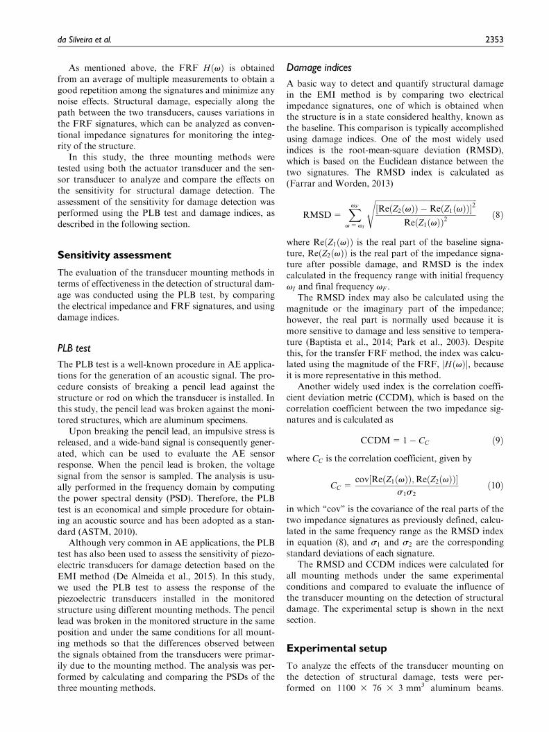
For the conventional direct mounting method, thetransducer was bonded directly to the structure usingcyanoacrylate glue at a distance of 30 mm from the cen-ter of the transducer and the end of the beam. The con-ventional transducer mounting is shown in Figure 4.
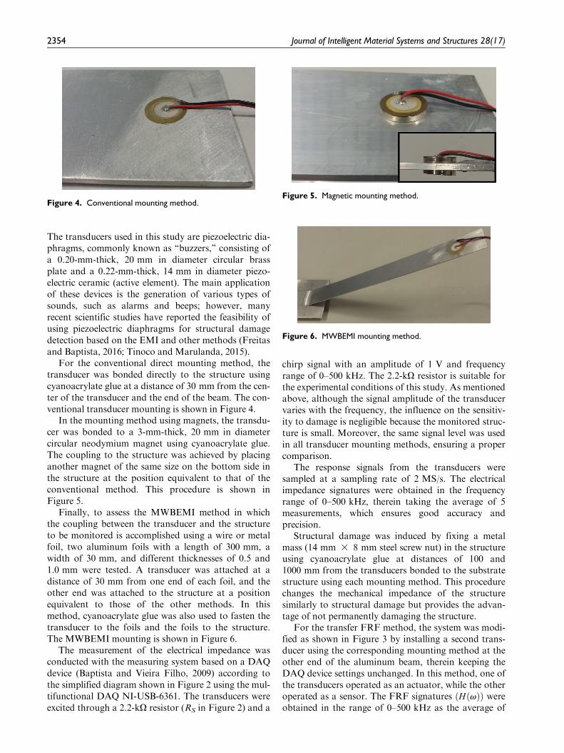
In the mounting method using magnets, the transdu-cer was bonded to a 3-mm-thick, 20 mm in diametercircular neodymium magnet using cyanoacrylate glue.The coupling to the structure was achieved by placinganother magnet of the same size on the bottom side inthe structure at the position equivalent to that of theconventional method. This procedure is shown inFigure 5.
Finally, to assess the MWBEMI method in whichthe coupling between the transducer and the structureto be monitored is accomplished using a wire or metalfoil, two aluminum foils with a length of 300 mm, awidth of 30 mm, and different thicknesses of 0.5 and1.0 mm were tested. A transducer was attached at adistance of 30 mm from one end of each foil, and theother end was attached to the structure at a positionequivalent to those of the other methods. In thismethod, cyanoacrylate glue was also used to fasten thetransducer to the foils and the foils to the structure.The MWBEMI mounting is shown in Figure 6.
The measurement of the electrical impedance wasconducted with the measuring system based on a DAQdevice (Baptista and Vieira Filho, 2009) according tothe simplified diagram shown in Figure 2 using the mul-tifunctional DAQ NI-USB-6361. The transducers wereexcited through a 2.2-kO resistor (RS in Figure 2) and a
chirp signal with an amplitude of 1 V and frequencyrange of 0–500 kHz. The 2.2-kO resistor is suitable forthe experimental conditions of this study. As mentionedabove, although the signal amplitude of the transducervaries with the frequency, the influence on the sensitiv-ity to damage is negligible because the monitored struc-ture is small. Moreover, the same signal level was usedin all transducer mounting methods, ensuring a propercomparison.
The response signals from the transducers weresampled at a sampling rate of 2 MS/s. The electricalimpedance signatures were obtained in the frequencyrange of 0–500 kHz, therein taking the average of 5measurements, which ensures good accuracy andprecision.
Structural damage was induced by fixing a metalmass (14 mm 3 8 mm steel screw nut) in the structureusing cyanoacrylate glue at distances of 100 and1000 mm from the transducers bonded to the substratestructure using each mounting method. This procedurechanges the mechanical impedance of the structuresimilarly to structural damage but provides the advan-tage of not permanently damaging the structure.
For the transfer FRF method, the system was modi-fied as shown in Figure 3 by installing a second trans-ducer using the corresponding mounting method at theother end of the aluminum beam, therein keeping theDAQ device settings unchanged. In this method, one ofthe transducers operated as an actuator, while the otheroperated as a sensor. The FRF signatures ðHðvÞÞ wereobtained in the range of 0–500 kHz as the average of
Figure 4. Conventional mounting method.Figure 5. Magnetic mounting method.
Figure 6. MWBEMI mounting method.
2354 Journal of Intelligent Material Systems and Structures 28(17)
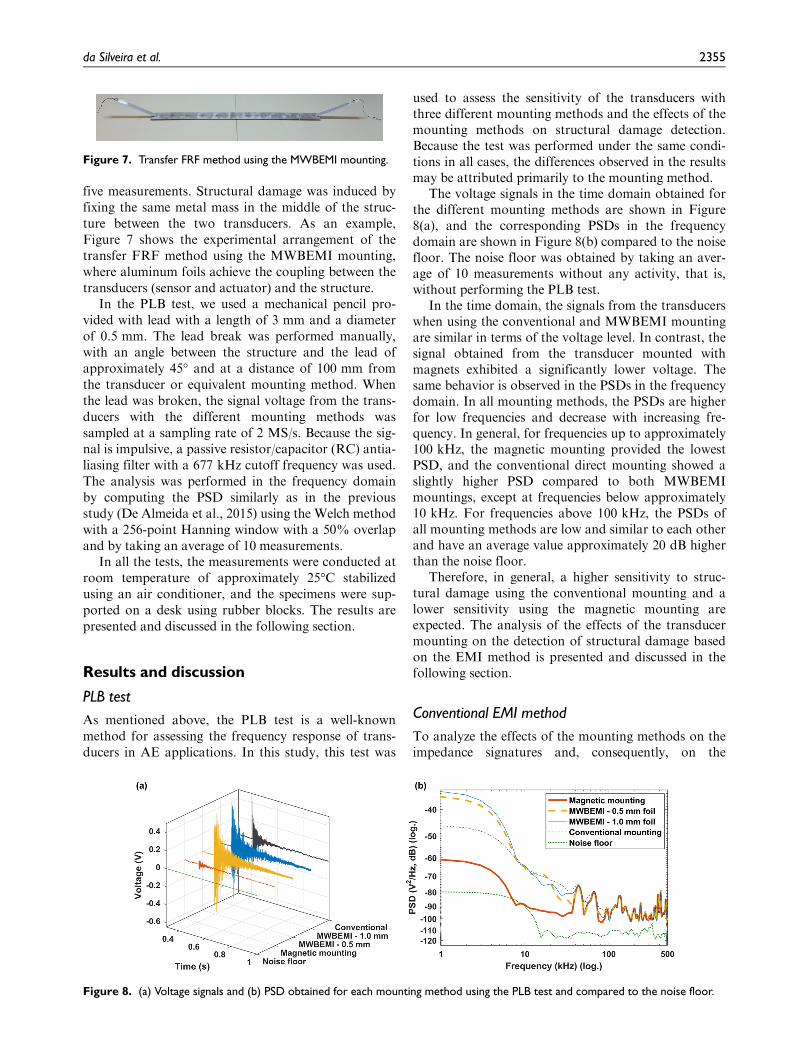
five measurements. Structural damage was induced byfixing the same metal mass in the middle of the struc-ture between the two transducers. As an example,Figure 7 shows the experimental arrangement of thetransfer FRF method using the MWBEMI mounting,where aluminum foils achieve the coupling between thetransducers (sensor and actuator) and the structure.
In the PLB test, we used a mechanical pencil pro-vided with lead with a length of 3 mm and a diameterof 0.5 mm. The lead break was performed manually,with an angle between the structure and the lead ofapproximately 45� and at a distance of 100 mm fromthe transducer or equivalent mounting method. Whenthe lead was broken, the signal voltage from the trans-ducers with the different mounting methods wassampled at a sampling rate of 2 MS/s. Because the sig-nal is impulsive, a passive resistor/capacitor (RC) antia-liasing filter with a 677 kHz cutoff frequency was used.The analysis was performed in the frequency domainby computing the PSD similarly as in the previousstudy (De Almeida et al., 2015) using the Welch methodwith a 256-point Hanning window with a 50% overlapand by taking an average of 10 measurements.
In all the tests, the measurements were conducted atroom temperature of approximately 25�C stabilizedusing an air conditioner, and the specimens were sup-ported on a desk using rubber blocks. The results arepresented and discussed in the following section.
Results and discussion
PLB test
As mentioned above, the PLB test is a well-knownmethod for assessing the frequency response of trans-ducers in AE applications. In this study, this test was
used to assess the sensitivity of the transducers withthree different mounting methods and the effects of themounting methods on structural damage detection.Because the test was performed under the same condi-tions in all cases, the differences observed in the resultsmay be attributed primarily to the mounting method.
The voltage signals in the time domain obtained forthe different mounting methods are shown in Figure8(a), and the corresponding PSDs in the frequencydomain are shown in Figure 8(b) compared to the noisefloor. The noise floor was obtained by taking an aver-age of 10 measurements without any activity, that is,without performing the PLB test.
In the time domain, the signals from the transducerswhen using the conventional and MWBEMI mountingare similar in terms of the voltage level. In contrast, thesignal obtained from the transducer mounted withmagnets exhibited a significantly lower voltage. Thesame behavior is observed in the PSDs in the frequencydomain. In all mounting methods, the PSDs are higherfor low frequencies and decrease with increasing fre-quency. In general, for frequencies up to approximately100 kHz, the magnetic mounting provided the lowestPSD, and the conventional direct mounting showed aslightly higher PSD compared to both MWBEMImountings, except at frequencies below approximately10 kHz. For frequencies above 100 kHz, the PSDs ofall mounting methods are low and similar to each otherand have an average value approximately 20 dB higherthan the noise floor.
Therefore, in general, a higher sensitivity to struc-tural damage using the conventional mounting and alower sensitivity using the magnetic mounting areexpected. The analysis of the effects of the transducermounting on the detection of structural damage basedon the EMI method is presented and discussed in thefollowing section.
Conventional EMI method
To analyze the effects of the mounting methods on theimpedance signatures and, consequently, on the
Figure 7. Transfer FRF method using the MWBEMI mounting.
Figure 8. (a) Voltage signals and (b) PSD obtained for each mounting method using the PLB test and compared to the noise floor.
da Silveira et al. 2355
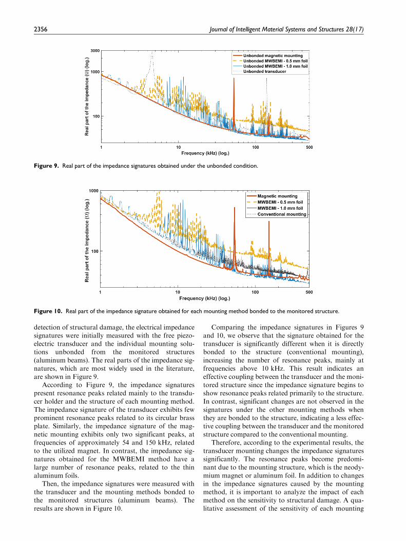
detection of structural damage, the electrical impedancesignatures were initially measured with the free piezo-electric transducer and the individual mounting solu-tions unbonded from the monitored structures(aluminum beams). The real parts of the impedance sig-natures, which are most widely used in the literature,are shown in Figure 9.
According to Figure 9, the impedance signaturespresent resonance peaks related mainly to the transdu-cer holder and the structure of each mounting method.The impedance signature of the transducer exhibits fewprominent resonance peaks related to its circular brassplate. Similarly, the impedance signature of the mag-netic mounting exhibits only two significant peaks, atfrequencies of approximately 54 and 150 kHz, relatedto the utilized magnet. In contrast, the impedance sig-natures obtained for the MWBEMI method have alarge number of resonance peaks, related to the thinaluminum foils.
Then, the impedance signatures were measured withthe transducer and the mounting methods bonded tothe monitored structures (aluminum beams). Theresults are shown in Figure 10.
Comparing the impedance signatures in Figures 9and 10, we observe that the signature obtained for thetransducer is significantly different when it is directlybonded to the structure (conventional mounting),increasing the number of resonance peaks, mainly atfrequencies above 10 kHz. This result indicates aneffective coupling between the transducer and the moni-tored structure since the impedance signature begins toshow resonance peaks related primarily to the structure.In contrast, significant changes are not observed in thesignatures under the other mounting methods whenthey are bonded to the structure, indicating a less effec-tive coupling between the transducer and the monitoredstructure compared to the conventional mounting.
Therefore, according to the experimental results, thetransducer mounting changes the impedance signaturessignificantly. The resonance peaks become predomi-nant due to the mounting structure, which is the neody-mium magnet or aluminum foil. In addition to changesin the impedance signatures caused by the mountingmethod, it is important to analyze the impact of eachmethod on the sensitivity to structural damage. A qua-litative assessment of the sensitivity of each mounting
Figure 9. Real part of the impedance signatures obtained under the unbonded condition.
Figure 10. Real part of the impedance signature obtained for each mounting method bonded to the monitored structure.
2356 Journal of Intelligent Material Systems and Structures 28(17)
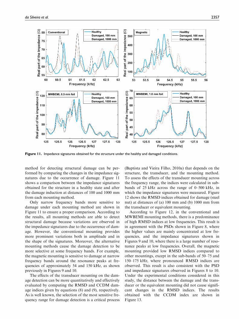
method for detecting structural damage can be per-formed by comparing the changes in the impedance sig-natures due to the occurrence of damage. Figure 11shows a comparison between the impedance signaturesobtained for the structure in a healthy state and afterthe damage induction at distances of 100 and 1000 mmfrom each mounting method.
Only narrow frequency bands more sensitive todamage under each mounting method are shown inFigure 11 to ensure a proper comparison. According tothe results, all mounting methods are able to detectstructural damage because variations are observed inthe impedance signatures due to the occurrence of dam-age. However, the conventional mounting providesmore prominent variations both in amplitude and inthe shape of the signatures. Moreover, the alternativemounting methods cause the damage detection to bemore selective at some frequency bands. For example,the magnetic mounting is sensitive to damage at narrowfrequency bands around the resonance peaks at fre-quencies of approximately 54 and 150 kHz, as shownpreviously in Figures 9 and 10.
The effects of the transducer mounting on the dam-age detection can be more quantitatively and effectivelyevaluated by computing the RMSD and CCDM dam-age indices given by equations (8) and (9), respectively.As is well known, the selection of the most sensitive fre-quency range for damage detection is a critical process
(Baptista and Vieira Filho, 2010a) that depends on thestructure, the transducer, and the mounting method.To assess the effects of the transducer mounting acrossthe frequency range, the indices were calculated in sub-bands of 25 kHz across the range of 0–500 kHz, inwhich the impedance signatures were measured. Figure12 shows the RMSD indices obtained for damage (steelnut) at distances of (a) 100 mm and (b) 1000 mm fromthe transducer or equivalent mounting.
According to Figure 12, in the conventional andMWBEMI mounting methods, there is a predominanceof high RMSD indices at low frequencies. This result isin agreement with the PSDs shown in Figure 8, wherethe higher values are mainly concentrated at low fre-quencies, and the impedance signatures shown inFigures 9 and 10, where there is a large number of reso-nance peaks at low frequencies. Overall, the magneticmounting provided low RMSD indices compared toother mountings, except in the sub-bands of 50–75 and150–175 kHz, where pronounced RMSD indices areobserved. This result is also consistent with the PSDand impedance signatures observed in Figures 8 to 10.Under the experimental conditions considered in thisstudy, the distance between the damage and the trans-ducer or the equivalent mounting did not cause signifi-cant changes in the RMSD indices. The resultsobtained with the CCDM index are shown inFigure 13.
Figure 11. Impedance signatures obtained for the structure under the healthy and damaged conditions.
da Silveira et al. 2357
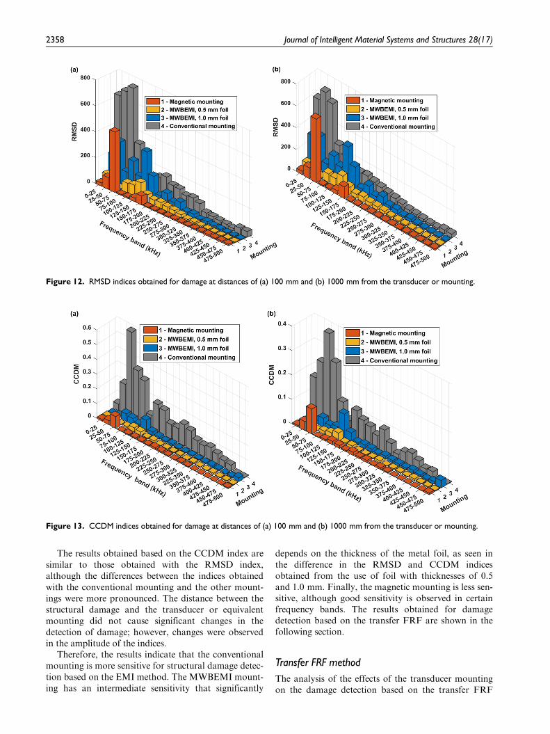
The results obtained based on the CCDM index aresimilar to those obtained with the RMSD index,although the differences between the indices obtainedwith the conventional mounting and the other mount-ings were more pronounced. The distance between thestructural damage and the transducer or equivalentmounting did not cause significant changes in thedetection of damage; however, changes were observedin the amplitude of the indices.
Therefore, the results indicate that the conventionalmounting is more sensitive for structural damage detec-tion based on the EMI method. The MWBEMI mount-ing has an intermediate sensitivity that significantly
depends on the thickness of the metal foil, as seen inthe difference in the RMSD and CCDM indicesobtained from the use of foil with thicknesses of 0.5and 1.0 mm. Finally, the magnetic mounting is less sen-sitive, although good sensitivity is observed in certainfrequency bands. The results obtained for damagedetection based on the transfer FRF are shown in thefollowing section.
Transfer FRF method
The analysis of the effects of the transducer mountingon the damage detection based on the transfer FRF
Figure 12. RMSD indices obtained for damage at distances of (a) 100 mm and (b) 1000 mm from the transducer or mounting.
Figure 13. CCDM indices obtained for damage at distances of (a) 100 mm and (b) 1000 mm from the transducer or mounting.
2358 Journal of Intelligent Material Systems and Structures 28(17)
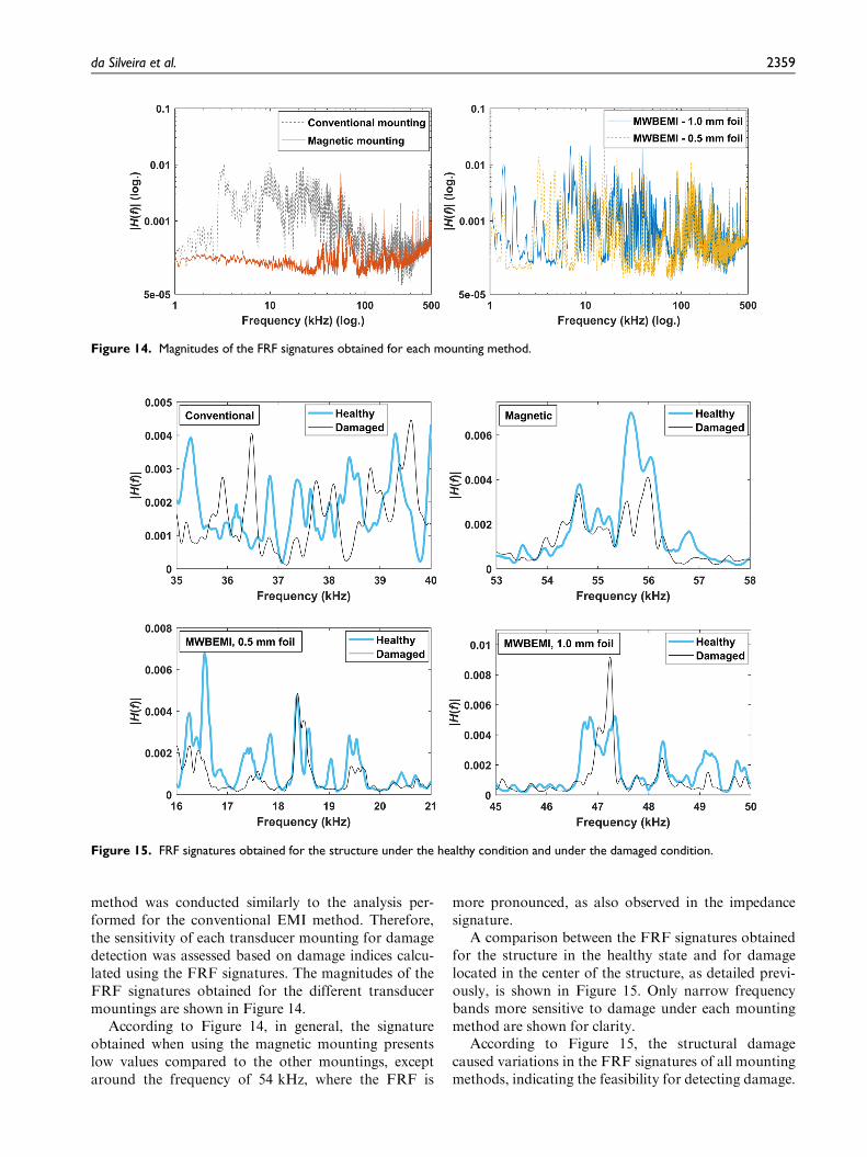
method was conducted similarly to the analysis per-formed for the conventional EMI method. Therefore,the sensitivity of each transducer mounting for damagedetection was assessed based on damage indices calcu-lated using the FRF signatures. The magnitudes of theFRF signatures obtained for the different transducermountings are shown in Figure 14.
According to Figure 14, in general, the signatureobtained when using the magnetic mounting presentslow values compared to the other mountings, exceptaround the frequency of 54 kHz, where the FRF is
more pronounced, as also observed in the impedancesignature.
A comparison between the FRF signatures obtainedfor the structure in the healthy state and for damagelocated in the center of the structure, as detailed previ-ously, is shown in Figure 15. Only narrow frequencybands more sensitive to damage under each mountingmethod are shown for clarity.
According to Figure 15, the structural damagecaused variations in the FRF signatures of all mountingmethods, indicating the feasibility for detecting damage.
Figure 14. Magnitudes of the FRF signatures obtained for each mounting method.
Figure 15. FRF signatures obtained for the structure under the healthy condition and under the damaged condition.
da Silveira et al. 2359
Qualitatively, the conventional mounting providesslightly more prominent variations in the shape andamplitude between the healthy and damaged signatures.Similar to the results obtained with the conventionalEMI method, the magnetic mounting provides less sig-nificant variation between the two FRF signatures.
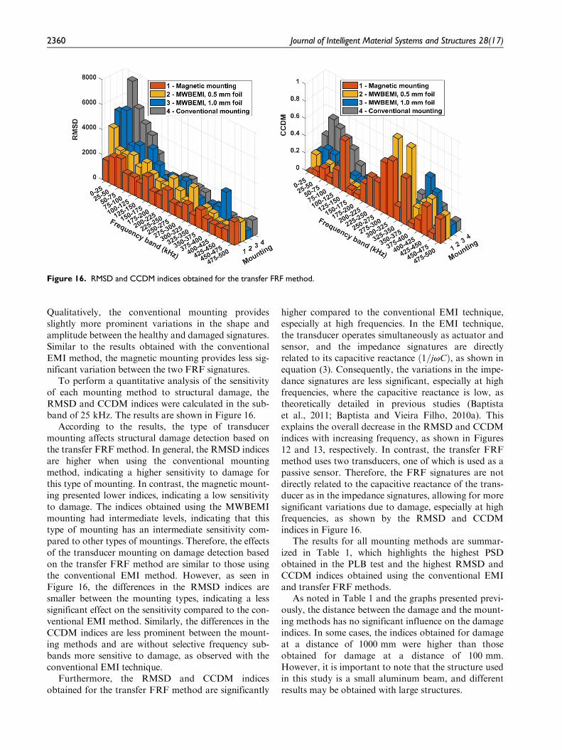
To perform a quantitative analysis of the sensitivityof each mounting method to structural damage, theRMSD and CCDM indices were calculated in the sub-band of 25 kHz. The results are shown in Figure 16.
According to the results, the type of transducermounting affects structural damage detection based onthe transfer FRF method. In general, the RMSD indicesare higher when using the conventional mountingmethod, indicating a higher sensitivity to damage forthis type of mounting. In contrast, the magnetic mount-ing presented lower indices, indicating a low sensitivityto damage. The indices obtained using the MWBEMImounting had intermediate levels, indicating that thistype of mounting has an intermediate sensitivity com-pared to other types of mountings. Therefore, the effectsof the transducer mounting on damage detection basedon the transfer FRF method are similar to those usingthe conventional EMI method. However, as seen inFigure 16, the differences in the RMSD indices aresmaller between the mounting types, indicating a lesssignificant effect on the sensitivity compared to the con-ventional EMI method. Similarly, the differences in theCCDM indices are less prominent between the mount-ing methods and are without selective frequency sub-bands more sensitive to damage, as observed with theconventional EMI technique.
Furthermore, the RMSD and CCDM indicesobtained for the transfer FRF method are significantly
higher compared to the conventional EMI technique,especially at high frequencies. In the EMI technique,the transducer operates simultaneously as actuator andsensor, and the impedance signatures are directlyrelated to its capacitive reactance ð1=jvCÞ, as shown inequation (3). Consequently, the variations in the impe-dance signatures are less significant, especially at highfrequencies, where the capacitive reactance is low, astheoretically detailed in previous studies (Baptistaet al., 2011; Baptista and Vieira Filho, 2010a). Thisexplains the overall decrease in the RMSD and CCDMindices with increasing frequency, as shown in Figures12 and 13, respectively. In contrast, the transfer FRFmethod uses two transducers, one of which is used as apassive sensor. Therefore, the FRF signatures are notdirectly related to the capacitive reactance of the trans-ducer as in the impedance signatures, allowing for moresignificant variations due to damage, especially at highfrequencies, as shown by the RMSD and CCDMindices in Figure 16.
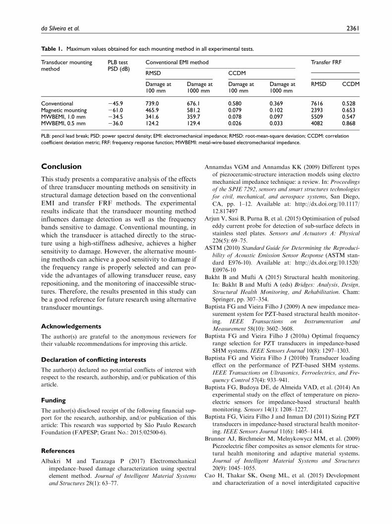
The results for all mounting methods are summar-ized in Table 1, which highlights the highest PSDobtained in the PLB test and the highest RMSD andCCDM indices obtained using the conventional EMIand transfer FRF methods.
As noted in Table 1 and the graphs presented previ-ously, the distance between the damage and the mount-ing methods has no significant influence on the damageindices. In some cases, the indices obtained for damageat a distance of 1000 mm were higher than thoseobtained for damage at a distance of 100 mm.However, it is important to note that the structure usedin this study is a small aluminum beam, and differentresults may be obtained with large structures.
Figure 16. RMSD and CCDM indices obtained for the transfer FRF method.
2360 Journal of Intelligent Material Systems and Structures 28(17)
Conclusion
This study presents a comparative analysis of the effectsof three transducer mounting methods on sensitivity instructural damage detection based on the conventionalEMI and transfer FRF methods. The experimentalresults indicate that the transducer mounting methodinfluences damage detection as well as the frequencybands sensitive to damage. Conventional mounting, inwhich the transducer is attached directly to the struc-ture using a high-stiffness adhesive, achieves a highersensitivity to damage. However, the alternative mount-ing methods can achieve a good sensitivity to damage ifthe frequency range is properly selected and can pro-vide the advantages of allowing transducer reuse, easyrepositioning, and the monitoring of inaccessible struc-tures. Therefore, the results presented in this study canbe a good reference for future research using alternativetransducer mountings.
Acknowledgements
The author(s) are grateful to the anonymous reviewers fortheir valuable recommendations for improving this article.
Declaration of conflicting interests
The author(s) declared no potential conflicts of interest withrespect to the research, authorship, and/or publication of thisarticle.
Funding
The author(s) disclosed receipt of the following financial sup-port for the research, authorship, and/or publication of thisarticle: This research was supported by Sao Paulo ResearchFoundation (FAPESP; Grant No.: 2015/02500-6).
References
Albakri M and Tarazaga P (2017) Electromechanical
impedance–based damage characterization using spectral
element method. Journal of Intelligent Material Systems
and Structures 28(1): 63–77.
Annamdas VGM and Annamdas KK (2009) Different types
of piezoceramic-structure interaction models using electro
mechanical impedance technique: a review. In: Proceedings
of the SPIE 7292, sensors and smart structures technologies
for civil, mechanical, and aerospace systems, San Diego,
CA, pp. 1–12. Available at: http://dx.doi.org/10.1117/
12.817497Arjun V, Sasi B, Purna B, et al. (2015) Optimisation of pulsed
eddy current probe for detection of sub-surface defects in
stainless steel plates. Sensors and Actuators A: Physical
226(5): 69–75.ASTM (2010) Standard Guide for Determining the Reproduci-
bility of Acoustic Emission Sensor Response (ASTM stan-
dard E976-10). Available at: http://dx.doi.org/10.1520/
E0976-10Bakht B and Mufti A (2015) Structural health monitoring.
In: Bakht B and Mufti A (eds) Bridges: Analysis, Design,
Structural Health Monitoring, and Rehabilitation. Cham:
Springer, pp. 307–354.Baptista FG and Vieira Filho J (2009) A new impedance mea-
surement system for PZT-based structural health monitor-
ing. IEEE Transactions on Instrumentation and
Measurement 58(10): 3602–3608.Baptista FG and Vieira Filho J (2010a) Optimal frequency
range selection for PZT transducers in impedance-based
SHM systems. IEEE Sensors Journal 10(8): 1297–1303.Baptista FG and Vieira Filho J (2010b) Transducer loading
effect on the performance of PZT-based SHM systems.
IEEE Transactions on Ultrasonics, Ferroelectrics, and Fre-
quency Control 57(4): 933–941.Baptista FG, Budoya DE, de Almeida VAD, et al. (2014) An
experimental study on the effect of temperature on piezo-
electric sensors for impedance-based structural health
monitoring. Sensors 14(1): 1208–1227.Baptista FG, Vieira Filho J and Inman DJ (2011) Sizing PZT
transducers in impedance-based structural health monitor-
ing. IEEE Sensors Journal 11(6): 1405–1414.Brunner AJ, Birchmeier M, Melnykowycz MM, et al. (2009)
Piezoelectric fiber composites as sensor elements for struc-
tural health monitoring and adaptive material systems.
Journal of Intelligent Material Systems and Structures
20(9): 1045–1055.Cao H, Thakar SK, Oseng ML, et al. (2015) Development
and characterization of a novel interdigitated capacitive
Table 1. Maximum values obtained for each mounting method in all experimental tests.
Transducer mountingmethod
PLB testPSD (dB)
Conventional EMI method Transfer FRF
RMSD CCDM
Damage at100 mm
Damage at1000 mm
Damage at100 mm
Damage at1000 mm
RMSD CCDM
Conventional 245.9 739.0 676.1 0.580 0.369 7616 0.528Magnetic mounting 261.0 465.9 581.2 0.079 0.102 2393 0.653MWBEMI, 1.0 mm 234.5 341.6 359.7 0.078 0.097 5509 0.547MWBEMI, 0.5 mm 236.0 124.2 129.4 0.026 0.033 4082 0.868
PLB: pencil lead break; PSD: power spectral density; EMI: electromechanical impedance; RMSD: root-mean-square deviation; CCDM: correlation
coefficient deviation metric; FRF: frequency response function; MWBEMI: metal-wire-based electromechanical impedance.
da Silveira et al. 2361
strain sensor for structural health monitoring. IEEE Sen-
sors Journal 15(11): 6542–6548.Cortez NE, Vieira Filho J and Baptista FG (2013) A new
microcontrolled structural health monitoring system basedon the electromechanical impedance principle. StructuralHealth Monitoring 12(1): 14–22.
De Almeida VAD, Baptista FG and de Aguiar PR (2015)Piezoelectric transducers assessed by the pencil lead breakfor impedance-based structural health monitoring. IEEESensors Journal 15(2): 693–702.
Farrar CR and Worden K (2013) Structural Health Monitor-
ing: A Machine Learning Perspective. Chichester: JohnWiley & Sons.
Freitas ES and Baptista FG (2016) Experimental analysis ofthe feasibility of low-cost piezoelectric diaphragms inimpedance-based SHM applications. Sensors and Actua-
tors A: Physical 238: 220–228.
Giurgiutiu V (2013) Embedded NDT with piezoelectric waferactive sensors. In: Gunesx O and Akkaya Y (eds) Nondes-
tructive Testing of Materials and Structures (RILEM bookseries, vol. 6). Dordrecht: Springer, pp. 987–992.
Kamas T and Tekkalmaz M (2016) SHM of thick structuresvia E/M impedance of embedded PWAS for weight lossdefects. In: Proceedings of the 8th European workshop on
structural health monitoring (EWSHM 2016), Bilbao, 5–8July.
Kaur N, Bhalla S, Shanker R, et al. (2016) Experimental eva-luation of miniature impedance chip for structural healthmonitoring of prototype steel/RC structures. Experimental
Techniques 40(3): 981–992.Kim I and Chattopadhyay A (2015) Guided Lamb wave–
based structural health monitoring using a novel wavepacket tracing method for damage localization and sizequantification. Journal of Intelligent Material Systems and
Structures 26(18): 2515–2530.Liang C, Sun FP and Rogers CA (1994) Coupled electro-
mechanical analysis of adaptive material systems—determination of the actuator power consumption andsystem energy transfer. Journal of Intelligent Material
Systems and Structures 5(1): 12–20.Martowicz A, Sendecki A, Salamon M, et al. (2016) Applica-
tion of electromechanical impedance-based SHM for dam-age detection in bolted pipeline connection. Nondestructive
Testing and Evaluation 31(1): 17–44.Maruo C II, Giachero GF, Steffen Junior V, et al. (2015)
Electromechanical impedance-based structural healthmonitoring instrumentation system applied to aircraftstructures and employing a multiplexed sensor array. Jour-nal of Aerospace Technology and Management 7(3):294–306.
Meitzler AH, Tiersten HF, Berlincourt D, et al. (1988) IEEE
Standard on Piezoelectricity: An American National Stan-
dard (Standard 176). New York: IEEE-ANSI, 66 pp.Moharana S and Bhalla S (2015) Influence of adhesive bond
layer on power and energy transduction efficiency of
piezo-impedance transducer. Journal of Intelligent Mate-
rial Systems and Structures 26(3): 247–259.Na S and Lee H (2013) Steel wire electromechanical impe-
dance method using a piezoelectric material for compositestructures with complex surfaces. Composite Structures
98(4): 79–84.Na S, Tawie R and Lee H (2012) Electromechanical impe-
dance method of fiber-reinforced plastic adhesive joints incorrosive environment using a reusable piezoelectricdevice. Journal of Intelligent Material Systems and Struc-
tures 23(7): 737–747.Na W and Park KT (2017) A cost-effective impedance-based
structural health monitoring technique for steel structuresby monitoring multiple areas. Journal of Intelligent Mate-
rial Systems and Structures 28(2): 154–162.Naskar S and Bhalla S (2016) Metal-wire-based twin one-
dimensional orthogonal array configuration of PZT
patches for damage assessment of two-dimensional struc-tures. Journal of Intelligent Material Systems and Struc-
tures 27(11): 1440–1460.Ohtsu M, Enoki M, Mizutani Y, et al. (2016) Principles of the
acoustic emission (AE) method and signal processing. In:Practical Acoustic Emission Testing. Tokyo, Japan:
Springer, pp. 5–34. Available at: http://dx.doi.org/10.1007/978-4-431-55072-3_2.
Overly TG, Gyuhae P, Farinholt KM, et al. (2009) Piezoelec-tric active-sensor diagnostics and validation using instan-taneous baseline data. IEEE Sensors Journal 9(11):1414–1421.
Park G, Sohn H, Farrar CR, et al. (2003) Overview of piezo-electric impedance-based health monitoring and path for-ward. The Shock and Vibration Digest 35(6): 451–463.
Shahab S and Erturk A (2016) Coupling of experimentallyvalidated electroelastic dynamics and mixing rules formu-lation for macro-fiber composite piezoelectric structures.Journal of Intelligent Material Systems and Structures.Epub ahead of print 3 November. DOI: 10.1177/1045389X16672732.
Tinoco HA and Marulanda DJ (2015) Damage identificationin active plates with indices based on Gaussian confidenceellipses obtained of the electromechanical admittance.Journal of Nondestructive Evaluation 34: 28.
Vieira Filho J, Baptista FG and Inman DJ (2011) Time-domain analysis of piezoelectric impedance-basedstructural health monitoring using multilevel waveletdecomposition. Mechanical Systems and Signal Processing
25(5): 1550–1558.Waugh RC (2016) Non-destructive evaluation. In: Waugh
RC (ed.) Development of Infrared Techniques for Practical
Defect Identification in Bonded Joints (Springer theses).Cham: Springer, pp. 21–37. Available at: http://dx.doi.org/
10.1007/978-3-319-22982-9_3Zhao J, Bao T and Amjad U (2015) Optical fiber sensing of
small cracks in isotropic homogeneous materials. Sensorsand Actuators A: Physical 225(4): 133–138.
2362 Journal of Intelligent Material Systems and Structures 28(17)


