Embed Size (px)
Citation preview
Performance of single Si3N4 and mixed Si3N4CPCBN wiper cutting tools
applied to high speed face milling of cast iron
Antonio Maria de Souza Jr.a, Wisley Falco Salesb, Sandro Cardoso Santosc,*,Alisson Rocha Machadod
aFiat-GM Powertrain Ltd, Betim, MG, BrazilbMechatronic Engineering, Polytechnic Institute—IPUC, Pontifical Catholic University of Minas Gerais—PUC Minas, IPUC, Belo Horizonte, MG, Brazil
cMechanical Engineering Department, Federal Technologycal Education Centre, CEFET-MG, Av. Amazonas, 7675, Nova Gameleira,
Belo Horizonte 30410-000, MG, BrazildFaculty of Mechanical Engineering, Federal University of Uberlandia, Uberlandia, MG, Brazil
Received 22 October 2003; accepted 3 August 2004
Available online 19 October 2004
Abstract
In this work two face milling cutter systems were used in high speed cutting of gray cast iron under cutting condition encountered in the
shop floor. The first system, called ‘A’, has 24 Si3N4 ceramic inserts all with square wiper edges. The second system, called ‘B’, is a mixed
tool material system, having 24 wiper inserts, 20 of them are Si3N4 intercalated by four PCBN inserts. Cutting speed (vc), depth of cut (doc)
and feed rate per tooth (fz) were kept constant. Surface roughness (Ra and Rt) and waviness (Wt), tool life (based on flank wear, VBBmax) and
burr formation (length of the burr, h) were the parameters considered to compare the two systems. System ‘B’ presented better performance
according to all parameters, although only end of life criterion based on Rt parameter has been reached.
q 2004 Elsevier Ltd. All rights reserved.
Keywords: Si3N4; PCBN; Tool wear; Wear mechanisms; Surface finishing; Burr formation
1. Introduction
Advances in milling processes technologies have been
accelerating in recent years. Designers and users of cutting
tools have worked to optimize shape and tool geometry, tool
life, processes parameters related surface finish, pro-
ductivity and finally, the most important factor, the
machining cost per piece. Until recent years it was common
to use single tool material or tool geometry in a tool holder.
This paradigm in milling processes has been overcome, with
the use of the mixed technology, that is, two or more tool
materials or tools of more than one geometry mounted in a
tool holder [1].
0890-6955/$ - see front matter q 2004 Elsevier Ltd. All rights reserved.
doi:10.1016/j.ijmachtools.2004.08.006
* Corresponding author. Tel.: C55 31 3319 5208; fax: C55 31 3319
5212.
E-mail addresses: [email protected] (A.M. de
Souza Jr.), [email protected] (W.F. Sales), [email protected]
(S.C. Santos), [email protected] (A.R. Machado).
PCBN tools are used in machining operations, where
tight dimensional tolerances are required due to their high
elasticity modulus and hardness and low expansion volu-
metric coefficient. This material is recommended to
machine practically all work piece materials [2], except
low carbon steel [3]. This is because low carbon steel is
ductile enough to generate a large chip/tool contact area,
promoting strong chemical interactions and consequently
activating diffusion wear mechanisms. In the last years,
PCBN tools were used on shop floors in high speed
machining of gray cast iron, white cast iron and hardened
steels with low machining costs per piece. In these
applications they tends to be economically advantageous
[1,4,5].
Si3N4 ceramic tools are largely used to machine gray cast
iron and hardened steels. When cutting gray cast iron, high
speed machining is frequently used with low costs per
pieces.
International Journal of Machine Tools & Manufacture 45 (2005) 335–344
www.elsevier.com/locate/ijmactool

Fig. 1. Upper view of the engine block and indication of some machining
operation details.
A.M. de Souza Jr. et al. / International Journal of Machine Tools & Manufacture 45 (2005) 335–344336
The conventional milling processes use all inserts with
the same geometry, mounted on the cutter. Normal
octagonal inserts are frequently used for roughing cuts.
For finishing cuts wiper systems offer much better
surface finishing. When machining blocks and engine heads
good surface finishing is required and wiper systems are
usually used [5].
Milling cutters with two or more tool materials or tool
geometries is a recent technology. This system uses
octagonal inserts and intercalated by wiper inserts.
Although, they show satisfactory results with respect to
surface roughness the main reason for their choice is related
to low machining costs, presented when compared to a
system having only wiper tools [5].
With the need of better efficiency and performance of
automotive engines and in order to be competitive car
manufacturers have introduced in their engines a new
metallic cylinder head junction. This provides a greater
rigidity in the junction between the cylinder head and the
block, with practically no deformation during lifetime and
keeping the integrity of the junction. This reduces premature
wear, which is usually observed in conventional head
junctions, due to high load, and pressure variations that
occur during the thermal cycles. The use of metallic head
junctions demands better surface finishing (roughness
parameters Ra and Rt, and waviness Wt) and reduction or
elimination of burr formation to allow a good assembling of
the cylinder head onto the cylinder block.
Burrs are defined as ‘undesirable projections of material
beyond the edge of the workpiece due to plastic deformation
during machining’ [6]. The burrs generated in milling
processes are extremely undesirable because they present
accident risks to the operators in the assembly lines.
Furthermore, they can hinder contacts between surfaces,
compromising or damaging the desirable precision in
assembled parts and most critical of all is that burrs can
become detached and contaminate the lubrication and
cooling lines, in the case of internal combustion engines.
Burr removal is an expensive time consuming operation.
Thus, the knowledge of the phenomenon of burr
formation is of great importance because the milling
process can be controlled, particularly the cutting par-
ameters such as cutting speed (vc), feed rate (f ), depth of cut
(doc), tool geometry, and approach angle, cr, so that burr
formation can be minimized and, in some cases eliminated.
With respect to wear, both flank and crater affect the burr
formation process. The dimensions of the burr tend to
increase with increasing wear levels. This is more critical
after a certain amount of wear has been reached [7]. In the
final stage of the process of burr formation a breakout can
occur, particularly in brittle workpiece materials such as
gray cast iron that can lead to scrap the part.
In the production line both burr and breakout must be
avoided because serious problem will happen lately at the
serial assembly line. Occurrence of either will usually lead
to the loss of the part. More critical is when this
phenomenon happens on the last machining operation
after a reasonable amount of money had already been
aggregated into the process.
The objective of this work is to compare the performance
of two milling cutter systems and to study the formation of
burrs at the exit edge of the workpiece considering also and
the surface quality and their relations with tool wear. Both
systems have 24 wiper inserts. System ‘A’ is composed by
Si3N4 ceramic tools while the system ‘B’ has 20 Si3N4 tools
intercalated by four PCBN tools. The tests were all
performed in the production line, using the same serial
machinery for engine production. The cutting speed (vc), the
depth of cut (doc) and feed rate per tooth (fz), were kept
constant.
2. Experimental work
2.1. Machining process
The top surfaces of engine blocks of car engines as
shown in Fig. 1 were face milled. This surface is
characterized by a complex system of tool entrance and
exit to and from the workpiece due to the inherent geometry
of the block.
The engine block material was GH 190 UNI gray cast
iron, with the following chemical composition: 3.2–3.5%C;
2.0–2.5%Si; 0.2%Cr; 0.15%S; 0.10%P and an average
hardness 200 HV.
The experiments were carried out on a transfer line
machine during the engine block production of a car
manufacturing industry. The milling machine with a Siemens
840D electronic control unit was driven by a tri-phasic
asynchronous engine and has a GR ISO130 mono-mandrill.
A constant spindle speed of 1270 rpm (vcZ1000 m/min) was
always used. All the tests were performed during a normal
production regime. Feed per tooth (fz) and depth of cut (doc)
were 0.06 mm/tooth and 0.3 mm, respectively.
Fig. 1 also shows schematically the milling cutter
position with its rotation and feed directions, and

Fig. 2. Positions of PCBN inserts on mill that characterize system B.
A.M. de Souza Jr. et al. / International Journal of Machine Tools & Manufacture 45 (2005) 335–344 337
the region, where the maximum burr length was always
observed.
2.2. Cutting tools
Two different cutting tool assemblies, named system ‘A’
and system ‘B’ were evaluated in this investigation. Both
systems used milling cutters of 250 mm diameter.
System ‘A’ had 24 Si3N4 wiper inserts. These inserts had
the following ISO designation: SNEN 1504ADTR with T
05!15 chanfer edge.
The tool system ‘B’, had 24 inserts, 20 Si3N4 OPHN
0504 ZZN-A27 geometry and four PCBN wiper inserts
OPHX 0504ZZR-A27 geometry. The PCBN inserts were
positioned intercalating each five Si3N4 inserts, as shown in
Fig. 2.
The clamping system used a support pin for the tools and
a mechanism with axial adjustments for the wiper tools.
The adjustment of the tools was performed on an
Ingersoll table, which a flat tip stylus. For milling cutter
Fig. 3. General view of Si3N4 cutting to
of system ‘A’ all the 24 wiper inserts have individual axial
adjustment. The maximum admissible axial deviation was
30 mm. The milling cutter of system ‘B’ had admissible
maximum axial deviation of 40 mm among the Si3N4 inserts,
and 20 mm among the PCBN inserts. The PCBN inserts
were positioned 50 mm above the highest Si3N4 insert.
2.3. Measurement of tool wear, surface texture and burr size
A Wild-Heerbrugg optical microscope model 117.775
and an Omis Mini Optical Measurement Inspection System
were used for tool wear measurements. Analysis of system
‘B’ tools was restricted to PCBN wiper tools because it
greater responsibility to surface finish of machined parts.
The worn surfaces of the tools were analysed within a
Phillips scanning electronic microscope with objective to
identify predominant shapes and wear mechanisms. Surface
roughness and waviness measurements were performed by a
Taylor Hobson MK3 profilometer. Cut-off length of 0.8 mm
was adopted.
The length of the burr was measured with a diamond
stylus gauge (20 mm resolution). Five measurements were
taken and the mean value considered. Lee et al. [8] was also
utilized a similar procedure.
2.4. End of tool life criterion
End of tool life criterion based on tool flank wear
(VBBmaxZ0.7 mm) was adopted, and in order to comply
with requirements from the design of the engine block to
avoid workpiece rejection other criteria were also con-
sidered based on surface roughness parameters (maximum
roughness average, RaZ1.6 mm; maximum roughness
height, RtZ10 mm) and burr dimensions (maximum burr
length, hZ1.8 mm).
In each test the roughness parameters Ra and Rt,
maximum flank wear VBBmax and burr length (h) were
ol shows flank and chatter wear.

Fig. 4. Detail shows some wear mechanisms such as micro-cracks, plastic deformation and abrasion.
A.M. de Souza Jr. et al. / International Journal of Machine Tools & Manufacture 45 (2005) 335–344338
measured after machining the first five workpieces. Next, up
to the 100th engine block machined the intervals of
measurements of theses parameters was enhanced to 10
workpieces. From the 100th to the 800th engine block
machined the intervals of measurements was fixed in 100
workpieces and after the 800th engine block the interval was
increased to 200 workpieces machined until one of the tool
life rejection criteria was reached.
3. Results and discussion
Results obtained are presented and discussed in this
section, which is divided into two parts. First part presents a
sequence of scanning electronic microscope photographs of
worn cutting edges of wiper tools that will contribute for the
discussion of the results of tool wear behavior, surface
texture and burr size presented in the second part.
Fig. 5. Detail shows micro-cra
3.1. Scanning electronic microscope images
of worn surfaces
Worn surfaces of Si3N4 tools are shown in Figs. 3–6.
Fig. 3 shows the general aspects of the worn surface, that
allow identify flank wear as the main wear form. Smooth
aspect of the topography of worn region can be also
observed. Occurrence of this appearance may be attributed
to adhesion of workpiece material, diffusive wear [9] or
abrasion due the action of harder particles over softer
materials [10]. Amplifications of worn region are shown in
Figs. 4–6 that permit identify the presence of cracks in
different regions of worn surface. Propagation of cracks
causes chipping of some Si3N4 cutting tools that occurs
during the tests. Smooth topography and flow of material
over the worn surface indicates occurrence of adhesion.
High chemical affinity of tool and workpiece material
components also justifies the hypothesis of adhesion.
cks and abrasive wear.

Fig. 6. Detail of worn surface of Si3N4 cutting tools shows micro-cracks.
A.M. de Souza Jr. et al. / International Journal of Machine Tools & Manufacture 45 (2005) 335–344 339
Figs. 5 and 6 show the flow of workpiece material over
the tool flank surface. Figs. 4 and 6 show details of cracks
present at the worn area of the tool. Smooth surfaces near
the cracks and surfaces that present abrasion marks can be
observed. The gray cast iron workpiece material has in its
composition silicon carbide, SiC, with high hardness
(2500 HV). According to Refs. [11,12], the presence of
hard particles in the tribological system can promote wear
and the relationship between workpiece/abrasive hardness
materials is an important effect on the wear regime. For
hardness ratio less than 0.6 the so-called soft abrasion will
occur while for ratio more than 0.6 the so-called hard
abrasion regime will take place. Large system damage is
encountered when hard abrasion is dominated. The
tribological system evaluated presents Si3N4 tool material
Fig. 7. General view of PCBN cut
with average hardness of 1600 HV and the hardness ratio is
around 0.64, which situates on the hard abrasion regime.
Fig. 7F shows cracks that propagate in several directions.
The aspects of worn region of Si3N4 justify the tendency of
catastrophic failure of the tools due chipping. Other wear
mechanisms were reported by Silva et al. [13] and Vleugels
and Van Der Biest [14]. The later showed the incompat-
ibility of the use the of Si3N4 tools at high cutting speed and
dry machining of steels because of the high interface
temperatures and the chemical compatibility between the
materials involved in the tribological system which
encourage chemical wear which is dominant under those
evaluated cutting conditions.
Aspects of the worn surfaces of PCBN cutting tools are
shown in Figs. 7–9, those are characterized by presence of
ting tools shows flank wear.

Fig. 8. Detail shows some wear mechanisms such as micro-cracks, plastic deformation and adhesion of the work piece material.
A.M. de Souza Jr. et al. / International Journal of Machine Tools & Manufacture 45 (2005) 335–344340
cracks running to the cutting edge. The presence of abrasion
marks is also observed in these figures. This tribological
system involves silicon carbides and a PCBN (4000 HV)
and the hardness ratio workpiece/abrasive material is
around 0.6. Therefore, the wear regime is a transition
between soft and hard abrasion, but it is clear the presence
of the abrasive wear. Aspects the worn surface suggest that
thermal and mechanical cyclic load was the main factor to
influence the wear of the cutting tools and fracture
toughness resistance should be the main property required
when machining with PCBN cutting tools. It was observed a
tendency of the workpiece material to adhere into the
cracks, hypothesis confirmed by EDX analysis.
The results indicated the presence of Fe and Si, elements
of the workpiece material. These portions contribute to
cracks growth and propagation.
Fig. 9. Detail shows evidences wear mechanisms
Gastel et al. [15] has studied the performance of PCBN
tools on grey cast iron and compact graphite iron turning.
They showed that oxidation of the tools and interdiffusion of
constituting chemical elements between tool and workpiece
were the dominant wear mechanisms.
3.2. Tool wear, surface texture and burr size
Behavior of maximum flank wear of cutting tool during
engine block production is shown in Fig. 10. System ‘A’
was able to produce 1600 parts, while system ‘B’ could
produce 2577 blocks. Tools that compose system ‘A’
showed relatively low wear until 1400 parts were produced
and after which a rapid growth was observed. System ‘B’
tools tended to present a uniform increase of flank wear
during all the tool life.
such as abrasion and plastic deformation.

Fig. 10. Evaluation of flank wear (VBBmax) as a function of number of blocks machined.
A.M. de Souza Jr. et al. / International Journal of Machine Tools & Manufacture 45 (2005) 335–344 341
The type of wear observed on cutting tools can explain
the behavior of the maximum flank wear curves. Si3N4
cutting tools presented a tendency to chip or break as a
consequence of formation and propagation of cracks, as
shown in Figs. 4–6. The occurrence of chipping implies in
an abrupt change on tool geometry, which can be reflected
in rapid increase in flank wear, as shown in Fig. 10. On the
other hand, PCBN cutting tools presented a gradual increase
of flank wear, which is compatible with wear aspects
observed in these tools. Formation and growth of cracks
were gradually observed, fact that implies in gradual
increase of flank wear.
Surface average roughnesses obtained by the two
systems are shown in Fig. 11. Both systems presented the
same behavior throughout the tool life. The exception of this
is the last engine block machined with system ‘B’, when the
Ra parameter was much higher than the end of tool life
criterion RaZ1.6 mm.
The PCBN and Si3N4 cutting tools presented different
wear patterns, as shown by the different surface profiles of
the machined surfaces. To complement the study of surface
Fig. 11. Roughness (Ra) as a function
texture two other parameters like maximum peak to valley
distance (Rt) and waviness (Wt) were also measured as a
function of the number of engine blocks machined. Results
for Rt are presented in Fig. 12.
System ‘A’ tends to produce higher values of Rt
parameter during all the tool lives. Engine blocks milled
by system ‘B’ tend to present relative uniform values of Rt,
while system ‘A’ sowed crescent values. According to the
results shown in Fig. 12, both systems exceeded the end of
tool life criterion, RtZ10 mm.
Results of waviness parameter Wt are shown in Fig. 13.
As observed for Rt parameter, system ‘A’ presented
higher values of Wt than system ‘B’ practically throughout
the tool life. The wear of the PCBN tools was smaller than
the wear of the Si3N4 tools. This fact is implied by the
smaller cutting effort when machining with the former
cutting tools, and consequently smaller deformation and
vibration, which results in better surface finish.
Burr height as a function of the number of blocks
machined is shown in Fig. 14. The ceramic cutting tools
tend to produce higher burrs and this difference increases
of number of blocks machined.

Fig. 12. Maximum peak to valley distance (Rt) as a function of number of the blocks machined.
A.M. de Souza Jr. et al. / International Journal of Machine Tools & Manufacture 45 (2005) 335–344342
when the number of parts machined increases. Again the
higher wear of the ceramics compared to the PCBN tools is
responsible for these results.
According to Olvera and Barrow [16], the thickness
and/or the length can be used to characterize the burr but the
former is it’s the main dimension. The thicker burrs are the
more difficult to be broken during a deburring operation.
However, the measurement of its thickness is more difficult
and laborious because metallographic preparation is usually
required. On the other hand, the length of the burr can be
easily measured, allowing a large number of measurements
in a short period of time, and it can also be used for its
characterization [17]. In the present work it was thus
decided to measure the length of the burr instead of its
thickness since the entire test were carried out in the
production line.
Work by Olvera and Barrow [16] in face milling AISI
1040 steel bars at a cutting speed of 142 m/min, investigated
the influence of the depth of cut (doc) and the nose radii on
the burr length. They founded that the burr length increases
Fig. 13. Waviness parameter (Wt) as a functi
when doc and nose radius increases until a value, called
critical value, from which it starts to decrease. These
transition points encountered were docZ0.5, 0.8 and
0.9 mm for the tool nose radii of 0.4, 0.8 and 1.2 mm,
respectively. Although in the present investigation the work
material is cast iron and the cutting speed (1000 m/min) is
far higher than that used by Olvera and Barrow [16], which
might imply here the development of higher cutting
temperatures [9] the transition point might also be present.
In this work the tool nose radius was 0.4 mm and the depth
of cut was 0.3 mm and they did not vary, and therefore the
transition point (or critical value) could not be determined.
However, the influence of the wear or the burr length is
clear. The burr length increases when the wear increases.
This is in agreement with the mathematical model
presented by Hashimura et al. [18] that indicates an increase
in the burr sizes with increasing in the cutting section area.
During all the tests no breakout phenomenon was
observed. This means that the amount of wear was not
enough to increase the plastic deformation zones to an
on of the number of blocks machined.
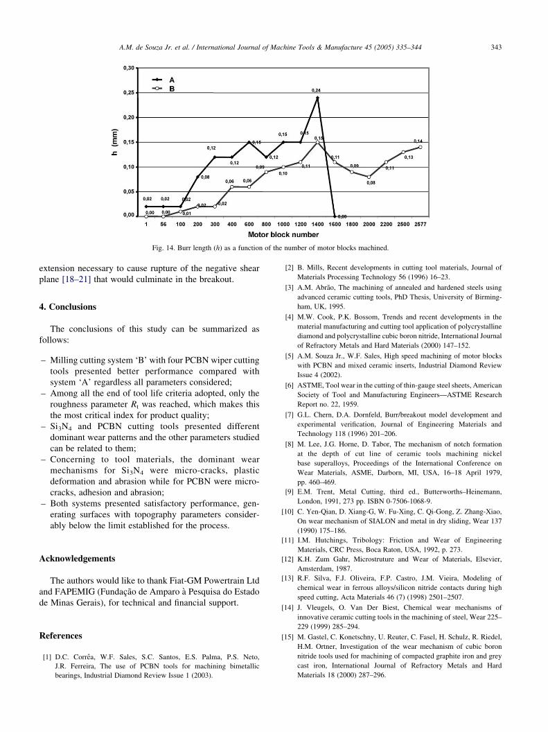
Fig. 14. Burr length (h) as a function of the number of motor blocks machined.
A.M. de Souza Jr. et al. / International Journal of Machine Tools & Manufacture 45 (2005) 335–344 343
extension necessary to cause rupture of the negative shear
plane [18–21] that would culminate in the breakout.
4. Conclusions
The conclusions of this study can be summarized as
follows:
–
Milling cutting system ‘B’ with four PCBN wiper cuttingtools presented better performance compared with
system ‘A’ regardless all parameters considered;
–
Among all the end of tool life criteria adopted, only theroughness parameter Rt was reached, which makes this
the most critical index for product quality;
–
Si3N4 and PCBN cutting tools presented differentdominant wear patterns and the other parameters studied
can be related to them;
–
Concerning to tool materials, the dominant wearmechanisms for Si3N4 were micro-cracks, plastic
deformation and abrasion while for PCBN were micro-
cracks, adhesion and abrasion;
–
Both systems presented satisfactory performance, gen-erating surfaces with topography parameters consider-
ably below the limit established for the process.
Acknowledgements
The authors would like to thank Fiat-GM Powertrain Ltd
and FAPEMIG (Fundacao de Amparo a Pesquisa do Estado
de Minas Gerais), for technical and financial support.
References
[1] D.C. Correa, W.F. Sales, S.C. Santos, E.S. Palma, P.S. Neto,
J.R. Ferreira, The use of PCBN tools for machining bimetallic
bearings, Industrial Diamond Review Issue 1 (2003).
[2] B. Mills, Recent developments in cutting tool materials, Journal of
Materials Processing Technology 56 (1996) 16–23.
[3] A.M. Abrao, The machining of annealed and hardened steels using
advanced ceramic cutting tools, PhD Thesis, University of Birming-
ham, UK, 1995.
[4] M.W. Cook, P.K. Bossom, Trends and recent developments in the
material manufacturing and cutting tool application of polycrystalline
diamond and polycrystalline cubic boron nitride, International Journal
of Refractory Metals and Hard Materials (2000) 147–152.
[5] A.M. Souza Jr., W.F. Sales, High speed machining of motor blocks
with PCBN and mixed ceramic inserts, Industrial Diamond Review
Issue 4 (2002).
[6] ASTME, Tool wear in the cutting of thin-gauge steel sheets, American
Society of Tool and Manufacturing Engineers—ASTME Research
Report no. 22, 1959.
[7] G.L. Chern, D.A. Dornfeld, Burr/breakout model development and
experimental verification, Journal of Engineering Materials and
Technology 118 (1996) 201–206.
[8] M. Lee, J.G. Horne, D. Tabor, The mechanism of notch formation
at the depth of cut line of ceramic tools machining nickel
base superalloys, Proceedings of the International Conference on
Wear Materials, ASME, Darborn, MI, USA, 16–18 April 1979,
pp. 460–469.
[9] E.M. Trent, Metal Cutting, third ed., Butterworths–Heinemann,
London, 1991, 273 pp. ISBN 0-7506-1068-9.
[10] C. Yen-Qian, D. Xiang-G, W. Fu-Xing, C. Qi-Gong, Z. Zhang-Xiao,
On wear mechanism of SIALON and metal in dry sliding, Wear 137
(1990) 175–186.
[11] I.M. Hutchings, Tribology: Friction and Wear of Engineering
Materials, CRC Press, Boca Raton, USA, 1992, p. 273.
[12] K.H. Zum Gahr, Microstruture and Wear of Materials, Elsevier,
Amsterdam, 1987.
[13] R.F. Silva, F.J. Oliveira, F.P. Castro, J.M. Vieira, Modeling of
chemical wear in ferrous alloys/silicon nitride contacts during high
speed cutting, Acta Materials 46 (7) (1998) 2501–2507.
[14] J. Vleugels, O. Van Der Biest, Chemical wear mechanisms of
innovative ceramic cutting tools in the machining of steel, Wear 225–
229 (1999) 285–294.
[15] M. Gastel, C. Konetschny, U. Reuter, C. Fasel, H. Schulz, R. Riedel,
H.M. Ortner, Investigation of the wear mechanism of cubic boron
nitride tools used for machining of compacted graphite iron and grey
cast iron, International Journal of Refractory Metals and Hard
Materials 18 (2000) 287–296.

A.M. de Souza Jr. et al. / International Journal of Machine Tools & Manufacture 45 (2005) 335–344344
[16] O. Olvera, G. Barrow, Influence of exit angle and tool nose geometry
on burr formation in face milling operations, Proceedings of the
Institution of Mechanical Engineers 212 (part B) (1998) 59–72.
[17] L.K. Gillespie, P.T. Blotter, The formation and properties of
machining burrs, Transactions of the ASME (1976) 66–74.
[18] M. Hashimura, Y.P. Chang, D. Dornfeld, Analysis of burr formation
mechanism in orthogonal cutting, Journal of Manufacturing Science
and Engineering 121 (1999) 1–7.
[19] A.J. Pekelharing, The exit failure uninterrupted cutting, Annals of the
CIRP 27 (1) (1978) 5–10.
[20] S.L. Ko, D.A. Dornfeld, Analysis of fracture in burr formation at the
exit stage of metal cutting, Journal of Materials Processing
Technology 58 (1996) 189–200.
[21] S.L. Ko, D.A. Dornfeld, Burr formation and fracture in oblique
cutting, Journal of Materials Processing Technology 63 (1996)
24–36.


