Embed Size (px)
Citation preview

Soong, T.T. and Dargush, G.F. “Passive Energy Dissipation and Active Control”Structural Engineering HandbookEd. Chen Wai-FahBoca Raton: CRC Press LLC, 1999
Passive Energy Dissipation andActive Control
T.T. Soong andG.F. DargushDepartment of Civil Engineering,State University of New Yorkat Buffalo, Buffalo, NY
27.1 Introduction27.2 Basic Principles and Methods of Analysis
Single-Degree-of-Freedom Structural Systems • Multi-Degree-of-FreedomStructural Systems • EnergyFormulations• Energy-Based Design
27.3 Recent Development and ApplicationsPassive Energy Dissipation • Active Control
27.4 Code Development27.5 Concluding RemarksReferences
27.1 Introduction
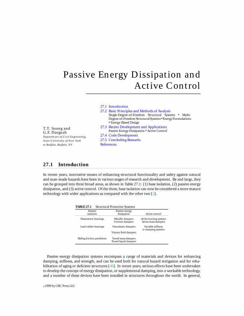
In recent years, innovative means of enhancing structural functionality and safety against naturaland man-made hazards have been in various stages of research and development. By and large, theycan be grouped into three broad areas, as shown in Table 27.1: (1) base isolation, (2) passive energydissipation, and (3) active control. Of the three, base isolation can now be considered a more maturetechnology with wider applications as compared with the other two [2].
TABLE 27.1 Structural Protective SystemsSeismic Passive energyisolation dissipation Active control
Elastomeric bearings Metallic dampers Active bracing systemsFriction dampers Active mass dampers
Lead rubber bearings Viscoelastic dampers Variable stiffnessor damping systems
Viscous fluid dampers
Sliding friction pendulum Tuned mass dampersTuned liquid dampers
Passive energy dissipation systems encompass a range of materials and devices for enhancingdamping, stiffness, and strength, and can be used both for natural hazard mitigation and for reha-bilitation of aging or deficient structures [46]. In recent years, serious efforts have been undertakento develop the concept of energy dissipation, or supplemental damping, into a workable technology,and a number of these devices have been installed in structures throughout the world. In general,
c©1999 by CRC Press LLC
such systems are characterized by a capability to enhance energy dissipation in the structural systemsin which they are installed. This effect may be achieved either by conversion of kinetic energy to heator by transferring of energy among vibrating modes. The first method includes devices that operateon principles such as frictional sliding, yielding of metals, phase transformation in metals, defor-mation of viscoelastic solids or fluids, and fluid orificing. The latter method includes supplementaloscillators that act as dynamic absorbers. A list of such devices that have found applications is givenin Table 27.1.
Among the current passive energy dissipation systems, those based on deformation of viscoelasticpolymers and on fluid orificing represent technologies in which the U.S. industry has a worldwidelead. Originally developed for industrial and military applications, these technologies have foundrecent applications in natural hazard mitigation in the form of either energy dissipation or elementsof seismic isolation systems.
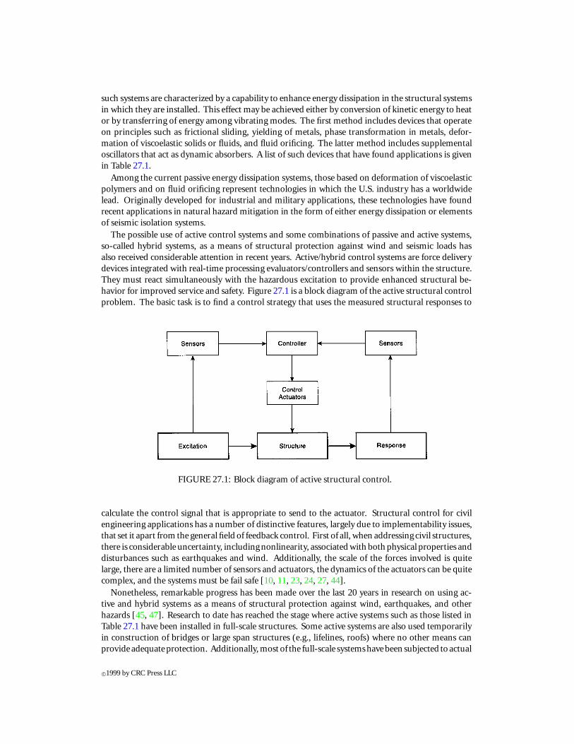
The possible use of active control systems and some combinations of passive and active systems,so-called hybrid systems, as a means of structural protection against wind and seismic loads hasalso received considerable attention in recent years. Active/hybrid control systems are force deliverydevices integrated with real-time processing evaluators/controllers and sensors within the structure.They must react simultaneously with the hazardous excitation to provide enhanced structural be-havior for improved service and safety. Figure 27.1 is a block diagram of the active structural controlproblem. The basic task is to find a control strategy that uses the measured structural responses to
FIGURE 27.1: Block diagram of active structural control.
calculate the control signal that is appropriate to send to the actuator. Structural control for civilengineering applications has a number of distinctive features, largely due to implementability issues,that set it apart from the general field of feedback control. First of all, when addressing civil structures,there is considerable uncertainty, including nonlinearity, associated with both physical properties anddisturbances such as earthquakes and wind. Additionally, the scale of the forces involved is quitelarge, there are a limited number of sensors and actuators, the dynamics of the actuators can be quitecomplex, and the systems must be fail safe [10, 11, 23, 24, 27, 44].
Nonetheless, remarkable progress has been made over the last 20 years in research on using ac-tive and hybrid systems as a means of structural protection against wind, earthquakes, and otherhazards [45, 47]. Research to date has reached the stage where active systems such as those listed inTable 27.1 have been installed in full-scale structures. Some active systems are also used temporarilyin construction of bridges or large span structures (e.g., lifelines, roofs) where no other means canprovide adequateprotection. Additionally, most of the full-scale systemshavebeen subjected to actual
c©1999 by CRC Press LLC
wind forces and ground motions, and their observed performances provide invaluable informationin terms of (1) validating analytical and simulation procedures used to predict system performance,(2) verifying complex electronic-digital-servohydraulic systems under actual loading conditions, and(3) verifying the capability of these systems to operate or shutdown under prescribed conditions.
The focus of this chapter is on passive energy dissipation and active control systems. Their basicoperating principles and methods of analysis are given in Section 27.2, followed by a review in Sec-tion 27.3 of recent development and applications. Code development is summarized in Section 27.4,and some comments on possible future directions in this emerging technological area are advancedin Section 27.5. In the following subsections, we shall use the term structural protective systems torepresent either passive energy dissipation systems or active control systems.
27.2 Basic Principles and Methods of Analysis
With recent development and implementation of modern structural protective systems, the entirestructural engineering discipline is now undergoing a major change. The traditional idealization ofa building or bridge as a static entity is no longer adequate. Instead, structures must be analyzed anddesigned by considering their dynamic behavior. It is with this in mind that we present some basicconcepts related to topics that are of primary importance in understanding, analyzing, and designingstructures that incorporate structural protective systems.
In what follows, a simple single-degree-of-freedom (SDOF) structural model is discussed. Thisrepresents the prototype for dynamic behavior. Particular emphasis is given to the effect of damp-ing. As we shall see, increased damping can significantly reduce system response to time-varyingdisturbances. While this model is useful for developing an understanding of dynamic behavior, itis not sufficient for representing real structures. We must include more detail. Consequently, amulti-degree-of-freedom (MDOF) model is then introduced, and several numerical procedures areoutlined for general dynamic analysis. A discussion comparing typical damping characteristics intraditional and control-augmented structures is also included. Finally, a treatment of energy for-mulations is provided. Essentially one can envision an environmental disturbance as an injection ofenergy into a structure. Design then focuses on the management of that energy. As we shall see, theseenergy concepts are particularly relevant in the discussion of passively or actively damped structures.
27.2.1 Single-Degree-of-Freedom Structural Systems
Consider the lateral motion of the basic SDOF model, shown in Figure 27.2, consisting of a mass,m, supported by springs with total linear elastic stiffness, k, and a damper with linear viscosity, c.This SDOF system is then subjected to an external disturbance, characterized by f (t). The excitedmodel responds with a lateral displacement, x(t), relative to the ground, which satisfies the equationof motion:
mx + cx + kx = f (t) (27.1)
in which a superposed dot represents differentiation with respect to time. For a specified input, f (t),and with known structural parameters, the solution of this equation can be readily obtained.
In the above, f (t) represents an arbitrary environmental disturbance such as wind or an earth-quake. In the case of an earthquake load,
f (t) = −mxg(t) (27.2)
where xg(t) is ground acceleration.Consider now the addition of a generic passive or active control element into the SDOF model, as
indicated in Figure 27.3. The response of the system is now influenced by this additional element.
c©1999 by CRC Press LLC
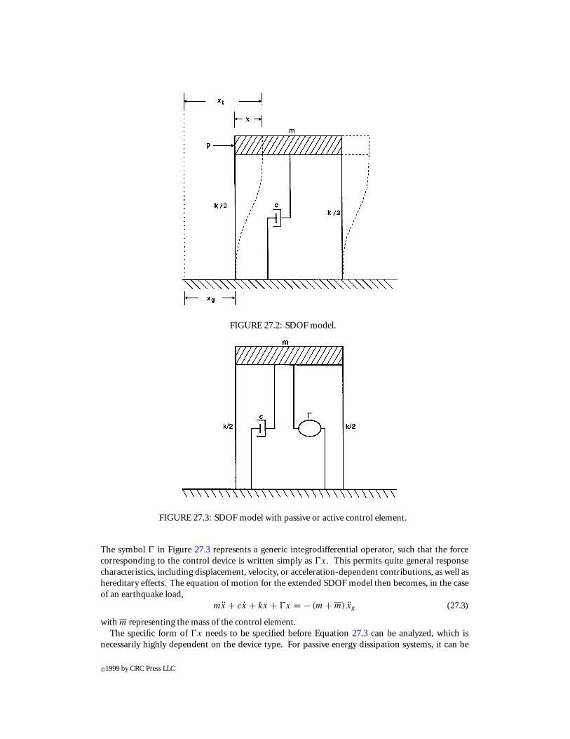
FIGURE 27.2: SDOF model.
FIGURE 27.3: SDOF model with passive or active control element.
The symbol 0 in Figure 27.3 represents a generic integrodifferential operator, such that the forcecorresponding to the control device is written simply as 0x. This permits quite general responsecharacteristics, including displacement, velocity, or acceleration-dependent contributions, as well ashereditary effects. The equation of motion for the extended SDOF model then becomes, in the caseof an earthquake load,
mx + cx + kx + 0x = − (m + m) xg (27.3)
with m representing the mass of the control element.The specific form of 0x needs to be specified before Equation 27.3 can be analyzed, which is
necessarily highly dependent on the device type. For passive energy dissipation systems, it can be
c©1999 by CRC Press LLC
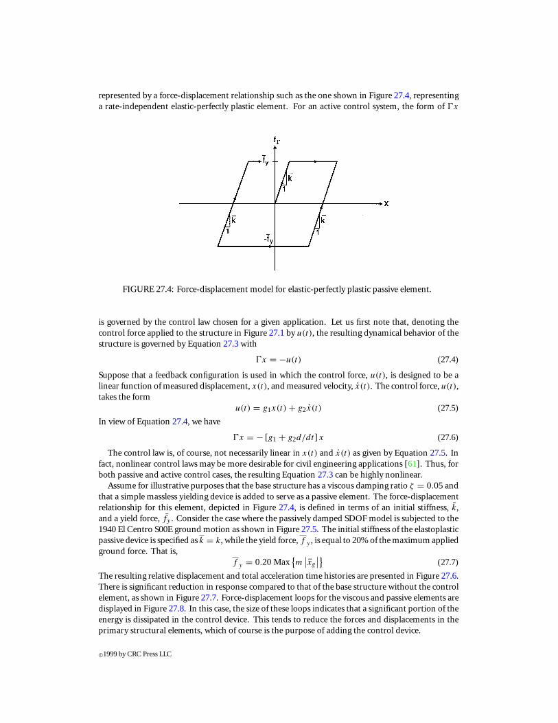
represented by a force-displacement relationship such as the one shown in Figure 27.4, representinga rate-independent elastic-perfectly plastic element. For an active control system, the form of 0x
FIGURE 27.4: Force-displacement model for elastic-perfectly plastic passive element.
is governed by the control law chosen for a given application. Let us first note that, denoting thecontrol force applied to the structure in Figure 27.1 by u(t), the resulting dynamical behavior of thestructure is governed by Equation 27.3 with
0x = −u(t) (27.4)
Suppose that a feedback configuration is used in which the control force, u(t), is designed to be alinear function of measured displacement, x(t), and measured velocity, x(t). The control force, u(t),takes the form
u(t) = g1x(t) + g2x(t) (27.5)
In view of Equation 27.4, we have
0x = − [g1 + g2d/dt ] x (27.6)
The control law is, of course, not necessarily linear in x(t) and x(t) as given by Equation 27.5. Infact, nonlinear control laws may be more desirable for civil engineering applications [61]. Thus, forboth passive and active control cases, the resulting Equation 27.3 can be highly nonlinear.
Assume for illustrative purposes that the base structure has a viscous damping ratio ζ = 0.05andthat a simple massless yielding device is added to serve as a passive element. The force-displacementrelationship for this element, depicted in Figure 27.4, is defined in terms of an initial stiffness, k,and a yield force, fy . Consider the case where the passively damped SDOF model is subjected to the1940 El Centro S00E ground motion as shown in Figure 27.5. The initial stiffness of the elastoplasticpassive device is specified as k = k, while the yield force, f y , is equal to 20% of the maximum appliedground force. That is,
f y = 0.20Max{m
∣∣xg
∣∣} (27.7)
The resulting relative displacement and total acceleration time histories are presented in Figure 27.6.There is significant reduction in response compared to that of the base structure without the controlelement, as shown in Figure 27.7. Force-displacement loops for the viscous and passive elements aredisplayed in Figure 27.8. In this case, the size of these loops indicates that a significant portion of theenergy is dissipated in the control device. This tends to reduce the forces and displacements in theprimary structural elements, which of course is the purpose of adding the control device.
c©1999 by CRC Press LLC
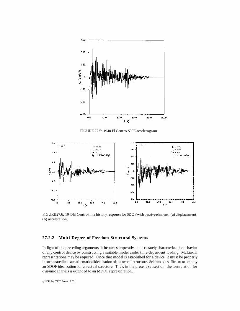
FIGURE 27.5: 1940 El Centro S00E accelerogram.
FIGURE27.6: 1940ElCentro timehistory response for SDOFwithpassive element: (a)displacement,(b) acceleration.
27.2.2 Multi-Degree-of-Freedom Structural Systems
In light of the preceding arguments, it becomes imperative to accurately characterize the behaviorof any control device by constructing a suitable model under time-dependent loading. Multiaxialrepresentations may be required. Once that model is established for a device, it must be properlyincorporated intoamathematical idealizationof theoverall structure. Seldomis it sufficient toemployan SDOF idealization for an actual structure. Thus, in the present subsection, the formulation fordynamic analysis is extended to an MDOF representation.
c©1999 by CRC Press LLC
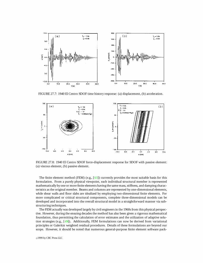
FIGURE 27.7: 1940 El Centro SDOF time history response: (a) displacement, (b) acceleration.
FIGURE 27.8: 1940 El Centro SDOF force-displacement response for SDOF with passive element:(a) viscous element, (b) passive element.
The finite element method (FEM) (e.g., [63]) currently provides the most suitable basis for thisformulation. From a purely physical viewpoint, each individual structural member is representedmathematically by one or more finite elements having the same mass, stiffness, and damping charac-teristics as the original member. Beams and columns are represented by one-dimensional elements,while shear walls and floor slabs are idealized by employing two-dimensional finite elements. Formore complicated or critical structural components, complete three-dimensional models can bedeveloped and incorporated into the overall structural model in a straightforward manner via sub-structuring techniques.
The FEM actually was developed largely by civil engineers in the 1960s from this physical perspec-tive. However, during the ensuing decades the method has also been given a rigorous mathematicalfoundation, thus permitting the calculation of error estimates and the utilization of adaptive solu-tion strategies (e.g., [49]). Additionally, FEM formulations can now be derived from variationalprinciples or Galerkin weighted residual procedures. Details of these formulations are beyond ourscope. However, it should be noted that numerous general-purpose finite element software pack-
c©1999 by CRC Press LLC
ages currently exist to solve the structural dynamics problem, including ABAQUS, ADINA, ANSYS,and MSC/NASTRAN. While none of these programs specifically addresses the special formulationsneeded to characterize structural protective systems, most permit generic user-defined elements.Alternatively, one can utilize packages geared exclusively toward civil engineering structures, such asETABS, DRAIN, and IDARC, which in some cases can already accommodate typical passive elements.
Via any of the above-mentioned methods and programs, the displacement response of the structureis ultimately represented by a discrete set of variables, which can be considered the components of ageneralized relative displacement vector, x(t), of dimension N . Then, in analogy with Equation 27.3,the N equations of motion for the discretized structural system, subjected to uniform base excitationand time varying forces, can be written:
Mx + Cx + Kx + 0x = −(M + M)xg (27.8)
where M, C, and K represent the mass, damping, and stiffness matrices, respectively, while 0 sym-bolizes a matrix of operators that model the protective system present in the structure. Meanwhile,the vector xg contains the rigid body contribution of the seismic ground displacement to each degreeof freedom. The matrix M represents the mass of the protective system.
There are several approaches that can be taken to solve Equation 27.8. The preferred approach, interms of accuracy and efficiency, depends upon the form of the various terms in that equation. Let usfirst suppose that the protective device can be modeled as direct linear functions of the acceleration,velocity, and displacement vectors. That is,
0x = Mx + Cx + Kx (27.9)
Then, Equation 27.8 can be rewritten as
Mx + Cx + Kx = −Mxg (27.10)
in which
M = M + M (27.11a)
C = C + C (27.11b)
K = K + K (27.11c)
Equation 27.10 is now in the form of the classical matrix structural dynamic analysis problem. In thesimplest case, which we will now assume, all of the matrix coefficients associated with the primarystructure and the passive elements are constant. As a result, Equation 27.10 represents a set of N
linear second-order ordinary differential equations with constant coefficients. These equations are,in general, coupled. Thus, depending upon N , the solution of Equation 27.10 throughout the timerange of interest could become computationally demanding. This required effort can be reducedconsiderably if the equation can be uncoupled via a transformation; that is, if M, C, and K can bediagonalized. Unfortunately, this is not possible for arbitrary matrices M, C, and K . However, withcertain restrictions on the damping matrix, C, the transformation to modal coordinates accomplishesthe objective via the modal superposition method (see, e.g., [7]).
As mentioned earlier, it is more common having 0x in Equation 27.9 nonlinear in x for a variety ofpassive and active control elements. Consequently, it is important to develop alternative numericalapproaches and design methodologies applicable to more generic passively or actively damped struc-tural systems governed by Equation 27.8. Direct time-domain numerical integration algorithms aremost useful in that regard. The Newmark beta algorithm, for example, is one of these algorithmsand is used extensively in structural dynamics.
c©1999 by CRC Press LLC
27.2.3 Energy Formulations
In the previous two subsections, we have considered SDOF and MDOF structural systems. Theprimary thrust of our analysis procedures has been the determination of displacements, velocities,accelerations, and forces. These are the quantities that, historically, have been of most interest.However, with the advent of innovative concepts for structural design, including structural protectivesystems, it is important to rethink current analysis and design methodologies. In particular, a focuson energy as a design criterion is conceptually very appealing. With this approach, the engineer isconcerned, not so much with the resistance to lateral loads but rather, with the need to dissipate theenergy input into the structure from environmental disturbances. Actually, this energy concept is notnew. Housner [21] suggested an energy-based design approach even for more traditional structuresseveral decades ago. The resulting formulation is quite appropriate for a general discussion of energydissipation in structures equipped with structural protective systems.
In what follows, an energy formulation is developed for an idealized structural system, which mayinclude one or more control devices. The energy concept is ideally suited for application to non-traditional structures employing control elements, since for these systems proper energy managementis a key to successful design. To conserve space, only SDOF structural systems are considered, whichcan be easily generalized to MDOF systems.
Consider once again the SDOF oscillator shown in Figure 27.2 and governed by the equationof motion defined in Equation 27.1. An energy representation can be formed by integrating theindividual force terms in Equation 27.1 over the entire relative displacement history. The resultbecomes
EK + ED + ES = EI (27.12)
where
EK =∫
mxdx = mx2
2(27.13a)
ED =∫
cxdx =∫
cx2dt (27.13b)
ES =∫
kxdx = kx2
2(27.13c)
EI =∫
f dx (27.13d)
The individual contributions included on the left-hand side of Equation 27.12 represent the relativekinetic energy of the mass (EK), the dissipative energy caused by inherent damping within thestructure (ED), and the elastic strain energy (ES). The summation of these energies must balancethe input energy (EI ) imposed on the structure by the external disturbance. Note that each of theenergy terms is actually a function of time, and that the energy balance is required at each instantthroughout the duration of the loading.
Consider aseismic design as a more representative case. It is unrealistic to expect that a tradi-tionally designed structure will remain entirely elastic during a major seismic disturbance. Instead,inherent ductility of structures is relied upon to prevent catastrophic failure, while accepting the factthat some damage may occur. In such a case, the energy input (EI ) from the earthquake simplyexceeds the capacity of the structure to store and dissipate energy by the mechanisms specified inEquations 27.13a–c. Once this capacity is surpassed, portions of the structure typically yield or crack.The stiffness is then no longer a constant, and the spring force in Equation 27.1 must be replacedby a more general functional relation, gS(x), which will commonly incorporate hysteretic effects. In
c©1999 by CRC Press LLC
general, Equation 27.13c is redefined as follows for inelastic response:
ES =∫
gS(x)dx = ESe + ESp (27.14)
in which ES is assumed separable into additive contributions ESe and ESp , representing the fullyrecoverable elastic strain energy and the dissipative plastic strain energy, respectively.
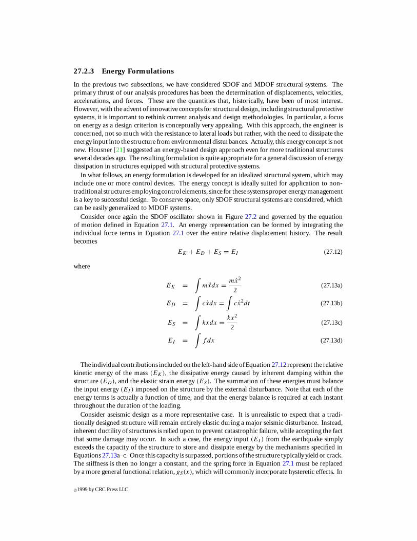
Figure 27.9a provides the energy response of a 0.3-scale, six-story concentrically braced steelstructure as measured by Uang and Bertero [54]. The seismic input consisted of the 1978 Miyagi-
FIGURE 27.9: Energy response of a traditional structure: (a) damageability limit state, (b) collapselimit state. (From Uang, C.M. and Bertero, V.V. 1986. Earthquake Simulation Tests and AssociatedStudies of a 0.3 Scale Model of a Six-Story Concentrically Braced Steel Structure. Report No. UCB/EERC - 86/10, Earthquake Engineering Research Center, Berkeley, CA. With permission.)
Ken-Oki Earthquake signal scaled to produce a peak shaking table acceleration of 0.33 g, which wasdeemed to represent the damageability limit state of the model. At this level of loading, a significantportion of the energy input to the structure is dissipated, with both viscous damping and inelastichysteretic mechanisms having substantial contributions. If the intensity of the signal is elevated, aneven greater share of the energy is dissipated via inelastic deformation. Finally, for the collapse limitstate of this model structure at 0.65 g peak table acceleration, approximately 90% of the energy isconsumed by hysteretic phenomena, as shown in Figure 27.9b. Evidently, the consumption of thisquantity of energy has destroyed the structure.
From an energy perspective, then, for proper aseismic design, one must attempt to minimize theamount of hysteretic energy dissipated by the structure. There are basically two viable approachesavailable. The first involves designs that result in a reduction in the amount of energy input to thestructure. Base isolation systems and some active control systems, for example, fall into that category.The second approach, as in the passive and active control system cases, focuses on the introduction ofadditional energy-dissipating mechanisms into the structure. These devices are designed to consumea portion of the input energy, thereby reducing damage to the main structure caused by hystereticdissipation. Naturally, for a large earthquake, the devices must dissipate enormous amounts ofenergy.
The SDOF system with a control element is displayed in Figure 27.3, while the governing inte-grodifferential equation is provided in Equation 27.3. After integrating with respect to x, an energybalance equation can be written:
EK + ED + ESe + ESp + EC = EI (27.15)
c©1999 by CRC Press LLC
where the energy associated with the control element is
EC =∫
0xdx (27.16)
and the other terms are as previously defined.As an example of the effects of control devices on the energy response of a structure, consider the
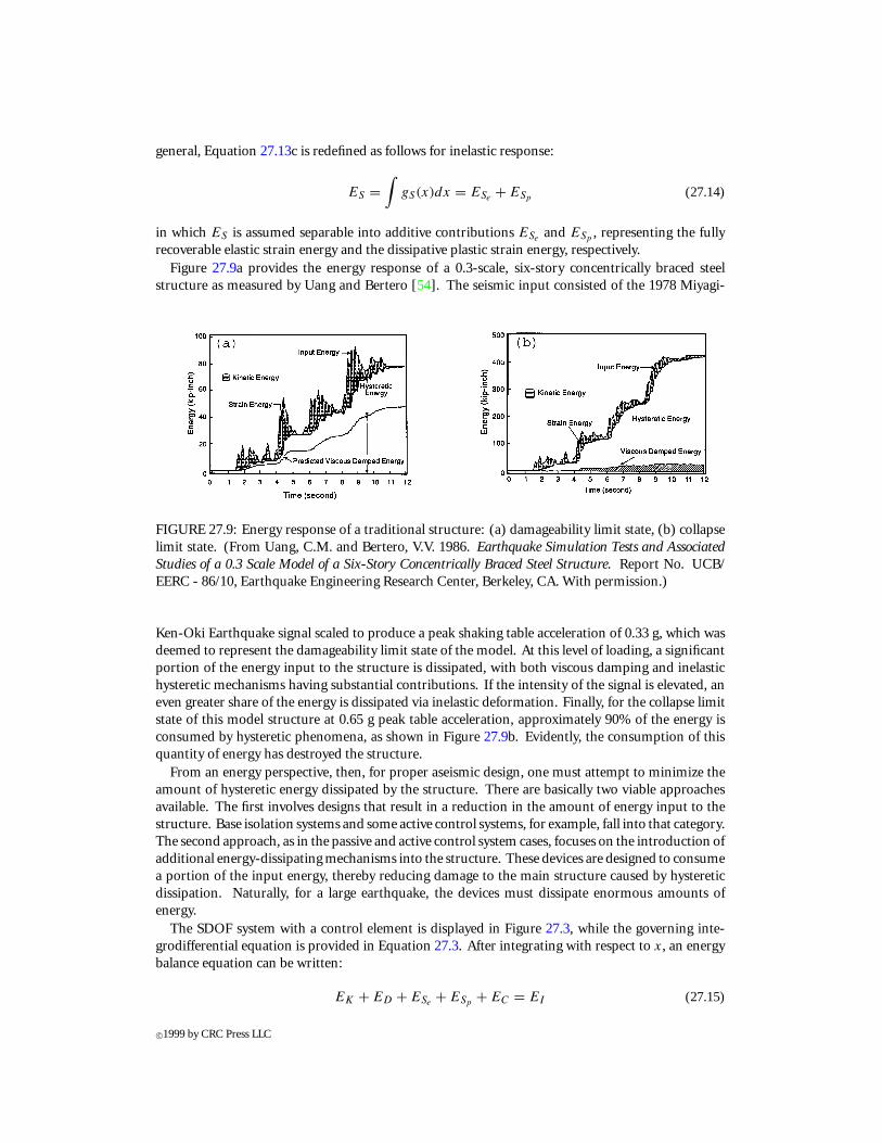
tests, of a one-third scale three-story lightly reinforced concrete framed building, conducted by Loboet al. [30]. Figure 27.10a displays the measured response of the structure due to the scaled 1952 TaftN21Eearthquake signal normalized for peak ground accelerations of 0.20 g. A considerable portion of
FIGURE27.10: Energy responseof test structure: (a)withoutpassivedevices, (b)withpassivedevices.(FromLobo, R.F., Bracci, J.M., Shen, K.L., Reinhorn, A.M., andSoong., T.T. 1993. EarthquakeSpectra,9(3), 419-446. With permission.)
the input energy is dissipated via hysteretic mechanisms, which tend to damage the primary structurethrough cracking and the formation of plastic hinges. On the other hand, damage is minimal withthe addition of a set of viscoelastic braced dampers. The energy response of the braced structure,due to the same seismic signal, is shown in Figure 27.10b. Notice that although the input energyhas increased slightly, the dampers consume a significant portion of the total, thus protecting theprimary structure.
27.2.4 Energy-Based Design
While the energy concept, as outlined briefly above, does not currently provide the basis for aseismicdesign codes, there is a considerable body of knowledge that has been developed from its applicationto traditional structures. Housner [21, 22] was the first to propose an energy-based philosophyfor earthquake-resistant design. In particular, he was concerned with limit design methods aimedtoward preventing collapse of structures in seismically active regions. Housner assumed that theenergy input calculated for an undamped, elastic idealization of a structure provided a reasonableupper bound to that for the actual inelastic structure.
Berg and Thomaides [4] examined the energy consumption in SDOF elastoplastic structures vianumerical computation and developed energy input spectra for several strong-motion earthquakes.These spectra indicate that the amount of energy, EI , imparted to a structure from a given seismicevent is quite dependent upon the structure itself. The mass, the natural period of vibration, thecritical damping ratio, and yield force level were all found to be important characteristics.
c©1999 by CRC Press LLC
On the other hand, their results did suggest that the establishment of upper bounds forEI might bepossible, and thus provided support for the approach introduced by Housner. However, the energyapproach was largely ignored for a number of years. Instead, limit state design methodologies weredeveloped which utilized the concept of displacement ductility to construct inelastic response spectraas proposed initially by Veletsos and Newmark [56].
More recently, there has been a resurgence of interest in energy-based concepts. For example,ZahrahandHall [62]developedanMDOFenergy formulationandconductedanextensiveparametricstudy of energy absorption in simple structural frames. Their numerical work included a comparisonbetween energy-based and displacement ductility-based assessments of damage, but the authorsstopped short of issuing a general recommendation.
A critical assessment of the energy concept as a basis for design was provided by Uang and Bert-ero [55]. The authors initially contrast two alternative definitions of the seismic input energy. Thequantity specified in Equation 27.13d is labeled the relative input energy, while the absolute inputenergy (EIa ) is defined by
EIa =∫
mxtdxg (27.17a)
In conjunction with this latter quantity, an absolute kinetic energy (EKa ) is also required, where
EKa = mx2t
2(27.17b)
The absolute energy equation corresponding to Equation 27.15 then becomes
EKa + ED + ESe + ESp + EC = EIa (27.18)
Based upon the development of input energy spectra for an SDOF system, the authors concludethat, while both measures produce approximately equivalent spectra in the intermediate periodrange, EIa should be used as a damage index for short period structures and EI is more suitable forlong period structures. Furthermore, an investigation revealed that the assumption of Housner toemploy the idealized elastic strain energy, as an estimate of the actual input energy, is not necessarilyconservative. Uang and Bertero [55] also studied an MDOF structure, and concluded that the inputenergy spectra for an SDOF can be used to predict the input energy demand for that type of building.In a second portion of the report, an investigation was conducted on the validity of the assumptionthat energy dissipation capacity can be used as a measure of damage. In testing cantilever steel beams,reinforced concrete shear walls, and composite beams the authors found that damage depends uponthe load path.
The last observation should come as no surprise to anyone familiar with classical failure criteria.However, it does highlight a serious shortcoming for the use of the energy concept for limit designof traditional structures. As was noted above, in these structures, a major portion of the inputenergy must be dissipated via inelastic deformation, but damage to the structure is not determinedsimply by the magnitude of the dissipated energy. On the other hand, in non-traditional structuresincorporating passive damping mechanisms, the energy concept is much more appropriate. Theemphasis in design is directly on energy dissipation. Furthermore, since an attempt is made tominimize the damage to the primary structure, the selection of a proper failure criterion is lessimportant.
c©1999 by CRC Press LLC
27.3 Recent Development and Applications
As a result of serious efforts that have been undertaken in recent years to develop and implement theconcept of passive energy dissipation and active control, a number of these devices have been installedin structures throughout the world, including Japan, New Zealand, Italy, Mexico, Canada, and theU.S. In what follows, advances in terms of their development and applications are summarized.
27.3.1 Passive Energy Dissipation
As alluded to in Section 27.1 and Table 27.1, a number of passive energy dissipation devices havebeen developed and installed in structures for performance enhancement under wind or earthquakeloads. Discussions presented below are centered around some of the more common devices that havefound applications in these areas.
Metallic Yield Dampers
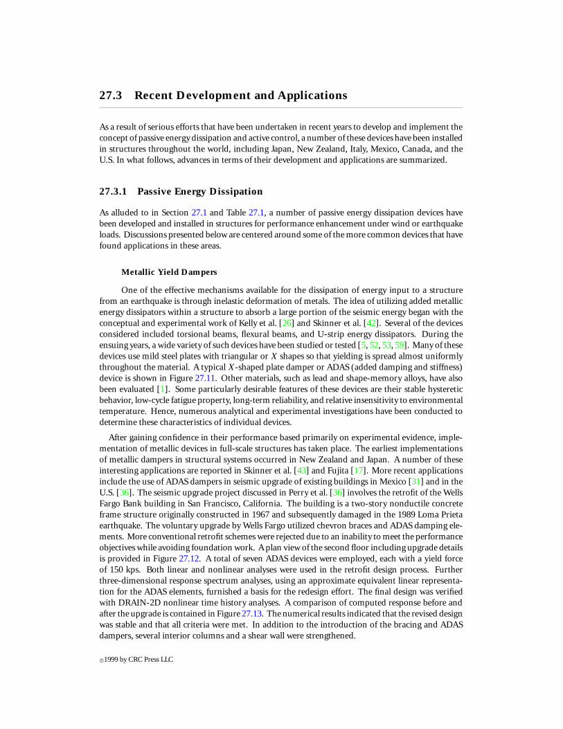
One of the effective mechanisms available for the dissipation of energy input to a structurefrom an earthquake is through inelastic deformation of metals. The idea of utilizing added metallicenergy dissipators within a structure to absorb a large portion of the seismic energy began with theconceptual and experimental work of Kelly et al. [26] and Skinner et al. [42]. Several of the devicesconsidered included torsional beams, flexural beams, and U-strip energy dissipators. During theensuing years, a wide variety of such devices have been studied or tested [5, 52, 53, 59]. Many of thesedevices use mild steel plates with triangular or X shapes so that yielding is spread almost uniformlythroughout the material. A typical X-shaped plate damper or ADAS (added damping and stiffness)device is shown in Figure 27.11. Other materials, such as lead and shape-memory alloys, have alsobeen evaluated [1]. Some particularly desirable features of these devices are their stable hystereticbehavior, low-cycle fatigue property, long-term reliability, and relative insensitivity to environmentaltemperature. Hence, numerous analytical and experimental investigations have been conducted todetermine these characteristics of individual devices.
After gaining confidence in their performance based primarily on experimental evidence, imple-mentation of metallic devices in full-scale structures has taken place. The earliest implementationsof metallic dampers in structural systems occurred in New Zealand and Japan. A number of theseinteresting applications are reported in Skinner et al. [43] and Fujita [17]. More recent applicationsinclude the use of ADAS dampers in seismic upgrade of existing buildings in Mexico [31] and in theU.S. [36]. The seismic upgrade project discussed in Perry et al. [36] involves the retrofit of the WellsFargo Bank building in San Francisco, California. The building is a two-story nonductile concreteframe structure originally constructed in 1967 and subsequently damaged in the 1989 Loma Prietaearthquake. The voluntary upgrade by Wells Fargo utilized chevron braces and ADAS damping ele-ments. More conventional retrofit schemes were rejected due to an inability to meet the performanceobjectives while avoiding foundation work. A plan view of the second floor including upgrade detailsis provided in Figure 27.12. A total of seven ADAS devices were employed, each with a yield forceof 150 kps. Both linear and nonlinear analyses were used in the retrofit design process. Furtherthree-dimensional response spectrum analyses, using an approximate equivalent linear representa-tion for the ADAS elements, furnished a basis for the redesign effort. The final design was verifiedwith DRAIN-2D nonlinear time history analyses. A comparison of computed response before andafter the upgrade is contained in Figure 27.13. The numerical results indicated that the revised designwas stable and that all criteria were met. In addition to the introduction of the bracing and ADASdampers, several interior columns and a shear wall were strengthened.
c©1999 by CRC Press LLC
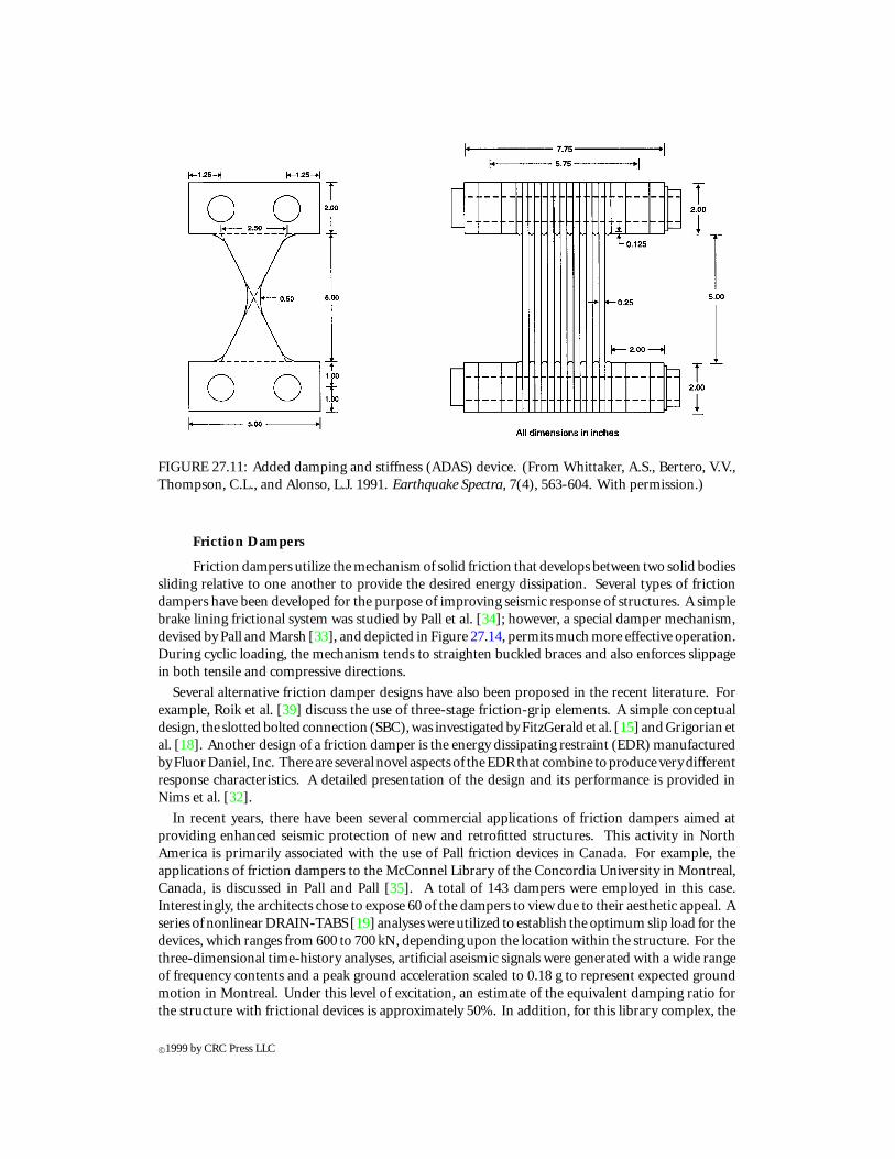
FIGURE 27.11: Added damping and stiffness (ADAS) device. (From Whittaker, A.S., Bertero, V.V.,Thompson, C.L., and Alonso, L.J. 1991. Earthquake Spectra, 7(4), 563-604. With permission.)
Friction Dampers
Friction dampers utilize the mechanism of solid friction that develops between two solid bodiessliding relative to one another to provide the desired energy dissipation. Several types of frictiondampers have been developed for the purpose of improving seismic response of structures. A simplebrake lining frictional system was studied by Pall et al. [34]; however, a special damper mechanism,devised by Pall and Marsh [33], and depicted in Figure 27.14, permits much more effective operation.During cyclic loading, the mechanism tends to straighten buckled braces and also enforces slippagein both tensile and compressive directions.
Several alternative friction damper designs have also been proposed in the recent literature. Forexample, Roik et al. [39] discuss the use of three-stage friction-grip elements. A simple conceptualdesign, the slotted bolted connection (SBC), was investigated by FitzGerald et al. [15] and Grigorian etal. [18]. Another design of a friction damper is the energy dissipating restraint (EDR) manufacturedbyFluorDaniel, Inc. There are several novel aspects of theEDRthat combine toproduce verydifferentresponse characteristics. A detailed presentation of the design and its performance is provided inNims et al. [32].
In recent years, there have been several commercial applications of friction dampers aimed atproviding enhanced seismic protection of new and retrofitted structures. This activity in NorthAmerica is primarily associated with the use of Pall friction devices in Canada. For example, theapplications of friction dampers to the McConnel Library of the Concordia University in Montreal,Canada, is discussed in Pall and Pall [35]. A total of 143 dampers were employed in this case.Interestingly, the architects chose to expose 60 of the dampers to view due to their aesthetic appeal. Aseries of nonlinear DRAIN-TABS [19] analyses were utilized to establish the optimum slip load for thedevices, which ranges from 600 to 700 kN, depending upon the location within the structure. For thethree-dimensional time-history analyses, artificial aseismic signals were generated with a wide rangeof frequency contents and a peak ground acceleration scaled to 0.18 g to represent expected groundmotion in Montreal. Under this level of excitation, an estimate of the equivalent damping ratio forthe structure with frictional devices is approximately 50%. In addition, for this library complex, the
c©1999 by CRC Press LLC
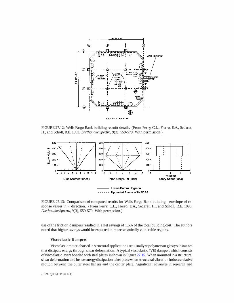
FIGURE 27.12: Wells Fargo Bank building retrofit details. (From Perry, C.L., Fierro, E.A., Sedarat,H., and Scholl, R.E. 1993. Earthquake Spectra, 9(3), 559-579. With permission.)
FIGURE 27.13: Comparison of computed results for Wells Fargo Bank building—envelope of re-sponse values in x direction. (From Perry, C.L., Fierro, E.A., Sedarat, H., and Scholl, R.E. 1993.Earthquake Spectra, 9(3), 559-579. With permission.)
use of the friction dampers resulted in a net savings of 1.5% of the total building cost. The authorsnoted that higher savings would be expected in more seismically vulnerable regions.
Viscoelastic Dampers
Viscoelasticmaterialsused in structural applicationsareusually copolymersorglassy substancesthat dissipate energy through shear deformation. A typical viscoelastic (VE) damper, which consistsof viscoelastic layers bonded with steel plates, is shown in Figure 27.15. When mounted in a structure,shear deformation and hence energy dissipation takes place when structural vibration induces relativemotion between the outer steel flanges and the center plate. Significant advances in research and
c©1999 by CRC Press LLC
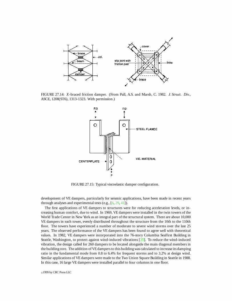
FIGURE 27.14: X-braced friction damper. (From Pall, A.S. and Marsh, C. 1982. J. Struct. Div.,ASCE, 1208(ST6), 1313-1323. With permission.)
FIGURE 27.15: Typical viscoelastic damper configuration.
development of VE dampers, particularly for seismic applications, have been made in recent yearsthrough analyses and experimental tests (e.g., [6, 29, 41]).
The first applications of VE dampers to structures were for reducing acceleration levels, or in-creasing human comfort, due to wind. In 1969, VE dampers were installed in the twin towers of theWorld Trade Center in New York as an integral part of the structural system. There are about 10,000VE dampers in each tower, evenly distributed throughout the structure from the 10th to the 110thfloor. The towers have experienced a number of moderate to severe wind storms over the last 25years. The observed performance of the VE dampers has been found to agree well with theoreticalvalues. In 1982, VE dampers were incorporated into the 76-story Columbia SeaFirst Building inSeattle, Washington, to protect against wind-induced vibrations [25]. To reduce the wind-inducedvibration, the design called for 260 dampers to be located alongside the main diagonal members inthe building core. The addition of VE dampers to this building was calculated to increase its dampingratio in the fundamental mode from 0.8 to 6.4% for frequent storms and to 3.2% at design wind.Similar applications of VE dampers were made to the Two Union Square Building in Seattle in 1988.In this case, 16 large VE dampers were installed parallel to four columns in one floor.
c©1999 by CRC Press LLC
Seismic applications of VE dampers to structures began only recently. A seismic retrofit projectusing VE dampers began in 1993 for the 13-story Santa Clara County building in San Jose, Califor-nia [8]. Situated in a high seismic risk region, the building was built in 1976. It is approximately 64 min height and nearly square in plan, with 51 × 51 m on typical upper floors. The exterior claddingconsists of full-height glazing on two sides and metal siding on the other two sides. The exteriorcladding, however, provides little resistance to structural drift. The equivalent viscous damping inthe fundamental mode is less than 1% of critical.
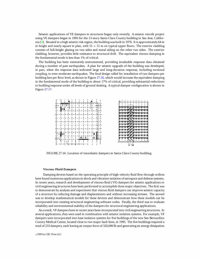
The building has been extensively instrumented, providing invaluable response data obtainedduring a number of past earthquakes. A plan for seismic upgrade of the building was developed,in part, when the response data indicated large and long-duration response, including torsionalcoupling, to even moderate earthquakes. The final design called for installation of two dampers perbuilding face per floor level, as shown in Figure 27.16, which would increase the equivalent dampingin the fundamental mode of the building to about 17% of critical, providing substantial reductionsto building response under all levels of ground shaking. A typical damper configuration is shown inFigure 27.17.
FIGURE 27.16: Location of viscoelastic dampers in Santa Clara County building.
Viscous Fluid Dampers
Damping devices based on the operating principle of high-velocity fluid flow through orificeshave found numerous applications in shock and vibration isolation of aerospace and defense systems.In recent years, research and development of viscous fluid (VF) dampers for seismic applications tocivil engineering structures have been performed to accomplish three major objectives. The first wasto demonstrate by analysis and experiment that viscous fluid dampers can improve seismic capacityof a structure by reducing damage and displacements and without increasing stresses. The secondwas to develop mathematical models for these devices and demonstrate how these models can beincorporated into existing structural engineering software codes. Finally, the third was to evaluatereliability and environmental stability of the dampers for structural engineering applications.
As a result, VF dampers have in recent years been incorporated into civil engineering structures. Inseveral applications, they were used in combination with seismic isolation systems. For example, VFdampers were incorporated into base isolation systems for five buildings of the new San BernardinoCounty Medical Center, located close to two major fault lines, in 1995. The five buildings required atotal of 233 dampers, each having an output force of 320,000 lb and generating an energy dissipation
c©1999 by CRC Press LLC
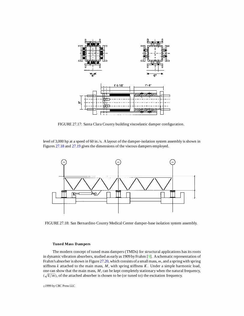
FIGURE 27.17: Santa Clara County building viscoelastic damper configuration.
level of 3,000 hp at a speed of 60 in./s. A layout of the damper-isolation system assembly is shown inFigures 27.18 and 27.19 gives the dimensions of the viscous dampers employed.
FIGURE 27.18: San Bernardino County Medical Center damper-base isolation system assembly.
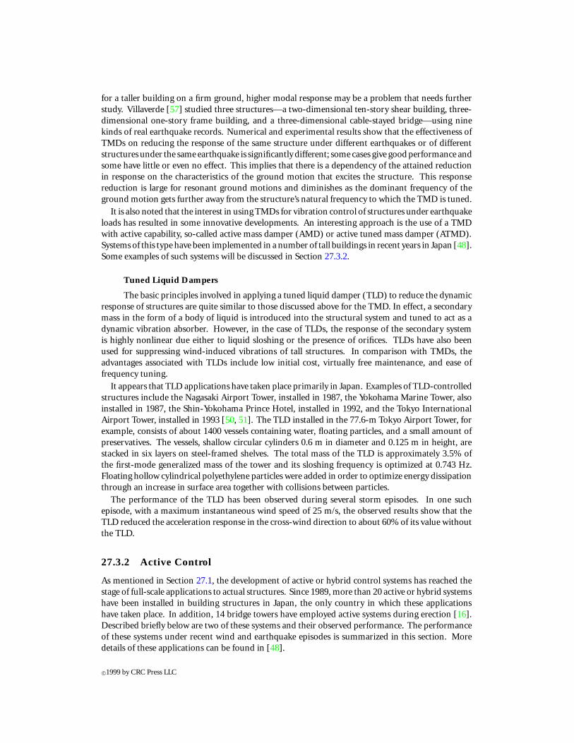
Tuned Mass Dampers
The modern concept of tuned mass dampers (TMDs) for structural applications has its rootsin dynamic vibration absorbers, studied as early as 1909 by Frahm [9]. A schematic representation ofFrahm’s absorber is shown in Figure 27.20, which consists of a small mass, m, and a spring with springstiffness k attached to the main mass, M , with spring stiffness K . Under a simple harmonic load,one can show that the main mass, M , can be kept completely stationary when the natural frequency,(√
k/m), of the attached absorber is chosen to be (or tuned to) the excitation frequency.
c©1999 by CRC Press LLC
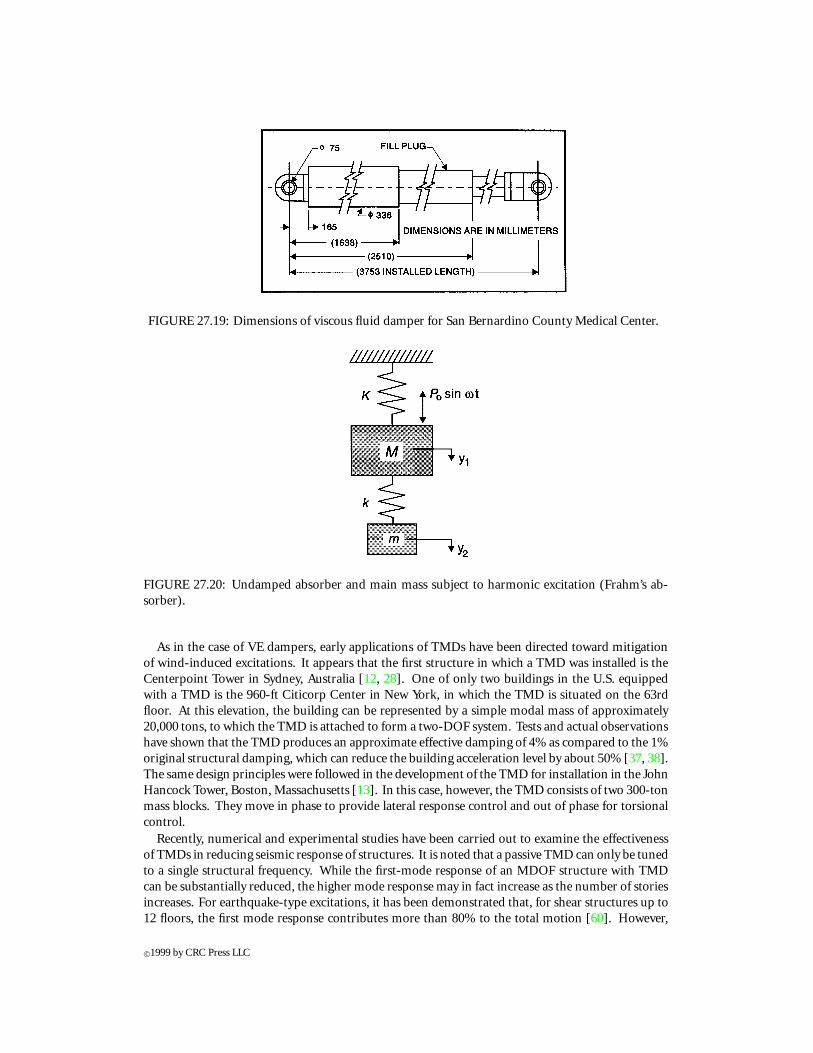
FIGURE 27.19: Dimensions of viscous fluid damper for San Bernardino County Medical Center.
FIGURE 27.20: Undamped absorber and main mass subject to harmonic excitation (Frahm’s ab-sorber).
As in the case of VE dampers, early applications of TMDs have been directed toward mitigationof wind-induced excitations. It appears that the first structure in which a TMD was installed is theCenterpoint Tower in Sydney, Australia [12, 28]. One of only two buildings in the U.S. equippedwith a TMD is the 960-ft Citicorp Center in New York, in which the TMD is situated on the 63rdfloor. At this elevation, the building can be represented by a simple modal mass of approximately20,000 tons, to which the TMD is attached to form a two-DOF system. Tests and actual observationshave shown that the TMD produces an approximate effective damping of 4% as compared to the 1%original structural damping, which can reduce the building acceleration level by about 50% [37, 38].The same design principles were followed in the development of the TMD for installation in the JohnHancock Tower, Boston, Massachusetts [13]. In this case, however, the TMD consists of two 300-tonmass blocks. They move in phase to provide lateral response control and out of phase for torsionalcontrol.
Recently, numerical and experimental studies have been carried out to examine the effectivenessof TMDs in reducing seismic response of structures. It is noted that a passive TMD can only be tunedto a single structural frequency. While the first-mode response of an MDOF structure with TMDcan be substantially reduced, the higher mode response may in fact increase as the number of storiesincreases. For earthquake-type excitations, it has been demonstrated that, for shear structures up to12 floors, the first mode response contributes more than 80% to the total motion [60]. However,
c©1999 by CRC Press LLC
for a taller building on a firm ground, higher modal response may be a problem that needs furtherstudy. Villaverde [57] studied three structures—a two-dimensional ten-story shear building, three-dimensional one-story frame building, and a three-dimensional cable-stayed bridge—using ninekinds of real earthquake records. Numerical and experimental results show that the effectiveness ofTMDs on reducing the response of the same structure under different earthquakes or of differentstructures under the same earthquake is significantly different; some cases give good performance andsome have little or even no effect. This implies that there is a dependency of the attained reductionin response on the characteristics of the ground motion that excites the structure. This responsereduction is large for resonant ground motions and diminishes as the dominant frequency of theground motion gets further away from the structure’s natural frequency to which the TMD is tuned.
It is also noted that the interest in using TMDs for vibration control of structures under earthquakeloads has resulted in some innovative developments. An interesting approach is the use of a TMDwith active capability, so-called active mass damper (AMD) or active tuned mass damper (ATMD).Systems of this type have been implemented in a number of tall buildings in recent years in Japan [48].Some examples of such systems will be discussed in Section 27.3.2.
Tuned Liquid Dampers
The basic principles involved in applying a tuned liquid damper (TLD) to reduce the dynamicresponse of structures are quite similar to those discussed above for the TMD. In effect, a secondarymass in the form of a body of liquid is introduced into the structural system and tuned to act as adynamic vibration absorber. However, in the case of TLDs, the response of the secondary systemis highly nonlinear due either to liquid sloshing or the presence of orifices. TLDs have also beenused for suppressing wind-induced vibrations of tall structures. In comparison with TMDs, theadvantages associated with TLDs include low initial cost, virtually free maintenance, and ease offrequency tuning.
It appears that TLD applications have taken place primarily in Japan. Examples of TLD-controlledstructures include the Nagasaki Airport Tower, installed in 1987, the Yokohama Marine Tower, alsoinstalled in 1987, the Shin-Yokohama Prince Hotel, installed in 1992, and the Tokyo InternationalAirport Tower, installed in 1993 [50, 51]. The TLD installed in the 77.6-m Tokyo Airport Tower, forexample, consists of about 1400 vessels containing water, floating particles, and a small amount ofpreservatives. The vessels, shallow circular cylinders 0.6 m in diameter and 0.125 m in height, arestacked in six layers on steel-framed shelves. The total mass of the TLD is approximately 3.5% ofthe first-mode generalized mass of the tower and its sloshing frequency is optimized at 0.743 Hz.Floating hollow cylindrical polyethylene particles were added in order to optimize energy dissipationthrough an increase in surface area together with collisions between particles.
The performance of the TLD has been observed during several storm episodes. In one suchepisode, with a maximum instantaneous wind speed of 25 m/s, the observed results show that theTLD reduced the acceleration response in the cross-wind direction to about 60% of its value withoutthe TLD.
27.3.2 Active Control
As mentioned in Section 27.1, the development of active or hybrid control systems has reached thestage of full-scale applications to actual structures. Since 1989, more than 20 active or hybrid systemshave been installed in building structures in Japan, the only country in which these applicationshave taken place. In addition, 14 bridge towers have employed active systems during erection [16].Described briefly below are two of these systems and their observed performance. The performanceof these systems under recent wind and earthquake episodes is summarized in this section. Moredetails of these applications can be found in [48].
c©1999 by CRC Press LLC
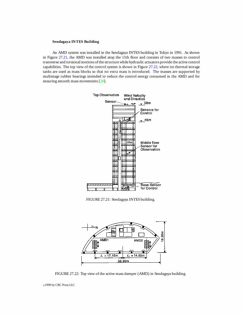
Sendagaya INTES Building
An AMD system was installed in the Sendagaya INTES building in Tokyo in 1991. As shownin Figure 27.21, the AMD was installed atop the 11th floor and consists of two masses to controltransverse and torsional motions of the structure while hydraulic actuators provide the active controlcapabilities. The top view of the control system is shown in Figure 27.22, where ice thermal storagetanks are used as mass blocks so that no extra mass is introduced. The masses are supported bymultistage rubber bearings intended to reduce the control energy consumed in the AMD and forensuring smooth mass movements [20].
FIGURE 27.21: Sendagaya INTES building.
FIGURE 27.22: Top view of the active mass damper (AMD) in Sendagaya building.
c©1999 by CRC Press LLC
Sufficient data were obtained for evaluation of the AMD performance when the building wassubjected to strong wind on March 29, 1993, with peak instantaneous wind speed of 30.6 m/s. Anexample of the response Fourier spectra using samples of 30-s duration is shown in Figure 27.23,showing good performance in the low frequency range. The response of the fundamental mode wasreduced by 18 and 28% for translation and torsion, respectively. Similar performance characteristicswere observed during a series of earthquakes recorded between May 1992 and February 1993.
Hankyu Chayamachi Building
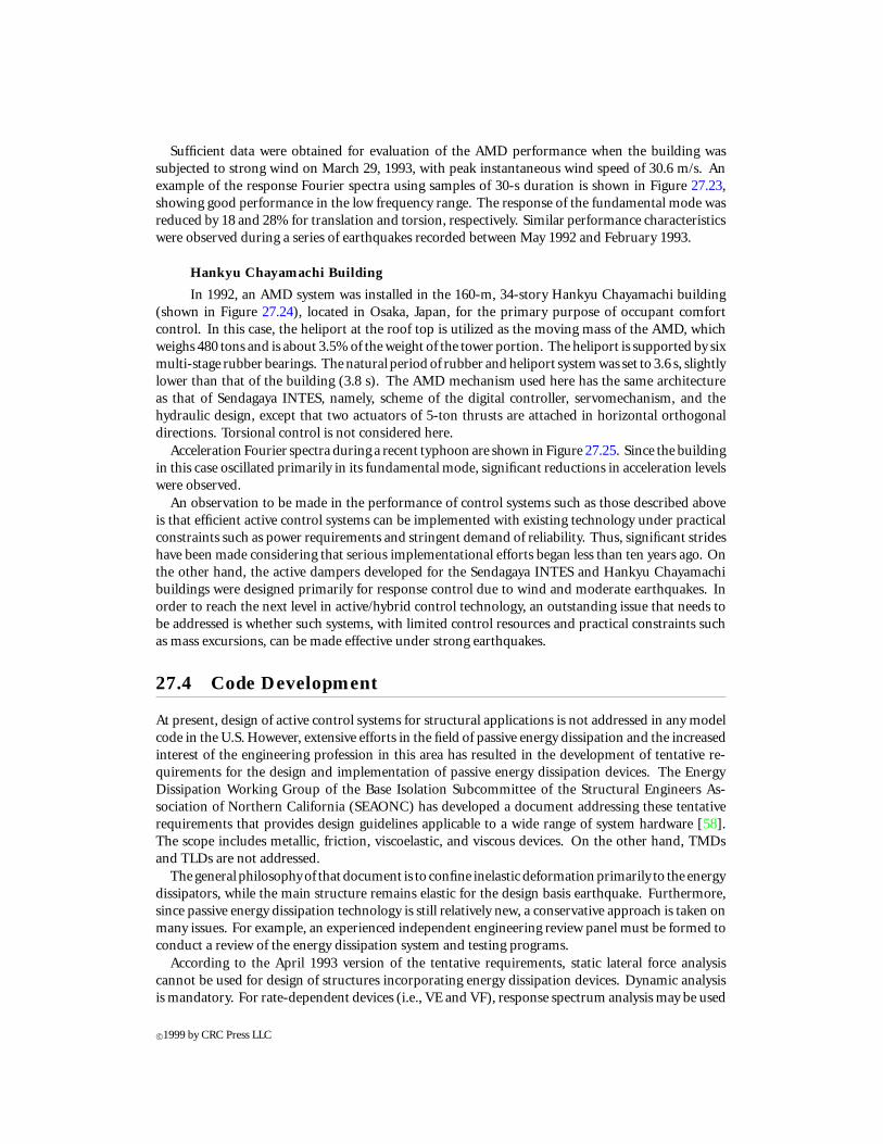
In 1992, an AMD system was installed in the 160-m, 34-story Hankyu Chayamachi building(shown in Figure 27.24), located in Osaka, Japan, for the primary purpose of occupant comfortcontrol. In this case, the heliport at the roof top is utilized as the moving mass of the AMD, whichweighs 480 tons and is about 3.5% of the weight of the tower portion. The heliport is supported by sixmulti-stage rubber bearings. The natural period of rubber and heliport system was set to 3.6 s, slightlylower than that of the building (3.8 s). The AMD mechanism used here has the same architectureas that of Sendagaya INTES, namely, scheme of the digital controller, servomechanism, and thehydraulic design, except that two actuators of 5-ton thrusts are attached in horizontal orthogonaldirections. Torsional control is not considered here.
Acceleration Fourier spectra during a recent typhoon are shown in Figure 27.25. Since the buildingin this case oscillated primarily in its fundamental mode, significant reductions in acceleration levelswere observed.
An observation to be made in the performance of control systems such as those described aboveis that efficient active control systems can be implemented with existing technology under practicalconstraints such as power requirements and stringent demand of reliability. Thus, significant strideshave been made considering that serious implementational efforts began less than ten years ago. Onthe other hand, the active dampers developed for the Sendagaya INTES and Hankyu Chayamachibuildings were designed primarily for response control due to wind and moderate earthquakes. Inorder to reach the next level in active/hybrid control technology, an outstanding issue that needs tobe addressed is whether such systems, with limited control resources and practical constraints suchas mass excursions, can be made effective under strong earthquakes.
27.4 Code Development
At present, design of active control systems for structural applications is not addressed in any modelcode in the U.S. However, extensive efforts in the field of passive energy dissipation and the increasedinterest of the engineering profession in this area has resulted in the development of tentative re-quirements for the design and implementation of passive energy dissipation devices. The EnergyDissipation Working Group of the Base Isolation Subcommittee of the Structural Engineers As-sociation of Northern California (SEAONC) has developed a document addressing these tentativerequirements that provides design guidelines applicable to a wide range of system hardware [58].The scope includes metallic, friction, viscoelastic, and viscous devices. On the other hand, TMDsand TLDs are not addressed.
The general philosophy of that document is to confine inelastic deformation primarily to the energydissipators, while the main structure remains elastic for the design basis earthquake. Furthermore,since passive energy dissipation technology is still relatively new, a conservative approach is taken onmany issues. For example, an experienced independent engineering review panel must be formed toconduct a review of the energy dissipation system and testing programs.
According to the April 1993 version of the tentative requirements, static lateral force analysiscannot be used for design of structures incorporating energy dissipation devices. Dynamic analysisis mandatory. For rate-dependent devices (i.e., VE and VF), response spectrum analysis may be used
c©1999 by CRC Press LLC
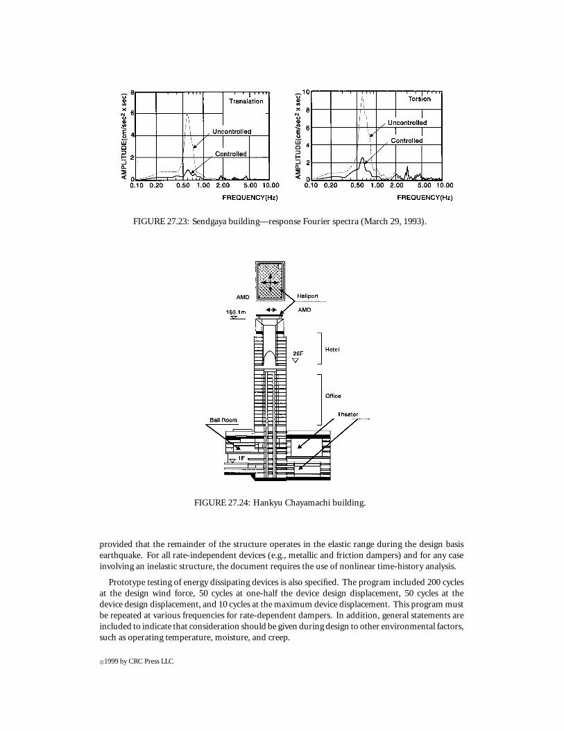
FIGURE 27.23: Sendgaya building—response Fourier spectra (March 29, 1993).
FIGURE 27.24: Hankyu Chayamachi building.
provided that the remainder of the structure operates in the elastic range during the design basisearthquake. For all rate-independent devices (e.g., metallic and friction dampers) and for any caseinvolving an inelastic structure, the document requires the use of nonlinear time-history analysis.
Prototype testing of energy dissipating devices is also specified. The program included 200 cyclesat the design wind force, 50 cycles at one-half the device design displacement, 50 cycles at thedevice design displacement, and 10 cycles at the maximum device displacement. This program mustbe repeated at various frequencies for rate-dependent dampers. In addition, general statements areincluded to indicate that consideration should be given during design to other environmental factors,such as operating temperature, moisture, and creep.
c©1999 by CRC Press LLC
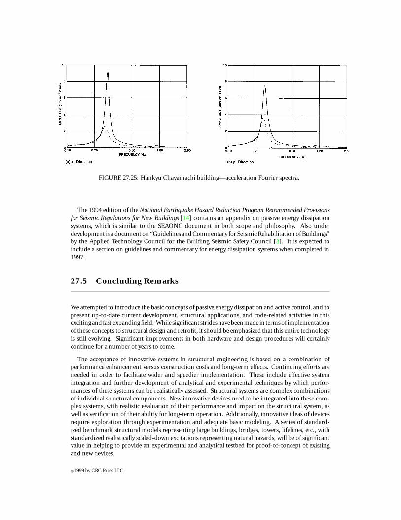
FIGURE 27.25: Hankyu Chayamachi building—acceleration Fourier spectra.
The 1994 edition of the National Earthquake Hazard Reduction Program Recommended Provisionsfor Seismic Regulations for New Buildings [14] contains an appendix on passive energy dissipationsystems, which is similar to the SEAONC document in both scope and philosophy. Also underdevelopment is a document on “Guidelines and Commentary for Seismic Rehabilitation of Buildings”by the Applied Technology Council for the Building Seismic Safety Council [3]. It is expected toinclude a section on guidelines and commentary for energy dissipation systems when completed in1997.
27.5 Concluding Remarks
We attempted to introduce the basic concepts of passive energy dissipation and active control, and topresent up-to-date current development, structural applications, and code-related activities in thisexcitingand fast expandingfield. While significant strideshavebeenmade in termsof implementationof these concepts to structural design and retrofit, it should be emphasized that this entire technologyis still evolving. Significant improvements in both hardware and design procedures will certainlycontinue for a number of years to come.
The acceptance of innovative systems in structural engineering is based on a combination ofperformance enhancement versus construction costs and long-term effects. Continuing efforts areneeded in order to facilitate wider and speedier implementation. These include effective systemintegration and further development of analytical and experimental techniques by which perfor-mances of these systems can be realistically assessed. Structural systems are complex combinationsof individual structural components. New innovative devices need to be integrated into these com-plex systems, with realistic evaluation of their performance and impact on the structural system, aswell as verification of their ability for long-term operation. Additionally, innovative ideas of devicesrequire exploration through experimentation and adequate basic modeling. A series of standard-ized benchmark structural models representing large buildings, bridges, towers, lifelines, etc., withstandardized realistically scaled-down excitations representing natural hazards, will be of significantvalue in helping to provide an experimental and analytical testbed for proof-of-concept of existingand new devices.
c©1999 by CRC Press LLC
References
[1] Aiken, I.D. and Kelly, J.M. 1992. Comparative Study of Four Passive Energy Dissipation Systems.Bull. N.Z. Nat. Soc. Earthquake Eng., 25(3), 175-192.
[2] Applied Technology Council. 1993. Proceedings on Seismic Isolation, Passive Energy Dissipa-tion, and Active Control, ATC 17-1, Redwood City, CA.
[3] Applied Technology Council. 1995. Guidelines and Commentary for Seismic Rehabilitationof Buildings, ATC-33, 75% Complete Draft, Redwood City, CA.
[4] Berg, G.V. and Thomaides, S.S. 1960. Energy Consumption by Structures in Strong MotionEarthquakes, Proc. 2nd World Conf. Earthquake Eng., II, 681-697, Tokyo.
[5] Bergman, D.M. and Goel, S.C. 1987. Evaluation of Cyclic Testing of Steel-Plate Devices forAdded Damping and Stiffness, Report No. UMCE 87-10, University of Michigan, Ann Arbor,MI.
[6] Chang, K.C., Shen, K.L., Soong, T.T. and Lai, M.L. 1994. Seismic Retrofit of a Concrete Framewith Added Viscoelastic Dampers, 5th Nat. Conf. Earthquake Eng., Chicago, IL.
[7] Clough, R.W. and Penzien, J. 1975. Dynamics of Structures, McGraw-Hill, NY.[8] Crosby, P., Kelly, J.M. and Singh, J. 1994. Utilizing Viscoelastic Dampers in the Seismic Retrofit
of a Thirteen Story Steel Frame Building, Struct. Congress XII, Atlanta, GA, pp. 1286-1291.[9] Den Hartog, J.P. 1956. Mechanical Vibrations, 4th ed., McGraw-Hill, New York.
[10] Dyke, S.J., Spencer Jr., B.F., Quast P., Sain, M.K., Kaspari Jr., D.C. and Soong, T.T. 1994.Experimental Verification of Acceleration Feedback Control Strategies for an Active TendonSystem, NCEER-94-0024, Buffalo, NY.
[11] Dyke, S.J., Spencer Jr., B.F., Quast, P. and Sain, M.K. 1995. The Role of Control-StructureInteraction in Protective System Design, J. Eng. Mech., ASCE, 121(2), 322-338.
[12] ENR. 1971. Tower Cables Handle Wind, Water Tank Dampens It, Eng. News-Record, p.23, Dec.9.
[13] ENR. 1975. Hancock Tower Now to Get Dampers, Eng. News-Record, p.11, October 30.[14] Federal Emergency Management Association. 1995. 1994 NEHRP Recommended Provisions
for Seismic Regulations for New Buildings, Report FEMA 222A, Washington, D.C.[15] FitzGerald, T.F., Anagnos, T., Goodson, M. and Zsutty, T. 1989. Slotted Bolted Connections in
Aseismic Design for Concentrically Braced Connections, Earthquake Spectra, 5(2), 383-391.[16] Fujino, Y. 1994. Recent Research and Developments on Control of Bridges under Wind and
Traffic Excitations in Japan, Proc. Int. Workshop on Struct. Control, pp. 144-150.[17] Fujita, T. (Ed.). 1991. Seismic Isolation and Response Control for Nuclear and Non-Nuclear
Structures, Special Issue for the Exhibition of 11th Int. Conf. on SMiRT, Tokyo, Japan.[18] Grigorian, C.E., Yang, T.S. and Popov, E.P. 1993. Slotted Bolted Connection Energy Dissipators,
Earthquake Spectra, 9(3), 491-504.[19] Guendeman-Israel, R. and Powell, G.H. 1977. DRAIN-TABS—A Computerized Program for
Inelastic Earthquake Response of Three Dimensional Buildings, Report No. UCB/EERC 77-08,University of California, Berkeley, CA.
[20] Higashino, M. and Aizawa, S. 1993. Application of Active Mass Damper System in ActualBuildings, Proc. Int. Workshop on Structural Control, G.W. Housner and S.F. Masri (Eds.), LosAngeles, CA, pp. 194-205.
[21] Housner, G.W. 1956. Limit Design of Structures to Resist Earthquakes, Proc. 1st World Conf.on Earthquake Eng., pp. 5-1 – 5-13, Earthquake Eng. Research Center, Berkeley, CA.
[22] Housner, G.W. 1959. Behavior of Structures During Earthquakes, J. Eng. Mech. Div., ASCE,85(EM4), 109-129.
[23] Housner, G.W,Soong, T.T. andMasri, S.F. 1994. SecondGenerationofActive StructuralControlin Civil Engineering, Proc. 1st World Conf. on Struct. Control, Los Angeles, CA, FA2, 3-18.
c©1999 by CRC Press LLC
[24] Housner, G.W., Masri, S.F. and Chassiakos, A.G. (Eds.). 1994. Proc. 1st World Conf. on Struct.Control, Los Angeles, CA.
[25] Keel, C.J. and Mahmoodi, P. 1986. Designing of Viscoelastic Dampers for Columbia CenterBuilding, Building Motion in Wind, N. Isyumov and T. Tschanz (Eds.), ASCE, New York, pp.66-82.
[26] Kelly, J.M., Skinner, R.I. and Heine, A.J. 1972. Mechanisms of Energy Absorption in SpecialDevices for Use in Earthquake Resistant Structures, Bull. N.Z. Nat. Soc. Earthquake Eng., 5,63-88.
[27] Kobori, T. 1994. Future Direction on Research and Development of Seismic-Response-Controlled Structure, Proc. 1st World Conf. on Struct. Control, Los Angeles, CA, Panel, 19-31.
[28] Kwok, K.C.S. and MacDonald, P.A. 1987. Wind-Induced Response of Sydney Tower, Proc. 1stNat. Struct. Eng. Conf., pp. 19-24.
[29] Lai, M.L., Chang, K.C., Soong, T.T., Hao, D.S. and Yeh, Y.C. 1995. Full-scale ViscoelasticallyDamped Steel Frame, ASCE J. Struct. Eng., 121(10), 1443-1447.
[30] Lobo, R.F., Bracci, J.M., Shen, K.L., Reinhorn, A.M. and Soong., T.T. 1993. Inelastic Responseof R/C Structures with Viscoelastic Braces, Earthquake Spectra, 9(3), 419-446.
[31] Martinez-Romero, E. 1993. Experiences on the Use of Supplemental Energy Dissipators onBuilding Structures, Earthquake Spectra, 9(3), 581-624.
[32] Nims, D.K., Richter, P.J. and Bachman, R.E. 1993. The Use of the Energy Dissipating Restraintfor Seismic Hazard Mitigation, Earthquake Spectra, 9(3), 467-489.
[33] Pall, A.S. and Marsh, C. 1982. Response of Friction Damped Braced Frames, J. Struct. Div.,ASCE, 1208(ST6), 1313-1323.
[34] Pall, A.S., Marsh, C. and Fazio, P. 1980. Friction Joints for Seismic Control of Large PanelStructures, J. Prestressed Concrete Inst., 25(6), 38-61.
[35] Pall, A.S. and Pall, R. 1993. Friction-Dampers Used for Seismic Control of New and ExistingBuilding in Canada, Proc. ATC 17-1 Seminar on Isolation, Energy Dissipation and ActiveControl, San Francisco, CA, 2, 675-686.
[36] Perry, C.L., Fierro, E.A., Sedarat, H. and Scholl, R.E. 1993. Seismic Upgrade in San FranciscoUsing Energy Dissipation Devices, Earthquake Spectra, 9(3), 559-579.
[37] Petersen, N.R. 1980. Design of Large Scale TMD, Struct. Control, North Holland, Amsterdam,pp. 581-596.
[38] Petersen, N.R. 1981. Using Servohydraulics to Control High-Rise Building Motion, Proc. Nat.Convention Fluid Power, Chicago, pp. 209-213.
[39] Roik, K., Dorka, U. and Dechent, P. 1988. Vibration Control of Structures under EarthquakeLoading by Three-Stage Friction-Grip Elements, Earthquake Eng. Struct. Dyn., 16, 501-521.
[40] Sakurai, T., Shibata, K., Watanabe, S., Endoh, A., Yamada, K., Tanaka, N. and Kobayashi, H.1992. Application of Joint Damper to Thermal Power Plant Buildings, Proc. 10th World Conf.Earthquake Eng., Madrid, Spain, 7, 4149-4154.
[41] Shen, K.L., Soong, T.T., Chang, K.C. and Lai, M.L. 1995. Seismic Behavior of ReinforcedConcrete Frame with Added Viscoelastic Dampers, Eng. Structures, 17(5), 372-380.
[42] Skinner, R.I., Kelly, J.M. and Heine, A.J. 1975. Hysteresis Dampers for Earthquake-ResistantStructures, Earthquake Eng. Struct. Dyn., 3, 287-296.
[43] Skinner, R.I., Tyler, R.G., Heine, A.J. and Robinson, W.H. 1980. Hysteretic Dampers for theProtection of Structures from Earthquakes, Bull. N.Z. Nat. Soc. Earthquake Eng., 13(1), 22-36.
[44] Soong, T.T. 1990. Active Structural Control: Theory and Practice, Longman Scientific andTechnical, Essex, England, and Wiley, New York.
[45] Soong, T.T. and Constantinou, M.C. (Eds.). 1994. Passive and Active Structural VibrationControl in Civil Engineering, Springer-Verlag, Wien and New York.
[46] Soong, T.T. and Dargush, G.F. 1997. Passive Energy Dissipation Systems in Structural Engi-neering, Wiley, London.
c©1999 by CRC Press LLC
[47] Soong, T.T. and Reinhorn, A.M. 1993. An Overview of Active and Hybrid Structural ControlResearch in the U.S., J. Struct. Design Tall Bldg., 2, 193-209.
[48] Soong, T.T., Reinhorn, A.M., Aizawa, S. andHigashino, M.1994.Recent StructuralApplicationsof Active Control Technology, J. Struct. Control, 1(2), 5-21.
[49] Szabo, B. and Babuska, I. 1991. Finite Element Analysis, John Wiley & Sons, New York.[50] Tamura, Y., Shimada, K., Sasaki, A., Kohsaka, R. and Fuji, K. 1994. Variation of Structural
Damping Ratios and Natural Frequencies of Tall Buildings During Strong Winds, Proc. 9th Int.Conf. Wind Eng., New Delhi, India, 3, 1396-1407.
[51] Tamura, Y., Fujii, K., Ohtsuki, T., Wakahara, T. and Kohsaka, R. 1995. Effectiveness of TunedLiquid Dampers and Wind Excitations, Eng. Struct., 17(9), 609-621.
[52] Tsai, K.C., Chen, H.W., Hong, C.P. and Su, Y.F. 1993. Design of Steel Triangular Plate EnergyAbsorbers for Seismic-Resistant Construction, Earthquake Spectra, 9(3), 505-528.
[53] Tyler, R.G. 1985. Test on a Brake Lining Damper for Structures, Bull. N.Z. Nat. Soc. EarthquakeEng., 18(3), 280-284.
[54] Uang, C.M. and Bertero, V.V. 1986. Earthquake Simulation Tests and Associated Studies of a0.3 Scale Model of a Six-Story Concentrically Braced Steel Structure, Report No. UCB/EERC-86/10, Earthquake Engineering Research Center, Berkeley, CA.
[55] Uang, C.M. and Bertero, V.V. 1988. Use of Energy as a Design Criterion in Earthquake ResistantDesign, Report No. UCB/EERC-88/18, Earthquake Engineering Research Center, Berkeley, CA.
[56] Veletsos, A.S. and Newmark, N.M. 1960. Effect of Inelastic Behavior on the Response of SimpleSystems to Earthquake Motions, Proc. 2nd World Conf. Earthquake Eng., II, 895-912, Tokyo.
[57] Villaverde, R. 1994. Seismic-Control of Structures with Damped Resonant Appendages, Proc.1st World Conf. Struct. Control, Los Angeles, CA, 1, WP4-113 - WP4-122.
[58] Whittaker, A.S., Aiken, I., Bergman, P., Clark, J., Cohen, J., Kelly, J.M. and Scholl, R. 1993.Code Requirements for the Design and Implementation of Passive Energy Dissipation Systems,Proc. ATC 17-1 Seminar Seismic Isolation, Passive Energy Dissipation and Active Control,San Francisco, 2, 497-508.
[59] Whittaker, A.S., Bertero, V.V., Thompson, C.L. and Alonso, L.J. 1991. Seismic Testing of SteelPlate Energy Dissipation Devices, Earthquake Spectra, 7(4), 563-604.
[60] Wirsching, P.H. and Yao, J.T.P. 1970. Modal Response of Structures, J. Struct. Div., ASCE, 96(4),879-883.
[61] Wu, Z. and Soong, T.T. 1995. Nonlinear Feedback Control for Improved Peak Response Re-duction, J. Smart Mater. Struct., 4, A140-A147.
[62] Zahrah, T.F. and Hall, W.J. 1982. Seismic Energy Absorption in Simple Structures, StructuralResearch Series No. 501, University of Illinois, Urbana, IL.
[63] Zienkiewicz, O.C. and Taylor, R.L. 1989. The Finite Element Method, Vols. 1 and 2, 4 ed.,McGraw-Hill, London.
c©1999 by CRC Press LLC