Embed Size (px)
Citation preview
Pack
aged
Gase
sProduct Catalog
Ensuring cryogenic supply capabilities.Any application - Any time
Packaged Gases Advantage
Chart’s Packaged Gases are engineered and manufactured to the highest quality standards toprovide you with the safest and most reliable equipment available. Driven by innovation, ourpatented cylinder support system and Liquid Cylinder Control Manifold (LCCM) revolutionized theindustry. Experience from understanding our customer’s specifications and the end-use applicationshas made Chart the standard in the industry. When you want the best in packaged gases equipment,our wide range of products are certain to satisfy your requirements while providing the lowest costof ownership.
When you choose Chart, you get single-source accountabilityfrom initial quality through after the sale service support.
Engineering Design
Our Packaged Gases equipment designs arebased on integrating patented and proveninnovative technologies. Every componentis engineered, built and tested to createthe safest and most reliable PackagedGases equipment available today.
Quality Manufacturing
Our experience and code compliant ISO9001 ensures our liquid cylinders arecompleted to high quality standards andon time.
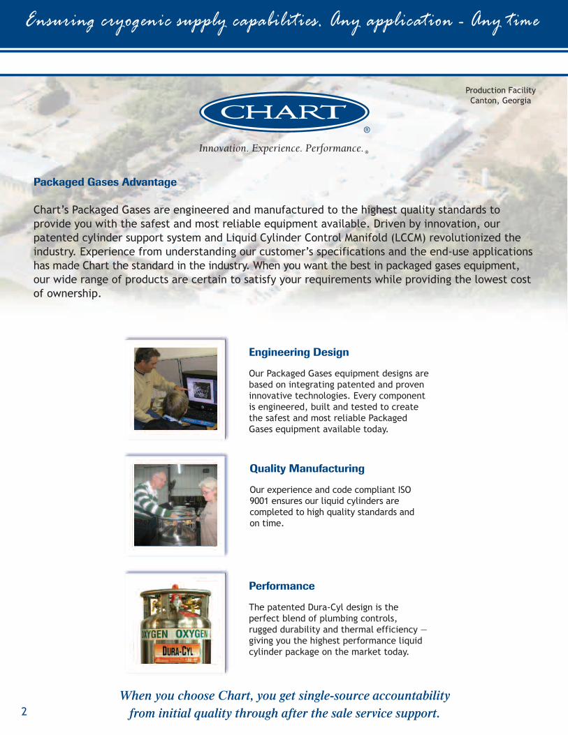
Performance
The patented Dura-Cyl design is theperfect blend of plumbing controls,rugged durability and thermal efficiency —giving you the highest performance liquidcylinder package on the market today.
Ensuring cryogenic supply capabilities. Any application - Any time
2
Production FacilityCanton, Georgia
Packaged Gases
How We Build the Best Liquid Cylinder
3
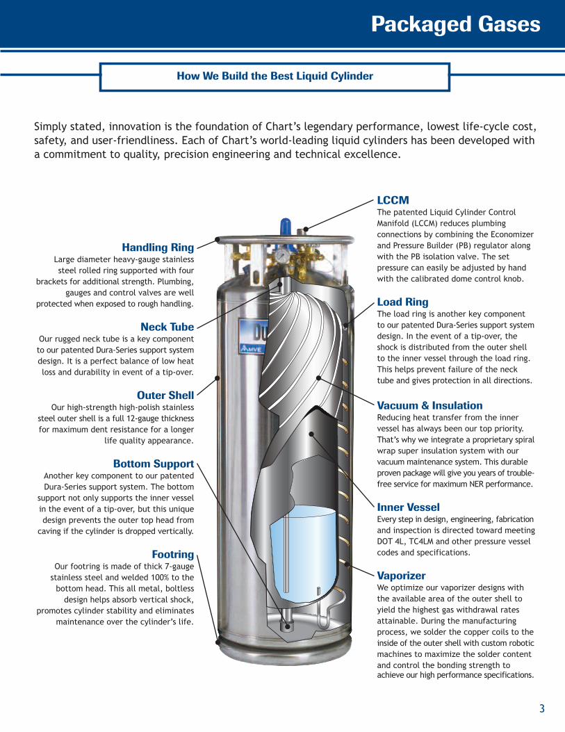
Simply stated, innovation is the foundation of Chart’s legendary performance, lowest life-cycle cost,safety, and user-friendliness. Each of Chart’s world-leading liquid cylinders has been developed witha commitment to quality, precision engineering and technical excellence.
Handling RingLarge diameter heavy-gauge stainlesssteel rolled ring supported with four
brackets for additional strength. Plumbing,gauges and control valves are well
protected when exposed to rough handling.
Neck TubeOur rugged neck tube is a key componentto our patented Dura-Series support systemdesign. It is a perfect balance of low heatloss and durability in event of a tip-over.
Outer ShellOur high-strength high-polish stainless
steel outer shell is a full 12-gauge thicknessfor maximum dent resistance for a longer
life quality appearance.
Bottom SupportAnother key component to our patentedDura-Series support system. The bottom
support not only supports the inner vesselin the event of a tip-over, but this uniquedesign prevents the outer top head fromcaving if the cylinder is dropped vertically.
FootringOur footring is made of thick 7-gaugestainless steel and welded 100% to thebottom head. This all metal, boltlessdesign helps absorb vertical shock,
promotes cylinder stability and eliminatesmaintenance over the cylinder’s life.
LCCMThe patented Liquid Cylinder ControlManifold (LCCM) reduces plumbingconnections by combining the Economizerand Pressure Builder (PB) regulator alongwith the PB isolation valve. The setpressure can easily be adjusted by handwith the calibrated dome control knob.
Load RingThe load ring is another key componentto our patented Dura-Series support systemdesign. In the event of a tip-over, theshock is distributed from the outer shellto the inner vessel through the load ring.This helps prevent failure of the necktube and gives protection in all directions.
Vacuum & InsulationReducing heat transfer from the innervessel has always been our top priority.That’s why we integrate a proprietary spiralwrap super insulation system with ourvacuum maintenance system. This durableproven package will give you years of trouble-free service for maximum NER performance.
Inner VesselEvery step in design, engineering, fabricationand inspection is directed toward meetingDOT 4L, TC4LM and other pressure vesselcodes and specifications.
VaporizerWe optimize our vaporizer designs withthe available area of the outer shell toyield the highest gas withdrawal ratesattainable. During the manufacturingprocess, we solder the copper coils to theinside of the outer shell with custom roboticmachines to maximize the solder contentand control the bonding strength toachieve our high performance specifications.
Welding - GMAW/MIG, GTAW/TIG and Laser Beam WeldingMetal fabrication uses many different welding processes for the wide rangeof materials, thicknesses and product applications. Many of these unique andspecialized welding processes use inert shielding gas or the combination ofgases to obtain maximum weld quality with optimized productivity. Liquidcylinders offer the flexibility to easily alter the gas supply to match themanufacturing process changes.
Packaged Gases Meet the Needs of Any Application
Ensuring cryogenic supply capabilities. Any application - Any time
4
Cutting – Laser, Oxy Fuel and PlasmaAll thermal cutting techniques utilize gases to assist in the cutting process.High-pressure nitrogen and oxygen are used as an assist gas to rapidly remove themolten metal from the cut zone or burn it away during the laser cutting process.To maintain maximum laser uptime and achieve the best cut quality, it is criticalthat the gas supply be uninterrupted and the required pressures and flows for thematerial and thickness being cut are maintained. Oxy Fuel and Plasma cuttingprocesses have similar requirements. Laser-Cyl liquid cylinders manifolded togetherare an economical solution to providing an uninterrupted gas supply.
ICP/ICP-MS – Inductively Coupled Plasma/Mass SpectrometryGC – Gas ChromatographA continuous flow of high purity argon gas is required for ICP/ICP-MS systems torepeatedly process material samples trouble-free. Dura-Cyl liquid cylindersmanifolded together meet this requirement. In addition, liquid cylinders arecompact so they take up a minimal amount of valuable lab space.
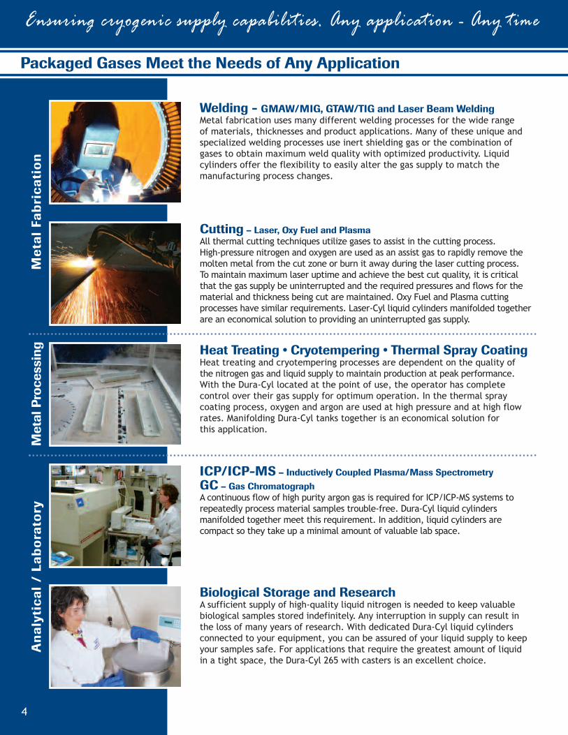
Biological Storage and ResearchA sufficient supply of high-quality liquid nitrogen is needed to keep valuablebiological samples stored indefinitely. Any interruption in supply can result inthe loss of many years of research. With dedicated Dura-Cyl liquid cylindersconnected to your equipment, you can be assured of your liquid supply to keepyour samples safe. For applications that require the greatest amount of liquidin a tight space, the Dura-Cyl 265 with casters is an excellent choice.
Heat Treating • Cryotempering • Thermal Spray CoatingHeat treating and cryotempering processes are dependent on the quality ofthe nitrogen gas and liquid supply to maintain production at peak performance.With the Dura-Cyl located at the point of use, the operator has completecontrol over their gas supply for optimum operation. In the thermal spraycoating process, oxygen and argon are used at high pressure and at high flowrates. Manifolding Dura-Cyl tanks together is an economical solution forthis application.
MetalFabrica
tion
Analytica
l/La
boratory
MetalProcessing
Packaged Gases
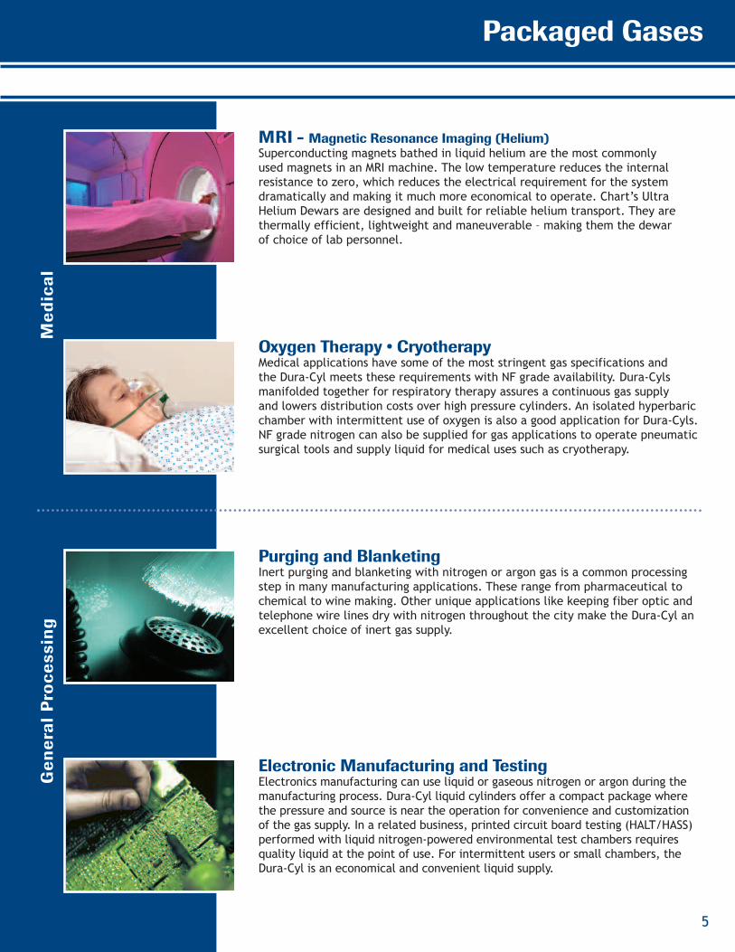
MRI - Magnetic Resonance Imaging (Helium)Superconducting magnets bathed in liquid helium are the most commonlyused magnets in an MRI machine. The low temperature reduces the internalresistance to zero, which reduces the electrical requirement for the systemdramatically and making it much more economical to operate. Chart’s UltraHelium Dewars are designed and built for reliable helium transport. They arethermally efficient, lightweight and maneuverable – making them the dewarof choice of lab personnel.
Oxygen Therapy • CryotherapyMedical applications have some of the most stringent gas specifications andthe Dura-Cyl meets these requirements with NF grade availability. Dura-Cylsmanifolded together for respiratory therapy assures a continuous gas supplyand lowers distribution costs over high pressure cylinders. An isolated hyperbaricchamber with intermittent use of oxygen is also a good application for Dura-Cyls.NF grade nitrogen can also be supplied for gas applications to operate pneumaticsurgical tools and supply liquid for medical uses such as cryotherapy.
Purging and BlanketingInert purging and blanketing with nitrogen or argon gas is a common processingstep in many manufacturing applications. These range from pharmaceutical tochemical to wine making. Other unique applications like keeping fiber optic andtelephone wire lines dry with nitrogen throughout the city make the Dura-Cyl anexcellent choice of inert gas supply.
Electronic Manufacturing and TestingElectronics manufacturing can use liquid or gaseous nitrogen or argon during themanufacturing process. Dura-Cyl liquid cylinders offer a compact package wherethe pressure and source is near the operation for convenience and customizationof the gas supply. In a related business, printed circuit board testing (HALT/HASS)performed with liquid nitrogen-powered environmental test chambers requiresquality liquid at the point of use. For intermittent users or small chambers, theDura-Cyl is an economical and convenient liquid supply.
Medical
GeneralProce
ssing
5
Dura-Cyl Benefits:
• Ideal for liquid nitrogen,oxygen, argon, CO2 ornitrous oxide
• Different sizes, pressures,and features to meetyour needs
• Stainless steel construction
• Thicker, dent-resistantouter shell
• Patented durable,inner-vessel supportsystem
• Heavy-duty footring andlarge diameter handlingring with four supports
• Combination PressureControl Regulator options
• Roto-Cal Liquid LevelGauge System
• Five-year vacuumwarranty
Ensuring cryogenic supply capabilities. Any application - Any time
6
Dura-Cyl
DURA–CYL®
PREMIUM LIQUID CYLINDERS
1
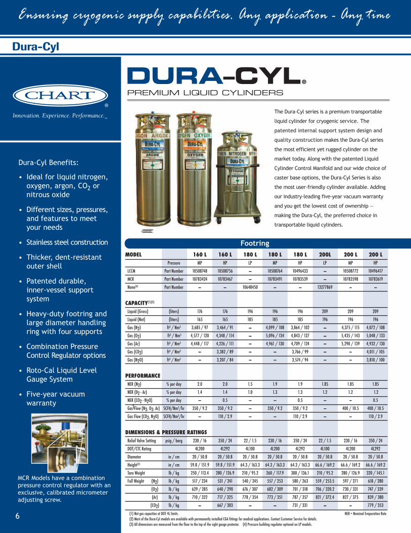
The Dura-Cyl series is a premium transportable
liquid cylinder for cryogenic service. The
patented internal support system design and
quality construction makes the Dura-Cyl series
the most efficient yet rugged cylinder on the
market today. Along with the patented Liquid
Cylinder Control Manifold and our wide choice of
caster base options, the Dura-Cyl Series is also
the most user-friendly cylinder available. Adding
our industry-leading five-year vacuum warranty
and you get the lowest cost of ownership —
making the Dura-Cyl, the preferred choice in
transportable liquid cylinders.
MCR Models have a combinationpressure control regulator with anexclusive, calibrated micrometeradjusting screw.
MODEL 160 L 160 L 180 L 180 L 180 L 200L 200 L 200 LPressure MP HP LP MP HP LP MP HP
LCCM Part Number 10508748 10508756 — 10508764 10496433 — 10508772 10496417
MCR Part Number 10783424 10783467 — 10783491 10783539 — 10783598 10783619
None(4) Part Number — — 10648450 — — 13277869 — —
CAPACITY(1)(2)
Liquid (Gross) (liters) 176 176 196 196 196 209 209 209
Liquid (Net) (liters) 165 165 185 185 185 196 196 196
Gas (N2) ft3 / Nm3 3,685 / 97 3,464 / 91 — 4,099 / 108 3,864 / 102 — 4,375 / 115 4,072 / 108
Gas (O2) ft3 / Nm3 4,577 / 120 4,348 / 114 — 5,096 / 134 4,843 / 127 — 5,435 / 143 5,048 / 133
Gas (Ar) ft3 / Nm3 4,448 / 117 4,226 / 111 — 4,961 / 130 4,709 / 124 — 5,290 / 139 4,932 / 130
Gas (CO2) ft3 / Nm3 — 3,382 / 89 — — 3,766 / 99 — — 4,011 / 105
Gas (N2O) ft3 / Nm3 — 3,207 / 84 — --- 3,574 / 94 — — 3,810 / 100
PERFORMANCENER (N2) % per day 2.0 2.0 1.5 1.9 1.9 1.85 1.85 1.85
NER (02 - Ar) % per day 1.4 1.4 1.0 1.3 1.3 1.2 1.2 1.2
NER (CO2 - N2O) % per day — 0.5 — — 0.5 — — 0.5
Gas Flow (N2, O2, Ar) SCFH/Nm3/hr 350 / 9.2 350 / 9.2 — 350 / 9.2 350 / 9.2 — 400 / 10.5 400 / 10.5
Gas Flow (CO2, N2O) SCFH/Nm3/hr — 110 / 2.9 — — 110 / 2.9 — — 110 / 2.9
DIMENSIONS & PRESSURE RATINGSRelief Valve Setting psig / barg 230 / 16 350 / 24 22 / 1.5 230 / 16 350 / 24 22 / 1.5 230 / 16 350 / 24
DOT/CTC Rating 4L200 4L292 4L100 4L200 4L292 4L100 4L200 4L292
Diameter in / cm 20 / 50.8 20 / 50.8 20 / 50.8 20 / 50.8 20 / 50.8 20 / 50.8 20 / 50.8 20 / 50.8
Height(3) in / cm 59.8 / 151.9 59.8 / 151.9 64.3 / 163.3 64.3 / 163.3 64.3 / 163.3 66.6 / 169.2 66.6 / 169.2 66.6 / 169.2
Tare Weight lb / kg 250 / 113.4 280 / 126.9 210 / 95.2 260 / 117.9 300 / 136.1 210 / 95.2 280 / 126.9 320 / 145.1
Full Weight (N2) lb / kg 517 / 234 531 / 241 540 / 245 557 / 253 580 / 263 559 / 253.5 597 / 271 618 / 280
(O2) lb / kg 629 / 285 640 / 290 676 / 307 682 / 309 701 / 318 706 / 320.2 730 / 331 747 / 339
(Ar) lb / kg 710 / 322 717 / 325 778 / 354 773 / 351 787 / 357 821 / 372.4 827 / 375 839 / 380
(CO2) lb / kg — 667 / 303 — --- 731 / 331 — — 779 / 353
(1) Net gas capacities at DOT 4L limits. NER = Nominal Evaporation Rate(2) Most of the Dura-Cyl models are available with permanently installed CGA fittings for medical applications. Contact Customer Service for details.(3) All dimensions are measured from the floor to the top of the sight gauge protector. (4) Pressure building regulator optional on LP models.
Footring
7
Packaged Gases
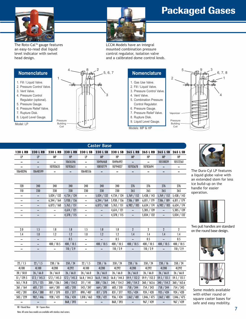
The Roto-Cal™ gauge featuresan easy-to-read dial liquidlevel indicator with swivelhead design.
LCCM Models have an integralmounted combination pressurecontrol regulator, isolation valveand a calibrated dome control knob.
Some models availablewith either round orsquare caster bases forsafe and easy mobility.
Two pull handles are standardon the round base design.
The Dura-Cyl LP featuresa liquid globe valve withan extended stem for lessice build-up on thehandle for easieroperation.
Nomenclature2
3
8 5, 6, 74
1
PressureBuilding
Coil
1. Fill / Liquid Valve.2. Pressure Control Valve.3. Vent Valve.4. Pressure Control Regulator (optional).5. Pressure Gauge.6. Pressure Relief Valve.7. Rupture Disk.8. Liquid Level Gauge.
Model: LP
Nomenclature1
3
4
9 6, 7, 85
2
Vaporizer
PressureBuilding
Coil
1. Gas Use Valve.2. Fill / Liquid Valve.3. Pressure Control Valve.4. Vent Valve.5. Combination Pressure Control Regulator.6. Pressure Gauge.7. Pressure Relief Valve.8. Rupture Disk.9. Liquid Level Gauge.
Models: MP & HP
Caster Base120 L RB 230 L RB 230 L RB 230 L RB 230 L SB 230 L SB 230 L SB 265 L RB 265 L RB 265 L SB 265 L SB
LP LP MP HP LP MP HP MP HP MP HP— — — 10616546 — 10496468 10496492 — — 10510039 10512561— — 10783635 10783651 — 10810779 10794027 10783678 10783694 — —
10648396 10648599 — — 10648556 — — — — — —
120 240 240 240 240 240 240 276 276 276 276110 230 230 230 230 230 230 265 265 265 265— — 5,024 / 132 4,734 / 124 — 5,024 / 132 4,734 / 124 5,769 / 152 5,438 / 143 5,769 / 152 5,438 / 143— — 6,244 / 164 5,930 / 156 — 6,244 / 164 5,930 / 156 7,186 / 189 6,811 / 179 7,186 / 189 6,811 / 179— — 6,073 / 160 5,763 / 151 — 6,073 / 160 5,763 / 151 6,982 / 183 6,634 / 174 6,982 / 183 6,634 / 174— — — 4,614 / 121 — — 4,614 / 121 — 5,305 / 139 — 5,305 / 139— — — 4,378 / 115 — — 4,378 / 115 — 5,034 / 132 — 5,034 / 132
2.0 1.5 1.8 1.8 1.5 1.8 1.8 2 2 2 21.4 1.0 1.2 1.2 1.0 1.2 1.2 1.4 1.4 1.4 1.4— — — 0.5 — — 0.5 — 0.5 — 0.5— — 400 / 10.5 400 / 10.5 — 400 / 10.5 400 / 10.5 400 / 10.5 400 / 10.5 400 / 10.5 400 / 10.5— — — 110 / 2.9 — — 110 / 2.9 — 110 / 2.9 — 110 / 2.9
22 / 1.5 22 / 1.5 230 / 16 350 / 24 22 / 1.5 230 / 16 350 / 24 230 / 16 350 / 24 230 / 16 350 / 244L100 4L100 4L200 4L292 4L100 4L200 4L292 4L200 4L292 4L200 4L292
20 / 50.8 26 / 66.0 26 / 66.0 26 / 66.0 26 / 66.0 26 / 66.0 26 / 66.0 26 / 66.0 26 / 66.0 26 / 66.0 26 / 66.051 / 129.5 57.2 / 145.3 57.2 / 145.3 57.2 / 145.3 56.8 / 144.3 56.8 / 144.3 56.8 / 144.3 59.9 / 152.2 59.9 / 152.2 59.5 / 151.1 59.5 / 151.1165 / 74.8 275 / 125 300 / 136.1 340 / 154.2 311 / 141 300 / 136.1 340 / 154.2 340 / 154.2 360 / 163.6 340 / 154.2 360 / 163.6361 / 164 685 / 311 664 / 301 683 / 310 543 / 247 664 / 301 683 / 310 758 / 344 754 / 343 758 / 344 754 / 343442 / 201 854 / 388 817 / 370 831 / 377 890 / 407 817 / 370 831 / 377 935 / 424 924 / 420 935 / 424 924 / 420503 / 229 982 / 446 928 / 421 936 / 424 1,018 / 463 928 / 421 936 / 424 1,062 / 481 1,046 / 475 1,062 / 481 1,046 / 475
— — — 868 / 393 — — 868 / 393 — 967 / 439 — 967 / 439RB = Round Base SB = Square Base
Note: All caster base models are available with stainless steel casters.
Cryo-Cyl Benefits:
• Ideal for liquid nitrogen,oxygen, argon, CO2 ornitrous oxide
• Stainless steel construction
• Thicker, dent-resistantouter shell
• Patented durable,inner-vessel supportsystem
• Heavy-duty footring andlarge diameter handlingring with two supports
• Roto-Cal Liquid LevelGauge System
• Five-year vacuumwarranty
Cryo-Cyl
Ensuring cryogenic supply capabilities. Any application - Any time
8
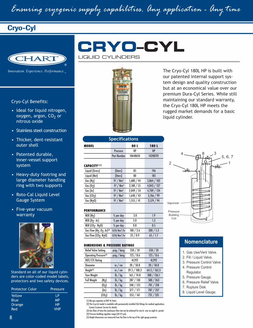
The Cryo-Cyl 180L HP is built withour patented internal support sys-tem design and quality constructionbut at an economical value over ourpremium Dura-Cyl Series. While stillmaintaining our standard warranty,the Cryo-Cyl 180L HP meets therugged market demands for a basicliquid cylinder.
CRYO–CYLLIQUID CYLINDERS
Standard on all of our liquid cylin-ders are color-coded model labels,protectors and two safety devices.
Protector Color Pressure
Yellow LPBlue MPOrange HPRed VHP
MODEL 80 L 180 LPressure HP HP
Part Number 10648610 14248701
CAPACITY(1)(2)
Liquid (Gross) (liters) 85 196Liquid (Net) (liters) 80 185Gas (N2) ft3 / Nm3 1,680 / 44 3,864 / 102Gas (O2) ft3 / Nm3 2,108 / 55 4,843 / 127Gas (Ar) ft3 / Nm3 2,049 / 54 4,709 / 124Gas (CO2) ft3 / Nm3 1,640 / 43 3,766 / 99Gas (N2O) ft3 / Nm3 1,555 / 41 3,574 / 94
PERFORMANCENER (N2) % per day 3.0 1.9NER (02 - Ar) % per day 2.0 1.3NER (CO2 - N2O) % per day 0.8 0.5Gas Flow (N2, O2, Ar)(3) SCFH/Nm3/hr 100 / 2.6 200 / 5.3Gas Flow (CO2, N2O) SCFH/Nm3/hr 35 / 0.9 65 / 1.7
DIMENSIONS & PRESSURE RATINGSRelief Valve Setting psig / barg 350 / 24 350 / 24Operating Pressure(4) psig / barg 125 / 8.6 125 / 8.6DOT/CTC Rating 4L292 4L292Diameter in / cm 20 / 50.8 20 / 50.8Height(5) in / cm 39.5 / 100.3 64.3 / 163.3Tare Weight lb / kg 165 / 74.8 300 / 136.1Full Weight (N2) lb / kg 287 / 130 580 / 263
(O2) lb / kg 340 / 155 701 / 318(Ar) lb / kg 377 / 171 787 / 357(CO2) lb / kg 353 / 161 731 / 331
Specifications
(1) Net gas capacities at DOT 4L limits.(2) The Cryo-Cyl model is available with permanently installed CGA fittings for medical applications.
Contact Customer Service for details.(3) Gas flows of twice the continuous flow rate can be achieved for one hr. over an eight hr. period.(4) Pressure building regulator range (50-175 psi).(5) Height dimensions are measured from the floor to the top of the sight gauge protector.
1
38 5, 6, 74
2
Vaporizer
PressureBuilding
Coil
Nomenclature1
1. Gas Use/Vent Valve.2. Fill / Liquid Valve.3. Pressure Control Valve.4. Pressure Control Regulator.5. Pressure Gauge.6. Pressure Relief Valve.7. Rupture Disk.8. Liquid Level Gauge.
Packaged Gases
9
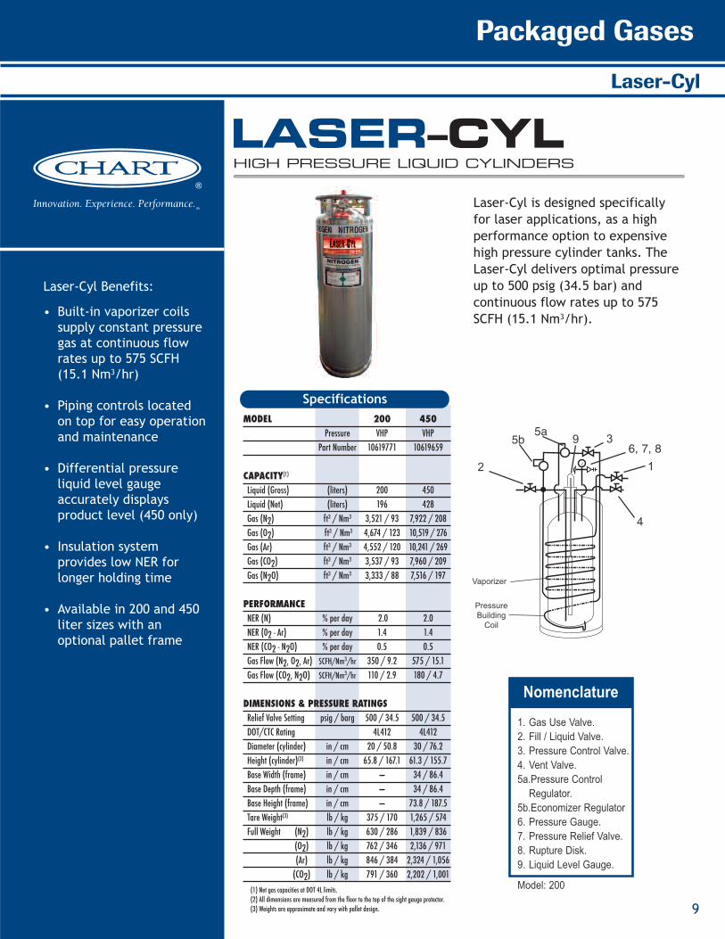
Laser-Cyl Benefits:
• Built-in vaporizer coilssupply constant pressuregas at continuous flowrates up to 575 SCFH(15.1 Nm3/hr)
• Piping controls locatedon top for easy operationand maintenance
• Differential pressureliquid level gaugeaccurately displaysproduct level (450 only)
• Insulation systemprovides low NER forlonger holding time
• Available in 200 and 450liter sizes with anoptional pallet frame
Laser-Cyl
LASER–CYLHIGH PRESSURE LIQUID CYLINDERS
Laser-Cyl is designed specificallyfor laser applications, as a highperformance option to expensivehigh pressure cylinder tanks. TheLaser-Cyl delivers optimal pressureup to 500 psig (34.5 bar) andcontinuous flow rates up to 575SCFH (15.1 Nm3/hr).
MODEL 200 450Pressure VHP VHP
Part Number 10619771 10619659
CAPACITY(1)
Liquid (Gross) (liters) 200 450Liquid (Net) (liters) 196 428Gas (N2) ft3 / Nm3 3,521 / 93 7,922 / 208Gas (O2) ft3 / Nm3 4,674 / 123 10,519 / 276Gas (Ar) ft3 / Nm3 4,552 / 120 10,241 / 269Gas (CO2) ft3 / Nm3 3,537 / 93 7,960 / 209Gas (N2O) ft3 / Nm3 3,333 / 88 7,516 / 197
PERFORMANCENER (N) % per day 2.0 2.0NER (02 - Ar) % per day 1.4 1.4NER (CO2 - N2O) % per day 0.5 0.5Gas Flow (N2, O2, Ar) SCFH/Nm3/hr 350 / 9.2 575 / 15.1Gas Flow (CO2, N2O) SCFH/Nm3/hr 110 / 2.9 180 / 4.7
DIMENSIONS & PRESSURE RATINGSRelief Valve Setting psig / barg 500 / 34.5 500 / 34.5DOT/CTC Rating 4L412 4L412Diameter (cylinder) in / cm 20 / 50.8 30 / 76.2Height (cylinder)(2) in / cm 65.8 / 167.1 61.3 / 155.7Base Width (frame) in / cm — 34 / 86.4Base Depth (frame) in / cm — 34 / 86.4Base Height (frame) in / cm — 73.8 / 187.5Tare Weight(3) lb / kg 375 / 170 1,265 / 574Full Weight (N2) lb / kg 630 / 286 1,839 / 836
(O2) lb / kg 762 / 346 2,136 / 971(Ar) lb / kg 846 / 384 2,324 / 1,056(CO2) lb / kg 791 / 360 2,202 / 1,001
Specifications
1
3
4
9 6, 7, 85b 5a
2
Vaporizer
PressureBuilding
Coil
Nomenclature1
1. Gas Use Valve.2. Fill / Liquid Valve.3. Pressure Control Valve.4. Vent Valve.5a.Pressure Control Regulator.5b.Economizer Regulator6. Pressure Gauge.7. Pressure Relief Valve.8. Rupture Disk.9. Liquid Level Gauge.
Model: 200(1) Net gas capacities at DOT 4L limits.(2) All dimensions are measured from the floor to the top of the sight gauge protector.(3) Weights are approximate and vary with pallet design.
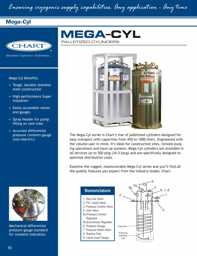
Mega-Cyl Benefits:
• Tough, durable stainlesssteel construction
• High-performance SuperInsulation
• Easily accessible valvesand gauges
• Spray header for pumpfilling on vent tube
• Accurate differentialpressure contents gauge(non-electric)
Mechanical differentialpressure gauge standardfor contents indication.
Ensuring cryogenic supply capabilities. Any application - Any time
10
Mega-Cyl
The Mega-Cyl series is Chart’s line of palletized cylinders designed foreasy transport with capacities from 450 to 1000 liters. Engineered withthe volume user in mind, it’s ideal for construction sites, remote purg-ing operations and back-up systems. Mega-Cyl cylinders are available inall services up to 500 psig (34.5 barg) and are specifically designed tooptimize distribution costs.
Examine the rugged, maneuverable Mega-Cyl series and you’ll find allthe quality features you expect from the industry leader, Chart.
MEGA–CYLPALLETIZED CYLINDERS
Nomenclature1
3
4
9
6, 7, 85b 5a
2
Vaporizer
PressureBuilding
Coil
1. Gas Use Valve.2. Fill / Liquid Valve.3. Pressure Control Valve.4. Vent Valve.5a.Pressure Control Regulator.5b.Economizer Regulator6. Pressure Gauge.7. Pressure Relief Valve.8. Rupture Disk.9. Liquid Level Gauge.
Packaged Gases
11
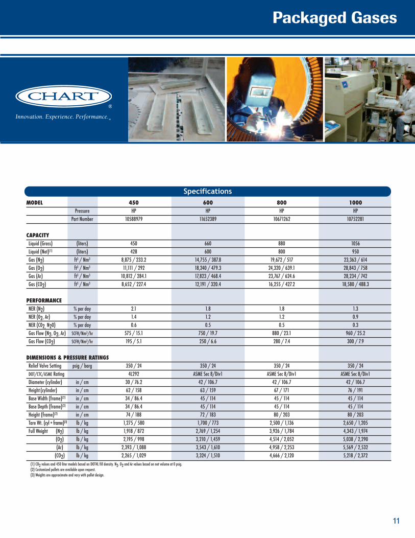
MODEL 450 600 800 1000Pressure HP HP HP HP
Part Number 10588979 11652389 10671262 10752281
CAPACITYLiquid (Gross) (liters) 450 660 880 1056Liquid (Net)(1) (liters) 428 600 800 950Gas (N2) ft3 / Nm3 8,875 / 233.2 14,755 / 387.8 19,672 / 517 23,363 / 614Gas (O2) ft3 / Nm3 11,111 / 292 18,240 / 479.3 24,320 / 639.1 28,843 / 758Gas (Ar) ft3 / Nm3 10,812 / 284.1 17,823 / 468.4 23,767 / 624.6 28,234 / 742Gas (CO2) ft3 / Nm3 8,652 / 227.4 12,191 / 320.4 16,255 / 427.2 18,580 / 488.3
PERFORMANCENER (N2) % per day 2.1 1.8 1.8 1.3NER (02, Ar) % per day 1.4 1.2 1.2 0.9NER (C02, N20) % per day 0.6 0.5 0.5 0.3Gas Flow (N2, O2, Ar) SCFH/Nm3/hr 575 / 15.1 750 / 19.7 880 / 23.1 960 / 25.2Gas Flow (CO2) SCFH/Nm3/hr 195 / 5.1 250 / 6.6 280 / 7.4 300 / 7.9
DIMENSIONS & PRESSURE RATINGSRelief Valve Setting psig / barg 350 / 24 350 / 24 350 / 24 350 / 24DOT/CTC/ASME Rating 4L292 ASME Sec 8/Div1 ASME Sec 8/Div1 ASME Sec 8/Div1Diameter (cylinder) in / cm 30 / 76.2 42 / 106.7 42 / 106.7 42 / 106.7Height (cylinder) in / cm 62 / 158 63 / 159 67 / 171 76 / 191Base Width (frame)(2) in / cm 34 / 86.4 45 / 114 45 / 114 45 / 114Base Depth (frame)(2) in / cm 34 / 86.4 45 / 114 45 / 114 45 / 114Height (frame)(2) in / cm 74 / 188 72 / 183 80 / 203 80 / 203Tare Wt. (cyl + frame)(3) lb / kg 1,275 / 580 1,700 / 773 2,500 / 1,136 2,650 / 1,205Full Weight (N2) lb / kg 1,918 / 872 2,769 / 1,254 3,926 / 1,784 4,343 / 1,974
(O2) lb / kg 2,195 / 998 3,210 / 1,459 4,514 / 2,052 5,038 / 2,290(Ar) lb / kg 2,393 / 1,088 3,543 / 1,610 4,958 / 2,253 5,569 / 2,532(CO2) lb / kg 2,265 / 1,029 3,324 / 1,510 4,666 / 2,120 5,218 / 2,372
(1) CO2 values and 450 liter models based on DOT4L fill density. N2, O2 and Ar values based on net volume at 0 psig.(2) Customized pallets are available upon request.(3) Weights are approximate and vary with pallet design.
Specifications
Ensuring cryogenic supply capabilities. Any application - Any time
12
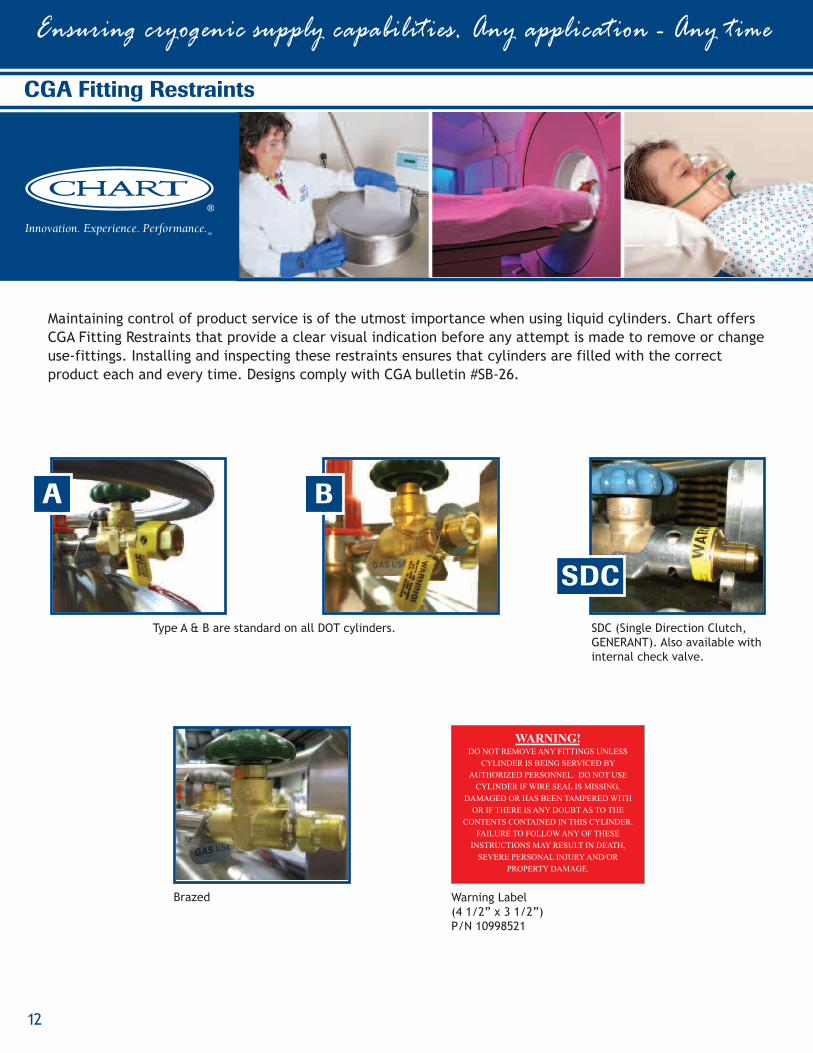
CGA Fitting Restraints
Maintaining control of product service is of the utmost importance when using liquid cylinders. Chart offersCGA Fitting Restraints that provide a clear visual indication before any attempt is made to remove or changeuse-fittings. Installing and inspecting these restraints ensures that cylinders are filled with the correctproduct each and every time. Designs comply with CGA bulletin #SB-26.
A B
SDC
WARNING!DO NOT REMOVE ANY FITTINGS UNLESS
CYLINDER IS BEING SERVICED BY
AUTHORIZED PERSONNEL. DO NOT USE
CYLINDER IF WIRE SEAL IS MISSING,
DAMAGED OR HAS BEEN TAMPERED WITH
OR IF THERE IS ANY DOUBT AS TO THE
CONTENTS CONTAINED IN THIS CYLINDER.
FAILURE TO FOLLOW ANY OF THESE
INSTRUCTIONS MAY RESULT IN DEATH,
SEVERE PERSONAL INJURY AND/OR
PROPERTY DAMAGE.
Warning Label(4 1/2” x 3 1/2”)P/N 10998521
SDC (Single Direction Clutch,GENERANT). Also available withinternal check valve.
Type A & B are standard on all DOT cylinders.
Brazed
Packaged Gases
13
Liquid Cylinder Accessories
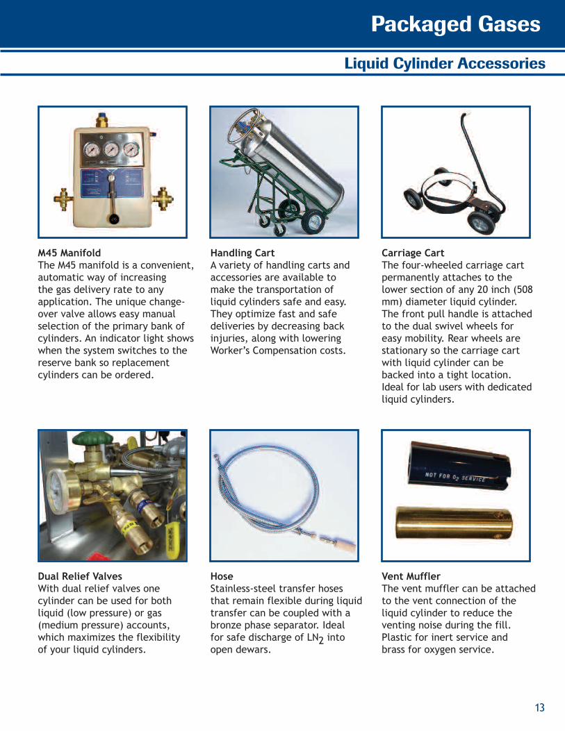
M45 ManifoldThe M45 manifold is a convenient,automatic way of increasingthe gas delivery rate to anyapplication. The unique change-over valve allows easy manualselection of the primary bank ofcylinders. An indicator light showswhen the system switches to thereserve bank so replacementcylinders can be ordered.
Handling CartA variety of handling carts andaccessories are available tomake the transportation ofliquid cylinders safe and easy.They optimize fast and safedeliveries by decreasing backinjuries, along with loweringWorker’s Compensation costs.
Carriage CartThe four-wheeled carriage cartpermanently attaches to thelower section of any 20 inch (508mm) diameter liquid cylinder.The front pull handle is attachedto the dual swivel wheels foreasy mobility. Rear wheels arestationary so the carriage cartwith liquid cylinder can bebacked into a tight location.Ideal for lab users with dedicatedliquid cylinders.
Dual Relief ValvesWith dual relief valves onecylinder can be used for bothliquid (low pressure) or gas(medium pressure) accounts,which maximizes the flexibilityof your liquid cylinders.
HoseStainless-steel transfer hosesthat remain flexible during liquidtransfer can be coupled with abronze phase separator. Idealfor safe discharge of LN2 intoopen dewars.
Vent MufflerThe vent muffler can be attachedto the vent connection of theliquid cylinder to reduce theventing noise during the fill.Plastic for inert service andbrass for oxygen service.
Ensuring cryogenic supply capabilities. Any application - Any time
14
Lo-Loss
Lo-Loss Benefits:
• Designed for pressuretransfer filling in argon,oxygen and nitrogen*service
• Automatic liquid cylinderpressure regulationthroughout the fill cycle
• Modular design allowsintegration into existingsystems
• Automatic shutoffimproves labor utilizationby allowing unattendedfilling
• Promotes DOT-compliantfilling and eliminateswasted product associatedwith vent filling
* Each product requires aseparate pressure control unit
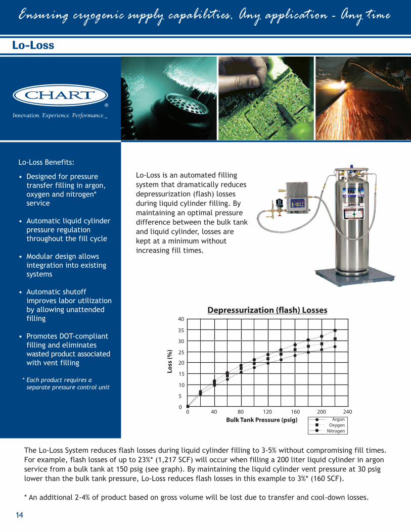
The Lo-Loss System reduces flash losses during liquid cylinder filling to 3-5% without compromising fill times.For example, flash losses of up to 23%* (1,217 SCF) will occur when filling a 200 liter liquid cylinder in argonservice from a bulk tank at 150 psig (see graph). By maintaining the liquid cylinder vent pressure at 30 psiglower than the bulk tank pressure, Lo-Loss reduces flash losses in this example to 3%* (160 SCF).
* An additional 2-4% of product based on gross volume will be lost due to transfer and cool-down losses.
40
35
30
25
20
15
10
5
0
Depressurization (flash) Losses
Loss
(%)
Bulk Tank Pressure (psig)0 40 80 120 160 200 240
ArgonOxygen
Nitrogen
Lo-Loss is an automated fillingsystem that dramatically reducesdepressurization (flash) lossesduring liquid cylinder filling. Bymaintaining an optimal pressuredifference between the bulk tankand liquid cylinder, losses arekept at a minimum withoutincreasing fill times.
Argon Maximizer Benefits:
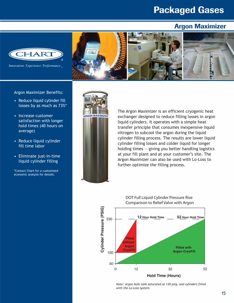
• Reduce liquid cylinder filllosses by as much as 73%*
• Increase customersatisfaction with longerhold times (40 hours onaverage)
• Reduce liquid cylinderfill time labor
• Eliminate just-in-timeliquid cylinder filling
*Contact Chart for a customizedeconomic analysis for details.
The Argon Maximizer is an efficient cryogenic heatexchanger designed to reduce filling losses in argonliquid cylinders. It operates with a simple heattransfer principle that consumes inexpensive liquidnitrogen to subcool the argon during the liquidcylinder filling process. The results are lower liquidcylinder filling losses and colder liquid for longerholding times — giving you better handling logisticsat your fill plant and at your customer’s site. TheArgon Maximizer can also be used with Lo-Loss tofurther optimize the filling process.
Cylin
derP
ress
ure(
PSIG
)
Hold Time (Hours)
12 Hour Hold Time 52 Hour Hold Time230
100
500 12 32 52
DOT Full Liquid Cylinder Pressure Rise Comparison to Relief Valve with Argon
Filled withArgon CryoFill
Filledwithout
ArgonCryoFill
Packaged Gases
15
Argon Maximizer
Note: Argon bulk tank saturated at 130 psig, and cylinders filledwith the Lo-Loss system.
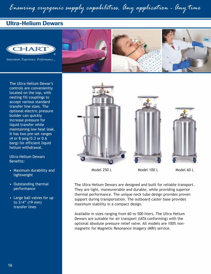
The Ultra Helium Dewar’scontrols are convenientlylocated on the top, withnesting fill couplings toaccept various standardtransfer line sizes. Theoptional electric pressurebuilder can quicklyincrease pressure forliquid transfer whilemaintaining low heat leak.It has two pre-set ranges(4 or 8 psig/0.3 or 0.6barg) for efficient liquidhelium withdrawal.
Ultra-Helium DewarsBenefits:
• Maximum durability andlightweight
• Outstanding thermalperformance
• Large ball valves for upto 3/4” (19 mm)transfer lines
Ensuring cryogenic supply capabilities. Any application - Any time
16
Ultra-Helium Dewars
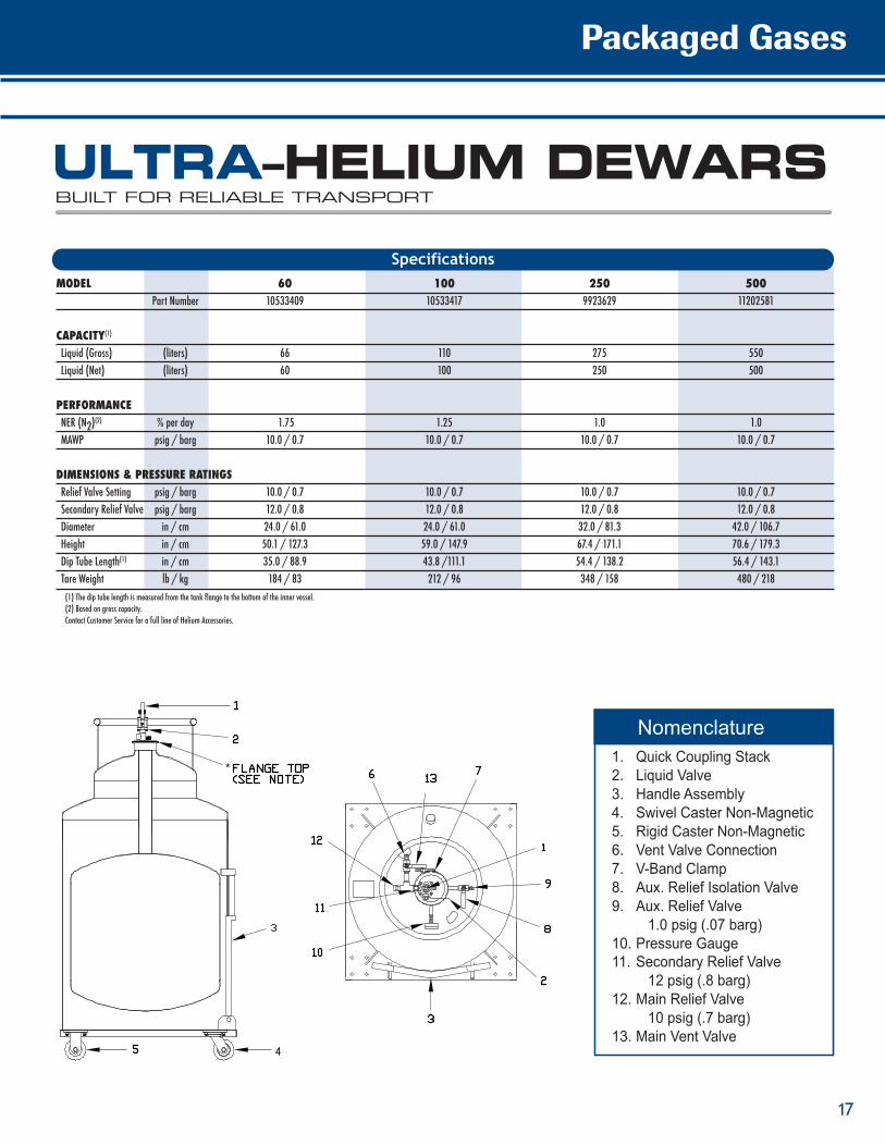
The Ultra Helium Dewars are designed and built for reliable transport.They are light, maneuverable and durable, while providing superiorthermal performance. The unique neck tube design provides provensupport during transportation. The outboard caster base providesmaximum stability in a compact design.
Available in sizes ranging from 60 to 500 liters. The Ultra HeliumDewars are suitable for air transport (IATA conforming) with theoptional absolute pressure relief valve. All models are 100% non-magnetic for Magnetic Resonance Imagery (MRI) service.
Model 250 L Model 100 L Model 60 L
ULTRA–HELIUM DEWARSBUILT FOR RELIABLE TRANSPORT
Packaged Gases
17
*
MODEL 60 100 250 500Part Number 10533409 10533417 9923629 11202581
CAPACITY(1)
Liquid (Gross) (liters) 66 110 275 550Liquid (Net) (liters) 60 100 250 500
PERFORMANCENER (N2)
(2) % per day 1.75 1.25 1.0 1.0MAWP psig / barg 10.0 / 0.7 10.0 / 0.7 10.0 / 0.7 10.0 / 0.7
DIMENSIONS & PRESSURE RATINGSRelief Valve Setting psig / barg 10.0 / 0.7 10.0 / 0.7 10.0 / 0.7 10.0 / 0.7Secondary Relief Valve psig / barg 12.0 / 0.8 12.0 / 0.8 12.0 / 0.8 12.0 / 0.8Diameter in / cm 24.0 / 61.0 24.0 / 61.0 32.0 / 81.3 42.0 / 106.7Height in / cm 50.1 / 127.3 59.0 / 147.9 67.4 / 171.1 70.6 / 179.3Dip Tube Length(1) in / cm 35.0 / 88.9 43.8 /111.1 54.4 / 138.2 56.4 / 143.1Tare Weight lb / kg 184 / 83 212 / 96 348 / 158 480 / 218(1) The dip tube length is measured from the tank flange to the bottom of the inner vessel.(2) Based on gross capacity.Contact Customer Service for a full line of Helium Accessories.
Specifications
Nomenclature1. Quick Coupling Stack2. Liquid Valve3. Handle Assembly4. Swivel Caster Non-Magnetic 5. Rigid Caster Non-Magnetic 6. Vent Valve Connection 7. V-Band Clamp 8. Aux. Relief Isolation Valve 9. Aux. Relief Valve
1.0 psig (.07 barg) 10. Pressure Gauge11. Secondary Relief Valve
12 psig (.8 barg) 12. Main Relief Valve
13. Main Vent Valve 10 psig (.7 barg)
M
Ensuring cryogenic supply capabilities. Any application - Any time
18
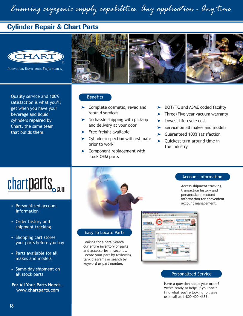
Cylinder Repair & Chart Parts
Quality service and 100%satisfaction is what you’llget when you have yourbeverage and liquidcylinders repaired byChart, the same teamthat builds them.
� Complete cosmetic, revac andrebuild services
� No hassle shipping with pick-upand delivery at your door
� Free freight available
� Cylinder inspection with estimateprior to work
� Component replacement withstock OEM parts
� DOT/TC and ASME coded facility
� Three/Five year vacuum warranty
� Lowest life-cycle cost
� Service on all makes and models
� Guaranteed 100% satisfaction
� Quickest turn-around time inthe industry
Benefits
Personalized Service
Account Information
Easy To Locate Parts
Access shipment tracking,transaction history andpersonalized accountinformation for convenientaccount management.
Have a question about your order?We’re ready to help! If you can’tfind what you’re looking for, giveus a call at 1-800-400-4683.
Looking for a part? Searchour entire inventory of partsand accessories in seconds.Locate your part by reviewingtank diagrams or search bykeyword or part number.
• Personalized accountinformation
• Order history andshipment tracking
• Shopping cart storesyour parts before you buy
• Parts available for allmakes and models
• Same-day shipment onall stock parts
For All Your Parts Needs…www.chartparts.com
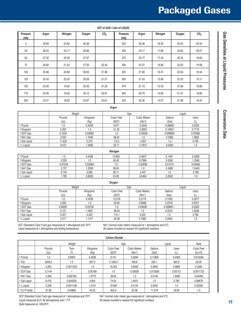
Pressure Argon Nitrogen Oxygen CO2 Pressure Argon Nitrogen Oxygen CO2psig psig
0 29.69 24.60 30.36 225 23.58 18.35 24.24 20.34
25 28.24 23.17 28.89 250 23.17 17.89 23.83 20.07
50 27.32 22.26 27.97 275 22.77 17.43 23.43 19.82
75 26.60 21.53 27.25 22.40 300 22.37 16.96 23.03 19.58
100 25.98 20.89 26.63 21.96 325 21.98 16.47 22.64 19.34
125 25.43 20.33 26.09 21.57 350 21.43 15.96 22.25 19.11
150 24.93 19.80 25.59 21.23 375 21.19 15.42 21.86 18.88
175 24.46 19.30 25.12 20.91 400 20.79 14.80 21.47 18.66
200 24.01 18.82 24.67 20.61 425 20.39 14.07 21.08 18.44
Nitrogen1 Pound 1.0 0.4536 13.803 0.3627 0.1481 0.56061 Kilogram 2.205 1.0 30.42 0.7996 0.3262 1.23491 SCF Gas 0.07245 0.03286 1.0 0.02628 0.01074 0.040651 Nm3 Gas 2.757 1.2506 38.04 1.0 0.4080 1.54431 Gal Liquid 6.745 3.060 93.11 2.447 1.0 3.7851 L Liquid 1.782 0.8083 24.60 0.6464 0.2642 1.0
OxygenWeight Gas Liquid
Pounds Kilograms Cubic Feet Cubic Meters Gallons Liters(Lb) (Kg) (SCF) (Nm3) (Gal) (L)
1 Pound 1.0 0.4536 12.076 0.3174 0.1050 0.39771 Kilogram 2.205 1.0 26.62 0.6998 0.2316 0.87671 SCF Gas 0.08281 0.03756 1.0 0.02628 0.008691 0.03291 Nm3 Gas 3.151 1.4291 38.04 1.0 0.3310 1.25281 Gal Liquid 9.527 4.322 115.1 3.025 1.0 3.7851 L Liquid 2.517 1.1417 30.38 0.7983 0.2642 1.0
SCF (Standard Cubic Foot) gas measured at 1 atmosphere and 70°F. Nm3 (normal cubic meter) measured at 1 atmosphere and 0°C.Liquid measured at 1 atmosphere and boiling temperature. All values rounded to nearest 4/5 significant numbers.
GasDensitiesatLiquidPressuresConversionData
Carbon Dioxide
Weight Gas Liquid SolidPounds Tons Kilograms Cubic Feet Cubic Meters Gallons Liters Cubic Feet(Lb) (T) (Kg) (SCF) (Nm3) (Gal) (L) (Cu Ft)
1 Pound 1.0 0.0005 0.4536 8.741 0.2294 0.11806 0.4469 0.0102461 Ton 2000.0 1.0 907.2 17,483.0 458.8 236.1 893.9 20.491 Kilogram 2.205 0.0011023 1.0 19.253 0.5058 0.2603 0.9860 0.22601 SCF Gas 0.1144 — 0.05189 1.0 0.02628 0.013506 0.05113 0.00117231 Nm3 Gas 4.359 0.002180 1.9772 38.04 1.0 0.5146 1.9480 0.044681 Gal Liquid 8.470 0.004235 3.842 74.04 1.9431 1.0 3.785 0.086781 L Liquid 2.238 0.0011185 1.0151 19.562 0.5134 0.2642 1.0 0.022931 Cu Ft Solid 97.56 0.04880 44.25 852.8 22.38 11.518 43.60 1.0
SCF (Standard Cubic Foot) gas measured at 1 atmosphere and 70°F. Nm3 (normal cubic meter) gas measured at 1 atmosphere and 0°C.Liquid measured at 21.42 atmospheres and 1.7°F. All values rounded to nearest 4/5 significant numbers.Solid measured at -109.25°F.
Argon
Weight Gas LiquidPounds Kilograms Cubic Feet Cubic Meters Gallons Liters(Lb) (Kg) (SCF) (Nm3) (Gal) (L)
1 Pound 1.0 0.4536 9.671 0.2543 0.08600 0.32551 Kilogram 2.205 1.0 21.32 0.5605 0.18957 0.71761 SCF Gas 0.1034 0.04690 1.0 0.02628 0.008893 0.033661 Nm3 Gas 3.933 1.7840 38.04 1.0 0.3382 1.28021 Gal Liquid 11.630 5.276 112.5 2.957 1.0 3.7851 L Liquid 3.072 1.3936 29.71 0.7812 0.2642 1.0
SCF of GAS / Liter of LIQUID
Packaged Gases
19
Phone1-800-400-4683
Fax1-952-758-8275
Worldwide1-952-758-4484
Chart Inc.407 Seventh Street NWNew Prague, MN 56071
www.chart-ind.com
©2009 Chart Inc.P/N 13962022


