Embed Size (px)
Citation preview

Packaged CCE Administration
• Getting Started, on page 1• Smart License, on page 10• Infrastructure Settings, on page 30• User Setup, on page 93• Organization Setup, on page 113• Desktop Settings, on page 152• Call Settings, on page 189• Feature Setup, on page 229• Email and Chat, on page 251• Bulk Imports, on page 251• Capacity, on page 266
Getting Started
Sign InYou must do post installation configurations to sign in to the Unified CCE Administration. For moreinformation, see Post Installation Configuration .
Sign in to Unified CCE Administration at https://<IP Address>/cceadmin. <IP Address> is the address of theSide A or B Unified CCE AW or optional external HDS.
Users are logged out of the Unified CCE Administration console automatically after 30 minutes of inactivity.Note
Administrators
Administrators sign in using their Active Directory credentials. For username, use the [email protected].
Packaged CCE Administration1
Supervisors
Supervisors on an IPv6 network sign in to Unified CCEAdministration at https://<FQDN>/cceadmin.<FQDN> is the fully qualified domain name of the Side A or B CCE AW or optional external HDS.
Supervisors sign in using their Active Directory ([email protected]) or single sign-on credentials. If supervisorsare enabled for single sign-on, after entering their username they are redirected to the Identity Provider sign-inscreen to enter their credentials. Supervisors are redirected to Unified CCE Administration after successfullysigning in.
Languages
If the Language Pack is installed, the Sign-In window includes a Language drop-down menu, showing morethan a dozen languages. English is the initial and the default language. Select any other language to see theuser interface and the online help in that language. The system retains your choice for subsequent sign-insuntil you change it again.
Single Sign-On Log OutFor a complete logout from all applications, sign out of the applications and close the browser window. In aWindows desktop, log out of the Windows account. In a Mac desktop, quit the browser application.
Users enabled for single sign-on are at risk of having their accounts misused by others if the browser is notclosed completely. If the browser is left open, a different user can access the application from the browserpage without entering credentials.
Note
System InterfacePackaged CCE user interface enables you to configure the application through one window. The landing pagehas a left navigation bar and a card view which contains all the configuration options. What you see after asuccessful sign-in depends on your role.
The left navigation bar consists of the following menus:
• Overview
• Infrastructure
• Organization
• Users
• Desktop
• Capacity
The following menus appear as cards:
• Infrastructure Settings
• Call Settings
• User Setup
Packaged CCE Administration2
Packaged CCE AdministrationSingle Sign-On Log Out
• Organization Setup
• Bulk Import
• Desktop Settings
• Features
• Email and Chat
(Available only when ECEWeb Server is added to the Infrastructure > Inventory page on the UnifiedCCE Administration.)
The Unified CCE Administration interface also provides access to HTML-based online help for users andadministrators. Click on the help button (?) on any page (except the Overview page) in the Unified CCEAdministration interface and the online help specific to that page is displayed in a pop-over window. You cannavigate to the previous or next page in the online help using the following keys:
• MAC - Command + left arrow or Command + right arrow
• Windows - Alt+ right arrow or Alt + left arrow
Note
Lists
List Windows
Most tools open to a List window that has rows for all currently configured objects. For example, the Teamstool has a list with a row for each team, and the Call Types tool has a list with a row for each call type. Listwindows allow you to search, sort, edit, and delete from the list.
Permissions on List windows vary for administrators and supervisors and are noted in the topic for each tool.
Search a List
There is a Search field on the List window for most tools. The search interface is similar, with small variations,depending on the tool.
Search and Administrators
If you sign in as a global administrator, a search returns all objects.
If you sign in as a departmental administrator, a search returns all objects in the departments you administer,as well as all global objects (objects that are in no departments).
Basic Search
Some tools offer a basic search on the Name (or name-equivalent) and Description fields.
Enter all or part of either value to find matches. Clear the search by deleting text from the Search field.
Search for Tools with Department IDs
For objects that can be associated with a department, you can click the + icon to the right of the Search fieldto open a popup window, where you can:
Packaged CCE Administration3
Packaged CCE AdministrationLists
• Enter a name or description ( for call types and precision queues add id).
• Select departments, with options for Globals and Departments, Globals only, or Departments only.
Selecting Globals and Departments or Departments only enables an input field where you can entera space-separated list of department names. (Departments is an OR search.)
Search by department is enabled only when departments are configured.Note
Agent Advanced Search
The Search field in the Agents tool offers an advanced and flexible search.
Click the + icon at the far right of the Search field to open a popup window, where you can:
• Select to search for agents only, supervisors only, or both.
• Enter a username, agent ID, first or last name, or description to search for that string.
• Enter one or more team names separated by spaces. (Team is an OR search--the agent or supervisor mustbe a member of one of the teams.)
• Enter one or more attribute names separated by spaces. (Attributes is an AND search--the agent orsupervisor must have all attributes.)
• Enter one or more skill group names separated by spaces. (Skill Groups is an AND search.)
• Select departments, with options for Globals and Departments, Globals only, or Departments only.
Selecting Globals and Departments or Departments only enables an input field where you can entera space-separated list of department names. (Departments is an OR search.)
Related TopicsDepartments, on page 133
Sort a List
If a column in a List window has an arrow icon in the column header, click the arrow to sort in ascending ordescending order.
Add ObjectsClick New in a List window to open an Add window where you can complete fields to create and save a newobject.
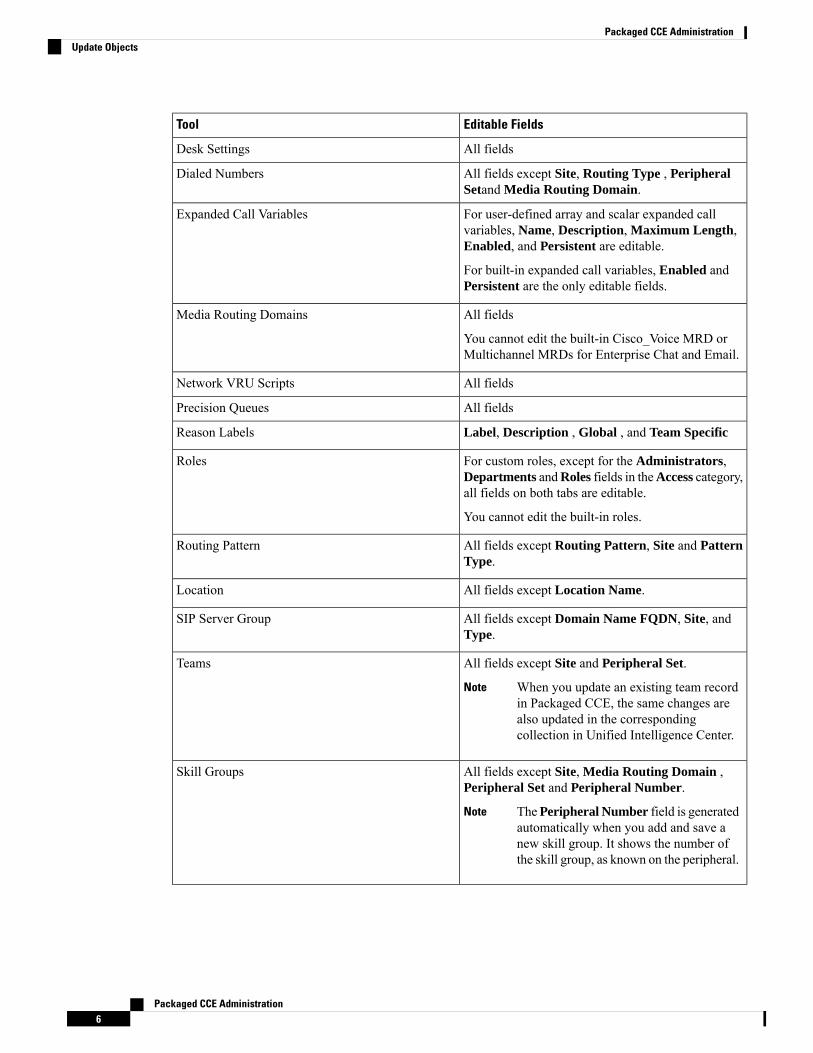
Update ObjectsTo edit an object in a List window, click in the row for that object. This opens a window where you can makeand save modifications. This table explains which fields are editable for each tool.
In the List window for the Agent tool, you can edit descriptions, desk settings, and teams for multiple agentsat once (see Edit Description, Desk Settings, and Teams for Multiple Agents, on page 101).
In the List window of the Dialed Number tool, you can edit the ringtonemedia file for multiple Dialed Numbersat once (see Add and Update Ringtone Media File for Multiple Dialed Numbers, on page 196).
Packaged CCE Administration4
Packaged CCE AdministrationSort a List
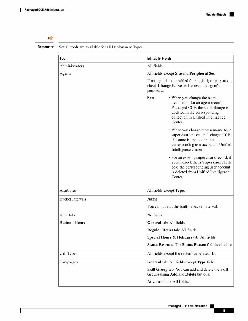
Not all tools are available for all Deployment Types.Remember
Editable FieldsTool
All fieldsAdministrators
All fields except Site and Peripheral Set.
If an agent is not enabled for single sign-on, you cancheck Change Password to reset the agent'spassword.
Note • When you change the teamassociation for an agent record inPackaged CCE, the same change isupdated in the correspondingcollection in Unified IntelligenceCenter.
• When you change the username for asupervisor's record in Packaged CCE,the same is updated in thecorresponding user account in UnifiedIntelligence Center.
• For an existing supervisor's record, ifyou uncheck the Is Supervisor checkbox, the corresponding user accountis deleted from Unified IntelligenceCenter.
Agents
All fields except Type.Attributes
Name
You cannot edit the built-in bucket interval.
Bucket Intervals
No fieldsBulk Jobs
General tab: All fields.
Regular Hours tab: All fields.
Special Hours & Holidays tab: All fields.
Status Reasons: The Status Reason field is editable.
Business Hours
All fields except the system-generated ID.Call Types
General tab: All fields except Type field.
Skill Group tab: You can add and delete the SkillGroups using Add and Delete buttons.
Advanced tab: All fields.
Campaigns
Packaged CCE Administration5
Packaged CCE AdministrationUpdate Objects
Editable FieldsTool
All fieldsDesk Settings
All fields except Site, Routing Type , PeripheralSetand Media Routing Domain.
Dialed Numbers
For user-defined array and scalar expanded callvariables, Name, Description, Maximum Length,Enabled, and Persistent are editable.
For built-in expanded call variables, Enabled andPersistent are the only editable fields.
Expanded Call Variables
All fields
You cannot edit the built-in Cisco_Voice MRD orMultichannel MRDs for Enterprise Chat and Email.
Media Routing Domains
All fieldsNetwork VRU Scripts
All fieldsPrecision Queues
Label, Description , Global , and Team SpecificReason Labels
For custom roles, except for the Administrators,Departments andRoles fields in theAccess category,all fields on both tabs are editable.
You cannot edit the built-in roles.
Roles
All fields except Routing Pattern, Site and PatternType.
Routing Pattern
All fields except Location Name.Location
All fields except Domain Name FQDN, Site, andType.
SIP Server Group
All fields except Site and Peripheral Set.
When you update an existing team recordin Packaged CCE, the same changes arealso updated in the correspondingcollection in Unified Intelligence Center.
Note
Teams
All fields except Site, Media Routing Domain ,Peripheral Set and Peripheral Number.
ThePeripheral Number field is generatedautomatically when you add and save anew skill group. It shows the number ofthe skill group, as known on the peripheral.
Note
Skill Groups
Packaged CCE Administration6
Packaged CCE AdministrationUpdate Objects
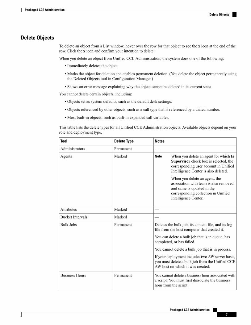
Delete ObjectsTo delete an object from a List window, hover over the row for that object to see the x icon at the end of therow. Click the x icon and confirm your intention to delete.
When you delete an object from Unified CCE Administration, the system does one of the following:
• Immediately deletes the object.
• Marks the object for deletion and enables permanent deletion. (You delete the object permanently usingthe Deleted Objects tool in Configuration Manager.)
• Shows an error message explaining why the object cannot be deleted in its current state.
You cannot delete certain objects, including:
• Objects set as system defaults, such as the default desk settings.
• Objects referenced by other objects, such as a call type that is referenced by a dialed number.
• Most built-in objects, such as built-in expanded call variables.
This table lists the delete types for all Unified CCE Administration objects. Available objects depend on yourrole and deployment type.
NotesDelete TypeTool
—PermanentAdministrators
When you delete an agent for which IsSupervisor check box is selected, thecorresponding user account in UnifiedIntelligence Center is also deleted.
When you delete an agent, theassociation with team is also removedand same is updated in thecorresponding collection in UnifiedIntelligence Center.
NoteMarkedAgents
—MarkedAttributes
—MarkedBucket Intervals
Deletes the bulk job, its content file, and its logfile from the host computer that created it.
You can delete a bulk job that is in queue, hascompleted, or has failed.
You cannot delete a bulk job that is in process.
If your deployment includes two AW server hosts,you must delete a bulk job from the Unified CCEAW host on which it was created.
PermanentBulk Jobs
You cannot delete a business hour associated witha script. You must first dissociate the businesshour from the script.
PermanentBusiness Hours
Packaged CCE Administration7
Packaged CCE AdministrationDelete Objects

NotesDelete TypeTool
—PermanentStatus Reasons
—MarkedCall Types
—MarkedCampaigns
—PermanentDesk Settings
—MarkedDialed Numbers
You cannot delete the SIP Server Group associatedwith a Routing Pattern. You must first remove theSIP Server Group from the Routing Pattern.
PermanentSIP Server Group
—MarkedExpanded Call Variables
You cannot delete the built-in Cisco_Voice MRDor Multichannel MRDs for Enterprise Chat andEmail (ECE).
PermanentMedia Routing Domains
—PermanentNetwork VRU Scripts
Deletes the file transfer job, its job details file, andits log file from the host computer where it iscreated.
You cannot delete a file transfer job that is inprocessing state.
PermanentFile Transfer Job
Depends on whether the precision queue isreferenced statically or dynamically in a script. .
MarkedPrecision Queues
—MarkedReason Labels
—PermanentRoles
—PermanentRouting Pattern
—PermanentLocation
When you delete a team in PackagedCCE, the corresponding collection isalso deleted in Unified IntelligenceCenter.
NotePermanentTeams
—MarkedSkill Groups
Related TopicsPermanent Deletion
Popup Windows
Popup window selection
Many Add and Edit windows have popup windows for searching and choosing objects that are relevant tothat tool.
Packaged CCE Administration8
Packaged CCE AdministrationPopup Windows
Some popup windows allow you to chose one object. Other popup windows allow you to select multipleobjects. For example, because an agent can be on only one team, the popup window for adding an agent to ateam allows only one selection, while the Skill Group Members popup window allows you to select one ormore agents to add to the skill group.
Click the + icon to open the popup window, where you can locate and select items that are configured.
Keyboard Shortcuts
Press the question mark (?) key to open a window that shows the keyboard shortcuts that are applicable forthat tool and for your status (Supervisor or Administrator).
The keyboard shortcuts window does not open when you press the (?) key in a text field. Press the esc key toremove focus from the text field and then press the (?) key.
Tip
System and Device Sync AlertsUnified CCE Administration includes icons to notify users of any system alerts and device out-of-sync alert.
System AlertsIn Unified CCEAdministration, you canmonitor the status of the systems. The Alerts icon on the page includesalert count.
To view the alert and validation rule of a machine, click the Alerts icon. The Inventory page opens where youcan view more details on the errors. For more information on server status rules, see Monitor Server StatusRules for Packaged CCE 2000 Agents Deployment
Device Out of Sync AlertsIn Unified CCE Administration, the configured data is synchronized with respective devices deployed in theinventory. If configured data synchronization fails with any device, the device is marked as out-of-sync andthe Out of Sync device alert icon appears at the top of the page.
You can click the icon to open the Inventory page, and view data synchronization status of:
• Cisco Unified Customer Voice Portal (CVP)
• Cisco Finesse Primary
• Cisco Unified Intelligence Center (CUIC) Publisher
• Enterprise Email and Chat (ECE) Web Server
• Cisco Virtualized Voice Browser (VVB) and
• Cloud Connect Publisher
You can perform manual synchronization of data on each In Sync and Out of Sync device in the Inventory.See Manual Synchronization of Configured Data, on page 10.
Packaged CCE Administration9
Packaged CCE AdministrationKeyboard Shortcuts
Manual Synchronization of Configured Data
This procedure explains how to manually synchronize configured data. You can do a Full Sync (for CVP andVVB) or a Differential sync.
Full Sync: This option is enabled for all CVPs (Main site and remote site) and VVBs (Main site and remotesite).
Full Sync does the following:
• CVP: reinitializes the device (CVP redeploy) and synchronizes all configuration data from the timewhenthe initial configuration was done. Use this option after you reimage or reinstall the CVP Server.
• VVB: synchronizes all configuration data from the time when the initial configuration was done. Usethis option after you reimage, reinstall, or readd the VVB Server.
• Cloud Connect: synchronizes all configuration data from the time when the initial configuration wasdone. Use this option after you reimage, reinstall, or read the Cloud Connect Publisher.
Differential Sync: This option synchronizes the configured data from the time the device was out of sync.
Procedure
Step 1 Navigate to Unified CCE Administration > Overview > Infrastructure Settings > Inventory.Step 2 If the device Sync Status is In Sync, click the Sync icon and select Full Sync.Step 3 If the device Sync Status is Out of Sync, click the Sync icon and select one of the following options
• Differential Sync
• Full Sync
Step 4 Click the Sync button.
If the Full Sync operation is successful, you must restart the CVP device.Note
Smart License
Overview
Tomanage your CVP licenses in the Unified CCEAdministration portal, enable this feature in Packaged CCE12.0 by installing the mandatory ES 37. For details, seeCisco Unified Contact Center Enterprise EngineeringSpecials (ES) Information at https://www.cisco.com/c/en/us/td/docs/voice_ip_comm/cust_contact/contact_center/icm_enterprise/ucce_b_unified-contact-center-enterprise-engineering/ucce_b_unified-contact-center-enterprise-engineering_chapter_0101.html
Note
Packaged CCE Administration10
Packaged CCE AdministrationManual Synchronization of Configured Data
Cisco Smart Software Licensing is a flexible software licensing model that streamlines the way you activateand manage Cisco software licenses across your organization. Smart Licenses provide greater insight intosoftware license ownership and consumption, so that you know what you own and how the licenses are beingused. The solution allows you to easily track the status of your license and software usage trends. It pools thelicense entitlements in a single account and allows you to move licenses freely across virtual accounts. SmartLicensing is enabled across most of the Cisco products and managed by a direct cloud-based or mediateddeployment model.
Smart Licensing registers the Product Instance, reports license usage, and obtains the necessary authorizationfrom Cisco Smart Software Manager (Cisco SSM) or Cisco Smart Software Manager On-Prem (CiscoSSM On-Prem).
You can use Smart Licensing to:
• View license usage and count.
• View the status of each license type and the product instance.
• View the product licenses available on Cisco SSM or Cisco SSM On-Prem.
• Register or deregister the Product Instance, renew license authorization and license registration.
• Sign in additional agents to Unified CCX up to the maximum limit that is configured in your OVA.
Related TopicsLicense Management, on page 26Prerequisites for Smart Licensing, on page 12Smart License Deployments, on page 12Evaluation ModeSelect License Type, on page 15Registration, Authorization, and Entitlement Status, on page 18Out-Of-Compliance and Enforcement Rules, on page 20Smart Licensing Task Flow, on page 13Obtain the Product Instance Registration Token, on page 14Configure Transport Settings for Smart Licensing, on page 15Register with Cisco Smart Software Manager, on page 17Smart Licensing Tasks, on page 27Renew Authorization, on page 28Renew Registration, on page 28Reregister License, on page 28Deregister License, on page 29
Smart Licensing CapabilitiesSmart Licensing works in conjunction with Cisco Smart Software Manager (Cisco SSM) to intelligentlymanage product licenses by providing real-time visibility of license status and usage. You can use this datato make better purchase decisions, based on your consumption. Smart Licensing establishes a pool of softwarelicenses or entitlements in Cisco Smart Account.
The Smart Account provides a central location where you can view, store, and manage your licenses, acrossthe organization. You can get access to your software licenses, hardware, and subscriptions through yourSmart Account. Smart Accounts are required to access and manage Smart License-enabled products.
Packaged CCE Administration11
Packaged CCE AdministrationSmart Licensing Capabilities
Creating a Smart Account is easy and takes less than five minutes. Create a Smart Account onsoftware.cisco.com.
Documentation Resources
Table 1: Documentation Resources
Go to...For
Prerequisites for Smart Licensing, on page 12Smart Licensing Pre-requisites
License Consumption Calculation, on page 23Understanding the License consumptionCalculation
Migrate to Smart Licensing, on page 25Migration to Smart Licensing
Smart Licensing Task Flow, on page 13Smart Licensing tasks in SPOG/OAMP
Best Practices, on page 29Best Practices
Prerequisites for Smart LicensingThe following are the prerequisites for configuring Smart Licensing:
• Smart Licensing Enrollment
Set up Smart and Virtual accounts. For more information, seehttps://software.cisco.com/#module/SmartLicensing.
• Adoption of License Integration Strategy
Decide how you want to connect your product instance to Smart Licensing servers:
• On-Cloud: Configure Packaged CCEUnified CVP to connect to Cisco SSM.
• On-Premise:
1. Deploy the Cisco SSM On-Prem. For instructions on how to do this, seehttps://www.cisco.com/c/en/us/buy/smart-accounts/software-manager-satellite.html.
2. Configure Packaged CCEUnified CVP to connect to Cisco SSM On-Prem.
For more information, see Smart License Deployments, on page 12.
• If you are moving to Smart Licensing, make sure to take backup of your existing PAKs. If you haveunconsumed PAKs, convert these PAKs to Smart Licenses. For more information on converting existingPAKs to Smart Licensing, see https://software.cisco.com/web/fw/softwareworkspace/smartlicensing/ssmcompiledhelps/g_Convert_Licensing.html.
Related TopicsConfigure Transport Settings for Smart Licensing, on page 15
Smart License DeploymentsThere are two software deployment options for Smart Licensing:
Packaged CCE Administration12
Packaged CCE AdministrationDocumentation Resources

• Direct - Cisco Smart Software Manager (Cisco SSM)
• Cisco Smart Software Manager On-Prem (Cisco SSM On-Prem)
Direct - Cisco Smart Software Manager (Cisco SSM)
The Cisco SSM is a cloud-based service that handles your system licensing. The Product Instance can connecteither directly to Cisco SSM or through a proxy server.
Cisco SSM allows you to:
• Create, manage, or view virtual accounts.
• Manage and track the licenses.
• Move licenses across the virtual accounts.
• Create and manage Product Instance Registration Tokens.
For more information about Cisco SSM, go to https://software.cisco.com.
Cisco Smart Software Manager On-Prem (Cisco SSM On-Prem)
Cisco SSM On-Prem is an on-premises component that can handle your licensing needs. When you choosethis option, Packaged CCEUnified CVP registers and reports license consumption to the Cisco SSMOn-Prem,which synchronizes its database regularly with Cisco SSM that is hosted on cisco.com.
You can use the Cisco SSM On-Prem in either Connected or Disconnected mode, depending on whether theCisco SSM On-Prem can connect directly to cisco.com.
Configure Transport URL for Cisco SSM On-Prem with Smart Call-Home URL:https://<OnpremCSSM_IP>/Transportgateway/services/DeviceRequestHandler
• Connected—Use when there is connectivity to cisco.com directly from the Cisco SSMOn-Prem. Smartaccount synchronization occurs automatically.
• Disconnected—Use when there is no connectivity to cisco.com from the Cisco SSM On-Prem. CiscoSSM On-Prem must synchronize with Cisco SSM manually to reflect the latest license entitlements.
For more information on Cisco SSM On-Prem, see https://www.cisco.com/c/en/us/buy/smart-accounts/software-manager.html.
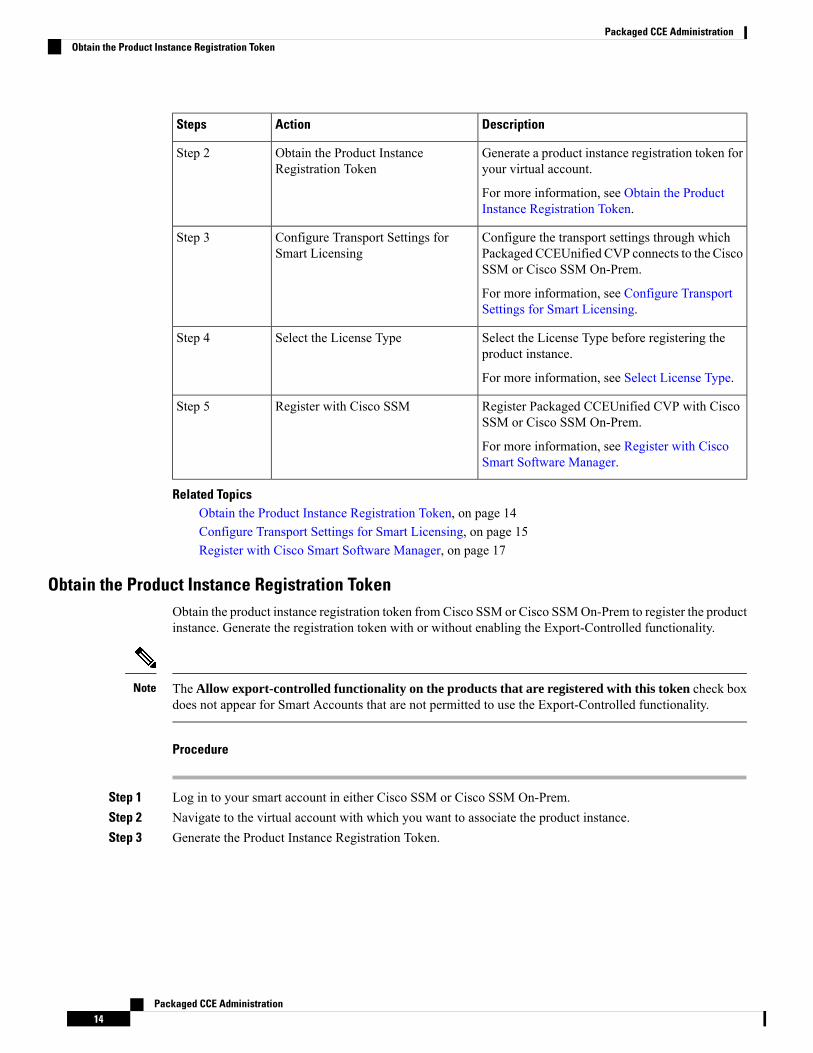
Smart Licensing Task FlowComplete these tasks to set up smart licensing for Packaged CCEUnified CVP.
DescriptionActionSteps
Use the Smart Account to organize licensesaccording to your needs. To create a SmartAccount, go to http://software.cisco.com
After the Smart Account is created, Cisco SSMcreates a default Virtual Account for this SmartAccount. You can use the default account or createother Virtual Accounts.
Create your Smart AccountStep 1
Packaged CCE Administration13
Packaged CCE AdministrationSmart Licensing Task Flow
DescriptionActionSteps
Generate a product instance registration token foryour virtual account.
For more information, see Obtain the ProductInstance Registration Token.
Obtain the Product InstanceRegistration Token
Step 2
Configure the transport settings through whichPackaged CCEUnified CVP connects to the CiscoSSM or Cisco SSM On-Prem.
For more information, see Configure TransportSettings for Smart Licensing.
Configure Transport Settings forSmart Licensing
Step 3
Select the License Type before registering theproduct instance.
For more information, see Select License Type.
Select the License TypeStep 4
Register Packaged CCEUnified CVP with CiscoSSM or Cisco SSM On-Prem.
For more information, see Register with CiscoSmart Software Manager.
Register with Cisco SSMStep 5
Related TopicsObtain the Product Instance Registration Token, on page 14Configure Transport Settings for Smart Licensing, on page 15Register with Cisco Smart Software Manager, on page 17
Obtain the Product Instance Registration TokenObtain the product instance registration token from Cisco SSM or Cisco SSMOn-Prem to register the productinstance. Generate the registration token with or without enabling the Export-Controlled functionality.
The Allow export-controlled functionality on the products that are registered with this token check boxdoes not appear for Smart Accounts that are not permitted to use the Export-Controlled functionality.
Note
Procedure
Step 1 Log in to your smart account in either Cisco SSM or Cisco SSM On-Prem.Step 2 Navigate to the virtual account with which you want to associate the product instance.Step 3 Generate the Product Instance Registration Token.
Packaged CCE Administration14
Packaged CCE AdministrationObtain the Product Instance Registration Token

• Select theAllow export-controlled functionality on the products registered with this tokencheck box to turn on the Export-Controlled functionality for a product instance you want inthis smart account. When you select this check box and accept the terms, you enable higherlevels of encryption for products that are registered with this registration token. By default,this check box is selected.
• Use this option only if you are compliant with the Export-Controlled functionality.
Note
Step 4 Copy the generated token. This token is required when registering Smart Licensing with Cisco SSM.
Configure Transport Settings for Smart LicensingConfigure the connection mode between Packaged CCEUnified CVP and Cisco SSM.
Configure the transport setting individually for all CVP devices installed in the deployment.Note
Procedure
Step 1 FromUnified CCEAdministration, navigate toOverview > Infrastructure Settings >License Management.Step 2 In Cisco Unified Customer Voice Portal, select License Management.
The License Management page is displayed.Step 3 The license information of the first CVP server in the Device Name drop-down list is displayed by default.
From the Device Name drop-down list, select a CVP server.Step 4 Click Transport Settings to set the connection method.Step 5 Select the connection method to Cisco SSM:
• Direct—Packaged CCEUnified CVP connects directly to Cisco SSM on cisco.com. This is the defaultoption.
• Transport Gateway—Packaged CCEUnified CVP connects to Cisco SSMOn-Prem for smart licensing.Enter the Cisco SSM On-Prem URL.
• HTTP/HTTPS Proxy—Packaged CCEUnified CVP connects to a proxy server, which connects to CiscoSSM. Enter the Fully Qualified Domain Name (FQDN) of the proxy server along with the port.
Step 6 Click Save to save the settings.
Select License Type
If you select incorrect License Type, the product instance is placed in the Out-of-Compliance state. If thisissue is unresolved, the product instance is placed in the Enforcement state where the system operations areimpacted.
Note
Packaged CCE Administration15
Packaged CCE AdministrationConfigure Transport Settings for Smart Licensing
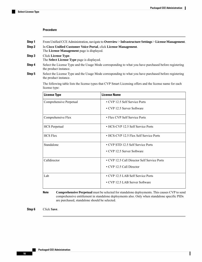
Procedure
Step 1 FromUnified CCEAdministration, navigate toOverview > Infrastructure Settings >License Management.Step 2 In Cisco Unified Customer Voice Portal, click License Management.
The License Management page is displayed.Step 3 Click License Type.
The Select License Type page is displayed.Step 4 Select the License Type and the Usage Mode corresponding to what you have purchased before registering
the product instance.Step 5 Select the License Type and the Usage Mode corresponding to what you have purchased before registering
the product instance.
The following table lists the license types that CVP Smart Licensing offers and the license name for eachlicense type:
License NameLicense Type
• CVP 12.5 Self Service Ports
• CVP 12.5 Server Software
Comprehensive Perpetual
• Flex CVP Self Service PortsComprehensive Flex
• HCS-CVP 12.5 Self Service PortsHCS Perpetual
• HCS-CVP 12.5 Flex Self Service PortsHCS Flex
• CVP STD 12.5 Self Service Ports
• CVP 12.5 Server Software
Standalone
• CVP 12.5 Call Director Self Service Ports
• CVP 12.5 Call Director
Calldirector
• CVP 12.5 LAB Self Service Ports
• CVP 12.5 LAB Server Software
Lab
Comprehensive Perpetual must be selected for standalone deployments. This causes CVP to sendcomprehensive entitlement in standalone deployments also. Only when standalone specific PIDsare purchased, standalone should be selected.
Note
Step 6 Click Save.
Packaged CCE Administration16
Packaged CCE AdministrationSelect License Type
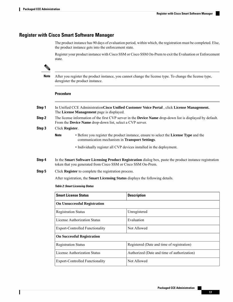
Register with Cisco Smart Software ManagerThe product instance has 90 days of evaluation period, within which, the registration must be completed. Else,the product instance gets into the enforcement state.
Register your product instance with Cisco SSM or Cisco SSMOn-Prem to exit the Evaluation or Enforcementstate.
After you register the product instance, you cannot change the license type. To change the license type,deregister the product instance.
Note
Procedure
Step 1 In Unified CCE AdministrationCisco Unified Customer Voice Portal , click License Management.The License Management page is displayed.
Step 2 The license information of the first CVP server in the Device Name drop-down list is displayed by default.From the Device Name drop-down list, select a CVP server.
Step 3 Click Register.
• Before you register the product instance, ensure to select the License Type and thecommunication mechanism in Transport Settings.
• Individually register all CVP devices installed in the deployment.
Note
Step 4 In the Smart Software Licensing Product Registration dialog box, paste the product instance registrationtoken that you generated from Cisco SSM or Cisco SSM On-Prem.
Step 5 Click Register to complete the registration process.
After registration, the Smart Licensing Status displays the following details.
Table 2: Smart Licensing Status
DescriptionSmart License Status
On Unsuccessful Registration
UnregisteredRegistration Status
EvaluationLicense Authorization Status
Not AllowedExport-Controlled Functionality
On Successful Registration
Registered (Date and time of registration)Registration Status
Authorized (Date and time of authorization)License Authorization Status
Not AllowedExport-Controlled Functionality
Packaged CCE Administration17
Packaged CCE AdministrationRegister with Cisco Smart Software Manager
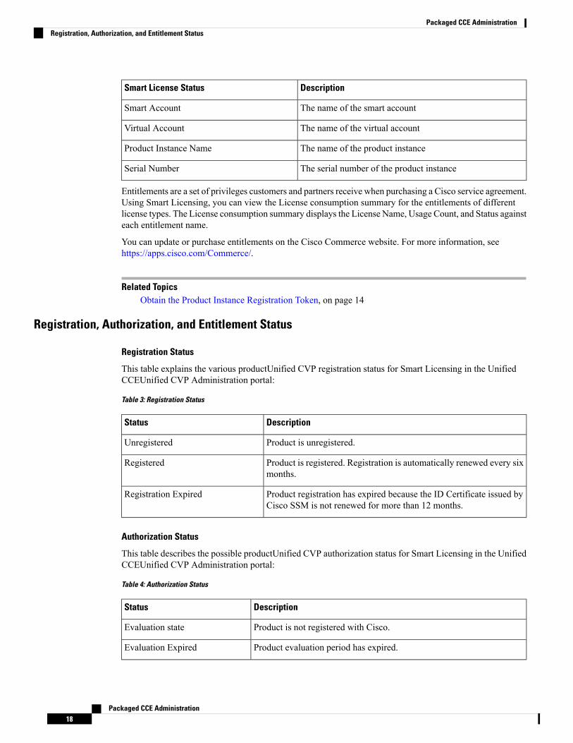
DescriptionSmart License Status
The name of the smart accountSmart Account
The name of the virtual accountVirtual Account
The name of the product instanceProduct Instance Name
The serial number of the product instanceSerial Number
Entitlements are a set of privileges customers and partners receive when purchasing a Cisco service agreement.Using Smart Licensing, you can view the License consumption summary for the entitlements of differentlicense types. The License consumption summary displays the License Name, Usage Count, and Status againsteach entitlement name.
You can update or purchase entitlements on the Cisco Commerce website. For more information, seehttps://apps.cisco.com/Commerce/.
Related TopicsObtain the Product Instance Registration Token, on page 14
Registration, Authorization, and Entitlement Status
Registration Status
This table explains the various productUnified CVP registration status for Smart Licensing in the UnifiedCCEUnified CVP Administration portal:
Table 3: Registration Status
DescriptionStatus
Product is unregistered.Unregistered
Product is registered. Registration is automatically renewed every sixmonths.
Registered
Product registration has expired because the ID Certificate issued byCisco SSM is not renewed for more than 12 months.
Registration Expired
Authorization Status
This table describes the possible productUnified CVP authorization status for Smart Licensing in the UnifiedCCEUnified CVP Administration portal:
Table 4: Authorization Status
DescriptionStatus
Product is not registered with Cisco.Evaluation state
Product evaluation period has expired.Evaluation Expired
Packaged CCE Administration18
Packaged CCE AdministrationRegistration, Authorization, and Entitlement Status
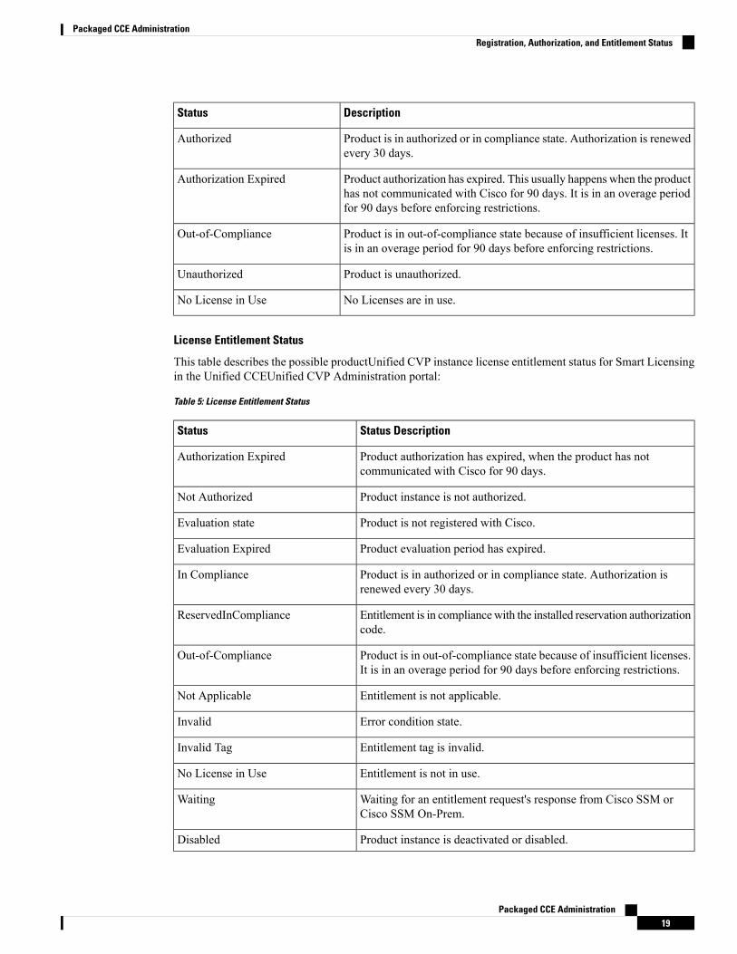
DescriptionStatus
Product is in authorized or in compliance state. Authorization is renewedevery 30 days.
Authorized
Product authorization has expired. This usually happens when the producthas not communicated with Cisco for 90 days. It is in an overage periodfor 90 days before enforcing restrictions.
Authorization Expired
Product is in out-of-compliance state because of insufficient licenses. Itis in an overage period for 90 days before enforcing restrictions.
Out-of-Compliance
Product is unauthorized.Unauthorized
No Licenses are in use.No License in Use
License Entitlement Status
This table describes the possible productUnified CVP instance license entitlement status for Smart Licensingin the Unified CCEUnified CVP Administration portal:
Table 5: License Entitlement Status
Status DescriptionStatus
Product authorization has expired, when the product has notcommunicated with Cisco for 90 days.
Authorization Expired
Product instance is not authorized.Not Authorized
Product is not registered with Cisco.Evaluation state
Product evaluation period has expired.Evaluation Expired
Product is in authorized or in compliance state. Authorization isrenewed every 30 days.
In Compliance
Entitlement is in compliancewith the installed reservation authorizationcode.
ReservedInCompliance
Product is in out-of-compliance state because of insufficient licenses.It is in an overage period for 90 days before enforcing restrictions.
Out-of-Compliance
Entitlement is not applicable.Not Applicable
Error condition state.Invalid
Entitlement tag is invalid.Invalid Tag
Entitlement is not in use.No License in Use
Waiting for an entitlement request's response from Cisco SSM orCisco SSM On-Prem.
Waiting
Product instance is deactivated or disabled.Disabled
Packaged CCE Administration19
Packaged CCE AdministrationRegistration, Authorization, and Entitlement Status

Out-Of-Compliance and Enforcement Rules
Out-of-Compliance
The Product Instance reports license usage to Cisco SSM every 15 minutes. If your license consumption ismore than the entitlements for four consecutive reporting intervals, the Product Instance is pushed to theOut-of-Compliance state. The Out-of-Compliance period is for 90 days, within which you need to purchasethe additional licenses. If you fail to take corrective action within the 90 days period, the Product Instance ispushed to the Enforcement state.
All CVPs in a virtual account share the licenses from a pool. If the license consumption exceeds than thoseavailable in the pool, all CVPs in the virtual account follow the Out-of-Compliance and Enforcement rules.
Enforcement
The Product Instance is in the Enforcement state in the following scenarios:
• Out-of-Compliance expiry: When the Out-of-Compliance period of 90 days has expired.
Purchase new licenses to exit the Enforcement state.
• Authorization expiry:When the Product Instance has not communicated with Cisco SSM or Cisco SSMOn-Prem for 90 days and has not automatically renewed the entitlement authorizations.
Renew the license authorizations to exit the authorization expiry state.
• Evaluation expiry: When the license evaluation period of 90 days has expired and the Product Instanceis not registered with Cisco SSM.
Register the Product Instance with Cisco SSM to exit the Evaluation expiry state.
In the Enforcement state, the following actions are blocked:
• Uploading VXML applications from OAMP
• Deploying application and updating application scripts in VXML server
• Deploying VXML applications REST call from the Unified CCE Administration interface in PackagedCCE
License StatesSmart Licensing has the following states:
• Registration State
• Unregistered—Product Instance is unregistered.
• Registered—After you purchase the license, you need to register the Product Instance with CiscoSSM. To register with Cisco SSM, generate a registration token from the Cisco SSM portal. Usethe registration token to register your Product Instance.
• Registration Expired—Product Instance registration has expired because the ID Certificate issuedby Cisco SSM is not renewed for more than 12 months. Reregister the Product Instance.
• Authorization State
Packaged CCE Administration20
Packaged CCE AdministrationOut-Of-Compliance and Enforcement Rules
• No licenses in use
• Evaluation Mode—The Product Instance license has an Evaluation period of 90 days. In theEvaluation period you have unlimited access to the product with highest set of product capabilitiesand unlimited number of licenses. You must register the system with Cisco SSM or Cisco SSMOn-Prem within 90 days. If the system is not registered before the end of the evaluation period, itwill be moved to the Enforcement state where certain system functions are restricted.
• In Compliance—When the license consumption is as per the purchased quantity, the product iscompliant.
• Evaluation expired—Product Instance evaluation period has expired.
• Authorized—Product Instance is in authorized or in compliance state. Authorization is renewedevery 30 days.
• Out of Compliance—Product Instance reports license usage to Cisco SSM every 15 minutes. Ifyour license consumption is more than the entitlements for five consecutive reporting intervals, theProduct Instance is transitioned to the Out of Compliance state. The out-of-compliance period isfor 90 days, within which you need to purchase the additional licenses. If you fail to take correctiveaction within the 90 days period, the Product Instance is transitioned to the Enforcement state.
• Authorization Expired—Product Instance authorization has expired. This usually happens whenthe product has not communicated with Cisco SSM for more than 90 days. It is in an overage periodfor 90 days before restrictions are enforced.
• Enforcement State
When the 90 day period of Out-of-Compliance, Evaluation Period or Authorization period has expired,the Product Instance is moved to the Enforcement state in which system operations are impacted forContact Center components. The Product Instance is in the Enforcement state in the following scenarios:
• Out-of-Compliance expiry—When the out-of-compliance period of 90 days has expired.
Purchase new licenses to exit the Enforcement state.
• Authorization expiry—When the Product Instance has not communicated with Cisco SSM orCisco SSM On-Prem for 90 days and has not automatically renewed the entitlement authorizations.
Renew the license authorizations to exit the Authorization expiry state.
• Evaluation expiry—When the license evaluation period of 90 days has expired and the ProductInstance is not registered with Cisco SSM.
Register the Product Instance with Cisco SSM to exit the evaluation expiry state.
In the Enforcement state, the following actions are blocked:
• Uploading VXML applications from OAMP.
• Deploying application and updating application scripts in VXML server.
• Deploying VXML applications REST call from PCCE SPOG.
A pictorial representation of different license states is as follows:
Packaged CCE Administration21
Packaged CCE AdministrationLicense States
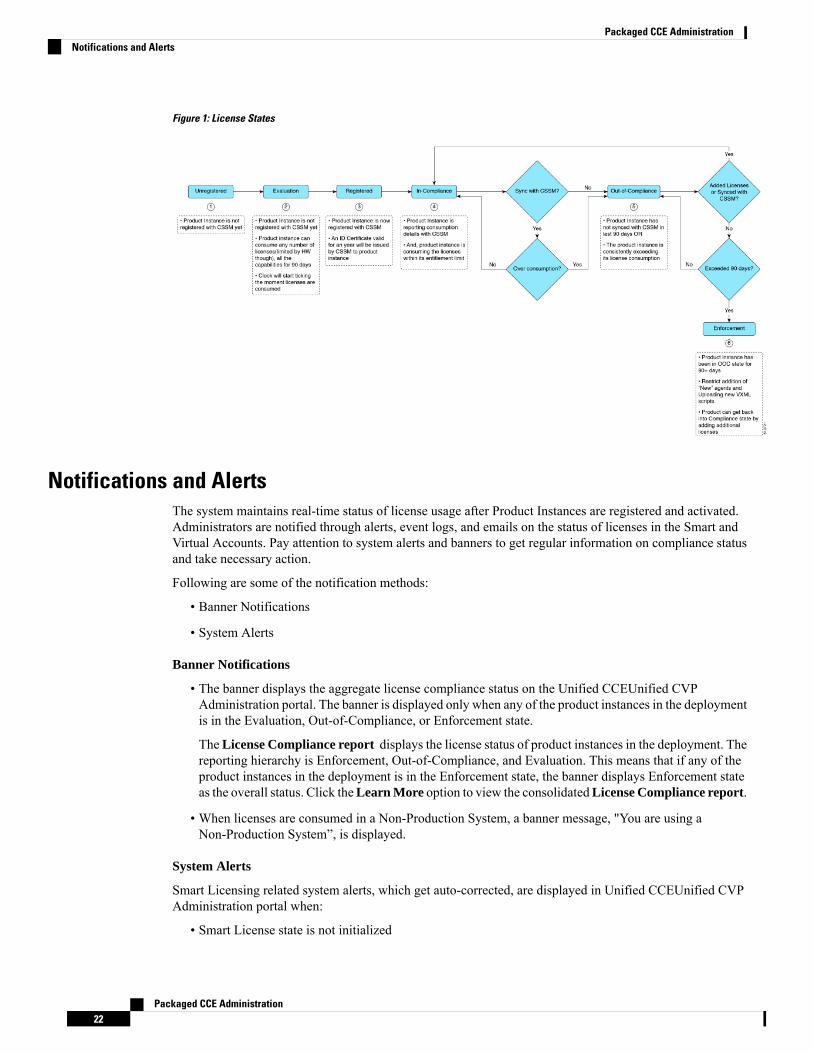
Figure 1: License States
Notifications and AlertsThe system maintains real-time status of license usage after Product Instances are registered and activated.Administrators are notified through alerts, event logs, and emails on the status of licenses in the Smart andVirtual Accounts. Pay attention to system alerts and banners to get regular information on compliance statusand take necessary action.
Following are some of the notification methods:
• Banner Notifications
• System Alerts
Banner Notifications
• The banner displays the aggregate license compliance status on the Unified CCEUnified CVPAdministration portal. The banner is displayed only when any of the product instances in the deploymentis in the Evaluation, Out-of-Compliance, or Enforcement state.
TheLicense Compliance report displays the license status of product instances in the deployment. Thereporting hierarchy is Enforcement, Out-of-Compliance, and Evaluation. This means that if any of theproduct instances in the deployment is in the Enforcement state, the banner displays Enforcement stateas the overall status. Click theLearn More option to view the consolidatedLicense Compliance report.
• When licenses are consumed in a Non-Production System, a banner message, "You are using aNon-Production System”, is displayed.
System Alerts
Smart Licensing related system alerts, which get auto-corrected, are displayed in Unified CCEUnified CVPAdministration portal when:
• Smart License state is not initialized
Packaged CCE Administration22
Packaged CCE AdministrationNotifications and Alerts

• Smart Agent is not enabled
• Serial number is not generated
In the above conditions, a red system alert is displayed in the Alerts button on the Unified CCEUnified CVPAdministration portal. The red circle against the name of the machine in the inventory indicates the identifiedissue and the immediate action needed. After the issue is resolved, a green circle against the name of themachine indicates the system is running fine, for example, when the Smart Agent is enabled or Smart Licensestate is initialized.
License Consumption CalculationThe system reports peak license usage to Cisco SSM every 15 minutes. If in five consecutive reports you areseen to have consumed more licenses than you are authorized to, the Product Instance is pushed to theOut-of-Compliance state. The Out-of-Compliance period is for 90 days, within which you need to purchaseadditional licenses. If you do not take corrective action within the 90 days period, the Product Instance ispushed to the Enforcement state in which, some of the operations are impacted.
Log in to Cisco SSM to view the detailed license consumption. Cisco SSM reports purchased quantity, in-usequantity, and balance licenses. At a quick glance, you can decide if the consumption of your licenses are indeficit or surplus, based on which you can make the right decision on the number of licenses that are required.
License Computation Scenario 1License purchased: 100 licensesFigure 2: License Computation
If Cisco SSM registers consecutive five instances of license over usage, the Product Instance transitions toOut-of-Compliance. Thereafter, the Product Instance reports Locked usage quantity (130 in the above scenario)until the deficit licenses (130-100=30) are purchased. The Locked usage is the highest number of licenseusage (130) in the Out-of-Compliance state. The Product Instance will not report the actual license usagewhen the Product Instance is in the Out-of-Compliance state.
Packaged CCE Administration23
Packaged CCE AdministrationLicense Consumption Calculation
Purchase additional licenses from the Cisco Commerce website (CCW) to exit the Out-of-Compliance state.
Reported Usage column in the License Management page displays the locked usage quantity. However, theactual license usage is available in the License Consumption report of CUIC.
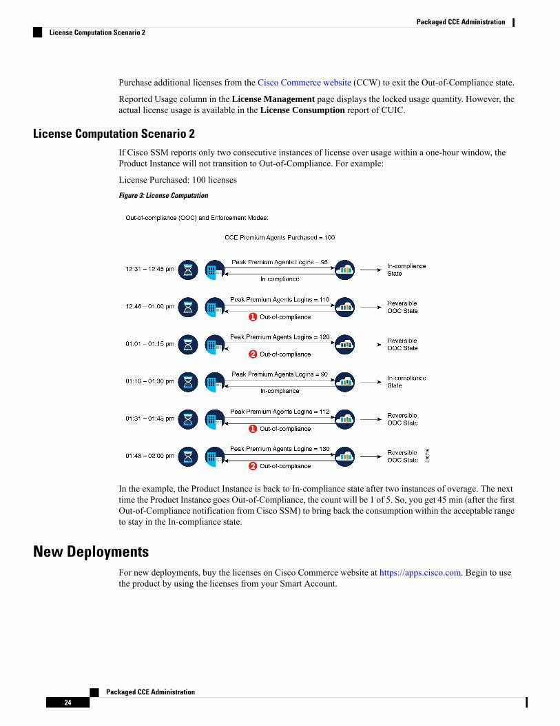
License Computation Scenario 2If Cisco SSM reports only two consecutive instances of license over usage within a one-hour window, theProduct Instance will not transition to Out-of-Compliance. For example:
License Purchased: 100 licensesFigure 3: License Computation
In the example, the Product Instance is back to In-compliance state after two instances of overage. The nexttime the Product Instance goes Out-of-Compliance, the count will be 1 of 5. So, you get 45 min (after the firstOut-of-Compliance notification from Cisco SSM) to bring back the consumption within the acceptable rangeto stay in the In-compliance state.
New DeploymentsFor new deployments, buy the licenses on Cisco Commerce website at https://apps.cisco.com. Begin to usethe product by using the licenses from your Smart Account.
Packaged CCE Administration24
Packaged CCE AdministrationLicense Computation Scenario 2
Migrate to Smart LicensingIf you are upgrading to Unified CCE Release 12.5(1), from Unified CCE Release 10.x or above, use self servecapabilities in Cisco SSM to declare the licenses that you own.
PAK-Based MigrationMigrate to Smart Licensing for fulfilled, partially fulfilled, and unfulfilled PAKs.
1. Log in to the Traditional Licensing Portal at https://tools.cisco.com/SWIFT/LicensingUI/Home.
2. Locate the PAKs that are to be migrated.
3. Right click and select Assign to Smart Account and Virtual Account.
4. Select the Smart Account and Virtual Account to which the PAK will be assigned.
Once done, the classic PAKs will show assigned Smart Account.
Using LRP
1. Select the PAK that needs to be converted to smart entitlement.
2. From the PAK context option, select Convert to Smart Licensing.
3. Select the SKUs, Quantity to Convert and click on Submit.
Classic Licenses that are partially converted will need new Classic License file for managing the remainingClassic Licenses.
Note
After the licenses are converted to smart entitlements, successful conversion message is shown. Theentitlements will be available on Cisco SSM under selected Smart and Virtual Account.
Using Cisco SSM
Convert PAKs to equivalent Smart Licenses.
1. Go to the Convert PAKs tab.
Assigned PAKs are listed on the Cisco SSM portal.
2. Click Convert to Smart License in the Actions column.
3. Select SKUs and Quantity to Convert and click Next.
Classic Licenses which are partially converted will need new Classic License file for managing theremaining Classic Licenses.
4. Review and to confirm click Convert License.
Once converted to Smart Entitlement, the old classic licenses will be invalidated. Converted Smart Licensesare added into the Smart Account and the Virtual Account.
Packaged CCE Administration25
Packaged CCE AdministrationMigrate to Smart Licensing
Device-Based ConversionUse the device-based Smart Licensing to convert the Classic licenses to smart entitlements.
Using LRP
1. Login to the Traditional Licensing Portal at https://tools.cisco.com/SWIFT/LicensingUI/Home
2. Go to Devices tab and then Add Device.
3. Locate the device to be migrated (filter using the device UUID). Once added, the added device shows upunder Devices tab.
4. Select the device and right click Assign to Smart Account to Smart Account and Virtual Account.
5. Select the Smart Account and the Virtual Account.
Once done, the table is updated with the Smart Account assigned to the device.
6. For Classic licenses to be converted to smart entitlements, select the device and select Convert licensesto Smart Licensing option.
7. Select the SKUs and Quantity to Convert.
Classic Licenses which are partially converted will need new Classic License file for managing theremaining Classic Licenses.
8. Confirm and click Submit.
Once the licenses are fully converted, the device UUID will be removed from the LRP. Once done, thesuccessful conversion message is shown. The entitlements will now be available on Cisco SSM underselected Smart and Virtual Account.
Using Cisco SSM
Assigned Devices show up on the Cisco SSM Portal. The Cisco SSM portal is refreshed every hour. If theassigned device is not visible in Cisco SSM, please recheck after an hour.
1. Go to Convert Licenses tab and click the License Conversion wizard.
2. Select the Product family and provide the device UUID.
3. Select the SKU and Quantity to Convert.
Classic Licenses which are partially converted will need new License file for managing the remainingClassic Licenses.
4. Review, Confirm and click Submit.
When the conversion is complete and smart licenses are active, the classic licenses are invalidated.
License ManagementSmart Licensing can be managed by using Cisco SSM and
• Cisco SSM—Cisco SSM enables you to manage all your Cisco smart software licenses from a centralizedwebsite. With Cisco SSM, you organize and view your licenses in groups called virtual accounts(collections of licenses and product instances).
Packaged CCE Administration26
Packaged CCE AdministrationDevice-Based Conversion
You can access Cisco SSM from https://software.cisco.com, by clicking the Smart Software Licensinglink under the License menu.
• License Management in Unified CCE Administration portal—Using the LicenseManagement optionin the Unified CCE Administration portal, you can register or deregister the product instance, select yourLicense Type, set transport settings or view the licensing consumption summary.
• License Management in CCVP—In CCVP there are various deployment models:
• CVP in Packaged CCE—When CVP is deployed with Packaged CCE, you can manage theconfigurations from the Unified CCE Administration Interface.
• CVP in Unified CCE or HCS for CC—When CVP is deployed with Unified CCE or HCS, youcan manage the configurations from the NOAMP in CVP.
• Standalone CVP—In the standalone CVPmodel, you canmanage the configurations in the NOAMPin CVP.
Using the License Management option in the Cisco CVP NOAMP portal or in Unified CCEAdministration, you can register or deregister the product instance, select your License Type, set transportsettings or view the licensing consumption summary.
Related TopicsConfigure Transport Settings for Smart Licensing, on page 15Register with Cisco Smart Software Manager, on page 17Select License Type, on page 15
Smart Licensing TasksAfter you successfully register Smart Licensing, you can perform the following tasks as per the requirement:
• Renew Authorization—The license authorization is renewed automatically every 30 days. Use thisoption to manually renew the authorization.
• Renew Registration—The initial registration is valid for one year. Registration is automatically renewedevery six months. Use this option to manually renew the registration.
• Reregister—Use this option to forcefully register the product instance again.
• Deregister—Use this option to release all the licenses from the current virtual account.
Renew Authorization and Renew Registration are automated tasks that take place at regular intervals. If thereis a failure in the automated process, you can manually renew authorization and registration.
You have to Deregister and Reregister manually.Note
Related TopicsRenew Authorization, on page 28Renew Registration, on page 28Reregister License, on page 28Deregister License, on page 29
Packaged CCE Administration27
Packaged CCE AdministrationSmart Licensing Tasks
Renew AuthorizationThe license authorization is renewed automatically every 30 days. The authorization status expires after 90days if the product is not connected to Cisco SSM or Cisco SSM On-Prem.
Use this procedure to manually renew the License Authorization Status for all the licenses listed in the LicenseType.
Procedure
Step 1 In Unified CCE AdministrationCisco Unified Customer Voice Portal, click License Management.The License Management page is displayed.
Step 2 The license information of the first CVP server in the Device Name drop-down list is displayed by default.From the Device Name drop-down list, select a CVP server.
Step 3 Click Action > Renew Authorization.
This process takes a few seconds to renew the authorization and close the window.
Renew RegistrationUse this procedure to manually renew your certificates.
The initial registration is valid for one year. Renewal of registration is automatically done every six months,provided the product is connected to Cisco SSM or Cisco SSM On-Prem.
Procedure
Step 1 In Unified CCE AdministrationCisco Unified Customer Voice Portal, click License Management.The License Management page is displayed.
Step 2 The license information of the first CVP server in the Device Name drop-down list is displayed by default.From the Device Name drop-down list, select a CVP server.
Step 3 Click Action > Renew Registration.
This process takes a few seconds to renew the authorization and close the window.
Reregister LicenseUse this procedure to reregister Packaged CCEUnified CVP with Cisco SSM or Cisco SSM On-Prem.
Product can migrate to a different virtual account when reregistering with the token from a new virtual account.Note
Packaged CCE Administration28
Packaged CCE AdministrationRenew Authorization
Procedure
Step 1 In Unified CCE AdministrationCisco Unified Customer Voice Portal, click License Management.The License Management page is displayed.
Step 2 The license information of the first CVP server in the Device Name drop-down list is displayed by default.From the Device Name drop-down list, select a CVP server.
Step 3 Click Action > Reregister.Step 4 In the Smart Software Licensing Product Registration dialog box, paste the copied or saved Registration
TokenKey that you generated using the Cisco SSMor Cisco SSMOn-Prem in the Product Instance RegistrationToken text box.
Step 5 Click Reregister to complete the reregistration process.Step 6 Close the window.
Deregister LicenseUse this procedure to deregister Packaged CCEUnified CVP from Cisco SSM or Cisco SSM On-Prem andrelease all the licenses from the current virtual account. All license entitlements that are used for the productare released to the virtual account and is available for other product instances to use.
If Packaged CCEUnified CVP is unable to connect to Cisco SSM or Cisco SSM On-Prem, and the productis deregistered, then a confirmation message notifies you to remove the product manually from Cisco SSMor Cisco SSM On-Prem to free up licenses.
Note
After deregistering, the product reverts to the Evaluation state if the evaluation period is not expired. All thelicense entitlements that are used for the product are immediately released to the virtual account and areavailable for other product instances to use it.
Note
Procedure
Step 1 In Unified CCE AdministrationCisco Unified Customer Voice Portal, click License Management.The License Management page is displayed.
Step 2 The license information of the first CVP server in the Device Name drop-down list is displayed by default.From the Device Name drop-down list, select a CVP server.
Step 3 Click Action > Deregister.Step 4 On the Confirm Deregistration dialog box, click Yes to deregister.
Best PracticesSome of the best practices for Smart Licensing are:
Packaged CCE Administration29
Packaged CCE AdministrationDeregister License
• Before purchasing your licenses, run the License Consumption report on the existing system to understandthe consumption pattern to make the right purchase decisions on the license requirement.
• Configure Admin email address in Cisco SSM to receive notifications and alerts from Cisco SSM.
Infrastructure Settings
Inventory ManagementInventory update can be done in the following scenarios:
• When you rebuild VirtualMachines (VMs), you can update the IP address or hostname of these machinesin the inventory.
• When you move your existing VMs to another data center, you can update the IP address or hostnameof these machines in the inventory.
For more information, see:
• Update IP Address or Hostname for 2000 Agent deployments
• Update IP Address or Hostname for 4000 or 12000 Agent deployments
Manage DevicesYou can configure any of the following components:
• CVP Server
• CVP Reporting Server
• VVB
• Finesse
• Identity Service
The term device refers to a configurable application or platform. More than one device can reside on a server.For example, one physical server can contain a CVP Server and a Reporting Server. In this case, each deviceis configured with the same IP address.
CVP Server Services SetupAs part of Packaged CCE fresh install, the CVP Server is added with default configuration values. You canconfigure:
• ICM Service
• SIP Service
• IVR Service
• VXML Server
Packaged CCE Administration30
Packaged CCE AdministrationInfrastructure Settings
• Infrastructure
Except for the configurations that require a Call Server restart, configure all the other CVP Server configurationsduring off-peak hours (not during heavy call load).
Important
For shutting down services of call server/reporting server, see Graceful Shutdown of Call Server/ReportingServer.
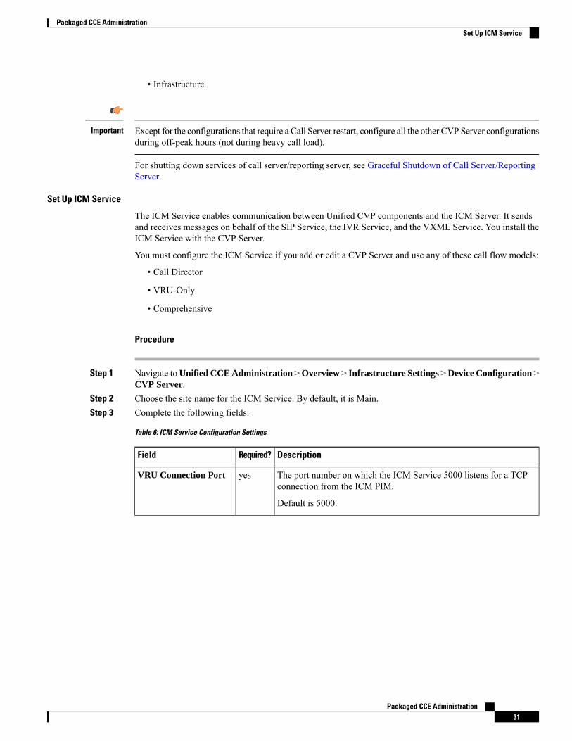
Set Up ICM Service
The ICM Service enables communication between Unified CVP components and the ICM Server. It sendsand receives messages on behalf of the SIP Service, the IVR Service, and the VXML Service. You install theICM Service with the CVP Server.
You must configure the ICM Service if you add or edit a CVP Server and use any of these call flow models:
• Call Director
• VRU-Only
• Comprehensive
Procedure
Step 1 Navigate toUnified CCE Administration >Overview > Infrastructure Settings >Device Configuration >CVP Server.
Step 2 Choose the site name for the ICM Service. By default, it is Main.Step 3 Complete the following fields:
Table 6: ICM Service Configuration Settings
DescriptionRequired?Field
The port number on which the ICM Service 5000 listens for a TCPconnection from the ICM PIM.
Default is 5000.
yesVRU Connection Port
Packaged CCE Administration31
Packaged CCE AdministrationSet Up ICM Service
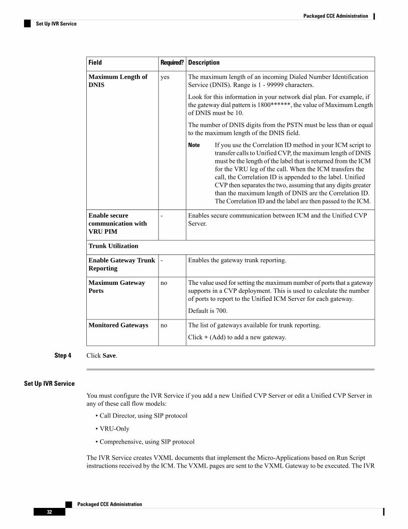
DescriptionRequired?Field
The maximum length of an incoming Dialed Number IdentificationService (DNIS). Range is 1 - 99999 characters.
Look for this information in your network dial plan. For example, ifthe gateway dial pattern is 1800******, the value ofMaximumLengthof DNIS must be 10.
The number of DNIS digits from the PSTN must be less than or equalto the maximum length of the DNIS field.
If you use the Correlation ID method in your ICM script totransfer calls to Unified CVP, themaximum length of DNISmust be the length of the label that is returned from the ICMfor the VRU leg of the call. When the ICM transfers thecall, the Correlation ID is appended to the label. UnifiedCVP then separates the two, assuming that any digits greaterthan the maximum length of DNIS are the Correlation ID.The Correlation ID and the label are then passed to the ICM.
Note
yesMaximum Length ofDNIS
Enables secure communication between ICM and the Unified CVPServer.
-Enable securecommunication withVRU PIM
Trunk Utilization
Enables the gateway trunk reporting.-Enable Gateway TrunkReporting
The value used for setting themaximum number of ports that a gatewaysupports in a CVP deployment. This is used to calculate the numberof ports to report to the Unified ICM Server for each gateway.
Default is 700.
noMaximum GatewayPorts
The list of gateways available for trunk reporting.
Click + (Add) to add a new gateway.
noMonitored Gateways
Step 4 Click Save.
Set Up IVR Service
You must configure the IVR Service if you add a new Unified CVP Server or edit a Unified CVP Server inany of these call flow models:
• Call Director, using SIP protocol
• VRU-Only
• Comprehensive, using SIP protocol
The IVR Service creates VXML documents that implement the Micro-Applications based on Run Scriptinstructions received by the ICM. The VXML pages are sent to the VXML Gateway to be executed. The IVR
Packaged CCE Administration32
Packaged CCE AdministrationSet Up IVR Service

Service can also generate external VXML through theMicro-Applications to engage the Unified CVPVXMLServer to generate the VXML documents.
The IVR Service plays a significant role in implementing a failover mechanism: those capabilities that canbe achieved without ASR/TTS Servers, and VXML Servers. Up to two of each such servers are supported,and the IVR Service orchestrates retries and failover between them.
Before you begin
Configure the following servers before setting up the IVR Service:
• ICM Server
• Media Server
• ASR/TTS Server
• Unified CVP VXML Server
• Gateway
Procedure
Step 1 Navigate toUnified CCE Administration >Overview > Infrastructure Settings >Device Configuration >CVP Server.
Step 2 Click the IVR tab. Complete the following fields:
Table 7: IVR Service Configuration Settings
DescriptionRequired?Field
If you selectNo (default), the HTTP URLs are generated to theMedia Servers.
The default setting is only applicable if the client isSIP Service and theMedia Server is not set to a URLthat explicitly specifies an HTTP/HTTPS scheme.
Note
Select Yes to generate the HTTPS URLs to the Media Servers.
-Use Security for MediaFetches
If you select Yes (default) and a Media Server is unavailable,the gateway attempts to connect to the backup Media Server.
-Use Backup Media/VXMLServers
Packaged CCE Administration33
Packaged CCE AdministrationSet Up IVR Service
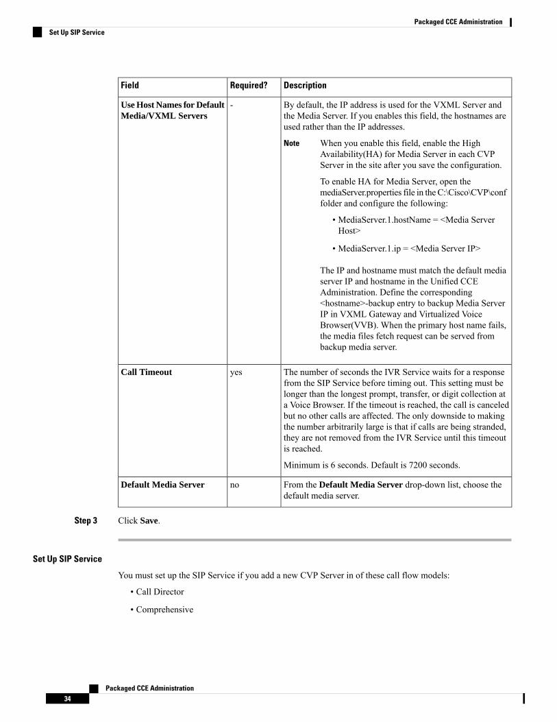
DescriptionRequired?Field
By default, the IP address is used for the VXML Server andthe Media Server. If you enables this field, the hostnames areused rather than the IP addresses.
When you enable this field, enable the HighAvailability(HA) for Media Server in each CVPServer in the site after you save the configuration.
To enable HA for Media Server, open themediaServer.properties file in the C:\Cisco\CVP\conffolder and configure the following:
Note
• MediaServer.1.hostName = <Media ServerHost>
• MediaServer.1.ip = <Media Server IP>
The IP and hostname must match the default mediaserver IP and hostname in the Unified CCEAdministration. Define the corresponding<hostname>-backup entry to backup Media ServerIP in VXML Gateway and Virtualized VoiceBrowser(VVB). When the primary host name fails,the media files fetch request can be served frombackup media server.
-Use Host Names for DefaultMedia/VXML Servers
The number of seconds the IVR Service waits for a responsefrom the SIP Service before timing out. This setting must belonger than the longest prompt, transfer, or digit collection ata Voice Browser. If the timeout is reached, the call is canceledbut no other calls are affected. The only downside to makingthe number arbitrarily large is that if calls are being stranded,they are not removed from the IVR Service until this timeoutis reached.
Minimum is 6 seconds. Default is 7200 seconds.
yesCall Timeout
From the Default Media Server drop-down list, choose thedefault media server.
noDefault Media Server
Step 3 Click Save.
Set Up SIP Service
You must set up the SIP Service if you add a new CVP Server in of these call flow models:
• Call Director
• Comprehensive
Packaged CCE Administration34
Packaged CCE AdministrationSet Up SIP Service
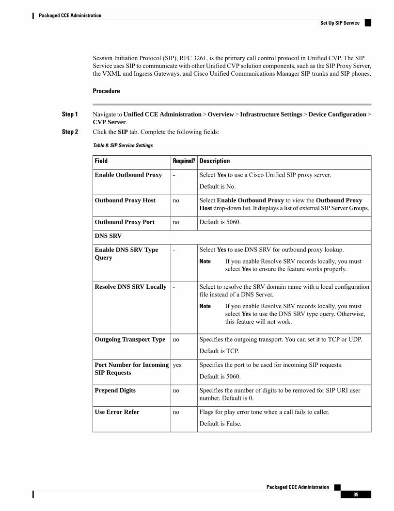
Session Initiation Protocol (SIP), RFC 3261, is the primary call control protocol in Unified CVP. The SIPService uses SIP to communicate with other Unified CVP solution components, such as the SIP Proxy Server,the VXML and Ingress Gateways, and Cisco Unified Communications Manager SIP trunks and SIP phones.
Procedure
Step 1 Navigate toUnified CCE Administration >Overview > Infrastructure Settings >Device Configuration >CVP Server.
Step 2 Click the SIP tab. Complete the following fields:
Table 8: SIP Service Settings
DescriptionRequired?Field
Select Yes to use a Cisco Unified SIP proxy server.
Default is No.
-Enable Outbound Proxy
Select Enable Outbound Proxy to view the Outbound ProxyHost drop-down list. It displays a list of external SIP Server Groups.
noOutbound Proxy Host
Default is 5060.noOutbound Proxy Port
DNS SRV
Select Yes to use DNS SRV for outbound proxy lookup.
If you enable Resolve SRV records locally, you mustselect Yes to ensure the feature works properly.
Note
-Enable DNS SRV TypeQuery
Select to resolve the SRV domain name with a local configurationfile instead of a DNS Server.
If you enable Resolve SRV records locally, you mustselect Yes to use the DNS SRV type query. Otherwise,this feature will not work.
Note
-Resolve DNS SRV Locally
Specifies the outgoing transport. You can set it to TCP or UDP.
Default is TCP.
noOutgoing Transport Type
Specifies the port to be used for incoming SIP requests.
Default is 5060.
yesPort Number for IncomingSIP Requests
Specifies the number of digits to be removed for SIP URI usernumber. Default is 0.
noPrepend Digits
Flags for play error tone when a call fails to caller.
Default is False.
noUse Error Refer
Packaged CCE Administration35
Packaged CCE AdministrationSet Up SIP Service
DescriptionRequired?Field
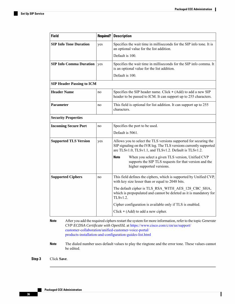
Specifies the wait time in milliseconds for the SIP info tone. It isan optional value for the list addition.
Default is 100.
yesSIP Info Tone Duration
Specifies the wait time in milliseconds for the SIP info comma. Itis an optional value for the list addition.
Default is 100.
yesSIP Info Comma Duration
SIP Header Passing to ICM
Specifies the SIP header name. Click + (Add) to add a new SIPheader to be passed to ICM. It can support up to 255 characters.
noHeader Name
This field is optional for list addition. It can support up to 255characters.
noParameter
Security Properties
Specifies the port to be used.
Default is 5061.
noIncoming Secure Port
Allows you to select the TLS versions supported for securing theSIP signaling on the IVR leg. The TLS versions currently supportedare TLSv1.0, TLSv1.1, and TLSv1.2. Default is TLSv1.2.
When you select a given TLS version, Unified CVPsupports the SIP TLS requests for that version and thehigher supported versions.
Note
yesSupported TLS Version
This field defines the ciphers, which is supported by Unified CVP,with key size lesser than or equal to 2048 bits.
The default cipher is TLS_RSA_WITH_AES_128_CBC_SHA,which is prepopulated and cannot be deleted as it is mandatory forTLSv1.2.
Cipher configuration is available only if TLS is enabled.
Click + (Add) to add a new cipher.
noSupported Ciphers
After you add the required ciphers restart the system for more information, refer to the topicGenerateCVP ECDSA Certificate with OpenSSL at https://www.cisco.com/c/en/us/support/customer-collaboration/unified-customer-voice-portal/products-installation-and-configuration-guides-list.html
Note
The dialed number uses default values to play the ringtone and the error tone. These values cannotbe edited.
Note
Step 3 Click Save.
Packaged CCE Administration36
Packaged CCE AdministrationSet Up SIP Service
Set Up VXML Server
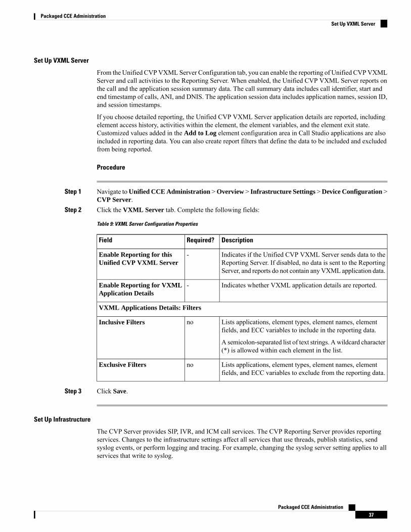
From the Unified CVPVXML Server Configuration tab, you can enable the reporting of Unified CVPVXMLServer and call activities to the Reporting Server. When enabled, the Unified CVP VXML Server reports onthe call and the application session summary data. The call summary data includes call identifier, start andend timestamp of calls, ANI, and DNIS. The application session data includes application names, session ID,and session timestamps.
If you choose detailed reporting, the Unified CVP VXML Server application details are reported, includingelement access history, activities within the element, the element variables, and the element exit state.Customized values added in the Add to Log element configuration area in Call Studio applications are alsoincluded in reporting data. You can also create report filters that define the data to be included and excludedfrom being reported.
Procedure
Step 1 Navigate toUnified CCE Administration >Overview > Infrastructure Settings >Device Configuration >CVP Server.
Step 2 Click the VXML Server tab. Complete the following fields:
Table 9: VXML Server Configuration Properties
DescriptionRequired?Field
Indicates if the Unified CVP VXML Server sends data to theReporting Server. If disabled, no data is sent to the ReportingServer, and reports do not contain any VXML application data.
-Enable Reporting for thisUnified CVP VXML Server
Indicates whether VXML application details are reported.-Enable Reporting for VXMLApplication Details
VXML Applications Details: Filters
Lists applications, element types, element names, elementfields, and ECC variables to include in the reporting data.
A semicolon-separated list of text strings. Awildcard character(*) is allowed within each element in the list.
noInclusive Filters
Lists applications, element types, element names, elementfields, and ECC variables to exclude from the reporting data.
noExclusive Filters
Step 3 Click Save.
Set Up Infrastructure
The CVP Server provides SIP, IVR, and ICM call services. The CVP Reporting Server provides reportingservices. Changes to the infrastructure settings affect all services that use threads, publish statistics, sendsyslog events, or perform logging and tracing. For example, changing the syslog server setting applies to allservices that write to syslog.
Packaged CCE Administration37
Packaged CCE AdministrationSet Up VXML Server
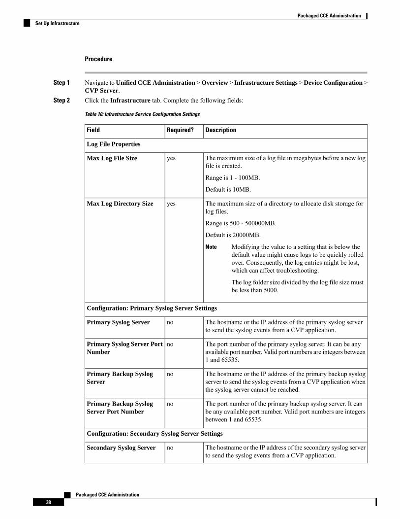
Procedure
Step 1 Navigate toUnified CCE Administration >Overview > Infrastructure Settings >Device Configuration >CVP Server.
Step 2 Click the Infrastructure tab. Complete the following fields:
Table 10: Infrastructure Service Configuration Settings
DescriptionRequired?Field
Log File Properties
The maximum size of a log file in megabytes before a new logfile is created.
Range is 1 - 100MB.
Default is 10MB.
yesMax Log File Size
The maximum size of a directory to allocate disk storage forlog files.
Range is 500 - 500000MB.
Default is 20000MB.
Modifying the value to a setting that is below thedefault value might cause logs to be quickly rolledover. Consequently, the log entries might be lost,which can affect troubleshooting.
The log folder size divided by the log file size mustbe less than 5000.
Note
yesMax Log Directory Size
Configuration: Primary Syslog Server Settings
The hostname or the IP address of the primary syslog serverto send the syslog events from a CVP application.
noPrimary Syslog Server
The port number of the primary syslog server. It can be anyavailable port number. Valid port numbers are integers between1 and 65535.
noPrimary Syslog Server PortNumber
The hostname or the IP address of the primary backup syslogserver to send the syslog events from a CVP application whenthe syslog server cannot be reached.
noPrimary Backup SyslogServer
The port number of the primary backup syslog server. It canbe any available port number. Valid port numbers are integersbetween 1 and 65535.
noPrimary Backup SyslogServer Port Number
Configuration: Secondary Syslog Server Settings
The hostname or the IP address of the secondary syslog serverto send the syslog events from a CVP application.
noSecondary Syslog Server
Packaged CCE Administration38
Packaged CCE AdministrationSet Up Infrastructure

DescriptionRequired?Field
The port number of the secondary syslog server. It can be anyavailable port number. Valid port numbers are integers between1 and 65535.
noSecondary Syslog ServerPort Number
The hostname or the IP address of the secondary backup syslogserver to send the syslog events from a CVP application whenthe syslog server cannot be reached.
noSecondary Backup SyslogServer
The port number of the secondary backup syslog server. It canbe any available port number. Valid port numbers are integersbetween 1 and 65535.
noSecondary Backup SyslogServer Port Number
Step 3 Click Save.
Unified CVP Security
Secure GED 125 Communication between Call Server and ICM
You can secure GED 125 communication by:
• Exchanging the self-signed certificates between the components.
• Signing the certificates by a Certificate Authority.
By default, mutual authentication between ICM and Call Server is enabled. To disable mutual authentication,go to%CVP_HOME%\conf\icm.properties and set the ICM.Secure.UseClientAuth property toFALSEand restart the Call Server.
Note
Before you begin:
For generating ECDSA certificates in ICM, refer to the How to enable ECDSA for Unified CCE corecomponents section in the Security Guide for Cisco Unified ICM/Contact Center Enterprise, Release 12.6(1)at https://www.cisco.com/c/en/us/support/customer-collaboration/unified-contact-center-enterprise/products-installation-and-configuration-guides-list.html.
Self-Signed Certificates
Generate Certificate on CVP Call Server
Procedure
Step 1 http://acrsrv-app-prd-01:8080/Export the Call Server certificate byrunning.%CVP_HOME%\jre\bin\keytool.exe -export -v -keystore%CVP_HOME%\conf\security\.keystore -storetype JCEKS -alias callserver_certificate -file%CVP_HOME%\conf\security\<callserver_certificate>
Step 2 Enter the keystore password when prompted.
Packaged CCE Administration39
Packaged CCE AdministrationUnified CVP Security
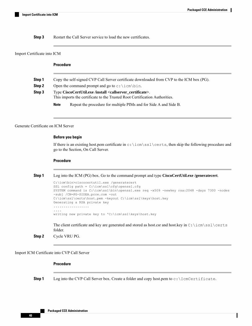
Step 3 Restart the Call Server service to load the new certificates.
Import Certificate into ICM
Procedure
Step 1 Copy the self-signed CVP Call Server certificate downloaded from CVP to the ICM box (PG).Step 2 Open the command prompt and go to c:\icm\bin.Step 3 Type CiscoCertUtil.exe /install <callserver_certificate>.
This imports the certificate to the Trusted Root Certification Authorities.
Repeat the procedure for multiple PIMs and for Side A and Side B.Note
Generate Certificate on ICM Server
Before you begin
If there is an existing host.pem certificate in c:\icm\ssl\certs, then skip the following procedure andgo to the Section, On Call Server.
Procedure
Step 1 Log into the ICM (PG) box. Go to the command prompt and type CiscoCertUtil.exe /generatecert.C:\icm\bin>ciscocertutil.exe /generatecertSSL config path = C:\icm\ssl\cfg\openssl.cfgSYSTEM command is C:\icm\ssl\bin\openssl.exe req -x509 -newkey rsa:2048 -days 7300 -nodes-subj /CN=PG-SIDEA.pcce.com -outC:\icm\ssl\certs\host.pem -keyout C:\icm\ssl\keys\host.keyGenerating a RSA private key......................writing new private key to 'C:\icm\ssl\keys\host.key
The client certificate and key are generated and stored as host.csr and host.key in C:\icm\ssl\certsfolder.
Step 2 Cycle VRU PG.
Import ICM Certificate into CVP Call Server
Procedure
Step 1 Log into the CVP Call Server box. Create a folder and copy host.pem to c:\IcmCertificate.
Packaged CCE Administration40
Packaged CCE AdministrationImport Certificate into ICM
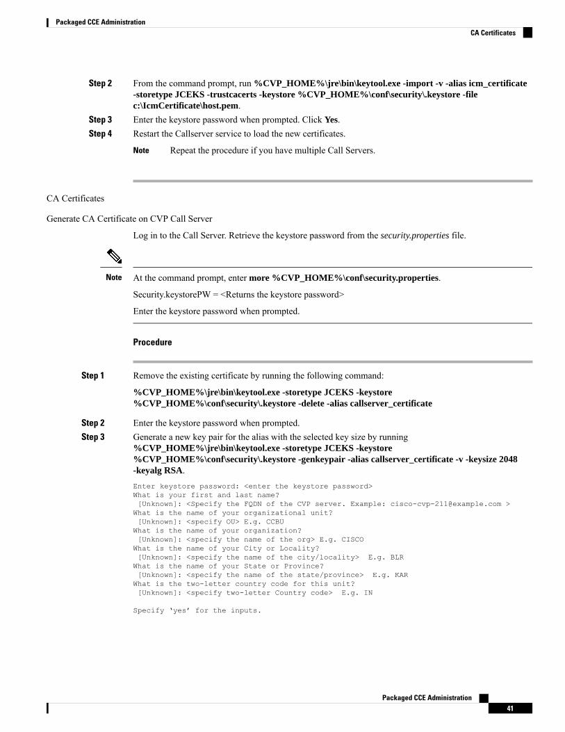
Step 2 From the command prompt, run %CVP_HOME%\jre\bin\keytool.exe -import -v -alias icm_certificate-storetype JCEKS -trustcacerts -keystore %CVP_HOME%\conf\security\.keystore -filec:\IcmCertificate\host.pem.
Step 3 Enter the keystore password when prompted. Click Yes.Step 4 Restart the Callserver service to load the new certificates.
Repeat the procedure if you have multiple Call Servers.Note
CA Certificates
Generate CA Certificate on CVP Call Server
Log in to the Call Server. Retrieve the keystore password from the security.properties file.
At the command prompt, enter more %CVP_HOME%\conf\security.properties.
Security.keystorePW = <Returns the keystore password>
Enter the keystore password when prompted.
Note
Procedure
Step 1 Remove the existing certificate by running the following command:
%CVP_HOME%\jre\bin\keytool.exe -storetype JCEKS -keystore%CVP_HOME%\conf\security\.keystore -delete -alias callserver_certificate
Step 2 Enter the keystore password when prompted.Step 3 Generate a new key pair for the alias with the selected key size by running
%CVP_HOME%\jre\bin\keytool.exe -storetype JCEKS -keystore%CVP_HOME%\conf\security\.keystore -genkeypair -alias callserver_certificate -v -keysize 2048-keyalg RSA.Enter keystore password: <enter the keystore password>What is your first and last name?[Unknown]: <Specify the FQDN of the CVP server. Example: [email protected] >What is the name of your organizational unit?[Unknown]: <specify OU> E.g. CCBUWhat is the name of your organization?[Unknown]: <specify the name of the org> E.g. CISCOWhat is the name of your City or Locality?[Unknown]: <specify the name of the city/locality> E.g. BLRWhat is the name of your State or Province?[Unknown]: <specify the name of the state/province> E.g. KARWhat is the two-letter country code for this unit?[Unknown]: <specify two-letter Country code> E.g. IN
Specify ‘yes’ for the inputs.
Packaged CCE Administration41
Packaged CCE AdministrationCA Certificates
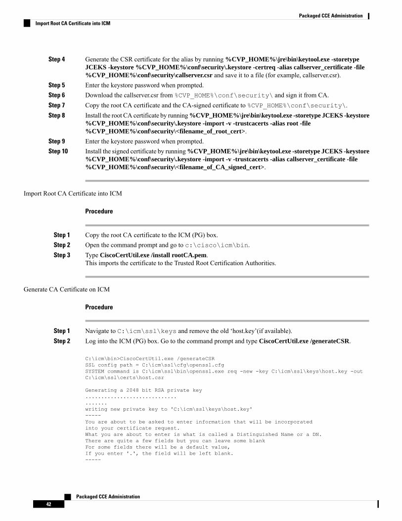
Step 4 Generate the CSR certificate for the alias by running %CVP_HOME%\jre\bin\keytool.exe -storetypeJCEKS -keystore %CVP_HOME%\conf\security\.keystore -certreq -alias callserver_certificate -file%CVP_HOME%\conf\security\callserver.csr and save it to a file (for example, callserver.csr).
Step 5 Enter the keystore password when prompted.Step 6 Download the callserver.csr from %CVP_HOME%\conf\security\ and sign it from CA.Step 7 Copy the root CA certificate and the CA-signed certificate to %CVP_HOME%\conf\security\.Step 8 Install the root CA certificate by running%CVP_HOME%\jre\bin\keytool.exe -storetype JCEKS -keystore
%CVP_HOME%\conf\security\.keystore -import -v -trustcacerts -alias root -file%CVP_HOME%\conf\security\<filename_of_root_cert>.
Step 9 Enter the keystore password when prompted.Step 10 Install the signed certificate by running%CVP_HOME%\jre\bin\keytool.exe -storetype JCEKS -keystore
%CVP_HOME%\conf\security\.keystore -import -v -trustcacerts -alias callserver_certificate -file%CVP_HOME%\conf\security\<filename_of_CA_signed_cert>.
Import Root CA Certificate into ICM
Procedure
Step 1 Copy the root CA certificate to the ICM (PG) box.Step 2 Open the command prompt and go to c:\cisco\icm\bin.Step 3 Type CiscoCertUtil.exe /install rootCA.pem.
This imports the certificate to the Trusted Root Certification Authorities.
Generate CA Certificate on ICM
Procedure
Step 1 Navigate to C:\icm\ssl\keys and remove the old ‘host.key’(if available).Step 2 Log into the ICM (PG) box. Go to the command prompt and type CiscoCertUtil.exe /generateCSR.
C:\icm\bin>CiscoCertUtil.exe /generateCSRSSL config path = C:\icm\ssl\cfg\openssl.cfgSYSTEM command is C:\icm\ssl\bin\openssl.exe req -new -key C:\icm\ssl\keys\host.key -outC:\icm\ssl\certs\host.csr
Generating a 2048 bit RSA private key....................................writing new private key to 'C:\icm\ssl\keys\host.key'-----You are about to be asked to enter information that will be incorporatedinto your certificate request.What you are about to enter is what is called a Distinguished Name or a DN.There are quite a few fields but you can leave some blankFor some fields there will be a default value,If you enter '.', the field will be left blank.-----
Packaged CCE Administration42
Packaged CCE AdministrationImport Root CA Certificate into ICM
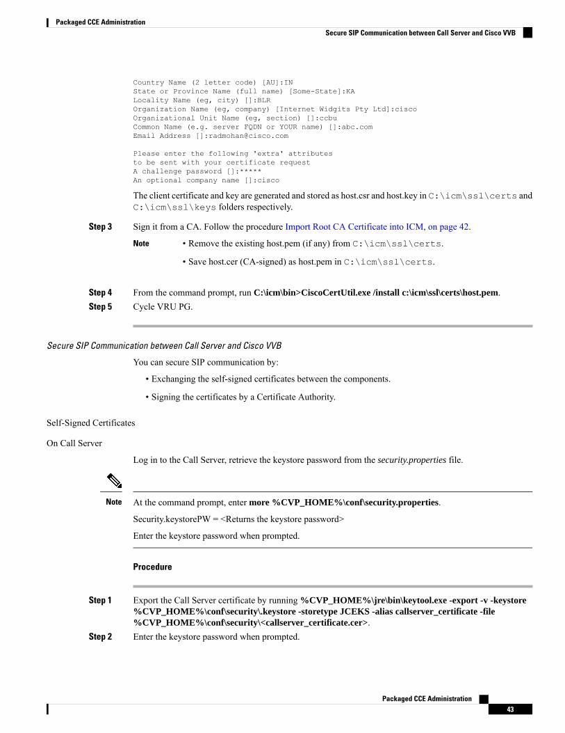
Country Name (2 letter code) [AU]:INState or Province Name (full name) [Some-State]:KALocality Name (eg, city) []:BLROrganization Name (eg, company) [Internet Widgits Pty Ltd]:ciscoOrganizational Unit Name (eg, section) []:ccbuCommon Name (e.g. server FQDN or YOUR name) []:abc.comEmail Address []:[email protected]
Please enter the following 'extra' attributesto be sent with your certificate requestA challenge password []:*****An optional company name []:cisco
The client certificate and key are generated and stored as host.csr and host.key in C:\icm\ssl\certs andC:\icm\ssl\keys folders respectively.
Step 3 Sign it from a CA. Follow the procedure Import Root CA Certificate into ICM, on page 42.
• Remove the existing host.pem (if any) from C:\icm\ssl\certs.
• Save host.cer (CA-signed) as host.pem in C:\icm\ssl\certs.
Note
Step 4 From the command prompt, run C:\icm\bin>CiscoCertUtil.exe /install c:\icm\ssl\certs\host.pem.Step 5 Cycle VRU PG.
Secure SIP Communication between Call Server and Cisco VVB
You can secure SIP communication by:
• Exchanging the self-signed certificates between the components.
• Signing the certificates by a Certificate Authority.
Self-Signed Certificates
On Call Server
Log in to the Call Server, retrieve the keystore password from the security.properties file.
At the command prompt, enter more %CVP_HOME%\conf\security.properties.
Security.keystorePW = <Returns the keystore password>
Enter the keystore password when prompted.
Note
Procedure
Step 1 Export the Call Server certificate by running %CVP_HOME%\jre\bin\keytool.exe -export -v -keystore%CVP_HOME%\conf\security\.keystore -storetype JCEKS -alias callserver_certificate -file%CVP_HOME%\conf\security\<callserver_certificate.cer>.
Step 2 Enter the keystore password when prompted.
Packaged CCE Administration43
Packaged CCE AdministrationSecure SIP Communication between Call Server and Cisco VVB
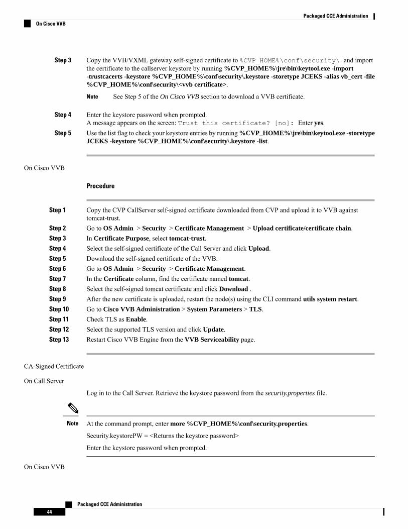
Step 3 Copy the VVB/VXML gateway self-signed certificate to %CVP_HOME%\conf\security\ and importthe certificate to the callserver keystore by running %CVP_HOME%\jre\bin\keytool.exe -import-trustcacerts -keystore %CVP_HOME%\conf\security\.keystore -storetype JCEKS -alias vb_cert -file%CVP_HOME%\conf\security\<vvb certificate>.
See Step 5 of the On Cisco VVB section to download a VVB certificate.Note
Step 4 Enter the keystore password when prompted.A message appears on the screen: Trust this certificate? [no]: Enter yes.
Step 5 Use the list flag to check your keystore entries by running%CVP_HOME%\jre\bin\keytool.exe -storetypeJCEKS -keystore %CVP_HOME%\conf\security\.keystore -list.
On Cisco VVB
Procedure
Step 1 Copy the CVP CallServer self-signed certificate downloaded from CVP and upload it to VVB againsttomcat-trust.
Step 2 Go to OS Admin > Security > Certificate Management > Upload certificate/certificate chain.Step 3 In Certificate Purpose, select tomcat-trust.Step 4 Select the self-signed certificate of the Call Server and click Upload.Step 5 Download the self-signed certificate of the VVB.Step 6 Go to OS Admin > Security > Certificate Management.Step 7 In the Certificate column, find the certificate named tomcat.Step 8 Select the self-signed tomcat certificate and click Download .Step 9 After the new certificate is uploaded, restart the node(s) using the CLI command utils system restart.Step 10 Go to Cisco VVB Administration > System Parameters > TLS.Step 11 Check TLS as Enable.Step 12 Select the supported TLS version and click Update.Step 13 Restart Cisco VVB Engine from the VVB Serviceability page.
CA-Signed Certificate
On Call Server
Log in to the Call Server. Retrieve the keystore password from the security.properties file.
At the command prompt, enter more %CVP_HOME%\conf\security.properties.
Security.keystorePW = <Returns the keystore password>
Enter the keystore password when prompted.
Note
On Cisco VVB
Packaged CCE Administration44
Packaged CCE AdministrationOn Cisco VVB
Procedure
Step 1 To generate the CSR certificate on VVB, open the administration page. From the Navigation drop-down list,choose Cisco Unified OS Administration and click Go.
Step 2 Go to Security >Certificate Management >Generate CSR Generate Certificate signing Request. Createthe CSR against tomcat with the key-length as 2048.
Step 3 To download the generated CSR, click Download CSR. After the Generate Certificate signing Requestdialog opens, click Download CSR.
Step 4 Open the certificate in Notepad, copy the contents and sign the certificate with CA.Step 5 Upload the root certificate generated from the CA into VVB against tomcat-trust:
a) Go to Security > Certificate Management > Generate CSR > Upload certificate/certificate chain.b) Choose tomcat-trust from the drop-down list.c) Click Browse and select the certificate.d) Click Upload to upload the root certificate of the Certificate Authority.
Step 6 Upload the signed certificate into VVB against tomcat.a) Go to Security > Certificate Management > Upload certificate/certificate chain.b) Choose tomcat from the drop-down list.c) Click Browse and select the certificate.d) Click Upload.After the certificate is uploaded successfully, VVB displays the certificate signed by <CA hostname>.
Step 7 Restart the Tomcat service and the VVB engine.
For the configuration steps, see the Manage System Parameters section.
Secure HTTP Communication between VXML Server and Cisco VVB
You can secure HTTP communication by:
• Exchanging the self-signed certificates between the VXML Server and VVB or VXML Gateway.
• Signing the certificates by a Certificate Authority.
Self-Signed Certificate
On VXML Server
Log in to the VXML Server. Retrieve the keystore password from the security.properties file.
At the command prompt, enter more %CVP_HOME%\conf\security.properties.
Security.keystorePW = <Returns the keystore password>
Enter the keystore password wherever it prompts.
Note
Packaged CCE Administration45
Packaged CCE AdministrationSecure HTTP Communication between VXML Server and Cisco VVB

Procedure
Step 1 Export theVXMLSERVER certificate by running%CVP_HOME%\jre\bin\keytool.exe -export -v -keystore%CVP_HOME%\conf\security\.keystore -storetype JCEKS -alias vxml_certificate -file%CVP_HOME%\conf\security\<vxml_certificate.cer>.
Step 2 Enter the keystore password when prompted.Step 3 Copy the VVB/VXML gateway self-signed certificate to %CVP_HOME%\conf\security\ and import
the certificate to the callserver keystore by running keystore.%CVP_HOME%\jre\bin\keytool.exe -import-trustcacerts -keystore %CVP_HOME%\conf\security\.keystore -storetype JCEKS -alias vb_cert -file%CVP_HOME%\conf\security\<vvb certificate>.
See Step 5 of the following Section, On Cisco VVB to download a VVB certificate.Note
Step 4 Enter the keystore password when prompted.A message appears on the screen: Trust this certificate? [no]: Enter yes.
Step 5 Use the list flag to check your keystore entries by running%CVP_HOME%\jre\bin\keytool.exe -storetypeJCEKS -keystore %CVP_HOME%\conf\security\.keystore -list.
On Cisco VVB
Procedure
Step 1 Copy theVXMLServer self-signed certificate downloaded fromCVP and upload it to VVB against tomcat-trust.Step 2 Go to OS Admin > Security > Certificate Management > Upload certificate/certificate chain.Step 3 In Certificate Purpose, select tomcat-trust.Step 4 Select the self-signed certificate of the VXML Server and click Upload.Step 5 Download the self-signed certificate of the VVB.Step 6 Go to OS Admin > Security > Certificate Management.Step 7 In the Certificate column, select the tomcat certificate.Step 8 Select the tomcat certificate and click Download .Step 9 After the new certificate uploads, restart the Cisco Tomcat service.Step 10 Go to Cisco VVB Administration > System Parameters > TLS.Step 11 Check the TLS check box as Enable.Step 12 Select the supported TLS version and click Update.Step 13 Restart the Cisco VVB Engine from the VVB Serviceability page.
To enable secured connection in Application Management from the Cisco VVB UI, see CiscoVirtualized Voice Browser Administration and Configuration Guide available athttps://www.cisco.com/c/en/us/support/customer-collaboration/virtualized-voice-browser/tsd-products-support-series-home.html.
Note
CA-Signed Certificate
Packaged CCE Administration46
Packaged CCE AdministrationOn Cisco VVB
On VXML Server
Log in to the VXML Server. Retrieve the keystore password from the security.properties file.
At the command prompt, enter more %CVP_HOME%\conf\security.properties.
Security.keystorePW = <Returns the keystore password>
Enter the keystore password when prompted.
Note
Procedure
Step 1 Remove the existing certificate by running %CVP_HOME%\jre\bin\keytool.exe -storetype JCEKS-keystore %CVP_HOME%\conf\security\.keystore -delete -alias vxml_certificate.
Step 2 Generate a new key pair for the alias with selected key size by running %CVP_HOME%\jre\bin\keytool.exe-storetype JCEKS -keystore %CVP_HOME%\conf\security\.keystore -genkeypair -alias vxml_certificate-v -keysize 2048 -keyalg RSA.Enter keystore password: <enter the keystore password>What is your first and last name?[Unknown]: <specify the CVP host name appended with "VXML_Server"> E.gcisco-cvp-211_VXML_ServerWhat is the name of your organizational unit?[Unknown]: <specify OU> E.g. CCBUWhat is the name of your organization?[Unknown]: <specify the name of the org> E.g. CISCOWhat is the name of your City or Locality?[Unknown]: <specify the name of the city/locality> E.g. BLRWhat is the name of your State or Province?[Unknown]: <specify the name of the state/province> E.g. KARWhat is the two-letter country code for this unit?[Unknown]: <specify two-letter Country code> E.g. INSpecify ‘yes’ for the inputs.
Step 3 Generate the CSR certificate for the alias by running %CVP_HOME%\jre\bin\keytool.exe -storetypeJCEKS -keystore %CVP_HOME%\conf\security\.keystore -certreq -alias vxml_certificate -file%CVP_HOME%\conf\security\vxmlserver.csr and save it to a file .
Step 4 Enter the keystore password when prompted.Step 5 Download the vxmserver.csr from CVP %CVP_HOME%\conf\security\ and sign it from CA.Step 6 Copy the root CA certificate and the CA-signed certificate to %CVP_HOME%\conf\security\
Step 7 Install the root CA certificate by running%CVP_HOME%\jre\bin\keytool.exe -storetype JCEKS -keystore%CVP_HOME%\conf\security\.keystore -import -v -trustcacerts -alias root -file%CVP_HOME%\conf\security\<filename_of_root_cert>.
Step 8 Enter the keystore password when prompted.Step 9 Install the signed certificate by running%CVP_HOME%\jre\bin\keytool.exe -storetype JCEKS -keystore
%CVP_HOME%\conf\security\.keystore -import -v -trustcacerts -alias vxml_certificate -file%CVP_HOME%\conf\security\<filename_of_CA_signed_cert>.
Step 10 Enter the keystore password when prompted.Step 11 Restart the VXML Server.
Packaged CCE Administration47
Packaged CCE AdministrationOn VXML Server

On Cisco VVB
Procedure
Step 1 Upload the root certificate generated from the CA into VVB against tomcat-trust. Go toOS Admin > Security >Certificate Management > Upload certificate/certificate chain, select tomcat-trust and upload the rootcertificate of the Certificate Authority.
If you use the same root certificate that was used in the Call Server configuration as described inSection, Secure Communication between Call Server and Cisco VVB and the certificate is alreadyimported, then you can skip this step.
Note
Step 2 Generate the CSR against tomcat with the key-length as 2048.Step 3 Open the certificate in Notepad. Copy the contents and sign the certificate with CA.Step 4 Restart the Tomcat service and the VVB engine.
To enable secure communications on the VXMLServer, see Unified CVPVXMLServer Setup AdministrationGuide for Cisco Unified Customer Voice Portal available at https://www.cisco.com/c/en/us/support/customer-collaboration/unified-customer-voice-portal/products-user-guide-list.html.
To enable secure communications on the VXML Server (standalone), see Unified CVP VXML Server(Standalone) Setup Administration Guide for Cisco Unified Customer Voice Portal available athttps://www.cisco.com/c/en/us/support/customer-collaboration/unified-customer-voice-portal/products-user-guide-list.html.
Secure HTTPS Communication between Media Server and Cisco VVB
This section describes how to import certificate from IIS MediaServer to Cisco VVB and how to import IISCA-signed certificate.
Procedure
Step 1 Enter https://<mediaserver>:443/ in the address bar of the web browser.Step 2 In the Security Alert dialog box, click View Certificate.Step 3 Click the Details tabStep 4 Click Copy to File.Step 5 In the Certificate Export Wizard dialog box, click Base-64 encoded X.509 (.CER), and then click Next.Step 6 In the File to the Export dialog box, specify a file name, and then click Next.Step 7 Click Finish.
A message indicates that the export was successful.Step 8 Click OK and close the Security Alert dialog box.Step 9 Copy the CVP MediaServer self-signed certificate downloaded from the CVP and upload into VVB against
tomcat-trust.Step 10 Go to OS Admin > Security > Certificate Management > Upload certificate/certificate chain > In
Certificate Purpose* select tomcat-trust, choose the self-signed certificate of the Call Server and pressUpload button.
Packaged CCE Administration48
Packaged CCE AdministrationOn Cisco VVB
Step 11 Restart Cisco VVB Engine.
Secure Communication on CUCM
You can secure communication on CUCM by:
• Exchanging the self-signed certificates.
• Signing the certificates by a Certificate Authority.
Self-Signed Certificate
Procedure
Step 1 Log in to the CUCM OS Administration page.Step 2 Go to Security > Certificate Management.Step 3 Click Generate Self-signed.Step 4 On the pop-up window, click Generate button.Step 5 Restart Tomcat from CUCM CLI by running utils service restart Cisco Tomcat.
Tomcat will take a few minutes to stop and then start. If you access the CUCM UI during this time,you may receive a 404 error.
Note
Step 6 When the CUCM UI is available, open the CUCM OS Administration page.Step 7 Go to Security > Certificate Management.Step 8 Click Find and identify the Self-signed certificate generated by the system.Step 9 Click the CallManager Certificate name.Step 10 In the dialog box, click Download.
CA-Signed Certificate
To configure TLS and SRTP, see Security Guide for Cisco Unified Communications Manager 11.6 availableat https://www.cisco.com/c/en/us/support/unified-communications/unified-communications-manager-callmanager/products-maintenance-guides-list.html
Procedure
Step 1 Enter the following command in the CLI to set the CUCM in the mixed mode, and to register the endpointsin the encrypted mode:admin: utils ctl set-cluster mixed-mode
This operation will set the cluster to Mixed mode. Auto-registration is enabled on at leastone CM node. Do you want to continue? (y/n):y
Moving Cluster to Mixed ModeCluster set to Mixed ModeYou must reset all phones to ensure they received the updated CTL file.
Packaged CCE Administration49
Packaged CCE AdministrationSecure Communication on CUCM
You must restart Cisco CTIManager services on all the nodes in the cluster that have theservice activated.admin:
Step 2 Choose CUCM Admin Page > System > Enterprise Parameters. Check if Cluster Security Mode is setto 1.
Step 3 Set the minimum TLS version command from the CLI:admin:set tls client min-version 1.2
**WARNING** If you are lowering the TLS version it can lead to security issues **WARNING**
Do you really want to continue (yes/no)?yExecute this command in the other nodes of the cluster.
Restart the system using the command 'utils system restart' for the changes to take effect
Command successfuladmin:set tls seradmin:set tls server miadmin:set tls server min-version?Syntax:set tls server min-version
admin:set tls server min-version 1.2
**WARNING** If you are lowering the TLS version it can lead to security issues **WARNING**
Do you really want to continue (yes/no)?yExecute this command in the other nodes of the cluster.
Restart the system using the command 'utils system restart' for the changes to take effect
Command successfuladmin:
Step 4 Create an encrypted phone profile and the SIP trunk profile. Associate them with the phone and CUCM SIPtrunk.
Step 5 Go to System > Security > SIP Trunk Security Profile and create a new SIP trunk security profile.Step 6 On CUCM SIP Trunk, check the SRTP Allowed check box.Step 7 From SIP Trunk Security Profile drop-down list, choose TLS Secure Profile.Step 8 Restart the TFTP and Cisco CallManager services on all the nodes in the cluster that run these services.Step 9 Upload the root certificate generated from the CA to CUCM against CUCM-trust.Step 10 Generate the CSR against CallManager and select the key-length as 2048.Step 11 Sign the certificate on a CA https://www.cisco.com/c/en/us/support/docs/unified-communications/
unified-communications-manager-callmanager/118731-configure-san-00.html.Step 12 Click Upload Certificate on CUCM by selecting the certificate name as CallManager.
On successful completion, CUCM displays the description as Certificate signed by <CA hostname>.
Step 13 Restart TFTP and Cisco CallManager services on all the nodes in the cluster that run these services.
Secure Communication between Ingress Gateway and Call Server
You can secure communication between the Ingress Gateway and the Call Server by:
Packaged CCE Administration50
Packaged CCE AdministrationSecure Communication between Ingress Gateway and Call Server
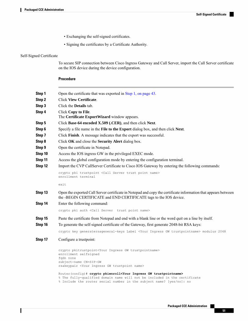
• Exchanging the self-signed certificates.
• Signing the certificates by a Certificate Authority.
Self-Signed Certificate
To secure SIP connection between Cisco Ingress Gateway and Call Server, import the Call Server certificateon the IOS device during the device configuration.
Procedure
Step 1 Open the certificate that was exported in Step 1, on page 43.Step 2 Click View Certificate.Step 3 Click the Details tab.Step 4 Click Copy to File.
The Certificate ExportWizard window appears.Step 5 Click Base-64 encoded X.509 (.CER), and then click Next.Step 6 Specify a file name in the File to the Export dialog box, and then click Next.Step 7 Click Finish. A message indicates that the export was successful.Step 8 Click OK and close the Security Alert dialog box.Step 9 Open the certificate in Notepad.Step 10 Access the IOS ingress GW in the privileged EXEC mode.Step 11 Access the global configuration mode by entering the configuration terminal.Step 12 Import the CVP CallServer Certificate to Cisco IOS Gateway by entering the following commands:
crypto pki trustpoint <Call Server trust point name>enrollment terminal
exit
Step 13 Open the exported Call Server certificate in Notepad and copy the certificate information that appears betweenthe -BEGIN CERTIFICATE and END CERTIFICATE tags to the IOS device.
Step 14 Enter the following command:crypto pki auth <Call Server trust point name>
Step 15 Paste the certificate from Notepad and end with a blank line or the word quit on a line by itself.Step 16 To generate the self-signed certificate of the Gateway, first generate 2048-bit RSA keys:
crypto key generatersageneral-keys Label <Your Ingress GW trustpointname> modulus 2048
Step 17 Configure a trustpoint:
crypto pkitrustpoint<Your Ingress GW trustpointname>enrollment selfsignedfqdn nonesubject-name CN=SIP-GWrsakeypair <Your Ingress GW trustpoint name>
Router(config)# crypto pkienroll<Your Ingress GW trustpointname>% The fully-qualified domain name will not be included in the certificate% Include the router serial number in the subject name? [yes/no]: no
Packaged CCE Administration51
Packaged CCE AdministrationSelf-Signed Certificate
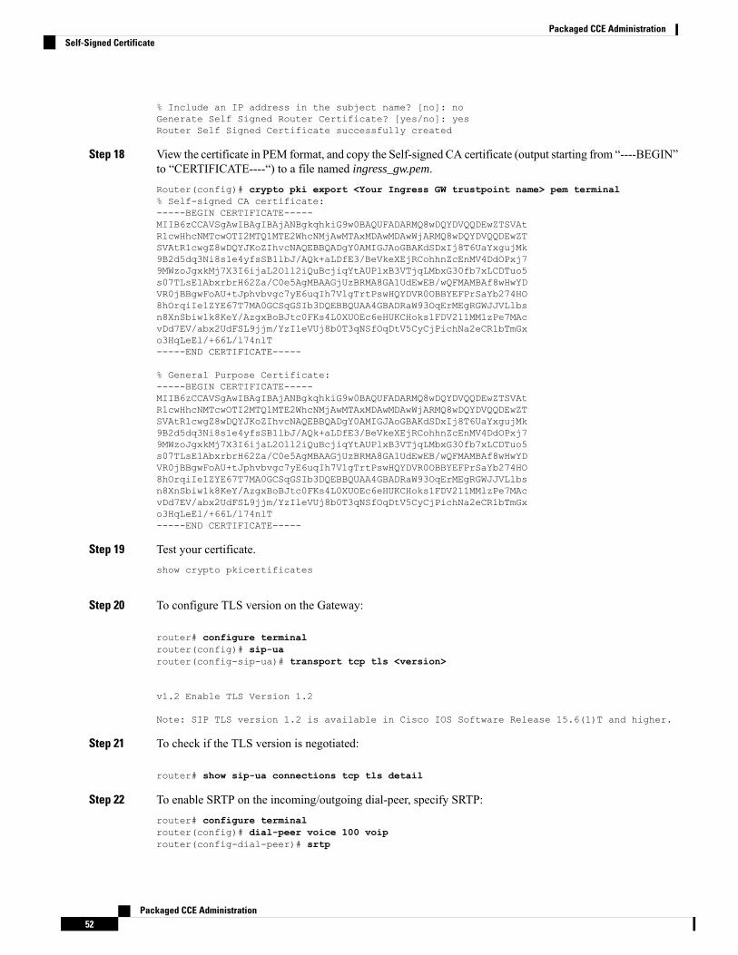
% Include an IP address in the subject name? [no]: noGenerate Self Signed Router Certificate? [yes/no]: yesRouter Self Signed Certificate successfully created
Step 18 View the certificate in PEM format, and copy the Self-signed CA certificate (output starting from “----BEGIN”to “CERTIFICATE----“) to a file named ingress_gw.pem.Router(config)# crypto pki export <Your Ingress GW trustpoint name> pem terminal% Self-signed CA certificate:-----BEGIN CERTIFICATE-----MIIB6zCCAVSgAwIBAgIBAjANBgkqhkiG9w0BAQUFADARMQ8wDQYDVQQDEwZTSVAtR1cwHhcNMTcwOTI2MTQ1MTE2WhcNMjAwMTAxMDAwMDAwWjARMQ8wDQYDVQQDEwZTSVAtR1cwgZ8wDQYJKoZIhvcNAQEBBQADgY0AMIGJAoGBAKdSDxIj8T6UaYxgujMk9B2d5dq3Ni8s1e4yfsSB1lbJ/AQk+aLDfE3/BeVkeXEjRCohhnZcEnMV4DdOPxj79MWzoJgxkMj7X3I6ijaL2Oll2iQuBcjiqYtAUPlxB3VTjqLMbxG30fb7xLCDTuo5s07TLsE1AbxrbrH62Za/C0e5AgMBAAGjUzBRMA8GA1UdEwEB/wQFMAMBAf8wHwYDVR0jBBgwFoAU+tJphvbvgc7yE6uqIh7VlgTrtPswHQYDVR0OBBYEFPrSaYb274HO8hOrqiIe1ZYE67T7MA0GCSqGSIb3DQEBBQUAA4GBADRaW93OqErMEgRGWJJVLlbsn8XnSbiw1k8KeY/AzgxBoBJtc0FKs4L0XUOEc6eHUKCHoks1FDV211MMlzPe7MAcvDd7EV/abx2UdFSL9jjm/YzIleVUj8b0T3qNSfOqDtV5CyCjPichNa2eCR1bTmGxo3HqLeEl/+66L/l74nlT-----END CERTIFICATE-----
% General Purpose Certificate:-----BEGIN CERTIFICATE-----MIIB6zCCAVSgAwIBAgIBAjANBgkqhkiG9w0BAQUFADARMQ8wDQYDVQQDEwZTSVAtR1cwHhcNMTcwOTI2MTQ1MTE2WhcNMjAwMTAxMDAwMDAwWjARMQ8wDQYDVQQDEwZTSVAtR1cwgZ8wDQYJKoZIhvcNAQEBBQADgY0AMIGJAoGBAKdSDxIj8T6UaYxgujMk9B2d5dq3Ni8s1e4yfsSB1lbJ/AQk+aLDfE3/BeVkeXEjRCohhnZcEnMV4DdOPxj79MWzoJgxkMj7X3I6ijaL2Oll2iQuBcjiqYtAUPlxB3VTjqLMbxG30fb7xLCDTuo5s07TLsE1AbxrbrH62Za/C0e5AgMBAAGjUzBRMA8GA1UdEwEB/wQFMAMBAf8wHwYDVR0jBBgwFoAU+tJphvbvgc7yE6uqIh7VlgTrtPswHQYDVR0OBBYEFPrSaYb274HO8hOrqiIe1ZYE67T7MA0GCSqGSIb3DQEBBQUAA4GBADRaW93OqErMEgRGWJJVLlbsn8XnSbiw1k8KeY/AzgxBoBJtc0FKs4L0XUOEc6eHUKCHoks1FDV211MMlzPe7MAcvDd7EV/abx2UdFSL9jjm/YzIleVUj8b0T3qNSfOqDtV5CyCjPichNa2eCR1bTmGxo3HqLeEl/+66L/l74nlT-----END CERTIFICATE-----
Step 19 Test your certificate.show crypto pkicertificates
Step 20 To configure TLS version on the Gateway:
router# configure terminalrouter(config)# sip-uarouter(config-sip-ua)# transport tcp tls <version>
v1.2 Enable TLS Version 1.2
Note: SIP TLS version 1.2 is available in Cisco IOS Software Release 15.6(1)T and higher.
Step 21 To check if the TLS version is negotiated:
router# show sip-ua connections tcp tls detail
Step 22 To enable SRTP on the incoming/outgoing dial-peer, specify SRTP:router# configure terminalrouter(config)# dial-peer voice 100 voiprouter(config-dial-peer)# srtp
Packaged CCE Administration52
Packaged CCE AdministrationSelf-Signed Certificate
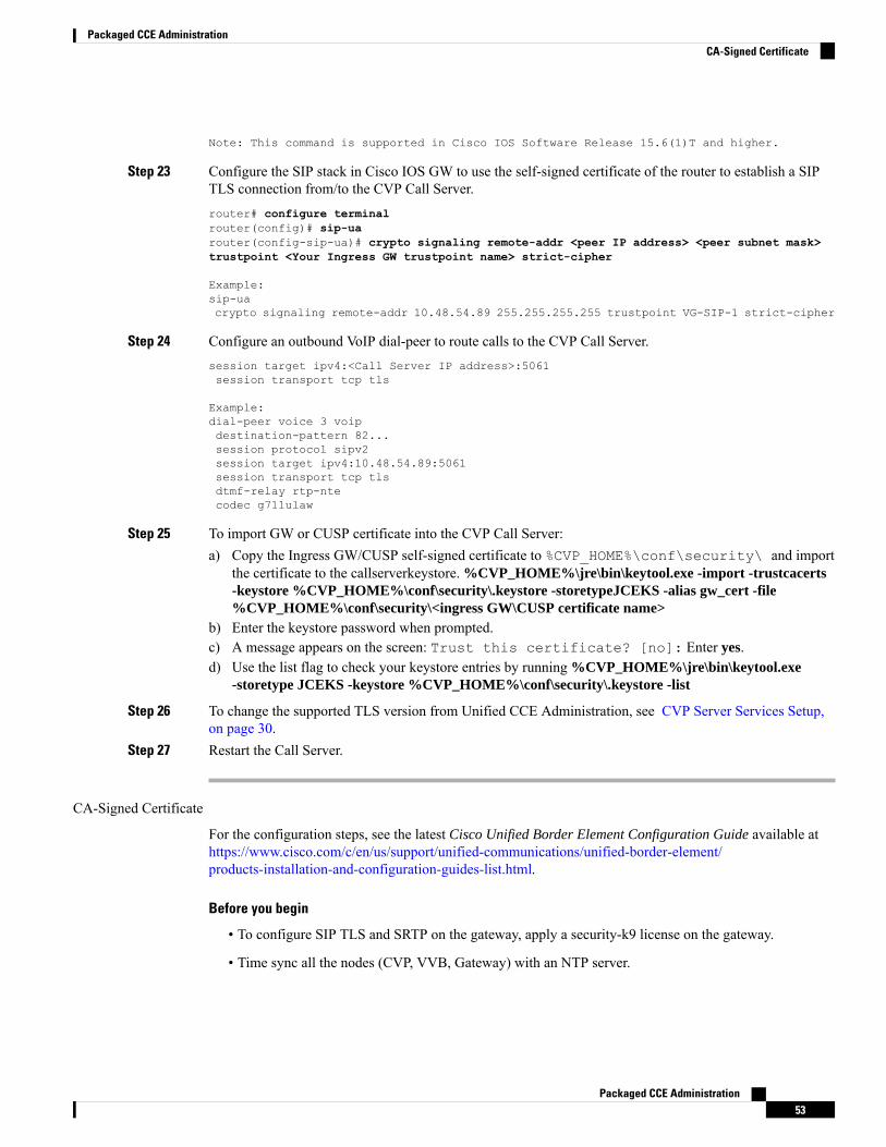
Note: This command is supported in Cisco IOS Software Release 15.6(1)T and higher.
Step 23 Configure the SIP stack in Cisco IOS GW to use the self-signed certificate of the router to establish a SIPTLS connection from/to the CVP Call Server.router# configure terminalrouter(config)# sip-uarouter(config-sip-ua)# crypto signaling remote-addr <peer IP address> <peer subnet mask>trustpoint <Your Ingress GW trustpoint name> strict-cipher
Example:sip-uacrypto signaling remote-addr 10.48.54.89 255.255.255.255 trustpoint VG-SIP-1 strict-cipher
Step 24 Configure an outbound VoIP dial-peer to route calls to the CVP Call Server.session target ipv4:<Call Server IP address>:5061session transport tcp tls
Example:dial-peer voice 3 voipdestination-pattern 82...session protocol sipv2session target ipv4:10.48.54.89:5061session transport tcp tlsdtmf-relay rtp-ntecodec g711ulaw
Step 25 To import GW or CUSP certificate into the CVP Call Server:a) Copy the Ingress GW/CUSP self-signed certificate to %CVP_HOME%\conf\security\ and import
the certificate to the callserverkeystore. %CVP_HOME%\jre\bin\keytool.exe -import -trustcacerts-keystore %CVP_HOME%\conf\security\.keystore -storetypeJCEKS -alias gw_cert -file%CVP_HOME%\conf\security\<ingress GW\CUSP certificate name>
b) Enter the keystore password when prompted.c) A message appears on the screen: Trust this certificate? [no]: Enter yes.d) Use the list flag to check your keystore entries by running %CVP_HOME%\jre\bin\keytool.exe
-storetype JCEKS -keystore %CVP_HOME%\conf\security\.keystore -list
Step 26 To change the supported TLS version from Unified CCE Administration, see CVP Server Services Setup,on page 30.
Step 27 Restart the Call Server.
CA-Signed Certificate
For the configuration steps, see the latest Cisco Unified Border Element Configuration Guide available athttps://www.cisco.com/c/en/us/support/unified-communications/unified-border-element/products-installation-and-configuration-guides-list.html.
Before you begin
• To configure SIP TLS and SRTP on the gateway, apply a security-k9 license on the gateway.
• Time sync all the nodes (CVP, VVB, Gateway) with an NTP server.
Packaged CCE Administration53
Packaged CCE AdministrationCA-Signed Certificate
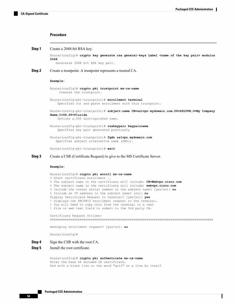
Procedure
Step 1 Create a 2048-bit RSA key.Router(config)# crypto key generate rsa general-keys Label <name of the key pair> modulus2048
Generates 2048 bit RSA key pair.
Step 2 Create a trustpoint. A trustpoint represents a trusted CA.
Example:
Router(config)# crypto pki trustpoint ms-ca-nameCreates the trustpoint.
Router(config-pki-trustpoint)# enrollment terminalSpecifies cut and paste enrollment with this trustpoint.
Router(config-pki-trustpoint)# subject-name CN=sslvpn.mydomain.com,OU=SSLVPN,O=My CompanyName,C=US,ST=Florida
Defines x.500 distinguished name.
Router(config-pki-trustpoint)# rsakeypair keypairnameSpecifies key pair generated previously
Router(config-pki-trustpoint)# fqdn sslvpn.mydomain.comSpecifies subject alternative name (DNS:).
Router(config-pki-trustpoint)# exit
Step 3 Create a CSR (Certificate Request) to give to the MS Certificate Server.
Example:
Router(config)# crypto pki enroll ms-ca-name% Start certificate enrollment ..% The subject name in the certificate will include: CN=Webvpn.cisco.com% The subject name in the certificate will include: webvpn.cisco.com% Include the router serial number in the subject name? [yes/no]: no% Include an IP address in the subject name? [no]: noDisplay Certificate Request to terminal? [yes/no]: yes! Displays the PKCS#10 enrollment request to the terminal.! You will need to copy this from the terminal to a text! file or web text field to submit to the 3rd party CA.
Certificate Request follows:xxxxxxxxxxxxxxxxxxxxxxxxxxxxxxxxxxxxxxxxxxxxxxxxxxxxxxxxxxxxxxxxxxxxxxxxxxxxxxxxxxxxxxxx
Redisplay enrollment request? [yes/no]: no
Router(config)#
Step 4 Sign the CSR with the root CA.Step 5 Install the root certificate.
Router(config)# crypto pki authenticate ms-ca-nameEnter the base 64 encoded CA certificate.End with a blank line or the word "quit" on a line by itself
Packaged CCE Administration54
Packaged CCE AdministrationCA-Signed Certificate
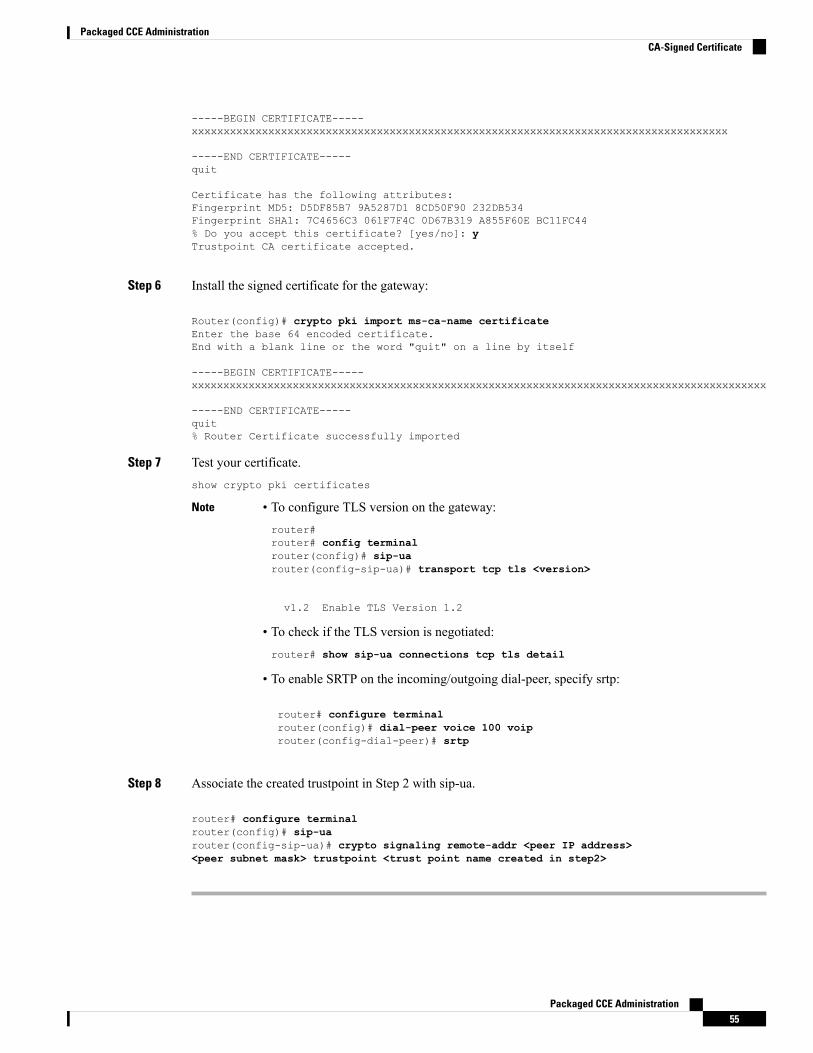
-----BEGIN CERTIFICATE-----xxxxxxxxxxxxxxxxxxxxxxxxxxxxxxxxxxxxxxxxxxxxxxxxxxxxxxxxxxxxxxxxxxxxxxxxxxxxxxxxxxxx
-----END CERTIFICATE-----quit
Certificate has the following attributes:Fingerprint MD5: D5DF85B7 9A5287D1 8CD50F90 232DB534Fingerprint SHA1: 7C4656C3 061F7F4C 0D67B319 A855F60E BC11FC44% Do you accept this certificate? [yes/no]: yTrustpoint CA certificate accepted.
Step 6 Install the signed certificate for the gateway:
Router(config)# crypto pki import ms-ca-name certificateEnter the base 64 encoded certificate.End with a blank line or the word "quit" on a line by itself
-----BEGIN CERTIFICATE-----xxxxxxxxxxxxxxxxxxxxxxxxxxxxxxxxxxxxxxxxxxxxxxxxxxxxxxxxxxxxxxxxxxxxxxxxxxxxxxxxxxxxxxxxxxx
-----END CERTIFICATE-----quit% Router Certificate successfully imported
Step 7 Test your certificate.show crypto pki certificates
• To configure TLS version on the gateway:router#router# config terminalrouter(config)# sip-uarouter(config-sip-ua)# transport tcp tls <version>
v1.2 Enable TLS Version 1.2
• To check if the TLS version is negotiated:router# show sip-ua connections tcp tls detail
• To enable SRTP on the incoming/outgoing dial-peer, specify srtp:
router# configure terminalrouter(config)# dial-peer voice 100 voiprouter(config-dial-peer)# srtp
Note
Step 8 Associate the created trustpoint in Step 2 with sip-ua.
router# configure terminalrouter(config)# sip-uarouter(config-sip-ua)# crypto signaling remote-addr <peer IP address><peer subnet mask> trustpoint <trust point name created in step2>
Packaged CCE Administration55
Packaged CCE AdministrationCA-Signed Certificate
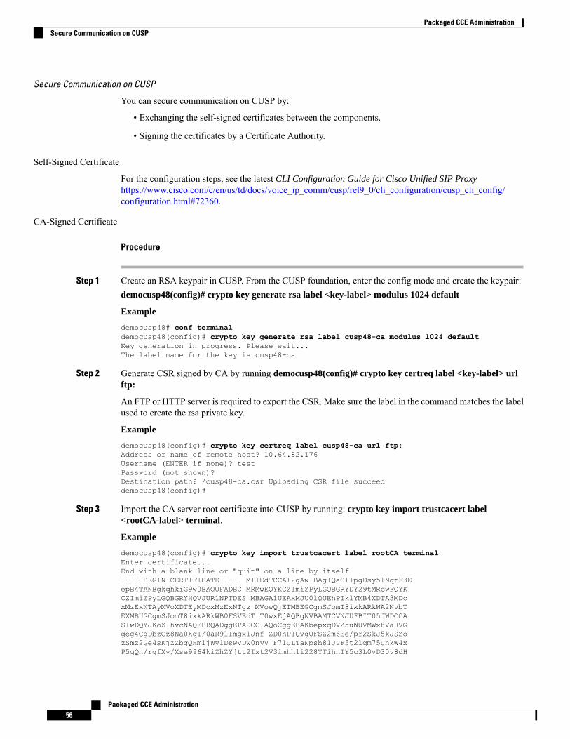
Secure Communication on CUSP
You can secure communication on CUSP by:
• Exchanging the self-signed certificates between the components.
• Signing the certificates by a Certificate Authority.
Self-Signed Certificate
For the configuration steps, see the latest CLI Configuration Guide for Cisco Unified SIP Proxyhttps://www.cisco.com/c/en/us/td/docs/voice_ip_comm/cusp/rel9_0/cli_configuration/cusp_cli_config/configuration.html#72360.
CA-Signed Certificate
Procedure
Step 1 Create an RSA keypair in CUSP. From the CUSP foundation, enter the config mode and create the keypair:democusp48(config)# crypto key generate rsa label <key-label> modulus 1024 default
Example
democusp48# conf terminaldemocusp48(config)# crypto key generate rsa label cusp48-ca modulus 1024 defaultKey generation in progress. Please wait...The label name for the key is cusp48-ca
Step 2 Generate CSR signed by CA by running democusp48(config)# crypto key certreq label <key-label> urlftp:
An FTP or HTTP server is required to export the CSR. Make sure the label in the command matches the labelused to create the rsa private key.
Example
democusp48(config)# crypto key certreq label cusp48-ca url ftp:Address or name of remote host? 10.64.82.176Username (ENTER if none)? testPassword (not shown)?Destination path? /cusp48-ca.csr Uploading CSR file succeeddemocusp48(config)#
Step 3 Import the CA server root certificate into CUSP by running: crypto key import trustcacert label<rootCA-label> terminal.
Example
democusp48(config)# crypto key import trustcacert label rootCA terminalEnter certificate...End with a blank line or "quit" on a line by itself-----BEGIN CERTIFICATE----- MIIEdTCCA12gAwIBAgIQaO1+pgDsy5lNqtF3EepB4TANBgkqhkiG9w0BAQUFADBC MRMwEQYKCZImiZPyLGQBGRYDY29tMRcwFQYKCZImiZPyLGQBGRYHQVJUR1NPTDES MBAGA1UEAxMJU0lQUEhPTklYMB4XDTA3MDcxMzExNTAyMVoXDTEyMDcxMzExNTgz MVowQjETMBEGCgmSJomT8ixkARkWA2NvbTEXMBUGCgmSJomT8ixkARkWB0FSVEdT T0wxEjAQBgNVBAMTCVNJUFBIT05JWDCCASIwDQYJKoZIhvcNAQEBBQADggEPADCC AQoCggEBAKbepxqDVZ5uWUVMWx8VaHVGgeg4CgDbzCz8Na0XqI/0aR9lImgx1Jnf ZD0nP1QvgUFSZ2m6Ee/pr2SkJ5kJSZozSmz2Ge4sKjZZbgQHmljWv1DswVDw0nyV F71ULTaNpsh81JVF5t2lqm75UnkW4xP5qQn/rgfXv/Xse9964kiZhZYjtt2Ixt2V3imhh1i228YTihnTY5c3L0vD30v8dH
Packaged CCE Administration56
Packaged CCE AdministrationSecure Communication on CUSP
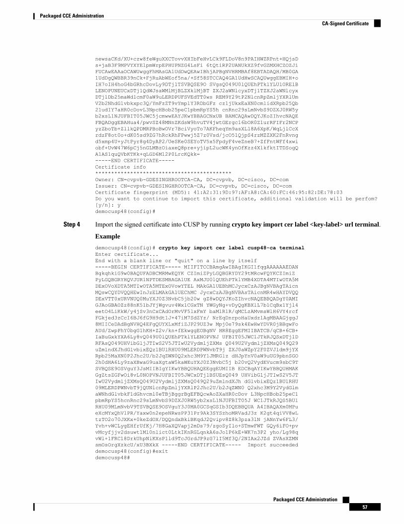
newsaCKd/XU+czw8feWguXXCTovvXHIbFeHvLCk9FLDoV8n9PAIHWZRPnt+HQjsDs+jaB3F9MPVYXYElpmWrpEPHUPNZG4LsFi 6tQtiRP2UANUkXZ9fvGZMXHCZOZJiFUCAwEAAaOCAWUwggFhMAsGA1UdDwQEAwIBhjAPBgNVHRMBAf8EBTADAQH/MB0GA1UdDgQWBBR39nCk+FjRuAbWEof5na/+Sf58STCCAQ4GA1UdHwSCAQUwggEBMIH+oIH7oIH4hoG4bGRhcDovLy9DTj1TSVBQSE9O SVgsQ049U0lQUEhPTklYLUlORElBLENOPUNEUCxDTj1QdWJsaWMlMjBLZXklMjBT ZXJ2aWNlcyxDTj1TZXJ2aWNlcyxDTj1Db25maWd1cmF0aW9uLERDPUFSVEdTT0ws REM9Y29tP2NlcnRpZmljYXRlUmV2b2NhdGlvbkxpc3Q/YmFzZT9vYmplY3RDbGFz cz1jUkxEaXN0cmlidXRpb25Qb2ludIY7aHR0cDovL3NpcHBob25peC1pbmRpYS5h cnRnc29sLmNvbS9DZXJ0RW5yb2xsL1NJUFBIT05JWC5jcmwwEAYJKwYBBAGCNxUB BAMCAQAwDQYJKoZIhvcNAQEFBQADggEBAHua4/pwvSZ48MNnZKdsW9hvuTV4jwtGErgc16bOR0Z1urRFIFr2NCPyzZboTb+ZllkQPDMRPBoBwOVr7BciVyoTo7AKFheqYm9asXL18A6XpK/WqLjlCcXrdzF8ot0o+dK05sd9ZG7hRckRhFPwwj5Z7z0Vsd/jcO51QjpS4rzMZZXK2FnRvngd5xmp4U+yJtPyr8g4DyAP2/UeSKe0SEYoTV5x5FpdyF4veZneB7+ZfFntWFf4xwiobf+UvW47W6pCj5nGLMBzOiaxeQ8pre+yjipL2ucWK4ynOfKzz4XlkfktITDSogQA1AS1quQVbKTKk+qLGD6Ml2P0LrcKQkk=-----END CERTIFICATE-----Certificate info*******************************************Owner: CN=cvpvb-GDESINGHROOTCA-CA, DC=cvpvb, DC=cisco, DC=comIssuer: CN=cvpvb-GDESINGHROOTCA-CA, DC=cvpvb, DC=cisco, DC=comCertificate fingerprint (MD5): 41:A2:31:9D:97:AF:A8:CA:60:FC:46:95:82:DE:78:03Do you want to continue to import this certificate, additional validation will be perfom?[y/n]: ydemocusp48(config)#
Step 4 Import the signed certificate into CUSP by running crypto key import cer label <key-label> url terminal.
Example
democusp48(config)# crypto key import cer label cusp48-ca terminalEnter certificate...End with a blank line or "quit" on a line by itself-----BEGIN CERTIFICATE----- MIIFITCCBAmgAwIBAgIKGI1fqgAAAAAAEDANBgkqhkiG9w0BAQUFADBCMRMwEQYK CZImiZPyLGQBGRYDY29tMRcwFQYKCZImiZPyLGQBGRYHQVJUR1NPTDESMBAGA1UE AxMJU0lQUEhPTklYMB4XDTA4MTIwOTA5MDExOVoXDTA5MTIwOTA5MTExOVowYTEL MAkGA1UEBhMCJycxCzAJBgNVBAgTAicnMQswCQYDVQQHEwInJzELMAkGA1UEChMC JycxCzAJBgNVBAsTAicnMR4wHAYDVQQDExVTT0xURVNUQ0MuYXJ0Z3NvbC5jb20w gZ8wDQYJKoZIhvcNAQEBBQADgY0AMIGJAoGBAOZz88nK51bJYjWgvuv4Wx1CGxTN YWGyNg+vDyQgKBXlL7b1CqBx1Yjl4eetO4LiKkW/y4jSv3nCxCAdOrMvVF5lxFmY baMlR1R/qMCLzAMvmsWlH6VY4rcfFGkjed3zCcI6BJ6fG9H9dt1J+47iM7SdZYz/ NrEqDnrpoHaUxdzlAgMBAAGjggJ8MIICeDAdBgNVHQ4EFgQUYXLxMfiZJP29UZ3w Mpj0e79sk4EwHwYDVR0jBBgwFoAUd/ZwpPhY0bgG1hKH+Z2v/kn+fEkwggEOBgNV HR8EggEFMIIBATCB/qCB+6CB+IaBuGxkYXA6Ly8vQ049U0lQUEhPTklYLENOPVNJ UFBIT05JWC1JTkRJQSxDTj1DRFAsQ049UHVibGljJTIwS2V5JTIwU2VydmljZXMs Q049U2VydmljZXMsQ049Q29uZmlndXJhdGlvbixEQz1BUlRHU09MLERDPWNvbT9j ZXJ0aWZpY2F0ZVJldm9jYXRpb25MaXN0P2Jhc2U/b2JqZWN0Q2xhc3M9Y1JMRGlz dHJpYnV0aW9uUG9pbnSGO2h0dHA6Ly9zaXBwaG9uaXgtaW5kaWEuYXJ0Z3NvbC5j b20vQ2VydEVucm9sbC9TSVBQSE9OSVguY3JsMIIBIgYIKwYBBQUHAQEEggEUMIIB EDCBqAYIKwYBBQUHMAKGgZtsZGFwOi8vL0NOPVNJUFBIT05JWCxDTj1BSUEsQ049 UHVibGljJTIwS2V5JTIwU2VydmljZXMsQ049U2VydmljZXMsQ049Q29uZmlndXJh dGlvbixEQz1BUlRHU09MLERDPWNvbT9jQUNlcnRpZmljYXRlP2Jhc2U/b2JqZWN0 Q2xhc3M9Y2VydGlmaWNhdGlvbkF1dGhvcml0eTBjBggrBgEFBQcwAoZXaHR0cDov L3NpcHBob25peC1pbmRpYS5hcnRnc29sLmNvbS9DZXJ0RW5yb2xsL1NJUFBIT05J WC1JTkRJQS5BUlRHU09MLmNvbV9TSVBQSE9OSVguY3J0MA0GCSqGSIb3DQEBBQUA A4IBAQAXm0MPueXcMYxQhVlPR/Yaxw0n2epeNRwsPP31Pr9Ak3SYSzhoMRVadJ3z K2gt4qiVV8wLtzTO2o70JXKx+0keZdOX/DQQndxBkiBKqdJ2Qvipv8Z8k3pza3lN jANnYw6FL3/Yvh+vWCLygEHfrUfKj/7H8GaXQVapj2mDs79/zgoSyIlo+STmwFWT GQy6iFO+pvvMcyfjjv2dsuwt1Ml0nlict0LtkIKnRGLqnkA6sJo1P6kE+WK7n3P2 yho/Lg98qvWl+1FRC18DrkUhpNiKXsP1ld9TcJGrdJP9zG7lI5Mf3Q/2NIAx2JZd ZVAsXZMNsmOsOrgXzkcU/xU3BXkX -----END CERTIFICATE----- Import succeededdemocusp48(config)#exitdemocusp48#
Packaged CCE Administration57
Packaged CCE AdministrationCA-Signed Certificate
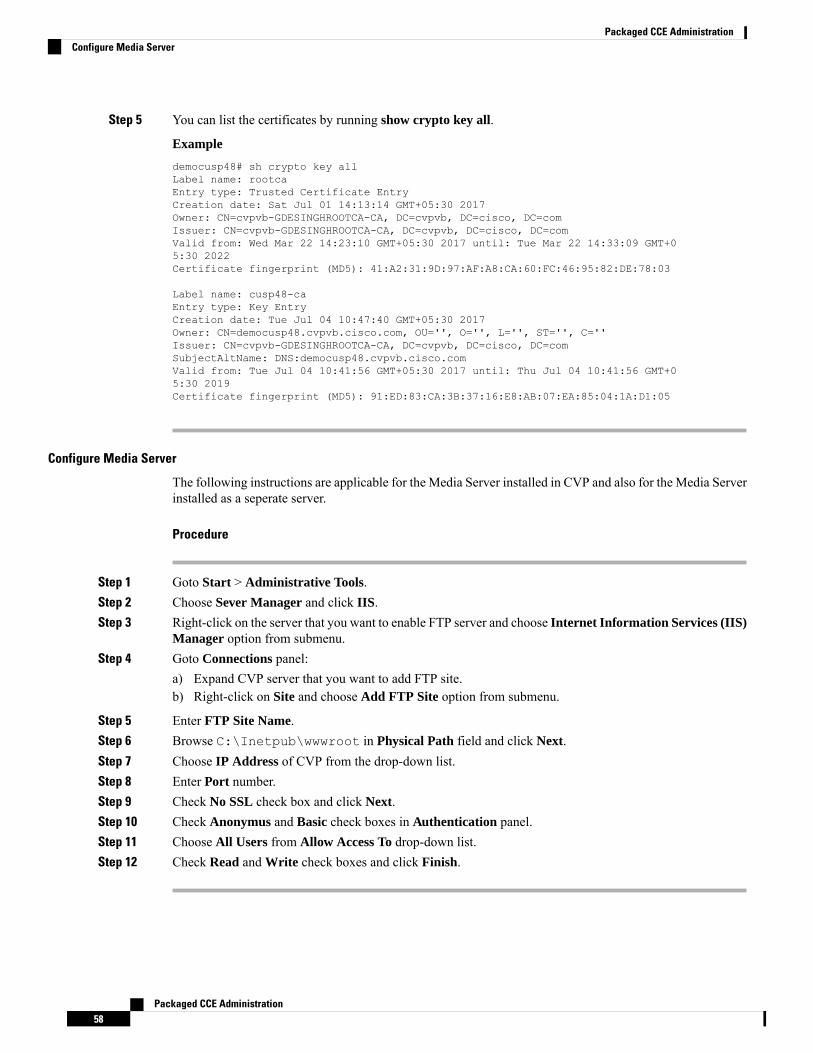
Step 5 You can list the certificates by running show crypto key all.
Example
democusp48# sh crypto key allLabel name: rootcaEntry type: Trusted Certificate EntryCreation date: Sat Jul 01 14:13:14 GMT+05:30 2017Owner: CN=cvpvb-GDESINGHROOTCA-CA, DC=cvpvb, DC=cisco, DC=comIssuer: CN=cvpvb-GDESINGHROOTCA-CA, DC=cvpvb, DC=cisco, DC=comValid from: Wed Mar 22 14:23:10 GMT+05:30 2017 until: Tue Mar 22 14:33:09 GMT+05:30 2022Certificate fingerprint (MD5): 41:A2:31:9D:97:AF:A8:CA:60:FC:46:95:82:DE:78:03
Label name: cusp48-caEntry type: Key EntryCreation date: Tue Jul 04 10:47:40 GMT+05:30 2017Owner: CN=democusp48.cvpvb.cisco.com, OU='', O='', L='', ST='', C=''Issuer: CN=cvpvb-GDESINGHROOTCA-CA, DC=cvpvb, DC=cisco, DC=comSubjectAltName: DNS:democusp48.cvpvb.cisco.comValid from: Tue Jul 04 10:41:56 GMT+05:30 2017 until: Thu Jul 04 10:41:56 GMT+05:30 2019Certificate fingerprint (MD5): 91:ED:83:CA:3B:37:16:E8:AB:07:EA:85:04:1A:D1:05
Configure Media Server
The following instructions are applicable for the Media Server installed in CVP and also for the Media Serverinstalled as a seperate server.
Procedure
Step 1 Goto Start > Administrative Tools.Step 2 Choose Sever Manager and click IIS.Step 3 Right-click on the server that you want to enable FTP server and choose Internet Information Services (IIS)
Manager option from submenu.Step 4 Goto Connections panel:
a) Expand CVP server that you want to add FTP site.b) Right-click on Site and choose Add FTP Site option from submenu.
Step 5 Enter FTP Site Name.Step 6 Browse C:\Inetpub\wwwroot in Physical Path field and click Next.Step 7 Choose IP Address of CVP from the drop-down list.Step 8 Enter Port number.Step 9 Check No SSL check box and click Next.Step 10 Check Anonymus and Basic check boxes in Authentication panel.Step 11 Choose All Users from Allow Access To drop-down list.Step 12 Check Read and Write check boxes and click Finish.
Packaged CCE Administration58
Packaged CCE AdministrationConfigure Media Server
Configure Basic Settings for FTP Server
Procedure
Step 1 Navigate to FTP server that you have created in Connections tab.Step 2 Goto Actions tab and click Basic Settings.Step 3 Click Connect As.Step 4 Choose Application User (pass-through authentication) option and click OK.Step 5 Click OK in Edit Site window.
Configure CVP Reporting ServerReporting provides historical reporting to a distributed self-service deployment in a call center. The CVPReporting Server receives the reporting data from one or more CVP Servers and CVP VXML Servers, andstores that data in an Informix database. The call data is stored in a relational database, on which you canwrite custom reports. The administrators can schedule data removal (delete) and database backups. MultipleCVP Call Servers can send data to a single CVP Reporting Server.
Reporting Server Users and Passwords
You can manage Reporting Server Users and Passwords using Windows Operating System Local UserManagement.
You can do this by using Local Users and Groups within the Computer Management console. To accessthis console, navigate to Start > Administrative Tools > Computer Management.
Changing Database User Passwords
You can change the password of Reporting Server database users. Navigate to Computer Management >Local Users and Groups>Users, choose cvp_dbadmin (Database Administrator) or cvp_dbuser (DatabaseUser), then right click and select Set Password.
Managing Reporting Server Users
You can add, modify, or delete the Reporting Server users. Navigate to Computer Management > LocalUsers and Groups > Users.
If these users need database access, you can add them to the Informix-Admin group.
Configure Reporting Properties
Procedure
Step 1 Navigate toUnified CCE Administration >Overview > Infrastructure Settings >Device Configuration >CVP Reporting Server.
Step 2 Click the Properties tab. Complete the following fields:
Packaged CCE Administration59
Packaged CCE AdministrationConfigure Basic Settings for FTP Server
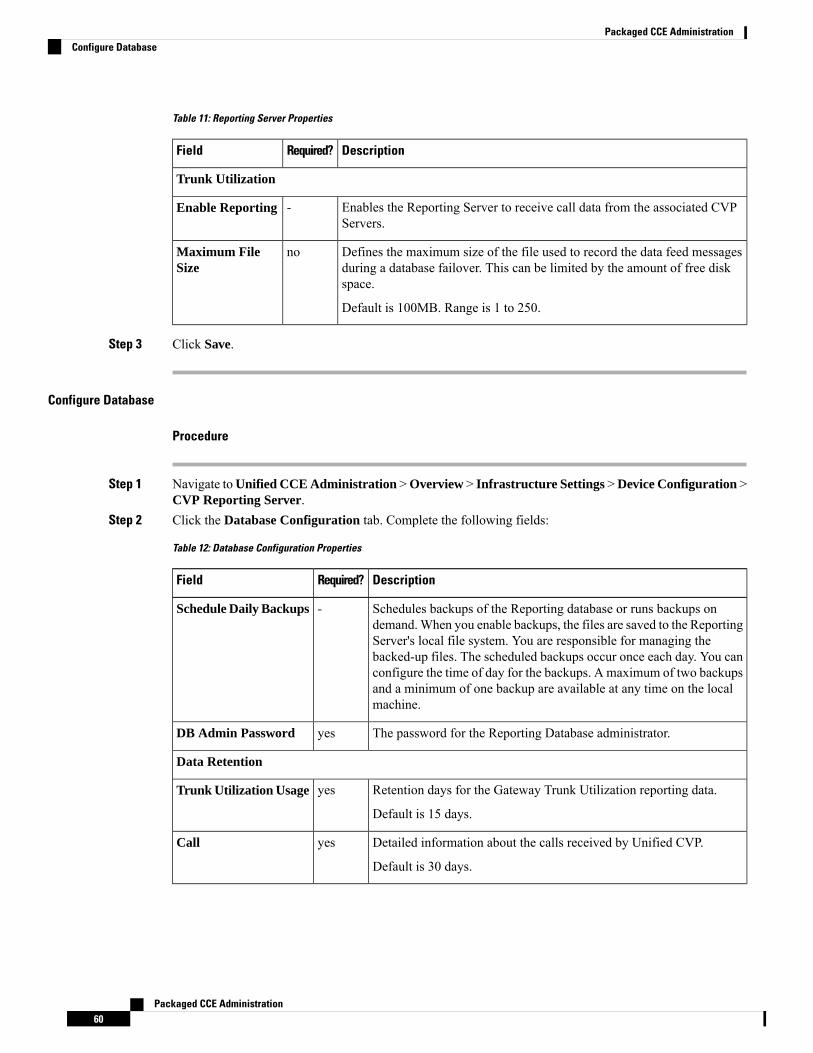
Table 11: Reporting Server Properties
DescriptionRequired?Field
Trunk Utilization
Enables the Reporting Server to receive call data from the associated CVPServers.
-Enable Reporting
Defines the maximum size of the file used to record the data feed messagesduring a database failover. This can be limited by the amount of free diskspace.
Default is 100MB. Range is 1 to 250.
noMaximum FileSize
Step 3 Click Save.
Configure Database
Procedure
Step 1 Navigate toUnified CCE Administration >Overview > Infrastructure Settings >Device Configuration >CVP Reporting Server.
Step 2 Click the Database Configuration tab. Complete the following fields:
Table 12: Database Configuration Properties
DescriptionRequired?Field
Schedules backups of the Reporting database or runs backups ondemand.When you enable backups, the files are saved to the ReportingServer's local file system. You are responsible for managing thebacked-up files. The scheduled backups occur once each day. You canconfigure the time of day for the backups. A maximum of two backupsand a minimum of one backup are available at any time on the localmachine.
-Schedule Daily Backups
The password for the Reporting Database administrator.yesDB Admin Password
Data Retention
Retention days for the Gateway Trunk Utilization reporting data.
Default is 15 days.
yesTrunk Utilization Usage
Detailed information about the calls received by Unified CVP.
Default is 30 days.
yesCall
Packaged CCE Administration60
Packaged CCE AdministrationConfigure Database
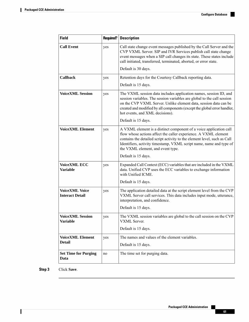
DescriptionRequired?Field
Call state change event messages published by the Call Server and theCVP VXML Server. SIP and IVR Services publish call state changeevent messages when a SIP call changes its state. These states includecall initiated, transferred, terminated, aborted, or error state.
Default is 30 days.
yesCall Event
Retention days for the Courtesy Callback reporting data.
Default is 15 days.
yesCallback
The VXML session data includes application names, session ID, andsession variables. The session variables are global to the call sessionon the CVP VXML Server. Unlike element data, session data can becreated andmodified by all components (except the global error handler,hot events, and XML decisions).
Default is 15 days.
yesVoiceXML Session
A VXML element is a distinct component of a voice application callflow whose actions affect the caller experience. A VXML elementcontains the detailed script activity to the element level, such as CallIdentifiers, activity timestamp, VXML script name, name and type ofthe VXML element, and event type.
Default is 15 days.
yesVoiceXML Element
Expanded Call Context (ECC) variables that are included in the VXMLdata. Unified CVP uses the ECC variables to exchange informationwith Unified ICME.
Default is 15 days.
yesVoiceXML ECCVariable
The application detailed data at the script element level from the CVPVXML Server call services. This data includes input mode, utterance,interpretation, and confidence.
Default is 15 days.
yesVoiceXML VoiceInteract Detail
The VXML session variables are global to the call session on the CVPVXML Server.
Default is 15 days.
yesVoiceXML SessionVariable
The names and values of the element variables.
Default is 15 days.
yesVoiceXML ElementDetail
The time set for purging data.noSet Time for PurgingData
Step 3 Click Save.
Packaged CCE Administration61
Packaged CCE AdministrationConfigure Database
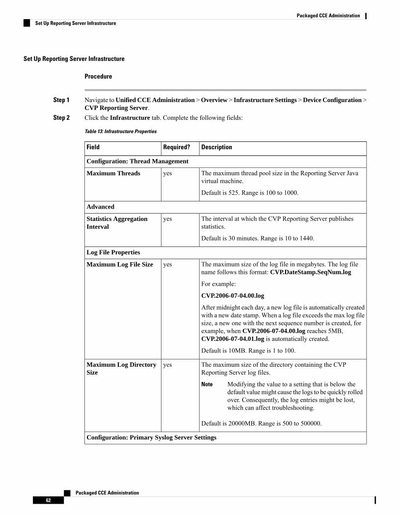
Set Up Reporting Server Infrastructure
Procedure
Step 1 Navigate toUnified CCE Administration >Overview > Infrastructure Settings >Device Configuration >CVP Reporting Server.
Step 2 Click the Infrastructure tab. Complete the following fields:
Table 13: Infrastructure Properties
DescriptionRequired?Field
Configuration: Thread Management
The maximum thread pool size in the Reporting Server Javavirtual machine.
Default is 525. Range is 100 to 1000.
yesMaximum Threads
Advanced
The interval at which the CVP Reporting Server publishesstatistics.
Default is 30 minutes. Range is 10 to 1440.
yesStatistics AggregationInterval
Log File Properties
The maximum size of the log file in megabytes. The log filename follows this format: CVP.DateStamp.SeqNum.log
For example:
CVP.2006-07-04.00.log
After midnight each day, a new log file is automatically createdwith a new date stamp. When a log file exceeds the max log filesize, a new one with the next sequence number is created, forexample, when CVP.2006-07-04.00.log reaches 5MB,CVP.2006-07-04.01.log is automatically created.
Default is 10MB. Range is 1 to 100.
yesMaximum Log File Size
The maximum size of the directory containing the CVPReporting Server log files.
Modifying the value to a setting that is below thedefault valuemight cause the logs to be quickly rolledover. Consequently, the log entries might be lost,which can affect troubleshooting.
Note
Default is 20000MB. Range is 500 to 500000.
yesMaximum Log DirectorySize
Configuration: Primary Syslog Server Settings
Packaged CCE Administration62
Packaged CCE AdministrationSet Up Reporting Server Infrastructure

DescriptionRequired?Field
The hostname or the IP address of the primary syslog server tosend the syslog events from a CVP application.
noPrimary Syslog Server
The port number of the primary syslog server. It can be anyavailable port number. Valid port numbers are integers between1 and 65535.
noPrimary Syslog ServerPort Number
The hostname or the IP address of the primary backup syslogserver to send the syslog events from a CVP application whenthe syslog server cannot be reached.
noPrimary Backup SyslogServer
The port number of the primary backup syslog server. It can beany available port number. Valid port numbers are integersbetween 1 and 65535.
noPrimary Backup SyslogServer Port Number
Configuration: Secondary Syslog Server Settings
The hostname or the IP address of the secondary syslog serverto send the syslog events from a CVP application.
noSecondary Syslog Server
The port number of the secondary syslog server. It can be anyavailable port number. Valid port numbers are integers between1 and 65535.
noSecondary Syslog ServerPort Number
The hostname or the IP address of the secondary backup syslogserver to send the syslog events from a CVP application whenthe syslog server cannot be reached.
noSecondary Backup SyslogServer
The port number of the secondary backup syslog server. It canbe any available port number. Valid port numbers are integersbetween 1 and 65535.
noSecondary Backup SyslogServer Port Number
Step 3 Click Save.
Associate Unified CVP Call Servers with CVP Reporting Server
To store the call data that are handled by Call Servers in the Reporting Database, you must associate CVPCall Servers with CVP Reporting Server.
A Unified CVP Reporting Server can have one or more CVP Call Servers. However, a Unified CVP CallServer can only be associated with one CVP Reporting Server.
Note
Procedure
Step 1 Navigate toUnified CCE Administration >Overview > Infrastructure Settings >Device Configuration >CVP Reporting Server.
Packaged CCE Administration63
Packaged CCE AdministrationAssociate Unified CVP Call Servers with CVP Reporting Server
Step 2 Click the Call Server Association link.The Call Server Association popup window opens.
Step 3 Select a Reporting Server from the drop-down list. The list includes all the Reporting Servers available inthe Packaged CCE inventory.
Step 4 To associate CVP Call Servers with the selected CVP Reporting Server:a) Click the + icon to open the Add CVP Call Server(s) popup. The popup includes a list of CVP Call
Servers that are available for reporting association.b) Select one or more Call Servers from the list and close the popup.
The selected Call Servers appear in the Configured Call Servers table.
Step 5 Click Save.
You can continue to associate other CVP Reporting Servers with available Call Servers.
Step 6 Click Cancel to return to the Device Configuration page.
Cisco Virtualized Voice Browser (VVB) SetupCisco Virtualized Voice Browser (Cisco VVB) provides a platform for interpreting VXML documents. Whenan incoming call arrives at the contact center, Cisco VVB allocates a VXML port that represents the VoIPendpoint. Cisco VVB sends HTTP requests to the Unified CVP VXML server. The Unified CVP VXMLserver executes the request and sends back a dynamically generated VXML document.
After fresh install, add VVB to the System Inventory as an external device.Note
After Packaged CCE Fresh Install, you can configure the following Virtualized Voice Browser settings forthe site:
• Configure Media Parameters
• Configure Security Parameters
• Configure Automatic Speech Recognition (ASR) and Text-to-Speech (TTS) servers.
• Configure the default applications types - Comprehensive, Ringtone, and Error, and add SIP triggers toinvoke the application.
Configure Media and Security Parameters
To configure media and security parameters, add audio codec andMRCP version, and enable TLS and SecureReal-Time Transport Protocol (SRTP).
Procedure
Step 1 Navigate toUnified CCE Administration >Overview > Infrastructure Settings >Device Configuration >Virtualized Voice Browser.
Step 2 Select the site name from the list for which you want to set up the VVB media and security parameters. Bydefault, it is 'Main'.
Packaged CCE Administration64
Packaged CCE AdministrationCisco Virtualized Voice Browser (VVB) Setup
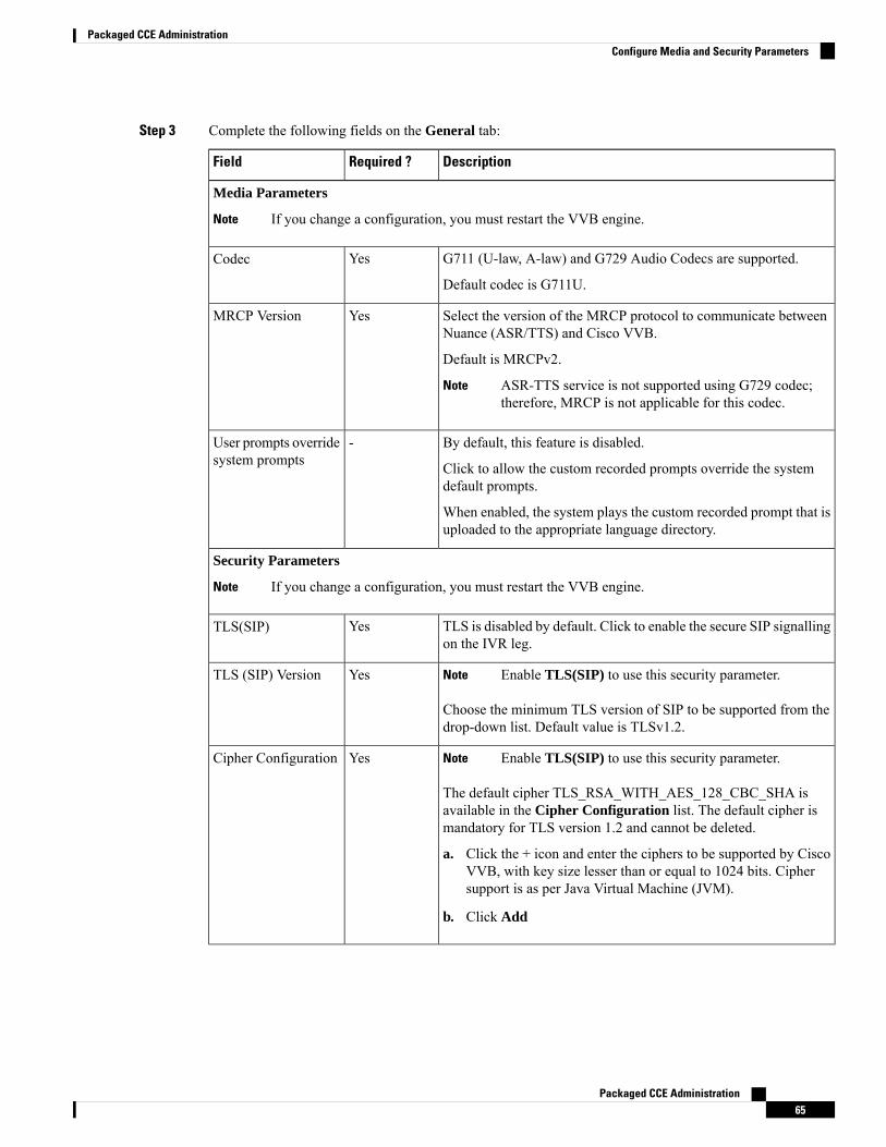
Step 3 Complete the following fields on the General tab:
DescriptionRequired ?Field
Media Parameters
If you change a configuration, you must restart the VVB engine.Note
G711 (U-law, A-law) and G729 Audio Codecs are supported.
Default codec is G711U.
YesCodec
Select the version of the MRCP protocol to communicate betweenNuance (ASR/TTS) and Cisco VVB.
Default is MRCPv2.
ASR-TTS service is not supported using G729 codec;therefore, MRCP is not applicable for this codec.
Note
YesMRCP Version
By default, this feature is disabled.
Click to allow the custom recorded prompts override the systemdefault prompts.
When enabled, the system plays the custom recorded prompt that isuploaded to the appropriate language directory.
-User prompts overridesystem prompts
Security Parameters
If you change a configuration, you must restart the VVB engine.Note
TLS is disabled by default. Click to enable the secure SIP signallingon the IVR leg.
YesTLS(SIP)
Enable TLS(SIP) to use this security parameter.Note
Choose the minimum TLS version of SIP to be supported from thedrop-down list. Default value is TLSv1.2.
YesTLS (SIP) Version
Enable TLS(SIP) to use this security parameter.Note
The default cipher TLS_RSA_WITH_AES_128_CBC_SHA isavailable in the Cipher Configuration list. The default cipher ismandatory for TLS version 1.2 and cannot be deleted.
a. Click the + icon and enter the ciphers to be supported by CiscoVVB, with key size lesser than or equal to 1024 bits. Ciphersupport is as per Java Virtual Machine (JVM).
b. Click Add
YesCipher Configuration
Packaged CCE Administration65
Packaged CCE AdministrationConfigure Media and Security Parameters
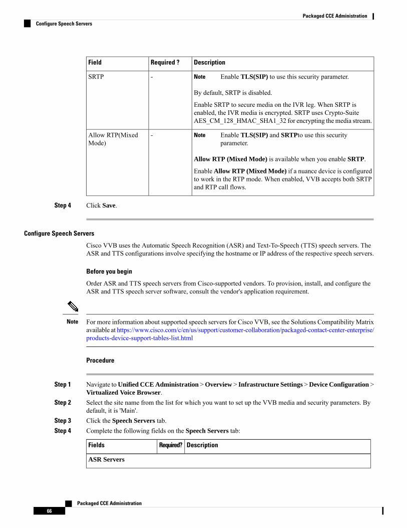
DescriptionRequired ?Field
Enable TLS(SIP) to use this security parameter.Note
By default, SRTP is disabled.
Enable SRTP to secure media on the IVR leg. When SRTP isenabled, the IVR media is encrypted. SRTP uses Crypto-SuiteAES_CM_128_HMAC_SHA1_32 for encrypting themedia stream.
-SRTP
Enable TLS(SIP) and SRTPto use this securityparameter.
Note
Allow RTP (Mixed Mode) is available when you enable SRTP.
Enable Allow RTP (Mixed Mode) if a nuance device is configuredto work in the RTP mode. When enabled, VVB accepts both SRTPand RTP call flows.
-Allow RTP(MixedMode)
Step 4 Click Save.
Configure Speech Servers
Cisco VVB uses the Automatic Speech Recognition (ASR) and Text-To-Speech (TTS) speech servers. TheASR and TTS configurations involve specifying the hostname or IP address of the respective speech servers.
Before you begin
Order ASR and TTS speech servers from Cisco-supported vendors. To provision, install, and configure theASR and TTS speech server software, consult the vendor's application requirement.
For more information about supported speech servers for Cisco VVB, see the Solutions Compatibility Matrixavailable at https://www.cisco.com/c/en/us/support/customer-collaboration/packaged-contact-center-enterprise/products-device-support-tables-list.html
Note
Procedure
Step 1 Navigate toUnified CCE Administration >Overview > Infrastructure Settings >Device Configuration >Virtualized Voice Browser.
Step 2 Select the site name from the list for which you want to set up the VVB media and security parameters. Bydefault, it is 'Main'.
Step 3 Click the Speech Servers tab.Step 4 Complete the following fields on the Speech Servers tab:
DescriptionRequired?Fields
ASR Servers
Packaged CCE Administration66
Packaged CCE AdministrationConfigure Speech Servers
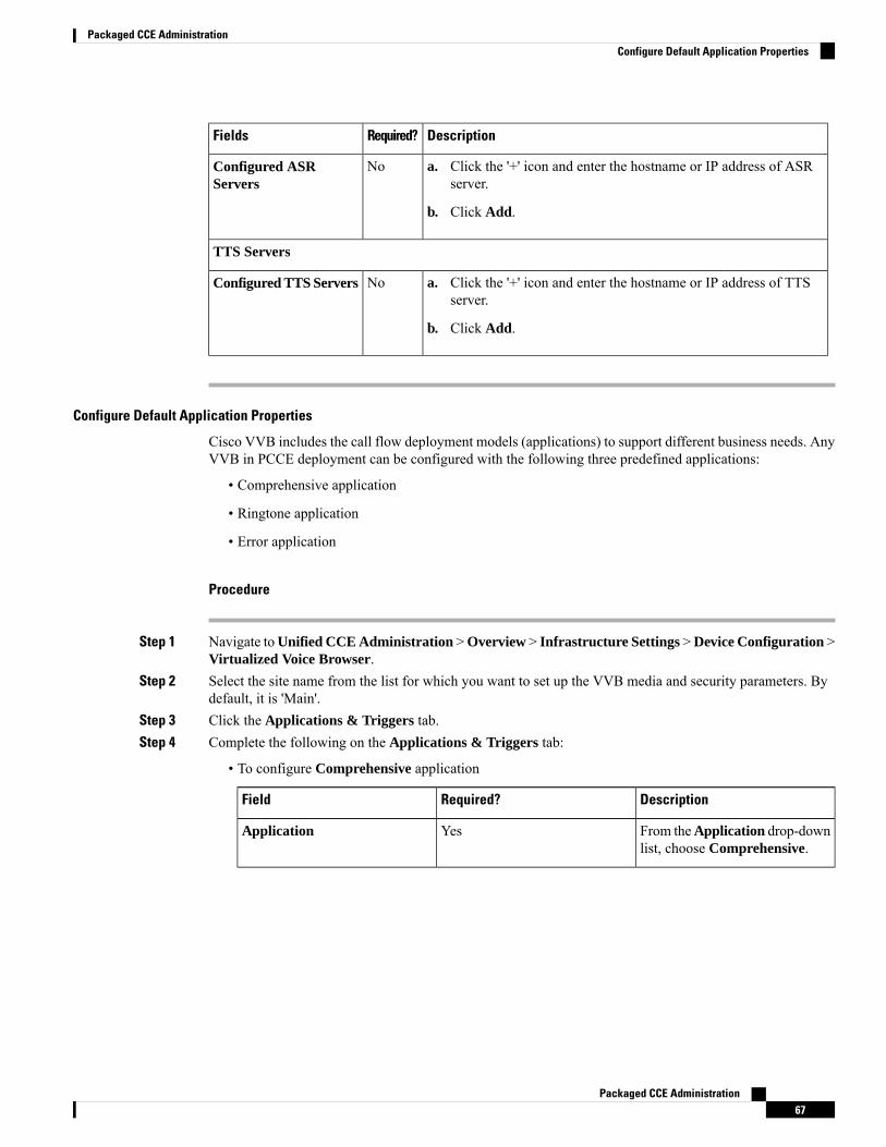
DescriptionRequired?Fields
a. Click the '+' icon and enter the hostname or IP address of ASRserver.
b. Click Add.
NoConfigured ASRServers
TTS Servers
a. Click the '+' icon and enter the hostname or IP address of TTSserver.
b. Click Add.
NoConfigured TTS Servers
Configure Default Application Properties
Cisco VVB includes the call flow deployment models (applications) to support different business needs. AnyVVB in PCCE deployment can be configured with the following three predefined applications:
• Comprehensive application
• Ringtone application
• Error application
Procedure
Step 1 Navigate toUnified CCE Administration >Overview > Infrastructure Settings >Device Configuration >Virtualized Voice Browser.
Step 2 Select the site name from the list for which you want to set up the VVB media and security parameters. Bydefault, it is 'Main'.
Step 3 Click the Applications & Triggers tab.Step 4 Complete the following on the Applications & Triggers tab:
• To configure Comprehensive application
DescriptionRequired?Field
From theApplication drop-downlist, choose Comprehensive.
YesApplication
Packaged CCE Administration67
Packaged CCE AdministrationConfigure Default Application Properties
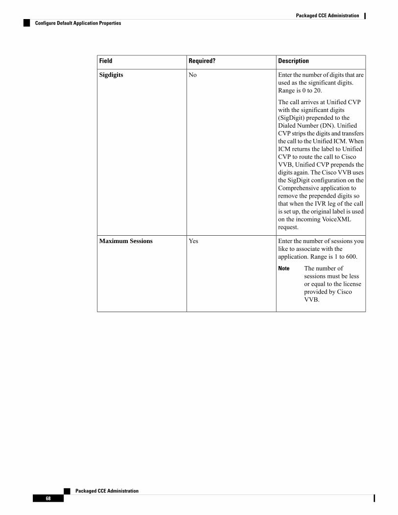
DescriptionRequired?Field
Enter the number of digits that areused as the significant digits.Range is 0 to 20.
The call arrives at Unified CVPwith the significant digits(SigDigit) prepended to theDialed Number (DN). UnifiedCVP strips the digits and transfersthe call to the Unified ICM.WhenICM returns the label to UnifiedCVP to route the call to CiscoVVB, Unified CVP prepends thedigits again. The Cisco VVB usesthe SigDigit configuration on theComprehensive application toremove the prepended digits sothat when the IVR leg of the callis set up, the original label is usedon the incoming VoiceXMLrequest.
NoSigdigits
Enter the number of sessions youlike to associate with theapplication. Range is 1 to 600.
The number ofsessions must be lessor equal to the licenseprovided by CiscoVVB.
Note
YesMaximum Sessions
Packaged CCE Administration68
Packaged CCE AdministrationConfigure Default Application Properties
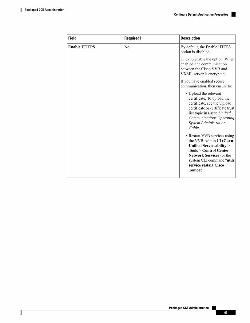
DescriptionRequired?Field
By default, the Enable HTTPSoption is disabled.
Click to enable the option. Whenenabled, the communicationbetween the Cisco VVB andVXML server is encrypted.
If you have enabled securecommunication, then ensure to:
• Upload the relevantcertificate. To upload thecertificate, see the Uploadcertificate or certificate trustlist topic in Cisco UnifiedCommunications OperatingSystem AdministrationGuide.
• Restart VVB services usingthe VVB Admin UI (CiscoUnified Serviceability >Tools > Control Center -Network Services) or thesystem CLI command "utilsservice restart CiscoTomcat".
NoEnable HTTPS
Packaged CCE Administration69
Packaged CCE AdministrationConfigure Default Application Properties
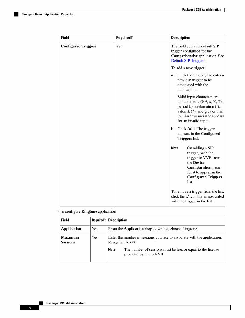
DescriptionRequired?Field
The field contains default SIPtrigger configured for theComprehensive application. SeeDefault SIP Triggers.
To add a new trigger:
a. Click the '+' icon, and enter anew SIP trigger to beassociated with theapplication.
Valid input characters arealphanumeric (0-9, x, X, T),period (.), exclamation (!),asterisk (*), and greater than(>). An errormessage appearsfor an invalid input.
b. Click Add. The triggerappears in the ConfiguredTriggers list.
On adding a SIPtrigger, push thetrigger to VVB fromthe DeviceConfiguration pagefor it to appear in theConfigured Triggerslist.
Note
To remove a trigger from the list,click the 'x' icon that is associatedwith the trigger in the list.
YesConfigured Triggers
• To configure Ringtone application
DescriptionRequired?Field
From the Application drop-down list, choose Ringtone.YesApplication
Enter the number of sessions you like to associate with the application.Range is 1 to 600.
The number of sessions must be less or equal to the licenseprovided by Cisco VVB.
Note
YesMaximumSessions
Packaged CCE Administration70
Packaged CCE AdministrationConfigure Default Application Properties
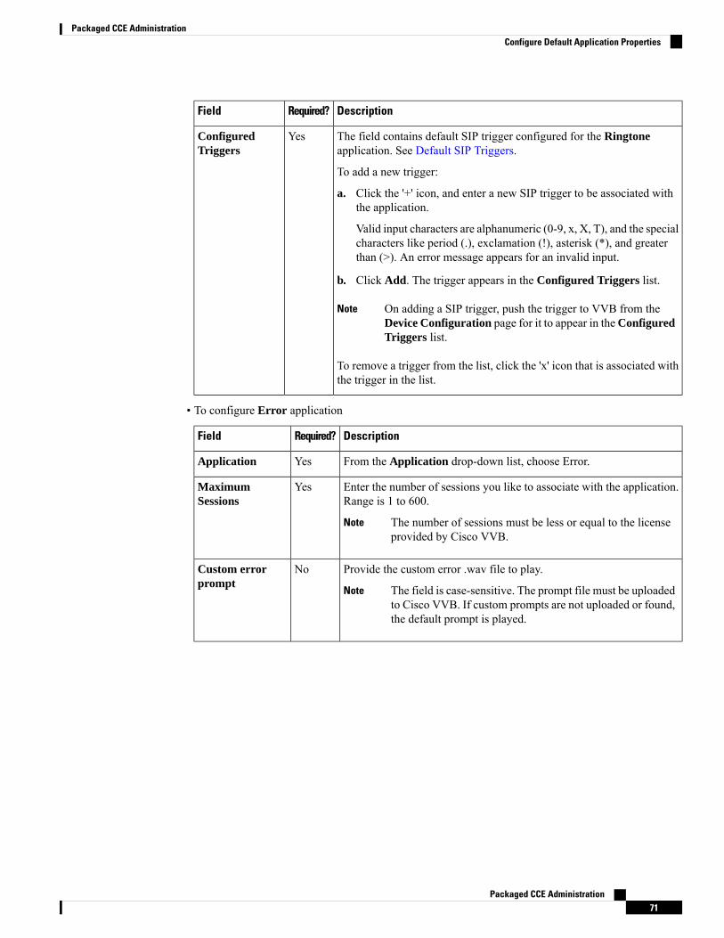
DescriptionRequired?Field
The field contains default SIP trigger configured for the Ringtoneapplication. See Default SIP Triggers.
To add a new trigger:
a. Click the '+' icon, and enter a new SIP trigger to be associated withthe application.
Valid input characters are alphanumeric (0-9, x, X, T), and the specialcharacters like period (.), exclamation (!), asterisk (*), and greaterthan (>). An error message appears for an invalid input.
b. Click Add. The trigger appears in the Configured Triggers list.
On adding a SIP trigger, push the trigger to VVB from theDevice Configuration page for it to appear in theConfiguredTriggers list.
Note
To remove a trigger from the list, click the 'x' icon that is associated withthe trigger in the list.
YesConfiguredTriggers
• To configure Error application
DescriptionRequired?Field
From the Application drop-down list, choose Error.YesApplication
Enter the number of sessions you like to associate with the application.Range is 1 to 600.
The number of sessions must be less or equal to the licenseprovided by Cisco VVB.
Note
YesMaximumSessions
Provide the custom error .wav file to play.
The field is case-sensitive. The prompt file must be uploadedto Cisco VVB. If custom prompts are not uploaded or found,the default prompt is played.
Note
NoCustom errorprompt
Packaged CCE Administration71
Packaged CCE AdministrationConfigure Default Application Properties

DescriptionRequired?Field
The field contains default SIP trigger configured for the Errorapplication. See Default SIP Triggers.
To add a new trigger:
a. Click the '+' icon, and enter a new SIP trigger to be associated withthe application.
Valid input characters are alphanumeric (0-9, x, X, T), period (.),exclamation (!), asterisk (*), and greater than (>). An error messageappears for an invalid input.
b. Click Add. The trigger appears in the Configured Triggers list.
On adding a SIP trigger, push the trigger to VVB from theDevice Configuration page for it to appear in theConfiguredTriggers list.
Note
To remove a trigger from the list, click the 'x' icon associated with thetrigger in the list.
YesConfiguredTriggers
Step 5 Click Save.
Default SIP Triggers
The pre-defined applications have the default SIP triggers as shown in the table.
Table 14: Default SIP Triggers
Pre-configured SIP TriggerDescriptionApplication
7777777777*Used for comprehensive callsComprehensive
91919191*Used for playing ringtone andwhisper
Ringtone
92929292*Used for playing error toneError
FinesseUse this page to configure the following settings for Cisco Finesse administration:
• IP Phone Agent
• CTI Server
• Administration and Data Server
• Cluster Settings
Packaged CCE Administration72
Packaged CCE AdministrationDefault SIP Triggers
The CTI Server, Administration and Data Server, and Cluster Settings are available only for Packaged CCE4000 Agents deployment to 12000 Agents deployment.
Note
IP Phone Agent Settings
You can set up the user credentials for an IP phone agent. Any changes that are made to these settings requirea restart of Cisco Finesse Tomcat to take effect.
Procedure
Step 1 In Unified CCE Administration, choose Overview > Infrastructure Settings > Device Configuration >Finesse > IP Phone Agent Settings.
Step 2 Choose a site for the Finesse server. By default, it is Main for Packaged CCE 2000 Agents deployment.Step 3 From the Peripheral Set drop-down list, select a peripheral set that has the Cisco Finesse configured for the
selected Site.
The Peripheral Set field is available only in Packaged CCE 4000 Agents and 12000 Agentsdeployments. For more information, see Add and Maintain Peripheral Set.
Note
Step 4 Under Phone URL Authentication Settings, enter your Username and Password.Step 5 Click Save to save your settings.Step 6 Click Revert to retrieve the previously saved settings.
Related TopicsContact Center Enterprise CTI Server Settings, on page 73Contact Center Enterprise Administration and Data Server Settings, on page 76Cluster Settings, on page 79
Contact Center Enterprise CTI Server Settings
Use the Contact Center Enterprise CTI Server Settings gadget to configure the A and B Side CTI servers.
All fields on this tab are populated with default system values or with values an administrator has previouslyentered. Change values to reflect your environment and preferences.
For configuring secure connection select the Enable SSL encryption check box.
Test the CTI connection for given configuration using the Test Connection button.
Packaged CCE Administration73
Packaged CCE AdministrationIP Phone Agent Settings
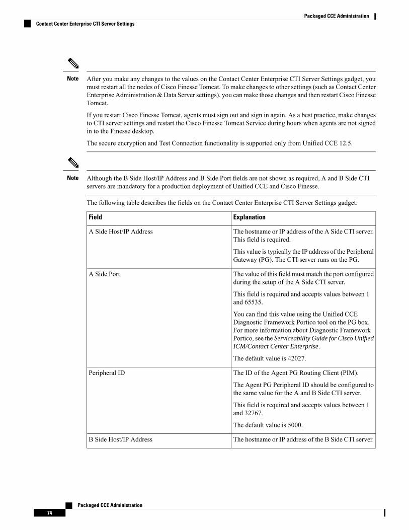
After you make any changes to the values on the Contact Center Enterprise CTI Server Settings gadget, youmust restart all the nodes of Cisco Finesse Tomcat. To make changes to other settings (such as Contact CenterEnterprise Administration&Data Server settings), you canmake those changes and then restart Cisco FinesseTomcat.
If you restart Cisco Finesse Tomcat, agents must sign out and sign in again. As a best practice, make changesto CTI server settings and restart the Cisco Finesse Tomcat Service during hours when agents are not signedin to the Finesse desktop.
The secure encryption and Test Connection functionality is supported only from Unified CCE 12.5.
Note
Although the B Side Host/IP Address and B Side Port fields are not shown as required, A and B Side CTIservers are mandatory for a production deployment of Unified CCE and Cisco Finesse.
Note
The following table describes the fields on the Contact Center Enterprise CTI Server Settings gadget:
ExplanationField
The hostname or IP address of the A Side CTI server.This field is required.
This value is typically the IP address of the PeripheralGateway (PG). The CTI server runs on the PG.
A Side Host/IP Address
The value of this field must match the port configuredduring the setup of the A Side CTI server.
This field is required and accepts values between 1and 65535.
You can find this value using the Unified CCEDiagnostic Framework Portico tool on the PG box.For more information about Diagnostic FrameworkPortico, see the Serviceability Guide for Cisco UnifiedICM/Contact Center Enterprise.
The default value is 42027.
A Side Port
The ID of the Agent PG Routing Client (PIM).
The Agent PG Peripheral ID should be configured tothe same value for the A and B Side CTI server.
This field is required and accepts values between 1and 32767.
The default value is 5000.
Peripheral ID
The hostname or IP address of the B Side CTI server.B Side Host/IP Address
Packaged CCE Administration74
Packaged CCE AdministrationContact Center Enterprise CTI Server Settings
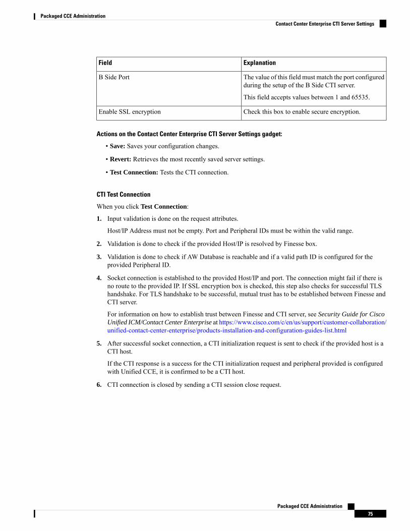
ExplanationField
The value of this field must match the port configuredduring the setup of the B Side CTI server.
This field accepts values between 1 and 65535.
B Side Port
Check this box to enable secure encryption.Enable SSL encryption
Actions on the Contact Center Enterprise CTI Server Settings gadget:
• Save: Saves your configuration changes.
• Revert: Retrieves the most recently saved server settings.
• Test Connection: Tests the CTI connection.
CTI Test Connection
When you click Test Connection:
1. Input validation is done on the request attributes.
Host/IP Address must not be empty. Port and Peripheral IDs must be within the valid range.
2. Validation is done to check if the provided Host/IP is resolved by Finesse box.
3. Validation is done to check if AW Database is reachable and if a valid path ID is configured for theprovided Peripheral ID.
4. Socket connection is established to the provided Host/IP and port. The connection might fail if there isno route to the provided IP. If SSL encryption box is checked, this step also checks for successful TLShandshake. For TLS handshake to be successful, mutual trust has to be established between Finesse andCTI server.
For information on how to establish trust between Finesse and CTI server, see Security Guide for CiscoUnified ICM/Contact Center Enterprise at https://www.cisco.com/c/en/us/support/customer-collaboration/unified-contact-center-enterprise/products-installation-and-configuration-guides-list.html
5. After successful socket connection, a CTI initialization request is sent to check if the provided host is aCTI host.
If the CTI response is a success for the CTI initialization request and peripheral provided is configuredwith Unified CCE, it is confirmed to be a CTI host.
6. CTI connection is closed by sending a CTI session close request.
Packaged CCE Administration75
Packaged CCE AdministrationContact Center Enterprise CTI Server Settings
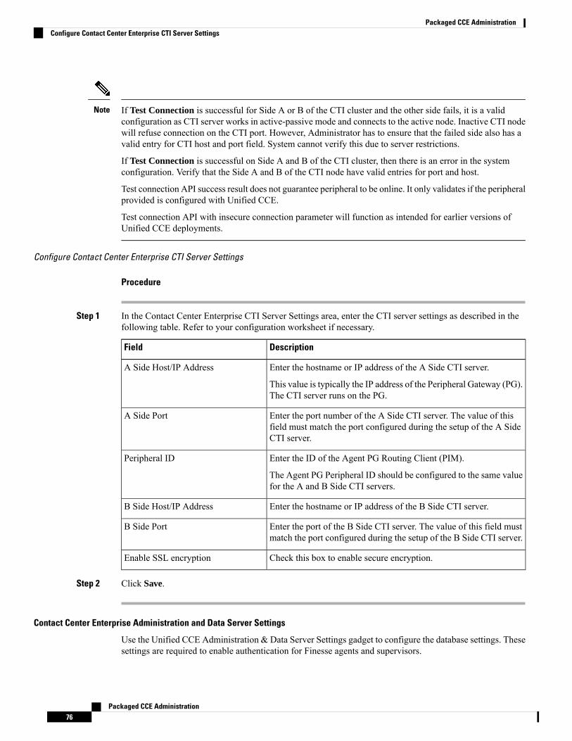
If Test Connection is successful for Side A or B of the CTI cluster and the other side fails, it is a validconfiguration as CTI server works in active-passive mode and connects to the active node. Inactive CTI nodewill refuse connection on the CTI port. However, Administrator has to ensure that the failed side also has avalid entry for CTI host and port field. System cannot verify this due to server restrictions.
If Test Connection is successful on Side A and B of the CTI cluster, then there is an error in the systemconfiguration. Verify that the Side A and B of the CTI node have valid entries for port and host.
Test connection API success result does not guarantee peripheral to be online. It only validates if the peripheralprovided is configured with Unified CCE.
Test connection API with insecure connection parameter will function as intended for earlier versions ofUnified CCE deployments.
Note
Configure Contact Center Enterprise CTI Server Settings
Procedure
Step 1 In the Contact Center Enterprise CTI Server Settings area, enter the CTI server settings as described in thefollowing table. Refer to your configuration worksheet if necessary.
DescriptionField
Enter the hostname or IP address of the A Side CTI server.
This value is typically the IP address of the Peripheral Gateway (PG).The CTI server runs on the PG.
A Side Host/IP Address
Enter the port number of the A Side CTI server. The value of thisfield must match the port configured during the setup of the A SideCTI server.
A Side Port
Enter the ID of the Agent PG Routing Client (PIM).
The Agent PG Peripheral ID should be configured to the same valuefor the A and B Side CTI servers.
Peripheral ID
Enter the hostname or IP address of the B Side CTI server.B Side Host/IP Address
Enter the port of the B Side CTI server. The value of this field mustmatch the port configured during the setup of the B Side CTI server.
B Side Port
Check this box to enable secure encryption.Enable SSL encryption
Step 2 Click Save.
Contact Center Enterprise Administration and Data Server Settings
Use the Unified CCE Administration & Data Server Settings gadget to configure the database settings. Thesesettings are required to enable authentication for Finesse agents and supervisors.
Packaged CCE Administration76
Packaged CCE AdministrationConfigure Contact Center Enterprise CTI Server Settings
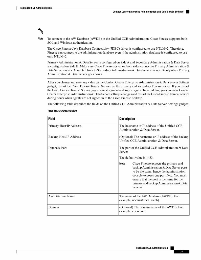
To connect to the AW Database (AWDB) in the Unified CCE Administration, Cisco Finesse supports bothSQL and Windows authentication.
The Cisco Finesse Java Database Connectivity (JDBC) driver is configured to use NTLMv2. Therefore,Finesse can connect to the administration database even if the administration database is configured to useonly NTLMv2.
Primary Administration & Data Server is configured on Side A and Secondary Administration & Data Serveris configured on Side B. Make sure Cisco Finesse server on both sides connect to Primary Administration &Data Server on side A and fall back to Secondary Administration & Data Server on side B only when PrimaryAdministration & Data Server goes down.
Note
After you change and save any value on the Contact Center Enterprise Administration & Data Server Settingsgadget, restart the Cisco Finesse Tomcat Service on the primary and secondary Finesse server. If you restartthe Cisco Finesse Tomcat Service, agents must sign out and sign in again. To avoid this, you can make ContactCenter Enterprise Administration&Data Server settings changes and restart the Cisco Finesse Tomcat serviceduring hours when agents are not signed in to the Cisco Finesse desktop.
The following table describes the fields on the Unified CCE Administration & Data Server Settings gadget:
Table 15: Field Descriptions
DescriptionField
The hostname or IP address of the Unified CCEAdministration & Data Server.
Primary Host/IP Address
(Optional) The hostname or IP address of the backupUnified CCE Administration & Data Server.
Backup Host/IP Address
The port of the Unified CCE Administration & DataServer.
The default value is 1433.
Cisco Finesse expects the primary andbackupAdministration&Data Server portsto be the same, hence the administrationconsole exposes one port field. You mustensure that the port is the same for theprimary and backupAdministration&DataServers.
Note
Database Port
The name of the AW Database (AWDB). Forexample, ucceinstance_awdb).
AW Database Name
(Optional) The domain name of the AWDB. Forexample, cisco.com.
Domain
Packaged CCE Administration77
Packaged CCE AdministrationContact Center Enterprise Administration and Data Server Settings

DescriptionField
The username required to sign in to the AWDB.
If you specify a domain, this user refers tothe Administrator Domain user that theAWDB uses to synchronize with thelogger. In which case, the AWDB servermust use Windows authentication and theconfigured username must be a domainuser.
If you do not specify a domain, this usermust be an SQL user.
Note
Username
The password required to sign in to the AWDB.Password
For more information about these settings, see the Administration Guide for Cisco Unified Contact CenterEnterprise and the Staging Guide for Cisco Unified ICM/Contact Center Enterprise.
Actions on the Unified CCE Administration & Data Server Settings gadget:
• Save: Saves your configuration changes
• Revert: Retrieves the most recently saved enterprise database settings
When you update any of the following fields and click Save, Cisco Finesse attempts to connect to the AWDB:
• Primary Host/IP Address
• Backup Host/IP Address
• Database Port
• AW Database Name
If Cisco Finesse cannot connect to the AWDB, an error message appears and you are asked if you still wantto save. If you click Yes, the settings are saved. If you click No, the settings are not saved. You can changethe settings and try again or click Revert to retrieve the previously saved settings.
When you update the Username or Password fields and click Save, Cisco Finesse attempts to authenticateagainst the AWDB. If authentication fails, an error message appears and you are asked if you still want tosave. Click Yes to save the settings or click No to change the settings. Click Revert to retrieve the previouslysaved settings.
Finesse will not come into service in case of AWDB errors when connecting Cisco Finesse 11.5(1) and higherversions to Unified CCE 11.5(1) and higher versions.
Note
Configure Contact Center Enterprise Administration and Data Server Settings
Configure the Unified CCEAdministration &Data Server settings to enable authentication for Finesse agentsand supervisors.
Packaged CCE Administration78
Packaged CCE AdministrationConfigure Contact Center Enterprise Administration and Data Server Settings
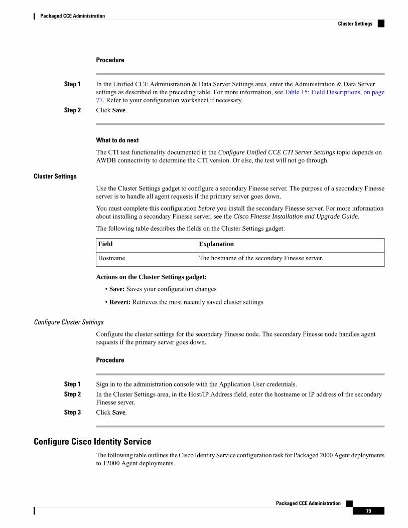
Procedure
Step 1 In the Unified CCE Administration & Data Server Settings area, enter the Administration & Data Serversettings as described in the preceding table. For more information, see Table 15: Field Descriptions, on page77. Refer to your configuration worksheet if necessary.
Step 2 Click Save.
What to do next
The CTI test functionality documented in the Configure Unified CCE CTI Server Settings topic depends onAWDB connectivity to determine the CTI version. Or else, the test will not go through.
Cluster Settings
Use the Cluster Settings gadget to configure a secondary Finesse server. The purpose of a secondary Finesseserver is to handle all agent requests if the primary server goes down.
You must complete this configuration before you install the secondary Finesse server. For more informationabout installing a secondary Finesse server, see the Cisco Finesse Installation and Upgrade Guide.
The following table describes the fields on the Cluster Settings gadget:
ExplanationField
The hostname of the secondary Finesse server.Hostname
Actions on the Cluster Settings gadget:
• Save: Saves your configuration changes
• Revert: Retrieves the most recently saved cluster settings
Configure Cluster Settings
Configure the cluster settings for the secondary Finesse node. The secondary Finesse node handles agentrequests if the primary server goes down.
Procedure
Step 1 Sign in to the administration console with the Application User credentials.Step 2 In the Cluster Settings area, in the Host/IP Address field, enter the hostname or IP address of the secondary
Finesse server.Step 3 Click Save.
Configure Cisco Identity ServiceThe following table outlines the Cisco Identity Service configuration task for Packaged 2000Agent deploymentsto 12000 Agent deployments.
Packaged CCE Administration79
Packaged CCE AdministrationCluster Settings
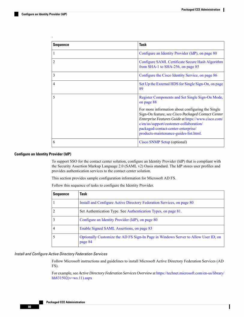
.
TaskSequence
Configure an Identity Provider (IdP), on page 801
Configure SAML Certificate Secure Hash Algorithmfrom SHA-1 to SHA-256, on page 85
2
Configure the Cisco Identity Service, on page 863
Set Up the External HDS for Single Sign-On, on page89
4
Register Components and Set Single Sign-On Mode,on page 88
For more information about configuring the SingleSign-On feature, see Cisco Packaged Contact CenterEnterprise Features Guide at https://www.cisco.com/c/en/us/support/customer-collaboration/packaged-contact-center-enterprise/products-maintenance-guides-list.html.
5
Cisco SNMP Setup (optional)6
Configure an Identity Provider (IdP)
To support SSO for the contact center solution, configure an Identity Provider (IdP) that is compliant withthe Security Assertion Markup Language 2.0 (SAML v2) Oasis standard. The IdP stores user profiles andprovides authentication services to the contact center solution.
This section provides sample configuration information for Microsoft AD FS.
Follow this sequence of tasks to configure the Identity Provider.
TaskSequence
Install and Configure Active Directory Federation Services, on page 801
Set Authentication Type. See Authentication Types, on page 81.2
Configure an Identity Provider (IdP), on page 803
Enable Signed SAML Assertions, on page 834
Optionally Customize the AD FS Sign-In Page in Windows Server to Allow User ID, onpage 84
5
Install and Configure Active Directory Federation Services
Follow Microsoft instructions and guidelines to install Microsoft Active Directory Federation Services (ADFS).
For example, see Active Directory Federation Services Overview at https://technet.microsoft.com/en-us/library/hh831502(v=ws.11).aspx
Packaged CCE Administration80
Packaged CCE AdministrationConfigure an Identity Provider (IdP)
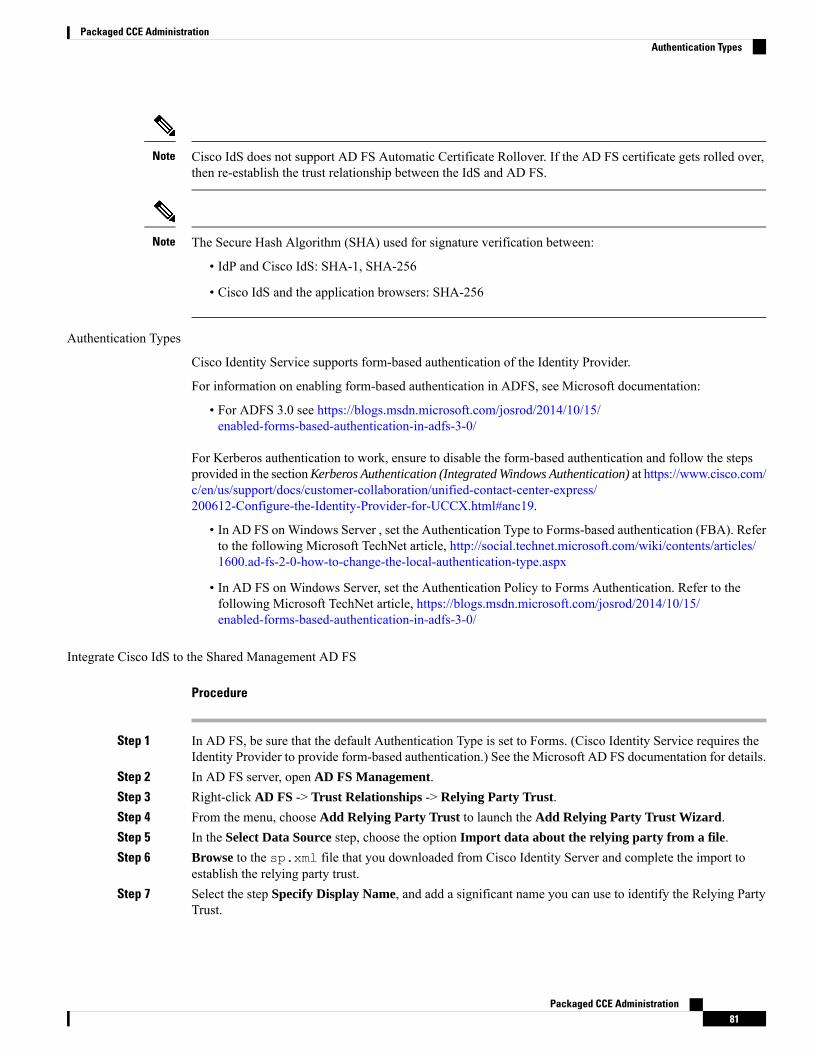
Cisco IdS does not support AD FS Automatic Certificate Rollover. If the AD FS certificate gets rolled over,then re-establish the trust relationship between the IdS and AD FS.
Note
The Secure Hash Algorithm (SHA) used for signature verification between:
• IdP and Cisco IdS: SHA-1, SHA-256
• Cisco IdS and the application browsers: SHA-256
Note
Authentication Types
Cisco Identity Service supports form-based authentication of the Identity Provider.
For information on enabling form-based authentication in ADFS, see Microsoft documentation:
• For ADFS 3.0 see https://blogs.msdn.microsoft.com/josrod/2014/10/15/enabled-forms-based-authentication-in-adfs-3-0/
For Kerberos authentication to work, ensure to disable the form-based authentication and follow the stepsprovided in the sectionKerberos Authentication (Integrated Windows Authentication) at https://www.cisco.com/c/en/us/support/docs/customer-collaboration/unified-contact-center-express/200612-Configure-the-Identity-Provider-for-UCCX.html#anc19.
• In AD FS onWindows Server , set the Authentication Type to Forms-based authentication (FBA). Referto the following Microsoft TechNet article, http://social.technet.microsoft.com/wiki/contents/articles/1600.ad-fs-2-0-how-to-change-the-local-authentication-type.aspx
• In AD FS on Windows Server, set the Authentication Policy to Forms Authentication. Refer to thefollowing Microsoft TechNet article, https://blogs.msdn.microsoft.com/josrod/2014/10/15/enabled-forms-based-authentication-in-adfs-3-0/
Integrate Cisco IdS to the Shared Management AD FS
Procedure
Step 1 In AD FS, be sure that the default Authentication Type is set to Forms. (Cisco Identity Service requires theIdentity Provider to provide form-based authentication.) See the Microsoft AD FS documentation for details.
Step 2 In AD FS server, open AD FS Management.Step 3 Right-click AD FS -> Trust Relationships -> Relying Party Trust.Step 4 From the menu, choose Add Relying Party Trust to launch the Add Relying Party Trust Wizard.Step 5 In the Select Data Source step, choose the option Import data about the relying party from a file.Step 6 Browse to the sp.xml file that you downloaded from Cisco Identity Server and complete the import to
establish the relying party trust.Step 7 Select the step Specify Display Name, and add a significant name you can use to identify the Relying Party
Trust.
Packaged CCE Administration81
Packaged CCE AdministrationAuthentication Types
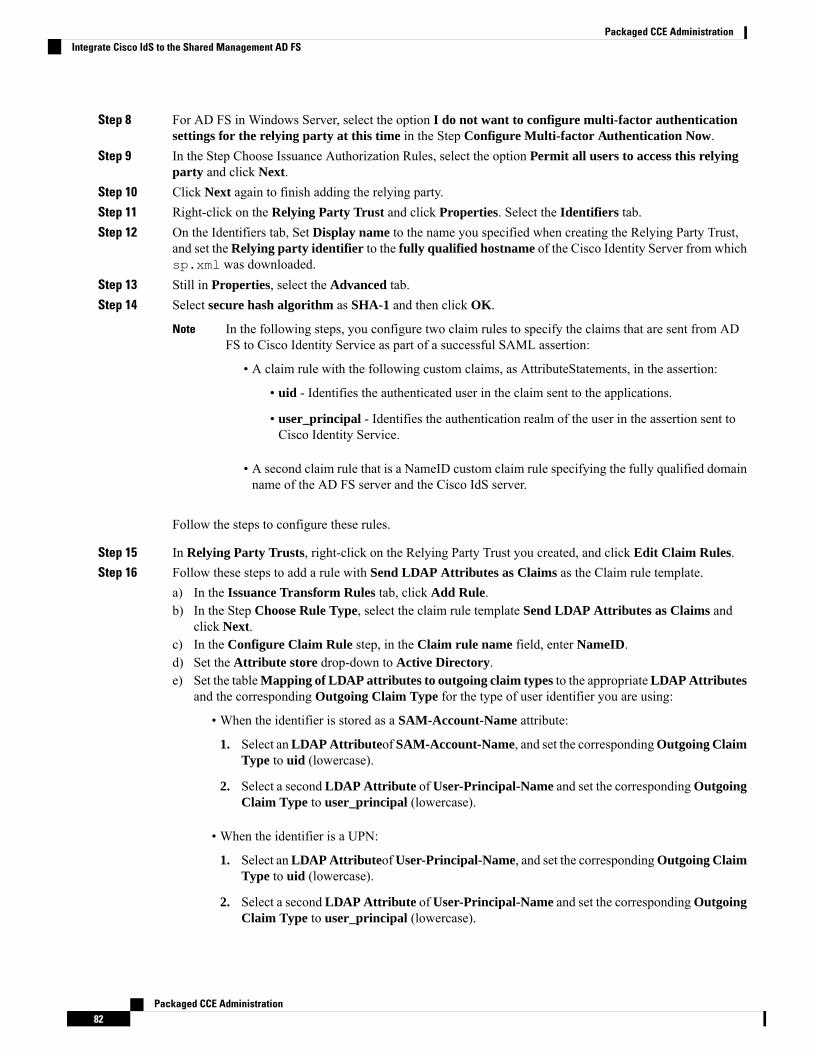
Step 8 For AD FS in Windows Server, select the option I do not want to configure multi-factor authenticationsettings for the relying party at this time in the Step Configure Multi-factor Authentication Now.
Step 9 In the Step Choose Issuance Authorization Rules, select the option Permit all users to access this relyingparty and click Next.
Step 10 Click Next again to finish adding the relying party.Step 11 Right-click on the Relying Party Trust and click Properties. Select the Identifiers tab.Step 12 On the Identifiers tab, Set Display name to the name you specified when creating the Relying Party Trust,
and set the Relying party identifier to the fully qualified hostname of the Cisco Identity Server from whichsp.xml was downloaded.
Step 13 Still in Properties, select the Advanced tab.Step 14 Select secure hash algorithm as SHA-1 and then click OK.
In the following steps, you configure two claim rules to specify the claims that are sent from ADFS to Cisco Identity Service as part of a successful SAML assertion:
• A claim rule with the following custom claims, as AttributeStatements, in the assertion:
• uid - Identifies the authenticated user in the claim sent to the applications.
• user_principal - Identifies the authentication realm of the user in the assertion sent toCisco Identity Service.
• A second claim rule that is a NameID custom claim rule specifying the fully qualified domainname of the AD FS server and the Cisco IdS server.
Note
Follow the steps to configure these rules.
Step 15 In Relying Party Trusts, right-click on the Relying Party Trust you created, and click Edit Claim Rules.Step 16 Follow these steps to add a rule with Send LDAP Attributes as Claims as the Claim rule template.
a) In the Issuance Transform Rules tab, click Add Rule.b) In the Step Choose Rule Type, select the claim rule template Send LDAP Attributes as Claims and
click Next.c) In the Configure Claim Rule step, in the Claim rule name field, enter NameID.d) Set the Attribute store drop-down to Active Directory.e) Set the tableMapping of LDAP attributes to outgoing claim types to the appropriateLDAP Attributes
and the corresponding Outgoing Claim Type for the type of user identifier you are using:
• When the identifier is stored as a SAM-Account-Name attribute:
1. Select anLDAP Attributeof SAM-Account-Name, and set the correspondingOutgoing ClaimType to uid (lowercase).
2. Select a second LDAP Attribute ofUser-Principal-Name and set the correspondingOutgoingClaim Type to user_principal (lowercase).
• When the identifier is a UPN:
1. Select anLDAP AttributeofUser-Principal-Name, and set the correspondingOutgoing ClaimType to uid (lowercase).
2. Select a second LDAP Attribute ofUser-Principal-Name and set the correspondingOutgoingClaim Type to user_principal (lowercase).
Packaged CCE Administration82
Packaged CCE AdministrationIntegrate Cisco IdS to the Shared Management AD FS
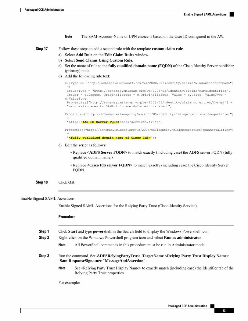
The SAM-Account-Name or UPN choice is based on the User ID configured in the AW.Note
Step 17 Follow these steps to add a second rule with the template custom claim rule.a) Select Add Rule on the Edit Claim Rules window.b) Select Send Claims Using Custom Rule.c) Set the name of rule to the fully qualified domain name (FQDN) of the Cisco Identity Server publisher
(primary) node.d) Add the following rule text:
c:[Type == "http://schemas.microsoft.com/ws/2008/06/identity/claims/windowsaccountname"]=>issue(Type = "http://schemas.xmlsoap.org/ws/2005/05/identity/claims/nameidentifier",Issuer = c.Issuer, OriginalIssuer = c.OriginalIssuer, Value = c.Value, ValueType =c.ValueType,Properties["http://schemas.xmlsoap.org/ws/2005/05/identity/claimproperties/format"] ="urn:oasis:names:tc:SAML:2.0:nameid-format:transient",
Properties["http://schemas.xmlsoap.org/ws/2005/05/identity/claimproperties/namequalifier"]="http://<AD FS Server FQDN>/adfs/services/trust",
Properties["http://schemas.xmlsoap.org/ws/2005/05/identity/claimproperties/spnamequalifier"]="<fully qualified domain name of Cisco IdS>");
e) Edit the script as follows:
• Replace <ADFS Server FQDN> to match exactly (including case) the ADFS server FQDN (fullyqualified domain name.)
• Replace <Cisco IdS server FQDN> to match exactly (including case) the Cisco Identity ServerFQDN.
Step 18 Click OK.
Enable Signed SAML Assertions
Enable Signed SAML Assertions for the Relying Party Trust (Cisco Identity Service).
Procedure
Step 1 Click Start and type powershell in the Search field to display the Windows Powershell icon.Step 2 Right-click on the Windows Powershell program icon and select Run as administrator
All PowerShell commands in this procedure must be run in Administrator mode.Note
Step 3 Run the command, Set-ADFSRelyingPartyTrust -TargetName <Relying Party Trust Display Name>-SamlResponseSignature "MessageAndAssertion".
Set <Relying Party Trust Display Name> to exactly match (including case) the Identifier tab of theRelying Party Trust properties.
Note
For example:
Packaged CCE Administration83
Packaged CCE AdministrationEnable Signed SAML Assertions
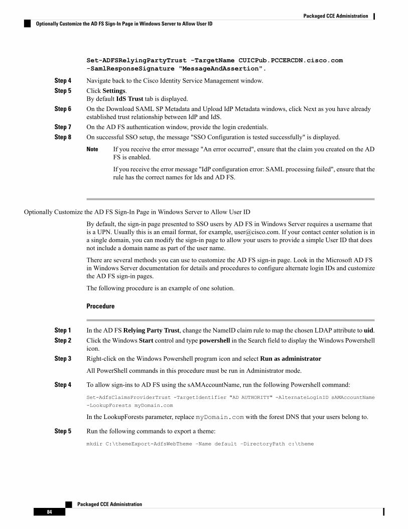
Set-ADFSRelyingPartyTrust -TargetName CUICPub.PCCERCDN.cisco.com-SamlResponseSignature "MessageAndAssertion".
Step 4 Navigate back to the Cisco Identity Service Management window.Step 5 Click Settings.
By default IdS Trust tab is displayed.Step 6 On the Download SAML SP Metadata and Upload IdP Metadata windows, click Next as you have already
established trust relationship between IdP and IdS.Step 7 On the AD FS authentication window, provide the login credentials.Step 8 On successful SSO setup, the message "SSO Configuration is tested successfully" is displayed.
If you receive the error message "An error occurred", ensure that the claim you created on the ADFS is enabled.
If you receive the error message "IdP configuration error: SAML processing failed", ensure that therule has the correct names for Ids and AD FS.
Note
Optionally Customize the AD FS Sign-In Page in Windows Server to Allow User ID
By default, the sign-in page presented to SSO users by AD FS in Windows Server requires a username thatis a UPN. Usually this is an email format, for example, [email protected]. If your contact center solution is ina single domain, you can modify the sign-in page to allow your users to provide a simple User ID that doesnot include a domain name as part of the user name.
There are several methods you can use to customize the AD FS sign-in page. Look in the Microsoft AD FSin Windows Server documentation for details and procedures to configure alternate login IDs and customizethe AD FS sign-in pages.
The following procedure is an example of one solution.
Procedure
Step 1 In the AD FS Relying Party Trust, change the NameID claim rule to map the chosen LDAP attribute to uid.Step 2 Click the Windows Start control and type powershell in the Search field to display the Windows Powershell
icon.Step 3 Right-click on the Windows Powershell program icon and select Run as administrator
All PowerShell commands in this procedure must be run in Administrator mode.
Step 4 To allow sign-ins to AD FS using the sAMAccountName, run the following Powershell command:
Set-AdfsClaimsProviderTrust -TargetIdentifier "AD AUTHORITY" -AlternateLoginID sAMAccountName
-LookupForests myDomain.com
In the LookupForests parameter, replace myDomain.com with the forest DNS that your users belong to.
Step 5 Run the following commands to export a theme:
mkdir C:\themeExport-AdfsWebTheme –Name default –DirectoryPath c:\theme
Packaged CCE Administration84
Packaged CCE AdministrationOptionally Customize the AD FS Sign-In Page in Windows Server to Allow User ID
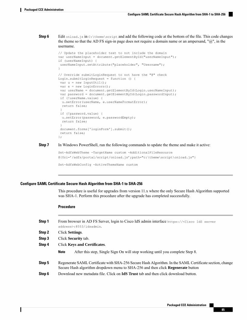
Step 6 Edit onload.js in C:\theme\script and add the following code at the bottom of the file. This code changesthe theme so that the AD FS sign-in page does not require a domain name or an ampersand, "@", in theusername.// Update the placeholder text to not include the domainvar userNameInput = document.getElementById("userNameInput");if (userNameInput) {userNameInput.setAttribute("placeholder", "Username");}
// Override submitLoginRequest to not have the "@" checkLogin.submitLoginRequest = function () {var u = new InputUtil();var e = new LoginErrors();var userName = document.getElementById(Login.userNameInput);var password = document.getElementById(Login.passwordInput);if (!userName.value) {u.setError(userName, e.userNameFormatError);return false;}if (!password.value) {u.setError(password, e.passwordEmpty);return false;}document.forms['loginForm'].submit();return false;};
Step 7 In Windows PowerShell, run the following commands to update the theme and make it active:
Set-AdfsWebTheme -TargetName custom -AdditionalFileResource
@{Uri=’/adfs/portal/script/onload.js’;path="c:\theme\script\onload.js"}
Set-AdfsWebConfig -ActiveThemeName custom
Configure SAML Certificate Secure Hash Algorithm from SHA-1 to SHA-256
This procedure is useful for upgrades from version 11.x where the only Secure Hash Algorithm supportedwas SHA-1. Perform this procedure after the upgrade has completed successfully.
Procedure
Step 1 From browser in AD FS Server, login to Cisco IdS admin interface https://<Cisco IdS server
address>:8553/idsadmin.Step 2 Click Settings.Step 3 Click Security tab.Step 4 Click Keys and Certificates.
After this step, Single Sign On will stop working until you complete Step 8.Note
Step 5 Regenerate SAMLCertificate with SHA-256 Secure Hash Algorithm. In the SAMLCertificate section, changeSecure Hash algorithm dropdown menu to SHA-256 and then click Regenerate button
Step 6 Download new metadata file. Click on IdS Trust tab and then click download button.
Packaged CCE Administration85
Packaged CCE AdministrationConfigure SAML Certificate Secure Hash Algorithm from SHA-1 to SHA-256
Step 7 Change Secure Hash Algorithm in AD FS Relaying Party Trust configuration. In AD FS server, open AD FSManagement. Go to ADFS ->Trust Relationships->Relying Party Trusts, right click on existing RelyingParty Trust for Cisco IdS and then click on Properties. In the Advanced Tab, change the Secure Hash Algorithmto SHA-256. Click Apply.
Step 8 Update Relying party trust on AD FS. From AD FS Server, run the following Powershell command:Update-AdfsRelyingPartyTrust -MetadataFile <path to Step 6 new MetaData File> -TargetName
<Relying Party Trust Display Name>
Configure the Cisco Identity Service
The Cisco Identity Service (Cisco IdS) provides authorization between the Identity Provider (IdP) andapplications.
When you configure the Cisco IdS, you set up a metadata exchange between the Cisco IdS and the IdP. Thisexchange establishes a trust relationship that then allows applications to use the Cisco IdS for single sign-on.You establish the trust relationship by downloading a metadata file from the Cisco IdS and uploading it tothe IdP. You can then select settings that are related to security, identify clients of the Cisco IdS service, andset log levels. If desired, enable Syslog format.
In Packaged CCE 4000 or 12000 Agent deployments:
• Unified CCE AW, Unified Intelligence Center, Finesse, and external HDS gets automatically associatedwith a default Cisco Identity Service (Cisco IdS).
• Make sure that the Principal AW is configured, and is functional before using the Single Sign-On toolin the Unified CCE Administration. Also, add the SSO-capable machines to the Inventory.
In Packaged CCE 2000 Agent deployments, you must manually associate an external HDS with a defaultCisco Identity Service (Cisco IdS). For more information, see Set Up the External HDS for Single Sign-On,on page 89.
Note
Procedure
Step 1 In the Unified CCE Administration, choose Overview > Infrastructure Settings > Device Configuration >Identity Service.
Use a log in name in the format username@FQDN to log in to the Unified CCE Administration.Note
The Identity Service Nodes, Identity Service Settings, and Identity Service Clients tabs appear.Step 2 Click Identity Service Nodes.
You can view the overall Node level and identify which nodes are in service. You can also view the SAMLCertificate Expiry details for each node, indicating when the certificate is due to expire. The node Statusoptions are Not Configured, In Service, Partial Service, and Out of Service. Click a status to see moreinformation. The star to the right of one of the Node names identifies the node that is the primary publisher.
Step 3 Click Identity Service Settings.Step 4 Click Security.Step 5 Click Tokens.
Packaged CCE Administration86
Packaged CCE AdministrationConfigure the Cisco Identity Service
Enter the duration for the following settings:
• Refresh Token Expiry -- Refresh token is used to get new Access tokens. This parameter specifies theduration after which the Refresh token expires. The default value is 10 hours. The minimum value is 2hours. The maximum is 24 hours.
• Authorization Code Expiry -- Authorization code is used to get Access tokens from Cisco IdS. Thisparameter specifies the duration after which the Authorization code expires. The default value is 1 minute,which is also the minimum. The maximum is 10 minutes.
• Access Token Expiry -- Access token contains security credentials used to authorize clients for accessingresource server. This parameter specifies the duration after which the Access token expires. The defaultvalue is 60 minutes. The minimum value is 5 minutes. The maximum is 120 minutes.
Step 6 Set the Encrypt Token (optional); the default setting is On. Use this configuration to secure the tokens asCisco IdS issues tokens in both plain text or encrypted formats.
Step 7 Click Save.Step 8 Click Keys and Certificates.
The Generate Keys and SAML Certificate page opens and allows you to:
• Regenerate the Encryption/Signature key by clicking Regenerate. A message appears to say that theToken Registration is successful and advises you to restart the system to complete the configuration. AnAdministrator regenerates the Encryption/Signature key when it is exposed or compromised.
• Regenerate the SAML Certificate by clicking Regenerate. A message appears to say that the SAMLcertificate regeneration is successful. SAML certificate is regenerated when it expires or when IdS relyingparty trust configuration on IdP is deleted.
Establish the trust relationship again whenever the Encryption keys or SAML certificates areregenerated.
Note
Step 9 Click Save.Step 10 Click Identity Service Clients.
On the Identity Service Clients tab, you can view the existing Cisco IdS clients, with the client name, clientID, and a redirect URL. To search for a particular client, click the Search icon above the list of names andtype the name of client.
Step 11 To add a client on the Identity Service Clients tab:a) Click New.b) Enter the name of client.c) Enter the Redirect URL. To add more than one URL, click the plus icon.d) Click Add (or click Clear and then click the X to close the page without adding the client).
Step 12 To edit or delete a client, highlight the client row and click the ellipses under Actions. Then:
• Click Edit to edit the client's name, ID, or redirect URL. On the Edit Client page, make changes andclick Save (or click Clear and then click the X to close the page without saving edits).
• Click Delete to delete the client.
Step 13 Click Identity Service Settings.Step 14 Click Troubleshooting to perform some optional troubleshooting.
Packaged CCE Administration87
Packaged CCE AdministrationConfigure the Cisco Identity Service
Step 15 From the Log Level drop-down list, set the local log level by choosing Error, Warning, Info (the default),Debug, or Trace.
Step 16 To receive errors in Syslog format, enter the name of the Remote Syslog Server in the Host (Optional) field.Step 17 Click Save.
You can now:
• Register components with the Cisco IdS.
• Enable (or disable) SSO for the entire deployment.
If SSO is enabled in the deployment, then import all the IdS server nodes certificate into Cisco Finesse, CUIC,and LiveData component trust store.
Note
Register Components and Set Single Sign-On Mode
If you add any SSO-compatible machines to the System Inventory after you register components with theCisco IdS, those machines are registered automatically.
Before you begin
• Configure the Cisco Identity Service (Cisco IdS).
• Disable popup blockers. It enables viewing all test results correctly.
• If you are using Internet Explorer, verify that:
• It is not in the Compatibility Mode.
• You are using the fully qualified domain name of AW to access the CCE Administration (forexample, https://<FQDN>/cceadmin).
Procedure
Step 1 In the Unified CCE Administration, navigate to Features > Single Sign-OnOverview > InfrastructureSettings > Device Configuration > Identity Service.
Step 2 Click the Register button to register all SSO-compatible components with the Cisco IdS.
The component status table displays the registration status of each component.
If a component fails to register, correct the error and click Retry.
Step 3 Click the Test button. When the new browser tab opens, you may be prompted to accept a certificate. In orderfor the page to load, accept any certificates. Then, when presented with a log in dialog, log in as a user withSSO credentials.
The test process verifies that each component has been configured correctly to reach the Identity Provider,and that the Cisco IdS successfully generates access tokens. Each component that you are setting up for SSOis tested.
Packaged CCE Administration88
Packaged CCE AdministrationRegister Components and Set Single Sign-On Mode

The component status table displays the status of testing each component.
If a test is unsuccessful, correct the error, and then click Test again.
Test results are not saved. If you refresh the page, run the test again before enabling SSO.
Step 4 Select the SSO mode for the system from the Set Mode drop-down menu:
• Non-SSO: This mode disables SSO for all agents and supervisors. Users log in using existing ActiveDirectory-based local authentication.
• Hybrid: This mode allows you to enable agents and supervisors selectively for SSO.
• SSO: This mode enables SSO for all agents and supervisors.
The component status table displays the status of setting the SSO mode on each component.
If the SSO mode fails to be set on a component, correct the error, and then select the mode again.
Set Up the External HDS for Single Sign-On
If you have an external HDS in 2000 Agent deployments, manually associate it with a default Cisco IdS byexecuting the following instructions.
Procedure
Step 1 In Unified CCE Administration, click Infrastructure > Inventory to open the Inventory page.Step 2 Click the pencil icon for the External HDS to open the edit machine popup window.Step 3 Click the Search icon next to Default Identity Service.
The Select Identity Service popup window opens.Step 4 Enter the machine name for the Cisco IdS in the Search field or choose the Cisco IdS from the list.Step 5 Click Save.
Application GatewayDetailed information for Application Gateway is available in the Cisco Packaged Contact Center EnterpriseFeatures Guide at https://www.cisco.com/c/en/us/support/customer-collaboration/packaged-contact-center-enterprise/products-maintenance-guides-list.html.
Peripheral GatewaysThis display-only tool shows details about the peripheral gateways and peripherals in your deployment.
Click the Site tab to view the details of peripheral gateways and peripherals configured for that site.
Packaged CCE Administration89
Packaged CCE AdministrationSet Up the External HDS for Single Sign-On
Log Collection
Only set trace level to detailed and run log collection during off-peak hours. Do not run log collection duringheavy call load.
Important
Use the Log Collection tool to collect logs for these components:
• Unified CCE
• Unified Communications Manager
• Unified CVP
• Finesse
• Unified Intelligence Center
Unless limited by their role, administrators have full access to Log Collection. Supervisors have no access tothis tool.
You can select individual or multiple components for log collection, and specify the start and end time forthe logs. The maximum duration for log collection is eight hours. The logs for all selected components areconsolidated into a single downloadable zip file. You can run one log collection at a time.
For most components, you can specify whether normal or detailed logs are collected using the Trace Levelsoption. Click Trace Levels to view the current trace level for each component and, if necessary, change it forfuture log collection.
The Current Level for each component can be Normal, Detailed, or Custom. Custom indicates that the levelhas been set outside of Unified CCE Administration and does not match the Normal or Detailed settingsfor that component.
System-wide trace levels are gathered periodically. If a trace level is changed outside of Unified CCEAdministration, it may take several minutes before the new trace level appears in the Log Collection tool.
To use Log Collection to debug a problem:
1. In Unified CCE Administration, choose Overview > Infrastructure Settings > Log Collection.
2. To change trace level to detailed, click Trace Levels, and select Detailed from the drop-down menus forthe relevant components. Click Update Trace Levels to apply the changes.
3. Recreate the problem in your deployment or wait until the problem occurs again.
4. Return to the Log Collection tool and collect logs for the appropriate date and time interval, during whichdetailed trace level was selected. For example, if you set the trace level to detailed on 01/27/2014 at 09:00,you can collect detailed logs for intervals after that date and time.
5. When you have finished debugging the problem, reset the trace level to Normal.
To collect log files:
1. In Unified CCE Administration, choose Overview > Infrastructure Settings > Log Collection.
2. Check each component for which you want to collect logs, or check Select All.
Packaged CCE Administration90
Packaged CCE AdministrationLog Collection
3. Click the calendar icon to select a Start Time and End Time for log collection. Select a date and timefrom the calendar, and then click anywhere outside the calendar to save your selection.
4. Click Collect Logs.
The new log collection appears in the list with an in progress icon in the Status column. When the logcollection is complete, its download and delete icons are enabled automatically.
If errors are encountered during log collection, the Status column shows an error icon. Hover over the iconto view the tooltip which explains the error. If the Unified CCE Administration service restarts during logcollection, a cancelled icon appears in the Status column. You can delete log collections that have errors orhave been cancelled; you cannot download these collections.
Note
5. Click the download icon to download the log zip file.
To delete a stored log collection, click the delete icon for that collection in the list.
Command Execution PaneThe Command Execution Pane provides a user interface in the Unified CCEAdministration. This pane allowsSystem Administrators to execute REST API calls to Unified CVP, Unified CVP Reporting, and VirtualizedVoice Browser.
Use this pane to configure certain parameters in Unified CVP, Unified CVP Reporting, and Virtualized VoiceBrowser, for which no user interface is available in the Unified CCEAdministration. For example, to configureDNIS in CVP.
Caution
For DNIS API details, see the Unified CVP API Developer Guide at https://developer.cisco.com/site/customer-voice-portal/documents/rest-api/.
Note
Before you begin
If you do not have CA-signed certificates, import self-signed certificates of CVP Call Server and VirtualizedVoice Browser (VVB) into the AW machines. For more information, see Self-Signed Certificates.
Procedure
Step 1 In Unified CCEAdministration, chooseOverview > Infrastructure Settings >Command Execution Pane.Step 2 Complete the following parameters.
Packaged CCE Administration91
Packaged CCE AdministrationCommand Execution Pane

DescriptionField
Choose the machine type. Valid values are:
• Unified CVP
• Unified CVP Reporting
• Virtualized Voice Browser
Machine Type
Choose the site. You can run the REST API call on the Main site or the Remotesite machines.
Default is All Sites when a Machine Type is selected.
Site
Choose a Host Name or multiple Host Names.
Host Names are displayed based on the selected Machine Type and Site.
Host Name
Choose the HTTP method. Valid values are:
• GET
• POST
• PUT
• DELETE
Default is GET.
Method
Enter the relative URI of the API.
Based on theMachine Type you select, most frequently used APIs are displayedas auto suggestions. For example, when the Machine Type is Unified CVP,the path displayed is cvp-orm/rest/cvpconfig/properties.
For more information about APIs, refer to the respective CCE Componentdocumentation.
Path
Enter the request data in JSON or XML format.
Mandatory if the Method is POST or PUT.
Request Body
Choose the Response Type as JSON or XML. Default is JSON.
Response Type is only applicable for Success result.Note
Response Type
Step 3 Click Execute.
The window displays the Success or Failure response.
The RESET button resets all the fields on the page to its default value.Note
Packaged CCE Administration92
Packaged CCE AdministrationCommand Execution Pane
User Setup
Manage Agents
AgentsAgents respond to contacts from customers. These contact requests are often phone calls, but can also be chatrequests or emails.
You can configure the types of contacts that are routed to an agent. For example, if an agent is a member ofa skill group that is set up for the Cisco_Voice routing domain only, that agent is a voice agent for that skillgroup. If an agent is a member of a skill group that is set up for a nonvoice routing domain, that agent is amultichannel agent for that skill group.
Agents can be located at a contact center site or designated as mobile agents who work elsewhere—perhapsfrom a home office. Setting upmobile agents is documented in the Cisco Packaged Contact Center EnterpriseFeatures Guide , at https://www.cisco.com/c/en/us/support/customer-collaboration/packaged-contact-center-enterprise/products-maintenance-guides-list.html.
Agents can be assigned to skill groups and to one team. Teams are organizational units that reflect the reportingstructure in a contact center. They can also be assigned attributes that indicate their proficiency—perhapsexpertise in a certain language or technology.
Agents work from an agent desktop. Each agent is associated with one Desk Settings, either the current defaultdesk settings or another desk settings. Desk settings are a set of permissions or characteristics that control thefeatures agents can see and use while they are interacting with customers.
You can indicate that an agent is a supervisor. An agent with supervisor status can oversee multiple teams,can view reports that monitor activities of the agents on those teams, and can join and participate inagent/customer calls. Supervisors work from a supervisor desktop.
In Unified CCE Administration, choose Users > Agents to view the Agent list. the administrators can seeand maintain all agents. Supervisors see a list of agents who are on teams they supervise.
Related TopicsAdd and Maintain Agents, on page 93Add an Agent by Copying an Existing Agent Record, on page 98Edit Description, Desk Settings, and Teams for Multiple Agents, on page 101Add Supervisor Status to an Agent, on page 104Attributes, on page 123Desk Settings, on page 185Roles, on page 105Skill Groups, on page 120Teams, on page 113
Add and Maintain AgentsThis procedure explains how to add an agent. For information on maintaining agents, see Update Objects, onpage 4 and Delete Objects, on page 7.
You can add agents one at a time from the Agents page , using this procedure. You can also do the following:
Packaged CCE Administration93
Packaged CCE AdministrationUser Setup
• Create a new agent by copying an existing agent record (see Add an Agent by Copying an Existing AgentRecord, on page 98).
• Run bulk jobs to add or edit multiple agent records (see Manage Bulk Jobs, on page 251).
• Edit the skill groupmembership for multiple agents at once (see Edit Skill GroupMembership forMultipleAgents, on page 100).
• Edit descriptions, desk settings, and teams for multiple agents at once (see Edit Description, Desk Settings,and Teams for Multiple Agents, on page 101).
Procedure
Step 1 In Unified CCE Administration, choose Users > Agents.Step 2 Click New to open the New Agent page.
This page has five tabs: Description, Attributes, Skill Groups, Supervised Teams, and Email & Chat.You cannot save the agent until you have entered all required fields on the General tab. You can completeother tabs as needed and in any order.
Step 3 Complete the fields on the General tab:
DescriptionRequired?Field
Indicates whether the agent is set for single sign-on (SSO). When SSO isenabled, the agent uses Active Directory or other SSO credentials to sign intothe agent desktop and other tools.
You can check this check box to enable SSO for this agent if SSO is setglobally to mixed mode.
You cannot edit this setting if SSO is enabled or disabled globally.
If SSO is enabled globally, saving the agent's new or updated record enablesSSO for the agent.
noEnable SSO
Checked by default. Uncheck the check box only if you do not want this agentto be able to sign in.
noLogin Enabled
Check to configure this agent as a Supervisor.
Note • When you check this check box, a user account is created inCisco Unified Intelligence Center with the supervisor'susername and domain name. If the username and domainname exists in Unified Intelligence Center, the user accountand supervisor's record is synchronized to have sameusername and domain name.
• For an existing supervisor's record, if you uncheck this checkbox, the corresponding user account is deleted from UnifiedIntelligence Center.
noIs Supervisor
This check box appears only when ECE is configured for a peripheral set ora data center. By default, it is not checked.
noSupport Email &Chat
Packaged CCE Administration94
Packaged CCE AdministrationAdd and Maintain Agents
DescriptionRequired?Field
Enter a unique username for the Agent.
Enter up to 255 characters as the username. Supports all characters, exceptfor the following:
Double quotation mark ("), forward slash (/), backward slash (\), squarebrackets ([ ]), colon (:), semicolon (;), pipe (|), equal to (=), comma (,), plussign (+), asterisk (*), question mark (?), angle brackets (< >), and SPACE.
For supervisors and for agents with single sign-on (SSO) enabled, theusername is the user's Active Directory or SSO account username.
For supervisors who are not enabled for single sign-on (SSO), the ActiveDirectory username must be in the user@domain format.
An agent who is designated as a supervisor signs in to UnifiedCCE Administration with this username.
Remember
Ensure that Agent ID (Peripheral number) and agent Login nameis unique for each user.
Note
yesUsername
See Native Character Sets.yesFirst Name
See Native Character Sets.yesLast Name
Enter a unique string of up to 11 digits.
If you leave this field blank, Packaged CCE automatically generates a 7-digitagent ID, which you can later edit.
The agent uses the Agent ID to sign in to Cisco Finesse.
-Agent ID
Enter a description of the agent.
See Native Character Sets.
noDescription
The Desk Settings field defaults to show the current system-default. (SeeMain Site, on page 228.) To change it, click the magnifying glass icon todisplay the Select Desk Settings list where you can select a different desksetting.
-Desk Settings
A departmental administrator must select one department from the pop-uplist to associate with this agent. The list shows all administrator's departments.
A global administrator can retain the default value for this field, which setsthe agent as global (belonging to no departments), or can select a departmentfor this agent.
See Departments, on page 133 for more information about associating agentswith departments.
yes (fordepartmentaladministrators)
Department
Packaged CCE Administration95
Packaged CCE AdministrationAdd and Maintain Agents
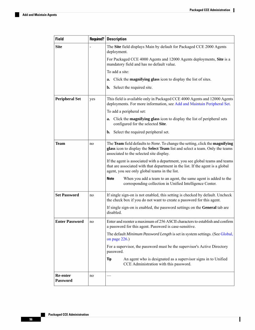
DescriptionRequired?Field
The Site field displays Main by default for Packaged CCE 2000 Agentsdeployment.
For Packaged CCE 4000 Agents and 12000 Agents deployments, Site is amandatory field and has no default value.
To add a site:
a. Click the magnifying glass icon to display the list of sites.
b. Select the required site.
-Site
This field is available only in Packaged CCE 4000 Agents and 12000 Agentsdeployments. For more information, see Add and Maintain Peripheral Set.
To add a peripheral set:
a. Click the magnifying glass icon to display the list of peripheral setsconfigured for the selected Site.
b. Select the required peripheral set.
yesPeripheral Set
TheTeam field defaults toNone. To change the setting, click themagnifyingglass icon to display the Select Team list and select a team. Only the teamsassociated to the selected site display.
If the agent is associated with a department, you see global teams and teamsthat are associated with that department in the list. If the agent is a globalagent, you see only global teams in the list.
When you add a team to an agent, the same agent is added to thecorresponding collection in Unified Intelligence Center.
Note
noTeam
If single sign-on is not enabled, this setting is checked by default. Uncheckthe check box if you do not want to create a password for this agent.
If single sign-on is enabled, the password settings on the General tab aredisabled.
noSet Password
Enter and reenter amaximumof 256ASCII characters to establish and confirma password for this agent. Password is case-sensitive.
The defaultMinimum Password Length is set in system settings. (See Global,on page 226.)
For a supervisor, the password must be the supervisor's Active Directorypassword.
An agent who is designated as a supervisor signs in to UnifiedCCE Administration with this password.
Tip
noEnter Password
—noRe-enterPassword
Packaged CCE Administration96
Packaged CCE AdministrationAdd and Maintain Agents
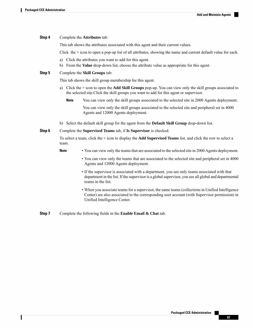
Step 4 Complete the Attributes tab:
This tab shows the attributes associated with this agent and their current values.
Click the + icon to open a pop-up list of all attributes, showing the name and current default value for each.
a) Click the attributes you want to add for this agent.b) From the Value drop-down list, choose the attribute value as appropriate for this agent.
Step 5 Complete the Skill Groups tab:
This tab shows the skill group membership for this agent.
a) Click the + icon to open the Add Skill Groups pop-up. You can view only the skill groups associated tothe selected site.Click the skill groups you want to add for this agent or supervisor.
You can view only the skill groups associated to the selected site in 2000 Agents deployment.
You can view only the skill groups associated to the selected site and peripheral set in 4000Agents and 12000 Agents deployment.
Note
b) Select the default skill group for the agent from the Default Skill Group drop-down list.
Step 6 Complete the Supervised Teams tab, if Is Supervisor is checked.
To select a team, click the + icon to display the Add Supervised Teams list, and click the row to select ateam.
• You can view only the teams that are associated to the selected site in 2000 Agents deployment.
• You can view only the teams that are associated to the selected site and peripheral set in 4000Agents and 12000 Agents deployment.
• If the supervisor is associated with a department, you see only teams associated with thatdepartment in the list. If the supervisor is a global supervisor, you see all global and departmentalteams in the list.
• When you associate teams for a supervisor, the same teams (collections in Unified IntelligenceCenter) are also associated to the corresponding user account (with Supervisor permission) inUnified Intelligence Center.
Note
Step 7 Complete the following fields in the Enable Email & Chat tab.
Packaged CCE Administration97
Packaged CCE AdministrationAdd and Maintain Agents
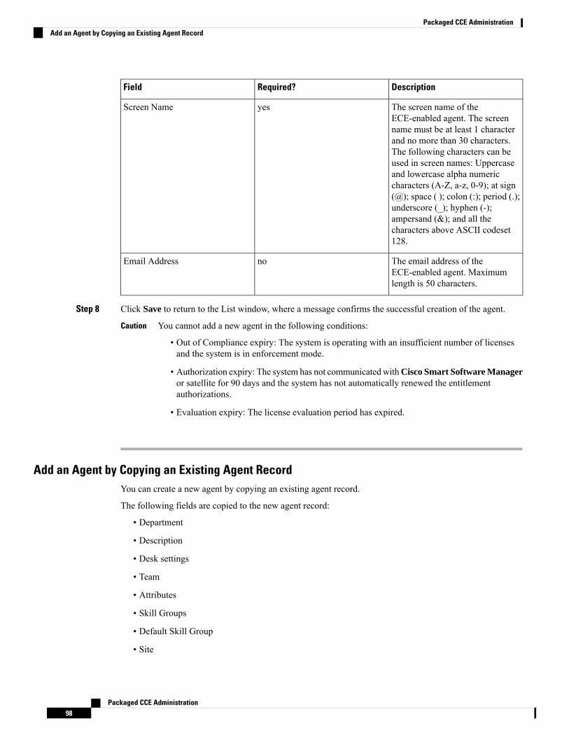
DescriptionRequired?Field
The screen name of theECE-enabled agent. The screenname must be at least 1 characterand no more than 30 characters.The following characters can beused in screen names: Uppercaseand lowercase alpha numericcharacters (A-Z, a-z, 0-9); at sign(@); space ( ); colon (:); period (.);underscore (_); hyphen (-);ampersand (&); and all thecharacters above ASCII codeset128.
yesScreen Name
The email address of theECE-enabled agent. Maximumlength is 50 characters.
noEmail Address
Step 8 Click Save to return to the List window, where a message confirms the successful creation of the agent.
You cannot add a new agent in the following conditions:
• Out of Compliance expiry: The system is operating with an insufficient number of licensesand the system is in enforcement mode.
• Authorization expiry: The system has not communicatedwithCisco Smart Software Manageror satellite for 90 days and the system has not automatically renewed the entitlementauthorizations.
• Evaluation expiry: The license evaluation period has expired.
Caution
Add an Agent by Copying an Existing Agent RecordYou can create a new agent by copying an existing agent record.
The following fields are copied to the new agent record:
• Department
• Description
• Desk settings
• Team
• Attributes
• Skill Groups
• Default Skill Group
• Site
Packaged CCE Administration98
Packaged CCE AdministrationAdd an Agent by Copying an Existing Agent Record
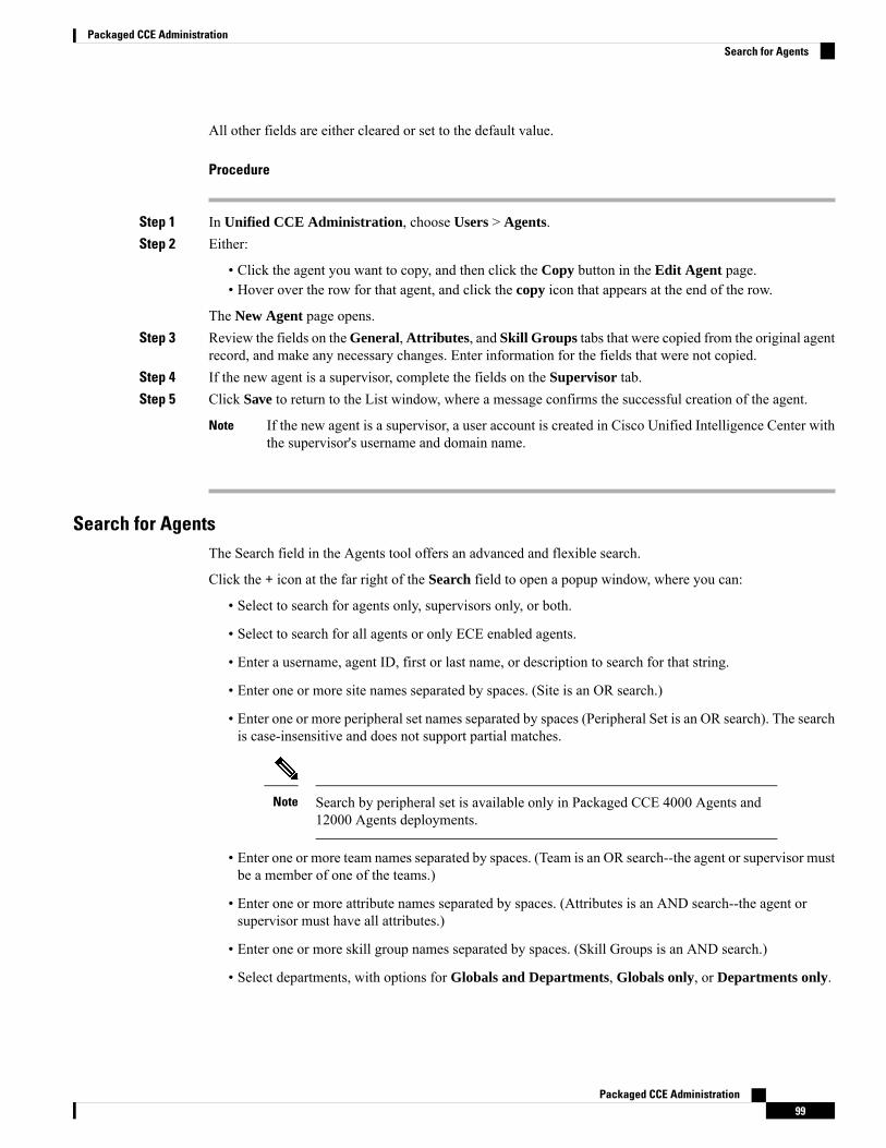
All other fields are either cleared or set to the default value.
Procedure
Step 1 In Unified CCE Administration, choose Users > Agents.Step 2 Either:
• Click the agent you want to copy, and then click the Copy button in the Edit Agent page.• Hover over the row for that agent, and click the copy icon that appears at the end of the row.
The New Agent page opens.Step 3 Review the fields on theGeneral,Attributes, and Skill Groups tabs that were copied from the original agent
record, and make any necessary changes. Enter information for the fields that were not copied.Step 4 If the new agent is a supervisor, complete the fields on the Supervisor tab.Step 5 Click Save to return to the List window, where a message confirms the successful creation of the agent.
If the new agent is a supervisor, a user account is created in Cisco Unified Intelligence Center withthe supervisor's username and domain name.
Note
Search for AgentsThe Search field in the Agents tool offers an advanced and flexible search.
Click the + icon at the far right of the Search field to open a popup window, where you can:
• Select to search for agents only, supervisors only, or both.
• Select to search for all agents or only ECE enabled agents.
• Enter a username, agent ID, first or last name, or description to search for that string.
• Enter one or more site names separated by spaces. (Site is an OR search.)
• Enter one or more peripheral set names separated by spaces (Peripheral Set is an OR search). The searchis case-insensitive and does not support partial matches.
Search by peripheral set is available only in Packaged CCE 4000 Agents and12000 Agents deployments.
Note
• Enter one or more team names separated by spaces. (Team is an OR search--the agent or supervisor mustbe a member of one of the teams.)
• Enter one or more attribute names separated by spaces. (Attributes is an AND search--the agent orsupervisor must have all attributes.)
• Enter one or more skill group names separated by spaces. (Skill Groups is an AND search.)
• Select departments, with options for Globals and Departments, Globals only, or Departments only.
Packaged CCE Administration99
Packaged CCE AdministrationSearch for Agents
• Selecting Globals and Departments or Departments only enables an input field where you can entera space-separated list of department names. (Departments is an OR search.)
Search by department is available only when departments are configured.
Search by site is available only when remote sites are configured.
Note
Manage Agent ExpertiseThere are two ways that agents can be categorized such that calls are sent to them based on their experienceand their expertise in handling specific types of customer concerns.
• You can add an agent to one or more skill groups. For example, agents who work on fulfilling ordersmight be added to a Customer Service or a Tracking Orders skill group.
• You can assign one or more attributes to an agent. For example, an agent who speaks fluent Spanishmight be assigned an attribute of Spanish.
Agent ReskillingSupervisors can reskill agents who are on teams that they supervise. This procedure explains how to reskilla single agent. For information on reskilling multiple agents at once, see Edit Skill Group Membership forMultiple Agents, on page 100.
If you remove an agent from the agent's default skill group, the agent's default skill group is changed to thesystem defined default skill group.
Note
Procedure
Step 1 In Unified CCE Administration Manage, choose Users > Agents to view the Agents list.Step 2 Click the agent you want to reskill.Step 3 Click the Skill Groups tab.Step 4 To add a skill group, click the magnifying glass icon to open the pop-up list of skill groups. Work in the
pop-up window to add skill groups to the agent.Step 5 To remove a skill group, click the skill group's x icon in the List of Skill Groups section of the Skill Groups
tab.Step 6 Click Save.
Edit Skill Group Membership for Multiple AgentsUsing the Agent tool, you can edit skill group membership for multiple agents at once.
In Packaged CCE deployments only, the agents must all belong to the same site and same department, or allbe global agents. The Edit button disables if you select:
Packaged CCE Administration100
Packaged CCE AdministrationManage Agent Expertise
• Agents from different sites, departments, or peripheral sets.
• A mix of global and departmental agents.
• A mix of agents on main site and remote site.
If you remove an agent from the agent's default skill group, the agent's default skill group is changed to thesystem defined default skill group.
Use the Search field to find the agents whose skill group membership you want to edit. For example, youcould find agents belonging to a particular department, team, or skill group, or with certain attributes. (SeeSearch for Agents, on page 99.)
Tip
Procedure
Step 1 In Unified CCE Administration, choose Users > Agents.Step 2 Check the check box for each agent whose skill group membership you want to edit.
To select all agents in a list, check the select/deselect all check box in the list header. (The check box isenabled for select all only when the number of agents in the list is less than or equal to 50. )
The total number of selected agents appears above the agent list. To uncheck all agents, click the select/deselectall check box. (The check box is enabled for deselect all when you check one or more agents in the list,regardless of the number of agents in the list.)
Step 3 Click Edit > Skill Groups.
The Edit Skill Groups dialog opens with a list of skill groups.
The # of Selected Agents column indicates how many of the selected agents currently belong to each skillgroup.
In Packaged CCE deployments only, if you select agents from a specific department and a site, global skillgroups on that site, and skill groups for that department and site appear in the list. If you have selected globalagents from a specific site, all global and departmental skill groups on that site appear in the list.
Step 4 In theAction column, click the + icon for each skill group to which you want to add the selected agents. Clickthe x icon for each skill group from which you want to remove the selected agents.
If all selected agents belong to a skill group, only the x icon appears for that skill group. If none ofthe selected agents belong to a skill group, only the + icon appears for that skill group.
Note
The total number of skill groups that you are adding and removing appears at the bottom of the dialog.
Step 5 To undo a skill group membership change, click theUndo Add icon in theAction column for that skill group.Step 6 Click Save, and then click Yes to confirm the changes.
Edit Description, Desk Settings, and Teams for Multiple AgentsUsing the Agent tool, you can edit the description, desk settings assignment, and teammembership for multipleagents at once.
Packaged CCE Administration101
Packaged CCE AdministrationEdit Description, Desk Settings, and Teams for Multiple Agents

The agents must all belong to the same site and same department, or all be global agents. The Edit buttondisables if you select:
• Agents from different sites, departments, or peripheral sets.
• A mix of global and departmental agents.
• A mix of agents on main site and remote site.
Use the Search field to find the agents whose settings you want to edit. For example, you could find agentsbelonging to a particular department, team, or skill group, or with certain attributes. (See Search for Agents,on page 99.)
Tip
Procedure
Step 1 In Unified CCE Administration, choose Users > Agents.Step 2 Check the check box for each agent whose description, desk settings, and team membership you want to edit.
To select all agents in a list, check the select/deselect all check box in the list header. (The check box isenabled for select all only when the number of agents in the list is less than or equal to 50. )
The total number of selected agents appears above the agent list. To clear all agents, check the select/deselectall check box. (The check box is enabled for deselect all when you check one or more agents in the list,regardless of the number of agents in the list.)
Step 3 Click Edit > General.
The Edit General Details pop-up windows opens.
Step 4 To change the description for all selected agents, check the Description check box and enter the descriptionin the text field.
Step 5 To assign desk settings to all selected agents:a) Check the Desk Settings check box.b) Click the magnifying glass icon to display the Select Desk Settings list, and then select the desk setting.
Step 6 To assign all selected agents to a team:a) Check the Team check box.b) Click the magnifying glass icon to display the Select Teams list, and then select the team.
Step 7 Click Save, and then click Yes to confirm the changes.
Manage SupervisorsYou can configure agents to have supervisor status.
Supervisors with Single Sign-on (SSO) enabled, use their SSO credentials to sign in to Unified CCEAdministration.
Packaged CCE Administration102
Packaged CCE AdministrationManage Supervisors
Supervisors with Single Sign-on (SSO) disabled, use their Unified ICM credentials to sign in to Unified CCEAdministration.
With Supervisor status, agents can perform the following tasks:
• Supervise multiple teams and can be both a supervisor and a member of a team.
• Generate reports and view data for the teams they supervise and the agents on those teams.
• Use a supervisor desktop to barge-in, intercept, silently monitor, and log out agents.
• Join an agent or customer call to assist on a consultative or emergency basis. The agent's ability to requestsupervisor assistance is a setting on the Desk Settings.
• Change the attributes, and skill groups of agents who are on teams they supervise. Supervisors can alsochange the passwords for agents who do not have single sign-on enabled.
To configure supervisors inUnified CCE Administration, chooseUsers >Agents. Click an agent and checkthe Is Supervisor check box on the General tab.
Supervisor Access and PermissionsSupervisors can access the following tools:
PermissionsTool
On the Agent List page, supervisors can see and edit settings for the agents thatthey supervise.
• General tab: Supervisors can edit the password for agents who do nothave single sign-on enabled. Other fields are read-only.
After changing the agent's password,
• The agent can sign in to Cisco Finesse only after 30 minutes, or
• Restart Unified Intelligence Center Reporting Service and then theagent can sign in to Cisco Finesse.
• Attributes tab: Supervisors can add, modify, and remove attributes foragents on teams they supervise.
• Skill Groups tab: Supervisors can add and remove the agent's membershipin skill groups and can change the agent's default skill group.
• Supervised Teams tab: Read-only for supervisors.
Supervisors can also change skill group or attribute assignments for up to 50agents at once by selecting the agents on the Agent List page, and then clickingEdit > Skill Groups or Edit > Attributes.
If a supervisor attempts to make numerous membership changes atonce (in excess of 3500 in a single save), the system alerts thesupervisor of attempting too many changes in a single operation.
Note
Agents
Packaged CCE Administration103
Packaged CCE AdministrationSupervisor Access and Permissions

PermissionsTool
On the Attributes List window, supervisors can see and edit agent attributeassignments. Supervisors cannot add or delete attributes.
• General tab: Fields are read-only.
• Agents tab: Supervisors can add and remove attribute assignments foragents that they supervise.
Attributes
Read-only.Precision Queues
On the Skill Group List page, supervisors can see and edit membership for skillgroups. Supervisors cannot add or delete skill groups.
• General tab: Fields are read-only.
• Members tab: Supervisors can add and remove skill groups for agentsthat they supervise.
Skill Groups
Read-only.Teams
On the Business Hours page, supervisors can see and edit all the fields forbusiness hours. Supervisors cannot add or delete business hours.
Business Hours
Add Supervisor Status to an AgentThis procedure explains how to create a supervisor. For information on maintaining supervisors, see UpdateObjects, on page 4 and Delete Objects, on page 7.
The agent to whom you are adding supervisor status must already exist in Active Directory.Remember
In Unified CCE Administration,choose Users > Agents.
Procedure
Step 1 Create a new agent or edit an existing agent. See Add and Maintain Agents, on page 93.Step 2 Check Is Supervisor to configure this agent as a Supervisor.
• When you check this check box, a user account is created in Cisco Unified Intelligence Centerwith the supervisor's username and domain name. If the username and domain name exists inUnified Intelligence Center, the user account and supervisor's record is synchronized to havesame username and domain name.
• For an existing supervisor's record in Packaged CCE, if you uncheck this check box, thecorresponding user account is deleted from Unified Intelligence Center.
Note
Step 3 Click the Supervised Teams tab.Step 4 Select the teams for this supervisor:
Packaged CCE Administration104
Packaged CCE AdministrationAdd Supervisor Status to an Agent
a) Click Add next to List of Supervised Teams to open Add Supervised Teams.b) Click the team name to add the team.
When you associate teams for a supervisor, the same teams (collections in Unified IntelligenceCenter) are also associated to the corresponding user account (with Supervisor permission) in UnifiedIntelligence Center.
Note
Step 5 Click Save to create the supervisor.
Manage Roles
RolesRoles specify which features and subfeatures an administrator can see and use. An administrator can beassigned to a built-in role or to a custom role. (An administrator who has no role cannot sign in.)
In Unified CCE Administration, choose Users > Roles to view the list of roles currently configured.
Features and subfeatures access for roles are defined by check boxes. You cannot alter the features andsubfeatures access for built-in roles (all allowed features and subfeatures are checked). But, you can createcustom roles to define customized sets of features and subfeatures access.
Role changes can take up to 30 minutes to take effect.Note
Built-In Roles
On the Roles page, click the built-in role to view the features and subfeatures associated with it.
Packaged CCE Administration105
Packaged CCE AdministrationManage Roles
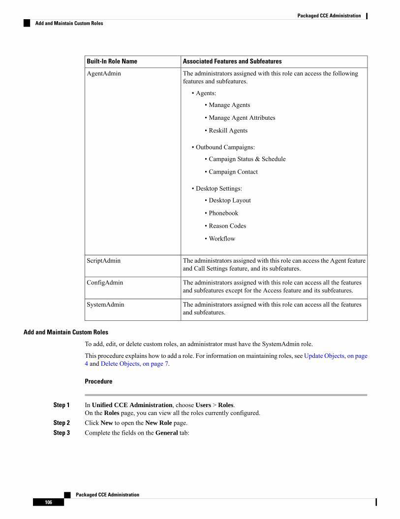
Associated Features and SubfeaturesBuilt-In Role Name
The administrators assigned with this role can access the followingfeatures and subfeatures.
• Agents:
• Manage Agents
• Manage Agent Attributes
• Reskill Agents
• Outbound Campaigns:
• Campaign Status & Schedule
• Campaign Contact
• Desktop Settings:
• Desktop Layout
• Phonebook
• Reason Codes
• Workflow
AgentAdmin
The administrators assigned with this role can access the Agent featureand Call Settings feature, and its subfeatures.
ScriptAdmin
The administrators assigned with this role can access all the featuresand subfeatures except for the Access feature and its subfeatures.
ConfigAdmin
The administrators assigned with this role can access all the featuresand subfeatures.
SystemAdmin
Add and Maintain Custom Roles
To add, edit, or delete custom roles, an administrator must have the SystemAdmin role.
This procedure explains how to add a role. For information on maintaining roles, see Update Objects, on page4 and Delete Objects, on page 7.
Procedure
Step 1 In Unified CCE Administration, choose Users > Roles.On the Roles page, you can view all the roles currently configured.
Step 2 Click New to open the New Role page.Step 3 Complete the fields on the General tab:
Packaged CCE Administration106
Packaged CCE AdministrationAdd and Maintain Custom Roles
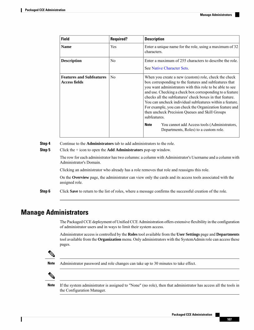
DescriptionRequired?Field
Enter a unique name for the role, using a maximum of 32characters.
YesName
Enter a maximum of 255 characters to describe the role.
See Native Character Sets.
NoDescription
When you create a new (custom) role, check the checkbox corresponding to the features and subfeatures thatyou want administrators with this role to be able to seeand use. Checking a check box corresponding to a featurechecks all the subfeatures' check boxes in that feature.You can uncheck individual subfeatures within a feature.For example, you can check the Organization feature andthen uncheck Precision Queues and Skill Groupssubfeatures.
You cannot add Access tools (Administrators,Departments, Roles) to a custom role.
Note
NoFeatures and SubfeaturesAccess fields
Step 4 Continue to the Administrators tab to add administrators to the role.Step 5 Click the + icon to open the Add Administrators pop-up window.
The row for each administrator has two columns: a column with Administrator's Username and a column withAdministrator's Domain.
Clicking an administrator who already has a role removes that role and reassigns this role.
On the Overview page, the administrator can view only the cards and its access tools associated with theassigned role.
Step 6 Click Save to return to the list of roles, where a message confirms the successful creation of the role.
Manage AdministratorsThe Packaged CCE deployment of Unified CCEAdministration offers extensive flexibility in the configurationof administrator users and in ways to limit their system access.
Administrator access is controlled by the Roles tool available from the User Settings page and Departmentstool available from theOrganizationmenu. Only administrators with the SystemAdmin role can access thesepages.
Administrator password and role changes can take up to 30 minutes to take effect.Note
If the system administrator is assigned to "None" (no role), then that administrator has access all the tools inthe Configuration Manager.
Note
Packaged CCE Administration107
Packaged CCE AdministrationManage Administrators
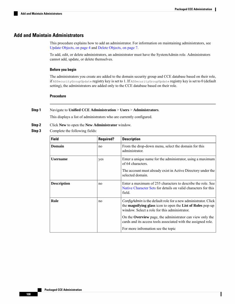
Add and Maintain AdministratorsThis procedure explains how to add an administrator. For information on maintaining administrators, seeUpdate Objects, on page 4 and Delete Objects, on page 7.
To add, edit, or delete administrators, an administrator must have the SystemAdmin role. Administratorscannot add, update, or delete themselves.
Before you begin
The administrators you create are added to the domain security group and CCE database based on their role,if ADSecurityGroupUpdate registry key is set to 1. If ADSecurityGroupUpdate registry key is set to 0 (defaultsetting), the administrators are added only to the CCE database based on their role.
Procedure
Step 1 Navigate to Unified CCE Administration > Users > Administrators.
This displays a list of administrators who are currently configured.
Step 2 Click New to open the New Administrator window.Step 3 Complete the following fields:
DescriptionRequired?Field
From the drop-down menu, select the domain for thisadministrator.
noDomain
Enter a unique name for the administrator, using a maximumof 64 characters.
The account must already exist in Active Directory under theselected domain.
yesUsername
Enter a maximum of 255 characters to describe the role. SeeNative Character Sets for details on valid characters for thisfield.
noDescription
ConfigAdmin is the default role for a new administrator. Clickthe magnifying glass icon to open the List of Roles pop-upwindow. Select a role for this administrator.
On the Overview page, the administrator can view only thecards and its access tools associated with the assigned role.
For more infromation see the topic
noRole
Packaged CCE Administration108
Packaged CCE AdministrationAdd and Maintain Administrators
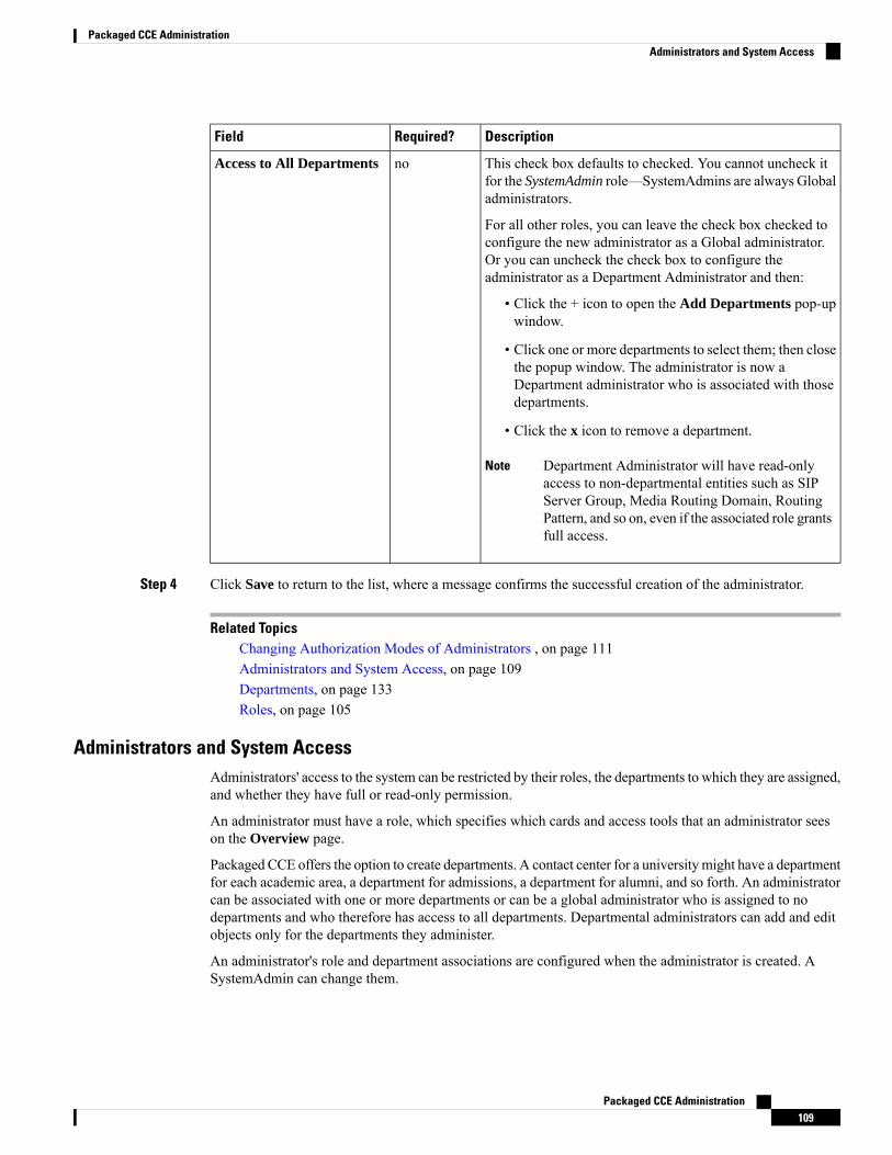
DescriptionRequired?Field
This check box defaults to checked. You cannot uncheck itfor the SystemAdmin role—SystemAdmins are always Globaladministrators.
For all other roles, you can leave the check box checked toconfigure the new administrator as a Global administrator.Or you can uncheck the check box to configure theadministrator as a Department Administrator and then:
• Click the + icon to open the Add Departments pop-upwindow.
• Click one or more departments to select them; then closethe popup window. The administrator is now aDepartment administrator who is associated with thosedepartments.
• Click the x icon to remove a department.
Department Administrator will have read-onlyaccess to non-departmental entities such as SIPServer Group, Media Routing Domain, RoutingPattern, and so on, even if the associated role grantsfull access.
Note
noAccess to All Departments
Step 4 Click Save to return to the list, where a message confirms the successful creation of the administrator.
Related TopicsChanging Authorization Modes of Administrators , on page 111Administrators and System Access, on page 109Departments, on page 133Roles, on page 105
Administrators and System AccessAdministrators' access to the system can be restricted by their roles, the departments to which they are assigned,and whether they have full or read-only permission.
An administrator must have a role, which specifies which cards and access tools that an administrator seeson the Overview page.
Packaged CCE offers the option to create departments. A contact center for a universitymight have a departmentfor each academic area, a department for admissions, a department for alumni, and so forth. An administratorcan be associated with one or more departments or can be a global administrator who is assigned to nodepartments and who therefore has access to all departments. Departmental administrators can add and editobjects only for the departments they administer.
An administrator's role and department associations are configured when the administrator is created. ASystemAdmin can change them.
Packaged CCE Administration109
Packaged CCE AdministrationAdministrators and System Access
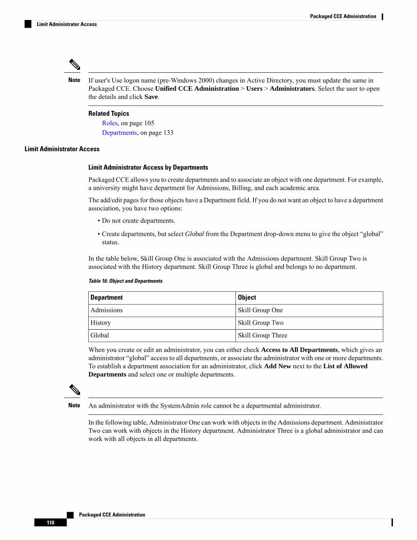
If user's Use logon name (pre-Windows 2000) changes in Active Directory, you must update the same inPackaged CCE. Choose Unified CCE Administration > Users > Administrators. Select the user to openthe details and click Save.
Note
Related TopicsRoles, on page 105Departments, on page 133
Limit Administrator Access
Limit Administrator Access by Departments
Packaged CCE allows you to create departments and to associate an object with one department. For example,a university might have department for Admissions, Billing, and each academic area.
The add/edit pages for those objects have a Department field. If you do not want an object to have a departmentassociation, you have two options:
• Do not create departments.
• Create departments, but select Global from the Department drop-down menu to give the object “global”status.
In the table below, Skill Group One is associated with the Admissions department. Skill Group Two isassociated with the History department. Skill Group Three is global and belongs to no department.
Table 16: Object and Departments
ObjectDepartment
Skill Group OneAdmissions
Skill Group TwoHistory
Skill Group ThreeGlobal
When you create or edit an administrator, you can either check Access to All Departments, which gives anadministrator “global” access to all departments, or associate the administrator with one or more departments.To establish a department association for an administrator, click Add New next to the List of AllowedDepartments and select one or multiple departments.
An administrator with the SystemAdmin role cannot be a departmental administrator.Note
In the following table, Administrator One can work with objects in the Admissions department. AdministratorTwo can work with objects in the History department. Administrator Three is a global administrator and canwork with all objects in all departments.
Packaged CCE Administration110
Packaged CCE AdministrationLimit Administrator Access

Table 17: Administrators and Departments
AdministratorDepartment
Administrator OneAdmissions
Administrator TwoHistory
Administrator ThreeGlobal
Limit Administrator Access by Role and Permissions
An administrator must be assigned a role to be allowed to sign in to the Unified CCE Administration.
Permissions defined in the following table indicate which tools an administrator can view, add, edit, or delete,unless restricted by departmental association.
Table 18: Administrator Tools and Permissions
PermissionsToolAdministrator
• Full access to Agent Tools
• View, add, edit, and delete Skill GroupOne
• Add Admissions Department agents toSkill Group One
• Add global agents to Skill Group One
• View Skill Group Three
Agent ToolsAdministrator One
• Full access to Agent Tools
• View, add, edit, and delete Skill GroupTwo
• Add History Department agents to SkillGroup Two
• Add global agents to Skill Group Two
• View Skill Group Three
Agent ToolsAdministrator Two
• Full access to Script and Call Tools
• Full access to agents and Skill Groupsfrom all departments
• Full access to global agents and SkillGroups
Script and Call ToolsAdministrator Three
Changing Authorization Modes of AdministratorsWhen you provide permissions to a user (account):
Packaged CCE Administration111
Packaged CCE AdministrationChanging Authorization Modes of Administrators
The registry settings in the local AW machine HKEY_LOCAL_MACHINE > SOFTWARE > CiscoSystems Inc > ICM > <instance> > AW with the key ADSecurityGroupUpdate decides whether a user willbe added to the domain Config and Setup Security Groups.
Default Key Value
The default value of theADSecurityGroupUpdate key is 0 whichmeans that the AW is in local authorizationmode. If the user is added using the Administrator Gadget or the API with pre-defined or custom roles, theuser is not added to the corresponding domain security groups. The user is added to the database with thecorresponding roles.
If you want to use the configuration manager tool, then you have to provide a user with the Config permissions,add the user to the UcceConfig local security group manually.
To provide a user the Setup permissions, add the user to the UcceConfig and local administrator securitygroups of the AW machine manually.
Key value Set to 1
If the value of theADSecurityGroupUpdate key is set to 1, the AWmachine is in the domain authorizationmode. If the user is added using the Administrator Gadget or the API with pre-defined or , the user is addedto the corresponding domain security group. The user is added to the database with the corresponding roles.There is no need to manually add the user to the local groups of the AW machine.
Move to Local Authorization Mode
To move to Local Authorization mode from domain authorization you have to change the registryADSecurityGroupUpdate from 1 to 0.
All the existing users which are available in domain Config and Setup security groups under instance OUmust be manually moved to UcceConfig local group of all AW machine except Admin Client machine.All the users in the domain setup security group has to be added to the local Administrators group of all AWmachine except Admin Client machine.
Remove the users from domain Config and Setup security group under instance OU.
Move to Domain Authorization Mode
To move to domain authorization mode from local authorization mode you have to change the registryADSecurityGroupUpdate from 0 to 1.
All the users in local UcceConfig group of all the AW except Admin Client has to be added manually tothe domain Config security group.
Remove all users from local UcceConfig group.
Identify the system admininstrator role users from the Administrator Gadget and move those users from localAdministrators group of all AW (except Admin Client) to the domain setup security group. Remove thoseusers from local Administrators group.
Move to System Administrator Role
To add all the users in ConfigAdmin group to UcceConfig group:
1. Open Computer Management > Local Users and Groups > Groups.
2. Right click on UcceConfig, and select Properties.
Packaged CCE Administration112
Packaged CCE AdministrationChanging Authorization Modes of Administrators
3. Add all users with ConfigAdmin role into UcceConfig group.
Organization Setup
Manage Teams
TeamsYou can create teams to associate a set of agents with supervisors. Supervisors can run reports on the teamand receive Supervisor Assist requests from the team members.
Supervisor Assist must be indicated in the Desk Settings tool and must be supported by the agent desktop.
Agent cannot be a member of more than one team.
Note
After you create a team with agents and/or supervisors, you can assign resources such as custom desktoplayout, phone books, reasons (not ready, sign out, and wrap-up), and workflow to the team.
The desktop layout, phone books, and workflow resources are preconfigured in Desktop > Resources. Thereasons (not ready, sign out, and wrap-up) are preconfigured in Desktop > Reason Labels.
Administrators can see and maintain teams .
Supervisors have display-only access to the Teams tool.
To configure teams, navigate toUnified CCE Administration >Overview >Organization Setup > Teams,or choose Organization > Teams from the left navigation.
Related TopicsAdd and Maintain Teams , on page 113Agents, on page 93Manage Supervisors, on page 102Add and Maintain Desk Settings, on page 186
Add and Maintain Teams
Procedure
Step 1 In Unified CCE Administration , choose Organization > Teams from the left navigation.Step 2 Click New to open the New Team page.Step 3 Complete the following fields on the Basic Details tab:
DescriptionRequired?Field
Enter up to 32 alphanumeric characters.YesName
Packaged CCE Administration113
Packaged CCE AdministrationOrganization Setup
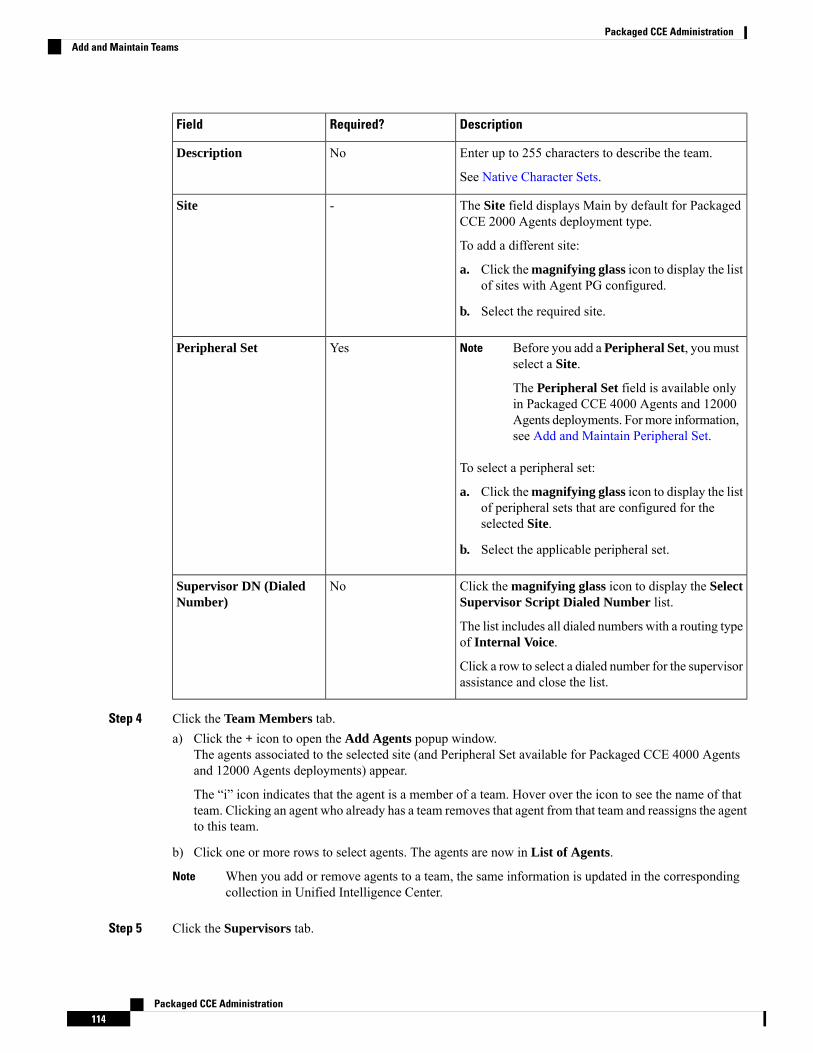
DescriptionRequired?Field
Enter up to 255 characters to describe the team.
See Native Character Sets.
NoDescription
The Site field displays Main by default for PackagedCCE 2000 Agents deployment type.
To add a different site:
a. Click themagnifying glass icon to display the listof sites with Agent PG configured.
b. Select the required site.
-Site
Before you add a Peripheral Set, you mustselect a Site.
The Peripheral Set field is available onlyin Packaged CCE 4000 Agents and 12000Agents deployments. For more information,see Add and Maintain Peripheral Set.
Note
To select a peripheral set:
a. Click themagnifying glass icon to display the listof peripheral sets that are configured for theselected Site.
b. Select the applicable peripheral set.
YesPeripheral Set
Click the magnifying glass icon to display the SelectSupervisor Script Dialed Number list.
The list includes all dialed numbers with a routing typeof Internal Voice.
Click a row to select a dialed number for the supervisorassistance and close the list.
NoSupervisor DN (DialedNumber)
Step 4 Click the Team Members tab.a) Click the + icon to open the Add Agents popup window.
The agents associated to the selected site (and Peripheral Set available for Packaged CCE 4000 Agentsand 12000 Agents deployments) appear.
The “i” icon indicates that the agent is a member of a team. Hover over the icon to see the name of thatteam. Clicking an agent who already has a team removes that agent from that team and reassigns the agentto this team.
b) Click one or more rows to select agents. The agents are now in List of Agents.
When you add or remove agents to a team, the same information is updated in the correspondingcollection in Unified Intelligence Center.
Note
Step 5 Click the Supervisors tab.
Packaged CCE Administration114
Packaged CCE AdministrationAdd and Maintain Teams
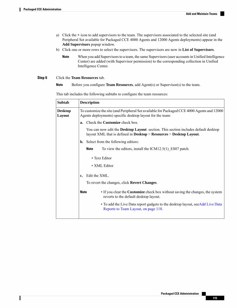
a) Click the + icon to add supervisors to the team. The supervisors associated to the selected site (andPeripheral Set available for Packaged CCE 4000 Agents and 12000 Agents deployments) appear in theAdd Supervisors popup window.
b) Click one or more rows to select the supervisors. The supervisors are now in List of Supervisors.
When you add Supervisors to a team, the same Supervisors (user accounts in Unified IntelligenceCenter) are added (with Supervisor permission) to the corresponding collection in UnifiedIntelligence Center.
Note
Step 6 Click the Team Resources tab.
Before you configure Team Resources, add Agent(s) or Supervisor(s) to the team.Note
This tab includes the following subtabs to configure the team resources:
DescriptionSubtab
To customize the site (and Peripheral Set available for Packaged CCE 4000Agents and 12000Agents deployments) specific desktop layout for the team:
a. Check the Customize check box.
You can now edit the Desktop Layout section. This section includes default desktoplayout XML that is defined in Desktop > Resources > Desktop Layout.
b. Select from the following editors:
To view the editors, install the ICM12.5(1)_ES07 patch.Note
• Text Editor
• XML Editor
c. Edit the XML.
To revert the changes, click Revert Changes.
Note • If you clear theCustomize check box without saving the changes, the systemreverts to the default desktop layout.
• To add the Live Data report gadgets to the desktop layout, seeAdd Live DataReports to Team Layout, on page 118.
DesktopLayout
Packaged CCE Administration115
Packaged CCE AdministrationAdd and Maintain Teams
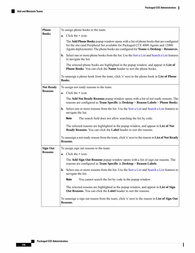
To assign phone books to the team:
a. Click the + icon.
TheAdd Phone Books popupwindow opens with a list of phone books that are configuredfor the site (and Peripheral Set available for Packaged CCE 4000 Agents and 12000Agents deployments). The phone books are configured forTeams inDesktop >Resources.
b. Select one or more phone books from the list. Use the Sort a List and Search a List featuresto navigate the list.
The selected phone books are highlighted in the popup window, and appear in List ofPhone Books. You can click the Name header to sort the phone books.
To unassign a phone book from the team, click 'x' next to the phone book in List of PhoneBooks.
PhoneBooks
To assign not ready reasons to the team:
a. Click the + icon.
The Add Not Ready Reasons popup window opens with a list of not ready reasons. Thereasons are configured as Team Specific in Desktop > Reason Labels > Phone Books.
b. Select one or more reasons from the list. Use the Sort a List and Search a List features tonavigate the list.
The search field does not allow searching the list by code.Note
The selected reasons are highlighted in the popup window, and appear in List of NotReady Reasons. You can click the Label header to sort the reasons.
To unassign a not ready reason from the team, click 'x' next to the reason inList of Not ReadyReasons.
Not ReadyReasons
To assign sign out reasons to the team:
a. Click the + icon.
The Add Sign Out Reasons popup window opens with a list of sign out reasons. Thereasons are configured as Team Specific in Desktop > Reason Labels.
b. Select one or more reasons from the list. Use the Sort a List and Search a List features tonavigate the list.
You cannot search the list by code in the popup window.Note
The selected reasons are highlighted in the popup window, and appear in List of SignOut Reasons. You can click the Label header to sort the reasons.
To unassign a sign out reason from the team, click 'x' next to the reason in List of Sign OutReasons.
Sign OutReasons
Packaged CCE Administration116
Packaged CCE AdministrationAdd and Maintain Teams
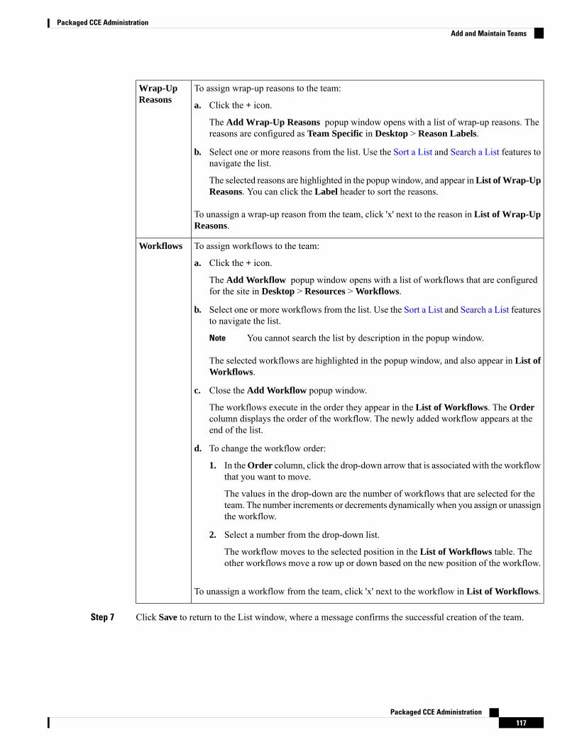
To assign wrap-up reasons to the team:
a. Click the + icon.
The Add Wrap-Up Reasons popup window opens with a list of wrap-up reasons. Thereasons are configured as Team Specific in Desktop > Reason Labels.
b. Select one or more reasons from the list. Use the Sort a List and Search a List features tonavigate the list.
The selected reasons are highlighted in the popup window, and appear inList of Wrap-UpReasons. You can click the Label header to sort the reasons.
To unassign a wrap-up reason from the team, click 'x' next to the reason in List of Wrap-UpReasons.
Wrap-UpReasons
To assign workflows to the team:
a. Click the + icon.
The Add Workflow popup window opens with a list of workflows that are configuredfor the site in Desktop > Resources > Workflows.
b. Select one or more workflows from the list. Use the Sort a List and Search a List featuresto navigate the list.
You cannot search the list by description in the popup window.Note
The selected workflows are highlighted in the popup window, and also appear in List ofWorkflows.
c. Close the Add Workflow popup window.
The workflows execute in the order they appear in the List of Workflows. The Ordercolumn displays the order of the workflow. The newly added workflow appears at theend of the list.
d. To change the workflow order:
1. In theOrder column, click the drop-down arrow that is associated with the workflowthat you want to move.
The values in the drop-down are the number of workflows that are selected for theteam. The number increments or decrements dynamically when you assign or unassignthe workflow.
2. Select a number from the drop-down list.
The workflow moves to the selected position in the List of Workflows table. Theother workflows move a row up or down based on the new position of the workflow.
To unassign a workflow from the team, click 'x' next to the workflow in List of Workflows.
Workflows
Step 7 Click Save to return to the List window, where a message confirms the successful creation of the team.
Packaged CCE Administration117
Packaged CCE AdministrationAdd and Maintain Teams
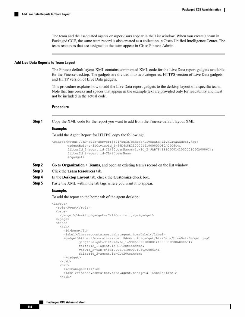
The team and the associated agents or supervisors appear in the List window. When you create a team inPackaged CCE, the same team record is also created as a collection in Cisco Unified Intelligence Center. Theteam resources that are assigned to the team appear in Cisco Finesse Admin.
Add Live Data Reports to Team Layout
The Finesse default layout XML contains commented XML code for the Live Data report gadgets availablefor the Finesse desktop. The gadgets are divided into two categories: HTTPS version of Live Data gadgetsand HTTP version of Live Data gadgets.
This procedure explains how to add the Live Data report gadgets to the desktop layout of a specific team.Note that line breaks and spaces that appear in the example text are provided only for readability and mustnot be included in the actual code.
Procedure
Step 1 Copy the XML code for the report you want to add from the Finesse default layout XML.
Example:
To add the Agent Report for HTTPS, copy the following:<gadget>https://my-cuic-server:8444/cuic/gadget/LiveData/LiveDataGadget.jsp?
gadgetHeight=310&viewId_1=99E6C8E210000141000000D80A0006C4&filterId_1=agent.id=CL%20teamName&viewId_2=9AB7848B10000141000001C50A0006C4&filterId_2=agent.id=CL%20teamName</gadget>
Step 2 Go to Organization > Teams, and open an existing team's record on the list window.Step 3 Click the Team Resources tab.Step 4 In the Desktop Layout tab, check the Customize check box.Step 5 Paste the XML within the tab tags where you want it to appear.
Example:
To add the report to the home tab of the agent desktop:<layout><role>Agent</role><page><gadget>/desktop/gadgets/CallControl.jsp</gadget>
</page><tabs><tab><id>home</id><label>finesse.container.tabs.agent.homeLabel</label><gadget>https://my-cuic-server:8444/cuic/gadget/LiveData/LiveDataGadget.jsp?
gadgetHeight=310&viewId_1=99E6C8E210000141000000D80A0006C4&filterId_1=agent.id=CL%20teamName&viewId_2=9AB7848B10000141000001C50A0006C4&filterId_2=agent.id=CL%20teamName
</gadget></tab><tab><id>manageCall</id><label>finesse.container.tabs.agent.manageCallLabel</label>
</tab>
Packaged CCE Administration118
Packaged CCE AdministrationAdd Live Data Reports to Team Layout
</tabs></layout>
Step 6 Replace my-cuic-server with the fully qualified domain name of your Cisco Unified Intelligence Center Server.Step 7 Optionally, change the gadget height.
Example:
The height specified in the Live Data gadget URLs is 310 pixels. If you want to change the height, changethe gadgetHeight parameter in the URL to the desired value. For example, if you want the gadget height tobe 400 pixels, change the code as follows:<gadget>https://my-cuic-server:8444/cuic/gadget/LiveData/LiveDataGadget.jsp?
gadgetHeight=400&viewId_1=99E6C8E210000141000000D80A0006C4&filterId_1=agent.id=CL%20teamName&viewId_2=9AB7848B10000141000001C50A0006C4&filterId_2=agent.id=CL%20teamName</gadget>
Tomaintain the optimal display of the gadget with scroll bars, set the value for the gadget height to a minimumof 200 pixels. If the report does not require scroll bars, for example a one-row report, you can set a smallergadget height (for example, 100 pixels). If you do not specify anything for the gadget height (if you removethe 310 from the URL), it defaults to 170 pixels.
Step 8 Click Save.
After you add a gadget, sign in to the Finesse desktop and make sure it appears the way you want.If you use a report with a large number of rows, you may want to adjust the gadget height or thescreen resolution on the computer used to access the desktop to make the report easier to read ormake more rows appear on the screen without needing to scroll down.
Agents who are signed in when you change the desktop layout must sign out and sign back in tosee the change on their desktops.
Note
You can also perform the above steps in Unified CCE Administration (https://<Side A/B UnifiedCCEAW-HDS-DDS IP address>/cceadminnew). In Unified CCEAdministration, you can navigateto Desktop > Resources to copy the XML code from default layout, and then navigate to Organization> Teams to access the Team Resources paste the XML.
Note
Search for Teams
The Search field in the Team tool offers an advanced and flexible search.
Click the + icon at the right of the Search field in the Team tool. In the popup window, you can:
• Search for a name or description.
• Enter one or more site names separated by spaces. (Site is an OR search.)
• Enter one or more peripheral set names separated by spaces (Peripheral Set is an OR search). The searchis case-insensitive and does not support partial matches.
Search by peripheral set is available only in Packaged CCE 4000 Agents and12000 Agents deployments.
Note
Packaged CCE Administration119
Packaged CCE AdministrationSearch for Teams
• Select departments, with options for Globals and Departments, Globals only, or Departments only.
If you selectGlobals and Departments or Departments only, you can only enter a space-separated listof department names. (Department is an OR search.)
Search by department is available only when departments are configured.
Search by site is available only when remote sites are configured.
Note
Manage SkillsCalls are queued to agents based on their membership in skill groups or their qualification in precision queues.
Administrators have access to all tools documented in this chapter .
Supervisors have limited access to Skill Groups and display-only access to Attributes and Precision Queues.
Skill GroupsA skill group is a collection of agents who share a common set of competencies that equip them to handle thesame types of requests. Some examples of skill groups are a collection of agents who speak a specific languageor who can assist callers with billing questions.
An agent can be a member of multiple skill groups. Each skill group is associated with a specific media routingdomain (MRD) such as voice, chat, or email.
An agent's skill group membership can determine the types of contacts that are routed to that agent. Forexample, if an agent is a member of a skill group that is set up for the Cisco_Voice routing domain only, thenthat agent is a voice agent for that skill group. If an agent is a member of a skill group that is set up for anonvoice routing domain, then that agent is a multichannel agent for that skill group.
Use Cisco Unified Intelligence Center reports to view agent activity in skill groups, to monitor call distributionamong skill groups, or to see how one skill group is performing compared with others.
Navigate toUnified CCE Administration >Organization > Skills > Skill Groups to configure skill groups.
Administrators have full permission to configure skill groups. Supervisors have permission to add and removetheir supervised agents on the Skill Groups Members tab.
Related TopicsSearch for Skill Groups, on page 123Add and Maintain Skill Groups, on page 120Agents, on page 93Skill Groups or Precision Queues?, on page 126Manage Supervisors, on page 102
Add and Maintain Skill Groups
Procedure
Step 1 Navigate to Unified CCE Administration > Organization > Skills > Skill Groups.
Packaged CCE Administration120
Packaged CCE AdministrationManage Skills
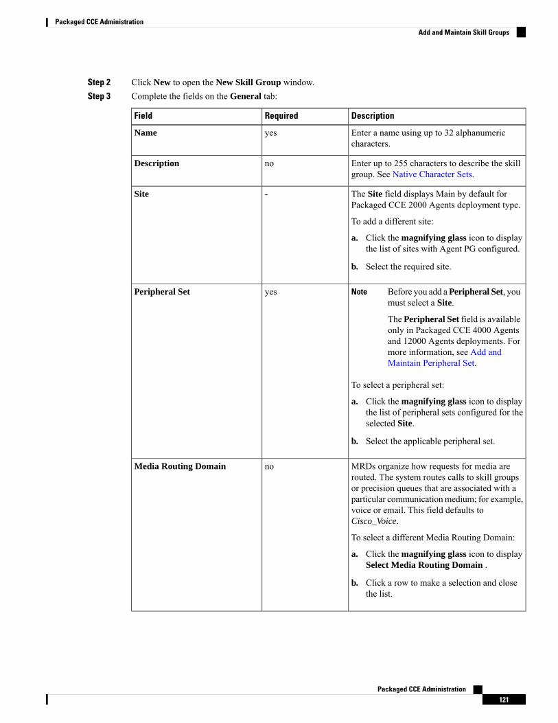
Step 2 Click New to open the New Skill Group window.Step 3 Complete the fields on the General tab:
DescriptionRequiredField
Enter a name using up to 32 alphanumericcharacters.
yesName
Enter up to 255 characters to describe the skillgroup. See Native Character Sets.
noDescription
The Site field displays Main by default forPackaged CCE 2000 Agents deployment type.
To add a different site:
a. Click the magnifying glass icon to displaythe list of sites with Agent PG configured.
b. Select the required site.
-Site
Before you add aPeripheral Set, youmust select a Site.
The Peripheral Set field is availableonly in Packaged CCE 4000 Agentsand 12000 Agents deployments. Formore information, see Add andMaintain Peripheral Set.
Note
To select a peripheral set:
a. Click the magnifying glass icon to displaythe list of peripheral sets configured for theselected Site.
b. Select the applicable peripheral set.
yesPeripheral Set
MRDs organize how requests for media arerouted. The system routes calls to skill groupsor precision queues that are associated with aparticular communicationmedium; for example,voice or email. This field defaults toCisco_Voice.
To select a different Media Routing Domain:
a. Click the magnifying glass icon to displaySelect Media Routing Domain .
b. Click a row to make a selection and closethe list.
noMedia Routing Domain
Packaged CCE Administration121
Packaged CCE AdministrationAdd and Maintain Skill Groups
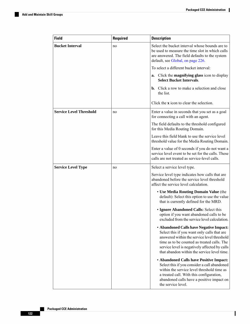
DescriptionRequiredField
Select the bucket interval whose bounds are tobe used to measure the time slot in which callsare answered. The field defaults to the systemdefault, see Global, on page 226.
To select a different bucket interval:
a. Click the magnifying glass icon to displaySelect Bucket Intervals.
b. Click a row to make a selection and closethe list.
Click the x icon to clear the selection.
noBucket Interval
Enter a value in seconds that you set as a goalfor connecting a call with an agent.
The field defaults to the threshold configuredfor this Media Routing Domain.
Leave this field blank to use the service levelthreshold value for the Media Routing Domain.
Enter a value of 0 seconds if you do not want aservice level event to be set for the calls. Thesecalls are not treated as service-level calls.
noService Level Threshold
Select a service level type.
Service level type indicates how calls that areabandoned before the service level thresholdaffect the service level calculation.
• Use Media Routing Domain Value (thedefault): Select this option to use the valuethat is currently defined for the MRD.
• Ignore Abandoned Calls: Select thisoption if you want abandoned calls to beexcluded from the service level calculation.
• Abandoned Calls have Negative Impact:Select this if you want only calls that areanswered within the service level thresholdtime as to be counted as treated calls. Theservice level is negatively affected by callsthat abandon within the service level time.
• Abandoned Calls have Positive Impact:Select this if you consider a call abandonedwithin the service level threshold time asa treated call. With this configuration,abandoned calls have a positive impact onthe service level.
noService Level Type
Packaged CCE Administration122
Packaged CCE AdministrationAdd and Maintain Skill Groups
Step 4 Complete the Members tab:
This tab shows the list of agents for this skill group.
a) Click the + icon to open Add Agents. The agents associated to the selected site (and Peripheral Setavailable for Packaged CCE 4000 Agents and 12000 Agents deployments) display.
b) Click the agents you want to add to this skill group.c) Close the window. The agents you chose appear on the List of Agents.d) Click Save on this tab to return to the List window, where a message confirms the successful creation of
the skill group.
Search for Skill Groups
The Search field in the Skill Groups tool offers an advanced and flexible search.
Click the + icon in the Search field to open a popup window, where you can:
• Enter a name or description to search for that string.
• Enter one or more site names separated by spaces. (Site is an OR search.)
• Enter one or more peripheral set names separated by spaces (Peripheral Set is an OR search). The searchis case-insensitive and does not support partial matches.
Search by peripheral set is available only in Packaged CCE 4000 Agents and12000 Agents deployments.
Note
• Select departments, with options for Globals and Departments, Globals only, or Departments only.
Selecting Globals and Departments or Departments only enables an input field where you can entera space-separated list of department names. (Department is an OR search.)
Search by department is available only when departments are configured.
Search by site is available only when remote sites are configured.
Note
AttributesAttributes identify a call routing requirement, such as language, location, or agent expertise. You can createtwo types of attributes: Boolean or Proficiency.
• Use Boolean attributes to identify an agent attribute value as true or false. For example, you can createa Boston attribute that specifies that the agent assigned to this attribute must be located in Boston. Anagent in Boston would have Boston = True as the term for that attribute.
• Use Proficiency attributes to establish a level of expertise in a range from 1 to 10, with 10 being thehighest level of expertise. For a Spanish language attribute, for example, a native speaker would havethe attribute Proficiency = 10.
Packaged CCE Administration123
Packaged CCE AdministrationSearch for Skill Groups
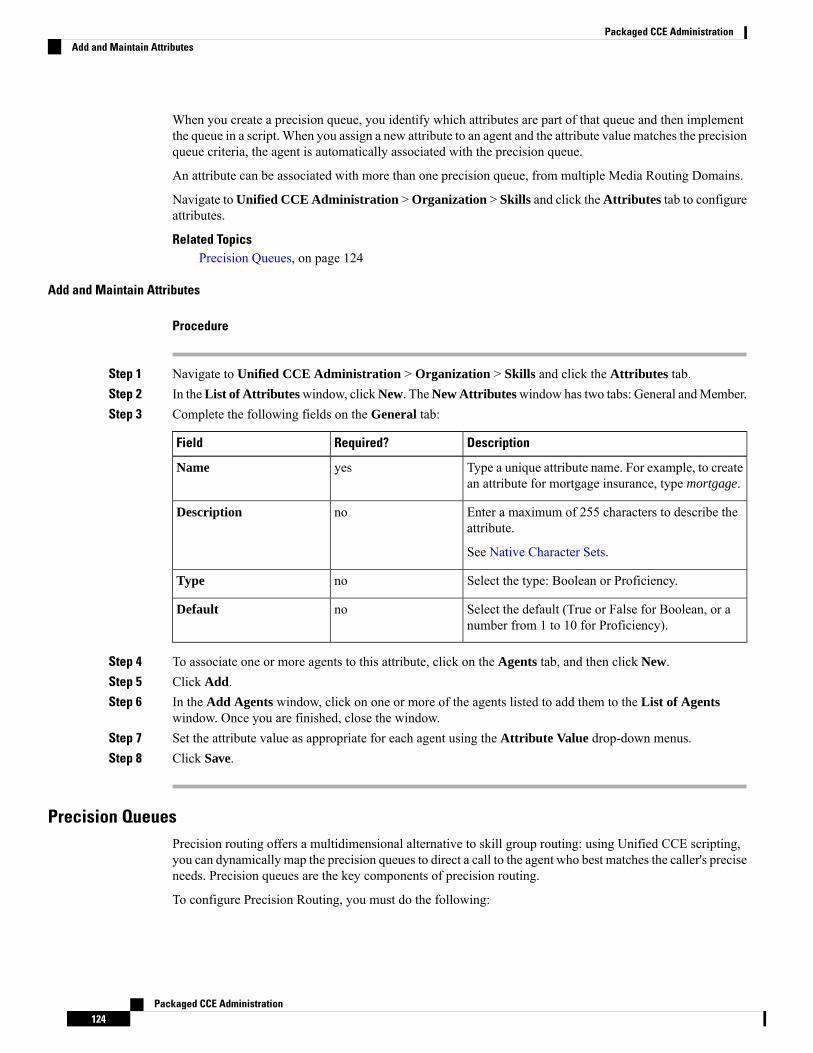
When you create a precision queue, you identify which attributes are part of that queue and then implementthe queue in a script. When you assign a new attribute to an agent and the attribute value matches the precisionqueue criteria, the agent is automatically associated with the precision queue.
An attribute can be associated with more than one precision queue, from multiple Media Routing Domains.
Navigate toUnified CCE Administration >Organization > Skills and click theAttributes tab to configureattributes.
Related TopicsPrecision Queues, on page 124
Add and Maintain Attributes
Procedure
Step 1 Navigate to Unified CCE Administration > Organization > Skills and click the Attributes tab.Step 2 In theList of Attributeswindow, clickNew. TheNew Attributeswindow has two tabs: General andMember.Step 3 Complete the following fields on the General tab:
DescriptionRequired?Field
Type a unique attribute name. For example, to createan attribute for mortgage insurance, type mortgage.
yesName
Enter a maximum of 255 characters to describe theattribute.
See Native Character Sets.
noDescription
Select the type: Boolean or Proficiency.noType
Select the default (True or False for Boolean, or anumber from 1 to 10 for Proficiency).
noDefault
Step 4 To associate one or more agents to this attribute, click on the Agents tab, and then click New.Step 5 Click Add.Step 6 In the Add Agents window, click on one or more of the agents listed to add them to the List of Agents
window. Once you are finished, close the window.Step 7 Set the attribute value as appropriate for each agent using the Attribute Value drop-down menus.Step 8 Click Save.
Precision QueuesPrecision routing offers a multidimensional alternative to skill group routing: using Unified CCE scripting,you can dynamically map the precision queues to direct a call to the agent who best matches the caller's preciseneeds. Precision queues are the key components of precision routing.
To configure Precision Routing, you must do the following:
Packaged CCE Administration124
Packaged CCE AdministrationAdd and Maintain Attributes
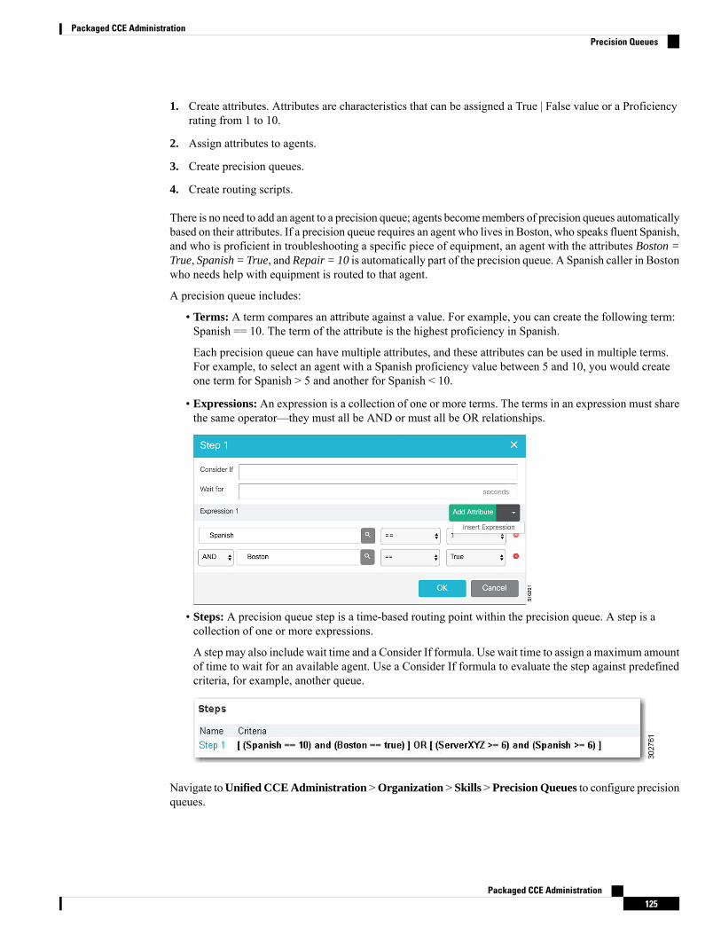
1. Create attributes. Attributes are characteristics that can be assigned a True | False value or a Proficiencyrating from 1 to 10.
2. Assign attributes to agents.
3. Create precision queues.
4. Create routing scripts.
There is no need to add an agent to a precision queue; agents becomemembers of precision queues automaticallybased on their attributes. If a precision queue requires an agent who lives in Boston, who speaks fluent Spanish,and who is proficient in troubleshooting a specific piece of equipment, an agent with the attributes Boston =True, Spanish = True, and Repair = 10 is automatically part of the precision queue. A Spanish caller in Bostonwho needs help with equipment is routed to that agent.
A precision queue includes:
• Terms: A term compares an attribute against a value. For example, you can create the following term:Spanish == 10. The term of the attribute is the highest proficiency in Spanish.
Each precision queue can have multiple attributes, and these attributes can be used in multiple terms.For example, to select an agent with a Spanish proficiency value between 5 and 10, you would createone term for Spanish > 5 and another for Spanish < 10.
• Expressions: An expression is a collection of one or more terms. The terms in an expression must sharethe same operator—they must all be AND or must all be OR relationships.
• Steps: A precision queue step is a time-based routing point within the precision queue. A step is acollection of one or more expressions.
A step may also include wait time and a Consider If formula. Use wait time to assign a maximum amountof time to wait for an available agent. Use a Consider If formula to evaluate the step against predefinedcriteria, for example, another queue.
Navigate toUnified CCE Administration >Organization > Skills >Precision Queues to configure precisionqueues.
Packaged CCE Administration125
Packaged CCE AdministrationPrecision Queues
Navigate toUnified CCE Administration >Organization > Skills >Precision Queues to configure precisionqueues.
When you add or modify precision queues associated with a large number of agents, the system avoids potentialoverload conditions by updating the agent associations as system resources allow. Precision queue updatesmay be rejected if the system is too busy.
Skill Groups or Precision Queues?
Should you use skill groups or precision queues for the routing needs of your organization? This sectiondistinguishes the two methods.
Use a Skill Group
A skill group represents a competency or responsibility. For example, it could be a predefined collection oftraits, such as salespeople who are in charge of selling to England. The skill group could be called “Englishsales”. If you wanted to divide the agents in this group into two types of proficiencies (perhaps based onexperience), you would need to set up two separate skill groups; for example, English Sales 1 and EnglishSales 2. You would then associate an agent with one of them, based on the agent's proficiency. Do this byaccessing the skill group and locating the agent that you want to add to it (or add that skill group to the agent).To summarize, creating a skill group involves first building a concept of what combinations of traits you wantfor each agent, like English Sales 2.
Use a Precision Queue
In contrast to skill groups, a precision queue breaks down attribute definitions to form a collection of agentsat an attribute level. The agents that match the attribute level of the precision queue become associated withthat precision queue.
With precision queues, the preceding English sales example involves defining the attributes English and Sales,and associating agents that have those traits to them. The precision queue English Sales would dynamicallymap all those agents that had those traits to the precision queue. In addition, you can define more complexproficiency attributes to associate with those agents. This would allow you to build, in a single precisionqueue, multiple proficiency searches like English language proficiency 10 and sales proficiency 5.
To break down the precision queue example into skill groups, you would need to set up two separate skillgroups: English language proficiency 10 and sales proficiency 5.With precision queues, you can refine agentsby attributes. With skill groups, you define a skill group and then assign agents to it.
Decide on Skill Groups or a Precision Queue
Precision routing enhances and can replace traditional routing. Traditional routing looks at all of the skillgroups to which an agent belongs and defines the hierarchy of skills to map business needs. However, traditionalrouting is restricted by its single-dimensional nature.
Precision routing provides multidimensional routing with simple configuration, scripting, and reporting.Agents are represented through multiple attributes with proficiencies so that the capabilities of each agent areaccurately exposed, bringing more value to the business.
If your routing needs are not too complex, consider using one or two skill groups. However, if you want toconduct a search involving as many as ten different proficiency levels in one easily managed queue, useprecision queues.
Packaged CCE Administration126
Packaged CCE AdministrationSkill Groups or Precision Queues?
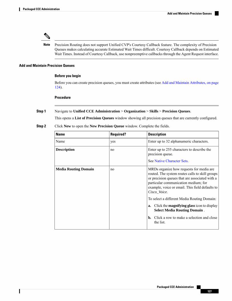
Precision Routing does not support Unified CVP's Courtesy Callback feature. The complexity of PrecisionQueues makes calculating accurate Estimated Wait Times difficult. Courtesy Callback depends on EstimatedWait Times. Instead of Courtesy Callback, use nonpreemptive callbacks through the Agent Request interface.
Note
Add and Maintain Precision Queues
Before you begin
Before you can create precision queues, you must create attributes (see Add and Maintain Attributes, on page124).
Procedure
Step 1 Navigate to Unified CCE Administration > Organization > Skills > Precision Queues.
This opens a List of Precision Queues window showing all precision queues that are currently configured.
Step 2 Click New to open the New Precision Queue window. Complete the fields.
DescriptionRequired?Name
Enter up to 32 alphanumeric characters.yesName
Enter up to 255 characters to describe theprecision queue.
See Native Character Sets.
noDescription
MRDs organize how requests for media arerouted. The system routes calls to skill groupsor precision queues that are associated with aparticular communication medium; forexample, voice or email. This field defaults toCisco_Voice.
To select a different Media Routing Domain:
a. Click themagnifying glass icon to displaySelect Media Routing Domain .
b. Click a row to make a selection and closethe list.
noMedia Routing Domain
Packaged CCE Administration127
Packaged CCE AdministrationAdd and Maintain Precision Queues
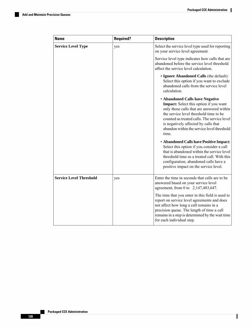
DescriptionRequired?Name
Select the service level type used for reportingon your service level agreement.
Service level type indicates how calls that areabandoned before the service level thresholdaffect the service level calculation.
• Ignore Abandoned Calls (the default):Select this option if you want to excludeabandoned calls from the service levelcalculation.
• Abandoned Calls have NegativeImpact: Select this option if you wantonly those calls that are answered withinthe service level threshold time to becounted as treated calls. The service levelis negatively affected by calls thatabandonwithin the service level thresholdtime.
• Abandoned Calls have Positive Impact:Select this option if you consider a callthat is abandoned within the service levelthreshold time as a treated call. With thisconfiguration, abandoned calls have apositive impact on the service level.
yesService Level Type
Enter the time in seconds that calls are to beanswered based on your service levelagreement, from 0 to 2,147,483,647.
The time that you enter in this field is used toreport on service level agreements and doesnot affect how long a call remains in aprecision queue. The length of time a callremains in a step is determined by the wait timefor each individual step.
yesService Level Threshold
Packaged CCE Administration128
Packaged CCE AdministrationAdd and Maintain Precision Queues
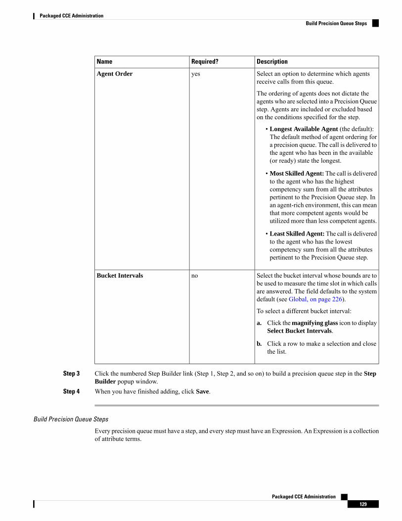
DescriptionRequired?Name
Select an option to determine which agentsreceive calls from this queue.
The ordering of agents does not dictate theagents who are selected into a Precision Queuestep. Agents are included or excluded basedon the conditions specified for the step.
• Longest Available Agent (the default):The default method of agent ordering fora precision queue. The call is delivered tothe agent who has been in the available(or ready) state the longest.
• Most Skilled Agent: The call is deliveredto the agent who has the highestcompetency sum from all the attributespertinent to the Precision Queue step. Inan agent-rich environment, this can meanthat more competent agents would beutilized more than less competent agents.
• Least Skilled Agent:The call is deliveredto the agent who has the lowestcompetency sum from all the attributespertinent to the Precision Queue step.
yesAgent Order
Select the bucket interval whose bounds are tobe used to measure the time slot in which callsare answered. The field defaults to the systemdefault (see Global, on page 226).
To select a different bucket interval:
a. Click themagnifying glass icon to displaySelect Bucket Intervals.
b. Click a row to make a selection and closethe list.
noBucket Intervals
Step 3 Click the numbered Step Builder link (Step 1, Step 2, and so on) to build a precision queue step in the StepBuilder popup window.
Step 4 When you have finished adding, click Save.
Build Precision Queue Steps
Every precision queue must have a step, and every step must have an Expression. An Expression is a collectionof attribute terms.
Packaged CCE Administration129
Packaged CCE AdministrationBuild Precision Queue Steps
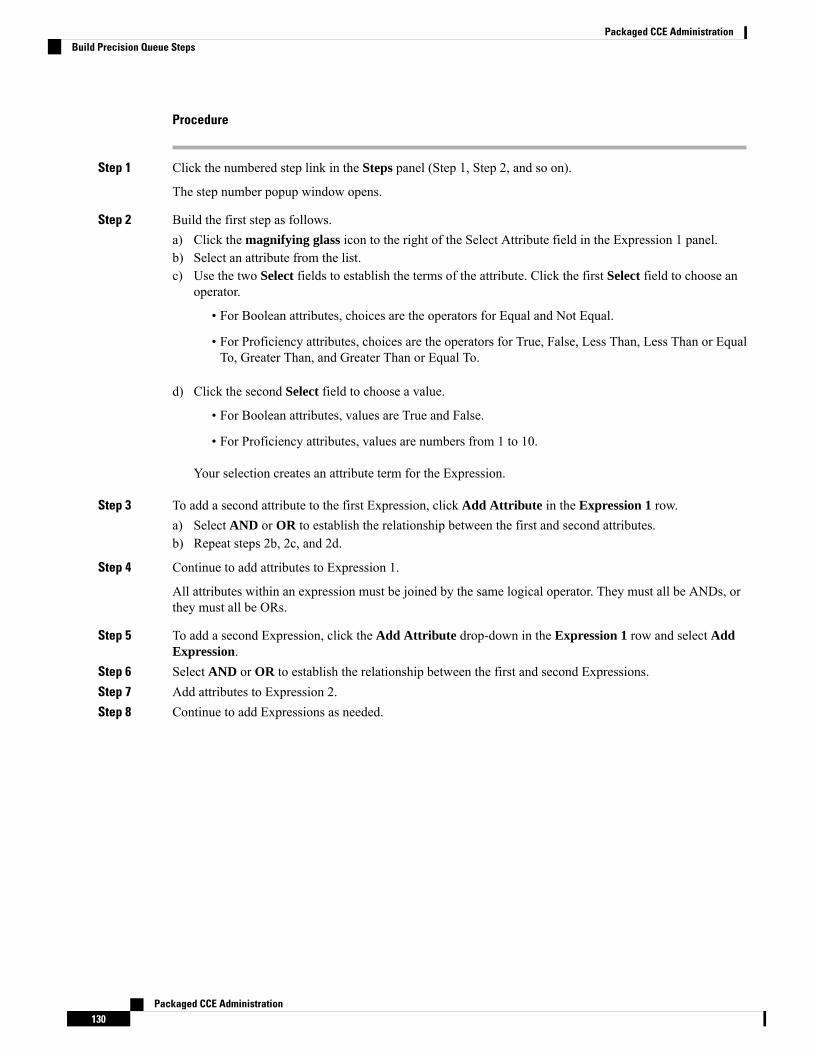
Procedure
Step 1 Click the numbered step link in the Steps panel (Step 1, Step 2, and so on).
The step number popup window opens.
Step 2 Build the first step as follows.a) Click the magnifying glass icon to the right of the Select Attribute field in the Expression 1 panel.b) Select an attribute from the list.c) Use the two Select fields to establish the terms of the attribute. Click the first Select field to choose an
operator.
• For Boolean attributes, choices are the operators for Equal and Not Equal.
• For Proficiency attributes, choices are the operators for True, False, Less Than, Less Than or EqualTo, Greater Than, and Greater Than or Equal To.
d) Click the second Select field to choose a value.
• For Boolean attributes, values are True and False.
• For Proficiency attributes, values are numbers from 1 to 10.
Your selection creates an attribute term for the Expression.
Step 3 To add a second attribute to the first Expression, click Add Attribute in the Expression 1 row.a) Select AND or OR to establish the relationship between the first and second attributes.b) Repeat steps 2b, 2c, and 2d.
Step 4 Continue to add attributes to Expression 1.
All attributes within an expression must be joined by the same logical operator. They must all be ANDs, orthey must all be ORs.
Step 5 To add a second Expression, click the Add Attribute drop-down in the Expression 1 row and select AddExpression.
Step 6 Select AND or OR to establish the relationship between the first and second Expressions.Step 7 Add attributes to Expression 2.Step 8 Continue to add Expressions as needed.
Packaged CCE Administration130
Packaged CCE AdministrationBuild Precision Queue Steps
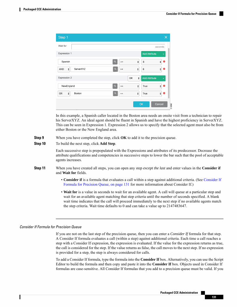
In this example, a Spanish caller located in the Boston area needs an onsite visit from a technician to repairhis ServerXYZ. An ideal agent should be fluent in Spanish and have the highest proficiency in ServerXYZ.This can be seen in Expression 1. Expression 2 allows us to specify that the selected agent must also be fromeither Boston or the New England area.
Step 9 When you have completed the step, click OK to add it to the precision queue.Step 10 To build the next step, click Add Step.
Each successive step is prepopulated with the Expressions and attributes of its predecessor. Decrease theattribute qualifications and competencies in successive steps to lower the bar such that the pool of acceptableagents increases.
Step 11 When you have created all steps, you can open any step except the last and enter values in the Consider ifand Wait for fields.
• Consider if is a formula that evaluates a call within a step against additional criteria. (See Consider IfFormula for Precision Queue, on page 131 for more information about Consider If.)
• Wait for is a value in seconds to wait for an available agent. A call will queue at a particular step andwait for an available agent matching that step criteria until the number of seconds specified. A blankwait time indicates that the call will proceed immediately to the next step if no available agents matchthe step criteria. Wait time defaults to 0 and can take a value up to 2147483647.
Consider If Formula for Precision Queue
If you are not on the last step of the precision queue, then you can enter a Consider If formula for that step.A Consider If formula evaluates a call (within a step) against additional criteria. Each time a call reaches astep with a Consider If expression, the expression is evaluated. If the value for the expression returns as true,the call is considered for the step. If the value returns as false, the call moves to the next step. If no expressionis provided for a step, the step is always considered for calls.
To add a Consider If formula, type the formula into the Consider If box. Alternatively, you can use the ScriptEditor to build the formula and then copy and paste it into the Consider If box. Objects used in Consider Ifformulas are case-sensitive. All Consider If formulas that you add to a precision queue must be valid. If you
Packaged CCE Administration131
Packaged CCE AdministrationConsider If Formula for Precision Queue
add an invalid formula, you cannot save the precision queue. To ensure that the formula is valid, use ScriptEditor to build and validate the formula.
Only the following scripting objects are valid in a Consider If formula:
• Call
• PQ
• Skillgroup
• ECC
• PQ Step
• Call Type
• Custom Functions (You can create custom functions in Script Editor.)
It is possible that a valid Consider If formula can become invalid. For example, if you delete an object usedin the formula after you create or update the precision queue, the formula is no longer valid.
Consider If Formula Examples
• PQ.PQ1.LoggedOn > 1--Evaluates whether there is more than one agent logged in to this queue.
• CallType.CallType1.CallsRoutedToday > 100--Evaluates whether more than 100 calls of this call typewere routed today.
• PQStep.PQ1.1.RouterAgentsLoggedIn > 1--Evaluates whether there is more than one router agentlogged in to this queue for Step 1.
• CustomFunction(Call.PeripheralVariable1) > 10--Evaluates whether this formula using a customfunction returns a value greater than 10.
Precision Queue Call Flow Example
At a high level, consider a 5-step precision queue with a Consider If formula for Caller is Premium Memberattached to the Step 1:
• Step 1 - Attribute: Skill > 8 - Consider If: Caller is Premium Member
• Step 2 - Attribute: Skill > 6
• Step 3 - Attribute: Skill > 4
• Step 4 - Attribute: Skill > 3
• Step 5 - Attribute: Skill >= 1
Caller John, who is not a premium customer, calls 1-800-repairs. John's call is routed to this precision queue.
• Since John is not a premium customer, he is immediately routed out of Step 1 (because of the ConsiderIf on Step 1) and into Step 2 where he waits for his call to be answered.
• After the Step 2 wait time has expired, John's call moves to Step 3 to wait for an agent.
• After the Step 3 wait time has expired, John's call moves to Step 4 to wait for an agent.
Packaged CCE Administration132
Packaged CCE AdministrationPrecision Queue Call Flow Example
• When it arrives at Step 5, John's call will wait indefinitely for an available agent. This step cannot beavoided by any call because there is no routing logic past this.
The overarching idea is that customer will use each successive step to expand the pool of available agents.Eventually, when you reach the "last" step (the step with the highest number), the call is waiting in a potentiallyvery large pool of agents. With each extra step, the chances of the call being handled increase. This also putsthe most valuable and skilled agents in the earlier precision queue steps. Calls come to them first beforemoving on the less appropriate agents in later steps.
When two or more agents have the same proficiently level for the attributes the PQ step leverages the LongestAvailable Agent (LLA).
Note
Manage Departments
DepartmentsYou have the option to create departments to facilitate contact center operation and maintenance. A contactcenter for a hospital might create departments for Surgery, Radiology, Obstetrics, and other operational units.A contact center for a university might create departments for Admissions, Alumni, and Registration.Departments are not required, and there are no built-in departments.
If you do not create departments, all administrators and objects are global, meaning that they are not associatedwith a department.
If you create departments, you have the option to associate a department with each administrator and object.These are called departmental administrators and objects. Your Packaged CCE configuration can include amix of global and departmental administrators and objects.
You can creating routing scripts for a department by referencing objects from that department in the scripts.
You can also create custom reporting collections in Cisco Unified Intelligence Center to report on departmentalobjects. See the at https://www.cisco.com/c/en/us/support/customer-collaboration/unified-intelligence-center/products-user-guide-list.html for directions on customizing reports.
Departmental Objects
The following objects can be associated with a single department. If departments are configured, the Listscreens for these objects have a Department column. The New and Edit windows for these objects have aDepartment field.
• Agents
• Attributes
• Bucket intervals
• Call types
• Desk settings
• Dialed numbers
• Network VRU scripts
Packaged CCE Administration133
Packaged CCE AdministrationManage Departments
• Precision queues
• Skill groups
• Teams
Relationships Between Global and Departmental Objects
You can create relationships between objects in your configuration. For example, you can associate an agentwith skill groups, a call type with a dialed number, and so on. An object's department assignment controls therelationships it can have to other objects.
The rules for creating relationships between objects are as follows:
• A global object can be associated with any global or departmental objects. For example, when you areassigning skill groups to a global agent, the skill group selection list includes global skill groups and skillgroups in all departments to which you have access.
• A departmental object can be associated with global objects or with objects in the same department.For example, when you are assigning skill groups to an agent in Department A, the skill group selectionlist includes global skill groups and skill groups in Department A.
These rules are summarized in the following table.
Table 19: Rules for Relationships Between Global and Departmental Objects
Can be associated withDepartmental object?
Can be associated with Global object?Object Type
yes, with objects from anydepartment
yesGlobal
yes, with objects from samedepartment only
yesDepartmental
The only exceptions to these rules are for the relationships between the following objects:
• Teams and agent: A global agent can belong only to a global team. A departmental agent can belongeither to a global team or to a team that is associated with the same department.
• Teams and supervisors: Global supervisors can supervise both global and departmental teams.Departmental supervisors can supervise only teams that are associated with the same department.
These exceptions prevent departmental supervisors from modifying global agents, and are summarized in thefollowing table.
Table 20: Rules for Relationships Between Teams and Agents and Teams and Supervisors
Supervisor -Departmental
Supervisor - GlobalAgent -Departmental
Agent - Global
noyesyesyesTeam - Global
yes (samedepartment only)
yesyes (samedepartment only)
noTeam -Departmental
Packaged CCE Administration134
Packaged CCE AdministrationDepartments

Change Departments for an Object
When you change the department for an object, relationships with objects in the original department arecleared; relationships with global objects and objects in the new department remain intact. For example, ifyou change an agent from Department A to Department B, any skill groups in Department A that had beenassociated with the agent are cleared.
For some objects, such as call type, the Edit window does not show all related objects. If you try to changethe department for those objects, you see an error indicating that you cannot change the department becausea related object is in the original department. For example, you see this error if you try to change a call typefrom Department A to Department B and it is related to a dialed number in Department A. You must changethe department of the dialed number before you can change the department of the call type.
System-wide Settings and Global Objects
Only global objects can be selected for system-wide settings in the Call Settings > Labels.
Global and Departmental Administrators
When you create administrators, you can configure them as global administrators or associate them withdepartments. See Add and Maintain Administrators, on page 108.
Global administrators
Global administrators:
• Have read and write access to departmental objects and global objects on all tools and menus that areallowed for their role.
• Can use Script Editor or Internet Script Editor to modify routing scripts.
Departmental administrators
Departmental administrators:
• Can be associated with multiple departments. They have read and write access to global objects andobjects in their departments on all tools and menus that are allowed for their role.
• A departmental administrator with the ConfigAdmin role has read-only access to the General tools onthe System menu: Information, Settings, Deployment, and Agent Trace.
• Can use Internet Script Editor to modify scripts that reference objects associated with their departments.Departmental administrators cannot log into Script Editor.
Add and Maintain Departments
To add, edit, or delete departments, an administrator must have the SystemAdmin role.
This procedure explains how to add a department. For information on maintaining departments, see UpdateObjects, on page 4 and Delete Objects, on page 7.
Procedure
Step 1 Navigate to Unified CCE Administration > Organization > Departments.
A List of Departments window opens.
Packaged CCE Administration135
Packaged CCE AdministrationAdd and Maintain Departments

Step 2 Click New to open the New Department window.Step 3 Complete the fields on the General tab:
a) Name (Required) Enter a unique name for the department, using a maximum of 32 characters.b) Description (Optional) Enter a maximum of 255 characters to describe the department. See Native
Character Sets for details on valid characters for this field.
Step 4 Click the Administrators tab.
This tab shows the Username and Domain of the administrators who currently serve as departmentadministrators and allows you to add or remove administrators.
a) Click the + icon to open the Add Administrators popup window.b) Click one or more rows to select administrators; then close the popup window. The administrators are
now on the List of Administrators.c) Click the x icon to remove an administrator from the list.
Step 5 Click Save to return to the list window, where a message confirms the successful creation of the department.
Manage Campaigns
Add and Maintain Agent Based CampaignsThis procedure explains how to add an agent based campaign. For information on maintaining campaigns,see Update Objects and Delete Objects.
Procedure
Step 1 In Unified CCE Administration, choose Organization > Campaigns.Step 2 On the Campaigns page, click New and then choose Agent Based.Step 3 On the New Agent Based Campaign, complete the following information on the General tab.
DescriptionRequired?Field
Enter a unique name for the campaign. Maximum length is 32characters. Valid characters are alphanumeric, period (.), andunderscore (_). The first character must be alphanumeric.
You cannot use the system reserved terms such as dncand none as a campaign name.
Note
YesName
The option to enable or disable the campaign. It is enabled bydefault.
-Status
Displays Agent Based by default.-Type
Packaged CCE Administration136
Packaged CCE AdministrationManage Campaigns
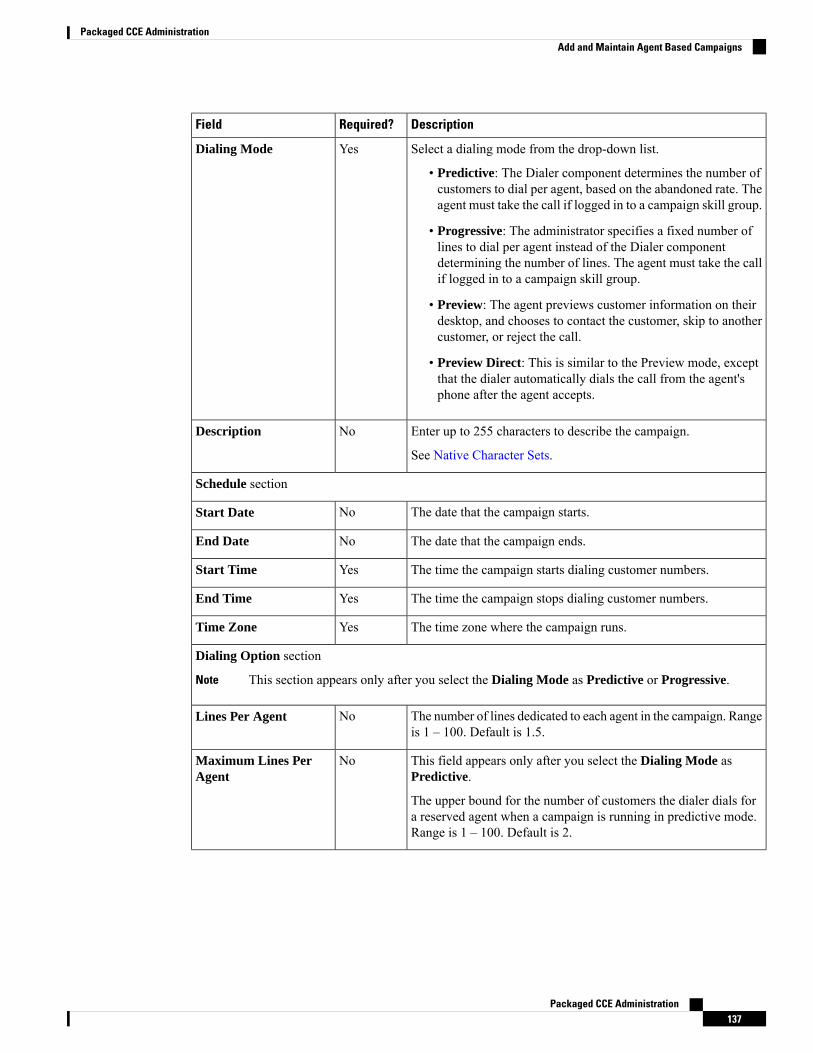
DescriptionRequired?Field
Select a dialing mode from the drop-down list.
• Predictive: The Dialer component determines the number ofcustomers to dial per agent, based on the abandoned rate. Theagent must take the call if logged in to a campaign skill group.
• Progressive: The administrator specifies a fixed number oflines to dial per agent instead of the Dialer componentdetermining the number of lines. The agent must take the callif logged in to a campaign skill group.
• Preview: The agent previews customer information on theirdesktop, and chooses to contact the customer, skip to anothercustomer, or reject the call.
• Preview Direct: This is similar to the Preview mode, exceptthat the dialer automatically dials the call from the agent'sphone after the agent accepts.
YesDialing Mode
Enter up to 255 characters to describe the campaign.
See Native Character Sets.
NoDescription
Schedule section
The date that the campaign starts.NoStart Date
The date that the campaign ends.NoEnd Date
The time the campaign starts dialing customer numbers.YesStart Time
The time the campaign stops dialing customer numbers.YesEnd Time
The time zone where the campaign runs.YesTime Zone
Dialing Option section
This section appears only after you select the Dialing Mode as Predictive or Progressive.Note
The number of lines dedicated to each agent in the campaign. Rangeis 1 – 100. Default is 1.5.
NoLines Per Agent
This field appears only after you select the Dialing Mode asPredictive.
The upper bound for the number of customers the dialer dials fora reserved agent when a campaign is running in predictive mode.Range is 1 – 100. Default is 2.
NoMaximum Lines PerAgent
Packaged CCE Administration137
Packaged CCE AdministrationAdd and Maintain Agent Based Campaigns

DescriptionRequired?Field
This field appears only after you select the Dialing Mode asPredictive.
A call is considered abandoned if a person answers it and the contactcenter does not connect the call to an agent within two seconds ofthe person's completed greeting.
The granularity is to one-tenth of a percent. Default is 3.
-Call Abandon Limit
You can set the limit for abandon calls only after you enable theCall Abandon Limit option.
You can set a limit (0.1-100) for the percentage of abandoned callsin a campaign.
If the Call Abandon Limit option is disabled, the campaign dialswithout regard to the abandon limit.
NoLimit
Enabled by default.
If you keep it enabled, make sure you have configuredand enabled Call Progress Analysis in the VoiceGateway.
Note
-Call Progress Analysis(CPA)
If you enable this option, the gateway provides a media stream andthe dialer records the .wav files.
-Record CPA
Enabled by default. This enables the dialer to detect an answeringmachine. From the drop-down list, choose one of the followingactions that the dialer must perform when the dialer detects ananswering machine:
• Abandon Call: Drops the call, marks it as an answeringmachine, and schedules a retry. This option is selected bydefault.
• Transfer to Agent: Transfers the call to an agent.
• Transfer to IVR Route Point: Transfers the call to play aprerecorded message. The IVR route point is configured inthe Skill Group selection dialog box on the Skill Groups tab.
-Answering MachineTreatment
This field is activated only when the Answering MachineTreatment field enabled and you select theTransfer to IVR RoutePoint option from the drop-down list.
You can enable this field to allow the dialer to transfer the call toIVR route point after detecting the answering machine beep.
-Terminate Tone Detect
Callback Settings section
Enable this option allows an agent to schedule a callback to acustomer for a specific date and time. A personal callback connectsthe same agent who initiated the callback to the customer.
-Personalized Callback
Packaged CCE Administration138
Packaged CCE AdministrationAdd and Maintain Agent Based Campaigns

DescriptionRequired?Field
Select an option from the drop-down list to handle the personalcallback in case the agent is not available.
• Abandon: Abandon the personal callback. This option isselected by default.
• Same time next business day: Reschedule the personalcallback to the same time the next business day.
• Use campaign dialed number: Use the alternate dialednumber.
Yes (WhenPersonalizedCallbackoption isenabled.)
Missed Callback
Step 4 On the Skill Group tab, click Add to open the Add Skill Group pop-up window.
You must add at least one Skill Group for a campaign.Note
Step 5 Complete the following information in the Add Skill Group pop-up window.
DescriptionRequired?Field
Select a site from the drop-down list. Based on the site, you canselect peripheral set, skill group and dialed number in the subsequentfields.
YesSite
This field is available only in Packaged CCE 4000 Agents and12000 Agents deployments. For more information, see Add andMaintain Peripheral Set.
Select a peripheral set from the drop-down list. The list containsthe peripheral sets associated to the selected site.
YesPeripheral Set
Click the Search icon to open the Add a Skill Group pop-up.
You can search and select the Skill Group based on the name anddescription.
The search result does not display the Skill Groups that are alreadyadded to a Campaign.
YesSkill Group
Click the Search icon to open the Add Dialed Number pop-up.
By default, you can view all the dialed numbers for which theRouting Type is set as Outbound Voice.
You can search and select the dialed number based on the stringvalue and description.
The search result does not display the dialed numbers that arealready added to a Campaign.
The selected number is dialed to reserve an agent in the configuredskill group.
YesDialed Number
Packaged CCE Administration139
Packaged CCE AdministrationAdd and Maintain Agent Based Campaigns
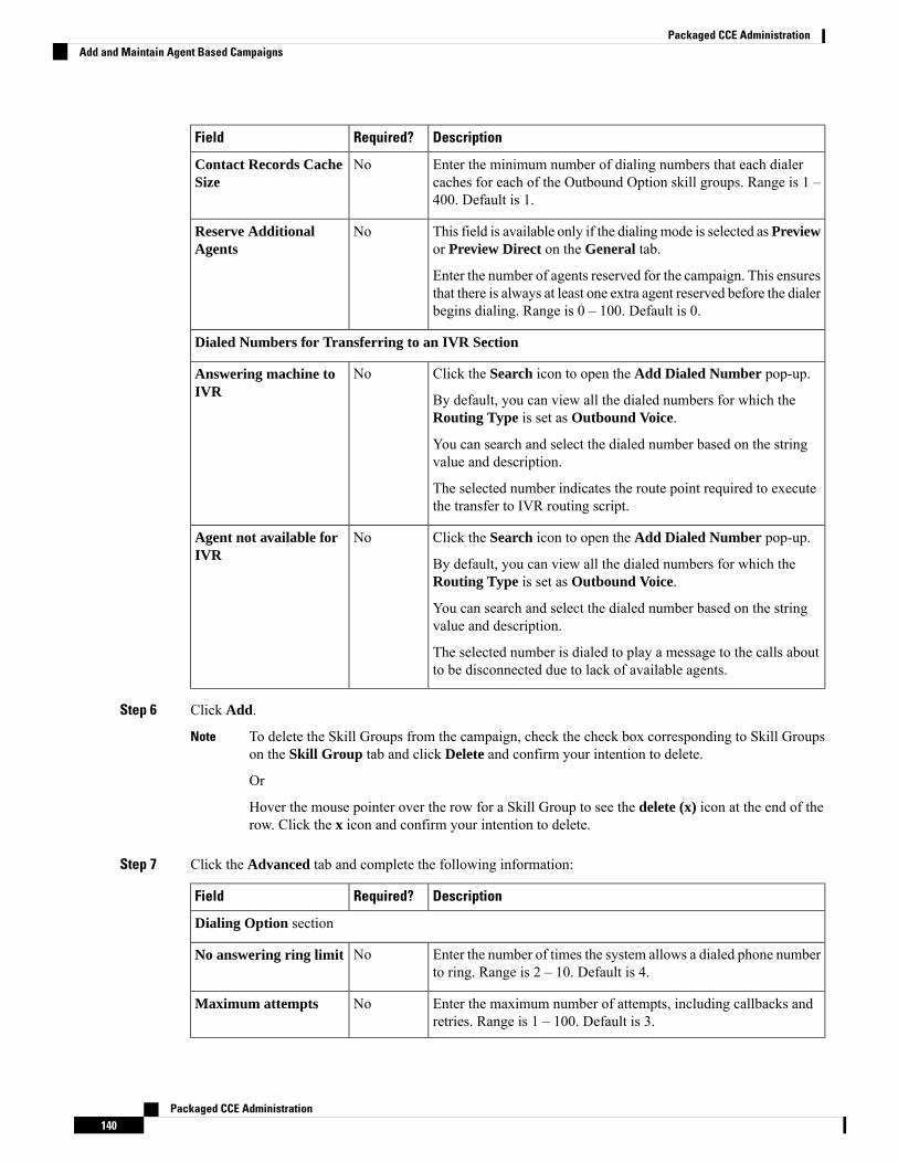
DescriptionRequired?Field
Enter the minimum number of dialing numbers that each dialercaches for each of the Outbound Option skill groups. Range is 1 –400. Default is 1.
NoContact Records CacheSize
This field is available only if the dialingmode is selected as Previewor Preview Direct on the General tab.
Enter the number of agents reserved for the campaign. This ensuresthat there is always at least one extra agent reserved before the dialerbegins dialing. Range is 0 – 100. Default is 0.
NoReserve AdditionalAgents
Dialed Numbers for Transferring to an IVR Section
Click the Search icon to open the Add Dialed Number pop-up.
By default, you can view all the dialed numbers for which theRouting Type is set as Outbound Voice.
You can search and select the dialed number based on the stringvalue and description.
The selected number indicates the route point required to executethe transfer to IVR routing script.
NoAnswering machine toIVR
Click the Search icon to open the Add Dialed Number pop-up.
By default, you can view all the dialed numbers for which theRouting Type is set as Outbound Voice.
You can search and select the dialed number based on the stringvalue and description.
The selected number is dialed to play a message to the calls aboutto be disconnected due to lack of available agents.
NoAgent not available forIVR
Step 6 Click Add.
To delete the Skill Groups from the campaign, check the check box corresponding to Skill Groupson the Skill Group tab and click Delete and confirm your intention to delete.
Or
Hover the mouse pointer over the row for a Skill Group to see the delete (x) icon at the end of therow. Click the x icon and confirm your intention to delete.
Note
Step 7 Click the Advanced tab and complete the following information:
DescriptionRequired?Field
Dialing Option section
Enter the number of times the system allows a dialed phone numberto ring. Range is 2 – 10. Default is 4.
NoNo answering ring limit
Enter the maximum number of attempts, including callbacks andretries. Range is 1 – 100. Default is 3.
NoMaximum attempts
Packaged CCE Administration140
Packaged CCE AdministrationAdd and Maintain Agent Based Campaigns
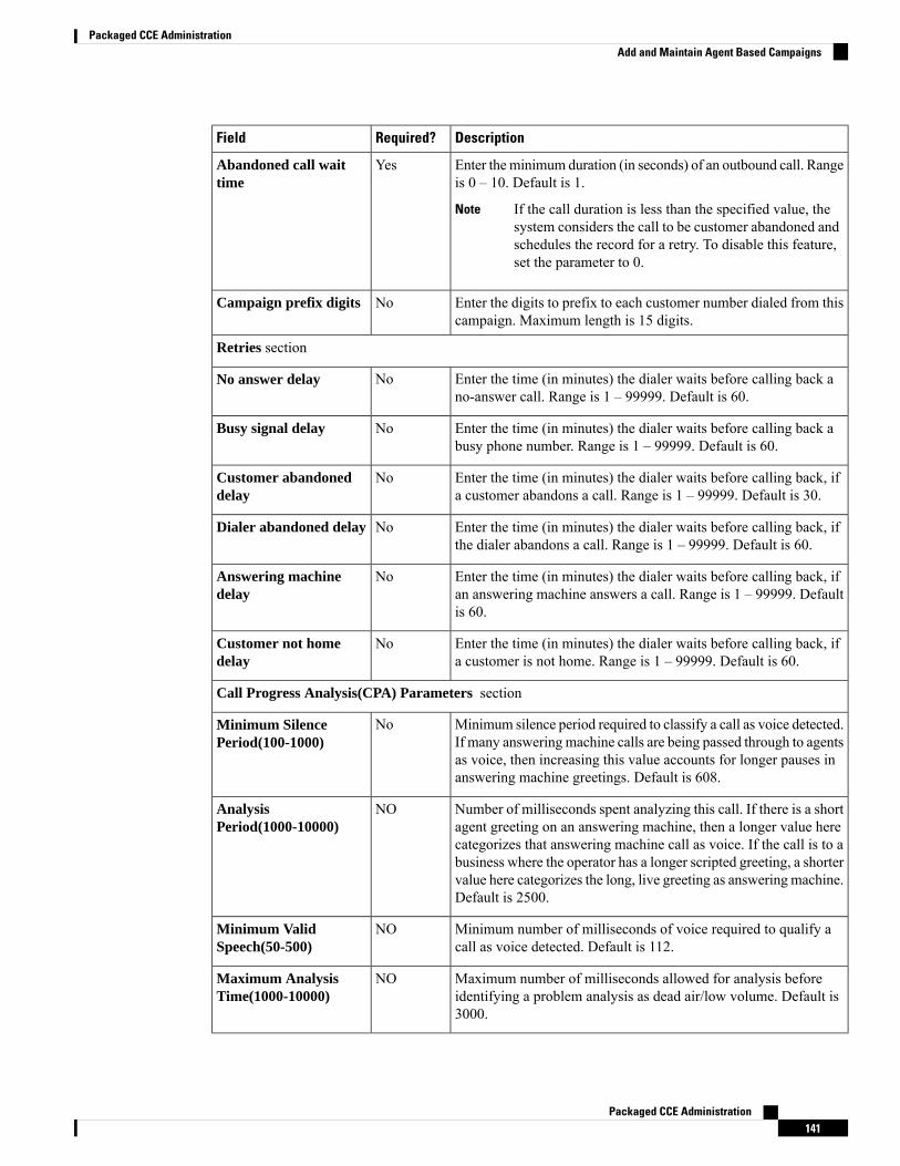
DescriptionRequired?Field
Enter theminimum duration (in seconds) of an outbound call. Rangeis 0 – 10. Default is 1.
If the call duration is less than the specified value, thesystem considers the call to be customer abandoned andschedules the record for a retry. To disable this feature,set the parameter to 0.
Note
YesAbandoned call waittime
Enter the digits to prefix to each customer number dialed from thiscampaign. Maximum length is 15 digits.
NoCampaign prefix digits
Retries section
Enter the time (in minutes) the dialer waits before calling back ano-answer call. Range is 1 – 99999. Default is 60.
NoNo answer delay
Enter the time (in minutes) the dialer waits before calling back abusy phone number. Range is 1 – 99999. Default is 60.
NoBusy signal delay
Enter the time (in minutes) the dialer waits before calling back, ifa customer abandons a call. Range is 1 – 99999. Default is 30.
NoCustomer abandoneddelay
Enter the time (in minutes) the dialer waits before calling back, ifthe dialer abandons a call. Range is 1 – 99999. Default is 60.
NoDialer abandoned delay
Enter the time (in minutes) the dialer waits before calling back, ifan answering machine answers a call. Range is 1 – 99999. Defaultis 60.
NoAnswering machinedelay
Enter the time (in minutes) the dialer waits before calling back, ifa customer is not home. Range is 1 – 99999. Default is 60.
NoCustomer not homedelay
Call Progress Analysis(CPA) Parameters section
Minimum silence period required to classify a call as voice detected.If many answeringmachine calls are being passed through to agentsas voice, then increasing this value accounts for longer pauses inanswering machine greetings. Default is 608.
NoMinimum SilencePeriod(100-1000)
Number of milliseconds spent analyzing this call. If there is a shortagent greeting on an answering machine, then a longer value herecategorizes that answering machine call as voice. If the call is to abusiness where the operator has a longer scripted greeting, a shortervalue here categorizes the long, live greeting as answering machine.Default is 2500.
NOAnalysisPeriod(1000-10000)
Minimum number of milliseconds of voice required to qualify acall as voice detected. Default is 112.
NOMinimum ValidSpeech(50-500)
Maximum number of milliseconds allowed for analysis beforeidentifying a problem analysis as dead air/low volume. Default is3000.
NOMaximum AnalysisTime(1000-10000)
Packaged CCE Administration141
Packaged CCE AdministrationAdd and Maintain Agent Based Campaigns
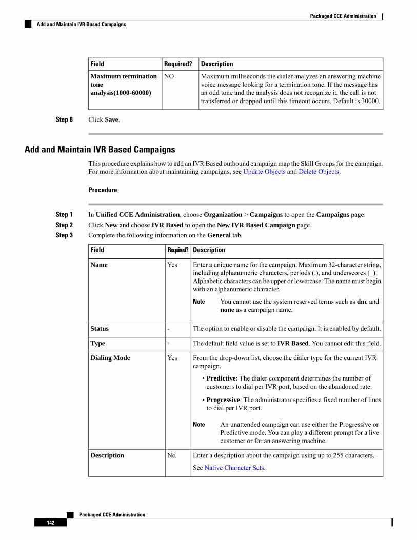
DescriptionRequired?Field
Maximum milliseconds the dialer analyzes an answering machinevoice message looking for a termination tone. If the message hasan odd tone and the analysis does not recognize it, the call is nottransferred or dropped until this timeout occurs. Default is 30000.
NOMaximum terminationtoneanalysis(1000-60000)
Step 8 Click Save.
Add and Maintain IVR Based CampaignsThis procedure explains how to add an IVRBased outbound campaignmap the Skill Groups for the campaign.For more information about maintaining campaigns, see Update Objects and Delete Objects.
Procedure
Step 1 In Unified CCE Administration, choose Organization > Campaigns to open the Campaigns page.Step 2 Click New and choose IVR Based to open the New IVR Based Campaign page.Step 3 Complete the following information on the General tab.
DescriptionRequired?Field
Enter a unique name for the campaign. Maximum 32-character string,including alphanumeric characters, periods (.), and underscores (_).Alphabetic characters can be upper or lowercase. The namemust beginwith an alphanumeric character.
You cannot use the system reserved terms such as dnc andnone as a campaign name.
Note
YesName
The option to enable or disable the campaign. It is enabled by default.-Status
The default field value is set to IVR Based. You cannot edit this field.-Type
From the drop-down list, choose the dialer type for the current IVRcampaign.
• Predictive: The dialer component determines the number ofcustomers to dial per IVR port, based on the abandoned rate.
• Progressive: The administrator specifies a fixed number of linesto dial per IVR port.
An unattended campaign can use either the Progressive orPredictive mode. You can play a different prompt for a livecustomer or for an answering machine.
Note
YesDialing Mode
Enter a description about the campaign using up to 255 characters.
See Native Character Sets.
NoDescription
Packaged CCE Administration142
Packaged CCE AdministrationAdd and Maintain IVR Based Campaigns
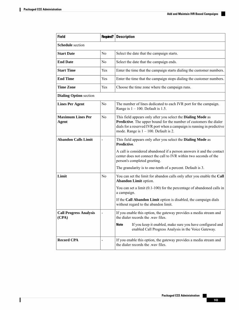
DescriptionRequired?Field
Schedule section
Select the date that the campaign starts.NoStart Date
Select the date that the campaign ends.NoEnd Date
Enter the time that the campaign starts dialing the customer numbers.YesStart Time
Enter the time that the campaign stops dialing the customer numbers.YesEnd Time
Choose the time zone where the campaign runs.YesTime Zone
Dialing Option section
The number of lines dedicated to each IVR port for the campaign.Range is 1 – 100. Default is 1.5.
NoLines Per Agent
This field appears only after you select the Dialing Mode asPredictive. The upper bound for the number of customers the dialerdials for a reserved IVR port when a campaign is running in predictivemode. Range is 1 – 100. Default is 2.
NoMaximum Lines PerAgent
This field appears only after you select the Dialing Mode asPredictive.
A call is considered abandoned if a person answers it and the contactcenter does not connect the call to IVR within two seconds of theperson's completed greeting.
The granularity is to one-tenth of a percent. Default is 3.
-Abandon Calls Limit
You can set the limit for abandon calls only after you enable the CallAbandon Limit option.
You can set a limit (0.1-100) for the percentage of abandoned calls ina campaign.
If the Call Abandon Limit option is disabled, the campaign dialswithout regard to the abandon limit.
NoLimit
If you enable this option, the gateway provides a media stream andthe dialer records the .wav files.
If you keep it enabled, make sure you have configured andenabled Call Progress Analysis in the Voice Gateway.
Note
-Call Progress Analysis(CPA)
If you enable this option, the gateway provides a media stream andthe dialer records the .wav files.
-Record CPA
Packaged CCE Administration143
Packaged CCE AdministrationAdd and Maintain IVR Based Campaigns
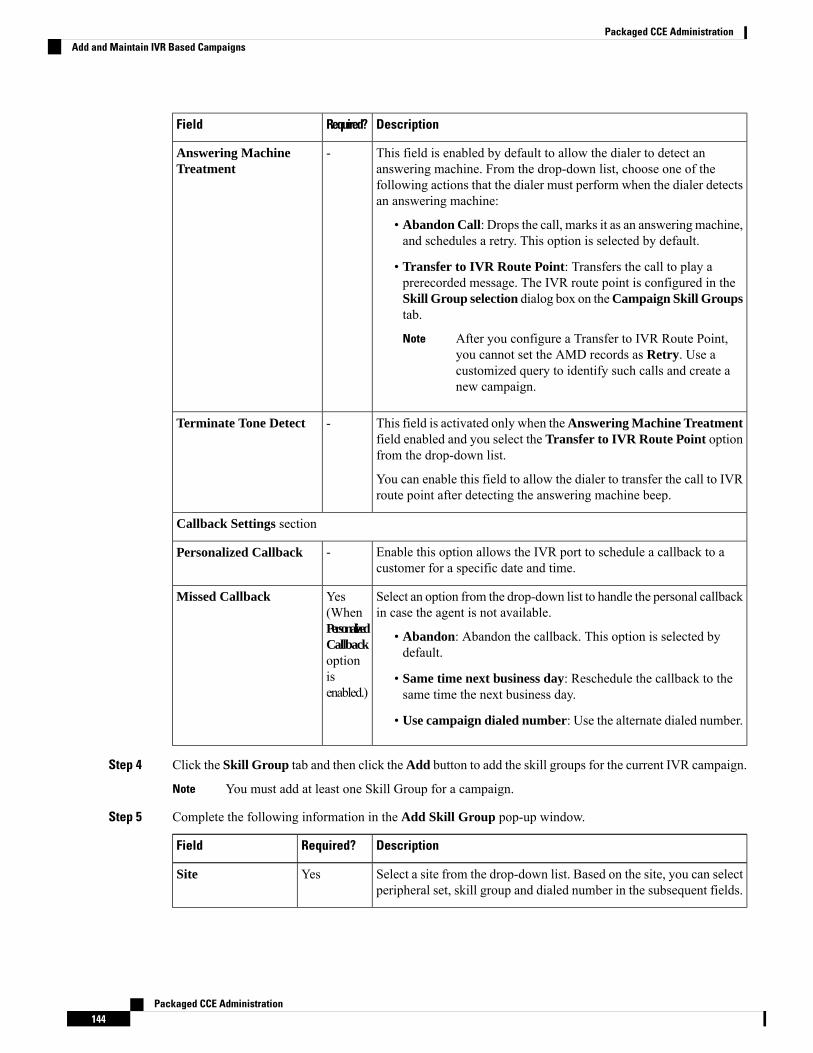
DescriptionRequired?Field
This field is enabled by default to allow the dialer to detect ananswering machine. From the drop-down list, choose one of thefollowing actions that the dialer must perform when the dialer detectsan answering machine:
• Abandon Call: Drops the call, marks it as an answering machine,and schedules a retry. This option is selected by default.
• Transfer to IVR Route Point: Transfers the call to play aprerecorded message. The IVR route point is configured in theSkill Group selection dialog box on theCampaign Skill Groupstab.
After you configure a Transfer to IVR Route Point,you cannot set the AMD records as Retry. Use acustomized query to identify such calls and create anew campaign.
Note
-Answering MachineTreatment
This field is activated only when theAnswering Machine Treatmentfield enabled and you select the Transfer to IVR Route Point optionfrom the drop-down list.
You can enable this field to allow the dialer to transfer the call to IVRroute point after detecting the answering machine beep.
-Terminate Tone Detect
Callback Settings section
Enable this option allows the IVR port to schedule a callback to acustomer for a specific date and time.
-Personalized Callback
Select an option from the drop-down list to handle the personal callbackin case the agent is not available.
• Abandon: Abandon the callback. This option is selected bydefault.
• Same time next business day: Reschedule the callback to thesame time the next business day.
• Use campaign dialed number: Use the alternate dialed number.
Yes(WhenPersonalizedCallbackoptionisenabled.)
Missed Callback
Step 4 Click the Skill Group tab and then click theAdd button to add the skill groups for the current IVR campaign.
You must add at least one Skill Group for a campaign.Note
Step 5 Complete the following information in the Add Skill Group pop-up window.
DescriptionRequired?Field
Select a site from the drop-down list. Based on the site, you can selectperipheral set, skill group and dialed number in the subsequent fields.
YesSite
Packaged CCE Administration144
Packaged CCE AdministrationAdd and Maintain IVR Based Campaigns

DescriptionRequired?Field
This field is available only in Packaged CCE 4000 Agents and 12000Agents deployments. For more information, see Add and MaintainPeripheral Set.
Select a peripheral set from the drop-down list. The list contains theperipheral sets associated to the selected site.
YesPeripheral Set
Click the Search icon to open the Add a Skill Group pop-up.
You can search and select the Skill Group based on the name anddescription.
The search result do not display the Skill Groups that are already addedto a Campaign.
YesSkill Group
Click the Search icon to open the Add Dialed Number pop-up.
By default, you can view all the dialed numbers for which theRoutingType is set as Outbound Voice.
You can search and select the dialed number based on the string valueand description.
The search result do not display the dialed numbers that are alreadyadded to a Campaign.
The selected number is dialed to reserve an IVR port in the configuredskill group.
YesDialed Number
Enter the minimum number of dialing numbers that each dialer cachesfor each of the Outbound Option skill groups. Range is 1 – 400. Defaultis 1.
YesContact Recordscache Size
Enter the total number of IVR ports allocated for the specified skillgroup.
This value indicates how many ports are available for the dialer totransfer customer calls. The application uses one IVR to play differentmessages based on the route point where the contact is transferred. Ifthere are multiple dialers associated with this skill group, each dialerdials a fraction of the total number of ports.
NoNumber of IVRPorts
Dialed Numbers for Transferring to an IVR Section
Click the Search icon to open the Add Dialed Number pop-up.
By default, you can view all the dialed numbers for which theRoutingType is set as Outbound Voice.
You can search and select the dialed number based on the string valueand description.
When the dialer identifies the answering machine, the selected numberis dialed to transfer the call to IVR routing script. The routing scripttransfers the call to an IVR.
YesAnswering Machineto IVR
Packaged CCE Administration145
Packaged CCE AdministrationAdd and Maintain IVR Based Campaigns
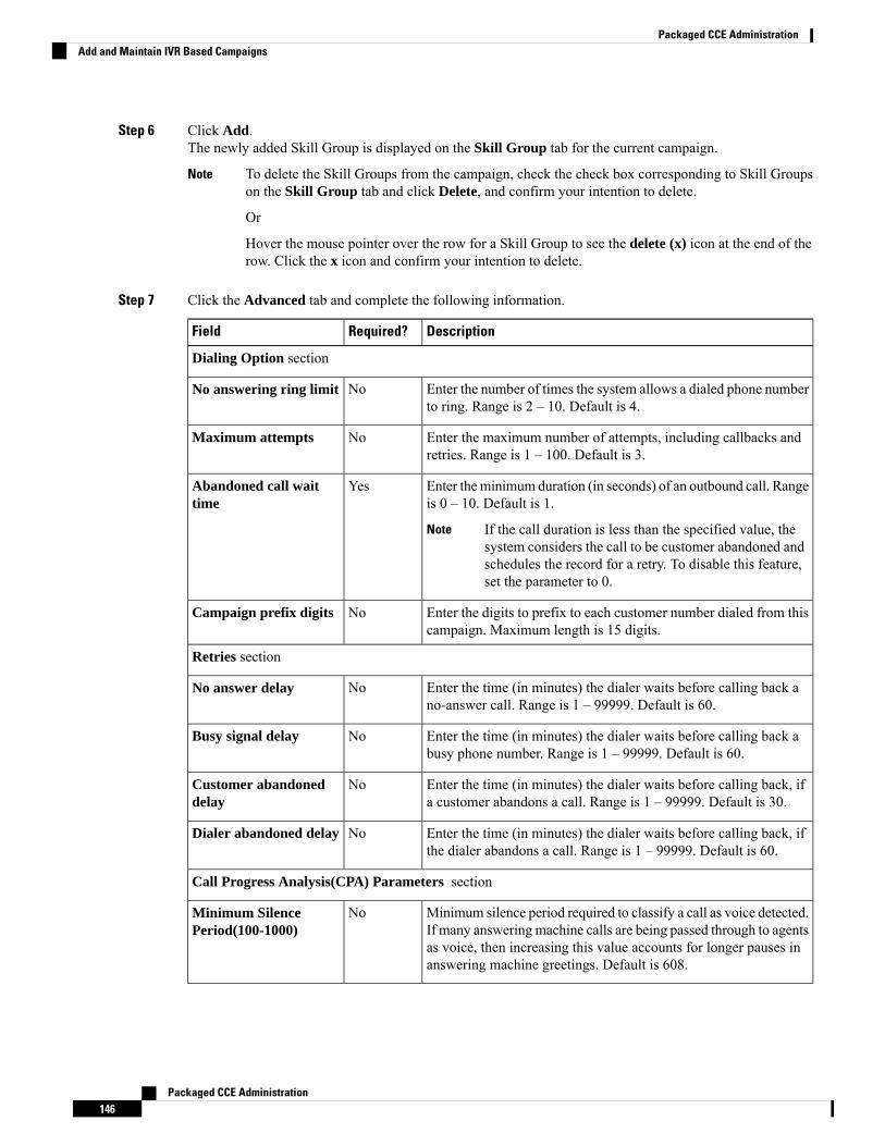
Step 6 Click Add.The newly added Skill Group is displayed on the Skill Group tab for the current campaign.
To delete the Skill Groups from the campaign, check the check box corresponding to Skill Groupson the Skill Group tab and click Delete, and confirm your intention to delete.
Or
Hover the mouse pointer over the row for a Skill Group to see the delete (x) icon at the end of therow. Click the x icon and confirm your intention to delete.
Note
Step 7 Click the Advanced tab and complete the following information.
DescriptionRequired?Field
Dialing Option section
Enter the number of times the system allows a dialed phone numberto ring. Range is 2 – 10. Default is 4.
NoNo answering ring limit
Enter the maximum number of attempts, including callbacks andretries. Range is 1 – 100. Default is 3.
NoMaximum attempts
Enter theminimum duration (in seconds) of an outbound call. Rangeis 0 – 10. Default is 1.
If the call duration is less than the specified value, thesystem considers the call to be customer abandoned andschedules the record for a retry. To disable this feature,set the parameter to 0.
Note
YesAbandoned call waittime
Enter the digits to prefix to each customer number dialed from thiscampaign. Maximum length is 15 digits.
NoCampaign prefix digits
Retries section
Enter the time (in minutes) the dialer waits before calling back ano-answer call. Range is 1 – 99999. Default is 60.
NoNo answer delay
Enter the time (in minutes) the dialer waits before calling back abusy phone number. Range is 1 – 99999. Default is 60.
NoBusy signal delay
Enter the time (in minutes) the dialer waits before calling back, ifa customer abandons a call. Range is 1 – 99999. Default is 30.
NoCustomer abandoneddelay
Enter the time (in minutes) the dialer waits before calling back, ifthe dialer abandons a call. Range is 1 – 99999. Default is 60.
NoDialer abandoned delay
Call Progress Analysis(CPA) Parameters section
Minimum silence period required to classify a call as voice detected.If many answeringmachine calls are being passed through to agentsas voice, then increasing this value accounts for longer pauses inanswering machine greetings. Default is 608.
NoMinimum SilencePeriod(100-1000)
Packaged CCE Administration146
Packaged CCE AdministrationAdd and Maintain IVR Based Campaigns
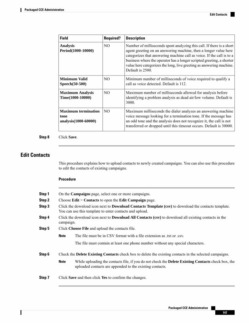
DescriptionRequired?Field
Number of milliseconds spent analyzing this call. If there is a shortagent greeting on an answering machine, then a longer value herecategorizes that answering machine call as voice. If the call is to abusiness where the operator has a longer scripted greeting, a shortervalue here categorizes the long, live greeting as answering machine.Default is 2500.
NOAnalysisPeriod(1000-10000)
Minimum number of milliseconds of voice required to qualify acall as voice detected. Default is 112.
NOMinimum ValidSpeech(50-500)
Maximum number of milliseconds allowed for analysis beforeidentifying a problem analysis as dead air/low volume. Default is3000.
NOMaximum AnalysisTime(1000-10000)
Maximum milliseconds the dialer analyzes an answering machinevoice message looking for a termination tone. If the message hasan odd tone and the analysis does not recognize it, the call is nottransferred or dropped until this timeout occurs. Default is 30000.
NOMaximum terminationtoneanalysis(1000-60000)
Step 8 Click Save.
Edit ContactsThis procedure explains how to upload contacts to newly created campaigns. You can also use this procedureto edit the contacts of existing campaigns.
Procedure
Step 1 On the Campaigns page, select one or more campaigns.Step 2 Choose Edit > Contacts to open the Edit Campaign page.Step 3 Click the download icon next to Download Contacts Template (csv) to download the contacts template.
You can use this template to enter contacts and upload.Step 4 Click the download icon next to Download All Contacts (csv) to download all existing contacts in the
campaign.Step 5 Click Choose File and upload the contacts file.
The file must be in CSV format with a file extension as .txt or .csv.
The file must contain at least one phone number without any special characters.
Note
Step 6 Check the Delete Existing Contacts check box to delete the existing contacts in the selected campaigns.
While uploading the contacts file, if you do not check the Delete Existing Contacts check box, theuploaded contacts are appended to the existing contacts.
Note
Step 7 Click Save and then click Yes to confirm the changes.
Packaged CCE Administration147
Packaged CCE AdministrationEdit Contacts
Edit Status and ScheduleThis procedure explains how to edit the status and schedule of campaigns.
Procedure
Step 1 On the Campaigns page, select one or more campaigns to edit.Step 2 Choose Edit > Status and Schedule to open the Edit Campaign page.
• If you have selected one campaign, edit the status and the schedule of the campaign.
• If you have selected multiple campaigns,
a. Check the Edit Status check box and edit the status of the campaign.
b. Check the Edit Schedule check box to enable the fields under Schedule and select new values.
Step 3 Click Save and then click Yes to confirm the changes.
Save File Path of Do Not Call List Import FileMany countries require phone solicitors to maintain do not call lists. A Do Not Call (DNC) list ensures thatyour contact center does not call those customers who request that you do not contact them.
The Do Not Call list is a list of phone numbers that are identified as off-limits for outbound calling. This listcan include numbers from a national DNC list and numbers from customers who have directly requested thatyou not contact them. Outbound Campaigns do not dial entries in the Do Not Call list even if they are includedin a contact list. The DNC list is shared across all campaigns and contains only phone numbers.
Before you begin:
1. Using a text editor, create a text file to contain the "Do Not Call" phone numbers.
2. For each "Do Not Call" entry, enter a phone number of up to 20 characters on a new line.
The following is an example of a Do Not Call list:
2225554444
2225556666
2225559999
3. Save the text file to the path that is accessible from the logger.
Procedure
Step 1 In Unified CCE Administration, choose Organization > Campaigns to open the Campaigns page.Step 2 Click the Do Not Call - Settings link.
The Do Not Call - Settings pop-up window appears.Step 3 In the File Path with Name field, you must enter the DNC list import file path on the logger or the path
accessible from the logger.
Packaged CCE Administration148
Packaged CCE AdministrationEdit Status and Schedule
Step 4 Click Save.The solution import the DNC phone numbers to Do_Not_Call table in BA database. The name of DNC listimport file is renamed after the successful import.
On the Campaigns page, you can save only one DNC list import file path at a time.Note
The campaign validates that a number in the dialing list is not in the Do Not Call list before sending it to adialer. The solution checks the list at the last minute before placing the call. You can update a Do Not Calllist while a campaign is running.
To edit the DNC phone numbers import file path:
1. Click the Do Not Call - Settings link. The solution displays the existing file path of the DNC list importfile in the File Path with Name field.
2. Enter the file path of the new or updated DNC list import file in the File Path with Name field.
3. (Optional) Check the Delete existing "Do Not Call" Phone Numbers check box to delete the existingphone numbers from the Do_Not_Call table.
If this check box is unchecked, the existing DNC phone numbers are appended to the new or updatedDNC phone numbers in the Do_Not_Call table.
4. Click Save.
Business Hours
Business HoursBusiness hours are the working hours during which you conduct business. You can create andmodify businesshours and set weekly and daily schedules for each business hour. You can create different business hourschedules for regular working days and holidays. You can also open or close the business hours if there is anemergency.
You can define the status reasons for business hours and assign codes for each status reason. Status reason isrequired when you force open or force close a business hour, and when you add special hours and holidays.
Search for Business HoursThe Search field on the Business Hours page offers an advanced and flexible search.
Click the + icon on the Search field to open a popup window, where you can:
• Enter a business hour name or description to search for that string.
• Select Globals and Departments or Departments only to enable an input field where you can enter aspace-separated list of department names. (Departments is an OR search.)
Search by department is available only when departments are configured.Note
Packaged CCE Administration149
Packaged CCE AdministrationBusiness Hours

Add and Maintain Business Hours
Procedure
Step 1 In Unified CCE Administration, choose Organization > Business Hours.Step 2 On the Business Hours page, click New to open the New Business Hours page.Step 3 Complete the following information on the General tab and click Save.
DescriptionRequired?Field
Select one of the following statuses for the business hour:
• Open/Closed as per Business Calendar
• Force Open
• Force Close
-Status
This field is enabled only if the status is Force Open or Force Close.Search and select a status reason for the business hour.
Yes, if thestatus isForce Openor ForceClose.
Status Reason
Enter a unique name for the business hour. Maximum length is 32characters. Valid characters are alphanumeric, period (.), andunderscore (_). The first character must be alphanumeric.
YesName
Enter a description of the business hour.NoDescription
Select a time zone of the business hour from the drop-down list.YesTime Zone
Search and select a department to associate with the business hour.Default is Global.
-Department
Step 4 Click the Regular Hours tab and complete the following information:
• Select one of the following Business Hour Type:
• 24x7: Always open. You cannot customize the working hours.
• Custom: You can customize the working hours.
• If you select Custom, enable at least one business day and select the Start Time and End Time.
Step 5 Click the Special Hours & Holiday tab. You can either add or import special hours and holidays.Step 6 Click Add to open the Add Special Hours & Holiday popup window. Complete the following information:
DescriptionRequired?Field
Select a date from the calendar.YesDate
Enter a description for the special hour.NoDescription
Packaged CCE Administration150
Packaged CCE AdministrationAdd and Maintain Business Hours
DescriptionRequired?Field
Select a status.
If the status is Open, the Start Time and End Time fields areenabled.
-Status
Select a start time for the special hour.Yes, ifstatus isOpen.
Start Time
Select an end time for the special hour.Yes, ifstatus isOpen.
End Time
Displays the duration of the special hour.-Duration
Search and select a status reason.YesStatus Reason
Step 7 Click Save to add the special hours and holidays.Step 8 To import special hours and holidays, follow these steps.
a) Click Import to open the Import Special Hours and Holidays pop-up window.b) Click the download icon to download the Special Hours & Holidays template. Use this template to enter
the special hours and holidays.c) Click Choose File and browse to the special hours and holidays file. ClickImport to upload the file.
The file must contain at least one special hour and holiday.
The file must be in CSV format with a file extension as .txt or .csv.
Note
Step 9 Click Export to download the special hours and holidays in .csv format.Step 10 Click Save.
The imported business hours overwrites the existing ones.Note
Add Status ReasonsThis procedure explains how to add and maintain status reasons for business hours.
Procedure
Step 1 In Unified CCE Administration, choose Organization > Business Hours > Status Reasons.Step 2 Click Add to open the Add Status Reason popup window.Step 3 Enter the Status Reason. Maximum length is 255 characters.Step 4 Enter a unique Reason Code. Range is 1001 to 65535. Codes 1 to 1000 are reserved as system-defined reason
codes.Step 5 Click Save.
Packaged CCE Administration151
Packaged CCE AdministrationAdd Status Reasons
To add more status reasons, repeat steps from 2 to 5.
Step 6 Click Done to return to the List window.
Edit Status for Multiple Business HoursPerform the following steps to edit the status of multiple business hours at once.
Procedure
Step 1 On the Business Hours page, select two or more business hours to edit.Step 2 Choose Edit > Status to open the Edit Business Hours page.Step 3 Check the Status check box and select the required status.Step 4 If you select the status as Force Open or Force Close, search and select a Status Reason.Step 5 Click Save.
Edit Schedule for Multiple Business HoursPerform the following steps to edit schedules of multiple business hours at once.
Procedure
Step 1 On the Business Hours page, select two or more business hours to edit.Step 2 Choose Edit > Schedule to open the Edit Business Hours page.Step 3 Check the Time Zone check box and the select the required time zone from the drop-down list.Step 4 Check the Type check box and select the required business hour type.Step 5 If you select Custom, enable atleast one business day and select the Start Time and End Time.Step 6 Click Save.
Desktop Settings
Resources
ResourcesTheResources page allows you to configure resources for the teams. In Unified CCE Administration, chooseDesktop > Resources to open the Resources page. You can select a site from the Site drop-down list. Bydefault Main is selected for Packaged CCE 2000 Agents deployment.
Packaged CCE Administration152
Packaged CCE AdministrationEdit Status for Multiple Business Hours
The Packaged CCE 4000 Agents or 12000 Agents deployment type provides an option to select a peripheralset that includes the Cisco Finesse component configured. For more information to add peripheral sets to asite, see Add and Maintain Peripheral Set.
After you select a site, select a peripheral set from the Peripheral Set drop-down list. The drop-down listincludes the peripheral sets configured for the selected site.
This page contains the following tabs that you click to configure the respective resources:
• Call Variables Layout: Manage the call variables and (Extended Call Context ECC) variables thatappear on the agent desktop call control gadget.
• Desktop Layout: Make changes to the default desktop layout for agents and supervisors.
• Phone Books: Add, edit, or delete phone books or phone book contacts.
• Workflows: Create and manage workflows and workflow actions.
The resources that you configure are case-sensitive. For example, you can create two workflows namedWORKFLOW and workflow or two phone books named BOOK and book.
Manage Call Variables LayoutYou can use the Call Variables Layouts gadget to define how call variables appear on the Finesse agentdesktop. You can configure up to 200 unique Call Variables Layouts (one default layout and 199 customlayouts). As part of this functionality:
• Each layout has a name (required) and description (optional).
• After an upgrade from a release earlier than Cisco Finesse Release 11.0, Finesse migrates the previouslyconfigured default layout and assigns it the default name (Default Layout) and description (Layout usedwhen no other layout matches the user layout Custom/ECC Variable).
• You can change the name and description of the default Call Variables Layout.
• You cannot delete the default Call Variables Layout.
• Finesse appends (Default) to the name of the default Call Variables Layout.
• To display a custom Call Variables Layout, in the Unified CCE routing script set the user.Layout ECCvariable to the name of a configured Call Variables Layout. In this case, if no custom layouts match theuser.Layout value (or no custom layouts are configured), the Finesse displays the default layout.
• Finesse retains the custom layout as specified by the user.Layout ECC variable on CTI server failover.During PG failover, Finesse changes the active call layout to the default layout while retaining the callvariables and time indicators.
Call Variables
Each Call Variables Layout supports one variable in the header of the call control gadget and up to a total of20 variables in two columns below the header (up to 10 in each column). You can use call variables, ExtendedCall Context (ECC) variables, or the following Outbound Option ECC variables:
• BACampaign
• BAAccountNumber
• BAResponse
Packaged CCE Administration153
Packaged CCE AdministrationManage Call Variables Layout
• BAStatus
• BADialedListID
• BATimeZone
• BABuddyName
Columns can be empty.
The administrator can include the following additional fields in the Call Variables Layout. These variablesappear as a drop-down list in the call variable gadget which the admin can assign to a layout.
• queueNumber
• queueName
• callKeyCallId
• callKeyPrefix
• callKeySequenceNum
• wrapUpReason
The callKeyPrefix indicates the day when the call was routed.
The callKeyCallId indicates the unique number for the call routed on that day.
To uniquely locate the call in Unified CCE database records, concatenate the two variables callKeyPrefix andcallKeyCallId.
Note
To enable Outbound Option data to appear in Cisco Finesse, the administrator must edit the Default Layoutto include some or all Outbound Option variables.
Edit Call Variables
Administrator can set call variables (callVariable1 to callVariable10) values and ECC variable values aseditable. Amongst BA (campaign-based outbound calls) variables, only BAResponse can be edited. The agentand the supervisor can edit the call variable values during an active call or in the wrap-up state.
• Cisco Finesse refers to the ECC variable length from the AWDB and this length is validated while youedit the ECC variable. Cisco Finesse server takes about 15 minutes to update these changes fromAWDB.Agents must sign in again for the ECC variable configuration changes to reflect in the Cisco Finessedesktop.
• Call variables edit operation updates the values of the variables within the particular call. All entitieslistening to dialog events receive the updated call variables through the Cisco Finesse notifications. Ifany CTI clients are connected to the same Agent PG, they also receive notifications of the changed calldata though CTI call events. However, application scripts or databases that are used to populate the callvariables are not directly affected by this edit.
Note
Packaged CCE Administration154
Packaged CCE AdministrationEdit Call Variables
For more information on call variable limits, see the Solution Design Guide for Cisco Packaged ContactCenter Enterprise at https://www.cisco.com/c/en/us/support/customer-collaboration/packaged-contact-center-enterprise/products-technical-reference-list.html.
Configure Call Variables Layouts
Procedure
Step 1 From the Call Variables Layouts gadget:
• Click New to create a new Call Variables Layout.
• Choose a layout from the list and click Edit to modify an existing Call Variables Layout (or click Deleteto remove it).
Step 2 Under Create New Layout (or under Edit <layout name> when editing an existing layout):
• Enter a name for the Call Variables Layout (maximum 40 characters).
• Enter a description of the Call Variables Layout (maximum 128 characters).
Step 3 Under Call Header Layout:
• Enter the display name that you want to appear in the header of the Call Control gadget on the desktop.For example, Customer Name (maximum 50 characters).
• From the drop-down list, choose the call variable or Outbound Option ECC variable that you want toappear in the header. For example, callVariable3 (maximum 32 characters).
Step 4 In the Call Body Left-Hand Layout and Call Body Right-Hand Layout areas:a) Click Add Row to add a new row (or click the “X” to delete a row).b) For each row:
• Enter the display name that you want to appear on the desktop. For example, Customer Name(maximum 50 characters).
• Enter the corresponding call variable or Outbound Option ECC variable from the drop-down list(maximum 32 characters).
Step 5 Select up to five call variables using the check box. The selected call variables are displayed in agent callpopover and supervisor active call details.
If you do not select any call variables, the first two call variables from the Call Body Left-Handlayout area will be displayed in the agent call popover and supervisor active call details. If there areno call variables in the Left-hand layout area, then the call variables in the Right-Hand Layout willbe selected.
Note
Step 6 Turn on the toggle switch to enable the edit option for a specific call variable. By default, this option is turnedoff.
Packaged CCE Administration155
Packaged CCE AdministrationConfigure Call Variables Layouts
• Call variable (callVariable1 to callVariable10) values are editable.
• ECC variable values are editable.
• Amongst BA variables (campaign-based outbound calls), only BAResponse value is editable.
Note
Step 7 Click Save to save the changes, or Cancel to discard the changes.
When you modify the Call Variables Layout of the agent desktop, the changes you make take effectafter three seconds. However, agents or supervisors who are signed in when the changes are mademust sign out and sign back in to see those changes reflected on their desktops.
Note
Step 8 To view the latest configured Call Variables Layout, click Refresh from the Call Variables Layouts gadget.
Add ECC Variables to Call Variables Layout
Procedure
Step 1 In the header or the row where you want the ECC variable to appear, from the Variable drop-down list, chooseCustom.
Step 2 In the Custom/ECC Variable Name field, enter the name of the ECC variable you want to appear on the agentdesktop.
Step 3 Click Set.
The ECC variable now appears in the Variable drop-down list for selection.
Assign Call Variables Layouts
Procedure
Step 1 In CCE Configuration Manager, create an ECC variable called user.Layout in the Expanded Call Variablelist.
If a user.layout and a user.Layout are specified, Finesse will prioritize user.layout over user.Layout.If the layout specified in the user.Layout or user.layout is not found, Finesse uses the Default layout.
Note
Step 2 Add user.Layout to the CCE routing script. Use a Set Variable node in an appropriate place in the script toset the value of user.Layout to the name of the call variables layout to display. The layout name should matchthe name of a call variables layout that was created on the Call Variables Layout tab.
Manipulate Call Variables Layouts with a Workflow
You can manipulate the call variables layout that an agent sees when a call is answered by using a workflow.To do so, configure an HTTP Request workflow action and set the value of the ECC variable user. Layout tothe name of the custom layout to display.
Packaged CCE Administration156
Packaged CCE AdministrationAdd ECC Variables to Call Variables Layout
Manage Desktop LayoutsYou can define the layout of the Finesse desktop on the Desktop Layouts tab.
Requirements, such as processor speed and RAM, for clients accessing the Finesse desktop can vary. Desktopsthat receive events for more than one agent (such as agent and supervisor desktops running Live Data reportsthat contain information about other agents and skill groups) require more processing power than desktopsthat receive events for a single agent.
Factors that determine howmuch power is required for the client include, but are not limited to, the following:
• Contact center traffic
• Additional integrated gadgets in the desktop (such as Live Data reports or third-party gadgets)
• Other applications that run on the client and share resources with the Finesse desktop
Important
Finesse Desktop Layout XML
The Finesse Layout XML defines the layout of the Finesse desktop, and the gadgets and components displayedon the desktop.
Use the Desktop Layout gadget to upload an XML layout file to define the layout of the Finesse desktop foragents and supervisors.
To configure Live Data, see Configure Live Data Reports with Multiple Views, on page 158.
Actions on the Desktop Layouts gadget are as follows:
• Edit the code using any of the following editors:
• Text Editor
• XML Editor
• View Default Layout - Displays the Cisco Finesse default layout.
• Restore Default Layout - Restores the Cisco Finesse desktop to the default layout.
• Save - Saves your configuration changes.
• Revert - Retrieves and applies the most recently saved desktop layout.
Modify Live Data Stock Reports for Finesse
This procedure describes how to modify the Live Data stock reports in Cisco Unified Intelligence Center andadd the modified report to the Finesse desktop layout. Note that line breaks and spaces that appear in theexample text are provided only for readability and must not be included in the actual code.
To make sure the modified gadget renders in the Finesse desktop, you must give the appropriate permissionfor that report in Cisco Unified Intelligence Center.
Note
Packaged CCE Administration157
Packaged CCE AdministrationManage Desktop Layouts
Procedure
Step 1 Copy the gadget URL for the report you want to modify from the Finesse default layout XML and paste itinto a text editor.
Example:
If you want to modify the Agent Report for HTTPS, copy the following URL and paste it into a text editor:<gadget>https://my-cuic-server:8444/cuic/gadget/LiveData/LiveDataGadget.jsp?
gadgetHeight=310&viewId_1=99E6C8E210000141000000D80A0006C4&filterId_1=agent.id=CL%20teamName&viewId_2=9AB7848B10000141000001C50A0006C4&filterId_2=agent.id=CL%20teamName</gadget>
Step 2 In Cisco Unified Intelligence Center, in Edit view of the report, select the view for which you want to createa gadget URL and then click Links.
The HTML Link field displays the permalink of the customized report.
Step 3 Copy the permalink of the customized report from the HTML Link field, and paste it in a text editor. Thencopy the viewId value from this link into the desired view.
Example:
Copy the viewId, which is underlined in this example, from the permalink for the report.
https://<Server Name>:8444/cuic/permalink/PermalinkViewer.htmx?viewId=5C90012F10000140000000830A4E5B33&linkType=htmlType&viewType=Grid
Step 4 Replace the desired viewId value in the gadget URLwith the viewId value from the permalink of the customizedreport.
Step 5 Replace my-cuic-server with the FQDN of the Cisco Unified Intelligence Center Server.Step 6 Add the customized gadget URL to the desktop layout XML in the Manage Desktop Layout gadget and click
Save.
After you add the gadget, sign in to the Finesse desktop and make sure it appears the way you want.If you use a report with a large number of rows, you may want to adjust the gadget height or thescreen resolution on the computer used to access the desktop to make the report easier to read ormake more rows appear on the screen without the need to scroll.
Agents who are signed in when you change the desktop layout must sign out and sign back in tosee the change on their desktops.
Note
Configure Live Data Reports with Multiple Views
Cisco Unified Intelligence Center allows you to display multiple Live Data reports or views on a single gadget.Agents can select the desired view to display from a drop-down list on the gadget toolbar, which lists up tofive report views in Report Name - View Name format.
This procedure describes how to addmultiple Live Data views to the Finesse desktop layout using the viewId_nand filterId_n keys. You can specify up to five report views to appear in your gadget. The first view amongthe five is the default view. There is no defined order for how the remaining views are displayed.
Packaged CCE Administration158
Packaged CCE AdministrationConfigure Live Data Reports with Multiple Views
Finesse still supports the display of a single gadget using a single viewId. However, if you specify the singleviewId along with multiple viewId_n keys, the multiple views are used and the single viewId is ignored.
To make sure the modified gadget renders in the Finesse desktop, you must give the appropriate permissionfor that report in Unified Intelligence Center.
Note
Procedure
Step 1 For each report or view that you want to include in the gadget, obtain the associated viewId from the permalinkfor the view:a) In Unified Intelligence Center, in Edit view of the report, select the desired view then click Links.
The HTML Link field displays the permalink of the customized report.
b) Copy the permalink of the customized report from the HTML Link field, and paste it in a text editor, andthen copy the viewID value from the permalink and save it.
Example:
Copy the viewId, which is underlined in this example, from the permalink for the report.
https://<Server Name>:8444/cuic/permalink/PermalinkViewer.htmx?viewId=5C90012F10000140000000830A4E5B33&linkType=htmlType&viewType=Grid
Step 2 From the Finesse default layout XML, copy the gadget URL for one of the Live Data reports and paste it intoa text editor.
Example:
Copy the URL for the Agent Skill Group for HTTPS from the default layout XML and paste it into a texteditor:
<gadget>https://my-cuic-server:8444/cuic/gadget/LiveData/LiveDataGadget.jsp?gadgetHeight=310&viewId_1=9AB7848B10000141000001C50A0006C4&filterId_1=agent.id=CL%20teamName</gadget>
Step 3 To update the URL to refer to a different report view, populate the viewId_1 value (after the equal sign) withthe desired viewId obtained in step 1.
Example:
The following shows the URL updated with the example viewId copied from step 1.
<gadget>https://my-cuic-server:8444/cuic/gadget/LiveData/LiveDataGadget.jsp?gadgetHeight=310&viewId_1=5C90012F10000140000000830A4E5B33&filterId_1=agent.id=CL%20teamName</gadget>
Step 4 For each additional view you want to include:a) At the end of the URL, copy and paste the viewId_1 and agentId_1 strings with a leading ampersand.
Example:
<gadget>https://my-cuic-server:8444/cuic/gadget/LiveData/LiveDataGadget.jsp?gadgetHeight=310&
Packaged CCE Administration159
Packaged CCE AdministrationConfigure Live Data Reports with Multiple Views
viewId_1=5C90012F10000140000000830A4E5B33&filterId_1=agent.id=CL%20teamName&viewId_1=5C90012F10000140000000830A4E5B33&filterId_1=agent.id=CL%20teamName</gadget>
b) Update the copied viewId_1 and filterId_1 in the URL to the next available integer (in this example,viewId_2 and filterId_2).
Example:
<gadget>https://my-cuic-server:8444/cuic/gadget/LiveData/LiveDataGadget.jsp?gadgetHeight=310&viewId_1=5C90012F10000140000000830A4E5B33&filterId_1=agent.id=CL%20teamName&viewId_2=5C90012F10000140000000830A4E5B33&filterId_2=agent.id=CL%20teamName</gadget>
c) Populate the copied viewId value (after the equal sign) with the value defined in the permalink for thedesired report (in this example, 99E6C8E210000141000000D80A0006C4).
Example:
<gadget>https://my-cuic-server:8444/cuic/gadget/LiveData/LiveDataGadget.jsp?gadgetHeight=310&viewId_1=5C90012F10000140000000830A4E5B33&filterId_1=agent.id=CL%20teamName&viewId_2=99E6C8E210000141000000D80A0006C4&filterId_2=agent.id=CL%20teamName</gadget>
d) Make sure that the filterId value matches the type required by the report type, as follows:
• Agent Reports: filterId_N=agent.id=CL%20teamName
• Agent Skill Group Reports: filterId_N=agent.id=CL%20teamName
• Skill Group Reports: filterId_N=skillGroup.id=CL%20teamName
• Precision Queue Reports: filterId_N=precisionQueue.id=CL%20teamName
Step 5 Replace my-cuic-server with the fully qualified domain name of your Cisco Unified Intelligence Center Server.Step 6 Add the customized gadget URL to the desktop layout XML in the Manage Desktop Layout gadget and click
Save.
After you add the gadget, sign in to the Finesse desktop and make sure it appears the way you want.If you use a report with a large number of rows, you may want to adjust the gadget height or thescreen resolution on the computer used to access the desktop to make the report easier to read ormake more rows appear on the screen without the need to scroll.
Agents who are signed in when you change the desktop layout must sign out and sign back in tosee the change on their desktops.
Note
Default Layout XML
The Desktop Layouts supports the following types of editors:
• Text Editor—A plain text editor. It is the default editor. You can use the Expand All option to see allthe code details and Search text box to refine your search results.
• XML Editor—An XML editor.
Packaged CCE Administration160
Packaged CCE AdministrationDefault Layout XML

• You cannot add or edit comments (<!-- and -->) in the XML Editor.
• In this document, all the examples that are related to desktop layout areapplicable for text editor.
Note
Both the editors support the following features:
• Expand and collapse option.
• Syntax highlights and color code for the visual indication.
• Auto-complete suggestions and hints for valid elements in the tags.
The Cisco Finesse default desktop layout XML for Unified CCE and Packaged CCE contains optional gadgetsand notes. The notes describe how to modify the layout for your deployment type.
Optional Live Data gadgets in the layout XML are commented out. After you install and configure Live Data,remove the comment tags from the reports that you want to appear on the desktop.
Following are the updates available in the default layout XML for Cisco Finesse desktop:
• Sample configurations for customizing desktop properties are added to the default layout (DesktopLayout) and team-specific layout (Team Resources > Desktop Layout).
For upgraded layouts, sample configurations for customizing desktop properties do not appear by default.The administrator must copy the XML from the View Default Layout and add to the respective customlayouts.
• Horizontal Header is available in the layout configuration and the Header can be customized.
• Title and Logo of Cisco Finesse desktop can be customized.
• Desktop Chat, TeamMessage, Dialer, Agent Identity, and Non-Voice State Control are added as part ofthe header component.
For upgraded layouts, TeamMessage and Desktop Chat will not appear by default. The XML must becopied from the default layout and added to the respective custom layouts. See Cisco Cisco FinesseInstallation & Upgrade Guide.
• Vertical tabs in Cisco Finesse desktop are moved to collapsible left navigation bar for which the iconscan be customized.
• Support for inbuilt java script components has been added.
• The ID attribute (optional) is the ID of the HTMLDOM element used to display the gadget or component.The ID should start with an alphabet and can contain alphanumeric characters along with hyphen(-) andunderscore(_). It can be set through the Cisco Finesse Administrative portal and has to be unique acrosscomponents and gadgets.
• ThemanagedBy attribute (optional) for Live Data gadgets defines the gadgets which manage these LiveData gadgets. The value of managedBy attribute for Live Data gadgets is team-performance. Thismeans that the rendering of the gadget is managed by the Team Performance gadget. These gadgets arenot rendered by default, but will be rendered when the options Show State History and ShowCall Historyare selected in the Team Performance gadget.
Packaged CCE Administration161
Packaged CCE AdministrationDefault Layout XML
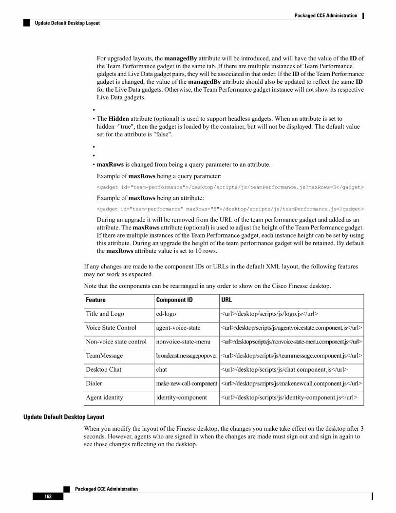
For upgraded layouts, the managedBy attribute will be introduced, and will have the value of the ID ofthe Team Performance gadget in the same tab. If there are multiple instances of Team Performancegadgets and Live Data gadget pairs, they will be associated in that order. If the ID of the Team Performancegadget is changed, the value of the managedBy attribute should also be updated to reflect the same IDfor the Live Data gadgets. Otherwise, the Team Performance gadget instance will not show its respectiveLive Data gadgets.
•• The Hidden attribute (optional) is used to support headless gadgets. When an attribute is set tohidden="true", then the gadget is loaded by the container, but will not be displayed. The default valueset for the attribute is "false".
••• maxRows is changed from being a query parameter to an attribute.
Example of maxRows being a query parameter:<gadget id="team-performance">/desktop/scripts/js/teamPerformance.js?maxRows=5</gadget>
Example of maxRows being an attribute:<gadget id="team-performance" maxRows="5">/desktop/scripts/js/teamPerformance.js</gadget>
During an upgrade it will be removed from the URL of the team performance gadget and added as anattribute. ThemaxRows attribute (optional) is used to adjust the height of the Team Performance gadget.If there are multiple instances of the Team Performance gadget, each instance height can be set by usingthis attribute. During an upgrade the height of the team performance gadget will be retained. By defaultthe maxRows attribute value is set to 10 rows.
If any changes are made to the component IDs or URLs in the default XML layout, the following featuresmay not work as expected.
Note that the components can be rearranged in any order to show on the Cisco Finesse desktop.
URLComponent IDFeature
<url>/desktop/scripts/js/logo.js</url>cd-logoTitle and Logo
<url>/desktop/scripts/js/agentvoicestate.component.js</url>agent-voice-stateVoice State Control
<url>/desktop/scripts/js/nonvoice-state-menu.component.js</url>nonvoice-state-menuNon-voice state control
<url>/desktop/scripts/js/teammessage.component.js</url>broadcastmessagepopoverTeamMessage
<url>/desktop/scripts/js/chat.component.js</url>chatDesktop Chat
<url>/desktop/scripts/js/makenewcall.component.js</url>make-new-call-componentDialer
<url>/desktop/scripts/js/identity-component.js</url>identity-componentAgent identity
Update Default Desktop Layout
When you modify the layout of the Finesse desktop, the changes you make take effect on the desktop after 3seconds. However, agents who are signed in when the changes are made must sign out and sign in again tosee those changes reflecting on the desktop.
Packaged CCE Administration162
Packaged CCE AdministrationUpdate Default Desktop Layout
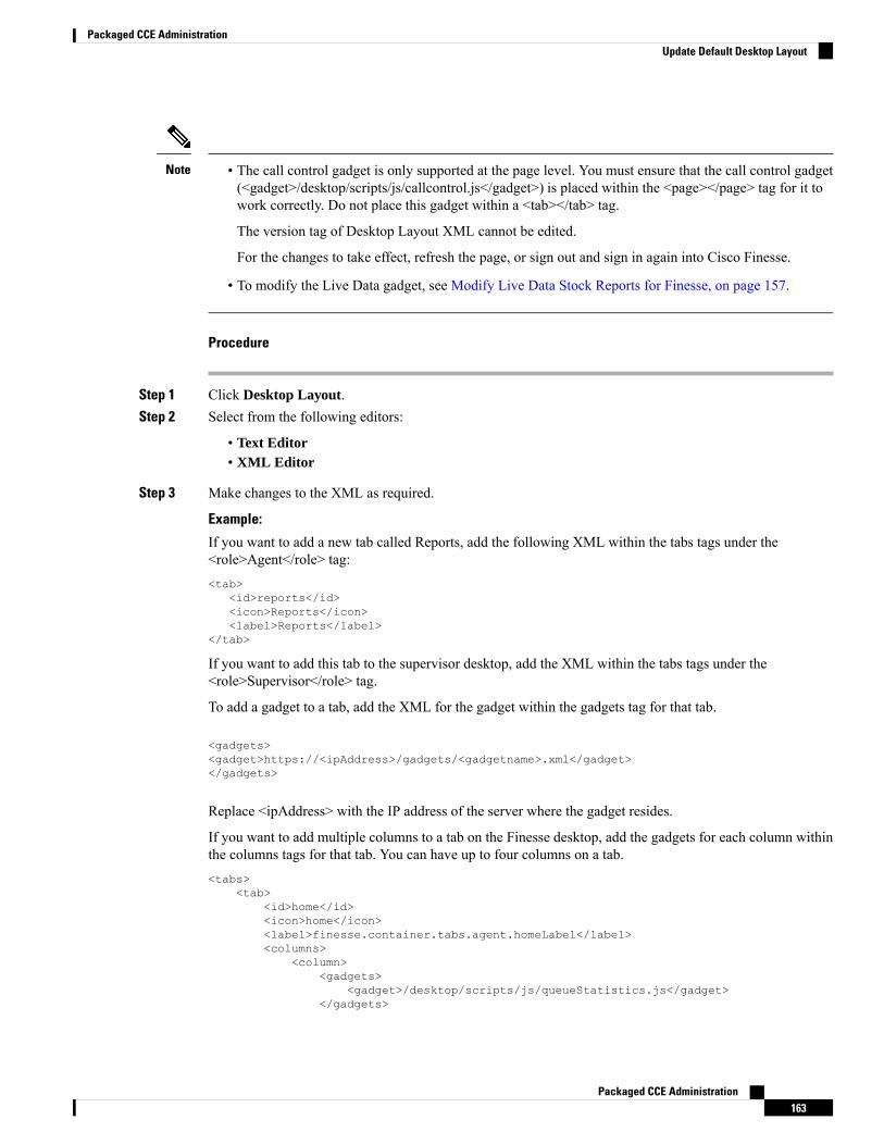
• The call control gadget is only supported at the page level. You must ensure that the call control gadget(<gadget>/desktop/scripts/js/callcontrol.js</gadget>) is placed within the <page></page> tag for it towork correctly. Do not place this gadget within a <tab></tab> tag.
The version tag of Desktop Layout XML cannot be edited.
For the changes to take effect, refresh the page, or sign out and sign in again into Cisco Finesse.
• To modify the Live Data gadget, see Modify Live Data Stock Reports for Finesse, on page 157.
Note
Procedure
Step 1 Click Desktop Layout.Step 2 Select from the following editors:
• Text Editor• XML Editor
Step 3 Make changes to the XML as required.
Example:
If you want to add a new tab called Reports, add the following XML within the tabs tags under the<role>Agent</role> tag:<tab>
<id>reports</id><icon>Reports</icon><label>Reports</label>
</tab>
If you want to add this tab to the supervisor desktop, add the XML within the tabs tags under the<role>Supervisor</role> tag.
To add a gadget to a tab, add the XML for the gadget within the gadgets tag for that tab.
<gadgets><gadget>https://<ipAddress>/gadgets/<gadgetname>.xml</gadget></gadgets>
Replace <ipAddress> with the IP address of the server where the gadget resides.
If you want to add multiple columns to a tab on the Finesse desktop, add the gadgets for each column withinthe columns tags for that tab. You can have up to four columns on a tab.<tabs>
<tab><id>home</id><icon>home</icon><label>finesse.container.tabs.agent.homeLabel</label><columns>
<column><gadgets>
<gadget>/desktop/scripts/js/queueStatistics.js</gadget></gadgets>
Packaged CCE Administration163
Packaged CCE AdministrationUpdate Default Desktop Layout

</column></columns>
</tab><tab>
<id>myHistory</id><icon>history</icon><label>finesse.container.tabs.agent.myHistoryLabel</label><columns>
<column><!-- The following gadgets are used for viewing the call history
and state history of an agent. --></column>
</columns></tab>
Step 4 Click Save.
After you add a gadget, sign in to the Finesse desktop and make sure it appears the way you want.If you use a report with a large number of rows, you may want to adjust the gadget height or thescreen resolution on the computer used to access the desktop to make the report easier to read ormake more rows appear on the screen without needing to scroll down.
Agents who are signed in when you change the desktop layout must sign out and sign back in tosee the change on their desktops.
Note
Finesse validates the XML file to ensure that it is valid XML syntax and conforms to the Finesse schema.
Step 5 After you save your changes, if you want to revert to the last saved desktop layout, click Revert. If you wantto revert to the default desktop layout, click Restore Default Layout.
During upgrade, any changes made to the Cisco Finesse Default Layout will be not be updated.You need to click on Restore Default Layout to get the latest changes.
Note
Horizontal Header
The Horizontal Header on the Finesse desktop has the following components from left to right. All thesecomponents can be removed and replaced with custom gadgets as required.
• Logo: Default is Cisco logo. Can be customized.
• Product Name: Default is Cisco Finesse. Can be customized.
• Agent State for Voice: Displays agent state for voice call.
• Agent State for Digital Channels: Displays agent state for digital channels.
• Dialer Component: Agent can make a new call.
• Identity Component: Displays agent name and signout functionality with reason codes.
The sum of widths set for all gadgets and components in the header (inside right aligned columns and leftaligned colums) should not exceed the total header width. If it exceeds the header width, some of thegadgets/components will not be visible.
Note
Packaged CCE Administration164
Packaged CCE AdministrationHorizontal Header
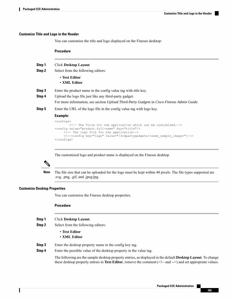
Customize Title and Logo in the Header
You can customize the title and logo displayed on the Finesse desktop:
Procedure
Step 1 Click Desktop Layout.Step 2 Select from the following editors:
• Text Editor• XML Editor
Step 3 Enter the product name in the config value tag with title key.Step 4 Upload the logo file just like any third-party gadget.
For more information, see section Upload Third-Party Gadgets in Cisco Finesse Admin Guide.
Step 5 Enter the URL of the logo file in the config value tag with logo key.
Example:<configs>
<!-- The Title for the application which can be customised.--><config value="product.full-name" Key="title"/>
<!-- The logo file for the application--><!--<config key="logo" value="/3rdpartygadgets/<some_sample_image>"/-->
</configs>
The customized logo and product name is displayed on the Finesse desktop.
The file size that can be uploaded for the logo must be kept within 40 pixels. The file types supported are.svg, .png, .gif, and .jpeg/jpg.
Note
Customize Desktop Properties
You can customize the Finesse desktop properties.
Procedure
Step 1 Click Desktop Layout.Step 2 Select from the following editors:
• Text Editor• XML Editor
Step 3 Enter the desktop property name in the config key tag.Step 4 Enter the possible value of the desktop property in the value tag.
The following are the sample desktop property entries, as displayed in the defaultDesktop Layout. To changethese desktop property entries in Text Editor, remove the comment (<!-- and -->) and set appropriate values.
Packaged CCE Administration165
Packaged CCE AdministrationCustomize Title and Logo in the Header
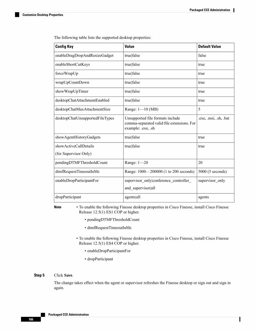
The following table lists the supported desktop properties:
Default ValueValueConfig Key
falsetrue|falseenableDragDropAndResizeGadget
truetrue|falseenableShortCutKeys
truetrue|falseforceWrapUp
truetrue|falsewrapUpCountDown
truetrue|falseshowWrapUpTimer
truetrue|falsedesktopChatAttachmentEnabled
5Range: 1—10 (MB)desktopChatMaxAttachmentSize
.exe, .msi, .sh, .batUnsupported file formats includecomma-separated valid file extensions. Forexample: .exe, .sh
desktopChatUnsupportedFileTypes
truetrue|falseshowAgentHistoryGadgets
truetrue|falseshowActiveCallDetails
(for Supervisor Only)
20Range: 1—20pendingDTMFThresholdCount
5000 (5 seconds)Range: 1000—200000 (1 to 200 seconds)dtmfRequestTimeoutInMs
supervisor_onlysupervisor_only|conference_controller_
and_supervisor|all
enableDropParticipantFor
agentsagents|alldropParticipant
• To enable the following Finesse desktop properties in Cisco Finesse, install Cisco FinesseRelease 12.5(1) ES1 COP or higher.
• pendingDTMFThresholdCount
• dtmfRequestTimeoutInMs
• To enable the following Finesse desktop properties in Cisco Finesse, install Cisco FinesseRelease 12.5(1) ES4 COP or higher.
• enableDropParticipantFor
• dropParticipant
Note
Step 5 Click Save.
The change takes effect when the agent or supervisor refreshes the Finesse desktop or sign out and sign inagain.
Packaged CCE Administration166
Packaged CCE AdministrationCustomize Desktop Properties
If you clear the Override System Default check box and click Save. The changes are overwritten,and the editing pane reverts to the default desktop layout XML.
Note
alternateHosts Configuration
The <gadget> element in the Finesse Layout XML provides an attribute to specify alternate hosts from whichthe gadget can be loaded. This allows the Cisco Finesse desktop to load the gadget using a different host ifthe primary server is unavailable.
The alternateHosts attribute contains a comma-separated list of FQDNs that will be used if theprimary-host-FQDN is unavailable.<gadget alternateHosts="host1,host2,host3,...">
https://<primary-host-FQDN>/<gadget-URL></gadget>
The alternateHosts attribute is only applicable for gadgets with an absolute URL. That is URLs containingthe FQDN of a host, an optional port, and the complete URL path to the gadget. For example: <gadgetalternateHosts="host1,host2">https://primary host/relative_path</gadget>
If loading the gadget from the primary-host fails, the Cisco Finesse container attempts to load the gadget fromthe alternate hosts in the order specified in the alternateHosts attribute.
The Cisco Finesse desktop may fail to load the gadget even if some of the hosts are reachable. In such cases,refresh the Cisco Finesse desktop.
When the gadget is specified with a relative URL, for example: <gadget>/3rdpartygadgets/relative_path</gadget>, the alternateHosts attribute does not apply and is ignored bythe Cisco Finesse desktop.
If the host serving the gadget fails after the Cisco Finesse desktop was successfully loaded, the desktop mustbe refreshed in order to load the gadget from an alternate host. The gadget does not implement its own failovermechanism.
Note
Headless Gadget Configuration
Headless gadgets are gadgets which do not need a display space, but can be loaded and run like a backgroundtask in the browser. The Hidden attribute (optional) is used to support headless gadgets in the layout XML.When an attribute is set to "hidden=true", then the gadget is loaded by the container, but will not be displayed.The default value set for the attribute is "false".
Customize Icons in Left Navigation Bar
You can add icons (both custom and inbuilt) to the collapsible left navigation bar of the Finesse desktop:
Procedure
Step 1 Click Desktop Layout.Step 2 Select from the following editors:
• Text Editor
Packaged CCE Administration167
Packaged CCE AdministrationalternateHosts Configuration

• XML Editor
Step 3 Enter name of the gadget or component in the id tag.Step 4 Enter the value of the icon in the icon tag.Step 5 Upload the icon file just like any third-party gadget.
For more information, see section Upload Third-Party Gadgets in Cisco Finesse Admin Guide.
When adding a custom icon, provide the path in the icon tag and if you are adding an inbuilt icon,provide the icon value in the icon tag
Note
Example:
The file size that can be uploaded in the left navigation bar as custom icons is 25 pixels by 25 pixels.The maximum width of the tab title in the left navigation bar must be 80 pixels or less. The filetypes supported are .svg, .png, .gif, and .jpeg/jpg.
Note
XML Schema Definition
You must ensure that the XML uploaded conforms to the XML schema definition for Finesse. The XMLschema definition for Finesse is as follows:<?xml version="1.0" encoding="UTF-8"?><xs:schema xmlns:xs="http://www.w3.org/2001/XMLSchema"xmlns="http://www.cisco.com/vtg/finesse" targetNamespace="http://www.cisco.com/vtg/finesse"elementFormDefault="qualified"><!-- definition of version element --><xs:element name="version">
<xs:simpleType><xs:restriction base="xs:double">
<xs:pattern value="[0-9\.]+" /></xs:restriction>
</xs:simpleType></xs:element><!-- The below elements are for common desktop header and configs --><!-- Copied from:
https://github5.cisco.com/ccbu-shared/common-desktop/blob/master/java/layout-manager/src/main/resources/layoutSchema.xsd--><!-- If the common-desktop XSD changes, this too needs to be updated --><!-- Only difference is that, column has been renamed to headercolumn, since column is
alredy there in finesse desktop layout --><xs:complexType name="configs">
<xs:sequence><xs:element name="config" type="config" minOccurs="0" maxOccurs="unbounded" />
</xs:sequence></xs:complexType><xs:complexType name="config">
<xs:attribute name="key"><xs:simpleType>
<xs:restriction base="xs:string"><xs:pattern value="[a-zA-Z]*" />
</xs:restriction></xs:simpleType>
</xs:attribute><xs:attribute name="value" type="xs:string" />
</xs:complexType><xs:complexType name="header">
<xs:choice><xs:sequence>
Packaged CCE Administration168
Packaged CCE AdministrationXML Schema Definition
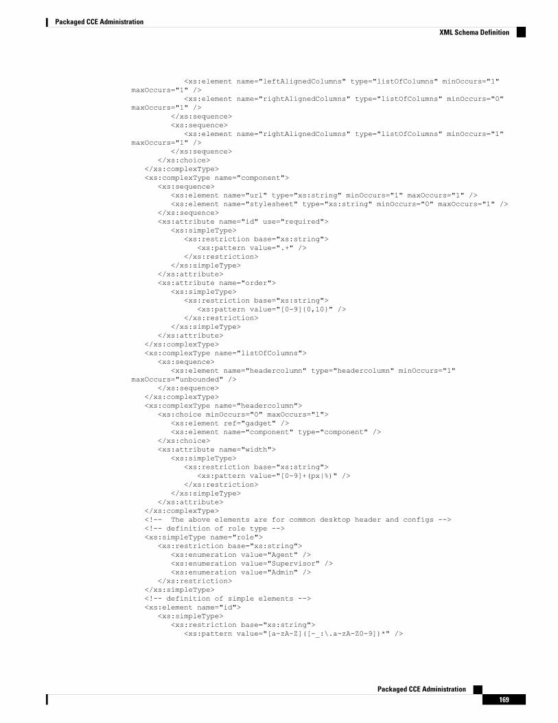
<xs:element name="leftAlignedColumns" type="listOfColumns" minOccurs="1"maxOccurs="1" />
<xs:element name="rightAlignedColumns" type="listOfColumns" minOccurs="0"maxOccurs="1" />
</xs:sequence><xs:sequence>
<xs:element name="rightAlignedColumns" type="listOfColumns" minOccurs="1"maxOccurs="1" />
</xs:sequence></xs:choice>
</xs:complexType><xs:complexType name="component">
<xs:sequence><xs:element name="url" type="xs:string" minOccurs="1" maxOccurs="1" /><xs:element name="stylesheet" type="xs:string" minOccurs="0" maxOccurs="1" />
</xs:sequence><xs:attribute name="id" use="required">
<xs:simpleType><xs:restriction base="xs:string">
<xs:pattern value=".+" /></xs:restriction>
</xs:simpleType></xs:attribute><xs:attribute name="order">
<xs:simpleType><xs:restriction base="xs:string">
<xs:pattern value="[0-9]{0,10}" /></xs:restriction>
</xs:simpleType></xs:attribute>
</xs:complexType><xs:complexType name="listOfColumns">
<xs:sequence><xs:element name="headercolumn" type="headercolumn" minOccurs="1"
maxOccurs="unbounded" /></xs:sequence>
</xs:complexType><xs:complexType name="headercolumn">
<xs:choice minOccurs="0" maxOccurs="1"><xs:element ref="gadget" /><xs:element name="component" type="component" />
</xs:choice><xs:attribute name="width">
<xs:simpleType><xs:restriction base="xs:string">
<xs:pattern value="[0-9]+(px|%)" /></xs:restriction>
</xs:simpleType></xs:attribute>
</xs:complexType><!-- The above elements are for common desktop header and configs --><!-- definition of role type --><xs:simpleType name="role">
<xs:restriction base="xs:string"><xs:enumeration value="Agent" /><xs:enumeration value="Supervisor" /><xs:enumeration value="Admin" />
</xs:restriction></xs:simpleType><!-- definition of simple elements --><xs:element name="id">
<xs:simpleType><xs:restriction base="xs:string">
<xs:pattern value="[a-zA-Z]([-_:\.a-zA-Z0-9])*" />
Packaged CCE Administration169
Packaged CCE AdministrationXML Schema Definition
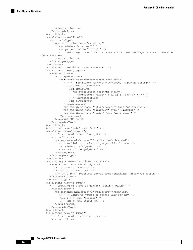
</xs:restriction></xs:simpleType>
</xs:element><xs:element name="label">
<xs:simpleType><xs:restriction base="xs:string">
<xs:minLength value="1" /><xs:pattern value="[^\r\n]+" /><!-- This regex restricts the label string from carriage returns or newline
characters --></xs:restriction>
</xs:simpleType></xs:element><xs:element name="icon" type="xs:anyURI" /><xs:element name="gadget">
<xs:complexType><xs:simpleContent>
<xs:extension base="restrictWhiteSpaces"><!-- <xs:attribute name="staticMessage" type="xs:string"/> --><xs:attribute name="id">
<xs:simpleType><xs:restriction base="xs:string">
<xs:pattern value="[a-zA-Z]([-_a-zA-Z0-9])*" /></xs:restriction>
</xs:simpleType></xs:attribute><xs:attribute name="alternateHosts" type="xs:string" /><xs:attribute name="managedBy" type="xs:string" /><xs:attribute name="hidden" type="xs:boolean" />
</xs:extension></xs:simpleContent>
</xs:complexType></xs:element><xs:element name="role" type="role" /><xs:element name="gadgets">
<!-- Grouping of a set of gadgets --><xs:complexType>
<xs:sequence minOccurs="0" maxOccurs="unbounded"><!-- No limit to number of gadget URIs for now --><xs:element ref="gadget" /><!-- URI of the gadget xml -->
</xs:sequence></xs:complexType>
</xs:element><xs:simpleType name="restrictWhiteSpaces">
<xs:restriction base="xs:anyURI"><xs:minLength value="1" /><xs:pattern value="\S+" /><!-- This regex restricts anyURI from containing whitespace within -->
</xs:restriction></xs:simpleType><xs:element name="column">
<!-- Grouping of a set of gadgets within a column --><xs:complexType>
<xs:sequence minOccurs="0" maxOccurs="unbounded"><!-- No limit to number of gadget URIs for now --><xs:element ref="gadgets" /><!-- URI of the gadget xml -->
</xs:sequence></xs:complexType>
</xs:element><xs:element name="columns">
<!-- Grouping of a set of columns --><xs:complexType>
Packaged CCE Administration170
Packaged CCE AdministrationXML Schema Definition
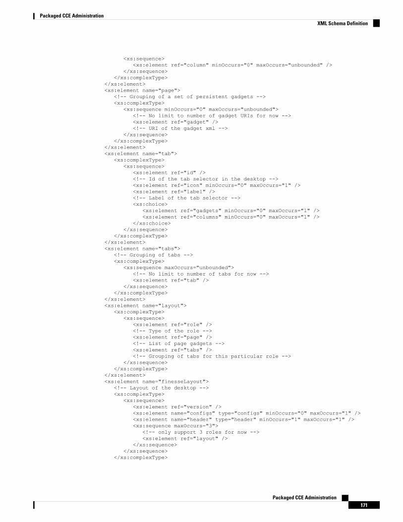
<xs:sequence><xs:element ref="column" minOccurs="0" maxOccurs="unbounded" />
</xs:sequence></xs:complexType>
</xs:element><xs:element name="page">
<!-- Grouping of a set of persistent gadgets --><xs:complexType>
<xs:sequence minOccurs="0" maxOccurs="unbounded"><!-- No limit to number of gadget URIs for now --><xs:element ref="gadget" /><!-- URI of the gadget xml -->
</xs:sequence></xs:complexType>
</xs:element><xs:element name="tab">
<xs:complexType><xs:sequence>
<xs:element ref="id" /><!-- Id of the tab selector in the desktop --><xs:element ref="icon" minOccurs="0" maxOccurs="1" /><xs:element ref="label" /><!-- Label of the tab selector --><xs:choice>
<xs:element ref="gadgets" minOccurs="0" maxOccurs="1" /><xs:element ref="columns" minOccurs="0" maxOccurs="1" />
</xs:choice></xs:sequence>
</xs:complexType></xs:element><xs:element name="tabs">
<!-- Grouping of tabs --><xs:complexType>
<xs:sequence maxOccurs="unbounded"><!-- No limit to number of tabs for now --><xs:element ref="tab" />
</xs:sequence></xs:complexType>
</xs:element><xs:element name="layout">
<xs:complexType><xs:sequence>
<xs:element ref="role" /><!-- Type of the role --><xs:element ref="page" /><!-- List of page gadgets --><xs:element ref="tabs" /><!-- Grouping of tabs for this particular role -->
</xs:sequence></xs:complexType>
</xs:element><xs:element name="finesseLayout">
<!-- Layout of the desktop --><xs:complexType>
<xs:sequence><xs:element ref="version" /><xs:element name="configs" type="configs" minOccurs="0" maxOccurs="1" /><xs:element name="header" type="header" minOccurs="1" maxOccurs="1" /><xs:sequence maxOccurs="3">
<!-- only support 3 roles for now --><xs:element ref="layout" />
</xs:sequence></xs:sequence>
</xs:complexType>
Packaged CCE Administration171
Packaged CCE AdministrationXML Schema Definition
</xs:element></xs:schema>
Manage Phone BooksOn thePhone Books section, you can create andmanage global and team phonebooks and phonebook contacts.Global phonebooks are available to all agents; team phonebooks are available to agents in that specific team.
The system supports the following number of phone books:
• 10 global phone books
• 300 team phone books
The system supports a total of 50,000 contacts. The total number of contacts per agent across all phone booksis limited to 1500.
Use the Phone Books gadget to view, add, edit, or delete phone books and phone book contacts. Click theName or Assign To headers to sort the phone books in ascending or descending order. Click the Last Name,First Name, Number, or Note headers to sort the contacts in ascending or descending order.
The following table describes the fields on the Phone Books gadget.
ExplanationField
The name of the phone book. The name must be unique, and can be a maximumlength of 64 alphanumeric characters.
Name
Indicates if the phone book is global (All Users) or team (Teams).Assign To
The last name of a contact. The last name can be a maximum length of 128characters. This field is optional.
Last Name
The first name of a contact. The first name can be a maximum length of 128characters. This field is optional.
First Name
The phone number for the contact. The phone number can be 1-32 characters longand cannot be blank.
Number
Optional text that describes the contact. The note can be a maximum length of128 characters.
Note
Actions on the Phone Books gadget:
• New: Add a new phone book or contact
• Edit: Edit an existing phone book or contact
• Delete: Delete a phone book or contact
• Refresh: Reload the list of phone books or contacts from the server
• Import: Import a list of contacts to the phone book
• Export: Export a list of contacts from the phone book
Packaged CCE Administration172
Packaged CCE AdministrationManage Phone Books

Add Phone Book
Procedure
Step 1 In the Phone Books gadget, click New.
The New Phone Book area appears.
Step 2 In the Name field, enter a name for the phone book.
Phone book names can be a maximum of 64 characters.Note
Step 3 From the Assign To drop-down, select All Users if the phone book is global or Teams if the phone book isavailable to specified teams.
Step 4 Click Save.
Edit Phone Book
Procedure
Step 1 In the Phone Books gadget, select the phone book you want to edit.Step 2 Click Edit.Step 3 In the Name field, enter the new name for the phone book. If you want to change who can access the phone
book, in the Assign To drop-down, choose All Users or Teams.Step 4 Click Save.
If you change the Assign To field from Teams to All Users, click Yes to confirm the change.
Delete Phone Book
Procedure
Step 1 In the Phone Books gadget, select the phone book that you want to delete.Step 2 Click Delete.Step 3 Click Yes to confirm the deletion of the selected phone book.
Add Contact
Procedure
Step 1 In the Phone Books gadget, select the phone book to which you want to add a contact.
Packaged CCE Administration173
Packaged CCE AdministrationAdd Phone Book
The List of Contacts for <phone book name> area appears.
Step 2 Click New.Step 3 Complete the fields. The First Name, Last Name, and Note fields are optional and have a maximum length
of 128 characters. The Number field is required and has a maximum length of 32 characters.Step 4 Click Save.
Edit Contact
Procedure
Step 1 In the Phone Books gadget, select the phone book that contains the contact you want to edit.
The List of Contacts for <phone book name> area appears.
Step 2 Select the contact you want to edit.Step 3 Click Edit.Step 4 Edit the fields that you want to change. The First Name, Last Name, and Note fields are optional and have a
maximum of 128 characters. The Number field is required and has a maximum of 32 characters.Step 5 Click Save.
Delete Contact
Procedure
Step 1 In the Phone Books gadget, select the phone book that contains the contact you want to delete.
The List of Contacts for <phone book name> area appears.
Step 2 Select the contact that you want to delete.Step 3 Click Delete.Step 4 Click Yes to confirm the deletion of the selected contact.
Import Contacts
The Import function allows you to replace all the contacts in a phone book with a new list of contacts, or topopulate a new phone book with contacts.
The import list must be in the specified comma separated values (CSV) format, and can contain a maximumof 6000 contacts. Import lists that contain more than 6000 contacts are rejected with an error message.
The CSV file contains the fields described in the following table:
Packaged CCE Administration174
Packaged CCE AdministrationEdit Contact

Permitted CharactersCan Be Blank?MaxLength
Field
Alphanumeric characters
The CSV file that contains the contacts toimport must use Latin encoding.
Note
Yes128First Name
Yes128Last Name
No32Phone Number
Yes128Notes
The following is an example of a phone book CSV file:"First Name","Last Name","Phone Number","Notes""Amanda","Cohen","6511234","""Nicholas","Knight","612-555-1228","Sales""Natalie","Lambert","952-555-9876","Benefits""Joseph","Stonetree","651-555-7612","Manager"
A phone book CSV file must conform to this format and include the headers in the first line. During import,the file is scanned for illegal characters. If any are found, they are replaced with question marks.
Exported CSV files always show each field enclosed in double quotes to ensure that any commas or doublequotes that are part of the actual filed data are not mistaken for field delimiters. If your data does not includethese characters, you can omit the double quotes in files you prepare for importing.
Note
Procedure
Step 1 In the Phone Books gadget, select the phone book into which you want to import a list of contacts.Step 2 Click Import.Step 3 Click Browse and navigate to the location of the CSV file containing the contacts you want to import.
The CSV file must use Latin encoding.Note
Step 4 Click OK.
Export Contacts
The Export function allows you to extract a list of contacts from an existing phone book. The exported list issaved in CSV format.
Procedure
Step 1 In the Phone Books gadget, select the phone book that contains the contacts you want to export.Step 2 Click Export.Step 3 Click Open to open the CSV file in Excel, or click the Save drop-down list and choose Save, Save as, or
Save and open.
Packaged CCE Administration175
Packaged CCE AdministrationExport Contacts
Step 4 A message appears that gives you the option to view the downloaded file, open the folder into which thedownload was saved, view the Internet Explorer View Downloads window, or dismiss the message withoutviewing the file.
Manage WorkflowsOn the Workflows tab, you can create and manage workflows and workflow actions.
Workflows and Workflow Actions
You can use workflows to automate common repetitive agent tasks. A workflow has a unique name and ahelpful description. Use the Manage Workflows and Manage Workflow Actions gadgets to view, add, edit,or delete workflows and workflow actions.
All workflows are team-level workflows. You cannot create a global workflow. If you need a global workflow,create a team workflow and assign it to all teams.
Finesse supports the following number of workflows and workflow actions:
• 100 workflows per Finesse system
• 100 actions per Finesse system
• 20 workflows per team
• 5 conditions per workflow
• 5 actions per workflow
• 5 variables per action
Additionally, following are the fields that can be used to configure workflows:
• queueNumber
• queueName
• callKeyCallId
• callKeyPrefix
• callKeySequenceNum
• wrapUpReason
Click the column headers to sort workflows and workflow actions in ascending or descending order.
The following table describes the fields on the Manage Workflows gadget:
ExplanationField
The name of the workflow must be unique and can be a maximum length of 40characters.
Name
The description of the workflow can be a maximum length of 128 characters.Description
The media of the workflow. You can configure the media to Voice and anypreferred Digital Channel.
Media
Packaged CCE Administration176
Packaged CCE AdministrationManage Workflows
The following table describes the fields on the Manage Workflow Actions gadget:
ExplanationField
The name of the workflow action must be unique and can be a maximum lengthof 64 characters.
Name
The type of workflow. Possible values are Browser Pop and HTTP Request.Type
Actions on the Manage Workflows and Manage Workflow Actions gadgets:
• New: Add a new workflow or workflow action
• Edit: Edit an workflow or workflow action
• Delete: Delete a workflow or workflow action
• Refresh: Reload the list of workflows or workflow actions from the server
You can configure workflow actions to be handled by the Finesse desktop or in a third-party gadget. Athird-party gadget can be designed to handle the action differently than Finesse does.
Each workflow must contain only one trigger. Triggers are based on Finesse dialog events.
You can configure the trigger only after you select the media.Note
• Voice dialog events include the following:
• When a Call arrives
• When a Call is answered
• When a Call ends
• When making a Call
The call variable workflow responds as expected only when you add both theconditions: Is not equal and Is not empty.
Note
• While previewing an Outbound Option call
• Digital Channels dialog events include the following:
• When a task is offered
• When a task is accepted
• When a task is active
• When a task is paused
• When a task is interrupted
• When a task is closed
Packaged CCE Administration177
Packaged CCE AdministrationWorkflows and Workflow Actions
The workflow engine uses the following simple logic to determine whether to execute a workflow:
The workflow logic and examples are similar for all media.Note
• Its trigger set and conditions are evaluated against each dialog event received.
• The workflow engine processes workflow events for the first call that matches any configured workflow'strigger set and conditions. No other workflows run until this call has ended. If the agent accepts a secondcall while still on the first call, workflows do not run on the second call even after the first call has ended.
• After a workflow for a particular trigger type (for example, Call Arrives) executes, it never triggers againfor the same dialog ID.
The workflow engine caches workflows for an agent when the agent signs in. Workflows do not change forthe agent until the agent signs out and signs in again or refreshes the browser.
Workflows that trigger when a call arrives, when a call is answered, or when making a call, run whenever thebrowser is refreshed. When an agent refreshes the browser, the workflow engine sees the call as newly arrivedor newly made. If an HTTP request action is part of the workflow, the HTTP request is sent when the agentrefreshes the browser. Applications that receive the HTTP requests must account for this scenario.
Note
An example of a workflow is a Call Arrival event that triggers an action that collects information from thedialog event (for example, the ANI or customer information) and displays a web page containing customerinformation.
You can filter trigger events by the value of the data that comes in the event. You can configure a workflowto execute if any conditions are met or if all conditions are met.
Individual conditions comprise of the following:
• A piece of event data to be examined, for example, DNIS or call variables.
• A comparison between the event data and entered values (for example, contains, is equal to, is not equalto, begins with, ends with, is empty, is not empty, and is in list).
When the trigger and its conditions are satisfied, a list of actions assigned to the workflow are executed. Theactions execute in the listed order.
Workflows run only for agents and supervisors who are Finesse users. The Workflow Engine is a JavaScriptlibrary that runs client-side on a per-user basis within the Finesse desktop application. The desktop retrievesthe workflows to execute for a user from the server when the user signs in or refreshes the browser.
Changes made to a workflow or its actions while a user is signed in are not automatically pushed to that user.Note
It is possible to set workflows, conditions, and actions that are contradictory so that a workflow or actioncannot function. Workflows are not validated.
If multiple workflows are configured for a team, theWorkflow Engine evaluates them in the configured order.TheWorkflow Engine ignores workflows with no actions. When theWorkflow Engine finds a workflow with
Packaged CCE Administration178
Packaged CCE AdministrationWorkflows and Workflow Actions
a matching trigger for the event and the workflow conditions evaluate to true, then that workflow is the oneused and subsequent workflows in the list are not evaluated. Workflows with no conditions evaluate to trueif the event matches the workflow trigger. All workflows are enabled by default. Only one workflow for aspecific user can run at a time.
The Workflow Engine retrieves dialog-based variables used in workflow conditions from the dialog thattriggered the workflow. If a variable is not found in the dialog, then its value is assumed to be empty.
The Workflow Engine executes the actions associated with the matched workflow in the order in which theyare listed. The Workflow Engine executes actions in a workflow even if the previously executed action fails.Failed actions are logged.
The Finesse server controls which calls are displayed to the Finesse user. If the user has multiple calls, theworkflow applies only to the first call that matches a trigger. If the first call displayed does not match anytriggers but the second call does match a trigger, the Workflow Engine evaluates and processes the triggersfor the second call.
A call is considered to be the first displayed call if it is the only call on the Finesse desktop when it appears.If two calls on a phone are merged (as they are in a conference call), then the first displayed call flag valueof the surviving call is used.
If the user has a call when the user refreshes the browser, the Workflow Engine evaluates the call as it is. Ifthe dialog data (call variable values) change, the data may not match the trigger and conditions of the originalworkflow. The data may match a different workflow or no workflows at all.
If the user has multiple calls when the user refreshes the browser, the Workflow Engine treats the first dialogreceived from the Finesse server as the first displayed call. This call may not be the same call that was thefirst displayed call before the browser refresh. Dialogs received for any other call are ignored because theyare not considered first displayed calls. If dialogs for more than one call are received before the WorkflowEngine is loaded after the browser refresh, no dialogs are evaluated because none are considered first displayedcalls.
Workflows run for both Finesse agents and supervisors. The team to which the supervisor belongs (asdistinguished from the team that the supervisor manages) determines which workflows run for the supervisor.Put the supervisors in their own team to keep agent workflows from being run for them.
Workflow Triggers and Outbound Calls
When you create a workflow specifically for Outbound Option calls, add a condition of BAStatus is not empty(except for the Workflow Trigger 'When a call arrives' as BAStatus will be empty at that point of time). Thiscondition ensures that the workflow can distinguish Outbound Option calls from agent-initiated outboundcalls.
Note
The following table illustrates when workflows trigger in outbound call scenarios:
Progressive/PredictiveOutbound Call
Preview Outbound CallDirect Preview OutboundCall
Workflow Trigger
Does not triggerWhen the agent previewsthe call (before acceptingor rejecting it)
When the agent previewsthe call (before acceptingor rejecting it)
While previewing a call
When the call arrives onthe agent desktop
When the agent acceptsthe call
Does not triggerWhen a call arrives
Packaged CCE Administration179
Packaged CCE AdministrationWorkflow Triggers and Outbound Calls
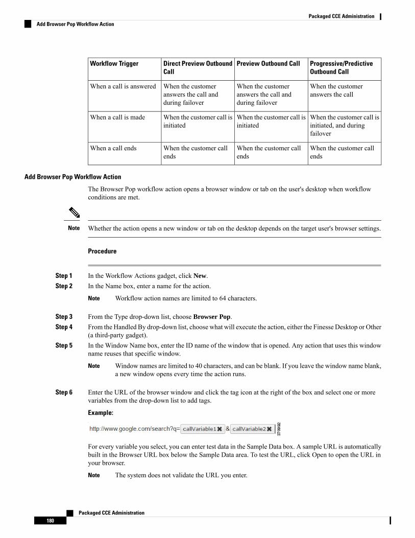
Progressive/PredictiveOutbound Call
Preview Outbound CallDirect Preview OutboundCall
Workflow Trigger
When the customeranswers the call
When the customeranswers the call andduring failover
When the customeranswers the call andduring failover
When a call is answered
When the customer call isinitiated, and duringfailover
When the customer call isinitiated
When the customer call isinitiated
When a call is made
When the customer callends
When the customer callends
When the customer callends
When a call ends
Add Browser Pop Workflow Action
The Browser Pop workflow action opens a browser window or tab on the user's desktop when workflowconditions are met.
Whether the action opens a new window or tab on the desktop depends on the target user's browser settings.Note
Procedure
Step 1 In the Workflow Actions gadget, click New.Step 2 In the Name box, enter a name for the action.
Workflow action names are limited to 64 characters.Note
Step 3 From the Type drop-down list, choose Browser Pop.Step 4 From the Handled By drop-down list, choose what will execute the action, either the Finesse Desktop or Other
(a third-party gadget).Step 5 In the Window Name box, enter the ID name of the window that is opened. Any action that uses this window
name reuses that specific window.
Window names are limited to 40 characters, and can be blank. If you leave the window name blank,a new window opens every time the action runs.
Note
Step 6 Enter the URL of the browser window and click the tag icon at the right of the box and select one or morevariables from the drop-down list to add tags.
Example:
For every variable you select, you can enter test data in the Sample Data box. A sample URL is automaticallybuilt in the Browser URL box below the Sample Data area. To test the URL, click Open to open the URL inyour browser.
The system does not validate the URL you enter.Note
Packaged CCE Administration180
Packaged CCE AdministrationAdd Browser Pop Workflow Action
Step 7 Click Save.
Add HTTP Request Workflow Action
The HTTP Request workflow action makes an HTTP request to an API on behalf of the desktop user.
Procedure
Step 1 In the Workflow Actions area, click New.Step 2 In the Name box, enter a name for the action.
A workflow action name can contain a maximum of 64 characters.
Step 3 From the Type drop-down list, select HTTP Request.Step 4 From the Handled By drop-down list, select what will execute the action, the Finesse desktop or Other (a
third-party gadget).Step 5 From the Method drop-down list, select the method to use.
You can select either PUT or POST.
Step 6 From the Location drop-down list, select the location.
If you are making the HTTP request to a Finesse API, select Finesse. If you are making a request to any otherAPI, select Other.
Step 7 In the Content Type box, enter the content type.
The default content type is application/xml, which is the content type for Finesse APIs. If you are using adifferent API, enter the content types for that API (for example, application/JSON).
Step 8 In the URL box, enter the URL to which to make the request. To add variables to the URL, click the tag iconat the right of the box and select one or more variables from the drop-down list.
Example:
The following is the URL example for a Finesse API:
When the location is FINESSE, do not specify the protocol, host, and port information. Finesseautomatically fetches these details when the REST request is executed.
If you want to make a request to another API, you must enter the entire URL (for example,http://googleapis.com).
Note
You can click the tag icon at the right of the box and select one or more variables from the drop-down list toadd tags to the URL. In the preceding example, to add the dialogId, click the tag icon and select dialogId fromthe list.
Step 9 In the Body box, enter the text for the request. The body must match the content type (for example, if thecontent types is application/xml, the body must contain XML). To add variables to the body, click the tagicon at the right of the box and select one or more variables from the drop-down list.
Example:
Packaged CCE Administration181
Packaged CCE AdministrationAdd HTTP Request Workflow Action
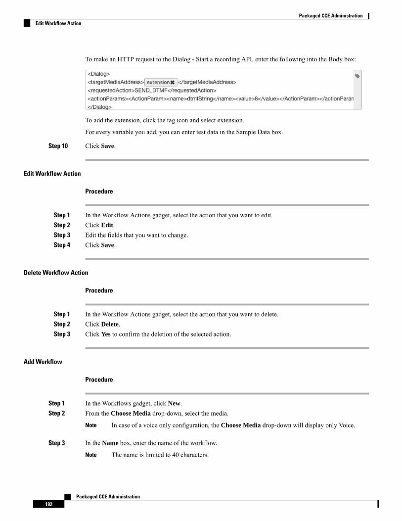
To make an HTTP request to the Dialog - Start a recording API, enter the following into the Body box:
To add the extension, click the tag icon and select extension.
For every variable you add, you can enter test data in the Sample Data box.
Step 10 Click Save.
Edit Workflow Action
Procedure
Step 1 In the Workflow Actions gadget, select the action that you want to edit.Step 2 Click Edit.Step 3 Edit the fields that you want to change.Step 4 Click Save.
Delete Workflow Action
Procedure
Step 1 In the Workflow Actions gadget, select the action that you want to delete.Step 2 Click Delete.Step 3 Click Yes to confirm the deletion of the selected action.
Add Workflow
Procedure
Step 1 In the Workflows gadget, click New.Step 2 From the Choose Media drop-down, select the media.
In case of a voice only configuration, the Choose Media drop-down will display only Voice.Note
Step 3 In the Name box, enter the name of the workflow.
The name is limited to 40 characters.Note
Packaged CCE Administration182
Packaged CCE AdministrationEdit Workflow Action
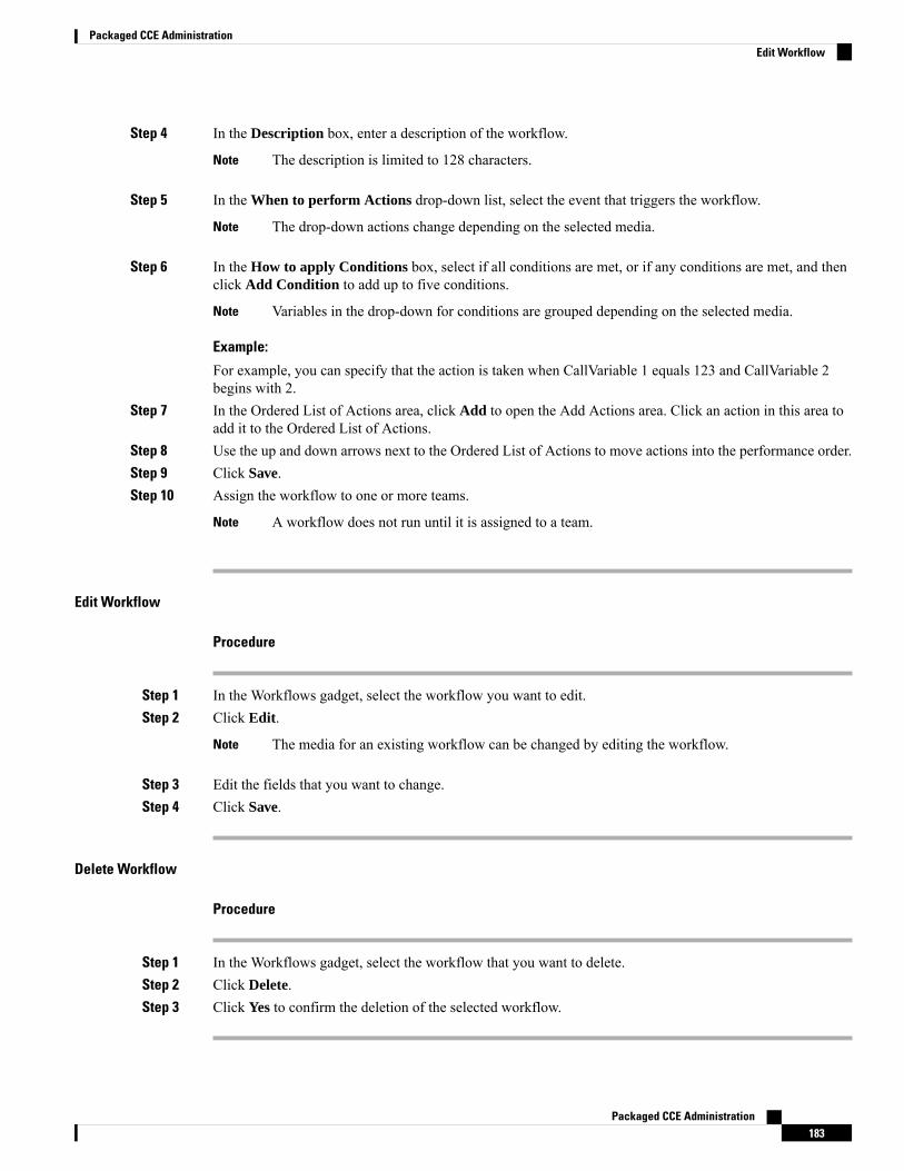
Step 4 In the Description box, enter a description of the workflow.
The description is limited to 128 characters.Note
Step 5 In the When to perform Actions drop-down list, select the event that triggers the workflow.
The drop-down actions change depending on the selected media.Note
Step 6 In the How to apply Conditions box, select if all conditions are met, or if any conditions are met, and thenclick Add Condition to add up to five conditions.
Variables in the drop-down for conditions are grouped depending on the selected media.Note
Example:
For example, you can specify that the action is taken when CallVariable 1 equals 123 and CallVariable 2begins with 2.
Step 7 In the Ordered List of Actions area, click Add to open the Add Actions area. Click an action in this area toadd it to the Ordered List of Actions.
Step 8 Use the up and down arrows next to the Ordered List of Actions to move actions into the performance order.Step 9 Click Save.Step 10 Assign the workflow to one or more teams.
A workflow does not run until it is assigned to a team.Note
Edit Workflow
Procedure
Step 1 In the Workflows gadget, select the workflow you want to edit.Step 2 Click Edit.
The media for an existing workflow can be changed by editing the workflow.Note
Step 3 Edit the fields that you want to change.Step 4 Click Save.
Delete Workflow
Procedure
Step 1 In the Workflows gadget, select the workflow that you want to delete.Step 2 Click Delete.Step 3 Click Yes to confirm the deletion of the selected workflow.
Packaged CCE Administration183
Packaged CCE AdministrationEdit Workflow
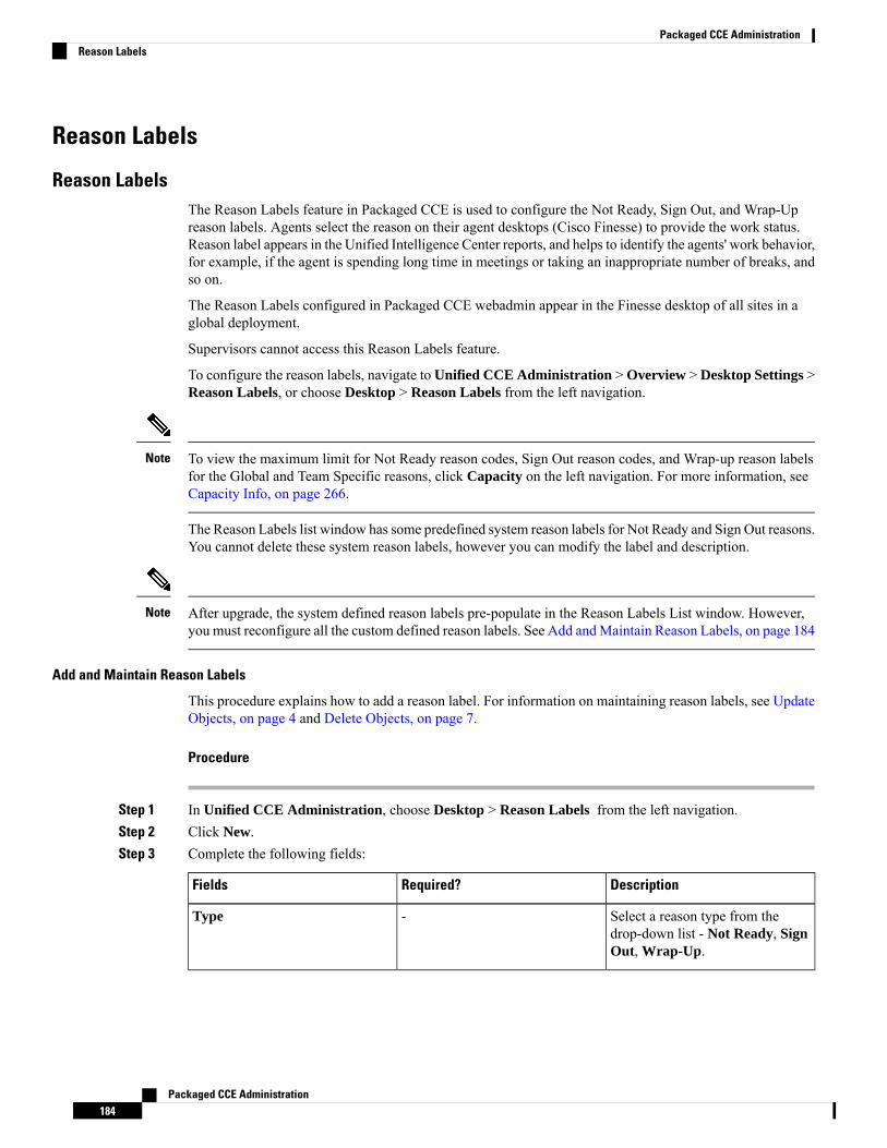
Reason Labels
Reason LabelsThe Reason Labels feature in Packaged CCE is used to configure the Not Ready, Sign Out, and Wrap-Upreason labels. Agents select the reason on their agent desktops (Cisco Finesse) to provide the work status.Reason label appears in the Unified Intelligence Center reports, and helps to identify the agents' work behavior,for example, if the agent is spending long time in meetings or taking an inappropriate number of breaks, andso on.
The Reason Labels configured in Packaged CCE webadmin appear in the Finesse desktop of all sites in aglobal deployment.
Supervisors cannot access this Reason Labels feature.
To configure the reason labels, navigate to Unified CCE Administration > Overview > Desktop Settings >Reason Labels, or choose Desktop > Reason Labels from the left navigation.
To view the maximum limit for Not Ready reason codes, Sign Out reason codes, and Wrap-up reason labelsfor the Global and Team Specific reasons, click Capacity on the left navigation. For more information, seeCapacity Info, on page 266.
Note
The Reason Labels list window has some predefined system reason labels for Not Ready and Sign Out reasons.You cannot delete these system reason labels, however you can modify the label and description.
After upgrade, the system defined reason labels pre-populate in the Reason Labels List window. However,you must reconfigure all the custom defined reason labels. See Add andMaintain Reason Labels, on page 184
Note
Add and Maintain Reason Labels
This procedure explains how to add a reason label. For information on maintaining reason labels, see UpdateObjects, on page 4 and Delete Objects, on page 7.
Procedure
Step 1 In Unified CCE Administration, choose Desktop > Reason Labels from the left navigation.Step 2 Click New.Step 3 Complete the following fields:
DescriptionRequired?Fields
Select a reason type from thedrop-down list - Not Ready, SignOut, Wrap-Up.
-Type
Packaged CCE Administration184
Packaged CCE AdministrationReason Labels

DescriptionRequired?Fields
Enter a label for the selected reasontype. The field allowsmaximum of40 characters. Both alphanumericand special characters aresupported.
Enter unique labels forthe Wrap-Up reasons.
Note
YesLabel
Enter a unique code for the selectedreason type. The valid range is from1 to 65535.
The Code field is notavailable for theWrap-Up reasons.
Note
YesCode
Enter a maximum of 255 charactersto describe the reason label.
See Native Character Sets.
NoDescription
Step 4 To assign the reason label to one for more teams, select the Team Specific option.
By default, the Global option is selected to make the reason label generic or visible to all teams.Note
Step 5 Click Save to return to the List screen, where a message confirms the successful creation. You can performthe Sort a List, Search a List, and Delete Objects tasks on the List screen.
What to do next
To assign the configured team specific reason labels to one or more teams, navigate toOrganization >Teams(Team Resources tab) from the left navigation. For more information, see Add andMaintain Teams , on page113.
Desk Settings
Desk SettingsDesk settings are a collection of permissions or characteristics for the agent, such as how and when calls tothe agent are redirected, how and when the agent enters various work states, and how requests to the supervisorare handled.
To configure desk settings, go to Unified CCE Administration > Desktop > Desk Settings.
Administrators have unlimited access to Desk Settings configuration. Supervisors cannot access Desk Settings.
Packaged CCE Administration185
Packaged CCE AdministrationDesk Settings
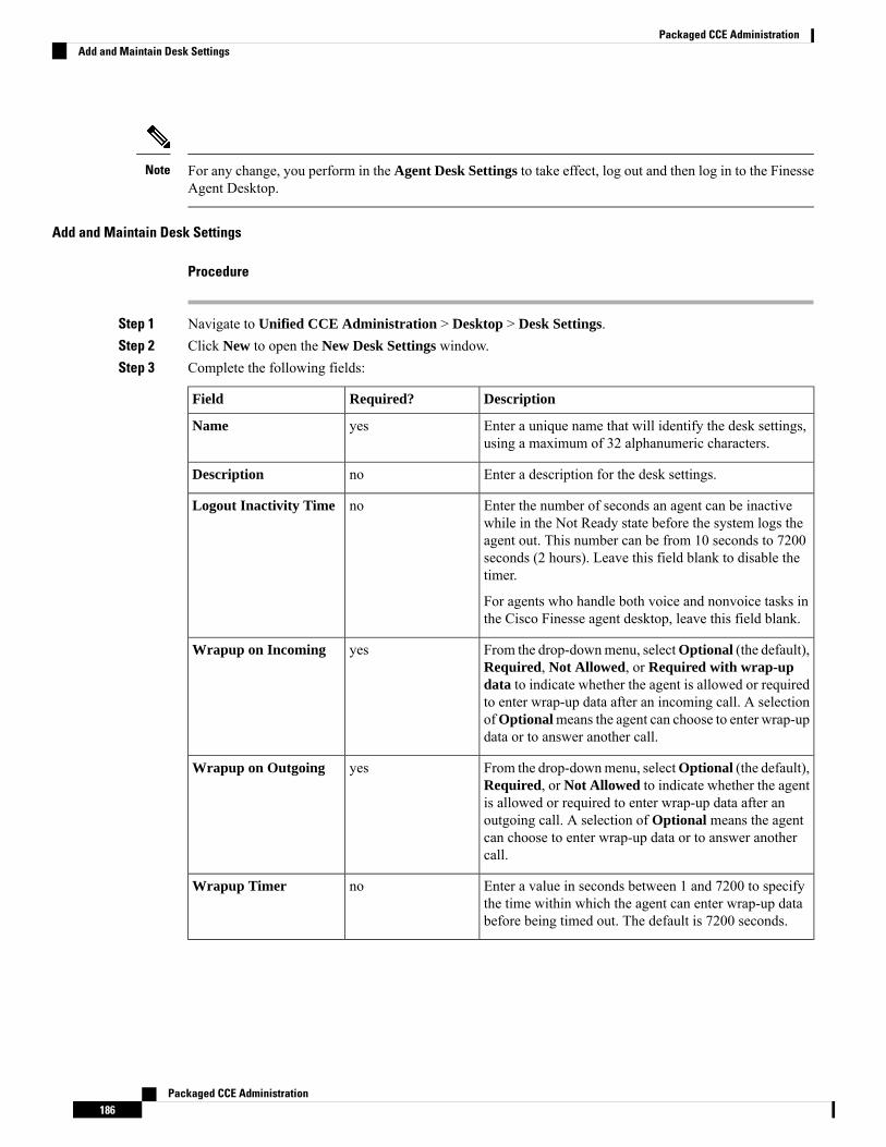
For any change, you perform in the Agent Desk Settings to take effect, log out and then log in to the FinesseAgent Desktop.
Note
Add and Maintain Desk Settings
Procedure
Step 1 Navigate to Unified CCE Administration > Desktop > Desk Settings.Step 2 Click New to open the New Desk Settings window.Step 3 Complete the following fields:
DescriptionRequired?Field
Enter a unique name that will identify the desk settings,using a maximum of 32 alphanumeric characters.
yesName
Enter a description for the desk settings.noDescription
Enter the number of seconds an agent can be inactivewhile in the Not Ready state before the system logs theagent out. This number can be from 10 seconds to 7200seconds (2 hours). Leave this field blank to disable thetimer.
For agents who handle both voice and nonvoice tasks inthe Cisco Finesse agent desktop, leave this field blank.
noLogout Inactivity Time
From the drop-downmenu, selectOptional (the default),Required, Not Allowed, or Required with wrap-updata to indicate whether the agent is allowed or requiredto enter wrap-up data after an incoming call. A selectionofOptionalmeans the agent can choose to enter wrap-updata or to answer another call.
yesWrapup on Incoming
From the drop-downmenu, selectOptional (the default),Required, or Not Allowed to indicate whether the agentis allowed or required to enter wrap-up data after anoutgoing call. A selection of Optional means the agentcan choose to enter wrap-up data or to answer anothercall.
yesWrapup on Outgoing
Enter a value in seconds between 1 and 7200 to specifythe time within which the agent can enter wrap-up databefore being timed out. The default is 7200 seconds.
noWrapup Timer
Packaged CCE Administration186
Packaged CCE AdministrationAdd and Maintain Desk Settings
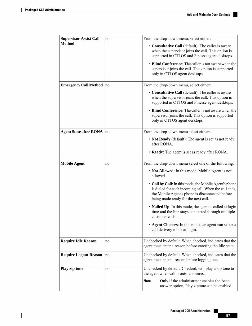
From the drop-down menu, select either:
• Consultative Call (default): The caller is awarewhen the supervisor joins the call. This option issupported in CTI OS and Finesse agent desktops.
• Blind Conference: The caller is not aware when thesupervisor joins the call. This option is supportedonly in CTI OS agent desktops.
noSupervisor Assist CallMethod
From the drop-down menu, select either:
• Consultative Call (default): The caller is awarewhen the supervisor joins the call. This option issupported in CTI OS and Finesse agent desktops.
• Blind Conference: The caller is not aware when thesupervisor joins the call. This option is supportedonly in CTI OS agent desktops.
noEmergency Call Method
From the drop-down menu select either:
• Not Ready (default): The agent is set as not readyafter RONA.
• Ready: The agent is set as ready after RONA.
noAgent State after RONA
From the drop-down menu select one of the following:
• Not Allowed: In this mode, Mobile Agent is notallowed.
• Call by Call: In this mode, theMobile Agent's phoneis dialed for each incoming call. When the call ends,the Mobile Agent's phone is disconnected beforebeing made ready for the next call.
• Nailed Up: In this mode, the agent is called at logintime and the line stays connected through multiplecustomer calls.
• Agent Chooses: In this mode, an agent can select acall delivery mode at login.
noMobile Agent
Unchecked by default. When checked, indicates that theagent must enter a reason before entering the Idle state.
noRequire Idle Reason
Unchecked by default. When checked, indicates that theagent must enter a reason before logging out.
noRequire Logout Reason
Unchecked by default. Checked, will play a zip tone tothe agent when call is auto-answered.
Only if the administrator enables the Autoanswer option, Play ziptone can be enabled.
Note
noPlay zip tone
Packaged CCE Administration187
Packaged CCE AdministrationAdd and Maintain Desk Settings
There is no RONA timer field on the Desk Settings tool. The Requery on No Answer (RONA) timeron the Unified Cisco Unified Voice Portal (CVP) controls the agent desk settings for PackagedCCE.
Note
Step 4 Save the desk settings to return to the List window, where a message confirms the successful creation.
Agent Trace
Agent TraceEnabling agent trace allows you to track and report on every state an agent passes through. You might enableagent trace if you have concerns about the productivity or performance of one or more agents.
Enabling trace can affect system performance, as it requires additional network bandwidth and database space.Typically, you use this feature for short-term tracking of specific agents. The system imposes a configurationlimit on the number of agents for whom you can enable trace.
Important
Use this tool to view, add, and remove agents for whom agent trace is enabled.
Add and Maintain Agent Trace
Procedure
Step 1 In Unified CCE Administration, navigate to Desktop > Agent Trace.Step 2 Click the + icon to open theAdd Agents with Trace Enabled popup window. Use the sort and search features
to navigate the list.Step 3 Click one or more agent usernames to give them the trace-enabled status.Step 4 Close Add Agents with Trace Enabled to return to the list.Step 5 Click Save on the List window to confirm the trace status for the agents you added. Click Revert before you
save to remove an agent from the Trace Enabled list.
Remove Agent Trace
Procedure
Step 1 In Unified CCE Administration, navigate to Desktop > Agent Trace.Step 2 On the List of Agents with Trace Enabled list, locate the agent whose trace status you want to remove.Step 3 Click the x icon to clear trace status for that agent.Step 4 Click Save on the List window to confirm the removal. To cancel, click Revert.
Packaged CCE Administration188
Packaged CCE AdministrationAgent Trace
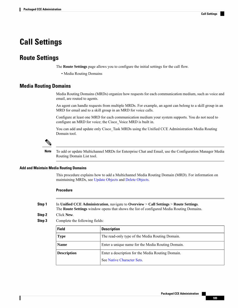
Call Settings
Route SettingsThe Route Settings page allows you to configure the initial settings for the call flow.
• Media Routing Domains
Media Routing DomainsMedia Routing Domains (MRDs) organize how requests for each communication medium, such as voice andemail, are routed to agents.
An agent can handle requests from multiple MRDs. For example, an agent can belong to a skill group in anMRD for email and to a skill group in an MRD for voice calls.
Configure at least one MRD for each communication medium your system supports. You do not need toconfigure an MRD for voice; the Cisco_Voice MRD is built in.
You can add and update only Cisco_Task MRDs using the Unified CCE Administration Media RoutingDomain tool.
To add or update Multichannel MRDs for Enterprise Chat and Email, use the Configuration Manager MediaRouting Domain List tool.
Note
Add and Maintain Media Routing Domains
This procedure explains how to add a Multichannel Media Routing Domain (MRD). For information onmaintaining MRDs, see Update Objects and Delete Objects.
Procedure
Step 1 In Unified CCE Administration, navigate to Overview > Call Settings > Route Settings.The Route Settings window opens that shows the list of configured Media Routing Domains.
Step 2 Click New.Step 3 Complete the following fields:
DescriptionField
The read-only type of the Media Routing Domain.Type
Enter a unique name for the Media Routing Domain.Name
Enter a description for the Media Routing Domain.
See Native Character Sets.
Description
Packaged CCE Administration189
Packaged CCE AdministrationCall Settings
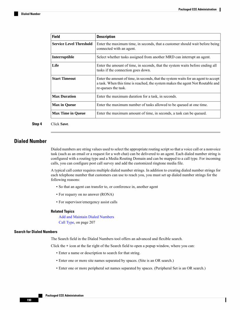
DescriptionField
Enter the maximum time, in seconds, that a customer should wait before beingconnected with an agent.
Service Level Threshold
Select whether tasks assigned from another MRD can interrupt an agent.Interruptible
Enter the amount of time, in seconds, that the system waits before ending alltasks if the connection goes down.
Life
Enter the amount of time, in seconds, that the systemwaits for an agent to accepta task. When this time is reached, the systemmakes the agent Not Routable andre-queues the task.
Start Timeout
Enter the maximum duration for a task, in seconds.Max Duration
Enter the maximum number of tasks allowed to be queued at one time.Max in Queue
Enter the maximum amount of time, in seconds, a task can be queued.Max Time in Queue
Step 4 Click Save.
Dialed NumberDialed numbers are string values used to select the appropriate routing script so that a voice call or a nonvoicetask (such as an email or a request for a web chat) can be delivered to an agent. Each dialed number string isconfigured with a routing type and a Media Routing Domain and can be mapped to a call type. For incomingcalls, you can configure post call survey and add the customized ringtone media file.
A typical call center requires multiple dialed number strings. In addition to creating dialed number strings foreach telephone number that customers can use to reach you, you must set up dialed number strings for thefollowing reasons:
• So that an agent can transfer to, or conference in, another agent
• For requery on no answer (RONA)
• For supervisor/emergency assist calls
Related TopicsAdd and Maintain Dialed NumbersCall Type, on page 207
Search for Dialed Numbers
The Search field in the Dialed Numbers tool offers an advanced and flexible search.
Click the + icon at the far right of the Search field to open a popup window, where you can:
• Enter a name or description to search for that string.
• Enter one or more site names separated by spaces. (Site is an OR search.)
• Enter one or more peripheral set names separated by spaces. (Peripheral Set is an OR search.)
Packaged CCE Administration190
Packaged CCE AdministrationDialed Number
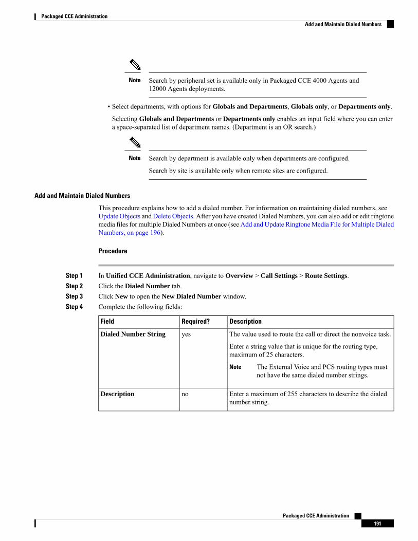
Search by peripheral set is available only in Packaged CCE 4000 Agents and12000 Agents deployments.
Note
• Select departments, with options for Globals and Departments, Globals only, or Departments only.
Selecting Globals and Departments or Departments only enables an input field where you can entera space-separated list of department names. (Department is an OR search.)
Search by department is available only when departments are configured.
Search by site is available only when remote sites are configured.
Note
Add and Maintain Dialed Numbers
This procedure explains how to add a dialed number. For information on maintaining dialed numbers, seeUpdate Objects and Delete Objects. After you have created Dialed Numbers, you can also add or edit ringtonemedia files for multiple Dialed Numbers at once (see Add and Update RingtoneMedia File for Multiple DialedNumbers, on page 196).
Procedure
Step 1 In Unified CCE Administration, navigate to Overview > Call Settings > Route Settings.Step 2 Click the Dialed Number tab.Step 3 Click New to open the New Dialed Number window.Step 4 Complete the following fields:
DescriptionRequired?Field
The value used to route the call or direct the nonvoice task.
Enter a string value that is unique for the routing type,maximum of 25 characters.
The External Voice and PCS routing types mustnot have the same dialed number strings.
Note
yesDialed Number String
Enter a maximum of 255 characters to describe the dialednumber string.
noDescription
Packaged CCE Administration191
Packaged CCE AdministrationAdd and Maintain Dialed Numbers
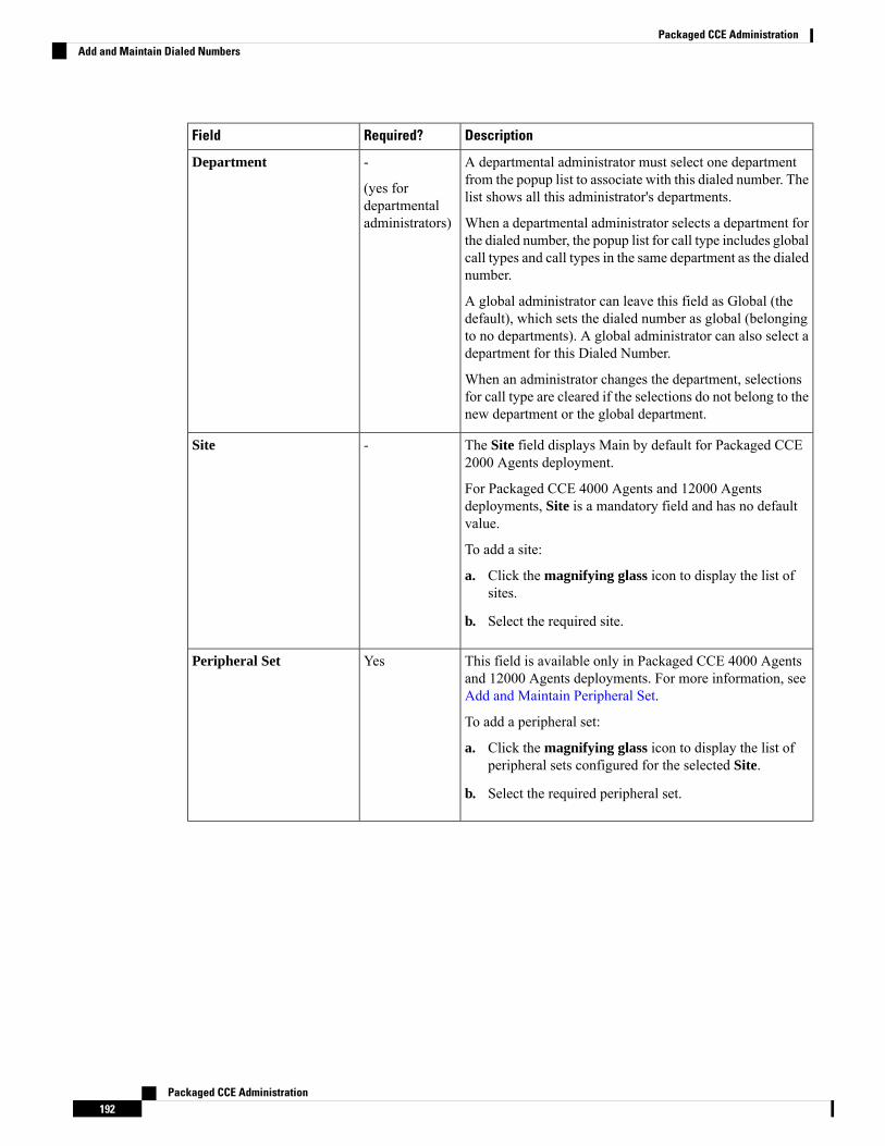
DescriptionRequired?Field
A departmental administrator must select one departmentfrom the popup list to associate with this dialed number. Thelist shows all this administrator's departments.
When a departmental administrator selects a department forthe dialed number, the popup list for call type includes globalcall types and call types in the same department as the dialednumber.
A global administrator can leave this field as Global (thedefault), which sets the dialed number as global (belongingto no departments). A global administrator can also select adepartment for this Dialed Number.
When an administrator changes the department, selectionsfor call type are cleared if the selections do not belong to thenew department or the global department.
-
(yes fordepartmentaladministrators)
Department
The Site field displays Main by default for Packaged CCE2000 Agents deployment.
For Packaged CCE 4000 Agents and 12000 Agentsdeployments, Site is a mandatory field and has no defaultvalue.
To add a site:
a. Click the magnifying glass icon to display the list ofsites.
b. Select the required site.
-Site
This field is available only in Packaged CCE 4000 Agentsand 12000 Agents deployments. For more information, seeAdd and Maintain Peripheral Set.
To add a peripheral set:
a. Click the magnifying glass icon to display the list ofperipheral sets configured for the selected Site.
b. Select the required peripheral set.
YesPeripheral Set
Packaged CCE Administration192
Packaged CCE AdministrationAdd and Maintain Dialed Numbers

DescriptionRequired?Field
-Routing Type
Packaged CCE Administration193
Packaged CCE AdministrationAdd and Maintain Dialed Numbers
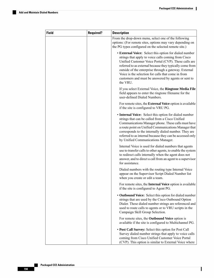
DescriptionRequired?Field
From the drop-down menu, select one of the followingoptions: (For remote sites, options may vary depending onthe PG types configured on the selected remote site.)
• External Voice: Select this option for dialed numberstrings that apply to voice calls coming from CiscoUnified Customer Voice Portal (CVP). These calls arereferred to as external because they typically come fromoutside of the enterprise through a gateway. ExternalVoice is the selection for calls that come in fromcustomers and must be answered by agents or sent tothe VRU.
If you select External Voice, the Ringtone Media Filefield appears to enter the ringtone filename for theuser-defined Dialed Numbers.
For remote sites, theExternal Voice option is availableif the site is configured to VRU PG.
• Internal Voice: Select this option for dialed numberstrings that can be called from a Cisco UnifiedCommunicationsManager phone. These calls must havea route point on Unified CommunicationsManager thatcorresponds to the internally dialed number. They arereferred to as internal because they can be accessed onlyby Unified Communications Manager.
Internal Voice is used for dialed numbers that agentsuse to transfer calls to other agents, to enable the systemto redirect calls internally when the agent does notanswer, and to direct a call from an agent to a supervisorfor assistance.
Dialed numbers with the routing type Internal Voiceappear on the Supervisor Script Dialed Number listwhen you create or edit a team.
For remote sites, the Internal Voice option is availableif the site is configured to Agent PG.
• Outbound Voice: Select this option for dialed numberstrings that are used by the Cisco Outbound OptionDialer. These dialed number strings are referenced andused to route calls to agents or to VRU scripts in theCampaign Skill Group Selection.
For remote sites, the Outbound Voice option isavailable if the site is configured to Multichannel PG.
• Post Call Survey: Select this option for Post CallSurvey dialed number strings that apply to voice callscoming from Cisco Unified Customer Voice Portal(CVP). This option is similar to External Voice where
Packaged CCE Administration194
Packaged CCE AdministrationAdd and Maintain Dialed Numbers
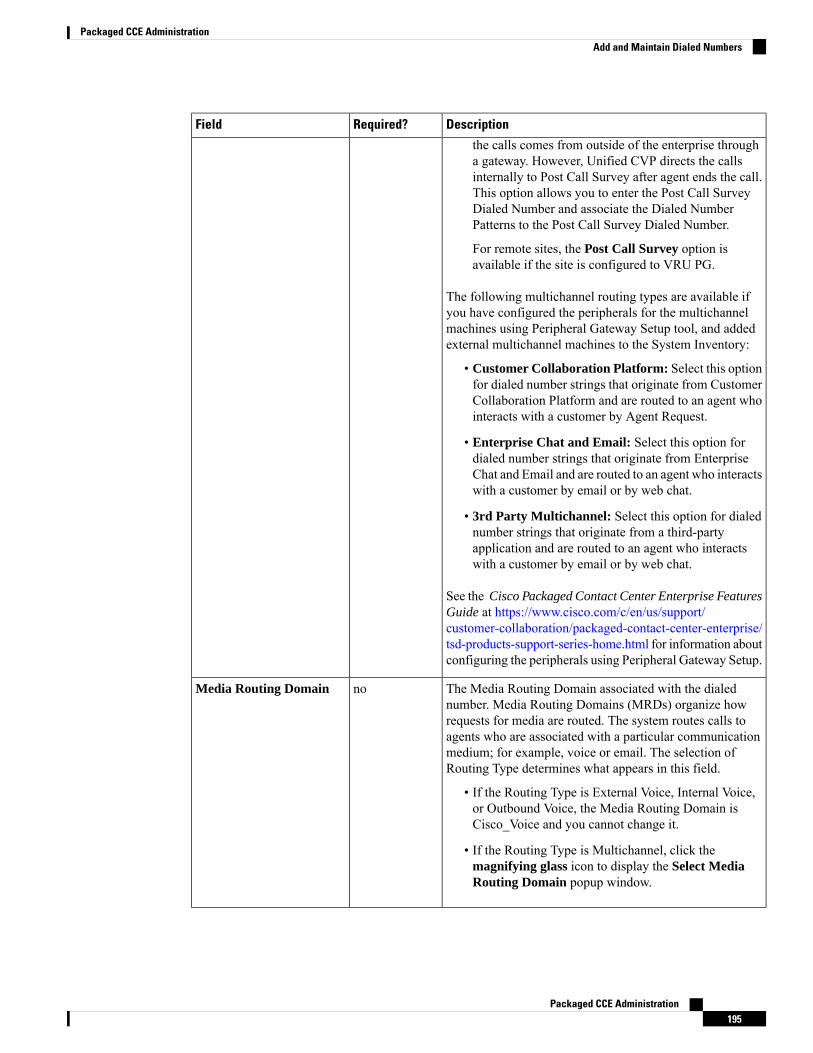
DescriptionRequired?Field
the calls comes from outside of the enterprise througha gateway. However, Unified CVP directs the callsinternally to Post Call Survey after agent ends the call.This option allows you to enter the Post Call SurveyDialed Number and associate the Dialed NumberPatterns to the Post Call Survey Dialed Number.
For remote sites, the Post Call Survey option isavailable if the site is configured to VRU PG.
The following multichannel routing types are available ifyou have configured the peripherals for the multichannelmachines using Peripheral Gateway Setup tool, and addedexternal multichannel machines to the System Inventory:
• Customer Collaboration Platform: Select this optionfor dialed number strings that originate from CustomerCollaboration Platform and are routed to an agent whointeracts with a customer by Agent Request.
• Enterprise Chat and Email: Select this option fordialed number strings that originate from EnterpriseChat and Email and are routed to an agent who interactswith a customer by email or by web chat.
• 3rd Party Multichannel: Select this option for dialednumber strings that originate from a third-partyapplication and are routed to an agent who interactswith a customer by email or by web chat.
See the Cisco Packaged Contact Center Enterprise FeaturesGuide at https://www.cisco.com/c/en/us/support/customer-collaboration/packaged-contact-center-enterprise/tsd-products-support-series-home.html for information aboutconfiguring the peripherals using Peripheral Gateway Setup.
The Media Routing Domain associated with the dialednumber. Media Routing Domains (MRDs) organize howrequests for media are routed. The system routes calls toagents who are associated with a particular communicationmedium; for example, voice or email. The selection ofRouting Type determines what appears in this field.
• If the Routing Type is External Voice, Internal Voice,or Outbound Voice, the Media Routing Domain isCisco_Voice and you cannot change it.
• If the Routing Type is Multichannel, click themagnifying glass icon to display the Select MediaRouting Domain popup window.
noMedia Routing Domain
Packaged CCE Administration195
Packaged CCE AdministrationAdd and Maintain Dialed Numbers
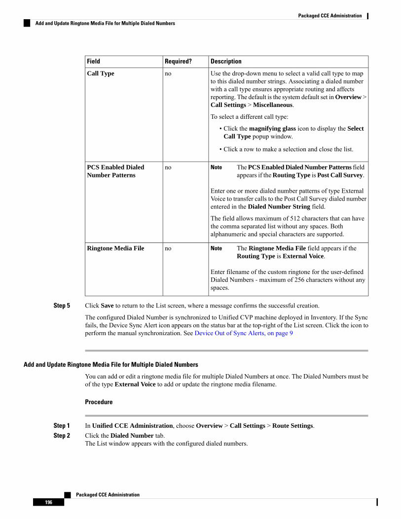
DescriptionRequired?Field
Use the drop-down menu to select a valid call type to mapto this dialed number strings. Associating a dialed numberwith a call type ensures appropriate routing and affectsreporting. The default is the system default set inOverview >Call Settings > Miscellaneous.
To select a different call type:
• Click the magnifying glass icon to display the SelectCall Type popup window.
• Click a row to make a selection and close the list.
noCall Type
ThePCS Enabled Dialed Number Patterns fieldappears if theRouting Type is Post Call Survey.
Note
Enter one or more dialed number patterns of type ExternalVoice to transfer calls to the Post Call Survey dialed numberentered in the Dialed Number String field.
The field allows maximum of 512 characters that can havethe comma separated list without any spaces. Bothalphanumeric and special characters are supported.
noPCS Enabled DialedNumber Patterns
The Ringtone Media File field appears if theRouting Type is External Voice.
Note
Enter filename of the custom ringtone for the user-definedDialed Numbers - maximum of 256 characters without anyspaces.
noRingtone Media File
Step 5 Click Save to return to the List screen, where a message confirms the successful creation.
The configured Dialed Number is synchronized to Unified CVP machine deployed in Inventory. If the Syncfails, the Device Sync Alert icon appears on the status bar at the top-right of the List screen. Click the icon toperform the manual synchronization. See Device Out of Sync Alerts, on page 9
Add and Update Ringtone Media File for Multiple Dialed Numbers
You can add or edit a ringtone media file for multiple Dialed Numbers at once. The Dialed Numbers must beof the type External Voice to add or update the ringtone media filename.
Procedure
Step 1 In Unified CCE Administration, choose Overview > Call Settings > Route Settings.Step 2 Click the Dialed Number tab.
The List window appears with the configured dialed numbers.
Packaged CCE Administration196
Packaged CCE AdministrationAdd and Update Ringtone Media File for Multiple Dialed Numbers
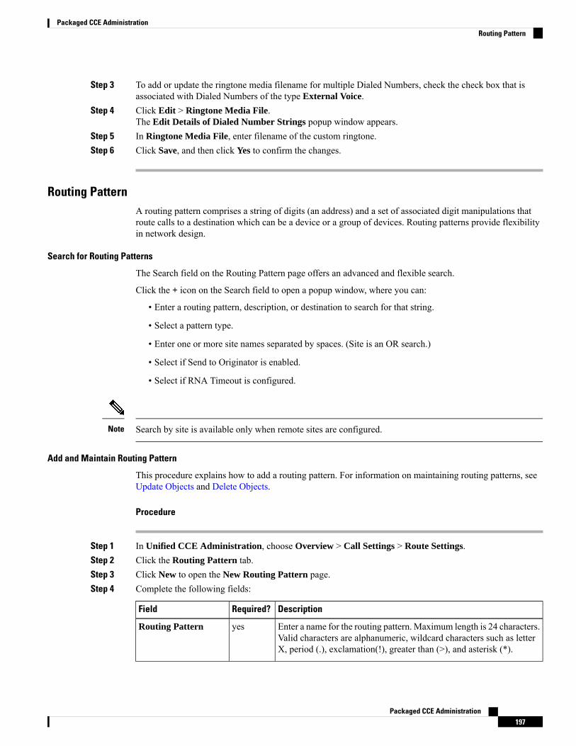
Step 3 To add or update the ringtone media filename for multiple Dialed Numbers, check the check box that isassociated with Dialed Numbers of the type External Voice.
Step 4 Click Edit > Ringtone Media File.The Edit Details of Dialed Number Strings popup window appears.
Step 5 In Ringtone Media File, enter filename of the custom ringtone.Step 6 Click Save, and then click Yes to confirm the changes.
Routing PatternA routing pattern comprises a string of digits (an address) and a set of associated digit manipulations thatroute calls to a destination which can be a device or a group of devices. Routing patterns provide flexibilityin network design.
Search for Routing Patterns
The Search field on the Routing Pattern page offers an advanced and flexible search.
Click the + icon on the Search field to open a popup window, where you can:
• Enter a routing pattern, description, or destination to search for that string.
• Select a pattern type.
• Enter one or more site names separated by spaces. (Site is an OR search.)
• Select if Send to Originator is enabled.
• Select if RNA Timeout is configured.
Search by site is available only when remote sites are configured.Note
Add and Maintain Routing Pattern
This procedure explains how to add a routing pattern. For information on maintaining routing patterns, seeUpdate Objects and Delete Objects.
Procedure
Step 1 In Unified CCE Administration, choose Overview > Call Settings > Route Settings.Step 2 Click the Routing Pattern tab.Step 3 Click New to open the New Routing Pattern page.Step 4 Complete the following fields:
DescriptionRequired?Field
Enter a name for the routing pattern. Maximum length is 24 characters.Valid characters are alphanumeric, wildcard characters such as letterX, period (.), exclamation(!), greater than (>), and asterisk (*).
yesRouting Pattern
Packaged CCE Administration197
Packaged CCE AdministrationRouting Pattern
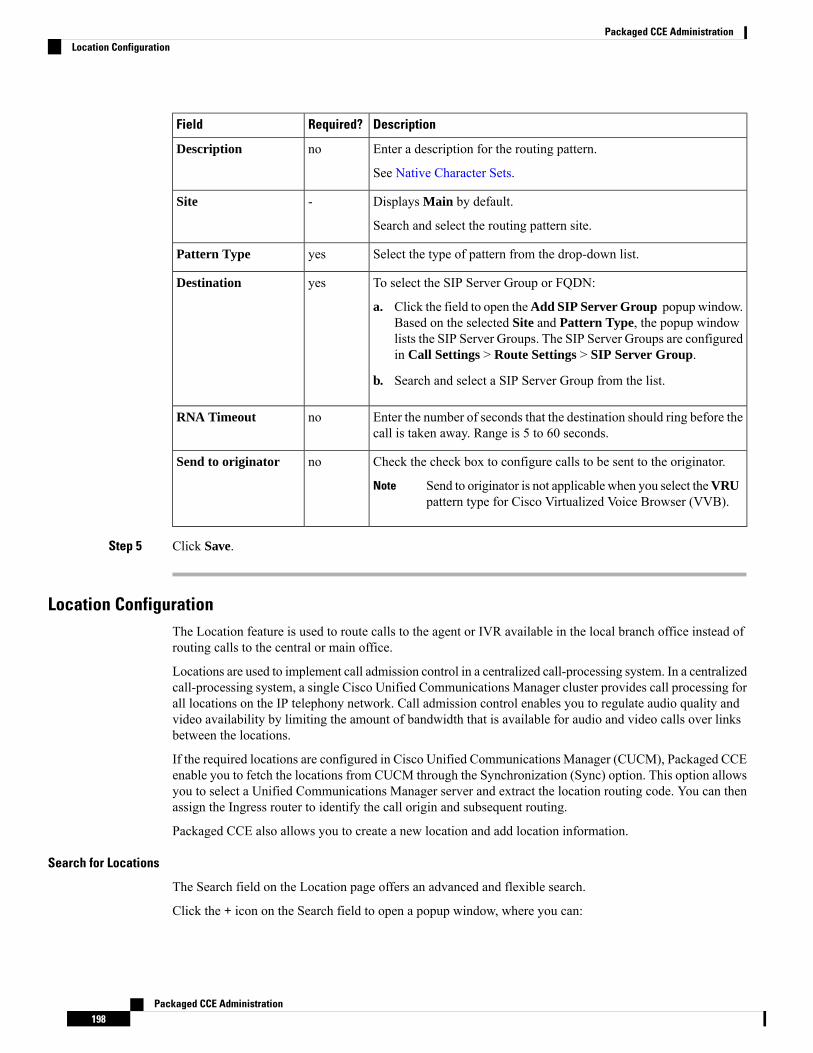
DescriptionRequired?Field
Enter a description for the routing pattern.
See Native Character Sets.
noDescription
Displays Main by default.
Search and select the routing pattern site.
-Site
Select the type of pattern from the drop-down list.yesPattern Type
To select the SIP Server Group or FQDN:
a. Click the field to open theAdd SIP Server Group popup window.Based on the selected Site and Pattern Type, the popup windowlists the SIP Server Groups. The SIP Server Groups are configuredin Call Settings > Route Settings > SIP Server Group.
b. Search and select a SIP Server Group from the list.
yesDestination
Enter the number of seconds that the destination should ring before thecall is taken away. Range is 5 to 60 seconds.
noRNA Timeout
Check the check box to configure calls to be sent to the originator.
Send to originator is not applicable when you select theVRUpattern type for Cisco Virtualized Voice Browser (VVB).
Note
noSend to originator
Step 5 Click Save.
Location ConfigurationThe Location feature is used to route calls to the agent or IVR available in the local branch office instead ofrouting calls to the central or main office.
Locations are used to implement call admission control in a centralized call-processing system. In a centralizedcall-processing system, a single Cisco Unified Communications Manager cluster provides call processing forall locations on the IP telephony network. Call admission control enables you to regulate audio quality andvideo availability by limiting the amount of bandwidth that is available for audio and video calls over linksbetween the locations.
If the required locations are configured in Cisco Unified Communications Manager (CUCM), Packaged CCEenable you to fetch the locations from CUCM through the Synchronization (Sync) option. This option allowsyou to select a Unified Communications Manager server and extract the location routing code. You can thenassign the Ingress router to identify the call origin and subsequent routing.
Packaged CCE also allows you to create a new location and add location information.
Search for Locations
The Search field on the Location page offers an advanced and flexible search.
Click the + icon on the Search field to open a popup window, where you can:
Packaged CCE Administration198
Packaged CCE AdministrationLocation Configuration
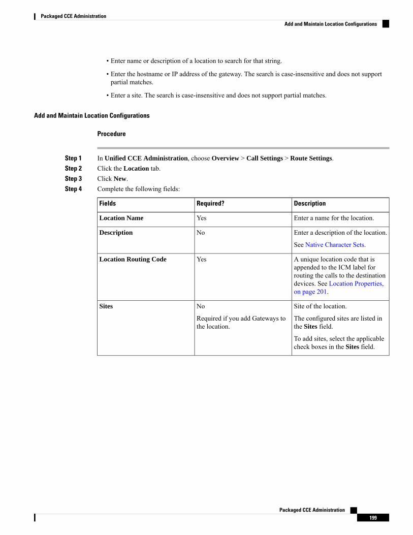
• Enter name or description of a location to search for that string.
• Enter the hostname or IP address of the gateway. The search is case-insensitive and does not supportpartial matches.
• Enter a site. The search is case-insensitive and does not support partial matches.
Add and Maintain Location Configurations
Procedure
Step 1 In Unified CCE Administration, choose Overview > Call Settings > Route Settings.Step 2 Click the Location tab.Step 3 Click New.Step 4 Complete the following fields:
DescriptionRequired?Fields
Enter a name for the location.YesLocation Name
Enter a description of the location.
See Native Character Sets.
NoDescription
A unique location code that isappended to the ICM label forrouting the calls to the destinationdevices. See Location Properties,on page 201.
YesLocation Routing Code
Site of the location.
The configured sites are listed inthe Sites field.
To add sites, select the applicablecheck boxes in the Sites field.
No
Required if you add Gateways tothe location.
Sites
Packaged CCE Administration199
Packaged CCE AdministrationAdd and Maintain Location Configurations

DescriptionRequired?Fields
Gateways that are associated withthe location.
To associate a gateway to thelocation:
a. Click the + icon.
The Add Gateways popupwindow opens with a list ofgateways.
b. Select a gateway from the list.Use the Search a List feature tonavigate the list.
You can view up to 18servers for a site.Additional server entrieswill not be displayedand cannot be retrievedvia the search feature.
Note
No
Required if you select Site(s) forthe location.
Gateways
Step 5 Click Save.
Synchronize the Location Information
Location synchronization is a user-initiated task. A single synchronization operation runs in the backgroundwhen initiated. When initiated, the system synchronizes and merges the locations from the Unified CM serverselected during the configuration.
To complete a synchronizing operation:
• The system retrieves the location data from the Unified CM database.
• The system merges the retrieved data with any existing location data.
Procedure
Step 1 In Unified CCE Administration, choose Overview > Call Settings > Route Settings.Step 2 Click the Location tab.Step 3 Click the Sync button.
The Synchronize Location popup window opens.Step 4 Select a Unified CM server from the Select CUCM Publisher drop-down list.Step 5 Click Sync.
The synchronized locations appear on the List window.
Packaged CCE Administration200
Packaged CCE AdministrationSynchronize the Location Information

What to do next
You can addLocation Routing Code and associate applicable Sites andGateways to the required Locations.
Location Properties
The Location Properties feature provides options for the placement of the location routing code. The LocationProperties setting applies to all the configured locations.
You can place the routing code at the beginning of the Network VRU label, in the middle of the NetworkVRU label and the correlation ID, or can choose not to insert the routing code.
Procedure
Step 1 In Unified CCE Administration, choose Overview > Call Settings > Route Settings.Step 2 Click the Location tab.Step 3 Click the Properties link.
The Properties popup window opens.Step 4 Select an option to insert the location routing code.
The options are:
• Insert routing code between Network VRU label and the correlation ID.
• Insert routing code at the beginning of the Network VRU label.
• Do not insert routing code.
The Insert routing code between Network VRU label and the correlation ID option is the default selection.
Step 5 Click Save to return to the List window.
What to do next
After you change the routing code insertion setting, you must recreate Routing Patterns and VVB Triggersassociated to locations.
SIP Server GroupYou can add the SIP Server groups to perform SIP dynamic routing by Cisco Unified Customer Voice Portal(CVP).
A SIP Server Group consists of one or more destination addresses (elements), and is identified by a ServerGroup domain name. This domain name is also known as the Fully Qualified Domain Name (FQDN).
The site specific SIP Server Groups' configuration is updated to all the Unified CVP of the corresponding sitepresent in the Inventory (see System Inventory for Packaged CCE 2000 Agents Deployment).
Note
Related TopicsSearch for SIP Server Groups, on page 202
Packaged CCE Administration201
Packaged CCE AdministrationLocation Properties

Add and Maintain SIP Server Group, on page 202SIP Server Group Properties, on page 204
Search for SIP Server Groups
The Search field in the SIP Server Group tool offers an advanced and flexible search.
Click the + icon at the right of the Search field in the SIP Server Group tool. In the popup window, you can:
• Search for a name or description.
• Enter one or more site names separated by spaces (Site is an OR search).
• Select SIP Server type.
• Enter hostname/IP address of the element. The search is case-sensitive and does not support partialmatches.
Search by site is available only when you configure remote sites.Note
Add and Maintain SIP Server Group
This procedure explains how to add a SIP Server Group. For information about maintaining SIP Server Groups,see Update Objects and Delete Objects.
Procedure
Step 1 In Unified CCE Administration, choose Overview > Call Settings > Route Settings.Step 2 Click the SIP Server Group tab.Step 3 Click New to open the New SIP Server Group page.Step 4 Complete the following fields on the General tab:
DescriptionRequired?Field
Enter the SIP Server Group Fully Qualified Domain Name (FQDN).
Must be a valid FQDN limited to 128 characters. Can contain acombination of uppercase and lowercase alphanumeric characters,underscore [ _ ], and period [.].
yesDomain Name FQDN
Enter a maximum of 255 characters to describe the SIP Server Group.
See Native Character Sets.
noDescription
Packaged CCE Administration202
Packaged CCE AdministrationSearch for SIP Server Groups

DescriptionRequired?Field
To select the site of the group.
Displays Main by default.
To select a remote site:
a. Click the magnifying glass icon to display the list of configuredsites.
b. Select the required site.
-Site
To select the type of group.
From the drop-down list, choose one of the following options:
• VRU - For Cisco VirtualizedVoice Browser (VVB), Cisco UnifiedSIP Proxy (CUSP), and VXML Gateway devices.
• Agent - For Cisco Unified Communications Manager (CUCM)and CUSP devices.
• External - For Ingress Gateway and CUSP devices.
yesType
Step 5 Click Members tab.a) Click the + icon.
The Add Group Members popup window appears with the hostname or IP address of the configureddevices based on the Site and Type selected in the General tab.
To search a device configured in a different site, choose a site from the Site drop-down list.Note
b) Choose one or more devices from the Add Group Members popup window.The selected devices appear in the List of Group Members table.
You can view up to 25 servers for a site. Additional server entries will not be displayed andcannot be retrieved via the search feature.
Note
c) Enter appropriate values in the following fields:
DescriptionRequired?Field
Priority of the element in relation to the other elements in the server group.Specifies whether the server is a primary or backup server. Primary servers arespecified as 1. Range is 1 to 2147483647
yesPriority
Weight of the element in relation to the other elements in the server group. Specifiesthe frequency with which requests are sent to servers in that priority group. Rangeis 10 to 2147483647.
yesWeight
Port number of the element in the server group. The default value is 5060. Rangeis 1 to 65535
yesPort
The listening port for secure connection. Range is 1 to 65535noSecurePort
Packaged CCE Administration203
Packaged CCE AdministrationAdd and Maintain SIP Server Group
Step 6 Click Save to return to the List screen, where a message confirms the successful creation.
SIP Server Group Properties
The SIP Server Group properties configure the heartbeat parameters to exchange the heartbeat messagebetween SIP Server Group elements and SIP Server Group.
The configuration of SIP Server Group properties forms the global setting for all SIP Server Groups acrossall sites.
Note
The Up and Down Endpoint Heartbeat Interval is between any two heartbeats; however, it is not betweenheartbeats to the same endpoint. The SIP Server Group does not wake up at a specific interval and sends aheartbeat for all elements since this approach can result in CPU utilization issues. It also takes more resourcesto track heartbeats for many endpoints. For example, for 3 total elements across all SIP Server Groups, toproactively send a heartbeat to each element at 30000ms (30 seconds) intervals, you have to set the EndpointHeartbeat Interval to 10000ms (10 seconds). It is less deterministic for reactive mode since elements that arecurrently down can fluctuate so the heartbeat interval fluctuates with it. To turn off pinging when the elementis UP, set the UP interval to zero (reactive pinging). To turn off pinging when the element is down, set theDOWN interval to zero (proactive pinging). To ping when the element is either UP or DOWN, set both theintervals to greater than zero (adaptive pinging).
Note
Update SIP Server Group Properties
Procedure
Step 1 In Unified CCE Administration, choose Overview > Call Settings > Route Settings.Step 2 Click the SIP Server Group tab.Step 3 Click the Properties link.
The SIP Server Properties window opens to configure SIP Server Group properties.Step 4 Update any of the following fields values:
Packaged CCE Administration204
Packaged CCE AdministrationSIP Server Group Properties
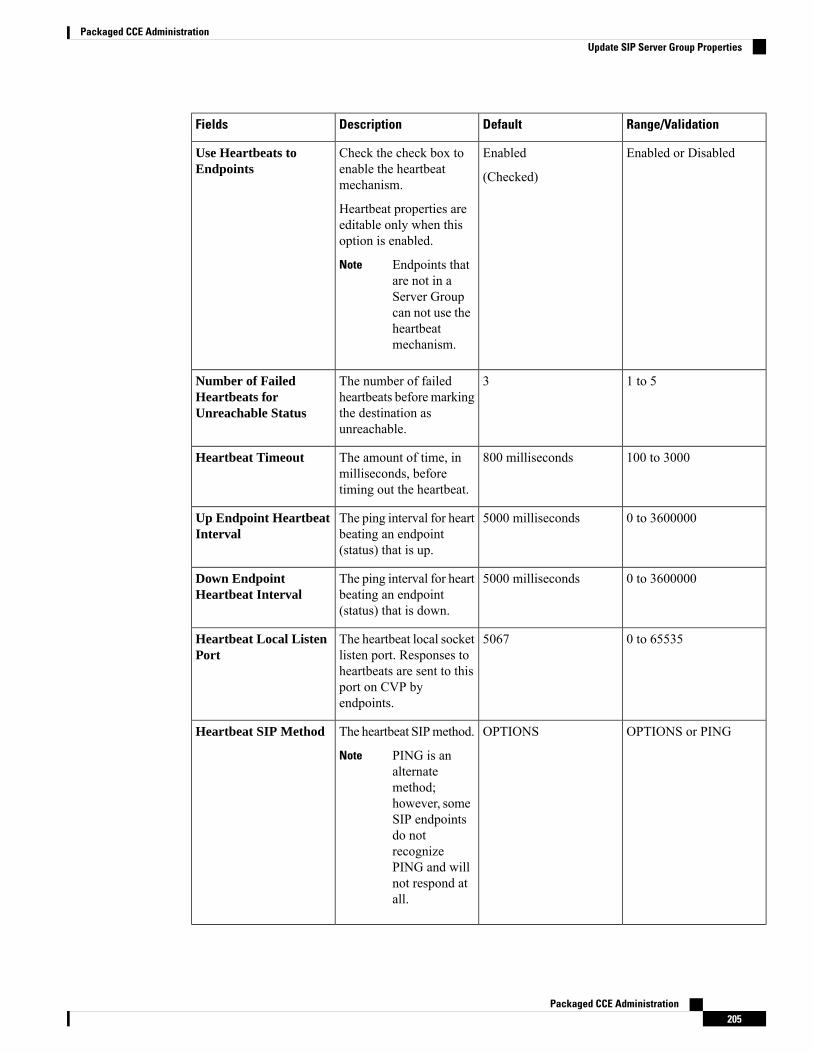
Range/ValidationDefaultDescriptionFields
Enabled or DisabledEnabled
(Checked)
Check the check box toenable the heartbeatmechanism.
Heartbeat properties areeditable only when thisoption is enabled.
Endpoints thatare not in aServer Groupcan not use theheartbeatmechanism.
Note
Use Heartbeats toEndpoints
1 to 53The number of failedheartbeats before markingthe destination asunreachable.
Number of FailedHeartbeats forUnreachable Status
100 to 3000800 millisecondsThe amount of time, inmilliseconds, beforetiming out the heartbeat.
Heartbeat Timeout
0 to 36000005000 millisecondsThe ping interval for heartbeating an endpoint(status) that is up.
Up Endpoint HeartbeatInterval
0 to 36000005000 millisecondsThe ping interval for heartbeating an endpoint(status) that is down.
Down EndpointHeartbeat Interval
0 to 655355067The heartbeat local socketlisten port. Responses toheartbeats are sent to thisport on CVP byendpoints.
Heartbeat Local ListenPort
OPTIONS or PINGOPTIONSThe heartbeat SIPmethod.
PING is analternatemethod;however, someSIP endpointsdo notrecognizePING and willnot respond atall.
Note
Heartbeat SIP Method
Packaged CCE Administration205
Packaged CCE AdministrationUpdate SIP Server Group Properties
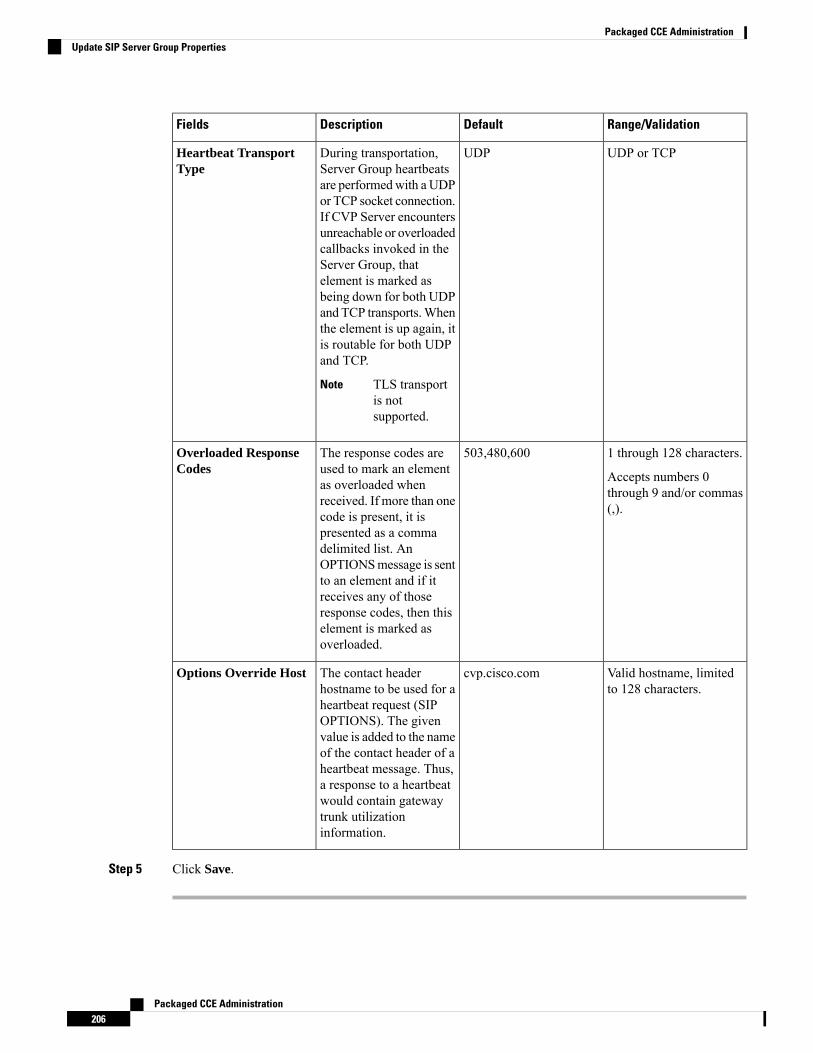
Range/ValidationDefaultDescriptionFields
UDP or TCPUDPDuring transportation,Server Group heartbeatsare performedwith a UDPor TCP socket connection.If CVP Server encountersunreachable or overloadedcallbacks invoked in theServer Group, thatelement is marked asbeing down for both UDPand TCP transports.Whenthe element is up again, itis routable for both UDPand TCP.
TLS transportis notsupported.
Note
Heartbeat TransportType
1 through 128 characters.
Accepts numbers 0through 9 and/or commas(,).
503,480,600The response codes areused to mark an elementas overloaded whenreceived. If more than onecode is present, it ispresented as a commadelimited list. AnOPTIONSmessage is sentto an element and if itreceives any of thoseresponse codes, then thiselement is marked asoverloaded.
Overloaded ResponseCodes
Valid hostname, limitedto 128 characters.
cvp.cisco.comThe contact headerhostname to be used for aheartbeat request (SIPOPTIONS). The givenvalue is added to the nameof the contact header of aheartbeat message. Thus,a response to a heartbeatwould contain gatewaytrunk utilizationinformation.
Options Override Host
Step 5 Click Save.
Packaged CCE Administration206
Packaged CCE AdministrationUpdate SIP Server Group Properties
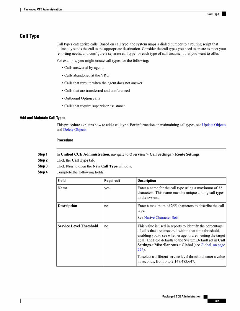
Call TypeCall types categorize calls. Based on call type, the system maps a dialed number to a routing script thatultimately sends the call to the appropriate destination. Consider the call types you need to create to meet yourreporting needs, and configure a separate call type for each type of call treatment that you want to offer.
For example, you might create call types for the following:
• Calls answered by agents
• Calls abandoned at the VRU
• Calls that reroute when the agent does not answer
• Calls that are transferred and conferenced
• Outbound Option calls
• Calls that require supervisor assistance
Add and Maintain Call Types
This procedure explains how to add a call type. For information on maintaining call types, see Update Objectsand Delete Objects.
Procedure
Step 1 In Unified CCE Administration, navigate to Overview > Call Settings > Route Settings.Step 2 Click the Call Type tab.Step 3 Click New to open the New Call Type window.Step 4 Complete the following fields :
DescriptionRequired?Field
Enter a name for the call type using a maximum of 32characters. This name must be unique among call typesin the system.
yesName
Enter a maximum of 255 characters to describe the calltype.
See Native Character Sets.
noDescription
This value is used in reports to identify the percentageof calls that are answered within that time threshold,enabling you to see whether agents are meeting the targetgoal. The field defaults to the System Default set in CallSettings >Miscellaneous >Global (see Global, on page226).
To select a different service level threshold, enter a valuein seconds, from 0 to 2,147,483,647.
noService Level Threshold
Packaged CCE Administration207
Packaged CCE AdministrationCall Type
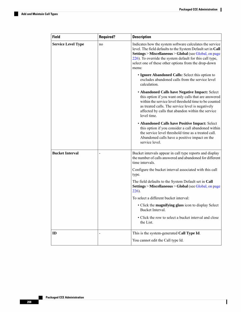
DescriptionRequired?Field
Indicates how the system software calculates the servicelevel. The field defaults to the SystemDefault set inCallSettings >Miscellaneous >Global (see Global, on page226). To override the system default for this call type,select one of these other options from the drop-downmenu:
• Ignore Abandoned Calls: Select this option toexcludes abandoned calls from the service levelcalculation.
• Abandoned Calls have Negative Impact: Selectthis option if you want only calls that are answeredwithin the service level threshold time to be countedas treated calls. The service level is negativelyaffected by calls that abandon within the servicelevel time.
• Abandoned Calls have Positive Impact: Selectthis option if you consider a call abandoned withinthe service level threshold time as a treated call.Abandoned calls have a positive impact on theservice level.
noService Level Type
Bucket intervals appear in call type reports and displaythe number of calls answered and abandoned for differenttime intervals.
Configure the bucket interval associated with this calltype.
The field defaults to the System Default set in CallSettings >Miscellaneous >Global (see Global, on page226).
To select a different bucket interval:
• Click the magnifying glass icon to display SelectBucket Interval.
• Click the row to select a bucket interval and closethe List.
-Bucket Interval
This is the system-generated Call Type Id.
You cannot edit the Call type Id.
-ID
Packaged CCE Administration208
Packaged CCE AdministrationAdd and Maintain Call Types

DescriptionRequired?Field
This option will be available only if you have addedCloud Connect in the Inventory page, and configuredWebex Experience Management.
In case you want to populate the Webex ExperienceManagement survey, you can select the EnableExperience Management check box.
The Experience Management tab will be enabled withthe following options:-
• Inline Survey: (post-call voice survey).
• Deferred Survey: (post-call Email and SMS survey).
You can associate only one Survey to aCall Type.
Note
Click on the magnifying glass icon, and the configuredsurvey will be populated in the pop-up window.
noEnable ExperienceManagement
Step 5 Click Save to return to the List window, where a message confirms the successful creation.
Expanded Call Variables
Calls can carry data with them as they move through the system. This data, called expanded call variable data,is embedded within the call and is visible to the agent on the agent desktop. ECC variables are passed backand forth in ECC payloads. Expanded call variable data can assist the agent in working with the caller.
The expanded call variable can be set or updated by Cisco Unified Customer Voice Portal (CVP), by UnifiedCCE scripting, or by an agent who is transferring the call.
• If the call is at Unified CVP for VRU treatment, the call context is exchanged between Unified CVP andUnified CCE.
• If the call is at an agent, the call context is exchanged between the desktop and Unified CCE.
Note that this is a two-way exchange: in some cases the expanded call variable data is sent to Unified CCEfrom Unified CVP or the agent desktop, and in some cases the data is sent by Unified CCE based on scriptconfiguration to Unified CVP or the agent desktop.
Built-in expanded call variables are identified by the BuiltIn check box on the Edit Expanded Call Variablewindow. You cannot delete these expanded call variables. You can create new expanded call variables subjectto certain sizing constraints.
For Packaged CCE 4000 and 12000 Agents deployment, seeConfiguration Guide for Cisco Unified CustomerVoice Portal at https://www.cisco.com/c/en/us/support/customer-collaboration/unified-customer-voice-portal/products-installation-and-configuration-guides-list.html for the list of ECC Variables.
Packaged CCE Administration209
Packaged CCE AdministrationExpanded Call Variables
ECC Payloads
You can define as many ECC variables as necessary. But, you can only pass 2000 bytes of ECC variables ona specific interface at any one time. To aid you in organizing ECC variables for specific purposes, the solutionhas ECC payloads.
An ECC payload is a defined set of ECC variables with a maximum size of 2000 bytes. You can create ECCpayloads to suit the necessary information for a given operation. You can include a specific ECC variable inmultiple ECC payloads.The particular ECC variables in a given ECC payload are called its members.
For ECC payloads to a CTI client, the size limit is 2000 bytes plus an extra 500 bytes for the ECC variablenames. Unlike other interfaces, the CTI message includes ECC variable names.
In certain cases, mainly when using APIs, you might create an ECC payload that exceeds the CTI Servermessage size limit. If you use such an ECC payload in a client request, the CTI Server rejects the request. Foran OPC message with such an ECC payload, the CTI Server sends the message without the ECC data. In thiscase, the following event is logged, “CTI Server was unable to forward ECC variables due to an overflowcondition.”
Note
You can use several ECC payloads in the same call flow, but only one ECC payload has scope at a givenmoment. TCDs and RCDs record the ID of the ECC payload that had scope during that leg of the call. TheCall.ECCPayloadID variable contains the ID of the ECC payload which currently has scope.
In solutions that only use the default ECC payload, the system does not create an ECC variable that exceedsthe 2000-byte limit for an ECC payload or the 2500-byte CTI Message Size limit.
Packaged CCE 2000 Agent deployment allows you to use only the default ECC payload for the NetworkVRU.
Note
If you create another ECC payload, the system no longer checks the 2000-byte limit when creating ECCvariables. The system creates the ECC variables without assigning them to an ECC payload. Assign the newECC variable to an appropriate ECC payload yourself through the ECC Payload Tool.
You can create and modify ECC payloads in the Configuration Manager > List Tools > Expanded CallVariable Payload List tool. In Packaged CCE 4000 Agent and 12000 Agent deployments, you can assignan ECC payload to Network VRU using the Network VRU Explorer tool in Configuration Manager.
Default ECC Payload
The solution includes an ECC payload named "Default" for backward compatibility. If your solution does notrequire more ECC variable space, you only need the Default payload. The solution uses the Default payloadunless you override it.
If your solution only has the Default payload, the solution automatically adds any new ECC variables to theDefault payload until it reaches the 2000-byte limit.
You cannot delete the Default payload. But, you can change its members.Note
Packaged CCE Administration210
Packaged CCE AdministrationECC Payloads

During upgrades, when the system first migrates your existing ECC variables to the Default payload, it doesnot check the CTI message size limit. The member names might exceed the extra 500 bytes that is allocatedfor ECC payloads to a CTI client. Manually check the CTI Message Size counter in the Expanded CallVariable Payload List tool to ensure that the Default payload does not exceed the limit. If the Default payloadexceeds the limit, modify it to meet the limit.
Important
In a fresh install, the Default payload includes the predefined system ECC variables. In an upgrade, the Defaultpayload's contents depend on whether the starting release supports ECC payloads:
• ECC payloads not supported—During the upgrade, a script adds your existing ECC variables to theDefault payload.
• ECC payloads are supported—The upgrade brings forward the existing definition of your Defaultpayload.
If your solution includes PGs from a previous release that does not support ECC payloads, the Router alwayssends the Default payload to those PGs. Those PGs can properly handle the Default payload.
Note
ECC Payload Node
The ECC Payload node is available from the General tab on the Object Palette:Figure 4: Payload icon
Use this node to change the ECC payload that has scope for the following part of your script. Once you selectan ECC payload, it has scope for all non-VRU operations until changed. You can select the ECC payloadeither statically or dynamically by the payload's EnterpriseName or ID.
Add and Maintain Expanded Call Variables
Procedure
Step 1 InUnified CCE Administration, navigate toOverview >Call Settings >Route Settings > Expanded CallVariables to open the List of Expanded Call Variables.
The window tracks the number of bytes used by the expanded call variables, measured against the systemtotal and the CTI Server total.
Step 2 Click New to open the New Expanded Call Variable page.Step 3 Complete the following fields:
Packaged CCE Administration211
Packaged CCE AdministrationAdd and Maintain Expanded Call Variables
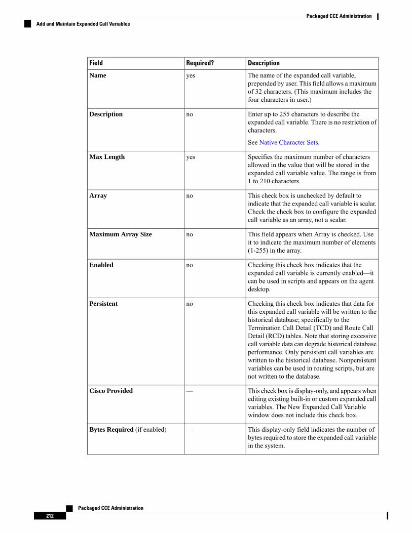
DescriptionRequired?Field
The name of the expanded call variable,prepended by user. This field allows a maximumof 32 characters. (This maximum includes thefour characters in user.)
yesName
Enter up to 255 characters to describe theexpanded call variable. There is no restriction ofcharacters.
See Native Character Sets.
noDescription
Specifies the maximum number of charactersallowed in the value that will be stored in theexpanded call variable value. The range is from1 to 210 characters.
yesMax Length
This check box is unchecked by default toindicate that the expanded call variable is scalar.Check the check box to configure the expandedcall variable as an array, not a scalar.
noArray
This field appears when Array is checked. Useit to indicate the maximum number of elements(1-255) in the array.
noMaximum Array Size
Checking this check box indicates that theexpanded call variable is currently enabled—itcan be used in scripts and appears on the agentdesktop.
noEnabled
Checking this check box indicates that data forthis expanded call variable will be written to thehistorical database; specifically to theTermination Call Detail (TCD) and Route CallDetail (RCD) tables. Note that storing excessivecall variable data can degrade historical databaseperformance. Only persistent call variables arewritten to the historical database. Nonpersistentvariables can be used in routing scripts, but arenot written to the database.
noPersistent
This check box is display-only, and appears whenediting existing built-in or custom expanded callvariables. The New Expanded Call Variablewindow does not include this check box.
—Cisco Provided
This display-only field indicates the number ofbytes required to store the expanded call variablein the system.
—Bytes Required (if enabled)
Packaged CCE Administration212
Packaged CCE AdministrationAdd and Maintain Expanded Call Variables

DescriptionRequired?Field
This display-only field is similar to BytesRequired, above, but applies to the CTI Server.In CTI Server, the number of bytes requiredincludes the length of the expanded call variablename.
—Bytes Required in CTI Server (ifenabled)
This display-only field keeps a running total ofthe number of bytes used by all expanded callvariables.
The maximum limit allowed is 2000 bytes perECC payload.
—Total Bytes Required forEnabled Variables: # ofmaximum 2000 bytes (# bytesremaining)
This display-only field keeps a running total ofthe number of bytes used by all expanded callvariables in CTI Server.
The maximum limit allowed is 2000 bytes perECC payload with an extra 500 bytes to add thenames of the ECC variables in that payload.
—Total Bytes Required forEnabled Variables in CTIServer: # of maximum 2500 bytes(# bytes remaining)
Step 4 Save the expanded call variable and return to the List window, where a message confirms the successfulcreation.
What to do next
If you change the configuration of any ECC variable, restart the Unified CVP Call Server or VRU PIM toforce a renegotiation of the ECC variables.
Before you can use the new ECC variable, you must add it to an ECC payload.
If your solution only has a Default payload, the solution automatically adds any new ECC variables to theDefault payload until it reaches the 2000-byte limit.
Note
Define ECC Payloads
You can create and modify ECC payloads in the Expanded Call Variable Payload List tool.
The tool checks that the ECC payload does not exceed the 2000-byte limit only when you save your changes.The counters on the Members tab only show what the current size is with all the selected members. They areonly informational and do not enforce the limit. The limit is enforced when you attempt to save the changes.
Note
To define an ECC payload, you create the ECC payload and then add its members.
Packaged CCE Administration213
Packaged CCE AdministrationDefine ECC Payloads
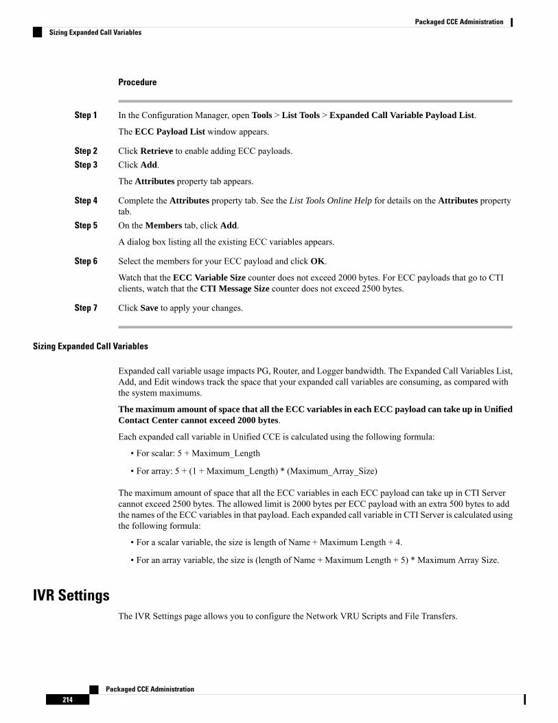
Procedure
Step 1 In the Configuration Manager, open Tools > List Tools > Expanded Call Variable Payload List.
The ECC Payload List window appears.
Step 2 Click Retrieve to enable adding ECC payloads.Step 3 Click Add.
The Attributes property tab appears.
Step 4 Complete the Attributes property tab. See the List Tools Online Help for details on the Attributes propertytab.
Step 5 On the Members tab, click Add.
A dialog box listing all the existing ECC variables appears.
Step 6 Select the members for your ECC payload and click OK.
Watch that the ECC Variable Size counter does not exceed 2000 bytes. For ECC payloads that go to CTIclients, watch that the CTI Message Size counter does not exceed 2500 bytes.
Step 7 Click Save to apply your changes.
Sizing Expanded Call Variables
Expanded call variable usage impacts PG, Router, and Logger bandwidth. The Expanded Call Variables List,Add, and Edit windows track the space that your expanded call variables are consuming, as compared withthe system maximums.
The maximum amount of space that all the ECC variables in each ECC payload can take up in UnifiedContact Center cannot exceed 2000 bytes.
Each expanded call variable in Unified CCE is calculated using the following formula:
• For scalar: 5 + Maximum_Length
• For array: 5 + (1 + Maximum_Length) * (Maximum_Array_Size)
The maximum amount of space that all the ECC variables in each ECC payload can take up in CTI Servercannot exceed 2500 bytes. The allowed limit is 2000 bytes per ECC payload with an extra 500 bytes to addthe names of the ECC variables in that payload. Each expanded call variable in CTI Server is calculated usingthe following formula:
• For a scalar variable, the size is length of Name + Maximum Length + 4.
• For an array variable, the size is (length of Name + Maximum Length + 5) * Maximum Array Size.
IVR SettingsThe IVR Settings page allows you to configure the Network VRU Scripts and File Transfers.
Packaged CCE Administration214
Packaged CCE AdministrationSizing Expanded Call Variables

Network VRU ScriptsNot all calls are delivered directly to agents. Some are sent to a Voice Response Unit (VRU) instead of, orbefore, they are sent to an agent. In the Packaged CCE deployment, the VRU is Cisco Unified Customer VoicePortal (Unified CVP). You must configure network VRU scripts to direct Unified CVP on how to handle thetreatment of individual calls, using Unified CVP microapplication functions.
There are six Unified CVP microapplication types:
• Play Media (PM): Retrieves and plays a media file such as a welcome.wav or an agent greeting.
• Play Data (PD): Retrieves and plays data of various types, such as numbers, characters, time of day, orcurrency.
• Get Digits (GD): Plays a media file and retrieves digits from the caller.
• Menu (M): Plays media menu file and retrieves a single telephone keypad entry from the caller.
• Get Speech (GS): A "GS,Server,V" script is provided with Packaged CCE and appears in the List ofNetwork VRU Scripts.
• Capture: Allows you to trigger the storage of current call data at various points.
Related TopicsAccess to VRU Scripts in Packaged CCE Routing Scripts
Add and Maintain Network VRU Scripts
Procedure
Step 1 InUnified CCE Administration, chooseOverview >Call Settings > IVR Settings >Network VRU Scriptsto open the List of Network VRU Scripts.
Step 2 Click New to open the New Network VRU Script window. Complete the following fields:
DescriptionRequired?Field
Enter a unique name to identify the script,using a maximum of 32 alphanumericcharacters.
yesName
Enter additional information about the script.See Native Character Sets.
noDescription
Retain the default (Voice) or selectMultichannel from the drop-down menu.Voice routes the script to Unified CVP.Multichannel routes the script to EnterpriseChat and Email (ECE).
yesRouting Type
Enter the name of the script as it is known onthe Unified CVP. See VRU Script NameParameters, on page 216.
yesVRU Script Name
Packaged CCE Administration215
Packaged CCE AdministrationNetwork VRU Scripts
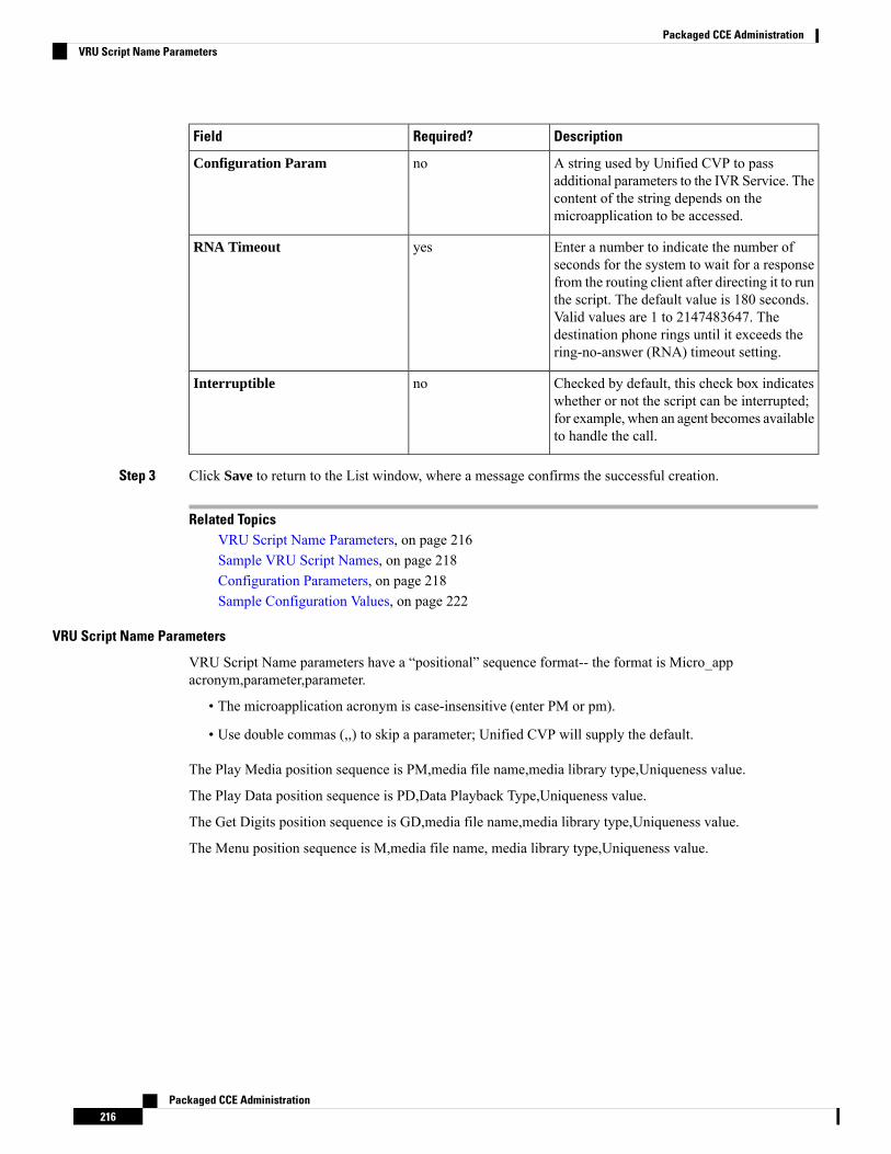
DescriptionRequired?Field
A string used by Unified CVP to passadditional parameters to the IVR Service. Thecontent of the string depends on themicroapplication to be accessed.
noConfiguration Param
Enter a number to indicate the number ofseconds for the system to wait for a responsefrom the routing client after directing it to runthe script. The default value is 180 seconds.Valid values are 1 to 2147483647. Thedestination phone rings until it exceeds thering-no-answer (RNA) timeout setting.
yesRNA Timeout
Checked by default, this check box indicateswhether or not the script can be interrupted;for example, when an agent becomes availableto handle the call.
noInterruptible
Step 3 Click Save to return to the List window, where a message confirms the successful creation.
Related TopicsVRU Script Name Parameters, on page 216Sample VRU Script Names, on page 218Configuration Parameters, on page 218Sample Configuration Values, on page 222
VRU Script Name Parameters
VRU Script Name parameters have a “positional” sequence format-- the format is Micro_appacronym,parameter,parameter.
• The microapplication acronym is case-insensitive (enter PM or pm).
• Use double commas (,,) to skip a parameter; Unified CVP will supply the default.
The Play Media position sequence is PM,media file name,media library type,Uniqueness value.
The Play Data position sequence is PD,Data Playback Type,Uniqueness value.
The Get Digits position sequence is GD,media file name,media library type,Uniqueness value.
The Menu position sequence is M,media file name, media library type,Uniqueness value.
Packaged CCE Administration216
Packaged CCE AdministrationVRU Script Name Parameters
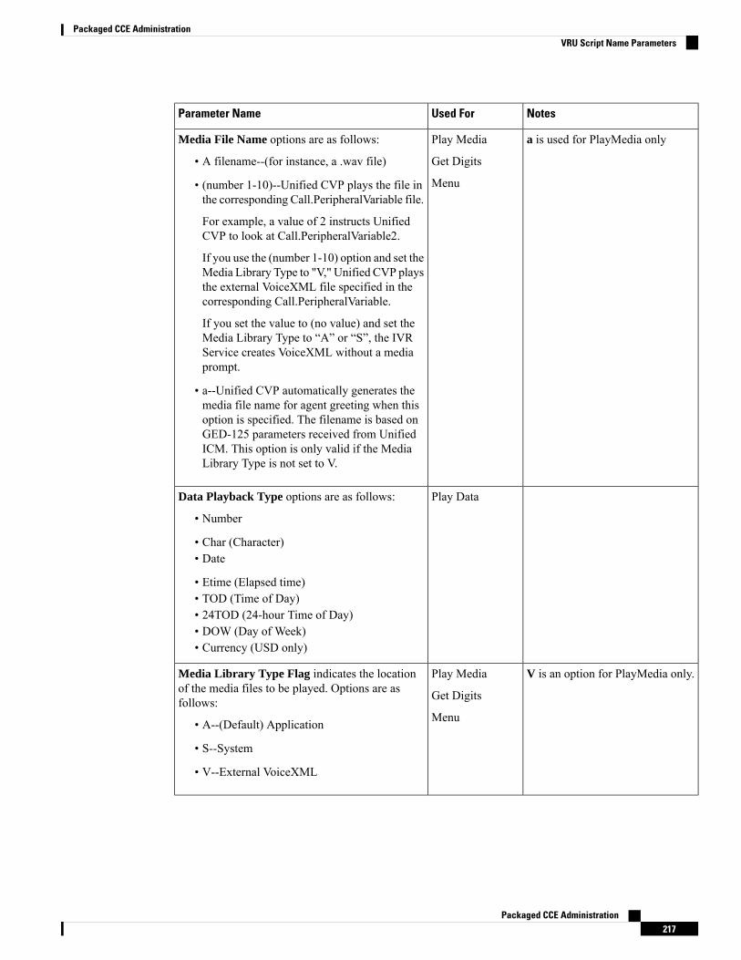
NotesUsed ForParameter Name
a is used for PlayMedia onlyPlay Media
Get Digits
Menu
Media File Name options are as follows:
• A filename--(for instance, a .wav file)
• (number 1-10)--Unified CVP plays the file inthe corresponding Call.PeripheralVariable file.
For example, a value of 2 instructs UnifiedCVP to look at Call.PeripheralVariable2.
If you use the (number 1-10) option and set theMedia Library Type to "V," Unified CVP playsthe external VoiceXML file specified in thecorresponding Call.PeripheralVariable.
If you set the value to (no value) and set theMedia Library Type to “A” or “S”, the IVRService creates VoiceXML without a mediaprompt.
• a--Unified CVP automatically generates themedia file name for agent greeting when thisoption is specified. The filename is based onGED-125 parameters received from UnifiedICM. This option is only valid if the MediaLibrary Type is not set to V.
Play DataData Playback Type options are as follows:
• Number
• Char (Character)• Date
• Etime (Elapsed time)• TOD (Time of Day)• 24TOD (24-hour Time of Day)• DOW (Day of Week)• Currency (USD only)
V is an option for PlayMedia only.Play Media
Get Digits
Menu
Media Library Type Flag indicates the locationof the media files to be played. Options are asfollows:
• A--(Default) Application
• S--System
• V--External VoiceXML
Packaged CCE Administration217
Packaged CCE AdministrationVRU Script Name Parameters
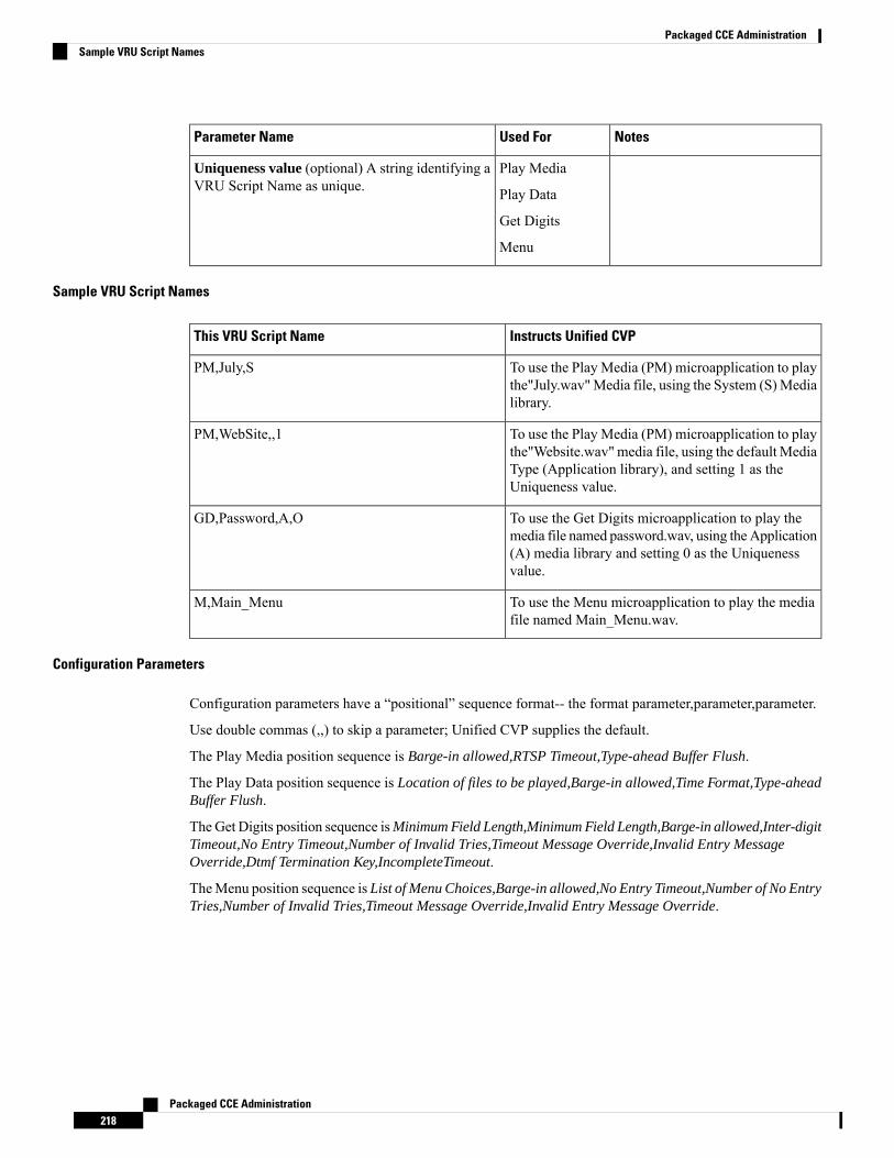
NotesUsed ForParameter Name
Play Media
Play Data
Get Digits
Menu
Uniqueness value (optional) A string identifying aVRU Script Name as unique.
Sample VRU Script Names
Instructs Unified CVPThis VRU Script Name
To use the Play Media (PM) microapplication to playthe"July.wav"Media file, using the System (S)Medialibrary.
PM,July,S
To use the Play Media (PM) microapplication to playthe"Website.wav"media file, using the default MediaType (Application library), and setting 1 as theUniqueness value.
PM,WebSite,,1
To use the Get Digits microapplication to play themedia file named password.wav, using theApplication(A) media library and setting 0 as the Uniquenessvalue.
GD,Password,A,O
To use the Menu microapplication to play the mediafile named Main_Menu.wav.
M,Main_Menu
Configuration Parameters
Configuration parameters have a “positional” sequence format-- the format parameter,parameter,parameter.
Use double commas (,,) to skip a parameter; Unified CVP supplies the default.
The Play Media position sequence is Barge-in allowed,RTSP Timeout,Type-ahead Buffer Flush.
The Play Data position sequence is Location of files to be played,Barge-in allowed,Time Format,Type-aheadBuffer Flush.
The Get Digits position sequence isMinimum Field Length,Minimum Field Length,Barge-in allowed,Inter-digitTimeout,No Entry Timeout,Number of Invalid Tries,Timeout Message Override,Invalid Entry MessageOverride,Dtmf Termination Key,IncompleteTimeout.
TheMenu position sequence is List of Menu Choices,Barge-in allowed,No Entry Timeout,Number of No EntryTries,Number of Invalid Tries,Timeout Message Override,Invalid Entry Message Override.
Packaged CCE Administration218
Packaged CCE AdministrationSample VRU Script Names
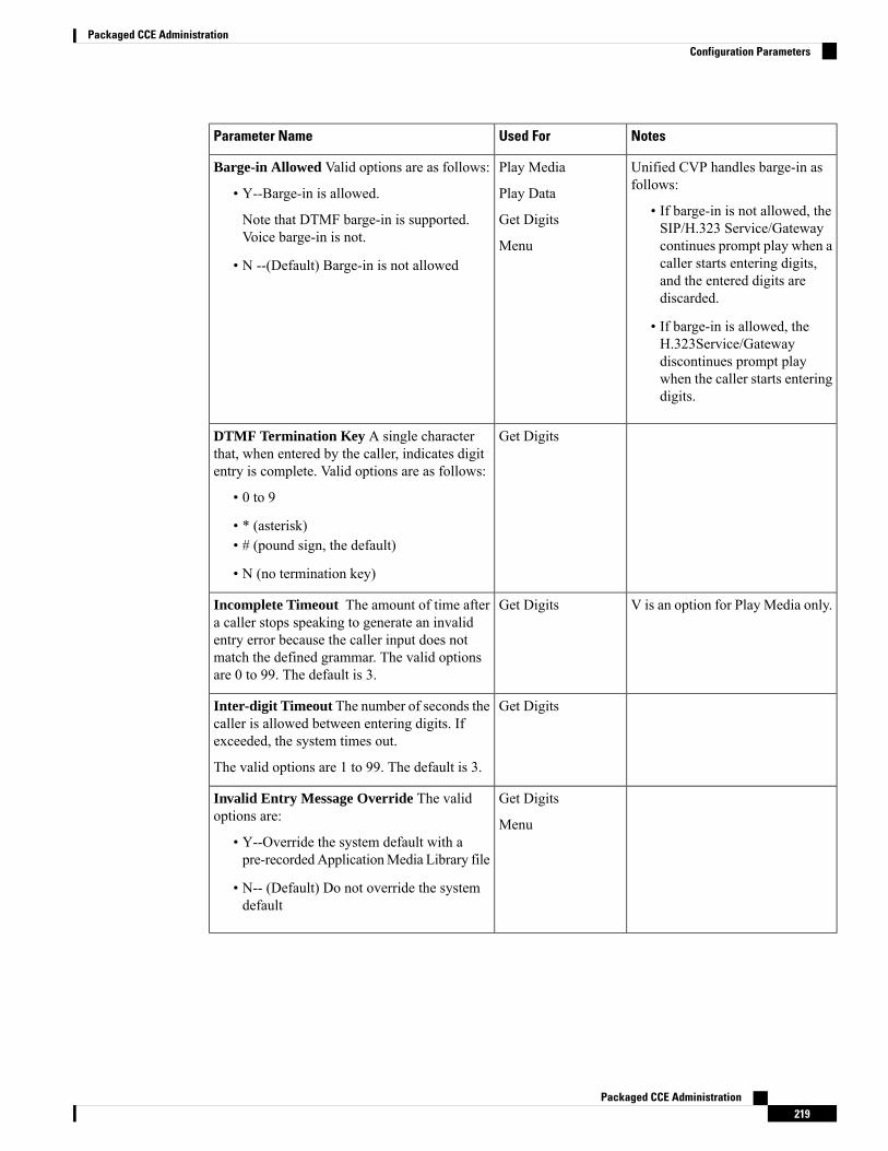
NotesUsed ForParameter Name
Unified CVP handles barge-in asfollows:
• If barge-in is not allowed, theSIP/H.323 Service/Gatewaycontinues prompt play when acaller starts entering digits,and the entered digits arediscarded.
• If barge-in is allowed, theH.323Service/Gatewaydiscontinues prompt playwhen the caller starts enteringdigits.
Play Media
Play Data
Get Digits
Menu
Barge-in Allowed Valid options are as follows:
• Y--Barge-in is allowed.
Note that DTMF barge-in is supported.Voice barge-in is not.
• N --(Default) Barge-in is not allowed
Get DigitsDTMF Termination Key A single characterthat, when entered by the caller, indicates digitentry is complete. Valid options are as follows:
• 0 to 9
• * (asterisk)• # (pound sign, the default)
• N (no termination key)
V is an option for Play Media only.Get DigitsIncomplete Timeout The amount of time aftera caller stops speaking to generate an invalidentry error because the caller input does notmatch the defined grammar. The valid optionsare 0 to 99. The default is 3.
Get DigitsInter-digit Timeout The number of seconds thecaller is allowed between entering digits. Ifexceeded, the system times out.
The valid options are 1 to 99. The default is 3.
Get Digits
Menu
Invalid Entry Message Override The validoptions are:
• Y--Override the system default with apre-recordedApplicationMedia Library file
• N-- (Default) Do not override the systemdefault
Packaged CCE Administration219
Packaged CCE AdministrationConfiguration Parameters
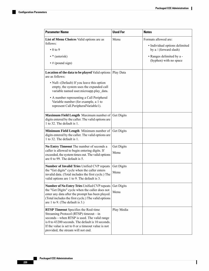
NotesUsed ForParameter Name
Formats allowed are:
• Individual options delimitedby a / (forward slash)
• Ranges delimited by a -(hyphen) with no space
MenuList of Menu Choices Valid options are asfollows:
• 0 to 9
• * (asterisk)
• # (pound sign)
Play DataLocation of the data to be playedValid optionsare as follows:
• Null--(Default) If you leave this optionempty, the system uses the expanded callvariable named user.microapp.play_data.
• A number representing a Call PeripheralVariable number (for example, a 1 torepresent Call.PeripheralVariable1).
Get DigitsMaximum Field Length Maximum number ofdigits entered by the caller. The valid options are1 to 32. The default is 1.
Get DigitsMinimum Field Length Minimum number ofdigits entered by the caller. The valid options are1 to 32. The default is 1.
Get Digits
Menu
No Entry Timeout The number of seconds acaller is allowed to begin entering digits. Ifexceeded, the system times out. The valid optionsare 0 to 99. The default is 5.
Get Digits
Menu
Number of Invalid Tries Unified CVP repeatsthe "Get digits" cycle when the caller entersinvalid data. (Total includes the first cycle.) Thevalid options are 1 to 9. The default is 3.
Get Digits
Menu
Number of No Entry TriesUnified CVP repeatsthe "Get Digits" cycle when the caller does notenter any data after the prompt has been played.(Total includes the first cycle.) The valid optionsare 1 to 9. (The default is 3.)
Play MediaRTSP Timeout Specifies the Real-timeStreaming Protocol (RTSP) timeout—inseconds—when RTSP is used. The valid rangeis 0 to 43200 seconds. The default is 10 seconds.If the value is set to 0 or a timeout value is notprovided, the stream will not end.
Packaged CCE Administration220
Packaged CCE AdministrationConfiguration Parameters
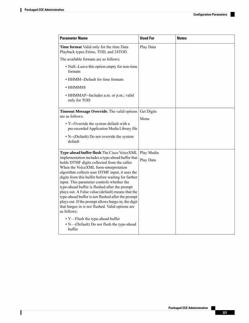
NotesUsed ForParameter Name
Play DataTime format Valid only for the time DataPlayback types Etime, TOD, and 24TOD.
The available formats are as follows:
• Null--Leave this option empty for non-timeformats
• HHMM--Default for time formats
• HHMMSS
• HHMMAP--Includes a.m. or p.m.; validonly for TOD
Get Digits
Menu
Timeout Message Override. The valid optionsare as follows:
• Y--Override the system default with apre-recordedApplicationMedia Library file
• N--(Default) Do not override the systemdefault
Play Media
Play Data
Type-ahead buffer flush The Cisco VoiceXMLimplementation includes a type-ahead buffer thatholds DTMF digits collected from the caller.When the VoiceXML form-interpretationalgorithm collects user DTMF input, it uses thedigits from this buffer before waiting for furtherinput. This parameter controls whether thetype-ahead buffer is flushed after the promptplays out. A False value (default) means that thetype-ahead buffer is not flushed after the promptplays out. If the prompt allows barge-in, the digitthat barges in is not flushed. Valid options areas follows:
• Y—Flush the type-ahead buffer• N—(Default) Do not flush the type-aheadbuffer
Packaged CCE Administration221
Packaged CCE AdministrationConfiguration Parameters
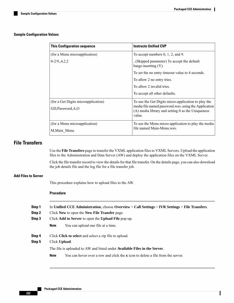
Sample Configuration Values
Instructs Unified CVPThis Configuration sequence
To accept numbers 0, 1, 2, and 9.
, (Skipped parameter) To accept the defaultbarge-insetting (Y).
To set the no entry timeout value to 4 seconds.
To allow 2 no entry tries.
To allow 2 invalid tries.
To accept all other defaults.
(for a Menu microapplication)
0-2/9,,4,2,2
To use the Get Digits micro-application to play themedia file named password.wav, using theApplication(A) media library and setting 0 as the Uniquenessvalue.
(for a Get Digits microapplication)
GD,Password,A,O
To use the Menu micro-application to play the mediafile named Main-Menu.wav.
(for a Menu microapplication)
M,Main_Menu
File TransfersUse the File Transfers page to transfer the VXML application files to VXML Servers. Upload the applicationfiles to the Administration and Data Server (AW) and deploy the application files on the VXML Server.
Click the file transfer record to view the details for that file transfer. On the details page, you can also downloadthe job details file and the log file for a file transfer job.
Add Files to Server
This procedure explains how to upload files to the AW.
Procedure
Step 1 In Unified CCE Administration, choose Overview > Call Settings > IVR Settings > File Transfers.Step 2 Click New to open the New File Transfer page.Step 3 Click Add to Server to open the Upload File pop-up.
You can upload one file at a time.Note
Step 4 Click Click to select and select a zip file to upload.Step 5 Click Upload.
The file is uploaded to AW and listed under Available Files in the Server.
You can hover over a row and click the x icon to delete a file from the server.Note
Packaged CCE Administration222
Packaged CCE AdministrationSample Configuration Values

Add and Maintain File Transfers
This procedure explains how to create a new file transfer job. For information on deleting file transfers, seeDelete Objects, on page 7.
Procedure
Step 1 In Unified CCE Administration, choose Overview > Call Settings > IVR Settings > File Transfers.Step 2 Click New to open the New File Transfer page.Step 3 Select one or more sites for the file transfer.Step 4 Enter a description for the file transfer.Step 5 On the Available Files in the Server list, select the files that you want to transfer and click Save.
This initiates the transfer of the selected files to VXML Server of the selected sites.
View Details for a File Transfer
On the IVR Settings page > File Transfers tab, click the file transfer record to view the details for that filetransfer.
For details page fields' description, refer the following table:
DescriptionField
Shows one of the following status options for the filetransfer:
• Queued: Indicates that the file transfer job hasbeen queued and is processed after any filetransfer jobs submitted ahead of it are completed.When multiple file transfer jobs are submitted,they are run in the order they are created.
• Processing: Indicates that the file transfer isbeing processed.
• Succeeded: Indicates that all operations in thefile transfer were successful.
• Partially Succeeded: Indicates that someoperations were successful, and some wereunsuccessful.
• Failed: Indicates that all operations wereunsuccessful.
• Cancelled: Indicates that the file transfer job iscancelled when the preceding job is terminateddue to unrecoverable error while this job was inthe queued state.
State
Displays the description of the file transfer.Description
Packaged CCE Administration223
Packaged CCE AdministrationAdd and Maintain File Transfers
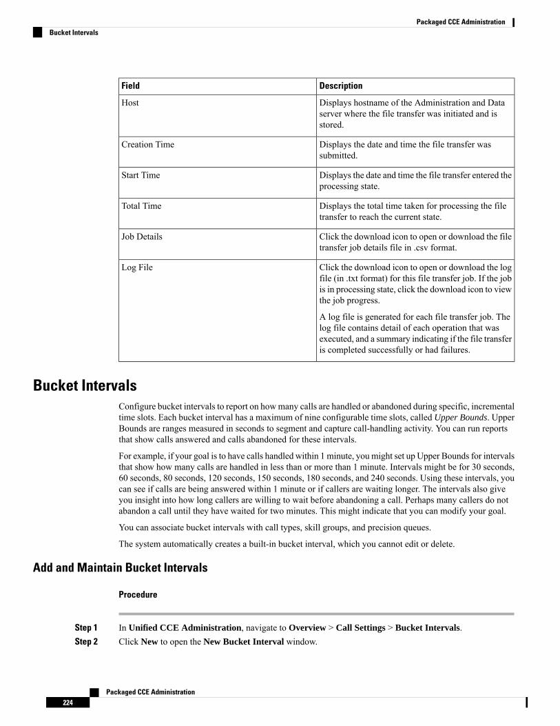
DescriptionField
Displays hostname of the Administration and Dataserver where the file transfer was initiated and isstored.
Host
Displays the date and time the file transfer wassubmitted.
Creation Time
Displays the date and time the file transfer entered theprocessing state.
Start Time
Displays the total time taken for processing the filetransfer to reach the current state.
Total Time
Click the download icon to open or download the filetransfer job details file in .csv format.
Job Details
Click the download icon to open or download the logfile (in .txt format) for this file transfer job. If the jobis in processing state, click the download icon to viewthe job progress.
A log file is generated for each file transfer job. Thelog file contains detail of each operation that wasexecuted, and a summary indicating if the file transferis completed successfully or had failures.
Log File
Bucket IntervalsConfigure bucket intervals to report on howmany calls are handled or abandoned during specific, incrementaltime slots. Each bucket interval has a maximum of nine configurable time slots, called Upper Bounds. UpperBounds are ranges measured in seconds to segment and capture call-handling activity. You can run reportsthat show calls answered and calls abandoned for these intervals.
For example, if your goal is to have calls handled within 1 minute, you might set up Upper Bounds for intervalsthat show how many calls are handled in less than or more than 1 minute. Intervals might be for 30 seconds,60 seconds, 80 seconds, 120 seconds, 150 seconds, 180 seconds, and 240 seconds. Using these intervals, youcan see if calls are being answered within 1 minute or if callers are waiting longer. The intervals also giveyou insight into how long callers are willing to wait before abandoning a call. Perhaps many callers do notabandon a call until they have waited for two minutes. This might indicate that you can modify your goal.
You can associate bucket intervals with call types, skill groups, and precision queues.
The system automatically creates a built-in bucket interval, which you cannot edit or delete.
Add and Maintain Bucket Intervals
Procedure
Step 1 In Unified CCE Administration, navigate to Overview > Call Settings > Bucket Intervals.Step 2 Click New to open the New Bucket Interval window.
Packaged CCE Administration224
Packaged CCE AdministrationBucket Intervals
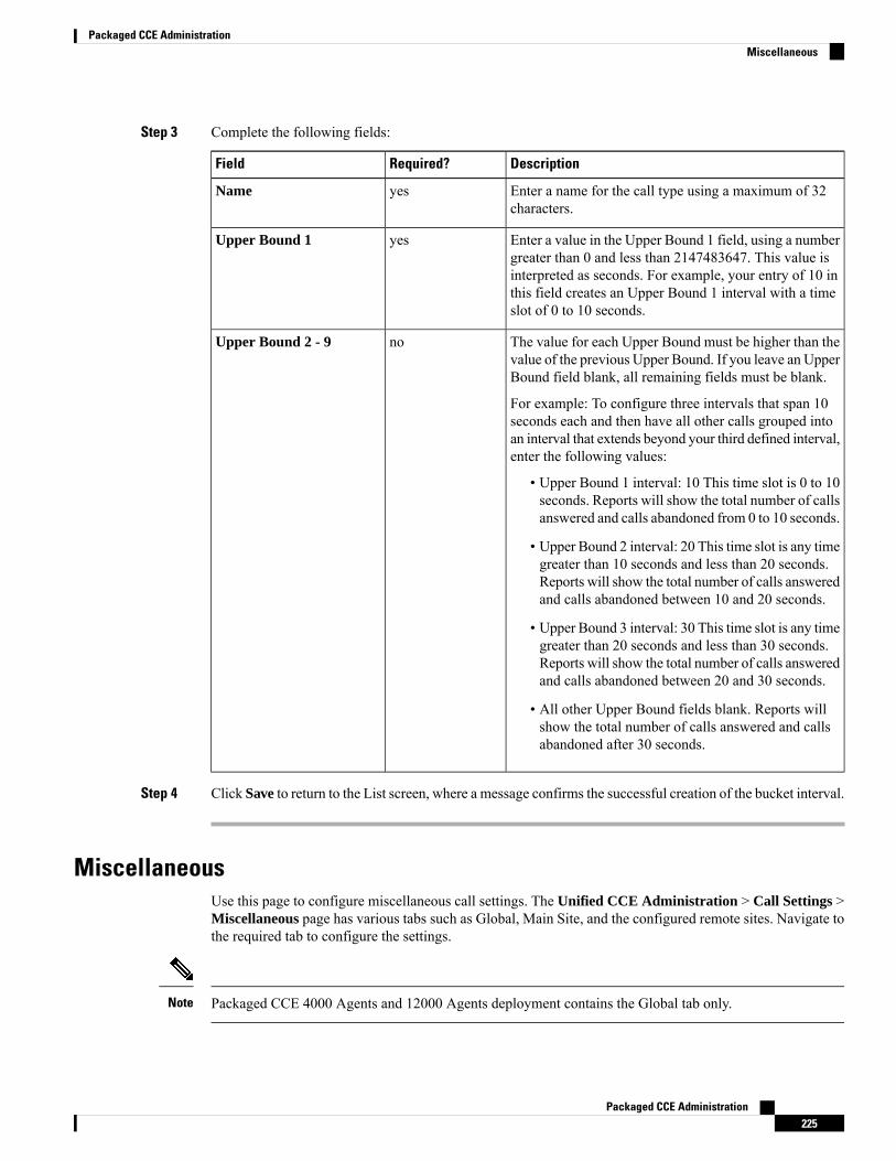
Step 3 Complete the following fields:
DescriptionRequired?Field
Enter a name for the call type using a maximum of 32characters.
yesName
Enter a value in the Upper Bound 1 field, using a numbergreater than 0 and less than 2147483647. This value isinterpreted as seconds. For example, your entry of 10 inthis field creates an Upper Bound 1 interval with a timeslot of 0 to 10 seconds.
yesUpper Bound 1
The value for each Upper Bound must be higher than thevalue of the previous Upper Bound. If you leave an UpperBound field blank, all remaining fields must be blank.
For example: To configure three intervals that span 10seconds each and then have all other calls grouped intoan interval that extends beyond your third defined interval,enter the following values:
• Upper Bound 1 interval: 10 This time slot is 0 to 10seconds. Reports will show the total number of callsanswered and calls abandoned from 0 to 10 seconds.
• Upper Bound 2 interval: 20 This time slot is any timegreater than 10 seconds and less than 20 seconds.Reports will show the total number of calls answeredand calls abandoned between 10 and 20 seconds.
• Upper Bound 3 interval: 30 This time slot is any timegreater than 20 seconds and less than 30 seconds.Reports will show the total number of calls answeredand calls abandoned between 20 and 30 seconds.
• All other Upper Bound fields blank. Reports willshow the total number of calls answered and callsabandoned after 30 seconds.
noUpper Bound 2 - 9
Step 4 Click Save to return to the List screen, where a message confirms the successful creation of the bucket interval.
MiscellaneousUse this page to configure miscellaneous call settings. The Unified CCE Administration > Call Settings >Miscellaneous page has various tabs such as Global, Main Site, and the configured remote sites. Navigate tothe required tab to configure the settings.
Packaged CCE 4000 Agents and 12000 Agents deployment contains the Global tab only.Note
Packaged CCE Administration225
Packaged CCE AdministrationMiscellaneous
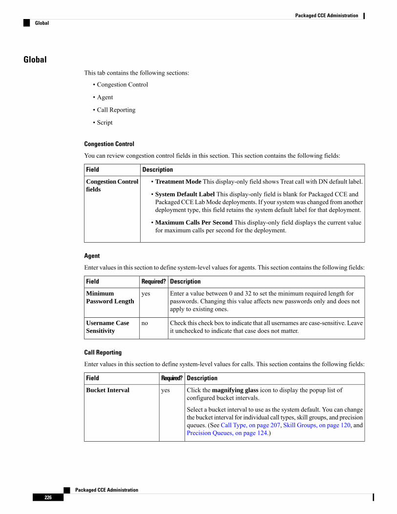
GlobalThis tab contains the following sections:
• Congestion Control
• Agent
• Call Reporting
• Script
Congestion Control
You can review congestion control fields in this section. This section contains the following fields:
DescriptionField
• Treatment Mode This display-only field shows Treat call with DN default label.
• System Default Label This display-only field is blank for Packaged CCE andPackaged CCE LabMode deployments. If your systemwas changed from anotherdeployment type, this field retains the system default label for that deployment.
• Maximum Calls Per Second This display-only field displays the current valuefor maximum calls per second for the deployment.
Congestion Controlfields
Agent
Enter values in this section to define system-level values for agents. This section contains the following fields:
DescriptionRequired?Field
Enter a value between 0 and 32 to set the minimum required length forpasswords. Changing this value affects new passwords only and does notapply to existing ones.
yesMinimumPassword Length
Check this check box to indicate that all usernames are case-sensitive. Leaveit unchecked to indicate that case does not matter.
noUsername CaseSensitivity
Call Reporting
Enter values in this section to define system-level values for calls. This section contains the following fields:
DescriptionRequired?Field
Click the magnifying glass icon to display the popup list ofconfigured bucket intervals.
Select a bucket interval to use as the system default. You can changethe bucket interval for individual call types, skill groups, and precisionqueues. (See Call Type, on page 207, Skill Groups, on page 120, andPrecision Queues, on page 124.)
yesBucket Interval
Packaged CCE Administration226
Packaged CCE AdministrationGlobal
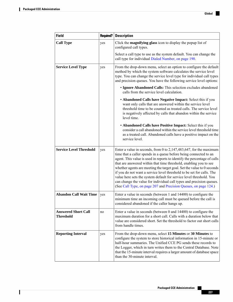
DescriptionRequired?Field
Click the magnifying glass icon to display the popup list ofconfigured call types.
Select a call type to use as the system default. You can change thecall type for individual Dialed Number, on page 190.
yesCall Type
From the drop-down menu, select an option to configure the defaultmethod by which the system software calculates the service leveltype. You can change the service level type for individual call typesand precision queues. You have the following service level options:
• Ignore Abandoned Calls: This selection excludes abandonedcalls from the service level calculation.
• Abandoned Calls have Negative Impact: Select this if youwant only calls that are answered within the service levelthreshold time to be counted as treated calls. The service levelis negatively affected by calls that abandon within the servicelevel time.
• Abandoned Calls have Positive Impact: Select this if youconsider a call abandoned within the service level threshold timeas a treated call. Abandoned calls have a positive impact on theservice level.
yesService Level Type
Enter a value in seconds, from 0 to 2,147,483,647, for the maximumtime that a caller spends in a queue before being connected to anagent. This value is used in reports to identify the percentage of callsthat are answered within that time threshold, enabling you to seewhether agents are meeting the target goal. Set the value to 0 secondsif you do not want a service level threshold to be set for calls. Thevalue here sets the system default for service level threshold. Youcan change the value for individual call types and precision queues.(See Call Type, on page 207 and Precision Queues, on page 124.)
yesService Level Threshold
Enter a value in seconds (between 1 and 14400) to configure theminimum time an incoming call must be queued before the call isconsidered abandoned if the caller hangs up.
yesAbandon Call Wait Time
Enter a value in seconds (between 0 and 14400) to configure themaximum duration for a short call. Calls with a duration below thatvalue are considered short. Set the threshold to factor out short callsfrom handle times.
noAnswered Short CallThreshold
From the drop-down menu, select 15 Minutes or 30 Minutes toconfigure the system to store historical information in 15-minute orhalf-hour summaries. The Unified CCE PG sends these records tothe Logger, which in turn writes them to the Central Database. Notethat the 15-minute interval requires a larger amount of database spacethan the 30-minute interval.
yesReporting Interval
Packaged CCE Administration227
Packaged CCE AdministrationGlobal
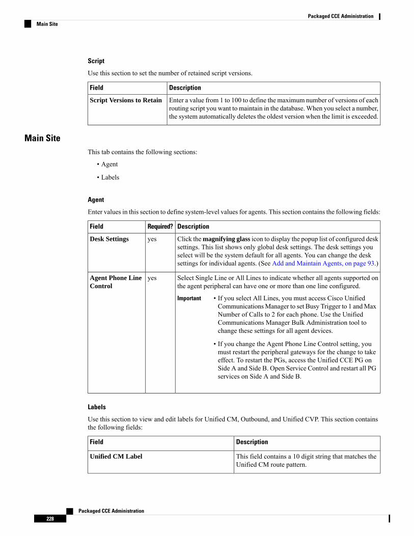
Script
Use this section to set the number of retained script versions.
DescriptionField
Enter a value from 1 to 100 to define the maximum number of versions of eachrouting script you want to maintain in the database.When you select a number,the system automatically deletes the oldest version when the limit is exceeded.
Script Versions to Retain
Main SiteThis tab contains the following sections:
• Agent
• Labels
Agent
Enter values in this section to define system-level values for agents. This section contains the following fields:
DescriptionRequired?Field
Click themagnifying glass icon to display the popup list of configured desksettings. This list shows only global desk settings. The desk settings youselect will be the system default for all agents. You can change the desksettings for individual agents. (See Add and Maintain Agents, on page 93.)
yesDesk Settings
Select Single Line or All Lines to indicate whether all agents supported onthe agent peripheral can have one or more than one line configured.
Important • If you select All Lines, you must access Cisco UnifiedCommunicationsManager to set Busy Trigger to 1 andMaxNumber of Calls to 2 for each phone. Use the UnifiedCommunications Manager Bulk Administration tool tochange these settings for all agent devices.
• If you change the Agent Phone Line Control setting, youmust restart the peripheral gateways for the change to takeeffect. To restart the PGs, access the Unified CCE PG onSide A and Side B. Open Service Control and restart all PGservices on Side A and Side B.
yesAgent Phone LineControl
Labels
Use this section to view and edit labels for Unified CM, Outbound, and Unified CVP. This section containsthe following fields:
DescriptionField
This field contains a 10 digit string that matches theUnified CM route pattern.
Unified CM Label
Packaged CCE Administration228
Packaged CCE AdministrationMain Site
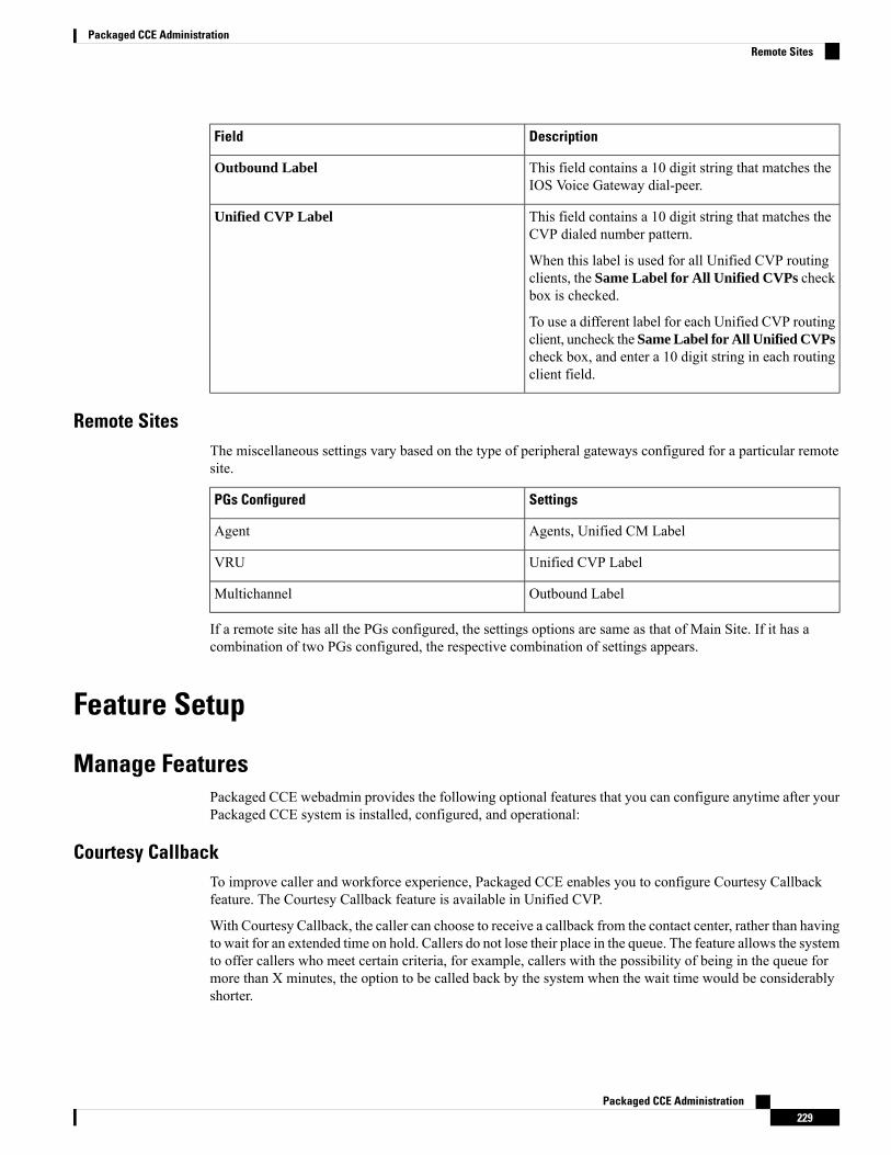
DescriptionField
This field contains a 10 digit string that matches theIOS Voice Gateway dial-peer.
Outbound Label
This field contains a 10 digit string that matches theCVP dialed number pattern.
When this label is used for all Unified CVP routingclients, the Same Label for All Unified CVPs checkbox is checked.
To use a different label for each Unified CVP routingclient, uncheck the Same Label for All Unified CVPscheck box, and enter a 10 digit string in each routingclient field.
Unified CVP Label
Remote SitesThe miscellaneous settings vary based on the type of peripheral gateways configured for a particular remotesite.
SettingsPGs Configured
Agents, Unified CM LabelAgent
Unified CVP LabelVRU
Outbound LabelMultichannel
If a remote site has all the PGs configured, the settings options are same as that of Main Site. If it has acombination of two PGs configured, the respective combination of settings appears.
Feature Setup
Manage FeaturesPackaged CCE webadmin provides the following optional features that you can configure anytime after yourPackaged CCE system is installed, configured, and operational:
Courtesy CallbackTo improve caller and workforce experience, Packaged CCE enables you to configure Courtesy Callbackfeature. The Courtesy Callback feature is available in Unified CVP.
With Courtesy Callback, the caller can choose to receive a callback from the contact center, rather than havingto wait for an extended time on hold. Callers do not lose their place in the queue. The feature allows the systemto offer callers who meet certain criteria, for example, callers with the possibility of being in the queue formore than X minutes, the option to be called back by the system when the wait time would be considerablyshorter.
Packaged CCE Administration229
Packaged CCE AdministrationRemote Sites
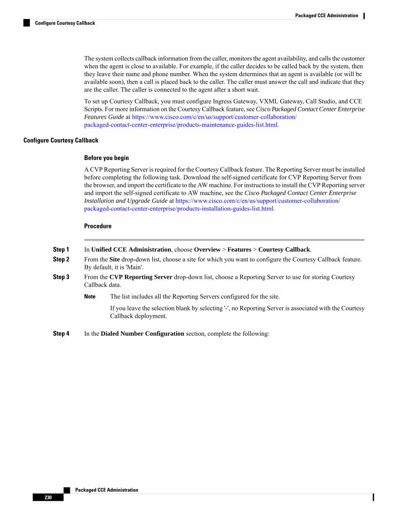
The system collects callback information from the caller, monitors the agent availability, and calls the customerwhen the agent is close to available. For example, if the caller decides to be called back by the system, thenthey leave their name and phone number. When the system determines that an agent is available (or will beavailable soon), then a call is placed back to the caller. The caller must answer the call and indicate that theyare the caller. The caller is connected to the agent after a short wait.
To set up Courtesy Callback, you must configure Ingress Gateway, VXML Gateway, Call Studio, and CCEScripts. For more information on the Courtesy Callback feature, seeCisco Packaged Contact Center EnterpriseFeatures Guide at https://www.cisco.com/c/en/us/support/customer-collaboration/packaged-contact-center-enterprise/products-maintenance-guides-list.html.
Configure Courtesy Callback
Before you begin
ACVPReporting Server is required for the Courtesy Callback feature. The Reporting Server must be installedbefore completing the following task. Download the self-signed certificate for CVP Reporting Server fromthe browser, and import the certificate to the AWmachine. For instructions to install the CVPReporting serverand import the self-signed certificate to AW machine, see the Cisco Packaged Contact Center EnterpriseInstallation and Upgrade Guide at https://www.cisco.com/c/en/us/support/customer-collaboration/packaged-contact-center-enterprise/products-installation-guides-list.html.
Procedure
Step 1 In Unified CCE Administration, choose Overview > Features > Courtesy Callback.Step 2 From the Site drop-down list, choose a site for which you want to configure the Courtesy Callback feature.
By default, it is 'Main'.Step 3 From the CVP Reporting Server drop-down list, choose a Reporting Server to use for storing Courtesy
Callback data.
The list includes all the Reporting Servers configured for the site.
If you leave the selection blank by selecting '-', no Reporting Server is associated with the CourtesyCallback deployment.
Note
Step 4 In the Dialed Number Configuration section, complete the following:
Packaged CCE Administration230
Packaged CCE AdministrationConfigure Courtesy Callback
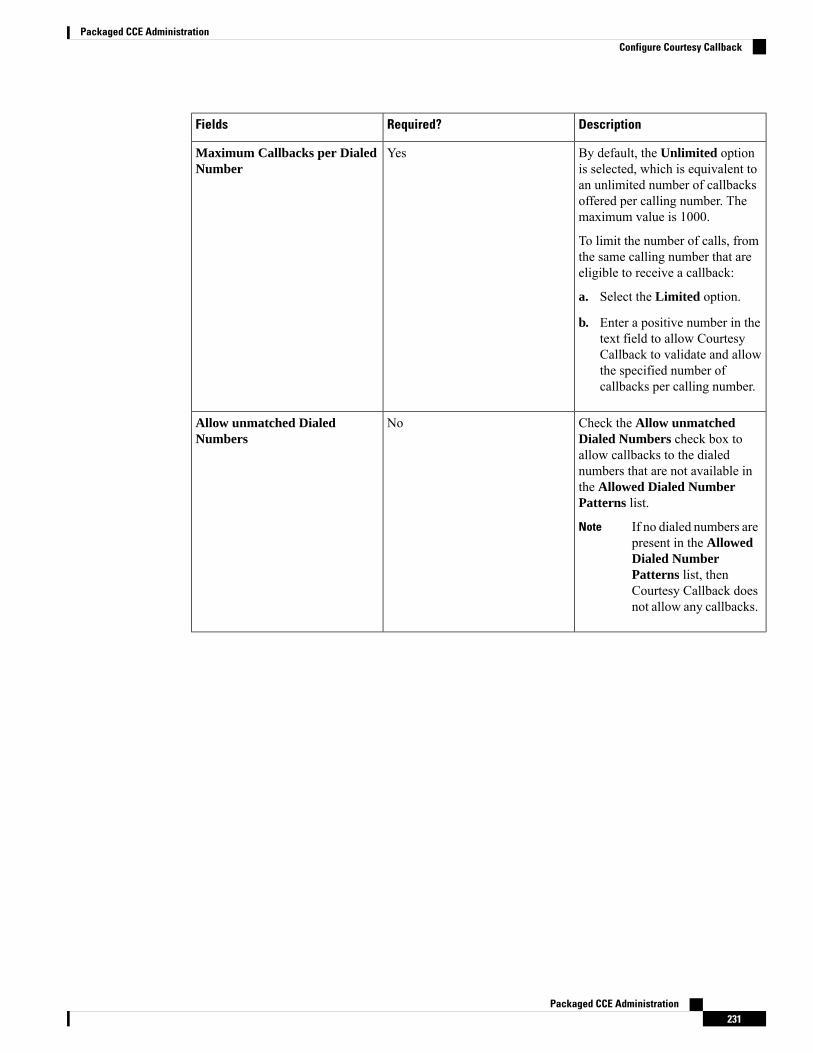
DescriptionRequired?Fields
By default, the Unlimited optionis selected, which is equivalent toan unlimited number of callbacksoffered per calling number. Themaximum value is 1000.
To limit the number of calls, fromthe same calling number that areeligible to receive a callback:
a. Select the Limited option.
b. Enter a positive number in thetext field to allow CourtesyCallback to validate and allowthe specified number ofcallbacks per calling number.
YesMaximum Callbacks per DialedNumber
Check the Allow unmatchedDialed Numbers check box toallow callbacks to the dialednumbers that are not available inthe Allowed Dialed NumberPatterns list.
If no dialed numbers arepresent in the AllowedDialed NumberPatterns list, thenCourtesy Callback doesnot allow any callbacks.
Note
NoAllow unmatched DialedNumbers
Packaged CCE Administration231
Packaged CCE AdministrationConfigure Courtesy Callback
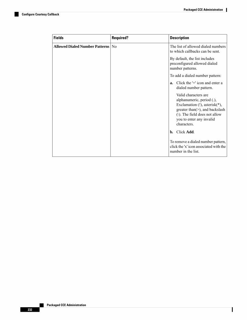
DescriptionRequired?Fields
The list of allowed dialed numbersto which callbacks can be sent.
By default, the list includespreconfigured allowed dialednumber patterns.
To add a dialed number pattern:
a. Click the '+' icon and enter adialed number pattern.
Valid characters arealphanumeric, period (.),Exclamation (!), asterisk(*),greater than(>), and backslash(\). The field does not allowyou to enter any invalidcharacters.
b. Click Add.
To remove a dialed number pattern,click the 'x' icon associated with thenumber in the list.
NoAllowed Dialed Number Patterns
Packaged CCE Administration232
Packaged CCE AdministrationConfigure Courtesy Callback

DescriptionRequired?Fields
NoDenied Dialed Number Patterns
Packaged CCE Administration233
Packaged CCE AdministrationConfigure Courtesy Callback
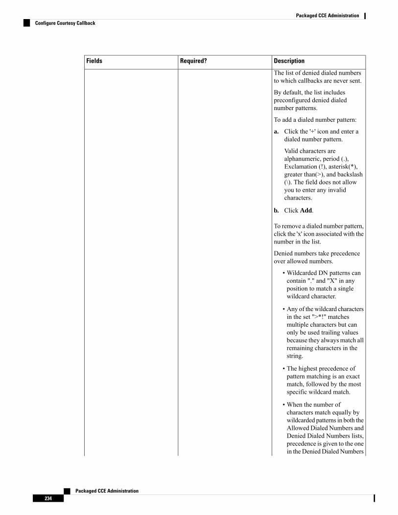
DescriptionRequired?Fields
The list of denied dialed numbersto which callbacks are never sent.
By default, the list includespreconfigured denied dialednumber patterns.
To add a dialed number pattern:
a. Click the '+' icon and enter adialed number pattern.
Valid characters arealphanumeric, period (.),Exclamation (!), asterisk(*),greater than(>), and backslash(\). The field does not allowyou to enter any invalidcharacters.
b. Click Add.
To remove a dialed number pattern,click the 'x' icon associated with thenumber in the list.
Denied numbers take precedenceover allowed numbers.
• Wildcarded DN patterns cancontain "." and "X" in anyposition to match a singlewildcard character.
• Any of the wildcard charactersin the set ">*!" matchesmultiple characters but canonly be used trailing valuesbecause they alwaysmatch allremaining characters in thestring.
• The highest precedence ofpattern matching is an exactmatch, followed by the mostspecific wildcard match.
• When the number ofcharacters match equally bywildcarded patterns in both theAllowed Dialed Numbers andDenied Dialed Numbers lists,precedence is given to the onein the Denied Dialed Numbers
Packaged CCE Administration234
Packaged CCE AdministrationConfigure Courtesy Callback

DescriptionRequired?Fields
list.
Step 5 Click Save.
Single Sign-OnSingle sign-on (SSO) is an authentication and authorization process. (Authentication proves that you are theuser you say that you are, and authorization verifies that you are allowed to do what you want to do.) SSOallows you to sign in to one application and then securely access other authorized applications without aprompt to resupply user credentials. SSO permits Cisco supervisors or agents to sign on only once with ausername and password. Supervisors and agents gain access to all of their Cisco browser-based applicationsand services within a single browser instance. By using SSO, Cisco administrators can manage all users froma common user directory and enforce password policies for all users consistently.
SSO is an optional feature. If you are using SSO, use the Single Sign-On tool to configure the Cisco IdentityService (IdS). You can then register and test components with the Cisco IdS, and set the SSO mode oncomponents.
For complete instructions on setting up SSO in your deployment, see one of the following:
• Cisco Unified Contact Center Enterprise Features Guide at https://www.cisco.com/c/en/us/support/customer-collaboration/unified-contact-center-enterprise/products-feature-guides-list.html
• Cisco Packaged Contact Center Enterprise Features Guide at https://www.cisco.com/c/en/us/support/customer-collaboration/packaged-contact-center-enterprise/products-maintenance-guides-list.html
• Installing and Configuring Guide for Cisco HCS for CC at https://www.cisco.com/c/en/us/support/unified-communications/hosted-collaboration-solution-contact-center/products-installation-guides-list.html
Third-party Integration
Third-party gadgets can be added or modified only from a principal AW machine.Note
Third-party integration enables you to add user interfaces of third-party components your Contact Centeremploys in to Unified CCE Administration. You can add custom gadgets such as an agent reskilling gadgetor third-party pages such as a browser-based CRM tool. Integrate the user-interfaces and administer multiplethird-party components from Unified CCE Administration.
This feature also allows you to personalize the layout of Unified CCE Administration.
The system-defined cards in the layout have been placed in the order in which an administrator would typicallyuse them. Menus with common or similar functionalities are grouped in a single card or menu. (For example,the User Setup card contains menus that allow you to manage agents, administrators, and assign permissionsto user roles.)
You can add the third-party user interface to system-defined menu or card with a common or similarfunctionality. If the functionality does not match, add the third-party user interface to a user-defined menu or
Packaged CCE Administration235
Packaged CCE AdministrationSingle Sign-On
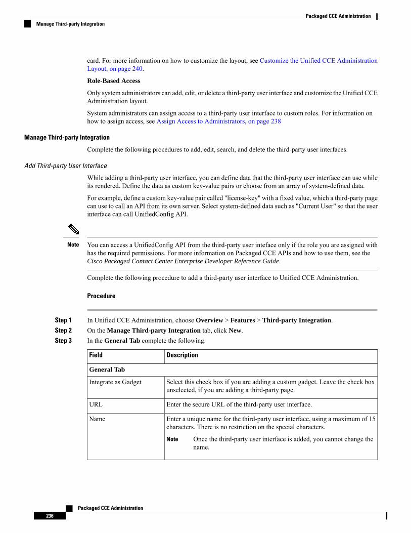
card. For more information on how to customize the layout, see Customize the Unified CCE AdministrationLayout, on page 240.
Role-Based Access
Only system administrators can add, edit, or delete a third-party user interface and customize the Unified CCEAdministration layout.
System administrators can assign access to a third-party user interface to custom roles. For information onhow to assign access, see Assign Access to Administrators, on page 238
Manage Third-party Integration
Complete the following procedures to add, edit, search, and delete the third-party user interfaces.
Add Third-party User Interface
While adding a third-party user interface, you can define data that the third-party user interface can use whileits rendered. Define the data as custom key-value pairs or choose from an array of system-defined data.
For example, define a custom key-value pair called "license-key" with a fixed value, which a third-party pagecan use to call an API from its own server. Select system-defined data such as "Current User" so that the userinterface can call UnifiedConfig API.
You can access a UnifiedConfig API from the third-party user inteface only if the role you are assigned withhas the required permissions. For more information on Packaged CCE APIs and how to use them, see theCisco Packaged Contact Center Enterprise Developer Reference Guide.
Note
Complete the following procedure to add a third-party user interface to Unified CCE Administration.
Procedure
Step 1 In Unified CCE Administration, choose Overview > Features > Third-party Integration.Step 2 On the Manage Third-party Integration tab, click New.Step 3 In the General Tab complete the following.
DescriptionField
General Tab
Select this check box if you are adding a custom gadget. Leave the check boxunselected, if you are adding a third-party page.
Integrate as Gadget
Enter the secure URL of the third-party user interface.URL
Enter a unique name for the third-party user interface, using a maximum of 15characters. There is no restriction on the special characters.
Once the third-party user interface is added, you cannot change thename.
Note
Name
Packaged CCE Administration236
Packaged CCE AdministrationManage Third-party Integration
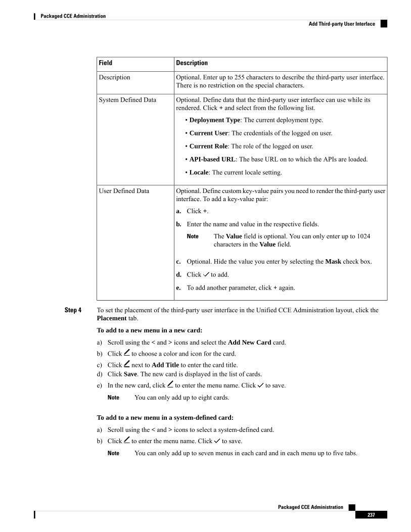
DescriptionField
Optional. Enter up to 255 characters to describe the third-party user interface.There is no restriction on the special characters.
Description
Optional. Define data that the third-party user interface can use while itsrendered. Click + and select from the following list.
• Deployment Type: The current deployment type.
• Current User: The credentials of the logged on user.
• Current Role: The role of the logged on user.
• API-based URL: The base URL on to which the APIs are loaded.
• Locale: The current locale setting.
System Defined Data
Optional. Define custom key-value pairs you need to render the third-party userinterface. To add a key-value pair:
a. Click +.
b. Enter the name and value in the respective fields.
The Value field is optional. You can only enter up to 1024characters in the Value field.
Note
c. Optional. Hide the value you enter by selecting the Mask check box.
d. Click to add.
e. To add another parameter, click + again.
User Defined Data
Step 4 To set the placement of the third-party user interface in the Unified CCE Administration layout, click thePlacement tab.
To add to a new menu in a new card:
a) Scroll using the < and > icons and select the Add New Card card.
b) Click to choose a color and icon for the card.
c) Click next to Add Title to enter the card title.d) Click Save. The new card is displayed in the list of cards.
e) In the new card, click to enter the menu name. Click to save.
You can only add up to eight cards.Note
To add to a new menu in a system-defined card:
a) Scroll using the < and > icons to select a system-defined card.
b) Click to enter the menu name. Click to save.
You can only add up to seven menus in each card and in each menu up to five tabs.Note
Packaged CCE Administration237
Packaged CCE AdministrationAdd Third-party User Interface
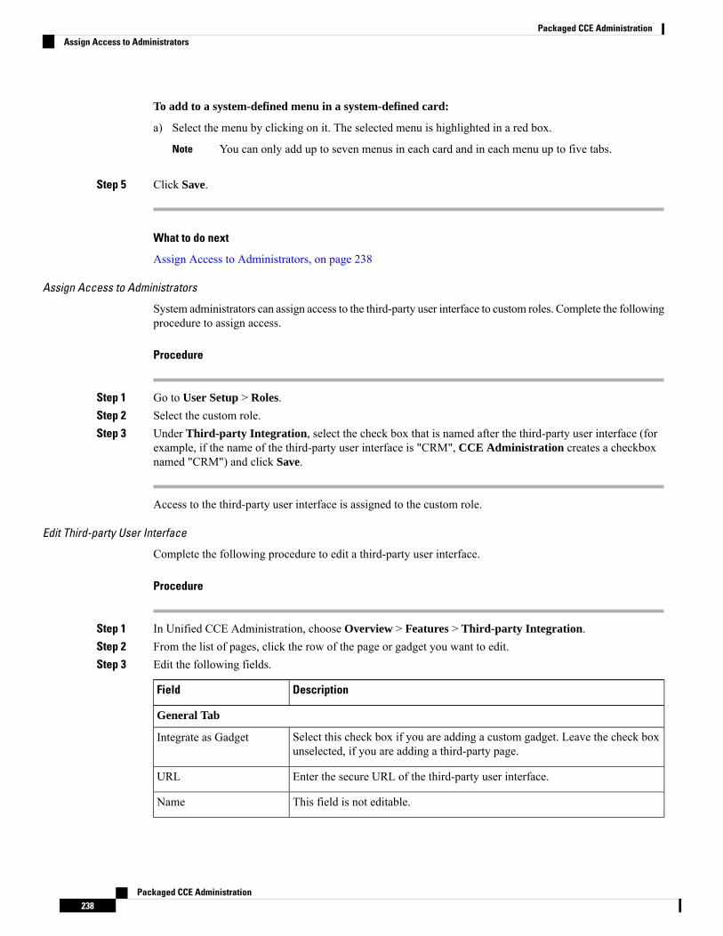
To add to a system-defined menu in a system-defined card:
a) Select the menu by clicking on it. The selected menu is highlighted in a red box.
You can only add up to seven menus in each card and in each menu up to five tabs.Note
Step 5 Click Save.
What to do next
Assign Access to Administrators, on page 238
Assign Access to Administrators
System administrators can assign access to the third-party user interface to custom roles. Complete the followingprocedure to assign access.
Procedure
Step 1 Go to User Setup > Roles.Step 2 Select the custom role.Step 3 Under Third-party Integration, select the check box that is named after the third-party user interface (for
example, if the name of the third-party user interface is "CRM", CCE Administration creates a checkboxnamed "CRM") and click Save.
Access to the third-party user interface is assigned to the custom role.
Edit Third-party User Interface
Complete the following procedure to edit a third-party user interface.
Procedure
Step 1 In Unified CCE Administration, choose Overview > Features > Third-party Integration.Step 2 From the list of pages, click the row of the page or gadget you want to edit.Step 3 Edit the following fields.
DescriptionField
General Tab
Select this check box if you are adding a custom gadget. Leave the check boxunselected, if you are adding a third-party page.
Integrate as Gadget
Enter the secure URL of the third-party user interface.URL
This field is not editable.Name
Packaged CCE Administration238
Packaged CCE AdministrationAssign Access to Administrators
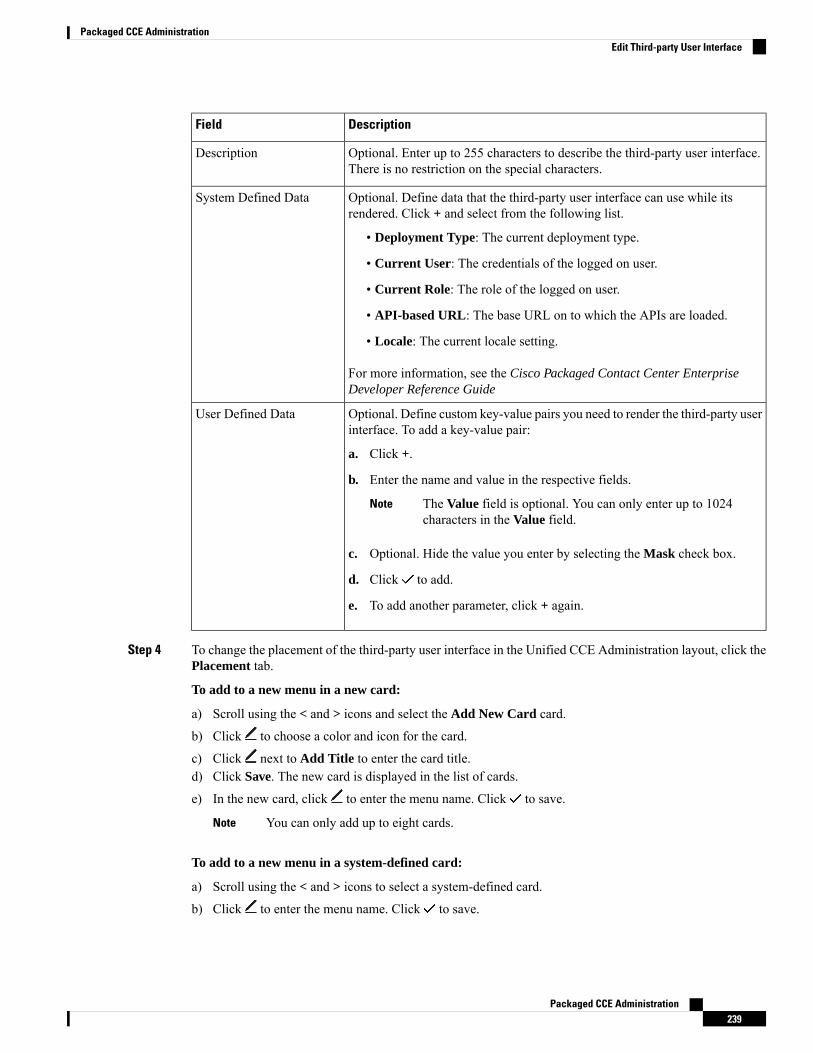
DescriptionField
Optional. Enter up to 255 characters to describe the third-party user interface.There is no restriction on the special characters.
Description
Optional. Define data that the third-party user interface can use while itsrendered. Click + and select from the following list.
• Deployment Type: The current deployment type.
• Current User: The credentials of the logged on user.
• Current Role: The role of the logged on user.
• API-based URL: The base URL on to which the APIs are loaded.
• Locale: The current locale setting.
For more information, see the Cisco Packaged Contact Center EnterpriseDeveloper Reference Guide
System Defined Data
Optional. Define custom key-value pairs you need to render the third-party userinterface. To add a key-value pair:
a. Click +.
b. Enter the name and value in the respective fields.
The Value field is optional. You can only enter up to 1024characters in the Value field.
Note
c. Optional. Hide the value you enter by selecting the Mask check box.
d. Click to add.
e. To add another parameter, click + again.
User Defined Data
Step 4 To change the placement of the third-party user interface in the Unified CCE Administration layout, click thePlacement tab.
To add to a new menu in a new card:
a) Scroll using the < and > icons and select the Add New Card card.
b) Click to choose a color and icon for the card.
c) Click next to Add Title to enter the card title.d) Click Save. The new card is displayed in the list of cards.
e) In the new card, click to enter the menu name. Click to save.
You can only add up to eight cards.Note
To add to a new menu in a system-defined card:
a) Scroll using the < and > icons to select a system-defined card.
b) Click to enter the menu name. Click to save.
Packaged CCE Administration239
Packaged CCE AdministrationEdit Third-party User Interface
You can only add up to seven menus in each card and in each menu up to five tabs.Note
To add to a system-defined menu in a system-defined card:
a) Select the menu by clicking on it. The selected menu is highlighted in a red box.
You can only add up to seven menus in each card and in each menu up to five tabs.Note
Step 5 Click Save.
Sort and Search Third-party User Interface
Complete the following procedure to sort the list of third-party user interfaces and to search for specificuser-interfaces.
Procedure
Step 1 In Unified CCE Administration, choose Overview > Features > Third-party Integration.Step 2 On the Manage Third-party Integration tab, the Name and Description columns has an arrow icon in the
column header. Click the arrow to sort in the ascending or descending order.Step 3 To search for a user-interface, enter the name or description of the page in the text box in the far left corner.
As you type, user-interfaces that match your search term appear.
Delete Third-party User Interface
Complete the following procedure to delete a third-party user interface.
Procedure
Step 1 In Unified CCE Administration, choose Overview > Features > Third-party Integration > ManageThird-party Integration.
Step 2 Hover the mouse pointer over the row of that third-party user interface to see the x icon at the end of the row.Click the x icon and confirm your intention to delete.The third-party user interface is deleted from Packaged CCE.
Customize the Unified CCE Administration Layout
In Unified CCEAdministration, chooseOverview > Features >Third-party Integration >Manage Layout.
From the Manage Layout page you can:
• Add a third-party user interface to the menu you select or create.
The third-party user interface is always added as a new tab in the menu.Note
Packaged CCE Administration240
Packaged CCE AdministrationSort and Search Third-party User Interface
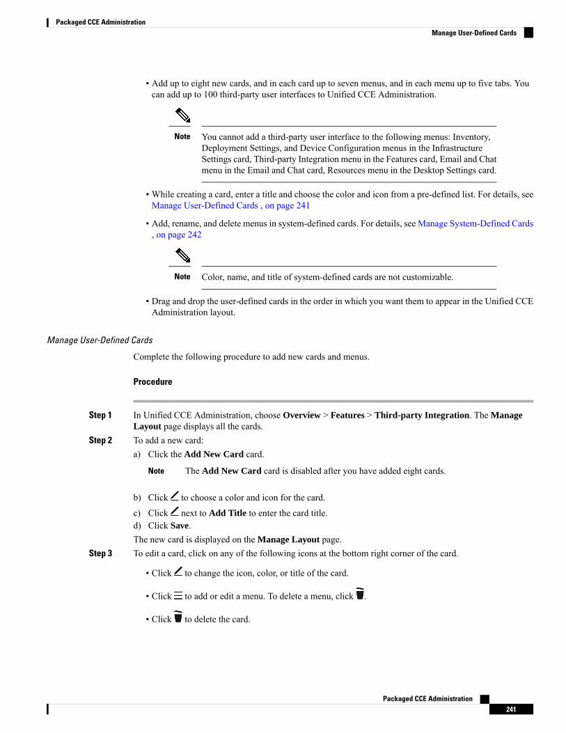
• Add up to eight new cards, and in each card up to seven menus, and in each menu up to five tabs. Youcan add up to 100 third-party user interfaces to Unified CCE Administration.
You cannot add a third-party user interface to the following menus: Inventory,Deployment Settings, and Device Configuration menus in the InfrastructureSettings card, Third-party Integration menu in the Features card, Email and Chatmenu in the Email and Chat card, Resources menu in the Desktop Settings card.
Note
• While creating a card, enter a title and choose the color and icon from a pre-defined list. For details, seeManage User-Defined Cards , on page 241
• Add, rename, and delete menus in system-defined cards. For details, see Manage System-Defined Cards, on page 242
Color, name, and title of system-defined cards are not customizable.Note
• Drag and drop the user-defined cards in the order in which you want them to appear in the Unified CCEAdministration layout.
Manage User-Defined Cards
Complete the following procedure to add new cards and menus.
Procedure
Step 1 In Unified CCE Administration, choose Overview > Features > Third-party Integration. The ManageLayout page displays all the cards.
Step 2 To add a new card:a) Click the Add New Card card.
The Add New Card card is disabled after you have added eight cards.Note
b) Click to choose a color and icon for the card.
c) Click next to Add Title to enter the card title.d) Click Save.The new card is displayed on the Manage Layout page.
Step 3 To edit a card, click on any of the following icons at the bottom right corner of the card.
• Click to change the icon, color, or title of the card.
• Click to add or edit a menu. To delete a menu, click .
• Click to delete the card.
Packaged CCE Administration241
Packaged CCE AdministrationManage User-Defined Cards
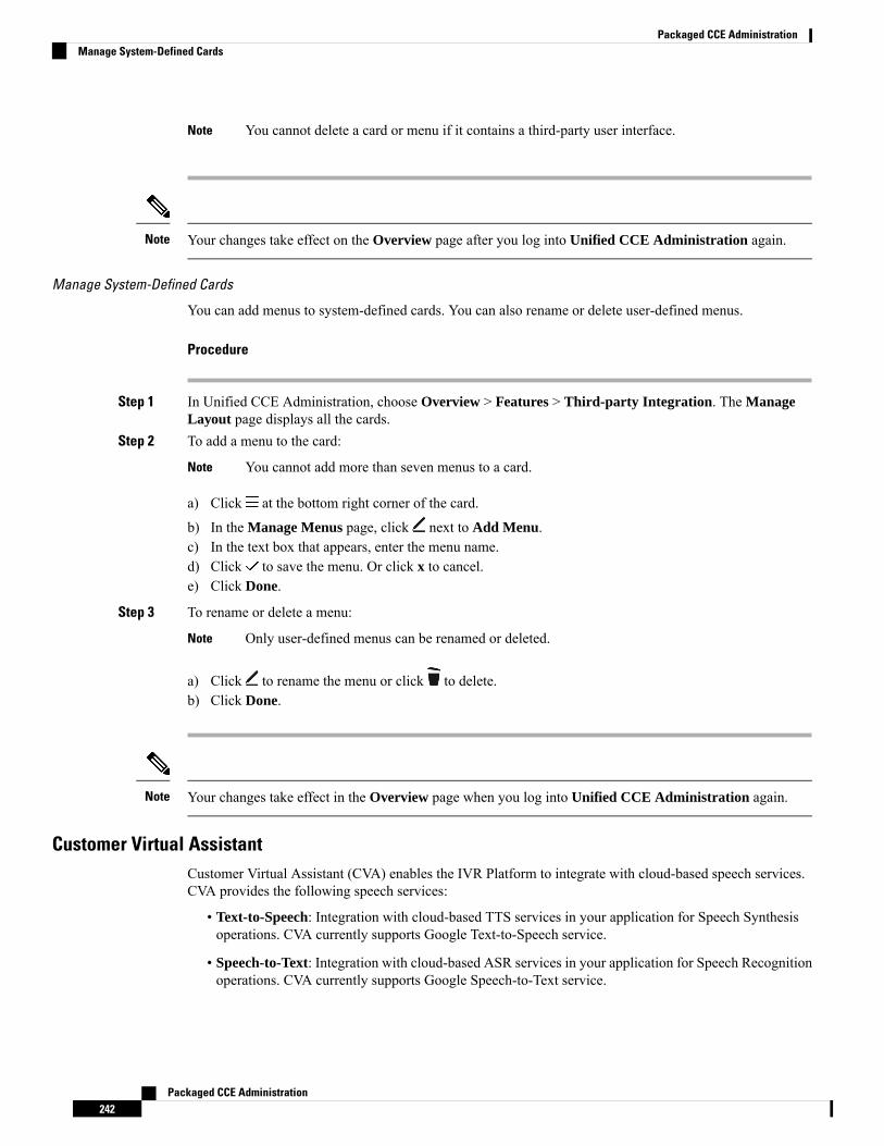
You cannot delete a card or menu if it contains a third-party user interface.Note
Your changes take effect on the Overview page after you log into Unified CCE Administration again.Note
Manage System-Defined Cards
You can add menus to system-defined cards. You can also rename or delete user-defined menus.
Procedure
Step 1 In Unified CCE Administration, choose Overview > Features > Third-party Integration. The ManageLayout page displays all the cards.
Step 2 To add a menu to the card:
You cannot add more than seven menus to a card.Note
a) Click at the bottom right corner of the card.
b) In the Manage Menus page, click next to Add Menu.c) In the text box that appears, enter the menu name.d) Click to save the menu. Or click x to cancel.e) Click Done.
Step 3 To rename or delete a menu:
Only user-defined menus can be renamed or deleted.Note
a) Click to rename the menu or click to delete.b) Click Done.
Your changes take effect in the Overview page when you log into Unified CCE Administration again.Note
Customer Virtual AssistantCustomer Virtual Assistant (CVA) enables the IVR Platform to integrate with cloud-based speech services.CVA provides the following speech services:
• Text-to-Speech: Integration with cloud-based TTS services in your application for Speech Synthesisoperations. CVA currently supports Google Text-to-Speech service.
• Speech-to-Text: Integration with cloud-based ASR services in your application for Speech Recognitionoperations. CVA currently supports Google Speech-to-Text service.
Packaged CCE Administration242
Packaged CCE AdministrationManage System-Defined Cards
• Speech-to-Intent: CVA provides capability of identifying the intent of customer utterances by processingthe text received from Speech-to-Text operations. CVA offers this service by using cloud-based NaturalLanguage Understanding (NLU) services. CVA currently supports Google Dialogflow service.
You can configure and manage speech services using the Unified CCE Administration > Overview >Features > Customer Virtual Assistant > page.
This page contains the following tabs to configure speech services:
• Text to Speech: Go to this tab to configure TTS service accounts.
• Automatic Speech Recognition: Go to this tab to configure ASR service accounts.
• Natural Language Understanding: Go to this tab to configure NLU service accounts.
Text to Speech
Text to Speech (TTS) tab enables you to view, add, edit, or delete TTS service accounts.
Related TopicsCustomer Virtual Assistant
Add and Maintain Text to Speech Account
This procedure explains how to add a text to speech account. For more information on maintaining serviceaccounts, see Edit Text to Speech Service Account, on page 243 and Delete Service Account, on page 246.
Procedure
Step 1 Click the Text to Speech tab.Step 2 Click New to open the New Text to Speech Account pop-up.Step 3 Complete the fields.
For more information, see Field Details for Text to Speech Service Provider, on page 246.
Step 4 Click Next to continue.Step 5 Complete the fields that are displayed based on the selected service provider.Step 6 Click Save.
Edit Text to Speech Service Account
This procedure explains how to edit configuration details for a Text to Speech account.
Any change in configuration takes effect after 5 minutes.Note
Procedure
Step 1 Click the Text to Speech tab.
Packaged CCE Administration243
Packaged CCE AdministrationText to Speech
Step 2 Click the service account for which you want to edit the configuration.
The Edit section opens for the selected service account.
Step 3 Edit the required fields.
For more information, see Field Details for Text to Speech Service Provider, on page 246.
Step 4 Click Save.
Automatic Speech Recognition
Automatic Speech Recognition (ASR) tab enables you to view, add, edit, or delete ASR service accounts.
Related TopicsCustomer Virtual Assistant
Add and Maintain Automatic Speech Recognition Account
This procedure explains how to add an Automatic Speech Recognition account. For more information onmaintaining service accounts, see Edit Automatic Speech Recognition Service Account, on page 244 andDelete Service Account, on page 246.
Procedure
Step 1 Click the Automatic Speech Recognition tab.Step 2 Click New to open the New Automatic Speech Recognition pop-up.Step 3 Complete the fields.
For more information, see Field Details for Automatic Speech Recognition Service Provider, on page 247.
Step 4 Click Next to continue.Step 5 Complete the fields that are displayed based on the selected service provider.Step 6 Click Save.
Edit Automatic Speech Recognition Service Account
This procedure explains how to edit configuration details for an Automatic Speech Recognition account.
Any change in configuration takes effect after 5 minutes.Note
Procedure
Step 1 Click the Automatic Speech Recognition tab.Step 2 Click the service account for which you want to edit the configuration.
The Edit section opens for the selected service account.
Packaged CCE Administration244
Packaged CCE AdministrationAutomatic Speech Recognition
Step 3 Edit the required fields.
For more information, see Field Details for Automatic Speech Recognition Service Provider, on page 247.
Step 4 Click Save.
Natural Language Understanding
Natural Language Understanding (NLU) tab enables you to view, add, edit, or delete NLU service accounts.
Related TopicsCustomer Virtual Assistant
Add and Maintain Natural Language Understanding Account
This procedure explains how to add a Natural Language Understanding (NLU) account. For more informationonmaintaining service accounts, see Edit Natural Language Understanding Service Account, on page 245 andDelete Service Account, on page 246.
Procedure
Step 1 Click the Natural Language Understanding tab.Step 2 Click New to open the New Natural Language Understanding pop-up.Step 3 Complete the fields.
For more information, see Field Details for Natural Language Understanding Service Provider, on page 248.
Step 4 Click Next to continue.Step 5 Complete the fields that are displayed based on the selected service provider.Step 6 Click Save.
Edit Natural Language Understanding Service Account
This procedure explains how to edit configuration details for a Natural Language Understanding account.
Any change in configuration takes effect after 5 minutes.Note
Procedure
Step 1 Click the Natural Language Understanding tab.Step 2 Click the service account for which you want to edit the configuration.
The Edit section opens for the selected service account.
Step 3 Edit the required fields.
For more information, see Field Details for Natural Language Understanding Service Provider, on page 248.
Packaged CCE Administration245
Packaged CCE AdministrationNatural Language Understanding
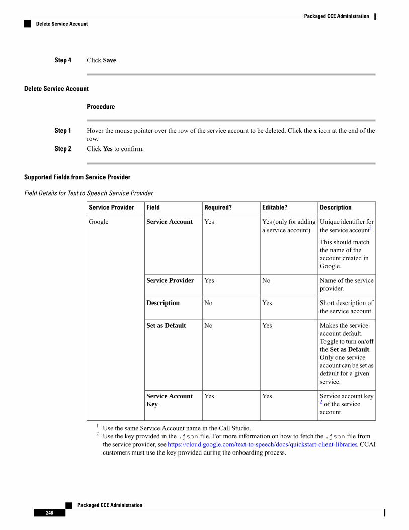
Step 4 Click Save.
Delete Service Account
Procedure
Step 1 Hover the mouse pointer over the row of the service account to be deleted. Click the x icon at the end of therow.
Step 2 Click Yes to confirm.
Supported Fields from Service Provider
Field Details for Text to Speech Service Provider
DescriptionEditable?Required?FieldService Provider
Unique identifier forthe service account1.
This should matchthe name of theaccount created inGoogle.
Yes (only for addinga service account)
YesService AccountGoogle
Name of the serviceprovider.
NoYesService Provider
Short description ofthe service account.
YesNoDescription
Makes the serviceaccount default.Toggle to turn on/offthe Set as Default.Only one serviceaccount can be set asdefault for a givenservice.
YesNoSet as Default
Service account key2 of the serviceaccount.
YesYesService AccountKey
1 Use the same Service Account name in the Call Studio.2 Use the key provided in the .json file. For more information on how to fetch the .json file fromthe service provider, see https://cloud.google.com/text-to-speech/docs/quickstart-client-libraries. CCAIcustomers must use the key provided during the onboarding process.
Packaged CCE Administration246
Packaged CCE AdministrationDelete Service Account
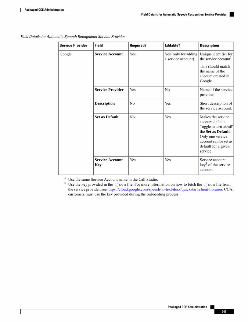
Field Details for Automatic Speech Recognition Service Provider
DescriptionEditable?Required?FieldService Provider
Unique identifier forthe service account3.
This should matchthe name of theaccount created inGoogle.
Yes (only for addinga service account)
YesService AccountGoogle
Name of the serviceprovider.
NoYesService Provider
Short description ofthe service account.
YesNoDescription
Makes the serviceaccount default.Toggle to turn on/offthe Set as Default.Only one serviceaccount can be set asdefault for a givenservice.
YesNoSet as Default
Service accountkey4 of the serviceaccount.
YesYesService AccountKey
3 Use the same Service Account name in the Call Studio.4 Use the key provided in the .json file. For more information on how to fetch the .json file fromthe service provider, see https://cloud.google.com/speech-to-text/docs/quickstart-client-libraries. CCAIcustomers must use the key provided during the onboarding process.
Packaged CCE Administration247
Packaged CCE AdministrationField Details for Automatic Speech Recognition Service Provider
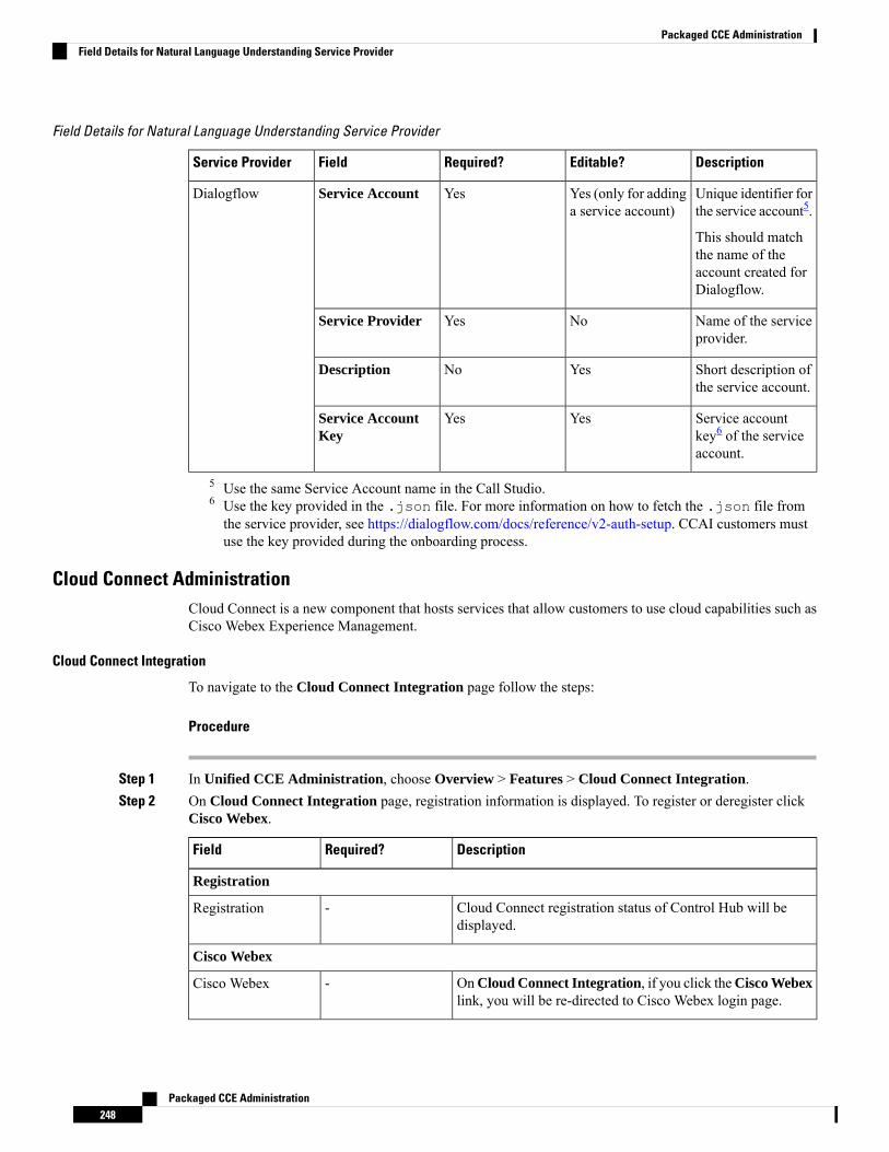
Field Details for Natural Language Understanding Service Provider
DescriptionEditable?Required?FieldService Provider
Unique identifier forthe service account5.
This should matchthe name of theaccount created forDialogflow.
Yes (only for addinga service account)
YesService AccountDialogflow
Name of the serviceprovider.
NoYesService Provider
Short description ofthe service account.
YesNoDescription
Service accountkey6 of the serviceaccount.
YesYesService AccountKey
5 Use the same Service Account name in the Call Studio.6 Use the key provided in the .json file. For more information on how to fetch the .json file fromthe service provider, see https://dialogflow.com/docs/reference/v2-auth-setup. CCAI customers mustuse the key provided during the onboarding process.
Cloud Connect AdministrationCloud Connect is a new component that hosts services that allow customers to use cloud capabilities such asCisco Webex Experience Management.
Cloud Connect Integration
To navigate to the Cloud Connect Integration page follow the steps:
Procedure
Step 1 In Unified CCE Administration, choose Overview > Features > Cloud Connect Integration.Step 2 On Cloud Connect Integration page, registration information is displayed. To register or deregister click
Cisco Webex.
DescriptionRequired?Field
Registration
Cloud Connect registration status of Control Hub will bedisplayed.
-Registration
Cisco Webex
OnCloud Connect Integration, if you click theCisco Webexlink, you will be re-directed to Cisco Webex login page.
-Cisco Webex
Packaged CCE Administration248
Packaged CCE AdministrationField Details for Natural Language Understanding Service Provider
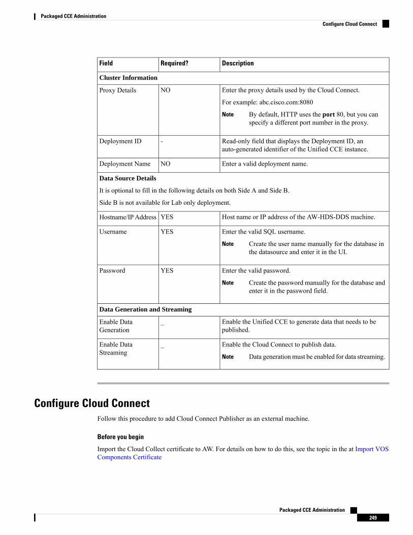
DescriptionRequired?Field
Cluster Information
Enter the proxy details used by the Cloud Connect.
For example: abc.cisco.com:8080
By default, HTTP uses the port 80, but you canspecify a different port number in the proxy.
Note
NOProxy Details
Read-only field that displays the Deployment ID, anauto-generated identifier of the Unified CCE instance.
-Deployment ID
Enter a valid deployment name.NODeployment Name
Data Source Details
It is optional to fill in the following details on both Side A and Side B.
Side B is not available for Lab only deployment.
Host name or IP address of the AW-HDS-DDS machine.YESHostname/IPAddress
Enter the valid SQL username.
Create the user name manually for the database inthe datasource and enter it in the UI.
Note
YESUsername
Enter the valid password.
Create the password manually for the database andenter it in the password field.
Note
YESPassword
Data Generation and Streaming
Enable the Unified CCE to generate data that needs to bepublished.
_Enable DataGeneration
Enable the Cloud Connect to publish data.
Data generationmust be enabled for data streaming.Note
_Enable DataStreaming
Configure Cloud ConnectFollow this procedure to add Cloud Connect Publisher as an external machine.
Before you begin
Import the Cloud Collect certificate to AW. For details on how to do this, see the topic in the at Import VOSComponents Certificate
Packaged CCE Administration249
Packaged CCE AdministrationConfigure Cloud Connect
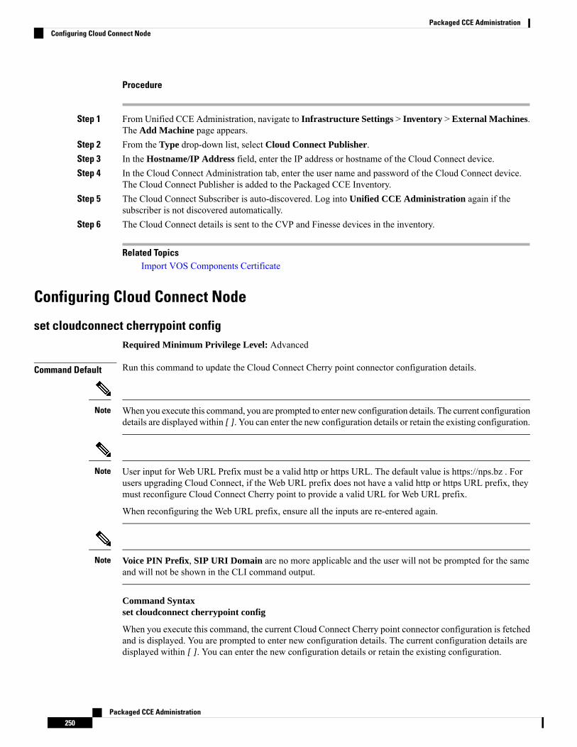
Procedure
Step 1 From Unified CCE Administration, navigate to Infrastructure Settings > Inventory > External Machines.The Add Machine page appears.
Step 2 From the Type drop-down list, select Cloud Connect Publisher.Step 3 In the Hostname/IP Address field, enter the IP address or hostname of the Cloud Connect device.Step 4 In the Cloud Connect Administration tab, enter the user name and password of the Cloud Connect device.
The Cloud Connect Publisher is added to the Packaged CCE Inventory.Step 5 The Cloud Connect Subscriber is auto-discovered. Log into Unified CCE Administration again if the
subscriber is not discovered automatically.Step 6 The Cloud Connect details is sent to the CVP and Finesse devices in the inventory.
Related TopicsImport VOS Components Certificate
Configuring Cloud Connect Node
set cloudconnect cherrypoint configRequired Minimum Privilege Level: Advanced
Command Default Run this command to update the Cloud Connect Cherry point connector configuration details.
When you execute this command, you are prompted to enter new configuration details. The current configurationdetails are displayed within [ ]. You can enter the new configuration details or retain the existing configuration.
Note
User input for Web URL Prefix must be a valid http or https URL. The default value is https://nps.bz . Forusers upgrading Cloud Connect, if the Web URL prefix does not have a valid http or https URL prefix, theymust reconfigure Cloud Connect Cherry point to provide a valid URL for Web URL prefix.
When reconfiguring the Web URL prefix, ensure all the inputs are re-entered again.
Note
Voice PIN Prefix, SIP URI Domain are no more applicable and the user will not be prompted for the sameand will not be shown in the CLI command output.
Note
Command Syntaxset cloudconnect cherrypoint config
When you execute this command, the current Cloud Connect Cherry point connector configuration is fetchedand is displayed. You are prompted to enter new configuration details. The current configuration details aredisplayed within [ ]. You can enter the new configuration details or retain the existing configuration.
Packaged CCE Administration250
Packaged CCE AdministrationConfiguring Cloud Connect Node
Example:admin:set cloudconnect cherrypoint configFetching existing configuration...Enter the Config details to be saved:Desktop User (with Read Only Privileges): readonlyusernameDesktop User API Key []: apikey-ABCD1234EFGH5789!dummySystem User (with Read and Write Privileges): reawriteusernameSystem User API Key []: apikey-JKMLN012345OPQRST6789!dummyWeb URL Prefix: https://nps.bzDeployment ID: CCE_Deployment_Bangalore_SiteProxy Enabled(true/false) [false]: trueProxy Host: proxyhost.domain.comProxy Port [0]: 5678The config details updated successfully.
Email and Chat
Email and ChatEnterprise Chat and Email (ECE) is an optional feature that provides email and chat functionality to the contactcenter. To configure ECE from Unified CCE Administration, you need to add ECE Web Server into theInventory page as an external machine. For more information, see Add External Machines.
In Unified CCE Administration, choose Overview > Email and Chat to configure the email and chatfunctionality.
Configuration Tasks
Configure Email and Chat
Bulk Imports
Manage Bulk JobsBulk jobs are a fast and efficient way to enter data at initial setup and to incorporate large-scale changes, suchas changing agent skill groups between shifts and incorporating a new contact center with multiple new agents.
Changes to an individual record are made directly to that record, using the appropriate tool (Agent, DialedNumber, and so on).
Although bulk job content files create records explicitly, they also implicitly create related records, as follows:
• An agent bulk job content file contains cells for agent team, skill groups, and attributes. Entering contentin those cells creates those objects if they do not exist.
• A dialed number bulk job content file contains cells for call type. Entering content in those cells createsthose objects if they do not exist.
Packaged CCE Administration251
Packaged CCE AdministrationEmail and Chat
• Run bulk jobs:
• Only during off-peak hours. Do not run bulk jobs during heavy call load.
• Only when the Sync Status is In Sync for all the devices.
Important
Supervisors have no access to the Bulk Jobs tool.
Download Bulk Job Content File TemplateBulk jobs apply changes entered in content file templates. Content file templates are in .csv format.
The content file is syntactically validated before the bulk job is created. Database-related errors and conflictsare reported during execution of the job.
If you are using the Packaged CCE Lab deployment, you can download the Inventory content file. Use thisfile to enable the System Inventory and certain features, by providing machine information and credentials.
Note
Procedure
Step 1 Navigate to Unified CCE Administration > Overview > Bulk Import to open the List of Bulk Jobs page.Step 2 Click Templates.
The Download Templates popup window opens.
Step 3 Click the Download icon for the template you want to use.Step 4 Click OK to close the Download Templates popup window.Step 5 Open the template in Microsoft Excel.Step 6 Populate the file.Step 7 Save the populated file locally.
Related TopicsInventory Content File
Content File Rules
The rules in this section do not apply to the SSO Migration content file.
For more information about using the SSO Migration content file, see the Cisco Packaged Contact CenterEnterprise Features Guide at https://www.cisco.com/c/en/us/support/customer-collaboration/packaged-contact-center-enterprise/products-maintenance-guides-list.html.
Note
Packaged CCE Administration252
Packaged CCE AdministrationDownload Bulk Job Content File Template
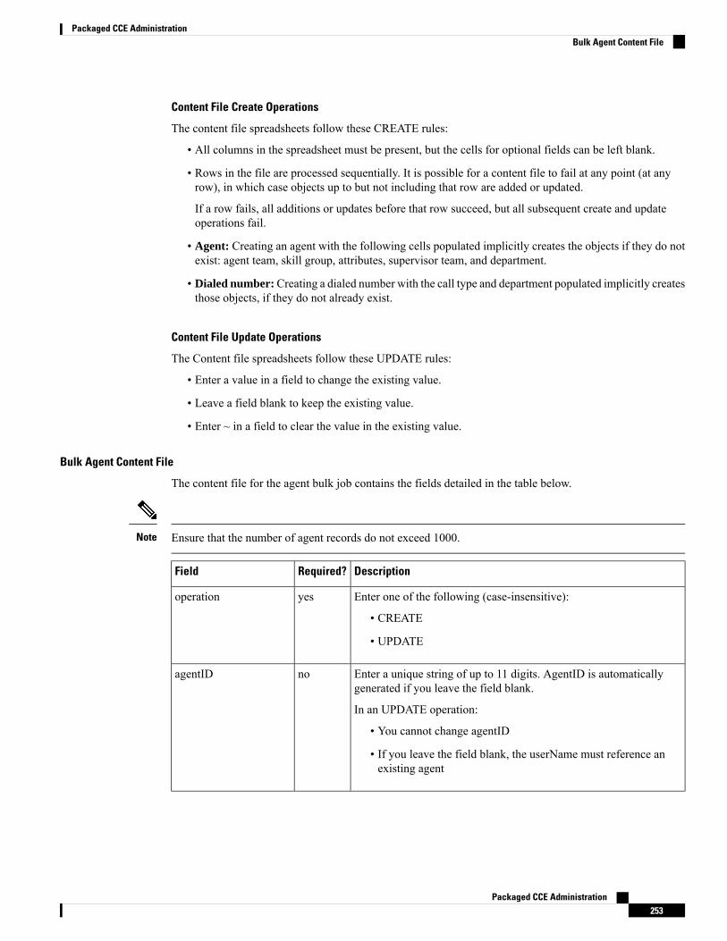
Content File Create Operations
The content file spreadsheets follow these CREATE rules:
• All columns in the spreadsheet must be present, but the cells for optional fields can be left blank.
• Rows in the file are processed sequentially. It is possible for a content file to fail at any point (at anyrow), in which case objects up to but not including that row are added or updated.
If a row fails, all additions or updates before that row succeed, but all subsequent create and updateoperations fail.
• Agent: Creating an agent with the following cells populated implicitly creates the objects if they do notexist: agent team, skill group, attributes, supervisor team, and department.
• Dialed number:Creating a dialed number with the call type and department populated implicitly createsthose objects, if they do not already exist.
Content File Update Operations
The Content file spreadsheets follow these UPDATE rules:
• Enter a value in a field to change the existing value.
• Leave a field blank to keep the existing value.
• Enter ~ in a field to clear the value in the existing value.
Bulk Agent Content File
The content file for the agent bulk job contains the fields detailed in the table below.
Ensure that the number of agent records do not exceed 1000.Note
DescriptionRequired?Field
Enter one of the following (case-insensitive):
• CREATE
• UPDATE
yesoperation
Enter a unique string of up to 11 digits. AgentID is automaticallygenerated if you leave the field blank.
In an UPDATE operation:
• You cannot change agentID
• If you leave the field blank, the userName must reference anexisting agent
noagentID
Packaged CCE Administration253
Packaged CCE AdministrationBulk Agent Content File
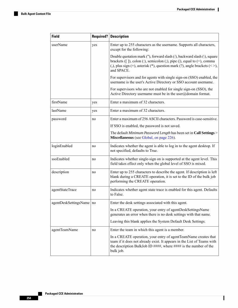
DescriptionRequired?Field
Enter up to 255 characters as the username. Supports all characters,except for the following:
Double quotationmark ("), forward slash (/), backward slash (\), squarebrackets ([ ]), colon (:), semicolon (;), pipe (|), equal to (=), comma(,), plus sign (+), asterisk (*), question mark (?), angle brackets (< >),and SPACE.
For supervisors and for agents with single sign-on (SSO) enabled, theusername is the user's Active Directory or SSO account username.
For supervisors who are not enabled for single sign-on (SSO), theActive Directory username must be in the user@domain format.
yesuserName
Enter a maximum of 32 characters.yesfirstName
Enter a maximum of 32 characters.yeslastName
Enter a maximum of 256 ASCII characters. Password is case-sensitive.
If SSO is enabled, the password is not saved.
The defaultMinimum Password Length has been set inCall Settings >Miscellaneous (see Global, on page 226).
nopassword
Indicates whether the agent is able to log in to the agent desktop. Ifnot specified, defaults to True.
nologinEnabled
Indicates whether single-sign on is supported at the agent level. Thisfield takes effect only when the global level of SSO is mixed.
nossoEnabled
Enter up to 255 characters to describe the agent. If description is leftblank during a CREATE operation, it is set to the ID of the bulk jobperforming the CREATE operation.
nodescription
Indicates whether agent state trace is enabled for this agent. Defaultsto False.
noagentStateTrace
Enter the desk settings associated with this agent.
In a CREATE operation, your entry of agentDeskSettingsNamegenerates an error when there is no desk settings with that name.
Leaving this blank applies the System Default Desk Settings.
noagentDeskSettingsName
Enter the team in which this agent is a member.
In a CREATE operation, your entry of agentTeamName creates thatteam if it does not already exist. It appears in the List of Teams withthe description BulkJob ID ####, where #### is the number of thebulk job.
noagentTeamName
Packaged CCE Administration254
Packaged CCE AdministrationBulk Agent Content File
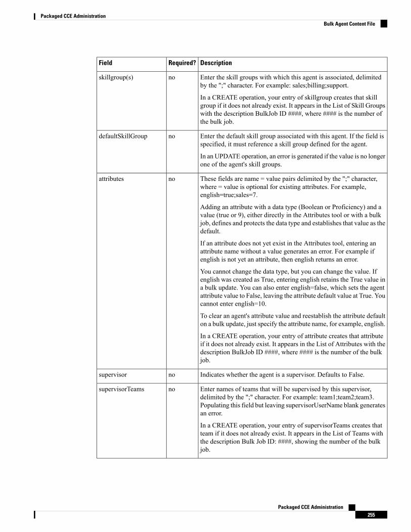
DescriptionRequired?Field
Enter the skill groups with which this agent is associated, delimitedby the ";" character. For example: sales;billing;support.
In a CREATE operation, your entry of skillgroup creates that skillgroup if it does not already exist. It appears in the List of Skill Groupswith the description BulkJob ID ####, where #### is the number ofthe bulk job.
noskillgroup(s)
Enter the default skill group associated with this agent. If the field isspecified, it must reference a skill group defined for the agent.
In an UPDATE operation, an error is generated if the value is no longerone of the agent's skill groups.
nodefaultSkillGroup
These fields are name = value pairs delimited by the ";" character,where = value is optional for existing attributes. For example,english=true;sales=7.
Adding an attribute with a data type (Boolean or Proficiency) and avalue (true or 9), either directly in the Attributes tool or with a bulkjob, defines and protects the data type and establishes that value as thedefault.
If an attribute does not yet exist in the Attributes tool, entering anattribute name without a value generates an error. For example ifenglish is not yet an attribute, then english returns an error.
You cannot change the data type, but you can change the value. Ifenglish was created as True, entering english retains the True value ina bulk update. You can also enter english=false, which sets the agentattribute value to False, leaving the attribute default value at True. Youcannot enter english=10.
To clear an agent's attribute value and reestablish the attribute defaulton a bulk update, just specify the attribute name, for example, english.
In a CREATE operation, your entry of attribute creates that attributeif it does not already exist. It appears in the List of Attributes with thedescription BulkJob ID ####, where #### is the number of the bulkjob.
noattributes
Indicates whether the agent is a supervisor. Defaults to False.nosupervisor
Enter names of teams that will be supervised by this supervisor,delimited by the ";" character. For example: team1;team2;team3.Populating this field but leaving supervisorUserName blank generatesan error.
In a CREATE operation, your entry of supervisorTeams creates thatteam if it does not already exist. It appears in the List of Teams withthe description Bulk Job ID: ####, showing the number of the bulkjob.
nosupervisorTeams
Packaged CCE Administration255
Packaged CCE AdministrationBulk Agent Content File

DescriptionRequired?Field
This field is mandatory for Packaged CCE 4000 agent and12000 agent deployments.
Note
The site name for this dialed number.
For remote sites, the value must match an existing remote site name.
For the main site, do not specify any value.
nositeName
Indicates whether the agent is a ECE enabled. Defaults to False.noecePerson
yes, ifecePersonis entered
screenName
The email address of the ECE-enabled agent. Maximum length is 50characters.
noemailAddress
This mandatory field is available only for Packaged CCE4000 agent and 12000 agent deployments.
Note
The peripheral set name for this agent.
The value must match an existing peripheral set name configured forthe site specified in the siteName column.
In an UPDATE operation, you cannot change peripheralSetName.
In a DELETE operation, you cannot delete peripheralSetName.
yesperipheralSetName
Related TopicsContent File Rules, on page 252
Bulk Dialed Number Content File for 2000 Agent Deployments
The content file for the dialed number bulk job contains these fields:
DescriptionRequired?Field
Enter one of the following (case-insensitive):
• CREATE
• UPDATE
• DELETE
yesoperation
The dialedNumberString for this dialed number.
Enter a string value that is unique for the routing type, maximumof 25 characters.
Valid values are alphanumeric, +, and @.
You cannot update dialedNumberString.Note
yesdialedNumberString
Packaged CCE Administration256
Packaged CCE AdministrationBulk Dialed Number Content File for 2000 Agent Deployments
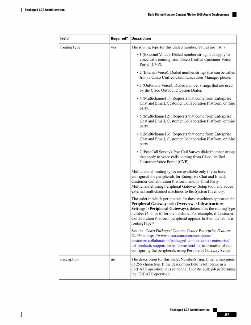
DescriptionRequired?Field
The routing type for this dialed number. Values are 1 to 7.
• 1 (External Voice): Dialed number strings that apply tovoice calls coming from Cisco Unified Customer VoicePortal (CVP).
• 2 (Internal Voice): Dialed number strings that can be calledfrom a Cisco Unified Communications Manager phone.
• 3 (Outbound Voice): Dialed number strings that are usedby the Cisco Outbound Option Dialer.
• 4 (Multichannel 1). Requests that come from EnterpriseChat and Email, Customer Collaboration Platform, or thirdparty.
• 5 (Multichannel 2). Requests that come from EnterpriseChat and Email, Customer Collaboration Platform, or thirdparty.
• 6 (Multichannel 3). Requests that come from EnterpriseChat and Email, Customer Collaboration Platform, or thirdparty.
• 7 (Post Call Survey). Post Call Survey dialed number stringsthat apply to voice calls coming from Cisco UnifiedCustomer Voice Portal (CVP).
Multichannel routing types are available only if you haveconfigured the peripherals for Enterprise Chat and Email,Customer Collaboration Platform, and/or Third PartyMultichannel using Peripheral Gateway Setup tool, and addedexternal multichannel machines to the System Inventory.
The order in which peripherals for these machines appear on thePeripheral Gateways tab (Overview > InfrastructureSettings > Peripheral Gateways), determines the routingTypenumber (4, 5, or 6) for the machine. For example, if CustomerCollaboration Platform peripheral appears first on the tab, it isroutingType 4.
See the Cisco Packaged Contact Center Enterprise FeaturesGuide at https://www.cisco.com/c/en/us/support/customer-collaboration/packaged-contact-center-enterprise/tsd-products-support-series-home.html for information aboutconfiguring the peripherals using Peripheral Gateway Setup.
yesroutingType
The description for this dialedNumberString. Enter a maximumof 255 characters. If the description field is left blank in aCREATE operation, it is set to the ID of the bulk job performingthe CREATE operation.
nodescription
Packaged CCE Administration257
Packaged CCE AdministrationBulk Dialed Number Content File for 2000 Agent Deployments
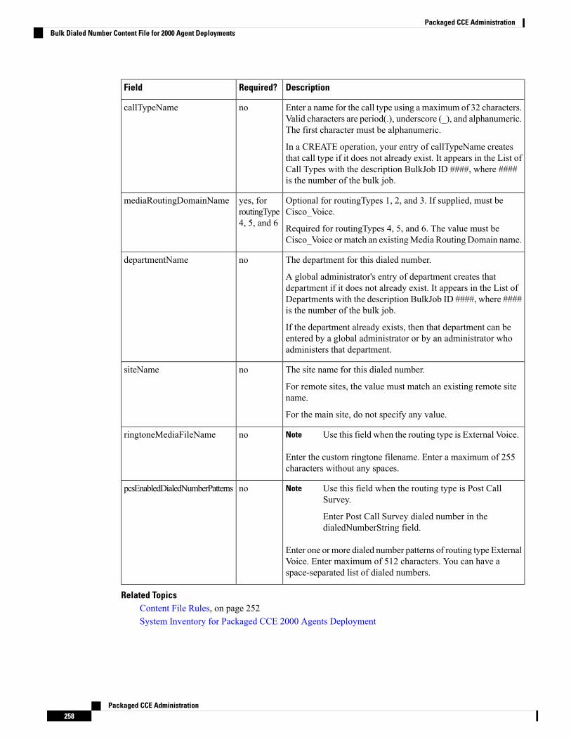
DescriptionRequired?Field
Enter a name for the call type using a maximum of 32 characters.Valid characters are period(.), underscore (_), and alphanumeric.The first character must be alphanumeric.
In a CREATE operation, your entry of callTypeName createsthat call type if it does not already exist. It appears in the List ofCall Types with the description BulkJob ID ####, where ####is the number of the bulk job.
nocallTypeName
Optional for routingTypes 1, 2, and 3. If supplied, must beCisco_Voice.
Required for routingTypes 4, 5, and 6. The value must beCisco_Voice or match an existingMedia Routing Domain name.
yes, forroutingType4, 5, and 6
mediaRoutingDomainName
The department for this dialed number.
A global administrator's entry of department creates thatdepartment if it does not already exist. It appears in the List ofDepartments with the description BulkJob ID ####, where ####is the number of the bulk job.
If the department already exists, then that department can beentered by a global administrator or by an administrator whoadministers that department.
nodepartmentName
The site name for this dialed number.
For remote sites, the value must match an existing remote sitename.
For the main site, do not specify any value.
nositeName
Use this field when the routing type is External Voice.Note
Enter the custom ringtone filename. Enter a maximum of 255characters without any spaces.
noringtoneMediaFileName
Use this field when the routing type is Post CallSurvey.
Enter Post Call Survey dialed number in thedialedNumberString field.
Note
Enter one or more dialed number patterns of routing type ExternalVoice. Enter maximum of 512 characters. You can have aspace-separated list of dialed numbers.
nopcsEnabledDialedNumberPatterns
Related TopicsContent File Rules, on page 252System Inventory for Packaged CCE 2000 Agents Deployment
Packaged CCE Administration258
Packaged CCE AdministrationBulk Dialed Number Content File for 2000 Agent Deployments

Bulk Dialed Number Content File for 4000 and 12000 Agent Deployments
The content file for the dialed number bulk job contains these fields:
DescriptionRequired?Field
Enter one of the following (case-insensitive):
• CREATE
• UPDATE
• DELETE
yesoperation
The dialedNumberString for this dialed number.
Enter a string value that is unique for the routing type, maximumof 25 characters.
Valid values are alphanumeric, +, and @.
You cannot update dialedNumberString.Note
yesdialedNumberString
Packaged CCE Administration259
Packaged CCE AdministrationBulk Dialed Number Content File for 4000 and 12000 Agent Deployments
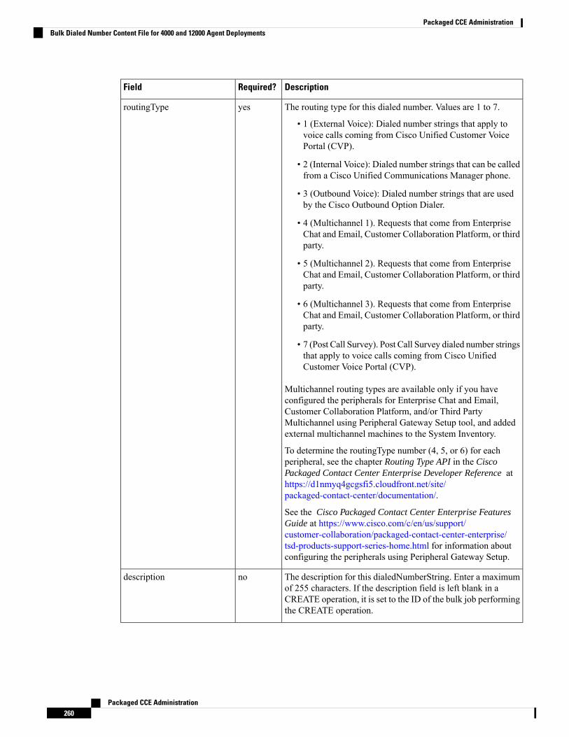
DescriptionRequired?Field
The routing type for this dialed number. Values are 1 to 7.
• 1 (External Voice): Dialed number strings that apply tovoice calls coming from Cisco Unified Customer VoicePortal (CVP).
• 2 (Internal Voice): Dialed number strings that can be calledfrom a Cisco Unified Communications Manager phone.
• 3 (Outbound Voice): Dialed number strings that are usedby the Cisco Outbound Option Dialer.
• 4 (Multichannel 1). Requests that come from EnterpriseChat and Email, Customer Collaboration Platform, or thirdparty.
• 5 (Multichannel 2). Requests that come from EnterpriseChat and Email, Customer Collaboration Platform, or thirdparty.
• 6 (Multichannel 3). Requests that come from EnterpriseChat and Email, Customer Collaboration Platform, or thirdparty.
• 7 (Post Call Survey). Post Call Survey dialed number stringsthat apply to voice calls coming from Cisco UnifiedCustomer Voice Portal (CVP).
Multichannel routing types are available only if you haveconfigured the peripherals for Enterprise Chat and Email,Customer Collaboration Platform, and/or Third PartyMultichannel using Peripheral Gateway Setup tool, and addedexternal multichannel machines to the System Inventory.
To determine the routingType number (4, 5, or 6) for eachperipheral, see the chapter Routing Type API in the CiscoPackaged Contact Center Enterprise Developer Reference athttps://d1nmyq4gcgsfi5.cloudfront.net/site/packaged-contact-center/documentation/.
See the Cisco Packaged Contact Center Enterprise FeaturesGuide at https://www.cisco.com/c/en/us/support/customer-collaboration/packaged-contact-center-enterprise/tsd-products-support-series-home.html for information aboutconfiguring the peripherals using Peripheral Gateway Setup.
yesroutingType
The description for this dialedNumberString. Enter a maximumof 255 characters. If the description field is left blank in aCREATE operation, it is set to the ID of the bulk job performingthe CREATE operation.
nodescription
Packaged CCE Administration260
Packaged CCE AdministrationBulk Dialed Number Content File for 4000 and 12000 Agent Deployments
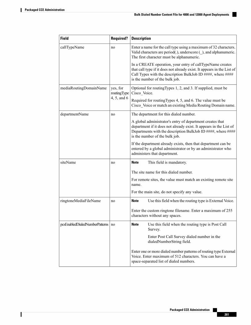
DescriptionRequired?Field
Enter a name for the call type using a maximum of 32 characters.Valid characters are period(.), underscore (_), and alphanumeric.The first character must be alphanumeric.
In a CREATE operation, your entry of callTypeName createsthat call type if it does not already exist. It appears in the List ofCall Types with the description BulkJob ID ####, where ####is the number of the bulk job.
nocallTypeName
Optional for routingTypes 1, 2, and 3. If supplied, must beCisco_Voice.
Required for routingTypes 4, 5, and 6. The value must beCisco_Voice or match an existingMedia Routing Domain name.
yes, forroutingType4, 5, and 6
mediaRoutingDomainName
The department for this dialed number.
A global administrator's entry of department creates thatdepartment if it does not already exist. It appears in the List ofDepartments with the description BulkJob ID ####, where ####is the number of the bulk job.
If the department already exists, then that department can beentered by a global administrator or by an administrator whoadministers that department.
nodepartmentName
This field is mandatory.Note
The site name for this dialed number.
For remote sites, the value must match an existing remote sitename.
For the main site, do not specify any value.
nositeName
Use this field when the routing type is External Voice.Note
Enter the custom ringtone filename. Enter a maximum of 255characters without any spaces.
noringtoneMediaFileName
Use this field when the routing type is Post CallSurvey.
Enter Post Call Survey dialed number in thedialedNumberString field.
Note
Enter one or more dialed number patterns of routing type ExternalVoice. Enter maximum of 512 characters. You can have aspace-separated list of dialed numbers.
nopcsEnabledDialedNumberPatterns
Packaged CCE Administration261
Packaged CCE AdministrationBulk Dialed Number Content File for 4000 and 12000 Agent Deployments
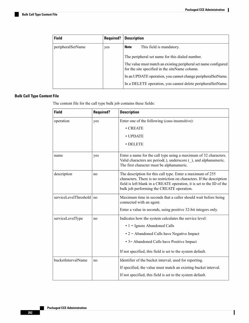
DescriptionRequired?Field
This field is mandatory.Note
The peripheral set name for this dialed number.
The value must match an existing peripheral set name configuredfor the site specified in the siteName column.
In anUPDATE operation, you cannot change peripheralSetName.
In a DELETE operation, you cannot delete peripheralSetName.
yesperipheralSetName
Bulk Call Type Content File
The content file for the call type bulk job contains these fields:
DescriptionRequired?Field
Enter one of the following (case-insensitive):
• CREATE
• UPDATE
• DELETE
yesoperation
Enter a name for the call type using a maximum of 32 characters.Valid characters are period(.), underscore (_), and alphanumeric.The first character must be alphanumeric.
yesname
The description for this call type. Enter a maximum of 255characters. There is no restriction on characters. If the descriptionfield is left blank in a CREATE operation, it is set to the ID of thebulk job performing the CREATE operation.
nodescription
Maximum time in seconds that a caller should wait before beingconnected with an agent.
Enter a value in seconds, using positive 32-bit integers only.
noserviceLevelThreshold
Indicates how the system calculates the service level:
• 1 = Ignore Abandoned Calls
• 2 = Abandoned Calls have Negative Impact
• 3= Abandoned Calls have Positive Impact
If not specified, this field is set to the system default.
noserviceLevelType
Identifier of the bucket interval, used for reporting.
If specified, the value must match an existing bucket interval.
If not specified, this field is set to the system default.
nobucketIntervalName
Packaged CCE Administration262
Packaged CCE AdministrationBulk Call Type Content File
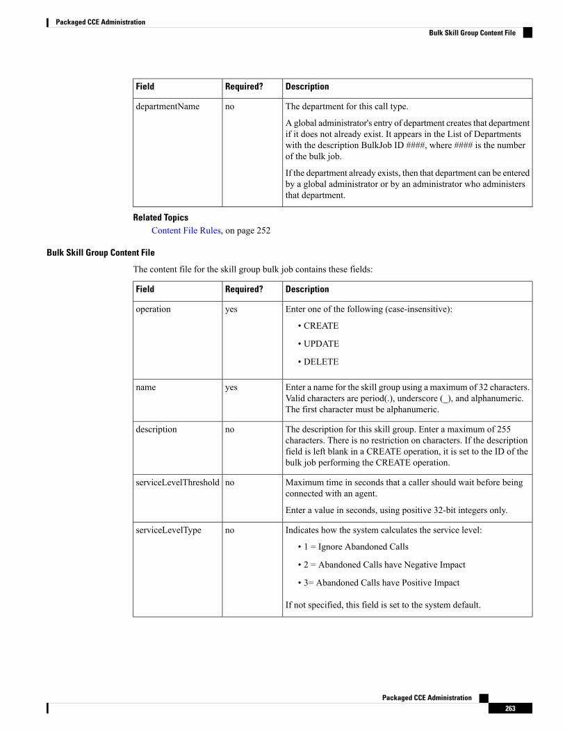
DescriptionRequired?Field
The department for this call type.
A global administrator's entry of department creates that departmentif it does not already exist. It appears in the List of Departmentswith the description BulkJob ID ####, where #### is the numberof the bulk job.
If the department already exists, then that department can be enteredby a global administrator or by an administrator who administersthat department.
nodepartmentName
Related TopicsContent File Rules, on page 252
Bulk Skill Group Content File
The content file for the skill group bulk job contains these fields:
DescriptionRequired?Field
Enter one of the following (case-insensitive):
• CREATE
• UPDATE
• DELETE
yesoperation
Enter a name for the skill group using a maximum of 32 characters.Valid characters are period(.), underscore (_), and alphanumeric.The first character must be alphanumeric.
yesname
The description for this skill group. Enter a maximum of 255characters. There is no restriction on characters. If the descriptionfield is left blank in a CREATE operation, it is set to the ID of thebulk job performing the CREATE operation.
nodescription
Maximum time in seconds that a caller should wait before beingconnected with an agent.
Enter a value in seconds, using positive 32-bit integers only.
noserviceLevelThreshold
Indicates how the system calculates the service level:
• 1 = Ignore Abandoned Calls
• 2 = Abandoned Calls have Negative Impact
• 3= Abandoned Calls have Positive Impact
If not specified, this field is set to the system default.
noserviceLevelType
Packaged CCE Administration263
Packaged CCE AdministrationBulk Skill Group Content File
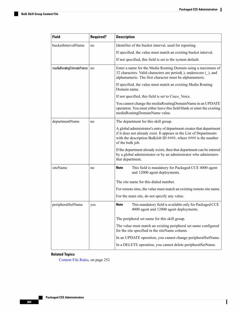
DescriptionRequired?Field
Identifier of the bucket interval, used for reporting.
If specified, the value must match an existing bucket interval.
If not specified, this field is set to the system default.
nobucketIntervalName
Enter a name for the Media Routing Domain using a maximum of32 characters. Valid characters are period(.), underscore (_), andalphanumeric. The first character must be alphanumeric.
If specified, the value must match an existing Media RoutingDomain name.
If not specified, this field is set to Cisco_Voice.
You cannot change themediaRoutingDomainName in an UPDATEoperation. Youmust either leave this field blank or enter the existingmediaRoutingDomainName value.
nomediaRoutingDomainName
The department for this skill group.
A global administrator's entry of department creates that departmentif it does not already exist. It appears in the List of Departmentswith the description BulkJob ID ####, where #### is the numberof the bulk job.
If the department already exists, then that department can be enteredby a global administrator or by an administrator who administersthat department.
nodepartmentName
This field is mandatory for Packaged CCE 4000 agentand 12000 agent deployments.
Note
The site name for this dialed number.
For remote sites, the value must match an existing remote site name.
For the main site, do not specify any value.
nositeName
This mandatory field is available only for Packaged CCE4000 agent and 12000 agent deployments.
Note
The peripheral set name for this skill group.
The value must match an existing peripheral set name configuredfor the site specified in the siteName column.
In an UPDATE operation, you cannot change peripheralSetName.
In a DELETE operation, you cannot delete peripheralSetName.
yesperipheralSetName
Related TopicsContent File Rules, on page 252
Packaged CCE Administration264
Packaged CCE AdministrationBulk Skill Group Content File

Add and Maintain Bulk Jobs
Procedure
Step 1 Navigate to the Unified CCE Administration > Overview > Bulk Import to maintain (Add, Review, andDelete) bulk jobs.
Step 2 Click New to open the New Bulk Job window.Step 3 In the optional Description fields, enter up to 255 characters to describe the bulk job. See Native Character
Sets.Step 4 In the requiredContent File field, browse to the content file you have completed for this bulk job. The content
file is validated before the bulk job is created.Step 5 Click Save.
Review Bulk Job Details
To review the details for a bulk job, click the bulk job row on the List of Bulk Jobs page. Fields on the pageare display-only.
DescriptionField
Show the ID, description entered and type of bulk jobselected when the bulk job was created.
ID, Description, and Type
Shows one of:
• Queued: The bulk job has been queued and willprocess when any jobs submitted ahead of it havecompleted. When multiple bulk jobs aresubmitted, they are run in the order they arecreated.
• Processing: The bulk job is being processed. Toview the progress, click Log File Download tomonitor the log file.
• Succeeded: All operations in the bulk job weresuccessful.
• Partially Succeeded: Some operations weresuccessful, and some were unsuccessful.
• Failed: All operations were unsuccessful.
• Cancelled: A bulk job is canceled when thepreceding bulk job is terminated due tounrecoverable error while this job was in thequeued state.
State
Packaged CCE Administration265
Packaged CCE AdministrationAdd and Maintain Bulk Jobs
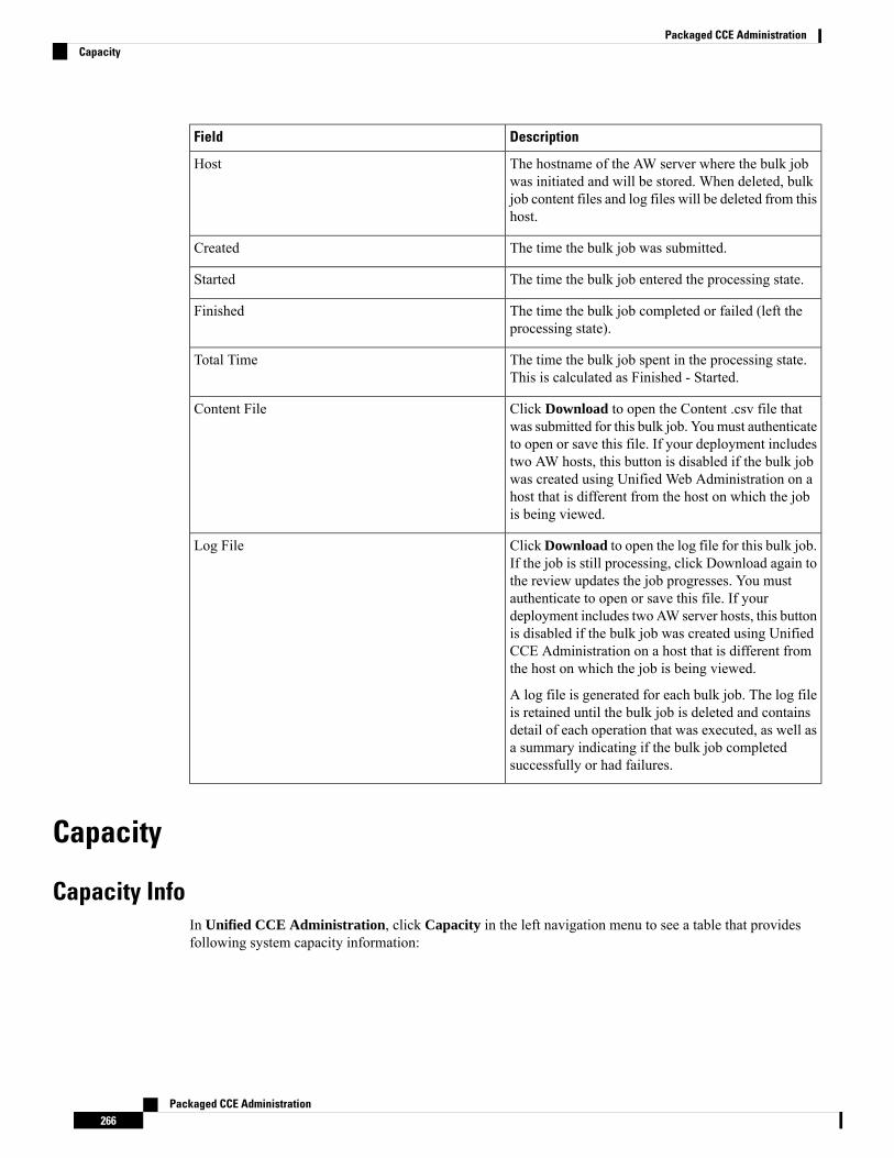
DescriptionField
The hostname of the AW server where the bulk jobwas initiated and will be stored. When deleted, bulkjob content files and log files will be deleted from thishost.
Host
The time the bulk job was submitted.Created
The time the bulk job entered the processing state.Started
The time the bulk job completed or failed (left theprocessing state).
Finished
The time the bulk job spent in the processing state.This is calculated as Finished - Started.
Total Time
Click Download to open the Content .csv file thatwas submitted for this bulk job. Youmust authenticateto open or save this file. If your deployment includestwo AW hosts, this button is disabled if the bulk jobwas created using Unified Web Administration on ahost that is different from the host on which the jobis being viewed.
Content File
ClickDownload to open the log file for this bulk job.If the job is still processing, click Download again tothe review updates the job progresses. You mustauthenticate to open or save this file. If yourdeployment includes two AW server hosts, this buttonis disabled if the bulk job was created using UnifiedCCE Administration on a host that is different fromthe host on which the job is being viewed.
A log file is generated for each bulk job. The log fileis retained until the bulk job is deleted and containsdetail of each operation that was executed, as well asa summary indicating if the bulk job completedsuccessfully or had failures.
Log File
Capacity
Capacity InfoIn Unified CCE Administration, click Capacity in the left navigation menu to see a table that providesfollowing system capacity information:
Packaged CCE Administration266
Packaged CCE AdministrationCapacity
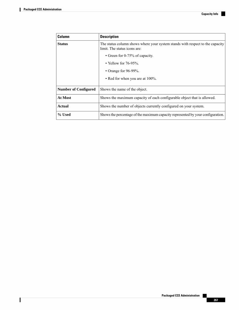
DescriptionColumn
The status column shows where your system stands with respect to the capacitylimit. The status icons are:
• Green for 0-75% of capacity.
• Yellow for 76-95%.
• Orange for 96-99%.
• Red for when you are at 100%.
Status
Shows the name of the object.Number of Configured
Shows the maximum capacity of each configurable object that is allowed.At Most
Shows the number of objects currently configured on your system.Actual
Shows the percentage of themaximum capacity represented by your configuration.% Used
Packaged CCE Administration267
Packaged CCE AdministrationCapacity Info

Packaged CCE Administration268
Packaged CCE AdministrationCapacity Info


