Embed Size (px)
Citation preview
Owner’s Manual
__________________________________________________________________________________
Issue Date: May 2016
NOTE: Carefully read, understand and follow the instructions provided in this manual, and keep it in a safe place for future reference. If you have anydoubt whatsoever regarding the use or care of your vehicle, please visit your Mahindra dealer for assistance or advice.
This Owner's Manual should be considered as an integral part of the vehicle and should remain with the vehicle.

__________________________________________________________________________________
MAHINDRA & MAHINDRA LTD., Mahindra Towers, G.M.Bhosale Marg, Worli, Mumbai- 400 018, India.

1 INTRODUCTION AND SAFETY PRECAUTIONS ........................1-1
Introduction.............................................................................1-1
Safety Symbols .......................................................................1-1
General Safety Information and Instructions ..................1-2
To Owner’s of a Mahindra Vehicle.....................................1-3
Audio/Infotainment Manual................................................1-6
2 GENERAL ..........................................................................................2-1
Dimensions..............................................................................2-1
Lubricants and Capacities ...................................................2-2
Bulb Specification .................................................................. 2-3
Fuses & Relays.......................................................................2-4
Flat Tire ................................................................................. 2-10
Technical Specifications .................................................... 2-19
Vehicle Identification Number (VIN)................................ 2-21
Engine Number ................................................................... 2-21
3 VEHICLE OVERVIEW.......................................................................3-1
Front Overview........................................................................3-1
Rear Overview.........................................................................3-2
Instrument Panel Overview .................................................3-3
4 INSTRUMENT CLUSTER OVERVIEW..........................................4-1
Instrument Cluster ................................................................4-1
Warning Lamps Overview....................................................4-2
Warning Lamps ....................................................................4-3
5 SEATS AND SEAT BELTS..............................................................5-1
Front Seats .............................................................................5-1
Head Restraint .......................................................................5-4
Second Row Seats ................................................................5-5
Third Row Seats..................................................................... 5-7
General Warnings and Instructions- Seat Belts.............5-9
Fastening the Seat Belt (3-Point type) ........................... 5-11
Fastening the Seat Belt (2-Point Lap type) ................... 5-12
Unfastening the Seat Belt (both 3-Point & 2-
Point)...................................................................................... 5-13
Seat Belt Height Adjuster ................................................. 5-13
Child Restraint System (CRS) (if equipped)................... 5-14
Child Restraint System (CRS) Using ISOFIX (if
equipped) .............................................................................. 5-15
Table of Contents
6 SUPPLEMENTAL RESTRAINT SYSTEM (SRS) (if
equipped) ..........................................................................................6-1
Airbag ....................................................................................... 6-1
Driver and Front Passenger Air Bag ................................ 6-3
Side Impact Airbag ................................................................ 6-4
Curtain Airbag ........................................................................ 6-5
Airbag System Malfunction Lamp ..................................... 6-6
Airbag Inflation/Deployment ..............................................6-6
Child Restraint and Airbag ..................................................6-9
Airbag Deployment ............................................................... 6-9
Airbag Replacement .......................................................... 6-12
Self Removing SRS Related Parts .................................. 6-12
Airbag Disposal ................................................................... 6-12
Airbag Repair....................................................................... 6-12
Airbag Maintenance........................................................... 6-12
7 LOCKS AND KEYS ..........................................................................7-1
Doors........................................................................................7-1
Central Locking System........................................................ 7-3
Child Safety Rear Door Lock ...............................................7-4
Remote Keyless Entry (RKE) System ................................7-5
Engine Immobilizer System............................................... 7-11
8 FEATURES AND CONTROL...........................................................8-1
Quadruple Switch...................................................................8-1
Mirrors.....................................................................................8-4
Sun Visor .................................................................................8-6
Utility Holders .........................................................................8-7
Horn....................................................................................... 8-16
Interior Lamps..................................................................... 8-16
Power Outlet (if equipped)................................................. 8-21
Instrument Panel Illumination .......................................... 8-23
AUX and USB Ports ........................................................... 8-23
Exterior Lamps .................................................................... 8-24
Windshield Wipers............................................................. 8-35
Electric Sunroof with Antipinch (if equipped) ................ 8-39
Instrument Cluster ............................................................. 8-44
Warning/Telltale Lamps in the Instrument
Cluster................................................................................... 8-49
Radio Frequency ID (RFID) Tag (if equipped) ................ 8-56
Table of Contents
9 STEERING AND BRAKES...............................................................9-1
Steering....................................................................................9-1
Steering Controls - Audio (if equipped) .............................9-3
Brakes ......................................................................................9-4
Hazard on Panic Braking .....................................................9-5
Anti-Lock Brake System (ABS) (if equipped) ....................9-6
Electronic Brake Force Distribution (EBD) (if
equipped) .................................................................................9-7
Hydraulic Brake Assist (HBA) (if equipped)......................9-7
10 HEATING, VENTILATION AND AIR-CONDITIONING SYSTEM
(HVAC)............................................................................................ 10-1
HVAC Overview.................................................................... 10-2
Climate Control ................................................................... 10-4
Temperature Control......................................................... 10-5
Blower Speed Control........................................................ 10-6
Economy Button (ECon)..................................................... 10-7
Air-conditioner ON (AC ON) .............................................. 10-8
Re-circulation Mode ........................................................... 10-9
Fresh Air Mode .................................................................10-10
Rear AC...............................................................................10-11
Auto Mode (Automatic Climate Control only).............10-11
Air Distribution Mode.......................................................10-12
Rapid Cabin Cooling..........................................................10-14
Rapid Cabin Heating.........................................................10-15
Front Windshield Defogging/De-misting ....................10-15
Rear Windshield Defogging/De-misting.....................10-16
Points to Remember........................................................10-17
11 STARTING AND DRIVING THE VEHICLE ................................. 11-1
Safety Tips - Before Starting your Vehicle..................... 11-1
Starting the Engine............................................................. 11-2
Stopping the Engine ........................................................... 11-3
Exhaust Gases ..................................................................... 11-3
Driving Your Vehicle ........................................................... 11-4
Tips for Better Fuel Economy........................................... 11-7
Ignition Switch (if equipped) .............................................. 11-9
Transmission .....................................................................11-10
Engine Idling .......................................................................11-13
All Wheel Drive (AWD) Operation (if equipped) .........11-14
Table of Contents
Electronic Stability Program (ESP) (if equipped) .......11-15
Hill Descent Control (HDC) (if equipped) .....................11-17
Hill Hold Control (HHC) (if equipped).............................11-18
Cruise Control (if equipped) ............................................11-18
Stop/Start System (if equipped)...................................11-21
Fuel.......................................................................................11-25
DPF Regeneration Strategy ...........................................11-27
DIESEL EXHAUST FLUID (DEF) ......................................11-28
Recommendations on DEF.............................................11-33
Handling of DEF .................................................................11-34
Contamination/ Incorrect DEF .....................................11-34
Freezing...............................................................................11-35
Refilling DEF........................................................................11-35
12 WHEELS AND TYRES ................................................................. 12-1
Tire Information................................................................... 12-1
Tyre Rating ........................................................................... 12-1
Tyre Label (Vehicle Placard)............................................. 12-3
Tire Pressure....................................................................... 12-3
Tire Rotation Recommendations .................................... 12-6
Tiretronics (if equipped) .................................................... 12-8
13 EMERGENCIES.............................................................................. 13-1
Hazard Warning Flashers ................................................ 13-1
Vehicle Does Not Start - Checks ..................................... 13-1
Vehicle Overheating............................................................ 13-2
Jump Starting...................................................................... 13-3
Limp Home Mode ............................................................... 13-7
Towing ................................................................................... 13-7
14 MAINTENANCE ............................................................................ 14-1
General Owners Information............................................ 14-1
Opening and Closing the Hood......................................... 14-4
Engine Compartment......................................................... 14-6
General Maintenance ........................................................ 14-7
In the Engine Compartment ............................................. 14-8
Maintenance - Inside the Vehicle ..................................14-13
Maintenance - Outside the Vehicle ...............................14-14
Battery.................................................................................14-14
Wiper Blades.....................................................................14-16
Appearance Care and Protection.................................14-17
Table of Contents
Air Conditioning System Maintenance.........................14-21
Vehicle Storage .................................................................14-21
Winter Care .......................................................................14-21
Bulb Replacement ............................................................14-23
Projector Head lamp........................................................14-24
Non Projectile Head lamp...............................................14-24
Maintenance Schedule Chart ........................................14-25
Table of Contents

© Copyright Mahindra and Mahindra Ltd. 052016 1-1
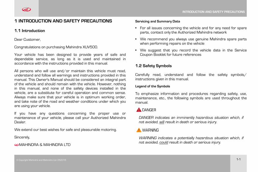
1 INTRODUCTION AND SAFETY PRECAUTIONS
1.1 Introduction
Dear Customer,
Congratulations on purchasing Mahindra XUV500.
Your vehicle has been designed to provide years of safe anddependable service, as long as it is used and maintained inaccordance with the instructions provided in this manual.
All persons who will use and/or maintain this vehicle must read,understand and follow all warnings and instructions provided in thismanual. This Owner's Manual should be considered an integral partof the vehicle and should remain with the vehicle. However, nothingin this manual, and none of the safety devices installed in thevehicle, are a substitute for careful operation and common sense.Always make sure that your vehicle is in optimum working order,and take note of the road and weather conditions under which youare using your vehicle.
If you have any questions concerning the proper use ormaintenance of your vehicle, please call your Authorized MahindraDealer.
We extend our best wishes for safe and pleasurable motoring.
Sincerely,
MAHINDRA & MAHINDRA LTD
Servicing and Summary Data
• For all issues concerning the vehicle and for any need for spareparts, contact only the Authorized Mahindra network
• We recommend you always use genuine Mahindra spare partswhen performing repairs on the vehicle
• We suggest that you record the vehicle data in the ServiceCoupon Booklet for future references
1.2 Safety Symbols
Carefully read, understand and follow the safety symbols/instructions given in this manual.
Legend of the Symbols
To emphasize information and procedures regarding safety, use,maintenance, etc., the following symbols are used throughout themanual.
DANGER indicates an imminently hazardous situation which, ifnot avoided, will result in death or serious injury.
WARNING indicates a potentially hazardous situation which, ifnot avoided, could result in death or serious injury.
INTRODUCTION AND SAFETY PRECAUTIONS
1-2 © Copyright Mahindra and Mahindra Ltd.052016
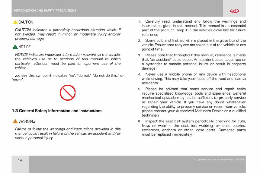
CAUTION indicates a potentially hazardous situation which, ifnot avoided, may result in minor or moderate injury and/orproperty damage.
NOTICE indicates important information relevant to the vehicle,the vehicle's use or to sections of this manual to whichparticular attention must be paid for optimum use of thevehicle.
If you see this symbol, it indicates “no”, “do not,” “do not do this,” or“never”.
1.3 General Safety Information and Instructions
Failure to follow the warnings and instructions provided in thismanual could result in failure of the vehicle, an accident and/orserious personal injury.
1. Carefully read, understand and follow the warnings andinstructions given in this manual. This manual is an essentialpart of the product. Keep it in the vehicles glove box for futurereference
2. Spare bulb and first aid kit are placed in the glove box of thevehicle. Ensure that they are not taken out of the vehicle at anypoint of time.
3. Please note that throughout this manual, reference is madethat “an accident” could occur. An accident could cause you ora bystander to sustain personal injury, or result in propertydamage
4. Never use a mobile phone or any device with headphonewhile driving. This may take your focus off the road and lead toaccidents
5. Please be advised that many service and repair tasksrequire specialized knowledge, tools and experience. Generalmechanical aptitude may not be sufficient to properly serviceor repair your vehicle. If you have any doubt whatsoeverregarding the ability to properly service or repair your vehicle,please contact your Authorized Mahindra Dealer or a qualifiedtechnician
6. Inspect the seat belt system periodically, checking for cuts,frays or wear in the seat belt webbing, or loose buckles,retractors, anchors or other loose parts. Damaged partsmust be replaced immediately
INTRODUCTION AND SAFETY PRECAUTIONS
© Copyright Mahindra and Mahindra Ltd. 052016 1-3
7. Always start and operate the engine in a well-ventilated area.If in an enclosed area, vent the exhaust to the outside. Do notmodify or tamper with the exhaust system
8. Examine tyres for excessive tread wear and uneven wearpatterns. Check for stones, nails, glass, or other objectslodged in the tread and check sidewalls for any cuts, cracks, orother signs of wear. Replace as necessary
9. Always maintain the safety labels affixed to your vehicle in agood legible condition
10. All signal lamps, buzzers, shields, guards and otherprotective safety devices must always remain in place and ingood, proper working condition
11. The life span of Mahindra products depend on many factors.Improper use, abuse or harsh use in general may compromisethe integrity of the vehicle and significantly reduce its life span.The vehicle is also subject to wear over a period of time.Please have your vehicle regularly inspected by an AuthorizedMahindra Dealer or a qualified mechanic. If the inspectionreveals any damage or excessive wear, immediately replace orhave the component serviced
12. We recommend that you use only genuine parts supplied byMahindra. The use of non-Mahindra parts will not be coveredby warranty
13. Never crawl under or be in close proximity to the vehiclewhen it is lifted off the ground (by a jack), unless the vehicle isproperly supported with jack stands, wheel chocks and otherappropriate safety devices
14. Never attempt any repairs or adjustments to anycomponent while the vehicle is in motion. Always switch off theengine, and wait for the engine to come to a complete stopbefore performing any repairs or adjustments
15. The vehicle identification plates are the only legalidentification reference, hence it is necessary to keep them ingood condition. Never modify data on the plates or removethem. The customer is responsible for any possible tamperingwith the plates, which will immediately void the warranty
16. Do not attempt sharp turns, abrupt maneuvers, or otherunsafe driving actions that can cause loss of vehicle control.When the vehicle is fully loaded, drive at a slow speed,especially when turning. Note that the centre of gravity of thevehicle changes when the vehicle is fully loaded , and also ifluggage is mounted on the roof carrier
1.4 To Owner’s of a Mahindra Vehicle
When first driving the vehicle after long periods of non-use, you mayexperience a temporary drive disturbance. This is a characteristicof the tyres and should be no reason for concern. The conditionshould correct itself within 5-15 kms. of driving. If the disturbancepersists, have the tyres checked by an Authorized Mahindra Dealer.
INTRODUCTION AND SAFETY PRECAUTIONS
1-4 © Copyright Mahindra and Mahindra Ltd.052016
Driving and Alcohol
Your driving ability can be seriously impaired by alcohol even if theblood alcohol level is far below the legal minimum. Drunken drivingis one of the most frequent causes of accidents.
Never drink and drive. Drinking and driving will lead to anaccident resulting in serious personal injury.
Driving and Drugs/Medication
Your driving ability can be seriously impaired through the use ofprescription or non-prescription drugs or medication (even coughsyrup). If you are taking any sort of drug or medication, be sure thatit will not affect your driving ability.
Mobile Phones Warning
Use of electrical devices such as mobile phones, computers,portable radios or other by the driver while driving is dangerous. Inexceptional condition if use of a mobile phone is necessary despitethis warning, use a handsfree system to ensure that the hands arefree to drive the vehicle. Even handsfree do not ensure that due todistraction an accident will not happen
Please comply with the legal regulations concerning the use ofcommunication equipment in vehicles in your country.
Driving Long Distances
When you are driving over long distances, follow these tips so thatyou have a safe journey;
• Lack of sleep or fatigue will impact your ability to drive safely.
• Exercise your eyes by shifting the focus of your eyes to differentparts of the road.
• Use stimulating beverages such as coffee or tea.
• Relax and stay calm.
• Take breaks at regular intervals
Protecting Our Environment
All of us should play our part in protecting our environment.Judicious vehicle usage and ensuring hazardous waste disposal(including cleaning and lubrication fluids) are important stepstowards this initiative.
Mahindra vehicles confirm to existing emission norms (standards).Adhering to the periodical maintenance schedule and usingMahindra genuine parts will help retain emission performance ofthe vehicle and is a pre-requisite for emissions warranty coverage.
Servicing
If you have any questions concerning the proper use ormaintenance of your vehicle, please call your Authorized MahindraDealer.
INTRODUCTION AND SAFETY PRECAUTIONS
© Copyright Mahindra and Mahindra Ltd. 052016 1-5
Running-in
Driving smoothly during first 1000 kms. will help to preventabnormal and premature system wear . Proper running in willimproving the life of drivetrain and vehicle components.
A new engine may consume more oil during the first 1000 kms. ofrunning. This should be considered as a normal part of break-in andnot interpreted as any problem with the engine.
Mahindra Genuine Parts
Mahindra uses high quality parts for building the vehicles.
In the event that any parts need replacement, we recommend thatyou use only Mahindra genuine parts.
Non-Mahindra parts may harm vehicle performance and will not becovered by your Mahindra warranty.
To avoid counterfeit parts and to protect our brand image,Mahindra genuine parts are packed in a branded carton. Look forthe “Mahindra Genuine Parts” logo.
Any unauthorized modifications or alterations to this vehicle orfailure to use appropriate specification and quality spare parts
could seriously affect vehicle road worthiness and safetyleading to an accident, resulting in serious injury
Mahindra Genuine Accessories
A wide selection of quality accessories is available through yourauthorized Mahindra dealership. These accessories have beenspecifically engineered to allow you to personalize your vehicle tosuit your requirements and compliment its style and aerodynamicappearance.
Each accessory is made from high quality materials and meetsMahindra's rigid engineering and safety specifications. EveryMahindra accessory installed according to the Mahindrainstallation provisions comes with the respective accessorywarranty.
Consult your Mahindra authorized dealer for detailed informationabout accessories available for your specific model variant.
For maximum vehicle performance and safety considerationsalways keep the following information in mind.
• When adding accessories, equipment, passengers andluggage to your vehicle, do not exceed the total weightcapacity of the vehicle or of the front and rear axle. ConsultMahindra authorized dealer for specific weight information.
INTRODUCTION AND SAFETY PRECAUTIONS
1-6 © Copyright Mahindra and Mahindra Ltd.052016
• Bull bars and nudge guards are not recommended forvariants with an airbag.
• Accessories causing any change in vehicle specifications likewheel rims, bull bars, etc., may affect the performance ofsafety systems.
• Mobile communication systems such as two way radios,telephones and theft alarms that are equipped with radiotransmitters and installed in your vehicle should comply withthe local regulations and should be installed only by a yourAuthorized Mahindra Dealer
Vehicle Safety
When leaving your vehicle unoccupied;
• Always remove the ignition key when you park the vehicle
• Close all the windows completely and lock all the doors
• Do not leave any valuables in your vehicle. If you must leavesomething in your vehicle, hide them and securely lock all thedoors
1.5 Audio/Infotainment Manual
Please refer the Audio/Infotainment manual available in the manualpouch for details regarding;
• Audio/Video functions
• Bluetooth functions
• Navigation (if equipped)
• Map upgradation details
To upgrade the maps in your navigation system (if equipped),please refer the Infotainment manual.
INTRODUCTION AND SAFETY PRECAUTIONS
© Copyright Mahindra and Mahindra Ltd. 052016 2-1
2 GENERAL
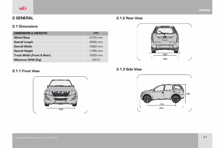
2.1 Dimensions
DIMENSION &WEIGHTS mm
Wheel Base 2700 mm
Overall Length 4585 mm
Overall Width 1890 mm
Overall Height 1785 mm
Track Width (Front & Rear) 1600 mm
Maximum GVW (Kg) 2510
2.1.1 Front View
2.1.2 Rear View
2.1.3 Side View
GENERAL
2-2 © Copyright Mahindra and Mahindra Ltd.052016
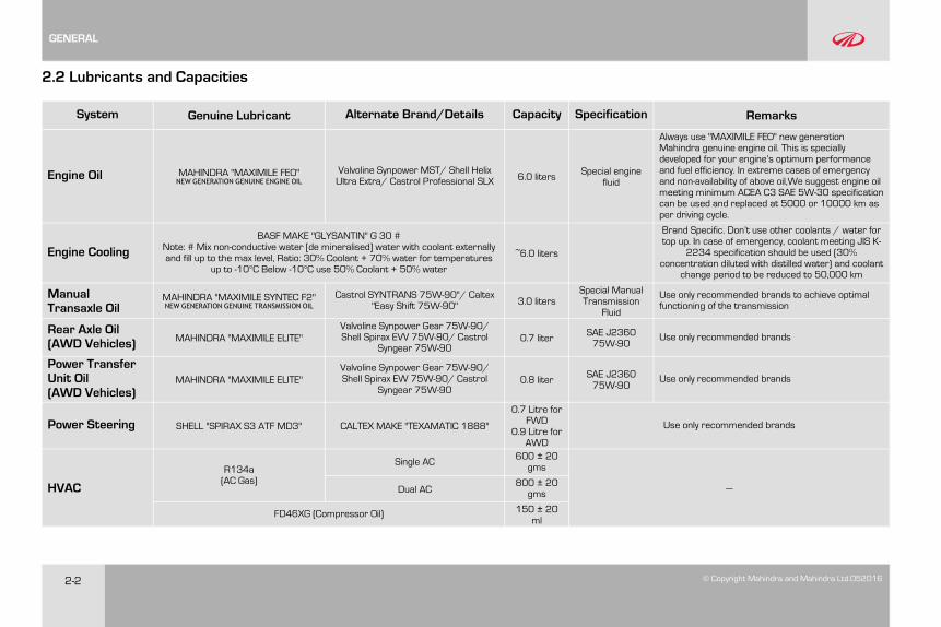
2.2 Lubricants and Capacities
System Genuine Lubricant Alternate Brand/Details Capacity Specification Remarks
Engine Oil MAHINDRA "MAXIMILE FEO"NEW GENERATION GENUINE ENGINE OIL
Valvoline Synpower MST/ Shell HelixUltra Extra/ Castrol Professional SLX 6.0 liters Special engine
fluid
Always use "MAXIMILE FEO" new generationMahindra genuine engine oil. This is speciallydeveloped for your engine’s optimum performanceand fuel efficiency. In extreme cases of emergencyand non-availability of above oil,We suggest engine oilmeeting minimum ACEA C3 SAE 5W-30 specificationcan be used and replaced at 5000 or 10000 km asper driving cycle.
Engine CoolingBASF MAKE "GLYSANTIN" G 30 #
Note: # Mix non-conductive water [de mineralised] water with coolant externallyand fill up to the max level, Ratio: 30% Coolant + 70% water for temperatures
up to -10°C Below -10°C use 50% Coolant + 50% water
~6.0 liters
Brand Specific. Don’t use other coolants / water fortop up. In case of emergency, coolant meeting JIS K-
2234 specification should be used (30%concentration diluted with distilled water) and coolant
change period to be reduced to 50,000 km
ManualTransaxle Oil
MAHINDRA "MAXIMILE SYNTEC F2"NEW GENERATION GENUINE TRANSMISSION OIL
Castrol SYNTRANS 75W-90"/ Caltex"Easy Shift 75W-90" 3.0 liters
Special ManualTransmissionFluid
Use only recommended brands to achieve optimalfunctioning of the transmission
Rear Axle Oil(AWD Vehicles) MAHINDRA "MAXIMILE ELITE"
Valvoline Synpower Gear 75W-90/Shell Spirax EVV 75W-90/ Castrol
Syngear 75W-900.7 liter SAE J2360
75W-90Use only recommended brands
Power TransferUnit Oil(AWD Vehicles)
MAHINDRA "MAXIMILE ELITE"Valvoline Synpower Gear 75W-90/Shell Spirax EW 75W-90/ Castrol
Syngear 75W-900.8 liter SAE J2360
75W-90Use only recommended brands
Power Steering SHELL "SPIRAX S3 ATF MD3" CALTEX MAKE "TEXAMATIC 1888"
0.7 Litre forFWD
0.9 Litre forAWD
Use only recommended brands
HVAC
R134a(AC Gas)
Single AC 600 ± 20gms
—Dual AC800 ± 20gms
FD46XG (Compressor Oil) 150 ± 20ml
GENERAL
© Copyright Mahindra and Mahindra Ltd. 052016 2-3
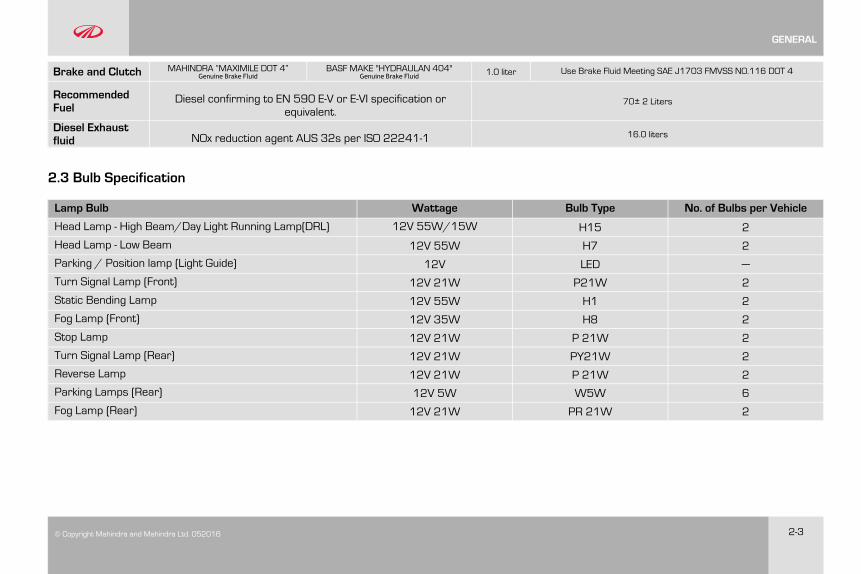
Brake and Clutch MAHINDRA “MAXIMILE DOT 4”Genuine Brake Fluid
BASF MAKE "HYDRAULAN 404"Genuine Brake Fluid 1.0 liter Use Brake Fluid Meeting SAE J1703 FMVSS NO.116 DOT 4
RecommendedFuel
Diesel confirming to EN 590 E-V or E-VI specification orequivalent.
70± 2 Liters
Diesel Exhaustfluid NOx reduction agent AUS 32s per ISO 22241-1 16.0 liters
2.3 Bulb Specification
Lamp Bulb Wattage Bulb Type No. of Bulbs per Vehicle
Head Lamp - High Beam/Day Light Running Lamp(DRL) 12V 55W/15W H15 2
Head Lamp - Low Beam 12V 55W H7 2
Parking / Position lamp (Light Guide) 12V LED —
Turn Signal Lamp (Front) 12V 21W P21W 2
Static Bending Lamp 12V 55W H1 2
Fog Lamp (Front) 12V 35W H8 2
Stop Lamp 12V 21W P 21W 2
Turn Signal Lamp (Rear) 12V 21W PY21W 2
Reverse Lamp 12V 21W P 21W 2
Parking Lamps (Rear) 12V 5W W5W 6
Fog Lamp (Rear) 12V 21W PR 21W 2
GENERAL
2-4 © Copyright Mahindra and Mahindra Ltd.052016
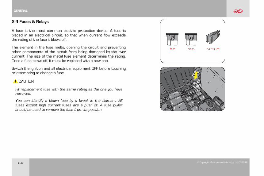
2.4 Fuses & Relays
A fuse is the most common electric protection device. A fuse isplaced in an electrical circuit, so that when current flow exceedsthe rating of the fuse it blows off.
The element in the fuse melts, opening the circuit and preventingother components of the circuit from being damaged by the overcurrent. The size of the metal fuse element determines the rating.Once a fuse blows off, it must be replaced with a new one.
Switch the ignition and all electrical equipment OFF before touchingor attempting to change a fuse.
Fit replacement fuse with the same rating as the one you haveremoved.
You can identify a blown fuse by a break in the filament. Allfuses except high current fuses are a push fit. A fuse pullershould be used to remove the fuse from its position.
GENERAL
© Copyright Mahindra and Mahindra Ltd. 052016 2-5
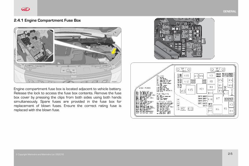
2.4.1 Engine Compartment Fuse Box
W22B41
Engine compartment fuse box is located adjacent to vehicle battery.Release the lock to access the fuse box contents. Remove the fusebox cover by pressing the clips from both sides using both handssimultaneously. Spare fuses are provided in the fuse box forreplacement of blown fuses. Ensure the correct rating fuse isreplaced with the blown fuse.
GENERAL
2-6 © Copyright Mahindra and Mahindra Ltd.052016
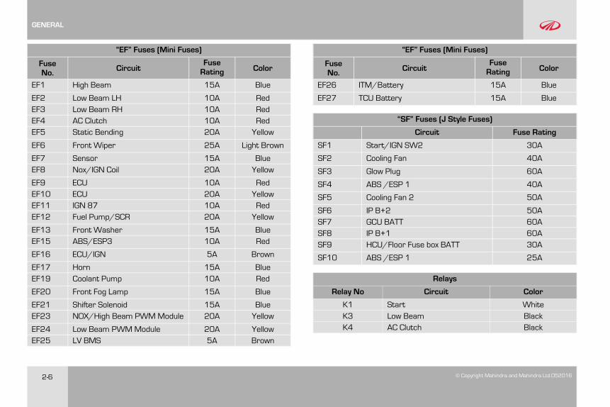
“EF” Fuses (Mini Fuses)
FuseNo. Circuit
FuseRating Color
EF1 High Beam 15A Blue
EF2 Low Beam LH 10A RedEF3 Low Beam RH 10A RedEF4 AC Clutch 10A RedEF5 Static Bending 20A Yellow
EF6 Front Wiper 25A Light Brown
EF7 Sensor 15A BlueEF8 Nox/IGN Coil 20A Yellow
EF9 ECU 10A RedEF10 ECU 20A YellowEF11 IGN 87 10A RedEF12 Fuel Pump/SCR 20A Yellow
EF13 Front Washer 15A BlueEF15 ABS/ESP3 10A Red
EF16 ECU/IGN 5A Brown
EF17 Horn 15A BlueEF19 Coolant Pump 10A Red
EF20 Front Fog Lamp 15A Blue
EF21 Shifter Solenoid 15A BlueEF23 NOX/High Beam PWMModule 20A Yellow
EF24 Low Beam PWMModule 20A YellowEF25 LV BMS 5A Brown
“EF” Fuses (Mini Fuses)
FuseNo. Circuit
FuseRating Color
EF26 ITM/Battery 15A Blue
EF27 TCU Battery 15A Blue
“SF” Fuses (J Style Fuses)
Circuit Fuse Rating
SF1 Start/IGN SW2 30A
SF2 Cooling Fan 40A
SF3 Glow Plug 60A
SF4 ABS /ESP 1 40A
SF5 Cooling Fan 2 50A
SF6 IP B+2 50ASF7 GCU BATT 60ASF8 IP B+1 60ASF9 HCU/Floor Fuse box BATT 30A
SF10 ABS /ESP 1 25A
Relays
Relay No Circuit Color
K1 Start WhiteK3 Low Beam BlackK4 AC Clutch Black
GENERAL
© Copyright Mahindra and Mahindra Ltd. 052016 2-7
Relays
Relay No Circuit Color
K6 Cooling Fan Low Grey
K7 Cooling Fan High Grey
K8 Front Wiper On Black
K9 Front Wiper Speed Black
K11 GNS BlackK12 Fuel Pump/SCR Main White
K15 Glow Plug Grey
K16 Coolant Pump Black
K17 Front Fog Lamp Black
K18 Shifter Solenoid WhiteK21 Main Grey
PCB Relays
K2 DRLK5 Static Bending
K10 HornK13 Front WasherK22 High Beam
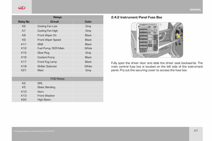
2.4.2 Instrument Panel Fuse Box
F31
F25
F19
F13
F7
F1
23134-352-X270
V23074-A1001-A402
12VDC
20A
V23074-A1001-A402
12VDC
20A
V23074-A1001-A402
12VDC
20A
V23074-A1001-A402
12VDC
20A
W22B42
Fully open the driver door and slide the driver seat backwards. Themain central fuse box is located on the left side of the instrumentpanel. Pry out the securing cover to access the fuse box.
GENERAL
2-8 © Copyright Mahindra and Mahindra Ltd.052016
5657
54
5253
50
4748
45
4344
10987 11 12
654321
36
302928272625
242322212019
181716151413
3534333231
46
51
55
F31
F25
F19
F13
F7
F1
23134-352-X270
V23074-A1001-A402
12VDC
20A
V23074-A1001-A402
12VDC
20A
V23074-A1001-A402
12VDC
20A
V23074-A1001-A402
12VDC
20A
37 38 39 40 41 42
4958
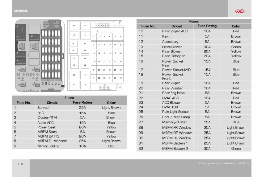
FusesFuse No. Circuit Fuse Rating Color1 Sunroof 25A Light Brown
2 BEC 15A Blue3 Cluster/ITM 5A Brown
4 Audio ACC 15A Blue5 Power Seat 20A Yellow6 MBFM Start 5A Brown7 MBFM BATT3 20A Yellow8 MBFM FL -Window 25A Light Brown
9 Mirror Folding 10A Red
FusesFuse No. Circuit Fuse Rating Color10 Rear Wiper ACC 10A Red
11 Key In 5A Brown
12 Accessory 5A Brown
13 Front Blower 30A Green14 Rear Blower 20A Yellow15 Rear Defogger 20A Yellow
16 Power SocketRear
15A Blue
17 Power Socket MID 15A Blue18 Power Socket
Front15A Blue
19 Rear Wiper 10A Red
20 Rear Washer 10A Red21 Rear Fog lamp 5A Brown
22 HVAC ACC 10A Red23 ACC Blower 5A Brown24 HVAC IGN 5A Brown25 Rain Light Sensor 5A Brown
26 Roof / Map Lamp 5A Brown
27 Memory-Cluster 15A Blue
28 MBFM FR Window 25A Light Brown
29 MBFM RRWindow 25A Light Brown
30 MBFM RL Window 25A Light Brown
31 MBFM Battery 1 25A Light Brown
32 MBFM Battery 2 30A Green
GENERAL
© Copyright Mahindra and Mahindra Ltd. 052016 2-9
FusesFuse No. Circuit Fuse Rating Color33 Audio / BATT 15A Blue
34 Airbag 15A Blue
35 Reverse lamp 10A Red
36 AUD/Sun Roof/TIRE (Tiretronics)IGN
5A Brown
37 Spare 5A Brown
38 Spare 10A Red
39 Spare 15A Blue
40 Spare 20A Yellow
41 Spare 25A Light Brown
42 Spare 30A Green
Relays
Relay No. Circuit Relay Rating Color
43 Rear Defogger Relay 40A Brown
44 Not used
45 Accessory Relay 50A Grey
46 Front Blower Relay 40A Brown
47 Rear Blower Relay 20A Blue
48 Rear Fog Lamp 20A Blue
49 Key Lock Solenoid Relay 20A Blue
50 Mirror Unfold Relay 20A Black
Relays
Relay No. Circuit Relay Rating Color
51 Rear Wiper Relay 20A Blue
52 Mirror Fold Relay 20A Black
53 Rear Washer 20A Blue
54 Not used
55 Not used
56 Not used
57 Not used
58 Reverse Lamp Relay 20A Blue
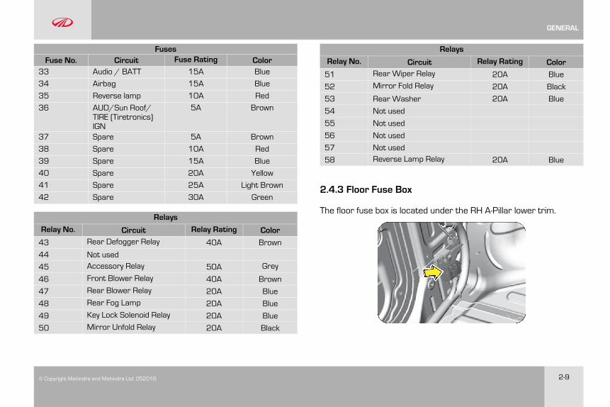
2.4.3 Floor Fuse Box
The floor fuse box is located under the RH A-Pillar lower trim.
GENERAL
2-10 © Copyright Mahindra and Mahindra Ltd.052016
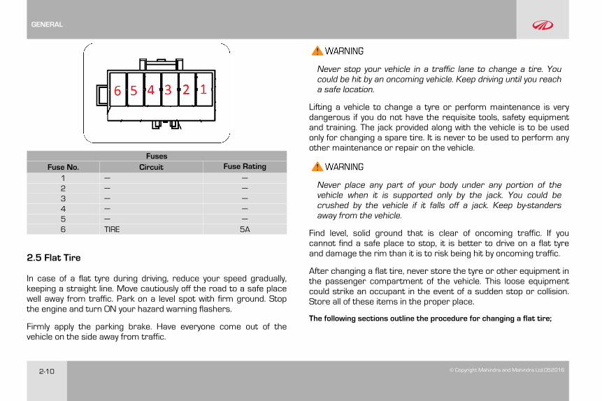
FusesFuse No. Circuit Fuse Rating
1 — —2 — —3 — —4 — —5 — —6 TIRE 5A
2.5 Flat Tire
In case of a flat tyre during driving, reduce your speed gradually,keeping a straight line. Move cautiously off the road to a safe placewell away from traffic. Park on a level spot with firm ground. Stopthe engine and turn ON your hazard warning flashers.
Firmly apply the parking brake. Have everyone come out of thevehicle on the side away from traffic.
Never stop your vehicle in a traffic lane to change a tire. Youcould be hit by an oncoming vehicle. Keep driving until you reacha safe location.
Lifting a vehicle to change a tyre or perform maintenance is verydangerous if you do not have the requisite tools, safety equipmentand training. The jack provided along with the vehicle is to be usedonly for changing a spare tire. It is never to be used to perform anyother maintenance or repair on the vehicle.
Never place any part of your body under any portion of thevehicle when it is supported only by the jack. You could becrushed by the vehicle if it falls off a jack. Keep by-standersaway from the vehicle.
Find level, solid ground that is clear of oncoming traffic. If youcannot find a safe place to stop, it is better to drive on a flat tyreand damage the rim than it is to risk being hit by oncoming traffic.
After changing a flat tire, never store the tyre or other equipment inthe passenger compartment of the vehicle. This loose equipmentcould strike an occupant in the event of a sudden stop or collision.Store all of these items in the proper place.
The following sections outline the procedure for changing a flat tire;
GENERAL
© Copyright Mahindra and Mahindra Ltd. 052016 2-11
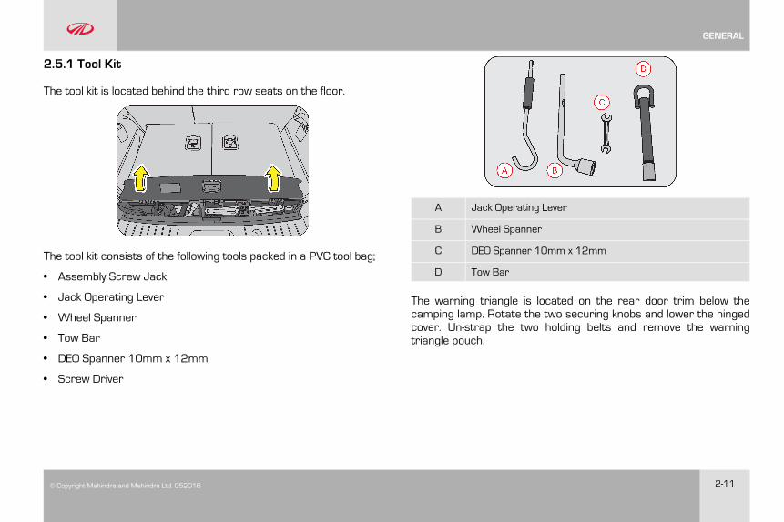
2.5.1 Tool Kit
The tool kit is located behind the third row seats on the floor.
The tool kit consists of the following tools packed in a PVC tool bag;
• Assembly Screw Jack
• Jack Operating Lever
• Wheel Spanner
• Tow Bar
• DEO Spanner 10mm x 12mm
• Screw Driver
A Jack Operating Lever
B Wheel Spanner
C DEO Spanner 10mm x 12mm
D Tow Bar
The warning triangle is located on the rear door trim below thecamping lamp. Rotate the two securing knobs and lower the hingedcover. Un-strap the two holding belts and remove the warningtriangle pouch.
GENERAL
2-12 © Copyright Mahindra and Mahindra Ltd.052016
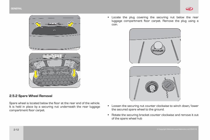
2.5.2 Spare Wheel Removal
Spare wheel is located below the floor at the rear end of the vehicle.It is held in place by a securing nut underneath the rear luggagecompartment floor carpet.
• Locate the plug covering the securing nut below the rearluggage compartment floor carpet. Remove the plug using acoin.
• Loosen the securing nut counter clockwise to winch down/lowerthe secured spare wheel to the ground.
• Rotate the securing bracket counter clockwise and remove it outof the spare wheel hub
GENERAL
© Copyright Mahindra and Mahindra Ltd. 052016 2-13
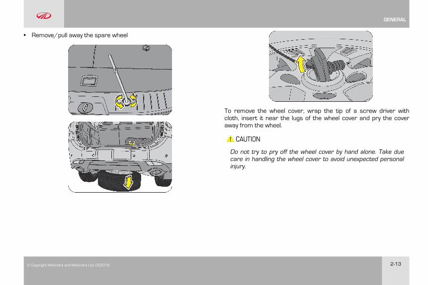
• Remove/pull away the spare wheel
To remove the wheel cover, wrap the tip of a screw driver withcloth, insert it near the lugs of the wheel cover and pry the coveraway from the wheel.
Do not try to pry off the wheel cover by hand alone. Take duecare in handling the wheel cover to avoid unexpected personalinjury.
GENERAL
2-14 © Copyright Mahindra and Mahindra Ltd.052016
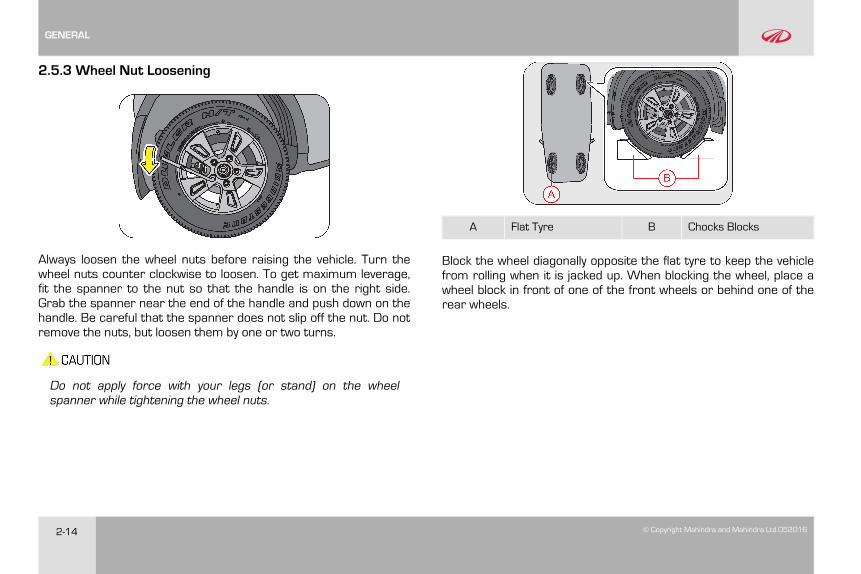
2.5.3 Wheel Nut Loosening
Always loosen the wheel nuts before raising the vehicle. Turn thewheel nuts counter clockwise to loosen. To get maximum leverage,fit the spanner to the nut so that the handle is on the right side.Grab the spanner near the end of the handle and push down on thehandle. Be careful that the spanner does not slip off the nut. Do notremove the nuts, but loosen them by one or two turns.
Do not apply force with your legs (or stand) on the wheelspanner while tightening the wheel nuts.
A Flat Tyre B Chocks Blocks
Block the wheel diagonally opposite the flat tyre to keep the vehiclefrom rolling when it is jacked up. When blocking the wheel, place awheel block in front of one of the front wheels or behind one of therear wheels.
GENERAL
© Copyright Mahindra and Mahindra Ltd. 052016 2-15
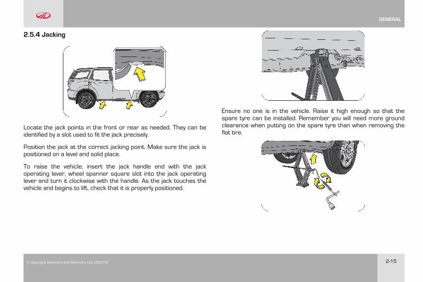
2.5.4 Jacking
Locate the jack points in the front or rear as needed. They can beidentified by a slot used to fit the jack precisely.
Position the jack at the correct jacking point. Make sure the jack ispositioned on a level and solid place.
To raise the vehicle, insert the jack handle end with the jackoperating lever, wheel spanner square slot into the jack operatinglever and turn it clockwise with the handle. As the jack touches thevehicle and begins to lift, check that it is properly positioned.
Ensure no one is in the vehicle. Raise it high enough so that thespare tyre can be installed. Remember you will need more groundclearance when putting on the spare tyre than when removing theflat tire.
GENERAL
2-16 © Copyright Mahindra and Mahindra Ltd.052016
Make sure to set the jack properly in the jacking point. Raisingthe vehicle with jack improperly positioned will damage theunderbody of vehicle or may allow the vehicle to fall off the jackand cause personal injury.
• Use the jack only for lifting your vehicle during wheelchanging
• When raising the vehicle, do not place any objects on top ofor underneath the jack.
• Do not raise the jack with someone in the vehicle.
• Raise the vehicle only high enough to remove and changethe wheel.
• Follow jacking instructions
• Do not start or run the engine while your vehicle issupported by the jack.
Never get under the vehicle when the vehicle is supported bythe jack alone.
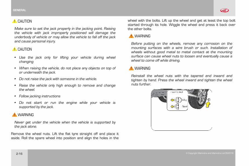
Remove the wheel nuts. Lift the flat tyre straight off and place itaside. Roll the spare wheel into position and align the holes in the
wheel with the bolts. Lift up the wheel and get at least the top boltstarted through its hole. Wiggle the wheel and press it back overthe other bolts.
Before putting on the wheels, remove any corrosion on themounting surfaces with a wire brush or such. Installation ofwheels without good metal to metal contact at the mountingsurface can cause wheel nuts to loosen and eventually cause awheel to come off while driving.
Reinstall the wheel nuts with the tapered end inward andtighten by hand. Press the wheel inward and tighten the wheelnuts further.
GENERAL
© Copyright Mahindra and Mahindra Ltd. 052016 2-17
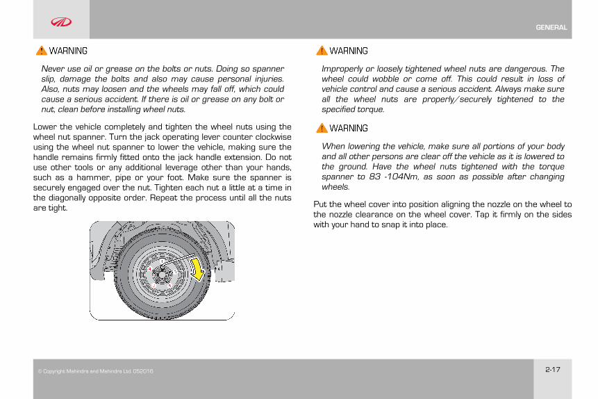
Never use oil or grease on the bolts or nuts. Doing so spannerslip, damage the bolts and also may cause personal injuries.Also, nuts may loosen and the wheels may fall off, which couldcause a serious accident. If there is oil or grease on any bolt ornut, clean before installing wheel nuts.
Lower the vehicle completely and tighten the wheel nuts using thewheel nut spanner. Turn the jack operating lever counter clockwiseusing the wheel nut spanner to lower the vehicle, making sure thehandle remains firmly fitted onto the jack handle extension. Do notuse other tools or any additional leverage other than your hands,such as a hammer, pipe or your foot. Make sure the spanner issecurely engaged over the nut. Tighten each nut a little at a time inthe diagonally opposite order. Repeat the process until all the nutsare tight.
Improperly or loosely tightened wheel nuts are dangerous. Thewheel could wobble or come off. This could result in loss ofvehicle control and cause a serious accident. Always make sureall the wheel nuts are properly/securely tightened to thespecified torque.
When lowering the vehicle, make sure all portions of your bodyand all other persons are clear off the vehicle as it is lowered tothe ground. Have the wheel nuts tightened with the torquespanner to 83 -104Nm, as soon as possible after changingwheels.
Put the wheel cover into position aligning the nozzle on the wheel tothe nozzle clearance on the wheel cover. Tap it firmly on the sideswith your hand to snap it into place.
GENERAL
2-18 © Copyright Mahindra and Mahindra Ltd.052016
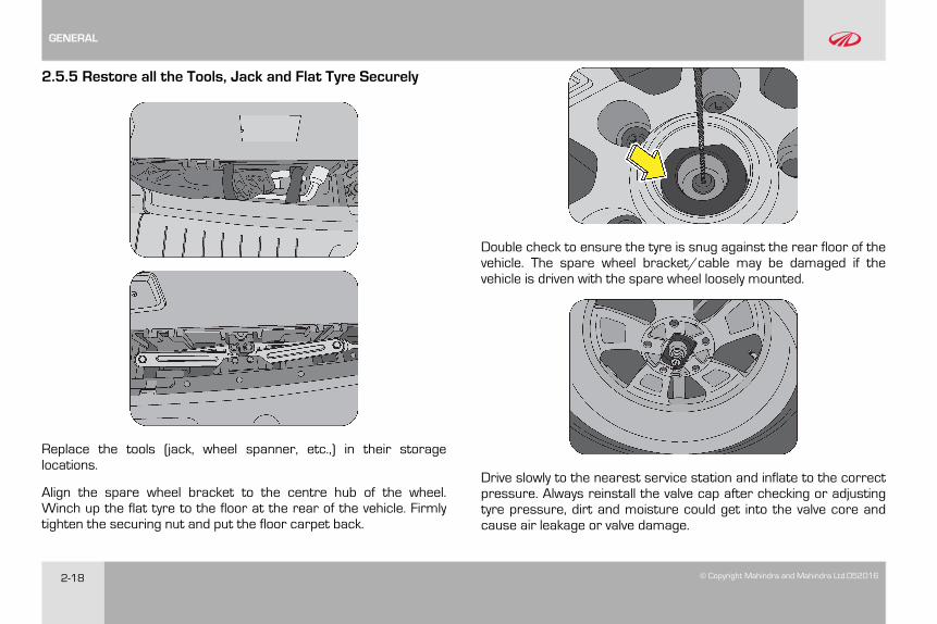
2.5.5 Restore all the Tools, Jack and Flat Tyre Securely
Replace the tools (jack, wheel spanner, etc.,) in their storagelocations.
Align the spare wheel bracket to the centre hub of the wheel.Winch up the flat tyre to the floor at the rear of the vehicle. Firmlytighten the securing nut and put the floor carpet back.
Double check to ensure the tyre is snug against the rear floor of thevehicle. The spare wheel bracket/cable may be damaged if thevehicle is driven with the spare wheel loosely mounted.
Drive slowly to the nearest service station and inflate to the correctpressure. Always reinstall the valve cap after checking or adjustingtyre pressure, dirt and moisture could get into the valve core andcause air leakage or valve damage.
GENERAL
© Copyright Mahindra and Mahindra Ltd. 052016 2-19
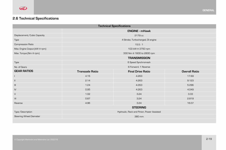
2.6 Technical Specifications
Technical Specifications
ENGINE - mHawkDisplacement/Cubic Capacity 2179 cc
Type 4 Stroke, Turbocharged, DI engine
Compression Ratio 15.5 : 1
Max. Engine Output (kW @ rpm) 103 kW @ 3750 rpm
Max. Torque (Nm @ rpm) 330 Nm @ 1600 to 2800 rpm
TRANSMISSIONType 6 Speed Synchromesh
No. of Gears 6 Forward, 1 Reverse
GEAR RATIOS Transaxle Ratio Final Drive Ratio Overall RatioI 4.15 4.263 17.69
II 2.14 4.263 9.123
III 1.24 4.263 5.286
IV 0.95 4.263 4.049
V 1.02 3.24 3.33
VI 0.87 3.24 2.819
Reverse 4.96 3.24 16.07
STEERINGType/Description Hydraulic, Rack and Pinion, Power Assisted
Steering Wheel Diameter 380 mm
GENERAL
2-20 © Copyright Mahindra and Mahindra Ltd.052016
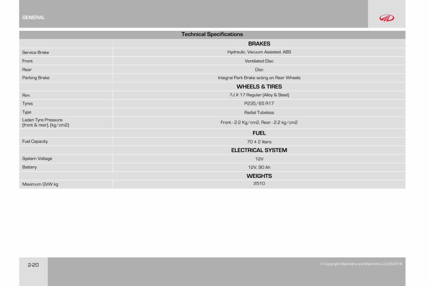
Technical Specifications
BRAKESService Brake Hydraulic, Vacuum Assisted, ABS
Front Ventilated Disc
Rear Disc
Parking Brake Integral Park Brake acting on Rear Wheels
WHEELS & TIRESRim 7J X 17 Regular (Alloy & Steel)
Tyres P235/65 R17
Type Radial Tubeless
Laden Tyre Pressure(front & rear), (kg/cm2) Front - 2.2 Kg/cm2, Rear - 2.2 kg/cm2
FUELFuel Capacity 70 ± 2 liters
ELECTRICAL SYSTEMSystem Voltage 12V
Battery 12V, 90 Ah
WEIGHTSMaximum GVW kg 2510
GENERAL
© Copyright Mahindra and Mahindra Ltd. 052016 2-21
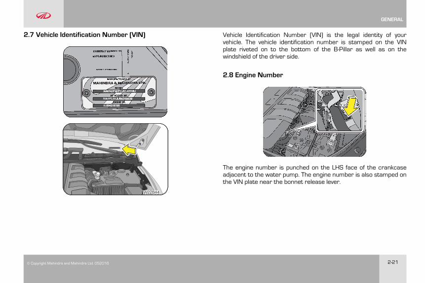
2.7 Vehicle Identification Number (VIN)
MA1XXXXXXXXXXXXXX
W22B44
Vehicle Identification Number (VIN) is the legal identity of yourvehicle. The vehicle identification number is stamped on the VINplate riveted on to the bottom of the B-Pillar as well as on thewindshield of the driver side.
2.8 Engine Number
The engine number is punched on the LHS face of the crankcaseadjacent to the water pump. The engine number is also stamped onthe VIN plate near the bonnet release lever.
GENERAL

© Copyright Mahindra and Mahindra Ltd. 052016 3-1
3 VEHICLE OVERVIEW
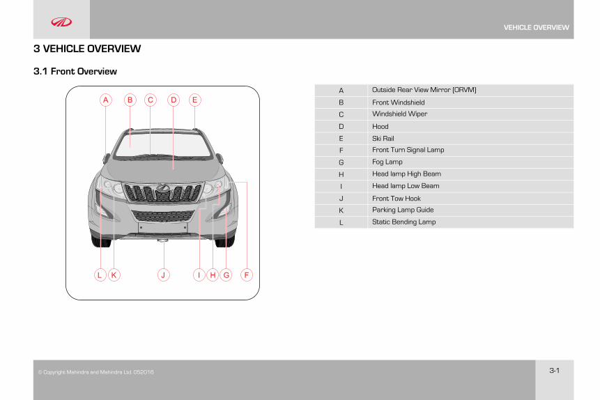
3.1 Front Overview
B C D E
FGJKL HI
AA Outside Rear View Mirror (ORVM)
B Front Windshield
C Windshield Wiper
D Hood
E Ski Rail
F Front Turn Signal Lamp
G Fog Lamp
H Head lamp High Beam
I Head lamp Low Beam
J Front Tow Hook
K Parking Lamp Guide
L Static Bending Lamp
VEHICLE OVERVIEW
3-2 © Copyright Mahindra and Mahindra Ltd.052016
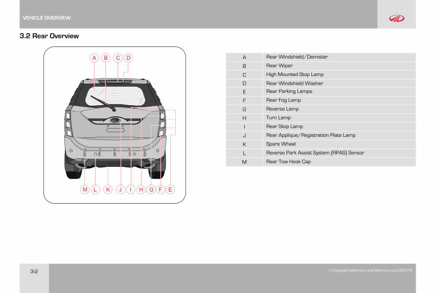
3.2 Rear Overview
A C DB
EFGHILM K J
A Rear Windshield/Demister
B Rear Wiper
C High Mounted Stop Lamp
D Rear Windshield Washer
E Rear Parking Lamps
F Rear Fog Lamp
G Reverse Lamp
H Turn Lamp
I Rear Stop Lamp
J Rear Applique/Registration Plate Lamp
K Spare Wheel
L Reverse Park Assist System (RPAS) Sensor
M Rear Tow Hook Cap
VEHICLE OVERVIEW
© Copyright Mahindra and Mahindra Ltd. 052016 3-3
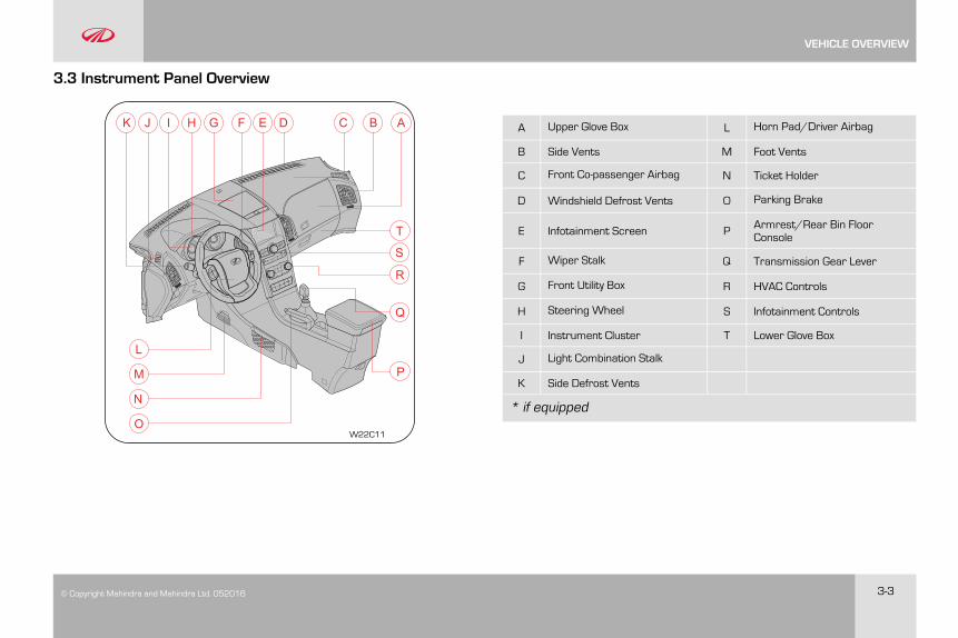
3.3 Instrument Panel Overview
P
Q
R
S
T
ABCDEFGHJK I
L
M
N
OW22C11
A Upper Glove Box L Horn Pad/Driver Airbag
B Side Vents M Foot Vents
C Front Co-passenger Airbag N Ticket Holder
D Windshield Defrost Vents O Parking Brake
E Infotainment Screen P Armrest/Rear Bin FloorConsole
F Wiper Stalk Q Transmission Gear Lever
G Front Utility Box R HVAC Controls
H Steering Wheel S Infotainment Controls
I Instrument Cluster T Lower Glove Box
J Light Combination Stalk
K Side Defrost Vents
* if equipped
VEHICLE OVERVIEW

© Copyright Mahindra and Mahindra Ltd. 052016 4-1
4 INSTRUMENT CLUSTER OVERVIEW
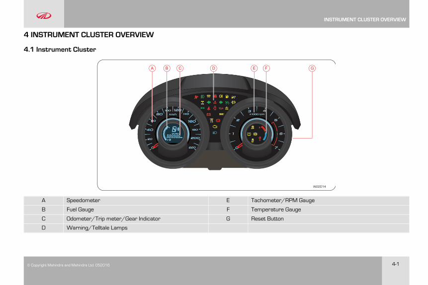
4.1 Instrument Cluster
D FEB CA G
W22D14
A Speedometer E Tachometer/RPM Gauge
B Fuel Gauge F Temperature Gauge
C Odometer/Trip meter/Gear Indicator G Reset Button
D Warning/Telltale Lamps
INSTRUMENT CLUSTER OVERVIEW
4-2 © Copyright Mahindra and Mahindra Ltd.052016
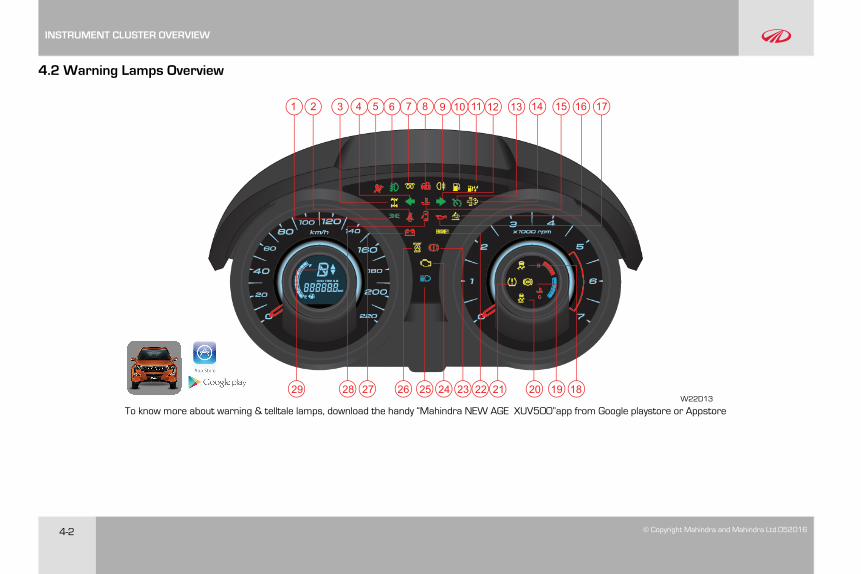
4.2 Warning Lamps Overview
1 2 3 4 5 6 7 8 9 10 11 12 13 14 15 1716
1820 19212223242526272829
To know more about warning & telltale lamps, download the handy “Mahindra NEW AGE XUV5OO”app from Google playstore or AppstoreW22D13
INSTRUMENT CLUSTER OVERVIEW
© Copyright Mahindra and Mahindra Ltd. 052016 4-3
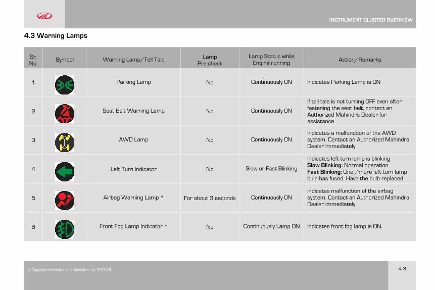
4.3 Warning Lamps
Sr.No.
Symbol Warning Lamp/Tell Tale LampPre-check
Lamp Status whileEngine running Action/Remarks
1 Parking Lamp No Continuously ON Indicates Parking Lamp is ON
2 Seat Belt Warning Lamp No Continuously ON
If tell tale is not turning OFF even afterfastening the seat belt, contact anAuthorized Mahindra Dealer forassistance
3 AWD Lamp No Continuously ONIndicates a malfunction of the AWDsystem. Contact an Authorized MahindraDealer Immediately
4 Left Turn Indicator No Slow or Fast Blinking
Indicates left turn lamp is blinkingSlow Blinking: Normal operationFast Blinking: One /more left turn lampbulb has fused. Have the bulb replaced
5 Airbag Warning Lamp * For about 3 seconds Continuously ONIndicates malfunction of the airbagsystem. Contact an Authorized MahindraDealer immediately
6 Front Fog Lamp Indicator * No Continuously Lamp ON Indicates front fog lamp is ON.
INSTRUMENT CLUSTER OVERVIEW
4-4 © Copyright Mahindra and Mahindra Ltd.052016
Sr.No.
Symbol Warning Lamp/Tell Tale LampPre-check
Lamp Status whileEngine running Action/Remarks
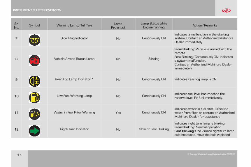
7 Glow Plug Indicator No Continuously ONIndicates a malfunction in the startingsystem. Contact an Authorized MahindraDealer immediately
8 Vehicle Armed Status Lamp No Blinking
Slow Blinking: Vehicle is armed with theremoteFast Blinking/Continuously ON: Indicatesa system malfunction.Contact an Authorized Mahindra Dealerimmediately
9 Rear Fog Lamp Indicator * No Continuously ON Indicates rear fog lamp is ON
10 Low Fuel Warning Lamp No Continuously ON Indicates fuel level has reached thereserve level. Re-fuel immediately.
11 Water in Fuel Filter Warning Yes Continuously ONIndicates water in fuel filter. Drain thewater from filter or contact an AuthorizedMahindra Dealer for assistance
12 Right Turn Indicator No Slow or Fast Blinking
Indicates right turn lamp is blinkingSlow Blinking: Normal operationFast Blinking: One /more right turn lampbulb has fused. Have the bulb replaced
INSTRUMENT CLUSTER OVERVIEW
© Copyright Mahindra and Mahindra Ltd. 052016 4-5
Sr.No.
Symbol Warning Lamp/Tell Tale LampPre-check
Lamp Status whileEngine running Action/Remarks
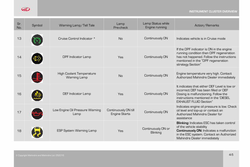
13 Cruise Control Indicator * No Continuously ON Indicates vehicle is in Cruise mode
14 DPF Indicator Lamp Yes Continuously ON
If the DPF indicator is ON in the enginerunning condition then DPF regenerationhas not happened. Follow the instructionsmentioned in the “DPF regenerationstrategy Section”
15High Coolant Temperature
Warning Lamp No Continuously ON Engine temperature very high. ContactAuthorized Mahindra Dealer immediately
16 DEF Indicator Lamp Yes Continuously ON
It indicates that either DEF Level is low orincorrect DEF has been filled or DEFDosing is malfunctioning. Follow theinstructions mentioned in the ‘DIESELEXHAUST FLUID Section”
17Low Engine Oil Pressure Warning
LampContinuously ON tillEngine Starts Continuously ON
Indicates engine oil pressure is low. Checkoil level and top-up or contact anAuthorized Mahindra Dealer forassistance
18 ESP System Warning Lamp YesContinuously ON or
Blinking
Blinking: Indicates ESC has taken controlof the vehicle stabilityContinuously ON: Indicates a malfunctionin the ESC system. Contact an AuthorizedMahindra Dealer immediately
INSTRUMENT CLUSTER OVERVIEW
4-6 © Copyright Mahindra and Mahindra Ltd.052016
Sr.No.
Symbol Warning Lamp/Tell Tale LampPre-check
Lamp Status whileEngine running Action/Remarks
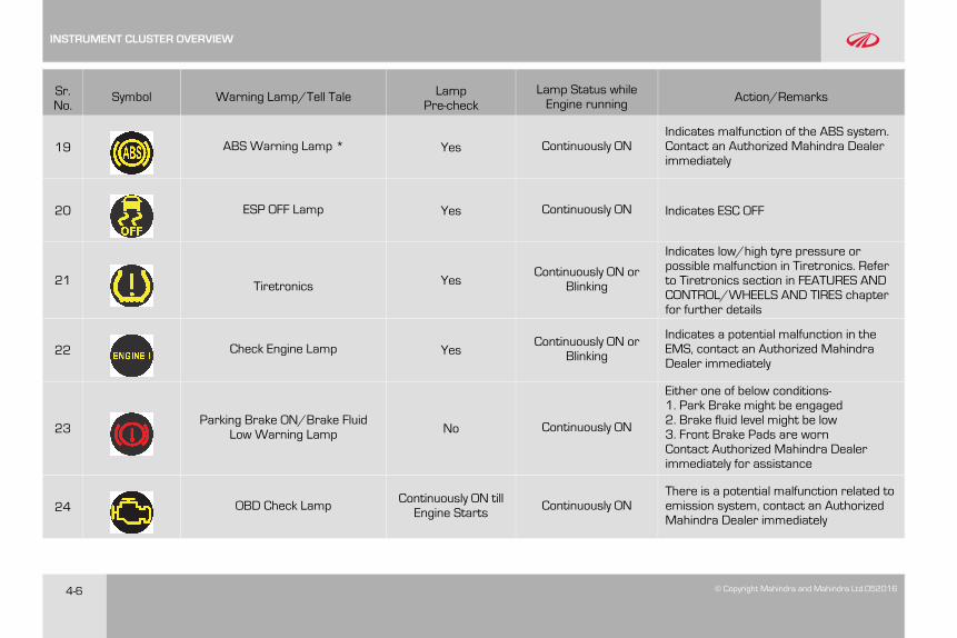
19 ABS Warning Lamp * Yes Continuously ONIndicates malfunction of the ABS system.Contact an Authorized Mahindra Dealerimmediately
20 ESP OFF Lamp Yes Continuously ON Indicates ESC OFF
21 Tiretronics YesContinuously ON or
Blinking
Indicates low/high tyre pressure orpossible malfunction in Tiretronics. Referto Tiretronics section in FEATURES ANDCONTROL/WHEELS AND TIRES chapterfor further details
22 Check Engine Lamp YesContinuously ON or
Blinking
Indicates a potential malfunction in theEMS, contact an Authorized MahindraDealer immediately
23Parking Brake ON/Brake Fluid
Low Warning Lamp No Continuously ON
Either one of below conditions-1. Park Brake might be engaged2. Brake fluid level might be low3. Front Brake Pads are wornContact Authorized Mahindra Dealerimmediately for assistance
24 OBD Check Lamp Continuously ON tillEngine Starts Continuously ON
There is a potential malfunction related toemission system, contact an AuthorizedMahindra Dealer immediately
INSTRUMENT CLUSTER OVERVIEW
© Copyright Mahindra and Mahindra Ltd. 052016 4-7
Sr.No.
Symbol Warning Lamp/Tell Tale LampPre-check
Lamp Status whileEngine running Action/Remarks
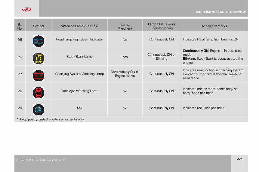
25 Head lamp High Beam Indicator No Continuously ON Indicates Head lamp high beam is ON
26 Stop/Start Lamp YesContinuously ON or
Blinking
Continuously ON: Engine is in auto stopmodeBlinking: Stop/Start is about to stop theengine
27 Charging System Warning Lamp Continuously ON tillEngine starts Continuously ON
Indicates malfunction in charging system.Contact Authorized Mahindra Dealer forassistance
28 Door Ajar Warning Lamp No Continuously ON Indicates one or more doors and/orboot/hood are open
29 GSI No Continuously ON Indicates the Gear positions
* if equipped / select models or variants only
INSTRUMENT CLUSTER OVERVIEW

© Copyright Mahindra and Mahindra Ltd. 052016 5-1
5 SEATS AND SEAT BELTS
5.1 Front Seats
5.1.1 Sitting in Correct Position
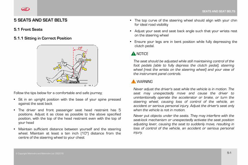
Follow the tips below for a comfortable and safe journey;
• Sit in an upright position with the base of your spine pressedagainst the seat back
• The driver and front passenger seat head restraint has 5positions. Adjust it as close as possible to the above specifiedposition, with the top of the head restraint even with the top ofyour head
• Maintain sufficient distance between yourself and the steeringwheel. Maintain at least a ten inch (10") distance from thecentre of the steering wheel to your chest
• The top curve of the steering wheel should align with your chinfor ideal road visibility
• Adjust your seat and seat back angle such that your wrists reston the steering wheel
• Ensure your legs are in bent position while fully depressing theclutch pedal.
The seat should be adjusted while still maintaining control of thefoot pedals (able to fully depress the clutch pedal), steeringwheel (rest the wrists on the steering wheel) and your view ofthe instrument panel controls.
Never adjust the driver's seat while the vehicle is in motion. Theseat may unexpectedly move and cause the driver tounintentionally operate the accelerator or brake, or turn thesteering wheel, causing loss of control of the vehicle, anaccident or serious personal injury. Adjust the driver's seat onlywhen the vehicle is not in motion.
Never put objects under the seats. They may interfere with theseat-lock mechanism or unexpectedly activate the seat positionadjusting lever, causing the seat to suddenly move, resulting inloss of control of the vehicle, an accident or serious personalinjury.
SEATS AND SEAT BELTS
5-2 © Copyright Mahindra and Mahindra Ltd.052016
While adjusting the seat, do not put your hands under the seator near the moving parts. This may lead to injuries.
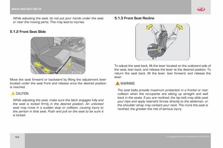
5.1.2 Front Seat Slide
W22E22
Move the seat forward or backward by lifting the adjustment leverlocated under the seat front and release once the desired positionis reached.
While adjusting the seat, make sure the latch engages fully andthe seat is locked firmly in the desired position. An unlockedseat may move in a sudden stop or collision, causing injury tothe person in that seat. Push and pull on the seat to be sure itis locked.
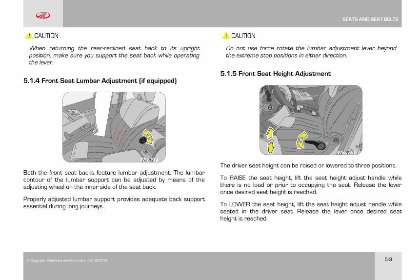
5.1.3 Front Seat Recline
To adjust the seat back, lift the lever located on the outboard side ofthe seat, lean back, and release the lever at the desired position. Toreturn the seat back, lift the lever, lean forward, and release thelever.
The seat belts provide maximum protection in a frontal or rearcollision when the occupants are sitting up straight and wellback in the seats. If you are reclined, the lap belt may slide pastyour hips and apply restraint forces directly to the abdomen, orthe shoulder strap may contact your neck. The more the seat isreclined, the greater the risk of serious injury.
SEATS AND SEAT BELTS
© Copyright Mahindra and Mahindra Ltd. 052016 5-3
When returning the rear-reclined seat back to its uprightposition, make sure you support the seat back while operatingthe lever.
5.1.4 Front Seat Lumbar Adjustment (if equipped)
W22E27
Both the front seat backs feature lumbar adjustment. The lumbarcontour of the lumbar support can be adjusted by means of theadjusting wheel on the inner side of the seat back.
Properly adjusted lumbar support provides adequate back supportessential during long journeys.
Do not use force rotate the lumbar adjustment lever beyondthe extreme stop positions in either direction.
5.1.5 Front Seat Height Adjustment
W22E33
The driver seat height can be raised or lowered to three positions.
To RAISE the seat height, lift the seat height adjust handle whilethere is no load or prior to occupying the seat. Release the leveronce desired seat height is reached.
To LOWER the seat height, lift the seat height adjust handle whileseated in the driver seat. Release the lever once desired seatheight is reached.
SEATS AND SEAT BELTS
5-4 © Copyright Mahindra and Mahindra Ltd.052016
Do not adjust the height of seat while vehicle is in motion.
5.2 Head Restraint
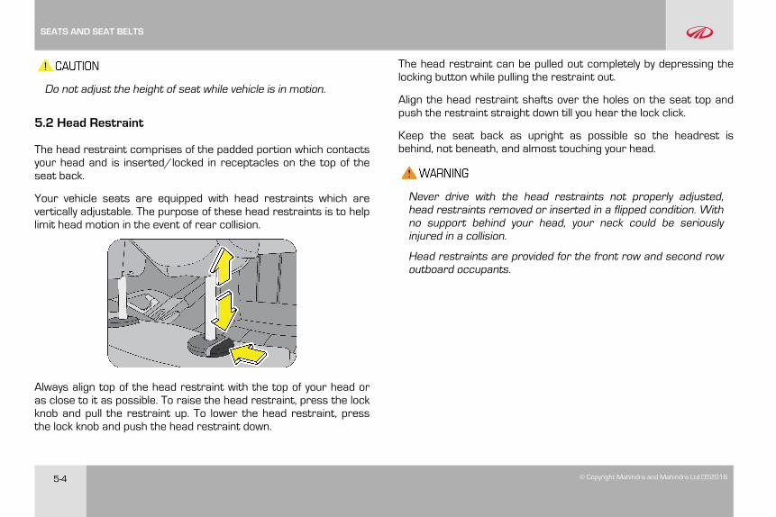
The head restraint comprises of the padded portion which contactsyour head and is inserted/locked in receptacles on the top of theseat back.
Your vehicle seats are equipped with head restraints which arevertically adjustable. The purpose of these head restraints is to helplimit head motion in the event of rear collision.
Always align top of the head restraint with the top of your head oras close to it as possible. To raise the head restraint, press the lockknob and pull the restraint up. To lower the head restraint, pressthe lock knob and push the head restraint down.
The head restraint can be pulled out completely by depressing thelocking button while pulling the restraint out.
Align the head restraint shafts over the holes on the seat top andpush the restraint straight down till you hear the lock click.
Keep the seat back as upright as possible so the headrest isbehind, not beneath, and almost touching your head.
Never drive with the head restraints not properly adjusted,head restraints removed or inserted in a flipped condition. Withno support behind your head, your neck could be seriouslyinjured in a collision.
Head restraints are provided for the front row and second rowoutboard occupants.
SEATS AND SEAT BELTS
© Copyright Mahindra and Mahindra Ltd. 052016 5-5
5.3 Second Row Seats
Loading luggage on the seats is dangerous. The luggage canbecome a projectile that could hit and injure passengers in asudden stop or collision. Luggage should always be kept on thefloor.
To avoid serious injury, do not sit on or place objects on a foldedseat back while the vehicle is moving.
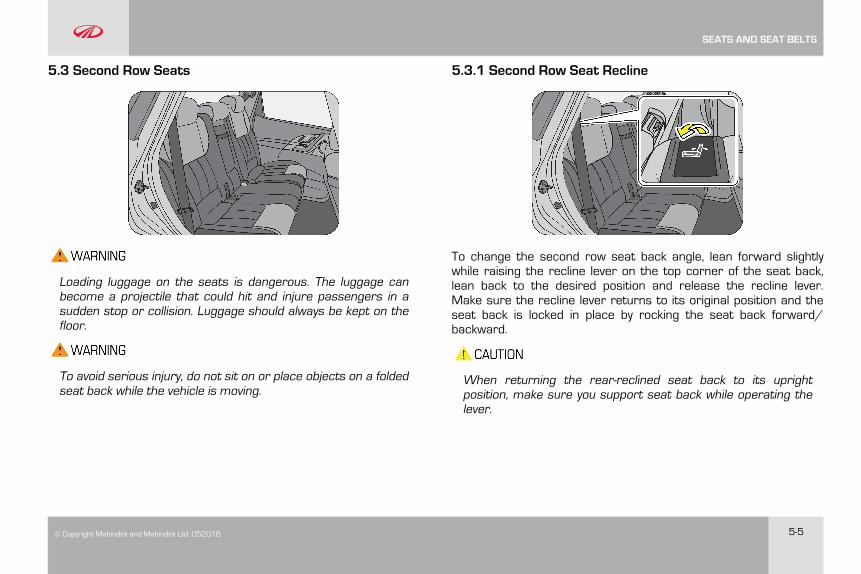
5.3.1 Second Row Seat Recline
To change the second row seat back angle, lean forward slightlywhile raising the recline lever on the top corner of the seat back,lean back to the desired position and release the recline lever.Make sure the recline lever returns to its original position and theseat back is locked in place by rocking the seat back forward/backward.
When returning the rear-reclined seat back to its uprightposition, make sure you support seat back while operating thelever.
SEATS AND SEAT BELTS
5-6 © Copyright Mahindra and Mahindra Ltd.052016
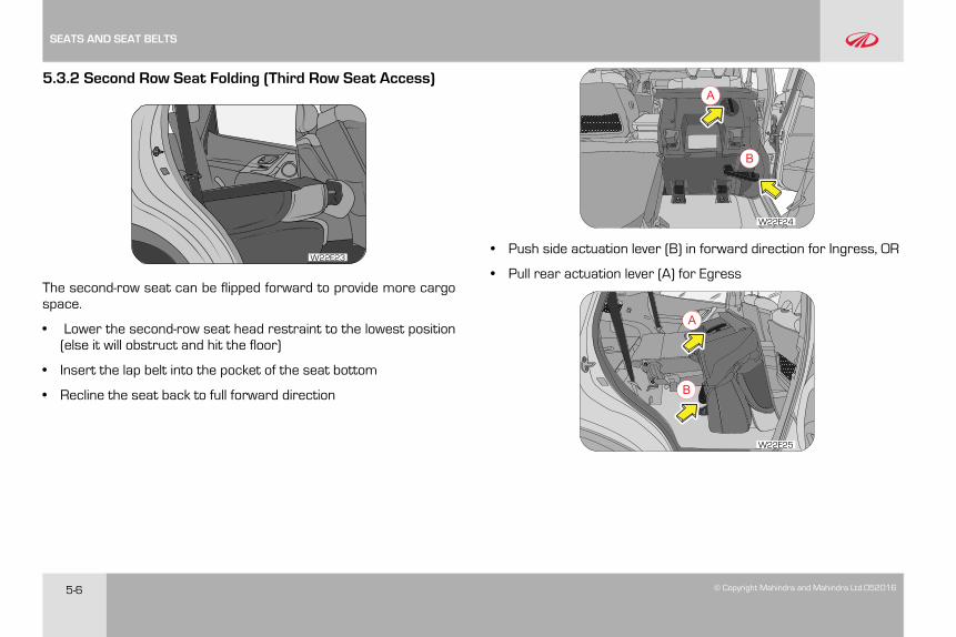
5.3.2 Second Row Seat Folding (Third Row Seat Access)
W22E23
The second-row seat can be flipped forward to provide more cargospace.
• Lower the second-row seat head restraint to the lowest position(else it will obstruct and hit the floor)
• Insert the lap belt into the pocket of the seat bottom
• Recline the seat back to full forward direction
A
B
W22E24
• Push side actuation lever (B) in forward direction for Ingress, OR
• Pull rear actuation lever (A) for Egress
A
B
W22E25
SEATS AND SEAT BELTS
© Copyright Mahindra and Mahindra Ltd. 052016 5-7
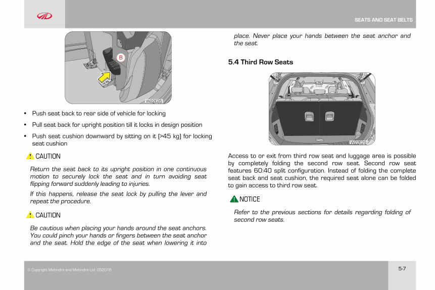
B
W22E26
• Push seat back to rear side of vehicle for locking
• Pull seat back for upright position till it locks in design position
• Push seat cushion downward by sitting on it (>45 kg) for lockingseat cushion
Return the seat back to its upright position in one continuousmotion to securely lock the seat and in turn avoiding seatflipping forward suddenly leading to injuries.
If this happens, release the seat lock by pulling the lever andrepeat the procedure.
Be cautious when placing your hands around the seat anchors.You could pinch your hands or fingers between the seat anchorand the seat. Hold the edge of the seat when lowering it into
place. Never place your hands between the seat anchor andthe seat.
5.4 Third Row Seats
W22E29
Access to or exit from third row seat and luggage area is possibleby completely folding the second row seat. Second row seatfeatures 60:40 split configuration. Instead of folding the completeseat back and seat cushion, the required seat alone can be foldedto gain access to third row seat.
Refer to the previous sections for details regarding folding ofsecond row seats.
SEATS AND SEAT BELTS
5-8 © Copyright Mahindra and Mahindra Ltd.052016
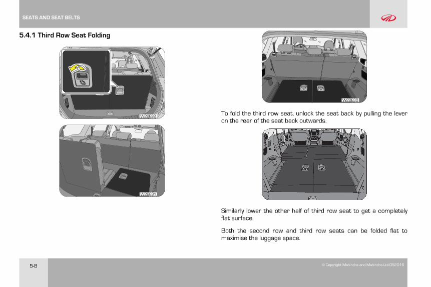
5.4.1 Third Row Seat Folding
W22E32
W22E31
W22E30
To fold the third row seat, unlock the seat back by pulling the leveron the rear of the seat back outwards.
Similarly lower the other half of third row seat to get a completelyflat surface.
Both the second row and third row seats can be folded flat tomaximise the luggage space.
SEATS AND SEAT BELTS
© Copyright Mahindra and Mahindra Ltd. 052016 5-9
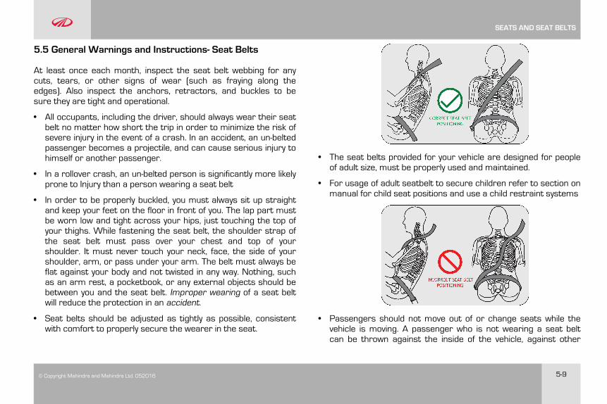
5.5 General Warnings and Instructions- Seat Belts
At least once each month, inspect the seat belt webbing for anycuts, tears, or other signs of wear (such as fraying along theedges). Also inspect the anchors, retractors, and buckles to besure they are tight and operational.
• All occupants, including the driver, should always wear their seatbelt no matter how short the trip in order to minimize the risk ofsevere injury in the event of a crash. In an accident, an un-beltedpassenger becomes a projectile, and can cause serious injury tohimself or another passenger.
• In a rollover crash, an un-belted person is significantly more likelyprone to Injury than a person wearing a seat belt
• In order to be properly buckled, you must always sit up straightand keep your feet on the floor in front of you. The lap part mustbe worn low and tight across your hips, just touching the top ofyour thighs. While fastening the seat belt, the shoulder strap ofthe seat belt must pass over your chest and top of yourshoulder. It must never touch your neck, face, the side of yourshoulder, arm, or pass under your arm. The belt must always beflat against your body and not twisted in any way. Nothing, suchas an arm rest, a pocketbook, or any external objects should bebetween you and the seat belt. Improper wearing of a seat beltwill reduce the protection in an accident.
• Seat belts should be adjusted as tightly as possible, consistentwith comfort to properly secure the wearer in the seat.
• The seat belts provided for your vehicle are designed for peopleof adult size, must be properly used and maintained.
• For usage of adult seatbelt to secure children refer to section onmanual for child seat positions and use a child restraint systems
• Passengers should not move out of or change seats while thevehicle is moving. A passenger who is not wearing a seat beltcan be thrown against the inside of the vehicle, against other
SEATS AND SEAT BELTS
5-10 © Copyright Mahindra and Mahindra Ltd.052016
occupants, or out of the vehicle during a crash or emergencystop
• Do not use any accessories on seat belts or modify in any waythe seat belt system. Devices claiming to improve occupantcomfort or reposition the seat belt can reduce the protectionprovided by the seat belt and increase the chance of seriousinjury in a crash
• An accident or emergency stop, can damage your seat beltsystem, even if the accident is “minor”. Please have yourAuthorized Mahindra Dealer inspect the seat belt system afteran accident
• Please be aware that any unsecured item in your vehicle, suchas your pet, unsecured child restraint system, a laptop or mobilephones, can become a projectile in the event of an accident orsudden stop, causing injuries to occupants in the vehicle
Never use a damaged seat belt system. A damaged seat beltwill not provide protection in an accident, resulting in seriousinjury.
• Seat belt systems can be prone to abuse. They are notindestructible. They must be handled with care to avoid damage
• Keep the belts clean and dry. Belt retraction may becomedifficult if the belts and webbing are soiled. If they need cleaning,use a mild soap solution or lukewarm water. Never use bleach,
dye, or abrasive cleaners. These chemicals will severely weakenthe belts
• Retractors in 3-point type seat belts retract the seat belts whennot in use. The inertia lock and coil spring allow the belts toremain comfortable on users during normal driving. Duringaccidents or abrupt stops, inertia locks restrict the suddenforward movement of the wearer
Seat Belts - Patients
Persons with serious medical conditions should also wear a seatbelt. Consult your doctor for specific recommendations beforetravel.
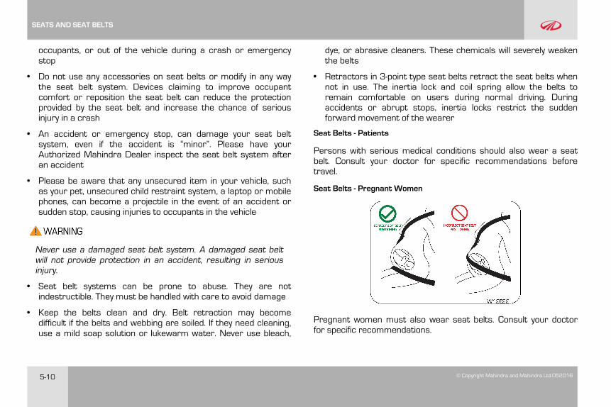
Seat Belts - Pregnant Women
Pregnant women must also wear seat belts. Consult your doctorfor specific recommendations.
SEATS AND SEAT BELTS
© Copyright Mahindra and Mahindra Ltd. 052016 5-11
The lap belt should be worn snugly and as low as possible over thehips. The shoulder belt should be worn across your shoulder, butnever across the stomach area. When worn properly, the seat beltwill protect both the mother and the foetus in an accident oremergency stop.
A pregnant woman should never wear the seat belt across thestomach area. This could lead to serious injuries to the foetusand/or the pregnant mother.
Never wear twisted seat belts. Excessive forces will betransferred from the belt to the wearer, in a collision, resultingin serious personal injury.
Each seat belt is meant for use by one person only. Using oneseat belt for more than one person at a time is dangerous. Theseat belt will not be able to spread the impact forces properlyleading to serious injuries.
Never put a belt around a child being carried on the occupant'slap. This could lead to serious injuries.
Seat Belt Usage is Necessary to:
• Reduce the possibility of being thrown from your vehicle
• Reduce the possibility of injuries to upper body, lower body andlegs during an accident
• Hold the driver in a position which allows better control of thevehicle
Children who are too large for child restraint systems should alwaysoccupy the rear seat and use the vehicle seat belts. The lap portionshould be fastened snug on the hips and as low as possible and theshoulder strap should be across the child's shoulder, not the neckor face. If you are unable to position the strap across the child'sshoulder, the child should remain in a booster seat. Frequentlycheck the seat belt to be sure it remains snug and in position. Asquirming child could cause the seat belt to come out of position.
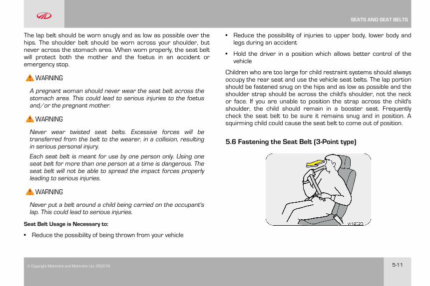
5.6 Fastening the Seat Belt (3-Point type)
SEATS AND SEAT BELTS
5-12 © Copyright Mahindra and Mahindra Ltd.052016
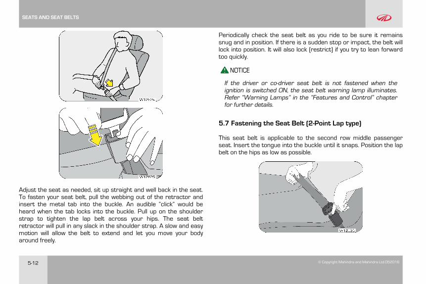
Adjust the seat as needed, sit up straight and well back in the seat.To fasten your seat belt, pull the webbing out of the retractor andinsert the metal tab into the buckle. An audible “click” would beheard when the tab locks into the buckle. Pull up on the shoulderstrap to tighten the lap belt across your hips. The seat beltretractor will pull in any slack in the shoulder strap. A slow and easymotion will allow the belt to extend and let you move your bodyaround freely.
Periodically check the seat belt as you ride to be sure it remainssnug and in position. If there is a sudden stop or impact, the belt willlock into position. It will also lock (restrict) if you try to lean forwardtoo quickly.
If the driver or co-driver seat belt is not fastened when theignition is switched ON, the seat belt warning lamp illuminates.Refer “Warning Lamps” in the “Features and Control” chapterfor further details.
5.7 Fastening the Seat Belt (2-Point Lap type)
This seat belt is applicable to the second row middle passengerseat. Insert the tongue into the buckle until it snaps. Position the lapbelt on the hips as low as possible.
SEATS AND SEAT BELTS
© Copyright Mahindra and Mahindra Ltd. 052016 5-13
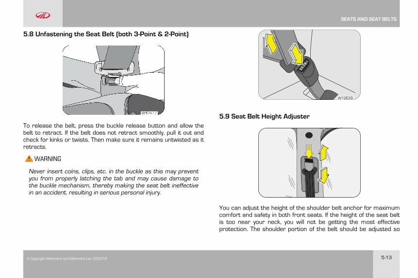
5.8 Unfastening the Seat Belt (both 3-Point & 2-Point)
To release the belt, press the buckle release button and allow thebelt to retract. If the belt does not retract smoothly, pull it out andcheck for kinks or twists. Then make sure it remains untwisted as itretracts.
Never insert coins, clips, etc. in the buckle as this may preventyou from properly latching the tab and may cause damage tothe buckle mechanism, thereby making the seat belt ineffectivein an accident, resulting in serious personal injury.
CORRECT SEAT BELTPOSITIONING
PRESS
W12E28
5.9 Seat Belt Height Adjuster
You can adjust the height of the shoulder belt anchor for maximumcomfort and safety in both front seats. If the height of the seat beltis too near your neck, you will not be getting the most effectiveprotection. The shoulder portion of the belt should be adjusted so
SEATS AND SEAT BELTS

5-14 © Copyright Mahindra and Mahindra Ltd.052016
that it lies across your chest and midway over your shouldernearest to the door and not your neck.
To adjust the height of the seat belt anchor, lower or raise theheight adjuster to an appropriate position while pressing the heightadjuster button. Release the button to lock the anchor into position.Try sliding the height adjuster to make sure that it has locked intothe position.
Adjust the shoulder belt height sitting well back in the seat. Donot adjust the seat belt height while vehicle is in motion.
5.10 Child Restraint System (CRS) (if equipped)
Use a child restraint system only if the child is not big enough toproperly wear the seat belts. Else, use the regular seat belt insteadof the child restraint system. Seat the child in the rear seat and usethe seat belt. According to accident statistics, children are saferwhen properly restrained in the rear seat than in the front seat.Always secure a child in a proper child restraint system inaccordance with age and size of the child as recommended by thechild restraint system manufacturer.
Do not allow children to stand up or kneel on either the rear orthe front seats. An unrestrained child could suffer seriousinjuries during emergency braking or collision.
It is also not recommended that children travel sitting on yourlap as it does not provide sufficient restraint.
Mass Group Weight of Child(kg)Fitting the child
restraints system usingseat belt
Group 0 0–10 Rear-facing childrestraint system on theoutboard 2ndrow seatsusing seat belt.
Group 0+ upto 13
Group 1 9–18 Forward-facing childrestraint system on theoutboard 2ndrow seatsusing seat belt.
Group 2 15–25
Group 3 22–36
U
U
U
Not Suitable position for using child restraint system using seat belt
Suitable position for using universal child restraint system using seat belt
W22E28
SEATS AND SEAT BELTS
© Copyright Mahindra and Mahindra Ltd. 052016 5-15
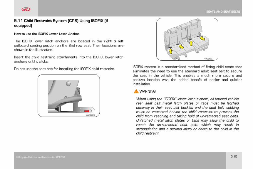
5.11 Child Restraint System (CRS) Using ISOFIX (ifequipped)
How to use the ISOFIX Lower Latch Anchor
The ISOFIX lower latch anchors are located in the right & leftoutboard seating position on the 2nd row seat. Their locations areshown in the illustration.
Insert the child restraint attachments into the ISOFIX lower latchanchors until it clicks.
Do not use the seat belt for installing the ISOFIX child restraint.
W22E36
W22E37
ISOFIX system is a standardised method of fitting child seats thateliminates the need to use the standard adult seat belt to securethe seat in the vehicle. This enables a much more secure andpositive location with the added benefit of easier and quickerinstallation.
When using the “ISOFIX” lower latch system, all unused vehiclerear seat belt metal latch plates or tabs must be latchedsecurely in their seat belt buckles and the seat belt webbingmust be retracted behind the child restraint to prevent thechild from reaching and taking hold of un-retracted seat belts.Unlatched metal latch plates or tabs may allow the child toreach the un-retracted seat belts which may result instrangulation and a serious injury or death to the child in thechild restraint.
SEATS AND SEAT BELTS
5-16 © Copyright Mahindra and Mahindra Ltd.052016
Child restraint anchorages are designed to withstand onlythose loads imposed by correctly fitted child restraints. Underno circumstances are they to be used for adult seat belts orharnesses or for attaching other items or equipment to thevehicle.
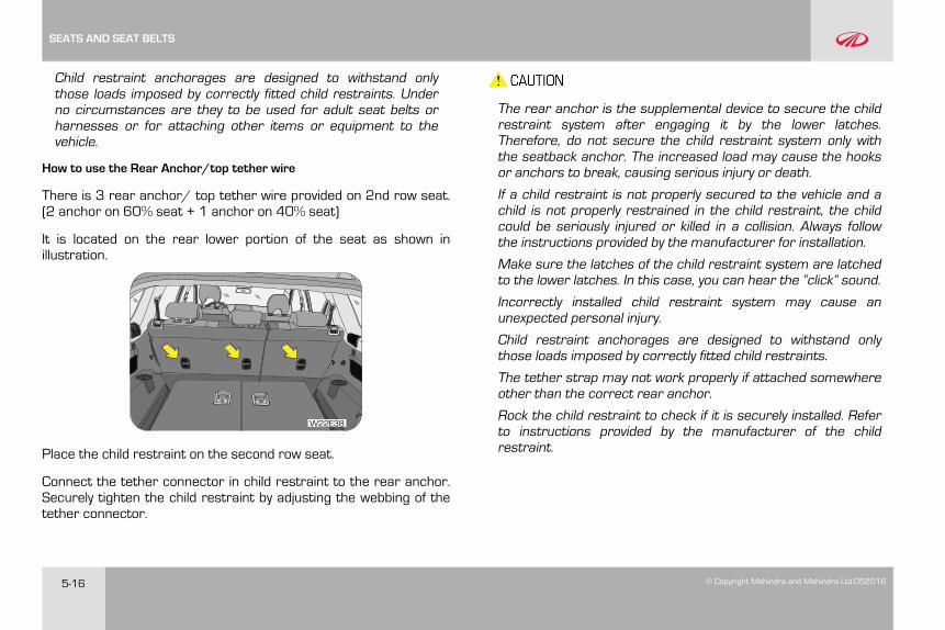
How to use the Rear Anchor/top tether wire
There is 3 rear anchor/ top tether wire provided on 2nd row seat.(2 anchor on 60% seat + 1 anchor on 40% seat)
It is located on the rear lower portion of the seat as shown inillustration.
W22E38
Place the child restraint on the second row seat.
Connect the tether connector in child restraint to the rear anchor.Securely tighten the child restraint by adjusting the webbing of thetether connector.
The rear anchor is the supplemental device to secure the childrestraint system after engaging it by the lower latches.Therefore, do not secure the child restraint system only withthe seatback anchor. The increased load may cause the hooksor anchors to break, causing serious injury or death.
If a child restraint is not properly secured to the vehicle and achild is not properly restrained in the child restraint, the childcould be seriously injured or killed in a collision. Always followthe instructions provided by the manufacturer for installation.
Make sure the latches of the child restraint system are latchedto the lower latches. In this case, you can hear the “click” sound.
Incorrectly installed child restraint system may cause anunexpected personal injury.
Child restraint anchorages are designed to withstand onlythose loads imposed by correctly fitted child restraints.
The tether strap may not work properly if attached somewhereother than the correct rear anchor.
Rock the child restraint to check if it is securely installed. Referto instructions provided by the manufacturer of the childrestraint.
SEATS AND SEAT BELTS
© Copyright Mahindra and Mahindra Ltd. 052016 6-1
6 SUPPLEMENTAL RESTRAINT SYSTEM (SRS) (ifequipped)
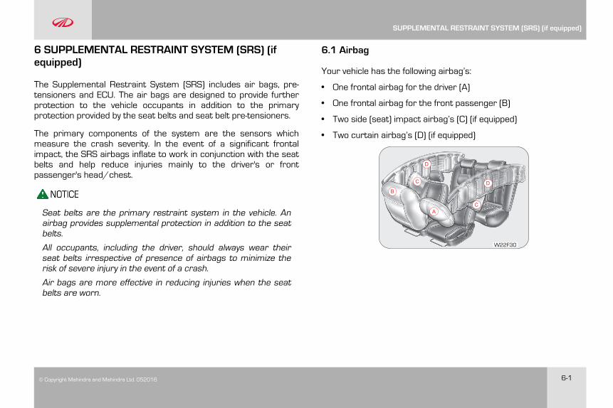
The Supplemental Restraint System (SRS) includes air bags, pre-tensioners and ECU. The air bags are designed to provide furtherprotection to the vehicle occupants in addition to the primaryprotection provided by the seat belts and seat belt pre-tensioners.
The primary components of the system are the sensors whichmeasure the crash severity. In the event of a significant frontalimpact, the SRS airbags inflate to work in conjunction with the seatbelts and help reduce injuries mainly to the driver's or frontpassenger's head/chest.
Seat belts are the primary restraint system in the vehicle. Anairbag provides supplemental protection in addition to the seatbelts.
All occupants, including the driver, should always wear theirseat belts irrespective of presence of airbags to minimize therisk of severe injury in the event of a crash.
Air bags are more effective in reducing injuries when the seatbelts are worn.
6.1 Airbag
Your vehicle has the following airbag’s:
• One frontal airbag for the driver (A)
• One frontal airbag for the front passenger (B)
• Two side (seat) impact airbag’s (C) (if equipped)
• Two curtain airbag’s (D) (if equipped)
A
B
C
C
D
D
W22F30
SUPPLEMENTAL RESTRAINT SYSTEM (SRS) (if equipped)
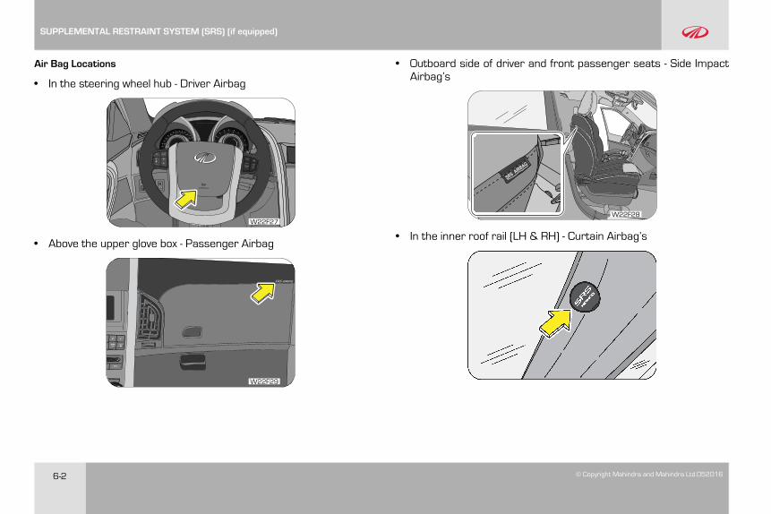
6-2 © Copyright Mahindra and Mahindra Ltd.052016
Air Bag Locations
• In the steering wheel hub - Driver Airbag
W22F27
• Above the upper glove box - Passenger Airbag
W22F29
• Outboard side of driver and front passenger seats - Side ImpactAirbag’s
W22F28
• In the inner roof rail (LH & RH) - Curtain Airbag’s
SUPPLEMENTAL RESTRAINT SYSTEM (SRS) (if equipped)
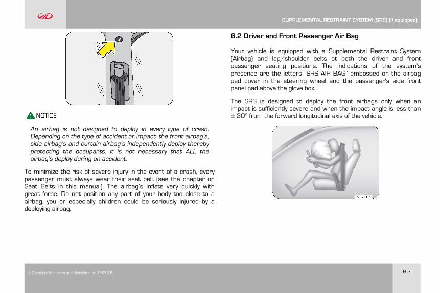
© Copyright Mahindra and Mahindra Ltd. 052016 6-3
An airbag is not designed to deploy in every type of crash.Depending on the type of accident or impact, the front airbag’s,side airbag’s and curtain airbag’s independently deploy therebyprotecting the occupants. It is not necessary that ALL theairbag’s deploy during an accident.
To minimize the risk of severe injury in the event of a crash, everypassenger must always wear their seat belt (see the chapter onSeat Belts in this manual). The airbag’s inflate very quickly withgreat force. Do not position any part of your body too close to aairbag, you or especially children could be seriously injured by adeploying airbag.
6.2 Driver and Front Passenger Air Bag
Your vehicle is equipped with a Supplemental Restraint System(Airbag) and lap/shoulder belts at both the driver and frontpassenger seating positions. The indications of the system'spresence are the letters “SRS AIR BAG” embossed on the airbagpad cover in the steering wheel and the passenger's side frontpanel pad above the glove box.
The SRS is designed to deploy the front airbags only when animpact is sufficiently severe and when the impact angle is less than± 30° from the forward longitudinal axis of the vehicle.
SUPPLEMENTAL RESTRAINT SYSTEM (SRS) (if equipped)
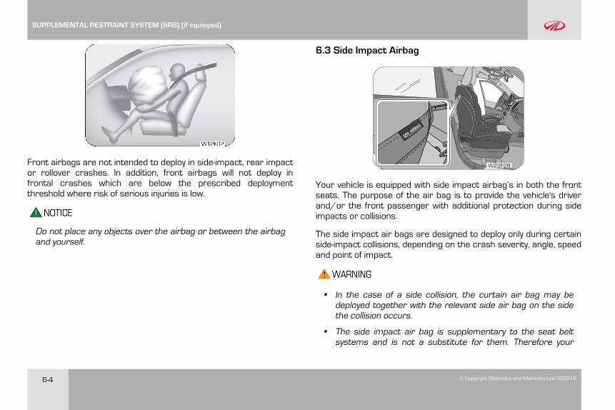
6-4 © Copyright Mahindra and Mahindra Ltd.052016
Front airbags are not intended to deploy in side-impact, rear impactor rollover crashes. In addition, front airbags will not deploy infrontal crashes which are below the prescribed deploymentthreshold where risk of serious injuries is low.
Do not place any objects over the airbag or between the airbagand yourself.
6.3 Side Impact Airbag
W22F28
Your vehicle is equipped with side impact airbag’s in both the frontseats. The purpose of the air bag is to provide the vehicle's driverand/or the front passenger with additional protection during sideimpacts or collisions.
The side impact air bags are designed to deploy only during certainside-impact collisions, depending on the crash severity, angle, speedand point of impact.
• In the case of a side collision, the curtain air bag may bedeployed together with the relevant side air bag on the sidethe collision occurs.
• The side impact air bag is supplementary to the seat beltsystems and is not a substitute for them. Therefore your
SUPPLEMENTAL RESTRAINT SYSTEM (SRS) (if equipped)
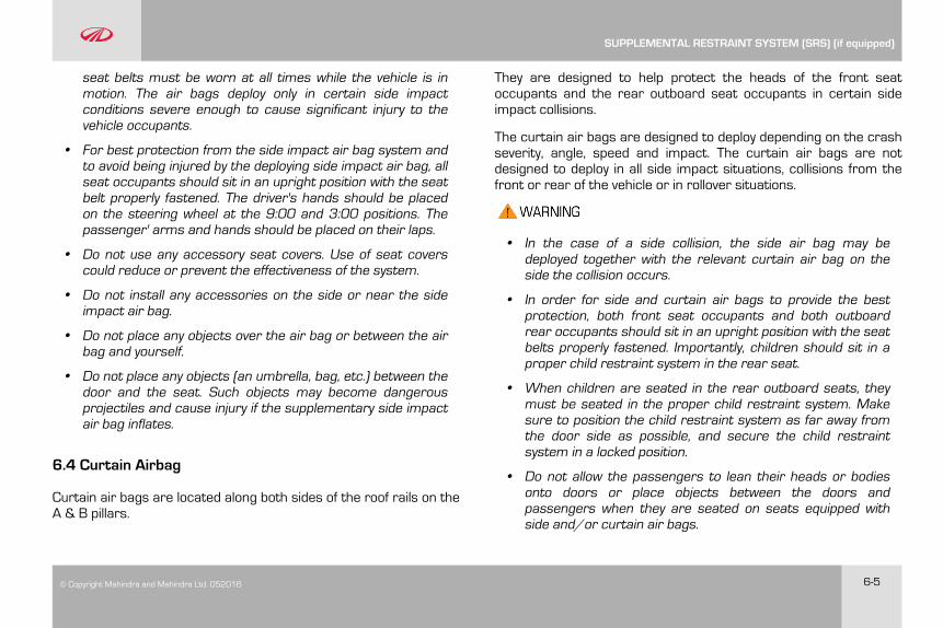
© Copyright Mahindra and Mahindra Ltd. 052016 6-5
seat belts must be worn at all times while the vehicle is inmotion. The air bags deploy only in certain side impactconditions severe enough to cause significant injury to thevehicle occupants.
• For best protection from the side impact air bag system andto avoid being injured by the deploying side impact air bag, allseat occupants should sit in an upright position with the seatbelt properly fastened. The driver's hands should be placedon the steering wheel at the 9:00 and 3:00 positions. Thepassenger' arms and hands should be placed on their laps.
• Do not use any accessory seat covers. Use of seat coverscould reduce or prevent the effectiveness of the system.
• Do not install any accessories on the side or near the sideimpact air bag.
• Do not place any objects over the air bag or between the airbag and yourself.
• Do not place any objects (an umbrella, bag, etc.) between thedoor and the seat. Such objects may become dangerousprojectiles and cause injury if the supplementary side impactair bag inflates.
6.4 Curtain Airbag
Curtain air bags are located along both sides of the roof rails on theA & B pillars.
They are designed to help protect the heads of the front seatoccupants and the rear outboard seat occupants in certain sideimpact collisions.
The curtain air bags are designed to deploy depending on the crashseverity, angle, speed and impact. The curtain air bags are notdesigned to deploy in all side impact situations, collisions from thefront or rear of the vehicle or in rollover situations.
• In the case of a side collision, the side air bag may bedeployed together with the relevant curtain air bag on theside the collision occurs.
• In order for side and curtain air bags to provide the bestprotection, both front seat occupants and both outboardrear occupants should sit in an upright position with the seatbelts properly fastened. Importantly, children should sit in aproper child restraint system in the rear seat.
• When children are seated in the rear outboard seats, theymust be seated in the proper child restraint system. Makesure to position the child restraint system as far away fromthe door side as possible, and secure the child restraintsystem in a locked position.
• Do not allow the passengers to lean their heads or bodiesonto doors or place objects between the doors andpassengers when they are seated on seats equipped withside and/or curtain air bags.
SUPPLEMENTAL RESTRAINT SYSTEM (SRS) (if equipped)
6-6 © Copyright Mahindra and Mahindra Ltd.052016
6.5 Airbag System Malfunction Lamp
Airbags do not require any regular maintenance ofservice. The airbag system malfunction lampilluminates when the ignition is ON, and it turns OFFafter about two seconds as self check confirming
normal operations of airbag system and malfunction lamp.
This lamp monitors airbag sensor assembly, airbag sensors,indicator lamp, seat belt pre-tensioner assemblies, inflators,interconnecting wiring and power sources.
If either of the following conditions occur, there is a malfunction ofthe airbags or seat belt pre-tensioner. Immediately contact yourMahindra Dealer.
• The lamp does not glow when the ignition is switched ON orglows beyond six (6) seconds after switching the ignition ON
• The lamp comes ON at any other time, even briefly
• The lamp comes ON intermittently
Never make any modifications to your vehicle which could affectthe performance of your airbag system. In particular, changesto the vehicle frame, bumpers, bull bar, front fenders, rideheight, suspension, seat belts, interior trim, seats or steeringwheel (especially covers, pads or other trim), could preventproper deployment of the airbag. If you need to make any
modifications to accommodate any disability you may have,please contact your Authorized Mahindra Dealer.
Never try to open or strike the airbag cover. If the airbag coveris cracked or damaged in any way, the airbag may not functionas intended. Take the vehicle to an Authorized Mahindra Dealer.
Even if the airbags do not deploy during an accident, take yourvehicle to an authorized Mahindra Dealer for a thorough inspectionof the airbag and seat belt systems, no matter how minor theaccident. The airbag system could have been damaged, and maynot work as intended in the future, resulting in serious injury.
6.6 Airbag Inflation/Deployment
The airbag sensors constantly monitor the forward deceleration ofthe vehicle. If an impact results in a forward deceleration beyondthe designed threshold level, the system triggers the airbaginflators. This initiates a chemical reaction which quickly fills theairbags with non-toxic gas.
Upon deployment, tear seams molded directly into the pad coversseparate under pressure from the expansion of the airbags.Further opening of the covers allows full inflation of the airbags. Afully inflated airbag, in combination with a properly worn seat belt,slows the driver's or the passenger's forward motion, reducing therisk of head and chest injury.
SUPPLEMENTAL RESTRAINT SYSTEM (SRS) (if equipped)
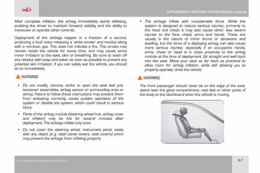
© Copyright Mahindra and Mahindra Ltd. 052016 6-7
After complete inflation, the airbag immediately starts deflating,enabling the driver to maintain forward visibility and the ability tomaneuver or operate other controls.
Deployment of the airbags happen in a fraction of a second,producing a loud noise releasing a ‘white smoke’ and residue alongwith a non-toxic gas. This does not indicate a fire. This smoke mayremain inside the vehicle for some time, and may cause someminor irritation to the eyes, skin or breathing. Be sure to wash offany residue with soap and water as soon as possible to prevent anypotential skin irritation. If you can safely exit the vehicle, you shoulddo so immediately.
• Do not modify, remove, strike or open the seat belt pre-tensioner assemblies, airbag sensor or surrounding area orwiring. Failure to follow these instructions may prevent themfrom activating correctly, cause sudden operation of thesystem or disable the system, which could result in seriousinjury
• Parts of the airbag module (steering wheel hub, airbag coverand inflator) may be hot for several minutes afterdeployment. The airbags inflate only once
• Do not cover the steering wheel, instrument panel, seatswith any object (e.g. dash panel covers, seat covers) whichmay prevent the airbags from inflating properly
• The airbags inflate with considerable force. While thesystem is designed to reduce serious injuries, primarily tothe head and chest, it may also cause other, less severeinjuries to the face, chest, arms and hands. These areusually in the nature of minor burns or abrasions andswelling, but the force of a deploying airbag can also causemore serious injuries, especially if an occupant's hands,arms, chest or head is in close proximity to the airbagmodule at the time of deployment. Sit straight and well backinto the seat. Move your seat as far back as practical toallow room for airbag inflation, while still allowing you toproperly operate/drive the vehicle
The front passenger should never sit on the edge of the seat,stand near the glove compartment, rest feet or other parts ofthe body on the dashboard when the vehicle is moving.
SUPPLEMENTAL RESTRAINT SYSTEM (SRS) (if equipped)
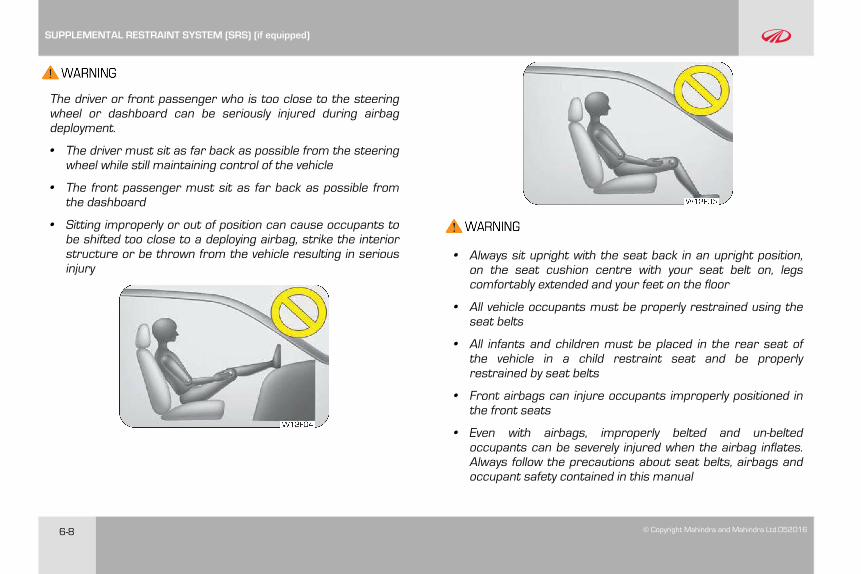
6-8 © Copyright Mahindra and Mahindra Ltd.052016
The driver or front passenger who is too close to the steeringwheel or dashboard can be seriously injured during airbagdeployment.
• The driver must sit as far back as possible from the steeringwheel while still maintaining control of the vehicle
• The front passenger must sit as far back as possible fromthe dashboard
• Sitting improperly or out of position can cause occupants tobe shifted too close to a deploying airbag, strike the interiorstructure or be thrown from the vehicle resulting in seriousinjury
• Always sit upright with the seat back in an upright position,on the seat cushion centre with your seat belt on, legscomfortably extended and your feet on the floor
• All vehicle occupants must be properly restrained using theseat belts
• All infants and children must be placed in the rear seat ofthe vehicle in a child restraint seat and be properlyrestrained by seat belts
• Front airbags can injure occupants improperly positioned inthe front seats
• Even with airbags, improperly belted and un-beltedoccupants can be severely injured when the airbag inflates.Always follow the precautions about seat belts, airbags andoccupant safety contained in this manual
SUPPLEMENTAL RESTRAINT SYSTEM (SRS) (if equipped)
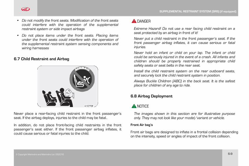
© Copyright Mahindra and Mahindra Ltd. 052016 6-9
• Do not modify the front seats. Modification of the front seatscould interfere with the operation of the supplementalrestraint system or side impact airbags
• Do not place items under the front seats. Placing itemsunder the front seats could interfere with the operation ofthe supplemental restraint system sensing components andwiring harnesses
6.7 Child Restraint and Airbag
Never place a rear-facing child restraint in the front passenger’sseat. If the airbag deploys, injuries to the child may be fatal..
In addition, do not place front-facing child restraints in the frontpassenger’s seat either. If the front passenger airbag inflates, itcould cause serious or fatal injuries to the child.
Extreme Hazard! Do not use a rear facing child restraint on aseat protected by an airbag in front of it!
Never put a child restraint in the front passenger’s seat. If thefront passenger airbag inflates, it can cause serious or fatalinjuries.
Never hold an infant or child on your lap. The infant or childcould be seriously injured in the event of a crash. All infants andchildren should be properly restrained in appropriate childsafety seats or seat belts in the rear seat.
Install the child restraint system on the rear outboard seats,and securely lock the child restraint system in position.
Always Buckle Children (ABC) in the back seat. It is the safestplace for children of any age to ride.
6.8 Airbag Deployment
The images shown in this section are for illustrative purposeonly. They may not look like your model/variant or vehicle.
Front Air bag’s
Front air bags are designed to inflate in a frontal collision dependingon the intensity, speed or angles of impact of the front collision.
SUPPLEMENTAL RESTRAINT SYSTEM (SRS) (if equipped)
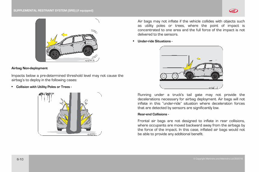
6-10 © Copyright Mahindra and Mahindra Ltd.052016
Airbag Non-deployment
Impacts below a pre-determined threshold level may not cause theairbag’s to deploy in the following cases:
• Collision with Utility Poles or Trees -
Air bags may not inflate if the vehicle collides with objects suchas utility poles or trees, where the point of impact isconcentrated to one area and the full force of the impact is notdelivered to the sensors.
• Under-ride Situations -
Running under a truck's tail gate may not provide thedecelerations necessary for airbag deployment. Air bags will notinflate in this “under-ride” situation where deceleration forcesthat are detected by sensors are significantly low.
Rear-end Collisions -
Frontal air bags are not designed to inflate in rear collisions,where occupants are moved backward away from the airbags bythe force of the impact. In this case, inflated air bags would notbe able to provide any additional benefit.
SUPPLEMENTAL RESTRAINT SYSTEM (SRS) (if equipped)
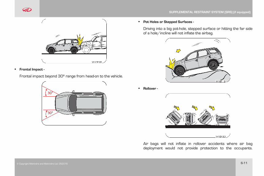
© Copyright Mahindra and Mahindra Ltd. 052016 6-11
• Frontal Impact -
Frontal impact beyond 30º range from head-on to the vehicle.
• Pot Holes or Stepped Surfaces -
Driving into a big pot-hole, stepped surface or hitting the far sideof a hole/incline will not inflate the airbag.
• Rollover -
Air bags will not inflate in rollover accidents where air bagdeployment would not provide protection to the occupants.
SUPPLEMENTAL RESTRAINT SYSTEM (SRS) (if equipped)
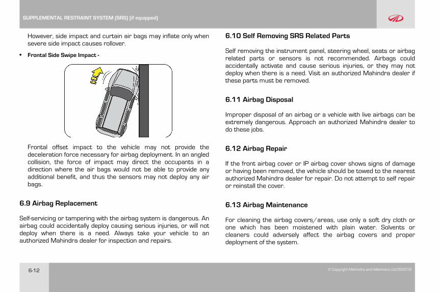
6-12 © Copyright Mahindra and Mahindra Ltd.052016
However, side impact and curtain air bags may inflate only whensevere side impact causes rollover.
• Frontal Side Swipe Impact -
Frontal offset impact to the vehicle may not provide thedeceleration force necessary for airbag deployment. In an angledcollision, the force of impact may direct the occupants in adirection where the air bags would not be able to provide anyadditional benefit, and thus the sensors may not deploy any airbags.
6.9 Airbag Replacement
Self-servicing or tampering with the airbag system is dangerous. Anairbag could accidentally deploy causing serious injuries, or will notdeploy when there is a need. Always take your vehicle to anauthorized Mahindra dealer for inspection and repairs.
6.10 Self Removing SRS Related Parts
Self removing the instrument panel, steering wheel, seats or airbagrelated parts or sensors is not recommended. Airbags couldaccidentally activate and cause serious injuries, or they may notdeploy when there is a need. Visit an authorized Mahindra dealer ifthese parts must be removed.
6.11 Airbag Disposal
Improper disposal of an airbag or a vehicle with live airbags can beextremely dangerous. Approach an authorized Mahindra dealer todo these jobs.
6.12 Airbag Repair
If the front airbag cover or IP airbag cover shows signs of damageor having been removed, the vehicle should be towed to the nearestauthorized Mahindra dealer for repair. Do not attempt to self repairor reinstall the cover.
6.13 Airbag Maintenance
For cleaning the airbag covers/areas, use only a soft dry cloth orone which has been moistened with plain water. Solvents orcleaners could adversely affect the airbag covers and properdeployment of the system.
SUPPLEMENTAL RESTRAINT SYSTEM (SRS) (if equipped)

© Copyright Mahindra and Mahindra Ltd. 052016 7-1
7 LOCKS AND KEYS
XUV500 comes with two RKE’s. Your key number is given on thetag attached to the key. It is recommended that you record the keynumber and store in a safe place. The keys operate all locks in yourvehicle including those of the doors and ignition with steering lock.We advise you to keep one of these keys at a safe place foremergency use, but not in the vehicle.
RKE Remote Keyless Entry
Never leave the key in the ignition switch with children in thevehicle. A child could switch on the ignition, start the engine,operate power windows and other controls, or move thevehicle, resulting in personal injuries to the bystanders and/orchildren seated inside.
7.1 Doors
To Open a Door from Inside
Pull the door lever away from the door and push the door outwardto open.
W22G53
LOCKS AND KEYS
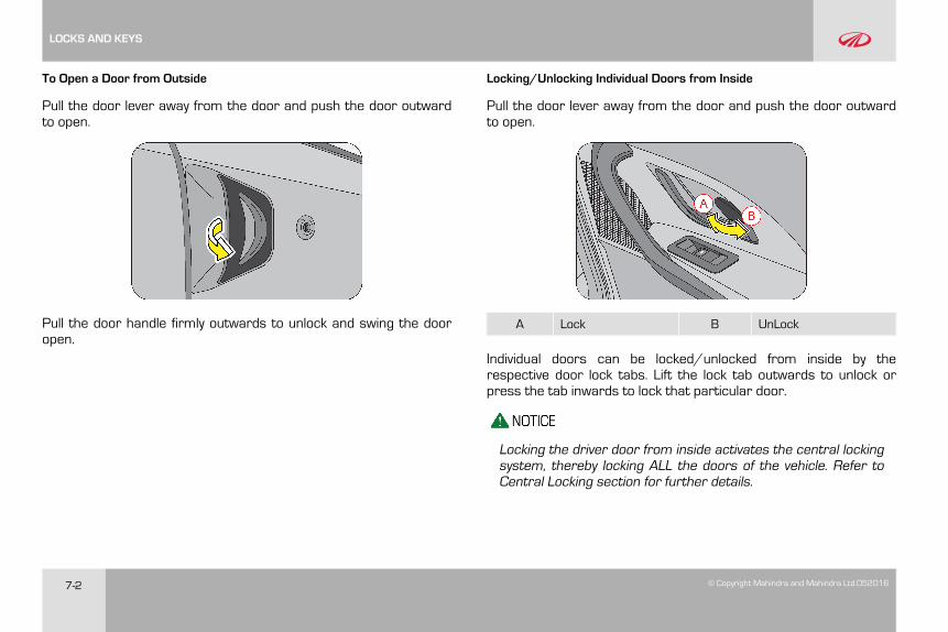
7-2 © Copyright Mahindra and Mahindra Ltd.052016
To Open a Door from Outside
Pull the door lever away from the door and push the door outwardto open.
Pull the door handle firmly outwards to unlock and swing the dooropen.
Locking/Unlocking Individual Doors from Inside
Pull the door lever away from the door and push the door outwardto open.
A Lock B UnLock
Individual doors can be locked/unlocked from inside by therespective door lock tabs. Lift the lock tab outwards to unlock orpress the tab inwards to lock that particular door.
Locking the driver door from inside activates the central lockingsystem, thereby locking ALL the doors of the vehicle. Refer toCentral Locking section for further details.
LOCKS AND KEYS
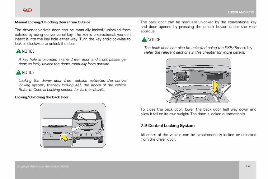
© Copyright Mahindra and Mahindra Ltd. 052016 7-3
Manual Locking/Unlocking Doors from Outside
The driver/co-driver door can be manually locked/unlocked fromoutside by using conventional key. The key is bi-directional; you caninsert it into the key hole either way. Turn the key anti-clockwise tolock or clockwise to unlock the door.
A key hole is provided in the driver door and front passengerdoor, to lock/unlock the doors manually from outside.
Locking the driver door from outside activates the centrallocking system, thereby locking ALL the doors of the vehicle.Refer to Central Locking section for further details.
Locking/Unlocking the Back Door
The back door can be manually unlocked by the conventional keyand door opened by pressing the unlock button under the rearapplique.
The back door can also be unlocked using the RKE/Smart key.Refer the relevant sections in this chapter for more details.
To close the back door, lower the back door half way down andallow it fall on its own weight. The door is locked automatically
7.2 Central Locking System
All doors of the vehicle can be simultaneously locked or unlockedfrom the driver door.
LOCKS AND KEYS

7-4 © Copyright Mahindra and Mahindra Ltd.052016
Central Locking/Unlocking All Doors from Outside
To manually lock/unlock all the doors from outside using theconventional key, turn the key anti-clockwise /clockwise respectivelyin the driver door key hole.
In case the back door is open when the central locking isactivated, the back door will not be locked even if it is closedlater.
If any other door is open when central locking is activated, thesystem locks the open doors when they are closed.
Central locking ALL the doors in the vehicle can also be doneusing the RKE/Smart key. Refer the relevant sections in thischapter for more details.
Central Locking/Unlocking All Doors from Inside
Press the driver door lock tab down (A) to lock or lift the lock tab up(B) to unlock all doors simultaneously.
AB
W22G54
7.3 Child Safety Rear Door Lock
Your vehicle is equipped with left and right side child safety reardoor locks. When the lock mechanism is engaged, the rear door(s)cannot be opened from the inside. The door(s) can only be openedfrom the outside.
To activate the child safety right rear door lock push the lever down(A) till you hear a distinct click indicating the activation of the childlock.
To de-activate the child safety right rear door lock pull the lever up(B) till you hear a distinct click indicating the deactivation of the childlock.
LOCKS AND KEYS
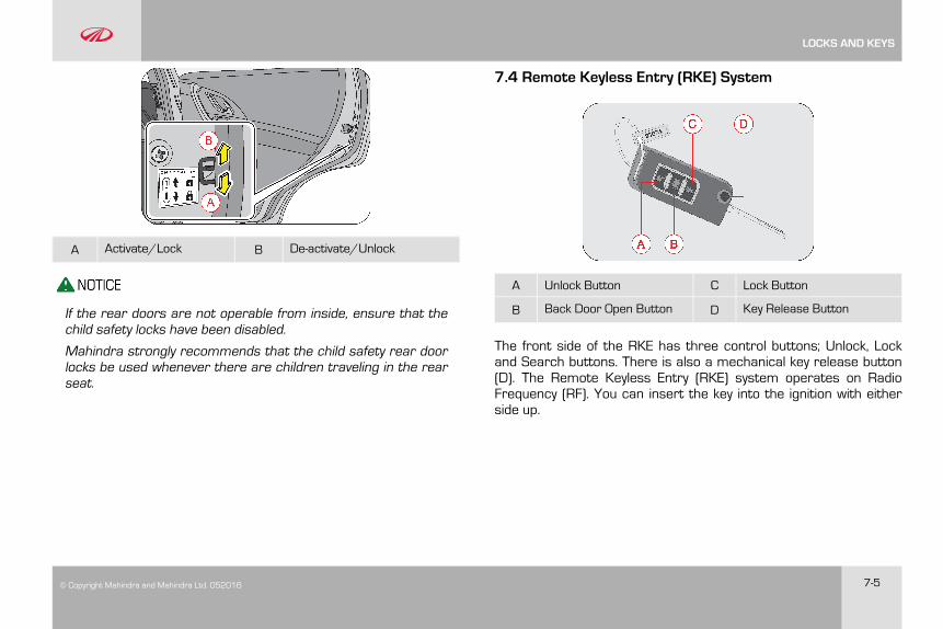
© Copyright Mahindra and Mahindra Ltd. 052016 7-5
A Activate/Lock B De-activate/Unlock
If the rear doors are not operable from inside, ensure that thechild safety locks have been disabled.
Mahindra strongly recommends that the child safety rear doorlocks be used whenever there are children traveling in the rearseat.
7.4 Remote Keyless Entry (RKE) System
A Unlock Button C Lock Button
B Back Door Open Button D Key Release Button
The front side of the RKE has three control buttons; Unlock, Lockand Search buttons. There is also a mechanical key release button(D). The Remote Keyless Entry (RKE) system operates on RadioFrequency (RF). You can insert the key into the ignition with eitherside up.
LOCKS AND KEYS
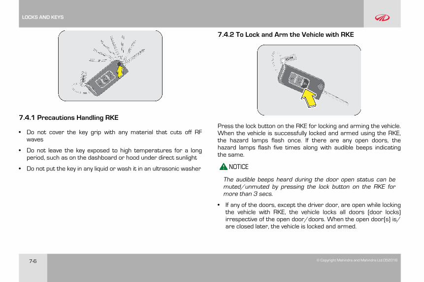
7-6 © Copyright Mahindra and Mahindra Ltd.052016
7.4.1 Precautions Handling RKE
• Do not cover the key grip with any material that cuts off RFwaves
• Do not leave the key exposed to high temperatures for a longperiod, such as on the dashboard or hood under direct sunlight
• Do not put the key in any liquid or wash it in an ultrasonic washer
7.4.2 To Lock and Arm the Vehicle with RKE
Press the lock button on the RKE for locking and arming the vehicle.When the vehicle is successfully locked and armed using the RKE,the hazard lamps flash once. If there are any open doors, thehazard lamps flash five times along with audible beeps indicatingthe same.
The audible beeps heard during the door open status can bemuted/unmuted by pressing the lock button on the RKE formore than 3 secs.
• If any of the doors, except the driver door, are open while lockingthe vehicle with RKE, the vehicle locks all doors (door locks)irrespective of the open door/doors. When the open door(s) is/are closed later, the vehicle is locked and armed.
LOCKS AND KEYS
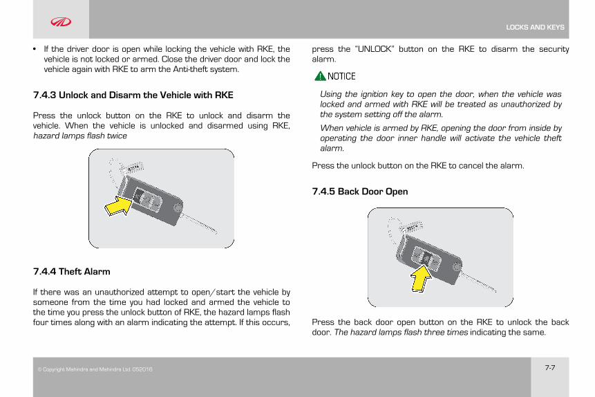
© Copyright Mahindra and Mahindra Ltd. 052016 7-7
• If the driver door is open while locking the vehicle with RKE, thevehicle is not locked or armed. Close the driver door and lock thevehicle again with RKE to arm the Anti-theft system.
7.4.3 Unlock and Disarm the Vehicle with RKE
Press the unlock button on the RKE to unlock and disarm thevehicle. When the vehicle is unlocked and disarmed using RKE,hazard lamps flash twice
7.4.4 Theft Alarm
If there was an unauthorized attempt to open/start the vehicle bysomeone from the time you had locked and armed the vehicle tothe time you press the unlock button of RKE, the hazard lamps flashfour times along with an alarm indicating the attempt. If this occurs,
press the “UNLOCK” button on the RKE to disarm the securityalarm.
Using the ignition key to open the door, when the vehicle waslocked and armed with RKE will be treated as unauthorized bythe system setting off the alarm.
When vehicle is armed by RKE, opening the door from inside byoperating the door inner handle will activate the vehicle theftalarm.
Press the unlock button on the RKE to cancel the alarm.
7.4.5 Back Door Open
Press the back door open button on the RKE to unlock the backdoor. The hazard lamps flash three times indicating the same.
LOCKS AND KEYS
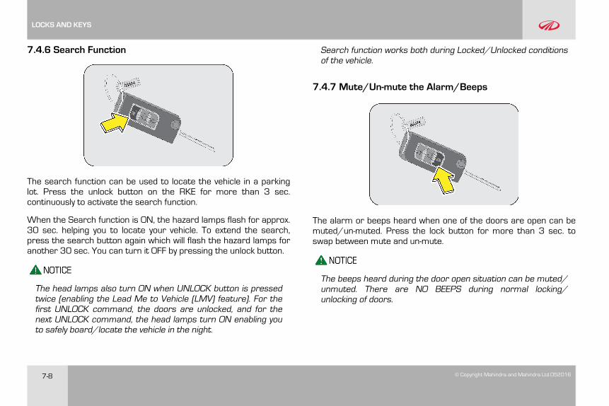
7-8 © Copyright Mahindra and Mahindra Ltd.052016
7.4.6 Search Function
The search function can be used to locate the vehicle in a parkinglot. Press the unlock button on the RKE for more than 3 sec.continuously to activate the search function.
When the Search function is ON, the hazard lamps flash for approx.30 sec. helping you to locate your vehicle. To extend the search,press the search button again which will flash the hazard lamps foranother 30 sec. You can turn it OFF by pressing the unlock button.
The head lamps also turn ON when UNLOCK button is pressedtwice (enabling the Lead Me to Vehicle (LMV) feature). For thefirst UNLOCK command, the doors are unlocked, and for thenext UNLOCK command, the head lamps turn ON enabling youto safely board/locate the vehicle in the night.
Search function works both during Locked/Unlocked conditionsof the vehicle.
7.4.7 Mute/Un-mute the Alarm/Beeps
The alarm or beeps heard when one of the doors are open can bemuted/un-muted. Press the lock button for more than 3 sec. toswap between mute and un-mute.
The beeps heard during the door open situation can be muted/unmuted. There are NO BEEPS during normal locking/unlocking of doors.
LOCKS AND KEYS
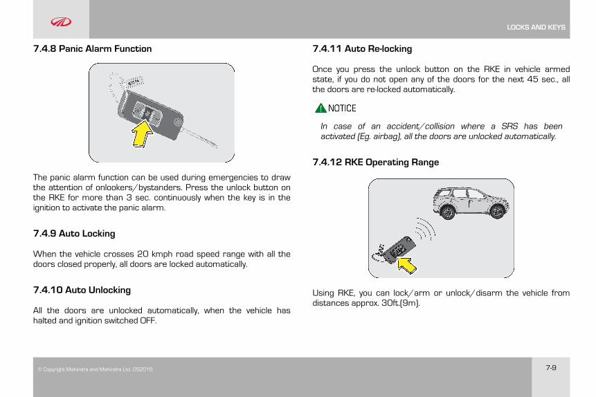
© Copyright Mahindra and Mahindra Ltd. 052016 7-9
7.4.8 Panic Alarm Function
The panic alarm function can be used during emergencies to drawthe attention of onlookers/bystanders. Press the unlock button onthe RKE for more than 3 sec. continuously when the key is in theignition to activate the panic alarm.
7.4.9 Auto Locking
When the vehicle crosses 20 kmph road speed range with all thedoors closed properly, all doors are locked automatically.
7.4.10 Auto Unlocking
All the doors are unlocked automatically, when the vehicle hashalted and ignition switched OFF.
7.4.11 Auto Re-locking
Once you press the unlock button on the RKE in vehicle armedstate, if you do not open any of the doors for the next 45 sec., allthe doors are re-locked automatically.
In case of an accident/collision where a SRS has beenactivated (Eg. airbag), all the doors are unlocked automatically.
7.4.12 RKE Operating Range
Using RKE, you can lock/arm or unlock/disarm the vehicle fromdistances approx. 30ft.(9m).
LOCKS AND KEYS
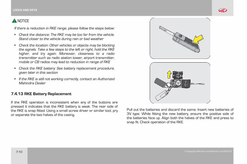
7-10 © Copyright Mahindra and Mahindra Ltd.052016
If there is reduction in RKE range, please follow the steps below:
• Check the distance: The RKE may be too far from the vehicle.Stand closer to the vehicle during rain or bad weather
• Check the location: Other vehicles or objects may be blockingthe signals. Take a few steps to the left or right, hold the RKEhigher, and try again. Moreover, closeness to a radiotransmitter such as radio station tower, airport transmitter,mobile or CB radios may lead to reduction in range of RKE
• Check the RKE battery: See battery replacement procedure,given later in this section
• If the RKE is still not working correctly, contact an AuthorizedMahindra Dealer
7.4.13 RKE Battery Replacement
If the RKE operation is inconsistent when any of the buttons arepressed it indicates that the RKE battery is weak. The rear side ofthe RKE is snap fitted. Using a small screw driver or similar tool, pryor separate the two halves of the casing.
Pull out the batteries and discard the same. Insert new batteries of3V type. While fitting the new battery, ensure the positive side ofthe batteries face up. Align both the halves of the RKE and press tosnap fit. Check operation of the RKE.
LOCKS AND KEYS
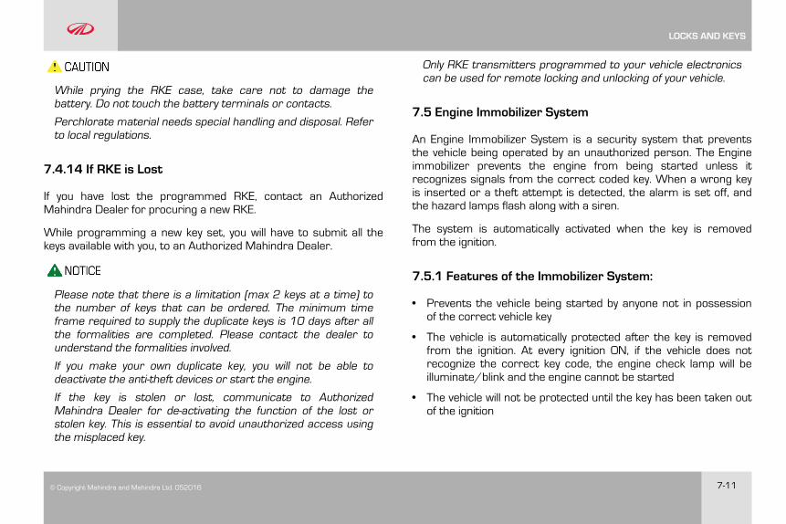
© Copyright Mahindra and Mahindra Ltd. 052016 7-11
While prying the RKE case, take care not to damage thebattery. Do not touch the battery terminals or contacts.
Perchlorate material needs special handling and disposal. Referto local regulations.
7.4.14 If RKE is Lost
If you have lost the programmed RKE, contact an AuthorizedMahindra Dealer for procuring a new RKE.
While programming a new key set, you will have to submit all thekeys available with you, to an Authorized Mahindra Dealer.
Please note that there is a limitation (max 2 keys at a time) tothe number of keys that can be ordered. The minimum timeframe required to supply the duplicate keys is 10 days after allthe formalities are completed. Please contact the dealer tounderstand the formalities involved.
If you make your own duplicate key, you will not be able todeactivate the anti-theft devices or start the engine.
If the key is stolen or lost, communicate to AuthorizedMahindra Dealer for de-activating the function of the lost orstolen key. This is essential to avoid unauthorized access usingthe misplaced key.
Only RKE transmitters programmed to your vehicle electronicscan be used for remote locking and unlocking of your vehicle.
7.5 Engine Immobilizer System
An Engine Immobilizer System is a security system that preventsthe vehicle being operated by an unauthorized person. The Engineimmobilizer prevents the engine from being started unless itrecognizes signals from the correct coded key. When a wrong keyis inserted or a theft attempt is detected, the alarm is set off, andthe hazard lamps flash along with a siren.
The system is automatically activated when the key is removedfrom the ignition.
7.5.1 Features of the Immobilizer System:
• Prevents the vehicle being started by anyone not in possessionof the correct vehicle key
• The vehicle is automatically protected after the key is removedfrom the ignition. At every ignition ON, if the vehicle does notrecognize the correct key code, the engine check lamp will beilluminate/blink and the engine cannot be started
• The vehicle will not be protected until the key has been taken outof the ignition
LOCKS AND KEYS
7-12 © Copyright Mahindra and Mahindra Ltd.052016
If the engine check lamp flashes or remains continuouslyilluminated after the ignition being switched ON, there is asystem malfunction. Contact an Authorized Mahindra Dealerimmediately.
Inserting the correct coded key in the ignition and switching theignition ON, automatically deactivates the system. This enables theengine to start.
In the event of the vehicle not starting with the correct key,switch off the ignition for a minimum of 1 minute and attemptto start the vehicle again.
Do not modify, remove or disassemble the engine immobilizersystem. Any unauthorized changes or modifications can affectproper operation of the system and will void your warranty.
The security system will be activated only when the vehicle islocked using the Smart key. Locking the doors with the manualkey will not activate the security system.
Using the ignition key to open the door, when the vehicle waslocked and armed with Smart key will be treated as
unauthorized by the system setting off the alarm. Press theunlock button on the Smart key to cancel the alarm.
LOCKS AND KEYS
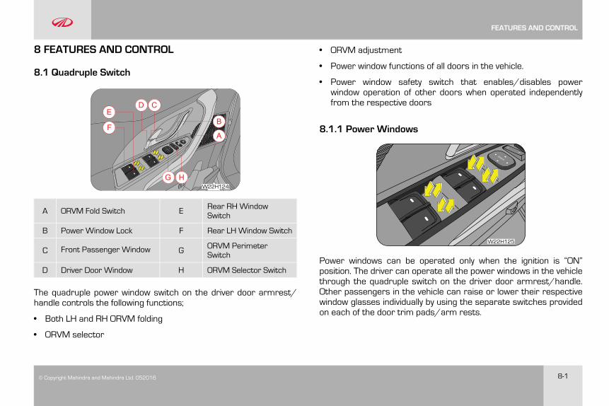
© Copyright Mahindra and Mahindra Ltd. 052016 8-1
8 FEATURES AND CONTROL
8.1 Quadruple Switch
F
ED C
A
G H
B
W22H124
A ORVM Fold Switch E Rear RH WindowSwitch
B Power Window Lock F Rear LH Window Switch
C Front Passenger Window G ORVM PerimeterSwitch
D Driver Door Window H ORVM Selector Switch
The quadruple power window switch on the driver door armrest/handle controls the following functions;
• Both LH and RH ORVM folding
• ORVM selector
• ORVM adjustment
• Power window functions of all doors in the vehicle.
• Power window safety switch that enables/disables powerwindow operation of other doors when operated independentlyfrom the respective doors
8.1.1 Power Windows
W22H125
Power windows can be operated only when the ignition is “ON”position. The driver can operate all the power windows in the vehiclethrough the quadruple switch on the driver door armrest/handle.Other passengers in the vehicle can raise or lower their respectivewindow glasses individually by using the separate switches providedon each of the door trim pads/arm rests.
FEATURES AND CONTROL
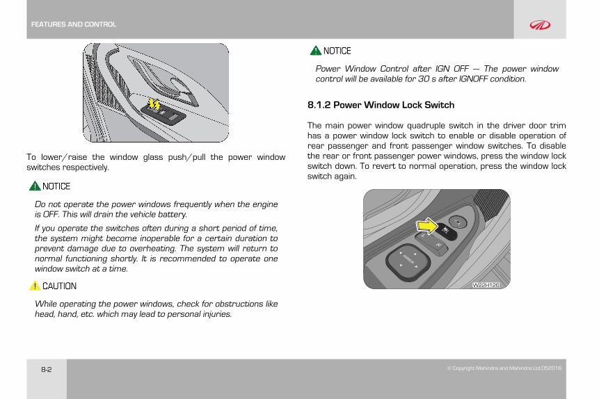
8-2 © Copyright Mahindra and Mahindra Ltd.052016
To lower/raise the window glass push/pull the power windowswitches respectively.
Do not operate the power windows frequently when the engineis OFF. This will drain the vehicle battery.
If you operate the switches often during a short period of time,the system might become inoperable for a certain duration toprevent damage due to overheating. The system will return tonormal functioning shortly. It is recommended to operate onewindow switch at a time.
While operating the power windows, check for obstructions likehead, hand, etc. which may lead to personal injuries.
Power Window Control after IGN OFF — The power windowcontrol will be available for 30 s after IGNOFF condition.
8.1.2 Power Window Lock Switch
The main power window quadruple switch in the driver door trimhas a power window lock switch to enable or disable operation ofrear passenger and front passenger window switches. To disablethe rear or front passenger power windows, press the window lockswitch down. To revert to normal operation, press the window lockswitch again.
W22H126
FEATURES AND CONTROL
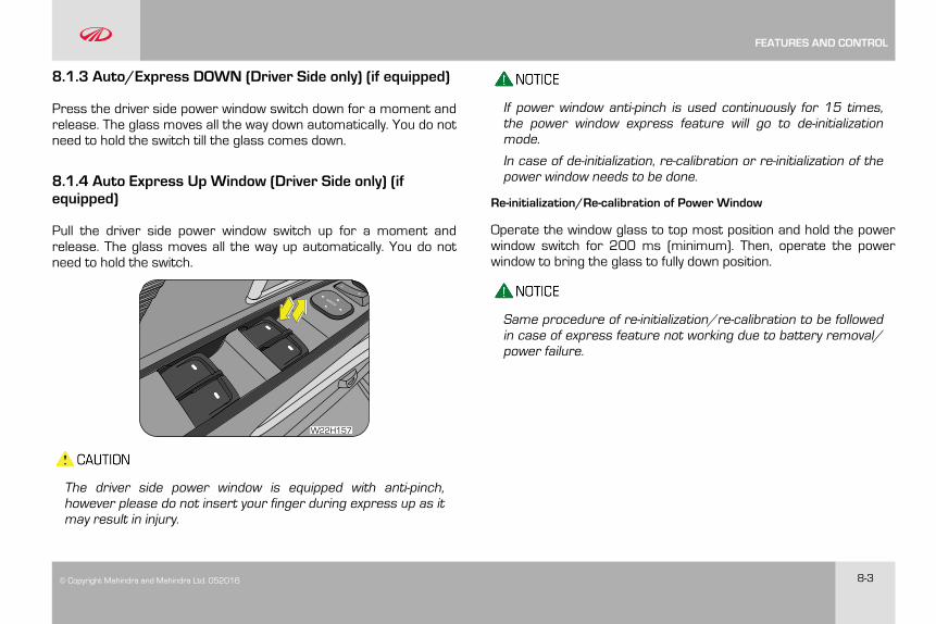
© Copyright Mahindra and Mahindra Ltd. 052016 8-3
8.1.3 Auto/Express DOWN (Driver Side only) (if equipped)
Press the driver side power window switch down for a moment andrelease. The glass moves all the way down automatically. You do notneed to hold the switch till the glass comes down.
8.1.4 Auto Express Up Window (Driver Side only) (ifequipped)
Pull the driver side power window switch up for a moment andrelease. The glass moves all the way up automatically. You do notneed to hold the switch.
W22H157
The driver side power window is equipped with anti-pinch,however please do not insert your finger during express up as itmay result in injury.
If power window anti-pinch is used continuously for 15 times,the power window express feature will go to de-initializationmode.
In case of de-initialization, re-calibration or re-initialization of thepower window needs to be done.
Re-initialization/Re-calibration of Power Window
Operate the window glass to top most position and hold the powerwindow switch for 200 ms (minimum). Then, operate the powerwindow to bring the glass to fully down position.
Same procedure of re-initialization/re-calibration to be followedin case of express feature not working due to battery removal/power failure.
FEATURES AND CONTROL
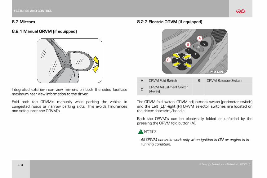
8-4 © Copyright Mahindra and Mahindra Ltd.052016
8.2 Mirrors
8.2.1 Manual ORVM (if equipped)
Integrated exterior rear view mirrors on both the sides facilitatemaximum rear view information to the driver.
Fold both the ORVM’s manually while parking the vehicle incongested roads or narrow parking slots. This avoids hindrancesand safeguards the ORVM’s.
8.2.2 Electric ORVM (if equipped)
B
A
C
W22H127
A ORVM Fold Switch B ORVM Selector Switch
CORVM Adjustment Switch(4-way)
The ORVM fold switch, ORVM adjustment switch (perimeter switch)and the Left (L)/Right (R) ORVM selector switches are located onthe driver door trim/handle.
Both the ORVM’s can be electrically folded or unfolded by thepressing the ORVM fold button (A).
All ORVM controls work only when ignition is ON or engine is inrunning condition.
FEATURES AND CONTROL
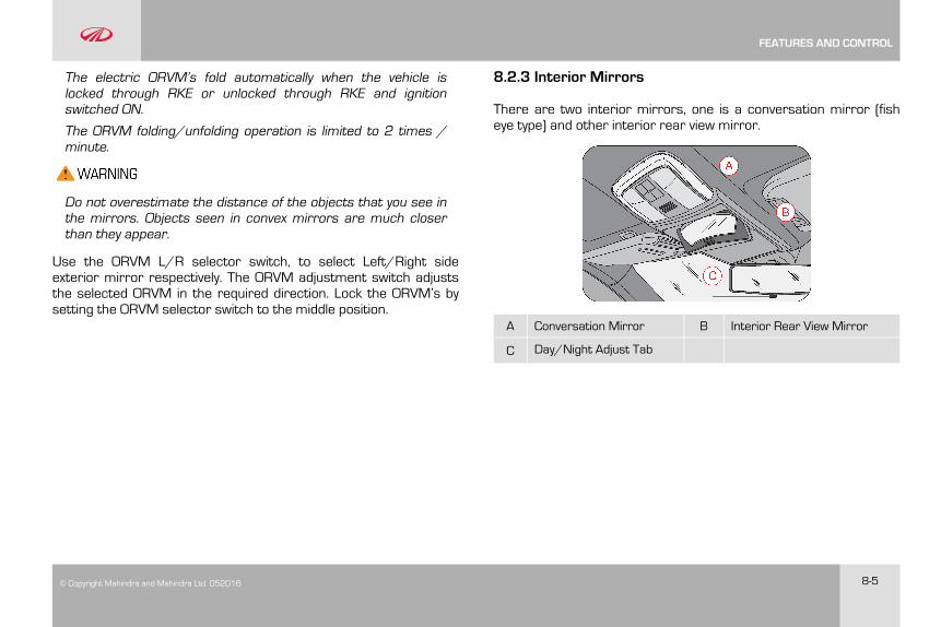
© Copyright Mahindra and Mahindra Ltd. 052016 8-5
The electric ORVM’s fold automatically when the vehicle islocked through RKE or unlocked through RKE and ignitionswitched ON.
The ORVM folding/unfolding operation is limited to 2 times /minute.
Do not overestimate the distance of the objects that you see inthe mirrors. Objects seen in convex mirrors are much closerthan they appear.
Use the ORVM L/R selector switch, to select Left/Right sideexterior mirror respectively. The ORVM adjustment switch adjuststhe selected ORVM in the required direction. Lock the ORVM’s bysetting the ORVM selector switch to the middle position.
8.2.3 Interior Mirrors
There are two interior mirrors, one is a conversation mirror (fisheye type) and other interior rear view mirror.
A Conversation Mirror B Interior Rear View Mirror
C Day/Night Adjust Tab
FEATURES AND CONTROL

8-6 © Copyright Mahindra and Mahindra Ltd.052016
8.2.4 Conversation Mirror (if equipped)
The conversation mirror can be used to converse with the rearpassengers in the vehicle. Press the mirror cover to lower theconversation mirror. Close the mirror back and press to lock themirror in position.
8.2.5 Interior Rear View Mirror
The interior rear view mirror provides the rear view information tothe driver and also aids during reversing.
This mirror has day and night (anti-glare) positions. The nightposition reduces glare from head lamps of vehicles behind you. Flipthe tab (A) on the bottom edge of the mirror to select the day ornight position.
8.3 Sun Visor
Sun Visors are provided for both driver and co-driver above thewindshield. The sun visors can be used for either frontal orsideward shade, to reduce glare or to shut out direct rays of thesun.
FEATURES AND CONTROL
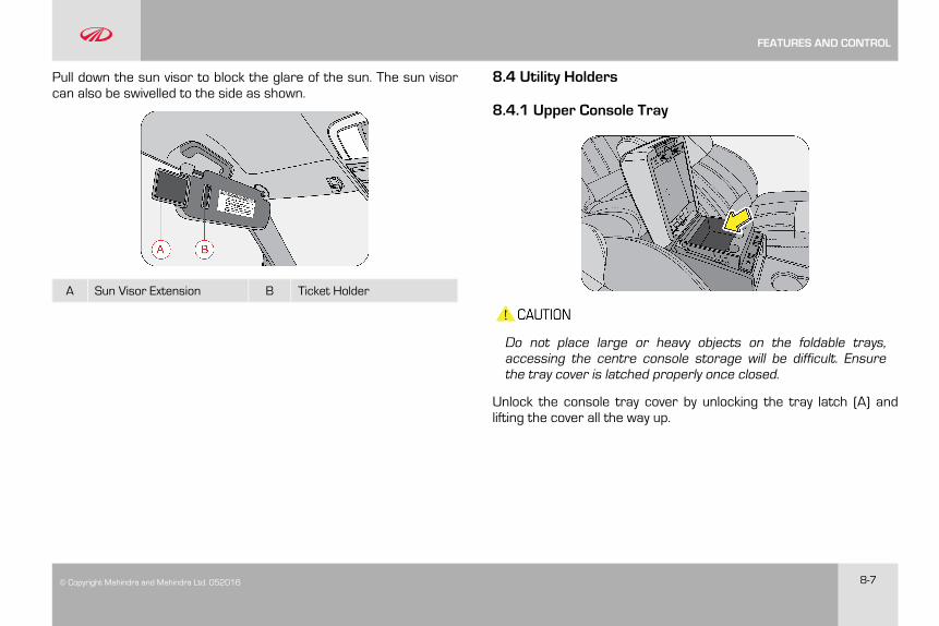
© Copyright Mahindra and Mahindra Ltd. 052016 8-7
Pull down the sun visor to block the glare of the sun. The sun visorcan also be swivelled to the side as shown.
A Sun Visor Extension B Ticket Holder
8.4 Utility Holders
8.4.1 Upper Console Tray
Do not place large or heavy objects on the foldable trays,accessing the centre console storage will be difficult. Ensurethe tray cover is latched properly once closed.
Unlock the console tray cover by unlocking the tray latch (A) andlifting the cover all the way up.
FEATURES AND CONTROL
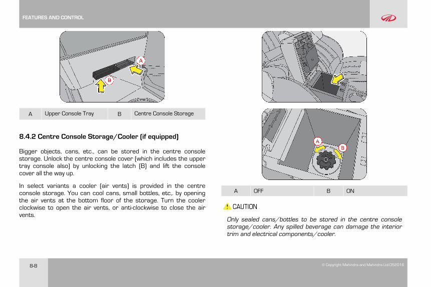
8-8 © Copyright Mahindra and Mahindra Ltd.052016
A Upper Console Tray B Centre Console Storage
8.4.2 Centre Console Storage/Cooler (if equipped)
Bigger objects, cans, etc., can be stored in the centre consolestorage. Unlock the centre console cover (which includes the uppertray console also) by unlocking the latch (B) and lift the consolecover all the way up.
In select variants a cooler (air vents) is provided in the centreconsole storage. You can cool cans, small bottles, etc,. by openingthe air vents at the bottom floor of the storage. Turn the coolerclockwise to open the air vents, or anti-clockwise to close the airvents.
A OFF B ON
Only sealed cans/bottles to be stored in the centre consolestorage/cooler. Any spilled beverage can damage the interiortrim and electrical components/cooler.
FEATURES AND CONTROL
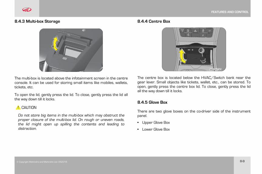
© Copyright Mahindra and Mahindra Ltd. 052016 8-9
8.4.3 Multi-box Storage
The multi-box is located above the infotainment screen in the centreconsole. It can be used for storing small items like mobiles, wallets,tickets, etc.
To open the lid, gently press the lid. To close, gently press the lid allthe way down till it locks.
Do not store big items in the multi-box which may obstruct theproper closure of the multi-box lid. On rough or uneven roads,the lid might open up spilling the contents and leading todistraction.
8.4.4 Centre Box
W22H150
The centre box is located below the HVAC/Switch bank near thegear lever. Small objects like tickets, wallet, etc., can be stored. Toopen, gently press the centre box lid. To close, gently press the lidall the way down till it locks.
8.4.5 Glove Box
There are two glove boxes on the co-driver side of the instrumentpanel.
• Upper Glove Box
• Lower Glove Box
FEATURES AND CONTROL
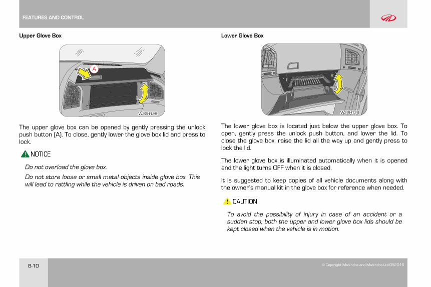
8-10 © Copyright Mahindra and Mahindra Ltd.052016
Upper Glove Box
A
W22H128
The upper glove box can be opened by gently pressing the unlockpush button (A). To close, gently lower the glove box lid and press tolock.
Do not overload the glove box.
Do not store loose or small metal objects inside glove box. Thiswill lead to rattling while the vehicle is driven on bad roads.
Lower Glove Box
W22H129
The lower glove box is located just below the upper glove box. Toopen, gently press the unlock push button, and lower the lid. Toclose the glove box, raise the lid all the way up and gently press tolock the lid.
The lower glove box is illuminated automatically when it is openedand the light turns OFF when it is closed.
It is suggested to keep copies of all vehicle documents along withthe owner’s manual kit in the glove box for reference when needed.
To avoid the possibility of injury in case of an accident or asudden stop, both the upper and lower glove box lids should bekept closed when the vehicle is in motion.
FEATURES AND CONTROL
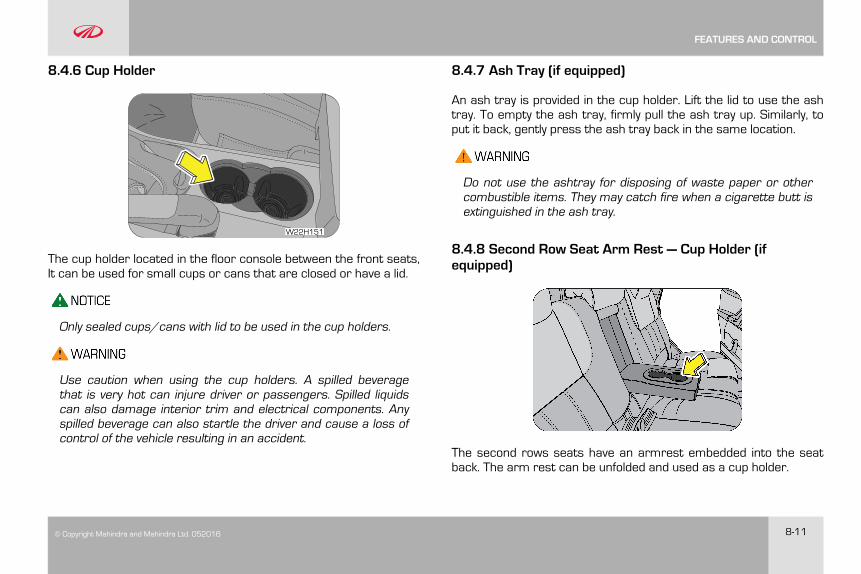
© Copyright Mahindra and Mahindra Ltd. 052016 8-11
8.4.6 Cup Holder
W22H151
The cup holder located in the floor console between the front seats,It can be used for small cups or cans that are closed or have a lid.
Only sealed cups/cans with lid to be used in the cup holders.
Use caution when using the cup holders. A spilled beveragethat is very hot can injure driver or passengers. Spilled liquidscan also damage interior trim and electrical components. Anyspilled beverage can also startle the driver and cause a loss ofcontrol of the vehicle resulting in an accident.
8.4.7 Ash Tray (if equipped)
An ash tray is provided in the cup holder. Lift the lid to use the ashtray. To empty the ash tray, firmly pull the ash tray up. Similarly, toput it back, gently press the ash tray back in the same location.
Do not use the ashtray for disposing of waste paper or othercombustible items. They may catch fire when a cigarette butt isextinguished in the ash tray.
8.4.8 Second Row Seat Arm Rest — Cup Holder (ifequipped)
The second rows seats have an armrest embedded into the seatback. The arm rest can be unfolded and used as a cup holder.
FEATURES AND CONTROL
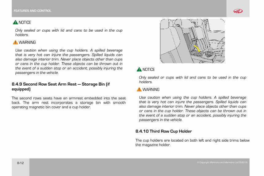
8-12 © Copyright Mahindra and Mahindra Ltd.052016
Only sealed or cups with lid and cans to be used in the cupholders.
Use caution when using the cup holders. A spilled beveragethat is very hot can injure the passengers. Spilled liquids canalso damage interior trim. Never place objects other than cupsor cans in the cup holder. These objects can be thrown out inthe event of a sudden stop or an accident, possibly injuring thepassengers in the vehicle.
8.4.9 Second Row Seat Arm Rest — Storage Bin (ifequipped)
The second rows seats have an armrest embedded into the seatback. The arm rest incorporates a storage bin with smoothoperating magnetic bin cover and a cup holder.
Only sealed or cups with lid and cans to be used in the cupholders.
Use caution when using the cup holders. A spilled beveragethat is very hot can injure the passengers. Spilled liquids canalso damage interior trim. Never place objects other than cupsor cans in the cup holder. These objects can be thrown out inthe event of a sudden stop or an accident, possibly injuring thepassengers in the vehicle.
8.4.10 Third Row Cup Holder
The cup holders are located on both left and right side trims belowthe magazine holder.
FEATURES AND CONTROL
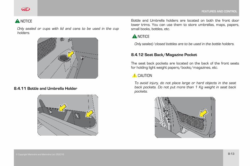
© Copyright Mahindra and Mahindra Ltd. 052016 8-13
Only sealed or cups with lid and cans to be used in the cupholders.
8.4.11 Bottle and Umbrella Holder
Bottle and Umbrella holders are located on both the front doorlower trims. You can use them to store umbrellas, maps, papers,small books, bottles, etc.
Only sealed/closed bottles are to be used in the bottle holders.
8.4.12 Seat Back/Magazine Pocket
The seat back pockets are located on the back of the front seatsfor holding light weight papers/books/magazines, etc.
To avoid injury, do not place large or hard objects in the seatback pockets. Do not put more than 1 Kg weight in seat backpockets.
FEATURES AND CONTROL
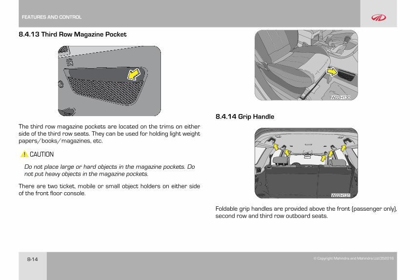
8-14 © Copyright Mahindra and Mahindra Ltd.052016
8.4.13 Third Row Magazine Pocket
The third row magazine pockets are located on the trims on eitherside of the third row seats. They can be used for holding light weightpapers/books/magazines, etc.
Do not place large or hard objects in the magazine pockets. Donot put heavy objects in the magazine pockets.
There are two ticket, mobile or small object holders on either sideof the front floor console.
W22H130
8.4.14 Grip Handle
W22H131
Foldable grip handles are provided above the front (passenger only),second row and third row outboard seats.
FEATURES AND CONTROL
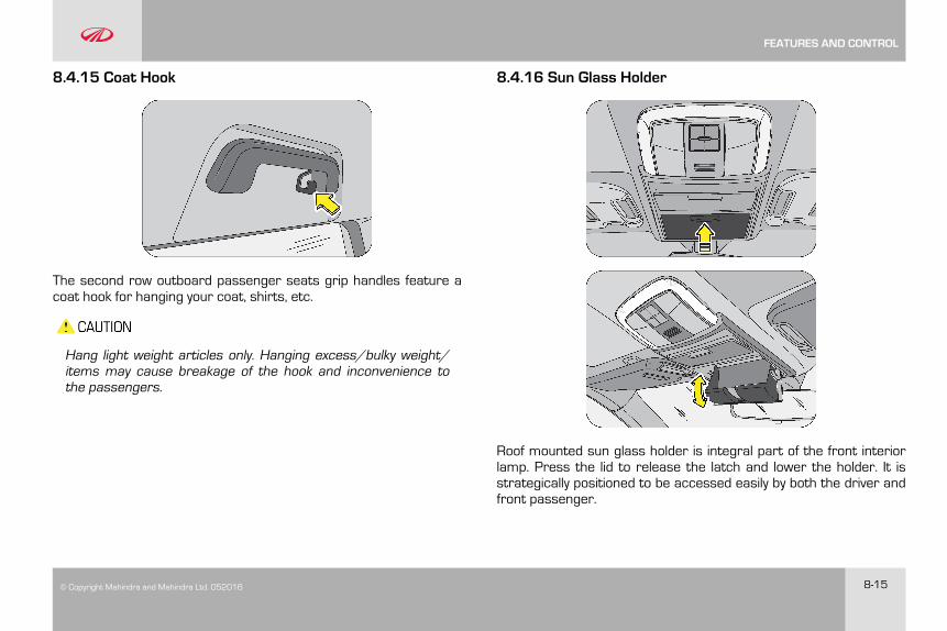
© Copyright Mahindra and Mahindra Ltd. 052016 8-15
8.4.15 Coat Hook
The second row outboard passenger seats grip handles feature acoat hook for hanging your coat, shirts, etc.
Hang light weight articles only. Hanging excess/bulky weight/items may cause breakage of the hook and inconvenience tothe passengers.
8.4.16 Sun Glass Holder
Roof mounted sun glass holder is integral part of the front interiorlamp. Press the lid to release the latch and lower the holder. It isstrategically positioned to be accessed easily by both the driver andfront passenger.
FEATURES AND CONTROL
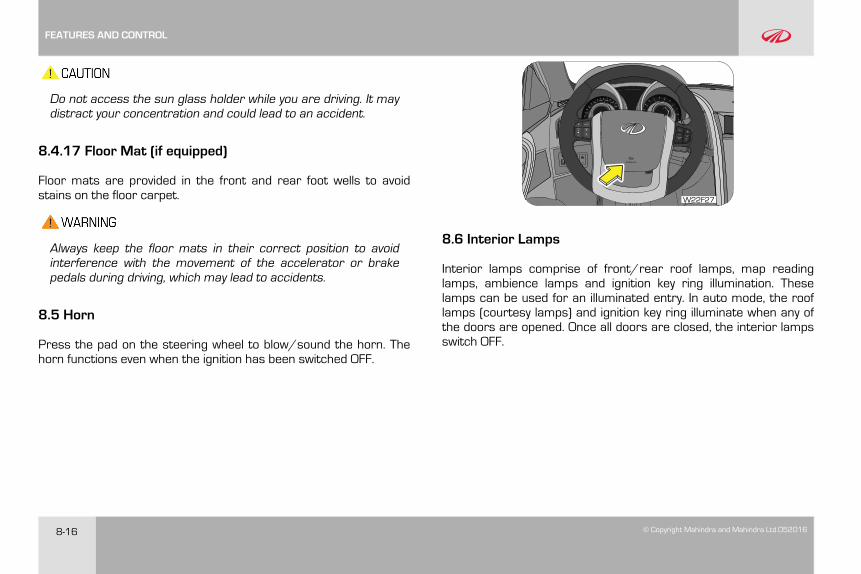
8-16 © Copyright Mahindra and Mahindra Ltd.052016
Do not access the sun glass holder while you are driving. It maydistract your concentration and could lead to an accident.
8.4.17 Floor Mat (if equipped)
Floor mats are provided in the front and rear foot wells to avoidstains on the floor carpet.
Always keep the floor mats in their correct position to avoidinterference with the movement of the accelerator or brakepedals during driving, which may lead to accidents.
8.5 Horn
Press the pad on the steering wheel to blow/sound the horn. Thehorn functions even when the ignition has been switched OFF.
W22F27
8.6 Interior Lamps
Interior lamps comprise of front/rear roof lamps, map readinglamps, ambience lamps and ignition key ring illumination. Theselamps can be used for an illuminated entry. In auto mode, the rooflamps (courtesy lamps) and ignition key ring illuminate when any ofthe doors are opened. Once all doors are closed, the interior lampsswitch OFF.
FEATURES AND CONTROL
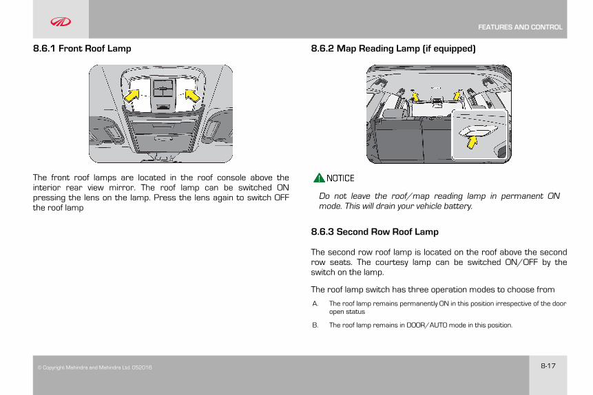
© Copyright Mahindra and Mahindra Ltd. 052016 8-17
8.6.1 Front Roof Lamp
The front roof lamps are located in the roof console above theinterior rear view mirror. The roof lamp can be switched ONpressing the lens on the lamp. Press the lens again to switch OFFthe roof lamp
8.6.2 Map Reading Lamp (if equipped)
Do not leave the roof/map reading lamp in permanent ONmode. This will drain your vehicle battery.
8.6.3 Second Row Roof Lamp
The second row roof lamp is located on the roof above the secondrow seats. The courtesy lamp can be switched ON/OFF by theswitch on the lamp.
The roof lamp switch has three operation modes to choose from
A. The roof lamp remains permanently ON in this position irrespective of the dooropen status
B. The roof lamp remains in DOOR/AUTO mode in this position.
FEATURES AND CONTROL
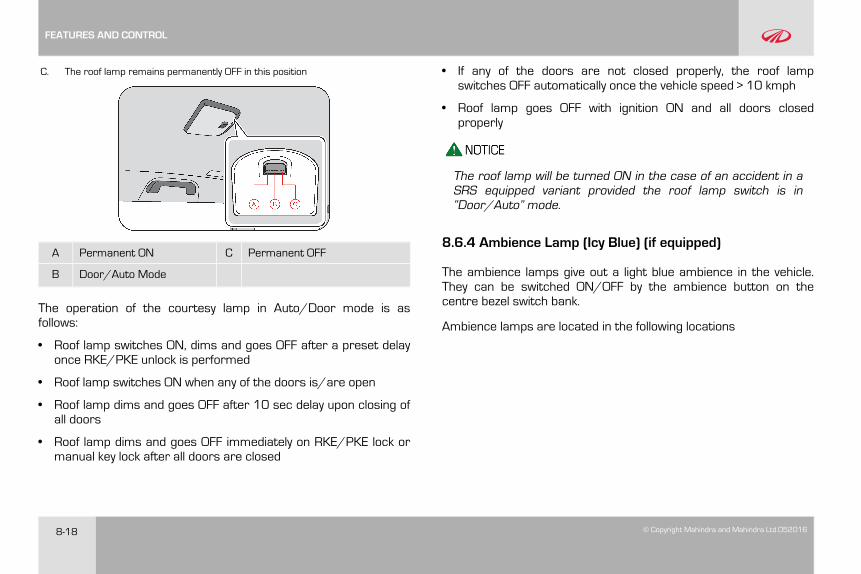
8-18 © Copyright Mahindra and Mahindra Ltd.052016
C. The roof lamp remains permanently OFF in this position
A Permanent ON C Permanent OFF
B Door/Auto Mode
The operation of the courtesy lamp in Auto/Door mode is asfollows:
• Roof lamp switches ON, dims and goes OFF after a preset delayonce RKE/PKE unlock is performed
• Roof lamp switches ON when any of the doors is/are open
• Roof lamp dims and goes OFF after 10 sec delay upon closing ofall doors
• Roof lamp dims and goes OFF immediately on RKE/PKE lock ormanual key lock after all doors are closed
• If any of the doors are not closed properly, the roof lampswitches OFF automatically once the vehicle speed > 10 kmph
• Roof lamp goes OFF with ignition ON and all doors closedproperly
The roof lamp will be turned ON in the case of an accident in aSRS equipped variant provided the roof lamp switch is in“Door/Auto” mode.
8.6.4 Ambience Lamp (Icy Blue) (if equipped)
The ambience lamps give out a light blue ambience in the vehicle.They can be switched ON/OFF by the ambience button on thecentre bezel switch bank.
Ambience lamps are located in the following locations
FEATURES AND CONTROL
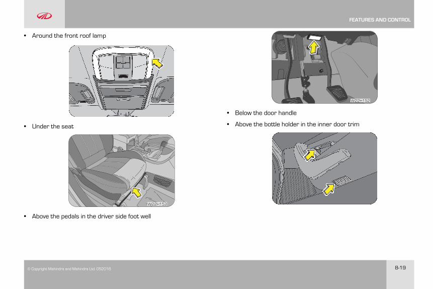
© Copyright Mahindra and Mahindra Ltd. 052016 8-19
• Around the front roof lamp
• Under the seat
W22H153
• Above the pedals in the driver side foot well
W22H152
• Below the door handle
• Above the bottle holder in the inner door trim
FEATURES AND CONTROL
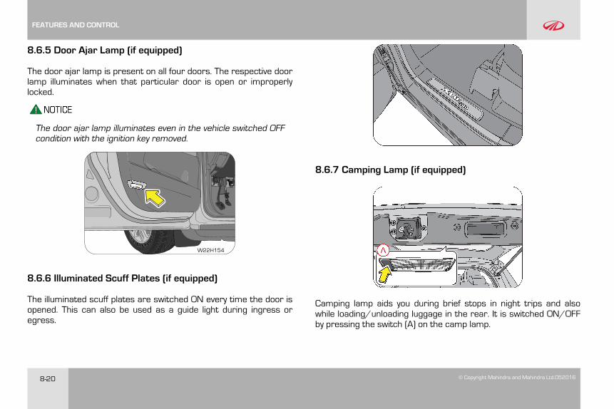
8-20 © Copyright Mahindra and Mahindra Ltd.052016
8.6.5 Door Ajar Lamp (if equipped)
The door ajar lamp is present on all four doors. The respective doorlamp illuminates when that particular door is open or improperlylocked.
The door ajar lamp illuminates even in the vehicle switched OFFcondition with the ignition key removed.
W22H154
8.6.6 Illuminated Scuff Plates (if equipped)
The illuminated scuff plates are switched ON every time the door isopened. This can also be used as a guide light during ingress oregress.
8.6.7 Camping Lamp (if equipped)
Camping lamp aids you during brief stops in night trips and alsowhile loading/unloading luggage in the rear. It is switched ON/OFFby pressing the switch (A) on the camp lamp.
FEATURES AND CONTROL
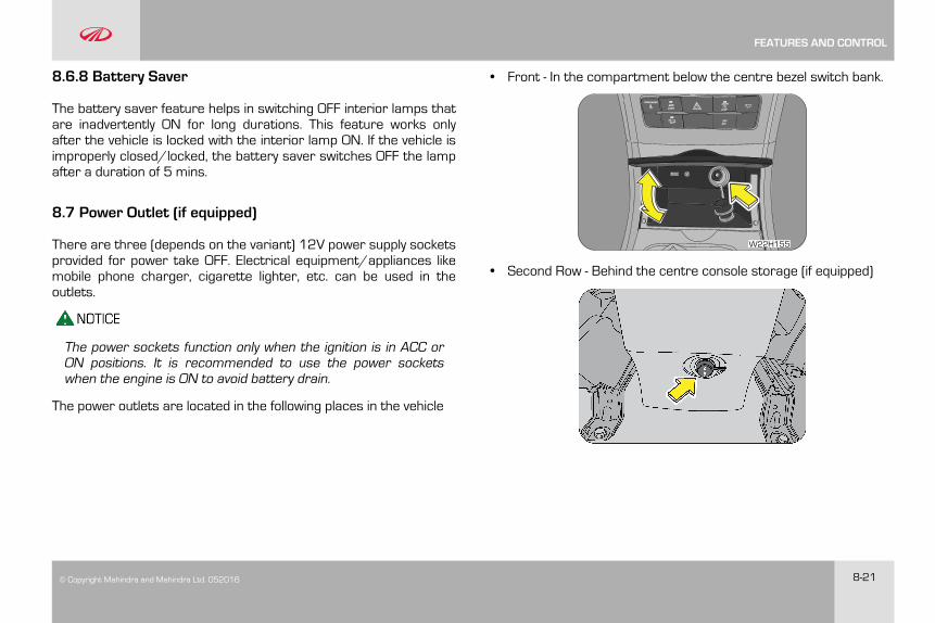
© Copyright Mahindra and Mahindra Ltd. 052016 8-21
8.6.8 Battery Saver
The battery saver feature helps in switching OFF interior lamps thatare inadvertently ON for long durations. This feature works onlyafter the vehicle is locked with the interior lamp ON. If the vehicle isimproperly closed/locked, the battery saver switches OFF the lampafter a duration of 5 mins.
8.7 Power Outlet (if equipped)
There are three (depends on the variant) 12V power supply socketsprovided for power take OFF. Electrical equipment/appliances likemobile phone charger, cigarette lighter, etc. can be used in theoutlets.
The power sockets function only when the ignition is in ACC orON positions. It is recommended to use the power socketswhen the engine is ON to avoid battery drain.
The power outlets are located in the following places in the vehicle
• Front - In the compartment below the centre bezel switch bank.
W22H155
• Second Row - Behind the centre console storage (if equipped)
FEATURES AND CONTROL
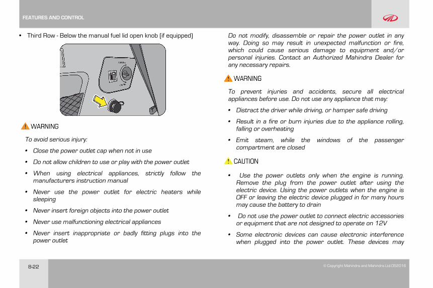
8-22 © Copyright Mahindra and Mahindra Ltd.052016
• Third Row - Below the manual fuel lid open knob (if equipped)
To avoid serious injury:
• Close the power outlet cap when not in use
• Do not allow children to use or play with the power outlet
• When using electrical appliances, strictly follow themanufacturers instruction manual
• Never use the power outlet for electric heaters whilesleeping
• Never insert foreign objects into the power outlet
• Never use malfunctioning electrical appliances
• Never insert inappropriate or badly fitting plugs into thepower outlet
Do not modify, disassemble or repair the power outlet in anyway. Doing so may result in unexpected malfunction or fire,which could cause serious damage to equipment and/orpersonal injuries. Contact an Authorized Mahindra Dealer forany necessary repairs.
To prevent injuries and accidents, secure all electricalappliances before use. Do not use any appliance that may:
• Distract the driver while driving, or hamper safe driving
• Result in a fire or burn injuries due to the appliance rolling,falling or overheating
• Emit steam, while the windows of the passengercompartment are closed
• Use the power outlets only when the engine is running.Remove the plug from the power outlet after using theelectric device. Using the power outlets when the engine isOFF or leaving the electric device plugged in for many hoursmay cause the battery to drain
• Do not use the power outlet to connect electric accessoriesor equipment that are not designed to operate on 12V
• Some electronic devices can cause electronic interferencewhen plugged into the power outlet. These devices may
FEATURES AND CONTROL
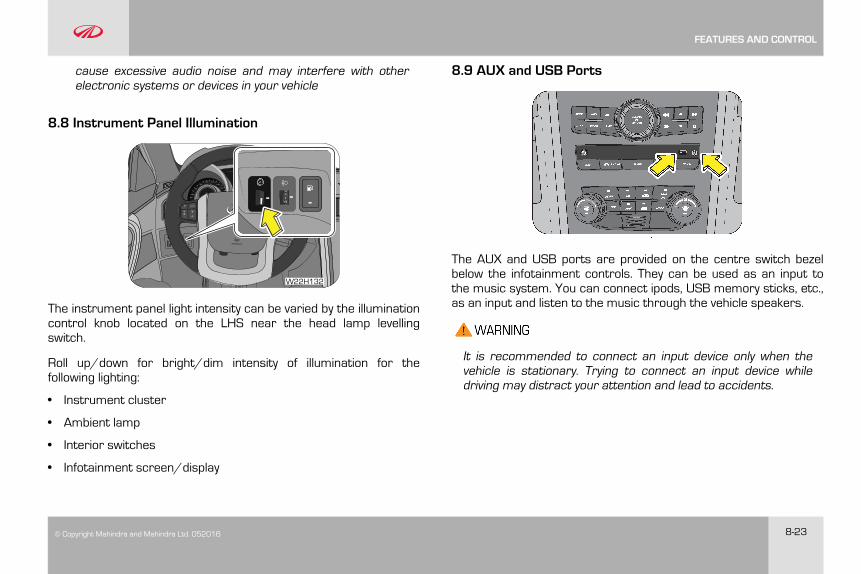
© Copyright Mahindra and Mahindra Ltd. 052016 8-23
cause excessive audio noise and may interfere with otherelectronic systems or devices in your vehicle
8.8 Instrument Panel Illumination
W22H132
The instrument panel light intensity can be varied by the illuminationcontrol knob located on the LHS near the head lamp levellingswitch.
Roll up/down for bright/dim intensity of illumination for thefollowing lighting:
• Instrument cluster
• Ambient lamp
• Interior switches
• Infotainment screen/display
8.9 AUX and USB Ports
The AUX and USB ports are provided on the centre switch bezelbelow the infotainment controls. They can be used as an input tothe music system. You can connect ipods, USB memory sticks, etc.,as an input and listen to the music through the vehicle speakers.
It is recommended to connect an input device only when thevehicle is stationary. Trying to connect an input device whiledriving may distract your attention and lead to accidents.
FEATURES AND CONTROL
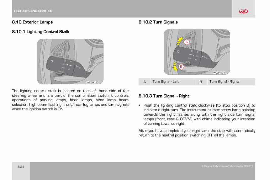
8-24 © Copyright Mahindra and Mahindra Ltd.052016
8.10 Exterior Lamps
8.10.1 Lighting Control Stalk
A
W22H133
The lighting control stalk is located on the Left hand side of thesteering wheel and is a part of the combination switch. It controlsoperations of parking lamps, head lamps, head lamp beamselection, high beam flashing, front/rear fog lamps and turn signalswhen the ignition switch is ON.
8.10.2 Turn Signals
A
A
B
W22H134
A Turn Signal - Left B Turn Signal - Rights
8.10.3 Turn Signal - Right
• Push the lighting control stalk clockwise (to stop position B) toindicate a right turn. The instrument cluster arrow lamp pointingtowards the right flashes along with the right side turn signallamps (front, rear & ORVM) with chime indicating your intentionof turning towards right
After you have completed your right turn, the stalk will automaticallyreturn to the neutral position switching OFF all the lamps.
FEATURES AND CONTROL
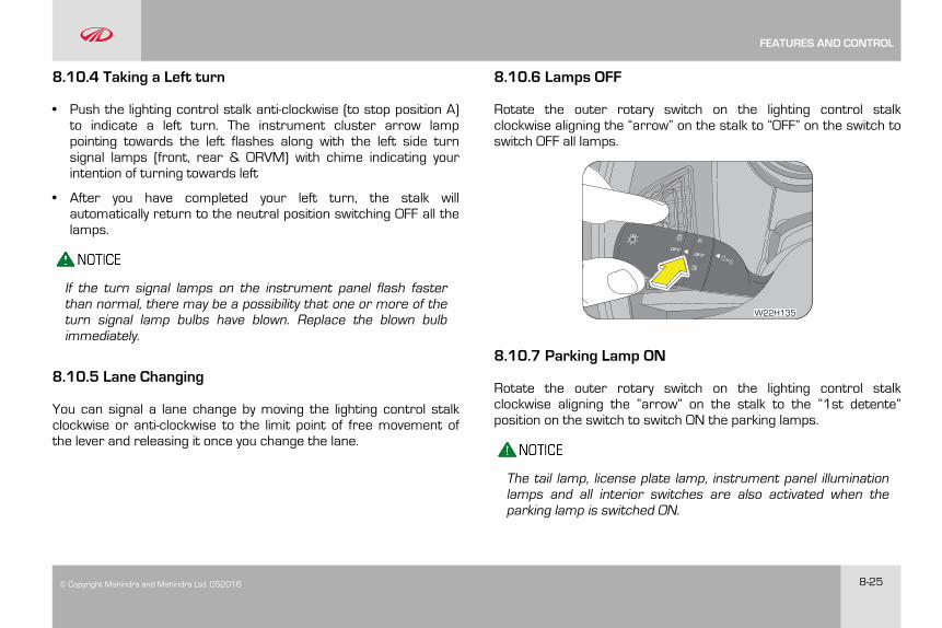
© Copyright Mahindra and Mahindra Ltd. 052016 8-25
8.10.4 Taking a Left turn
• Push the lighting control stalk anti-clockwise (to stop position A)to indicate a left turn. The instrument cluster arrow lamppointing towards the left flashes along with the left side turnsignal lamps (front, rear & ORVM) with chime indicating yourintention of turning towards left
• After you have completed your left turn, the stalk willautomatically return to the neutral position switching OFF all thelamps.
If the turn signal lamps on the instrument panel flash fasterthan normal, there may be a possibility that one or more of theturn signal lamp bulbs have blown. Replace the blown bulbimmediately.
8.10.5 Lane Changing
You can signal a lane change by moving the lighting control stalkclockwise or anti-clockwise to the limit point of free movement ofthe lever and releasing it once you change the lane.
8.10.6 Lamps OFF
Rotate the outer rotary switch on the lighting control stalkclockwise aligning the “arrow” on the stalk to “OFF” on the switch toswitch OFF all lamps.
A
W22H135
8.10.7 Parking Lamp ON
Rotate the outer rotary switch on the lighting control stalkclockwise aligning the “arrow” on the stalk to the “1st detente”position on the switch to switch ON the parking lamps.
The tail lamp, license plate lamp, instrument panel illuminationlamps and all interior switches are also activated when theparking lamp is switched ON.
FEATURES AND CONTROL
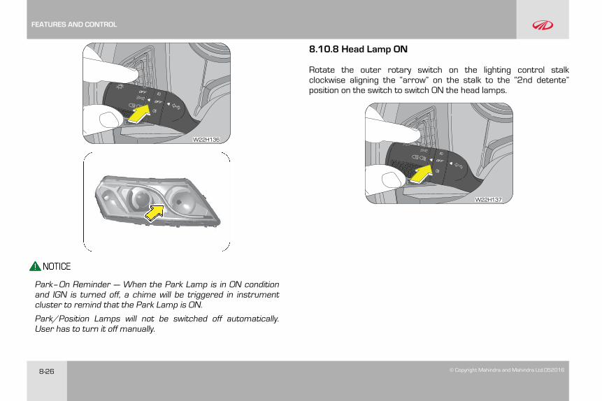
8-26 © Copyright Mahindra and Mahindra Ltd.052016
W22H136
Park–On Reminder — When the Park Lamp is in ON conditionand IGN is turned off, a chime will be triggered in instrumentcluster to remind that the Park Lamp is ON.
Park/Position Lamps will not be switched off automatically.User has to turn it off manually.
8.10.8 Head Lamp ON
Rotate the outer rotary switch on the lighting control stalkclockwise aligning the “arrow” on the stalk to the “2nd detente”position on the switch to switch ON the head lamps.
W22H137
FEATURES AND CONTROL
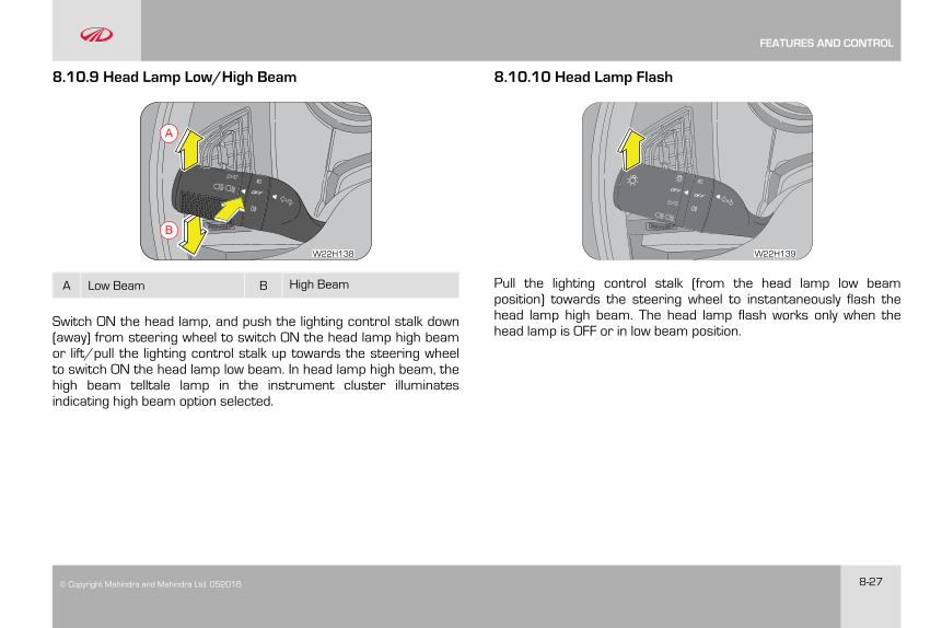
© Copyright Mahindra and Mahindra Ltd. 052016 8-27
8.10.9 Head Lamp Low/High Beam
A
B
W22H138
A Low Beam B High Beam
Switch ON the head lamp, and push the lighting control stalk down(away) from steering wheel to switch ON the head lamp high beamor lift/pull the lighting control stalk up towards the steering wheelto switch ON the head lamp low beam. In head lamp high beam, thehigh beam telltale lamp in the instrument cluster illuminatesindicating high beam option selected.
8.10.10 Head Lamp Flash
A
W22H139
Pull the lighting control stalk (from the head lamp low beamposition) towards the steering wheel to instantaneously flash thehead lamp high beam. The head lamp flash works only when thehead lamp is OFF or in low beam position.
FEATURES AND CONTROL
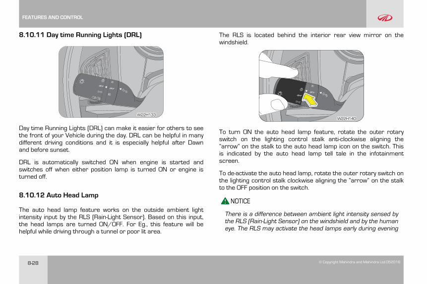
8-28 © Copyright Mahindra and Mahindra Ltd.052016
8.10.11 Day time Running Lights (DRL)
A
W22H133
Day time Running Lights (DRL) can make it easier for others to seethe front of your Vehicle during the day. DRL can be helpful in manydifferent driving conditions and it is especially helpful after Dawnand before sunset.
DRL is automatically switched ON when engine is started andswitches off when either position lamp is turned ON or engine isturned off.
8.10.12 Auto Head Lamp
The auto head lamp feature works on the outside ambient lightintensity input by the RLS (Rain-Light Sensor). Based on this input,the head lamps are turned ON/OFF. For Eg., this feature will behelpful while driving through a tunnel or poor lit area.
The RLS is located behind the interior rear view mirror on thewindshield.
A
W22H140
To turn ON the auto head lamp feature, rotate the outer rotaryswitch on the lighting control stalk anti-clockwise aligning the“arrow” on the stalk to the auto head lamp icon on the switch. Thisis indicated by the auto head lamp tell tale in the infotainmentscreen.
To de-activate the auto head lamp, rotate the outer rotary switch onthe lighting control stalk clockwise aligning the “arrow” on the stalkto the OFF position on the switch.
There is a difference between ambient light intensity sensed bythe RLS (Rain-Light Sensor) on the windshield and by the humaneye. The RLS may activate the head lamps early during evening
FEATURES AND CONTROL
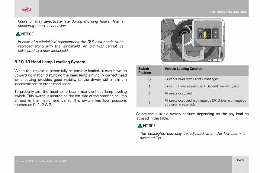
© Copyright Mahindra and Mahindra Ltd. 052016 8-29
hours or may de-activate late during morning hours. This isabsolutely a normal behavior.
In case of a windshield replacement, the RLS also needs to bereplaced along with the windshield. An old RLS cannot becalibrated to a new windshield.
8.10.13 Head Lamp Levelling System
When the vehicle is either fully or partially loaded, it may have anupward inclination disturbing the head lamp aiming. A correct headlamp setting provides good visibility to the driver with minimuminconvenience to other road users.
To properly aim the head lamp beam, use the head lamp levelingswitch. This switch is located on the left side of the steering columnshroud in the instrument panel. This switch has four positionsmarked as 0, 1, 2 & 3.
W22H141
SwitchPosition
Vehicle Loading Condition
0 Driver/Driver with Front Passenger
1 Driver + Front passenger + Second row occupied
2 All seats occupied
3 All seats occupied with luggage OR Driver with luggageat extreme rear side.
Select the suitable switch position depending on the pay load asadvised in the table.
The headlights can only be adjusted when the low beam isswitched ON
FEATURES AND CONTROL
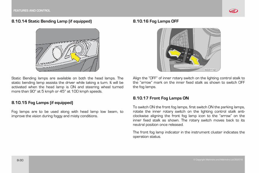
8-30 © Copyright Mahindra and Mahindra Ltd.052016
8.10.14 Static Bending Lamp (if equipped)
Static Bending lamps are available on both the head lamps. Thestatic bending lamp assists the driver while taking a turn. It will beactivated when the head lamp is ON and steering wheel turnedmore than 90° at 5 kmph or 45° at 100 kmph speeds.
8.10.15 Fog Lamps (if equipped)
Fog lamps are to be used along with head lamp low beam, toimprove the vision during foggy and misty conditions.
8.10.16 Fog Lamps OFF
W22H142
Align the “OFF” of inner rotary switch on the lighting control stalk tothe “arrow” mark on the inner fixed stalk as shown to switch OFFthe fog lamps.
8.10.17 Front Fog Lamps ON
To switch ON the front fog lamps, first switch ON the parking lamps,rotate the inner rotary switch on the lighting control stalk anti-clockwise aligning the front fog lamp icon to the “arrow” on theinner fixed stalk as shown. The rotary switch moves back to itsneutral position once released.
The front fog lamp indicator in the instrument cluster indicates theoperation status.
FEATURES AND CONTROL
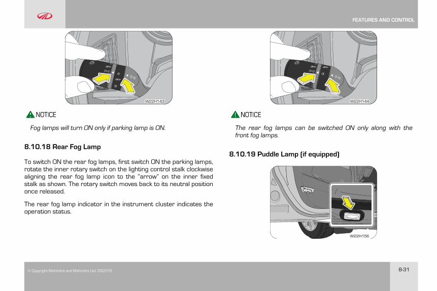
© Copyright Mahindra and Mahindra Ltd. 052016 8-31
W22H143
Fog lamps will turn ON only if parking lamp is ON.
8.10.18 Rear Fog Lamp
To switch ON the rear fog lamps, first switch ON the parking lamps,rotate the inner rotary switch on the lighting control stalk clockwisealigning the rear fog lamp icon to the “arrow” on the inner fixedstalk as shown. The rotary switch moves back to its neutral positiononce released.
The rear fog lamp indicator in the instrument cluster indicates theoperation status.
W22H144
The rear fog lamps can be switched ON only along with thefront fog lamps.
8.10.19 Puddle Lamp (if equipped)
W22H156
FEATURES AND CONTROL
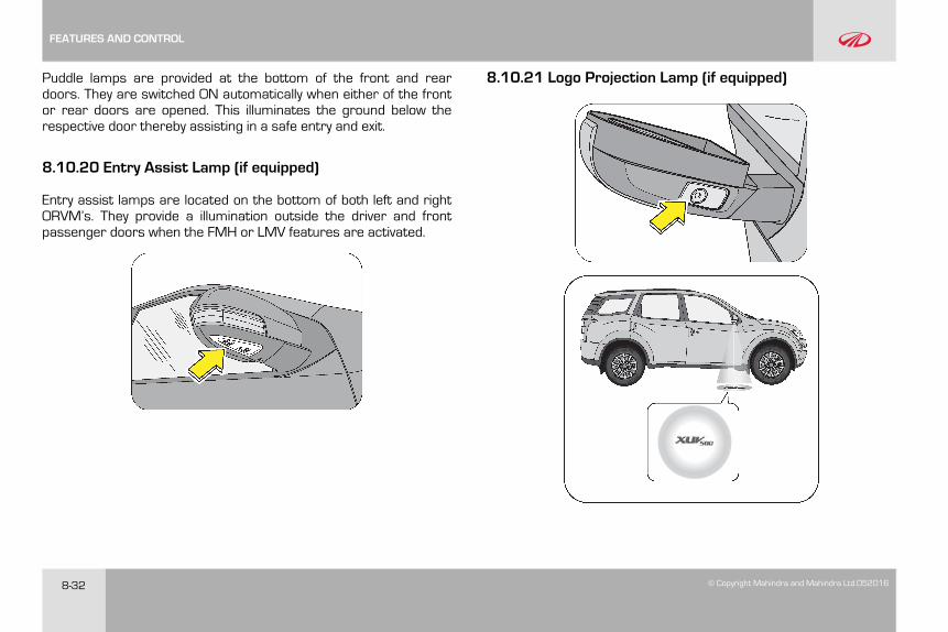
8-32 © Copyright Mahindra and Mahindra Ltd.052016
Puddle lamps are provided at the bottom of the front and reardoors. They are switched ON automatically when either of the frontor rear doors are opened. This illuminates the ground below therespective door thereby assisting in a safe entry and exit.
8.10.20 Entry Assist Lamp (if equipped)
Entry assist lamps are located on the bottom of both left and rightORVM’s. They provide a illumination outside the driver and frontpassenger doors when the FMH or LMV features are activated.
8.10.21 Logo Projection Lamp (if equipped)
FEATURES AND CONTROL
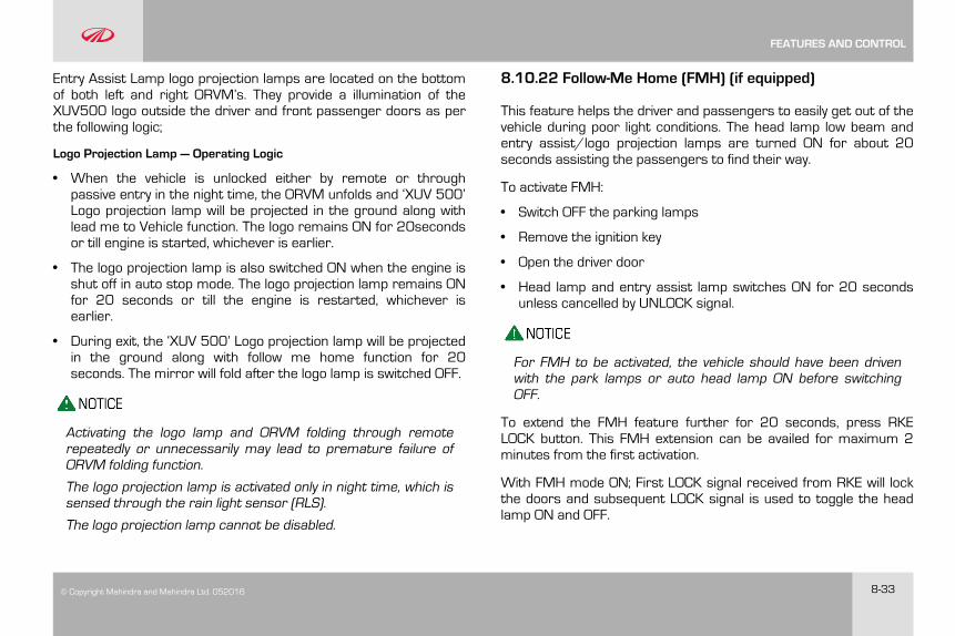
© Copyright Mahindra and Mahindra Ltd. 052016 8-33
Entry Assist Lamp logo projection lamps are located on the bottomof both left and right ORVM’s. They provide a illumination of theXUV500 logo outside the driver and front passenger doors as perthe following logic;
Logo Projection Lamp — Operating Logic
• When the vehicle is unlocked either by remote or throughpassive entry in the night time, the ORVM unfolds and ‘XUV 500’Logo projection lamp will be projected in the ground along withlead me to Vehicle function. The logo remains ON for 20secondsor till engine is started, whichever is earlier.
• The logo projection lamp is also switched ON when the engine isshut off in auto stop mode. The logo projection lamp remains ONfor 20 seconds or till the engine is restarted, whichever isearlier.
• During exit, the ‘XUV 500’ Logo projection lamp will be projectedin the ground along with follow me home function for 20seconds. The mirror will fold after the logo lamp is switched OFF.
Activating the logo lamp and ORVM folding through remoterepeatedly or unnecessarily may lead to premature failure ofORVM folding function.
The logo projection lamp is activated only in night time, which issensed through the rain light sensor (RLS).
The logo projection lamp cannot be disabled.
8.10.22 Follow-Me Home (FMH) (if equipped)
This feature helps the driver and passengers to easily get out of thevehicle during poor light conditions. The head lamp low beam andentry assist/logo projection lamps are turned ON for about 20seconds assisting the passengers to find their way.
To activate FMH:
• Switch OFF the parking lamps
• Remove the ignition key
• Open the driver door
• Head lamp and entry assist lamp switches ON for 20 secondsunless cancelled by UNLOCK signal.
For FMH to be activated, the vehicle should have been drivenwith the park lamps or auto head lamp ON before switchingOFF.
To extend the FMH feature further for 20 seconds, press RKELOCK button. This FMH extension can be availed for maximum 2minutes from the first activation.
With FMH mode ON; First LOCK signal received from RKE will lockthe doors and subsequent LOCK signal is used to toggle the headlamp ON and OFF.
FEATURES AND CONTROL
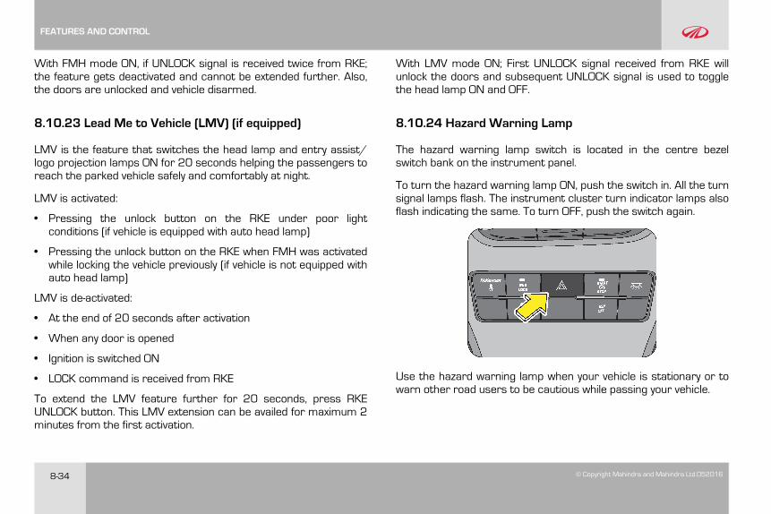
8-34 © Copyright Mahindra and Mahindra Ltd.052016
With FMH mode ON, if UNLOCK signal is received twice from RKE;the feature gets deactivated and cannot be extended further. Also,the doors are unlocked and vehicle disarmed.
8.10.23 Lead Me to Vehicle (LMV) (if equipped)
LMV is the feature that switches the head lamp and entry assist/logo projection lamps ON for 20 seconds helping the passengers toreach the parked vehicle safely and comfortably at night.
LMV is activated:
• Pressing the unlock button on the RKE under poor lightconditions (if vehicle is equipped with auto head lamp)
• Pressing the unlock button on the RKE when FMH was activatedwhile locking the vehicle previously (if vehicle is not equipped withauto head lamp)
LMV is de-activated:
• At the end of 20 seconds after activation
• When any door is opened
• Ignition is switched ON
• LOCK command is received from RKE
To extend the LMV feature further for 20 seconds, press RKEUNLOCK button. This LMV extension can be availed for maximum 2minutes from the first activation.
With LMV mode ON; First UNLOCK signal received from RKE willunlock the doors and subsequent UNLOCK signal is used to togglethe head lamp ON and OFF.
8.10.24 Hazard Warning Lamp
The hazard warning lamp switch is located in the centre bezelswitch bank on the instrument panel.
To turn the hazard warning lamp ON, push the switch in. All the turnsignal lamps flash. The instrument cluster turn indicator lamps alsoflash indicating the same. To turn OFF, push the switch again.
Use the hazard warning lamp when your vehicle is stationary or towarn other road users to be cautious while passing your vehicle.
FEATURES AND CONTROL
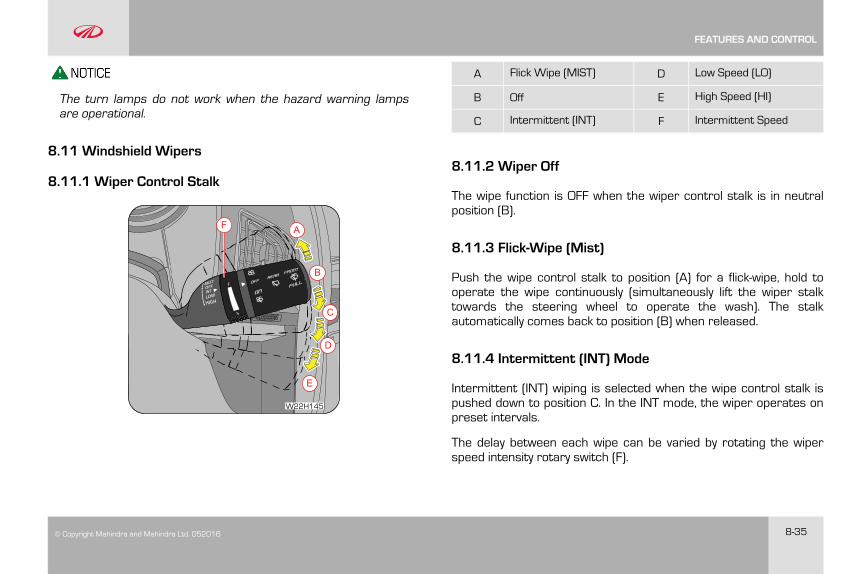
© Copyright Mahindra and Mahindra Ltd. 052016 8-35
The turn lamps do not work when the hazard warning lampsare operational.
8.11 Windshield Wipers
8.11.1 Wiper Control Stalk
A
B
C
D
E
F
W22H145
A Flick Wipe (MIST) D Low Speed (LO)
B Off E High Speed (HI)
C Intermittent (INT) F Intermittent Speed
8.11.2 Wiper Off
The wipe function is OFF when the wiper control stalk is in neutralposition (B).
8.11.3 Flick-Wipe (Mist)
Push the wipe control stalk to position (A) for a flick-wipe, hold tooperate the wipe continuously (simultaneously lift the wiper stalktowards the steering wheel to operate the wash). The stalkautomatically comes back to position (B) when released.
8.11.4 Intermittent (INT) Mode
Intermittent (INT) wiping is selected when the wipe control stalk ispushed down to position C. In the INT mode, the wiper operates onpreset intervals.
The delay between each wipe can be varied by rotating the wiperspeed intensity rotary switch (F).
FEATURES AND CONTROL
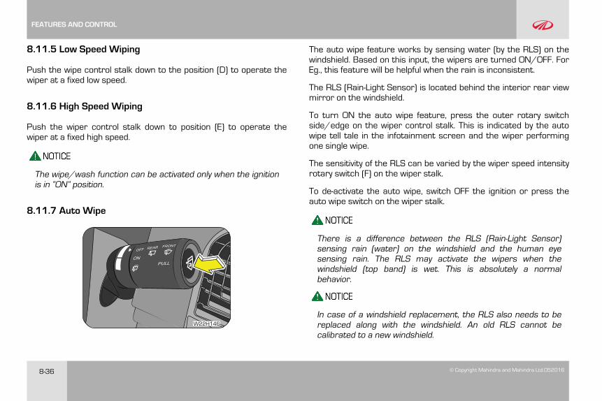
8-36 © Copyright Mahindra and Mahindra Ltd.052016
8.11.5 Low Speed Wiping
Push the wipe control stalk down to the position (D) to operate thewiper at a fixed low speed.
8.11.6 High Speed Wiping
Push the wiper control stalk down to position (E) to operate thewiper at a fixed high speed.
The wipe/wash function can be activated only when the ignitionis in “ON” position.
8.11.7 Auto Wipe
W22H146
The auto wipe feature works by sensing water (by the RLS) on thewindshield. Based on this input, the wipers are turned ON/OFF. ForEg., this feature will be helpful when the rain is inconsistent.
The RLS (Rain-Light Sensor) is located behind the interior rear viewmirror on the windshield.
To turn ON the auto wipe feature, press the outer rotary switchside/edge on the wiper control stalk. This is indicated by the autowipe tell tale in the infotainment screen and the wiper performingone single wipe.
The sensitivity of the RLS can be varied by the wiper speed intensityrotary switch (F) on the wiper stalk.
To de-activate the auto wipe, switch OFF the ignition or press theauto wipe switch on the wiper stalk.
There is a difference between the RLS (Rain-Light Sensor)sensing rain (water) on the windshield and the human eyesensing rain. The RLS may activate the wipers when thewindshield (top band) is wet. This is absolutely a normalbehavior.
In case of a windshield replacement, the RLS also needs to bereplaced along with the windshield. An old RLS cannot becalibrated to a new windshield.
FEATURES AND CONTROL
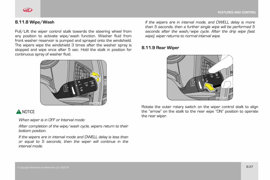
© Copyright Mahindra and Mahindra Ltd. 052016 8-37
8.11.8 Wipe/Wash
Pull/Lift the wiper control stalk towards the steering wheel fromany position to activate wipe/wash function. Washer fluid fromfront washer reservoir is pumped and sprayed onto the windshield.The wipers wipe the windshield 3 times after the washer spray isstopped and wipe once after 5 sec. Hold the stalk in position forcontinuous spray of washer fluid.
W22H147
When wiper is in OFF or Interval mode:
After completion of the wipe/wash cycle, wipers return to theirbottom position.
If the wipers are in interval mode and DWELL delay is less thanor equal to 5 seconds, then the wiper will continue in theinterval mode.
If the wipers are in interval mode, and DWELL delay is morethan 5 seconds, then a further single wipe will be performed 5seconds after the wash/wipe cycle. After the drip wipe (lastwipe), wiper returns to normal interval wipe.
8.11.9 Rear Wiper
W22H149
Rotate the outer rotary switch on the wiper control stalk to alignthe “arrow” on the stalk to the rear wipe “ON” position to operatethe rear wiper.
FEATURES AND CONTROL
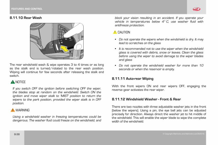
8-38 © Copyright Mahindra and Mahindra Ltd.052016
8.11.10 Rear Wash
W22H148
The rear windshield wash & wipe operates 3 to 4 times or as longas the stalk end is turned/rotated to the rear wash position.Wiping will continue for few seconds after releasing the stalk endswitch.
If you switch OFF the ignition before switching OFF the wiper,the blades stop at random on the windshield. Switch ON theignition and move wiper stalk to 'MIST' position to return thewipers to the park position, provided the wiper stalk is in OFFposition.
Using a windshield washer in freezing temperatures could bedangerous. The washer fluid could freeze on the windshield, and
block your vision resulting in an accident. If you operate yourvehicle in temperatures below 4° C, use washer fluid withantifreeze protection.
• Do not operate the wipers when the windshield is dry. It maylead to scratches on the glass
• It is recommended not to use the wiper when the windshieldglass is covered with debris, snow or leaves. Clean the glassbefore using the wiper to avoid damage to the wiper bladesand glass
• Do not operate the windshield washer for more than 10seconds or when the reservoir is empty.
8.11.11 Auto-rear Wiping
With the front wipers ON and rear wipers OFF, engaging thereverse gear activates the rear wiper.
8.11.12 Windshield Washer - Front & Rear
There are two nozzles with three adjustable washer jets in the front(below the wipers). Using a pin, the eye ball jets can be adjustedprecisely for direction. Always direct the washer jet to hit middle ofthe windshield. This will enable the wiper blade to wipe the completewidth of the windshield.
FEATURES AND CONTROL
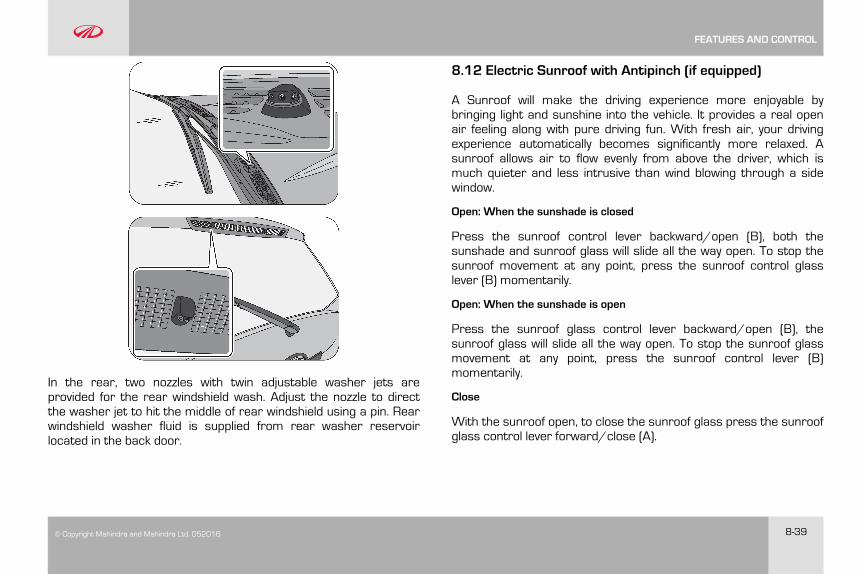
© Copyright Mahindra and Mahindra Ltd. 052016 8-39
In the rear, two nozzles with twin adjustable washer jets areprovided for the rear windshield wash. Adjust the nozzle to directthe washer jet to hit the middle of rear windshield using a pin. Rearwindshield washer fluid is supplied from rear washer reservoirlocated in the back door.
8.12 Electric Sunroof with Antipinch (if equipped)
A Sunroof will make the driving experience more enjoyable bybringing light and sunshine into the vehicle. It provides a real openair feeling along with pure driving fun. With fresh air, your drivingexperience automatically becomes significantly more relaxed. Asunroof allows air to flow evenly from above the driver, which ismuch quieter and less intrusive than wind blowing through a sidewindow.
Open: When the sunshade is closed
Press the sunroof control lever backward/open (B), both thesunshade and sunroof glass will slide all the way open. To stop thesunroof movement at any point, press the sunroof control glasslever (B) momentarily.
Open: When the sunshade is open
Press the sunroof glass control lever backward/open (B), thesunroof glass will slide all the way open. To stop the sunroof glassmovement at any point, press the sunroof control lever (B)momentarily.
Close
With the sunroof open, to close the sunroof glass press the sunroofglass control lever forward/close (A).
FEATURES AND CONTROL
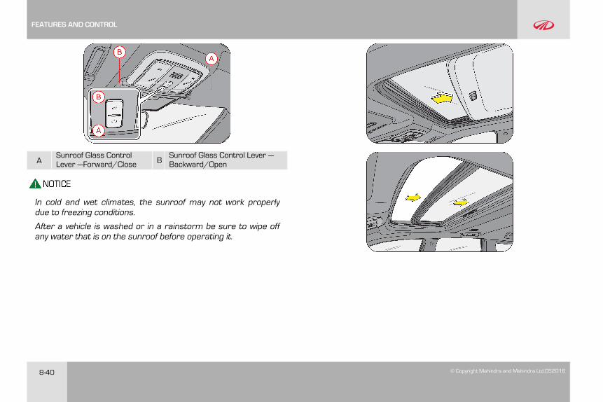
8-40 © Copyright Mahindra and Mahindra Ltd.052016
ASunroof Glass ControlLever —Forward/Close B
Sunroof Glass Control Lever —Backward/Open
In cold and wet climates, the sunroof may not work properlydue to freezing conditions.
After a vehicle is washed or in a rainstorm be sure to wipe offany water that is on the sunroof before operating it.
FEATURES AND CONTROL
© Copyright Mahindra and Mahindra Ltd. 052016 8-41
Sunroof Tilting Operation
Tilt up — The sunroof is tilted up when the Sunroof Glass ControlLever —Forward/Close (A) is shortly pressed (in the sunroof closedcondition).
Tilt down/close — The sunroof is tilted down/closed when theSunroof Glass Control Lever —Backward/Open (B) is pressed (inthe sunroof tiled up condition).
• Even though the sunroof can be operated when the ignitionkey is in the ON position (the engine is not running),operating the sunroof repeatedly with the engine turned offwill run down the battery. Operate the sunroof while theengine is running
• When a desired sunroof operation is completed, release theswitch. If you keep the switch operating, it could cause amalfunction. Especially in the winter, never operate thesunroof if moving areas are iced. Wait until the areas aredeiced
• When leaving the vehicle unattended, be sure to completelyclose the sunroof. This may otherwise lead to risk of vehicletheft or, the interior of the vehicle getting wet when it rainsor snows
• If there are children in the car: Close the sunroof securelyand remove the key before leaving the vehicle.
• Ensure children do not stand on the “armrest” to lookout ofthe sunroof. The armrest is a movable part and may movecausing injury/accident.
Anti-Pinch Function
To prevent any body parts from being trapped by the auto-closingsunroof, an Anti-Pinch Function automatically opens the sunroofwhen an object is trapped.
• The sunroof pinch protection function only operates duringautomatic closing, not manual closing
• When operating the sunroof, be aware of safety conditionsbefore operation. Parts of the body can be trapped
FEATURES AND CONTROL
8-42 © Copyright Mahindra and Mahindra Ltd.052016
• Never adjust the sunroof or sunshade while driving. Thiscould result in loss of control and an accident that maycause death, serious injury, or property damage.
• Anti-pinch function is not available in sunroof “Tilt” closeoperation
• If you would like to carry items on the roof rack using a crossbar, do not operate the sunroof. When carrying cargo on theroof rack, do not load heavy items above the sunroof orglass roof.
Wind Buffeting
When you drive the vehicle with the window or sunroof open at acertain position, you may feel some pressure upon your ears orhear some noises similar to those from a helicopter. This happensbecause of an influx in air through the window or sunroof and itsresonance effect. If this happens, adjust by opening the window orsunroof.
Battery Discharge/Disconnect or Power Failure while OperatingSunroof
If the sunroof is stopped midway due to a discharged battery orpower failure or battery has been disconnected, you need to re-calibrate the starting point of the sunroof. In addition, the followingcases need the re-calibration.
• The sunroof does not completely close or open by operating theswitch once
• The sunroof slides back to close. But the operation does not stopeven after a complete close and tilts up the sunroof
• The opening gap remarkably decreases for the sliding open ortilt up
• Operation of the sunroof switch does not do anything or workproperly
Re-Calibrating the Sunroof Starting Point
• Close the sunroof completely by using the Sunroof Glass ControlLever —Forward/Close (A). Release the lever
• Push the sunroof control lever forward/close in the direction ofclose (for about 10 seconds) until the sunroof moves a little.Then, release the lever
• Push the sunroof control lever forward/close in the direction ofclose, until the sunroof operates as follows; The sunshade andsunroof glass slide open → The sunroof glass slide close → Thesunshade close
• Release the lever
• When this is completed, the sunroof system has been reset
When the sunroof is completely opened with the sunroof switchand the switch is operated to the “OPEN” direction for morethan 5 seconds, the sunroof cannot completely be either closedor opened by operating the switch once. The sunroof will be
FEATURES AND CONTROL
© Copyright Mahindra and Mahindra Ltd. 052016 8-43
moving only when the switch is being operated. When thishappens, re-calibrate the beginning point of the sunroof toreactivate the one touch function.
Periodically remove any dirt that may accumulate on the guiderail.
Close the sunroof when driving in dusty environments. Dustmay cause a malfunction of the system.
FEATURES AND CONTROL
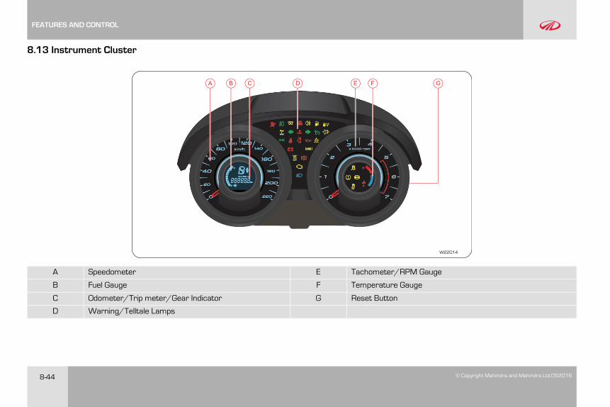
8-44 © Copyright Mahindra and Mahindra Ltd.052016
8.13 Instrument Cluster
D FEB CA G
W22D14
A Speedometer E Tachometer/RPM Gauge
B Fuel Gauge F Temperature Gauge
C Odometer/Trip meter/Gear Indicator G Reset Button
D Warning/Telltale Lamps
FEATURES AND CONTROL
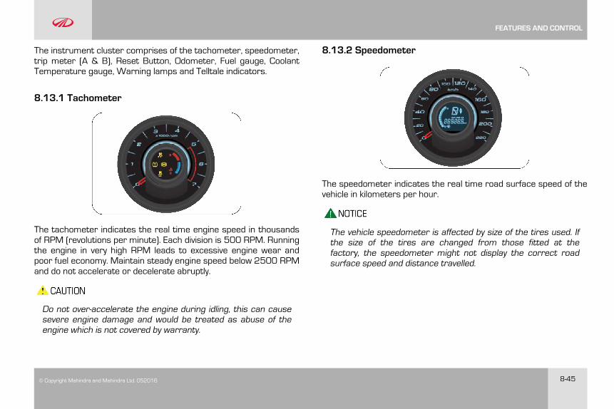
© Copyright Mahindra and Mahindra Ltd. 052016 8-45
The instrument cluster comprises of the tachometer, speedometer,trip meter (A & B), Reset Button, Odometer, Fuel gauge, CoolantTemperature gauge, Warning lamps and Telltale indicators.
8.13.1 Tachometer
The tachometer indicates the real time engine speed in thousandsof RPM (revolutions per minute). Each division is 500 RPM. Runningthe engine in very high RPM leads to excessive engine wear andpoor fuel economy. Maintain steady engine speed below 2500 RPMand do not accelerate or decelerate abruptly.
Do not over-accelerate the engine during idling, this can causesevere engine damage and would be treated as abuse of theengine which is not covered by warranty.
8.13.2 Speedometer
The speedometer indicates the real time road surface speed of thevehicle in kilometers per hour.
The vehicle speedometer is affected by size of the tires used. Ifthe size of the tires are changed from those fitted at thefactory, the speedometer might not display the correct roadsurface speed and distance travelled.
FEATURES AND CONTROL
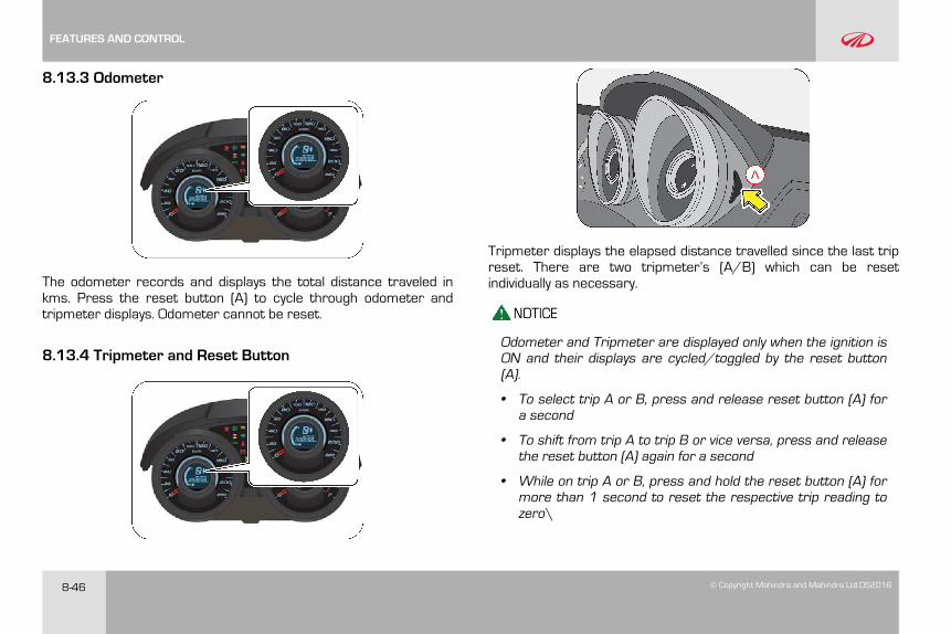
8-46 © Copyright Mahindra and Mahindra Ltd.052016
8.13.3 Odometer
The odometer records and displays the total distance traveled inkms. Press the reset button (A) to cycle through odometer andtripmeter displays. Odometer cannot be reset.
8.13.4 Tripmeter and Reset Button
Tripmeter displays the elapsed distance travelled since the last tripreset. There are two tripmeter’s (A/B) which can be resetindividually as necessary.
Odometer and Tripmeter are displayed only when the ignition isON and their displays are cycled/toggled by the reset button(A).
• To select trip A or B, press and release reset button (A) fora second
• To shift from trip A to trip B or vice versa, press and releasethe reset button (A) again for a second
• While on trip A or B, press and hold the reset button (A) formore than 1 second to reset the respective trip reading tozero\
FEATURES AND CONTROL
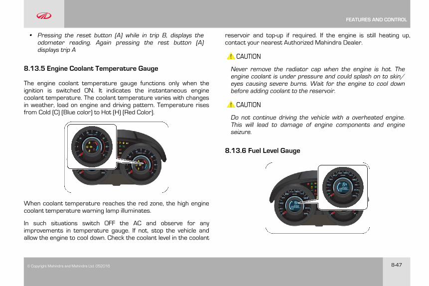
© Copyright Mahindra and Mahindra Ltd. 052016 8-47
• Pressing the reset button (A) while in trip B, displays theodometer reading. Again pressing the rest button (A)displays trip A
8.13.5 Engine Coolant Temperature Gauge
The engine coolant temperature gauge functions only when theignition is switched ON. It indicates the instantaneous enginecoolant temperature. The coolant temperature varies with changesin weather, load on engine and driving pattern. Temperature risesfrom Cold (C) (Blue color) to Hot (H) (Red Color).
When coolant temperature reaches the red zone, the high enginecoolant temperature warning lamp illuminates.
In such situations switch OFF the AC and observe for anyimprovements in temperature gauge. If not, stop the vehicle andallow the engine to cool down. Check the coolant level in the coolant
reservoir and top-up if required. If the engine is still heating up,contact your nearest Authorized Mahindra Dealer.
Never remove the radiator cap when the engine is hot. Theengine coolant is under pressure and could splash on to skin/eyes causing severe burns. Wait for the engine to cool downbefore adding coolant to the reservoir.
Do not continue driving the vehicle with a overheated engine.This will lead to damage of engine components and engineseizure.
8.13.6 Fuel Level Gauge
FEATURES AND CONTROL
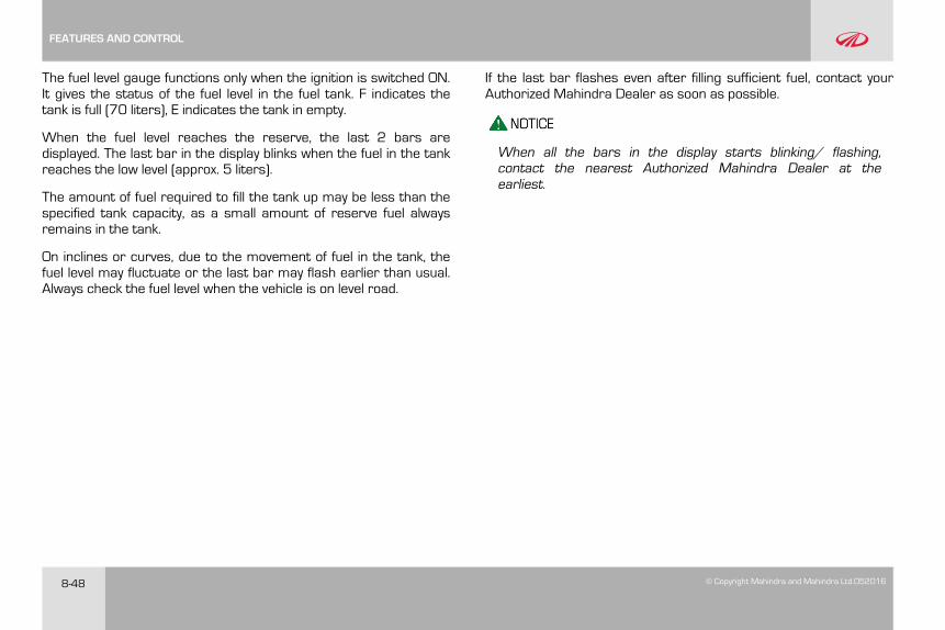
8-48 © Copyright Mahindra and Mahindra Ltd.052016
The fuel level gauge functions only when the ignition is switched ON.It gives the status of the fuel level in the fuel tank. F indicates thetank is full (70 liters), E indicates the tank in empty.
When the fuel level reaches the reserve, the last 2 bars aredisplayed. The last bar in the display blinks when the fuel in the tankreaches the low level (approx. 5 liters).
The amount of fuel required to fill the tank up may be less than thespecified tank capacity, as a small amount of reserve fuel alwaysremains in the tank.
On inclines or curves, due to the movement of fuel in the tank, thefuel level may fluctuate or the last bar may flash earlier than usual.Always check the fuel level when the vehicle is on level road.
If the last bar flashes even after filling sufficient fuel, contact yourAuthorized Mahindra Dealer as soon as possible.
When all the bars in the display starts blinking/ flashing,contact the nearest Authorized Mahindra Dealer at theearliest.
FEATURES AND CONTROL
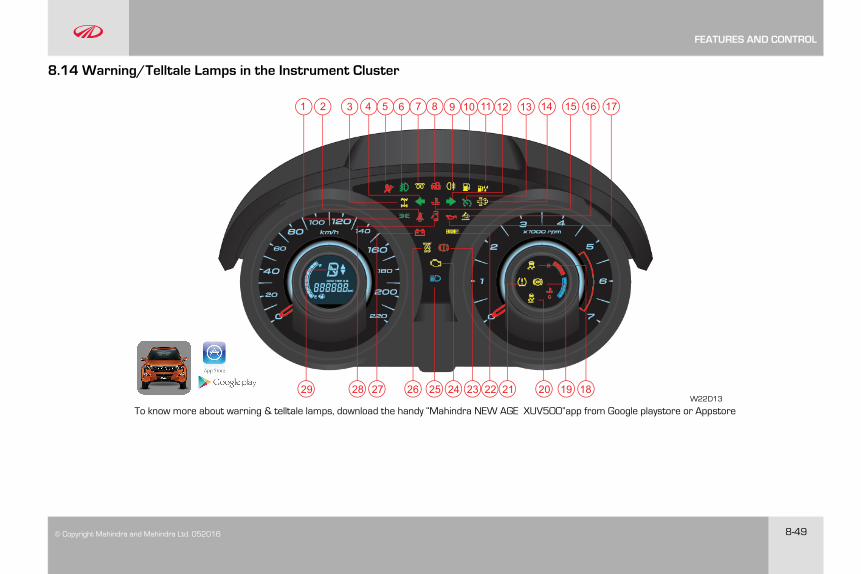
© Copyright Mahindra and Mahindra Ltd. 052016 8-49
8.14 Warning/Telltale Lamps in the Instrument Cluster
1 2 3 4 5 6 7 8 9 10 11 12 13 14 15 1716
1820 19212223242526272829
To know more about warning & telltale lamps, download the handy “Mahindra NEW AGE XUV5OO”app from Google playstore or AppstoreW22D13
FEATURES AND CONTROL
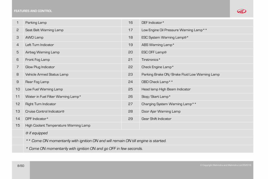
8-50 © Copyright Mahindra and Mahindra Ltd.052016
1 Parking Lamp 16 DEF Indicator*
2 Seat Belt Warning Lamp 17 Low Engine Oil Pressure Warning Lamp**
3 AWD Lamp 18 ESC System Warning Lamp@*
4 Left Turn Indicator 19 ABS Warning Lamp*
5 Airbag Warning Lamp 20 ESC OFF Lamp@
6 Front Fog Lamp 21 Tiretronics*
7 Glow Plug Indicator 22 Check Engine Lamp*
8 Vehicle Armed Status Lamp 23 Parking Brake ON/Brake Fluid Low Warning Lamp
9 Rear Fog Lamp 24 OBD Check Lamp**
10 Low Fuel Warning Lamp 25 Head lamp High Beam Indicator
11 Water in Fuel Filter Warning Lamp* 26 Stop/Start Lamp*
12 Right Turn Indicator 27 Charging System Warning Lamp**
13 Cruise Control Indicator@ 28 Door Ajar Warning Lamp
14 DPF Indicator* 29 Gear Shift Indicator
15 High Coolant Temperature Warning Lamp
@ if equipped
** Come ON momentarily with ignition ON and will remain ON till engine is started.
* Come ON momentarily with ignition ON and go OFF in few seconds.
FEATURES AND CONTROL
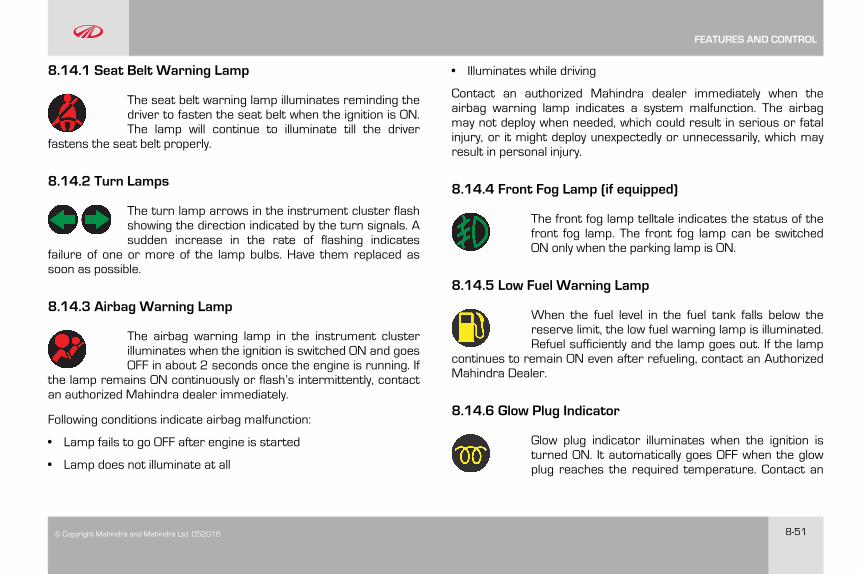
© Copyright Mahindra and Mahindra Ltd. 052016 8-51
8.14.1 Seat Belt Warning Lamp
The seat belt warning lamp illuminates reminding thedriver to fasten the seat belt when the ignition is ON.The lamp will continue to illuminate till the driver
fastens the seat belt properly.
8.14.2 Turn Lamps
The turn lamp arrows in the instrument cluster flashshowing the direction indicated by the turn signals. Asudden increase in the rate of flashing indicates
failure of one or more of the lamp bulbs. Have them replaced assoon as possible.
8.14.3 Airbag Warning Lamp
The airbag warning lamp in the instrument clusterilluminates when the ignition is switched ON and goesOFF in about 2 seconds once the engine is running. If
the lamp remains ON continuously or flash’s intermittently, contactan authorized Mahindra dealer immediately.
Following conditions indicate airbag malfunction:
• Lamp fails to go OFF after engine is started
• Lamp does not illuminate at all
• Illuminates while driving
Contact an authorized Mahindra dealer immediately when theairbag warning lamp indicates a system malfunction. The airbagmay not deploy when needed, which could result in serious or fatalinjury, or it might deploy unexpectedly or unnecessarily, which mayresult in personal injury.
8.14.4 Front Fog Lamp (if equipped)
The front fog lamp telltale indicates the status of thefront fog lamp. The front fog lamp can be switchedON only when the parking lamp is ON.
8.14.5 Low Fuel Warning Lamp
When the fuel level in the fuel tank falls below thereserve limit, the low fuel warning lamp is illuminated.Refuel sufficiently and the lamp goes out. If the lamp
continues to remain ON even after refueling, contact an AuthorizedMahindra Dealer.
8.14.6 Glow Plug Indicator
Glow plug indicator illuminates when the ignition isturned ON. It automatically goes OFF when the glowplug reaches the required temperature. Contact an
FEATURES AND CONTROL
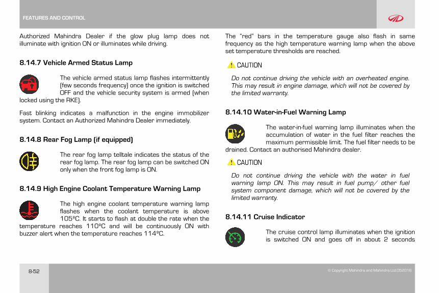
8-52 © Copyright Mahindra and Mahindra Ltd.052016
Authorized Mahindra Dealer if the glow plug lamp does notilluminate with ignition ON or illuminates while driving.
8.14.7 Vehicle Armed Status Lamp
The vehicle armed status lamp flashes intermittently(few seconds frequency) once the ignition is switchedOFF and the vehicle security system is armed (when
locked using the RKE).
Fast blinking indicates a malfunction in the engine immobilizersystem. Contact an Authorized Mahindra Dealer immediately.
8.14.8 Rear Fog Lamp (if equipped)
The rear fog lamp telltale indicates the status of therear fog lamp. The rear fog lamp can be switched ONonly when the front fog lamp is ON.
8.14.9 High Engine Coolant Temperature Warning Lamp
The high engine coolant temperature warning lampflashes when the coolant temperature is above105ºC. It starts to flash at double the rate when the
temperature reaches 110ºC and will be continuously ON withbuzzer alert when the temperature reaches 114ºC.
The “red” bars in the temperature gauge also flash in samefrequency as the high temperature warning lamp when the aboveset temperature thresholds are reached.
Do not continue driving the vehicle with an overheated engine.This may result in engine damage, which will not be covered bythe limited warranty.
8.14.10 Water-in-Fuel Warning Lamp
The water-in-fuel warning lamp illuminates when theaccumulation of water in the fuel filter reaches themaximum permissible limit. The fuel filter needs to be
drained. Contact an authorised Mahindra dealer.
Do not continue driving the vehicle with the water in fuelwarning lamp ON. This may result in fuel pump/ other fuelsystem component damage, which will not be covered by thelimited warranty.
8.14.11 Cruise Indicator
The cruise control lamp illuminates when the ignitionis switched ON and goes off in about 2 seconds
FEATURES AND CONTROL
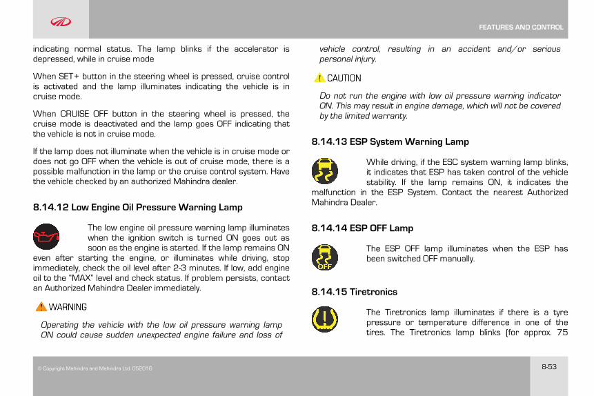
© Copyright Mahindra and Mahindra Ltd. 052016 8-53
indicating normal status. The lamp blinks if the accelerator isdepressed, while in cruise mode
When SET+ button in the steering wheel is pressed, cruise controlis activated and the lamp illuminates indicating the vehicle is incruise mode.
When CRUISE OFF button in the steering wheel is pressed, thecruise mode is deactivated and the lamp goes OFF indicating thatthe vehicle is not in cruise mode.
If the lamp does not illuminate when the vehicle is in cruise mode ordoes not go OFF when the vehicle is out of cruise mode, there is apossible malfunction in the lamp or the cruise control system. Havethe vehicle checked by an authorized Mahindra dealer.
8.14.12 Low Engine Oil Pressure Warning Lamp
The low engine oil pressure warning lamp illuminateswhen the ignition switch is turned ON goes out assoon as the engine is started. If the lamp remains ON
even after starting the engine, or illuminates while driving, stopimmediately, check the oil level after 2-3 minutes. If low, add engineoil to the “MAX” level and check status. If problem persists, contactan Authorized Mahindra Dealer immediately.
Operating the vehicle with the low oil pressure warning lampON could cause sudden unexpected engine failure and loss of
vehicle control, resulting in an accident and/or seriouspersonal injury.
Do not run the engine with low oil pressure warning indicatorON. This may result in engine damage, which will not be coveredby the limited warranty.
8.14.13 ESP System Warning Lamp
While driving, if the ESC system warning lamp blinks,it indicates that ESP has taken control of the vehiclestability. If the lamp remains ON, it indicates the
malfunction in the ESP System. Contact the nearest AuthorizedMahindra Dealer.
8.14.14 ESP OFF Lamp
The ESP OFF lamp illuminates when the ESP hasbeen switched OFF manually.
8.14.15 Tiretronics
The Tiretronics lamp illuminates if there is a tyrepressure or temperature difference in one of thetires. The Tiretronics lamp blinks (for approx. 75
FEATURES AND CONTROL
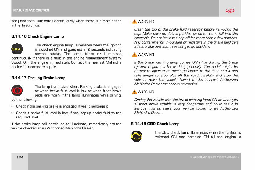
8-54 © Copyright Mahindra and Mahindra Ltd.052016
sec.) and then illuminates continuously when there is a malfunctionin the Tiretronics.
8.14.16 Check Engine Lamp
The check engine lamp illuminates when the ignitionis switched ON and goes out in 2 seconds indicatingnormal status. The lamp blinks or illuminates
continuously if there is a fault in the engine management system.Switch OFF the engine immediately. Contact the nearest Mahindradealer for necessary repairs.
8.14.17 Parking Brake Lamp
The lamp illuminates when; Parking brake is engagedor when brake fluid level is low or when front brakepads are worn. If the lamp illuminates while driving,
do the following:
• Check if the parking brake is engaged. If yes, disengage it
• Check if brake fluid level is low. If yes, top-up brake fluid to therequired level
If the brake lamp still continues to illuminate, immediately get thevehicle checked at an Authorized Mahindra Dealer.
Clean the top of the brake fluid reservoir before removing thecap. Make sure no dirt, impurities or other items fall into thereservoir. Do not leave the cap off for more than a few minutes.Any contaminants, impurities or moisture in the brake fluid canaffect brake operation, resulting in an accident.
If the brake warning lamp comes ON while driving, the brakesystem might not be working properly. The pedal might beharder to operate or might go closer to the floor and it cantake longer to stop. Pull off the road carefully and stop thevehicle. Have the vehicle towed to the nearest AuthorizedMahindra Dealer for checks or repairs.
Driving the vehicle with the brake warning lamp ON or when yoususpect brake trouble is very dangerous and could result inserious injuries. Have your vehicle towed to an AuthorizedMahindra Dealer.
8.14.18 OBD Check Lamp
The OBD check lamp illuminates when the ignition isswitched ON and remains ON till the engine is
FEATURES AND CONTROL
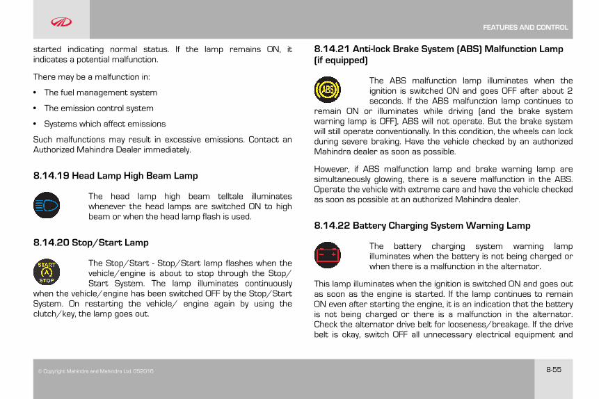
© Copyright Mahindra and Mahindra Ltd. 052016 8-55
started indicating normal status. If the lamp remains ON, itindicates a potential malfunction.
There may be a malfunction in:
• The fuel management system
• The emission control system
• Systems which affect emissions
Such malfunctions may result in excessive emissions. Contact anAuthorized Mahindra Dealer immediately.
8.14.19 Head Lamp High Beam Lamp
The head lamp high beam telltale illuminateswhenever the head lamps are switched ON to highbeam or when the head lamp flash is used.
8.14.20 Stop/Start Lamp
The Stop/Start - Stop/Start lamp flashes when thevehicle/engine is about to stop through the Stop/Start System. The lamp illuminates continuously
when the vehicle/engine has been switched OFF by the Stop/StartSystem. On restarting the vehicle/ engine again by using theclutch/key, the lamp goes out.
8.14.21 Anti-lock Brake System (ABS) Malfunction Lamp(if equipped)
The ABS malfunction lamp illuminates when theignition is switched ON and goes OFF after about 2seconds. If the ABS malfunction lamp continues to
remain ON or illuminates while driving (and the brake systemwarning lamp is OFF), ABS will not operate. But the brake systemwill still operate conventionally. In this condition, the wheels can lockduring severe braking. Have the vehicle checked by an authorizedMahindra dealer as soon as possible.
However, if ABS malfunction lamp and brake warning lamp aresimultaneously glowing, there is a severe malfunction in the ABS.Operate the vehicle with extreme care and have the vehicle checkedas soon as possible at an authorized Mahindra dealer.
8.14.22 Battery Charging System Warning Lamp
The battery charging system warning lampilluminates when the battery is not being charged orwhen there is a malfunction in the alternator.
This lamp illuminates when the ignition is switched ON and goes outas soon as the engine is started. If the lamp continues to remainON even after starting the engine, it is an indication that the batteryis not being charged or there is a malfunction in the alternator.Check the alternator drive belt for looseness/breakage. If the drivebelt is okay, switch OFF all unnecessary electrical equipment and
FEATURES AND CONTROL
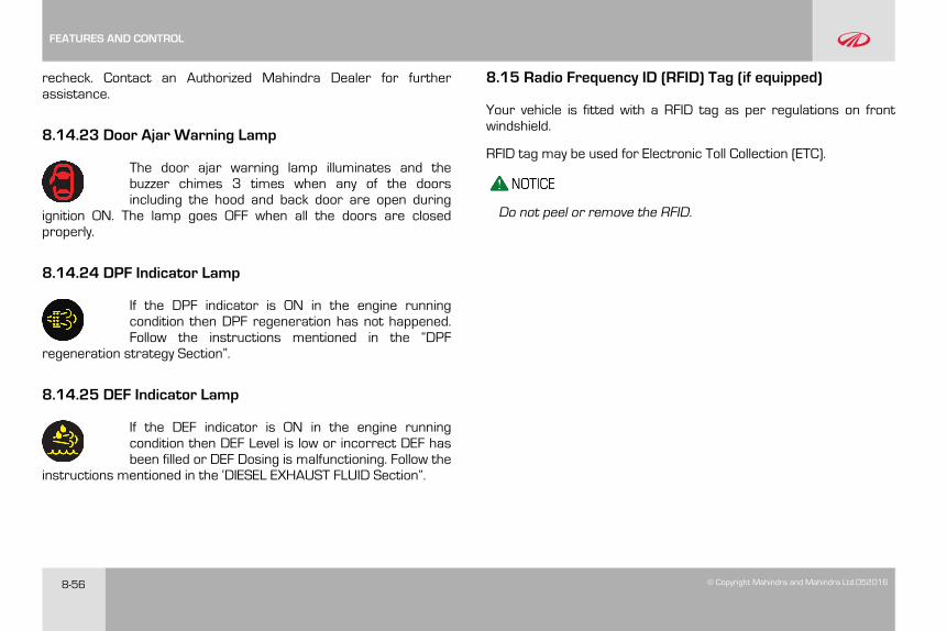
8-56 © Copyright Mahindra and Mahindra Ltd.052016
recheck. Contact an Authorized Mahindra Dealer for furtherassistance.
8.14.23 Door Ajar Warning Lamp
The door ajar warning lamp illuminates and thebuzzer chimes 3 times when any of the doorsincluding the hood and back door are open during
ignition ON. The lamp goes OFF when all the doors are closedproperly.
8.14.24 DPF Indicator Lamp
If the DPF indicator is ON in the engine runningcondition then DPF regeneration has not happened.Follow the instructions mentioned in the “DPF
regeneration strategy Section”.
8.14.25 DEF Indicator Lamp
If the DEF indicator is ON in the engine runningcondition then DEF Level is low or incorrect DEF hasbeen filled or DEF Dosing is malfunctioning. Follow the
instructions mentioned in the ‘DIESEL EXHAUST FLUID Section”.
8.15 Radio Frequency ID (RFID) Tag (if equipped)
Your vehicle is fitted with a RFID tag as per regulations on frontwindshield.
RFID tag may be used for Electronic Toll Collection (ETC).
Do not peel or remove the RFID.
FEATURES AND CONTROL
© Copyright Mahindra and Mahindra Ltd. 052016 9-1
9 STEERING AND BRAKES
9.1 Steering
Your vehicle is equipped with power steering. Power steering usesenergy from the engine to decrease the driver's effort in steeringthe vehicle. The power steering system will give you good vehicleresponse and increased ease of maneuverability in tight spaces. Iffor some reason the power assist is interrupted, it will providemechanical steering capability to steer the vehicle. Under theseconditions, you will observe a substantial increase in steering effort,especially at very low vehicle speeds and during parking maneuvers.
Upon initial start-up in cold weather, the power steering pumpmay produce noise for a short amount of time. This is due tothe cold, thick fluid in the steering system. This noise should beconsidered normal, and it does not in any way damage thesteering system.
Continued operation with reduced power steering performancecould pose a safety risk to yourself and others. Have the vehicleserviced at specified intervals or whenever a power steeringproblem is noticed.
Do not grip the steering wheel spokes when driving off road. Abad bump could jerk the wheel and injure your hands. Keepboth hands especially your thumbs on the outside of thesteering wheel rim.
To help prevent damage to the power steering pump:
• Never hold the steering wheel to the extreme right or theextreme left for more than a few seconds when the engine isrunning
• Heavy or uneven steering efforts may be caused by low powersteering pump fluid level. Check for low power steering pumpfluid level before seeking service by an Authorized MahindraDealer
• Do not fill the power steering pump reservoir above the MAXmark on the reservoir, this may result in leaks from the reservoir
If the power steering system breaks down (or if the engine isturned OFF), you can still steer the vehicle manually, but it takesmore effort.
STEERING AND BRAKES
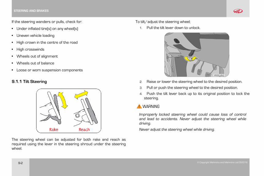
9-2 © Copyright Mahindra and Mahindra Ltd.052016
If the steering wanders or pulls, check for:
• Under inflated tire(s) on any wheel(s)
• Uneven vehicle loading
• High crown in the centre of the road
• High crosswinds
• Wheels out of alignment
• Wheels out of balance
• Loose or worn suspension components
9.1.1 Tilt Steering
The steering wheel can be adjusted for both rake and reach asrequired using the lever in the steering shroud under the steeringwheel.
To tilt/adjust the steering wheel;
1. Pull the tilt lever down to unlock.
W22J44
2. Raise or lower the steering wheel to the desired position.
3. Pull or push the steering wheel to the desired position.
4. Push the tilt lever back up to its original position to lock thesteering.
Improperly locked steering wheel could cause loss of controland lead to accidents. Never adjust the steering wheel whiledriving.
Never adjust the steering wheel while driving.
STEERING AND BRAKES
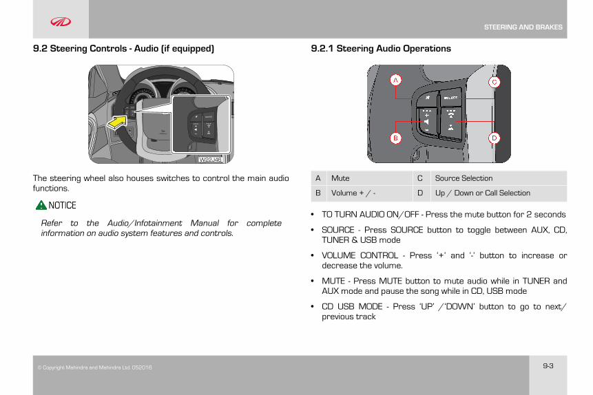
© Copyright Mahindra and Mahindra Ltd. 052016 9-3
9.2 Steering Controls - Audio (if equipped)
W22J46
The steering wheel also houses switches to control the main audiofunctions.
Refer to the Audio/Infotainment Manual for completeinformation on audio system features and controls.
9.2.1 Steering Audio Operations
A Mute C Source Selection
B Volume + / - D Up / Down or Call Selection
• TO TURN AUDIO ON/OFF - Press the mute button for 2 seconds
• SOURCE - Press SOURCE button to toggle between AUX, CD,TUNER & USB mode
• VOLUME CONTROL - Press ‘+’ and ‘-’ button to increase ordecrease the volume.
• MUTE - Press MUTE button to mute audio while in TUNER andAUX mode and pause the song while in CD, USB mode
• CD USB MODE - Press ‘UP’ /‘DOWN’ button to go to next/previous track
STEERING AND BRAKES
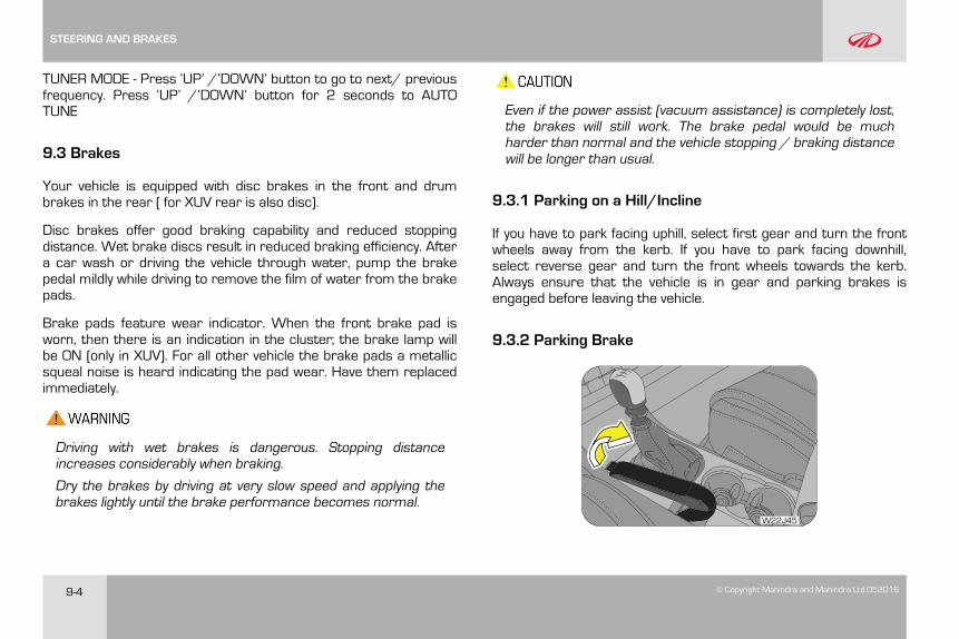
9-4 © Copyright Mahindra and Mahindra Ltd.052016
TUNER MODE - Press ‘UP’ /‘DOWN’ button to go to next/ previousfrequency. Press ‘UP’ /‘DOWN’ button for 2 seconds to AUTOTUNE
9.3 Brakes
Your vehicle is equipped with disc brakes in the front and drumbrakes in the rear ( for XUV rear is also disc).
Disc brakes offer good braking capability and reduced stoppingdistance. Wet brake discs result in reduced braking efficiency. Aftera car wash or driving the vehicle through water, pump the brakepedal mildly while driving to remove the film of water from the brakepads.
Brake pads feature wear indicator. When the front brake pad isworn, then there is an indication in the cluster; the brake lamp willbe ON (only in XUV). For all other vehicle the brake pads a metallicsqueal noise is heard indicating the pad wear. Have them replacedimmediately.
Driving with wet brakes is dangerous. Stopping distanceincreases considerably when braking.
Dry the brakes by driving at very slow speed and applying thebrakes lightly until the brake performance becomes normal.
Even if the power assist (vacuum assistance) is completely lost,the brakes will still work. The brake pedal would be muchharder than normal and the vehicle stopping / braking distancewill be longer than usual.
9.3.1 Parking on a Hill/Incline
If you have to park facing uphill, select first gear and turn the frontwheels away from the kerb. If you have to park facing downhill,select reverse gear and turn the front wheels towards the kerb.Always ensure that the vehicle is in gear and parking brakes isengaged before leaving the vehicle.
9.3.2 Parking Brake
W22J45
STEERING AND BRAKES
© Copyright Mahindra and Mahindra Ltd. 052016 9-5
To apply the parking brake, pull the park brake lever up as firmly aspossible. When the parking brake is applied with the ignition ON, thebrake warning lamp in the instrument cluster illuminates. Torelease the parking brake, pull the parking brake lever up slightly,press the release button on the lever tip and lower the parkingbrake lever completely.
The brake warning lamp indicates only the parking brake status.It does not indicate the degree of brake application. Be sure theparking brake is firmly set when parked and the gear shift leveris in gear. When parking on a hill ; first apply the Parking brake ;after that shift the TGS lever to the P position (for AT) and gearfor MT. T his will avoid the load on the transmission lockingmechanism may make it difficult to move the shift lever out ofgear.
Be sure the parking brake is fully disengaged before driving off.Failure to do so can lead to brake problems due to excessiveheating of the rear brakes. It will also result in reduced fuelefficiency; lowered brake pad life and rear brake squeal.
• The parking brake should be adjusted as per recommendedmaintenance schedule
• Always apply the parking brake when leaving the vehicle, andbe certain to leave the transmission in gear. Failure to do so
may allow the vehicle to roll and cause damage, hit abystander resulting in personal injury.
• Leaving unattended children in a vehicle is dangerous for anumber of reasons. Children should be warned not to touchthe parking brake or the gear shift lever. Do not leave the keyin the ignition. A child could move the vehicle leading toaccidents
• The parking brake should always be applied when the driveris not in the vehicle.
Engaging the parking brake while the vehicle is in motion can causethe rear wheels to lock up. You could lose control of the vehicle andcause an accident.
9.4 Hazard on Panic Braking
Hazard lamps are turned ON during panic braking for 5 sec whenthe following conditions are met:
• Ignition is ON
• Vehicle speed is greater than 80 kmph
• Panic/sudden brake is applied and high deceleration rate issensed
STEERING AND BRAKES
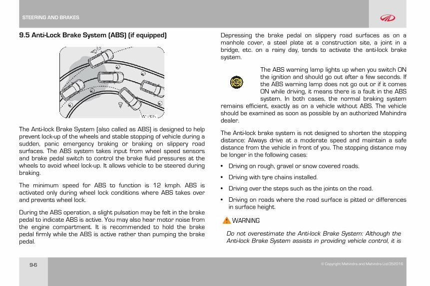
9-6 © Copyright Mahindra and Mahindra Ltd.052016
9.5 Anti-Lock Brake System (ABS) (if equipped)
The Anti-lock Brake System (also called as ABS) is designed to helpprevent lock-up of the wheels and stable stopping of vehicle during asudden, panic emergency braking or braking on slippery roadsurfaces. The ABS system takes input from wheel speed sensorsand brake pedal switch to control the brake fluid pressures at thewheels to avoid wheel lock-up. It allows vehicle to be steered duringbraking.
The minimum speed for ABS to function is 12 kmph. ABS isactivated only during wheel lock conditions where ABS takes overand prevents wheel lock.
During the ABS operation, a slight pulsation may be felt in the brakepedal to indicate ABS is active. You may also hear motor noise fromthe engine compartment. It is recommended to hold the brakepedal firmly while the ABS is active rather than pumping the brakepedal.
Depressing the brake pedal on slippery road surfaces as on amanhole cover, a steel plate at a construction site, a joint in abridge, etc. on a rainy day, tends to activate the anti-lock brakesystem.
The ABS warning lamp lights up when you switch ONthe ignition and should go out after a few seconds. Ifthe ABS warning lamp does not go out or if it comesON while driving, it means there is a fault in the ABSsystem. In both cases, the normal braking system
remains efficient, exactly as on a vehicle without ABS. The vehicleshould be examined as soon as possible by an authorized Mahindradealer.
The Anti-lock brake system is not designed to shorten the stoppingdistance: Always drive at a moderate speed and maintain a safedistance from the vehicle in front of you. The stopping distance maybe longer in the following cases:
• Driving on rough, gravel or snow covered roads.
• Driving with tyre chains installed.
• Driving over the steps such as the joints on the road.
• Driving on roads where the road surface is pitted or differencesin surface height.
Do not overestimate the Anti-lock Brake System: Although theAnti-lock Brake System assists in providing vehicle control, it is
STEERING AND BRAKES
© Copyright Mahindra and Mahindra Ltd. 052016 9-7
still important to drive with all due care and maintain amoderate speed and safe distance from the vehicle in front ofyou. There are limits to the vehicle stability and effectiveness ofsteering wheel operation even with ABS active.
If tyre grip performance exceeds its capability, or if hydroplaningoccurs during high speed driving in the rain, the Anti-lock BrakeSystem will not assist with vehicle control.
9.6 Electronic Brake Force Distribution (EBD) (if equipped)
EBD, as a subsystem of the ABS system, controls the effectiveadhesion utilization of the rear wheels. EBD aids in distributing thebrake forces more evenly leading to better vehicle stability duringbraking.
Typically, the front end carries more weight and EBD distributesless braking pressure to the rear brakes avoiding a lock up/skid.
For example, under light loads EBD applies less effort to the rearbrakes and for heavy loads it allows full braking effort to the rearwheels.
A fault with EBD is indicated by illumination of the brake as well asABS warning lamps. The vehicle should be examined as soon aspossible by an authorized Mahindra dealer.
9.7 Hydraulic Brake Assist (HBA) (if equipped)
ESP system recognizes / identifies an emergency braking situationfrom the braking characteristics and thereby achieves a brakingoutput equivalent to a full force demand at the controls. HBAautomatically boosts the braking force to the maximum and helpsto stop the vehicle as quickly as possible.
Pressure should be maintained on the brake pedal duringentire brake application. If the brake pedal is released, HBA willstop operating
STEERING AND BRAKES

© Copyright Mahindra and Mahindra Ltd. 052016 10-1
10 HEATING, VENTILATION AND AIR-CONDITIONINGSYSTEM (HVAC)
HVAC system provided in the vehicle enables occupants toautomatically/manually adjust air flow distribution pattern, air flowrate, air intake mode and air temperature inside passengercompartment. By appropriately adjusting the control knobs/switches provided on the HVAC control panel, located on centreconsole, occupant’s comfort can be ensured. HVAC system alsohelps in defrosting and defogging/ de-misting the windshield andwindows.
Air flow direction can be further controlled by adjusting louvers ofair vents. An air filter is provided at the inlet of HVAC blower.
Engine coolant is utilized to heat the cabin air. For cooling the cabinair, an air conditioning circuit based on the vapor compressionrefrigeration cycle is used. The air conditioning system uses arefrigerant along with a suitable lubricating oil. Although being non-ozone depleting, the refrigerant is a greenhouse gas, hence onceallowed to escape in the atmosphere, it adversely affects theenvironment by contributing to global warming/climate change.
Refrigerant used in system is a hazardous liquefied gas and isunder high pressure. The refrigerant is colorless and hasethereal or faint sweetish odor. Exposure of refrigerant to skinor eyes may cause irritation and frostbite. They can also causesuffocation, dizziness and loss of concentration. When mixedwith compressed air or certain other refrigerants, it may formflammable mixture. Never try to service HVAC system yourselfwhich would involve refrigerant handling.
Multiple vents are provided for distributing the air, being force-circulated by HVAC blower, throughout the passengercompartment.
To ensure sufficient air flow and hence adequate HVAC systemperformance, air flow path should be kept free of obstructions.Keep system’s air intake, located near plenum appliqué, free ofsnow, leaves and other debris. Also keep the area in front of airvents free of any obstruction inside the cabin.
HEATING, VENTILATION AND AIR-CONDITIONING SYSTEM (HVAC)
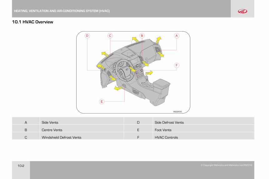
10-2 © Copyright Mahindra and Mahindra Ltd.052016
10.1 HVAC Overview
W22K55
AC BD
F
E
A Side Vents D Side Defrost Vents
B Centre Vents E Foot Vents
C Windshield Defrost Vents F HVAC Controls
HEATING, VENTILATION AND AIR-CONDITIONING SYSTEM (HVAC)
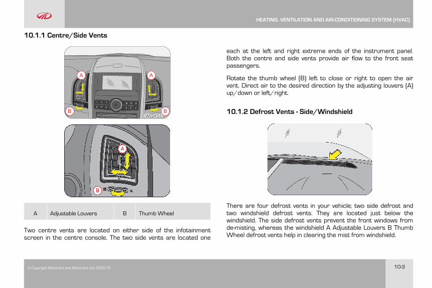
© Copyright Mahindra and Mahindra Ltd. 052016 10-3
10.1.1 Centre/Side Vents
AA
B BW22K53
A Adjustable Louvers B Thumb Wheel
Two centre vents are located on either side of the infotainmentscreen in the centre console. The two side vents are located one
each at the left and right extreme ends of the instrument panel.Both the centre and side vents provide air flow to the front seatpassengers.
Rotate the thumb wheel (B) left to close or right to open the airvent. Direct air to the desired direction by the adjusting louvers (A)up/down or left/right.
10.1.2 Defrost Vents - Side/Windshield
There are four defrost vents in your vehicle; two side defrost andtwo windshield defrost vents. They are located just below thewindshield. The side defrost vents prevent the front windows fromde-misting, whereas the windshield A Adjustable Louvers B ThumbWheel defrost vents help in clearing the mist from windshield.
HEATING, VENTILATION AND AIR-CONDITIONING SYSTEM (HVAC)
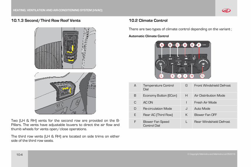
10-4 © Copyright Mahindra and Mahindra Ltd.052016
10.1.3 Second/Third Row Roof Vents
Two (LH & RH) vents for the second row are provided on the B-Pillars. The vents have adjustable louvers to direct the air flow andthumb wheels for vents open/close operations.
The third row vents (LH & RH) are located on side trims on eitherside of the third row seats.
10.2 Climate Control
There are two types of climate control depending on the variant ;
Automatic Climate Control
A Temperature ControlDial
G Front Windshield Defrost
B Economy Button (ECon) H Air Distribution Mode
C AC ON I Fresh Air Mode
D Re-circulation Mode J Auto Mode
E Rear AC (Third Row) K Blower Fan OFF
F Blower Fan SpeedControl Dial
L Rear Windshield Defrost
HEATING, VENTILATION AND AIR-CONDITIONING SYSTEM (HVAC)
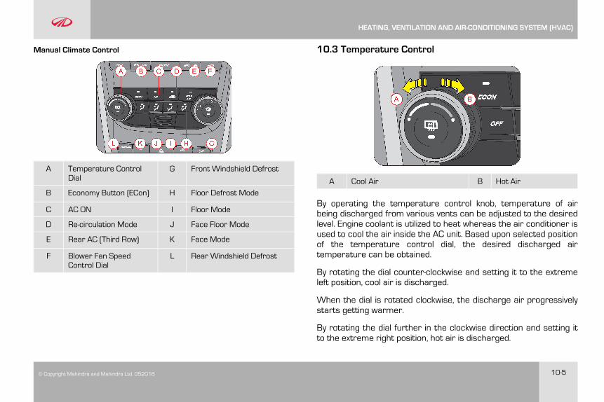
© Copyright Mahindra and Mahindra Ltd. 052016 10-5
Manual Climate Control
A Temperature ControlDial
G Front Windshield Defrost
B Economy Button (ECon) H Floor Defrost Mode
C AC ON I Floor Mode
D Re-circulation Mode J Face Floor Mode
E Rear AC (Third Row) K Face Mode
F Blower Fan SpeedControl Dial
L Rear Windshield Defrost
10.3 Temperature Control
A Cool Air B Hot Air
By operating the temperature control knob, temperature of airbeing discharged from various vents can be adjusted to the desiredlevel. Engine coolant is utilized to heat whereas the air conditioner isused to cool the air inside the AC unit. Based upon selected positionof the temperature control dial, the desired discharged airtemperature can be obtained.
By rotating the dial counter-clockwise and setting it to the extremeleft position, cool air is discharged.
When the dial is rotated clockwise, the discharge air progressivelystarts getting warmer.
By rotating the dial further in the clockwise direction and setting itto the extreme right position, hot air is discharged.
HEATING, VENTILATION AND AIR-CONDITIONING SYSTEM (HVAC)
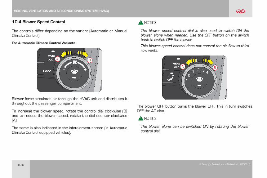
10-6 © Copyright Mahindra and Mahindra Ltd.052016
10.4 Blower Speed Control
The controls differ depending on the variant (Automatic or ManualClimate Control).
For Automatic Climate Control Variants
Blower force-circulates air through the HVAC unit and distributes itthroughout the passenger compartment.
To increase the blower speed, rotate the control dial clockwise (B)and to reduce the blower speed, rotate the dial counter clockwise(A).
The same is also indicated in the infotainment screen (in AutomaticClimate Control equipped vehicles).
The blower speed control dial is also used to switch ON theblower alone when needed. Use the OFF button on the switchbank to switch OFF the blower.
This blower speed control does not control the air flow to thirdrow vents.
The blower OFF button turns the blower OFF. This in turn switchesOFF the AC also.
The blower alone can be switched ON by rotating the blowercontrol dial.
HEATING, VENTILATION AND AIR-CONDITIONING SYSTEM (HVAC)
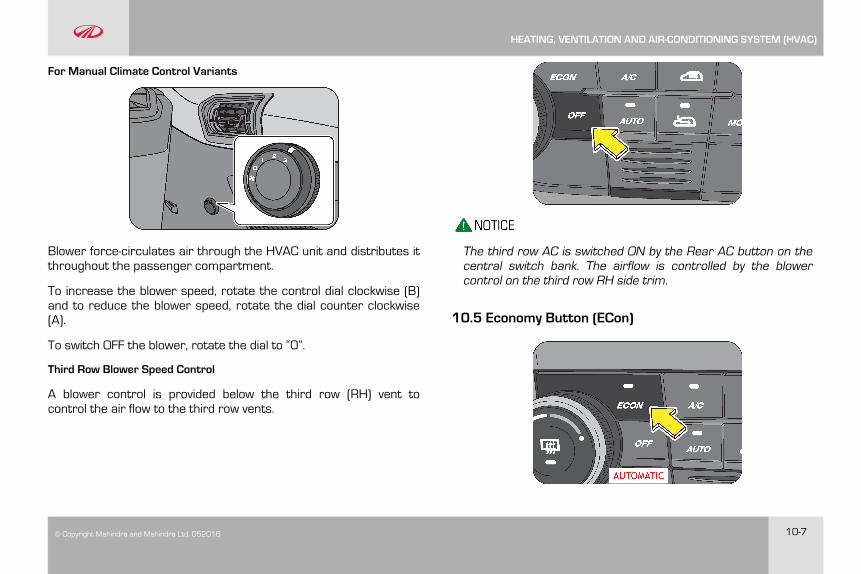
© Copyright Mahindra and Mahindra Ltd. 052016 10-7
For Manual Climate Control Variants
Blower force-circulates air through the HVAC unit and distributes itthroughout the passenger compartment.
To increase the blower speed, rotate the control dial clockwise (B)and to reduce the blower speed, rotate the dial counter clockwise(A).
To switch OFF the blower, rotate the dial to “0”.
Third Row Blower Speed Control
A blower control is provided below the third row (RH) vent tocontrol the air flow to the third row vents.
The third row AC is switched ON by the Rear AC button on thecentral switch bank. The airflow is controlled by the blowercontrol on the third row RH side trim.
10.5 Economy Button (ECon)
HEATING, VENTILATION AND AIR-CONDITIONING SYSTEM (HVAC)
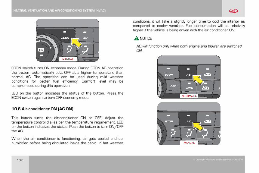
10-8 © Copyright Mahindra and Mahindra Ltd.052016
ECON switch turns ON economy mode. During ECON AC operationthe system automatically cuts OFF at a higher temperature thannormal AC. The operation can be used during mild weatherconditions for better fuel efficiency. Comfort level may becompromised during this operation.
LED on the button indicates the status of the button. Press theECON switch again to turn OFF economy mode.
10.6 Air-conditioner ON (AC ON)
This button turns the air-conditioner ON or OFF. Adjust thetemperature control dial as per the temperature requirement. LEDon the button indicates the status. Push the button to turn ON/OFFthe AC.
When the air conditioner is functioning, air gets cooled and de-humidified before being circulated inside the cabin. In hot weather
conditions, it will take a slightly longer time to cool the interior ascompared to cooler weather. Fuel consumption will be relativelyhigher if the vehicle is being driven with the air conditioner ON.
AC will function only when both engine and blower are switchedON.
HEATING, VENTILATION AND AIR-CONDITIONING SYSTEM (HVAC)
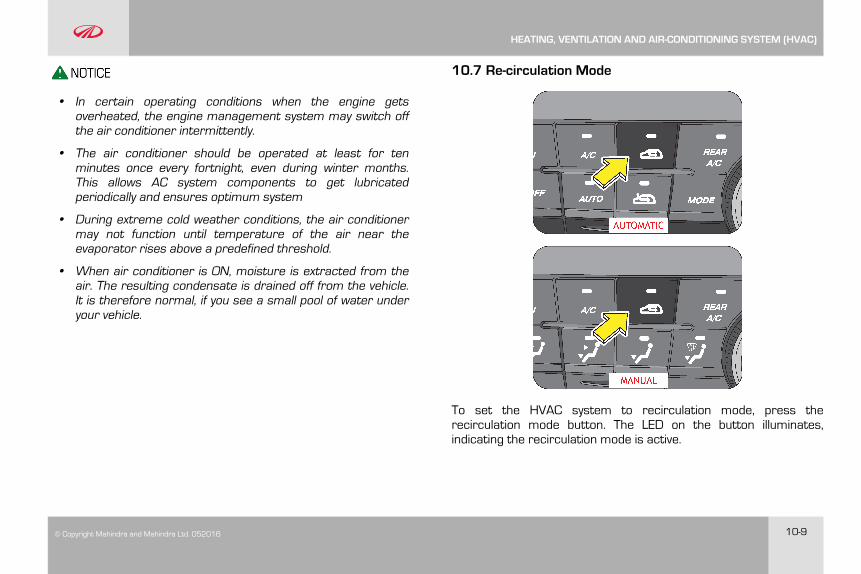
© Copyright Mahindra and Mahindra Ltd. 052016 10-9
• In certain operating conditions when the engine getsoverheated, the engine management system may switch offthe air conditioner intermittently.
• The air conditioner should be operated at least for tenminutes once every fortnight, even during winter months.This allows AC system components to get lubricatedperiodically and ensures optimum system
• During extreme cold weather conditions, the air conditionermay not function until temperature of the air near theevaporator rises above a predefined threshold.
• When air conditioner is ON, moisture is extracted from theair. The resulting condensate is drained off from the vehicle.It is therefore normal, if you see a small pool of water underyour vehicle.
10.7 Re-circulation Mode
To set the HVAC system to recirculation mode, press therecirculation mode button. The LED on the button illuminates,indicating the recirculation mode is active.
HEATING, VENTILATION AND AIR-CONDITIONING SYSTEM (HVAC)
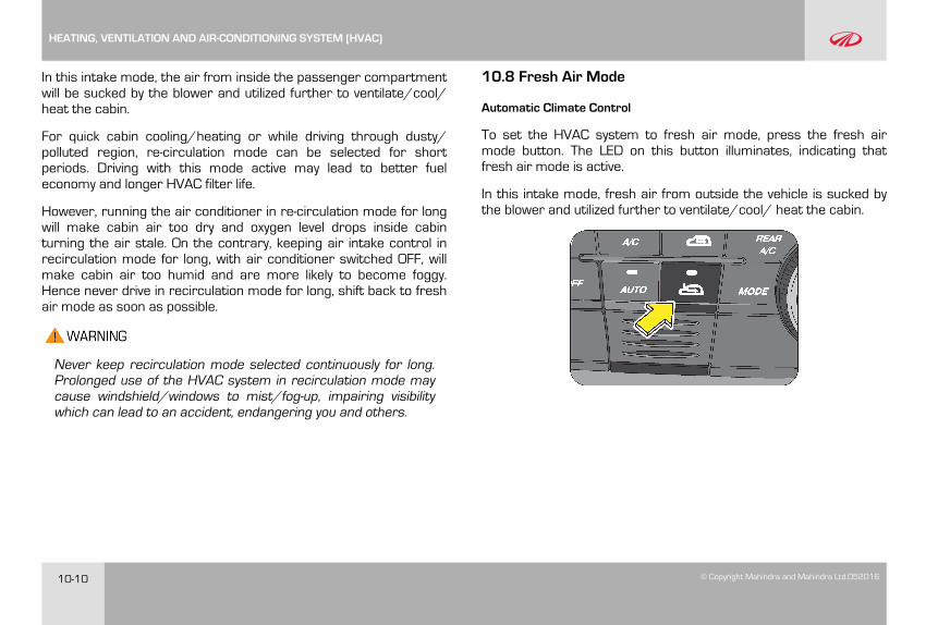
10-10 © Copyright Mahindra and Mahindra Ltd.052016
In this intake mode, the air from inside the passenger compartmentwill be sucked by the blower and utilized further to ventilate/cool/heat the cabin.
For quick cabin cooling/heating or while driving through dusty/polluted region, re-circulation mode can be selected for shortperiods. Driving with this mode active may lead to better fueleconomy and longer HVAC filter life.
However, running the air conditioner in re-circulation mode for longwill make cabin air too dry and oxygen level drops inside cabinturning the air stale. On the contrary, keeping air intake control inrecirculation mode for long, with air conditioner switched OFF, willmake cabin air too humid and are more likely to become foggy.Hence never drive in recirculation mode for long, shift back to freshair mode as soon as possible.
Never keep recirculation mode selected continuously for long.Prolonged use of the HVAC system in recirculation mode maycause windshield/windows to mist/fog-up, impairing visibilitywhich can lead to an accident, endangering you and others.
10.8 Fresh Air Mode
Automatic Climate Control
To set the HVAC system to fresh air mode, press the fresh airmode button. The LED on this button illuminates, indicating thatfresh air mode is active.
In this intake mode, fresh air from outside the vehicle is sucked bythe blower and utilized further to ventilate/cool/ heat the cabin.
HEATING, VENTILATION AND AIR-CONDITIONING SYSTEM (HVAC)
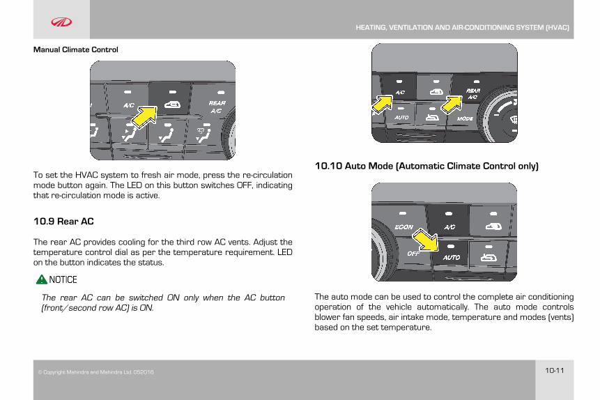
© Copyright Mahindra and Mahindra Ltd. 052016 10-11
Manual Climate Control
To set the HVAC system to fresh air mode, press the re-circulationmode button again. The LED on this button switches OFF, indicatingthat re-circulation mode is active.
10.9 Rear AC
The rear AC provides cooling for the third row AC vents. Adjust thetemperature control dial as per the temperature requirement. LEDon the button indicates the status.
The rear AC can be switched ON only when the AC button(front/second row AC) is ON.
10.10 Auto Mode (Automatic Climate Control only)
The auto mode can be used to control the complete air conditioningoperation of the vehicle automatically. The auto mode controlsblower fan speeds, air intake mode, temperature and modes (vents)based on the set temperature.
HEATING, VENTILATION AND AIR-CONDITIONING SYSTEM (HVAC)
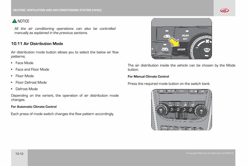
10-12 © Copyright Mahindra and Mahindra Ltd.052016
All the air conditioning operations can also be controlledmanually as explained in the previous sections.
10.11 Air Distribution Mode
Air distribution mode button allows you to select the below air flowpatterns;
• Face Mode
• Face and Floor Mode
• Floor Mode
• Floor Defrost Mode
• Defrost Mode
Depending on the variant, the operation of air distribution modechanges.
For Automatic Climate Control
Each press of mode switch changes the flow pattern accordingly.
The air distribution inside the vehicle can be chosen by the Modebutton.
For Manual Climate Control
Press the required mode button on the switch bank.
HEATING, VENTILATION AND AIR-CONDITIONING SYSTEM (HVAC)
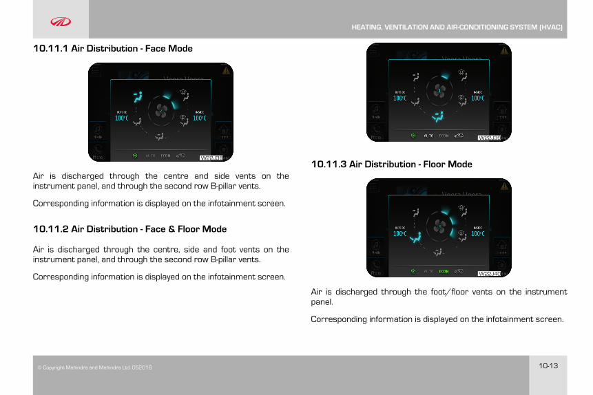
© Copyright Mahindra and Mahindra Ltd. 052016 10-13
10.11.1 Air Distribution - Face Mode
W22J38
Air is discharged through the centre and side vents on theinstrument panel, and through the second row B-pillar vents.
Corresponding information is displayed on the infotainment screen.
10.11.2 Air Distribution - Face & Floor Mode
Air is discharged through the centre, side and foot vents on theinstrument panel, and through the second row B-pillar vents.
Corresponding information is displayed on the infotainment screen.
W22J39
10.11.3 Air Distribution - Floor Mode
W22J40
Air is discharged through the foot/floor vents on the instrumentpanel.
Corresponding information is displayed on the infotainment screen.
HEATING, VENTILATION AND AIR-CONDITIONING SYSTEM (HVAC)
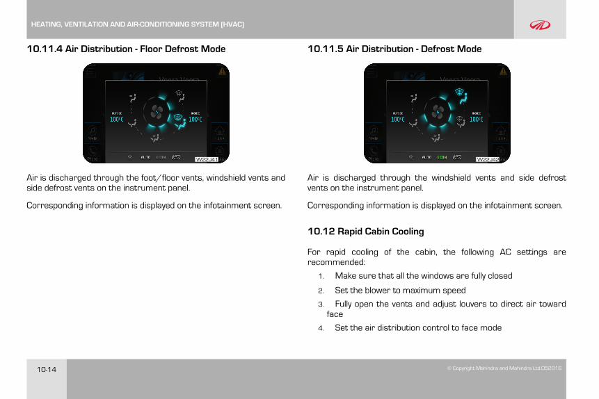
10-14 © Copyright Mahindra and Mahindra Ltd.052016
10.11.4 Air Distribution - Floor Defrost Mode
W22J41
Air is discharged through the foot/floor vents, windshield vents andside defrost vents on the instrument panel.
Corresponding information is displayed on the infotainment screen.
10.11.5 Air Distribution - Defrost Mode
W22J42
Air is discharged through the windshield vents and side defrostvents on the instrument panel.
Corresponding information is displayed on the infotainment screen.
10.12 Rapid Cabin Cooling
For rapid cooling of the cabin, the following AC settings arerecommended:
1. Make sure that all the windows are fully closed
2. Set the blower to maximum speed
3. Fully open the vents and adjust louvers to direct air towardface
4. Set the air distribution control to face mode
HEATING, VENTILATION AND AIR-CONDITIONING SYSTEM (HVAC)
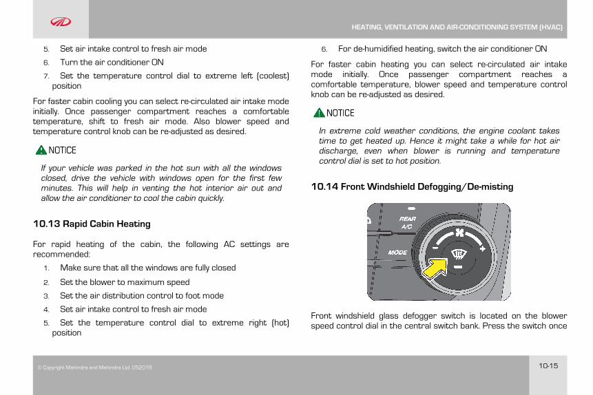
© Copyright Mahindra and Mahindra Ltd. 052016 10-15
5. Set air intake control to fresh air mode
6. Turn the air conditioner ON
7. Set the temperature control dial to extreme left (coolest)position
For faster cabin cooling you can select re-circulated air intake modeinitially. Once passenger compartment reaches a comfortabletemperature, shift to fresh air mode. Also blower speed andtemperature control knob can be re-adjusted as desired.
If your vehicle was parked in the hot sun with all the windowsclosed, drive the vehicle with windows open for the first fewminutes. This will help in venting the hot interior air out andallow the air conditioner to cool the cabin quickly.
10.13 Rapid Cabin Heating
For rapid heating of the cabin, the following AC settings arerecommended:
1. Make sure that all the windows are fully closed
2. Set the blower to maximum speed
3. Set the air distribution control to foot mode
4. Set air intake control to fresh air mode
5. Set the temperature control dial to extreme right (hot)position
6. For de-humidified heating, switch the air conditioner ON
For faster cabin heating you can select re-circulated air intakemode initially. Once passenger compartment reaches acomfortable temperature, blower speed and temperature controlknob can be re-adjusted as desired.
In extreme cold weather conditions, the engine coolant takestime to get heated up. Hence it might take a while for hot airdischarge, even when blower is running and temperaturecontrol dial is set to hot position.
10.14 Front Windshield Defogging/De-misting
Front windshield glass defogger switch is located on the blowerspeed control dial in the central switch bank. Press the switch once
HEATING, VENTILATION AND AIR-CONDITIONING SYSTEM (HVAC)
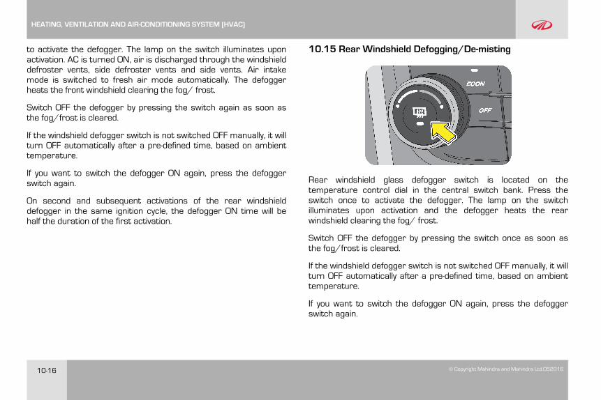
10-16 © Copyright Mahindra and Mahindra Ltd.052016
to activate the defogger. The lamp on the switch illuminates uponactivation. AC is turned ON, air is discharged through the windshielddefroster vents, side defroster vents and side vents. Air intakemode is switched to fresh air mode automatically. The defoggerheats the front windshield clearing the fog/ frost.
Switch OFF the defogger by pressing the switch again as soon asthe fog/frost is cleared.
If the windshield defogger switch is not switched OFF manually, it willturn OFF automatically after a pre-defined time, based on ambienttemperature.
If you want to switch the defogger ON again, press the defoggerswitch again.
On second and subsequent activations of the rear windshielddefogger in the same ignition cycle, the defogger ON time will behalf the duration of the first activation.
10.15 Rear Windshield Defogging/De-misting
Rear windshield glass defogger switch is located on thetemperature control dial in the central switch bank. Press theswitch once to activate the defogger. The lamp on the switchilluminates upon activation and the defogger heats the rearwindshield clearing the fog/ frost.
Switch OFF the defogger by pressing the switch once as soon asthe fog/frost is cleared.
If the windshield defogger switch is not switched OFF manually, it willturn OFF automatically after a pre-defined time, based on ambienttemperature.
If you want to switch the defogger ON again, press the defoggerswitch again.
HEATING, VENTILATION AND AIR-CONDITIONING SYSTEM (HVAC)
© Copyright Mahindra and Mahindra Ltd. 052016 10-17
On second and subsequent activations of the rear windshielddefogger in the same ignition cycle, the defogger ON time will behalf the duration of the first activation.
10.16 Points to Remember
• For quickly defogging/de-misting/defrosting outside ofwindshield, it is advisable to operate the windshield wiper/washer for few times intermittently.
• If snow has deposited on windshield, use ice scraper to removeice deposited before using wiper.
• In freezing weather, warm the windshield with the defrosterbefore using the windshield washer. Also use a washer fluidhaving anti-freezing properties. These will help prevent thewasher fluid from freezing on your windshield.
• Dirty/contaminated windshield would make misting/ fogging-upworse. Always keep the inside and outside of windshield clean.
• Reduced air flow because of clogged HVAC filter or any otherobstructions in air flow path may lead to in-adequate defogging/de-misting/defrosting performance. If air flow seems to haveconsiderably reduced, get the filter cleaned or replacedimmediately. Air flow path should be kept free of obstructions.
• Reduced cooling performance from air conditioner may lead toin-adequate defogging/de-misting/defrosting. If cooling effectseems to have dropped considerably, get the air conditioningsystem checked by an authorized Mahindra dealer.
Your vehicle is equipped with a HVAC filter. If the ACperformance is considerably low, it is recommended have theHVAC filter checked at the nearest Mahindra dealer.
Never operate HVAC system with the filter removed. This mayresult in premature failure of system components.
HEATING, VENTILATION AND AIR-CONDITIONING SYSTEM (HVAC)

© Copyright Mahindra and Mahindra Ltd. 052016 11-1
11 STARTING AND DRIVING THE VEHICLE
11.1 Safety Tips - Before Starting your Vehicle
11.1.1 General
• Before starting the vehicle, inspect the inside and outside of thevehicle ; look for any damages, leaks, loose parts, foreignobjects/debris. Contact an Authorized Mahindra Dealer ifrequired.
• Before starting your journey, check the working of all safetydevices/components especially brakes, steering, lamps, signalsand tires. In case you suspect any system/devices not workingproperly contact Authorized Mahindra Dealer.
• Adjust the seat headrest, steering wheel and fasten the seat beltas described in this manual. Never perform any seat/ steeringadjustments when the vehicle is in motion.
• Start the vehicle only when seated and belted in the driver's seat.
The Engine Management System controls the engine's idlespeed. When the engine starts, idle RPM runs higher thannormal in order to warm the engine. The engine idle speedRPM reduces once the engine warms up.
Never start your vehicle in a closed garage or in an enclosedarea. Exhaust fumes can be toxic. Always keep the garage dooropen or start the engine in an open area.
11.1.2 Mirror Adjustment
Ensure that the rear view mirror and both the ORVM’s are adjustedfor an unobstructed view of the road behind.
11.1.3 Exterior Lamps
Have someone observe and confirm normal operation of all exteriorlamps while you work on the controls from the driver seat. Also,check functioning of all lamps in the instrument panel.
11.1.4 Door Latches
Check for positive closing, latching, and locking of all doors, bothfrom inside and outside.
11.1.5 Fluid Leaks
Check the area under vehicle after an overnight parking for fuel,power steering fluid, brake fluid, engine coolant, oil, or other fluid
STARTING AND DRIVING THE VEHICLE
11-2 © Copyright Mahindra and Mahindra Ltd.052016
leaks. If leaks are observed, contact an Authorized MahindraDealer.
11.2 Starting the Engine
Make sure all vehicle occupants are properly seated in their seatsand have buckled their safety belts. For more information on seat,headrest positioning, safety belts and their proper usage, refer tothe “Seat Belts” section in this manual.
Before cranking the engine
• Make sure the gear shift lever is in neutral
• Make sure the parking brake is engaged. Turn the key to IGNposition but do not turn the key to start
• Few warning lamps briefly illuminate. See “Warning Lamps inthe Instrument Cluster” section for more information
1. Shift the gear shift lever to neutral position.
2. Apply parking brake.
3. Turn the ignition ON.
4. Do not press the accelerator.
5. Turn the key momentarily to the START position to crank the
6. Once the engine starts, release the key; it will return to theIGN position
Do not continue cranking after the engine has started.This will lead to damage of the starter and other enginecomponents.
7. If the engine fails to start, attempt to restart after about 10seconds
8. If the engine fails to start even after repeated attempts asper the procedure given above, contact the nearestAuthorized Mahindra Dealer
To prevent damage to the starter, wait 10 seconds beforeattempting to restart the engine.
If the vehicle battery has discharged, use booster cables, abooster battery or a battery from another vehicle to start.Jump-starting a vehicle can be dangerous if done improperly.Refer to the “Jump-starting procedure” section in this manual.
If the engine still fails to start, contact an Authorized MahindraDealer for assistance.
The idle speed is controlled automatically and it will decrease as theengine warms up.
Observe the following when the engine is running;
STARTING AND DRIVING THE VEHICLE
© Copyright Mahindra and Mahindra Ltd. 052016 11-3
• All warning lamps are OFF
• Low oil pressure lamp is OFF
After idling for a few seconds, release the parking brake, depressthe clutch, shift the gear shift lever to 1st gear, release the servicebrake pedal, drive by releasing the clutch and depressing theaccelerator pedal simultaneously.
11.2.1 Engine Idling - In Cold Weather
Avoid full throttle operation when the engine is cold and prolongedidling at low ambient temperatures. Long periods of idling may beharmful to your engine. Combustion chamber temperatures candrop so low that the fuel may not burn completely. Incompletecombustion allows carbon and varnish to form on piston rings andinjector nozzles. Also, the unburned fuel can enter the crankcase,diluting the oil and causing rapid wear to the engine.
11.3 Stopping the Engine
Your vehicle is powered by a turbo diesel engine. Before turning theengine OFF, always allow the engine to return to normal idle speedand run for few seconds. This assures proper cooling andlubrication of the turbocharger. This is particularly necessary afterany hard driving.
To reduce the risk of personal injury, before turning OFF theengine and leaving the vehicle, always,
• Keep your right foot on the service brake pedal
• Turn front wheels towards the road curb
• Switch OFF the ignition, turn the key to the steering lock positionand remove the key
• Firmly engage the parking brake
• Move the gear shift lever to 1st gear position (reverse gear ifparking on an incline)
• Slowly release the service brake pedal
• Lock your vehicle when leaving
11.4 Exhaust Gases
Protection against exhaust gas entry into the vehicles interior isconsidered in the design of the exhaust system.
• Vehicle exhaust contains Carbon Monoxide, Carbon Dioxide,Nitrogen Oxides, Hydrocarbons and Particulate Matter. Theseare potential environmental and health hazards.
• Avoid inhaling the exhaust gases. Carbon Monoxide is a colorlessand odorless gas and can cause unconsciousness or evendeath.
STARTING AND DRIVING THE VEHICLE
11-4 © Copyright Mahindra and Mahindra Ltd.052016
• If the exhaust system is damaged for any reason or you notice achange in the exhaust noise, have the vehicle checked by anAuthorized Mahindra Dealer immediately.
• Do not start the vehicle in a closed garage or in an enclosedarea where ventilation is poor for the exhaust gases.
• Since the engine compartment and exhaust system componentsare hot and can ignite a fire, do not park or leave the vehicle withthe engine idling over dry grass, leaves, paper, rags or anycombustible material.
Never keep the engine running when the vehicle is parked in anarea which is not properly ventilated. This could lead to seriousrespiratory problems and/or death.
11.5 Driving Your Vehicle
11.5.1 General Driving Precautions
Always observe the following precautions to minimize the risk ofaccidents leading to serious personal injury or damage to yourvehicle.
• Before you drive your vehicle, please read this manual carefully.
• Before you start driving, check proper operation of the brakesand steering system.
• If, while driving, you hear any strange noise or feel unusualvibration, or if you have any concerns whatsoever, or if anywarning lamps illuminate or buzzers sound, park/stop thevehicle in a safe location as soon as possible. Identify the causeand take any necessary remedial action. Contact your AuthorizedMahindra Dealer if necessary.
• Never overload or improperly load your vehicle.
• Always be attentive while driving and follow safe drivingpractices.
• Always maintain the recommended inflation pressure in tires.
• Always drive at a safe speed appropriate for given drivingconditions. You must follow the speed limits.
• While backing up, keep a constant lookout for people, particularlychildren, or other obstructions or hazardous material that mightbe present behind the vehicle.
• Avoid loading any items on the roof that will raise the vehiclescenter of gravity and make your vehicle more unstable.
• Loaded vehicles, with a higher center of gravity, may handledifferently than unloaded vehicles. Extra precautions, such asslower speeds and increased stopping distance, should be takenwhen driving a heavily loaded vehicle.
STARTING AND DRIVING THE VEHICLE
© Copyright Mahindra and Mahindra Ltd. 052016 11-5
• Always slow down in gusty crosswinds. Because of its profile andhigher center of gravity, your vehicle is more sensitive to sidewinds than an ordinary passenger car. Slowing down will allowyou to have much better control.
• When driving off-road or on rugged terrain, do not drive atexcessive speeds, jump, make sharp turns, strike objects, etc.This may cause loss of control or vehicle rollover causing seriousinjury. You are also risking expensive damage to your vehicle'ssuspension and chassis.
• Maintain steering wheel control at all times, especially on roughterrains. Sudden changes in terrain can result in abrupt steeringwheel motion. Make sure you grip the steering wheel from theoutside. Do not grip the spokes.
• If the vehicle goes from one type of surface to another (e.g. fromconcrete to gravel/sand/mud/snow) there will be a change inthe way the vehicle responds, especially the way it responds tosteering, braking and accelerating inputs.
• Be extremely careful when driving on pavements made slipperyby loose sand, water, gravel, snow or ice.
• If your vehicle goes off the edge of the pavement, slow down, butavoid severe brake or steering application. Ease the vehicle backonto the pavement only after reducing your speed. Do not turnthe steering wheel too sharply while returning to the roadsurface.
• It may be safer to stay on the apron or shoulder of the road andslow down gradually before returning to the pavement. You may
lose control if you do not slow down or if you turn the steeringwheel too sharply or abruptly.
• In an unavoidable emergency situation where a sudden sharpturn must be made, turn the steering wheel only as rapidly andas far as required to avoid the emergency. Excessive steering willresult in less vehicle control. Additionally, smooth variations ofthe accelerator and/or brake pedal pressure should be utilized ifchanges in vehicle speed are called for. Avoid abrupt steering,acceleration or braking which could result in an increased risk ofloss of vehicle control, vehicle rollover and/or personal injury.Use all available road surfaces to return the vehicle to a safedirection of travel.
11.5.2 Off Road Driving Precautions
• When driving off-road or on rugged terrains, never overspeed ormake sharp turns. This may cause loss of control or vehiclerollover causing serious injury.
• Maintain steering wheel control at all times. Sudden changes interrain can result in abrupt steering wheel motion.
• Do not drive horizontally or diagonally across steep slopes, yourvehicle can tip over sideways. Driving straight up or straightdown is preferred.
• Drive cautiously to avoid vehicle damage from concealed objectssuch as rocks and stumps. You should either know the terrain ormap-out your route before driving in the area.
STARTING AND DRIVING THE VEHICLE
11-6 © Copyright Mahindra and Mahindra Ltd.052016
• Always perform a maintenance inspection after each day of off-road driving that has taken you through rough terrain, sand, mudor water.
11.5.3 Driving Through Water
Although your vehicle is capable of driving through shallow water,there are a number of precautions that must be considered beforeentering the water.
Never drive through still water that is higher than the bottom ofthe axle hubs. Not following this instruction will allow water toenter vehicle components causing internal damage to thecomponents, affecting driveability, safety, emissions andreliability.
When driving through water, drive very slowly and at constantspeed, less than 8 kmph. Drive with accelerator pedal in OFFand control speed using only the brakes. At higher speed wavescan be generated by the front of the vehicle. These waterwaves may enter air intake, causing severe engine damage orcause a vehicle to get stalled.
You must slow down while driving through shallow water.Speeding may cause water to splash onto the windshield,impairing your vision In extreme conditions you may get a waterwedge formation between the road and tyre causing loss ofcontrol in the vehicle.
• The ground under the water might not be firm which could resultthe water being deeper than expected when driving the vehiclethrough it.
• Do not stop or shut OFF the engine while immersed in water. Ithelps in preventing water getting inside the exhaust pipes.
• When backing down a ramp, do not allow the exhaust tail pipe toimmerse in water.
• Water can wash the grease from wheel bearings, causingrusting and premature failure. It may also enter the differentials,transmission and transfer case, reducing the oil's lubricatingqualities. If these are submerged in water, the lubricants shouldbe replaced as required.
• Water entering the transmission will cause deterioration in shiftquality, locking up of your transmission accompanied by vibration,and ultimately damaging the transmission.
• Sand, mud/sludge that has accumulated in brake drums andaround brake discs may affect braking efficiency. This may alsodamage brake system components. Wet brakes cannot stop thevehicle as effectively as dry brakes. Drying can be improved bydriving the vehicle slowly while applying light pressure on thebrake pedal.
• When driving through water, traction or brake capability may belimited. Always perform a maintenance inspection after each dayof off-road driving that has taken you through water.
STARTING AND DRIVING THE VEHICLE
© Copyright Mahindra and Mahindra Ltd. 052016 11-7
11.5.4 Flowing Water
If the water is swift flowing and rising (as in storm run-off) avoidcrossing until the water level recedes and/or the flow rate isreduced.
The flowing water can erode the streambed causing your vehicle tosink into deeper water.
Determine the exit point(s) that are downstream of your entry pointto compensate for drifting.
11.5.5 After Driving Off-road or through Water
Off-road operation puts more stress on your vehicle than does moston-road driving. Always perform a maintenance inspection aftereach day of off-road driving that has taken you through roughterrain, sand, mud, or water.
• After going off-road, it is always a good idea to check for damage.Completely inspect the underbody of the vehicle for anydamages.
• Check for accumulations of plants or bushes. or polyethylene /plastic These could be a fire hazard. They might also hidedamage to fuel lines, brake tubes/hoses, etc.
• Inspect all the tubes/hoses and check for any fluid leakages.
• Get heat exchangers (radiator and condenser) cleaned.
• Check threaded fasteners for looseness, particularly on thechassis, drive train components, steering, suspension andbrakes. Retighten them, if required, and torque to the valuesspecified in the ‘Repair Manual’.
• We also recommend that the vehicle be checked at theAuthorised Dealer for any water entry into the transmission/axle or the engine
Abrasive material in any part of the brakes may causeexcessive wear or unpredictable braking. You might not havefull braking power when needed leading to accidents. If you havebeen operating the vehicle in off-road conditions, get the brakeschecked and cleaned as necessary.
• If any unusual vibration is experienced, check the wheels forimpacted material. Impacted material can cause a wheelimbalance. Get it inspected/corrected as soon as possible.
• After driving through deep water, inspect your vehicle fluids andlubricants (engine oil, transmission/transfer case/axle oils) toensure the fluids have not been contaminated.
11.6 Tips for Better Fuel Economy
Give due consideration to the points listed below for betterperformance of vehicle and enhancement of fuel economy.
• Smooth, moderate operation will yield savings in fuel
STARTING AND DRIVING THE VEHICLE
11-8 © Copyright Mahindra and Mahindra Ltd.052016
• Steady speeds without stopping will usually give the best fueleconomy
• Ensure that the parking brake is fully released
• Idling for long periods of time will waste fuel
• Anticipate stopping; slowing down may eliminate the need tostop
• Sudden or hard accelerations reduce fuel economy
• Slow down gradually
• Drive at moderate speeds
• Revving the engine before turning it off may reduce fuel economy
• The air conditioner may reduce fuel economy
• Warming up a vehicle in neutral on cold mornings is not requiredand may reduce fuel economy
• While idling put the gear shift lever in the neutral position
• Resting your foot on the clutch pedal while driving will reduce fueleconomy
• Combine errands and minimize stop-and-go driving
• Keep tires properly inflated. It is recommended to check your tirepressure in the morning when the tyre is cold
• Use recommended engine oil. Refer to the Maintenance Sectionfor specifications and capacities
• Replace the fuel filter and air filter at the recommended intervals
• Shift gears at the recommended speeds and rpm bands only.Refer to the gear shifting speed table for further details
• Control the maximum speed between 90 to 100 kmph in 5thgear to achieve the best fuel efficiency
• Follow the recommended maintenance schedule and performthe owner maintenance checks recommended
• Heavily loading a vehicle or towing a trailer will reduce fueleconomy
• Carrying unnecessary weight may reduce fuel economy
• Adding certain accessories to your vehicle may reduce fueleconomy
• Four-wheel-drive operation (if equipped) is less fuel efficient thantwo-wheel-drive operation
• Driving on flat terrains offer improved fuel economy ascompared to driving on hilly terrains
• Close windows during high speed driving for better fuel economy
• It is recommended to refuel in the mornings (cold weathercondition)
STARTING AND DRIVING THE VEHICLE
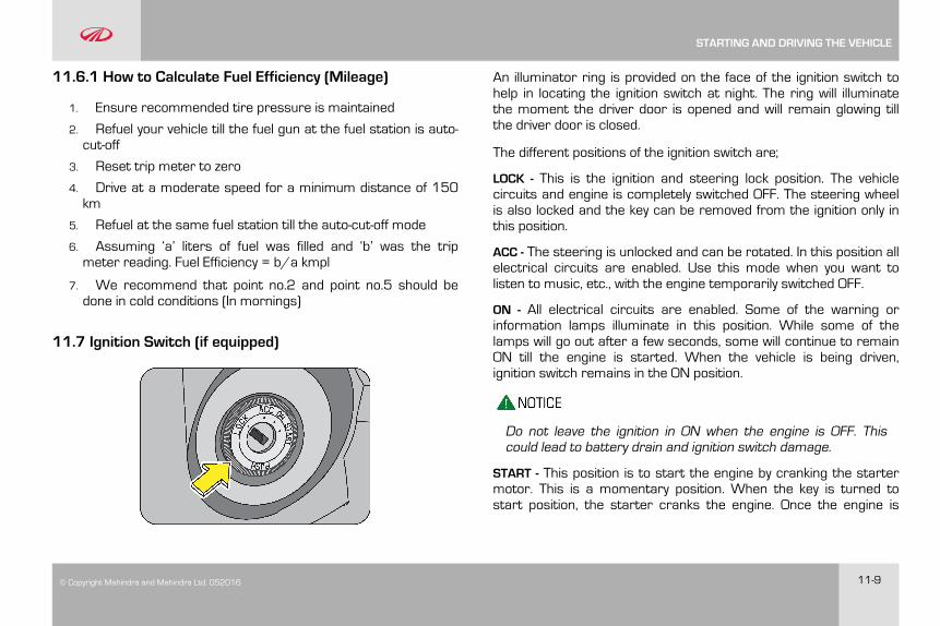
© Copyright Mahindra and Mahindra Ltd. 052016 11-9
11.6.1 How to Calculate Fuel Efficiency (Mileage)
1. Ensure recommended tire pressure is maintained
2. Refuel your vehicle till the fuel gun at the fuel station is auto-cut-off
3. Reset trip meter to zero
4. Drive at a moderate speed for a minimum distance of 150km
5. Refuel at the same fuel station till the auto-cut-off mode
6. Assuming ‘a’ liters of fuel was filled and ‘b’ was the tripmeter reading. Fuel Efficiency = b/a kmpl
7. We recommend that point no.2 and point no.5 should bedone in cold conditions (In mornings)
11.7 Ignition Switch (if equipped)
An illuminator ring is provided on the face of the ignition switch tohelp in locating the ignition switch at night. The ring will illuminatethe moment the driver door is opened and will remain glowing tillthe driver door is closed.
The different positions of the ignition switch are;
LOCK - This is the ignition and steering lock position. The vehiclecircuits and engine is completely switched OFF. The steering wheelis also locked and the key can be removed from the ignition only inthis position.
ACC - The steering is unlocked and can be rotated. In this position allelectrical circuits are enabled. Use this mode when you want tolisten to music, etc., with the engine temporarily switched OFF.
ON - All electrical circuits are enabled. Some of the warning orinformation lamps illuminate in this position. While some of thelamps will go out after a few seconds, some will continue to remainON till the engine is started. When the vehicle is being driven,ignition switch remains in the ON position.
Do not leave the ignition in ON when the engine is OFF. Thiscould lead to battery drain and ignition switch damage.
START - This position is to start the engine by cranking the startermotor. This is a momentary position. When the key is turned tostart position, the starter cranks the engine. Once the engine is
STARTING AND DRIVING THE VEHICLE
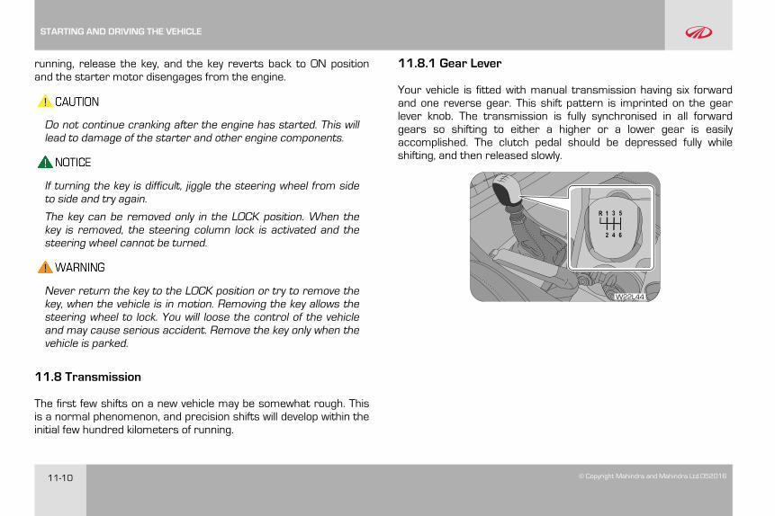
11-10 © Copyright Mahindra and Mahindra Ltd.052016
running, release the key, and the key reverts back to ON positionand the starter motor disengages from the engine.
Do not continue cranking after the engine has started. This willlead to damage of the starter and other engine components.
If turning the key is difficult, jiggle the steering wheel from sideto side and try again.
The key can be removed only in the LOCK position. When thekey is removed, the steering column lock is activated and thesteering wheel cannot be turned.
Never return the key to the LOCK position or try to remove thekey, when the vehicle is in motion. Removing the key allows thesteering wheel to lock. You will loose the control of the vehicleand may cause serious accident. Remove the key only when thevehicle is parked.
11.8 Transmission
The first few shifts on a new vehicle may be somewhat rough. Thisis a normal phenomenon, and precision shifts will develop within theinitial few hundred kilometers of running.
11.8.1 Gear Lever
Your vehicle is fitted with manual transmission having six forwardand one reverse gear. This shift pattern is imprinted on the gearlever knob. The transmission is fully synchronised in all forwardgears so shifting to either a higher or a lower gear is easilyaccomplished. The clutch pedal should be depressed fully whileshifting, and then released slowly.
W22L44
STARTING AND DRIVING THE VEHICLE
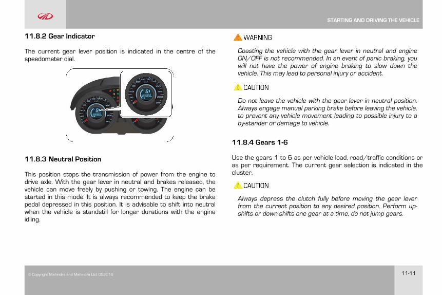
© Copyright Mahindra and Mahindra Ltd. 052016 11-11
11.8.2 Gear Indicator
The current gear lever position is indicated in the centre of thespeedometer dial.
11.8.3 Neutral Position
This position stops the transmission of power from the engine todrive axle. With the gear lever in neutral and brakes released, thevehicle can move freely by pushing or towing. The engine can bestarted in this mode. It is always recommended to keep the brakepedal depressed in this position. It is advisable to shift into neutralwhen the vehicle is standstill for longer durations with the engineidling.
Coasting the vehicle with the gear lever in neutral and engineON/OFF is not recommended. In an event of panic braking, youwill not have the power of engine braking to slow down thevehicle. This may lead to personal injury or accident.
Do not leave the vehicle with the gear lever in neutral position.Always engage manual parking brake before leaving the vehicle,to prevent any vehicle movement leading to possible injury to aby-stander or damage to vehicle.
11.8.4 Gears 1-6
Use the gears 1 to 6 as per vehicle load, road/traffic conditions oras per requirement. The current gear selection is indicated in thecluster.
Always depress the clutch fully before moving the gear leverfrom the current position to any desired position. Perform up-shifts or down-shifts one gear at a time, do not jump gears.
STARTING AND DRIVING THE VEHICLE
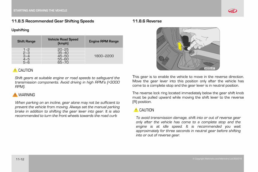
11-12 © Copyright Mahindra and Mahindra Ltd.052016
11.8.5 Recommended Gear Shifting Speeds
Upshifting
Shift Range Vehicle Road Speed(kmph) Engine RPM Range
1–2 20–25
1800–22002–3 35–403–4 45–504–5 55–605–6 65–70
Shift gears at suitable engine or road speeds to safeguard thetransmission components. Avoid driving in high RPM’s (>3000RPM).
When parking on an incline, gear alone may not be sufficient toprevent the vehicle from moving. Always set the manual parkingbrake in addition to shifting the gear lever into gear. It is alsorecommended to turn the front wheels towards the road curb
11.8.6 Reverse
W22L47
This gear is to enable the vehicle to move in the reverse direction.Move the gear lever into this position only after the vehicle hascome to a complete stop and the gear lever is in neutral position.
The reverse lock ring located immediately below the gear shift knobmust be pulled upward while moving the shift lever to the reverse(R) position.
To avoid transmission damage, shift into or out of reverse gearonly after the vehicle has come to a complete stop and theengine is at idle speed. It is recommended you waitapproximately for three seconds in neutral gear before shiftinginto or out of reverse gear.
STARTING AND DRIVING THE VEHICLE
© Copyright Mahindra and Mahindra Ltd. 052016 11-13
For brief stops, e. g. at traffic lights, keep the gear shift inneutral and hold the vehicle with the brake pedal. For prolongedstops, it is recommended to switch OFF the engine and applythe parking brake. When stopping the vehicle on an uphillgradient, do not hold it with the clutch/accelerator; use thebrake to avoid unnecessary clutch wear/heat buildup.
Do not leave children unattended in the vehicle or with accessto an unlocked vehicle. Children could move the gear lever,which could result in an accident or serious injury.
On slippery/wet road surfaces, never downshift in order toobtain braking action. This could result in a wheel slip andreduced vehicle control.
11.8.7 Uphill and Downhill Driving
To prevent the engine from laboring at a low RPM when drivinguphill gradients or with your vehicle heavily loaded, downshift whennecessary to maintain engine RPM within the best torque range.Similarly while driving downhill, downshift to utilize the enginebraking in an optimum manner.
11.9 Engine Idling
The idle speed is controlled automatically and it will decrease as theengine warms up.
Observe that all warning lamps are OFF when the engine is running.
After idling for a few seconds, follow the below steps to drive away;
1. Release the parking brake
2. Depress the clutch
3. Shift the gear lever to 1st gear
4. Release the service brake pedal
5. Drive by releasing the clutch and depressing the acceleratorpedal simultaneously.
11.9.1 Engine Idling - In Cold Weather
Avoid full throttle operation when the engine is cold and prolongedidling at low ambient temperatures. Long periods of idling may beharmful to your engine. Combustion chamber temperatures candrop so low that the fuel may not burn completely. Incompletecombustion allows carbon and varnish to form on piston rings andinjector nozzles. Also, the unburned fuel can enter the crankcase,diluting the oil and causing rapid wear to the engine.
You must fuel this vehicle with Ultra Low Sulfur Diesel. For smoothfunctioning and reliable operation of the engine during cold weather
STARTING AND DRIVING THE VEHICLE
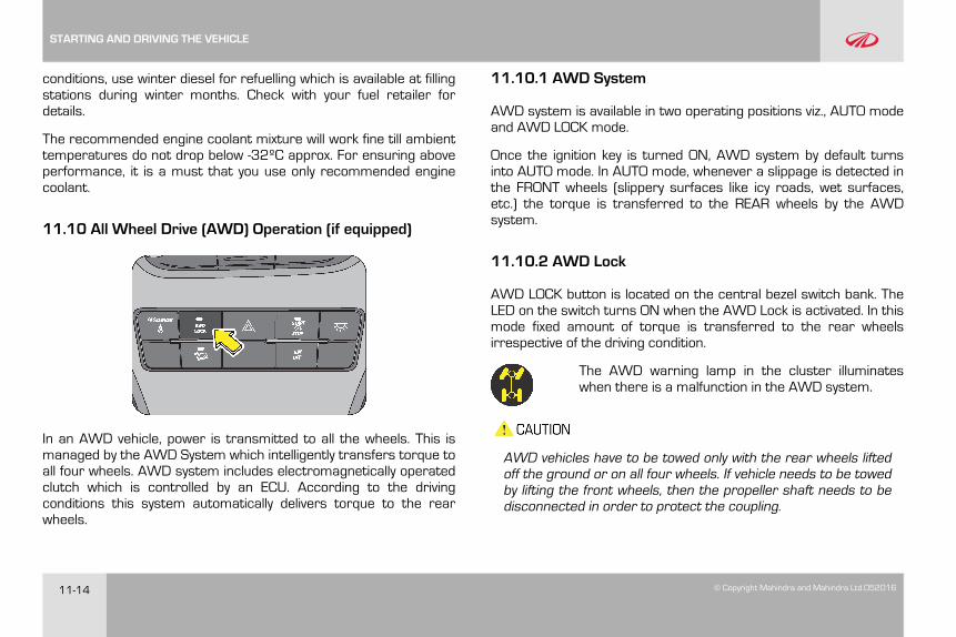
11-14 © Copyright Mahindra and Mahindra Ltd.052016
conditions, use winter diesel for refuelling which is available at fillingstations during winter months. Check with your fuel retailer fordetails.
The recommended engine coolant mixture will work fine till ambienttemperatures do not drop below -32ºC approx. For ensuring aboveperformance, it is a must that you use only recommended enginecoolant.
11.10 All Wheel Drive (AWD) Operation (if equipped)
In an AWD vehicle, power is transmitted to all the wheels. This ismanaged by the AWD System which intelligently transfers torque toall four wheels. AWD system includes electromagnetically operatedclutch which is controlled by an ECU. According to the drivingconditions this system automatically delivers torque to the rearwheels.
11.10.1 AWD System
AWD system is available in two operating positions viz., AUTO modeand AWD LOCK mode.
Once the ignition key is turned ON, AWD system by default turnsinto AUTO mode. In AUTO mode, whenever a slippage is detected inthe FRONT wheels (slippery surfaces like icy roads, wet surfaces,etc.) the torque is transferred to the REAR wheels by the AWDsystem.
11.10.2 AWD Lock
AWD LOCK button is located on the central bezel switch bank. TheLED on the switch turns ON when the AWD Lock is activated. In thismode fixed amount of torque is transferred to the rear wheelsirrespective of the driving condition.
The AWD warning lamp in the cluster illuminateswhen there is a malfunction in the AWD system.
AWD vehicles have to be towed only with the rear wheels liftedoff the ground or on all four wheels. If vehicle needs to be towedby lifting the front wheels, then the propeller shaft needs to bedisconnected in order to protect the coupling.
STARTING AND DRIVING THE VEHICLE
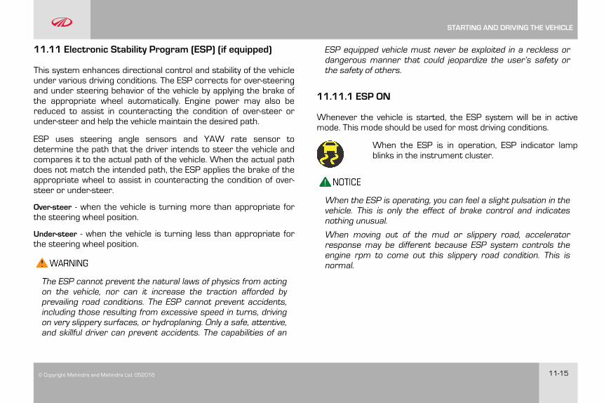
© Copyright Mahindra and Mahindra Ltd. 052016 11-15
11.11 Electronic Stability Program (ESP) (if equipped)
This system enhances directional control and stability of the vehicleunder various driving conditions. The ESP corrects for over-steeringand under steering behavior of the vehicle by applying the brake ofthe appropriate wheel automatically. Engine power may also bereduced to assist in counteracting the condition of over-steer orunder-steer and help the vehicle maintain the desired path.
ESP uses steering angle sensors and YAW rate sensor todetermine the path that the driver intends to steer the vehicle andcompares it to the actual path of the vehicle. When the actual pathdoes not match the intended path, the ESP applies the brake of theappropriate wheel to assist in counteracting the condition of over-steer or under-steer.
Over-steer - when the vehicle is turning more than appropriate forthe steering wheel position.
Under-steer - when the vehicle is turning less than appropriate forthe steering wheel position.
The ESP cannot prevent the natural laws of physics from actingon the vehicle, nor can it increase the traction afforded byprevailing road conditions. The ESP cannot prevent accidents,including those resulting from excessive speed in turns, drivingon very slippery surfaces, or hydroplaning. Only a safe, attentive,and skillful driver can prevent accidents. The capabilities of an
ESP equipped vehicle must never be exploited in a reckless ordangerous manner that could jeopardize the user’s safety orthe safety of others.
11.11.1 ESP ON
Whenever the vehicle is started, the ESP system will be in activemode. This mode should be used for most driving conditions.
When the ESP is in operation, ESP indicator lampblinks in the instrument cluster.
When the ESP is operating, you can feel a slight pulsation in thevehicle. This is only the effect of brake control and indicatesnothing unusual.
When moving out of the mud or slippery road, acceleratorresponse may be different because ESP system controls theengine rpm to come out this slippery road condition. This isnormal.
STARTING AND DRIVING THE VEHICLE
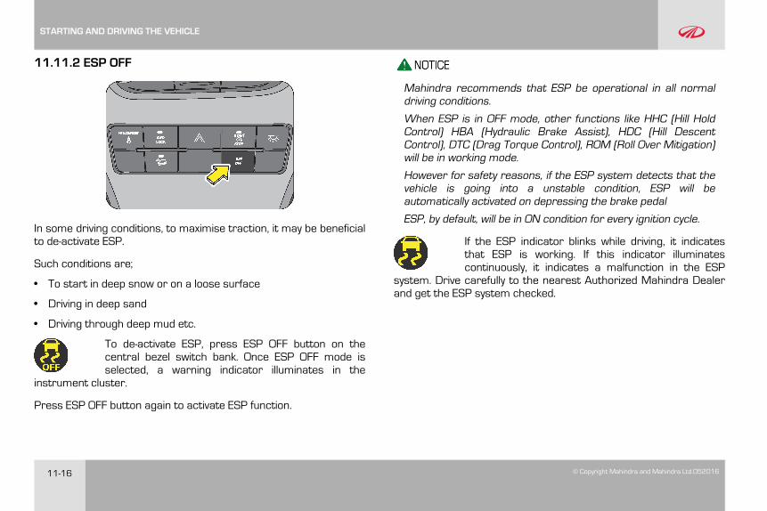
11-16 © Copyright Mahindra and Mahindra Ltd.052016
11.11.2 ESP OFF
In some driving conditions, to maximise traction, it may be beneficialto de-activate ESP.
Such conditions are;
• To start in deep snow or on a loose surface
• Driving in deep sand
• Driving through deep mud etc.
To de-activate ESP, press ESP OFF button on thecentral bezel switch bank. Once ESP OFF mode isselected, a warning indicator illuminates in the
instrument cluster.
Press ESP OFF button again to activate ESP function.
Mahindra recommends that ESP be operational in all normaldriving conditions.
When ESP is in OFF mode, other functions like HHC (Hill HoldControl) HBA (Hydraulic Brake Assist), HDC (Hill DescentControl), DTC (Drag Torque Control), ROM (Roll Over Mitigation)will be in working mode.
However for safety reasons, if the ESP system detects that thevehicle is going into a unstable condition, ESP will beautomatically activated on depressing the brake pedal
ESP, by default, will be in ON condition for every ignition cycle.
If the ESP indicator blinks while driving, it indicatesthat ESP is working. If this indicator illuminatescontinuously, it indicates a malfunction in the ESP
system. Drive carefully to the nearest Authorized Mahindra Dealerand get the ESP system checked.
STARTING AND DRIVING THE VEHICLE
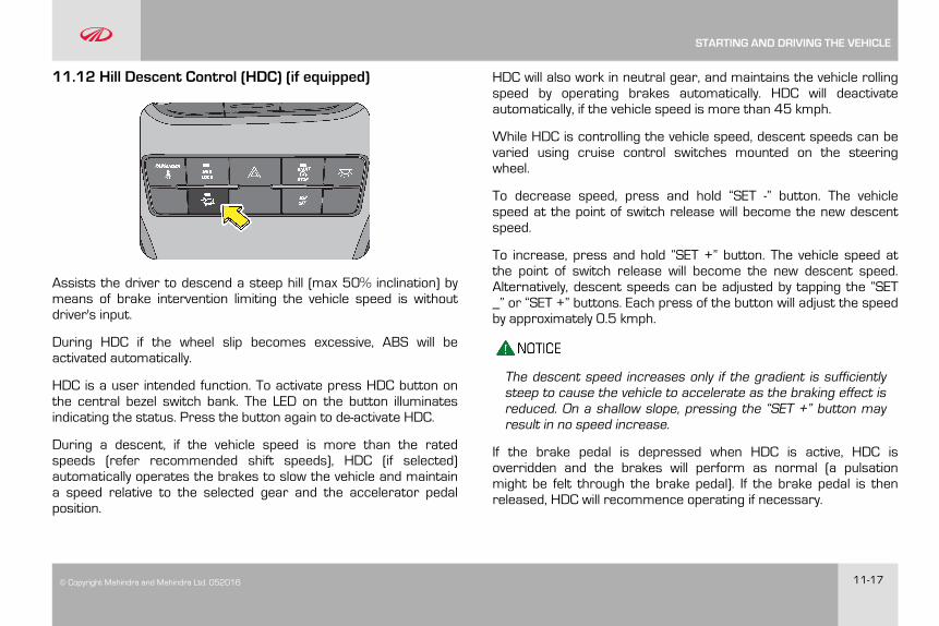
© Copyright Mahindra and Mahindra Ltd. 052016 11-17
11.12 Hill Descent Control (HDC) (if equipped)
Assists the driver to descend a steep hill (max 50% inclination) bymeans of brake intervention limiting the vehicle speed is withoutdriver's input.
During HDC if the wheel slip becomes excessive, ABS will beactivated automatically.
HDC is a user intended function. To activate press HDC button onthe central bezel switch bank. The LED on the button illuminatesindicating the status. Press the button again to de-activate HDC.
During a descent, if the vehicle speed is more than the ratedspeeds (refer recommended shift speeds), HDC (if selected)automatically operates the brakes to slow the vehicle and maintaina speed relative to the selected gear and the accelerator pedalposition.
HDC will also work in neutral gear, and maintains the vehicle rollingspeed by operating brakes automatically. HDC will deactivateautomatically, if the vehicle speed is more than 45 kmph.
While HDC is controlling the vehicle speed, descent speeds can bevaried using cruise control switches mounted on the steeringwheel.
To decrease speed, press and hold “SET -” button. The vehiclespeed at the point of switch release will become the new descentspeed.
To increase, press and hold “SET +” button. The vehicle speed atthe point of switch release will become the new descent speed.Alternatively, descent speeds can be adjusted by tapping the “SET_” or “SET +” buttons. Each press of the button will adjust the speedby approximately 0.5 kmph.
The descent speed increases only if the gradient is sufficientlysteep to cause the vehicle to accelerate as the braking effect isreduced. On a shallow slope, pressing the “SET +” button mayresult in no speed increase.
If the brake pedal is depressed when HDC is active, HDC isoverridden and the brakes will perform as normal (a pulsationmight be felt through the brake pedal). If the brake pedal is thenreleased, HDC will recommence operating if necessary.
STARTING AND DRIVING THE VEHICLE
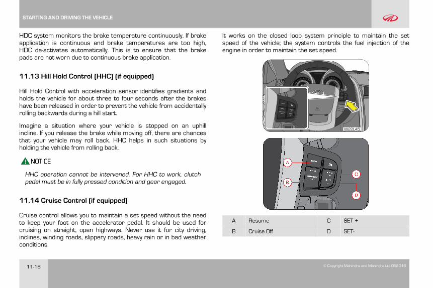
11-18 © Copyright Mahindra and Mahindra Ltd.052016
HDC system monitors the brake temperature continuously. If brakeapplication is continuous and brake temperatures are too high,HDC de-activates automatically. This is to ensure that the brakepads are not worn due to continuous brake application.
11.13 Hill Hold Control (HHC) (if equipped)
Hill Hold Control with acceleration sensor identifies gradients andholds the vehicle for about three to four seconds after the brakeshave been released in order to prevent the vehicle from accidentallyrolling backwards during a hill start.
Imagine a situation where your vehicle is stopped on an uphillincline. If you release the brake while moving off, there are chancesthat your vehicle may roll back. HHC helps in such situations byholding the vehicle from rolling back.
HHC operation cannot be intervened. For HHC to work, clutchpedal must be in fully pressed condition and gear engaged.
11.14 Cruise Control (if equipped)
Cruise control allows you to maintain a set speed without the needto keep your foot on the accelerator pedal. It should be used forcruising on straight, open highways. Never use it for city driving,inclines, winding roads, slippery roads, heavy rain or in bad weatherconditions.
It works on the closed loop system principle to maintain the setspeed of the vehicle; the system controls the fuel injection of theengine in order to maintain the set speed.
W22L45
A Resume C SET +
B Cruise Off D SET-
STARTING AND DRIVING THE VEHICLE
© Copyright Mahindra and Mahindra Ltd. 052016 11-19
Cruise control enhances your comfort while driving and allows youto effortlessly maintain the desired lane speed limit. Improper use ofthe cruise control can lead to an accident.
Cruise control is designed to operate above a vehicle speed of20 kmph for all gears except 1st and reverse gears. The cruiselamp in the instrument cluster functions only if the cruisecontrol is active.
Cruise control will function only under the following conditions;
• The vehicle is cruising above 20 kmph.
• Engine RPM above 1200 RPM.
• Vehicle is in any gear except 1st and reverse.
• Clutch pedal released.
• Brake pedal released.
• Cruise is activated first time in an ignition cycle by SET+ /SET-button.
• Subsequent cruise engagements can be done by RESUME SET+/SET- buttons in the same ignition cycle.
Cruise control is deactivated under the following conditions;
• CRUISE OFF button is pressed.
• Brake or clutch pedal depressed.
• If the vehicle speed exceeds the cruise set speed by 30 kmph byaccelerator pedal intervention.
• If vehicle speed is increased by 10 kmph for more than 30 sec.by pressing the accelerator pedal.
• When Set+/Set- switch is pressed for more than 12 sec. (In thiscase vehicle will not go into cruise mode in that ignition cycle. Inorder to restore the cruise function switch OFF the ignition, waitfor 30 sec. and switch ON the ignition)
• Cruise influencing error indicated by Check Engine Lamp, OBDlamp, etc.,
11.14.1 Cruise Control Activation
Drive the vehicle to the desired cruising speed (any value greaterthan 20 kmph), press and hold the SET+ button until the cruiselamp in the instrument cluster illuminates.
If cruise is deactivated (eg. by depressing brake to handle anintervention in the road etc.,) in current driving cycle, reactivate theCruise to the last active Cruise Speed by pressing the RESUMEbutton.
Cruise control may not hold the set speed when you are going up ordown hills, and the vehicle may come out of cruise control. This isindicated by the cruise lamp going OFF in the instrument cluster.
STARTING AND DRIVING THE VEHICLE
11-20 © Copyright Mahindra and Mahindra Ltd.052016
11.14.2 Cruise Control De-activation
You can cancel cruise control in any of the following ways;
• Press the CRUISE OFF button in the steering wheel.
• Press the brake pedal.
• Gear selector moved into neutral.
• HDC or ESP becomes active.
11.14.3 SET+ Button
SET+ button is used to activate cruise control and also to increasethe cruise set speed.
To increase the speed in very small amounts, press the SET +button. Each time you press, the cruise set speed increases byabout 2 kmph. When you wish to continuously increase the cruisingspeed, press and hold the SET + button and release when thedesired speed is reached.
11.14.4 SET- Button
To decrease the speed in small amounts, press the SET - button.Each time you press, the cruise set speed decreases by about 2kmph.
When you wish to continuously decrease the cruising speed, pressand hold the SET- button. When the desired speed is reached,release the button.
If switch is pressed for more than 12 secs, the switch isassumed to be malfunctioning and the cruise functionalityceases to function in that ignition cycle. To resume functionality,ignition has to toggled.
The cruise control is a convenience system designed to assistthe driver during vehicle operation. The driver must at all timesremain alert of road/traffic conditions and responsible for thevehicle brake operation / steering control.
Never activate cruise control in traffic or when driven inadverse road conditions (heavy rains, windy, slippery etc.)
11.14.5 RESUME Button
With the help of RESUME, you can opt for the previous set cruisingspeed of the vehicle in the same ignition cycle. This is best explainedwith the following example:
STARTING AND DRIVING THE VEHICLE
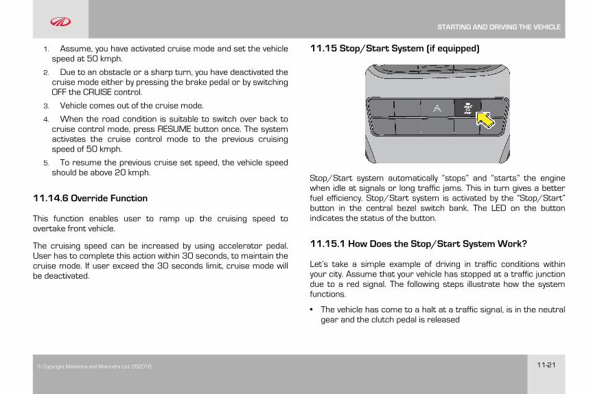
© Copyright Mahindra and Mahindra Ltd. 052016 11-21
1. Assume, you have activated cruise mode and set the vehiclespeed at 50 kmph.
2. Due to an obstacle or a sharp turn, you have deactivated thecruise mode either by pressing the brake pedal or by switchingOFF the CRUISE control.
3. Vehicle comes out of the cruise mode.
4. When the road condition is suitable to switch over back tocruise control mode, press RESUME button once. The systemactivates the cruise control mode to the previous cruisingspeed of 50 kmph.
5. To resume the previous cruise set speed, the vehicle speedshould be above 20 kmph.
11.14.6 Override Function
This function enables user to ramp up the cruising speed toovertake front vehicle.
The cruising speed can be increased by using accelerator pedal.User has to complete this action within 30 seconds, to maintain thecruise mode. If user exceed the 30 seconds limit, cruise mode willbe deactivated.
11.15 Stop/Start System (if equipped)
Stop/Start system automatically “stops” and “starts” the enginewhen idle at signals or long traffic jams. This in turn gives a betterfuel efficiency. Stop/Start system is activated by the “Stop/Start”button in the central bezel switch bank. The LED on the buttonindicates the status of the button.
11.15.1 How Does the Stop/Start System Work?
Let’s take a simple example of driving in traffic conditions withinyour city. Assume that your vehicle has stopped at a traffic junctiondue to a red signal. The following steps illustrate how the systemfunctions.
• The vehicle has come to a halt at a traffic signal, is in the neutralgear and the clutch pedal is released
STARTING AND DRIVING THE VEHICLE
11-22 © Copyright Mahindra and Mahindra Ltd.052016
• The “Stop/Start” lamp in the cluster will blink indicating that theengine is going to stop shortly. The engine will shut downautomatically after a specific time period
• The “Stop/Start” lamp will illuminate in the instrument clusterindicating the engine was stopped by the Stop/ Start System
• Once the signal turns green, press the clutch pedal and theengine starts immediately
• The indicator in the cluster goes OFF indicating that the enginehas started again and you are ready to drive on
For auto stop to happen the following conditions are to be met
• Stop/Start System is activated using the Stop/Start button
• Bonnet is fully closed
• In the current ignition cycle, the vehicle has crossed 2 kmph atleast once
• Current status of the engine is idling
• Vehicle speed is zero
• Accelerator pedal and clutch pedal are fully released
• Vehicle battery should be in healthy condition
• Engine is warm (Engine coolant temperature is between 25 °Cand 100 °C). This is an extra precaution to ensure safe workingof the engine
• Fuel temperature is less than 60 °C
• Gear in neutral
For auto start to happen the following conditions are to be met
• Vehicle should have been stopped by the Stop/Start System
• Gear lever is in the neutral position, Clutch pedal is fully de-pressed
• Vehicle speed is zero
• Stop/Start System is in active state
• Bonnet should be closed
STARTING AND DRIVING THE VEHICLE
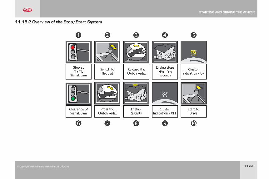
© Copyright Mahindra and Mahindra Ltd. 052016 11-23
11.15.2 Overview of the Stop/Start System
STARTING AND DRIVING THE VEHICLE

11-24 © Copyright Mahindra and Mahindra Ltd.052016
11.15.3 Frequently Asked Questions (FAQ)
1. What is the advantage of the system?
The Stop/Start System aids in attaining better fuel efficiencyon your vehicle and thus reducing your running costs.However, the mileage improvement will depend upon variousparameters such as prevailing traffic, driving patterns, etc.
2. What are the other advantages of the system?
• Since the engine is switched off during traffic signals/ jams,considerable amount of CO2 release to the atmosphere isavoided. This reduces global warming and thus provides uswith a cleaner atmosphere to live
• Ability to start the engine by pressing the clutch pedal
• Reduces noise pollution at traffic signals
3. Is it possible to start the engine through the clutch pedal forthe first time?
No, the engine can be cranked only with the ignition key for thefirst time. If the engine is stopped automatically by the system,only then it is possible to start the engine through clutch pedal.
4. How to activate/deactivate the system?
The system is activated by default during every ignition cycle.The LED indication on the Stop/Start switch indicates thestatus of the system. The system can be turned OFF or backON using the Stop/Start switch.
5. Whether the system will get activated as soon as the engineis started the first time with the ignition key?
No, the Stop/Start system can be activated only by the Stop/Start switch, provided all listed conditions (in the previoussection) are met. This is to ensure better performance of theengine in terms of fuel economy and durability.
6. What is to be done, if I don’t want the system to stop myengine at traffic signals/Jams?
The system can be turned OFF by the Stop/Start button in thecentral bezel switch bank.
7. Whether the A/C will function, if the engine is switched off?
No, the A/C will not work. However the blower will be inoperation when the ignition is ON.
8. What will happen if I keep the clutch continuously pressed attraffic signals/jams?
The system will not stop the engine if the clutch is continuouslypressed since it indicates the driver’s intention of moving thevehicle immediately.
9. When the battery charge is low, whether the engine will beswitched off?
If the battery charge drops below a certain threshold level, thesystem will not stop the engine so as to preserve the batteryfrom further draining.
STARTING AND DRIVING THE VEHICLE
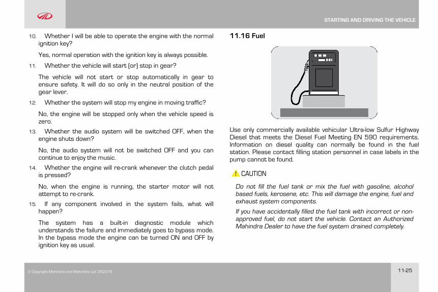
© Copyright Mahindra and Mahindra Ltd. 052016 11-25
10. Whether I will be able to operate the engine with the normalignition key?
Yes, normal operation with the ignition key is always possible.
11. Whether the vehicle will start (or) stop in gear?
The vehicle will not start or stop automatically in gear toensure safety. It will do so only in the neutral position of thegear lever.
12. Whether the system will stop my engine in moving traffic?
No, the engine will be stopped only when the vehicle speed iszero.
13. Whether the audio system will be switched OFF, when theengine shuts down?
No, the audio system will not be switched OFF and you cancontinue to enjoy the music.
14. Whether the engine will re-crank whenever the clutch pedalis pressed?
No, when the engine is running, the starter motor will notattempt to re-crank.
15. If any component involved in the system fails, what willhappen?
The system has a built-in diagnostic module whichunderstands the failure and immediately goes to bypass mode.In the bypass mode the engine can be turned ON and OFF byignition key as usual.
11.16 Fuel
Use only commercially available vehicular Ultra-low Sulfur HighwayDiesel that meets the Diesel Fuel Meeting EN 590 requirements.Information on diesel quality can normally be found in the fuelstation. Please contact filling station personnel in case labels in thepump cannot be found.
Do not fill the fuel tank or mix the fuel with gasoline, alcoholbased fuels, kerosene, etc. This will damage the engine, fuel andexhaust system components.
If you have accidentally filled the fuel tank with incorrect or non-approved fuel, do not start the vehicle. Contact an AuthorizedMahindra Dealer to have the fuel system drained completely.
STARTING AND DRIVING THE VEHICLE
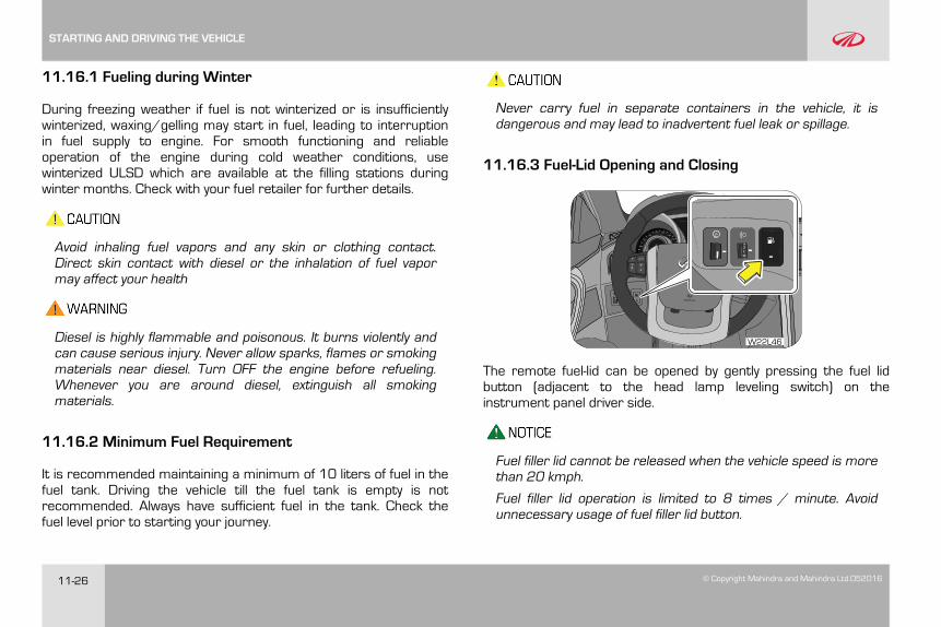
11-26 © Copyright Mahindra and Mahindra Ltd.052016
11.16.1 Fueling during Winter
During freezing weather if fuel is not winterized or is insufficientlywinterized, waxing/gelling may start in fuel, leading to interruptionin fuel supply to engine. For smooth functioning and reliableoperation of the engine during cold weather conditions, usewinterized ULSD which are available at the filling stations duringwinter months. Check with your fuel retailer for further details.
Avoid inhaling fuel vapors and any skin or clothing contact.Direct skin contact with diesel or the inhalation of fuel vapormay affect your health
Diesel is highly flammable and poisonous. It burns violently andcan cause serious injury. Never allow sparks, flames or smokingmaterials near diesel. Turn OFF the engine before refueling.Whenever you are around diesel, extinguish all smokingmaterials.
11.16.2 Minimum Fuel Requirement
It is recommended maintaining a minimum of 10 liters of fuel in thefuel tank. Driving the vehicle till the fuel tank is empty is notrecommended. Always have sufficient fuel in the tank. Check thefuel level prior to starting your journey.
Never carry fuel in separate containers in the vehicle, it isdangerous and may lead to inadvertent fuel leak or spillage.
11.16.3 Fuel-Lid Opening and Closing
W22L46
The remote fuel-lid can be opened by gently pressing the fuel lidbutton (adjacent to the head lamp leveling switch) on theinstrument panel driver side.
Fuel filler lid cannot be released when the vehicle speed is morethan 20 kmph.
Fuel filler lid operation is limited to 8 times / minute. Avoidunnecessary usage of fuel filler lid button.
STARTING AND DRIVING THE VEHICLE
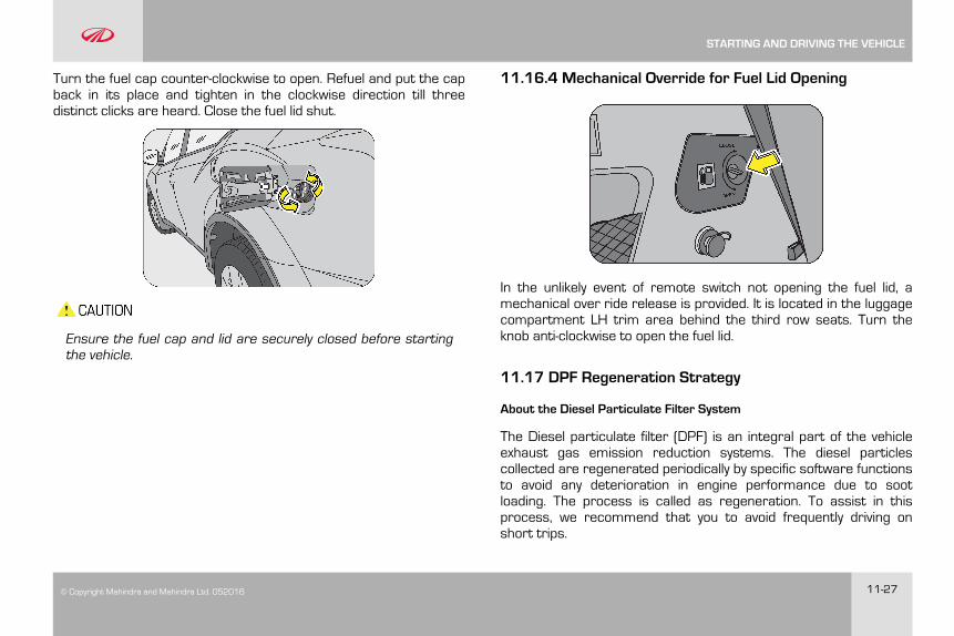
© Copyright Mahindra and Mahindra Ltd. 052016 11-27
Turn the fuel cap counter-clockwise to open. Refuel and put the capback in its place and tighten in the clockwise direction till threedistinct clicks are heard. Close the fuel lid shut.
Ensure the fuel cap and lid are securely closed before startingthe vehicle.
11.16.4 Mechanical Override for Fuel Lid Opening
In the unlikely event of remote switch not opening the fuel lid, amechanical over ride release is provided. It is located in the luggagecompartment LH trim area behind the third row seats. Turn theknob anti-clockwise to open the fuel lid.
11.17 DPF Regeneration Strategy
About the Diesel Particulate Filter System
The Diesel particulate filter (DPF) is an integral part of the vehicleexhaust gas emission reduction systems. The diesel particlescollected are regenerated periodically by specific software functionsto avoid any deterioration in engine performance due to sootloading. The process is called as regeneration. To assist in thisprocess, we recommend that you to avoid frequently driving onshort trips.
STARTING AND DRIVING THE VEHICLE
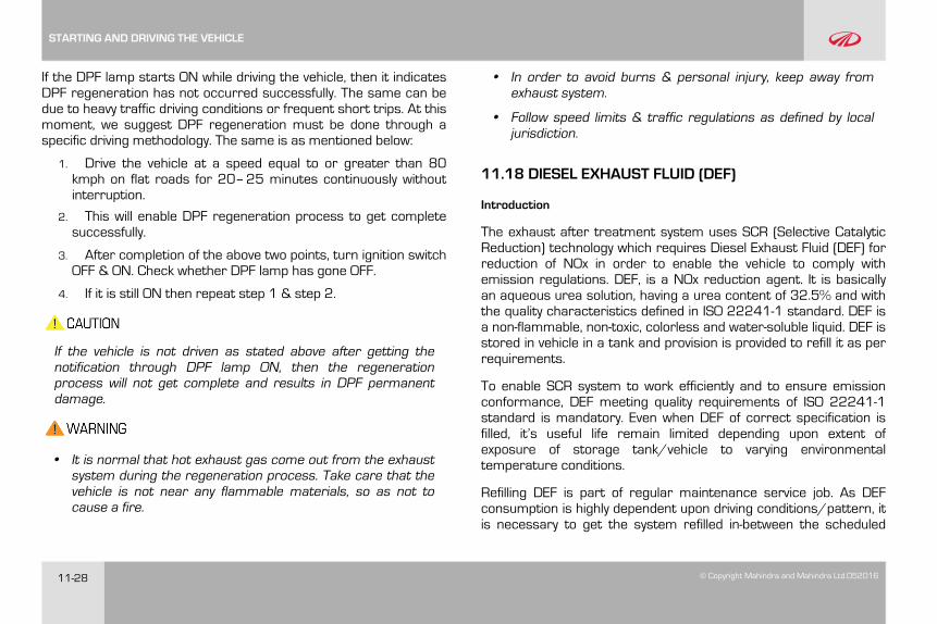
11-28 © Copyright Mahindra and Mahindra Ltd.052016
If the DPF lamp starts ON while driving the vehicle, then it indicatesDPF regeneration has not occurred successfully. The same can bedue to heavy traffic driving conditions or frequent short trips. At thismoment, we suggest DPF regeneration must be done through aspecific driving methodology. The same is as mentioned below:
1. Drive the vehicle at a speed equal to or greater than 80kmph on flat roads for 20–25 minutes continuously withoutinterruption.
2. This will enable DPF regeneration process to get completesuccessfully.
3. After completion of the above two points, turn ignition switchOFF & ON. Check whether DPF lamp has gone OFF.
4. If it is still ON then repeat step 1 & step 2.
If the vehicle is not driven as stated above after getting thenotification through DPF lamp ON, then the regenerationprocess will not get complete and results in DPF permanentdamage.
• It is normal that hot exhaust gas come out from the exhaustsystem during the regeneration process. Take care that thevehicle is not near any flammable materials, so as not tocause a fire.
• In order to avoid burns & personal injury, keep away fromexhaust system.
• Follow speed limits & traffic regulations as defined by localjurisdiction.
11.18 DIESEL EXHAUST FLUID (DEF)
Introduction
The exhaust after treatment system uses SCR (Selective CatalyticReduction) technology which requires Diesel Exhaust Fluid (DEF) forreduction of NOx in order to enable the vehicle to comply withemission regulations. DEF, is a NOx reduction agent. It is basicallyan aqueous urea solution, having a urea content of 32.5% and withthe quality characteristics defined in ISO 22241-1 standard. DEF isa non-flammable, non-toxic, colorless and water-soluble liquid. DEF isstored in vehicle in a tank and provision is provided to refill it as perrequirements.
To enable SCR system to work efficiently and to ensure emissionconformance, DEF meeting quality requirements of ISO 22241-1standard is mandatory. Even when DEF of correct specification isfilled, it’s useful life remain limited depending upon extent ofexposure of storage tank/vehicle to varying environmentaltemperature conditions.
Refilling DEF is part of regular maintenance service job. As DEFconsumption is highly dependent upon driving conditions/pattern, itis necessary to get the system refilled in-between the scheduled
STARTING AND DRIVING THE VEHICLE
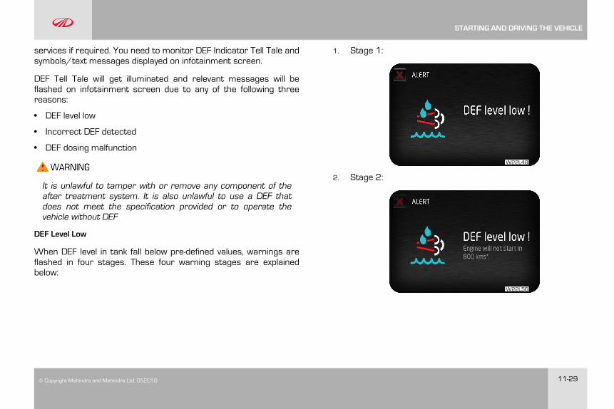
© Copyright Mahindra and Mahindra Ltd. 052016 11-29
services if required. You need to monitor DEF Indicator Tell Tale andsymbols/text messages displayed on infotainment screen.
DEF Tell Tale will get illuminated and relevant messages will beflashed on infotainment screen due to any of the following threereasons:
• DEF level low
• Incorrect DEF detected
• DEF dosing malfunction
It is unlawful to tamper with or remove any component of theafter treatment system. It is also unlawful to use a DEF thatdoes not meet the specification provided or to operate thevehicle without DEF
DEF Level Low
When DEF level in tank fall below pre-defined values, warnings areflashed in four stages. These four warning stages are explainedbelow:
1. Stage 1:
W22L48
2. Stage 2:
W22L56
STARTING AND DRIVING THE VEHICLE
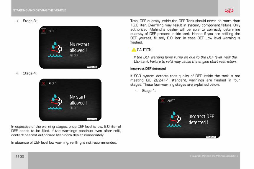
11-30 © Copyright Mahindra and Mahindra Ltd.052016
3. Stage 3:
W22L49
4. Stage 4:
W22L50
Irrespective of the warning stages, once DEF level is low, 8.0 liter ofDEF needs to be filled. If the warnings continue even after refill,contact nearest authorized Mahindra dealer immediately.
In absence of DEF level low warning, refilling is not recommended.
Total DEF quantity inside the DEF Tank should never be more than16.0 liter. Overfilling may result in system/component failure. Onlyauthorized Mahindra dealer will be able to correctly determinequantity of DEF present inside tank. Hence if you are refilling theDEF yourself, fill only 8.0 liter, in case DEF Low level warning isflashed.
If the DEF warning lamp turns on due to the DEF level, refill theDEF tank. Failure to refill may cause the engine start restriction.
Incorrect DEF detected
If SCR system detects that quality of DEF inside the tank is notmeeting ISO 22241-1 standard, warnings are flashed in fourstages. These four warning stages are explained below:
1. Stage 1:
W22L51
STARTING AND DRIVING THE VEHICLE
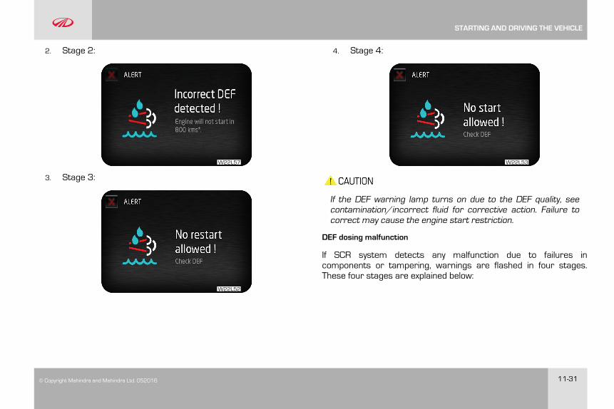
© Copyright Mahindra and Mahindra Ltd. 052016 11-31
2. Stage 2:
W22L57
3. Stage 3:
W22L52
4. Stage 4:
W22L53
If the DEF warning lamp turns on due to the DEF quality, seecontamination/incorrect fluid for corrective action. Failure tocorrect may cause the engine start restriction.
DEF dosing malfunction
If SCR system detects any malfunction due to failures incomponents or tampering, warnings are flashed in four stages.These four stages are explained below:
STARTING AND DRIVING THE VEHICLE
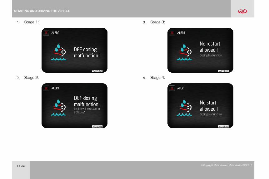
11-32 © Copyright Mahindra and Mahindra Ltd.052016
1. Stage 1:
W22L54
2. Stage 2:
W22L58
3. Stage 3:
W22L59
4. Stage 4:
W22L55
STARTING AND DRIVING THE VEHICLE
© Copyright Mahindra and Mahindra Ltd. 052016 11-33
If the DEF warning lamp turns on due to dosing malfunction, seeyour authorised M&M dealer to have this repaired. Failure torepair the system may cause the engine start restriction.
11.19 Recommendations on DEF
DEF conforming to ISO 22241-1 is commercially available incontainers of various capacities. Also an individual DEF containermay have specific design of filler neck. They may need filler pipe forfilling DEF in vehicle. While using DEF refill container, instructions ofits manufacturer must be followed.
It is unlawful to tamper with or remove any component of theafter treatment system. It is also unlawful to use a DEF thatdoes not meet the specification provided or to operate thevehicle without DEF
• Diesel exhaust fluid (DEF) must comply with ISO 22241-1standard. There is no acceptable substitute. Failure to usethe correct DEF may cause engine damage and/or void thewarranty.
• Never attempt to create Diesel Exhaust Fluid (DEF) by mixingagricultural grade urea with water. Agricultural grade urea
does not meet the necessary specifications required and theafter treatment system may be damaged.
• Total DEF quantity inside the DEF Tank should never be morethan 16.0 liter. Overfilling may result in system/componentfailure.
• To avoid system/component failures resulting out ofimpurities present in DEF, only fresh DEF should be filled.
• DEF quality and purity can be ensured only if it is stored andcontained properly. Hence ensure that instructions given byDEF manufacturer/supplier have been met, before usingDEF in the system.
• Do not add additives to DEF and do not dilute with water.Otherwise, the exhaust gas after treatment system could bedamaged.
• While refilling DEF inside tank, be careful not to allow anyforeign particles, liquids, wiping paper/clothing fibers or lintto get inside the system. These may clog or damage thesystem.
• Before using containers, funnels, etc. that will be used todispense, handle or store DEF, make sure to wash themthoroughly and dry to remove any contaminants and thenrinse with distilled water.
• Do not use tap water to rinse components that will be usedto deliver DEF. Tap water will contaminate the DEF. If distilled
STARTING AND DRIVING THE VEHICLE

11-34 © Copyright Mahindra and Mahindra Ltd.052016
water is not available, rinse with tap water and then rinsewith DEF.
• If DEF is spilled over vehicle components and metal surfaces,rinse with water or use sponge wetted with water. DEFresidues will corrode the components and metal surfaces,painted body panels.
• DEF is not a fuel additive and must not be added to the dieselfuel tank. If DEF is mixed with the diesel fuel, engine/fuelsystem could get damaged.
• In the event that incorrect fluid is added to the DEF Tank,contact an authorized M&M dealer to determine theappropriate repair direction.
11.20 Handling of DEF
• Ensure that DEF does not come into contact with skin, eyes,or clothing
• Keep DEF out of the reach of children
• If you have come into contact with DEF, clean affected skinimmediately with plenty of water.
• If DEF contacted with eyes, flush with plenty of waterimmediately and seek medical help.
• If DEF is swallowed, rinse mouth immediately with plenty ofwater, drink plenty of water immediately and seek medicalhelp.
• Don’t store DEF refill containers inside the vehicle. Ammoniavapors may escape from container which have a pungentodor and are particularly irritating for skin, mucousmembranes and eyes. Inhaling ammonia vapors may causeburning eyes, nose and throat, as well as cough andwatering eyes.
• When opening the DEF filler cap, ammonia vapors mayescape. Refill DEF in a well ventilated area only.
• If Diesel Exhaust Fluid is spilled on metal surfaces rinse andclean immediately with water. Failure to do so may leavepermanent corrosive stains on the metal surfaces whichcannot be removed.
11.21 Contamination/ Incorrect DEF
In the event that incorrect or contaminated fluid is filled inside DEFTank, contact an authorized M&M dealer to determine theappropriate repair direction.
• Diesel exhaust fluid (DEF) must comply with ISO 22241-1standard. There is no other acceptable substitute. Failure to
STARTING AND DRIVING THE VEHICLE
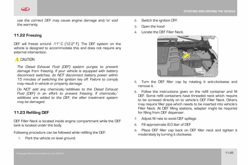
© Copyright Mahindra and Mahindra Ltd. 052016 11-35
use the correct DEF may cause engine damage and/or voidthe warranty.
11.22 Freezing
DEF will freeze around -11° C (12.2° F). The DEF system on thevehicle is designed to accommodate this and does not require anyexternal intervention.
The Diesel Exhaust Fluid (DEF) system purges to preventdamage from freezing. If your vehicle is equipped with batterydisconnect switches, do NOT disconnect battery power within15 minutes of switching the ignition key off. Failure to complymay result in vehicle or property damage.
Do NOT add any chemicals/additives to the Diesel ExhaustFluid (DEF) in an effort to prevent freezing. If chemicals/additives are added to the DEF, the after treatment systemmay be damaged.
11.23 Refilling DEF
DEF Filler Neck is located inside engine compartment while the DEFtank is located under the body.
Following procedure can be followed while refilling the DEF:
1. Park the vehicle on level ground.
2. Switch the ignition OFF.
3. Open the hood
4. Locate the DEF Filler Neck.
W22L60
5. Turn the DEF filler cap by rotating it anti-clockwise andremove it.
6. Follow the instructions given on the refill container and fillDEF. Some refill containers have threaded neck which requireto be screwed directly on to vehicle’s DEF Filler Neck. Othersmay require filler pipe which needs to be inserted into vehicle’sFiller Neck. At DEF filling stations, adapter might be requiredfor filling from DEF dispenser.
7. Adjust fill rate to avoid DEF spillage
8. Fill approximate 8.0 liter of DEF
9. Place DEF filler cap back on DEF filler neck and tighten itmoderately by turning it clockwise.
STARTING AND DRIVING THE VEHICLE
11-36 © Copyright Mahindra and Mahindra Ltd.052016
10. Rinse with water or use sponge wetted with water to cleanthe components/surfaces in case of DEF spills over.
11. Close the hood
12. Switch the ignition ON
13. Verify that there is no warning regarding DEF low level. IfDEF Level Low warning is still appearing, contact nearestauthorized M&M dealer immediately.
STARTING AND DRIVING THE VEHICLE
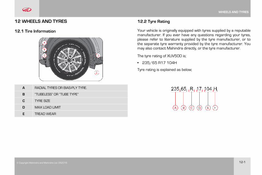
© Copyright Mahindra and Mahindra Ltd. 052016 12-1
12 WHEELS AND TYRES
12.1 Tire Information
A RADIAL TYRES OR BIAS-PLY TYRE.
B “TUBELESS” OR “TUBE TYPE”
C TYRE SIZE
D MAX LOAD LIMIT
E TREAD WEAR
12.2 Tyre Rating
Your vehicle is originally equipped with tyres supplied by a reputablemanufacturer. If you ever have any questions regarding your tyres,please refer to literature supplied by the tyre manufacturer, or tothe separate tyre warranty provided by the tyre manufacturer. Youmay also contact Mahindra directly, or the tyre manufacturer.
The tyre rating of XUV500 is;
• 235/65 R17 104H
Tyre rating is explained as below;
WHEELS AND TYRES
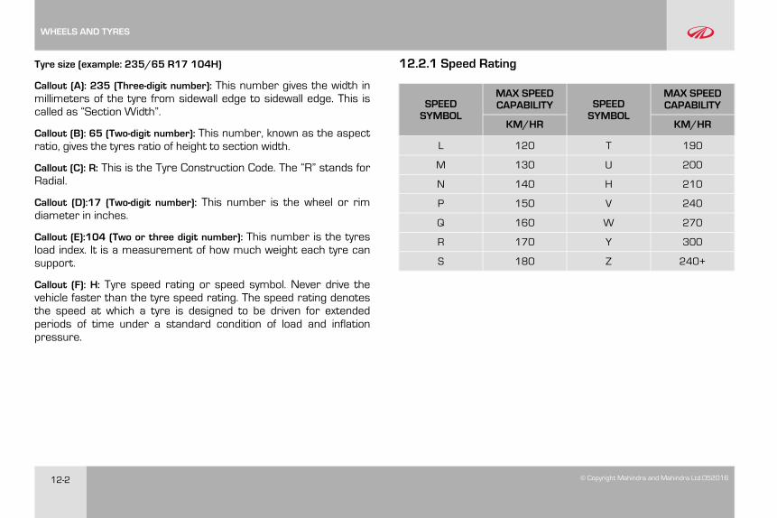
12-2 © Copyright Mahindra and Mahindra Ltd.052016
Tyre size (example: 235/65 R17 104H)
Callout (A): 235 (Three-digit number): This number gives the width inmillimeters of the tyre from sidewall edge to sidewall edge. This iscalled as “Section Width”.
Callout (B): 65 (Two-digit number): This number, known as the aspectratio, gives the tyres ratio of height to section width.
Callout (C): R: This is the Tyre Construction Code. The “R” stands forRadial.
Callout (D):17 (Two-digit number): This number is the wheel or rimdiameter in inches.
Callout (E):104 (Two or three digit number): This number is the tyresload index. It is a measurement of how much weight each tyre cansupport.
Callout (F): H: Tyre speed rating or speed symbol. Never drive thevehicle faster than the tyre speed rating. The speed rating denotesthe speed at which a tyre is designed to be driven for extendedperiods of time under a standard condition of load and inflationpressure.
12.2.1 Speed Rating
SPEEDSYMBOL
MAX SPEEDCAPABILITY SPEED
SYMBOL
MAX SPEEDCAPABILITY
KM/HR KM/HR
L 120 T 190
M 130 U 200
N 140 H 210
P 150 V 240
Q 160 W 270
R 170 Y 300
S 180 Z 240+
WHEELS AND TYRES
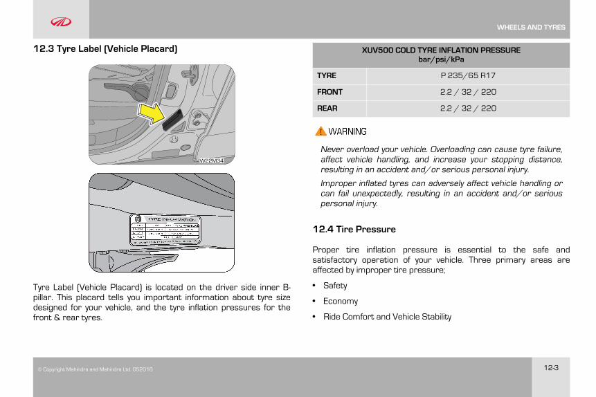
© Copyright Mahindra and Mahindra Ltd. 052016 12-3
12.3 Tyre Label (Vehicle Placard)
W22M34
Tyre Label (Vehicle Placard) is located on the driver side inner B-pillar. This placard tells you important information about tyre sizedesigned for your vehicle, and the tyre inflation pressures for thefront & rear tyres.
XUV500 COLD TYRE INFLATION PRESSUREbar/psi/kPa
TYRE P 235/65 R17
FRONT 2.2 / 32 / 220
REAR 2.2 / 32 / 220
Never overload your vehicle. Overloading can cause tyre failure,affect vehicle handling, and increase your stopping distance,resulting in an accident and/or serious personal injury.
Improper inflated tyres can adversely affect vehicle handling orcan fail unexpectedly, resulting in an accident and/or seriouspersonal injury.
12.4 Tire Pressure
Proper tire inflation pressure is essential to the safe andsatisfactory operation of your vehicle. Three primary areas areaffected by improper tire pressure;
• Safety
• Economy
• Ride Comfort and Vehicle Stability
WHEELS AND TYRES
12-4 © Copyright Mahindra and Mahindra Ltd.052016
Proper tire inflation contributes to a comfortable and safe ride.Overinflating produces a jarring and uncomfortable ride. Bothunderinflation and overinflation affect the stability of the vehicle andcan produce a feeling of sluggish response or over responsivenessin the steering. Unequal tire pressures can cause erratic andunpredictable steering response or may cause the vehicle to driftleft or right.
Improper inflation pressures can cause uneven wear patterns todevelop across the tire tread. These abnormal wear patterns willreduce tread life resulting in a need for earlier tire replacement.Under inflation also increases tire rolling resistance and results inhigher fuel consumption.
The proper cold tire inflation pressure is listed in the Tire Label(Vehicle Placard), located on the front passenger side inner B-pillar.
12.4.1 Inspection and Adjustment Procedure
The tire pressure should be checked and adjusted, as well asinspected for signs of tire wear or visible damage, at least once amonth. Use a good quality pressure gauge to check tire pressure.Do not make a visual judgement when determining proper inflation.Radial tires may look properly inflated even when they areunderinflated. At the same time, each tire should be inspected forsigns of tire wear or visible damage.
Inflation pressures specified on the placard are always cold tireinflation pressures. Cold tire inflation pressure is defined as the tirepressure after the vehicle has not been driven for at least threehours, or driven less than 1 km after a three-hour period. Check tirepressures more often if subject to a wide range of outdoortemperatures, as tire pressures vary with temperature changes.Tire pressures change by approximately 1 psi (7 kPa) per 7°C of airtemperature change. Keep this in mind when checking tirepressure inside a garage, especially in the winter.
When it was new, the spare tire in your vehicle was fully inflated.However, a spare tire can lose pressure over time. In order to avoidbeing stranded, check the spare tire air pressure frequently.
12.4.2 Inflating Your Tires
Safe operation of your vehicle requires that your tires are properlyinflated. Remember that a tire can lose up to half of its air pressurewithout appearing flat.
At least once a month or before long trips, inspect each tire andcheck the tire pressure with a tire gauge (including spare tire).Inflate all tires to the recommended inflation pressure.
Under-inflation is the most common cause of tire failures andmay result in severe tire cracking, tread separation or“blowout”, with unexpected loss of vehicle control and increased
WHEELS AND TYRES
© Copyright Mahindra and Mahindra Ltd. 052016 12-5
risk of injury. Under-inflation increases sidewall flexing androlling resistance, resulting in heat buildup and internal damageto the tire. It also may result in unnecessary tire stress,irregular wear, loss of vehicle control and accidents.
Always inflate your tires to the recommended pressure even if it isless than the maximum inflation pressure information found on thetire. The recommended tire inflation pressure is found on the TireLabel which is located on the front passenger side inner B-pillar.Failure to follow the tire pressure recommendations can causeuneven tread wear patterns and adversely affect the way yourvehicle handles.
If you overfill the tire, release air by pushing the metal stem inthe center of the valve. Then recheck the pressure.
After inspecting or adjusting the tire pressure, always reinstallthe valve stem cap (if equipped). This will prevent moisture anddirt from entering the valve stem, which could damage thestem, resulting in an unexpected loss of tire pressure, anaccident and/or personal injury.
12.4.3 Radial Ply Tires
Combining radial ply tires with other types of tires on yourvehicle will cause your vehicle to handle poorly, resulting in anaccident and/or personal injury. Always use radial tires in setsof four. Never combine them with other types of tires.
Cuts and punctures in radial tires are repairable only in thetread area because of sidewall flexing. Consult your authorizeddealer for radial tire repairs.
12.4.4 Tread Wear Indicators (TWI)
Tread wear indicators are molded into the bottom of the treadgrooves. They will appear as bands when the tread depth becomes1/16 inch (2 mm). When the indicators appear in two or moreadjacent grooves, the tire should be replaced.
Avoid abrupt maneuvering and braking. This can cause tiredeterioration and lead to loss of steering or braking control.
12.4.5 Life of Tire
The service life of a tire is dependent upon various factors includingbut not limited to;
WHEELS AND TYRES

12-6 © Copyright Mahindra and Mahindra Ltd.052016
• Driving style
• Tire pressure
• Distance driven
Tires and the spare tire should be replaced after six years,regardless of the remaining tread. Failure to follow this warningcan result in sudden and unexpected tire failure, leading to anaccident and/or personal injury.
Keep dismounted tires in a cool, dry place with as littleexposure to light as possible. Protect tires from contact with oil,grease and fuels.
Do not use a tire, wheel size or speed rating other than thatspecified for your vehicle on the tire placard. Combinations ofunapproved tires and wheels may change suspensiongeometric and performance characteristics, resulting inchanges to steering, handling and braking of your vehicle. Thiscan cause unpredictable handling, stress to steering andsuspension components. You could lose control of the vehicleor the tire can unexpectedly fail, resulting in an accident and/orpersonal injury.
Replacing original tires with tires of a different size may resultin false speedometer and odometer readings.
12.4.6 Snow Chains
Snow chains cannot be used on these tires.
In case of harsh winter driving conditions, it is recommendedusing winter tires with the same specifications for betterstability, safety and performance.
12.5 Tire Rotation Recommendations
Type 1 - Applicable for all 5 Steel / 5 Alloy wheels
WHEELS AND TYRES
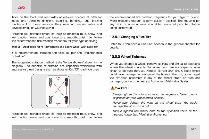
© Copyright Mahindra and Mahindra Ltd. 052016 12-7
Tires on the front and rear axles of vehicles operate at differentloads and perform different steering, handling, and brakingfunctions. For these reasons, they wear at unequal rates anddevelop irregular wear patterns.
Rotation will increase tread life, help to maintain mud, snow, andwet traction levels, and contribute to a smooth, quiet ride. Followthe recommended tire rotation frequency for your type of driving.
Type 2 – Applicable for 4 Alloy wheels and Spare wheel with Steel rim
It is recommended rotating the tires as per the “MaintenanceSchedule”.
The suggested rotation method is the “forward-cross” shown in thediagram. The benefits of rotation are especially worthwhile withaggressive tread designs such as those on On/Off-road type tires.
Rotation will increase tread life, help to maintain mud, snow, andwet traction levels, and contribute to a smooth, quiet ride. Follow
the recommended tire rotation frequency for your type of driving.More frequent rotation is permissible if desired. The reasons forany rapid or unusual wear should be corrected prior to rotationbeing performed.
12.5.1 Changing a Flat Tire
Refer to “If you have a Flat Tire” section in the general chapter fordetails.
12.5.2 Wheel Tightness
When you change a wheel, remove all rust and dirt at all locationswhere the wheel contacts the wheel hub. Use a scraper or wirebrush to be sure that you remove all rust and dirt. A loose wheelcould have damaged or elongated the holes in the rim, or damagedthe rim/hub assembly. If any of the wheel studs or nuts aredamaged, contact the nearest Authorized Mahindra Dealer.
Always tighten the nuts in a crisscross sequence. Never use oilor grease on your wheel studs or nuts.
Never over tighten the nuts on the wheel stud. You coulddamage the stud or the nut.
Torque tighten the wheel nuts to the specified value at thenearest Authorized Mahindra Workshop.
WHEELS AND TYRES

12-8 © Copyright Mahindra and Mahindra Ltd.052016
The tyres fitted in this vehicle meet the requirements of BIS andthey comply with the requirements under the Central MotorVehicles Rules (CMVR) 1989.
12.6 Tiretronics (if equipped)
Tiretronics is an electronic system designed to monitor the airpressure inside the pneumatic tyres. This system will alert thedriver if the tyre pressure falls below the low pressure or raisesabove high pressure warning limit for any reason, including lowtemperature effects and natural pressure loss through the tyre.
The Tiretronics will continue to alert the driver and will not turn offuntil the tyre pressure is inflated to the recommended pressure.
12.6.1 Operation of Tiretronics
Tiretronics uses wireless technology with wheel rim mountedelectronic sensors to monitor tyre pressure levels. Sensorsmounted to the valve stem of each wheel, transmit tyre pressurereadings to the receiver module. Receiver module in turn willcommunicate this information to the instrument cluster andinfotainment system. Tyre locations will display as OK, if all tyrepressure and temperature are in the recommended range.
The Tiretronics has been customized only for the manufacturer’sgenuine tyres and wheels. Tiretronics pressure limits and warningmessages have been established for the tyre size equipped on yourvehicle.
Replacement of manufacturer’s parts with a different size, type orstyle of components may damage the sensor and lead to incorrectreadings.
Do not use aftermarket tyre sealants or balance beads if yourvehicle is equipped with Tiretronics. Failure to comply may lead tosensor damage.
The Tiretronics is not intended to replace normal tyre care andmaintenance or to provide warning of a tyre failure or condition.
The Tiretronics should not be used as a tyre pressure gauge whileadjusting vehicle tyre pressure.
Driving with under-inflated tyres cause the tyres to overheat andmay lead to tyre failure.
Under-inflated tyres reduce fuel efficiency, tyre tread life and mayaffect the vehicle's maneuverability & braking ability.
The Tiretronics is not a substitute for tyre maintenance, it is thedriver's responsibility to maintain correct tyre pressure using anaccurate pressure gauge, even if under-inflation has not reachedthe level to trigger illumination of the Tiretronics warning indicator.
WHEELS AND TYRES
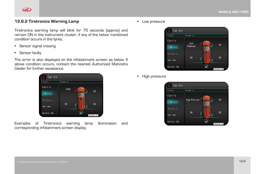
© Copyright Mahindra and Mahindra Ltd. 052016 12-9
12.6.2 Tiretronics Warning Lamp
Tiretronics warning lamp will blink for 75 seconds (approx) andremain ON in the instrument cluster, if any of the below mentionedcondition occurs in the tyres;
• Sensor signal missing
• Sensor faulty
The error is also displayed on the infotainment screen as below. Ifabove condition occurs, contact the nearest Authorized MahindraDealer for further assistance.
W22L31
Examples of Tiretronics warning lamp illumination andcorresponding infotainment screen display;
• Low pressure
W22L32
• High pressure
W22L33
WHEELS AND TYRES
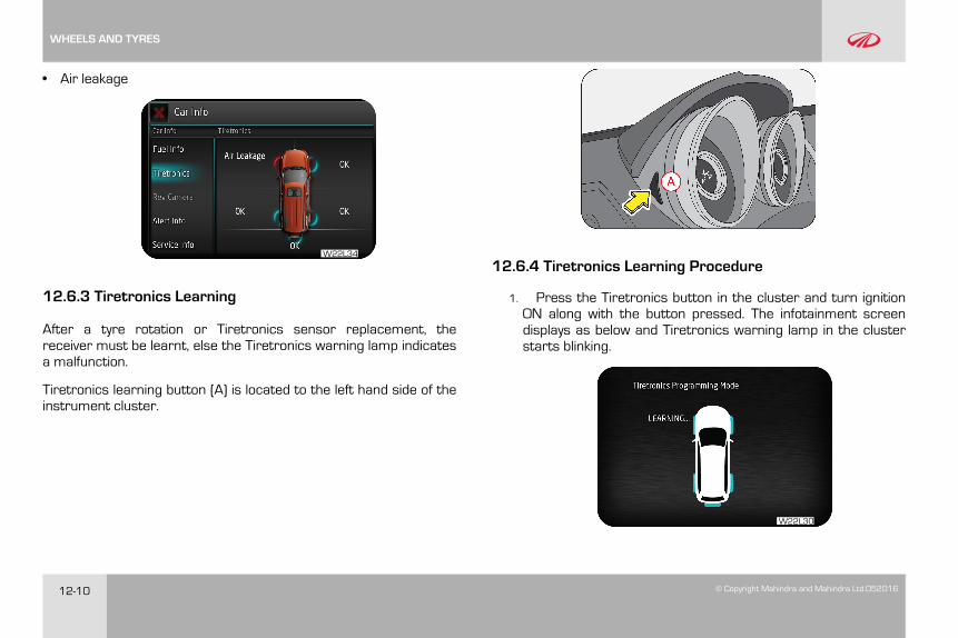
12-10 © Copyright Mahindra and Mahindra Ltd.052016
• Air leakage
W22L34
12.6.3 Tiretronics Learning
After a tyre rotation or Tiretronics sensor replacement, thereceiver must be learnt, else the Tiretronics warning lamp indicatesa malfunction.
Tiretronics learning button (A) is located to the left hand side of theinstrument cluster.
12.6.4 Tiretronics Learning Procedure
1. Press the Tiretronics button in the cluster and turn ignitionON along with the button pressed. The infotainment screendisplays as below and Tiretronics warning lamp in the clusterstarts blinking.
W22L30
WHEELS AND TYRES
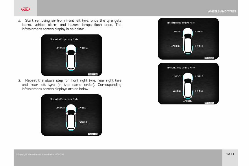
© Copyright Mahindra and Mahindra Ltd. 052016 12-11
2. Start removing air from front left tyre, once the tyre getslearnt, vehicle alarm and hazard lamps flash once. Theinfotainment screen display is as below.
W22L24
3. Repeat the above step for front right tyre, rear right tyreand rear left tyre (in the same order). Correspondinginfotainment screen displays are as below.
W22L25
W22L26
W22L27
WHEELS AND TYRES
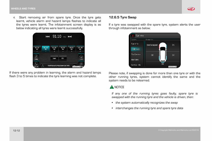
12-12 © Copyright Mahindra and Mahindra Ltd.052016
4. Start removing air from spare tyre. Once the tyre getslearnt, vehicle alarm and hazard lamps flashes to indicate allthe tyres were learnt. The infotainment screen display is asbelow indicating all tyres were learnt successfully.
W22L28
If there were any problem in learning, the alarm and hazard lampsflash 3 to 5 times to indicate the tyre learning was not complete.
12.6.5 Tyre Swap
If a tyre was swapped with the spare tyre, system alerts the userthrough infotainment as below;
W22L29
Please note, if swapping is done for more than one tyre or with theother running tyres, system cannot identify the same and thesystem needs to be relearned.
If any one of the running tyres goes faulty, spare tyre isswapped with the running tyre and the vehicle is driven, then:
• the system automatically recognizes the swap
• interchanges the running tyre and spare tyre data
WHEELS AND TYRES
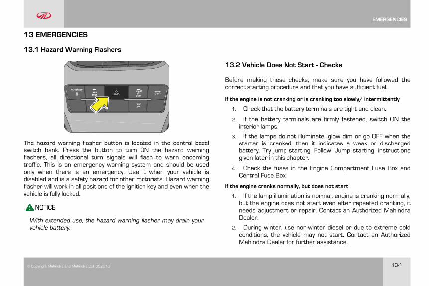
© Copyright Mahindra and Mahindra Ltd. 052016 13-1
13 EMERGENCIES
13.1 Hazard Warning Flashers
The hazard warning flasher button is located in the central bezelswitch bank. Press the button to turn ON the hazard warningflashers, all directional turn signals will flash to warn oncomingtraffic. This is an emergency warning system and should be usedonly when there is an emergency. Use it when your vehicle isdisabled and is a safety hazard for other motorists. Hazard warningflasher will work in all positions of the ignition key and even when thevehicle is fully locked.
With extended use, the hazard warning flasher may drain yourvehicle battery.
13.2 Vehicle Does Not Start - Checks
Before making these checks, make sure you have followed thecorrect starting procedure and that you have sufficient fuel.
If the engine is not cranking or is cranking too slowly/ intermittently
1. Check that the battery terminals are tight and clean.
2. If the battery terminals are firmly fastened, switch ON theinterior lamps.
3. If the lamps do not illuminate, glow dim or go OFF when thestarter is cranked, then it indicates a weak or dischargedbattery. Try jump starting. Follow ‘Jump starting’ instructionsgiven later in this chapter.
4. Check the fuses in the Engine Compartment Fuse Box andCentral Fuse Box.
If the engine cranks normally, but does not start
1. If the lamp illumination is normal, engine is cranking normally,but the engine does not start even after repeated cranking, itneeds adjustment or repair. Contact an Authorized MahindraDealer.
2. During winter, use non-winter diesel or due to extreme coldconditions, the vehicle may not start. Contact an AuthorizedMahindra Dealer for further assistance.
EMERGENCIES
13-2 © Copyright Mahindra and Mahindra Ltd.052016
To prevent damage to the starter, do not crank the enginefor more than 15 seconds at a time. Wait 10 to 15seconds before trying again.
If the engine stalls while driving
Reduce your speed gradually, keeping a straight line. Movecautiously off the road to a safe place. Turn ON your hazard warningflashers and check for any malfunction lamps in the instrumentcluster. Turn the ignition OFF, wait for approximately 90 secondsand try starting the engine again. If the vehicle still does not startcontact an Authorized Mahindra Dealer.
If the engine stalls while running, the power assist for thebrakes and steering will not work. Steering and braking will bemuch harder than usual.
If the engine speed does not increase
If the engine speed does not increase when the accelerator pedal isdepressed, there may be a problem in the Engine ManagementSystem, electrical or electronic controls. In case of certain faults,the engine may go to limp home mode, which is indicated by thecheck engine lamp. Have your vehicle checked by an AuthorizedMahindra Dealer as soon as possible.
13.3 Vehicle Overheating
If the needle in the temperature gauge in the instrument cluster isall the way up to the H and/or the high engine coolant temperaturewarning lamp is ON, your engine has overheated.
If the engine is getting overheated, the Engine Management Systemreduces engine power substantially and may even shut the engineOFF; it is dangerous to continue driving when the engine hasoverheated. You need to first cool the engine down before startingto drive again.
Follow the below instructions to cool the engine down
• Progressively reduce the vehicle speed and bring the vehicle to astop at the side of the road
• Turn ON the hazard warning flashers
• Keep the engine running at idle
• Engage the parking brake
• Switch off the air conditioner
• Wait till the engine coolant temperature drops sufficiently suchthat the needle in the temperature gauge is around halfwaybetween C and H
EMERGENCIES
© Copyright Mahindra and Mahindra Ltd. 052016 13-3
Now switch the engine OFF and carefully open the bonnet/hood tovisibly inspect the engine cooling system parts. Be cautious whiledoing an inspection as vehicle parts will still be too hot. Verify thatthe engine coolant level in the coolant recovery tank is maintainedbetween the 'Min' and 'Max' mark. Check for possible fluid leakages.Check for damages to heat exchangers and connecting hoses. Alsoverify that the radiator shrouds, engine fan blades and the enginebelt all are in good condition.
If any evidence of failure is observed, contact the nearestAuthorized Mahindra Dealer for help. In case, no system leakage/failure is suspected, driving can be continued.
Either due to severe operating conditions or due to any systemleakages or failures, the engine can get overheated. However if theengine is getting overheated repeatedly, even in normal operatingconditions, get the vehicle checked by an Authorized MahindraDealer as soon as possible.
Refer to the 'High Engine Coolant Temperature' section underthe 'Features and Control' chapter for details.
If the high engine coolant temperature warning is ignored, theengine shuts OFF abruptly to safeguard engine componentsfrom overheating and consequent failure. Abrupt engine shut-off can lead to uncontrollable driving condition and accidents.
Stay clear of hot and rotating vehicle parts while visuallyinspecting the vehicle. The coolant inside the cooling system isunder high pressure and temperature. Never open thepressure cap of the degassing tank when the engine is hot. Nottaking precautions may lead to serious injury to your skin/eyes.
For optimum performance of the cooling system you mustmaintain the required coolant level and use only recommendedengine coolant.
13.4 Jump Starting
If your vehicle's battery has run down, you may be able to start theengine by using a standalone booster battery or a vehicle with agood condition battery.
But before going ahead with this procedure ensure that the batteryis the cause of vehicle not starting. To confirm this, few simple testscan be conducted as follows;;
• Check the headlights - Are they dim or bright? If they are dim, it'slikely your battery is dead. If your headlights are bright, you do nothave a dead battery and a jump start may not help
• Try to start your vehicle -Does it turn over very slowly, or does itcrank quickly? If it cranks quickly, you do not have a dead batteryand a jump start may not help. If it cranks slowly, or not at all, youprobably have a dead battery
EMERGENCIES
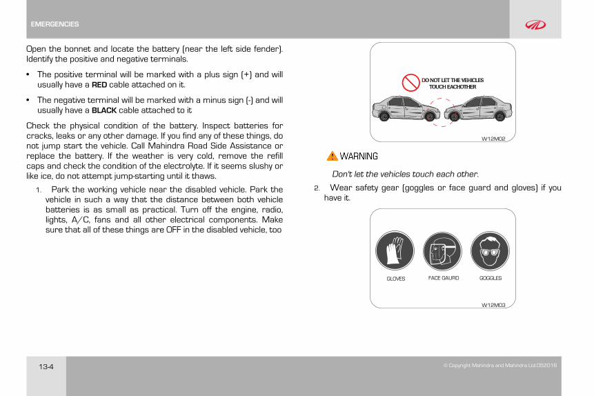
13-4 © Copyright Mahindra and Mahindra Ltd.052016
Open the bonnet and locate the battery (near the left side fender).Identify the positive and negative terminals.
• The positive terminal will be marked with a plus sign (+) and willusually have a RED cable attached on it.
• The negative terminal will be marked with a minus sign (-) and willusually have a BLACK cable attached to it
Check the physical condition of the battery. Inspect batteries forcracks, leaks or any other damage. If you find any of these things, donot jump start the vehicle. Call Mahindra Road Side Assistance orreplace the battery. If the weather is very cold, remove the refillcaps and check the condition of the electrolyte. If it seems slushy orlike ice, do not attempt jump-starting until it thaws.
1. Park the working vehicle near the disabled vehicle. Park thevehicle in such a way that the distance between both vehiclebatteries is as small as practical. Turn off the engine, radio,lights, A/C, fans and all other electrical components. Makesure that all of these things are OFF in the disabled vehicle, too
W12M02
DO NOT LET THE VEHICLESTOUCH EACHOTHER
Don't let the vehicles touch each other.
2. Wear safety gear (goggles or face guard and gloves) if youhave it.
W12M03
EMERGENCIES
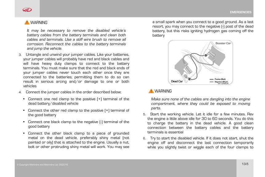
© Copyright Mahindra and Mahindra Ltd. 052016 13-5
It may be necessary to remove the disabled vehicle’sbattery cables from the battery terminals and clean bothcables and terminals. Use a stiff wire brush to remove allcorrosion. Reconnect the cables to the battery terminalsand jump the vehicle.
3. Untangle and unwind your jumper cables. Like your batteries,your jumper cables will probably have red and black cables andwill have heavy duty clamps to connect to the batteryterminals. You must make sure that the red and black ends ofyour jumper cables never touch each other once they areconnected to the batteries; permitting them to do so canresult in serious arcing and/or damage to one or bothvehicles
4. Connect the jumper cables in the order described below;
• Connect one red clamp to the positive (+) terminal of thedead battery/disabled vehicle
• Connect the other red clamp to the positive (+) terminal ofthe good battery
• Connect one black clamp to the negative (-) terminal of thegood battery
• Connect the other black clamp to a piece of groundedmetal on the dead vehicle, preferably shiny metal (notpainted or oily) that is attached to the engine. Usually a nut,bolt or other protruding shiny metal will work. You may see
a small spark when you connect to a good ground. As a lastresort, you may connect to the negative (-) post of the deadbattery, but this risks igniting hydrogen gas coming off thebattery
Booster Car
Dead CarPostive (Red)Negative (Black)
W12M04
Make sure none of the cables are dangling into the enginecompartment, where they could be exposed to movingparts.
5. Start the working vehicle. Let it idle for a few minutes. Revthe engine a little above idle for 30 to 60 seconds. You do thisto charge the battery in the dead vehicle. A good cleanconnection between the battery cables and the batteryterminals is essential
6. Try to start the disabled vehicle. If it does not start, shut theengine off and disconnect the last connection temporarilywhile you slightly twist or wiggle each of the four clamps to
EMERGENCIES
13-6 © Copyright Mahindra and Mahindra Ltd.052016
help ensure a good electrical connection. Restart the workingvehicle again. Allow another 5 minutes for charging beforeattempting to start the disabled vehicle. If this does not workafter a few tries, you may need to have the vehicle towed orthe battery replaced
7. Remove the jumper cables once the vehicle starts. Do this inthe reverse of the order in which they were attached, anddon't let any of the cables or clamps touch each other (ordangle into the engine compartment)
• Disconnect the black clamp from the grounded metal onthe dead vehicle
• Disconnect the black clamp from the negative (-) terminal ofthe good battery
• Disconnect the red clamp from the positive (+) terminal ofthe good battery
• Disconnect the red clamp from the positive (+) terminal ofthe dead battery
Replace any positive (+) red post protective covers if applicable(You have had to remove or open these in the beginning)These covers help prevent accidental short circuiting of thebattery
8. Keep the recently-disabled vehicle's engine running. Run thevehicle above idle (slightly revved up with your foot on theaccelerator). This should give the battery enough charge tostart the vehicle again. If it does not, you probably have a deadbattery or a dying alternator
Improper jump starting procedures can result in batteryexplosion and acid burn hazard.
Loosely connected battery cables could damage the electroniccontrol units.
To disconnect battery terminals wait for at least 2 minutes toallow discharge of high voltage or it could lead to personalinjury.
While disconnecting, always disconnect the -VE terminal firstand while connecting, always connect the -VE terminal last.
Do not connect battery terminals with opposite polarity, it willlead to alternator failure
Towing a vehicle to start could be dangerous. The vehicle beingtowed could surge forward when the engine starts, causing thetow vehicles to collide, injuring the occupants.
Modern vehicles with electronic management systems shouldnot be jump started without ‘protected’ jump starter leads. It isnecessary to refer to the owner's handbook for jump startingprocedures for such vehicles.
EMERGENCIES
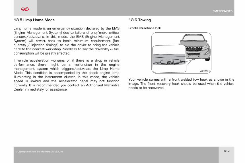
© Copyright Mahindra and Mahindra Ltd. 052016 13-7
13.5 Limp Home Mode
Limp home mode is an emergency situation declared by the EMS(Engine Management System) due to failure of one/more criticalsensors/actuators. In this mode, the EMS (Engine ManagementSystem) will revert back to basic minimum requirement (fuelquantity / injection timings) to aid the driver to bring the vehicleback to the nearest workshop. Needless to say the drivability & fuelconsumption will be greatly affected.
If vehicle acceleration worsens or if there is a drop in vehicleperformance, there might be a malfunction in the enginemanagement system which triggers/activates the Limp HomeMode. This condition is accompanied by the check engine lampilluminating in the instrument cluster. In this mode, the vehiclespeed is limited and the accelerator pedal may not functionnormally. It is recommended you contact an Authorized MahindraDealer immediately for assistance.
13.6 Towing
Front Extraction Hook
W22M31
Your vehicle comes with a front welded tow hook as shown in theimage. The front recovery hook should be used when the vehicleneeds to be recovered.
EMERGENCIES
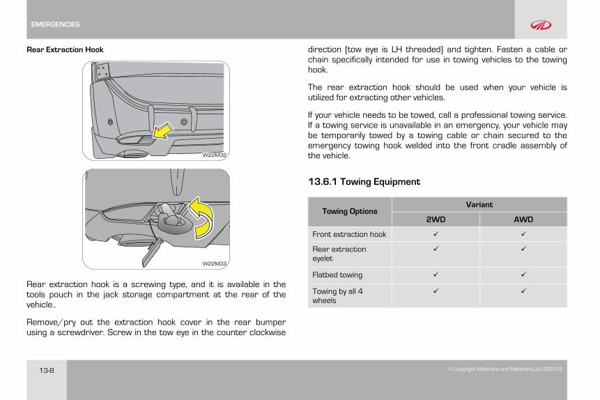
13-8 © Copyright Mahindra and Mahindra Ltd.052016
Rear Extraction Hook
W22M31W22M32
W22M31W22M33
Rear extraction hook is a screwing type, and it is available in thetools pouch in the jack storage compartment at the rear of thevehicle..
Remove/pry out the extraction hook cover in the rear bumperusing a screwdriver. Screw in the tow eye in the counter clockwise
direction (tow eye is LH threaded) and tighten. Fasten a cable orchain specifically intended for use in towing vehicles to the towinghook.
The rear extraction hook should be used when your vehicle isutilized for extracting other vehicles.
If your vehicle needs to be towed, call a professional towing service.If a towing service is unavailable in an emergency, your vehicle maybe temporarily towed by a towing cable or chain secured to theemergency towing hook welded into the front cradle assembly ofthe vehicle.
13.6.1 Towing Equipment
Towing OptionsVariant
2WD AWD
Front extraction hook ✔ ✔
Rear extractioneyelet
✔ ✔
Flatbed towing ✔ ✔
Towing by all 4wheels
✔ ✔
EMERGENCIES
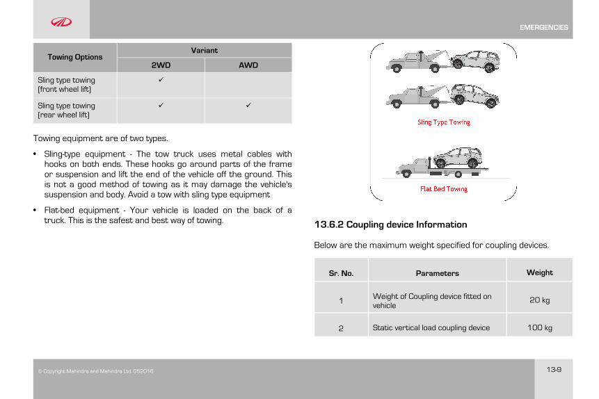
© Copyright Mahindra and Mahindra Ltd. 052016 13-9
Towing OptionsVariant
2WD AWD
Sling type towing(front wheel lift)
✔
Sling type towing(rear wheel lift)
✔ ✔
Towing equipment are of two types.
• Sling-type equipment - The tow truck uses metal cables withhooks on both ends. These hooks go around parts of the frameor suspension and lift the end of the vehicle off the ground. Thisis not a good method of towing as it may damage the vehicle'ssuspension and body. Avoid a tow with sling type equipment
• Flat-bed equipment - Your vehicle is loaded on the back of atruck. This is the safest and best way of towing. 13.6.2 Coupling device Information
Below are the maximum weight specified for coupling devices.
Sr. No. Parameters Weight
1 Weight of Coupling device fitted onvehicle
20 kg
2 Static vertical load coupling device 100 kg
EMERGENCIES
13-10 © Copyright Mahindra and Mahindra Ltd.052016
With trailer coupled and coupling load on the vehicle the vehiclespeed should not exceed 100km/h.
EMERGENCIES
© Copyright Mahindra and Mahindra Ltd. 052016 14-1
14 MAINTENANCE
14.1 General Owners Information
Your vehicle has been designed for fewer maintenancerequirements with longer service intervals to save both your timeand money. However, each regular maintenance, as well as day-to-day care is more important to ensure a smooth, trouble free, safeand economical operation.
It is the owner's responsibility to make sure the specifiedmaintenance, including general maintenance service is performed.Note that both the new vehicle limited warranty and emissioncontrol system limited warranties specify that proper maintenanceand care must be performed. See Service Coupon Booklet forcomplete warranty information.
Where to go for service?
Mahindra technicians are well trained specialists and are kept up todate with the latest service information through technical bulletins,service tips and in dealership training programs. They learn to workon Mahindra vehicles before they work on your vehicle, rather thanwhile they are working on it.
You can be confident that your Mahindra dealer's servicedepartment does the best job to meet the maintenancerequirements on your vehicle reliably and economically.
Get the most from your vehicle with routine maintenance
Routine maintenance is the best way to help ensure you get theperformance, dependability, long life and better resale value youexpect from your vehicle. This is exactly why we've put together thisMaintenance Section. It outlines the services required to properlymaintain your vehicle and when they should be performed. Thefocus is on maintaining your vehicle while it's running great, whichgoes a long way toward preventing major repairs and expenseslater.
Here are a few suggestions to help you get started on routinemaintenance:
• Familiarize yourself with your vehicle by going through yourOwner's Manual
• Take a few minutes to review this Maintenance Section
• Make it a habit to use this manual to record scheduledmaintenance in the Service Coupon Booklet
• Consult with your Authorized Mahindra Dealer for all yourvehicle's needs
14.1.1 Suggestions for Obtaining Service for your Vehicle
Prepare for the Appointment
If you have warranty work to be done, be sure to have the rightpapers with you. All work to be performed may not be covered by
MAINTENANCE
14-2 © Copyright Mahindra and Mahindra Ltd.052016
the warranty. Discuss additional charges with the service manager.Keep a maintenance log of your vehicle's service history.
Prepare a List
Make a written list of your vehicle's problems or the specific workyou want done. If you've had an accident or work done that is not onyour maintenance log, let the service advisor know about it.
Be Reasonable with Requests
If you list a number of items and you must have your vehicle by theend of the day, discuss the situation with the service advisor and listthe items in order of priority.
14.1.2 Need Assistance?
It is recommended talking to an Authorized Mahindra Dealerservice manager first. Most matters can be resolved with thisprocess. If for some reason you are still not satisfied, talk to thegeneral manager or owner of the dealership.
If an Authorized Mahindra Dealership is unable to resolve theconcern, you may contact any Mahindra Customer Care executive.They would need the following information:
Owner's name and address, owner's telephone number (home andoffice), Authorized Dealership name, Vehicle Identification Number(VIN), vehicle delivery date and mileage.
14.1.3 Warranty Information
Read the Warranty Information given in the ‘Warranty Information &Maintenance Guide’ for the terms and provisions of Mahindrawarranties applicable to this vehicle. Mahindra genuine parts, fluids,lubricants and accessories are available at any AuthorizedMahindra Dealer. They will help keep the vehicle operating at itsbest.
14.1.4 Protect your Warranty
Routine maintenance is not only the best way to help keep yourvehicle performing as intended, it's also the best way to protectyour warranty. Failure to perform scheduled maintenance specifiedin the Service Coupon Booklet will invalidate warranty coverage onparts affected by the lack of maintenance. We can't stress enoughhow important it is to keep records of all maintenance. Damage orfailures due to neglect or lack of proper maintenance are notcovered under warranty.
Keeping maintenance records is easy with the service couponbooklet
It's important to document the maintenance of your vehicle. Foryour convenience to maintain records of service, the scheduledmaintenance coupons are provided in the service coupon booklet.Every time you bring your vehicle in for scheduled maintenance, besure to present this booklet and certify the work. Also record thedate of service and mileage at the time of service. This will make
MAINTENANCE
© Copyright Mahindra and Mahindra Ltd. 052016 14-3
record keeping easy and, should your vehicle ever require warrantycoverage, you will have all the documentation to show you'veproperly maintained it.
14.1.1 Maintenance Interval
Mahindra establishes recommended maintenance intervals basedupon engineering testing to determine the most appropriatemileage to perform the various maintenance services. This protectsyour vehicle at the lowest overall cost to you. Mahindrarecommends that you do not deviate from the maintenanceschedules presented in this Maintenance Schedule.
14.1.1.2 Oils, Fluids and Flushing
In many cases, fluid discoloration is a normal operatingcharacteristic by itself, and does not necessarily indicate a concernor that the fluid needs to be changed. However, discolored fluidsthat also show signs of overheating and/or foreign materialcontamination should be inspected immediately by a qualified expertsuch as the factory trained technicians at your AuthorizedMahindra Dealer. Your vehicle's oils and fluids should be changed atthe specified intervals or in conjunction with a repair.
14.1.1.3 Chemicals and Additives
Non-Mahindra approved chemicals or additives are not required forfactory recommended maintenance. In fact, Mahindrarecommends against the use of such additive products unlessspecifically recommended by Mahindra for a particular application.
Your vehicle is very sophisticated and built with multiple complexperformance systems. Every manufacturer develops these systemsusing different specifications and performance features. That's whyit's important to rely on your Authorized Mahindra Dealer toproperly diagnose and repair your vehicle.
When planning your maintenance services, consider yourAuthorized Mahindra Dealer for all your vehicle's needs.
14.1.1.4 Get the most from your service and maintenancevisits
Getting your vehicle serviced at an Authorized Mahindra Dealeradds great value to your vehicle in number of ways. Hence, it isrecommended to service your vehicle at an Authorized MahindraDealer only.
14.1.5 Vehicle Self Maintenance - General Precautions
• Refer to relevant sections of the manual before starting
• Set the parking brake
MAINTENANCE
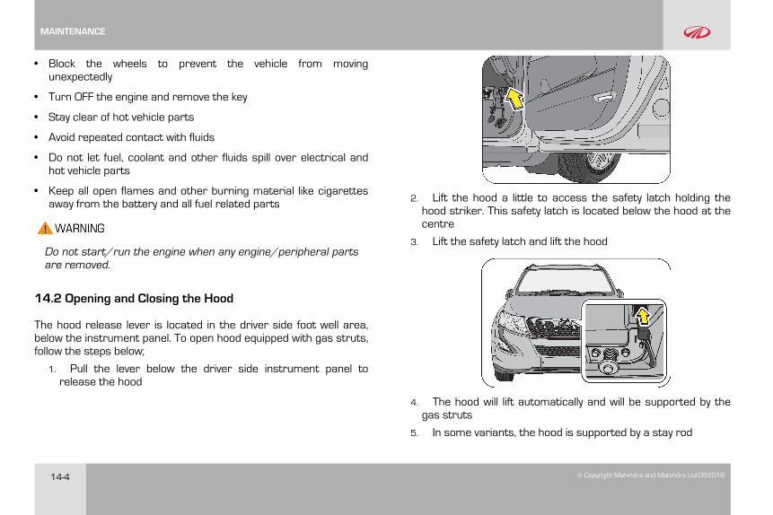
14-4 © Copyright Mahindra and Mahindra Ltd.052016
• Block the wheels to prevent the vehicle from movingunexpectedly
• Turn OFF the engine and remove the key
• Stay clear of hot vehicle parts
• Avoid repeated contact with fluids
• Do not let fuel, coolant and other fluids spill over electrical andhot vehicle parts
• Keep all open flames and other burning material like cigarettesaway from the battery and all fuel related parts
Do not start/run the engine when any engine/peripheral partsare removed.
14.2 Opening and Closing the Hood
The hood release lever is located in the driver side foot well area,below the instrument panel. To open hood equipped with gas struts,follow the steps below;
1. Pull the lever below the driver side instrument panel torelease the hood
2. Lift the hood a little to access the safety latch holding thehood striker. This safety latch is located below the hood at thecentre
3. Lift the safety latch and lift the hood
4. The hood will lift automatically and will be supported by thegas struts
5. In some variants, the hood is supported by a stay rod
MAINTENANCE
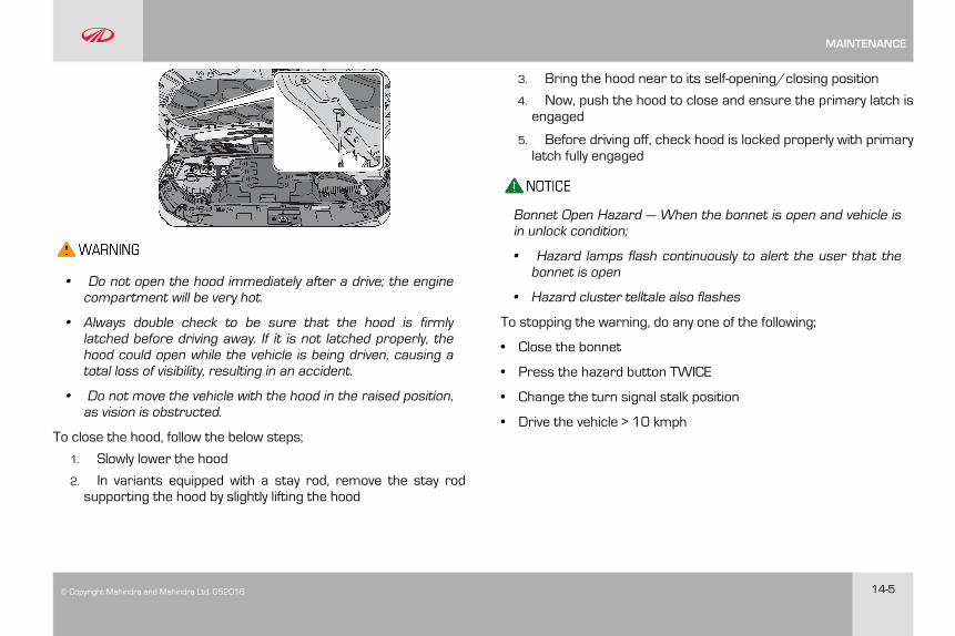
© Copyright Mahindra and Mahindra Ltd. 052016 14-5
• Do not open the hood immediately after a drive; the enginecompartment will be very hot.
• Always double check to be sure that the hood is firmlylatched before driving away. If it is not latched properly, thehood could open while the vehicle is being driven, causing atotal loss of visibility, resulting in an accident.
• Do not move the vehicle with the hood in the raised position,as vision is obstructed.
To close the hood, follow the below steps;
1. Slowly lower the hood
2. In variants equipped with a stay rod, remove the stay rodsupporting the hood by slightly lifting the hood
3. Bring the hood near to its self-opening/closing position
4. Now, push the hood to close and ensure the primary latch isengaged
5. Before driving off, check hood is locked properly with primarylatch fully engaged
Bonnet Open Hazard — When the bonnet is open and vehicle isin unlock condition;
• Hazard lamps flash continuously to alert the user that thebonnet is open
• Hazard cluster telltale also flashes
To stopping the warning, do any one of the following;
• Close the bonnet
• Press the hazard button TWICE
• Change the turn signal stalk position
• Drive the vehicle > 10 kmph
MAINTENANCE

14-6 © Copyright Mahindra and Mahindra Ltd.052016
14.3 Engine Compartment
A DCB E F JG H I
W22P01
A Degassing Tank F Brake/Clutch Fluid Reservoir
B Front Windshield Washer Fluid Reservoir G Diesel Exhaust Fluid filler
C Engine Oil Cap H Air Filter Assembly
D Engine Cover I Battery
E Dipstick J Engine Compartment Fuse Box
MAINTENANCE
© Copyright Mahindra and Mahindra Ltd. 052016 14-7
Maintenance is classified as below;
• General Maintenance
• Scheduled Maintenance
14.4 General Maintenance
Exercise extreme caution when the hood is open and engine isON.
Listed below are the general maintenance items that should beperformed frequently. In addition to checking the items listed below,if you notice any unusual noise, fluid leakages, smell or vibration, youshould investigate the cause or take your vehicle to your AuthorizedMahindra Dealer or a qualified service shop immediately.
Make these checks only with adequate ventilation if you intendto run the engine.
In the Engine Compartment
• Front windshield washer fluid level
• Engine coolant level
• Battery condition
• Brake/Clutch fluid level
• Engine oil level
• Power steering fluid level
• Fluid leaks
• Hoses, joints and pipes for any abnormalities
Inside the Vehicle
• Lights
• Warning lamps
• Windshield wipe and wash
• Steering wheel
• Seats
• Seat belts
• Accelerator pedal
• Brake pedal
• Brakes
• Parking brake
• Gear lever shift mechanism
Outside the Vehicle
• Lamps
MAINTENANCE
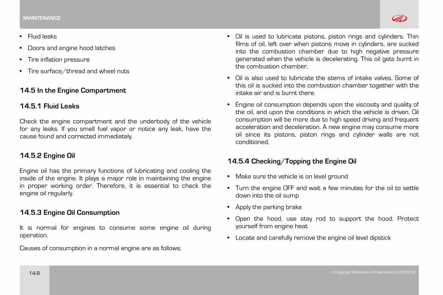
14-8 © Copyright Mahindra and Mahindra Ltd.052016
• Fluid leaks
• Doors and engine hood latches
• Tire inflation pressure
• Tire surface/thread and wheel nuts
14.5 In the Engine Compartment
14.5.1 Fluid Leaks
Check the engine compartment and the underbody of the vehiclefor any leaks. If you smell fuel vapor or notice any leak, have thecause found and corrected immediately.
14.5.2 Engine Oil
Engine oil has the primary functions of lubricating and cooling theinside of the engine. It plays a major role in maintaining the enginein proper working order. Therefore, it is essential to check theengine oil regularly.
14.5.3 Engine Oil Consumption
It is normal for engines to consume some engine oil duringoperation.
Causes of consumption in a normal engine are as follows;
• Oil is used to lubricate pistons, piston rings and cylinders. Thinfilms of oil, left over when pistons move in cylinders, are suckedinto the combustion chamber due to high negative pressuregenerated when the vehicle is decelerating. This oil gets burnt inthe combustion chamber.
• Oil is also used to lubricate the stems of intake valves. Some ofthis oil is sucked into the combustion chamber together with theintake air and is burnt there.
• Engine oil consumption depends upon the viscosity and quality ofthe oil, and upon the conditions in which the vehicle is driven. Oilconsumption will be more due to high speed driving and frequentacceleration and deceleration. A new engine may consume moreoil since its pistons, piston rings and cylinder walls are notconditioned.
14.5.4 Checking/Topping the Engine Oil
• Make sure the vehicle is on level ground
• Turn the engine OFF and wait a few minutes for the oil to settledown into the oil sump
• Apply the parking brake
• Open the hood, use stay rod to support the hood. Protectyourself from engine heat
• Locate and carefully remove the engine oil level dipstick
MAINTENANCE
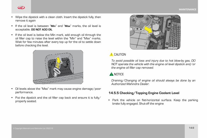
© Copyright Mahindra and Mahindra Ltd. 052016 14-9
• Wipe the dipstick with a clean cloth. Insert the dipstick fully, thenremove it again
• If the oil level is between “Min” and “Max” marks, the oil level isacceptable. DO NOT ADD OIL
• If the oil level is below the Min mark, add enough oil through theoil filler cap to raise the level within the “Min” and “Max” marks.Wait for few minutes after every top up for the oil to settle downbefore checking the level.
• Oil levels above the “Max” mark may cause engine damage/poorperformance.
• Put the dipstick and the oil filler cap back and ensure it is fully/properly seated.
W22P02
To avoid possible oil loss and injury due to hot blow-by gas, DONOT operate the vehicle with the engine oil level dipstick and/orthe engine oil filler cap removed.
Draining/Changing of engine oil should always be done by anAuthorized Mahindra Dealer.
14.5.5 Checking/Topping Engine Coolant Level
• Park the vehicle on flat-horizontal surface. Keep the parkingbrake fully engaged. Shut-off the engine
MAINTENANCE
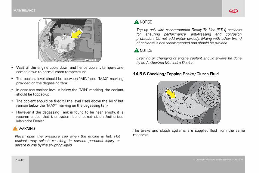
14-10 © Copyright Mahindra and Mahindra Ltd.052016
W22P03
• Wait till the engine cools down and hence coolant temperaturecomes down to normal room temperature
• The coolant level should be between “MIN” and “MAX” markingprovided on the degassing tank
• In case the coolant level is below the “MIN” marking, the coolantshould be topped-up
• The coolant should be filled till the level rises above the 'MIN' butremain below the “MAX” marking on the degassing tank
• However if the degassing Tank is found to be near empty, it isrecommended that the system be checked at an AuthorizedMahindra Dealer
Never open the pressure cap when the engine is hot. Hotcoolant may splash resulting in serious personal injury orsevere burns by the erupting liquid.
Top up only with recommended Ready To Use (RTU) coolantsfor ensuring performance, anti-freezing and corrosionprotection. Do not add water directly. Mixing with other brandof coolants is not recommended and should be avoided.
Draining or changing of engine coolant should always be doneby an Authorized Mahindra Dealer.
14.5.6 Checking/Topping Brake/Clutch Fluid
The brake and clutch systems are supplied fluid from the samereservoir.
MAINTENANCE
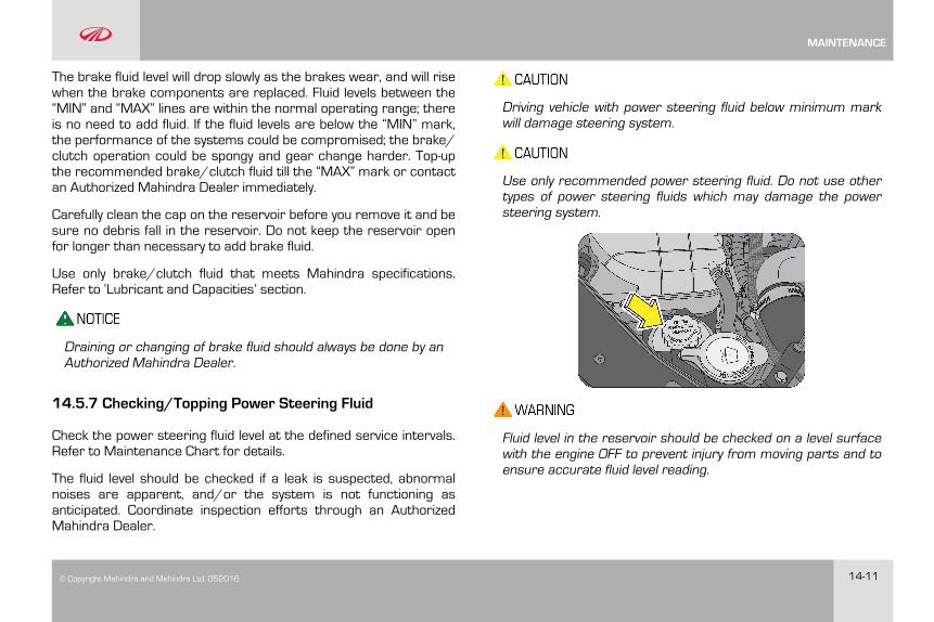
© Copyright Mahindra and Mahindra Ltd. 052016 14-11
The brake fluid level will drop slowly as the brakes wear, and will risewhen the brake components are replaced. Fluid levels between the“MIN” and “MAX” lines are within the normal operating range; thereis no need to add fluid. If the fluid levels are below the “MIN” mark,the performance of the systems could be compromised; the brake/clutch operation could be spongy and gear change harder. Top-upthe recommended brake/clutch fluid till the “MAX” mark or contactan Authorized Mahindra Dealer immediately.
Carefully clean the cap on the reservoir before you remove it and besure no debris fall in the reservoir. Do not keep the reservoir openfor longer than necessary to add brake fluid.
Use only brake/clutch fluid that meets Mahindra specifications.Refer to ‘Lubricant and Capacities’ section.
Draining or changing of brake fluid should always be done by anAuthorized Mahindra Dealer.
14.5.7 Checking/Topping Power Steering Fluid
Check the power steering fluid level at the defined service intervals.Refer to Maintenance Chart for details.
The fluid level should be checked if a leak is suspected, abnormalnoises are apparent, and/or the system is not functioning asanticipated. Coordinate inspection efforts through an AuthorizedMahindra Dealer.
Driving vehicle with power steering fluid below minimum markwill damage steering system.
Use only recommended power steering fluid. Do not use othertypes of power steering fluids which may damage the powersteering system.
Fluid level in the reservoir should be checked on a level surfacewith the engine OFF to prevent injury from moving parts and toensure accurate fluid level reading.
MAINTENANCE
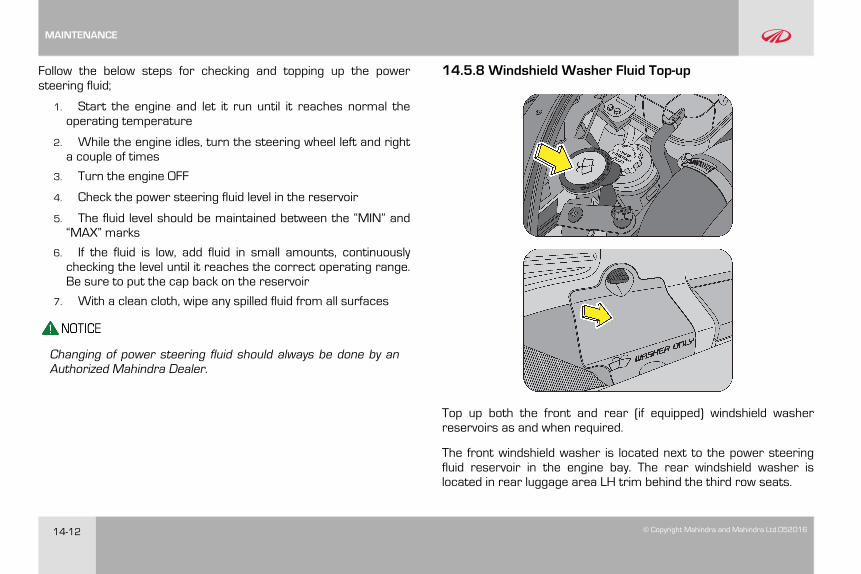
14-12 © Copyright Mahindra and Mahindra Ltd.052016
Follow the below steps for checking and topping up the powersteering fluid;
1. Start the engine and let it run until it reaches normal theoperating temperature
2. While the engine idles, turn the steering wheel left and righta couple of times
3. Turn the engine OFF
4. Check the power steering fluid level in the reservoir
5. The fluid level should be maintained between the “MIN” and“MAX” marks
6. If the fluid is low, add fluid in small amounts, continuouslychecking the level until it reaches the correct operating range.Be sure to put the cap back on the reservoir
7. With a clean cloth, wipe any spilled fluid from all surfaces
Changing of power steering fluid should always be done by anAuthorized Mahindra Dealer.
14.5.8 Windshield Washer Fluid Top-up
Top up both the front and rear (if equipped) windshield washerreservoirs as and when required.
The front windshield washer is located next to the power steeringfluid reservoir in the engine bay. The rear windshield washer islocated in rear luggage area LH trim behind the third row seats.
MAINTENANCE
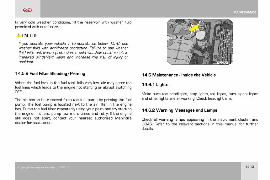
© Copyright Mahindra and Mahindra Ltd. 052016 14-13
In very cold weather conditions, fill the reservoir with washer fluidpremixed with anti-freeze.
If you operate your vehicle in temperatures below 4.5ºC, usewasher fluid with anti-freeze protection. Failure to use washerfluid with anti-freeze protection in cold weather could result inimpaired windshield vision and increase the risk of injury oraccident.
14.5.9 Fuel Filter Bleeding/Priming
When the fuel level in the fuel tank falls very low, air may enter thefuel lines which leads to the engine not starting or abrupt switchingOFF.
The air has to be removed from the fuel pump by priming the fuelpump. The fuel pump is located next to the air filter in the enginebay. Pump the fuel filter repeatedly using your palm and try startingthe engine. If it fails, pump few more times and retry. If the enginestill does not start, contact your nearest authorized Mahindradealer for assistance.
W22P04
14.6 Maintenance - Inside the Vehicle
14.6.1 Lights
Make sure the headlights, stop lights, tail lights, turn signal lightsand other lights are all working. Check headlight aim.
14.6.2 Warning Messages and Lamps
Check all warning lamps appearing in the instrument cluster andDDAS. Refer to the relevant sections in this manual for furtherdetails.
MAINTENANCE
14-14 © Copyright Mahindra and Mahindra Ltd.052016
14.6.3 Seats
Check that all seat controls such as seat adjusters, seat backrecliner, etc. operate smoothly and that all latches lock securely inany position. Check that the head restraints move up and downsmoothly and that the locks hold securely in any latched position.
14.6.4 Seat Belts
Check that the seat belt system such as buckles, retractors andanchors operate properly and smoothly. Make sure the beltwebbing is not cut, frayed, worn or damaged.
14.6.5 Accelerator Pedal
Check the pedal for smooth operation, uneven pedal effort orstickiness. Check the foot well and remove obstructions if any.
14.6.6 Brake Pedal
Check the pedal for smooth operation and proper clearance. Checkthe foot well and remove obstructions if any.
14.7 Maintenance - Outside the Vehicle
The following checks should be carried out from time to time,unless otherwise specified.
14.7.1 Lamps
Check and ensure proper functioning of all exterior lamps.
14.7.2 Fluid Leaks
Check the engine compartment and the underbody of the vehiclefor any leaks. If you smell fuel vapor or notice any leak, have thecause found and corrected immediately.
14.7.3 Doors and Engine Hood
Check all doors and latches including the tailgate for properfunctioning. Make sure the engine hood secondary latch securesthe hood from opening when the primary latch is released.
14.7.4 Tyre Inflation Pressure
Check the tire pressure with a pressure gauge every week.
14.8 Battery
Your vehicle is equipped with a Mahindra genuine battery. Forlonger, trouble-free operation, keep the top of the battery clean anddry. Also, make certain the battery cables are always tightlyfastened to the battery terminals.
MAINTENANCE
© Copyright Mahindra and Mahindra Ltd. 052016 14-15
If you see any corrosion on the battery or terminals, remove thecables from the terminals and clean with a wire brush. To preventcorrosion, apply petroleum jelly to the battery terminals. Tightenloose terminals and hold down clamp nuts only enough to keep thebattery firmly in place. Tightening excessively may damage thebattery terminals.
14.8.1 For Best Battery Service
• Keep the battery securely mounted
• Keep the battery top clean and dry
• Keep the terminals and connections clean, tight and coated withpetroleum jelly or terminal grease
• Rinse any spilled electrolyte from the battery immediately with asolution of water and baking soda
Do not disconnect battery terminals while the engine is running.This will adversely affect all electronic controllers.
While removing the battery, always disconnect the negativeterminal first. And while installing the battery, ensure thenegative terminal is connected last.
It is recommended that the negative battery cable terminal bedisconnected from the battery if you plan to store your vehicle foran extended period of time. This will minimize the discharge of yourbattery during storage.
Battery fluid is a corrosive acid solution; do not allow batteryacid to contact eyes, skin or clothing. Don't lean over batterywhen attaching clamps or allow the clamps to touch eachother. If acid splashes in the eyes or on the skin, flushcontaminated area immediately with large quantities of water.
A battery generates hydrogen gas which is flammable andexplosive. Keep any flame or spark away from the vent holes.
Keep batteries out of reach of children. Battery posts,terminals and related accessories contain lead and leadcomponents. Wash hands after handling batteries.
If the battery has been disconnected or a new battery has beeninstalled, the clock (if equipped) and the preset radio (ifequipped) stations must be reset once the battery isreconnected.
The replacement battery must meet the specification of theoriginally fitted battery.
MAINTENANCE
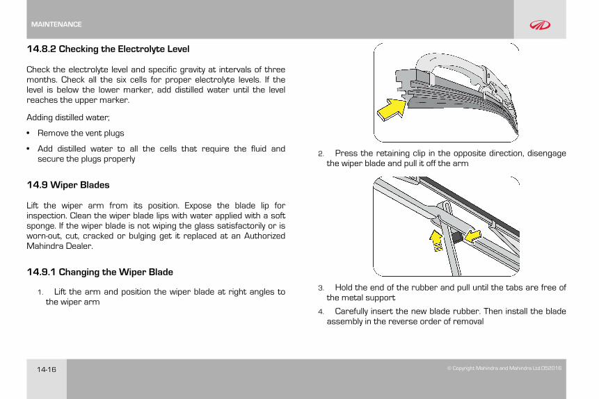
14-16 © Copyright Mahindra and Mahindra Ltd.052016
14.8.2 Checking the Electrolyte Level
Check the electrolyte level and specific gravity at intervals of threemonths. Check all the six cells for proper electrolyte levels. If thelevel is below the lower marker, add distilled water until the levelreaches the upper marker.
Adding distilled water;
• Remove the vent plugs
• Add distilled water to all the cells that require the fluid andsecure the plugs properly
14.9 Wiper Blades
Lift the wiper arm from its position. Expose the blade lip forinspection. Clean the wiper blade lips with water applied with a softsponge. If the wiper blade is not wiping the glass satisfactorily or isworn-out, cut, cracked or bulging get it replaced at an AuthorizedMahindra Dealer.
14.9.1 Changing the Wiper Blade
1. Lift the arm and position the wiper blade at right angles tothe wiper arm
2. Press the retaining clip in the opposite direction, disengagethe wiper blade and pull it off the arm
3. Hold the end of the rubber and pull until the tabs are free ofthe metal support
4. Carefully insert the new blade rubber. Then install the bladeassembly in the reverse order of removal
MAINTENANCE
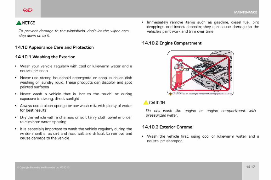
© Copyright Mahindra and Mahindra Ltd. 052016 14-17
To prevent damage to the windshield, don’t let the wiper armslap down on to it.
14.10 Appearance Care and Protection
14.10.1 Washing the Exterior
• Wash your vehicle regularly with cool or lukewarm water and aneutral pH soap
• Never use strong household detergents or soap, such as dishwashing or laundry liquid. These products can discolor and spotpainted surfaces
• Never wash a vehicle that is ‘hot to the touch’ or duringexposure to strong, direct sunlight
• Always use a clean sponge or car wash mitt with plenty of waterfor best results
• Dry the vehicle with a chamois or soft terry cloth towel in orderto eliminate water spotting
• It is especially important to wash the vehicle regularly during thewinter months, as dirt and road salt are difficult to remove andcause damage to the vehicle
• Immediately remove items such as gasoline, diesel fuel, birddroppings and insect deposits; they can cause damage to thevehicle's paint work and trim over time
14.10.2 Engine Compartment
Do not wash the engine or engine compartment withpressurized water.
14.10.3 Exterior Chrome
• Wash the vehicle first, using cool or lukewarm water and aneutral pH shampoo
MAINTENANCE
14-18 © Copyright Mahindra and Mahindra Ltd.052016
• Use the custom bright metal cleaners, available at yourAuthorized Mahindra Dealer. Apply the product as you would waxto clean chrome parts; allow the cleaner to dry for a fewminutes, and then wipe off the haze with a clean, dry rag
• Never use abrasive materials such as steel wool or plastic padsas they can leave scratches on the chrome surface
• After polishing the chrome parts, you can also apply a coating ofPremium Liquid Wax, available at your Authorized MahindraDealer, or an equivalent quality product to help protect fromenvironmental effects
14.10.4 Paint Chips
• Mahindra dealers have the exact touch-up paint to match yourvehicle's color
• Take your vehicle to an Authorized Mahindra Dealer for painttouch-up or paint repairs
• Remove particles such as bird droppings, tree sap, insectdeposits, tar spots, road salt and industrial fallout beforerepairing paint chips
• Always read the instructions before using the products
14.10.5 Aluminium Wheels And Wheel Covers (ifequipped)
Aluminum wheels and wheel covers are coated with a clear coat ofpaint finish. In order to maintain their shine;
• Clean weekly with wheel and tire cleaner, which is available atyour Authorized Mahindra Dealer. Heavy dirt and brake dustaccumulation may require agitation with a sponge. Rinsethoroughly with a strong stream of water
• Never apply any cleaning chemicals to hot or warm wheel rimsor covers
• Do not use hydrofluoric acid-based or high caustic-based wheelcleaners, steel wool, fuels or strong household detergents
14.10.6 Plastic (Non-painted) Exterior Parts
Use only approved products to clean plastic parts. These productsare available with your authorized dealer. You can use thesecleaners;
• For routine cleaning of plastic parts
• For tar or grease spots
• For plastic head lamp lenses
MAINTENANCE
© Copyright Mahindra and Mahindra Ltd. 052016 14-19
14.10.7 Windows and Wiper Blades
The front/rear windshield, side windows and the wiper bladesshould be cleaned regularly. If the wipers do not wipe properly,substances on the vehicle's glass or the wiper blades may be thecause. These may include hot wax treatments used by commercialcar washes, water repellent coatings, tree sap, or other organiccontamination; these contaminants may cause squeaking orchatter noise from the blades, and streaking and smearing of thewindshield.
To clean these items follow these tips;
• The windshield, rear windows and side windows may be cleanedwith a non-abrasive cleaner such as Clear Spray Glass Cleaner,available at your Authorized Mahindra Dealer.
• The wiper blades can be cleaned with alcohol or PremiumWindshield Washer Concentrate, available at your AuthorizedMahindra Dealer. This washer fluid contains a special solution inaddition to alcohol which helps remove the hot wax deposited onthe wiper blade and windshield. Be sure to replace wiper bladeswhen they appear worn or do not function properly.
• Do not use abrasives, as they may cause scratches.
• Do not use fuel, kerosene, or paint thinner to clean any glassparts.
If you cannot remove those streaks after cleaning with the glasscleaner or if the wipers chatter and move in a jerky motion, cleanthe outer surface of the windshield and the wiper blades using a
sponge or soft cloth with a neutral detergent or mild-abrasivecleaning solution. After cleaning, rinse the windshield and wiperblades with clean water. The windshield is clean if beads do notform when you rinse the windshield with water.
Do not use sharp objects, such as a razor blade, to remove decals,as it may cause damage to the glass or rear windshield heater gridlines (if equipped).
14.10.8 Instrument Panel/Interior Trim and Cluster Lens
Do not use chemical solvents or strong detergents whencleaning the steering wheel or instrument panel.
Clean the instrument panel, interior trim areas and cluster lenswith a clean and damp white cotton cloth, then with a clean and drywhite cotton cloth; you may also use Dash and Vinyl Cleaner on theinstrument panel and interior trim areas.
• Avoid cleaners or polishes that increase the gloss of the upperportion of the instrument panel. The dull finish in this area helpsprotect the driver from undesirable windshield reflection
• Do not use household or glass cleaners as these may damagethe finish of the instrument panel, interior trim and cluster lens
If a staining liquid like coffee/juice has been spilled on theinstrument panel or on the interior trim surfaces, clean as follows;
MAINTENANCE
14-20 © Copyright Mahindra and Mahindra Ltd.052016
• Wipe up spilled liquid using a clean white cotton cloth
• Apply Vinyl Cleaner to the wiped area and spread around evenly
• Apply cleaner to a clean white cotton cloth and press the clothonto the soiled area and allow this to set in at room temperaturefor 30 minutes
• Remove the soaked cloth, and if it is not soiled badly, use thiscloth to clean the area with a rubbing motion for 60 seconds
• Following this, wipe area dry with a clean white cotton cloth
14.10.9 Interior Maintenance
For fabric, carpets, cloth seats, safety belts and seats:
• Remove dust and loose dirt with a vacuum cleaner
• Remove light stains and soil with carpet and upholstery cleaner
• If grease or tar is present on the material, spot-clean the areafirst with a stain remover
• Do not use household cleaning products or glass cleaners, whichcan stain and discolor the fabric and affect the flame retardantabilities of the seat materials
• Do not use cleaning solvents, bleach or dye on the vehicle'ssafety belts, as these actions may weaken the belt webbing.
14.10.10 Leather Seats (where applicable)
Your leather seating surfaces have a clear, protective coating overthe leather.
• To clean, use a soft cloth with a leather and vinyl cleaner. Dry thearea with a soft cloth
• To help maintain its resiliency and color, use the leather care kit,available from an Authorized Mahindra Dealer
• Do not use household cleaning products, alcohol solutions,solvents or cleaners intended for rubber, vinyl and plastics, oroil/petroleum-based leather conditioners. These products maycause premature wearing of the clear, protective coating
In some instances, a color or dye transfer can occur when wetclothing comes in contact with leather upholstery. If this occurs,clean the leather immediately to avoid permanent staining.
14.10.11 Underbody
Flush the complete underside of your vehicle frequently. Keep bodyand door drain holes free from packed dirt. You can also use ananti-corrosion spray for the underbody to avoid rusting andcorrosion especially for vehicles in coastal places.
MAINTENANCE
© Copyright Mahindra and Mahindra Ltd. 052016 14-21
14.11 Air Conditioning System Maintenance
Your vehicle's air-conditioning is a sealed system. Any majormaintenance, such as recharging should be done by a qualifiedtechnician. However, you can do a few things by yourself to makesure the air conditioning works efficiently.
Run the air-conditioning system at least once a week, even duringthe cold weather months. Run it for at least ten minutes with theengine running at normal operating temperature. This circulatesthe lubricating oil contained in the refrigerant.
Whenever you get the air-conditioning system serviced, makesure the service facility uses a refrigerant recycling system.This system captures the refrigerant for re-use. Releasing therefrigerant into the atmosphere may cause damage to theenvironment.
14.12 Vehicle Storage
If you are leaving your vehicle for more than 2 weeks you may wantto take stopping to protect your battery. Disconnect the negativecable from the battery. Anytime you store your vehicle, or keep itout of service (i. e. vacation) for two weeks or more, run the airconditioning system at idle for about five minutes in the fresh airmode and high blower speed setting. This will ensure adequate
system lubrication to minimize the possibility of compressordamage when the system is started again.
It is recommended storing the vehicle in a covered, clean, dry, wellleveled, ventilated and closed place.
14.13 Winter Care
14.13.1 Dealing With Ice
Make sure you have window ice scrapers and de-icers for the locks.When you're stuck, having a small shovel is useful to dig out of thesnow. The weight of a bag of sand in the trunk will give addedtraction in rear-wheel drive vehicles and can be used to sprinkle onthe snow and ice to gain better traction. And don't forget personalprotection such as a warm coat, hat, gloves and a blanket, in caseyou get stuck in a storm.
14.13.2 Keep Enough Fuel in the Tank
Never let the fuel level in the tank drop below the half-full mark. Asudden storm with unexpected heavy rains could leave youstranded for hours. Having adequate fuel supply will allow you to idlethe engine from time to time to keep warm.
MAINTENANCE
14-22 © Copyright Mahindra and Mahindra Ltd.052016
Do not:
• Tap the ice on the window to crack it or chip it for a good placeto start scraping. You could end up cracking more than the iceand end up with a cracked or shattered windshield/ window
• Pour warm or hot water on the windshield to melt ice. This willcrack your windshield
14.13.3 During Winter Storage
Start the engine occasionally, here are a few pointers to keep inmind;
• Run it in a well ventilated area. Carbon monoxide can build upquickly
• Run for a minimum of 20 minutes to allow the engine to comeup to the normal operating temperature. This will allow the oil tocirculate and will also open up the thermostat so that yourradiator anti-freeze circulates as well
• Start up the air conditioner and/or heater and run both for 10minutes or so. Again, circulating fluids is essential for good life ofthe system
• If your vehicle has power steering, you may want to turn thewheels a few times to keep the fluids flowing
14.13.4 Exterior
Wash and wax your car to provide an extra layer of protection toyour paint.
14.13.5 Vinyl and Rubber
Use a good conditioner on all vinyl and rubber parts to prevent fromdrying out.
14.13.6 Interior
Clean the glass, shampoo the carpets, dig in between the seats tosee what's there, clean the upholstery in all nooks and corners.
14.13.7 Engine
Check all hoses and wires to make sure everything is in goodcondition and replace any that need to be. The last thing to do is tomake sure the internal components of the engine remain lubricatedand don't corrode.
If the engine is being started after a very long period of non-use,warm up the engine at an idle speed for 2-3 minutes beforedriving the vehicle.
MAINTENANCE
© Copyright Mahindra and Mahindra Ltd. 052016 14-23
14.14 Bulb Replacement
14.14.1 Head Lamp Bulb Replacement
The head lamp bulb can be replaced without removing the headlamp assembly from the vehicle. The head lamp assembly hasbeen removed here for illustration purpose only.
To replace the head lamp bulb;
• Ensure ignition is switched OFF
• Remove rear dust cover from the head lamp
• Remove the bulb assembly with connector from the head lampby unlocking the wire clamp
• Detach the bulb assembly from the wiring connector near to thehead lamp
• Insert the connector into the new bulb (of the same wattage),and follow the reverse procedure to assemble the bulb assemblyin the headlight assembly
• Clamp the bulb assembly by wire clamp properly
Do not touch the new bulb with your fingers. Oil contaminationwill severely shorten bulb life. If the bulb comes in contact withany oily surface, clean the bulb with rubbing alcohol.
To avoid burning yourself, do not replace the light bulbs whenthey are hot. Halogen bulbs have pressurized gas inside andare to be handled with special care. Mishandling it may causethe bulb to burst or shatter. Hold the bulb with its metal/plasticholder/base and do not touch the glass part with bare hands.
Using bulbs with units of higher output capacity/wattage isillegal and may damage your vehicle’s electrical system.
Replacement bulbs must meet the specification of originallyfitted bulbs.
MAINTENANCE
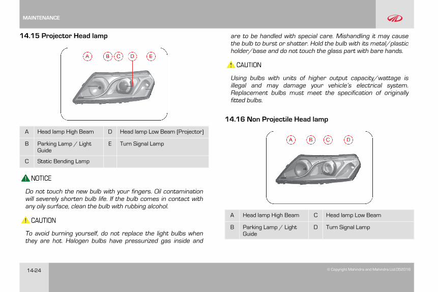
14-24 © Copyright Mahindra and Mahindra Ltd.052016
14.15 Projector Head lamp
A Head lamp High Beam D Head lamp Low Beam (Projector)
B Parking Lamp / LightGuide
E Turn Signal Lamp
C Static Bending Lamp
Do not touch the new bulb with your fingers. Oil contaminationwill severely shorten bulb life. If the bulb comes in contact withany oily surface, clean the bulb with rubbing alcohol.
To avoid burning yourself, do not replace the light bulbs whenthey are hot. Halogen bulbs have pressurized gas inside and
are to be handled with special care. Mishandling it may causethe bulb to burst or shatter. Hold the bulb with its metal/plasticholder/base and do not touch the glass part with bare hands.
Using bulbs with units of higher output capacity/wattage isillegal and may damage your vehicle’s electrical system.Replacement bulbs must meet the specification of originallyfitted bulbs.
14.16 Non Projectile Head lamp
A Head lamp High Beam C Head lamp Low Beam
B Parking Lamp / LightGuide
D Turn Signal Lamp
MAINTENANCE
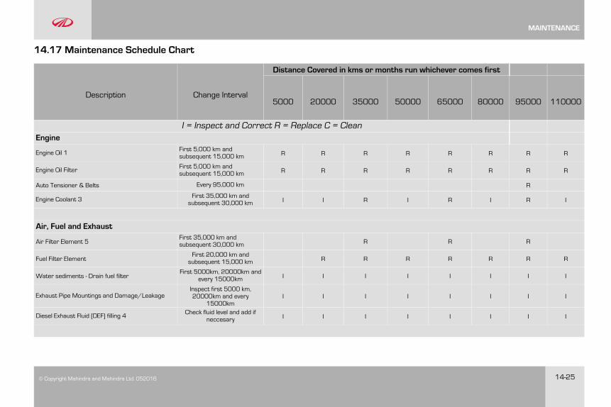
© Copyright Mahindra and Mahindra Ltd. 052016 14-25
14.17 Maintenance Schedule Chart
Description Change Interval
Distance Covered in kms or months run whichever comes first
5000 20000 35000 50000 65000 80000 95000 110000
I = Inspect and Correct R = Replace C = CleanEngine
Engine Oil 1 First 5,000 km andsubsequent 15,000 km R R R R R R R R
Engine Oil Filter First 5,000 km andsubsequent 15,000 km R R R R R R R R
Auto Tensioner & Belts Every 95,000 km R
Engine Coolant 3 First 35,000 km andsubsequent 30,000 km I I R I R I R I
Air, Fuel and Exhaust
Air Filter Element 5First 35,000 km andsubsequent 30,000 km R R R
Fuel Filter ElementFirst 20,000 km andsubsequent 15,000 km R R R R R R R
Water sediments - Drain fuel filterFirst 5000km, 20000km and
every 15000km I I I I I I I I
Exhaust Pipe Mountings and Damage/LeakageInspect first 5000 km,20000km and every
15000kmI I I I I I I I
Diesel Exhaust Fluid (DEF) filling 4 Check fluid level and add ifneccesary I I I I I I I I
MAINTENANCE
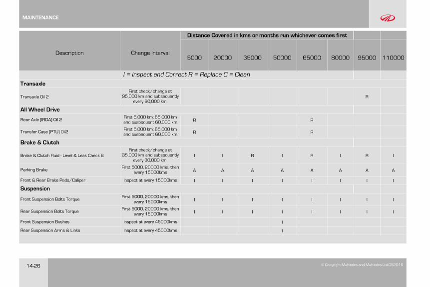
14-26 © Copyright Mahindra and Mahindra Ltd.052016
Description Change Interval
Distance Covered in kms or months run whichever comes first
5000 20000 35000 50000 65000 80000 95000 110000
I = Inspect and Correct R = Replace C = CleanTransaxle
Transaxle Oil 2First check/change at
95,000 km and subsequentlyevery 60,000 km.
R
All Wheel Drive
Rear Axle (IRDA) Oil 2 First 5,000 km; 65,000 kmand susbequent 60,000 km R R
Transfer Case (PTU) Oil2 First 5,000 km; 65,000 kmand susbequent 60,000 km R R
Brake & Clutch
Brake & Clutch Fluid - Level & Leak Check BFirst check/change at
35,000 km and subsequentlyevery 30,000 km.
I I R I R I R I
Parking Brake First 5000, 20000 kms, thenevery 15000kms A A A A A A A A
Front & Rear Brake Pads/Caliper Inspect at every 15000kms I I I I I I I I
Suspension
Front Suspension Bolts Torque First 5000, 20000 kms, thenevery 15000kms I I I I I I I I
Rear Suspension Bolts TorqueFirst 5000, 20000 kms, then
every 15000kms I I I I I I I I
Front Suspension Bushes Inspect at every 45000kms I
Rear Suspension Arms & Links Inspect at every 45000kms I
MAINTENANCE
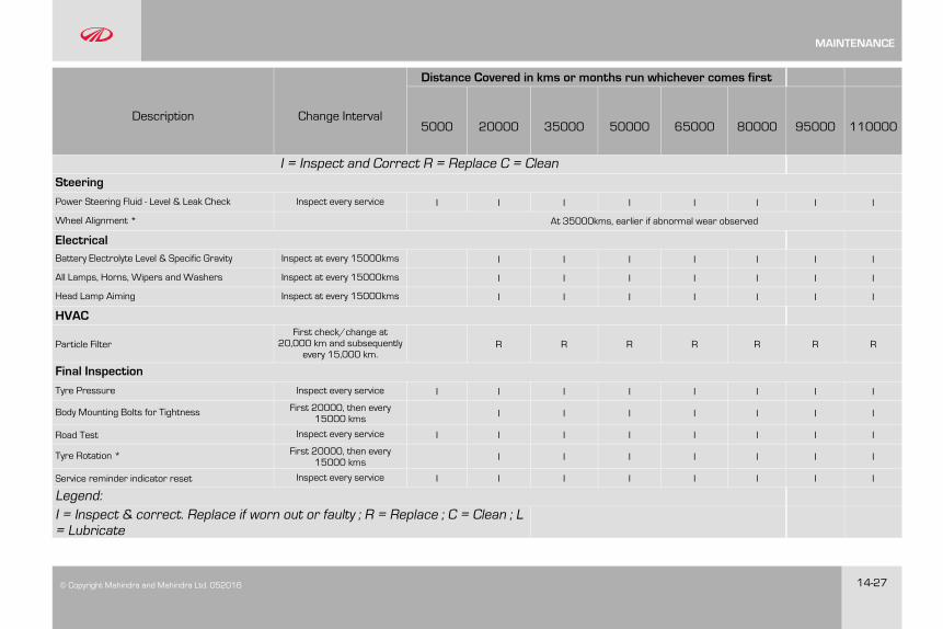
© Copyright Mahindra and Mahindra Ltd. 052016 14-27
Description Change Interval
Distance Covered in kms or months run whichever comes first
5000 20000 35000 50000 65000 80000 95000 110000
I = Inspect and Correct R = Replace C = CleanSteering
Power Steering Fluid - Level & Leak Check Inspect every service I I I I I I I I
Wheel Alignment * At 35000kms, earlier if abnormal wear observed
ElectricalBattery Electrolyte Level & Specific Gravity Inspect at every 15000kms I I I I I I I
All Lamps, Horns, Wipers and Washers Inspect at every 15000kms I I I I I I I
Head Lamp Aiming Inspect at every 15000kms I I I I I I I
HVAC
Particle FilterFirst check/change at
20,000 km and subsequentlyevery 15,000 km.
R R R R R R R
Final Inspection
Tyre Pressure Inspect every service I I I I I I I I
Body Mounting Bolts for Tightness First 20000, then every15000 kms I I I I I I I
Road Test Inspect every service I I I I I I I I
Tyre Rotation * First 20000, then every15000 kms I I I I I I I
Service reminder indicator reset Inspect every service I I I I I I I I
Legend:I = Inspect & correct. Replace if worn out or faulty ; R = Replace ; C = Clean ; L= Lubricate
MAINTENANCE
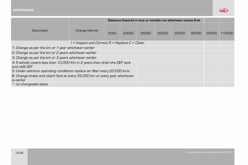
14-28 © Copyright Mahindra and Mahindra Ltd.052016
Description Change Interval
Distance Covered in kms or months run whichever comes first
5000 20000 35000 50000 65000 80000 95000 110000
I = Inspect and Correct R = Replace C = Clean1- Change as per the km or 1 year whichever earlier2- Change as per the km or 2 years whichever earlier3- Change as per the km or 3 years whichever earlier4- If vehicle covers less than 10,000 Km in 2 years then drain the DEF tankand refill DEF5- Under extreme operating conditions replace air filter every 20,000 kmsB- Change brake and clutch fluid at every 35,000 km or every year whicheveris earlier*- on chargeable basis
MAINTENANCE
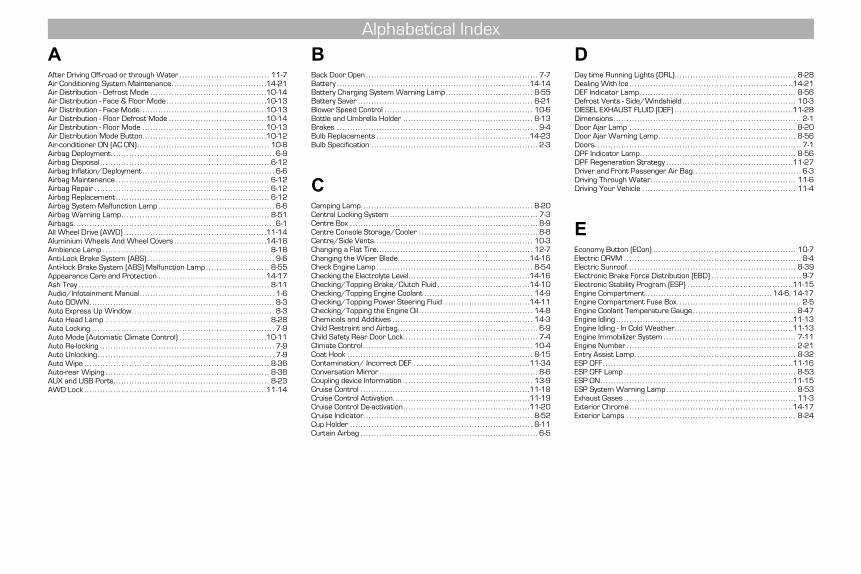
AAfter Driving Off-road or through Water . . . . . . . . . . . . . . . . . . . . . . . . . . . . . . . . . . 11-7Air Conditioning System Maintenance. . . . . . . . . . . . . . . . . . . . . . . . . . . . . . . . . . . .14-21Air Distribution - Defrost Mode . . . . . . . . . . . . . . . . . . . . . . . . . . . . . . . . . . . . . . . . . . . .10-14Air Distribution - Face & Floor Mode. . . . . . . . . . . . . . . . . . . . . . . . . . . . . . . . . . . . . .10-13Air Distribution - Face Mode. . . . . . . . . . . . . . . . . . . . . . . . . . . . . . . . . . . . . . . . . . . . . . . .10-13Air Distribution - Floor Defrost Mode . . . . . . . . . . . . . . . . . . . . . . . . . . . . . . . . . . . . .10-14Air Distribution - Floor Mode . . . . . . . . . . . . . . . . . . . . . . . . . . . . . . . . . . . . . . . . . . . . . . .10-13Air Distribution Mode Button. . . . . . . . . . . . . . . . . . . . . . . . . . . . . . . . . . . . . . . . . . . . . . .10-12Air-conditioner ON (AC ON). . . . . . . . . . . . . . . . . . . . . . . . . . . . . . . . . . . . . . . . . . . . . . . . . . 10-8Airbag Deployment. . . . . . . . . . . . . . . . . . . . . . . . . . . . . . . . . . . . . . . . . . . . . . . . . . . . . . . . . . . . . . 6-9Airbag Disposal . . . . . . . . . . . . . . . . . . . . . . . . . . . . . . . . . . . . . . . . . . . . . . . . . . . . . . . . . . . . . . . . 6-12Airbag Inflation/Deployment . . . . . . . . . . . . . . . . . . . . . . . . . . . . . . . . . . . . . . . . . . . . . . . . . . 6-6Airbag Maintenance . . . . . . . . . . . . . . . . . . . . . . . . . . . . . . . . . . . . . . . . . . . . . . . . . . . . . . . . . . 6-12Airbag Repair . . . . . . . . . . . . . . . . . . . . . . . . . . . . . . . . . . . . . . . . . . . . . . . . . . . . . . . . . . . . . . . . . . 6-12Airbag Replacement . . . . . . . . . . . . . . . . . . . . . . . . . . . . . . . . . . . . . . . . . . . . . . . . . . . . . . . . . . 6-12Airbag System Malfunction Lamp . . . . . . . . . . . . . . . . . . . . . . . . . . . . . . . . . . . . . . . . . . . . 6-6Airbag Warning Lamp. . . . . . . . . . . . . . . . . . . . . . . . . . . . . . . . . . . . . . . . . . . . . . . . . . . . . . . . 8-51Airbags. . . . . . . . . . . . . . . . . . . . . . . . . . . . . . . . . . . . . . . . . . . . . . . . . . . . . . . . . . . . . . . . . . . . . . . . . . . . 6-1All Wheel Drive (AWD) . . . . . . . . . . . . . . . . . . . . . . . . . . . . . . . . . . . . . . . . . . . . . . . . . . . . . .11-14Aluminium Wheels And Wheel Covers . . . . . . . . . . . . . . . . . . . . . . . . . . . . . . . . . . .14-18Ambience Lamp . . . . . . . . . . . . . . . . . . . . . . . . . . . . . . . . . . . . . . . . . . . . . . . . . . . . . . . . . . . . . . . 8-18Anti-Lock Brake System (ABS) . . . . . . . . . . . . . . . . . . . . . . . . . . . . . . . . . . . . . . . . . . . . . . . . 9-6Anti-lock Brake System (ABS) Malfunction Lamp . . . . . . . . . . . . . . . . . . . . . . . . 8-55Appearance Care and Protection . . . . . . . . . . . . . . . . . . . . . . . . . . . . . . . . . . . . . . . . .14-17Ash Tray . . . . . . . . . . . . . . . . . . . . . . . . . . . . . . . . . . . . . . . . . . . . . . . . . . . . . . . . . . . . . . . . . . . . . . . . 8-11Audio/Infotainment Manual . . . . . . . . . . . . . . . . . . . . . . . . . . . . . . . . . . . . . . . . . . . . . . . . . . . 1-6Auto DOWN. . . . . . . . . . . . . . . . . . . . . . . . . . . . . . . . . . . . . . . . . . . . . . . . . . . . . . . . . . . . . . . . . . . . . . 8-3Auto Express Up Window. . . . . . . . . . . . . . . . . . . . . . . . . . . . . . . . . . . . . . . . . . . . . . . . . . . . . . 8-3Auto Head Lamp . . . . . . . . . . . . . . . . . . . . . . . . . . . . . . . . . . . . . . . . . . . . . . . . . . . . . . . . . . . . . . 8-28Auto Locking . . . . . . . . . . . . . . . . . . . . . . . . . . . . . . . . . . . . . . . . . . . . . . . . . . . . . . . . . . . . . . . . . . . . . 7-9Auto Mode (Automatic Climate Control) . . . . . . . . . . . . . . . . . . . . . . . . . . . . . . . . .10-11Auto Re-locking . . . . . . . . . . . . . . . . . . . . . . . . . . . . . . . . . . . . . . . . . . . . . . . . . . . . . . . . . . . . . . . . . . 7-9Auto Unlocking. . . . . . . . . . . . . . . . . . . . . . . . . . . . . . . . . . . . . . . . . . . . . . . . . . . . . . . . . . . . . . . . . . . 7-9Auto Wipe . . . . . . . . . . . . . . . . . . . . . . . . . . . . . . . . . . . . . . . . . . . . . . . . . . . . . . . . . . . . . . . . . . . . . . 8-36Auto-rear Wiping . . . . . . . . . . . . . . . . . . . . . . . . . . . . . . . . . . . . . . . . . . . . . . . . . . . . . . . . . . . . . . 8-38AUX and USB Ports. . . . . . . . . . . . . . . . . . . . . . . . . . . . . . . . . . . . . . . . . . . . . . . . . . . . . . . . . . . 8-23AWD Lock . . . . . . . . . . . . . . . . . . . . . . . . . . . . . . . . . . . . . . . . . . . . . . . . . . . . . . . . . . . . . . . . . . . . .11-14
BBack Door Open . . . . . . . . . . . . . . . . . . . . . . . . . . . . . . . . . . . . . . . . . . . . . . . . . . . . . . . . . . . . . . . . . 7-7Battery . . . . . . . . . . . . . . . . . . . . . . . . . . . . . . . . . . . . . . . . . . . . . . . . . . . . . . . . . . . . . . . . . . . . . . . . .14-14Battery Charging System Warning Lamp. . . . . . . . . . . . . . . . . . . . . . . . . . . . . . . . . 8-55Battery Saver . . . . . . . . . . . . . . . . . . . . . . . . . . . . . . . . . . . . . . . . . . . . . . . . . . . . . . . . . . . . . . . . . . 8-21Blower Speed Control . . . . . . . . . . . . . . . . . . . . . . . . . . . . . . . . . . . . . . . . . . . . . . . . . . . . . . . . 10-6Bottle and Umbrella Holder . . . . . . . . . . . . . . . . . . . . . . . . . . . . . . . . . . . . . . . . . . . . . . . . . 8-13Brakes . . . . . . . . . . . . . . . . . . . . . . . . . . . . . . . . . . . . . . . . . . . . . . . . . . . . . . . . . . . . . . . . . . . . . . . . . . . . 9-4Bulb Replacements . . . . . . . . . . . . . . . . . . . . . . . . . . . . . . . . . . . . . . . . . . . . . . . . . . . . . . . . . .14-23Bulb Specification . . . . . . . . . . . . . . . . . . . . . . . . . . . . . . . . . . . . . . . . . . . . . . . . . . . . . . . . . . . . . . . 2-3
CCamping Lamp. . . . . . . . . . . . . . . . . . . . . . . . . . . . . . . . . . . . . . . . . . . . . . . . . . . . . . . . . . . . . . . . . 8-20Central Locking System . . . . . . . . . . . . . . . . . . . . . . . . . . . . . . . . . . . . . . . . . . . . . . . . . . . . . . . . 7-3Centre Box . . . . . . . . . . . . . . . . . . . . . . . . . . . . . . . . . . . . . . . . . . . . . . . . . . . . . . . . . . . . . . . . . . . . . . . 8-9Centre Console Storage/Cooler . . . . . . . . . . . . . . . . . . . . . . . . . . . . . . . . . . . . . . . . . . . . . 8-8Centre/Side Vents. . . . . . . . . . . . . . . . . . . . . . . . . . . . . . . . . . . . . . . . . . . . . . . . . . . . . . . . . . . . 10-3Changing a Flat Tire. . . . . . . . . . . . . . . . . . . . . . . . . . . . . . . . . . . . . . . . . . . . . . . . . . . . . . . . . . . 12-7Changing the Wiper Blade. . . . . . . . . . . . . . . . . . . . . . . . . . . . . . . . . . . . . . . . . . . . . . . . . .14-16Check Engine Lamp . . . . . . . . . . . . . . . . . . . . . . . . . . . . . . . . . . . . . . . . . . . . . . . . . . . . . . . . . . . 8-54Checking the Electrolyte Level. . . . . . . . . . . . . . . . . . . . . . . . . . . . . . . . . . . . . . . . . . . . . .14-16Checking/Topping Brake/Clutch Fluid . . . . . . . . . . . . . . . . . . . . . . . . . . . . . . . . . . .14-10Checking/Topping Engine Coolant . . . . . . . . . . . . . . . . . . . . . . . . . . . . . . . . . . . . . . . . . 14-9Checking/Topping Power Steering Fluid . . . . . . . . . . . . . . . . . . . . . . . . . . . . . . . . .14-11Checking/Topping the Engine Oil . . . . . . . . . . . . . . . . . . . . . . . . . . . . . . . . . . . . . . . . . . . 14-8Chemicals and Additives . . . . . . . . . . . . . . . . . . . . . . . . . . . . . . . . . . . . . . . . . . . . . . . . . . . . . 14-3Child Restraint and Airbag. . . . . . . . . . . . . . . . . . . . . . . . . . . . . . . . . . . . . . . . . . . . . . . . . . . . . 6-9Child Safety Rear Door Lock. . . . . . . . . . . . . . . . . . . . . . . . . . . . . . . . . . . . . . . . . . . . . . . . . . . 7-4Climate Control . . . . . . . . . . . . . . . . . . . . . . . . . . . . . . . . . . . . . . . . . . . . . . . . . . . . . . . . . . . . . . . . 10-4Coat Hook . . . . . . . . . . . . . . . . . . . . . . . . . . . . . . . . . . . . . . . . . . . . . . . . . . . . . . . . . . . . . . . . . . . . . . 8-15Contamination/ Incorrect DEF . . . . . . . . . . . . . . . . . . . . . . . . . . . . . . . . . . . . . . . . . . . .11-34Conversation Mirror . . . . . . . . . . . . . . . . . . . . . . . . . . . . . . . . . . . . . . . . . . . . . . . . . . . . . . . . . . . . 8-6Coupling device Information . . . . . . . . . . . . . . . . . . . . . . . . . . . . . . . . . . . . . . . . . . . . . . . . . 13-9Cruise Control . . . . . . . . . . . . . . . . . . . . . . . . . . . . . . . . . . . . . . . . . . . . . . . . . . . . . . . . . . . . . . . .11-18Cruise Control Activation. . . . . . . . . . . . . . . . . . . . . . . . . . . . . . . . . . . . . . . . . . . . . . . . . . . .11-19Cruise Control De-activation. . . . . . . . . . . . . . . . . . . . . . . . . . . . . . . . . . . . . . . . . . . . . . . .11-20Cruise Indicator. . . . . . . . . . . . . . . . . . . . . . . . . . . . . . . . . . . . . . . . . . . . . . . . . . . . . . . . . . . . . . . . 8-52Cup Holder . . . . . . . . . . . . . . . . . . . . . . . . . . . . . . . . . . . . . . . . . . . . . . . . . . . . . . . . . . . . . . . . . . . . . 8-11Curtain Airbag . . . . . . . . . . . . . . . . . . . . . . . . . . . . . . . . . . . . . . . . . . . . . . . . . . . . . . . . . . . . . . . . . . . 6-5
DDay time Running Lights (DRL). . . . . . . . . . . . . . . . . . . . . . . . . . . . . . . . . . . . . . . . . . . . . . 8-28Dealing With Ice . . . . . . . . . . . . . . . . . . . . . . . . . . . . . . . . . . . . . . . . . . . . . . . . . . . . . . . . . . . . . .14-21DEF Indicator Lamp . . . . . . . . . . . . . . . . . . . . . . . . . . . . . . . . . . . . . . . . . . . . . . . . . . . . . . . . . . . 8-56Defrost Vents - Side/Windshield . . . . . . . . . . . . . . . . . . . . . . . . . . . . . . . . . . . . . . . . . . . 10-3DIESEL EXHAUST FLUID (DEF) . . . . . . . . . . . . . . . . . . . . . . . . . . . . . . . . . . . . . . . . . . . . .11-28Dimensions. . . . . . . . . . . . . . . . . . . . . . . . . . . . . . . . . . . . . . . . . . . . . . . . . . . . . . . . . . . . . . . . . . . . . . . 2-1Door Ajar Lamp . . . . . . . . . . . . . . . . . . . . . . . . . . . . . . . . . . . . . . . . . . . . . . . . . . . . . . . . . . . . . . . 8-20Door Ajar Warning Lamp. . . . . . . . . . . . . . . . . . . . . . . . . . . . . . . . . . . . . . . . . . . . . . . . . . . . 8-56Doors. . . . . . . . . . . . . . . . . . . . . . . . . . . . . . . . . . . . . . . . . . . . . . . . . . . . . . . . . . . . . . . . . . . . . . . . . . . . . . 7-1DPF Indicator Lamp. . . . . . . . . . . . . . . . . . . . . . . . . . . . . . . . . . . . . . . . . . . . . . . . . . . . . . . . . . . 8-56DPF Regeneration Strategy . . . . . . . . . . . . . . . . . . . . . . . . . . . . . . . . . . . . . . . . . . . . . . . .11-27Driver and Front Passenger Air Bag. . . . . . . . . . . . . . . . . . . . . . . . . . . . . . . . . . . . . . . . . 6-3Driving Through Water. . . . . . . . . . . . . . . . . . . . . . . . . . . . . . . . . . . . . . . . . . . . . . . . . . . . . . . 11-6Driving Your Vehicle . . . . . . . . . . . . . . . . . . . . . . . . . . . . . . . . . . . . . . . . . . . . . . . . . . . . . . . . . . 11-4
EEconomy Button (ECon) . . . . . . . . . . . . . . . . . . . . . . . . . . . . . . . . . . . . . . . . . . . . . . . . . . . . . . 10-7Electric ORVM . . . . . . . . . . . . . . . . . . . . . . . . . . . . . . . . . . . . . . . . . . . . . . . . . . . . . . . . . . . . . . . . . . . 8-4Electric Sunroof. . . . . . . . . . . . . . . . . . . . . . . . . . . . . . . . . . . . . . . . . . . . . . . . . . . . . . . . . . . . . . . . 8-39Electronic Brake Force Distribution (EBD) . . . . . . . . . . . . . . . . . . . . . . . . . . . . . . . . . . 9-7Electronic Stability Program (ESP) . . . . . . . . . . . . . . . . . . . . . . . . . . . . . . . . . . . . . . . .11-15Engine Compartment . . . . . . . . . . . . . . . . . . . . . . . . . . . . . . . . . . . . . . . . . . . . . . . . 14-6, 14-17Engine Compartment Fuse Box . . . . . . . . . . . . . . . . . . . . . . . . . . . . . . . . . . . . . . . . . . . . . . . 2-5Engine Coolant Temperature Gauge . . . . . . . . . . . . . . . . . . . . . . . . . . . . . . . . . . . . . . . 8-47Engine Idling . . . . . . . . . . . . . . . . . . . . . . . . . . . . . . . . . . . . . . . . . . . . . . . . . . . . . . . . . . . . . . . . . . .11-13Engine Idling - In Cold Weather. . . . . . . . . . . . . . . . . . . . . . . . . . . . . . . . . . . . . . . . . . . . .11-13Engine Immobilizer System . . . . . . . . . . . . . . . . . . . . . . . . . . . . . . . . . . . . . . . . . . . . . . . . . . 7-11Engine Number . . . . . . . . . . . . . . . . . . . . . . . . . . . . . . . . . . . . . . . . . . . . . . . . . . . . . . . . . . . . . . . . 2-21Entry Assist Lamp. . . . . . . . . . . . . . . . . . . . . . . . . . . . . . . . . . . . . . . . . . . . . . . . . . . . . . . . . . . . . 8-32ESP OFF . . . . . . . . . . . . . . . . . . . . . . . . . . . . . . . . . . . . . . . . . . . . . . . . . . . . . . . . . . . . . . . . . . . . . . . .11-16ESP OFF Lamp . . . . . . . . . . . . . . . . . . . . . . . . . . . . . . . . . . . . . . . . . . . . . . . . . . . . . . . . . . . . . . . . . 8-53ESP ON. . . . . . . . . . . . . . . . . . . . . . . . . . . . . . . . . . . . . . . . . . . . . . . . . . . . . . . . . . . . . . . . . . . . . . . . .11-15ESP System Warning Lamp . . . . . . . . . . . . . . . . . . . . . . . . . . . . . . . . . . . . . . . . . . . . . . . . . 8-53Exhaust Gases . . . . . . . . . . . . . . . . . . . . . . . . . . . . . . . . . . . . . . . . . . . . . . . . . . . . . . . . . . . . . . . . . 11-3Exterior Chrome. . . . . . . . . . . . . . . . . . . . . . . . . . . . . . . . . . . . . . . . . . . . . . . . . . . . . . . . . . . . . .14-17Exterior Lamps . . . . . . . . . . . . . . . . . . . . . . . . . . . . . . . . . . . . . . . . . . . . . . . . . . . . . . . . . . . . . . . . 8-24
Alphabetical Index
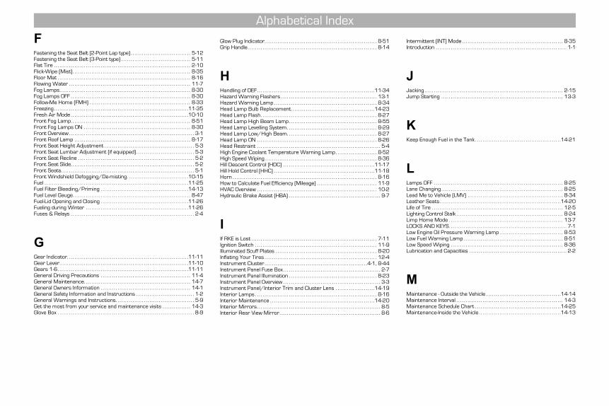
FFastening the Seat Belt (2-Point Lap type) . . . . . . . . . . . . . . . . . . . . . . . . . . . . . . . . 5-12Fastening the Seat Belt (3-Point type) . . . . . . . . . . . . . . . . . . . . . . . . . . . . . . . . . . . . . 5-11Flat Tire . . . . . . . . . . . . . . . . . . . . . . . . . . . . . . . . . . . . . . . . . . . . . . . . . . . . . . . . . . . . . . . . . . . . . . . . . 2-10Flick-Wipe (Mist) . . . . . . . . . . . . . . . . . . . . . . . . . . . . . . . . . . . . . . . . . . . . . . . . . . . . . . . . . . . . . . . 8-35Floor Mat . . . . . . . . . . . . . . . . . . . . . . . . . . . . . . . . . . . . . . . . . . . . . . . . . . . . . . . . . . . . . . . . . . . . . . . 8-16Flowing Water . . . . . . . . . . . . . . . . . . . . . . . . . . . . . . . . . . . . . . . . . . . . . . . . . . . . . . . . . . . . . . . . . 11-7Fog Lamps. . . . . . . . . . . . . . . . . . . . . . . . . . . . . . . . . . . . . . . . . . . . . . . . . . . . . . . . . . . . . . . . . . . . . . 8-30Fog Lamps OFF . . . . . . . . . . . . . . . . . . . . . . . . . . . . . . . . . . . . . . . . . . . . . . . . . . . . . . . . . . . . . . . . 8-30Follow-Me Home (FMH) . . . . . . . . . . . . . . . . . . . . . . . . . . . . . . . . . . . . . . . . . . . . . . . . . . . . . . 8-33Freezing. . . . . . . . . . . . . . . . . . . . . . . . . . . . . . . . . . . . . . . . . . . . . . . . . . . . . . . . . . . . . . . . . . . . . . . .11-35Fresh Air Mode . . . . . . . . . . . . . . . . . . . . . . . . . . . . . . . . . . . . . . . . . . . . . . . . . . . . . . . . . . . . . . .10-10Front Fog Lamp. . . . . . . . . . . . . . . . . . . . . . . . . . . . . . . . . . . . . . . . . . . . . . . . . . . . . . . . . . . . . . . . 8-51Front Fog Lamps ON . . . . . . . . . . . . . . . . . . . . . . . . . . . . . . . . . . . . . . . . . . . . . . . . . . . . . . . . . 8-30Front Overview. . . . . . . . . . . . . . . . . . . . . . . . . . . . . . . . . . . . . . . . . . . . . . . . . . . . . . . . . . . . . . . . . . . 3-1Front Roof Lamp . . . . . . . . . . . . . . . . . . . . . . . . . . . . . . . . . . . . . . . . . . . . . . . . . . . . . . . . . . . . . . 8-17Front Seat Height Adjustment . . . . . . . . . . . . . . . . . . . . . . . . . . . . . . . . . . . . . . . . . . . . . . . . 5-3Front Seat Lumbar Adjustment (if equipped) . . . . . . . . . . . . . . . . . . . . . . . . . . . . . . . 5-3Front Seat Recline . . . . . . . . . . . . . . . . . . . . . . . . . . . . . . . . . . . . . . . . . . . . . . . . . . . . . . . . . . . . . . 5-2Front Seat Slide. . . . . . . . . . . . . . . . . . . . . . . . . . . . . . . . . . . . . . . . . . . . . . . . . . . . . . . . . . . . . . . . . . 5-2Front Seats. . . . . . . . . . . . . . . . . . . . . . . . . . . . . . . . . . . . . . . . . . . . . . . . . . . . . . . . . . . . . . . . . . . . . . . 5-1Front Windshield Defogging/De-misting. . . . . . . . . . . . . . . . . . . . . . . . . . . . . . . . .10-15Fuel . . . . . . . . . . . . . . . . . . . . . . . . . . . . . . . . . . . . . . . . . . . . . . . . . . . . . . . . . . . . . . . . . . . . . . . . . . . . .11-25Fuel Filter Bleeding/Priming . . . . . . . . . . . . . . . . . . . . . . . . . . . . . . . . . . . . . . . . . . . . . . .14-13Fuel Level Gauge. . . . . . . . . . . . . . . . . . . . . . . . . . . . . . . . . . . . . . . . . . . . . . . . . . . . . . . . . . . . . . . 8-47Fuel-Lid Opening and Closing . . . . . . . . . . . . . . . . . . . . . . . . . . . . . . . . . . . . . . . . . . . . . . .11-26Fueling during Winter . . . . . . . . . . . . . . . . . . . . . . . . . . . . . . . . . . . . . . . . . . . . . . . . . . . . . . .11-26Fuses & Relays . . . . . . . . . . . . . . . . . . . . . . . . . . . . . . . . . . . . . . . . . . . . . . . . . . . . . . . . . . . . . . . . . . 2-4
GGear Indicator. . . . . . . . . . . . . . . . . . . . . . . . . . . . . . . . . . . . . . . . . . . . . . . . . . . . . . . . . . . . . . . . .11-11Gear Lever. . . . . . . . . . . . . . . . . . . . . . . . . . . . . . . . . . . . . . . . . . . . . . . . . . . . . . . . . . . . . . . . . . . . .11-10Gears 1-6. . . . . . . . . . . . . . . . . . . . . . . . . . . . . . . . . . . . . . . . . . . . . . . . . . . . . . . . . . . . . . . . . . . . . .11-11General Driving Precautions . . . . . . . . . . . . . . . . . . . . . . . . . . . . . . . . . . . . . . . . . . . . . . . . 11-4General Maintenance. . . . . . . . . . . . . . . . . . . . . . . . . . . . . . . . . . . . . . . . . . . . . . . . . . . . . . . . . 14-7General Owners Information . . . . . . . . . . . . . . . . . . . . . . . . . . . . . . . . . . . . . . . . . . . . . . . . 14-1General Safety Information and Instructions . . . . . . . . . . . . . . . . . . . . . . . . . . . . . . . 1-2General Warnings and Instructions. . . . . . . . . . . . . . . . . . . . . . . . . . . . . . . . . . . . . . . . . . 5-9Get the most from your service and maintenance visits . . . . . . . . . . . . . . . 14-3Glove Box . . . . . . . . . . . . . . . . . . . . . . . . . . . . . . . . . . . . . . . . . . . . . . . . . . . . . . . . . . . . . . . . . . . . . . . . . 8-9
Glow Plug Indicator. . . . . . . . . . . . . . . . . . . . . . . . . . . . . . . . . . . . . . . . . . . . . . . . . . . . . . . . . . . . 8-51Grip Handle. . . . . . . . . . . . . . . . . . . . . . . . . . . . . . . . . . . . . . . . . . . . . . . . . . . . . . . . . . . . . . . . . . . . . 8-14
HHandling of DEF. . . . . . . . . . . . . . . . . . . . . . . . . . . . . . . . . . . . . . . . . . . . . . . . . . . . . . . . . . . . . . .11-34Hazard Warning Flashers . . . . . . . . . . . . . . . . . . . . . . . . . . . . . . . . . . . . . . . . . . . . . . . . . . . 13-1Hazard Warning Lamp . . . . . . . . . . . . . . . . . . . . . . . . . . . . . . . . . . . . . . . . . . . . . . . . . . . . . . . 8-34Head Lamp Bulb Replacement. . . . . . . . . . . . . . . . . . . . . . . . . . . . . . . . . . . . . . . . . . . . .14-23Head Lamp Flash. . . . . . . . . . . . . . . . . . . . . . . . . . . . . . . . . . . . . . . . . . . . . . . . . . . . . . . . . . . . . . 8-27Head Lamp High Beam Lamp. . . . . . . . . . . . . . . . . . . . . . . . . . . . . . . . . . . . . . . . . . . . . . . 8-55Head Lamp Levelling System. . . . . . . . . . . . . . . . . . . . . . . . . . . . . . . . . . . . . . . . . . . . . . . . 8-29Head Lamp Low/High Beam. . . . . . . . . . . . . . . . . . . . . . . . . . . . . . . . . . . . . . . . . . . . . . . . 8-27Head Lamp ON . . . . . . . . . . . . . . . . . . . . . . . . . . . . . . . . . . . . . . . . . . . . . . . . . . . . . . . . . . . . . . . . 8-26Head Restraint . . . . . . . . . . . . . . . . . . . . . . . . . . . . . . . . . . . . . . . . . . . . . . . . . . . . . . . . . . . . . . . . . . 5-4High Engine Coolant Temperature Warning Lamp. . . . . . . . . . . . . . . . . . . . . . 8-52High Speed Wiping. . . . . . . . . . . . . . . . . . . . . . . . . . . . . . . . . . . . . . . . . . . . . . . . . . . . . . . . . . . . 8-36Hill Descent Control (HDC) . . . . . . . . . . . . . . . . . . . . . . . . . . . . . . . . . . . . . . . . . . . . . . . . .11-17Hill Hold Control (HHC) . . . . . . . . . . . . . . . . . . . . . . . . . . . . . . . . . . . . . . . . . . . . . . . . . . . . . .11-18Horn . . . . . . . . . . . . . . . . . . . . . . . . . . . . . . . . . . . . . . . . . . . . . . . . . . . . . . . . . . . . . . . . . . . . . . . . . . . . . 8-16How to Calculate Fuel Efficiency (Mileage) . . . . . . . . . . . . . . . . . . . . . . . . . . . . . . . . 11-9HVAC Overview . . . . . . . . . . . . . . . . . . . . . . . . . . . . . . . . . . . . . . . . . . . . . . . . . . . . . . . . . . . . . . . . 10-2Hydraulic Brake Assist (HBA) . . . . . . . . . . . . . . . . . . . . . . . . . . . . . . . . . . . . . . . . . . . . . . . . . 9-7
IIf RKE is Lost . . . . . . . . . . . . . . . . . . . . . . . . . . . . . . . . . . . . . . . . . . . . . . . . . . . . . . . . . . . . . . . . . . . 7-11Ignition Switch . . . . . . . . . . . . . . . . . . . . . . . . . . . . . . . . . . . . . . . . . . . . . . . . . . . . . . . . . . . . . . . . . 11-9Illuminated Scuff Plates . . . . . . . . . . . . . . . . . . . . . . . . . . . . . . . . . . . . . . . . . . . . . . . . . . . . . . 8-20Inflating Your Tires . . . . . . . . . . . . . . . . . . . . . . . . . . . . . . . . . . . . . . . . . . . . . . . . . . . . . . . . . . . . 12-4Instrument Cluster. . . . . . . . . . . . . . . . . . . . . . . . . . . . . . . . . . . . . . . . . . . . . . . . . . . . . . .4-1, 8-44Instrument Panel Fuse Box . . . . . . . . . . . . . . . . . . . . . . . . . . . . . . . . . . . . . . . . . . . . . . . . . . . . 2-7Instrument Panel Illumination . . . . . . . . . . . . . . . . . . . . . . . . . . . . . . . . . . . . . . . . . . . . . . . 8-23Instrument Panel Overview . . . . . . . . . . . . . . . . . . . . . . . . . . . . . . . . . . . . . . . . . . . . . . . . . . . . 3-3Instrument Panel/Interior Trim and Cluster Lens . . . . . . . . . . . . . . . . . . . . .14-19Interior Lamps . . . . . . . . . . . . . . . . . . . . . . . . . . . . . . . . . . . . . . . . . . . . . . . . . . . . . . . . . . . . . . . . . 8-16Interior Maintenance . . . . . . . . . . . . . . . . . . . . . . . . . . . . . . . . . . . . . . . . . . . . . . . . . . . . . . . .14-20Interior Mirrors. . . . . . . . . . . . . . . . . . . . . . . . . . . . . . . . . . . . . . . . . . . . . . . . . . . . . . . . . . . . . . . . . . 8-5Interior Rear View Mirror. . . . . . . . . . . . . . . . . . . . . . . . . . . . . . . . . . . . . . . . . . . . . . . . . . . . . . 8-6
Intermittent (INT) Mode . . . . . . . . . . . . . . . . . . . . . . . . . . . . . . . . . . . . . . . . . . . . . . . . . . . . . . 8-35Introduction . . . . . . . . . . . . . . . . . . . . . . . . . . . . . . . . . . . . . . . . . . . . . . . . . . . . . . . . . . . . . . . . . . . . . . 1-1
JJacking . . . . . . . . . . . . . . . . . . . . . . . . . . . . . . . . . . . . . . . . . . . . . . . . . . . . . . . . . . . . . . . . . . . . . . . . . . 2-15Jump Starting . . . . . . . . . . . . . . . . . . . . . . . . . . . . . . . . . . . . . . . . . . . . . . . . . . . . . . . . . . . . . . . . . 13-3
KKeep Enough Fuel in the Tank . . . . . . . . . . . . . . . . . . . . . . . . . . . . . . . . . . . . . . . . . . . . . .14-21
LLamps OFF . . . . . . . . . . . . . . . . . . . . . . . . . . . . . . . . . . . . . . . . . . . . . . . . . . . . . . . . . . . . . . . . . . . . . 8-25Lane Changing . . . . . . . . . . . . . . . . . . . . . . . . . . . . . . . . . . . . . . . . . . . . . . . . . . . . . . . . . . . . . . . . . 8-25Lead Me to Vehicle (LMV) . . . . . . . . . . . . . . . . . . . . . . . . . . . . . . . . . . . . . . . . . . . . . . . . . . . 8-34Leather Seats. . . . . . . . . . . . . . . . . . . . . . . . . . . . . . . . . . . . . . . . . . . . . . . . . . . . . . . . . . . . . . . . .14-20Life of Tire . . . . . . . . . . . . . . . . . . . . . . . . . . . . . . . . . . . . . . . . . . . . . . . . . . . . . . . . . . . . . . . . . . . . . . 12-5Lighting Control Stalk . . . . . . . . . . . . . . . . . . . . . . . . . . . . . . . . . . . . . . . . . . . . . . . . . . . . . . . . . 8-24Limp Home Mode . . . . . . . . . . . . . . . . . . . . . . . . . . . . . . . . . . . . . . . . . . . . . . . . . . . . . . . . . . . . . 13-7LOCKS AND KEYS. . . . . . . . . . . . . . . . . . . . . . . . . . . . . . . . . . . . . . . . . . . . . . . . . . . . . . . . . . . . . . . 7-1Low Engine Oil Pressure Warning Lamp . . . . . . . . . . . . . . . . . . . . . . . . . . . . . . . . . . 8-53Low Fuel Warning Lamp . . . . . . . . . . . . . . . . . . . . . . . . . . . . . . . . . . . . . . . . . . . . . . . . . . . . . 8-51Low Speed Wiping . . . . . . . . . . . . . . . . . . . . . . . . . . . . . . . . . . . . . . . . . . . . . . . . . . . . . . . . . . . . 8-36Lubrication and Capacities . . . . . . . . . . . . . . . . . . . . . . . . . . . . . . . . . . . . . . . . . . . . . . . . . . . . 2-2
MMaintenance - Outside the Vehicle . . . . . . . . . . . . . . . . . . . . . . . . . . . . . . . . . . . . . . . .14-14Maintenance Interval . . . . . . . . . . . . . . . . . . . . . . . . . . . . . . . . . . . . . . . . . . . . . . . . . . . . . . . . . 14-3Maintenance Schedule Chart . . . . . . . . . . . . . . . . . . . . . . . . . . . . . . . . . . . . . . . . . . . . . .14-25Maintenance-Inside the Vehicle . . . . . . . . . . . . . . . . . . . . . . . . . . . . . . . . . . . . . . . . . . . .14-13
Alphabetical Index
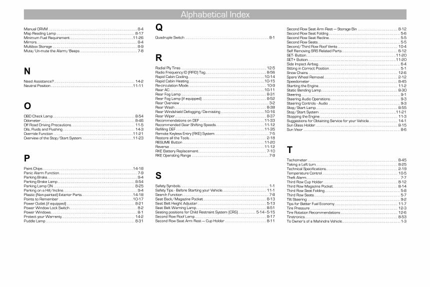
Manual ORVM . . . . . . . . . . . . . . . . . . . . . . . . . . . . . . . . . . . . . . . . . . . . . . . . . . . . . . . . . . . . . . . . . . . 8-4Map Reading Lamp . . . . . . . . . . . . . . . . . . . . . . . . . . . . . . . . . . . . . . . . . . . . . . . . . . . . . . . . . . . 8-17Minimum Fuel Requirement. . . . . . . . . . . . . . . . . . . . . . . . . . . . . . . . . . . . . . . . . . . . . . . .11-26Mirrors. . . . . . . . . . . . . . . . . . . . . . . . . . . . . . . . . . . . . . . . . . . . . . . . . . . . . . . . . . . . . . . . . . . . . . . . . . . . 8-4Multibox Storage . . . . . . . . . . . . . . . . . . . . . . . . . . . . . . . . . . . . . . . . . . . . . . . . . . . . . . . . . . . . . . . . 8-9Mute/Un-mute the Alarm/Beeps . . . . . . . . . . . . . . . . . . . . . . . . . . . . . . . . . . . . . . . . . . . 7-8
NNeed Assistance?. . . . . . . . . . . . . . . . . . . . . . . . . . . . . . . . . . . . . . . . . . . . . . . . . . . . . . . . . . . . . 14-2Neutral Position . . . . . . . . . . . . . . . . . . . . . . . . . . . . . . . . . . . . . . . . . . . . . . . . . . . . . . . . . . . . . .11-11
OOBD Check Lamp. . . . . . . . . . . . . . . . . . . . . . . . . . . . . . . . . . . . . . . . . . . . . . . . . . . . . . . . . . . . . . 8-54Odometer. . . . . . . . . . . . . . . . . . . . . . . . . . . . . . . . . . . . . . . . . . . . . . . . . . . . . . . . . . . . . . . . . . . . . . . 8-46Off Road Driving Precautions. . . . . . . . . . . . . . . . . . . . . . . . . . . . . . . . . . . . . . . . . . . . . . . . 11-5Oils, Fluids and Flushing . . . . . . . . . . . . . . . . . . . . . . . . . . . . . . . . . . . . . . . . . . . . . . . . . . . . . . 14-3Override Function . . . . . . . . . . . . . . . . . . . . . . . . . . . . . . . . . . . . . . . . . . . . . . . . . . . . . . . . . . . .11-21Overview of the Stop/Start System. . . . . . . . . . . . . . . . . . . . . . . . . . . . . . . . . . . . . . .11-23
PPaint Chips . . . . . . . . . . . . . . . . . . . . . . . . . . . . . . . . . . . . . . . . . . . . . . . . . . . . . . . . . . . . . . . . . . . .14-18Panic Alarm Function. . . . . . . . . . . . . . . . . . . . . . . . . . . . . . . . . . . . . . . . . . . . . . . . . . . . . . . . . . . 7-9Parking Brake. . . . . . . . . . . . . . . . . . . . . . . . . . . . . . . . . . . . . . . . . . . . . . . . . . . . . . . . . . . . . . . . . . . . 9-4Parking Brake Lamp . . . . . . . . . . . . . . . . . . . . . . . . . . . . . . . . . . . . . . . . . . . . . . . . . . . . . . . . . . 8-54Parking Lamp ON . . . . . . . . . . . . . . . . . . . . . . . . . . . . . . . . . . . . . . . . . . . . . . . . . . . . . . . . . . . . . 8-25Parking on a Hill/Incline. . . . . . . . . . . . . . . . . . . . . . . . . . . . . . . . . . . . . . . . . . . . . . . . . . . . . . . . 9-4Plastic (Non-painted) Exterior Parts. . . . . . . . . . . . . . . . . . . . . . . . . . . . . . . . . . . . . . .14-18Points to Remember . . . . . . . . . . . . . . . . . . . . . . . . . . . . . . . . . . . . . . . . . . . . . . . . . . . . . . . .10-17Power Outlet (if equipped) . . . . . . . . . . . . . . . . . . . . . . . . . . . . . . . . . . . . . . . . . . . . . . . . . . . 8-21Power Window Lock Switch . . . . . . . . . . . . . . . . . . . . . . . . . . . . . . . . . . . . . . . . . . . . . . . . . . . 8-2Power Windows . . . . . . . . . . . . . . . . . . . . . . . . . . . . . . . . . . . . . . . . . . . . . . . . . . . . . . . . . . . . . . . . . 8-1Protect your Warranty . . . . . . . . . . . . . . . . . . . . . . . . . . . . . . . . . . . . . . . . . . . . . . . . . . . . . . . 14-2Puddle Lamp . . . . . . . . . . . . . . . . . . . . . . . . . . . . . . . . . . . . . . . . . . . . . . . . . . . . . . . . . . . . . . . . . . . 8-31
QQuadruple Switch . . . . . . . . . . . . . . . . . . . . . . . . . . . . . . . . . . . . . . . . . . . . . . . . . . . . . . . . . . . . . . . 8-1
RRadial Ply Tires . . . . . . . . . . . . . . . . . . . . . . . . . . . . . . . . . . . . . . . . . . . . . . . . . . . . . . . . . . . . . . . . 12-5Radio Frequency ID (RFID) Tag. . . . . . . . . . . . . . . . . . . . . . . . . . . . . . . . . . . . . . . . . . . . . . 8-56Rapid Cabin Cooling. . . . . . . . . . . . . . . . . . . . . . . . . . . . . . . . . . . . . . . . . . . . . . . . . . . . . . . . . .10-14Rapid Cabin Heating . . . . . . . . . . . . . . . . . . . . . . . . . . . . . . . . . . . . . . . . . . . . . . . . . . . . . . . . .10-15Re-circulation Mode. . . . . . . . . . . . . . . . . . . . . . . . . . . . . . . . . . . . . . . . . . . . . . . . . . . . . . . . . . . 10-9Rear AC. . . . . . . . . . . . . . . . . . . . . . . . . . . . . . . . . . . . . . . . . . . . . . . . . . . . . . . . . . . . . . . . . . . . . . . .10-11Rear Fog Lamp . . . . . . . . . . . . . . . . . . . . . . . . . . . . . . . . . . . . . . . . . . . . . . . . . . . . . . . . . . . . . . . . 8-31Rear Fog Lamp (if equipped) . . . . . . . . . . . . . . . . . . . . . . . . . . . . . . . . . . . . . . . . . . . . . . . . 8-52Rear Overview . . . . . . . . . . . . . . . . . . . . . . . . . . . . . . . . . . . . . . . . . . . . . . . . . . . . . . . . . . . . . . . . . . . 3-2Rear Wash . . . . . . . . . . . . . . . . . . . . . . . . . . . . . . . . . . . . . . . . . . . . . . . . . . . . . . . . . . . . . . . . . . . . . 8-38Rear Windshield Defogging/De-misting . . . . . . . . . . . . . . . . . . . . . . . . . . . . . . . . .10-16Rear Wiper. . . . . . . . . . . . . . . . . . . . . . . . . . . . . . . . . . . . . . . . . . . . . . . . . . . . . . . . . . . . . . . . . . . . . 8-37Recommendations on DEF . . . . . . . . . . . . . . . . . . . . . . . . . . . . . . . . . . . . . . . . . . . . . . . . .11-33Recommended Gear Shifting Speeds. . . . . . . . . . . . . . . . . . . . . . . . . . . . . . . . . . . . .11-12Refilling DEF . . . . . . . . . . . . . . . . . . . . . . . . . . . . . . . . . . . . . . . . . . . . . . . . . . . . . . . . . . . . . . . . . . .11-35Remote Keyless Entry (RKE) System. . . . . . . . . . . . . . . . . . . . . . . . . . . . . . . . . . . . . . . . . 7-5Restore all the Tools . . . . . . . . . . . . . . . . . . . . . . . . . . . . . . . . . . . . . . . . . . . . . . . . . . . . . . . . . . 2-18RESUME Button . . . . . . . . . . . . . . . . . . . . . . . . . . . . . . . . . . . . . . . . . . . . . . . . . . . . . . . . . . . . . .11-20Reverse . . . . . . . . . . . . . . . . . . . . . . . . . . . . . . . . . . . . . . . . . . . . . . . . . . . . . . . . . . . . . . . . . . . . . . . .11-12RKE Battery Replacement . . . . . . . . . . . . . . . . . . . . . . . . . . . . . . . . . . . . . . . . . . . . . . . . . . . 7-10RKE Operating Range . . . . . . . . . . . . . . . . . . . . . . . . . . . . . . . . . . . . . . . . . . . . . . . . . . . . . . . . . . 7-9
SSafety Symbols. . . . . . . . . . . . . . . . . . . . . . . . . . . . . . . . . . . . . . . . . . . . . . . . . . . . . . . . . . . . . . . . . . . 1-1Safety Tips - Before Starting your Vehicle . . . . . . . . . . . . . . . . . . . . . . . . . . . . . . . . . 11-1Search Function . . . . . . . . . . . . . . . . . . . . . . . . . . . . . . . . . . . . . . . . . . . . . . . . . . . . . . . . . . . . . . . . . 7-8Seat Back/Magazine Pocket. . . . . . . . . . . . . . . . . . . . . . . . . . . . . . . . . . . . . . . . . . . . . . . . 8-13Seat Belt Height Adjuster . . . . . . . . . . . . . . . . . . . . . . . . . . . . . . . . . . . . . . . . . . . . . . . . . . . . 5-13Seat Belt Warning Lamp. . . . . . . . . . . . . . . . . . . . . . . . . . . . . . . . . . . . . . . . . . . . . . . . . . . . . 8-51Seating positions for Child Restraint System (CRS) . . . . . . . . . . . . . 5-14–5-15Second Row Roof Lamp. . . . . . . . . . . . . . . . . . . . . . . . . . . . . . . . . . . . . . . . . . . . . . . . . . . . . . 8-17Second Row Seat Arm Rest — Cup Holder . . . . . . . . . . . . . . . . . . . . . . . . . . . . . . . 8-11
Second Row Seat Arm Rest — Storage Bin . . . . . . . . . . . . . . . . . . . . . . . . . . . . . . 8-12Second Row Seat Folding . . . . . . . . . . . . . . . . . . . . . . . . . . . . . . . . . . . . . . . . . . . . . . . . . . . . . . 5-6Second Row Seat Recline. . . . . . . . . . . . . . . . . . . . . . . . . . . . . . . . . . . . . . . . . . . . . . . . . . . . . . 5-5Second Row Seats . . . . . . . . . . . . . . . . . . . . . . . . . . . . . . . . . . . . . . . . . . . . . . . . . . . . . . . . . . . . . . 5-5Second/Third Row Roof Vents . . . . . . . . . . . . . . . . . . . . . . . . . . . . . . . . . . . . . . . . . . . . . 10-4Self Removing SRS Related Parts . . . . . . . . . . . . . . . . . . . . . . . . . . . . . . . . . . . . . . . . . . 6-12SET- Button . . . . . . . . . . . . . . . . . . . . . . . . . . . . . . . . . . . . . . . . . . . . . . . . . . . . . . . . . . . . . . . . . . . .11-20SET+ Button. . . . . . . . . . . . . . . . . . . . . . . . . . . . . . . . . . . . . . . . . . . . . . . . . . . . . . . . . . . . . . . . . . .11-20Side Impact Airbag. . . . . . . . . . . . . . . . . . . . . . . . . . . . . . . . . . . . . . . . . . . . . . . . . . . . . . . . . . . . . . 6-4Sitting in Correct Position. . . . . . . . . . . . . . . . . . . . . . . . . . . . . . . . . . . . . . . . . . . . . . . . . . . . . . 5-1Snow Chains . . . . . . . . . . . . . . . . . . . . . . . . . . . . . . . . . . . . . . . . . . . . . . . . . . . . . . . . . . . . . . . . . . . 12-6Spare Wheel Removal. . . . . . . . . . . . . . . . . . . . . . . . . . . . . . . . . . . . . . . . . . . . . . . . . . . . . . . . 2-12Speedometer . . . . . . . . . . . . . . . . . . . . . . . . . . . . . . . . . . . . . . . . . . . . . . . . . . . . . . . . . . . . . . . . . . 8-45Starting the Engine. . . . . . . . . . . . . . . . . . . . . . . . . . . . . . . . . . . . . . . . . . . . . . . . . . . . . . . . . . . . 11-2Static Bending Lamp. . . . . . . . . . . . . . . . . . . . . . . . . . . . . . . . . . . . . . . . . . . . . . . . . . . . . . . . . . 8-30Steering. . . . . . . . . . . . . . . . . . . . . . . . . . . . . . . . . . . . . . . . . . . . . . . . . . . . . . . . . . . . . . . . . . . . . . . . . . . 9-1Steering Audio Operations. . . . . . . . . . . . . . . . . . . . . . . . . . . . . . . . . . . . . . . . . . . . . . . . . . . . . 9-3Steering Controls - Audio . . . . . . . . . . . . . . . . . . . . . . . . . . . . . . . . . . . . . . . . . . . . . . . . . . . . . . 9-3Stop/Start Lamp. . . . . . . . . . . . . . . . . . . . . . . . . . . . . . . . . . . . . . . . . . . . . . . . . . . . . . . . . . . . . . 8-55Stop/Start System . . . . . . . . . . . . . . . . . . . . . . . . . . . . . . . . . . . . . . . . . . . . . . . . . . . . . . . . . .11-21Stopping the Engine. . . . . . . . . . . . . . . . . . . . . . . . . . . . . . . . . . . . . . . . . . . . . . . . . . . . . . . . . . . 11-3Suggestions for Obtaining Service for your Vehicle. . . . . . . . . . . . . . . . . . . . . . 14-1Sun Glass Holder . . . . . . . . . . . . . . . . . . . . . . . . . . . . . . . . . . . . . . . . . . . . . . . . . . . . . . . . . . . . . . 8-15Sun Visor . . . . . . . . . . . . . . . . . . . . . . . . . . . . . . . . . . . . . . . . . . . . . . . . . . . . . . . . . . . . . . . . . . . . . . . . . 8-6
TTachometer . . . . . . . . . . . . . . . . . . . . . . . . . . . . . . . . . . . . . . . . . . . . . . . . . . . . . . . . . . . . . . . . . . . . 8-45Taking a Left turn. . . . . . . . . . . . . . . . . . . . . . . . . . . . . . . . . . . . . . . . . . . . . . . . . . . . . . . . . . . . . . 8-25Technical Specifications. . . . . . . . . . . . . . . . . . . . . . . . . . . . . . . . . . . . . . . . . . . . . . . . . . . . . . 2-19Temperature Control . . . . . . . . . . . . . . . . . . . . . . . . . . . . . . . . . . . . . . . . . . . . . . . . . . . . . . . . . 10-5Theft Alarm. . . . . . . . . . . . . . . . . . . . . . . . . . . . . . . . . . . . . . . . . . . . . . . . . . . . . . . . . . . . . . . . . . . . . . . 7-7Third Row Cup Holder . . . . . . . . . . . . . . . . . . . . . . . . . . . . . . . . . . . . . . . . . . . . . . . . . . . . . . . . 8-12Third Row Magazine Pocket. . . . . . . . . . . . . . . . . . . . . . . . . . . . . . . . . . . . . . . . . . . . . . . . . 8-14Third Row Seat Folding . . . . . . . . . . . . . . . . . . . . . . . . . . . . . . . . . . . . . . . . . . . . . . . . . . . . . . . . . 5-8Third Row Seats . . . . . . . . . . . . . . . . . . . . . . . . . . . . . . . . . . . . . . . . . . . . . . . . . . . . . . . . . . . . . . . . . 5-7Tilt Steering . . . . . . . . . . . . . . . . . . . . . . . . . . . . . . . . . . . . . . . . . . . . . . . . . . . . . . . . . . . . . . . . . . . . . . 9-2Tips for Better Fuel Economy . . . . . . . . . . . . . . . . . . . . . . . . . . . . . . . . . . . . . . . . . . . . . . . 11-7Tire Pressure . . . . . . . . . . . . . . . . . . . . . . . . . . . . . . . . . . . . . . . . . . . . . . . . . . . . . . . . . . . . . . . . . . 12-3Tire Rotation Recommendations . . . . . . . . . . . . . . . . . . . . . . . . . . . . . . . . . . . . . . . . . . . 12-6Tiretronics. . . . . . . . . . . . . . . . . . . . . . . . . . . . . . . . . . . . . . . . . . . . . . . . . . . . . . . . . . . . . . . . . . . . . . 8-53To Owner’s of a Mahindra Vehicle. . . . . . . . . . . . . . . . . . . . . . . . . . . . . . . . . . . . . . . . . . . . 1-3
Alphabetical Index
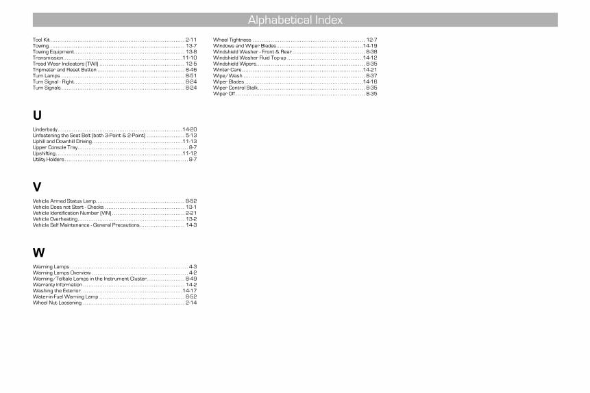
Tool Kit . . . . . . . . . . . . . . . . . . . . . . . . . . . . . . . . . . . . . . . . . . . . . . . . . . . . . . . . . . . . . . . . . . . . . . . . . . 2-11Towing. . . . . . . . . . . . . . . . . . . . . . . . . . . . . . . . . . . . . . . . . . . . . . . . . . . . . . . . . . . . . . . . . . . . . . . . . . . 13-7Towing Equipment. . . . . . . . . . . . . . . . . . . . . . . . . . . . . . . . . . . . . . . . . . . . . . . . . . . . . . . . . . . . . 13-8Transmission. . . . . . . . . . . . . . . . . . . . . . . . . . . . . . . . . . . . . . . . . . . . . . . . . . . . . . . . . . . . . . . . . .11-10Tread Wear Indicators (TWI) . . . . . . . . . . . . . . . . . . . . . . . . . . . . . . . . . . . . . . . . . . . . . . . 12-5Tripmeter and Reset Button . . . . . . . . . . . . . . . . . . . . . . . . . . . . . . . . . . . . . . . . . . . . . . . . 8-46Turn Lamps . . . . . . . . . . . . . . . . . . . . . . . . . . . . . . . . . . . . . . . . . . . . . . . . . . . . . . . . . . . . . . . . . . . . 8-51Turn Signal - Right. . . . . . . . . . . . . . . . . . . . . . . . . . . . . . . . . . . . . . . . . . . . . . . . . . . . . . . . . . . . . 8-24Turn Signals . . . . . . . . . . . . . . . . . . . . . . . . . . . . . . . . . . . . . . . . . . . . . . . . . . . . . . . . . . . . . . . . . . . . 8-24
UUnderbody. . . . . . . . . . . . . . . . . . . . . . . . . . . . . . . . . . . . . . . . . . . . . . . . . . . . . . . . . . . . . . . . . . . . .14-20Unfastening the Seat Belt (both 3-Point & 2-Point) . . . . . . . . . . . . . . . . . . . . . 5-13Uphill and Downhill Driving . . . . . . . . . . . . . . . . . . . . . . . . . . . . . . . . . . . . . . . . . . . . . . . . . .11-13Upper Console Tray. . . . . . . . . . . . . . . . . . . . . . . . . . . . . . . . . . . . . . . . . . . . . . . . . . . . . . . . . . . . . 8-7Upshifting . . . . . . . . . . . . . . . . . . . . . . . . . . . . . . . . . . . . . . . . . . . . . . . . . . . . . . . . . . . . . . . . . . . . . .11-12Utility Holders . . . . . . . . . . . . . . . . . . . . . . . . . . . . . . . . . . . . . . . . . . . . . . . . . . . . . . . . . . . . . . . . . . . . 8-7
VVehicle Armed Status Lamp. . . . . . . . . . . . . . . . . . . . . . . . . . . . . . . . . . . . . . . . . . . . . . . . . 8-52Vehicle Does not Start - Checks . . . . . . . . . . . . . . . . . . . . . . . . . . . . . . . . . . . . . . . . . . . . 13-1Vehicle Identification Number (VIN) . . . . . . . . . . . . . . . . . . . . . . . . . . . . . . . . . . . . . . . . 2-21Vehicle Overheating. . . . . . . . . . . . . . . . . . . . . . . . . . . . . . . . . . . . . . . . . . . . . . . . . . . . . . . . . . . 13-2Vehicle Self Maintenance - General Precautions. . . . . . . . . . . . . . . . . . . . . . . . . 14-3
WWarning Lamps . . . . . . . . . . . . . . . . . . . . . . . . . . . . . . . . . . . . . . . . . . . . . . . . . . . . . . . . . . . . . . . . . 4-3Warning Lamps Overview . . . . . . . . . . . . . . . . . . . . . . . . . . . . . . . . . . . . . . . . . . . . . . . . . . . . . 4-2Warning/Telltale Lamps in the Instrument Cluster. . . . . . . . . . . . . . . . . . . . . 8-49Warranty Information . . . . . . . . . . . . . . . . . . . . . . . . . . . . . . . . . . . . . . . . . . . . . . . . . . . . . . . . 14-2Washing the Exterior . . . . . . . . . . . . . . . . . . . . . . . . . . . . . . . . . . . . . . . . . . . . . . . . . . . . . . . .14-17Water-in-Fuel Warning Lamp . . . . . . . . . . . . . . . . . . . . . . . . . . . . . . . . . . . . . . . . . . . . . . . 8-52Wheel Nut Loosening . . . . . . . . . . . . . . . . . . . . . . . . . . . . . . . . . . . . . . . . . . . . . . . . . . . . . . . . 2-14
Wheel Tightness . . . . . . . . . . . . . . . . . . . . . . . . . . . . . . . . . . . . . . . . . . . . . . . . . . . . . . . . . . . . . . 12-7Windows and Wiper Blades. . . . . . . . . . . . . . . . . . . . . . . . . . . . . . . . . . . . . . . . . . . . . . . .14-19Windshield Washer - Front & Rear . . . . . . . . . . . . . . . . . . . . . . . . . . . . . . . . . . . . . . . . 8-38Windshield Washer Fluid Top-up . . . . . . . . . . . . . . . . . . . . . . . . . . . . . . . . . . . . . . . . . .14-12Windshield Wipers. . . . . . . . . . . . . . . . . . . . . . . . . . . . . . . . . . . . . . . . . . . . . . . . . . . . . . . . . . . . 8-35Winter Care. . . . . . . . . . . . . . . . . . . . . . . . . . . . . . . . . . . . . . . . . . . . . . . . . . . . . . . . . . . . . . . . . . .14-21Wipe/Wash . . . . . . . . . . . . . . . . . . . . . . . . . . . . . . . . . . . . . . . . . . . . . . . . . . . . . . . . . . . . . . . . . . . 8-37Wiper Blades . . . . . . . . . . . . . . . . . . . . . . . . . . . . . . . . . . . . . . . . . . . . . . . . . . . . . . . . . . . . . . . . .14-16Wiper Control Stalk . . . . . . . . . . . . . . . . . . . . . . . . . . . . . . . . . . . . . . . . . . . . . . . . . . . . . . . . . . . 8-35Wiper Off . . . . . . . . . . . . . . . . . . . . . . . . . . . . . . . . . . . . . . . . . . . . . . . . . . . . . . . . . . . . . . . . . . . . . . . 8-35
Alphabetical Index