Embed Size (px)
Citation preview
OTN Wrapper Overview
Optical Transport Network (OTN) Wrapper feature provides robust transport services that leverage many ofthe benefits such as resiliency and performance monitoring, while adding enhanced multi-rate capabilities insupport of packet traffic, plus the transparency required by DenseWavelength DivisionMultiplexing (DWDM)networks. OTN is the ideal technology to bridge the gap between next generation IP and legacy Time DivisionMultiplexing (TDM) networks by acting as a converged transport layer for newer packet-based and existingTDM services. OTN is defined in ITU G.709 and allows network operators to converge networks throughseamless transport of the numerous types of legacy protocols, while providing the flexibility required tosupport future client protocols.
OTN Wrapper feature is supported on the following interface modules:
• 8-port 10 Gigabit Ethernet Interface Module (8x10GE) (A900-IMA8Z) (NCS4200-8T-PS) - Theencapsulation type is OTU1e and OTU2e.
• 2-port 40 Gigabit Ethernet QSFP Interface Module (2x40GE) (A900-IMA2F) (NCS4200-2Q-P) - Theencapsulation type is OTU3.
• 1-port 100 Gigabit Ethernet Interface Module (1X100GE) (NCS4200-1H-PK) (A900-IMA1C) - Theencapsulation type is OTU4.
The chassis acts as an aggregator for ethernet, TDM, and SONET traffic to connect to an OTN network andvice versa. The ports on the interface modules are capable of OTN functionality. The OTN controller modeenables the IPoDWDM technology in the interface modules. The OTNWrapper encapsulates 10G LAN, 40GLAN, and 100G LAN into the corresponding OTU1e or OTU2e, OTU3, and OTU4 containers, respectively.This enables the ports of the interface modules to work in layer 1 optical mode in conformance with standardG.709.
OTN Wrapper Overview1
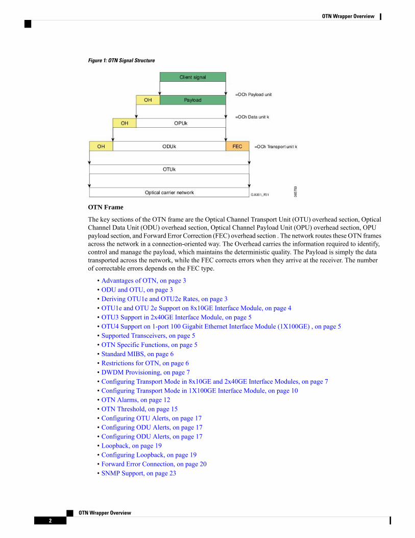
Figure 1: OTN Signal Structure
OTN Frame
The key sections of the OTN frame are the Optical Channel Transport Unit (OTU) overhead section, OpticalChannel Data Unit (ODU) overhead section, Optical Channel Payload Unit (OPU) overhead section, OPUpayload section, and Forward Error Correction (FEC) overhead section . The network routes these OTN framesacross the network in a connection-oriented way. The Overhead carries the information required to identify,control and manage the payload, which maintains the deterministic quality. The Payload is simply the datatransported across the network, while the FEC corrects errors when they arrive at the receiver. The numberof correctable errors depends on the FEC type.
• Advantages of OTN, on page 3• ODU and OTU, on page 3• Deriving OTU1e and OTU2e Rates, on page 3• OTU1e and OTU 2e Support on 8x10GE Interface Module, on page 4• OTU3 Support in 2x40GE Interface Module, on page 5• OTU4 Support on 1-port 100 Gigabit Ethernet Interface Module (1X100GE) , on page 5• Supported Transceivers, on page 5• OTN Specific Functions, on page 5• Standard MIBS, on page 6• Restrictions for OTN, on page 6• DWDM Provisioning, on page 7• Configuring Transport Mode in 8x10GE and 2x40GE Interface Modules, on page 7• Configuring Transport Mode in 1X100GE Interface Module, on page 10• OTN Alarms, on page 12• OTN Threshold, on page 15• Configuring OTU Alerts, on page 17• Configuring ODU Alerts, on page 17• Configuring ODU Alerts, on page 17• Loopback, on page 19• Configuring Loopback, on page 19• Forward Error Connection, on page 20• SNMP Support, on page 23
OTN Wrapper Overview2
OTN Wrapper Overview
• Performance Monitoring, on page 24• Troubleshooting Scenarios, on page 31• Associated Commands, on page 31
Advantages of OTNThe following are the advantages of OTN:
• Provides multi-layer performance monitoring and enhanced maintenance capability for signals traversingmulti-operator networks.
• Allows Forward Error Correction (FEC) to improve the system performance.
• Provides enhanced alarm handling capability.
• Insulates the network against uncertain service mix by providing transparent native transport of signalsencapsulating all client-management information.
• Performs multiplexing for optimum capacity utilization, thereby improving network efficiency.
• Enables network scalability as well as support for dedicated Ethernet services with service definitions.
ODU and OTUOptical Channel Transport Unit (OTU) and Optical Channel Data Unit (ODU) are the two digital layernetworks. All client signals are mapped into the optical channel via the ODU and OTU layer networks.
OTU
The OTU section is composed of two main sections: the Frame Alignment section and the SectionMonitoring(SM) section. The OTU Overhead (OH) provides the error detection correction as well as section-layerconnection and monitoring functions on the section span. The OTUOH also includes framing bytes, enablingreceivers to identify frame boundaries. For more information, see G.709 document.
ODU
The ODU section is an internal element allowing mapping or switching between different rates, which isimportant in allowing operators the ability to understand how the end user pipe is transferred through to thehigher network rates. The ODU OH contains path overhead bytes allowing the ability to monitor theperformance, fault type and location, generic communication, and six levels of channel protection based onTandem Connection Monitoring (TCM). For more information, see G.709 document.
Deriving OTU1e and OTU2e RatesA standard OTN frame consists of 255 16-column blocks and the payload rate is 9953280 Kbit/s. This isbecause the overhead and stuffing in the OTN frames happen at a granularity of 16-column blocks. Thus,OPU payload occupies (3824-16)/16=238 blocks. The ODU occupies 239 blocks and the OTU (includingFEC) occupies 255 blocks. Hence, the multiplication factor in the G.709 spec is specified using numbers like237, 238, 255.
Since OPU2e uses 16 columns that are reserved for stuffing and also for payload, the effective OPU2e frequencyis:
OTN Wrapper Overview3
OTN Wrapper OverviewAdvantages of OTN
• OPU2e = 238/237 x 10312500 Kbit/s = 10.356012 Gbit/s
• ODU2e = 239/237 x 10312500 Kbit/s = 10.399525 Gbit/s
• OTU2e = 255/237 x 10312500 Kbit/s = 11.095727 Gbit/s
Since OPU1e uses 16 columns that are reserved for stuffing and also for payload, the effective OPU1e frequencyis:
• OPU1e = 238/238 x 10312500 Kbit/s = 10.3125 Gbit/s
• ODU1e = 239/238 x 10312500 Kbit/s = 10.355829 Gbit/s
• OTU1e = 255/238 x 10312500 Kbit/s = 11.049107 Gbit/s
OTU1e and OTU 2e Support on 8x10GE Interface ModuleThe OTU1e and OTU2e are mapping mechanisms to map a client 10G Base-R signal to OTN framestransparently as per ITU-T G series Supplement 43 specification. Both these modes are over-clocked OTNmodes. These mechanisms provide real bit transparency of 10 GbE LAN signals and are useful for deploymentof 10G services.
The OTU1e and OTU2e are inherently intra-domain interfaces (IaDI) and are generally applicable only to asingle vendor island within an operator's network to enable the use of unique optical technology. The OTU1eand OTU2e are not standard G.709 bit-rate signals and they do not interwork with the standard mappings ofEthernet using GFP-F. These two over-clocked mechanisms do not interwork with each other. As a result,such signals are only deployed in a point-to-point configuration between equipment that implements the samemapping.
The standard 10 GbE LAN has a data rate of 10.3125 Gbps. In the OTU1e and OTU2e mapping schemes, thefull 10.3125 Gbit/s is transported including the 64B/66B coded information, IPG, MAC FCS, preamble,start-of-frame delimiter (SFD) and the ordered sets (to convey fault information). So, the effective OTU2eand OTU1e rates are:
• OTU1e: 11.0491 Gbits/s +/- 100ppm
• OTU2e: 11.0957 Gbits/s +/- 100ppm
The 10GBase-R client signal with fixed stuff bytes is accommodated into an OPU-like signal, then into anODU-like signal, and further into an OTU-like signal. These signals are denoted as OPU2e, ODU2e andOTU2e, respectively . The OTU1e does not add 16 columns of fixed stuff bytes and hence overall data rateis relatively lesser at 11.0491 Gbps as compared to OTU2e which is 11.0957 Gbps.
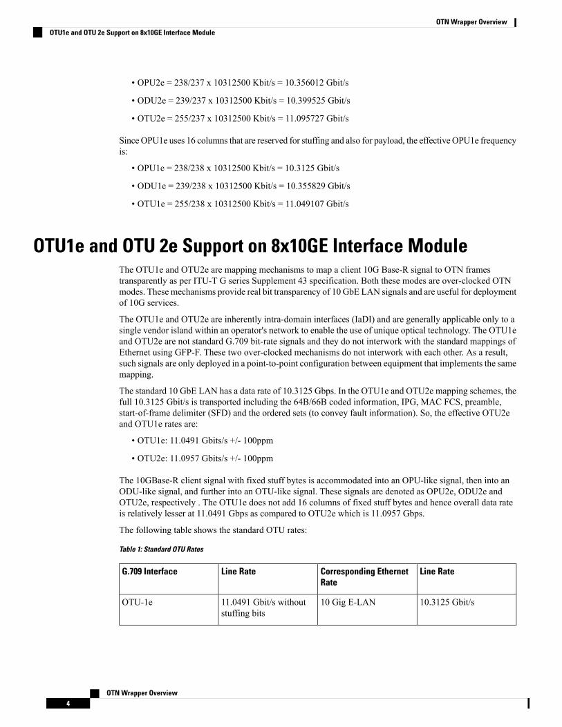
The following table shows the standard OTU rates:
Table 1: Standard OTU Rates
Line RateCorresponding EthernetRate
Line RateG.709 Interface
10.3125 Gbit/s10 Gig E-LAN11.0491 Gbit/s withoutstuffing bits
OTU-1e
OTN Wrapper Overview4
OTN Wrapper OverviewOTU1e and OTU 2e Support on 8x10GE Interface Module
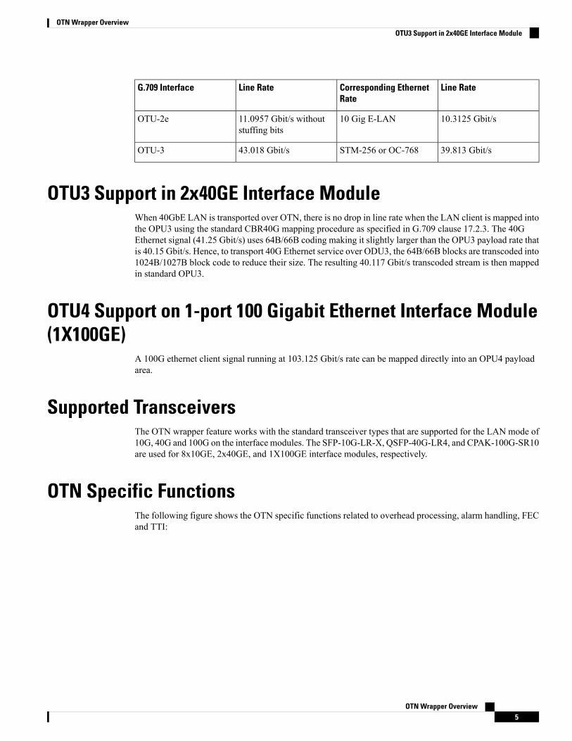
Line RateCorresponding EthernetRate
Line RateG.709 Interface
10.3125 Gbit/s10 Gig E-LAN11.0957 Gbit/s withoutstuffing bits
OTU-2e
39.813 Gbit/sSTM-256 or OC-76843.018 Gbit/sOTU-3
OTU3 Support in 2x40GE Interface ModuleWhen 40GbE LAN is transported over OTN, there is no drop in line rate when the LAN client is mapped intothe OPU3 using the standard CBR40G mapping procedure as specified in G.709 clause 17.2.3. The 40GEthernet signal (41.25 Gbit/s) uses 64B/66B coding making it slightly larger than the OPU3 payload rate thatis 40.15 Gbit/s. Hence, to transport 40G Ethernet service over ODU3, the 64B/66B blocks are transcoded into1024B/1027B block code to reduce their size. The resulting 40.117 Gbit/s transcoded stream is then mappedin standard OPU3.
OTU4 Support on 1-port 100 Gigabit Ethernet Interface Module(1X100GE)
A 100G ethernet client signal running at 103.125 Gbit/s rate can be mapped directly into an OPU4 payloadarea.
Supported TransceiversThe OTN wrapper feature works with the standard transceiver types that are supported for the LAN mode of10G, 40G and 100G on the interface modules. The SFP-10G-LR-X, QSFP-40G-LR4, and CPAK-100G-SR10are used for 8x10GE, 2x40GE, and 1X100GE interface modules, respectively.
OTN Specific FunctionsThe following figure shows the OTN specific functions related to overhead processing, alarm handling, FECand TTI:
OTN Wrapper Overview5
OTN Wrapper OverviewOTU3 Support in 2x40GE Interface Module
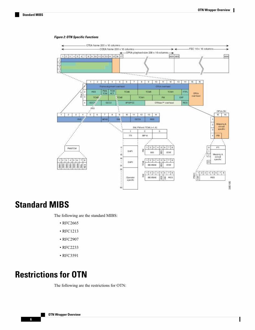
Figure 2: OTN Specific Functions
Standard MIBSThe following are the standard MIBS:
• RFC2665
• RFC1213
• RFC2907
• RFC2233
• RFC3591
Restrictions for OTNThe following are the restrictions for OTN:
OTN Wrapper Overview6
OTN Wrapper OverviewStandard MIBS
• OTL alarms are not supported.
• FECMISMATCH alarm is not supported.
• Enhanced FEC is not supported.
• Alarm and error counters are visible when the controller is in shutdown state.
DWDM ProvisioningAll DWDM provisioning configurations take place on the controller. To configure a DWDM controller, usethe controller dwdm command in global configuration mode.
Prerequisites for DWDM ProvisioningThe g709 configuration commands can be used only when the controller is in the shutdown state. Use the noshutdown command after configuring the parameters, to remove the controller from shutdown state and toenable the controller to move to up state.
Configuring DWDM ProvisioningUse the following commands to configure DWDM provisioning:enableconfigure terminalcontroller dwdm 0/1/0
Configuring Transport Mode in 8x10GE and 2x40GE InterfaceModules
Use the transport-mode command in interface configuration mode to configure LAN and OTN transportmodes in 8x10GE and 2x40GE interface modules. The transport-mode command otn option has thebit-transparent sub-option, using which bit transparent mapping into OPU1e or OPU2e can be configured.
Use the following commands to configure LAN and OTN transport modes:enableconfigure terminalcontroller dwdm 0/0/0transport-mode otn bit-transparent opu1e
LAN transport mode is the default mode.Note
To configure the transport administration state on a DWDM port, use the admin-state command in DWDMconfiguration mode. To return the administration state from a DWDM port to the default, use the no form ofthis command.
OTN Wrapper Overview7
OTN Wrapper OverviewDWDM Provisioning
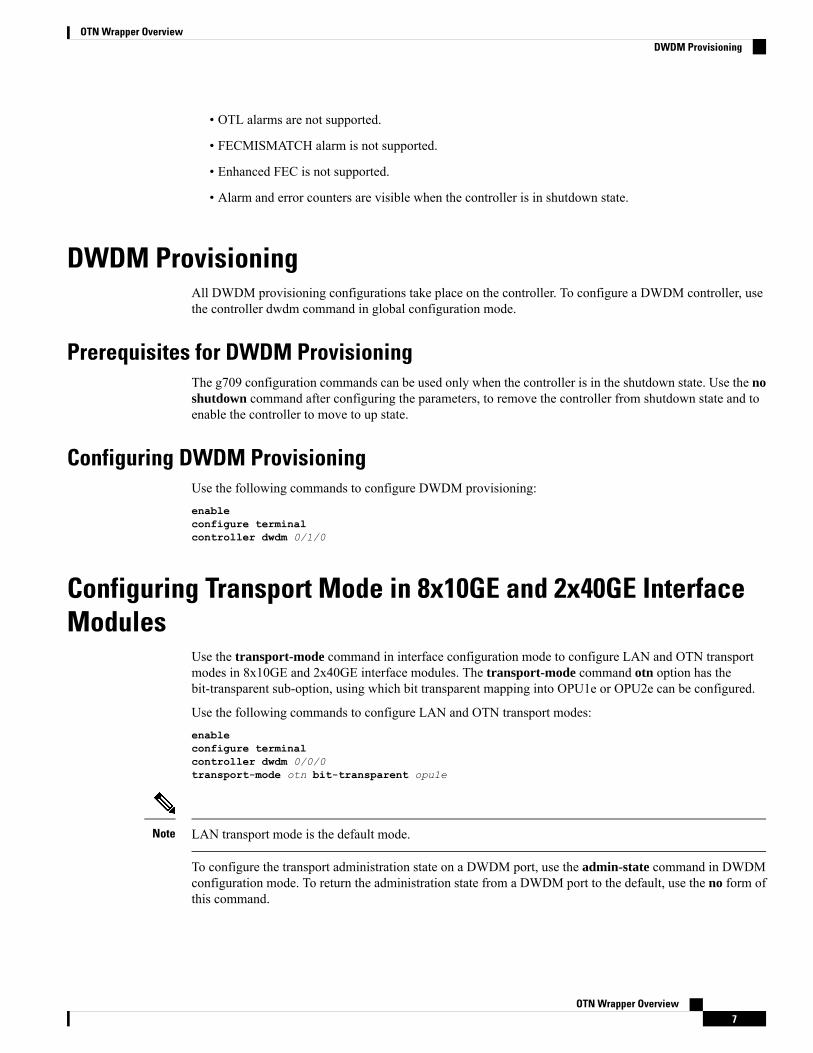
Verification of LAN Transport Mode ConfigurationUse the show interfaces command to verify the configuration of LAN transport mode:Router#sh int te0/1/0TenGigabitEthernet0/1/0 is up, line protocol is upMTU 1500 bytes, BW 10000000 Kbit/sec, DLY 10 usec,
reliability 255/255, txload 8/255, rxload 193/255Encapsulation ARPA, loopback not setKeepalive set (10 sec)Full Duplex, 10000Mbps, link type is force-up, media type is SFP-SRoutput flow-control is unsupported, input flow-control is onTransport mode LANARP type: ARPA, ARP Timeout 04:00:00Last input 04:02:09, output 04:02:09, output hang neverLast clearing of "show interface" counters 00:29:47Input queue: 0/375/0/0 (size/max/drops/flushes); Total output drops: 0Queueing strategy: fifoOutput queue: 0/40 (size/max)5 minute input rate 7605807000 bits/sec, 14854906 packets/sec5 minute output rate 335510000 bits/sec, 655427 packets/sec
26571883351 packets input, 1700600465344 bytes, 0 no bufferReceived 0 broadcasts (0 IP multicasts)0 runts, 0 giants, 0 throttles0 input errors, 0 CRC, 0 frame, 0 overrun, 0 ignored0 watchdog, 0 multicast, 0 pause input10766634813 packets output, 689064271464 bytes, 0 underruns0 output errors, 0 collisions, 0 interface resets0 unknown protocol drops0 babbles, 0 late collision, 0 deferred0 lost carrier, 0 no carrier, 0 pause output0 output buffer failures, 0 output buffers swapped out
Router#
Verification of OTN Transport Mode Configuration in 8x10GE Interface ModulesUse the show interfaces command to verify the configuration of OTN transport mode in 8x10GE interfacemodules:Router#sh int te0/1/1TenGigabitEthernet0/1/1 is up, line protocol is upMTU 1500 bytes, BW 10000000 Kbit/sec, DLY 10 usec,
reliability 255/255, txload 193/255, rxload 7/255Encapsulation ARPA, loopback not setKeepalive set (10 sec)Full Duplex, 10000Mbps, link type is force-up, media type is SFP-SRoutput flow-control is unsupported, input flow-control is onTransport mode OTN (10GBASE-R over OPU1e w/o fixed stuffing, 11.0491Gb/s)ARP type: ARPA, ARP Timeout 04:00:00Last input 03:28:14, output 03:28:14, output hang neverLast clearing of "show interface" counters 00:30:47Input queue: 0/375/0/0 (size/max/drops/flushes); Total output drops: 0Queueing strategy: fifoOutput queue: 0/40 (size/max)5 minute input rate 281326000 bits/sec, 549608 packets/sec5 minute output rate 7596663000 bits/sec, 14837094 packets/sec
10766669034 packets input, 689066159324 bytes, 0 no bufferReceived 0 broadcasts (0 IP multicasts)0 runts, 0 giants, 0 throttles0 input errors, 0 CRC, 0 frame, 0 overrun, 0 ignored0 watchdog, 0 multicast, 0 pause input
OTN Wrapper Overview8
OTN Wrapper OverviewVerification of LAN Transport Mode Configuration
27457291925 packets output, 1757266795328 bytes, 0 underruns0 output errors, 0 collisions, 0 interface resets0 unknown protocol drops0 babbles, 0 late collision, 0 deferred0 lost carrier, 0 no carrier, 0 pause output0 output buffer failures, 0 output buffers swapped out
Router#
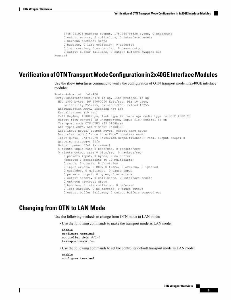
Verification of OTN Transport Mode Configuration in 2x40GE Interface ModulesUse the show interfaces command to verify the configuration of OTN transport mode in 2x40GE interfacemodules:Router#show int fo0/4/0FortyGigabitEthernet0/4/0 is up, line protocol is upMTU 1500 bytes, BW 40000000 Kbit/sec, DLY 10 usec,
reliability 255/255, txload 1/255, rxload 1/255Encapsulation ARPA, loopback not setKeepalive set (10 sec)Full Duplex, 40000Mbps, link type is force-up, media type is QSFP_40GE_SRoutput flow-control is unsupported, input flow-control is onTransport mode OTN OTU3 (43.018Gb/s)ARP type: ARPA, ARP Timeout 04:00:00Last input never, output never, output hang neverLast clearing of "show interface" counters neverInput queue: 0/375/0/0 (size/max/drops/flushes); Total output drops: 0Queueing strategy: fifoOutput queue: 0/40 (size/max)5 minute input rate 0 bits/sec, 0 packets/sec5 minute output rate 0 bits/sec, 0 packets/sec
0 packets input, 0 bytes, 0 no bufferReceived 0 broadcasts (0 IP multicasts)0 runts, 0 giants, 0 throttles0 input errors, 0 CRC, 0 frame, 0 overrun, 0 ignored0 watchdog, 0 multicast, 0 pause input0 packets output, 0 bytes, 0 underruns0 output errors, 0 collisions, 2 interface resets0 unknown protocol drops0 babbles, 0 late collision, 0 deferred0 lost carrier, 0 no carrier, 0 pause output0 output buffer failures, 0 output buffers swapped out
Changing from OTN to LAN ModeUse the following methods to change from OTN mode to LAN mode:
• Use the following commands to make the transport mode as LAN mode:enableconfigure terminalcontroller dwdm 0/0/0transport-mode lan
• Use the following commands to set the controller default transport mode as LAN mode:enableconfigure terminal
OTN Wrapper Overview9
OTN Wrapper OverviewVerification of OTN Transport Mode Configuration in 2x40GE Interface Modules
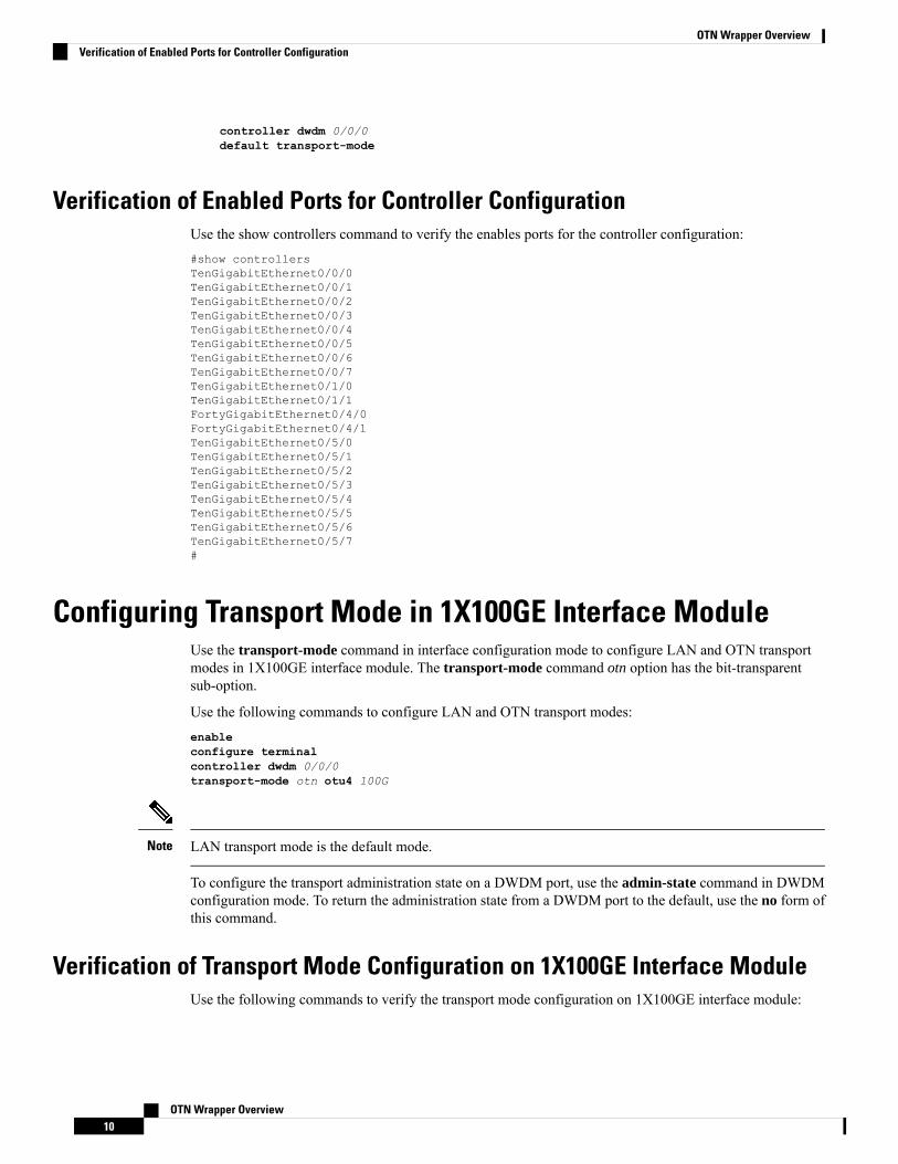
controller dwdm 0/0/0default transport-mode
Verification of Enabled Ports for Controller ConfigurationUse the show controllers command to verify the enables ports for the controller configuration:#show controllersTenGigabitEthernet0/0/0TenGigabitEthernet0/0/1TenGigabitEthernet0/0/2TenGigabitEthernet0/0/3TenGigabitEthernet0/0/4TenGigabitEthernet0/0/5TenGigabitEthernet0/0/6TenGigabitEthernet0/0/7TenGigabitEthernet0/1/0TenGigabitEthernet0/1/1FortyGigabitEthernet0/4/0FortyGigabitEthernet0/4/1TenGigabitEthernet0/5/0TenGigabitEthernet0/5/1TenGigabitEthernet0/5/2TenGigabitEthernet0/5/3TenGigabitEthernet0/5/4TenGigabitEthernet0/5/5TenGigabitEthernet0/5/6TenGigabitEthernet0/5/7#
Configuring Transport Mode in 1X100GE Interface ModuleUse the transport-mode command in interface configuration mode to configure LAN and OTN transportmodes in 1X100GE interface module. The transport-mode command otn option has the bit-transparentsub-option.
Use the following commands to configure LAN and OTN transport modes:enableconfigure terminalcontroller dwdm 0/0/0transport-mode otn otu4 100G
LAN transport mode is the default mode.Note
To configure the transport administration state on a DWDM port, use the admin-state command in DWDMconfiguration mode. To return the administration state from a DWDM port to the default, use the no form ofthis command.
Verification of Transport Mode Configuration on 1X100GE Interface ModuleUse the following commands to verify the transport mode configuration on 1X100GE interface module:
OTN Wrapper Overview10
OTN Wrapper OverviewVerification of Enabled Ports for Controller Configuration
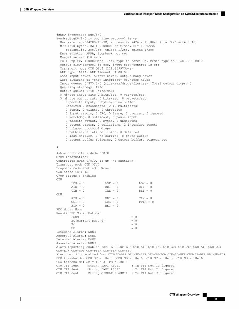
#show interfaces Hu0/8/0HundredGigE0/8/0 is up, line protocol is upHardware is NCS4200-1H-PK, address is 7426.acf6.8048 (bia 7426.acf6.8048)MTU 1500 bytes, BW 100000000 Kbit/sec, DLY 10 usec,
reliability 255/255, txload 1/255, rxload 1/255Encapsulation ARPA, loopback not setKeepalive set (10 sec)Full Duplex, 100000Mbps, link type is force-up, media type is CPAK-100G-SR10output flow-control is off, input flow-control is offTransport mode OTN OTU4 (111.80997Gb/s)ARP type: ARPA, ARP Timeout 04:00:00Last input never, output never, output hang neverLast clearing of "show interface" counters neverInput queue: 0/375/0/0 (size/max/drops/flushes); Total output drops: 0Queueing strategy: fifoOutput queue: 0/40 (size/max)5 minute input rate 0 bits/sec, 0 packets/sec5 minute output rate 0 bits/sec, 0 packets/sec
0 packets input, 0 bytes, 0 no bufferReceived 0 broadcasts (0 IP multicasts)0 runts, 0 giants, 0 throttles0 input errors, 0 CRC, 0 frame, 0 overrun, 0 ignored0 watchdog, 0 multicast, 0 pause input0 packets output, 0 bytes, 0 underruns0 output errors, 0 collisions, 2 interface resets0 unknown protocol drops0 babbles, 0 late collision, 0 deferred0 lost carrier, 0 no carrier, 0 pause output0 output buffer failures, 0 output buffers swapped out
#
#show controllers dwdm 0/8/0G709 Information:Controller dwdm 0/8/0, is up (no shutdown)Transport mode OTN OTU4Loopback mode enabled : NoneTAS state is : ISG709 status : EnabledOTU
LOS = 0 LOF = 0 LOM = 0AIS = 0 BDI = 0 BIP = 0TIM = 0 IAE = 0 BEI = 0
ODUAIS = 0 BDI = 0 TIM = 0OCI = 0 LCK = 0 PTIM = 0BIP = 0 BEI = 0
FEC Mode: NoneRemote FEC Mode: Unknown
FECM = 0EC(current second) = 0EC = 0UC = 0
Detected Alarms: NONEAsserted Alarms: NONEDetected Alerts: NONEAsserted Alerts: NONEAlarm reporting enabled for: LOS LOF LOM OTU-AIS OTU-IAE OTU-BDI OTU-TIM ODU-AIS ODU-OCIODU-LCK ODU-BDI ODU-PTIM ODU-TIM ODU-BIPAlert reporting enabled for: OTU-SD-BER OTU-SF-BER OTU-SM-TCA ODU-SD-BER ODU-SF-BER ODU-PM-TCABER thresholds: ODU-SF = 10e-3 ODU-SD = 10e-6 OTU-SF = 10e-3 OTU-SD = 10e-6TCA thresholds: SM = 10e-3 PM = 10e-3OTU TTI Sent String SAPI ASCII : Tx TTI Not ConfiguredOTU TTI Sent String DAPI ASCII : Tx TTI Not ConfiguredOTU TTI Sent String OPERATOR ASCII : Tx TTI Not Configured
OTN Wrapper Overview11
OTN Wrapper OverviewVerification of Transport Mode Configuration on 1X100GE Interface Module
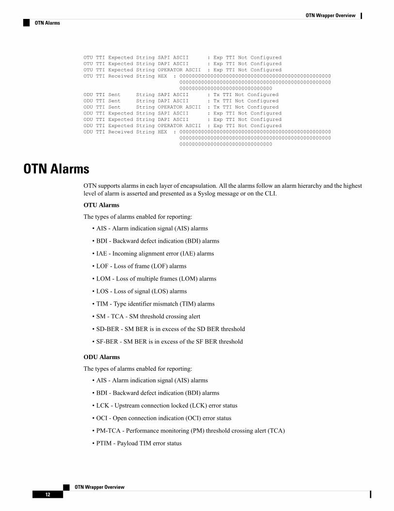
OTU TTI Expected String SAPI ASCII : Exp TTI Not ConfiguredOTU TTI Expected String DAPI ASCII : Exp TTI Not ConfiguredOTU TTI Expected String OPERATOR ASCII : Exp TTI Not ConfiguredOTU TTI Received String HEX : 0000000000000000000000000000000000000000000000000
0000000000000000000000000000000000000000000000000000000000000000000000000000000
ODU TTI Sent String SAPI ASCII : Tx TTI Not ConfiguredODU TTI Sent String DAPI ASCII : Tx TTI Not ConfiguredODU TTI Sent String OPERATOR ASCII : Tx TTI Not ConfiguredODU TTI Expected String SAPI ASCII : Exp TTI Not ConfiguredODU TTI Expected String DAPI ASCII : Exp TTI Not ConfiguredODU TTI Expected String OPERATOR ASCII : Exp TTI Not ConfiguredODU TTI Received String HEX : 0000000000000000000000000000000000000000000000000
0000000000000000000000000000000000000000000000000000000000000000000000000000000
OTN AlarmsOTN supports alarms in each layer of encapsulation. All the alarms follow an alarm hierarchy and the highestlevel of alarm is asserted and presented as a Syslog message or on the CLI.
OTU Alarms
The types of alarms enabled for reporting:
• AIS - Alarm indication signal (AIS) alarms
• BDI - Backward defect indication (BDI) alarms
• IAE - Incoming alignment error (IAE) alarms
• LOF - Loss of frame (LOF) alarms
• LOM - Loss of multiple frames (LOM) alarms
• LOS - Loss of signal (LOS) alarms
• TIM - Type identifier mismatch (TIM) alarms
• SM - TCA - SM threshold crossing alert
• SD-BER - SM BER is in excess of the SD BER threshold
• SF-BER - SM BER is in excess of the SF BER threshold
ODU Alarms
The types of alarms enabled for reporting:
• AIS - Alarm indication signal (AIS) alarms
• BDI - Backward defect indication (BDI) alarms
• LCK - Upstream connection locked (LCK) error status
• OCI - Open connection indication (OCI) error status
• PM-TCA - Performance monitoring (PM) threshold crossing alert (TCA)
• PTIM - Payload TIM error status
OTN Wrapper Overview12
OTN Wrapper OverviewOTN Alarms
• SD-BER - SM BER is in excess of the SD BER threshold
• SF-BER - SM BER is in excess of the SF BER threshold
• TIM - Type identifier mismatch (TIM) alarms
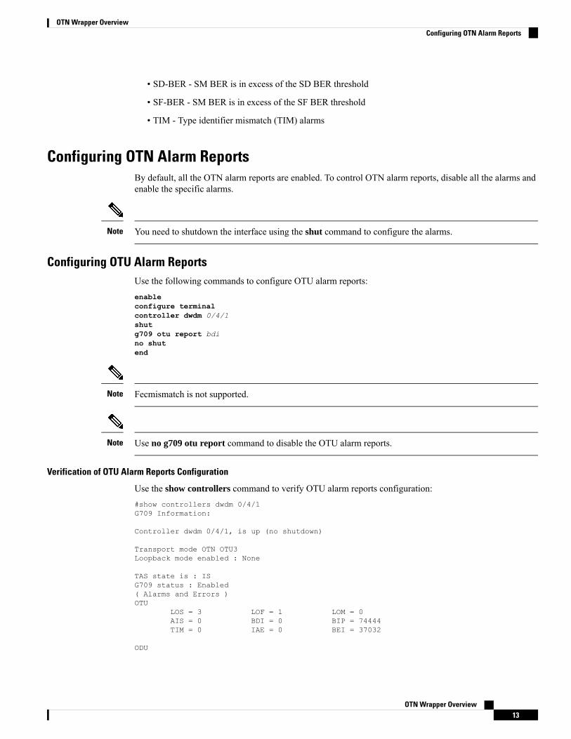
Configuring OTN Alarm ReportsBy default, all the OTN alarm reports are enabled. To control OTN alarm reports, disable all the alarms andenable the specific alarms.
You need to shutdown the interface using the shut command to configure the alarms.Note
Configuring OTU Alarm ReportsUse the following commands to configure OTU alarm reports:enableconfigure terminalcontroller dwdm 0/4/1shutg709 otu report bdino shutend
Fecmismatch is not supported.Note
Use no g709 otu report command to disable the OTU alarm reports.Note
Verification of OTU Alarm Reports Configuration
Use the show controllers command to verify OTU alarm reports configuration:#show controllers dwdm 0/4/1G709 Information:
Controller dwdm 0/4/1, is up (no shutdown)
Transport mode OTN OTU3Loopback mode enabled : None
TAS state is : ISG709 status : Enabled( Alarms and Errors )OTU
LOS = 3 LOF = 1 LOM = 0AIS = 0 BDI = 0 BIP = 74444TIM = 0 IAE = 0 BEI = 37032
ODU
OTN Wrapper Overview13
OTN Wrapper OverviewConfiguring OTN Alarm Reports
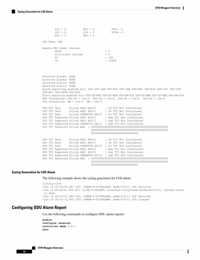
AIS = 0 BDI = 0 TIM = 0OCI = 0 LCK = 0 PTIM = 0BIP = 2 BEI = 0
FEC Mode: FEC
Remote FEC Mode: UnknownFECM = 0EC(current second) = 0EC = 186UC = 10695
Detected Alarms: NONEAsserted Alarms: NONEDetected Alerts: NONEAsserted Alerts: NONEAlarm reporting enabled for: LOS LOF LOM OTU-AIS OTU-IAE OTU-BDI ODU-AIS ODU-OCI ODU-LCKODU-BDI ODU-PTIM ODU-BIPAlert reporting enabled for: OTU-SD-BER OTU-SF-BER OTU-SM-TCA ODU-SD-BER ODU-SF-BER ODU-PM-TCABER thresholds: ODU-SF = 10e-3 ODU-SD = 10e-6 OTU-SF = 10e-3 OTU-SD = 10e-6TCA thresholds: SM = 10e-3 PM = 10e-3
OTU TTI Sent String SAPI ASCII : Tx TTI Not ConfiguredOTU TTI Sent String DAPI ASCII : Tx TTI Not ConfiguredOTU TTI Sent String OPERATOR ASCII : Tx TTI Not ConfiguredOTU TTI Expected String SAPI ASCII : Exp TTI Not ConfiguredOTU TTI Expected String DAPI ASCII : Exp TTI Not ConfiguredOTU TTI Expected String OPERATOR ASCII : Exp TTI Not ConfiguredOTU TTI Received String HEX : 0000000000000000000000000000000000000000000000000
0000000000000000000000000000000000000000000000000000000000000000000000000000000
ODU TTI Sent String SAPI ASCII : Tx TTI Not ConfiguredODU TTI Sent String DAPI ASCII : Tx TTI Not ConfiguredODU TTI Sent String OPERATOR ASCII : Tx TTI Not ConfiguredODU TTI Expected String SAPI ASCII : Exp TTI Not ConfiguredODU TTI Expected String DAPI ASCII : Exp TTI Not ConfiguredODU TTI Expected String OPERATOR ASCII : Exp TTI Not ConfiguredODU TTI Received String HEX : 0000000000000000000000000000000000000000000000000
0000000000000000000000000000000000000000000000000000000000000000000000000000000
Syslog Generation for LOS Alarm
The following example shows the syslog generation for LOS alarm:(config-if)#*Jan 16 06:32:50.487 IST: %DWDM-4-G709ALARM: dwdm-0/4/1: LOS declared*Jan 16 06:32:51.048 IST: %LINK-3-UPDOWN: Interface FortyGigabitEthernet0/4/1, changed stateto down*Jan 16 06:32:51.489 IST: %DWDM-4-G709ALARM: dwdm-0/4/1: LOF declared*Jan 16 06:32:51.495 IST: %DWDM-4-G709ALARM: dwdm-0/4/1: LOS cleared
Configuring ODU Alarm ReportUse the following commands to configure ODU alarm reports:enableconfigure terminalcontroller dwdm 0/4/1shut
OTN Wrapper Overview14
OTN Wrapper OverviewSyslog Generation for LOS Alarm
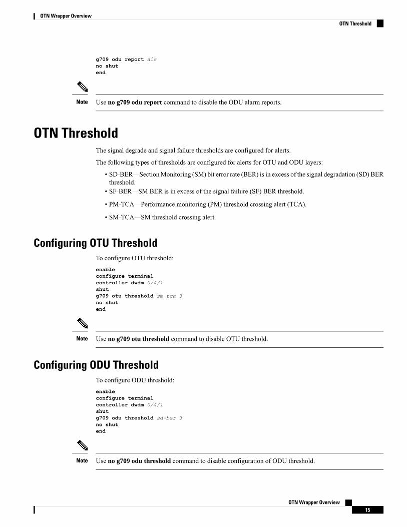
g709 odu report aisno shutend
Use no g709 odu report command to disable the ODU alarm reports.Note
OTN ThresholdThe signal degrade and signal failure thresholds are configured for alerts.
The following types of thresholds are configured for alerts for OTU and ODU layers:
• SD-BER—SectionMonitoring (SM) bit error rate (BER) is in excess of the signal degradation (SD) BERthreshold.
• SF-BER—SM BER is in excess of the signal failure (SF) BER threshold.
• PM-TCA—Performance monitoring (PM) threshold crossing alert (TCA).
• SM-TCA—SM threshold crossing alert.
Configuring OTU ThresholdTo configure OTU threshold:enableconfigure terminalcontroller dwdm 0/4/1shutg709 otu threshold sm-tca 3no shutend
Use no g709 otu threshold command to disable OTU threshold.Note
Configuring ODU ThresholdTo configure ODU threshold:enableconfigure terminalcontroller dwdm 0/4/1shutg709 odu threshold sd-ber 3no shutend
Use no g709 odu threshold command to disable configuration of ODU threshold.Note
OTN Wrapper Overview15
OTN Wrapper OverviewOTN Threshold
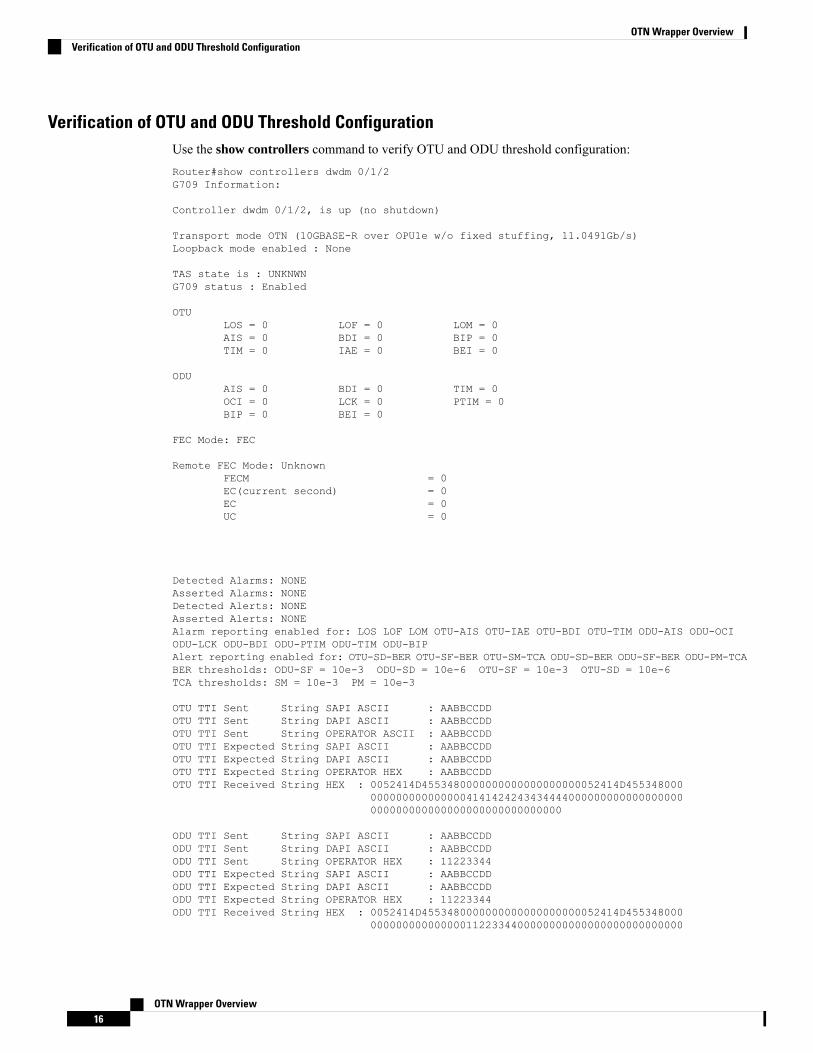
Verification of OTU and ODU Threshold ConfigurationUse the show controllers command to verify OTU and ODU threshold configuration:Router#show controllers dwdm 0/1/2G709 Information:
Controller dwdm 0/1/2, is up (no shutdown)
Transport mode OTN (10GBASE-R over OPU1e w/o fixed stuffing, 11.0491Gb/s)Loopback mode enabled : None
TAS state is : UNKNWNG709 status : Enabled
OTULOS = 0 LOF = 0 LOM = 0AIS = 0 BDI = 0 BIP = 0TIM = 0 IAE = 0 BEI = 0
ODUAIS = 0 BDI = 0 TIM = 0OCI = 0 LCK = 0 PTIM = 0BIP = 0 BEI = 0
FEC Mode: FEC
Remote FEC Mode: UnknownFECM = 0EC(current second) = 0EC = 0UC = 0
Detected Alarms: NONEAsserted Alarms: NONEDetected Alerts: NONEAsserted Alerts: NONEAlarm reporting enabled for: LOS LOF LOM OTU-AIS OTU-IAE OTU-BDI OTU-TIM ODU-AIS ODU-OCIODU-LCK ODU-BDI ODU-PTIM ODU-TIM ODU-BIPAlert reporting enabled for: OTU-SD-BER OTU-SF-BER OTU-SM-TCA ODU-SD-BER ODU-SF-BER ODU-PM-TCABER thresholds: ODU-SF = 10e-3 ODU-SD = 10e-6 OTU-SF = 10e-3 OTU-SD = 10e-6TCA thresholds: SM = 10e-3 PM = 10e-3
OTU TTI Sent String SAPI ASCII : AABBCCDDOTU TTI Sent String DAPI ASCII : AABBCCDDOTU TTI Sent String OPERATOR ASCII : AABBCCDDOTU TTI Expected String SAPI ASCII : AABBCCDDOTU TTI Expected String DAPI ASCII : AABBCCDDOTU TTI Expected String OPERATOR HEX : AABBCCDDOTU TTI Received String HEX : 0052414D4553480000000000000000000052414D455348000
0000000000000004141424243434444000000000000000000000000000000000000000000000000
ODU TTI Sent String SAPI ASCII : AABBCCDDODU TTI Sent String DAPI ASCII : AABBCCDDODU TTI Sent String OPERATOR HEX : 11223344ODU TTI Expected String SAPI ASCII : AABBCCDDODU TTI Expected String DAPI ASCII : AABBCCDDODU TTI Expected String OPERATOR HEX : 11223344ODU TTI Received String HEX : 0052414D4553480000000000000000000052414D455348000
0000000000000001122334400000000000000000000000000
OTN Wrapper Overview16
OTN Wrapper OverviewVerification of OTU and ODU Threshold Configuration
000000000000000000000000000000
Router#
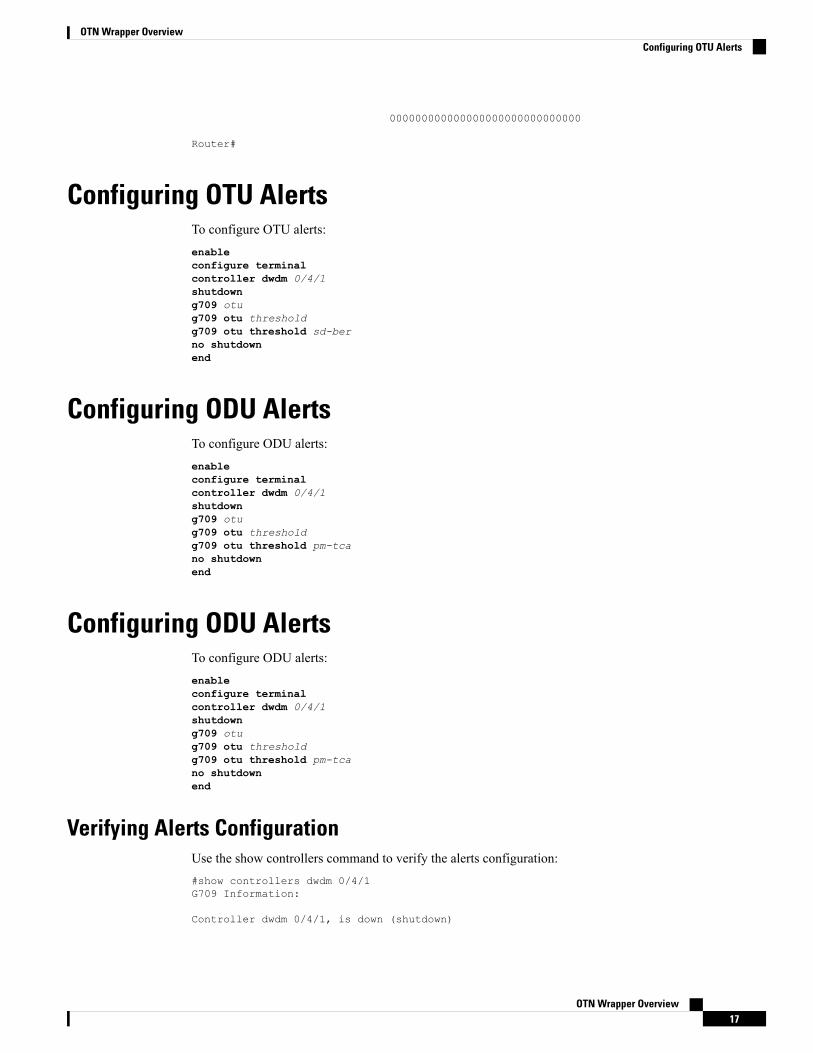
Configuring OTU AlertsTo configure OTU alerts:enableconfigure terminalcontroller dwdm 0/4/1shutdowng709 otug709 otu thresholdg709 otu threshold sd-berno shutdownend
Configuring ODU AlertsTo configure ODU alerts:enableconfigure terminalcontroller dwdm 0/4/1shutdowng709 otug709 otu thresholdg709 otu threshold pm-tcano shutdownend
Configuring ODU AlertsTo configure ODU alerts:enableconfigure terminalcontroller dwdm 0/4/1shutdowng709 otug709 otu thresholdg709 otu threshold pm-tcano shutdownend
Verifying Alerts ConfigurationUse the show controllers command to verify the alerts configuration:#show controllers dwdm 0/4/1G709 Information:
Controller dwdm 0/4/1, is down (shutdown)
OTN Wrapper Overview17
OTN Wrapper OverviewConfiguring OTU Alerts
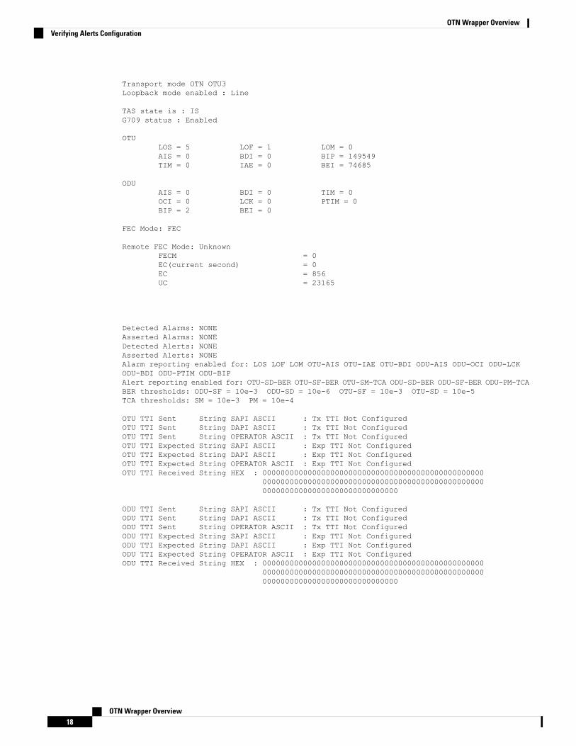
Transport mode OTN OTU3Loopback mode enabled : Line
TAS state is : ISG709 status : Enabled
OTULOS = 5 LOF = 1 LOM = 0AIS = 0 BDI = 0 BIP = 149549TIM = 0 IAE = 0 BEI = 74685
ODUAIS = 0 BDI = 0 TIM = 0OCI = 0 LCK = 0 PTIM = 0BIP = 2 BEI = 0
FEC Mode: FEC
Remote FEC Mode: UnknownFECM = 0EC(current second) = 0EC = 856UC = 23165
Detected Alarms: NONEAsserted Alarms: NONEDetected Alerts: NONEAsserted Alerts: NONEAlarm reporting enabled for: LOS LOF LOM OTU-AIS OTU-IAE OTU-BDI ODU-AIS ODU-OCI ODU-LCKODU-BDI ODU-PTIM ODU-BIPAlert reporting enabled for: OTU-SD-BER OTU-SF-BER OTU-SM-TCA ODU-SD-BER ODU-SF-BER ODU-PM-TCABER thresholds: ODU-SF = 10e-3 ODU-SD = 10e-6 OTU-SF = 10e-3 OTU-SD = 10e-5TCA thresholds: SM = 10e-3 PM = 10e-4
OTU TTI Sent String SAPI ASCII : Tx TTI Not ConfiguredOTU TTI Sent String DAPI ASCII : Tx TTI Not ConfiguredOTU TTI Sent String OPERATOR ASCII : Tx TTI Not ConfiguredOTU TTI Expected String SAPI ASCII : Exp TTI Not ConfiguredOTU TTI Expected String DAPI ASCII : Exp TTI Not ConfiguredOTU TTI Expected String OPERATOR ASCII : Exp TTI Not ConfiguredOTU TTI Received String HEX : 0000000000000000000000000000000000000000000000000
0000000000000000000000000000000000000000000000000000000000000000000000000000000
ODU TTI Sent String SAPI ASCII : Tx TTI Not ConfiguredODU TTI Sent String DAPI ASCII : Tx TTI Not ConfiguredODU TTI Sent String OPERATOR ASCII : Tx TTI Not ConfiguredODU TTI Expected String SAPI ASCII : Exp TTI Not ConfiguredODU TTI Expected String DAPI ASCII : Exp TTI Not ConfiguredODU TTI Expected String OPERATOR ASCII : Exp TTI Not ConfiguredODU TTI Received String HEX : 0000000000000000000000000000000000000000000000000
0000000000000000000000000000000000000000000000000000000000000000000000000000000
OTN Wrapper Overview18
OTN Wrapper OverviewVerifying Alerts Configuration
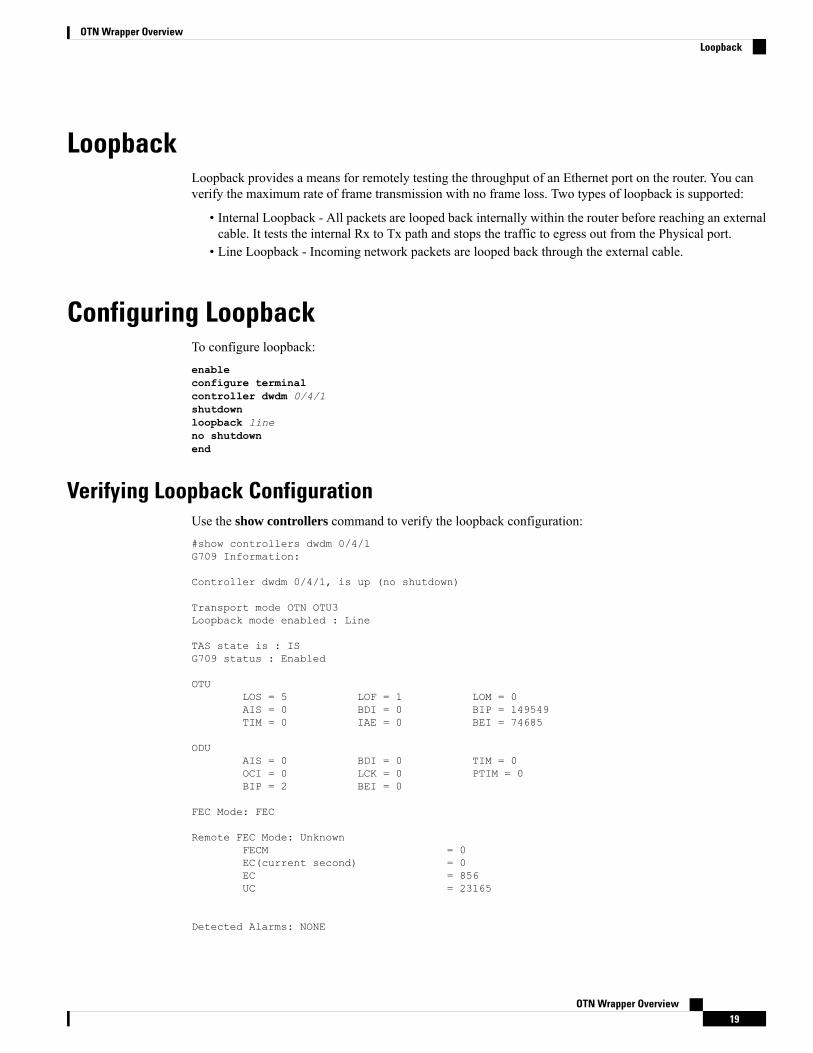
LoopbackLoopback provides a means for remotely testing the throughput of an Ethernet port on the router. You canverify the maximum rate of frame transmission with no frame loss. Two types of loopback is supported:
• Internal Loopback - All packets are looped back internally within the router before reaching an externalcable. It tests the internal Rx to Tx path and stops the traffic to egress out from the Physical port.
• Line Loopback - Incoming network packets are looped back through the external cable.
Configuring LoopbackTo configure loopback:enableconfigure terminalcontroller dwdm 0/4/1shutdownloopback lineno shutdownend
Verifying Loopback ConfigurationUse the show controllers command to verify the loopback configuration:#show controllers dwdm 0/4/1G709 Information:
Controller dwdm 0/4/1, is up (no shutdown)
Transport mode OTN OTU3Loopback mode enabled : Line
TAS state is : ISG709 status : Enabled
OTULOS = 5 LOF = 1 LOM = 0AIS = 0 BDI = 0 BIP = 149549TIM = 0 IAE = 0 BEI = 74685
ODUAIS = 0 BDI = 0 TIM = 0OCI = 0 LCK = 0 PTIM = 0BIP = 2 BEI = 0
FEC Mode: FEC
Remote FEC Mode: UnknownFECM = 0EC(current second) = 0EC = 856UC = 23165
Detected Alarms: NONE
OTN Wrapper Overview19
OTN Wrapper OverviewLoopback
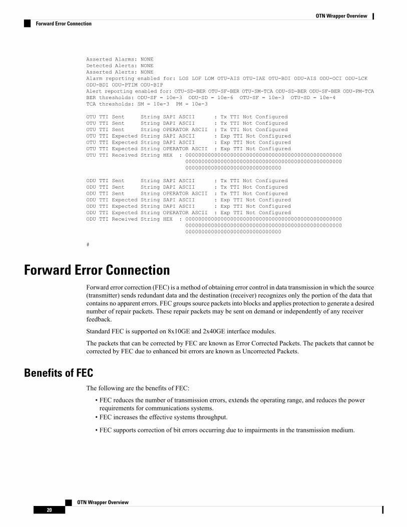
Asserted Alarms: NONEDetected Alerts: NONEAsserted Alerts: NONEAlarm reporting enabled for: LOS LOF LOM OTU-AIS OTU-IAE OTU-BDI ODU-AIS ODU-OCI ODU-LCKODU-BDI ODU-PTIM ODU-BIPAlert reporting enabled for: OTU-SD-BER OTU-SF-BER OTU-SM-TCA ODU-SD-BER ODU-SF-BER ODU-PM-TCABER thresholds: ODU-SF = 10e-3 ODU-SD = 10e-6 OTU-SF = 10e-3 OTU-SD = 10e-4TCA thresholds: SM = 10e-3 PM = 10e-3
OTU TTI Sent String SAPI ASCII : Tx TTI Not ConfiguredOTU TTI Sent String DAPI ASCII : Tx TTI Not ConfiguredOTU TTI Sent String OPERATOR ASCII : Tx TTI Not ConfiguredOTU TTI Expected String SAPI ASCII : Exp TTI Not ConfiguredOTU TTI Expected String DAPI ASCII : Exp TTI Not ConfiguredOTU TTI Expected String OPERATOR ASCII : Exp TTI Not ConfiguredOTU TTI Received String HEX : 0000000000000000000000000000000000000000000000000
0000000000000000000000000000000000000000000000000000000000000000000000000000000
ODU TTI Sent String SAPI ASCII : Tx TTI Not ConfiguredODU TTI Sent String DAPI ASCII : Tx TTI Not ConfiguredODU TTI Sent String OPERATOR ASCII : Tx TTI Not ConfiguredODU TTI Expected String SAPI ASCII : Exp TTI Not ConfiguredODU TTI Expected String DAPI ASCII : Exp TTI Not ConfiguredODU TTI Expected String OPERATOR ASCII : Exp TTI Not ConfiguredODU TTI Received String HEX : 0000000000000000000000000000000000000000000000000
0000000000000000000000000000000000000000000000000000000000000000000000000000000
#
Forward Error ConnectionForward error correction (FEC) is a method of obtaining error control in data transmission in which the source(transmitter) sends redundant data and the destination (receiver) recognizes only the portion of the data thatcontains no apparent errors. FEC groups source packets into blocks and applies protection to generate a desirednumber of repair packets. These repair packets may be sent on demand or independently of any receiverfeedback.
Standard FEC is supported on 8x10GE and 2x40GE interface modules.
The packets that can be corrected by FEC are known as Error Corrected Packets. The packets that cannot becorrected by FEC due to enhanced bit errors are known as Uncorrected Packets.
Benefits of FECThe following are the benefits of FEC:
• FEC reduces the number of transmission errors, extends the operating range, and reduces the powerrequirements for communications systems.
• FEC increases the effective systems throughput.
• FEC supports correction of bit errors occurring due to impairments in the transmission medium.
OTN Wrapper Overview20
OTN Wrapper OverviewForward Error Connection
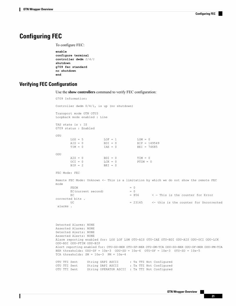
Configuring FECTo configure FEC:enableconfigure terminalcontroller dwdm 0/4/1shutdowng709 fec standardno shutdownend
Verifying FEC ConfigurationUse the show controllers command to verify FEC configuration:G709 Information:
Controller dwdm 0/4/1, is up (no shutdown)
Transport mode OTN OTU3Loopback mode enabled : Line
TAS state is : ISG709 status : Enabled
OTULOS = 5 LOF = 1 LOM = 0AIS = 0 BDI = 0 BIP = 149549TIM = 0 IAE = 0 BEI = 74685
ODUAIS = 0 BDI = 0 TIM = 0OCI = 0 LCK = 0 PTIM = 0BIP = 2 BEI = 0
FEC Mode: FEC
Remote FEC Mode: Unknown <— This is a limitation by which we do not show the remote FECmode
FECM = 0EC(current second) = 0EC = 856 < — This is the counter for Error
corrected bits .UC = 23165 <- this is the counter for Uncorrected
alarms .
Detected Alarms: NONEAsserted Alarms: NONEDetected Alerts: NONEAsserted Alerts: NONEAlarm reporting enabled for: LOS LOF LOM OTU-AIS OTU-IAE OTU-BDI ODU-AIS ODU-OCI ODU-LCKODU-BDI ODU-PTIM ODU-BIPAlert reporting enabled for: OTU-SD-BER OTU-SF-BER OTU-SM-TCA ODU-SD-BER ODU-SF-BER ODU-PM-TCABER thresholds: ODU-SF = 10e-3 ODU-SD = 10e-6 OTU-SF = 10e-3 OTU-SD = 10e-5TCA thresholds: SM = 10e-3 PM = 10e-4
OTU TTI Sent String SAPI ASCII : Tx TTI Not ConfiguredOTU TTI Sent String DAPI ASCII : Tx TTI Not ConfiguredOTU TTI Sent String OPERATOR ASCII : Tx TTI Not Configured
OTN Wrapper Overview21
OTN Wrapper OverviewConfiguring FEC
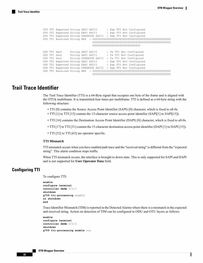
OTU TTI Expected String SAPI ASCII : Exp TTI Not ConfiguredOTU TTI Expected String DAPI ASCII : Exp TTI Not ConfiguredOTU TTI Expected String OPERATOR ASCII : Exp TTI Not ConfiguredOTU TTI Received String HEX : 0000000000000000000000000000000000000000000000000
0000000000000000000000000000000000000000000000000000000000000000000000000000000
ODU TTI Sent String SAPI ASCII : Tx TTI Not ConfiguredODU TTI Sent String DAPI ASCII : Tx TTI Not ConfiguredODU TTI Sent String OPERATOR ASCII : Tx TTI Not ConfiguredODU TTI Expected String SAPI ASCII : Exp TTI Not ConfiguredODU TTI Expected String DAPI ASCII : Exp TTI Not ConfiguredODU TTI Expected String OPERATOR ASCII : Exp TTI Not ConfiguredODU TTI Received String HEX : 0000000000000000000000000000000000000000000000000
0000000000000000000000000000000000000000000000000
Trail Trace IdentifierThe Trail Trace Identifier (TTI) is a 64-Byte signal that occupies one byte of the frame and is aligned withthe OTUk multiframe. It is transmitted four times per multiframe. TTI is defined as a 64-byte string with thefollowing structure:
• TTI [0] contains the Source Access Point Identifier (SAPI) [0] character, which is fixed to all-0s.• TTI [1] to TTI [15] contain the 15-character source access point identifier (SAPI[1] to SAPI[15]).
• TTI [16] contains the Destination Access Point Identifier (DAPI) [0] character, which is fixed to all-0s.
• TTI [17] to TTI [31] contain the 15-character destination access point identifier (DAPI [1] to DAPI [15]).
• TTI [32] to TTI [63] are operator specific.
TTI Mismatch
TTImismatch occurs when you have enabled path trace and the "received string" is different from the "expectedstring". This alarm condition stops traffic.
When TTI mismatch occurs, the interface is brought to down state. This is only supported for SAPI and DAPIand is not supported for User Operator Data field.
Configuring TTITo configure TTI:enableconfigure terminalcontroller dwdm 0/1/1shutdowng709 tti-processing enableno shutdownend
Trace Identifier Mismatch (TIM) is reported in the Detected Alarms where there is a mismatch in the expectedand received string. Action on detection of TIM can be configured in ODU and OTU layers as follows:enableconfigure terminalcontroller dwdm 0/1/1shutdowng709 tti-processing enable otu
OTN Wrapper Overview22
OTN Wrapper OverviewTrail Trace Identifier
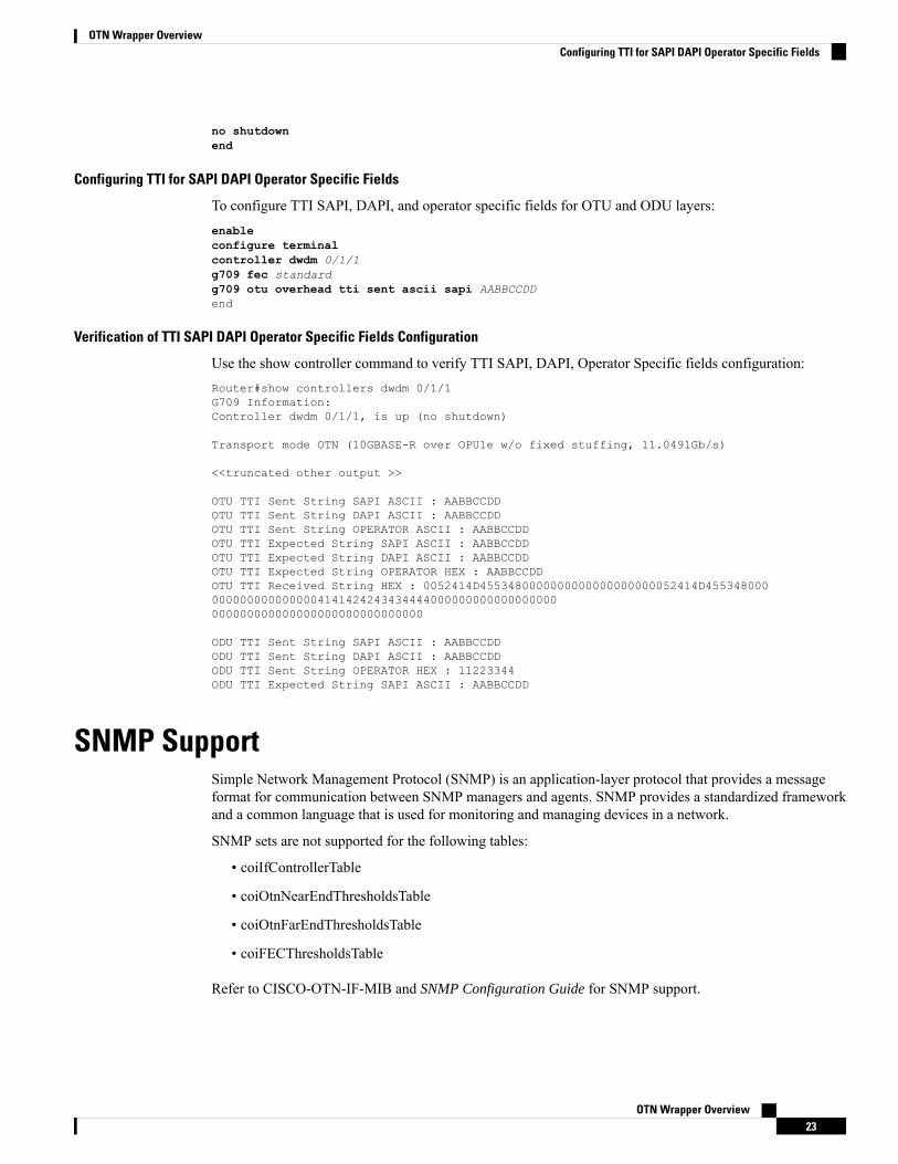
no shutdownend
Configuring TTI for SAPI DAPI Operator Specific Fields
To configure TTI SAPI, DAPI, and operator specific fields for OTU and ODU layers:enableconfigure terminalcontroller dwdm 0/1/1g709 fec standardg709 otu overhead tti sent ascii sapi AABBCCDDend
Verification of TTI SAPI DAPI Operator Specific Fields Configuration
Use the show controller command to verify TTI SAPI, DAPI, Operator Specific fields configuration:Router#show controllers dwdm 0/1/1G709 Information:Controller dwdm 0/1/1, is up (no shutdown)
Transport mode OTN (10GBASE-R over OPU1e w/o fixed stuffing, 11.0491Gb/s)
<<truncated other output >>
OTU TTI Sent String SAPI ASCII : AABBCCDDOTU TTI Sent String DAPI ASCII : AABBCCDDOTU TTI Sent String OPERATOR ASCII : AABBCCDDOTU TTI Expected String SAPI ASCII : AABBCCDDOTU TTI Expected String DAPI ASCII : AABBCCDDOTU TTI Expected String OPERATOR HEX : AABBCCDDOTU TTI Received String HEX : 0052414D4553480000000000000000000052414D4553480000000000000000004141424243434444000000000000000000000000000000000000000000000000
ODU TTI Sent String SAPI ASCII : AABBCCDDODU TTI Sent String DAPI ASCII : AABBCCDDODU TTI Sent String OPERATOR HEX : 11223344ODU TTI Expected String SAPI ASCII : AABBCCDD
SNMP SupportSimple Network Management Protocol (SNMP) is an application-layer protocol that provides a messageformat for communication between SNMP managers and agents. SNMP provides a standardized frameworkand a common language that is used for monitoring and managing devices in a network.
SNMP sets are not supported for the following tables:
• coiIfControllerTable
• coiOtnNearEndThresholdsTable
• coiOtnFarEndThresholdsTable
• coiFECThresholdsTable
Refer to CISCO-OTN-IF-MIB and SNMP Configuration Guide for SNMP support.
OTN Wrapper Overview23
OTN Wrapper OverviewConfiguring TTI for SAPI DAPI Operator Specific Fields
Performance MonitoringPerformance monitoring (PM) parameters are used by service providers to gather, store, set thresholds for,and report performance data for early detection of problems. Thresholds are used to set error levels for eachPM parameter. During the accumulation cycle, if the current value of a performance monitoring parameterreaches or exceeds its corresponding threshold value, a threshold crossing alert (TCA) is generated. The TCAsprovide early detection of performance degradation. PM statistics are accumulated on a 15-minute basis,synchronized to the start of each quarter-hour. Historical counts are maintained for 33 15-minutes intervalsand 2 daily intervals. PM parameters are collected for OTN and FEC.
Calculation and accumulation of the performance-monitoring data is in 15-minute and 24-hour intervals.
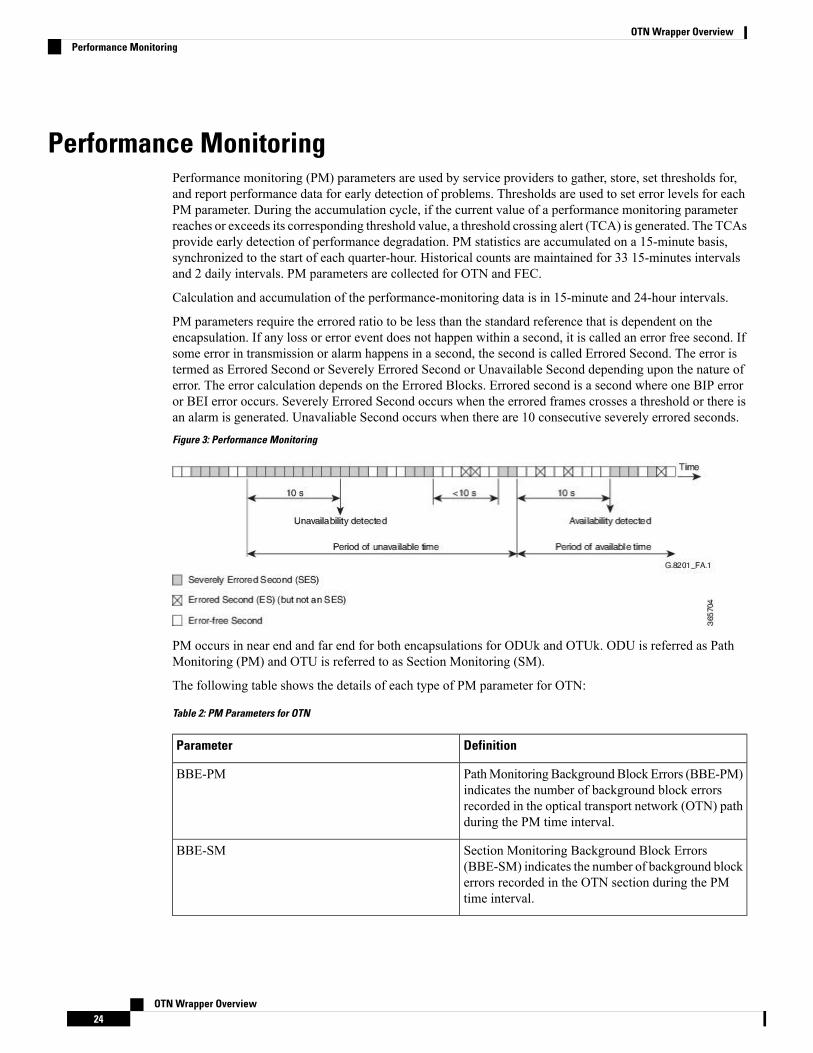
PM parameters require the errored ratio to be less than the standard reference that is dependent on theencapsulation. If any loss or error event does not happen within a second, it is called an error free second. Ifsome error in transmission or alarm happens in a second, the second is called Errored Second. The error istermed as Errored Second or Severely Errored Second or Unavailable Second depending upon the nature oferror. The error calculation depends on the Errored Blocks. Errored second is a second where one BIP erroror BEI error occurs. Severely Errored Second occurs when the errored frames crosses a threshold or there isan alarm is generated. Unavaliable Second occurs when there are 10 consecutive severely errored seconds.
Figure 3: Performance Monitoring
PM occurs in near end and far end for both encapsulations for ODUk and OTUk. ODU is referred as PathMonitoring (PM) and OTU is referred to as Section Monitoring (SM).
The following table shows the details of each type of PM parameter for OTN:
Table 2: PM Parameters for OTN
DefinitionParameter
PathMonitoring BackgroundBlock Errors (BBE-PM)indicates the number of background block errorsrecorded in the optical transport network (OTN) pathduring the PM time interval.
BBE-PM
Section Monitoring Background Block Errors(BBE-SM) indicates the number of background blockerrors recorded in the OTN section during the PMtime interval.
BBE-SM
OTN Wrapper Overview24
OTN Wrapper OverviewPerformance Monitoring
DefinitionParameter
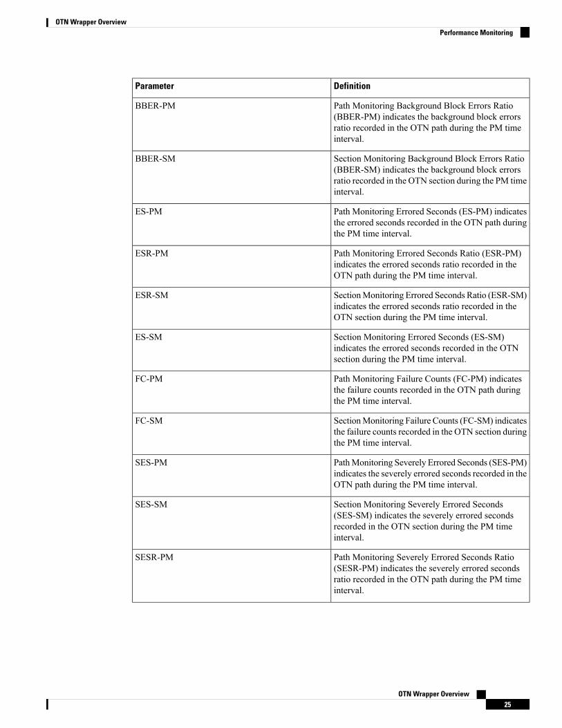
Path Monitoring Background Block Errors Ratio(BBER-PM) indicates the background block errorsratio recorded in the OTN path during the PM timeinterval.
BBER-PM
Section Monitoring Background Block Errors Ratio(BBER-SM) indicates the background block errorsratio recorded in the OTN section during the PM timeinterval.
BBER-SM
Path Monitoring Errored Seconds (ES-PM) indicatesthe errored seconds recorded in the OTN path duringthe PM time interval.
ES-PM
Path Monitoring Errored Seconds Ratio (ESR-PM)indicates the errored seconds ratio recorded in theOTN path during the PM time interval.
ESR-PM
SectionMonitoring Errored Seconds Ratio (ESR-SM)indicates the errored seconds ratio recorded in theOTN section during the PM time interval.
ESR-SM
Section Monitoring Errored Seconds (ES-SM)indicates the errored seconds recorded in the OTNsection during the PM time interval.
ES-SM
Path Monitoring Failure Counts (FC-PM) indicatesthe failure counts recorded in the OTN path duringthe PM time interval.
FC-PM
SectionMonitoring Failure Counts (FC-SM) indicatesthe failure counts recorded in the OTN section duringthe PM time interval.
FC-SM
PathMonitoring Severely Errored Seconds (SES-PM)indicates the severely errored seconds recorded in theOTN path during the PM time interval.
SES-PM
Section Monitoring Severely Errored Seconds(SES-SM) indicates the severely errored secondsrecorded in the OTN section during the PM timeinterval.
SES-SM
Path Monitoring Severely Errored Seconds Ratio(SESR-PM) indicates the severely errored secondsratio recorded in the OTN path during the PM timeinterval.
SESR-PM
OTN Wrapper Overview25
OTN Wrapper OverviewPerformance Monitoring
DefinitionParameter
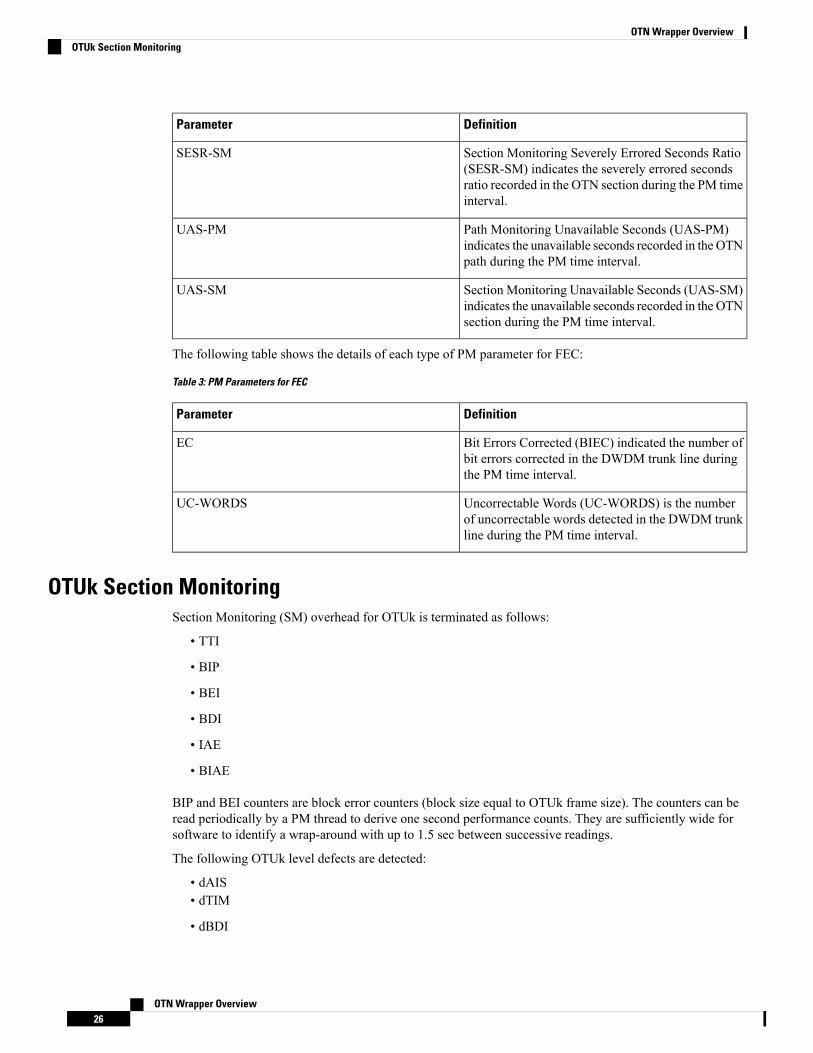
Section Monitoring Severely Errored Seconds Ratio(SESR-SM) indicates the severely errored secondsratio recorded in the OTN section during the PM timeinterval.
SESR-SM
Path Monitoring Unavailable Seconds (UAS-PM)indicates the unavailable seconds recorded in the OTNpath during the PM time interval.
UAS-PM
Section Monitoring Unavailable Seconds (UAS-SM)indicates the unavailable seconds recorded in the OTNsection during the PM time interval.
UAS-SM
The following table shows the details of each type of PM parameter for FEC:
Table 3: PM Parameters for FEC
DefinitionParameter
Bit Errors Corrected (BIEC) indicated the number ofbit errors corrected in the DWDM trunk line duringthe PM time interval.
EC
Uncorrectable Words (UC-WORDS) is the numberof uncorrectable words detected in the DWDM trunkline during the PM time interval.
UC-WORDS
OTUk Section MonitoringSection Monitoring (SM) overhead for OTUk is terminated as follows:
• TTI
• BIP
• BEI
• BDI
• IAE
• BIAE
BIP and BEI counters are block error counters (block size equal to OTUk frame size). The counters can beread periodically by a PM thread to derive one second performance counts. They are sufficiently wide forsoftware to identify a wrap-around with up to 1.5 sec between successive readings.
The following OTUk level defects are detected:
• dAIS• dTIM
• dBDI
OTN Wrapper Overview26
OTN Wrapper OverviewOTUk Section Monitoring
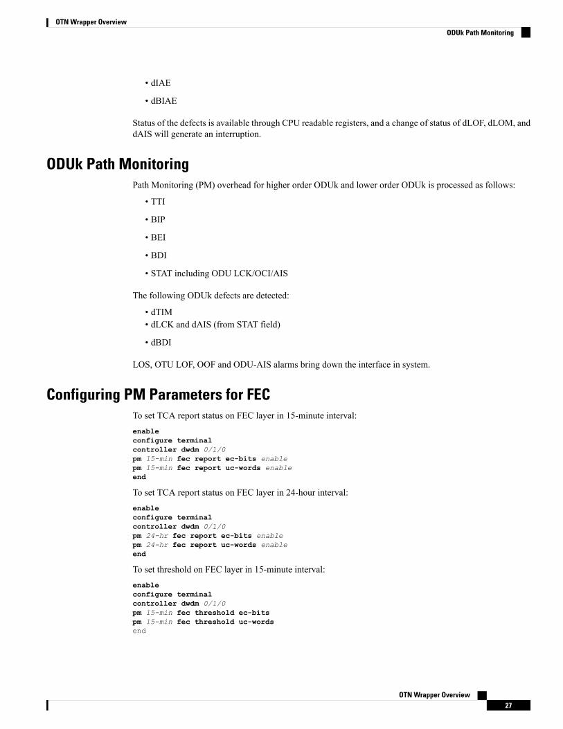
• dIAE
• dBIAE
Status of the defects is available through CPU readable registers, and a change of status of dLOF, dLOM, anddAIS will generate an interruption.
ODUk Path MonitoringPath Monitoring (PM) overhead for higher order ODUk and lower order ODUk is processed as follows:
• TTI
• BIP
• BEI
• BDI
• STAT including ODU LCK/OCI/AIS
The following ODUk defects are detected:
• dTIM• dLCK and dAIS (from STAT field)
• dBDI
LOS, OTU LOF, OOF and ODU-AIS alarms bring down the interface in system.
Configuring PM Parameters for FECTo set TCA report status on FEC layer in 15-minute interval:enableconfigure terminalcontroller dwdm 0/1/0pm 15-min fec report ec-bits enablepm 15-min fec report uc-words enableend
To set TCA report status on FEC layer in 24-hour interval:enableconfigure terminalcontroller dwdm 0/1/0pm 24-hr fec report ec-bits enablepm 24-hr fec report uc-words enableend
To set threshold on FEC layer in 15-minute interval:enableconfigure terminalcontroller dwdm 0/1/0pm 15-min fec threshold ec-bitspm 15-min fec threshold uc-wordsend
OTN Wrapper Overview27
OTN Wrapper OverviewODUk Path Monitoring
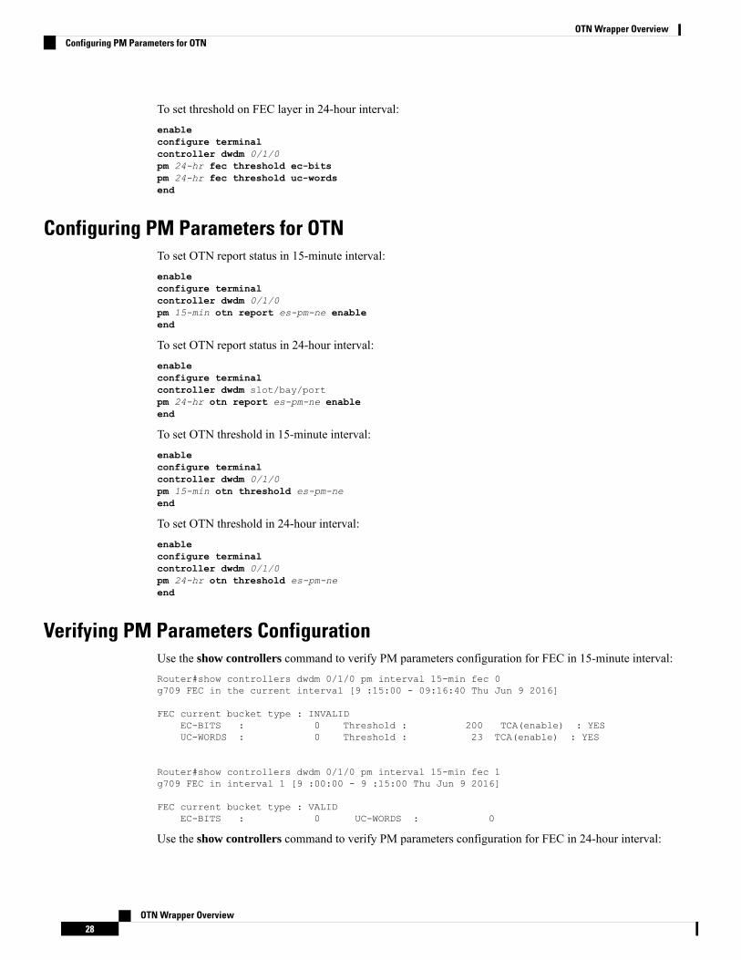
To set threshold on FEC layer in 24-hour interval:enableconfigure terminalcontroller dwdm 0/1/0pm 24-hr fec threshold ec-bitspm 24-hr fec threshold uc-wordsend
Configuring PM Parameters for OTNTo set OTN report status in 15-minute interval:enableconfigure terminalcontroller dwdm 0/1/0pm 15-min otn report es-pm-ne enableend
To set OTN report status in 24-hour interval:enableconfigure terminalcontroller dwdm slot/bay/portpm 24-hr otn report es-pm-ne enableend
To set OTN threshold in 15-minute interval:enableconfigure terminalcontroller dwdm 0/1/0pm 15-min otn threshold es-pm-neend
To set OTN threshold in 24-hour interval:enableconfigure terminalcontroller dwdm 0/1/0pm 24-hr otn threshold es-pm-neend
Verifying PM Parameters ConfigurationUse the show controllers command to verify PM parameters configuration for FEC in 15-minute interval:Router#show controllers dwdm 0/1/0 pm interval 15-min fec 0g709 FEC in the current interval [9 :15:00 - 09:16:40 Thu Jun 9 2016]
FEC current bucket type : INVALIDEC-BITS : 0 Threshold : 200 TCA(enable) : YESUC-WORDS : 0 Threshold : 23 TCA(enable) : YES
Router#show controllers dwdm 0/1/0 pm interval 15-min fec 1g709 FEC in interval 1 [9 :00:00 - 9 :15:00 Thu Jun 9 2016]
FEC current bucket type : VALIDEC-BITS : 0 UC-WORDS : 0
Use the show controllers command to verify PM parameters configuration for FEC in 24-hour interval:
OTN Wrapper Overview28
OTN Wrapper OverviewConfiguring PM Parameters for OTN
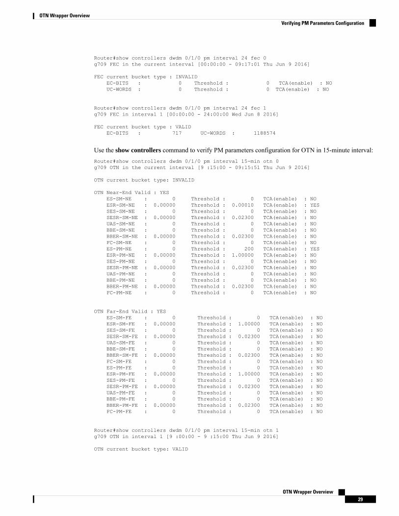
Router#show controllers dwdm 0/1/0 pm interval 24 fec 0g709 FEC in the current interval [00:00:00 - 09:17:01 Thu Jun 9 2016]
FEC current bucket type : INVALIDEC-BITS : 0 Threshold : 0 TCA(enable) : NOUC-WORDS : 0 Threshold : 0 TCA(enable) : NO
Router#show controllers dwdm 0/1/0 pm interval 24 fec 1g709 FEC in interval 1 [00:00:00 - 24:00:00 Wed Jun 8 2016]
FEC current bucket type : VALIDEC-BITS : 717 UC-WORDS : 1188574
Use the show controllers command to verify PM parameters configuration for OTN in 15-minute interval:Router#show controllers dwdm 0/1/0 pm interval 15-min otn 0g709 OTN in the current interval [9 :15:00 - 09:15:51 Thu Jun 9 2016]
OTN current bucket type: INVALID
OTN Near-End Valid : YESES-SM-NE : 0 Threshold : 0 TCA(enable) : NOESR-SM-NE : 0.00000 Threshold : 0.00010 TCA(enable) : YESSES-SM-NE : 0 Threshold : 0 TCA(enable) : NOSESR-SM-NE : 0.00000 Threshold : 0.02300 TCA(enable) : NOUAS-SM-NE : 0 Threshold : 0 TCA(enable) : NOBBE-SM-NE : 0 Threshold : 0 TCA(enable) : NOBBER-SM-NE : 0.00000 Threshold : 0.02300 TCA(enable) : NOFC-SM-NE : 0 Threshold : 0 TCA(enable) : NOES-PM-NE : 0 Threshold : 200 TCA(enable) : YESESR-PM-NE : 0.00000 Threshold : 1.00000 TCA(enable) : NOSES-PM-NE : 0 Threshold : 0 TCA(enable) : NOSESR-PM-NE : 0.00000 Threshold : 0.02300 TCA(enable) : NOUAS-PM-NE : 0 Threshold : 0 TCA(enable) : NOBBE-PM-NE : 0 Threshold : 0 TCA(enable) : NOBBER-PM-NE : 0.00000 Threshold : 0.02300 TCA(enable) : NOFC-PM-NE : 0 Threshold : 0 TCA(enable) : NO
OTN Far-End Valid : YESES-SM-FE : 0 Threshold : 0 TCA(enable) : NOESR-SM-FE : 0.00000 Threshold : 1.00000 TCA(enable) : NOSES-SM-FE : 0 Threshold : 0 TCA(enable) : NOSESR-SM-FE : 0.00000 Threshold : 0.02300 TCA(enable) : NOUAS-SM-FE : 0 Threshold : 0 TCA(enable) : NOBBE-SM-FE : 0 Threshold : 0 TCA(enable) : NOBBER-SM-FE : 0.00000 Threshold : 0.02300 TCA(enable) : NOFC-SM-FE : 0 Threshold : 0 TCA(enable) : NOES-PM-FE : 0 Threshold : 0 TCA(enable) : NOESR-PM-FE : 0.00000 Threshold : 1.00000 TCA(enable) : NOSES-PM-FE : 0 Threshold : 0 TCA(enable) : NOSESR-PM-FE : 0.00000 Threshold : 0.02300 TCA(enable) : NOUAS-PM-FE : 0 Threshold : 0 TCA(enable) : NOBBE-PM-FE : 0 Threshold : 0 TCA(enable) : NOBBER-PM-FE : 0.00000 Threshold : 0.02300 TCA(enable) : NOFC-PM-FE : 0 Threshold : 0 TCA(enable) : NO
Router#show controllers dwdm 0/1/0 pm interval 15-min otn 1g709 OTN in interval 1 [9 :00:00 - 9 :15:00 Thu Jun 9 2016]
OTN current bucket type: VALID
OTN Wrapper Overview29
OTN Wrapper OverviewVerifying PM Parameters Configuration
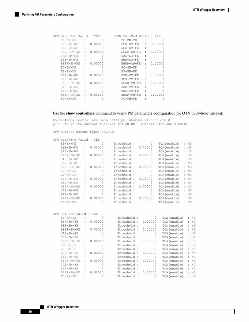
OTN Near-End Valid : YES OTN Far-End Valid : YESES-SM-NE : 0 ES-SM-FE : 0ESR-SM-NE : 0.00000 ESR-SM-FE : 0.00000SES-SM-NE : 0 SES-SM-FE : 0SESR-SM-NE : 0.00000 SESR-SM-FE : 0.00000UAS-SM-NE : 0 UAS-SM-FE : 0BBE-SM-NE : 0 BBE-SM-FE : 0BBER-SM-NE : 0.00000 BBER-SM-FE : 0.00000FC-SM-NE : 0 FC-SM-FE : 0ES-PM-NE : 0 ES-PM-FE : 0ESR-PM-NE : 0.00000 ESR-PM-FE : 0.00000SES-PM-NE : 0 SES-PM-FE : 0SESR-PM-NE : 0.00000 SESR-PM-FE : 0.00000UAS-PM-NE : 0 UAS-PM-FE : 0BBE-PM-NE : 0 BBE-PM-FE : 0BBER-PM-NE : 0.00000 BBER-PM-FE : 0.00000FC-PM-NE : 0 FC-PM-FE : 0
Use the show controllers command to verify PM parameters configuration for OTN in 24-hour interval:Router#show controllers dwdm 0/1/0 pm interval 24-hour otn 0g709 OTN in the current interval [00:00:00 - 09:16:10 Thu Jun 9 2016]
OTN current bucket type: INVALID
OTN Near-End Valid : YESES-SM-NE : 0 Threshold : 0 TCA(enable) : NOESR-SM-NE : 0.00000 Threshold : 0.00000 TCA(enable) : NOSES-SM-NE : 0 Threshold : 0 TCA(enable) : NOSESR-SM-NE : 0.00000 Threshold : 0.00000 TCA(enable) : NOUAS-SM-NE : 0 Threshold : 0 TCA(enable) : NOBBE-SM-NE : 0 Threshold : 0 TCA(enable) : NOBBER-SM-NE : 0.00000 Threshold : 0.00000 TCA(enable) : NOFC-SM-NE : 0 Threshold : 0 TCA(enable) : NOES-PM-NE : 0 Threshold : 0 TCA(enable) : NOESR-PM-NE : 0.00000 Threshold : 0.00000 TCA(enable) : NOSES-PM-NE : 0 Threshold : 0 TCA(enable) : NOSESR-PM-NE : 0.00000 Threshold : 0.00000 TCA(enable) : NOUAS-PM-NE : 0 Threshold : 0 TCA(enable) : NOBBE-PM-NE : 0 Threshold : 0 TCA(enable) : NOBBER-PM-NE : 0.00000 Threshold : 0.00000 TCA(enable) : NOFC-PM-NE : 0 Threshold : 0 TCA(enable) : NO
OTN Far-End Valid : YESES-SM-FE : 0 Threshold : 0 TCA(enable) : NOESR-SM-FE : 0.00000 Threshold : 0.00000 TCA(enable) : NOSES-SM-FE : 0 Threshold : 0 TCA(enable) : NOSESR-SM-FE : 0.00000 Threshold : 0.00000 TCA(enable) : NOUAS-SM-FE : 0 Threshold : 0 TCA(enable) : NOBBE-SM-FE : 0 Threshold : 0 TCA(enable) : NOBBER-SM-FE : 0.00000 Threshold : 0.00000 TCA(enable) : NOFC-SM-FE : 0 Threshold : 0 TCA(enable) : NOES-PM-FE : 0 Threshold : 0 TCA(enable) : NOESR-PM-FE : 0.00000 Threshold : 0.00000 TCA(enable) : NOSES-PM-FE : 0 Threshold : 0 TCA(enable) : NOSESR-PM-FE : 0.00000 Threshold : 0.00000 TCA(enable) : NOUAS-PM-FE : 0 Threshold : 0 TCA(enable) : NOBBE-PM-FE : 0 Threshold : 0 TCA(enable) : NOBBER-PM-FE : 0.00000 Threshold : 0.00000 TCA(enable) : NOFC-PM-FE : 0 Threshold : 0 TCA(enable) : NO
OTN Wrapper Overview30
OTN Wrapper OverviewVerifying PM Parameters Configuration
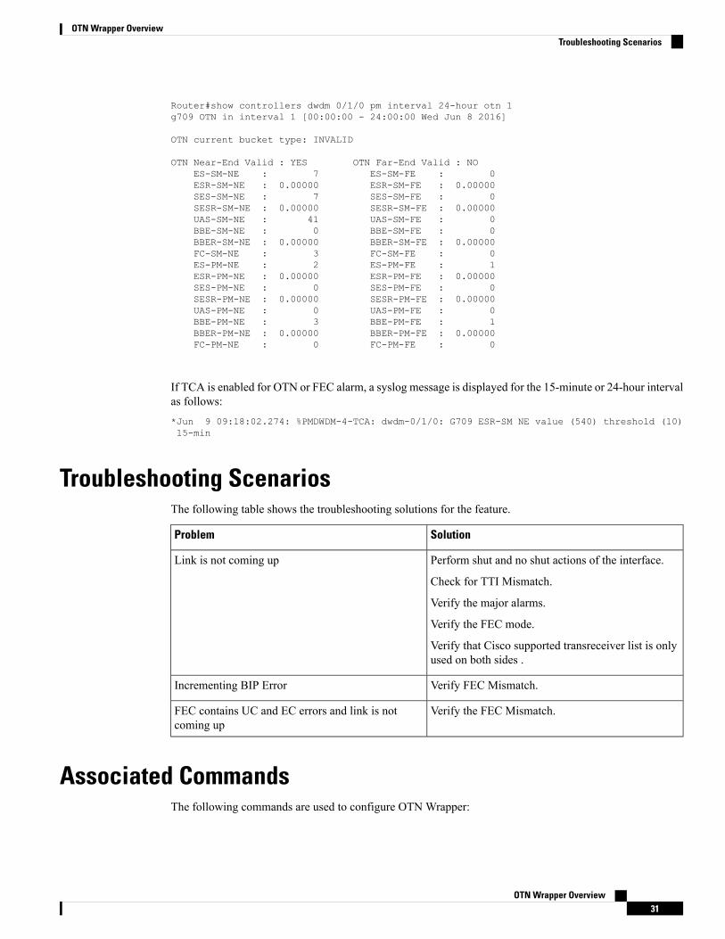
Router#show controllers dwdm 0/1/0 pm interval 24-hour otn 1g709 OTN in interval 1 [00:00:00 - 24:00:00 Wed Jun 8 2016]
OTN current bucket type: INVALID
OTN Near-End Valid : YES OTN Far-End Valid : NOES-SM-NE : 7 ES-SM-FE : 0ESR-SM-NE : 0.00000 ESR-SM-FE : 0.00000SES-SM-NE : 7 SES-SM-FE : 0SESR-SM-NE : 0.00000 SESR-SM-FE : 0.00000UAS-SM-NE : 41 UAS-SM-FE : 0BBE-SM-NE : 0 BBE-SM-FE : 0BBER-SM-NE : 0.00000 BBER-SM-FE : 0.00000FC-SM-NE : 3 FC-SM-FE : 0ES-PM-NE : 2 ES-PM-FE : 1ESR-PM-NE : 0.00000 ESR-PM-FE : 0.00000SES-PM-NE : 0 SES-PM-FE : 0SESR-PM-NE : 0.00000 SESR-PM-FE : 0.00000UAS-PM-NE : 0 UAS-PM-FE : 0BBE-PM-NE : 3 BBE-PM-FE : 1BBER-PM-NE : 0.00000 BBER-PM-FE : 0.00000FC-PM-NE : 0 FC-PM-FE : 0
If TCA is enabled for OTN or FEC alarm, a syslog message is displayed for the 15-minute or 24-hour intervalas follows:*Jun 9 09:18:02.274: %PMDWDM-4-TCA: dwdm-0/1/0: G709 ESR-SM NE value (540) threshold (10)15-min
Troubleshooting ScenariosThe following table shows the troubleshooting solutions for the feature.
SolutionProblem
Perform shut and no shut actions of the interface.
Check for TTI Mismatch.
Verify the major alarms.
Verify the FEC mode.
Verify that Cisco supported transreceiver list is onlyused on both sides .
Link is not coming up
Verify FEC Mismatch.Incrementing BIP Error
Verify the FEC Mismatch.FEC contains UC and EC errors and link is notcoming up
Associated CommandsThe following commands are used to configure OTN Wrapper:
OTN Wrapper Overview31
OTN Wrapper OverviewTroubleshooting Scenarios
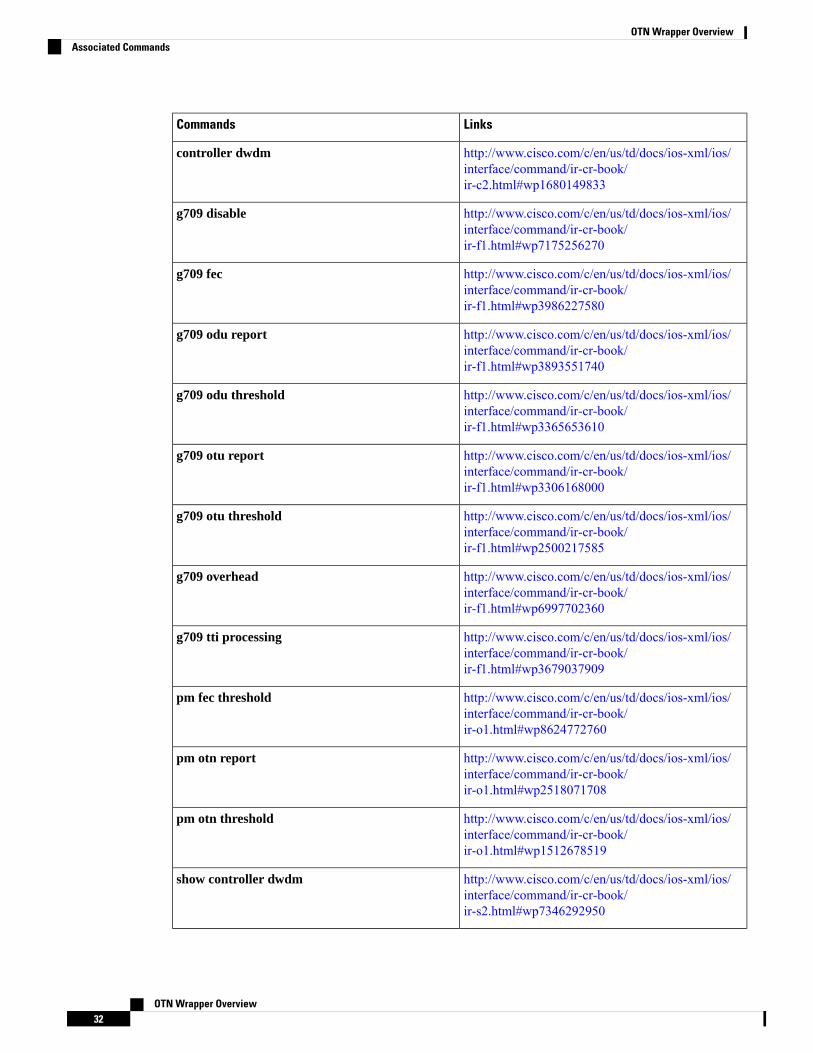
LinksCommands
http://www.cisco.com/c/en/us/td/docs/ios-xml/ios/interface/command/ir-cr-book/ir-c2.html#wp1680149833
controller dwdm
http://www.cisco.com/c/en/us/td/docs/ios-xml/ios/interface/command/ir-cr-book/ir-f1.html#wp7175256270
g709 disable
http://www.cisco.com/c/en/us/td/docs/ios-xml/ios/interface/command/ir-cr-book/ir-f1.html#wp3986227580
g709 fec
http://www.cisco.com/c/en/us/td/docs/ios-xml/ios/interface/command/ir-cr-book/ir-f1.html#wp3893551740
g709 odu report
http://www.cisco.com/c/en/us/td/docs/ios-xml/ios/interface/command/ir-cr-book/ir-f1.html#wp3365653610
g709 odu threshold
http://www.cisco.com/c/en/us/td/docs/ios-xml/ios/interface/command/ir-cr-book/ir-f1.html#wp3306168000
g709 otu report
http://www.cisco.com/c/en/us/td/docs/ios-xml/ios/interface/command/ir-cr-book/ir-f1.html#wp2500217585
g709 otu threshold
http://www.cisco.com/c/en/us/td/docs/ios-xml/ios/interface/command/ir-cr-book/ir-f1.html#wp6997702360
g709 overhead
http://www.cisco.com/c/en/us/td/docs/ios-xml/ios/interface/command/ir-cr-book/ir-f1.html#wp3679037909
g709 tti processing
http://www.cisco.com/c/en/us/td/docs/ios-xml/ios/interface/command/ir-cr-book/ir-o1.html#wp8624772760
pm fec threshold
http://www.cisco.com/c/en/us/td/docs/ios-xml/ios/interface/command/ir-cr-book/ir-o1.html#wp2518071708
pm otn report
http://www.cisco.com/c/en/us/td/docs/ios-xml/ios/interface/command/ir-cr-book/ir-o1.html#wp1512678519
pm otn threshold
http://www.cisco.com/c/en/us/td/docs/ios-xml/ios/interface/command/ir-cr-book/ir-s2.html#wp7346292950
show controller dwdm
OTN Wrapper Overview32
OTN Wrapper OverviewAssociated Commands
LinksCommands
http://www.cisco.com/c/en/us/td/docs/ios-xml/ios/interface/command/ir-cr-book/ir-s4.html#wp2987586133
show interfaces
http://www.cisco.com/c/en/us/td/docs/ios-xml/ios/interface/command/ir-cr-book/ir-t1.html#wp3012872075
transport-mode
OTN Wrapper Overview33
OTN Wrapper OverviewAssociated Commands

OTN Wrapper Overview34
OTN Wrapper OverviewAssociated Commands


