Embed Size (px)
Citation preview

Date: 03.10.2016
Orion User Manual
Version 2.0.2.74
VERIPOS

Procedure Title: Orion User Manual (Version 2.0.2.74) File Ref.: AB-V-MA-00594
Rev No:
A2 Page 2
A2 03.10.2016 Renamed to relate to Orion v2.0.2.74 only
AR RR RR -
A1 25.01.2016 Minor updates for Phase 8 compliance
AR RR RR -
A 03.08.2015 Minor changes following review AR RR RR -
1 23.07.2015 For review AR - -
REVISION DATE DESCRIPTION ORIGINATOR CHECKED APPROVED CLIENT APPR
Procedure Title:
Orion User Manual (Version 2.0.2.74)
File Ref: AB-V-MA-00594
Procedure Title: Orion User Manual (Version 2.0.2.74) File Ref.: AB-V-MA-00594
Rev No:
A2 Page 3
CONTENTS
1.1 INTRODUCTION ...................................................................................................................................4 1.2 SOFTWARE PLATFORMS ...................................................................................................................5 1.3 SOFTWARE ACTIVATION ....................................................................................................................5 1.4 ORION ON VERIPOS LD6 ....................................................................................................................6
1.4.1 Launching Orion On-board LD6.......................................................................................6 1.5 ORION CONFIGURATION MENUS .....................................................................................................7
1.5.1 Configuration - System Tab .............................................................................................8 1.5.2 Configuration - Heading Input ..........................................................................................9 1.5.3 Configuration - Motion .................................................................................................. 10 1.5.4 Configuration - Targets ................................................................................................. 12 1.5.5 Configuration - Vessel .................................................................................................. 13
2. OVERVIEW OF ORION ................................................................................................................................ 14
2.1 TABS BAR .......................................................................................................................................... 15 2.2 INFORMATION PANEL ...................................................................................................................... 16
2.2.1 Date & Time .................................................................................................................. 16 2.2.2 Solution Status .............................................................................................................. 17 2.2.3 Satellite Constellation ................................................................................................... 17 2.2.4 DOP (HDOP &PDOP) ................................................................................................... 18 2.2.5 Veripos Mode ................................................................................................................ 18 2.2.6 Position (WGS84) ......................................................................................................... 18 2.2.7 Horizontal Error (1ð) ..................................................................................................... 18 2.2.8 Latency ......................................................................................................................... 19
2.3 MAIN DISPLAY SCREEN .................................................................................................................. 20 2.3.1 Polar Plot ...................................................................................................................... 20 2.3.2 Heading tab ................................................................................................................... 21 2.3.3 Target ............................................................................................................................ 22
2.4 SYSTEM STATUS DASHBOARD ...................................................................................................... 23 2.4.1 Correction Status .......................................................................................................... 23 2.4.2 Positioning Status ......................................................................................................... 24
2.5 SHUT DOWN ..................................................................................................................................... 26
3. TROUBLESHOOTING ................................................................................................................................. 27
APPENDIX I. ........................................................................................................................................................... 30
CONTACT INFORMATION .......................................................................................................................... 30
APPENDIX II. .......................................................................................................................................................... 32
ABBREVIATIONS ......................................................................................................................................... 32
APPENDIX III. ......................................................................................................................................................... 34
VERIPOS REFERENCE STATIONS............................................................................................................ 34
APPENDIX IV. ........................................................................................................................................................ 36
QUALITY STANDARDS ............................................................................................................................... 36
APPENDIX V. ......................................................................................................................................................... 41
NMEA SENTENCES .................................................................................................................................... 41

Procedure Title: Orion User Manual (Version 2.0.2.74) File Ref.: AB-V-MA-00594
Rev No:
A2 Page 4
1.1 INTRODUCTION
VERIPOS specialise in providing robust data broadcast services for precise positioning applications for the offshore industry. The VERIPOS receiver may optionally be equipped with on-board visualisation software called Orion which is optimised for DP operations. It can also be used with VERIPOS Integrated Mobile Units connected to the Orion software running on a PC and connected (using a LAN). This manual contains the information required to operate the Orion software when running on-board an LD6 IMU.
Orion is quality and position monitoring software that has been designed specifically for DP operators and navigation users who need to quickly and continuously assess the quality of their positioning. It shows key positioning parameters as well as overall solution status. The display has a fixed format. The information displayed includes:
Position and Correction Status information
UTC Time
Horizontal Error
Latency
Satellite Polar Plot
PDOP and HDOP
Night Mode access
Constellation status
Solution status
Vessel heading
Course
Speed
Track

Procedure Title: Orion User Manual (Version 2.0.2.74) File Ref.: AB-V-MA-00594
Rev No:
A2 Page 5
For updates of this document and to access related VERIPOS documentation referenced please visit the VERIPOS online support system (VOSS): http://help.veripos.com Related documents:
LD6 Operations manual.
1.2 SOFTWARE PLATFORMS
Orion software can be used on Veripos LD6 Integrated Mobile Unit with a touch panel display or a PC Running Windows XP or Windows 7 and attached to a VERIPOS receiver (IMU). This manual covers the use of Orion when running on-board LD6 (on software version 8.2.0.3 & below) only. For details on Orion on a PC or on higher LD6 software versins, please refer to Orion manual (AB-V-MA-00553).
1.3 SOFTWARE ACTIVATION
Orion must first be ENABLED in the receiver. Orion is an additional VERIPOS service. When contacting the Helpdesk for an enable code please specify that a DP service is required in addition to your GNSS augmentation service. (e.g. DP and Ultra Service.) See the receiver Operations manual for details on enabling VERIPOS services with your receiver. The VERIPOS Helpdesk contact details are available in Appendix I.
Procedure Title: Orion User Manual (Version 2.0.2.74) File Ref.: AB-V-MA-00594
Rev No:
A2 Page 6
1.4 ORION ON VERIPOS LD6
The Orion software is typically provided pre – loaded on an LD6 and may use a touch screen display for viewing the Orion software suite. Where Orion is required, first check you have a build of software on the LD6 which includes Orion. The LD6 can be used in conjunction with a touchscreen monitor, using a VGA and USB (A) connection. Note: When installing the monitor a USB mouse is required for screen calibration. Attach the monitors VGA and a USB ports to the LD6 and power up. Go to Home screen/ Actions/ Apps. A “Launch Orion” button is shown when Orion software is installed on the LD6. The VERIPOS Helpdesk can provide further information on a LD6 software build required for use with Orion. Before using the software ensure the LD6 is enabled for a DP code and working with VERIPOS corrections. The LD6 Operations Quick Guide and Manual provide more information.
1.4.1 Launching Orion On-board LD6
Steps:
1. Power down and disconnect LD6 from the power supply.
2. Connect the touch screen provided to the VGA port and a USB A cable to a free USB port on the rear of the LD6.
3. Power up the LD6 and touch screen. Allow a few minutes for the LD6 to
start.
4. Attach a USB mouse for use during screen configuration.
5. To Calibrate Screen 1 (LD6 screen - on the LD6 front panel, use the mouse to navigate to Home/ Actions and then Calibrate Screen 1. Follow the on-screen directions to touch the buttons with your finger to calibrate the LD6 screen (Screen 1).
6. Touch Calibrate Screen 2 and wait until the display appears on the external touch screen monitor. Follow the on screen instructions and touch the four points as they appear on screen in turn to calibrate.
7. When the external screen calibration is completed, on the LD6 screen, touch through menu structure Actions/ Apps/ Launch Orion.
Procedure Title: Orion User Manual (Version 2.0.2.74) File Ref.: AB-V-MA-00594
Rev No:
A2 Page 7
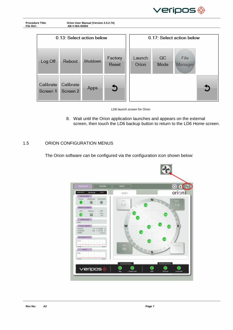
LD6 launch screen for Orion
8. Wait until the Orion application launches and appears on the external
screen, then touch the LD6 backup button to return to the LD6 Home screen.
1.5 ORION CONFIGURATION MENUS
The Orion software can be configured via the configuration icon shown below:

Procedure Title: Orion User Manual (Version 2.0.2.74) File Ref.: AB-V-MA-00594
Rev No:
A2 Page 8
1.5.1 Configuration - System Tab
When running the Orion software on board an LD6, the required NMEA messages will be available automatically without the need for user configuration.
All NMEA message icons should be green to show that all required messages are being received by the Orion software:
The Heading icon will only be green if a gyro input has been manually configured. See section 1.5.2 for further details regarding configuration of heading data input. In the Identification field, a User ID can be entered. The User ID entered here will be displayed above within the tab shown below. This is useful when more than one Orion system is running.
Procedure Title: Orion User Manual (Version 2.0.2.74) File Ref.: AB-V-MA-00594
Rev No:
A2 Page 9
Once changes have been made, confirm by pressing Apply. To restore settings back to previous configuration press Revert.
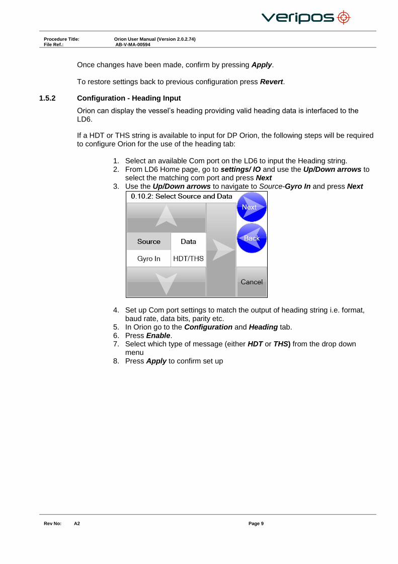
1.5.2 Configuration - Heading Input
Orion can display the vessel’s heading providing valid heading data is interfaced to the LD6.
If a HDT or THS string is available to input for DP Orion, the following steps will be required to configure Orion for the use of the heading tab:
1. Select an available Com port on the LD6 to input the Heading string. 2. From LD6 Home page, go to settings/ IO and use the Up/Down arrows to
select the matching com port and press Next 3. Use the Up/Down arrows to navigate to Source-Gyro In and press Next
4. Set up Com port settings to match the output of heading string i.e. format, baud rate, data bits, parity etc.
5. In Orion go to the Configuration and Heading tab. 6. Press Enable. 7. Select which type of message (either HDT or THS) from the drop down
menu 8. Press Apply to confirm set up
Procedure Title: Orion User Manual (Version 2.0.2.74) File Ref.: AB-V-MA-00594
Rev No:
A2 Page 10
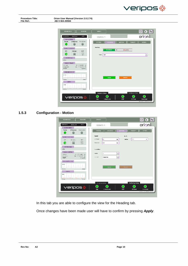
1.5.3 Configuration - Motion
In this tab you are able to configure the view for the Heading tab. Once changes have been made user will have to confirm by pressing Apply.

Procedure Title: Orion User Manual (Version 2.0.2.74) File Ref.: AB-V-MA-00594
Rev No:
A2 Page 11
1.5.3.1 Speed
This option is for the course arrow in the heading view. The arrow will increase and decrease to a varied size depending on speed. The options are minimum and maximum; a minimum can be set between 0 and 0.3. If the speed drops below the minimum speed set the arrow will disappear. The maximum speed can be set up to 20 knots. Once the vessel reaches the maximum speed set in the software the arrow will remain at its largest touch the edge of the circle.
1.5.3.2 Scale
The scale option allows the user to change the scale of the circle. The measure is from the centre of the circle to the edge of the circle.
1.5.3.3 Track Plot
The Track Plot will allow for a bubble to be printed on the screen at different intervals as the vessel moves allowing the user to view the movement of the vessel. There are 2 options to configure, Points and Interval. Points is the option for how many bubbles are displayed on screen, and is able to be set from 0 to 15 from the drop down menu and is in incremented values of 5, if Zero is selected there will be no bubble trail displayed. Interval is how often a bubble will be plotted on the screen, this is selected from the drop down menu and is selectable from values of 5 varying between 5 and 30 seconds.
Procedure Title: Orion User Manual (Version 2.0.2.74) File Ref.: AB-V-MA-00594
Rev No:
A2 Page 12
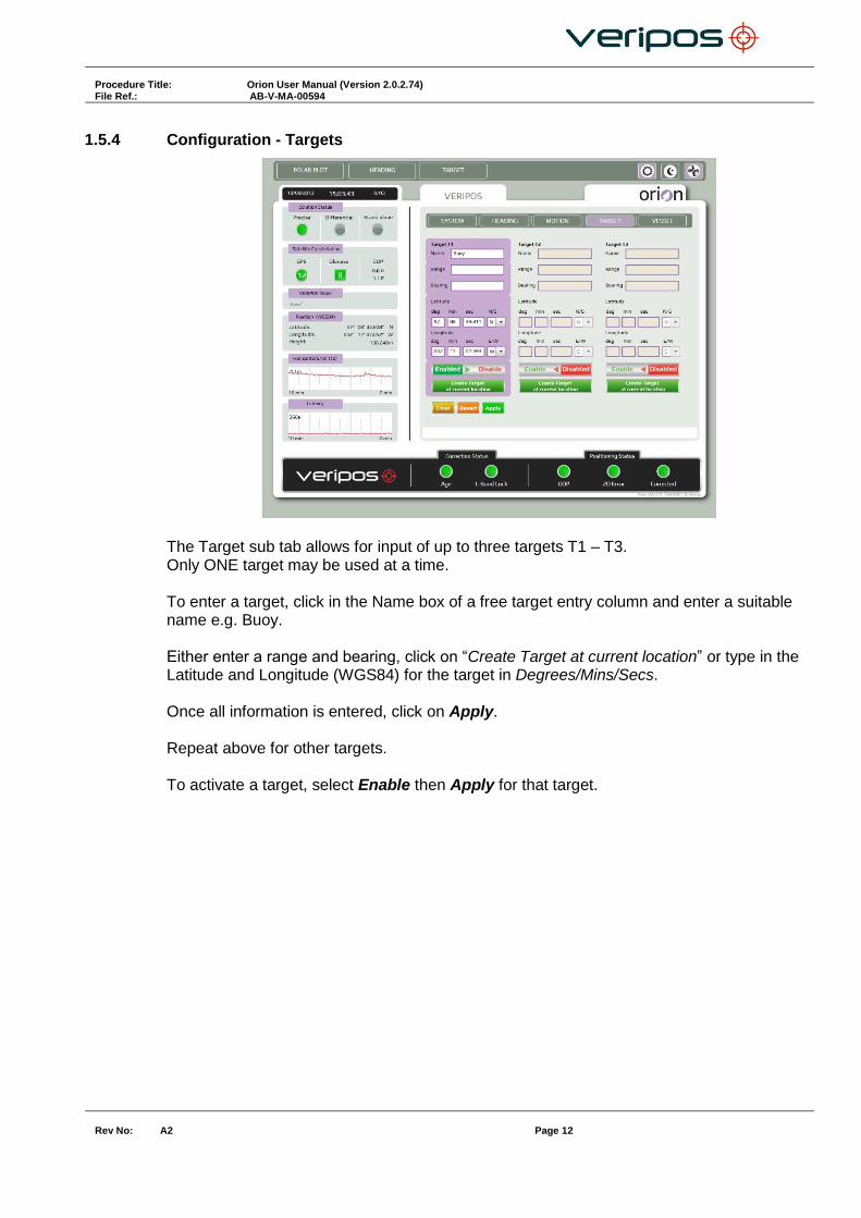
1.5.4 Configuration - Targets
The Target sub tab allows for input of up to three targets T1 – T3. Only ONE target may be used at a time. To enter a target, click in the Name box of a free target entry column and enter a suitable name e.g. Buoy. Either enter a range and bearing, click on “Create Target at current location” or type in the Latitude and Longitude (WGS84) for the target in Degrees/Mins/Secs. Once all information is entered, click on Apply. Repeat above for other targets. To activate a target, select Enable then Apply for that target.

Procedure Title: Orion User Manual (Version 2.0.2.74) File Ref.: AB-V-MA-00594
Rev No:
A2 Page 13
1.5.5 Configuration - Vessel
The Vessel sub – tab allows input of dimensions as an approximation for the vessel.
Use the Antenna Offset field to enter (in metres) to the required decimal point accuracy, the GNSS antenna offset as measured form the Central Reference Point (CRP) of the vessel. Use the Vessel field to enter the length and width of the vessel. NOTE: The antenna offset entered has no effect on the position output from the LD6 – the LD6 will ALWAYS output the antenna position.

Procedure Title: Orion User Manual (Version 2.0.2.74) File Ref.: AB-V-MA-00594
Rev No:
A2 Page 14
2. OVERVIEW OF ORION
With the receiver connected the Orion software will run when launched.
The home screen will be shown;
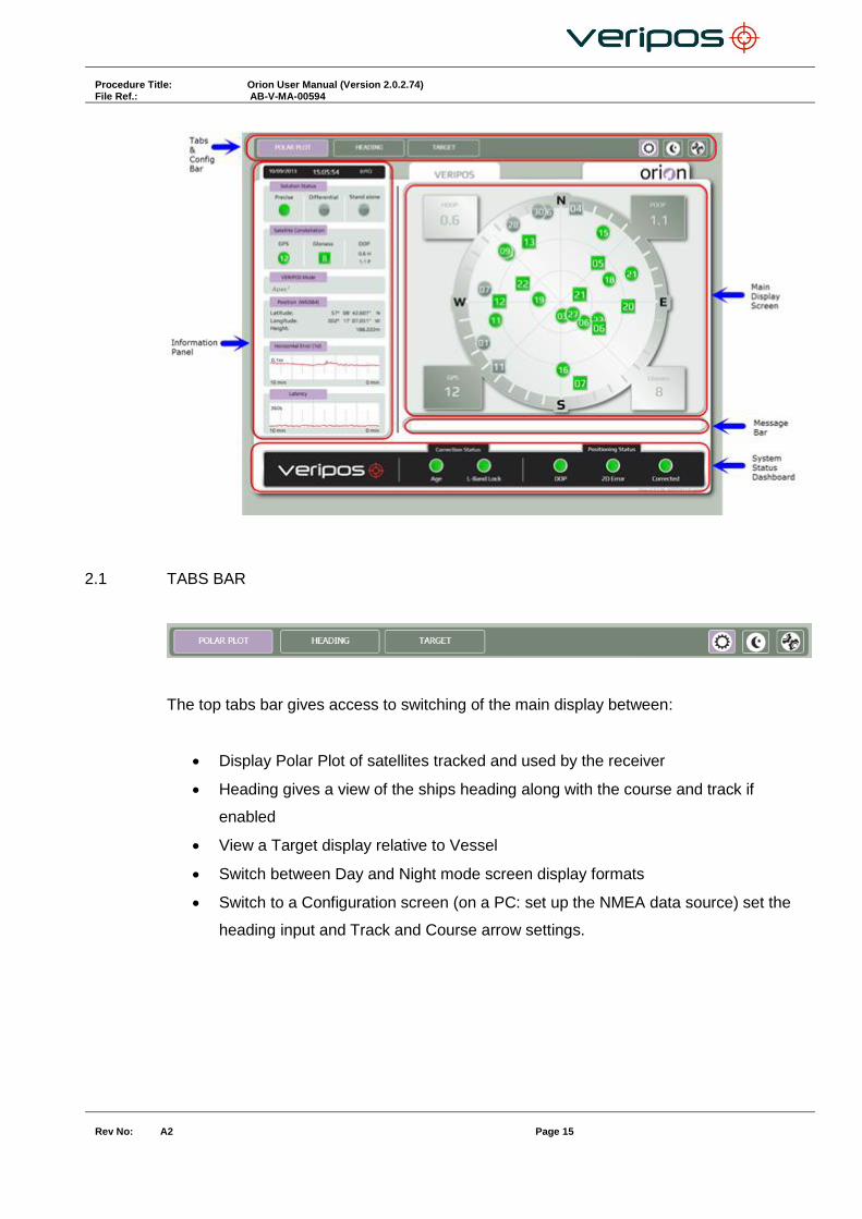
Orion Main screen
The main screen elements are:
Tabs Bar
Main Display Screen
Information Panel
System Status Dashboard
Message Bar
Procedure Title: Orion User Manual (Version 2.0.2.74) File Ref.: AB-V-MA-00594
Rev No:
A2 Page 15
2.1 TABS BAR
The top tabs bar gives access to switching of the main display between:
Display Polar Plot of satellites tracked and used by the receiver
Heading gives a view of the ships heading along with the course and track if
enabled
View a Target display relative to Vessel
Switch between Day and Night mode screen display formats
Switch to a Configuration screen (on a PC: set up the NMEA data source) set the
heading input and Track and Course arrow settings.

Procedure Title: Orion User Manual (Version 2.0.2.74) File Ref.: AB-V-MA-00594
Rev No:
A2 Page 16
2.2 INFORMATION PANEL
The side bar displays the Information Panel & provides key data:
2.2.1 Date & Time
When receiving an NMEA data stream the software displays UTC time.
When no NMEA data is present the PC system clock time is displayed and the display
turns from White numbers to red.

Procedure Title: Orion User Manual (Version 2.0.2.74) File Ref.: AB-V-MA-00594
Rev No:
A2 Page 17
2.2.2 Solution Status
Status information is shown for the correction solution currently being output from the
receiver.
In normal use a single, green illuminated button indicates the solution being output with the
colour indicating status:
Green button = Solution applied
Grey button = Not being applied
Example: for output of a Precise point position output
Amber button = Shown only against the Stand alone (uncorrected) position when this is
being output
Example: for output of Stand-alone:
Where the solution = Differential, the -
- Precise radio button = Grey
- Differential radio button = Green
- Stand Alone radio button = Grey
Example:
2.2.3 Satellite Constellation
Indicates the number of satellites for each constellation (GPS / GLONASS) in use.
Procedure Title: Orion User Manual (Version 2.0.2.74) File Ref.: AB-V-MA-00594
Rev No:
A2 Page 18
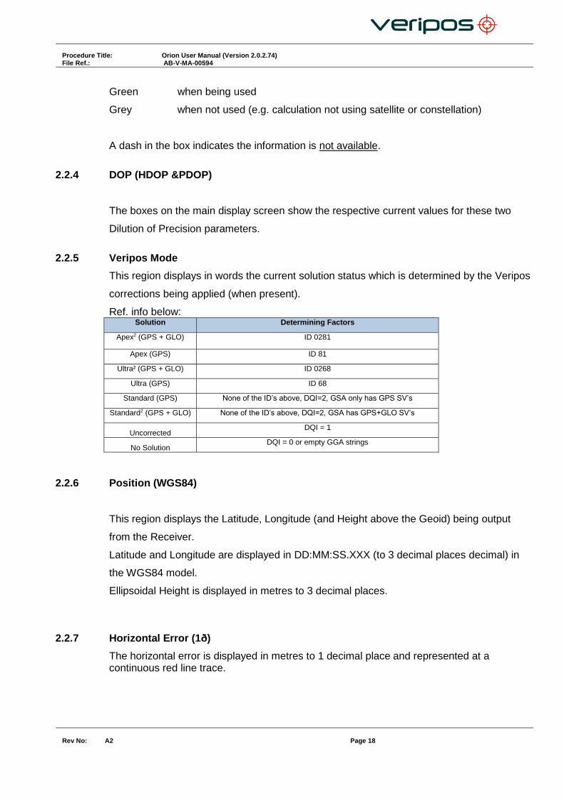
Green when being used
Grey when not used (e.g. calculation not using satellite or constellation)
A dash in the box indicates the information is not available.
2.2.4 DOP (HDOP &PDOP)
The boxes on the main display screen show the respective current values for these two
Dilution of Precision parameters.
2.2.5 Veripos Mode
This region displays in words the current solution status which is determined by the Veripos
corrections being applied (when present).
Ref. info below: Solution Determining Factors
Apex2 (GPS + GLO) ID 0281
Apex (GPS) ID 81
Ultra² (GPS + GLO) ID 0268
Ultra (GPS) ID 68
Standard (GPS) None of the ID’s above, DQI=2, GSA only has GPS SV’s
Standard2 (GPS + GLO) None of the ID’s above, DQI=2, GSA has GPS+GLO SV’s
Uncorrected DQI = 1
No Solution DQI = 0 or empty GGA strings
2.2.6 Position (WGS84)
This region displays the Latitude, Longitude (and Height above the Geoid) being output
from the Receiver.
Latitude and Longitude are displayed in DD:MM:SS.XXX (to 3 decimal places decimal) in
the WGS84 model.
Ellipsoidal Height is displayed in metres to 3 decimal places.
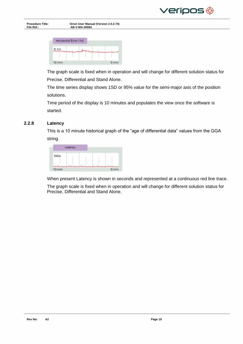
2.2.7 Horizontal Error (1ð)
The horizontal error is displayed in metres to 1 decimal place and represented at a continuous red line trace.
Procedure Title: Orion User Manual (Version 2.0.2.74) File Ref.: AB-V-MA-00594
Rev No:
A2 Page 19
The graph scale is fixed when in operation and will change for different solution status for
Precise, Differential and Stand Alone.
The time series display shows 1SD or 95% value for the semi-major axis of the position
solutions.
Time period of the display is 10 minutes and populates the view once the software is
started.
2.2.8 Latency
This is a 10 minute historical graph of the “age of differential data” values from the GGA
string.
When present Latency is shown in seconds and represented at a continuous red line trace.
The graph scale is fixed when in operation and will change for different solution status for Precise, Differential and Stand Alone.

Procedure Title: Orion User Manual (Version 2.0.2.74) File Ref.: AB-V-MA-00594
Rev No:
A2 Page 20
2.3 MAIN DISPLAY SCREEN
Currently there are 3 options to be displayed in the main display screen, selected from the tabs bar of Polar Plot, Heading and Target.
2.3.1 Polar Plot
The Main screen displays the Polar Plot for satellites above the GNSS antenna mask.
Satellites in use will be displayed Green
Satellites tracked but not in use will be displayed Grey
Circles represent GPS satellites.
Squares represent GLONASS satellites.
Satellites being used within the solution calculation are identified as being present within
the GSA string. Satellites being tracked but not used within the solution calculation are
identified as being present within the GSV string but not in GSA string.
2.3.1.1 PDOP
The current PDOP value for the solution being output
2.3.1.2 HDOP
The current HDOP value for the solution being output

Procedure Title: Orion User Manual (Version 2.0.2.74) File Ref.: AB-V-MA-00594
Rev No:
A2 Page 21
2.3.1.3 GPS
The number of GPS satellites being used to derive the position
2.3.1.4 GLONASS
The number of GLONASS satellites being used to derive the position
2.3.2 Heading tab
The main screen displays the vessel in relation to the heading and will rotate along with heading input. A ”bubble trail”, when enabled, will be displayed to show direction of travel.
2.3.2.1 SOG (knots)
This is the speed of the vessel input from the VTG NMEA message.
2.3.2.2 COG
This is the course of the vessel input from the VTG NMEA message.
2.3.2.3 Heading (true)
This is the heading input if option is enabled. This can be input via a HDT or THS NMEA message.
2.3.2.4 Dial Radius Scale
Displays the scale from the centre of the circle to the edge of the circle can be edited in the configuration tab.

Procedure Title: Orion User Manual (Version 2.0.2.74) File Ref.: AB-V-MA-00594
Rev No:
A2 Page 22
2.3.2.5 Beam Icons
Icons of Veripos beam satellites will be displayed at their bearing on the outer of the circle. This will assist when selecting available beams on the IMU.
2.3.3 Target
The Target screen displays an aerial view of the vessel relative to the selected target, together with relevant information on the bearing and range, COG, Speed (in knots) and Heading against scaled range rings. Note that the Vessel outline is not shown to scale.
2.3.3.1 Change target / parameters
To add / amend / delete a target go to the configuration /Target page:
Procedure Title: Orion User Manual (Version 2.0.2.74) File Ref.: AB-V-MA-00594
Rev No:
A2 Page 23
Click on the Target to Add/ change and enter the required information. Then Apply to confirm. To use this target, click on Enable then Apply. Only one target may be active at a time.
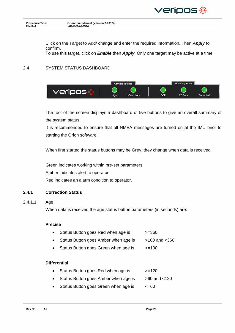
2.4 SYSTEM STATUS DASHBOARD
The foot of the screen displays a dashboard of five buttons to give an overall summary of
the system status.
It is recommended to ensure that all NMEA messages are turned on at the IMU prior to
starting the Orion software.
When first started the status buttons may be Grey, they change when data is received.
Green indicates working within pre-set parameters.
Amber indicates alert to operator.
Red indicates an alarm condition to operator.
2.4.1 Correction Status
2.4.1.1 Age
When data is received the age status button parameters (in seconds) are:
Precise
Status Button goes Red when age is >=360
Status Button goes Amber when age is >100 and <360
Status Button goes Green when age is <=100
Differential
Status Button goes Red when age is >=120
Status Button goes Amber when age is >60 and <120
Status Button goes Green when age is <=60
Procedure Title: Orion User Manual (Version 2.0.2.74) File Ref.: AB-V-MA-00594
Rev No:
A2 Page 24
Stand Alone
Status Button is Red when Solution Status = Stand Alone
2.4.1.2 L-Band Lock
When the L-Band module has lock to a VERIPOS beam the button will be green. If there is no lock to a beam or not available, the button is Red.
2.4.2 Positioning Status
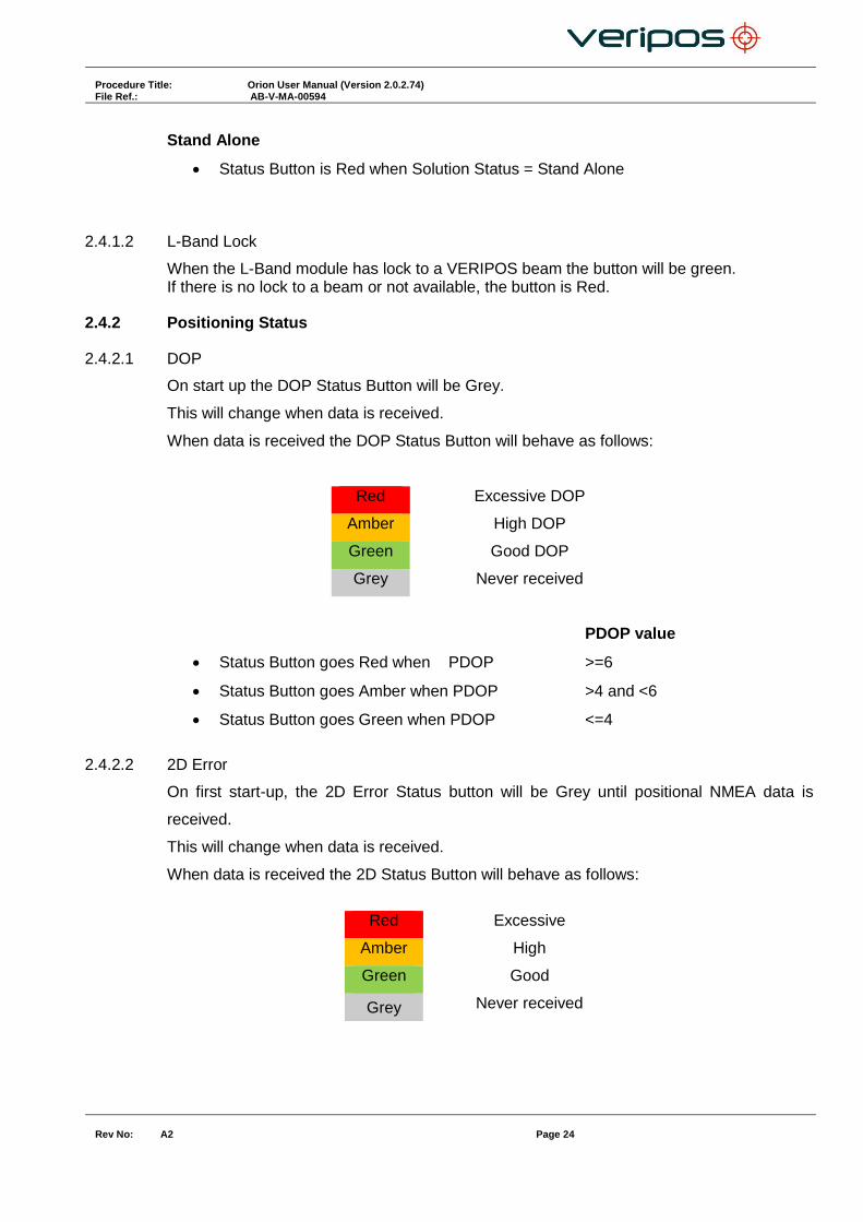
2.4.2.1 DOP
On start up the DOP Status Button will be Grey.
This will change when data is received.
When data is received the DOP Status Button will behave as follows:
Red Excessive DOP
Amber High DOP
Green Good DOP
Grey Never received
PDOP value
Status Button goes Red when PDOP >=6
Status Button goes Amber when PDOP >4 and <6
Status Button goes Green when PDOP <=4
2.4.2.2 2D Error
On first start-up, the 2D Error Status button will be Grey until positional NMEA data is
received.
This will change when data is received.
When data is received the 2D Status Button will behave as follows:
Red Excessive
Amber High
Green Good
Grey Never received

Procedure Title: Orion User Manual (Version 2.0.2.74) File Ref.: AB-V-MA-00594
Rev No:
A2 Page 25
Precise
Traffic light goes Red when 2D Error >=0.5 m
Traffic light goes Amber 2D Error >0.3 m and <0.5m
Traffic light goes Green when 2D Error <=0.3m
Differential
Traffic light goes Red when 2D Error >=1.5 m
Traffic light goes Amber 2D Error >1 m and <1.5m
Traffic light goes Green when 2D Error <=1m
Stand Alone
Traffic light goes Red when 2D Error >=1.5 m
Traffic light goes Amber 2D Error >1 m and <1.5m
Traffic light goes Green when 2D Error <=1m
2.4.2.3 Corrected
When started, the Corrected status button will be Grey.
This will change when data is received.
If data is received the Corrected status button will behave as follows:
Red Uncorrected Solution
Green Corrected Solution
Grey Never received
Traffic light goes Red when DQI = 1 or 0
Traffic light goes Green when DQI >1

Procedure Title: Orion User Manual (Version 2.0.2.74) File Ref.: AB-V-MA-00594
Rev No:
A2 Page 26
2.5 SHUT DOWN
To shut down the Orion software, navigate to the CONFIGURATION / System tab.
Select Shut Down. A timer appears confirming your selection before closing Orion.
Select Cancel to stop shut down of Orion
Procedure Title: Orion User Manual (Version 2.0.2.74) File Ref.: AB-V-MA-00594
Rev No:
A2 Page 27
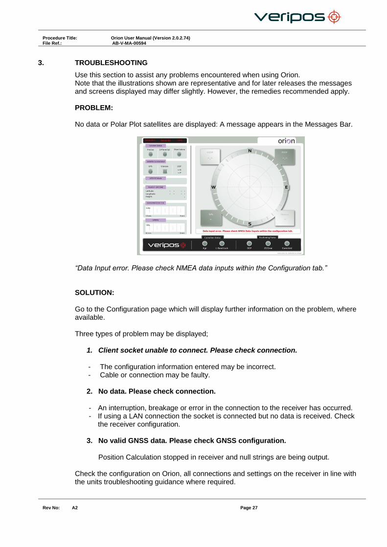
3. TROUBLESHOOTING
Use this section to assist any problems encountered when using Orion. Note that the illustrations shown are representative and for later releases the messages and screens displayed may differ slightly. However, the remedies recommended apply. PROBLEM: No data or Polar Plot satellites are displayed: A message appears in the Messages Bar.
“Data Input error. Please check NMEA data inputs within the Configuration tab.” SOLUTION: Go to the Configuration page which will display further information on the problem, where available. Three types of problem may be displayed;
1. Client socket unable to connect. Please check connection.
- The configuration information entered may be incorrect. - Cable or connection may be faulty.
2. No data. Please check connection.
- An interruption, breakage or error in the connection to the receiver has occurred. - If using a LAN connection the socket is connected but no data is received. Check
the receiver configuration.
3. No valid GNSS data. Please check GNSS configuration. Position Calculation stopped in receiver and null strings are being output.
Check the configuration on Orion, all connections and settings on the receiver in line with the units troubleshooting guidance where required.

Procedure Title: Orion User Manual (Version 2.0.2.74) File Ref.: AB-V-MA-00594
Rev No:
A2 Page 28
PROBLEM: I shut down my LD6. When re-started, the Orion touch screen does not display Orion. SOLUTION: Each time the LD6 is started, Orion should launch automatically if it was running when the LD6 was shut down.. If Orion does not launch automatically, from LD6 Home screen, touch Actions/Launch Orion and wait 10 seconds or so for the application to launch. PROBLEM: The screen appears darkened. SOLUTION: Night mode has been selected; monitor brightness / contrast has been modified. Adjust monitor controls or select the Day Mode from the Tabs Bar.
PROBLEM: The display freezes and the remainder of the screen does not update. SOLUTION: This indicates a total positioning failure caused a by a loss of GNSS input. Refer to the receiver Operations manual for troubleshooting procedures.
Procedure Title: Orion User Manual (Version 2.0.2.74) File Ref.: AB-V-MA-00594
Rev No:
A2 Page 29
PROBLEM: Using Orion with an LD6, the unit displays 16 satellites: however the data streams indicate there are more than 16 satellites available / in use to calculate the position. SOLUTION: On an LD6 a maximum of 16 satellites will display. This is a known issue with the output from RTMFVC on an LD6.
Procedure Title: Orion User Manual (Version 2.0.2.74) File Ref.: AB-V-MA-00594
Rev No:
A2 Page 30
APPENDIX I.
CONTACT INFORMATION

Procedure Title: Orion User Manual (Version 2.0.2.74) File Ref.: AB-V-MA-00594
Rev No:
A2 Page 31
VERIPOS CONTACT INFORMATION
All initial contacts regarding technical or support issues should be initially addressed to the VERIPOS Helpdesk. Where appropriate, the Helpdesk will refer issues to the regional operations and engineering teams.
VERIPOS Helpdesk Telephone: +44 (0) 1224 965900
VERIPOS Helpdesk E-mail: [email protected] VERIPOS Online Support Site (VOSS):http://help.veripos.com
If shipping equipment back to VERIPOS, please contact the Helpdesk who will provide the current shipping address, according to your area of operations. UK VERIPOS office address:
For other VERIPOS office locations visit www.veripos.com.
Veripos House, 1B Farburn Terrace, Dyce, Aberdeen. AB21 7DT Scotland UK
Procedure Title: Orion User Manual (Version 2.0.2.74) File Ref.: AB-V-MA-00594
Rev No:
A2 Page 32
APPENDIX II.
ABBREVIATIONS
Procedure Title: Orion User Manual (Version 2.0.2.74) File Ref.: AB-V-MA-00594
Rev No:
A2 Page 33
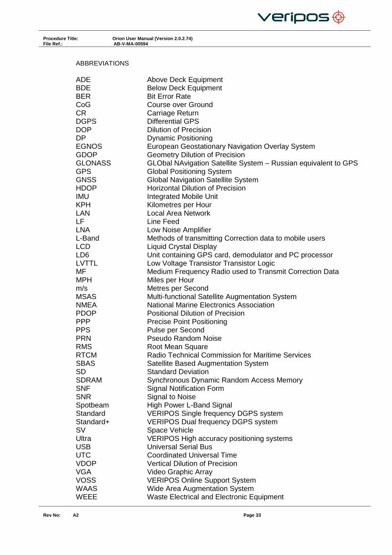
ABBREVIATIONS
ADE Above Deck Equipment BDE Below Deck Equipment BER Bit Error Rate CoG Course over Ground CR Carriage Return DGPS Differential GPS DOP Dilution of Precision DP Dynamic Positioning EGNOS European Geostationary Navigation Overlay System GDOP Geometry Dilution of Precision GLONASS GLObal NAvigation Satellite System – Russian equivalent to GPS GPS Global Positioning System GNSS Global Navigation Satellite System HDOP Horizontal Dilution of Precision IMU Integrated Mobile Unit KPH Kilometres per Hour LAN Local Area Network LF Line Feed LNA Low Noise Amplifier L-Band Methods of transmitting Correction data to mobile users LCD Liquid Crystal Display LD6 Unit containing GPS card, demodulator and PC processor LVTTL Low Voltage Transistor Transistor Logic MF Medium Frequency Radio used to Transmit Correction Data MPH Miles per Hour m/s Metres per Second MSAS Multi-functional Satellite Augmentation System NMEA National Marine Electronics Association PDOP Positional Dilution of Precision PPP Precise Point Positioning PPS Pulse per Second PRN Pseudo Random Noise RMS Root Mean Square RTCM Radio Technical Commission for Maritime Services SBAS Satellite Based Augmentation System SD Standard Deviation SDRAM Synchronous Dynamic Random Access Memory SNF Signal Notification Form SNR Signal to Noise Spotbeam High Power L-Band Signal Standard VERIPOS Single frequency DGPS system Standard+ VERIPOS Dual frequency DGPS system SV Space Vehicle Ultra VERIPOS High accuracy positioning systems USB Universal Serial Bus UTC Coordinated Universal Time VDOP Vertical Dilution of Precision VGA Video Graphic Array VOSS VERIPOS Online Support System WAAS Wide Area Augmentation System WEEE Waste Electrical and Electronic Equipment
Procedure Title: Orion User Manual (Version 2.0.2.74) File Ref.: AB-V-MA-00594
Rev No:
A2 Page 34
APPENDIX III.
VERIPOS REFERENCE STATIONS

Procedure Title: Orion User Manual (Version 2.0.2.74) File Ref.: AB-V-MA-00594
Rev No:
A2 Page 35
VERIPOS reference stations.
The latest VERIPOS Station listing can be found on the VERIPOS Online Support System via the following URL: http://help.veripos.com in FAQ’s. VERPOS Ultra, Ultra² APEX and APEX2 ID’s
MF / IALA BEACONS: A listing of IALA MF stations is available from: http://site.ialathree.org/ (Select “IALA Lists of Radionavigation Services”)

Procedure Title: Orion User Manual (Version 2.0.2.74) File Ref.: AB-V-MA-00594
Rev No:
A2 Page 36
APPENDIX IV.
QUALITY STANDARDS

Procedure Title: Orion User Manual (Version 2.0.2.74) File Ref.: AB-V-MA-00594
Rev No:
A2 Page 37
QUALITY STANDARDS
A number of standards offer marine satellite navigation system users DGNSS (DGPS/DGPS+DGLONASS) quality information. The most well-known and frequently referred to standards are:
1. UKOOA 2. NMEA-0183
Each standard is explained in more detail in the following sections. NMEA have recently introduced the NMEA-2000 interface standard. This standard falls outside the scope of this document. See www.nmea.org for further information. References [1] Guidelines for the use of Differential GPS in offshore surveying, UKOOA, 1994 [2] NMEA 0183 Standard for interfacing marine electronic devices, version 3.01,
January 1, 2002 [3] Guidelines on the use of DGPS as a positioning reference in control systems, IMCA
M 141, October 1997 UKOOA STANDARD
The UK Offshore Operator Association (UKOOA) issued ‘Guidelines for the use of Differential GPS in offshore surveying’ in 1994. These guidelines set out what is generally regarded as good practise in the offshore industry. They are not mandatory and operators are free to adopt different guidelines or standards. These guidelines are now dated in certain areas due to advancements in positioning technology and algorithms. However, they contain useful suggestions for quality monitoring as indicated below [see 1]: -
“To assist DGPS operators and client representatives to monitor the quality of the DGPS system in real-time the following information should be continuously available:
Pseudo-range residuals of all SV’s and observation weight values used
Unit variance
Number of satellites in view and number used in solution
Redundancy of least squares solution
DOP values (HDOP, PDOP and VDOP)
Latency of differential correction data
Position comparisons derived from different reference stations
Derived antenna height with respect to “known” height
Monitor station information, especially position error measured at the monitor station. All data should be time tagged
Maximum external reliability figure and observation carrying it” The UKOOA guidelines present a set of test statistics and quality measures recommended for use with DGPS. In its final recommendations [see 1] it states: -

Procedure Title: Orion User Manual (Version 2.0.2.74) File Ref.: AB-V-MA-00594
Rev No:
A2 Page 38
“It is essential to assess the precision and reliability of each position in order to ensure the quality of the DGPS measurements. Thus is recommends that the following processing steps be implemented: -
w-test for outliers carried out for each position fix
F-test for unit variance carried out for each position fix
When no more outliers are identified in any fix, precision and reliability measures will be calculated:
o Precision: a-posteriori error ellipse o Reliability: external reliability (positional MDE using a power of
test of 80%)” Where accuracy and precision statistical parameters are generated these all represent a 95% (2σ) confidence region. Appendix A of the UKOOA guidelines emphasises this by listing ‘Suggested parameters to be specified by a system user for typical marine survey operations’ and states that ‘In order to carry out rigorous QC, the covariance matrix generated by the least squares computation should be used to generate test statistics and quality measures’. It recommends the following Test Statistics:
1. w-test used to detect outliers 2. F-test used to verify the model which is being used to account for
‘errors’ in the DGPS observations It recommends also the following Quality Measures:
1. Error Ellipse an approximate graphical representation of the positional standard deviation in two dimensions
2. External Reliability the effect of the maximum MDE (Marginally Detectable Error) on the computed position
These recommendations are particularly aimed at survey applications but could be applied equally to DP applications.

Procedure Title: Orion User Manual (Version 2.0.2.74) File Ref.: AB-V-MA-00594
Rev No:
A2 Page 39
NMEA-0183 STANDARD
The National Marine Electronics Association (NMEA) has developed a specification defining the interface between various pieces of marine electronic equipment. The standard permits marine electronics to send information to computers and to other marine equipment via a serial interface. A full copy of this standard is available for purchase at their web site (www.nmea.org). The current version of the standard is 3.01. GPS receiver communication is defined within this specification. The idea of NMEA is to send a line of data called a sentence that is totally self-contained and independent from other sentences. There are standard sentences for each device category and in addition NMEA permits hardware manufactures to define their own proprietary sentences for whatever purpose they see fit. All standard sentences have a two letter prefix defining the device using that sentence type. For GPS receivers the prefix is GP followed by a three letter sequence defining the sentence contents. All proprietary sentences begin with the letter P and are followed with 3 letters identifying the manufacturer controlling that sentence. NMEA consists of sentences, the first word of which, called a data type, defines the interpretation of the rest of the sentence. Each data type has its own unique interpretation and is defined in the NMEA standard. Each sentence begins with a '$' and ends with a carriage return/line feed sequence no longer than 80 characters of visible text (plus the line terminators). The data is contained within this single line with data items separated by commas. The data itself is ASCII text and may extend over multiple sentences in certain specialized instances but is normally fully contained in one variable length sentence. The data may vary in the amount of precision contained in the sentence. For example time might be indicated to decimal parts of a second or location may be shown with 3 or even 5 digits after the decimal point. Programs reading the data should only use the commas to determine the field boundaries and not depend on column positions. There is a provision for a checksum at the end of each sentence which may or may not be checked by the unit reading the data. The checksum field consists of a '*' and two hex digits representing the exclusive OR of all characters between, but not including, the '$' and '*'. A checksum is required on some sentences. There have been several changes to the standard but for GPS use the only ones that are likely to be encountered are 1.5 and 2.0 through 2.3. Version 2.3 added a mode indicator to several sentences used to indicate the kind of fix the receiver currently has. The value can be A=autonomous, D=differential, E=Estimated, N=not valid, S=Simulator. Sometimes there can be a null value as well. Only the A and D values correspond to an active and reliable sentence. This mode character has been added to the RMC, RMB, VTG, and GLL, sentences and optionally some others including the BWC and XTE sentences. The hardware interface for GPS receivers is designed to meet the NMEA requirements. They are compatible also with most computer serial ports using RS232 protocols, however strictly speaking the NMEA standard is not RS232. They recommend conformance to EIA-422. The interface speed generally can be adjusted but the NMEA standard is 4800 baud with 8 bits of data, no parity, and one stop bit. All GPS receivers supporting NMEA should support this speed. Note that, at a baud rate of 4800, you can easily send enough data to more than fill a full second of time. At 4800 baud 480 characters per second can be sent. As an NMEA sentence can be as long as 82 characters this can be limited to less than six different sentences. The actual

Procedure Title: Orion User Manual (Version 2.0.2.74) File Ref.: AB-V-MA-00594
Rev No:
A2 Page 40
limit is determined by the specific sentences used and it is easy to overrun the capabilities for rapid sentence response. A cable is required to connect to the GPS receiver output. Data can be output also via Ethernet or wireless connection. For general NMEA use with a GPS receiver only two wires are required in the cable, data out from the GPS receiver and ground.
Procedure Title: Orion User Manual (Version 2.0.2.74) File Ref.: AB-V-MA-00594
Rev No:
A2 Page 41
APPENDIX V.
NMEA SENTENCES
Procedure Title: Orion User Manual (Version 2.0.2.74) File Ref.: AB-V-MA-00594
Rev No:
A2 Page 42
NMEA SENTENCES
This section describes the message structure of the following advanced positioning and QC output messages: -
GGA
GST
VTG
ZDA
GSV
GSA
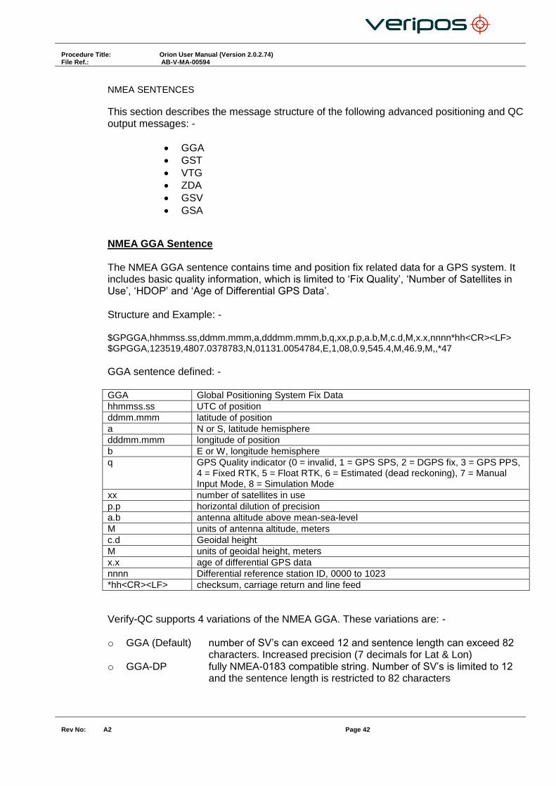
NMEA GGA Sentence The NMEA GGA sentence contains time and position fix related data for a GPS system. It includes basic quality information, which is limited to ‘Fix Quality’, ‘Number of Satellites in Use’, ‘HDOP’ and ‘Age of Differential GPS Data’. Structure and Example: - $GPGGA,hhmmss.ss,ddmm.mmm,a,dddmm.mmm,b,q,xx,p.p,a.b,M,c.d,M,x.x,nnnn*hh<CR><LF> $GPGGA,123519,4807.0378783,N,01131.0054784,E,1,08,0.9,545.4,M,46.9,M,,*47
GGA sentence defined: - GGA Global Positioning System Fix Data hhmmss.ss UTC of position ddmm.mmm latitude of position a N or S, latitude hemisphere dddmm.mmm longitude of position b E or W, longitude hemisphere q GPS Quality indicator (0 = invalid, 1 = GPS SPS, 2 = DGPS fix, 3 = GPS PPS,
4 = Fixed RTK, 5 = Float RTK, 6 = Estimated (dead reckoning), 7 = Manual Input Mode, 8 = Simulation Mode
xx number of satellites in use p.p horizontal dilution of precision a.b antenna altitude above mean-sea-level M units of antenna altitude, meters c.d Geoidal height M units of geoidal height, meters x.x age of differential GPS data nnnn Differential reference station ID, 0000 to 1023 *hh<CR><LF> checksum, carriage return and line feed
Verify-QC supports 4 variations of the NMEA GGA. These variations are: - o GGA (Default) number of SV’s can exceed 12 and sentence length can exceed 82
characters. Increased precision (7 decimals for Lat & Lon) o GGA-DP fully NMEA-0183 compatible string. Number of SV’s is limited to 12
and the sentence length is restricted to 82 characters
Procedure Title: Orion User Manual (Version 2.0.2.74) File Ref.: AB-V-MA-00594
Rev No:
A2 Page 43
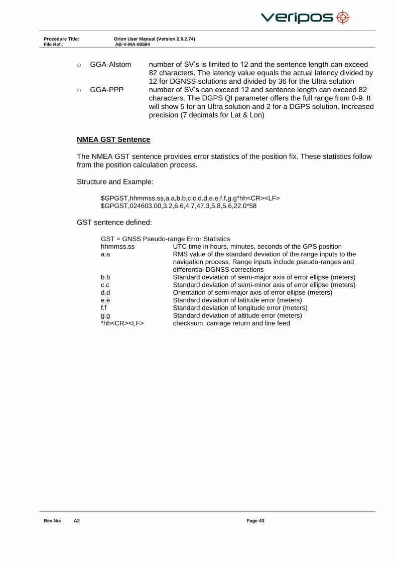
o GGA-Alstom number of SV’s is limited to 12 and the sentence length can exceed 82 characters. The latency value equals the actual latency divided by 12 for DGNSS solutions and divided by 36 for the Ultra solution
o GGA-PPP number of SV’s can exceed 12 and sentence length can exceed 82 characters. The DGPS QI parameter offers the full range from 0-9. It will show 5 for an Ultra solution and 2 for a DGPS solution. Increased precision (7 decimals for Lat & Lon)
NMEA GST Sentence The NMEA GST sentence provides error statistics of the position fix. These statistics follow from the position calculation process. Structure and Example:
$GPGST,hhmmss.ss,a.a,b.b,c.c,d.d,e.e,f.f,g.g*hh<CR><LF> $GPGST,024603.00,3.2,6.6,4.7,47.3,5.8,5.6,22.0*58
GST sentence defined:
GST = GNSS Pseudo-range Error Statistics hhmmss.ss UTC time in hours, minutes, seconds of the GPS position a.a RMS value of the standard deviation of the range inputs to the
navigation process. Range inputs include pseudo-ranges and differential DGNSS corrections
b.b Standard deviation of semi-major axis of error ellipse (meters) c.c Standard deviation of semi-minor axis of error ellipse (meters) d.d Orientation of semi-major axis of error ellipse (meters) e.e Standard deviation of latitude error (meters) f.f Standard deviation of longitude error (meters) g.g Standard deviation of altitude error (meters) *hh<CR><LF> checksum, carriage return and line feed

Procedure Title: Orion User Manual (Version 2.0.2.74) File Ref.: AB-V-MA-00594
Rev No:
A2 Page 44
NMEA VTG Sentence The NMEA VTG sentence provides the actual course and speed relative to the ground. Structure and Example: $GPVTG,p.p,T,q.q,M,r.r,N,s.s,K,u*hh<CR><LF>
$GPVTG,054.7,T,034.4,M,005.5,N,010.2,K*33
VTG sentence defined:
VTG = Course over ground and ground speed p.p course over ground T degrees True q.q course over ground M degrees Magnetic r.r speed over ground N knots s.s speed over ground K km/hr U mode indicator (A = Autonomous, D = Differential, E = Estimated) *hh<CR><LF> checksum, carriage return and line feed
Verify QC supports 2 variations of the NMEA VTG sentence. These variations are: o VTG (Default) conforms to NMEA v3.0 standard and includes the mode indicator o VTG (Old) conforms to previous NMEA standards and does not include the
mode indicator
NMEA ZDA Sentence The NMEA ZDA sentence provides time and time zone information. Structure and Example: $GPZDA,hhmmss.ss,dd,mm,yyyy,xx,yy*hh<CR><LF> $GPZDA,201530.00,04,07,2002,00,00*6E
ZDA sentence defined: ZDA = Time & Date
hhmmss.ss UTC time in hours, minutes, seconds of the GPS position dd,mm,yyy Day,Month,Year (UTC) xx local zone hours (00 to +/-13 hrs) yy local zone minutes (00 to 59)
*hh<CR><LF> checksum, carriage return and line feed

Procedure Title: Orion User Manual (Version 2.0.2.74) File Ref.: AB-V-MA-00594
Rev No:
A2 Page 45
NMEA GSA Sentence GSA sentence defined: GNSS DOP and Active Satellites GNSS receiver operating mode, satellites used in the navigation solution reported by the GGA or GNS sentence, and DOP values. If only GPS, GLONASS, etc. is used for the reported position solution the talker ID is GP, GL, etc. and the DOP values pertain to the individual system. If GPS, GLONASS, etc. are combined to obtain the reported position solution multiple GSA sentences are produced, one with the GPS satellites, another with the GLONASS satellites, etc. Each of these GSA sentences shall have talker ID GN, to indicate that the satellites are used in a combined solution and each shall have the PDOP, HDOP and VDOP for the combined satellites used in the position.
Notes: 1) Satellite ID numbers. To avoid possible confusion caused by repetition of satellite ID numbers when using multiple satellite systems, the following convention has been adopted:
a) GPS satellites are identified by their PRN numbers, which range from 1 to 32. b) The numbers 33-64 are reserved for WAAS satellites. The WAAS system PRN numbers are
120-138. The offset from NMEA WAAS SV ID to WAAS PRN number is 87. A WAAS PRN number of 120 minus 87 yields the SV ID of 33. The addition of 87 to the SV ID yields the WAAS PRN number.
c) The numbers 65-96 are reserved for GLONASS satellites. GLONASS satellites are identified by 64+satellite slot number. The slot numbers are 1 through 24 for the full GLONASS constellation of 24 satellites, this gives a range of 65 through 88. The numbers 89 through 96 are available if slot numbers above 24 are allocated to on-orbit spares.

Procedure Title: Orion User Manual (Version 2.0.2.74) File Ref.: AB-V-MA-00594
Rev No:
A2 Page 46
NMEA GSV Sentence
GSV sentence defined: GNSS Satellites In View Number of satellites (SV) in view, satellite ID numbers, elevation, azimuth, and SNR value. Four satellites maximum per transmission. Total number of sentences being transmitted and the number of the sentence being transmitted are indicated in the first two fields. If multiple GPS, GLONASS, etc. satellites are in view, use separate GSV sentences with talker ID GP to show the GPS satellites in view and talker GL to show the GLONASS satellites in view, etc. The GN identifier shall not be used with this sentence.
Notes: 1) Satellite information may require the transmission of multiple sentences all containing identical field formats when sending a complete message. The first field specifies the total number of sentences, minimum value 1. The second field identifies the order of this sentence (sentence number), minimum value 1. For efficiency it is recommended that null fields be used in the additional sentences when the data is unchanged from the first sentence. 2) A variable number of "Satellite ID-Elevation-Azimuth-SNR" sets are allowed up to a maximum of four sets per sentence. Null fields are not required for unused sets when less than four sets are transmitted. 3) Satellite ID numbers. To avoid possible confusion caused by repetition of satellite ID numbers when using multiple satellite systems, the following convention has been adopted:
a) GPS satellites are identified by their PRN numbers, which range from 1 to 32. b) The numbers 33-64 are reserved for WAAS satellites. The WAAS system PRN numbers are
120-138. The offset from NMEA WAAS SV ID to WAAS PRN number is 87. A WAAS PRN number of 120 minus 87 yields the SV ID of 33. The addition of 87 to the SV ID yields the WAAS PRN number.
c) The numbers 65-96 are reserved for GLONASS satellites. GLONASS satellites are identified by 64+satellite slot number. The slot numbers are 1 through 24 for the full GLONASS constellation of 24 satellites, this gives a range of 65 through 88. The numbers 89 through 96 are available if slot numbers above 24 are allocated to on-orbit spares.


