Embed Size (px)
Citation preview
Operations & Service Manual FSH-5 & FSH-6
FSH-5 Ceiling Suspended Version
FSH-6 Floor Stand Version
ISO 9001-2015 Registered • Committed to Quality2750 Gunter Park Drive West • Montgomery, AL 36109 USAToll Free: 800.554.4537 (USA & Canada Only) Other: 334.272.1457Fax: 334.239.4117 • Website: www.gfse.com • Email: [email protected]
Printed in USA, Form 64898 (Rel. Date: Jul.1999, Rev. Date: Dec.2018. Rev. H)

LIMITED WARRANTY
• Subject to the terms and conditions of this Limited Warranty as herein stated, all Giles Enterprises Inc. (here-after referred to as “Giles”) food service equipment and parts purchased new from an authorized Giles rep-resentative are warranted as to defects in material or workmanship for a period of twenty-four (24) monthsfrom the date of installation, provided, however, that with regard to labor costs in connection with this war-ranty, see below. All installations must be made by a qualified installing agency in accordance with all appli-cable codes and/or regulations in the jurisdiction in which installed. Limited warranty coverage is extendedonly to the original owner and is void if the unit is resold.
• During the Limited Warranty period, Giles will replace or recondition, at its factory, any part or parts of thisunit which Giles inspectors judge defective, provided the unit has been properly installed, subjected to nor-mal usage, and operated and maintained in accordance with specified procedures. This Limited Warrantydoes not cover cosmetic damage, and damage due to acts of God, accident, misuse, alteration, negligence,abuse, or use of unorthodox repair methods. All parts replaced under this Limited Warranty carry only theunexpired term of this Limited Warranty. Limited Warranty service may be furnished only by an authorizedGiles service representative.
• If Limited Warranty service is requested, Giles will dispatch factory-authorized service representatives toinspect, repair, recondition, or replace units of its manufacture with such labor being rendered without costto owner for twenty-four (24) months from the date of installation. Otherwise, service, including labor andtransportation charges or other expenses, in connection with the removal or installation of any part or partssupplied under this Limited Warranty, are specified on the original sales contract between the purchaser andthe authorized Giles representative.
• Failure to use Giles OEM replacement parts and Giles OEM filters may void this Warranty.
• Giles reserves the right to change or improve its equipment and/or parts in any way without obligation toalter such equipment or parts previously manufactured.
• Giles makes no further warranties, express or implied, including implied warranties of merchantability or fit-ness for a particular purpose, and has no other obligation or liability not specifically stated herein.
• Repair or replacement as provided under this limited warranty is the exclusive remedy. Giles shall not beliable for any incidental or consequential damages for breach of any express or implied warranty on thisproduct, except to the extent prohibited by applicable law. Any implied warranty of merchantability or fit-ness for a particular purpose on this product is limited in duration to the duration of this limited warranty.
• Used Giles food service equipment or parts, or Giles food service equipment or parts not purchased from anauthorized Giles representative, carry no warranties, express or implied.

iii
Model: FSH-5 & FSH-6Table Of Contents
Safety . . . . . . . . . . . . . . . . . . . . . . . . . . . . . . . . . . . . . . . . . . . . . . . . . . . . . . . . . . . . . . . . vSafety Overview . . . . . . . . . . . . . . . . . . . . . . . . . . . . . . . . . . . . . . . . . . . . . . . . . . . . . . . . . . . . . . . . . . . . . . . . . . . . . . . . vSpecific Safety Precautions . . . . . . . . . . . . . . . . . . . . . . . . . . . . . . . . . . . . . . . . . . . . . . . . . . . . . . . . . . . . . . . . . . . . . . . vi
1. Introduction . . . . . . . . . . . . . . . . . . . . . . . . . . . . . . . . . . . . . . . . . . . . . . . . . . . . . 11.01 Construction . . . . . . . . . . . . . . . . . . . . . . . . . . . . . . . . . . . . . . . . . . . . . . . . . . . . . . . . . . . . . . . . . . . . . . . . . 11.02 Standard Features . . . . . . . . . . . . . . . . . . . . . . . . . . . . . . . . . . . . . . . . . . . . . . . . . . . . . . . . . . . . . . . . . . . . 11.03 Optional Features . . . . . . . . . . . . . . . . . . . . . . . . . . . . . . . . . . . . . . . . . . . . . . . . . . . . . . . . . . . . . . . . . . . . . 11.04 Specifications . . . . . . . . . . . . . . . . . . . . . . . . . . . . . . . . . . . . . . . . . . . . . . . . . . . . . . . . . . . . . . . . . . . . . . . . 21.04.1 Overall Dimensions - Ceiling Suspended Version . . . . . . . . . . . . . . . . . . . . . . . . . . . . . . . . . . . . . . . . . . . 21.04.2 Overall Dimensions - Floor Stand Version . . . . . . . . . . . . . . . . . . . . . . . . . . . . . . . . . . . . . . . . . . . . . . . . . 31.04.3 Agency Certifications . . . . . . . . . . . . . . . . . . . . . . . . . . . . . . . . . . . . . . . . . . . . . . . . . . . . . . . . . . . . . . . . . . 41.04.4 Weights . . . . . . . . . . . . . . . . . . . . . . . . . . . . . . . . . . . . . . . . . . . . . . . . . . . . . . . . . . . . . . . . . . . . . . . . . . . . . 4
2. Installation . . . . . . . . . . . . . . . . . . . . . . . . . . . . . . . . . . . . . . . . . . . . . . . . . . . . . . 52.01 Location. . . . . . . . . . . . . . . . . . . . . . . . . . . . . . . . . . . . . . . . . . . . . . . . . . . . . . . . . . . . . . . . . . . . . . . . . . . . . 52.02 Unpacking . . . . . . . . . . . . . . . . . . . . . . . . . . . . . . . . . . . . . . . . . . . . . . . . . . . . . . . . . . . . . . . . . . . . . . . . . . . 62.03.1 Mounting Detail - Ceiling Suspended . . . . . . . . . . . . . . . . . . . . . . . . . . . . . . . . . . . . . . . . . . . . . . . . . . . . . 72.03.2 Backsplash & Skirt Installation - Ceiling Suspended . . . . . . . . . . . . . . . . . . . . . . . . . . . . . . . . . . . . . . . . . 82.03.3 Stand Assembly - Free Standing Version . . . . . . . . . . . . . . . . . . . . . . . . . . . . . . . . . . . . . . . . . . . . . . . . . . 92.04 Cooking Appliance Constraints & Clearances . . . . . . . . . . . . . . . . . . . . . . . . . . . . . . . . . . . . . . . . . . . . . 102.04.1 Fryer Constraints . . . . . . . . . . . . . . . . . . . . . . . . . . . . . . . . . . . . . . . . . . . . . . . . . . . . . . . . . . . . . . . . . . . . 102.04.2 Fryer Clearances . . . . . . . . . . . . . . . . . . . . . . . . . . . . . . . . . . . . . . . . . . . . . . . . . . . . . . . . . . . . . . . . . . . . . 102.04.3 Oven Constraints . . . . . . . . . . . . . . . . . . . . . . . . . . . . . . . . . . . . . . . . . . . . . . . . . . . . . . . . . . . . . . . . . . . . 112.04.4 Oven Clearances. . . . . . . . . . . . . . . . . . . . . . . . . . . . . . . . . . . . . . . . . . . . . . . . . . . . . . . . . . . . . . . . . . . . . 112.04.5 Griddle Constraints . . . . . . . . . . . . . . . . . . . . . . . . . . . . . . . . . . . . . . . . . . . . . . . . . . . . . . . . . . . . . . . . . . 122.04.6 Griddle Clearances . . . . . . . . . . . . . . . . . . . . . . . . . . . . . . . . . . . . . . . . . . . . . . . . . . . . . . . . . . . . . . . . . . . 122.04.7 Range Constraints . . . . . . . . . . . . . . . . . . . . . . . . . . . . . . . . . . . . . . . . . . . . . . . . . . . . . . . . . . . . . . . . . . . 132.04.8 Range Clearances . . . . . . . . . . . . . . . . . . . . . . . . . . . . . . . . . . . . . . . . . . . . . . . . . . . . . . . . . . . . . . . . . . . . 132.05 Electrical Specifications - Hood Only . . . . . . . . . . . . . . . . . . . . . . . . . . . . . . . . . . . . . . . . . . . . . . . . . . . . 142.05.1 Electrical Connections . . . . . . . . . . . . . . . . . . . . . . . . . . . . . . . . . . . . . . . . . . . . . . . . . . . . . . . . . . . . . . . . 142.05.2 Routing Power Conduit & Wiring . . . . . . . . . . . . . . . . . . . . . . . . . . . . . . . . . . . . . . . . . . . . . . . . . . . . . . . 152.05.3 Hood and Appliance Interlock Diagram . . . . . . . . . . . . . . . . . . . . . . . . . . . . . . . . . . . . . . . . . . . . . . . . . . 152.06 Fire Suppression System Installation . . . . . . . . . . . . . . . . . . . . . . . . . . . . . . . . . . . . . . . . . . . . . . . . . . . . 162.06.1 Fire Suppression System Connection . . . . . . . . . . . . . . . . . . . . . . . . . . . . . . . . . . . . . . . . . . . . . . . . . . . . 162.06.2 Fire Suppression Detector Links & Location . . . . . . . . . . . . . . . . . . . . . . . . . . . . . . . . . . . . . . . . . . . . . . 172.06.3 Appliance Nozzles. . . . . . . . . . . . . . . . . . . . . . . . . . . . . . . . . . . . . . . . . . . . . . . . . . . . . . . . . . . . . . . . . . . . 172.06.4 Fire Extinguisher Nozzle Locations . . . . . . . . . . . . . . . . . . . . . . . . . . . . . . . . . . . . . . . . . . . . . . . . . . . . . . 18
3. Overview. . . . . . . . . . . . . . . . . . . . . . . . . . . . . . . . . . . . . . . . . . . . . . . . . . . . . . . 193.01 Control Panel . . . . . . . . . . . . . . . . . . . . . . . . . . . . . . . . . . . . . . . . . . . . . . . . . . . . . . . . . . . . . . . . . . . . . . . 203.02 Filter Chamber & Exhaust . . . . . . . . . . . . . . . . . . . . . . . . . . . . . . . . . . . . . . . . . . . . . . . . . . . . . . . . . . . . . 223.03 Accessories Items Included w/Hood. . . . . . . . . . . . . . . . . . . . . . . . . . . . . . . . . . . . . . . . . . . . . . . . . . . . . 24
iv
Model: FSH-5 & FSH-6 Table Of Contents
5. Hood Cleaning and Maintenance. . . . . . . . . . . . . . . . . . . . . . . . . . . . . . . . . . . 415.01 Monthly Hood Interlock Inspection . . . . . . . . . . . . . . . . . . . . . . . . . . . . . . . . . . . . . . . . . . . . . . . . . . . . . 415.02 Quarterly Hood Cleaning . . . . . . . . . . . . . . . . . . . . . . . . . . . . . . . . . . . . . . . . . . . . . . . . . . . . . . . . . . . . . . 425.03 Fire Suppression System Maintenance . . . . . . . . . . . . . . . . . . . . . . . . . . . . . . . . . . . . . . . . . . . . . . . . . . 425.03.1 Semi-Annual Fire Suppression Inspection & Maintenance . . . . . . . . . . . . . . . . . . . . . . . . . . . . . . . . . . 435.03.2 Annual Fire Suppression System Inspection & Maintenance. . . . . . . . . . . . . . . . . . . . . . . . . . . . . . . . . 435.03.3 12-Year Fire Suppression System Inspection & Maintenance . . . . . . . . . . . . . . . . . . . . . . . . . . . . . . . . 435.04 Maintenance & Service Log. . . . . . . . . . . . . . . . . . . . . . . . . . . . . . . . . . . . . . . . . . . . . . . . . . . . . . . . . . . . 44
6. Troubleshooting . . . . . . . . . . . . . . . . . . . . . . . . . . . . . . . . . . . . . . . . . . . . . . . . . 456.01 Troubleshooting Procedures . . . . . . . . . . . . . . . . . . . . . . . . . . . . . . . . . . . . . . . . . . . . . . . . . . . . . . . . . . . 45
7. Parts List . . . . . . . . . . . . . . . . . . . . . . . . . . . . . . . . . . . . . . . . . . . . . . . . . . . . . . . 477.01 Parts Ordering & Service Information . . . . . . . . . . . . . . . . . . . . . . . . . . . . . . . . . . . . . . . . . . . . . . . . . . . 477.02 Component Drawer & Control Panel . . . . . . . . . . . . . . . . . . . . . . . . . . . . . . . . . . . . . . . . . . . . . . . . . . . . 487.03 Hood Front - Opened. . . . . . . . . . . . . . . . . . . . . . . . . . . . . . . . . . . . . . . . . . . . . . . . . . . . . . . . . . . . . . . . . 507.04 Under-Hood Filters & Light . . . . . . . . . . . . . . . . . . . . . . . . . . . . . . . . . . . . . . . . . . . . . . . . . . . . . . . . . . . . 527.05 Doors & Front Panel - Ceiling Suspended Model . . . . . . . . . . . . . . . . . . . . . . . . . . . . . . . . . . . . . . . . . . 547.06 Doors & Front Panel - Free-Standing Floor Model . . . . . . . . . . . . . . . . . . . . . . . . . . . . . . . . . . . . . . . . . 56
4. Operation & Filter Maintenance. . . . . . . . . . . . . . . . . . . . . . . . . . . . . . . . . . . . 274.01 Starting the Hood . . . . . . . . . . . . . . . . . . . . . . . . . . . . . . . . . . . . . . . . . . . . . . . . . . . . . . . . . . . . . . . . . . . . 274.02 Filter System, Filter Maintenance & Filter Alarms . . . . . . . . . . . . . . . . . . . . . . . . . . . . . . . . . . . . . . . . . 274.02.1 Ventless Hood Filter Table. . . . . . . . . . . . . . . . . . . . . . . . . . . . . . . . . . . . . . . . . . . . . . . . . . . . . . . . . . . . . 274.02.2 Baffle Filter Removal . . . . . . . . . . . . . . . . . . . . . . . . . . . . . . . . . . . . . . . . . . . . . . . . . . . . . . . . . . . . . . . . . 284.02.3 Baffle Filter Installation . . . . . . . . . . . . . . . . . . . . . . . . . . . . . . . . . . . . . . . . . . . . . . . . . . . . . . . . . . . . . . . 294.02.4 Pre-Filter Removal . . . . . . . . . . . . . . . . . . . . . . . . . . . . . . . . . . . . . . . . . . . . . . . . . . . . . . . . . . . . . . . . . . . 304.02.5 Pre-Filter Installation . . . . . . . . . . . . . . . . . . . . . . . . . . . . . . . . . . . . . . . . . . . . . . . . . . . . . . . . . . . . . . . . . 314.02.6 E.A.C. Filter Cell Removal. . . . . . . . . . . . . . . . . . . . . . . . . . . . . . . . . . . . . . . . . . . . . . . . . . . . . . . . . . . . . . 324.02.7 E.A.C. Filter Cell Installation . . . . . . . . . . . . . . . . . . . . . . . . . . . . . . . . . . . . . . . . . . . . . . . . . . . . . . . . . . . 334.02.8 Charcoal Filter Removal. . . . . . . . . . . . . . . . . . . . . . . . . . . . . . . . . . . . . . . . . . . . . . . . . . . . . . . . . . . . . . . 344.02.9 Charcoal Filter Installation. . . . . . . . . . . . . . . . . . . . . . . . . . . . . . . . . . . . . . . . . . . . . . . . . . . . . . . . . . . . . 354.03 Hood Filter Alarms . . . . . . . . . . . . . . . . . . . . . . . . . . . . . . . . . . . . . . . . . . . . . . . . . . . . . . . . . . . . . . . . . . . 364.03.1 Baffle, Pre-Filter or Charcoal Filter Missing . . . . . . . . . . . . . . . . . . . . . . . . . . . . . . . . . . . . . . . . . . . . . . . 364.03.2 Baffle, Pre-Filter or Charcoal Filter Clogged. . . . . . . . . . . . . . . . . . . . . . . . . . . . . . . . . . . . . . . . . . . . . . . 364.03.3 E.A.C. Filter Status & Alarm. . . . . . . . . . . . . . . . . . . . . . . . . . . . . . . . . . . . . . . . . . . . . . . . . . . . . . . . . . . . 374.04 Filter Maintenance . . . . . . . . . . . . . . . . . . . . . . . . . . . . . . . . . . . . . . . . . . . . . . . . . . . . . . . . . . . . . . . . . . . 374.04.1 Baffle Filter Cleaning . . . . . . . . . . . . . . . . . . . . . . . . . . . . . . . . . . . . . . . . . . . . . . . . . . . . . . . . . . . . . . . . . 384.04.2 E.A.C. Filter Cell Cleaning. . . . . . . . . . . . . . . . . . . . . . . . . . . . . . . . . . . . . . . . . . . . . . . . . . . . . . . . . . . . . . 384.04.3 Pre-Filter Maintenance . . . . . . . . . . . . . . . . . . . . . . . . . . . . . . . . . . . . . . . . . . . . . . . . . . . . . . . . . . . . . . . 394.04.4 Charcoal Filter Maintenance . . . . . . . . . . . . . . . . . . . . . . . . . . . . . . . . . . . . . . . . . . . . . . . . . . . . . . . . . . . 39
v
Model: FSH-5 & FSH-6Safety
Safety Overview:
The information contained in this manual has been prepared to describe the proper procedures for safely installing,operating and maintaining Giles Food Service Equipment.
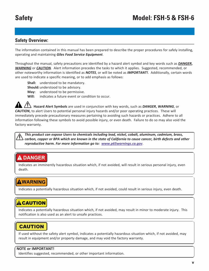
Throughout the manual, safety precautions are identified by a hazard alert symbol and key words such as DANGER,WARNING or CAUTION. Alert information precedes the tasks to which it applies. Suggested, recommended, orother noteworthy information is identified as NOTES, or will be noted as IMPORTANT!. Additionally, certain wordsare used to indicate a specific meaning, or to add emphasis as follows:
Shall: understood to be mandatory.Should: understood to be advisory.May: understood to be permissive.Will: indicates a future event or condition to occur.
This product can expose Users to chemicals including lead, nickel, cobalt, aluminum, cadmium, brass,carbon, copper or BPA which are known in the state of California to cause cancer, birth defects and otherreproductive harm. For more information go to: www.p65warnings.ca.gov.
Indicates an imminently hazardous situation which, if not avoided, will result in serious personal injury, evendeath.
Indicates a potentially hazardous situation which, if not avoided, could result in serious injury, even death.
Indicates a potentially hazardous situation which, if not avoided, may result in minor to moderate injury. Thisnotification is also used as an alert to unsafe practices.
If used without the safety alert symbol, indicates a potentially hazardous situation which, if not avoided, mayresult in equipment and/or property damage, and may void the factory warranty.
NOTE or IMPORTANT!Identifies suggested, recommended, or other important information.
Hazard Alert Symbols are used in conjunction with key words, such as DANGER, WARNING, orCAUTION, to alert Users to potential personal injury hazards and/or poor operating practices. These willimmediately precede precautionary measures pertaining to avoiding such hazards or practices. Adhere to allinformation following these symbols to avoid possible injury, or even death. Failure to do so may also void thefactory warranty.
vi
Model: FSH-5 & FSH-6 Safety
Specific Safety Precautions:
For your safety, please observe the following precautions when operating or servicing the Model OVH-10 or PO-VHVentless Recirculating Hoods. Adhering to the following important safety information will help to prevent personalinjury and/or damage to the equipment.
• Before cleaning or performing maintenance, place power switch in the OFF position. Unplug power cord or turnOFF power at the electrical panel supplying power to remove all power from the appliance.
• Failure to have the Power switch in the OFF position during servicing or when replacing filters, could result inequipment damage, electrical shock and/or serious personal injury.
• DO NOT wash down the Hood interior or exterior with water from a spray hose.• Failure to comply with DANGER notices will result in serious injury, even death; or damage to equipment and/or
property and may void the factory warranty.
• Prior to installation, consult a qualified electrician to ensure that installation will comply with all electricalrequirements and codes.
• The unit must be adequately and properly grounded. Improper grounding may result in electrical shock to theuser. Always refer to local electrical code to ensure proper grounding of this or any other electrical equipment.
• Check the rating label on the unit to determine the proper power supply required. Always consult with anelectrician, or other qualified service technician, to ensure that circuit breakers and wiring are of sufficient ratingand gauge to power this equipment. A Wiring Diagram has been provided with the unit as an aid fortechnicians. The unit must be installed and electrically grounded in accordance with local codes, or in theabsence of local codes, in accordance with the National Electrical Code, NFPA 70.
• Improper installation, adjustment, alteration, service or maintenance could result in serious injury, even death;equipment and/or property damage; and will potentially void the factory warranty.
• DO NOT use or store flammable liquids, or materials that produce flammable vapors, in the vicinity of this orany other appliance!
• Failure to comply with WARNING notices could result in serious injury, even death; damage to equipmentand/or property; and will potentially void the factory warranty.
vii
Model: FSH-5 & FSH-6Safety
• Exercise care when removing wooden crate framework and the unit from shipping pallet. The Floor Standversion will be very top-heavy once fully assembled, use extreme care when moving the unit into its finallocation.
• Once located, be sure a Floor Stand units is properly leveled and anchored.
• DO NOT operate the appliance, unless its components and their intended functions are fully understood (seeSection 3). Once you have read and fully understand Section 3, closely follow the instructions presented in thisOperations Manual in order to prevent equipment damage, or malfunction.
• This appliance is not intended for use by persons (including children) with reduced physical, sensory, or mentalcapabilities, or lack of experience and knowledge, unless they have been given adequate instruction and/orsupervision concerning its use by a person responsible for their safety. Children should not be allowed to playwith, or around, this appliance.
• When working in the kitchen environment, take necessary precautions to avoid injury due to HOT cookingappliances, utensils, tools, etc. As applicable, always wear thermal protection, such as oven mitts or gloves,when handling hot pans, utensils or foods.
• Failure to comply with CAUTION notices may result in minor to moderate personal injury, damage to equipmentor property, and potentially void the warranty.
• Components exposed on the Control Panel surface are impact-sensitive. To avoid damage and maintain properoperation, exercise care to avoid damage and maintain proper operation.
• Handle the Electronic Air Cleaner (E.A.C.) Cell carefully. DO NOT bend the collection plates (fins) or break any ofthe ionizer wires. Doing so will significantly reduce the performance of the EAC and can eventually cause powerto the appliance beneath the Hood to be shutdown.
• DO NOT attempt to dry the E.A.C. Cell after cleaning by installing it and running the hood or by running theappliance below the hood to generate heat for drying. This could potentially damage the EAC Power Supplycausing improper operation and voiding the warranty. NEVER PLACE A WET E.A.C. CELL INTO THE HOOD.
• When cleaning the appliance:
- DO NOT steam clean.- DO NOT use products containing chlorine, or other corrosive chemicals.- DO NOT use abrasive products, steel wool or scouring pads.- DO NOT use oven cleaners.
• DO NOT alter, add attachments, or otherwise modify this equipment! DO NOT attempt to attach any type ofductwork to the Hood exhaust.
• Failure to comply with CAUTION notices may result in damage to equipment or property, and void the factorywarranty.
Specific Safety Precautions:
NOTE:▪ When received, If damage to the shipping pallet is evident, immediately and thoroughly inspect the equipment
and it accessories. Notify the freight company of any damages. Generally, negotiating freight damage claimsshall be the responsibility of the Customer.
▪ Comply with all appropriate state and/or local heath regulations regarding cleaning and sanitation of anyfoodservice equipment.
▪ To clean difficult surface areas, having excessive build-up of grease residue, GILES recommends using a mild, bio-degradable, non-toxic degreasing cleaner such as Simple Green® HD Pro.
▪ GILES assumes no responsibility in regard to code compliance for installation and use of Ventless RecirculatingVentilation equipment. The customer is responsible for obtaining all of the necessary approvals from AuthoritiesHaving Jurisdiction (AHJ) concerning use of this equipment.
viii
Model: FSH-5 & FSH-6 Safety
Specific Safety Precautions:
1
Model: FSH-5 & FSH-6Introduction
Control Panel:• LED indicator light clusters display the performance status for each of the two (2) Electronic Air Cleaner collector
cells.• [FILTER MISSING] Light indicates when one or more of the Baffle Filters, Pre-Filters or Charcoal Filters is missing
or improperly installed.Filters:• (2) Baffle Filters - capture and remove large grease particulate.• (2) Pre-Filters - capture and remove smaller grease particulate and some moisture.• (2) Electronic Air Cleaner (E.A.C.) Cells - capture fine particle air contaminates.• (2) Charcoal Filters - help to control undesirable cooking aromas in the exhaust air.
Fire Suppression System: Factory pre-plumbed and ready for connection to a listed fire suppression system (AnsulR-102 wet chemical). Includes piping, plenum nozzles, detector link brackets and conduit. The fire extinguishingsystem, field installation and set-up, testing and final charging shall be supplied by an authorized Ansul®Distributor/Dealer and is the responsibility of the Customer (not included with Hood purchase).
Hood is constructed primarily of Series 430 stainless steel; 16, 18 & 20 Ga.
Inter-Locking Start System (ILS):• Push-To-Start feature requires Users to press a control button to restart the Hood and restore power to the
appliance after all power interruptions. The feature prevents unattended startup of Hood/Appliance after a lossof power service and may be a code requirement in certain jurisdictions (primarily CA).
Floor Stand Mount:
• 72” high self-supporting Stand. Alternative to the standard ceiling suspended model. Use of the Stand places thebottom edge of the Hood unit 72” above the floor.
1. IntroductionTHANK YOU for purchasing the Giles Model FSH-5 or FSH-6 Ventless Recirculating Hood, manufactured by GilesEnterprises, Inc., Montgomery, Alabama (USA), hereafter referred to as "GILES". Every unit is thoroughly inspectedand tested prior to shipment in efforts to ensure that it will operate flawlessly when installed. With proper careand maintenance this equipment will provide years of trouble-free service. These Hoods are available as either aceiling suspended model, or a free-standing model mounted on a 72” tall self-supporting Stand. To help protect your investment, we recommend that you take the time to review this Manual and become familiarwith the procedures in it pertaining to installation, operation, cleaning and maintenance. Adherence torecommended procedures will minimize potential for costly “downtime” and future repair expense.Please retain this Manual for future reference.
1.01 Construction
1.02 Standard Features
1.03 Optional Features
2
Model: FSH-5 & FSH-6 Introduction
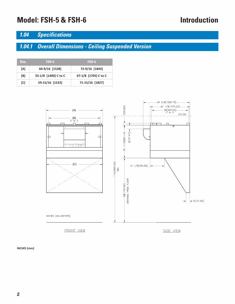
Dim. FSH-5 FSH-6
[A] 60-9/16 [1538] 72-9/16 [1843]
[B] 55-1/8 [1400] C to C 67-1/8 [1705] C to C
[C] 59-15/16 [1522] 71-15/16 [1827]
1.04 Specifications
1.04.1 Overall Dimensions - Ceiling Suspended Version
INCHES [mm]
(A)
(B)
(C)
3
Model: FSH-5 & FSH-6Introduction
INCHES [mm]
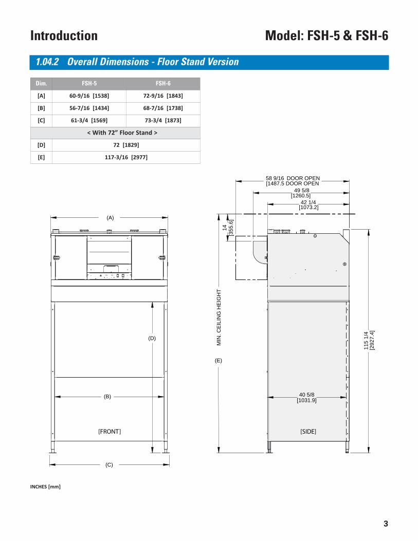
1.04.2 Overall Dimensions - Floor Stand Version
Dim. FSH-5 FSH-6
[A] 60-9/16 [1538] 72-9/16 [1843]
[B] 56-7/16 [1434] 68-7/16 [1738]
[C] 61-3/4 [1569] 73-3/4 [1873]
< With 72” Floor Stand >
[D] 72 [1829]
[E] 117-3/16 [2977]
(D)
(A)
115
1/4
49 5/8
58 9/16 DOOR OPEN
(B)
14
(E)
MIN
. CE
ILIN
G H
EIG
HT
42 1/4
40 5/8
(C)
[1487.5 DOOR OPEN
[1260.5]
[1073.2]
[355
.6]
[292
7.4]
[1031.9]
[FRONT] [SIDE]
4
Model: FSH-5 & FSH-6 Introduction
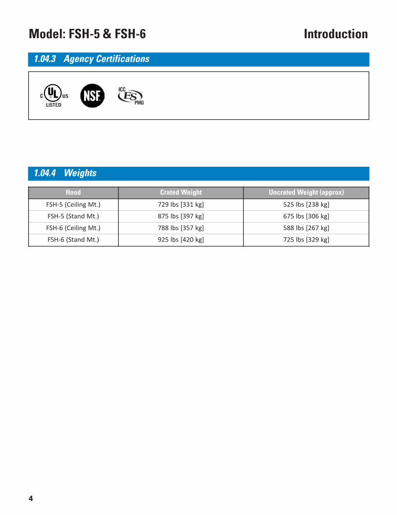
Hood Crated Weight Uncrated Weight (approx)
FSH-5 (Ceiling Mt.) 729 lbs [331 kg] 525 lbs [238 kg]
FSH-5 (Stand Mt.) 875 lbs [397 kg] 675 lbs [306 kg]
FSH-6 (Ceiling Mt.) 788 lbs [357 kg] 588 lbs [267 kg]
FSH-6 (Stand Mt.) 925 lbs [420 kg] 725 lbs [329 kg]
1.04.3 Agency Certifications
1.04.4 Weights
5
Model: FSH-5 & FSH-6Installation
2. InstallationThis section summarizes the procedures necessary to install a new FSH-5 or FSH-6 Ventless Hood. Beforecontinuing, please thoroughly review this Section and any accompanying installation instructions.Following these procedures and instructions will help to ensure a safe and proper installation.
DO NOT ALTER, ADD ATTACHMENTS OR OTHERWISE MODIFY THIS EQUIPMENT.
IMPORTANT!:▪ In some cases, it may be necessary to consult with a HVAC contractor and have them confirm that proper
room air exchange is occurring, and that the capability of current on-site air conditioning systems is sufficientto handle the heat load of any additional cooking equipment.
▪ Exhaust ventilation is recommended for areas in which recirculating Hoods are being operated. Gilesrecommends at least 50 CFM airflow per linear foot of hood space. This amount could vary based on local codesand site-specific installation requirements.
▪ The sound level of the Hood when operating is approximately 73 dB’s.
▪ DO NOT attach any additional ductwork to the Hood’s exhaust outlet. Doing so creates excessive back pressure that willsignificantly reduce Hood capture, resulting in unsatisfactory performance.
▪ DO NOT attempt to direct the Hood exhaust into a ceiling niche or the space above a suspended ceiling.
2.01 Location
1. A minimum clearance of 14” (355.6 mm) must be maintained between the top of the Hood exhaust outlet andthe ceiling, or other overhead obstructions.
2. For ceiling suspended models, be certain that the intended mounting site is structurally sound and capable ofsupporting the Hood’s weight. See Section 1.04.4, Weights.
3. Ventless Hoods are intended only for use in relatively large, unconfined, open spaces that have sufficient freshair make-up.
IMPORTANT!:It is the responsibility of the Purchaser/Customer to provide the following, not included with Hood purchase:
• Installation materials, both mechanical and electrical, such as necessary mounting hardware, electrical conduitand wire, conduit connectors, any required additional electrical panels and circuit breakers, etc.
• All installation labor expenses, including building modifications, rental expense for tools/equipment required tocomplete installation, etc. It is adviseable to contract a professional kitchen equipment service company toinstall the Hood.
• All approvals, permits and fees required by the Authorities Having Jurisdiction (AHJ) to authorize use of aventless recirculating Hood ... building inspector, fire marshal, health department, etc. Be sure that all approvalsare obtained before proceeding.
• The listed fire suppression system to be connected to the Hood ... Ansul® R-102 Wet Chemical System. Fieldinstallation, set-up, testing and charging must be preformed by an authorized Ansul Distributor/Dealer. Hood isfactory pre-plumbed with piping, conduit, nozzles, and detector brackets, including an exhaust fire damper.
6
Model: FSH-5 & FSH-6 Installation
IMPORTANT NOTE!!If there is evidence of damage to the palletized unit, or any of the accompanying items, immediately andthoroughly inspect the unit and all components. Notify the freight company of all damages. Generally, it is theresponsibility of the Customer to file and negotiate freight damage claims with freight carriers.
6. In many cases, it may be preferable to leave the unit on the pallet so that handling equipment can be used tomove it to the desired permanent location.
7. Carefully remove the equipment (Hood unit, Stand components, etc.) from the shipping skid using suitableequipment and/or sufficient manpower and safe work practices. Stage all components for installation orassembly.
2.02 Unpacking
Unit is shipped on a wooden pallet, secured by high-tensile plastic strapping and wrapped in machine-appliedstretch wrap. In most cases a wooden framework is built around the unit for added protection. Unpack unit asfollows:
1. Position received pallet in an area that provides adequate space for unpacking.2. Remove the plastic stretch wrap, strapping and other packaging materials as necessary.3. Carefully remove any wooden supports and/or framework that might be attached.4. Locate and secure the envelope containing Warranty Card, Operation Manual, and any other documentation or
hardware provided for installation.5. Secure the stainless steel Soaking Tank and set aside. It will be required for properly cleaning the Electronic Air
Cleaner Collector Cell (E.A.C.). Often additional items will be packed inside Tank; be sure check and remove.HEPA Filter model Hoods will not have a Soaking Tank included.
• The unit is very heavy and bulky! Use suitable equipment and/or sufficient manpower to lift and move theHood from the shipping skid. See Section 1.04.4, Weights.
• Take care when removing and disposing of packaging materials.
• When moving and handling the Hood, take special care not damage the bottom skirting. Dragging the Hoodalong the floor or lifting the unit by the bottom edge has the potential to damage the skirt portion.
• Failure to comply with these CAUTION notices may result in moderate to minor injury, equipment or propertydamage, and could void the warranty.
7
Model: FSH-5 & FSH-6Installation
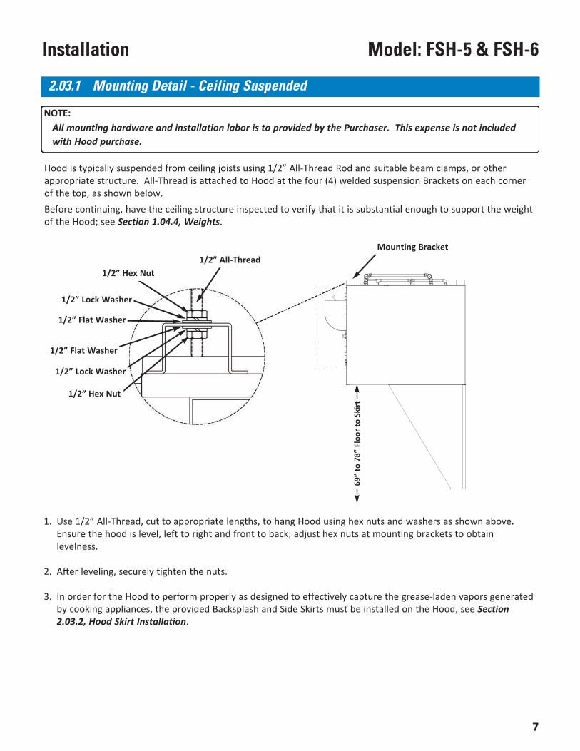
1. Use 1/2” All-Thread, cut to appropriate lengths, to hang Hood using hex nuts and washers as shown above.Ensure the hood is level, left to right and front to back; adjust hex nuts at mounting brackets to obtainlevelness.
2. After leveling, securely tighten the nuts.
3. In order for the Hood to perform properly as designed to effectively capture the grease-laden vapors generatedby cooking appliances, the provided Backsplash and Side Skirts must be installed on the Hood, see Section2.03.2, Hood Skirt Installation.
69”
to 7
8” F
loor
to S
kirt
2.03.1 Mounting Detail - Ceiling Suspended
NOTE:All mounting hardware and installation labor is to provided by the Purchaser. This expense is not includedwith Hood purchase.
Hood is typically suspended from ceiling joists using 1/2” All-Thread Rod and suitable beam clamps, or otherappropriate structure. All-Thread is attached to Hood at the four (4) welded suspension Brackets on each cornerof the top, as shown below.Before continuing, have the ceiling structure inspected to verify that it is substantial enough to support the weightof the Hood; see Section 1.04.4, Weights.
1/2” All-Thread1/2” Hex Nut
1/2” Lock Washer
1/2” Flat Washer
1/2” Hex Nut
1/2” Lock Washer
1/2” Flat Washer
Mounting Bracket
8
Model: FSH-5 & FSH-6 Installation
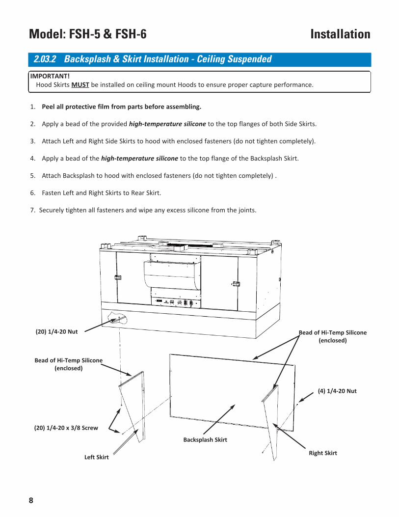
(20) 1/4-20 x 3/8 Screw
(20) 1/4-20 Nut
Bead of Hi-Temp Silicone(enclosed)
Bead of Hi-Temp Silicone(enclosed)
1. Peel all protective film from parts before assembling.
2. Apply a bead of the provided high-temperature silicone to the top flanges of both Side Skirts.
3. Attach Left and Right Side Skirts to hood with enclosed fasteners (do not tighten completely).
4. Apply a bead of the high-temperature silicone to the top flange of the Backsplash Skirt.
5. Attach Backsplash to hood with enclosed fasteners (do not tighten completely) .
6. Fasten Left and Right Skirts to Rear Skirt.
7. Securely tighten all fasteners and wipe any excess silicone from the joints.
Left Skirt Right Skirt
Backsplash Skirt
IMPORTANT!Hood Skirts MUST be installed on ceiling mount Hoods to ensure proper capture performance.
2.03.2 Backsplash & Skirt Installation - Ceiling Suspended
(4) 1/4-20 Nut
9
Model: FSH-5 & FSH-6Installation
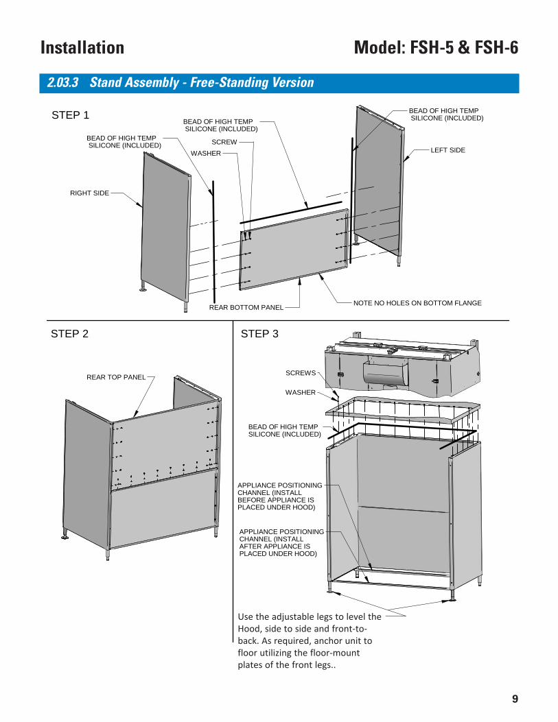
2.03.3 Stand Assembly - Free-Standing Version
STEP 1
STEP 2
RIGHT SIDE
LEFT SIDE
REAR BOTTOM PANEL
WASHERSCREWBEAD OF HIGH TEMP
SILICONE (INCLUDED)
BEAD OF HIGH TEMP SILICONE (INCLUDED)
SCREWS
WASHER
BEAD OF HIGH TEMPSILICONE (INCLUDED)
FASTEN FRONT LEGSTO FLOOR, AS REQUIREDBY LOCAL CODE OR GENERALCONTRACTOR
P
MONTGOMERY, ALABAMA
ENTERPRISES, INC.
STEP 3
NOTE NO HOLES ON BOTTOM FLANGE
BEAD OF HIGH TEMP SILICONE (INCLUDED)
REAR TOP PANEL
APPLIANCE POSITIONINGCHANNEL (INSTALLBEFORE APPLIANCE ISPLACED UNDER HOOD)
APPLIANCE POSITIONINGCHANNEL (INSTALLAFTER APPLIANCE ISPLACED UNDER HOOD)
Use the adjustable legs to level theHood, side to side and front-to-back. As required, anchor unit tofloor utilizing the floor-mountplates of the front legs..
10
Model: FSH-5 & FSH-6 Installation
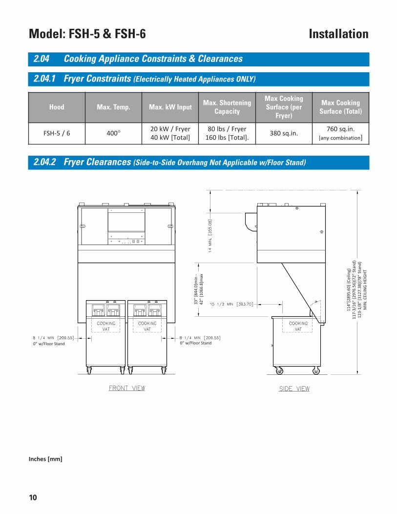
Hood Max. Temp. Max. kW Input Max. ShorteningCapacity
Max CookingSurface (per
Fryer)
Max CookingSurface (Total)
FSH-5 / 6 400° 20 kW / Fryer40 kW [Total]
80 lbs / Fryer160 lbs [Total]. 380 sq.in. 760 sq.in.
[any combination]
Inches [mm]
2.04 Cooking Appliance Constraints & Clearances
2.04.1 Fryer Constraints (Electrically Heated Appliances ONLY)
2.04.2 Fryer Clearances (Side-to-Side Overhang Not Applicable w/Floor Stand)
0” w/Floor Stand
33”
[844
.0]m
in -
42”
[106
6.8]
max
114”
[289
5.60
] (Ce
iling
)11
7-3/
16”
[297
6.56
](72”
Sta
nd)
123-
1/8”
[312
7.38
](78”
Sta
nd)
MIN
. CEI
LIN
G HE
IGHT
0” w/Floor Stand
11
Model: FSH-5 & FSH-6Installation
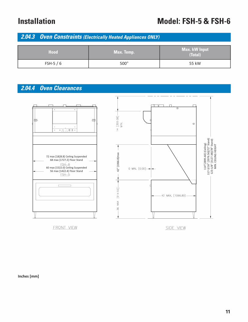
Hood Max. Temp. Max. kW Input(Total)
FSH-5 / 6 500° 55 kW
Inches [mm]
2.04.3 Oven Constraints (Electrically Heated Appliances ONLY)
2.04.4 Oven Clearances
72 max [1828.8] Ceiling Suspended68 max [1727.2] Floor Stand
60 max [1522.0] Ceiling Suspended56 max [1422.4] Floor Stand 42
” [1
066.
8]m
ax
114”
[289
5.60
] (Ce
iling
)11
7-3/
16”
[297
6.56
](72”
Sta
nd)
123-
1/8”
[312
7.38
](78”
Sta
nd)
MIN
. CEI
LIN
G HE
IGHT
12
Model: FSH-5 & FSH-6 Installation
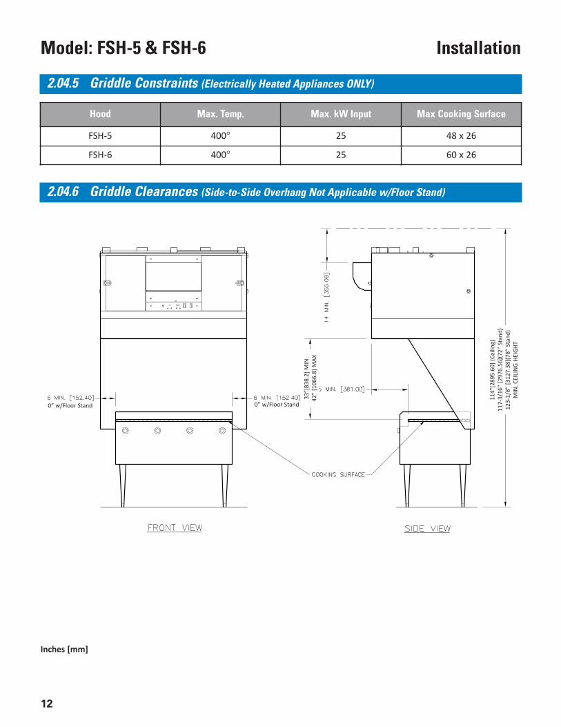
Hood Max. Temp. Max. kW Input Max Cooking Surface
FSH-5 400° 25 48 x 26
FSH-6 400° 25 60 x 26
Inches [mm]
2.04.5 Griddle Constraints (Electrically Heated Appliances ONLY)
2.04.6 Griddle Clearances (Side-to-Side Overhang Not Applicable w/Floor Stand)
33”[
838.
2] M
IN.
42”
[106
6.8]
MAX
0” w/Floor Stand0” w/Floor Stand
114”
[289
5.60
] (Ce
iling
)11
7-3/
16”
[297
6.56
](72”
Sta
nd)
123-
1/8”
[312
7.38
](78”
Sta
nd)
MIN
. CEI
LIN
G HE
IGHT
13
Model: FSH-5 & FSH-6Installation
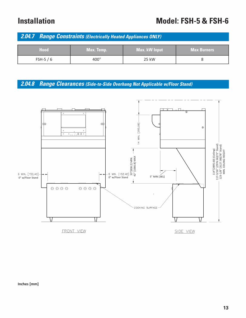
Hood Max. Temp. Max. kW Input Max Burners
FSH-5 / 6 400° 25 kW 8
2.04.7 Range Constraints (Electrically Heated Appliances ONLY)
2.04.8 Range Clearances (Side-to-Side Overhang Not Applicable w/Floor Stand)
Inches [mm]
0” w/Floor Stand0” w/Floor Stand
33”[
838.
2] M
IN.
42”
[106
6.8]
MAX
5” MIN [381]
114”
[289
5.60
] (Ce
iling
)11
7-3/
16”
[297
6.56
](72”
Sta
nd)
123-
1/8”
[312
7.38
](78”
Sta
nd)
MIN
. CEI
LIN
G HE
IGHT
14
Model: FSH-5 & FSH-6 Installation
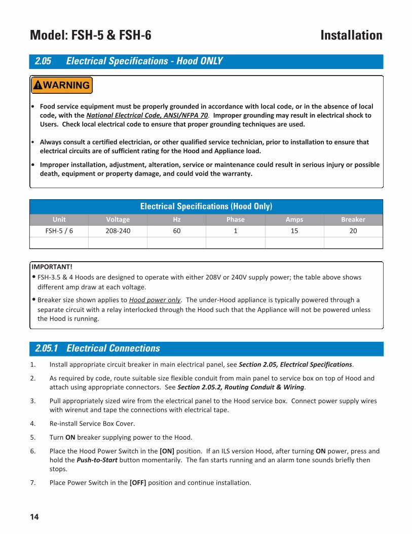
1. Install appropriate circuit breaker in main electrical panel, see Section 2.05, Electrical Specifications.
2. As required by code, route suitable size flexible conduit from main panel to service box on top of Hood andattach using appropriate connectors. See Section 2.05.2, Routing Conduit & Wiring.
3. Pull appropriately sized wire from the electrical panel to the Hood service box. Connect power supply wireswith wirenut and tape the connections with electrical tape.
4. Re-install Service Box Cover.
5. Turn ON breaker supplying power to the Hood.
6. Place the Hood Power Switch in the [ON] position. If an ILS version Hood, after turning ON power, press andhold the Push-to-Start button momentarily. The fan starts running and an alarm tone sounds briefly thenstops.
7. Place Power Switch in the [OFF] position and continue installation.
2.05 Electrical Specifications - Hood ONLY
• Food service equipment must be properly grounded in accordance with local code, or in the absence of localcode, with the National Electrical Code, ANSI/NFPA 70. Improper grounding may result in electrical shock toUsers. Check local electrical code to ensure that proper grounding techniques are used.
• Always consult a certified electrician, or other qualified service technician, prior to installation to ensure thatelectrical circuits are of sufficient rating for the Hood and Appliance load.
• Improper installation, adjustment, alteration, service or maintenance could result in serious injury or possibledeath, equipment or property damage, and could void the warranty.
Electrical Specifications (Hood Only) Unit Voltage Hz Phase Amps Breaker
FSH-5 / 6 208-240 60 1 15 20
IMPORTANT!• FSH-3.5 & 4 Hoods are designed to operate with either 208V or 240V supply power; the table above shows
different amp draw at each voltage.
• Breaker size shown applies to Hood power only. The under-Hood appliance is typically powered through aseparate circuit with a relay interlocked through the Hood such that the Appliance will not be powered unlessthe Hood is running.
2.05.1 Electrical Connections
15
Model: FSH-5 & FSH-6Installation
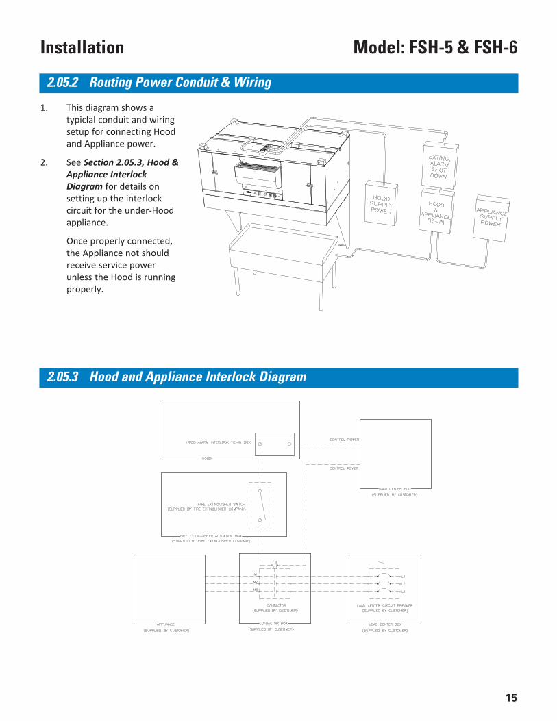
2.05.2 Routing Power Conduit & Wiring
1. This diagram shows atypiclal conduit and wiringsetup for connecting Hoodand Appliance power.
2. See Section 2.05.3, Hood &Appliance InterlockDiagram for details onsetting up the interlockcircuit for the under-Hoodappliance.
Once properly connected,the Appliance not shouldreceive service powerunless the Hood is runningproperly.
2.05.3 Hood and Appliance Interlock Diagram
16
Model: FSH-5 & FSH-6 Installation
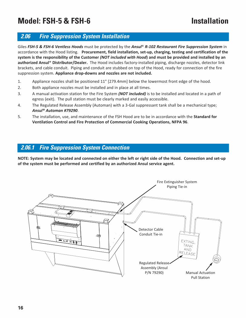
Giles FSH-5 & FSH-6 Ventless Hoods must be protected by the Ansul® R-102 Restaurant Fire Suppression System inaccordance with the Hood listing. Procurement, field installation, set-up, charging, testing and certification of thesystem is the responsibility of the Customer (NOT included with Hood) and must be provided and installed by anauthorized Ansul® Distributor/Dealer. The Hood includes factory-installed piping, discharge nozzles, detector linkbrackets, and cable conduit. Piping and conduit are stubbed on top of the Hood, ready for connection of the firesuppression system. Appliance drop-downs and nozzles are not included.
1. Appliance nozzles shall be positioned 11" [279.4mm] below the lowermost front edge of the hood.2. Both appliance nozzles must be installed and in place at all times.3. A manual activation station for the Fire System (NOT included) is to be installed and located in a path of
egress (exit). The pull station must be clearly marked and easily accessible.4. The Regulated Release Assembly (Automan) with a 3-Gal suppressant tank shall be a mechanical type;
Ansul® Automan #79290.5. The installation, use, and maintenance of the FSH Hood are to be in accordance with the Standard for
Ventilation Control and Fire Protection of Commercial Cooking Operations, NFPA 96.
NOTE: System may be located and connected on either the left or right side of the Hood. Connection and set-upof the system must be performed and certified by an authorized Ansul service agent.
2.06 Fire Suppression System Installation
2.06.1 Fire Suppression System Connection
Fire Extinguisher SystemPiping Tie-in
Detector CableConduit Tie-in
Regulated ReleaseAssembly (Ansul
P/N 79290) Manual ActuationPull Station
17
Model: FSH-5 & FSH-6Installation
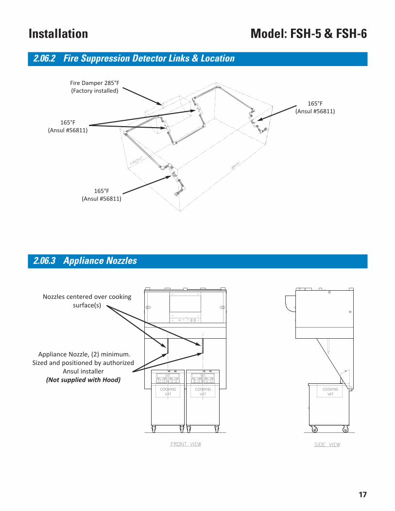
Appliance Nozzle, (2) minimum.Sized and positioned by authorized
Ansul installer(Not supplied with Hood)
Nozzles centered over cookingsurface(s)
2.06.2 Fire Suppression Detector Links & Location
2.06.3 Appliance Nozzles
165°F(Ansul #56811)
165°F(Ansul #56811)
Fire Damper 285°F(Factory installed)
165°F(Ansul #56811)
18
Model: FSH-5 & FSH-6 Installation
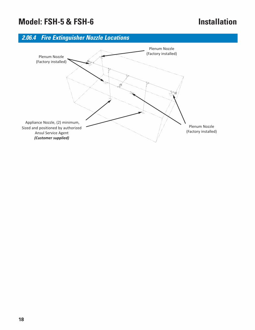
2.06.4 Fire Extinguisher Nozzle Locations
Appliance Nozzle, (2) minimum,Sized and positioned by authorized
Ansul Service Agent(Customer supplied)
Plenum Nozzle(Factory installed)
Plenum Nozzle(Factory installed)
Plenum Nozzle(Factory installed)
19
Model: FSH-5 & FSH-6Overview
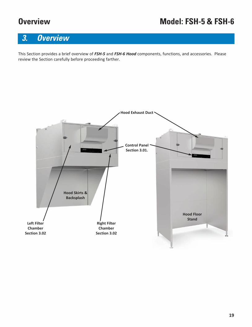
This Section provides a brief overview of FSH-5 and FSH-6 Hood components, functions, and accessories. Pleasereview the Section carefully before proceeding farther.
Hood Exhaust Duct
Hood Skirts &Backsplash
Left FilterChamber
Section 3.02
3. Overview
Control PanelSection 3.01.
Right FilterChamber
Section 3.02
Hood FloorStand
Model: FSH-5 & FSH-6 Overview
20
5 2* 1
* ILS Option Only
34
3.01 Control Panel
21
Model: FSH-5 & FSH-6Overview
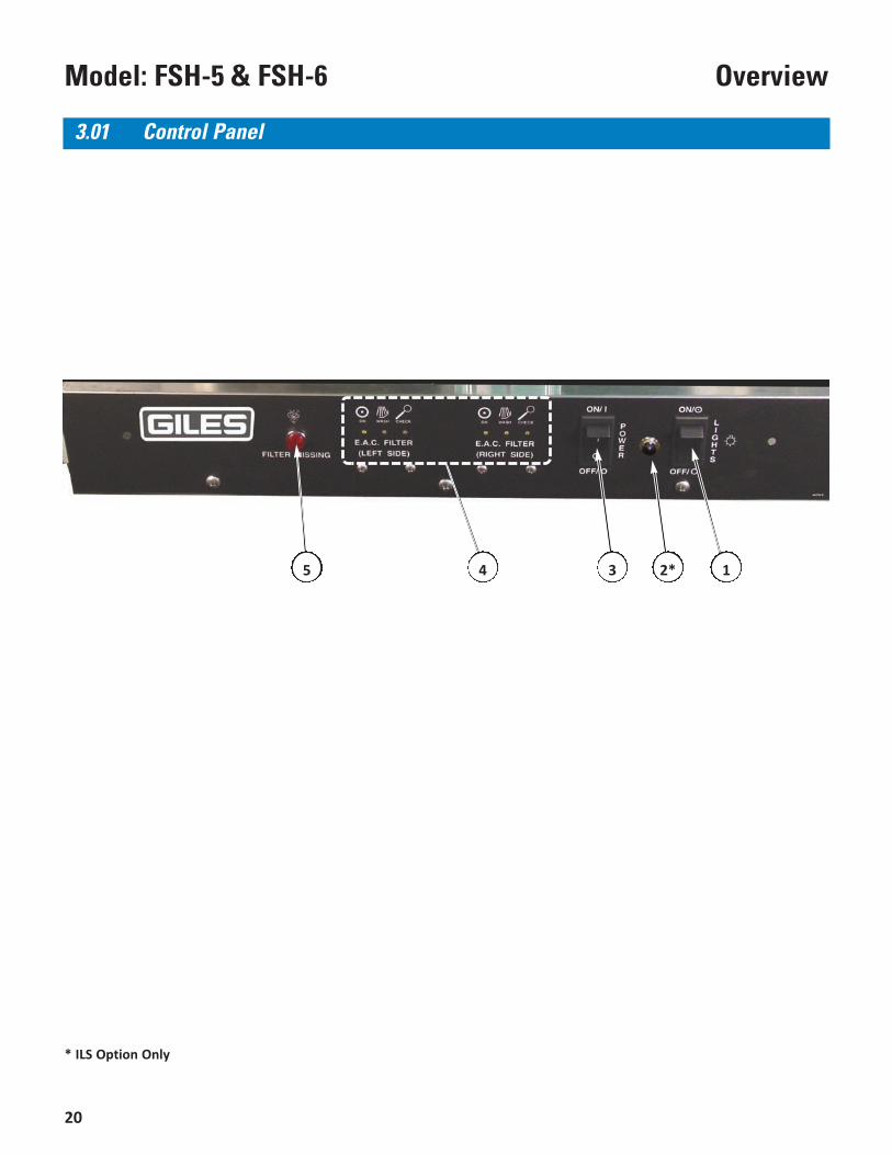
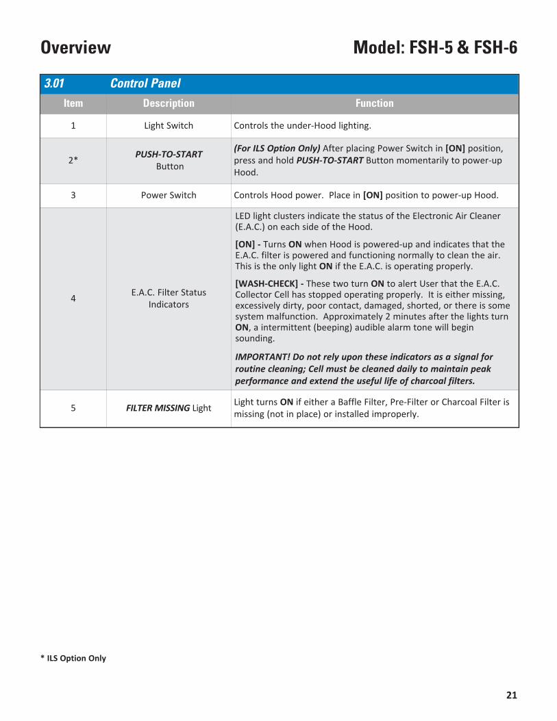
3.01 Control PanelItem Description Function
1 Light Switch Controls the under-Hood lighting.
2* PUSH-TO-STARTButton
(For ILS Option Only) After placing Power Switch in [ON] position,press and hold PUSH-TO-START Button momentarily to power-upHood.
3 Power Switch Controls Hood power. Place in [ON] position to power-up Hood.
4 E.A.C. Filter StatusIndicators
LED light clusters indicate the status of the Electronic Air Cleaner(E.A.C.) on each side of the Hood.
[ON] - Turns ON when Hood is powered-up and indicates that theE.A.C. filter is powered and functioning normally to clean the air.This is the only light ON if the E.A.C. is operating properly.
[WASH-CHECK] - These two turn ON to alert User that the E.A.C.Collector Cell has stopped operating properly. It is either missing,excessively dirty, poor contact, damaged, shorted, or there is somesystem malfunction. Approximately 2 minutes after the lights turnON, a intermittent (beeping) audible alarm tone will beginsounding.
IMPORTANT! Do not rely upon these indicators as a signal forroutine cleaning; Cell must be cleaned daily to maintain peakperformance and extend the useful life of charcoal filters.
5 FILTER MISSING Light Light turns ON if either a Baffle Filter, Pre-Filter or Charcoal Filter ismissing (not in place) or installed improperly.
* ILS Option Only
22
Model: FSH-5 & FSH-6 Overview
3.02 Filter Chamber & Exhaust
* Not shown
2
7
8
1 5 34
6
9
9
23
Model: FSH-5 & FSH-6Overview
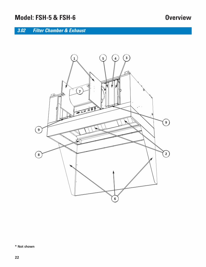
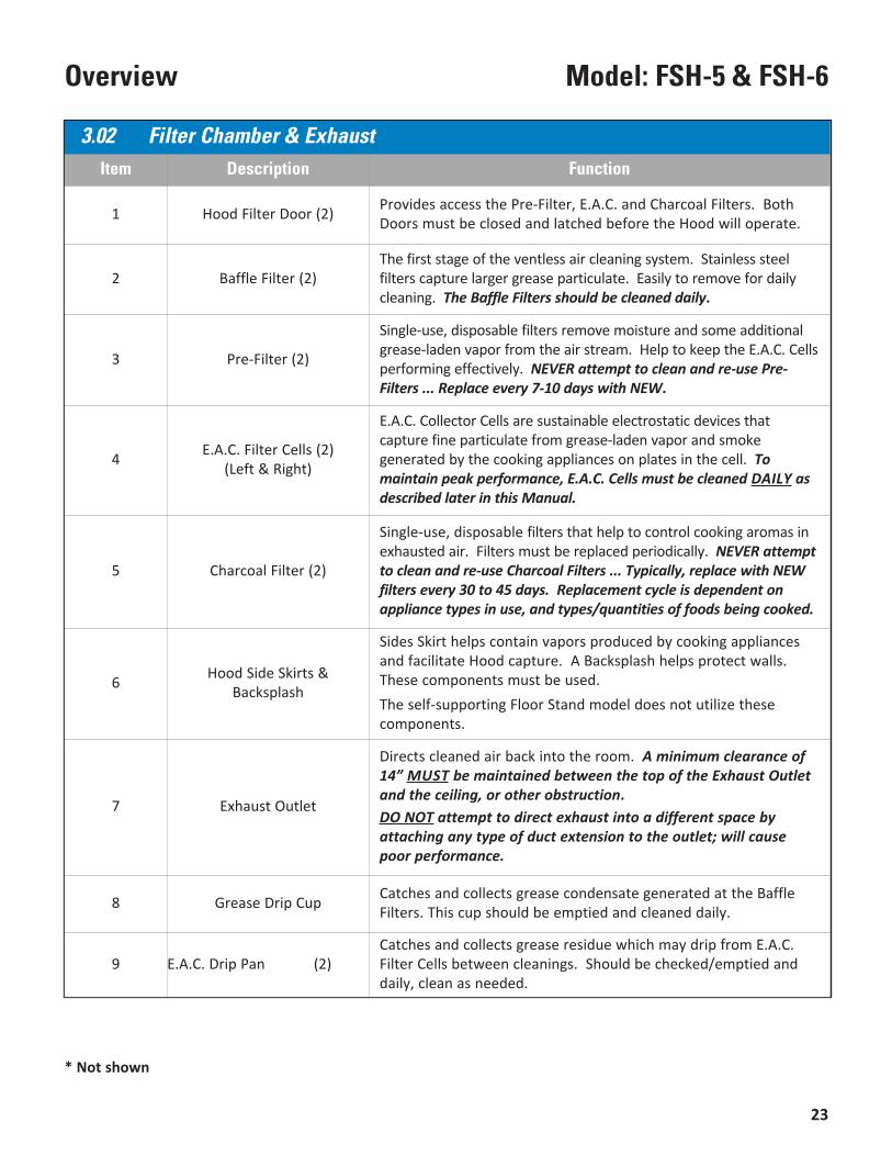
3.02 Filter Chamber & ExhaustItem Description Function
1 Hood Filter Door (2) Provides access the Pre-Filter, E.A.C. and Charcoal Filters. BothDoors must be closed and latched before the Hood will operate.
2 Baffle Filter (2)The first stage of the ventless air cleaning system. Stainless steelfilters capture larger grease particulate. Easily to remove for dailycleaning. The Baffle Filters should be cleaned daily.
3 Pre-Filter (2)
Single-use, disposable filters remove moisture and some additionalgrease-laden vapor from the air stream. Help to keep the E.A.C. Cellsperforming effectively. NEVER attempt to clean and re-use Pre-Filters ... Replace every 7-10 days with NEW.
4 E.A.C. Filter Cells (2) (Left & Right)
E.A.C. Collector Cells are sustainable electrostatic devices thatcapture fine particulate from grease-laden vapor and smokegenerated by the cooking appliances on plates in the cell. Tomaintain peak performance, E.A.C. Cells must be cleaned DAILy asdescribed later in this Manual.
5 Charcoal Filter (2)
Single-use, disposable filters that help to control cooking aromas inexhausted air. Filters must be replaced periodically. NEVER attemptto clean and re-use Charcoal Filters ... Typically, replace with NEWfilters every 30 to 45 days. Replacement cycle is dependent onappliance types in use, and types/quantities of foods being cooked.
6 Hood Side Skirts &Backsplash
Sides Skirt helps contain vapors produced by cooking appliancesand facilitate Hood capture. A Backsplash helps protect walls.These components must be used.The self-supporting Floor Stand model does not utilize thesecomponents.
7 Exhaust Outlet
Directs cleaned air back into the room. A minimum clearance of14” MUST be maintained between the top of the Exhaust Outletand the ceiling, or other obstruction.DO NOT attempt to direct exhaust into a different space byattaching any type of duct extension to the outlet; will causepoor performance.
8 Grease Drip Cup Catches and collects grease condensate generated at the BaffleFilters. This cup should be emptied and cleaned daily.
9 E.A.C. Drip Pan (2)Catches and collects grease residue which may drip from E.A.C.Filter Cells between cleanings. Should be checked/emptied anddaily, clean as needed.
* Not shown
24
Model: FSH-5 & FSH-6 Overview
3.03 Accessory Items Included w/Hood
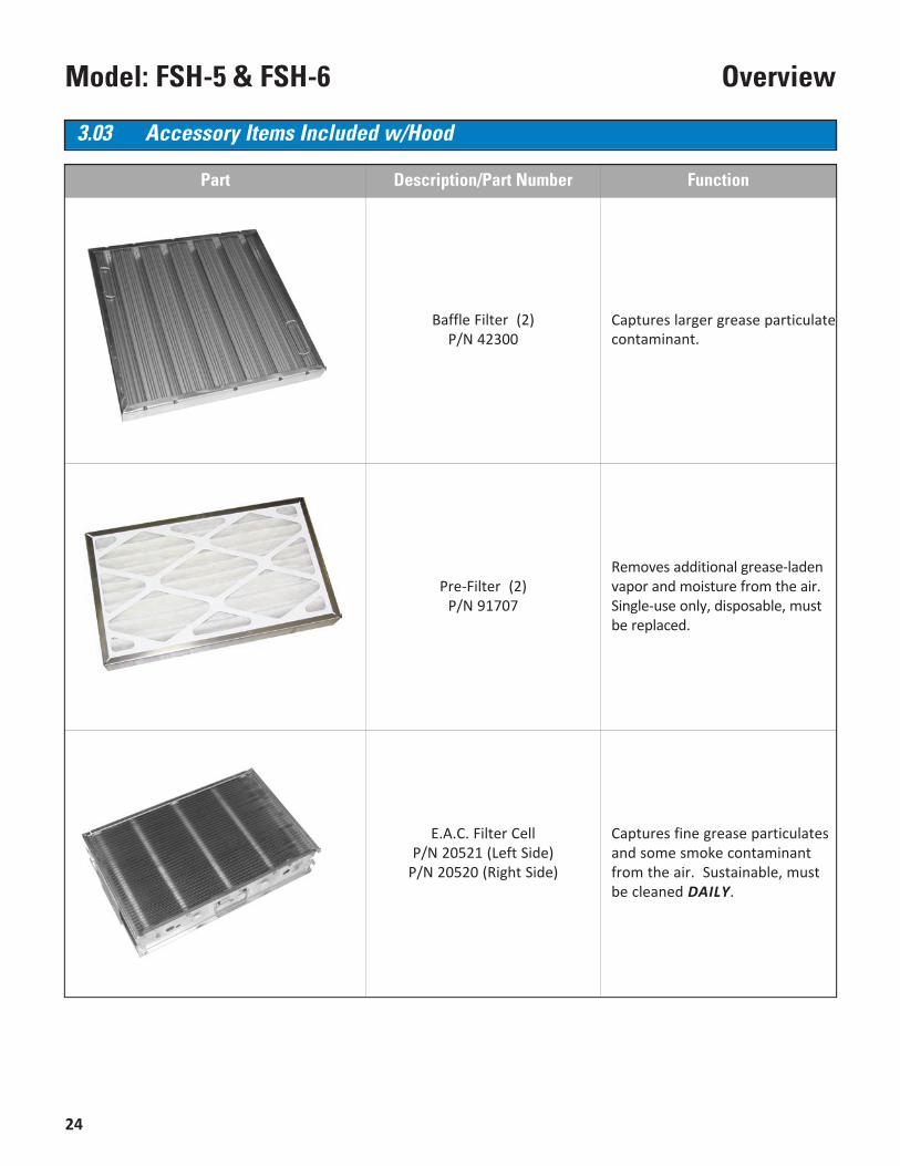
Part Description/Part Number Function
Baffle Filter (2)P/N 42300
Captures larger grease particulate contaminant.
Pre-Filter (2)P/N 91707
Removes additional grease-ladenvapor and moisture from the air. Single-use only, disposable, mustbe replaced.
E.A.C. Filter CellP/N 20521 (Left Side)
P/N 20520 (Right Side)
Captures fine grease particulatesand some smoke contaminantfrom the air. Sustainable, mustbe cleaned DAILy.
25
Model: FSH-5 & FSH-6Overview
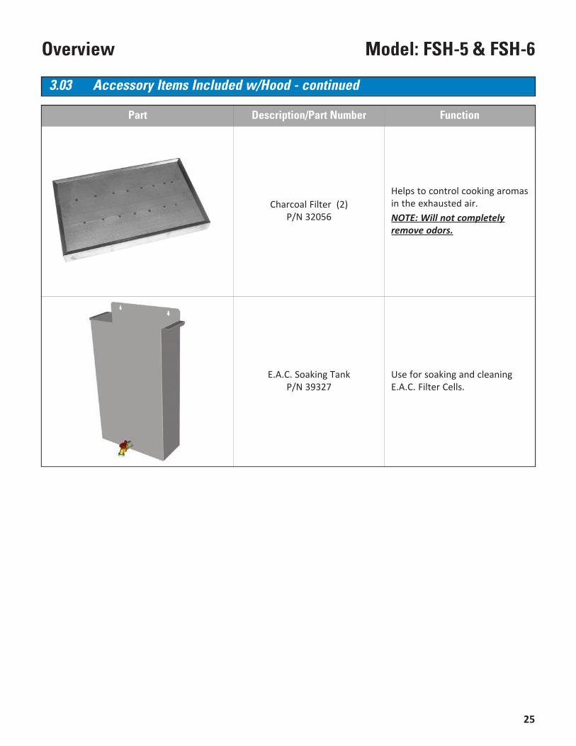
Part Description/Part Number Function
Charcoal Filter (2)P/N 32056
Helps to control cooking aromasin the exhausted air.NOTE: Will not completelyremove odors.
E.A.C. Soaking TankP/N 39327
Use for soaking and cleaningE.A.C. Filter Cells.
3.03 Accessory Items Included w/Hood - continued
26
Model: FSH-3.5 & FSH-4 Overview
27
Model: FSH-5 & FSH-6Operation & Filter Maintenance
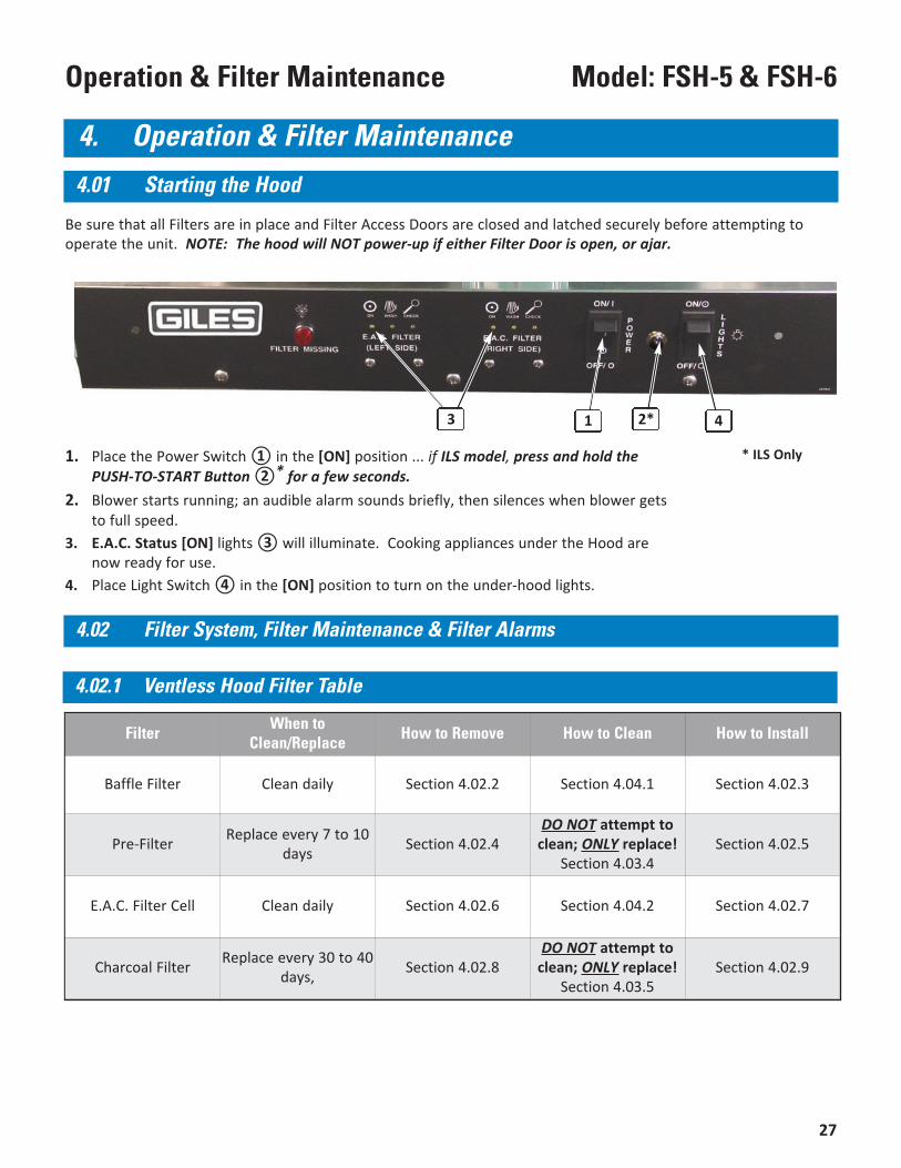
1. Place the Power Switch ① in the [ON] position ... if ILS model, press and hold thePUSH-TO-START Button ②* for a few seconds.
2. Blower starts running; an audible alarm sounds briefly, then silences when blower getsto full speed.
3. E.A.C. Status [ON] lights ③ will illuminate. Cooking appliances under the Hood arenow ready for use.
4. Place Light Switch ④ in the [ON] position to turn on the under-hood lights.
Be sure that all Filters are in place and Filter Access Doors are closed and latched securely before attempting tooperate the unit. NOTE: The hood will NOT power-up if either Filter Door is open, or ajar.
* ILS Only
4. Operation & Filter Maintenance
4.01 Starting the Hood
1 2*3 4
4.02 Filter System, Filter Maintenance & Filter Alarms
4.02.1 Ventless Hood Filter Table
Filter When toClean/Replace How to Remove How to Clean How to Install
Baffle Filter Clean daily Section 4.02.2 Section 4.04.1 Section 4.02.3
Pre-Filter Replace every 7 to 10days Section 4.02.4
DO NOT attempt toclean; ONLY replace!
Section 4.03.4Section 4.02.5
E.A.C. Filter Cell Clean daily Section 4.02.6 Section 4.04.2 Section 4.02.7
Charcoal Filter Replace every 30 to 40days, Section 4.02.8
DO NOT attempt toclean; ONLY replace!
Section 4.03.5Section 4.02.9
28
Model: FSH-5 & FSH-6 Operation & Filter Maintenance
③
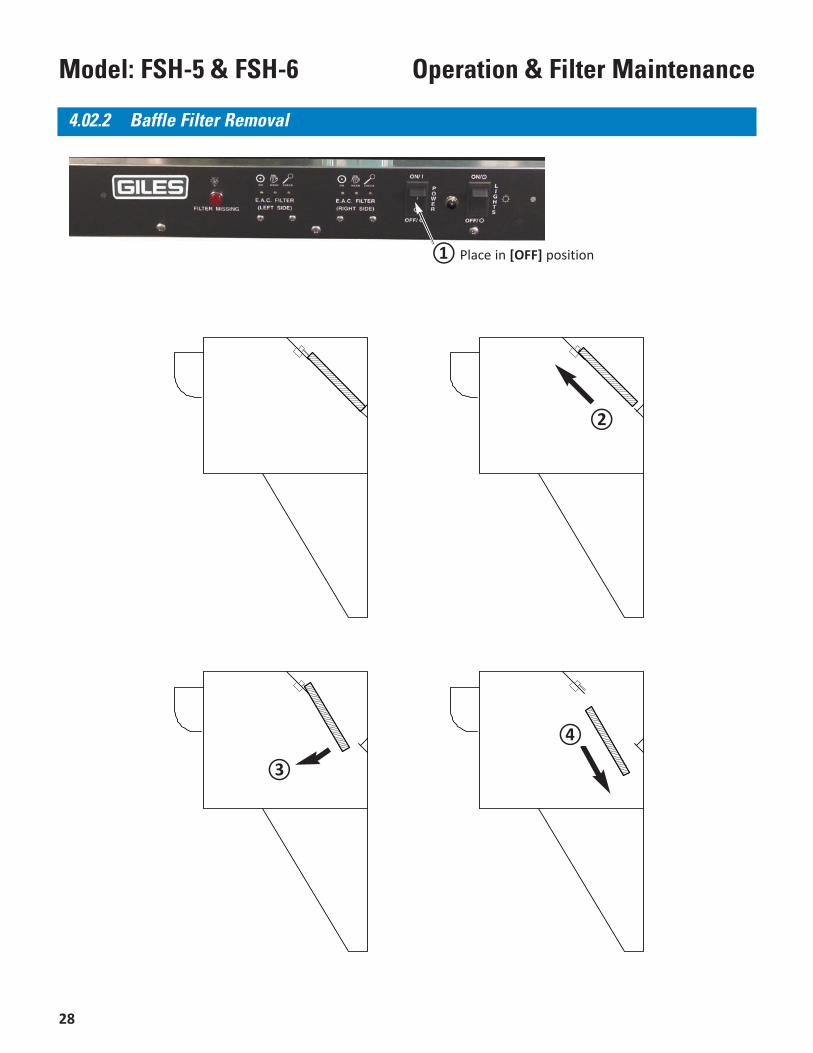
4.02.2 Baffle Filter Removal
④
②
① Place in [OFF] position
29
Model: FSH-5 & FSH-6Operation & Filter Maintenance
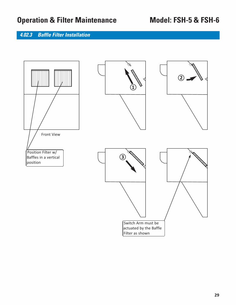
Switch Arm must beactuated by the BaffleFilter as shown
Front View
4.02.3 Baffle Filter Installation
②
①
③Position Filter w/Baffles in a verticalposition
30
Model: FSH-5 & FSH-6 Operation & Filter Maintenance
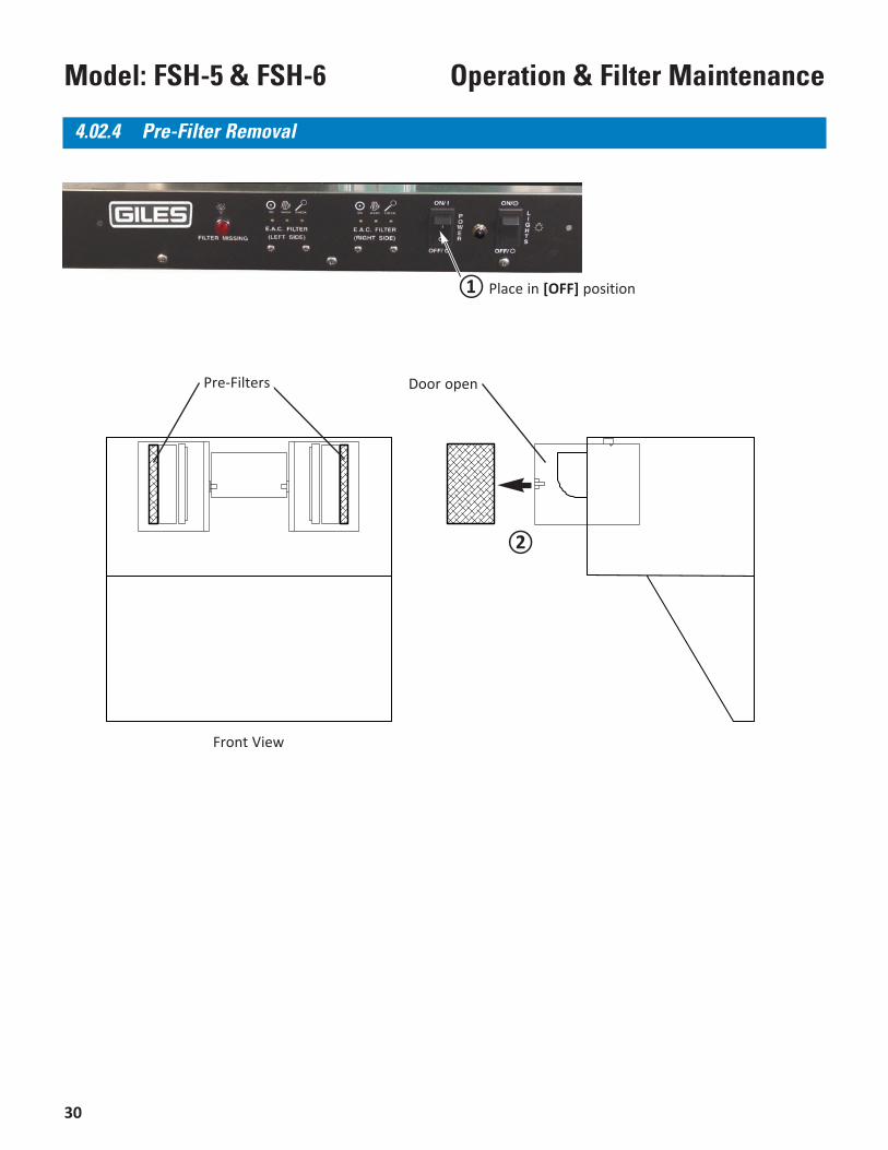
Door open
Front View
4.02.4 Pre-Filter Removal
Pre-Filters
②
① Place in [OFF] position
31
Model: FSH-5 & FSH-6Operation & Filter Maintenance
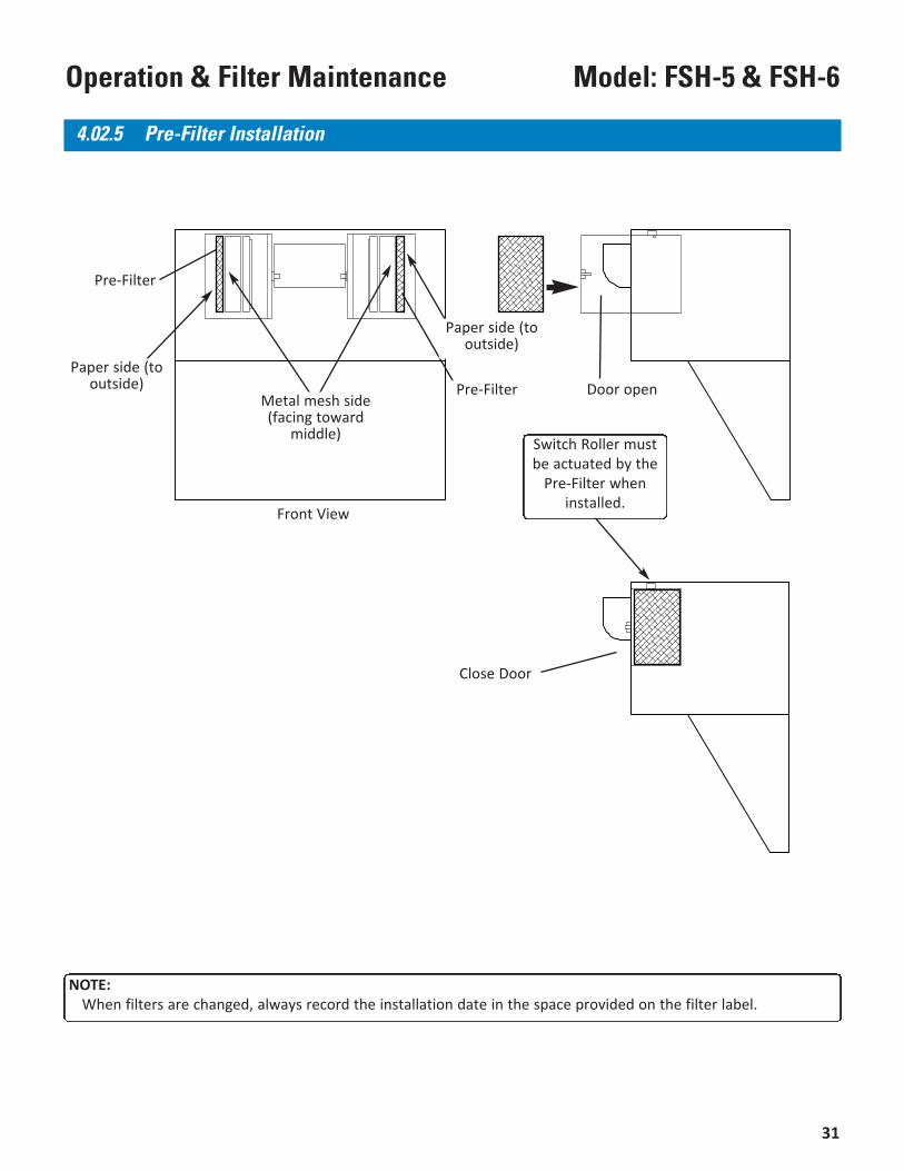
Door open
Front View
Pre-Filter
NOTE:When filters are changed, always record the installation date in the space provided on the filter label.
4.02.5 Pre-Filter Installation
Metal mesh side(facing toward
middle)
Pre-Filter
Paper side (tooutside)
Paper side (tooutside)
Switch Roller mustbe actuated by the
Pre-Filter wheninstalled.
Close Door
32
Model: FSH-5 & FSH-6 Operation & Filter Maintenance
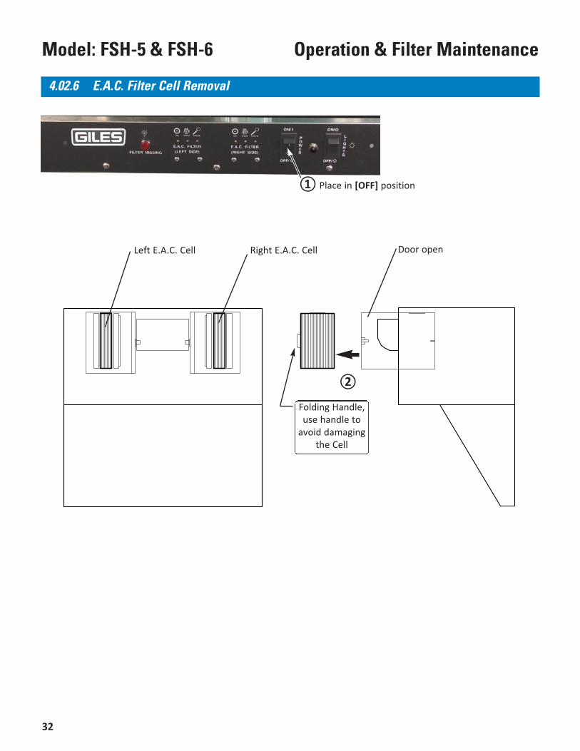
Folding Handle,use handle to
avoid damagingthe Cell
Left E.A.C. Cell Right E.A.C. Cell Door open
4.02.6 E.A.C. Filter Cell Removal
②
① Place in [OFF] position
33
Model: FSH-5 & FSH-6Operation & Filter Maintenance
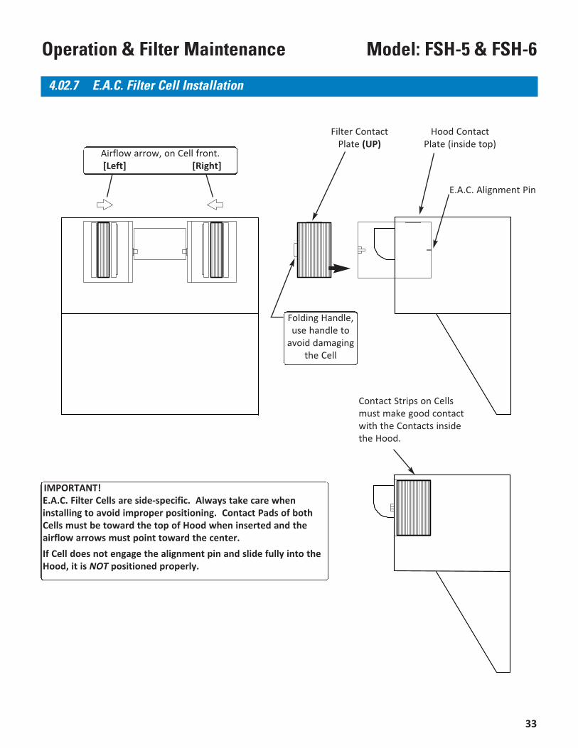
4.02.7 E.A.C. Filter Cell Installation
E.A.C. Alignment Pin
Hood ContactPlate (inside top)
Filter ContactPlate (UP)
Airflow arrow, on Cell front.[Left] [Right]
Folding Handle,use handle to
avoid damagingthe Cell
IMPORTANT!E.A.C. Filter Cells are side-specific. Always take care wheninstalling to avoid improper positioning. Contact Pads of bothCells must be toward the top of Hood when inserted and theairflow arrows must point toward the center.If Cell does not engage the alignment pin and slide fully into theHood, it is NOT positioned properly.
Contact Strips on Cellsmust make good contactwith the Contacts insidethe Hood.
34
Model: FSH-5 & FSH-6 Operation & Filter Maintenance
Charcoal Filter Door open
Front View
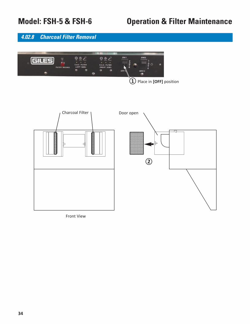
4.02.8 Charcoal Filter Removal
②
① Place in [OFF] position
35
Model: FSH-5 & FSH-6Operation & Filter Maintenance
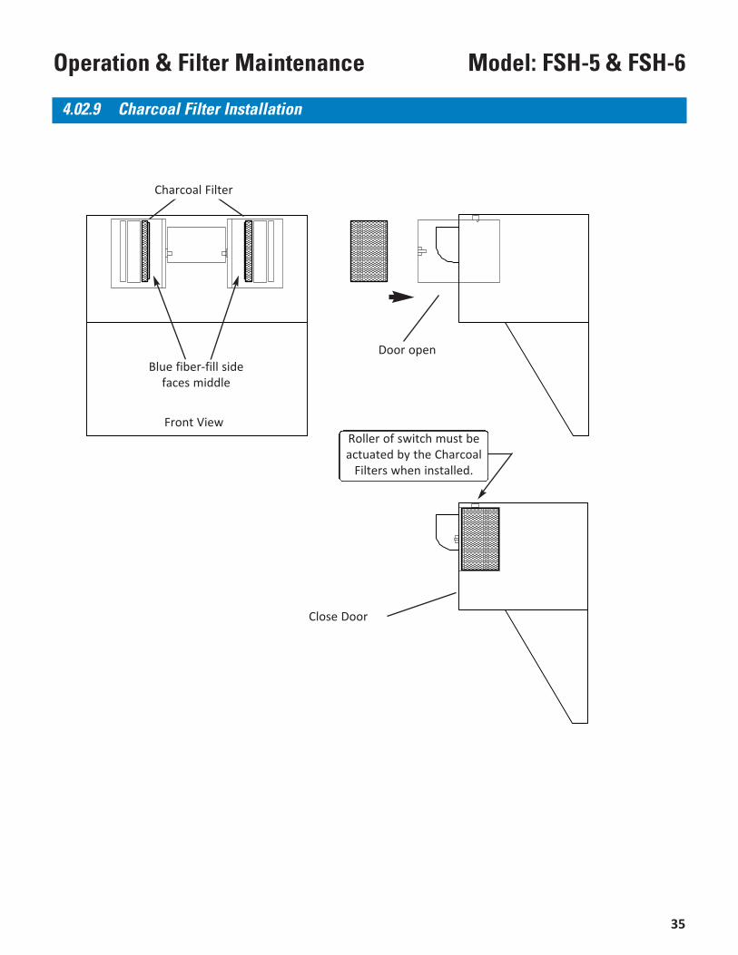
4.02.9 Charcoal Filter Installation
Door open
Close Door
Front View
Charcoal Filter
Blue fiber-fill sidefaces middle
Roller of switch must beactuated by the Charcoal
Filters when installed.
36
Model: FSH-5 & FSH-6 Operation & Filter Maintenance
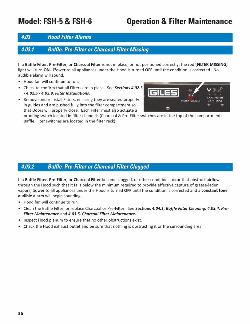
If a Baffle Filter, Pre-Filter, or Charcoal Filter is not in place, or not positioned correctly, the red [FILTER MISSING]light will turn ON. Power to all appliances under the Hood is turned OFF until the condition is corrected. Noaudible alarm will sound.• Hood fan will continue to run.• Check to confirm that all Filters are in place. See Sections 4.02.3
- 4.02.5 - 4.02.9, Filter Installations.• Remove and reinstall Filters, ensuring they are seated properly
in guides and are pushed fully into the filter compartment sothat Doors will properly close. Each Filter must also actuate aproofing switch located in filter channels (Charcoal & Pre-Filter switches are in the top of the compartment;Baffle Filter switches are located in the filter rack).
4.03 Hood Filter Alarms
4.03.1 Baffle, Pre-Filter or Charcoal Filter Missing
If a Baffle Filter, Pre-Filter, or Charcoal Filter become clogged, or other conditions occur that obstruct airflowthrough the Hood such that it falls below the minimum required to provide effective capture of grease-ladenvapors, power to all appliances under the Hood is turned OFF until the condition is corrected and a constant toneaudible alarm will begin sounding.• Hood fan will continue to run.• Clean the Baffle Filter, or replace Charcoal or Pre-Filter. See Sections 4.04.1, Baffle Filter Cleaning, 4.03.4, Pre-
Filter Maintenance and 4.03.5, Charcoal Filter Maintenance.• Inspect Hood plenum to ensure that no other obstructions exist.• Check the Hood exhaust outlet and be sure that nothing is obstructing it or the surrounding area.
4.03.2 Baffle, Pre-Filter or Charcoal Filter Clogged
37
Model: FSH-5 & FSH-6Operation & Filter Maintenance
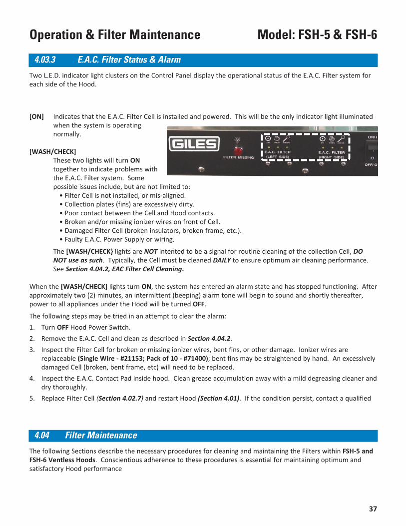
Two L.E.D. indicator light clusters on the Control Panel display the operational status of the E.A.C. Filter system foreach side of the Hood.
[ON] Indicates that the E.A.C. Filter Cell is installed and powered. This will be the only indicator light illuminatedwhen the system is operatingnormally.
[WASH/CHECK]These two lights will turn ONtogether to indicate problems withthe E.A.C. Filter system. Somepossible issues include, but are not limited to: • Filter Cell is not installed, or mis-aligned.
• Collection plates (fins) are excessively dirty. • Poor contact between the Cell and Hood contacts. • Broken and/or missing ionizer wires on front of Cell. • Damaged Filter Cell (broken insulators, broken frame, etc.). • Faulty E.A.C. Power Supply or wiring.
The [WASH/CHECK} lights are NOT intented to be a signal for routine cleaning of the collection Cell, DONOT use as such. Typically, the Cell must be cleaned DAILY to ensure optimum air cleaning performance.See Section 4.04.2, EAC Filter Cell Cleaning.
When the [WASH/CHECK] lights turn ON, the system has entered an alarm state and has stopped functioning. Afterapproximately two (2) minutes, an intermittent (beeping) alarm tone will begin to sound and shortly thereafter,power to all appliances under the Hood will be turned OFF.
The following steps may be tried in an attempt to clear the alarm:1. Turn OFF Hood Power Switch.2. Remove the E.A.C. Cell and clean as described in Section 4.04.2.3. Inspect the Filter Cell for broken or missing ionizer wires, bent fins, or other damage. Ionizer wires are
replaceable (Single Wire - #21153; Pack of 10 - #71400); bent fins may be straightened by hand. An excessivelydamaged Cell (broken, bent frame, etc) will need to be replaced.
4. Inspect the E.A.C. Contact Pad inside hood. Clean grease accumulation away with a mild degreasing cleaner anddry thoroughly.
5. Replace Filter Cell (Section 4.02.7) and restart Hood (Section 4.01). If the condition persist, contact a qualified
4.03.3 E.A.C. Filter Status & Alarm
4.04 Filter Maintenance
The following Sections describe the necessary procedures for cleaning and maintaining the Filters within FSH-5 andFSH-6 Ventless Hoods. Conscientious adherence to these procedures is essential for maintaining optimum andsatisfactory Hood performance
38
Model: FSH-5 & FSH-6 Operation & Filter Maintenance
4.04.1 Baffle Filter Cleaning
Grease Baffle Filters should be cleaned daily. Remove and clean in sink with a mild, bio-degradable, degreasingcleaner (Giles recommends Simple Green® HD Pro). Rinse and dry thoroughly. Reinstall dry Filters in the unit.Generally, Baffle Filters may be washed in a dishwasher.Ensure that Filters are completely dry before reinstalling in Hood. NEVER PLACE A WET FILTER INTO THE HOOD!
The stainless steel Baffle Filters are fabricated from thin guage metal that has potential topresent sharp edges. Exercise due care when handling and cleaning the Filters to avoidinjury. It is recommended that heavy-duty rubber gloves be worn.
The E.A.C. Filter Collector Cells MUST BE CLEANED DAILY to maintain peak performance. Failure to do so willeventually lead to malfunction of the E.A.C. Filter system and also shorten the useful life of Charcoal Filters. ASoaking Tank has been provided with the Unit for use in cleaning the Cells. Precisely follow the steps below foreffective cleaning. With proper care and cleaning, the Cells are designed to provide years of sustainable service.
IMPORTANT: The E.A.C. Collector Cells CANNOT withstand washing in commercial dishwashing equipment.
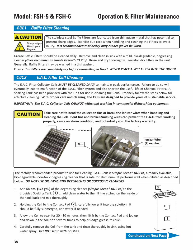
Take care not to bend the collection fins or break the ionizer wires when handling andcleaning the Cell. Bent fins and broken/missing wires can prevent the E.A.C. from working
properly, cause an alarm condition, and potentially void the factory warranty.
FinsIonizer Wire(9) required
4.04.2 E.A.C. Filter Cell Cleaning
The factory-recommended product to use for cleaning E.A.C. Cells is Simple Green® HD-Pro, a readily available,bio-degradable, non-toxic degreasing cleaner that is safe for aluminum. It performs well when diluted as describedbelow. DO NOT USE DISHWASHING DETERGENTS OR CORROSIVE CLEANERS.
1. Add 64 ozs. (1/2 gal.) of the degreasing cleaner [Simple Green® HD-Pro] to theprovided Soaking Tank ① ... add clean water to the fill line etched on the inside ofthe tank back and mix thoroughly.
2. Holding the Cell by the Contact Pad ②, carefully lower it into the solution. Itshould be fully submerged, add water if needed.
3. Allow the Cell to soak for 20 - 30 minutes, then lift it by the Contact Pad and jog upand down in the solution several times to help dislodge grease residue.
4. Carefully remove the Cell from the tank and rinse thoroughly in sink, using hotwater spray. DO NOT scrub with brushes.
1
2
Continued on Next Page
39
Model: FSH-5 & FSH-6Operation & Filter Maintenance
Replace Pre-Filters weekly (see Sections 4.02.4 & 4.02.5). These CANNOT be cleaned and are not intended for long-term use.
Use GILES replacement Item No. 91707. Write the replacement date on new filter.
5. Stand Cell on end, in a dish drainer, with Contact Pad up and allow it to air dry overnight. Cell must becompletely dry before reinstalling in Hood.
6. Inspect for broken/missing wires and bent fins. Broken wires need to replaced promptly. If needed, bent finsmay be gently straightened by hand.
4.04.2 E.A.C. Filter Cell Cleaning - continued
NOTE:The degreasing solution can be used for up to 10 days multiple times ... discard and replenish when a greasy film remainsvisible floating on the liquid. When soaking, always ensure that solution completely covers the Cell ... add water if needed.
• NOT dishwasher safe ... DO NOT wash Cells in the dishwasher!• DO NOT dry Cells by installing and running the Hood fan to air dry. This could potentially
damage the EAC system causing improper operation and void the warranty. If desired,place a small electric fan to blow on Cell as it drains to help expedite drying.
• DO NOT clean the Cell with cleaners which might be corrosive to aluminum.
Charcoal Filters are single-use, disposable Filters. NEVER attempt to clean and reuse;doing so can cause damage to the unit.
Charcoal Filters are consumable items which must be replaced periodically (see Sections 4.02.8 & 4.02.9). TheseCANNOT be cleaned and reused. Typical replacement cycle is every 30 to 40 days, depending on usage.
Use GILES replacement Item No. 32056. Write the replacement date on new filter.
IMPORTANT: Failure to use Giles OEM parts and OEM replacement filters may void the factory warranty.
4.03.5 Charcoal Filter Maintenance
4.03.4 Pre-Filter Maintenance
Pre-Filters are single-use, disposable Filters. NEVER attempt to clean and reuse; doing socan cause damage to the unit.
IMPORTANT: Failure to use Giles OEM parts and OEM replacement filters may void the factory warranty.
40
Model: FSH-5 & FSH-6 Operation & Filter Maintenance
41
Model: FSH-5 & FSH-6Hood Cleaning & Maintenance
5. Hood Cleaning & MaintenanceThis Section describes the steps to generally maintain and clean FSH-5 & FSH-6 Hoods. Attention to theseprocedures will help ensure the Hood remains in satisfactory operating condition and continues to run efficientlyand safely.
A Maintenance & Service Log is provided, see Section 5.06.
The Hood design incorporates various interlock switches to ensure that the unit will shutdown if certain conditions existthat are not consistent with safe and effective operation. The interlocks should be tested MONTHLY as describedbelow. Use the Maintenance & Service Log to record completion of testing. If problems are detected, contact GILESor an authorized service provider.
1. Door Interlock Test: Start Hood. With Hood running, unlatch and slightly open the Filter Access Doors, onat a time. With each Door confirm Hood powers OFF when opened and all appliances under the Hood turnOFF, or will not turn ON.
2. Baffle Filter Test: Remove Baffle Filter from one side then turn ON Hood power. Verify that the red [FILTERMISSING] light turns ON. Check to ensure that all appliances under Hood will not turn ON. Reinstall theBaffle Filter and repeat test with the other Filter. See Sections 4.02.2 & 4.02.3, Removal & Installation.
3. Pre-Filter/Charcoal Filter Test: Same procedure as [#2] except perform for each of the Pre-Filters andCharcoal Filters, one at a time in succession. Reinstall the Charcoal Filter. See Sections 4.02.4, 4.02.5, 4.02.8& 4.02.9, Removal & Installation.
3. E.A.C. Filter Test: Same procedure as [#2 & #3] except remove each E.A.C. Filter Collector Cell, one at atime, close and latch Door. Turn ON Hood power. Verify that all three (3) small E.A.C. Status Lights comeON for the side without Cell in place. Wait approx. two (2) minutes. A beeping tone alarm should beginsounding. Check to ensure that all appliances under Hood will not turn ON. Reinstall the E.A.C. Cell, repeatfor other side. See Section 4.02.6. & 4.02.7, Removal & Installation.
5. Filter Clogged Test: Perform this test ONLY after installing new Charcoal Filter. Start Hood normally andallow to run. Use cardboard or other material to completely block Hood exhaust outlet, holding it firmly inplace so that no air is escaping. Within a few seconds, a continuous tone alarm should begin sounding.Check to ensure that all appliances under Hood will not turn ON. Remove the obstruction; the alarm shouldsilence and the appliances should be powered again.
Should any of these tests fail to yield the described results, contact a factory-authorized service company and havethe unit evaluated and repaired. Any Giles Manufacturer’s Representative can provide information about nearbyauthorized service providers, or call GILES Services at 800-554-4537 for assistance in locating a Representative orservice provider.
5.01 Monthly Hood Interlock Inspection (Can be Performed by User)
42
Model: FSH-5 & FSH-6 Hood Cleaning & Maintenance
To maintain effectiveness and performance, the Hood must be deep cleaned, at a minimum, every 3 months.
1. Disconnect power to the unit, preferably at the circuit breaker.
2. Unplug and remove appliances from under Hood.
3. Remove all of the Filters.
4. Use a soft cloth, or sponge, and a mild bio-degradable degreasing cleaner (Simple Green® HD Prorecommended) to clean inside the entire hood plenum, on both sides, to remove grease film accumulationfrom interior surfaces.
5. Inspect the Hood fans on each side and, if possible, clean any grease build-up from the blade using degreaserand a small brush (use cleaner sparingly). NOTE: When restarting Hood after cleaning, hold a cardboard box,or other suitable item, over the exhaust outlet to catch residue/cleaner which may be discharged from theblowers.
5. Thoroughly clean the under-hood area and all exterior surfaces with mild degreaser or a good quality stainlesssteel cleaner.
6. Allow hood to thoroughly dry or wipe dry with clean dry cloth.
7. Clean Baffle Filters and E.A.C. Collector Cells see Sections 4.04.1 & 4.04.2. If necessary, obtain and install afresh new Pre-Filters and Charcoal Filters. Reinstall all Filters in Hood.
8. Restore power to the Hood and reposition under-hood appliances.
5.02 Quarterly Hood Cleaning
DO NOT wash down Hood with water from a spray hose.DO NOT steam clean or use any type pressure washing equipment.DO NOT use products containing chlorine or other caustic chemicals.DO NOT use abrasive products, steel wool or scouring pads.
The factory-recommended product to use for general cleaning/degreasing of this equipment is Simple Green® HD-Pro, a readily available, bio-degradable, non-toxic degreasing cleaner.
The fire extinguishing system connected to the Hood must be maintained in accordance with the Standard for WetChemical Extinguishing Systems, NFPA 17A and with the instructions of the system’s installer.
All inspection, maintenance, troubleshooting, repairs and general servicing of the fire extinguishing system must beperformed by an authorized Ansul® Distributor/Dealer. Required maintenance activities are described in thesubsequent sections.
Consult the Fire Suppression System documentation provided by the system installer for complete maintenanceguidelines.
5.03 Fire Suppression System Maintenance
43
Model: FSH-5 & FSH-6Hood Cleaning & Maintenance
5.03.1 Semi-Annual (6-Mo) Fire Suppression System Inspection & Maintenance
• Confirm that the fire hazard potential has not changed.
• Inspect suppressant storage tank for chemical level and charge pressure.
• Inspect and test the Automan release mechanism.
• Check all nozzles to ensure they are free of grease build-up. Confirm that all nozzle blow-off caps are in placeand in good condition; replace as needed. See Section 2.06.4, Fire Extinguisher Nozzle Locations.
• Inspect and test the remote manual activation station for function and wear.
• Install test detector link; cut to test automatic actuation.
• Inspect and clean detector links. Confirm that detector links are of the correct temperature rating. SeeSection 2.06.2, Fire Suppression Detector Links & Location.
• Inspect link conduit and wire cable for wear at pulleys and detectors; replace if necessary.
• Record maintenance date and service performed in a permanent file, and sign-off on tag attached to system ina conspicuous location.
Service and inspection of the fire suppression system must be performed by a qualified Ansul® Distributor/Dealer. As aminimum, field inspection of the fire suppression system must be conducted semi-annually (every 6 months) and shallconsist of the following:
The Annual Inspection & Maintenance is the same as Semi-Annual except:
• All detector links must be replaced with new. See Section 2.05.1, Fire Suppression Detector Link Specification& Location.
5.03.2 Annual (12-Mo) Fire Suppression System Inspection & Maintenance
Same as Annual Inspection & Maintenance except:
• Replace wet-chemical fire suppressant.
• Hydrostatic test and certify Suppressant Tank and Compressed Gas Charging Cartridge. As alternativecomponents can be replaced with new.
• Flow test the regulator.
5.03.3 12-Year Fire Suppression System Inspection & Maintenance
44
Model: FSH-5 & FSH-6 Hood Cleaning & Maintenance
1 2 3 4 51 2 3 4 51 2 3 4 5 61 2 3 4 51 2 3 4 51 2 3 4 5 61 2 3 4 51 2 3 4 51 2 3 4 5 61 2 3 4 51 2 3 4 51 2 3 4 5 61 2 3 4 51 2 3 4 51 2 3 4 5 61 2 3 4 51 2 3 4 51 2 3 4 5 61 2 3 4 51 2 3 4 51 2 3 4 5 61 2 3 4 51 2 3 4 51 2 3 4 5 61 2 3 4 51 2 3 4 51 2 3 4 5 61 2 3 4 51 2 3 4 51 2 3 4 5 61 2 3 4 51 2 3 4 51 2 3 4 5 61 2 3 4 51 2 3 4 51 2 3 4 5 6 7
1 2 3 4 5RT 1-2-151 2 3 4 51 2 3 4 5 61 2 3 4 51 2 3 4 51 2 3 4 5 61 2 3 4 51 2 3 4 51 2 3 4 5 61 2 3 4 51 2 3 4 51 2 3 4 5 61 2 3 4 51 2 3 4 51 2 3 4 5 61 2 3 4 51 2 3 4 51 2 3 4 5 61 2 3 4 51 2 3 4 51 2 3 4 5 61 2 3 4 51 2 3 4 51 2 3 4 5 61 2 3 4 51 2 3 4 51 2 3 4 5 61 2 3 4 51 2 3 4 51 2 3 4 5 61 2 3 4 51 2 3 4 51 2 3 4 5 61 2 3 4 51 2 3 4 51 2 3 4 5 6
Check Initial/Date
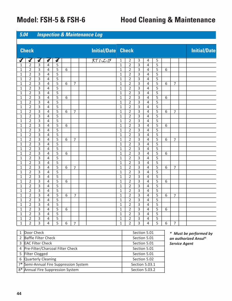
1 Door Check Section 5.012 Baffle Filter Check Section 5.013 EAC Filter Check Section 5.014 Pre-Filter/Charcoal Filter Check Section 5.015 Filter Clogged Section 5.016 Quarterly Cleaning Section 5.02
7* Semi-Annual Fire Suppression System Section 5.03.18* Annual Fire Suppression System Section 5.03.2
* Must be performed byan authorized Ansul®Service Agent
Check Initial/Date
5.04 Inspection & Maintenance Log
7
7
7
7
7
7
7
7
7
7
7
45
Model: FSH-5 & FSH-6Troubleshooting
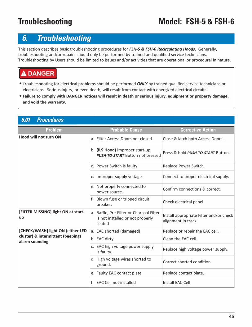
6. TroubleshootingThis section describes basic troubleshooting procedures for FSH-5 & FSH-6 Recirculating Hoods. Generally,troubleshooting and/or repairs should only be performed by trained and qualified service technicians.Troubleshooting by Users should be limited to issues and/or activities that are operational or procedural in nature.
• Troubleshooting for electrical problems should be performed ONLY by trained qualified service technicians orelectricians. Serious injury, or even death, will result from contact with energized electrical circuits.
• Failure to comply with DANGER notices will result in death or serious injury, equipment or property damage,and void the warranty.
6.01 Procedures
Problem Probable Cause Corrective ActionHood will not turn ON a. Filter Access Doors not closed Close & latch both Access Doors.
b. (ILS Hood) Improper start-up;PUSH-TO-START Button not pressed Press & hold PUSH-TO-START Button.
c. Power Switch is faulty Replace Power Switch.
c. Improper supply voltage Connect to proper electrical supply.
e. Not properly connected to power source. Confirm connections & correct.
f. Blown fuse or tripped circuitbreaker. Check electrical panel
[FILTER MISSING] light ON at start-up
a. Baffle, Pre-Filter or Charcoal Filteris not installed or not properlyseated
Install appropriate Filter and/or checkalignment in track.
[CHECK/WASH] light ON (either LEDcluster) & intermittent (beeping)alarm sounding
a. EAC shorted (damaged) Replace or repair the EAC cell.
b. EAC dirty Clean the EAC cell.
c. EAC high voltage power supply is faulty. Replace high voltage power supply.
d. High voltage wires shorted toground. Correct shorted condition.
e. Faulty EAC contact plate Replace contact plate.
f. EAC Cell not installed Install EAC Cell
46
Model: FSH-5 & FSH-6 Troubleshooting
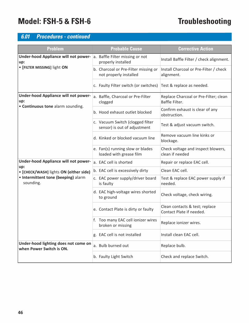
Problem Probable Cause Corrective Action
Under-hood Appliance will not power-up:• [FILTER MISSING] light ON
a. Baffle Filter missing or notproperly installed Install Baffle Filter / check alignment.
b. Charcoal or Pre-Filter missing ornot properly installed
Install Charcoal or Pre-Filter / checkalignment.
c. Faulty Filter switch (or switches) Test & replace as needed.
Under-hood Appliance will not power-up:• Continuous tone alarm sounding.
a. Baffle, Charcoal or Pre-Filterclogged
Replace Charcoal or Pre-Filter; cleanBaffle Filter.
b. Hood exhaust outlet blocked Confirm exhaust is clear of anyobstruction.
c. Vacuum Switch (clogged filtersensor) is out of adjustment Test & adjust vacuum switch.
d. Kinked or blocked vacuum line Remove vacuum line kinks orblockage.
e. Fan(s) running slow or bladesloaded with grease film
Check voltage and inspect blowers,clean if needed
Under-hood Appliance will not power-up:• [CHECK/WASH] lights ON (either side)• Intermittent tone (beeping) alarm
sounding.
a. EAC cell is shorted Repair or replace EAC cell.
b. EAC cell is excessively dirty Clean EAC cell.
c. EAC power supply/driver boardis faulty
Test & replace EAC power supply ifneeded.
d. EAC high-voltage wires shortedto ground Check voltage, check wiring.
e. Contact Plate is dirty or faulty Clean contacts & test; replaceContact Plate if needed.
f. Too many EAC cell ionizer wiresbroken or missing Replace ionizer wires.
g. EAC cell is not installed Install clean EAC cell.
Under-hood lighting does not come onwhen Power Switch is ON.
a. Bulb burned out Replace bulb.
b. Faulty Light Switch Check and replace Switch.
6.01 Procedures - continued
47
Model: FSH-5 & FSH-6Parts List
7. Parts ListThis section lists some of the various parts that are available for replacement on the unit. This is not an all inclusivelisting; please contact an authorized Giles representative or service agent concerning other parts that may bereplaced in the field.
7.01 Parts Ordering & Service Information
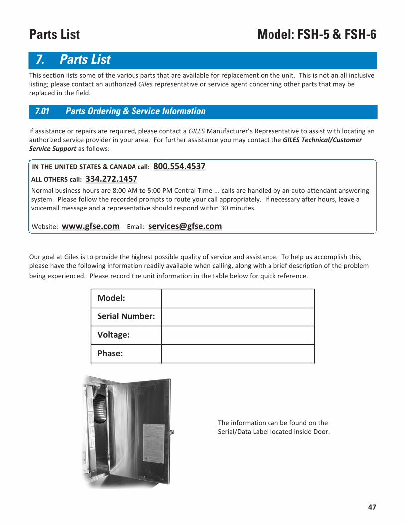
Our goal at Giles is to provide the highest possible quality of service and assistance. To help us accomplish this,please have the following information readily available when calling, along with a brief description of the problembeing experienced. Please record the unit information in the table below for quick reference.
The information can be found on theSerial/Data Label located inside Door.
IN THE UNITED STATES & CANADA call: 800.554.4537ALL OTHERS call: 334.272.1457Normal business hours are 8:00 AM to 5:00 PM Central Time ... calls are handled by an auto-attendant answeringsystem. Please follow the recorded prompts to route your call appropriately. If necessary after hours, leave avoicemail message and a representative should respond within 30 minutes.
Website: www.gfse.com Email: [email protected]
If assistance or repairs are required, please contact a GILES Manufacturer’s Representative to assist with locating anauthorized service provider in your area. For further assistance you may contact the GILES Technical/CustomerService Support as follows:
Model:
Serial Number:
Voltage:
Phase:
48
Model: FSH-5 & FSH-6 Parts List
* ILS Model Only
7
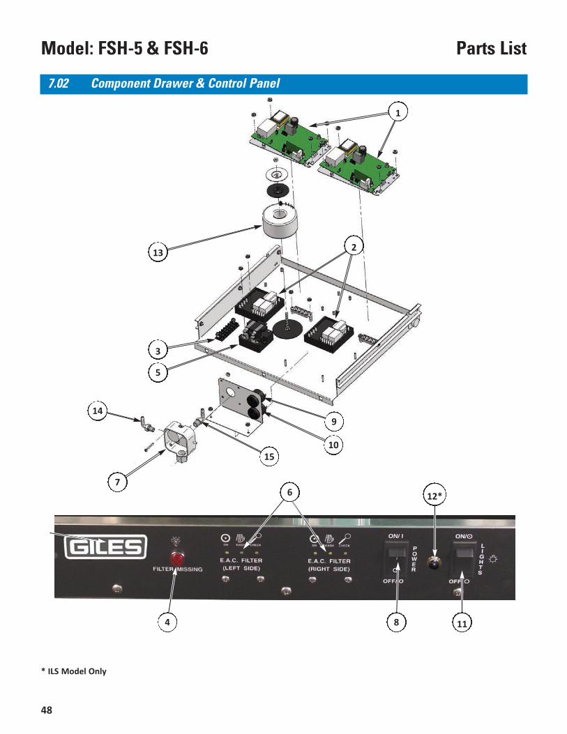
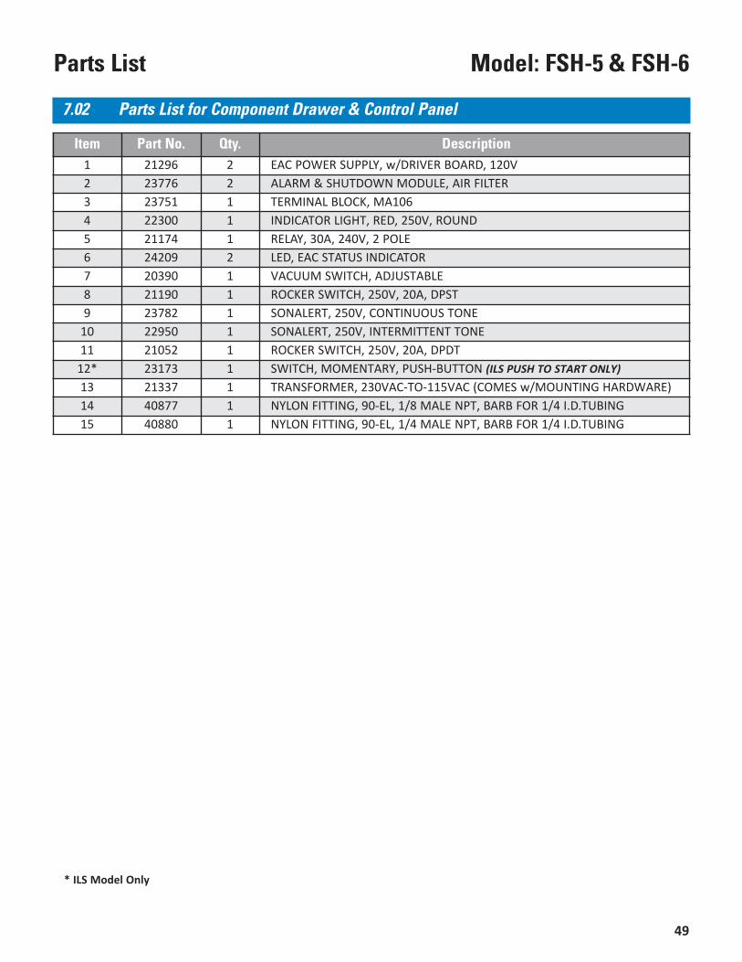
7.02 Component Drawer & Control Panel
3
5
6
11
15
13
1
2
14
4 8
9
10
12*
49
Model: FSH-5 & FSH-6Parts List
* ILS Model Only
Item Part No. Qty. Description1 21296 2 EAC POWER SUPPLY, w/DRIVER BOARD, 120V2 23776 2 ALARM & SHUTDOWN MODULE, AIR FILTER3 23751 1 TERMINAL BLOCK, MA1064 22300 1 INDICATOR LIGHT, RED, 250V, ROUND5 21174 1 RELAY, 30A, 240V, 2 POLE6 24209 2 LED, EAC STATUS INDICATOR7 20390 1 VACUUM SWITCH, ADJUSTABLE8 21190 1 ROCKER SWITCH, 250V, 20A, DPST9 23782 1 SONALERT, 250V, CONTINUOUS TONE
10 22950 1 SONALERT, 250V, INTERMITTENT TONE11 21052 1 ROCKER SWITCH, 250V, 20A, DPDT
12* 23173 1 SWITCH, MOMENTARY, PUSH-BUTTON (ILS PUSH TO START ONLY)13 21337 1 TRANSFORMER, 230VAC-TO-115VAC (COMES w/MOUNTING HARDWARE)14 40877 1 NYLON FITTING, 90-EL, 1/8 MALE NPT, BARB FOR 1/4 I.D.TUBING15 40880 1 NYLON FITTING, 90-EL, 1/4 MALE NPT, BARB FOR 1/4 I.D.TUBING
7.02 Parts List for Component Drawer & Control Panel
50
Model: FSH-5 & FSH-6 Parts List
* Inside Chamber, Not Shown
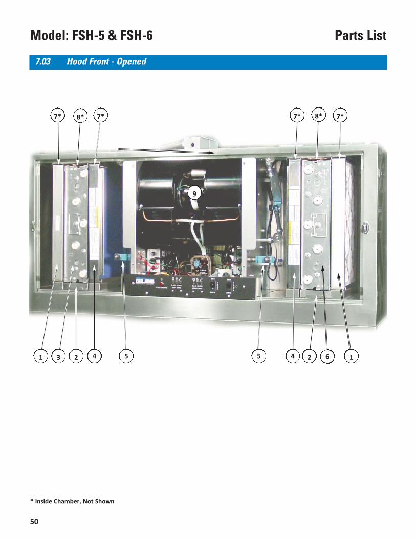
7.03 Hood Front - Opened
62
9
14
8* 7*
21 3 4 55
7*7* 7* 8*
51
Model: FSH-5 & FSH-6Parts List
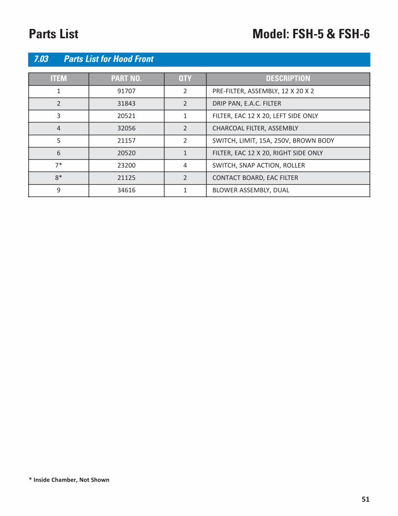
ITEM PART NO. QTY DESCRIPTION
1 91707 2 PRE-FILTER, ASSEMBLY, 12 X 20 X 2
2 31843 2 DRIP PAN, E.A.C. FILTER
3 20521 1 FILTER, EAC 12 X 20, LEFT SIDE ONLY
4 32056 2 CHARCOAL FILTER, ASSEMBLY
5 21157 2 SWITCH, LIMIT, 15A, 250V, BROWN BODY
6 20520 1 FILTER, EAC 12 X 20, RIGHT SIDE ONLY
7* 23200 4 SWITCH, SNAP ACTION, ROLLER
8* 21125 2 CONTACT BOARD, EAC FILTER
9 34616 1 BLOWER ASSEMBLY, DUAL
7.03 Parts List for Hood Front
* Inside Chamber, Not Shown
52
Model: FSH-5 & FSH-6 Parts List
* Not shown
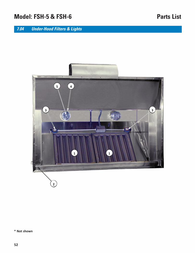
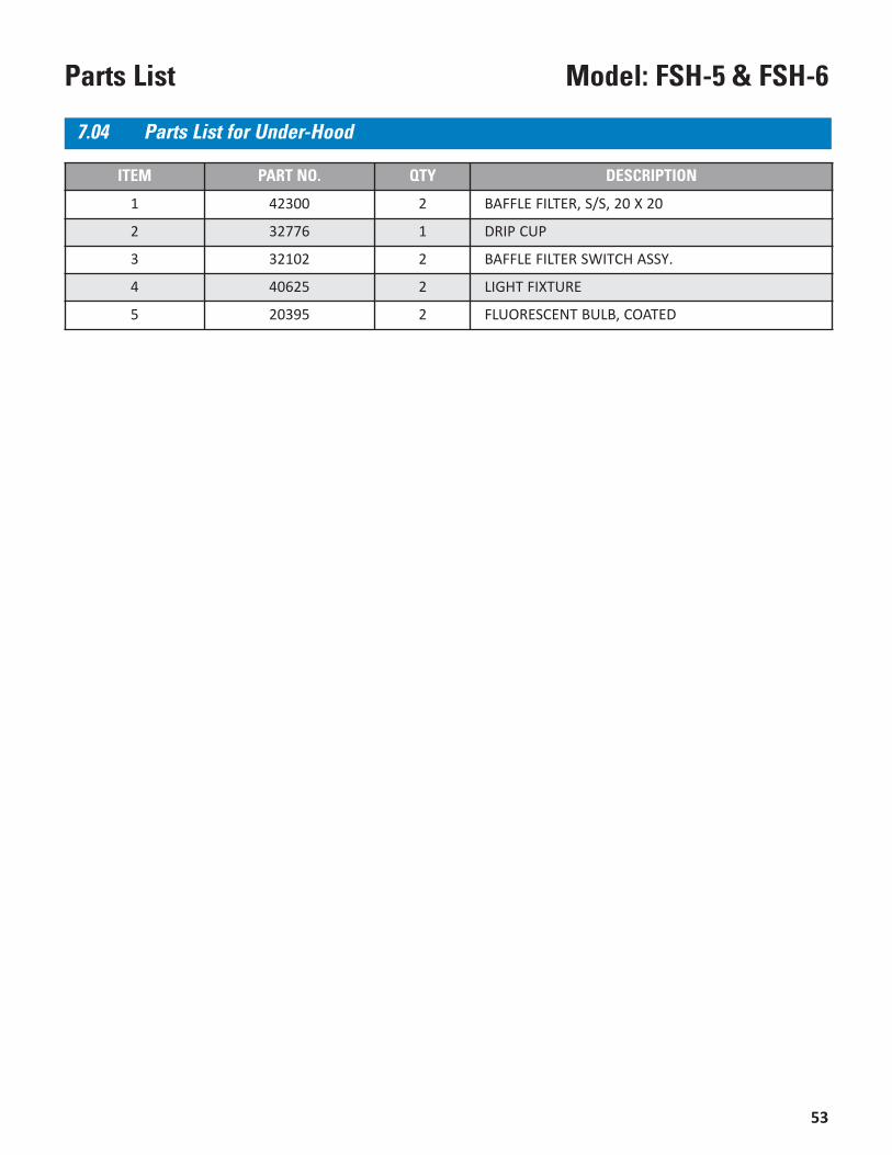
7.04 Under-Hood Filters & Lights
45
2
1
3
1
3
53
Model: FSH-5 & FSH-6Parts List
ITEM PART NO. QTY DESCRIPTION
1 42300 2 BAFFLE FILTER, S/S, 20 X 20
2 32776 1 DRIP CUP
3 32102 2 BAFFLE FILTER SWITCH ASSY.
4 40625 2 LIGHT FIXTURE
5 20395 2 FLUORESCENT BULB, COATED
7.04 Parts List for Under-Hood
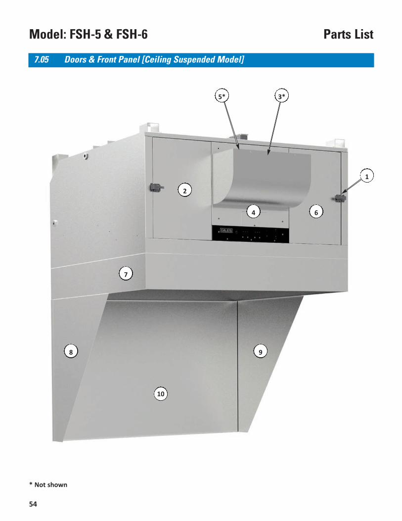
54
Model: FSH-5 & FSH-6 Parts List
* Not shown
7.05 Doors & Front Panel [Ceiling Suspended Model]
7
9
4
2
1
3*
6
5*
8
10
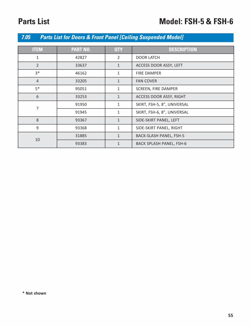
55
Model: FSH-5 & FSH-6Parts List
* Not shown
ITEM PART NO. QTY DESCRIPTION
1 42827 2 DOOR LATCH
2 33637 1 ACCESS DOOR ASSY, LEFT
3* 46162 1 FIRE DAMPER
4 33205 1 FAN COVER
5* 95051 1 SCREEN, FIRE DAMPER
6 33253 1 ACCESS DOOR ASSY, RIGHT
791950 1 SKIRT, FSH-5, 8”, UNIVERSAL
91945 1 SKIRT, FSH-6, 8”, UNIVERSAL
8 93367 1 SIDE-SKIRT PANEL, LEFT
9 93368 1 SIDE-SKIRT PANEL, RIGHT
1031885 1 BACK-SLASH PANEL, FSH-5
93383 1 BACK SPLASH PANEL, FSH-6
7.05 Parts List for Doors & Front Panel [Ceiling Suspended Model]
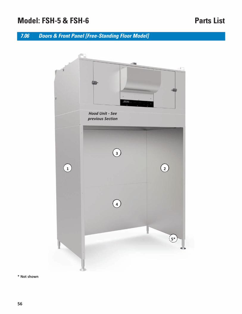
56
Model: FSH-5 & FSH-6 Parts List
* Not shown
7.06 Doors & Front Panel [Free-Standing Floor Model]
Hood Unit - Seeprevious Section
4
21
3
5*
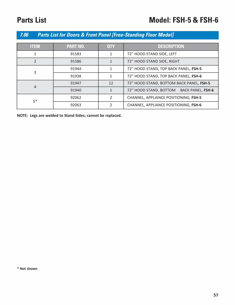
57
Model: FSH-5 & FSH-6Parts List
7.06 Parts List for Doors & Front Panel [Free-Standing Floor Model]
ITEM PART NO. QTY DESCRIPTION
1 91583 1 72” HOOD STAND SIDE, LEFT
2 91586 1 72” HOOD STAND SIDE, RIGHT
391944 1 72” HOOD STAND, TOP BACK PANEL, FSH-5
91938 1 72” HOOD STAND, TOP BACK PANEL, FSH-6
491947 12 72” HOOD STAND, BOTTOM BACK PANEL, FSH-5
91940 1 72” HOOD STAND, BOTTOM BACK PANEL, FSH-6
5*92062 2 CHANNEL, APPLIANCE POSITIONING, FSH-5
92063 2 CHANNEL, APPLIANCE POSITIONING, FSH-6
* Not shown
NOTE: Legs are welded to Stand Sides; cannot be replaced.
58
Model: FSH-5 & FSH-6 Parts List


2750 Gunter Park Drive West • Montgomery, Al 36109 USAPhone: 334.272.1457 • Toll Free: 800.554.4537 (USA & Canada Only) • FAX: 334.239.4117 • www.gfse.com
Form No. 65898 (Rel. Date: Jul.1999, Rev. Date: Dec.2018, Rev. H)


