Embed Size (px)
Citation preview

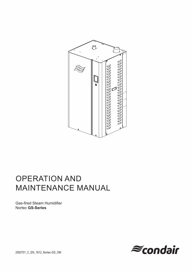
OPERATION AND MAINTENANCE MANUAL
Gas-fired Steam Humidifier Nortec GS-Series
25
8370
1_C
_EN
_181
2_N
orte
c-G
S_O
M
Humidification and Evaporative Cooling
NORTEC
IMPORTANT! Read and save these instructions. This manual to be left with the equipment.
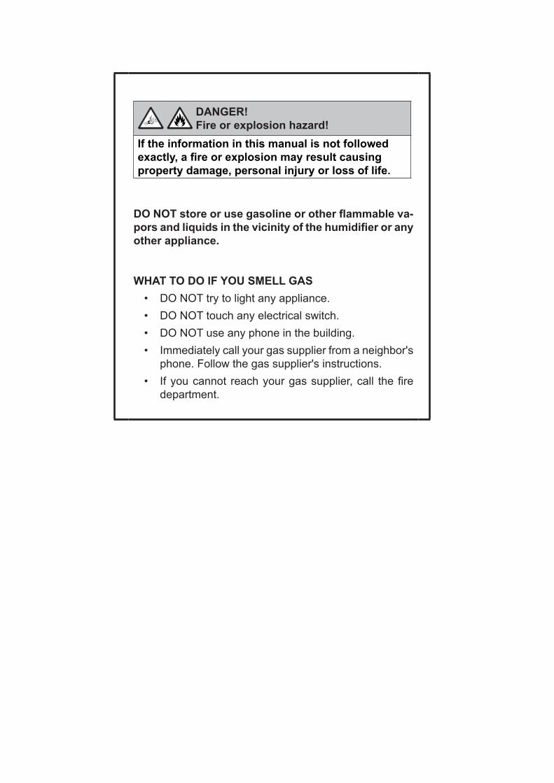
DANGER!Fire or explosion hazard!
If the information in this manual is not followed exactly, a fire or explosion may result causing property damage, personal injury or loss of life.
DO NOT store or use gasoline or other flammable va-pors and liquids in the vicinity of the humidifier or any other appliance.
WHAT TO DO IF YOU SMELL GAS• DO NOT try to light any appliance.• DO NOT touch any electrical switch.• DO NOT use any phone in the building.• Immediately call your gas supplier from a neighbor's
phone. Follow the gas supplier's instructions.• If you cannot reach your gas supplier, call the fire
department.
OPERATION AND MAINTENANCE MANUAL
Gas-fired Steam Humidifier Nortec GS-Series
2583701_C_EN_1812_Nortec-GS_OM
Thank you for choosing Condair!
INSTALLATION DATE (DD/MM/YYYY):
COMMISSIONING DATE (DD/MM/YYYY):
SITE:
MODEL:
SERIAL NUMBER:
Proprietary NoticeThis document and the information disclosed herein are proprietary data of Condair Ltd. Neither this document, nor the information contained herein shall be reproduced, used, or disclosed to others without the written authorization of Condair Ltd., except to the extent required for installation, operation or maintenance of the customer's equipment.
Liability NoticeCondair Ltd. does not accept any liability due to incorrect installation, maintenance or operation of the equipment, or due to the use of parts/components/equipment that are not authorized by Condair Ltd.
Copyright Notice© Condair Ltd, All rights reserved.
Loctite® is a registered mark of the Henkel Corporation.
Technical modification rights reserved.
5ContentsNortec GS 2583701_C_EN_1812_Nortec-GS_OM
Contents
1 Introduction 71.1 Before You Start! 71.2 General 7
2 For Your Safety 9
3 Product Overview 133.1 General Description 133.2 Functional Description 15
4 Operator Interface 184.1 Controls 184.2 Control Software 194.2.1 Home Screen 194.2.2 General Navigational Elements 204.2.3 Operating Status 214.2.4 Maintenance and Fault Status 224.2.5 Help 224.2.6 System Information 234.2.7 Main Menu 274.2.7.1 Configuration Menu 284.2.7.2 Service Menu 424.2.7.3 Administrator Menu 474.3 Software Configuration 484.3.1 Configuring the Control Software 484.3.2 Configuring for Multi-Unit Operation 49
5 Operation 505.1 General 505.2 Operating Procedures 505.2.1 Filling the System 505.2.2 Ignition Safety Shutoff Test 505.2.3 Starting the Humidifier 515.2.4 Remote Monitoring 525.2.5 Inspections During Operation 525.2.6 Manually Initiate Tank Draining 535.2.7 Full Tank Blowdown 535.2.8 Shutting Down 545.2.9 Restarting After Shutdown 54
6 Maintenance 566.1 General 566.2 Mandatory Maintenance Schedule 576.3 List of Consumables 58
6 Contents 2583701_C_EN_1812_Nortec-GS_OM Nortec GS
6.4 Management of Scale and Chloride Levels 586.4.1 Adjusting Blowdown Settings 596.5 Maintenance Procedures 606.5.1 Removal and Installation of Access Panels 606.5.2 Cleaning the Tank 616.5.3 Cleaning the Secondary Heat-exchanger 646.5.4 Cleaning the Float Chamber 656.5.5 Cleaning Hoses, Dual Fill Valves and Drain Pump 666.5.6 Cleaning the Burner Assembly 686.5.7 Replacing Backup Battery 706.5.8 Replacing Internal Fuse 716.5.9 Resetting Service Reminder 726.6 Installing Software Updates 72
7 Fault Isolation 747.1 General 747.2 Fault Indication 747.3 General Troubleshooting 757.4 Nortec GS Warning and Fault List 777.5 Resetting Fault Status 867.6 Driver Board Layout 877.7 Integrated Control Board Layout 87
8 Wiring Diagrams 88
9 Decommissioning 909.1 General 909.2 Removal from Service for Disposal or Long-term Storage 919.3 Disposal/Recycling 91
10 Product Specifications 9210.1 Performance Data 9210.2 Operating Data 9210.3 Size and Weight 93
A Appendix 94A.1 Torque Values 94A.1.1 Torque Sequences 95
7IntroductionNortec GS 2583701_C_EN_1812_Nortec-GS_OM
1 Introduction
1.1 Before You Start!
Thank you for purchasing the Nortec GS humidifier.
The Nortec GS humidifier incorporates the latest technical advances and meets all recognized safety standards. Never-the-less, improper use of the Nortec GS humidifier may result in danger to the user or third parties, and/or damage to property.
To ensure safe, proper and economical operation of the Nortec GS humidifier, observe and comply with all information and safety instructions contained in this manual, as well as all relevant documentation of components of the installed humidification system. Comply with all local and regional regulations dealing with gas, combustion air, flue gases, water, steam and electrical systems.
If you have additional questions, contact your Condair representative. They will be glad to assist you.
1.2 General
LimitationsThe subject of this manual is the Nortec GS humidifier. The various options and accessories may only be described in-so-far as is necessary for proper installation and operation of the equipment. Additional information on available options and accessories can be obtained in the instructions that are supplied with them.
This manual is restricted to the operation and maintenance of the Nortec GS humidifier, and is intended for well trained personnel who are suitably qualified for their respective tasks.
Symbols Used in This Manual
CAUTION!
The catchword "CAUTION" in conjunction with the general caution symbol is used to provide safety instructions that, if neglected, may cause damage and/or malfunction of the unit or damage to property.
WARNING!
The catchword "WARNING" in conjunction with the general warning symbol is used to provide safety instructions that, if neglected, may cause injury to personnel. Other specific warning symbols may also be used in place of the general symbol.
DANGER!
The catchword "DANGER" in conjunction with the general danger symbol is used to provide safety instructions that, if neglected, may cause severe injury to personnel or even death. Other specific danger symbols may also be used in place of the general symbol.
8 Introduction 2583701_C_EN_1812_Nortec-GS_OM Nortec GS
Other Related PublicationsThis Operation and Maintenance Manual is supplemented by other publications such as the Installation Manual, Spare Parts List, etc., which are included in the delivery of the equipment. Where necessary, appropriate cross-references to these publications have been added in this manual.
Storage of ManualKeep this manual in a place where it is safe and readily accessible. If the equipment is moved to another location, make sure that the manual is passed on to the new user.If the manual is lost or misplaced, contact your Condair representative for a replacement copy.
Language VersionsThis manual is also available in other languages. Contact your Condair representative.
9For Your SafetyNortec GS 2583701_C_EN_1812_Nortec-GS_OM
2 For Your Safety
GeneralEvery person who is tasked with the operation and maintenance of the Nortec GS humidifier must read and understand this manual before performing any work. Knowing and understanding the contents of the Installation Manual, and the Operation and Maintenance Manual is a basic requirement for protect-ing personnel against any kind of danger, preventing faulty operation, and operating the unit safely and correctly.
All labels, signs and markings applied to the Nortec GS humidifier must be observed and kept in a readable state.
Personnel QualificationsAll procedures described in this manual must only be performed by personnel who are adequately quali-fied, well trained and are authorized by the customer.For safety and warranty reasons, any activity beyond the scope of this manual must only be performed by qualified personnel authorized by Condair.All personnel working with the Nortec GS humidifier must be familiar with, and comply with the appropri-ate regulations on workplace safety and prevention of accidents.
Intended UseThe Nortec GS humidifier is intended exclusively for air humidification using a Condair-approved steam distributor within specified operating conditions (refer to "Operating Data" on page 86 for details). Any other type of application, without the express written consent of Condair, is considered to be NOT conforming to its intended purpose, and may lead to dangerous operation and will void the warranty.In order to operate the equipment in the intended manner all information contained in this manual, in particular the safety instructions, must be observed closely.
Safety Precautions that Must be Observed
DANGER! Risk of electric shock!
The Nortec GS humidifier is mains powered. Live parts may be exposed when the access panels are removed. Touching live parts may cause severe injury or even death.Prevention: Before performing any work inside the Nortec GS humidifier shut down the humidifier properly and secure it against accidental power-up as described in "Shutting Down" on page 48.
10 For Your Safety 2583701_C_EN_1812_Nortec-GS_OM Nortec GS
DANGER!Risk of fire or explosion!
The Nortec GS is a gas-fired humidifier. Improper installation, adjustment, alteration, service, maintenance or use can cause carbon monoxide poisoning, explosion, fire or other hazards that can cause serious injury, death or property damage.If over-heating occurs or if the gas fails to shut off: Shut off the gas supply at the manual gas shutoff valve before shutting off the electrical power supply.DO NOT use this appliance if any part has been under water. Call a qualified service techni-cian immediately to inspect and replace any part of the control system or gas control that has been under water.Any work on the gas system must only be performed by a qualified installer, service agency or your local gas supplier. Use only factory-authorized and listed kits or accessories when installing or modifying this appliance.DO NOT store or use gasoline or other flammable vapors and liquids in the vicinity of the humidifier or any other appliance.
What to do if You Smell Gas: DO NOT try to light any appliance.DO NOT touch any electrical switch.DO NOT use any phone in the building.Leave the building immediately.Call your gas supplier immediately from a location far away from the building with the gas leak. Follow the gas supplier's instructions.If you cannot reach your gas supplier, call the fire department.
WARNING! Risk of severe burns from contact with hot steam vapors!
The Nortec GS humidifier produces hot steam vapors for humidification. Bare skin in contact with hot steam vapors can result in severe burns.Prevention: Never perform any work on the steam system (including the steam lines, steam dis-tributors, etc.) while the humidifier is operating. Shut down the Nortec GS steam humidifier, as described in "Shutting Down" on page 48 before fixing any leaks in the steam system.
WARNING! Risk of severe burns from contact with hot surfaces!
The water tank, steam line and exhaust system in the Nortec GS humidifier get very hot during operation. Bare skin in contact with hot surfaces can result in severe burns.Prevention: Shut down the Nortec GS steam humidifier as described in "Shutting Down" on page 48 and wait for the components to cool down before working on the steam system.
WARNING! Risk of severe burns from contact with hot surfaces, steam or hot water!
The tank may contain steam or hot water at up to 212 °F (100 °C). Contact with the hot surfaces, steam vapors or hot water can result in severe burns.Prevention: Never open the tank until it has been fully drained, and the unit has cooled down to a safe temperature. Never use the manual drain valve until the unit has cooled down. Use the manual drain valve to verify that the tank is empty before removing the tank cover. Drain the tank as described in "Manually Initiate Tank Draining" on page 47.
11For Your SafetyNortec GS 2583701_C_EN_1812_Nortec-GS_OM
CAUTION!Electrostatic discharge (ESD)!
The electronic components inside the control cabinet in the humidifier are sensitive to elec-trostatic discharge (ESD).Prevention: Take appropriate measures to protect the electronic components inside the unit against damage caused by electrostatic discharge (ESD). Refer to ANSI/ESD-S20.20.
Preventing Unsafe OperationIf it is suspected that the Nortec GS steam humidifier cannot be operated safely for any of the reasons listed below, shut it down immediately as described in "Shutting Down" on page 48 and secure it against accidental power-up.
• Humidifier is damaged
• Electrical connections are loose or damaged
• Humidifier is not operating properly
• Leaks in the steam system or gas supply
All personnel working with the Nortec GS humidifier must immediately report to the customer any alter-nations to the humidifier that may affect safety.
Modifications to the Unit ProhibitedModifications are NOT permitted on the Nortec GS humidifier without the express written consent of Condair.
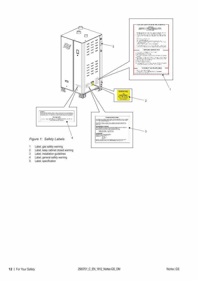
Always use original Condair replacement parts and accessories available through your Condair representative.The location of the various safety labels on the Nortec GS humidifier is shown in Figure 1.
12 For Your Safety 2583701_C_EN_1812_Nortec-GS_OM Nortec GS
Figure 1:
1
2
3
4
5
Safety Labels
1 Label, gas safety warning2 Label, keep cabinet closed warning3 Label, installation guidelines4 Label, general safety warning5 Label, specification
13Product OverviewNortec GS 2583701_C_EN_1812_Nortec-GS_OM
3 Product Overview
3.1 General Description
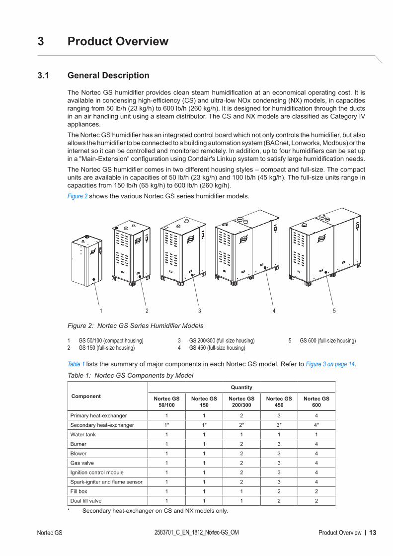
The Nortec GS humidifier provides clean steam humidification at an economical operating cost. It is available in condensing high-efficiency (CS) and ultra-low NOx condensing (NX) models, in capacities ranging from 50 lb/h (23 kg/h) to 600 lb/h (260 kg/h). It is designed for humidification through the ducts in an air handling unit using a steam distributor. The CS and NX models are classified as Category IV appliances.The Nortec GS humidifier has an integrated control board which not only controls the humidifier, but also allows the humidifier to be connected to a building automation system (BACnet, Lonworks, Modbus) or the internet so it can be controlled and monitored remotely. In addition, up to four humidifiers can be set up in a "Main-Extension" configuration using Condair's Linkup system to satisfy large humidification needs.The Nortec GS humidifier comes in two different housing styles – compact and full-size. The compact units are available in capacities of 50 lb/h (23 kg/h) and 100 lb/h (45 kg/h). The full-size units range in capacities from 150 lb/h (65 kg/h) to 600 lb/h (260 kg/h).Figure 2 shows the various Nortec GS series humidifier models.
Figure 2:
1 2 3 4 5
Nortec GS Series Humidifier Models
1 GS 50/100 (compact housing)2 GS 150 (full-size housing)
3 GS 200/300 (full-size housing)4 GS 450 (full-size housing)
5 GS 600 (full-size housing)
Table 1 lists the summary of major components in each Nortec GS model. Refer to Figure 3 on page 14.
Table 1: Nortec GS Components by Model
ComponentQuantity
Nortec GS 50/100
Nortec GS 150
Nortec GS 200/300
Nortec GS 450
Nortec GS 600
Primary heat-exchanger 1 1 2 3 4
Secondary heat-exchanger 1* 1* 2* 3* 4*
Water tank 1 1 1 1 1
Burner 1 1 2 3 4
Blower 1 1 2 3 4
Gas valve 1 1 2 3 4
Ignition control module 1 1 2 3 4
Spark-igniter and flame sensor 1 1 2 3 4
Fill box 1 1 1 2 2
Dual fill valve 1 1 1 2 2
* Secondary heat-exchanger on CS and NX models only.
14 Product Overview 2583701_C_EN_1812_Nortec-GS_OM Nortec GS
Figure 3:
3
8
9
13
18
11, 12
14
15
19
25
28
10
16
17
20
22
23
24
27
26
1
2
4
5
6
7
21
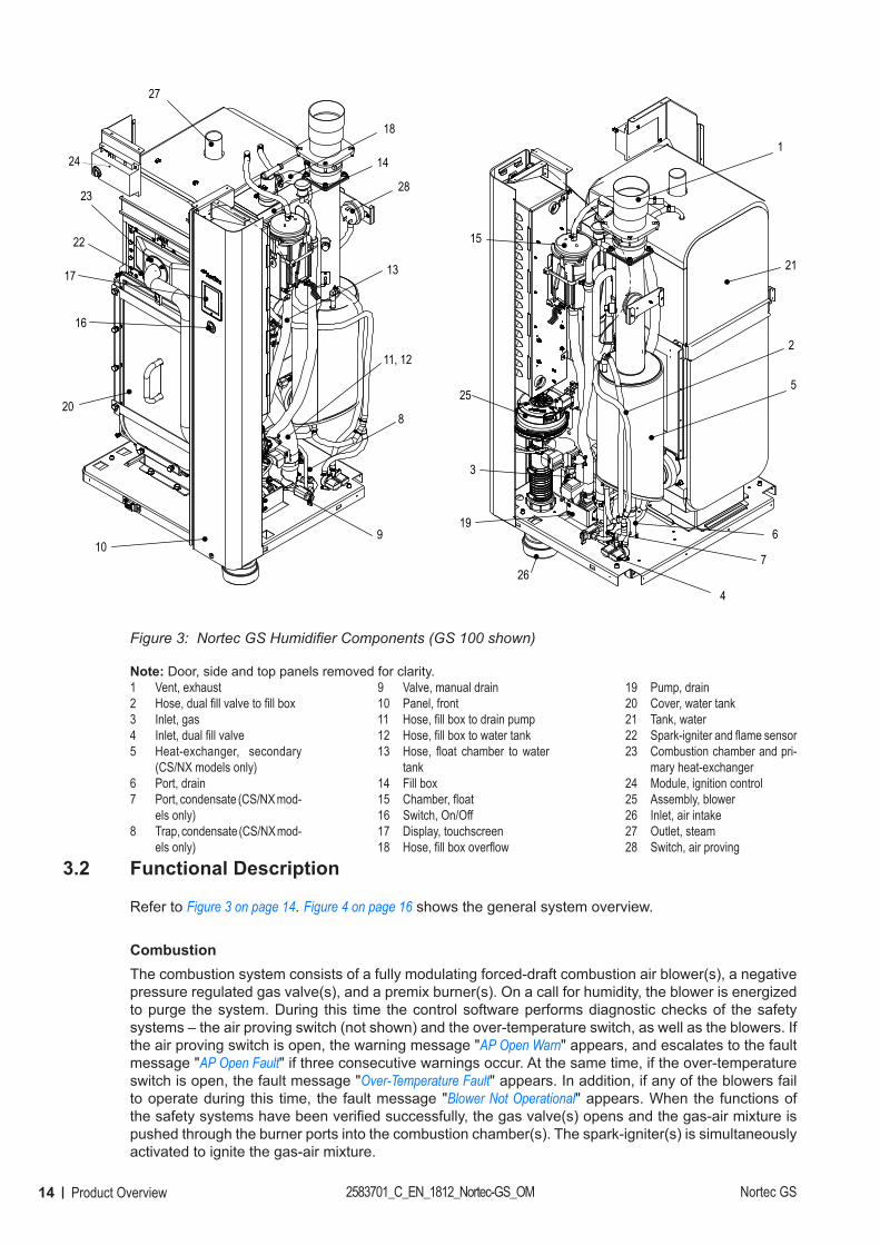
Nortec GS Humidifier Components (GS 100 shown)
Note: Door, side and top panels removed for clarity.1 Vent, exhaust2 Hose, dual fill valve to fill box3 Inlet, gas4 Inlet, dual fill valve5 Heat-exchanger, secondary
(CS/NX models only)6 Port, drain7 Port, condensate (CS/NX mod-
els only)8 Trap, condensate (CS/NX mod-
els only)
9 Valve, manual drain10 Panel, front11 Hose, fill box to drain pump12 Hose, fill box to water tank13 Hose, float chamber to water
tank14 Fill box15 Chamber, float16 Switch, On/Off17 Display, touchscreen18 Hose, fill box overflow
19 Pump, drain20 Cover, water tank21 Tank, water22 Spark-igniter and flame sensor23 Combustion chamber and pri-
mary heat-exchanger24 Module, ignition control25 Assembly, blower26 Inlet, air intake27 Outlet, steam28 Switch, air proving
3.2 Functional Description
Refer to Figure 3 on page 14. Figure 4 on page 16 shows the general system overview.
CombustionThe combustion system consists of a fully modulating forced-draft combustion air blower(s), a negative pressure regulated gas valve(s), and a premix burner(s). On a call for humidity, the blower is energized to purge the system. During this time the control software performs diagnostic checks of the safety systems – the air proving switch (not shown) and the over-temperature switch, as well as the blowers. If the air proving switch is open, the warning message "AP Open Warn" appears, and escalates to the fault message "AP Open Fault" if three consecutive warnings occur. At the same time, if the over-temperature switch is open, the fault message "Over-Temperature Fault" appears. In addition, if any of the blowers fail to operate during this time, the fault message "Blower Not Operational" appears. When the functions of the safety systems have been verified successfully, the gas valve(s) opens and the gas-air mixture is pushed through the burner ports into the combustion chamber(s). The spark-igniter(s) is simultaneously activated to ignite the gas-air mixture.
15Product OverviewNortec GS 2583701_C_EN_1812_Nortec-GS_OM
If a flame is not sensed by the flame sensor(s), the above sequence is repeated after 15 seconds. The sequence is repeated upto a maximum of three times, after which the ignition control module(s) locks out and the fault message "Ignition Fail" appears. If a flame is sensed by the flame sensor(s), the gas valve(s) remains open and combustion continues. The gas valve(s) continues to maintain a constant air-to-gas ratio independent of the blower speed or external conditions. On the CS and NX models, the hot flue gases pass through the primary heat-exchanger then the second-ary heat-exchanger, where it is cooled further before it exits through the exhaust vent. The heat recov-ered by the secondary heat-exchanger is used to warm up the feed water. On the standard-efficiency model, the hot flue gases pass through the primary heat-exchanger and exit through the exhaust vent.
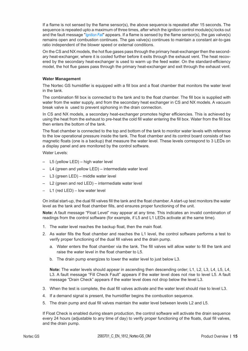
Water ManagementThe Nortec GS humidifier is equipped with a fill box and a float chamber that monitors the water level in the tank. The combination fill box is connected to the tank and to the float chamber. The fill box is supplied with water from the water supply, and from the secondary heat exchanger in CS and NX models. A vacuum break valve is used to prevent siphoning in the drain connection. In CS and NX models, a secondary heat-exchanger promotes higher efficiencies. This is achieved by using the heat from the exhaust to pre-heat the cold fill water entering the fill box. Water from the fill box then enters the bottom of the tank.The float chamber is connected to the top and bottom of the tank to monitor water levels with reference to the low operational pressure inside the tank. The float chamber and its control board consists of two magnetic floats (one is a backup) that measure the water level. These levels correspond to 3 LEDs on a display panel and are monitored by the control software.Water Levels:
– L5 (yellow LED) – high water level
– L4 (green and yellow LED) – intermediate water level
– L3 (green LED) – middle water level
– L2 (green and red LED) – intermediate water level
– L1 (red LED) – low water level
On initial start-up, the dual fill valves fill the tank and the float chamber. A start-up test monitors the water level as the tank and float chamber fills, and ensures proper functioning of the unit.Note: A fault message “Float Level” may appear at any time. This indicates an invalid combination of readings from the control software (for example, if L5 and L1 LEDs activate at the same time).
1. The water level reaches the backup float, then the main float.
2. As water fills the float chamber and reaches the L1 level, the control software performs a test to verify proper functioning of the dual fill valves and the drain pump.
a. Water enters the float chamber via the tank. The fill valves will allow water to fill the tank and raise the water level in the float chamber to L5.
b. The drain pump energizes to lower the water level to just below L3.
Note: The water levels should appear in ascending then descending order; L1, L2, L3, L4, L5, L4, L3. A fault message “Fill Check Fault” appears if the water level does not rise to level L5. A fault message “Drain Check” appears if the water level does not drop below the level L3.
3. When the test is complete, the dual fill valves activate and the water level should rise to level L3.
4. If a demand signal is present, the humidifier begins the combustion sequence.
5. The drain pump and dual fill valves maintain the water level between levels L2 and L5.
If Float Check is enabled during steam production, the control software will activate the drain sequence every 24 hours (adjustable to any time of day) to verify proper functioning of the floats, dual fill valves, and the drain pump.
16 Product Overview 2583701_C_EN_1812_Nortec-GS_OM Nortec GS
Figure 4:
1
23
4
5
14
15
6
7
9
8
9
12
13
11
10
16
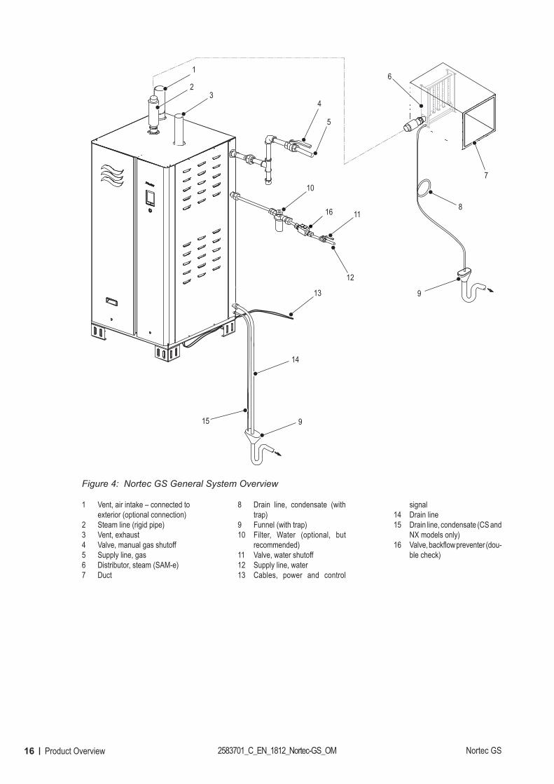
Nortec GS General System Overview
1 Vent, air intake – connected to exterior (optional connection)
2 Steam line (rigid pipe)3 Vent, exhaust4 Valve, manual gas shutoff5 Supply line, gas6 Distributor, steam (SAM-e)7 Duct
8 Drain line, condensate (with trap)
9 Funnel (with trap)10 Filter, Water (optional, but
recommended)11 Valve, water shutoff12 Supply line, water13 Cables, power and control
signal14 Drain line15 Drain line, condensate (CS and
NX models only)16 Valve, backflow preventer (dou-
ble check)
17Operator InterfaceNortec GS 2583701_C_EN_1812_Nortec-GS_OM
4 Operator Interface
4.1 Controls
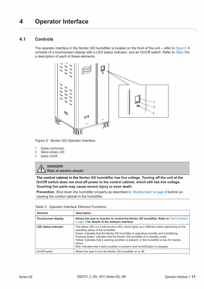
The operator interface in the Nortec GS humidifier is located on the front of the unit – refer to Figure 5. It consists of a touchscreen display with a LED status indicator, and an On/Off switch. Refer to Table 2 for a description of each of these elements.
Figure 5:
1
2
3
Nortec GS Operator Interface
1 Display, touchscreen 2 Status indicator, LED3 Switch, On/Off
DANGER! Risk of electric shock!
The control cabinet in the Nortec GS humidifier has live voltage. Turning off the unit at the On/Off switch does not shut off power to the control cabinet, which still has live voltage. Touching live parts may cause severe injury or even death.Prevention: Shut down the humidifier properly as described in "Shutting Down" on page 48 before ac-cessing the control cabinet in the humidifier.
Table 2: Operator Interface Element Functions
Element Description
Touchscreen display Allows the user to monitor or control the Nortec GS humidifier. Refer to "Control Software" on page 18 for details of the software interface.
LED status indicator The status LED is a multi-function LED, which lights up in different colors depending on the operating status of the humidifier.Green: indicates that the Nortec GS humidifier is operating normally and humidifying.Flashing Green: indicates that the Nortec GS humidifier is in standby mode.Yellow: indicates that a warning condition is present, or the humidifier is due for mainte-nance.Red: indicates that a fault condition is present, and humidification is stopped.
On/Off switch Allows the user to turn the Nortec GS humidifier on or off.
18 Operator Interface 2583701_C_EN_1812_Nortec-GS_OM Nortec GS
4.2 Control Software
The control software runs in the background and controls all the functions of the Nortec GS humidifier. The user interacts with the control software through the screens on the touchscreen display. Details of the screens are described in the following sections.Note: The screens shown in this chapter are for representation purposes only, and may differ from what is displayed on your humidifier.
4.2.1 Home Screen
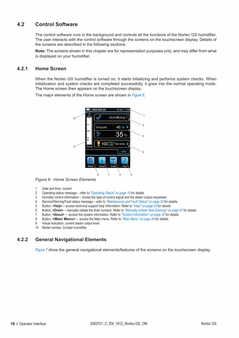
When the Nortec GS humidifier is turned on, it starts initializing and performs system checks. When initialization and system checks are completed successfully, it goes into the normal operating mode. The Home screen then appears on the touchscreen display. The major elements of the Home screen are shown in Figure 6.
Figure 6:
2
3
4
5678
9
1
10
Home Screen Elements
1 Date and time, current2 Operating status message – refer to "Operating Status" on page 19 for details.3 Humidity control information – shows the type of control signal and the steam output requested.4 Service/Warning/Fault status message – refer to "Maintenance and Fault Status" on page 20 for details. 5 Button, <Help> – access technical support help information. Refer to "Help" on page 20 for details.6 Button, <Drain> – manually initiate the drain function. Refer to "Manually Initiate Tank Draining" on page 47 for details.7 Button, <About> – access the system information. Refer to "System Information" on page 20 for details.8 Button, <Main Menu> – access the Main menu. Refer to "Main Menu" on page 24 for details.9 Visual indication, current steam output level10 Model number, Condair humidifier
4.2.2 General Navigational Elements
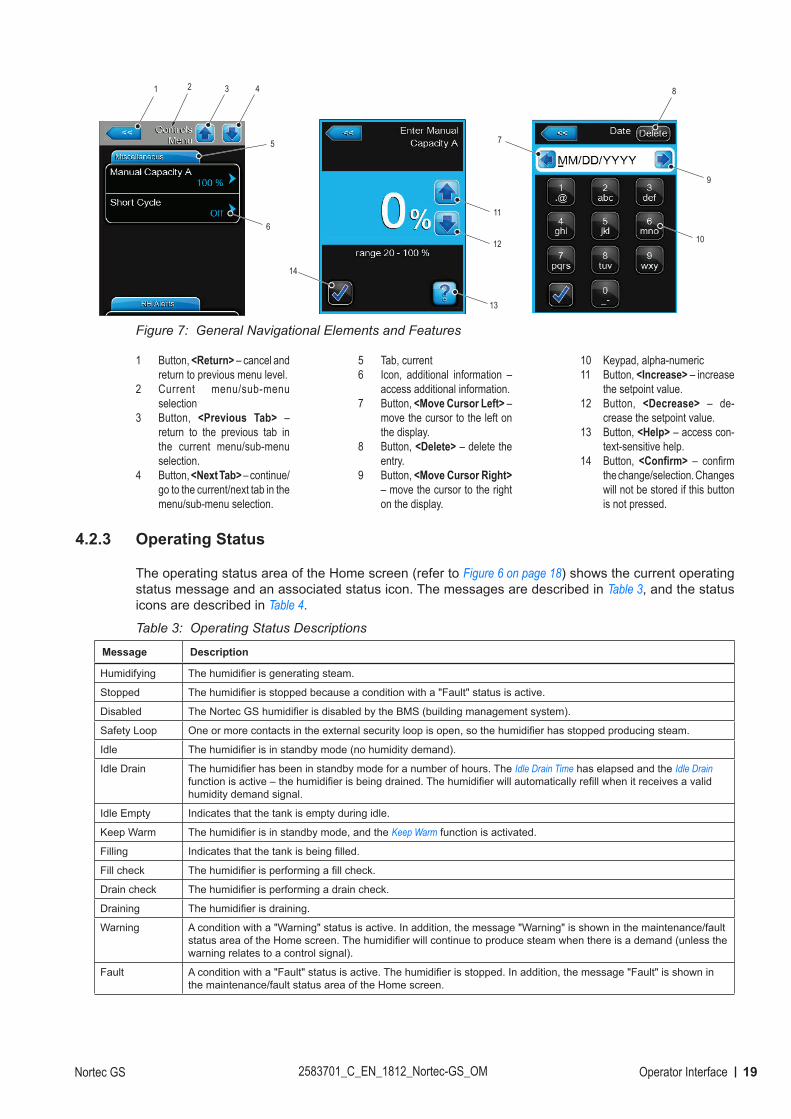
Figure 7 show the general navigational elements/features of the screens on the touchscreen display.
19Operator InterfaceNortec GS 2583701_C_EN_1812_Nortec-GS_OM
Figure 7:
8
7
9
10
1 2 3 4
5
11
12
13
14
6
General Navigational Elements and Features
1 Button, <Return> – cancel and return to previous menu level.
2 Current menu/sub-menu selection
3 Button, <Previous Tab> – return to the previous tab in the current menu/sub-menu selection.
4 Button, <Next Tab> – continue/go to the current/next tab in the menu/sub-menu selection.
5 Tab, current6 Icon, additional information –
access additional information.7 Button, <Move Cursor Left> –
move the cursor to the left on the display.
8 Button, <Delete> – delete the entry.
9 Button, <Move Cursor Right> – move the cursor to the right on the display.
10 Keypad, alpha-numeric11 Button, <Increase> – increase
the setpoint value.12 Button, <Decrease> – de-
crease the setpoint value.13 Button, <Help> – access con-
text-sensitive help.14 Button, <Confirm> – confirm
the change/selection. Changes will not be stored if this button is not pressed.
4.2.3 Operating Status
The operating status area of the Home screen (refer to Figure 6 on page 18) shows the current operating status message and an associated status icon. The messages are described in Table 3, and the status icons are described in Table 4.
Table 3: Operating Status Descriptions
Message Description
Humidifying The humidifier is generating steam.
Stopped The humidifier is stopped because a condition with a "Fault" status is active.
Disabled The Nortec GS humidifier is disabled by the BMS (building management system).
Safety Loop One or more contacts in the external security loop is open, so the humidifier has stopped producing steam.
Idle The humidifier is in standby mode (no humidity demand).
Idle Drain The humidifier has been in standby mode for a number of hours. The Idle Drain Time has elapsed and the Idle Drain function is active – the humidifier is being drained. The humidifier will automatically refill when it receives a valid humidity demand signal.
Idle Empty Indicates that the tank is empty during idle.
Keep Warm The humidifier is in standby mode, and the Keep Warm function is activated.
Filling Indicates that the tank is being filled.
Fill check The humidifier is performing a fill check.
Drain check The humidifier is performing a drain check.
Draining The humidifier is draining.
Warning A condition with a "Warning" status is active. In addition, the message "Warning" is shown in the maintenance/fault status area of the Home screen. The humidifier will continue to produce steam when there is a demand (unless the warning relates to a control signal).
Fault A condition with a "Fault" status is active. The humidifier is stopped. In addition, the message "Fault" is shown in the maintenance/fault status area of the Home screen.
20 Operator Interface 2583701_C_EN_1812_Nortec-GS_OM Nortec GS
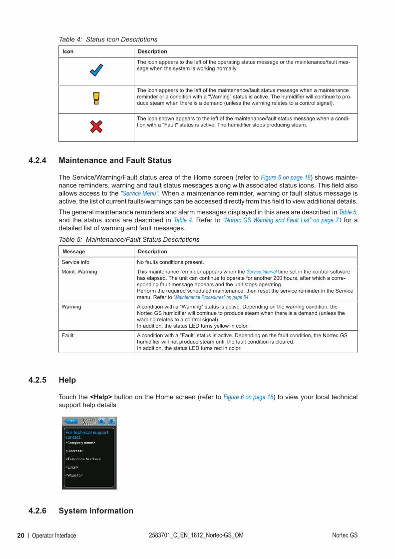
Table 4: Status Icon Descriptions
Icon Description
The icon appears to the left of the operating status message or the maintenance/fault mes-sage when the system is working normally.
The icon appears to the left of the maintenance/fault status message when a maintenance reminder or a condition with a "Warning" status is active. The humidifier will continue to pro-duce steam when there is a demand (unless the warning relates to a control signal).
The icon shown appears to the left of the maintenance/fault status message when a condi-tion with a "Fault" status is active. The humidifier stops producing steam.
4.2.4 Maintenance and Fault Status
The Service/Warning/Fault status area of the Home screen (refer to Figure 6 on page 18) shows mainte-nance reminders, warning and fault status messages along with associated status icons. This field also allows access to the "Service Menu". When a maintenance reminder, warning or fault status message is active, the list of current faults/warnings can be accessed directly from this field to view additional details.The general maintenance reminders and alarm messages displayed in this area are described in Table 5, and the status icons are described in Table 4. Refer to "Nortec GS Warning and Fault List" on page 71 for a detailed list of warning and fault messages.
Table 5: Maintenance/Fault Status Descriptions
Message Description
Service info No faults conditions present.
Maint. Warning This maintenance reminder appears when the Service Interval time set in the control software has elapsed. The unit can continue to operate for another 200 hours, after which a corre-sponding fault message appears and the unit stops operating.Perform the required scheduled maintenance, then reset the service reminder in the Service menu. Refer to "Maintenance Procedures" on page 54.
Warning A condition with a "Warning" status is active. Depending on the warning condition, the Nortec GS humidifier will continue to produce steam when there is a demand (unless the warning relates to a control signal).In addition, the status LED turns yellow in color.
Fault A condition with a "Fault" status is active. Depending on the fault condition, the Nortec GS humidifier will not produce steam until the fault condition is cleared.In addition, the status LED turns red in color.
4.2.5 Help
Touch the <Help> button on the Home screen (refer to Figure 6 on page 18) to view your local technical support help details.
4.2.6 System Information
21Operator InterfaceNortec GS 2583701_C_EN_1812_Nortec-GS_OM
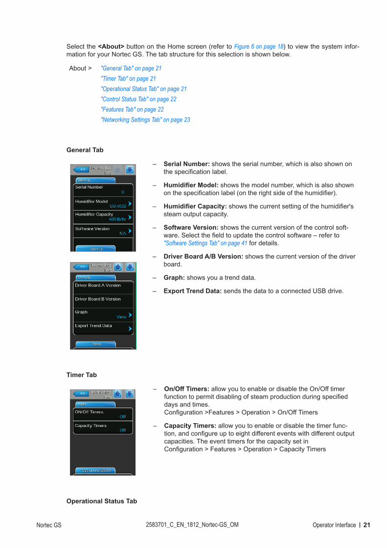
Select the <About> button on the Home screen (refer to Figure 6 on page 18) to view the system infor-mation for your Nortec GS. The tab structure for this selection is shown below.
About > "General Tab" on page 21"Timer Tab" on page 21"Operational Status Tab" on page 21"Control Status Tab" on page 22"Features Tab" on page 22"Networking Settings Tab" on page 23
General Tab
– Serial Number: shows the serial number, which is also shown on the specification label.
– Humidifier Model: shows the model number, which is also shown on the specification label (on the right side of the humidifier).
– Humidifier Capacity: shows the current setting of the humidifier's steam output capacity.
– Software Version: shows the current version of the control soft-ware. Select the field to update the control software – refer to "Software Settings Tab" on page 41 for details.
– Driver Board A/B Version: shows the current version of the driver board.
– Graph: shows you a trend data.
– Export Trend Data: sends the data to a connected USB drive.
Timer Tab
– On/Off Timers: allow you to enable or disable the On/Off timer function to permit disabling of steam production during specified days and times. Configuration >Features > Operation > On/Off Timers
– Capacity Timers: allow you to enable or disable the timer func-tion, and configure up to eight different events with different output capacities. The event timers for the capacity set in Configuration > Features > Operation > Capacity Timers
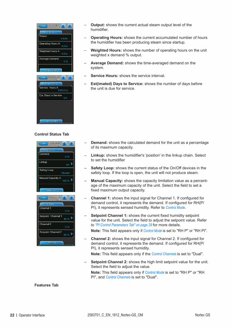
Operational Status Tab
22 Operator Interface 2583701_C_EN_1812_Nortec-GS_OM Nortec GS
– Output: shows the current actual steam output level of the humidifier.
– Operating Hours: shows the current accumulated number of hours the humidifier has been producing steam since startup.
– Weighted Hours: shows the number of operating hours on the unit weighted x demand % output.
– Average Demand: shows the time-averaged demand on the system.
– Service Hours: shows the service interval.
– Est(imated) Days to Service: shows the number of days before the unit is due for service.
Control Status Tab
– Demand: shows the calculated demand for the unit as a percentage of its maximum capacity.
– Linkup: shows the humidifier's 'position' in the linkup chain. Select to set the humidifier
– Safety Loop: shows the current status of the On/Off devices in the safety loop. If the loop is open, the unit will not produce steam.
– Manual Capacity: shows the capacity limitation value as a percent-age of the maximum capacity of the unit. Select the field to set a fixed maximum output capacity.
– Channel 1: shows the input signal for Channel 1. If configured for demand control, it represents the demand. If configured for RH(P/PI), it represents sensed humidity. Refer to Control Mode.
– Setpoint Channel 1: shows the current fixed humidity setpoint value for the unit. Select the field to adjust the setpoint value. Refer to "PI Control Parameters Tab" on page 29 for more details.Note: This field appears only if Control Mode is set to "RH P" or "RH PI".
– Channel 2: shows the input signal for Channel 2. If configured for demand control, it represents the demand. If configured for RH(P/PI), it represents sensed humidity.Note: This field appears only if the Control Channels is set to "Dual".
– Setpoint Channel 2: shows the high limit setpoint value for the unit. Select the field to adjust the value.Note: This field appears only if Control Mode is set to "RH P" or "RH PI", and Control Channels is set to "Dual".
Features Tab

23Operator InterfaceNortec GS 2583701_C_EN_1812_Nortec-GS_OM
– Blowdown Rate: shows the rate at which the tank is partially drained, as a percentage of actual steam production. Refer to the "Water Management Tab" on page 25 for more details.
– Drain Cool: shows the configuration setting of the drain cool function. Select the field to choose a different mode – "Off", "On" or "Smart". Refer to the "Water Management Tab" on page 25 for more details.
– Float Check: shows the configuration setting of the float check func-tion. Select the field to enable or disable the function. Refer to the "Operation Tab" on page 27 for more details.
– Float Check Time: allows you to see and set the time of day when the float check function will occur.
– FTBD (Full Tank Blowdown): shows the configuration setting of the full tank blowdown function. Select the field to enable or disable the function. Refer to the "Water Management Tab" on page 25 for more details.
– FTBD Interval: shows how often a full tank blowdown will occur. Refer to the "Water Management Tab" on page 25 for more details.
– FTBD Time: shows the time of day when a full tank blowdown will oc-cur. Refer to the "Water Management Tab" on page 25 for more details.
– Time Proportioning: shows the configuration setting of the time pro-portioning function. Select the field to enable or disable the function. Refer to the "Operation Tab" on page 27 for more details.
– Idle Mode: allows you to set the idle function of the humidifier when it is in standby mode.
– Idle Drain Time: allows you to set the time duration the humidifier stays in standby mode without a demand, after which the humidifier carries out the function specified in Idle Mode.
– Short Cycle: allows you to enable or disable a timer function that delays steam production until the already delivered humidity can stabilize in the conditioned environment. This feature prevents the humidifier from flooding the environment with excess humidity from false humidity readings.
– Short Cycle Time: allows you to set the time duration that the unit waits in standby mode before responding to a new demand signal.
Networking Settings Tab
– Modbus: shows if Modbus communication is enabled.
– Modbus Address: shows the Modbus address.
– BACnet MSTP MAC: shows the MAC address assigned to the humidifier.
– IP Address: shows the IP address assigned to the humidifier.

24 Operator Interface 2583701_C_EN_1812_Nortec-GS_OM Nortec GS
4.2.7 Main Menu
Select the <Main Menu> button on the Home screen to view the Main menu. The Main menu and its contents are password-protected. Refer to Figure 8. Enter the password "0335" to access the Main menu.
Figure 8:
33 50
Main Menu Access
The structure of the Main menu and its sub-menus is shown in Table 6.
Table 6: Main Menu Structure"Main Menu" on page 24 >
"Configuration Menu" on page 24 >
"Features Menu" on page 25 >
"Water Management Tab" on page 25
"Operation Tab" on page 27
"Control Settings Menu" on page 28 >
"Basic Tab" on page 28
"PI Control Parameters Tab" on page 29
"RH Alerts Tab" on page 30
"Multi-Unit Operation Tab" on page 31
"General Menu" on page 33 >
"Basic Tab" on page 33
"Time Date Tab" on page 33
"Communications Menu" on page 34 >
"Remote Enable Tab" on page 34
"IP Parameters Tab" on page 34
"BMS Timeout Tab" on page 35
"Modbus Parameters Tab" on page 35
"BACnet Parameters Tab" on page 35
"Nortec Online Tab" on page 37
"Remote Fault Board" on page 37
"Service Menu" on page 38
"Humidifier Service Tab" on page 38
"General Service Tab" on page 38
"Fault/Service History Tab" on page 39
"Diagnostics Tab" on page 39 >
Input Diagnostics
Output Diagnostics
Relay Diagnostics
"Setpoint" on page 40
"Administrator Menu" on page 40 >
"Password Setting Tab" on page 41
"Software Updates Tab" on page 41
"Software Settings Tab" on page 41
4.2.7.1 Configuration Menu
>
The Configuration menu lets you configure the operation of the Nortec GS humidifier. The menu and sub-menu items are discussed below. Refer to Table 6 on page 24 for the menu structure.

25Operator InterfaceNortec GS 2583701_C_EN_1812_Nortec-GS_OM
Features MenuEach tab under the Features menu is discussed below.
Water Management Tab
– Idle Mode: allows you to set the idle function of the humidifier when it is in standby mode.Options: Idle Only – the humidifier waits indefinitely
for a demand signal. Idle Drain – the tank is drained after Idle Drain
Time elapses without demand. Keep Warm – the water in the tank is kept
warm while in standby mode.Factory setting: Idle Drain
– Idle Drain Time: allows you to set the time duration the humidifier stays in standby mode without a demand, after which the humidi-fier carries out the function specified in Idle Mode 2.Setting range: 1-100 hoursFactory setting: 72 hours
– Float Check: allows you to enable or disable the float check func-tion. When enabled, the humidifier performs a float check at start-up and every 24 hours (without interrupting steam production if humidifier is operating, or in standby mode), to verify that the float system is working properly. .Options: On or OffFactory setting: On
– Float Check Time: allows you to set the time of day when the float check function will occur.
– Blowdown Rate: allows you to set the rate (as a percentage of actual steam production) at which the tank is drained. Refer to "Adjusting Blowdown Settings" on page 53 for additional details.Setting range: 1-50%Factory setting: 25%
– Drain Cool: allows you to enable or disable the drain water cooling function that is used to cool down the drain water before it is discharged.Options: On – enable the function. Off – disable the function. Smart – drain water cooling happens only if
the tank is hot.Factory setting: On
– DWC (Drain Water Cooling) Source: allows you to select the water source used in drain water cooling.Options: Internal – use the fill valve in the unit to sup-
ply water for drain water cooling setting: Internal
26 Operator Interface 2583701_C_EN_1812_Nortec-GS_OM Nortec GS
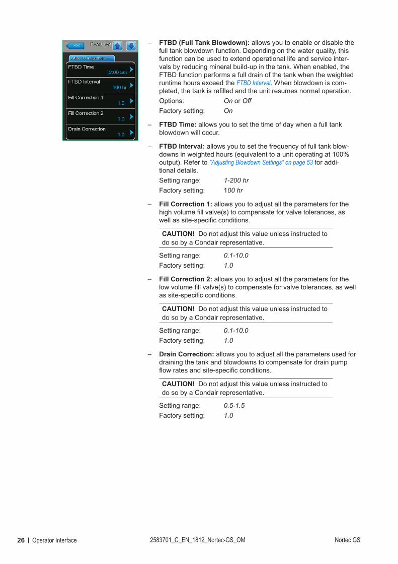
– FTBD (Full Tank Blowdown): allows you to enable or disable the full tank blowdown function. Depending on the water quality, this function can be used to extend operational life and service inter-vals by reducing mineral build-up in the tank. When enabled, the FTBD function performs a full drain of the tank when the weighted runtime hours exceed the FTBD Interval. When blowdown is com-pleted, the tank is refilled and the unit resumes normal operation.Options: On or OffFactory setting: On
– FTBD Time: allows you to set the time of day when a full tank blowdown will occur.
– FTBD Interval: allows you to set the frequency of full tank blow-downs in weighted hours (equivalent to a unit operating at 100% output). Refer to "Adjusting Blowdown Settings" on page 53 for addi-tional details.Setting range: 1-200 hrFactory setting: 100 hr
– Fill Correction 1: allows you to adjust all the parameters for the high volume fill valve(s) to compensate for valve tolerances, as well as site-specific conditions.
CAUTION! Do not adjust this value unless instructed to do so by a Condair representative.
Setting range: 0.1-10.0Factory setting: 1.0
– Fill Correction 2: allows you to adjust all the parameters for the low volume fill valve(s) to compensate for valve tolerances, as well as site-specific conditions.
CAUTION! Do not adjust this value unless instructed to do so by a Condair representative.
Setting range: 0.1-10.0Factory setting: 1.0
– Drain Correction: allows you to adjust all the parameters used for draining the tank and blowdowns to compensate for drain pump flow rates and site-specific conditions.
CAUTION! Do not adjust this value unless instructed to do so by a Condair representative.
Setting range: 0.5-1.5Factory setting: 1.0
27Operator InterfaceNortec GS 2583701_C_EN_1812_Nortec-GS_OM
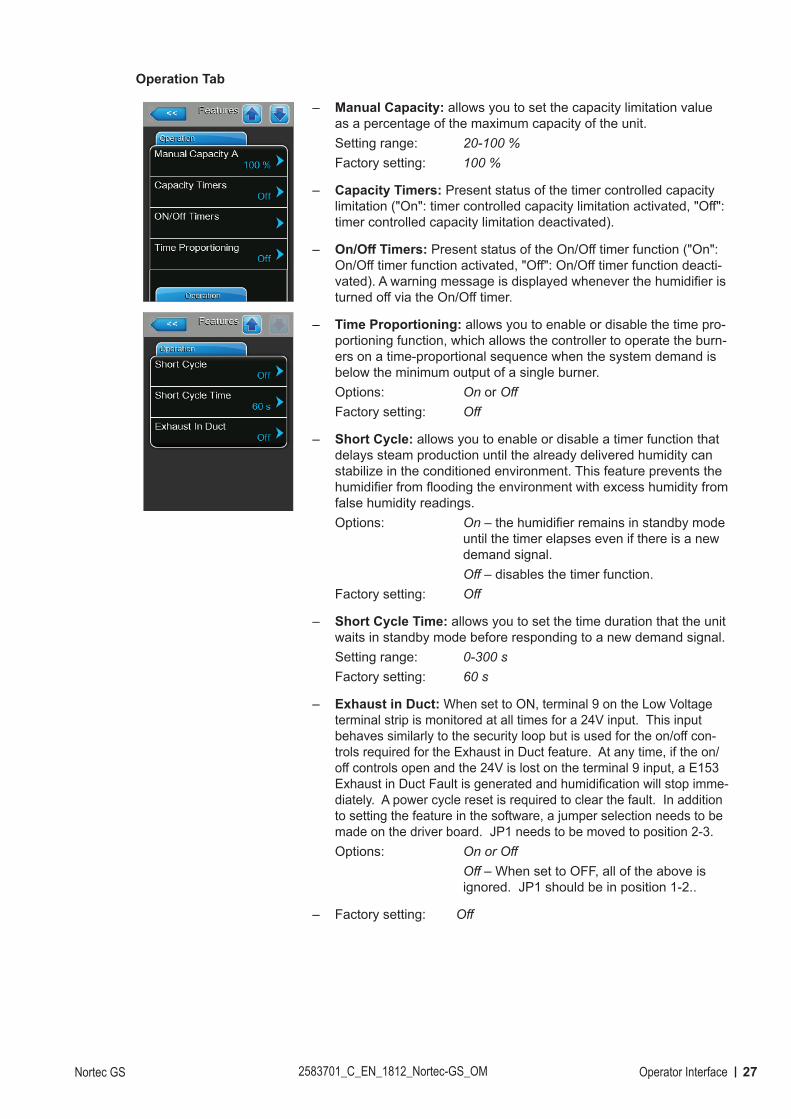
Operation Tab
– Manual Capacity: allows you to set the capacity limitation value as a percentage of the maximum capacity of the unit. Setting range: 20-100 %Factory setting: 100 %
– Capacity Timers: Present status of the timer controlled capacity limitation ("On": timer controlled capacity limitation activated, "Off": timer controlled capacity limitation deactivated).
– On/Off Timers: Present status of the On/Off timer function ("On": On/Off timer function activated, "Off": On/Off timer function deacti-vated). A warning message is displayed whenever the humidifier is turned off via the On/Off timer.
– Time Proportioning: allows you to enable or disable the time pro-portioning function, which allows the controller to operate the burn-ers on a time-proportional sequence when the system demand is below the minimum output of a single burner.Options: On or OffFactory setting: Off
– Short Cycle: allows you to enable or disable a timer function that delays steam production until the already delivered humidity can stabilize in the conditioned environment. This feature prevents the humidifier from flooding the environment with excess humidity from false humidity readings.Options: On – the humidifier remains in standby mode
until the timer elapses even if there is a new demand signal.
Off – disables the timer function.Factory setting: Off
– Short Cycle Time: allows you to set the time duration that the unit waits in standby mode before responding to a new demand signal.Setting range: 0-300 sFactory setting: 60 s
– Exhaust in Duct: When set to ON, terminal 9 on the Low Voltage terminal strip is monitored at all times for a 24V input. This input behaves similarly to the security loop but is used for the on/off con-trols required for the Exhaust in Duct feature. At any time, if the on/off controls open and the 24V is lost on the terminal 9 input, a E153 Exhaust in Duct Fault is generated and humidification will stop imme-diately. A power cycle reset is required to clear the fault. In addition to setting the feature in the software, a jumper selection needs to be made on the driver board. JP1 needs to be moved to position 2-3. Options: On or Off Off – When set to OFF, all of the above is
ignored. JP1 should be in position 1-2..
– Factory setting: Off
28 Operator Interface 2583701_C_EN_1812_Nortec-GS_OM Nortec GS
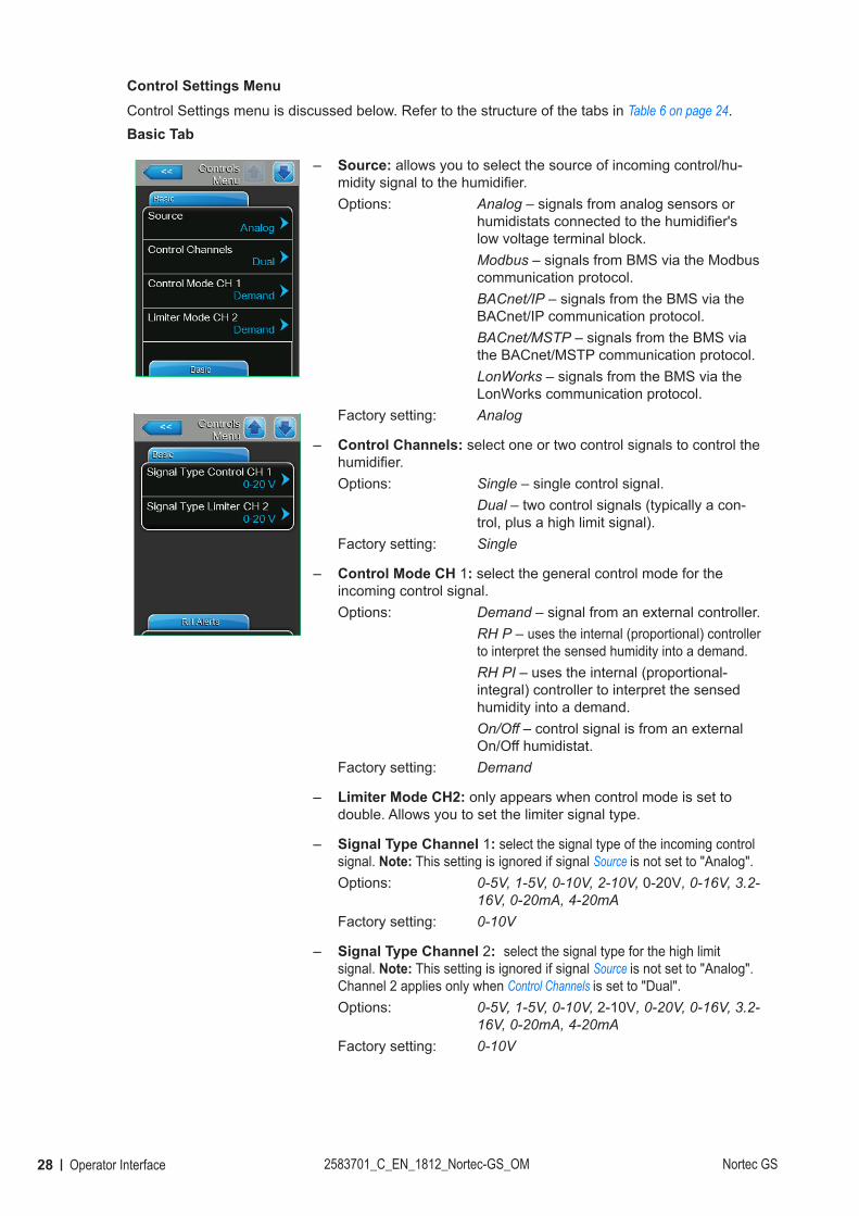
Control Settings MenuControl Settings menu is discussed below. Refer to the structure of the tabs in Table 6 on page 24.Basic Tab
– Source: allows you to select the source of incoming control/hu-midity signal to the humidifier.Options: Analog – signals from analog sensors or
humidistats connected to the humidifier's low voltage terminal block.
Modbus – signals from BMS via the Modbus communication protocol.
BACnet/IP – signals from the BMS via the BACnet/IP communication protocol.
BACnet/MSTP – signals from the BMS via the BACnet/MSTP communication protocol.
LonWorks – signals from the BMS via the LonWorks communication protocol.
Factory setting: Analog
– Control Channels: select one or two control signals to control the humidifier. Options: Single – single control signal. Dual – two control signals (typically a con-
trol, plus a high limit signal).Factory setting: Single
– Control Mode CH 1: select the general control mode for the incoming control signal.Options: Demand – signal from an external controller. RH P – uses the internal (proportional) controller
to interpret the sensed humidity into a demand. RH PI – uses the internal (proportional-
integral) controller to interpret the sensed humidity into a demand.
On/Off – control signal is from an external On/Off humidistat.
Factory setting: Demand
– Limiter Mode CH2: only appears when control mode is set to double. Allows you to set the limiter signal type.
– Signal Type Channel 1: select the signal type of the incoming control signal. Note: This setting is ignored if signal Source is not set to "Analog". Options: 0-5V, 1-5V, 0-10V, 2-10V, 0-20V, 0-16V, 3.2-
16V, 0-20mA, 4-20mAFactory setting: 0-10V
– Signal Type Channel 2: select the signal type for the high limit signal. Note: This setting is ignored if signal Source is not set to "Analog". Channel 2 applies only when Control Channels is set to "Dual". Options: 0-5V, 1-5V, 0-10V, 2-10V, 0-20V, 0-16V, 3.2-
16V, 0-20mA, 4-20mAFactory setting: 0-10V
29Operator InterfaceNortec GS 2583701_C_EN_1812_Nortec-GS_OM
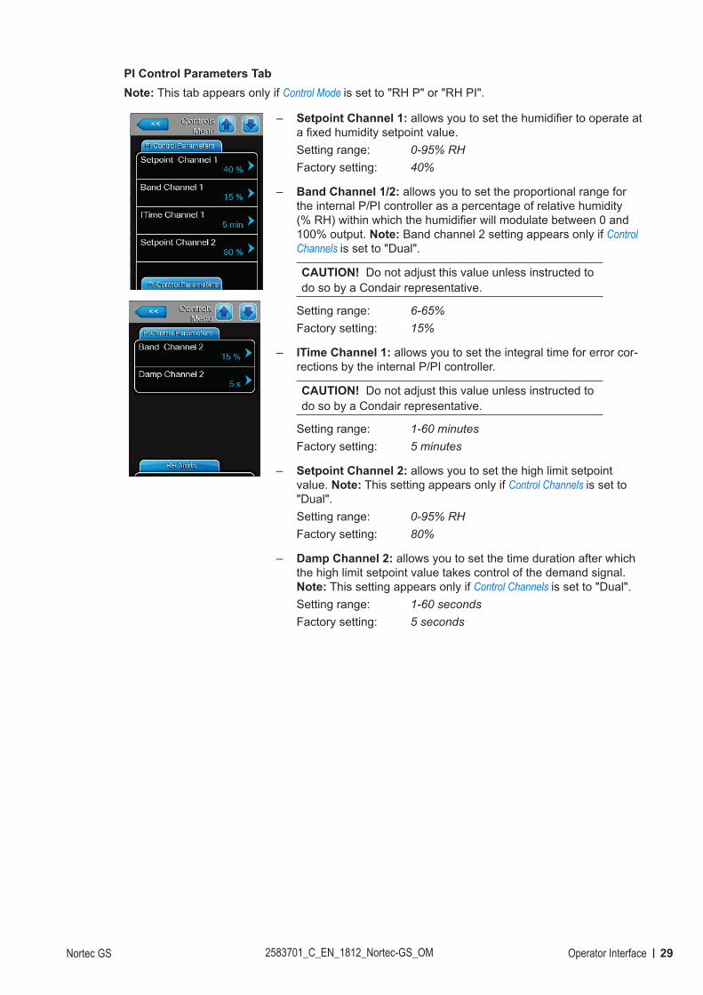
PI Control Parameters TabNote: This tab appears only if Control Mode is set to "RH P" or "RH PI".
– Setpoint Channel 1: allows you to set the humidifier to operate at a fixed humidity setpoint value.Setting range: 0-95% RHFactory setting: 40%
– Band Channel 1/2: allows you to set the proportional range for the internal P/PI controller as a percentage of relative humidity (% RH) within which the humidifier will modulate between 0 and 100% output. Note: Band channel 2 setting appears only if Control Channels is set to "Dual".
CAUTION! Do not adjust this value unless instructed to do so by a Condair representative.
Setting range: 6-65%Factory setting: 15%
– ITime Channel 1: allows you to set the integral time for error cor-rections by the internal P/PI controller.
CAUTION! Do not adjust this value unless instructed to do so by a Condair representative.
Setting range: 1-60 minutesFactory setting: 5 minutes
– Setpoint Channel 2: allows you to set the high limit setpoint value. Note: This setting appears only if Control Channels is set to "Dual".Setting range: 0-95% RHFactory setting: 80%
– Damp Channel 2: allows you to set the time duration after which the high limit setpoint value takes control of the demand signal. Note: This setting appears only if Control Channels is set to "Dual".Setting range: 1-60 secondsFactory setting: 5 seconds
30 Operator Interface 2583701_C_EN_1812_Nortec-GS_OM Nortec GS
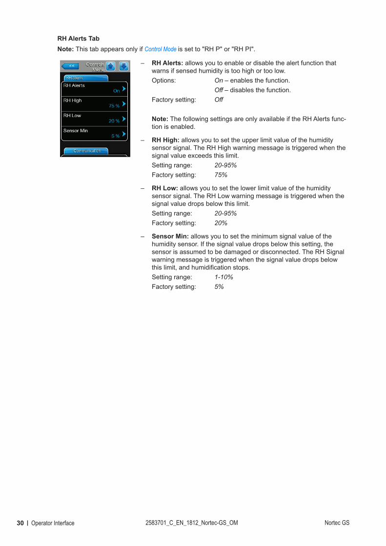
RH Alerts TabNote: This tab appears only if Control Mode is set to "RH P" or "RH PI".
– RH Alerts: allows you to enable or disable the alert function that warns if sensed humidity is too high or too low.Options: On – enables the function. Off – disables the function.Factory setting: Off
Note: The following settings are only available if the RH Alerts func-tion is enabled.
– RH High: allows you to set the upper limit value of the humidity sensor signal. The RH High warning message is triggered when the signal value exceeds this limit.Setting range: 20-95%Factory setting: 75%
– RH Low: allows you to set the lower limit value of the humidity sensor signal. The RH Low warning message is triggered when the signal value drops below this limit.Setting range: 20-95%Factory setting: 20%
– Sensor Min: allows you to set the minimum signal value of the humidity sensor. If the signal value drops below this setting, the sensor is assumed to be damaged or disconnected. The RH Signal warning message is triggered when the signal value drops below this limit, and humidification stops.Setting range: 1-10%Factory setting: 5%
31Operator InterfaceNortec GS 2583701_C_EN_1812_Nortec-GS_OM
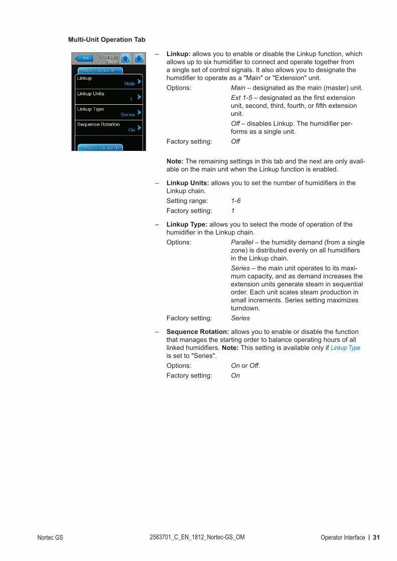
Multi-Unit Operation Tab
– Linkup: allows you to enable or disable the Linkup function, which allows up to six humidifier to connect and operate together from a single set of control signals. It also allows you to designate the humidifier to operate as a "Main" or "Extension" unit.Options: Main – designated as the main (master) unit. Ext 1-5 – designated as the first extension
unit, second, third, fourth, or fifth extension unit.
Off – disables Linkup. The humidifier per-forms as a single unit.
Factory setting: Off
Note: The remaining settings in this tab and the next are only avail-able on the main unit when the Linkup function is enabled.
– Linkup Units: allows you to set the number of humidifiers in the Linkup chain.Setting range: 1-6Factory setting: 1
– Linkup Type: allows you to select the mode of operation of the humidifier in the Linkup chain.Options: Parallel – the humidity demand (from a single
zone) is distributed evenly on all humidifiers in the Linkup chain.
Series – the main unit operates to its maxi-mum capacity, and as demand increases the extension units generate steam in sequential order. Each unit scales steam production in small increments. Series setting maximizes turndown.
Factory setting: Series
– Sequence Rotation: allows you to enable or disable the function that manages the starting order to balance operating hours of all linked humidifiers. Note: This setting is available only if Linkup Type is set to "Series".Options: On or Off.Factory setting: On
32 Operator Interface 2583701_C_EN_1812_Nortec-GS_OM Nortec GS
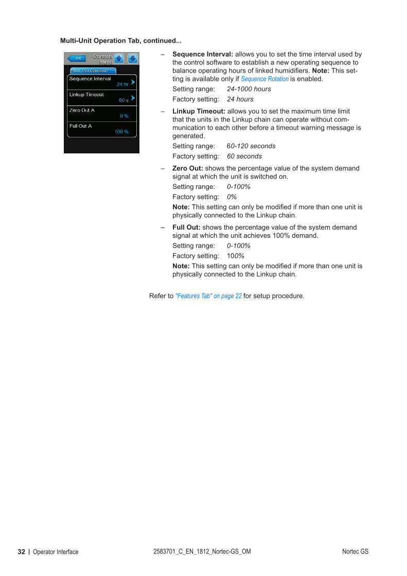
Multi-Unit Operation Tab, continued...
– Sequence Interval: allows you to set the time interval used by the control software to establish a new operating sequence to balance operating hours of linked humidifiers. Note: This set-ting is available only if Sequence Rotation is enabled.Setting range: 24-1000 hoursFactory setting: 24 hours
– Linkup Timeout: allows you to set the maximum time limit that the units in the Linkup chain can operate without com-munication to each other before a timeout warning message is generated.Setting range: 60-120 secondsFactory setting: 60 seconds
– Zero Out: shows the percentage value of the system demand signal at which the unit is switched on.Setting range: 0-100%Factory setting: 0%Note: This setting can only be modified if more than one unit is physically connected to the Linkup chain.
– Full Out: shows the percentage value of the system demand signal at which the unit achieves 100% demand.Setting range: 0-100%Factory setting: 100%Note: This setting can only be modified if more than one unit is physically connected to the Linkup chain.
Refer to "Features Tab" on page 22 for setup procedure.
33Operator InterfaceNortec GS 2583701_C_EN_1812_Nortec-GS_OM
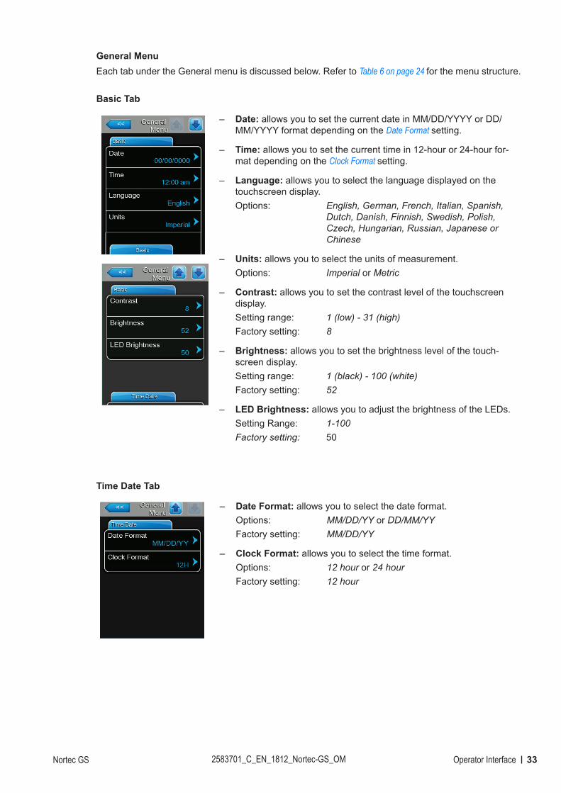
General MenuEach tab under the General menu is discussed below. Refer to Table 6 on page 24 for the menu structure.
Basic Tab
– Date: allows you to set the current date in MM/DD/YYYY or DD/MM/YYYY format depending on the Date Format setting.
– Time: allows you to set the current time in 12-hour or 24-hour for-mat depending on the Clock Format setting.
– Language: allows you to select the language displayed on the touchscreen display.Options: English, German, French, Italian, Spanish,
Dutch, Danish, Finnish, Swedish, Polish, Czech, Hungarian, Russian, Japanese or Chinese
– Units: allows you to select the units of measurement.Options: Imperial or Metric
– Contrast: allows you to set the contrast level of the touchscreen display.Setting range: 1 (low) - 31 (high)Factory setting: 8
– Brightness: allows you to set the brightness level of the touch-screen display.Setting range: 1 (black) - 100 (white)Factory setting: 52
– LED Brightness: allows you to adjust the brightness of the LEDs.Setting Range: 1-100Factory setting: 50
Time Date Tab
– Date Format: allows you to select the date format.Options: MM/DD/YY or DD/MM/YYFactory setting: MM/DD/YY
– Clock Format: allows you to select the time format.Options: 12 hour or 24 hourFactory setting: 12 hour
34 Operator Interface 2583701_C_EN_1812_Nortec-GS_OM Nortec GS
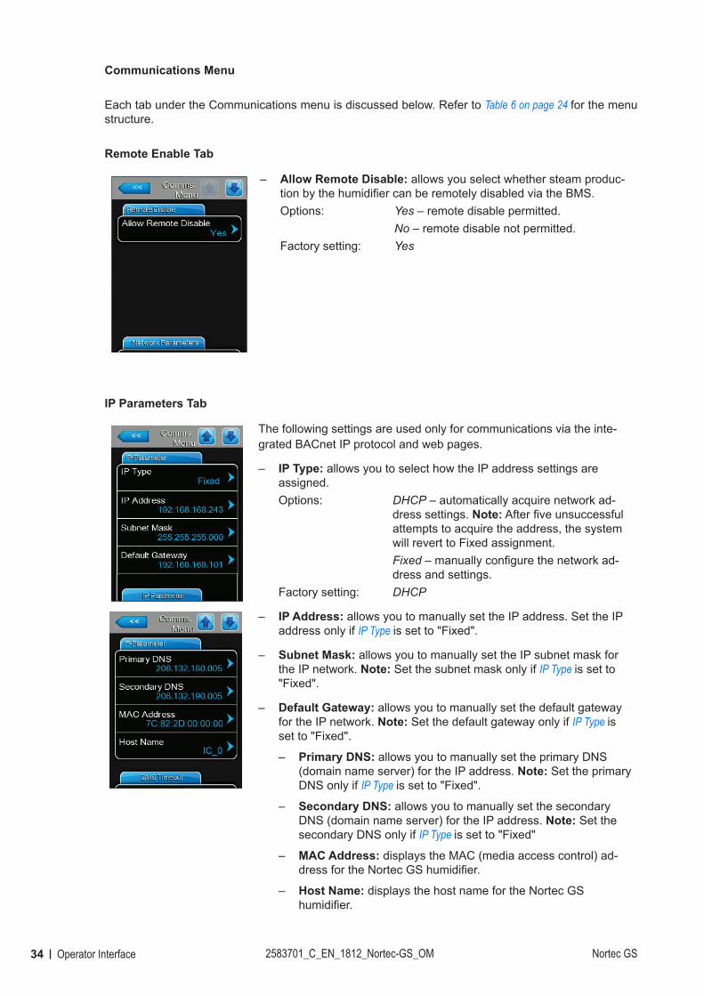
Communications Menu
Each tab under the Communications menu is discussed below. Refer to Table 6 on page 24 for the menu structure.
Remote Enable Tab
– Allow Remote Disable: allows you select whether steam produc-tion by the humidifier can be remotely disabled via the BMS.Options: Yes – remote disable permitted. No – remote disable not permitted.Factory setting: Yes
IP Parameters Tab
The following settings are used only for communications via the inte-grated BACnet IP protocol and web pages.
– IP Type: allows you to select how the IP address settings are assigned.Options: DHCP – automatically acquire network ad-
dress settings. Note: After five unsuccessful attempts to acquire the address, the system will revert to Fixed assignment.
Fixed – manually configure the network ad-dress and settings.
Factory setting: DHCP
– IP Address: allows you to manually set the IP address. Set the IP address only if IP Type is set to "Fixed".
– Subnet Mask: allows you to manually set the IP subnet mask for the IP network. Note: Set the subnet mask only if IP Type is set to "Fixed".
– Default Gateway: allows you to manually set the default gateway for the IP network. Note: Set the default gateway only if IP Type is set to "Fixed".
– Primary DNS: allows you to manually set the primary DNS (domain name server) for the IP address. Note: Set the primary DNS only if IP Type is set to "Fixed".
– Secondary DNS: allows you to manually set the secondary DNS (domain name server) for the IP address. Note: Set the secondary DNS only if IP Type is set to "Fixed"
– MAC Address: displays the MAC (media access control) ad-dress for the Nortec GS humidifier.
– Host Name: displays the host name for the Nortec GS humidifier.
35Operator InterfaceNortec GS 2583701_C_EN_1812_Nortec-GS_OM
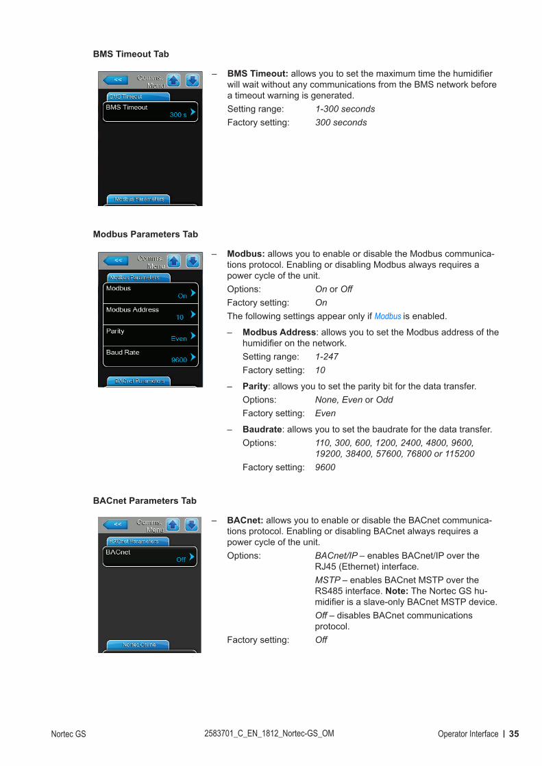
BMS Timeout Tab
– BMS Timeout: allows you to set the maximum time the humidifier will wait without any communications from the BMS network before a timeout warning is generated. Setting range: 1-300 secondsFactory setting: 300 seconds
Modbus Parameters Tab
– Modbus: allows you to enable or disable the Modbus communica-tions protocol. Enabling or disabling Modbus always requires a power cycle of the unit.Options: On or OffFactory setting: OnThe following settings appear only if Modbus is enabled.
– Modbus Address: allows you to set the Modbus address of the humidifier on the network.Setting range: 1-247Factory setting: 10
– Parity: allows you to set the parity bit for the data transfer.Options: None, Even or OddFactory setting: Even
– Baudrate: allows you to set the baudrate for the data transfer.Options: 110, 300, 600, 1200, 2400, 4800, 9600,
19200, 38400, 57600, 76800 or 115200Factory setting: 9600
BACnet Parameters Tab
– BACnet: allows you to enable or disable the BACnet communica-tions protocol. Enabling or disabling BACnet always requires a power cycle of the unit.Options: BACnet/IP – enables BACnet/IP over the
RJ45 (Ethernet) interface. MSTP – enables BACnet MSTP over the
RS485 interface. Note: The Nortec GS hu-midifier is a slave-only BACnet MSTP device.
Off – disables BACnet communications protocol.
Factory setting: Off
36 Operator Interface 2583701_C_EN_1812_Nortec-GS_OM Nortec GS
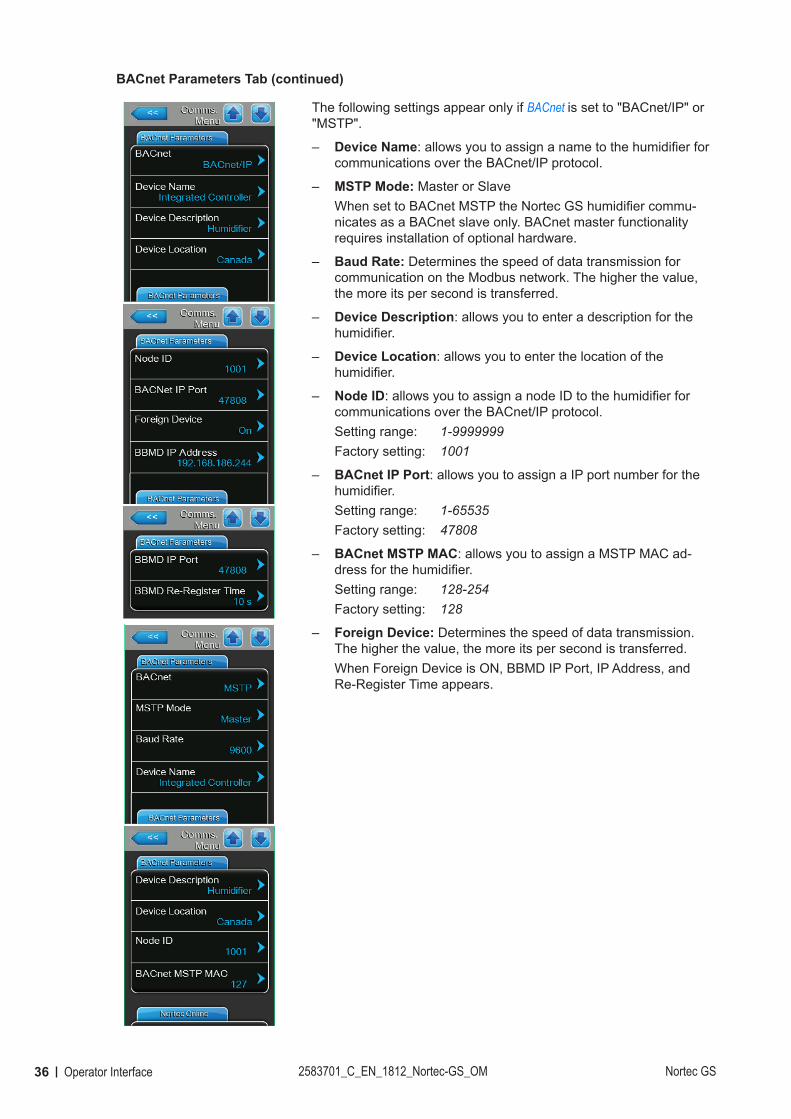
BACnet Parameters Tab (continued)
The following settings appear only if BACnet is set to "BACnet/IP" or "MSTP".
– Device Name: allows you to assign a name to the humidifier for communications over the BACnet/IP protocol.
– MSTP Mode: Master or Slave When set to BACnet MSTP the Nortec GS humidifier commu-nicates as a BACnet slave only. BACnet master functionality requires installation of optional hardware.
– Baud Rate: Determines the speed of data transmission for communication on the Modbus network. The higher the value, the more its per second is transferred.
– Device Description: allows you to enter a description for the humidifier.
– Device Location: allows you to enter the location of the humidifier.
– Node ID: allows you to assign a node ID to the humidifier for communications over the BACnet/IP protocol.Setting range: 1-9999999Factory setting: 1001
– BACnet IP Port: allows you to assign a IP port number for the humidifier.Setting range: 1-65535Factory setting: 47808
– BACnet MSTP MAC: allows you to assign a MSTP MAC ad-dress for the humidifier.Setting range: 128-254Factory setting: 128
– Foreign Device: Determines the speed of data transmission. The higher the value, the more its per second is transferred.When Foreign Device is ON, BBMD IP Port, IP Address, and Re-Register Time appears.
37Operator InterfaceNortec GS 2583701_C_EN_1812_Nortec-GS_OM
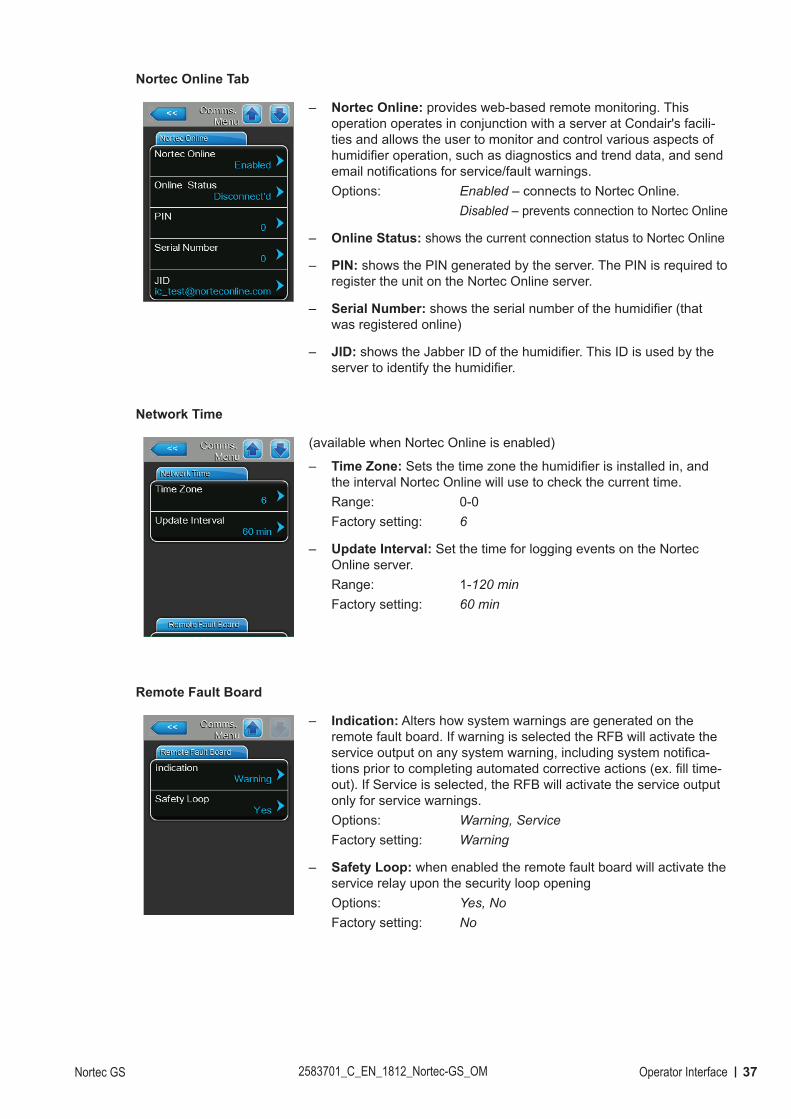
Nortec Online Tab
– Nortec Online: provides web-based remote monitoring. This operation operates in conjunction with a server at Condair's facili-ties and allows the user to monitor and control various aspects of humidifier operation, such as diagnostics and trend data, and send email notifications for service/fault warnings.Options: Enabled – connects to Nortec Online. Disabled – prevents connection to Nortec Online
– Online Status: shows the current connection status to Nortec Online
– PIN: shows the PIN generated by the server. The PIN is required to register the unit on the Nortec Online server.
– Serial Number: shows the serial number of the humidifier (that was registered online)
– JID: shows the Jabber ID of the humidifier. This ID is used by the server to identify the humidifier.
Network Time
(available when Nortec Online is enabled)
– Time Zone: Sets the time zone the humidifier is installed in, and the interval Nortec Online will use to check the current time. Range: 0-0Factory setting: 6
– Update Interval: Set the time for logging events on the Nortec Online server. Range: 1-120 minFactory setting: 60 min
Remote Fault Board
– Indication: Alters how system warnings are generated on the remote fault board. If warning is selected the RFB will activate the service output on any system warning, including system notifica-tions prior to completing automated corrective actions (ex. fill time-out). If Service is selected, the RFB will activate the service output only for service warnings.Options: Warning, ServiceFactory setting: Warning
– Safety Loop: when enabled the remote fault board will activate the service relay upon the security loop openingOptions: Yes, NoFactory setting: No
38 Operator Interface 2583701_C_EN_1812_Nortec-GS_OM Nortec GS
4.2.7.2 Service Menu
The Service menu lets you enter the startup code, reset the service reminder after performing scheduled maintenance, access the fault and maintenance history lists and perform diagnostics. Refer to Figure 8 on page 24. Refer to Table 6 on page 24 for the menu structure.Each tab under the Service menu is discussed below. The Service menu can also be accessed from the maintenance and fault status area on the Home screen – refer to Figure 8 on page 24.
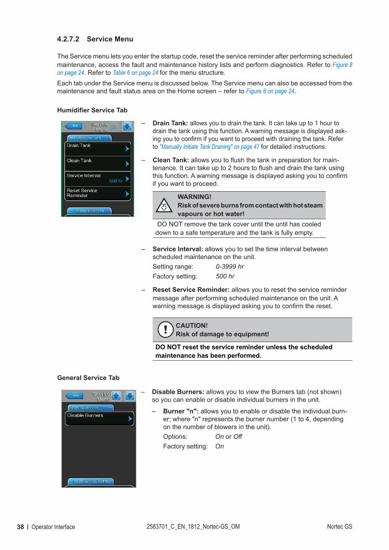
Humidifier Service Tab
– Drain Tank: allows you to drain the tank. It can take up to 1 hour to drain the tank using this function. A warning message is displayed ask-ing you to confirm if you want to proceed with draining the tank. Refer to "Manually Initiate Tank Draining" on page 47 for detailed instructions.
– Clean Tank: allows you to flush the tank in preparation for main-tenance. It can take up to 2 hours to flush and drain the tank using this function. A warning message is displayed asking you to confirm if you want to proceed.
WARNING! Risk of severe burns from contact with hot steam vapours or hot water!
DO NOT remove the tank cover until the until has cooled down to a safe temperature and the tank is fully empty.
– Service Interval: allows you to set the time interval between scheduled maintenance on the unit.Setting range: 0-3999 hrFactory setting: 500 hr
– Reset Service Reminder: allows you to reset the service reminder message after performing scheduled maintenance on the unit. A warning message is displayed asking you to confirm the reset.
CAUTION! Risk of damage to equipment!
DO NOT reset the service reminder unless the scheduled maintenance has been performed.
General Service Tab
– Disable Burners: allows you to view the Burners tab (not shown) so you can enable or disable individual burners in the unit.
– Burner "n": allows you to enable or disable the individual burn-er; where "n" represents the burner number (1 to 4, depending on the number of blowers in the unit).Options: On or OffFactory setting: On
39Operator InterfaceNortec GS 2583701_C_EN_1812_Nortec-GS_OM
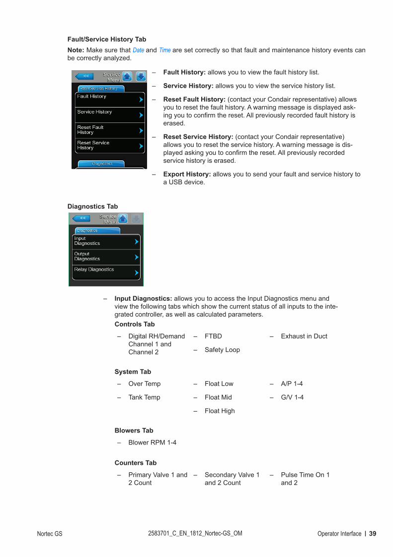
Fault/Service History TabNote: Make sure that Date and Time are set correctly so that fault and maintenance history events can be correctly analyzed.
– Fault History: allows you to view the fault history list.
– Service History: allows you to view the service history list.
– Reset Fault History: (contact your Condair representative) allows you to reset the fault history. A warning message is displayed ask-ing you to confirm the reset. All previously recorded fault history is erased.
– Reset Service History: (contact your Condair representative) allows you to reset the service history. A warning message is dis-played asking you to confirm the reset. All previously recorded service history is erased.
– Export History: allows you to send your fault and service history to a USB device.
Diagnostics Tab
– Input Diagnostics: allows you to access the Input Diagnostics menu and view the following tabs which show the current status of all inputs to the inte-grated controller, as well as calculated parameters.Controls Tab
– Digital RH/Demand Channel 1 and Channel 2
– FTBD
– Safety Loop
– Exhaust in Duct
System Tab
– Over Temp
– Tank Temp
– Float Low
– Float Mid
– Float High
– A/P 1-4
– G/V 1-4
Blowers Tab
– Blower RPM 1-4
Counters Tab
– Primary Valve 1 and 2 Count
– Secondary Valve 1 and 2 Count
– Pulse Time On 1 and 2
40 Operator Interface 2583701_C_EN_1812_Nortec-GS_OM Nortec GS
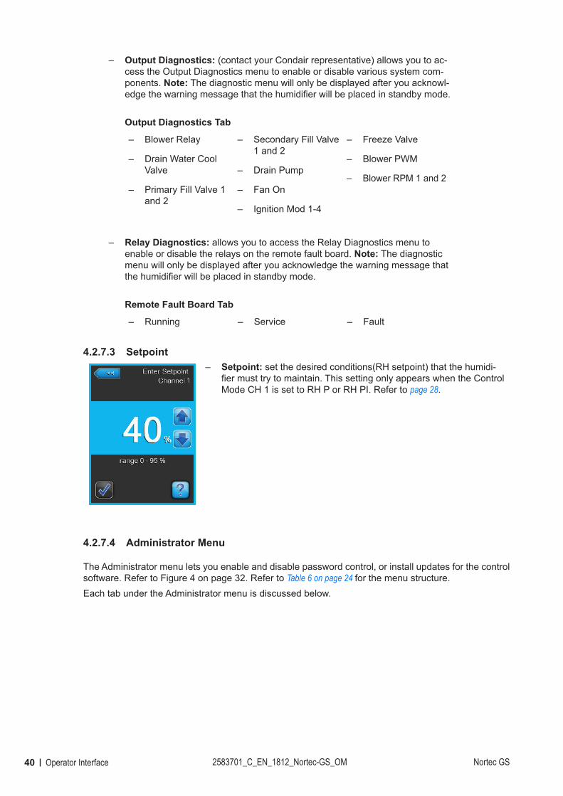
– Output Diagnostics: (contact your Condair representative) allows you to ac-cess the Output Diagnostics menu to enable or disable various system com-ponents. Note: The diagnostic menu will only be displayed after you acknowl-edge the warning message that the humidifier will be placed in standby mode.
Output Diagnostics Tab
– Blower Relay
– Drain Water Cool Valve
– Primary Fill Valve 1 and 2
– Secondary Fill Valve 1 and 2
– Drain Pump
– Fan On
– Ignition Mod 1-4
– Freeze Valve
– Blower PWM
– Blower RPM 1 and 2
– Relay Diagnostics: allows you to access the Relay Diagnostics menu to enable or disable the relays on the remote fault board. Note: The diagnostic menu will only be displayed after you acknowledge the warning message that the humidifier will be placed in standby mode.
Remote Fault Board Tab
– Running – Service – Fault
4.2.7.3 Setpoint – Setpoint: set the desired conditions(RH setpoint) that the humidi-
fier must try to maintain. This setting only appears when the Control Mode CH 1 is set to RH P or RH PI. Refer to page 28.
4.2.7.4 Administrator Menu
The Administrator menu lets you enable and disable password control, or install updates for the control software. Refer to Figure 4 on page 32. Refer to Table 6 on page 24 for the menu structure.Each tab under the Administrator menu is discussed below.
41Operator InterfaceNortec GS 2583701_C_EN_1812_Nortec-GS_OM
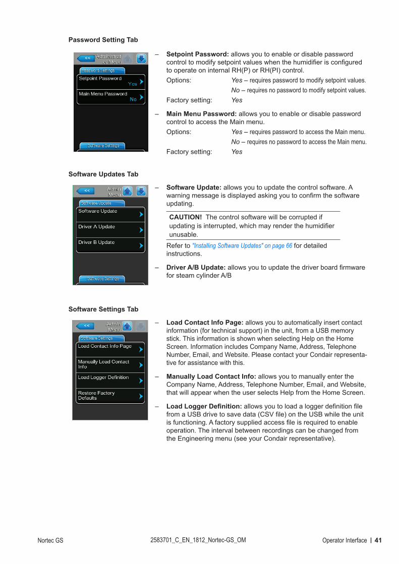
Password Setting Tab
– Setpoint Password: allows you to enable or disable password control to modify setpoint values when the humidifier is configured to operate on internal RH(P) or RH(PI) control.Options: Yes – requires password to modify setpoint values. No – requires no password to modify setpoint values.Factory setting: Yes
– Main Menu Password: allows you to enable or disable password control to access the Main menu.Options: Yes – requires password to access the Main menu. No – requires no password to access the Main menu.Factory setting: Yes
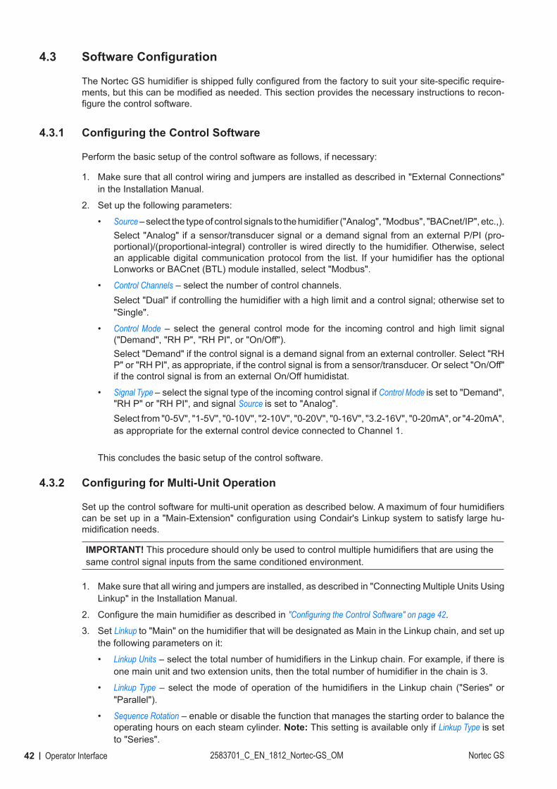
Software Updates Tab
– Software Update: allows you to update the control software. A warning message is displayed asking you to confirm the software updating.
CAUTION! The control software will be corrupted if updating is interrupted, which may render the humidifier unusable.
Refer to "Installing Software Updates" on page 66 for detailed instructions.
– Driver A/B Update: allows you to update the driver board firmware for steam cylinder A/B
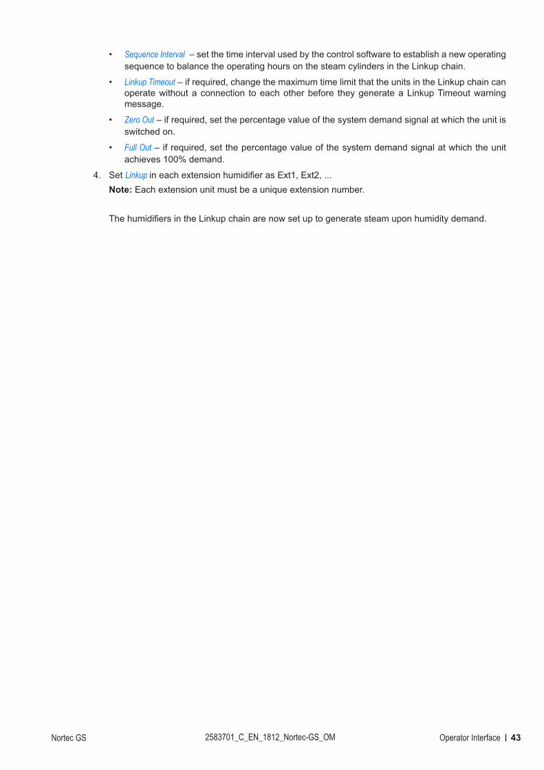
Software Settings Tab
– Load Contact Info Page: allows you to automatically insert contact information (for technical support) in the unit, from a USB memory stick. This information is shown when selecting Help on the Home Screen. Information includes Company Name, Address, Telephone Number, Email, and Website. Please contact your Condair representa-tive for assistance with this.
– Manually Load Contact Info: allows you to manually enter the Company Name, Address, Telephone Number, Email, and Website, that will appear when the user selects Help from the Home Screen.
– Load Logger Definition: allows you to load a logger definition file from a USB drive to save data (CSV file) on the USB while the unit is functioning. A factory supplied access file is required to enable operation. The interval between recordings can be changed from the Engineering menu (see your Condair representative).
42 Operator Interface 2583701_C_EN_1812_Nortec-GS_OM Nortec GS
4.3 Software Configuration
The Nortec GS humidifier is shipped fully configured from the factory to suit your site-specific require-ments, but this can be modified as needed. This section provides the necessary instructions to recon-figure the control software.
4.3.1 Configuring the Control Software
Perform the basic setup of the control software as follows, if necessary:
1. Make sure that all control wiring and jumpers are installed as described in "External Connections" in the Installation Manual.
2. Set up the following parameters:
• Source – select the type of control signals to the humidifier ("Analog", "Modbus", "BACnet/IP", etc.,).Select "Analog" if a sensor/transducer signal or a demand signal from an external P/PI (pro-portional)/(proportional-integral) controller is wired directly to the humidifier. Otherwise, select an applicable digital communication protocol from the list. If your humidifier has the optional Lonworks or BACnet (BTL) module installed, select "Modbus".
• Control Channels – select the number of control channels.Select "Dual" if controlling the humidifier with a high limit and a control signal; otherwise set to "Single".
• Control Mode – select the general control mode for the incoming control and high limit signal ("Demand", "RH P", "RH PI", or "On/Off").Select "Demand" if the control signal is a demand signal from an external controller. Select "RH P" or "RH PI", as appropriate, if the control signal is from a sensor/transducer. Or select "On/Off" if the control signal is from an external On/Off humidistat.
• Signal Type – select the signal type of the incoming control signal if Control Mode is set to "Demand", "RH P" or "RH PI", and signal Source is set to "Analog". Select from "0-5V", "1-5V", "0-10V", "2-10V", "0-20V", "0-16V", "3.2-16V", "0-20mA", or "4-20mA", as appropriate for the external control device connected to Channel 1.
This concludes the basic setup of the control software.
4.3.2 Configuring for Multi-Unit Operation
Set up the control software for multi-unit operation as described below. A maximum of four humidifiers can be set up in a "Main-Extension" configuration using Condair's Linkup system to satisfy large hu-midification needs.
IMPORTANT! This procedure should only be used to control multiple humidifiers that are using the same control signal inputs from the same conditioned environment.
1. Make sure that all wiring and jumpers are installed, as described in "Connecting Multiple Units Using Linkup" in the Installation Manual.
2. Configure the main humidifier as described in "Configuring the Control Software" on page 42.
3. Set Linkup to "Main" on the humidifier that will be designated as Main in the Linkup chain, and set up the following parameters on it:
• Linkup Units – select the total number of humidifiers in the Linkup chain. For example, if there is one main unit and two extension units, then the total number of humidifier in the chain is 3.
• Linkup Type – select the mode of operation of the humidifiers in the Linkup chain ("Series" or "Parallel").
• Sequence Rotation – enable or disable the function that manages the starting order to balance the operating hours on each steam cylinder. Note: This setting is available only if Linkup Type is set to "Series".
43Operator InterfaceNortec GS 2583701_C_EN_1812_Nortec-GS_OM
• Sequence Interval – set the time interval used by the control software to establish a new operating sequence to balance the operating hours on the steam cylinders in the Linkup chain.
• Linkup Timeout – if required, change the maximum time limit that the units in the Linkup chain can operate without a connection to each other before they generate a Linkup Timeout warning message.
• Zero Out – if required, set the percentage value of the system demand signal at which the unit is switched on.
• Full Out – if required, set the percentage value of the system demand signal at which the unit achieves 100% demand.
4. Set Linkup in each extension humidifier as Ext1, Ext2, ... Note: Each extension unit must be a unique extension number.
The humidifiers in the Linkup chain are now set up to generate steam upon humidity demand.
44 Operation 2583701_C_EN_1812_Nortec-GS_OM Nortec GS
5 Operation
5.1 General
Personnel QualificationsThe Nortec GS humidifier must only be operated by personnel who are adequately qualified, well trained and are authorized by the customer.
SafetyObserve all safety precautions described in "For Your Safety".
5.2 Operating Procedures
The procedures described in this section assume that the Nortec GS humidifier has been set up properly and commissioned by a Condair technician or Condair-approved technician.Before the Nortec GS humidifier can initiate combustion, it must be filled with water and the control software must perform a series of functional and safety tests.
5.2.1 Filling the System
Fill the Nortec GS humidifier as follows. The control software also performs the float test to ensure that the fill system, the water level controls and the drain pump(s) are functioning properly.
1. Close the manual gas shutoff valve in the supply line.
2. Open the shutoff valve in the water supply line.
3. Set the On/Off button on the humidifier to the On position. The control software then energizes the dual fill valves and starts to fill the tank. When the water in the float chamber(s) reaches the L1 level (red LED), the control software runs a series of tests on the fill and drain system as described in "Water Management" on page 15. On successful completion of the tests, the float chamber is filled to the L3 level (green LED), and the humidifier goes into standby mode. This process can take approximately 10-30 minutes depending on the size of the unit.
4. Set the On/Off button to the Off position, and perform the "Ignition Safety Shutoff Test" described below.
5.2.2 Ignition Safety Shutoff Test
Perform the ignition safety shutoff test as described below:
1. Check that the manual gas shutoff valve in the supply line is still closed.
2. Make sure that the contacts of all devices connected to the external security loop are closed.
3. Set the On/Off button to the On position. The control software runs a series of tests on the fill and drain system, and on successful completion the humidifier goes into standby mode.
4. Set the demand signal to the humidifier from the building management system (BMS) or humidistat at 100%.The control software energizes the blower(s) to initiate the combustion sequence. The blower(s) run at full capacity for the pre-purge duration to purge the system. The control software then verifies the proper functioning of the safety systems and the blowers as described in "Combustion" on page 14. After the safety systems check is completed successfully, the ignition control module(s) is energized.
45OperationNortec GS 2583701_C_EN_1812_Nortec-GS_OM
The spark-igniter(s) attempts to fire up three times to ignite the gas-air mixture. Since the gas supply is shut off, no flame is detected by the flame sensor(s) and the gas valve(s) is de-energized. The red LED in the ignition control module(s) flashes to indicate a safety lockout. The warning message "Ignition Fail" also appears on the touchscreen display after a short delay.Note: On units with multiple burners, each burner attempts to ignite in sequence. Hence, it is impor-tant to wait for all burners to complete its cycle.The ignition safety shutoff test is successful when no gas flows to the burner(s) when the manual gas shutoff valve is closed.After all burners have failed to ignite, the fault message "No Burners Available" will appear on the display. The blowers will perform a post-purge and then shut off.
5. Power cycle the humidifier to reset the fault condition.
6. Open the manual gas shutoff valve.
5.2.3 Starting the Humidifier
Start the humidifier as follows:
1. Make sure that the tank in the humidifier is filled with water – refer to "Filling the System" on page 44.
2. Make sure that the ignition safety shutdown test is completed – refer to "Ignition Safety Shutoff Test" on page 44.
3. Check that the shutoff valve in the water supply line is open.
4. Check that the manual gas shutoff valve in the supply line is open
5. On the CS/NX models, make sure that the condensate trap inside the unit is primed properly.
6. Check that the contacts of all devices connected to the external security loop are closed.
7. Make sure that all access panels on the humidifier are installed and fastened securely.
8. Set the On/Off button on the humidifier to the On position.The control software then energizes the dual fill valve(s) and starts to fill the tank. It then performs a series of tests to verify the function of the floats, the dual fill valves and the drain pump – refer to "Water Management" on page 15. Upon successful completion of the tests, the combustion sequence starts – refer to "Combustion" on page 14.Depending on the system demand, the blower(s) runs faster or slower to control the input of the burner(s). The generated heat turns the water in the tank to steam, which is then delivered to the distribution system.As the water level in the tank is reduced due to evaporation, the dual fill valves pulse to maintain water at the proper level. In CS/NX models, cold fill water passes through the secondary heat-exchanger. Here, heat from the exhaust warms up the cold fill water entering the tank before entering the fill box. The water will then flow from the fill box into the tank. When the humidity demand has been satisfied (demand drops below the minimum %), the gas valve(s) is de-energized. The blower(s) then performs a post-purge of the combustion chamber(s), and then shuts off. If there is no humidity demand, the humidifier goes into standby mode to await the next humidity demand signal.
46 Operation 2583701_C_EN_1812_Nortec-GS_OM Nortec GS
5.2.4 Remote Monitoring
The Nortec GS humidifier can be monitored remotely through the remote fault board wired to a remote monitoring system. Table 7 describes the function of each relay when triggered.
Table 7: Remote Relay Function
Remote Relay DescriptionError The humidifier is stopped due to a fault condition, or may be oper-
able only for a limited period of time.Service/Warning Depending on the software configuration, indicates that a service
warning or a system warning/notification is active. Unit On The humidifier has power, and the On/Off switch is in the On
position.
The Nortec GS humidifier can also be monitored remotely from a laptop or desktop computer using the ethernet port on the integrated control board. Contact your Condair representative for assistance.
5.2.5 Inspections During Operation
Perform regular inspection of the Nortec GS humidifier and the humidification system when it is in op-eration. Inspect the following:
� Check the gas connection for any leaks. � Check the water, drain and steam connections for any leakages. � If applicable, check the humidifier and other system components have not shifted from their mount-
ings, and are fastened securely. � Check for leaks in the exhaust vent. Check that there are no obstructions anywhere in the exhaust
vent, including the exhaust terminal. � Keep the area around the air intake in the unit clear of all obstructions. If an air intake vent is used,
check for leaks and obstructions in the vent, including the intake terminal. � Check the area around the unit is clear of all insulating and combustible materials. � Visually check the electrical wiring for any damage. � Check the Home screen on the humidifier for service or system warning messages.
If any irregularities (leakages, fault messages or damaged components) are found, shut down the Nortec GS humidifier before performing service – refer to "Shutting Down" on page 48. Contact your Condair representative if assistance is required.

47OperationNortec GS 2583701_C_EN_1812_Nortec-GS_OM
5.2.6 Manually Initiate Tank Draining
Figure 9: Drain Screens
During periods of inactivity, such as off-season or periods of low demand, drain the water from the tank. To drain the tank in the Nortec GS humidifier, manually initiate draining as follows. Refer to Figure 9.
1. Select the <Drain> button on the Home screen. If more than one humidifier is connected in a Linkup chain, select the appropriate tank, then press the check mark.
2. Select the <Yes> button on the confirmation screen. If humidification is in progress, it is interrupted and the drain pump(s) empties the tank. A progress bar shows the status of the drain cycle.Select the <Cancel> button at any time to interrupt the drain cycle. If the drain cycle is interrupted before it is completed, open the manual drain valve and verify that there is still water in the tank. Close the manual drain valve, then select the <No> button on the next screen to confirm that the tank has not been emptied fully.Note: If necessary, set the On/Off switch to the Off position at the end of the drain cycle to prevent the humidifier from filling the tank again.
WARNING! Risk of severe burns from contact with hot surfaces, steam or hot water!
The tank may contain steam or hot water at up to 212 °F (100 °C). Contact with the hot surfaces, steam vapors or hot water can result in severe burns.Prevention: Never open the tank until it has been fully drained, and the unit has cooled down to a safe temperature. Never use the manual drain valve until the unit has cooled down. Use the manual drain valve to verify that the tank is empty before removing the tank cover.
Note: If the control software/drain valve(s) does not function properly, wait for the unit to cool down then open the manual drain valve and empty the tank. Failure to do so may damage drain lines that are not rated to handle hot water at up to 212 °F (100 °C). Close the drain valve after emptying the tank.
5.2.7 Full Tank Blowdown
The control software in the Nortec GS humidifier performs a full tank blowdown to reduce the amount of dissolved minerals accumulated inside the tank. The Drain Cool function in the control software permits drain water cooling whenever the drain pump runs. Make sure that the function is enabled if drain cool-ing is required. The frequency of the blowdown can be set in the control software.In addition to the software-controlled full tank blowdown, a separate 24 VAC signal connected to pins "1" and "8" in the low voltage terminal strip can also initiate a full tank blowdown. When a full tank blowdown is initiated, the tank is drained fully then refilled. Make sure the Drain Cool function is enabled if drain cooling is required.
48 Operation 2583701_C_EN_1812_Nortec-GS_OM Nortec GS
5.2.8 Shutting Down
DANGER! Risk of electric shock!
The control cabinet in the Nortec GS has live voltage. Turning off the unit at the On/Off switch does not shut off power to the control cabinet. Touching live parts may cause severe injury or even death.Prevention: Before performing any work inside the humidifier or with the humidification system, shut down the humidifier properly as described below.
Shut down the Nortec GS humidifier as follows for maintenance, or at the end of the season:
1. Set the demand signal to the humidifier from the BMS or the humidistat at 0%. Then allow the burner(s) to shut off and the blower(s) to perform a post-purge of the combustion chamber(s).
2. Manually initiate draining of the tank. Refer to "Manually Initiate Tank Draining" on page 47.
WARNING! Risk of severe burns from contact with hot surfaces, steam or hot water!
The tank may contain steam or hot water at up to 212 °F (100 °C). Contact with the hot surfaces, steam vapors or hot water can result in severe burns.Prevention: Never open the tank until it has been fully drained, and the unit has cooled down to a safe temperature. Never use the manual drain valve until the unit has cooled down. Use the manual drain valve to verify that the tank is empty before removing the tank cover.
Note: If the control software/drain valve(s) does not function properly, wait for the unit to cool down then open the manual drain valve and empty the tank. Failure to do so may damage drain lines that are not rated to handle hot water at up to 212 °F (100 °C). Close the drain valve after emptying the tank.
3. Make a note of any fault code displayed on the Home screen.Note: At the end of the season, report the fault history to a Condair-certified technician. Select Service > Fault/Service History tab to access the fault history.
4. Set the On/Off button to the Off position.
5. Close the manual gas shutoff valve in the supply line.
6. Close the shutoff valve in the water supply line.
7. Disconnect the power supply to the humidifier at the external disconnect switch. To prevent accidental power-up, lockout and tag out according to the established safety practices at your facility.
WARNING! Risk of severe burns from contact with hot surfaces!
Components of the steam system may reach 212°F (100°C) during operation. Contact with the hot surfaces can result in severe burns.Prevention: Avoid touching any components in the plumbing cabinet until the unit has cooled down to a safe temperature.
8. Wait for the unit to cool down to a safe temperature before performing any maintenance inside the plumbing cabinet.
5.2.9 Restarting After Shutdown
Restart the Nortec GS humidifier as follows after it has been shut down for maintenance or at the start of the season:

49OperationNortec GS 2583701_C_EN_1812_Nortec-GS_OM
DANGER! Risk of harm to personnel or damage to property.
Operating a damaged or improperly secured humidifier presents a risk of danger to person-nel or damage to property.Prevention: Do not restart a damaged or improperly secured humidifier.
1. Examine the humidifier and other system components for damage. Do not use the applicance if any part of the humidifier has been under water. Call a qualified service technician to inspect and replace any part of the control system or gas control that has been under water.
2. Check for loose or damaged electrical connections, and repair if necessary.
3. If applicable, make sure that the humidifier and its components have not shifted from their mount-ings, and are fastened securely.
4. Make sure that all condensate traps in the exhaust and steam lines are primed properly.
5. Clean any build-up of dirt around the control cabinet, the area around the burner(s). Clean the area around the air intake inlet to prevent contaminants from being drawn into the combustion chamber.
6. Clean the air intake terminal, if the humidifier is connected to the exterior.
7. Make sure that all access panels on the humidifier are installed and fastened securely. Refer to "Removal and Installation of Access Panels" on page 55.
8. Remove the lock and tag from the external disconnect switch, and restore power to the humidifier.
9. Open the water and gas supply to the unit.
10. Start up the humidifier as described in "Starting the Humidifier" on page 45.
50 Maintenance 2583701_C_EN_1812_Nortec-GS_OM Nortec GS
6 Maintenance
6.1 General
To ensure proper performance and long operating life of the Nortec GS humidifier, Condair recommends inspection of the appliance and installation at least once a year by a qualified service person. The amount and type of maintenance required is generally dependent on how much the humidifier operates. The Nortec GS humidifier monitors the amount of steam produced over time and will indicate when service is required. All units come with a default service interval of 1000 hours, which can be adjusted in the control software.The combustion air blower motors are permanently lubricated and do not require lubrication.The gas valves in the Nortec GS humidifier are negative static pressure regulating valves. The valves are factory-set for the correct gas type. The valve setting listed on the product rating plate is shown relative to atmosphere – this setting will always remain constant. Contact the factory if adjustment is needed.
IMPORTANT! Tampering with the gas valve, without the express consent of Condair, will void the warranty.
In general, the burners do not require adjustment or servicing. The combustion chamber and heat-exchanger tubes are all fabricated from stainless steel, and do not require internal cleaning.The exhaust vent connected to the Nortec GS humidifier does not require cleaning, but needs to be inspected regularly for leaks, blockages, sagging and proper condensate removal. For proper and safe operation of the unit, the area around the air intake in the unit must be kept clear of all obstructions. If an air intake vent is used, it must be inspected for leaks and obstructions (including the intake terminal).Refer to "Mandatory Maintenance Schedule" on page 51 for other maintenance requirements. Also perform regular inspections when the unit is operating – refer to "Inspections During Operation" on page 46.
IMPORTANT! Damage caused by use of non-approved parts is not covered by warranty. Use only original Condair replacement parts.
Personnel QualificationsMaintenance on the Nortec GS humidifier must only be performed by well qualified and properly trained personnel authorized by the customer. It is the customer's responsibility to verify qualifications of the personnel.
SafetyMake sure that the Nortec GS humidifier is shut down properly as described in "Shutting Down" on page 48, and observe all safety precautions described in "For Your Safety" before performing any maintenance on the humidifier.
WARNING!Wiring errors can cause improper and dangerous operation of the humidifier!
Prevention: Tag all wires before disconnecting them. Reconnect all wires correctly after servicing, and check the unit functions properly.
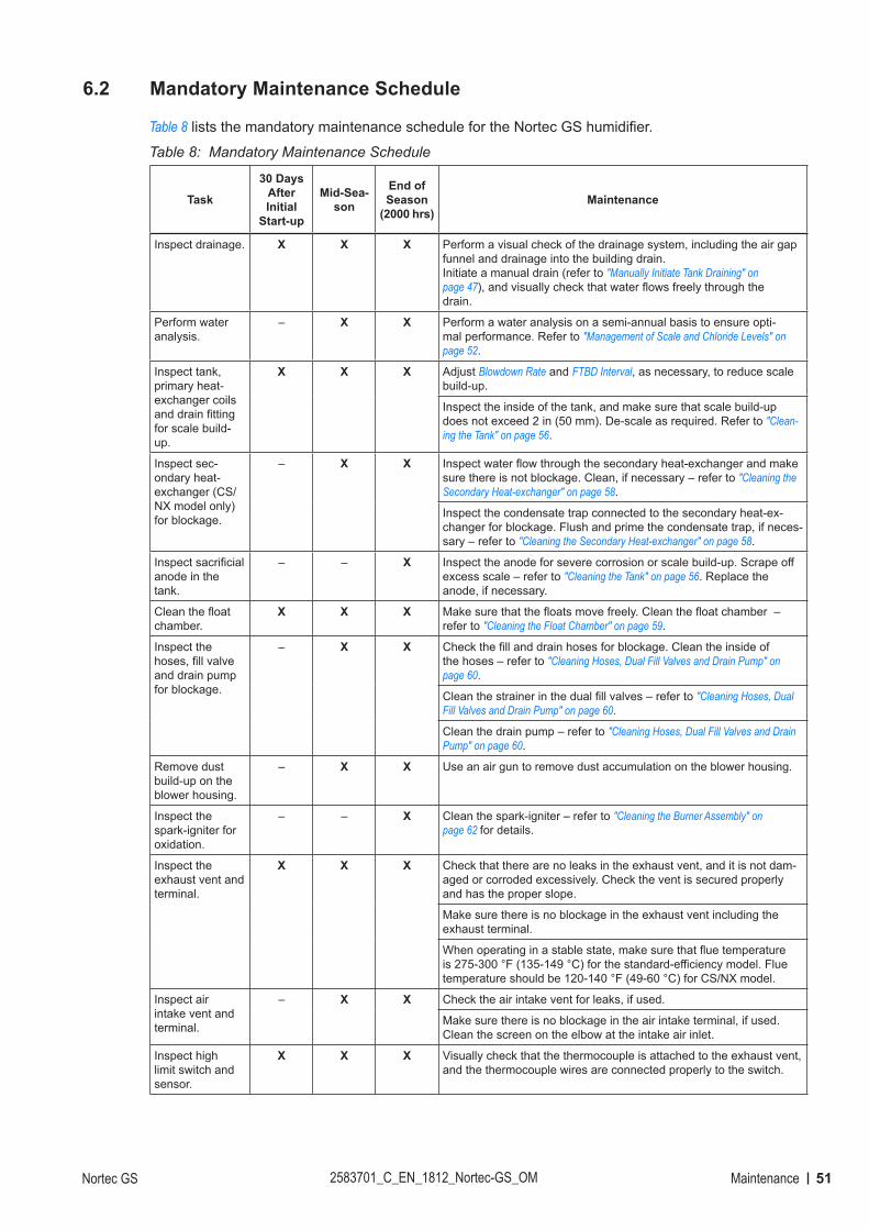
51MaintenanceNortec GS 2583701_C_EN_1812_Nortec-GS_OM
6.2 Mandatory Maintenance Schedule
Table 8 lists the mandatory maintenance schedule for the Nortec GS humidifier.
Table 8: Mandatory Maintenance Schedule
Task
30 Days After Initial
Start-up
Mid-Sea-son
End of Season
(2000 hrs)Maintenance
Inspect drainage. X X X Perform a visual check of the drainage system, including the air gap funnel and drainage into the building drain. Initiate a manual drain (refer to "Manually Initiate Tank Draining" on page 47), and visually check that water flows freely through the drain.
Perform water analysis.
– X X Perform a water analysis on a semi-annual basis to ensure opti-mal performance. Refer to "Management of Scale and Chloride Levels" on page 52.
Inspect tank, primary heat-exchanger coils and drain fitting for scale build-up.
X X X Adjust Blowdown Rate and FTBD Interval, as necessary, to reduce scale build-up.
Inspect the inside of the tank, and make sure that scale build-up does not exceed 2 in (50 mm). De-scale as required. Refer to "Clean-ing the Tank" on page 56.
Inspect sec-ondary heat-exchanger (CS/NX model only) for blockage.
– X X Inspect water flow through the secondary heat-exchanger and make sure there is not blockage. Clean, if necessary – refer to "Cleaning the Secondary Heat-exchanger" on page 58.
Inspect the condensate trap connected to the secondary heat-ex-changer for blockage. Flush and prime the condensate trap, if neces-sary – refer to "Cleaning the Secondary Heat-exchanger" on page 58.
Inspect sacrificial anode in the tank.
– – X Inspect the anode for severe corrosion or scale build-up. Scrape off excess scale – refer to "Cleaning the Tank" on page 56. Replace the anode, if necessary.
Clean the float chamber.
X X X Make sure that the floats move freely. Clean the float chamber – refer to "Cleaning the Float Chamber" on page 59.
Inspect the hoses, fill valve and drain pump for blockage.
– X X Check the fill and drain hoses for blockage. Clean the inside of the hoses – refer to "Cleaning Hoses, Dual Fill Valves and Drain Pump" on page 60.
Clean the strainer in the dual fill valves – refer to "Cleaning Hoses, Dual Fill Valves and Drain Pump" on page 60.
Clean the drain pump – refer to "Cleaning Hoses, Dual Fill Valves and Drain Pump" on page 60.
Remove dust build-up on the blower housing.
– X X Use an air gun to remove dust accumulation on the blower housing.
Inspect the spark-igniter for oxidation.
– – X Clean the spark-igniter – refer to "Cleaning the Burner Assembly" on page 62 for details.
Inspect the exhaust vent and terminal.
X X X Check that there are no leaks in the exhaust vent, and it is not dam-aged or corroded excessively. Check the vent is secured properly and has the proper slope.
Make sure there is no blockage in the exhaust vent including the exhaust terminal.
When operating in a stable state, make sure that flue temperature is 275-300 °F (135-149 °C) for the standard-efficiency model. Flue temperature should be 120-140 °F (49-60 °C) for CS/NX model.
Inspect air intake vent and terminal.
– X X Check the air intake vent for leaks, if used.
Make sure there is no blockage in the air intake terminal, if used. Clean the screen on the elbow at the intake air inlet.
Inspect high limit switch and sensor.
X X X Visually check that the thermocouple is attached to the exhaust vent, and the thermocouple wires are connected properly to the switch.
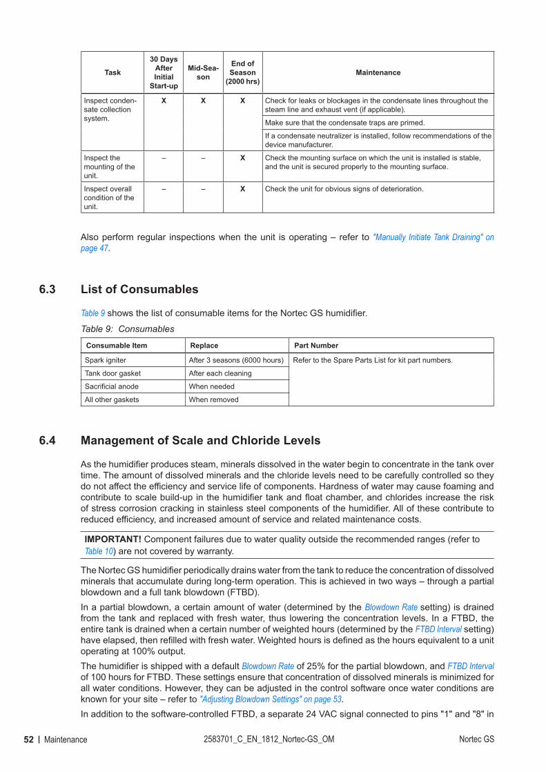
52 Maintenance 2583701_C_EN_1812_Nortec-GS_OM Nortec GS
Task
30 Days After Initial
Start-up
Mid-Sea-son
End of Season
(2000 hrs)Maintenance
Inspect conden-sate collection system.
X X X Check for leaks or blockages in the condensate lines throughout the steam line and exhaust vent (if applicable).
Make sure that the condensate traps are primed.
If a condensate neutralizer is installed, follow recommendations of the device manufacturer.
Inspect the mounting of the unit.
– – X Check the mounting surface on which the unit is installed is stable, and the unit is secured properly to the mounting surface.
Inspect overall condition of the unit.
– – X Check the unit for obvious signs of deterioration.
Also perform regular inspections when the unit is operating – refer to "Manually Initiate Tank Draining" on page 47.
6.3 List of Consumables
Table 9 shows the list of consumable items for the Nortec GS humidifier.
Table 9: Consumables
Consumable Item Replace Part Number
Spark igniter After 3 seasons (6000 hours) Refer to the Spare Parts List for kit part numbers.
Tank door gasket After each cleaning
Sacrificial anode When needed
All other gaskets When removed
6.4 Management of Scale and Chloride Levels
As the humidifier produces steam, minerals dissolved in the water begin to concentrate in the tank over time. The amount of dissolved minerals and the chloride levels need to be carefully controlled so they do not affect the efficiency and service life of components. Hardness of water may cause foaming and contribute to scale build-up in the humidifier tank and float chamber, and chlorides increase the risk of stress corrosion cracking in stainless steel components of the humidifier. All of these contribute to reduced efficiency, and increased amount of service and related maintenance costs.
IMPORTANT! Component failures due to water quality outside the recommended ranges (refer to Table 10) are not covered by warranty.
The Nortec GS humidifier periodically drains water from the tank to reduce the concentration of dissolved minerals that accumulate during long-term operation. This is achieved in two ways – through a partial blowdown and a full tank blowdown (FTBD). In a partial blowdown, a certain amount of water (determined by the Blowdown Rate setting) is drained from the tank and replaced with fresh water, thus lowering the concentration levels. In a FTBD, the entire tank is drained when a certain number of weighted hours (determined by the FTBD Interval setting) have elapsed, then refilled with fresh water. Weighted hours is defined as the hours equivalent to a unit operating at 100% output.The humidifier is shipped with a default Blowdown Rate of 25% for the partial blowdown, and FTBD Interval of 100 hours for FTBD. These settings ensure that concentration of dissolved minerals is minimized for all water conditions. However, they can be adjusted in the control software once water conditions are known for your site – refer to "Adjusting Blowdown Settings" on page 53.In addition to the software-controlled FTBD, a separate 24 VAC signal connected to pins "1" and "8" in
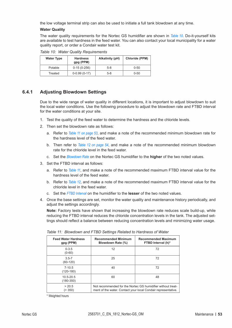
53MaintenanceNortec GS 2583701_C_EN_1812_Nortec-GS_OM
the low voltage terminal strip can also be used to initiate a full tank blowdown at any time.Water QualityThe water quality requirements for the Nortec GS humidifier are shown in Table 10. Do-it-yourself kits are available to test hardness in the feed water. You can also contact your local municipality for a water quality report, or order a Condair water test kit.
Table 10: Water Quality RequirementsWater Type Hardness
gpg (PPM)Alkalinity (pH) Chloride (PPM)
Potable 0-15 (0-256) 5-8 0-50
Treated 0-0.99 (0-17) 5-8 0-50
6.4.1 Adjusting Blowdown Settings
Due to the wide range of water quality in different locations, it is important to adjust blowdown to suit the local water conditions. Use the following procedure to adjust the blowdown rate and FTBD interval for the water conditions at your site.
1. Test the quality of the feed water to determine the hardness and the chloride levels.
2. Then set the blowdown rate as follows:
a. Refer to Table 11 on page 53, and make a note of the recommended minimum blowdown rate for the hardness level of the feed water.
b. Then refer to Table 12 on page 54, and make a note of the recommended minimum blowdown rate for the chloride level in the feed water.
c. Set the Blowdown Rate on the Nortec GS humidifier to the higher of the two noted values.
3. Set the FTBD interval as follows:
a. Refer to Table 11, and make a note of the recommended maximum FTBD interval value for the hardness level of the feed water.
b. Refer to Table 12, and make a note of the recommended maximum FTBD interval value for the chloride level in the feed water.
c. Set the FTBD Interval on the humidifier to the lesser of the two noted values.4. Once the base settings are set, monitor the water quality and maintenance history periodically, and
adjust the settings accordingly. Note: Factory tests have shown that increasing the blowdown rate reduces scale build-up, while reducing the FTBD interval reduces the chloride concentration levels in the tank. The adjusted set-tings should reflect a balance between reducing concentration levels and minimizing water usage.
Table 11: Blowdown and FTBD Settings Related to Hardness of Water
Feed Water Hardnessgpg (PPM)
Recommended Minimum Blowdown Rate (%)
Recommended Maximum FTBD Interval (h)*
0-3.5 (0-60)
12 72
3.5-7 (60-120)
25 72
7-10.5 (120-180)
40 72
10.5-20.5(180-350)
60 48
> 20.5(> 350)
Not recommended for the Nortec GS humidifier without treat-ment of the water. Contact your local Condair representative.
* Weighted hours
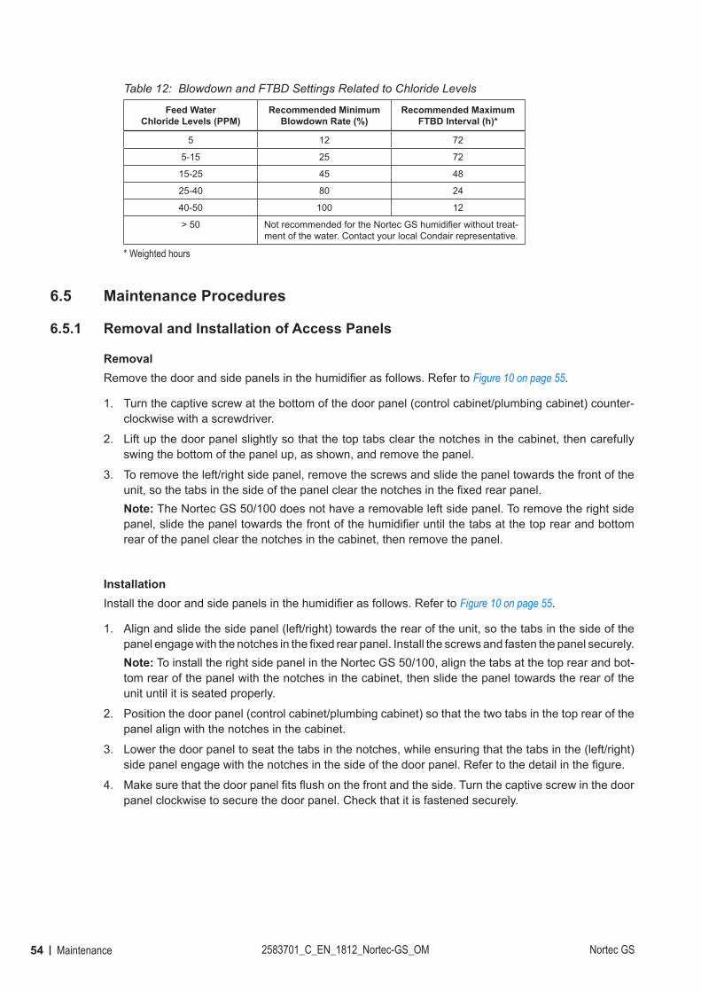
54 Maintenance 2583701_C_EN_1812_Nortec-GS_OM Nortec GS
Table 12: Blowdown and FTBD Settings Related to Chloride Levels
Feed Water Chloride Levels (PPM)
Recommended Minimum Blowdown Rate (%)
Recommended Maximum FTBD Interval (h)*
5 12 72
5-15 25 72
15-25 45 48
25-40 80 24
40-50 100 12
> 50 Not recommended for the Nortec GS humidifier without treat-ment of the water. Contact your local Condair representative.
* Weighted hours
6.5 Maintenance Procedures
6.5.1 Removal and Installation of Access Panels
RemovalRemove the door and side panels in the humidifier as follows. Refer to Figure 10 on page 55.
1. Turn the captive screw at the bottom of the door panel (control cabinet/plumbing cabinet) counter-clockwise with a screwdriver.
2. Lift up the door panel slightly so that the top tabs clear the notches in the cabinet, then carefully swing the bottom of the panel up, as shown, and remove the panel.
3. To remove the left/right side panel, remove the screws and slide the panel towards the front of the unit, so the tabs in the side of the panel clear the notches in the fixed rear panel.Note: The Nortec GS 50/100 does not have a removable left side panel. To remove the right side panel, slide the panel towards the front of the humidifier until the tabs at the top rear and bottom rear of the panel clear the notches in the cabinet, then remove the panel.
InstallationInstall the door and side panels in the humidifier as follows. Refer to Figure 10 on page 55.
1. Align and slide the side panel (left/right) towards the rear of the unit, so the tabs in the side of the panel engage with the notches in the fixed rear panel. Install the screws and fasten the panel securely.Note: To install the right side panel in the Nortec GS 50/100, align the tabs at the top rear and bot-tom rear of the panel with the notches in the cabinet, then slide the panel towards the rear of the unit until it is seated properly.
2. Position the door panel (control cabinet/plumbing cabinet) so that the two tabs in the top rear of the panel align with the notches in the cabinet.
3. Lower the door panel to seat the tabs in the notches, while ensuring that the tabs in the (left/right) side panel engage with the notches in the side of the door panel. Refer to the detail in the figure.
4. Make sure that the door panel fits flush on the front and the side. Turn the captive screw in the door panel clockwise to secure the door panel. Check that it is fastened securely.
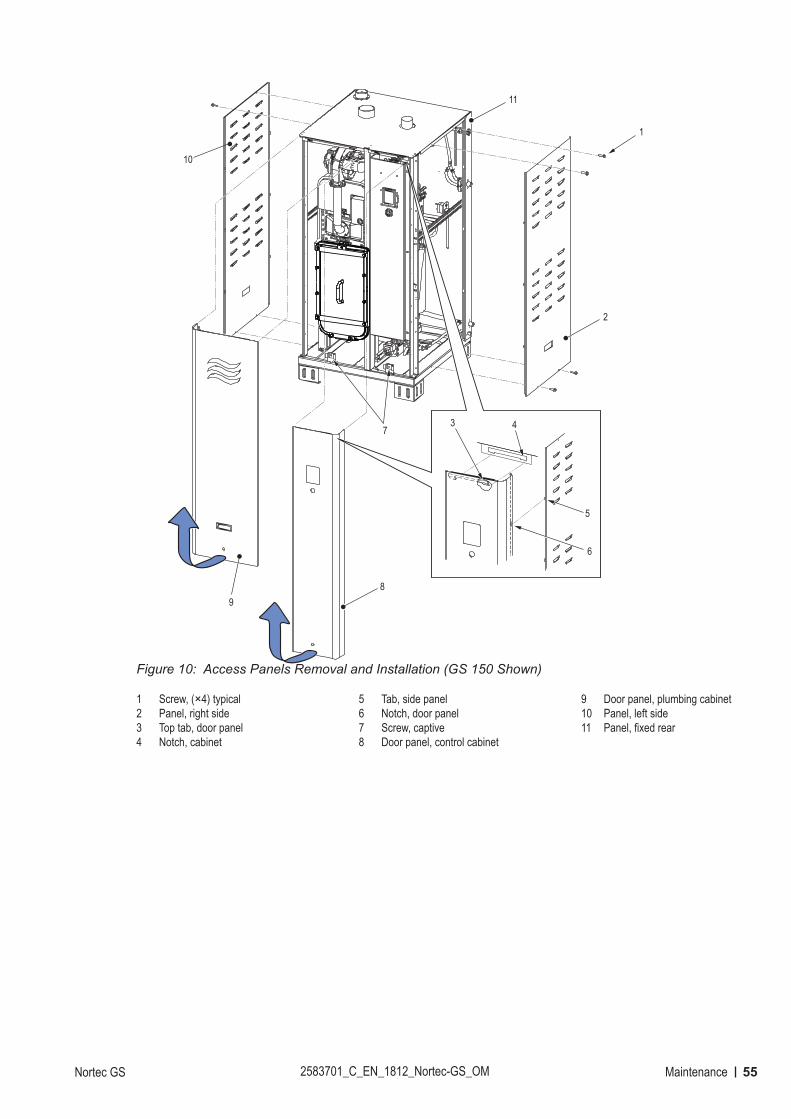
55MaintenanceNortec GS 2583701_C_EN_1812_Nortec-GS_OM
Figure 10:
5
1
6
43
8
2
7
9
10
11
Access Panels Removal and Installation (GS 150 Shown)
1 Screw, (×4) typical 2 Panel, right side3 Top tab, door panel4 Notch, cabinet
5 Tab, side panel6 Notch, door panel7 Screw, captive 8 Door panel, control cabinet
9 Door panel, plumbing cabinet10 Panel, left side11 Panel, fixed rear
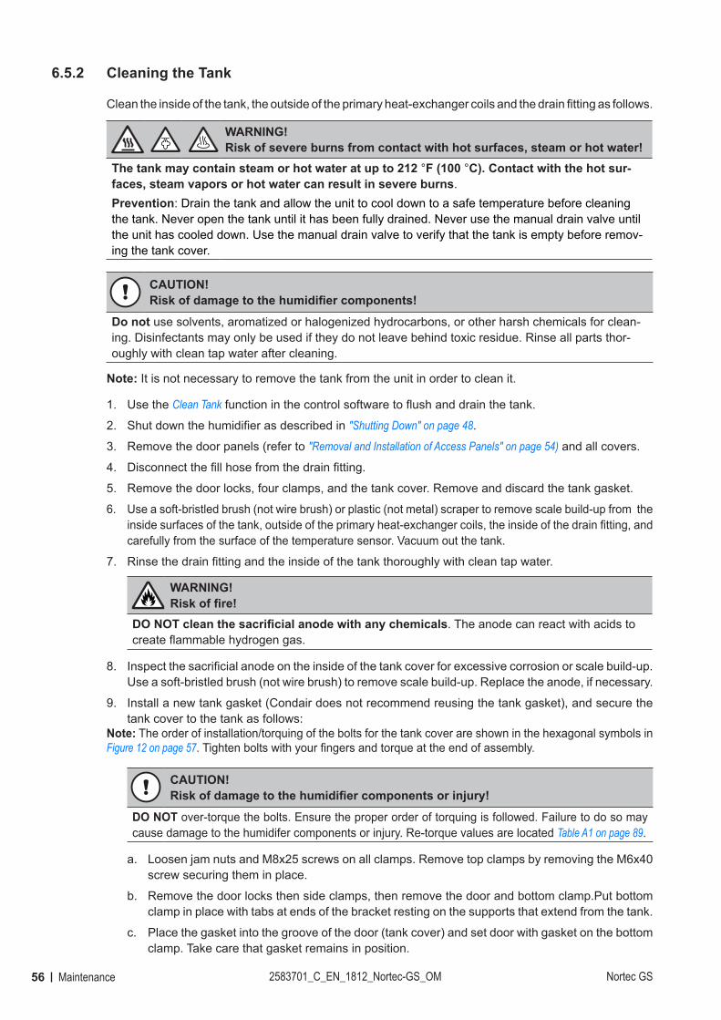
56 Maintenance 2583701_C_EN_1812_Nortec-GS_OM Nortec GS
6.5.2 Cleaning the Tank
Clean the inside of the tank, the outside of the primary heat-exchanger coils and the drain fitting as follows.
WARNING! Risk of severe burns from contact with hot surfaces, steam or hot water!
The tank may contain steam or hot water at up to 212 °F (100 °C). Contact with the hot sur-faces, steam vapors or hot water can result in severe burns.Prevention: Drain the tank and allow the unit to cool down to a safe temperature before cleaning the tank. Never open the tank until it has been fully drained. Never use the manual drain valve until the unit has cooled down. Use the manual drain valve to verify that the tank is empty before remov-ing the tank cover.
CAUTION!Risk of damage to the humidifier components!
Do not use solvents, aromatized or halogenized hydrocarbons, or other harsh chemicals for clean-ing. Disinfectants may only be used if they do not leave behind toxic residue. Rinse all parts thor-oughly with clean tap water after cleaning.
Note: It is not necessary to remove the tank from the unit in order to clean it.
1. Use the Clean Tank function in the control software to flush and drain the tank.
2. Shut down the humidifier as described in "Shutting Down" on page 48.
3. Remove the door panels (refer to "Removal and Installation of Access Panels" on page 54) and all covers.
4. Disconnect the fill hose from the drain fitting.
5. Remove the door locks, four clamps, and the tank cover. Remove and discard the tank gasket.
6. Use a soft-bristled brush (not wire brush) or plastic (not metal) scraper to remove scale build-up from the inside surfaces of the tank, outside of the primary heat-exchanger coils, the inside of the drain fitting, and carefully from the surface of the temperature sensor. Vacuum out the tank.
7. Rinse the drain fitting and the inside of the tank thoroughly with clean tap water.
WARNING! Risk of fire!
DO NOT clean the sacrificial anode with any chemicals. The anode can react with acids to create flammable hydrogen gas.
8. Inspect the sacrificial anode on the inside of the tank cover for excessive corrosion or scale build-up. Use a soft-bristled brush (not wire brush) to remove scale build-up. Replace the anode, if necessary.
9. Install a new tank gasket (Condair does not recommend reusing the tank gasket), and secure the tank cover to the tank as follows:
Note: The order of installation/torquing of the bolts for the tank cover are shown in the hexagonal symbols in Figure 12 on page 57. Tighten bolts with your fingers and torque at the end of assembly.
CAUTION!Risk of damage to the humidifier components or injury!
DO NOT over-torque the bolts. Ensure the proper order of torquing is followed. Failure to do so may cause damage to the humidifer components or injury. Re-torque values are located Table A1 on page 89.
a. Loosen jam nuts and M8x25 screws on all clamps. Remove top clamps by removing the M6x40 screw securing them in place.
b. Remove the door locks then side clamps, then remove the door and bottom clamp.Put bottom clamp in place with tabs at ends of the bracket resting on the supports that extend from the tank.
c. Place the gasket into the groove of the door (tank cover) and set door with gasket on the bottom clamp. Take care that gasket remains in position.
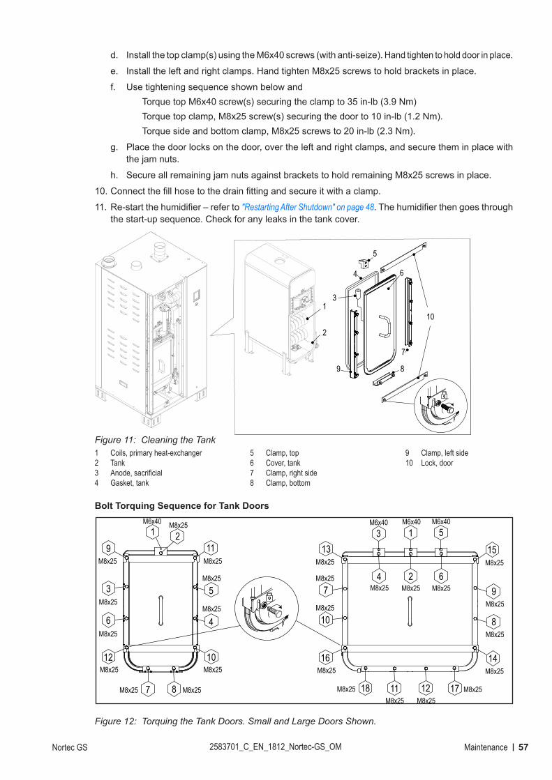
57MaintenanceNortec GS 2583701_C_EN_1812_Nortec-GS_OM
d. Install the top clamp(s) using the M6x40 screws (with anti-seize). Hand tighten to hold door in place.
e. Install the left and right clamps. Hand tighten M8x25 screws to hold brackets in place.
f. Use tightening sequence shown below and Torque top M6x40 screw(s) securing the clamp to 35 in-lb (3.9 Nm)Torque top clamp, M8x25 screw(s) securing the door to 10 in-lb (1.2 Nm).Torque side and bottom clamp, M8x25 screws to 20 in-lb (2.3 Nm).
g. Place the door locks on the door, over the left and right clamps, and secure them in place with the jam nuts.
h. Secure all remaining jam nuts against brackets to hold remaining M8x25 screws in place.
10. Connect the fill hose to the drain fitting and secure it with a clamp.
11. Re-start the humidifier – refer to "Restarting After Shutdown" on page 48. The humidifier then goes through the start-up sequence. Check for any leaks in the tank cover.
Figure 11:
1
2
5
4 6
9 8
7
3
10
Cleaning the Tank1 Coils, primary heat-exchanger2 Tank3 Anode, sacrificial4 Gasket, tank
5 Clamp, top 6 Cover, tank 7 Clamp, right side8 Clamp, bottom
9 Clamp, left side 10 Lock, door
Bolt Torquing Sequence for Tank Doors
Figure 12:
9
10
11
12
7 8
1 2M6x40 M8x25
M8x25
M8x25
M8x25M8x25
M8x25
M8x25
14
15M8x25
M8x25
13
16M8x25
M8x25
3
4
M6x40
M8x25
5
6
M6x40
M8x25
17 M8x2518M8x25 12M8x25
2M8x25
1M6x40
7M8x25
10M8x25
9M8x25
8M8x25
3M8x25
6M8x25
5M8x25
4M8x25
11M8x25
Torquing the Tank Doors. Small and Large Doors Shown.
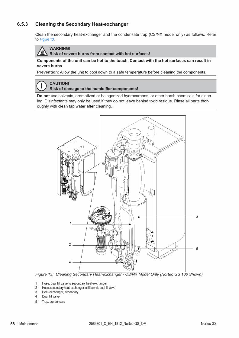
58 Maintenance 2583701_C_EN_1812_Nortec-GS_OM Nortec GS
6.5.3 Cleaning the Secondary Heat-exchanger
Clean the secondary heat-exchanger and the condensate trap (CS/NX model only) as follows. Refer to Figure 13.
WARNING! Risk of severe burns from contact with hot surfaces!
Components of the unit can be hot to the touch. Contact with the hot surfaces can result in severe burns.Prevention: Allow the unit to cool down to a safe temperature before cleaning the components.
CAUTION!Risk of damage to the humidifier components!
Do not use solvents, aromatized or halogenized hydrocarbons, or other harsh chemicals for clean-ing. Disinfectants may only be used if they do not leave behind toxic residue. Rinse all parts thor-oughly with clean tap water after cleaning.
Figure 13:
1
2
3
4
5
1
Cleaning Secondary Heat-exchanger - CS/NX Model Only (Nortec GS 100 Shown)
1 Hose, dual fill valve to secondary heat-exchanger2 Hose, secondary heat-exchanger to fill box via dual fill valve3 Heat-exchanger, secondary 4 Dual fill valve5 Trap, condensate
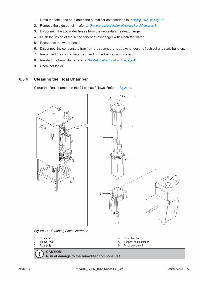
59MaintenanceNortec GS 2583701_C_EN_1812_Nortec-GS_OM
1. Drain the tank, and shut down the humidifier as described in "Shutting Down" on page 48.
2. Remove the side panel – refer to "Removal and Installation of Access Panels" on page 54.
3. Disconnect the two water hoses from the secondary heat-exchanger.
4. Flush the inside of the secondary heat-exchanger with clean tap water.
5. Reconnect the water hoses.
6. Disconnect the condensate trap from the secondary heat-exchanger and flush out any scale build-up.
7. Reconnect the condensate trap, and prime the trap with water.
8. Re-start the humidifier – refer to "Restarting After Shutdown" on page 48.
9. Check for leaks.
6.5.4 Cleaning the Float Chamber
Clean the float chamber in the fill box as follows. Refer to Figure 14.
Figure 14:
1
2
3
4
5
6
Cleaning Float Chamber
1 Screw (×3) 2 Sleeve, float3 Float (×2)
4 Float chamber5 Support, float chamber6 Fill box weldment
CAUTION!Risk of damage to the humidifier components!
60 Maintenance 2583701_C_EN_1812_Nortec-GS_OM Nortec GS
Do not use solvents, aromatized or halogenized hydrocarbons, or other harsh chemicals for clean-ing. Disinfectants may only be used if they do not leave behind toxic residue. Rinse all parts thor-oughly with clean tap water after cleaning.
1. Shut down the humidifier as described in "Shutting Down" on page 48.
2. Remove the side panel – refer to "Removal and Installation of Access Panels" on page 54.
3. Remove the float chamber from the fill box weldment, the three screws, and the float sleeve.
4. Carefully remove the two floats. Make a note of the orientation of the floats.
5. Use a soft-bristled brush (not wire brush) to remove all scale build-up on the floats, the inside of the float sleeve and the float chamber. Rinse with clean tap water.
6. Visually check each float for cracks or other damage. Place the two floats in a container filled with clean water, and check that they both have equal buoyancy. If necessary, replace the floats.
IMPORTANT! When assembling the float sleeve, make sure that the floats are in the same ori-entation as when they were disassembled – opposing poles of the magnet within the floats must face up.
7. Assemble the float sleeve making sure that the floats are installed correctly. Install the float sleeve and secure it to the fill box with the three screws.
8. Re-start the humidifier – refer to "Restarting After Shutdown" on page 48.
9. Ensure that the Float Check is enabled in the features menu – refer to "Features Menu" on page 25.
10. Check for leaks.
6.5.5 Cleaning Hoses, Dual Fill Valves and Drain Pump
Clean the fill and drain hoses, the dual fill valves and the drain pump as follows. Refer to Figure 15 on page 61.
CAUTION!Risk of damage to the humidifier components!
Do not use solvents, aromatized or halogenized hydrocarbons, or other harsh chemicals for clean-ing. Disinfectants may only be used if they do not leave behind toxic residue.
1. Shut down the humidifier as described in "Restarting After Shutdown" on page 48.
2. Remove the side panel – refer to "Removal and Installation of Access Panels" on page 54.
3. Loosen the hose clamps and remove the fill and drain hoses from the humidifier.
4. Carefully remove the strainer in the dual fill valves. Use a soft-bristled brush (not wire brush) and carefully remove any scale build-up on the strainer in the dual fill valve. Assemble the dual fill valves after cleaning, taking care not to damage the strainer.
5. Remove the setscrew, and rotate the drain pump assembly to disengage it from the drain fitting. Rotate and separate the pump cover from the pump housing. Use a soft-bristled brush (not wire brush) to remove any scale build-up on the inside of the pump cover, impeller, large O-ring and pump housing. Assemble all drain pump components in reverse order after cleaning. Install the pump as-sembly in the drain fitting, making sure that the small O-ring is installed in the drain fitting. Secure the drain pump in place with the setscrew.
6. Use a rubber mallet to knock out any scale build-up in the fill and drain hoses. Rinse the hoses thoroughly with hot tap water before installing the hoses. Secure the hoses with clamps.
7. Re-start the humidifier – refer to "Restarting After Shutdown" on page 48.
8. Check for leaks.
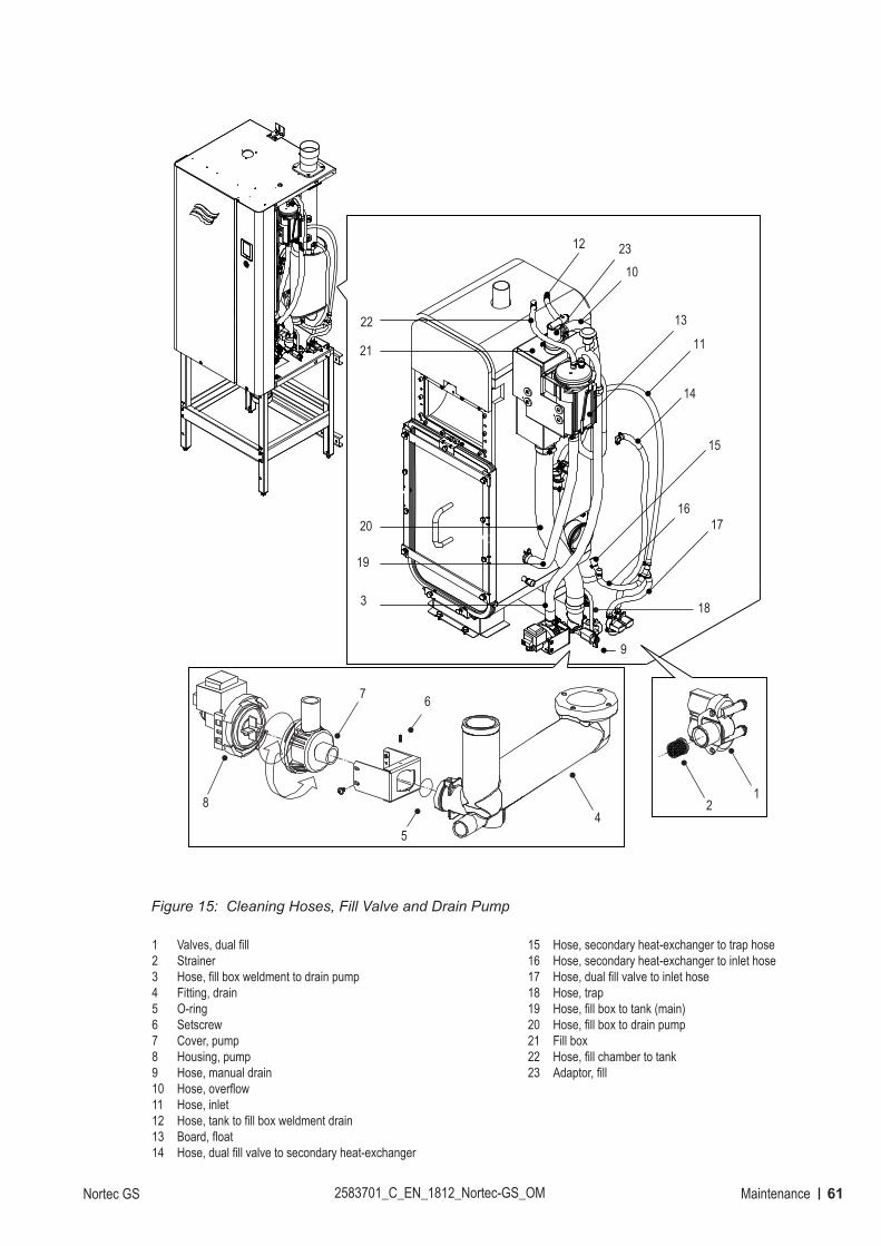
61MaintenanceNortec GS 2583701_C_EN_1812_Nortec-GS_OM
Figure 15:
12
6
8
54
7
3
9
10
11
12
13
14
15
1617
18
19
20
21
22
23
Cleaning Hoses, Fill Valve and Drain Pump
1 Valves, dual fill2 Strainer3 Hose, fill box weldment to drain pump4 Fitting, drain5 O-ring 6 Setscrew7 Cover, pump8 Housing, pump9 Hose, manual drain10 Hose, overflow 11 Hose, inlet12 Hose, tank to fill box weldment drain13 Board, float14 Hose, dual fill valve to secondary heat-exchanger
15 Hose, secondary heat-exchanger to trap hose16 Hose, secondary heat-exchanger to inlet hose17 Hose, dual fill valve to inlet hose18 Hose, trap19 Hose, fill box to tank (main)20 Hose, fill box to drain pump21 Fill box22 Hose, fill chamber to tank23 Adaptor, fill
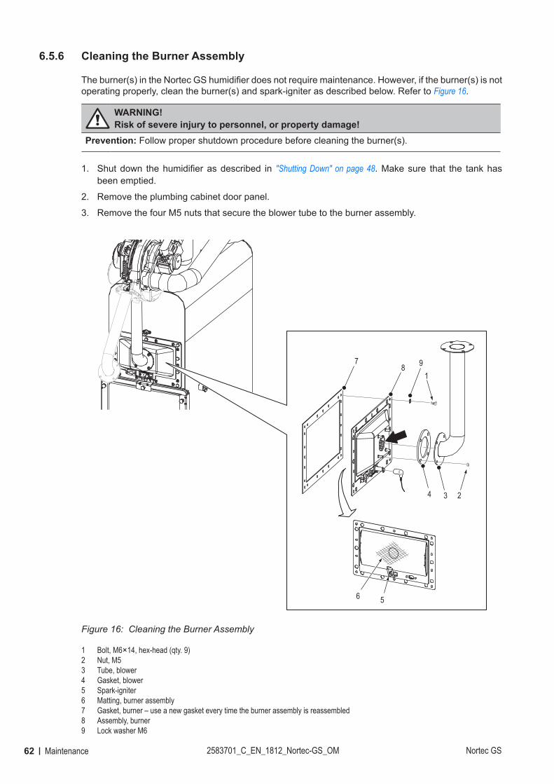
62 Maintenance 2583701_C_EN_1812_Nortec-GS_OM Nortec GS
6.5.6 Cleaning the Burner Assembly
The burner(s) in the Nortec GS humidifier does not require maintenance. However, if the burner(s) is not operating properly, clean the burner(s) and spark-igniter as described below. Refer to Figure 16.
WARNING! Risk of severe injury to personnel, or property damage!
Prevention: Follow proper shutdown procedure before cleaning the burner(s).
1. Shut down the humidifier as described in "Shutting Down" on page 48. Make sure that the tank has been emptied.
2. Remove the plumbing cabinet door panel.
3. Remove the four M5 nuts that secure the blower tube to the burner assembly.
Figure 16:
1
234
56
78 9
Cleaning the Burner Assembly
1 Bolt, M6×14, hex-head (qty. 9)2 Nut, M53 Tube, blower4 Gasket, blower5 Spark-igniter6 Matting, burner assembly7 Gasket, burner – use a new gasket every time the burner assembly is reassembled8 Assembly, burner9 Lock washer M6
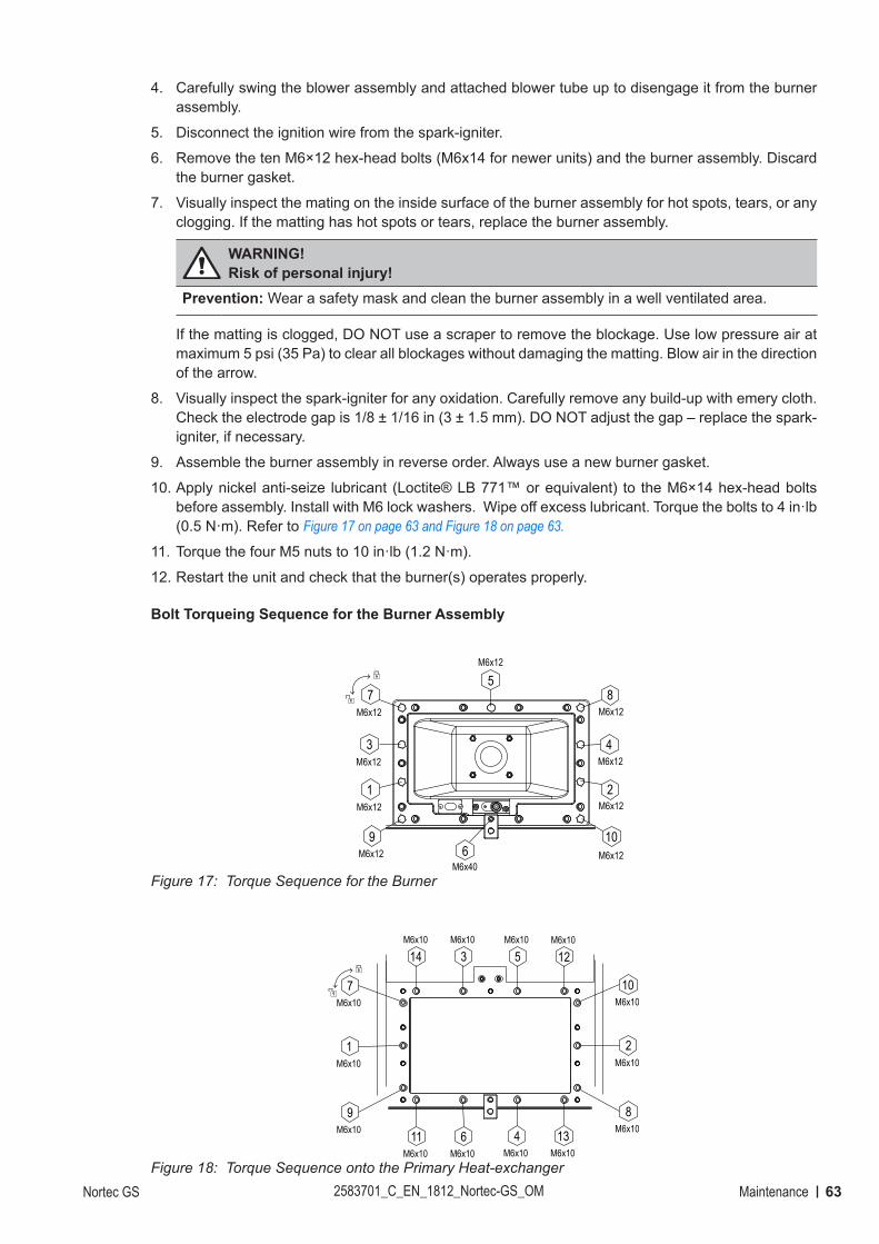
63MaintenanceNortec GS 2583701_C_EN_1812_Nortec-GS_OM
4. Carefully swing the blower assembly and attached blower tube up to disengage it from the burner assembly.
5. Disconnect the ignition wire from the spark-igniter.
6. Remove the ten M6×12 hex-head bolts (M6x14 for newer units) and the burner assembly. Discard the burner gasket.
7. Visually inspect the mating on the inside surface of the burner assembly for hot spots, tears, or any clogging. If the matting has hot spots or tears, replace the burner assembly.
WARNING! Risk of personal injury!
Prevention: Wear a safety mask and clean the burner assembly in a well ventilated area.
If the matting is clogged, DO NOT use a scraper to remove the blockage. Use low pressure air at maximum 5 psi (35 Pa) to clear all blockages without damaging the matting. Blow air in the direction of the arrow.
8. Visually inspect the spark-igniter for any oxidation. Carefully remove any build-up with emery cloth. Check the electrode gap is 1/8 ± 1/16 in (3 ± 1.5 mm). DO NOT adjust the gap – replace the spark-igniter, if necessary.
9. Assemble the burner assembly in reverse order. Always use a new burner gasket.
10. Apply nickel anti-seize lubricant (Loctite® LB 771™ or equivalent) to the M6×14 hex-head bolts before assembly. Install with M6 lock washers. Wipe off excess lubricant. Torque the bolts to 4 in·lb (0.5 N·m). Refer to Figure 17 on page 63 and Figure 18 on page 63.
11. Torque the four M5 nuts to 10 in·lb (1.2 N·m).
12. Restart the unit and check that the burner(s) operates properly.
Bolt Torqueing Sequence for the Burner Assembly
Figure 17:
7M6x12
5M6x12
3M6x12
1M6x12
9M6x12
8M6x12
4M6x12
2M6x12
10M6x126
M6x40Torque Sequence for the Burner
Figure 18:
7M6x10
1M6x10
9M6x10 11
M6x106
M6x104
M6x1013
M6x10
14M6x10
3M6x10
5M6x10
12M6x10
10M6x10
2M6x10
8M6x10
Torque Sequence onto the Primary Heat-exchanger
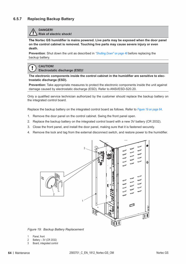
64 Maintenance 2583701_C_EN_1812_Nortec-GS_OM Nortec GS
6.5.7 Replacing Backup Battery
DANGER! Risk of electric shock!
The Nortec GS humidifier is mains powered. Live parts may be exposed when the door panel on the control cabinet is removed. Touching live parts may cause severe injury or even death.Prevention: Shut down the unit as described in "Shutting Down" on page 48 before replacing the backup battery.
CAUTION!Electrostatic discharge (ESD)!
The electronic components inside the control cabinet in the humidifier are sensitive to elec-trostatic discharge (ESD).Prevention: Take appropriate measures to protect the electronic components inside the unit against damage caused by electrostatic discharge (ESD). Refer to ANSI/ESD-S20.20.
Only a qualified service technician authorized by the customer should replace the backup battery on the integrated control board.
Replace the backup battery on the integrated control board as follows. Refer to Figure 19 on page 64.
1. Remove the door panel on the control cabinet. Swing the front panel open.
2. Replace the backup battery on the integrated control board with a new 3V battery (CR 2032).
3. Close the front panel, and install the door panel, making sure that it is fastened securely.
4. Remove the lock and tag from the external disconnect switch, and restore power to the humidifier.
Figure 19:
3
2
1
Backup Battery Replacement
1 Panel, front2 Battery – 3V (CR 2032)3 Board, integrated control
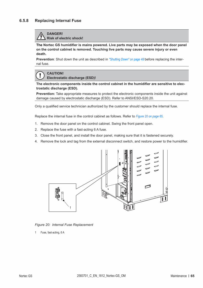
65MaintenanceNortec GS 2583701_C_EN_1812_Nortec-GS_OM
6.5.8 Replacing Internal Fuse
DANGER! Risk of electric shock!
The Nortec GS humidifier is mains powered. Live parts may be exposed when the door panel on the control cabinet is removed. Touching live parts may cause severe injury or even death.Prevention: Shut down the unit as described in "Shutting Down" on page 48 before replacing the inter-nal fuse.
CAUTION!Electrostatic discharge (ESD)!
The electronic components inside the control cabinet in the humidifier are sensitive to elec-trostatic discharge (ESD).Prevention: Take appropriate measures to protect the electronic components inside the unit against damage caused by electrostatic discharge (ESD). Refer to ANSI/ESD-S20.20.
Only a qualified service technician authorized by the customer should replace the internal fuse.
Replace the internal fuse in the control cabinet as follows. Refer to Figure 20 on page 65.
1. Remove the door panel on the control cabinet. Swing the front panel open.
2. Replace the fuse with a fast-acting 6 A fuse.
3. Close the front panel, and install the door panel, making sure that it is fastened securely.
4. Remove the lock and tag from the external disconnect switch, and restore power to the humidifier.
Figure 20:
1
Internal Fuse Replacement
1 Fuse, fast-acting, 6 A
66 Maintenance 2583701_C_EN_1812_Nortec-GS_OM Nortec GS
6.5.9 Resetting Service Reminder
CAUTION! Risk of damage to equipment!
DO NOT reset the service reminder unless the scheduled maintenance has been performed.
Reset the service reminder in the control software as follows after performing the required scheduled maintenance:
1. Select the <Main Menu> button on the Home screen, then enter the password to login. Refer to "Main Menu" on page 24.
2. Select Service > General Service tab > Reset Service Reminder. A reset dialog appears and prompts you to confirm the reset.
3. Select the <Yes> button on the confirmation screen. The maintenance warning and the service reminder messages are reset.Select the <No> button at any time to abort the reset.
6.6 Installing Software Updates
All software updates can be downloaded from the Downloads link on www.humidity.com. Download the file and extract it to a USB memory stick that has been formatted to 32-bit FAT system. The software update file (ending with .bin) should be located at the root level on the USB stick.Note: If software updating is accidentally interrupted, the humidifier will not operate. However, updating can be resumed by leaving the USB key inserted in the board and power cycling the unit. The integrated control board will detect that the software was not installed properly, and restart the updating.Install the updates for the control software as follows:
DANGER! Risk of electric shock!
The Nortec GS is mains powered. Live parts may be exposed when the door panel is re-moved. Touching live parts may cause severe injury or even death.Prevention: Shut down the humidifier properly at the external disconnect switch before accessing the integrated control board in the humidifier.
1. Set the On/Off button to the Off position.
2. Disconnect the power supply to the humidifier at the external disconnect switch. To prevent accidental power-up, lockout and tag out according to the established safety practices at your facility.
3. Remove the door panel on the control cabinet – refer to "Removal and Installation of Access Panels" on page 54.
4. Swing the front panel open.
5. Carefully insert the USB memory stick into the USB port. Make sure that the maximum length of the memory stick does not exceed 3 in (75 mm).
6. Close the front panel, and install the door panel.
7. Remove the lock and tag from the external disconnect switch, and restore power to the humidifier.
8. Set the On/Off button to the On position.
9. When the Home screen appears, select the <MAIN Menu> button, then enter the password to login.
67MaintenanceNortec GS 2583701_C_EN_1812_Nortec-GS_OM
CAUTION!Risk of file corruption!
DO NOT interrupt software updating once it starts. Wait until updating is completed. Corrupted control software can render the humidifier unusable.Note: If software updating is accidentally interrupted, the humidifier will not operate. However, updating can be resumed by leaving the USB key inserted in the board and power cycling the unit. The integrated control board will detect that the software was not installed properly, and restart the updating.
10. Select Administrator > Software Settings tab > Software Update to update the control software. A progress bar shows the status of the updating process. When updating is completed, the Home screen is displayed.
11. Repeat Step 1 to Step 4, and carefully remove the USB memory stick.
12. Close the front panel. Install the door panel, making sure that it is fastened securely – refer to "Removal and Installation of Access Panels" on page 54.
13. Repeat Step 7 and Step 8 to power up the humidifier.
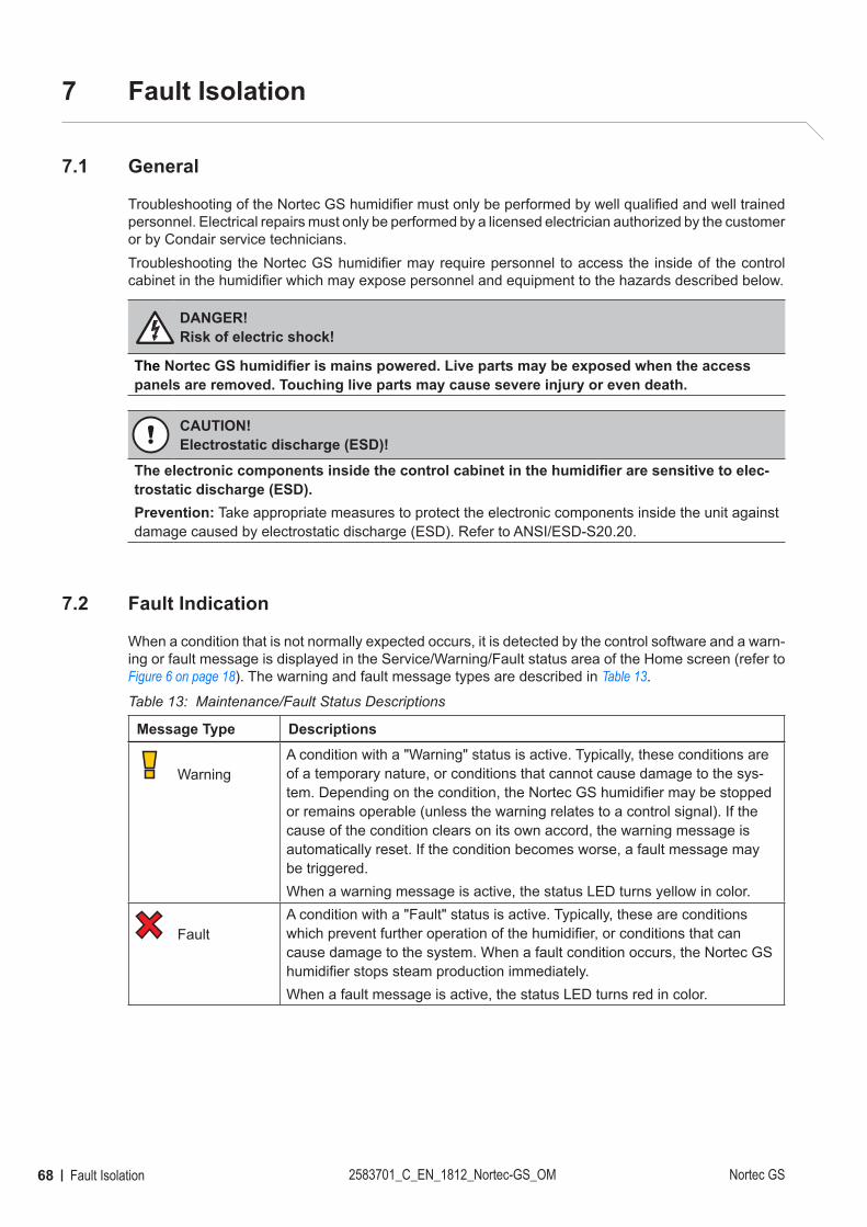
68 Fault Isolation 2583701_C_EN_1812_Nortec-GS_OM Nortec GS
7 Fault Isolation
7.1 General
Troubleshooting of the Nortec GS humidifier must only be performed by well qualified and well trained personnel. Electrical repairs must only be performed by a licensed electrician authorized by the customer or by Condair service technicians.Troubleshooting the Nortec GS humidifier may require personnel to access the inside of the control cabinet in the humidifier which may expose personnel and equipment to the hazards described below.
DANGER! Risk of electric shock!
The Nortec GS humidifier is mains powered. Live parts may be exposed when the access panels are removed. Touching live parts may cause severe injury or even death.
CAUTION!Electrostatic discharge (ESD)!
The electronic components inside the control cabinet in the humidifier are sensitive to elec-trostatic discharge (ESD).Prevention: Take appropriate measures to protect the electronic components inside the unit against damage caused by electrostatic discharge (ESD). Refer to ANSI/ESD-S20.20.
7.2 Fault Indication
When a condition that is not normally expected occurs, it is detected by the control software and a warn-ing or fault message is displayed in the Service/Warning/Fault status area of the Home screen (refer to Figure 6 on page 18). The warning and fault message types are described in Table 13.
Table 13: Maintenance/Fault Status Descriptions
Message Type Descriptions
WarningA condition with a "Warning" status is active. Typically, these conditions are of a temporary nature, or conditions that cannot cause damage to the sys-tem. Depending on the condition, the Nortec GS humidifier may be stopped or remains operable (unless the warning relates to a control signal). If the cause of the condition clears on its own accord, the warning message is automatically reset. If the condition becomes worse, a fault message may be triggered.When a warning message is active, the status LED turns yellow in color.
FaultA condition with a "Fault" status is active. Typically, these are conditions which prevent further operation of the humidifier, or conditions that can cause damage to the system. When a fault condition occurs, the Nortec GS humidifier stops steam production immediately.When a fault message is active, the status LED turns red in color.
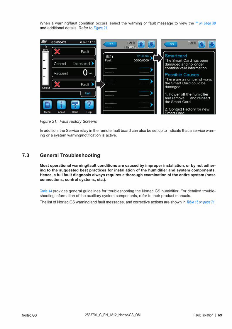
69Fault IsolationNortec GS 2583701_C_EN_1812_Nortec-GS_OM
When a warning/fault condition occurs, select the warning or fault message to view the "" on page 38 and additional details. Refer to Figure 21.
Figure 21: Fault History Screens
In addition, the Service relay in the remote fault board can also be set up to indicate that a service warn-ing or a system warning/notification is active.
7.3 General Troubleshooting
Most operational warning/fault conditions are caused by improper installation, or by not adher-ing to the suggested best practices for installation of the humidifier and system components. Hence, a full fault diagnosis always requires a thorough examination of the entire system (hose connections, control systems, etc.).
Table 14 provides general guidelines for troubleshooting the Nortec GS humidifier. For detailed trouble-shooting information of the auxiliary system components, refer to their product manuals.The list of Nortec GS warning and fault messages, and corrective actions are shown in Table 15 on page 71.
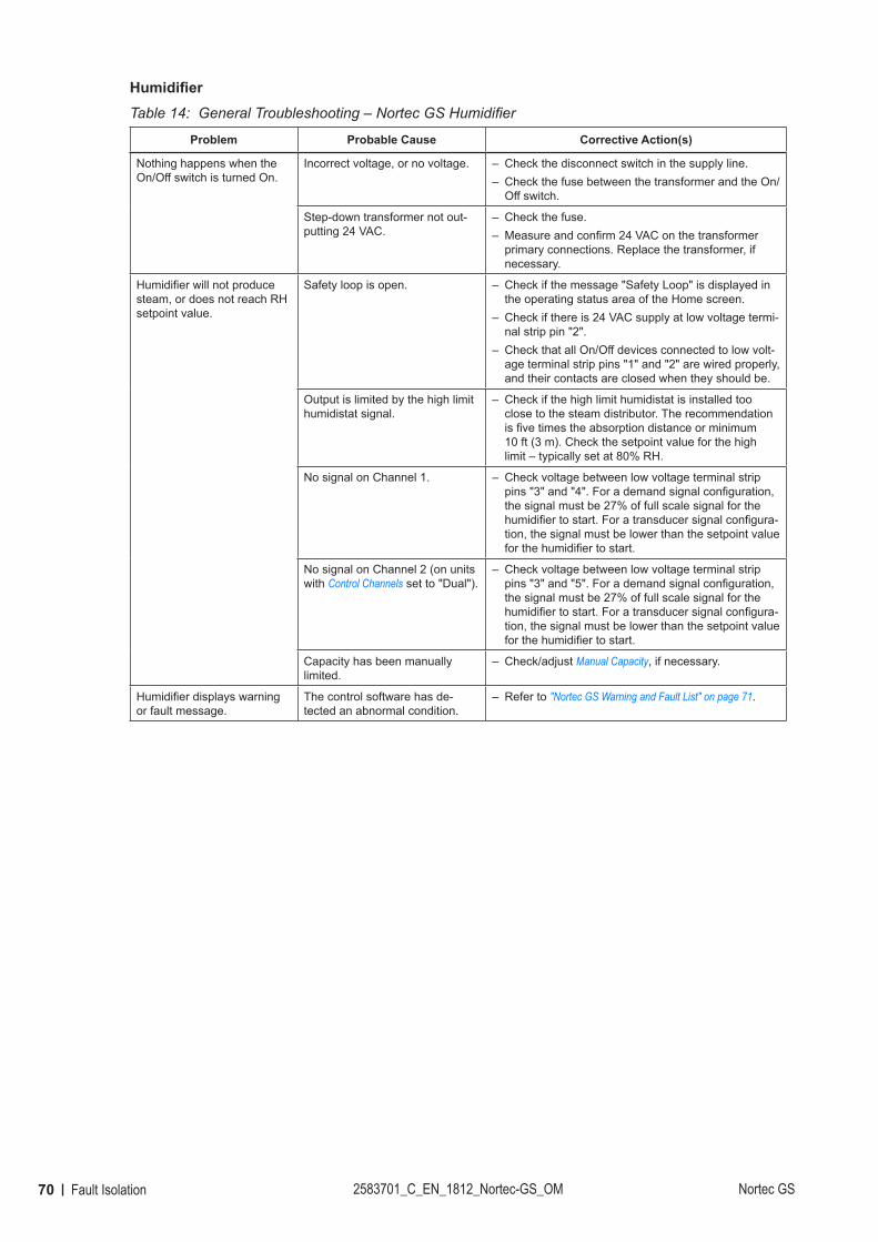
70 Fault Isolation 2583701_C_EN_1812_Nortec-GS_OM Nortec GS
HumidifierTable 14: General Troubleshooting – Nortec GS Humidifier
Problem Probable Cause Corrective Action(s)
Nothing happens when the On/Off switch is turned On.
Incorrect voltage, or no voltage. – Check the disconnect switch in the supply line. – Check the fuse between the transformer and the On/Off switch.
Step-down transformer not out-putting 24 VAC.
– Check the fuse. – Measure and confirm 24 VAC on the transformer primary connections. Replace the transformer, if necessary.
Humidifier will not produce steam, or does not reach RH setpoint value.
Safety loop is open. – Check if the message "Safety Loop" is displayed in the operating status area of the Home screen.
– Check if there is 24 VAC supply at low voltage termi-nal strip pin "2".
– Check that all On/Off devices connected to low volt-age terminal strip pins "1" and "2" are wired properly, and their contacts are closed when they should be.
Output is limited by the high limit humidistat signal.
– Check if the high limit humidistat is installed too close to the steam distributor. The recommendation is five times the absorption distance or minimum 10 ft (3 m). Check the setpoint value for the high limit – typically set at 80% RH.
No signal on Channel 1. – Check voltage between low voltage terminal strip pins "3" and "4". For a demand signal configuration, the signal must be 27% of full scale signal for the humidifier to start. For a transducer signal configura-tion, the signal must be lower than the setpoint value for the humidifier to start.
No signal on Channel 2 (on units with Control Channels set to "Dual").
– Check voltage between low voltage terminal strip pins "3" and "5". For a demand signal configuration, the signal must be 27% of full scale signal for the humidifier to start. For a transducer signal configura-tion, the signal must be lower than the setpoint value for the humidifier to start.
Capacity has been manually limited.
– Check/adjust Manual Capacity, if necessary.
Humidifier displays warning or fault message.
The control software has de-tected an abnormal condition.
– Refer to "Nortec GS Warning and Fault List" on page 71.
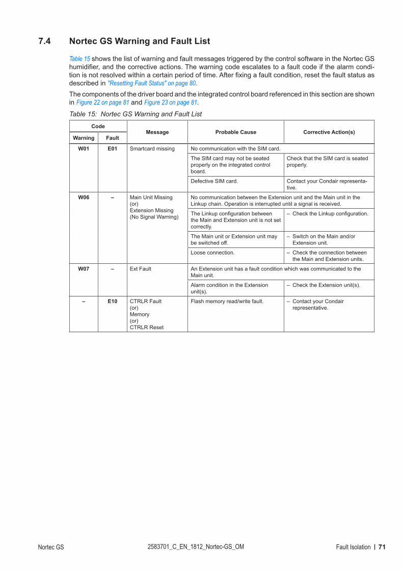
71Fault IsolationNortec GS 2583701_C_EN_1812_Nortec-GS_OM
7.4 Nortec GS Warning and Fault List
Table 15 shows the list of warning and fault messages triggered by the control software in the Nortec GS humidifier, and the corrective actions. The warning code escalates to a fault code if the alarm condi-tion is not resolved within a certain period of time. After fixing a fault condition, reset the fault status as described in "Resetting Fault Status" on page 80.The components of the driver board and the integrated control board referenced in this section are shown in Figure 22 on page 81 and Figure 23 on page 81.
Table 15: Nortec GS Warning and Fault List
CodeMessage Probable Cause Corrective Action(s)
Warning Fault
W01 E01 Smartcard missing No communication with the SIM card.
The SIM card may not be seated properly on the integrated control board.
Check that the SIM card is seated properly.
Defective SIM card. Contact your Condair representa-tive.
W06 – Main Unit Missing (or)Extension Missing(No Signal Warning)
No communication between the Extension unit and the Main unit in the Linkup chain. Operation is interrupted until a signal is received.
The Linkup configuration between the Main and Extension unit is not set correctly.
– Check the Linkup configuration.
The Main unit or Extension unit may be switched off.
– Switch on the Main and/or Extension unit.
Loose connection. – Check the connection between the Main and Extension units.
W07 – Ext Fault An Extension unit has a fault condition which was communicated to theMain unit.
Alarm condition in the Extensionunit(s).
– Check the Extension unit(s).
– E10 CTRLR Fault(or)Memory(or)CTRLR Reset
Flash memory read/write fault. – Contact your Condair representative.
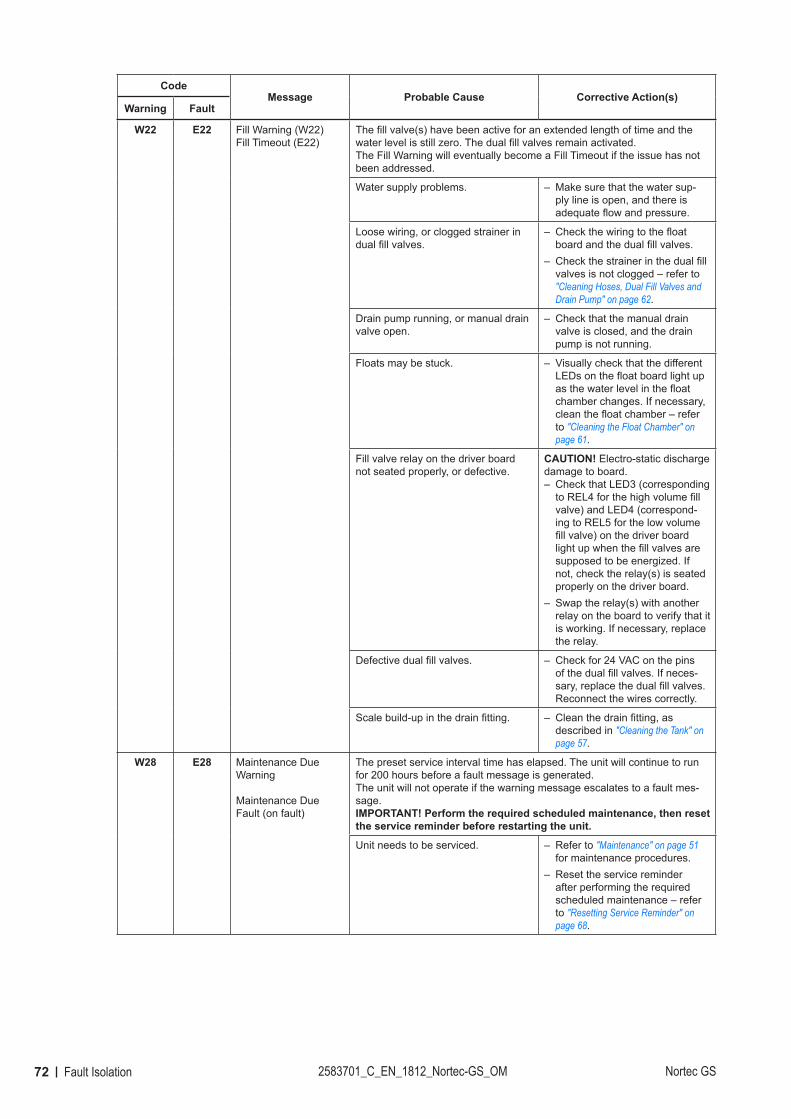
72 Fault Isolation 2583701_C_EN_1812_Nortec-GS_OM Nortec GS
CodeMessage Probable Cause Corrective Action(s)
Warning Fault
W22 E22 Fill Warning (W22)Fill Timeout (E22)
The fill valve(s) have been active for an extended length of time and the water level is still zero. The dual fill valves remain activated.The Fill Warning will eventually become a Fill Timeout if the issue has not been addressed.
Water supply problems. – Make sure that the water sup-ply line is open, and there is adequate flow and pressure.
Loose wiring, or clogged strainer in dual fill valves.
– Check the wiring to the float board and the dual fill valves.
– Check the strainer in the dual fill valves is not clogged – refer to "Cleaning Hoses, Dual Fill Valves and Drain Pump" on page 62.
Drain pump running, or manual drain valve open.
– Check that the manual drain valve is closed, and the drain pump is not running.
Floats may be stuck. – Visually check that the different LEDs on the float board light up as the water level in the float chamber changes. If necessary, clean the float chamber – refer to "Cleaning the Float Chamber" on page 61.
Fill valve relay on the driver board not seated properly, or defective.
CAUTION! Electro-static discharge damage to board.
– Check that LED3 (corresponding to REL4 for the high volume fill valve) and LED4 (correspond-ing to REL5 for the low volume fill valve) on the driver board light up when the fill valves are supposed to be energized. If not, check the relay(s) is seated properly on the driver board.
– Swap the relay(s) with another relay on the board to verify that it is working. If necessary, replace the relay.
Defective dual fill valves. – Check for 24 VAC on the pins of the dual fill valves. If neces-sary, replace the dual fill valves. Reconnect the wires correctly.
Scale build-up in the drain fitting. – Clean the drain fitting, as described in "Cleaning the Tank" on page 57.
W28 E28 Maintenance Due Warning
Maintenance Due Fault (on fault)
The preset service interval time has elapsed. The unit will continue to run for 200 hours before a fault message is generated.The unit will not operate if the warning message escalates to a fault mes-sage. IMPORTANT! Perform the required scheduled maintenance, then reset the service reminder before restarting the unit.
Unit needs to be serviced. – Refer to "Maintenance" on page 51 for maintenance procedures.
– Reset the service reminder after performing the required scheduled maintenance – refer to "Resetting Service Reminder" on page 68.

73Fault IsolationNortec GS 2583701_C_EN_1812_Nortec-GS_OM
CodeMessage Probable Cause Corrective Action(s)
Warning Fault
W32 – RH Signal The RH input is less than 3%. Operation is interrupted until an input higher than 3% is received.
Loose wiring, faulty sensor. – Check the connection between the sensor and the unit.
– Swap the sensor with another sensor and verify that it is work-ing. If necessary, replace the sensor.
Layout of the humidifier control sys-tem may be causing signal interfer-ence.
– Check that the controls layout permits accurate readings.
W34 – Remote Disabled The unit has been disabled remotely by the building management system (BMS) through Modbus communication. Operation is interrupted until the unit is enabled again through Modbus or the control software.
Unit disabled through the BMS. – Enable the unit through the BMS.
– If unit cannot be enabled remotely, try enabling the unit through the Modbus setting in the control software.
W35 – BMS T/O (timeout) The maximum wait time without any communications from the BMS hasbeen exceeded. If the signal Source is set to "Analog", the humidifier willcontinue operating; otherwise it stops producing steam until communica-tions with the BMS is re-established.
W42 – RH High Warning Sensed humidity is above the RH High value configured in the control soft-ware. The unit will remain idle until the sensed RH value drops below the setpoint value.
Incorrect layout of the humidifier control system (sensor location too close to steam distributor or other sources that affect measurement), or defective components.
– Check the humidifier control system.
Humidifier capacity too large for the space being humidified.
– Limit the output capacity of the humidifier – refer to Manual Capacity.
– Adjust the proportional and/or integral value of the controller.
The RH High value for the sensor signal may be set too low.
– Adjust the RH High value for the sensor signal.
W43 – RH Low Warning Sensed humidity is below the minimum value configured in the control soft-ware. The unit should continue operating unless it is in standby mode.
Incorrect layout of the humidifier control system (sensor location too close to steam distributor or other sources that affect measurement), or defective components.
– Check the humidifier control system.
The RH Low value for the sensor signal may be set too high.
– Adjust the RH Low value for the sensor signal.
Unit may be in standby mode. – Check the safety loop is closed, and that all burners are operational.
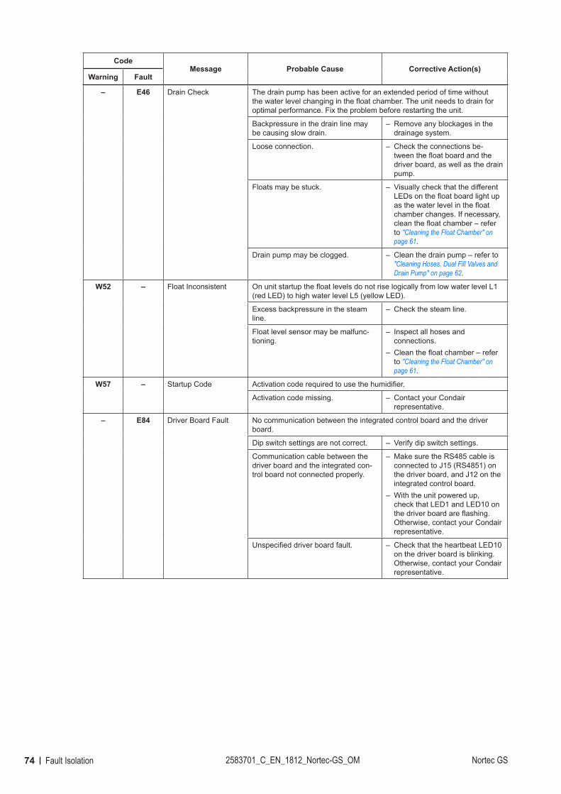
74 Fault Isolation 2583701_C_EN_1812_Nortec-GS_OM Nortec GS
CodeMessage Probable Cause Corrective Action(s)
Warning Fault
– E46 Drain Check The drain pump has been active for an extended period of time without the water level changing in the float chamber. The unit needs to drain for optimal performance. Fix the problem before restarting the unit.
Backpressure in the drain line may be causing slow drain.
– Remove any blockages in the drainage system.
Loose connection. – Check the connections be-tween the float board and the driver board, as well as the drain pump.
Floats may be stuck. – Visually check that the different LEDs on the float board light up as the water level in the float chamber changes. If necessary, clean the float chamber – refer to "Cleaning the Float Chamber" on page 61.
Drain pump may be clogged. – Clean the drain pump – refer to "Cleaning Hoses, Dual Fill Valves and Drain Pump" on page 62.
W52 – Float Inconsistent On unit startup the float levels do not rise logically from low water level L1 (red LED) to high water level L5 (yellow LED).
Excess backpressure in the steam line.
– Check the steam line.
Float level sensor may be malfunc-tioning.
– Inspect all hoses and connections.
– Clean the float chamber – refer to "Cleaning the Float Chamber" on page 61.
W57 – Startup Code Activation code required to use the humidifier.
Activation code missing. – Contact your Condair representative.
– E84 Driver Board Fault No communication between the integrated control board and the driver board.
Dip switch settings are not correct. – Verify dip switch settings.
Communication cable between the driver board and the integrated con-trol board not connected properly.
– Make sure the RS485 cable is connected to J15 (RS4851) on the driver board, and J12 on the integrated control board.
– With the unit powered up, check that LED1 and LED10 on the driver board are flashing. Otherwise, contact your Condair representative.
Unspecified driver board fault. – Check that the heartbeat LED10 on the driver board is blinking. Otherwise, contact your Condair representative.
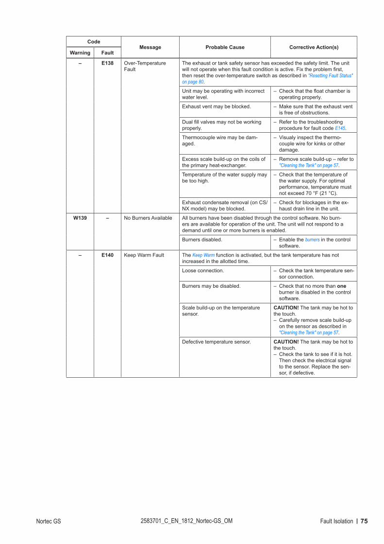
75Fault IsolationNortec GS 2583701_C_EN_1812_Nortec-GS_OM
CodeMessage Probable Cause Corrective Action(s)
Warning Fault
– E138 Over-Temperature Fault
The exhaust or tank safety sensor has exceeded the safety limit. The unit will not operate when this fault condition is active. Fix the problem first, then reset the over-temperature switch as described in "Resetting Fault Status" on page 80.
Unit may be operating with incorrect water level.
– Check that the float chamber is operating properly.
Exhaust vent may be blocked. – Make sure that the exhaust vent is free of obstructions.
Dual fill valves may not be working properly.
– Refer to the troubleshooting procedure for fault code E145.
Thermocouple wire may be dam-aged.
– Visualy inspect the thermo-couple wire for kinks or other damage.
Excess scale build-up on the coils of the primary heat-exchanger.
– Remove scale build-up – refer to "Cleaning the Tank" on page 57.
Temperature of the water supply may be too high.
– Check that the temperature of the water supply. For optimal performance, temperature must not exceed 70 °F (21 °C).
Exhaust condensate removal (on CS/NX model) may be blocked.
– Check for blockages in the ex-haust drain line in the unit.
W139 – No Burners Available All burners have been disabled through the control software. No burn-ers are available for operation of the unit. The unit will not respond to a demand until one or more burners is enabled.
Burners disabled. – Enable the burners in the control software.
– E140 Keep Warm Fault The Keep Warm function is activated, but the tank temperature has not increased in the allotted time.
Loose connection. – Check the tank temperature sen-sor connection.
Burners may be disabled. – Check that no more than one burner is disabled in the control software.
Scale build-up on the temperature sensor.
CAUTION! The tank may be hot to the touch.
– Carefully remove scale build-up on the sensor as described in "Cleaning the Tank" on page 57.
Defective temperature sensor. CAUTION! The tank may be hot to the touch.
– Check the tank to see if it is hot. Then check the electrical signal to the sensor. Replace the sen-sor, if defective.
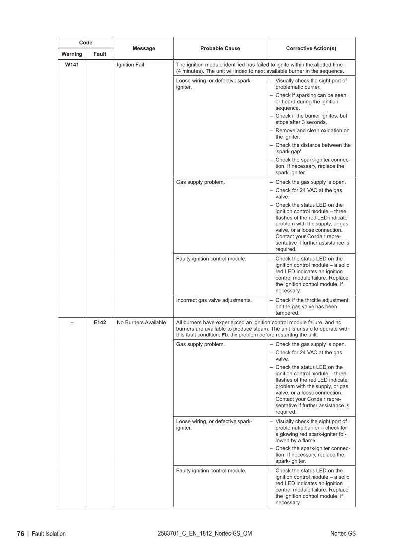
76 Fault Isolation 2583701_C_EN_1812_Nortec-GS_OM Nortec GS
CodeMessage Probable Cause Corrective Action(s)
Warning Fault
W141 Ignition Fail The ignition module identified has failed to ignite within the allotted time (4 minutes). The unit will index to next available burner in the sequence.
Loose wiring, or defective spark-igniter.
– Visually check the sight port of problematic burner.
– Check if sparking can be seen or heard during the ignition sequence.
– Check if the burner ignites, but stops after 3 seconds.
– Remove and clean oxidation on the igniter.
– Check the distance between the 'spark gap'.
– Check the spark-igniter connec-tion. If necessary, replace the spark-igniter.
Gas supply problem. – Check the gas supply is open. – Check for 24 VAC at the gas valve.
– Check the status LED on the ignition control module – three flashes of the red LED indicate problem with the supply, or gas valve, or a loose connection. Contact your Condair repre-sentative if further assistance is required.
Faulty ignition control module. – Check the status LED on the ignition control module – a solid red LED indicates an ignition control module failure. Replace the ignition control module, if necessary.
Incorrect gas valve adjustments. – Check if the throttle adjustment on the gas valve has been tampered.
– E142 No Burners Available All burners have experienced an ignition control module failure, and no burners are available to produce steam. The unit is unsafe to operate with this fault condition. Fix the problem before restarting the unit.
Gas supply problem. – Check the gas supply is open. – Check for 24 VAC at the gas valve.
– Check the status LED on the ignition control module – three flashes of the red LED indicate problem with the supply, or gas valve, or a loose connection. Contact your Condair repre-sentative if further assistance is required.
Loose wiring, or defective spark-igniter.
– Visually check the sight port of problematic burner – check for a glowing red spark-igniter fol-lowed by a flame.
– Check the spark-igniter connec-tion. If necessary, replace the spark-igniter.
Faulty ignition control module. – Check the status LED on the ignition control module – a solid red LED indicates an ignition control module failure. Replace the ignition control module, if necessary.
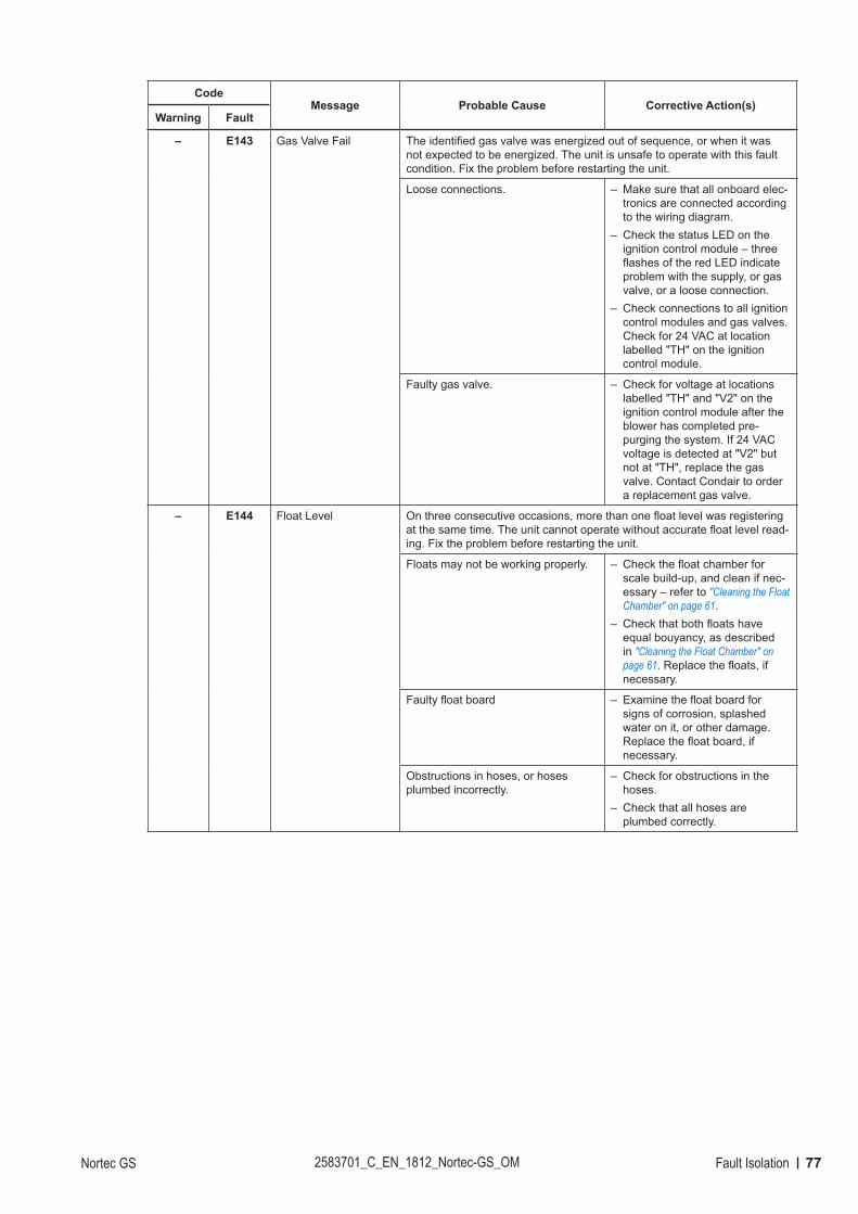
77Fault IsolationNortec GS 2583701_C_EN_1812_Nortec-GS_OM
CodeMessage Probable Cause Corrective Action(s)
Warning Fault
– E143 Gas Valve Fail The identified gas valve was energized out of sequence, or when it was not expected to be energized. The unit is unsafe to operate with this fault condition. Fix the problem before restarting the unit.
Loose connections. – Make sure that all onboard elec-tronics are connected according to the wiring diagram.
– Check the status LED on the ignition control module – three flashes of the red LED indicate problem with the supply, or gas valve, or a loose connection.
– Check connections to all ignition control modules and gas valves. Check for 24 VAC at location labelled "TH" on the ignition control module.
Faulty gas valve. – Check for voltage at locations labelled "TH" and "V2" on the ignition control module after the blower has completed pre-purging the system. If 24 VAC voltage is detected at "V2" but not at "TH", replace the gas valve. Contact Condair to order a replacement gas valve.
– E144 Float Level On three consecutive occasions, more than one float level was registering at the same time. The unit cannot operate without accurate float level read-ing. Fix the problem before restarting the unit.
Floats may not be working properly. – Check the float chamber for scale build-up, and clean if nec-essary – refer to "Cleaning the Float Chamber" on page 61.
– Check that both floats have equal bouyancy, as described in "Cleaning the Float Chamber" on page 61. Replace the floats, if necessary.
Faulty float board – Examine the float board for signs of corrosion, splashed water on it, or other damage. Replace the float board, if necessary.
Obstructions in hoses, or hoses plumbed incorrectly.
– Check for obstructions in the hoses.
– Check that all hoses are plumbed correctly.
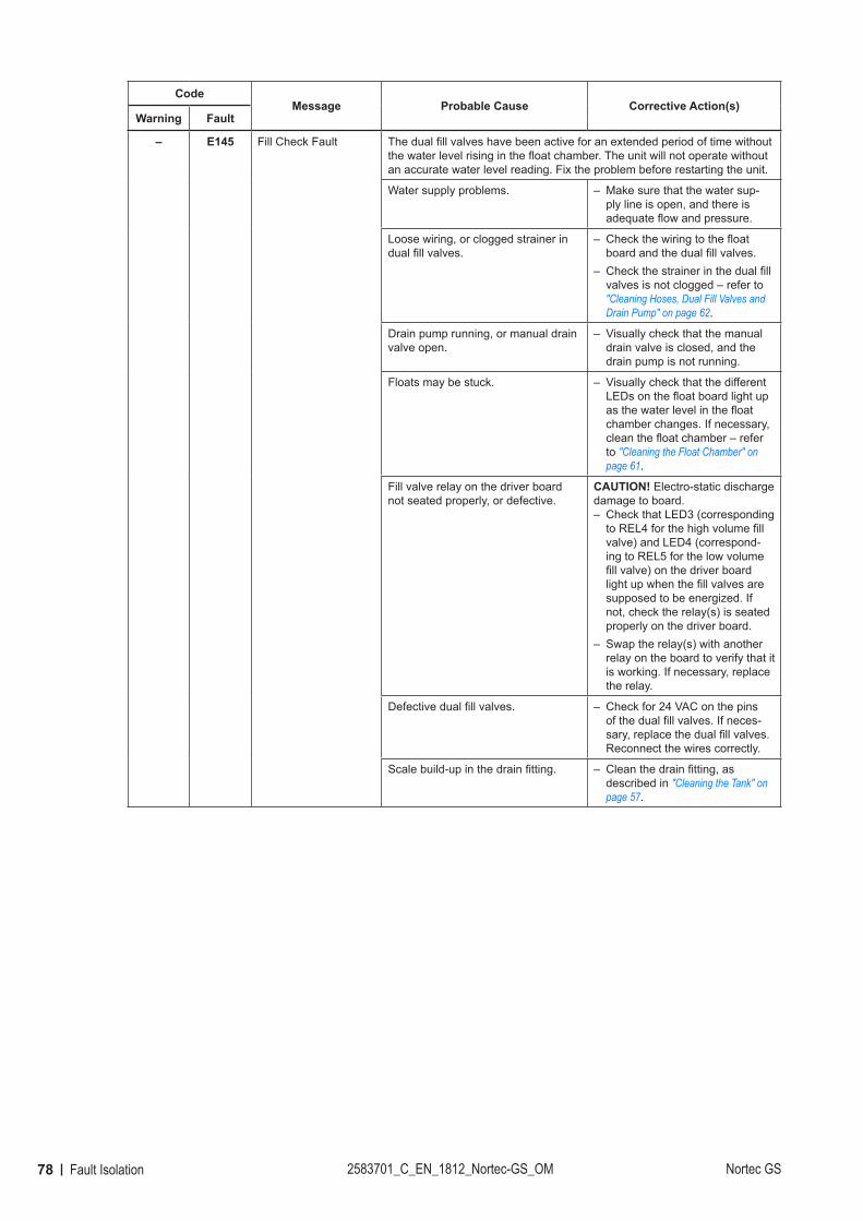
78 Fault Isolation 2583701_C_EN_1812_Nortec-GS_OM Nortec GS
CodeMessage Probable Cause Corrective Action(s)
Warning Fault
– E145 Fill Check Fault The dual fill valves have been active for an extended period of time without the water level rising in the float chamber. The unit will not operate without an accurate water level reading. Fix the problem before restarting the unit.
Water supply problems. – Make sure that the water sup-ply line is open, and there is adequate flow and pressure.
Loose wiring, or clogged strainer in dual fill valves.
– Check the wiring to the float board and the dual fill valves.
– Check the strainer in the dual fill valves is not clogged – refer to "Cleaning Hoses, Dual Fill Valves and Drain Pump" on page 62.
Drain pump running, or manual drain valve open.
– Visually check that the manual drain valve is closed, and the drain pump is not running.
Floats may be stuck. – Visually check that the different LEDs on the float board light up as the water level in the float chamber changes. If necessary, clean the float chamber – refer to "Cleaning the Float Chamber" on page 61.
Fill valve relay on the driver board not seated properly, or defective.
CAUTION! Electro-static discharge damage to board.
– Check that LED3 (corresponding to REL4 for the high volume fill valve) and LED4 (correspond-ing to REL5 for the low volume fill valve) on the driver board light up when the fill valves are supposed to be energized. If not, check the relay(s) is seated properly on the driver board.
– Swap the relay(s) with another relay on the board to verify that it is working. If necessary, replace the relay.
Defective dual fill valves. – Check for 24 VAC on the pins of the dual fill valves. If neces-sary, replace the dual fill valves. Reconnect the wires correctly.
Scale build-up in the drain fitting. – Clean the drain fitting, as described in "Cleaning the Tank" on page 57.
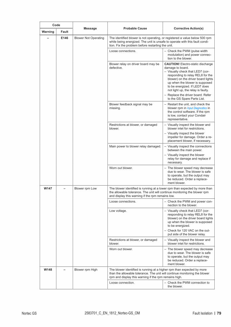
79Fault IsolationNortec GS 2583701_C_EN_1812_Nortec-GS_OM
CodeMessage Probable Cause Corrective Action(s)
Warning Fault
– E146 Blower Not Operating The identified blower is not operating, or registered a value below 500 rpm while being energized. The unit is unsafe to operate with this fault condi-tion. Fix the problem before restarting the unit.
Loose connections. – Check the PWM (pulse width modulation) and power connec-tion to the blower.
Blower relay on driver board may be defective.
CAUTION! Electro-static discharge damage to board.
– Visually check that LED7 (cor-responding to relay REL8 for the blower) on the driver board lights up when the blower is supposed to be energized. If LED7 does not light up, the relay is faulty.
– Replace the driver board. Refer to the GS Spare Parts List.
Blower feedback signal may be missing.
– Restart the unit, and check the blower rpm in Input Diagnostics in the control software. If the rpm is low, contact your Condair representative.
Restrictions at blower, or damaged blower.
– Visually inspect the blower and blower inlet for restrictions.
– Visually inspect the blower impeller for damage. Order a re-placement blower, if necessary.
Main power to blower relay damaged. – Visually inspect the connections between the main power.
– Visually inspect the blower relay for damage and replace if necessary.
Worn out blower. – The blower speed may decrease due to wear. The blower is safe to operate, but the output may be reduced. Order a replace-ment blower.
W147 – Blower rpm Low The blower identified is running at a lower rpm than expected by more than the allowable tolerance. The unit will continue monitoring the blower rpm and display this warning if the rpm remains low.
Loose connections. – Check the PWM and power con-nection to the blower.
Low voltage. – Visually check that LED7 (cor-responding to relay REL8 for the blower) on the driver board lights up when the blower is supposed to be energized.
– Check for 120 VAC on the out-put side of the blower relay.
Restrictions at blower, or damaged blower.
– Visually inspect the blower and blower inlet for restrictions.
Worn out blower. – The blower speed may decrease due to wear. The blower is safe to operate, but the output may be reduced. Order a replace-ment blower.
W148 – Blower rpm High The blower identified is running at a higher rpm than expected by more than the allowable tolerance. The unit will continue monitoring the blower rpm and display this warning if the rpm remains high.
Loose connection. – Check the PWM connection to the blower.
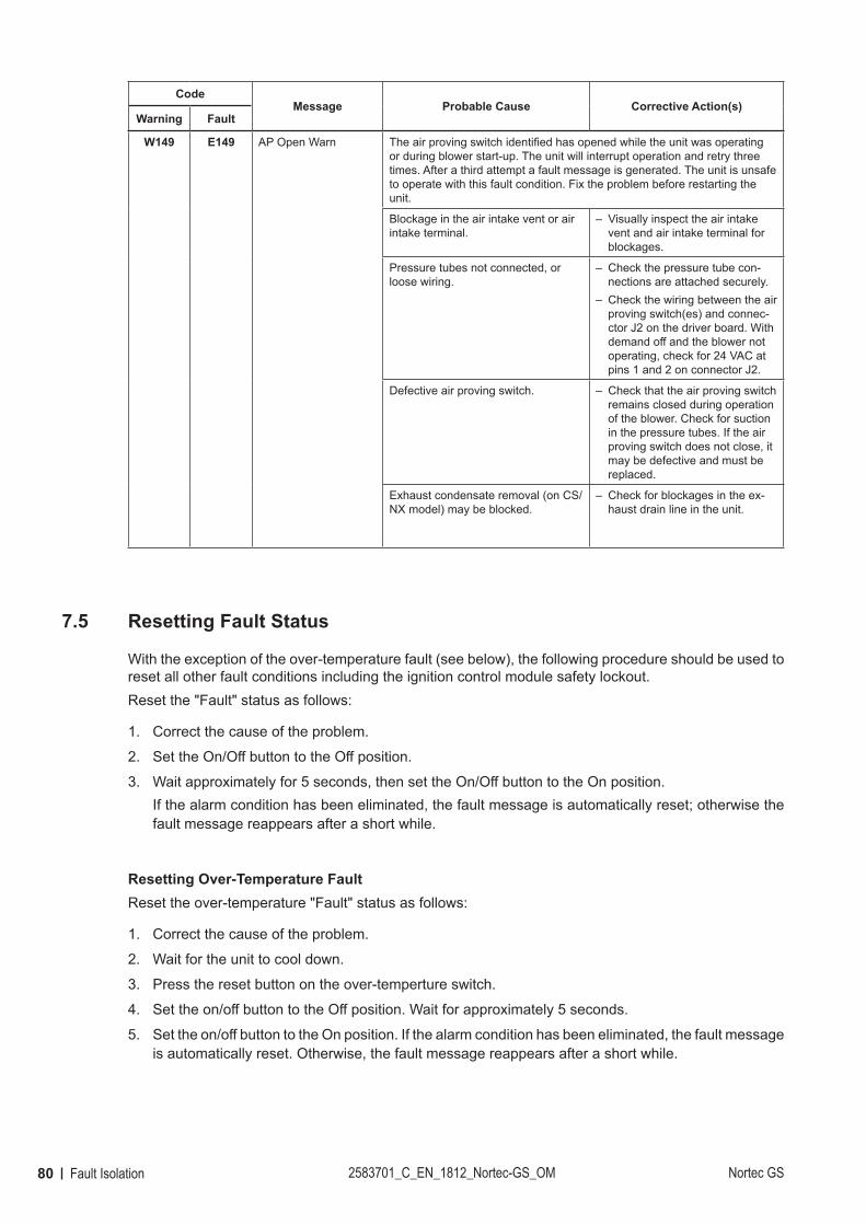
80 Fault Isolation 2583701_C_EN_1812_Nortec-GS_OM Nortec GS
CodeMessage Probable Cause Corrective Action(s)
Warning Fault
W149 E149 AP Open Warn The air proving switch identified has opened while the unit was operating or during blower start-up. The unit will interrupt operation and retry three times. After a third attempt a fault message is generated. The unit is unsafe to operate with this fault condition. Fix the problem before restarting the unit.
Blockage in the air intake vent or air intake terminal.
– Visually inspect the air intake vent and air intake terminal for blockages.
Pressure tubes not connected, or loose wiring.
– Check the pressure tube con-nections are attached securely.
– Check the wiring between the air proving switch(es) and connec-ctor J2 on the driver board. With demand off and the blower not operating, check for 24 VAC at pins 1 and 2 on connector J2.
Defective air proving switch. – Check that the air proving switch remains closed during operation of the blower. Check for suction in the pressure tubes. If the air proving switch does not close, it may be defective and must be replaced.
Exhaust condensate removal (on CS/NX model) may be blocked.
– Check for blockages in the ex-haust drain line in the unit.
7.5 Resetting Fault Status
With the exception of the over-temperature fault (see below), the following procedure should be used to reset all other fault conditions including the ignition control module safety lockout. Reset the "Fault" status as follows:
1. Correct the cause of the problem.
2. Set the On/Off button to the Off position.
3. Wait approximately for 5 seconds, then set the On/Off button to the On position.If the alarm condition has been eliminated, the fault message is automatically reset; otherwise the fault message reappears after a short while.
Resetting Over-Temperature FaultReset the over-temperature "Fault" status as follows:
1. Correct the cause of the problem.
2. Wait for the unit to cool down.
3. Press the reset button on the over-temperture switch.
4. Set the on/off button to the Off position. Wait for approximately 5 seconds.
5. Set the on/off button to the On position. If the alarm condition has been eliminated, the fault message is automatically reset. Otherwise, the fault message reappears after a short while.
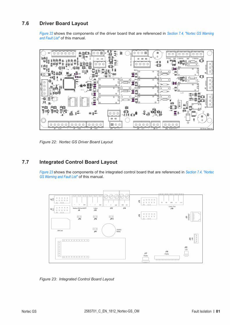
81Fault IsolationNortec GS 2583701_C_EN_1812_Nortec-GS_OM
7.6 Driver Board Layout
Figure 22 shows the components of the driver board that are referenced in Section 7.4, "Nortec GS Warning and Fault List" of this manual.
Figure 22:
GS Driver 2580143
LE
D12
LE
D11
LED9
LED8
LED7
LED6
LE
D5
LE
D4
LE
D3
LED2
R98
RE
L4
C82C81
R96
R95
R97
R94
C77
REL1
Fc
Fb
Fa
U8
R82
C74
C73
C72C7
1
C51
J9 NTCJ1 FLOAT J7 PWM1 J8 PWM2
REL3
REL8
REL2
REL7R
EL
5
REL10
REL9
R59
U3
U7 U9
J11
C54
C2 C3C4
C5
C6
C7
C8
C10
C11
C12
C13
C14
C15
C16
C18
C19
C20
C21
C22
C2
3
C2
4
C25
C26
C27
C28
C29
C30
C31C32
C33
C34
C35
C36
C37C38
C39
C40
C41C42
C43
C44
C45
C46
C47
C48
C49
C50
C52
C53
C55
C57
C58
C59
C61
C62
C64
C65
C66
C67
C68
C69
C70
D4
D8
D9
D17
D19
D20
D22
D23
D24
D25
D28D29
D30
D31
D32
D40
D41D42
D43
D44
J4
JP1
JP2
L2
LED1
R1 R2
R3
R5
R6
R7
R8
R9
R11
R12
R13
R14
R15
R16
R18
R19
R20
R21
R22
R23
R24
R25
R26
R27
R29R30
R31
R33
R34
R35
R37R38
R39R40
R4
1
R4
2
R43
R44
R4
5
R4
6
R47
R48
R49R50
R51
R52
R53
R54
R55
R60
R61
R62
R63
R64 R65
R66
R67
R68
R69 R71
R72
R73
R74
R75
R76
R77
R78
R85
R86
S1
T1T2
TP1
TP2
TP3
TP5
TP6
TP7
TP8
TP9
TP10
TP11
TP12
TP13
TP14
TP15
TP16
TP17
TP18
TP19TP20
TP21
TP22
TP23
TP
24
TP25
TP27TP28
TP29
TP30
TP32
TP33
U1
U2
U4
U5
U6
U10
XT1
ZD2 ZD3 ZD4
C9
C17
D18
R10R17
TP4
R56
LED10R32
C75
C76
J3
DIG
I_IN
PU
TS
J12 POWER SUPPLYJ17 FILL_1_2_3
R87 R88
R89
R90
R91
R92
U12
U13U14
D53
R93
U11
C78
C79
C80
D10
D1D2 D3
D5
D6
D7
D11
D12
D13
D15
D16
D36
D37
D38
D39
D46
D47
D48
D49
D50
D51
D52
L1
RE
L6
L3
C83
EXT1
10V 24V
12
3
1 5 1 4 1 4 1 5
62
1 4 1 1 42
J2
A/P
SW
ITC
H
13
J5
IGN
ITIO
N1
13
J6
IGN
ITIO
N2
13
J16RS485-2
13
J15RS485-1
13
J1324Vout
12
J14
PM
P_F
RE
_D
RN
_B
LO
WE
R
17
28
15
26
J10
6 1
J18
EX
T1
14
Nortec GS Driver Board Layout
7.7 Integrated Control Board Layout
Figure 23 shows the components of the integrated control board that are referenced in Section 7.4, "Nortec GS Warning and Fault List" of this manual.
Figure 23:
J2
RF
B
J3
AC
C.
GND+– GND+–
SIM Card
JP4 JP8
JP7 Battery
CR2032
JP11
GND+–
J12
GND 24 V
J14
J15
J16
J17
Display
J18
Display
J22
LED
J23
US
B
J21
ET
HE
RN
ET
GND 5 V 3.3 VRDTD
Comm. Port
J19Linkup
J10
Modbus/ BACnet MSTP
J6
Integrated Control Board Layout
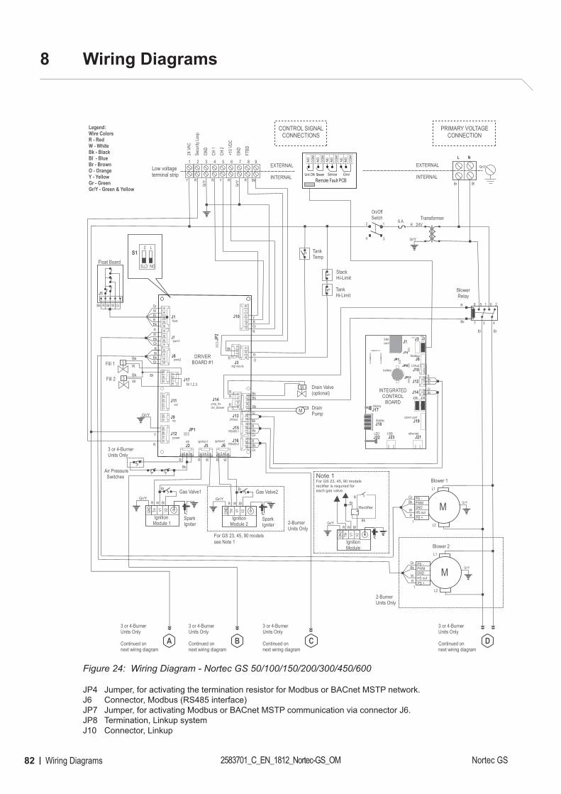
82 Wiring Diagrams 2583701_C_EN_1812_Nortec-GS_OM Nortec GS
8 Wiring Diagrams
Figure 24:
R6 A
DrainPump
Fill 1
StackHi-Limit
R
Bk
Float Board
J1
Br BlR R Bk
BlowerRelay
7
8
3 4
5 1 6 2
NLEXTERNAL
INTERNAL
Transformer24V
On/OffSwitch
12
34 Gr/Y
S
Legend:Wire ColorsR - RedW - WhiteBk - BlackBl - BlueBr - BrownO - OrangeY - YellowGr - GreenGr/Y - Green & Yellow
L1
L2
Blower 1
MPWMPS -
PS +
GNDHS out
1RW
BkGr
L1
L2
Blower 2
MPWMPS -
PS +
GNDHS out
1RW
BkGr
Bl Br
Bk
BkGr
BkW
Air Pressure Switches
Gas Valve1
GND
TH V2V1
Ignition Module 1
GND
TH V2V1
IgnitionModule 2
WR
SparkIgniter
SparkIgniter
WR
R
WR GrBrBk
S
S
Y R
Gr/Y
24 V
AC
Secu
rity Lo
op
GND
GND
FTBD
CH 1
CH 2
+10 V
DC
1 2 3 4 5 6 7 8 9
R
R
R
Y
Y
Gr
Fill 2
TankHi-Limit
OR
TankTemp
Bk
R
Bk
Bk
Bk
GrBkR
GrBk
GrBkR
CONTROL SIGNALCONNECTIONS
PRIMARY VOLTAGECONNECTION
EXTERNAL
INTERNAL
W BlR W Bl
MBk
M Drain Valve(optional)Bk
Gas Valve2
2-BurnerUnits Only
Bk
2-BurnerUnits Only
COM
Remote Fault PCB
NONC
SteamUnit ON ErrorService
COM
NONCCOM
NOCOM
NO
Low voltageterminal strip
BkR
3 or 4-BurnerUnits Only
Continued onnext wiring diagram
DC
3 or 4-BurnerUnits Only
Continued onnext wiring diagram
3 or 4-BurnerUnits Only
Continued onnext wiring diagram
A
3 or 4-BurnerUnits Only
Continued onnext wiring diagram
B
Gr/Y
Gr
Gr
Gr/Y Gr/YGr/Y
Gr/Y
W
12
ON CTS
S1
3 or 4-BurnerUnits Only
Gr/Y
Br Br
W
R
Gr
Br
WR
Gr
R Bk
R
R
R
R
Y
Gr/Y
R
J2 J5
J15
J16
J14
J1 J10
J3
J7
J8
J17
J11
J9
J12
J6
J13
float
pwm1
pwm2
fill 1,2,3
ext
ntc
powera/p ignition1 ignition2
RS485-2
RS485-1
24Vout
pmp_fredrn_blower
digi inputs
DRIVER BOARD #1
R
JP1
JP2
Bl
ethernetUSB
comm port
RFBACC
J22LED
J18display
J17display
U UU U
J15
J1 J2J3
J6
J12
J10
J14
J19
J23 J21
J16
INTEGRATEDCONTROL
BOARD
Modbus
Linkupbattery
SIMcard
JP11
JP8
JP7
JP4
GND
TH V2V1
IgnitionModule
W Bl
+ _
BrR
Rectifier
Note 1For GS 23, 45, 90 models rectifier is required for each gas valve.
For GS 23, 45, 90 models see Note 1
Bk
RGr/Y
Wiring Diagram - Nortec GS 50/100/150/200/300/450/600
JP4 Jumper, for activating the termination resistor for Modbus or BACnet MSTP network.J6 Connector, Modbus (RS485 interface)JP7 Jumper, for activating Modbus or BACnet MSTP communication via connector J6.JP8 Termination, Linkup systemJ10 Connector, Linkup
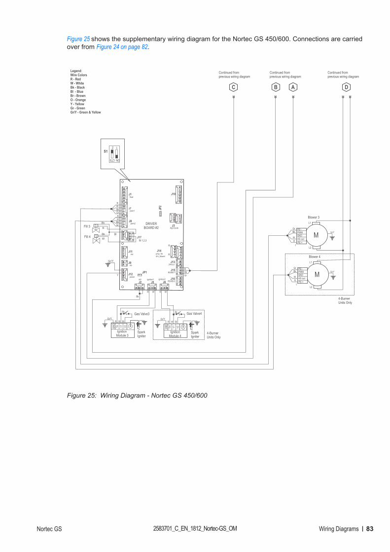
83Wiring DiagramsNortec GS 2583701_C_EN_1812_Nortec-GS_OM
Figure 25 shows the supplementary wiring diagram for the Nortec GS 450/600. Connections are carried over from Figure 24 on page 82.
Figure 25:
L1
L2
Blower 4
MPWMPS -
PS +
GNDHS out
1RW
BkGr
L1
L2
Blower 3
MPWMPS -
PS +
GNDHS out
1RW
BkGr
J2 J5
J15
J16
J14
J1 J10
J3
J7
J8
J17
J11
J9
J12
J6
J13
float
pwm1
pwm2
fill 1,2,3
ext
ntc
powera/p ignition1 ignition2
RS485-2
RS485-1
24Vout
pmp_fredrn_blower
digi inputsDRIVER
BOARD #2
R
Gas Valve3
GND
TH V2V1
Ignition Module 3
GND
TH V2V1
IgnitionModule 4
WR
SparkIgniter
SparkIgniter
WR
RGr/Y
W BlRGr/Y
W Bl
Gas Valve4
Bk
4-BurnerUnits Only
Fill 3 R
Bk
WR
BkGr
BkGr
WR
S
SFill 4Bk
Gr/Y
GrBkR
R
4-BurnerUnits Only
C D
Continued fromprevious wiring diagram
Continued fromprevious wiring diagram
Y
AB
Continued fromprevious wiring diagram
Legend:Wire ColorsR - RedW - WhiteBk - BlackBl - BlueBr - BrownO - OrangeY - YellowGr - GreenGr/Y - Green & Yellow
Gr/Y
Gr/Y
JP1
JP2
W
Bl
12
ON CTS
S1
Br Br
Wiring Diagram - Nortec GS 450/600
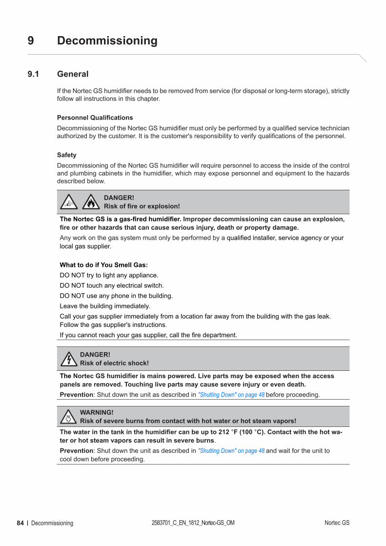
84 Decommissioning 2583701_C_EN_1812_Nortec-GS_OM Nortec GS
9 Decommissioning
9.1 General
If the Nortec GS humidifier needs to be removed from service (for disposal or long-term storage), strictly follow all instructions in this chapter.
Personnel QualificationsDecommissioning of the Nortec GS humidifier must only be performed by a qualified service technician authorized by the customer. It is the customer's responsibility to verify qualifications of the personnel.
SafetyDecommissioning of the Nortec GS humidifier will require personnel to access the inside of the control and plumbing cabinets in the humidifier, which may expose personnel and equipment to the hazards described below.
DANGER!Risk of fire or explosion!
The Nortec GS is a gas-fired humidifier. Improper decommissioning can cause an explosion, fire or other hazards that can cause serious injury, death or property damage.Any work on the gas system must only be performed by a qualified installer, service agency or your local gas supplier.
What to do if You Smell Gas: DO NOT try to light any appliance.DO NOT touch any electrical switch.DO NOT use any phone in the building.Leave the building immediately.Call your gas supplier immediately from a location far away from the building with the gas leak. Follow the gas supplier's instructions.If you cannot reach your gas supplier, call the fire department.
DANGER! Risk of electric shock!
The Nortec GS humidifier is mains powered. Live parts may be exposed when the access panels are removed. Touching live parts may cause severe injury or even death.Prevention: Shut down the unit as described in "Shutting Down" on page 48 before proceeding.
WARNING! Risk of severe burns from contact with hot water or hot steam vapors!
The water in the tank in the humidifier can be up to 212 °F (100 °C). Contact with the hot wa-ter or hot steam vapors can result in severe burns.Prevention: Shut down the unit as described in "Shutting Down" on page 48 and wait for the unit to cool down before proceeding.
85DecommissioningNortec GS 2583701_C_EN_1812_Nortec-GS_OM
WARNING! Risk of severe burns from contact with hot surfaces!
Components of the stream system may reach 212 °F (100 °C) during operation. Contact with the hot surfaces can result in severe burns.Prevention: Avoid touching any components in the plumbing cabinet until the unit has cooled down to room temperature.
CAUTION!Electrostatic discharge (ESD)!
The electronic components inside the control cabinet in the humidifier are sensitive to elec-trostatic discharge (ESD).Prevention: Take appropriate measures to protect the electronic components inside the unit against damage caused by electrostatic discharge (ESD). Refer to ANSI/ESD-S20.20.
9.2 Removal from Service for Disposal or Long-term Storage
Remove the Nortec GS humidifier from service (for disposal or long-term storage) as follows:
1. Drain the tank, and shut down the humidifier as described in "Shutting Down" on page 48. Follow all safety precautions.
2. Disconnect the gas connection to the humidifier.
3. Disconnect and remove the power supply to the Nortec GS humidifier. Refer to "Wiring Diagrams" on page 82.
4. Disconnect and remove the control signal inputs to the humidifier.
5. Disconnect the steam and condensate lines, and empty out all fluids.
6. Disconnect the water and drain connections to the humidifier.
7. Disconnect and remove the intake and exhaust vents.
8. Remove the humidifier from its mounting surface.
9. If the Nortec GS humidifier is to be put into long-term storage, store the humidifier in its original packaging inside a protected area that meets the following requirements:
• Room temperature: 41 to 104 °F (5 to 40 °C)
• Room humidity: 10 to 75% RH
10. If the Nortec GS humidifier is to be disposed off, refer to "Disposal/Recycling".
9.3 Disposal/Recycling
The Nortec GS humidifier should not be disposed off in domestic waste, and should only be disposed off in accordance with local regulations at authorized collection facilities.If you have any questions, contact the appropriate local authorities or your local Condair representative.
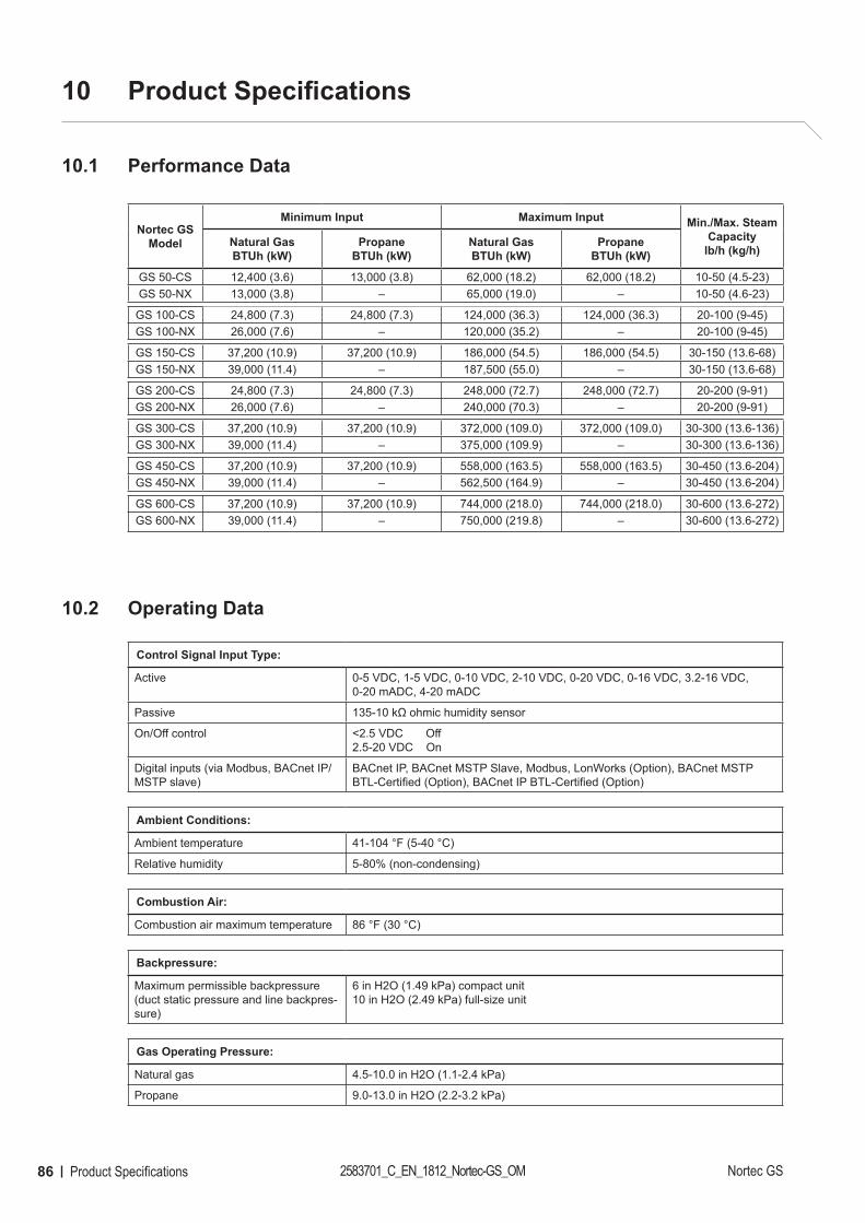
86 Product Specifications 2583701_C_EN_1812_Nortec-GS_OM Nortec GS
10 Product Specifications
10.1 Performance Data
Nortec GSModel
Minimum Input Maximum Input Min./Max. Steam Capacity
lb/h (kg/h)Natural GasBTUh (kW)
PropaneBTUh (kW)
Natural GasBTUh (kW)
PropaneBTUh (kW)
GS 50-CS 12,400 (3.6) 13,000 (3.8) 62,000 (18.2) 62,000 (18.2) 10-50 (4.5-23)GS 50-NX 13,000 (3.8) – 65,000 (19.0) – 10-50 (4.6-23)
GS 100-CS 24,800 (7.3) 24,800 (7.3) 124,000 (36.3) 124,000 (36.3) 20-100 (9-45)GS 100-NX 26,000 (7.6) – 120,000 (35.2) – 20-100 (9-45)
GS 150-CS 37,200 (10.9) 37,200 (10.9) 186,000 (54.5) 186,000 (54.5) 30-150 (13.6-68)GS 150-NX 39,000 (11.4) – 187,500 (55.0) – 30-150 (13.6-68)
GS 200-CS 24,800 (7.3) 24,800 (7.3) 248,000 (72.7) 248,000 (72.7) 20-200 (9-91)GS 200-NX 26,000 (7.6) – 240,000 (70.3) – 20-200 (9-91)
GS 300-CS 37,200 (10.9) 37,200 (10.9) 372,000 (109.0) 372,000 (109.0) 30-300 (13.6-136)GS 300-NX 39,000 (11.4) – 375,000 (109.9) – 30-300 (13.6-136)
GS 450-CS 37,200 (10.9) 37,200 (10.9) 558,000 (163.5) 558,000 (163.5) 30-450 (13.6-204)GS 450-NX 39,000 (11.4) – 562,500 (164.9) – 30-450 (13.6-204)
GS 600-CS 37,200 (10.9) 37,200 (10.9) 744,000 (218.0) 744,000 (218.0) 30-600 (13.6-272)GS 600-NX 39,000 (11.4) – 750,000 (219.8) – 30-600 (13.6-272)
10.2 Operating Data
Control Signal Input Type:
Active 0-5 VDC, 1-5 VDC, 0-10 VDC, 2-10 VDC, 0-20 VDC, 0-16 VDC, 3.2-16 VDC, 0-20 mADC, 4-20 mADC
Passive 135-10 kΩ ohmic humidity sensor
On/Off control <2.5 VDC Off2.5-20 VDC On
Digital inputs (via Modbus, BACnet IP/MSTP slave)
BACnet IP, BACnet MSTP Slave, Modbus, LonWorks (Option), BACnet MSTP BTL-Certified (Option), BACnet IP BTL-Certified (Option)
Ambient Conditions:
Ambient temperature 41-104 °F (5-40 °C)
Relative humidity 5-80% (non-condensing)
Combustion Air:
Combustion air maximum temperature 86 °F (30 °C)
Backpressure:
Maximum permissible backpressure (duct static pressure and line backpres-sure)
6 in H2O (1.49 kPa) compact unit10 in H2O (2.49 kPa) full-size unit
Gas Operating Pressure:
Natural gas 4.5-10.0 in H2O (1.1-2.4 kPa)
Propane 9.0-13.0 in H2O (2.2-3.2 kPa)
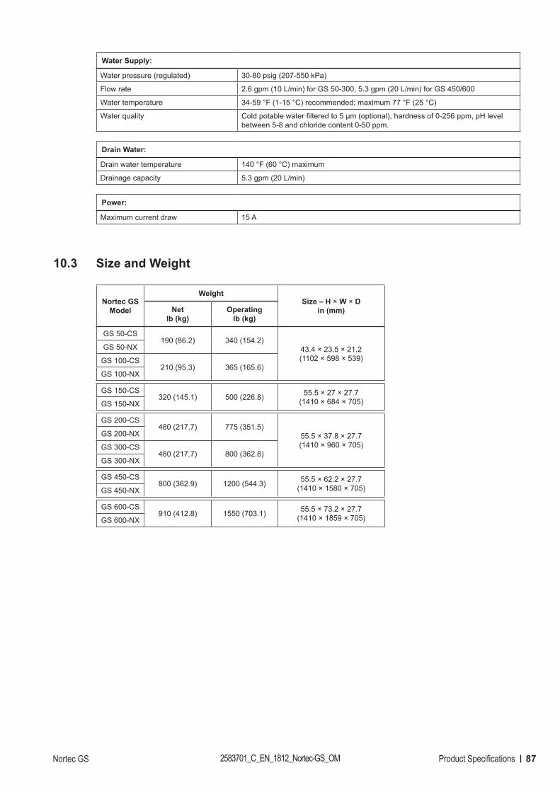
87Product SpecificationsNortec GS 2583701_C_EN_1812_Nortec-GS_OM
Water Supply:
Water pressure (regulated) 30-80 psig (207-550 kPa)
Flow rate 2.6 gpm (10 L/min) for GS 50-300, 5.3 gpm (20 L/min) for GS 450/600
Water temperature 34-59 °F (1-15 °C) recommended; maximum 77 °F (25 °C)
Water quality Cold potable water filtered to 5 μm (optional), hardness of 0-256 ppm, pH level between 5-8 and chloride content 0-50 ppm.
Drain Water:
Drain water temperature 140 °F (60 °C) maximum
Drainage capacity 5.3 gpm (20 L/min)
Power:
Maximum current draw 15 A
10.3 Size and Weight
Nortec GSModel
WeightSize – H × W × D
in (mm)Net lb (kg)
Operating lb (kg)
GS 50-CS190 (86.2) 340 (154.2)
43.4 × 23.5 × 21.2 (1102 × 598 × 539)
GS 50-NX
GS 100-CS210 (95.3) 365 (165.6)
GS 100-NX
GS 150-CS320 (145.1) 500 (226.8) 55.5 × 27 × 27.7
(1410 × 684 × 705)GS 150-NX
GS 200-CS480 (217.7) 775 (351.5)
55.5 × 37.8 × 27.7(1410 × 960 × 705)
GS 200-NX
GS 300-CS480 (217.7) 800 (362.8)
GS 300-NX
GS 450-CS800 (362.9) 1200 (544.3) 55.5 × 62.2 × 27.7
(1410 × 1580 × 705)GS 450-NX
GS 600-CS910 (412.8) 1550 (703.1) 55.5 × 73.2 × 27.7
(1410 × 1859 × 705)GS 600-NX
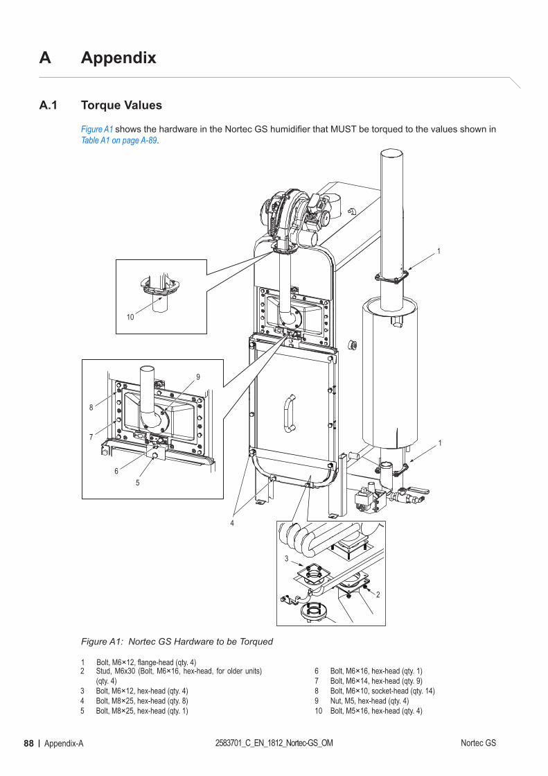
88 Appendix-A 2583701_C_EN_1812_Nortec-GS_OM Nortec GS
A Appendix
A.1 Torque Values
Figure A1 shows the hardware in the Nortec GS humidifier that MUST be torqued to the values shown in Table A1 on page A-89.
Figure A1:
1
1
4
56
7
8
9
10
2
3
Nortec GS Hardware to be Torqued
1 Bolt, M6×12, flange-head (qty. 4)2 Stud, M6x30 (Bolt, M6×16, hex-head, for older units)
(qty. 4)3 Bolt, M6×12, hex-head (qty. 4)4 Bolt, M8×25, hex-head (qty. 8)5 Bolt, M8×25, hex-head (qty. 1)
6 Bolt, M6×16, hex-head (qty. 1)7 Bolt, M6×14, hex-head (qty. 9)8 Bolt, M6×10, socket-head (qty. 14)9 Nut, M5, hex-head (qty. 4)10 Bolt, M5×16, hex-head (qty. 4)
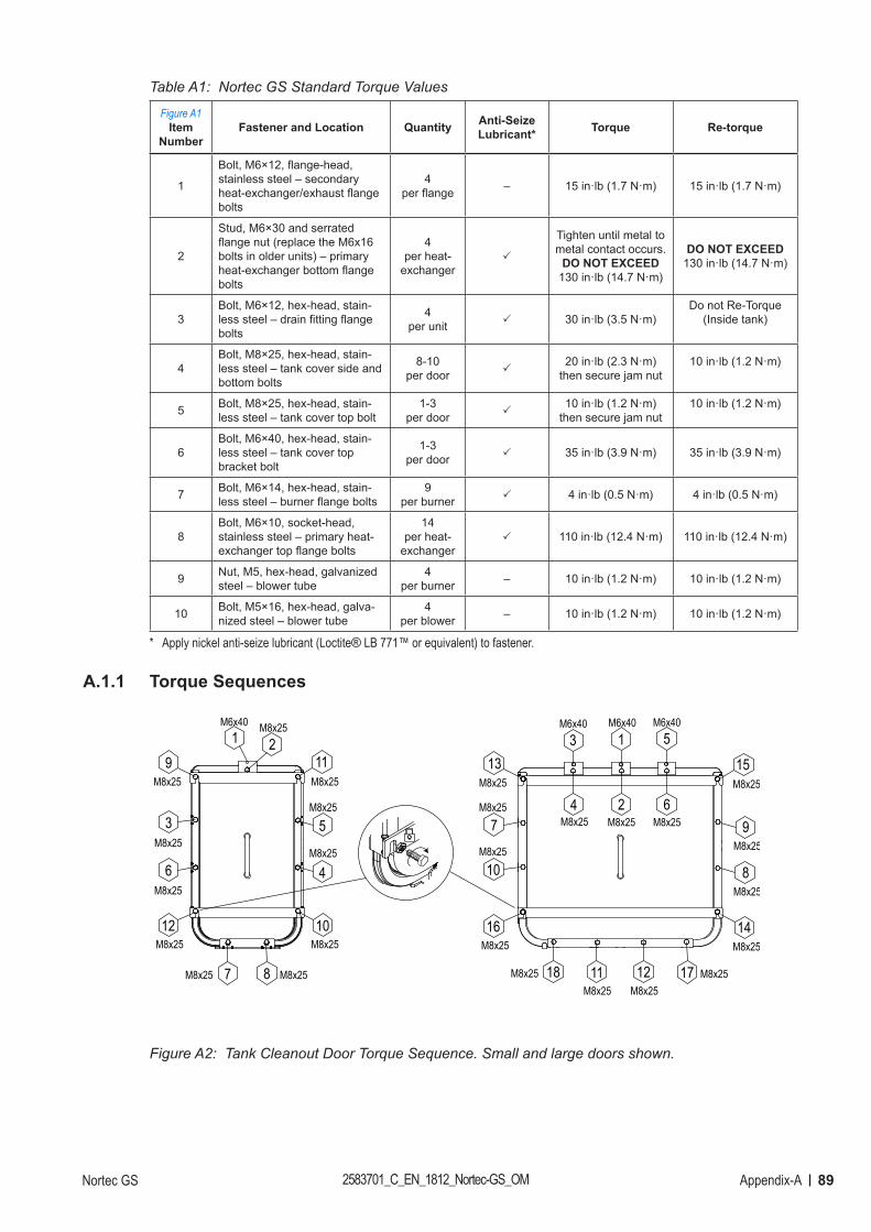
89Appendix-ANortec GS 2583701_C_EN_1812_Nortec-GS_OM
Table A1: Nortec GS Standard Torque Values
Figure A1 Item
NumberFastener and Location Quantity Anti-Seize
Lubricant* Torque Re-torque
1
Bolt, M6×12, flange-head, stainless steel – secondary heat-exchanger/exhaust flange bolts
4per flange – 15 in·lb (1.7 N·m) 15 in·lb (1.7 N·m)
2
Stud, M6×30 and serrated flange nut (replace the M6x16 bolts in older units) – primary heat-exchanger bottom flange bolts
4per heat-
exchanger
Tighten until metal to metal contact occurs.
DO NOT EXCEED 130 in·lb (14.7 N·m)
DO NOT EXCEED 130 in·lb (14.7 N·m)
3Bolt, M6×12, hex-head, stain-less steel – drain fitting flange bolts
4per unit 30 in·lb (3.5 N·m)
Do not Re-Torque (Inside tank)
4Bolt, M8×25, hex-head, stain-less steel – tank cover side and bottom bolts
8-10per door
20 in·lb (2.3 N·m)then secure jam nut
10 in·lb (1.2 N·m)
5 Bolt, M8×25, hex-head, stain-less steel – tank cover top bolt
1-3per door
10 in·lb (1.2 N·m)then secure jam nut
10 in·lb (1.2 N·m)
6Bolt, M6×40, hex-head, stain-less steel – tank cover top bracket bolt
1-3per door 35 in·lb (3.9 N·m) 35 in·lb (3.9 N·m)
7 Bolt, M6×14, hex-head, stain-less steel – burner flange bolts
9per burner 4 in·lb (0.5 N·m) 4 in·lb (0.5 N·m)
8Bolt, M6×10, socket-head, stainless steel – primary heat-exchanger top flange bolts
14per heat-
exchanger 110 in·lb (12.4 N·m) 110 in·lb (12.4 N·m)
9 Nut, M5, hex-head, galvanized steel – blower tube
4per burner – 10 in·lb (1.2 N·m) 10 in·lb (1.2 N·m)
10 Bolt, M5×16, hex-head, galva-nized steel – blower tube
4per blower – 10 in·lb (1.2 N·m) 10 in·lb (1.2 N·m)
* Apply nickel anti-seize lubricant (Loctite® LB 771™ or equivalent) to fastener.
A.1.1 Torque Sequences
9
10
11
12
7 8
1 2M6x40 M8x25
M8x25
M8x25
M8x25M8x25
M8x25
M8x25
14
15M8x25
M8x25
13
16M8x25
M8x25
3
4
M6x40
M8x25
5
6
M6x40
M8x25
17 M8x2518M8x25 12M8x25
2M8x25
1M6x40
7M8x25
10M8x25
9M8x25
8M8x25
3M8x25
6M8x25
5M8x25
4M8x25
11M8x25
Figure A2: Tank Cleanout Door Torque Sequence. Small and large doors shown.
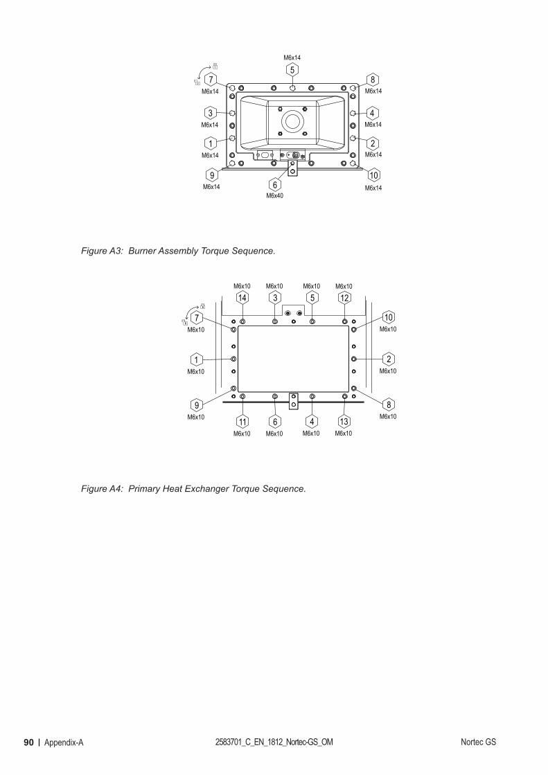
90 Appendix-A 2583701_C_EN_1812_Nortec-GS_OM Nortec GS
7M6x14
5M6x14
3M6x14
1M6x14
9M6x14
8M6x14
4M6x14
2M6x14
10M6x146
M6x40
Figure A3: Burner Assembly Torque Sequence.
7M6x10
1M6x10
9M6x10 11
M6x106
M6x104
M6x1013
M6x10
14M6x10
3M6x10
5M6x10
12M6x10
10M6x10
2M6x10
8M6x10
Figure A4: Primary Heat Exchanger Torque Sequence.
WarrantyCondair Inc. and/or Condair Ltd. (hereinafter collectively referred to as THE COMPANY), warrant for a period of two years after installation or 30 months from manufacturer’s ship date, whichever date is earlier, that THE COMPANY’s manufactured and assembled products, not otherwise expressly warranted, are free from defects in material and workmanship. No warranty is made against corrosion, deterioration, or suitability of substituted materials used as a result of compliance with government regulations. THE COMPANY’s obligations and liabilities under this warranty are limited to furnishing replacement parts to the customer, F.O.B. THE COMPANY’s factory, providing the defective part(s) is returned freight prepaid by the customer. Parts used for repairs are warranted for the balance of the term of the warranty on the original humidifier or 90 days, whichever is longer. The warranties set forth herein are in lieu of all other warranties expressed or implied by law. No liability whatsoever shall be attached to THE COMPANY until said products have been paid for in full and then said liability shall be limited to the original purchase price for the product. Any further warranty must be in writing, signed by an officer of THE COMPANY. THE COMPANY’s parts or materials that are considered consumables, including but not limited to: cylinders, filters, nozzles, membranes, media, gaskets, O-rings, etc. are NOT covered by the warranty. THE COMPANY makes no warranty and assumes no liability unless the equipment is installed in strict accordance with a copy of the catalog and installation manual in effect at the date of purchase and by a contractor approved by THE COMPANY to install such equipment. THE COMPANY makes no warranty and assumes no liability whatsoever for consequential damage or dam-age resulting directly from misapplication, incorrect sizing or lack of proper maintenance of the equipment. THE COMPANY makes no warranty and assumes no liability whatsoever for damage resulting from freezing of the humidifier, supply lines, drain lines, or quality of the water used. THE COMPANY retains the right to change the design, specification and performance criteria of its products without notice or obligation. THE COMPANY’s limited warranty on accessories, not of the companies manufacture, such as controls, humidistats, pumps, etc. is limited to the warranty of the original equipment manufacturer from date of original shipment of humidifier.
Extended Warranty Extended warranties are available to purchase under the conditions listed above.
U.S.A.835 Commerce Park DriveOgdensburg, NY 1366-2209
CANADA2740 Fenton RoadOttawa, ON, K1T 3T7
Tel: 1.866.667.8321 Fax: 613.822.7964
Email: [email protected]: www.condair.com
CONSULTING, SALES AND SERVICE:


