Embed Size (px)
Citation preview
CEN 302-Software Engineering ONLINE STORE Epoka University
FACULTY OF ECONOMICS AND ADMINISTRATIVE SCIENCES
DEPARTMENT OF BUSINESS INFORMATICS
TOPIC: Online Shopping
PREPARED FOR: Igli Hakrama
PREPARED BY:
Bedrana Mekolli
1
CEN 302-Software Engineering ONLINE STORE Epoka University
Table of Contents1. Requirements......................................................3
1.1. Product Perspectives.........................................3
1.2. Product Functions............................................31.3. User Characteristics.........................................4
1.4. General Constraints..........................................41.5. Assumptions and Dependencies.................................4
1.6. System Requirements..........................................41.7. User Profile.................................................4
1.8. Feature Requirements (User Stories)..........................62. UML Diagrams......................................................6
DFD.................................................................62.2. ER Diagram.....................................................9
2.3. Behavioral Diagram.............................................101. Use Case......................................................10
3. Activity Diagram..............................................144. State Chart...................................................20
2.1. Interaction Diagram...........................................221. Sequence......................................................22
2. Collaboration.................................................262.4. Structural Diagram.............................................28
Class Diagram....................................................28Object Diagram...................................................30
Component........................................................30Deployment.......................................................32
2.5. Implementation.................................................32
2
CEN 302-Software Engineering ONLINE STORE Epoka University
1. Requirements
1.1. Product Perspectives
I choose to develop this product because online stores nowadays
are becoming very successful businesses. An online store does not
only provide facilities for the customers to buy products from
around the world but also have a very low price regarding to
other stores which are not selling online. All the customers and
users of this product will benefit a lot because they will not
have to get tired to shop but they will find a full of diversity
products and data in a very efficient an effective way. Other
thing that the users will gain is the competitive prices as it is
mentioned above and the newest arrivals that for other stores it
is more difficult to become possible.
1.2. Product Functions
The product will facilitate the work of the customers to choose
the products without getting tired and losing time. Also will
help the stakeholders to have a more organized life of their
companies, to achieve greater speed in data processing, to
retrieve faster the information. It will integrate the area of
business, will allow the cost reduction and will provide a better
security.
Activities of customers
1. They just will Login with their Password
3
CEN 302-Software Engineering ONLINE STORE Epoka University
2. They will shop while in the comfort of their home without
having to go out and shopping.
Main functions
1. Keeping records of admission of customers.
2. Keeping the records of products.
3. Keeping the daily sell.
4. Storing the feedback given by the customer.
5. Keeping details about the product it is delivered or not etc.
6. Storing the items selected by the customer in the temporary
storage.
1.3. User Characteristics
The finished product can be use by everyone, because it is not
required a professional skill for using this type of product. As
it is mentioned also above the user should only have the basic
computer knowledge and English language.
1.4. General Constraints
• The text box should not be left empty and it should have
sufficient information.
• must be a 64 MB on-board memory.
• The exit of application should not have problems, so always the
close it has to be normal.
4
CEN 302-Software Engineering ONLINE STORE Epoka University
1.5. Assumptions and Dependencies
The interface will be in English only.
A single server must be for the system to work correctly.
The availability may get affected because the system don’t have
maintainability
GUI features available
1.6. System Requirements
User must be trained for basic computer functionalities.
The basic knowledge of English is required for the user to know
in order to fulfill successfully the requirements.
The database software respond must be in time by the system.
1.7. User Profile
1. General public
See the product
See the prices
See the quantity available
Cannot buy the products
2. Customers
He/she login in its account
5
CEN 302-Software Engineering ONLINE STORE Epoka University
Purchase products
Manage the credit card
Choose the shipping type.)
3. Administrator
Login
Update the items
Manage the card
Grand permission to user
Add new product
Edit a product
Delete a product.
4. Online Seller
Login in account
Register the items
Inform the dealer to seller.
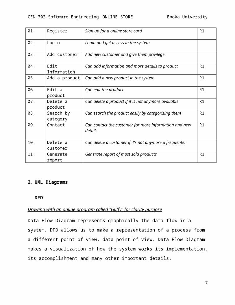
1.8. Feature Requirements (User Stories)
Number
User Story Name
Description Release
6
CEN 302-Software Engineering ONLINE STORE Epoka University
01. Register Sign up for a online store card R1
02. Login Login and get access in the system
03. Add customer Add new customer and give them privilege
04. Edit Information
Can add information and more details to product R1
05. Add a product Can add a new product in the system R1
06. Edit a product
Can edit the product R1
07. Delete a product
Can delete a product if it is not anymore available R1
08. Search by category
Can search the product easily by categorizing them R1
09. Contact Can contact the customer for more information and new details
R1
10. Delete a customer
Can delete a customer if it’s not anymore a frequenter
11. Generate report
Generate report of most sold products R1
2. UML Diagrams
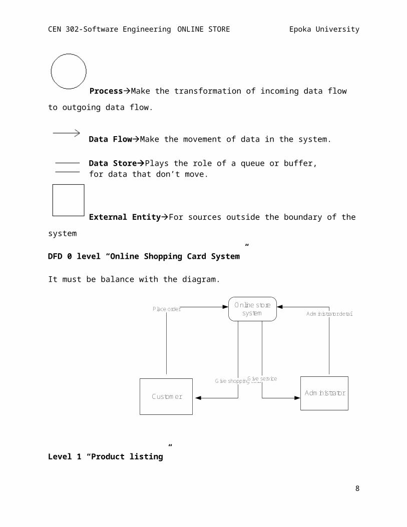
DFD
Drawing with an online program called “Gliffy” for clarity purpose
Data Flow Diagram represents graphically the data flow in a
system. DFD allows us to make a representation of a process from
a different point of view, data point of view. Data Flow Diagram
makes a visualization of how the system works its implementation,
its accomplishment and many other important details.
7
CEN 302-Software Engineering ONLINE STORE Epoka University
ProcessMake the transformation of incoming data flow
to outgoing data flow.
Data FlowMake the movement of data in the system.
Data StorePlays the role of a queue or buffer, for data that don’t move.
External EntityFor sources outside the boundary of the
system
DFD 0 level “Online Shopping Card System”
It must be balance with the diagram.
Online storesystem
Custom er Adm inistrator
Place order
Give shopping card
Adm inistrator detail
Give service
Level 1 “Product listing”
8
CEN 302-Software Engineering ONLINE STORE Epoka University
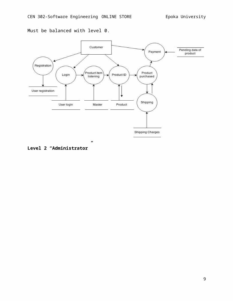
Must be balanced with level 0.
Level 2 “Administrator”
9
CEN 302-Software Engineering ONLINE STORE Epoka University
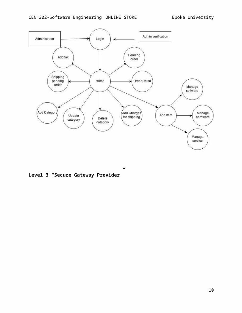
Level 3 “Secure Gateway Provider”
10
CEN 302-Software Engineering ONLINE STORE Epoka University
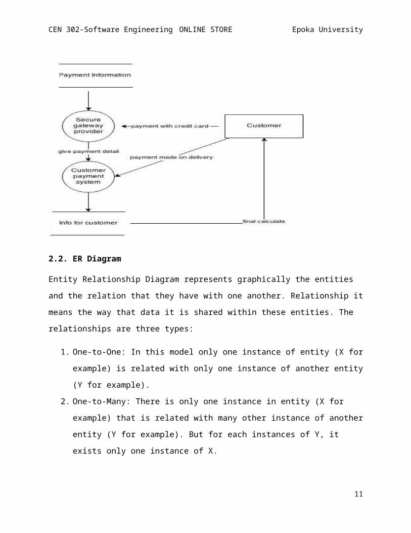
2.2. ER Diagram
Entity Relationship Diagram represents graphically the entities
and the relation that they have with one another. Relationship it
means the way that data it is shared within these entities. The
relationships are three types:
1. One-to-One: In this model only one instance of entity (X for
example) is related with only one instance of another entity
(Y for example).
2. One-to-Many: There is only one instance in entity (X for
example) that is related with many other instance of another
entity (Y for example). But for each instances of Y, it
exists only one instance of X.
11
CEN 302-Software Engineering ONLINE STORE Epoka University
3. Many-to-Many: Is similar with One-to-Many but the difference
is that each instance of Y is related with many instances of
X.
.
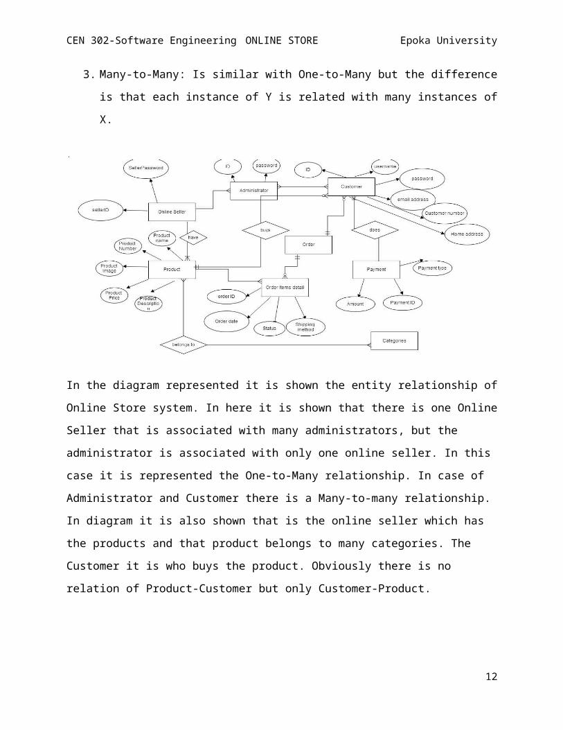
In the diagram represented it is shown the entity relationship of
Online Store system. In here it is shown that there is one Online
Seller that is associated with many administrators, but the
administrator is associated with only one online seller. In this
case it is represented the One-to-Many relationship. In case of
Administrator and Customer there is a Many-to-many relationship.
In diagram it is also shown that is the online seller which has
the products and that product belongs to many categories. The
Customer it is who buys the product. Obviously there is no
relation of Product-Customer but only Customer-Product.
12
CEN 302-Software Engineering ONLINE STORE Epoka University
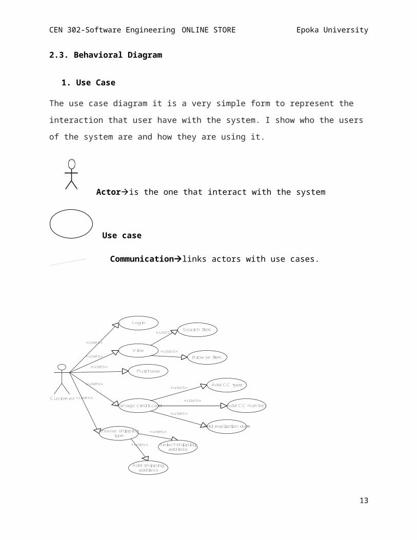
2.3. Behavioral Diagram
1. Use Case
The use case diagram it is a very simple form to represent the
interaction that user have with the system. I show who the users
of the system are and how they are using it.
Actoris the one that interact with the system
Use case
Communicationlinks actors with use cases.
Custom er
«uses»
«uses»
«uses»
«uses»
«uses»
Login
View
Purchase
M anage credit card
choose shippingtype
«uses»
«uses»
Search Item
Browse Item
«uses»
«uses»
«uses»
Add CC type
Add CC num ber
Add expiration date«uses»
«uses» Select shippingaddress
Add shippingaddress
13
CEN 302-Software Engineering ONLINE STORE Epoka University
Use Case Diagram for Customer
The use case for customer shows what the customer does in the
system. He/she login in its account, purchase products, manage
the credit card and choose the shipping type.
Adm inistrator
«uses»
Update Item s
«uses»
«uses»
M anage card
Grand perm issionto user
«uses»
«uses»
Delete a product
Add a product
«uses»Edit a product
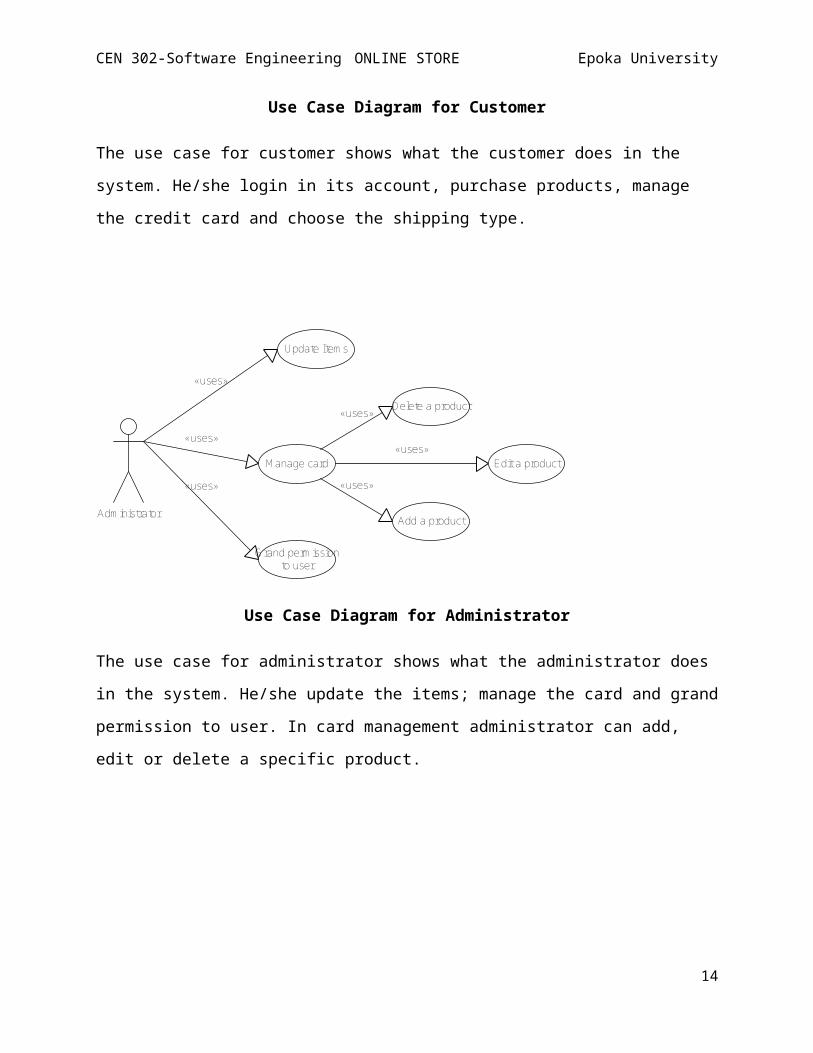
Use Case Diagram for Administrator
The use case for administrator shows what the administrator does
in the system. He/she update the items; manage the card and grand
permission to user. In card management administrator can add,
edit or delete a specific product.
14
CEN 302-Software Engineering ONLINE STORE Epoka University
online seller
«uses»
«uses»
«uses»
Login
Register item
Inform the dealerto seller
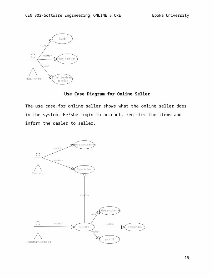
Use Case Diagram for Online Seller
The use case for online seller shows what the online seller does
in the system. He/she login in account, register the items and
inform the dealer to seller.
Custom er
Registerd Custom er
«uses»
«uses»
Register custom er
Search Item
«uses»Buy Item
«uses»
«uses»
«uses»
«uses»
Validate custom er
pay bill
prepare bill
15
CEN 302-Software Engineering ONLINE STORE Epoka University
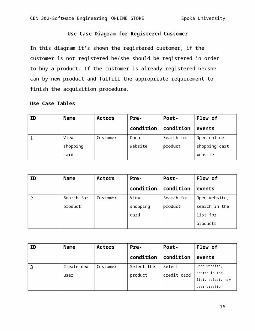
Use Case Diagram for Registered Customer
In this diagram it’s shown the registered customer, if the
customer is not registered he/she should be registered in order
to buy a product. If the customer is already registered he/she
can by new product and fulfill the appropriate requirement to
finish the acquisition procedure.
Use Case Tables
ID Name Actors Pre-
condition
Post-
condition
Flow of
events1 View
shopping
card
Customer Open
website
Search for
product
Open online
shopping cart
website
ID Name Actors Pre-
condition
Post-
condition
Flow of
events2 Search for
product
Customer View
shopping
card
Search for
product
Open website,
search in the
list for
products
ID Name Actors Pre-
condition
Post-
condition
Flow of
events3 Create new
user
Customer Select the
product
Select
credit card
Open website,
search in the
list, select, new
user creation
16
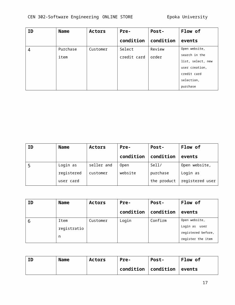
CEN 302-Software Engineering ONLINE STORE Epoka University
ID Name Actors Pre-
condition
Post-
condition
Flow of
events4 Purchase
item
Customer Select
credit card
Review
order
Open website,
search in the
list, select, new
user creation,
credit card
selection,
purchase
ID Name Actors Pre-
condition
Post-
condition
Flow of
events5 Login as
registered
user card
seller and
customer
Open
website
Sell/
purchase
the product
Open website,
Login as
registered user
ID Name Actors Pre-
condition
Post-
condition
Flow of
events6 Item
registratio
n
Customer Login Confirm Open website,
Login as user
registered before,
register the item
ID Name Actors Pre-
condition
Post-
condition
Flow of
events
17
CEN 302-Software Engineering ONLINE STORE Epoka University
7 Change the
information
Administrat
or
Login as
administrat
or
Update the
system
Open website,
Login, make
changes
ID Name Actors Pre-
condition
Post-
condition
Flow of
events8 Block users Administrat
or
Select user Search
product
Open website,
login, select
user, block user
ID Name Actors Pre-
condition
Post-
condition
Flow of
events9 Inform the
deal to
seller
Online
Seller and
Shopping
cart system
Check the
availabilit
y
Make a deal Open website,
login, seller sell
the item to
shopping cart
system, inform the
deal to seller
3. Activity Diagram
Activity Diagram gives a broad view of a process in business.
It represents in a visual way the floes of data, decisions and
activities of a system. Activity Diagrams differ from other
diagrams because it is a flow chart that shows flow of work
and control in a system. It gives a very clear manner the
paths that the system goes and show which activities are done
in parallel. There are three main containers of activity
diagram:
18
CEN 302-Software Engineering ONLINE STORE Epoka University
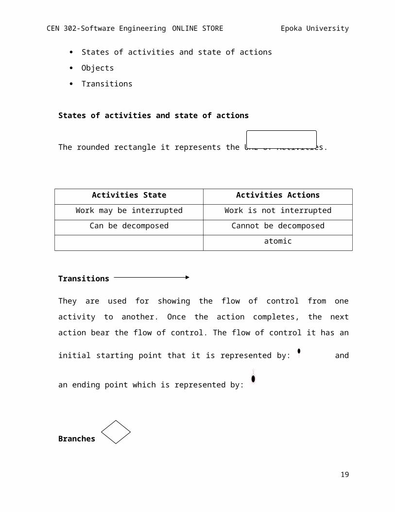
States of activities and state of actions
Objects
Transitions
States of activities and state of actions
The rounded rectangle it represents the UML of Activities.
Activities State Activities ActionsWork may be interrupted Work is not interrupted
Can be decomposed Cannot be decomposedatomic
Transitions
They are used for showing the flow of control from one
activity to another. Once the action completes, the next
action bear the flow of control. The flow of control it has an
initial starting point that it is represented by: and
an ending point which is represented by:
Branches
19
CEN 302-Software Engineering ONLINE STORE Epoka University
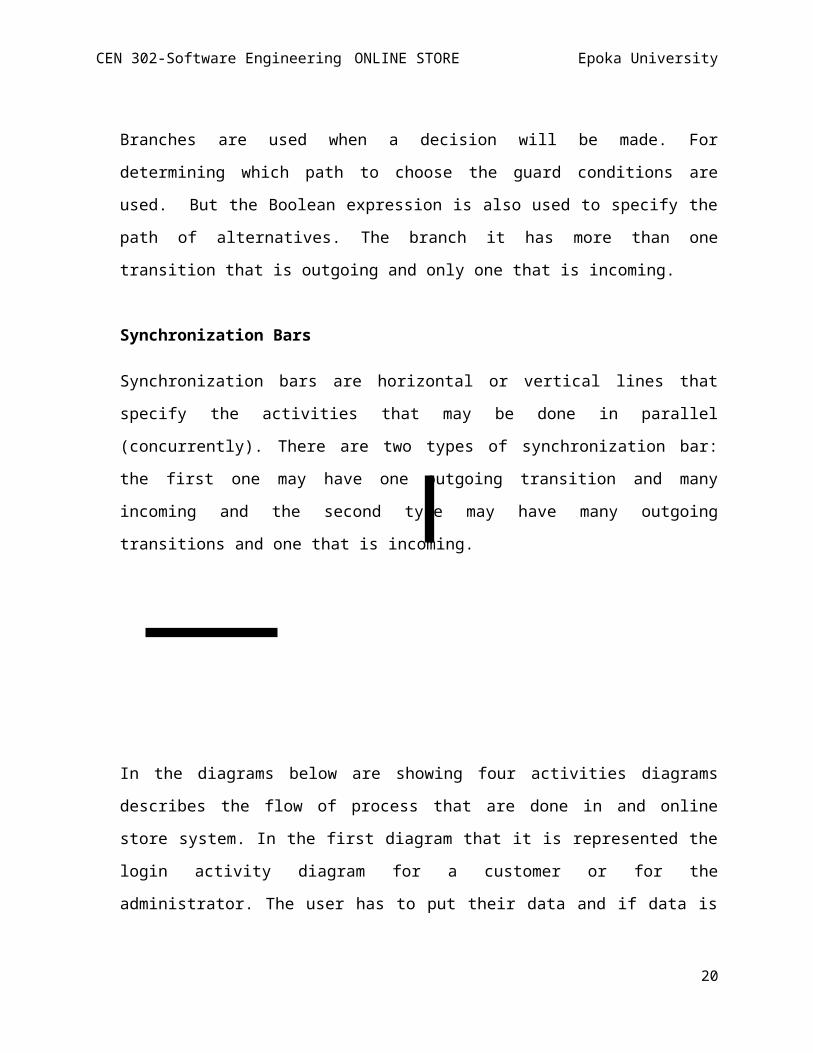
Branches are used when a decision will be made. For
determining which path to choose the guard conditions are
used. But the Boolean expression is also used to specify the
path of alternatives. The branch it has more than one
transition that is outgoing and only one that is incoming.
Synchronization Bars
Synchronization bars are horizontal or vertical lines that
specify the activities that may be done in parallel
(concurrently). There are two types of synchronization bar:
the first one may have one outgoing transition and many
incoming and the second type may have many outgoing
transitions and one that is incoming.
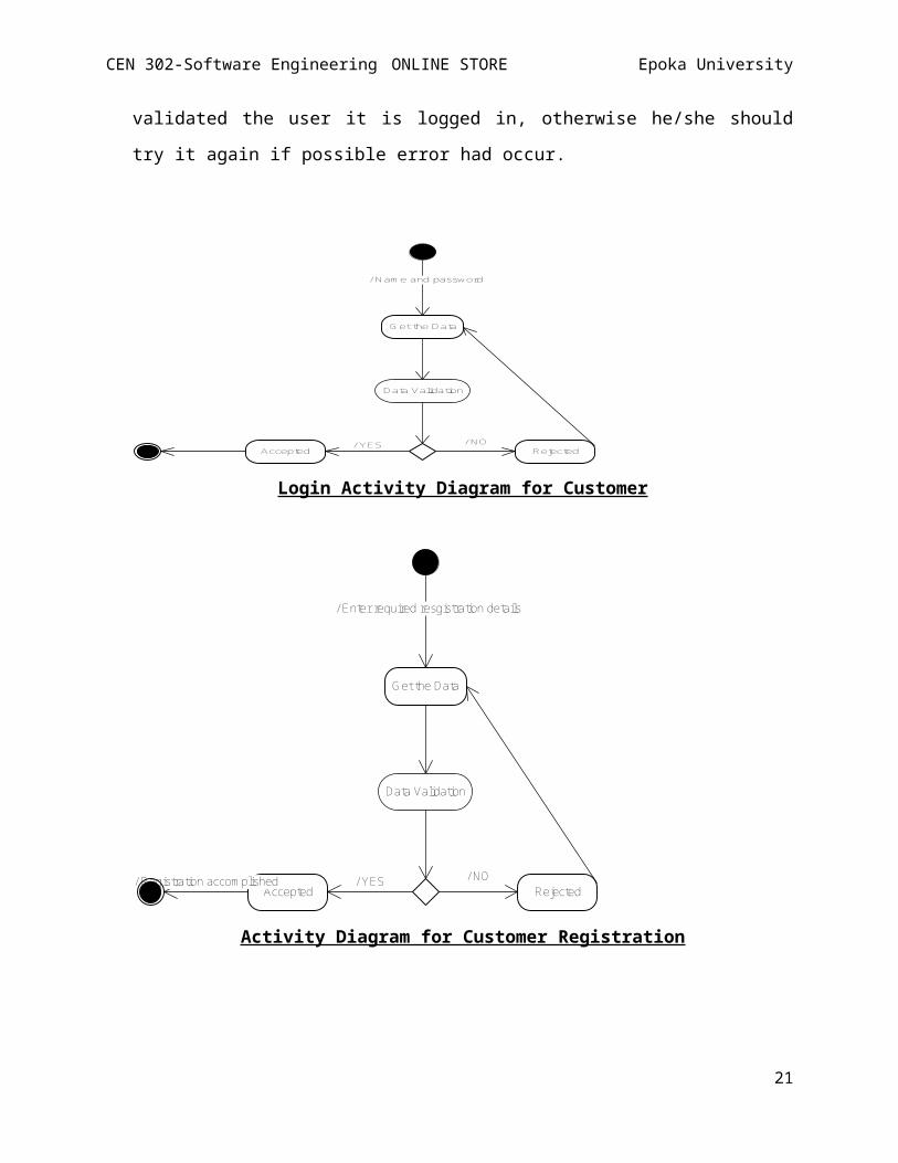
In the diagrams below are showing four activities diagrams
describes the flow of process that are done in and online
store system. In the first diagram that it is represented the
login activity diagram for a customer or for the
administrator. The user has to put their data and if data is
20
CEN 302-Software Engineering ONLINE STORE Epoka University
validated the user it is logged in, otherwise he/she should
try it again if possible error had occur.
/ Nam e and password
G et the Data
Data Validation
/ NO/ YESAccepted Rejected
Login Activity Diagram for Customer
/ Enter required resgistration details
Get the Data
Data Validation
/ NO/ YESAccepted
/ Registration accom plishedRejected
Activity Diagram for Customer Registration
21
CEN 302-Software Engineering ONLINE STORE Epoka University
View Product
/ Purchase?
/ NO/ YESproduct detail/ m em ber?
/ No
/ Yes
M ake registration
shopping card assigned
Login
do you want to add item to shopping card
/ No
/ Yes
Generate m ore
paym ent detail
/ cancel? / Yes cancel product
/ No
/ want to pay by credit card?
/ No
/ Yes
final bill/ feetback?
/ No
/ Yesfill the feetback signout
22
CEN 302-Software Engineering ONLINE STORE Epoka University
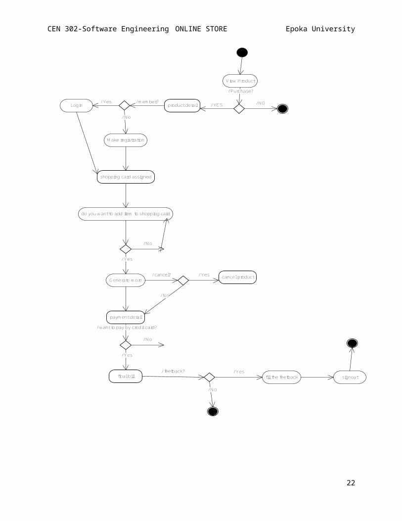
This is the activity diagram for product purchase. If the
customer agrees with product details, price and other details
than he/she can choose the way that is going to pay the product.
/ enter nam e and password
Get Data
Data Validation/ No
/ m anage custom ers orders / generate report/ m anage products
G et Data
GetData
GetData
Validate
Validate
Validate/ No / No
/ No
/ Yes
/ Process of data
Get Data
Data Validation/ Yes
23
CEN 302-Software Engineering ONLINE STORE Epoka University
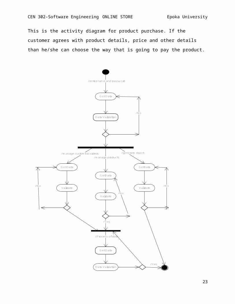
Activity Diagram for Administrator
After administrator has login in his/her account, manage the
orders given by customers, manages the product and generate the
general report. In this activity diagram it is also used the
branches
and synchronization bars. If the data it is validated than the
process goes on, but if the data given to administrator is not
validated than the process it is repeated to detect the errors.
4. State Chart
State Chart it is a state machine that describes the component’sstates in a system. They are part of UML diagram and are used todescribe behavior and condition of one object over use cases.
Starting point
Staterepresents state of object
Transitiontransition of object from one state toanother
End of state diagram
24
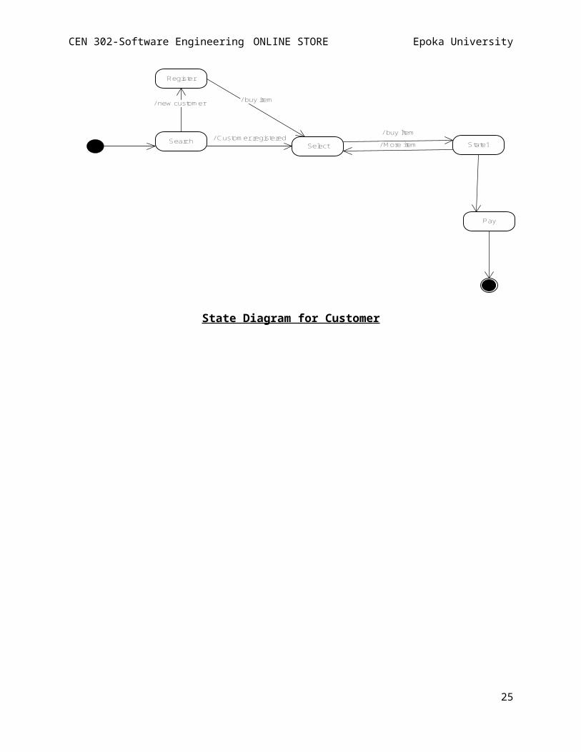
CEN 302-Software Engineering ONLINE STORE Epoka University
Search / Custom er registeredSelect
/ new custom er
Register
/ buy item
/ buy ItemState1/ M ore item
Pay
State Diagram for Customer
25
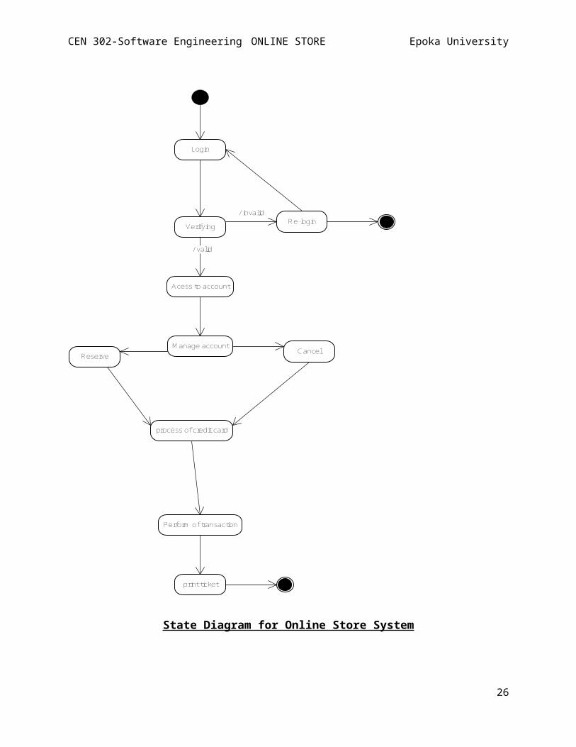
CEN 302-Software Engineering ONLINE STORE Epoka University
Login
Verifying
/ valid
Acess to account
/ invalidRe-login
M anage accountReserve Cancel
process of credit card
Perform of transaction
print ticket
State Diagram for Online Store System
26
CEN 302-Software Engineering ONLINE STORE Epoka University
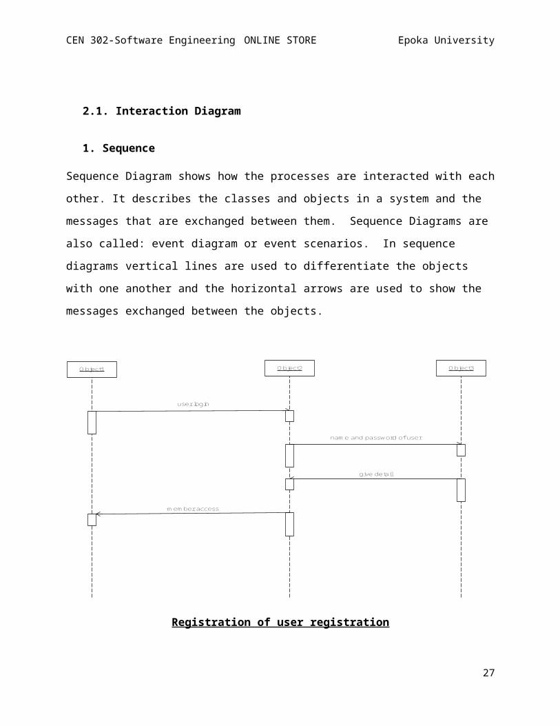
2.1. Interaction Diagram
1. Sequence
Sequence Diagram shows how the processes are interacted with each
other. It describes the classes and objects in a system and the
messages that are exchanged between them. Sequence Diagrams are
also called: event diagram or event scenarios. In sequence
diagrams vertical lines are used to differentiate the objects
with one another and the horizontal arrows are used to show the
messages exchanged between the objects.
Object1 Object2 Object3
user login
nam e and password of user
give detail
m em ber access
Registration of user registration
27
CEN 302-Software Engineering ONLINE STORE Epoka University
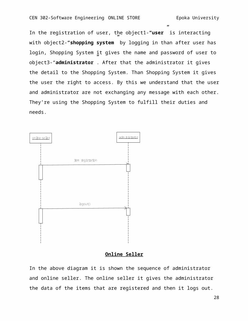
In the registration of user, the object1-“user” is interacting
with object2-“shopping system” by logging in than after user has
login, Shopping System it gives the name and password of user to
object3-“administrator”. After that the administrator it gives
the detail to the Shopping System. Than Shopping System it gives
the user the right to access. By this we understand that the user
and administrator are not exchanging any message with each other.
They’re using the Shopping System to fulfill their duties and
needs.
online seller adm inistrator
item registration
logout()
Online Seller
In the above diagram it is shown the sequence of administrator
and online seller. The online seller it gives the administrator
the data of the items that are registered and then it logs out. 28
CEN 302-Software Engineering ONLINE STORE Epoka University
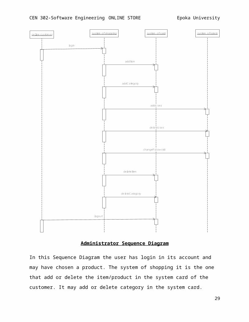
online custom er system of shopping system of card system of oders
login
addItem
addCategory
addUser
deleteUser
changePassword
deleteItem
deleteCategory
logout
Administrator Sequence Diagram
In this Sequence Diagram the user has login in its account and
may have chosen a product. The system of shopping it is the one
that add or delete the item/product in the system card of the
customer. It may add or delete category in the system card.
29
CEN 302-Software Engineering ONLINE STORE Epoka University
System Card it may add or delete the user in system of orders or
it may change his/her password. The customer may log out to
system of card. The overall process it is done by the
administrator.
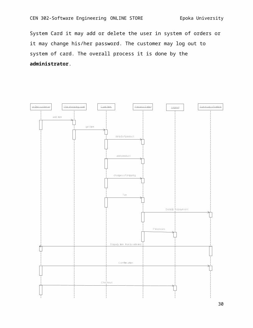
online custom er The shooping card Card Item Process O rder Logout Sum m ary of orders
add item
get item
detail of product
add product
charges of shipping
Tax
Details for paym ent
Processes
Dispaly item that is ordered
Confirm ation
Checkout
30
CEN 302-Software Engineering ONLINE STORE Epoka University
Sequence Diagram for Customer
In the diagram above it is shown the all sequence of a customer
how and where it get the item, how he/she can add a new product.
They way that he/she pay and where it pays, the details that are
needed for the purchasing and item etc.
2. Collaboration
Like Sequential Diagrams, the Collaboration Diagram is also part
of Interaction diagram because it shows the interactions of the
objects between one another. The difference is that collaboration
diagram it is more about the role that the objects play than t
show the message that the objects exchange with each other. It
contains class and association roles and message flows.
ObjectInteract in the system with one another.
RelationLink that makes the connection of
objects.
Messageshows the interaction between the object.
31
CEN 302-Software Engineering ONLINE STORE Epoka University
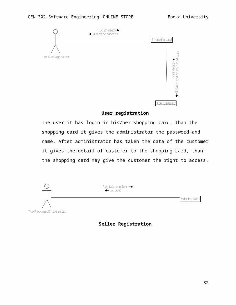
Shopping card
Adm inistrator
1.Login user4.M em ber access
2.Na
me and passwo
rd of user
3.Give detail
Top Package::User
User registration
The user it has login in his/her shopping card, than the
shopping card it gives the administrator the password and
name. After administrator has taken the data of the customer
it gives the detail of customer to the shopping card, than
the shopping card may give the customer the right to access.
Adm inistrator
RegistrationofitemLogout()
Top Package::Online seller
Seller Registration
32
CEN 302-Software Engineering ONLINE STORE Epoka University
Shopping card
Log out
Item of card
Process orderSum m ary of orders
1.Add Ite
m
9.Display Item s
10.Confirm
2.Get Item
3.Prod
uct Deta
ils
4.Add product
5.Orde
r of shipping
6.Taxes
7.Paym ent Detail
8.ProcessesTop Package::Custom er
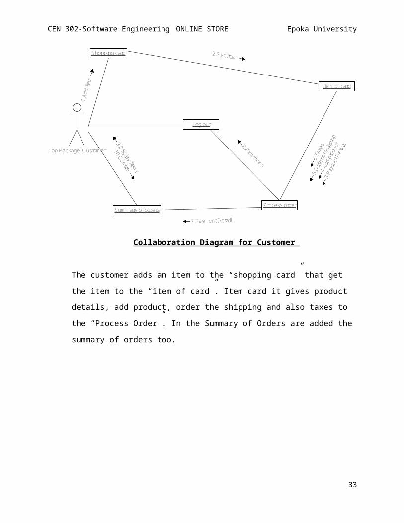
Collaboration Diagram for Customer
The customer adds an item to the “shopping card” that get
the item to the “item of card”. Item card it gives product
details, add product, order the shipping and also taxes to
the “Process Order”. In the Summary of Orders are added the
summary of orders too.
33
CEN 302-Software Engineering ONLINE STORE Epoka University
Card system
Shopping system
Orders system
1.Login()
9.Logout
Top Package::Adm inistrator
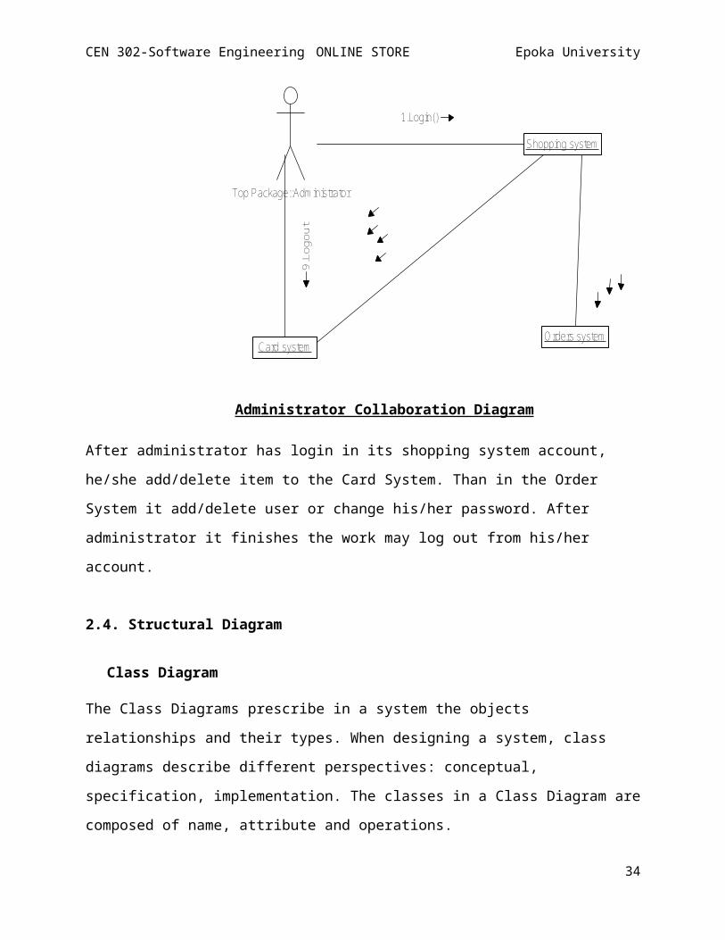
Administrator Collaboration Diagram
After administrator has login in its shopping system account,
he/she add/delete item to the Card System. Than in the Order
System it add/delete user or change his/her password. After
administrator it finishes the work may log out from his/her
account.
2.4. Structural Diagram
Class Diagram
The Class Diagrams prescribe in a system the objects
relationships and their types. When designing a system, class
diagrams describe different perspectives: conceptual,
specification, implementation. The classes in a Class Diagram are
composed of name, attribute and operations.
34
CEN 302-Software Engineering ONLINE STORE Epoka University
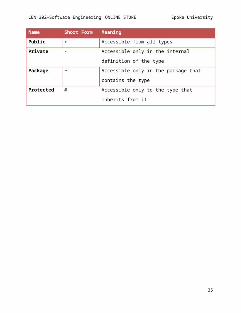
Name Short Form Meaning
Public + Accessible from all typesPrivate - Accessible only in the internal
definition of the typePackage ~ Accessible only in the package that
contains the typeProtected # Accessible only to the type that
inherits from it
35
CEN 302-Software Engineering ONLINE STORE Epoka University
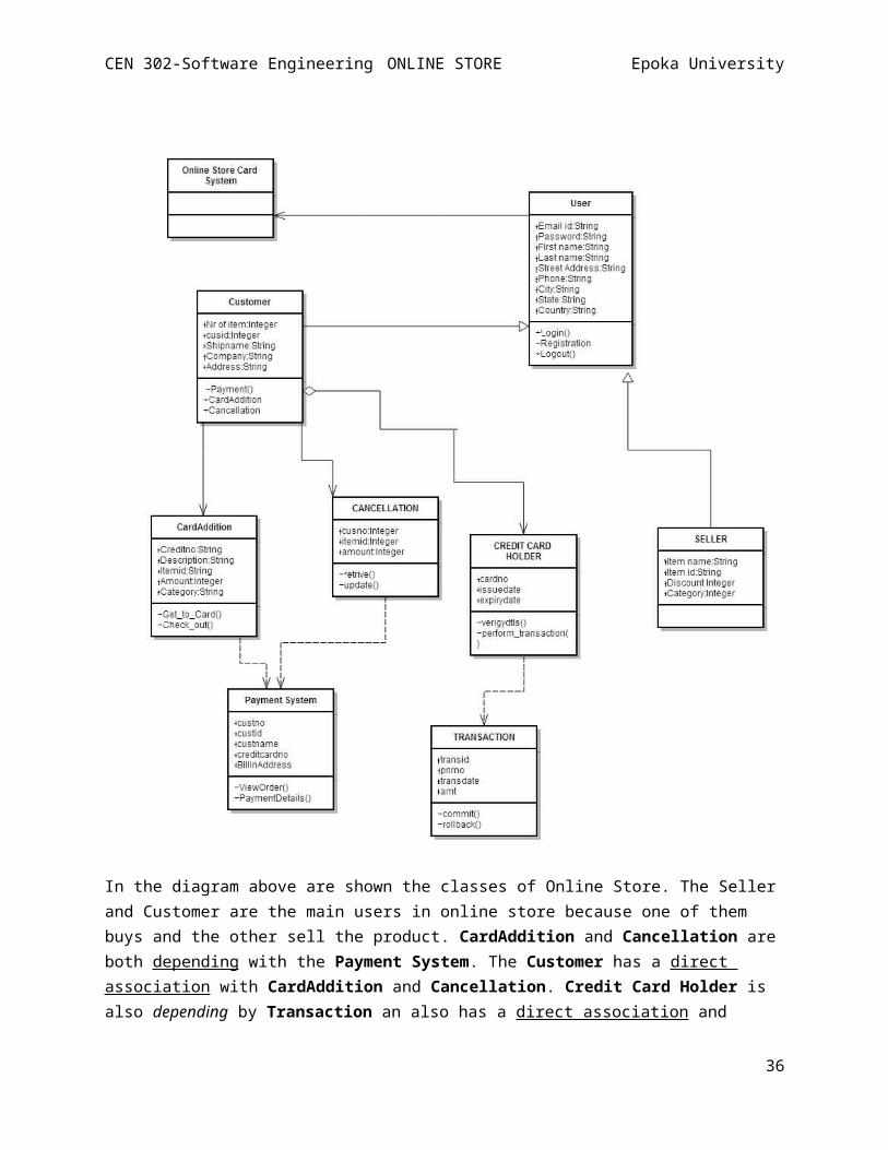
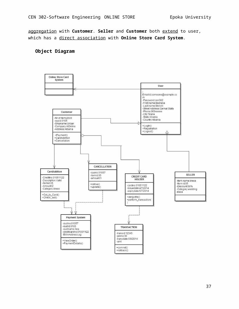
In the diagram above are shown the classes of Online Store. The Sellerand Customer are the main users in online store because one of them buys and the other sell the product. CardAddition and Cancellation areboth depending with the Payment System. The Customer has a direct association with CardAddition and Cancellation. Credit Card Holder is also depending by Transaction an also has a direct association and
36
CEN 302-Software Engineering ONLINE STORE Epoka University
aggregation with Customer. Seller and Customer both extend to user, which has a direct association with Online Store Card System.
Object Diagram
37
CEN 302-Software Engineering ONLINE STORE Epoka University
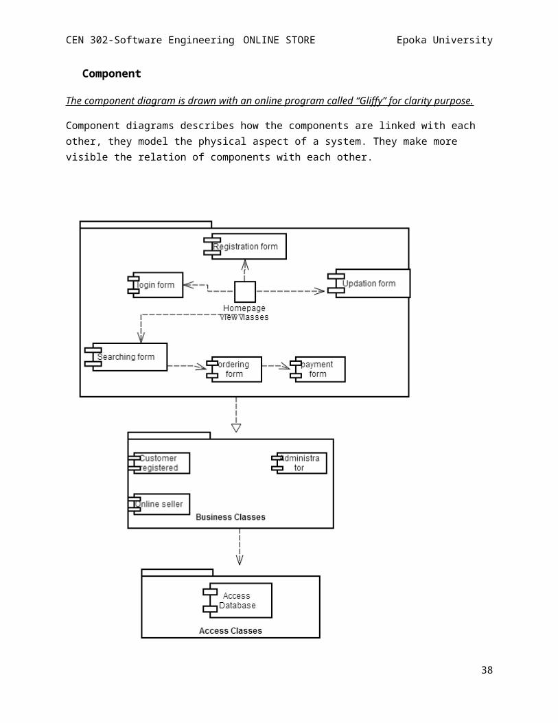
Component
The component diagram is drawn with an online program called “Gliffy” for clarity purpose.
Component diagrams describes how the components are linked with each other, they model the physical aspect of a system. They make more visible the relation of components with each other.
38
CEN 302-Software Engineering ONLINE STORE Epoka University
In online store case the server of database it includes: Customer,
Online seller, Administrator, Product and Payment. The nodes that have
no processing capabilities are the clients, the only node that send
request is the browser. In online store component diagram there are
also three packages: View Layer Classes, Access Classes and Business
Classes.
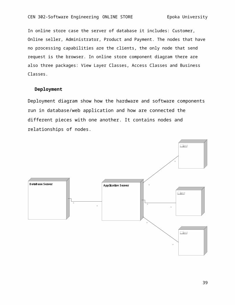
Deployment
Deployment diagram show how the hardware and software components
run in database/web application and how are connected the
different pieces with one another. It contains nodes and
relationships of nodes.
DataBase Server
**
Application Server
*
*
**
*
*
Client
Client
Client
39
CEN 302-Software Engineering ONLINE STORE Epoka University
2.5. Implementation
40


