Embed Size (px)
Citation preview

68 Journal of Electrical Engineering & Technology, Vol. 3, No. 1, pp.68~78, 2008
Modeling of a Four-Quadrant Switched Reluctance Motor Drive on EMTDC/PSCAD
Ismael El-Samahy*, Mostafa I. Marei† and Ehab F. El-Saadany*
Abstract – This paper introduces a complete package for SRM drive on Power System Computer-Aided Design / Electromagnetic Transients (PSCAD/EMTDC). A three-phase SRM drive is modeled and simulated on PSCAD. The motor is modeled using an accurate nonlinear analytical model that takes into consideration the machine nonlinearities. A current control algorithm is applied for torque ripple minimization to achieve a smooth output torque which is necessary for high performance applications. The motor drive is tested for four-quadrant operations. The modeled SRM is capable of operating as a motor or generator during clockwise and counterclockwise motions. The proposed package helps in understanding the operational principles of switched reluctance motors, investigating the dynamic characteristics of SRM drives, and achieving a high performance dynamic control task.
Keywords: EMTDC/PSCAD, Modeling, Simulation, SRM, Torque ripple minimization
1. Introduction Recently, Switched Reluctance Motor (SRM) drive has
found a desirable place in the market as a strong alternative for other motor drives. The SRM has been used in different adjustable speed applications whether at low power scale such as in the case of washers, dryers, and direct drive robotics, or at medium power scale such as in the case of electric vehicles, aerospace, mining, and the aviation industry. Researchers have been paying greater attention to the SRM due to its excellent features and the last decade has witnessed significant interest in modeling, control, and simulation of this motor drive.
In construction, the SR machines are the simplest of all electrical machines as only the stator has winding while the rotor is made of steel laminations without conductors or a permanent magnet. They are very reliable machines since the phases are largely independent physically, electrically and magnetically from each other. Simple power electronic drive requirements is one of the main features of this motor as only one switch per phase is needed because unidirectional current is required from the converter. The SRM can achieve very high speeds (100,000 rpm) due to the absence of any conductors or magnet on the rotor [1, 2].
The double salient structure of this type of machine
causes strong non-linear magnetic characteristics complicating its analysis and control. The drive performance depends on the magnetization curve, which is a non-linear function relating the flux linkage, the current, and the rotor position. The key to a fine control is then a simple but accurate model for the machine. Different approaches have been reported in the literature to develop a model for the SRM taking into consideration its magnetic non-linearity [3-16].
The highly non-linear and discrete nature of the torque production mechanism in the SRM results in high torque ripple. The minimization of torque ripples is essential in high performance applications, which require smooth operation with minimum torque pulsations. Many attempts have appeared for torque ripple minimization by applying suitable control algorithms and making use of the highly progressing technology in power electronics [17-29].
When torque or speed control tasks are required to be achieved, the complete SRM drive should be implemented in suitable software. Dynamic simulation of the SRM has always been achieved through programming using C or FORTRAN languages to solve a set of differential equations that represent the SRM model. Few simulation studies have been performed with circuit-based languages such as SPICE [30], [31] and MathCAD. However, these techniques are specially adapted to electronic circuit simulation and are not well-designed for time domain simulations. Recently, there has been significant progress in replication software such as MATLAB/SIMULINK [32], [33] and EMTDC/PSCAD [34] software, which are more appropriate for modeling and simulation of electric
* Dept. of Electrical and Computer Engineering, University of Waterloo, 200 University Avenue West, Waterloo, Ontario, Canada, N2L3G1. ([email protected] , [email protected])
† Corresponding Author: Electrical Power and Machines Dept., Ain Shams University, 1 El Sarayat St., Abbassia, Cairo, Egypt, 11517, Tel. (02) 010-6957052. ([email protected])
Received 12 March, 2007 ; Accepted 4 August, 2007

Ismael El-Samahy, Mostafa I. Marei and Ehab F. El-Saadany 69
motor drives. The solver engine of EMTDC/PSCAD software takes less time than MATLAB/SIMULINK to solve a mathematical model.
In the work presented in this paper, a complete SRM drive system is built and simulated on EMTDC/PSCAD software to investigate the dynamics of the drive system in both one-quadrant and four-quadrant operation. The implemented drive system includes the motor model, as well as the speed, torque, and current controllers. The introduced package is suitable for real-time high-performance dynamic control of the SRM drive.
The paper is organized as follows; Section 2 includes a quick review for the main modeling approaches that have appeared in the literature as well as a detailed discussion for the non-linear analytical model used in this work. Section 3 contains a brief review of the main techniques reported for torque ripple minimization for the SRM. A current control algorithm for reduced-ripple torque production is also discussed. The implementation of the complete drive system, as well as four-quadrant operation, is presented in Section 4. Section 5 includes the simulation results, where the dynamic performance of the drive is evidently revealed all the way through the waveforms of the phase currents, phase and total motor torque, phase voltages, and motor speed. Finally, the paper is concluded in Section 6.
2. Machine Model
2.1 Review Different techniques have been proposed to develop a
model for the SRM taking into consideration its non-linearity. Some of these techniques are based on calculating the flux linkage using look-up tables, on-line interpolation algorithms, and estimation techniques. The data for these models represents a set of curves for flux linkage versus current at different rotor positions. This data can be obtained by the Finite Element Method (FEM) [3], [4] or static tests on the available motor [5-7]. A 3-D FEM should be used in numerical calculations in order to reach the same accuracy of the static test data. The results of the FEM are accurate enough to predict the performance of the SRM. However, for the SRM control task, the FEM is not considered suitable because of the large amount of computation and huge input data that are required. On the other hand, static tests do not take into account the dynamic losses of the motor. When using look-up tables, the memory requirements depend on the desired accuracy and can get large if high accuracy is required for high performance applications.
Motivated by this, many researchers have attempted to
provide a non-linear analytical model that can accurately represent the dynamic performance of the SRM and at the same time be suitable for real-time control. The most popular approach is to decouple the effect of phase current and rotor position on flux linkage using Fourier expansions and polynomial equations. The coefficients of this expansion are calculated by curve fitting with the machine characteristics [8-13]. Piecewise modeling on the other hand was suggested in [14-16], where the flux linkage is expressed by a polynomial in i and θ. The coefficients of the polynomials are calculated by applying a curve fitting algorithm between the analytical expressions and the magnetization curves of the machine.
The basic set of equations used to model electrical and mechanical variables of an SRM are:
rivdt
idjj
j ⋅−=),( θψ (1)
L
m
jj TT
dtdJ −= ∑
=1
ω (2)
ωθ=
dtd (3)
where ψj is the flux linkage of phase j, vj is the voltage applied to the terminals of phase j, ij is the stator current of phase j, r is the stator phase resistance, θ is the rotor position, ω is the rotor speed, TL is the load torque, Tj is the developed torque of phase j, and J is the motor inertia.
The torque, Tj, produced by phase j, is determined by differentiating the coenergy function, Wj'(θ, ij), with respect to θ [1], [2]:
θθ
∂
∂=
'
),( jjj
WiT (4)
where
∫=ji
jjjjj diiiW0
' ),(),( θψθ (5)
For real-time control and simulation purposes, it is
more preferable to have a continuous function that can approximately represent the flux linkage characteristics, and hence expressions for coenergy and torque can be easily determined. Due to magnetic saturation, ψj is a nonlinear function of θ, and ij usually expressed by either polynomial or Fourier series expansions. If high level of accuracy is required, the model becomes more complicated in order to account for all the nonlinearities of the machine. For high dynamic performance control tasks, it is always required to find an inverse expression to

70 Modeling of a Four-Quadrant Switched Reluctance Motor Drive on EMTDC/PSCAD
determine the required current for a certain desired torque. However, using these nonlinear analytical expressions, it is hard to obtain an analytical expression for the phase current as a function of torque and rotor position. Iterative numerical techniques are thus used to obtain the required current to achieve the control task. With such complicated analytical models, these iterative numerical methods will be too computationally expensive to be practically implemented for real-time control. Simplicity is then an important requirement for an analytical model of SRM without losing an adequate level of accuracy in representing the machine nonlinearities.
2.2 The Non-Linear Analytical Model Used in This
Work A simple non-linear analytical model of the SRM was
introduced in [12]. The idea is to separate the effect of the phase current and rotor position on the flux linkage, which will be composed of three components; aligned and unaligned flux linkages, determined only by the phase current, and an angular function depending only on the rotor position. The method is very simple as the model uses only fundamental mathematical functions without any polynomial or Fourier series expansions. There are no coefficients to be precalculated and the magnetization characteristics do not need to be stored or curve fitted, which makes the model very suitable for real-time control. The results of the model were sufficiently accurate when compared with the measured results.
Based on the per unit system, a mathematical model was proposed to describe the flux linkage function as follows:
( ) )())()(()(, θψψψθψ fiiii uau −+= (6)
where ψa, ψu are aligned and unaligned flux linkage,
function only in the phase current, and f(θ) is an angular function depending only on the rotor position θ. All the parameters are in per unit values. The rated voltage and motor speed (in rpm) are taken as the base values for the voltage and speed respectively. The base value for the rotor position (θ) is chosen to be π. The current that produces the base flux linkage at aligned rotor position is chosen as the base current.
The flux linkage at the unaligned position can be considered linear and is given by:
iLi uu =)(ψ (7)
The flux linkage at the aligned position should satisfy
the following conditions:
1|0| 10 == == iaia ψψ (8)
uia
aia L
did
Ldi
d== ∞== || 0
ψψ
A suitable expression for the flux linkage at the aligned
rotor position can then be given by:
ikiLLiLi
suaaa +
−+=1
)()(ψ (9)
where La and Lu are the aligned and unaligned inductance and ks is the saturation factor and is given by:
u
as L
Lk
−−
=1
1 (10)
A suitable description of the angular function was
presented in [13] as follows:
⎪⎭
⎪⎬
⎫
⎪⎩
⎪⎨
⎧
≤
>⎟⎟⎠
⎞⎜⎜⎝
⎛−−⋅
−=
2/0
2/)2/(
)2/(cos5.05.0
)(
k
kk
kb
fθθ
θθπθπθθθ
θ (11)
where θk represents the non-overlap angle effect of rotor and stator poles (θk = 15/180 for 6/4 SRM) and θb is the base value of the position angle (θb = π). The angular function f(θ) varies between 0 at the unaligned position (when θ = 0) and 1 at the aligned position (when θ = 1 p.u).
3. Torque Ripple Minimization
3.1 Review Torque ripple minimization in the SRM can be
achieved either by improving the magnetic design of the motor or using a more sophisticated electronic control. However, complicated design requirements lead to losing the simple construction of the SRM. The motor performance and efficiency will be reduced due to these changes in the motor design. Hence, using a more sophisticated control algorithm is sometimes more preferred than using design as a solution for torque ripple problems. It is more preferable to maintain the simple structure of the SRM, which is considered one of its main advantages, and use the highly progressing technology in electronics to design more complicated controllers to achieve this task.
Many techniques have been reported throughout the literature for torque ripple minimization for the SRM. Some of these techniques, such as the fuzzy-logic [17, 18] and neural networks [19-21], are rarely used due to the

Ismael El-Samahy, Mostafa I. Marei and Ehab F. El-Saadany 71
highly nonlinear nature of the control task which increases the computational requirements for these techniques in order to achieve good results. Other techniques, such as feedback linearization [8, 22-24] are based on single-phase excitation torque control where only one phase is excited at a time through a commutator which determines the instant of turning off the reference current in one phase and turning it on in the next phase. During the commutation intervals, if the current is only controlled in the incoming phase and not controlled in the outgoing phase, the torque will have a notch during this interval. In order to avoid this, more sophisticated current control algorithms are applied to maintain constant torque and these commutation intervals.
3.2 The Torque Ripple Minimization Technique
Used in This Work Instead of applying single-phase excitation control, the
torque request can be distributed between two phases during the commutation interval through a Torque Distribution Function (TDF), which is a function of the rotor position. This TDF is defined so that the total torque is maintained constant at the desired value. The idea is to make the current follow a certain contour for all of the phases of the motor so that the sum of torques produced by each phase is constant and equals to the desired value no matter how smooth the current waveform is. A high-bandwidth current regulator is necessary to regulate the phase currents. In order to achieve this constant torque, a contour function TDFT(θ) is defined such that:
)(θTreftotal TDFTT ∗= (12)
)(θkrefrefk TDFTT ∗= (13)
1)()(1
==∑=
n
kkT TDFTDF θθ (14)
where Trefk and TDFk are the reference torque and the contour function for the kth phase respectively, while n is the number of phases.
This contour function may be referred to as a torque distribution function (TDF), or sometimes torque sharing function (TSF) and it is a function of the rotor position. A number of attempts in minimizing torque ripple were dedicated in designing torque distribution functions, which would define the individual phase torque requirement [25-28]. A cosine function similar to the one presented in [29] is chosen in the work presented here. The torque is distributed between the three-phases of the motor according to the following contour function:
Fig. 1. The contour function for the three-phases
⎪⎪⎩
⎪⎪⎨
⎧
<≤−−<≤
<≤−−
=
otherwise
TDF
0)(3cos5.05.0
1)(3cos5.05.0
)(320
21
100
θθθθθθθθ
θθθθθ
θ (15)
The contour functions for the three-phases are shown in
Fig. 1.
4. Implementation of the SRM drive in EMTDC/PSCAD
EMTDC/PSCAD is a general-purpose time domain
simulation tool dedicated for dynamic analysis and studying electromagnetic transients of power systems and electric machines. PSCAD is a fast, accurate, and easy-to-use power system simulator for the design and verification of all types of power systems with a comprehensive library of models encompassing all aspects of AC and DC power systems and controls. The well-known FORTRAN based EMTDC solution engine is most suitable for simulating time domain instantaneous responses (electromagnetic transients), in both electrical and control systems. EMTDC/PSCAD is widely used for modeling and simulating different control systems, transient analysis, and power electronic modeling.
In this section, the complete drive system shown in Fig. 2, including the motor and the speed, torque and current controllers, is implemented in EMTDC/PSCAD software. The speed controller is a conventional PI controller with a proper selection for its proportional and integral constants. Current control is achieved with closed-loop control through hysteresis switching control of the converter. The challenging task then involves the implementation of the motor model and the torque controller, as well as achieving four-quadrant operation.

72 Modeling of a Four-Quadrant Switched Reluctance Motor Drive on EMTDC/PSCAD
Fig. 2. Complete SRM drive system
4.1 Implementation of the Motor Model
The nonlinear analytical model described in Section 2.2
is implemented within the SRM block on EMTDC/PSCAD software. Using the motor parameters, the base values for voltage (Vb), speed (nb), time (tb), flux linkage (ψb), current (Ib), inductance (Lb), resistance (Rb), and torque (Tb) are calculated. The rated voltage and speed of the motor are chosen as the base voltage and speed respectively. The base value of the position angle is π. The base current is the current that produces the base flux linkage at aligned position, and can be found from the magnetization curve of the motor. The per unit values for the parameters required for the model such as per unit resistance, aligned and unaligned inductance, are then calculated. The flow chart shown in Fig. A1, in the Appendix, illustrates the required steps for machine modeling
4.2 Implementation of the Torque Controller
The block diagram of the torque controller consists of
two blocks; the TDF block and the Current Command Generating (CCG) block. The inputs to the torque controller are the reference torque (T*) coming from the outer speed loop and the rotor position (θ) from the SRM block. The TDF block generates the contour functions for the three-phases which determine the torque distribution among the motor phases. Using these contour functions together with the reference torque, the CCG block generates the current commands for the three motor phases. A Hysteresis Current Controller (HCC) is then used to regulate the phase currents according to these current commands to produce the required switching signals for the power converter. A current control algorithm is implemented to achieve a smooth output torque with reduced ripple. The algorithm is illustrated with the flow chart shown in Fig. A2 in the Appendix.
4.3 Four-Quadrant Operation An adjustable speed motor drive may operate in
different quadrants of the torque-speed plane depending on the application. In some applications torque control in one quadrant is sufficient. Whereas, in other applications such as hydraulic drive systems [35] and integrated
Fig. 3. The four operational quadrants
starter/alternator [36], a four-quadrant operation is necessary for a successful motor operation. This implies the ability to operate the switched reluctance machine as a motor or generator during clockwise and counterclockwise motions. The four operational quadrants are given in Fig. 3.
Forward motoring (first quadrant) operation is achieved by exciting the stator phase windings at the onset of increasing inductance when the rotor is moving from unaligned to aligned position. For forward regeneration (fourth quadrant) operation, the stator phase windings are however excited at the onset of decreasing inductance when the rotor is moving from aligned to unaligned position. Operation in the second and the third quadrants is the mirror symmetry of that of the fourth and the first quadrants respectively as the direction of motion (phase sequence) is reversed.
Four-quadrant operation of the SRM drive is achieved on EMTDC/PSCAD through a control block whose inputs are the speed and torque commands, while the output is a flag which determines the mode of operation. The controller switches the motor between the motoring and the regenerative braking modes in both directions according to the control command. Four different cases, representing the four modes of operation, will then emerge according to the polarity of the speed and torque commands. The flag is either 0 or 1 according to the polarity of the torque command. The angular function f(θ), given by (11), was defined for forward motoring operation, which implies positive torque production. For negative torque production, the angular function should be modified as the machine is now excited when it is moving from the aligned to the unaligned rotor position. The new angular function is given by:
⎪⎭
⎪⎬
⎫
⎪⎩
⎪⎨
⎧
−>
−≤⎟⎟⎠
⎞⎜⎜⎝
⎛−−⋅
+=
)2/1(0
)2/1()2/(
)2/(cos5.05.0
)(
k
kk
kb
fθθ
θθπθπθθθ
θ (16)
Ismael El-Samahy, Mostafa I. Marei and Ehab F. El-Saadany 73
A negative speed command implies operation in the opposite direction (reverse modes). This requires the load torque (TL) to be negative. Hence, on receiving a negative speed command, the controller set the load torque to a negative value for a reverse operation mode. The control algorithm used for four-quadrant operation can be summarized in the flow chart revealed in Fig. A3 in the Appendix.
5. Simulation Results A 6/4 three-phase SRM is simulated on EMTDC
/PSCAD software in order to investigate the dynamic characteristics of the motor. A 6/4 three-phase SRM is used for simulation with phase resistance of 1.3 Ω and inertia value of 0.0013 Kg.m2. The minimum and maximum inductances are 8mH and 60mH respectively [32].
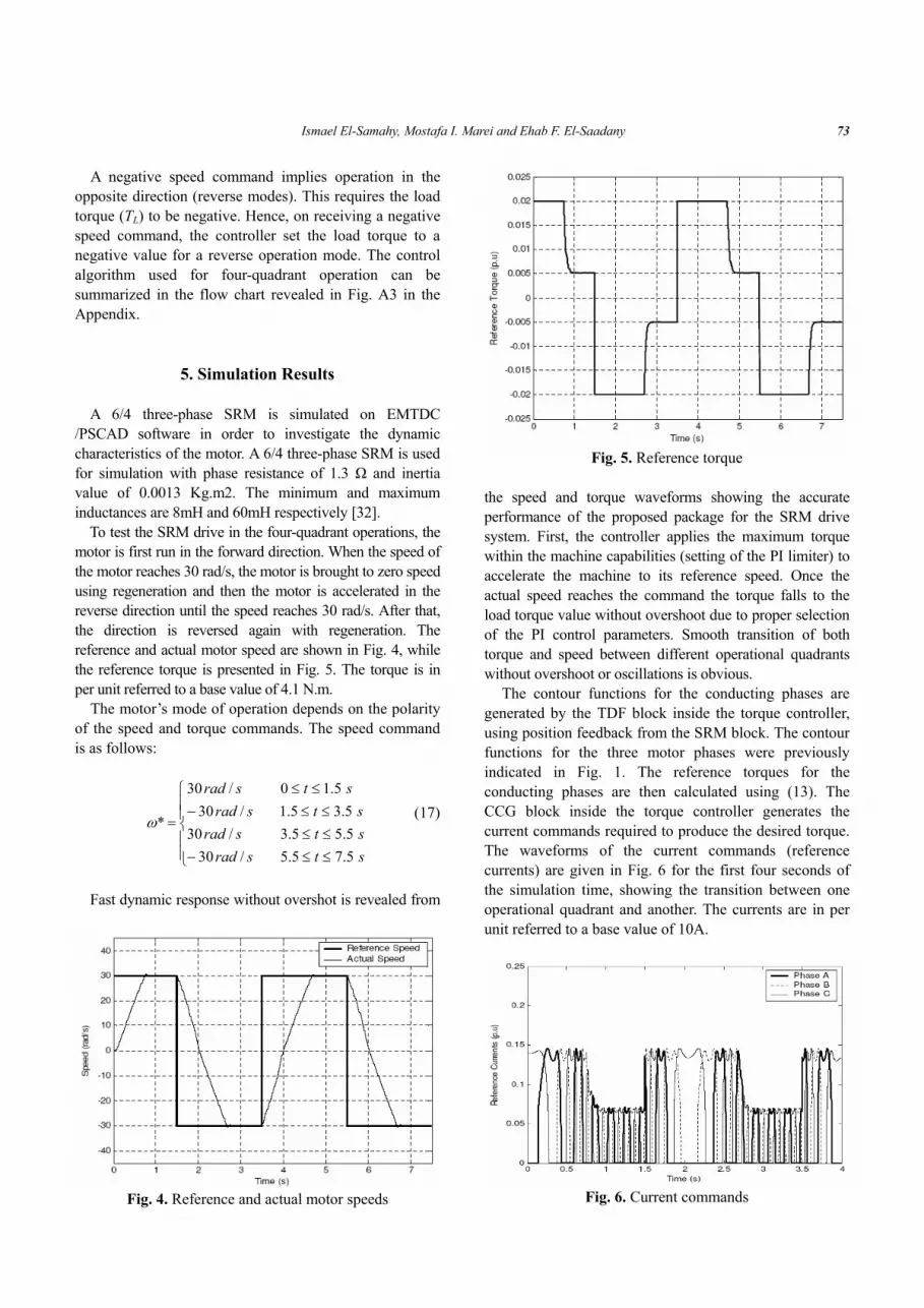
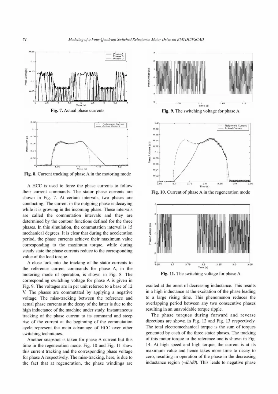
To test the SRM drive in the four-quadrant operations, the motor is first run in the forward direction. When the speed of the motor reaches 30 rad/s, the motor is brought to zero speed using regeneration and then the motor is accelerated in the reverse direction until the speed reaches 30 rad/s. After that, the direction is reversed again with regeneration. The reference and actual motor speed are shown in Fig. 4, while the reference torque is presented in Fig. 5. The torque is in per unit referred to a base value of 4.1 N.m.
The motor’s mode of operation depends on the polarity of the speed and torque commands. The speed command is as follows:
⎪⎪⎩
⎪⎪⎨
⎧
≤≤−≤≤≤≤−
≤≤
=
stsradstsradstsrad
stsrad
5.75.5/305.55.3/305.35.1/30
5.10/30
*ω (17)
Fast dynamic response without overshot is revealed from
Fig. 4. Reference and actual motor speeds
Fig. 5. Reference torque
the speed and torque waveforms showing the accurate performance of the proposed package for the SRM drive system. First, the controller applies the maximum torque within the machine capabilities (setting of the PI limiter) to accelerate the machine to its reference speed. Once the actual speed reaches the command the torque falls to the load torque value without overshoot due to proper selection of the PI control parameters. Smooth transition of both torque and speed between different operational quadrants without overshoot or oscillations is obvious.
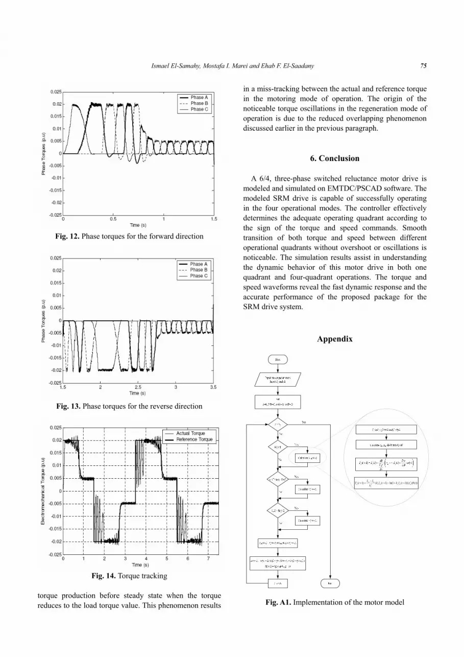
The contour functions for the conducting phases are generated by the TDF block inside the torque controller, using position feedback from the SRM block. The contour functions for the three motor phases were previously indicated in Fig. 1. The reference torques for the conducting phases are then calculated using (13). The CCG block inside the torque controller generates the current commands required to produce the desired torque. The waveforms of the current commands (reference currents) are given in Fig. 6 for the first four seconds of the simulation time, showing the transition between one operational quadrant and another. The currents are in per unit referred to a base value of 10A.
Fig. 6. Current commands
74 Modeling of a Four-Quadrant Switched Reluctance Motor Drive on EMTDC/PSCAD
Fig. 7. Actual phase currents
Fig. 8. Current tracking of phase A in the motoring mode
A HCC is used to force the phase currents to follow
their current commands. The stator phase currents are shown in Fig. 7. At certain intervals, two phases are conducting. The current in the outgoing phase is decaying while it is growing in the incoming phase. These intervals are called the commutation intervals and they are determined by the contour functions defined for the three phases. In this simulation, the commutation interval is 15 mechanical degrees. It is clear that during the acceleration period, the phase currents achieve their maximum value corresponding to the maximum torque, while during steady state the phase currents reduce to the corresponding value of the load torque.
A close look into the tracking of the stator currents to the reference current commands for phase A, in the motoring mode of operation, is shown in Fig. 8. The corresponding switching voltage for phase A is given in Fig. 9. The voltages are in per unit referred to a base of 12 V. The phases are commutated by applying a negative voltage. The miss-tracking between the reference and actual phase currents at the decay of the latter is due to the high inductance of the machine under study. Instantaneous tracking of the phase current to its command and steep rise of the current at the beginning of the commutation cycle represent the main advantage of HCC over other switching techniques.
Another snapshot is taken for phase A current but this time in the regeneration mode. Fig. 10 and Fig. 11 show this current tracking and the corresponding phase voltage for phase A respectively. The miss-tracking, here, is due to the fact that at regeneration, the phase windings are
Fig. 9. The switching voltage for phase A
Fig. 10. Current of phase A in the regeneration mode
Fig. 11. The switching voltage for phase A
excited at the onset of decreasing inductance. This results in a high inductance at the excitation of the phase leading to a large rising time. This phenomenon reduces the overlapping period between any two consecutive phases resulting in an unavoidable torque ripple.
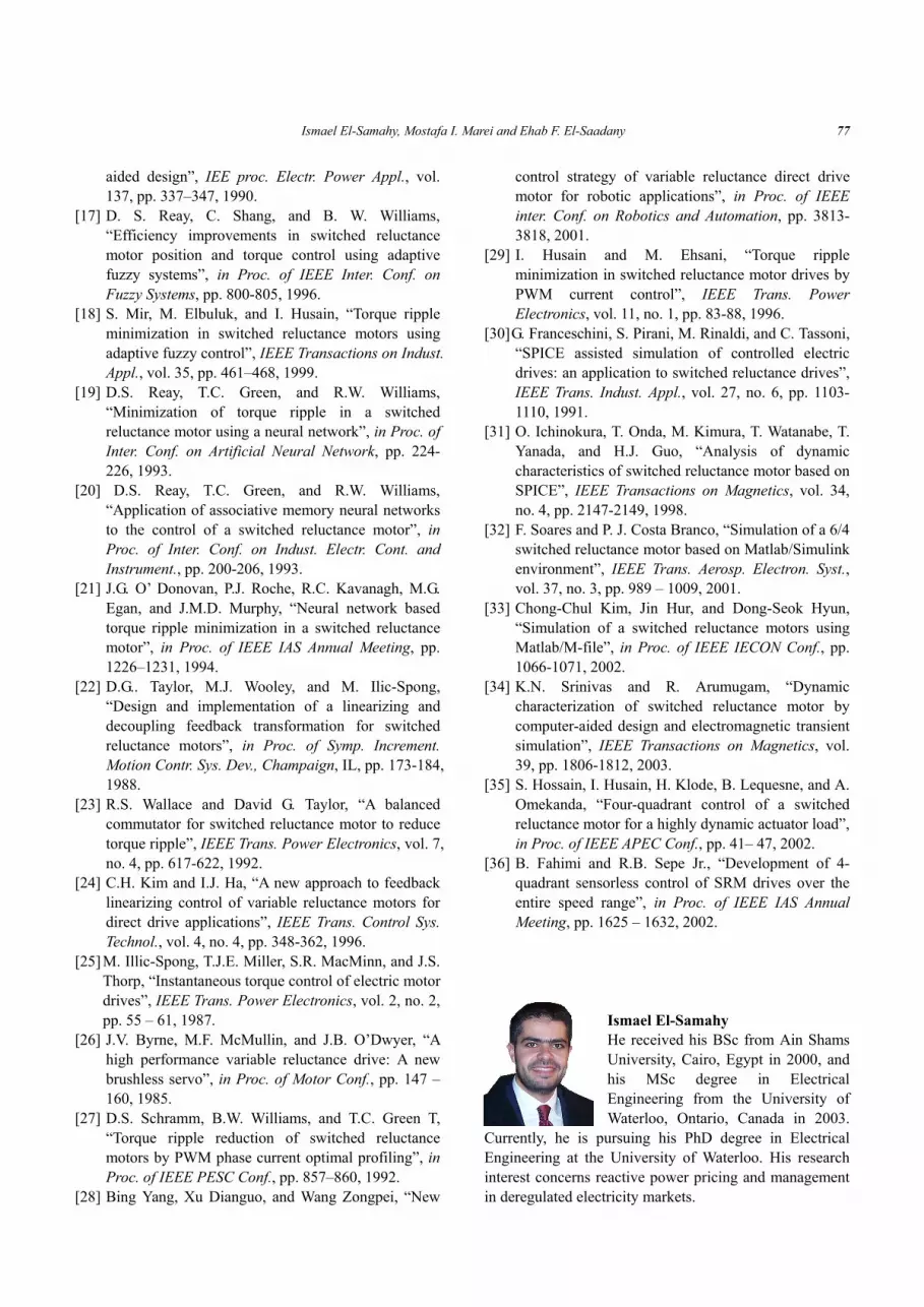
The phase torques during forward and reverse directions are shown in Fig. 12 and Fig. 13 respectively. The total electromechanical torque is the sum of torques generated by each of the three stator phases. The tracking of this motor torque to the reference one is shown in Fig. 14. At high speed and high torque, the current is at its maximum value and hence takes more time to decay to zero, resulting in operation of the phase in the decreasing inductance region (-dL/dθ). This leads to negative phase
Ismael El-Samahy, Mostafa I. Marei and Ehab F. El-Saadany 75
Fig. 12. Phase torques for the forward direction
Fig. 13. Phase torques for the reverse direction
Fig. 14. Torque tracking
torque production before steady state when the torque reduces to the load torque value. This phenomenon results
in a miss-tracking between the actual and reference torque in the motoring mode of operation. The origin of the noticeable torque oscillations in the regeneration mode of operation is due to the reduced overlapping phenomenon discussed earlier in the previous paragraph.
6. Conclusion A 6/4, three-phase switched reluctance motor drive is
modeled and simulated on EMTDC/PSCAD software. The modeled SRM drive is capable of successfully operating in the four operational modes. The controller effectively determines the adequate operating quadrant according to the sign of the torque and speed commands. Smooth transition of both torque and speed between different operational quadrants without overshoot or oscillations is noticeable. The simulation results assist in understanding the dynamic behavior of this motor drive in both one quadrant and four-quadrant operations. The torque and speed waveforms reveal the fast dynamic response and the accurate performance of the proposed package for the SRM drive system.
Appendix
))(()))1(1ln()1(()1( '2 tftIktIk
kLLtT aasas
s
uaa θ++−+
−=+
Fig. A1. Implementation of the motor model

76 Modeling of a Four-Quadrant Switched Reluctance Motor Drive on EMTDC/PSCAD
))(()))(1ln()(()( '2 tftIktIk
kLLtT arefasrefas
s
uaa θ+−
−=
Fig. A2. Torque ripple minimization algorithm
Fig. A3. Control algorithm for four-quadrant operation
References
[1] R. Krishnan, Switches Reluctance Motor Drives: Industrial Electronics Series, CRC Press, 2001.
[2] T. J. E. Miller, Electronic Control of Switch Reluctance Machines: Newnes Power Engineering Series, 2001.
[3] R. Arumugam, D.A. Lowther, R. Krishnan, and J.F.
Lindsay, “Magnetic field analysis of a switched reluctance motor using a two dimensional finite element method”, IEEE Trans. Magnetics, vol. 21, pp. 1883 –1885, 1985.
[4] J.F. Lindsay, R. Arumugan, and R. Krishnan, “Finite-element analysis characterization of a switched reluctance motor with multitooth per stator pole,” IEE Proc. Electr. Power Appl., vol. 133, no. 6, pp. 347–353, 1986.
[5] R.C. Kavanagh, J.M.D. Murphy, and M.G. Egan, “Torque ripple minimization in switched reluctance drives using self learning techniques”, in Proc. of IEEE, IECON Conf., pp. 289-294, 1991.
[6] J. . Moreira, “Torque ripple minimization in switched reluctance motor via bi-cubic spline interpolation”, in Proc. of IEEE PESC Conf., pp. 851-856, 1992.
[7] D.S. Schramm, B.W. Williams, and T.C. Green, “Torque ripple reduction of switched reluctance motors by phase current optimal profiling”, in Proc. of IEEE PESC Conf., pp. 857-860, 1992.
[8] M.I. Spong, R.M. Marino, S.M. Peresada, “Feedback linearizing control of switched reluctance motor", IEEE Trans. Auto. Control, vol. 32, no. 5, pp. 317-379, 1987.
[9] D.A. Torrey and J.H. Lang, “Modelling a non-linear variable reluctance motor drive”, IEE Proc. Electr. Power Appl., vol. 137, no. 5, pp. 314-326, 1990.
[10] S. Saha, K.Ochiai, T. Kosaka, and N. Matsui, “Developing a Sensorless Approach for Switched Reluctance Motors from a New Analytical Model”, in Proc. of IEEE IAS Annual Meeting, pp. 525-532, 1999.
[11] B. Fahimi, G. Suresh, J. Mahdavi, and M. Ehsani, “A new approach to model switched reluctance motor drive application to dynamic performance prediction, control and design”, in Proc. of IEEE PESC Conf., pp. 2097-2102, 1998.
[12] M. Stiebler and K. Liu, “An Analytical Model of Switched Reluctance Machines”, IEEE Trans. Energy Conversion, vol. 14, no. 4, pp. 1100–1105, 1999.
[13] L. Shanshan, Z. Zhengming, M. Shuo, and C. Jianyun, “A nonlinear analytical model for switched reluctance motor”, in Proc. of IEEE TENCON Conf., pp. 2034 – 2037, 2002.
[14] D.G. Manzer, M. Varghese, and J.S. Thorp, “Variable reluctance motor characterization”, IEEE Trans. Indust. Electr., vol. 36, no. 1, pp. 56-63, 1989.
[15] S.U. Rehman and D.G. Taylor, “Piecewise modeling and optimal commutation of switched reluctance motors”, in Proc. of IEEE ISIE Conf., pp. 266 – 271, 1995.
[16] T.J.E. Miller and M. McGilp, “Nonlinear theory of the switched reluctance motor for rapid computer-
Ismael El-Samahy, Mostafa I. Marei and Ehab F. El-Saadany 77
aided design”, IEE proc. Electr. Power Appl., vol. 137, pp. 337–347, 1990.
[17] D. S. Reay, C. Shang, and B. W. Williams, “Efficiency improvements in switched reluctance motor position and torque control using adaptive fuzzy systems”, in Proc. of IEEE Inter. Conf. on Fuzzy Systems, pp. 800-805, 1996.
[18] S. Mir, M. Elbuluk, and I. Husain, “Torque ripple minimization in switched reluctance motors using adaptive fuzzy control”, IEEE Transactions on Indust. Appl., vol. 35, pp. 461–468, 1999.
[19] D.S. Reay, T.C. Green, and R.W. Williams, “Minimization of torque ripple in a switched reluctance motor using a neural network”, in Proc. of Inter. Conf. on Artificial Neural Network, pp. 224-226, 1993.
[20] D.S. Reay, T.C. Green, and R.W. Williams, “Application of associative memory neural networks to the control of a switched reluctance motor”, in Proc. of Inter. Conf. on Indust. Electr. Cont. and Instrument., pp. 200-206, 1993.
[21] J.G. O’ Donovan, P.J. Roche, R.C. Kavanagh, M.G. Egan, and J.M.D. Murphy, “Neural network based torque ripple minimization in a switched reluctance motor”, in Proc. of IEEE IAS Annual Meeting, pp. 1226–1231, 1994.
[22] D.G.. Taylor, M.J. Wooley, and M. Ilic-Spong, “Design and implementation of a linearizing and decoupling feedback transformation for switched reluctance motors”, in Proc. of Symp. Increment. Motion Contr. Sys. Dev., Champaign, IL, pp. 173-184, 1988.
[23] R.S. Wallace and David G. Taylor, “A balanced commutator for switched reluctance motor to reduce torque ripple”, IEEE Trans. Power Electronics, vol. 7, no. 4, pp. 617-622, 1992.
[24] C.H. Kim and I.J. Ha, “A new approach to feedback linearizing control of variable reluctance motors for direct drive applications”, IEEE Trans. Control Sys. Technol., vol. 4, no. 4, pp. 348-362, 1996.
[25] M. Illic-Spong, T.J.E. Miller, S.R. MacMinn, and J.S. Thorp, “Instantaneous torque control of electric motor drives”, IEEE Trans. Power Electronics, vol. 2, no. 2, pp. 55 – 61, 1987.
[26] J.V. Byrne, M.F. McMullin, and J.B. O’Dwyer, “A high performance variable reluctance drive: A new brushless servo”, in Proc. of Motor Conf., pp. 147 –160, 1985.
[27] D.S. Schramm, B.W. Williams, and T.C. Green T, “Torque ripple reduction of switched reluctance motors by PWM phase current optimal profiling”, in Proc. of IEEE PESC Conf., pp. 857–860, 1992.
[28] Bing Yang, Xu Dianguo, and Wang Zongpei, “New
control strategy of variable reluctance direct drive motor for robotic applications”, in Proc. of IEEE inter. Conf. on Robotics and Automation, pp. 3813-3818, 2001.
[29] I. Husain and M. Ehsani, “Torque ripple minimization in switched reluctance motor drives by PWM current control”, IEEE Trans. Power Electronics, vol. 11, no. 1, pp. 83-88, 1996.
[30] G. Franceschini, S. Pirani, M. Rinaldi, and C. Tassoni, “SPICE assisted simulation of controlled electric drives: an application to switched reluctance drives”, IEEE Trans. Indust. Appl., vol. 27, no. 6, pp. 1103-1110, 1991.
[31] O. Ichinokura, T. Onda, M. Kimura, T. Watanabe, T. Yanada, and H.J. Guo, “Analysis of dynamic characteristics of switched reluctance motor based on SPICE”, IEEE Transactions on Magnetics, vol. 34, no. 4, pp. 2147-2149, 1998.
[32] F. Soares and P. J. Costa Branco, “Simulation of a 6/4 switched reluctance motor based on Matlab/Simulink environment”, IEEE Trans. Aerosp. Electron. Syst., vol. 37, no. 3, pp. 989 – 1009, 2001.
[33] Chong-Chul Kim, Jin Hur, and Dong-Seok Hyun, “Simulation of a switched reluctance motors using Matlab/M-file”, in Proc. of IEEE IECON Conf., pp. 1066-1071, 2002.
[34] K.N. Srinivas and R. Arumugam, “Dynamic characterization of switched reluctance motor by computer-aided design and electromagnetic transient simulation”, IEEE Transactions on Magnetics, vol. 39, pp. 1806-1812, 2003.
[35] S. Hossain, I. Husain, H. Klode, B. Lequesne, and A. Omekanda, “Four-quadrant control of a switched reluctance motor for a highly dynamic actuator load”, in Proc. of IEEE APEC Conf., pp. 41– 47, 2002.
[36] B. Fahimi and R.B. Sepe Jr., “Development of 4-quadrant sensorless control of SRM drives over the entire speed range”, in Proc. of IEEE IAS Annual Meeting, pp. 1625 – 1632, 2002.
Ismael El-Samahy He received his BSc from Ain Shams University, Cairo, Egypt in 2000, and his MSc degree in Electrical Engineering from the University of Waterloo, Ontario, Canada in 2003.
Currently, he is pursuing his PhD degree in Electrical Engineering at the University of Waterloo. His research interest concerns reactive power pricing and management in deregulated electricity markets.
78 Modeling of a Four-Quadrant Switched Reluctance Motor Drive on EMTDC/PSCAD
Mostafa I. Marei He was born in Alexandria, Egypt on June 17, 1975. He received his B.Sc. and M.Sc. degrees in Electrical Engineering from Ain Shams University, Cairo, Egypt, in 1997 and 2000, respectively, and his Ph.D. in
Electrical Engineering from the University of Waterloo, Waterloo, ON, Canada, in 2004. From 2004 to 2006 he was a Postdoctoral Fellow at the University of Waterloo. Currently, he is an Assistant Professor at the Electrical Power and Machines Dept., Ain Shams University. His research interests include power electronics, hybrid electric vehicles, custom power, artificial intelligent applications in power systems, digital control-based microcontrollers and digital signal processors (DSPs), power quality, and distributed generation.
Ehab F. El-Saadany He was born in Cairo, Egypt in 1964. He received his B.Sc. and M.Sc. in Electrical Engineering from Ain Shams University, Cairo, Egypt in 1986 and 1990, respectively, and his Ph.D. degree, also in Electrical
Engineering in 1998 from the University of Waterloo, Waterloo, ON, Canada. He is currently an Assistant Professor in the Department of Electrical and Computer Engineering at the University of Waterloo. His research interests are distribution system control and operation, power quality, power electronics, and DSP applications to power systems. Dr. El-Saadany is a member of the IEEE.


