Embed Size (px)
Citation preview
vw
5 things to considerwhen selecting your
Omnidirectional Base Station Antenna
Manufacturers have a large product offering when it comes to Omnidirectional Antennas for base station applications.
Building out network infrastructure for Public Safety, IoT or LTE networks will typically need the highest performance criteria in electrical, mechanical, and environmental protection. These are usually the most cutting-edge pro-duct the manufacturer offers. There is a premium to having these high spec antennas but expect a service life of 10 years plus. Typical features should be low PIM, high power handling (PIP), robust windspeed survi-val (186mph/300kmh), lighting protection, fixed down tilt and null fill.
Private / Land Mobile Radio etc.At the other end of the scale, Omnidirectional Antennas for Private / Land Mobile Radio, external antennas for gateways (IoT), or for a fixed terminal, then it is still possible to get great performance without some of the characteristics of the premium product that are simply not needed.
Expect to have reasonable wind survival, smal-ler diameter mast, fixed 0 degree down tilt, and quite often an integral clamp. A service life of 5 years plus would be a reasonable expectation.
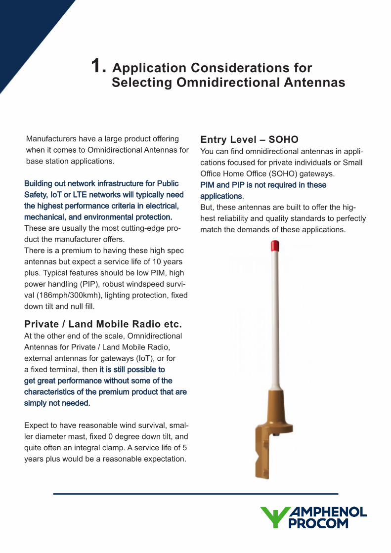
Entry Level – SOHOYou can find omnidirectional antennas in appli-cations focused for private individuals or Small Office Home Office (SOHO) gateways. PIM and PIP is not required in these applications. But, these antennas are built to offer the hig-hest reliability and quality standards to perfectly match the demands of these applications.
1. Application Considerations for Selecting Omnidirectional Antennas
GainThis is a white paper in itself, so we are going to skip past all the technical parameters. There is a lot of “spec-man-ship” that goes on here, so make sure to compare apples to apples when looking at gain values. Some datasheets will show gain measured in dBd and other in dBi. It’s like measuring in inches or centimetres; to convert, the dBd value is always 2.15 less than the dBi value - for example 0dBd is equal to 2.15dBi.
Pattern TiltPattern Tilt is is a very useful feature and normally only found in high end solutions. It’s used to tilt the pattern so it will cover users directly below the mast, or to avoid crashing into other parts of your network, or other people’s networks.
This is typically an electrical parameter, built into the RF feed system of the antenna, that is fixed during manufacturing and typically offered with a range from 0-15 degrees. This option is fixed and needs to be chosen at point of order; it cannot be changed in the field. Mid to low tier models don’t usually have this option - they are all 0 degrees. Selecting the correct down tilt is usually figured out by the installer and/or the network coverage plan.
Passive Intermodulation (PIM)Briefly speaking, PIM is a form of harmonic noise that can occur in RF components and products like antennas. Typically, PIM occurs when there is a mix of two strong RF signals in one device. In some configurations, this will cause interference in the receive channel.
High end, low-PIM products will be constructed to minimise this, and if you are operating or planning a multi carrier network like LTE and Public Safety, you really need to have this feature. The industry standard value is -153dBc (3rd Order, 2 x Tx @ 43dBm). Anything lower, like -143dBc, PIM measured in the 5th order, orwith carrier levels lower than 43dBm may notbe suitable for LTE or Public Safety networks.Make sure and check the specifications care-fully.
Peak Instantaneous (PIP)PIP rating is used to measure the instantane-ous peak in voltage in a multicarrier system. There is a lot more science to this but in high-end antennas, designed to be used in LTE mul-ticarrier networks, the antenna needs to have a PIP specification of around 25kW. If there is no PIP spec. then you might find that voltage arcs across other junctions inside the antenna and over time causes field failures. Middle tier and entry level omni’s will not have this feature.
2. Electrical Characteristics
Consider a very hostile environment for a new Public Safety network designed to cover 95% of the land mass based in Norway. Can you imagine the strain and stress the omnidirectio-nal antenna would go under due to the weather conditions? Wind, ice, and snow for sustained periods of time.
TemperatureTemperature is a crucial consideration for Net-work infrastructure antennas (high end omni antennas) as they are exposed to extreme temperatures and need to remain fully functio-nal even when the mercury reads -50°C (-58°F) to 55°C (131°F). Antennas with these charac-teristics ensure that the worst weather condi-tions will not harm the integrity of the network, the material used in the construction are the best available and don’t forget that the feeder cable and jumper cables need to meet a similar specification too. Mid-tier product you should expect to survive -30°C (-22°F) to at least 55°C (131°F) low tier product will have further reduc-tions in their temperature survival capability.
Wind SurvivalWind survival is critical for any antenna being placed in a network. When putting a 3mtr (10ft) antenna on a mast in the mountains, gusts can be extreme, and high speeds sustained over long periods of time. Market leading pro-ducts will usually withstand speeds of 300kph (186mph), that’s a force 5 hurricane.
Lightning ProtectionLightning protection in antennas is achieved by DC grounding all metallic parts; this is a design feature. In some high-end omni antennas, a metal cap is provided, so the antenns remain intact following a lightning strike of 2.5 x 10⁵ A2 seconds. Don’t confuse this with surge / lightning arrestors; these devices are placed inline of the coax feeder system and break the connection when they detect a sudden and unexpected burst of energy.
Not all antennas will have this level of prote-ction, not all will need it. It really depends on where you are installing the antennas and associated risk of lightning strikes.
3. Environmental Specifications
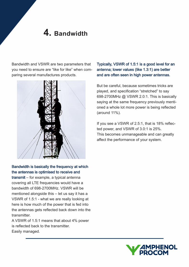
Bandwidth and VSWR are two parameters that you need to ensure are “like for like” when com-paring several manufactures products.
Bandwidth is basically the frequency at which the antennas is optimised to receive and transmit – for example, a typical antenna covering all LTE frequencies would have a bandwidth of 698-2700MHz. VSWR will be mentioned alongside this – let us say it has a VSWR of 1.5:1 - what we are really looking at here is how much of the power that is fed into the antennas gets reflected back down into the transmitter. A VSWR of 1.5:1 means that about 4% power is reflected back to the transmitter. Easily managed.
Typically, VSWR of 1.5:1 is a good level for an antenna; lower values (like 1.3:1) are better and are often seen in high power antennas.
But be careful, because sometimes tricks are played, and specification “stretched” to say 698-2700MHz @ VSWR 2.0:1. This is basically saying at the same frequency previously menti-oned a whole lot more power is being reflected (around 11%).
If you see a VSWR of 2.5:1, that is 18% reflec-ted power, and VSWR of 3.0:1 is 25%. This becomes unmanageable and can greatly affect the performance of your system.
4. Bandwidth
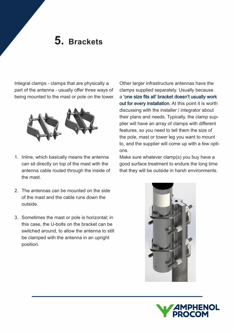
Integral clamps - clamps that are physically a part of the antenna - usually offer three ways of being mounted to the mast or pole on the tower.
1. Inline, which basically means the antennacan sit directly on top of the mast with theantenna cable routed through the inside ofthe mast.
2. The antennas can be mounted on the sideof the mast and the cable runs down theoutside.
3. Sometimes the mast or pole is horizontal; inthis case, the U-bolts on the bracket can beswitched around, to allow the antenna to stillbe clamped with the antenna in an uprightposition.
Other larger infrastructure antennas have the clamps supplied separately. Usually because a ‘one size fits all’ bracket doesn’t usually work out for every installation. At this point it is worth discussing with the installer / integrator about their plans and needs. Typically, the clamp sup-plier will have an array of clamps with different features, so you need to tell them the size of the pole, mast or tower leg you want to mount to, and the supplier will come up with a few opti-ons. Make sure whatever clamp(s) you buy have a good surface treatment to endure the long time that they will be outside in harsh environments.
5. Brackets

antennaPRO Sales: [email protected]
https://www.antennapro.co.uk
antennaPRO Unit 5B, Altira Park, Herne Bay, Kent. CT6 6GZ
Here to help
At antennaPRO we take a consultative approach to our customers’ requests.
If you have a question, need some support or cannot find what you are looking for, we are here to help.


