Embed Size (px)
Citation preview
OMA Independent Power Project
Geometric Power Limited
Environmental and Social Impact Assessment
April 2016
Envir onmental and Soci al Impact Assessment
Geometirc Power Li mited
60K31700
OMA Independent Power Project
Project no: 60K31700
Document title: Environmental and Social Impact Assessment of Oma Independent Power Project
Revision: 4
Date: April 2016
Client name: Geometric Power Limited
Project manager: John Paul Wale/Dorney Burgdorf
Author: Dorney Burgdorf
Jacobs Engineering UK Limited
Tower Bridge Court
226 Tower Bridge Road
London
SE1 2UP
Tel: +44(0)207.403.3330
Fax: +44(0)207.939.1418
Time Zone: +0000 UTC/GMT
www.jacobs.com
© Copyright 2015 Jacobs Engineering UK Limited. The concepts and information contained in this document are the property of Jacobs. Use or
copying of this document in whole or in part without the written permission of Jacobs constitutes an infringement of copyright.
Limitation: This report has been prepared on behalf of, and for the exclusive use of Jacobs’ Client, and is subject to, and issued in accordance with, the
provisions of the contract between Jacobs and the Client. Jacobs accepts no liability or responsibility whatsoever for, or in respect of, any use of, or reliance
upon, this report by any third party.
Document history and status
Revision Date Description By Review Approved
1 15-09-15 EC DB/JPW DC
2 30-10-15 DB JPW DC
3 01-03-16 Addressing comments from World Bank DB/HG DC DB
4 13-04-16 Incorporation of final comments DB/HG DC DB
Environmental and Social Impact Assessment of Oma
Independent Power Project
The report was prepared by Jacobs for the sole benefit and use of Oma Power Generation Company Limited. Jacobs and
its affiliates shall have no liability whatsoever to third parties for any defect, deficiency, error, or omission in any
statement contained in or in any way related to the study or report or any related documents. Neither Jacobs nor any
person acting on Jacobs’ behalf makes any warranty, express or implied, or assumes any liability with respect to use or
reliance on any information, technology or methods disclosed or discussed in the study or report. Any forecasts,
estimates, projections, opinions or conclusions reached in the study or report are dependent upon numerous technical
and economic conditions over which Jacobs has no control and which are or may not occur. Reliance upon such opinions
or conclusions by any person or entity is at the sole risk of the person relying thereon.
In some cases the data, information and assumptions used to develop the report or study were obtained or derived from
documents or information furnished by others. Jacobs did not independently verify the field data collected or the desktop
studies completed by others and does not assume responsibility for its accuracy or completeness. Any forecasts, or costs
or pricing estimates in the study or report are considered forward-looking statements and represent Jacobs’ current
opinion and expectation of a likely outcome. They do not anticipate possible changes in governmental policies,
governmental regulations, military action, embargoes, or production cutbacks, regional conflicts, or other events or
factors that could cause the forecast or estimates to differ materially from what is contained in our forward-looking
statements. The study or report is dated as of the date stated herein, which is the date Jacobs completed its work.
Jacobs has no obligation to update or revise the study or report or to revise any opinions, forecasts or assumptions
because of events, circumstances or transactions occurring after the date of the study or report.
Environmental and Social Impact Assessment of Oma
Independent Power Project
Contents
Acronyms ............................................................................................................................................................... 9
PART 1 – Non-technical Summary ..................................................................................................................... 13
1. The Project ............................................................................................................................................... 14
1.1 Project Objectives ...................................................................................................................................... 14
1.2 The Proponent(s) ....................................................................................................................................... 14
1.3 The Site and Proposed Development ....................................................................................................... 14
1.4 Consultation and stakeholder engagement ............................................................................................... 17
1.5 Policy, Legal and Administrative Framework ............................................................................................ 17
2. Environmental Impacts and Mitigation ................................................................................................. 19
2.1 Air Quality .................................................................................................................................................. 19
2.2 Energy Efficiency and Greenhouse Gas Emissions .................................................................................. 19
2.3 Noise.......................................................................................................................................................... 19
2.4 Geology, Soils, Hydrogeology and Hydrology ........................................................................................... 20
2.5 Ecology ...................................................................................................................................................... 20
2.6 Waste and Hazardous Materials ............................................................................................................... 21
2.7 Socio Economics ....................................................................................................................................... 21
2.8 Cumulative Impact Assessment ................................................................................................................ 22
PART 2 – Environmental and Social Impact Assessment ............................................................................... 23
1. Introduction .............................................................................................................................................. 24
1.1 General ...................................................................................................................................................... 24
1.2 The Proponents ......................................................................................................................................... 24
1.3 Study Location ........................................................................................................................................... 25
1.4 Environmental and Social Impact Assessment Scope .............................................................................. 26
1.5 Environmental and Social Impact Assessment Objectives ....................................................................... 27
1.6 Environmental and Social Impact Assessment Methodology ................................................................... 28
1.7 Structure of the Report .............................................................................................................................. 30
1.8 Input from International Consultants (Jacobs UK Limited) ........................................................................ 31
2. Policy, Legal and Administrative Framework ....................................................................................... 32
2.1 Overview .................................................................................................................................................... 32
2.2 Regulatory Constraints .............................................................................................................................. 32
2.3 Nigerian Government Administrative Subdivisions ................................................................................... 32
2.4 Federal Environmental Management Framework and Corresponding Agency Jurisdictional Authority .................................................................................................................................................... 32
2.5 Electrical Power Sector Regulatory Framework ........................................................................................ 44
2.6 International Financing Guidelines and Standards ................................................................................... 49
3. Project Justification ................................................................................................................................ 53
3.1 General ...................................................................................................................................................... 53
3.2 Need for the Project ................................................................................................................................... 54
3.3 Benefits of the Proposed Project ............................................................................................................... 57
3.4 Envisaged Sustainability............................................................................................................................ 57
3.5 Alternatives Development and Analysis .................................................................................................... 58
Environmental and Social Impact Assessment of Oma
Independent Power Project
3.6 Site Location and Alternatives ................................................................................................................... 65
3.7 “No Action” Alternative............................................................................................................................... 65
3.8 Conclusion ................................................................................................................................................. 66
3.9 Cumulative Impacts ................................................................................................................................... 66
4. Project Description .................................................................................................................................. 68
4.1 General ...................................................................................................................................................... 68
4.2 Design Concept ......................................................................................................................................... 68
4.3 Facility Design/Plan ................................................................................................................................... 70
4.4 Principal Features of the Power Plant ....................................................................................................... 75
4.5 Process Design ......................................................................................................................................... 98
4.6 Fire Protection ......................................................................................................................................... 103
4.7 Instrumentation and Control .................................................................................................................... 107
4.8 Personnel Requirements ......................................................................................................................... 108
4.9 Maintenance and Inspection Philosophy ................................................................................................. 109
4.10 Safety and Emergency Response Procedures ....................................................................................... 109
4.11 Abandonment and Decommissioning Activities ...................................................................................... 110
5. Physical Environmental Baseline ........................................................................................................ 111
5.1 General .................................................................................................................................................... 111
5.2 Baseline Data Acquisition Method ........................................................................................................... 111
5.3 Climate and Meteorology......................................................................................................................... 115
5.4 Air Quality ................................................................................................................................................ 125
5.5 Noise........................................................................................................................................................ 128
5.6 Geology, Hydrogeology and Hydrology................................................................................................... 128
5.7 Groundwater Chemistry........................................................................................................................... 134
5.8 Soils ......................................................................................................................................................... 136
5.9 Ecology .................................................................................................................................................... 141
5.10 Wastes and Hazardous Materials ........................................................................................................... 150
6. Socio - Economic Baseline .................................................................................................................. 152
6.1 Introduction .............................................................................................................................................. 152
6.2 Legal and Regulatory Framework ........................................................................................................... 173
7. Environmental and Social Impact Assessment Methodology .......................................................... 176
7.1 Overview of the ESIA Process ................................................................................................................ 176
7.2 The ESIA Study Report ........................................................................................................................... 176
7.3 Procedure for Assessment of Environmental Impacts and their significance ......................................... 177
7.4 Other Developments and Cumulative Effect Assessment ...................................................................... 178
8. Associated and Potential Impacts ....................................................................................................... 180
8.1 Overview .................................................................................................................................................. 180
8.2 Sources of Potential Environmental Impacts during Pre-Construction ................................................... 183
8.3 Sources of Potential Environmental Impacts during Construction ......................................................... 185
8.4 Sources of Potential Health and Safety Impacts Pre-Construction Phase ............................................. 191
8.5 Sources of Potential Health and Safety Impacts Construction Phase .................................................... 191
8.6 Sources of Potential Socio-Economic Impacts - Construction Phase ..................................................... 193
Environmental and Social Impact Assessment of Oma
Independent Power Project
8.7 Sources of Potential Environmental Impacts - Operational Phase ......................................................... 195
8.8 Sources of Potential Health and Safety Impacts – Operational Phase ................................................... 213
8.9 Sources of Potential Socio-Economic Impacts - Operational Phase ...................................................... 214
8.10 Sources of Potential Decommissioning Impacts ..................................................................................... 215
8.11 Cumulative Impacts ................................................................................................................................. 220
9. Mitigation Measures .............................................................................................................................. 222
9.1 Mitigation Measures for Environmental Impacts in the Pre-Construction and Construction Phase........ 222
9.2 Mitigation Measures for Health and Safety Impacts in the Pre-Construction and Construction Phase and Operational Phases .......................................................................................................................... 228
9.3 Mitigation Measures for Socio-Economic Impacts in the Construction and Operational Phases ........... 229
9.4 Mitigation Measures for Environmental Impacts in the Operational Phase ............................................ 230
9.5 Mitigation Measures for Environmental Impacts in the Decommissioning Phase................................... 237
9.6 Mitigation Measures for Transmission Line Impacts in the Construction and Operational Phases ........ 238
10. Environmental and Social Management Plan ..................................................................................... 240
10.1 Introduction .............................................................................................................................................. 240
10.2 Environmental and Social Management Plan Actions ............................................................................ 243
10.3 Environmental and Social Management Costs ....................................................................................... 244
11. Stakeholder Consultation ..................................................................................................................... 271
11.1 Introduction .............................................................................................................................................. 271
11.2 Consultation undertaken.......................................................................................................................... 271
11.3 Future consultation and public engagement ........................................................................................... 278
Appendices
Appendix I – Land title exchange documents
Appendix II - Field Methodologies
Appendix III – Baseline Data
Appendix IV – Scope for socio-economic studies
Appendix V – GE Design Standards
Appendix VI – Project Greenhouse Gas Emissions Calculations
Appendix VII – Air Quality Technical Appendix
Appendix VIII – Noise Technical Appendix
Appendix IX – Focus Group Discussions 2015 - meeting minutes
Environmental and Social Impact Assessment of Oma
Independent Power Project
List of Figures
Figure NTS-1……………………………………………………………………………………………………………….15
Figure NTS-2……………………………………………………………………………………………………………….16
Figure 1-1: Map of Nigeria .................................................................................................................................... 25 Figure 1-2: Map of Abia State ............................................................................................................................... 26 Figure 2-1: FMEnv EIA Management Procedure ................................................................................................. 36 Figure 2-2: Electric Power Sector Reform Act of 2005 ......................................................................................... 48 Figure 3-1: System Peak Demand Supplied 2007 - 2013 .................................................................................... 53 Figure 3-2: Electricity Consumption and GDP in 134 Countries .......................................................................... 55 Figure 3-3: Comparison of Available Generating Capacity Against Population for Different Countries .............. 55 Figure 4-1: Plant Schematic Layout (2 x (3+3+1) Configuration .......................................................................... 77 Figure 4-2: Area Plan of the Proposed OMA Power Plant Site ............................................................................ 80 Figure 4-3 : Transmission Line Route .................................................................................................................. 81 Figure 4-4: Typical Layout of one block (3 x 1) combined cycle plant ................................................................. 82 Figure 4-5: GE Frame 9E Gas Turbine ................................................................................................................ 83 Figure 4-6: Energy Balance Phase 1 .................................................................................................................... 87 Figure 4-7: Energy balance for one block of combined cycle............................................................................... 88 Figure 4-8: Preliminary Plant water Balance Diagram (Phase 1) ...................................................................... 100 Figure 5-1: Environmental Monitoring Locations. ............................................................................................... 114 Figure 5-2: Basic Map of Nigerian Climates. ...................................................................................................... 116 Figure 5-3 : Temperature during the wet and dry seasons at locations across the study area ......................... 117 Figure 5-4: Average monthly maximum and minimum temperature at Port Harcourt (1998 - 2006) ................. 117 Figure 5-5 : Relative humidity during the wet and dry seasons at locations across the study area ................... 118 Figure 5-6 : Average monthly maximum and minimum relative humidity at Port Harcourt (1998 - 2006) ......... 119 Figure 5-7 : Average monthly rainfall at Port Harcourt (1979 - 2009) ................................................................ 120 Figure 5-8 : Time series of changes in maximum and minimum temperatures for present-day and future climate
in Nigeria under B1 and A2 scenarios. ............................................................................................................... 121 Figure 5-9 : Projected changes in rainfall over Nigeria in future (2046-2065 and 2081-2100) for B1 and A2
scenarios ............................................................................................................................................................ 122 Figure 5-10: Wind pattern of the area during the wet season fieldwork ............................................................. 123 Figure 5-11: Wind pattern of the area during dry season fieldwork.................................................................... 124 Figure 5-12: Diurnal wind class distribution at study area during the wet season ............................................. 124 Figure 5-13: Diurnal wind class distribution at study area during the dry season .............................................. 125 Figure 5-14: Lithosections of Boreholes 1-3 ....................................................................................................... 130 Figure 5-15: Community water supply borehole locations ................................................................................ 132 Figure 5-16: River Network ................................................................................................................................. 133 Figure 5-17: Vegetation types within and adjacent to the survey area .............................................................. 143 Figure 5-18: Oil palm (Elaeis guineensis), dominant emergent canopy species ............................................... 144 Figure 5-19: Polyboroides radiates and Thryonomys swinderianus .................................................................. 147 Figure 5-20: Illegal dump site on the outskirts of the community ....................................................................... 150 Figure 6-1 : Socio-economic survey locations .................................................................................................... 153 Figure 6-2: Representative Housing in Obehie Community ............................................................................... 157 Figure 6-3: Obuzo-ngwa Community .................................................................................................................. 158 Figure 6-4: Representative Housing Obiga Community ................................................................................... 158 Figure 6-5: Ihie-iyi Community ........................................................................................................................... 159 Figure 6-6 : Marital Status within Project Area of Influence .............................................................................. 160 Figure 6-7 : Age of Survey Respondents ........................................................................................................... 161 Figure 6-8 : Educational Levels within the Project Area of Influence ................................................................. 162 Figure 6-9 : Occupations within the Project Area of Influence ........................................................................... 163 Figure 6-10 : Estimated Income within the Project Area of Influence ................................................................ 164 Figure 6-11 : Transportation in Project Area of Influence ................................................................................... 168 Figure 6-12 : Domestic source of water in the surveyed communities ............................................................... 169 Figure 6-13 : Type of sanitation used in the communities .................................................................................. 169 Figure 6-14 : Types of social problem affecting communities ............................................................................ 171 Figure 6-15 : Typical housing types .................................................................................................................... 171 Figure 6-16 : Housing type in the communities .................................................................................................. 172

Environmental and Social Impact Assessment of Oma
Independent Power Project
Figure 6-17 : Typical traditional power and administrative structures in Igbo community. ................................. 173 Figure 6-18 : Local Land ownership System According to Survey Respondents .............................................. 175
Environmental and Social Impact Assessment of Oma
Independent Power Project
List of Tables
Table 3-1: PTFP Unconstrained Demand Forecast (MWs) 2011......................................................................... 54 Table 3-2: Summary of 2020 Generation Requirements ...................................................................................... 56 Table 3-3: Summary of Key Issues around Available Fuel Types........................................................................ 60 Table 4-1: Emission Data for Phase 1 .................................................................................................................. 83 Table 4-2: Exhaust Gas Analysis % Volume ........................................................................................................ 85 Table 4-3: Natural Gas Analysis - Composition of the Fuel Gas for OMA Project ............................................... 94 Table 4-4: Estimated Fuel Gas Consumption Rate by the Proposed Power Plant for GTG 1, 2, 3 & 4 .............. 94 Table 4-5: Phase 1 Estimated Fuel Gas Consumption Rate per Hour ................................................................ 95 Table 4-6: Composition of the Diesel Fuel for IPP Project ................................................................................... 96 Table 5-1: Sampling Points and Geographical Coordinates .............................................................................. 112 Table 5-2: Mean Monthly Weather Data for Port Harcourt (1998 - 2006 except rainfall data 1979 – 2009) ..... 115 Table 5-3: Summary of Lithology observed in deep (60m) Boreholes ............................................................... 131 Table 5-4: Forest Data Summary in the Project area ......................................................................................... 145 Table 5-5: Mean Concentrations of Heavy Metals in Foliage of Representative Plant Species from the Project
area. .................................................................................................................................................................... 145 Table 5-6: Plant Pathological Conditions (Disease Symptoms and Isolated Pathogens) of Some Plants in the
Project Area ........................................................................................................................................................ 146 Table 5-7: Selected Plant Species with Potential Utilitarian Benefits to the Communities in the Project Area .. 146 Table 5-8: Wildlife of the Proposed Project Area ............................................................................................... 148 Table 6-1 : Oma Household Surveys ................................................................................................................. 154 Table 6-2 : Focus Group Discussion (FGD) Venue and GPS Coordinates ....................................................... 154 Table 6-3 : Projected Population of Ugwunagbo and Ukwa West LGAs, 2013-2017 ........................................ 155 Table 6-4 : Social infrastructural facilities in the Project Area of Influence ........................................................ 165 Table 7-1: Geographical Context and Policy Importance ................................................................................... 177 Table 7-2: Magnitude Criteria ............................................................................................................................. 177 Table 7-3: Evaluation of Significance of Effect ................................................................................................... 178 Table 8-1: Summary of potential environmental, social and safety impacts ...................................................... 180 Table 8-2: IFC Emission Guidelines for Natural Gas-Fuelled Combustion Turbines >50 MWth. ..................... 197 Table 8-3: Ambient Air Quality Guideline Values ............................................................................................... 198 Table 8-4: Maximum modelled concentrations at sensitive receptors – Phase 1 .............................................. 199 Table 8-5: Maximum modelled concentrations at sensitive receptors – Phase 2 .............................................. 200 Table 8-6: Maximum modelled concentrations at sensitive receptors – Phase 3a ............................................ 201 Table 8-7: Maximum modelled concentrations at sensitive receptors – Phase 3b ............................................ 202 Table 8-8: Annual Carbon Emissions for 4 Gas Turbines in Phase 1& 2 ......................................................... 204 Table 8-9: Lifetime Carbon Emissions for 4 Gas Turbines in Phase 1 and 2 .................................................... 204 Table 8-10: IFC/WBG General EHS Guidelines: Noise Level Guidelines (dB) ................................................ 205 Table 8-11: A-weighted sound power levels for equipment ............................................................................. 208 Table 9-1: World Bank Noise Level Guidelines ................................................................................................ 232 Table 9-2: Noise Mitigation Strategies .............................................................................................................. 233 Table 9-3: OPGCL Waste Stream and Management Principles ....................................................................... 236 Table 10-1: Roles and Responsibilities .............................................................................................................. 241 Table 10-2 : ESMP for OMA Power Generation Project – Mitigation Actions in Design / Pre-construction ...... 245 Table 10-3: ESMP for OMA Power Generation Project – Construction and Decommissioning Actions ........... 248 Table 10-4 : ESMP for OMA Power Generation Project – Operational and Actions .......................................... 260 Table 11-1 : Focus Group Discussion (FGD) locations, 2015 ............................................................................ 272 Table 11-2 : Consultation undertaken in 2012-2014, show by group ................................................................. 273 Table 11-3 : Consultation undertaken in 2013 ................................................................................................... 277
Environmental and Social Impact Assessment of Oma
Independent Power Project
9
Acronyms
°C degrees Centigrade
AAQG Ambient Air Quality Guideline
ACC Air Cooled Condensers
ADMS Atmospheric Dispersion Modelling System
AFF Aqueous Film Forming Foam
AIS Air-Insulated Switchgear
ASTM American Society for Testing and Material
BOD Biochemical Oxygen Demand
CCS Carbon Capture and Sequestration
CDM Clean Development Mechanisms
CEC Cations Exchange Capacity
CEMS Continuous Emission Monitoring System
CER Certified Emission Reduction
CHP Combined Heat and Power
CITES Convention on International Trade on Endangered Species of Wild Fauna and Flora
CLO Community Liaison Officer
cm centimetre
CMS Christian Missionary Service
CO Carbon Monoxide
CO2 Carbon dioxide
COD Chemical Oxygen Demand
CRC Convention on the Rights of the Child
CWMP Construction Waste Management Plan
d day
DA Degraded airshed
dB LAeq ‘A’-weighted equivalent sound pressure level in decibels
DC double circuit
DLN Dry Low NOx
DO Dissolved Oxygen
DPR Department of Petroleum Resources
EBRD European Bank for Reconstruction and Development
EER Environmental Evaluation Report
EHS Environmental, Health and Safety
EIA Environmental Impact Assessment
ELO Environmental Liaison Officer
EMS Environmental Management Systems
EPC Engineering, Procurement and Construction
EPs Equator Principles
EPSR Electric Power Sector Reform
ERP Emergency Response Plan
ESIA Environmental and Social Impact Assessment

Environmental and Social Impact Assessment of Oma
Independent Power Project
10
ESMP Environmental and Social Management Plan
ESMS Environmental and Social Management System
FCT Federal Capital Territory
FDI Foreign Direct Investment
FEPA Federal Environmental Protection Agency
FGD Focus Group Discussion
FMEnv Federal Ministry of Environment
GACN Gas Aggregator Company of Nigeria
GE General Electric
GHG Greenhouse Gas
GIIP Good International Industry Practice
GP Geometric Power
GPS Global Positioning System
GRE Glass Reinforced Epoxy
GT Gas Turbine
GTG Gas Turbine Generator
h hour
HIV/AIDS Human Immunodeficiency Virus / Acquired immune Deficiency Syndrome
HRSG Heat Recovery Steam Generator
HSE Health Safety and Environment
HUB Hydrocarbon utilizing bacteria
HUF Hydrocarbon utilizing fungi
HVAC Heating, Ventilation and Air Conditioning equipment
Hz Hertz
IEC International Electrotechnical Commission
IEE Institute of Electrical Engineers
IES Illuminating Engineering Society
IFAD International Fund for Agricultural Development
IFC International Financing Corporation
IFI International Financing Institutions
IGCC Integrated Gasification Combined Cycle
IOC International Oil Company
IPP Independent Power Producer
ISO International Organization for Standardisation
ITCZ Inter-Tropical Convergence Zone
IUCN International Union for the Conservation of Nature
JDA Joint Development Agreement
JMTF Joint Military Task Force
JV Joint Venture
kg kilogram
km kilometre
KPI Key Performance Indicator
kV kilovolt

Environmental and Social Impact Assessment of Oma
Independent Power Project
11
kWh Kilowatt hour
LCV Lower Calorific Value
LGA Local Government Areas
LGC Local Government Council
LV/MV/HV Low/Medium/High Voltage
m metre
m AMSL Metres Above Mean Sea Level
MAN Manufacturers Association of Nigeria
m bgl metres below ground level
MCC Motor Control Centres
MDG Millennium Development Goals
MIGA Multilateral Investment Guarantee Agency
MIL Main Infrastructure Limited
MJ megajoule
mm millimetre
MoU Memorandum of Understanding
MW megawatt
MWe megawatts electrical
MWth megawatts thermal
Na Sodium
NASSI National Association of Small Scale Industries
NBET Nigerian Bulk Electricity Trading Company
NBS National Bureau of Statistics
NDA Non-degraded airshed
NDDC Niger Delta Development Commission
NEPA National Electric Power Authority
NERC Nigerian Electricity Regulatory Commission
NESREA National Environmental Standards and Regulations Enforcement Agency
NFPA National Fire Protection Association
NIPP National Integrated Power Project
NO Nitric oxide
NO3- Nitrate
NOx Nitrogen oxides
NPC National Population Commission
O/W Oil / Water
OEM Original equipment manufacturer
OMPADEC Oil Mineral Producing Areas Development Commission
ONAF Oil Natural Air Forced
OP Operational Policy
OPGCL Oma Power Generation Company Limited
PC Power Centre
PC Process Contribution
PEC Predicted Environmental Concentration
PHCN Power Holding Company of Nigeria

Environmental and Social Impact Assessment of Oma
Independent Power Project
12
ppb parts per billion
PPE Personal Protective Equipment
PS Performance Standards
PTFP Presidential Task Force on Power
QAE Quality Assurance Engineer
R.O. Reverse Osmosis
rpm Revolutions per minute
SAR Sodium Absorption Ratio
s second
SiO2 Silicon Dioxide
Sm3 Standard Cubic Meter
SO2 Sulphur dioxide
SO3 Sulphur trioxide
SO42-
Sulphates
SOAEL Significant Observed Adverse Effect Level
SPM Suspended Particulate Matter
SPV Special Purpose Vehicle
ST Steam Turbine
STG Steam Turbine Generators
TCN Transmission Company of Nigeria
TDX Total Dissolved Solid
THB Total heterotrophic bacteria
THBC Total heterotrophic bacterial counts
THC Total Hydrocarbon Content
THF Total heterotrophic fungi
THFC Total heterotrophic fungi counts
TSS Total Suspended Solids
UAT Unit Auxiliary Transformer
UN United Nations
UNFCCC United Nations Framework Convention on Climate Change
WHO World Health Organisation
WMP Waste Management Plan
WTP Water Treatment Plant
WwT Waste water Treatment
XLPE Cross-linked Polyethylene
y year
μS Microsiemens

Environmental and Social Impact Assessment of Oma
Independent Power Project
13
PART 1 – Non-technical Summary

Environmental and Social Impact Assessment of Oma
Independent Power Project
14
1. The Project
1.1 Project Objectives
Geometric Power Limited (GP), an independent power producer, and its joint development partners, intend to
execute a power plant project. The aim of the project is to successfully complete the design, construction,
commissioning and take-over of a gas fired power plant in the Nigerian state of Abia.
This ESIA details the proposals of a three phased development plan where Phase One comprises a gas-fired
station capable of producing approximately 500 Megawatt (MW) gross generating capacity, to be exported to
the Nigerian electrical National Grid. Phases Two and Three include the potential configurations for upgrade to
1,125MW generating capacity. It also considers impacts associated with a 300m long stretch of overhead
transmission line, to be constructed from the project switchyard to tie-in to the nearby existing network.
This ESIA presents an assessment of the potential social and environmental effects of the proposed
development, including a description of the measures required to be implemented in order to avoid, reduce and
where necessary, remedy any identified significant adverse effects.
1.2 The Proponent(s)
GP are an indigenous power generating company, with its headquarters registered in Abuja. They have a track
record of efficient power delivery within Nigeria with the construction completion of its Phase One power plant
project in Aba, Abia state. The company is engaged in power generation and distribution, having been given
approval to participate in the on-going independent power production scheme of the Federal Government of
Nigeria.
GP plans to develop the proposed project, as part of a joint venture with General Electric (GE). A Special
Purpose Vehicle, Oma Power Generation Company Limited, has been established by the joint venture to
develop this project, capitalised on a 60 / 40 basis by GP and GE respectively.
1.3 The Site and Proposed Development
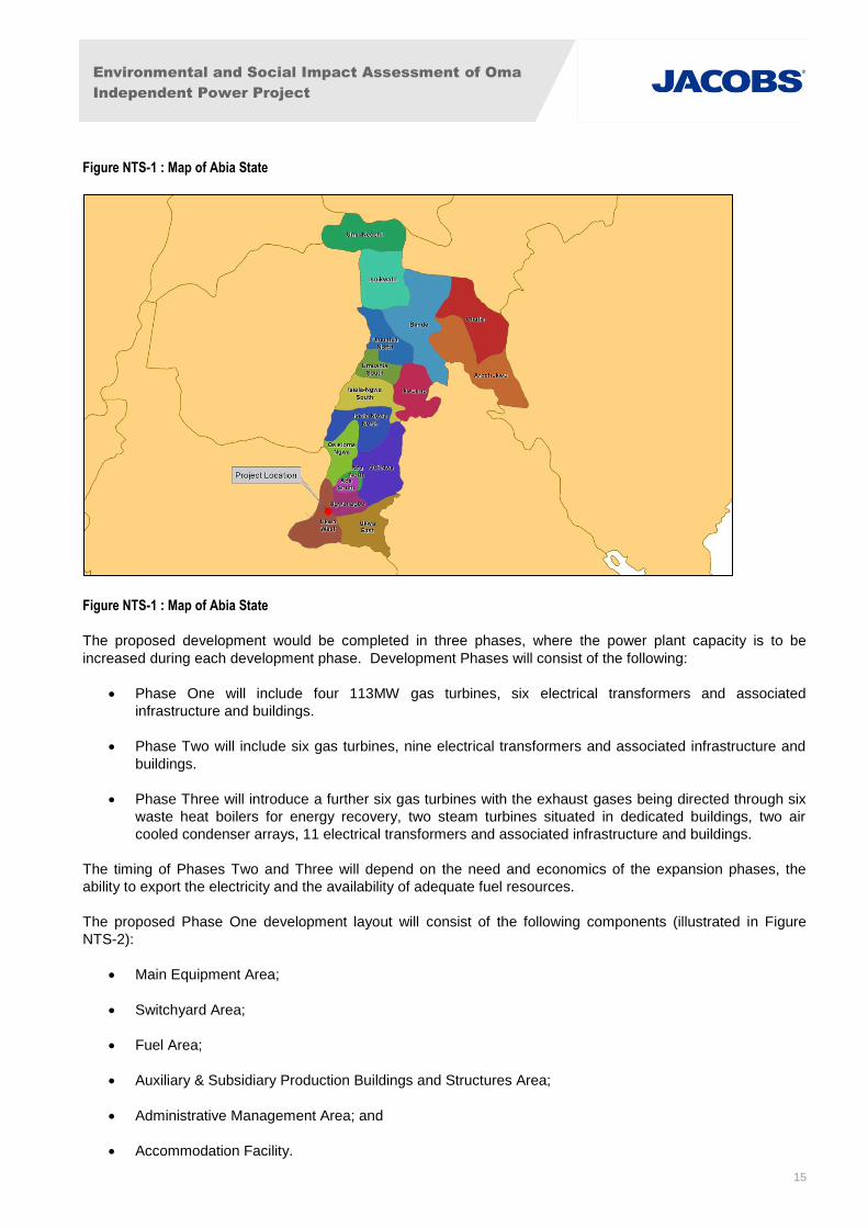
The proposed Site covers approximately 22.3 hectares of rural land located within the local government areas
of (LGA) Ukwa West of Abia state in southern Nigeria, north east of the settlement Asa, illustrated in Figure
NTS-1.
Environmental and Social Impact Assessment of Oma
Independent Power Project
15
Figure NTS-1 : Map of Abia State
Figure NTS-1 : Map of Abia State
The proposed development would be completed in three phases, where the power plant capacity is to be
increased during each development phase. Development Phases will consist of the following:
Phase One will include four 113MW gas turbines, six electrical transformers and associated
infrastructure and buildings.
Phase Two will include six gas turbines, nine electrical transformers and associated infrastructure and
buildings.
Phase Three will introduce a further six gas turbines with the exhaust gases being directed through six
waste heat boilers for energy recovery, two steam turbines situated in dedicated buildings, two air
cooled condenser arrays, 11 electrical transformers and associated infrastructure and buildings.
The timing of Phases Two and Three will depend on the need and economics of the expansion phases, the
ability to export the electricity and the availability of adequate fuel resources.
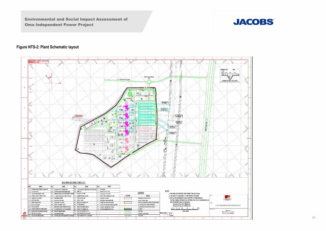
The proposed Phase One development layout will consist of the following components (illustrated in Figure
NTS-2):
Main Equipment Area;
Switchyard Area;
Fuel Area;
Auxiliary & Subsidiary Production Buildings and Structures Area;
Administrative Management Area; and
Accommodation Facility.
Environmental and Social Impact Assessment of
Oma Independent Power Project
16
Figure NTS-2: Plant Schematic layout
Environmental and Social Impact Assessment of Oma
Independent Power Project
17
1.4 Consultation and stakeholder engagement
Consultations were carried out with relevant stakeholders as part of the ESIA process, the result of which
formed the basis for the potential impact assessment and informed field surveys. The stakeholders
consulted include but are not limited to:
FMEnv;
Abia State Ministry of Environment;
Ukwa West and Ugwunagbo LGAs; and
Communities of Obehie, Orgwu (Ogwe), Ihie-Iyi, Obiga, Ngwaiyiekwe, Obuzongwa, Owo-ala, and
Umuaka.
Consultation activities with local communities included formal and informal meetings, in a variety of public
groups and smaller meetings. The purpose of these activities was to provide information about the
proposed project and the likely implications of its development, to gather information about stakeholders’
concerns, ideas and expectations, and to work towards addressing concerns through mutually agreeable
mitigation measures.
Meeting venues, dates and issues raised are discussed in further detail in Section 11, Stakeholder
Consultation, and associated appendices.
Over the course of the project development, consultation will be ongoing process, and a stakeholder
engagement plan will be developed to facilitate and formalise this.
1.5 Policy, Legal and Administrative Framework
The project is required to comply with the relevant laws and regulations of Nigeria. The project must also
meet the requirements of the World Bank Group (WBG) and the International Finance Corporation (IFC)
Performance Standards and relevant Environmental Health and Safety Guidelines. The following
provides a brief overview of the key applicable environmental legislation.
1.5.1 National Regulatory Framework
The basis for environmental policy in Nigeria can be found in Section 20 of the 1999 Constitution of the
Federal Republic of Nigeria. The principal regulatory framework for managing the environment in Nigeria
is as follows:
A. National Environmental Standards and Regulations Enforcement Agency Act 2007;
B. Environmental Impact Assessment Act 1992;
C. EIA Sectoral Guidelines of the Federal Ministry of Environment (FMEnv);
D. National Environmental Protection (Effluent Limitations) Regulation (S.1.8) 1991;
E. National Environmental Protection Regulation (S.1.9) 1991;
F. National Environmental Protection (Management of Solid Hazardous Wastes) Regulation (S.1.15)
1991;
Environmental and Social Impact Assessment of Oma
Independent Power Project
18
G. National Policy on the Environment;
H. Harmful Waste Act 1988;
I. Water Resources Act 1993;
J. National Environmental Standards and Regulations Enforcement Agency (NESREA) Act; and
K. The Associated Gas Re-Injection Act No 99 of 1979.
1.5.2 International Regulations
This ESIA considers the policies, guidelines and standards of the WBG’s IFC. The requirements of the
WB Multilateral Investment Guarantee Agency essentially reflect those of the IFC Standards for private
sector projects. The following international conventions would also apply to the project:
Convention on Biological Diversity;
The Ramsar Convention;
Convention on the Trade in Endangered Species;
UN Convention to Combat Desertification;
UN Framework Convention on Climate Change (UNFCCC);
Vienna Convention for the Protection of the Ozone Layer;
Convention on the Conservation of Migratory Species of Wild Animals;
United Nations Guiding Principles on the Human Environment;
International Union of Conservation of Nature and Natural Resources; and,
Kyoto Protocol to the United Nations Framework Convention on Climate Change
Environmental and Social Impact Assessment of Oma
Independent Power Project
19
2. Environmental Impacts and Mitigation
2.1 Air Quality
Potential impacts on air quality from the project during construction are likely to be combustion gas
emissions and dust generation arising from cars and trucks and construction equipment. Diesel exhaust
from these sources is known to contain several chemicals and compounds that may be detrimental to
human health over the long-term with repeated exposure where exposure of on-site workers to diesel
exhaust could be significant.
Potential impacts during plant operations could arise from plant equipment and traffic associated with the
project. However, results from air quality modelling for the project indicate that impacts are unlikely to
Mitigation measures focus on the design and construction scheduling of the development including using
site and plant operation to minimise dust generation, the provision of tarred be significant during any of
the project Phases.
Mitigation measures for construction will include dust suppression on earthworks and stockpiles of
excavated material, adopting modern combustion technology for generators, and appropriately designed
stacks and stack height to ensure adequate dispersion of emissions to atmosphere. Operational
mitigation measures include the use of low sulphur fuel, emission control / abatement and monitoring of
ambient air and stack emissions.
Overall no long-term air quality impacts are anticipated given the projects minor contribution to local air
quality impacts.
2.2 Energy Efficiency and Greenhouse Gas Emissions
The greenhouse gas emissions from the project over its lifetime have been quantified and compared with
Nigeria’s annual carbon emissions.
Despite inherent mitigation measures in design that aim to maximise the efficiency of the plant and
reduce carbon emissions, the project will still have a significant associated carbon footprint and will
contribute to global greenhouse gas emissions. It is noted that the carbon emissions for the operational of
the development will be significantly lower than for crude oil and coal fired power plants.
The magnitude of effect for operation is assessed as being of major significance.
2.3 Noise
An assessment of the noise impacts that are predicted to occur during the construction, operation and
decommissioning of the proposed development has been undertaken. The assessment included the
development of a three-dimensional noise model to assess potential operational noise impacts. A
baseline noise survey was completed to characterise the existing background noise levels within and
adjacent to the project site. The nearest sensitive receptors are located over 400m away from the
development area.
Potential impacts of construction, operation and decommissioning on receptors of noise from earthworks
and site preparation, piling, creation of hardstanding, laying of foundations, erection of structure, creation
of access tracks, an increase of traffic and the operation of gas and steam turbines and associated
transformers were considered potentially significant in the short-term.
Environmental and Social Impact Assessment of Oma
Independent Power Project
20
In terms of plant operations, the results of modelling showed that night-time noise levels are likely to
exceed residential noise standards at the nearest sensitive receptors.
A Noise Management Plan is proposed to address this along with mitigation measures to reduce
operational and construction noise impacts. These would include the use of personal protective
equipment for workers during construction, maintenance of all equipment on site, movement of vehicles
shall be restricted to day time and noise complaints shall be logged and investigated. During operation,
design measures shall be adopted to reduce plant equipment noise levels including: acoustic machine
enclosures, selecting structures according to their noise isolation effect to envelop the building, using
mufflers or silencers in intake and exhaust channels, using sound absorptive materials in walls and
ceilings, and using vibration isolators and flexible connections.
No long term noise impacts are anticipated following implementation of these measures.
2.4 Geology, Soils, Hydrogeology and Hydrology
The geology, soil, hydrogeology and hydrology assessment comprised a desk based review of published
data, ground investigations for the site of geology and hydrogeology, and consultation with local
Environmental Health Departments to determine public and private water supplies, and other sensitive
receptors that are hydraulically connected to the Study Area.
Local topography of the Study Area, which generally slopes north to south, serves two surface water
catchments: Imo River to the east and south, and Aba River to the east (that discharges to the Imo River
to the southeast of the study area). No other significant surface water features were noted within the
Study Area. Both surface water catchments within the Study Area ultimately discharge to the Atlantic
Ocean, 65km to the southeast of the Site, near the settlement of Ikot Abasi.
Groundwater was encountered approximately 27m below ground surface and observed to follow regional
topography. Groundwater resources are used locally to support community water supplies.
Impacts of construction, operation and decommissioning of the project on receptors of geology, soil,
hydrogeology and hydrology concern soil erosion, fuel/chemical contamination of soils or water
resources, and remobilisation of unrecorded contaminated land. Mitigation measures include temporary
drainage installation, excavated material management, fuel/chemical storage guidance and monitoring of
community supply boreholes. After implementation of mitigation measures the residual impacts noted for
soil and groundwater contamination from fuel and chemical spillages are assessed as being negligible.
2.5 Ecology
The Ecology assessment comprised a desk based review of published data and field visit of the Study
Area.
No known areas of natural or critical habitat or archaeological significance were found within 10km of the
proposed development area and during field surveys vegetation consisted of a mosaic of farmlands
(mostly cassava) and fallow lands.
Potential impacts from construction of the project infrastructure on ecology would include the loss,
degradation or fragmentation of wildlife habitat, loss of vegetation and the contamination of habitats. The
potential impacts during operation are significantly less than construction and include only the potential
contamination of habitats and groundwater from accidental release of hazardous substances.
Mitigation measures proposed during construction include limiting the extent of vegetation and habitat
removal during site clearance to what is necessary and vegetation retained will be demarcated to ensure
preservation. Landscaping will maximise the use of excavated materials and re-vegetation accomplished
Environmental and Social Impact Assessment of Oma
Independent Power Project
21
using indigenous species of fauna. Construction work will be scheduled to minimise the construction
footprint. During operation the safe storage and use of hazardous materials shall be managed to prevent
accidental release.
Ecological impacts associated with the proposed project could include permanent loss of wildlife habitat
on the project site, minor degradation of wildlife habitat and possible relocation to a potentially less
favourable habitat, but the ecological value of the project site is considered to be low and potential
impacts minor.
2.6 Waste and Hazardous Materials
The waste assessment comprised a desk based review of published data and field visit of the Study
Area. Waste management within the LGA that serves the Site (Ugwunagbo) has been reported as absent
with no landfills nearby that has led to fly tipping on private and public land. Lack of sewerage is
commonplace and localised contaminated land is suspected from biosolids. The lack of waste
management within the study area has led to infection of pests on some illegal dumping sites.
Waste during construction will be managed through the development of a construction waste
management plan (CWMP) while a waste management plan (WMP) will be employed during operation.
The management plans will identify opportunities for prevention, reuse, recycling and disposal of waste
that is generated on Site.
Impacts from construction, operation and decommissioning of the development arising from waste have
been identified as generation of excessive waste and contamination of groundwater and air quality from
hazardous wastes including solvents, fuels and wastewater. A waste management plan and other
mitigation measures are proposed to address potential impacts including maximising reuse of excavated
materials (soils and inert rubble) in landscaping, recycling of materials; making benign waste materials
(i.e. wood) available to the local community; disposal of waste hazardous liquids and gas tanks to an
approved facility and the provision of portaloos/cesspits until permanent sewerage has been provided.
No long term impacts are expected following mitigation.
2.7 Socio Economics
The socio-economic baseline was established based on a desk-top study combined with a household
survey and focus group discussions held in the communities of Obehie, Orgwu (Ogwe), Ihie-Iyi, Obiga,
Ngwaiyiekwe, Obuzongwa, Owo-ala, and Umuaka. Settlements of primary interest for the study were
those 8 located within 5km of the project site. Based on interviews with community leaders, the
estimated population in this area is approximately 27,500 people, although the accuracy of this figure is
difficult to verify. The main economic activity in each of the communities is farming.
Sources of potential impacts included beneficial impacts associated with employment and economic
development from construction and operation of the project; occupational community health and safety
impacts from increased hazards associated with more traffic, and potential accidents and emergencies
arising from construction of the project or the associated transmission line; and community conflicts and
health and safety issues associated with the pressures of population influx from construction and
operational workers along with increased demand for services. All of these adverse effects will be
addressed by the development of appropriate health and safety plans along with the development of
some enhancement measures to promote positive community relations and improved opportunities for
local employment.
Environmental and Social Impact Assessment of Oma
Independent Power Project
22
2.8 Cumulative Impact Assessment
Within each of the environmental topics described the specific impacts of the development are addressed
separately. However, the combined effect of developments in the area must also be considered as
‘cumulative impacts.’ This would include consideration of a power station and associated noise, air
pollution, greenhouse gas and carbon emissions, habitat loss and fragmentation, socio-economic effects,
contamination effects and other minor implications of the project combine with the effects of other
planned development in the area.
Considering the limited footprint of the proposed development and its distance from other large scale
projects physical impacts of the project on the local area are not considered to be significant. Although
there are noise and air quality emissions associated with the project, the anticipated cumulative impacts
to air quality and noise are not expected to be significant as industrial emissions in the local area are
some distance away.
For all these reasons, cumulative impacts are assessed to be of low significance.

Environmental and Social Impact Assessment of Oma
Independent Power Project
23
PART 2 – Environmental and Social Impact Assessment
Environmental and Social Impact Assessment of Oma
Independent Power Project
24
1. Introduction
1.1 General
Geometric Power Limited (GP), an independent power producer (IPP), intends to execute a power plant
project to export power to the Nigerian National grid. The initial objective of this project is to successfully
complete the design, construction, commissioning and take-over of Phase 1 of the power plant that
consists of a gas-fired simple–cycle plant of approximately 500 Megawatt (MW) gross generating
capacity that will export power to the Nigerian national electrical grid. It is also intended to upgrade the
Phase 1 plant, in two additional separate phases. Phase 2 will add two further simple-cycle power
generation units and Phase 3 will add two combined cycle generating units to bring the total gross
generating capacity to 1,125 MW.
GP, a private IPP developer in Nigeria, plans to develop the proposed project, as part of a joint venture
(JV) with General Electric (GE). A Special Purpose Vehicle (SPV), Oma Power Generation Company
Limited, has been established by the JV to develop this project, capitalised on a 60 / 40 basis by GP and
GE respectively.
In line with GP’s Health Safety and Environment (HSE) policy, Federal Ministry of Environment (FMEnv)
Nigeria, procedural guidelines and in conformance to the regulations governing the environment of
Nigeria, BGI Resources Limited in association with Jacobs UK Limited, was commissioned to carry out
an Environmental and Social Impact Assessment (ESIA) for the proposed project, hereafter referred to as
OMA power plant.
This ESIA will address Phase 1, the simple-cycle (500 MW gross generating capacity) and Phases 2 and
3, the potential configurations (625 MW gross generating capacity simple and combined cycle) for
upgrade to 1,125MW generating capacity.
The ESIA will also meet the requirements of International Financing Institutions (IFIs) as generally
defined in the Performance Standards for Environmental and Social Sustainability (‘IFC Standards’ or ‘the
Performance Standards) of the International Financing Corporation (IFC) that is part of the World Bank
Group (WBG) and the requirements of the WBG Environmental, Health and Safety (EHS) Guidelines.
This ESIA presents a statement of the likely social and environmental effects of the proposed project and
includes a description of the measures which require to be implemented in order to avoid, reduce and
where possible, remedy any identified significant adverse effects.
1.2 The Proponents
GP is an indigenous power generating company with a track record of efficient power delivery exemplified
by the 22 MW capacity emergency power delivered to Abuja Federal Capital Territory (FCT) from 2001 to
2004. The company has completed the development and construction of its phase 1 power plant project
in Aba, Abia State, currently with an initial installed capacity of 141MW with approximately 110 kilometres
of overhead lines for distribution to end users. GP’s head office is located at 7 Mary Slessor Street, off
Udo Udoma Crescent, Asokoro, Abuja. The company is engaged in power generation and distribution,
having been given approval to participate in the on-going independent power production scheme of the
Federal Government of Nigeria.
GE is a global diversified technology and financial services company, with products and services ranging
from aircraft engines, power generation, water processing to medical imaging and industrial products.
The company is a respected global leader in the power equipment supply and services sector. The first
phase of the Oma Project will utilize 4 GE Frame 9E open cycle gas turbines.
Environmental and Social Impact Assessment of Oma
Independent Power Project
25
GE has been present in Nigeria for over 10 years and is investing US$1Bn in a manufacturing facility,
creating 2,300 jobs and boosting the local economy. It has a strong commitment to the Nigeria power
sector, and signed a Memorandum of Understanding (MOU) with the Nigerian Government in 2012 to
develop 10,000 MW over 10 years jointly with the private sector.
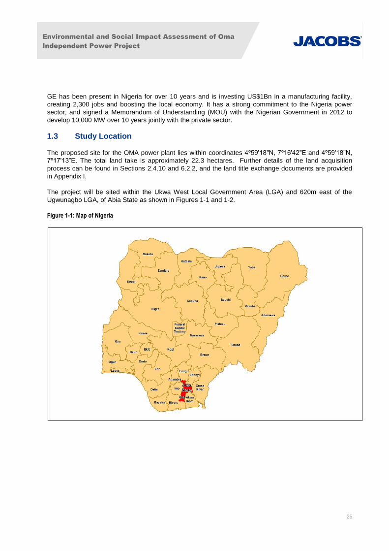
1.3 Study Location
The proposed site for the OMA power plant lies within coordinates 4º59ʹ18ʺN, 7º16ʹ42ʺE and 4º59ʹ18ʺN,
7º17ʹ13”E. The total land take is approximately 22.3 hectares. Further details of the land acquisition
process can be found in Sections 2.4.10 and 6.2.2, and the land title exchange documents are provided
in Appendix I.
The project will be sited within the Ukwa West Local Government Area (LGA) and 620m east of the
Ugwunagbo LGA, of Abia State as shown in Figures 1-1 and 1-2.
Figure 1-1: Map of Nigeria
Environmental and Social Impact Assessment of Oma
Independent Power Project
26
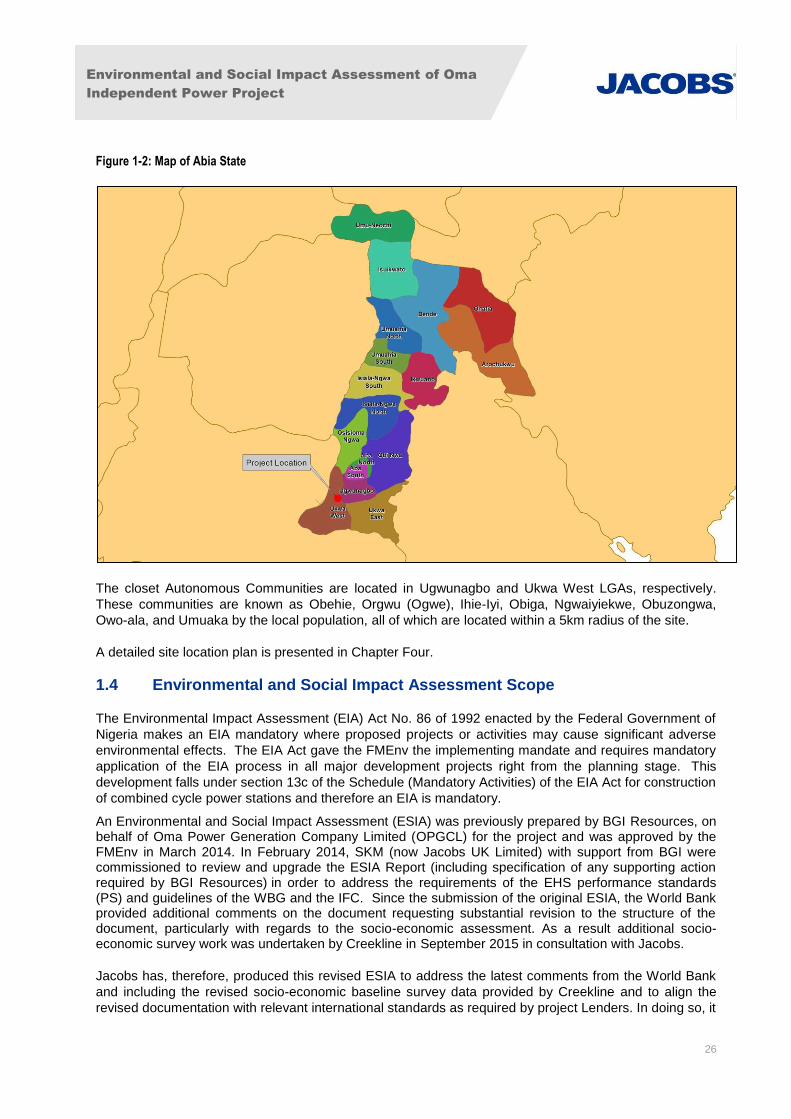
Figure 1-2: Map of Abia State
The closet Autonomous Communities are located in Ugwunagbo and Ukwa West LGAs, respectively.
These communities are known as Obehie, Orgwu (Ogwe), Ihie-Iyi, Obiga, Ngwaiyiekwe, Obuzongwa,
Owo-ala, and Umuaka by the local population, all of which are located within a 5km radius of the site.
A detailed site location plan is presented in Chapter Four.
1.4 Environmental and Social Impact Assessment Scope
The Environmental Impact Assessment (EIA) Act No. 86 of 1992 enacted by the Federal Government of
Nigeria makes an EIA mandatory where proposed projects or activities may cause significant adverse
environmental effects. The EIA Act gave the FMEnv the implementing mandate and requires mandatory
application of the EIA process in all major development projects right from the planning stage. This
development falls under section 13c of the Schedule (Mandatory Activities) of the EIA Act for construction
of combined cycle power stations and therefore an EIA is mandatory.
An Environmental and Social Impact Assessment (ESIA) was previously prepared by BGI Resources, on behalf of Oma Power Generation Company Limited (OPGCL) for the project and was approved by the FMEnv in March 2014. In February 2014, SKM (now Jacobs UK Limited) with support from BGI were commissioned to review and upgrade the ESIA Report (including specification of any supporting action required by BGI Resources) in order to address the requirements of the EHS performance standards (PS) and guidelines of the WBG and the IFC. Since the submission of the original ESIA, the World Bank provided additional comments on the document requesting substantial revision to the structure of the document, particularly with regards to the socio-economic assessment. As a result additional socio-economic survey work was undertaken by Creekline in September 2015 in consultation with Jacobs.
Jacobs has, therefore, produced this revised ESIA to address the latest comments from the World Bank
and including the revised socio-economic baseline survey data provided by Creekline and to align the
revised documentation with relevant international standards as required by project Lenders. In doing so, it
Environmental and Social Impact Assessment of Oma
Independent Power Project
27
is important to note that Jacobs did not undertake the baseline data collection for the original ESIA and
whilst the information has been reviewed, Jacobs has not verified all data provided by BGI. Some
sections of the ESIA remain as BGI’s text and are based upon the technical data collected by BGI. In
order to align with international assessment methodology standards and World Bank comments, the
structure of the ESIA was altered and the documentation text has been significantly revised by Jacobs.
Upon approval of the ESIA from the international lenders, construction and operation of the OMA Power
Plant will be required to comply with the EHS conditions set by the WBG and IFC as well as with the
laws, regulations, and policies of the Nigerian Federal, State, and local governments.
This ESIA considers the various stages of the proposed development including:
Pre-construction Phase: Impacts related to pre-construction activities could include road
grading, equipment mobilisation, site clearance and development of the workers camp, but
anticipated impacts would be minor. These impacts were considered and mitigation provided as
a separate phase in the ESMP.
Construction Phase: Impacts may arise from construction activities, typically the effects are
short-term.
Operation Phase: Impacts result from, principally but not exclusively, the plant’s air and noise
emissions and aqueous emissions. Such emissions are generally produced for the life of the
project.
Decommissioning Phase: There will be short-term impacts associated with the removal of the
plant and associated infrastructure. Impacts of the decommissioning phase are similar to those
of the construction phase of the project. A discussion of decommissioning phase impacts is
included.
This ESIA will enable the FMEnv Nigeria and international lenders to formally comment on the proposed
methodology and the environmental issues that have been identified and to confirm that any potential
significant adverse environmental and/or social issues are fully addressed in the Environmental and
Social Management Plan (ESMP), provided in Section 10. The ESMP will be further developed during the
construction and operational environmental protection systems and will be updated as required.
1.5 Environmental and Social Impact Assessment Objectives
The main objectives of the ESIA include the following:
To gather comprehensive baseline information and existing data of the site and surrounding
area, so as to establish the environmental and social baseline conditions of the project area;
To establish the environmental sensitivities prevalent in the project area;
To identify, quantify and assess the likely negative and positive environmental impacts of the
proposed project, including cumulative impacts, as presently designed;
To identify, evaluate and predict the potential and associated impacts of the proposed project on
the biophysical, socio-economic and cultural settings of the area with adequate interfacing and
project interaction;
To inform project design such that the best design options are selected based on environmental
and social factors as well as operational and economic factors;
Environmental and Social Impact Assessment of Oma
Independent Power Project
28
To consult with project stakeholders, including local communities, so that their concerns are
addressed;
To identify health hazards that may arise from different phases of the project execution and
evaluate local population exposure to these hazards;
To recommend control measures in order to eliminate and mitigate significant impacts on the
proposed project environment;
To identify any environmental and socioeconomic issues and concerns that may, in the future,
affect the successful operation of the project and advise on appropriate approaches to address
them; and
To put in place an effective ESMP to coordinate the management of the identified impacts
throughout all phases of the project and to provide a framework for the project’s detailed
environmental management systems to be implemented.
1.6 Environmental and Social Impact Assessment Methodology
The ESIA was designed to address the surrounding environment of the project area by concentrating its
investigations on the following:
Comprehensive literature review to define the biophysical and socio-economic characteristics of
the project area;
A field sampling and survey program of the project site, to validate/supplement the
information/data currently available;
Laboratory analyses of the samples collected from the field survey/sampling program;
Review of relevant national and international environmental regulatory requirements and good
practice guiding power plant construction and operation;
Environmental, socio-economic and health impact identification, prediction, interpretation and
evaluation;
Development of avoidance and/or mitigation measures and monitoring program as applicable to
be incorporated into the ESMP; and
Preparation of both draft and final ESIA reports in line with the FMEnv Nigeria, Department of
Petroleum Resources (DPR) guidelines and IFC and WBG EHS Performance Standards and
Guidelines.
The purpose of the ESIA is to identify and assess the impacts of the project on the environment, as well
as develop appropriate mitigations measures for effective management of adverse impacts. The study
approach involved a blend of multidisciplinary standard methods from environmental science,
engineering and social sciences in order to obtain data/information for impact identification, and to
establish avoidance and mitigation measures. The ESIA involved a literature review, baseline/field data
acquisition, consultations, impact identification and assessment and the development of appropriate
impact avoidance/mitigation measures incorporated into an ESMP framework.
Literature Review
A literature review was undertaken to acquire information on climate, geology, soil, vegetation, health,
socio-economics and other environmental components of the proposed project area. The materials
Environmental and Social Impact Assessment of Oma
Independent Power Project
29
reviewed include textbooks, articles, journals, maps, photographs and previous EIA reports. References
are included in Appendices II and III where relevant. Examples include, but are not limited to, the
following:
Climate
o Nigeria Meteorological Agency (NIMET)
o UNFCCC (2014) 2nd National Communication submitted by Nigeria, February 2014
Geology, groundwater and soils
o Niger Delta Environmental Survey (NDES) (1997), Environmental and Socio Economic
Characteristics
o Grossman and Reinsch, 2002
Vegetation
o Nigeria National Biodiversity Plan, 2010, 104pp (www.cbd.int/doc/world/ng/ng-nbap-01-
en.boc)
o Important Bird Areas in Africa and Associated Islands: Priority Areas for Conservation,
Newbury and Cambridge, UK, Birdlife Conservation Series No.11
(www.birdlife.org/datazone/userfiles/file/IBAs/AfricaCntryPDFs/Nigeria.pdf)
Health
o National Agency for the Control of AIDS (http://www.naca.gov.ng/)
Socio-economics
o Census data from the National Population Commission, Nigeria
(http://www.population.gov.ng/index.php/censuses)
Air quality
o Journal articles including: Huang et al., 2009; Peavy, et al., 1985; Chineke and
Chiemeka 2009; WHO, 1976; Rao & Rao, 2005; Davis and Masten 2004.
Baseline/Field Data Acquisition
Field data acquisition was carried out to ground-truth existing information and obtain additional data to
better characterize the environmental and socio-economic baseline conditions of the project area. Field
data to support the environmental and socioeconomic status of the project area was acquired during a
field data gathering program carried out between 11th to 13th July, 2012 (wet season) and 12th and 15th
February, 2013 (dry season). Data was acquired on vegetation, wildlife, soil, air quality/noise, ground
water, hydrobiology, socio-economics and health. Additional surveys were undertaken in April 2014 to
identify the location of local community water supply boreholes.
Consultation
Consultations were carried out with relevant stakeholders to ensure that their views and opinions
concerning the proposed project and its associated and potential impacts are integrated into the ESIA
Environmental and Social Impact Assessment of Oma
Independent Power Project
30
process. Some of these stakeholders were consulted during the scoping stage, prior to the start of the
field studies. Socio-economic consultations with the host communities were also carried out to create
awareness and integrate the communities’ opinions and concerns into the ESIA process. The result of
such consultations forms the basis for the potential impact assessment which is an integral part of this
ESIA report. The stakeholders consulted include but are not limited to:
FMEnv;
Abia State Ministry of Environment;
Ukwa West and Ugwunagbo LGAs;
Ogwe Community of Ukwa West LGA; and
Ihie-Iyi, Community of Ugwunagbo LGA.
The consultation process is a key component of the ESIA process and the ESMP, and will continue
throughout the construction and operational phases of the project.
Potential and Associated Impact Assessment and Mitigation
In each of the environmental topic areas, professional judgement and (where relevant, e.g. for air quality)
the results of modelling analysis are used in combination with relevant guidance to assess and evaluate
the significance for each effect. Effects are considered to be major, minor or negligible and can be
negative or positive. Where positive impacts are identified mitigation is not required however positive
impacts will be enhanced where possible. Further details on the criteria applied to the assessment of
potential impacts are provided in Section 7 of this ESIA.
1.7 Structure of the Report
The structure of this ESIA report is as follows:
Non-technical Summary: This provides an overview of the project, potential environmental
impacts and proposed mitigation and monitoring strategies, using non-technical language.
Section 1, Introduction: This section provides an introduction to the project, the project proponent
and an overview of the project objectives.
Section 2, Policy, Legal and Administrative Framework: This section summarises the key
elements of national, local, and international legislation and standards that apply to the proposed
project.
Section 3, Project Justification: This section provides a description the project’s justification and
presents the need/value and the envisaged sustainability of the project as well as the
development alternatives considered
Section 4, Project Description: This section presents a description of the proposed project
activities including engineering/detailed design, project management and operations philosophies
and the project execution schedule.
Section 5, Physical Environmental Baseline: This section presents the baseline environmental
conditions of the project area as identified by desk-based studies and supplemented by site
visits.
Environmental and Social Impact Assessment of Oma
Independent Power Project
31
Section 6, Socio - Economic Baseline: This section presents the socio economic baseline
conditions of the project area as identified by desk-based studies and supplemented by site
visits.
Section 7, Environmental and Social Impact Assessment Methodology: This section details the
criteria applied to the assessment of potential impacts arising from the proposed project elements
described in the Section 4. It provides definitions of impact magnitude and significance as they
apply to the potential effects on environmental and social aspects.
Section 8, Associated and Potential Impacts: This section presents the likely impacts of the
project elements on the identified social and environmental aspects.
Section 9, Mitigation Measures: This section proffers mitigation and enhancement measures, and
alternatives for the identified adverse impacts. A summary of the residual impacts post mitigation
is provided.
Section 10, Environmental and Social Management Plan: This section presents the social and
environmental management, mitigation and monitoring measures, including roles and
responsibilities, identified by the ESIA process as required to be undertaken during project
implementation and operation to implement the mitigation actions, reduce adverse environmental
and social effects to acceptable levels and to enhance potential benefits.
Section 11, Stakeholder Consultation: This section presents the consultation that has been
conducted for the project and includes a proposed plan for consultation moving forward.
1.8 Input from International Consultants (Jacobs UK Limited)
An ESIA was previously prepared by BGI Resources for the project. This was submitted to the FMEnv
and approval was granted in March 2014. Since the submission of the original ESIA, Jacobs has been
commissioned to align the documentation with relevant international standards and thus this document
has been prepared in accordance with Environmental Impact Assessment (EIA) Act No. 86 of 1992 and
also to meet good international industry practice.
In making these amendments, Jacobs has generally used the data provided by BGI Resources,
supplemented by additional information provided by BGI resources and OMA and has not undertaken
additional technical studies. Jacobs was, however, also responsible for preparing the air quality and noise
technical assessments contained in the updated ESIA and the socio-economic assessment work that
was re-scoped and baseline survey information provided by Creekline in September 2015 in consultation
with Jacobs.
The ESIA is intended to enable the reader to understand the nature of the proposed development and to
evaluate the likely environmental effects. The ESIA therefore acts to aid the decision-making process
and to present information in a readily accessible form.
Environmental and Social Impact Assessment of Oma
Independent Power Project
32
2. Policy, Legal and Administrative Framework
2.1 Overview
Relevant identified legislation, regulations, policies, guidelines and standards from Nigeria and
International treaties, standards and guidance will be considered in the development of the ESIA.
2.2 Regulatory Constraints
Based on available information, there are no environmental regulatory constraints that would restrict
development and implementation of the proposed project. Furthermore, no known rare, threatened or
endangered species were identified as located in or adjacent to the proposed project area. There are no
communities or indigenous people present on the site that will be affected or require relocation as a result
of the proposed OMA Power Plant.
2.3 Nigerian Government Administrative Subdivisions
There are essentially three tiers of governance in Nigeria. The first tier is the Federal Government of
Nigeria which is divided into 36 states and a Federal Capital Territory. The next two tiers of governance
are the States which are further sub-divided into 774 LGAs.
The constitutional framework for environmental management remains highly centralized. The federal and
state governments are given the primary responsibility for developing and implementing the legislative
framework for environmental management. At the state level, relevant institutions exist for the
enforcement or implementation of environmental policies. The major cross-sectoral regulator of the
environment at the federal level is the FMEnv. For effective coordination between the federal and state
agencies, the FMEnv has offices in each of the 36 states, each headed by a senior personnel designated
as “Controller of the Environment,” whose function is to liaise with the headquarters of the Ministry in
Abuja, regarding developments in the environmental sector in the state of his/her posting.
Responsibilities on environmental issues in the states lie with the State Ministries of Environment whose
functions include: liaising with the FMEnv to achieve the National Policy on Environment; and, co-
operating with FMEnv and other National Directorates/Agencies in the performance of environmental
functions including raising environmental education / awareness of the citizenry.
The primary responsibility of LGAs is economic planning and development. LGAs do not enact laws, but
can enforce requirements that pertain to natural resource conservation provided such requirements do
not run counter to those of either the state or federal government. LGAs are required to ensure that laws
derived from the upper two tiers of government are not compromised in their areas of jurisdiction.
Another tier of government, albeit an informal one, exists beneath the LGAs. Most rural communities
have traditional or cultural governance organizations composed of elected individuals within the
community such as village elders, chiefs, or traditional heads who exercise influence over the local
population. Though not provided for in Nigeria’s constitution, they nevertheless serve to resolve social-
economic issues within their respective communities.
2.4 Federal Environmental Management Framework and Corresponding Agency Jurisdictional Authority
This section presents the principal regulations that will govern the proposed OMA Power Plant. The
specific provisions within each piece of legislation that has relevance to the OMA Power Plant is also
identified and discussed along with the corresponding regulatory agency responsible for implementing
the regulation. Moreover, the environmental performance criterion to be used in the environmental
analysis is identified.
Environmental and Social Impact Assessment of Oma
Independent Power Project
33
The basis for environmental policy in Nigeria can be found in Section 20 of the 1999 Constitution of the
Federal Republic of Nigeria. Pursuant to Section 20, provisions for the protection and improvement of the
environment and safe guarding of water, air, land, forests and wildlife in Nigeria are provided. The
principal regulatory framework for managing the environment in Nigeria is as follows:
A. National Environmental Standards and Regulations Enforcement Agency Act 2007;
B. Environmental Impact Assessment Act 1992;
C. EIA Sectoral Guidelines of the Federal Ministry of Environment (FMEnv);
D. National Environmental Protection (Effluent Limitations) Regulation (S.1.8) 1991;
E. National Environmental Protection Regulation (S.1.9) 1991;
F. National Environmental Protection (Management of Solid Hazardous Wastes) Regulation (S.1.15)
1991;
G. National Policy on the Environment;
H. Harmful Waste Act 1988;
I. Water Resources Act 1993;
J. National Environmental Standards and Regulations Enforcement Agency (NESREA) Act;
K. The Associated Gas Re-Injection Act No 99 of 1979; and,
L. Others.
2.4.1 National Environmental Standards and Regulations Enforcement Agency Act 2007
(NESREA)
The National Environmental Standards and Regulations Enforcement Agency (NESREA) Act repealed
the Federal Environmental Protection Agency Act (FEPA Act) and established the National
Environmental Standards and Regulations Enforcement Agency. NESREA is an agency of the FMEnv. It
is responsible for enforcing compliance with all environmental standards, rules, laws, policies and
guidelines for all industrial sectors except the petroleum sector. It is also responsible for development of
biodiversity conservation and sustainable development programs and coordination and liaisons with
relevant stakeholders within and outside of Nigeria on matters pertaining to environmental policies,
regulations, laws and standards. Although the NESREA Act repealed the FEPA Act, it nonetheless
retained subsidiary legislation made pursuant to that Act.
This legislation is still applicable under NESREA and is as follows:
1. National Environmental Protection (Effluent Limitation) Regulations;
2. National Environmental Protection (Pollution Abatement in Industries and Facilities Generating
Waste) Regulations; and
3. National Environmental Protection (Management of Solid and Hazardous Waste) Regulations.
2.4.2 National Environmental Protection (Effluent Limitations) Regulation (S.1.8) 1991
This regulation makes it mandatory for industries generating wastes to install anti-pollution and pollution
abatement equipment on site. The regulation is specific to each category of waste generating facility with
respect to limitations of solid and liquid discharges or gaseous emissions into the ecosystem.
Appropriate penalties for contravention are also specified in the regulation.
Environmental and Social Impact Assessment of Oma
Independent Power Project
34
2.4.3 National Environmental Protection Regulation (S.I.9) 1991
The National Environmental Protection (Pollution Abatement in Industries Producing Waste) Regulation
of 1991 regulates the release of toxic substances, requirement for pollution monitoring unit, machinery for
combating pollution and contingency plan by industries. It also provides that industries producing wastes
should submit lists and details of chemicals used by such industries to FMEnv as well as permissible
limits of discharge into public drains. It details protection of workers, requirements for environmental audit
and penalty for contravention. Paragraph 15 (2) of S.1.9 states that no oil in any form shall be discharged
into public drains, rivers, lakes, seas, atmosphere or underground injection without the permit issued by
FMEnv or any organization designated by the ministry. Paragraph 17 of the same section also states that
an industry or a facility which is likely to release gaseous, particulate, liquid or solid untreated discharges
shall install into its system, appropriate abatement equipment in such a manner as may be determined by
the agency.
2.4.4 National Environmental Protection (Management of Solid Hazardous Wastes) Regulation
(S.1.15) 1991
This regulation spells out the requirements for groundwater protection, surface impoundment, land
treatment, waste piles, landfills, incinerators, etc. It also describes the hazardous chemical products and
dangerous waste constituents. Specifically, S.1.15 provides a comprehensive list of Wastes that are
classified as being dangerous to the environment. It also gives detail on the contingency planning and
emergency procedure to be followed in case of sudden release of any of these hazardous wastes into the
environment.
2.4.5 National Policy on the Environment
The overall goal of achieving sustainable development in Nigeria is the main aim of the National Policy on
Environment [1989]. The policy details implementation strategies for the various sectors such as the
human population, land use and conservation, water resources management, forestry/wildlife protected
areas, marine and coastal resources, sanitation and waste management, toxic and hazardous
substances mining and mineral resources, agricultural chemicals, energy production and use, air
pollution, noise pollution, working environment [occupational, health and safety]; settlements recreational
space, greenbelts monuments and cultural property. The policy also provides for public participation,
institutional arrangements, legal basis, obedience to international treaties and obligations. The provisions
of the policy include:
Monitoring for all Nigerians, a quality environment for their health and well-being, conserving and
using the environment and natural resources for the benefit of present and future generations;
Restoring, maintaining and enhancing the ecosystems and ecological process essential for the
functions of the biosphere to present biological diversity and the principle of optimum sustainable
yield in the use of living natural resources and ecosystems;
Raising public awareness and promoting understanding of essential linkages between the
environment and development and to encourage individual and community participation in the
environmental improvement efforts; and
The co-operation in good faith with other countries, international organization / agencies to
achieve optimal use of trans-boundary natural resources and effective prevention or abatement
of trans-boundary environmental pollution while stipulating an environmental problem-solving
approach predicated on an integrated, holistic and systemic view.
Environmental and Social Impact Assessment of Oma
Independent Power Project
35
2.4.6 Environmental Impact Assessment Act No 86 of 1992
The Environmental Impact Assessment Act (EIA Act) establishes the EIA as an action-forcing document
which ensures that the policies and goals defined in the Act are infused into the proposed project. The
purpose of the EIA is to provide a full and fair discussion of the significant environmental impacts
resulting from the project, and to inform the decision-makers and the public of reasonable alternatives
which will avoid or minimize any adverse impacts.
The FMEnv is responsible for administering and enforcing this law. The law empowers FMEnv to monitor
and certify in writing, environmental assessments on all projects for which an EIA is mandatory pursuant
to Schedule E of the Act.
In September 1995, FEPA published the EIA Sectoral Guidelines for Oil and Gas Industry projects.
These guidelines are intended to assist in the proper and detailed execution of EIA of oil and gas projects
in consonance with EIA Act of 1992. The FMEnv EIA procedural flow diagram is presented in Figure 2-1.
The Act requires an EIA to be developed for some power generation and transmission projects. In
reviewing the Act, the sections of applicability (or closely applicable) to the proposed project, i.e. those
that require development of an EIA, are those entailing the construction of a combined cycle power
station.
2.4.7 EIA Sectoral Guidelines of the FMEnv
Federal Environmental Protection Agency (FEPA) now FMEnv was established by Act 58 of 1988 to
monitor and prevent the pollution of the environment following the Koko toxic wastes dump incident. This
empowered FEPA to prepare Environmental Guidelines and Standards as instruments for prevention of
environmental pollution. This Act also gives specific powers to FMEnv to facilitate environmental
assessment of projects.
In addition, FEPA regulations S.1.8, S.1.9 and S.1.15 of 1991 provided guidelines and standards for the
following:
Solid and Hazardous waste management;
Effluent limitations; and
Pollution abatement in industries and facilities generating wastes.
The FMEnv management procedure is shown in Figure 2-1.
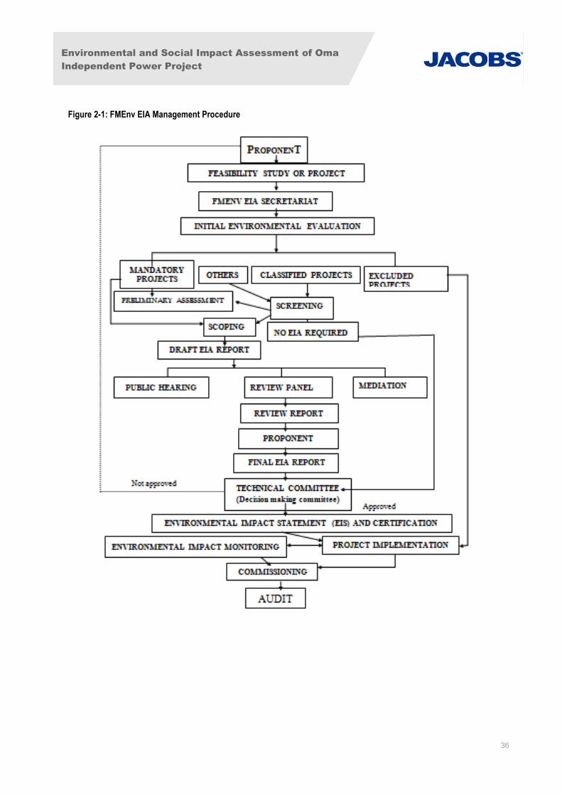
Environmental and Social Impact Assessment of Oma
Independent Power Project
36
Figure 2-1: FMEnv EIA Management Procedure
Environmental and Social Impact Assessment of Oma
Independent Power Project
37
2.4.8 Harmful Waste Act 1988
The Harmful Waste Act prohibits the purchasing, selling, importing, storage, carrying, depositing or
dumping of harmful wastes on any land or territorial waters (reference the Territorial Waters Act 1967)
within Nigeria. Such acts incur severe penalties. The Act defines harmful wastes as “any injurious,
poisonous, toxic or noxious substance, and in particular includes nuclear wastes emitting any radioactive
substance if the waste is in such quantity, whether with any other consignment of the same or of different
substance, as to subject any person to the risk of death, fatal injury, or incurable impairment of physical
and mental health.”
2.4.9 Water Resources Act 1993
The Water Resources Act vests in the Federal Government of Nigeria the right to control the use of all
surface water and groundwater in the nation. Pursuant to this Act, the Minister of Water Resources may
prohibit or regulate the carrying out of any activity on land or water that may interfere with the quantity or
quality of any water in any watercourse or groundwater. The Act allows anyone to acquire the right, i.e.
a license from the Minister, to use or take water from any watercourse or any groundwater for any
purpose in accordance with the Act and any regulations pursuant thereto. The Act further empowers the
Minister to impose a fee on the issuance of such license.
During the preliminary engineering phase, the project will obtain any license, as required pursuant to
Section 13(a) of the Act, to install the groundwater wells as described in the project description in Section
4 of this ESIA.
2.4.10 Land Management
The Land Use Act of 1978 nationalised land-holding in Nigeria. The Act entrust all land to the State,
excluding land vested to the Federal Government or its agencies. The State Governor holds such land in
trust for the people and is thus responsible for its allocation in all urban areas to individual residents or
businesses in the State. With respect to non-urban areas, similar powers are conferred to Local
Government Councils (LGCs). The legal status of land users in Nigeria is thus one of occupancy rather
than ownership.
Pursuant to Part II Section 9 of the Act, the Governor may issue a certificate of occupancy when any
entity or person is in occupation of land under a customary right of occupancy and applies in a prescribed
manner. The terms, conditions and annual fee pursuant to the certificate of occupancy are enforceable
against the holder and successors.
Pursuant to the Joint Development Agreement (JDA) signed between the co-developers of the OMA
Power Plant project, GP is responsible for ensuring that the project site is procured and provided to the
project company. The project site procurement was commenced by the initial majority shareholder of the
project SPV, which is Main Infrastructure Limited (MIL).
In 2013 the project site was procured from the owners of the land and fenced and secured by GP. The
registration process at the Land Registry in Umuahia, Abia State is currently being completed. The
registration of the land with the Land Registry is a part of the process that will culminate in the issuance
of the Certificate of Occupancy by the Abia State Governor. Issuance of the Certificate of Occupancy can
take a significant period of time due to the Governor often personally signing the Certificates and
extended delays in the processing of the application by the Land Registry. The JDA allows for the
valuation and transfer of the project site to the project SPV at financial close of the project. The land title
exchange documents are provided in Appendix I.
Further details on land acquisition and compensation are provided in Section 6 of this ESIA.
Environmental and Social Impact Assessment of Oma
Independent Power Project
38
2.4.11 Criminal Code
The Nigerian Criminal Code makes it an offence punishable with up to 6 month’s imprisonment for any
person who:
Violates the atmosphere in any place so as to make it noxious to the health of persons in general
dwelling or carrying on business in the neighbourhood, or passing along a public way; or
Does any act which is, and which he knows or has reason to believe to be, likely to spread the
infection of any disease dangerous to life, whether human or animal.
There are also other regulations including:
Wild Animals Preservation Act Cap 132 LFN 1990;
Explosives Regulations, 1967; and
Natural Resources Conservation Act Cap 286 LFN 1990.
2.4.12 Laws Protecting Flora and Fauna
Nigeria’s National Forestry Policy was approved in 2006. The legislation to support this Policy known as
the National Forestry Act is currently under review. Once passed, the National Forestry Act will be
administered by the Federal Department of Forestry which is a parastatal agency of the FMEnv. Limited
information available on the draft Forestry Act indicates that its goal is to economically exploit forests
resources in a sustainable manner with careful consideration given to biological diversity and ecosystem
protection.
Parks, Game Reserves and other Protected Areas: There are three categories of protected areas in
Nigeria established to protect flora and fauna. These categories are the National Parks, Game Reserves
and Forest Reserves. At the national level, the mandate for wildlife conservation and protected areas
management is the responsibility of the National Parks Service, an agency within the FMEnv. There are
seven national parks spread across the country. These parks receive the highest level of protection in
accordance with the National Parks Service Act of 1999, Act 46. A variety of game reserves are
managed by the states in which they reside in an effort to preserve wildlife species. States also manage
innumerable forest reserves with the intention of preserving trees and other plant species along with
associated wildlife. There are no National Parks within 10km of the proposed project.
Endangered Species (Control of International Trade and Traffic) Act; Nigeria acceded to the
Convention on International Trade on Endangered Species of Wild Fauna and Flora (CITES) in 1974.
The treaty’s goal is to ensure that international trade in specimens of wild animals and plants do not
threaten their survival. In accordance with Nigeria’s obligations under CITES, the government enacted
the Endangered Species (Control of International Trade and Traffic) Act. This seeks to control and in
some cases prohibit the trafficking or trade of special status species, as defined by the Act, including the
commercial exploitation of such species. The project will not involve the trafficking of “special status
species” as defined by the Act.
The proposed project will use the International Union for the Conservation of Nature’s (IUCN’s) “Red List”
to determine the species to address in this environmental analysis. This is discussed in Section 5.9 of
this ESIA, which evaluates the baseline species composition in line with the Red List.
Environmental and Social Impact Assessment of Oma
Independent Power Project
39
2.4.13 State Environmental Management Framework
The different States within Nigeria have the power to enact laws to protect the environment within their
respective jurisdiction. The applicable State regulations have been taken into cognizance as part of the
proposed project. Some of the functions of the State Ministry of Environment include:
Liaising with the FMEnv to achieve the National policy on Environment,
Co-operating with FMEnv and other National Directorates/Agencies in the performance of
environmental functions including environmental education / awareness to the citizenry,
Responsibility for monitoring waste management standards,
Responsibility for general environmental matters in the States, and
Monitoring the implementation of EIAs and other environmental studies for all development
projects in the States.
Abia State Basic Environmental Law, 2004 and 2013 as Amended: This study took cognisance of the
Abia State relevant laws and policies. Among which is the Abia State Basic Environmental Law, 2004 and
2013 as Amended. The Agency shall, subject to this law, perform the following functions:
The Environmental Monitoring Division shall perform the following functions:
o Management and control of reference laboratories;
o Analytical Services;
o Environmental research and studies;
o Oil and gas contamination, monitoring and evaluation; and
o Monitoring of standard, testing and sampling of industrial effluents.
The Environmental Inspectorate Division shall perform the following functions:
o Environmental Management System;
o Environmental quality coordination (air, water, noise, radiation and hazardous
substances);
o Quality standard development;
o Enforcement and control of Regional movement;
o Pollution control;
o Monitoring of persistent organic pollution of hazardous toxic substances;
o Standards enforcement; and
o Interventional (matters and convention).
Environmental Impact Assessment Division (EIA) and Environmental Evaluation Report (EER)
shall perform the following functions:
o EIA processing/guideline development;
o Hazard and risk analysis;
o Effluent control;

Environmental and Social Impact Assessment of Oma
Independent Power Project
40
o Industrial Compliance and Hygiene; and
o Urban and rural Land use information and plans regulation and quality.
Abia State Public Health law (CAP 139, 2005): Also relevant to this project is the Abia State Public
Health laws cap 139, 2005. Particularly, in Section 13 sub section 1 of the law states that any person
who by any act or default causes or suffers to be brought or to flow into any well, stream, tank, reservoir,
aqueduct or pond used or intended to supplying water for man or beast or into any conduit
communication therewith any deleterious substance or commits any act whereby such water is or may be
fouled shall be liable to a fine of N1,500 and a further sum of N200 for everyday during which the offence
continued after conviction.
Sub section 2 further states that such penalty may be recovered during the continuance of the offence or
within one calendar month after it has ceased.
2.4.14 International Treaties on the Environment
Nigeria has ratified numerous international treaties on the environment. Under Nigerian law it is
necessary to incorporate a treaty into domestic legislation before it can have the full force of law. In
many cases, the ratified treaties have yet to be implemented into the laws of Nigeria. As such, the courts
in Nigeria may not enforce them.
The following environmental treaties have been ratified by Nigeria and have implementing legislation in-
place that will apply to the project, including:
Convention on Biological Diversity;
The Ramsar Convention;
Convention on the Trade in Endangered Species;
UN Convention to Combat Desertification;
UN Framework Convention on Climate Change (UNFCCC);
Vienna Convention for the Protection of the Ozone Layer;
Convention on the Conservation of Migratory Species of Wild Animals;
United Nations Guiding Principles on the Human Environment;
International Union of Conservation of Nature and Natural Resources; and,
Kyoto Protocol to the United Nations Framework Convention on Climate Change.
Although not yet implemented in Nigerian law, the international conventions specified above have been
taken into consideration in the preparation of this Study Report.
Convention on Biological Diversity: The purpose of this convention is to ensure the conservation and
sustainable use of biodiversity. Nigeria signed the convention on 13th June 1992 and ratified the same
on 29th August 1994. A number of institutions and organizations have been designated to carry out
activities that could facilitate the implementation of the Convention on Biological Diversity in Nigeria. The
FMEnv coordinates the activities of these institutions. The provisions of this Convention have been
integrated in many laws in Nigeria.
Environmental and Social Impact Assessment of Oma
Independent Power Project
41
The Ramsar Convention: The Ramsar Convention came into force for Nigeria on 2nd of February 2001.
The Ramsar Convention on Wetlands is primarily concerned with the conservation and Management of
Wetlands. Parties to the convention are also required to promote wise use of wetlands in their territories
and to take measures for the conservation by establishing nature reserves in wetlands, whether they are
included in the Ramsar list or not. The proposed development is not located on wetland habitat per se,
rather it is sited on fallow farmland and cassava plantation; with no water courses or standing water noted
within or close to the proposed development area.
Convention on the Wetlands of International Importance as Waterfowl Habitat: This convention is
also referred to as Ramsar Convention. Its main objective is to promote conservation and wise use of
wetlands by national action and international cooperation as a means to achieving sustainable
development throughout the world. Nigeria acceded the Convention on 2nd October 2000.
Convention on International Trade on Endangered Species of Wild Fauna and Flora 1974:
implemented by the Endangered Species Act; seeks to control and in some cases prohibit the
international trade in wild plants and animals that are at risk of extinction as a result of trade. The
Convention seeks to control trade not only in live species but also in dead specimen and their derivatives.
United Nations Convention to Combat Desertification: The above Convention was adopted on 17th
June 1994 in Paris and came into force on 26th December 1976. Nigeria ratified the Convention on 24th
June 1997. The purpose of the UNCCD is to address the problem of the degradation of land by
desertification and the impact of drought particularly in arid and dry semi-humid areas.
United Nations Convention on Climate Change (UNFCCC): The convention on climate change was
signed in 1992 during the Rio Earth Summit but put into force in 1994. The primary purpose of the
convention is to establish methods to minimise global warming and in particular the emission of the
greenhouse gases.
Vienna Convention for the Protection of the Ozone Layer: The convention was instituted in 1985 and
encourages intergovernmental cooperation on research, systematic observation of the ozone layer,
monitoring of CFC production and the exchange of information. It places general obligations on countries
to take appropriate measures to protect human health and the environment against adverse effects
resulting from human activities which tend to modify the ozone layer.
The Montreal Protocol on Substances that Deplete the Ozone Layer was adopted in September 1987,
and was intended to allow the revision of phase out schedule on the basis of periodic scientific and
technological assessments. The Protocol was adjusted to accelerate the phase out schedules. It has
since been amended to introduce other kinds of control measures and to add new controlled substances
to the list.
Convention on Conservation of Migratory Species of Wild Animals: This convention also known as
the Bonn Convention of 1979 was adopted on 23rd June 1979 and came to force on 1st November 1983.
It is intended to ensure that migratory species of wild animals spelt out on Appendix I and II (of the
Convention) to that convention are protected from extinction. The Convention requires intergovernmental
cooperation to ensure that the species are allowed to migrate as their nature and habit is preserved, and
stipulates actions for the conservation and management of migratory species including habitat
conservation.
United Nations Guiding Principles on the Human Environment: The United Nations (UN), concerned
about negative environmental trends since its formation, published two major concept documents:
Guiding Principles on the Human Environment, 1972 and the Rio Declaration on Environment and
Development. Ten of these Guiding Principles were defined as formal declarations that express the
basis on which an environmental policy can be built and which provide a foundation for action. The
principles relevant to the proposed project are summarized below;
Environmental and Social Impact Assessment of Oma
Independent Power Project
42
Principle 2: The natural resources of the earth, including the air, water, land, flora and fauna and
especially representative samples of natural ecosystems, must be safeguarded for the benefit of
present and future generations through careful planning or management, as appropriate.
Principle 3: The capacity of the earth to produce vital renewable resources must be maintained
and, wherever practicable, restored or improved.
Principle 6: The discharge of toxic substances or of other substances and the release of heat, in
such quantities or concentrations as to exceed the capacity of the environment to render them
harmless, must be halted in order to ensure that serious or irreversible damage is not inflicted
upon the ecosystems. The just struggle of the peoples against pollution should be supported.
International Union for Conservation of nature and Natural Resources (IUCN) Guidelines (1996):
The World Conservation Union – IUCN Red List of threatened animals provides taxonomic, conservation
status and distribution information on species that have been evaluated using the IUCN Red List
categories. This system is designed to determine relative risk of extinction and the main purpose of the
Red List is to catalogue the species that are regarded as threatened at the global level i.e. at risk of
overall extinction. The 1996 Red List also included information on species that are categorized as extinct,
species that cannot be assessed because of insufficient data, and certain species in the lower risk
category. Nigeria as a member categorizes species using the Red List.
Kyoto Protocol: The Kyoto Protocol requires signatories to the United Nations Framework Convention
on Climate Change (UNFCCC) to reduce their greenhouse emission levels to 5% below 1990 levels by
the year 2012. The Protocol came into force on 16th February 2005, after it received the pre-requisite
signatures. However, major countries like United States, China, India and Australia are not signatories to
the Protocol. Nigeria is not a signatory to the Protocol, however have undergone accession, an act by
which a State signifies its agreement to be legally bound by the terms of a particular treaty. It has the
same legal effect as ratification, but is not preceded by an act of signature.
Note that In February 2014, Nigeria submitted its 2nd National Communication to UNFCC. This
document includes Greenhouse Gas (GHG) reporting requirements and adaptation strategies for dealing
with the effects of climate change. As such it is directly relevant to this project and has been considered
in relevant aspects in the ESIA and ESMP development.
2.4.15 Agenda 21
Nigeria continues to implement Agenda 21 to support sustainable development through the integration of
environmental concerns into the national development policies, plans and programmes.
2.4.16 Millennium Development Goals (MDGs)
Whilst there is no mention of energy in the eight MDGs, energy services is inevitably an essential input to
achieving all the eight goals. This is due to the fact that in order to implement the goal accepted by the
international community, to halve the proportion of people living below the poverty line by 2015, access to
affordable energy services is a prerequisite.
2.4.17 Convention on the Rights of the Child
The Convention on the Rights of the Child (CRC), 1989 is the most comprehensive compilation of
International legal standards for the protection of the human rights of children. The CRC is also the most
widely ratified international human rights treaty, ratified by all countered in the world, with the exception of
two. The Convention acknowledges children as individuals with rights and responsibilities according to
their age and development (rather than the property of their parents or as victims), as well as members of
Environmental and Social Impact Assessment of Oma
Independent Power Project
43
a family and community. Underlying the Convention are four main principles: non-discrimination, the best
interests of the child, the right to life, survival and development and the right to participate.
The CRC reaffirms children’s basic human rights to health, shelter and education. Special emphasis is
placed on safeguarding family unit and the reunification of families (Articles 8, 10, 20). Another
fundamental right enumerated in the Convention is the child’s right to education and the obligation of
states to make primary education free and compulsory for all children (Articles 28, 29). Education has
also been identified as an effective and essential form of protection for displaced children. For example,
displaced children in school may be more protected from the risks of military recruitment, exploitation and
abuse. Educational and recreational activities, like sports, can also help children recover from the trauma
of conflict and displacement (Internal Displacement Monitoring Centre, 2004).
2.4.18 Convention on the Elimination of all forms of Discrimination against Women
The Convention on the Elimination of all forms of Discrimination again Women places explicit obligations
on states to protect women and girls from sexual exploitation and abuse.
Universal Declaration of Human Rights (Article 7), the UN Charter (Articles 1, 13, 55 and 76) and the
International Covenant on Civil and Political Rights (Article 24) reaffirm the freedoms and rights of all
children, including internally displaced children.
2.4.19 Forced Labour Convention
Each Member of the International Labour Organisation which ratifies this Convention undertakes to
suppress the use of forced or compulsory labour in all its forms within the shortest possible period.
With a view to this complete suppression, recourse to forced or compulsory labour may be had, during
the transitional period, for public purposes only and as an exceptional measure, subject to the conditions
and guarantees hereinafter provided.
2.4.20 Minimum Age Convention
Each Member for which this Convention is in force undertakes to pursue a national policy designed to
ensure the effective abolition of child labour and to raise progressively the minimum age for admission to
employment or work to a level consistent with the fullest physical and mental development of young
persons.
2.4.21 Discrimination (Employment and Occupation) Convention
Each Member for which this Convention is in force undertakes to declare and pursue a national policy
designed to promote, by methods appropriate to national conditions and practice, equality of opportunity
and treatment in respect of employment and occupation, with a view to eliminating any discrimination in
respect thereof.
2.4.22 United Nations Convention against Corruption
This United Nations Convention concerns the threats posed by corruption to the stability and security of
societies which undermine the institutions and values of democracy. The Convention also aims at
tackling the links between corruption and organised and economic crime. The United Nations Convention
against Corruption is the first global instrument on the prevention of, and fight against, corruption. It
provides a comprehensive framework and a variety of important minimum standards for all participating
States.
Environmental and Social Impact Assessment of Oma
Independent Power Project
44
The Convention applies to the prevention, investigation and prosecution of corruption and to the freezing,
seizure, confiscation and return of the proceeds of offences.
2.5 Electrical Power Sector Regulatory Framework
The major power utility company in Nigeria, the National Electric Power Authority (NEPA), now known as
the Power Holding Company of Nigeria (PHCN) is owned by the Nigerian Federal Government. Until the
recent privatization it has been the main electric power monopoly for the generation, transmission and
distribution of a centralized power grid.
2.5.1 Electricity Act, 1976
This provides for the regulation and control of power generation, transmission, supply and use of
electrical energy in Nigeria. This Act is enforced by the Power Holding Company of Nigeria (PHCN). The
relevant parts to the OMA power plant project include: Parts III, IV, V, VI, VII,VIII, IX and X.
Part III: Regulations prescribing the issue of a private license and governing a licensee;
Part IV: Regulations appertaining to electricity apparatus;
Part V: Safety regulations for supplies and users of electrical energy and equipment as affecting
new installations;
Part VI: Regulations appertaining to overhead lines restrictions to placing electrical lines above
the ground;
Part VII: Stipulates protection for substations and transformers;
Part X: Electrical lines and apparatus general other than consumer installations; and
Part XI: Supply to premises of consumers/consumers’ installations.
Relevant parts of these regulations are:
Part III
Application for a license [Regulation 22(3)]
i. Every application for a license whether for sole source or supply or emergency supply
shall be in writing and in the form set out in the Schedule thereto, and shall be
accompanied by the fee prescribed by regulation 40(1) of the Electricity supply regulation
as amended from time to time and together with a prepared plan.
ii. In schedule II, the supply authority in the area concerned shall be consulted to say
whether they can undertake the functions of the said application either at all or within a
reasonable time in the case of sole source of supply or whether they have any objection
in the case of generating plant installed for emergency purposes only.
iii. Where the application involves the placing of any works or electric lines on or across,
under or over, any public place, the applicant shall furnish evidence at the time of his
application that:
Notice in writing shall be served on the following:
Environmental and Social Impact Assessment of Oma
Independent Power Project
45
The Local Authority concerned;
The Local water Supply authority;
The Director of Telecommunications; and
The owner of any other electrical line interested in the proposed work.
That the proposed works are not objected to or are approved subject to certain
conditions being observed.
The purposes of Regulations 22(3), it shall be sufficient if certified copies of any notice served and any
counter notice received by the applicant are attached to the application.
Regulations 23-24 concern license terms, conditions that may lead to plant shut down, prohibitions of
electricity sale, suspension and license revocation and penalties.
Part IV
Regulations 36-40 appertain to design standards; safety; maintenance; reports on accident,
interruptions and breakages; and license fees respectively.
Regulations 41 - 44 give specifications for the proper earthling of all equipment, which require
earthling.
Part V
This part stipulates safety regulations and uses of electrical energy, and equipment affecting new
installations. It deals with conditions of direct-current supply with earth return in Regulation 41, system
earthing in 42, Delta and star-connected systems with earthed and isolated neutrals in 44 and 45
respectively.
Part VI
Regulation 94 stipulates the standard requirements on insulation for cable whether a.c. or d.c.
and for all voltages, while 95 lists regulations on trenching and protection of cables from damage,
giving the depth at which the cables should be laid (1 meter minimum) and a minimum distance
of 300mm between cables. It also requires that cable should be laid in sifted soil or sand to
prevent damage by stones and protected against mechanical damage with interlocked tile
sufficiently wide to give a minimum overlap of 50mm of each side and 150mm above the cables.
The cable routes shall also be indicated at surface level with cable marker at suitable intervals,
particularly at positions where the cable changes direction.
Regulation 96 requires protection of cables at a point at least 50cm below ground where cables
enter or leave the ground, while 97 requires that all proposals in respect of railway crossing be
submitted to General Manager in accordance with regulation 64 which requires the Licencee to
serve a written notice to appropriate authorities prior to placing electric line(s) other than a
service line in the proximity of railway line.
Part VII
Regulation 101 of this part stipulates their provisions requiring the following:
i. That outdoor substations and switch stations be efficiently protected by fencing not less
than 2.5metres which shall be earthed separately from the substation earth;
Environmental and Social Impact Assessment of Oma
Independent Power Project
46
ii. Appropriately labelled danger notices shall be displayed on the Licensees works;
iii. Any metal work accessible from the ground, shall be connected to an earth mat, situated
such that the operator is situated within its area; and
iv. Suitable provision shall be made to guard against danger of the system becoming
accidentally charged above its normal voltage by leakage, or contact with the system at
the higher voltage.
v. Section 2 of the same regulation gives provisions for sub-stations situated inside a
building. It requires the mandatory removal of oil from the oil-receptacle for oil-immersed
transformers or switches to guard against the danger of fire as a precaution and that
spare oil be stored in an area away from any such substation or switch station.
Regulation 102 requires the protection of all transformers by primary fuses or overload circuit
breakers adjacent to the transformer.
Part VIII
Regulation 104 deals with automatic protection and isolation of circuits. It requires that:
i. Means be provided at the origination of every main circuit to automatically cut off the
supply of energy in the event of:
The passage of current of such magnitude and duration as would be liable to
damage the line or its associated joint and fitting.
Leakage of current to earth in excess of the amount permitted by the regulations.
ii. The means provided in compliance with Regulation 104(1) shall be circuit breakers
constructed and installed in conformity with the relevant Nigerian Standard and they shall
be capable of interruption, without damage to the equipment or danger to the operator,
system short-circuit currents likely to be handled under conditions of use to which they
are subjected and further shall similarly withstand without damage to the equipment or
damage to the operator, the currents flowing if closure is made on a line or circuit which
is short circuited.
iii. Every automatic device shall be provided with means so that it can be locked in the “off”
position to prevent unauthorized interference. During the time that the device is locked in
the “off” position the relevant keys for the lock shall be kept in safe custody as prescribed
by Regulation 75(3).
Regulation 105 gives general conditions as to transformation and control for energy at high
voltage being transformed, converted or otherwise controlled in sub-or switching – stations for
which the following provisions shall be effective:
i. Sub-and switch stations shall preferably be erected above ground, but where necessarily
constructed underground there shall be due provision for ventilation.
ii. Outdoors substations and switch stations shall be enclosed within a chain link or woven
wire or mild steel unclimbable fence.
iii. Fire – resisting casing on the premises of a consumer preferable of metal connected with
earth shall completely enclose all electric lines and so secured to prevent access to
electricity charged parts by an unauthorized person. It also requires appropriate danger
Environmental and Social Impact Assessment of Oma
Independent Power Project
47
notice on the works stating the Licensees name, address and telephone number at which
an officer will be in attendance at all times.
Further construction details for specified cases are captured in Regulation 106, while 107 gives
precautions against fire risk. Precautions are the draining way of any oil, which may leak, from
tanks, receptacles or chamber in switching station using oil-immersed transformers and provision
for extinguishing any fire, which may occur. It also prohibits the storage of oil in any station.
Regulation 108 makes provisions for faults between transformer windings.
Part IX
Regulations 109 - 111 appertain to switch boards, connection with earth, power stations, 114
spell out regulations for horizontal clearance in passage ways, power-houses and sub-stations
enclosures, 116 deals with notice on electric shock treatment and 119 gives precautions against
excess leakage.
Regulation 120 gives provisions, which apply to connection with earth of high voltage systems.
Part X
Contained in part X are regulations 121 - 134. Relevant legislation is contained in Regulations
121; standard construction of electric lines; 122 - 123: protection against energy; precaution
against shock and fire; protection from lightning and precautions against metal works becoming
electrically charged respectively.
Regulations 127 - 129 concern insulation or protection, receptacles for electric lines and
apparatus and underground shafts.
Regulations 133 appertains to placing of electric cables below ground, requiring the licensee not
to place cables on the opposite side of the streets to the telegraph line unless the Director of
Electrical services expressly authorizes in writing a relaxation of these requirements.
Regulation 134 requires the exchange of plant between the licensee and Director of
Telecommunications for any existing works placed below ground.
2.5.2 Electricity Amendment Act 1998
The electricity amendment Act No. 28 of 1998 was the legislative backing to commence the deregulation
of the electricity sector in Nigeria. Hitherto NEPA had the statutory responsibility to generate, distribute
and supply power in Nigeria. This Act promulgated by the Federal Government of Nigeria clearly
demonstrates the readiness to allow competition in the power sector of Nigeria. By this Act it is expected
that both national and international investors interested in the sale of electricity will be willing to compete
favourably in power generation, distribution and supply. This Act automatically abolishes all the monopoly
previously enjoyed by NEPA.
Section (2) of this Act amends the electricity Act among other things to make it clear that licenses under
the Act may be granted to any person, other than the NEPA, a state Government or any of its agencies.
Section (3) sates that a person granted licenses under subsection (1) of this section shall be subject to
the terms and conditions of the license and have the same rights and obligations as the Authority, a state
Government and/or agencies. Section (4) states that the issuance of a license under this Act shall not be
deemed to give to the licensee a monopoly of the exclusive right to supply electricity within the area
authorized by the license.
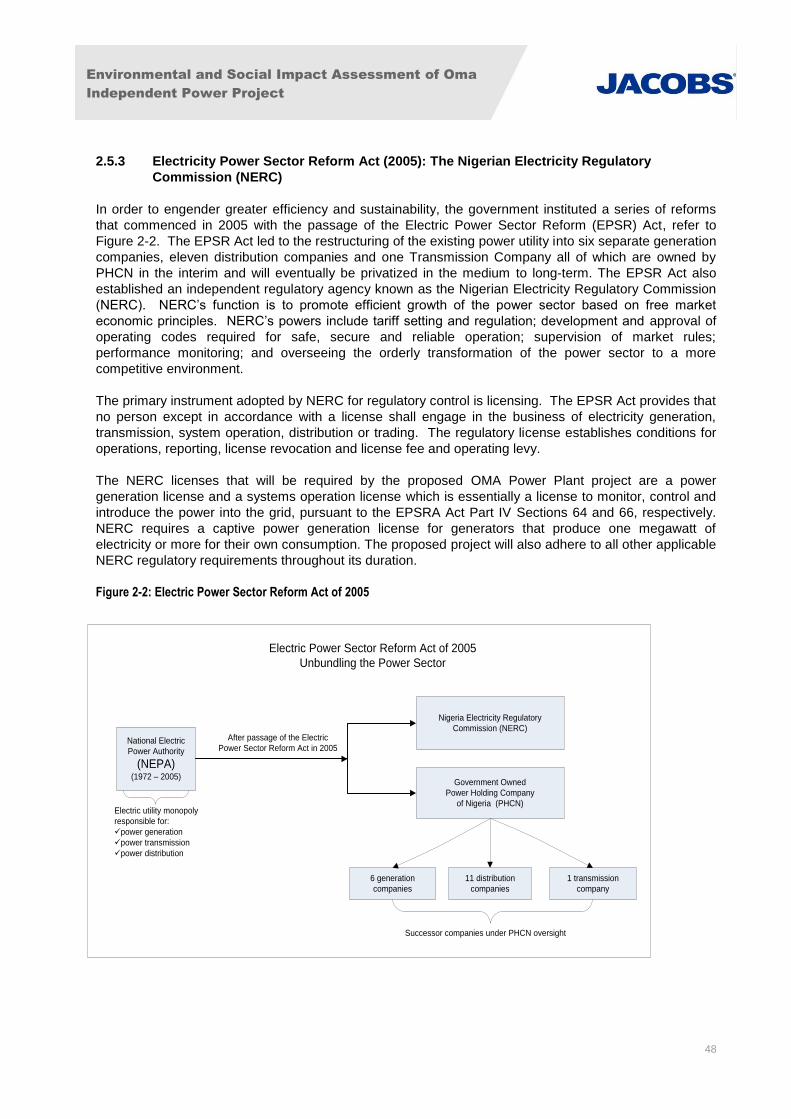
Environmental and Social Impact Assessment of Oma
Independent Power Project
48
2.5.3 Electricity Power Sector Reform Act (2005): The Nigerian Electricity Regulatory
Commission (NERC)
In order to engender greater efficiency and sustainability, the government instituted a series of reforms
that commenced in 2005 with the passage of the Electric Power Sector Reform (EPSR) Act, refer to
Figure 2-2. The EPSR Act led to the restructuring of the existing power utility into six separate generation
companies, eleven distribution companies and one Transmission Company all of which are owned by
PHCN in the interim and will eventually be privatized in the medium to long-term. The EPSR Act also
established an independent regulatory agency known as the Nigerian Electricity Regulatory Commission
(NERC). NERC’s function is to promote efficient growth of the power sector based on free market
economic principles. NERC’s powers include tariff setting and regulation; development and approval of
operating codes required for safe, secure and reliable operation; supervision of market rules;
performance monitoring; and overseeing the orderly transformation of the power sector to a more
competitive environment.
The primary instrument adopted by NERC for regulatory control is licensing. The EPSR Act provides that
no person except in accordance with a license shall engage in the business of electricity generation,
transmission, system operation, distribution or trading. The regulatory license establishes conditions for
operations, reporting, license revocation and license fee and operating levy.
The NERC licenses that will be required by the proposed OMA Power Plant project are a power
generation license and a systems operation license which is essentially a license to monitor, control and
introduce the power into the grid, pursuant to the EPSRA Act Part IV Sections 64 and 66, respectively.
NERC requires a captive power generation license for generators that produce one megawatt of
electricity or more for their own consumption. The proposed project will also adhere to all other applicable
NERC regulatory requirements throughout its duration.
Figure 2-2: Electric Power Sector Reform Act of 2005
National Electric
Power Authority
(NEPA)(1972 – 2005)
Government Owned
Power Holding Company
of Nigeria (PHCN)
6 generation
companies
11 distribution
companies
1 transmission
company
Nigeria Electricity Regulatory
Commission (NERC)
Electric Power Sector Reform Act of 2005
Unbundling the Power Sector
After passage of the Electric
Power Sector Reform Act in 2005
Electric utility monopoly
responsible for:
üpower generation
üpower transmission
üpower distribution
Successor companies under PHCN oversight
Environmental and Social Impact Assessment of Oma
Independent Power Project
49
2.6 International Financing Guidelines and Standards
The project will be required to comply with the applicable standards of international financing institutions.
Compliance with Equator Principles III (EPs) is a requirement of many commercial banks for new project
financing with total capital costs of US $10 million or more. The EPs are a voluntary set of standards for
project reporting and determining, assessing and managing social and environmental risk in project
financing. It is expected that this project will source funding from organisations that are signatories to
these principles which include:
Review and Categorise based on International Finance Corporation (IFC) criteria;
Social and Environmental Assessment;
Applicable Social and Environmental Standards;
Action Plan and Management System;
Consultation and Disclosure;
Grievance Mechanism;
Independent Review;
Covenants Requiring Compliance;
Independent Monitoring and Reporting; and,
Public Reporting Process and Experience.
The EPs relate to good practice with specified applicable social and environmental performance
standards and generally require compliance with the performance standards and guidelines of the IFC,
dependent upon the economic status of the country. For this project to comply with the EPs, the IFC
Performance Standards (2012), the General EHS Guidelines (2007) and the EHS Guidelines for Thermal
Power Plants (2007) will apply.
This ESIA study will examine in detail all relevant Nigerian legislation and international conventions and
standards and their applicability to the project.
2.6.1 World Bank Operational Policies
The World Bank has developed 10 environmental, social and legal Safeguard Policies that are used to
examine potential environmental and social risks and benefits associated with World Bank lending
operations to prevent and mitigate undue harm to people and their environment during the development
process. These policies provide guidelines for the identification, preparation, and implementation of
programmes and projects, and provide a means for stakeholders to participate in and inform the project
design. These safeguard policies include Environmental Assessment (Operational Policy, OP 4.01);
Natural Habitats (OP 4.04); Forestry (OP 4.36); Pest Management (OP 4.09); Physical Cultural
Resources (OP 4.11); Involuntary Resettlement (OP 4.12); Indigenous Peoples (4.10); Safety of Dams
(4.37); Projects in International Waters (OP 7.50); and Projects in Disputed Areas (OP 7.60).
The policies relevant to the Oma project are Operational Policies 4.01, 4.03 and 4.04 that are
summarised below.
Environmental Assessment (Operational Policy, OP 4.01)
Environmental and Social Impact Assessment of Oma
Independent Power Project
50
The objective of OP 4.01 is to ensure that Bank-financed projects are environmentally sound and
sustainable, and the decision-making is improved through appropriate analysis of actions and of their
likely environmental impacts. This policy is triggered if a project is likely to have potentially adverse
environmental risks and impacts in its area of influence. OP 4.01 covers impacts on the natural
environment (air, water and land); human health and safety; physical cultural resources, and trans-
boundary and global environment concerns.
Thus the construction and operation of a thermal power plant is likely to have environmental impacts,
which require mitigation.
Performance Standards for Private Sector Activities (Operational Policy, OP 4.03)
The aim of this policy is to facilitate Bank financing for private sector led economic development projects
by applying environmental and social policy standards that are better suited to the private sector, while
enhancing greater policy coherence and cooperation across the World Bank Group.
Natural Habitats (Operational Policy, OP 4.04)
This policy recognises that the conservation of natural habitats is essential to safeguard their unique
biodiversity and to maintain environmental services and products for human society and for long-term
sustainable development. The Bank therefore supports the protection, management and restoration of
natural habitats in its project financing, as well as policy dialogue and economic and sector work. The
Bank supports and expects borrowers to apply a precautionary approach to natural resource
management to ensure opportunities for environmentally sustainable development. Natural habitats are
land and water areas where most of the original native plant and animal species are still present. Natural
habitats comprise many types of terrestrial, freshwater, coastal and marine ecosystems. They include
areas lightly modified by human activities, but retaining their ecological functions and most native
species.
The proposed power plant is not considered to cause the loss or degradation of natural habitats and
therefore this policy is not considered applicable to this project. The habitats present were found to be
modified habitats, areas which have been subject to human activity such as vegetation clearance and or
agriculture. Some areas of the site where the farmland has been left fallow have begun to regenerate,
however tree species diversity remains low.
For project-related conditions, the more stringent standard, be it Nigerian, Company or World Bank, will
apply.
2.6.2 International Finance Corporation (IFC) Performance Standards and EHS Guidelines
The IFC Performance Standards establish a private regulatory framework in respect of labour and
working conditions; environmental practices; workplace health & safety; community health, safety and
security; land acquisition and involuntary resettlement; relations with indigenous communities, and;
preservation of cultural heritage. IFC Performance Standards are set out to help in carrying out the
policies set out in the Operational Policy on Environmental Assessment (OP 4.01) and related
documents. The Performance Standards define client’s responsibilities for managing their environmental
and social risks, provide guidance on how to identify risks and impacts and help avoid, mitigate and
manage risks and impacts as a way of doing business in a sustainable way (including stakeholder
engagement and disclosure obligation of the client in relation to project –level activities). The eight
Performance Standards (2012) whose requirements are to be met by the project throughout its life cycle
are as follows:

Environmental and Social Impact Assessment of Oma
Independent Power Project
51
Performance Standard 1: Assessment and Management of Environmental and Social Risks and
Impacts;
Performance Standard 2: Labour and Working Conditions;
Performance Standard 3: Resource Efficiency and Pollution Prevention;
Performance Standard 4: Community Health, Safety and Security;
Performance Standard 5: Land Acquisition and Involuntary Resettlement;
Performance Standard 6: Biodiversity Conservation and Sustainable Management of Living
Natural Resources;
Performance Standard 7: Indigenous Peoples; and,
Performance Standard 8: Cultural Heritage.
Since no indigenous people will be affected by the project or require relocation as a result of the
proposed project, Performance Standard 7 is not relevant to this project and is not considered further in
this ESIA. The remaining seven Performance Standards are considered to be relevant to the project, and
the ESIA of OMA Power Plant has considered these throughout the life-cycle of the project.
IFC has also produced EHS Guidelines, which are technical reference documents with general and
industry-specific examples of Good International Industry Practice (GIIP). IFC uses the EHS Guidelines
as a technical source of information during project appraisal activities.
The EHS Guidelines relevant to the OMA Power Plant are:
General EHS Guidelines; and,
EHS Guidelines for Thermal Power Plants.
In addition to the express guidelines of the IFC Standards and EHS Guidelines, clients must meet the
requirements of local and international laws, regardless of whether such laws are regularly or consistently
enforced. In this way, the IFC Standards/ guidelines require the client to operate beyond minimum
compliance with laws and regulations where such laws and regulations fall below the IFC Standards. Of
particular relevance to this project, more specifically, detailed environmental, health and safety guidelines
exist for Thermal Power Plants.
2.6.3 Multilateral Investment Guarantee Agency (MIGA) Performance Standards
Multilateral Investment Guarantee Agency (MIGA) is a member of the World Bank Group. Our mission is
to promote foreign direct investment (FDI) into developing countries to help support economic growth,
reduce poverty, and improve people's lives. MIGA's Performance Standards address:
assessment and management of environmental and social risks and impacts
labour and working conditions
resource efficiency and pollution prevention
community, health, safety, and security
Environmental and Social Impact Assessment of Oma
Independent Power Project
52
land acquisition and involuntary resettlement
biodiversity conservation and sustainable management of living natural resources
indigenous peoples
cultural heritage
These Performance Standards help MIGA and its clients manage and improve social and environmental
performance through an outcomes-based approach. The desired outcomes are described in the
objectives of each Performance Standard, followed by specific requirements to help clients achieve these
outcomes through means that are appropriate to the nature and scale of the project and commensurate
with the level of social and environmental risks (likelihood of harm) and impacts. Central to these
requirements is a consistent approach to avoid adverse impacts on workers, communities, and the
environment, or if avoidance is not possible, to reduce, mitigate, or compensate for the impacts, as
appropriate.
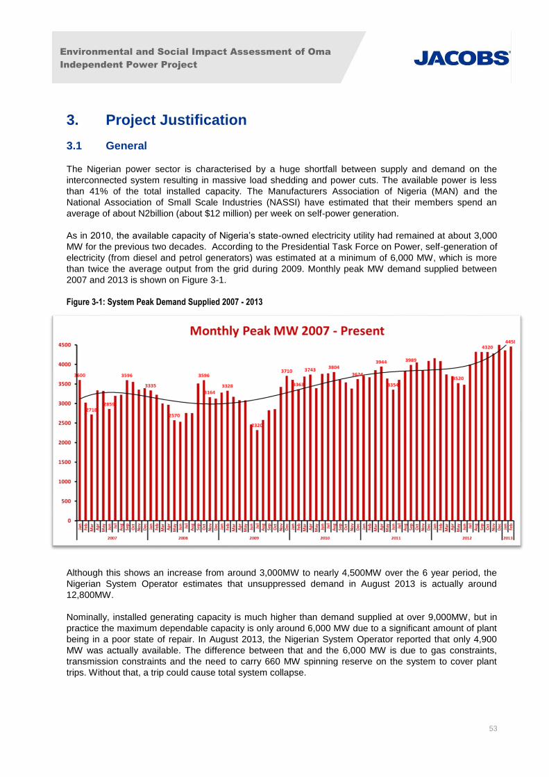
Environmental and Social Impact Assessment of Oma
Independent Power Project
53
3. Project Justification
3.1 General
The Nigerian power sector is characterised by a huge shortfall between supply and demand on the
interconnected system resulting in massive load shedding and power cuts. The available power is less
than 41% of the total installed capacity. The Manufacturers Association of Nigeria (MAN) and the
National Association of Small Scale Industries (NASSI) have estimated that their members spend an
average of about N2billion (about $12 million) per week on self-power generation.
As in 2010, the available capacity of Nigeria’s state-owned electricity utility had remained at about 3,000
MW for the previous two decades. According to the Presidential Task Force on Power, self-generation of
electricity (from diesel and petrol generators) was estimated at a minimum of 6,000 MW, which is more
than twice the average output from the grid during 2009. Monthly peak MW demand supplied between
2007 and 2013 is shown on Figure 3-1.
Figure 3-1: System Peak Demand Supplied 2007 - 2013
Although this shows an increase from around 3,000MW to nearly 4,500MW over the 6 year period, the
Nigerian System Operator estimates that unsuppressed demand in August 2013 is actually around
12,800MW.
Nominally, installed generating capacity is much higher than demand supplied at over 9,000MW, but in
practice the maximum dependable capacity is only around 6,000 MW due to a significant amount of plant
being in a poor state of repair. In August 2013, the Nigerian System Operator reported that only 4,900
MW was actually available. The difference between that and the 6,000 MW is due to gas constraints,
transmission constraints and the need to carry 660 MW spinning reserve on the system to cover plant
trips. Without that, a trip could cause total system collapse.
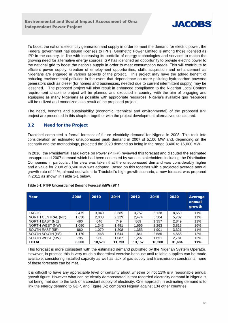
Environmental and Social Impact Assessment of Oma
Independent Power Project
54
To boost the nation’s electricity generation and supply in order to meet the demand for electric power, the
Federal government has issued licenses to IPPs. Geometric Power Limited is among those licensed as
IPP in the country. In line with increasing its portfolio of energy technologies and services to match the
growing need for alternative energy sources, GP has identified an opportunity to provide electric power to
the national grid to boost the nation’s supply in order to meet consumption needs. This will contribute to
efficient power supply, creation of employment opportunities, skills acquisition and enhancement as
Nigerians are engaged in various aspects of the project. This project may have the added benefit of
reducing environmental pollution in the event that dependence on more polluting hydrocarbon powered
generators such as diesel (for homes and businesses, needed due to current intermittent supply) may be
lessened. The proposed project will also result in enhanced compliance to the Nigerian Local Content
requirement since the project will be planned and executed in-country, with the aim of engaging and
equipping as many Nigerians as possible with appropriate resources. Nigeria’s available gas resources
will be utilized and monetized as a result of the proposed project.
The need, benefits and sustainability (economic, technical and environmental) of the proposed IPP
project are presented in this chapter, together with the project development alternatives considered.
3.2 Need for the Project
Tractebel completed a formal forecast of future electricity demand for Nigeria in 2008. This took into
consideration an estimated unsuppressed peak demand in 2007 of 5,100 MW and, depending on the
scenario and the methodology, projected the 2020 demand as being in the range 8,400 to 16,000 MW.
In 2010, the Presidential Task Force on Power (PTFP) reviewed this forecast and disputed the estimated
unsuppressed 2007 demand which had been contested by various stakeholders including the Distribution
Companies in particular. The view was taken that the unsuppressed demand was considerably higher
and a value for 2008 of 8,500 MW was adopted. Based on this together with a projected average annual
growth rate of 11%, almost equivalent to Tractebel’s high growth scenario, a new forecast was prepared
in 2011 as shown in Table 3-1 below.
Table 3-1: PTFP Unconstrained Demand Forecast (MWs) 2011
This forecast is more consistent with the estimated demand published by the Nigerian System Operator.
However, in practice this is very much a theoretical exercise because until reliable supplies can be made
available, considering installed capacity as well as lack of gas supply and transmission constraints, none
of these forecasts can be met.
It is difficult to have any appreciable level of certainty about whether or not 11% is a reasonable annual
growth figure. However what can be clearly demonstrated is that recorded electricity demand in Nigeria is
not being met due to the lack of a constant supply of electricity. One approach in estimating demand is to
link the energy demand to GDP, and Figure 3-2 compares Nigeria against 134 other countries.
Year 2008 2010 2011 2012 2015 2020 Average
annual
growth
LAGOS 2,475 3,049 3,385 3,757 5,138 8,659 11%
NORTH CENTRAL (NC) 1,630 2,008 2,229 2,474 3,384 5,702 11%
NORTH EAST (NE) 480 646 749 869 1,357 2,849 11%
NORTH WEST (NW) 1,090 1,343 1,491 1,655 2,263 3,813 16%
SOUTH EAST (SE) 860 1,079 1,208 1,353 1,901 3,321 11%
SOUTH SOUTH (SS) 1,170 1,468 1,644 1,841 2,586 4,558 12%
SOUTH WEST (SW) 795 980 1,087 1,207 1,651 2,781 12%
TOTAL 8,500 10,573 11,793 13,157 18,280 31,684 11%
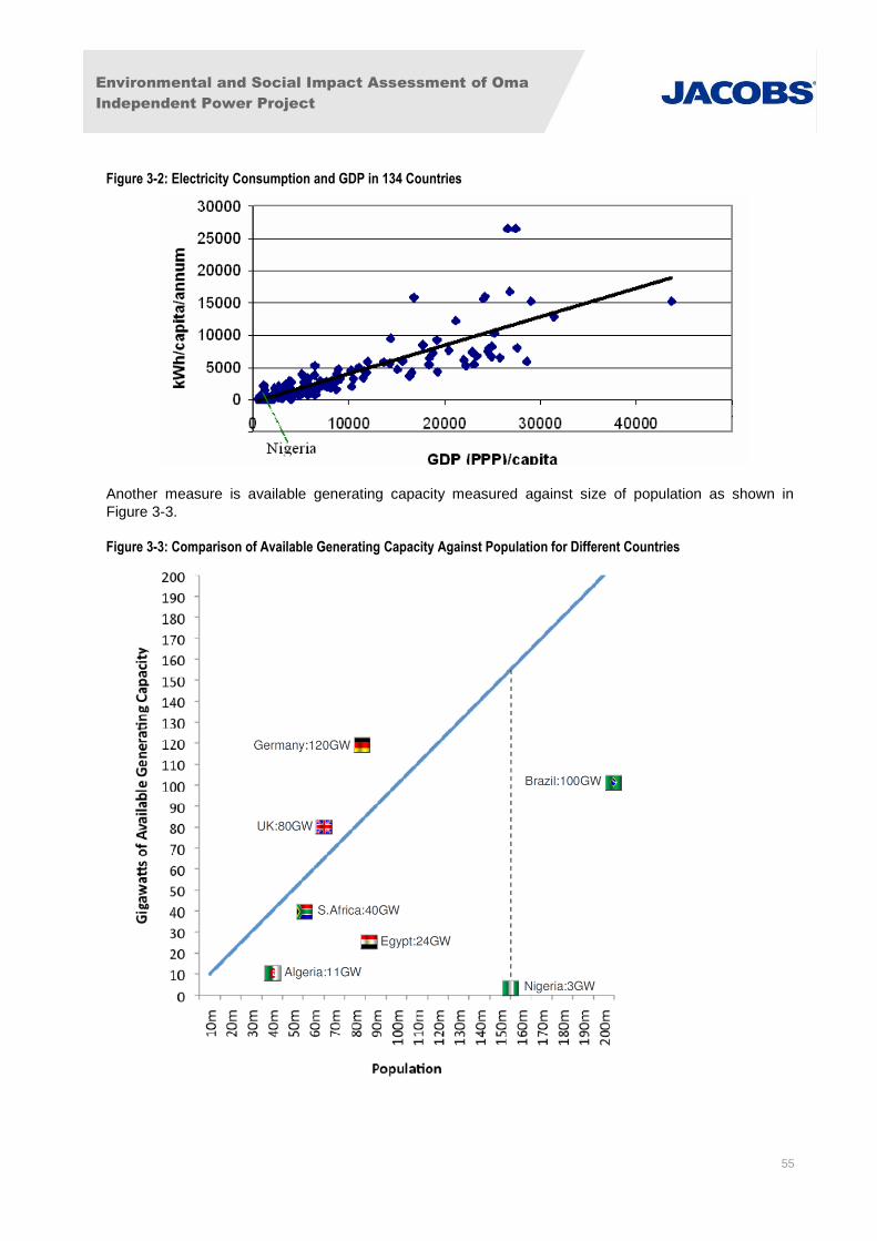
Environmental and Social Impact Assessment of Oma
Independent Power Project
55
Figure 3-2: Electricity Consumption and GDP in 134 Countries
Another measure is available generating capacity measured against size of population as shown in
Figure 3-3.
Figure 3-3: Comparison of Available Generating Capacity Against Population for Different Countries
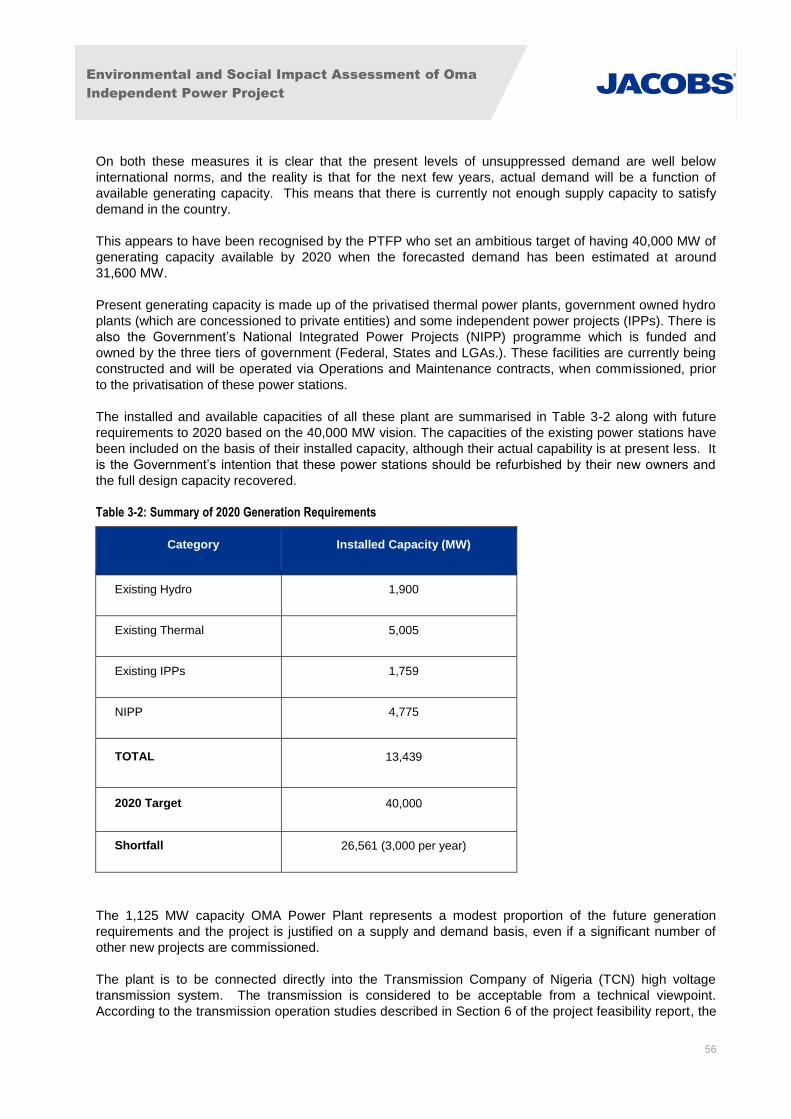
Environmental and Social Impact Assessment of Oma
Independent Power Project
56
On both these measures it is clear that the present levels of unsuppressed demand are well below
international norms, and the reality is that for the next few years, actual demand will be a function of
available generating capacity. This means that there is currently not enough supply capacity to satisfy
demand in the country.
This appears to have been recognised by the PTFP who set an ambitious target of having 40,000 MW of
generating capacity available by 2020 when the forecasted demand has been estimated at around
31,600 MW.
Present generating capacity is made up of the privatised thermal power plants, government owned hydro
plants (which are concessioned to private entities) and some independent power projects (IPPs). There is
also the Government’s National Integrated Power Projects (NIPP) programme which is funded and
owned by the three tiers of government (Federal, States and LGAs.). These facilities are currently being
constructed and will be operated via Operations and Maintenance contracts, when commissioned, prior
to the privatisation of these power stations.
The installed and available capacities of all these plant are summarised in Table 3-2 along with future
requirements to 2020 based on the 40,000 MW vision. The capacities of the existing power stations have
been included on the basis of their installed capacity, although their actual capability is at present less. It
is the Government’s intention that these power stations should be refurbished by their new owners and
the full design capacity recovered.
Table 3-2: Summary of 2020 Generation Requirements
Category Installed Capacity (MW)
Existing Hydro 1,900
Existing Thermal 5,005
Existing IPPs 1,759
NIPP 4,775
TOTAL 13,439
2020 Target 40,000
Shortfall 26,561 (3,000 per year)
The 1,125 MW capacity OMA Power Plant represents a modest proportion of the future generation
requirements and the project is justified on a supply and demand basis, even if a significant number of
other new projects are commissioned.
The plant is to be connected directly into the Transmission Company of Nigeria (TCN) high voltage
transmission system. The transmission is considered to be acceptable from a technical viewpoint.
According to the transmission operation studies described in Section 6 of the project feasibility report, the
Environmental and Social Impact Assessment of Oma
Independent Power Project
57
plant can be incorporated into the system without the need for reinforcement, even for Phase 3.
Therefore, the location and transmission system is deemed to be acceptable from an existing capacity
perspective, and the TCN transmission reinforcement works are still scheduled to be completed as
planned.
Due to the insufficient, erratic and unreliable nature of power supply by existing utilities in Nigeria and the
current liberalization/reform of the sector, the proposed power plant in its totality is needed to:
Generate and supply power to the National Grid;
Improve the reliability of electricity supply to the nation; and
Stimulate industrial development within the country and improve the employment opportunity
base of its inhabitants.
3.3 Benefits of the Proposed Project
In addition to benefits already described above, the proposed OMA Power Plant project is designed to
optimize the following benefits:
Continuing the technological advancement in plant design and power generation within Nigeria;
Generation of low cost and more secure source of power, compared with expensive temporary
diesel generation;
Availability of a stable electric power supply both for new and existing industrial establishments
that are connected to the grid;
Providing security of supply which contributes to supporting conditions for local small and
medium scale industrial/business development and investment opportunities;
Utilizing gas for electricity generation and supply of efficient power in a more environment friendly
manner compared with more polluting and inefficient thermal generation including light/heavy fuel
oil, coal and diesel;
Provision of permanent employment opportunities for Nigerians;
Improving international relations and foreign exchange earnings through attraction of foreign
investors; and,
Contributing to the overall long-term growth and business development targets of Nigeria.
3.4 Envisaged Sustainability
3.4.1 Economic and Commercial Sustainability
The proposed power plant is envisaged to be economically and commercially sustainable throughout its
design life span. This is because of:
The availability of the volume of gas to be negotiated with an International Oil Company such as
TOTAL E & P Nigeria and the Gas Aggregator Company of Nigeria (GACN);
Environmental and Social Impact Assessment of Oma
Independent Power Project
58
The proximity of the likely delivery point of the gas, Imo River, to the proposed OMA IPP plant
site; and,
The revenue that would accrue from power generation, which would serve for payment of staff,
procurement of maintenance facilities, servicing of loans and dividends for investors.
3.4.2 Technical Sustainability
GP along with its joint development partner, GE, will ensure the technical sustainability of the proposed
project by applying their proven expertise and track record in overseeing the project development and
implementing the design, construction and operation of the project. Furthermore, the project will
successfully adopt and apply best available technologies, and contractors will be required to adhere
strictly to internationally and nationally acceptable engineering design and construction standards and
codes of practice at all stages of development. Several energy-efficiency measures (such as use of high
efficiency turbines) will be incorporated into the design to reduce fuel gas consumption that will greatly
enhance the technical sustainability of the project whilst at the same time reducing environmental effects
such as resource usage and emissions. Relevant design standards are provided in Appendix V.
The Plant will be sourced through international competitive bidding and each phase is likely to be
constructed on a turnkey basis under one Engineering, Procurement and Construction (EPC) contract.
The EPC contractor will develop operating manuals and appropriate documentation detailing the proper
operation and maintenance of the planned facilities. These materials will be used as the basis for
providing facility-specific training to relevant personnel prior to start-up to further ensure technical
sustainability of the project.
3.4.3 Environmental Sustainability
The environmental sustainability of the project is reflected through the following:
The beneficial use of natural gas rather than diesel as a primary fuel source for the plant. This is
a major environmental consideration and advantage that will reduce air pollution;
The use of energy efficient technology that will minimise environmental impacts and resource
usage in line with the requirements of IFC PS3;
In order to further enhance the environmental viability of the project, the findings of the ESIA as
well as the avoidance/mitigation and monitoring measures identified will be integrated into the
project and implemented throughout its lifetime.
A detailed Environmental and Social Management System (ESMS) will be developed from the ESIA
ESMP (Section 10) and implemented in the course of the project.
3.5 Alternatives Development and Analysis
Alternatives are different means of completing the proposed project while still meeting the purpose and
need for the proposed activity. Furthermore, the alternatives analysis is intended to address other means
of completing the proposed project that could avoid or minimize adverse impacts that would be
associated with the proposed project.
A variety of alternatives were proposed and have been analysed for the power plant project development.
The technical engineering and economic feasibility, together with the environmental, health and safety
concerns, flexibility for loading operations and expansion, regulatory and stakeholder requirements, cost
effectiveness and ease of operation and maintenance of the system through its design life have been
important considerations in the assessment of alternatives.

Environmental and Social Impact Assessment of Oma
Independent Power Project
59
3.5.1 Alternative Sources of Electricity Generation
The suitability of generation technologies has been assessed against the following criteria:
Readiness/ availability;
Size;
Reliability;
Environmental performance; and
Compliance with local and national policy.
The summary of the key issues identified by the criteria in relation to the power generation options
available in Nigeria is given in Table 3-3 below.
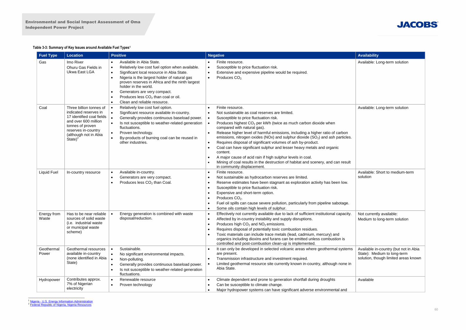
Environmental and Social Impact Assessment of Oma
Independent Power Project
60
Table 3-3: Summary of Key Issues around Available Fuel Types1
Fuel Type Location Positive Negative Availability
Gas Imo River
Ohuru Gas Fields in Ukwa East LGA
Available in Abia State.
Relatively low cost fuel option when available.
Significant local resource in Abia State.
Nigeria is the largest holder of natural gas proven reserves in Africa and the ninth largest holder in the world.
Generators are very compact.
Produces less CO2 than coal or oil.
Clean and reliable resource.
Finite resource.
Susceptible to price fluctuation risk.
Extensive and expensive pipeline would be required.
Produces CO2.
Available: Long-term solution
Coal Three billion tonnes of indicated reserves in 17 identified coal fields and over 600 million tonnes of proven reserves in-country (although not in Abia State)
2
Relatively low cost fuel option.
Significant resource available in-country.
Generally provides continuous baseload power.
Is not susceptible to weather-related generation fluctuations.
Proven technology.
By-products of burning coal can be reused in other industries.
Finite resource.
Not sustainable as coal reserves are limited.
Susceptible to price fluctuation risk.
Produces highest CO2 per kWh (twice as much carbon dioxide when compared with natural gas).
Release higher level of harmful emissions, including a higher ratio of carbon emissions, nitrogen oxides (NOx) and sulphur dioxide (SO2) and ash particles.
Requires disposal of significant volumes of ash by-product.
Coal can have significant sulphur and lesser heavy metals and organic content.
A major cause of acid rain if high sulphur levels in coal.
Mining of coal results in the destruction of habitat and scenery, and can result in community displacement.
Available: Long-term solution
Liquid Fuel In-country resource Available in-country.
Generators are very compact.
Produces less CO2 than Coal.
Finite resource.
Not sustainable as hydrocarbon reserves are limited.
Reserve estimates have been stagnant as exploration activity has been low.
Susceptible to price fluctuation risk.
Expensive and short-term option.
Produces CO2.
Fuel oil spills can cause severe pollution, particularly from pipeline sabotage.
Some oils contain high levels of sulphur.
Available: Short to medium-term solution
Energy from Waste
Has to be near reliable sources of solid waste (i.e. industrial waste or municipal waste scheme)
Energy generation is combined with waste disposal/reduction.
Effectively not currently available due to lack of sufficient institutional capacity.
Affected by in-country instability and supply disruptions.
Produces high CO2 and NO2 emissions.
Requires disposal of potentially toxic combustion residues.
Toxic materials can include trace metals (lead, cadmium, mercury) and organics including dioxins and furans can be emitted unless combustion is controlled and post-combustion clean-up is implemented.
Not currently available:
Medium to long-term solution
Geothermal Power
Geothermal resources available in-country (none identified in Abia State)
Sustainable.
No significant environmental impacts.
Non-polluting.
Generally provides continuous baseload power.
Is not susceptible to weather-related generation fluctuations.
It can only be developed in selected volcanic areas where geothermal systems are present.
Transmission infrastructure and investment required.
Limited geothermal resource site currently known in-country, although none in Abia State.
Available in-country (but not in Abia State): Medium to long-term solution, though limited areas known
Hydropower Contributes approx. 7% of Nigerian electricity
Renewable resource
Proven technology
Climate dependent and prone to generation shortfall during droughts
Can be susceptible to climate change.
Major hydropower systems can have significant adverse environmental and
Available
1 Nigeria - U.S. Energy Information Administration 2 Federal Republic of Nigeria, Nigeria Resources
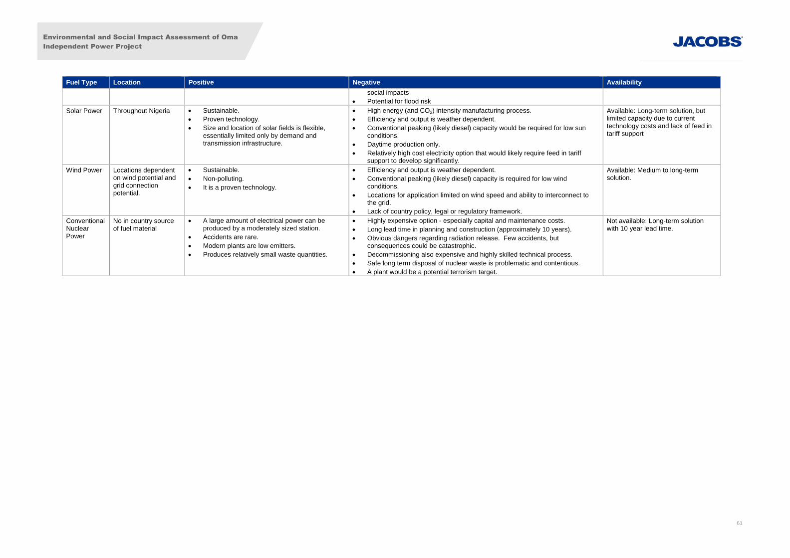
Environmental and Social Impact Assessment of Oma
Independent Power Project
61
Fuel Type Location Positive Negative Availability
social impacts
Potential for flood risk
Solar Power Throughout Nigeria Sustainable.
Proven technology.
Size and location of solar fields is flexible, essentially limited only by demand and transmission infrastructure.
High energy (and CO2) intensity manufacturing process.
Efficiency and output is weather dependent.
Conventional peaking (likely diesel) capacity would be required for low sun conditions.
Daytime production only.
Relatively high cost electricity option that would likely require feed in tariff support to develop significantly.
Available: Long-term solution, but limited capacity due to current technology costs and lack of feed in tariff support
Wind Power Locations dependent on wind potential and grid connection potential.
Sustainable.
Non-polluting.
It is a proven technology.
Efficiency and output is weather dependent.
Conventional peaking (likely diesel) capacity is required for low wind conditions.
Locations for application limited on wind speed and ability to interconnect to the grid.
Lack of country policy, legal or regulatory framework.
Available: Medium to long-term solution.
Conventional Nuclear Power
No in country source of fuel material
A large amount of electrical power can be produced by a moderately sized station.
Accidents are rare.
Modern plants are low emitters.
Produces relatively small waste quantities.
Highly expensive option - especially capital and maintenance costs.
Long lead time in planning and construction (approximately 10 years).
Obvious dangers regarding radiation release. Few accidents, but consequences could be catastrophic.
Decommissioning also expensive and highly skilled technical process.
Safe long term disposal of nuclear waste is problematic and contentious.
A plant would be a potential terrorism target.
Not available: Long-term solution with 10 year lead time.
Environmental and Social Impact Assessment of Oma
Independent Power Project
62
Table 3-3 indicates that natural gas is the preferred option as it is an available long-term resource. It
is a cleaner, more cost-effective and reliable option than the conventional coal and oil power
generation within Nigeria. Furthermore, it is not affected by the weather/climate uncertainty issues
associated with wind and hydropower.
3.5.2 Alternative Technologies for Natural Gas Generation
The core criteria used for considering and choosing between technological/design alternatives for
natural gas generation are as follows:
Overall safety of the personnel working in the proposed project facility and the public living in
the vicinity of the project area;
Environmental impact of the proposed project with respect to its effects on air quality,
underground water, soil, geographical terrain, vegetation, wildlife, socioeconomics, noise and
other environmental aspects;
Potential impacts to communities, their health, lifestyle and activities such as businesses,
transportation, recreation, etc.;
Best available/practicable technologies that is not only familiar, but also acceptable within the
applicable area in order to ensure effective operation, maintenance and sustainability;
Feasibility of construction, operation and maintenance in view of satisfactory and cost
effective practices;
Availability and reliability of fuel supply for the proposed plant operation such as the use and
volume of natural gas or diesel requirements;
Mitigation, management and monitoring requirements that will ensure safe and
environmentally sound operations;
Acceptance by stakeholders with due considerations of technical, environmental, regulatory
and cost implications of implementation and maintenance of proposed project; and,
Other institutional, regulatory, national and international requirements of proposed project.
Environmental and Social Impact Assessment of Oma
Independent Power Project
63
Based on the above, the summaries of technological/process considerations for natural gas
generation are as follows:
Steam Turbine Power Plant
The steam turbine has as its advantages high overall electrical generating efficiencies of up to 75%
when utilised in a combined heat and power (CHP) application through the reuse of the waste heat.
However, there are no potential sources for waste heat so CHP is not an option and typical upper
limits of steam turbine efficiencies are around 37%.
Other disadvantages include cost, slow start up times, the risk of corrosion of the pipes and other
factors dealing with heat transfer in the steam turbine. The efficiency of a steam turbine is limited by
the maximum temperature of the steam produced and is not directly a function of the fuel used.
Significant cooling is required for steam condensation and auxiliary stations, which needs either large
water quantities (which are not available at the site) or more inefficient air cooling.
Cooling can produce significant waste heat which if not utilised in cogeneration reduces overall
efficiencies and can have negative environmental impacts if cooling water is disposed into surface
waters, increasing the temperature of the receiving water body. The equipment takes a lot of energy
to heat up, therefore increasing start up times, and is usually heavy compared to other engines like
gas, diesel, or electric.
Based on the considerations of need for expensive high-pressure boilers and other equipment, slow
start up times, poor part load performance and low electrical efficiencies of operating the steam
turbine alone, this option was rejected.
Simple Cycle and Combined Cycle Gas Turbine Power Plant
The simple cycle gas turbine is simpler to install, operate and maintain. It is capable of producing
large amounts of useful power for a relatively small size and weight. Since motion of all its major
components involve pure rotation (i.e. no reciprocating motion as in a piston engine), its mechanical
life is long and the corresponding maintenance cost is relatively low. Although the gas turbine must be
started by some external means (a small external motor or other source, such as another gas turbine
or diesel generator), it can be brought up to full-load (peak output) conditions in minutes as contrasted
to a steam turbine plant whose start up time is measured in hours.
A major disadvantage of the gas turbine in simple cycle is that as the waste heat is not recovered,
leading to thermal efficiency in the range of 33%. Operating in combined cycle mode with a heat
recovery steam generator will increase the thermal efficiency to about 55%.
Gas Turbine Generator (GTG) Sizing and Selection
The GTGs are critical long lead equipment for the project. The sizing and selection considered the
following:
Frame 6 is too small for the service, capable only of delivering about 40MW per unit. Using
this option will imply procurement of several units in order to meet the required capacity. This
would equally result in incremental requirement of resources and utilities for its operations
and maintenance. It would also mean more complicated processes of operations and
maintenance for the several systems that would be involved. Higher fuel consumption by the
several units will lead to consequent increase in emissions and discharges. This will
subsequently raise the monitoring, mitigation and other regulatory compliance requirements.
Environmental and Social Impact Assessment of Oma
Independent Power Project
64
All of these will result in excessive cost that may not be effective for sustainable operations of
the proposed project.
Frame 7E is designed to operate 3,600 rpm (60Hz) whereas Nigeria requires a 3,000 rpm
machine that can generate power at 50Hz. It therefore was unacceptable.
Frame 9E proved efficient for stand-alone power plant because of its ability to deliver the
required net generating capacity of up to 500MW from phase 1 with minimal units generating
capacity in the order of 113MW each. Other added advantages include its life cycle and cost
efficiency. It is also widely utilized in Nigeria making it a very familiar technology both with the
power regulatory and generation companies as well as other operating companies and
maintenance engineers within the country. The lower capital cost involved in comparison to its
higher power delivery, operations and maintenance requirements all add up to make it a cost
efficient option. It is not the latest in terms of technology. However, the need to provide a plant
that is reliable, familiar, and widely used in Nigeria further qualified it as the preferred option.
Additional Technology Considerations
The use of low-sulphur fuel.
The proposed project will use natural gas, an existing domestically abundant fuel stream to
generate electricity for domestic use. The use of natural gas offers a number of environmental
benefits over other sources of energy, particularly other fossil fuels. For example, coal and oil
are composed of much more complex molecules with a higher carbon ratio and higher nitrogen
and sulphur contents. This means that when combusted, coal and oil release higher levels of
harmful emissions, including a higher ratio of carbon emissions, NOx and sulphur dioxide (SO2).
Combustion of coal and fuel oil also releases particulate matter to atmosphere. The combustion
of natural gas, on the other hand, releases negligible quantities of sulphur and nitrogen oxides
(about 60% less than plants that use coal assuming emission reductions measures are not
employed), virtually no ash or particulate matter, and lower levels of CO.
The use of modern combustion technology and effective combustion to minimise the generation of
NOx and CO emissions.
The proposed OMA Power Plant will employ technology recognized as being the most
appropriate for power production on the scale proposed. The net efficiency for the natural gas-
fired simple cycle power plant option (e.g. Phases 1 and 2) will be approximately 33%. As a
benchmark, coal and oil generation units are typically only 30 and 35% efficient, respectively.
Efficiency will increase to up to 54% through the addition of the waste heat boilers and steam
turbine generators when operating in combined cycle mode in Phase 3.
Emission control / abatement.
The IPP will utilise Dry Low NOx (DLN) technology to minimise emissions of NOx and to ensure
emissions meet the IFC emission standard of 25ppm.
Appropriately designed stacks and stack height to ensure adequate dispersion of emissions to
atmosphere.
Per the air quality analysis conducted for the project for Phases 1 and 2, the proposed stack
height of 40m is demonstrated to lead to minimal increases in ambient concentrations of NOx
and CO at nearby receptor locations. The stack height is approximately 20m higher than any
other structure on the site for Phases 1 and 2.
Environmental and Social Impact Assessment of Oma
Independent Power Project
65
3.5.3 Summary of the Preferred Alternative for the Proposed Project
After detailed evaluations of the merits and demerits of the various options highlighted above, the GE
Frame 9 simple cycle gas turbine power plant was adopted for implementation due to its cost
effectiveness, acceptable cycle efficiency, minimal environmental effects, and also the relatively lower
cost of operation and maintenance. The simple cycle machines to be deployed for Phase 1 and
Phase 2 will be converted to combined cycle during Phase 3 which will significantly increase the
overall efficiency of the plant.
3.6 Site Location and Alternatives
The following criteria were used to determine the most suitable site for the location of the power plant:
Sufficient land available to construct and operate a generating facility of this size;
Its proximity to GP’s existing power plant and worker accommodation facilities;
Distance to the Imo River gas gathering facility and the availability of sufficient gas quantity at
this location for transportation to site;
Availability of electric transmission/evacuation capacity;
Avoidance of environmentally and socially sensitive areas;
Compatibility with surrounding land uses; and
Community acceptance and support.
The location for this development was chosen above two other potential locations considered for the
siting of the power plant. A summary of the outcome of this assessment is provided below.
Site 1: A site adjacent to the current GP power plant at Umuojima-Ogbu was also considered
for the siting of the power plant. The available land at this site did not meet the size required
for the construction and operation of all three phases of the proposed generating facility and
thus was rejected.
Site 2: A greenfield site, located in Ihie-Iyi, along the PH-Aba Expressway was also
considered. Although this site met some of the criteria noted above, it failed to meet all of the
key requirements for siting the power plant. The situation of the site in relation to the
overhead transmission lines was also considered. On the basis of these factors, Site 2 was
also rejected.
Additional details of land management in the development area are provided in Section 2.4.10 above,
and in the Socio-economic baseline, Section 6. The present site chosen for the power plant meets all
the criteria set for this project.
3.7 “No Action” Alternative
No action is a possible alternative. It is assumed to be equivalent to a “No Build” alternative. In that
case, potential environmental disturbances that would result from the construction activities and the
operations of the plant will be avoided. No land will be taken, anticipated social conflicts due to
congregation of people with diverse background, understanding, and perspectives will also be
eliminated. “No Action” will prevent the safety and health challenges that could lead to accidents,
dusts and noise, all arising due to heavy traffic associated with the project. In addition, the adverse
Environmental and Social Impact Assessment of Oma
Independent Power Project
66
economic impacts on those who derive their means of livelihood from and within the proposed project
area will equally be prevented.
Currently, there is only one power plant in Abia State with sufficient power for Aba industries with
limited spare capacity for other residents of Aba and environs. The power situation in Abia State and
the nation as a whole is grossly inadequate implying stunted or non-development of businesses and
human capital due to high operating cost outlay. Adopting the ‘no action’ alternative would entail
continually enduring the frequent outages, excessive low voltages and power surges with the
associated dangers and environmental concerns such as increased emissions due to the use of
diesel generators by individuals and business entities for self-generation. Also, with this option the
benefits outlined in Section 3.3 above, will be forfeited. This option was therefore rejected.
3.8 Conclusion
With due considerations to optimal safety, security, environmental, technical and cost implications, the
chosen and recommended options for the proposed OMA Power Plant project provides the best
balance between operational, economic, social and environmental conditions in comparison to the
other sites.
3.9 Cumulative Impacts
The various impacts of this proposed project on the environmental aspects have been identified and
appropriate mitigation measures proposed for applicable conditions. The anticipated cumulative
impacts to air quality and noise are expected to be synergistic rather than additive, over the life of the
project. This is in consideration of the numerous expected benefits, especially with respect to reduced
emissions due to lowered dependence on hydrocarbon-powered generators.
From an environmental perspective, the main considerations regarding cumulative impacts of a power
station would include:
Noise;
Air pollution;
Greenhouse Gas and Carbon Emissions,
Habitat loss and Fragmentation; and
Collision of bird species with power lines.
Currently it is understood that there are two other power stations in the area: the Aba Power Plant
(also owned by GP), located 20km away, and the Alaoji Power Plant (owned by the Niger Delta Power
Holding Company) which is a combined cycle gas turbine plant., located 10km away. Therefore
because of the distance noise effects from the plant are unlikely to be synergistic and there is not
likely to be a cumulative impact on nature conservation interests in the area due to noise.
The air quality assessment indicated that there will be little or no change in the air quality as a result
of the operation of the proposed power station. Given that the closest plants are located some
distance away and that the main air emissions of concern would be short-term exceedances and
given the fact that it is unlikely that exceedances from two plants would occur simultaneously,
cumulative impacts are likely to be less than significant. Therefore it is considered likely that there will
not be any significant cumulative impact on air quality.
In terms of the impact on Nigeria’s annual carbon emissions, according to the US Department of
Energy the total carbon emissions from the consumption of energy in 2012 were 86,398 kt CO2. The
calculated annual carbon emissions from the power plant from all 6 Frame 9 Gas Turbines (Phases 1
and 2) is 3,350 kt CO2, adding 3.9% to the total annual carbon emissions of the country.

Environmental and Social Impact Assessment of Oma
Independent Power Project
67
Due to the distance between the two power stations and the limited footprint of each power station,
habitat fragmentation and loss of former farm land is not considered to be significant, in terms of the
nature conservation interest of the species and habitats present.
The OMA power station is not anticipated to significantly contribute to bird collisions with power lines
on a cumulative basis, as it is situation on former farming land, over 10km away from the nearest
wetland habitat and area where large birds would be expected to be present.
Environmental and Social Impact Assessment of Oma
Independent Power Project
68
4. Project Description3
4.1 General
The proposed project is the OMA Power Plant jointly developed by GP and GE. The project is to be
located in Ugwunagbo LGA state of Abia State, Nigeria. The project will be developed in three
phases. The initial objective of this project is to successfully complete the design, construction,
commissioning and take-over of Phase 1 of the power plant that consists of a gas-fired simple–cycle
plant of approximately 500 Megawatt (MW) net generating capacity that will export power to the
Nigerian national electrical grid. It is also intended to upgrade the Phase 1 plant, in two additional
separate phases. Phase 2 will add two further simple-cycle power generation units and Phase 3 will
add two combined cycle generating units to bring the total net generating capacity to 1,125 MW.
This ESIA will address both the simple-cycle (500 MW net generating capacity) and the potential
configurations (simple and combined cycle) for upgrade to 1,125MW generating capacity. The Project
will support the Federal Government of Nigeria’s objective to reliably increase domestic power
generation in order to promote economic growth and development.
This chapter presents the proposed OMA Power Plant project’s engineering design, construction,
operation and decommissioning activities. These include the design codes and standards (see
Appendix V), the design concepts, operating philosophy and schedule for the project.
4.2 Design Concept
The overall technical philosophy for the OMA Power Plant project is to have a well operated, efficient,
reliable, durable and environmentally friendly power generating plant. In order to achieve this, various
concepts were considered for the different components of the proposed project, before arriving at the
current design.
The power plant will be constructed in three phases to arrive at an eventual combined cycle plant:
Phase 1 with approximately 500MW net capacity in open cycle;
Phase 2 adding approximately 250MW of capacity in open cycle; and,
Phase 3 adding 375MW of capacity by conversion to combined cycle, bringing the total net
capacity to 1,125MW at site conditions.
The timing of Phases 2 and 3 will depend on the need and economics of the expansion phases (as
defined by the Power Purchase Agreement with the Nigerian Bulk Electricity Trading Company,
NBET), the ability to export the electricity (which depends on progress with transmission line upgrades
by TCN), and the availability of adequate fuel resources (natural gas purchase contract
GACN/International Oil Company (IOC)).
The key elements of the design concept are summarised as follows:
Civil engineering works, gas turbine generation units and the associated ancillaries, electrical
and control equipment including the process systems for the power station including a black
start diesel generator set;
3 The language in this section consists of the original BGI text and has not been authored directly by Jacobs.
Environmental and Social Impact Assessment of Oma
Independent Power Project
69
Installation of fuel gas system and gas supply pipeline between the site and the existing gas
gathering facility at Imo River (note that impacts of the gas pipeline will be addressed in a
separate ESIA which will be prepared for approval by Federal Ministry of Environment);
Construction of groundwater boreholes, water treatment facilities, pumping, tankage and
installation of water supply reticulation serving the closed-circuit auxiliary cooling water
system of the gas turbines, generators and steam turbines (Phases 1 to 3), makeup water for
combined cycle water-steam cycle (Phase 3), service water system, wastewater treatment
system, an independent fire-fighting system and potable water system for the power station;
330kV air-insulated switchgear (AIS) switchyard within the power station site.
A 300m long, 330kV double circuit (DC) overhead transmission line to be constructed from
the project switchyard to tie-in to the nearby 330kV double circuit line running from Afam to
Alaoji (Figure 4-3). This is required for Phases 2 and 3.
Ancillary works such as administration and security buildings, workshops, equipment and
spares store, roads and car-parking, communication system (within the power station), and
security fencing, accommodation facilities and gate-house for the proposed power station.
Separate to this project, in order to reinforce the 330kV grid and to enable the export of the full
capacity of the power plant, TCN is re-enforcing the ITU, UYO and EKET 132/33kV substations whilst
the Eket-Uyo-Itu-Calabar 132kV lines will be re-stringed in a double circuit bare conductor lines for
more power to be transported to the load centres within the two states. This approach will further
reduce the total losses witnessed with or without OMA Power Plant. Construction of the 12 NIPP
330kV circuits is planned to be completed quickly to enable power to flow to the east and the north
eastern States of Gombe and Adamawa based on the schedule with TCN.
Applicable codes and Standards
The conceptual design of the proposed project was based on the practices recommended by a
consistent set of internationally recognised codes and standards that shall be applied to all aspects
and components of the proposed OMA power plant project. Standards are provided in Appendix V.
Environmental Consideration
The conceptual design process of the proposed OMA power plant project considered environmental
and engineering concerns in implementation. These primarily focussed around control of effluents
and contamination, solid wastes, noise and air emissions and health and safety. Associated aspects
of the project design are discussed in relevant sections below.
Site Area, Topography and Hydrologic Data:
Ground Elevation = 52-54m
Slope (gradient) = 2 – 4 %
Area of Site = 22.3ha
Groundwater Level = 26-27m below ground level (bgl)
Road Elevation = 55m
The elevation of the site varies from 52 to 54m above mean sea level (m AMSL) and the ground
surface generally slopes from northeast to southwest.
Environmental and Social Impact Assessment of Oma
Independent Power Project
70
4.3 Facility Design/Plan
The major considerations in the design of the facility layout were safety in operation and maintenance,
accessibility and movement, and minimum separation distances. Other considerations were
provisions for expansion at each phase of the project, compact arrangement, room for effective
functionality, and measures to avoid or minimize adverse environmental effects upon the surrounding
environment, optimizing of visual aesthetics, particularly the greenbelt of the plant area. The total area
for the project is 22.3 ha. The design life of the power plant will be twenty-five years.
Operational accommodation will be provided on-site for up to 10 shift workers on site. Construction
worker accommodations will also be developed on site. Details of the proposed construction worker
accommodation and mitigation and monitoring associated with the construction workers’ camp are
detailed in Section 6 and subsequently in the ESMP, Section 10.
4.3.1 Highway and Plant Transportation
Access to the proposed project site shall be via the existing road network and the A3 Aba to Port
Harcourt motorway, which is understood to be in good condition. Improvement works will be carried-
out to the short (c.300m) stretch of road from the A3 up to the site boundary.
A ring-road system will be provided within the site boundary and shall service all the buildings and
houses, so as to meet traffic and other requirements of production, daily life and fire-fighting. The
road within the plant area shall be the urban type with concrete curbing and a general width of 7.5m.
Significant impacts on the road network are not anticipated given that the site is served by a major
national motorway route from the port where plant and equipment is likely to be imported. An
assessment of the potential impacts on the transport network will be undertaken prior to construction,
in order to consider current traffic flows at that time. This is included as an action in the ESMP.
4.3.2 Water Supply, Treatment and Distribution Systems
Raw Water System
The plant will meet its total water needs by drawing raw water from local boreholes and treating it
according to the various uses within the site. The raw water will be drawn from the boreholes and
forwarded into the supply system by use of dual redundant raw water pumps. The raw water is then
pre-treated by being passed through dual redundant clarifiers. The waste effluent of the clarifiers will
either be routed to the effluent treatment plant or drained to the rainwater drainage system depending
on final composition. The treated raw water is then passed to dual above-ground storage tanks which
serve as dual purpose service and firewater storage for use in the service and firewater systems, as
well as providing a reservoir for further demineralization treatment as necessary for process and
potable water.
Service Water System
The pre-treated water is stored in dual tanks which are designed to maintain a reserve quantity solely
for firefighting purposes, whilst primarily providing a buffer capacity which feeds the suction side of a
set of dual redundant service water forwarding pumps located in the main water supply pump-house.
The service water pumps provide a feed to the demineralization water treatment plant via the
dedicated clarified water tank, plus a pressurised supply to the plant service water network. The
service water network provided wash-down water to plant areas such as the plant and machinery
houses, the drainage run-off of which passes to the oily water collection areas and then to the
treatment facilities.
Environmental and Social Impact Assessment of Oma
Independent Power Project
71
Treated effluent from the oily water treatment facilities is drained to the plant evaporation pond,
whereas the oily waste will be removed from the oily water treatment facilities by suction tanker and
transported off site for disposal.
Bird netting will be installed as humane physical barrier to block birds from entering the evaporation
pond. The pond net will be heavy duty, designed for use in harsh chemical environments. This is
included as an action in the ESMP.
Demineralised Water System
The water treatment plant (WTP) receives clarified water and produces demineralized water by a
combination of dual-media and carbon filters followed by reverse osmosis (R.O) units fed by high
pressure pumps. The demineralized produce water is stored in dual storage tanks local to the WTP in
order to provide suction to the dual redundant demineralized water forwarding pumps.
The demineralised water forwarding pumps feed the demineralized water distribution system which
supplies a number of consumers around the plant. Main consumers of demineralised water are the
make-up demand of the auxiliary closed-cooling water, gas turbine washing system usage plus other
plant water losses.
The WTP also provides potable water in order to meet the plant demand for drinking, sanitary and
miscellaneous usage.
The demineralization process results in waste effluent due to back-washing of filters and R.O.
membranes, plus the R.O. waste concentrate. The waste effluent is drained to the plant evaporation
pond, whereas sludge from R.O membranes in the raw water treatment plant will be transported off
site by an appropriately licensed waste contractor to a licensed facility. This is included as an action in
the ESMP.
Potable Water System
Treated water of potable quality is produced by the WTP and stored in the plant potable water tank.
The tank is treated with a disinfectant and provided in a reservoir of potable water to be used in the
pressurised potable water consumer network.
Drainage water from the sanitary facilities within the plant is taken by the sanitary waste water
treatment system, from where the treated effluent is discharged to the storm water drainage system.
Liquids are disinfected so that all concentrations are within IFC EHS Guidelines and the Nigerian
effluent limits whichever is more stringent prior to discharge to the storm water drainage system.
Solids from sanitary waste will be trucked off site along with sludge from R.O membranes in the raw
water treatment plant.
Fire Water Supply System
A fire water system is provided throughout the plant, fed by pumps located in the fire water pump
house. In plant areas where oil contamination of fire water run-off is possible, the drainage water is
led to the plant oily water treatment units. Otherwise the fire water run-off drains to the rain water
collection system.
Environmental and Social Impact Assessment of Oma
Independent Power Project
72
4.3.3 Drainage Systems
Drainage for the project will be treated via two separate systems. Spills will be routed to the
evaporation pond from the raw water demineralisation plant and the separated water stream from the
o/w separator. A separate sanitary treatment plant will be developed for the project.
The drainage system for discharged water will be designed in accordance to the standards of FMEnv
and the Federal Ministry of Works and Housing. All liquids from the project will be disinfected so that
all concentrations are within IFC EHS Guidelines and Nigerian standards and then discharged to the
storm water drainage system.
Completely independent collection and drainage systems will be constructed for rain, industrial
wastewater and domestic sewage from the OMA Power Plant project.
Solids from sanitary waste will be trucked off site along with sludge from IO membranes in the raw
water treatment plant. Contractors have not yet been selected, but Oma and AECOM have confirmed
that there are appropriately licenced waste collection, processing and disposal contractors/facilities to
allow management of waste in line with Nigerian and international standards.
Rain Drainage System
The rainwater storm drainage system will be designed with sufficient capacity to accept a 1 in 10 year
frequency storm, plus an appropriate additional factor to allow for potential increase in rainfall
frequency/intensity due to climate change.
The system will be gravity flow drainage ditches constructed with reinforced concrete and will drain
hardstanding areas of the site uncontaminated with oil. The drains will be “V” form or rectangular and
located on either side of the road so that in rainfall weather, rain will flow smoothly into the drainage
ditches following the ground gradient into a retention reservoir for evaporation and absorption into the
ground.
The design of the discharge outfall from the storm drainage system has not yet been
confirmed. However, it will be designed in order to prevent any detrimental impacts to adjacent lands,
down gradient from the outfall (e.g. erosion around the outfall and creation of gullies, associated
additional sediment generation or increased overland flows due to rapid transmission of rainwater on
new hardstanding). The ESMP includes an action to finalise the drainage discharge design
considering good international industry practice whilst ensuring that the design appropriate for the
climatic conditions of the site, given the intensity of wet season rains in Nigeria.
In addition to the storm water drainage system, the design of earthworks will also be configured to
divert any surface storm water away from the critical areas of the plant where practicable.
Industrial Wastewater
The industrial wastewater of the power plant shall consist of potentially oily wastewater; effluent from
the water treatment plant, a small amount of blowdown water from the closed-loop auxiliary cooling
system and sanitary waste, wash wastewater from the workshops. These waste streams shall be
pumped into a waste water treatment (WwT) facility (through separate pipes) for treatment before
discharge into the rain drainage system. For oily-waste water, this will be suitably treated in oil-water
separator/wastewater treatment before discharge into the drainage system. The system shall include
an observation pond with sufficient capacity to provide adequate retention time to arrest any
accidental breakthrough of oil or other potential contaminant spills and to allow testing.
All discharged effluent will be treated in line with relevant Nigerian effluent limits and IFC EHS
standards prior to discharge into the storm drainage network.

Environmental and Social Impact Assessment of Oma
Independent Power Project
73
Discharge from the WTP R.O and filtration system will be discharged to an evaporation pond with
impermeable HDPE lining. Here the effluent will settle/evaporate with accumulated solid material
being removed periodically and discharged by licenced contractor (to be identified by the EPC
contractor following appointment). The capacity of the pond is currently anticipated at 900m3,
sufficient for an effluent demand of 5 m3 per hour for 7days, which is sized for Phase 1 and
2. Overflow from the pond will be routed to the effluent treatment system before being discharged into
the storm drainage system following treatment to international standards. The exact volume and
design of the evaporation pond shall be finalized based upon detailed meteorological data for rainfall,
solar radiation and evaporation. Additional capacity will be installed for Phase 3 as required.
The main sources of oily wastewater will be oil-contaminated water from hardstanding around GTGs ,
emergency diesel generators /diesel oil storage, oil tanks of transformers, lubrication system and
maintenance workshop. All potentially oily wastewater from these areas shall be collected and
treated in the oily WwT system.
This will consist of an oil / water (O/W) separator which will settle and skim oil residues from the water
and pump the waste oil to a storage container. Water from the O/W separator will be pumped to the
WTP for removal of potential contaminants. Discharge water will be suitably treated to meet the IFC
EHS guideline limits for effluents.
Domestic Sewage Drainage
Sewage from water closets and urinals will be channelled into a reinforced concrete underground
septic tank that will be constructed at the site. Digested sewage from the septic tank will pass through
a drainage pipe into the water treatment plant where it will be treated in line with IFC EHS guidelines.
The maximum treatment capacity is about 5m3/h. Treated water from domestic sewage treatment
station will then be discharged into the storm water system.
4.3.4 Piping and Culverts Arrangement
The main piping shall not cross/extend to the reserved site. All pipes shall be coordinated to have
linkages with each other and with reasonable crossings where necessary within the plant layout.
4.3.5 Landscaping Design
The plant shall be designed and developed as far as practicable to be sensitive to the aesthetic
quality of the surrounding environment. The space between buildings and house entrance/fronted
area shall be re-vegetated with native grass and shrubs.
Small native ornamental trees alternating with shrub and flowers shall be planted on both sides of the
main and branch roads, while native climbing green-plants (especially the ivy) shall be grown to climb
upon the walls and fences of suitable administration buildings. Also, sheltered forest formation of
trees shall be grown on all sides of the power plant. The main entry square of the OMA Power plant
site area as well as the administrative areas (the landscape zone) shall be planted with indigenous
evergreen trees and shrubs, arbors, flowers, etc.
The grass and shrubs shall be grown in all the spare areas, excluding the main equipment, switchyard
and the oil tank areas. The switchyard and the oil tank areas shall be covered with cobblestones
while the main equipment area shall be covered with concrete, for maintenance purposes.
Soil type is the key element to affect the growth of the plants thus; organic soil stripped from topsoil
shall be reused for the landscaping. The backfill soil thickness for the landscape shall not be less than
300mm.
Environmental and Social Impact Assessment of Oma
Independent Power Project
74
4.3.6 Soil and Foundations
One of the key objectives of the civil design is to minimize the volume of earthwork and to prevent the
rainwater outside the power plant area flooding onto the site and to facilitate rainwater drainage from
the site.
Site preparation work will comprise the levelling of the working areas of the site, earthworks, and the
excavations for foundations. Trenching, installation of underground services and provision of
temporary construction facilities and services will then take place.
Shallow Foundations
The natural soil near the ground surface on site comprises soft to firm clay and clayey silty sand in
some places. Graded crushed stone in 600mm thickness will be used to fill over the clay to get more
bearing capacity mainly for single level structures. This foundation can support loads from structures
that are not sensitive to settlement. The shallow foundation depth is –1.50m. Wide strip foundations
will be considered if the bearing capacity of the soil is low.
Pile Foundations
For heavier equipment or structures, bearing piles shall be required where the soil at normal
foundation level cannot support ordinary pad, strip, or raft foundation or where structures are sited on
deep filling which is compressible and settling under its own weight. All significant structures, such as
the gas turbine generator, steel gantry etc, shall be constructed using pile foundations.
Considering local conditions, precast piles shall be used for the foundations. The settlement of gas
turbine/generator foundation shall not be more than 100mm, and the bank error not more than
0.0015L (L - length of side). The bearing capacity of each pile would be more than 60tons, which
shall be confirmed by static load tests after installation or dynamic pile analysis during driving.
Raft Foundations
Raft foundations shall be considered for the diesel tank (discussed below) and associated bunded
(spill containment) structure. Depending on the soil condition, draining concrete will be used to treat
the foundation soil.
4.3.7 Ventilation and Air Conditioning
The control room and electronic equipment room shall be maintained at 19 – 22oC temperature range
with relative humidity of 50 ± 10%. Air conditioner units will be installed at the control room, electronic
equipment room and necessary other buildings. In order to protect the sensitive electronic equipment
the air quality circulated within these rooms, air change and filter function will be set for the air
conditioning system. No refrigerants containing unacceptable ozone depleting substance will be
used.
The distribution room will be equipped with a ventilation system to aerate the room and reduce indoor
heat. Natural ventilation and mechanical draft ventilation system shall be applied. A combination of
natural ventilation and mechanical draft systems will be adopted for other locations that demand
ventilation, if natural ventilation alone cannot fulfil the requirement.
4.3.8 Workers’ Camp
A construction workers’ camp is planned for development either on the project site prior to
construction, but it is also expected that many of the workforce will come from the local communities
and will not require accommodation on site.
Environmental and Social Impact Assessment of Oma
Independent Power Project
75
Permanent facilities on site will also be constructed for the operational phase. This will include beds
for temporary (not permanent dwellings) use by up to 10 persons at any one time (e.g. shift workers or
visiting staff). All permanent staff will live among the local community.
The workers’ camp will comply with IFC PS and EHS requirements for worker facilities including
sufficient washing and sanitary facilities and management of wastes and effluent. The camp will also
include the necessary amenities such as a dining hall and kitchen. On-site first-aid and emergency
services will be provided. Other services and infrastructure will likely include a water treatment plant,
sewage treatment plant, power generation, fuel storage, miscellaneous storage and fire-fighting
equipment.
Security at the workers’ camp would consist of a combination of security managers and local guards.
Perimeter security, entry control points as well as roving security patrols will likely be used. Security
services would be procured and operated in line with the requirements of IFC PS2 and PS4 regarding
occupational and community health, safety and security.
A worker management plan including worker’s rights and a code of conduct will be completed as an
action within the ESMP. Should additional land outside of the site be required for development of the
worker’s camp and/or permanent housing, associated environmental and social elements would be
considered in a separate study.
4.4 Principal Features of the Power Plant
The proposed power plant shall be constructed, over a period of time, in three distinct phases:
Phase 1 shall utilize four (4) Frame 9E General Electric gas turbines giving an installed gross
capacity of 500MW that will generate approximately 500MW of net electric power operating in
open (simple) cycle configuration. This phase will also include the main site civil works, a
330kV AIS substation, all buildings and WTP required. The gas turbines will be operated on
natural gas only; this gas will be provided from a terminal point at the Imo River. The pipeline
will be designed to meet the fuel gas requirements of the fully developed project (up to Phase
3). (Note that impacts of the gas pipeline will be addressed in a separate ESIA which will be
prepared for approval by FMEnv for the IPP). Generated electricity will be exported via the
330kV switchyard and the national transmission system.
Phase 2 shall further increase capacity by the addition of two (2) Frame 9E General Electric
gas turbines, operating in open cycle; this will increase the plant generating capacity by
approximately 250MW.
Phase 3 plant configuration will be an additional steam cycle conversion generating
approximately 375MW of additional electrical power. In this final phase of development, the 6
existing gas turbine generator sets are integrated into a combined cycle configuration. This
requires the addition to the plant of waste heat boilers and steam turbine generators.
In Phase 1 and Phase 2 plant configurations, the gas turbines indicated above are each capable of
producing about 113 MW of electricity (in simple-cycle operation).
The total plant Combined Cycle configuration is a “2 x (3+3+1)” arrangement (Figure 4-1). In this there
are two units, each unit consisting of three gas turbines, three waste heat boilers and one steam
turbine. The two steam turbines will be capable of producing about 338MW in total; this ensures that
the project will deliver 1,125MW and that there is sufficient space on the site to locate all three phases
of the project. Alternatives such as 3 x (2+2+1) i.e. three units, each consisting of 2GTs, 2HRs & 1ST,

Environmental and Social Impact Assessment of Oma
Independent Power Project
76
would require more land, since there would be an additional air cooled condenser and additional
steam turbine and would therefore be more costly.
The development will have grid black start capability. This includes approximately 10 MW black start
unit to provide independent supply to the power plant, i.e. to provide sufficient electrical power to the
plant for auxiliaries and to start up a large gas turbine in the event of a total power loss on the grid.
The Gas Turbine Generators will be capable of closing the generator circuit breakers onto a dead bus
bar and thus capable of initiating a “black start” of the local grid system.
The total electrical output of OMA power plant project (including the 10 MW black start unit) will
therefore be approximately 1022.5MWe at rated site conditions (or approximately 1135MW at the ISO
conditions) with a thermal input of approximately 2300MWth.
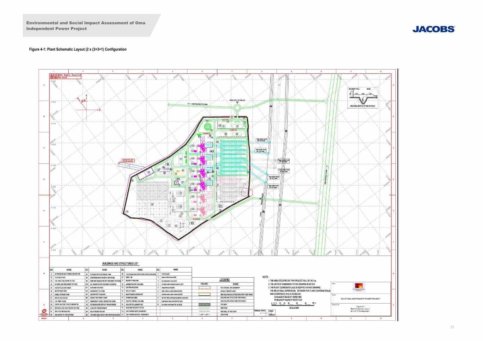
Environmental and Social Impact Assessment of Oma
Independent Power Project
77
Figure 4-1: Plant Schematic Layout (2 x (3+3+1) Configuration
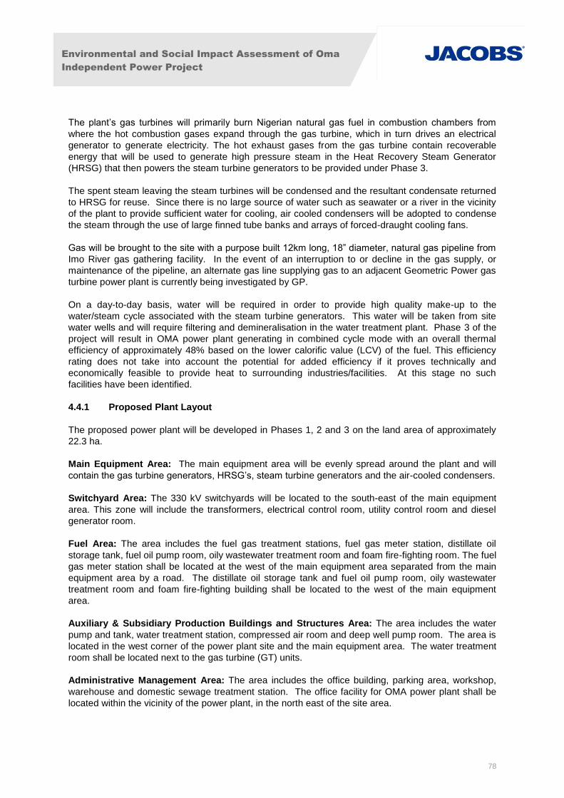
Environmental and Social Impact Assessment of Oma
Independent Power Project
78
The plant’s gas turbines will primarily burn Nigerian natural gas fuel in combustion chambers from
where the hot combustion gases expand through the gas turbine, which in turn drives an electrical
generator to generate electricity. The hot exhaust gases from the gas turbine contain recoverable
energy that will be used to generate high pressure steam in the Heat Recovery Steam Generator
(HRSG) that then powers the steam turbine generators to be provided under Phase 3.
The spent steam leaving the steam turbines will be condensed and the resultant condensate returned
to HRSG for reuse. Since there is no large source of water such as seawater or a river in the vicinity
of the plant to provide sufficient water for cooling, air cooled condensers will be adopted to condense
the steam through the use of large finned tube banks and arrays of forced-draught cooling fans.
Gas will be brought to the site with a purpose built 12km long, 18” diameter, natural gas pipeline from
Imo River gas gathering facility. In the event of an interruption to or decline in the gas supply, or
maintenance of the pipeline, an alternate gas line supplying gas to an adjacent Geometric Power gas
turbine power plant is currently being investigated by GP.
On a day-to-day basis, water will be required in order to provide high quality make-up to the
water/steam cycle associated with the steam turbine generators. This water will be taken from site
water wells and will require filtering and demineralisation in the water treatment plant. Phase 3 of the
project will result in OMA power plant generating in combined cycle mode with an overall thermal
efficiency of approximately 48% based on the lower calorific value (LCV) of the fuel. This efficiency
rating does not take into account the potential for added efficiency if it proves technically and
economically feasible to provide heat to surrounding industries/facilities. At this stage no such
facilities have been identified.
4.4.1 Proposed Plant Layout
The proposed power plant will be developed in Phases 1, 2 and 3 on the land area of approximately
22.3 ha.
Main Equipment Area: The main equipment area will be evenly spread around the plant and will
contain the gas turbine generators, HRSG’s, steam turbine generators and the air-cooled condensers.
Switchyard Area: The 330 kV switchyards will be located to the south-east of the main equipment
area. This zone will include the transformers, electrical control room, utility control room and diesel
generator room.
Fuel Area: The area includes the fuel gas treatment stations, fuel gas meter station, distillate oil
storage tank, fuel oil pump room, oily wastewater treatment room and foam fire-fighting room. The fuel
gas meter station shall be located at the west of the main equipment area separated from the main
equipment area by a road. The distillate oil storage tank and fuel oil pump room, oily wastewater
treatment room and foam fire-fighting building shall be located to the west of the main equipment
area.
Auxiliary & Subsidiary Production Buildings and Structures Area: The area includes the water
pump and tank, water treatment station, compressed air room and deep well pump room. The area is
located in the west corner of the power plant site and the main equipment area. The water treatment
room shall be located next to the gas turbine (GT) units.
Administrative Management Area: The area includes the office building, parking area, workshop,
warehouse and domestic sewage treatment station. The office facility for OMA power plant shall be
located within the vicinity of the power plant, in the north east of the site area.

Environmental and Social Impact Assessment of Oma
Independent Power Project
79
Accommodation Facility: Employee operational and maintenance housing communities and first aid
facilities are planned to be located at a site, 100m away from the power plant site. Housing on the
Geometric Power plant site at Umuojima-Ogbu, less than 20km from the OMA plant site shall initially
be provided for key operational staff.
Schematic Diagrams/Layouts: The site location is shown in Figure 4-2 while Figure 4-4 shows a
typical layout of a one block (3 x 1) combined cycle plant. The gas turbine is shown in Figure 4-5.
4.4.2 Thermo-Mechanical System
The thermo-mechanical system of the power plant includes the gas turbine generators, fuel gas
system, fuel oil system, air compressor, maintenance and laboratory equipment and all connecting
piping. Phase 1 comprises four units GE Frame 9E. These units are well tested throughout the world
and in countries with the same climatic conditions as Nigeria. Also, in Nigeria, more than 70% of
generating thermal power units as well as power plants being developed uses the GE Frame 9E.
Six (6) units of frame 9E’s turbines will be installed: four (4) units in Phase 1 and two (2) units in
Phase 2.
GE Frame 9 Unit
The Frame 9 unit (Model PG 9171E) is provided by GEEPE, Belfort, France.
The PG 9171 E model is an impulse/reaction, single shaft, heavy-duty outdoor unit with a turbine
speed of 3,000 rpm. Under design conditions the generator is rated at 113.55MW using fuel gas.
Under ISO conditions, the output is 126MW without water injection using fuel gas.
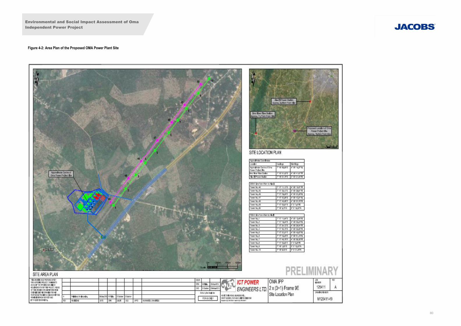
Environmental and Social Impact Assessment of Oma
Independent Power Project
80
Figure 4-2: Area Plan of the Proposed OMA Power Plant Site
Environmental and Social Impact Assessment of Oma
Independent Power Project
81
Figure 4-3 : Transmission Line Route
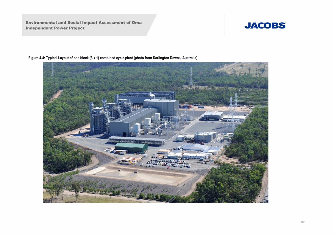
Environmental and Social Impact Assessment of Oma
Independent Power Project
82
Figure 4-4: Typical Layout of one block (3 x 1) combined cycle plant (photo from Darlington Downs, Australia)
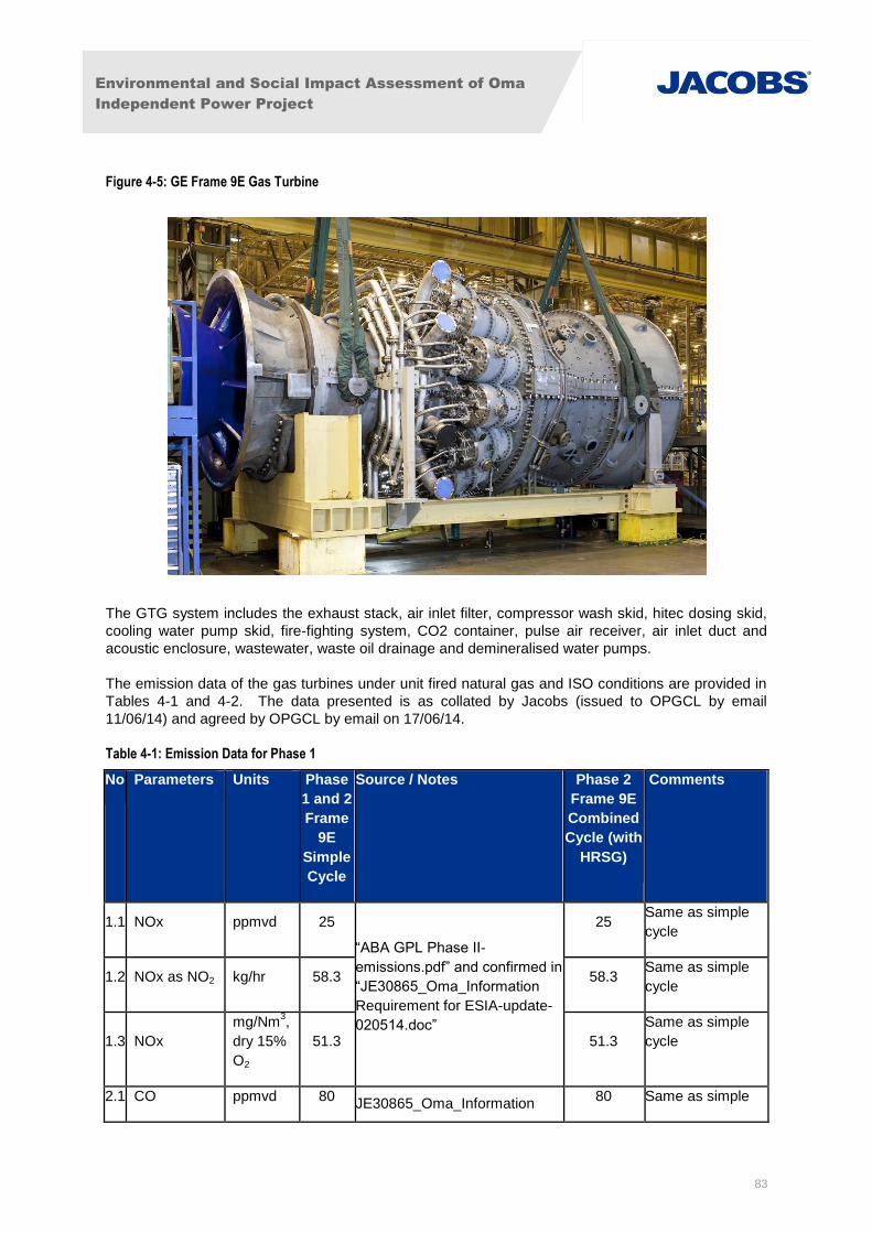
Environmental and Social Impact Assessment of Oma
Independent Power Project
83
Figure 4-5: GE Frame 9E Gas Turbine
The GTG system includes the exhaust stack, air inlet filter, compressor wash skid, hitec dosing skid,
cooling water pump skid, fire-fighting system, CO2 container, pulse air receiver, air inlet duct and
acoustic enclosure, wastewater, waste oil drainage and demineralised water pumps.
The emission data of the gas turbines under unit fired natural gas and ISO conditions are provided in
Tables 4-1 and 4-2. The data presented is as collated by Jacobs (issued to OPGCL by email
11/06/14) and agreed by OPGCL by email on 17/06/14.
Table 4-1: Emission Data for Phase 1
No Parameters Units Phase
1 and 2
Frame
9E
Simple
Cycle
Source / Notes Phase 2
Frame 9E
Combined
Cycle (with
HRSG)
Comments
1.1 NOx ppmvd 25
“ABA GPL Phase II-
emissions.pdf” and confirmed in
“JE30865_Oma_Information
Requirement for ESIA-update-
020514.doc”
25 Same as simple
cycle
1.2 NOx as NO2 kg/hr 58.3 58.3 Same as simple
cycle
1.3 NOx
mg/Nm3,
dry 15%
O2
51.3 51.3
Same as simple
cycle
2.1 CO ppmvd 80 JE30865_Oma_Information
80 Same as simple
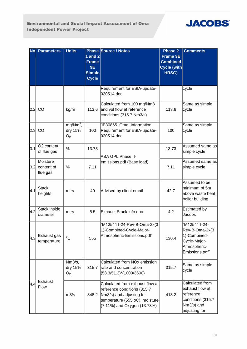
Environmental and Social Impact Assessment of Oma
Independent Power Project
84
No Parameters Units Phase
1 and 2
Frame
9E
Simple
Cycle
Source / Notes Phase 2
Frame 9E
Combined
Cycle (with
HRSG)
Comments
Requirement for ESIA-update-
020514.doc
cycle
2.2 CO kg/hr 113.6
Calculated from 100 mg/Nm3
and vol flow at reference
conditions (315.7 Nm3/s)
113.6
Same as simple
cycle
2.3 CO
mg/Nm3,
dry 15%
O2
100
JE30865_Oma_Information
Requirement for ESIA-update-
020514.doc
100
Same as simple
cycle
3.1 O2 content
of flue gas % 13.73
ABA GPL Phase II-
emissions.pdf (Base load)
13.73 Assumed same as
simple cycle
3.2
Moisture
content of
flue gas
% 7.11 7.11
Assumed same as
simple cycle
4.1 Stack
heights mtrs 40 Advised by client email 42.7
Assumed to be
minimum of 5m
above waste heat
boiler building
4.2 Stack inside
diameter mtrs 5.5 Exhaust Stack info.doc 4.2
Estimated by
Jacobs
4.3 Exhaust gas
temperature oC 555
“M125411-24-Rev-B-Oma-2x(3
1)-Combined-Cycle-Major-
Atmospheric-Emissions.pdf” 130.4
“M125411-24-
Rev-B-Oma-2x(3
1)-Combined-
Cycle-Major-
Atmospheric-
Emissions.pdf”
4.4 Exhaust
Flow
Nm3/s,
dry 15%
O2
315.7
Calculated from NOx emission
rate and concentration
(58.3/51.3)*(1000/3600)
315.7 Same as simple
cycle
m3/s 848.2
Calculated from exhaust flow at
reference conditions (315.7
Nm3/s) and adjusting for
temperature (555 oC), moisture
(7.11%) and Oxygen (13.73%)
413.2
Calculated from
exhaust flow at
reference
conditions (315.7
Nm3/s) and
adjusting for

Environmental and Social Impact Assessment of Oma
Independent Power Project
85
No Parameters Units Phase
1 and 2
Frame
9E
Simple
Cycle
Source / Notes Phase 2
Frame 9E
Combined
Cycle (with
HRSG)
Comments
temperature
(130.4 oC),
moisture (7.11%)
and Oxygen
(13.73%)
4.5 Exhaust gas
velocity m/s 35.7
Calculated from stack diameter
of 5.5m and vol flow of 848.2
m3/s
29.8
Calculated from
stack diameter of
4.2m and vol flow
of 413.2 m3/s
Table 4-2: Exhaust Gas Analysis % Volume
Parameter Frame 9
Argon 0.85
Nitrogen 70.99
Oxygen 12.59
Carbon Dioxide 3.39
Water 12.19
Environmental and Social Impact Assessment of Oma
Independent Power Project
86
Fuel Gas System
The natural gas fuel for Phase 1 will be piped approximately 12km from the existing Imo River gas
gathering facility, via an 18” pipeline through a fuel gas flow check meter and a fuel gas-receiving skid
before the gas enters the gas turbine generator. Provision will be made to allow any item of
equipment and associated piping to be taken out of service for maintenance, purging and flushing
without shutting down the turbines. To ensure the fail-safe protection of the plant, emergency shut-off
valves will be installed at each fuel gas treatment station inlet and outlet. The system will include a
nitrogen purging system to facilitate evacuation of gas from the pipeline for repair and maintenance
work, purging of air and nitrogen blanketing.
Energy Balance
The Energy balance of the proposed Phases 1 and 2 and the combined cycle is outlined in Figures 4-
6 and 4-7 respectively.
Air Compressor System
The air compressor will be provided for Phase 3 only. The facilities provided will include two
instrument air compressors, two driers and an external air storage tank.
Maintenance Workshop Equipment and Laboratory Equipment
In order that certain maintenance and testing can be performed in the plant a maintenance workshop
and laboratory will be provided. The workshop will be fitted with machine tools and equipment while
the laboratory will have testing and analysing equipment.
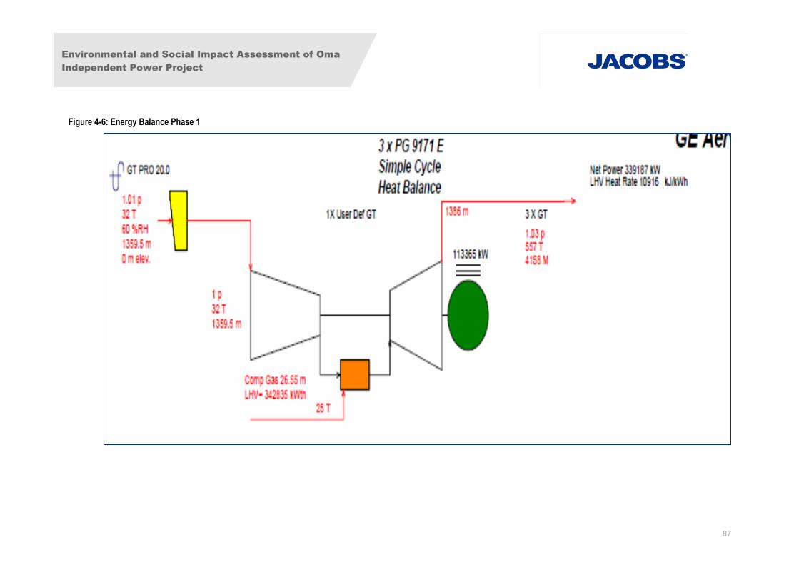
Environmental and Social Impact Assessment of Oma
Independent Power Project
87
Figure 4-6: Energy Balance Phase 1
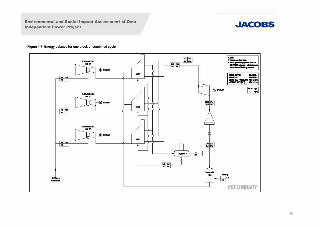
Environmental and Social Impact Assessment of Oma
Independent Power Project
88
Figure 4-7: Energy balance for one block of combined cycle
Environmental and Social Impact Assessment of Oma
Independent Power Project
89
During maintenance activities, oily wastes, metal spare parts, wood and cardboard packing waste etc.
will be generated. These wastes will be disposed of as detailed in the site ESMP.
4.4.3 Chemical System
The chemical systems to be installed will be those associated with the various plant water systems.
Closed Circuit Cooling System
A closed circuit cooling water system shall be used for cooling the ancillaries of all phase 1 and phase
2 gas turbines. The closed circuit cooling water system will contain treated i.e. demineralized water.
The circulating water transmits the heat from the ancillaries such as lubricating oil coolers and
dissipates the heat to atmosphere via air-blast coolers employing finned tube banks and forced draft
fans. These systems will have self-contained Chemical dosing systems with corrosion inhibitors and
oxygen scavengers. Space shall be reserved for a demineralization system, to provide the necessary
high purity water for gas turbine water injection for NOx abatement, should this become necessary,
and/or for make-up water for Phase 3 HRSGs and associated closed circuit cooling water systems.
Raw Water Treatment Plant
The water treatment plant will consist of the following: a raw water break tank, treated water storage
tanks, three 50%-duty demineralisation streams, dual-media filters, activated carbon filters high-
pressure pumps, forwarding pumps, an automatic effluent neutralising system, a control panel and all
interconnecting pipe work.
The plant will treat all non-oil effluent produced by the power plant to the more stringent of the
Nigerian or World Bank / IFC EHS guidelines for Thermal Power Plants. The treatment process to be
used involves filtration, followed by R.O. demineralisation.
Gas Turbine dry low NOx combustion technology will be deployed.
Oily Wastewater
Oily wastewater from the various production areas of the power plant shall be collected and treated
through the oily wastewater treatment system. Oily wastewater is first treated through an oil water
separation tank, which acts as a pre-separator where most of the oil is removed and pumped to a
separate waste oil storage tank where it will then be pumped out and disposed of by licenced
contractors.
The separated wastewater is then further treated through a two-stage treatment system where the oil
concentration will be reduced to less than 10mg/l as required by the Nigerian environmental
guidelines and IFC EHS guidelines. Oil concentration monitoring instrument shall be mounted at the
outlet of wastewater discharge pump. If the oil concentration exceeds the stated maximum, oily
wastewater shall be cycled to the inlet of oil water separator. In the final stage of the process, the
tested and treated wastewater shall be discharged into storm drainage ditches.
4.4.4 Electrical System
The installed capacity in the power station will be approximately 1012.5MW (minimum) after Phase 3
is completed. Four sets of GE Frame 9 gas turbine generators shall be installed in Phase One and
two sets in Phase two. Phase Three includes the addition of two steam units in combined cycle
configuration. All the power generated shall be transmitted to the national grid via a 330kV twin DC
circuit line running from project site in Ogwe to Afam – Alaoji as well as Alaoji – Ikot Ekpene 330kV
Environmental and Social Impact Assessment of Oma
Independent Power Project
90
DC transmission lines. The connecting transmission lines and substations will be constructed by the
project developer under an agreement with Transmission Company of Nigeria (TCN) for a refund of
the associated costs. A small amount of power will be made available for station use, most probably
11-33kV.
No new transmission lines will be constructed for phase 1. The proposed transmission line required
for phases 2 and 3 will be 300m long and run from the proposed power plant project switchyard to tie-
in to the nearby 330kV double circuit line running from Afam to Alaoji (see Figure 4-3) and will
comprise a minimum number of pylons (approximately 2-4). The transmission line will lie within the
middle of two existing transmission lines.
Under the FMEnv Environmental Impact Assessment Act No 86 of 1992 (see Section 2.4.6) there is
no mandatory requirement to provide an EIA assessment for this length of transmission line. There is
similarly no requirement to undertake a formal EIA under other internationally recognised EIA acts, for
example the European Union Directive 2011/92/EU, for a short stretch of transmission line such as
this, and associated with and adjacent to larger development projects.
Nonetheless, considerations of the environmental and social issues associated with the proposed
transmission line are included within Section 8.
4.4.5 Generator Auxiliaries
For each Phase 1, Phase 2 and Phase 3 units, the generator step up transformers shall be connected
via a 330kV step up transformer to the 330kV switchyard bus bars.
The system shall consist of the following main components: medium voltage (MV) cross-linked
polyethylene (XLPE) cables bus duct, MV cable terminals, tee terminal connections to the auxiliary
transformers, tee terminal connections to the generator outlet surge absorber and voltage transformer
cabinets. The bus duct assembly shall be rated to accept the full peak output of the generators over
the entire ambient temperature range.
The generator circuit breaker shall consist of the following main components: Tee terminal
connections to the unit auxiliary transformers, tee terminals to the generator outlet surge
absorber and voltage transformer cabinets. The circuit breakers are vacuum type and shall be
installed at the unit switch room. When the GTG set starts up, the generator circuit breaker shall
be switched on first and the auxiliary power supply shall be fed from the power network through
the main transformer and unit auxiliary transformer. Then the generator output synchronizes to
the switchyard and the generator circuit breaker shall be switched off. The generator circuit
breakers shall be manufactured and tested in accordance with International Electrotechnical
Commission (IEC) publications 56 and 71 and with Institute of Electrical Engineers (IEE)
standards.
4.4.6 Power Transformer
The transformers shall be of three-phase, 50Hz and outdoor-arranged, double windings with star
connections for the high voltage and delta connections for the low voltage windings. The transformers
are cooled with forced and oil-air cooling system (ONAF).
The main transformers shall be supplied, erected and tested in accordance with the following
standards and codes: IEC publication 60 - High Voltage Test Techniques, IEC publication 71 -
Insulation Co-ordination, IEC publication 76 -1~5- Power Transformers, IEC publication 137 -
Bushings for Alternative Voltage above 1kV, IEC publication 185 - Current Transformers, GB 6451-86
- Technical Parameters and Methods for Three Phase Oil-immersed Transformers.
Environmental and Social Impact Assessment of Oma
Independent Power Project
91
The step-up transformers shall be set on a concrete foundation. Oil containment shall be provided as
part of the Oil Spill Prevention System. Fire detection/alarm system and protection systems shall be
provided.
Transformers will be on hard surfaced areas with containment walls to contain any loss of transformer
oil.
Power Plant 330kV Switch Yard (for Phases 1 & 2)
Concept design for the project is fixed, and currently includes 330kV AIS high voltage (HV) switchyard
using a double bus-bar connection system. The switchyard system shall consist of the following
components: circuit breakers, isolators with earthing switch, capacitance voltage transformers, current
transformers, and lightning arrestors. Detailed design for the project is subject to EPC Contractor
appointment and could result in some refinements to Phases 2 and 3.
Phases 1, 2 & 3 Switchyard
Gas Turbine(GT) & Steam Turbine (ST) circuits main 11/330kV transformer incoming line
bays
2 circuits outgoing line bays to Alaoji substation
Capacitance voltage transformers and lightning arrestors
Auxiliary Power System
The auxiliary power systems shall be 6.6kV, 3.3kV and 400/230V. Only the 400/230V system shall be
neutral point directly grounded.
Each GTG set shall be equipped with one auxiliary transformer. Each Unit Auxiliary Transformer
(UAT) primary side shall be connected with the generator outgoing auxiliary branch circuit breaker
through XLPE cable. The auxiliary branch circuit breaker shall be installed in the unit switch room.
Power plant uses such as the lighting system, integrated pump house, wastewater treatment, oil
waste water treatment station, circulating cooling water treatment station, circulating water pumps
shall each be fed by a separate unit power centre (PC).
The auxiliary power system includes the following major items of equipment:
Unit auxiliary transformers
3.15kV switchgear
Low voltage (LV) auxiliary transformers
LV power centre
LV motor control centres (MCC)
Emergency Power System
Under normal operating conditions, power for the starter motor of the GT units is provided from the
auxiliary power 6.6kV (for the Frame 9E) bus bar from the power grid through the main transformer
and the auxiliary transformers. When the auxiliary power fails, the starter motor shall be fed from the
Environmental and Social Impact Assessment of Oma
Independent Power Project
92
Black start generator/s. There shall be an electrical interlock between the circuit breaker of the Black
start generator and the emergency power centre incoming circuit breaker.
The Black start generator set(s) will be initially 2 off 1000kW, 3-phase, 4-pole and Wye-connected.
The rated voltage of the generator will be 3.15kV or 415V and the frequency, 50Hz. The rated power
factor is 0.8. The generator(s) will have a rotating speed of 1500 rpm and shall be water/air-cooled.
The 3.15kV or 415/240V emergency power centre will be installed in the diesel generator house. The
emergency power centre bus shall employ a single bus connection. The diesel generator shall be
connected to the 3.15kV (415V) emergency power centre bus bar via a high current air circuit breaker.
The emergency power system will be augmented to provide black start capability for the CCGT power
plant (phases 1& 2), and final capacities would be up to 10MW (this may be only Diesel engines or in
combination with a small Gas engine).
Uninterruptible Power Supply System
Direct current (DC) power for the GTG control packages is provided by 125V Nickel-Cadmium or
valve controlled regulated lead acid battery sets. These provide power for the gas turbine DC drives
and for control supply for the generator and turbine control panels. Two 220V battery sets and
chargers will be furnished to supply power to DC drives and the control for 330kV substation and
auxiliary power system. The valve controlled regulated lead acid battery will utilize 220V battery sets.
The batteries will be stored in a ventilated room with spill containment under the batteries.
A radial and loop network will be used for the DC distribution system. For important DC loads, two
feeders from different DC bus will be installed. In order to ensure continuous DC power, feeders will
be loop designed.
A DC insulation monitoring device will be equipped with each bus to detect on line if DC system is
grounded and which feeder is grounded. The monitoring device will also monitor the voltage and
current for the DC system and send alarm signal to the remote with relay output contact or port RS-
232.
Lighting System
The lighting system shall meet the illumination requirements for power stations recommended by the
Illuminating Engineering Society (IES).
Normal lighting shall be fed from the 415/240V LV power plant auxiliary systems. Emergency lighting
shall be fed from the 220V DC power supply from the emergency lighting changeover panel installed
in the central control room. If the AC power source fails, the emergency lighting power shall
automatically change to the 220V DC power source. The control room lighting shall be permanently
fed from the 220V DC system.
Lightning Protection System
The lightning protection system shall protect buildings and equipment from damage by lightning and
shall include the following major components:
lightning rods;
lightning conductors;
down conductors; and
Environmental and Social Impact Assessment of Oma
Independent Power Project
93
Copper or brass plates.
Lightning rods shall be installed on all major buildings and equipment. The design shall be in
accordance with National Fire Protection Association (NFPA) 780, UL 96A Standards. Those
structures requiring lightning protection shall be determined during the detailed design.
In the switchyard area, overhead steel lightning arrestors supported on the steel structure shall be
used to provide lightning protection.
4.4.7 Earthing System
All outdoor equipment such as metal enclosures, cabinets, boxes, steel structures, and fencing shall
be adequately connected to the plant grounding system. The switchyard area shall be fenced and
surfaced with crushed aggregate for personnel safety.
The earthing system shall consist of the following major components:
earth grid and earth loop conductors with terminals for attachment to metallic structures and
selected equipment;
earthing rods or earth detecting wells; and
Earthing conductors to plant equipment.
4.4.8 Fuel Source and Composition
Fuel Source: The natural gas will be supplied to Phase 1 and Phase 2 by 18” (457mm) underground
pipeline connecting an IOC such as TOTAL E&P’s gas gathering facility at IMO River, pressure
reducing station, gas metering and treatment stations to the proposed site at a delivery pressure of 35
bar gauge. The approximate length of pipe is 12km. Other facilities to be installed may include
dedicated filters, pressure let down station and a slug catcher.
However, should the available fuel gas pressure not meet the GTGs requirements then the installation
of an electric drive gas compressor station and a gas storage tank within the project area shall be
considered. A spur line to the 12” line supplying gas to the GP’s power plant at Osisioma may be
included as gas supply backup should the dedicated line not be available for maintenance reasons.
Fuel Composition: The final fuel composition for the power plant is not yet confirmed. However, the
typical composition of natural gas likely to be used for power generation for the proposed OMA power
plant project is presented in Table 4-3. The fuel low heating value (LHV) is about 35.4MJ/Sm3
(megajoules per standard cubic meter), where Sm3 is the volume under the condition of 101.32kPa
pressure and 15oC temperature. Should the natural gas contain lower methane, then the installation
of a stripping plant will be negotiated with the gas suppliers to enable the gas conform to the levels
presented in Table 4-3.
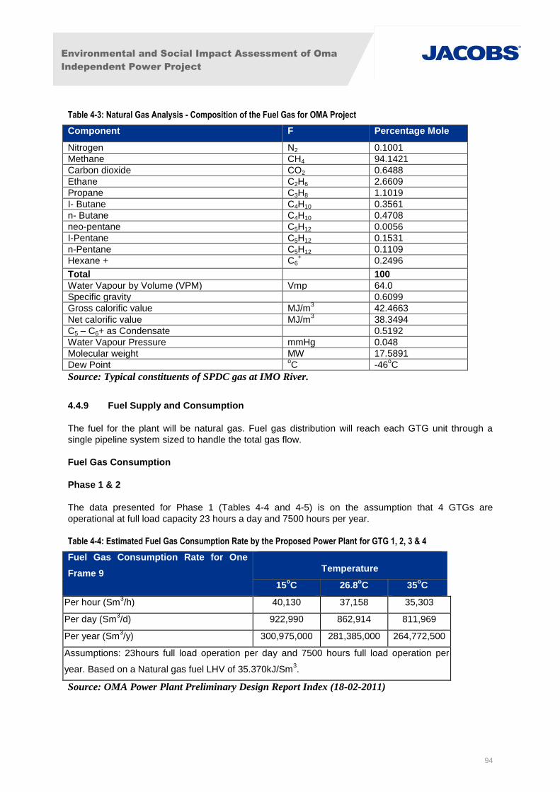
Environmental and Social Impact Assessment of Oma
Independent Power Project
94
Table 4-3: Natural Gas Analysis - Composition of the Fuel Gas for OMA Project
Component F Percentage Mole
Nitrogen N2 0.1001
Methane CH4 94.1421
Carbon dioxide CO2 0.6488
Ethane C2H6 2.6609
Propane C3H8 1.1019
I- Butane C4H10 0.3561
n- Butane C4H10 0.4708
neo-pentane C5H12 0.0056
I-Pentane C5H12 0.1531
n-Pentane C5H12 0.1109
Hexane + C6+ 0.2496
Total 100
Water Vapour by Volume (VPM) Vmp 64.0
Specific gravity 0.6099
Gross calorific value MJ/m3 42.4663
Net calorific value MJ/m3 38.3494
C5 – C6+ as Condensate 0.5192
Water Vapour Pressure mmHg 0.048
Molecular weight MW 17.5891
Dew Point oC -46
oC
Source: Typical constituents of SPDC gas at IMO River.
4.4.9 Fuel Supply and Consumption
The fuel for the plant will be natural gas. Fuel gas distribution will reach each GTG unit through a
single pipeline system sized to handle the total gas flow.
Fuel Gas Consumption
Phase 1 & 2
The data presented for Phase 1 (Tables 4-4 and 4-5) is on the assumption that 4 GTGs are
operational at full load capacity 23 hours a day and 7500 hours per year.
Table 4-4: Estimated Fuel Gas Consumption Rate by the Proposed Power Plant for GTG 1, 2, 3 & 4
Fuel Gas Consumption Rate for One
Frame 9 Temperature
15oC 26.8
oC 35
oC
Per hour (Sm3/h) 40,130 37,158 35,303
Per day (Sm3/d) 922,990 862,914 811,969
Per year (Sm3/y) 300,975,000 281,385,000 264,772,500
Assumptions: 23hours full load operation per day and 7500 hours full load operation per
year. Based on a Natural gas fuel LHV of 35.370kJ/Sm3.
Source: OMA Power Plant Preliminary Design Report Index (18-02-2011)

Environmental and Social Impact Assessment of Oma
Independent Power Project
95
Table 4-5: Phase 1 Estimated Fuel Gas Consumption Rate per Hour (base load and based on ambient temperature
of 30oC)
Volumetric Flow Rate (Sm3/ h) Mass Flow Rate (kg/h)
Frame 9E 34,667 28,613
Frame 9E 34,667 28,613
Frame 9E 34,667 28,613
Frame 9E 34,667 28,613
Total 138,667 114,452
Source: OMA Power Plant Preliminary Design Report Index (18-02-2011)
Phase 3
In Phase 3, two steam turbine units will be added to the six gas turbine units thus converting the plant
under the Phase 3 works as a combined cycle facility.
Provisions will be made in the design to allow any items of equipment and associated piping to be
disconnected for servicing/maintenance, purging and flushing without shutting down the turbines. It is
also planned that for reliable operation of the gas turbines, the fuel gas shall be supplied at constant
pressure and at an acceptable quality as required by the gas turbine original equipment manufacturer
(OEM) specification. The fuel gas will be supplied at 28°C, above the gas dew point, to minimize any
possible condensation of hydrocarbon in the station fuel gas system.
Furthermore, to ensure fail-safe protection of the proposed OMA power plant, emergency shut-off
valves will be installed at each fuel gas treatment station inlet. Also, to measure and monitor the total
gas consumption of the station, a computerized gas measurement system containing flow meters with
meter-proving facilities, analyser, etc. will be provided to give information on volume, mass and
energy as required. The flowmeter will be located in the utility control room and shall be used as a
component of the gas control unit of each gas turbine.
Fuel Gas Receiving Skid
The fuel gas shall pass through a fuel gas-receiving skid consisting mainly of emergency stop valve
(solenoid operated), pressure control valves, scrubbers, and common condensate drain tank before
the fuel gas enters the GTG. The gas pressure control valve shall maintain proper pressure of the
outgoing gas. The gas will first enter the scrubbers where all impurities (solid particles and liquid
contaminants) to a large extent (above 99%) are removed. The condensate drain tanks will be
responsible for collecting hydrocarbon drains from various points.
Fuel Gas Flow Meter
Fuel gas flow meter will be provided complete with continuous integration and automatic
compensation for temperature and pressure fluctuations, as well as the summated fuel consumption
totaliser. The flow meter is a metering system and will be used to measure the volume of the fuel gas
flow used by the gas turbine.
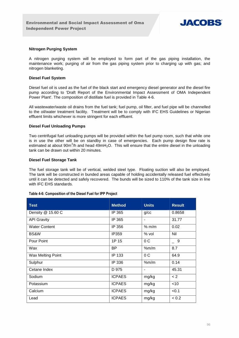
Environmental and Social Impact Assessment of Oma
Independent Power Project
96
Nitrogen Purging System
A nitrogen purging system will be employed to form part of the gas piping installation, the
maintenance work; purging of air from the gas piping system prior to charging up with gas; and
nitrogen blanketing.
Diesel Fuel System
Diesel fuel oil is used as the fuel of the black start and emergency diesel generator and the diesel fire
pump according to 'Draft Report of the Environmental Impact Assessment of OMA Independent
Power Plant'. The composition of distillate fuel is provided in Table 4-6.
All wastewater/waste oil drains from the fuel tank; fuel pump, oil filter, and fuel pipe will be channelled
to the oil/water treatment facility. Treatment will be to comply with IFC EHS Guidelines or Nigerian
effluent limits whichever is more stringent for each effluent.
Diesel Fuel Unloading Pumps
Two centrifugal fuel unloading pumps will be provided within the fuel pump room, such that while one
is in use the other will be on standby in case of emergencies. Each pump design flow rate is
estimated at about 90m3/h and head 49mH2O. This will ensure that the entire diesel in the unloading
tank can be drawn out within 20 minutes.
Diesel Fuel Storage Tank
The fuel storage tank will be of vertical, welded steel type. Floating suction will also be employed.
The tank will be constructed in bunded areas capable of holding accidentally released fuel effectively
until it can be detected and safely recovered. The bunds will be sized to 110% of the tank size in line
with IFC EHS standards.
Table 4-6: Composition of the Diesel Fuel for IPP Project
Test Method Units Result
Density @ 15.60 C IP 365 g/cc 0.8658
API Gravity IP 365 - 31.77
Water Content IP 356 % m/m 0.02
BS&W IP359 % vol Nil
Pour Point 1P 15 0 C _ 9
Wax BP %m/m 8.7
Wax Melting Point IP 133 0 C 64.9
Sulphur IP 336 %m/m 0.14
Cetane Index D 975 - 45.31
Sodium ICPAES mg/kg < 2
Potassium ICPAES mg/kg <10
Calcium ICPAES mg/kg <0.1
Lead ICPAES mg/kg < 0.2
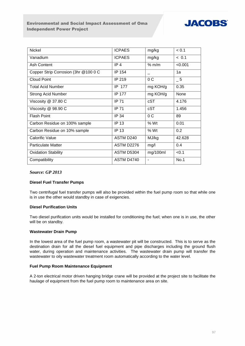
Environmental and Social Impact Assessment of Oma
Independent Power Project
97
Nickel ICPAES mg/kg < 0.1
Vanadium ICPAES mg/kg < 0.1
Ash Content IP 4 % m/m <0.001
Copper Strip Corrosion (3hr @100 0 C IP 154 _ 1a
Cloud Point IP 219 0 C _ 5
Total Acid Number IP 177 mg KOH/g 0.35
Strong Acid Number IP 177 mg KOH/g None
Viscosity @ 37.80 C IP 71 cST 4.176
Viscosity @ 98.90 C IP 71 cST 1.456
Flash Point IP 34 0 C 89
Carbon Residue on 100% sample IP 13 % Wt 0.01
Carbon Residue on 10% sample IP 13 % Wt 0.2
Calorific Value ASTM D240 MJ/kg 42.628
Particulate Matter ASTM D2276 mg/l 0.4
Oxidation Stability ASTM D5304 mg/100ml <0.1
Compatibility ASTM D4740 - No.1
Source: GP 2013
Diesel Fuel Transfer Pumps
Two centrifugal fuel transfer pumps will also be provided within the fuel pump room so that while one
is in use the other would standby in case of exigencies.
Diesel Purification Units
Two diesel purification units would be installed for conditioning the fuel; when one is in use, the other
will be on standby.
Wastewater Drain Pump
In the lowest area of the fuel pump room, a wastewater pit will be constructed. This is to serve as the
destination drain for all the diesel fuel equipment and pipe discharges including the ground flush
water, during operation and maintenance activities. The wastewater drain pump will transfer the
wastewater to oily wastewater treatment room automatically according to the water level.
Fuel Pump Room Maintenance Equipment
A 2-ton electrical motor driven hanging bridge crane will be provided at the project site to facilitate the
haulage of equipment from the fuel pump room to maintenance area on site.
Environmental and Social Impact Assessment of Oma
Independent Power Project
98
4.4.10 Plant Auxiliary Services
Maintenance Workshop and Laboratory Buildings
Due to the fact that some equipment will be maintained on site, and chemical analysis will be carried
out there will be a maintenance workshop and a laboratory buildings on site. The maintenance
workshop will occupy about 500m2 area and shall house major equipment such as mechanical
process machines and an overhead travelling crane. The laboratory shall cover an area of about
150m2 and shall mainly house some test and analysis equipment.
Oxygen, Acetylene and Nitrogen Supply
Oxygen and acetylene shall be used for welding during maintenance while nitrogen will serve for pipe
purging. These shall be sourced from the local market. Appropriate storage facilities will be provided
for these gasses and used cylinders of these gasses.
Thermal Insulation Material
The aluminium silicate will be employed as the thermal insulation material. The protection layer will be
made of stainless steel or textured aluminium of 0.5mm thickness.
Paint System and Galvanizing
An effective paint system shall be adopted to avoid rapid deterioration due to the weather. All paints
shall have dry film thickness (DFT) of 300 microns. The paint system to be used shall be in
accordance with the following order:
shot blasting of the substrate;
striping the coat of all welds (surface preparation) and other areas likely to cause incomplete
application of primer;
application of 125-micron base coat of inorganic zinc silicate primer;
application of 125-micron intermediate coat of high-build epoxy; and
Application of 50-micron colour coat.
Galvanizing shall be in accordance with the appropriate British standard, or equivalent, as
appropriate. Pre-galvanized sheet and sections that are often bent into profiles shall not be
acceptable because, the coating rapidly fails along the bend lines.
4.5 Process Design
4.5.1 Water Supply System
Water Demand and Groundwater Supply System
A test borehole has proven the presence of good quantities (60m3/hr) of groundwater beneath the
site. Additional production-scale groundwater boreholes will be sunk to provide the water supply for
the various project requirements described above. The boreholes will be drilled to depths in the order
of not less than 60 meters below ground level (m bgl) with a target capacity of 90m3/hr per borehole,
in order that each borehole can provide the full amount required for Phase 1 and operate alternatively,
with a second borehole providing redundancy.

Environmental and Social Impact Assessment of Oma
Independent Power Project
99
The water balance diagram for Phase 1 is presented in Figure 4-8. The estimated average water flow
demand for Phase 1 is about 25-30m3/h. Instantaneous flows could be greater than this average
requirement, but these are unlikely to increase by greater than 1%.
Estimated water requirements for Phase 2 and Phase 3 are 12m3/h and 120m
3/h, respectively, giving
a cumulative total of 162m3/h. Depending on the final installed capacity of the boreholes for phase 1,
additional boreholes may be required for Phase 2, and will definitely be required for Phase 3. The
locations of additional boreholes and any associated assessment will be confirmed at that stage.
The volume of water required to meet the maximum demand of the fire-fighting system is
approximately 500m3. This is discussed further in Section 4.6 below.
As detailed in Section 5.6.1, the aquifer from which water would be drawn is regionally extensive.
Hydrogeological studies carried out on site indicate that it is very unlikely that there will be a
significant impact on water availability at the community supply boreholes due to water abstraction at
the plant during Phase 1.
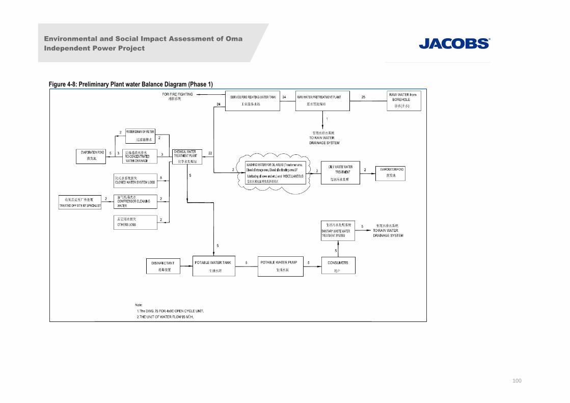
Environmental and Social Impact Assessment of Oma
Independent Power Project
100
Figure 4-8: Preliminary Plant water Balance Diagram (Phase 1)
Environmental and Social Impact Assessment of Oma
Independent Power Project
101
Electric powered submersible borehole water pumps shall be installed with flow meters at the discharge
points to measure the flow rate and regulate the flow capacity of the boreholes during the OMA power
plant project. Also, by-pass pipes and valves will be installed to ensure that there is no disruption of the
normal operation of the pumps should the flow meters be damaged.
There will be two 600m3 surface tanks with pressed steel sectional structure for the storage of fire-fighting
water and raw water. In order to ensure continuous water supply during inspection and maintenance
activities, the raw water tank will be separated into two chambers so that when one chamber is being
cleaned, the other can be routed to normal water flow ensuring that the power plant stays operational.
Also, to control microbial growth in the treated water and reduce sterilization time, a surface tank will be
installed for storing sterilized drinking water at the project site. The tank will be a pressed steel sectional
structure while the disinfectant will come (controlled and measured) from the circulating water treatment
station.
The sterilized water tank is estimated to be 4m in length, 4m in width and 3m in height giving a total
volume of 48m3, and operational capacity of 45.6m
3. To ensure the safe and continuous delivery of the
domestic water supply during inspection and maintenance, the sterilized water tank will also be separated
into two chambers so that when one chamber is being cleaned the other can be routed to normal water
flow.
All the pipes that will be used in the well water supply system shall be made of Glass Reinforced
Epoxy (GRE), single main pipe types with nominal diameter of 150mm. The piping will also include
valves, expansion joints, air vents, supports, flange and other accessories needed for the system.
Domestic Water Supply System
The domestic water will come from the Potable water tank and the supply system will convey water from
the potable water tank to the consumers. This is to satisfy the demand for potable water, sanitation, and
car wash water in the power plant area. The domestic water supply system shall be designed in
accordance with World Health Organisation (WHO) standards.
The domestic water requirement of the power plant is estimated at about 5m3/h. The water requirement
for road wash will only occur in the dry season because in the wet season high rainfall density in the
project area would account for these needs. Also, to ensure that daily water requirements are met, an
automatic water supply device with pressure keeping and transformable water flow function will be
installed. The domestic water supply system piping will be made of GRE pipes with nominal diameter of
50mm. The piping will also include valves, expansion joints, air vents, supports, flange and other
accessories.
Any domestic water supply system piped to equipment areas shall be separated from the building supply
by a “break tank”, which will prevent any possibility of backflow from the equipment into the domestic
water supply system. Electrical water heaters will be installed at central points for sanitation purposes.
4.5.2 Air Cooling System Water Requirements
Phases 1 & 2
Environmental and Social Impact Assessment of Oma
Independent Power Project
102
The circulating water system will be designed to meet the cooling water requirements of the frame 9
turbines and generators with a closed loop and will be equipped with Fin Fan coolers in the circuit.
Phase 3
With the absence of surface water around the plant vicinity and in order to conserve the use of ground
water, an air cooled condenser (ACC) will provide the means of recycling the condensed water using
exhaust from the steam turbine. The steam is passed in large ducts to the ACC and is condensed inside
finned tubes. The tubes are cooled by an array of large forced draft fans.
The efficiency of the ACC system will be a function of the ambient temperature, with high efficiencies
gained during low ambient temperatures, and lower efficiencies gained during high ambient temperatures.
The dry ACC system will be designed to provide sufficient cooling capacity during times of high ambient
temperature.
Circulating Water System Pumps, Pipes and Accessories
The gas turbine lubricating oil, hydrogen generator, boiler circulating pumps, sample coolers and other
minor systems will be cooled by a closed circuit cooling system linked to external fin fan coolers.
According to the requirement of circulating water system, centrifugal circulating water pumps (one in
operation and the other one on standby) will be utilized for each GTG. The pumps will be designed for
continuous operation at any point on the head/quantity curve between rated minimum flow and maximum
output.
Single main pipes will be used for the circulating water system. The pipes will be made of welded carbon
steel, with nominal diameters of 250mm and 200mm, respectively. The piping will also include valves,
expansion joints, air vents, supports, flanges and other accessories needed for the system.
In order to ensure the safe operation of the circulating water system and to remove suspended solids and
floating material, a strainer will be installed. To ensure that damage to the strainer water flow meter does
not influence normal operation of the circulating water system, a by-pass pipe and valve will be also
installed.
4.5.3 Water Processes
Raw Water Treatment Process
In order to remove suspended solids and floaters from the borehole water, reduce the ion contents, and
prevent rusting and corrosion (through oxidation and deposition of the iron and manganese ions) of the
pipes and other water supply equipment, the groundwater shall be treated to ensure all regulatory
requirements are met. The treatment will require chlorination of all potable water.
Oily Wastewater Treatment Process
Irregular oily wastewater consists mainly of oil-contaminated rainwater from fuel storage tank area and
oily wastewater from emergency transformer oil tanks while regular oily wastewater consists mainly of oil
from fuel oil storage tanks, GTG area, fuel oil pump house, maintenance shop, transformer, STG area
etc.
Environmental and Social Impact Assessment of Oma
Independent Power Project
103
Oily wastewater from various production areas shall be collected and treated together through oily
wastewater treatment plant. The design capacity of the oily wastewater treatment plant is estimated to
be 20m3/h. When it rains, oil-contaminated rainwater shall be channelled into an oily wastewater storage
tank before treatment. The wastewater storage tank will have a holding capacity of about 1000m3. This
process will address wastewater associated with phase 1 and 2. At phase 3, the need to provide
additional treatment facility will be detailed and provided at the same location.
Based on local regulatory requirements (FMEnv, 1991; DPR, 1999) the discharge limit (10mg/l) of oil
concentration in treated wastewater in inshore waters shall be adopted. The required treatment
equipment/facility shall be installed in the oily wastewater treatment room, which will be located next to
the fuel storage tank.
Demineralization System
The requirement for demineralized water is estimated to be 36m3/h. Primary demineralization by reverse
osmosis will be adopted for this system. The demineralization system shall consist of three trains of
equipment: 1 train will be in operation while the other will be in backwash/cleaning, the third train will be in
standby. The control system shall be automatic.
The quality of the demineralised water that will serve as direct injection water for the GTGs shall meet the
following standards as a minimum:
Sodium ions, Na+ <50ppb (parts per billion)
Silicon Dioxide / silica, SiO2 <100ppb
Conductivity <0.5µS/cm (25oC) microsiemens per centimetre
NOX Control Process
The NOx control system is expected to be a dry low NOx (DLN) system. Wet NOx treatment will not be
used.
4.6 Fire Protection
This section identifies the various fire protection techniques that are proposed for the OMA power plant
project and provides information relating to anticipated types of fires, and the various protection/fighting
techniques and equipment planned for installation.
A selection from the following facilities will be installed to provide an effective fire protection/fighting
system in the proposed plant:
A firewater distribution system.
Foam systems.
Sprinkler systems.
Inert Gas installations.
Environmental and Social Impact Assessment of Oma
Independent Power Project
104
Carbon dioxide extinguishing systems.
Portable fire-fighting equipment and fire/smoke suppression systems.
Fire station for housing fire engines, ancillary equipment and supplies.
4.6.1 Firewater Distribution System
Fire water distribution system shall be provided and designed on a ring main basis, to cover the fire
protection requirements for the plant and equipment.
The system will incorporate appropriate loops and section valves, so that sufficient water can be supplied
to the required areas in the event of failure of a single path. The design will be in accordance with NFPA.
Firewater will be drawn from the service/fire water storage tanks. The volume of firewater required is
approximately 500m3, based on the maximum anticipated flow rate for the largest single fire risk
associated with the power station plus the demand for two hydrant points, for a period of two hours.
NFPA requires a flow of 150% of the rated capacity. This is in accordance with the requirements of the
relevant international fire hazard control standard (NFPA 850).
4.6.2 Firewater Pumps
The firewater pumps will provide water for the entire power plant. One 100 per cent duty electric motor
driven pump and one 100 per cent duty diesel engine driven pump shall be supplied, each pump capable
of supplying water to all sprayers, sprinklers, hydrants or hose reels associated with the largest single fire
risk and comply with the requirements of NFPA 20. Jockey pump(s) will be provided to maintain the fire
main under pressure and to cater for minor usage/leakage.
The status of each pump will be indicated on the master fire alarm panel.
The fire pumps will be located within a building to give adequate protection from the environmental
conditions.
4.6.3 Firewater Piping System
The firewater piping system shall be laid out in a loop system around each phase of the plant with
sectional isolation valves provided at all crossovers and elsewhere, as necessary, to permit isolation of
any sector of the firewater system without compromising the safety of the plant.
The firewater main supply lines shall not be smaller than 6 inch (150mm) in diameter. The lines shall
favour the least hazardous side of the road to facilitate access to fire hydrants. Firewater lines around
process equipment and large machinery shall generally be on the side of the road remote from them.
4.6.4 Hydrants
The arrangement of the site fire hydrant system will be in accordance with the requirements of NFPA 24,
and the number of hydrants will be such that two hose streams can be directed to any single outbreak of
fire.
Environmental and Social Impact Assessment of Oma
Independent Power Project
105
4.6.5 Foam System
Foam injection lines will be provided for the application of aqueous film forming foam (AFF) to the liquid
surface of the distillate fuel oil storage tanks via air foam chambers and top strake pourers. The
installation will comprise all pipework, valves and fittings for the safe and efficient operation of the system.
The foam system shall be designed in accordance with the requirements of NFPA 11, with the rate of
foam application being not less than 4.1 litres/min to each square metre of liquid surface.
The system shall be arranged such that the control valves can be operated from the control panel located
at the foam station. It is envisaged in the event of a fire, the foam system will be applied to the fire
incident tank in conjunction with the automatic cooling water spray system, the activation of which will
raise an alarm on the main fire alarm panel in the central control room.
In addition, the Contractor shall provide hose reel assemblies attached to the outside of the fuel oil tank
bund walls, the hose reels shall be located at 30 metre spacing, and shall have the capability of injecting
foam into the fuel oil tank bund area. Foam concentrate shall be held in containers located close to each
hose reel. During a fire, the operator should remain as far as possible from the tank.
4.6.6 Water Sprinklers
These shall comprise specialized units:
Cooling of Storage Tanks and Pressure Vessels: Water for cooling storage tanks and
pressure vessels shall be applied at a rate of 0.5m3/h/m
2 of area calculated on the exposed area.
In the case of vertical vessels (storage tanks) where cooling water is supplied by hose streams
the required quantity shall normally be 25% of the total surface area.
Sprinkler Systems in Buildings: Sprinkler systems shall be installed in all buildings where
combustible material may be present. They shall not be installed in buildings housing electrical
equipment. Installation of sprinkler systems in buildings shall be in accordance with NFPA codes.
4.6.7 Water Spray Systems
Water spray systems normally discharge a fine pattern of water and shall be used for fire extinguishing,
control or prevention as well as for protection of structures and equipment from exposure to fire. For
exposure protection of structures and equipment a fine spray of water is projected against the item to be
protected from permanently installed spray heads.
Two types of water spray systems (manually and automatically controlled) will be installed in the
proposed plant. Manually controlled systems are usually empty until water is admitted to the system, at
which time water is discharged through all spray heads. Automatically controlled systems are of two
types, the wet and the dry pipe systems.
The wet pipe system shall consist of spray heads attached to pipes containing water and permanently
connected to a water supply. The water shall be discharged immediately through spray heads opened by
fire. On the other hand, the dry pipe system shall consist of spray heads attached to pipes containing air
under pressure, the release of which would permit water to enter the system through a deluge valve. The
water shall be discharged through spray heads opened by fire.
Environmental and Social Impact Assessment of Oma
Independent Power Project
106
4.6.8 Inert Gas / Argon Fire Protection System
Inert gas and Argon are relatively inexpensive and readily available fire extinguishing agents used to put
out electrical fires in enclosed spaces. They shall be installed particularly for use in generator enclosures
and all control cubicles where water cannot be used. Inert gas and Argon also offer the advantages of
inert atmosphere with minimum risk to personnel, high efficiency, compact storage containers and
pipework, no cold shocks to delicate apparatus, no residue left after discharge, indefinite storage life, and
non-conductor of electricity and can be used safely on electrical and electronic apparatus. However,
there could still be a threat of asphyxiation which shall be addressed in the Occupational Health and
Safety Plans for the project detailed during the ESMP Phase.
4.6.9 Carbon Dioxide Extinguishing Systems
Carbon dioxide (CO2) extinguishing systems shall be installed in the proposed OMA power plant site
because when discharged into a closed room or into enclosed spaces it makes an effective extinguishing
agent for fire involving liquid hydrocarbons and electrical equipment. Both high pressure and low-
pressure systems shall be installed within the power plant. Specifically, it shall be used on electrical
generating equipment for fire protection in the rotating electrical element as well as large electrical
switchgears. However, it will not be used in the generator housings. However, there could still be a
threat of asphyxiation which shall be addressed in the Occupational Health and Safety Plans for the
project detailed during the ESMP Phase.
4.6.10 Hose Stations and Hose Reel Stations
Service water hose stations shall be provided at the diesel oil pump house, fuel gas arrival and metering
facilities, diesel oil truck unloading bay, diesel tanks, slop oil handling and storage facilities, warehouses,
the laboratory and workshops.
However, offices, the laboratory, workshops and warehouses shall be provided with fixed hose reel
stations on each floor as required by the fire code.
4.6.11 First Response Fire Fighting Appliances
First response fire-fighting appliances are intended for controlling initial phases of all fires and for
extinguishing small fires. Two types of extinguishers shall be used namely, dry chemical and CO2
extinguishers. These are the most commonly found first aid fire extinguishing apparatus in use. The
CO2 extinguishers are basically pressurized cylinders of CO2 gas with suitable control valves and
discharge nozzles. A dry chemical extinguisher consists of a container of dry powder, usually sodium
bicarbonate with a flow fluidizing agent, a separate pressurizing gas cylinder, a suitable control valve and
a discharge nozzle.
The carbon dioxide extinguishers to be used shall be fitted with discharge cones, flexible hose and trigger
permitting one-person operation. The dry chemical extinguishers to be used shall also have discharge
cone or nozzle, non-caking chemical charge, and carbon dioxide pressurizing cartridge. The cartridge
shall be replaceable independently of powder charge.
4.6.12 Fire and Smoke Stopping System
A fire and smoke stopping system shall be provided for all the openings through which cables go. This
shall include conduit ends, openings in walls, floors or ceilings, cable risers, under all electrical
Environmental and Social Impact Assessment of Oma
Independent Power Project
107
enclosures and switchboards and any other areas which shall prevent the fire from spreading. The
system shall be applied at 3m intervals to prevent the chimney from affecting the vertical cable systems
(i.e. cable risers).
4.6.13 Miscellaneous Equipment
Miscellaneous equipment consisting of fire axes, shovels, heat resistant clothing, sand, buckets, etc. shall
be identified and provided. A list shall be prepared identifying the quantity and their location.
4.6.14 Fire Station
A fire station will not be provided. However, space shall be reserved for a fire station, should it be
decided to construct one in the future. The future fire station shall be of sufficient size to permit parking of
all vehicles provided specifically for fire-fighting. In addition, space shall be provided in the station for
storage of miscellaneous items such as hoses, axes, foam liquid, fittings for fire hydrants, etc.
4.6.15 Fire and Gas Detection, Control and Alarm Facilities
Fire and gas detection, control and alarm facilities shall be provided to cover the entire plant. Gas
detection, control and alarm facilities shall cover areas where the gas pipelines, arrival facilities,
scrubbers and generators are installed. The type of gas detectors to be used shall be suitable for the
local conditions.
4.6.16 Emergency Shutdown
In the event of a plant fire or an emergency a controlled shutdown will be initiated. Such systems will be
defined, engineered and implemented to safeguard the plant. An Emergency Response Plan (ERP) will
be prepared as part of the project ESMP. The ERP will cover all potential emergency situations including
fire and explosion and will incorporate the systems described here, according to the IFC’s PSs and the
WBG EHS guidelines.
4.7 Instrumentation and Control
The operations philosophy for the OMA power plant project is to:
use minimum land resources for production facilities and activities;
be self-sufficient in production operation and frontline maintenance capability;
monitor the inflow of the sources of power generation (fuel gas and fuel oil) at the pipeline entry
points and consequently control the product quality requirements to meet regulatory standards
and project objectives; and
Assure asset integrity.
All instrument control and protection panels with measuring equipment, relays, control switches,
automatic controllers, etc. will be supplied and installed necessarily for proper operation and monitoring of
the GTG units, HRSGs, Steam Turbine Generators (STG), switchyard equipment and their associated
facilities. The control system will be micro-processor-based.
Environmental and Social Impact Assessment of Oma
Independent Power Project
108
4.7.1 GTGs Control Requirements
The GTGs will be furnished with a control system (Mark VIe), including complete monitoring, control and
protection requirements for GTG sets.
4.7.2 Control Mode – Plant Control System
The Plant Control System will be capable of providing control of the whole power plant, individual drives,
of sequencing a functional group of drives to an optimized program of plant operation, and of sequencing
functional groups to provide full automatic plant operation.
The Plant Control System will be interfaced with the substation SCADA system (SCADA system supplied
by others).
The Plant Control System will incorporate functions for use by the operating, engineering and
management staff including, but not limited to, data historian, event and alarm handling, engineering and
diagnostic tools, software configuration tools, plant condition monitoring and performance monitoring.
Main items of plant such as the gas turbine, fuel systems, water treatment plant, compressed air system,
black start facility etc. may be supplied with purpose-designed systems for control, monitoring and
protection. Such systems will be designed to function independently of each other but shall be interfaced
with the Plant Control System to allow integrated operation of the total plant. The Plant Control System
will be fully integrated with the control, instrumentation and alarm equipment of the plant being provided,
in order to maximise automation of the power plant and minimise operator manning levels.
4.8 Personnel Requirements
For Phase 3, there is likely to be a full time staff component of anywhere between 40 and 70 staff,
depending upon the level of plant automation in the design for the latter project phases. Numbers will be
confirmed at that time.
For Phase 1, it is anticipated to employ a total of 24 staff for the routine operations and maintenance
(technical and administration) and 14 more at the major maintenance period of the proposed power plant;
however, the figure is subject to review pending final design requirements. The staff distribution for the
different activities of the power plant is listed below.
In addition there will be financial and management staff located in Abuja.
4.8.1 Operations
It is envisaged that five (5) shifts will be required to operate the power station. Three shifts will be on duty
for eight (8) per day and seven (7) days per week. A shift will involve:
GTGs/STG control room operators 10
Administration and maintenance personnel 14
Thus, a total of 24 persons are envisaged for routine operations and maintenance of the power plant.
Environmental and Social Impact Assessment of Oma
Independent Power Project
109
4.8.2 Maintenance Team
As above, however for major maintenance designated teams will be utilized at that time.
It is envisaged that these teams will consist of an additional 14 persons of varying disciplines utilized
during the major maintenance shut down.
4.9 Maintenance and Inspection Philosophy
The maintenance and inspection philosophy for the proposed power plant facility shall be geared towards
assessing and assuring the technical integrity of the GTGs/HRSG/STG and other installed devices with a
view to achieving high availability at best value for money. This means achieving minimal power
production deferment and reducing to as low as reasonably practicable the risk of GTG or other
equipment failure.
4.10 Safety and Emergency Response Procedures
In case of an emergency during the life span of the project, the OMA Site Emergency Response
Procedure further detailed in the Site HSE Plan would be triggered. Its objectives are among others to
ensure:
that the environment is protected;
that manpower, equipment and funds are available to effectively contain and clean up
oil/chemical spills;
that good record keeping is maintained and accurate information concerning emergencies are
disseminated to the workers, members of the public and government; and
No loss of life.
The procedures cover the following issues:
problem search;
isolation of causes;
notification of authorities;
safety and environment issues;
repair methods and procedures;
emergency repair material;
contractor arrangements; and
Re-commissioning and start-up.
Environmental and Social Impact Assessment of Oma
Independent Power Project
110
4.11 Abandonment and Decommissioning Activities
The design of the facilities shall take due recognition to decommissioning programme at the end of its
operational life. When the facility reaches the end of its safe operating life or alternatively when the
economic life is reached, it will be decommissioned. The abandonment plan shall take due note of the
prevalent national and international legislative requirements as well as OMA HSE guidelines and
standards for facility abandonment.
At the end of the Project’s useful life, OPGCL will offer the facility for sale. If the facility is not purchased
by someone else to operate, OPGCL will sell useful equipment for reuse elsewhere. OPGCL will sell
useful buildings for reuse as appropriate under the terms of its land lease. All funds derived from these
sales will be used to restore the site.
OPGCL will demonstrate with independent testing that it has not been responsible for contamination of
the site with hazardous waste or spills during the expected 20 years (with 5 years optional extension) life-
cycle of the proposed power plant, OPGCL shall develop a detailed decommissioning / abandonment
plan for approval by FMEnv, before implementation.
Firstly, OPGCL shall consider the need for facilities decommissioning, then notify FMEnv. Secondly, a
team shall be set up to study and plan the decommissioning / abandonment programme in a manner that
meets standard requirements.
Environmental and Social Impact Assessment of Oma
Independent Power Project
111
5. Physical Environmental Baseline4
5.1 General
The environmental baseline of the proposed project and its surroundings has been established for each
environmental aspect under consideration. This has been achieved largely through consultations with
relevant stakeholders, a desktop review of available data and site walkovers.
Section 5.2 describes the multi-disciplinary data acquisition method, followed by the detailed findings of
each discipline in Sections 5.3 – 5.10 as follows:
5.3: Climate and Meteorology;
5.4: Air Quality;
5.5: Noise;
5.6: Geology, Hydrogeology and Hydrology;
5.7: Groundwater Chemistry;
5.8: Soils;
5.9: Ecology ; and
5.10: Wastes and hazardous materials.
5.2 Baseline Data Acquisition Method
A multi-disciplinary approach was employed in the acquisition of baseline data of the proposed project
area. The environmental baseline data for the proposed OMA power plant project was obtained through
desktop research from similar FMEnv approved projects such as GP’s IPP scheme for Aba Industrial
zone; two season field work/sampling and measurements as well as laboratory analyses of biological,
chemical and physical characteristics of sampled environmental components.
5.2.1 Desktop Research
This method involved a detailed search of relevant textbooks, research publications, articles, and reports
on previous environmental surveys of proximal environment. The demographic pattern and wildlife
characteristics were also complemented from information acquired from literatures, questionnaires, focus
group discussion and interviews. The data gathered included; maps, demographic, air/noise,
meteorological and soil characteristic of the survey area among others.
4 The language in this section contains original BGI text which has not been authored directly by Jacobs.
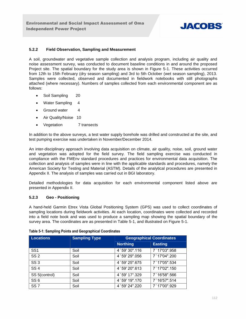
Environmental and Social Impact Assessment of Oma
Independent Power Project
112
5.2.2 Field Observation, Sampling and Measurement
A soil, groundwater and vegetative sample collection and analysis program, including air quality and
noise assessment survey, was conducted to document baseline conditions in and around the proposed
Project site. The spatial boundary for the study area is shown in Figure 5-1. These activities occurred
from 12th to 15th February (dry season sampling) and 3rd to 5th October (wet season sampling), 2013.
Samples were collected, observed and documented in fieldwork notebooks with still photographs
attached (where necessary). Numbers of samples collected from each environmental component are as
follows:
Soil Sampling 20
Water Sampling 4
Ground water 4
Air Quality/Noise 10
Vegetation 7 transects
In addition to the above surveys, a test water supply borehole was drilled and constructed at the site, and
test pumping exercise was undertaken in November/December 2014.
An inter-disciplinary approach involving data acquisition on climate, air quality, noise, soil, ground water
and vegetation was adopted for the field survey. The field sampling exercise was conducted in
compliance with the FMEnv standard procedures and practices for environmental data acquisition. The
collection and analysis of samples were in line with the applicable standards and procedures, namely the
American Society for Testing and Material (ASTM). Details of the analytical procedures are presented in
Appendix II. The analysis of samples was carried out in BGI laboratory.
Detailed methodologies for data acquisition for each environmental component listed above are
presented in Appendix II.
5.2.3 Geo - Positioning
A hand-held Garmin Etrex Vista Global Positioning System (GPS) was used to collect coordinates of
sampling locations during fieldwork activities. At each location, coordinates were collected and recorded
into a field note book and was used to produce a sampling map showing the spatial boundary of the
survey area. The coordinates are as presented in Table 5-1, and illustrated on Figure 5-1.
Table 5-1: Sampling Points and Geographical Coordinates
Locations Sampling Type Geographical Coordinates
Northing Easting
SS1 Soil 4 ̊ 59′ 30".116 7 ̊ 17′03".958
SS 2 Soil 4 ̊ 59′ 29".056 7 ̊ 17′04".200
SS 3 Soil 4 ̊ 59′ 25".675 7 ̊ 17′05".534
SS 4 Soil 4 ̊ 59′ 20".613 7 ̊ 17′02".150
SS 5(control) Soil 4 ̊ 59′ 17".329 7 ̊ 16′58".566
SS 6 Soil 4 ̊ 59′ 19".170 7 ̊ 16′57".514
SS 7 Soil 4 ̊ 59′ 24".220 7 ̊ 17′00".929

Environmental and Social Impact Assessment of Oma
Independent Power Project
113
Locations Sampling Type Geographical Coordinates
Northing Easting
SS 8 Soil 4 ̊ 59′ 27".905 7 ̊ 16′59".493
SS 9 Soil 4 ̊ 59′ 22".855 7 ̊ 16′56".078
SS 10 Soil 4 ̊ 59′ 19".169 7 ̊ 16′50".699
SS 11 Soil 4 ̊ 59′ 21".491 7 ̊ 16′51".227
SS 12 Soil 4 ̊ 59′ 26".541 7 ̊ 16′54".642
SS 13 Soil 4 ̊ 59′ 30".535 7 ̊ 16′58".222
SS 14 Soil 4 ̊ 59′ 30".227 7 ̊ 16′53".206
SS 15 Soil 4 ̊ 59′ 25".177 7 ̊ 16′49".791
SS 16 Soil 4 ̊ 59′ 20".561 7 ̊ 16′47".810
SS 17 (control) Soil 4 ̊ 59′ 24".056 7 ̊ 16′45".104
SS 18 Soil 4 ̊ 59′ 28".862 7 ̊ 16′48".355
SS 19 (control) Soil 4 ̊ 59′ 29".608 7 ̊ 16′44".432
SS 20 Soil 4 ̊ 59′ 27".412 7 ̊ 16′43".737
AQ 1(control) Air Quality & Noise 4 ̊ 59′ 31".906 7 ̊ 16′53".430
AQ 2 Air Quality & Noise 4 ̊ 59′ 30".127 7 ̊ 17′01".031
AQ 3 Air Quality & Noise 4 ̊ 59′ 26".735 7 ̊ 17′02".649
AQ 4 Air Quality & Noise 4 ̊ 59′ 22".949 7 ̊ 17′03".610
AQ 5 (control) Air Quality & Noise 4 ̊ 59′ 17".885 7 ̊ 16′52".818
AQ 6 Air Quality & Noise 4 ̊ 59′ 20".349 7 ̊ 16′54".387
AQ 7 Air Quality & Noise 4 ̊ 59′ 25".390 7 ̊ 16′57".823
AQ 8 Air Quality & Noise 4 ̊ 59′ 27".604 7 ̊ 16′51".504
AQ 9 Air Quality & Noise 4 ̊ 59′ 22".648 7 ̊ 16′48".103
AQ 10 Air Quality & Noise 4 ̊ 59′ 29".627 7 ̊ 16′46".282
VG 1 Vegetation & Wildlife 4 ̊ 59′ 27".762 7 ̊ 17′06".123
VG 2 Vegetation & Wildlife 4 ̊ 59′ 18".466 7 ̊ 16′59".940
VG 3 Vegetation & Wildlife 4 ̊ 59′ 24".016 7 ̊ 16′52".935
VG 4 Vegetation & Wildlife 4 ̊ 59′ 19".532 7 ̊ 16′49".055
VG 5 Vegetation & Wildlife 4 ̊ 59′ 30".908 7 ̊ 16′50".123
GW 1 Groundwater 4 ̊ 59′ 29".476 7 ̊ 17′03".457
GW 2 Groundwater 4 ̊ 59′ 18".932 7 ̊ 17′00".373
GW 3 Groundwater 4 ̊ 59′ 27".208 7 ̊ 16′44".113
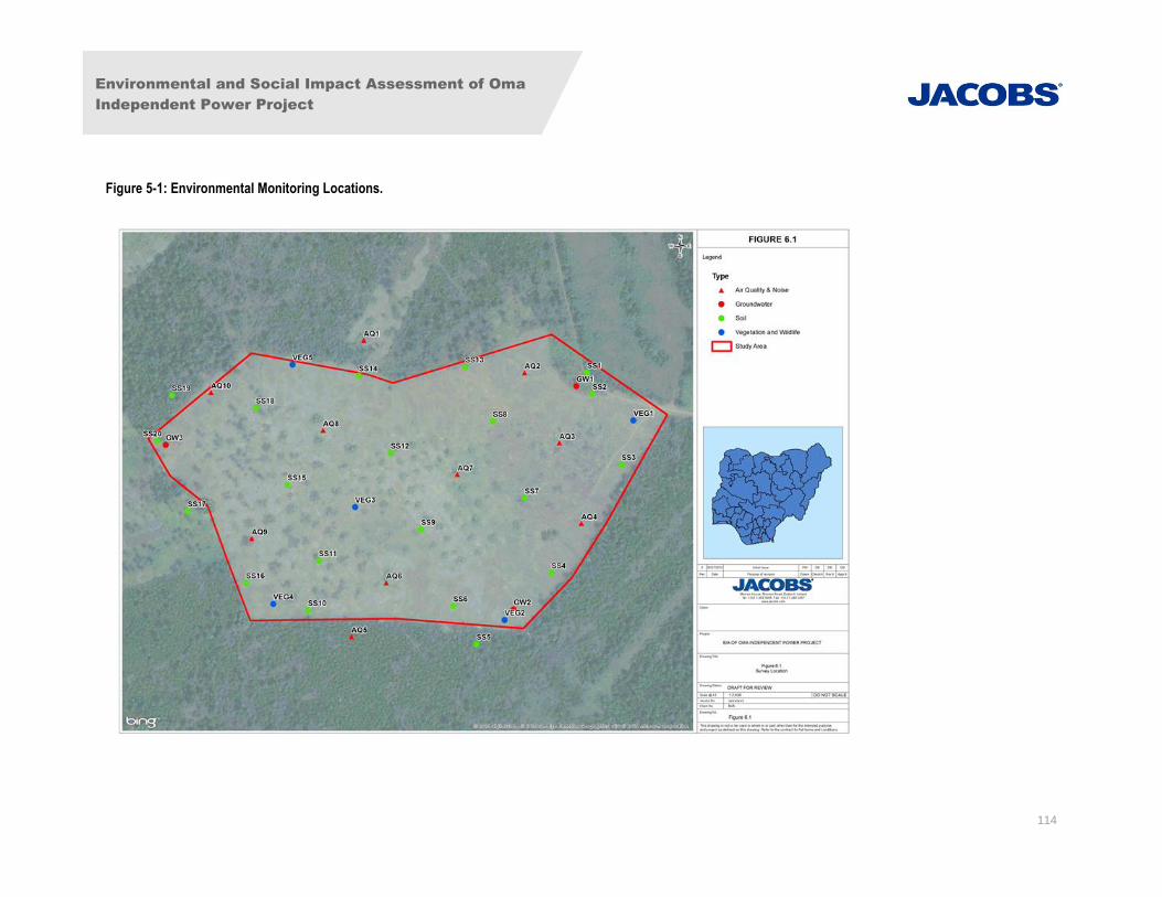
Environmental and Social Impact Assessment of Oma
Independent Power Project
114
Figure 5-1: Environmental Monitoring Locations.
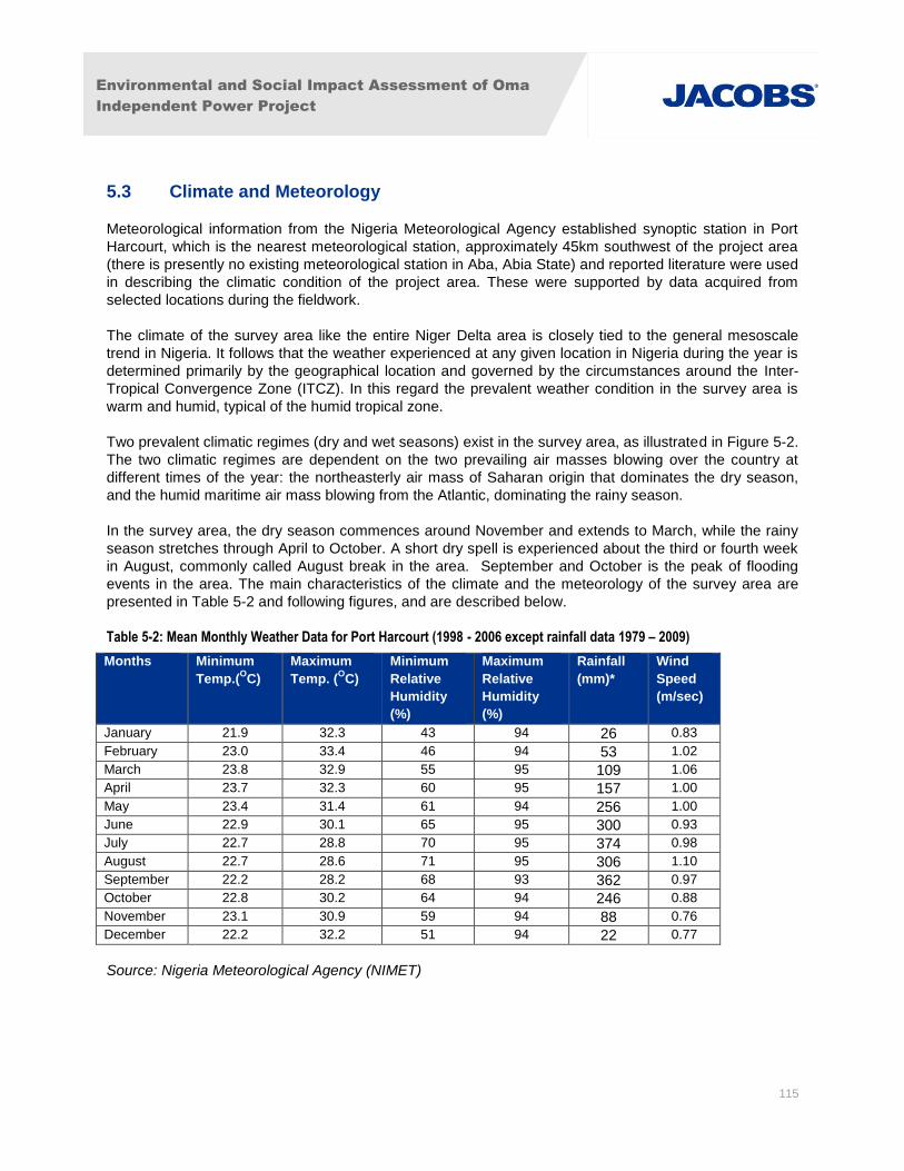
Environmental and Social Impact Assessment of Oma
Independent Power Project
115
5.3 Climate and Meteorology
Meteorological information from the Nigeria Meteorological Agency established synoptic station in Port
Harcourt, which is the nearest meteorological station, approximately 45km southwest of the project area
(there is presently no existing meteorological station in Aba, Abia State) and reported literature were used
in describing the climatic condition of the project area. These were supported by data acquired from
selected locations during the fieldwork.
The climate of the survey area like the entire Niger Delta area is closely tied to the general mesoscale
trend in Nigeria. It follows that the weather experienced at any given location in Nigeria during the year is
determined primarily by the geographical location and governed by the circumstances around the Inter-
Tropical Convergence Zone (ITCZ). In this regard the prevalent weather condition in the survey area is
warm and humid, typical of the humid tropical zone.
Two prevalent climatic regimes (dry and wet seasons) exist in the survey area, as illustrated in Figure 5-2.
The two climatic regimes are dependent on the two prevailing air masses blowing over the country at
different times of the year: the northeasterly air mass of Saharan origin that dominates the dry season,
and the humid maritime air mass blowing from the Atlantic, dominating the rainy season.
In the survey area, the dry season commences around November and extends to March, while the rainy
season stretches through April to October. A short dry spell is experienced about the third or fourth week
in August, commonly called August break in the area. September and October is the peak of flooding
events in the area. The main characteristics of the climate and the meteorology of the survey area are
presented in Table 5-2 and following figures, and are described below.
Table 5-2: Mean Monthly Weather Data for Port Harcourt (1998 - 2006 except rainfall data 1979 – 2009)
Months Minimum
Temp.(OC)
Maximum
Temp. (OC)
Minimum
Relative
Humidity
(%)
Maximum
Relative
Humidity
(%)
Rainfall
(mm)*
Wind
Speed
(m/sec)
January 21.9 32.3 43 94 26 0.83
February 23.0 33.4 46 94 53 1.02
March 23.8 32.9 55 95 109 1.06
April 23.7 32.3 60 95 157 1.00
May 23.4 31.4 61 94 256 1.00
June 22.9 30.1 65 95 300 0.93
July 22.7 28.8 70 95 374 0.98
August 22.7 28.6 71 95 306 1.10
September 22.2 28.2 68 93 362 0.97
October 22.8 30.2 64 94 246 0.88
November 23.1 30.9 59 94 88 0.76
December 22.2 32.2 51 94 22 0.77
Source: Nigeria Meteorological Agency (NIMET)
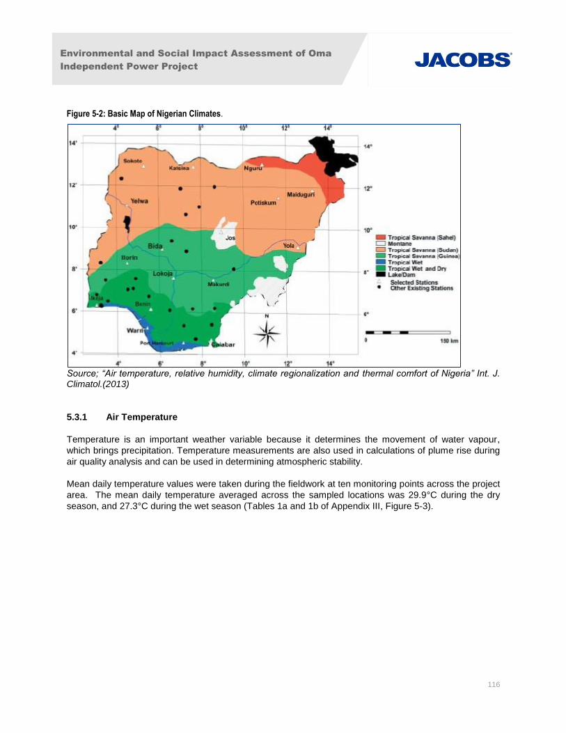
Environmental and Social Impact Assessment of Oma
Independent Power Project
116
Figure 5-2: Basic Map of Nigerian Climates.
Source; “Air temperature, relative humidity, climate regionalization and thermal comfort of Nigeria” Int. J. Climatol.(2013)
5.3.1 Air Temperature
Temperature is an important weather variable because it determines the movement of water vapour,
which brings precipitation. Temperature measurements are also used in calculations of plume rise during
air quality analysis and can be used in determining atmospheric stability.
Mean daily temperature values were taken during the fieldwork at ten monitoring points across the project
area. The mean daily temperature averaged across the sampled locations was 29.9°C during the dry
season, and 27.3°C during the wet season (Tables 1a and 1b of Appendix III, Figure 5-3).
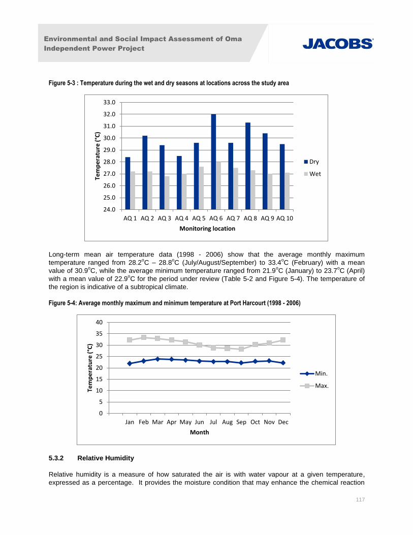
Environmental and Social Impact Assessment of Oma
Independent Power Project
117
Figure 5-3 : Temperature during the wet and dry seasons at locations across the study area
Long-term mean air temperature data (1998 - 2006) show that the average monthly maximum
temperature ranged from 28.2oC – 28.8
oC (July/August/September) to 33.4
oC (February) with a mean
value of 30.9oC, while the average minimum temperature ranged from 21.9
oC (January) to 23.7
oC (April)
with a mean value of 22.9oC for the period under review (Table 5-2 and Figure 5-4). The temperature of
the region is indicative of a subtropical climate.
Figure 5-4: Average monthly maximum and minimum temperature at Port Harcourt (1998 - 2006)
5.3.2 Relative Humidity
Relative humidity is a measure of how saturated the air is with water vapour at a given temperature,
expressed as a percentage. It provides the moisture condition that may enhance the chemical reaction
24.0
25.0
26.0
27.0
28.0
29.0
30.0
31.0
32.0
33.0
AQ 1 AQ 2 AQ 3 AQ 4 AQ 5 AQ 6 AQ 7 AQ 8 AQ 9 AQ 10
Tem
pe
ratu
re (
°C)
Monitoring location
Dry
Wet
0
5
10
15
20
25
30
35
40
Jan Feb Mar Apr May Jun Jul Aug Sep Oct Nov Dec
Tem
pe
ratu
re (
°C)
Month
Min.
Max.
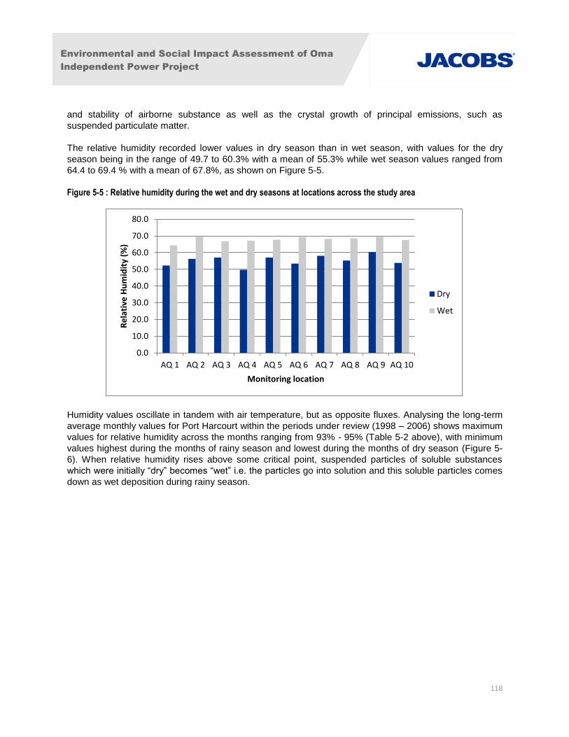
Environmental and Social Impact Assessment of Oma
Independent Power Project
118
and stability of airborne substance as well as the crystal growth of principal emissions, such as
suspended particulate matter.
The relative humidity recorded lower values in dry season than in wet season, with values for the dry
season being in the range of 49.7 to 60.3% with a mean of 55.3% while wet season values ranged from
64.4 to 69.4 % with a mean of 67.8%, as shown on Figure 5-5.
Figure 5-5 : Relative humidity during the wet and dry seasons at locations across the study area
Humidity values oscillate in tandem with air temperature, but as opposite fluxes. Analysing the long-term
average monthly values for Port Harcourt within the periods under review (1998 – 2006) shows maximum
values for relative humidity across the months ranging from 93% - 95% (Table 5-2 above), with minimum
values highest during the months of rainy season and lowest during the months of dry season (Figure 5-
6). When relative humidity rises above some critical point, suspended particles of soluble substances
which were initially “dry” becomes “wet” i.e. the particles go into solution and this soluble particles comes
down as wet deposition during rainy season.
0.0
10.0
20.0
30.0
40.0
50.0
60.0
70.0
80.0
AQ 1 AQ 2 AQ 3 AQ 4 AQ 5 AQ 6 AQ 7 AQ 8 AQ 9 AQ 10
Re
lati
ve H
um
idit
y (%
)
Monitoring location
Dry
Wet
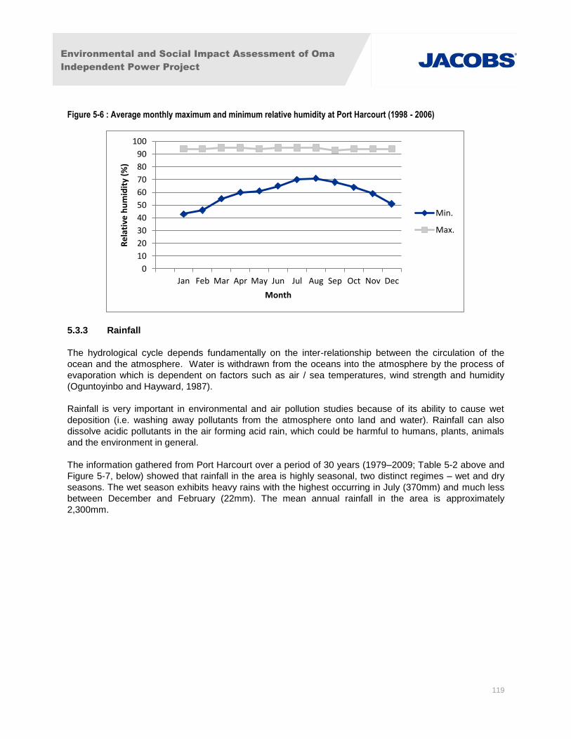
Environmental and Social Impact Assessment of Oma
Independent Power Project
119
Figure 5-6 : Average monthly maximum and minimum relative humidity at Port Harcourt (1998 - 2006)
5.3.3 Rainfall
The hydrological cycle depends fundamentally on the inter-relationship between the circulation of the
ocean and the atmosphere. Water is withdrawn from the oceans into the atmosphere by the process of
evaporation which is dependent on factors such as air / sea temperatures, wind strength and humidity
(Oguntoyinbo and Hayward, 1987).
Rainfall is very important in environmental and air pollution studies because of its ability to cause wet
deposition (i.e. washing away pollutants from the atmosphere onto land and water). Rainfall can also
dissolve acidic pollutants in the air forming acid rain, which could be harmful to humans, plants, animals
and the environment in general.
The information gathered from Port Harcourt over a period of 30 years (1979–2009; Table 5-2 above and
Figure 5-7, below) showed that rainfall in the area is highly seasonal, two distinct regimes – wet and dry
seasons. The wet season exhibits heavy rains with the highest occurring in July (370mm) and much less
between December and February (22mm). The mean annual rainfall in the area is approximately
2,300mm.
0
10
20
30
40
50
60
70
80
90
100
Jan Feb Mar Apr May Jun Jul Aug Sep Oct Nov Dec
Re
lati
ve h
um
idit
y (%
)
Month
Min.
Max.
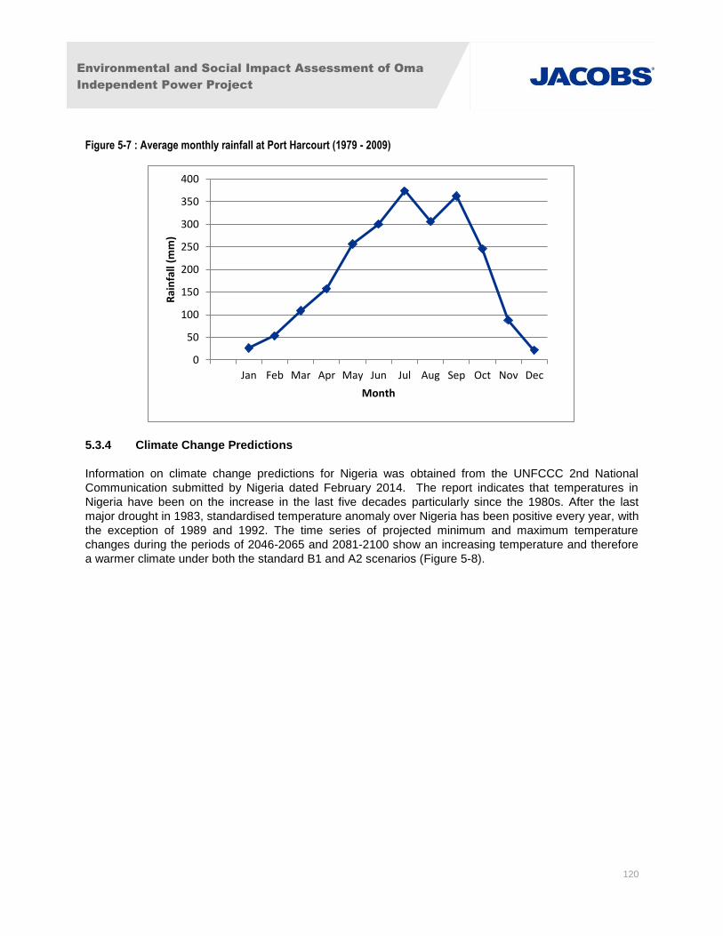
Environmental and Social Impact Assessment of Oma
Independent Power Project
120
Figure 5-7 : Average monthly rainfall at Port Harcourt (1979 - 2009)
5.3.4 Climate Change Predictions
Information on climate change predictions for Nigeria was obtained from the UNFCCC 2nd National
Communication submitted by Nigeria dated February 2014. The report indicates that temperatures in
Nigeria have been on the increase in the last five decades particularly since the 1980s. After the last
major drought in 1983, standardised temperature anomaly over Nigeria has been positive every year, with
the exception of 1989 and 1992. The time series of projected minimum and maximum temperature
changes during the periods of 2046-2065 and 2081-2100 show an increasing temperature and therefore
a warmer climate under both the standard B1 and A2 scenarios (Figure 5-8).
0
50
100
150
200
250
300
350
400
Jan Feb Mar Apr May Jun Jul Aug Sep Oct Nov Dec
Rai
nfa
ll (m
m)
Month
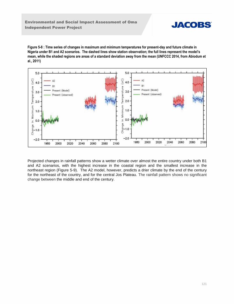
Environmental and Social Impact Assessment of Oma
Independent Power Project
121
Figure 5-8 : Time series of changes in maximum and minimum temperatures for present-day and future climate in
Nigeria under B1 and A2 scenarios. The dashed lines show station observation; the full lines represent the model’s
mean, while the shaded regions are areas of a standard deviation away from the mean (UNFCCC 2014, from Abiodum et
al., 2011)
Projected changes in rainfall patterns show a wetter climate over almost the entire country under both B1
and A2 scenarios, with the highest increase in the coastal region and the smallest increase in the
northeast region (Figure 5-9). The A2 model, however, predicts a drier climate by the end of the century
for the northeast of the country, and for the central Jos Plateau. The rainfall pattern shows no significant
change between the middle and end of the century.
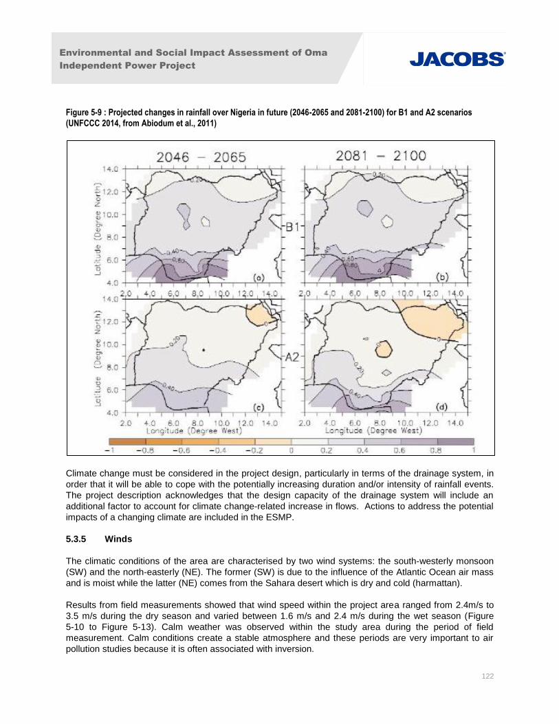
Environmental and Social Impact Assessment of Oma
Independent Power Project
122
Figure 5-9 : Projected changes in rainfall over Nigeria in future (2046-2065 and 2081-2100) for B1 and A2 scenarios
(UNFCCC 2014, from Abiodum et al., 2011)
Climate change must be considered in the project design, particularly in terms of the drainage system, in
order that it will be able to cope with the potentially increasing duration and/or intensity of rainfall events.
The project description acknowledges that the design capacity of the drainage system will include an
additional factor to account for climate change-related increase in flows. Actions to address the potential
impacts of a changing climate are included in the ESMP.
5.3.5 Winds
The climatic conditions of the area are characterised by two wind systems: the south-westerly monsoon
(SW) and the north-easterly (NE). The former (SW) is due to the influence of the Atlantic Ocean air mass
and is moist while the latter (NE) comes from the Sahara desert which is dry and cold (harmattan).
Results from field measurements showed that wind speed within the project area ranged from 2.4m/s to
3.5 m/s during the dry season and varied between 1.6 m/s and 2.4 m/s during the wet season (Figure
5-10 to Figure 5-13). Calm weather was observed within the study area during the period of field
measurement. Calm conditions create a stable atmosphere and these periods are very important to air
pollution studies because it is often associated with inversion.
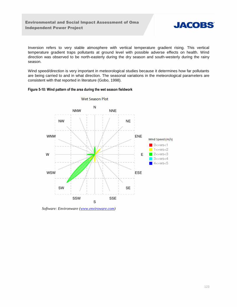
Environmental and Social Impact Assessment of Oma
Independent Power Project
123
Inversion refers to very stable atmosphere with vertical temperature gradient rising. This vertical
temperature gradient traps pollutants at ground level with possible adverse effects on health. Wind
direction was observed to be north-easterly during the dry season and south-westerly during the rainy
season.
Wind speed/direction is very important in meteorological studies because it determines how far pollutants
are being carried to and in what direction. The seasonal variations in the meteorological parameters are
consistent with that reported in literature (Gobo, 1998).
Figure 5-10: Wind pattern of the area during the wet season fieldwork
Software: Environware (www.enviroware.com)
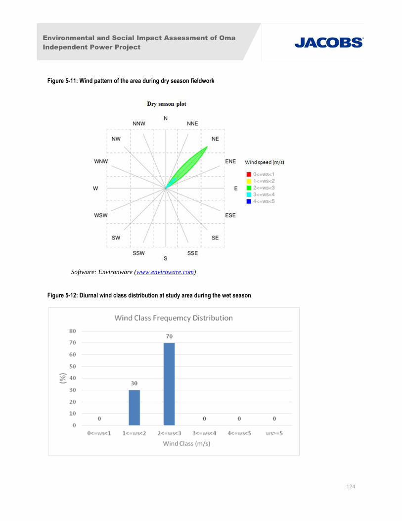
Environmental and Social Impact Assessment of Oma
Independent Power Project
124
Figure 5-11: Wind pattern of the area during dry season fieldwork
Software: Environware (www.enviroware.com)
Figure 5-12: Diurnal wind class distribution at study area during the wet season
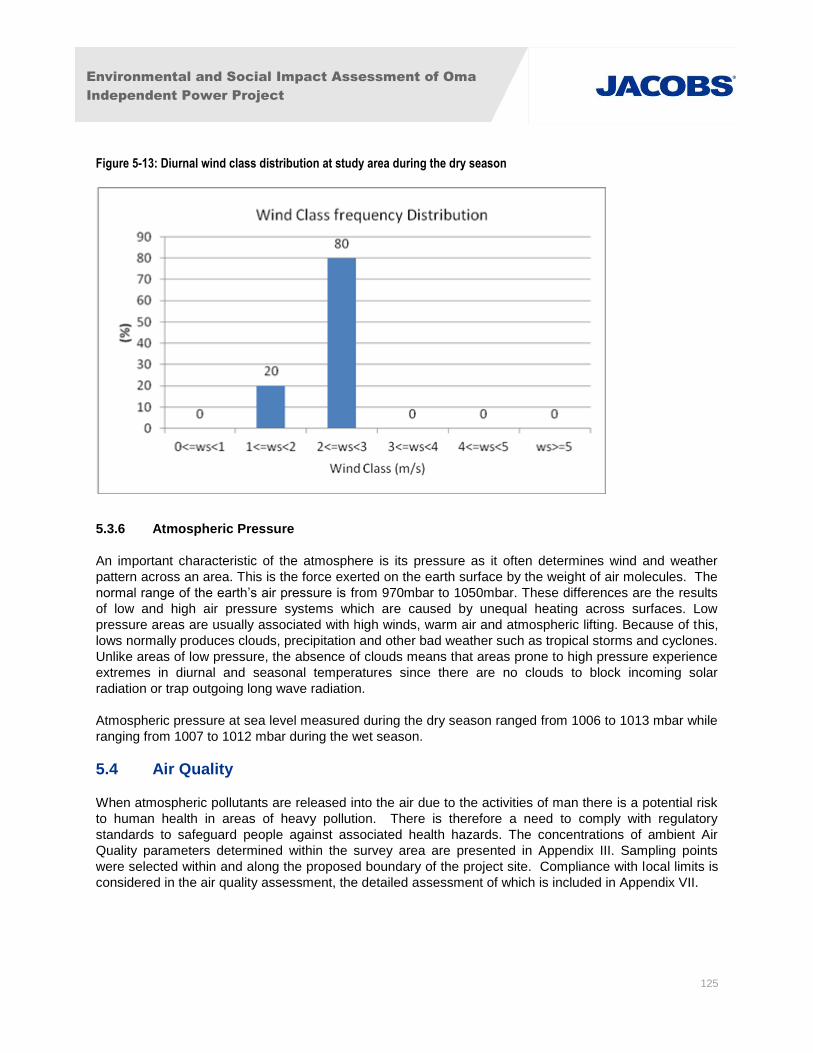
Environmental and Social Impact Assessment of Oma
Independent Power Project
125
Figure 5-13: Diurnal wind class distribution at study area during the dry season
5.3.6 Atmospheric Pressure
An important characteristic of the atmosphere is its pressure as it often determines wind and weather
pattern across an area. This is the force exerted on the earth surface by the weight of air molecules. The
normal range of the earth’s air pressure is from 970mbar to 1050mbar. These differences are the results
of low and high air pressure systems which are caused by unequal heating across surfaces. Low
pressure areas are usually associated with high winds, warm air and atmospheric lifting. Because of this,
lows normally produces clouds, precipitation and other bad weather such as tropical storms and cyclones.
Unlike areas of low pressure, the absence of clouds means that areas prone to high pressure experience
extremes in diurnal and seasonal temperatures since there are no clouds to block incoming solar
radiation or trap outgoing long wave radiation.
Atmospheric pressure at sea level measured during the dry season ranged from 1006 to 1013 mbar while
ranging from 1007 to 1012 mbar during the wet season.
5.4 Air Quality
When atmospheric pollutants are released into the air due to the activities of man there is a potential risk
to human health in areas of heavy pollution. There is therefore a need to comply with regulatory
standards to safeguard people against associated health hazards. The concentrations of ambient Air
Quality parameters determined within the survey area are presented in Appendix III. Sampling points
were selected within and along the proposed boundary of the project site. Compliance with local limits is
considered in the air quality assessment, the detailed assessment of which is included in Appendix VII.
Environmental and Social Impact Assessment of Oma
Independent Power Project
126
5.4.1 Suspended Particulate Matter
Suspended Particulate Matter is a composite group of substances (liquid or solids) dispersed in the
atmosphere, which range in diameter from a fraction of a micron to several hundreds of microns. The
particles (dust, smoke and other aerosols) may be of anthropogenic and/or natural origin. The most
significant of these are the particles of <10µm in diameter, usually referred to as PM10.
High concentrations of suspended particulate matter (SPM) are known to irritate the mucous membranes
and may initiate a variety of respiratory diseases. Fine particulates may cause cancer and aggravate
morbidity and mortality from respiratory dysfunctions (Huang et al., 2009).
SPM can also cause damage to materials by soiling clothing and textiles, corroding metals (at relative
humidity above 75%), eroding building surfaces, and discolouring/destroying painted surfaces (Peavy, et
al., 1985).
Particulate monitoring is important not only in respect of health but in causing reduced visibility and
entering into atmospheric reactions (WHO, 1976), influencing radiation budget of the atmosphere as a
result of scattering and absorption and indirectly by serving as condensation nuclei and by modifying the
albedo of clouds and the processes that lead to precipitation (Chineke and Chiemeka 2009).
The ambient SPM level in the survey area ranged from 59.0 to 162.0µg/m3 during the dry season
(Appendix III, Table 1a) and from 9.1µg/m3 to 20.2µg/m
3 during the wet season (Appendix III, Table 1b).
The values of SPM were within the FMEnv limit of 250µg/m3.
5.4.2 Carbon Monoxide
Carbon monoxide (CO) is a colourless, odourless and poisonous gas produced by the incomplete
combustion of fossil fuels such as gas, oil and coal. At present ambient levels, it has little if any effect on
property, vegetation, or materials. However, it impairs the oxygen carrying capacity of the blood at higher
concentrations, owing to its high affinity for haemoglobin, the component of the blood that transports of
oxygen.
The carbon monoxide levels in the ambient air across the locations ranged from 2.1 ppm to 3.2 ppm for
the dry season and 1.3ppm to 2.4ppm for the wet season.
5.4.3 Oxides of Sulphur
Sulphur dioxide (SO2) and sulphur trioxide (SO3) are the two oxides of sulphur of most interest in the
survey of air pollution. The SO2 is often measured during environmental assessment because it is
relatively more stable in the atmosphere than SO3.
SO2 is a colourless gas that is produced from volcanic, oceans, biological decay and forest fire releases.
It can also be produced from the combustion of fossil fuel.
Sulphur dioxide is an irritant gas which affects the mucous membranes when inhaled. Under certain
conditions, some of the air-borne sulphur dioxide gas is oxidized to sulphur trioxide. Each of these two
gases, in the presence of water vapour, forms sulphurous and sulphuric acid respectively resulting in acid
rain, which destroys building materials and work of arts (Rao & Rao, 2005). Sulphur trioxide is a very
strong irritant gas, much stronger than sulphur dioxide, causing bronchospasms at relatively low level of
concentration. The adverse health effects of sulphur dioxide are breathing/respiratory illness, alterations
Environmental and Social Impact Assessment of Oma
Independent Power Project
127
in pulmonary defences and aggravation of existing cardiovascular diseases. According to Rao & Rao
(2005) Sulphur dioxide also causes necrosis and interveinal chlorotic bleaching of plant leaves.
The concentration of SO2 measured ranged from 0.01ppm to 0.03ppm during the dry season (Appendix
III, Table 1a), and 0.01ppm to 0.04ppm during the wet season (Appendix III, Table 1b). The FMEnv
regulatory limit of SOx is 0.10ppm. No increase in SOx is anticipated as a result of emissions from the
power plant.
5.4.4 Oxides of Nitrogen
Nitrogen oxides are formed by many human or anthropogenic activities and are classified as pollutants
because of their environmental and health effects. Nitrogen dioxide (NO2) is reddish brown in
concentrated form and gives a brownish yellow tint at lower concentration. Nitrogen oxides are hazardous
to human health and the environment. According to Davis and Masten (2004), exposure to NOx
concentrations above 5ppm for 15 minutes results in cough and irritation of the respiratory tract.
Continued exposure to this gas may produce an abnormal accumulation of fluid in the lung (a condition
described as pulmonary oedema). Excessive levels of nitrogen oxides can decrease the strength of
textiles, discolour fabrics, and corrode metal surfaces. Oxides of nitrogen also suppress plant growth and
cause leaf bleaching; however, NOx are converted to nitrates through nitric acid formation and are
important for soil fertility in tropical areas. The levels of nitrogen oxides for the dry season ranged from
0.01ppm to 0.02ppm (Appendix III, Table 1a), and <0.01 ppm to 0.02ppm during the wet season
(Appendix III, Table 1b). The FMEnv regulatory limit for NOx is 0.06ppm.
5.4.5 Hydrogen sulphide (H2S)
H2S is a foul smelling gas. The sources of its natural emission into the atmosphere include anaerobic
biological decay process on land, in marshes and in the oceans. Exposure to H2S for short periods can
result in fatigue of the sense of smell. The concentrations of hydrogen sulphide in the ambient air of the
proposed project area for the wet and dry seasons were below 0.01ppm at all locations (Appendix III,
Tables 1a and 1b). These values were within the FMEnv regulatory limit of 0.08ppm.
5.4.6 Ammonia (NH3)
Ammonia is a very soluble gas which may have health repercussion on human health. Exposure to NH3
concentration higher than 0.5ppm (1 mg/m3) can trigger changes in pulmonary function in healthy people.
The levels of NH3 in the ambient air at the sampled points were below the detection limit (less than
0.01ppm) for both the dry and wet seasons (Appendix III, Tables 1a and 1b), and were therefore within
the FMEnv regulatory limit of 0.01ppm
5.4.7 Volatile Organic Substances (VOCs)
These include methane (CH4), ethane (C2H6), propane (C3H8) and other derivatives of aliphatic and
aromatic organic compounds which are emitted from both man-made and natural sources. Hydrocarbon
vapour in the atmosphere arise from fugitive emissions, vents and incomplete combustion of fuels,
particularly where fuel to air ratios are too high. Most members of this group are significantly toxic and
exposure to high concentrations in the atmosphere (about 1000ppm or more) could result in interference
with oxygen intake and acute leukaemia (SIEP, 1996). The concentrations of VOCs in the survey area
ranged from 3.5ppm to 6.2ppm during the dry season and from 2.5ppm to 7.3ppm during the wet season
(Appendix III, Tables 1a and 1b).
Environmental and Social Impact Assessment of Oma
Independent Power Project
128
5.4.8 Heavy metals
The concentrations of the heavy metals cadmium, iron, zinc, copper, magnesium, manganese, sodium
and nickel were below the 0.01ppm detection limit for both the dry and wet seasons (Appendix III, Tables
1a and 1b). As illustrated in Tables 1a and 1b in Appendix III, the average heavy metal concentration
values were compared with the Nigerian Air Quality Standards from the Federal Ministry of Environment
and WHO standards and were shown to be within acceptable limits.
The low concentrations of gaseous pollutants obtained in the project area during this survey may be due
to the absence of industrial activities in the area that would generate such materials as well as the
influence of rains which dilute and dissolve pollutants in the atmosphere.
5.5 Noise
Noise is commonly defined as unwanted sound or an aspect of sound which is not pleasurable. It is an
environmental phenomenon to which humans are exposed to throughout life. Noise can also be
considered as environmental pollutant, waste product generated in conjunction with various
anthropogenic activities (Davis & Masten, 2004). Noise produces undesired physiological and
psychological effect in an individual and also interferes with the social ends (such as work, rest,
communication, sleep etc.) of an individual or group. According to Davis & Masten, (2004), noise has both
auditory effects and psychological-sociological effects on people. Auditory effects include both hearing
loss speech interference, while psychological-sociological effects include annoyance, sleep interference,
effect on performance, and acoustical privacy.
The noise levels measured at all points ranged from 38.6dBA to 47.2dBA for the dry season and 35.6
dBA to 48.1 dBA for the wet season. All noise level measurements were within the FMEnv regulatory
permissible noise level of 90dBA. Noise monitoring data was collected at the same locations as air
quality on the site and site boundary (see Figure 5-1). No significant local noise producing sources were
identified during the surveys and therefore these locations were considered representative of the local
ambient noise conditions for the nearest noise receptors.
5.6 Geology, Hydrogeology and Hydrology
Ugwunagbo and Ukwa West L.G.As are located within modified (farmed) areas of the rainforest belt. The
state of Abia is generally flat lying with an overall gentle slope towards the coast some 60km to the south.
5.6.1 Geology and Hydrogeology
The site is located in the Eastern Niger Delta sedimentary basin which formed during cycles of
subsidence and deposition. Two principal geological formations underlie the site; the Bende-Ameki
Formation and the Coastal Plain Sands, also known as the Benin Formation. The Benin Formation
overlies the Bende-Ameki strata. It is approximately 200m thick with a dip towards the south west. The
lithology of the Benin Formation comprises unconsolidated fine-medium, coarse grained, cross bedded
sands with occasional bands of clay and shale.
The two Formations are able to sustain regional borehole abstractions, however the Bende-Ameki
Formation will sustain lower yields as it is comprised of lenticular sand bodies which are not considered to
be extensive. Permeability of the Benin Formation is greater and is capable of sustaining higher
groundwater yields.
Environmental and Social Impact Assessment of Oma
Independent Power Project
129
Within a regionally extensive, predominantly sand aquifer such as the Coastal Plains aquifer, with no
significant local surface water features, regional groundwater flow is likely to be controlled by a
combination of the prevailing topography and groundwater gradient to the nearest regional discharge sink
(the rivers). Groundwater flow direction local to the site will also be influenced by localized variations in
aquifer lithology, but is likely to broadly reflect the regional groundwater flow direction. It is anticipated
that groundwater flow will contain a predominantly southerly component, and is likely to flow towards the
southwest towards the closed regional surface water feature (the Imo River).
Two investigations have been undertaken to assess the geology and hydrogeology of the site. One
investigation assessed the shallow soils and groundwater whereas the second predominantly targeted
the deeper strata and the aquifer within the Benin Formation for the purposes of a test pumping exercise.
The stratigraphy of the shallow, subsurface soil in the study area was investigated using Percussion
drilling technique to drill with a diameter size of 6 inches and a depth of 27m (90ft). These investigations
confirmed the presence of the Benin (Coastal Plain Sands) aquifer beneath the site. The direction of flow
for ground water was found to trend NE to SW.
The stratigraphy of the shallow boreholes and the units observed are displayed in a lithologic section to
show stratigraphic features as shown in Figure 5-14. The lithologic units ranged from silty clay to coarse
sand in a fining upward sequence. Three distinct lithologic units were observed in the three boreholes. In
borehole 1, the clay unit had a thickness of about 15m, serving as a covering and reducing the
vulnerability of the aquifer layer. The second lithologic unit consisted of fine to medium-grained sand with
a thickness of about 1.0m while the third layer was observed to be composed of poorly graded medium-
grained sandy clay with a thickness of about 10m, down to the aquifer layer. In borehole 2, the first layer
consisted of silty clay with a thickness of about 12m. The second layer consisted of fine grained sand with
a thickness of about 2m and the third layer had a thickness of 11m running through the aquifer layer.
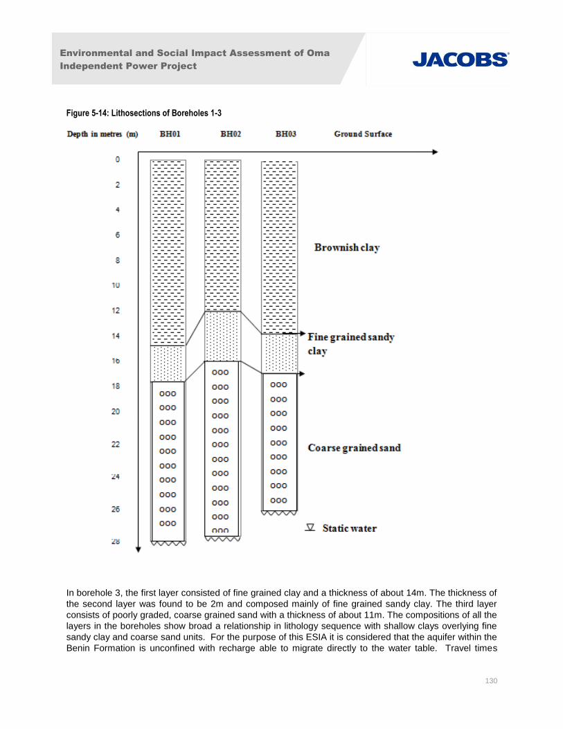
Environmental and Social Impact Assessment of Oma
Independent Power Project
130
Figure 5-14: Lithosections of Boreholes 1-3
In borehole 3, the first layer consisted of fine grained clay and a thickness of about 14m. The thickness of
the second layer was found to be 2m and composed mainly of fine grained sandy clay. The third layer
consists of poorly graded, coarse grained sand with a thickness of about 11m. The compositions of all the
layers in the boreholes show broad a relationship in lithology sequence with shallow clays overlying fine
sandy clay and coarse sand units. For the purpose of this ESIA it is considered that the aquifer within the
Benin Formation is unconfined with recharge able to migrate directly to the water table. Travel times
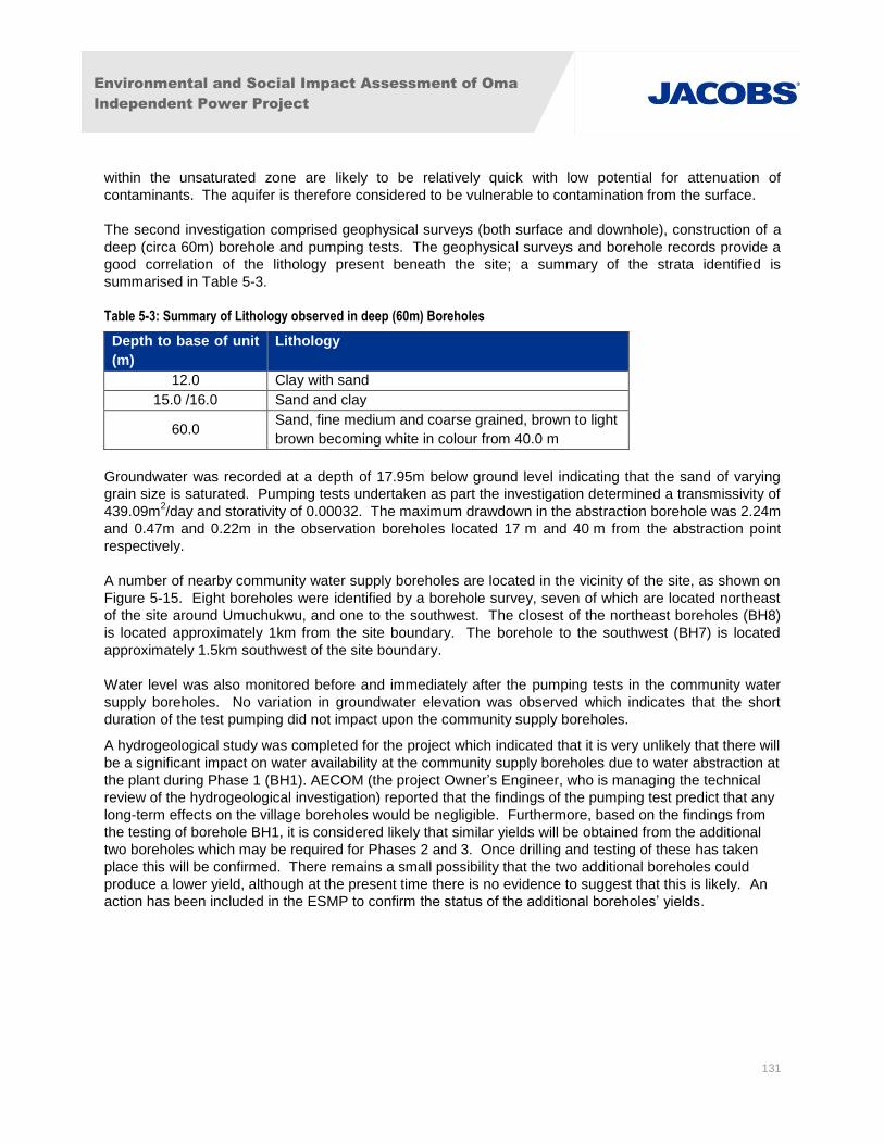
Environmental and Social Impact Assessment of Oma
Independent Power Project
131
within the unsaturated zone are likely to be relatively quick with low potential for attenuation of
contaminants. The aquifer is therefore considered to be vulnerable to contamination from the surface.
The second investigation comprised geophysical surveys (both surface and downhole), construction of a
deep (circa 60m) borehole and pumping tests. The geophysical surveys and borehole records provide a
good correlation of the lithology present beneath the site; a summary of the strata identified is
summarised in Table 5-3.
Table 5-3: Summary of Lithology observed in deep (60m) Boreholes
Depth to base of unit
(m)
Lithology
12.0 Clay with sand
15.0 /16.0 Sand and clay
60.0 Sand, fine medium and coarse grained, brown to light
brown becoming white in colour from 40.0 m
Groundwater was recorded at a depth of 17.95m below ground level indicating that the sand of varying
grain size is saturated. Pumping tests undertaken as part the investigation determined a transmissivity of
439.09m2/day and storativity of 0.00032. The maximum drawdown in the abstraction borehole was 2.24m
and 0.47m and 0.22m in the observation boreholes located 17 m and 40 m from the abstraction point
respectively.
A number of nearby community water supply boreholes are located in the vicinity of the site, as shown on
Figure 5-15. Eight boreholes were identified by a borehole survey, seven of which are located northeast
of the site around Umuchukwu, and one to the southwest. The closest of the northeast boreholes (BH8)
is located approximately 1km from the site boundary. The borehole to the southwest (BH7) is located
approximately 1.5km southwest of the site boundary.
Water level was also monitored before and immediately after the pumping tests in the community water
supply boreholes. No variation in groundwater elevation was observed which indicates that the short
duration of the test pumping did not impact upon the community supply boreholes.
A hydrogeological study was completed for the project which indicated that it is very unlikely that there will
be a significant impact on water availability at the community supply boreholes due to water abstraction at
the plant during Phase 1 (BH1). AECOM (the project Owner’s Engineer, who is managing the technical
review of the hydrogeological investigation) reported that the findings of the pumping test predict that any
long-term effects on the village boreholes would be negligible. Furthermore, based on the findings from
the testing of borehole BH1, it is considered likely that similar yields will be obtained from the additional
two boreholes which may be required for Phases 2 and 3. Once drilling and testing of these has taken
place this will be confirmed. There remains a small possibility that the two additional boreholes could
produce a lower yield, although at the present time there is no evidence to suggest that this is likely. An
action has been included in the ESMP to confirm the status of the additional boreholes’ yields.
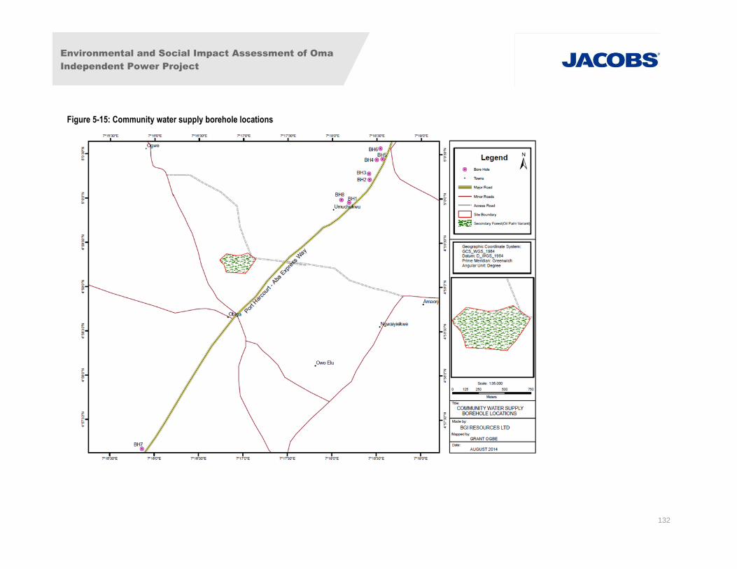
Environmental and Social Impact Assessment of Oma
Independent Power Project
132
Figure 5-15: Community water supply borehole locations
Environmental and Social Impact Assessment of Oma
Independent Power Project
133
5.6.2 Hydrology
The most significant surface water feature in the region is the River Imo, located approximately 11.5km
west of the site. The Imo flows in a southerly direction for approximately 20km to Obigbo, before turning
east for approximately 40km to Ohambele, and ultimately turning south to the coast.
The other significant surface water feature is the River Aba, located approximately 20km to the east. The
Aba flows to the southeast, to a confluence with the Imo, approximately 30km southeast of the site.
Site visits have confirmed mapping which indicates that there are no significant water courses located
between the site and the River Imo, as illustrated in Figure 5-16.
Figure 5-16: River Network
Environmental and Social Impact Assessment of Oma
Independent Power Project
134
5.7 Groundwater Chemistry
5.7.1 Physico-chemical Characteristics of Groundwater
The chemistry of groundwater varies from place to place depending on the nature of the subsoil and
rocks that it passes through. In areas where volcanic rocks of sandstones are present, softer water is
normal (Daly, 1994). However, groundwater is often ‘hard’, containing high concentrations of calcium,
magnesium, and bicarbonate in areas where limestone bedrock and limestone-dominated subsoil are
common. Therefore, in considering the impact of human activities, it is necessary to first consider the
natural (or baseline) water quality. Groundwater is usually considered pure and safe to drink as it
undergoes a filtering and cleansing process through a subsoil cover and rock medium that surface waters
do not have. However, this does not guarantee groundwater purity. Problems can arise either due to the
natural conditions in the ground or pollution by human activities.
The physicochemical characteristics of ground water in the survey area are presented in Tables 2a and
2b of Appendix III and described below:
Temperature: The temperature of the groundwater of the survey area in the wet season, ranged
from 26.30oC to 26.8
oC while in the dry season, temperature values ranged from 27.30
oC to
33.20oC. These temperature values compared well and corroborated the report of the NDES
(1997) on groundwater temperatures of the Niger Delta.
pH: The pH of the groundwater of the survey area in the wet season ranged from 6.50 to 6.65
and from 5.03 to 7.02 in the dry season. The regulatory limit of pH is 6.5 to 8.5 (DPR, 2002). The
pH of ground water will vary depending on the composition of the rocks and sediments that
surround the travel pathway of the recharge water infiltrating to the ground water. Ground water
passing through carbonate-rich rocks (e.g. limestones and marbles) will usually have pH values
greater than 7 as the acidic water is “neutralized.” If the geology of the aquifer containing the
ground water has few carbonate rocks (e.g., sandstones, metamorphic granitic schists and
gneisses; volcanic rocks, etc.) the ground water will tend to remain acidic (The American Well
Owner, 2003). Acidic pH may cause corrosion of the borehole casing and metals in the
distribution system.
Turbidity: Turbidity in water is a measure of the cloudiness. It is caused by the presence of
suspended matter which scatters and absorbs light (Kiely, 1998). Although turbidity has no health
effects, it can however interfere with disinfection and provide a medium for microbial growth. The
values obtained for turbidity of the groundwater in the area ranged between 2.4 NTU and 5.3
NTU for the wet season and between 3.1 NTU and 11.0 NTU for the dry season.
Electrical Conductivity: Electrical Conductivity is the ability of a solution to permit the flow of
electrical current. It varies with the number and type of ions in the solution. The conductivity in
water is proportional to the concentration of dissolved solids, mostly inorganic salts. The higher
the salinity of water the higher the conductivity value (Kiely, 1998). The conductivity values
ranged from 36.3µS/cm to 42.1µS/cm in the wet season and from 40µS/cm to 170µS/cm in the
dry season.
Salinity (as Chloride): This is a measure of solids of oxides and chlorides in water. It affects the
taste of a groundwater quality. The salinity values ranged from 10.5 mg/l to 45.1mg/l in the dry
season and ranged from 9.8 mg/l to 16.2 mg/l in the wet season.
Environmental and Social Impact Assessment of Oma
Independent Power Project
135
Dissolved Oxygen (DO): The concentration of DO in groundwater of the area during the dry
season ranged from 3.90 mg/l to 6.72 mg/l. A range of 5.20mg/l to 6.10mg/l was obtained during
the wet season in the survey area.
Total Dissolved Solid (TDS): Total Dissolved Solid (TDS) of water is the differences between the
total solid (TS) and the suspended solid (SS). The result of the total dissolved solid (TDS)
showed relative high values with range of 22.0mg/l to 93.5mg/l and 15.3mg/l to 21.5mg/l for both
the dry and wet seasons respectively. This result correlated with the obtained turbidity values and
it could be said to be an indication of possible mineral salts intrusion into the groundwater.
Total Suspended Solids (TSS): The TSS of the groundwater samples in the survey area during
the dry season was between 7.43mg/l and 10.00mg/l. Values of TSS ranging from 2.0mg/l to
3.1mg/l were recorded within the area in the wet season.
Chemical Oxygen Demand (COD): The COD of the groundwater samples in the survey area
during the dry season was between 2.0mg/l and 10.0mg/l. COD values ranging from 12.4mg/l to
18.1mg/l were recorded within the area in the wet season.
Biochemical Oxygen Demand (BOD): BOD level in the ground water samples within the survey
area in the dry season was between 3.78mg/l and 6.60mg/l. Values ranging from 4.10mg/l to
4.61mg/l was recorded in wet season sampling.
Total Hydrocarbon Content (THC): Groundwater chemistry indicates that the presence of
hydrocarbon causes tastes and odour problems. The concentration of Total hydrocarbon (THC)
were below the detection limit of <0.001 mg/l in the dry and wet seasons.
Nutrients: Nutrients include the ionic forms (NO3-, PO4
3- and SO4
2-) and utilizable forms of
nitrogen, phosphate and sulphur respectively. Nitrate (NO3-) is one of the most common
contaminants identified in groundwater. It is highly mobile and under wet conditions is easily
leached out of the rooting zone, through soil and permeable subsoil. NO3- is a good indicator of
contamination by fertilizers and waste organic matter. The consumption of nitrate rich water by
children may give rise to a condition known as methaemoglobinaemia, also called blue boy
syndrome (Kiely, 1998). Sulphates (SO42-
) are also good indicator of contamination by fertilizers
and waste organic matter.
The concentration of nitrates (NO3-) was between 0.96 mg/l to 1.20 mg/l during the dry season
and 0.15mg/l to 0.21mg/l in the wet season. Sulphates (SO42-
) recorded a concentration range of
1.41mg/l to 28.10mg/l and 2.21mg/l to 6.20mg/l during the dry and wet seasons respectively.
Phosphate levels recorded across the boreholes during the dry season ranged from 0.11mg/l to
1.15mg/l. Phosphate range of 0.17 to 0.40 mg/l was obtained during the wet season.
Cations: Sodium, potassium, ammonium and calcium ions (Na+, K
+, NH4
+and Ca
2+) are common
cations that are essential macro nutrients present in a water environment.
The values of potassium and calcium in the ground water were below the detection limits of
0.001mg/l during the dry and wet seasons. The levels of sodium ranged from 0.17mg/l to
1.10mg/l during the dry season and from 0.21mg/l to 2.20mg/l during the wet season. Ammonium
ranged from 0.26mg/l to 0.33mg/l and from 0.07mg/l to 0.21mg/l during the dry and wet season
respectively.
Environmental and Social Impact Assessment of Oma
Independent Power Project
136
Water Hardness (Carbonate and Bicarbonate): Groundwater passing through limestone dissolves
the calcium and magnesium compounds, which cause hardness. Consequently, hard
groundwater is common in limestone areas. Hard water is beneficial to health; it helps to build
strong bones and teeth. In addition, it gives a pleasant taste. However, very high levels can be a
nuisance, resulting in scale formation in kettles, pipes and boilers. The hardness of the
groundwater was between 15.2mg/l and 26.0mg/l during the dry season while ranging from
35.0mg/l to 60.0mg/l in the wet season.
5.7.2 Heavy Metals in Groundwater
The assessment of heavy metal status is because of the concerns relating to their presence in water.
Such concerns are toxicity, bioaccumulation and hazards to human health (GEMS 1992). The heavy
metals concentration in boreholes water of the survey area is presented in Tables 2a and 2b of Appendix
III. In both seasons of the survey, Cr, As, Cd, Hg, V and Pb were not detected in the borehole water
samples. The concentrations of Fe ranged from <0.001mg/l to 0.012mg/l in the dry season and from
0.018 mg/l to 0.230 mg/l in the wet season while the concentrations of Zn, Cu and Ni were below the
detection limit of 0.001 mg/l in the dry season and ranged from 0.006mg/l to 0.021mg/l, 0.020mg/l to
0.051mg/l and 0.17mg/l to 0.26mg/l respectively in the wet season.
The water quality of the groundwater boreholes in the survey area may stem from the fact that soil is a
natural filter where processes such as filtration, adsorption, biodegradation, ion exchange and dispersion
may reduce concentration of contaminants to a great extent (Adeyinka and Rim-Rukeh, 1999; Rim-Rukeh
and Okokoyo, 2004).
5.7.3 Microbiology of Groundwater
The distribution of heterotrophic bacteria and fungi as well as the hydrocarbon utilizers in the ground
water samples collected at different sampling locations is presented in Tables 2a and 2b of Appendix III.
Total heterotrophic bacteria (THB) counts were observed to vary between zero and 1.0 x 101 cfu.ml
-1 in
the dry season, and between 2.0 x 101 cfu.ml
-1 and 5.0 x 10
1 cfu.ml
-1 in the wet season. Total
heterotrophic fungi (THF) were not found during the dry season. The THF were however observed to
range from 0 to 1.0 x 101cfu.ml
-1 during the wet season.
Hydrocarbon utilizing bacteria (HUB) were not observed in the wet season, the mean HUB in the dry
season was observed to be 5.0 x 100 cfu.ml
-1. Hydrocarbon utilizing fungi (HUF) were not found during
the wet and dry seasons.
Coliform bacteria which were not detected during the wet season however ranged from zero to 2.0 x
101cfu/100ml during the dry season.
5.7.4 Groundwater Quality as Determined During Pumping Tests
Samples of groundwater were collected during the pumping test undertaken on the deep abstraction
borehole. It is reported that the concentration of all of the elements analysed were within the acceptable
limits set by WHO.
5.8 Soils
The soil provides nutrient for the healthy growth of plants and soil fauna. Soil as a natural resource is a
complex body made up of interacting minerals, organic, water and air components with both biotic and
Environmental and Social Impact Assessment of Oma
Independent Power Project
137
abiotic features. Thus its characterization is of prime importance in regard to conservation strategies and
land use systems. Therefore to describe and understand soil material there is the need to characterize
soil chemical, physical and biological properties (McKenzie et al., 2002).
5.8.1 Physical properties of Soil
Tables 3 a(i) and b(i) of Appendix III show some specific physical characteristics of soil. Seasonal
variation had no effect on the textural class of the soil, the texture of the soils ranged from loamy sand to
sandy soils. Available moisture content on the surface soil during the dry season ranged from 16.0% to
31.0% and from 42.0% to 52.0% during the wet season, while at the subsurface soil region, the available
moisture content during the dry season ranged from 21.0% to 33.0% and from 39.0% to 51.0% during the
wet season. Bulk density at the surface soils ranged from 1.36g/cm3 to 1.66g/cm
3 during the dry season
and from 1.36g/cm3 to 1.54g/cm
3 during the wet season. At the subsurface soil region, bulk density
ranged from 1.23g/cm3 to 1.65g/cm
3 during the dry season and from 1.36g/cm
3 to 1.62g/cm
3 during the
wet season. Porosity of the surface soil varied between 37.4% and 48.0% during the dry season while
ranging from 42.0% to 49.0% during the wet season. At the subsurface soil region, porosity ranged from
38.0% to 49.0% and from 37.7% to 53.7% during the wet and dry seasons respectively. Based on these
indexes of structural stability, the physical properties of this soil are considered structurally stable for any
land use system. The second lithologic unit consisted of fine to medium-grained sand with a thickness of
about 1.0m while the third layer was observed to be composed of poorly graded medium-grained sandy
clay with a thickness of about 10m, down to the aquifer layer. In borehole 2, the first layer consisted of
silty clay with a thickness of about 12m. The second layer consisted of fine grained sand with a thickness
of about 2m and the third layer had a thickness of 11m running through the aquifer layer.
5.8.2 Chemical Properties
Soil pH and Redox reactions: Soil reaction which is given in terms of pH value is a measure of the free
hydrogen ion (H+) concentration of soil solution. It is one of the most common and important
measurements in standard soil analyses. Many soil chemical and biological reactions are controlled by
the pH of soil solution in equilibrium with the soil particle surfaces (Taylor, 1955). The value of the free H+
concentration in a soil influences the availability of nutrient elements and biochemical reactions in the soil.
In strongly acidic soils for instance, basic cation uptake by plant roots is inhibited. Beneficial soil
microorganisms are affected by soil reaction and the yields of many crops are highly reduced when the
pH values are low (strongly acidic < 5.0) (NSPS, 2005). The results of soil reaction revealed only slight
differences in pH between the surface and subsurface layers during the wet and dry seasons (Tables
3a(ii) and 3b(ii) of Appendix III). On the surface soil, pH ranged from 4.11 to 5.63 and 4.12 to 5.83 during
the wet and dry seasons respectively. The pH of the subsurface soil ranged from 4.11 to 5.28 and 4.00 to
5.55 during the wet and dry seasons respectively. Soil pH is often considered in terms of the soil
capability and suitability to support plant growth. The pH of 4.8 is set as the lower limit for optimum growth
of plants, and conversely the pH of 9.5 is regarded as the extreme upper limit of alkalinity at which plants
can still grow. Thus, the soil under this pH condition can support the optimum performance of most arable
crops.
Electrical Conductivity: The electrical conductivity of a soil indicates the total ionic strength (anions and
cations) of a soil. Low total ionic strength in a soil indicates low dissolved salt contents and vice versa.
Consequently Electrical conductivity increases with higher amount of soluble salts. During the dry season,
the spatial variation in conductivity ranged from 23.0µS/cm to 82.0µS/cm with a mean value of
48.45µS/cm at the surface level, and from 20.0 µS/cm to 90.0 µS/cm at the subsurface level. But during
the wet season, electrical conductivity value of the surface soil increased by 48.7% (40.0µS/cm -
105.0µS/cm) and 50% in the subsurface (45.0µS/cm -90.0µS/cm) with a mean value of 72.05µS/cm and
Environmental and Social Impact Assessment of Oma
Independent Power Project
138
71.1µS/cm in the respective layers. Though these values are within the tolerance levels for plant growth,
there is however, the likelihood of soil nutrients immobility owing to very low conductivity especially during
dry spell. Electrical conductivity tolerance levels for plants growing on soils have been set at 4000 µS/cm
in the saturated soil extract.
Exchangeable cations (Magnesium, Mg and Sodium, Na): The exchangeable cations concentrations of
the soil was not in consonance with the decreasing cation magnitude of Oputa and Udo (1980), that is,
Ca2++
> Mg2++
> K+ > Na
+. The Magnesium level in the soil during the wet and dry seasons varied with soil
depth, higher concentration was observed at the surface layer, with 78.9% reduction during the wet
season. The concentration ranged from 1.60mg/kg to 32.0mg/kg; 1.12mg/kg to 29.2mg/kg (dry season)
and from 1.11mg/kg to 6.62mg/kg; 1.02mg/kg to 5.18mg/kg (wet season) in the respective depth (surface
and subsurface soils). The same trend was observed for Sodium (Na) content (Tables 3a(ii) and 3b(ii) of
Appendix III) with 38.9% reduction during the wet season. During dry season Na ranged from 3.98 to 21.3
meq/100g and from 0.89meq/100g to 17.2meq/100g at the surface and subsurface layers while varying
between 1.18meq/100g to 16.3meq/100g and 0.5meq/100g to 46.2meq/100g at the surface and
subsurface layers during the wet season.
Leaching of magnesium (Mg) and sodium (Na) is largely responsible for the development of acidity in the
soils. The low level of Na and Mg which may favour the solubility of aluminium (Al) and manganese (Mn),
thus reducing plant yield is indicated by this soils’ pH, which varied from slight to moderate acidity.
Although Na deficiency has not been identified as a limitation to most of the arable crops such as maize
production, magnesium deficiency is common. This indirect effect of Na and magnesium results in the rise
of exchangeable Al level which usually occurs at low pH and affect crop yield (Enwezor and Sabulo,
1984).
Sodium Absorption Ratio (SAR): Sodium absorption ratio measure the level of monovalent cation that
attach to soil micelle in place of basic cations. The state of soil aggregation at any time results from the
balance between the forces or processes promoting aggregation and those tending to cause its
breakdown. SAR controls the stability of soil aggregation. As the ratio of SAR increases in the soil, the
amount of basic cations attached to the soil sorption site decreases. SAR was more on the subsurface
soil during both seasons with 53% and 54% reductions during the wet season (2.4 to 9.3 and 2.0 to 8.7 in
the surface and subsurface layers respectively). A serious destructive condition may occur during the dry
season (2.0 to 8.7) because thoroughly desiccated aggregates are dispersed by air during dry spell. Also
during wet season, the water drawn into each aggregate over its entire periphery may trap and compress
the air originally present in the dry aggregate. Because the cohesive strength of the outer part of the clod
is reduced by swelling and the pressure of the entrapped air builds up in proportion to its compression,
sooner or later the latter exceeds the former and the clod may actually explode. It is assumed that during
the rainy season, drainage occurs under steady-state conditions, that is, that temporal perturbations at
the soil surface resulting from intermittent periods of rainfall and evapotranspiration are damped out in the
upper layer of the soil.
Cations Exchange Capacity (CEC): CEC measures the strength of essential nutrient elements storage in
the soil which could be released for crop use in large amount for sustainable growth and development.
Most of the cations in tropical soils that are available for plant uptake are induced by microbial activities in
the soil (NPSPS, 2005). Thus CEC availability is also affected by soil environmental factors that affect
microbial activities. The critical level of 20.0meq/100g was provided for tropical soils (Edem, 2002). The
CEC contents of the soils in dry season ranged from 1.30meq/100g to 21.3meq/100g (surface) and from
1.35meq/100g to 17.3meq/100g (subsurface). In wet season, CEC content on the surface soil ranged
from 6.15meq/100g to 23.5meq/100g with a mean of 13.48meq/100g, while the subsurface soil layer
varied from 2.15meq/100g to 17.0meq/100g with a mean of 9.13meq/100g.
Environmental and Social Impact Assessment of Oma
Independent Power Project
139
5.8.3 Salinity and Organic Compounds
Salinity: Salinity determined as chloride is a monovalent stable oxidation state of halogen in soils. It is
essential for plant growth in trace amounts. As shown in Tables 3a(iv) and 3b(iv) of Appendix III, the
concentration of chloride in these soils ranged from 4.44mg/kg to 62.1mg/kg at the surface soil level with
a mean of 39.99mg/kg, and from 8.88mg/kg to 53.3mg/kg at the subsurface soil level of dry season.
Salinity determined as chloride is a monovalent stable oxidation state of halogen in soils. It is essential for
plant growth in trace amounts. Excessive amount of chloride in soils increase the osmotic pressure of the
soil water thereby reducing the availability of water to plants. The wet season influenced the reduction of
the chloride concentration on the surface soils by 43.5% (8.44mg/kg to 45.5mg/kg) and 31.54% (10mg/kg
to 33.4mg/kg) on the subsurface soil. As chloride moves through the soil, its carries water solute load in
its convective stream, leaving some of it behind to the extent that the component salts are adsorbed,
taken up by plants, or precipitated whenever their concentration exceeds (> 30 their solubility (mainly at
the soil surface during evaporation). These could be attributed to overland flow and leaching processes
that took place during intensive down pour.
Nitrate-N and Ammonium-N (Total N): Total Nitrogen content of a soil gives an indication of the organic
nitrogen present in the soil. Most of the Nitrogen in soils is in the organic form as only relatively small
quantities occur in NH4+ and NH3
+; the more available forms. The amount of available nitrogen in the soil
is an indication of how suitable conditions in the soils are. A value below 0.1% total Nitrogen is
considered low for soils The concentration of Nitrate-N of the surface soil ranged from 0.33 to 1.82 mg/kg
and from 0.23mg/kg to 1.26mg/kg during the wet and dry seasons respectively while at the subsurface
soil layer, concentrations ranged from 0.21mg/kg to 0.99mg/kg and 0.17 to 1.26 mg/kg during the wet and
dry seasons. Ammonium-N concentrations ranged from 0.10 to 0.59 mg/kg and from 0.09 to 0.43 mg/kg
at the surface and subsurface soils respectively during the wet season while ranging from 0.15mg/kg to
0.98mg/kg at the surface soil and from 0.12mg/kg to 0.89mg/kg at the subsurface soil during the dry
season. Nitrogen values of 0.15%, 0.15% - 0.20%, and >2.0% are classified as low, medium, and high
respectively (Enwezor et al, 1988).
Oil and Grease: Although oil and grease are alien to the soil, oil by itself on polluting the soil is not toxic
to plants but it exerts its adverse effects on plant indirectly by creating certain conditions which make
nutrients essential for plant growth unavailable, while the adverse conditions created in the soil makes
some nutrient like Zn and Fe more available and toxic to plant (Odu, 2000). The concentration of oil and
grease of the surface soil of the proposed site ranged from 0.32mg/kg to 2.13mg/kg and 0.27mg/kg to
1.20mg/kg during the wet and dry seasons respectively. Concentration ranges of 0.22mg/kg to 1.12mg/kg
and 0.22mg/kg to 1.23mg/kg where obtained at the subsurface soil during the wet and dry season
respectively.
Total Organic Carbon (TOC): Organic carbons are complex and valuable mixture of compounds which
is alien to soil and their presence affects exchange of oxygen and stain surface soil. Soil organic carbon
usually mixes up with fine clay particles to form soil colloids. It is an important soil fraction due to its
binding properties which enhances most physical and chemical activities in the soil thus, increasing
contact with other colloids and with soil solution resulting in the strong friction and cohesion bonds
between particles and soil water. Thus, clay soil holds together better than sandy soil when wet. The
concentration of TOC varied from 0.27mg/kg to 1.23mg/kg with a mean of 0.83mg/kg (surface soil), and
0.29mg/kg to 1.32mg/kg with a mean value of 0.80mg/kg (subsurface soil) in the dry season. But
generally during wet season, TOC values increased in a range of 0.87mg/kg to 21mg/kg, averaging 5.32
mg/kg on the surface and 0.52mg/kg to 15.8mg/kg, averaging 3.92mg/kg in the subsurface. TOC
increased by 536% on the surface and 338% in the subsurface layers during the wet season. This result
Environmental and Social Impact Assessment of Oma
Independent Power Project
140
could be attributed to favourable environmental condition during this season where soil fauna thrives in
large number and subsequently break down compounds to simple form that is released into the soil.
The important physical advantage of this soil is its non-vulnerability to soil erosion particularly under
aggressive rainfall condition. The TOC increased significantly during the wet season as a result of rainfall.
The TOC is accounted for mainly from biogenic sources of wax and suberins from decay of plants and
animals. No special management tool is required for this soil.
Analyses of soil samples showed that concentrations of the phenols, polycyclic aromatic hydrocarbon
(PAH), Aliphatic Hydrocarbon, and BTEX were below detectable limits.
5.8.4 Heavy metals (Trace elements)
The mineral elements originate from soil and dissolve in water for plant roots’ absorption. Those required
in small quantity for optimum performance are regarded as trace elements. The concentration of these
metals can however be increased to become potential pollutants if heavy metals – containing waste
products from industrial or domestic activities are introduced into the environment (Bohn et al, 1984).
Concern over the presence of heavy metals in an environment arises from the fact that they cannot be
broken down into non-toxic forms. Thus once aquatic ecosystems are contaminated by heavy metals,
they remain a potential threat for many years
Tables 3a(iii) and 3b(iii) of Appendix III show the characteristics of heavy metals in both surface and
subsurface soils in the proposed project area during the wet and dry seasons.
Copper (Cu): Copper is important for the reproductive growth and root metabolism. A major property
affecting the availability is soil pH, a measure of soil acidity or alkalinity. Cu tends to be less available in
soils with high pH (Akinrinde, 2006). Copper concentrations during the wet season, ranged from
3.04mg/kg to 9.10mg/kg and 0.82mg/kg to 8.23mg/kg at the surface and subsurface soil layers
respectively while ranging from 3.31mg/kg to 8.00mg/kg at the surface soil and from 0.82mg/kg to
8.12mg/kg at the subsurface layer during the dry season. The concentration of Cu showed 16.47%
increase during the wet season on the surface layer and only 4% reduction in the subsurface.
Nickel (Ni): The total Ni concentrations in dry season ranged from 1.01mg/kg to 2.99mg/kg (1.67mg/kg)
on the surface soil layer, and from 1.15mg/kg to 2.29mg/kg (1.58 mg/kg) at the subsurface level. Soil
study during the wet season revealed value range from 0.52mg/kg to 2.52mg/kg (1.37mg/kg) and
2.10mg/kg to 14.3mg/kg (5.16mg/kg) in the surface and subsurface layers respectively. Ni concentration
reduced by 17.64% and 25.12% in the surface and subsurface soils respectively during the wet season
as a result of rainfall.
Lead (Pb): Lead concentrations ranged from <0.01mg/kg to 0.42mg/kg at the surface soil and from
<0.01mg/kg to 0.60mg/kg at the subsurface soil during the wet season. Concentration ranges of
0.09mg/kg to 0.35mg/kg at the surface soil and 0.05mg/kg to 0.70mg/kg at the subsurface soil were
obtained during the dry season. Rainy season generally reduced the concentration of Pb by 40.46% and
59.68% on the surface and subsurface layers respectively.
Iron: Iron concentration in dry season ranged from 18mg/kg to 29mg/kg at the surface soil level, and from
18mg/kg to 28mg/kg at the subsurface soil level. Lower concentrations of iron were observed in the wet
season with values ranging from 2.25mg/kg to 15.50mg/kg (6.36mg/kg) on the surface soil layer and 2.10
to 14.3mg/kg (5.16mg/kg) at the subsurface layer.
Environmental and Social Impact Assessment of Oma
Independent Power Project
141
Zinc: Zn concentrations during the dry season ranged from 1.98mg/kg to 8.01mg/kg at the surface soil
level, and from 0.82mg/kg to 54.0mg/kg in the subsurface level. Zn on the surface soil during the wet
season showed concentration range of 1.01mg/kg to 8.04mg/kg and 0.89mg/kg to 5.33mg/kg in the
subsurface layer with concentrations average of 5.28mg/kg and 3.70mg/kg at the surface and subsurface
soil layers respectively.
The elements Mercury, Vanadium, Cadmium, Barium and Chromium were below the equipment
detectable limits of <0.001mg/kg (Vanadium and Barium) and <0.01mg/kg (Cadmium, Mercury and
Chromium). This is indicative of the absence of significant pollution or toxicity in the proposed project
area.
5.8.5 Microbiological Characteristics of Soil
The soil environment which is one of the most abundant and diverse ecosystem on the earth (Brady,
2002) is teeming with biological life. The microbial community in soil is important because of its
relationship to soil fertility and the biochemical cycling of elements. The soil microbes consisting mainly of
fungi and bacteria are substantial to the recycling of nutrients within the system. Microorganisms are the
first component of biota in an ecosystem which could be employed in predicting and demonstrating the
effect of environmental pollution resulting from any contamination. As shown in Tables 3a (v) and 3b(v) of
Appendix III, total heterotrophic bacterial counts (THBC) in the surface soil varied from zero to 6.0 x 10⁴
cfu/g soil with a mean value of 2.35 x 10⁴ cfu/g and from zero to 8.0 x 10⁴ cfu/g of soil averaging 2.85 x
104 cfu/g in the subsurface layer during the dry season. THB counts of 1.0 to 8.0 x 10⁴cfu/g with mean
of 2.85 X 10⁴ cfu/g and 1.0 to 5.0 x 10⁴cfu/g with a mean of 2.45 X 10⁴ cfu/g were obtained in the
surface and subsurface soils during the wet season. THFC during the wet season ranged from zero to 4.0
x 104 cfu/g and zero to 3.0 x 10⁴cfu/g in the surface and subsurface soils respectively. Similarly, the
heterotrophic fungi count in the soil during the dry season did not change significantly. It varied between
zero and 3.0 x 10⁴ cfu/g soil with mean values of 0.90 X 10⁴ cfu/g and 0.30 X 10⁴ cfu/g in both the
surface and subsurface soil layers. During the seasons under investigation, the Counts for the
Hydrocarbon utilizing bacteria (HUB) and fungi (HUF) were equally low at both soil depths. HUB and HUF
varied between zero and 1.0 x 10²cfu/g of soil at the surface and subsurface layers during the dry
season, while HUB ranged from zero to 2.0 x 10²cfu/g and zero to 3.0 x 10² cfu/g at the surface and
subsurface layers respectively during the wet season. HUF ranged from 1.0 to 2.0 x 10²cfu/g and zero to
3.0 x 10²cfu/g of soil at the surface and subsurface layers respectively during the wet season. The results
show HUB/THBC ratios of both seasons to be less than 1%, an indication of the absence of crude oil
pollution in the environment.
The results of bacteria and fungi population in the area are indicative of a rich/thriving environment and
do not indicate the presence of any significant pollution in the soil.
5.9 Ecology
No known areas of natural or critical habitat (endemic species, wildlife breeding sites) or archaeological
significance were found within 10km of the proposed development area.
5.9.1 Environmental Status of Vegetation /Forestry
Vegetation in most of the sampling locations in the proposed project area (Veg. 1-5 on Figure 5-1)
consisted of a mosaic of farmlands (mostly cassava) and fallow lands at various stages of regeneration.
Vegetation in the area has been greatly disturbed by farming and other anthropogenic activities. A
checklist of plant species in the proposed project area is shown in Table 4 of Appendix III. Figure 5-17

Environmental and Social Impact Assessment of Oma
Independent Power Project
142
shows the site location and surrounding vegetation types. No natural watercourses were found within 1km
of the site boundary and no water courses or aquatic habitats were noted within the site boundary.
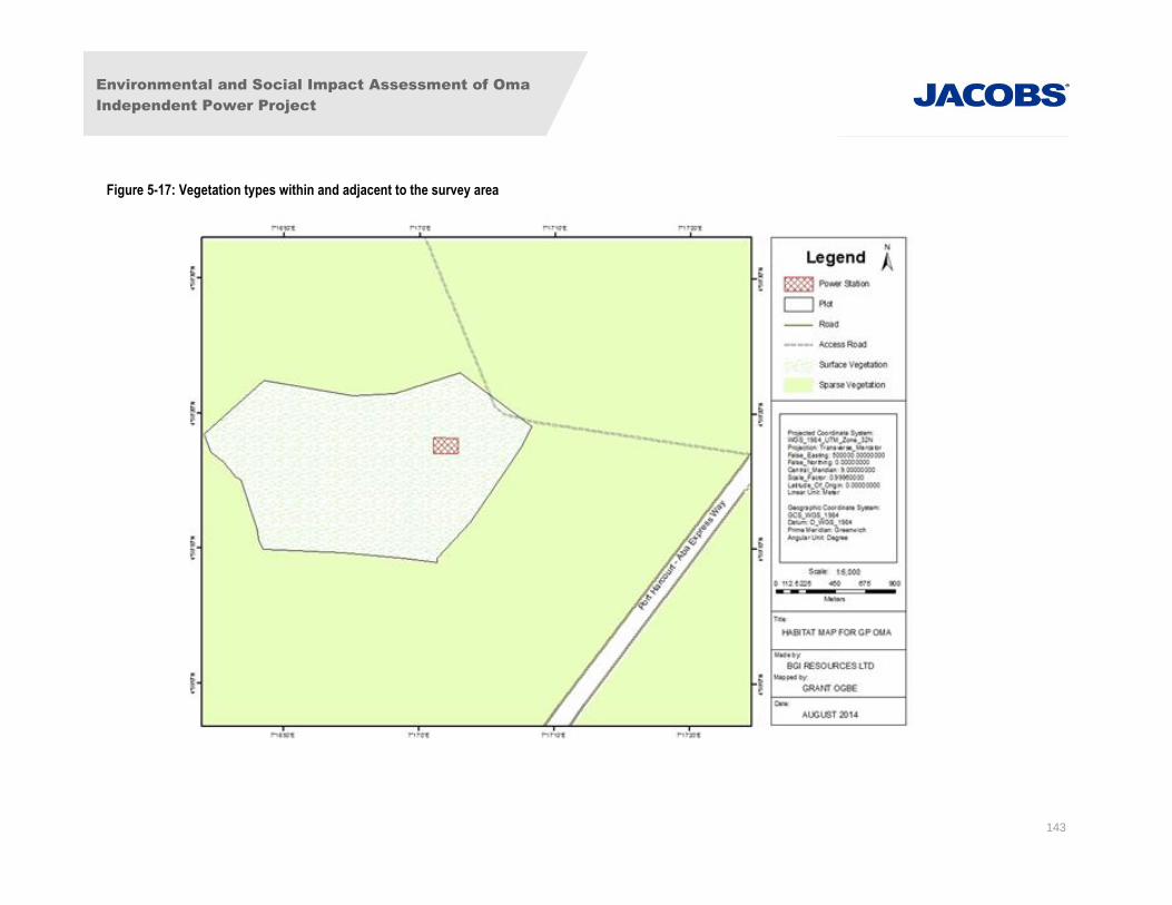
Environmental and Social Impact Assessment of Oma
Independent Power Project
143
Figure 5-17: Vegetation types within and adjacent to the survey area
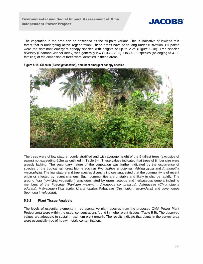
Environmental and Social Impact Assessment of Oma
Independent Power Project
144
The vegetation in the area can be described as the oil palm variant. This is indicative of lowland rain
forest that is undergoing active regeneration. These areas have been long under cultivation. Oil palms
were the dominant emergent canopy species with heights of up to 25m (Figure 5-18). Tree species
diversity (Shannon-Wiener index) was generally low (1.36 – 2.06). Only 5 - 9 species (belonging to 4 - 6
families) of the dimension of trees were identified in these areas.
Figure 5-18: Oil palm (Elaeis guineensis), dominant emergent canopy species
The trees were of low stature, poorly stratified and with average height of the 5 tallest trees (exclusive of
palms) not exceeding 6.2m as outlined in Table 5-4. These values indicated that trees of timber size were
grossly lacking. The secondary nature of the vegetation was further indicated by the occurrence of
species of the tropical rainforest biome such as Pycnanthus angolensis, Albizia zygia and Anthonotha
macrophylla. The low stature and tree species diversity indices suggested that the community is of recent
origin or affected by recent changes. Such communities are unstable and likely to change rapidly. The
ground flora (low-lying vegetation) was dominated by graminaceous and herbaceous genera including
members of the Poaceae (Panicum maximum, Axonopus compressus), Asteraceae (Chromolaena
odorata), Malvaceae (Sida acuta, Urena lobata), Fabaceae (Desmodium ascendens) and cover crops
(Ipomoea involucrata).
5.9.2 Plant Tissue Analysis
The levels of essential elements in representative plant species from the proposed OMA Power Plant
Project area were within the usual concentrations found in higher plant tissues (Table 5-5). The observed
values are adequate to sustain maximum plant growth. The results indicate that plants in the survey area
were essentially free of heavy metals contamination.
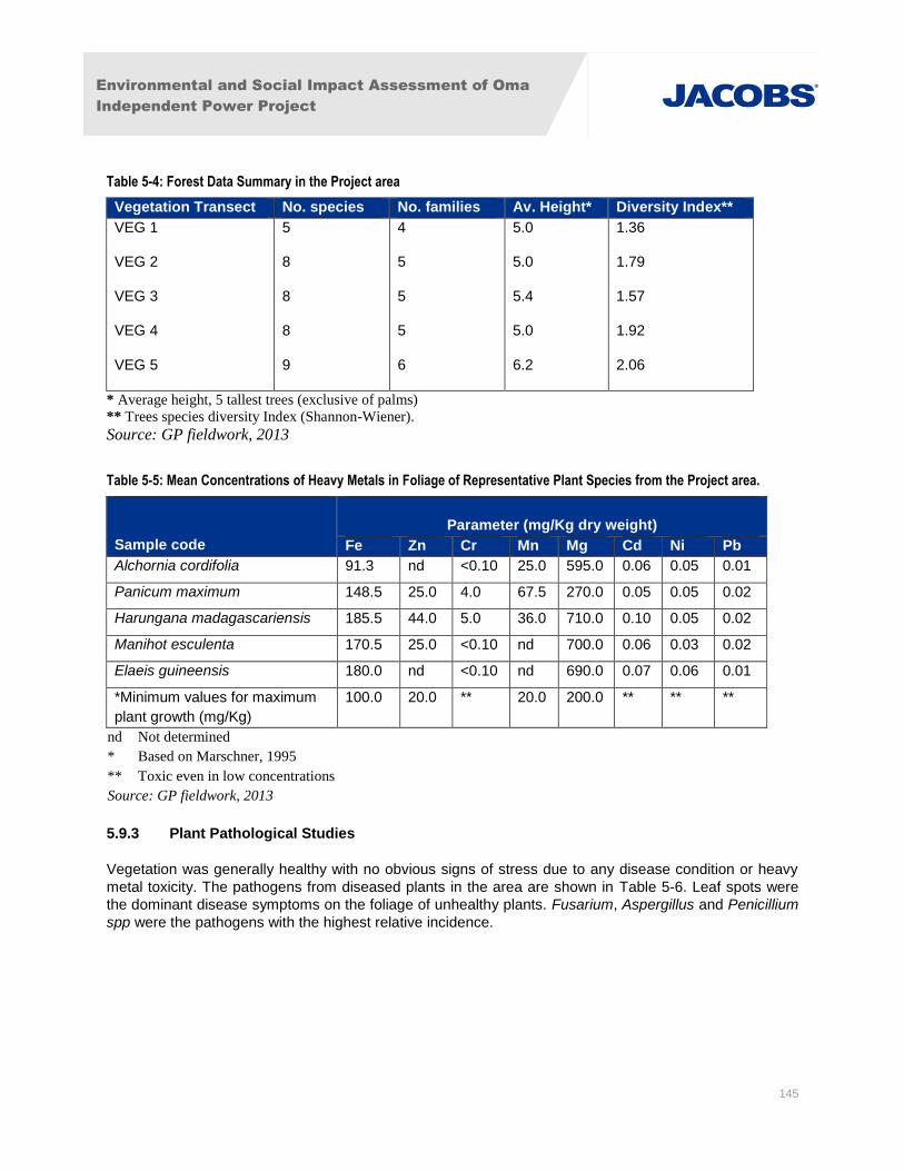
Environmental and Social Impact Assessment of Oma
Independent Power Project
145
Table 5-4: Forest Data Summary in the Project area
Vegetation Transect No. species No. families Av. Height* Diversity Index**
VEG 1
VEG 2
VEG 3
VEG 4
VEG 5
5
8
8
8
9
4
5
5
5
6
5.0
5.0
5.4
5.0
6.2
1.36
1.79
1.57
1.92
2.06
* Average height, 5 tallest trees (exclusive of palms)
** Trees species diversity Index (Shannon-Wiener).
Source: GP fieldwork, 2013
Table 5-5: Mean Concentrations of Heavy Metals in Foliage of Representative Plant Species from the Project area.
Sample code
Parameter (mg/Kg dry weight)
Fe Zn Cr Mn Mg Cd Ni Pb
Alchornia cordifolia 91.3 nd <0.10 25.0 595.0 0.06 0.05 0.01
Panicum maximum 148.5 25.0 4.0 67.5 270.0 0.05 0.05 0.02
Harungana madagascariensis 185.5 44.0 5.0 36.0 710.0 0.10 0.05 0.02
Manihot esculenta 170.5 25.0 <0.10 nd 700.0 0.06 0.03 0.02
Elaeis guineensis 180.0 nd <0.10 nd 690.0 0.07 0.06 0.01
*Minimum values for maximum
plant growth (mg/Kg)
100.0 20.0 ** 20.0 200.0 ** ** **
nd Not determined
* Based on Marschner, 1995
** Toxic even in low concentrations
Source: GP fieldwork, 2013
5.9.3 Plant Pathological Studies
Vegetation was generally healthy with no obvious signs of stress due to any disease condition or heavy
metal toxicity. The pathogens from diseased plants in the area are shown in Table 5-6. Leaf spots were
the dominant disease symptoms on the foliage of unhealthy plants. Fusarium, Aspergillus and Penicillium
spp were the pathogens with the highest relative incidence.
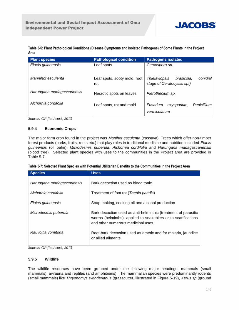
Environmental and Social Impact Assessment of Oma
Independent Power Project
146
Table 5-6: Plant Pathological Conditions (Disease Symptoms and Isolated Pathogens) of Some Plants in the Project
Area
Plant species Pathological condition Pathogens isolated
Elaeis guineensis
Mannihot esculenta
Harungana madagascariensis
Alchornia cordifolia
Leaf spots
Leaf spots, sooty mold, root
rot
Necrotic spots on leaves
Leaf spots, rot and mold
Cercospora sp.
Thielaviopsis brasicola, conidial
stage of Ceratocystis sp.)
Plerothecium sp.
Fusarium oxysporium, Penicillium
vermiculatum
Source: GP fieldwork, 2013
5.9.4 Economic Crops
The major farm crop found in the project was Manihot esculenta (cassava). Trees which offer non-timber
forest products (barks, fruits, roots etc.) that play roles in traditional medicine and nutrition included Elaeis
guineensis (oil palm), Microdesmis puberula, Alchornia cordifolia and Harungana madagascariensis
(blood tree). Selected plant species with uses to the communities in the Project area are provided in
Table 5-7.
Table 5-7: Selected Plant Species with Potential Utilitarian Benefits to the Communities in the Project Area
Species Uses
Harungana madagascariensis
Alchornia cordifolia
Elaies guineensis
Microdesmis puberula
Rauvolfia vomitoria
Bark decoction used as blood tonic.
Treatment of foot rot (Taenia paedis)
Soap making, cooking oil and alcohol production
Bark decoction used as anti-helminthic (treatment of parasitic
worms (helminths), applied to snakebites or to scarifications
and other numerous medicinal uses.
Root-bark decoction used as emetic and for malaria, jaundice
or allied ailments.
Source: GP fieldwork, 2013
5.9.5 Wildlife
The wildlife resources have been grouped under the following major headings: mammals (small
mammals), avifauna and reptiles (and amphibians). The mammalian species were predominantly rodents
(small mammals) like Thryonomys swinderianus (grasscutter, illustrated in Figure 5-19), Xerus sp (ground
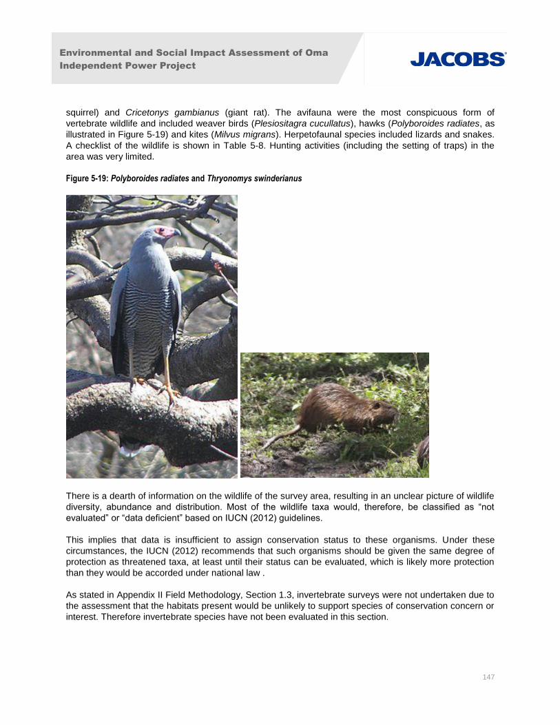
Environmental and Social Impact Assessment of Oma
Independent Power Project
147
squirrel) and Cricetonys gambianus (giant rat). The avifauna were the most conspicuous form of
vertebrate wildlife and included weaver birds (Plesiositagra cucullatus), hawks (Polyboroides radiates, as
illustrated in Figure 5-19) and kites (Milvus migrans). Herpetofaunal species included lizards and snakes.
A checklist of the wildlife is shown in Table 5-8. Hunting activities (including the setting of traps) in the
area was very limited.
Figure 5-19: Polyboroides radiates and Thryonomys swinderianus
There is a dearth of information on the wildlife of the survey area, resulting in an unclear picture of wildlife
diversity, abundance and distribution. Most of the wildlife taxa would, therefore, be classified as “not
evaluated” or “data deficient” based on IUCN (2012) guidelines.
This implies that data is insufficient to assign conservation status to these organisms. Under these
circumstances, the IUCN (2012) recommends that such organisms should be given the same degree of
protection as threatened taxa, at least until their status can be evaluated, which is likely more protection
than they would be accorded under national law .
As stated in Appendix II Field Methodology, Section 1.3, invertebrate surveys were not undertaken due to
the assessment that the habitats present would be unlikely to support species of conservation concern or
interest. Therefore invertebrate species have not been evaluated in this section.
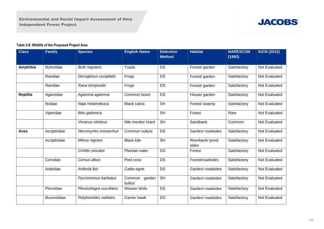
Environmental and Social Impact Assessment of Oma
Independent Power Project
148
Table 5-8: Wildlife of the Proposed Project Area
Class Family Species English Name
Detection
Method
Habitat NARESCON
(1992)
IUCN (2012)
Amphibia Bufonidae Bufo regularis Toads DS Forest/ garden Satisfactory Not Evaluated
Ranidae Dicroglosus occipitalis Frogs DS Forest/ garden Satisfactory Not Evaluated
Ranidae Rana temporalis Frogs DS Forest/ garden Satisfactory Not Evaluated
Reptilia Agamidae Agamma agamma Common lizard DS House/ garden Satisfactory Not Evaluated
Boidae Naja melanoleuca Black cobra SH Forest/ swamp Satisfactory Not Evaluated
Viperidae Bitis gabonica SH Forest Rare Not Evaluated
Veranus niloticus Nile monitor lizard SH Sandbank Common Not Evaluated
Aves Accipitridae Necrosyrtes monarchus Common vulture DS Garden/ roadsides Satisfactory Not Evaluated
Accipitridae Milvus nigrans Black kite SH Riverbank/ pond-
sides
Satisfactory Not Evaluated
Crinifer piscator Plantain eater DS Forest Satisfactory Not Evaluated
Corvidae Corvus albus Pied crow DS Forest/roadsides Satisfactory Not Evaluated
Ardeidae Ardeola ibis Cattle egret DS Garden/ roadsides Satisfactory Not Evaluated
Pycnomonus barbatus Common garden
bulbul
SH Garden/ roadsides Satisfactory Not Evaluated
Ploceidae Plesiositagra cucullatus Weaver birds DS Garden/ roadsides Satisfactory Not Evaluated
Bucerotidae Polyboroides radiates Carrier hawk DS Garden/ roadsides Satisfactory Not Evaluated
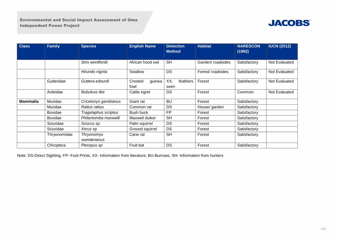
Environmental and Social Impact Assessment of Oma
Independent Power Project
149
Class Family Species English Name
Detection
Method
Habitat NARESCON
(1992)
IUCN (2012)
Strix wordfordii African hood owl SH Garden/ roadsides Satisfactory Not Evaluated
Hirundo nigrita Swallow DS Forest/ roadsides Satisfactory Not Evaluated
Gutteridae Guttera edourdi Crested guinea
fowl
XX; feathers
seen
Forest Satisfactory Not Evaluated
Ardeidae Bubulcus ibis Cattle egret DS Forest Common Not Evaluated
Mammalia Muridae Cricetonys gambianus Giant rat BU Forest Satisfactory
Muridae Rattus rattus Common rat DS House/ garden Satisfactory
Bovidae Tragelaphus scriptus Bush buck FP Forest Satisfactory
Bovidae Philantomba maxwelli Maxwell duiker SH Forest Satisfactory
Sciuridae Sciurus sp Palm squirrel DS Forest Satisfactory
Sciuridae Xerus sp Ground squirrel DS Forest Satisfactory
Thryonomidae Thryonomys
swinderianus
Cane rat SH Forest Satisfactory
Chiroptera Pteropus sp Fruit bat DS Forest Satisfactory
Note: DS-Direct Sighting, FP- Foot Prints, XX- Information from literature, BU-Burrows, SH- Information from hunters
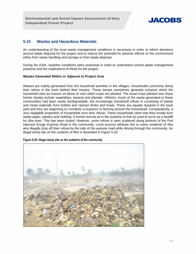
Environmental and Social Impact Assessment of Oma
Independent Power Project
150
5.10 Wastes and Hazardous Materials
An understanding of the local waste management conditions is necessary in order to inform decisions
around waste disposal for the project and to reduce the potential for adverse effects on the environment
either from waste handling and storage or from waste disposal.
During the ESIA, baseline conditions were examined in order to understand current waste management
practices and the implications of these for the project.
Wastes Generated Within or Adjacent to Project Area
Wastes are mainly generated from the household activities in the villages. Households commonly dump
their refuse in the bush behind their houses. These dumps sometimes generate compost which the
household uses as manure on farms or over which crops are planted. The usual crops planted over these
former dumps include vegetables, banana and plantain. Hitherto, much of the waste generated in these
communities had been easily biodegradable, but increasingly household refuse is consisting of plastic
and metal materials from bottled and canned drinks and foods. These are equally dumped in the back
yard and they are beginning to constitute a nuisance to farming around the homestead. Comparatively, a
very negligible proportion of households burn their refuse. These households claim that they mostly burn
waste paper, plastics and clothing. A former borrow pit in the outskirts of Ihie-Iyi used to serve as a landfill
for Aba town. This has been closed. However, some refuse is seen scattered along portions of the Port
Harcourt Enugu Express Road in the community. Local sources attribute this to some residents of Aba
who illegally drop off their refuse by the side of the express road while driving through the community. An
illegal dump site on the outskirts of Ilhie is illustrated in Figure 5-20.
Figure 5-20: Illegal dump site on the outskirts of the community
Environmental and Social Impact Assessment of Oma
Independent Power Project
151
The use of water closet type of toilet is not common among households. Most households use pit toilets.
Many of these are covered pit toilets. A few households across the study area indicated their members
defecated in the bushes. This was not for lack of a toilet at home but apparently, some farmers were in
the habit of mostly defecating when they were at work in their farms and doing so in the bushes around
their farms.
The most commonly used household refuse and sewage disposal methods could be considered generally
safe for now. The methods are not modern but they are generally effective in consigning household
waste. It is noteworthy, however, that with increasing population and urbanization these methods will
become obsolete and unhygienic.
Solid Waste Management
The wastes generated in the communities were mainly garbage and other domestic wastes. In Ihie Ukwu,
wastes were dumped in farm, while tenants dump on any available space in the community. Ogwe
community seems to have a more defined way of disposing domestic refuse, which is mandatorily down
in the farmland. Ihie Ukwu and Ogwe communities do not enjoy municipal solid waste disposal services,
such that wastes were often dumped indiscriminately especially in Ihie Ukwu. Leaching from the wastes
can be a source of contamination of the groundwater, especially as electronics are sometimes part of the
wastes. Electronics have been shown to be capable of contributing as much 50% – 80% of the heavy
metals leaches from a dump site. (Chiodo et al 2002).
It was obvious during the field survey that members of the community made some effort to ensure the
safe management of wastes, but the widespread complaints of vector and rat infestations in the
community seem to suggest that these efforts are not sufficiently effective.
Environmental and Social Impact Assessment of Oma
Independent Power Project
152
6. Socio - Economic Baseline
6.1 Introduction
This section describes the social and economic characteristics of the communities surrounding the project
in order to measure the influence of the project on these factors. The socio-economic baseline presented
originated from a combination of a desktop study of published sources, a household survey, targeted
interviews with community leaders, and focus group discussions. Secondary data was obtained from
public agencies such as the National Population Commission (NPC) and the National Bureau of Statistics
(NBS). The scope of the socio-economic studies is provided in Appendix IV.
6.1.1 Socio-economic Structure of Nigeria and the Abia State
The Federal Republic of Nigeria covers an area of 923,768 km2 with a population of over 140 million.
Primary traditional agriculture remains the dominant economic activity of the nation, accounting for about
40.0% of GDP and more than 60.0% of total employment5. The proposed project is located in the Abia
State, which is one of five states in the south eastern geopolitical zone of Nigeria. The southern section of
the State lies within the riverine part of Nigeria. It is generally low-lying, characterized by heavy rainfall.
Abia State is mainly an agricultural state, but is also engaged in crude oil and gas production.
There are seventeen local government areas (LGAs) in the state. Each local government is headed by a
democratically-elected Chairman working with an elected council. The closest major urban area to the
project site is one of the biggest in the state known as Aba, a major commercial centre. Presently, the
project area is largely inhabited by Igbo people, one of the three largest ethnic groups in Niger and they
speak Igbo, with some dialectical variation6.
The affected communities fall within two local government areas (LGA) jurisdiction, namely Ukwa West
and Ugwunagbo. Ukwa West has its government headquarters at Oke Ikpe and has an area of 271km2
and a population of 88,555 at the 2006 census with a total land mass of 105sq miles. The local
government (Ukwa West) is the only major crude oil producing area in Abia State, but some of its
communities and wards are lacking in some basic amenities, such as good roads, and electricity.
Ugwunagbo as a local government has its headquarters in the town of Ugwunagbo. It has an area of
108km2 and a population of 97,710 according to the 2006 estimated census. Ugwunagbo is primarily a
farming community.
6.1.2 Project Area of Influence
Settlements/communities of primary interest were selected for the socio-economic study based on a 5km
radius around the proposed project site. Obehie, Orgwu (Ogwe), Ihie-Iyi, Obiga, Ngwaiyiekwe,
Obuzongwa, Owo-ala, and Umuaka by their local names are the identified communities within the 5km
radius to the proposed OMA power plant project and each of these communities was surveyed using a
targeted questionnaire. Figure 6-1 illustrates the local geography and settlement areas within the Project
Area of Influence. The sample population size that was targeted in each community generally correlated
to the size of the community, i.e. more surveys and focus groups were conducted in the more populous
areas.
5 Nigeria Millennium Development Goals Report, UNDP 2013. 6 Ijezie, Innocent, et al., Socioeconomic status and obesity in Abia State, South East Nigeria, Dovepress Journal, 15 October 2013.
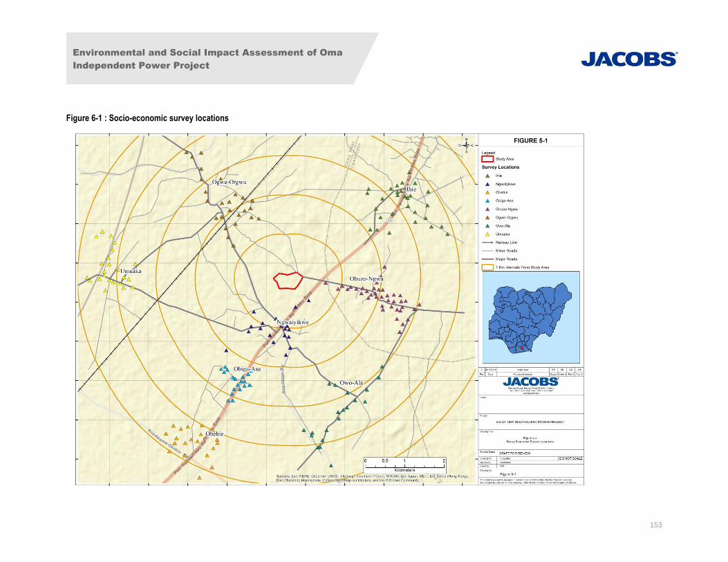
Environmental and Social Impact Assessment of Oma
Independent Power Project
153
Figure 6-1 : Socio-economic survey locations
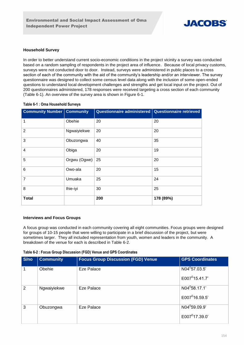
Environmental and Social Impact Assessment of Oma
Independent Power Project
154
Household Survey
In order to better understand current socio-economic conditions in the project vicinity a survey was conducted
based on a random sampling of respondents in the project area of influence. Because of local privacy customs,
surveys were not conducted door to door. Instead, surveys were administered in public places to a cross
section of each of the community with the aid of the community’s leadership and/or an interviewer. The survey
questionnaire was designed to collect some census level data along with the inclusion of some open-ended
questions to understand local development challenges and strengths and get local input on the project. Out of
200 questionnaires administered, 178 responses were received targeting a cross section of each community
(Table 6-1). An overview of the survey area is shown in Figure 6-1.
Table 6-1 : Oma Household Surveys
Interviews and Focus Groups
A focus group was conducted in each community covering all eight communities. Focus groups were designed
for groups of 10-15 people that were willing to participate in a brief discussion of the project, but were
sometimes larger. They all included representation from youth, women and leaders in the community. A
breakdown of the venue for each is described in Table 6-2.
Table 6-2 : Focus Group Discussion (FGD) Venue and GPS Coordinates
Community Number Community Questionnaire administered Questionnaire retrieved
1 Obehie 20 20
2 Ngwaiyiekwe 20 20
3 Obuzongwa 40 35
4 Obiga 20 19
5 Orgwu (Ogwe) 25 20
6 Owo-ala 20 15
7 Umuaka 25 24
8 Ihie-iyi 30 25
Total 200 178 (89%)
S/no Community Focus Group Discussion (FGD) Venue GPS Coordinates
1 Obehie Eze Palace N04057.03.5’
E007015.41.7’
2 Ngwaiyiekwe Eze Palace N04058.17.1’
E007016.59.5’
3 Obuzongwa Eze Palace N04059.09.9’
E007017.39.0’
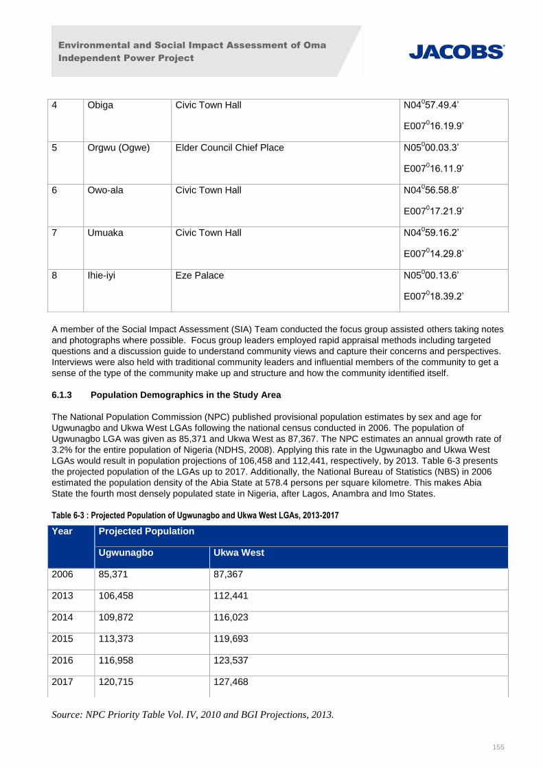
Environmental and Social Impact Assessment of Oma
Independent Power Project
155
A member of the Social Impact Assessment (SIA) Team conducted the focus group assisted others taking notes
and photographs where possible. Focus group leaders employed rapid appraisal methods including targeted
questions and a discussion guide to understand community views and capture their concerns and perspectives.
Interviews were also held with traditional community leaders and influential members of the community to get a
sense of the type of the community make up and structure and how the community identified itself.
6.1.3 Population Demographics in the Study Area
The National Population Commission (NPC) published provisional population estimates by sex and age for
Ugwunagbo and Ukwa West LGAs following the national census conducted in 2006. The population of
Ugwunagbo LGA was given as 85,371 and Ukwa West as 87,367. The NPC estimates an annual growth rate of
3.2% for the entire population of Nigeria (NDHS, 2008). Applying this rate in the Ugwunagbo and Ukwa West
LGAs would result in population projections of 106,458 and 112,441, respectively, by 2013. Table 6-3 presents
the projected population of the LGAs up to 2017. Additionally, the National Bureau of Statistics (NBS) in 2006
estimated the population density of the Abia State at 578.4 persons per square kilometre. This makes Abia
State the fourth most densely populated state in Nigeria, after Lagos, Anambra and Imo States.
Table 6-3 : Projected Population of Ugwunagbo and Ukwa West LGAs, 2013-2017
Source: NPC Priority Table Vol. IV, 2010 and BGI Projections, 2013.
4 Obiga Civic Town Hall N04057.49.4’
E007016.19.9’
5 Orgwu (Ogwe) Elder Council Chief Place N05000.03.3’
E007016.11.9’
6 Owo-ala Civic Town Hall N04056.58.8’
E007017.21.9’
7 Umuaka Civic Town Hall N04059.16.2’
E007014.29.8’
8 Ihie-iyi Eze Palace N05000.13.6’
E007018.39.2’
Year Projected Population
Ugwunagbo Ukwa West
2006 85,371 87,367
2013 106,458 112,441
2014 109,872 116,023
2015 113,373 119,693
2016 116,958 123,537
2017 120,715 127,468

Environmental and Social Impact Assessment of Oma
Independent Power Project
156
Based on interviews with community leaders, estimated population in the Project Area of Influence consists of
approximately: Obehie 5,000; Ngwaiyiekwe 4,500; Obuzongwa 2,000; Obiga 3000; Ogwe (Orgwu) 2,000; Owo-
ala 1,500; Umuaka 3,500; and Ihie-Iyi 6,000. It is difficult to verify the accuracy of these figures as individual
community population figures are not yet publicly available. However, it gives an indication of community size
relative to each other.
Photographs of communities are provided where available, Figure 6-2 to Figure 6-5.
Obehie Community
Obehie is located between 4-5 km southwest of the project site more developed communities surrounding the
site including medium density housing and development. The population of Obehie largely migrated from Ngwa
to the north moving to the area in search of a favourable place to settle. Asannetu (Nzu) founded Obehie
community upon discovering a pond in the area and the original inhabitants were from his family. Obehie is
made up of three (3) villages, namely Umuokomiri, Umuoyeke, and Umuala and is largely rural. The community
is divided by the expressway.
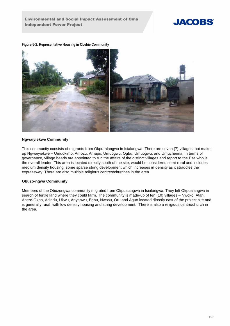
Environmental and Social Impact Assessment of Oma
Independent Power Project
157
Figure 6-2: Representative Housing in Obehie Community
Ngwaiyiekwe Community
This community consists of migrants from Okpu-alangwa in Isialangwa. There are seven (7) villages that make-
up Ngwaiyiekwe – Umuokimo, Amozu, Amapu, Umuogwu, Ogbu, Umuogwu, and Umuchenna. In terms of
governance, village heads are appointed to run the affairs of the distinct villages and report to the Eze who is
the overall leader. This area is located directly south of the site, would be considered semi-rural and includes
medium density housing, some sparse string development which increases in density as it straddles the
expressway. There are also multiple religious centres/churches in the area.
Obuzo-ngwa Community
Members of the Obuzongwa community migrated from Okpualangwa in Isialangwa. They left Okpualangwa in
search of fertile land where they could farm. The community is made-up of ten (10) villages – Nwoko, Atah,
Anere-Okpo, Adindu, Ukwu, Anyanwu, Egbu, Nwosu, Oru and Aguo located directly east of the project site and
is generally rural with low density housing and string development. There is also a religious centre/church in
the area.
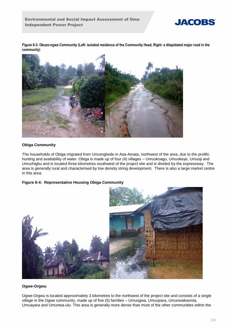
Environmental and Social Impact Assessment of Oma
Independent Power Project
158
Figure 6-3: Obuzo-ngwa Community (Left: isolated residence of the Community Head, Right: a dilapidated major road in the
community)
Obiga Community
The households of Obiga migrated from Umumgbede in Asa-Amata, northwest of the area, due to the prolific
hunting and availability of water. Obiga is made up of four (4) villages – Umuokoagu, Umuokeye, Umuoji and
Umuchigbu and is located three kilometres southwest of the project site and is divided by the expressway. The
area is generally rural and characterised by low density string development. There is also a large market centre
in this area.
Figure 6-4: Representative Housing Obiga Community
Ogwe-Orgwu
Ogwe-Orgwu is located approximately 3 kilometres to the northwest of the project site and consists of a single
village in the Ogwe community, made up of five (5) families – Umuogwa, Umuopara, Umunwakwonta,
Umuayara and Umunwa-ulu. This area is generally more dense than most of the other communities within the
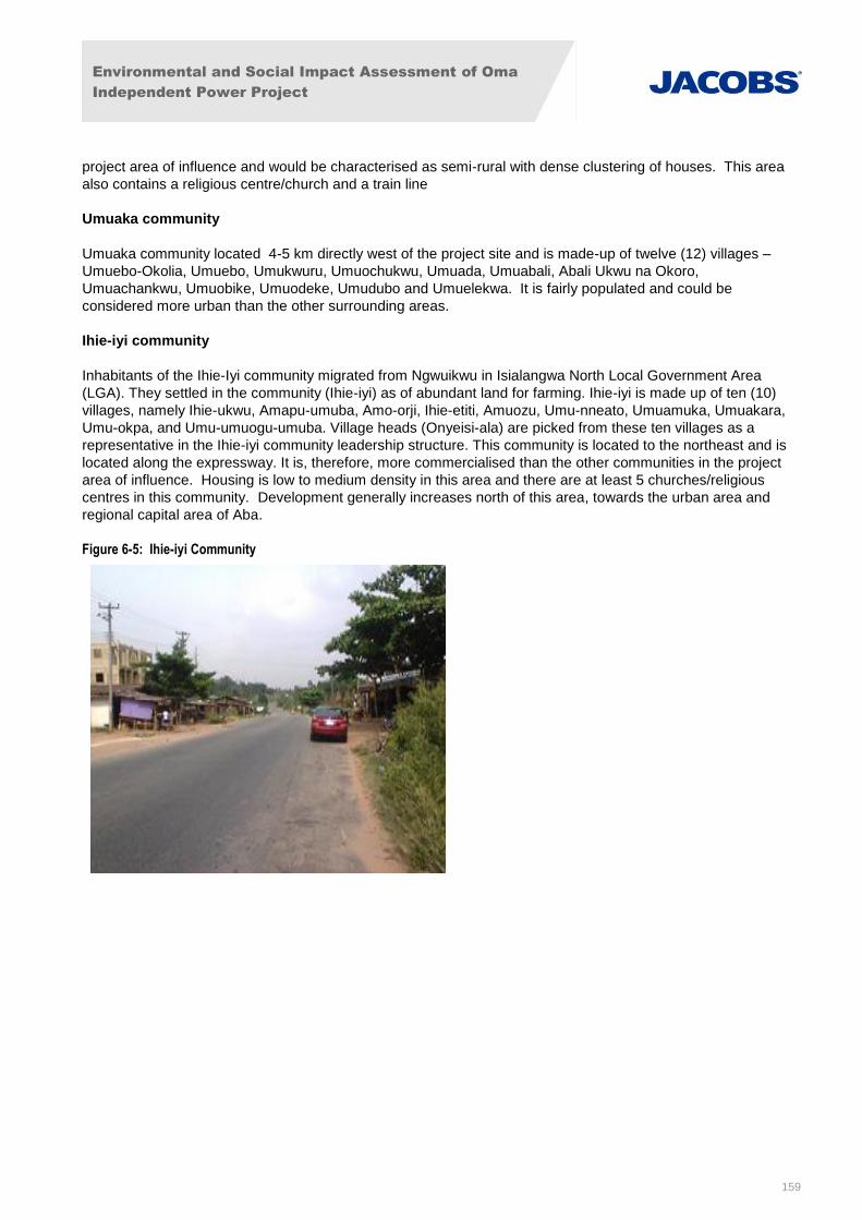
Environmental and Social Impact Assessment of Oma
Independent Power Project
159
project area of influence and would be characterised as semi-rural with dense clustering of houses. This area
also contains a religious centre/church and a train line
Umuaka community
Umuaka community located 4-5 km directly west of the project site and is made-up of twelve (12) villages –
Umuebo-Okolia, Umuebo, Umukwuru, Umuochukwu, Umuada, Umuabali, Abali Ukwu na Okoro,
Umuachankwu, Umuobike, Umuodeke, Umudubo and Umuelekwa. It is fairly populated and could be
considered more urban than the other surrounding areas.
Ihie-iyi community
Inhabitants of the Ihie-Iyi community migrated from Ngwuikwu in Isialangwa North Local Government Area
(LGA). They settled in the community (Ihie-iyi) as of abundant land for farming. Ihie-iyi is made up of ten (10)
villages, namely Ihie-ukwu, Amapu-umuba, Amo-orji, Ihie-etiti, Amuozu, Umu-nneato, Umuamuka, Umuakara,
Umu-okpa, and Umu-umuogu-umuba. Village heads (Onyeisi-ala) are picked from these ten villages as a
representative in the Ihie-iyi community leadership structure. This community is located to the northeast and is
located along the expressway. It is, therefore, more commercialised than the other communities in the project
area of influence. Housing is low to medium density in this area and there are at least 5 churches/religious
centres in this community. Development generally increases north of this area, towards the urban area and
regional capital area of Aba.
Figure 6-5: Ihie-iyi Community
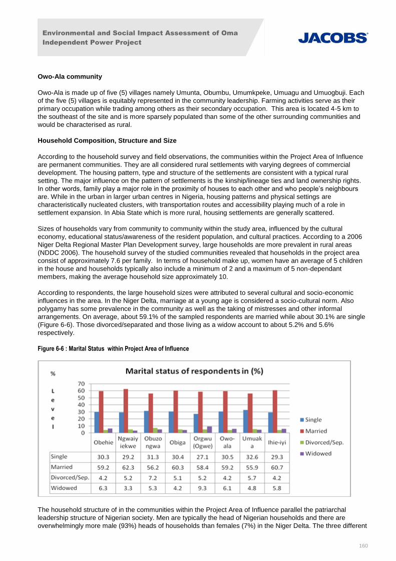
Environmental and Social Impact Assessment of Oma
Independent Power Project
160
Owo-Ala community
Owo-Ala is made up of five (5) villages namely Umunta, Obumbu, Umumkpeke, Umuagu and Umuogbuji. Each
of the five (5) villages is equitably represented in the community leadership. Farming activities serve as their
primary occupation while trading among others as their secondary occupation. This area is located 4-5 km to
the southeast of the site and is more sparsely populated than some of the other surrounding communities and
would be characterised as rural.
Household Composition, Structure and Size
According to the household survey and field observations, the communities within the Project Area of Influence
are permanent communities. They are all considered rural settlements with varying degrees of commercial
development. The housing pattern, type and structure of the settlements are consistent with a typical rural
setting. The major influence on the pattern of settlements is the kinship/lineage ties and land ownership rights.
In other words, family play a major role in the proximity of houses to each other and who people’s neighbours
are. While in the urban in larger urban centres in Nigeria, housing patterns and physical settings are
characteristically nucleated clusters, with transportation routes and accessibility playing much of a role in
settlement expansion. In Abia State which is more rural, housing settlements are generally scattered.
Sizes of households vary from community to community within the study area, influenced by the cultural
economy, educational status/awareness of the resident population, and cultural practices. According to a 2006
Niger Delta Regional Master Plan Development survey, large households are more prevalent in rural areas
(NDDC 2006). The household survey of the studied communities revealed that households in the project area
consist of approximately 7.6 per family. In terms of household make up, women have an average of 5 children
in the house and households typically also include a minimum of 2 and a maximum of 5 non-dependant
members, making the average household size approximately 10.
According to respondents, the large household sizes were attributed to several cultural and socio-economic
influences in the area. In the Niger Delta, marriage at a young age is considered a socio-cultural norm. Also
polygamy has some prevalence in the community as well as the taking of mistresses and other informal
arrangements. On average, about 59.1% of the sampled respondents are married while about 30.1% are single
(Figure 6-6). Those divorced/separated and those living as a widow account to about 5.2% and 5.6%
respectively.
Figure 6-6 : Marital Status within Project Area of Influence
The household structure of in the communities within the Project Area of Influence parallel the patriarchal
leadership structure of Nigerian society. Men are typically the head of Nigerian households and there are
overwhelmingly more male (93%) heads of households than females (7%) in the Niger Delta. The three different
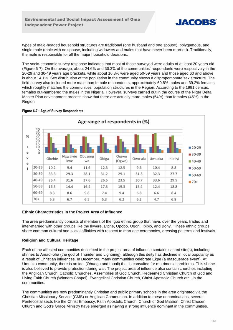
Environmental and Social Impact Assessment of Oma
Independent Power Project
161
types of male-headed household structures are traditional (one husband and one spouse), polygamous, and
single male (male with no spouse, including widowers and males that have never been married). Traditionally,
the male is responsible for all the major household decisions.
The socio-economic survey response indicates that most of those surveyed were adults of at least 20 years old
(Figure 6-7). On the average, about 24.6% and 30.3% of the communities’ respondents were respectively in the
20-29 and 30-49 years age brackets, while about 16.3% were aged 50-59 years and those aged 60 and above
is about 14.1%. Sex distribution of the population in the community shows a disproportionate sex structure. The
field survey also included more male than female respondents, approximately 60.8% males and 39.2% females,
which roughly matches the communities’ population structures in the Region. According to the 1991 census,
females out-numbered the males in the Nigeria. However, surveys carried out in the course of the Niger Delta
Master Plan development process show that there are actually more males (54%) than females (46%) in the
Region.
Figure 6-7 : Age of Survey Respondents
Ethnic Characteristics in the Project Area of Influence
The area predominantly consists of members of the Igbo ethnic group that have, over the years, traded and
inter-married with other groups like the Ikwere, Etche, Opobo, Ogoni, Ibibio, and Bony. These ethnic groups
share common cultural and social affinities with respect to marriage ceremonies, dressing patterns and festivals.
Religion and Cultural Heritage
Each of the affected communities described in the project area of influence contains sacred site(s), including
shrines to Amadi-oha (the god of Thunder and Lightning), although this deity has declined in local popularity as
a result of Christian influences. In December, many communities celebrate Ekpe (a masquerade event). At
Umuaka community, there is an idol (Ohuogu and Ihuali) that is consulted for matrimonial problems. This shrine
is also believed to provide protection during war. The project area of influence also contain churches including
the Anglican Church, Catholic Churches, Assemblies of God Church, Redeemed Christian Church of God and
Living Faith Church (Winners Chapel), Evangelical Christian Church, Christ Apostolic Church etc., in the
communities.
The communities are now predominantly Christian and public primary schools in the area originated via the
Christian Missionary Service (CMS) or Anglican Communion. In addition to these denominations, several
Pentecostal sects like the Christ Embassy, Faith Apostolic Church, Church of God Mission, Christ Chosen
Church and God’s Grace Ministry have emerged as having a strong influence dominant in the communities.
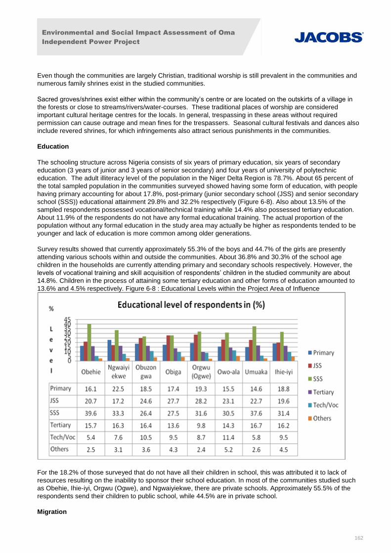
Environmental and Social Impact Assessment of Oma
Independent Power Project
162
Even though the communities are largely Christian, traditional worship is still prevalent in the communities and
numerous family shrines exist in the studied communities.
Sacred groves/shrines exist either within the community’s centre or are located on the outskirts of a village in
the forests or close to streams/rivers/water-courses. These traditional places of worship are considered
important cultural heritage centres for the locals. In general, trespassing in these areas without required
permission can cause outrage and mean fines for the trespassers. Seasonal cultural festivals and dances also
include revered shrines, for which infringements also attract serious punishments in the communities.
Education
The schooling structure across Nigeria consists of six years of primary education, six years of secondary
education (3 years of junior and 3 years of senior secondary) and four years of university of polytechnic
education. The adult illiteracy level of the population in the Niger Delta Region is 78.7%. About 65 percent of
the total sampled population in the communities surveyed showed having some form of education, with people
having primary accounting for about 17.8%, post-primary (junior secondary school (JSS) and senior secondary
school (SSS)) educational attainment 29.8% and 32.2% respectively (Figure 6-8). Also about 13.5% of the
sampled respondents possessed vocational/technical training while 14.4% also possessed tertiary education.
About 11.9% of the respondents do not have any formal educational training. The actual proportion of the
population without any formal education in the study area may actually be higher as respondents tended to be
younger and lack of education is more common among older generations.
Survey results showed that currently approximately 55.3% of the boys and 44.7% of the girls are presently
attending various schools within and outside the communities. About 36.8% and 30.3% of the school age
children in the households are currently attending primary and secondary schools respectively. However, the
levels of vocational training and skill acquisition of respondents’ children in the studied community are about
14.8%. Children in the process of attaining some tertiary education and other forms of education amounted to
13.6% and 4.5% respectively. Figure 6-8 : Educational Levels within the Project Area of Influence
For the 18.2% of those surveyed that do not have all their children in school, this was attributed it to lack of
resources resulting on the inability to sponsor their school education. In most of the communities studied such
as Obehie, Ihie-iyi, Orgwu (Ogwe), and Ngwaiyiekwe, there are private schools. Approximately 55.5% of the
respondents send their children to public school, while 44.5% are in private school.
Migration

Environmental and Social Impact Assessment of Oma
Independent Power Project
163
According to regional data, the majority, approximately 65-70% of the population, in the study area LGAs are
considered non-migrants. According to the household survey conducted, the majority in the study area have
spent a greater part of their life in the communities. Results showed that approximately 75.4% of the
respondents in the surveyed community on the average have lived in the communities their whole lives since
birth without migrating. Approximately 5.7% have spent over 20 years in the communities and migrated there.
Approximately 9.5% migrated into the community within the last 11-20 years, and 9.4 migrated into the
communities within the last 10 years.
Most of the respondents are considered mainly ‘natives’ of the communities and out migration is very
uncommon with the exception of for temporary periods for work.
6.1.4 Local Ethnic and Vulnerable Groups
There are a wide variety of ethnicities in Nigeria however, based on the findings of the socio-economic survey
completed for the Project, there are no local ethnic or vulnerable groups living within or directly adjacent to the
Project site. There are other vulnerable groups that were identified within the LGAs and larger project region by
the survey respondents and focus groups such as disabled people and marginalised, but according to the
findings these groups were not detected within the study area of influence. Therefore, issues associated with
impacts to Indigenous Peoples from the project are not considered further in this assessment.
6.1.5 Economic Profile
According to survey responses and focus group discussions, the inhabitants of the surveyed communities are
predominantly farmers. The principal crops planted are yam, plantain, cassava, oil palm plantation, cocoyam,
banana, maize, melon, pepper and vegetables. As illustrated in Figure 6-9, survey results showed that farming,
fishing and trading account for about 49.8% of the primary occupation of the people, with fishing being a very
small contribution of 2.4% of the population. Approximately 9.8% of the population engages in technical/artisan
jobs.
Figure 6-9 : Occupations within the Project Area of Influence
Other economic activities include business/contracting consisting of 6.8% and unemployment which constitute
12.6%. About 21% of the sampled population are civil servants, students/apprentice or retired.
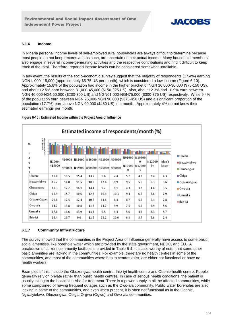
Environmental and Social Impact Assessment of Oma
Independent Power Project
164
6.1.6 Income
In Nigeria personal income levels of self-employed rural households are always difficult to determine because
most people do not keep records and as such, are uncertain of their actual income. Many household members
also engage in several income-generating activities and the respective contributions and find it difficult to keep
track of the total. Therefore, reported income levels can be considered somewhat unreliable.
In any event, the results of the socio-economic survey suggest that the majority of respondents (17.4%) earning
NGN1, 000–15,000 (approximately $5-75 US per month), which is considered a low income (Figure 6-10).
Approximately 15.8% of the population had income in the higher bracket of NGN 16,000-30,000 ($75-150 US),
and about 12.5% earn between 31,000-45,000 ($150-225 US). Also, about 12.3% and 10.9% earn between
NGN 46,000-NGN60,000 ($230-300 US) and NGN61,000-NGN75,000 ($300-375 US) respectively. While 9.4%
of the population earn between NGN 76,000-NGN 90,000 ($375-450 US) and a significant proportion of the
population (17.7%) earn above NGN 90,000 ($450 US) in a month. Approximately 4% do not know their
estimated earnings per month.
Figure 6-10 : Estimated Income within the Project Area of Influence
6.1.7 Community Infrastructure
The survey showed that the communities in the Project Area of Influence generally have access to some basic
social amenities, like borehole water which are provided by the state government, NDDC, and EU. A
breakdown of current community facilities is provided in Table 6-4. It is also worthy of note, that some other
basic amenities are lacking in the communities. For example, there are no health centres in some of the
communities, and most of the communities where health centres exist, are either not functional or have no
health workers.
Examples of this include the Obuzongwa health centre, Ihie-iyi health centre and Obehie health centre. People
generally rely on private rather than public health centres. In case of serious health conditions, the patient is
usually taking to the hospital in Aba for treatment. There is a power supply in all the affected communities, while
some complained of having frequent outages such as the Owo-ala community. Public water boreholes are also
lacking in some of the communities, and even when present, it is often not functional as in the Obehie,
Ngwaiyiekwe, Obuzongwa, Obiga, Orgwu (Ogwe) and Owo-ala communities.
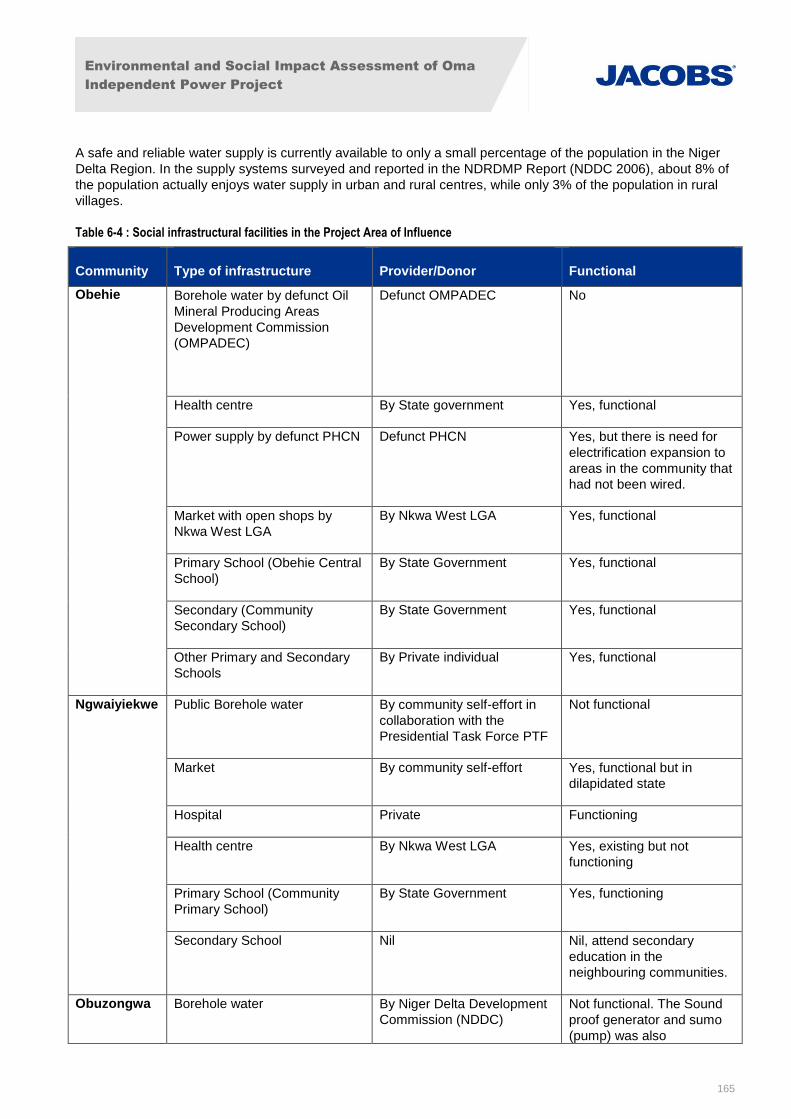
Environmental and Social Impact Assessment of Oma
Independent Power Project
165
A safe and reliable water supply is currently available to only a small percentage of the population in the Niger
Delta Region. In the supply systems surveyed and reported in the NDRDMP Report (NDDC 2006), about 8% of
the population actually enjoys water supply in urban and rural centres, while only 3% of the population in rural
villages.
Table 6-4 : Social infrastructural facilities in the Project Area of Influence
Community Type of infrastructure Provider/Donor Functional
Obehie Borehole water by defunct Oil
Mineral Producing Areas
Development Commission
(OMPADEC)
Defunct OMPADEC No
Health centre By State government Yes, functional
Power supply by defunct PHCN
Defunct PHCN Yes, but there is need for
electrification expansion to
areas in the community that
had not been wired.
Market with open shops by
Nkwa West LGA
By Nkwa West LGA Yes, functional
Primary School (Obehie Central
School)
By State Government Yes, functional
Secondary (Community
Secondary School)
By State Government Yes, functional
Other Primary and Secondary
Schools
By Private individual Yes, functional
Ngwaiyiekwe Public Borehole water By community self-effort in
collaboration with the
Presidential Task Force PTF
Not functional
Market By community self-effort Yes, functional but in
dilapidated state
Hospital Private Functioning
Health centre By Nkwa West LGA Yes, existing but not
functioning
Primary School (Community
Primary School)
By State Government Yes, functioning
Secondary School Nil Nil, attend secondary
education in the
neighbouring communities.
Obuzongwa Borehole water By Niger Delta Development
Commission (NDDC)
Not functional. The Sound
proof generator and sumo
(pump) was also
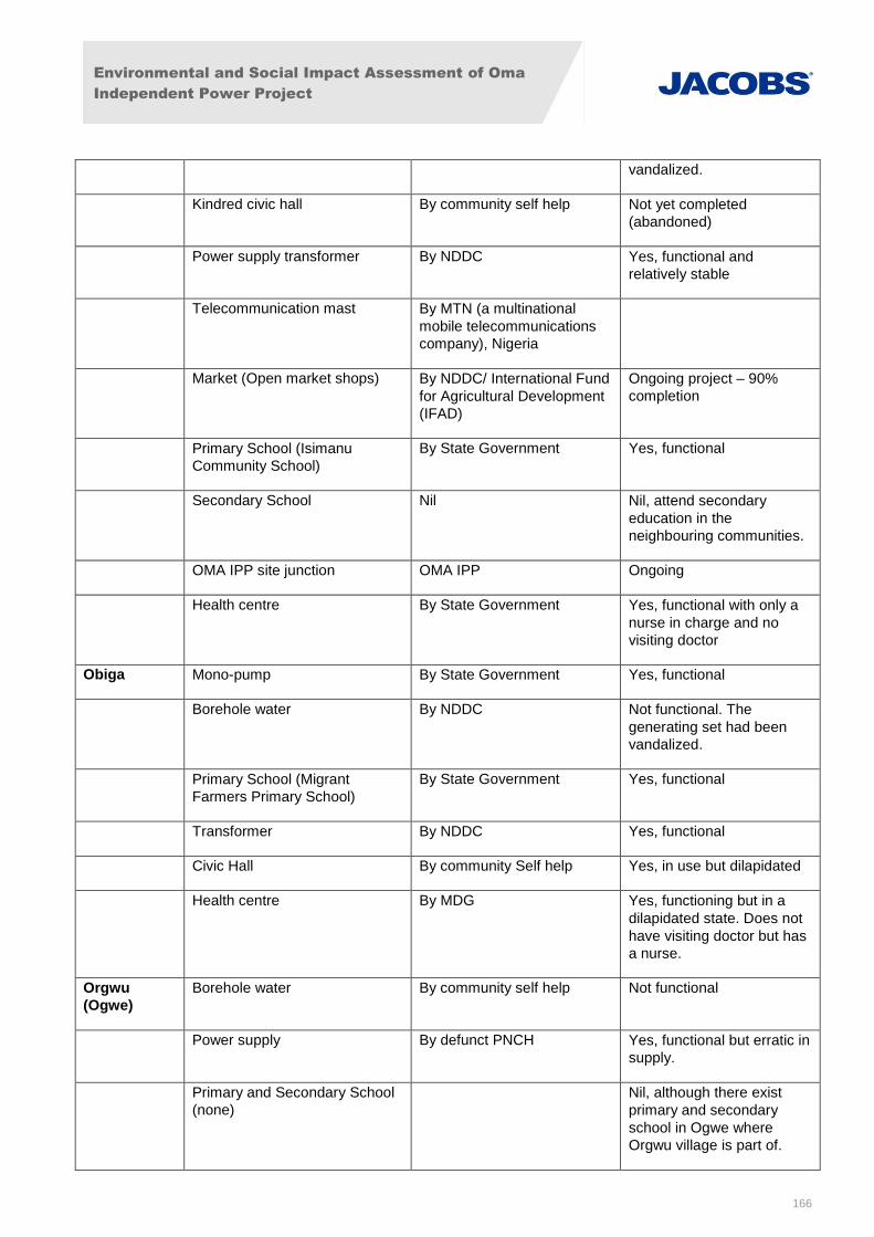
Environmental and Social Impact Assessment of Oma
Independent Power Project
166
vandalized.
Kindred civic hall By community self help Not yet completed
(abandoned)
Power supply transformer By NDDC Yes, functional and
relatively stable
Telecommunication mast By MTN (a multinational
mobile telecommunications
company), Nigeria
Market (Open market shops) By NDDC/ International Fund
for Agricultural Development
(IFAD)
Ongoing project – 90%
completion
Primary School (Isimanu
Community School)
By State Government Yes, functional
Secondary School Nil Nil, attend secondary
education in the
neighbouring communities.
OMA IPP site junction OMA IPP Ongoing
Health centre By State Government Yes, functional with only a
nurse in charge and no
visiting doctor
Obiga Mono-pump By State Government Yes, functional
Borehole water By NDDC Not functional. The
generating set had been
vandalized.
Primary School (Migrant
Farmers Primary School)
By State Government Yes, functional
Transformer By NDDC Yes, functional
Civic Hall By community Self help Yes, in use but dilapidated
Health centre By MDG Yes, functioning but in a
dilapidated state. Does not
have visiting doctor but has
a nurse.
Orgwu
(Ogwe)
Borehole water By community self help Not functional
Power supply By defunct PNCH Yes, functional but erratic in
supply.
Primary and Secondary School
(none)
Nil, although there exist
primary and secondary
school in Ogwe where
Orgwu village is part of.
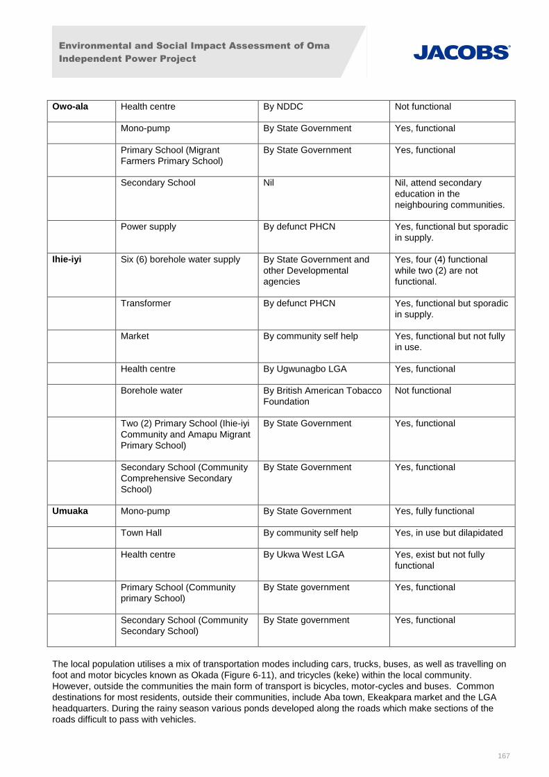
Environmental and Social Impact Assessment of Oma
Independent Power Project
167
Owo-ala Health centre By NDDC Not functional
Mono-pump By State Government Yes, functional
Primary School (Migrant
Farmers Primary School)
By State Government Yes, functional
Secondary School Nil Nil, attend secondary
education in the
neighbouring communities.
Power supply By defunct PHCN Yes, functional but sporadic
in supply.
Ihie-iyi Six (6) borehole water supply By State Government and
other Developmental
agencies
Yes, four (4) functional
while two (2) are not
functional.
Transformer By defunct PHCN Yes, functional but sporadic
in supply.
Market By community self help Yes, functional but not fully
in use.
Health centre By Ugwunagbo LGA Yes, functional
Borehole water By British American Tobacco
Foundation
Not functional
Two (2) Primary School (Ihie-iyi
Community and Amapu Migrant
Primary School)
By State Government Yes, functional
Secondary School (Community
Comprehensive Secondary
School)
By State Government Yes, functional
Umuaka Mono-pump By State Government Yes, fully functional
Town Hall By community self help Yes, in use but dilapidated
Health centre By Ukwa West LGA Yes, exist but not fully
functional
Primary School (Community
primary School)
By State government Yes, functional
Secondary School (Community
Secondary School)
By State government Yes, functional
The local population utilises a mix of transportation modes including cars, trucks, buses, as well as travelling on
foot and motor bicycles known as Okada (Figure 6-11), and tricycles (keke) within the local community.
However, outside the communities the main form of transport is bicycles, motor-cycles and buses. Common
destinations for most residents, outside their communities, include Aba town, Ekeakpara market and the LGA
headquarters. During the rainy season various ponds developed along the roads which make sections of the
roads difficult to pass with vehicles.
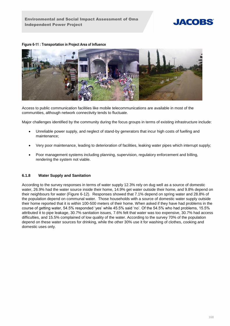
Environmental and Social Impact Assessment of Oma
Independent Power Project
168
Figure 6-11 : Transportation in Project Area of Influence
Access to public communication facilities like mobile telecommunications are available in most of the
communities, although network connectivity tends to fluctuate.
Major challenges identified by the community during the focus groups in terms of existing infrastructure include:
Unreliable power supply, and neglect of stand-by generators that incur high costs of fuelling and
maintenance;
Very poor maintenance, leading to deterioration of facilities, leaking water pipes which interrupt supply;
Poor management systems including planning, supervision, regulatory enforcement and billing,
rendering the system not viable.
6.1.8 Water Supply and Sanitation
According to the survey responses in terms of water supply 12.3% rely on dug well as a source of domestic
water, 26.9% had the water source inside their home, 14.9% get water outside their home, and 9.8% depend on
their neighbours for water (Figure 6-12). Responses showed that 7.1% depend on spring water and 28.8% of
the population depend on communal water. Those households with a source of domestic water supply outside
their home reported that it is within 100-500 meters of their home. When asked if they have had problems in the
course of getting water, 54.5% responded ‘yes’ while 45.5% said ‘no’. Of the 54.5% who had problems, 15.5%
attributed it to pipe leakage, 30.7% sanitation issues, 7.6% felt that water was too expensive, 30.7% had access
difficulties, and 15.5% complained of low quality of the water. According to the survey 70% of the population
depend on these water sources for drinking, while the other 30% use it for washing of clothes, cooking and
domestic uses only.
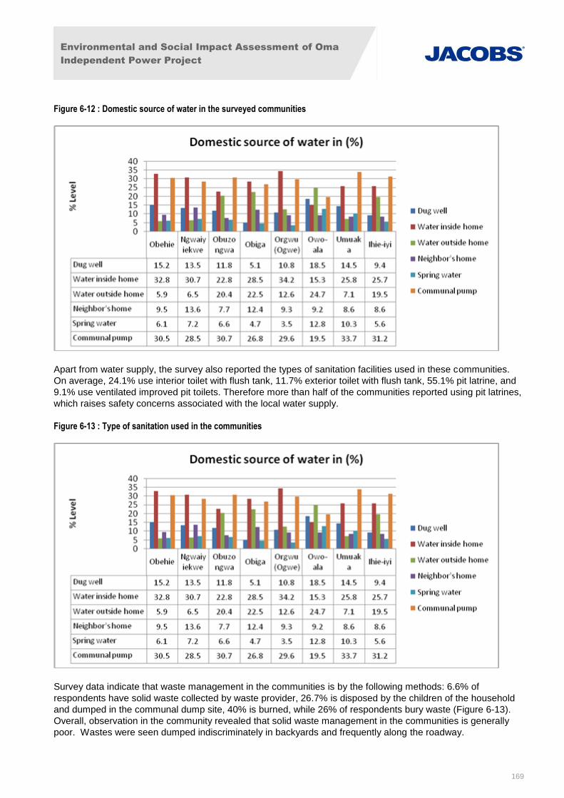
Environmental and Social Impact Assessment of Oma
Independent Power Project
169
Figure 6-12 : Domestic source of water in the surveyed communities
Apart from water supply, the survey also reported the types of sanitation facilities used in these communities.
On average, 24.1% use interior toilet with flush tank, 11.7% exterior toilet with flush tank, 55.1% pit latrine, and
9.1% use ventilated improved pit toilets. Therefore more than half of the communities reported using pit latrines,
which raises safety concerns associated with the local water supply.
Figure 6-13 : Type of sanitation used in the communities
Survey data indicate that waste management in the communities is by the following methods: 6.6% of
respondents have solid waste collected by waste provider, 26.7% is disposed by the children of the household
and dumped in the communal dump site, 40% is burned, while 26% of respondents bury waste (Figure 6-13).
Overall, observation in the community revealed that solid waste management in the communities is generally
poor. Wastes were seen dumped indiscriminately in backyards and frequently along the roadway.
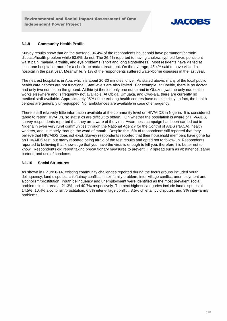
Environmental and Social Impact Assessment of Oma
Independent Power Project
170
6.1.9 Community Health Profile
Survey results show that on the average, 36.4% of the respondents household have permanent/chronic
disease/health problem while 63.6% do not. The 36.4% reported to having cholera, typhoid fever, persistent
waist pain, malaria, arthritis, and eye problems (short and long sightedness). Most residents have visited at
least one hospital or more for a check-up and/or treatment. On the average, 45.4% said to have visited a
hospital in the past year. Meanwhile, 9.1% of the respondents suffered water-borne diseases in the last year.
The nearest hospital is in Aba, which is about 20-30 minutes’ drive. As stated above, many of the local public
health care centres are not functional. Staff levels are also limited. For example, at Obehie, there is no doctor
and only two nurses on the ground. At Ihie-iyi there is only one nurse and in Obuzongwa the only nurse also
works elsewhere and is frequently not available. At Obiga, Umuaka, and Owo-ala, there are currently no
medical staff available. Approximately 95% of the existing health centres have no electricity. In fact, the health
centres are generally un-equipped. No ambulances are available in case of emergency.
There is still relatively little information available at the community level on HIV/AIDS in Nigeria. It is considered
taboo to report HIV/AIDs, so statistics are difficult to obtain. On whether the population is aware of HIV/AIDS,
survey respondents reported that they are aware of the virus. Awareness campaign has been carried out in
Nigeria in even very rural communities through the National Agency for the Control of AIDS (NACA), health
workers, and ultimately through the word of mouth. Despite this, 5% of respondents still reported that they
believe that HIV/AIDS does not exist. Survey respondents reported that their household members have gone for
an HIV/AIDS test, but many reported being afraid of the test results and opted not to follow-up. Respondents
reported to believing that knowledge that you have the virus is enough to kill you, therefore it is better not to
know. Respondents did report taking precautionary measures to prevent HIV spread such as abstinence, same
partner, and use of condoms.
6.1.10 Social Structures
As shown in Figure 6-14, existing community challenges reported during the focus groups included youth
delinquency, land disputes, chieftaincy conflicts, inter-family problem, inter-village conflict, unemployment and
alcoholism/prostitution. Youth delinquency and unemployment were identified as the most prevalent social
problems in the area at 21.3% and 40.7% respectively. The next highest categories include land disputes at
14.5%, 10.4% alcoholism/prostitution, 6.5% inter-village conflict, 3.5% chieftaincy disputes, and 3% inter-family
problems.
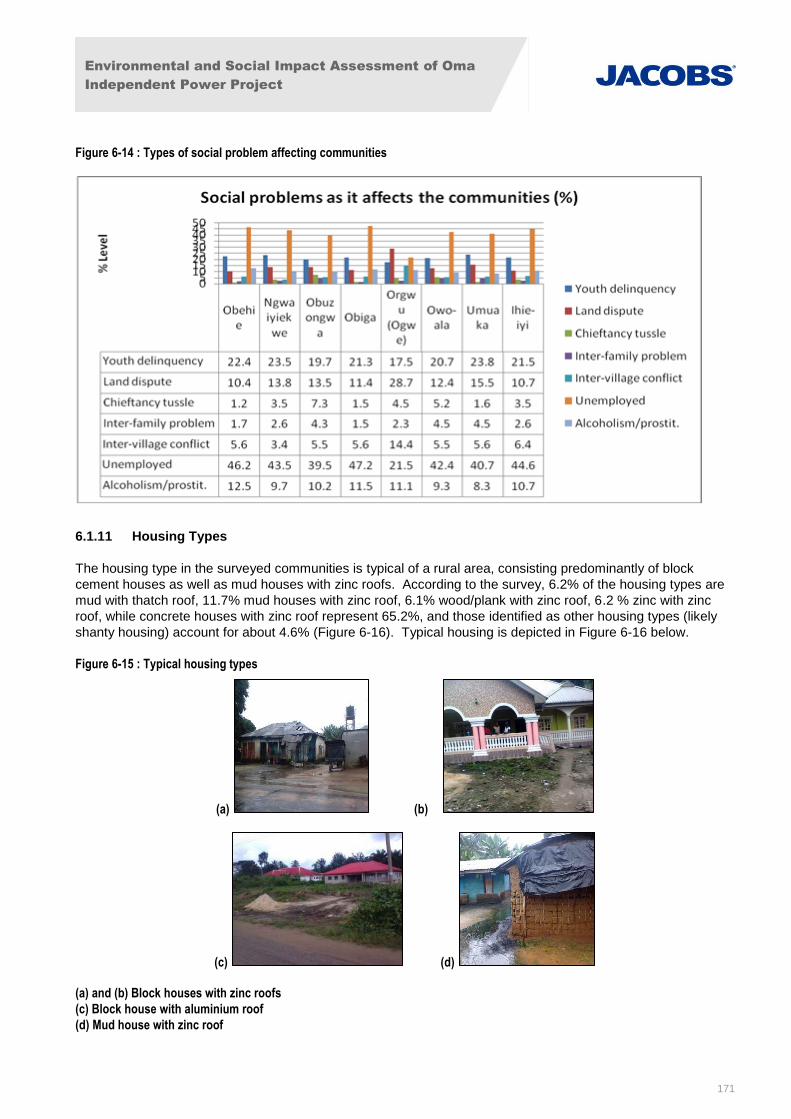
Environmental and Social Impact Assessment of Oma
Independent Power Project
171
Figure 6-14 : Types of social problem affecting communities
6.1.11 Housing Types
The housing type in the surveyed communities is typical of a rural area, consisting predominantly of block
cement houses as well as mud houses with zinc roofs. According to the survey, 6.2% of the housing types are
mud with thatch roof, 11.7% mud houses with zinc roof, 6.1% wood/plank with zinc roof, 6.2 % zinc with zinc
roof, while concrete houses with zinc roof represent 65.2%, and those identified as other housing types (likely
shanty housing) account for about 4.6% (Figure 6-16). Typical housing is depicted in Figure 6-16 below.
Figure 6-15 : Typical housing types
(a) (b)
(c) (d)
(a) and (b) Block houses with zinc roofs
(c) Block house with aluminium roof
(d) Mud house with zinc roof
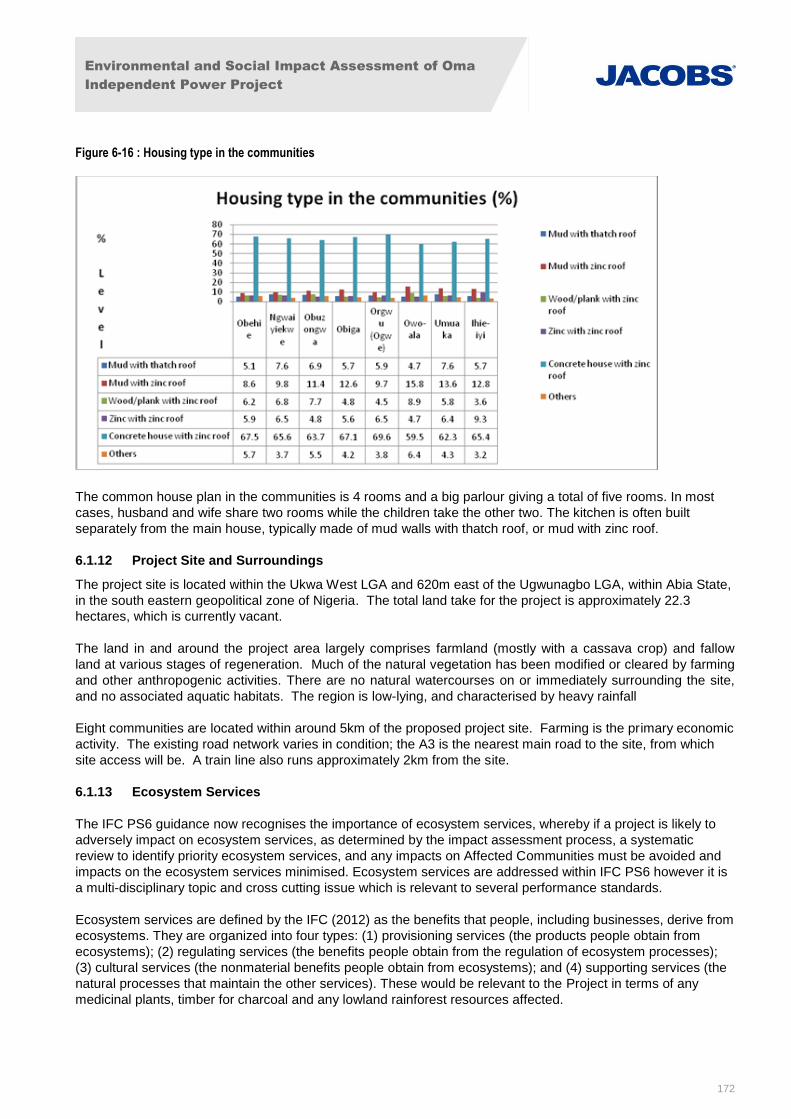
Environmental and Social Impact Assessment of Oma
Independent Power Project
172
Figure 6-16 : Housing type in the communities
The common house plan in the communities is 4 rooms and a big parlour giving a total of five rooms. In most
cases, husband and wife share two rooms while the children take the other two. The kitchen is often built
separately from the main house, typically made of mud walls with thatch roof, or mud with zinc roof.
6.1.12 Project Site and Surroundings
The project site is located within the Ukwa West LGA and 620m east of the Ugwunagbo LGA, within Abia State,
in the south eastern geopolitical zone of Nigeria. The total land take for the project is approximately 22.3
hectares, which is currently vacant.
The land in and around the project area largely comprises farmland (mostly with a cassava crop) and fallow
land at various stages of regeneration. Much of the natural vegetation has been modified or cleared by farming
and other anthropogenic activities. There are no natural watercourses on or immediately surrounding the site,
and no associated aquatic habitats. The region is low-lying, and characterised by heavy rainfall
Eight communities are located within around 5km of the proposed project site. Farming is the primary economic
activity. The existing road network varies in condition; the A3 is the nearest main road to the site, from which
site access will be. A train line also runs approximately 2km from the site.
6.1.13 Ecosystem Services
The IFC PS6 guidance now recognises the importance of ecosystem services, whereby if a project is likely to
adversely impact on ecosystem services, as determined by the impact assessment process, a systematic
review to identify priority ecosystem services, and any impacts on Affected Communities must be avoided and
impacts on the ecosystem services minimised. Ecosystem services are addressed within IFC PS6 however it is
a multi-disciplinary topic and cross cutting issue which is relevant to several performance standards.
Ecosystem services are defined by the IFC (2012) as the benefits that people, including businesses, derive from
ecosystems. They are organized into four types: (1) provisioning services (the products people obtain from
ecosystems); (2) regulating services (the benefits people obtain from the regulation of ecosystem processes);
(3) cultural services (the nonmaterial benefits people obtain from ecosystems); and (4) supporting services (the
natural processes that maintain the other services). These would be relevant to the Project in terms of any
medicinal plants, timber for charcoal and any lowland rainforest resources affected.
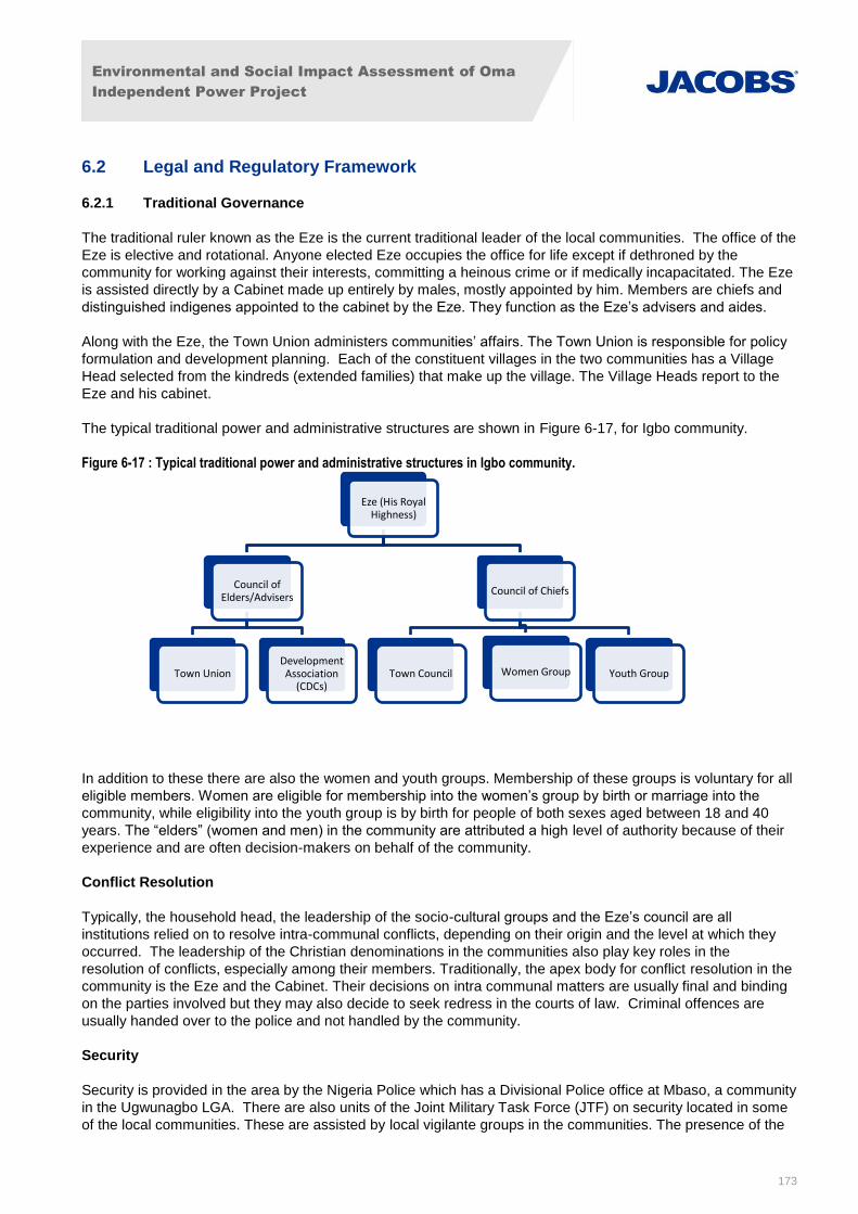
Environmental and Social Impact Assessment of Oma
Independent Power Project
173
6.2 Legal and Regulatory Framework
6.2.1 Traditional Governance
The traditional ruler known as the Eze is the current traditional leader of the local communities. The office of the
Eze is elective and rotational. Anyone elected Eze occupies the office for life except if dethroned by the
community for working against their interests, committing a heinous crime or if medically incapacitated. The Eze
is assisted directly by a Cabinet made up entirely by males, mostly appointed by him. Members are chiefs and
distinguished indigenes appointed to the cabinet by the Eze. They function as the Eze’s advisers and aides.
Along with the Eze, the Town Union administers communities’ affairs. The Town Union is responsible for policy
formulation and development planning. Each of the constituent villages in the two communities has a Village
Head selected from the kindreds (extended families) that make up the village. The Village Heads report to the
Eze and his cabinet.
The typical traditional power and administrative structures are shown in Figure 6-17, for Igbo community.
Figure 6-17 : Typical traditional power and administrative structures in Igbo community.
In addition to these there are also the women and youth groups. Membership of these groups is voluntary for all
eligible members. Women are eligible for membership into the women’s group by birth or marriage into the
community, while eligibility into the youth group is by birth for people of both sexes aged between 18 and 40
years. The “elders” (women and men) in the community are attributed a high level of authority because of their
experience and are often decision-makers on behalf of the community.
Conflict Resolution
Typically, the household head, the leadership of the socio-cultural groups and the Eze’s council are all
institutions relied on to resolve intra-communal conflicts, depending on their origin and the level at which they
occurred. The leadership of the Christian denominations in the communities also play key roles in the
resolution of conflicts, especially among their members. Traditionally, the apex body for conflict resolution in the
community is the Eze and the Cabinet. Their decisions on intra communal matters are usually final and binding
on the parties involved but they may also decide to seek redress in the courts of law. Criminal offences are
usually handed over to the police and not handled by the community.
Security
Security is provided in the area by the Nigeria Police which has a Divisional Police office at Mbaso, a community
in the Ugwunagbo LGA. There are also units of the Joint Military Task Force (JTF) on security located in some
of the local communities. These are assisted by local vigilante groups in the communities. The presence of the
Eze (His Royal Highness)
Council of Elders/Advisers
Town Union Development Association
(CDCs)
Council of Chiefs
Town Council Women Group Youth Group

Environmental and Social Impact Assessment of Oma
Independent Power Project
174
JTF was caused by incidences of kidnapping of persons for ransom which was experienced in Ihie and Ogwe
communities between 2009 and 2010. There have been no reported incidents in these areas since 2011.
6.2.2 Land Use and Management
Nigerian Land Use Act of 1978
Since 1978, the major legislation regulating land acquisition within Nigeria is the Land Use Act of 1978 which
states that all land in a State is to be held in trust by the State Governor for the benefit of all Nigerians. By law,
foreigners may also acquire land wherever it is located in the country from either the State governments or from
other holders.
Since the Land Use Act confers all land to the respective State government, a prospective buyer can apply to
the Governor of the State for a Certificate of Occupancy which is for a period of 99 years.
However, The Federal Government of Nigeria also has power to grant Certificate of Occupancy in respect of
lands comprised in the Federal Capital Territory (i.e., Abuja and its designated environs), or vested in the
Federal Government but located in States’ territories.
Local Governments may also grant ‘customary Certificate of Occupancy’ where the land in question is not in an
urban area. An application to the particular Government must be made, or any appropriate owner, for the
issuance of a right of occupancy which is called the Certificate of Occupancy
Land Ownership Tenure System in the Project Area
Generally, land is considered Nigeria’s most important long-term resource and can be a very contentious issue
in many areas where land availability is limited. Land in Nigeria falls under four broad ownership classifications
which consist of individually-owned, family-owned, communally-owned, and government-owned lands. The two
forms of land-ownership that are most common in the studied communities are family inheritance and
communal land ownership. Certain lands in the communities are owned by the founding families, known as
family ownership managed by the eldest man in the family, while some portions of land are equally owned by
the entire community.
The six principal methods of land acquisition in the project vicinity include: inheritance, purchase, lease, pledge,
exchange, and gift. Lands are frequently passed down through family inheritance. In recent times as
urbanisation increases in villages and towns, private individual or company ownership of land is becoming more
common, even being sold to those from outside of the community. Lands made available to government and
corporations (oil companies) for major public projects/utilities (schools, hospitals/clinics for example) often come
from communally owned land as well as lands used by the community to set-up civic centre/town hall, markets,
schools and places of religious worship.
According to the survey (Figure 6-18), 66.8% of lands in the Project Area of Influence are communally owned,
16.3% owned by family inheritance, 9.6% individually purchased, while 3.3% are utilised via sharecropping and
4% rented/leased. In terms of farming in the study area, arable land is generally used for sharecropping for
between 2 and 5 years.
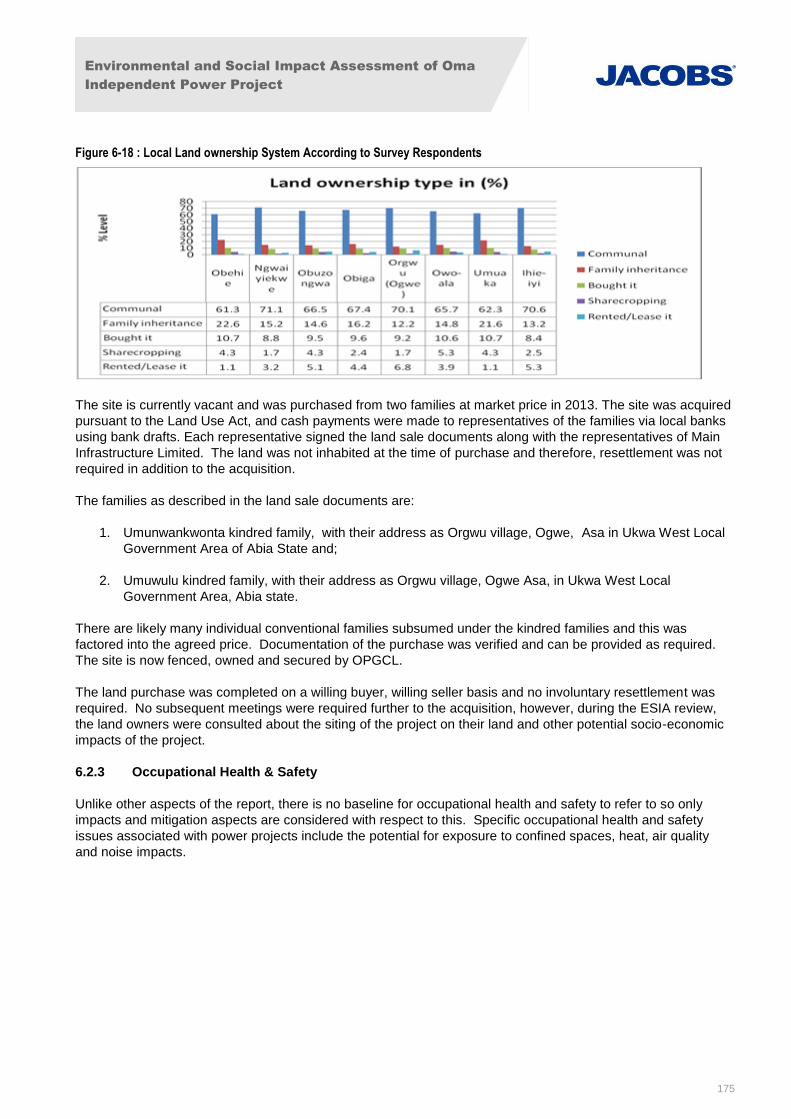
Environmental and Social Impact Assessment of Oma
Independent Power Project
175
Figure 6-18 : Local Land ownership System According to Survey Respondents
The site is currently vacant and was purchased from two families at market price in 2013. The site was acquired
pursuant to the Land Use Act, and cash payments were made to representatives of the families via local banks
using bank drafts. Each representative signed the land sale documents along with the representatives of Main
Infrastructure Limited. The land was not inhabited at the time of purchase and therefore, resettlement was not
required in addition to the acquisition.
The families as described in the land sale documents are:
1. Umunwankwonta kindred family, with their address as Orgwu village, Ogwe, Asa in Ukwa West Local
Government Area of Abia State and;
2. Umuwulu kindred family, with their address as Orgwu village, Ogwe Asa, in Ukwa West Local
Government Area, Abia state.
There are likely many individual conventional families subsumed under the kindred families and this was
factored into the agreed price. Documentation of the purchase was verified and can be provided as required.
The site is now fenced, owned and secured by OPGCL.
The land purchase was completed on a willing buyer, willing seller basis and no involuntary resettlement was
required. No subsequent meetings were required further to the acquisition, however, during the ESIA review,
the land owners were consulted about the siting of the project on their land and other potential socio-economic
impacts of the project.
6.2.3 Occupational Health & Safety
Unlike other aspects of the report, there is no baseline for occupational health and safety to refer to so only
impacts and mitigation aspects are considered with respect to this. Specific occupational health and safety
issues associated with power projects include the potential for exposure to confined spaces, heat, air quality
and noise impacts.
Environmental and Social Impact Assessment of Oma
Independent Power Project
176
7. Environmental and Social Impact Assessment Methodology
7.1 Overview of the ESIA Process
An ESIA is a systematic, scientific and participatory process to assess potential environmental and social
impacts of a development, including consideration of project alternatives and cumulative impacts with other
planned developments. The ESIA process ensures that new developments, and extensions to existing
developments, are located and designed in such a way as to minimise environmental and social impacts.
The objectives of an ESIA are:
To identify environmental constraints and opportunities within the study area, taking account of the
characteristics of the development and the local environment;
To identify potential impacts and interpret the nature of these impacts;
To describe the mitigation measures envisaged to prevent, reduce and where possible offset any
significant adverse effects on the environment, including the appropriateness of avoidance and
prevention measures; and
To determine the significance of any residual environmental effects following mitigation measures
To underpin the ESMP for implementation, management, monitoring and reporting of mitigation
measures.
7.2 The ESIA Study Report
This document is the ESIA study report; the following sections present an overview of the general impact
assessment methodology applied to the assessment of potential impacts arising from the project elements. The
findings of this assessment relevant to each of the environmental and social aspects listed in Sections 5 and 6
are outlined in Section 8, with a description of any mitigation measures required outlined in Section 9. Impacts
predicted as being of medium to high significance prior to the consideration of mitigation are assessed against
appropriate mitigation measures to predict the residual impact significance.
This ESIA Study Report is supplemented by the Environmental and Social Management Plan which is provided
as Section 10 of the ESIA. The ESMP summarises the mitigation action plan and shows how these will be
implemented, managed, monitored and reported.
This ESIA Study Report enables the WBG, local community and other key stakeholders to determine whether or
not the proposals (including recommended mitigation) are acceptable. This report also informs the permitting
process as the recommended mitigation measures and other actions included in the ESMP form conditions of
the Permit.
In order to evaluate environmental impacts and determine their effects and significance, it is important that
assessment criteria are identified. The various methodologies that have been used within each specialist area
or discipline are made clear within the appropriate sections of this ESIA Study Report.
Each specialist impact assessment section includes the following information:
Predicted effects: an evaluation of the proposed project’s impacts in quantitative and qualitative terms.
In general, the effect of an impact is assessed by a combination of sensitivity of the environment and
the degree of alteration from the baseline state (both positive and negative) which can be predicted.
Environmental sensitivity may be categorised by a multitude of factors such as the threat to a rare or
endangered species, transformation of landscapes or changes to soil quality or land use. Impacts can
have both direct and indirect effects, be cumulative, short-term, medium-term or long-term, permanent
or temporary and have positive or negative effects. Impacts can be analysed in terms of the source of
pollution and the pathways by which they travel to arrive at a receptor;
Environmental and Social Impact Assessment of Oma
Independent Power Project
177
Significance of effects: Project impacts are determined to be ‘significant’ or ‘not significant’.
Significance is a combination of magnitude and sensitivity to change and is evaluated in terms of the
geographic effect, duration and frequency, irreversibility, and any regulatory standards which may
apply. For effects where an assessment of significance cannot be determined (e.g. for reasons of
uncertainty), this issue will be highlighted and an explanation given as to why significance could not be
determined.
Mitigation measures: a description of the measures proposed to minimise potential significant adverse
effects; and
Residual impacts: determination of the project’s remaining level of effect after all the required and
recommended mitigation measures are implemented.
7.3 Procedure for Assessment of Environmental Impacts and their significance
The methodology developed and adopted for the impact assessments provides a tool for assessing and
evaluating the significance of effects and is based on the following criteria:
The type of effect (i.e. whether it is positive/acceptable, negative/unacceptable, neutral or uncertain);
Duration and/or frequency of occurrence (short-term/frequent, long-term/long return period, intermittent);
The policy importance or sensitivity of the resource under consideration in a geographical context (whether
it is international, national, regional or local, as defined in Table 7-1); and
The magnitude of the effect in relation to the resource that has been evaluated, quantified if possible, or
rated qualitatively as high, medium or low, as defined in Table 7-2.
Both professional judgement and the results of modelling analysis are used to assess the findings in relation to
each of these criteria to give an assessment of significance for each effect. Effects are considered to be major,
minor or negligible and can be negative or positive. Where positive impacts are identified mitigation is not
required.
Table 7-1: Geographical Context and Policy Importance
Geographical Context Topic Definition
International Important at global, African or trans-boundary levels
National Important in the context of Nigeria
Regional Important in the context of Abi State
District Important in the context of the Ugwunagbo and Ukwa West LGAs
Local Important within the site and up to 1 km from the site
Table 7-2: Magnitude Criteria
Magnitude of effect Negative effects Positive effects
High Widespread community concern.
Failure to meet legal compliance requirements.
Fatality or serious health disability.
Severe or possibly irreversible damage to an important ecosystem or resource.
Widespread community benefit.
High contribution to safety or prevention of fatalities.
High level of technology transfer.
Prevents serious damage to an important ecosystem or resource.
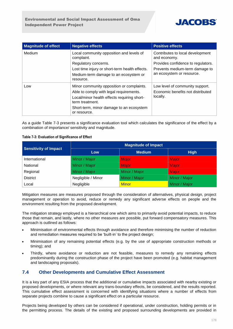
Environmental and Social Impact Assessment of Oma
Independent Power Project
178
Magnitude of effect Negative effects Positive effects
Medium Local community opposition and levels of complaint.
Regulatory concerns.
Lost time injury or short-term health effects.
Medium-term damage to an ecosystem or resource.
Contributes to local development and economy.
Provides confidence to regulators.
Prevents medium-term damage to an ecosystem or resource.
Low Minor community opposition or complaints.
Able to comply with legal requirements.
Local/minor health effects requiring short-term treatment.
Short-term, minor damage to an ecosystem or resource.
Low level of community support.
Economic benefits not distributed locally.
As a guide Table 7-3 presents a significance evaluation tool which calculates the significance of the effect by a
combination of importance/ sensitivity and magnitude.
Table 7-3: Evaluation of Significance of Effect
Sensitivity of Impact Magnitude of Impact
Low Medium High
International Minor / Major Major Major
National Minor / Major Major Major
Regional Minor / Major Minor / Major Major
District Negligible / Minor Minor / Major Minor / Major
Local Negligible Minor Minor / Major
Mitigation measures are measures proposed through the consideration of alternatives, physical design, project
management or operation to avoid, reduce or remedy any significant adverse effects on people and the
environment resulting from the proposed development.
The mitigation strategy employed is a hierarchical one which aims to primarily avoid potential impacts, to reduce
those that remain, and lastly, where no other measures are possible, put forward compensatory measures. This
approach is outlined as follows:
Minimisation of environmental effects through avoidance and therefore minimising the number of reduction
and remediation measures required to be ‘built-in’ to the project design;
Minimisation of any remaining potential effects (e.g. by the use of appropriate construction methods or
timing); and
Thirdly, where avoidance or reduction are not feasible, measures to remedy any remaining effects
predominantly during the construction phase of the project have been promoted (e.g. habitat management
and landscaping proposals).
7.4 Other Developments and Cumulative Effect Assessment
It is a key part of any ESIA process that the additional or cumulative impacts associated with nearby existing or
proposed developments, or where relevant any trans-boundary effects, be considered, and the results reported.
This cumulative effect assessment is concerned with identifying situations where a number of effects from
separate projects combine to cause a significant effect on a particular resource.
Projects being developed by others can be considered if operational, under construction, holding permits or in
the permitting process. The details of the existing and proposed surrounding developments are provided in

Environmental and Social Impact Assessment of Oma
Independent Power Project
179
Section 8. The cumulative impacts, taking into consideration these existing and potential developments, have
been assessed for each environmental and aspect and findings are included in Section 8.
An ESMP has been produced as part of the ESIA and is presented in Section 10. The ESMP is sufficiently
robust to support International Lending requirements as stipulated in IFC Performance Standard 1 –
Environmental and Social Assessment and meet the requirements of the EPA EIA requirements.
The ESMP ranks and prioritises recommended environmental and social actions, describing time period for
implementation. In addition, the ESMP indicates the roles and responsibilities of project personnel and third
parties such as local and regional administrations and sub-contractors.
The ESMP will be developed into a full Environmental and Social Management System (ESMS) that will be
aligned with ISO14001 that provides a formal and internationally acceptable structure that will be the central
repository for all environmental and social plans and procedures. The ESMP will be reviewed and updated (as
needed) throughout the duration of the project.
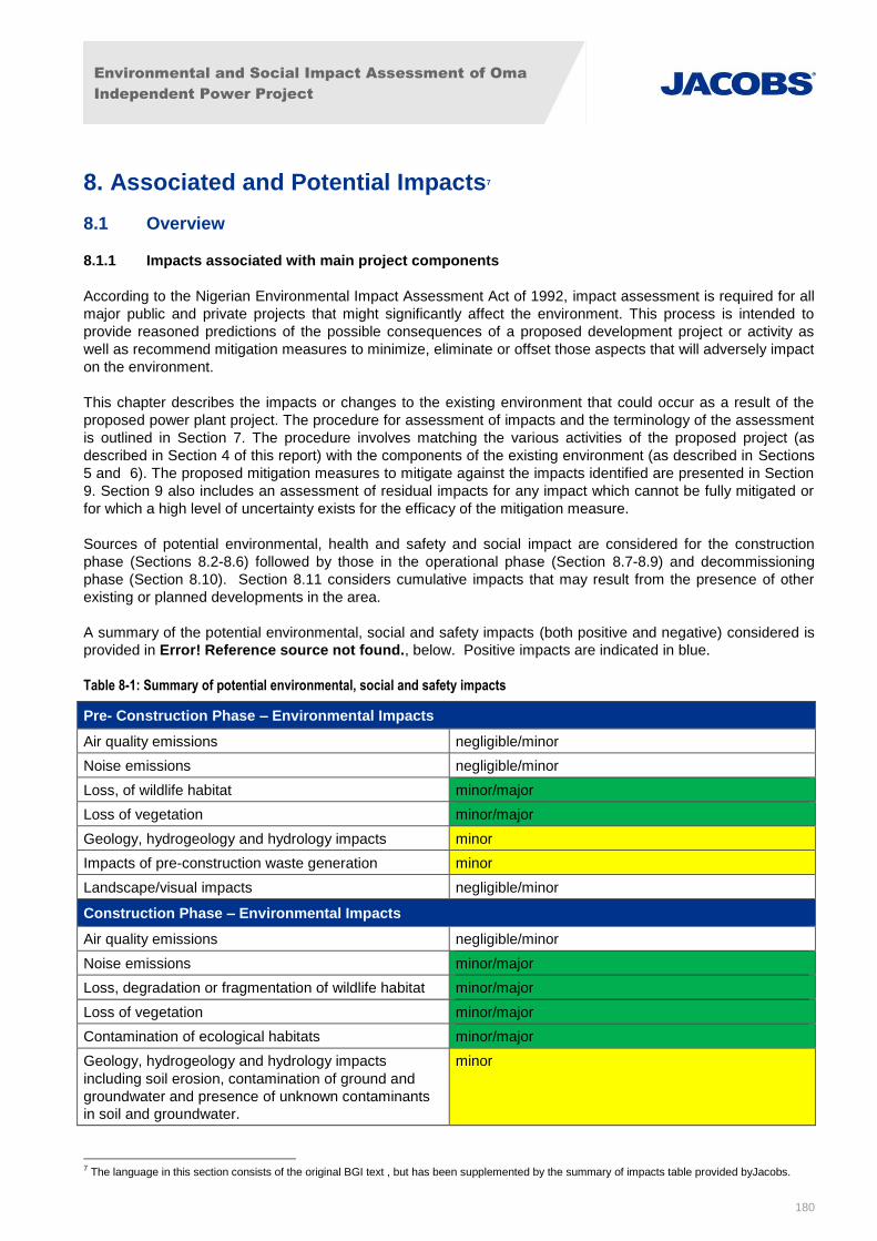
Environmental and Social Impact Assessment of Oma
Independent Power Project
180
8. Associated and Potential Impacts7
8.1 Overview
8.1.1 Impacts associated with main project components
According to the Nigerian Environmental Impact Assessment Act of 1992, impact assessment is required for all
major public and private projects that might significantly affect the environment. This process is intended to
provide reasoned predictions of the possible consequences of a proposed development project or activity as
well as recommend mitigation measures to minimize, eliminate or offset those aspects that will adversely impact
on the environment.
This chapter describes the impacts or changes to the existing environment that could occur as a result of the
proposed power plant project. The procedure for assessment of impacts and the terminology of the assessment
is outlined in Section 7. The procedure involves matching the various activities of the proposed project (as
described in Section 4 of this report) with the components of the existing environment (as described in Sections
5 and 6). The proposed mitigation measures to mitigate against the impacts identified are presented in Section
9. Section 9 also includes an assessment of residual impacts for any impact which cannot be fully mitigated or
for which a high level of uncertainty exists for the efficacy of the mitigation measure.
Sources of potential environmental, health and safety and social impact are considered for the construction
phase (Sections 8.2-8.6) followed by those in the operational phase (Section 8.7-8.9) and decommissioning
phase (Section 8.10). Section 8.11 considers cumulative impacts that may result from the presence of other
existing or planned developments in the area.
A summary of the potential environmental, social and safety impacts (both positive and negative) considered is
provided in Error! Reference source not found., below. Positive impacts are indicated in blue.
Table 8-1: Summary of potential environmental, social and safety impacts
Pre- Construction Phase – Environmental Impacts
Air quality emissions negligible/minor
Noise emissions negligible/minor
Loss, of wildlife habitat minor/major
Loss of vegetation minor/major
Geology, hydrogeology and hydrology impacts minor
Impacts of pre-construction waste generation minor
Landscape/visual impacts negligible/minor
Construction Phase – Environmental Impacts
Air quality emissions negligible/minor
Noise emissions minor/major
Loss, degradation or fragmentation of wildlife habitat minor/major
Loss of vegetation minor/major
Contamination of ecological habitats minor/major
Geology, hydrogeology and hydrology impacts
including soil erosion, contamination of ground and
groundwater and presence of unknown contaminants
in soil and groundwater.
minor
7 The language in this section consists of the original BGI text , but has been supplemented by the summary of impacts table provided byJacobs.
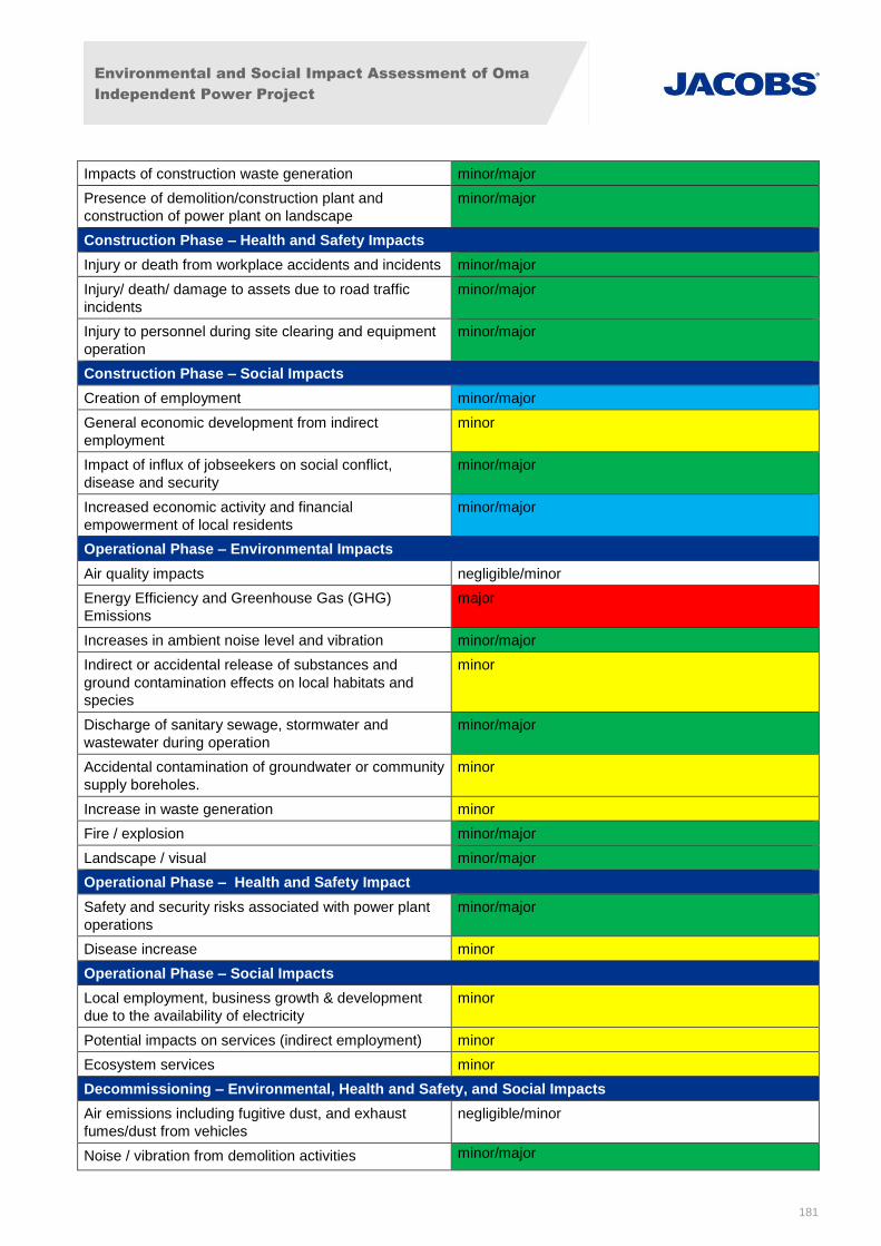
Environmental and Social Impact Assessment of Oma
Independent Power Project
181
Impacts of construction waste generation minor/major
Presence of demolition/construction plant and
construction of power plant on landscape
minor/major
Construction Phase – Health and Safety Impacts
Injury or death from workplace accidents and incidents minor/major
Injury/ death/ damage to assets due to road traffic
incidents
minor/major
Injury to personnel during site clearing and equipment
operation
minor/major
Construction Phase – Social Impacts
Creation of employment minor/major
General economic development from indirect
employment
minor
Impact of influx of jobseekers on social conflict,
disease and security
minor/major
Increased economic activity and financial
empowerment of local residents
minor/major
Operational Phase – Environmental Impacts
Air quality impacts negligible/minor
Energy Efficiency and Greenhouse Gas (GHG)
Emissions
major
Increases in ambient noise level and vibration minor/major
Indirect or accidental release of substances and
ground contamination effects on local habitats and
species
minor
Discharge of sanitary sewage, stormwater and
wastewater during operation
minor/major
Accidental contamination of groundwater or community
supply boreholes.
minor
Increase in waste generation minor
Fire / explosion minor/major
Landscape / visual minor/major
Operational Phase – Health and Safety Impact
Safety and security risks associated with power plant
operations
minor/major
Disease increase minor
Operational Phase – Social Impacts
Local employment, business growth & development
due to the availability of electricity
minor
Potential impacts on services (indirect employment) minor
Ecosystem services minor
Decommissioning – Environmental, Health and Safety, and Social Impacts
Air emissions including fugitive dust, and exhaust
fumes/dust from vehicles
negligible/minor
Noise / vibration from demolition activities minor/major
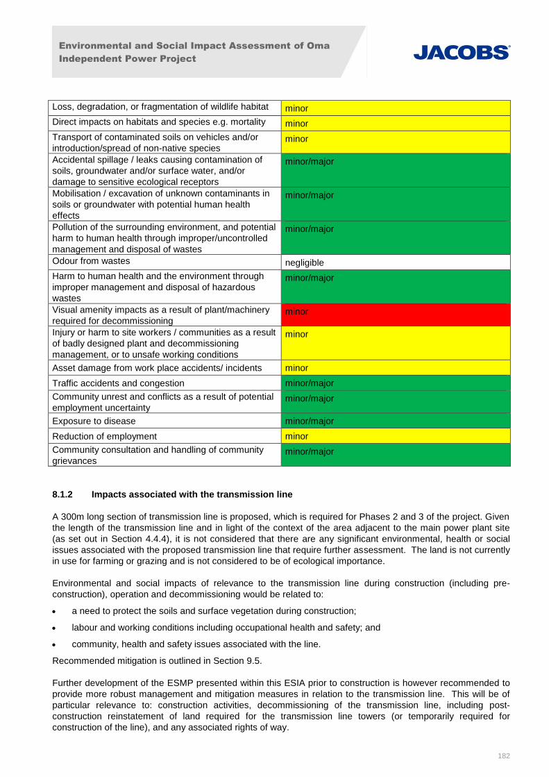
Environmental and Social Impact Assessment of Oma
Independent Power Project
182
Loss, degradation, or fragmentation of wildlife habitat minor
Direct impacts on habitats and species e.g. mortality minor
Transport of contaminated soils on vehicles and/or
introduction/spread of non-native species minor
Accidental spillage / leaks causing contamination of
soils, groundwater and/or surface water, and/or
damage to sensitive ecological receptors
minor/major
Mobilisation / excavation of unknown contaminants in
soils or groundwater with potential human health
effects
minor/major
Pollution of the surrounding environment, and potential
harm to human health through improper/uncontrolled
management and disposal of wastes
minor/major
Odour from wastes negligible
Harm to human health and the environment through
improper management and disposal of hazardous
wastes
minor/major
Visual amenity impacts as a result of plant/machinery
required for decommissioning minor
Injury or harm to site workers / communities as a result
of badly designed plant and decommissioning
management, or to unsafe working conditions
minor
Asset damage from work place accidents/ incidents minor
Traffic accidents and congestion minor/major
Community unrest and conflicts as a result of potential
employment uncertainty minor/major
Exposure to disease minor/major
Reduction of employment minor
Community consultation and handling of community
grievances minor/major
8.1.2 Impacts associated with the transmission line
A 300m long section of transmission line is proposed, which is required for Phases 2 and 3 of the project. Given
the length of the transmission line and in light of the context of the area adjacent to the main power plant site
(as set out in Section 4.4.4), it is not considered that there are any significant environmental, health or social
issues associated with the proposed transmission line that require further assessment. The land is not currently
in use for farming or grazing and is not considered to be of ecological importance.
Environmental and social impacts of relevance to the transmission line during construction (including pre-
construction), operation and decommissioning would be related to:
a need to protect the soils and surface vegetation during construction;
labour and working conditions including occupational health and safety; and
community, health and safety issues associated with the line.
Recommended mitigation is outlined in Section 9.5.
Further development of the ESMP presented within this ESIA prior to construction is however recommended to
provide more robust management and mitigation measures in relation to the transmission line. This will be of
particular relevance to: construction activities, decommissioning of the transmission line, including post-
construction reinstatement of land required for the transmission line towers (or temporarily required for
construction of the line), and any associated rights of way.
Environmental and Social Impact Assessment of Oma
Independent Power Project
183
8.2 Sources of Potential Environmental Impacts during Pre-Construction
Anticipated pre-construction work activities will include:
Mobilising equipment to the construction site;
Road grading for access roads; and
Establishing temporary construction facilities including a worker’s camp.
The potential environmental impacts that could occur during the pre-construction phase of the project are
summarised in the discussion below.
8.2.1 Air Quality
Heavy duty diesel vehicles could be used to transport equipment to the project site pre-construction. Diesel
exhaust is known to contain several compounds that may be detrimental to human health over the long-term
with repeated exposure. Although there are no mobile source emission regulations in Nigeria, in keeping with
good international industry practices, the proposed project would keep diesel emissions to a minimum. There is
also the potential for dust generation during development of the workers camp.
However, air emissions from pre-construction activities are not expected to significantly affect the air quality in
the region outside the proposed project site.
Impact Assessment
The magnitude of construction related air quality effects from the project is assessed as minor. The duration of
impacts on the surrounding environment will be short-term. Therefore, significance of the effects of the
construction activities is assessed as negligible/minor.
Residual Impacts
With implementation of mitigation measures to minimise dust and diesel emissions, impacts would be reduced
and would not be considered significant.
8.2.2 Noise
Activities to be undertaken during pre-construction are not anticipate to be a major source of noise. However,
there may also be some noise emissions from increased traffic movements. Heavy duty diesel trucks could be
used to transport raw equipment to the site and there will be limited noise associated with the development of
the workers camp.
Impact Assessment
Pre-construction noise impacts would likely minimal and the magnitude of noise impacts from pre-construction is
assessed as minor/negligible. The duration of impacts on the surrounding environment would be short-term.
The significance of noise effects from pre-construction activities is, therefore, assessed as minor/negligible.
Standard measures for the management of the impact of traffic noise are included within the ESMP.
Residual Impacts
No long term residual noise impacts are anticipated since noise associated with site preparation and
development of the workers camp would cease upon completion of these activities. Residual short-term impacts
would be limited to the construction area only given the distance to nearby residential receptors, over 400m
from the site. Therefore, overall residual noise impacts from construction are anticipated to be negligible.
8.2.3 Ecology
Pre-construction Impacts to habitats and species and may arise from:
Environmental and Social Impact Assessment of Oma
Independent Power Project
184
Vehicular traffic;
Presence of people;
Development of hardstanding and structure;.
Noise and vibration from use of machinery;
Emissions to the air from machinery and dust; and
There will be some habitat and species disturbance during pre-construction. Natural vegetation and plant
biodiversity loss would result from site clearing for development of the workers camp. In addition, lack of water,
increased exposure to sunlight and lack of nutrients often cause plants to be more prone to stress, disease, and
infestation. However, the project area only supports highly disturbed secondary lowland rainforest (which has a
lower biodiversity than primary lowland rainforest or less disturbed secondary lowland rainforest). In addition, it
is unlikely that there are existing plant species that are unique to the project site.
Impacts could include loss of vegetation during site clearance. Noise/illumination during pre-construction also
constitute nuisance to wildlife. The patchy distribution of wildlife in the proposed development area could be
attributable to previous forest conversion.
Impact Assessment
Based on all of the above, the magnitude of ecological effects from preconstruction are considered minor/major.
However, the effects will be limited and there will be no damage to any species or habitats of concern.
Therefore, the significance of the effects of pre-construction activities on ecology is assessed as minor/major
prior to mitigation.
Residual Impacts
Residual ecological impacts associated with the pre-construction could include permanent loss of wildlife habitat
on the project site and possible relocation to a potentially less favourable habitat for those species that remain
in the vicinity of the proposed project site. However, considering that the conservation value of these ecological
habitats is considered low, the limited scale of roadway gradin and development of the workers camp, and the
fact that there are no protected and vulnerable species populations in the area and given the localised nature of
impacts, overall residual impacts on ecology are considered to be of negligible significance.
8.2.4 Geology, Hydrogeology and Hydrology
Soil and water erosion
Clearing and grading for access roads could result in soil erosion. However, because of the relatively flat
topography of the construction site, it is expected that soil losses will be minimal. Temporary drainage will be
used during the course of pre- construction to accommodate anticipated rainfall and runoff from the disturbed
areas.
Impact Assessment
The magnitude of geology, hydrogeology and hydrology effects from pre-construction of the project and
associated transmission line is assessed as minor. Because erosion would be minimal, the significance of
geology, hydrogeology and hydrology effects from pre-construction is therefore assessed as minor prior to
mitigation.
Residual Impacts
With the implementation of appropriate management and mitigation measures to address any potential erosion
impacts, the significance of residual impacts is therefore assessed as negligible.
Environmental and Social Impact Assessment of Oma
Independent Power Project
185
8.2.5 Waste
Pre-construction activities are not anticipated to be a major source of waste. Worker camp construction could
result in some solid waste materials, which would be disposed of in accordance with national waste standards.
Impact Assessment
The magnitude of any effect that waste from pre-construction of the project may have on the environment is
assessed as minor. The significance of the impact of waste from pre-construction activities is, therefore,
assessed as minor.
Residual Impacts
With implementation of mitigation measures to manage waste, impacts would be reduced, and would be
considered negligible.
8.2.6 Landscape and Visual
Visual impacts due to landscape modification could be experienced by local residents near the workers camp.
However, this facility will likely be small scale and temporary.
Impact Assessment
The magnitude of pre-construction-related landscape and visual effects from the project is assessed as low.
The duration of these impacts will be relatively short-term. Therefore, significance of the effects of the pre-
construction activities is assessed as minor/negligible.
Residual Impacts
Landscaping of the site will take place post-construction including the workers camp. Soils excavated during
pre-construction may be used for landscaping if suitable. Long-term residual impacts would therefore be
considered negligible.
8.3 Sources of Potential Environmental Impacts during Construction
8.3.1 Overview
Construction of the power plant will involve the following stages:
Clearing of vegetation and removal and stockpiling of topsoil;
Bulk earthworks including site grading and excavation work;
Establishing and preparing concrete foundations for major plant and buildings; and
Construction of buildings and installation of equipment followed by commissioning.
The potential environmental impacts that could occur during the construction phase of the project are
summarised in the discussion below.
8.3.2 Air Quality
The most significant issues that could potentially impact ambient air quality during construction are combustion
gas emissions and nuisance dust. The principal sources of combustion gases would include the operation of a
concrete batch plant, diesel powered construction machinery, and vehicle exhaust.
As with any construction site, dust may be generated as a result of surface preparation and earthworks,
including earth moving and materials handling. Internal site traffic moving on un-surfaced routes/roads within
the development site may cause sufficient disturbance of loose surface materials to generate dust, particularly
Environmental and Social Impact Assessment of Oma
Independent Power Project
186
during the dry season. However, most roads to the proposed project site are paved and, therefore, dust
emissions from traffic movement would be restricted to the site itself.
Heavy duty diesel trucks would be used to transport raw materials such as sand, aggregate and cement to the
project site for concrete production. Diesel exhaust is known to contain several compounds that may be
detrimental to human health over the long-term with repeated exposure. Exposure of on-site workers to diesel
exhaust could be significant. Diesel exhaust emissions from construction vehicles for the project would be
generated on a short-term basis. Although there are no mobile source emission regulations in Nigeria, in
keeping with good international industry practices, the proposed project would keep diesel emissions to a
minimum.
Due to the nature of the construction process, potentially dust emitting activities would not be constant and
emissions would be limited to the operating periods for each item of plant and the combination of machinery
being used at any one time. The location of emission sources would also change as construction progresses.
Air emissions from construction activities are not expected to significantly affect the air quality in the region
outside the proposed project site. The nearest residential receptors are over 400m from the development site
and are therefore unlikely to be affected by construction phase emissions which will be highly localised. The
main risks from dust and particulate air emissions generated during construction would be to construction site
workers and personnel.
Impact Assessment
The magnitude of construction related air quality effects from the project is assessed as minor/major. The
duration of impacts on the surrounding environment will be short-term. Therefore, significance of the effects of
the construction activities is assessed as negligible/minor.
Residual Impacts
With implementation of mitigation measures to minimise dust and diesel emissions, impacts would be reduced
and would not be considered significant.
8.3.3 Noise
The most significant noise emissions during construction would be associated with the following activities:
Earthworks and Site Preparation;
Piling;
Creation of Hard Standings;
Construction of Foundations;
Building Erection; and
Creation of Roads.
The above construction works are estimated to generate high noise levels in the range 83-87 dB LAeq at a
distance of 10m. Therefore, personal hearing protection should be worn by all construction workers. Given the
separation distances to the nearest dwellings which are 400m away, construction noise levels are not predicted
to impact noise sensitive receptors for any significant duration.
In addition to noise emissions from major construction work, there may also be some noise emissions from
increased traffic movements. Heavy duty diesel trucks would be used to transport raw materials such as sand,
aggregate and cement to the project site for concrete production.
Impact Assessment
Impacts would be short-term and, as the site is some distance from the nearest sensitive receptors, (over
400m), noise impacts would be considered minimal. As such, the magnitude of noise impacts from construction
Environmental and Social Impact Assessment of Oma
Independent Power Project
187
of the project on human health or the environment is assessed as minor/major. The duration of impacts on the
surrounding environment would be short-term. The significance of noise effects from construction activities is,
therefore, assessed as minor/major. Standard measures for the management of the impact of construction and
traffic noise are included within the ESMP.
Residual Impacts
No long term residual noise impacts are anticipated since noise associated with site preparation and
construction would cease upon completion of these activities. Residual short-term impacts would be limited to
the construction area only given the distance to nearby residential receptors, over 400m from the site. The
potential impacts to human health for construction workers can be mitigated by the use of appropriate PPE and
implementation of adequate work procedures and good management practice. These will be included as actions
in the ESMP. Therefore, overall residual noise impacts from construction are anticipated to be negligible.
8.3.4 Ecology
Construction impacts to habitats and species and may arise from:
Clearance of vegetation;
Vehicular traffic;
Presence of people;
Ground and excavation works;
Construction of hardstanding and structure;.
Noise and vibration from use of machinery;
Emissions to the air from machinery and dust;
Lighting of the development (on nocturnal species);
Disturbance to hydrology (sedimentation, drainage); and
Environmental incidents and accidents (e.g. spillages).
The majority of impacts on ecological resources would occur during construction phase activities. The potential
impacts on wildlife and habitat are described in more detail below.
Loss, degradation or fragmentation of wildlife habitat
During the construction process, habitats and species on the project site will be disturbed and/or displaced, and
those adjacent to the site have the potential to be disturbed and/or displaced.
Natural vegetation and plant biodiversity loss would result from clearing, grubbing, scalping, removal of trees
and stumps, and removal and disposal of all vegetation and debris within the limits of clearing. Vegetation
could also be indirectly affected in areas adjacent to clearing. Conditions at the edge of clearings could be
altered making it unsuitable to support certain plant species due to changes in the amounts of nutrients, light,
and water (i.e., too little or too much). In addition, lack of water, increased exposure to sunlight and lack of
nutrients often cause plants to be more prone to stress, disease, and infestation. Thus, some species grow well
under cooler, moister, shaded forest conditions, but do not do well on the edge of land where temperature, light,
and moisture conditions are different from inside the forest.
It is anticipated that the impacts of ground and vegetation clearing and other associated effects of developing
and operating the proposed project will only result in limited loss of some biodiversity at the local level (i.e.,
within the immediate vicinity of the proposed project). This is due to the fact that the project site is relatively
small and only supports highly disturbed secondary lowland rainforest (which has a lower biodiversity than
primary lowland rainforest or less disturbed secondary lowland rainforest). In addition, it is unlikely that there
are existing plant species that are unique to the project site.
Environmental and Social Impact Assessment of Oma
Independent Power Project
188
Loss of vegetation
Impacts could include loss of vegetation during construction. Terrestrial vegetation influences elements of the
environment including landscape, fauna, microclimate and groundwater. Vegetation clearance causes habitat
loss and fragmentation of wildlife migration routes, and would as a result of the interactions between the
elements, impact on the associated fauna. Direct impacts during tree felling will include destruction of bird nests
and injury/disturbance to arboreal wildlife (including fruit bats, birds and snakes). Noise/illumination during
construction and operation activities also constitute nuisance to wildlife. The patchy distribution of wildlife in the
proposed development area could be attributable to previous forest conversion. Forest conversion for any
purpose results in a reduction in available habitats and wildlife stocks, as well as the probable elimination from
particular locales of less adaptive species. However, the conservation status of the small mammals in the area
has remained satisfactory (survival not threatened) as they have naturally high fecundity as well as adaptability
to changing habitat conditions.
Contamination of ecological habitats
There is the potential for accidental release of contaminants during construction works. The contaminants could
migrate into soils and groundwater and pollute ecological habitats and indirectly affect species. Measures to
mitigate against impacts to geology, hydrogeology and hydrology are presented in Sections 9.1.5 and 9.4.6.
Impact Assessment
Based on all of the above, the magnitude of ecological effects from construction is considered high, as effects
will be irreversible in the construction area. However, the effects will be localised and there will be no damage
to any species or habitats of concern. Therefore, the significance of the effects construction activities on ecology
is assessed as minor/major prior to mitigation.
Residual Impacts
Residual ecological impacts associated with the proposed project could include permanent loss of wildlife
habitat on the project site, minor degradation of wildlife habitat immediately adjacent to the project site, possible
relocation to a potentially less favourable habitat for those species that remain in the vicinity of the proposed
project site.
Residual ecological impacts associated with the proposed project could include permanent loss of wildlife
habitat on the project site, minor degradation of wildlife habitat immediately adjacent to the project site, possible
relocation to potentially less favourable habitat of those species that remain around the proposed project site.
However, considering that the conservation value of these ecological habitats is considered low, and the fact
that there are no protected and vulnerable species populations in the area and given the localised nature of
impacts, overall residual impacts on ecology are considered to be of negligible significance.
8.3.5 Geology, Hydrogeology and Hydrology
Soil and water erosion
Clearing and grubbing activities within the limits of the project site could result in soil erosion. However, because
of the relatively flat topography of the construction site, it is expected that soil losses will be minimal. Temporary
drainage will be used during the course of construction to accommodate anticipated rainfall and runoff from the
disturbed areas.
Fuel / chemical spills
Construction related impacts to soils could occur from the accidental release of contaminants such as fuels and
lubricants. These types of materials will likely be stored in the laydown area and possibly in the workers ’ camp,
all of which will remain on site throughout construction. As there are no watercourses present in the vicinity of
the site the risks to surface waters is considered to be low, however there is the potential for spills to migrate
Environmental and Social Impact Assessment of Oma
Independent Power Project
189
into groundwater and potentially contaminate local groundwater supply (as discussed in the Geology,
Hydrogeology and Hydrology Impacts Section). This risk will be addressed in the ESMP. Accidental spills
could result in localized soil contamination. Given the low quantities of hazardous materials stored and used in
the construction phase it is not envisaged that any potential contamination impacts would be significant or long-
term.
8.3.6 Unidentified Contamination
There is the potential for unknown soil and groundwater contamination to be encountered during the
construction phase. This could cause harm to human health if workers are exposed and may cause harm to the
environment if the contamination is mobilised and can migrate into groundwater and / or off-site.
Impact Assessment
The magnitude of geology, hydrogeology and hydrology effects from construction of the project and associated
transmission line is assessed as minor/major. Because potential contamination would be localised if it occurs,
the significance of geology, hydrogeology and hydrology effects from construction is therefore assessed as
minor prior to mitigation.
Residual Impacts
With the implementation of appropriate management and mitigation measures, including prompt emergency
response following an accidental release, no long-term impacts to land or water quality are expected and short-
term impacts would be low in magnitude and temporary in nature. The significance of residual impacts is
therefore assessed as negligible.
8.3.7 Waste
The scale of and severity of waste impacts from construction would depend upon the nature of the waste and
the medium into which they are disposed. This is also true of accidental release of waste. Since further details
about the timing and amount of waste to be generated by the project are not available at this time, potential
impacts cannot be discussed quantitatively. However, the impacts discussed below consider the potential harm
that may arise associated with each type of potential impact.
The wastes generated during project construction would include:
General construction wastes, including cement bags;
Accumulated concrete washings from washing down empty concrete trucks;
Building rubble;
Waste metal (including welding rods, disc cutters, piping etc.);
Waste oils and lubricants;
Waste paints and chemicals/ solvents;
Empty paint, oil and chemical/ solvent containers;
Empty oxygen and acetylene tanks (if oxy-acetylene welding and cutting required);
Packaging materials such as wood, cardboard and plastic;
Scrap metal from construction and packaging;
Electrical cabling and electrical components;
Domestic wastes, including food wastes;
Sewage effluent;
Paper; and
Glass.
Environmental and Social Impact Assessment of Oma
Independent Power Project
190
Typically, the largest component of solid waste from construction would be insulation material, timber, concrete,
wiring, etc., which constitutes up to 15% of the total construction materials on site. These wastes are normally
routed to a landfill which, given the likely considerable volume of waste material, has the potential to have a
negative impact on local communities. As there are no landfills in the area, a waste management programme
would be needed to maximise recycling and use appropriate disposal methods for wastes that cannot be
recycled.
Paints can contain solvents and heavy metals. The release of paints to the land and/ or water environment can
have a significant deleterious effect on the ecosystem to which it is released. Furthermore, paints and coatings
used will have a high BOD and COD content, and heavy metals within the paints can have a bioaccumulation
effect. Solvents within the paints can have a duel effect by increasing short term VOC concentrations in the air
and the generation of low level ozone on decomposition.
The main risk associated with a release of solvents into the ground would be contamination of groundwater and,
depending on the volatility of the solvent, could also result in a short-term negative effect on local air quality.
Certain solvents are also carcinogenic and care should be given to their disposal for health and safety reasons.
All solvents must be checked prior to disposal.
Untreated sewage effluents would have a deleterious effect upon any receiving waters if released. During the
construction phase this impact would be greater than during the operational phases due to the numbers of
individuals working on the site at any one time. In order to avoid or reduce this impact, cesspits/portaloos will
be used onsite, as a minimum precaution. Any sewage associated with the project will be treated in accordance
with national standards and good international industry practice.
Impact Assessment
The magnitude of any effect that waste from construction of the project may have on the environment is
assessed as minor/major. The significance of the impact of waste from construction activities is, therefore,
assessed as minor/major.
Residual Impacts
With the appropriate mitigation and emergency response measures there are not predicted to be any long-
lasting significant environmental impacts. The magnitude of effects will be low and therefore the significance of
effect minor following mitigation.
8.3.8 Landscape and Visual
The presence of demolition and construction plant, such as cranes, diggers and scaffolding, as well as the
erection of the power plant itself, will result in negative impacts on the surrounding landscape. Visual impacts
due to landscape modification will likely be experienced both by local residents and at settlements further afield.
Impact Assessment
The magnitude of construction-related landscape and visual effects from the project is assessed as low. The
construction period for Phase 1 of the power plant and the transmission line is expected to be approximately 2
years and 7 months. The duration of impacts of active construction will therefore be relatively short-term.
Therefore, significance of the effects of the construction activities is assessed as minor/major.
Residual Impacts
As detailed in the ESMP, landscaping of the site will take place upon completion of construction works. This will
both mitigate visual impact and reduce erosion from surface waters during heavy rains and flood periods. Soils
excavated during construction may be used for landscaping if suitable. Residual impacts would therefore be
considered negligible.
Environmental and Social Impact Assessment of Oma
Independent Power Project
191
8.4 Sources of Potential Health and Safety Impacts Pre-Construction Phase
8.4.1 Community Health and Safety
During pre-construction, materials will be delivered to the site and there will be a small increase in traffic. This
could lead to an increase in the potential for other health related impacts associated such as increases in noise,
dust, risk of accidents and exposure to hazardous materials. In order to minimise disturbance and community
health and safety concerns, project deliveries will be scheduled for daytime hours whenever possible. The
introduction of increased HGV traffic and general increasing traffic volumes presents a safety risk to the
community. In addition, there will be the potential for increased road traffic accidents from increased
construction traffic. Emergency response for potential accidents during construction will also be an important
consideration. Appropriate health and safety standards would need to be applied at the site to address effects
these potential community health and safety considerations.
As discussed in the traffic section, a ring-road system will be provided within the site boundary and shall service
all the buildings and houses, so as to meet traffic and other requirements of production, daily life and fire-
fighting. The road within the plant area shall be the urban type with concrete curbing and a general width of
7.5m. An assessment of the potential impacts on the transport network will be undertaken prior to construction,
in order to consider traffic flows and health and safety concerns.
There could also be health and safety impacts associated with mobilisation of equipment for construction of the
transmission line if accidents were to occur. However, this will be addressed via a relevant emergency
response plan.
Impact Assessment
Community safety impacts from increased roads and traffic is considered of a minor magnitude prior to
mitigation. Effects would likely be short-term and localised. Therefore, the significance of effects on community
health and safety during pre-construction activities is therefore assessed as minor.
Residual Impacts
With the appropriate mitigation and traffic and noise management measures there are not predicted to be any
long-lasting significant environmental impacts. The magnitude of effects will be low and therefore the
significance of effect minor following mitigation.
8.5 Sources of Potential Health and Safety Impacts Construction Phase
8.5.1 Occupational Health and Safety
The construction phase of the proposed project will involve activities including, but not limited to: excavation,
erection of temporary facilities, foundation preparation, and electrical and mechanical work. These activities will
expose the workforce to potential hazards.
Potential occupational health and safety issues during construction activities include:
Falls and slips;
Failures of support systems and/or platforms;
Collision with mobile plant or vehicles;
Road safety relating to water trucks;
Exposure to dust and to hazardous materials;
Burns;
Crushing by heavy plant or collapse of structures;
Falling debris;
Environmental and Social Impact Assessment of Oma
Independent Power Project
192
Adverse weather conditions;
Falls into voids during piling; and
Contact with concrete.
Hazards cited as of particular concern in IFC Thermal Power Plant Guidelines include:
Non-ionizing radiation;
Heat;
Noise;
Confined spaces;
Electrical hazards;
Fire and explosion hazards;
Chemical hazards; and
Dust.
The existing dirt access road to the Site will require upgrades/tarring and resurfacing. This may require stripping
of topsoil, and filling with sand from a borrow pit. There will also be cutting of trees and woody debris, including
the clearance of brush and vegetation within the entire area. This impact is considered to be significant but of
short duration.
Impact Assessment
Occupational health and safety impacts will be addressed by conformance with relevant national and
international health and safety standards during construction. Effects would likely be short-term and localised
and risks would be highest during the peak construction period. Since the magnitude of effects would be
considered high if an incident did occur, the significance of effects on occupational health and safety during
construction activities is assessed as minor/major, as the likelihood of effects will be low with proper training and
conformance to safety standards.
Residual Impacts
Following implementation of appropriate mitigation measures residual impacts would be considered
minor/major..
8.5.2 Community Health and Safety
During construction, materials will be delivered to the site and during operations traffic flow is predicted to
increase gradually. This would lead to an increase in the potential for other health related impacts associated
such as increases in noise, dust, risk of accidents and exposure to hazardous materials. Project deliveries will
be scheduled for daytime hours whenever possible due principally to safety reasons. The introduction of
increased HGV traffic and general increasing traffic volumes presents a safety risk to the community and to
workers. In addition, there will be the potential for increased road traffic accidents from increased construction
traffic. Emergency response for potential accidents will also be an important consideration. Appropriate health
and safety standards would need to be applied at the site to address effects associated with accidents.
Large numbers of workers on-site during construction could also increase the risk of communicable disease. In
addition, dust from construction can cause temporary respiratory effects and possibly exacerbate existing
respiratory illnesses for workers. Personal safety issues are also a concern including threats to personal
security and property as a result of unruly or disruptive behaviour by workers or other individuals on-site.
Impact Assessment
Environmental and Social Impact Assessment of Oma
Independent Power Project
193
Community safety impacts from increased traffic on roads, increased risk of communicable diseases and
exposure to hazards would be considered of a minor/major magnitude prior to mitigation. Effects would likely be
short-term and localised and risks would be highest during the peak construction period. Therefore, the
significance of effects on community health and safety during construction activities is therefore assessed as
minor/major.
Residual Impacts
With the appropriate mitigation and traffic and noise management measures, there are not predicted to be any
long-lasting significant environmental impacts. The magnitude of effects will be low and therefore the
significance of effect minor following mitigation.
8.6 Sources of Potential Socio-Economic Impacts - Construction Phase
8.6.1 Creation of Employment and Economic Growth
Employment impacts arising from the construction phase of the project would include:
Generation of direct employment by the project; and
Economic development created as a result of indirect employment by suppliers of goods and services to
the project.
Direct employment created during construction is considered a beneficial effect of the Project. Employment
estimates provided by One Energy provided in March 2015 consist of the following:
During project construction, employment impacts are considered to be largely positive. Current estimates
provided by AECOM consist of a peak of 900 construction workers, with an average of 400. The construction
period for Phase 1 of the power plant and the transmission line is expected to last approximately 2 years and 7
months. Although it is not clear how many of these jobs will be able to be sourced from the local community,
the project will provide a good source of employment and economic growth for the area during construction.
Oma and AECOM have confirmed that CMEC will build a worker camp on site, but it is also expected that many
of the workforce will come from the local communities and will not require accommodation on site.
Positive Impacts
8.6.2 Direct Employment
The project will have a minor/major beneficial impact on employment during construction and operations, both in
the project area of Influence, in the wider geographical region. Considerable construction and operational
employment opportunities could be generated and provided that local training of the workforce is undertaken,
then the overall benefits of direct employment can be maximised. However, the influx of migrant workers would
result in minor adverse impact from the increased demand for services during the construction period which can
result in growth challenges for the area.
The project is expected to bring different groups of people together (residents and workers), which has the
potential to encourage development of relationships. It is hoped that interactions will lead to the exchange of
knowledge and information, and increased knowledge of other places and people. It is also expected that the
project will financially empower some local residents and workers.
8.6.3 Indirect Employment
Construction workers and contractors will require numerous vendors, suppliers and service providers to meet
the daily operating needs of the project together with the domestic needs of its employees. This could include
goods and services such as food vendors, laundry, supply of vehicles and transportation services, security
patrols, as well as some construction equipment.
Environmental and Social Impact Assessment of Oma
Independent Power Project
194
In addition, the project will induce secondary/tertiary economic activity due to the influx of migrants from outside
the Project’s Area of Influence that will require housing, food, and other types of resources and services. There
will be opportunities for utilising local goods and services for the project and related activities.
Typically, 3.2-3.5 jobs in service and supply sectors are created for each direct job generated by oil and gas
projects.8 At the local and regional levels this is likely to stimulate growth in other industries. This would be
considered a minor beneficial impact.
Negative Impacts
8.6.4 Social conflicts and increased demand for services due to influx
Despite the considerable employment opportunities offered during construction, the level and range of skills and
applicable working experience available in the adjacent communities, particularly in rural areas, is limited by
education and relevant skills training. In addition, during the peak construction period, workers from outside the
area would likely be required due to the volume of workers required, which may create conflict between in-
migrants and the local population. This may create the potential for resentment and further conflict in the
community. In addition, as the demand for goods and services in the project area expands during the
construction period, there will be a need for additional capacity, training and resources to address the daily
commerce needs of the construction workers in particular informal businesses in the area such as food
provision which is typically run by women. Lack of understanding of local customs and the meaning of cultural
practices by outsiders can also lead to community conflicts. Cultural heritage assets such as sacred
groves/shrines could also be affected by the project unless properly managed..
8.6.5 Disease and Security Impacts Associated with Influx
An increase in local population as a result of the recruitment of workers and the phenomenon of camp followers
could result in changes in the demographic structure of the communities. The age and sex structure could also
be altered because it is envisaged that most workers on the project would be males aged 18-45. The
significance of these changes would depend on the number of workers that migrate into the community from
outside the area.
Coinciding with the influx of migrant workers is typically an increase in demand for goods and services during
the construction period. This can facilitate a rapid expansion in supply-side businesses operating in the area,
with associated increases in formal employment and informal labour. This expansion would likely result in
additional migration into the area. Entertainment and recreation activities are likely to increase as a result,
especially at Ihie junction which lies approximately 200m from the proposed plant site, including at night time.
Whilst the presence of migrant and/or expatriate employees during construction will provide social and
economic community benefits, as described above, there is also the potential for negative impacts including the
following:
Inappropriate behaviour and lack of respect for local leadership and cultural norms on the part of non-
local or expatriate workers;
Security issues, including threats to personal security and property as a result of unruly or disruptive
behaviour by workers or other individuals on-site;
Conflict resulting in part from resentment by skilled nationals and local residents if they perceive that
expatriates have been hired into jobs for which they are suitably qualified;
Increased incidence of community conflicts and/or resentment of non-local nationals by local residents
due to non-integration with the local community;
Increased incidence of teenage pregnancies, prostitution and criminal activities in the project area;
8 Macroeconomic Impacts of the Domestic Oil & Gas Industry, NPC, September 15, 2011 (PWC multipliers used).
Environmental and Social Impact Assessment of Oma
Independent Power Project
195
Increased prevalence of HIV/AIDS and other sexually transmitted diseases, both within the workforce
and the local community, as a result of large numbers of workers on-site during the peak construction
period, and the potentially higher incidence of prostitution;
Spread of other communicable diseases. If HIV/AIDS increases in the region, there is a high probability
that the risk of other associated diseases could increase. The local health system, would likely also be
impacted by this;
Close living conditions, and large numbers of workers and in-migrants sharing sanitation and other
facilities, as well as potentially poor hygiene practices, could also increase the risk of respiratory
disease, as well as food and water-borne diseases (e.g. cholera, typhoid). In addition, dust from
construction would exacerbate respiratory illnesses for workers;
Increased local demand for consumer goods and housing, with resulting increased prices, resulting in
financial hardship and lack of benefits for local people; and
Increased pressure on infrastructure, services (such as healthcare) and roads, particularly with the
establishment of informal settlements.
Impact Assessment
Impacts associated with influx of workers increasing the risk of communicable diseases, social conflicts, and
safety and security would be considered a minor/major adverse impact. Effects would likely be short-term and
localised and risks would be highest during the peak construction period. It will be necessary for the EPC
Contractor and Project parties to ensure appropriate labour and working conditions and that facilities are in
place for their workforce.
No impacts on cultural heritage assets are anticipated, however the EPC contractor shall engage with the local
community to ensure that any relevant areas are avoided.
Impacts associated with increased economic activity and financial empowerment of local residents would be
considered a minor/major positive impact. Effects would likely be relatively short-term, for the duration of
construction.
Residual Impacts
Following implementation of appropriate management and measures, social impacts are expected to be
reduced to less than significant levels.
8.7 Sources of Potential Environmental Impacts - Operational Phase
Sources of potential environmental impacts that could result from operation and maintenance of the plant are
described below.
8.7.1 Air Quality
This section provides an assessment of the potential air quality issues associated with the proposed OMA
Power Plant Project. The facility will have a number of air emission sources, which will give rise to emissions of
pollutants during the operational phases.
This section provides:
An outline of the scope of the air quality assessment including a description of the potential sources of
emissions to air;
A method statement detailing the relevant assessment criteria;
A summary of the baseline conditions;
Environmental and Social Impact Assessment of Oma
Independent Power Project
196
A study of the potential air quality impacts during each of the development operational phases;
Proposed mitigation measures; and
Predicted residual impacts and conclusions.
An assessment of emissions to air has been undertaken to determine the potential air quality impacts of the
proposed OMA Power Plant Project. The assessment has primarily been undertaken using a dispersion
modelling technique, and concentrations of pollutants have been predicted at sensitive locations within the
vicinity of the development site. The predicted concentrations have been compared to relevant ambient air
quality guidelines specified for the protection of human health as described above in section 5.4 and
Appendices III and VII.
For the purposes of the air quality assessment, the project has been assessed in three separate phases to
determine the full range of potential air quality impacts as follows:
Phase 1: 4 x gas turbines operating in simple cycle mode;
Phase 2: 6 x gas turbines operating in simple cycle mode; and
Phase 3: 6 x gas turbines operating in combined cycle mode (through the addition of waste heat boilers to
each gas turbine which will provide steam to two steam turbine generators). At this stage, the
exhaust stack location will change from the gas turbine to the waste heat boiler. Two different
configurations of HRSG have been assessed for Phase 3, representing both a horizontally
aligned Heat Recovery Steam Generator (HRSG) (Phase 3a) and vertically aligned HRSG
(Phase 3b).
Sources of Emissions to Air
During the operational phase of the proposed project, atmospheric emissions will principally be generated from
the natural gas-fired turbine generators (GTGs). Atmospheric emissions from the GTGs will predominately
consist of oxides of nitrogen (NOx), carbon monoxide (CO) and carbon dioxide (CO2). Emissions of other
substances associated with the combustion of fossil fuels (e.g. sulphur dioxide and particulate matter) are
negligible for the combustion of natural gas and are therefore not included in the air quality assessment.
Oxides of nitrogen – NOx produced from gas turbines comprises nitric oxide (NO) and nitrogen dioxide (NO2)
– the proportion of NO and NO2 within the exhaust gas varies but typically NO is the predominant species. The
NOx emissions are produced during combustion (i.e., the reaction of natural gas with air). NO is less potentially
harmful than NO2 and it is NO2 that is associated with adverse effects upon human health. NO in the exhaust
gas is oxidised in the atmosphere to form NO2. However, the reverse process converting NO2 to NO also takes
place in the atmosphere.
Carbon Monoxide – CO emissions are a measure of combustion completion as higher values of CO indicate
more incomplete combustion or less oxidation of CO to CO2.
Carbon Dioxide – CO2 is one of the major greenhouse gases under the United Nations Framework Convention
on Climate Change. As stated previously, the proposed project will use natural gas, a less carbon intensive
fossil fuel to generate electricity thereby ensuring that the least amount of CO2 is generated per unit of energy.
Further information on greenhouse gas emissions is provided in the air quality section.
On this basis, the assessment of emissions to air focuses on emissions of NOx and CO, as levels of sulphur
dioxide and particulate matter are negligible for the combustion of natural gas.
There are no significant sources of odour within the proposed OMA Power Plant facility and therefore odours
are not considered further. The proposed development will include emergency generators and a fire pump
which are fuelled by diesel. Other than very short periods of testing, these will only operate in emergency
situations and are therefore not considered within the air quality assessment.
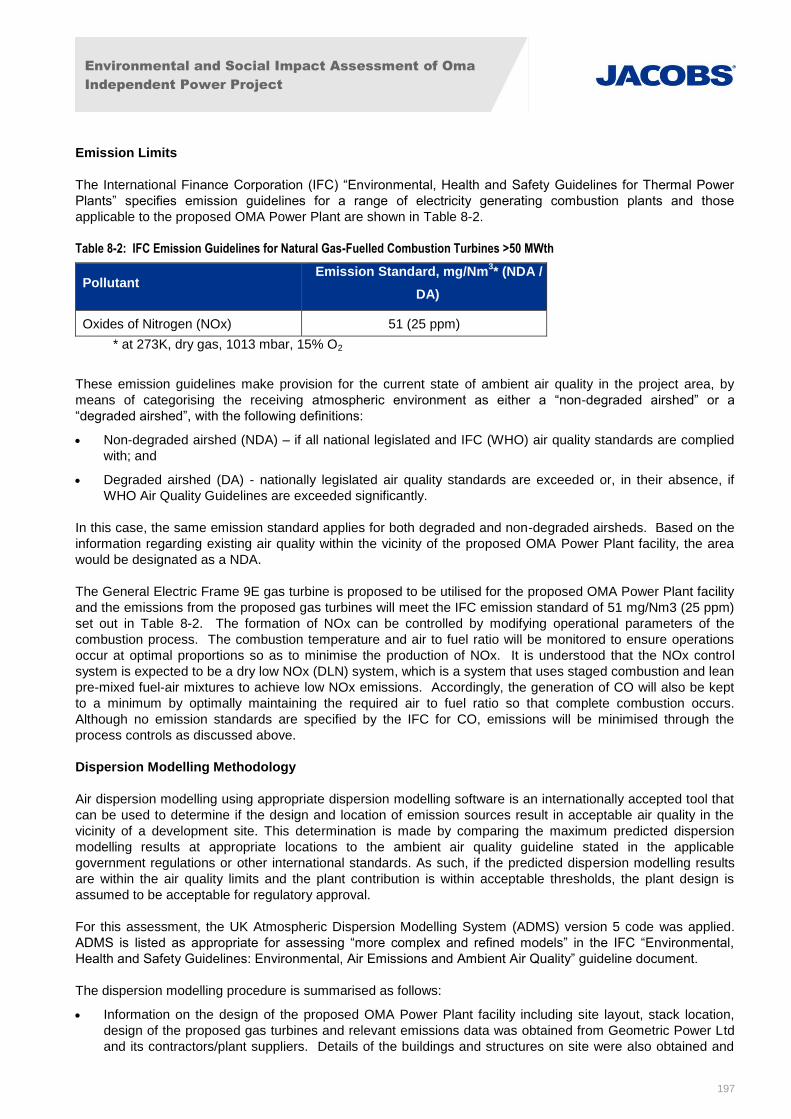
Environmental and Social Impact Assessment of Oma
Independent Power Project
197
Emission Limits
The International Finance Corporation (IFC) “Environmental, Health and Safety Guidelines for Thermal Power
Plants” specifies emission guidelines for a range of electricity generating combustion plants and those
applicable to the proposed OMA Power Plant are shown in Table 8-2.
Table 8-2: IFC Emission Guidelines for Natural Gas-Fuelled Combustion Turbines >50 MWth
Pollutant Emission Standard, mg/Nm
3* (NDA /
DA)
Oxides of Nitrogen (NOx) 51 (25 ppm)
* at 273K, dry gas, 1013 mbar, 15% O2
These emission guidelines make provision for the current state of ambient air quality in the project area, by
means of categorising the receiving atmospheric environment as either a “non-degraded airshed” or a
“degraded airshed”, with the following definitions:
Non-degraded airshed (NDA) – if all national legislated and IFC (WHO) air quality standards are complied
with; and
Degraded airshed (DA) - nationally legislated air quality standards are exceeded or, in their absence, if
WHO Air Quality Guidelines are exceeded significantly.
In this case, the same emission standard applies for both degraded and non-degraded airsheds. Based on the
information regarding existing air quality within the vicinity of the proposed OMA Power Plant facility, the area
would be designated as a NDA.
The General Electric Frame 9E gas turbine is proposed to be utilised for the proposed OMA Power Plant facility
and the emissions from the proposed gas turbines will meet the IFC emission standard of 51 mg/Nm3 (25 ppm)
set out in Table 8-2. The formation of NOx can be controlled by modifying operational parameters of the
combustion process. The combustion temperature and air to fuel ratio will be monitored to ensure operations
occur at optimal proportions so as to minimise the production of NOx. It is understood that the NOx control
system is expected to be a dry low NOx (DLN) system, which is a system that uses staged combustion and lean
pre-mixed fuel-air mixtures to achieve low NOx emissions. Accordingly, the generation of CO will also be kept
to a minimum by optimally maintaining the required air to fuel ratio so that complete combustion occurs.
Although no emission standards are specified by the IFC for CO, emissions will be minimised through the
process controls as discussed above.
Dispersion Modelling Methodology
Air dispersion modelling using appropriate dispersion modelling software is an internationally accepted tool that
can be used to determine if the design and location of emission sources result in acceptable air quality in the
vicinity of a development site. This determination is made by comparing the maximum predicted dispersion
modelling results at appropriate locations to the ambient air quality guideline stated in the applicable
government regulations or other international standards. As such, if the predicted dispersion modelling results
are within the air quality limits and the plant contribution is within acceptable thresholds, the plant design is
assumed to be acceptable for regulatory approval.
For this assessment, the UK Atmospheric Dispersion Modelling System (ADMS) version 5 code was applied.
ADMS is listed as appropriate for assessing “more complex and refined models” in the IFC “Environmental,
Health and Safety Guidelines: Environmental, Air Emissions and Ambient Air Quality” guideline document.
The dispersion modelling procedure is summarised as follows:
Information on the design of the proposed OMA Power Plant facility including site layout, stack location,
design of the proposed gas turbines and relevant emissions data was obtained from Geometric Power Ltd
and its contractors/plant suppliers. Details of the buildings and structures on site were also obtained and
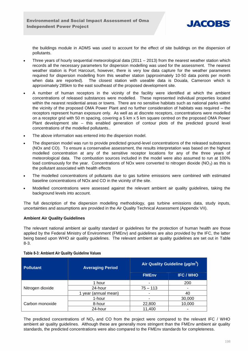
Environmental and Social Impact Assessment of Oma
Independent Power Project
198
the buildings module in ADMS was used to account for the effect of site buildings on the dispersion of
pollutants.
Three years of hourly sequential meteorological data (2011 – 2013) from the nearest weather station which
records all the necessary parameters for dispersion modelling was used for the assessment. The nearest
weather station is Port Harcourt, however, there is very low data capture for the weather parameters
required for dispersion modelling from this weather station (approximately 10-50 data points per month
when data are reported). The closest station with useable data is Douala, Cameroon which is
approximately 285km to the east southeast of the proposed development site.
A number of human receptors in the vicinity of the facility were identified at which the ambient
concentrations of released substances were modelled. These represented individual properties located
within the nearest residential areas or towns. There are no sensitive habitats such as national parks within
the vicinity of the proposed OMA Power Plant and no further consideration of habitats was required – the
receptors represent human exposure only. As well as at discrete receptors, concentrations were modelled
on a receptor grid with 50 m spacing, covering a 5 km x 5 km square centred on the proposed OMA Power
Plant development site – this enabled generation of contour plots of the predicted ground level
concentrations of the modelled pollutants..
The above information was entered into the dispersion model.
The dispersion model was run to provide predicted ground-level concentrations of the released substances
(NOx and CO). To ensure a conservative assessment, the results interpretation was based on the highest
modelled concentration at any of the sensitive receptor locations for any of the three years of
meteorological data. The combustion sources included in the model were also assumed to run at 100%
load continuously for the year. Concentrations of NOx were converted to nitrogen dioxide (NO2) as this is
the pollutant associated with health effects
The modelled concentrations of pollutants due to gas turbine emissions were combined with estimated
baseline concentrations of NOx and CO in the vicinity of the site.
Modelled concentrations were assessed against the relevant ambient air quality guidelines, taking the
background levels into account.
The full description of the dispersion modelling methodology, gas turbine emissions data, study inputs,
uncertainties and assumptions are provided in the Air Quality Technical Assessment (Appendix VII).
Ambient Air Quality Guidelines
The relevant national ambient air quality standard or guidelines for the protection of human health are those
applied by the Federal Ministry of Environment (FMEnv) and guidelines are also provided by the IFC, the latter
being based upon WHO air quality guidelines. The relevant ambient air quality guidelines are set out in Table
8-3.
Table 8-3: Ambient Air Quality Guideline Values
Pollutant Averaging Period Air Quality Guideline (µg/m
3)
FMEnv IFC / WHO
Nitrogen dioxide
1 hour - 200
24-hour 75 – 113 -
1 year (annual mean) - 40
Carbon monoxide
1-hour - 30,000
8-hour 22,800 10,000
24-hour 11,400 -
The predicted concentrations of NO2 and CO from the project were compared to the relevant IFC / WHO
ambient air quality guidelines. Although these are generally more stringent than the FMEnv ambient air quality
standards, the predicted concentrations were also compared to the FMEnv standards for completeness.
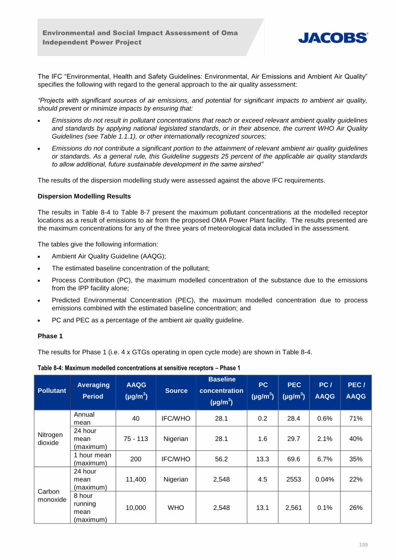
Environmental and Social Impact Assessment of Oma
Independent Power Project
199
The IFC “Environmental, Health and Safety Guidelines: Environmental, Air Emissions and Ambient Air Quality”
specifies the following with regard to the general approach to the air quality assessment:
“Projects with significant sources of air emissions, and potential for significant impacts to ambient air quality,
should prevent or minimize impacts by ensuring that:
Emissions do not result in pollutant concentrations that reach or exceed relevant ambient quality guidelines
and standards by applying national legislated standards, or in their absence, the current WHO Air Quality
Guidelines (see Table 1.1.1), or other internationally recognized sources;
Emissions do not contribute a significant portion to the attainment of relevant ambient air quality guidelines
or standards. As a general rule, this Guideline suggests 25 percent of the applicable air quality standards
to allow additional, future sustainable development in the same airshed”
The results of the dispersion modelling study were assessed against the above IFC requirements.
Dispersion Modelling Results
The results in Table 8-4 to Table 8-7 present the maximum pollutant concentrations at the modelled receptor
locations as a result of emissions to air from the proposed OMA Power Plant facility. The results presented are
the maximum concentrations for any of the three years of meteorological data included in the assessment.
The tables give the following information:
Ambient Air Quality Guideline (AAQG);
The estimated baseline concentration of the pollutant;
Process Contribution (PC), the maximum modelled concentration of the substance due to the emissions
from the IPP facility alone;
Predicted Environmental Concentration (PEC), the maximum modelled concentration due to process
emissions combined with the estimated baseline concentration; and
PC and PEC as a percentage of the ambient air quality guideline.
Phase 1
The results for Phase 1 (i.e. 4 x GTGs operating in open cycle mode) are shown in Table 8-4.
Table 8-4: Maximum modelled concentrations at sensitive receptors – Phase 1
Pollutant Averaging
Period
AAQG
(µg/m3)
Source
Baseline
concentration
(µg/m3)
PC
(µg/m3)
PEC
(µg/m3)
PC /
AAQG
PEC /
AAQG
Nitrogen
dioxide
Annual
mean 40 IFC/WHO 28.1 0.2 28.4 0.6% 71%
24 hour
mean
(maximum)
75 - 113 Nigerian 28.1 1.6 29.7 2.1% 40%
1 hour mean
(maximum) 200 IFC/WHO 56.2 13.3 69.6 6.7% 35%
Carbon
monoxide
24 hour
mean
(maximum)
11,400 Nigerian 2,548 4.5 2553 0.04% 22%
8 hour
running
mean
(maximum)
10,000 WHO 2,548 13.1 2,561 0.1% 26%
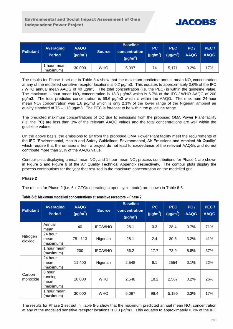
Environmental and Social Impact Assessment of Oma
Independent Power Project
200
Pollutant Averaging
Period
AAQG
(µg/m3)
Source
Baseline
concentration
(µg/m3)
PC
(µg/m3)
PEC
(µg/m3)
PC /
AAQG
PEC /
AAQG
1 hour mean
(maximum) 30,000 WHO 5,097 74 5,171 0.2% 17%
The results for Phase 1 set out in Table 8.4 show that the maximum predicted annual mean NO2 concentration
at any of the modelled sensitive receptor locations is 0.2 µg/m3. This equates to approximately 0.6% of the IFC
/ WHO annual mean AAQG of 40 µg/m3. The total concentration (i.e. the PEC) is within the guideline value.
The maximum 1-hour mean NO2 concentration is 13.3 µg/m3 which is 6.7% of the IFC / WHO AAQG of 200
µg/m3. The total predicted concentration is 69.6 µg/m3 which is within the AAQG. The maximum 24-hour
mean NO2 concentration was 1.6 µg/m3 which is only 2.1% of the lower range of the Nigerian ambient air
quality standard of 75 – 113 µg/m3. The PEC is forecast to be within the guideline range.
The predicted maximum concentrations of CO due to emissions from the proposed OMA Power Plant facility
(i.e. the PC) are less than 1% of the relevant AAQG values and the total concentrations are well within the
guideline values.
On the above basis, the emissions to air from the proposed OMA Power Plant facility meet the requirements of
the IFC “Environmental, Health and Safety Guidelines: Environmental, Air Emissions and Ambient Air Quality”
which require that the emissions from a project do not lead to exceedance of the relevant AAQGs and do not
contribute more than 25% of the AAQG value.
Contour plots displaying annual mean NO2 and 1 hour mean NO2 process contributions for Phase 1 are shown
in Figure 5 and Figure 6 of the Air Quality Technical Appendix respectively. The contour plots display the
process contributions for the year that resulted in the maximum concentration on the modelled grid.
Phase 2
The results for Phase 2 (i.e. 6 x GTGs operating in open cycle mode) are shown in Table 8-5.
Table 8-5: Maximum modelled concentrations at sensitive receptors – Phase 2
Pollutant Averaging
Period
AAQG
(µg/m3)
Source
Baseline
concentration
(µg/m3)
PC
(µg/m3)
PEC
(µg/m3)
PC /
AAQG
PEC /
AAQG
Nitrogen
dioxide
Annual
mean 40 IFC/WHO 28.1 0.3 28.4 0.7% 71%
24 hour
mean
(maximum)
75 - 113 Nigerian 28.1 2.4 30.5 3.2% 41%
1 hour mean
(maximum) 200 IFC/WHO 56.2 17.7 73.9 8.8% 37%
Carbon
monoxide
24 hour
mean
(maximum)
11,400 Nigerian 2,548 6.1 2554 0.1% 22%
8 hour
running
mean
(maximum)
10,000 WHO 2,548 18.2 2,567 0.2% 26%
1 hour mean
(maximum) 30,000 WHO 5,097 98.4 5,195 0.3% 17%
The results for Phase 2 set out in Table 8-5 show that the maximum predicted annual mean NO2 concentration
at any of the modelled sensitive receptor locations is 0.3 µg/m3. This equates to approximately 0.7% of the IFC
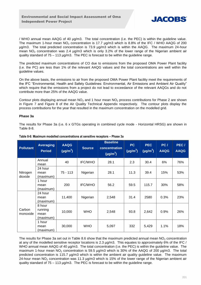
Environmental and Social Impact Assessment of Oma
Independent Power Project
201
/ WHO annual mean AAQG of 40 µg/m3. The total concentration (i.e. the PEC) is within the guideline value.
The maximum 1-hour mean NO2 concentration is 17.7 µg/m3 which is 8.8% of the IFC / WHO AAQG of 200
µg/m3. The total predicted concentration is 73.9 µg/m3 which is within the AAQG. The maximum 24-hour
mean NO2 concentration was 2.4 µg/m3 which is only 3.2% of the lower range of the Nigerian ambient air
quality standard of 75 – 113 µg/m3. The PEC is forecast to be within the guideline range.
The predicted maximum concentrations of CO due to emissions from the proposed OMA Power Plant facility
(i.e. the PC) are less than 1% of the relevant AAQG values and the total concentrations are well within the
guideline values.
On the above basis, the emissions to air from the proposed OMA Power Plant facility meet the requirements of
the IFC “Environmental, Health and Safety Guidelines: Environmental, Air Emissions and Ambient Air Quality”
which require that the emissions from a project do not lead to exceedance of the relevant AAQGs and do not
contribute more than 25% of the AAQG value.
Contour plots displaying annual mean NO2 and 1 hour mean NO2 process contributions for Phase 2 are shown
in Figure 7 and Figure 8 of the Air Quality Technical Appendix respectively. The contour plots display the
process contributions for the year that resulted in the maximum concentration on the modelled grid.
Phase 3a
The results for Phase 3a (i.e. 6 x GTGs operating in combined cycle mode - Horizontal HRSG) are shown in
Table 8-8.
Table 8-6: Maximum modelled concentrations at sensitive receptors – Phase 3a
Pollutant Averaging
Period
AAQG
(µg/m3)
Source
Baseline
concentration
(µg/m3)
PC
(µg/m3)
PEC
(µg/m3)
PC /
AAQG
PEC /
AAQG
Nitrogen
dioxide
Annual
mean 40 IFC/WHO 28.1 2.3 30.4 6% 76%
24 hour
mean
(maximum)
75 - 113 Nigerian 28.1 11.3 39.4 15% 53%
1 hour
mean
(maximum)
200 IFC/WHO 56.2 59.5 115.7 30% 58%
Carbon
monoxide
24 hour
mean
(maximum)
11,400 Nigerian 2,548 31.4 2580 0.3% 23%
8 hour
running
mean
(maximum)
10,000 WHO 2,548 93.8 2,642 0.9% 26%
1 hour
mean
(maximum)
30,000 WHO 5,097 332 5,429 1.1% 18%
The results for Phase 3a set out in Table 8.6 show that the maximum predicted annual mean NO2 concentration
at any of the modelled sensitive receptor locations is 2.3 µg/m3. This equates to approximately 6% of the IFC /
WHO annual mean AAQG of 40 µg/m3. The total concentration (i.e. the PEC) is within the guideline value. The
maximum 1-hour mean NO2 concentration is 59.5 µg/m3 which is 30% of the AAQG of 200 µg/m3. The total
predicted concentration is 115.7 µg/m3 which is within the ambient air quality guideline value. The maximum
24-hour mean NO2 concentration was 11.3 µg/m3 which is 15% of the lower range of the Nigerian ambient air
quality standard of 75 – 113 µg/m3. The PEC is forecast to be within the guideline range.
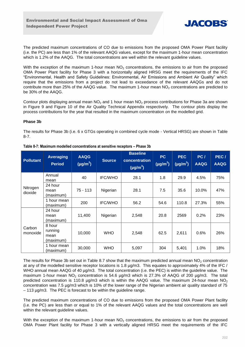
Environmental and Social Impact Assessment of Oma
Independent Power Project
202
The predicted maximum concentrations of CO due to emissions from the proposed OMA Power Plant facility
(i.e. the PC) are less than 1% of the relevant AAQG values, except for the maximum 1-hour mean concentration
which is 1.2% of the AAQG. The total concentrations are well within the relevant guideline values.
With the exception of the maximum 1-hour mean NO2 concentrations, the emissions to air from the proposed
OMA Power Plant facility for Phase 3 with a horizontally aligned HRSG meet the requirements of the IFC
“Environmental, Health and Safety Guidelines: Environmental, Air Emissions and Ambient Air Quality” which
require that the emissions from a project do not lead to exceedance of the relevant AAQGs and do not
contribute more than 25% of the AAQG value. The maximum 1-hour mean NO2 concentrations are predicted to
be 30% of the AAQG.
Contour plots displaying annual mean NO2 and 1 hour mean NO2 process contributions for Phase 3a are shown
in Figure 9 and Figure 10 of the Air Quality Technical Appendix respectively. The contour plots display the
process contributions for the year that resulted in the maximum concentration on the modelled grid.
Phase 3b
The results for Phase 3b (i.e. 6 x GTGs operating in combined cycle mode - Vertical HRSG) are shown in Table
8-7.
Table 8-7: Maximum modelled concentrations at sensitive receptors – Phase 3b
Pollutant Averaging
Period
AAQG
(µg/m3)
Source
Baseline
concentration
(µg/m3)
PC
(µg/m3)
PEC
(µg/m3)
PC /
AAQG
PEC /
AAQG
Nitrogen
dioxide
Annual
mean 40 IFC/WHO 28.1 1.8 29.9 4.5% 75%
24 hour
mean
(maximum)
75 - 113 Nigerian 28.1 7.5 35.6 10.0% 47%
1 hour mean
(maximum) 200 IFC/WHO 56.2 54.6 110.8 27.3% 55%
Carbon
monoxide
24 hour
mean
(maximum)
11,400 Nigerian 2,548 20.8 2569 0.2% 23%
8 hour
running
mean
(maximum)
10,000 WHO 2,548 62.5 2,611 0.6% 26%
1 hour mean
(maximum) 30,000 WHO 5,097 304 5,401 1.0% 18%
The results for Phase 3b set out in Table 8.7 show that the maximum predicted annual mean NO2 concentration
at any of the modelled sensitive receptor locations is 1.8 µg/m3. This equates to approximately 4% of the IFC /
WHO annual mean AAQG of 40 µg/m3. The total concentration (i.e. the PEC) is within the guideline value. The
maximum 1-hour mean NO2 concentration is 54.6 µg/m3 which is 27.3% of AAQG of 200 µg/m3. The total
predicted concentration is 110.8 µg/m3 which is within the AAQG value. The maximum 24-hour mean NO2
concentration was 7.5 µg/m3 which is 10% of the lower range of the Nigerian ambient air quality standard of 75
– 113 µg/m3. The PEC is forecast to be within the guideline range.
The predicted maximum concentrations of CO due to emissions from the proposed OMA Power Plant facility
(i.e. the PC) are less than or equal to 1% of the relevant AAQG values and the total concentrations are well
within the relevant guideline values.
With the exception of the maximum 1-hour mean NO2 concentrations, the emissions to air from the proposed
OMA Power Plant facility for Phase 3 with a vertically aligned HRSG meet the requirements of the IFC
Environmental and Social Impact Assessment of Oma
Independent Power Project
203
“Environmental, Health and Safety Guidelines: Environmental, Air Emissions and Ambient Air Quality” which
require that the emissions from a project do not lead to exceedance of the relevant AAQGs and do not
contribute more than 25% of the AAQG value. The maximum 1-hour mean NO2 concentrations are predicted to
be 27% of the AAQG.
Contour plots displaying annual mean NO2 and 1 hour mean NO2 process contributions for Phase 3b are shown
in Figure 11 and Figure 12 of the Air Quality Technical Appendix respectively. The contour plots display the
process contributions for the year that resulted in the maximum concentration on the modelled grid.
Impact Assessment
Considering the modelling results and the fact that the nearest receptors would be over 400 meters away, the
magnitude of the effect that operational activities will have on air quality is assessed as low. The significance of
effect of the operational activities is therefore assessed as negligible/minor without mitigation. The modelling
results account for mitigation measures already incorporated into the plant design. Additional mitigation
measure including management of operations and environmental monitoring measures are discussed in Section
9.4.1.
Residual Impacts
The results of the detailed air quality assessment show that there will not be any significant residual impacts to
air quality for Phases 1 and 2 of the proposed OMA Power Plant project. All predicted concentrations are well
within the applicable IFC/WHO ambient air quality guidelines and the contribution from the development is less
than 25% of the guideline values. This is classed as a low magnitude impact with negligible significance.
If the project proceeds to Phase 3, further detailed assessment will be required in order to determine whether
the stack height is appropriate and if any additional mitigation measures are required. The impact for Phase 3
for the current indicative design is classed as potentially minor/major impact with minor / major significance. It is
anticipated that, with appropriate amendments to the design, the impact for Phase 3 could be reduced to a low
magnitude impact of negligible / minor significance, similar to Phases 1 and 2.
8.7.2 Energy Efficiency and Greenhouse Gas Emissions
The GHG emissions from the project over its lifetime have been quantified. The predicted emissions have been
compared with Nigeria’s carbon grid factor and annual carbon emissions. The GHG emissions for the project
using alternatively fuelled technologies have also been considered.
The IFC/World Bank requirements in relation to avoiding, minimising and offsetting emissions of carbon dioxide
from new thermal power plants are detailed in IFC EHS Guidelines for Thermal Power Plants and IFC Guidance
Note 3 (2012)9. This Note provides guidance on the various available GHG emissions estimation methodologies
and recommends the IPCC (2006) Guidelines as the most authoritative methodology10
.
Based on this guidance, the following approach has been undertaken to determine GHG emissions and
comparison with alternative fuels and the Nigerian electricity grid factor:
Calculation of annual primary energy consumption of the power plant in phases 1 and 2.
Conversion to carbon emissions using IPCC carbon conversion factors.
Calculation of the lifetime carbon emissions based on the project life time.
GHG comparison with alternative fuels.
Calculation of carbon grid factor based on the efficiency of steam cycle operation.
Relative contribution of the Power Station to the Nigeria’s GHG emissions.
9 IFC (2012). Guidance Note 3: Resource Efficiency and Pollution Prevention. 10 IPCC (2006). Guidelines for National Greenhouse Gas Inventories of the Intergovernmental Panel on Climate Change (IPCC). Volume 1
(General Guidance and Reporting), Volume 2 (Energy),
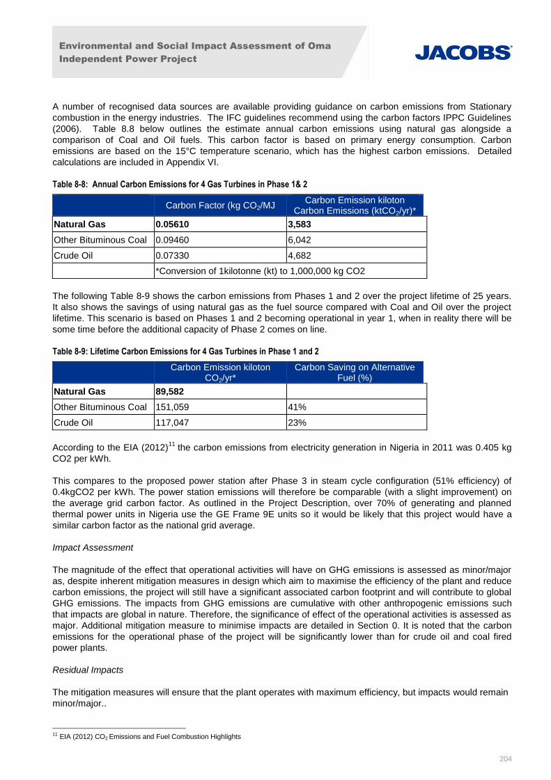
Environmental and Social Impact Assessment of Oma
Independent Power Project
204
A number of recognised data sources are available providing guidance on carbon emissions from Stationary
combustion in the energy industries. The IFC guidelines recommend using the carbon factors IPPC Guidelines
(2006). Table 8.8 below outlines the estimate annual carbon emissions using natural gas alongside a
comparison of Coal and Oil fuels. This carbon factor is based on primary energy consumption. Carbon
emissions are based on the 15°C temperature scenario, which has the highest carbon emissions. Detailed
calculations are included in Appendix VI.
Table 8-8: Annual Carbon Emissions for 4 Gas Turbines in Phase 1& 2
Carbon Factor (kg CO2/MJ
Carbon Emission kiloton Carbon Emissions (ktCO2/yr)*
Natural Gas 0.05610 3,583
Other Bituminous Coal 0.09460 6,042
Crude Oil 0.07330 4,682
*Conversion of 1kilotonne (kt) to 1,000,000 kg CO2
The following Table 8-9 shows the carbon emissions from Phases 1 and 2 over the project lifetime of 25 years.
It also shows the savings of using natural gas as the fuel source compared with Coal and Oil over the project
lifetime. This scenario is based on Phases 1 and 2 becoming operational in year 1, when in reality there will be
some time before the additional capacity of Phase 2 comes on line.
Table 8-9: Lifetime Carbon Emissions for 4 Gas Turbines in Phase 1 and 2
Carbon Emission kiloton CO2/yr*
Carbon Saving on Alternative Fuel (%)
Natural Gas 89,582
Other Bituminous Coal 151,059 41%
Crude Oil 117,047 23%
According to the EIA (2012)11
the carbon emissions from electricity generation in Nigeria in 2011 was 0.405 kg
CO2 per kWh.
This compares to the proposed power station after Phase 3 in steam cycle configuration (51% efficiency) of
0.4kgCO2 per kWh. The power station emissions will therefore be comparable (with a slight improvement) on
the average grid carbon factor. As outlined in the Project Description, over 70% of generating and planned
thermal power units in Nigeria use the GE Frame 9E units so it would be likely that this project would have a
similar carbon factor as the national grid average.
Impact Assessment
The magnitude of the effect that operational activities will have on GHG emissions is assessed as minor/major
as, despite inherent mitigation measures in design which aim to maximise the efficiency of the plant and reduce
carbon emissions, the project will still have a significant associated carbon footprint and will contribute to global
GHG emissions. The impacts from GHG emissions are cumulative with other anthropogenic emissions such
that impacts are global in nature. Therefore, the significance of effect of the operational activities is assessed as
major. Additional mitigation measure to minimise impacts are detailed in Section 0. It is noted that the carbon
emissions for the operational phase of the project will be significantly lower than for crude oil and coal fired
power plants.
Residual Impacts
The mitigation measures will ensure that the plant operates with maximum efficiency, but impacts would remain
minor/major..
11 EIA (2012) CO2 Emissions and Fuel Combustion Highlights
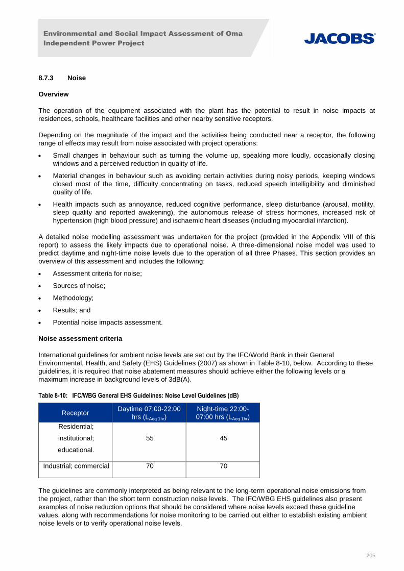
Environmental and Social Impact Assessment of Oma
Independent Power Project
205
8.7.3 Noise
Overview
The operation of the equipment associated with the plant has the potential to result in noise impacts at
residences, schools, healthcare facilities and other nearby sensitive receptors.
Depending on the magnitude of the impact and the activities being conducted near a receptor, the following
range of effects may result from noise associated with project operations:
Small changes in behaviour such as turning the volume up, speaking more loudly, occasionally closing
windows and a perceived reduction in quality of life.
Material changes in behaviour such as avoiding certain activities during noisy periods, keeping windows
closed most of the time, difficulty concentrating on tasks, reduced speech intelligibility and diminished
quality of life.
Health impacts such as annoyance, reduced cognitive performance, sleep disturbance (arousal, motility,
sleep quality and reported awakening), the autonomous release of stress hormones, increased risk of
hypertension (high blood pressure) and ischaemic heart diseases (including myocardial infarction).
A detailed noise modelling assessment was undertaken for the project (provided in the Appendix VIII of this
report) to assess the likely impacts due to operational noise. A three-dimensional noise model was used to
predict daytime and night-time noise levels due to the operation of all three Phases. This section provides an
overview of this assessment and includes the following:
Assessment criteria for noise;
Sources of noise;
Methodology;
Results; and
Potential noise impacts assessment.
Noise assessment criteria
International guidelines for ambient noise levels are set out by the IFC/World Bank in their General
Environmental, Health, and Safety (EHS) Guidelines (2007) as shown in Table 8-10, below. According to these
guidelines, it is required that noise abatement measures should achieve either the following levels or a
maximum increase in background levels of 3dB(A).
Table 8-10: IFC/WBG General EHS Guidelines: Noise Level Guidelines (dB)
Receptor Daytime 07:00-22:00
hrs (LAeq 1hr)
Night-time 22:00-
07:00 hrs (LAeq 1hr)
Residential;
institutional;
educational.
55 45
Industrial; commercial 70 70
The guidelines are commonly interpreted as being relevant to the long-term operational noise emissions from
the project, rather than the short term construction noise levels. The IFC/WBG EHS guidelines also present
examples of noise reduction options that should be considered where noise levels exceed these guideline
values, along with recommendations for noise monitoring to be carried out either to establish existing ambient
noise levels or to verify operational noise levels.

Environmental and Social Impact Assessment of Oma
Independent Power Project
206
The IFC/WBG has also published EHS Guidelines for Thermal Power Plants, which set out industry-specific
examples of good international industry practice. In respect to noise, these guidelines note that amongst the
principal sources of noise in thermal power plants are turbine generators and auxiliaries, boilers and auxiliaries,
fans and ductwork, pumps, compressors, piping, valves and cooling towers.
Noise impacts, control measures, and recommended ambient noise levels for thermal power plants are
presented in Section 1.7 of the General EHS Guidelines.
The noise guidelines presented in Section 1.7 of the General EHS Guidelines are based on the 1999 World
Health Organisation (WHO) Guidelines for Community Noise.
Although the General IFC EHS guidelines do not stipulate any environmental vibration criteria, the IFC requires
potential impacts from vibration to be mitigated.
Noise Sources
The noise assessment considered noise emissions arising from the operation of the following plant associated
with the three phases of the project which, briefly, comprise:
Phase 1:
Four General Electric (GE) ‘Frame 9’ 113MW gas turbines operating in simple cycle mode.
Six electrical transformers.
Associated infrastructure and buildings.
Phase 2:
Six GE ‘Frame 9’ 113MW gas turbines operating in simple cycle mode.
Nine electrical transformers.
Associated infrastructure and buildings.
Phase 3:
Six GE ‘Frame 9’ 113MW gas turbines operating simultaneously in combined cycle mode with the exhaust
gases being directed through six waste heat boilers for energy recovery.
Two steam turbines, situated in dedicated buildings.
Two air cooled condenser arrays.
11 electrical transformers.
Associated infrastructure and buildings.
The key noise sources associated with the three phases of the project are:
Gas Turbines: The gas turbines generate noise as a result of the flow of air and combustion gas. Noise is
emitted from the gas turbine casings, and from the associated air intakes and exhausts. In simple cycle
(also known as ‘open cycle’) mode the exhaust gases are discharged via 40m tall vertical flues (fitted with
attenuators) connected to the gas turbine exhausts. In combined cycle mode, a significant proportion of the
exhaust gas is directed through Waste Heat Boilers (WHB) and then exits through additional 40m tall
vertical flues. The WHBs generate steam to feed the Phase 3 steam turbines.
Air Inlet Filters: Air to the gas turbines is filtered before entering the inlet plenum to minimise the potential
for pollen, dust and sand to cause damage. The filters collect particulates in the air, and must be cleaned
periodically by high-pressure air pulses, which blow the particles off the filter surface.
Electrical Transformers: Noise from electrical transformers is caused by magnetostriction (where the metal
sheets forming the core extend and contract in response to the alternating magnetic field), and from the
cooling system.

Environmental and Social Impact Assessment of Oma
Independent Power Project
207
Air Cooled Condensers (ACC): ACCs are heat exchangers that use the ambient air to cool and condense
steam which has been through the steam turbine, in order for it to be recirculated to the waste heat boilers.
Each ACC comprises an array of large fans, which blow cool air over finned tubes containing the steam.
Each fan and its associated finned tubes is referred to as a cell. Noise is generated by the fan gearbox, fan
blades and the movement of air across the heat exchange surface.
Steam Turbines: Steam turbines convert thermal energy in the form of pressurised steam to mechanical
work and ultimately, electrical power through a generator. Noise is generated in the turbine by rotating
parts and pressure changes in the steam.
Noise Modelling Methodology
Noise modelling software provides a way of constructing a three-dimensional computer model of terrain, ground
characteristics and noise sources which enables the prediction of noise at any point within the modelled area.
In order to compute the environmental noise emission level from plant items and operations at the
representative noise sensitive receptors, noise emission modelling was undertaken using the CadnaA noise
prediction software. The software was configured to use the noise prediction methodology set out in ISO961312
,
which is suitable for the prediction of noise levels in the community from sources of known sound emission.
The noise prediction method described in part 2 of ISO9613 is general, and is suitable for a wide range of
engineering applications where the noise level outdoors is of interest. The noise source(s) may be moving or
stationary and the method considers the following major mechanisms of noise attenuation:
Geometrical divergence (also known as distance loss or geometric damping);
Atmospheric absorption;
Ground effect;
Reflection from surfaces; and
Screening by obstacles.
The method predicts noise levels under metrological conditions favourable to noise propagation from the sound
source to the receiver, such as downwind propagation, or equivalently, propagation under a moderate ground
based temperature inversion as commonly occurs at night.
All of the scenarios consider operation under steady-state conditions, rather than during start-up, maintenance
or emergency conditions, In particular, pulsing cleaning to clear debris from the gas turbine air intakes has not
been considered; this activity can lead to high noise levels, but is short in duration
Input data
The site layout, position and the height of buildings / plant in the noise model are derived from drawing
F2013021T-Z04 Rev 09 by China power Construction Engineering Consulting Central Sothern Co. Ltd., which is
included in Appendix VIII of this document for convenience.
The ground level in and around the site is assumed to be generally flat, and therefore no topographic screening
effects have been considered in the noise model. The intervening ground between the project and the closest
dwellings is generally natural scrub land, and therefore is considered to be acoustically porous.
Sound Power Levels
At this time, detailed noise emission data for the proposed equipment selections is not available. Therefore, the
following A-weighted sound power levels described in table 8.11 have been used in the noise predictions, which
are based upon empirical formulae in technical literature, noise measurements of similar equipment, or other
manufacturer’s data for similar equipment. These values were agreed with Geometric Power prior to
12 International Standard: ISO 9613-2: 1996(E): Acoustics - Attenuation of sound during propagation outdoors - Part 2: General method of calculation.
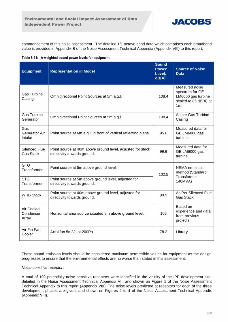
Environmental and Social Impact Assessment of Oma
Independent Power Project
208
commencement of this noise assessment. The detailed 1/1 octave band data which comprises each broadband
value is provided in Appendix B of the Noise Assessment Technical Appendix (Appendix VIII) to this report.
Table 8-11: A-weighted sound power levels for equipment
Equipment Representation in Model
Sound
Power
Level,
dB(A)
Source of Noise
Data
Gas Turbine
Casing Omnidirectional Point Sources at 5m a.g.l. 108.4
Measured noise
spectrum for GE
LM6000 gas turbine
scaled to 85 dB(A) at
1m.
Gas Turbine
Generator Omnidirectional Point Sources at 5m a.g.l. 108.4
As per Gas Turbine
Casing
Gas
Generator Air
Intake
Point source at 6m a.g.l. in front of vertical reflecting plane. 95.6
Measured data for
GE LM6000 gas
turbine.
Silenced Flue
Gas Stack
Point source at 40m above ground level, adjusted for stack
directivity towards ground. 99.9
Measured data for
GE LM6000 gas
turbine.
GTG
Transformer Point source at 5m above ground level.
102.5
NEMA empirical
method (Standard
Transformer
140MVA) STG
Transformer
Point source at 5m above ground level, adjusted for
directivity towards ground.
WHB Stack Point source at 40m above ground level, adjusted for
directivity towards ground. 99.9
As Per Silenced Flue
Gas Stack
Air Cooled
Condenser
Array
Horizontal area source situated 5m above ground level. 105
Based on
experience and data
from previous
projects
Air Fin Fan
Cooler Axial fan 5m3/s at 200Pa 78.2 Library
These sound emission levels should be considered maximum permissible values for equipment as the design
progresses to ensure that the environmental effects are no worse than stated in this assessment.
Noise sensitive receptors
A total of 102 potentially noise sensitive receptors were identified in the vicinity of the IPP development site,
detailed in the Noise Assessment Technical Appendix VIII and shown on Figure 1 of the Noise Assessment
Technical Appendix to this report (Appendix VIII). The noise levels predicted at receptors for each of the three
development phases are given, and shown on Figures 2 to 4 of the Noise Assessment Technical Appendix
(Appendix VIII).
Environmental and Social Impact Assessment of Oma
Independent Power Project
209
Results
The noise emissions of the plant will be the same night and day, and therefore the predicted levels have been
compared to the IFC night-time criterion for residential properties of 45 dB LAeq,1h to be conservative.
The highest noise levels are predicted for receptors to the south of the project in the Port Harcourt Aba Road
area. All of the predicted noise levels are below the recommended daytime ambient noise levels are presented
in Section 1.7 of the General EHS Guidelines for residential, institutional and educational facilities. However the
recommended night-time ambient noise levels will be exceeded in all three phases of operation:
During Phase 1, it is expected that the night noise criterion will be exceeded at 19 properties, by between
0.2 - 3.2 dB.
During Phase 2, it is expected that the night noise criterion will be exceeded at 25 properties, by between
0.3 – 5.5 dB
During Phase 3, it is expected that the night noise criterion will be exceeded at 27 properties, by between
0.2 – 5.6 dB
As the recommended noise levels set out in the General EHS Guidelines are predicted to be exceeded, it is
appropriate to consider the effects of the predicted noise levels and mitigation measures that may be employed
to reduce noise emissions from the project.
Furthermore, the WHO has set out international guidelines for indoor noise levels to avoid sleep disturbance.
Above 55 dB Lnight, outside, the situation is considered increasingly dangerous for public health: adverse
health effects occur frequently, a sizeable proportion of the population is highly annoyed and sleep-disturbed,
and there is evidence that the risk of cardiovascular disease increases. Correspondingly, the night noise
guidelines put forward an Interim Target of 55 dB Lnight, outside. This is considered to be an appropriate
Significant Observed Adverse Effect Level (SOAEL) for this assessment.
The highest noise levels predicted as a result of the project are below the SOAEL of 55 dB Lnight, outside.
However, noise levels in the predicted range (40-55 dB Lnight, outside) are associated with increased likelihood
of adverse health effects including self-reported sleep disturbance, environmental insomnia, increased use of
sleep-inducing drugs and sedatives, and changes in behaviour. The most common change in behaviour is to
close bedroom windows whilst sleeping, which may cause other issues with overheating and fresh air which
impact on quality of sleep. It is therefore considered good international industry practice to mitigate, as far as
possible, noise levels above 40 dB Lnight, outside.
Conclusions
The predicted noise levels for all three phases of the project would result in the IFC night-time noise criterion for
residential properties of 45 dB LAeq,1hour being exceeded at sensitive receptors (between 0.2 and 5.6 dB).
Therefore, potential mitigation measures are outlined in Section 9.4.3.
Updated socio-economic survey work completed for the project in 2015 showed that some of the receptors
considered in the noise assessment may not in fact be residential uses. As a result, it is recommended that a
Noise Management Plan be developed for the project in consultation with the Lender Group and following
confirmation of the nearby residential receptors to determine the most effective mitigation strategies to address
night time noise exceedances.
Impact Assessment
The magnitude of noise effects from operational activities is assessed as minor/major. The significance of effect
of the operational noise is therefore assessed as minor/major. However, provided that mitigation measures are
taken via a Noise Management Plan to ensure noise emission levels are adequately reduced, no long-term
residual noise impacts are anticipated during operation of the proposed project.
Residual Impacts
Environmental and Social Impact Assessment of Oma
Independent Power Project
210
Provided that measures are taken to ensure noise emission levels meet World Bank guidelines, no long-term
residual noise impacts are anticipated during operation of the proposed project. The magnitude of effects will be
low and therefore the significance of effect minor
8.7.4 Ecology
On completion of the plant construction, the only potential ecology impacts would be associated with any
indirect or accidental release of substances and ground contamination and its subsequent effects on local
habitats and species.
Impact Assessment
The magnitude of ecology effects from operational activities is assessed as being minor. The significance is
assessed as minor as effects are considered unlikely since measures will be taken consistent with good
international industry practice to avoid or manage any spills or contamination.
Residual Impacts
Residual ecological impacts associated with the proposed project could include permanent loss of wildlife
habitat on the project site, minor degradation of wildlife habitat immediately adjacent to the project site, possible
relocation to a potentially less favourable habitat for those species that remain in the vicinity of the proposed
project site.
Residual ecological impacts associated with the proposed project could include permanent loss of wildlife
habitat on the project site, minor degradation of wildlife habitat immediately adjacent to the project site, possible
relocation to potentially less favourable habitat of those species that remain around the proposed project site.
However, considering that the conservation value of these ecological habitats is considered low, and the fact
that there are no protected and vulnerable species populations in the area and given the localised nature of
impacts, overall residual impacts on ecology are considered to be of negligible significance.
8.7.5 Water and Wastewater
Wastewater can pose a number of potential risks if humans consume or are otherwise exposed to pathogenic
microorganisms, heavy metals, or harmful organic chemicals such as endocrine-disrupting compounds. Of
these, pathogenic microorganisms are generally considered to pose the greatest threat to human health. A wide
variety of pathogenic microorganisms may be found in wastewater, including bacteria, viruses, protozoans and
parasitic worms. Amongst many others, diseases associated with such pathogens may include typhoid,
dysentery, gastroenteritis, diarrhoea, vomiting, and malabsorption. The concentration of pathogens in
wastewater is dependent on the source population. The susceptibility to infection by such pathogens can vary
between human individuals, for example, children, the elderly and those who are already sick may succumb to
infection more easily or experience more serious symptoms.
Wastewater from the project if not properly treated could result in the risk of disease or health effects as
described above. A key potential receptor susceptible to the discharge of waste effluent from the site would be
the community water supply borehole located down- (hydraulic) gradient from the site. If appropriate mitigation
measures are not employed, there is the potential for contaminants to infiltrate to groundwater and migrate to
the community water supply.
Impact Assessment
The magnitude of the effect that wastewater from operational activities may have is considered minor/major.
Based on all of the above, the significance of effect of the operational activities is therefore assessed as
minor/major prior to mitigation.
Residual Impacts
Environmental and Social Impact Assessment of Oma
Independent Power Project
211
No long–term residual impacts are expected following deployment of the specified mitigation measures. The
magnitude of effects will be low and therefore the significance of effect minor following mitigation.
8.7.6 Groundwater
On-site storage of any potentially contaminating fluids for the project is not anticipated to contain volumes
sufficient to result in an accidental release that could significantly impact upon the major regional rivers.
However, accidental spills of fuels or other materials pose a potential for contamination of ground water with
potential for migration to down gradient community water supply boreholes. Given the predominantly sandy
geology and aquifer conditions, contaminants from accidental spills at the site could rapidly percolate to the
water table located approximately 27 meters below ground surface. As there are no nearby surface water
features, the community water supply boreholes are the key potential receptor for accidental contamination via
release to groundwater.
In addition to potential impacts to community supply boreholes associated with contamination, it is also possible
that water abstraction at the site could potentially impact upon water availability from the community boreholes.
Chapter 4 indicates that a cumulative peak instantaneous groundwater flow of 162 m3/h (potentially plus 1%) is
required to support the water usage of Stages 1, 2 and 3.
However, it is considered unlikely that the water supply abstraction at the plant will impact on the community
supply boreholes based the following information:
Baseline information on the regional coastal sands aquifer indicates that it is a large regionally extensive
aquifer and generally able to supply significant yields. It is noted that the test pumping exercise was
undertaken at flow rates much less than the peak instantaneous rate;
The community boreholes were monitored during the borehole drilling and test pumping investigation and
results indicate that there was no drop in groundwater level at the community boreholes during the test. It
is noted that this is to be expected given the aquifer lithology and distance from the pumping well.
Following the results of the hydrogeology investigation, given the distance, it is considered highly unlikely that
there will be a significant impact on water availability at the community supply boreholes due to water
abstraction at the plant.
Impact Assessment
The magnitude of any effect that operational activities may have on groundwater is assessed as minor/major.
The significance of effect of the operational activities is therefore assessed as minor prior to mitigation.
Residual impacts
Despite use of appropriate mitigation measures, there is still the potential for some residual impacts from
accidental release of contaminants to ground. Given the use of good management practices and
implementation of effective emergency response, the impacts will be low in magnitude, with no long-term effects
and not considered significant
8.7.7 Solid Waste
Although the project is not anticipated to generate significant volumes of solid waste, some solid waste will be
generated during the operational phase of the project that will require off-site disposal.
Typical wastes generated during the operational phase include:
Maintenance wastes include:
Waste oils and lubricants;
Scrap metal;
Environmental and Social Impact Assessment of Oma
Independent Power Project
212
Waste electrical and electronic components;
Batteries;
Contaminated rags;
(Potentially) Contaminated spill response equipment;
Contaminated safety clothing, gloves, masks, and equipment;
Waste wood;
Waste paints and solvents;
Contaminated plant and machinery, including filters;
Domestic and food wastes;
Sewage wastes;
Sludges (potentially contaminated); and
Oily water and run-off.
There will be a potentially significant effect if wastes are not properly controlled and leakages causing soil and
water contamination could result. Waste stored improperly can also be unsightly and may harbour pests or
cause diseases when stored too long and allowed to degrade prior to proper disposal. This impact will be
managed by implementing good international industry practice management procedures, including a designed
waste management plan, to be outlined in the ESMS followed by regular inspection.
Impact Assessment
Given the potential of the project to generate waste that will require off-site disposal and the potential impacts if
it is not properly disposed of, the magnitude of the effect that waste from operational activities may have is
assessed as minor/major. Since proper management procedures are planned (through the waste management
plan), the significance of effect of the operational activities is therefore assessed as minor. Effective waste
management measures are outlined in Section 9.4.7.
Residual Impacts
No long–term residual impacts are expected following mitigation. With appropriate mitigation and waste
management the magnitude of effects will be low and therefore the significance of effect minor.
8.7.8 Fire / explosion
Accidental leakages or explosion could lead to fire outbreaks which could result in the loss of habitats, direct or
indirect mortality of species, contamination of watercourses, and produce chemicals and gases harmful to the
environment.
Impact Assessment
Potential impacts from fire/explosion will be addressed by conformance with relevant national and international
health and safety standards during construction. Risks would be highest during the peak construction period,
and could be either localised or affecting the wider area. Although the magnitude of effects could be very high if
an incident did occur, the overall significance during construction is considered minor/major, as the likelihood of
such an incident will be low, provided proper training is given to staff, and site safety procedures are complied
with.
Residual Impacts
With the appropriate mitigation and emergency response measures there are not predicted to be any long-
lasting significant environmental impacts. The magnitude of effects will be low and therefore the significance of
effect minor following mitigation.
Environmental and Social Impact Assessment of Oma
Independent Power Project
213
8.7.9 Landscape and Visual
The constructed elements are detailed in Section 4.4, including the plant components themselves as well as
ancillary buildings, security fencing etc. The indicative layout can be seen in Figure 4-1 and Figure 4-4. The
plant will also include a stack at a height of 40m for Phase 1. This ESIA also considers impacts associated with
a 300m long stretch of overhead transmission line, which is required for later planned phases.
Visual impacts due to landscape modification will likely be experienced both by local residents and at
settlements further afield.
Impact Assessment
The presence of the constructed power plant will result in negative impacts on the surrounding landscape. The
transmission line will lie within the middle of two existing transmission lines and thus no significant negative
impacts are associated with this component. The magnitude of operational landscape and visual effects from
the project as a whole is assessed as medium. Based on the expected 20 year life-cycle of the proposed power
plant (with 5 years optional extension), the duration of impacts will be relatively long-term, and is assigned a
sensitivity of regional. The significance of the effects of the operation on landscape and visual assets is
therefore assessed as minor/major.
Residual Impacts
As detailed in the ESMP, landscaping of the site will take place upon completion of construction works. This will
both mitigate visual impact and reduce erosion from surface waters during heavy rains and flood periods. Soils
excavated during construction may be used for landscaping if suitable. The significance of visual impacts would
no longer be significant post mitigation.
8.8 Sources of Potential Health and Safety Impacts – Operational Phase
8.8.1 Community Health and Safety
Similarly to the construction phase, there will be a gradual increase in traffic and HGVs during project
operations which could result in the potential for increased road traffic accidents. Emergency response for
potential accidents during operations will also be an important consideration. Accidental leakages and explosion
could lead to fire outbreaks which could result in the loss of human lives, damaged properties and other serious
health implications. Accidental release of fumes and other toxic emissions emanating from the processing could
result in respiratory infections to workers as well as residents around the project site.
8.8.2 Occupational Health and Safety
Specific occupational health and safety issues associated with power projects include the potential for exposure
to confined spaces, heat and air quality and noise impacts.
In addition to these occupational health concerns, there are also health and safety risks associated with
operations and decommissioning activities and emergency situations.
Confined Spaces: Confined space hazards in this and any other industry sector are potentially fatal.
Confined space entry by workers and the potential for accidents may vary among power facilities
depending on design and on-site equipment. Therefore, confined spaces on site could result in adverse
health and safety impacts to workers.
Heat: Occupational exposure to heat occurs during construction activities, and during operation and
maintenance of pipes, wells, and related hot equipment. Therefore, heat associated with operational and
construction equipment on site could result in adverse health and safety impacts to workers.
Noise and Air Quality: Workers could be exposed to noise particulate emissions during construction
activities diesel engines, drilling and other heavy machinery are utilised. Operational noise and air quality
emissions could also expose workers to excessive noise and air quality emissions.
Environmental and Social Impact Assessment of Oma
Independent Power Project
214
Other Concerns: Potential occupational health and safety issues during construction activities would also
include:
o Falls and slips;
o Failures of support systems and/or platforms;
o Collision with mobile plant or vehicles;
o Road safety relating to water trucks;
o Exposure to dust and to hazardous materials;
o Explosions;
o Burns;
o Crushing by heavy plant or collapse of structures;
o Falling debris;
o Adverse weather conditions;
o Falls into voids during piling; and,
o Contact with concrete.
Impact Assessment
Impacts on worker and occupational health and safety associated with confined spaces, air quality and noise
concerns, heat, potential accidents and emergency concerns would be considered of medium magnitude, and
minor/major adverse significance. Implementation of proper health and safety plans/management system
would reduce these risks significantly.
There may also be community, health and safety risks associated with operation of the transmission line if
accidents occur.
Community safety impacts from increased traffic on roads, increased risk of communicable diseases and
exposure to hazards would be considered of medium magnitude and minor significance. Effects would likely be
short-term and localised and risks would be highest during the peak construction period. Children and other
vulnerable people including the elderly and those with existing health problems would likely be most susceptible
to the community health risks.
Residual Impacts
Following implementation of appropriate mitigation measures no residual impacts are expected.
8.9 Sources of Potential Socio-Economic Impacts - Operational Phase
8.9.1 Resettlement
The project site itself has no inhabitants (legal residents or squatters). No physical resettlement impacts or
economic displacement impacts are anticipated from the proposed project.
8.9.2 Employment
Employment impacts arising from operations phase of the project would include:
Generation of direct employment by the project.
Economic development created as a result of indirect employment by suppliers of goods and services to
the project.

Environmental and Social Impact Assessment of Oma
Independent Power Project
215
During project operations, employment impacts are considered to be beneficial. Permanent jobs associated
with the project would include approximately 40-50 positions, with additional contract staff required for roles as
drivers, and security and cleaning personnel, etc. Operational accommodation will be provided for up to 10 shift
workers on site. It is not clear whether or not these jobs will be able to be sourced from the local community as
this would largely depend upon skill levels and training in the local and regional community. Despite the fact
that employment opportunities are offered by the local power industry, local communities are often limited in
their ability to take advantage of them. The level and range of skills and applicable working experience available
in the community can be limited by education and relevant skills training. Without targeted training support from
the project, the ability to acquire a position, and successful performance once hired, will favour experienced
(skilled) personnel for professional roles, the majority of whom would likely come from outside the local area,
state or region. This could create the potential for resentment from the local community towards outsiders.
The project will also provide a good source of potential indirect employment and economic growth for the area,
although it will be relatively small.
Impact Assessment
Direct Employment
The project would have a minor beneficial impact on employment during construction and potentially during
operations both in the project area of influence and in the wider geographical region. Considerable construction
and a few potential operational employment opportunities could be generated by the project and providing that
local recruitment and employment procedures are applied, and training of the workforce is undertaken for the
project, then the overall benefits of direct employment can be maximised. As the project moves towards
decommissioning and closure, there will be a subsequent decrease in the workforce requirements.
Indirect Employment
Plant staff and contractors will require vendors, suppliers and service providers to meet the daily operating
needs of the project together with the domestic needs of its employees. This could include goods and services
including food vendors, laundry, supply of vehicles and transportation services, security patrols, as well as some
construction equipment. There will be opportunities for utilising local goods and services for the project and
related activities.
Typically, 3.2-3.5 jobs in service and supply sectors are created for each direct job generated by oil and gas
projects.13
At the local and regional levels, this is likely to stimulate work for agricultural producers, as well as
induce growth in other industries such as retail, hospitality, transportation, etc. This would be considered a
minor beneficial impact.
8.9.3 Ecosystem Services
The key ecosystem services which have the potential to be affected by the project are fuel sources, medicinal
plants or wetland-related resources. However, the ecology assessment does not predict significant impacts
upon these resources. The project is most likely to have a negative impact on the wetland if spillage of
contaminants in the project area occurs. This would be addressed by the mitigation measures proposed under
geology, hydrology and hydrogeology, therefore impacts to ecosystems services are considered to be unlikely
to occur, and of minor significance.
Residual Impacts
Following implementation of appropriate mitigation measures no residual impacts are expected.
8.10 Sources of Potential Decommissioning Impacts
As detailed in Section 4.11, a decommissioning / abandonment plan will be developed and agreed with FMEnv
to consider the end of the plant’s operational term. The impacts expected in association with the
13 Macroeconomic Impacts of the Domestic Oil & Gas Industry, NPC, September 15, 2011 (PWC multipliers used).
Environmental and Social Impact Assessment of Oma
Independent Power Project
216
decommissioning of the plant cannot be characterised in detail at this stage of the project lifecycle, however it is
likely that many will be similar to those impacts associated with the construction phase. Potential impacts
anticipated are set out in the following sections.
8.10.1 Air quality
The most significant issues that could potentially impact ambient air quality during decommissioning are
combustion gas emissions and nuisance dust. The principal sources of combustion gases would include the
operation of a diesel-powered demolition machinery and vehicle exhaust.
Dust may be generated as a result of any earthworks and demolition activities, particularly during the dry
season. It is not anticipated that significant use of un-surfaced routes/roads would be required.
Heavy duty diesel trucks may be used to transport material offsite. Diesel combustion products comprise
several compounds that may be detrimental to human health with repeated exposure. Exposure of on-site
workers to diesel exhaust could be significant, although the decommissioning phase is likely to be relatively
short-lived. There are no mobile source emission regulations in Nigeria, however with compliance with good
international industry practices, the proposed project will keep diesel emissions to a minimum.
Depending on the nature of the decommissioning activities, any potentially dust-emitting activities are likely to
be intermittent and varied in location. Air emissions are not expected to significantly affect the air quality in the
region outside the proposed project site. At the present time the nearest residential receptors are over 400m
from the development site and are therefore unlikely to be affected. The main risks from dust and particulate air
emissions generated would be to site workers and personnel.
Impact Assessment
The magnitude of air quality impacts during decommissioning the project is assessed as minor/major. The
duration of impacts on the surrounding environment will be short-term. Therefore, significance of the effects is
assessed as negligible/minor.
Residual Impacts
Mitigation measures to limit the impacts of any noisy works required will be set out within the detailed ESMP for
the decommissioning phase. Following implementation of appropriate mitigation measures no residual impacts
are expected.
8.10.2 Noise
Depending on the nature of the decommissioning activities, noise emissions could be associated with the
following activities:
Dismantling of plant machinery;
Demolition;
Excavation to remove hard standings or foundations;
Vehicle movements; and
Operation of mobile plant.
If any noisy works are required, personal hearing protection should be worn by all workers. Given the separation
distances to the nearest dwellings which are 400m away, noise levels are not predicted to impact noise-
sensitive receptors for any significant duration. Heavy duty diesel trucks may be required for transporting plant
and materials on / off site, which typically generate more noise and vibration than smaller vehicles.
Impact Assessment
Environmental and Social Impact Assessment of Oma
Independent Power Project
217
Impacts would be short-term and, as the site is some distance from the nearest sensitive receptors, noise
impacts would be considered minimal. As such, the magnitude of noise impacts on human health or the
environment is assessed as minor/major. The duration of impacts on the surrounding environment would be
short-term. The significance of noise effects is, therefore, assessed as minor/major. Standard measures for the
management of the impact of construction/demolition and traffic noise are included within the ESMP.
Residual Impacts
Following implementation of the mitigation measures within the ESMP, as appropriate to the nature of the
decommissioning works, no residual long-term noise impacts are expected. In the short-term, any residual
impacts would be limited to the works areas only, given the current distance to nearby residential receptors,
over 400m from the site. The potential impacts to human health for construction workers can be mitigated by
the use of appropriate PPE and implementation of adequate work procedures. Therefore, overall residual noise
impacts from decommissioning are anticipated to be negligible.
8.10.3 Ecology
Impacts on habitats and species are likely to be associated principally with:
Vehicular traffic incidents;
Demolition or excavation works;
Noise and vibration from use of machinery;
Emissions to the air from machinery and dust;
Lighting of the development (on nocturnal species);
Introduction of non-native species;
Disturbance to hydrology (sedimentation, drainage); and
Environmental incidents and accidents (e.g. spillages).
Whilst no loss or fragmentation of habitat is expected to be associated with site decommissioning, and any,
degradation of habitats would be minimal; the increased presence of people and vehicles during this period may
contribute to heightened levels of disturbance to wildlife. Noise and air quality emissions may also potentially
be elevated in the short term. Any plant or materials brought on site from outside the country or region also has
a potential to bring with it invasive and/or non-native species, resulting in their spread.
There is the potential for accidental release of contaminants during site decommissioning. The contaminants
could migrate into soils and groundwater, polluting ecological habitats and indirectly affecting species.
Good site practices, for example use of directional lighting if work after dark is unavoidable, the avoidance of
sensitive breeding periods for highly disturbing activities, and implementing pollution prevention strategies to
minimise the chance of contamination, will all help minimise the extent of impacts.
Impact Assessment
The magnitude of ecological effects from decommissioning is expected to be medium, as the majority of
disturbing works will have taken place during construction. Any effects are likely to be localised and there will
be no damage to any species or habitats of concern. Therefore, the significance of the effects on ecological
receptors is assessed as minor prior to mitigation. The significance of the potential impact of the transport of
contaminated soils or non-native species, on vehicles or otherwise, is also considered minor.
Residual Impacts
Following implementation of appropriate mitigation, including management of all materials brought on and off
site, residual ecological impacts associated with decommissioning could include minor degradation of wildlife
Environmental and Social Impact Assessment of Oma
Independent Power Project
218
habitat immediately adjacent to the project site, and displacement of species to potentially less favourable
habitat.
Based on the relatively low conservation value of the majority of habitats, and the absence of protected and
vulnerable species known from the area, overall residual impacts on ecology are considered to be of negligible
significance.
8.10.4 Geology, hydrogeology and hydrology
No significant soil erosion is anticipated during decommissioning. As detailed in Section 8.3.5. there exists the
potential for an accidental fuel or chemical spill to occur, releasing contaminants into the soil environment or
surface water, and with possible knock on effects on groundwater, ecological receptors and human health.
Given the low quantities of hazardous materials stored and used during decommissioning it is not envisaged
that any potential contamination impacts would be significant or long-term.
Impact Assessment
The magnitude of geology, hydrogeology and hydrology effects of the project and associated transmission line
is assessed as minor/major. Because potential contamination would be localised if it occurs, the significance of
geology, hydrogeology and hydrology effects is assessed as minor prior to mitigation.
Residual Impacts
Following the implementation of appropriate measures to minimise the potential for spillages of hazardous
substances to occur, to safeguard the water supply from community boreholes, and prevent discharge of any
sediment-laden waters, the significance of residual impacts is considered negligible, based on the small residual
possibility of for accidental release of contaminants. No long term impacts are, however, anticipated.
8.10.5 Waste
As detailed in sections 8.3.7 and 8.7.7, solid waste and wastewater can be associated with a wide variety of
pathogens, and with pollution of the environment, if not disposed of appropriately.
The scale and nature of waste impacts would depend upon the nature of the waste and the medium into which
they are disposed. This is also true of accidental release of waste. Materials for disposal will depend on the
intended plan for the plant at its end of operation life, but will likely be broadly similar to those during the
construction process.
Such wastes are normally routed to a landfill, which, given the likely considerable volume of waste material, has
the potential to have a negative impact on local communities. As there are no landfills in the area, a waste
management programme would be needed to maximise recycling and use appropriate disposal methods for
wastes that cannot be recycled. Hazardous wastes could be particularly harmful if released to the environment.
Paints can contain solvents and heavy metals, the release of which can have a significant deleterious effect on
ecosystems. Some heavy metals have a bioaccumulation effect, which can exacerbate the hazard. Solvents
within the paints can have a dual effect by increasing short term VOC concentrations in the air, and the
generation of low level ozone on decomposition.
The main risk associated with a release of solvents into the ground would be contamination of groundwater and,
depending on the volatility of the solvent, could also result in a short-term negative effect on local air quality.
Certain solvents are also carcinogenic and care should be given to their disposal for health and safety reasons.
All solvents must be checked prior to disposal.
Environmental and Social Impact Assessment of Oma
Independent Power Project
219
Untreated sewage effluents would have a deleterious effect upon any receiving waters if released. Sanitary
facilities will be provided throughout the decommissioning process. Sewage will be treated in accordance with
national standards and good international industry practice.
Impact Assessment
The magnitude and significance of environmental and health impacts of waste, including hazardous waste,
during decommissioning are assessed as minor/major.
Waste can also result in unpleasant or noxious odours however this is not likely to occur at a high level, and is
considered of negligible significance.
Residual Impacts
The implementation of an appropriate waste management plan to limit impacts on facilities used by local
communities and to maximise recycling opportunities will be important to minimise residual impacts from waste
during decommissioning. Based on the potentially large volumes involved it and the minimal facilities currently
available in the area, a minor residual effect may remain.
8.10.6 Landscape and visual
The extent and nature of landscape and visual impacts will depend on the intended plan for the plant at its end
of operation life, but may include the presence of cranes or demolition plant on site. Visual impacts due to
landscape modification will likely be experienced both by local residents and at settlements further afield.
Impact Assessment
An increase in plant presence/activity on site will represent a negative impact on the surrounding landscape, of
low magnitude. The duration of impacts will be relatively short-term, therefore, significance of the effects is
assessed as minor.
Residual Impacts
A minor short-term residual effect may be associated with the presence of decommissioning plant, however this
would be short-lived (for the duration of decommissioning), and no long-term residual impacts are anticipated.
8.10.7 Occupational health and safety
Impacts on site personnel are possible during decommissioning as a result of an increase in non-routine
operations, compared with the operational phase. As during construction (Section 8.5.1), this includes injury or
harm as a result of badly designed plant, poor management, or to unsafe working conditions. Asset damage
may also result from workplace accidents/incidents.
Impact Assessment
Occupational health and safety impacts will be addressed by conformance with relevant national and
international health and safety standards during decommissioning. Effects would likely be short-term and
localised. Although the magnitude of effects could be high if an incident did occur, the significance of effects
activities is assessed as minor/major, based on the likelihood of effects being low, provided site personnel are
given proper training and adhere with safety standards.
Residual Impacts
Following implementation of appropriate mitigation measures to manage risks to the workforce, minor/major
impacts are expected.
Environmental and Social Impact Assessment of Oma
Independent Power Project
220
8.10.8 Community health and safety
Community health and safety impacts during decommissioning may occur in relation to traffic accidents and
increased activity of HGVs. However, overall project traffic is likely to decrease over time during the
decommissioning period as deliveries and staff would be reduced.
Any emergency situation such as a fire, explosion, security threat or release of contaminants or noxious fumes
could pose a hazard to local communities. Consequences may include loss of human lives, damaged
properties, or serious health implications. Emergency responses for potential accidents will be an important
consideration.
Impact Assessment
Impacts on community health and safety associated with plant decommissioning are considered of medium
magnitude. Effects would likely be short-term and localised. Children and other vulnerable people including the
elderly and those with existing health problems would likely be most susceptible to the community health risks.
The significance of effects is therefore assessed as of minor/major significance.
Residual Impacts
With the appropriate mitigation and traffic and noise management measures there are not predicted to be any
long-lasting significant environmental impacts. The magnitude of effects will be low and therefore the
significance of effect minor following mitigation.
8.10.9 Social
The size of the decommissioning workforce will be dependent on the end of life plan for the plant, however
some workers will be required during this period. It is likely that the decommissioning phase will represent a
decrease in workforce over time. There could also be some economic downturn which would lead to some
social apprehension in the community associated with closure of the pant.
Impact assessment
Although there may be a short-term need for workers to demolish project structures, this is not expected to
require a substantial amount of workers or to continue during for a significant period of time.,
The workforce and contractors will be gradually reduced during this period which could create a negative social
impact on the local community if not well managed.
With appropriate consultation, job transition programs and community engagement plans in place, community
unrest or conflict is considered unlikely, but should it occur would represent a minor/major impact..
Residual Impacts
Following implementation of appropriate management and mitigation measures, social impacts are expected to
be reduced to less than significant levels.
8.11 Cumulative Impacts
The various environmental impacts of the proposed project have been identified and appropriate mitigation
measures proposed to reduce these. Although there are noise and air quality emissions associated with the
project, the anticipated cumulative impacts to air quality and noise are not expected to be cumulatively
significant as there are no other significant sources of industrial emissions in the local area,. The project is also
anticipated to result in numerous air quality benefits, especially with respect to reduced emissions due to
lowered dependence on hydrocarbon-powered generators.
Environmental and Social Impact Assessment of Oma
Independent Power Project
221
From an environmental perspective, the main considerations regarding cumulative impacts of a power station
would include:
Noise;
Air pollution;
Greenhouse gas and carbon emissions,
Habitat loss and fragmentation; and
Collision of bird species with power lines.
Currently, it is understood that there are two other power stations in the area: the Aba Power Plant (also owned
by GP), located 20km away, and the Alaoji Power Plant (owned by the Niger Delta Power Holding Company)
which is a combined cycle gas turbine plant located 10km away. These plants are located some distance away,
and given that the main air emissions of concern would be short-term exceedances and given the fact that it is
unlikely that exceedances from two plants would occur at the same time, cumulative air quality impacts are
likely to be less than significant. From a noise perspective, the plants are located some distance away and
combined noise impacts would not be likely to influence each other. Therefore, given the distance, the
environmental effects of combined industry operations in the local area are unlikely to be substantial.
The air quality assessment indicated that there will be little or no change in the air quality as a result of the
operation of the proposed power station. Therefore, it is considered likely that there will not be any significant
cumulative impact on air quality as a result of the project.
In terms of the impact on Nigeria’s annual carbon emissions, according to the US Department of Energy14
the
total carbon emissions from the consumption of energy in 2012 were 86,398 kt CO2. The calculated annual
carbon emissions from the power plant from all 6 Frame 9 Gas Turbines (Phases 1 and 2) is 3,350 kt CO2,
adding 3.9% to the total annual carbon emissions of the country.
Due to the limited footprint of the power station and given that the closest plants are located some distance
away, habitat fragmentation and loss of former farm land is not considered to be significant. In addition the
species and habitats present on site are considered of low conservation importance such that cumulative
impacts on ecology would be of low magnitude and of negligible significance. The OMA power station is not
anticipated to significantly contribute to bird collisions with power lines on a cumulative basis since it is located
over 10km away from the nearest wetland habitat and area where large birds would be expected to be present.
Given all of the above, the magnitude of cumulative impacts is assessed to be low and of negligible
significance.
14 DEA (2012) http://www.eia.gov/cfapps/ipdbproject/iedindex3.cfm?tid=90&pid=44&aid=8&cid=regions&syid=2010&eyid=2012&unit=MMTCD
Environmental and Social Impact Assessment of Oma
Independent Power Project
222
9. Mitigation Measures
This chapter outlines the mitigation measures proposed for the project to mitigate and minimise the potential
environmental and social impacts identified in Section 8. The proposed mitigation measures for each
environmental aspect are outlined in Section 9.1 for the construction phase and Section 9.4 for operational
phase. Mitigation relevant to impacts associated with decommissioning are included within the ESMP, Section
10.
9.1 Mitigation Measures for Environmental Impacts in the Pre-Construction and Construction Phase
9.1.1 Air Quality
The following mitigation measures will be implemented to ensure air quality impacts are minimised:
Concrete batch plant and equipment shall be designed and used in a manner which minimises dust
generation:
Access roads shall be tarred to limit additional dust rising during construction trucks and other vehicles
passage;
Project roads and areas between stockpiles will be covered or treated to with water or other
environmentally benign dust-suppressant material to the extent feasible;
Dust from stockpiles will be controlled by covering or by treating with water or some other environmentally
benign dust-suppressant material;
Careful location, grading and management of stockpiles of soil and similar materials will be undertaken to
prevent wind-blow;
Sealing and / or re-vegetation of completed earthworks will be undertaken as soon as reasonably
practicable;
Open-bodied vehicles transporting materials will be covered with a tarp or water or treat materials as
appropriate to reduce emissions;
Spills of batching materials (e.g., fly ash, sand, aggregate, or additives) would be cleaned up or controlled
to minimize dust;
To the extent practicable, the batch plants would be located downwind of the site and away from the local
community;
All dry material transfer points will be ducted through an appropriate filter unless there are no visible
emissions from the transfer point;
All transfer points will be equipped with a wet suppression system to control fugitive particulate emissions
unless there are no visible emissions;
All bulk storage silos including auxiliary bulk storage trailers would be equipped with appropriate type filter;
The dust collection system employed will be capable of controlling particulates using the best technology
available.
All conveyors will be covered unless the material being transferred results in no visible emissions.
With regard to combustion emissions from on-site plant and machinery, the following shall be considered:
Diesel powered construction equipment and vehicles will be well maintained to minimise exhaust
emissions; and
Idling reduction education for onsite diesel powered equipment and mobile vehicles.
Further mitigation measures relating to dust and traffic are provided within the ESMP.
Environmental and Social Impact Assessment of Oma
Independent Power Project
223
9.1.2 Noise
The following mitigation measures will be employed to mitigate against construction traffic noise:
The use of personal protective equipment will be enforced at worksite, to be detailed in the ESMS;
All noise-emitting equipment shall be properly maintained to minimize the noise impact on the area and
shall be compliant with the applicable World Bank standards (Table 9-1);
The roadworthiness of trucks shall be ensured to minimize the noise impact;
Movement of vehicles shall be restricted to day time; and
Noise complaints shall be logged and kept onsite by the construction contractor.
9.1.3 Water and Wastewater
Construction phase impacts on the local water environment will largely be controlled through the application of good international industry practice including consideration of drainage on the construction site and appropriate control and storage of potential pollutants such as fuels or cementitious material used in the construction process.
All workers will be trained in the handling, storing, and disposal of hazardous materials. Emergency procedures
will be in place so that in the event of an accidental release the spill can be contained and effects mitigated.
Emergency spill containment material and clean-up equipment will be distributed and stored in appropriate
places so that any spill can be cleared up as quickly as possible to minimize any adverse effects.
Site inspection and reporting is to be undertaken by a designated person during the construction phase to
ensure that good work practice is being adhered to.
9.1.4 Ecology
The potential construction related ecological impacts are presented below with proposed mitigation measures
where appropriate.
Loss of Vegetation
Impacts associated with the loss of vegetation as a result of the proposed project will be minimized through the
implementation of the following mitigation measures:
The limits of clearing will be delineated on appropriate scale site maps and the limits of clearing flagged to
clarify to site workers the extents of the vegetation removal required, and thus minimize the loss of natural
vegetation;
Trees and shrubs that are to be retained will be marked with flagging, and compaction of the adjacent soils
will (where possible) be avoided;
Local, native plant species will be used in areas to be landscaped. Native species are best adapted to the
local conditions, are more likely to become established, require minimal maintenance, and are less likely to
cause problems from the introduction of non-native species (due to competition with native species);
Salvaged and stockpiled topsoil will be used to the extent possible in re-vegetation efforts, erosion control,
and landscaping;
Use temporary fencing to prevent inadvertent damage to habitats adjacent to the construction area;
Ensure the way-leave area width is at its minimum for least removal of vegetation; and
Siting temporary works areas within land to be developed subsequently.
Direct Impacts on Habitats and Species
Environmental and Social Impact Assessment of Oma
Independent Power Project
224
It is considered that all wildlife that is able to move, in advance of, and during clearing operations would likely
move into adjacent areas and therefore would not be injured or killed during vegetation clearance or
construction operations. It is noted that the available species are not endemic or threatened.
To mitigate against minor disturbance of species the following measures will be employed:
Limiting use of lighting at night time;
Management of noise and vibration, where practical;
Education of workers on the need to protect habitats and species. Hunting to be prohibited.
Site inspection and reporting is to be undertaken by a designated person during the construction phase to
ensure that good work practice is being adhered to.
Ecological Impacts from Contamination
Potential for pollutants and surface water run-off to infiltrate to ground or migrate off site to be minimised by
appropriate containment and drainage and emergency response measures.
Additional mitigation measures for indirect impacts associated with potential accidental releases of pollutants
are as for those outlined in mitigation measures for geology, hydrogeology and hydrology impacts, Section
9.1.5, below.
9.1.5 Geology, Hydrogeology and Hydrology
Soil and Soil Erosion
To avoid and/or minimize adverse impacts due to soil erosion the following mitigation measures will be
implemented:
Covering of stockpiled topsoil, installation of wind fences, and reseeding of disturbed areas;
Post-construction and restoration activities to reduce the long-term impacts from soil erosion will be
implemented, for example:
- debris removal and disposal;
- the dismantling of all temporary facilities such as staging and laydown areas, and
- reseeding of areas disturbed by construction activities with vegetation similar to that removed.
Final site grade will be designed to facilitate drainage and avoid flooding or pooling.
Disturbed areas will be restored to their original condition to the extent practicable.
Contamination of Soil and Groundwater
To mitigate against accidental release of chemicals in the soil and groundwater, the following mitigation
measures will be employed:
Workers will be trained in the handling, storing and disposal of hazardous and non-hazardous materials.
In the event of an accidental release of hazardous materials, emergency procedures and management
plans will be in place so that any spills or leaks can be contained immediately.
Storage of potentially hazardous construction materials will take place on hard surfacing and within
appropriate containers. Where necessary, these would be covered and incorporate spill or leak
containment measures.
Chemicals that would react together if brought into contact will be located in segregated storage areas.
Emergency spill containment material and clean up equipment will be readily available.
Environmental and Social Impact Assessment of Oma
Independent Power Project
225
Drainage design and management will ensure that potentially contaminated surface run-off does not flow
directly into watercourses without treatment. This should include any areas where cement or wet concrete
is processed or stored.
To mitigate against creation of preferential pollution pathways in construction, all drilling and construction
techniques will be in line with GIIP (i.e. full impermeable grouting of borehole casing to prevent a rapid
contaminant source-receptor pathway).
Regarding water use, despite the low likelihood of any noticeable effect on water availability at the community
supply boreholes, these will be monitored during drilling and test pumping of the remaining production wells.
The boreholes will also be monitored during commissioning of the plant (specifically commissioning of the
boreholes).
Site inspection and reporting is to be undertaken by a designated person during the construction phase to
ensure that good work practice is being adhered to. In the event that significant geology, hydrogeology and
hydrology impacts are observed, a stop work order would be given and maintained until an appropriate
investigation into the issue has been completed and addressed to the satisfaction of the project, the community
and lenders.
Unidentified Contamination
It is recommended that any geotechnical intrusive investigation work undertaken prior to construction
incorporates environmental soil and groundwater sampling to determine if there are any contaminants present.
If the results indicate contamination is present then a remedial strategy should be developed and implemented
to remove or ensure contaminants are reduced to safe levels prior to construction.
Following environmental sampling and any remedial works required, there is the residual risk of encountering
‘hotspots’ of unknown soil and groundwater contamination during the construction phase. All workers should be
trained in the identification of potential contamination and, if contamination is suspected, then work should be
stopped immediately and samples of suspected contaminated materials sent for laboratory analysis. Work
should not resume until the results have been received and appropriate mitigation measures implemented.
Workers should wear appropriate PPE at all times throughout construction work.
9.1.6 Solid Wastes
A Construction Waste Management Plan (CWMP) will be required to be developed under the ESMP to mitigate
against the impacts from wastes. The following waste hierarchy will be employed for the management of waste:
1. Prevention - preventing and reducing waste generation;
2. Reuse and preparation for reuse - giving the products a second life before they become waste;
3. Recycle - any recovery operation by which waste materials are reprocessed into products, materials or
substances whether for the original or other purposes. It includes composting and it does not include
incineration; and
4. Disposal - processes to dispose of waste (for example landfilling, incineration, pyrolysis, gasification).
The practice for waste management will aim to prevent the generation of wastes and, if this is not possible will
explore options 2 to 4 in turn with disposal of wastes only undertaken when other options are not practicable. It
is noted that there are no landfills in the local area, therefore the CWMP will need to maximise recycling and
use appropriate disposal methods for wastes that cannot be recycled.
The following measures are recommended to minimise construction waste and promote recycling:
Wherever possible excavated soil should be used to complete landscaping and levelling requirements on
the construction site to minimise the need to remove such material off-site; and
Grade and sort benign waste such as wood off-cuts on site into different categories and make this available
at no cost to the local community to take away and reuse.
The CWMP will include the management of the following waste streams:
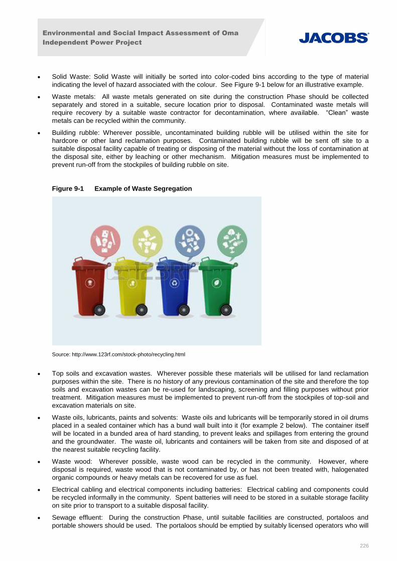
Environmental and Social Impact Assessment of Oma
Independent Power Project
226
Solid Waste: Solid Waste will initially be sorted into color-coded bins according to the type of material
indicating the level of hazard associated with the colour. See Figure 9-1 below for an illustrative example.
Waste metals: All waste metals generated on site during the construction Phase should be collected
separately and stored in a suitable, secure location prior to disposal. Contaminated waste metals will
require recovery by a suitable waste contractor for decontamination, where available. “Clean” waste
metals can be recycled within the community.
Building rubble: Wherever possible, uncontaminated building rubble will be utilised within the site for
hardcore or other land reclamation purposes. Contaminated building rubble will be sent off site to a
suitable disposal facility capable of treating or disposing of the material without the loss of contamination at
the disposal site, either by leaching or other mechanism. Mitigation measures must be implemented to
prevent run-off from the stockpiles of building rubble on site.
Figure 9-1 Example of Waste Segregation
Source: http://www.123rf.com/stock-photo/recycling.html
Top soils and excavation wastes. Wherever possible these materials will be utilised for land reclamation
purposes within the site. There is no history of any previous contamination of the site and therefore the top
soils and excavation wastes can be re-used for landscaping, screening and filling purposes without prior
treatment. Mitigation measures must be implemented to prevent run-off from the stockpiles of top-soil and
excavation materials on site.
Waste oils, lubricants, paints and solvents: Waste oils and lubricants will be temporarily stored in oil drums
placed in a sealed container which has a bund wall built into it (for example 2 below). The container itself
will be located in a bunded area of hard standing, to prevent leaks and spillages from entering the ground
and the groundwater. The waste oil, lubricants and containers will be taken from site and disposed of at
the nearest suitable recycling facility.
Waste wood: Wherever possible, waste wood can be recycled in the community. However, where
disposal is required, waste wood that is not contaminated by, or has not been treated with, halogenated
organic compounds or heavy metals can be recovered for use as fuel.
Electrical cabling and electrical components including batteries: Electrical cabling and components could
be recycled informally in the community. Spent batteries will need to be stored in a suitable storage facility
on site prior to transport to a suitable disposal facility.
Sewage effluent: During the construction Phase, until suitable facilities are constructed, portaloos and
portable showers should be used. The portaloos should be emptied by suitably licensed operators who will
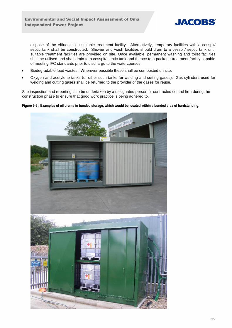
Environmental and Social Impact Assessment of Oma
Independent Power Project
227
dispose of the effluent to a suitable treatment facility. Alternatively, temporary facilities with a cesspit/
septic tank shall be constructed. Shower and wash facilities should drain to a cesspit/ septic tank until
suitable treatment facilities are provided on site. Once available, permanent washing and toilet facilities
shall be utilised and shall drain to a cesspit/ septic tank and thence to a package treatment facility capable
of meeting IFC standards prior to discharge to the watercourses.
Biodegradable food wastes: Wherever possible these shall be composted on site.
Oxygen and acetylene tanks (or other such tanks for welding and cutting gases): Gas cylinders used for
welding and cutting gases shall be returned to the provider of the gases for reuse.
Site inspection and reporting is to be undertaken by a designated person or contracted control firm during the
construction phase to ensure that good work practice is being adhered to.
Figure 9-2 : Examples of oil drums in bunded storage, which would be located within a bunded area of hardstanding.
Environmental and Social Impact Assessment of Oma
Independent Power Project
228
Source: http://www.chemstore.co.uk/chemical-fire-proof-and-gas-storage/bunded-chemical-stores/temperature-controlled/,
ehttp://www.unisanuk.com/4-drum-bunded-hardcover-drum-storage-unit.php
Residual Impacts
Following implementation of appropriate mitigation measures no residual waste impacts are expected during
construction. The impacts from solid wastes generation will be of low magnitude and negligible significance.
9.2 Mitigation Measures for Health and Safety Impacts in the Pre-Construction and Construction Phase and Operational Phases
9.2.1 Occupational health and safety
To ensure the protection of the workforce, occupational health standards and use of appropriate PPE will be
implemented in accordance with good international industry practices including Nigerian regulatory
requirements and World Bank guidelines. As such, the exposure to occupational health and safety issues will
be consistent with the level of risk normally expected at any other large civil-engineering project.
In line with the requirements of PS2 (Section 2.6.2), the following mitigation measures will be implemented to
address potential safety issues associated with early site preparation:
Modification, substitution, or elimination of hazardous conditions where possible;
Provide personnel with a Health and Safety orientation prior to early site preparation activities that
addresses the safe operating and work execution plan;
Enforce the use of appropriate PPE at work site;
Specific identification of potential hazards to workers, particularly those that may be life-threatening;
Documentation and reporting of occupational accidents, diseases, and incidents;
Substances and task-specific training of personnel; and
Emergency prevention, preparedness, and response arrangements.
Details of the above procedures and mitigation measures will be contained within the ESMS, and will be
updated and reviewed over the life of the project.
9.2.2 Community Health and Safety
The following mitigation measures are recommended to reduce potential community health and safety effects:
All project operations vehicles and contractor vehicles will have a speed limit set for travel through
settlements and areas where there are no posted speed limits.
A Worker Policy and Code of Behaviour shall be developed which includes guidance on visits,
prescribed actions for conduct violations and a grievance mechanism for complaints.
The EPC contractor shall engage with the local community to ensure that any relevant cultural heritage
areas are avoided.
An HIV/AIDS awareness and prevention program shall be implemented to provide the community with
tools and education materials to reduce the spread of HIV/AIDS.
An important aspect of minimising the spread of communicable diseases within the community is worker
health screening, particularly as many workers are local people. A worker health screening programme
shall be developed and implemented during the peak construction period or at any time when workers
on site number more than 100.
Environmental and Social Impact Assessment of Oma
Independent Power Project
229
Worker accommodation plans will be developed according to international requirements under IFC
Performance Standard 2.
First Aid and Safety training will be provided to workers and Community Emergency Response Plans
will be developed and tested including workers and nearby residents in the vicinity of Project-related
traffic. These will include emergency response related to traffic accidents and potential releases of
chemicals and other hazardous materials.
The impacts assessment identified transport movements to be the main risk to community health and safety. To
mitigate against this the OPGCL contractor will carry out a pre- and post-works assessment of the roads that will
be used during the project and develop a process that ensures overall safety along roads particularly near
communities, to be included within the ESMS.
The following additional mitigation measures to minimise adverse impacts due to traffic will be employed:
A Traffic Management Plan shall be implemented for any construction and operational traffic to reduce
the potential for accidents.
The main access road to plant will be upgraded / tarred which will have a positive effect on local traffic.
Temporary traffic control and diversion arrangements shall be provided at strategic points on local
roads, where necessary.
An effective journey management schedule shall be maintained to reduce the risk of accidents.
A transportation and materials management system for safe transportation of equipment and materials
to site shall be developed and implemented, to be included within the ESMS.
9.3 Mitigation Measures for Socio-Economic Impacts in the Construction and Operational Phases
Although employment impacts are anticipated to be beneficial, the following enhancement measures are
proposed to ensure that the employment process is well managed and the community conflicts are minimised.
Enhancement Measures
The following enhancement measures shall be applied to sustain and maximize the expected positive
impacts of the project while minimizing any negative impacts on the project area of influence:
Ensure a transparent hiring process is conducted help the community to understand strategic staffing
decisions for the project to avoid conflict.
OPGCL or OMA Power shall give preference to local community members in the Project Area of
Influence, to the extent feasible, with respect to the employment of unskilled labour. OMA Power and its
contractors shall maintain the policy of recruiting local labour through the community leaderships who
provide community members to help fill such slots when available. OMA Power reserves the right to
satisfy any outstanding positions for employment outside the local communities as needed.
OMA Power shall adopt and sustain a meaningful dialogue with the community’s representatives
including youths in regards to reasonable demands for employment and wages. This will be
managed as a matter of policy by Oma through its community liaison office, which shall engage
contractors and community leaders in pre-mobilization dialogue to foster good understanding and fair
wages for local workers. This process may give rise to the signing contractual agreements to
operate/work between contractors and communities. However, this is subject to Oma Power
discretion. OMA Power shall involve non-executive members of the local communities in skill acquisition
and other educational training programmes (if deemed necessary).
Environmental and Social Impact Assessment of Oma
Independent Power Project
230
OMA Power shall endeavour to contribute to community enhancement projects in the community
including the provision of community and social infrastructure in the Project Area of Influence.
OMA Power shall maintain its community relations policy in order to maintain good community relations.
9.4 Mitigation Measures for Environmental Impacts in the Operational Phase
9.4.1 Air Quality
Mitigation measures to minimise emissions of NOx and CO to air are included within the design of the proposed
OMA Power Plant. In addition, ambient air quality monitoring and emissions monitoring will be undertaken, as
described below:
Ambient Air Quality Monitoring.
Air quality monitoring will be carried out at, or close to, the location(s) of receptors predicted to experience
the highest increment in long term NO2 concentrations. The air emission modelling has identified two
receptors at which monitoring will be required. These are approximately 1 – 2 km downwind of the plant.
Detailed monitoring procedures will be developed as part of the overall environmental management plan.
The specific monitoring location(s) will be agreed with the FMEnv prior to the commencement of the
monitoring survey. A suitable background monitoring location will also be included in the survey. The
survey will be carried out using passive samplers in line with the requirements of the IFC “Environmental,
Health and Safety Guidelines for Thermal Power Plants” where the PC is less than 25% of the ambient air
quality guideline (i.e. Phases 1 and 2).
Stack Emissions Monitoring.
To further ensure conformity with current standards, a Continuous Emission Monitoring System (CEMS)
will be included in the power plant. This will provide continuous assessment of the stack emissions to verify
if the NOx concentration (measured as NO2) meet the project commitment not to exceed 25 ppm at the
stack. Appropriate maintenance and/or operating changes will be implemented, if necessary, to maintain
design parameters.
9.4.2 Energy Efficiency and Greenhouse Gas Emissions
It is recommended that OMA evaluate technically and financially feasible and cost-effective options to reduce or offset project-related GHG emissions during the design and operation of the project.
It is important to analyse the need for power and heat, the available space, and weight restrictions to design an
optimal solution to balance capital costs, energy costs and overall plant efficiency. Mitigation measure to
consider throughout the design and management of operations include:
Pumps/motors – use of high efficiency motors, variable speed drives or multi speed motors (depending on
circumstances) and motor load sensing for start/stop control.
Lighting - use high efficiency lights (e.g. LEDs) where appropriate, use motion and photo sensors, use as
much natural light as possible.
Waste – encourage reduction of waste through prevention and re-use. Where waste arises, opt to recycle
before considering other disposal routes.
Water – encourage reduction in water use by staff, mend any water leaks, treat blow down water for re-
use.
Given the location and nature of the project, it is also recommended that the project:
Monitor, Calculate and Disclosure GHG Emissions Annually
For projects that are expected to produce more than 25,000 tonnes of CO2e annually, the project is
required to quantify direct emissions from the facilities owned or controlled within the physical boundary as
well as indirect emissions associated with the offsite production of electricity used by the project. The
project will quantify and disclose these carbon emissions annually in annual reports, as part of the project’s
commitment to meeting the requirements of IFC Performance Standard 3.
Environmental and Social Impact Assessment of Oma
Independent Power Project
231
In order to quantify and manage GHG emissions the following will be undertaken:
- An Emissions Inventory to be maintained throughout all phases of the project. This should be a live
document, to ensure all emissions sources are up to date.
- Quantity of GHG emissions from fixed sources to be monitored.
- Emissions and sources of emissions to be monitored throughout the life of the project with a focus on
sensitive receptors as identified in the EIA.
Develop GHG Targets for Environmental Management System:
IFC Performance Standard (PS) 1 requires the establishment of effective environmental and social
management systems and PS3 requires the reduction of project GHG emissions. It is recommended that
(a) the project’s environmental management system include a target of reducing GHG emissions on an
absolute and intensity basis; (b) GHG emissions be determined on an annual basis using the methodology
described within IFC PS 3.
Other actions that could be considered and implemented to reduce and manage GHG emissions are as follows:
Demand Side Measures to Reduce Need for New Generation:
Typically, a country’s electricity sector is structured such that increased consumer demand is satisfied
through the construction of new power plants or expansion of existing plant rather than through measures
to reduce consumer demand. In some jurisdictions, for example California, power utilities are required to
demonstrate that they have implemented comprehensive energy efficiency programmes with customers
before they are permitted to develop new power plants.
Greater efficiency in the consumption of energy is commonly an attractive option for emissions reduction,
due to its dual benefit of reducing both emissions and the size of the energy bill. However, despite many
years of promotion, it is also the most overlooked option. In Clean Development Mechanisms (CDMs), for
instance, demand-side energy efficiency projects only make up 1% of the Certified Emission Reduction
(CER) generation. Among the many reasons for this is the fact that most developing countries focus on
energy access, rather than energy saving.
Make Provision for Potential Carbon Capture and Sequestration:
Considerable effort is made around the world to develop carbon capture and sequestration (CCS)
schemes. Of the 13 operational projects in the world, there is only one demonstration project in the power
generation sector (Canada) which uses post combustion capture technology. On the Africa continent, there
is one CCS plant in Algeria which uses pre-combustion capture as part of a gas processing facility. Other
plants in other industrial sectors have adequately demonstrated integrated gasification combined cycle’s
(IGCC) capacity, efficiency and environmental performance but some uncertainty remains regarding
availability, reliability and cost. There are currently 9 plants being built and 32 plants being planned in a
number of countries, almost all of which are expected to receive explicit public subsidies. Given the current
status of CCS in the power generation sector, the technology is not considered a timely proposition for this
project.
Carbon Credits / Offsets:
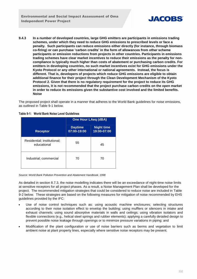
Environmental and Social Impact Assessment of Oma
Independent Power Project
232
9.4.3 In a number of developed countries, large GHG emitters are participants in emissions trading
schemes, under which they need to reduce GHG emissions to prescribed levels or face a
penalty. Such participants can reduce emissions either directly (for instance, through biomass
co-firing) or can purchase ‘carbon credits’ in the form of allowances from other scheme
participants or emission reductions from projects in other countries. Participants in emissions
trading schemes have clear market incentives to reduce their emissions as the penalty for non-
compliance is typically much higher than costs of abatement or purchasing carbon credits. For
emitters in developing countries, no such market incentives exist for GHG emissions under the
Kyoto Protocol or any other international or national agreements. Instead, the focus is
different. That is, developers of projects which reduce GHG emissions are eligible to obtain
additional finance for their project through the Clean Development Mechanism of the Kyoto
Protocol 2. Given that there is no regulatory requirement for the project to reduce its GHG
emissions, it is not recommended that the project purchase carbon credits on the open market
in order to reduce its emissions given the substantive cost involved and the limited benefits.
Noise
The proposed project shall operate in a manner that adheres to the World Bank guidelines for noise emissions,
as outlined in Table 9-1 below.
Table 9-1: World Bank Noise Level Guidelines
Receptor
One Hour LAeq (dBA)
Daytime
07:00-19:00
Night time
19:00-07:00
Residential; institutional;
educational 55
45
Industrial; commercial 70 70
Source: World Bank Pollution Prevention and Abatement Handbook, 1998
As detailed in section 8.7.3, the noise modelling indicates there will be an exceedance of night-time noise limits
at sensitive receptors for all project phases. As a result, a Noise Management Plan shall be developed for the
project. The recommended mitigation strategies that could be considered to reduce noise are included in Table
9-2 below. These strategies are based on the following measures for mitigation of noise recommended by EHS
guidelines provided by the IFC:
Use of noise control techniques such as: using acoustic machine enclosures; selecting structures
according to their noise isolation effect to envelop the building; using mufflers or silencers in intake and
exhaust channels; using sound absorptive materials in walls and ceilings; using vibration isolators and
flexible connections (e.g., helical steel springs and rubber elements); applying a carefully detailed design to
prevent possible noise leakage through openings or to minimize pressure variations in piping; and
Modification of the plant configuration or use of noise barriers such as berms and vegetation to limit
ambient noise at plant property lines, especially where sensitive noise receptors may be present.

Environmental and Social Impact Assessment of Oma
Independent Power Project
233
Table 9-2: Noise Mitigation Strategies
Mitigation Strategy Effectiveness Cost and Operational
Impact
Place gas turbines and generators in
enclosures or buildings offering good
sound insulation (Rw 20 dB or better).
Specifying transformers with a sound
power level (including fans) not
exceeding 92.5 dB LWA (ref 1x10-12
W).
Highly effective. Noise levels less than 45
dB LAeq,1hour will be achieved at all
sensitive receptors.
Highest cost and
operational / design
impacts.
Construction of a solid noise barrier
(and/or bund) along the southern
perimeter of the site, and local barriers
around turbines and generators.
Moderate effect; some noise reductions,
but noise levels at 14 receptors will still
exceed 45 dB LAeq,1hour, by up to 2.5 dB.
High cost, some
operational and design
impacts.
A sound insulation grant scheme for
residential properties where noise levels
are shown to exceed 45 dB LAeq,1hour at
night.
External noise levels will be unaltered, but
the sound insulation measures will enable
occupants to sleep comfortably with
windows closed.
Lowest cost, no
operational impact other
than administering grant
scheme.
It is recommended that consultation with the Lender Group over the most appropriate mitigation strategy for the
project be undertaken, and the selected strategy implemented.
In addition to the above, other mitigation measures to mitigate against general noise emissions for the project
include:
Appropriate design of the foundations for the gas turbines to ensure that all criteria including noise and
vibration are fully accommodated.
Foundations will be unitized and isolated to support the gas turbines generators and auxiliary/ancillary
plant.
Adequate clear working space between units for laydown and loading bays shall be provided.
Suitably sized foundations shall be provided to accommodate central and local control rooms, switchgears,
battery and HVAC (heating, ventilation, and air conditioning equipment) rooms, laboratory, offices, kitchen
and toilet facilities.
Design of buildings shall incorporate facilities for noise abatement such as double walls with rock wool
insulation between them, and solar-reflective double-glazed windows and doors.
Noise modelling, confirmation of sensitive receptors, design reviews and performance tests will be conducted to
confirm that noise limits are incorporated into the design of the project to ensure compliance with World Bank
noise emission guidelines.
The personnel on site shall be provided with appropriate protective or corrective device to ameliorate noise
effect. Measures are also to be taken at noise receptors located outside the project area boundary.
It is recommended that noise monitoring be undertaken at site boundaries and sensitive environmental
receptors throughout the project lifetime. Monitoring requirements should comply with IFC guidelines which
recommend a 48 hour monitoring period. A noise monitoring programme will need to be developed for the
project and this is included as an action in the ESMP.
Environmental and Social Impact Assessment of Oma
Independent Power Project
234
9.4.4 Water and Wastewater
Inherent mitigation measures for the safe treatment and disposal of water and waste water streams are outlined
below:
Sanitary Sewage Discharge
Sewage and urinals from water closets will be channelled into a reinforced concrete underground septic
tank. Digested sewage from the septic tank will pass through a drainage pipe into the water treatment plant
where it will be treated in line with World Bank / IFC EHS guidelines. The maximum treatment capacity is
about 5m3/h. Treated water from domestic sewage treatment station will then be discharged into the storm
water system.
Stormwater Discharge
The rainwater storm drainage system will be designed with sufficient capacity to accept a 1 in 10 year
frequency storm, plus an appropriate additional factor to allow for potential increase in rainfall
frequency/intensity due to climate change.
Stormwater from hardstanding areas with the potential to come into contact with contaminated materials
(e.g. oil from vehicle traffic and parking lots) will be directed through an oil/water separator. Separated oil
will be pumped out of the sump and removed by licenced waste contractor, whilst water effluent will be
pumped to the water treatment plant.
The discharge outfall from the storm drainage network will be design in order to prevent any detrimental
impacts to adjacent property (e.g. erosion around the outfall and associated additional sediment
generation; also increased overland flows due to rapid transmission of rainwater on new hardstanding)
down gradient from the outfall.
In addition to the storm water drainage system, the design of earthworks will also be configured to divert
any surface storm water away from the critical areas of the plant where practicable.
Wastewater Effluent Discharge
The main sources of oily wastewater will be oil-contaminated water from hardstanding around GTGs ,
emergency diesel generators /diesel oil storage, oil tanks of transformers, lubrication system and
maintenance workshop. All potentially oily wastewater from these areas shall be collected and treated in
the oily wastewater treatment plant system.
This will consist of an oil / water (O/W) separator which will settle and skim oil residues from the water and
pump the waste oil to a storage container. Water from the O/W separator will be pumped to the water
treatment plant for removal of potential contaminants.
The system shall include an observation pond with sufficient capacity to provide adequate retention time to
arrest any accidental breakthrough of oil or other potential contaminant spills and to allow testing.
In summary, all discharged effluent will be treated in line with the more stringent relevant Nigerian and IFC
EHS standards prior to discharge into the storm drainage network. This design mitigation in conjunction
with appropriate contamination spill control and response procedures will be providing appropriate
protection against soil and groundwater contamination.
Accidental Release
As in construction, there is the possibility that accidental spills of fuel, etc. could cause considerable
contamination of watercourses. Every precaution will be taken to prevent accidents, and oil and fuel areas
will be bounded. All workers will be trained in the handling, storing, and disposal of hazardous materials. In
the event of an accidental release there will be emergency procedures in place so that the spill can be
contained immediately. Emergency spill containment material and clean up equipment will be distributed
and stored in appropriate places so that any spill can be cleared up as quickly as possible to minimize any
adverse effects.
No additional mitigation measures are proposed.
Environmental and Social Impact Assessment of Oma
Independent Power Project
235
9.4.5 Ecology
As discussed in Section 0, no direct impacts are associated with operational phase activities. There may be
some indirect impacts following accidental release/ loss of containment of polluting substances. Mitigation
measures are provided in Section 9.4.6, below.
9.4.6 Geology, Hydrogeology, Hydrology
Mitigation regarding protection of land and groundwater from potential contamination will largely comprise
minimisation and appropriate storage and management of such materials on side along with pollution
prevention, control and response procedures in line with IFC PS3 and IFC EHS Guidelines. The following
mitigation measures will be employed:
Workers will be trained in the handling, storing, and disposal of hazardous materials. In the event of an
accidental release, emergency procedures and management plans will be in place so that the spill can be
contained immediately and cleaned and disposed appropriately.
Chemicals will be stored in designated bunded areas with bunds having the capacity to contain at least
110% of the volume of chemicals stored.
Wherever possible, there will be no bund wall penetration and all pipework will be routed over the bund
wall.
Hard standing areas around potentially contaminating materials storage areas will drain to the oil/water
separate and/or effluent drainage system.
Operational storage tanks will be designed and constructed in accordance with internationally recognised
standards (such as BS EN 14015 or API 650) ensuring they are robust and fit for purpose.
Chemicals that will react together if brought into contact will be located in segregated storage and bunded
areas.
Operational areas and roads where spills or leaks of hazardous materials could occur will be constructed in
low permeability hardstanding to minimise potential for infiltration of contaminants to ground.
All tank filling points will be situated within bunds so that any accidental spillage is contained.
OPGCL will have emergency response plans and procedures in place should there be any loss of
containment. Emergency spill response and clean up procedures will be in line with international standards.
Emergency spill containment materials and clean up equipment will be readily available.
OPGCL will maintain an inventory of the chemicals needed for the operation of the power plant, such as
dosing and treatment chemicals and lubricants. Details of locations and quantities on site, and their usage
will be strictly logged and tracked, and stored in a separate storage building at site.
Drainage design and management will ensure that potentially contaminated surface run-off does not flow
directly into watercourses. Stormwater / surface water run-off will be channelled to oil separators /
interceptors and silt traps prior to disposal to outfalls.
Periodic site inspection and reporting is to be undertaken by a designated person or contracted control firm to
ensure that good work practice is being adhered to.
9.4.7 Solid Waste
A Waste Management Plan (WMP) for the operational phase will be developed for the project, as required by
the EMMP to ensure wastes are handled and disposed of in the most efficient and sustainable way, minimising
impacts to people and the environment. The waste hierarchy principles to be applied are the same as for the
WMP required for the construction phase (CWMP), as outlined in section 9.1.6. The WMP shall identify the
environmental standards to which the waste recycling, treatment or disposal facility shall operate, when
handling, transporting and treating the wastes. It will be the responsibility of the contractor to identify suitable
treatment and disposal facilities capable of meeting appropriate environmental standards, when creating, and
then implementing the WMP for the construction, operation and decommissioning phases.
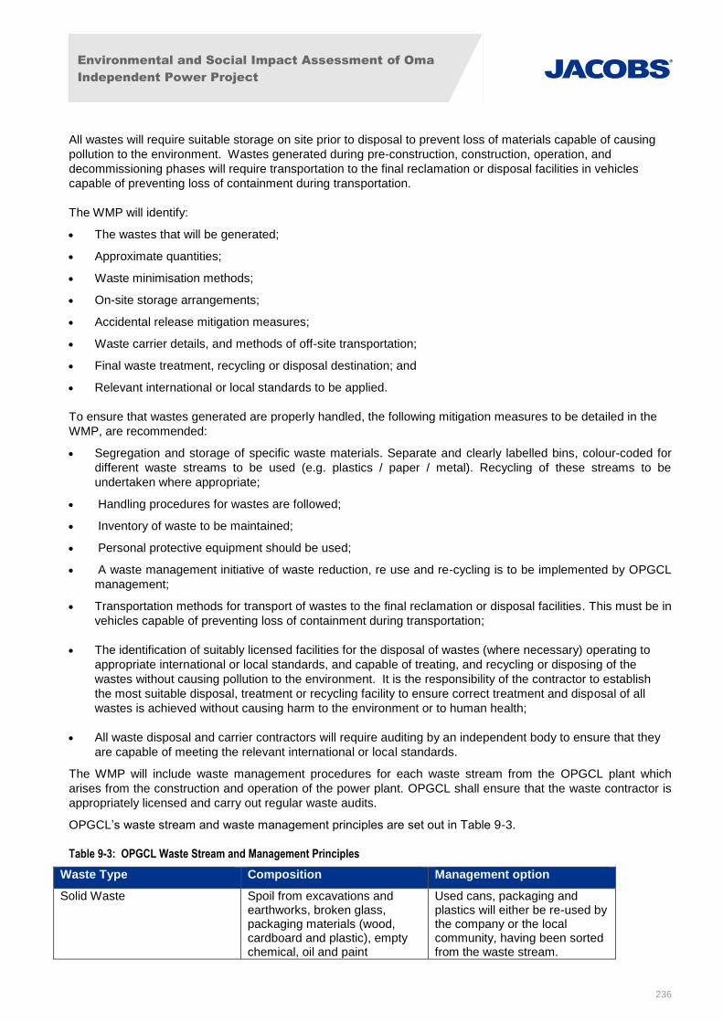
Environmental and Social Impact Assessment of Oma
Independent Power Project
236
All wastes will require suitable storage on site prior to disposal to prevent loss of materials capable of causing
pollution to the environment. Wastes generated during pre-construction, construction, operation, and
decommissioning phases will require transportation to the final reclamation or disposal facilities in vehicles
capable of preventing loss of containment during transportation.
The WMP will identify:
The wastes that will be generated;
Approximate quantities;
Waste minimisation methods;
On-site storage arrangements;
Accidental release mitigation measures;
Waste carrier details, and methods of off-site transportation;
Final waste treatment, recycling or disposal destination; and
Relevant international or local standards to be applied.
To ensure that wastes generated are properly handled, the following mitigation measures to be detailed in the
WMP, are recommended:
Segregation and storage of specific waste materials. Separate and clearly labelled bins, colour-coded for
different waste streams to be used (e.g. plastics / paper / metal). Recycling of these streams to be
undertaken where appropriate;
Handling procedures for wastes are followed;
Inventory of waste to be maintained;
Personal protective equipment should be used;
A waste management initiative of waste reduction, re use and re-cycling is to be implemented by OPGCL
management;
Transportation methods for transport of wastes to the final reclamation or disposal facilities. This must be in
vehicles capable of preventing loss of containment during transportation;
The identification of suitably licensed facilities for the disposal of wastes (where necessary) operating to
appropriate international or local standards, and capable of treating, and recycling or disposing of the
wastes without causing pollution to the environment. It is the responsibility of the contractor to establish
the most suitable disposal, treatment or recycling facility to ensure correct treatment and disposal of all
wastes is achieved without causing harm to the environment or to human health;
All waste disposal and carrier contractors will require auditing by an independent body to ensure that they
are capable of meeting the relevant international or local standards.
The WMP will include waste management procedures for each waste stream from the OPGCL plant which
arises from the construction and operation of the power plant. OPGCL shall ensure that the waste contractor is
appropriately licensed and carry out regular waste audits.
OPGCL’s waste stream and waste management principles are set out in Table 9-3.
Table 9-3: OPGCL Waste Stream and Management Principles
Waste Type Composition Management option
Solid Waste Spoil from excavations and earthworks, broken glass, packaging materials (wood, cardboard and plastic), empty chemical, oil and paint
Used cans, packaging and plastics will either be re-used by the company or the local community, having been sorted from the waste stream.
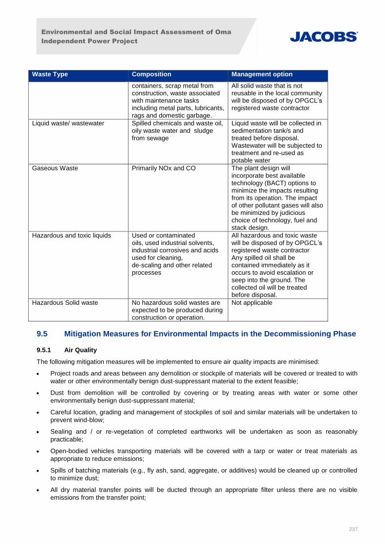
Environmental and Social Impact Assessment of Oma
Independent Power Project
237
Waste Type Composition Management option
containers, scrap metal from construction, waste associated with maintenance tasks including metal parts, lubricants, rags and domestic garbage.
All solid waste that is not reusable in the local community will be disposed of by OPGCL’s registered waste contractor
Liquid waste/ wastewater Spilled chemicals and waste oil, oily waste water and sludge from sewage
Liquid waste will be collected in sedimentation tank/s and treated before disposal. Wastewater will be subjected to treatment and re-used as potable water
Gaseous Waste Primarily NOx and CO The plant design will incorporate best available technology (BACT) options to minimize the impacts resulting from its operation. The impact of other pollutant gases will also be minimized by judicious choice of technology, fuel and stack design.
Hazardous and toxic liquids Used or contaminated oils, used industrial solvents, industrial corrosives and acids used for cleaning, de-scaling and other related processes
All hazardous and toxic waste will be disposed of by OPGCL’s registered waste contractor Any spilled oil shall be contained immediately as it occurs to avoid escalation or seep into the ground. The collected oil will be treated before disposal.
Hazardous Solid waste No hazardous solid wastes are expected to be produced during construction or operation.
Not applicable
9.5 Mitigation Measures for Environmental Impacts in the Decommissioning Phase
9.5.1 Air Quality
The following mitigation measures will be implemented to ensure air quality impacts are minimised:
Project roads and areas between any demolition or stockpile of materials will be covered or treated to with
water or other environmentally benign dust-suppressant material to the extent feasible;
Dust from demolition will be controlled by covering or by treating areas with water or some other
environmentally benign dust-suppressant material;
Careful location, grading and management of stockpiles of soil and similar materials will be undertaken to
prevent wind-blow;
Sealing and / or re-vegetation of completed earthworks will be undertaken as soon as reasonably
practicable;
Open-bodied vehicles transporting materials will be covered with a tarp or water or treat materials as
appropriate to reduce emissions;
Spills of batching materials (e.g., fly ash, sand, aggregate, or additives) would be cleaned up or controlled
to minimize dust;
All dry material transfer points will be ducted through an appropriate filter unless there are no visible
emissions from the transfer point;
Environmental and Social Impact Assessment of Oma
Independent Power Project
238
All transfer points will be equipped with a wet suppression system to control fugitive particulate emissions
unless there are no visible emissions;
All bulk storage silos including auxiliary bulk storage trailers would be equipped with appropriate type filter;
The dust collection system employed will be capable of controlling particulates using the best technology
available.
All conveyors will be covered unless the material being transferred results in no visible emissions.
Diesel powered vehicles will be well maintained to minimise exhaust emissions; and
Idling reduction education for onsite diesel powered equipment and mobile vehicles.
Further mitigation measures relating to dust and traffic are provided within the ESMP.
9.5.2 Noise
The following mitigation measures will be employed to reduce decommissioning noise impacts:
The use of personal protective equipment will be enforced at worksite, to be detailed in the ESMS;
All noise-emitting equipment shall be properly maintained to minimize the noise impact on the area and
shall be compliant with the applicable World Bank standards (Table 9-1);
The roadworthiness of trucks shall be ensured to minimize the noise impact;
Movement of vehicles shall be restricted to day time; and
Noise complaints shall be logged and kept onsite by the construction contractor.
9.5.3 Ecology
To mitigate against minor disturbance of species the following measures will be employed:
Limiting use of lighting at night time;
Management of noise and vibration, where practical;
Education of workers on the need to protect habitats and species. Hunting to be prohibited.
Site inspection and reporting is to be undertaken by a designated person during the decommissioning phase to
ensure that good work practice is being adhered to.
Potential for pollutants and surface water run-off to infiltrate to ground or migrate off site to be minimised by
appropriate containment and drainage and emergency response measures.
9.5.4 Other Impacts Decommissioning
Mitigation measures for other impacts associated with waste, community health and safety, geology, and
hydrology impacts are described in detail under sections 9.1.5, 9.1.6, 9.2.1 and 9.2.2 above and are also
included in the ESMP.
9.6 Mitigation Measures for Transmission Line Impacts in the Construction and Operational Phases
As outlined in Section 8.1.2, the ESMP should be further developed to provide more robust management and
mitigation measures in relation to the transmission line. It should include full construction and operational
management practice, and be developed and implemented from site preparation to decommissioning.
Independent third party review of the management and mitigation plans is recommended to ensure they meet
good international industry practice and the requirements of the IFC Performance Standards.
Environmental and social actions of relevance to the transmission line will focus on:
Environmental and Social Impact Assessment of Oma
Independent Power Project
239
a need to protect the soils and surface vegetation during construction;
labour and working conditions including occupational health and safety; and
community, health and safety.
Recommended measures include the following:
the disclosure of exclusion zones around the transmission line to the local community as part of ongoing
consultation, engagement and disclosure activities;
development of an emergency response plan and safety procedures for the transmission line and any
nearby rights of way;
ensure sufficient welfare facilities and emergency response infrastructure plans and procedures are
developed by the project to ensure appropriate management and resources are in place in the event of an
incident along the transmission line. Consideration of impacts in the event of an incident on the
neighbouring pipeline should also be considered within the plans.
Environmental and Social Impact Assessment of Oma
Independent Power Project
240
10. Environmental and Social Management Plan
10.1 Introduction
10.1.1 Overview
This document presents an Environmental and Social Management Plan (ESMP) for the Oma Power
Generation Company Limited (OPGCL or Oma), Oma Power Plant Project (“the project”). This ESMP
supplements the information provided within the Environmental and Social Impact Assessment (ESIA) originally
prepared for the project by BGI Resources in February 2014, with supporting studies undertaken by Jacobs. It
has been produced specifically to collate the mitigation measures and actions identified in the ESIA into a
standard format for internationally financed projects, for the purpose of defining the specific responsibilities of
the engineering, procurement and construction (EPC) contractor undertaking the construction works.
This ESMP will be used as a guide in the development of subsequent detailed management plans for pre-
construction, construction operation and decommissioning phases. An Environmental and Social Management
Systems (ESMS) team will be appointed for each project phase to develop this framework ESMP. For the
operational phase, the ESMP will be developed and expanded into a full EMS either accredited or aligned to
ISO 140001. ISO 140001 is an internationally accepted standard that outlines how to put an effective
environmental management system in place. The recommendations stipulated within this ESMP must be
adopted in the development of the detailed ESMS and international WBG/ IFC standards must be met for the
duration of the project.
The ESMP has been prepared in accordance with environmental and social commitments of OPGCL and in
compliance with the legal and regulatory requirements of Nigeria and of the International Finance Corporation
(IFC) Performance Standards and Environmental, Health and Safety Guidelines.
10.1.2 Objectives and Scope of the ESMP
The objectives of this ESMP are to:
Collate and describe all mitigation measures and actions identified through the ESIA process to
enhance positive benefits and to eliminate or reduce key identified environmental, socioeconomic and
health issues and impacts to acceptable levels. These measures will be implemented by the
engineering, procurement and construction (EPC) contractor during the detailed design, construction
and operation and decommissioning phases of the project
Identify key environmental and social reporting requirements, such as audits of performance which the
contractor will need to develop and undertake throughout all phases of the project.
Identify and describe monitoring required to ensure the reporting commitments are met. The reporting
requirements for the construction phase will be addressed by the EPC contractor. Reporting
commitments for the operational phase will be detailed within the operational Environmental
Management Systems (EMS) which will be developed by the plant operators.
The ESMP includes both general environmental and social requirements that are common to most construction
projects, and specific environmental and social initiatives unique to the issues identified in relation to this
project.
The actions within this ESMP will be used as a basis for the EPC Contractor to develop its own suite of
Environmental, Health and Safety Management Manuals and Systems for the construction of the project.
This ESMP and associated detailed plans are live documents that will be updated as the project proceeds.
Environmental and Social Impact Assessment of Oma
Independent Power Project
241
10.1.3 Implementation of the ESMP
Overview
This ESMP provides a framework document to be used throughout the lifetime of the Project. It forms the basis
from which more detailed plans will be developed once an EPC contractor has been selected and further design
details are available. The action and standards specified within this ESMP must be adopted in the development
and implementation of detailed management plans. International (IFC) standards, national Nigerian Federal
Ministry of Environment (FMEnv) standards and relevant national legislation must be met throughout the life of
the Project. The parties involved in the implementation of the ESMP and their roles and responsibilities are
outlined in Table 10-1. EMS teams will be appointed for each project phase and they will be responsible for
ensuring implementation of the ESMP.
Roles and Responsibilities – Administration
Table 10-1 below outlines the roles and responsibilities of the parties involved in the implementation of the
ESMP.
Table 10-1: Roles and Responsibilities
Party Responsibilities
Oma Power
Generation
Company Limited
(OPGCL)
Drafting of initial framework for the ESMP. This will be used as a guide in the
development of subsequent detailed management plans for all Project phases. The
recommendations of OPGCL must be adopted and international IFC standards used for
the duration the Project. OPGCL will appoint an Owner’s Engineer/contract a monitoring
firm, whose responsibilities will include review and oversight of the EPC Contractor’s
environmental, health and safety plans to ensure conformance with the ESMP.
EPC contractor(s)
In supporting the implementation of the ESMP and associated actions, the EPC
Contractor will be required to include, as a minimum, a team that comprises:
An environmental liaison officer (ELO), who shall be an environmental specialist
with experience of construction site environmental and social management;
A project quality assurance engineer (QAE); and
A community liaison officer (CLO).
The ELO shall be the focal point on environmental matters in relation to the construction
phase of the proposed project and will report to the EPC Contractor’s overall Project
Manager as well as the Oma environmental manager.
The ELO shall ensure strict adherence to the requirements of the ESMP, including
design mitigation measure specifications.
EMS team for the
construction phase
Drafting of the detailed ESMP for the construction phase, which will include all of the
aspects covered in this ESMP. (An EMS team for the decommissioning phase will draft
the detailed Decommissioning Management Plan in the future.)
The implementation and enforcement of actions required by the detailed management
plans, including any monitoring requirements and reporting.
The training of workers in how to perform tasks required by the detailed management
plans.
Environmental and Social Impact Assessment of Oma
Independent Power Project
242
The provision of all required items including safety equipment and emergency response
equipment required by the management plans.
Management of waste contractors and other external contractors and consultants used
in the construction / decommissioning phases of the Project.
Updating the management plans with any required changes as the Project progresses.
Waste Contractors Responsible for the collection and disposal of wastes to appropriate disposal facilities.
The contractors must abide by the standards specified within this ESMP and within the
detailed management plans.
Plant Owner /
Operator
The owner will appoint an EMS team to develop and implement Environmental, Health
and Social Management Plans for the construction, operational and decommissioning
phase.
EMS team for the
operational phase.
Drafting of the detailed EMS or equivalent documents, which will include all of the
operational aspects covered in this ESMP.
The implementation and enforcement of actions required by the detailed management
plans, including any monitoring requirements and reporting.
The training of workers in how to perform tasks required by the detailed management
plans.
The provision of all required items including safety equipment and emergency response
equipment required by the management plans.
Management of waste contractors and other external contractors and consultants used
in the operational phase of the Project.
Updating the management plans with any required changes as the project progresses.
External Consultants May be used to undertake monitoring works and reporting in both the construction and
operational phase. The consultants must abide by the standards specified within this
ESMP and within the detailed management plans drafted by the relevant EMS teams.
Nigerian FMEnv /
Regulating Bodies
Ensure that monitoring and reporting requirements (as required by the EMSP and
detailed management plans in accordance with FMEnv standards and guidelines).
Enforce any actions that may be needed to ensure environmental quality standards are
not breached and permit requirements are maintained.
International
Financing Institution
(IFI)
International Finance Institutions will develop their own Environmental and Social Action
Plan (ESAP) that will include conditions to be met. The ESAP will include the
requirement to comply with, among other plans, the ESMP.
Monitoring
Monitoring is required to ensure that the actions specified in the EMSP to mitigate environmental and social
impacts are effective. Monitoring must be undertaken on the specified schedule indicated for relevant actions
(e.g. daily, weekly, monthly, quarterly or annual basis). Where technical equipment must be used (e.g. for noise
Environmental and Social Impact Assessment of Oma
Independent Power Project
243
monitoring), it must be regularly maintained and calibrated with appropriate certification. For air quality
monitoring, a CEMS will be used.
Audit and Inspections
Internal audits and inspections are required throughout each project phase, on a regular basis, to ensure that
the requirements of the ESMP are being undertaken. The audits and inspections should be undertaken to the
standards specified within the detailed project EMS. The frequency of inspections will vary depending on the
nature of activities. Inspection records should be maintained and kept up to date.
External audits and inspections by regulating authorities will also be undertaken throughout the lifetime of the
project.
Reporting
Reporting of monitoring undertaken must be supplied to the relevant person/organisation(s) as specified within
detailed management plans, to include:
Construction Waste Management Plan;
Health and Safety Plan including Emergency Response Plan;
Traffic Management Plan;
Worker Management Plan;
Noise Management Plan; and
Waste Management Plan.
During the operational phase, annual reporting of monitoring works required by this ESMP for all Project phases
must be reported to the regulator and to the IFI where specified. Detailed reporting requirements and
procedures are to be developed as part of the detailed management plans. A more detailed numbering
reference system will be developed for each measure during the ESMP phase in order to keep track of the
management of each.
Change Management and ESMP Updates
The ESMP is a working document and will be updated in line with any changes to Project requirements or as a
result of actions required by internal / external audits. The EPC contractor is responsible for ensuring that
changes are incorporated into the relevant procedures and implemented.
As the Project progresses and detailed design is concluded, a greater level of certainty will be available
regarding the project’s likely impacts and understanding of the environmental and social aspects requiring
management during all phases. Where any additional issues are identified, these will be assessed as
necessary through an update to the ESIA and subsequent amendments of this ESMP and associated detailed
plans. Any amendments to the ESIA/ESMP will be re-submitted to the FMEnv and made available to the public.
10.2 Environmental and Social Management Plan Actions
Table 10-2 sets out the environmental and social mitigation measures and actions identified as required for
consideration in design / pre-construction.
Table 10-3 sets out the environmental and social mitigation measures and actions identified as required in the
construction and decommissioning phases for the project.
Table 10-4 sets out the environmental and social mitigation measures and actions identified as required in
operational phase for the project.
Environmental and Social Impact Assessment of Oma
Independent Power Project
244
10.3 Environmental and Social Management Costs
Although specific costs of each measure are not known at the stage, indicative costs are estimated below.
ESMS construction monitoring is estimated at approximately 150,000 US dollars. Some of the biggest cost
related monitoring activities during construction and approximate costs would include:
Appointment of a Health, Safety and Environment (HSE) Manager for 18 months -110,000 USD;
1 HSE assistants for the 18 months - 30,000 USD;
HSE Audits during Construction - 20,000 USD; and
The estimated budget for ESMS during operations would be approximately 200,000 US dollars (USD) per year.
Some of the biggest cost related monitoring activities during operations and approximate costs would include:
HSE Manager per year - 80,000 USD;
HSE Assistant - 50,000 USD;
Various Testing -40,000 USD; and
HSE Audits -20,000 USD.
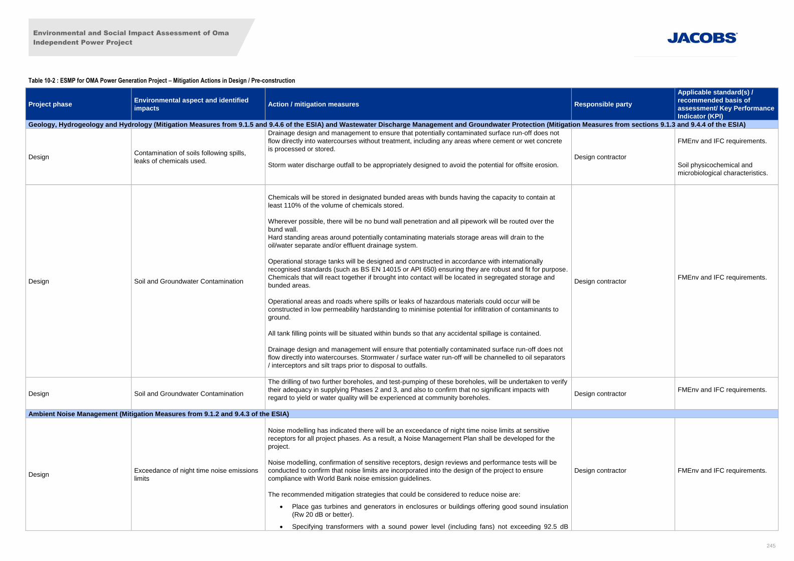
Environmental and Social Impact Assessment of Oma
Independent Power Project
245
Table 10-2 : ESMP for OMA Power Generation Project – Mitigation Actions in Design / Pre-construction
Project phase Environmental aspect and identified
impacts Action / mitigation measures Responsible party
Applicable standard(s) /
recommended basis of
assessment/ Key Performance
Indicator (KPI)
Geology, Hydrogeology and Hydrology (Mitigation Measures from 9.1.5 and 9.4.6 of the ESIA) and Wastewater Discharge Management and Groundwater Protection (Mitigation Measures from sections 9.1.3 and 9.4.4 of the ESIA)
Design Contamination of soils following spills,
leaks of chemicals used.
Drainage design and management to ensure that potentially contaminated surface run-off does not
flow directly into watercourses without treatment, including any areas where cement or wet concrete
is processed or stored.
Storm water discharge outfall to be appropriately designed to avoid the potential for offsite erosion.
Design contractor
FMEnv and IFC requirements.
Soil physicochemical and
microbiological characteristics.
Design Soil and Groundwater Contamination
Chemicals will be stored in designated bunded areas with bunds having the capacity to contain at
least 110% of the volume of chemicals stored.
Wherever possible, there will be no bund wall penetration and all pipework will be routed over the
bund wall.
Hard standing areas around potentially contaminating materials storage areas will drain to the
oil/water separate and/or effluent drainage system.
Operational storage tanks will be designed and constructed in accordance with internationally
recognised standards (such as BS EN 14015 or API 650) ensuring they are robust and fit for purpose.
Chemicals that will react together if brought into contact will be located in segregated storage and
bunded areas.
Operational areas and roads where spills or leaks of hazardous materials could occur will be
constructed in low permeability hardstanding to minimise potential for infiltration of contaminants to
ground.
All tank filling points will be situated within bunds so that any accidental spillage is contained.
Drainage design and management will ensure that potentially contaminated surface run-off does not
flow directly into watercourses. Stormwater / surface water run-off will be channelled to oil separators
/ interceptors and silt traps prior to disposal to outfalls.
Design contractor FMEnv and IFC requirements.
Design Soil and Groundwater Contamination
The drilling of two further boreholes, and test-pumping of these boreholes, will be undertaken to verify
their adequacy in supplying Phases 2 and 3, and also to confirm that no significant impacts with
regard to yield or water quality will be experienced at community boreholes.
Design contractor FMEnv and IFC requirements.
Ambient Noise Management (Mitigation Measures from 9.1.2 and 9.4.3 of the ESIA)
Design Exceedance of night time noise emissions
limits
Noise modelling has indicated there will be an exceedance of night time noise limits at sensitive
receptors for all project phases. As a result, a Noise Management Plan shall be developed for the
project.
Noise modelling, confirmation of sensitive receptors, design reviews and performance tests will be
conducted to confirm that noise limits are incorporated into the design of the project to ensure
compliance with World Bank noise emission guidelines.
The recommended mitigation strategies that could be considered to reduce noise are:
Place gas turbines and generators in enclosures or buildings offering good sound insulation
(Rw 20 dB or better).
Specifying transformers with a sound power level (including fans) not exceeding 92.5 dB
Design contractor
FMEnv and IFC requirements.
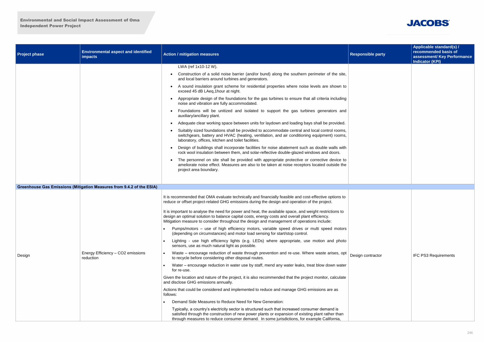
Environmental and Social Impact Assessment of Oma
Independent Power Project
246
Project phase Environmental aspect and identified
impacts Action / mitigation measures Responsible party
Applicable standard(s) /
recommended basis of
assessment/ Key Performance
Indicator (KPI)
LWA (ref 1x10-12 W).
Construction of a solid noise barrier (and/or bund) along the southern perimeter of the site,
and local barriers around turbines and generators.
A sound insulation grant scheme for residential properties where noise levels are shown to
exceed 45 dB LAeq,1hour at night.
Appropriate design of the foundations for the gas turbines to ensure that all criteria including
noise and vibration are fully accommodated.
Foundations will be unitized and isolated to support the gas turbines generators and
auxiliary/ancillary plant.
Adequate clear working space between units for laydown and loading bays shall be provided.
Suitably sized foundations shall be provided to accommodate central and local control rooms,
switchgears, battery and HVAC (heating, ventilation, and air conditioning equipment) rooms,
laboratory, offices, kitchen and toilet facilities.
Design of buildings shall incorporate facilities for noise abatement such as double walls with
rock wool insulation between them, and solar-reflective double-glazed windows and doors.
The personnel on site shall be provided with appropriate protective or corrective device to
ameliorate noise effect. Measures are also to be taken at noise receptors located outside the
project area boundary.
Greenhouse Gas Emissions (Mitigation Measures from 9.4.2 of the ESIA)
Design Energy Efficiency – CO2 emissions
reduction
It is recommended that OMA evaluate technically and financially feasible and cost-effective options to
reduce or offset project-related GHG emissions during the design and operation of the project.
It is important to analyse the need for power and heat, the available space, and weight restrictions to
design an optimal solution to balance capital costs, energy costs and overall plant efficiency.
Mitigation measure to consider throughout the design and management of operations include:
Pumps/motors – use of high efficiency motors, variable speed drives or multi speed motors
(depending on circumstances) and motor load sensing for start/stop control.
Lighting - use high efficiency lights (e.g. LEDs) where appropriate, use motion and photo
sensors, use as much natural light as possible.
Waste – encourage reduction of waste through prevention and re-use. Where waste arises, opt
to recycle before considering other disposal routes.
Water – encourage reduction in water use by staff, mend any water leaks, treat blow down water
for re-use.
Given the location and nature of the project, it is also recommended that the project monitor, calculate
and disclose GHG emissions annually.
Actions that could be considered and implemented to reduce and manage GHG emissions are as
follows:
Demand Side Measures to Reduce Need for New Generation:
Typically, a country’s electricity sector is structured such that increased consumer demand is
satisfied through the construction of new power plants or expansion of existing plant rather than
through measures to reduce consumer demand. In some jurisdictions, for example California,
Design contractor IFC PS3 Requirements
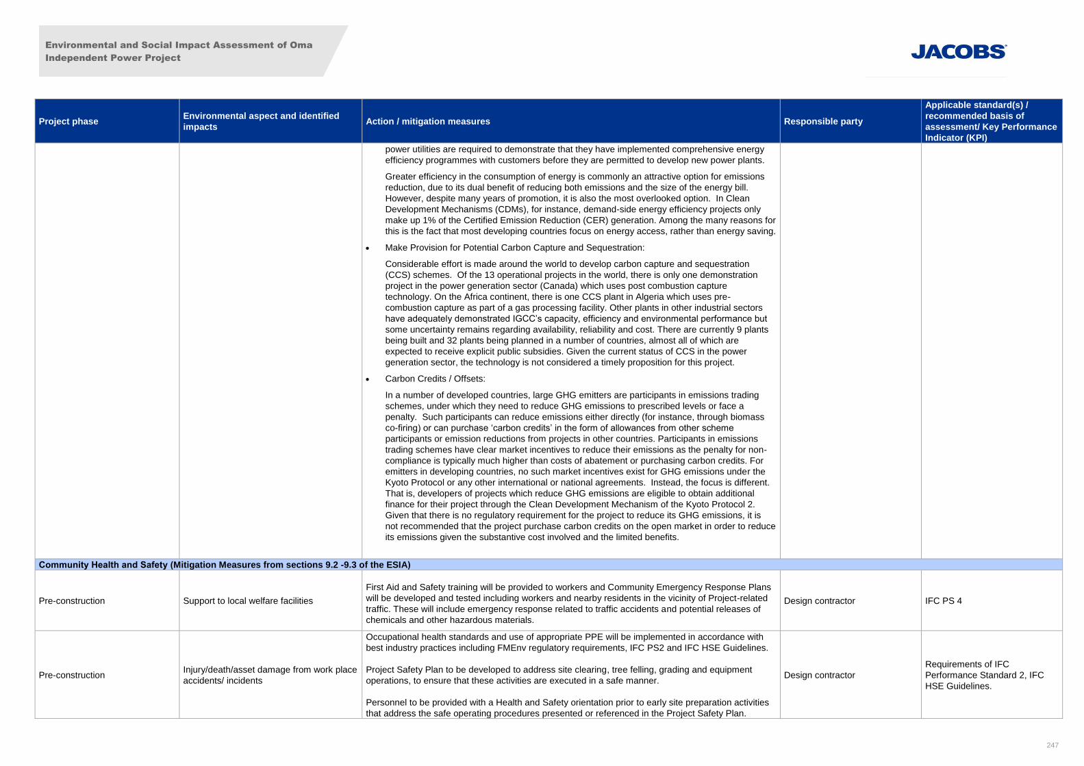
Environmental and Social Impact Assessment of Oma
Independent Power Project
247
Project phase Environmental aspect and identified
impacts Action / mitigation measures Responsible party
Applicable standard(s) /
recommended basis of
assessment/ Key Performance
Indicator (KPI)
power utilities are required to demonstrate that they have implemented comprehensive energy
efficiency programmes with customers before they are permitted to develop new power plants.
Greater efficiency in the consumption of energy is commonly an attractive option for emissions
reduction, due to its dual benefit of reducing both emissions and the size of the energy bill.
However, despite many years of promotion, it is also the most overlooked option. In Clean
Development Mechanisms (CDMs), for instance, demand-side energy efficiency projects only
make up 1% of the Certified Emission Reduction (CER) generation. Among the many reasons for
this is the fact that most developing countries focus on energy access, rather than energy saving.
Make Provision for Potential Carbon Capture and Sequestration:
Considerable effort is made around the world to develop carbon capture and sequestration
(CCS) schemes. Of the 13 operational projects in the world, there is only one demonstration
project in the power generation sector (Canada) which uses post combustion capture
technology. On the Africa continent, there is one CCS plant in Algeria which uses pre-
combustion capture as part of a gas processing facility. Other plants in other industrial sectors
have adequately demonstrated IGCC’s capacity, efficiency and environmental performance but
some uncertainty remains regarding availability, reliability and cost. There are currently 9 plants
being built and 32 plants being planned in a number of countries, almost all of which are
expected to receive explicit public subsidies. Given the current status of CCS in the power
generation sector, the technology is not considered a timely proposition for this project.
Carbon Credits / Offsets:
In a number of developed countries, large GHG emitters are participants in emissions trading
schemes, under which they need to reduce GHG emissions to prescribed levels or face a
penalty. Such participants can reduce emissions either directly (for instance, through biomass
co-firing) or can purchase ‘carbon credits’ in the form of allowances from other scheme
participants or emission reductions from projects in other countries. Participants in emissions
trading schemes have clear market incentives to reduce their emissions as the penalty for non-
compliance is typically much higher than costs of abatement or purchasing carbon credits. For
emitters in developing countries, no such market incentives exist for GHG emissions under the
Kyoto Protocol or any other international or national agreements. Instead, the focus is different.
That is, developers of projects which reduce GHG emissions are eligible to obtain additional
finance for their project through the Clean Development Mechanism of the Kyoto Protocol 2.
Given that there is no regulatory requirement for the project to reduce its GHG emissions, it is
not recommended that the project purchase carbon credits on the open market in order to reduce
its emissions given the substantive cost involved and the limited benefits.
Community Health and Safety (Mitigation Measures from sections 9.2 -9.3 of the ESIA)
Pre-construction Support to local welfare facilities
First Aid and Safety training will be provided to workers and Community Emergency Response Plans
will be developed and tested including workers and nearby residents in the vicinity of Project-related
traffic. These will include emergency response related to traffic accidents and potential releases of
chemicals and other hazardous materials.
Design contractor IFC PS 4
Pre-construction Injury/death/asset damage from work place
accidents/ incidents
Occupational health standards and use of appropriate PPE will be implemented in accordance with
best industry practices including FMEnv regulatory requirements, IFC PS2 and IFC HSE Guidelines.
Project Safety Plan to be developed to address site clearing, tree felling, grading and equipment
operations, to ensure that these activities are executed in a safe manner.
Personnel to be provided with a Health and Safety orientation prior to early site preparation activities
that address the safe operating procedures presented or referenced in the Project Safety Plan.
Design contractor
Requirements of IFC
Performance Standard 2, IFC
HSE Guidelines.
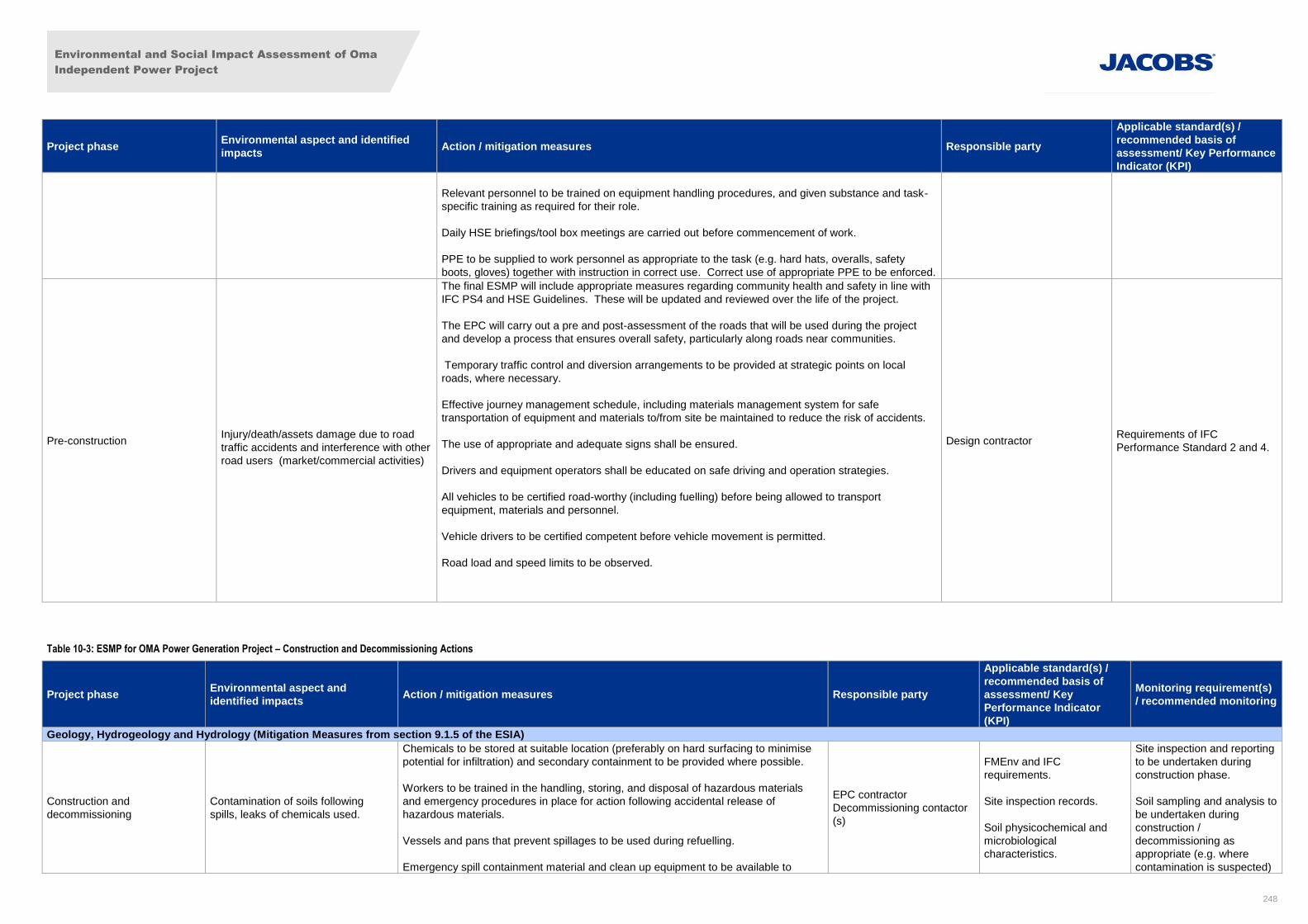
Environmental and Social Impact Assessment of Oma
Independent Power Project
248
Project phase Environmental aspect and identified
impacts Action / mitigation measures Responsible party
Applicable standard(s) /
recommended basis of
assessment/ Key Performance
Indicator (KPI)
Relevant personnel to be trained on equipment handling procedures, and given substance and task-
specific training as required for their role.
Daily HSE briefings/tool box meetings are carried out before commencement of work.
PPE to be supplied to work personnel as appropriate to the task (e.g. hard hats, overalls, safety
boots, gloves) together with instruction in correct use. Correct use of appropriate PPE to be enforced.
Pre-construction
Injury/death/assets damage due to road
traffic accidents and interference with other
road users (market/commercial activities)
The final ESMP will include appropriate measures regarding community health and safety in line with
IFC PS4 and HSE Guidelines. These will be updated and reviewed over the life of the project.
The EPC will carry out a pre and post-assessment of the roads that will be used during the project
and develop a process that ensures overall safety, particularly along roads near communities.
Temporary traffic control and diversion arrangements to be provided at strategic points on local
roads, where necessary.
Effective journey management schedule, including materials management system for safe
transportation of equipment and materials to/from site be maintained to reduce the risk of accidents.
The use of appropriate and adequate signs shall be ensured.
Drivers and equipment operators shall be educated on safe driving and operation strategies.
All vehicles to be certified road-worthy (including fuelling) before being allowed to transport
equipment, materials and personnel.
Vehicle drivers to be certified competent before vehicle movement is permitted.
Road load and speed limits to be observed.
Design contractor Requirements of IFC
Performance Standard 2 and 4.
Table 10-3: ESMP for OMA Power Generation Project – Construction and Decommissioning Actions
Project phase Environmental aspect and
identified impacts Action / mitigation measures Responsible party
Applicable standard(s) /
recommended basis of
assessment/ Key
Performance Indicator
(KPI)
Monitoring requirement(s)
/ recommended monitoring
Geology, Hydrogeology and Hydrology (Mitigation Measures from section 9.1.5 of the ESIA)
Construction and
decommissioning
Contamination of soils following
spills, leaks of chemicals used.
Chemicals to be stored at suitable location (preferably on hard surfacing to minimise
potential for infiltration) and secondary containment to be provided where possible.
Workers to be trained in the handling, storing, and disposal of hazardous materials
and emergency procedures in place for action following accidental release of
hazardous materials.
Vessels and pans that prevent spillages to be used during refuelling.
Emergency spill containment material and clean up equipment to be available to
EPC contractor
Decommissioning contactor
(s)
FMEnv and IFC
requirements.
Site inspection records.
Soil physicochemical and
microbiological
characteristics.
Site inspection and reporting
to be undertaken during
construction phase.
Soil sampling and analysis to
be undertaken during
construction /
decommissioning as
appropriate (e.g. where
contamination is suspected)
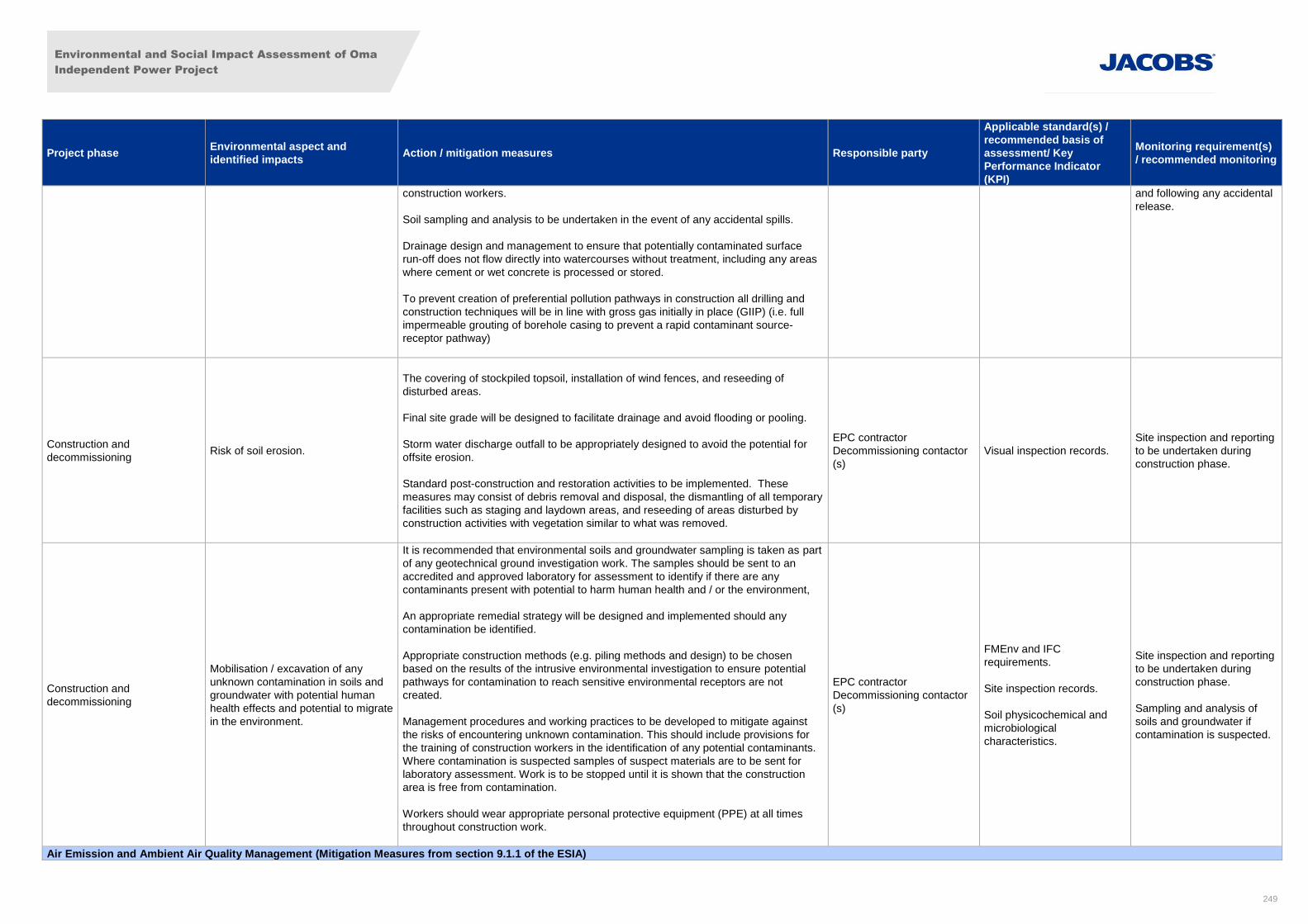
Environmental and Social Impact Assessment of Oma
Independent Power Project
249
Project phase Environmental aspect and
identified impacts Action / mitigation measures Responsible party
Applicable standard(s) /
recommended basis of
assessment/ Key
Performance Indicator
(KPI)
Monitoring requirement(s)
/ recommended monitoring
construction workers.
Soil sampling and analysis to be undertaken in the event of any accidental spills.
Drainage design and management to ensure that potentially contaminated surface
run-off does not flow directly into watercourses without treatment, including any areas
where cement or wet concrete is processed or stored.
To prevent creation of preferential pollution pathways in construction all drilling and
construction techniques will be in line with gross gas initially in place (GIIP) (i.e. full
impermeable grouting of borehole casing to prevent a rapid contaminant source-
receptor pathway)
and following any accidental
release.
Construction and
decommissioning Risk of soil erosion.
The covering of stockpiled topsoil, installation of wind fences, and reseeding of
disturbed areas.
Final site grade will be designed to facilitate drainage and avoid flooding or pooling.
Storm water discharge outfall to be appropriately designed to avoid the potential for
offsite erosion.
Standard post-construction and restoration activities to be implemented. These
measures may consist of debris removal and disposal, the dismantling of all temporary
facilities such as staging and laydown areas, and reseeding of areas disturbed by
construction activities with vegetation similar to what was removed.
EPC contractor
Decommissioning contactor
(s)
Visual inspection records.
Site inspection and reporting
to be undertaken during
construction phase.
Construction and
decommissioning
Mobilisation / excavation of any
unknown contamination in soils and
groundwater with potential human
health effects and potential to migrate
in the environment.
It is recommended that environmental soils and groundwater sampling is taken as part
of any geotechnical ground investigation work. The samples should be sent to an
accredited and approved laboratory for assessment to identify if there are any
contaminants present with potential to harm human health and / or the environment,
An appropriate remedial strategy will be designed and implemented should any
contamination be identified.
Appropriate construction methods (e.g. piling methods and design) to be chosen
based on the results of the intrusive environmental investigation to ensure potential
pathways for contamination to reach sensitive environmental receptors are not
created.
Management procedures and working practices to be developed to mitigate against
the risks of encountering unknown contamination. This should include provisions for
the training of construction workers in the identification of any potential contaminants.
Where contamination is suspected samples of suspect materials are to be sent for
laboratory assessment. Work is to be stopped until it is shown that the construction
area is free from contamination.
Workers should wear appropriate personal protective equipment (PPE) at all times
throughout construction work.
EPC contractor
Decommissioning contactor
(s)
FMEnv and IFC
requirements.
Site inspection records.
Soil physicochemical and
microbiological
characteristics.
Site inspection and reporting
to be undertaken during
construction phase.
Sampling and analysis of
soils and groundwater if
contamination is suspected.
Air Emission and Ambient Air Quality Management (Mitigation Measures from section 9.1.1 of the ESIA)
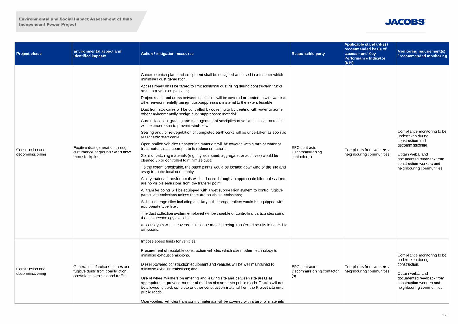
Environmental and Social Impact Assessment of Oma
Independent Power Project
250
Project phase Environmental aspect and
identified impacts Action / mitigation measures Responsible party
Applicable standard(s) /
recommended basis of
assessment/ Key
Performance Indicator
(KPI)
Monitoring requirement(s)
/ recommended monitoring
Construction and
decommissioning
Fugitive dust generation through
disturbance of ground / wind blow
from stockpiles.
Concrete batch plant and equipment shall be designed and used in a manner which
minimises dust generation:
Access roads shall be tarred to limit additional dust rising during construction trucks
and other vehicles passage;
Project roads and areas between stockpiles will be covered or treated to with water or
other environmentally benign dust-suppressant material to the extent feasible;
Dust from stockpiles will be controlled by covering or by treating with water or some
other environmentally benign dust-suppressant material;
Careful location, grading and management of stockpiles of soil and similar materials
will be undertaken to prevent wind-blow;
Sealing and / or re-vegetation of completed earthworks will be undertaken as soon as
reasonably practicable;
Open-bodied vehicles transporting materials will be covered with a tarp or water or
treat materials as appropriate to reduce emissions;
Spills of batching materials (e.g., fly ash, sand, aggregate, or additives) would be
cleaned up or controlled to minimize dust;
To the extent practicable, the batch plants would be located downwind of the site and
away from the local community;
All dry material transfer points will be ducted through an appropriate filter unless there
are no visible emissions from the transfer point;
All transfer points will be equipped with a wet suppression system to control fugitive
particulate emissions unless there are no visible emissions;
All bulk storage silos including auxiliary bulk storage trailers would be equipped with
appropriate type filter;
The dust collection system employed will be capable of controlling particulates using
the best technology available.
All conveyors will be covered unless the material being transferred results in no visible
emissions.
EPC contractor
Decommissioning
contactor(s)
Complaints from workers /
neighbouring communities.
Compliance monitoring to be
undertaken during
construction and
decommissioning.
Obtain verbal and
documented feedback from
construction workers and
neighbouring communities.
Construction and
decommissioning
Generation of exhaust fumes and
fugitive dusts from construction /
operational vehicles and traffic.
Impose speed limits for vehicles.
Procurement of reputable construction vehicles which use modern technology to
minimise exhaust emissions.
Diesel powered construction equipment and vehicles will be well maintained to
minimise exhaust emissions; and
Use of wheel washers on entering and leaving site and between site areas as
appropriate to prevent transfer of mud on site and onto public roads. Trucks will not
be allowed to track concrete or other construction material from the Project site onto
public roads.
Open-bodied vehicles transporting materials will be covered with a tarp, or materials
EPC contractor
Decommissioning contactor
(s)
Complaints from workers /
neighbouring communities.
Compliance monitoring to be
undertaken during
construction.
Obtain verbal and
documented feedback from
construction workers and
neighbouring communities.
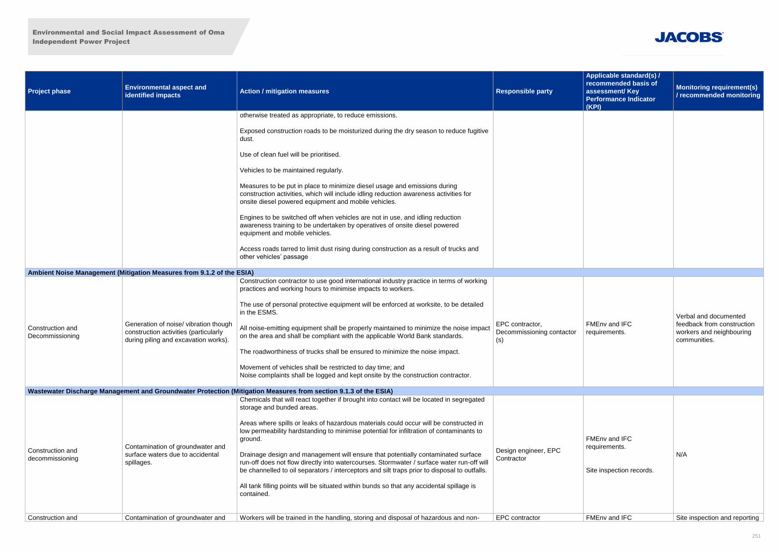
Environmental and Social Impact Assessment of Oma
Independent Power Project
251
Project phase Environmental aspect and
identified impacts Action / mitigation measures Responsible party
Applicable standard(s) /
recommended basis of
assessment/ Key
Performance Indicator
(KPI)
Monitoring requirement(s)
/ recommended monitoring
otherwise treated as appropriate, to reduce emissions.
Exposed construction roads to be moisturized during the dry season to reduce fugitive
dust.
Use of clean fuel will be prioritised.
Vehicles to be maintained regularly.
Measures to be put in place to minimize diesel usage and emissions during
construction activities, which will include idling reduction awareness activities for
onsite diesel powered equipment and mobile vehicles.
Engines to be switched off when vehicles are not in use, and idling reduction
awareness training to be undertaken by operatives of onsite diesel powered
equipment and mobile vehicles.
Access roads tarred to limit dust rising during construction as a result of trucks and
other vehicles’ passage
Ambient Noise Management (Mitigation Measures from 9.1.2 of the ESIA)
Construction and
Decommissioning
Generation of noise/ vibration though
construction activities (particularly
during piling and excavation works).
Construction contractor to use good international industry practice in terms of working
practices and working hours to minimise impacts to workers.
The use of personal protective equipment will be enforced at worksite, to be detailed
in the ESMS.
All noise-emitting equipment shall be properly maintained to minimize the noise impact
on the area and shall be compliant with the applicable World Bank standards.
The roadworthiness of trucks shall be ensured to minimize the noise impact.
Movement of vehicles shall be restricted to day time; and
Noise complaints shall be logged and kept onsite by the construction contractor.
EPC contractor,
Decommissioning contactor
(s)
FMEnv and IFC
requirements.
Verbal and documented
feedback from construction
workers and neighbouring
communities.
Wastewater Discharge Management and Groundwater Protection (Mitigation Measures from section 9.1.3 of the ESIA)
Construction and
decommissioning
Contamination of groundwater and
surface waters due to accidental
spillages.
Chemicals that will react together if brought into contact will be located in segregated
storage and bunded areas.
Areas where spills or leaks of hazardous materials could occur will be constructed in
low permeability hardstanding to minimise potential for infiltration of contaminants to
ground.
Drainage design and management will ensure that potentially contaminated surface
run-off does not flow directly into watercourses. Stormwater / surface water run-off will
be channelled to oil separators / interceptors and silt traps prior to disposal to outfalls.
All tank filling points will be situated within bunds so that any accidental spillage is
contained.
Design engineer, EPC
Contractor
FMEnv and IFC
requirements.
Site inspection records.
N/A
Construction and Contamination of groundwater and Workers will be trained in the handling, storing and disposal of hazardous and non- EPC contractor FMEnv and IFC Site inspection and reporting
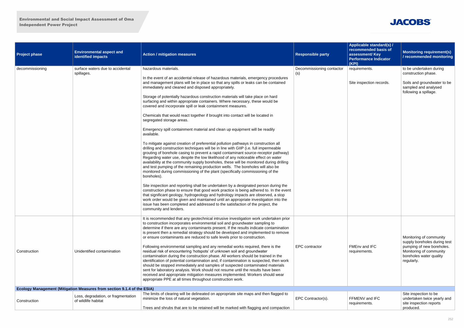
Environmental and Social Impact Assessment of Oma
Independent Power Project
252
Project phase Environmental aspect and
identified impacts Action / mitigation measures Responsible party
Applicable standard(s) /
recommended basis of
assessment/ Key
Performance Indicator
(KPI)
Monitoring requirement(s)
/ recommended monitoring
decommissioning surface waters due to accidental
spillages.
hazardous materials.
In the event of an accidental release of hazardous materials, emergency procedures
and management plans will be in place so that any spills or leaks can be contained
immediately and cleaned and disposed appropriately.
Storage of potentially hazardous construction materials will take place on hard
surfacing and within appropriate containers. Where necessary, these would be
covered and incorporate spill or leak containment measures.
Chemicals that would react together if brought into contact will be located in
segregated storage areas.
Emergency spill containment material and clean up equipment will be readily
available.
To mitigate against creation of preferential pollution pathways in construction all
drilling and construction techniques will be in line with GIIP (i.e. full impermeable
grouting of borehole casing to prevent a rapid contaminant source-receptor pathway)
Regarding water use, despite the low likelihood of any noticeable effect on water
availability at the community supply boreholes, these will be monitored during drilling
and test pumping of the remaining production wells. The boreholes will also be
monitored during commissioning of the plant (specifically commissioning of the
boreholes).
Site inspection and reporting shall be undertaken by a designated person during the
construction phase to ensure that good work practice is being adhered to. In the event
that significant geology, hydrogeology and hydrology impacts are observed, a stop
work order would be given and maintained until an appropriate investigation into the
issue has been completed and addressed to the satisfaction of the project, the
community and lenders.
Decommissioning contactor
(s)
requirements.
Site inspection records.
to be undertaken during
construction phase.
Soils and groundwater to be
sampled and analysed
following a spillage.
Construction Unidentified contamination
It is recommended that any geotechnical intrusive investigation work undertaken prior
to construction incorporates environmental soil and groundwater sampling to
determine if there are any contaminants present. If the results indicate contamination
is present then a remedial strategy should be developed and implemented to remove
or ensure contaminants are reduced to safe levels prior to construction.
Following environmental sampling and any remedial works required, there is the
residual risk of encountering ‘hotspots’ of unknown soil and groundwater
contamination during the construction phase. All workers should be trained in the
identification of potential contamination and, if contamination is suspected, then work
should be stopped immediately and samples of suspected contaminated materials
sent for laboratory analysis. Work should not resume until the results have been
received and appropriate mitigation measures implemented. Workers should wear
appropriate PPE at all times throughout construction work.
EPC contractor
FMEnv and IFC
requirements.
Monitoring of community
supply boreholes during test
pumping of new boreholes.
Monitoring of community
boreholes water quality
regularly.
Ecology Management (Mitigation Measures from section 9.1.4 of the ESIA)
Construction
Loss, degradation, or fragmentation
of wildlife habitat
The limits of clearing will be delineated on appropriate site maps and then flagged to
minimize the loss of natural vegetation.
Trees and shrubs that are to be retained will be marked with flagging and compaction
EPC Contractor(s).
FFMENV and IFC
requirements.
Site inspection to be
undertaken twice yearly and
site inspection reports
produced.
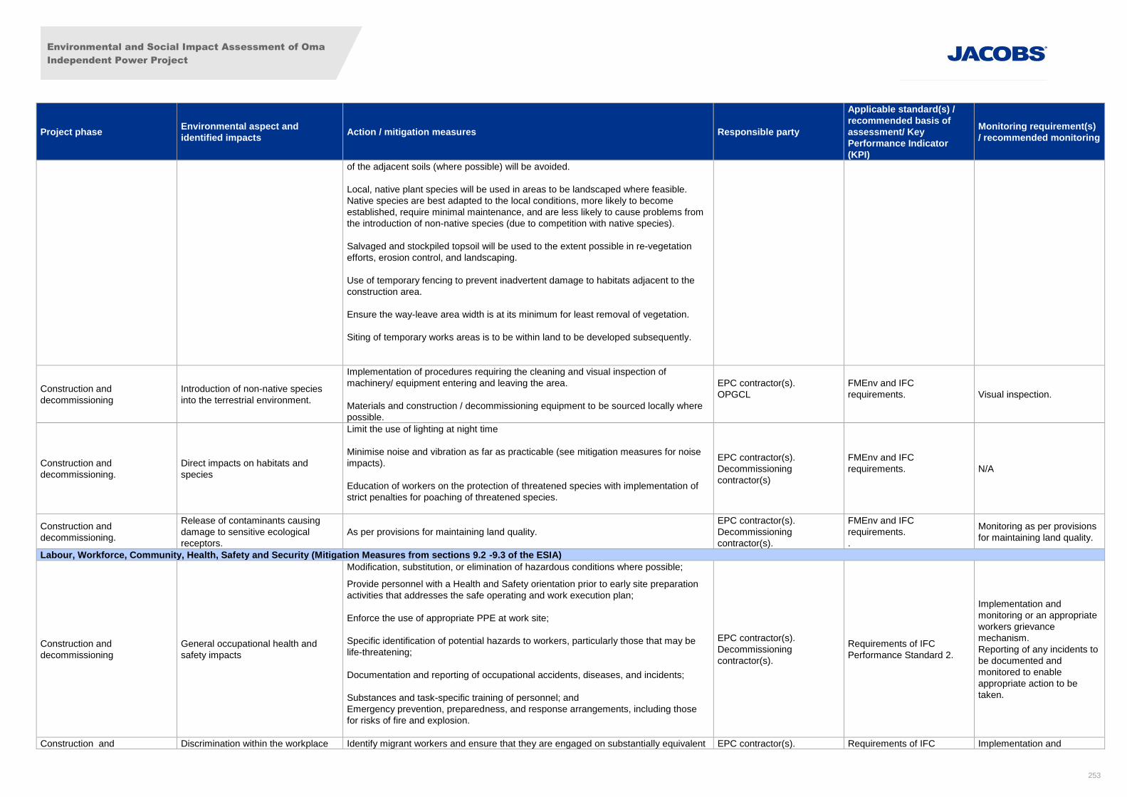
Environmental and Social Impact Assessment of Oma
Independent Power Project
253
Project phase Environmental aspect and
identified impacts Action / mitigation measures Responsible party
Applicable standard(s) /
recommended basis of
assessment/ Key
Performance Indicator
(KPI)
Monitoring requirement(s)
/ recommended monitoring
of the adjacent soils (where possible) will be avoided.
Local, native plant species will be used in areas to be landscaped where feasible.
Native species are best adapted to the local conditions, more likely to become
established, require minimal maintenance, and are less likely to cause problems from
the introduction of non-native species (due to competition with native species).
Salvaged and stockpiled topsoil will be used to the extent possible in re-vegetation
efforts, erosion control, and landscaping.
Use of temporary fencing to prevent inadvertent damage to habitats adjacent to the
construction area.
Ensure the way-leave area width is at its minimum for least removal of vegetation.
Siting of temporary works areas is to be within land to be developed subsequently.
Construction and
decommissioning
Introduction of non-native species
into the terrestrial environment.
Implementation of procedures requiring the cleaning and visual inspection of
machinery/ equipment entering and leaving the area.
Materials and construction / decommissioning equipment to be sourced locally where
possible.
EPC contractor(s).
OPGCL
FMEnv and IFC
requirements.
Visual inspection.
Construction and
decommissioning.
Direct impacts on habitats and
species
Limit the use of lighting at night time
Minimise noise and vibration as far as practicable (see mitigation measures for noise
impacts).
Education of workers on the protection of threatened species with implementation of
strict penalties for poaching of threatened species.
EPC contractor(s).
Decommissioning
contractor(s)
FMEnv and IFC
requirements.
N/A
Construction and
decommissioning.
Release of contaminants causing
damage to sensitive ecological
receptors.
As per provisions for maintaining land quality.
EPC contractor(s).
Decommissioning
contractor(s).
FMEnv and IFC
requirements.
.
Monitoring as per provisions
for maintaining land quality.
Labour, Workforce, Community, Health, Safety and Security (Mitigation Measures from sections 9.2 -9.3 of the ESIA)
Construction and
decommissioning
General occupational health and
safety impacts
Modification, substitution, or elimination of hazardous conditions where possible;
Provide personnel with a Health and Safety orientation prior to early site preparation
activities that addresses the safe operating and work execution plan;
Enforce the use of appropriate PPE at work site;
Specific identification of potential hazards to workers, particularly those that may be
life-threatening;
Documentation and reporting of occupational accidents, diseases, and incidents;
Substances and task-specific training of personnel; and
Emergency prevention, preparedness, and response arrangements, including those
for risks of fire and explosion.
EPC contractor(s).
Decommissioning
contractor(s).
Requirements of IFC
Performance Standard 2.
Implementation and
monitoring or an appropriate
workers grievance
mechanism.
Reporting of any incidents to
be documented and
monitored to enable
appropriate action to be
taken.
Construction and Discrimination within the workplace Identify migrant workers and ensure that they are engaged on substantially equivalent EPC contractor(s). Requirements of IFC Implementation and
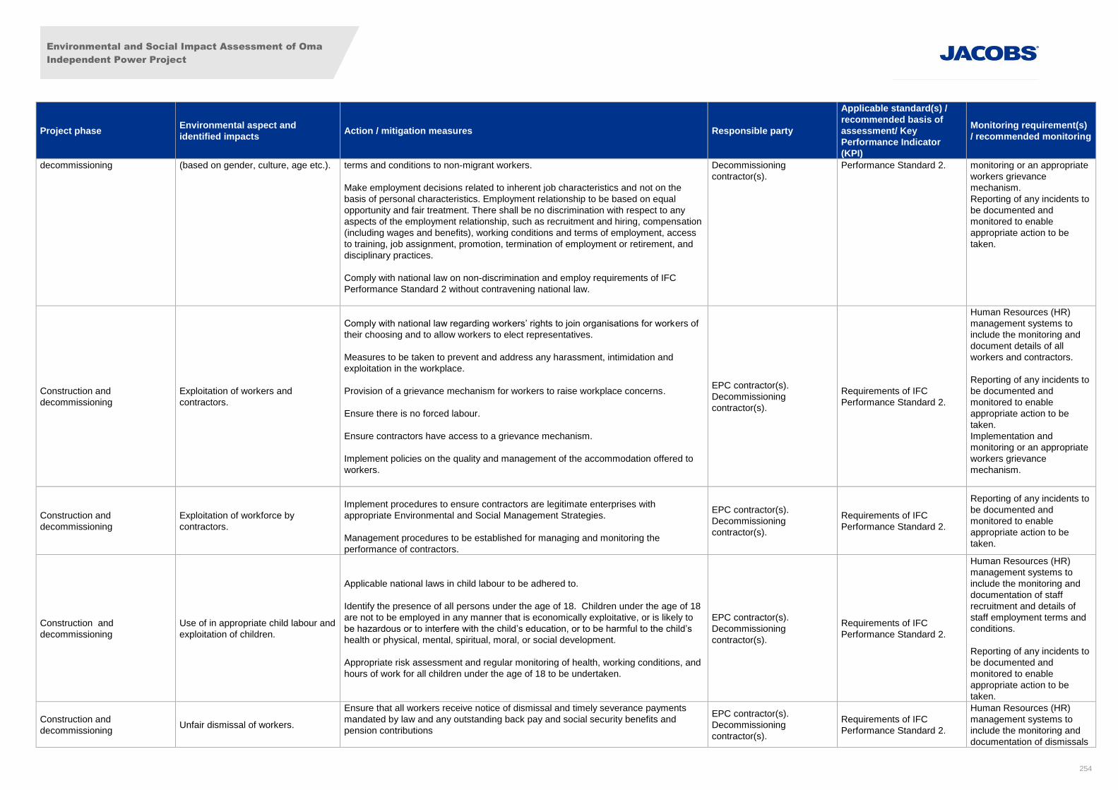
Environmental and Social Impact Assessment of Oma
Independent Power Project
254
Project phase Environmental aspect and
identified impacts Action / mitigation measures Responsible party
Applicable standard(s) /
recommended basis of
assessment/ Key
Performance Indicator
(KPI)
Monitoring requirement(s)
/ recommended monitoring
decommissioning (based on gender, culture, age etc.). terms and conditions to non-migrant workers.
Make employment decisions related to inherent job characteristics and not on the
basis of personal characteristics. Employment relationship to be based on equal
opportunity and fair treatment. There shall be no discrimination with respect to any
aspects of the employment relationship, such as recruitment and hiring, compensation
(including wages and benefits), working conditions and terms of employment, access
to training, job assignment, promotion, termination of employment or retirement, and
disciplinary practices.
Comply with national law on non-discrimination and employ requirements of IFC
Performance Standard 2 without contravening national law.
Decommissioning
contractor(s).
Performance Standard 2. monitoring or an appropriate
workers grievance
mechanism.
Reporting of any incidents to
be documented and
monitored to enable
appropriate action to be
taken.
Construction and
decommissioning
Exploitation of workers and
contractors.
Comply with national law regarding workers’ rights to join organisations for workers of
their choosing and to allow workers to elect representatives.
Measures to be taken to prevent and address any harassment, intimidation and
exploitation in the workplace.
Provision of a grievance mechanism for workers to raise workplace concerns.
Ensure there is no forced labour.
Ensure contractors have access to a grievance mechanism.
Implement policies on the quality and management of the accommodation offered to
workers.
EPC contractor(s).
Decommissioning
contractor(s).
Requirements of IFC
Performance Standard 2.
Human Resources (HR)
management systems to
include the monitoring and
document details of all
workers and contractors.
Reporting of any incidents to
be documented and
monitored to enable
appropriate action to be
taken.
Implementation and
monitoring or an appropriate
workers grievance
mechanism.
Construction and
decommissioning
Exploitation of workforce by
contractors.
Implement procedures to ensure contractors are legitimate enterprises with
appropriate Environmental and Social Management Strategies.
Management procedures to be established for managing and monitoring the
performance of contractors.
EPC contractor(s).
Decommissioning
contractor(s).
Requirements of IFC
Performance Standard 2.
Reporting of any incidents to
be documented and
monitored to enable
appropriate action to be
taken.
Construction and
decommissioning
Use of in appropriate child labour and
exploitation of children.
Applicable national laws in child labour to be adhered to.
Identify the presence of all persons under the age of 18. Children under the age of 18
are not to be employed in any manner that is economically exploitative, or is likely to
be hazardous or to interfere with the child’s education, or to be harmful to the child’s
health or physical, mental, spiritual, moral, or social development.
Appropriate risk assessment and regular monitoring of health, working conditions, and
hours of work for all children under the age of 18 to be undertaken.
EPC contractor(s).
Decommissioning
contractor(s).
Requirements of IFC
Performance Standard 2.
Human Resources (HR)
management systems to
include the monitoring and
documentation of staff
recruitment and details of
staff employment terms and
conditions.
Reporting of any incidents to
be documented and
monitored to enable
appropriate action to be
taken.
Construction and
decommissioning Unfair dismissal of workers.
Ensure that all workers receive notice of dismissal and timely severance payments
mandated by law and any outstanding back pay and social security benefits and
pension contributions
EPC contractor(s).
Decommissioning
contractor(s).
Requirements of IFC
Performance Standard 2.
Human Resources (HR)
management systems to
include the monitoring and
documentation of dismissals
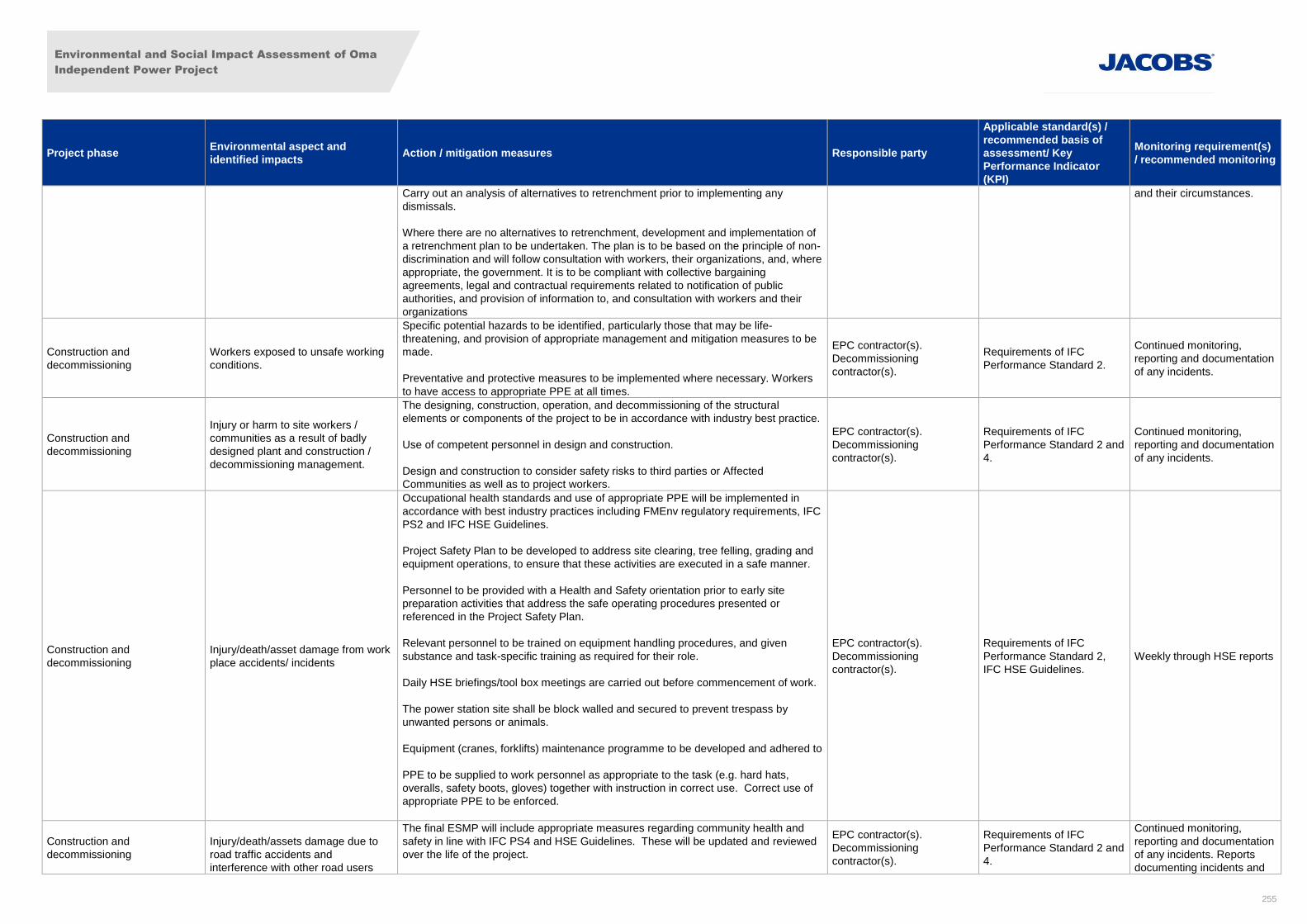
Environmental and Social Impact Assessment of Oma
Independent Power Project
255
Project phase Environmental aspect and
identified impacts Action / mitigation measures Responsible party
Applicable standard(s) /
recommended basis of
assessment/ Key
Performance Indicator
(KPI)
Monitoring requirement(s)
/ recommended monitoring
Carry out an analysis of alternatives to retrenchment prior to implementing any
dismissals.
Where there are no alternatives to retrenchment, development and implementation of
a retrenchment plan to be undertaken. The plan is to be based on the principle of non-
discrimination and will follow consultation with workers, their organizations, and, where
appropriate, the government. It is to be compliant with collective bargaining
agreements, legal and contractual requirements related to notification of public
authorities, and provision of information to, and consultation with workers and their
organizations
and their circumstances.
Construction and
decommissioning
Workers exposed to unsafe working
conditions.
Specific potential hazards to be identified, particularly those that may be life-
threatening, and provision of appropriate management and mitigation measures to be
made.
Preventative and protective measures to be implemented where necessary. Workers
to have access to appropriate PPE at all times.
EPC contractor(s).
Decommissioning
contractor(s).
Requirements of IFC
Performance Standard 2.
Continued monitoring,
reporting and documentation
of any incidents.
Construction and
decommissioning
Injury or harm to site workers /
communities as a result of badly
designed plant and construction /
decommissioning management.
The designing, construction, operation, and decommissioning of the structural
elements or components of the project to be in accordance with industry best practice.
Use of competent personnel in design and construction.
Design and construction to consider safety risks to third parties or Affected
Communities as well as to project workers.
EPC contractor(s).
Decommissioning
contractor(s).
Requirements of IFC
Performance Standard 2 and
4.
Continued monitoring,
reporting and documentation
of any incidents.
Construction and
decommissioning
Injury/death/asset damage from work
place accidents/ incidents
Occupational health standards and use of appropriate PPE will be implemented in
accordance with best industry practices including FMEnv regulatory requirements, IFC
PS2 and IFC HSE Guidelines.
Project Safety Plan to be developed to address site clearing, tree felling, grading and
equipment operations, to ensure that these activities are executed in a safe manner.
Personnel to be provided with a Health and Safety orientation prior to early site
preparation activities that address the safe operating procedures presented or
referenced in the Project Safety Plan.
Relevant personnel to be trained on equipment handling procedures, and given
substance and task-specific training as required for their role.
Daily HSE briefings/tool box meetings are carried out before commencement of work.
The power station site shall be block walled and secured to prevent trespass by
unwanted persons or animals.
Equipment (cranes, forklifts) maintenance programme to be developed and adhered to
PPE to be supplied to work personnel as appropriate to the task (e.g. hard hats,
overalls, safety boots, gloves) together with instruction in correct use. Correct use of
appropriate PPE to be enforced.
EPC contractor(s).
Decommissioning
contractor(s).
Requirements of IFC
Performance Standard 2,
IFC HSE Guidelines.
Weekly through HSE reports
Construction and
decommissioning
Injury/death/assets damage due to
road traffic accidents and
interference with other road users
The final ESMP will include appropriate measures regarding community health and
safety in line with IFC PS4 and HSE Guidelines. These will be updated and reviewed
over the life of the project.
EPC contractor(s).
Decommissioning
contractor(s).
Requirements of IFC
Performance Standard 2 and
4.
Continued monitoring,
reporting and documentation
of any incidents. Reports
documenting incidents and
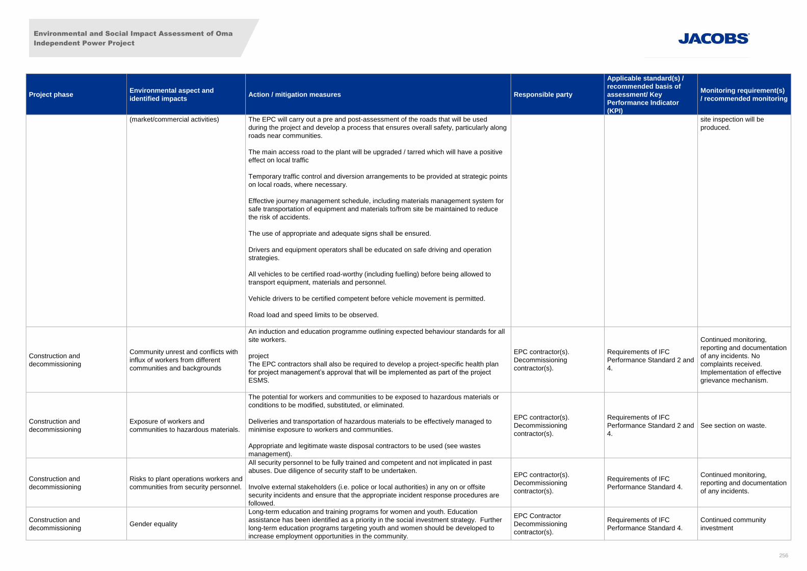
Environmental and Social Impact Assessment of Oma
Independent Power Project
256
Project phase Environmental aspect and
identified impacts Action / mitigation measures Responsible party
Applicable standard(s) /
recommended basis of
assessment/ Key
Performance Indicator
(KPI)
Monitoring requirement(s)
/ recommended monitoring
(market/commercial activities) The EPC will carry out a pre and post-assessment of the roads that will be used
during the project and develop a process that ensures overall safety, particularly along
roads near communities.
The main access road to the plant will be upgraded / tarred which will have a positive
effect on local traffic
Temporary traffic control and diversion arrangements to be provided at strategic points
on local roads, where necessary.
Effective journey management schedule, including materials management system for
safe transportation of equipment and materials to/from site be maintained to reduce
the risk of accidents.
The use of appropriate and adequate signs shall be ensured.
Drivers and equipment operators shall be educated on safe driving and operation
strategies.
All vehicles to be certified road-worthy (including fuelling) before being allowed to
transport equipment, materials and personnel.
Vehicle drivers to be certified competent before vehicle movement is permitted.
Road load and speed limits to be observed.
site inspection will be
produced.
Construction and
decommissioning
Community unrest and conflicts with
influx of workers from different
communities and backgrounds
An induction and education programme outlining expected behaviour standards for all
site workers.
project
The EPC contractors shall also be required to develop a project-specific health plan
for project management’s approval that will be implemented as part of the project
ESMS.
EPC contractor(s).
Decommissioning
contractor(s).
Requirements of IFC
Performance Standard 2 and
4.
Continued monitoring,
reporting and documentation
of any incidents. No
complaints received.
Implementation of effective
grievance mechanism.
Construction and
decommissioning
Exposure of workers and
communities to hazardous materials.
The potential for workers and communities to be exposed to hazardous materials or
conditions to be modified, substituted, or eliminated.
Deliveries and transportation of hazardous materials to be effectively managed to
minimise exposure to workers and communities.
Appropriate and legitimate waste disposal contractors to be used (see wastes
management).
EPC contractor(s).
Decommissioning
contractor(s).
Requirements of IFC
Performance Standard 2 and
4.
See section on waste.
Construction and
decommissioning
Risks to plant operations workers and
communities from security personnel.
All security personnel to be fully trained and competent and not implicated in past
abuses. Due diligence of security staff to be undertaken.
Involve external stakeholders (i.e. police or local authorities) in any on or offsite
security incidents and ensure that the appropriate incident response procedures are
followed.
EPC contractor(s).
Decommissioning
contractor(s).
Requirements of IFC
Performance Standard 4.
Continued monitoring,
reporting and documentation
of any incidents.
Construction and
decommissioning Gender equality
Long-term education and training programs for women and youth. Education
assistance has been identified as a priority in the social investment strategy. Further
long-term education programs targeting youth and women should be developed to
increase employment opportunities in the community.
EPC Contractor
Decommissioning
contractor(s).
Requirements of IFC
Performance Standard 4.
Continued community
investment
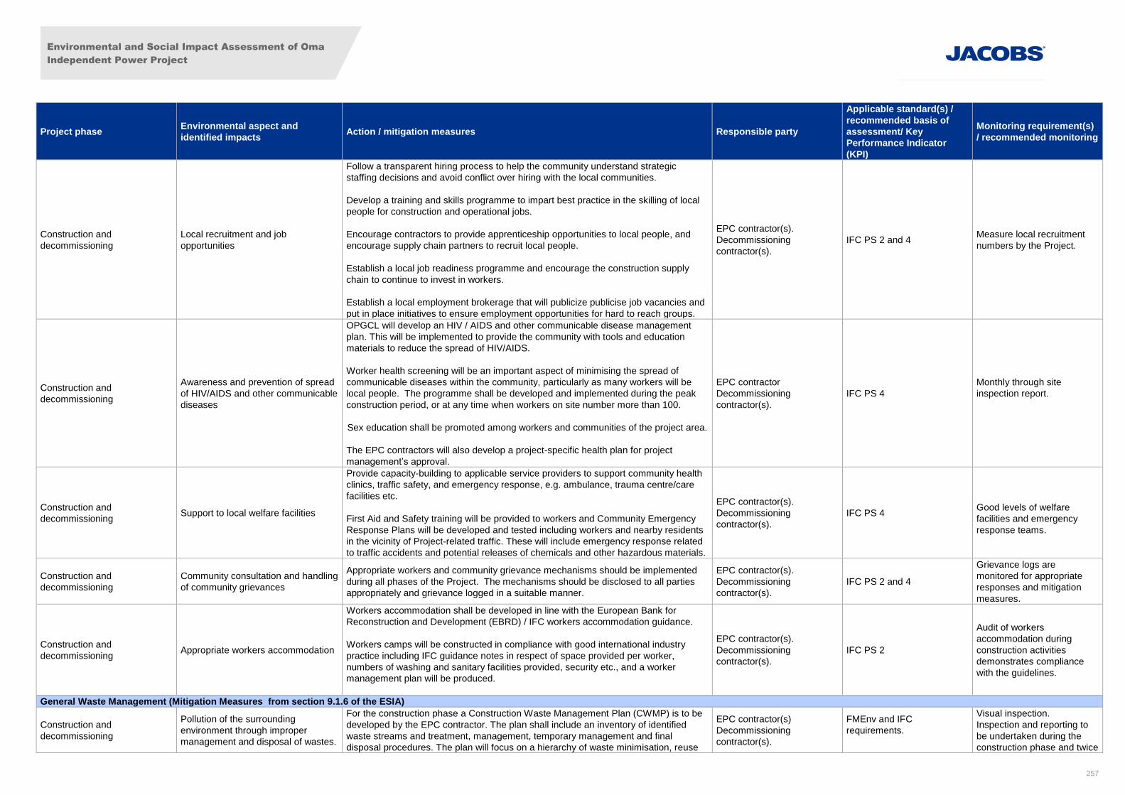
Environmental and Social Impact Assessment of Oma
Independent Power Project
257
Project phase Environmental aspect and
identified impacts Action / mitigation measures Responsible party
Applicable standard(s) /
recommended basis of
assessment/ Key
Performance Indicator
(KPI)
Monitoring requirement(s)
/ recommended monitoring
Construction and
decommissioning
Local recruitment and job
opportunities
Follow a transparent hiring process to help the community understand strategic
staffing decisions and avoid conflict over hiring with the local communities.
Develop a training and skills programme to impart best practice in the skilling of local
people for construction and operational jobs.
Encourage contractors to provide apprenticeship opportunities to local people, and
encourage supply chain partners to recruit local people.
Establish a local job readiness programme and encourage the construction supply
chain to continue to invest in workers.
Establish a local employment brokerage that will publicize publicise job vacancies and
put in place initiatives to ensure employment opportunities for hard to reach groups.
EPC contractor(s).
Decommissioning
contractor(s).
IFC PS 2 and 4 Measure local recruitment
numbers by the Project.
Construction and
decommissioning
Awareness and prevention of spread
of HIV/AIDS and other communicable
diseases
OPGCL will develop an HIV / AIDS and other communicable disease management
plan. This will be implemented to provide the community with tools and education
materials to reduce the spread of HIV/AIDS.
Worker health screening will be an important aspect of minimising the spread of
communicable diseases within the community, particularly as many workers will be
local people. The programme shall be developed and implemented during the peak
construction period, or at any time when workers on site number more than 100.
Sex education shall be promoted among workers and communities of the project area.
The EPC contractors will also develop a project-specific health plan for project
management’s approval.
EPC contractor
Decommissioning
contractor(s).
IFC PS 4
Monthly through site
inspection report.
Construction and
decommissioning Support to local welfare facilities
Provide capacity-building to applicable service providers to support community health
clinics, traffic safety, and emergency response, e.g. ambulance, trauma centre/care
facilities etc.
First Aid and Safety training will be provided to workers and Community Emergency
Response Plans will be developed and tested including workers and nearby residents
in the vicinity of Project-related traffic. These will include emergency response related
to traffic accidents and potential releases of chemicals and other hazardous materials.
EPC contractor(s).
Decommissioning
contractor(s).
IFC PS 4
Good levels of welfare
facilities and emergency
response teams.
Construction and
decommissioning
Community consultation and handling
of community grievances
Appropriate workers and community grievance mechanisms should be implemented
during all phases of the Project. The mechanisms should be disclosed to all parties
appropriately and grievance logged in a suitable manner.
EPC contractor(s).
Decommissioning
contractor(s).
IFC PS 2 and 4
Grievance logs are
monitored for appropriate
responses and mitigation
measures.
Construction and
decommissioning Appropriate workers accommodation
Workers accommodation shall be developed in line with the European Bank for
Reconstruction and Development (EBRD) / IFC workers accommodation guidance.
Workers camps will be constructed in compliance with good international industry
practice including IFC guidance notes in respect of space provided per worker,
numbers of washing and sanitary facilities provided, security etc., and a worker
management plan will be produced.
EPC contractor(s).
Decommissioning
contractor(s).
IFC PS 2
Audit of workers
accommodation during
construction activities
demonstrates compliance
with the guidelines.
General Waste Management (Mitigation Measures from section 9.1.6 of the ESIA)
Construction and
decommissioning
Pollution of the surrounding
environment through improper
management and disposal of wastes.
For the construction phase a Construction Waste Management Plan (CWMP) is to be
developed by the EPC contractor. The plan shall include an inventory of identified
waste streams and treatment, management, temporary management and final
disposal procedures. The plan will focus on a hierarchy of waste minimisation, reuse
EPC contractor(s)
Decommissioning
contractor(s).
FMEnv and IFC
requirements.
Visual inspection.
Inspection and reporting to
be undertaken during the
construction phase and twice
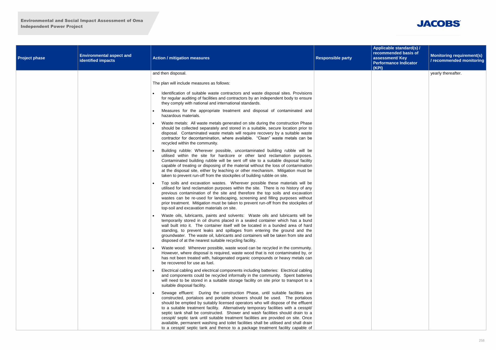
Environmental and Social Impact Assessment of Oma
Independent Power Project
258
Project phase Environmental aspect and
identified impacts Action / mitigation measures Responsible party
Applicable standard(s) /
recommended basis of
assessment/ Key
Performance Indicator
(KPI)
Monitoring requirement(s)
/ recommended monitoring
and then disposal.
The plan will include measures as follows:
Identification of suitable waste contractors and waste disposal sites. Provisions
for regular auditing of facilities and contractors by an independent body to ensure
they comply with national and international standards.
Measures for the appropriate treatment and disposal of contaminated and
hazardous materials.
Waste metals: All waste metals generated on site during the construction Phase
should be collected separately and stored in a suitable, secure location prior to
disposal. Contaminated waste metals will require recovery by a suitable waste
contractor for decontamination, where available. “Clean” waste metals can be
recycled within the community.
Building rubble: Wherever possible, uncontaminated building rubble will be
utilised within the site for hardcore or other land reclamation purposes.
Contaminated building rubble will be sent off site to a suitable disposal facility
capable of treating or disposing of the material without the loss of contamination
at the disposal site, either by leaching or other mechanism. Mitigation must be
taken to prevent run-off from the stockpiles of building rubble on site.
Top soils and excavation wastes. Wherever possible these materials will be
utilised for land reclamation purposes within the site. There is no history of any
previous contamination of the site and therefore the top soils and excavation
wastes can be re-used for landscaping, screening and filling purposes without
prior treatment. Mitigation must be taken to prevent run-off from the stockpiles of
top-soil and excavation materials on site.
Waste oils, lubricants, paints and solvents: Waste oils and lubricants will be
temporarily stored in oil drums placed in a sealed container which has a bund
wall built into it. The container itself will be located in a bunded area of hard
standing, to prevent leaks and spillages from entering the ground and the
groundwater. The waste oil, lubricants and containers will be taken from site and
disposed of at the nearest suitable recycling facility.
Waste wood: Wherever possible, waste wood can be recycled in the community.
However, where disposal is required, waste wood that is not contaminated by, or
has not been treated with, halogenated organic compounds or heavy metals can
be recovered for use as fuel.
Electrical cabling and electrical components including batteries: Electrical cabling
and components could be recycled informally in the community. Spent batteries
will need to be stored in a suitable storage facility on site prior to transport to a
suitable disposal facility.
Sewage effluent: During the construction Phase, until suitable facilities are
constructed, portaloos and portable showers should be used. The portaloos
should be emptied by suitably licensed operators who will dispose of the effluent
to a suitable treatment facility. Alternatively temporary facilities with a cesspit/
septic tank shall be constructed. Shower and wash facilities should drain to a
cesspit/ septic tank until suitable treatment facilities are provided on site. Once
available, permanent washing and toilet facilities shall be utilised and shall drain
to a cesspit/ septic tank and thence to a package treatment facility capable of
yearly thereafter.
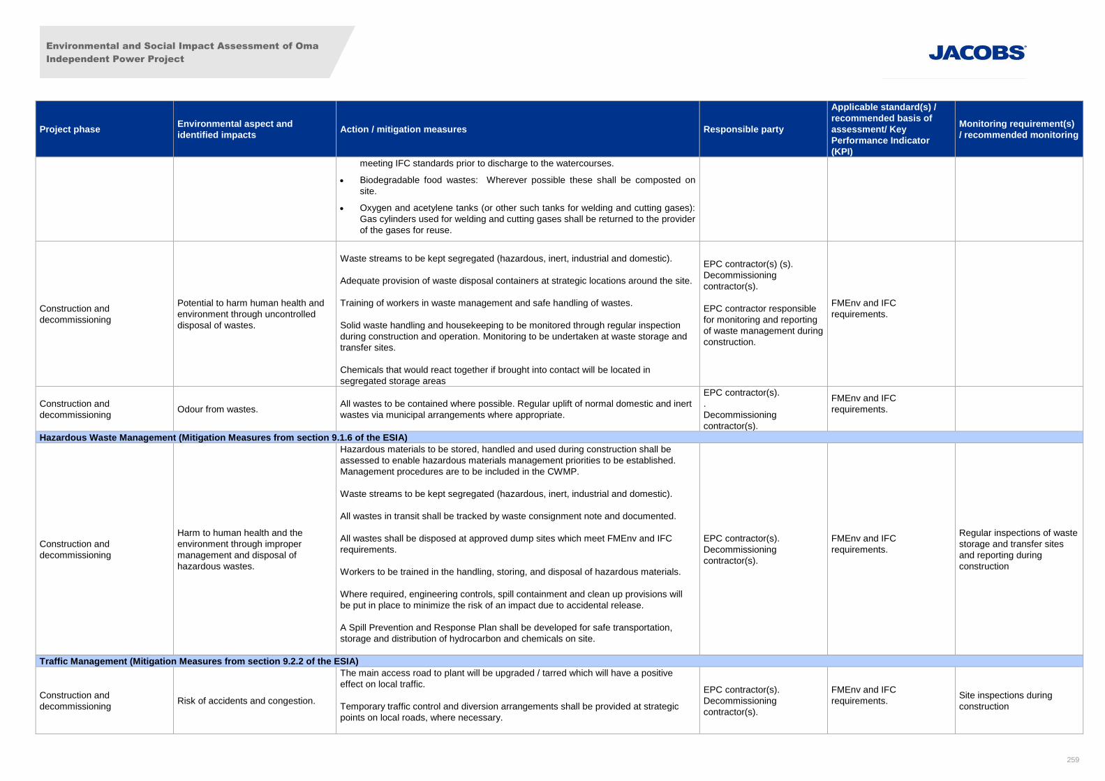
Environmental and Social Impact Assessment of Oma
Independent Power Project
259
Project phase Environmental aspect and
identified impacts Action / mitigation measures Responsible party
Applicable standard(s) /
recommended basis of
assessment/ Key
Performance Indicator
(KPI)
Monitoring requirement(s)
/ recommended monitoring
meeting IFC standards prior to discharge to the watercourses.
Biodegradable food wastes: Wherever possible these shall be composted on
site.
Oxygen and acetylene tanks (or other such tanks for welding and cutting gases):
Gas cylinders used for welding and cutting gases shall be returned to the provider
of the gases for reuse.
Construction and
decommissioning
Potential to harm human health and
environment through uncontrolled
disposal of wastes.
Waste streams to be kept segregated (hazardous, inert, industrial and domestic).
Adequate provision of waste disposal containers at strategic locations around the site.
Training of workers in waste management and safe handling of wastes.
Solid waste handling and housekeeping to be monitored through regular inspection
during construction and operation. Monitoring to be undertaken at waste storage and
transfer sites.
Chemicals that would react together if brought into contact will be located in
segregated storage areas
EPC contractor(s) (s).
Decommissioning
contractor(s).
EPC contractor responsible
for monitoring and reporting
of waste management during
construction.
FMEnv and IFC
requirements.
Construction and
decommissioning Odour from wastes.
All wastes to be contained where possible. Regular uplift of normal domestic and inert
wastes via municipal arrangements where appropriate.
EPC contractor(s).
.
Decommissioning
contractor(s).
FMEnv and IFC
requirements.
Hazardous Waste Management (Mitigation Measures from section 9.1.6 of the ESIA)
Construction and
decommissioning
Harm to human health and the
environment through improper
management and disposal of
hazardous wastes.
Hazardous materials to be stored, handled and used during construction shall be
assessed to enable hazardous materials management priorities to be established.
Management procedures are to be included in the CWMP.
Waste streams to be kept segregated (hazardous, inert, industrial and domestic).
All wastes in transit shall be tracked by waste consignment note and documented.
All wastes shall be disposed at approved dump sites which meet FMEnv and IFC
requirements.
Workers to be trained in the handling, storing, and disposal of hazardous materials.
Where required, engineering controls, spill containment and clean up provisions will
be put in place to minimize the risk of an impact due to accidental release.
A Spill Prevention and Response Plan shall be developed for safe transportation,
storage and distribution of hydrocarbon and chemicals on site.
EPC contractor(s).
Decommissioning
contractor(s).
FMEnv and IFC
requirements.
Regular inspections of waste
storage and transfer sites
and reporting during
construction
Traffic Management (Mitigation Measures from section 9.2.2 of the ESIA)
Construction and
decommissioning Risk of accidents and congestion.
The main access road to plant will be upgraded / tarred which will have a positive
effect on local traffic.
Temporary traffic control and diversion arrangements shall be provided at strategic
points on local roads, where necessary.
EPC contractor(s).
Decommissioning
contractor(s).
FMEnv and IFC
requirements.
Site inspections during
construction
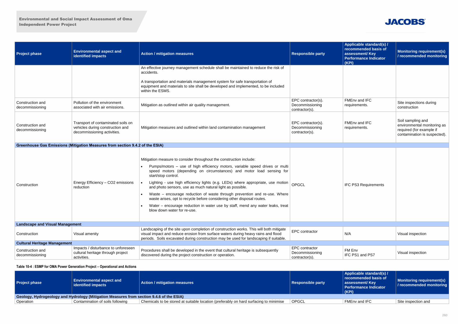
Environmental and Social Impact Assessment of Oma
Independent Power Project
260
Project phase Environmental aspect and
identified impacts Action / mitigation measures Responsible party
Applicable standard(s) /
recommended basis of
assessment/ Key
Performance Indicator
(KPI)
Monitoring requirement(s)
/ recommended monitoring
An effective journey management schedule shall be maintained to reduce the risk of
accidents.
A transportation and materials management system for safe transportation of
equipment and materials to site shall be developed and implemented, to be included
within the ESMS.
Construction and
decommissioning
Pollution of the environment
associated with air emissions. Mitigation as outlined within air quality management.
EPC contractor(s).
Decommissioning
contractor(s).
FMEnv and IFC
requirements.
Site inspections during
construction
Construction and
decommissioning
Transport of contaminated soils on
vehicles during construction and
decommissioning activities.
Mitigation measures and outlined within land contamination management
EPC contractor(s).
Decommissioning
contractor(s).
FMEnv and IFC
requirements.
Soil sampling and
environmental monitoring as
required (for example if
contamination is suspected).
Greenhouse Gas Emissions (Mitigation Measures from section 9.4.2 of the ESIA)
Construction Energy Efficiency – CO2 emissions
reduction
Mitigation measure to consider throughout the construction include:
Pumps/motors – use of high efficiency motors, variable speed drives or multi
speed motors (depending on circumstances) and motor load sensing for
start/stop control.
Lighting - use high efficiency lights (e.g. LEDs) where appropriate, use motion
and photo sensors, use as much natural light as possible.
Waste – encourage reduction of waste through prevention and re-use. Where
waste arises, opt to recycle before considering other disposal routes.
Water – encourage reduction in water use by staff, mend any water leaks, treat
blow down water for re-use.
OPGCL IFC PS3 Requirements
Landscape and Visual Management
Construction Visual amenity
Landscaping of the site upon completion of construction works. This will both mitigate
visual impact and reduce erosion from surface waters during heavy rains and flood
periods. Soils excavated during construction may be used for landscaping if suitable.
EPC contractor
N/A Visual inspection
Cultural Heritage Management
Construction and
decommissioning
Impacts / disturbance to unforeseen
cultural heritage through project
activities.
Procedures shall be developed in the event that cultural heritage is subsequently
discovered during the project construction or operation.
EPC contractor
Decommissioning
contractor(s).
FM Env
IFC PS1 and PS7 Visual inspection
Table 10-4 : ESMP for OMA Power Generation Project – Operational and Actions
Project phase Environmental aspect and
identified impacts Action / mitigation measures Responsible party
Applicable standard(s) /
recommended basis of
assessment/ Key
Performance Indicator
(KPI)
Monitoring requirement(s)
/ recommended monitoring
Geology, Hydrogeology and Hydrology (Mitigation Measures from section 9.4.6 of the ESIA)
Operation Contamination of soils following Chemicals to be stored at suitable location (preferably on hard surfacing to minimise OPGCL FMEnv and IFC Site inspection and
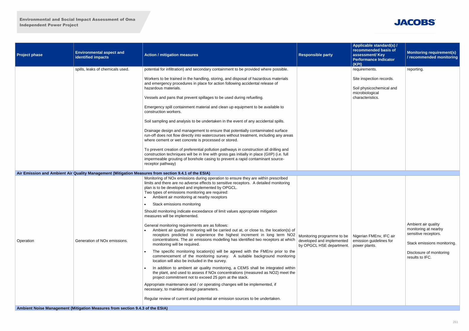
Environmental and Social Impact Assessment of Oma
Independent Power Project
261
Project phase Environmental aspect and
identified impacts Action / mitigation measures Responsible party
Applicable standard(s) /
recommended basis of
assessment/ Key
Performance Indicator
(KPI)
Monitoring requirement(s)
/ recommended monitoring
spills, leaks of chemicals used. potential for infiltration) and secondary containment to be provided where possible.
Workers to be trained in the handling, storing, and disposal of hazardous materials
and emergency procedures in place for action following accidental release of
hazardous materials.
Vessels and pans that prevent spillages to be used during refuelling.
Emergency spill containment material and clean up equipment to be available to
construction workers.
Soil sampling and analysis to be undertaken in the event of any accidental spills.
Drainage design and management to ensure that potentially contaminated surface
run-off does not flow directly into watercourses without treatment, including any areas
where cement or wet concrete is processed or stored.
To prevent creation of preferential pollution pathways in construction all drilling and
construction techniques will be in line with gross gas initially in place (GIIP) (i.e. full
impermeable grouting of borehole casing to prevent a rapid contaminant source-
receptor pathway)
requirements.
Site inspection records.
Soil physicochemical and
microbiological
characteristics.
reporting.
Air Emission and Ambient Air Quality Management (Mitigation Measures from section 9.4.1 of the ESIA)
Operation Generation of NOx emissions.
Monitoring of NOx emissions during operation to ensure they are within prescribed
limits and there are no adverse effects to sensitive receptors. A detailed monitoring
plan is to be developed and implemented by OPGCL.
Two types of emissions monitoring are required:
Ambient air monitoring at nearby receptors
Stack emissions monitoring
Should monitoring indicate exceedance of limit values appropriate mitigation
measures will be implemented.
General monitoring requirements are as follows:
Ambient air quality monitoring will be carried out at, or close to, the location(s) of
receptors predicted to experience the highest increment in long term NO2
concentrations. The air emissions modelling has identified two receptors at which
monitoring will be required.
The specific monitoring location(s) will be agreed with the FMEnv prior to the
commencement of the monitoring survey. A suitable background monitoring
location will also be included in the survey.
In addition to ambient air quality monitoring, a CEMS shall be integrated within
the plant, and used to assess if NOx concentrations (measured as NO2) meet the
project commitment not to exceed 25 ppm at the stack.
Appropriate maintenance and / or operating changes will be implemented, if
necessary, to maintain design parameters.
Regular review of current and potential air emission sources to be undertaken.
Monitoring programme to be
developed and implemented
by OPGCL HSE department.
Nigerian FMEnv, IFC air
emission guidelines for
power plants.
Ambient air quality
monitoring at nearby
sensitive receptors.
Stack emissions monitoring.
Disclosure of monitoring
results to IFC.
Ambient Noise Management (Mitigation Measures from section 9.4.3 of the ESIA)
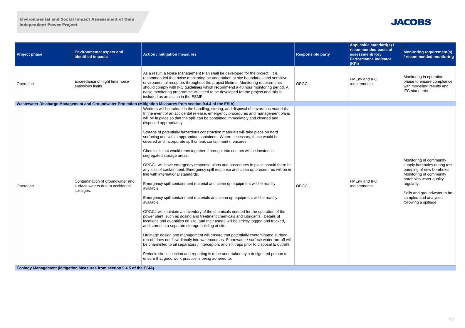
Environmental and Social Impact Assessment of Oma
Independent Power Project
262
Project phase Environmental aspect and
identified impacts Action / mitigation measures Responsible party
Applicable standard(s) /
recommended basis of
assessment/ Key
Performance Indicator
(KPI)
Monitoring requirement(s)
/ recommended monitoring
Operation Exceedance of night time noise
emissions limits
As a result, a Noise Management Plan shall be developed for the project. It is
recommended that noise monitoring be undertaken at site boundaries and sensitive
environmental receptors throughout the project lifetime. Monitoring requirements
should comply with IFC guidelines which recommend a 48 hour monitoring period. A
noise monitoring programme will need to be developed for the project and this is
included as an action in the ESMP.
OPGCL
FMEnv and IFC
requirements.
Monitoring in operation
phase to ensure compliance
with modelling results and
IFC standards.
Wastewater Discharge Management and Groundwater Protection (Mitigation Measures from section 9.4.4 of the ESIA)
Operation
Contamination of groundwater and
surface waters due to accidental
spillages.
Workers will be trained in the handling, storing, and disposal of hazardous materials.
In the event of an accidental release, emergency procedures and management plans
will be in place so that the spill can be contained immediately and cleaned and
disposed appropriately.
Storage of potentially hazardous construction materials will take place on hard
surfacing and within appropriate containers. Where necessary, these would be
covered and incorporate spill or leak containment measures.
Chemicals that would react together if brought into contact will be located in
segregated storage areas.
OPGCL will have emergency response plans and procedures in place should there be
any loss of containment. Emergency spill response and clean up procedures will be in
line with international standards.
Emergency spill containment material and clean up equipment will be readily
available.
Emergency spill containment materials and clean up equipment will be readily
available.
OPGCL will maintain an inventory of the chemicals needed for the operation of the
power plant, such as dosing and treatment chemicals and lubricants. Details of
locations and quantities on site, and their usage will be strictly logged and tracked,
and stored in a separate storage building at site.
Drainage design and management will ensure that potentially contaminated surface
run-off does not flow directly into watercourses. Stormwater / surface water run-off will
be channelled to oil separators / interceptors and silt traps prior to disposal to outfalls.
Periodic site inspection and reporting is to be undertaken by a designated person to
ensure that good work practice is being adhered to.
OPGCL
FMEnv and IFC
requirements.
Monitoring of community
supply boreholes during test
pumping of new boreholes.
Monitoring of community
boreholes water quality
regularly.
Soils and groundwater to be
sampled and analysed
following a spillage.
Ecology Management (Mitigation Measures from section 9.4.5 of the ESIA)
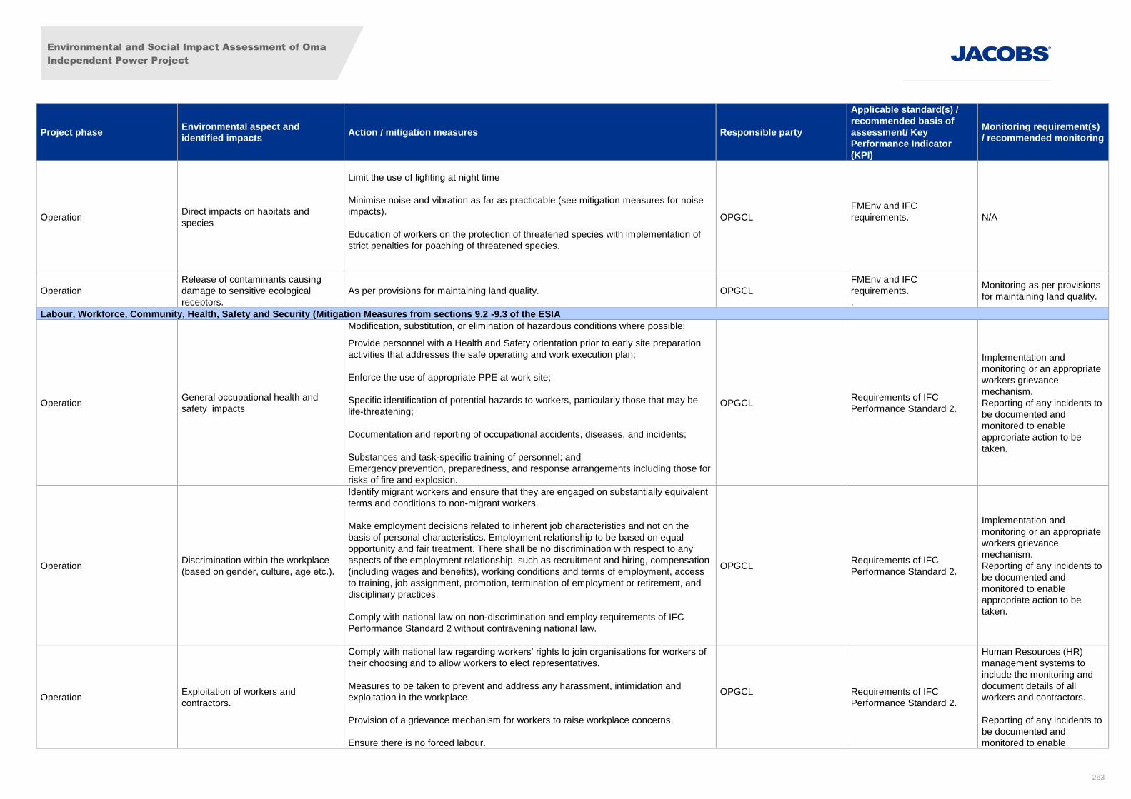
Environmental and Social Impact Assessment of Oma
Independent Power Project
263
Project phase Environmental aspect and
identified impacts Action / mitigation measures Responsible party
Applicable standard(s) /
recommended basis of
assessment/ Key
Performance Indicator
(KPI)
Monitoring requirement(s)
/ recommended monitoring
Operation Direct impacts on habitats and
species
Limit the use of lighting at night time
Minimise noise and vibration as far as practicable (see mitigation measures for noise
impacts).
Education of workers on the protection of threatened species with implementation of
strict penalties for poaching of threatened species.
OPGCL
FMEnv and IFC
requirements.
N/A
Operation
Release of contaminants causing
damage to sensitive ecological
receptors.
As per provisions for maintaining land quality. OPGCL
FMEnv and IFC
requirements.
.
Monitoring as per provisions
for maintaining land quality.
Labour, Workforce, Community, Health, Safety and Security (Mitigation Measures from sections 9.2 -9.3 of the ESIA
Operation General occupational health and
safety impacts
Modification, substitution, or elimination of hazardous conditions where possible;
Provide personnel with a Health and Safety orientation prior to early site preparation
activities that addresses the safe operating and work execution plan;
Enforce the use of appropriate PPE at work site;
Specific identification of potential hazards to workers, particularly those that may be
life-threatening;
Documentation and reporting of occupational accidents, diseases, and incidents;
Substances and task-specific training of personnel; and
Emergency prevention, preparedness, and response arrangements including those for
risks of fire and explosion.
OPGCL Requirements of IFC
Performance Standard 2.
Implementation and
monitoring or an appropriate
workers grievance
mechanism.
Reporting of any incidents to
be documented and
monitored to enable
appropriate action to be
taken.
Operation Discrimination within the workplace
(based on gender, culture, age etc.).
Identify migrant workers and ensure that they are engaged on substantially equivalent
terms and conditions to non-migrant workers.
Make employment decisions related to inherent job characteristics and not on the
basis of personal characteristics. Employment relationship to be based on equal
opportunity and fair treatment. There shall be no discrimination with respect to any
aspects of the employment relationship, such as recruitment and hiring, compensation
(including wages and benefits), working conditions and terms of employment, access
to training, job assignment, promotion, termination of employment or retirement, and
disciplinary practices.
Comply with national law on non-discrimination and employ requirements of IFC
Performance Standard 2 without contravening national law.
OPGCL Requirements of IFC
Performance Standard 2.
Implementation and
monitoring or an appropriate
workers grievance
mechanism.
Reporting of any incidents to
be documented and
monitored to enable
appropriate action to be
taken.
Operation Exploitation of workers and
contractors.
Comply with national law regarding workers’ rights to join organisations for workers of
their choosing and to allow workers to elect representatives.
Measures to be taken to prevent and address any harassment, intimidation and
exploitation in the workplace.
Provision of a grievance mechanism for workers to raise workplace concerns.
Ensure there is no forced labour.
OPGCL
Requirements of IFC
Performance Standard 2.
Human Resources (HR)
management systems to
include the monitoring and
document details of all
workers and contractors.
Reporting of any incidents to
be documented and
monitored to enable
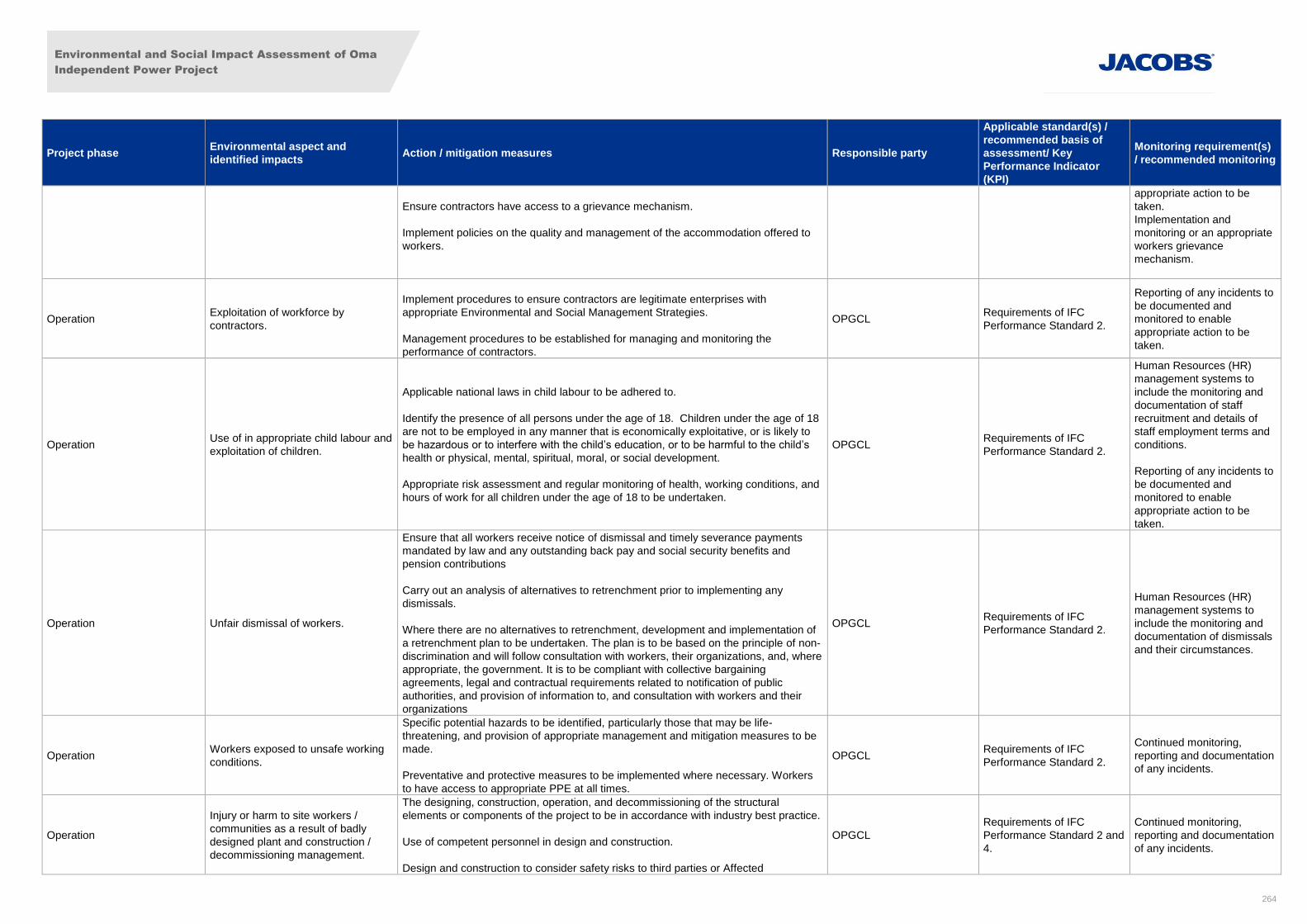
Environmental and Social Impact Assessment of Oma
Independent Power Project
264
Project phase Environmental aspect and
identified impacts Action / mitigation measures Responsible party
Applicable standard(s) /
recommended basis of
assessment/ Key
Performance Indicator
(KPI)
Monitoring requirement(s)
/ recommended monitoring
Ensure contractors have access to a grievance mechanism.
Implement policies on the quality and management of the accommodation offered to
workers.
appropriate action to be
taken.
Implementation and
monitoring or an appropriate
workers grievance
mechanism.
Operation Exploitation of workforce by
contractors.
Implement procedures to ensure contractors are legitimate enterprises with
appropriate Environmental and Social Management Strategies.
Management procedures to be established for managing and monitoring the
performance of contractors.
OPGCL Requirements of IFC
Performance Standard 2.
Reporting of any incidents to
be documented and
monitored to enable
appropriate action to be
taken.
Operation Use of in appropriate child labour and
exploitation of children.
Applicable national laws in child labour to be adhered to.
Identify the presence of all persons under the age of 18. Children under the age of 18
are not to be employed in any manner that is economically exploitative, or is likely to
be hazardous or to interfere with the child’s education, or to be harmful to the child’s
health or physical, mental, spiritual, moral, or social development.
Appropriate risk assessment and regular monitoring of health, working conditions, and
hours of work for all children under the age of 18 to be undertaken.
OPGCL Requirements of IFC
Performance Standard 2.
Human Resources (HR)
management systems to
include the monitoring and
documentation of staff
recruitment and details of
staff employment terms and
conditions.
Reporting of any incidents to
be documented and
monitored to enable
appropriate action to be
taken.
Operation Unfair dismissal of workers.
Ensure that all workers receive notice of dismissal and timely severance payments
mandated by law and any outstanding back pay and social security benefits and
pension contributions
Carry out an analysis of alternatives to retrenchment prior to implementing any
dismissals.
Where there are no alternatives to retrenchment, development and implementation of
a retrenchment plan to be undertaken. The plan is to be based on the principle of non-
discrimination and will follow consultation with workers, their organizations, and, where
appropriate, the government. It is to be compliant with collective bargaining
agreements, legal and contractual requirements related to notification of public
authorities, and provision of information to, and consultation with workers and their
organizations
OPGCL Requirements of IFC
Performance Standard 2.
Human Resources (HR)
management systems to
include the monitoring and
documentation of dismissals
and their circumstances.
Operation Workers exposed to unsafe working
conditions.
Specific potential hazards to be identified, particularly those that may be life-
threatening, and provision of appropriate management and mitigation measures to be
made.
Preventative and protective measures to be implemented where necessary. Workers
to have access to appropriate PPE at all times.
OPGCL Requirements of IFC
Performance Standard 2.
Continued monitoring,
reporting and documentation
of any incidents.
Operation
Injury or harm to site workers /
communities as a result of badly
designed plant and construction /
decommissioning management.
The designing, construction, operation, and decommissioning of the structural
elements or components of the project to be in accordance with industry best practice.
Use of competent personnel in design and construction.
Design and construction to consider safety risks to third parties or Affected
OPGCL
Requirements of IFC
Performance Standard 2 and
4.
Continued monitoring,
reporting and documentation
of any incidents.
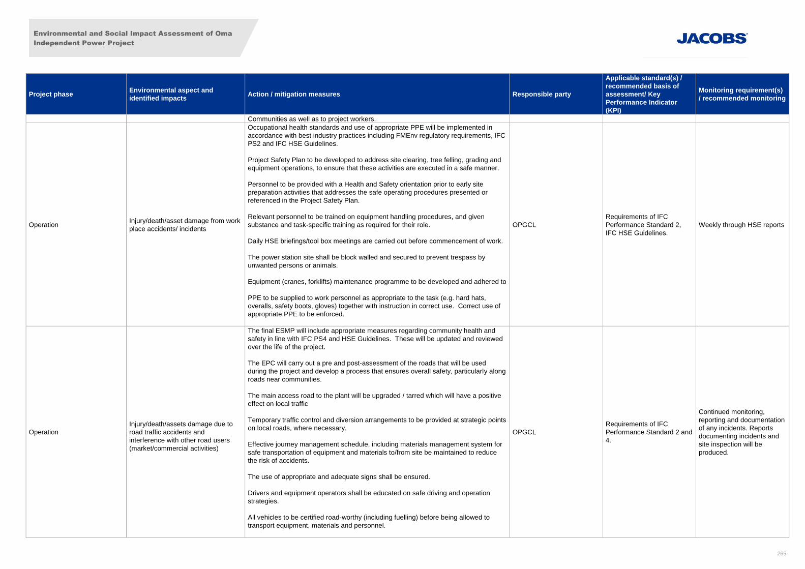
Environmental and Social Impact Assessment of Oma
Independent Power Project
265
Project phase Environmental aspect and
identified impacts Action / mitigation measures Responsible party
Applicable standard(s) /
recommended basis of
assessment/ Key
Performance Indicator
(KPI)
Monitoring requirement(s)
/ recommended monitoring
Communities as well as to project workers.
Operation Injury/death/asset damage from work
place accidents/ incidents
Occupational health standards and use of appropriate PPE will be implemented in
accordance with best industry practices including FMEnv regulatory requirements, IFC
PS2 and IFC HSE Guidelines.
Project Safety Plan to be developed to address site clearing, tree felling, grading and
equipment operations, to ensure that these activities are executed in a safe manner.
Personnel to be provided with a Health and Safety orientation prior to early site
preparation activities that addresses the safe operating procedures presented or
referenced in the Project Safety Plan.
Relevant personnel to be trained on equipment handling procedures, and given
substance and task-specific training as required for their role.
Daily HSE briefings/tool box meetings are carried out before commencement of work.
The power station site shall be block walled and secured to prevent trespass by
unwanted persons or animals.
Equipment (cranes, forklifts) maintenance programme to be developed and adhered to
PPE to be supplied to work personnel as appropriate to the task (e.g. hard hats,
overalls, safety boots, gloves) together with instruction in correct use. Correct use of
appropriate PPE to be enforced.
OPGCL
Requirements of IFC
Performance Standard 2,
IFC HSE Guidelines.
Weekly through HSE reports
Operation
Injury/death/assets damage due to
road traffic accidents and
interference with other road users
(market/commercial activities)
The final ESMP will include appropriate measures regarding community health and
safety in line with IFC PS4 and HSE Guidelines. These will be updated and reviewed
over the life of the project.
The EPC will carry out a pre and post-assessment of the roads that will be used
during the project and develop a process that ensures overall safety, particularly along
roads near communities.
The main access road to the plant will be upgraded / tarred which will have a positive
effect on local traffic
Temporary traffic control and diversion arrangements to be provided at strategic points
on local roads, where necessary.
Effective journey management schedule, including materials management system for
safe transportation of equipment and materials to/from site be maintained to reduce
the risk of accidents.
The use of appropriate and adequate signs shall be ensured.
Drivers and equipment operators shall be educated on safe driving and operation
strategies.
All vehicles to be certified road-worthy (including fuelling) before being allowed to
transport equipment, materials and personnel.
OPGCL
Requirements of IFC
Performance Standard 2 and
4.
Continued monitoring,
reporting and documentation
of any incidents. Reports
documenting incidents and
site inspection will be
produced.
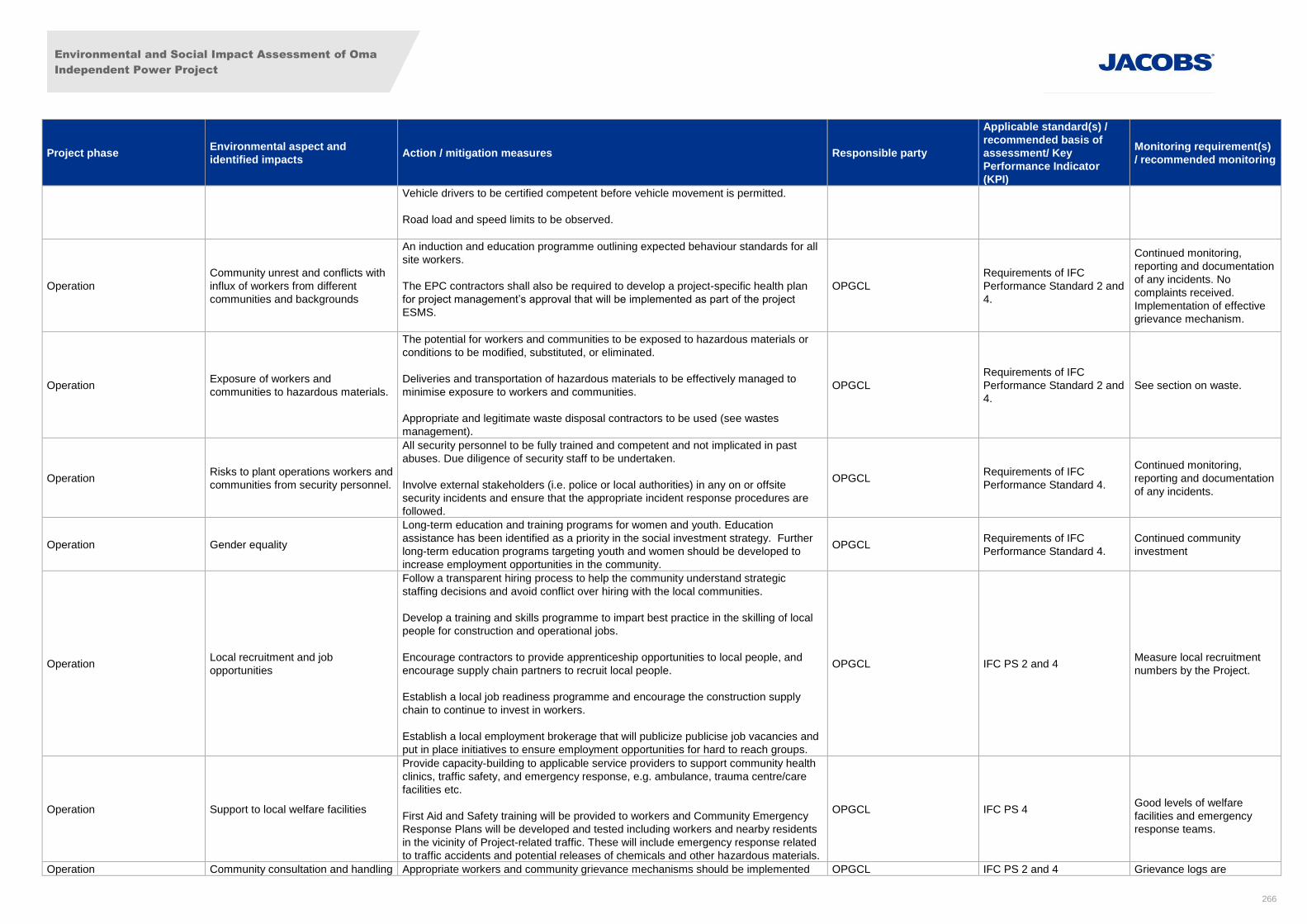
Environmental and Social Impact Assessment of Oma
Independent Power Project
266
Project phase Environmental aspect and
identified impacts Action / mitigation measures Responsible party
Applicable standard(s) /
recommended basis of
assessment/ Key
Performance Indicator
(KPI)
Monitoring requirement(s)
/ recommended monitoring
Vehicle drivers to be certified competent before vehicle movement is permitted.
Road load and speed limits to be observed.
Operation
Community unrest and conflicts with
influx of workers from different
communities and backgrounds
An induction and education programme outlining expected behaviour standards for all
site workers.
The EPC contractors shall also be required to develop a project-specific health plan
for project management’s approval that will be implemented as part of the project
ESMS.
OPGCL
Requirements of IFC
Performance Standard 2 and
4.
Continued monitoring,
reporting and documentation
of any incidents. No
complaints received.
Implementation of effective
grievance mechanism.
Operation Exposure of workers and
communities to hazardous materials.
The potential for workers and communities to be exposed to hazardous materials or
conditions to be modified, substituted, or eliminated.
Deliveries and transportation of hazardous materials to be effectively managed to
minimise exposure to workers and communities.
Appropriate and legitimate waste disposal contractors to be used (see wastes
management).
OPGCL
Requirements of IFC
Performance Standard 2 and
4.
See section on waste.
Operation Risks to plant operations workers and
communities from security personnel.
All security personnel to be fully trained and competent and not implicated in past
abuses. Due diligence of security staff to be undertaken.
Involve external stakeholders (i.e. police or local authorities) in any on or offsite
security incidents and ensure that the appropriate incident response procedures are
followed.
OPGCL Requirements of IFC
Performance Standard 4.
Continued monitoring,
reporting and documentation
of any incidents.
Operation Gender equality
Long-term education and training programs for women and youth. Education
assistance has been identified as a priority in the social investment strategy. Further
long-term education programs targeting youth and women should be developed to
increase employment opportunities in the community.
OPGCL Requirements of IFC
Performance Standard 4.
Continued community
investment
Operation Local recruitment and job
opportunities
Follow a transparent hiring process to help the community understand strategic
staffing decisions and avoid conflict over hiring with the local communities.
Develop a training and skills programme to impart best practice in the skilling of local
people for construction and operational jobs.
Encourage contractors to provide apprenticeship opportunities to local people, and
encourage supply chain partners to recruit local people.
Establish a local job readiness programme and encourage the construction supply
chain to continue to invest in workers.
Establish a local employment brokerage that will publicize publicise job vacancies and
put in place initiatives to ensure employment opportunities for hard to reach groups.
OPGCL IFC PS 2 and 4 Measure local recruitment
numbers by the Project.
Operation Support to local welfare facilities
Provide capacity-building to applicable service providers to support community health
clinics, traffic safety, and emergency response, e.g. ambulance, trauma centre/care
facilities etc.
First Aid and Safety training will be provided to workers and Community Emergency
Response Plans will be developed and tested including workers and nearby residents
in the vicinity of Project-related traffic. These will include emergency response related
to traffic accidents and potential releases of chemicals and other hazardous materials.
OPGCL IFC PS 4
Good levels of welfare
facilities and emergency
response teams.
Operation Community consultation and handling Appropriate workers and community grievance mechanisms should be implemented OPGCL IFC PS 2 and 4 Grievance logs are
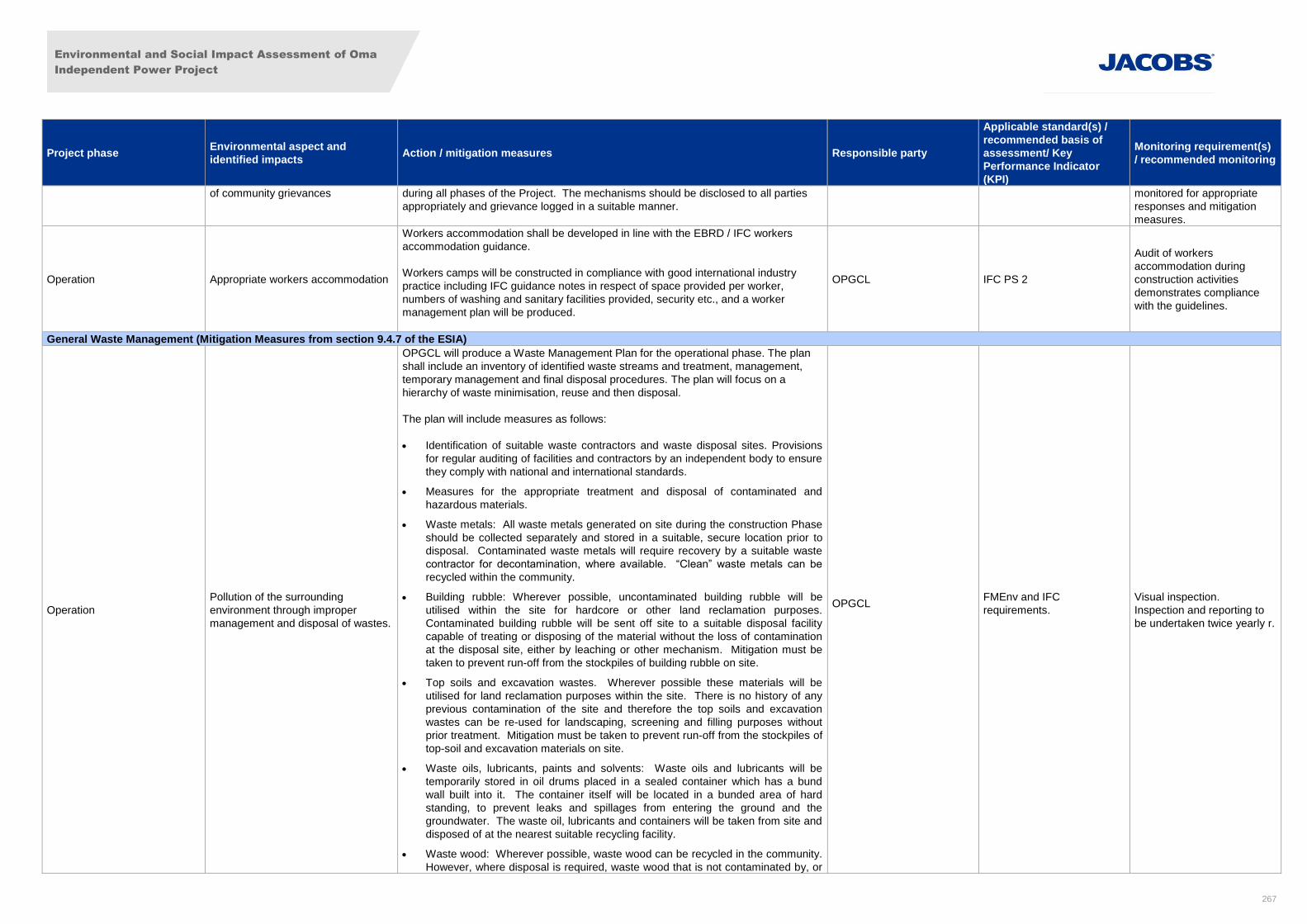
Environmental and Social Impact Assessment of Oma
Independent Power Project
267
Project phase Environmental aspect and
identified impacts Action / mitigation measures Responsible party
Applicable standard(s) /
recommended basis of
assessment/ Key
Performance Indicator
(KPI)
Monitoring requirement(s)
/ recommended monitoring
of community grievances during all phases of the Project. The mechanisms should be disclosed to all parties
appropriately and grievance logged in a suitable manner.
monitored for appropriate
responses and mitigation
measures.
Operation Appropriate workers accommodation
Workers accommodation shall be developed in line with the EBRD / IFC workers
accommodation guidance.
Workers camps will be constructed in compliance with good international industry
practice including IFC guidance notes in respect of space provided per worker,
numbers of washing and sanitary facilities provided, security etc., and a worker
management plan will be produced.
OPGCL IFC PS 2
Audit of workers
accommodation during
construction activities
demonstrates compliance
with the guidelines.
General Waste Management (Mitigation Measures from section 9.4.7 of the ESIA)
Operation
Pollution of the surrounding
environment through improper
management and disposal of wastes.
OPGCL will produce a Waste Management Plan for the operational phase. The plan
shall include an inventory of identified waste streams and treatment, management,
temporary management and final disposal procedures. The plan will focus on a
hierarchy of waste minimisation, reuse and then disposal.
The plan will include measures as follows:
Identification of suitable waste contractors and waste disposal sites. Provisions
for regular auditing of facilities and contractors by an independent body to ensure
they comply with national and international standards.
Measures for the appropriate treatment and disposal of contaminated and
hazardous materials.
Waste metals: All waste metals generated on site during the construction Phase
should be collected separately and stored in a suitable, secure location prior to
disposal. Contaminated waste metals will require recovery by a suitable waste
contractor for decontamination, where available. “Clean” waste metals can be
recycled within the community.
Building rubble: Wherever possible, uncontaminated building rubble will be
utilised within the site for hardcore or other land reclamation purposes.
Contaminated building rubble will be sent off site to a suitable disposal facility
capable of treating or disposing of the material without the loss of contamination
at the disposal site, either by leaching or other mechanism. Mitigation must be
taken to prevent run-off from the stockpiles of building rubble on site.
Top soils and excavation wastes. Wherever possible these materials will be
utilised for land reclamation purposes within the site. There is no history of any
previous contamination of the site and therefore the top soils and excavation
wastes can be re-used for landscaping, screening and filling purposes without
prior treatment. Mitigation must be taken to prevent run-off from the stockpiles of
top-soil and excavation materials on site.
Waste oils, lubricants, paints and solvents: Waste oils and lubricants will be
temporarily stored in oil drums placed in a sealed container which has a bund
wall built into it. The container itself will be located in a bunded area of hard
standing, to prevent leaks and spillages from entering the ground and the
groundwater. The waste oil, lubricants and containers will be taken from site and
disposed of at the nearest suitable recycling facility.
Waste wood: Wherever possible, waste wood can be recycled in the community.
However, where disposal is required, waste wood that is not contaminated by, or
OPGCL
FMEnv and IFC
requirements.
Visual inspection.
Inspection and reporting to
be undertaken twice yearly r.
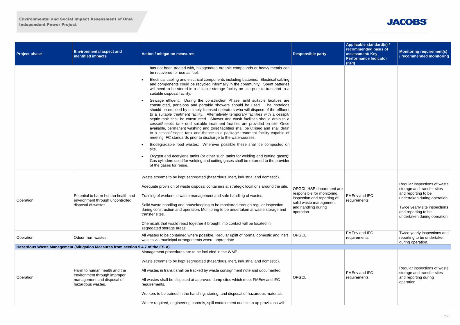
Environmental and Social Impact Assessment of Oma
Independent Power Project
268
Project phase Environmental aspect and
identified impacts Action / mitigation measures Responsible party
Applicable standard(s) /
recommended basis of
assessment/ Key
Performance Indicator
(KPI)
Monitoring requirement(s)
/ recommended monitoring
has not been treated with, halogenated organic compounds or heavy metals can
be recovered for use as fuel.
Electrical cabling and electrical components including batteries: Electrical cabling
and components could be recycled informally in the community. Spent batteries
will need to be stored in a suitable storage facility on site prior to transport to a
suitable disposal facility.
Sewage effluent: During the construction Phase, until suitable facilities are
constructed, portaloos and portable showers should be used. The portaloos
should be emptied by suitably licensed operators who will dispose of the effluent
to a suitable treatment facility. Alternatively temporary facilities with a cesspit/
septic tank shall be constructed. Shower and wash facilities should drain to a
cesspit/ septic tank until suitable treatment facilities are provided on site. Once
available, permanent washing and toilet facilities shall be utilised and shall drain
to a cesspit/ septic tank and thence to a package treatment facility capable of
meeting IFC standards prior to discharge to the watercourses.
Biodegradable food wastes: Wherever possible these shall be composted on
site.
Oxygen and acetylene tanks (or other such tanks for welding and cutting gases):
Gas cylinders used for welding and cutting gases shall be returned to the provider
of the gases for reuse.
Operation
Potential to harm human health and
environment through uncontrolled
disposal of wastes.
Waste streams to be kept segregated (hazardous, inert, industrial and domestic).
Adequate provision of waste disposal containers at strategic locations around the site.
Training of workers in waste management and safe handling of wastes.
Solid waste handling and housekeeping to be monitored through regular inspection
during construction and operation. Monitoring to be undertaken at waste storage and
transfer sites.
Chemicals that would react together if brought into contact will be located in
segregated storage areas
OPGCL HSE department are
responsible for monitoring,
inspection and reporting of
solid waste management
and handling during
operation.
FMEnv and IFC
requirements.
Regular inspections of waste
storage and transfer sites
and reporting to be
undertaken during operation.
Twice yearly site inspections
and reporting to be
undertaken during operation.
Operation Odour from wastes. All wastes to be contained where possible. Regular uplift of normal domestic and inert
wastes via municipal arrangements where appropriate.
OPGCL.
FMEnv and IFC
requirements.
Twice yearly inspections and
reporting to be undertaken
during operation.
Hazardous Waste Management (Mitigation Measures from section 9.4.7 of the ESIA)
Operation
Harm to human health and the
environment through improper
management and disposal of
hazardous wastes.
Management procedures are to be included in the WMP.
Waste streams to be kept segregated (hazardous, inert, industrial and domestic).
All wastes in transit shall be tracked by waste consignment note and documented.
All wastes shall be disposed at approved dump sites which meet FMEnv and IFC
requirements.
Workers to be trained in the handling, storing, and disposal of hazardous materials.
Where required, engineering controls, spill containment and clean up provisions will
OPGCL
FMEnv and IFC
requirements.
Regular inspections of waste
storage and transfer sites
and reporting during
operation.
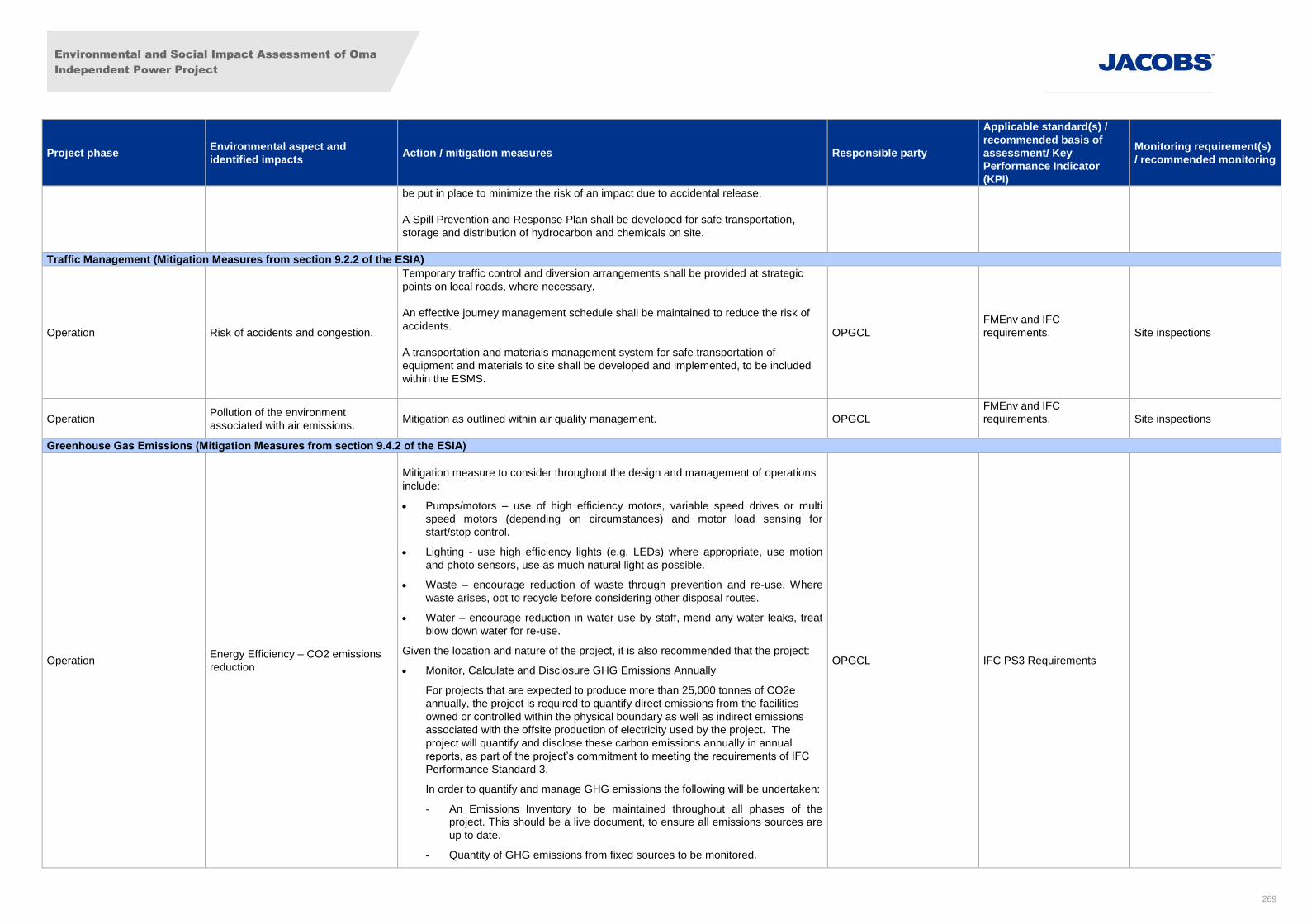
Environmental and Social Impact Assessment of Oma
Independent Power Project
269
Project phase Environmental aspect and
identified impacts Action / mitigation measures Responsible party
Applicable standard(s) /
recommended basis of
assessment/ Key
Performance Indicator
(KPI)
Monitoring requirement(s)
/ recommended monitoring
be put in place to minimize the risk of an impact due to accidental release.
A Spill Prevention and Response Plan shall be developed for safe transportation,
storage and distribution of hydrocarbon and chemicals on site.
Traffic Management (Mitigation Measures from section 9.2.2 of the ESIA)
Operation Risk of accidents and congestion.
Temporary traffic control and diversion arrangements shall be provided at strategic
points on local roads, where necessary.
An effective journey management schedule shall be maintained to reduce the risk of
accidents.
A transportation and materials management system for safe transportation of
equipment and materials to site shall be developed and implemented, to be included
within the ESMS.
OPGCL
FMEnv and IFC
requirements.
Site inspections
Operation Pollution of the environment
associated with air emissions. Mitigation as outlined within air quality management. OPGCL
FMEnv and IFC
requirements.
Site inspections
Greenhouse Gas Emissions (Mitigation Measures from section 9.4.2 of the ESIA)
Operation Energy Efficiency – CO2 emissions
reduction
Mitigation measure to consider throughout the design and management of operations
include:
Pumps/motors – use of high efficiency motors, variable speed drives or multi
speed motors (depending on circumstances) and motor load sensing for
start/stop control.
Lighting - use high efficiency lights (e.g. LEDs) where appropriate, use motion
and photo sensors, use as much natural light as possible.
Waste – encourage reduction of waste through prevention and re-use. Where
waste arises, opt to recycle before considering other disposal routes.
Water – encourage reduction in water use by staff, mend any water leaks, treat
blow down water for re-use.
Given the location and nature of the project, it is also recommended that the project:
Monitor, Calculate and Disclosure GHG Emissions Annually
For projects that are expected to produce more than 25,000 tonnes of CO2e
annually, the project is required to quantify direct emissions from the facilities
owned or controlled within the physical boundary as well as indirect emissions
associated with the offsite production of electricity used by the project. The
project will quantify and disclose these carbon emissions annually in annual
reports, as part of the project’s commitment to meeting the requirements of IFC
Performance Standard 3.
In order to quantify and manage GHG emissions the following will be undertaken:
- An Emissions Inventory to be maintained throughout all phases of the
project. This should be a live document, to ensure all emissions sources are
up to date.
- Quantity of GHG emissions from fixed sources to be monitored.
OPGCL IFC PS3 Requirements
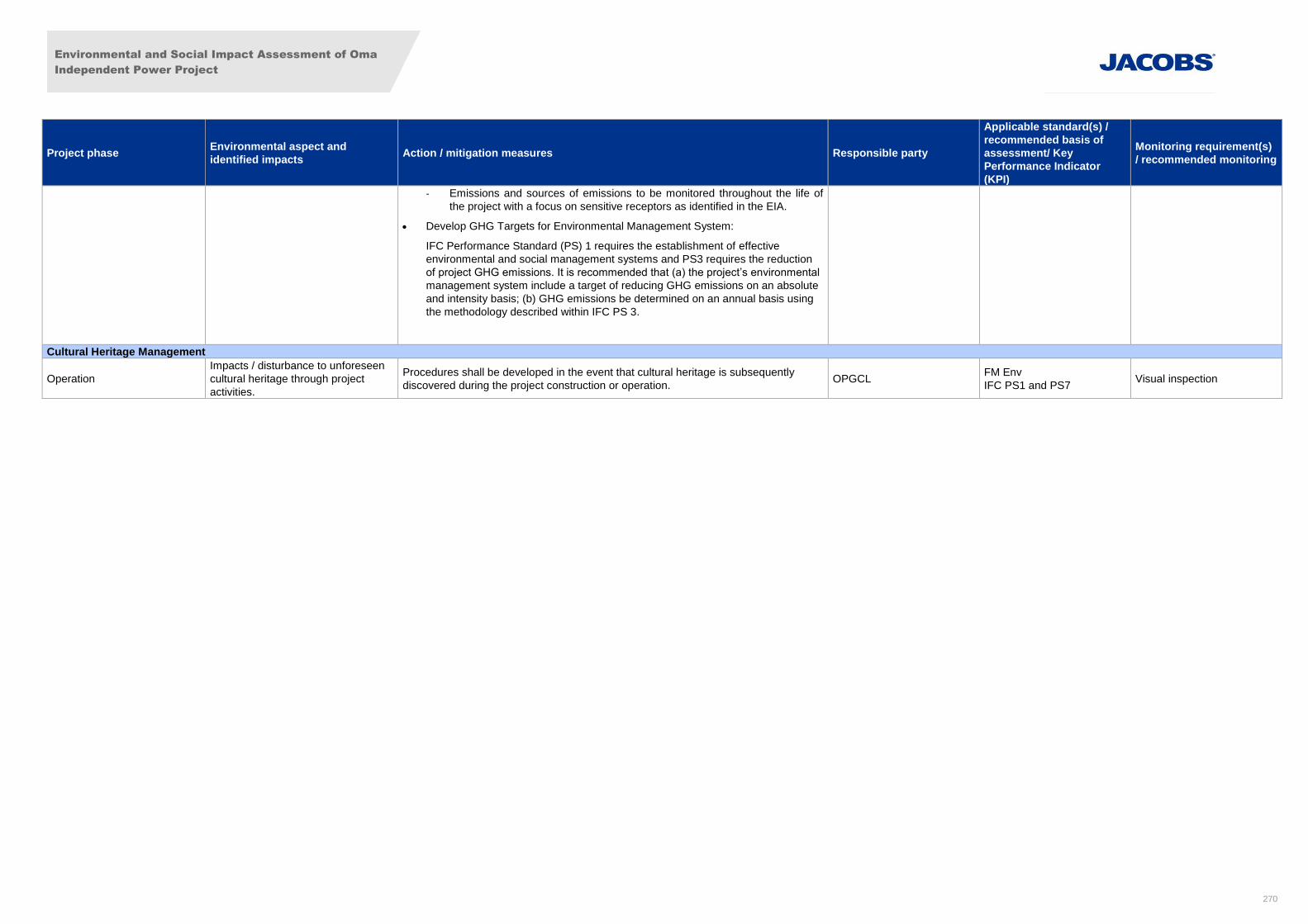
Environmental and Social Impact Assessment of Oma
Independent Power Project
270
Project phase Environmental aspect and
identified impacts Action / mitigation measures Responsible party
Applicable standard(s) /
recommended basis of
assessment/ Key
Performance Indicator
(KPI)
Monitoring requirement(s)
/ recommended monitoring
- Emissions and sources of emissions to be monitored throughout the life of
the project with a focus on sensitive receptors as identified in the EIA.
Develop GHG Targets for Environmental Management System:
IFC Performance Standard (PS) 1 requires the establishment of effective
environmental and social management systems and PS3 requires the reduction
of project GHG emissions. It is recommended that (a) the project’s environmental
management system include a target of reducing GHG emissions on an absolute
and intensity basis; (b) GHG emissions be determined on an annual basis using
the methodology described within IFC PS 3.
Cultural Heritage Management
Operation
Impacts / disturbance to unforeseen
cultural heritage through project
activities.
Procedures shall be developed in the event that cultural heritage is subsequently
discovered during the project construction or operation. OPGCL
FM Env
IFC PS1 and PS7 Visual inspection
Environmental and Social Impact Assessment of Oma
Independent Power Project
271
11. Stakeholder Consultation
11.1 Introduction
11.1.1 Overview
Engagement with interested and affected parties through the consultation process is a fundamental component
of the ESIA process. It allows relevant persons and organisations to be involved in the planning and
development of the project, and enables the developer to gather information about the understanding and
possible impacts and can be useful in determining community and individual preferences and selecting
alternatives. It also allows enhancement of project design and can promote greater project sustainability. This
section presents the consultation conducted for the project to date.
11.1.2 Objectives
The main objectives of public consultation for this project were to:
Inform stakeholders of the details of the proposed project and the likely implications of its development;
Understand stakeholders’ concerns, ideas and expectations in respect of the project (including
anticipated positive and negative impacts) and consider how the development can address these; and
In conjunction with the stakeholders, identify possible and agreeable mitigation measures.
11.2 Consultation undertaken
In line with the scope of the socio-economic assessment outlined in Appendix IV, consultation undertaken to
date has included both formal and informal consultation with the local community and key stakeholders, and
was conducted through the following means:
Meetings with key LGA stakeholders (political leaders / traditional rulers / civic leaders) to share project
information, and to secure permission and co-operation for the project and ESIA studies;
Discussions with identified non-governmental stakeholders and community groups in consultative
meetings to obtain useful knowledge of the project area and local communities;
A formal public forum event held on 19th July 2013;
Community meetings held in Obehie, Orgwu (Ogwe), Ihie-Iyi, Obiga, Ngwaiyiekwe, Obuzongwa, Owo-
ala, and Umuaka in 2015;
A meeting held at the Ogwe Autonomous Community Town Hall on 27th February 2014; and
Ongoing informal consultation with local stakeholders by the project team throughout the project.

Environmental and Social Impact Assessment of Oma
Independent Power Project
272
Table 11-1 shows the communities in which Focus Group Discussions were undertaken in 2015. Meeting
minutes for these meetings are provided in Appendix IX.

Environmental and Social Impact Assessment of Oma
Independent Power Project
276
Table 11-2 sets out the consultation undertaken between 2012 and 2014, and

Environmental and Social Impact Assessment of Oma
Independent Power Project
276
Table 11-3 provides further details of topics discussed during consultation activities undertaken during 2013.
Consultation was conducted by the local consultant, BGI, and the responses provided were given by BGI on
behalf of Oma and not by Jacobs.
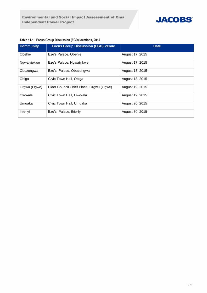
Environmental and Social Impact Assessment of Oma
Independent Power Project
276
Table 11-1 : Focus Group Discussion (FGD) locations, 2015
Community Focus Group Discussion (FGD) Venue Date
Obehie Eze’s Palace, Obehie August 17, 2015
Ngwaiyiekwe Eze’s Palace, Ngwaiyikwe August 17, 2015
Obuzongwa Eze’s Palace, Obuzongwa August 18, 2015
Obiga Civic Town Hall, Obiga August 18, 2015
Orgwu (Ogwe) Elder Council Chief Place, Orgwu (Ogwe) August 19, 2015
Owo-ala Civic Town Hall, Owo-ala August 19, 2015
Umuaka Civic Town Hall, Umuaka August 20, 2015
Ihie-iyi Eze’s Palace, Ihie-Iyi August 30, 2015
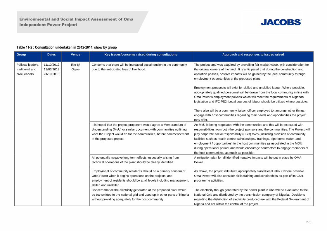
Environmental and Social Impact Assessment of Oma
Independent Power Project
276
Table 11-2 : Consultation undertaken in 2012-2014, show by group
Group Dates Venue Key issues/concerns raised during consultations Approach and responses to issues raised
Political leaders,
traditional and
civic leaders
11/10/2012
13/03/2013
24/10/2013
Ihie-Iyi
Ogwe
Concerns that there will be increased social tension in the community
due to the anticipated loss of livelihood.
The project land was acquired by prevailing fair market value, with consideration for
the original owners of the land. It is anticipated that during the construction and
operation phases, positive impacts will be gained by the local community through
employment opportunities at the proposed plant.
Employment prospects will exist for skilled and unskilled labour. Where possible,
appropriately qualified personnel will be drawn from the local community in line with
Oma Power’s employment policies which will meet the requirements of Nigerian
legislation and IFC PS2. Local sources of labour should be utilized where possible.
There also will be a community liaison officer employed to, amongst other things,
engage with host communities regarding their needs and opportunities the project
may offer.
It is hoped that the project proponent would agree a Memorandum of
Understanding (MoU) or similar document with communities outlining
what the Project would do for the communities, before commencement
of the proposed project.
An MoU is being negotiated with the communities and this will be executed with
responsibilities from both the project sponsors and the communities. The Project will
play corporate social responsibility (CSR) roles (including provision of community
facilities such as health centre, scholarships / trainings, pipe borne water, and
employment / opportunities) in the host communities as negotiated in the MOU
during operational period, and would encourage contractors to engage members of
the host communities, as much as possible.
All potentially negative long term effects, especially arising from
technical operations of the plant should be clearly identified.
A mitigation plan for all identified negative impacts will be put in place by OMA
Power.
Employment of community residents should be a primary concern of
Oma Power when it begins operations on the projects, and
employment of residents should be at all levels including management,
skilled and unskilled.
As above, the project will utilize appropriately skilled local labour where possible.
Oma Power will also consider skills training and scholarships as part of its CSR
programme activities.
Concern that all the electricity generated at the proposed plant would
be transmitted to the national grid and used up in other parts of Nigeria
without providing adequately for the host community.
The electricity though generated by the power plant in Aba will be evacuated to the
National Grid and distributed by the transmission company of Nigeria. Decisions
regarding the distribution of electricity produced are with the Federal Government of
Nigeria and not within the control of the project.
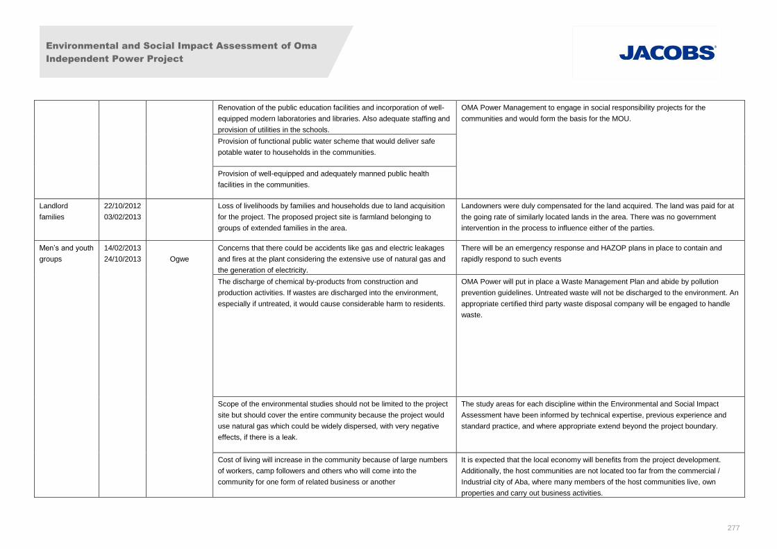
Environmental and Social Impact Assessment of Oma
Independent Power Project
277
Renovation of the public education facilities and incorporation of well-
equipped modern laboratories and libraries. Also adequate staffing and
provision of utilities in the schools.
OMA Power Management to engage in social responsibility projects for the
communities and would form the basis for the MOU.
Provision of functional public water scheme that would deliver safe
potable water to households in the communities.
Provision of well-equipped and adequately manned public health
facilities in the communities.
Landlord
families
22/10/2012
03/02/2013
Loss of livelihoods by families and households due to land acquisition
for the project. The proposed project site is farmland belonging to
groups of extended families in the area.
Landowners were duly compensated for the land acquired. The land was paid for at
the going rate of similarly located lands in the area. There was no government
intervention in the process to influence either of the parties.
Men’s and youth
groups
14/02/2013
24/10/2013
Ogwe
Concerns that there could be accidents like gas and electric leakages
and fires at the plant considering the extensive use of natural gas and
the generation of electricity.
There will be an emergency response and HAZOP plans in place to contain and
rapidly respond to such events
The discharge of chemical by-products from construction and
production activities. If wastes are discharged into the environment,
especially if untreated, it would cause considerable harm to residents.
OMA Power will put in place a Waste Management Plan and abide by pollution
prevention guidelines. Untreated waste will not be discharged to the environment. An
appropriate certified third party waste disposal company will be engaged to handle
waste.
Scope of the environmental studies should not be limited to the project
site but should cover the entire community because the project would
use natural gas which could be widely dispersed, with very negative
effects, if there is a leak.
The study areas for each discipline within the Environmental and Social Impact
Assessment have been informed by technical expertise, previous experience and
standard practice, and where appropriate extend beyond the project boundary.
Cost of living will increase in the community because of large numbers
of workers, camp followers and others who will come into the
community for one form of related business or another
It is expected that the local economy will benefits from the project development.
Additionally, the host communities are not located too far from the commercial /
Industrial city of Aba, where many members of the host communities live, own
properties and carry out business activities.
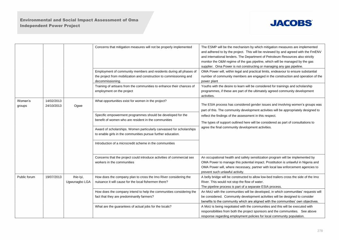
Environmental and Social Impact Assessment of Oma
Independent Power Project
278
Concerns that mitigation measures will not be properly implemented
The ESMP will be the mechanism by which mitigation measures are implemented
and adhered to by the project. This will be reviewed by and agreed with the FmENV
and international lenders. The Department of Petroleum Resources also strictly
monitor the O&M regime of the gas pipeline, which will be managed by the gas
supplier. Oma Power is not constructing or managing any gas pipeline.
Employment of community members and residents during all phases of
the project from mobilization and construction to commissioning and
decommissioning.
OMA Power will, within legal and practical limits, endeavour to ensure substantial
number of community members are engaged in the construction and operation of the
power plant
Training of artisans from the communities to enhance their chances of
employment on the project
Youths with the desire to learn will be considered for trainings and scholarship
programmes, if these are part of the ultimately agreed community development
activities.
Women’s
groups
14/02/2013
24/10/2013
Ogwe
What opportunities exist for women in the project? The ESIA process has considered gender issues and involving women’s groups was
part of this. The community development activities will be appropriately designed to
reflect the findings of the assessment in this respect.
The types of support outlined here will be considered as part of consultations to
agree the final community development activities.
Specific empowerment programmes should be developed for the
benefit of women who are resident in the communities
Award of scholarships. Women particularly canvassed for scholarships
to enable girls in the communities pursue further education.
Introduction of a microcredit scheme in the communities
Concerns that the project could introduce activities of commercial sex
workers in the communities
An occupational health and safety sensitization program will be implemented by
OMA Power to manage this potential impact. Prostitution is unlawful in Nigeria and
OMA Power will, where necessary, partner with local law enforcement agencies to
prevent such unlawful activity.
Public forum 19/07/2013 Ihie-Iyi,
Ugwunagbo LGA
How does the company plan to cross the Imo River considering the
nuisance it will cause for the local fishermen there?
A belly bridge will be constructed to allow low-bed trailers cross the side of the Imo
River. This would not stop the flow of water.
The pipeline process is part of a separate ESIA process.
How does the company intend to help the communities considering the
fact that they are predominantly farmers?
An MoU with the communities will be developed, in which communities’ requests will
be considered. Community development activities will be designed to consider
benefits to the community which are aligned with the communities’ own objectives.
What are the guarantees of actual jobs for the locals? A MoU is being negotiated with the communities and this will be executed with
responsibilities from both the project sponsors and the communities. See above
response regarding employment policies for local community population.
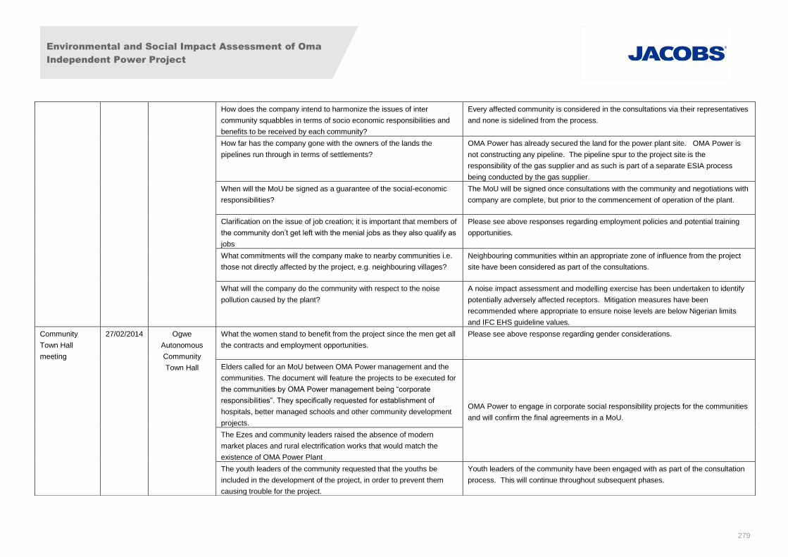
Environmental and Social Impact Assessment of Oma
Independent Power Project
279
How does the company intend to harmonize the issues of inter
community squabbles in terms of socio economic responsibilities and
benefits to be received by each community?
Every affected community is considered in the consultations via their representatives
and none is sidelined from the process.
How far has the company gone with the owners of the lands the
pipelines run through in terms of settlements?
OMA Power has already secured the land for the power plant site. OMA Power is
not constructing any pipeline. The pipeline spur to the project site is the
responsibility of the gas supplier and as such is part of a separate ESIA process
being conducted by the gas supplier.
When will the MoU be signed as a guarantee of the social-economic
responsibilities?
The MoU will be signed once consultations with the community and negotiations with
company are complete, but prior to the commencement of operation of the plant.
Clarification on the issue of job creation; it is important that members of
the community don’t get left with the menial jobs as they also qualify as
jobs
Please see above responses regarding employment policies and potential training
opportunities.
What commitments will the company make to nearby communities i.e.
those not directly affected by the project, e.g. neighbouring villages?
Neighbouring communities within an appropriate zone of influence from the project
site have been considered as part of the consultations.
What will the company do the community with respect to the noise
pollution caused by the plant?
A noise impact assessment and modelling exercise has been undertaken to identify
potentially adversely affected receptors. Mitigation measures have been
recommended where appropriate to ensure noise levels are below Nigerian limits
and IFC EHS guideline values.
Community
Town Hall
meeting
27/02/2014 Ogwe
Autonomous
Community
Town Hall
What the women stand to benefit from the project since the men get all
the contracts and employment opportunities.
Please see above response regarding gender considerations.
Elders called for an MoU between OMA Power management and the
communities. The document will feature the projects to be executed for
the communities by OMA Power management being “corporate
responsibilities”. They specifically requested for establishment of
hospitals, better managed schools and other community development
projects.
OMA Power to engage in corporate social responsibility projects for the communities
and will confirm the final agreements in a MoU.
The Ezes and community leaders raised the absence of modern
market places and rural electrification works that would match the
existence of OMA Power Plant
The youth leaders of the community requested that the youths be
included in the development of the project, in order to prevent them
causing trouble for the project.
Youth leaders of the community have been engaged with as part of the consultation
process. This will continue throughout subsequent phases.
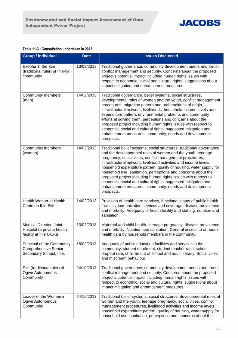
Environmental and Social Impact Assessment of Oma
Independent Power Project
280
Table 11-3 : Consultation undertaken in 2013
Group / individual Date Issues Discussed
Ezeoha 1; the Eze
(traditional ruler) of Ihie-Iyi
community
13/03/2013 Traditional governance, community development needs and thrust,
conflict management and security. Concerns about the proposed
project’s potential impact including human rights issues with
respect to economic, social and cultural rights, suggestions about
impact mitigation and enhancement measures.
Community members
(men)
14/02/2013 Traditional governance, belief systems, social structures,
developmental roles of women and the youth, conflict management
procedures, migration pattern and oral traditions of origin,
infrastructural network, livelihoods, household income levels and
expenditure pattern, environmental problems and community
efforts at solving them, perceptions and concerns about the
proposed project including human rights issues with respect to
economic, social and cultural rights, suggested mitigation and
enhancement measures, community, needs and development
prospects.
Community members
(women)
14/02/2013 Traditional belief systems, social structures, traditional governance
and the developmental roles of women and the youth, teenage
pregnancy, social vices, conflict management procedures,
infrastructural network, livelihood activities and income levels,
household expenditure pattern, quality of housing, water supply for
household use, sanitation, perceptions and concerns about the
proposed project including human rights issues with respect to
economic, social and cultural rights, suggested mitigation and
enhancement measures, community, needs and development
prospects.
Health Worker at Health
Centre in Ihie Etiti
14/02/2013 Provision of health care services, functional status of public health
facilities, immunization services and coverage, disease prevalence
and mortality. Adequacy of health facility and staffing, nutrition and
sanitation.
Medical Director, Joint
Hospital (a private health
facility at Ihie Ukwu)
13/02/2013 Maternal and child health, teenage pregnancy, disease prevalence
and mortality. Nutrition and sanitation. General access to orthodox
health care by household members in the community.
Principal of the Community
Comprehensive Senior
Secondary School, Ihie.
15/02/2013 Adequacy of public education facilities and services in the
community, student enrolment, student teacher ratio, school
dropout rate, children out of school and adult literacy. Social vices
and miscreant behaviour.
Eze (traditional ruler) of
Ogwe Autonomous
Community
24/10/2013 Traditional governance, community development needs and thrust,
conflict management and security. Concerns about the proposed
project’s potential impact including human rights issues with
respect to economic, social and cultural rights, suggestions about
impact mitigation and enhancement measures.
Leader of the Women in
Ogwe Autonomous
Community
24/10/2013 Traditional belief systems, social structures, developmental roles of
women and the youth, teenage pregnancy, social vices, conflict
management procedures, livelihood activities and income levels,
household expenditure pattern, quality of housing, water supply for
household use, sanitation, perceptions and concerns about the
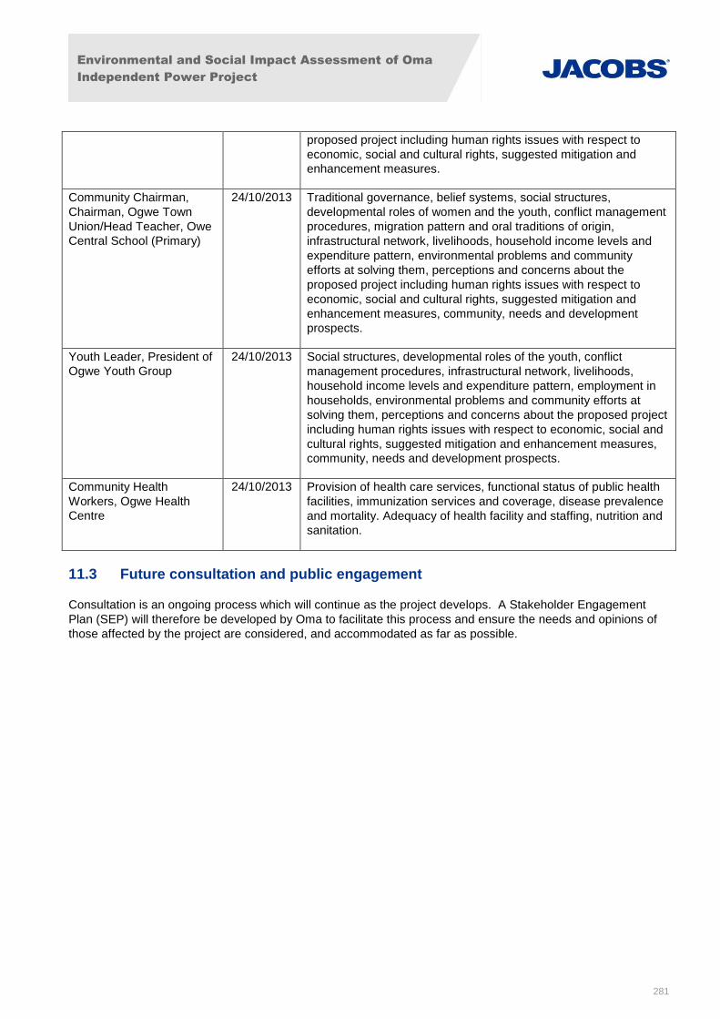
Environmental and Social Impact Assessment of Oma
Independent Power Project
281
11.3 Future consultation and public engagement
Consultation is an ongoing process which will continue as the project develops. A Stakeholder Engagement
Plan (SEP) will therefore be developed by Oma to facilitate this process and ensure the needs and opinions of
those affected by the project are considered, and accommodated as far as possible.
proposed project including human rights issues with respect to
economic, social and cultural rights, suggested mitigation and
enhancement measures.
Community Chairman,
Chairman, Ogwe Town
Union/Head Teacher, Owe
Central School (Primary)
24/10/2013 Traditional governance, belief systems, social structures,
developmental roles of women and the youth, conflict management
procedures, migration pattern and oral traditions of origin,
infrastructural network, livelihoods, household income levels and
expenditure pattern, environmental problems and community
efforts at solving them, perceptions and concerns about the
proposed project including human rights issues with respect to
economic, social and cultural rights, suggested mitigation and
enhancement measures, community, needs and development
prospects.
Youth Leader, President of
Ogwe Youth Group
24/10/2013 Social structures, developmental roles of the youth, conflict
management procedures, infrastructural network, livelihoods,
household income levels and expenditure pattern, employment in
households, environmental problems and community efforts at
solving them, perceptions and concerns about the proposed project
including human rights issues with respect to economic, social and
cultural rights, suggested mitigation and enhancement measures,
community, needs and development prospects.
Community Health
Workers, Ogwe Health
Centre
24/10/2013 Provision of health care services, functional status of public health
facilities, immunization services and coverage, disease prevalence
and mortality. Adequacy of health facility and staffing, nutrition and
sanitation.


