Embed Size (px)
Citation preview
Object-focused Environments Revisited
Doctoral Dissertation submitted to the
Faculty of Informatics of the Università della Svizzera Italiana
in partial fulfillment of the requirements for the degree of
Doctor of Philosophy
presented by
Fernando Olivero
under the supervision of
Prof. Dr. Michele Lanza
April 2013

Dissertation Committee
Prof. Dr. Theo D’Hondt Vrije Universiteit Brussel, BelgiumProf. Dr. Stéphane Ducasse INRIA Nord, FranceProf. Dr. Marc Langheinrich University Of Lugano, SwitzerlandProf. Dr. Oscar Nierstrasz University of Bern, SwitzerlandProf. Dr. Cesare Pautasso University Of Lugano, Switzerland
Dissertation accepted on April 2013
Research Advisor PhD Program Director
Prof. Dr. Michele Lanza Prof. Dr. Antonio Carzaniga
i
I certify that except where due acknowledgement has been given, the workpresented in this thesis is that of the author alone; the work has not been sub-mitted previously, in whole or in part, to qualify for any other academic award;and the content of the thesis is the result of work which has been carried outsince the official commencement date of the approved research program.
Fernando OliveroLugano, April 2013
ii
Abstract
In the object oriented programming (OOP) paradigm, programs are composedsolely of objects. The computational model is based on a world of collaboratingobjects, where they send each other messages to carry out tasks. The programsare crafted with the aid of tools, which enable to describe their componentsand behavior in a human readable form. With the advent of the graphicaluser interface came the pinnacle tool for software development, the integrateddevelopment environment (IDE).
IDEs include numerous tools to effectively construct, debug, and test theprograms. The tools work on a static textual representation of the program –the source code– which conceptually conflicts with the dynamic nature of thecomputational model of OOP. The use of a tool-based interface also producestechnical problems, which relate to navigating the system, preserving the taskcontext, and manipulating finer grained entities than the coarse grained per-spective offered by the tools.
In this thesis we investigate an alternative interface for OOP environments,which is based solely on direct manipulation of objects. It alleviates the con-ceptual and technical problems of tool-based IDEs, by giving prominence tothe objects themselves within the interface.
We propose an Object-focused environment, composed of a 2D surfacehosting behaviorally complete graphical representations of the objects. We pro-vide prototype implementations named Gaucho and Ronda, which illustrate theapplication of our approach to a broad range of tasks, such as modeling, pro-gramming, program comprehension, and collaborative software engineering.
To validate our thesis, we conducted a summative evaluation, instrumentedas a controlled experiment where we compared Gaucho with a traditional IDE,finding that it is indeed a viable alternative to the current state of the art.
iii

iv
Acknowledgements
It was four years ago when I crossed the ocean and landed in Switzerland, andsince then i’ve met many people who have greatly helped me along the wayinto completing my Ph.D studies. I extend my gratitude towards all of them,starting from my advisor Michele Lanza, to former and current REVEALER’s:the Doc Romain, Ricky, Mr D, Mircea, Lille, Alberto, Roberto, Remo, Luca,and Tommaso. It was great sharing an office, playing calcio, climbing in Vezia,traveling to conferences, and collecting anecdotes from Il Fornaio.
Michele, thanks for enlightening me with the ways of the word, and for allthe support, patience and coolness you emanated during my time in Lugano.
I would also thank the members of my committee, for asking both interestingand tough questions, which greatly improved the contents of this dissertation.
To my former employers, Leandro and Valeria, thank you for teaching meso much in so little time; and to my former professors, Hernan and Carlos, whogreatly inspired me to pursue a dissertation on such a interesting topic.
Needless to say, I greatly appreciate the effort and sacrifices that all myfamily endured during my extended european stay, GRACIAS TOTALES to all ofyou in the end of the world!
Wioleta, you made everything better, with your love and support. Thankyou for an amazing time in Lugano, Kocham Cie.
Fernando OliveroApril 2013
v

vi
Contents
Contents vii
List of Figures xi
List of Tables xiii
1 Introduction 11.1 Symbolic Programming . . . . . . . . . . . . . . . . . . . . . . . . . 21.2 On the writing of programs . . . . . . . . . . . . . . . . . . . . . . . 31.3 Programming is more than just writing . . . . . . . . . . . . . . . . 4
1.3.1 Integrated Development Environments . . . . . . . . . . . 41.4 Object-Oriented Programming . . . . . . . . . . . . . . . . . . . . . 61.5 The Problem . . . . . . . . . . . . . . . . . . . . . . . . . . . . . . . . 7
1.5.1 The Conceptual Problem: Tools vs Objects . . . . . . . . 71.5.2 Technical Problems . . . . . . . . . . . . . . . . . . . . . . . 81.5.3 Summary . . . . . . . . . . . . . . . . . . . . . . . . . . . . . 13
1.6 Thesis . . . . . . . . . . . . . . . . . . . . . . . . . . . . . . . . . . . . 141.7 Contributions . . . . . . . . . . . . . . . . . . . . . . . . . . . . . . . 151.8 Structure of the Document . . . . . . . . . . . . . . . . . . . . . . . 16
2 State of the Art 172.1 Smalltalk . . . . . . . . . . . . . . . . . . . . . . . . . . . . . . . . . . 18
2.1.1 Browsers and Inspectors . . . . . . . . . . . . . . . . . . . . 182.2 Code-Centric Environments . . . . . . . . . . . . . . . . . . . . . . . 20
2.2.1 Relo . . . . . . . . . . . . . . . . . . . . . . . . . . . . . . . . 212.2.2 Code Canvas . . . . . . . . . . . . . . . . . . . . . . . . . . . 222.2.3 Code Bubbles . . . . . . . . . . . . . . . . . . . . . . . . . . 232.2.4 Summary . . . . . . . . . . . . . . . . . . . . . . . . . . . . . 23
2.3 Modeling Environments . . . . . . . . . . . . . . . . . . . . . . . . . 242.4 Direct-Manipulation of Objects . . . . . . . . . . . . . . . . . . . . 28
vii
viii Contents
2.4.1 The Tools and Desktop Metaphor . . . . . . . . . . . . . . 282.4.2 From Structured Text to Graphical Objects . . . . . . . . . 292.4.3 Self . . . . . . . . . . . . . . . . . . . . . . . . . . . . . . . . . 322.4.4 Morphic . . . . . . . . . . . . . . . . . . . . . . . . . . . . . . 332.4.5 Naked Objects . . . . . . . . . . . . . . . . . . . . . . . . . . 33
2.5 Conclusions . . . . . . . . . . . . . . . . . . . . . . . . . . . . . . . . 34
3 Object-Focused Environments 373.1 Motivation . . . . . . . . . . . . . . . . . . . . . . . . . . . . . . . . . 38
3.1.1 From reality to the program . . . . . . . . . . . . . . . . . . 383.1.2 Scenarios . . . . . . . . . . . . . . . . . . . . . . . . . . . . . 403.1.3 Summary . . . . . . . . . . . . . . . . . . . . . . . . . . . . . 43
3.2 Gaucho . . . . . . . . . . . . . . . . . . . . . . . . . . . . . . . . . . . 443.2.1 Gaucho in a Nutshell . . . . . . . . . . . . . . . . . . . . . . 443.2.2 The Sessions and The System . . . . . . . . . . . . . . . . . 453.2.3 The Pampas . . . . . . . . . . . . . . . . . . . . . . . . . . . . 463.2.4 The Shapes . . . . . . . . . . . . . . . . . . . . . . . . . . . . 463.2.5 Implementation . . . . . . . . . . . . . . . . . . . . . . . . . 47
3.3 Modeling with Gaucho . . . . . . . . . . . . . . . . . . . . . . . . . 483.3.1 The MDE Shapes . . . . . . . . . . . . . . . . . . . . . . . . 48
3.4 Programming in Gaucho . . . . . . . . . . . . . . . . . . . . . . . . 503.4.1 Classes . . . . . . . . . . . . . . . . . . . . . . . . . . . . . . . 513.4.2 Methods . . . . . . . . . . . . . . . . . . . . . . . . . . . . . . 523.4.3 Test Cases . . . . . . . . . . . . . . . . . . . . . . . . . . . . . 533.4.4 Packages . . . . . . . . . . . . . . . . . . . . . . . . . . . . . . 543.4.5 Producing Fine-Grained Changes . . . . . . . . . . . . . . 553.4.6 Navigating the System . . . . . . . . . . . . . . . . . . . . . 583.4.7 Task Context Support . . . . . . . . . . . . . . . . . . . . . . 61
3.5 On the interface of Gaucho . . . . . . . . . . . . . . . . . . . . . . . 623.5.1 On the Textual Representation of Methods Statements . . 64
4 Evaluation 654.1 Instrumenting the Evaluation of Software Tools . . . . . . . . . . . 66
4.1.1 The Crux of Human-centric Experiments . . . . . . . . . . 674.1.2 Biscuit: Tracking Human-Centric Controlled Experiments 69
4.2 Context . . . . . . . . . . . . . . . . . . . . . . . . . . . . . . . . . . . 724.3 Experimental Design . . . . . . . . . . . . . . . . . . . . . . . . . . . 73
4.3.1 Research Questions . . . . . . . . . . . . . . . . . . . . . . . 734.3.2 Variables . . . . . . . . . . . . . . . . . . . . . . . . . . . . . 74
ix Contents
4.3.3 Baseline . . . . . . . . . . . . . . . . . . . . . . . . . . . . . . 744.3.4 Object system & Treatments . . . . . . . . . . . . . . . . . 754.3.5 Tasks . . . . . . . . . . . . . . . . . . . . . . . . . . . . . . . . 75
4.4 Experimental Operation and Results . . . . . . . . . . . . . . . . . 774.4.1 Operation . . . . . . . . . . . . . . . . . . . . . . . . . . . . . 774.4.2 Pre-Experiment Questionnaire . . . . . . . . . . . . . . . . 774.4.3 Experiment Questionnaire . . . . . . . . . . . . . . . . . . . 794.4.4 Debriefing Questionnaire . . . . . . . . . . . . . . . . . . . 864.4.5 Data collection . . . . . . . . . . . . . . . . . . . . . . . . . . 874.4.6 Results . . . . . . . . . . . . . . . . . . . . . . . . . . . . . . . 89
4.5 Reflections . . . . . . . . . . . . . . . . . . . . . . . . . . . . . . . . . 944.5.1 On the correctness of the performed tasks . . . . . . . . . 944.5.2 On the completion time of the performed tasks . . . . . . 954.5.3 Threats To Validity . . . . . . . . . . . . . . . . . . . . . . . . 95
4.6 Conclusions . . . . . . . . . . . . . . . . . . . . . . . . . . . . . . . . 964.6.1 Biscuit to the Rescue . . . . . . . . . . . . . . . . . . . . . . 97
5 Object-Focused Collaboration 995.1 On Object-Focused Collaborative Environments . . . . . . . . . . 100
5.1.1 Shared Development Sessions . . . . . . . . . . . . . . . . 1005.1.2 Object-focused environments . . . . . . . . . . . . . . . . . 101
5.2 Ronda . . . . . . . . . . . . . . . . . . . . . . . . . . . . . . . . . . . . 1025.2.1 Awareness of Fine-Grained Changes . . . . . . . . . . . . . 1025.2.2 Shared Development Sessions . . . . . . . . . . . . . . . . 1045.2.3 Change Authoring and Trust Levels . . . . . . . . . . . . . 1045.2.4 Avoiding Conflicts . . . . . . . . . . . . . . . . . . . . . . . . 104
5.3 Tea Time . . . . . . . . . . . . . . . . . . . . . . . . . . . . . . . . . . 1065.3.1 Customizing TeaTime for Ronda . . . . . . . . . . . . . . . 106
5.4 Summary . . . . . . . . . . . . . . . . . . . . . . . . . . . . . . . . . . 107
6 Conclusions 1096.1 Contributions . . . . . . . . . . . . . . . . . . . . . . . . . . . . . . . 1106.2 Future Work . . . . . . . . . . . . . . . . . . . . . . . . . . . . . . . . 112
6.2.1 Semantics . . . . . . . . . . . . . . . . . . . . . . . . . . . . . 1126.2.2 Relations . . . . . . . . . . . . . . . . . . . . . . . . . . . . . 1126.2.3 Education . . . . . . . . . . . . . . . . . . . . . . . . . . . . . 1126.2.4 Live Programming Tools . . . . . . . . . . . . . . . . . . . . 113
6.3 Closing Words . . . . . . . . . . . . . . . . . . . . . . . . . . . . . . . 113

x Contents
A Experiment Design with Biscuit 115A.1 Modeling and Running an Experiment . . . . . . . . . . . . . . . . 115A.2 The User Interface of the Experiment Run . . . . . . . . . . . . . . 116A.3 Designing the Experiment on Gaucho . . . . . . . . . . . . . . . . 117
Bibliography 121
Figures
1.1 University students translating their programs onto punch cards 31.2 An IDE with a graphical user interface for Smalltalk . . . . . . . . 51.3 Tool-based IDEs with different real-state management . . . . . . . 91.4 The Tools of a Smalltalk Environment . . . . . . . . . . . . . . . . . 12
2.1 Basic tools included in Smalltalk, from the original Smalltalk-80to the modern Pharo IDE . . . . . . . . . . . . . . . . . . . . . . . . 19
2.2 Code-centric mainstream IDEs . . . . . . . . . . . . . . . . . . . . . 202.3 Relo . . . . . . . . . . . . . . . . . . . . . . . . . . . . . . . . . . . . . 222.4 Code Canvas . . . . . . . . . . . . . . . . . . . . . . . . . . . . . . . . 232.5 Code Bubbles . . . . . . . . . . . . . . . . . . . . . . . . . . . . . . . 242.6 Cell: a simple modeling tool . . . . . . . . . . . . . . . . . . . . . . 252.7 Argo UML: a complete UML environment . . . . . . . . . . . . . . 262.8 Modeling tools . . . . . . . . . . . . . . . . . . . . . . . . . . . . . . 272.9 The evolution of the Smalltalk programming tools . . . . . . . . . 302.10 The inspector: a generic tool for manipulating objects . . . . . . 312.11 Self: the seminal object-focused environment . . . . . . . . . . . . 322.12 The Morphic UI framework implemented in Squeak Smalltalk
and the Lively Kernel for Javascript . . . . . . . . . . . . . . . . . . 332.13 The Naked Objects Framework . . . . . . . . . . . . . . . . . . . . 34
3.1 Our view on the programming process . . . . . . . . . . . . . . . . 383.2 An abstract scenario of our view on the programming process . 403.3 The workflows of the three practices under consideration . . . . 413.4 Gaucho: an object-focused environment . . . . . . . . . . . . . . . 443.5 The overall design of Gaucho . . . . . . . . . . . . . . . . . . . . . 453.6 Distinct Gaucho shapes populating a pampas . . . . . . . . . . . 463.7 First-class Model enhancements to Smalltalk . . . . . . . . . . . . 483.8 MDE shapes: TicTacToe example . . . . . . . . . . . . . . . . . . . 493.9 Programming in Gaucho . . . . . . . . . . . . . . . . . . . . . . . . 51
xi
xii Figures
3.10 The shape representing the class shape itself . . . . . . . . . . . . 523.11 A class with several of its methods surrounding the shape . . . . 533.12 Test Case shapes with different test results . . . . . . . . . . . . . . 543.13 The system view presents all the available packages . . . . . . . . 543.14 Presenting the Changes of a Session . . . . . . . . . . . . . . . . . 553.15 Adding classes in Gaucho . . . . . . . . . . . . . . . . . . . . . . . . 563.16 Changing a Class with the Pie Menu . . . . . . . . . . . . . . . . . 573.17 Changing a Class with the Daisy Menu . . . . . . . . . . . . . . . . 583.18 Adding and modifying methods . . . . . . . . . . . . . . . . . . . . 593.19 Navigating the system from a class shape . . . . . . . . . . . . . . 603.20 Navigating through interconnected shapes . . . . . . . . . . . . . 613.21 Task context support within Gaucho . . . . . . . . . . . . . . . . . 623.22 Gaucho Shapes present high level views of the objects . . . . . . 63
4.1 An experiment run instrumented with Biscuit . . . . . . . . . . . . 714.2 A System Browser of the Pharo IDE . . . . . . . . . . . . . . . . . . 744.3 The questions presented by Biscuit at the start . . . . . . . . . . . 784.4 The Introduction presented by Biscuit for the treatment using Pharo 794.5 The outline of the tasks of the experiment . . . . . . . . . . . . . . 804.6 The tasks of the experiment . . . . . . . . . . . . . . . . . . . . . . . 814.6 The tasks of the experiment (cont) . . . . . . . . . . . . . . . . . . . 824.6 The tasks of the experiment (cont) . . . . . . . . . . . . . . . . . . . 834.6 The tasks of the experiment (cont) . . . . . . . . . . . . . . . . . . . 844.6 The tasks of the experiment (cont.) . . . . . . . . . . . . . . . . . . 854.7 The post-experiment questionnaire presented by Biscuit . . . . . 864.8 Biscuit running on top of the Pharo IDE . . . . . . . . . . . . . . . 874.9 Biscuit output: reliable and precise data . . . . . . . . . . . . . . . 884.10 The time and correctness of the subjects on the performed tasks 894.11 The Subject’s Perceived Difficulty of the Tasks . . . . . . . . . . . 96
5.1 Self and Kansas: collaboration within an object-focused IDE . . 1005.2 Syde: collaboration support within the Eclipse IDE . . . . . . . . 1015.3 A Ronda session: the Pampas including several Shapes . . . . . . 1035.4 Ronda: the initial display . . . . . . . . . . . . . . . . . . . . . . . . 1035.5 Two ronda sessions depicting generation and awareness of changes1055.6 The infrastructure for collaboration in Ronda . . . . . . . . . . . . 107
A.1 The Classes that model an experiment in Biscuit . . . . . . . . . 115A.2 The Classes that model an experiment in Biscuit . . . . . . . . . 116
Tables
4.1 Treatments presented to the subjects . . . . . . . . . . . . . . . . . 754.2 The fourteen tasks of the experiment . . . . . . . . . . . . . . . . . 764.3 Referenced questions from Silito’s framework . . . . . . . . . . . . 774.4 The declared expertise of the subjects . . . . . . . . . . . . . . . . 784.5 The Completion Times and Correctness (incorrect answers are
colored red) of the subjects on the performed tasks . . . . . . . . 90
xiii

xiv Tables
Chapter 1
Introduction
Computer programming is an art, because it applies accumulatedknowledge to the world, because it requires skill and ingenuity, andespecially because it produces objects of beauty.
—DONALD E. KNUTH
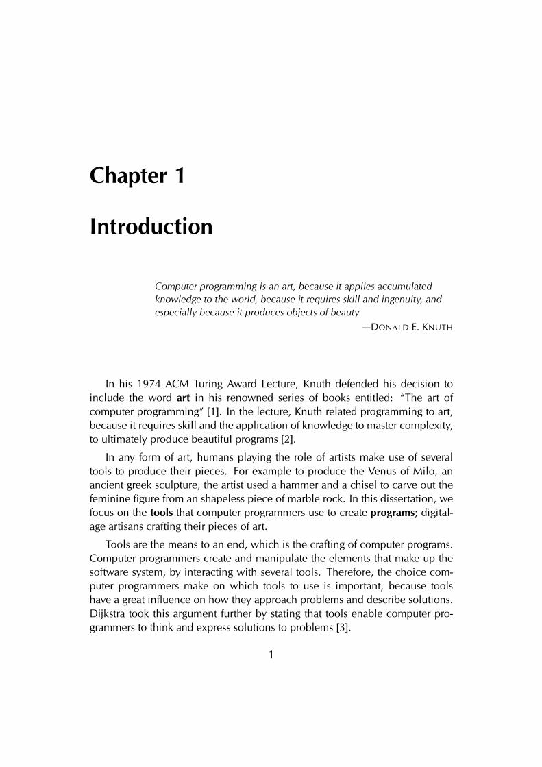
In his 1974 ACM Turing Award Lecture, Knuth defended his decision toinclude the word art in his renowned series of books entitled: “The art ofcomputer programming” [1]. In the lecture, Knuth related programming to art,because it requires skill and the application of knowledge to master complexity,to ultimately produce beautiful programs [2].
In any form of art, humans playing the role of artists make use of severaltools to produce their pieces. For example to produce the Venus of Milo, anancient greek sculpture, the artist used a hammer and a chisel to carve out thefeminine figure from an shapeless piece of marble rock. In this dissertation, wefocus on the tools that computer programmers use to create programs; digital-age artisans crafting their pieces of art.
Tools are the means to an end, which is the crafting of computer programs.Computer programmers create and manipulate the elements that make up thesoftware system, by interacting with several tools. Therefore, the choice com-puter programmers make on which tools to use is important, because toolshave a great influence on how they approach problems and describe solutions.Dijkstra took this argument further by stating that tools enable computer pro-grammers to think and express solutions to problems [3].
1
2 1.1 Symbolic Programming
1.1 Symbolic Programming
We established that programmers use tools to craft and manipulate programs,without defining what constitutes a program. Since the dawn of general pur-pose mechanical and electronic machines, humans have devised mechanismsto instruct them to perform tasks. We define this series of instructions, in abroad sense, as a program. The purpose of a program is to aid human labouror augment human intellect by instructing a general purpose machine –thecomputer– to perform a series of operations.
Programs are expressed following an interface mechanism between humansand computers, namely the language. Programs represent solutions to problemswithin the design space delimited by a language. Ingalls stated that the purposeof a language is to provide a framework for communication, that serves as aninterface between the models in the human mind and the computer [4].
The framework of communication initially evolved from basic machine in-structions to assembly language, easing the writing of programs by abstractingthe instructions and memory locations into a human readable form consistingof a combination of symbols and letters. A program written in assembly lan-guage consists of a series of operation codes mapping one to one to machineinstructions, together with labels referencing memory locations, instead of aplain succession of ones and zeroes closer to the computer hardware.
The prose of humans and computers started to diverge with the appearanceof high-level languages, such as Fortran, Lisp, Simula and Smalltalk. Programsevolved from simple tasks executing machine operations, to more complextasks involving concepts such as control flow statements, arrays, files, functions,and objects. The latter are not directly available from the machine instructionset, but rather enabled via multiple layers of abstraction.
Programming languages gradually came closer to a human readable form.The framework of communication was based on a symbolic representation ofthe program, where programmers make use of symbols and rules, to composeand specify programs, and its relation with the other parts of the system.
In our work, we focus on the programming languages that represent pro-grams in a textual form, that is programs that are defined by a piece of text –thesource code– that specifies the constituents and the behavior of the program,whose content is governed by the syntactic and semantic rules of the language.
3 1.2 On the writing of programs
1.2 On the writing of programs
From early psychological theories of programming to the present, programmingis acknowledged as a form of writing [5], thus while fulfilling programmingtasks, the editing and reading of a textual representation of the program –thesource code– is paramount. The former applies to programming languages thatare based on symbolic programming, which are our focus.
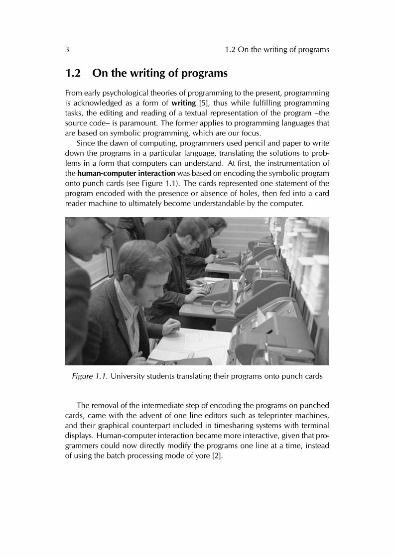
Since the dawn of computing, programmers used pencil and paper to writedown the programs in a particular language, translating the solutions to prob-lems in a form that computers can understand. At first, the instrumentation ofthe human-computer interaction was based on encoding the symbolic programonto punch cards (see Figure 1.1). The cards represented one statement of theprogram encoded with the presence or absence of holes, then fed into a cardreader machine to ultimately become understandable by the computer.
Figure 1.1. University students translating their programs onto punch cards
The removal of the intermediate step of encoding the programs on punchedcards, came with the advent of one line editors such as teleprinter machines,and their graphical counterpart included in timesharing systems with terminaldisplays. Human-computer interaction became more interactive, given that pro-grammers could now directly modify the programs one line at a time, insteadof using the batch processing mode of yore [2].
4 1.3 Programming is more than just writing
Once the terminal displays and personal computers with graphical user in-terfaces became widespread, the appearance of software applications knownas word processors raised the level of interactivity and flexibility of the pro-gramming tools. Word processors enabled the viewing and editing of multiplelines of the program at once, as opposed to the single line editing of commandline editors. Word processors became an important programming tool, centralto the instrumentation of human-computer interaction.
Nowadays, programmers use customized source code editors, evolved fromgeneral purpose text editors, for manipulating programs written in a particularlanguage. Modern source code editors provide advanced features to aid pro-grammers when writing and reading programs, such as automatically checkingthe syntactic rules to augment the view with relevant information, and the au-tocompletion of typed prefixes according to the context of the selected text, i.e.classes within a package or methods within a class hierarchy.
1.3 Programming is more than just writing
We established that programming involves the writing and reading of a textualrepresentation of the program, thus programmers make use of some form ofword processor to craft programs.
Nevertheless, the whole programming process involves a broad range ofother activities, such as the transformation of source code into an executableartifact, the monitoring of running programs to detect and fix problems, and thecreation of assertions on the quality and correctness of the programs.
1.3.1 Integrated Development Environments
During the late 70’s and the mid 80’s, programming became widespread dueto the appearance of more interactive programming tools –word processors interminal displays and personal computers–, and of simpler programming lan-guages such as BASIC. Programmers made use of several different tools to ac-complish diverse programming tasks, for example they use debuggers, com-pilers, linkers, and source-code editors. All the tools were running within thesame operating system, yet each one remaining a standalone application.
The lack of a common interface and of interoperability between the tools,favored the appearance of the integrated development environment (IDE), asingle application that included all the necessary tools.
5 1.3 Programming is more than just writing
The use of an IDE eased the undertaking of programming tasks, by providinga uniform interface to all the tools, which became accessible and were managedwithin one single entry point: the IDE.
One of the first IDEs to be widely adopted was Turbo Pascal, an IDE forthe Pascal language that ran on the DOS-based personal computers of the 80’s.Turbo Pascal enabled the running, compiling, debugging and editing of pro-grams within a keyboard-based environment.
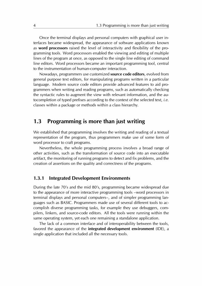
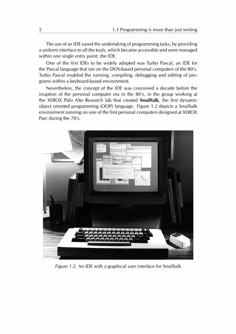
Nevertheless, the concept of the IDE was conceived a decade before theirruption of the personal computer era in the 80’s, in the group working atthe XEROX Palo Alto Research lab that created Smalltalk, the first dynamicobject oriented programming (OOP) language. Figure 1.2 depicts a Smalltalkenvironment running on one of the first personal computers designed at XEROXParc during the 70’s.
Figure 1.2. An IDE with a graphical user interface for Smalltalk
6 1.4 Object-Oriented Programming
Nowadays, programmers craft programs with the use of IDEs, and interactwith the source code and executables through graphical user interfaces inspiredfrom the early Smalltalk systems, which consisted of a dynamic OOP languageand an interactive development environment. Smalltalk was the first languageto enable OOP via a graphical user interface that grants access to the underly-ing objects of the system, solely through graphical elements on the computerdisplay, and the use of pointing devices and keyboards [6].
In this dissertation we focus on IDEs for programing in dynamic OOP lan-guages, and use Smalltalk as the target language for our thesis.
1.4 Object-Oriented Programming
When asked what that means he replies, "Smalltalk programs are just objects."When asked what objects are made of he replies, "objects." When asked again hesays "look, it’s all objects all the way down. Until you reach turtles."
—ALAN KAY
From the first high-level programming languages such as Fortran and Al-gol, programmers designed the programs around abstract data types and pro-cedures, making a clear distinction between (inert) data and the functionalityto modify it. Around the late 60’s, a different programming language paradigmemerged as a result of the work of Alan Kay, based on the metaphor of com-municating objects. Kay designed a system built from the ground up entirelyon this metaphor, whose first implementation was the Smalltalk environmentdeveloped at Xerox Parc during the 70’s [7].
Kay advocated the "disappearing of data" using only methods and objects.Objects subsume the concept of data and procedures into an entity which hasstate and behavior (methods), and the computation model is entirely based onmessage passing: the system is a collection of well behaved objects that askeach other to perform computation.
The key concepts of this new approach to computing came from biologicalcell communications modeled as networked whole computers. Kay was in-spired by his biology and mathematics background, his work on the ARPAnet,which became the Internet, and the inheritance mechanism present in the Sim-ula language [7]. Another source of inspiration was the Sketchpad, a computeraided design tool developed by Sutherland as part of his doctoral dissertation[8], which also introduced the concept of classes and instances.
7 1.5 The Problem
The OOP paradigm proved to simple, flexible, and powerful. Object ori-ented programming radically changed the computing programming culture. Inthe present, the OOP paradigm is widely recognized and adopted by academiaand industry, in its various flavors: dynamic (Smalltalk,Python), type-based(Java,C++), and prototype-based (Self,Javascript).
1.5 The Problem
We concluded that programming is a form of writing, and that the need toedit a textual representation of the program is satisfied by modern source codeeditors, which go beyond general purpose text edition facilities, by providingmore specific features tailored to a programming language.
Nevertheless, programmers spend most of their time analyzing the program[9], performing maintenance tasks that require an understanding of the system.In doing so, programmers seek the aid of several tools because software systemsare hard to understand [10]. The tools provide a means to wander around thesystem, learn about the composition of objects, and explore the relationshipsbetween them.
Nowadays, programmers use IDEs that provide numerous tools to effectivelyconstruct and maintain object-oriented programs. Besides source code edi-tors, modern IDEs include compilers, debuggers, modeling, and testing tools,amongst many other specific tools. The main tool for programming –the IDE–emphasizes the manipulation of tools for writing and reading the programs [11].The user interfaces of modern IDEs are built around a tools metaphor [12], be-cause developers visualize and interact with tools for editing and manipulatingthe objects of the system. We expand this discussion in Section 2.4.
The tool-based environments produce both conceptual and technical prob-lems when programming in OOP languages, discussed next.
1.5.1 The Conceptual Problem: Tools vs Objects
In object-oriented languages, the most important concept is that of an object.Moreover, in dynamic OOP languages –which is our focus–, the system is com-posed solely of objects, suppressing the arbitrary distinction between run-timeand compile-time, to enhance the liveliness of the system.
The conceptual problem occurs because a tool-based environment treatsobjects as lifeless entities, that can be only manipulated through a set of tools.For example, to add or remove methods from a class, Smalltalk programmers
8 1.5 The Problem
use System Browsers that provide the means to do so. Nevertheless, methodaddition or removal might also be achieved by sending messages to the class,because in Smalltalk, classes are just another kind of live object in the system.
This dichotomy, between inert and live human-object interactions, resultsfrom the former promoting a message-based interface, whereas the latter em-powers a tool with the responsibility of modifying inert data. In non-dynamicOOP languages, a tool-based IDE is instrumental because in such languages atcompile time programmers deal solely with an inert specification of the pro-gram: the source code. Therefore, tools are the only possible means of manip-ulating data. On the other hand, in dynamic OOP languages a tool-based IDEis conceptually detrimental because it diverges from the philosophy behind thelanguage: a computational model based on a world of live objects [4].
Nonetheless, programmers have become efficient on creating and main-taing programs using tool-based IDEs [13], thus we stress that the former is aconceptual problem, which hinders the understanding of the importance of therole of objects in dynamic OOP languages.
1.5.2 Technical Problems
In this section we discuss problems of the tool-based IDEs which are more prac-tical in nature, and result from contrasting developers needs to the interfaces ofthe tool-based development environments. We categorized the problems intothree categories: the first relates to a more fine-grained manipulation, the sec-ond to the real estate management of finite computer displays, and the third tothe representation of the objects in the interface of the IDE.
Fine-grained Manipulation of Objects
The file-based view of mainstream OOP IDEs prevents the manipulation at afiner-grained level than source code files. In a study on programmers habitswhile using Eclipse 1, while performing maintenance tasks, Ko et al. elicitedthe requirement that IDEs should provide a fine-grained manipulation of theprogram entities [14]. Ko advocates for finer-grained representations of the sys-tem, because programmers tend to form working sets of classes, methods andpackages, pertaining to the task at hand.
IDEs fail to meet this need, because they provide tools that enable a coarsemanipulation of the objects, in the form of whole file navigators and editors asin IDEs for mainstream OOP languages such as JAVA.
1An IDE for the Java language, http://www.eclipse.org
9 1.5 The Problem
Similarly, Smalltalk environments, include system browsers that grant accessto packages, classes, and methods within the same tool. Kersten et al. statedthat this problem is aggravated when the structure of the system is not alignedwith the structure of the task, and propose a degree of interest model that de-fines a task context, to aid programmers into forming those working sets [15].
Real Estate Management
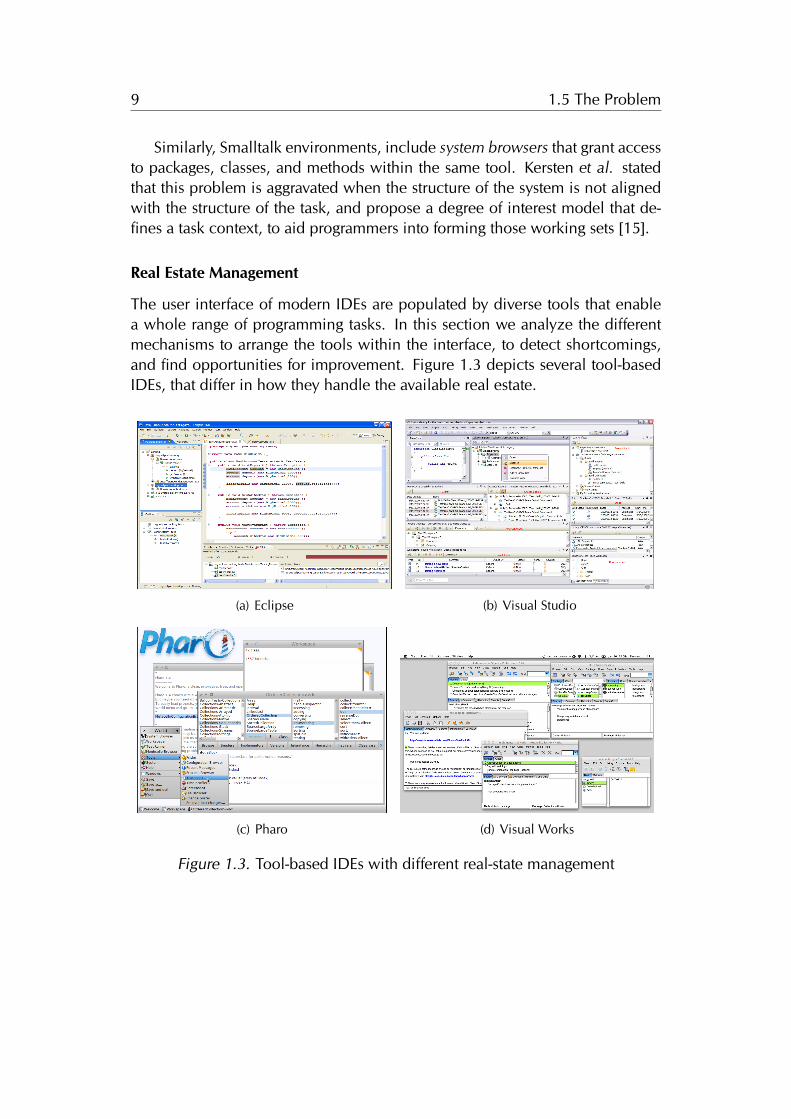
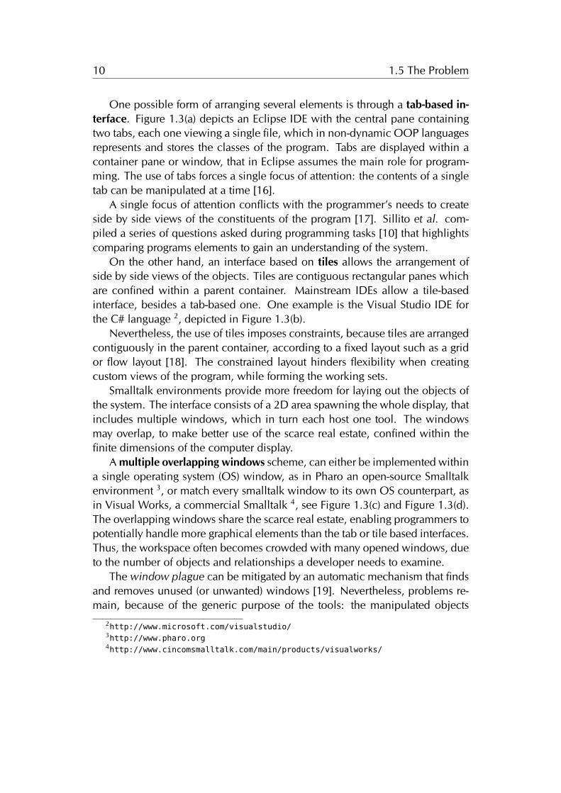
The user interface of modern IDEs are populated by diverse tools that enablea whole range of programming tasks. In this section we analyze the differentmechanisms to arrange the tools within the interface, to detect shortcomings,and find opportunities for improvement. Figure 1.3 depicts several tool-basedIDEs, that differ in how they handle the available real estate.
(a) Eclipse (b) Visual Studio
(c) Pharo (d) Visual Works
Figure 1.3. Tool-based IDEs with different real-state management
10 1.5 The Problem
One possible form of arranging several elements is through a tab-based in-terface. Figure 1.3(a) depicts an Eclipse IDE with the central pane containingtwo tabs, each one viewing a single file, which in non-dynamic OOP languagesrepresents and stores the classes of the program. Tabs are displayed within acontainer pane or window, that in Eclipse assumes the main role for program-ming. The use of tabs forces a single focus of attention: the contents of a singletab can be manipulated at a time [16].
A single focus of attention conflicts with the programmer’s needs to createside by side views of the constituents of the program [17]. Sillito et al. com-piled a series of questions asked during programming tasks [10] that highlightscomparing programs elements to gain an understanding of the system.
On the other hand, an interface based on tiles allows the arrangement ofside by side views of the objects. Tiles are contiguous rectangular panes whichare confined within a parent container. Mainstream IDEs allow a tile-basedinterface, besides a tab-based one. One example is the Visual Studio IDE forthe C# language 2, depicted in Figure 1.3(b).
Nevertheless, the use of tiles imposes constraints, because tiles are arrangedcontiguously in the parent container, according to a fixed layout such as a gridor flow layout [18]. The constrained layout hinders flexibility when creatingcustom views of the program, while forming the working sets.
Smalltalk environments provide more freedom for laying out the objects ofthe system. The interface consists of a 2D area spawning the whole display, thatincludes multiple windows, which in turn each host one tool. The windowsmay overlap, to make better use of the scarce real estate, confined within thefinite dimensions of the computer display.
A multiple overlapping windows scheme, can either be implemented withina single operating system (OS) window, as in Pharo an open-source Smalltalkenvironment 3, or match every smalltalk window to its own OS counterpart, asin Visual Works, a commercial Smalltalk 4, see Figure 1.3(c) and Figure 1.3(d).The overlapping windows share the scarce real estate, enabling programmers topotentially handle more graphical elements than the tab or tile based interfaces.Thus, the workspace often becomes crowded with many opened windows, dueto the number of objects and relationships a developer needs to examine.
The window plague can be mitigated by an automatic mechanism that findsand removes unused (or unwanted) windows [19]. Nevertheless, problems re-main, because of the generic purpose of the tools: the manipulated objects
2http://www.microsoft.com/visualstudio/3http://www.pharo.org4http://www.cincomsmalltalk.com/main/products/visualworks/
11 1.5 The Problem
depend on the current selection of the tools. The selection can be modified,thus the mapping of windows to the objects is not persistent, which complicatesthe reasoning behind the automatic scheme.
The problem of the explosion of graphical elements within the interface,occurs also when using tabs or tiles. Moreover, all the mentioned schemes canbe used in conjunction: tabs and tiles may coexist within the interface, andsmalltalk windows can include tabs.
To summarize, tool-based interfaces work on a coarse-grained level, whichconflicts with programmers need to form working sets of objects, which mayspawn across all the modules of the system. Another missing opportunity oc-curs because the mentioned schemes confine the graphical elements to a fi-nite 2D area, which prevents programmers from using a spatial memory andreasoning for the whole system [20], given that the clutter in the interface isproportional to the number of objects relevant to the task at hand.
Representation of the Objects in the Interface
Software is intangible [21; 22], thus the visual appearance of objects is an extrin-sic characteristic. Nevertheless, the objects must be represented in a graphicalform throughout the IDEs, because programmers interact with the system usingcomputer displays. Despite the intangible nature of software, objects have astructure and composition that serves as a guideline for designing their visualappearance. For instance, the containment relationship between a class and itsmethods, or between a package and its classes, serves as a guideline for therepresentation of the program, either in a textual or a graphical form.
The visual appearance of objects is an important concern when performingprogramming and program comprehension tasks. For example, the use of soft-ware visualization enable programmers to gain an understanding of the systemby exploiting metrics or intrinsic properties of the target of study: packages,classes, methods, or the system itself [23]. In this dissertation we focus on toolsfor programming in OOP languages, thus our concern is the visual representa-tion of objects within the interface.
The IDEs of mainstream non-dynamic OOP languages are file-based, mak-ing it explicit that source code is stored in operating system files. File-basedIDEs represent the program in a textual form, namely the source code, split intofiles containing one or more elements of the program. Figure 1.3(a) depictsEclipse, a mainstream IDE with a standard arrangement of panes in the inter-face, which includes several sub-panes surrounding a main tabbed pane thatpresents the source code, following a bento-box model [24].
12 1.5 The Problem
The source code is the complete specification of the program, it defines allthe objects, their behavior and composition. When the programmer writes orreads the code, he has to deal with the complexity of the syntactic rules of thelanguage, and process information to effectively modify the program. There-fore, IDEs make use of graphical elements which abstract over the raw code,such as code elision or class overview widgets. Code elision is the foldingof meaningful portions of code on demand, to hide irrelevant sections of theobjects, to aid programmers when reading complex source code files [25]. Sim-ilarly, IDEs provide another means of viewing and navigating the compositionof classes and packages, in the form of overview widgets, which enable a treeview interaction with the objects, depicted in Figure 1.3(a).
IDEs that provide the latter favor chunking. The method of presenting in-formation known as chunking consists in splitting concepts into smaller pieces,which are easier to manage and understand [26]. In this manner, file-basedIDEs enhance the usability of the interface at the expense of providing morethan one representation of the objects.
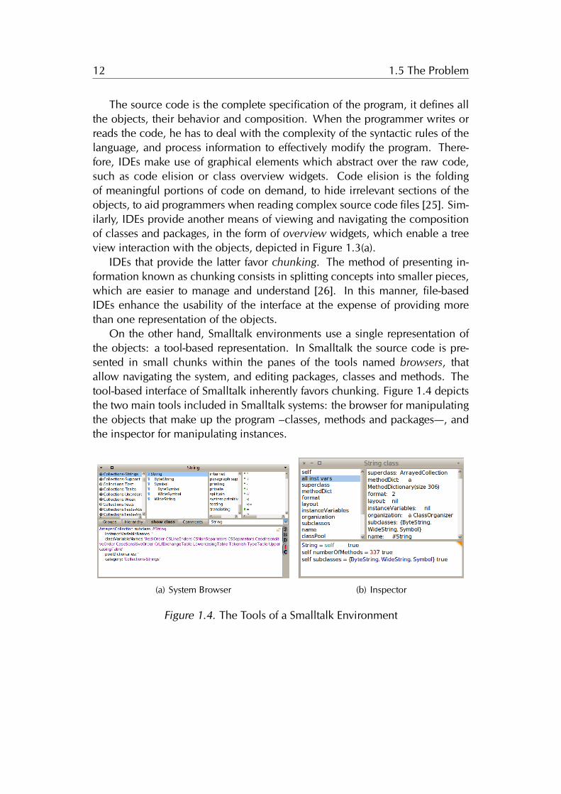
On the other hand, Smalltalk environments use a single representation ofthe objects: a tool-based representation. In Smalltalk the source code is pre-sented in small chunks within the panes of the tools named browsers, thatallow navigating the system, and editing packages, classes and methods. Thetool-based interface of Smalltalk inherently favors chunking. Figure 1.4 depictsthe two main tools included in Smalltalk systems: the browser for manipulatingthe objects that make up the program –classes, methods and packages—, andthe inspector for manipulating instances.
(a) System Browser (b) Inspector
Figure 1.4. The Tools of a Smalltalk Environment
13 1.5 The Problem
The downside of a tool-based interface is a single object may be presentedby more than one tool, thus the identity property of OOP languages is not con-veyed in the interface [11]. Another related problem is that tool-based interfacespresent the many different objects of the system using the same set of widgets.Classes, methods, and packages appear as a list item in the browsers columns,or in a textual description when the selection of the browser points to a specificobject. Figure 1.4 depicts a system browser with a selection on the class String,and the code pane presenting a textual representation of the class description.There are missing opportunities in this scheme, because the semantics of theobjects may be only conveyed by icons in the list item denoting the name of theobjects, as opposed to designing a visual appearance for each kind of object,tailored to reflect its type, structure, behavior, and state.
1.5.3 Summary
We started by discussing the conceptual problem of using a tool-based interfacefor programming in dynamic OOP language.The problem is that objects remainhidden behind the tools, which a have prominent role in the interface. Thus,objects are perceived as inert data that can only be manipulated by the use of atool. This conflicts with the essence of OOP, which is based on a computationalmodel of a world of live objects.
Secondly, we discussed the real estate management of current IDEs, for bothdynamic and non-dynamic languages, to find out that current interfaces presentthe objects in tab- or tile-based interfaces, or a multiple overlapping windowsscheme, confined within the finite boundaries of the computer display. Wedetailed how the traditional interfaces hinder the use of spatial memory andreasoning, effectively used for software visualization approaches, such as classblueprints [27] and software cartography [28].
Lastly, we analyzed how IDEs represent the objects that make up the pro-gram in the interface, to find missing opportunities of the tool-based interfacesfor conveying the semantics of the many different kinds of objects. IDEs presentthe objects either in a textual form –the source code–, or within one or moregeneric tools, making it difficult to denote changes to the objects due to a loss ofidentity, and presenting a uniform appearance regardless of the kind of objectbeing displayed. For instance, a Class is different than a Method, and a Num-ber is different than a Color, nevertheless these objects have the same visualappearance within tool-based interfaces.
14 1.6 Thesis
1.6 Thesis
Computer programmers craft programs with the aid of tools, which evolvedfrom simple pen and paper to those using a graphical user interface basedon windows, icons, menus and a pointing device. Nowadays, programs arecreated, maintained and executed with Integrated Development Environments(IDEs), which are built on a tool-based interface.
In this dissertation we focus on programs which are described entirely byobjects, following a computational model of a world of objects that collaborateby sending each other messages, i.e., we focus on the development environ-ments of Object-Oriented Programming languages.
The dynamic nature of a world of living objects is lessened in the interfaceof modern IDEs, which revolves around a textual representation of the program,namely the source code. In this sense, programming with traditional IDEs re-sembles the composing of musical tunes: both activities specify a dynamicartifact with a static one, method statements and class definitions in the former,and pentagrams with notes in the latter.
The tool-based interface of IDEs prevents programmers to directly engageinto conversations with the underlying objects of the system. On the otherhand, the interfaces built on the desktop metaphor make explicit the presenceof the manipulable entities, and provide the means to interact with them.
We investigate the application of the desktop metaphor to an object orienteddevelopment environment with an interface solely based on direct manipula-tion of objects, which we name an Object-focused environment.
We formulate our thesis as:
An Object-focused environment supports an extensible set of soft-ware engineering tasks, eliminates the need for extrinsic tools thatwork on the source-code, and conveys the dynamic nature of aworld of living objects.
To validate our thesis, we designed and implemented an object-focusedenvironment, and applied the novel interface to several software engineeringtasks, ranging from modeling to program comprehension tasks.
15 1.7 Contributions
1.7 Contributions
In the light of our described thesis, the contributions of this dissertation are:
The definition of an object-focused interface for software development [29].We describe in Chapter 3 the building blocks of our design of a develop-ment environment based on a desktop metaphor, a plausible alternativeto the tool-based interfaces of traditional IDEs.
The application of the object-focused interface to modeling and OOP [30].In Chapter 3 we also describe the shapes of the environment, which arethe behaviorally complete graphical counterparts of the objects that formthe models (see Section 3.3), and the programs ( see Section 3.4).
The implementation of an object-focused environment [31]. We implementedGaucho, an object-focused programming environment for the crafting ofmodels composed of objects, described in class-based object orientedlanguages. Gaucho is publicly available and has been used in academicresearch. We present our tool in Section 3.2.
The empirical validation of our approach through a controlled experiment[32]. We performed a controlled experiment to compare traditional IDEsand Gaucho with respect to a set of program comprehension tasks ex-tracted from the literature, such as creating, navigating, refactoring, andunderstanding an object-oriented system. We present the experiment,and reflect on the findings in Chapter 4.
The design and implementation of a tool to support human-centric con-trolled experiments [33]. We present Biscuit in Section 4.1. Biscuit is anautomated experiment runner toolset to support conducting experimentsfor evaluating software tools with human subjects.
The application of the object-focused interface to collaboration [34]. Todemonstrate the extensibility of our approach, we augmented the singledeveloper environment Gaucho into a collaborative development envi-ronment. In Chapter 5 we investigate the use of an object-focused envi-ronment to support collaboration and real-time awareness of fine-grainedchanges to the system.
The implementation of a tool to support collaboration [34] In Section 5.2 wedescribe Ronda, an object-focused environment that provides first-classsupport for collaborative development sessions.
16 1.8 Structure of the Document
1.8 Structure of the Document
We structured the remainder of this dissertation as follows:
Chapter 2. We start with a historical perspective on our work, by describing theevolution of the tools used by programmers to craft programs. We discussthe tool-based nature of IDEs, describe their problems, and present severalalternative user interfaces that alleviate them.
Chapter 3. We continue by describing our approach: the Object-focused en-vironment. An extensible re-design of object oriented development envi-ronments, with applications to different areas of software engineering.
We present Gaucho, the object-focused environment that enables model-ing, programming and program comprehension tasks, by interacting withshapes representing the objects.
Chapter 4. Next, we present a controlled experiment we performed to vali-date our approach. We also describe Biscuit, an automated experimentrunner toolset we implemented to support researchers when performingcontrolled experiments with human subjects to evaluate software tools.
Chapter 5. After describing the evaluation and its instrumentation, we presentRonda, an enhancement to the single developer environment Gauchowhich adds support for the collaborative nature of programming.
We implemented Ronda to demonstrate the extensibility our approach,and investigate the application of object-focused interfaces to collabora-tive development environments.
Chapter 6. We conclude this dissertation by discussing our approach and sum-marizing the contributions of this work, and detailing future research di-rections.
Chapter 2
State of the Art
It has to do with the influence of the tool we are trying to use upon our ownthinking habits. I observe a cultural tradition, which in all probability has itsroots in the Renaissance, to ignore this influence, to regard the human mind asthe supreme and autonomous master of its artefacts.
—EDSGER W. DIJKSTRA
From the beginning of the computer age, computer scientists have underes-timated the influence that tools have upon our working habits and the quality ofthe artifacts we produce [3]. For example, Weinberg recalls the skepticism sur-rounding the development of Fortran amongst fellow programmers, who chal-lenged the adoption of high level languages on the grounds that programmerswould always produce more efficient code [5]. On the other hand, several re-searchers pondered on the impact of tools. Dijkstra advocated for better toolsto struggle against their inadequacies, enabling programmers to focus on solv-ing the problems [3]. Knuth envisioned the use of tools that are a pleasureto use, encouraging programmers to write better programs, by providing moreinteractivity than the batch processing of early punch card based systems [2].
In this chapter we describe the tool-based development environments forprogramming in object oriented languages. We start by describing the inter-faces that give a prominent role to the tools, which are separate from the ob-jects of the system, whose generic nature enables the manipulation of manyelements of the program. We gradually move towards environments that favorfine-grained manipulation of software artifacts –objects, code–, where the toolspermeate throughout all the environment, to solve the manipulation, layout andvisualization problems discussed in Section 1.5.
17
18 2.1 Smalltalk
Structure of the chapter. We present Smalltalk, from the original versionsthat introduced the IDE, to more modern implementations in Section 2.1. InSection 2.2 we describe several environments with alternative interfaces forprogramming in code-centric languages. We detail modeling environments forlanguages that abstract away from the source code to models, in Section 2.3.We conclude this chapter in Section 2.4 by describing the environments whichare closer to our approach, the ones which favor direct manipulation of objects.
2.1 Smalltalk
The Smalltalk language was the precursor of both object oriented programming,and the integrated development environment. The original environments de-veloped at Xerox PARC during the 70’s introduced many of the tools that arestill in use today, such as object inspectors, debuggers, and code editors andnavigators. Differently than other programming languages that make a clear dis-tinction between the source code and the running programs, in Smalltalk theenvironment and the language are strongly coupled. This coupling results fromthe computational model of Smalltalk: a world of live objects, that collaborateby sending messages to each other. The graphical user interface to interact withthe objects was developed together with the language [7].
2.1.1 Browsers and Inspectors
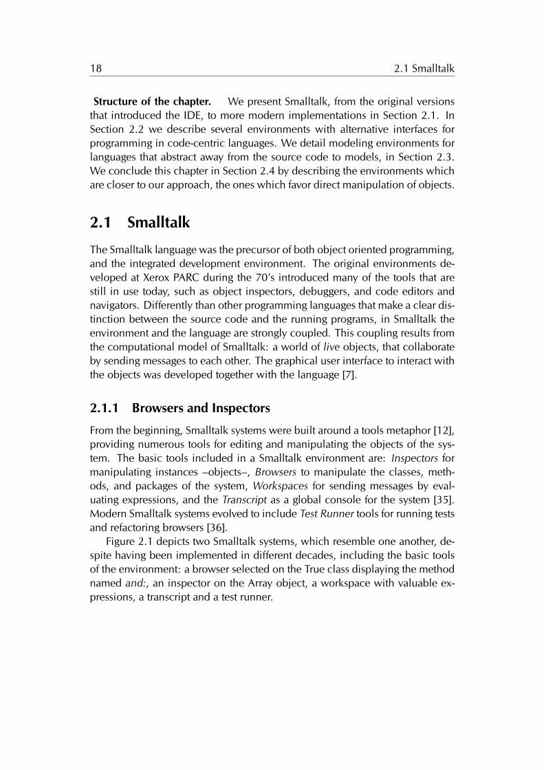
From the beginning, Smalltalk systems were built around a tools metaphor [12],providing numerous tools for editing and manipulating the objects of the sys-tem. The basic tools included in a Smalltalk environment are: Inspectors formanipulating instances –objects–, Browsers to manipulate the classes, meth-ods, and packages of the system, Workspaces for sending messages by eval-uating expressions, and the Transcript as a global console for the system [35].Modern Smalltalk systems evolved to include Test Runner tools for running testsand refactoring browsers [36].
Figure 2.1 depicts two Smalltalk systems, which resemble one another, de-spite having been implemented in different decades, including the basic toolsof the environment: a browser selected on the True class displaying the methodnamed and:, an inspector on the Array object, a workspace with valuable ex-pressions, a transcript and a test runner.
19 2.1 Smalltalk
(a) Smalltalk-80, 1980
(b) Pharo, 2012
Figure 2.1. Basic tools included in Smalltalk, from the original Smalltalk-80 tothe modern Pharo IDE
20 2.2 Code-Centric Environments
2.2 Code-Centric Environments
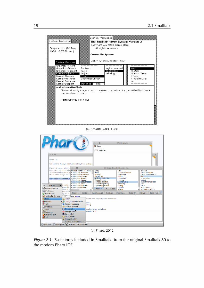
We stated previously that nowadays developers write programs, aided by inte-grated development environments (IDEs); and that IDEs feature numerous toolsthat provide the means to construct programs.
In this section we describe the mainstream IDEs, that are built around atextual representation of the program, namely the source code. We refer tothese IDEs as code-centric, because performing textual editions of the sourcecode is the main mechanism for programming.
Moreover, the files which host the code take a primary role within the in-terface, an often adopted fashion is to arrange the various tools in a bento boxmodel, around the source code. Mainstream IDEs are file-based, because theymake explicit that source code is stored in operating system files.
We depict Eclipse, a code-centric IDE for JAVA in Figure 2.2.
(a) Eclipse
Figure 2.2. Code-centric mainstream IDEs
21 2.2 Code-Centric Environments
The design and usage of Code-centric IDEs produces some problems wediscussed in Section 1.5.2, enumerated next:
• The fine-grained manipulation of the software artifacts.
• The real estate management that enables or impedes to layout the artifactsin an meaningful manner.
• The level of refinement of the visualization of the programs elementswithin the interface.
Next we describe several alternative code-centric environments, designedfor manipulating source-code in a non-traditional interface, to alleviate or avoidthe enumerated problems at all. The mentioned approaches are either tools thatcomplement the IDE or full-blown development environments.
2.2.1 Relo
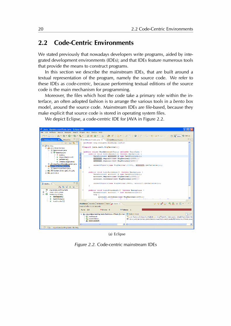
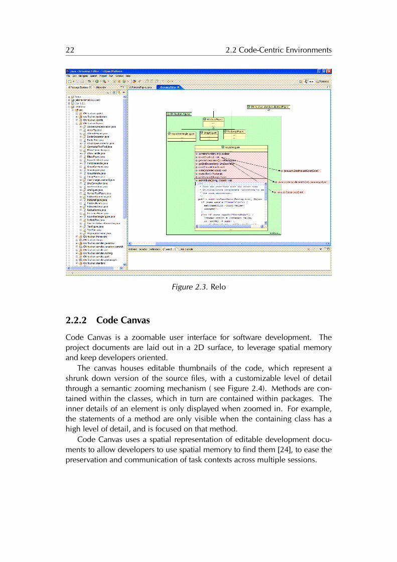
Relo is a program comprehension tool, that augments the Eclipse IDE with aninteractive diagram that includes a graphical representation of the code.
Relo aids programmers to comprehend complex systems with large code-bases, by making explicit the context while exploring the code. Figure 2.3depicts the tool within the Eclipse IDE.
The tool is designed on the premise that when exploring large codebasesprogrammers follow a bottom-up approach, starting from a relevant artifact, andadding the related ones by exploring their relationships. Therefore, RELO startswith a clean diagram, and provides the means to add elements from the system,and to easily navigate to other elements by interacting with the diagram. Thetool provides a fine-grained manipulation of the classes, methods and packagesof the program, thus addressing the first problem.
The nodes of the diagram are graphical elements representing the classes,methods and packages of the system. The source code is abstracted into a vi-sual language resembling the unified modeling language (UML), to ease thecomprehension of the objects. The nodes are automatically arranged followingtopological constraints, for example the inheritance edges between two classesare drawn vertically, while method calls are drawn horizontally. Even thoughRELO includes some form of real estate management, the tool lacks an over-all system layout management, because the diagrams are focused into smallportions of the system, providing a graphical context for exploring parts [37].
22 2.2 Code-Centric Environments
Figure 2.3. Relo
2.2.2 Code Canvas
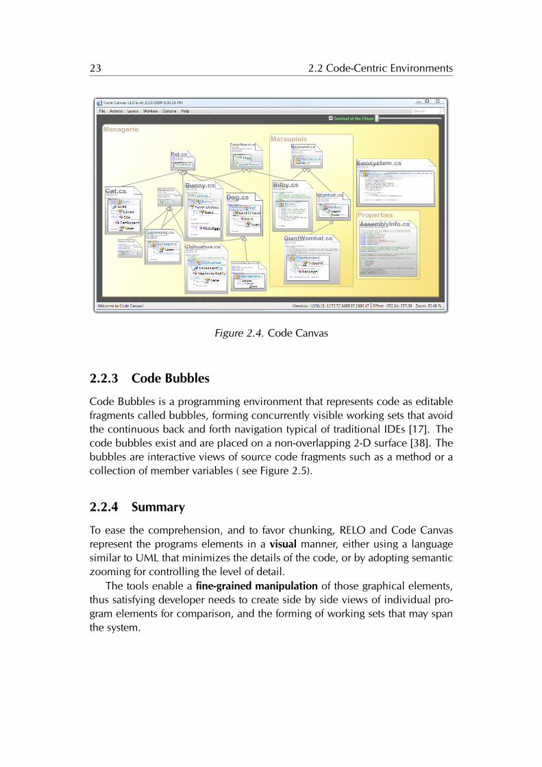
Code Canvas is a zoomable user interface for software development. Theproject documents are laid out in a 2D surface, to leverage spatial memoryand keep developers oriented.
The canvas houses editable thumbnails of the code, which represent ashrunk down version of the source files, with a customizable level of detailthrough a semantic zooming mechanism ( see Figure 2.4). Methods are con-tained within the classes, which in turn are contained within packages. Theinner details of an element is only displayed when zoomed in. For example,the statements of a method are only visible when the containing class has ahigh level of detail, and is focused on that method.
Code Canvas uses a spatial representation of editable development docu-ments to allow developers to use spatial memory to find them [24], to ease thepreservation and communication of task contexts across multiple sessions.
23 2.2 Code-Centric Environments
Figure 2.4. Code Canvas
2.2.3 Code Bubbles
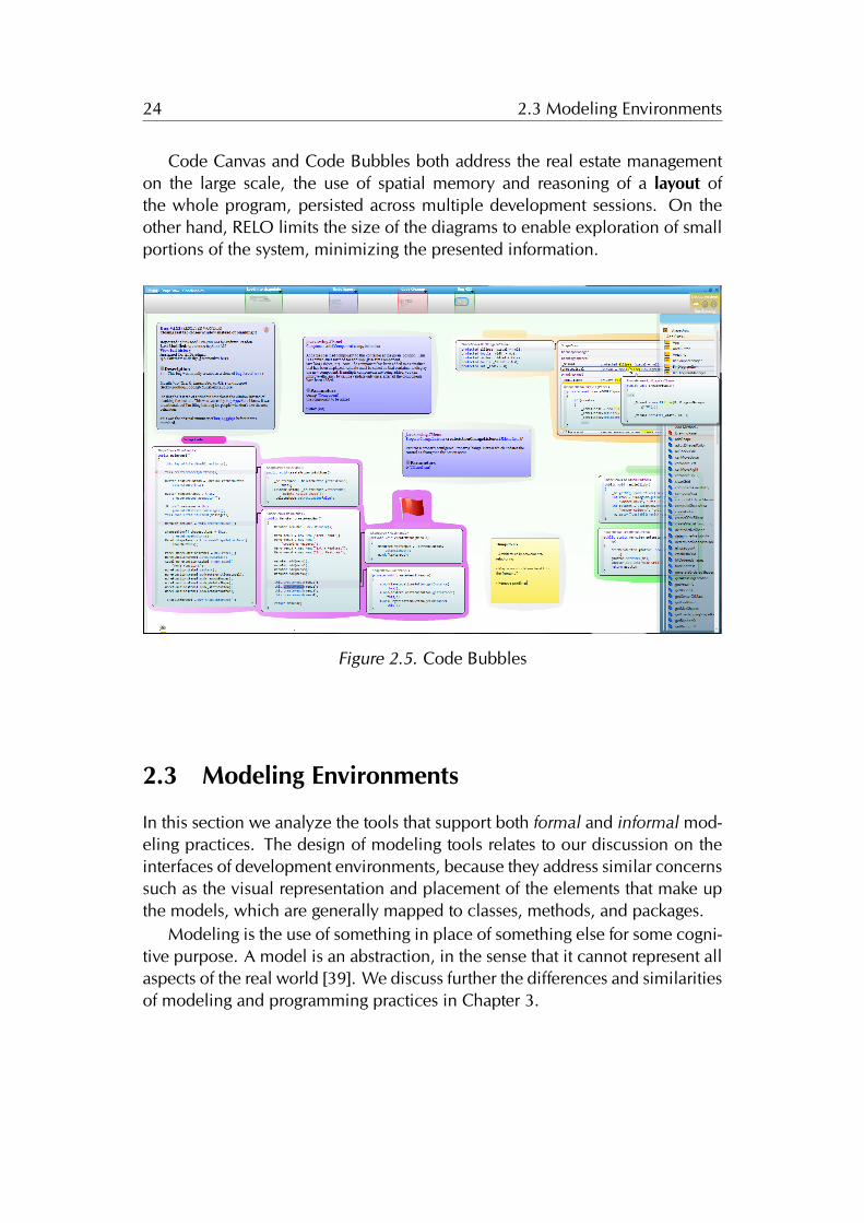
Code Bubbles is a programming environment that represents code as editablefragments called bubbles, forming concurrently visible working sets that avoidthe continuous back and forth navigation typical of traditional IDEs [17]. Thecode bubbles exist and are placed on a non-overlapping 2-D surface [38]. Thebubbles are interactive views of source code fragments such as a method or acollection of member variables ( see Figure 2.5).
2.2.4 Summary
To ease the comprehension, and to favor chunking, RELO and Code Canvasrepresent the programs elements in a visual manner, either using a languagesimilar to UML that minimizes the details of the code, or by adopting semanticzooming for controlling the level of detail.
The tools enable a fine-grained manipulation of those graphical elements,thus satisfying developer needs to create side by side views of individual pro-gram elements for comparison, and the forming of working sets that may spanthe system.
24 2.3 Modeling Environments
Code Canvas and Code Bubbles both address the real estate managementon the large scale, the use of spatial memory and reasoning of a layout ofthe whole program, persisted across multiple development sessions. On theother hand, RELO limits the size of the diagrams to enable exploration of smallportions of the system, minimizing the presented information.
Figure 2.5. Code Bubbles
2.3 Modeling Environments
In this section we analyze the tools that support both formal and informal mod-eling practices. The design of modeling tools relates to our discussion on theinterfaces of development environments, because they address similar concernssuch as the visual representation and placement of the elements that make upthe models, which are generally mapped to classes, methods, and packages.
Modeling is the use of something in place of something else for some cogni-tive purpose. A model is an abstraction, in the sense that it cannot represent allaspects of the real world [39]. We discuss further the differences and similaritiesof modeling and programming practices in Chapter 3.
25 2.3 Modeling Environments
Informal Modeling
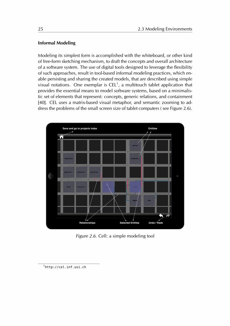
Modeling its simplest form is accomplished with the whiteboard, or other kindof free-form sketching mechanism, to draft the concepts and overall architectureof a software system. The use of digital tools designed to leverage the flexibilityof such approaches, result in tool-based informal modeling practices, which en-able persisting and sharing the created models, that are described using simplevisual notations. One exemplar is CEL1, a multitouch tablet application thatprovides the essential means to model software systems, based on a minimalis-tic set of elements that represent: concepts, generic relations, and containment[40]. CEL uses a matrix-based visual metaphor, and semantic zooming to ad-dress the problems of the small screen size of tablet computers ( see Figure 2.6).
UIW
indow
768 x 1024
Save and go to projects index Entities
Selected Entities Undo / RedoRelationships
Figure 2.6. Cell: a simple modeling tool
1http://cel.inf.usi.ch
26 2.3 Modeling Environments
Formal Modeling
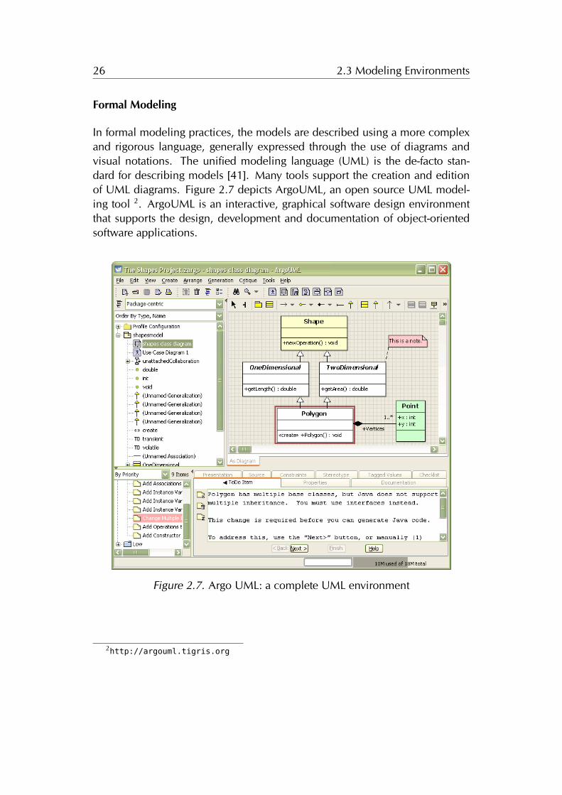
In formal modeling practices, the models are described using a more complexand rigorous language, generally expressed through the use of diagrams andvisual notations. The unified modeling language (UML) is the de-facto stan-dard for describing models [41]. Many tools support the creation and editionof UML diagrams. Figure 2.7 depicts ArgoUML, an open source UML model-ing tool 2. ArgoUML is an interactive, graphical software design environmentthat supports the design, development and documentation of object-orientedsoftware applications.
Figure 2.7. Argo UML: a complete UML environment
2http://argouml.tigris.org
27 2.3 Modeling Environments
Summary
Similarly to the alternative code-centric environments, modeling tools makeuse of fine-grained manipulation of the concepts, arranged within diagrams toleverage the use of spatial memory, and presented as editable graphical ele-ments which abstract from an otherwise cumbersome textual representation.
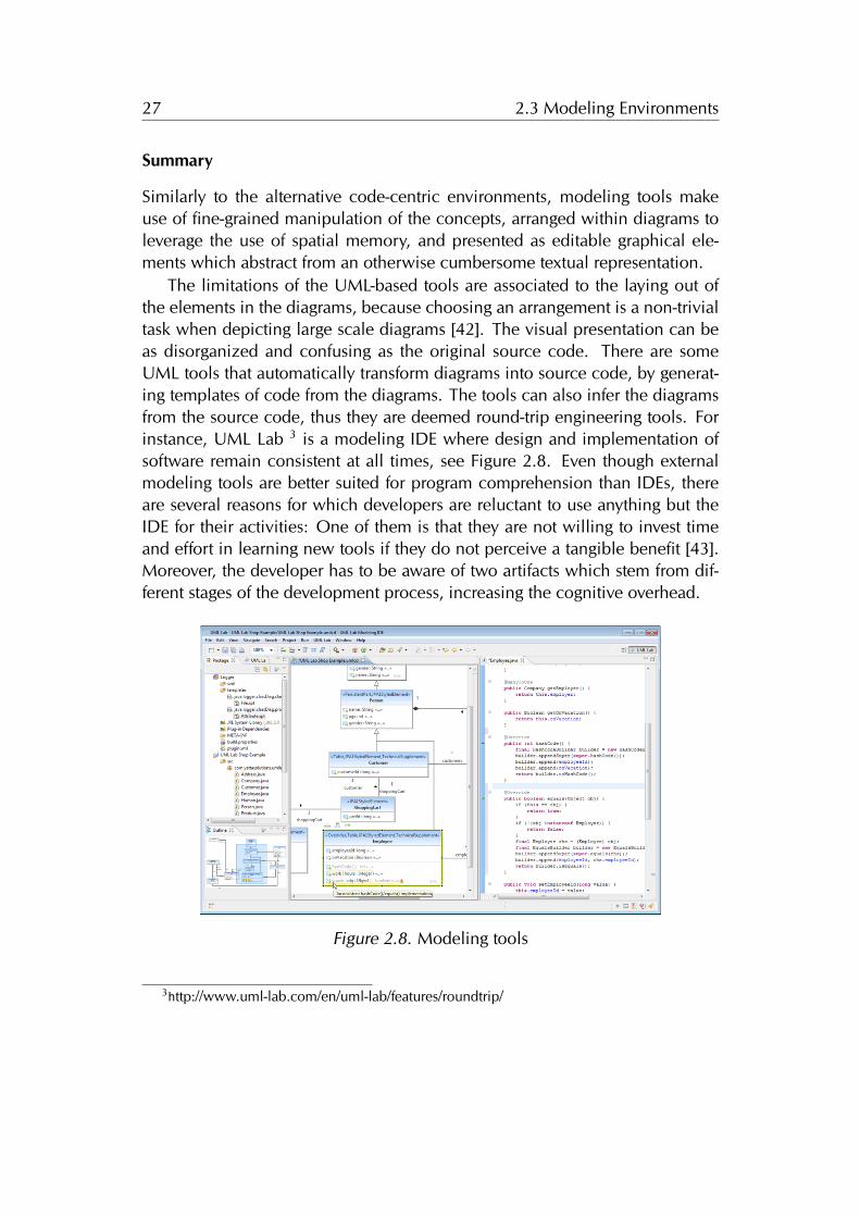
The limitations of the UML-based tools are associated to the laying out ofthe elements in the diagrams, because choosing an arrangement is a non-trivialtask when depicting large scale diagrams [42]. The visual presentation can beas disorganized and confusing as the original source code. There are someUML tools that automatically transform diagrams into source code, by generat-ing templates of code from the diagrams. The tools can also infer the diagramsfrom the source code, thus they are deemed round-trip engineering tools. Forinstance, UML Lab 3 is a modeling IDE where design and implementation ofsoftware remain consistent at all times, see Figure 2.8. Even though externalmodeling tools are better suited for program comprehension than IDEs, thereare several reasons for which developers are reluctant to use anything but theIDE for their activities: One of them is that they are not willing to invest timeand effort in learning new tools if they do not perceive a tangible benefit [43].Moreover, the developer has to be aware of two artifacts which stem from dif-ferent stages of the development process, increasing the cognitive overhead.
Figure 2.8. Modeling tools
3http://www.uml-lab.com/en/uml-lab/features/roundtrip/
28 2.4 Direct-Manipulation of Objects
2.4 Direct-Manipulation of Objects
In this section we describe an alternative metaphor for building developmentenvironments, based on direct manipulation of objects.
Hutchins et al. state that direct manipulation systems continuously presentthe objects of interest, replace the use of complex syntax by the use of labeledbuttons (amongst other widgets), and provide reversible operations specified ina higher level language interface, whose impact is shown immediately. Theeffect of direct manipulation in the interfaces reduces the distance between theuser’s intentions and the facilities provided by the system, therefore reducingthe effort of the user to accomplish goals [44].
The alternative code-centric environments and modeling tools we reviewedin the previous section, use some form of direct manipulation of either of por-tions of source-code defining classes, methods and packages, or the compo-nents of a model. We discuss next the two contrasting metaphors for buildinginterfaces, and describe the environments that were designed to minimize thepresence of tools, in favor of direct manipulation of objects.
2.4.1 The Tools and Desktop Metaphor
The mission of the XEROX Palo Alto Research Center (PARC) was to leveragethe potential of computers in the late 60’s. The team led by Alan Kay soughtto accomplish that goal by making computers accessible to everyone, not justtechnical people. Kay and his fellow scientists conceived the nowadays om-nipresent concept of a personal computer, with a graphical user interface (GUI)based on overlapping windows, menus, and icons [7]. Kay was building on theprevious work of researchers such as Douglas Engelbart, head of the StanfordAugmentation Research Center Lab, who designed the mouse and the first GUI.
The Smalltalk-72 system, implemented in 1972, was the first environmentto include a GUI, which included tools contained within the windows, thatpresented the content of the system: the objects. The objects were modifiedby performing textual edits with the keyboard, and pointing to actions in thecontextual menus with the mouse. Nowadays, many environments use a similarinterface to the Smalltalk systems, giving prominence to the tools.
On one hand, we have the Tools metaphor, and on the other hand wehave the Desktop metaphor. The interfaces of both metaphors consisted on agraphical user interface including windows, menus, icons and a mouse. Theydiffer in the target of the actions, and the primary role within the interface.
29 2.4 Direct-Manipulation of Objects
In tool-based interfaces, the users first open the tool, and then select thecontent to work upon, i.e., which may be data file or an object. Whereas, ininterfaces using a desktop-metaphor the users do not invoke the tools, but ratherinteract with the objects themselves. The desktop is a working environment,which resembles the top of an office desk were various pictures of familiarobjects reside: documents, folders, file drawers, etc.. The pictures are namedicons, and are the visible concrete embodiments of the corresponding physicalobjects. Icons represent the objects in the form of a picture that react to theactions of the user. Editing the objects involves invoking the associated tool bypointing and clicking the icon with the mouse, or on a menu [12].
The desktop metaphor pushes users toward their data rather than towardthe tools, employing analogies with the physical world, at the expense of cou-pling the objects to assigned tool. In this dissertation, we explore a system thatmerges the icon with the associated tool into a single graphical representationof the objects populating an infinite desktop, an Object-Focused Environment.
The ubiquitous association between an object and a single tool, strengthensthe notion that the manipulable “icon” is the object, which provides all the nec-essary features to change the object. For example, the tool representing a classof the system must provide features for renaming, adding or removing methodsand variables, navigating to related classes and to the containing package. Wedescribe the genesis of object-focused environments in the following sections.
2.4.2 From Structured Text to Graphical Objects
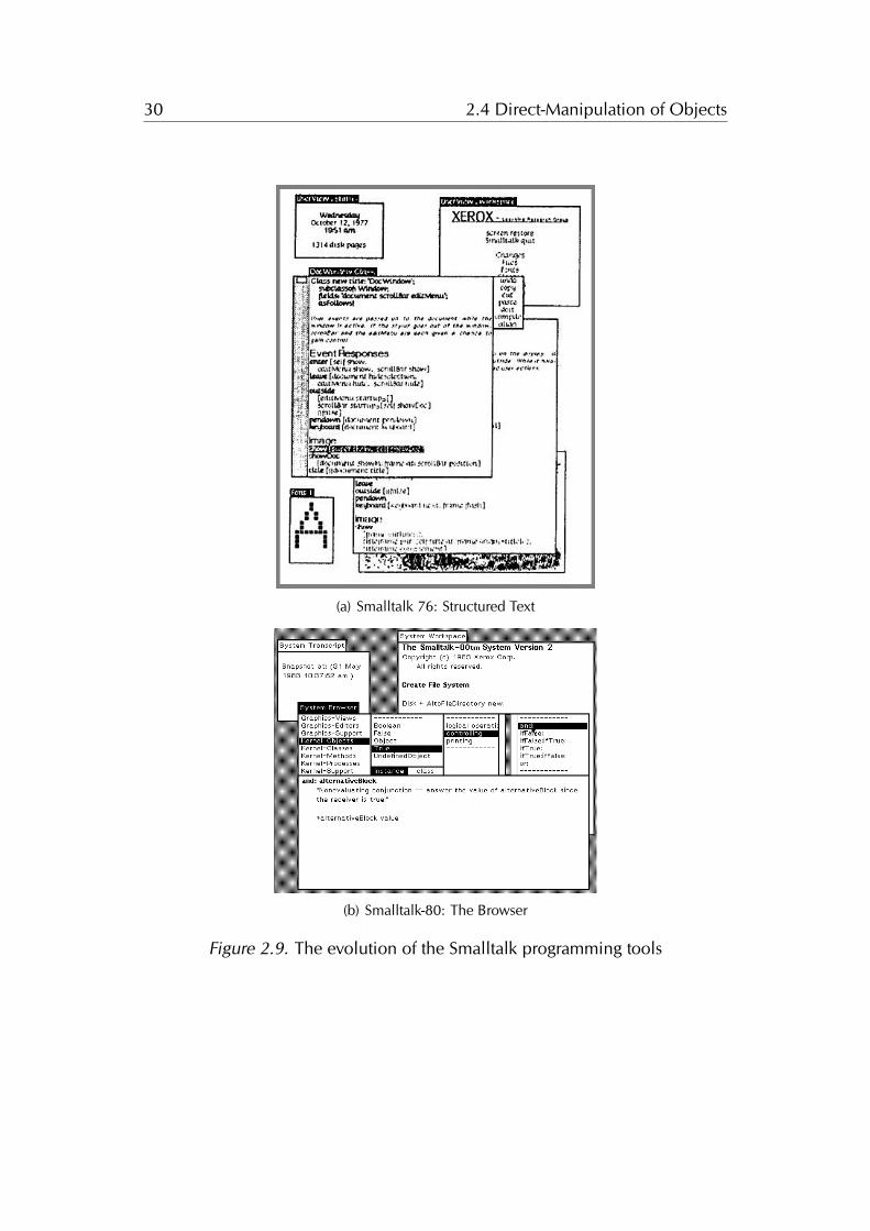
The first Smalltalk systems presented the objects as structured text contained inthe windows of the system. Figure 2.9(a) depicts a Smalltalk 76 system, the cen-tral window is presenting the class named DocWindow, subclass of Window,displaying several methods of the Event Responses and Image protocols.
In Smalltalk 76, the tool support for modifying the classes and methods ofthe system was based on editing a textual representation of the objects [45].Modern IDEs for mainstream OOP languages still rely on this interface, a code-centric interface with augmented text editors for changing the system. We de-scribed the mainstream IDEs in Chapter 2.2.
The following versions of Smalltalk replaced the structured text representa-tion and manipulation for a tool-based interface, that abstracted away from thesource-code. Figure 2.9(b) depicts a Smalltalk 80 system with several openedwindows containing the tools, the most important being a system browser, de-signed by Larry Tesler: a multi-paned class “browser” which allowed one toquickly and easily traverse all the classes and methods in the system [7].
30 2.4 Direct-Manipulation of Objects
Each�of�the�windows�shown�in�the�figure�belongs�to�some�subclass�of�Window;�the�subclass�handles�the�specific�content.�In�figure�2,�for�example,�the�user�has�awakened�a�window�for�editing�the�text�of�a�class.�Specific�to�this�content�is�the�ability�to�select�text�with�the�stylus,�scroll�the�text�up�and�down�by�entering�the�scroll�bar�at�the�window's�left,�and�send�specific�editing�messages�by�entering�the�menu�at�its�right.�The�class�has�thus�provided�a�simulation�of�itself�as�structured�text�(which�is�needed�for�printing�anyway).�This�text�in�turn�furnishes�a�text�editor�to�display�the�text�and�allow�it�to�be�manipulated.�Finally,�the�window�provides�a�spatial�channel�for�the�flow�of�information�in�both�directions�between�the�user�and�the�subject�of�investigation.�As�shown�in�figure�2,�the�user�has�just�drawn�the�stylus�through�the�text�of�the�message�show,�and�the�editor�has�responded�by�highlighting�the�text�and�noting�the�selection�internally.�
In�figure�3,�the�currently�active�window�supports�freehand�drawing.�It�provides�a�large�menu�from�which�to�choose�brush�shape�and�paint�tone�to�be�applied�when�the�stylus�is�depressed.�Another�window�interfaces�to�one�of�the�character�fonts,�allowing�the�user�to�design�new�fonts�at�will.�Yet�another�displays�the�time�of�day.�Each�of�the�windows�brings�its�own�semantics�to�the�uniform�"syntax"�of�stylus�motion�and�keyboard�action�available�to�the�investigator.�In�this�way,�the�underlying�metaphor�of�
used�with�Smalltalk,�and�they�are�not�the�subject�of�this�paper.
Figure�2.�Editing�text�
Page�4�of�16Smalltalk-76�Programming�System
30/11/2001http://users.ipa.net/~dwighth/smalltalk/St76/Smalltalk76ProgrammingSystem.html
(a) Smalltalk 76: Structured Text
(b) Smalltalk-80: The Browser
Figure 2.9. The evolution of the Smalltalk programming tools
31 2.4 Direct-Manipulation of Objects
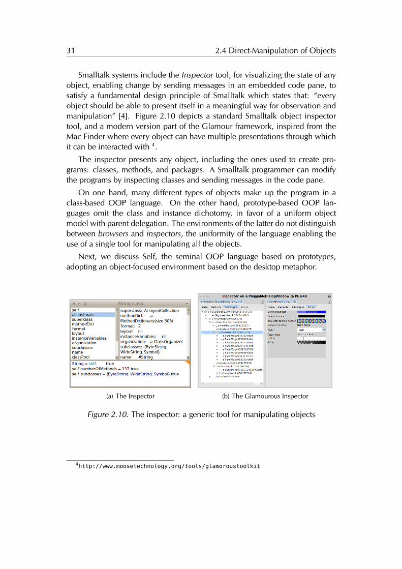
Smalltalk systems include the Inspector tool, for visualizing the state of anyobject, enabling change by sending messages in an embedded code pane, tosatisfy a fundamental design principle of Smalltalk which states that: “everyobject should be able to present itself in a meaningful way for observation andmanipulation” [4]. Figure 2.10 depicts a standard Smalltalk object inspectortool, and a modern version part of the Glamour framework, inspired from theMac Finder where every object can have multiple presentations through whichit can be interacted with 4.
The inspector presents any object, including the ones used to create pro-grams: classes, methods, and packages. A Smalltalk programmer can modifythe programs by inspecting classes and sending messages in the code pane.
On one hand, many different types of objects make up the program in aclass-based OOP language. On the other hand, prototype-based OOP lan-guages omit the class and instance dichotomy, in favor of a uniform objectmodel with parent delegation. The environments of the latter do not distinguishbetween browsers and inspectors, the uniformity of the language enabling theuse of a single tool for manipulating all the objects.
Next, we discuss Self, the seminal OOP language based on prototypes,adopting an object-focused environment based on the desktop metaphor.
(a) The Inspector (b) The Glamourous Inspector
Figure 2.10. The inspector: a generic tool for manipulating objects
4http://www.moosetechnology.org/tools/glamoroustoolkit
32 2.4 Direct-Manipulation of Objects
2.4.3 Self
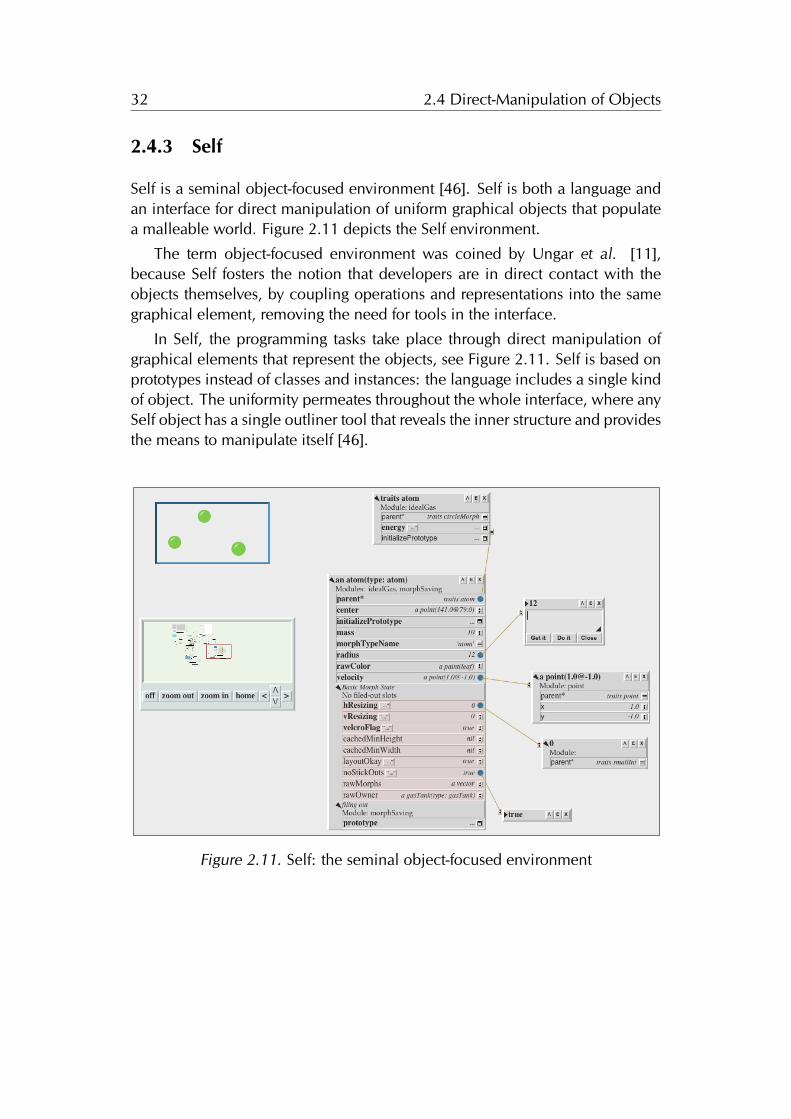
Self is a seminal object-focused environment [46]. Self is both a language andan interface for direct manipulation of uniform graphical objects that populatea malleable world. Figure 2.11 depicts the Self environment.
The term object-focused environment was coined by Ungar et al. [11],because Self fosters the notion that developers are in direct contact with theobjects themselves, by coupling operations and representations into the samegraphical element, removing the need for tools in the interface.
In Self, the programming tasks take place through direct manipulation ofgraphical elements that represent the objects, see Figure 2.11. Self is based onprototypes instead of classes and instances: the language includes a single kindof object. The uniformity permeates throughout the whole interface, where anySelf object has a single outliner tool that reveals the inner structure and providesthe means to manipulate itself [46].
Figure 2.11. Self: the seminal object-focused environment
33 2.4 Direct-Manipulation of Objects
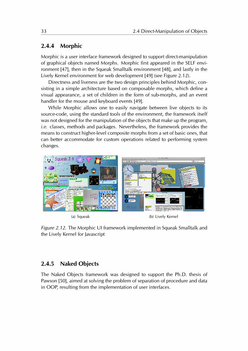
2.4.4 Morphic
Morphic is a user interface framework designed to support direct-manipulationof graphical objects named Morphs. Morphic first appeared in the SELF envi-ronment [47], then in the Squeak Smalltalk environment [48], and lastly in theLively Kernel environment for web development [49] (see Figure 2.12).
Directness and liveness are the two design principles behind Morphic, con-sisting in a simple architecture based on composable morphs, which define avisual appearance, a set of children in the form of sub-morphs, and an eventhandler for the mouse and keyboard events [49].
While Morphic allows one to easily navigate between live objects to itssource-code, using the standard tools of the environment, the framework itselfwas not designed for the manipulation of the objects that make up the program,i.e. classes, methods and packages. Nevertheless, the framework provides themeans to construct higher-level composite morphs from a set of basic ones, thatcan better accommodate for custom operations related to performing systemchanges.
(a) Squeak (b) Lively Kernel
Figure 2.12. The Morphic UI framework implemented in Squeak Smalltalk andthe Lively Kernel for Javascript
2.4.5 Naked Objects
The Naked Objects framework was designed to support the Ph.D. thesis ofPawson [50], aimed at solving the problem of separation of procedure and datain OOP, resulting from the implementation of user interfaces.
34 2.5 Conclusions
Pawson remarks that the objects representing the business entities, Cus-tomer, Product or Order, are often behaviorally weak, and that the missingfunctionality resides in procedures external to the object, which hinders behav-ioral completeness in object designs.
Thus, in naked objects all the domain objects are exposed explicitly, suchthat all user actions consist of viewing objects, and invoking behaviors on themby using contextual menus [50].
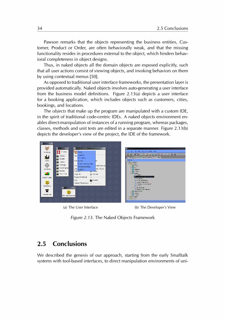
As opposed to traditional user interface frameworks, the presentation layer isprovided automatically. Naked objects involves auto-generating a user interfacefrom the business model definitions. Figure 2.13(a) depicts a user interfacefor a booking application, which includes objects such as customers, cities,bookings, and locations.
The objects that make up the program are manipulated with a custom IDE,in the spirit of traditional code-centric IDEs. A naked objects environment en-ables direct-manipulation of instances of a running program, whereas packages,classes, methods and unit tests are edited in a separate manner. Figure 2.13(b)depicts the developer’s view of the project, the IDE of the framework.
(a) The User Interface (b) The Developer’s View
Figure 2.13. The Naked Objects Framework
2.5 Conclusions
We described the genesis of our approach, starting from the early Smalltalksystems with tool-based interfaces, to direct manipulation environments of uni-
35 2.5 Conclusions
form objects in the case of Self, and of instances of the running programs as inthe Naked Objects framework.
In this dissertation we investigate a development environment for class-based OOP languages, that embraces the simplicity and directness of the in-terfaces of Self, of Naked Objects, modeling environments, and the alternativecode-centric IDEs. The directness results from designing the interface on thedesktop metaphor, as opposed to the tools metaphor. The reviewed interfacesalleviate many of the problems discussed in Section 1.5 related the real statemanagement, the visualization and the need for a fine-grained manipulation.
The IDE of a Naked Objects implementation enables modifying the pro-grams –the packages, classes, methods and unit tests– by turning to the devel-oper’s view of the project, which uses the standard interface of code-centricIDEs. We advocate for an environment that applies the same directness to theprogramming interface. On the other hand, the alternative code-centric IDEsprovide direct manipulation of the program, but do not provide for the manip-ulation of the instances.
In the Self programming language and environment both the instances andthe objects of the program co-exist in the interface, similarly to the Smalltalksystems, and the uniform object model based on prototypes enables the use ofa single tool for manipulating them, minimizing the presence of tools into anobject-focused environment.
Self is a prototype-based language that deliberately omits the concept ofclasses and instances. In our work we focus on class-based OOP languages,thus we investigate how to augment an object-focused environment to includemany different kinds of graphical elements: ideally one per each kind of objectin the system. The object-focused environment we envision includes graphicalelements tailored for manipulating diverse objects such as classes, meta-classes,methods, packages, tests, and code-critic rules.

36 2.5 Conclusions
Chapter 3
Object-Focused Environments
In the previous chapter of this dissertation we focused on the tools that enableprogramming, from the early punch card machines to the graphical interfaces ofpersonal computers, including the main tool used for the crafting of computersystems: the integrated development environment.
Drawing inspiration from several modeling tools, alternative code-centricenvironments, Self, and the Naked Objects framework, we advocate for devel-opment environments that make use of direct manipulation of objects. Thedirectness of the interface, and an unconstrained layout of fine grained graphi-cal elements helps to alleviate the conceptual and technical problems of IDEsdesigned around a tool-based interface, described in Section 1.5.
In this chapter we motivate the need for an object-focused environmentthat minimizes the presence of tools in favor of the manipulation of objects,and present our implementation of such an environment, named Gaucho. Theinterface of Gaucho is built on a desktop metaphor that can accommodate anextensible set of software engineering tasks.
Structure of the chapter. We start by relating object oriented programmingto modeling in Section 3.1, by discussing several scenarios depicting how dif-ferent software engineering practices solve a programming task. In Section 3.2we present an overview of the main concepts in Gaucho. We present our visionfor an integral modeling environment in Section 3.3. We describe the supportin Gaucho for OOP in Section 3.4, and conclude this chapter by reflecting onthe advantages of an object-focused environment in Section 3.5.
37
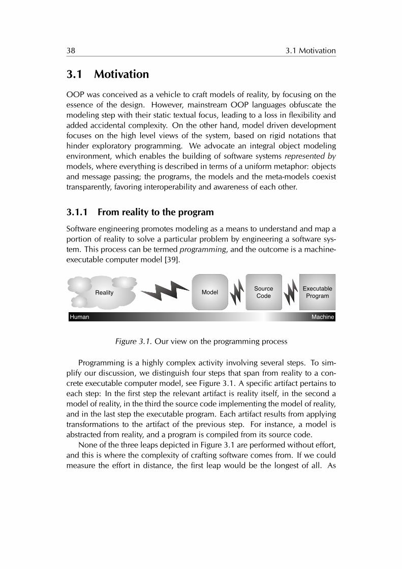
38 3.1 Motivation
3.1 Motivation
OOP was conceived as a vehicle to craft models of reality, by focusing on theessence of the design. However, mainstream OOP languages obfuscate themodeling step with their static textual focus, leading to a loss in flexibility andadded accidental complexity. On the other hand, model driven developmentfocuses on the high level views of the system, based on rigid notations thathinder exploratory programming. We advocate an integral object modelingenvironment, which enables the building of software systems represented bymodels, where everything is described in terms of a uniform metaphor: objectsand message passing; the programs, the models and the meta-models coexisttransparently, favoring interoperability and awareness of each other.
3.1.1 From reality to the program
Software engineering promotes modeling as a means to understand and map aportion of reality to solve a particular problem by engineering a software sys-tem. This process can be termed programming, and the outcome is a machine-executable computer model [39].
ExecutableProgramModel Source
Code
Human Machine
Reality
Figure 3.1. Our view on the programming process
Programming is a highly complex activity involving several steps. To sim-plify our discussion, we distinguish four steps that span from reality to a con-crete executable computer model, see Figure 3.1. A specific artifact pertains toeach step: In the first step the relevant artifact is reality itself, in the second amodel of reality, in the third the source code implementing the model of reality,and in the last step the executable program. Each artifact results from applyingtransformations to the artifact of the previous step. For instance, a model isabstracted from reality, and a program is compiled from its source code.
None of the three leaps depicted in Figure 3.1 are performed without effort,and this is where the complexity of crafting software comes from. If we couldmeasure the effort in distance, the first leap would be the longest of all. As
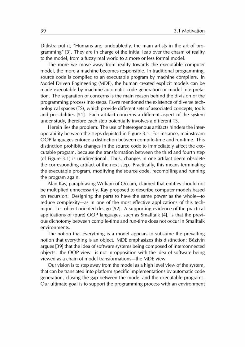
39 3.1 Motivation
Dijkstra put it, “Humans are, undoubtedly, the main artists in the art of pro-gramming” [3]. They are in charge of the initial leap over the chasm of realityto the model, from a fuzzy real world to a more or less formal model.
The more we move away from reality towards the executable computermodel, the more a machine becomes responsible. In traditional programming,source code is compiled to an executable program by machine compilers. InModel Driven Engineering (MDE), the human created explicit models can bemade executable by machine automatic code generation or model interpreta-tion. The separation of concerns is the main reason behind the division of theprogramming process into steps. Favre mentioned the existence of diverse tech-nological spaces (TS), which provide different sets of associated concepts, toolsand possibilities [51]. Each artifact concerns a different aspect of the systemunder study, therefore each step potentially involves a different TS.
Herein lies the problem: The use of heterogenous artifacts hinders the inter-operability between the steps depicted in Figure 3.1. For instance, mainstreamOOP languages enforce a distinction between compile-time and run-time. Thisdistinction prohibits changes in the source code to immediately affect the exe-cutable program, because the transformation between the third and fourth step(of Figure 3.1) is unidirectional. Thus, changes in one artifact deem obsoletethe corresponding artifact of the next step. Practically, this means terminatingthe executable program, modifying the source code, recompiling and runningthe program again.
Alan Kay, paraphrasing William of Occam, claimed that entities should notbe multiplied unnecessarily. Kay proposed to describe computer models basedon recursion: Designing the parts to have the same power as the whole—toreduce complexity—as in one of the most effective applications of this tech-nique, i.e. object-oriented design [52]. A supporting evidence of the practicalapplications of (pure) OOP languages, such as Smalltalk [4], is that the previ-ous dichotomy between compile-time and run-time does not occur in Smalltalkenvironments.
The notion that everything is a model appears to subsume the prevailingnotion that everything is an object. MDE emphasizes this distinction: Bézivinargues [39] that the idea of software systems being composed of interconnectedobjects—the OOP view—is not in opposition with the idea of software beingviewed as a chain of model transformations—the MDE view.
Our vision is to step away from the model as a high level view of the system,that can be translated into platform specific implementations by automatic codegeneration, closing the gap between the model and the executable programs.Our ultimate goal is to support the programming process with an environment
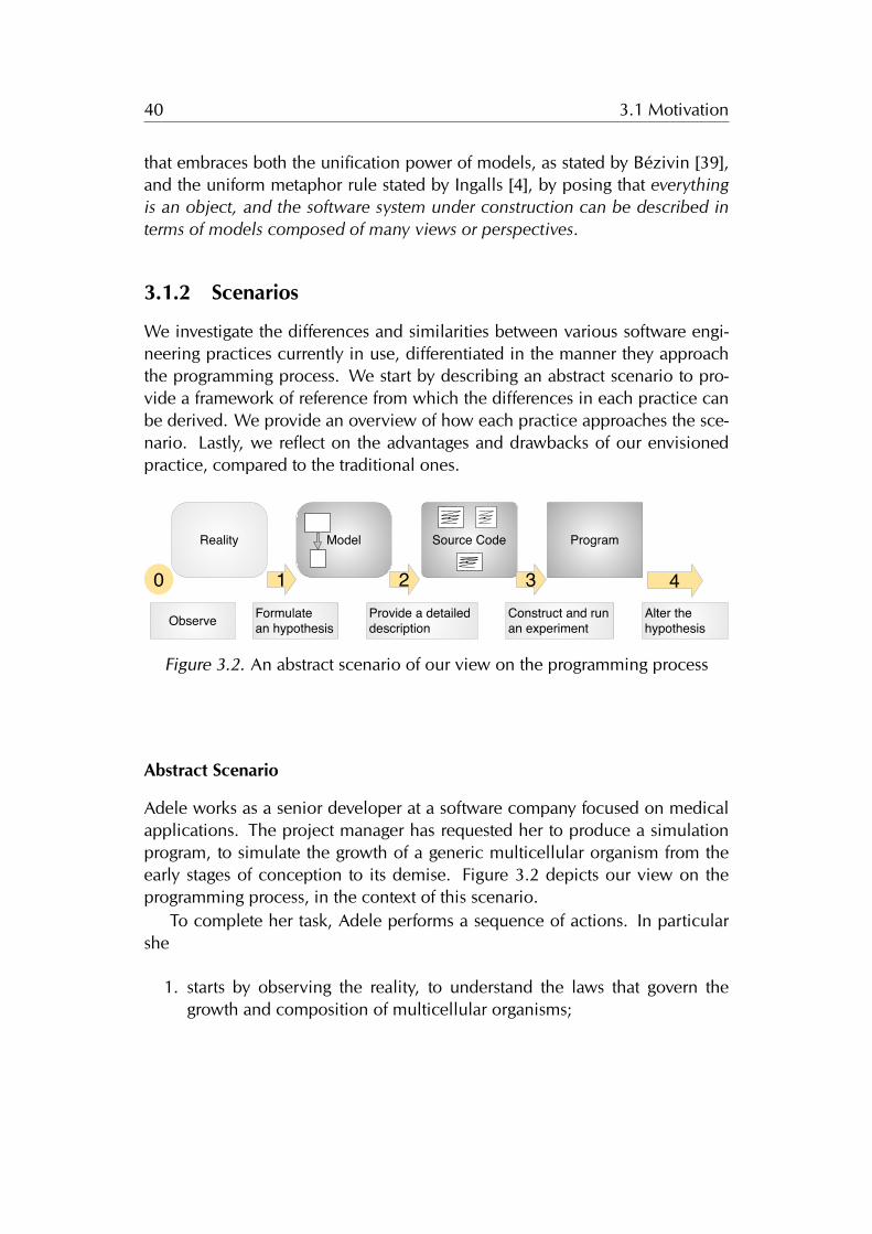
40 3.1 Motivation
that embraces both the unification power of models, as stated by Bézivin [39],and the uniform metaphor rule stated by Ingalls [4], by posing that everythingis an object, and the software system under construction can be described interms of models composed of many views or perspectives.
3.1.2 Scenarios
We investigate the differences and similarities between various software engi-neering practices currently in use, differentiated in the manner they approachthe programming process. We start by describing an abstract scenario to pro-vide a framework of reference from which the differences in each practice canbe derived. We provide an overview of how each practice approaches the sce-nario. Lastly, we reflect on the advantages and drawbacks of our envisionedpractice, compared to the traditional ones.
ProgramSource Code
1 3
Model
2
Reality
40
Observe Formulatean hypothesis
Provide a detailed description
Construct and run an experiment
Alter thehypothesis
Figure 3.2. An abstract scenario of our view on the programming process
Abstract Scenario
Adele works as a senior developer at a software company focused on medicalapplications. The project manager has requested her to produce a simulationprogram, to simulate the growth of a generic multicellular organism from theearly stages of conception to its demise. Figure 3.2 depicts our view on theprogramming process, in the context of this scenario.
To complete her task, Adele performs a sequence of actions. In particularshe
1. starts by observing the reality, to understand the laws that govern thegrowth and composition of multicellular organisms;
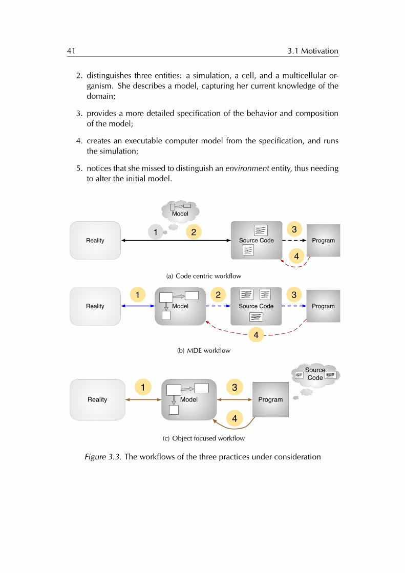
41 3.1 Motivation
2. distinguishes three entities: a simulation, a cell, and a multicellular or-ganism. She describes a model, capturing her current knowledge of thedomain;
3. provides a more detailed specification of the behavior and compositionof the model;
4. creates an executable computer model from the specification, and runsthe simulation;
5. notices that she missed to distinguish an environment entity, thus needingto alter the initial model.
ProgramSource Code1 3
Model
2
4
Reality
(a) Code centric workflow
ProgramSource Code1 3
Model2
4
Reality
(b) MDE workflow
Program1 3
ModelReality
4
Source Code
(c) Object focused workflow
Figure 3.3. The workflows of the three practices under consideration
42 3.1 Motivation
We describe how this happens for three software engineering practices, thecode centric approach (e.g. by using a mainstream OOP like Java), the MDEapproach, and the object-focused modeling approach, which is our vision. InFigure 3.3 we detail the workflow of each practice.
Code Centric Workflow
Mainstream OOP practices revolve around the notion of source code. Modelsare only implicitly part of the programming process, therefore Adele omits de-scribing it, and goes directly to writing the source code. She refines the specifi-cation by typing precise class and method definitions. Afterwards she compilesand runs an executable program. When Adele notices that she missed to distin-guish the environment entity, she is forced to discard the executable, then adda new class definition to the source code, and perform the necessary textualeditions to integrate it into the existing model. Given that the source code andthe executable are in different technological spaces, the program is deemedobsolete because the source code and the executable program cannot directlyinteroperate with each other. The latter is the main reason why code-centricpractices hinder flexible modeling activities.
MDE Workflow
Adele describes the model using a modeling language, such as UML. Thenshe uses MDE tools to automatically generate the source code, to ultimatelycompile the source code into a platform dependent computer executable pro-gram. Model transformation (MT) is an essential part of MDE, thus severaltools—termed roundtrip engineering tools—support UML transformations andsynchronization between the diagrams and the source code. The advantage isthat they automatically bridge the gap between the diagrams and the code, en-abling the use of high level views for comprehending the model without losingthe features offered by the tools for writing the programs.
Roundtrip engineering tools have not been widely adopted because the di-agrams are inert models, while the source code remains the complete specifi-cation of the system under construction [53]. The latter tools are mainly usedas palliatives for resolving navigation and comprehension issues when dealingwith source code [37]. The value of MDE models increases when they serveother purposes than just contemplative models used only for documentationor visualization purposes [39]. This occurs when MDE models are made exe-cutable by introducing a set of possible actions together with a complete code
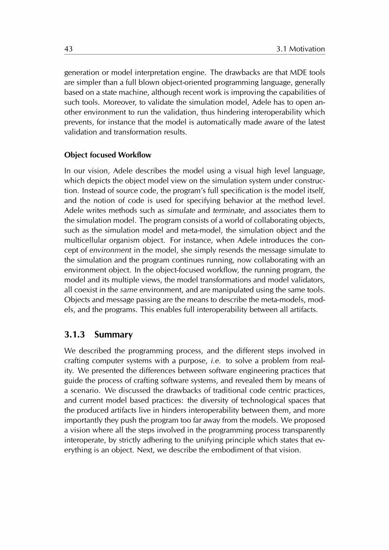
43 3.1 Motivation
generation or model interpretation engine. The drawbacks are that MDE toolsare simpler than a full blown object-oriented programming language, generallybased on a state machine, although recent work is improving the capabilities ofsuch tools. Moreover, to validate the simulation model, Adele has to open an-other environment to run the validation, thus hindering interoperability whichprevents, for instance that the model is automatically made aware of the latestvalidation and transformation results.
Object focused Workflow
In our vision, Adele describes the model using a visual high level language,which depicts the object model view on the simulation system under construc-tion. Instead of source code, the program’s full specification is the model itself,and the notion of code is used for specifying behavior at the method level.Adele writes methods such as simulate and terminate, and associates them tothe simulation model. The program consists of a world of collaborating objects,such as the simulation model and meta-model, the simulation object and themulticellular organism object. For instance, when Adele introduces the con-cept of environment in the model, she simply resends the message simulate tothe simulation and the program continues running, now collaborating with anenvironment object. In the object-focused workflow, the running program, themodel and its multiple views, the model transformations and model validators,all coexist in the same environment, and are manipulated using the same tools.Objects and message passing are the means to describe the meta-models, mod-els, and the programs. This enables full interoperability between all artifacts.
3.1.3 Summary
We described the programming process, and the different steps involved incrafting computer systems with a purpose, i.e. to solve a problem from real-ity. We presented the differences between software engineering practices thatguide the process of crafting software systems, and revealed them by means ofa scenario. We discussed the drawbacks of traditional code centric practices,and current model based practices: the diversity of technological spaces thatthe produced artifacts live in hinders interoperability between them, and moreimportantly they push the program too far away from the models. We proposeda vision where all the steps involved in the programming process transparentlyinteroperate, by strictly adhering to the unifying principle which states that ev-erything is an object. Next, we describe the embodiment of that vision.
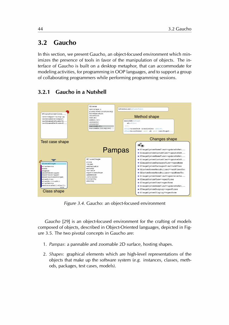
44 3.2 Gaucho
3.2 Gaucho
In this section, we present Gaucho, an object-focused environment which min-imizes the presence of tools in favor of the manipulation of objects. The in-terface of Gaucho is built on a desktop metaphor, that can accommodate formodeling activities, for programming in OOP languages, and to support a groupof collaborating programmers while performing programming sessions.
3.2.1 Gaucho in a Nutshell
Test case shape
Class shape
Method shape
Changes shape
Pampas
Figure 3.4. Gaucho: an object-focused environment
Gaucho [29] is an object-focused environment for the crafting of modelscomposed of objects, described in Object-Oriented languages, depicted in Fig-ure 3.5. The two pivotal concepts in Gaucho are:
1. Pampas: a pannable and zoomable 2D surface, hosting shapes.
2. Shapes: graphical elements which are high-level representations of theobjects that make up the software system (e.g. instances, classes, meth-ods, packages, test cases, models).
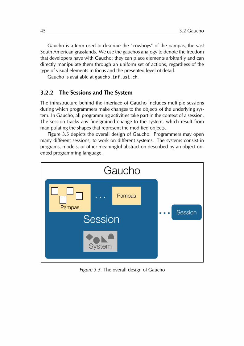
45 3.2 Gaucho
Gaucho is a term used to describe the “cowboys” of the pampas, the vastSouth American grasslands. We use the gauchos analogy to denote the freedomthat developers have with Gaucho: they can place elements arbitrarily and candirectly manipulate them through an uniform set of actions, regardless of thetype of visual elements in focus and the presented level of detail.
Gaucho is available at gaucho.inf.usi.ch.
3.2.2 The Sessions and The System
The infrastructure behind the interface of Gaucho includes multiple sessionsduring which programmers make changes to the objects of the underlying sys-tem. In Gaucho, all programming activities take part in the context of a session.The session tracks any fine-grained change to the system, which result frommanipulating the shapes that represent the modified objects.
Figure 3.5 depicts the overall design of Gaucho. Programmers may openmany different sessions, to work on different systems. The systems consist inprograms, models, or other meaningful abstraction described by an object ori-ented programming language.
Gaucho
SessionPampas
. .. Pampas
. .. Session
System
Figure 3.5. The overall design of Gaucho
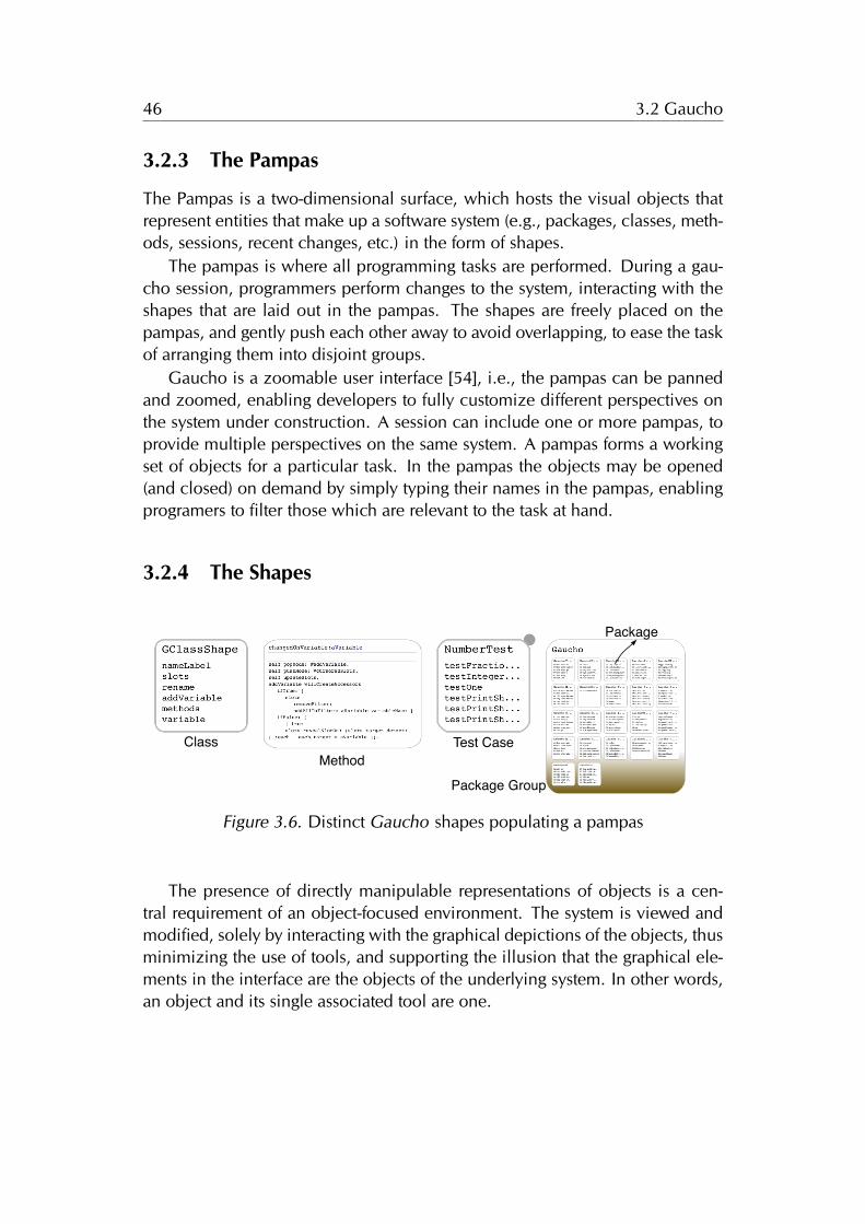
46 3.2 Gaucho
3.2.3 The Pampas
The Pampas is a two-dimensional surface, which hosts the visual objects thatrepresent entities that make up a software system (e.g., packages, classes, meth-ods, sessions, recent changes, etc.) in the form of shapes.
The pampas is where all programming tasks are performed. During a gau-cho session, programmers perform changes to the system, interacting with theshapes that are laid out in the pampas. The shapes are freely placed on thepampas, and gently push each other away to avoid overlapping, to ease the taskof arranging them into disjoint groups.
Gaucho is a zoomable user interface [54], i.e., the pampas can be pannedand zoomed, enabling developers to fully customize different perspectives onthe system under construction. A session can include one or more pampas, toprovide multiple perspectives on the same system. A pampas forms a workingset of objects for a particular task. In the pampas the objects may be opened(and closed) on demand by simply typing their names in the pampas, enablingprogramers to filter those which are relevant to the task at hand.
3.2.4 The Shapes
Class Test CaseMethod
Package Group
Package
Figure 3.6. Distinct Gaucho shapes populating a pampas
The presence of directly manipulable representations of objects is a cen-tral requirement of an object-focused environment. The system is viewed andmodified, solely by interacting with the graphical depictions of the objects, thusminimizing the use of tools, and supporting the illusion that the graphical ele-ments in the interface are the objects of the underlying system. In other words,an object and its single associated tool are one.
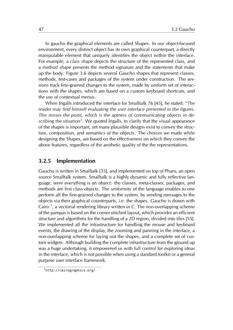
47 3.2 Gaucho
In gaucho the graphical elements are called Shapes. In our object-focusedenvironment, every distinct object has its own graphical counterpart, a directlymanipulable element that uniquely identifies the object within the interface.For example, a class shape depicts the structure of the represented class, anda method shape presents the method signature and the statements that makeup the body. Figure 3.6 depicts several Gaucho shapes that represent classes,methods, test-cases and packages of the system under construction. The ses-sions track fine-grained changes to the system, made by uniform set of interac-tions with the shapes, which are based on a custom keyboard shortcuts, andthe use of contextual menus.
When Ingalls introduced the interface for Smalltalk 76 [45], he stated: “Thereader may find himself evaluating the user interface presented in the figures.This misses the point, which is the aptness of communicating objects in de-scribing the situation”. We quoted Ingalls, to clarify that the visual appearanceof the shapes is important, yet many plausible designs exist to convey the struc-ture, composition, and semantics of the objects. The choices we made whiledesigning the Shapes, are based on the effectiveness on which they convey theabove features, regardless of the aesthetic quality of the the representations.
3.2.5 Implementation
Gaucho is written in Smalltalk [35], and implemented on top of Pharo, an opensource Smalltalk system. Smalltalk is a highly dynamic and fully reflective lan-guage, were everything is an object: the classes, meta-classes, packages, andmethods are first class objects. The uniformity of the language enables to oneperform all the fine-grained changes to the system, by sending messages to theobjects via their graphical counterparts, i.e. the shapes. Gaucho is drawn withCairo 1, a vectorial rendering library written in C. The non-overlapping schemeof the pampas is based on the corner stitched layout, which provides an efficientstructure and algorithms for the handling of a 2D region, divided into tiles [55].We implemented all the infrastructure for handling the mouse and keyboardevents, the drawing of the display, the zooming and panning in the interface, anon-overlapping scheme for laying out the shapes, and a complete set of cus-tom widgets. Although building the complete infrastructure from the ground upwas a huge undertaking, it empowered us with full control for exploring ideasin the interface, which is not possible when using a standard toolkit or a generalpurpose user interface framework.
1http://cairographics.org/
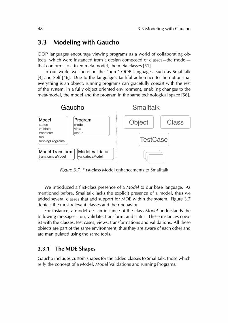
48 3.3 Modeling with Gaucho
3.3 Modeling with Gaucho
OOP languages encourage viewing programs as a world of collaborating ob-jects, which were instanced from a design composed of classes—the model—that conforms to a fixed meta-model, the meta-classes [51].
In our work, we focus on the “pure” OOP languages, such as Smalltalk[4] and Self [46]. Due to the language’s faithful adherence to the notion thateverything is an object, running programs can gracefully coexist with the restof the system, in a fully object oriented environment, enabling changes to themeta-model, the model and the program in the same technological space [56].
ModelstatusvalidatetransformrunrunningPrograms
Object
Model Validatorvalidate: aModel
Model Transformtransform: aModel
SmalltalkGaucho
TestCase
ClassProgrammodelviewstatus
Figure 3.7. First-class Model enhancements to Smalltalk
We introduced a first-class presence of a Model to our base language. Asmentioned before, Smalltalk lacks the explicit presence of a model, thus weadded several classes that add support for MDE within the system. Figure 3.7depicts the most relevant classes and their behavior.
For instance, a model i.e. an instance of the class Model understands thefollowing messages: run, validate, transform, and status. These instances coex-ist with the classes, test cases, views, transformations and validations. All theseobjects are part of the same environment, thus they are aware of each other andare manipulated using the same tools.
3.3.1 The MDE Shapes
Gaucho includes custom shapes for the added classes to Smalltalk, those whichreify the concept of a Model, Model Validations and running Programs.
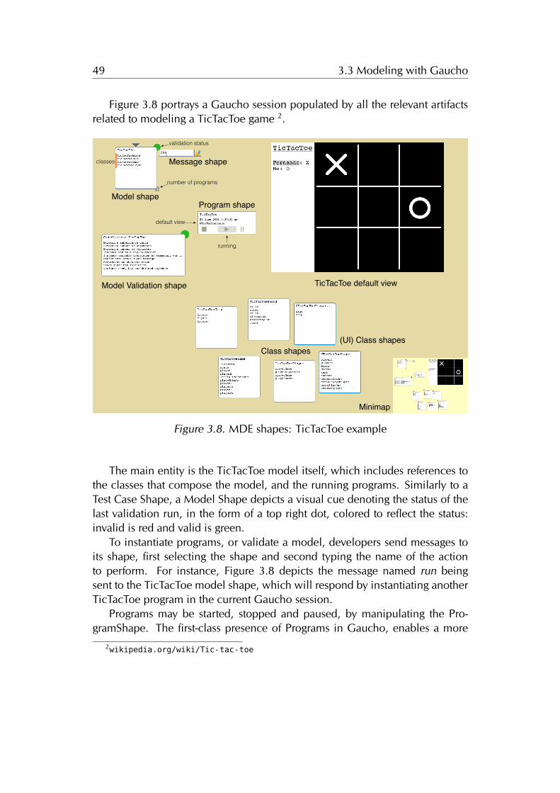
49 3.3 Modeling with Gaucho
Figure 3.8 portrays a Gaucho session populated by all the relevant artifactsrelated to modeling a TicTacToe game 2.
Model shapeProgram shape
TicTacToe default view
Class shapes(UI) Class shapes
Minimap
number of programs
running
validation status
Message shape
default view
classes
Model Validation shape
Figure 3.8. MDE shapes: TicTacToe example
The main entity is the TicTacToe model itself, which includes references tothe classes that compose the model, and the running programs. Similarly to aTest Case Shape, a Model Shape depicts a visual cue denoting the status of thelast validation run, in the form of a top right dot, colored to reflect the status:invalid is red and valid is green.
To instantiate programs, or validate a model, developers send messages toits shape, first selecting the shape and second typing the name of the actionto perform. For instance, Figure 3.8 depicts the message named run beingsent to the TicTacToe model shape, which will respond by instantiating anotherTicTacToe program in the current Gaucho session.
Programs may be started, stopped and paused, by manipulating the Pro-gramShape. The first-class presence of Programs in Gaucho, enables a more
2wikipedia.org/wiki/Tic-tac-toe
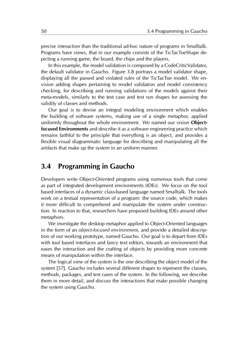
50 3.4 Programming in Gaucho
precise interaction than the traditional ad-hoc nature of programs in Smalltalk.Programs have views, that in our example consists of the TicTacToeShape de-picting a running game, the board, the chips and the players.
In this example, the model validation is composed by a CodeCriticValidator,the default validator in Gaucho. Figure 3.8 portrays a model validator shape,displaying all the passed and violated rules of the TicTacToe model. We en-vision adding shapes pertaining to model validation and model consistencychecking, for describing and running validations of the models against theirmeta-models, similarly to the test case and test run shapes for assessing thevalidity of classes and methods.
Our goal is to devise an integral modeling environment which enablesthe building of software systems, making use of a single metaphor, applieduniformly throughout the whole environment. We named our vision Object-focused Environments and describe it as a software engineering practice whichremains faithful to the principle that everything is an object, and provides aflexible visual diagrammatic language for describing and manipulating all theartifacts that make up the system in an uniform manner.
3.4 Programming in Gaucho
Developers write Object-Oriented programs using numerous tools that comeas part of integrated development environments (IDEs). We focus on the toolbased interfaces of a dynamic class-based language named Smalltalk. The toolswork on a textual representation of a program: the source code, which makesit more difficult to comprehend and manipulate the system under construc-tion. In reaction to that, researchers have proposed building IDEs around othermetaphors.
We investigate the desktop metaphor applied to Object-Oriented languagesin the form of an object-focused environment, and provide a detailed descrip-tion of our working prototype, named Gaucho. Our goal is to depart from IDEswith tool based interfaces and fancy text editors, towards an environment thateases the interaction and the crafting of objects by providing more concretemeans of manipulation within the interface.
The logical view of the system is the one describing the object model of thesystem [57]. Gaucho includes several different shapes to represent the classes,methods, packages, and test cases of the system. In the following, we describethem in more detail, and discuss the interactions that make possible changingthe system using Gaucho.
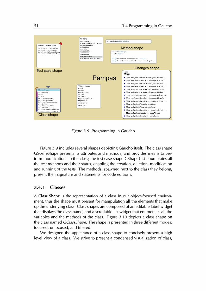
51 3.4 Programming in Gaucho
Test case shape
Class shape
Method shape
Changes shape
Pampas
Figure 3.9. Programming in Gaucho
Figure 3.9 includes several shapes depicting Gaucho itself: The class shapeGSceneShape presents its attributes and methods, and provides means to per-form modifications to the class; the test case shape GShapeTest enumerates allthe test methods and their status, enabling the creation, deletion, modificationand running of the tests. The methods, spawned next to the class they belong,present their signature and statements for code editions.
3.4.1 Classes
A Class Shape is the representation of a class in our object-focused environ-ment, thus the shape must present for manipulation all the elements that makeup the underlying class. Class shapes are composed of an editable label widgetthat displays the class name, and a scrollable list widget that enumerates all thevariables and the methods of the class. Figure 3.10 depicts a class shape onthe class named GClassShape. The shape is presented in three different modes:focused, unfocused, and filtered.
We designed the appearance of a class shape to concisely present a highlevel view of a class. We strive to present a condensed visualization of class,
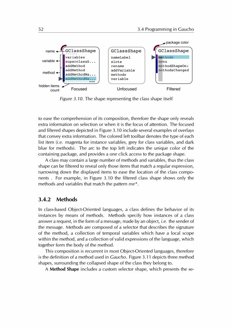
52 3.4 Programming in Gaucho
UnfocusedFocused Filtered
variable
method
name
hidden itemscount
package color
Figure 3.10. The shape representing the class shape itself
to ease the comprehension of its composition, therefore the shape only revealsextra information on selection or when it is the focus of attention. The focusedand filtered shapes depicted in Figure 3.10 include several examples of overlaysthat convey extra information. The colored left toolbar denotes the type of eachlist item (i.e. magenta for instance variables, grey for class variables, and darkblue for methods). The arc to the top left indicates the unique color of thecontaining package, and provides a one click access to the package shape.
A class may contain a large number of methods and variables, thus the classshape can be filtered to reveal only those items that match a regular expression,narrowing down the displayed items to ease the location of the class compo-nents . For example, in Figure 3.10 the filtered class shape shows only themethods and variables that match the pattern me*.
3.4.2 Methods
In class-based Object-Oriented languages, a class defines the behavior of itsinstances by means of methods. Methods specify how instances of a classanswer a request, in the form of a message, made by an object, i.e. the sender ofthe message. Methods are composed of a selector that describes the signatureof the method, a collection of temporal variables which have a local scopewithin the method, and a collection of valid expressions of the language, whichtogether form the body of the method.
This composition is recurrent in most Object-Oriented languages, thereforeis the definition of a method used in Gaucho. Figure 3.11 depicts three methodshapes, surrounding the collapsed shape of the class they belong to.
A Method Shape includes a custom selector shape, which presents the se-
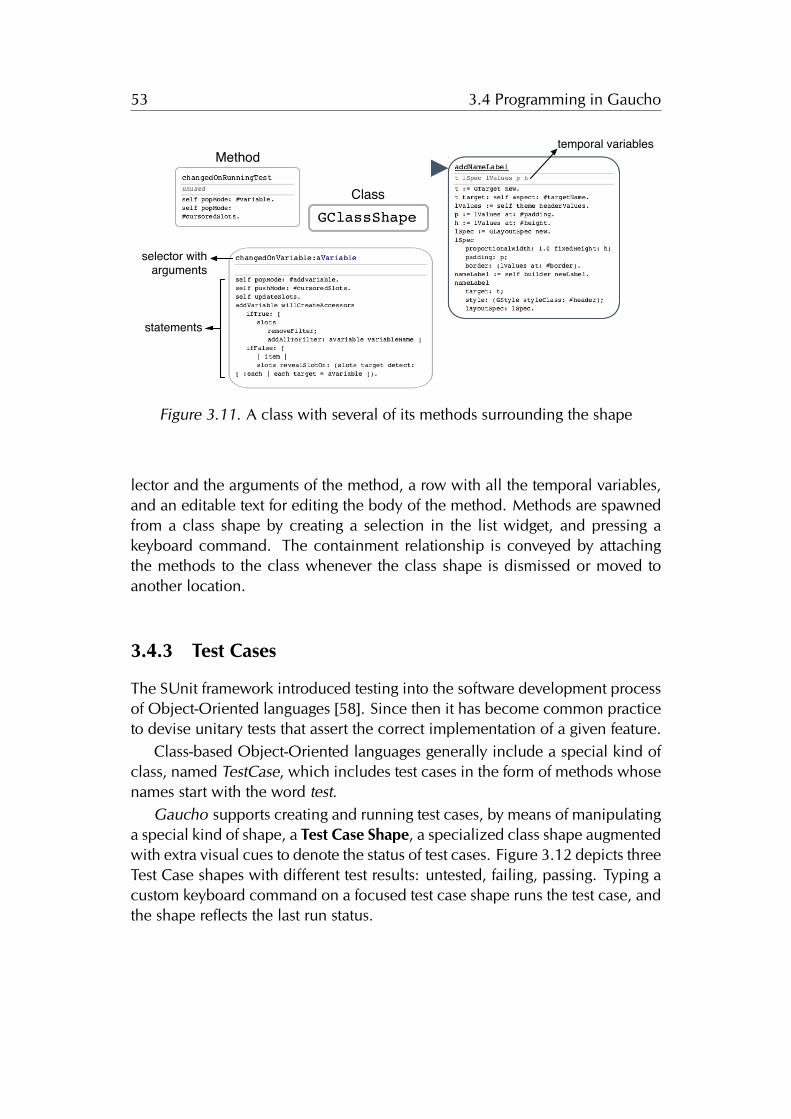
53 3.4 Programming in Gaucho
Class
Method
statements
selector with arguments
temporal variables
Figure 3.11. A class with several of its methods surrounding the shape
lector and the arguments of the method, a row with all the temporal variables,and an editable text for editing the body of the method. Methods are spawnedfrom a class shape by creating a selection in the list widget, and pressing akeyboard command. The containment relationship is conveyed by attachingthe methods to the class whenever the class shape is dismissed or moved toanother location.
3.4.3 Test Cases
The SUnit framework introduced testing into the software development processof Object-Oriented languages [58]. Since then it has become common practiceto devise unitary tests that assert the correct implementation of a given feature.
Class-based Object-Oriented languages generally include a special kind ofclass, named TestCase, which includes test cases in the form of methods whosenames start with the word test.
Gaucho supports creating and running test cases, by means of manipulatinga special kind of shape, a Test Case Shape, a specialized class shape augmentedwith extra visual cues to denote the status of test cases. Figure 3.12 depicts threeTest Case shapes with different test results: untested, failing, passing. Typing acustom keyboard command on a focused test case shape runs the test case, andthe shape reflects the last run status.
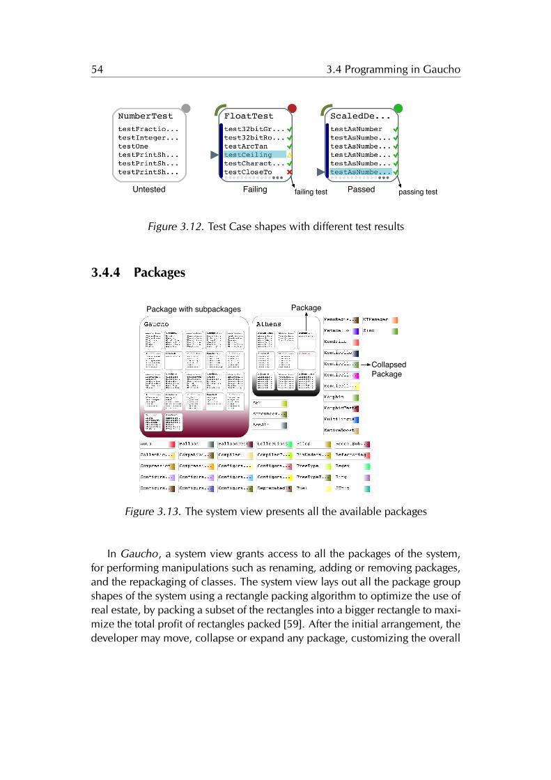
54 3.4 Programming in Gaucho
Untested Failing Passedfailing test passing test
Figure 3.12. Test Case shapes with different test results
3.4.4 Packages
Package with subpackages Package
CollapsedPackage
Figure 3.13. The system view presents all the available packages
In Gaucho, a system view grants access to all the packages of the system,for performing manipulations such as renaming, adding or removing packages,and the repackaging of classes. The system view lays out all the package groupshapes of the system using a rectangle packing algorithm to optimize the use ofreal estate, by packing a subset of the rectangles into a bigger rectangle to maxi-mize the total profit of rectangles packed [59]. After the initial arrangement, thedeveloper may move, collapse or expand any package, customizing the overall
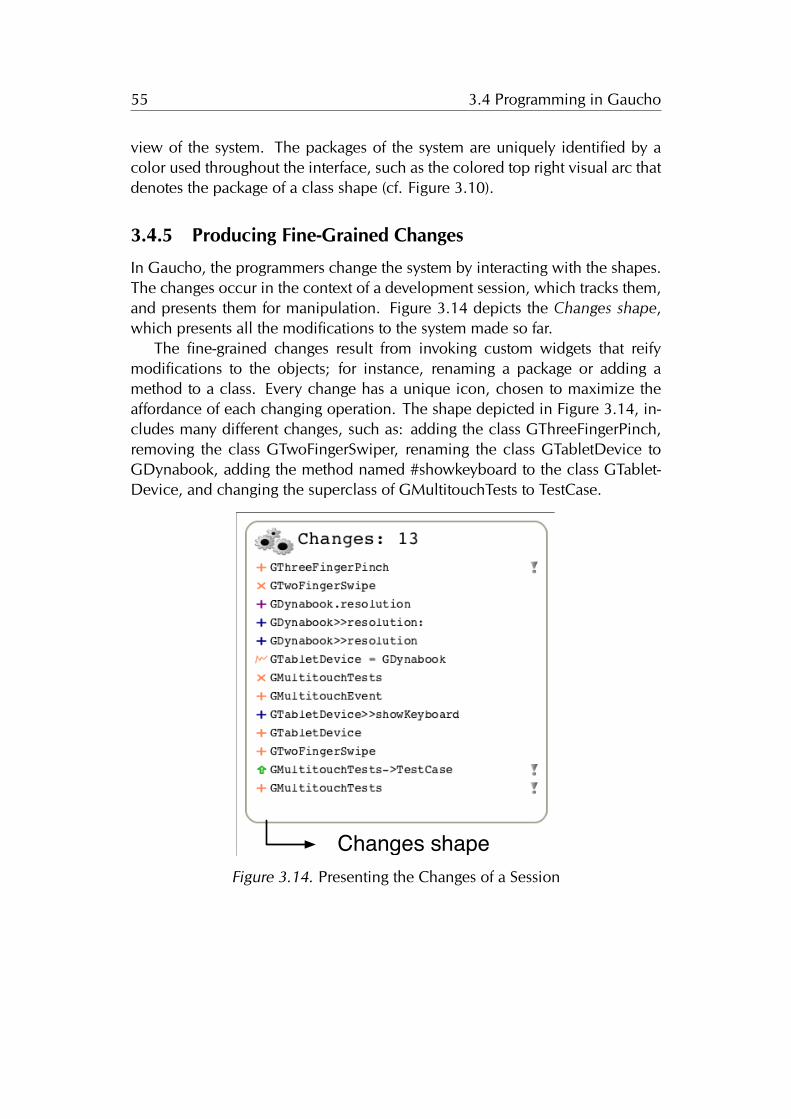
55 3.4 Programming in Gaucho
view of the system. The packages of the system are uniquely identified by acolor used throughout the interface, such as the colored top right visual arc thatdenotes the package of a class shape (cf. Figure 3.10).
3.4.5 Producing Fine-Grained Changes
In Gaucho, the programmers change the system by interacting with the shapes.The changes occur in the context of a development session, which tracks them,and presents them for manipulation. Figure 3.14 depicts the Changes shape,which presents all the modifications to the system made so far.
The fine-grained changes result from invoking custom widgets that reifymodifications to the objects; for instance, renaming a package or adding amethod to a class. Every change has a unique icon, chosen to maximize theaffordance of each changing operation. The shape depicted in Figure 3.14, in-cludes many different changes, such as: adding the class GThreeFingerPinch,removing the class GTwoFingerSwiper, renaming the class GTabletDevice toGDynabook, adding the method named #showkeyboard to the class GTablet-Device, and changing the superclass of GMultitouchTests to TestCase.
Test case shapeDevelopers shape
Changes shape
Notes shape
Change Shape
Class Shape
Pampas
Method Shape
Number Of Changes
Figure 3.14. Presenting the Changes of a Session
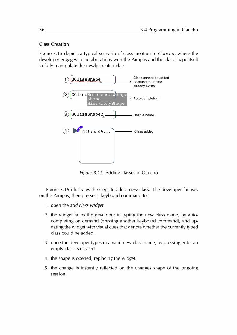
56 3.4 Programming in Gaucho
Class Creation
Figure 3.15 depicts a typical scenario of class creation in Gaucho, where thedeveloper engages in collaborations with the Pampas and the class shape itselfto fully manipulate the newly created class.
Class cannot be added because the name already exists
Auto-completion
Usable name
1
2
3
Class added4
Figure 3.15. Adding classes in Gaucho
Figure 3.15 illustrates the steps to add a new class. The developer focuseson the Pampas, then presses a keyboard command to:
1. open the add class widget
2. the widget helps the developer in typing the new class name, by auto-completing on demand (pressing another keyboard command), and up-dating the widget with visual cues that denote whether the currently typedclass could be added.
3. once the developer types in a valid new class name, by pressing enter anempty class is created
4. the shape is opened, replacing the widget.
5. the change is instantly reflected on the changes shape of the ongoingsession.
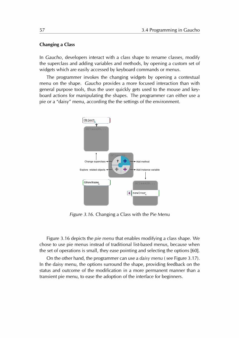
57 3.4 Programming in Gaucho
Changing a Class
In Gaucho, developers interact with a class shape to rename classes, modifythe superclass and adding variables and methods, by opening a custom set ofwidgets which are easily accessed by keyboard commands or menus.
The programmer invokes the changing widgets by opening a contextualmenu on the shape. Gaucho provides a more focused interaction than withgeneral purpose tools, thus the user quickly gets used to the mouse and key-board actions for manipulating the shapes. The programmer can either use apie or a “daisy” menu, according the the settings of the environment.
Change superclass Add method
Add instance variableExplore related objects
Figure 3.16. Changing a Class with the Pie Menu
Figure 3.16 depicts the pie menu that enables modifying a class shape. Wechose to use pie menus instead of traditional list-based menus, because whenthe set of operations is small, they ease pointing and selecting the options [60].
On the other hand, the programmer can use a daisy menu ( see Figure 3.17).In the daisy menu, the options surround the shape, providing feedback on thestatus and outcome of the modification in a more permanent manner than atransient pie menu, to ease the adoption of the interface for beginners.
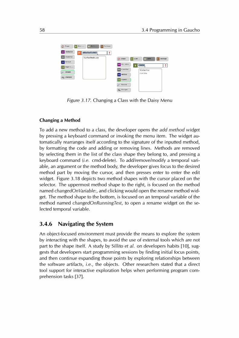
58 3.4 Programming in Gaucho
Figure 3.17. Changing a Class with the Daisy Menu
Changing a Method
To add a new method to a class, the developer opens the add method widgetby pressing a keyboard command or invoking the menu item. The widget au-tomatically rearranges itself according to the signature of the inputted method,by formatting the code and adding or removing lines. Methods are removedby selecting them in the list of the class shape they belong to, and pressing akeyboard command (i.e. cmd-delete). To add/remove/modify a temporal vari-able, an argument or the method body, the developer gives focus to the desiredmethod part by moving the cursor, and then presses enter to enter the editwidget. Figure 3.18 depicts two method shapes with the cursor placed on theselector. The uppermost method shape to the right, is focused on the methodnamed changedOnVariable:, and clicking would open the rename method wid-get. The method shape to the bottom, is focused on an temporal variable of themethod named changedOnRunningTest, to open a rename widget on the se-lected temporal variable.
3.4.6 Navigating the System
An object-focused environment must provide the means to explore the systemby interacting with the shapes, to avoid the use of external tools which are notpart to the shape itself. A study by Sillito et al. on developers habits [10], sug-gests that developers start programming sessions by finding initial focus points,and then continue expanding those points by exploring relationships betweenthe software artifacts, i.e., the objects. Other researchers stated that a directtool support for interactive exploration helps when performing program com-prehension tasks [37].
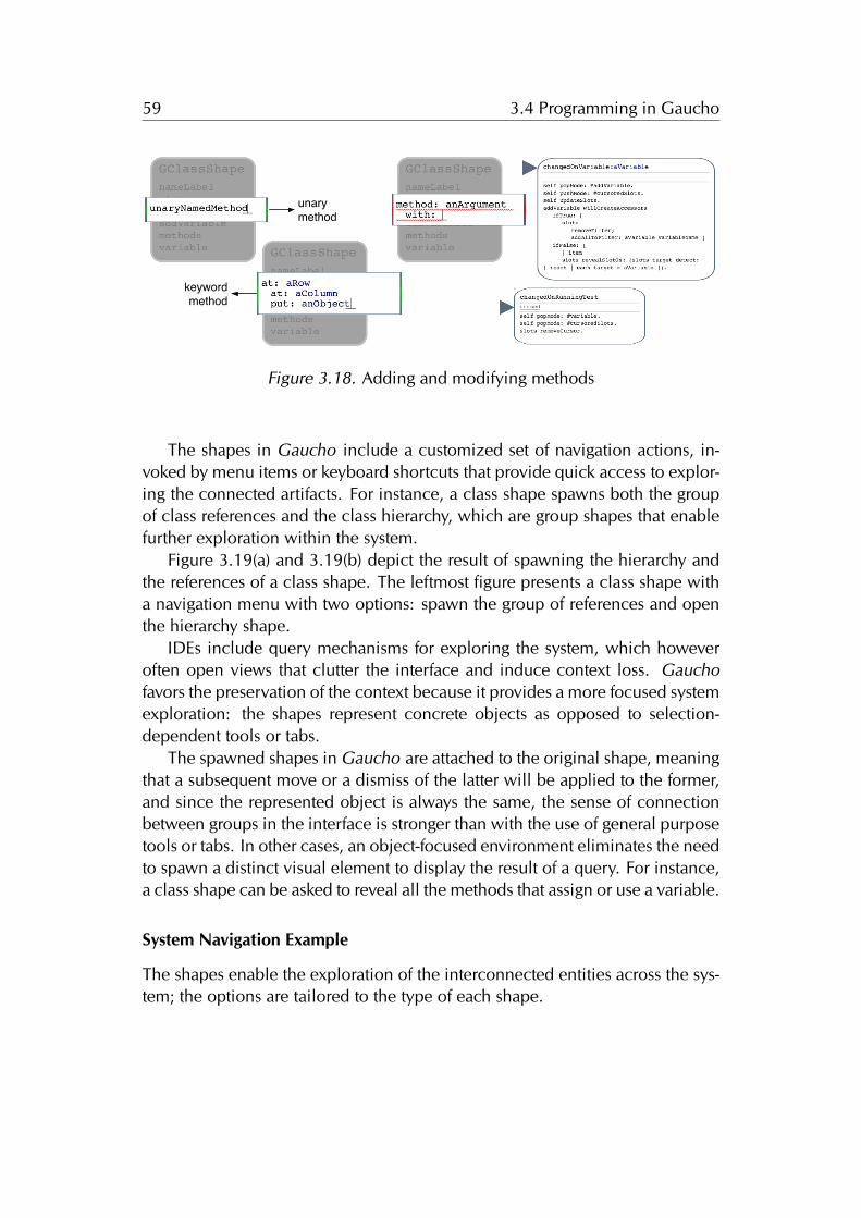
59 3.4 Programming in Gaucho
unary method
keyword method
Figure 3.18. Adding and modifying methods
The shapes in Gaucho include a customized set of navigation actions, in-voked by menu items or keyboard shortcuts that provide quick access to explor-ing the connected artifacts. For instance, a class shape spawns both the groupof class references and the class hierarchy, which are group shapes that enablefurther exploration within the system.
Figure 3.19(a) and 3.19(b) depict the result of spawning the hierarchy andthe references of a class shape. The leftmost figure presents a class shape witha navigation menu with two options: spawn the group of references and openthe hierarchy shape.
IDEs include query mechanisms for exploring the system, which howeveroften open views that clutter the interface and induce context loss. Gauchofavors the preservation of the context because it provides a more focused systemexploration: the shapes represent concrete objects as opposed to selection-dependent tools or tabs.
The spawned shapes in Gaucho are attached to the original shape, meaningthat a subsequent move or a dismiss of the latter will be applied to the former,and since the represented object is always the same, the sense of connectionbetween groups in the interface is stronger than with the use of general purposetools or tabs. In other cases, an object-focused environment eliminates the needto spawn a distinct visual element to display the result of a query. For instance,a class shape can be asked to reveal all the methods that assign or use a variable.
System Navigation Example
The shapes enable the exploration of the interconnected entities across the sys-tem; the options are tailored to the type of each shape.
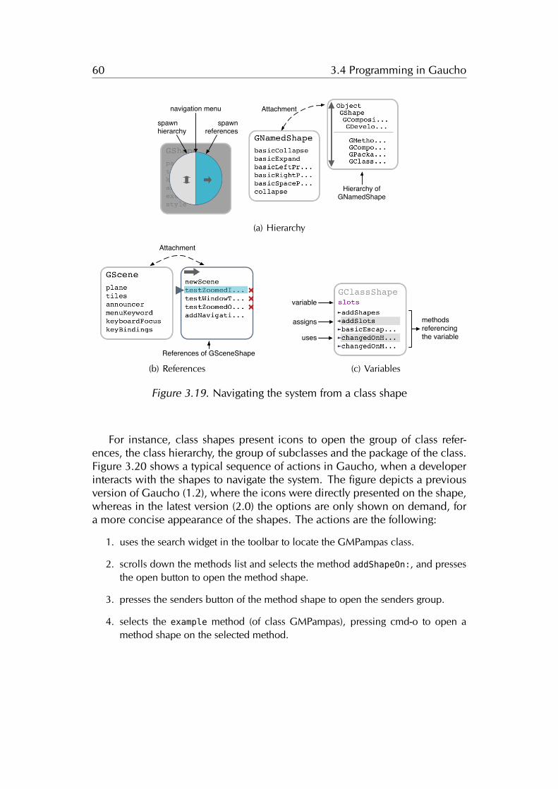
60 3.4 Programming in Gaucho
spawnreferences
spawn hierarchy
navigation menu
Hierarchy of GNamedShape
Attachment
(a) Hierarchy
Attachment
References of GSceneShape
(b) References
variable
methods referencing the variableuses
assigns
(c) Variables
Figure 3.19. Navigating the system from a class shape
For instance, class shapes present icons to open the group of class refer-ences, the class hierarchy, the group of subclasses and the package of the class.Figure 3.20 shows a typical sequence of actions in Gaucho, when a developerinteracts with the shapes to navigate the system. The figure depicts a previousversion of Gaucho (1.2), where the icons were directly presented on the shape,whereas in the latest version (2.0) the options are only shown on demand, fora more concise appearance of the shapes. The actions are the following:
1. uses the search widget in the toolbar to locate the GMPampas class.
2. scrolls down the methods list and selects the method addShapeOn:, and pressesthe open button to open the method shape.
3. presses the senders button of the method shape to open the senders group.
4. selects the example method (of class GMPampas), pressing cmd-o to open amethod shape on the selected method.
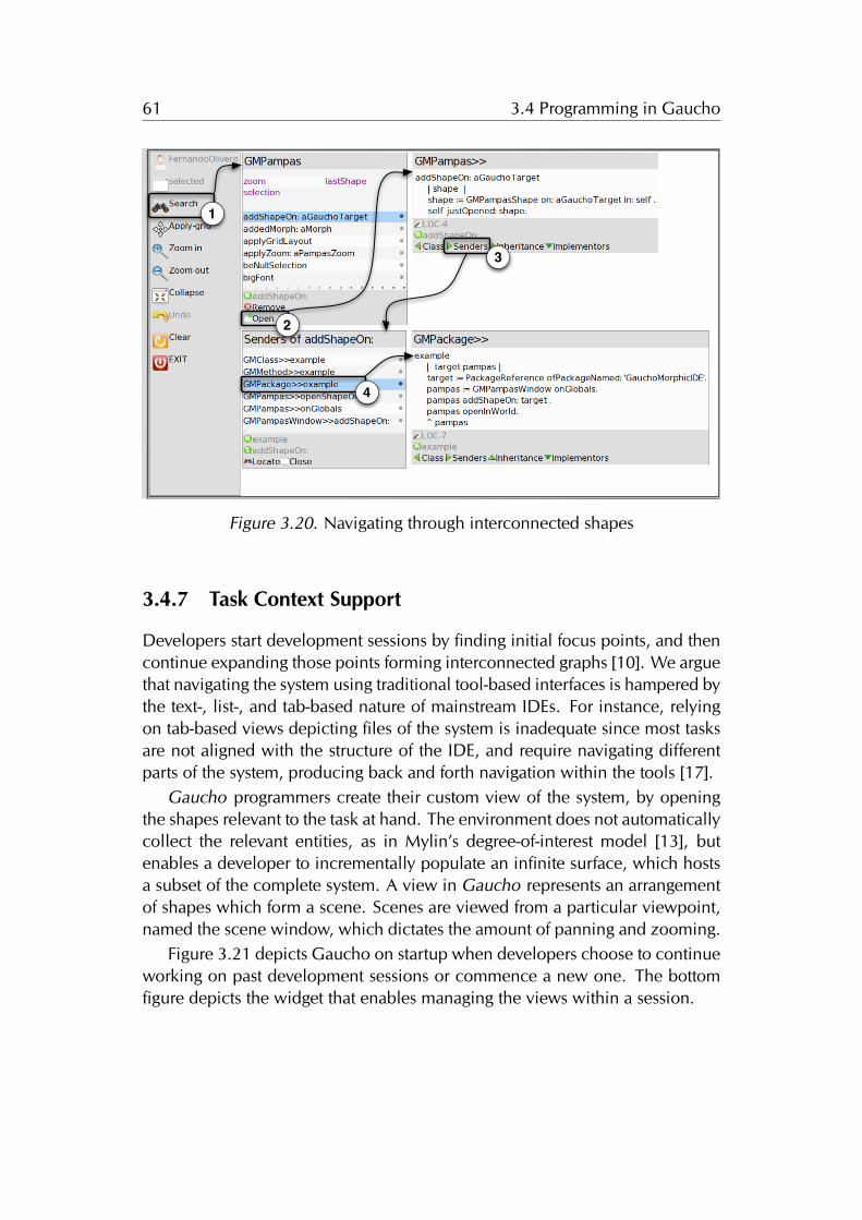
61 3.4 Programming in Gaucho
1
2
3
4
Figure 3.20. Navigating through interconnected shapes
3.4.7 Task Context Support
Developers start development sessions by finding initial focus points, and thencontinue expanding those points forming interconnected graphs [10]. We arguethat navigating the system using traditional tool-based interfaces is hampered bythe text-, list-, and tab-based nature of mainstream IDEs. For instance, relyingon tab-based views depicting files of the system is inadequate since most tasksare not aligned with the structure of the IDE, and require navigating differentparts of the system, producing back and forth navigation within the tools [17].
Gaucho programmers create their custom view of the system, by openingthe shapes relevant to the task at hand. The environment does not automaticallycollect the relevant entities, as in Mylin’s degree-of-interest model [13], butenables a developer to incrementally populate an infinite surface, which hostsa subset of the complete system. A view in Gaucho represents an arrangementof shapes which form a scene. Scenes are viewed from a particular viewpoint,named the scene window, which dictates the amount of panning and zooming.
Figure 3.21 depicts Gaucho on startup when developers choose to continueworking on past development sessions or commence a new one. The bottomfigure depicts the widget that enables managing the views within a session.
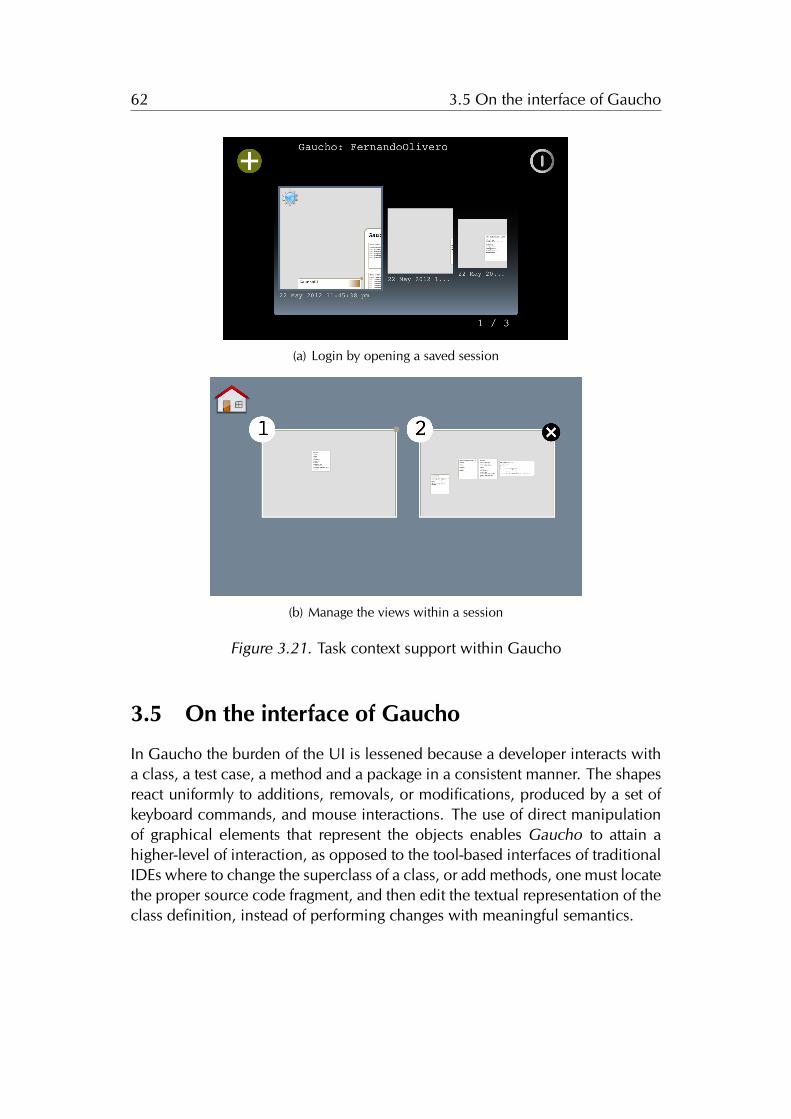
62 3.5 On the interface of Gaucho
(a) Login by opening a saved session
(b) Manage the views within a session
Figure 3.21. Task context support within Gaucho
3.5 On the interface of Gaucho
In Gaucho the burden of the UI is lessened because a developer interacts witha class, a test case, a method and a package in a consistent manner. The shapesreact uniformly to additions, removals, or modifications, produced by a set ofkeyboard commands, and mouse interactions. The use of direct manipulationof graphical elements that represent the objects enables Gaucho to attain ahigher-level of interaction, as opposed to the tool-based interfaces of traditionalIDEs where to change the superclass of a class, or add methods, one must locatethe proper source code fragment, and then edit the textual representation of theclass definition, instead of performing changes with meaningful semantics.
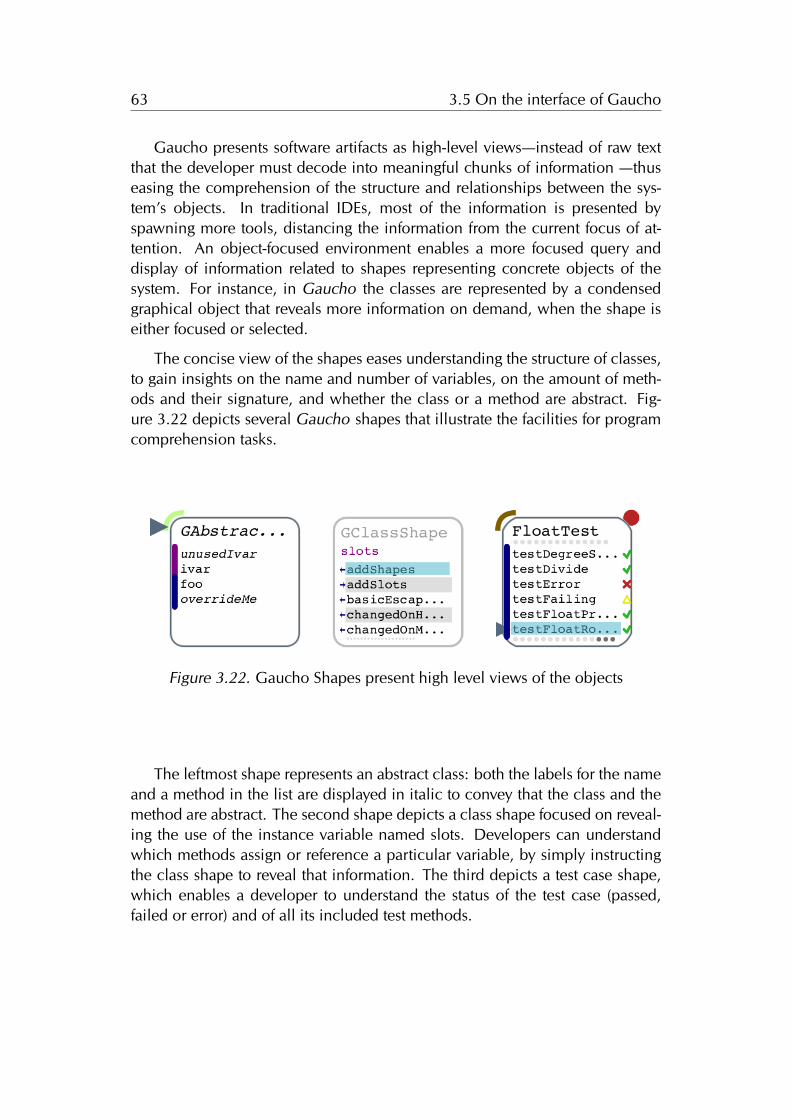
63 3.5 On the interface of Gaucho
Gaucho presents software artifacts as high-level views—instead of raw textthat the developer must decode into meaningful chunks of information —thuseasing the comprehension of the structure and relationships between the sys-tem’s objects. In traditional IDEs, most of the information is presented byspawning more tools, distancing the information from the current focus of at-tention. An object-focused environment enables a more focused query anddisplay of information related to shapes representing concrete objects of thesystem. For instance, in Gaucho the classes are represented by a condensedgraphical object that reveals more information on demand, when the shape iseither focused or selected.
The concise view of the shapes eases understanding the structure of classes,to gain insights on the name and number of variables, on the amount of meth-ods and their signature, and whether the class or a method are abstract. Fig-ure 3.22 depicts several Gaucho shapes that illustrate the facilities for programcomprehension tasks.
Figure 3.22. Gaucho Shapes present high level views of the objects
The leftmost shape represents an abstract class: both the labels for the nameand a method in the list are displayed in italic to convey that the class and themethod are abstract. The second shape depicts a class shape focused on reveal-ing the use of the instance variable named slots. Developers can understandwhich methods assign or reference a particular variable, by simply instructingthe class shape to reveal that information. The third depicts a test case shape,which enables a developer to understand the status of the test case (passed,failed or error) and of all its included test methods.
64 3.5 On the interface of Gaucho
3.5.1 On the Textual Representation of Methods Statements
Gaucho is a visual programming environment (VPE) which makes use of spatialrelationships, data abstractions, and a high level language of interaction forperforming programming tasks, such as renaming a class, or adding a methodto a class. Gaucho is in the middle ground between visual programming (VPLs)and pure textual languages [61].
In this dissertation we focused on investigating an alternate interface for theconstruction of OOP environments, nevertheless we decided to retain the useof text to specify behavior because of the complexities of devising a VPL forfully replacing textual descriptions of code [62; 63]. Nonetheless, we believethat Gaucho could easily be modified to incorporate other means of specify-ing behavior, including a shape that manipulates methods via a VPL insteadof editing textual descriptions of statements. For instance, the VPL could usean iconographic language to denote operations, and specify the method bodyusing a data-flow language such as Coherence [64], which relies on the abstrac-tion of a virtual tree, similar to the abstract syntax tree of a parsed method.
Chapter 4
Evaluation
In the previous chapter of the thesis, we introduced Gaucho, which is our ap-proach to the design of a development environment for OOP, and described itsapplication to several modeling and programming activities.
Gaucho is an object-focused environment that allows developers to writeprograms by creating and manipulating lightweight and intuitive depictions ofobject-oriented constructs.
On the other hand, traditional integrated development environments (IDEs)include many tools that provide the means to construct programs. Coinciden-tally, the very same IDEs are a primary vehicle for program comprehension.We claim that IDEs may be an impediment for program comprehension be-cause they treat software elements as text, which may be counterproductive inthe context of program understanding—where abstracting from the source textto the level of structural entities and relationships is the key.
The research question we investigate here is how does an object focused en-vironment such as Gaucho compare with traditional IDEs when it comes to per-forming program comprehension tasks.To answer our question, we conducteda preliminary controlled experiment with eight subjects, comparing Gauchoagainst a traditional IDE.
We acknowledge that software is created by humans, for humans, thus soft-ware engineering is—above all—a human activity. However, the intrinsicallynon-deterministic nature of humans introduces a number of threats to the va-lidity of controlled experiments, performed by researchers to evaluate softwaretools. One of them concerns how to record information without influencing thebehavior of the subjects involved. Another one relates to providing means toassure the correctness of the gathered data, for further analyses and replication.
65
66 4.1 Instrumenting the Evaluation of Software Tools
Furthermore, instrumenting an evaluation of a software development envi-ronment, such as Gaucho, places a heavy burden on the experimenters, due tothe short duration of the actions programmers perform to fulfill the tasks com-posing the experiment. The brevity of the tasks makes it hard to track the timeand effort of the subject under observation, which hampers with the correctnessof the ulterior observations regarding the experiment.
To alleviate this burden, we focused on improving the tool support that en-ables researchers to perform controlled experiments with human subjects toevaluate the performance and usability of novel approaches and software engi-neering tools. We devised Biscuit, a toolset to specify tasks to be undertakenby the subjects of the experiment, and precisely time the subjects and recordtheir complete behavior as they perform the tasks.
Structure of the chapter. In Section 4.1 we discuss often overlooked issuesthat come up during controlled experiments with human subjects, and wepresent Buiscuit, our toolset to alleviate some of the issues. In Section 4.2we discuss the context of the evaluation. We describe the experimental designin Section 4.3, and the operation and results in Section 4.4. We conclude thechapter by reflecting on the outcome of the evaluation in Section 4.5, and dis-cussing the advantages of instrumenting controlled experiments with tools suchas Biscuit in Section 4.6.
4.1 Instrumenting the Evaluation of Software Tools
If software engineering is above all a human activity, then taking the humanaspect out of the loop would be definitely wrong, when it comes to evaluatingsoftware engineering approaches.
Consequently, these past years have seen a steady increase of evaluationsbased on controlled experiments performed with human subjects. For exam-ple, Cornelissen et al. evaluated a tool for visualizing execution traces [65],Stasko et al. contrasted two visualization tools for depicting hierarchies usingdifferent space-filing layouts [66], Marcus et al. analyzed the support for pro-gram comprehension tasks of their sv3D tool [67], and Wettel et al. assessedthe validity of the city metaphor for visualizing software systems [68].
Controlled experiments are prone to a large number of pitfalls, due to theone and only uncontrollable element of any controlled experiment involvinghuman subjects: humans. Humans have individual talents, skills, behaviors,
67 4.1 Instrumenting the Evaluation of Software Tools
and quirks. In any experiment humans behave in a non-deterministic way,which introduces various threats to the validity of any experiment of this kind.
The pitfalls in question regard an issue that might be seen as a corollary toHeisenberg’s uncertainty principle: How is the information that one wants torecord actually being recorded, and does the fact that one records informationin an intrusive way influence or modify the behavior of subjects?. If so, howcan this be minimized?.
4.1.1 The Crux of Human-centric Experiments
There are diverse possibilities to record information in a controlled experiment,where a usual scenario is that a set of subjects is divided into two groups, thecontrol group and the experimental group. Subjects in the former group aregiven some baseline setting, while the subjects of the latter group are given thetool to be evaluated. The goal is then to assess whether the experimental groupcan perform a set of tasks better, faster, etc. as opposed to the control group.
A literature survey [65; 69; 67; 66] reveals commonly adopted practices totackle the issues which must be confronted when performing controlled exper-iments to evaluate software tools:
1. Give the subjects tasks to perform and/or questions to answer, and thepossibility to provide answers/findings in some form. The subjects knowwhat is expected from them; this can either come as a set of questions ora set of tasks. After performing the tasks the subjects then provide someform of feedback about what they have done, i.e., they need to answerquestions. The experimenter’s role in this situation is then, to obtain dataabout the correctness (i.e., was a task fulfilled or not/only partially) andthe time taken by the subjects to perform a task.
In the large majority of cases, experimenters opt for questionnaires, (oftenin the form of multiple choice questions or free-form text questions) tothe subjects who fill them out during the experiment. Questionnaires caneither be on paper or also in electronic form (such as survey websites).
2. Keep track of the time taken by each subject on each task. How canone reliably record the time it took for a subject to perform a task? Onepossibility is to have the subject write down the time (as part of the ques-tionnaire); this introduces the risk of subjects writing down wrong infor-mation.
68 4.1 Instrumenting the Evaluation of Software Tools
Another possibility is for the experimenter to record the timing, whichmakes it hard, if not impossible, to perform an experiment with multi-ple subjects at the same time or a remote experiment—without removingmeasurement issues due to human fallibility.
3. Record what the subjects do while they perform tasks to try to find an-swers. To record what subjects do, the often adopted solutions are "think-aloud" protocols, and/or filming and screencasts and/or audio-recording.Think-aloud protocols involve experiment participants thinking aloud asthey are performing a set of specified tasks. Users are asked to say what-ever they are looking at, thinking, doing, and feeling, as they go abouttheir task.
This enables observers to see first-hand the process of task completion(rather than only its final product). Observers at such a test are asked toobjectively take notes of everything that users say, without attempting tointerpret their actions and words. Test sessions are often audio and videotaped so that developers can go back and refer to what participants did,and how they reacted.
The purpose of this method is to make explicit what is implicitly presentin subjects who are able to perform a specific task. A screencast is adigital recording of computer screen output, also known as a video screencapture, often containing audio narration. Experimenters can use them torecord the full interaction of the subjects with the tools they used.
4. Process the previously recorded data to extract additional information,and allow the experimenters to gather the data easily. An additionalproblem is that the data recorded using such approaches needs to bepost-processed since it comes as a digital movie/audio recording.
The post-processing, e.g., transcribing what happened, can be lengthyand imprecise—especially when the number of subjects is high—due tothe lack of formalism in natural language and human behavior. Raisingthe level of abstraction of the data would allow for easier and more auto-mated processing.
Related to this issue, gathering the data in itself can be a challenge—eitherbecause of manual processing of hand-written questionnaires, or becauseit comes from multiple sources (e.g. questionnaires, timing data, andother recorded data).
69 4.1 Instrumenting the Evaluation of Software Tools
We do not address other important issues pertinent to controlled experimentinvolving humans, e.g., the choice of participants, controlled variables, tasks,etc. These and others are all important questions which go beyond the scopeof the present discussion. We focus on a seemingly smaller set of issues, whichhowever can and does contribute to a loss of precision or even a falsification ofthe recorded data.
Summing up. Due to issues related to timing, data processing, and mostlyinaccurate tracking of what happens during the experiment, the risk is that thedata that is being collected during an experiment is distorted or even wrong. Tomitigate such risks we devised Biscuit, an tool infrastructure for non-intrusiveand precise tracking of data related to experiments with human subjects.
4.1.2 Biscuit: Tracking Human-Centric Controlled Experiments
Biscuit supports performing controlled experiments, by recording relevant piecesof information regarding an experiment performed with human subjects. At themoment, it is geared towards experiments evaluating development tools.
Next, we detail how experimenters using Biscuit address the issues related toconducting evaluations with human subjects, we stated in the previous section:
1. Give the subjects tasks to perform and/or questions to answer, and thepossibility to provide answers/findings in some form. To address the firstissue, Biscuit can set up an experiment made up of tasks which in turn,consist in a description and goals that need to be accomplished by thesubjects.
The format of answers to the goals range from multiple choice questionsand free form text entries, to modifying the underlying system entities—such as adding/removing classes/methods until automated tests pass.
Using Biscuit, the experimenter can automatically generate a user inter-face for any experiment; it presents the experiment to the subjects andguides them through the tasks until completion.
2. Keep track of the time taken by each subject on each task. An automati-cally generated user interface for each experiment run, tracks the answersand durations of each task while the user is performing them. This ad-dresses the first two issues; namely giving the subjects tasks to perform orquestions to answer; and registering the answers and completion times.
70 4.1 Instrumenting the Evaluation of Software Tools
3. Record what the subjects do while they perform tasks to try to find an-swers. To address the third issue prior to running each task, Biscuit in-stalls a spy that records every user interaction: from simple mouse moveevents, to more complex interactions such as performing changes to thecode base, or providing answers to the experiment goals.
The spy is built on top of a system monitoring tool called Spyware [70],enhanced with a complete instrumentation of the Event-Command pat-tern. The recording enables one to keep track of every user interactionin the form of recorded events that trigger commands, thus eliminatinga great level of uncertainty from the correctness of the subjects answers,due to the faithful replicability of each experiment run.
The events recorded by Biscuit correspond to actual user actions (sourcecode navigation and modifications), in contrast to video recordings thatrequire significant further interpretation, thus addressing this fourth issue:the event trace is open to automated analyses and can be replicated.
4. Process the previously recorded data to extract additional information,and allow the experimenters to gather the data easily. To address thefourth and final issue, upon completing an experiment the subject is askedto send (via email) an automatically created zipped file containing all therecorded data to the experimenters. This file contains every user inter-action recorded by the spy during the experiment run, together with theanswers and solutions to each task, and additional meta-data such as theparticipant name or identifier, and the total completion time. The processis straightforward both from the subject’s and the experimenter’s point ofview.
Figure 4.1 depicts the experiment description that is shown once the subjecthas completed the pre-test questionnaire and entered basic data, and an actualexperimental run. The screenshot illustrates how the Biscuit task runner recordsand informs users of the passage of time, presents the tasks, and collects theanswers from the subjects. On the bottom corner, we see the task widget withthe answer form; the rest of the screen is occupied by the tool being evaluated,in this case Gaucho.
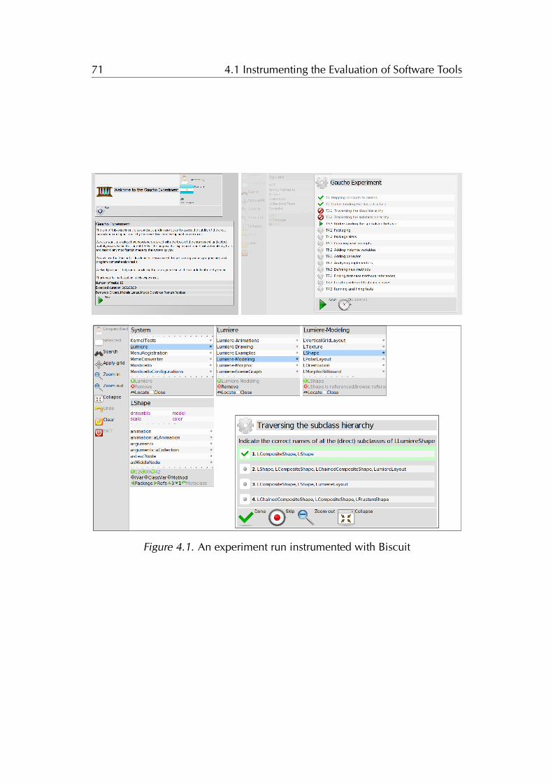
71 4.1 Instrumenting the Evaluation of Software Tools
Figure 4.1. An experiment run instrumented with Biscuit
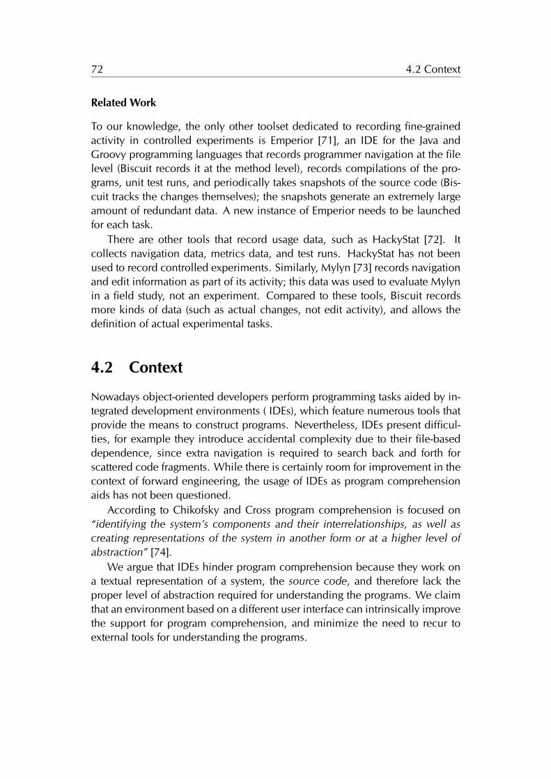
72 4.2 Context
Related Work
To our knowledge, the only other toolset dedicated to recording fine-grainedactivity in controlled experiments is Emperior [71], an IDE for the Java andGroovy programming languages that records programmer navigation at the filelevel (Biscuit records it at the method level), records compilations of the pro-grams, unit test runs, and periodically takes snapshots of the source code (Bis-cuit tracks the changes themselves); the snapshots generate an extremely largeamount of redundant data. A new instance of Emperior needs to be launchedfor each task.
There are other tools that record usage data, such as HackyStat [72]. Itcollects navigation data, metrics data, and test runs. HackyStat has not beenused to record controlled experiments. Similarly, Mylyn [73] records navigationand edit information as part of its activity; this data was used to evaluate Mylynin a field study, not an experiment. Compared to these tools, Biscuit recordsmore kinds of data (such as actual changes, not edit activity), and allows thedefinition of actual experimental tasks.
4.2 Context
Nowadays object-oriented developers perform programming tasks aided by in-tegrated development environments ( IDEs), which feature numerous tools thatprovide the means to construct programs. Nevertheless, IDEs present difficul-ties, for example they introduce accidental complexity due to their file-baseddependence, since extra navigation is required to search back and forth forscattered code fragments. While there is certainly room for improvement in thecontext of forward engineering, the usage of IDEs as program comprehensionaids has not been questioned.
According to Chikofsky and Cross program comprehension is focused on“identifying the system’s components and their interrelationships, as well ascreating representations of the system in another form or at a higher level ofabstraction” [74].
We argue that IDEs hinder program comprehension because they work ona textual representation of a system, the source code, and therefore lack theproper level of abstraction required for understanding the programs. We claimthat an environment based on a different user interface can intrinsically improvethe support for program comprehension, and minimize the need to recur toexternal tools for understanding the programs.
73 4.3 Experimental Design
The two contrasting interfaces here are the view-focused and the object-focused environments. Mainstream IDEs, such as Eclipse, are view-focused:Objects are secondary to the tools which are the concrete visual elements avail-able for interaction. On the contrary, object-focused environments, such as Self[46], foster the notion that developers are in direct contact with the objectsthemselves, instead of abstract entities subordinated to the tools.
We argue that an object focused environment such as Gaucho eases thecomprehension of a system, through the following features:
• Abstractions. The cognitive burden is lessened in Gaucho, because de-velopers interact with graphical elements depicting software artifact ashigh-level views, as opposed to raw text that the developer must decodeinto meaningful chunks of information.
• Relationships. The graphical elements depicting the objects provide quickaccess to related entities, favoring incremental exploration of the system,and easing the navigation of the relationships between objects.
• Unconstrained Layout. The graphical elements can be freely placed onthe interface, making it straightforward to create side by side views of theobjects for understanding and comparing them.
4.3 Experimental Design
We claim that the use of Gaucho eases the comprehension of the structure andrelationships between the entities making up a software system, compared tothe use of traditional IDEs. To assess the validity of this claim, we performeda preliminary controlled experiment. This experiment served also to detectusability issues and to collect impressions from developers using Gaucho.
4.3.1 Research Questions
The research questions underlying our experiment are:
RQ1. Does the use of Gaucho reduce the time necessary to perform programcomprehension tasks, compared to a traditional IDE?
RQ2. Does the use of Gaucho increase the correctness of the answers to theprogram comprehension tasks, compared to a traditional IDE?
74 4.3 Experimental Design
4.3.2 Variables
The purpose of the experiment is to assess the metaphor in use by Gaucho.Thus, the use of the metaphor is the single independent variable of the ex-periment. This variable has two levels: the object-focused metaphor and theview-focused metaphor, respectively represented by Gaucho and a baseline.The dependent variables of our experiment are correctness of the task solutionsand their completion time.
4.3.3 Baseline
We searched for a baseline within the modern object-oriented IDEs that treatobjects as text and settled on the Pharo Smalltalk IDE, a traditional image-based(not depending on files) IDE built around a WIMP (windows, icons, menus,pointing device) metaphor [43]. Since Pharo—as many mainstream IDEs—includes the standard development tools for navigating, inspecting and testingthe objects in the system, we found it to be an ideal candidate to compareGaucho to, see Figure 4.2.
Figure 4.2. A System Browser of the Pharo IDE
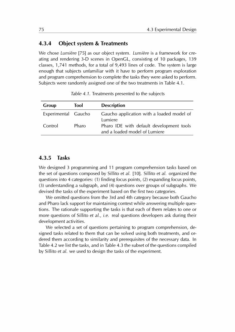
75 4.3 Experimental Design
4.3.4 Object system & Treatments
We chose Lumière [75] as our object system. Lumière is a framework for cre-ating and rendering 3-D scenes in OpenGL, consisting of 10 packages, 139classes, 1,741 methods, for a total of 9,493 lines of code. The system is largeenough that subjects unfamiliar with it have to perform program explorationand program comprehension to complete the tasks they were asked to perform.Subjects were randomly assigned one of the two treatments in Table 4.1.
Table 4.1. Treatments presented to the subjects
Group Tool Description
Experimental Gaucho Gaucho application with a loaded model ofLumiere
Control Pharo Pharo IDE with default development toolsand a loaded model of Lumiere
4.3.5 Tasks
We designed 3 programming and 11 program comprehension tasks based onthe set of questions composed by Sillito et al. [10]. Sillito et al. organized thequestions into 4 categories: (1) finding focus points, (2) expanding focus points,(3) understanding a subgraph, and (4) questions over groups of subgraphs. Wedevised the tasks of the experiment based on the first two categories.
We omitted questions from the 3rd and 4th category because both Gauchoand Pharo lack support for maintaining context while answering multiple ques-tions. The rationale supporting the tasks is that each of them relates to one ormore questions of Sillito et al., i.e. real questions developers ask during theirdevelopment activities.
We selected a set of questions pertaining to program comprehension, de-signed tasks related to them that can be solved using both treatments, and or-dered them according to similarity and prerequisites of the necessary data. InTable 4.2 we list the tasks, and in Table 4.3 the subset of the questions compiledby Sillito et al. we used to design the tasks of the experiment.
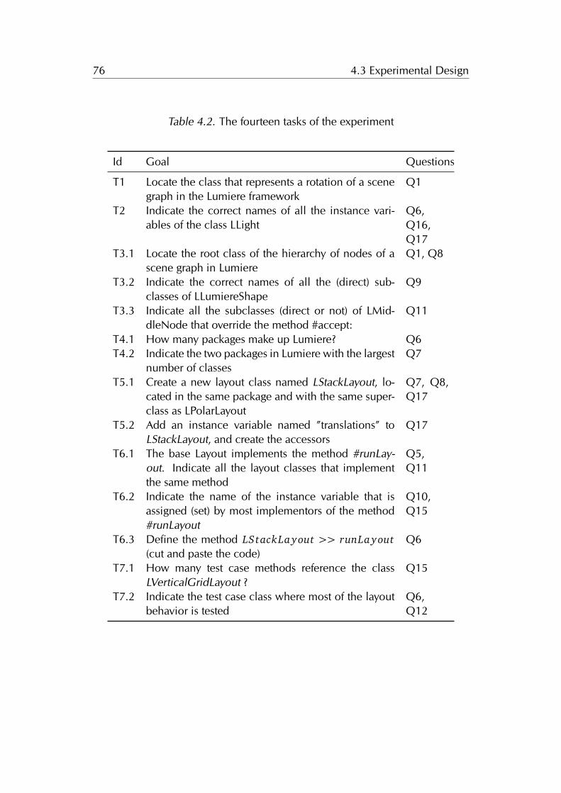
76 4.3 Experimental Design
Table 4.2. The fourteen tasks of the experiment
Id Goal Questions
T1 Locate the class that represents a rotation of a scenegraph in the Lumiere framework
Q1
T2 Indicate the correct names of all the instance vari-ables of the class LLight
Q6,Q16,Q17
T3.1 Locate the root class of the hierarchy of nodes of ascene graph in Lumiere
Q1, Q8
T3.2 Indicate the correct names of all the (direct) sub-classes of LLumiereShape
Q9
T3.3 Indicate all the subclasses (direct or not) of LMid-dleNode that override the method #accept:
Q11
T4.1 How many packages make up Lumiere? Q6T4.2 Indicate the two packages in Lumiere with the largest
number of classesQ7
T5.1 Create a new layout class named LStackLayout, lo-cated in the same package and with the same super-class as LPolarLayout
Q7, Q8,Q17
T5.2 Add an instance variable named ”translations” toLStackLayout, and create the accessors
Q17
T6.1 The base Layout implements the method #runLay-out. Indicate all the layout classes that implementthe same method
Q5,Q11
T6.2 Indicate the name of the instance variable that isassigned (set) by most implementors of the method#runLayout
Q10,Q15
T6.3 Define the method LStackLa yout >> runLa yout(cut and paste the code)
Q6
T7.1 How many test case methods reference the classLVerticalGridLayout ?
Q15
T7.2 Indicate the test case class where most of the layoutbehavior is tested
Q6,Q12
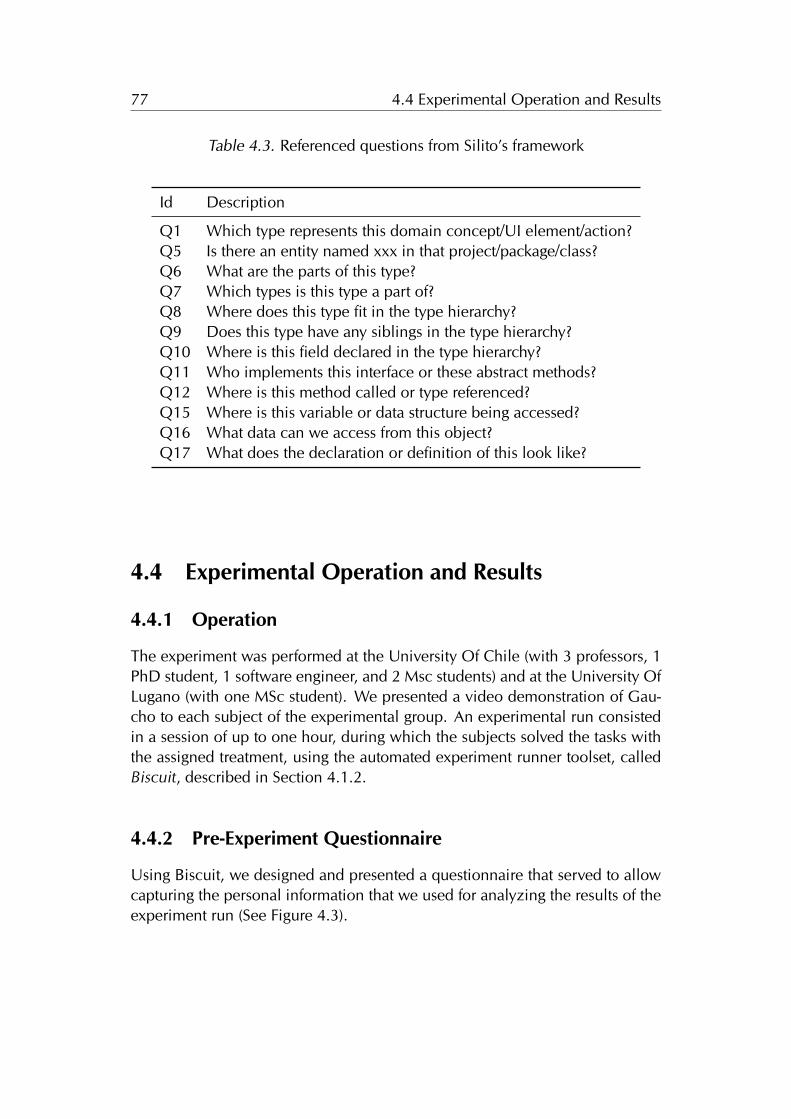
77 4.4 Experimental Operation and Results
Table 4.3. Referenced questions from Silito’s framework
Id Description
Q1 Which type represents this domain concept/UI element/action?Q5 Is there an entity named xxx in that project/package/class?Q6 What are the parts of this type?Q7 Which types is this type a part of?Q8 Where does this type fit in the type hierarchy?Q9 Does this type have any siblings in the type hierarchy?Q10 Where is this field declared in the type hierarchy?Q11 Who implements this interface or these abstract methods?Q12 Where is this method called or type referenced?Q15 Where is this variable or data structure being accessed?Q16 What data can we access from this object?Q17 What does the declaration or definition of this look like?
4.4 Experimental Operation and Results
4.4.1 Operation
The experiment was performed at the University Of Chile (with 3 professors, 1PhD student, 1 software engineer, and 2 Msc students) and at the University OfLugano (with one MSc student). We presented a video demonstration of Gau-cho to each subject of the experimental group. An experimental run consistedin a session of up to one hour, during which the subjects solved the tasks withthe assigned treatment, using the automated experiment runner toolset, calledBiscuit, described in Section 4.1.2.
4.4.2 Pre-Experiment Questionnaire
Using Biscuit, we designed and presented a questionnaire that served to allowcapturing the personal information that we used for analyzing the results of theexperiment run (See Figure 4.3).
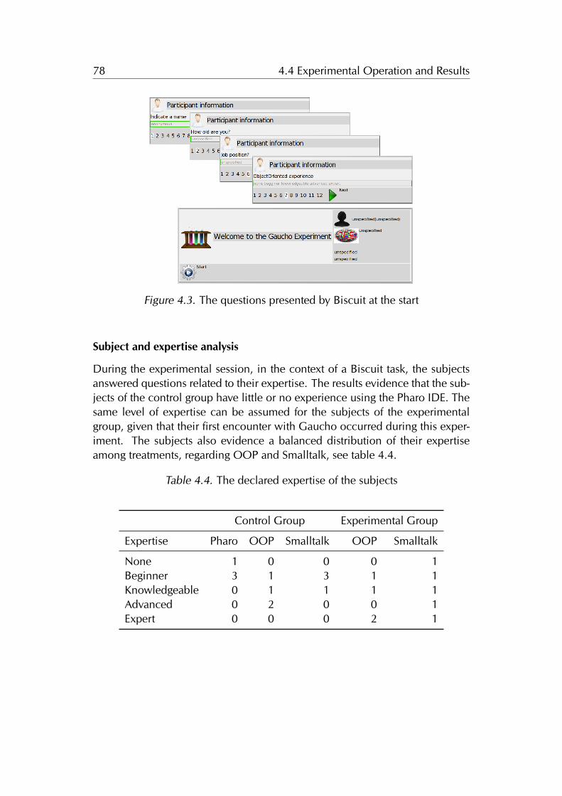
78 4.4 Experimental Operation and Results
Figure 4.3. The questions presented by Biscuit at the start
Subject and expertise analysis
During the experimental session, in the context of a Biscuit task, the subjectsanswered questions related to their expertise. The results evidence that the sub-jects of the control group have little or no experience using the Pharo IDE. Thesame level of expertise can be assumed for the subjects of the experimentalgroup, given that their first encounter with Gaucho occurred during this exper-iment. The subjects also evidence a balanced distribution of their expertiseamong treatments, regarding OOP and Smalltalk, see table 4.4.
Table 4.4. The declared expertise of the subjects
Control Group Experimental Group
Expertise Pharo OOP Smalltalk OOP Smalltalk
None 1 0 0 0 1Beginner 3 1 3 1 1Knowledgeable 0 1 1 1 1Advanced 0 2 0 0 1Expert 0 0 0 2 1
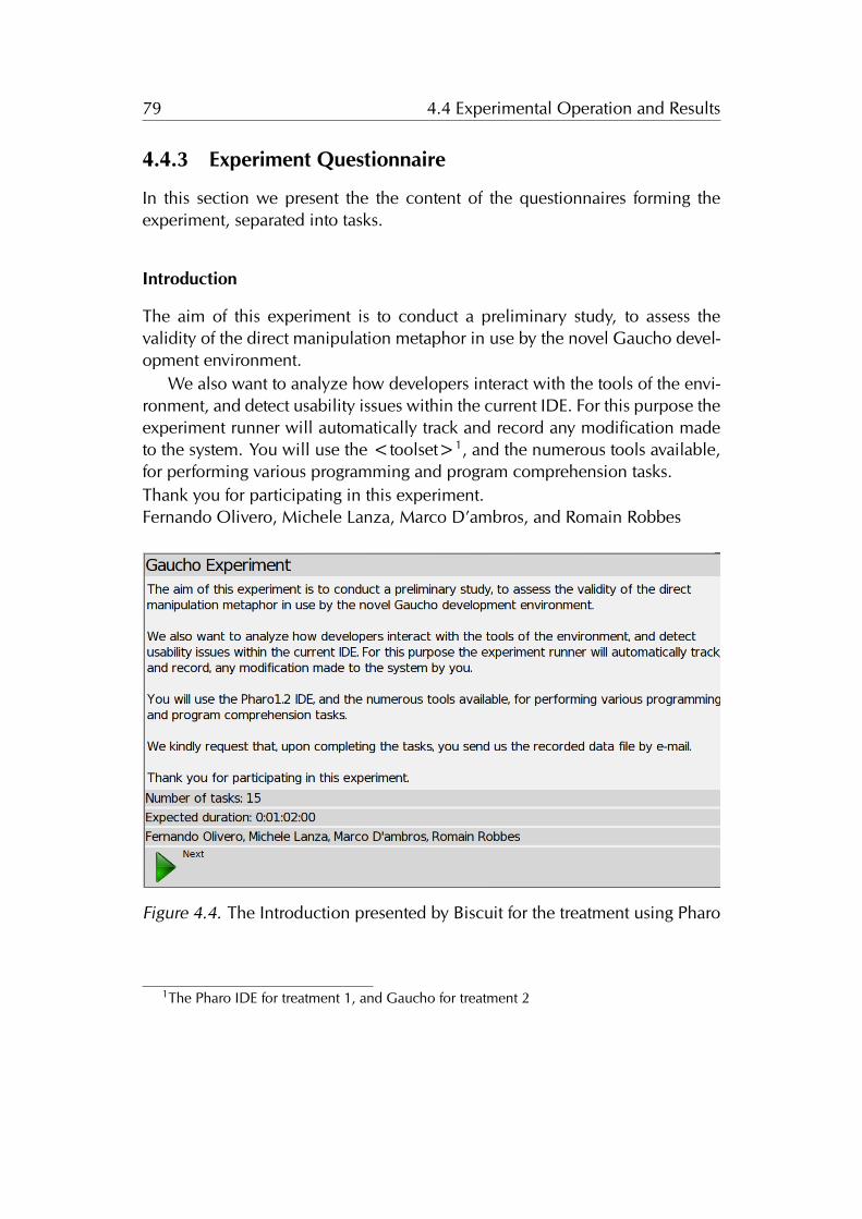
79 4.4 Experimental Operation and Results
4.4.3 Experiment Questionnaire
In this section we present the the content of the questionnaires forming theexperiment, separated into tasks.
Introduction
The aim of this experiment is to conduct a preliminary study, to assess thevalidity of the direct manipulation metaphor in use by the novel Gaucho devel-opment environment.
We also want to analyze how developers interact with the tools of the envi-ronment, and detect usability issues within the current IDE. For this purpose theexperiment runner will automatically track and record any modification madeto the system. You will use the <toolset>1, and the numerous tools available,for performing various programming and program comprehension tasks.Thank you for participating in this experiment.Fernando Olivero, Michele Lanza, Marco D’ambros, and Romain Robbes
Figure 4.4. The Introduction presented by Biscuit for the treatment using Pharo
1The Pharo IDE for treatment 1, and Gaucho for treatment 2
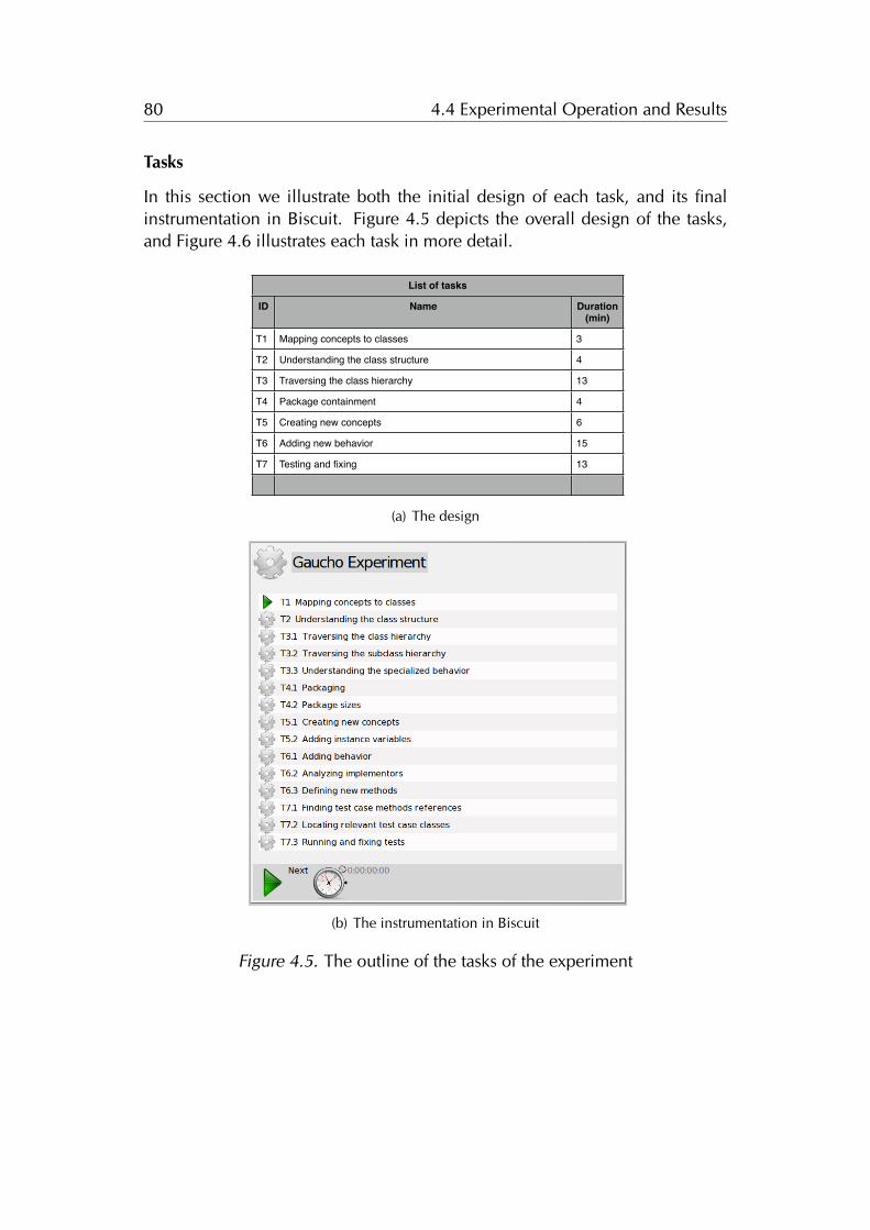
80 4.4 Experimental Operation and Results
Tasks
In this section we illustrate both the initial design of each task, and its finalinstrumentation in Biscuit. Figure 4.5 depicts the overall design of the tasks,and Figure 4.6 illustrates each task in more detail.
List of tasksList of tasksList of tasks
ID Name Duration(min)
T1 Mapping concepts to classes 3
T2 Understanding the class structure 4
T3 Traversing the class hierarchy 13
T4 Package containment 4
T5 Creating new concepts 6
T6 Adding new behavior 15
T7 Testing and fixing 13
(a) The design
(b) The instrumentation in Biscuit
Figure 4.5. The outline of the tasks of the experiment
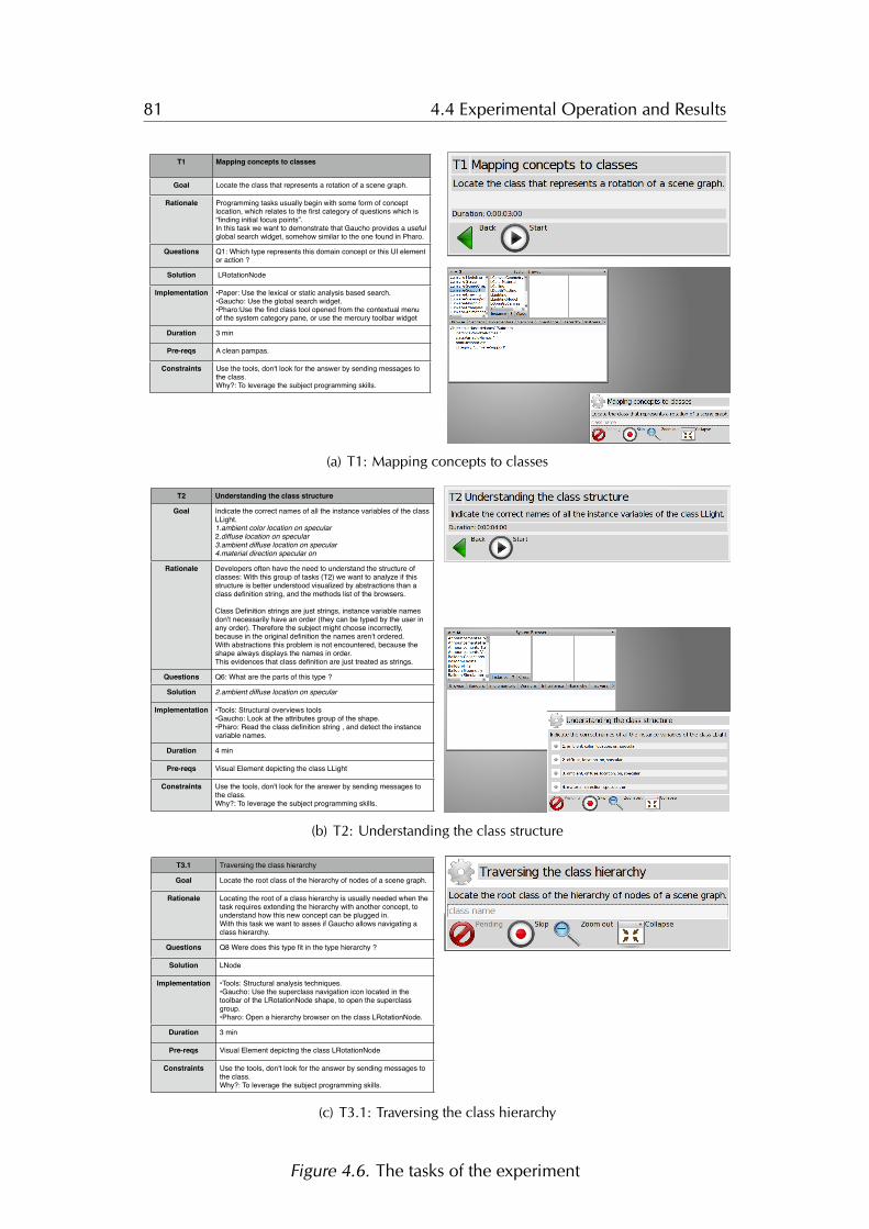
81 4.4 Experimental Operation and Results
T1 Mapping concepts to classes
Goal
Rationale
Questions
Solution
Implementation
Duration
Pre-reqs
Constraints
Locate the class that represents a rotation of a scene graph.
Programming tasks usually begin with some form of concept location, which relates to the first category of questions which is “finding initial focus points”.In this task we want to demonstrate that Gaucho provides a useful global search widget, somehow similar to the one found in Pharo.
Q1: Which type represents this domain concept or this UI element or action ?
LRotationNode
•Paper: Use the lexical or static analysis based search.•Gaucho: Use the global search widget.•Pharo:Use the find class tool opened from the contextual menu of the system category pane, or use the mercury toolbar widget
3 min
A clean pampas.
Use the tools, don't look for the answer by sending messages to the class. Why?: To leverage the subject programming skills.
(a) T1: Mapping concepts to classes
T2 Understanding the class structure
Goal
Rationale
Questions
Solution
Implementation
Duration
Pre-reqs
Constraints
Indicate the correct names of all the instance variables of the class LLight.1.ambient color location on specular2.diffuse location on specular 3.ambient diffuse location on specular4.material direction specular on
Developers often have the need to understand the structure of classes: With this group of tasks (T2) we want to analyze if this structure is better understood visualized by abstractions than a class definition string, and the methods list of the browsers.
Class Definition strings are just strings, instance variable names don't necessarily have an order (they can be typed by the user in any order). Therefore the subject might choose incorrectly, because in the original definition the names aren’t ordered.With abstractions this problem is not encountered, because the shape always displays the names in order.This evidences that class definition are just treated as strings.
Q6: What are the parts of this type ?
2.ambient diffuse location on specular
•Tools: Structural overviews tools•Gaucho: Look at the attributes group of the shape.•Pharo: Read the class definition string , and detect the instance variable names.
4 min
Visual Element depicting the class LLight
Use the tools, don't look for the answer by sending messages to the class. Why?: To leverage the subject programming skills.
(b) T2: Understanding the class structure
T3.1 Traversing the class hierarchy
Goal
Rationale
Questions
Solution
Implementation
Duration
Pre-reqs
Constraints
Locate the root class of the hierarchy of nodes of a scene graph.
Locating the root of a class hierarchy is usually needed when the task requires extending the hierarchy with another concept, to understand how this new concept can be plugged in.With this task we want to asses if Gaucho allows navigating a class hierarchy.
Q8 Were does this type fit in the type hierarchy ?
LNode
•Tools: Structural analysis techniques.•Gaucho: Use the superclass navigation icon located in the toolbar of the LRotationNode shape, to open the superclass group.•Pharo: Open a hierarchy browser on the class LRotationNode.
3 min
Visual Element depicting the class LRotationNode
Use the tools, don't look for the answer by sending messages to the class. Why?: To leverage the subject programming skills.
(c) T3.1: Traversing the class hierarchy
Figure 4.6. The tasks of the experiment
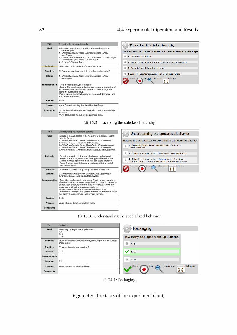
82 4.4 Experimental Operation and Results
T3.2 Traversing the subclass hierarchy
Goal
Rationale
Questions
Solution
Implementation
Duration
Pre-reqs
Constraints
Indicate the correct names of all the (direct) subclasses of LLumiereShape?1.LChainedCompositeShape LCompositeShape LShape LumiereLayout2.LChainedCompositeShape LCompositeShape LFrustumShape 3.LCompositeShape LShape LumiereLayout 4.LCompositeShape LShape
Understand the composition of a class hierarchy
Q9 Does this type have any siblings in the type hierarchy ?
1.LChainedCompositeShape LCompositeShape LShape LumiereLayout
•Tools: Structural analysis techniques•Gaucho:The subclasses navigation icon located in the toolbar of the LNode shape, indicates the number of direct siblings and opens the subclasses group.•Pharo: Open a hierarchy browser on the class LGeometry , and analyze the subclasses.
4 min
Visual Element depicting the class LLumiereShape
Use the tools, don't look for the answer by sending messages to the class. Why?: To leverage the subject programming skills.
Marco D'Ambros Nov 9, '10, 9:40 AM
This can probably be expanded a little bit. Why is it important to understand the composition of a class hierarchy in a programming task?Fernando : Ok , will expand most of the rationales with references to the literature.
(d) T3.2: Traversing the subclass hierarchy
T3.3 Understanding the specialized behavior
Goal
Rationale
Questions
Solution
Implementation
Duration
Pre-reqs
Constraints
Indicate all the subclasses in the hierarchy of middle nodes that override #accept: 1.LAffineTransformationNode, LRotationNode,LScaleNode, LTranslationNode, LDrawableWithChildNode.2.LAffineTransformationNode, LScaleNode, LTranslationNode.3.LAffineTransformationNode, LRotationNode,LScaleNode, LTranslationNode, LDrawableWithChildNode, LMatrixLoadNode.
•Force the subject to look at multiple classes, methods and relationships at once, to evidence the supposed benefit of the Gaucho interface against the more rigid tool based interfaces.•Asses if reifying the subclasses group is useful in this kind of programming tasks.
Q9 Does this type have any siblings in the type hierarchy ?
1.LAffineTransformationNode, LRotationNode,LScaleNode, LTranslationNode, LDrawableWithChildNode.
•Tools: Structural analysis techniques, Structural overviews tools•Gaucho:Use the subclasses navigation icon located in the toolbar of the LNode shape, to open the subclasses group. Spawn the group, and analyze the subclasses methods.•Pharo: Open a hierarchy browser on the class LNode or LMiddleNode. Navigate through the methods list, remember those that satisfy the condition, or open several browsers
6 min
Visual Element depicting the class LNode
(e) T3.3: Understanding the specialized behavior
T4.1 Packaging
Goal
Rationale
Questions
Solution
Implementation
Duration
Pre-reqs
Constraints
How many packages make up Lumiere?A.8B.10C.16
Asses the usability of the Gaucho system shape, and the package shape icons .
Q7 Which types is type a part of ?
B.10
3min
Visual element depicting the System
(f) T4.1: Packaging
Figure 4.6. The tasks of the experiment (cont)
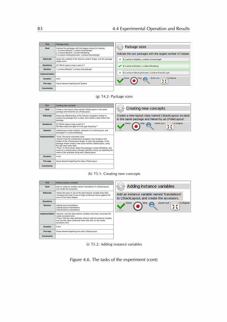
83 4.4 Experimental Operation and Results
T4.2 Package sizes
Goal
Rationale
Questions
Solution
Implementation
Duration
Pre-reqs
Constraints
Indicate the packages with the biggest amount of classes.1.'Lumiere-Morphic' 'Lumiere-SceneGraph’2.'Lumiere-Morphic' 'Lumiere-Modeling'3.'Lumiere-ViewingVolumes' ‘Lumiere-SceneGraph’
Asses the usability of the Gaucho system shape, and the package shape icons .
Q7 Which types is type a part of ?
1.Lumiere-Morphic' 'Lumiere-SceneGraph’
4min
Visual element depicting the System
(g) T4.2: Package sizes
T5.1 Creating new concepts
Goal
Rationale
Questions
Solution
Implementation
Duration
Pre-reqs
Constraints
Create a new layout class named LStackLayout in the same package and hierarchy as LPolarLayout.
Asses the effectiveness of the Gaucho navigation toolbar to access the package from a class, and create a class within that package.
Q7 Which types is type a part of ? Q8 Were does this type fit in the type hierarchy ?
LStackLayout class creation, subclass of LumiereLayout, and packaged in Lumiere-Modeling.
•Tools: Structural overviews tools•Gaucho:Use the containment navigation icon located in the toolbar of the LPolarLayout shape, to open the package. In the package shape create a new class named LStackLayout, using the add class entry field.•Pharo: In the browser select the package Lumiere-Modeling, and reuse an LumiereLayout subclass definition string, by replacing the name of the subclass string with LStackLayout.
4 min
Visual element depicting the class LPolarLayout.
Romain Robbes Nov 2, '10, 2:27 PMThe risk here is that if people don’t know exactly how to do that, they won’t be able to do it as fast as they are used to with Pharo. So the tutorial has to be thorough. Would it be possible to do an “automated tutorial”, before the “semi-automated” experiment?
The Gaucho description misses the subclass bit.
(h) T5.1: Creating new concepts
T5.2 Adding instance variables
Goal
Rationale
Questions
Solution
Implementation
Duration
Pre-reqs
Constraints
Add an instance variable named ‘translations’ to LStackLayout, and create the accessors.
•Asses the ease of use of the add instance variable entry field•Compare the ease of use of large contextual menus against the icons of the class shapes.
LStackLayout.translationsLStackLayout>>translations:LStackLayout>>translations
•Gaucho: Use the add instance variable entry field, and press the create accessors icon.•Pharo: Edit the class definition string to add the instance variable, and use the class contextual menu and click on the create accessors item.
3 min
Visual element depicting the class LStackLayout.
(i) T5.2: Adding instance variables
Figure 4.6. The tasks of the experiment (cont)
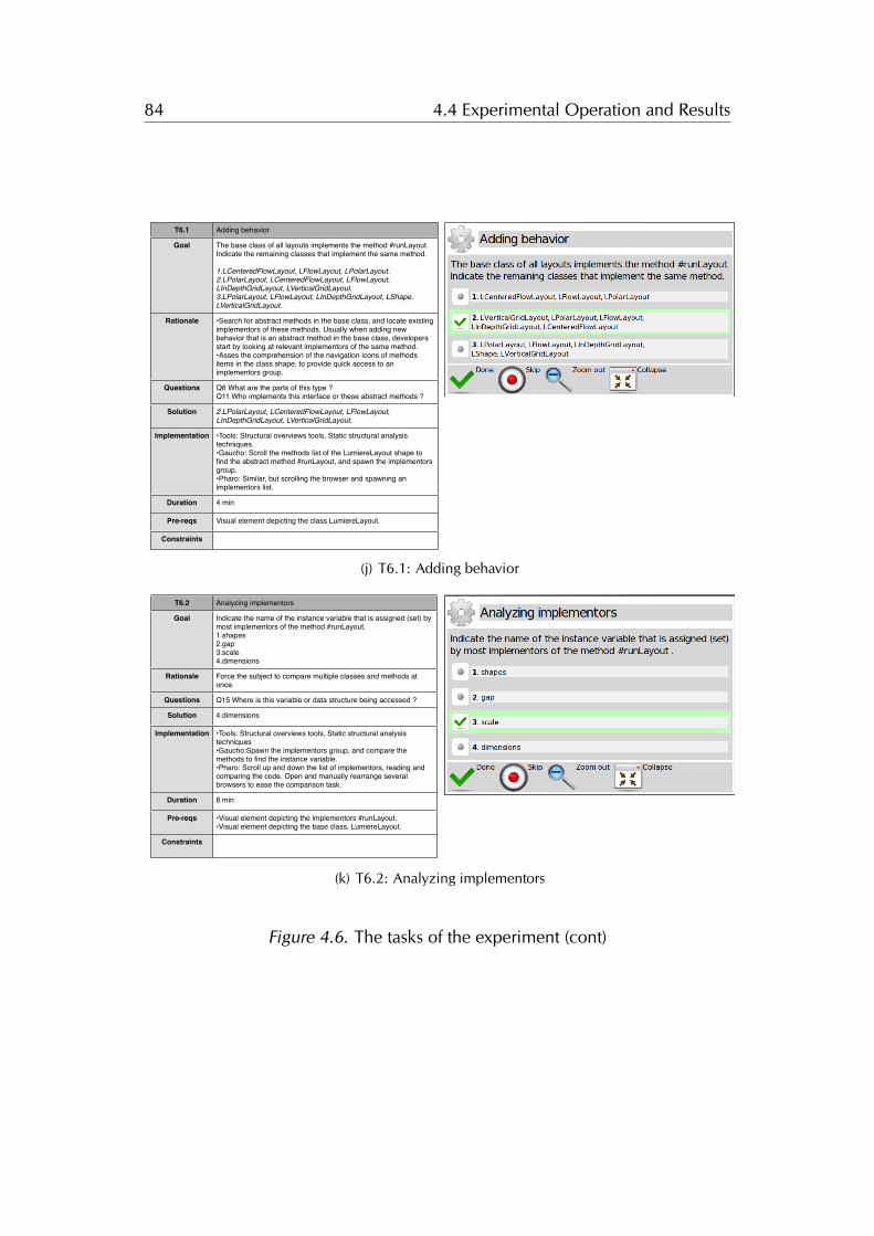
84 4.4 Experimental Operation and Results
T6.1 Adding behavior
Goal
Rationale
Questions
Solution
Implementation
Duration
Pre-reqs
Constraints
The base class of all layouts implements the method #runLayout. Indicate the remaining classes that implement the same method.
1.LCenteredFlowLayout, LFlowLayout, LPolarLayout.2.LPolarLayout, LCenteredFlowLayout, LFlowLayout, LInDepthGridLayout, LVerticalGridLayout.3.LPolarLayout, LFlowLayout, LInDepthGridLayout, LShape, LVerticalGridLayout.
•Search for abstract methods in the base class, and locate existing implementors of these methods. Usually when adding new behavior that is an abstract method in the base class, developers start by looking at relevant implementors of the same method.•Asses the comprehension of the navigation icons of methods items in the class shape, to provide quick access to an implementors group.
Q6 What are the parts of this type ?Q11 Who implements this interface or these abstract methods ?
2.LPolarLayout, LCenteredFlowLayout, LFlowLayout, LInDepthGridLayout, LVerticalGridLayout.
•Tools: Structural overviews tools, Static structural analysis techniques.•Gaucho: Scroll the methods list of the LumiereLayout shape to find the abstract method #runLayout, and spawn the implementors group.•Pharo: Similar, but scrolling the browser and spawning an implementors list.
4 min
Visual element depicting the class LumiereLayout.
(j) T6.1: Adding behavior
T6.2 Analyzing implementors
Goal
Rationale
Questions
Solution
Implementation
Duration
Pre-reqs
Constraints
Indicate the name of the instance variable that is assigned (set) by most implementors of the method #runLayout.1.shapes2.gap3.scale4.dimensions
Force the subject to compare multiple classes and methods at once.
Q15 Where is this variable or data structure being accessed ?
4.dimensions
•Tools: Structural overviews tools, Static structural analysis techniques•Gaucho:Spawn the implementors group, and compare the methods to find the instance variable.•Pharo: Scroll up and down the list of implementors, reading and comparing the code. Open and manually rearrange several browsers to ease the comparison task.
8 min
•Visual element depicting the implementors #runLayout.•Visual element depicting the base class, LumiereLayout.
(k) T6.2: Analyzing implementors
Figure 4.6. The tasks of the experiment (cont)
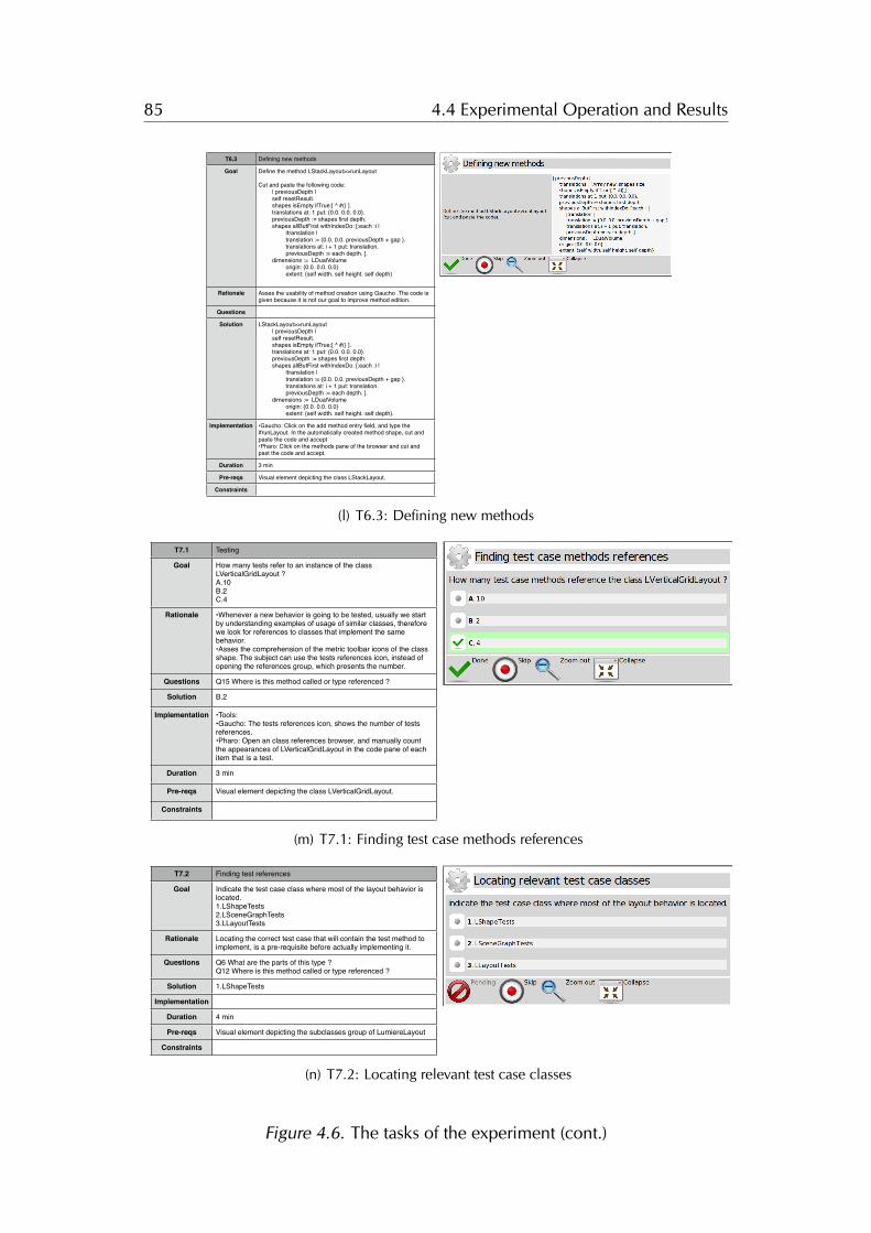
85 4.4 Experimental Operation and Results
T6.3 Defining new methods
Goal
Rationale
Questions
Solution
Implementation
Duration
Pre-reqs
Constraints
Define the method LStackLayout>>runLayout
Cut and paste the following code:! | previousDepth | ! self resetResult.! shapes isEmpty ifTrue:[ ^ #() ].! translations at: 1 put: {0.0. 0.0. 0.0}.! previousDepth := shapes first depth.! shapes allButFirst withIndexDo: [:each :i |! ! |translation |! ! translation := {0.0. 0.0. previousDepth + gap }.! ! translations at: i + 1 put: translation. ! ! previousDepth := each depth. ].! dimensions := LDualVolume! ! origin: {0.0. 0.0. 0.0}! ! extent: {self width. self height. self depth}!
Asses the usability of method creation using Gaucho .The code is given because it is not our goal to improve method edition.
LStackLayout>>runLayout! | previousDepth | ! self resetResult.! shapes isEmpty ifTrue:[ ^ #() ].! translations at: 1 put: {0.0. 0.0. 0.0}.! previousDepth := shapes first depth.! shapes allButFirst withIndexDo: [:each :i |! ! |translation |! ! translation := {0.0. 0.0. previousDepth + gap }.! ! translations at: i + 1 put: translation. ! ! previousDepth := each depth. ].! dimensions := LDualVolume! ! origin: {0.0. 0.0. 0.0}! ! extent: {self width. self height. self depth}.
•Gaucho: Click on the add method entry field, and type the #runLayout. In the automatically created method shape, cut and paste the code and accept •Pharo: Click on the methods pane of the browser and cut and past the code and accept.
3 min
Visual element depicting the class LStackLayout.
(l) T6.3: Defining new methods
T7.1 Testing
Goal
Rationale
Questions
Solution
Implementation
Duration
Pre-reqs
Constraints
How many tests refer to an instance of the class LVerticalGridLayout ?A.10B.2C.4
•Whenever a new behavior is going to be tested, usually we start by understanding examples of usage of similar classes, therefore we look for references to classes that implement the same behavior.•Asses the comprehension of the metric toolbar icons of the class shape. The subject can use the tests references icon, instead of opening the references group, which presents the number.
Q15 Where is this method called or type referenced ?
B.2
•Tools: •Gaucho: The tests references icon, shows the number of tests references.•Pharo: Open an class references browser, and manually count the appearances of LVerticalGridLayout in the code pane of each item that is a test.
3 min
Visual element depicting the class LVerticalGridLayout.
(m) T7.1: Finding test case methods references
T7.2 Finding test references
Goal
Rationale
Questions
Solution
Implementation
Duration
Pre-reqs
Constraints
Indicate the test case class where most of the layout behavior is located.1.LShapeTests2.LSceneGraphTests3.LLayoutTests
Locating the correct test case that will contain the test method to implement, is a pre-requisite before actually implementing it.
Q6 What are the parts of this type ?Q12 Where is this method called or type referenced ?
1.LShapeTests
4 min
Visual element depicting the subclasses group of LumiereLayout
(n) T7.2: Locating relevant test case classes
Figure 4.6. The tasks of the experiment (cont.)

86 4.4 Experimental Operation and Results
4.4.4 Debriefing Questionnaire
(a) Perceived difficulty of each task
(b) Skipped Tasks
Figure 4.7. The post-experiment questionnaire presented by Biscuit
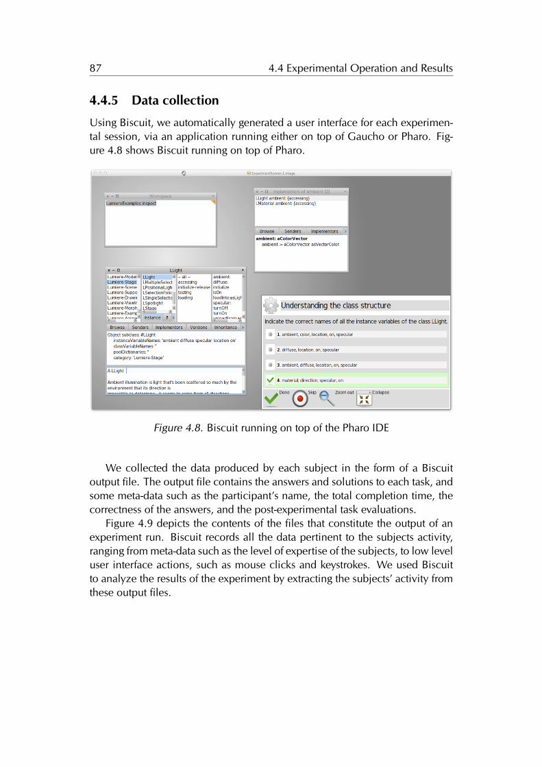
87 4.4 Experimental Operation and Results
4.4.5 Data collection
Using Biscuit, we automatically generated a user interface for each experimen-tal session, via an application running either on top of Gaucho or Pharo. Fig-ure 4.8 shows Biscuit running on top of Pharo.
Figure 4.8. Biscuit running on top of the Pharo IDE
We collected the data produced by each subject in the form of a Biscuitoutput file. The output file contains the answers and solutions to each task, andsome meta-data such as the participant’s name, the total completion time, thecorrectness of the answers, and the post-experimental task evaluations.
Figure 4.9 depicts the contents of the files that constitute the output of anexperiment run. Biscuit records all the data pertinent to the subjects activity,ranging from meta-data such as the level of expertise of the subjects, to low leveluser interface actions, such as mouse clicks and keystrokes. We used Biscuitto analyze the results of the experiment by extracting the subjects’ activity fromthese output files.
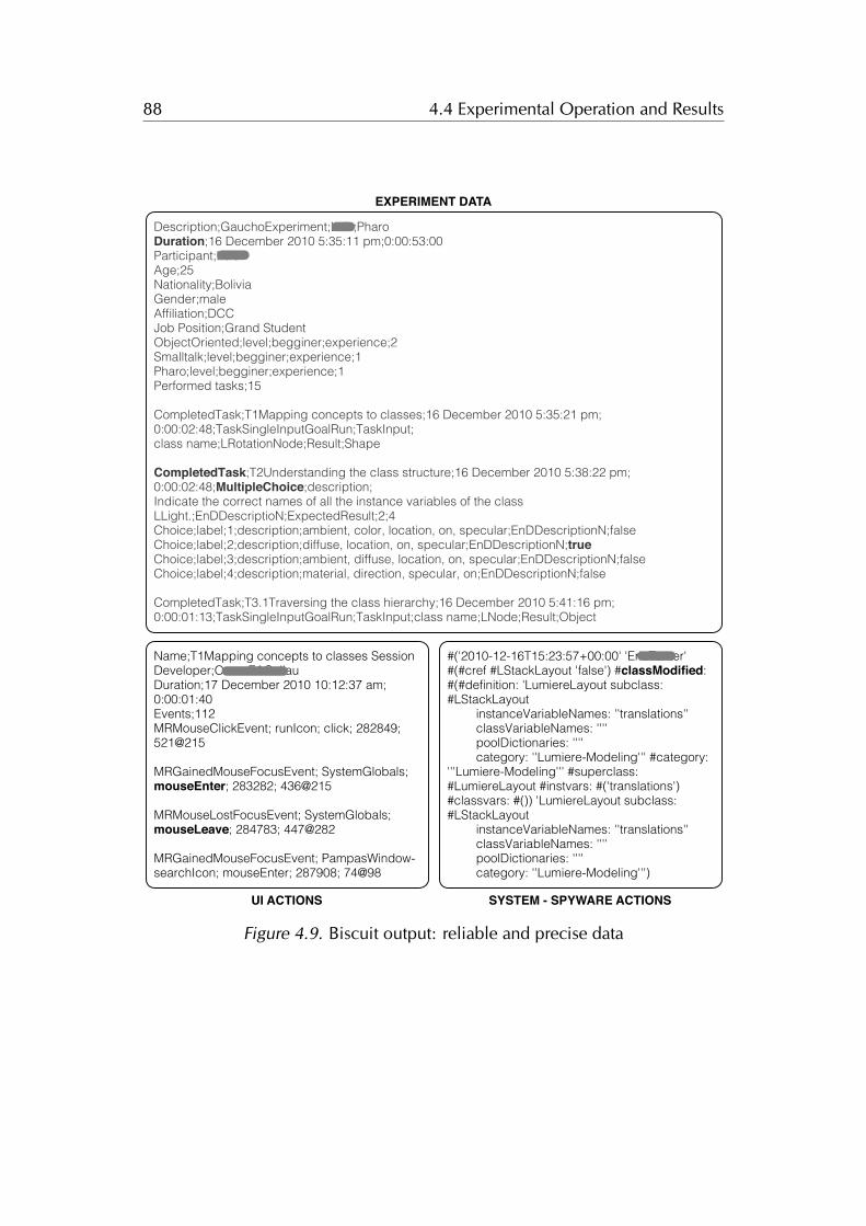
88 4.4 Experimental Operation and Results
Description;GauchoExperiment;Luis;PharoDuration;16 December 2010 5:35:11 pm;0:00:53:00Participant;LuisAge;25Nationality;BoliviaGender;maleAffiliation;DCCJob Position;Grand StudentObjectOriented;level;begginer;experience;2Smalltalk;level;begginer;experience;1Pharo;level;begginer;experience;1Performed tasks;15
CompletedTask;T1Mapping concepts to classes;16 December 2010 5:35:21 pm;0:00:02:48;TaskSingleInputGoalRun;TaskInput;class name;LRotationNode;Result;Shape
CompletedTask;T2Understanding the class structure;16 December 2010 5:38:22 pm;0:00:02:48;MultipleChoice;description;Indicate the correct names of all the instance variables of the class LLight.;EnDDescriptioN;ExpectedResult;2;4Choice;label;1;description;ambient, color, location, on, specular;EnDDescriptionN;falseChoice;label;2;description;diffuse, location, on, specular;EnDDescriptionN;trueChoice;label;3;description;ambient, diffuse, location, on, specular;EnDDescriptionN;falseChoice;label;4;description;material, direction, specular, on;EnDDescriptionN;false
CompletedTask;T3.1Traversing the class hierarchy;16 December 2010 5:41:16 pm;0:00:01:13;TaskSingleInputGoalRun;TaskInput;class name;LNode;Result;Object
Name;T1Mapping concepts to classes SessionDeveloper;OscarEACallauDuration;17 December 2010 10:12:37 am;0:00:01:40Events;112MRMouseClickEvent; runIcon; click; 282849; 521@215
MRGainedMouseFocusEvent; SystemGlobals; mouseEnter; 283282; 436@215
MRMouseLostFocusEvent; SystemGlobals; mouseLeave; 284783; 447@282
MRGainedMouseFocusEvent; PampasWindow-searchIcon; mouseEnter; 287908; 74@98
#('2010-12-16T15:23:57+00:00' 'EricTanter' #(#cref #LStackLayout 'false') #classModified: #(#definition: 'LumiereLayout subclass: #LStackLayout
instanceVariableNames: ''translations''classVariableNames: ''''poolDictionaries: ''''category: ''Lumiere-Modeling''' #category:
'''Lumiere-Modeling''' #superclass: #LumiereLayout #instvars: #('translations') #classvars: #()) 'LumiereLayout subclass: #LStackLayout
instanceVariableNames: ''translations''classVariableNames: ''''poolDictionaries: ''''category: ''Lumiere-Modeling''')
EXPERIMENT DATA
UI ACTIONS SYSTEM - SPYWARE ACTIONS
Figure 4.9. Biscuit output: reliable and precise data
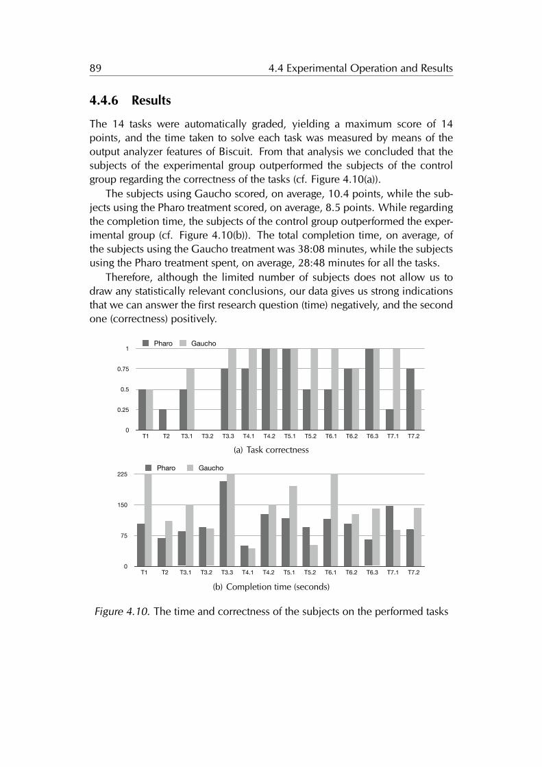
89 4.4 Experimental Operation and Results
4.4.6 Results
The 14 tasks were automatically graded, yielding a maximum score of 14points, and the time taken to solve each task was measured by means of theoutput analyzer features of Biscuit. From that analysis we concluded that thesubjects of the experimental group outperformed the subjects of the controlgroup regarding the correctness of the tasks (cf. Figure 4.10(a)).
The subjects using Gaucho scored, on average, 10.4 points, while the sub-jects using the Pharo treatment scored, on average, 8.5 points. While regardingthe completion time, the subjects of the control group outperformed the exper-imental group (cf. Figure 4.10(b)). The total completion time, on average, ofthe subjects using the Gaucho treatment was 38:08 minutes, while the subjectsusing the Pharo treatment spent, on average, 28:48 minutes for all the tasks.
Therefore, although the limited number of subjects does not allow us todraw any statistically relevant conclusions, our data gives us strong indicationsthat we can answer the first research question (time) negatively, and the secondone (correctness) positively.
0
0.25
0.5
0.75
1
T1 T2 T3.1 T3.2 T3.3 T4.1 T4.2 T5.1 T5.2 T6.1 T6.2 T6.3 T7.1 T7.2
Pharo Gaucho
(a) Task correctness
0
75
150
225
T1 T2 T3.1 T3.2 T3.3 T4.1 T4.2 T5.1 T5.2 T6.1 T6.2 T6.3 T7.1 T7.2
Pharo Gaucho
(b) Completion time (seconds)
Figure 4.10. The time and correctness of the subjects on the performed tasks
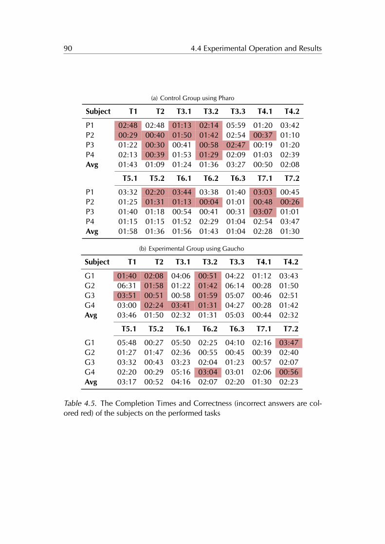
90 4.4 Experimental Operation and Results
(a) Control Group using Pharo
Subject T1 T2 T3.1 T3.2 T3.3 T4.1 T4.2
P1 02:48 02:48 01:13 02:14 05:59 01:20 03:42P2 00:29 00:40 01:50 01:42 02:54 00:37 01:10P3 01:22 00:30 00:41 00:58 02:47 00:19 01:20P4 02:13 00:39 01:53 01:29 02:09 01:03 02:39Avg 01:43 01:09 01:24 01:36 03:27 00:50 02:08
T5.1 T5.2 T6.1 T6.2 T6.3 T7.1 T7.2
P1 03:32 02:20 03:44 03:38 01:40 03:03 00:45P2 01:25 01:31 01:13 00:04 01:01 00:48 00:26P3 01:40 01:18 00:54 00:41 00:31 03:07 01:01P4 01:15 01:15 01:52 02:29 01:04 02:54 03:47Avg 01:58 01:36 01:56 01:43 01:04 02:28 01:30
(b) Experimental Group using Gaucho
Subject T1 T2 T3.1 T3.2 T3.3 T4.1 T4.2
G1 01:40 02:08 04:06 00:51 04:22 01:12 03:43G2 06:31 01:58 01:22 01:42 06:14 00:28 01:50G3 03:51 00:51 00:58 01:59 05:07 00:46 02:51G4 03:00 02:24 03:41 01:31 04:27 00:28 01:42Avg 03:46 01:50 02:32 01:31 05:03 00:44 02:32
T5.1 T5.2 T6.1 T6.2 T6.3 T7.1 T7.2
G1 05:48 00:27 05:50 02:25 04:10 02:16 03:47G2 01:27 01:47 02:36 00:55 00:45 00:39 02:40G3 03:32 00:43 03:23 02:04 01:23 00:57 02:07G4 02:20 00:29 05:16 03:04 03:01 02:06 00:56Avg 03:17 00:52 04:16 02:07 02:20 01:30 02:23
Table 4.5. The Completion Times and Correctness (incorrect answers are col-ored red) of the subjects on the performed tasks
91 4.4 Experimental Operation and Results
We now proceed with a qualitative evaluation of the results of each task.To better analyze the obtained results we grouped the tasks according to thesimilarities between their goals. In the following discussion, for each group oftasks, we present the IDs, a summary of the goals to be accomplished by thesubjects, and comment the obtained results.
Concept Location: T1
The goal is to find the class named LRotationNode, by searching the class thatmost resembles a rotation node of a Lumière scene graph. We wanted to assessif the global search widget of Gaucho was accessible and provided the means toeffectively perform concept location; it is similar to the lexical or static analysisbased search tools of IDEs.
The results of the subjects of the experimental group were similar to thecontrol group in terms of correctness. However, they spent—on average—moretime than the subjects in the control group, mostly because of usability issueswith the global search widget of Gaucho: it currently lacks support for perform-ing concept location via pattern matching.
Structural comprehension of classes and packages: T2, T4.1, T4.2
The goal is to choose the correct answer from a multiple choice scheme of theset of instance variables of the class LLight (task T2), the number of packagesthat make up Lumière (task T4.1), and the two packages in Lumière with thelargest number of classes (task T4.2). With these tasks we investigate whetherthe structure of an object is correctly understood when depicted using a high-level view—the class or package shape—as opposed to the textual representa-tion of the class definition.
The results for task T2 show that the subjects of the control group outper-formed the subjects using Gaucho. This negative score was a result of a misun-derstood scrollable widget of the class shape, which only reveals four instancevariables at a time; most subjects were not aware that this list could be scrolleddown to reveal the fifth instance variable, thus answering incorrectly.
The results for T4.1 and T4.2 show that the experimental group outper-formed the control group, but the subjects using Gaucho took more time onT4.2 and less on T4.1 than the subjects using Pharo. In T4.1, a single pack-age shape is involved (representing Lumière), whereas T4.2 requires interactingwith a larger number of package shapes, as they must be placed side by side tocompare their sizes.
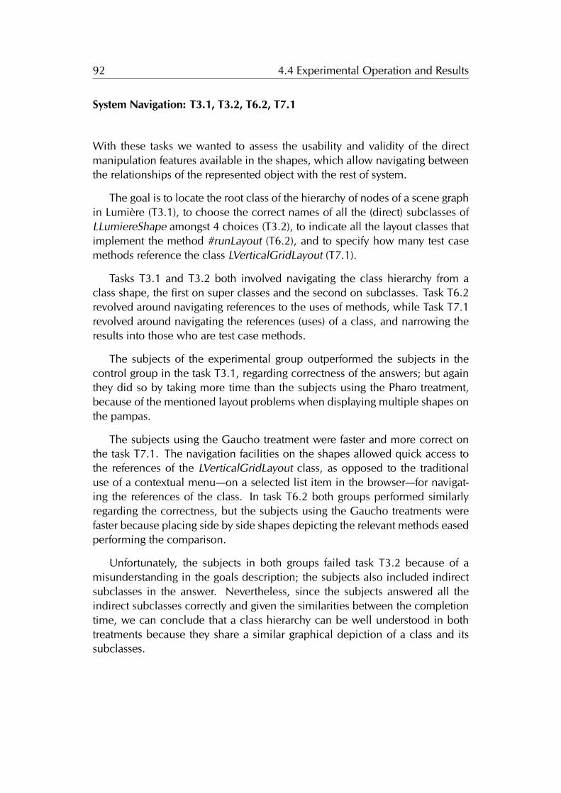
92 4.4 Experimental Operation and Results
System Navigation: T3.1, T3.2, T6.2, T7.1
With these tasks we wanted to assess the usability and validity of the directmanipulation features available in the shapes, which allow navigating betweenthe relationships of the represented object with the rest of system.
The goal is to locate the root class of the hierarchy of nodes of a scene graphin Lumière (T3.1), to choose the correct names of all the (direct) subclasses ofLLumiereShape amongst 4 choices (T3.2), to indicate all the layout classes thatimplement the method #runLayout (T6.2), and to specify how many test casemethods reference the class LVerticalGridLayout (T7.1).
Tasks T3.1 and T3.2 both involved navigating the class hierarchy from aclass shape, the first on super classes and the second on subclasses. Task T6.2revolved around navigating references to the uses of methods, while Task T7.1revolved around navigating the references (uses) of a class, and narrowing theresults into those who are test case methods.
The subjects of the experimental group outperformed the subjects in thecontrol group in the task T3.1, regarding correctness of the answers; but againthey did so by taking more time than the subjects using the Pharo treatment,because of the mentioned layout problems when displaying multiple shapes onthe pampas.
The subjects using the Gaucho treatment were faster and more correct onthe task T7.1. The navigation facilities on the shapes allowed quick access tothe references of the LVerticalGridLayout class, as opposed to the traditionaluse of a contextual menu—on a selected list item in the browser—for navigat-ing the references of the class. In task T6.2 both groups performed similarlyregarding the correctness, but the subjects using the Gaucho treatments werefaster because placing side by side shapes depicting the relevant methods easedperforming the comparison.
Unfortunately, the subjects in both groups failed task T3.2 because of amisunderstanding in the goals description; the subjects also included indirectsubclasses in the answer. Nevertheless, since the subjects answered all theindirect subclasses correctly and given the similarities between the completiontime, we can conclude that a class hierarchy can be well understood in bothtreatments because they share a similar graphical depiction of a class and itssubclasses.
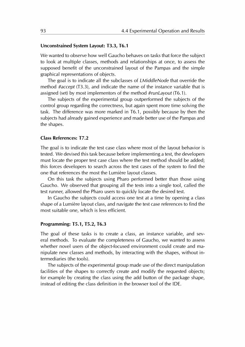
93 4.4 Experimental Operation and Results
Unconstrained System Layout: T3.3, T6.1
We wanted to observe how well Gaucho behaves on tasks that force the subjectto look at multiple classes, methods and relationships at once, to assess thesupposed benefit of the unconstrained layout of the Pampas and the simplegraphical representations of objects.
The goal is to indicate all the subclasses of LMiddleNode that override themethod #accept (T3.3), and indicate the name of the instance variable that isassigned (set) by most implementors of the method #runLayout (T6.1).
The subjects of the experimental group outperformed the subjects of thecontrol group regarding the correctness, but again spent more time solving thetask. The difference was more marked in T6.1, possibly because by then thesubjects had already gained experience and made better use of the Pampas andthe shapes.
Class References: T7.2
The goal is to indicate the test case class where most of the layout behavior istested. We devised this task because before implementing a test, the developersmust locate the proper test case class where the test method should be added;this forces developers to search across the test cases of the system to find theone that references the most the Lumière layout classes.
On this task the subjects using Pharo performed better than those usingGaucho. We observed that grouping all the tests into a single tool, called thetest runner, allowed the Pharo users to quickly locate the desired test.
In Gaucho the subjects could access one test at a time by opening a classshape of a Lumière layout class, and navigate the test case references to find themost suitable one, which is less efficient.
Programming: T5.1, T5.2, T6.3
The goal of these tasks is to create a class, an instance variable, and sev-eral methods. To evaluate the completeness of Gaucho, we wanted to assesswhether novel users of the object-focused environment could create and ma-nipulate new classes and methods, by interacting with the shapes, without in-termediaries (the tools).
The subjects of the experimental group made use of the direct manipulationfacilities of the shapes to correctly create and modify the requested objects;for example by creating the class using the add button of the package shape,instead of editing the class definition in the browser tool of the IDE.
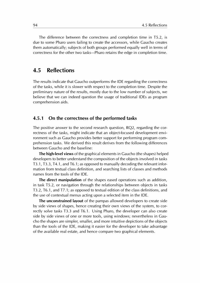
94 4.5 Reflections
The difference between the correctness and completion time in T5.2, isdue to some Pharo users failing to create the accessors, while Gaucho createsthem automatically; subjects of both groups performed equally well in terms ofcorrectness for the other two tasks—Pharo retains the edge in completion time.
4.5 Reflections
The results indicate that Gaucho outperforms the IDE regarding the correctnessof the tasks, while it is slower with respect to the completion time. Despite thepreliminary nature of the results, mostly due to the low number of subjects, webelieve that we can indeed question the usage of traditional IDEs as programcomprehension aids.
4.5.1 On the correctness of the performed tasks
The positive answer to the second research question, RQ2, regarding the cor-rectness of the tasks, might indicate that an object-focused development envi-ronment such as Gaucho provides better support for performing program com-prehension tasks. We derived this result derives from the following differencesbetween Gaucho and the baseline:
The high-level views of the graphical elements in Gaucho (the shapes) helpeddevelopers to better understand the composition of the objects involved in tasksT3.1, T3.3, T4.1, and T6.1; as opposed to manually decoding the relevant infor-mation from textual class definition, and searching lists of classes and methodsnames from the tools of the IDE.
The direct manipulation of the shapes eased operations such as addition,in task T5.2, or navigation through the relationships between objects in tasksT3.2, T6.1, and T7.1; as opposed to textual edition of the class definitions, andthe use of contextual menus acting upon a selected item in the IDE.
The unconstrained layout of the pampas allowed developers to create sideby side views of shapes, hence creating their own views of the system, to cor-rectly solve tasks T3.3 and T6.1. Using Pharo, the developer can also createside by side views of one or more tools, using windows; nevertheless in Gau-cho the shapes are simpler, smaller, and more intuitive depictions of the objectsthan the tools of the IDE, making it easier for the developer to take advantageof the available real estate, and hence compare two graphical elements.
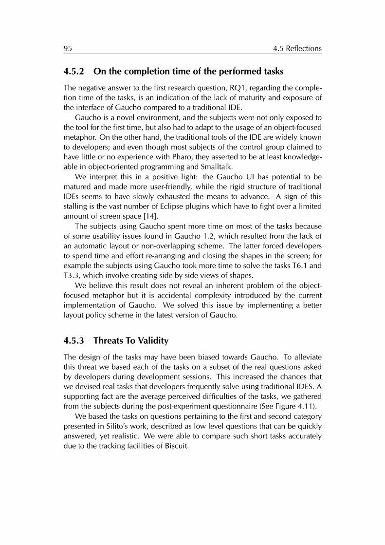
95 4.5 Reflections
4.5.2 On the completion time of the performed tasks
The negative answer to the first research question, RQ1, regarding the comple-tion time of the tasks, is an indication of the lack of maturity and exposure ofthe interface of Gaucho compared to a traditional IDE.
Gaucho is a novel environment, and the subjects were not only exposed tothe tool for the first time, but also had to adapt to the usage of an object-focusedmetaphor. On the other hand, the traditional tools of the IDE are widely knownto developers; and even though most subjects of the control group claimed tohave little or no experience with Pharo, they asserted to be at least knowledge-able in object-oriented programming and Smalltalk.
We interpret this in a positive light: the Gaucho UI has potential to bematured and made more user-friendly, while the rigid structure of traditionalIDEs seems to have slowly exhausted the means to advance. A sign of thisstalling is the vast number of Eclipse plugins which have to fight over a limitedamount of screen space [14].
The subjects using Gaucho spent more time on most of the tasks becauseof some usability issues found in Gaucho 1.2, which resulted from the lack ofan automatic layout or non-overlapping scheme. The latter forced developersto spend time and effort re-arranging and closing the shapes in the screen; forexample the subjects using Gaucho took more time to solve the tasks T6.1 andT3.3, which involve creating side by side views of shapes.
We believe this result does not reveal an inherent problem of the object-focused metaphor but it is accidental complexity introduced by the currentimplementation of Gaucho. We solved this issue by implementing a betterlayout policy scheme in the latest version of Gaucho.
4.5.3 Threats To Validity
The design of the tasks may have been biased towards Gaucho. To alleviatethis threat we based each of the tasks on a subset of the real questions askedby developers during development sessions. This increased the chances thatwe devised real tasks that developers frequently solve using traditional IDES. Asupporting fact are the average perceived difficulties of the tasks, we gatheredfrom the subjects during the post-experiment questionnaire (See Figure 4.11).
We based the tasks on questions pertaining to the first and second categorypresented in Silito’s work, described as low level questions that can be quicklyanswered, yet realistic. We were able to compare such short tasks accuratelydue to the tracking facilities of Biscuit.
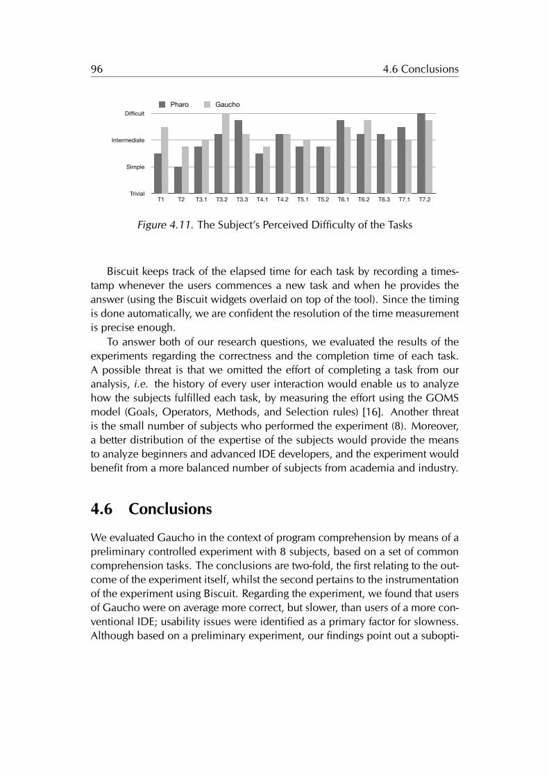
96 4.6 Conclusions
Participant DescriptionSubject Job Position OOP Smalltalk Pharo
P1P2P3P4
G1G2G3G4
Grand Student begginer(2) begginer(1) begginer(1)DW Consultant advanced(3) begginer(0.2) begginer(0.2)Assistant Professor advanced(12) knowledgeable(2) none(unspecified)Student knowledgeable(6) begginer(1) begginer(1)
Phd student knowledgeable(7) knowledgeable(2) knowledgeable(2)Assistant Professor expert(12) expert(10) expert(3)Prof expert(15) advanced(12) knowledgeable(1.5)student begginer(1) begginer(0.5) begginer(0.5)
Tasks DescriptionSubject T1 T2 T3.1 T3.2 T3.3 T4.1 T4.2 T5.1 T5.2 T6.1 T6.2 T6.3 T7.1 T7.2 T7.3
P1P2P3
G1G2G3G4
C C C C C C C C C C C C C C CC C C C C C C C C S S C S S SC C C C C C C C C C C C C C C
C C C C C C C C C C C C C C SC C C C C C C C C C C C C C CC C C C C C C C C C C C C C CC C C C C C C C C C C C C C C
Begginer Knowledgeable Advanced Expert
GauchoPharo
4 0 0 04 0 0 0
OOP Smalltalk Pharo
none
beginner
knowledgeable
advanced
expert
PHARO
0 0 1
1 3 3
1 1 0
2 0 0
0 0 0
OOP Smalltalk Pharo
none
beginner
knowledgeable
advanced
expert
Gaucho
0 0 0
1 1 1
1 1 2
0 1 0
2 1 1
OOP Smalltalk Pharo
11
2
0
1
0
2
11 111
000
Gaucho
OOP Smalltalk Pharo
000 00
2
0
11
33
1 1
00
Pharo
none beginner knowledgeable advanced expert
precevied difficultiesSubject T1 T2 T3.1 T3.2 T3.3 T4.1 T4.2 T5.1 T5.2 T6.1 T6.2 T6.3 T7.1 T7.2
P1P2P3P4AVG
G1G2G3G4Gaucho
4 4 4 4 4 4 4 4 4 4 4 4 4 43 2 3 3 4 2 4 3 2 5 4 3 3 51 1 2 3 4 1 2 2 2 3 2 2 4 42 1 2 3 3 3 3 2 3 3 3 4 3 4
2.5 2 2.75 3.25 3.75 2.5 3.25 2.75 2.75 3.75 3.25 3.25 3.5 4.25
4 4 4 4 4 4 4 4 4 4 4 4 4 45 4 4 4 4 4 4 4 4 4 4 4 4 43 2 3 3 4 2 4 3 2 5 4 3 3 52 1 1 5 1 1 1 1 1 1 3 1 1 2
3.5 2.75 3 4 3.25 2.75 3.25 3 2.75 3.5 3.75 3 3 3.75
P4;2;1;2;3;3;3;3;2;3;3;3;4;3;4;4
Simple
Intermediate
Difficult
T1 T2 T3.1 T3.2 T3.3 T4.1 T4.2 T5.1 T5.2 T6.1 T6.2 T6.3 T7.1 T7.2
Pharo
Trivial
Simple
Intermediate
Difficult
T1 T2 T3.1 T3.2 T3.3 T4.1 T4.2 T5.1 T5.2 T6.1 T6.2 T6.3 T7.1 T7.2
Pharo Gaucho
Figure 4.11. The Subject’s Perceived Difficulty of the Tasks
Biscuit keeps track of the elapsed time for each task by recording a times-tamp whenever the users commences a new task and when he provides theanswer (using the Biscuit widgets overlaid on top of the tool). Since the timingis done automatically, we are confident the resolution of the time measurementis precise enough.
To answer both of our research questions, we evaluated the results of theexperiments regarding the correctness and the completion time of each task.A possible threat is that we omitted the effort of completing a task from ouranalysis, i.e. the history of every user interaction would enable us to analyzehow the subjects fulfilled each task, by measuring the effort using the GOMSmodel (Goals, Operators, Methods, and Selection rules) [16]. Another threatis the small number of subjects who performed the experiment (8). Moreover,a better distribution of the expertise of the subjects would provide the meansto analyze beginners and advanced IDE developers, and the experiment wouldbenefit from a more balanced number of subjects from academia and industry.
4.6 Conclusions
We evaluated Gaucho in the context of program comprehension by means of apreliminary controlled experiment with 8 subjects, based on a set of commoncomprehension tasks. The conclusions are two-fold, the first relating to the out-come of the experiment itself, whilst the second pertains to the instrumentationof the experiment using Biscuit. Regarding the experiment, we found that usersof Gaucho were on average more correct, but slower, than users of a more con-ventional IDE; usability issues were identified as a primary factor for slowness.Although based on a preliminary experiment, our findings point out a subopti-
97 4.6 Conclusions
mal and stalling situation regarding traditional IDEs. While we investigated thecontext of program comprehension, the discussion is pertinent at all levels.
4.6.1 Biscuit to the Rescue
Performing controlled experiments with human subjects is a difficult task, sub-ject to many threats. Biscuit is an experimental toolkit aimed at reducing someof the threats related to recording and gathering experimental data.
Biscuit supports the recording of answers and timing information necessaryfor quantitative experiments; it also collects finer-grained data—user interactions—that, on the one hand, is useful for a qualitative analysis of the data and, on theother hand, makes the experiments fully replicable.
We raise the question of whether tools such as Biscuit can improve the qual-ity of the process by which we currently perform controlled experiments; andmore importantly, if the availability of more precise and reliable data can elim-inate some of the numerous threats present in controlled experiments, whichare manually conducted by fallible humans. Contrasting Gaucho’s controlledexperiment [32] (conducted using Biscuit) and our previous experiment [68](conducted in the traditional manner) we noticed that:
• by relieving ourselves from book-keeping tasks, we removed ourselves asthreats to validity;
• we were able to better observe the subjects during the experimental run,gathering in the process much more qualitative data about Gaucho’s us-ability;
• data post-processing was greatly simplified;
• since the Gaucho experiment featured several very short tasks (some witha duration under a minute), we doubt that conducting the same experi-ment would have been possible in a “traditional” (i.e., manual) way.
Conducting controlled experiments with human subjects to evaluate soft-ware engineering tools and approaches has become a necessity. Such experi-ments come with many threats to validity because of the humans involved; webelieve Biscuit helps to remove some of the threats that regard the operation ofcontrolled experiments.

98 4.6 Conclusions
Chapter 5
Object-Focused Collaboration
In this dissertation we discuss an extensible design for the interface of objectoriented development environments. To demonstrate the extensibility of ourapproach, in this chapter we investigate its application to collaboration.
The art of crafting programs to solve problems is rarely accomplished by asingle human working in solitude. Early psychological theories of programming[5] acknowledged that the software development process is a social humantask, and practitioners have observed that therein lies the main cause of projectfailures [76]. Nonetheless, the main vehicle for programming—the integrateddevelopment environment (IDE)—remains as it was conceived in the 1970s,focused on a single point of view of the system.
IDEs were designed without collaboration in mind, hence team membersare aware of system changes only after the code is committed to the versioningsystem, which delays discussions that would otherwise prevent conflicts. Therehave been attempts to provide better collaboration support in existing IDEs,such as Palantir [77] and Syde [78]. However, in these cases collaborationsupport is an afterthought stapled on top of existing environments that struggleto overcome their single-developer nature.
In this chapter we present Ronda, an extension to Gaucho, which offers first-class support for collaborative development sessions, and promotes awarenessof fine-grained changes to the system under development.
Structure of the chapter. In Section 5.1 we motivate the need for noveldevelopment environments designed to support a team of programmers. InSection 5.2 we describe Ronda, a collaborative object-focused environment. InSection 5.3 we conclude the chapter, detailing the infrastructure we built tosupport team collaboration within the scope of sessions in Ronda.
99
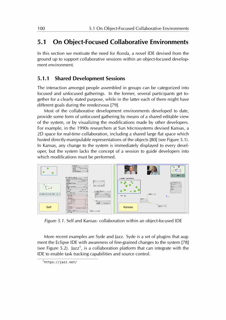
100 5.1 On Object-Focused Collaborative Environments
5.1 On Object-Focused Collaborative Environments
In this section we motivate the need for Ronda, a novel IDE devised from theground up to support collaborative sessions within an object-focused develop-ment environment.
5.1.1 Shared Development Sessions
The interaction amongst people assembled in groups can be categorized intofocused and unfocused gatherings. In the former, several participants get to-gether for a clearly stated purpose, while in the latter each of them might havedifferent goals during the rendezvous [79].
Most of the collaborative development environments developed to date,provide some form of unfocused gathering by means of a shared editable viewof the system, or by visualizing the modifications made by other developers.For example, in the 1990s researchers at Sun Microsystems devised Kansas, a2D space for real-time collaboration, including a shared large flat space whichhosted directly-manipulable representations of the objects [80] (see Figure 5.1).In Kansas, any change to the system is immediately displayed to every devel-oper, but the system lacks the concept of a session to guide developers intowhich modifications must be performed.
KansasSelf
Figure 5.1. Self and Kansas: collaboration within an object-focused IDE
More recent examples are Syde and Jazz. Syde is a set of plugins that aug-ment the Eclipse IDE with awareness of fine-grained changes to the system [78](see Figure 5.2). Jazz1, is a collaboration platform that can integrate with theIDE to enable task tracking capabilities and source control.
1https://jazz.net/
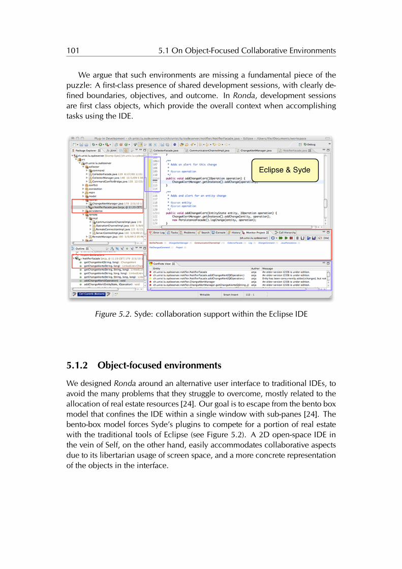
101 5.1 On Object-Focused Collaborative Environments
We argue that such environments are missing a fundamental piece of thepuzzle: A first-class presence of shared development sessions, with clearly de-fined boundaries, objectives, and outcome. In Ronda, development sessionsare first class objects, which provide the overall context when accomplishingtasks using the IDE.
Eclipse & Syde
Figure 5.2. Syde: collaboration support within the Eclipse IDE
5.1.2 Object-focused environments
We designed Ronda around an alternative user interface to traditional IDEs, toavoid the many problems that they struggle to overcome, mostly related to theallocation of real estate resources [24]. Our goal is to escape from the bento boxmodel that confines the IDE within a single window with sub-panes [24]. Thebento-box model forces Syde’s plugins to compete for a portion of real estatewith the traditional tools of Eclipse (see Figure 5.2). A 2D open-space IDE inthe vein of Self, on the other hand, easily accommodates collaborative aspectsdue to its libertarian usage of screen space, and a more concrete representationof the objects in the interface.
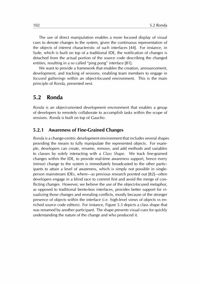
102 5.2 Ronda
The use of direct manipulation enables a more focused display of visualcues to denote changes to the system, given the continuous representation ofthe objects of interest characteristic of such interfaces [44]. For instance, inSyde, which is built on top of a traditional IDE, the notification of changes isdetached from the actual portion of the source code describing the changedentities, resulting in a so called “ping pong” interface [81].
We want to provide a framework that enables the creation, announcement,development, and tracking of sessions, enabling team members to engage infocused gatherings within an object-focused environment. This is the mainprinciple of Ronda, presented next.
5.2 Ronda
Ronda is an object-oriented development environment that enables a groupof developers to remotely collaborate to accomplish tasks within the scope ofsessions. Ronda is built on top of Gaucho.
5.2.1 Awareness of Fine-Grained Changes
Ronda is a change-centric development environment that includes several shapesproviding the means to fully manipulate the represented objects. For exam-ple, developers can create, rename, remove, and add methods and variablesto classes by solely interacting with a Class Shape. We track fine-grainedchanges within the IDE, to provide real-time awareness support, hence every(minor) change to the system is immediately broadcasted to the other partic-ipants to attain a level of awareness, which is simply not possible in single-person mainstream IDEs, where—as previous research pointed out [82]—oftendevelopers engage in a blind race to commit first and avoid the merge of con-flicting changes. However, we believe the use of the object-focused metaphor,as opposed to traditional bento-box interfaces, provides better support for vi-sualizing those changes and revealing conflicts, mostly because of the strongerpresence of objects within the interface (i.e. high-level views of objects vs en-riched source code editors). For instance, Figure 5.3 depicts a class shape thatwas renamed by another participant. The shape presents visual cues for quicklyunderstanding the nature of the change and who produced it.
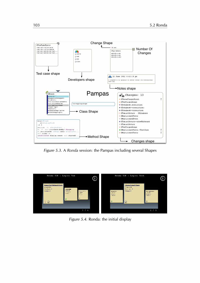
103 5.2 Ronda
Test case shape
Developers shape
Changes shape
Notes shape
Change Shape
Class Shape
Pampas
Method Shape
Number Of Changes
Figure 5.3. A Ronda session: the Pampas including several Shapes
Locked: only for trusted developers
OfflineOnline
Figure 5.4. Ronda: the initial display
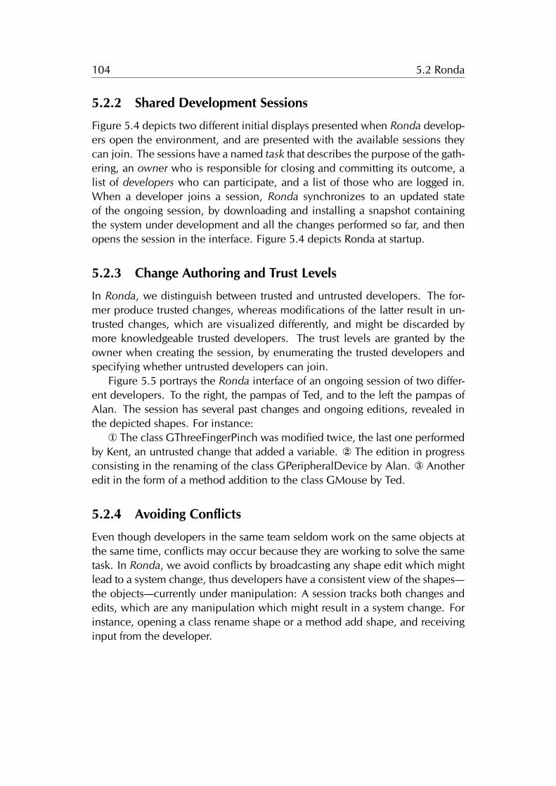
104 5.2 Ronda
5.2.2 Shared Development Sessions
Figure 5.4 depicts two different initial displays presented when Ronda develop-ers open the environment, and are presented with the available sessions theycan join. The sessions have a named task that describes the purpose of the gath-ering, an owner who is responsible for closing and committing its outcome, alist of developers who can participate, and a list of those who are logged in.When a developer joins a session, Ronda synchronizes to an updated stateof the ongoing session, by downloading and installing a snapshot containingthe system under development and all the changes performed so far, and thenopens the session in the interface. Figure 5.4 depicts Ronda at startup.
5.2.3 Change Authoring and Trust Levels
In Ronda, we distinguish between trusted and untrusted developers. The for-mer produce trusted changes, whereas modifications of the latter result in un-trusted changes, which are visualized differently, and might be discarded bymore knowledgeable trusted developers. The trust levels are granted by theowner when creating the session, by enumerating the trusted developers andspecifying whether untrusted developers can join.
Figure 5.5 portrays the Ronda interface of an ongoing session of two differ-ent developers. To the right, the pampas of Ted, and to the left the pampas ofAlan. The session has several past changes and ongoing editions, revealed inthe depicted shapes. For instance:
¬ The class GThreeFingerPinch was modified twice, the last one performedby Kent, an untrusted change that added a variable. The edition in progressconsisting in the renaming of the class GPeripheralDevice by Alan. ® Anotheredit in the form of a method addition to the class GMouse by Ted.
5.2.4 Avoiding Conflicts
Even though developers in the same team seldom work on the same objects atthe same time, conflicts may occur because they are working to solve the sametask. In Ronda, we avoid conflicts by broadcasting any shape edit which mightlead to a system change, thus developers have a consistent view of the shapes—the objects—currently under manipulation: A session tracks both changes andedits, which are any manipulation which might result in a system change. Forinstance, opening a class rename shape or a method add shape, and receivinginput from the developer.
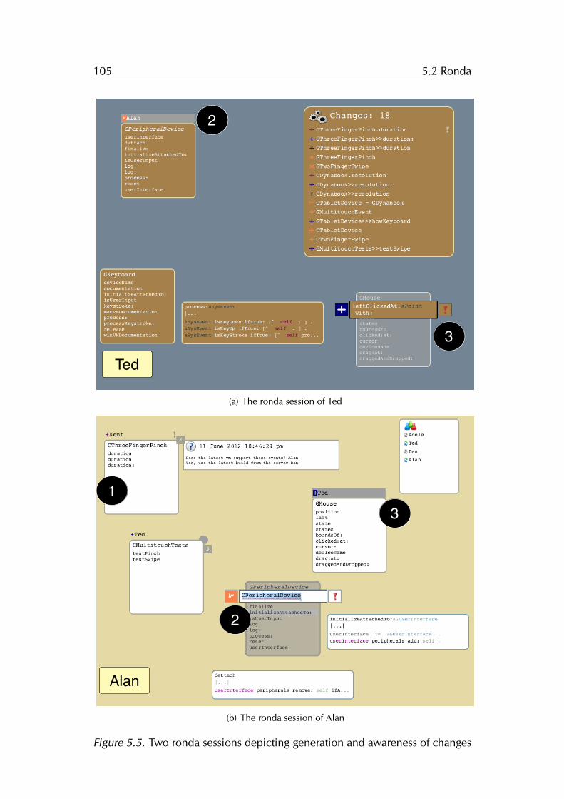
105 5.2 Ronda
AlanTed
2
2
1
3
3
(a) The ronda session of Ted
AlanTed
2
2
1
3
3
(b) The ronda session of Alan
Figure 5.5. Two ronda sessions depicting generation and awareness of changes
106 5.3 Tea Time
5.3 Tea Time
Ronda implements a simplified version of TeaTime [83], a decentralized dis-tributed framework that relies on replication of computation instead of data.TeaTime revolves around the concept of an Island, which is a secure containerof objects. An Island is an abstract concept with no inherent location.
The Islands are projected onto numerous concrete replicas, located in hostsof the network. Consistency amongst replicas is maintained by broadcastingany message that alters the state of the Island, via controllers connected tothe same router, following a two-phase commit protocol. TeaTime messagesoriginate in a host, then travel from the controller to the router, and finally getdispatched to all the connected controllers, including the original one.
The state-changing messages are generated in response to events performedby the developer, when manipulating the objects of the Island via their graph-ical counterpart within the user interface. The messages sent by the routerare ordered by a sequence number and a timestamp, to preserve the order ofexecution of all received messages in each replica. Thus, the replicas determin-istically evolve over time, because each replica is an exact copy of the Islandi.e. they hold the same objects, and send the same ordered stream of messages.
5.3.1 Customizing TeaTime for Ronda
In Ronda, a TeaTime Island includes the shared development sessions, repli-cated in the IDE of all collaborating developers. A development session in-cludes the system under construction, a list of trusted developers, and all thepast changes.
Figure 5.6 depicts the core architecture in Ronda, consisting of one or moredevelopers running a Ronda IDE (Alan, Ted, Dan, and Adele), composed of acontroller connected to the Island’s router via a TCP Socket, a replica of theongoing Session, and an augmented Gaucho IDE.
When developers manipulate Gaucho shapes:À a Tea Time message in the form of a UI command is generated Á, that
either represents a fine grained system change or a UI element editing, likea class rename. The command is sent to the controller and forwarded to theisland’s router Â. The router broadcasts the command to all the connectedcontrollers Ã. Afterwards, upon reception, the command is executed producingthe same result in every replica Ä, which results in a change Å that alters theongoing session, and is presented in the user interface of the IDE Æ.
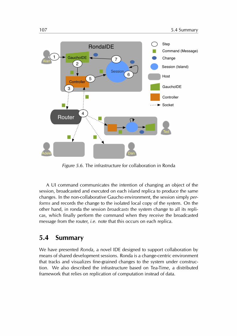
107 5.4 Summary
RondaIDE
Controller
GauchoIDE
Session
Router
2
3
56
7
4
Command (Message)
Change
Session (Island)
Host
Alan
Ted
Dan
Step
GauchoIDE
Controller
Socket
Adele
1
Figure 5.6. The infrastructure for collaboration in Ronda
A UI command communicates the intention of changing an object of thesession, broadcasted and executed on each island replica to produce the samechanges. In the non-collaborative Gaucho environment, the session simply per-forms and records the change to the isolated local copy of the system. On theother hand, in ronda the session broadcasts the system change to all its repli-cas, which finally perform the command when they receive the broadcastedmessage from the router, i.e. note that this occurs on each replica.
5.4 Summary
We have presented Ronda, a novel IDE designed to support collaboration bymeans of shared development sessions. Ronda is a change-centric environmentthat tracks and visualizes fine-grained changes to the system under construc-tion. We also described the infrastructure based on Tea-Time, a distributedframework that relies on replication of computation instead of data.

108 5.4 Summary
Chapter 6
Conclusions
Computer programming requires humans with the necessary skill to create theprograms, translating the solutions to problems from the human brain, into acomputer readable form. Since the beginning of computing, programmers re-cur to the aid of tools. From the punch cards of yore, to the word processorsof teleprinters or terminal displays of mainframe computers. With the advent ofthe personal computer era, programming tools irrevocably turned to an interac-tive nature, making use of graphical user interfaces.
Nowadays, programmers use IDEs, which include numerous tools to effec-tively construct programs, and perform all the tasks related to software engineer-ing. From the original Smalltalk systems, which introduced the IDE, Object-Oriented Programming is achieved using a tool-based interface: the tools rele-gate the objects within the interface. An IDE using a tool-based interface hasbeen found to produce both conceptual and technical problems, the former oc-curs because of the objects remain hidden behind the tools. The latter relatesto a need for a finer-grained manipulation, for better real state management of ascarce resource–the display–, and the use of software visualization techniques.
In this dissertation we introduced an approach that promotes direct manip-ulation of objects as the sole means of programming in OOP languages. Ourthesis is that an object-focused environment supports an broad and extensiblerange of software engineering tasks, and alleviates the conceptual and technicalproblems of traditional IDEs. To this aim, we designed several interfaces basedon our approach, and we implemented them in several tools. To validate ourthesis, we created and evaluated, on top of our approach, an object-focusedenvironment for modeling, programming, and collaborating. We presented allthe interfaces, showing that they support various software engineering tasks,and provide a plausible alternative to the traditional tool-based IDEs.
109
110 6.1 Contributions
6.1 Contributions
During the course of this dissertation, we made a series of contributions tothe state of the art in software development environments for object orientedprogramming languages.
We summarize the major ones in the following.
The definition of an object-focused interface for software development [29].We defined an interface for object-oriented development based on twopivotal concepts: the Shapes and the Pampas. Shapes are directly manip-ulable representations of objects, that enable a fine-grained manipulationof all the software artifacts.
We designed the shapes to concisely visualize the structure and compo-sition of the objects, and customized to each kind of object in the systemto provide a complete set of interactions. The behavioral completeness ofthe Shapes disregards the need for extrinsic tools, to enhance the illusionthat the graphical element on display is the object.
The Pampas is a 2D surface, where the shapes are freely placed to favorthe use of spatial reasoning and memory, the comparison of objects bycreating side by side views, and the customization of own views of theprogram, persisted across multiple sessions to support task context.
The application of the object-focused interface to programming [30]. Wedesigned a set of shapes for the crafting of models composed of objects,described in class-based object oriented languages.
The shapes represent classes, methods, test-cases and packages of thesystem under construction: a class shape depicts the structure of the rep-resented class, and a method shape presents the method signature andthe statements that make up the body.
We described the interactions between the programmers and the shapesto craft the programs, and undertake program comprehension tasks.
The implementation of a tool which supports our object-focused interface[31]. We developed Gaucho, an object-focused programming environ-ment for the crafting of models composed of objects, described in class-based object oriented languages. Gaucho is publicly available and hasbeen used in academic research.
111 6.1 Contributions
The empirical validation of our approach through a controlled experiment[32]. We performed a controlled experiment to compare a traditionalIDE and Gaucho with respect to a set of program comprehension tasksextracted from the literature, such as creating, navigating, refactoring, andunderstanding an object-oriented system.
We found that users of Gaucho were on average more correct, but slower,than users of a more conventional IDE; usability issues were identified asa primary factor for slowness. The experiment was fully instrumentedusing Biscuit. We include the entire experimental data set and everythingthat is required to make the experiment repeatable, in Chapter 4.
The implementation of a tool to support human-centric controlled experi-ments [33]. We designed and implemented Biscuit: to support researcherswhen performing controlled experiments. Biscuit records relevant piecesof information regarding an experiment performed with human subjects.
Conducting experiments to evaluate software engineering tools and ap-proaches has become a necessity. Such experiments come with manythreats to validity because of the humans involved, Biscuit helps to re-move some of the threats that regard the operation of experiments. Weillustrate the main concepts of Biscuit, and the design of our experimentin Appendix A.
The application of the object-focused interface to collaboration [34]. Weinvestigated the use of object-focused environments to support collabora-tion by means of shared development sessions.
We designed a change-centric environment which tracks and visualizesfine-grained changes to the system under construction, to provide real-time awareness support amongst the team members.
We shown how an object-focused interface provides better support forvisualizing those changes and revealing conflicts, because of the strongerpresence of objects within the interface: the shape presents visual cuesfor quickly understanding the nature of the change and who produced it.
The implementation of a tool to support collaboration [34] We presentedRonda, an extension to Gaucho, which provides first-class support for col-laborative development sessions. Ronda is a change-centric environment:It promotes awareness of fine-grained changes to the system.
112 6.2 Future Work
6.2 Future Work
Our design of an object-focused environment could be enhanced in the follow-ing directions:
6.2.1 Semantics
In Gaucho, the various types of objects are represented differently, the interfaceuses a set of customized shapes for the models, classes, methods, packages, andtest cases. Nevertheless, there are still missing opportunities for conveying thesemantics, the state and behavior of the particular objects within each category.For example, Code City is a tool that uses software visualization techniques, todetect design flaws in the programs, by presenting distinct visual cues to denoteseveral Object-Oriented Metrics [84; 85].
We could could use a similar approach in Gaucho, given the inherent visualnature of an object-focused environment, which enables to customize the ap-pearance of each individual shape. Another possibility is to empower program-mers to come up with their own visual language for expressing the meaning oftheir programs, as in the Silhouette environment [86].
6.2.2 Relations
Programmers spend most of their time performing maintenance tasks, navigat-ing the system, and building an understanding of the relevant objects and therelationships between them. The Gaucho Shapes assume a passive role, insteadof actively helping programmers into forming working sets of relevant objects.We envision a recommendation system built into the shapes, that automaticallysuggests hints for further exploration of the system to the programmer, visu-alizing dependencies between related objects to reduce the navigation [14].Another direction of research involves the implementation of an organic layoutof the system, where the objects place themselves dynamically, according toone or more relations with their collaborators, such as inheritance and packagecontainment [87].
6.2.3 Education
Using graphical environments for teaching object oriented programming to stu-dents is beneficial [88]. Many different object oriented learning environments
113 6.3 Closing Words
exist, for example BlueJ for Java [89; 90], and LOOP for Smalltalk [91]. An ob-ject focused environment such as Gaucho, could be enhanced to accommodatepedagogical tasks. In Gaucho, the Shapes abstract away from source code, thuseasing the understanding of the components of the program, and the directnessof the interface enables beginners to quickly produce models, to learn the mainconcepts of the object oriented paradigm.
6.2.4 Live Programming Tools
In the recent year, the concept of live programming has been included in manyteaching environments 1 2. A live programming interface augments the textualrepresentation of the statements, i.e. the lines of code, with several visualcues to better understand their meaning -syntax- and results -semantics. Inthis dissertation we investigated alternative interfaces for developing in class-based OOP languages, where manipulating objects that form the programs isparamount. The interface proposed in this thesis, could be extended to includesuch features by augmenting the method shapes, which present the statementsof the methods.
6.3 Closing Words
Object oriented programming is based on the computational model of a worldof collaborating objects. An inherently dynamic world, where live objects areready to carry out each others requests in the form of messages.
The user interface of a traditional IDE forces a misconception of the conceptof a program in the object oriented programming paradigm, which is that theprogram and the executable are separate entities, therefore the objects come tolife when the program is up and running, and cease to exist when the programterminates or aborts its execution.
Acknowledging that the tools influence our own thinking habits, and wehumans –in particular programmers– tend to disregard the impact of this influ-ence, we advocate for a different design of the interfaces of our developmentenvironments, one that avoids the misconception and “brings objects closer tothe programmers”.
In our work we designed an integral development environment, were pro-grammers converse with the objects that make up the system, by interacting
1http://worrydream.com/#!/LearnableProgramming2http://toplap.org
114 6.3 Closing Words
with reactive visual shapes, from the models to the running programs. Enablinga dynamic “conversational interface”, because an object-focused environmentpermeates through all the environment, differently than the traditional tool-based IDEs, were the tools are separated from the software artifacts.
Given that the technology for the instrumenting of user interfaces is evolvingfast, its time for adapting our programming habits as well, and adopt a moreimmersive environment for manipulating objects all the way.
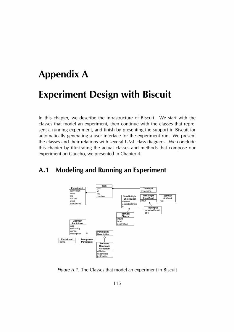
Appendix A
Experiment Design with Biscuit
In this chapter, we describe the infrastructure of Biscuit. We start with theclasses that model an experiment, then continue with the classes that repre-sent a running experiment, and finish by presenting the support in Biscuit forautomatically generating a user interface for the experiment run. We presentthe classes and their relations with several UML class diagrams. We concludethis chapter by illustrating the actual classes and methods that compose ourexperiment on Gaucho, we presented in Chapter 4.
A.1 Modeling and Running an Experiment
descriptiontaskstitleauthorsemailevaluations
Experiment goalidtitleduration
Task
descriptionTaskGoal
choicesexpectedChoice
TaskMultipleChoiceGoal
input
TaskSingleInputGoal
hint
TaskWithHintGoal
expectedResultlabel
TaskInput
inputslabeldescription
TaskGoalChoice
nameParticipant Anonymous
Participant
agenationalitygenderdescription
AbstractParticipant
ParticipantDescription
affiliationexperiencejobPosition
SoftwareDeveloperParticipant
Figure A.1. The Classes that model an experiment in Biscuit
115
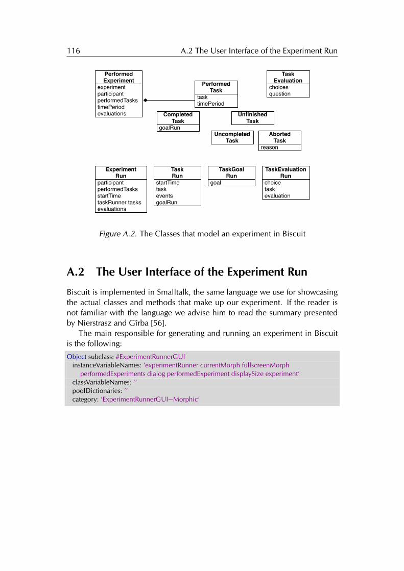
116 A.2 The User Interface of the Experiment Run
experimentparticipantperformedTaskstimePeriodevaluations
PerformedExperiment
tasktimePeriod
PerformedTask
goalRun
CompletedTask
UnfinishedTask
reason
AbortedTask
UncompletedTask
choicesquestion
TaskEvaluation
choicetaskevaluation
TaskEvaluationRun
participant performedTasks startTime taskRunner tasks evaluations
ExperimentRun
startTimetaskeventsgoalRun
TaskRun
goal
TaskGoalRun
Figure A.2. The Classes that model an experiment in Biscuit
A.2 The User Interface of the Experiment Run
Biscuit is implemented in Smalltalk, the same language we use for showcasingthe actual classes and methods that make up our experiment. If the reader isnot familiar with the language we advise him to read the summary presentedby Nierstrasz and Gîrba [56].
The main responsible for generating and running an experiment in Biscuitis the following:
Object subclass: #ExperimentRunnerGUIinstanceVariableNames: ’experimentRunner currentMorph fullscreenMorph
performedExperiments dialog performedExperiment displaySize experiment’classVariableNames: ’’poolDictionaries: ’’category: ’ExperimentRunnerGUI−Morphic’
117 A.3 Designing the Experiment on Gaucho
To start running an experiment by automatically generating a user interfaceto the subjects, the following message must be evaluated:
ExperimentRunnerGUI>>startRunning: anExperimentself adjustForDisplaySize.Display fullScreen: true .Author fullName: ’ExperimentRunner’.experiment := anExperiment.self openCreateParticipant.
The running experiment takes up the whole screen, and starts by presentingthe pre-questionaire to the subject. When the experiment is completed, Biscuitterminates itself by sending the following message:
ExperimentRunnerGUI>>endExperimentRunDisplay fullScreen: false.performedExperiment := experimentRunner asPerformedExperiment.performedExperiments add: performedExperiment.self saveLastPerformedExperiment.self openSendUsTheResults
Biscuit is built on top of Pharo, and uses its base graphic framework namedMorphic. We extended the framework with our own set of basic widgets, andseveral more specialized ones representing the running experiment in the userinterface. Amongst the many Morphs that compose the interface of a runningexperiment are the ExperimentWelcomeMorph, ExperimentMorph, Experimen-tRunnerMorph, TaskMorph, TaskGoalMorph, TaskChoiceMorph, TaskRunMorph,and ParticipantMorph.
A.3 Designing the Experiment on Gaucho
The entry point to our experiment is the class Experiment, which answers themessage #gaucho2010 with the actual object representing the experiment onGaucho.
Experiment>>gaucho2010^ GauchoExperiment2010Builder current build.
In Biscuit the experiments are created using the Builder pattern. The follow-ing class models an experiment builder.
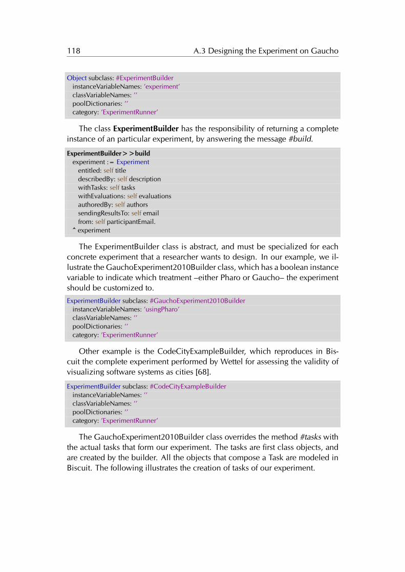
118 A.3 Designing the Experiment on Gaucho
Object subclass: #ExperimentBuilderinstanceVariableNames: ’experiment’classVariableNames: ’’poolDictionaries: ’’category: ’ExperimentRunner’
The class ExperimentBuilder has the responsibility of returning a completeinstance of an particular experiment, by answering the message #build.
ExperimentBuilder>>buildexperiment := Experiment
entitled: self titledescribedBy: self descriptionwithTasks: self taskswithEvaluations: self evaluationsauthoredBy: self authorssendingResultsTo: self emailfrom: self participantEmail.
^ experiment
The ExperimentBuilder class is abstract, and must be specialized for eachconcrete experiment that a researcher wants to design. In our example, we il-lustrate the GauchoExperiment2010Builder class, which has a boolean instancevariable to indicate which treatment –either Pharo or Gaucho– the experimentshould be customized to.
ExperimentBuilder subclass: #GauchoExperiment2010BuilderinstanceVariableNames: ’usingPharo’classVariableNames: ’’poolDictionaries: ’’category: ’ExperimentRunner’
Other example is the CodeCityExampleBuilder, which reproduces in Bis-cuit the complete experiment performed by Wettel for assessing the validity ofvisualizing software systems as cities [68].
ExperimentBuilder subclass: #CodeCityExampleBuilderinstanceVariableNames: ’’classVariableNames: ’’poolDictionaries: ’’category: ’ExperimentRunner’
The GauchoExperiment2010Builder class overrides the method #tasks withthe actual tasks that form our experiment. The tasks are first class objects, andare created by the builder. All the objects that compose a Task are modeled inBiscuit. The following illustrates the creation of tasks of our experiment.
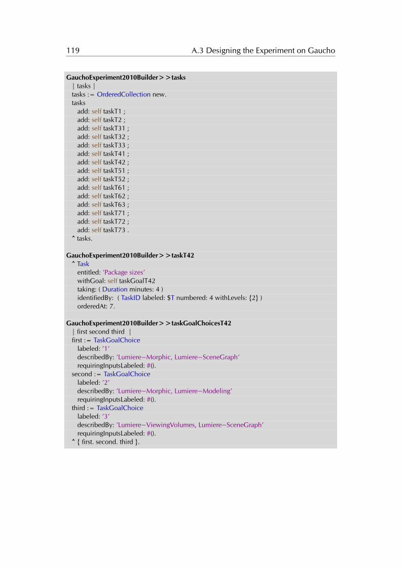
119 A.3 Designing the Experiment on Gaucho
GauchoExperiment2010Builder>>tasks| tasks |tasks := OrderedCollection new.tasks
add: self taskT1 ;add: self taskT2 ;add: self taskT31 ;add: self taskT32 ;add: self taskT33 ;add: self taskT41 ;add: self taskT42 ;add: self taskT51 ;add: self taskT52 ;add: self taskT61 ;add: self taskT62 ;add: self taskT63 ;add: self taskT71 ;add: self taskT72 ;add: self taskT73 .
^ tasks.
GauchoExperiment2010Builder>>taskT42^ Task
entitled: ’Package sizes’withGoal: self taskGoalT42taking: ( Duration minutes: 4 )identifiedBy: ( TaskID labeled: $T numbered: 4 withLevels: {2} )orderedAt: 7.
GauchoExperiment2010Builder>>taskGoalChoicesT42| first second third |first := TaskGoalChoice
labeled: ’1’describedBy: ’Lumiere−Morphic, Lumiere−SceneGraph’requiringInputsLabeled: #().
second := TaskGoalChoicelabeled: ’2’describedBy: ’Lumiere−Morphic, Lumiere−Modeling’requiringInputsLabeled: #().
third := TaskGoalChoicelabeled: ’3’describedBy: ’Lumiere−ViewingVolumes, Lumiere−SceneGraph’requiringInputsLabeled: #().
^ { first. second. third }.

120 A.3 Designing the Experiment on Gaucho
Bibliography
[1] D. E. Knuth, Art of Computer Programming, Volume 1: Fundamental Al-gorithms (3rd Edition). Addison-Wesley Professional, 1997.
[2] D. E. Knuth, “Computer programming as an art,” Commun. ACM, vol. 17,Dec. 1974.
[3] E. W. Dijkstra, “The humble programmer,” Commun. ACM, vol. 15,pp. 859–866, 1972.
[4] D. H. Ingalls, “Design principles behind smalltalk,” BYTE Magazine, no. 8,1981.
[5] G. Weinberg, The Psychology of Computer Programming. Dorset House,silver anniversary ed., 1998.
[6] M. Hiltzik, Dealers of Lightning: Xerox Parc and the Dawn of the Com-puter Age. HarperCollins Publishers, Apr. 1999.
[7] A. C. Kay, “The early history of smalltalk,” in The second ACM SIGPLANconference on History of programming languages, pp. 69–95, ACM,1993.
[8] I. E. Sutherland, “Sketch pad a man-machine graphical communicationsystem,” in Proceedings of the SHARE design automation workshop, DAC’64, pp. 6.329–6.346, ACM, 1964.
[9] T. A. Corbi, “Program understanding: challenge for the 1990’s,” IBM Syst.J., vol. 28, pp. 294–306, June 1989.
[10] J. Sillito, G. C. Murphy, and K. D. Volder, “Questions programmers askduring software evolution tasks,” in Proceedings of FSE-14 (14th Interna-tional Symposium on Foundations of Software Engineering), pp. 23–34,ACM Press, 2006.
121
122 Bibliography
[11] B.-W. Chang, D. Ungar, and R. B. Smith, Getting Close to Objects: Object-Focused Programming Environments. Prentice-Hall, 1995.
[12] J. Johnson, T. L. Roberts, W. Verplank, D. C. Smith, C. H. Irby, M. Beard,and K. Mackey, “The xerox star: A retrospective,” Computer, vol. 22,pp. 11–26, 28–29, Sept. 1989.
[13] G. C. Murphy, M. Kersten, and L. Findlater, “How are java software devel-opers using the eclipse ide?,” IEEE Softw., vol. 23, pp. 76–83, July 2006.
[14] A. J. Ko, H. Aung, and B. A. Myers, “Eliciting design requirements formaintenance-oriented IDEs: a detailed study of corrective and perfectivemaintenance tasks,” in Proceedings of ICSE 2005 (27th ACM/IEEE Interna-tional Conference on Software engineering), pp. 126–135, ACM, 2005.
[15] M. Kersten and G. C. Murphy, “Mylar: a degree-of-interest model for ides,”in Proceedings of the 4th international conference on Aspect-oriented soft-ware development, AOSD ’05, pp. 159–168, ACM, 2005.
[16] J. Raskin, The Humane Interface - New Directions for Designing Interac-tive Systems. Addison-Wesley, 2000.
[17] A. Bragdon, S. Reiss, R. Zeleznik, S. Karumuri, W. Cheung, J. Kaplan,C. Coleman, F. Adeputra, and J. J. LaViola, Jr., “Code Bubbles: Rethinkingthe user interface paradigm of integrated development environments,” inProceedings of ICSE 2010, pp. 455–464, ACM, 2010.
[18] J. K. Ousterhout, “Corner stitching: a data structuring technique for vlsilayout tools,” Tech. Rep. UCB/CSD-83-114, EECS Department, Universityof California, Berkeley, Dec 1982.
[19] D. Roethlisberger, O. Nierstrasz, and S. Ducasse, “Autumn leaves: Curingthe window plague in ides,” in Reverse Engineering, 332009. WCRE ’09.16th Working Conference on, pp. 237 –246, 2009.
[20] R. DeLine, M. Czerwinski, B. Meyers, G. Venolia, S. Drucker, andG. Robertson, “Code thumbnails: Using spatial memory to navigatesource code,” in Proceedings of the Visual Languages and Human-CentricComputing, VLHCC ’06, pp. 11–18, IEEE Computer Society, 2006.
[21] F. Brooks, The Mythical Man-Month. Addison-Wesley, 2nd ed., 1995.
123 Bibliography
[22] T. Ball and S. Eick, “Software visualization in the large,” Computer, vol. 29,no. 4, pp. 33–43, 1996.
[23] M. Lanza, Object-Oriented Reverse Engineering — Coarse-grained, Fine-grained, and Evolutionary Software Visualization. PhD thesis, Universityof Berne, May 2003.
[24] R. DeLine and K. Rowan, “Code canvas: zooming towards better develop-ment environments,” in Proceedings of ICSE 2010 (32nd ACM/IEEE Inter-national Conference on Software Engineering) - Volume 2, pp. 207–210,ACM, 2010.
[25] A. Cockburn and M. Smith, “Hidden messages: Evaluating the effi-ciency of code elision in program navigation,” Interacting with Comput-ers: The Interdisciplinary Journal of Human-Computer Interaction, vol. 15,pp. 387–407, 2003.
[26] W. Lidwell, K. Holden, and J. Butler, Universal Principles of Design. Rock-port, 2003.
[27] S. Ducasse and M. Lanza, “The class blueprint: Visually supporting theunderstanding of classes,” Transactions on Software Engineering (TSE),vol. 31, pp. 75–90, Jan. 2005.
[28] A. Kuhn, P. Loretan, and O. Nierstrasz, “Consistent layout for thematicsoftware maps,” in Proceedings of the 2008 15th Working Conference onReverse Engineering, WCRE ’08, pp. 209–218, IEEE Computer Society,2008.
[29] F. Olivero, M. Lanza, and M. Lungu, “Gaucho: From integrated devel-opment environments to direct manipulation environments,” in Proceed-ings of FlexiTools 2010 (1st International Workshop on Flexible ModelingTools), 2010.
[30] F. Olivero, “Object focused environments as vehicles for object-orientedmodeling,” in Proceedings of ECOOP ’11 (25th European Conference onObject-Oriented Programming), Doctoral Symposium, p. to be published,2011.
[31] F. Olivero, M. Lanza, M. D’Ambros, and R. Robbes, “Gaucho: Program-ming←→modeling,” in Proceedings of ECOOP ’11 (25th European Con-ference on Object-Oriented Programming), Demonstration, 2011.
124 Bibliography
[32] F. Olivero, M. Lanza, M. D’Ambros, and R. Robbes, “Enabling programcomprehension through a visual object-focused development environ-ment,” in Proceedings of VL/HCC ’11 (IEEE Symposium on Visual Lan-guages and Human-Centric Computing), pp. 127–134, 2011.
[33] F. Olivero, M. Lanza, M. D’Ambros, and R. Robbes, “Tracking human-centric controlled experiments with biscuit,” in Proceedings of PLATEAU2012 (4th International Workshop on Evaluation and Usability of Program-ming Languages and Tools), p. to be published, 2012.
[34] F. Olivero, M. Lanza, and M. D’Ambros, “Ronda: A fine grained collab-orative development environment,” in Proceedings of CDVE 2012 (9thInternational Conference on Cooperative Design, Visualization and Engi-neering), pp. 155–162, 2012.
[35] A. Goldberg and D. Robson, Smalltalk-80: The Language and its Imple-mentation. Addison-Wesley Longman Publishing Co., Inc., May 1983.
[36] D. Roberts, J. Brant, and R. Johnson, “A refactoring tool for smalltalk,”Theor. Pract. Object Syst., vol. 3, pp. 253–263, Oct. 1997.
[37] V. Sinha, D. Karger, and R. Miller, “Relo: Helping users manage contextduring interactive exploratory visualization of large codebases,” in Pro-ceedings of ETX 2005, pp. 21–25, ACM, 2005.
[38] A. Bragdon, R. Zeleznik, S. P. Reiss, S. Karumuri, W. Cheung, J. Kaplan,C. Coleman, F. Adeputra, and J. J. LaViola, Jr., “Code bubbles: a workingset-based interface for code understanding and maintenance,” in Proceed-ings of the SIGCHI Conference on Human Factors in Computing Systems,CHI ’10, pp. 2503–2512, ACM, 2010.
[39] J. Bézivin, “On the unification power of models,” Software and SystemsModeling, vol. 4, pp. 171–188, 2005.
[40] R. Lemma, “Software modeling in essence,” Master’s thesis, University ofLugano, 2012.
[41] M. Fowler, UML Distilled: A Brief Guide to the Standard Object ModelingLanguage. Addison-Wesley, 3. ed., 2003.
[42] B. Sharif and J. I. Maletic, “An empirical study on the comprehension ofstereotyped uml class diagram layouts,” in in Proceedings of 17th IEEE Intl.Conf. on Program Comprehension (ICPC), pp. 268–272, 2009.
125 Bibliography
[43] A. Cooper and R. Reimann, About Face 2.0 - The Essentials of InteractionDesign. Wiley, 2003.
[44] E. Hutchins, J. Hollan, and D. Norman, “Direct manipulation interfaces,”Human-Computer Interaction, vol. 1, pp. 311–338, 1985.
[45] D. H. H. Ingalls, “The smalltalk-76 programming system design and im-plementation,” in Proceedings of the 5th ACM SIGACT-SIGPLAN sympo-sium on Principles of programming languages, POPL ’78, pp. 9–16, ACM,1978.
[46] R. B. Smith, J. Maloney, and D. Ungar., “The self-4.0 user interface,” inOOPSLA ’95, pp. 47–60, October 1995.
[47] J. H. Maloney and R. B. Smith, “Directness and liveness in the morphicuser interface construction environment,” in Proceedings of UIST 1995(8th ACM symposium on User interface and software technology), pp. 21–28, ACM, 1995.
[48] J. Maloney, “An introduction to morphic: The squeak user interface frame-work,” tech. rep., Walt Disney Imagineering, 2000.
[49] D. Ingalls, K. Palacz, S. Uhler, A. Taivalsaari, and T. Mikkonen, “The livelykernel a self-supporting system on a web page,” in Self-Sustaining Systems,vol. 5146 of Lecture Notes in Computer Science, pp. 31–50, SpringerBerlin Heidelberg, 2008.
[50] R. Pawson, “Naked objects,” PhD thesis, 2004.
[51] J.-M. Favre, “Foundations of model (driven) (reverse) engineering: Mod-els – episode i: Stories of the fidus papyrus and of the solarus,” inPOST-PROCEEDINGS OF DAGSTHUL SEMINAR ON MODEL DRIVENREVERSE ENGINEERING, 2004.
[52] A. Kay, “Computer software,” Scientific American, 9 1984.
[53] G. Booch, “Why don’t developers draw diagrams?,” in SOFTVIS, pp. 3–4,2010.
[54] B. B. Bederson, “The promise of zoomable user interfaces,” in Proceed-ings of the 3rd International Symposium on Visual Information Communi-cation, VINCE ’10, ACM, 2010.
126 Bibliography
[55] M. Shand, “Algorithms for corner stitched data-structures,” Algorithmica,vol. 2, pp. 61–80, 1987.
[56] O. Nierstrasz and T. Gîrba, “Lessons in software evolution learned by lis-tening to smalltalk,” in Proceedings of the 36th Conference on CurrentTrends in Theory and Practice of Computer Science, SOFSEM ’10, pp. 77–95, Springer-Verlag, 2010.
[57] P. Kruchten, “Architectural Blueprints—The "4+1” View Model of Soft-ware Architecture,” IEEE Software, vol. 12, pp. 42–50, Nov. 1995.
[58] K. Beck and C. Andres, Extreme Programming Explained. Addison-Wesley,2nd ed., 2005.
[59] K. Jansen and G. Zhang, “On rectangle packing: maximizing benefits,”in Proceedings of the fifteenth annual ACM-SIAM symposium on Discretealgorithms, SODA ’04, pp. 204–213, Society for Industrial and AppliedMathematics, 2004.
[60] G. P. Kurtenbach, A. J. Sellen, and W. A. S. Buxton, “An empirical evalua-tion of some articulatory and cognitive aspects of marking menus,” Hum.-Comput. Interact., vol. 8, pp. 1–23, Mar. 1993.
[61] M. M. Burnett, Visual Programming. John Wiley & Sons, 1999.
[62] M. Petre, “Why looking isn’t always seeing: Readership skills and graph-ical programming,” Communications of the ACM, vol. 38, pp. 33–44,1995.
[63] A. F. Blackwell, “Metacognitive theories of visual programming: What dowe think we are doing?,” in Proceedings of the 1996 IEEE Symposium onVisual Languages, IEEE Computer Society, 1996.
[64] J. Edwards, “Coherent reaction,” in Proceedings of the 24th ACM SIG-PLAN conference companion on Object oriented programming systemslanguages and applications, OOPSLA ’09, pp. 925–932, ACM, 2009.
[65] B. Cornelissen, A. Zaidman, and A. van Deursen, “A controlled experi-ment for program comprehension through trace visualization,” IEEE Trans-actions on Software Engineering, vol. 99, 2010.
127 Bibliography
[66] J. Stasko, “An evaluation of space-filling information visualizations fordepicting hierarchical structures,” Int. J. Hum.-Comput. Stud., vol. 53,pp. 663–694, Nov. 2000.
[67] A. Marcus, D. Comorski, and A. Sergeyev, “Supporting the evolution of asoftware visualization tool through usability studies,” in in Proceedings In-ternational Workshop on Program Comprehension, pp. 307–316, PrenticeHall, 1997.
[68] R. Wettel, M. Lanza, and R. Robbes, “Software systems as cities: A con-trolled experiment,” in Proceedings of ICSE 2011 (33rd International Con-ference on Software Engineeering), pp. 551 – 560, ACM Press, 2011.
[69] A. J. Ko, R. DeLine, and G. Venolia, “Information needs in collocated soft-ware development teams,” in Proceedings of ICSE 2007 (29th ACM/IEEEInternational Conference on Software Engineering), pp. 344–353, IEEEComputer Society, 2007.
[70] R. Robbes and M. Lanza, “Spyware: A change-aware developmenttoolset,” in Proceedings of ICSE 2008 (30th ACM/IEEE International Con-ference in Software Engineering), pp. 847–850, ACM Press, 2008.
[71] M. Steinberg, “What is the impact of static type systems on maintenancetasks? an empirical study of differences in debugging time using staticallyand dynamically typed languages,” master Thesis, University of Duisburg-Essen, 2011.
[72] P. M. Johnson, H. Kou, J. Agustin, C. Chan, C. A. Moore, J. Miglani,S. Zhen, and W. E. J. Doane, “Beyond the personal software process: Met-rics collection and analysis for the differently disciplined,” in Proceedingsof ICSE 2003, pp. 641–646, 2003.
[73] M. Kersten and G. Murphy, “Using task context to improve programmerproductivity,” in Proceedings of FSE 2006 (16th SIGSOFT Symposium onthe Foundations of Software Engineering), pp. 1–11, ACM Press, 2006.
[74] E. Chikofsky and J. Cross, “Reverse engineering and design recovery: Ataxonomy,” IEEE Software, vol. 7, pp. 13–17, Jan. 1990.
[75] F. Olivero, M. Lanza, and R. Robbes, “Lumiére: A novel framework forrendering 3d graphics in smalltalk,” in Proceedings of IWST 2009 (1st In-ternational Workshop on Smalltalk Technologies), pp. 20–28, ACM Press,2009.
128 Bibliography
[76] T. D. Marco, Peopleware - Productive Projects and Teams. Dorset House,1999.
[77] A. Sarma, Palantir: enhancing configuration management systems withworkspace awareness to detect and resolve emerging conflicts. PhD thesis,CalState University, 2008.
[78] L. Hattori and M. Lanza, “Syde: A tool for collaborative software develop-ment,” in Proceedings of ICSE 2010 (32nd ACM/IEEE International Con-ference on Software Engineering), pp. 235–238, 2010.
[79] E. Goffman and A. J. Wootton, Exploring the interaction order. Polity Press,1988.
[80] R. B. Smith, M. Wolczko, and D. Ungar, “From kansas to oz: collaborativedebugging when a shared world breaks,” Commun. ACM, vol. 40, 1997.
[81] H. Lieberman and C. Fry, “Bridging the gulf between code and behaviorin programming,” in CHI, pp. 480–486, ACM/Addison-Wesley, 1995.
[82] C. R. B. de Souza, D. Redmiles, and P. Dourish, “Breaking the code, mov-ing between private and public work in collaborative software develop-ment,” in Proceedings of GROUP 2003 (International ACM SIGGROUPConference on Supporting Group Work), pp. 105–114, ACM Press, 2003.
[83] D. A. Smith, A. Kay, A. Raab, and D. P. Reed, “Croquet - a collaborationsystem architecture,” IEEE Computer Society, 2003.
[84] M. Lanza and R. Marinescu, Object-Oriented Metrics in Practice. Springer-Verlag, 2006.
[85] R. Wettel and M. Lanza, “Visually localizing design problems with dishar-mony maps,” in Proceedings of Softvis 2008 (4th ACM International Sym-posium on Software Visualization), pp. 155–164, ACM Press, 2008.
[86] C. G. Myers and E. L. A. Baniassad, “Silhouette: visual language for mean-ingful shape,” in Companion to the 24th Annual ACM SIGPLAN Con-ference on Object-Oriented Programming, Systems, Languages, and Ap-plications, OOPSLA 2009, October 25-29, 2009, Orlando, Florida, USA(S. Arora and G. T. Leavens, eds.), pp. 917–924, ACM, 2009.
129 Bibliography
[87] A. Noack and C. Lewerentz, “A space of layout styles for hierarchical graphmodels of software systems,” in Proceedings of the 2005 ACM symposiumon Software visualization, SoftVis ’05, pp. 155–164, ACM, 2005.
[88] S. Cooper, W. Dann, and R. Pausch, “Teaching objects-first in introductorycomputer science,” in Proceedings of the 34th SIGCSE technical sympo-sium on Computer science education, SIGCSE ’03, pp. 191–195, ACM,2003.
[89] M. Kölling, B. Quig, A. Patterson, and J. Rosenberg, “The BlueJ systemand its pedagogy,” Journal of Computer Science Education, vol. 13, Dec.2003.
[90] M. Kolling, “Teaching object orientation with the Blue environment,”Journal of Object-Oriented Programming, vol. 12, pp. 14–23, December1999.
[91] C. Griggio, G. Leiva, G. Polito, N. Passerini, and G. Decuzzi, “A program-ming environment supporting a prototype-based introduction to oop,”pp. 45–50, ACM Press, 2011.


