Embed Size (px)
Citation preview
NX University
G E T H A N D S O N W I T H
NX CAD | NX CAM
*****

1 HANDS-ON WORKSHOP | NX UNIVERSITY 2020 | SWOOSH TECHNOLOGIES
Hey there.
We’re your tech guys.
David Chiu Technical Director
Fluent in NX CAD and Teamcenter
Sam Estrada PDM/CAD Engineer
Fluent in Teamcenter
and Solid Edge
Al Kraus CAM/CAD Engineer
Fluent in NX CAM
and NX CAD
Reese Shearer CAD Engineer
Fluent in NX CAD
Dan Klostermann PDM Engineer
Fluent in Teamcenter
Michael Pinto CAD/CAE Engineer
Fluent in NX CAD,
KeyShot, and Simcenter
John Vincent CAM Engineer
Fluent in NX CAM
Dominic Santoro CAD Engineer
Fluent in NX CAD and Teamcenter
C O N T E N T S
NX CAD 1
ASSEMBLY ARRANGEMENTS 1
SETTING UP ATTRIBUTE TEMPLATES 14
NX CAM 24
IDENTIFYING VARIOUS TYPES OF FEATURES WITH THE FIND FEATURE FUNCTION 24
USING THE FIND FEATURE FUNCTION FOR MANUALLY CREATED OPERATIONS 28
CREATING RULE-BASED MANUFACTURING OPERATIONS 35
COURSE CATALOG 39
NX CAD COURSES 39
NX CAM COURSES 40
1 HANDS-ON WORKSHOP | NX UNIVERSITY 2020 | SWOOSH TECHNOLOGIES
NX CAD ACTIVTY 1
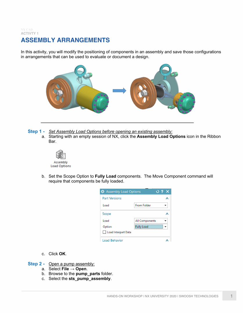
ASSEMBLY ARRANGEMENTS In this activity, you will modify the positioning of components in an assembly and save those configurations in arrangements that can be used to evaluate or document a design.
Step 1 - Set Assembly Load Options before opening an existing assembly: a. Starting with an empty session of NX, click the Assembly Load Options icon in the Ribbon
Bar.
b. Set the Scope Option to Fully Load components. The Move Component command will require that components be fully loaded.
c. Click OK.
Step 2 - Open a pump assembly: a. Select File → Open. b. Browse to the pump_parts folder. c. Select the sts_pump_assembly.
2 HANDS-ON WORKSHOP | NX UNIVERSITY 2020 | SWOOSH TECHNOLOGIES
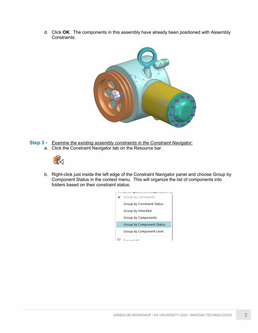
d. Click OK. The components in this assembly have already been positioned with Assembly Constraints.
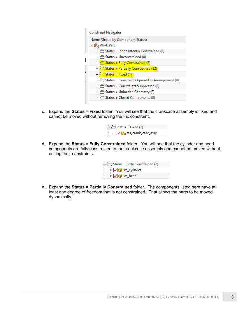
Step 3 - Examine the existing assembly constraints in the Constraint Navigator: a. Click the Constraint Navigator tab on the Resource bar.
b. Right-click just inside the left edge of the Constraint Navigator panel and choose Group by Component Status in the context menu. This will organize the list of components into folders based on their constraint status.
3 HANDS-ON WORKSHOP | NX UNIVERSITY 2020 | SWOOSH TECHNOLOGIES
c. Expand the Status = Fixed folder. You will see that the crankcase assembly is fixed and cannot be moved without removing the Fix constraint.
d. Expand the Status = Fully Constrained folder. You will see that the cylinder and head components are fully constrained to the crankcase assembly and cannot be moved without editing their constraints.
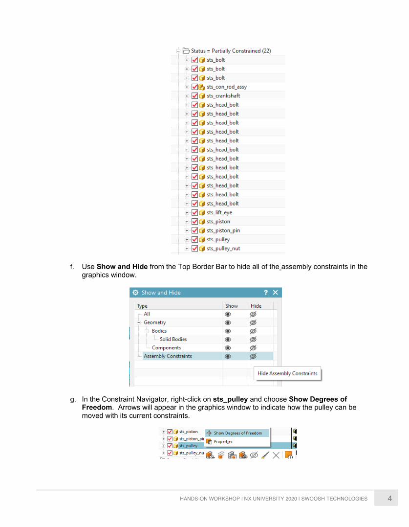
e. Expand the Status = Partially Constrained folder. The components listed here have at least one degree of freedom that is not constrained. That allows the parts to be moved dynamically.
4 HANDS-ON WORKSHOP | NX UNIVERSITY 2020 | SWOOSH TECHNOLOGIES
f. Use Show and Hide from the Top Border Bar to hide all of the assembly constraints in the graphics window.
g. In the Constraint Navigator, right-click on sts_pulley and choose Show Degrees of Freedom. Arrows will appear in the graphics window to indicate how the pulley can be moved with its current constraints.
5 HANDS-ON WORKSHOP | NX UNIVERSITY 2020 | SWOOSH TECHNOLOGIES
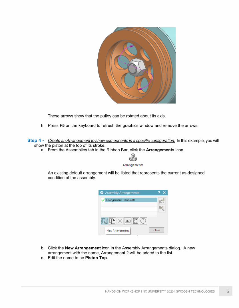
These arrows show that the pulley can be rotated about its axis.
h. Press F5 on the keyboard to refresh the graphics window and remove the arrows.
Step 4 - Create an Arrangement to show components in a specific configuration: In this example, you will
show the piston at the top of its stroke. a. From the Assemblies tab in the Ribbon Bar, click the Arrangements icon.
An existing default arrangement will be listed that represents the current as-designed condition of the assembly.
b. Click the New Arrangement icon in the Assembly Arrangements dialog. A new arrangement with the name, Arrangement 2 will be added to the list.
c. Edit the name to be Piston Top.
6 HANDS-ON WORKSHOP | NX UNIVERSITY 2020 | SWOOSH TECHNOLOGIES
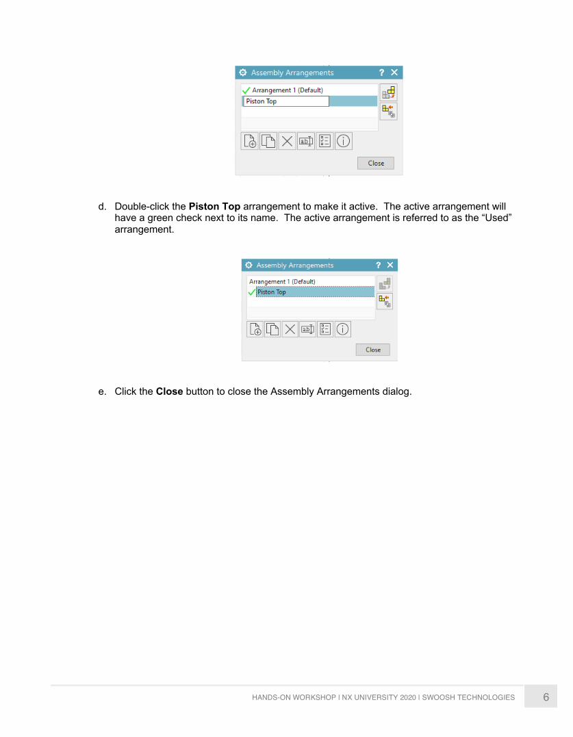
d. Double-click the Piston Top arrangement to make it active. The active arrangement will
have a green check next to its name. The active arrangement is referred to as the “Used” arrangement.
e. Click the Close button to close the Assembly Arrangements dialog.
7 HANDS-ON WORKSHOP | NX UNIVERSITY 2020 | SWOOSH TECHNOLOGIES
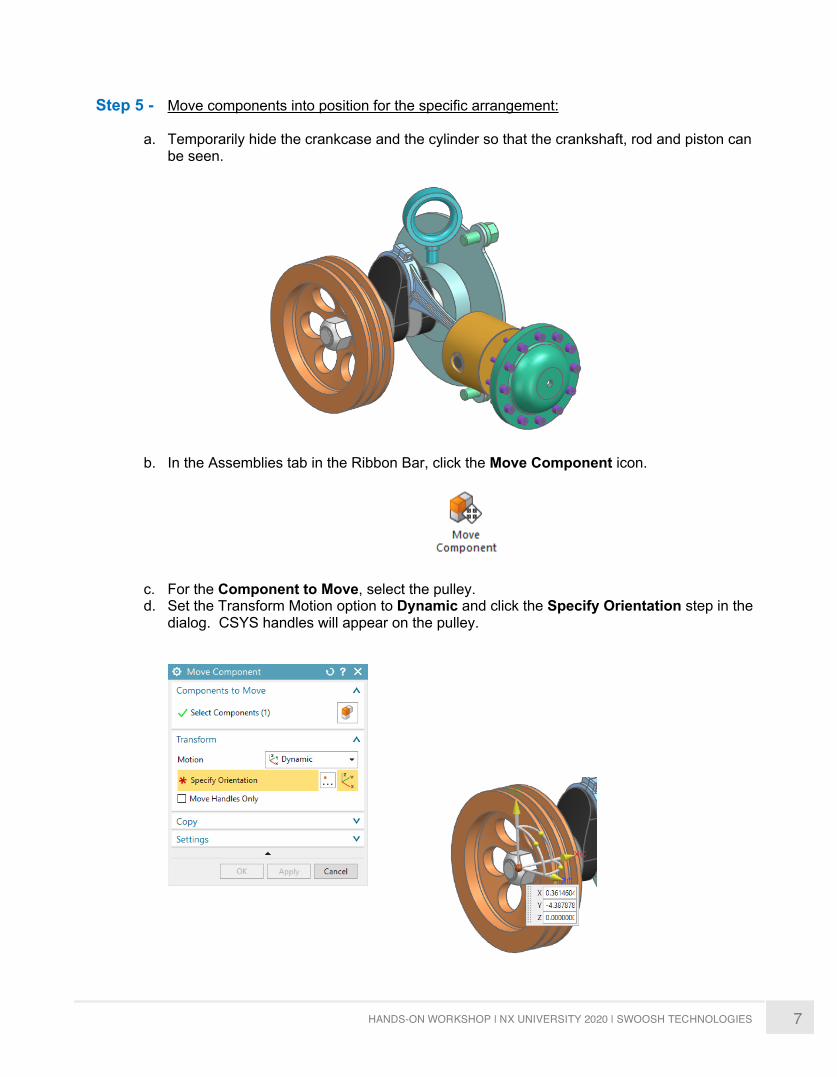
Step 5 - Move components into position for the specific arrangement:
a. Temporarily hide the crankcase and the cylinder so that the crankshaft, rod and piston can be seen.
b. In the Assemblies tab in the Ribbon Bar, click the Move Component icon.
c. For the Component to Move, select the pulley. d. Set the Transform Motion option to Dynamic and click the Specify Orientation step in the
dialog. CSYS handles will appear on the pulley.
8 HANDS-ON WORKSHOP | NX UNIVERSITY 2020 | SWOOSH TECHNOLOGIES
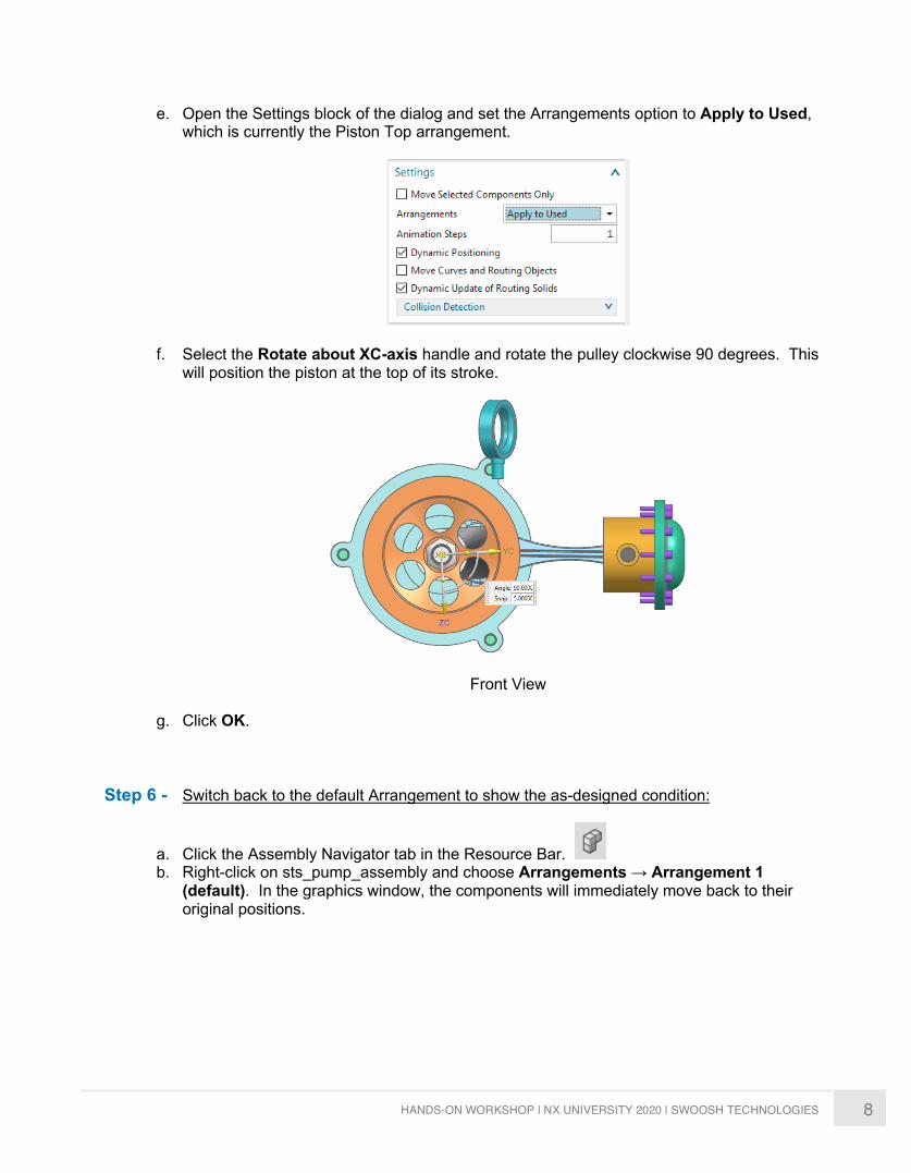
e. Open the Settings block of the dialog and set the Arrangements option to Apply to Used, which is currently the Piston Top arrangement.
f. Select the Rotate about XC-axis handle and rotate the pulley clockwise 90 degrees. This will position the piston at the top of its stroke.
Front View
g. Click OK.
Step 6 - Switch back to the default Arrangement to show the as-designed condition:
a. Click the Assembly Navigator tab in the Resource Bar. b. Right-click on sts_pump_assembly and choose Arrangements → Arrangement 1
(default). In the graphics window, the components will immediately move back to their original positions.
9 HANDS-ON WORKSHOP | NX UNIVERSITY 2020 | SWOOSH TECHNOLOGIES
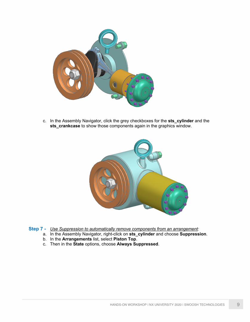
c. In the Assembly Navigator, click the grey checkboxes for the sts_cylinder and the sts_crankcase to show those components again in the graphics window.
Step 7 - Use Suppression to automatically remove components from an arrangement:
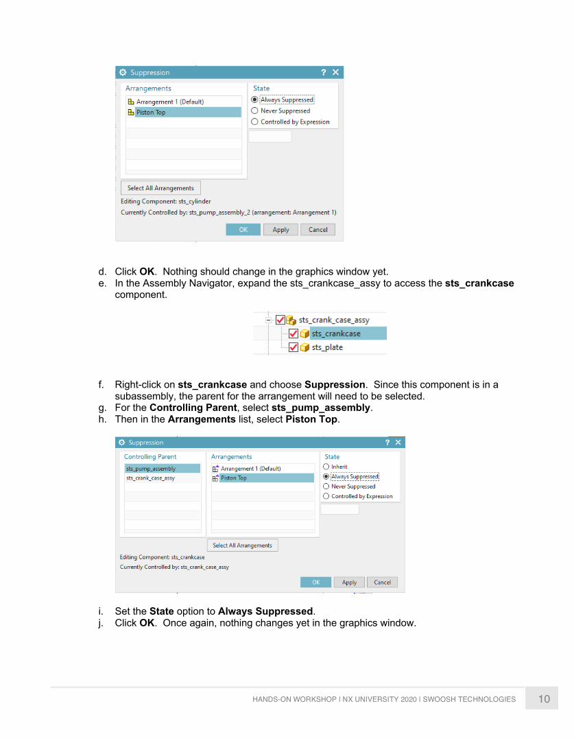
a. In the Assembly Navigator, right-click on sts_cylinder and choose Suppression. b. In the Arrangements list, select Piston Top. c. Then in the State options, choose Always Suppressed.
10 HANDS-ON WORKSHOP | NX UNIVERSITY 2020 | SWOOSH TECHNOLOGIES
d. Click OK. Nothing should change in the graphics window yet. e. In the Assembly Navigator, expand the sts_crankcase_assy to access the sts_crankcase
component.
f. Right-click on sts_crankcase and choose Suppression. Since this component is in a
subassembly, the parent for the arrangement will need to be selected. g. For the Controlling Parent, select sts_pump_assembly. h. Then in the Arrangements list, select Piston Top.
i. Set the State option to Always Suppressed. j. Click OK. Once again, nothing changes yet in the graphics window.
11 HANDS-ON WORKSHOP | NX UNIVERSITY 2020 | SWOOSH TECHNOLOGIES
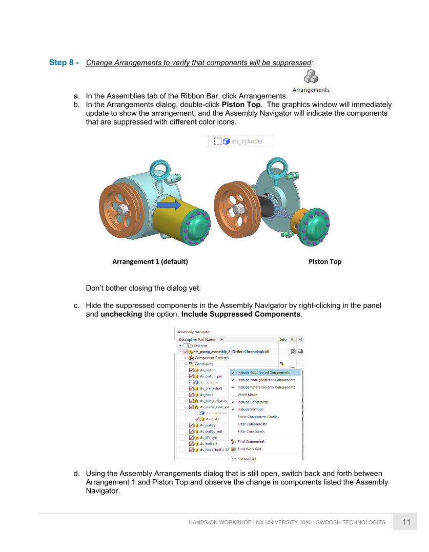
Step 8 - Change Arrangements to verify that components will be suppressed:
a. In the Assemblies tab of the Ribbon Bar, click Arrangements. b. In the Arrangements dialog, double-click Piston Top. The graphics window will immediately
update to show the arrangement, and the Assembly Navigator will indicate the components that are suppressed with different color icons.
Arrangement 1 (default) Piston Top
Don’t bother closing the dialog yet.
c. Hide the suppressed components in the Assembly Navigator by right-clicking in the panel and unchecking the option, Include Suppressed Components.
d. Using the Assembly Arrangements dialog that is still open, switch back and forth between Arrangement 1 and Piston Top and observe the change in components listed the Assembly Navigator.
12 HANDS-ON WORKSHOP | NX UNIVERSITY 2020 | SWOOSH TECHNOLOGIES
e. Make Arrangement 1 active, and then close the dialog.
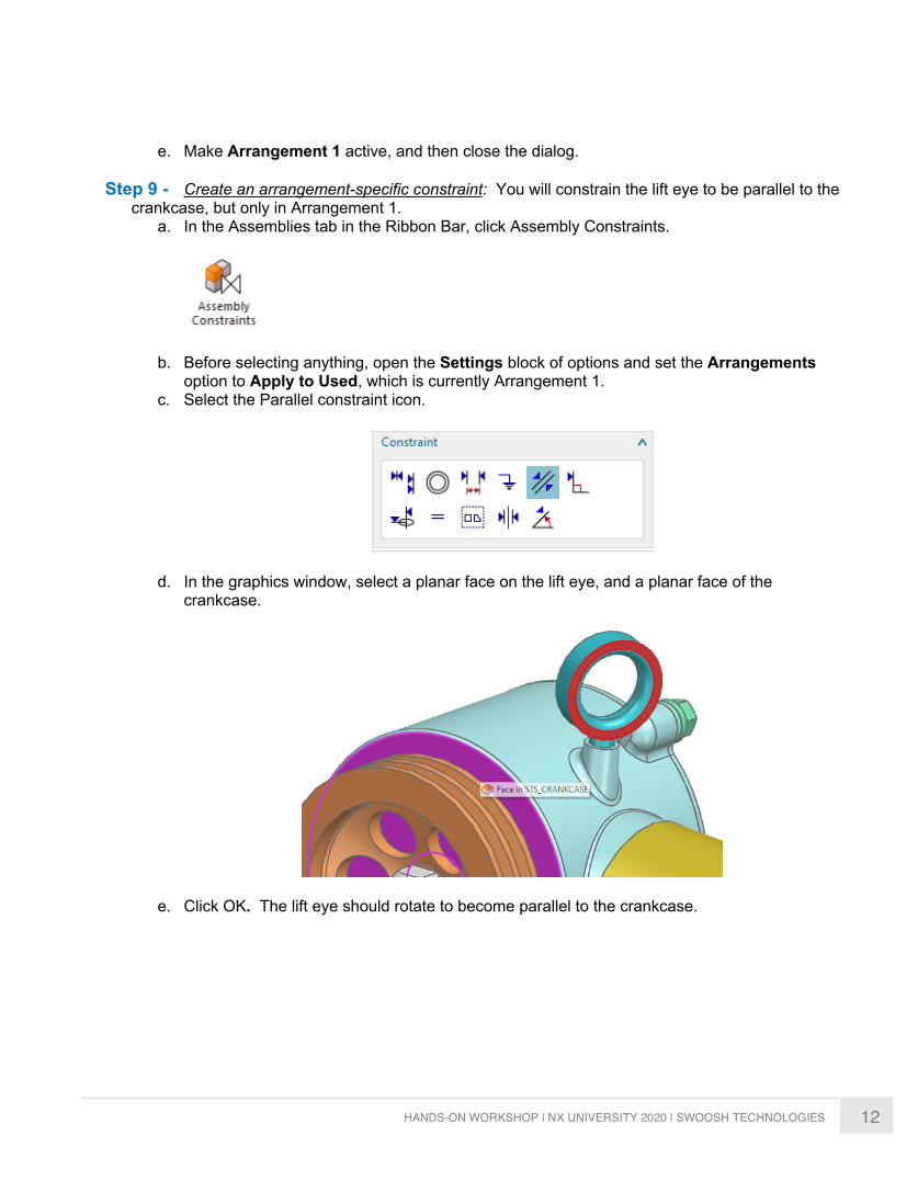
Step 9 - Create an arrangement-specific constraint: You will constrain the lift eye to be parallel to the crankcase, but only in Arrangement 1.
a. In the Assemblies tab in the Ribbon Bar, click Assembly Constraints.
b. Before selecting anything, open the Settings block of options and set the Arrangements option to Apply to Used, which is currently Arrangement 1.
c. Select the Parallel constraint icon.
d. In the graphics window, select a planar face on the lift eye, and a planar face of the crankcase.
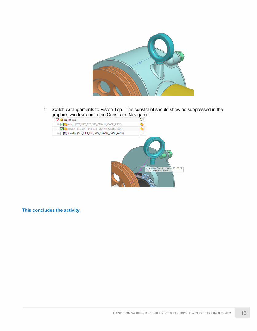
e. Click OK. The lift eye should rotate to become parallel to the crankcase.
13 HANDS-ON WORKSHOP | NX UNIVERSITY 2020 | SWOOSH TECHNOLOGIES
f. Switch Arrangements to Piston Top. The constraint should show as suppressed in the graphics window and in the Constraint Navigator.
This concludes the activity.
14 HANDS-ON WORKSHOP | NX UNIVERSITY 2020 | SWOOSH TECHNOLOGIES
ACTIVTY 2
SETTING UP ATTRIBUTE TEMPLATES
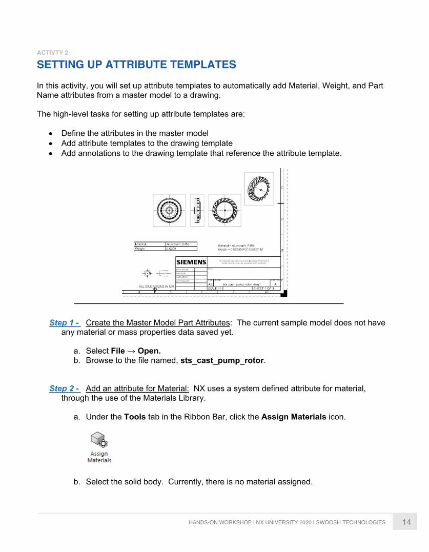
In this activity, you will set up attribute templates to automatically add Material, Weight, and Part Name attributes from a master model to a drawing.
The high-level tasks for setting up attribute templates are:
• Define the attributes in the master model• Add attribute templates to the drawing template• Add annotations to the drawing template that reference the attribute template.
Step 1 - Create the Master Model Part Attributes: The current sample model does not have any material or mass properties data saved yet.
a. Select File → Open.b. Browse to the file named, sts_cast_pump_rotor.
Step 2 - Add an attribute for Material: NX uses a system defined attribute for material, through the use of the Materials Library.
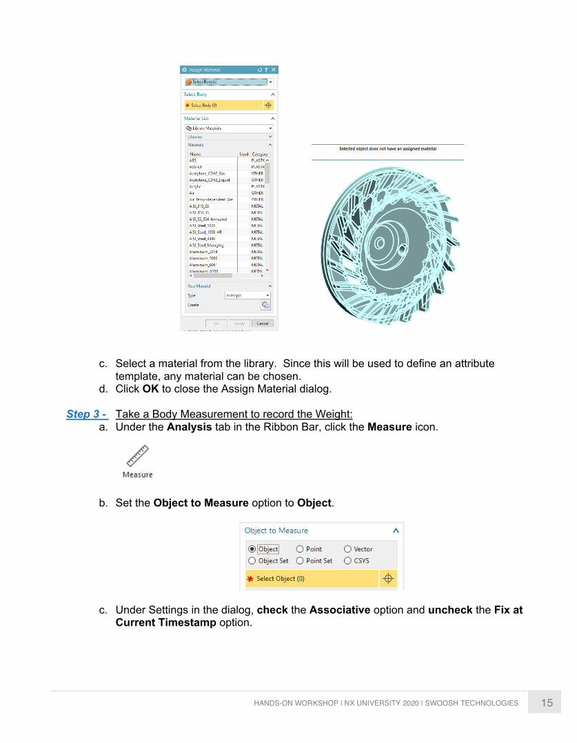
a. Under the Tools tab in the Ribbon Bar, click the Assign Materials icon.
b. Select the solid body. Currently, there is no material assigned.
15 HANDS-ON WORKSHOP | NX UNIVERSITY 2020 | SWOOSH TECHNOLOGIES
c. Select a material from the library. Since this will be used to define an attribute
template, any material can be chosen. d. Click OK to close the Assign Material dialog.
Step 3 - Take a Body Measurement to record the Weight:
a. Under the Analysis tab in the Ribbon Bar, click the Measure icon.
b. Set the Object to Measure option to Object.
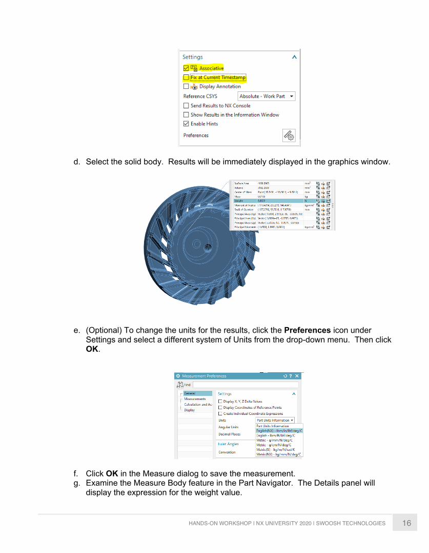
c. Under Settings in the dialog, check the Associative option and uncheck the Fix at Current Timestamp option.
16 HANDS-ON WORKSHOP | NX UNIVERSITY 2020 | SWOOSH TECHNOLOGIES
d. Select the solid body. Results will be immediately displayed in the graphics window.
e. (Optional) To change the units for the results, click the Preferences icon under
Settings and select a different system of Units from the drop-down menu. Then click OK.
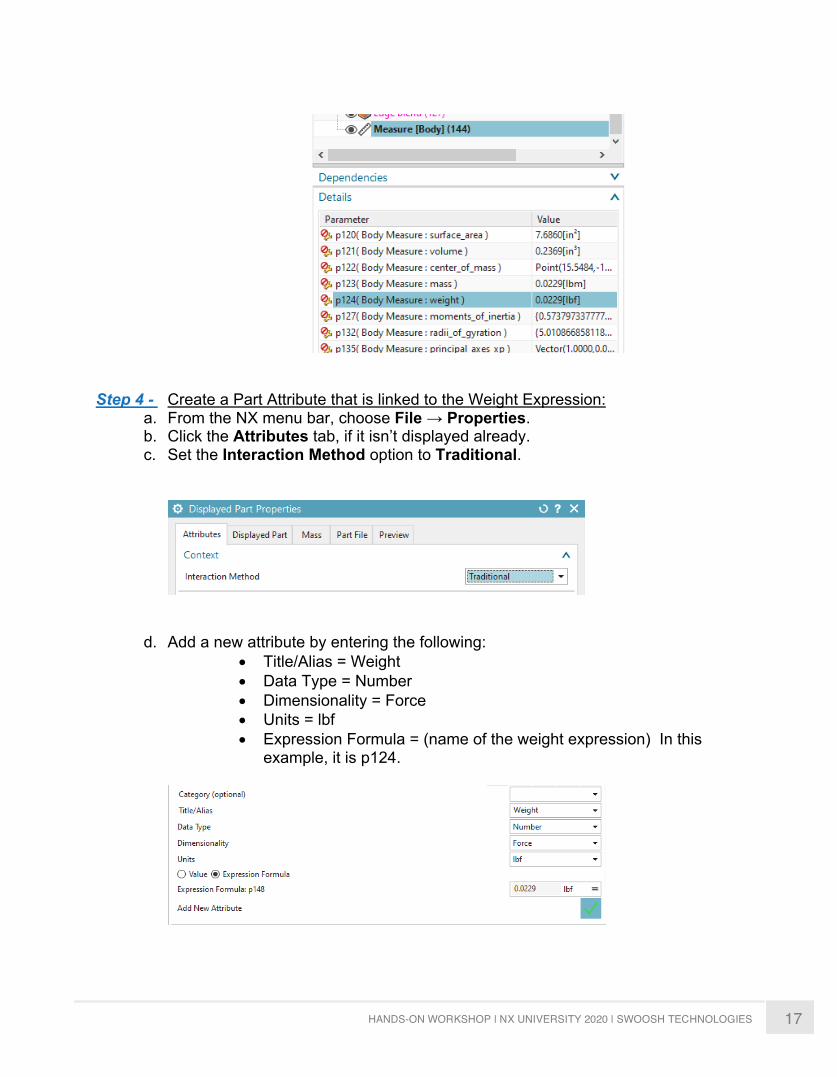
f. Click OK in the Measure dialog to save the measurement. g. Examine the Measure Body feature in the Part Navigator. The Details panel will
display the expression for the weight value.
17 HANDS-ON WORKSHOP | NX UNIVERSITY 2020 | SWOOSH TECHNOLOGIES
Step 4 - Create a Part Attribute that is linked to the Weight Expression:
a. From the NX menu bar, choose File → Properties. b. Click the Attributes tab, if it isn’t displayed already. c. Set the Interaction Method option to Traditional.
d. Add a new attribute by entering the following: • Title/Alias = Weight • Data Type = Number • Dimensionality = Force • Units = lbf • Expression Formula = (name of the weight expression) In this
example, it is p124.
18 HANDS-ON WORKSHOP | NX UNIVERSITY 2020 | SWOOSH TECHNOLOGIES
e. Click the Add New Attribute icon.
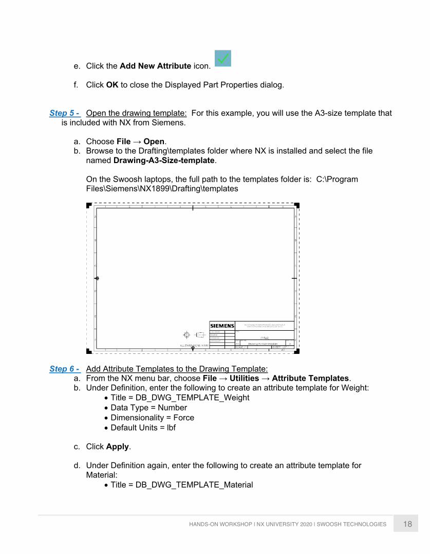
f. Click OK to close the Displayed Part Properties dialog. Step 5 - Open the drawing template: For this example, you will use the A3-size template that
is included with NX from Siemens.
a. Choose File → Open. b. Browse to the Drafting\templates folder where NX is installed and select the file
named Drawing-A3-Size-template. On the Swoosh laptops, the full path to the templates folder is: C:\Program Files\Siemens\NX1899\Drafting\templates
Step 6 - Add Attribute Templates to the Drawing Template: a. From the NX menu bar, choose File → Utilities → Attribute Templates. b. Under Definition, enter the following to create an attribute template for Weight:
• Title = DB_DWG_TEMPLATE_Weight • Data Type = Number • Dimensionality = Force • Default Units = lbf
c. Click Apply.
d. Under Definition again, enter the following to create an attribute template for
Material: • Title = DB_DWG_TEMPLATE_Material
19 HANDS-ON WORKSHOP | NX UNIVERSITY 2020 | SWOOSH TECHNOLOGIES
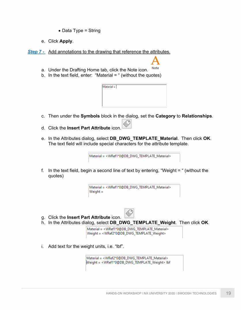
• Data Type = String
e. Click Apply.
Step 7 - Add annotations to the drawing that reference the attributes.
a. Under the Drafting Home tab, click the Note icon. b. In the text field, enter: “Material = “ (without the quotes)
c. Then under the Symbols block in the dialog, set the Category to Relationships.
d. Click the Insert Part Attribute icon.
e. In the Attributes dialog, select DB_DWG_TEMPLATE_Material. Then click OK. The text field will include special characters for the attribute template.
f. In the text field, begin a second line of text by entering, “Weight = “ (without the quotes)
g. Click the Insert Part Attribute icon. h. In the Attributes dialog, select DB_DWG_TEMPLATE_Weight. Then click OK.
i. Add text for the weight units, i.e. “lbf”.
20 HANDS-ON WORKSHOP | NX UNIVERSITY 2020 | SWOOSH TECHNOLOGIES
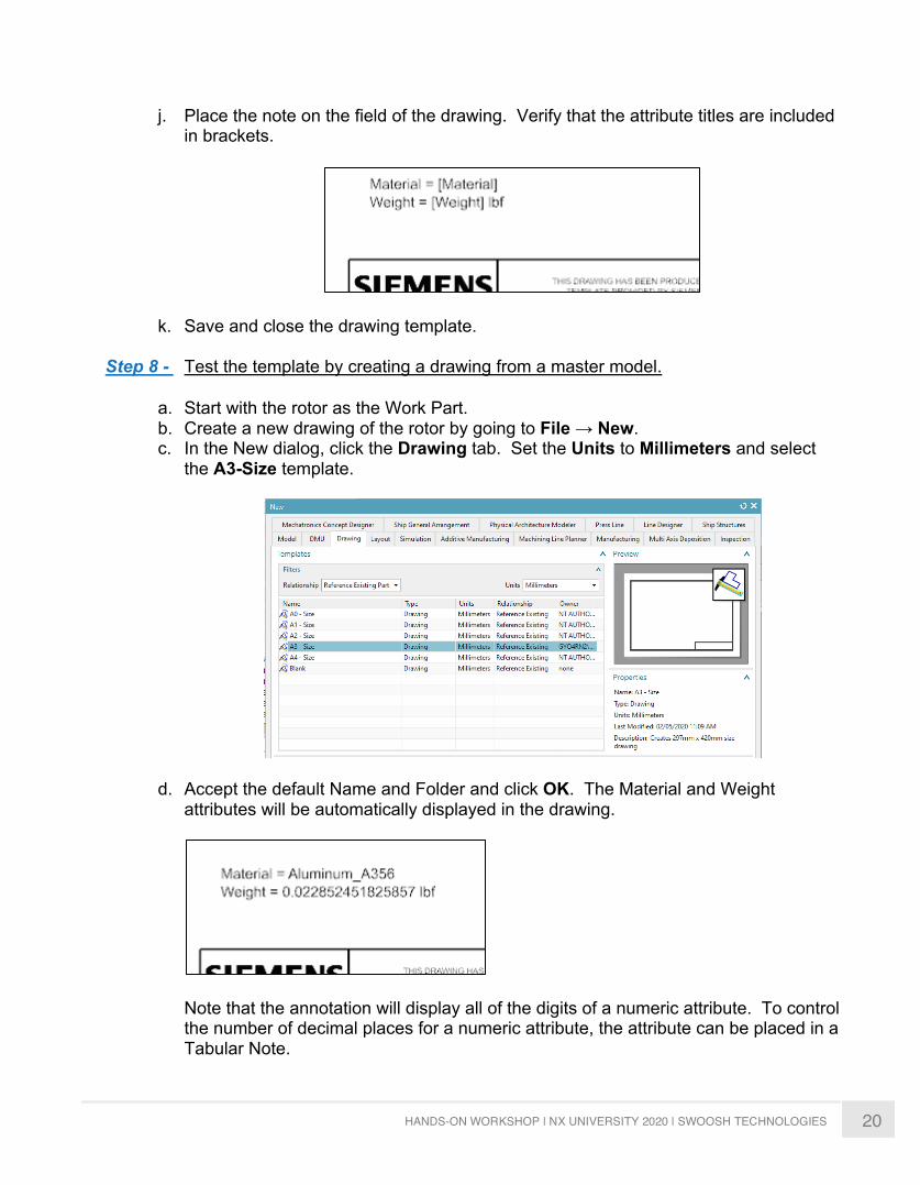
j. Place the note on the field of the drawing. Verify that the attribute titles are included in brackets.
k. Save and close the drawing template.
Step 8 - Test the template by creating a drawing from a master model.
a. Start with the rotor as the Work Part. b. Create a new drawing of the rotor by going to File → New. c. In the New dialog, click the Drawing tab. Set the Units to Millimeters and select
the A3-Size template.
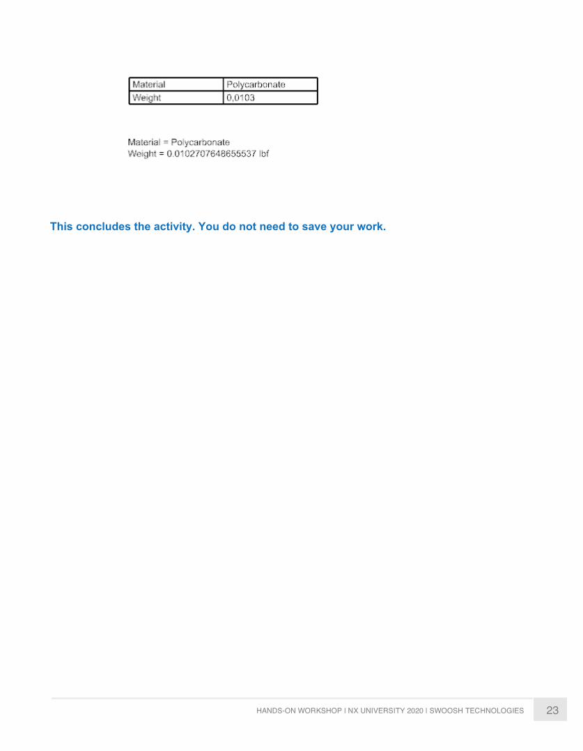
d. Accept the default Name and Folder and click OK. The Material and Weight attributes will be automatically displayed in the drawing.
Note that the annotation will display all of the digits of a numeric attribute. To control the number of decimal places for a numeric attribute, the attribute can be placed in a Tabular Note.
21 HANDS-ON WORKSHOP | NX UNIVERSITY 2020 | SWOOSH TECHNOLOGIES
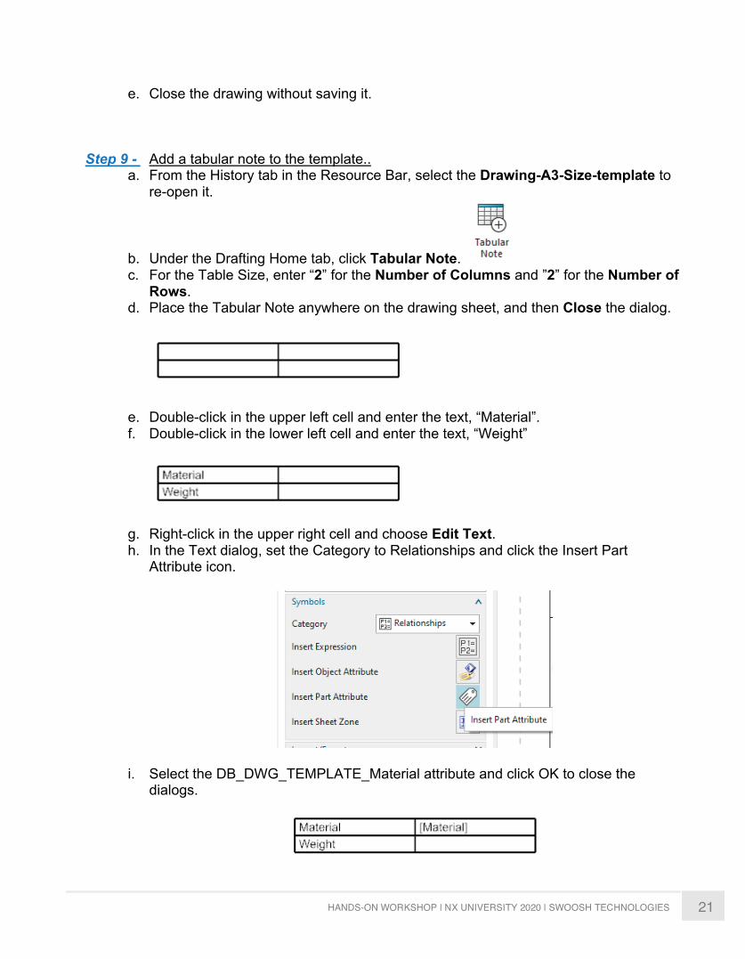
e. Close the drawing without saving it.
Step 9 - Add a tabular note to the template.. a. From the History tab in the Resource Bar, select the Drawing-A3-Size-template to
re-open it.
b. Under the Drafting Home tab, click Tabular Note. c. For the Table Size, enter “2” for the Number of Columns and ”2” for the Number of
Rows. d. Place the Tabular Note anywhere on the drawing sheet, and then Close the dialog.
e. Double-click in the upper left cell and enter the text, “Material”. f. Double-click in the lower left cell and enter the text, “Weight”
g. Right-click in the upper right cell and choose Edit Text. h. In the Text dialog, set the Category to Relationships and click the Insert Part
Attribute icon.
i. Select the DB_DWG_TEMPLATE_Material attribute and click OK to close the dialogs.
22 HANDS-ON WORKSHOP | NX UNIVERSITY 2020 | SWOOSH TECHNOLOGIES
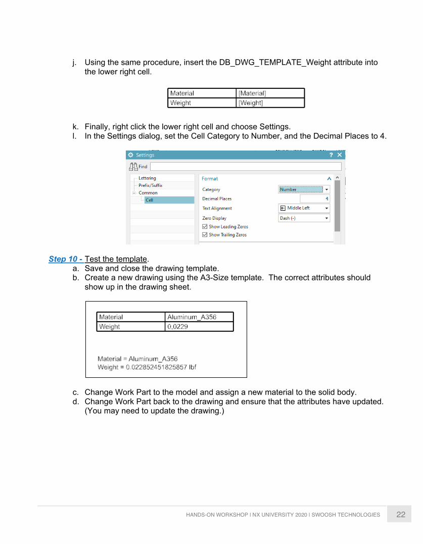
j. Using the same procedure, insert the DB_DWG_TEMPLATE_Weight attribute into
the lower right cell.
k. Finally, right click the lower right cell and choose Settings. l. In the Settings dialog, set the Cell Category to Number, and the Decimal Places to 4.
Step 10 - Test the template. a. Save and close the drawing template. b. Create a new drawing using the A3-Size template. The correct attributes should
show up in the drawing sheet.
c. Change Work Part to the model and assign a new material to the solid body. d. Change Work Part back to the drawing and ensure that the attributes have updated.
(You may need to update the drawing.)
23 HANDS-ON WORKSHOP | NX UNIVERSITY 2020 | SWOOSH TECHNOLOGIES
This concludes the activity. You do not need to save your work.
24 HANDS-ON WORKSHOP | NX UNIVERSITY 2020 | SWOOSH TECHNOLOGIES
NX CAM ACTIVTY 1
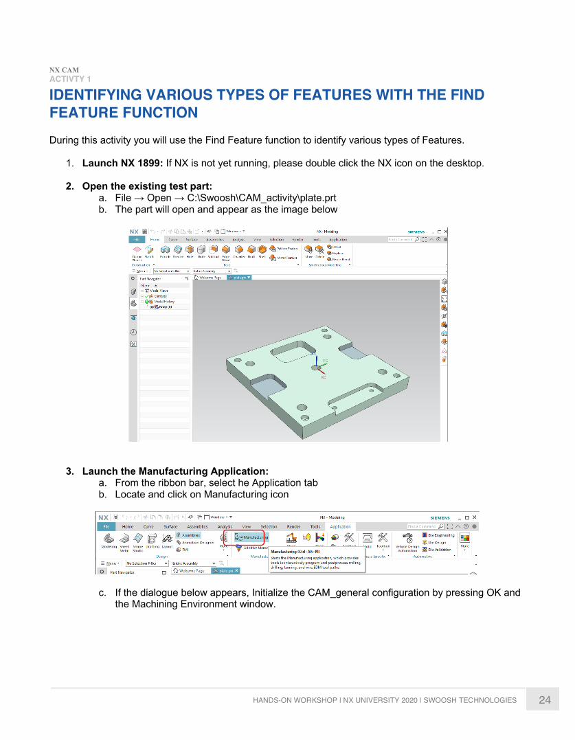
IDENTIFYING VARIOUS TYPES OF FEATURES WITH THE FIND FEATURE FUNCTION During this activity you will use the Find Feature function to identify various types of Features.
1. Launch NX 1899: If NX is not yet running, please double click the NX icon on the desktop.
2. Open the existing test part: a. File → Open → C:\Swoosh\CAM_activity\plate.prt b. The part will open and appear as the image below
3. Launch the Manufacturing Application:
a. From the ribbon bar, select he Application tab b. Locate and click on Manufacturing icon
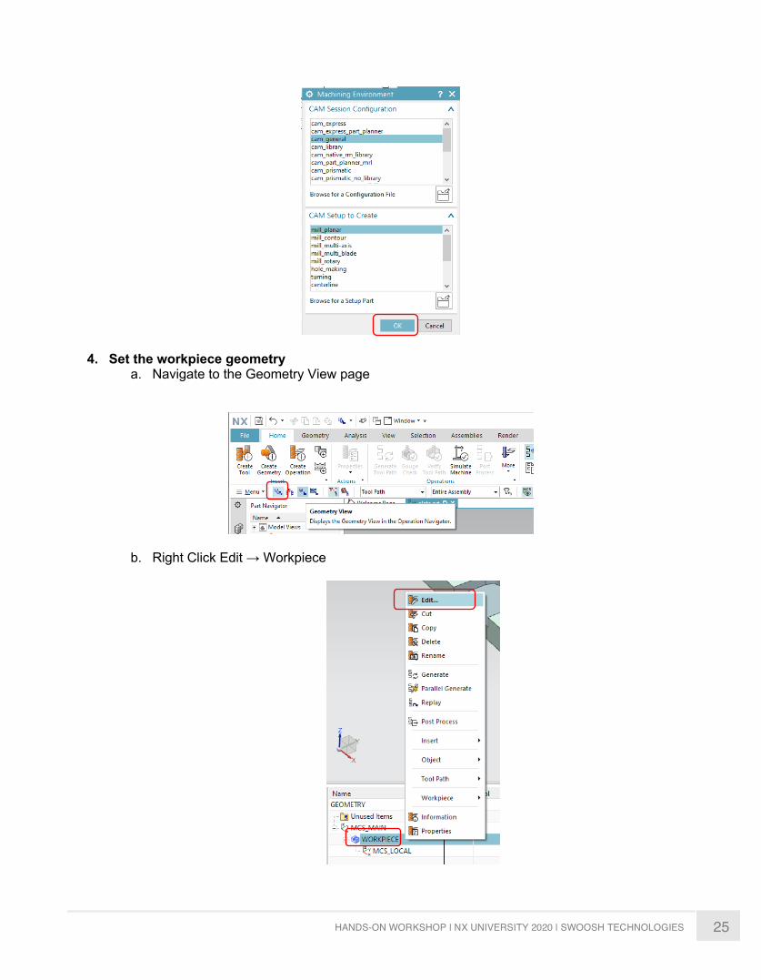
c. If the dialogue below appears, Initialize the CAM_general configuration by pressing OK and the Machining Environment window.
25 HANDS-ON WORKSHOP | NX UNIVERSITY 2020 | SWOOSH TECHNOLOGIES
4. Set the workpiece geometry a. Navigate to the Geometry View page
b. Right Click Edit → Workpiece
26 HANDS-ON WORKSHOP | NX UNIVERSITY 2020 | SWOOSH TECHNOLOGIES
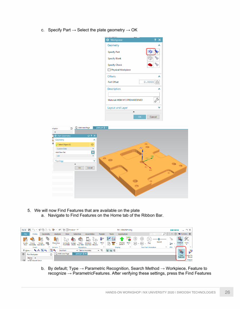
c. Specify Part → Select the plate geometry → OK
5. We will now Find Features that are available on the plate a. Navigate to Find Features on the Home tab of the Ribbon Bar.
b. By default; Type → Parametric Recognition, Search Method → Workpiece, Feature to recognize → ParametricFeatures. After verifying these settings, press the Find Features
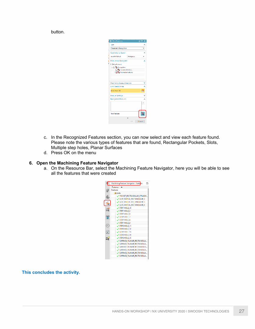
27 HANDS-ON WORKSHOP | NX UNIVERSITY 2020 | SWOOSH TECHNOLOGIES
button.
c. In the Recognized Features section, you can now select and view each feature found. Please note the various types of features that are found, Rectangular Pockets, Slots, Multiple step holes, Planar Surfaces
d. Press OK on the menu
6. Open the Machining Feature Navigator a. On the Resource Bar, select the Machining Feature Navigator, here you will be able to see
all the features that were created
This concludes the activity.
28 HANDS-ON WORKSHOP | NX UNIVERSITY 2020 | SWOOSH TECHNOLOGIES
ACTIVTY 2
USING THE FIND FEATURE FUNCTION FOR MANUALLY CREATED OPERATIONS During this activity you will use the Features that were created using the Find Feature function as geometry for manually created manufacturing operations.
1. Launch NX 1899: If NX is not yet running, please double click the NX icon on the desktop.
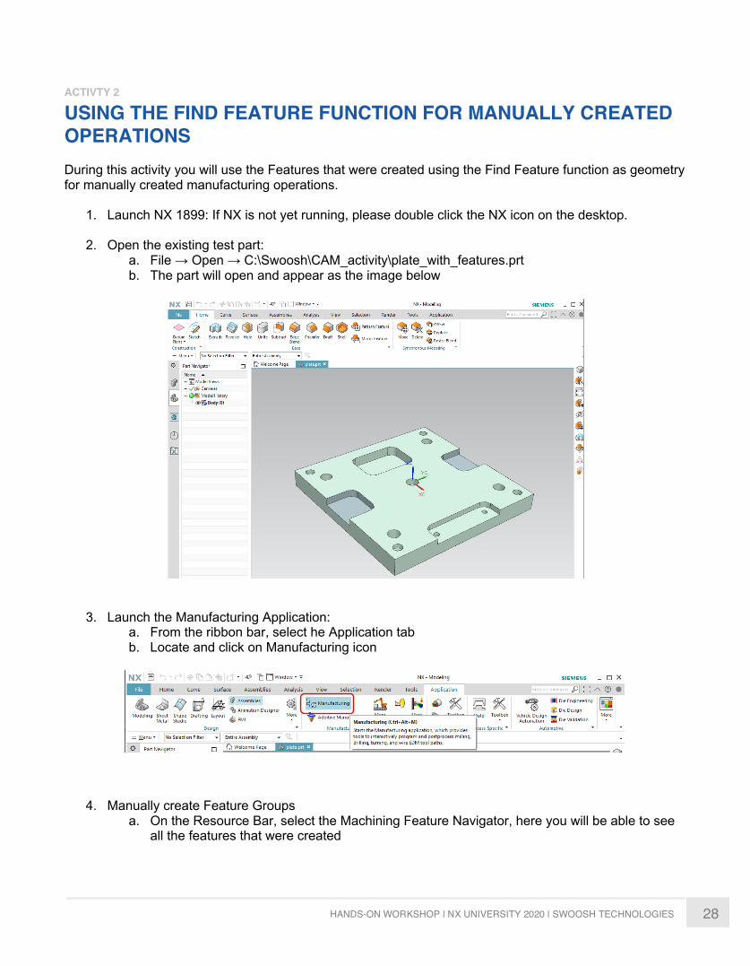
2. Open the existing test part: a. File → Open → C:\Swoosh\CAM_activity\plate_with_features.prt b. The part will open and appear as the image below
3. Launch the Manufacturing Application:
a. From the ribbon bar, select he Application tab b. Locate and click on Manufacturing icon
4. Manually create Feature Groups
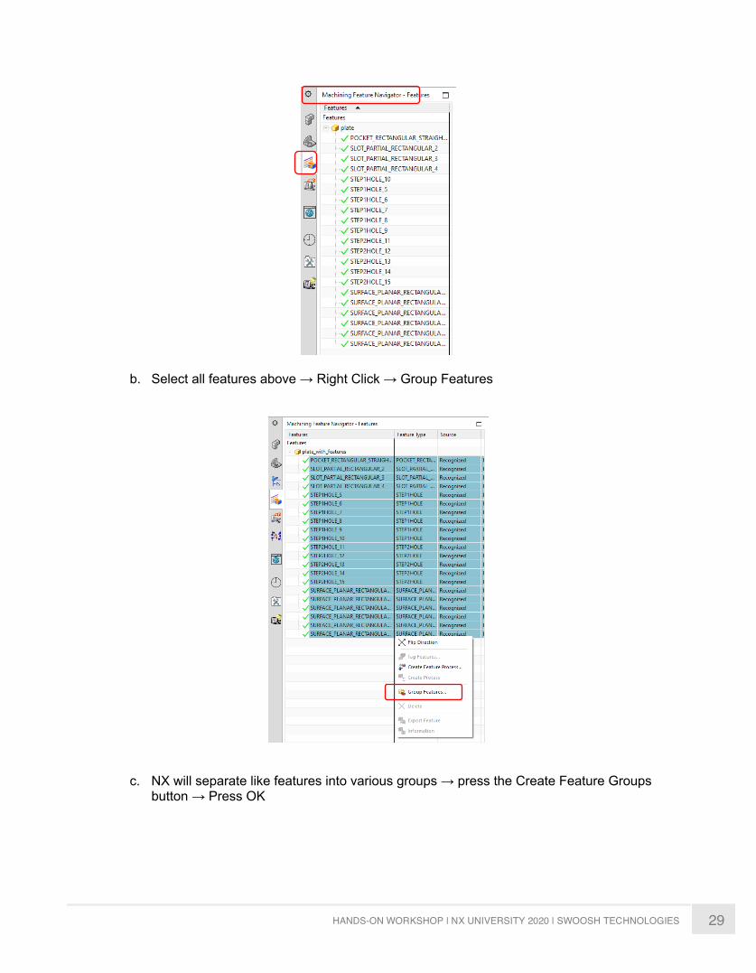
a. On the Resource Bar, select the Machining Feature Navigator, here you will be able to see all the features that were created
29 HANDS-ON WORKSHOP | NX UNIVERSITY 2020 | SWOOSH TECHNOLOGIES
b. Select all features above → Right Click → Group Features
c. NX will separate like features into various groups → press the Create Feature Groups button → Press OK
30 HANDS-ON WORKSHOP | NX UNIVERSITY 2020 | SWOOSH TECHNOLOGIES
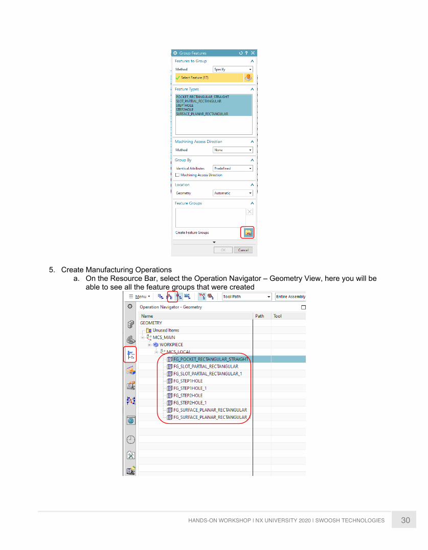
5. Create Manufacturing Operations a. On the Resource Bar, select the Operation Navigator – Geometry View, here you will be
able to see all the feature groups that were created
31 HANDS-ON WORKSHOP | NX UNIVERSITY 2020 | SWOOSH TECHNOLOGIES
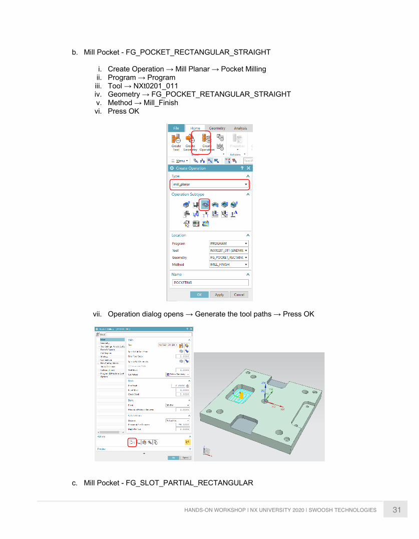
b. Mill Pocket - FG_POCKET_RECTANGULAR_STRAIGHT
i. Create Operation → Mill Planar → Pocket Milling ii. Program → Program iii. Tool → NXt0201_011 iv. Geometry → FG_POCKET_RETANGULAR_STRAIGHT v. Method → Mill_Finish vi. Press OK
vii. Operation dialog opens → Generate the tool paths → Press OK
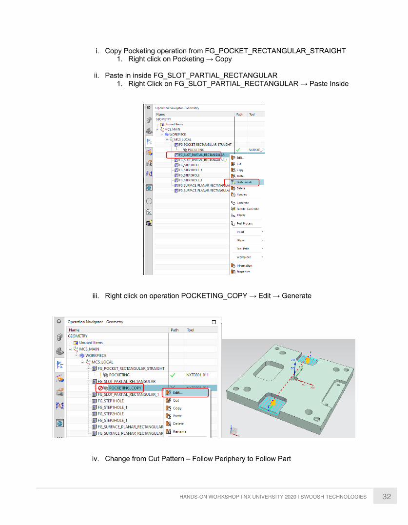
c. Mill Pocket - FG_SLOT_PARTIAL_RECTANGULAR
32 HANDS-ON WORKSHOP | NX UNIVERSITY 2020 | SWOOSH TECHNOLOGIES
i. Copy Pocketing operation from FG_POCKET_RECTANGULAR_STRAIGHT 1. Right click on Pocketing → Copy
ii. Paste in inside FG_SLOT_PARTIAL_RECTANGULAR
1. Right Click on FG_SLOT_PARTIAL_RECTANGULAR → Paste Inside
iii. Right click on operation POCKETING_COPY → Edit → Generate
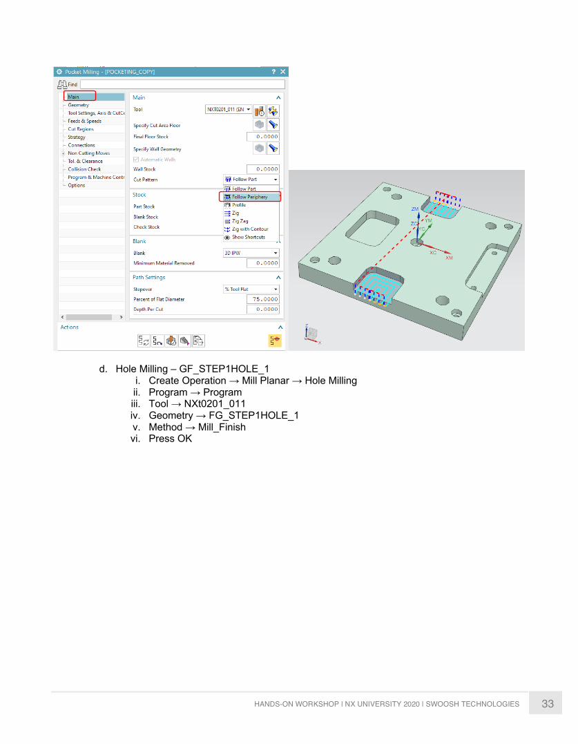
iv. Change from Cut Pattern – Follow Periphery to Follow Part
33 HANDS-ON WORKSHOP | NX UNIVERSITY 2020 | SWOOSH TECHNOLOGIES
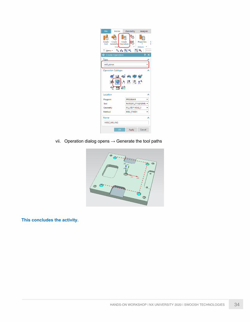
d. Hole Milling – GF_STEP1HOLE_1 i. Create Operation → Mill Planar → Hole Milling ii. Program → Program iii. Tool → NXt0201_011 iv. Geometry → FG_STEP1HOLE_1 v. Method → Mill_Finish vi. Press OK
34 HANDS-ON WORKSHOP | NX UNIVERSITY 2020 | SWOOSH TECHNOLOGIES
vii. Operation dialog opens → Generate the tool paths
This concludes the activity.
35 HANDS-ON WORKSHOP | NX UNIVERSITY 2020 | SWOOSH TECHNOLOGIES
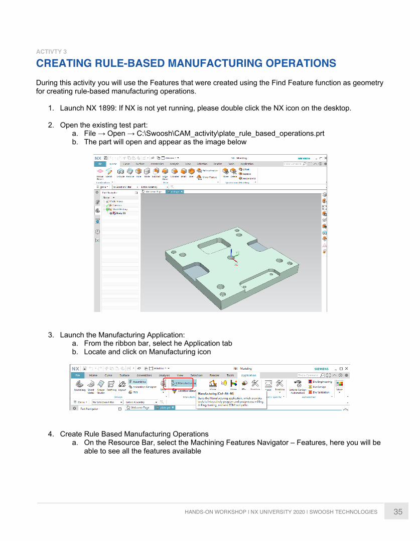
ACTIVTY 3
CREATING RULE-BASED MANUFACTURING OPERATIONS During this activity you will use the Features that were created using the Find Feature function as geometry for creating rule-based manufacturing operations.
1. Launch NX 1899: If NX is not yet running, please double click the NX icon on the desktop.
2. Open the existing test part: a. File → Open → C:\Swoosh\CAM_activity\plate_rule_based_operations.prt b. The part will open and appear as the image below
3. Launch the Manufacturing Application:
a. From the ribbon bar, select he Application tab b. Locate and click on Manufacturing icon
4. Create Rule Based Manufacturing Operations
a. On the Resource Bar, select the Machining Features Navigator – Features, here you will be able to see all the features available

36 HANDS-ON WORKSHOP | NX UNIVERSITY 2020 | SWOOSH TECHNOLOGIES
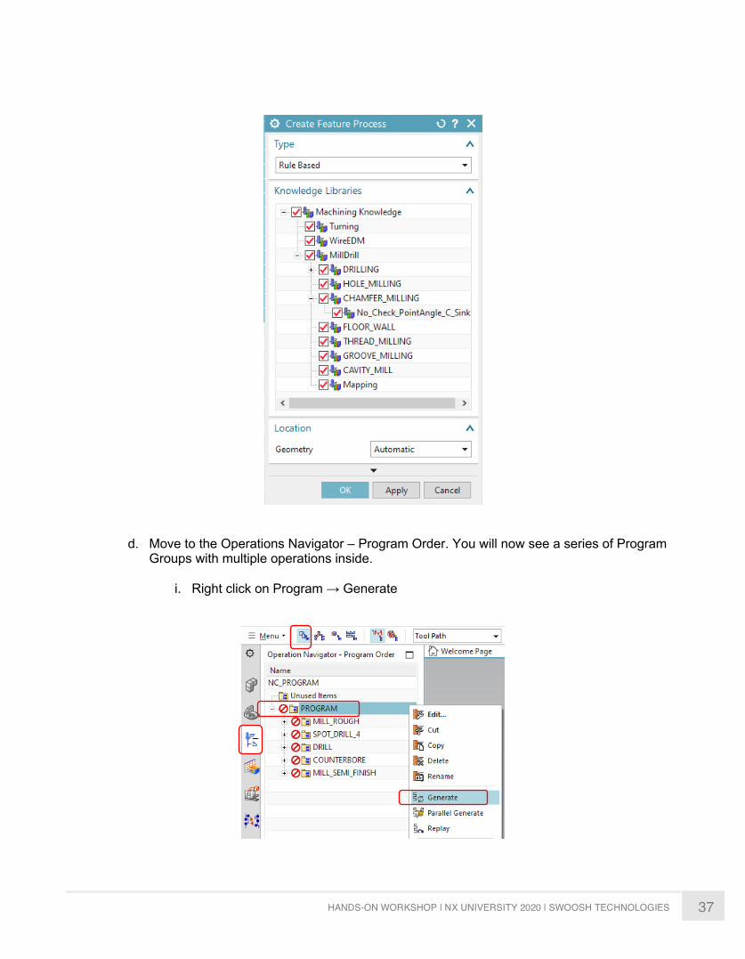
b. Select all Features → Right Click → Create Feature Process
c. The Create Feature Process dialogue will open, set Type → Rule Based, then click the
Machining Knowledge check box until a red check appears. Press OK.
37 HANDS-ON WORKSHOP | NX UNIVERSITY 2020 | SWOOSH TECHNOLOGIES
d. Move to the Operations Navigator – Program Order. You will now see a series of Program Groups with multiple operations inside.
i. Right click on Program → Generate

38 HANDS-ON WORKSHOP | NX UNIVERSITY 2020 | SWOOSH TECHNOLOGIES
ii. All of the operations have now generated, review the individual operations. These operations were created using rules that were establish and included OOTB with NX1899.
5. Using the Machining Knowledge Editor, you can create your own company rules for operation types and sequences, tooling standards, etc to customize the results when you use Feature Based Machining.
This concludes Activity 3
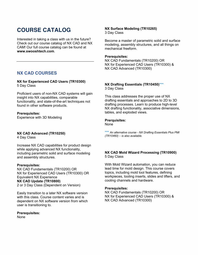
COURSE CATALOG Interested in taking a class with us in the future? Check out our course catalog of NX CAD and NX CAM! Our full course catalog can be found at www.swooshtech.com. NX CAD COURSES NX for Experienced CAD Users (TR10300) 5 Day Class Proficient users of non-NX CAD systems will gain insight into NX capabilities, comparable functionality, and state-of-the-art techniques not found in other software products. Prerequisites: Experience with 3D Modeling NX CAD Advanced (TR10250) 4 Day Class Increase NX CAD capabilities for product design while applying advanced NX functionality, including parametric solid and surface modeling and assembly structures. Prerequisites: NX CAD Fundamentals (TR10200) OR NX for Experienced CAD Users (TR10300) OR Equivalent NX Experience NX CAD Update (TR10800) 2 or 3 Day Class (Dependent on Version) Easily transition to a later NX software version with this class. Course content varies and is dependent on NX software version from which user is transitioning to. Prerequisites: None
NX Surface Modeling (TR10265) 3 Day Class Become a master of parametric solid and surface modeling, assembly structures, and all things on mechanical freeform. Prerequisites: NX CAD Fundamentals (TR10200) OR NX for Experienced CAD Users (TR10300) & NX CAD Advanced (TR10300) NX Drafting Essentials (TR10450)*** 3 Day Class This class addresses the proper use of NX drafting essentials and approaches to 2D to 3D drafting processes. Learn to produce high-level NX drafting functionality, associative dimensions, tables, and exploded views. Prerquisites: None *** An alternative course - NX Drafting Essentials Plus PMI (TR10460) – is also available. NX CAD Mold Wizard Processing (TR10900) 5 Day Class With Mold Wizard automation, you can reduce lead time for mold design. This course covers topics, including mold tool features, defining workpieces, tooling inserts, slides and lifters, and cooling channels and hardware. Prerequisites: NX CAD Fundamentals (TR10200) OR NX for Experienced CAD Users (TR10300) & NX CAD Advanced (TR10300)
40 HANDS-ON WORKSHOP | NX UNIVERSITY 2020 | SWOOSH TECHNOLOGIES
NX CAM COURSES NX Mill Manufacturing Fundamentals (TR20300) 4 Day Class NC programmers new to NX CAM will accelerate in understanding how to create tool paths for 2 and 3 axis milling/drilling centers in NX. Prerequisites: NX CAD Fundamentals (TR10200) OR NX for Experienced CAD Users (TR10300) Thorough understanding of NC/CNC programming principles NX Multi Axis Machining (TR20350) 2 Day Class Those responsible for 4 and 5 axis programs will benefit the most from this class. Learn how to create and modify 4 and 5 axis operations for complex machines. Prerequisites: NX Mill Manufacturing Fundamentals (TR20300) Knowledge of NX CAD 3-axis operations NX Turning Manufacturing Applications (TR20550) 3 Day Class Get essential turning training for lathes and mill-turn machine tools. Knowledge of programming lathes and/or mill turns not required. Prerequisites: NX Mill Manufacturing Fundamentals (TR20300)
NX Post Building Techniques and Machine Simulation (TR20450) 4 Day Class Learn to create and modify NC postprocessors for 2.5 thru 5 axis machines, as well as turning and mill turn postprocessors. Prerequisites: NX Mill Manufacturing Fundamentals (TR20300)


