Embed Size (px)
Citation preview

Mech. & Aerospace Eng. J. Vol. 3, No. 2, September 2007 73
73
Numerical Investigation of a 3-D Flow Past an Impenetrable Rotating Microparticle at Low and Moderate Reynolds Numbers
M.R. Meigounpoory1 and GH. Atefi2 H. Niazmand3 A. Mirbozorgi4
Mech. Eng. Dep't. Iran Univ. of science & Tech.
Mech. Eng. Dep't. Mashad Ferdowsi Univ.
Mech. Eng. Dep't. Birjand Univ.
ABSTRACT Computations are performed to determine the steady 3-D viscous fluid flow forces acting on an impenetrable rotating spherical suspended particle at low and moderate Reynolds numbers in the range of 10010 ≤≤ Re. . In order to extend the capabilities of the finite volume method, the boundary (body) fitted coordinates (BFC) method is used. Transformation of the governing partial differential equation to algebraic relations is based on the finite volume method and collocated variables arrangement. For solving the algebraic relations, the TDMA in a periodic state is used. To approximate the convective fluxes, the differencing scheme of Van Leer is used and the SIMPLEC algorithm handles the linkage between velocity and the pressure. Rotation increases the drag and lift forces exerted by flow at the surface of on the sphere. Using velocity components in Cartesian coordinates causes slight decrease in the run time of program with respect to using it in contra-variant and covariant coordinates. The flow patterns are changed with increasing rotation at x-y plane, but flow at x-y plane remains symmetric the present numerical results are in complete accord with other results of flow around a rotating sphere. Key Words: Rotating Suspended Particle, 3-D Flow, Body Fitted Coordinate
ذرهميكرويك حول سه بعديبررسي عددي جريان كامالو پايين كروي چرخان درمحدوده اعدادرينولدز متوسط
4 علي مير بزرگي3 حميد نيازمند2غالمعلي عاطفيو1محمدرضا ميگون پوري
مكانيكمهندسي دانشكده مكانيكمهندسي دانشكده دانشكده مهندسي مكانيك دانشگاه بيرجند دانشگاه فردوسي مشهد ايراناه علم وصنعتدانشگ
چكيدهدر جامدبه بررسي عددي جريان سه بعدي سيال غيرقابل تراكم در اطراف يك ذره كروياين مقاله در محدودهمعلق در حال دوران
10010 ≤≤ Re.اب.پرداخته مي شود كد عددي سه بعدي نوشته شده كه براي گسسته سازي معادالت ديفرانسيليكين منظورهو و براي جزئي با روش جبري از روش حجم محدود و براي مدل نمودن شارهاي جابجايي از روش ون لير با آرايش مرتب شده متغيرها
از روش مختصات، حجم محدود روشهاي براي افزايش قابليت. روش سيمپل سي استفاده مي كندازرعتارتباط دادن ميدانهاي فشار وسميTDMAو سيستم معادالت جبري توسط الگوريتم منطبق بر مرز استفاده مي شود شددر. گردد حل كه چرخش اين مقاله مشخص
و و توزيع فشار مي كره باعث تغييرات زيادي در الگوي جريان ذره كرويچرخش،در اعداد رينولدز پايين.دشوورتيسيتي جريان حول آندر تاثير زيادي بر ضرايب درگ وليفت ندارد برباالتر اعداد رينولدز ولي به،همچنين.مقادير ضرايب برا وپسا افزايش مي يابد تاثيرچرخش
و كون . مي شودحجم محاسبات باعث كاهش قابل مالحظه تراوارينت كارگيري مولفه هاي كارتزين سرعت به جاي مولفه هاي كووارينت.هاي مورد استفاده را تاييد مي كند مقايسه نتايج حاصله با نتايج ساير محققين صحت روند حل والگوريتم
مختصات منطبق بر مرز، جريانتحليل سه بعدي،كره چرخان:واژه هاي كليدي
1-PhD Student(Corresponding Author): [email protected] 2-Associate Professor: Atefi@ iust.ac.ir 3-Assistant Professor 4-Assistant Professor

74 Mech. & Aerospace Eng. J. Vol. 3, No. 2, September 2007
Symbols and Abbreviations A Area D Diameter of Sphere L Wake Length nr Normal Unit Vector p Pressure r, θ, ϕ Spherical Coordinates R Radius of Sphere Re Reynolds Number, Re U D ν∞=t Time u, v, w Velocity Components in the x, y, z cccccccccc Directions U∞ Free Stream Velocity
Vr
Velocity Vector CD Drag Coefficient CLy Lift Coefficient in y Direction ν Kinematic Viscosity θs Separation Angle τ Non-Dimensional Time, tU Dτ ∞=τt Viscous Stress Tensor f Fluid ∞ Free-Stream Introduction Flow over spheres is a fundamental problem encountered in many engineering problems. It is well known that the motion of spherical particles have many applications in industries, such as hydrodynamic dispersion in quiescent sedimenting suspensions, the dynamics of bubbles and drop or particle in arbitrary motion at different Reynolds numbers, Sedimentation of noncolloidal Particles, osmotic phenomena, transport of groundwater colloids, and the permeability reduction due to migrating fines in enhanced oil recovery and hydrodynamic dispersion, the motion of fuel droplets in combustors, solid particle in air, and two phase flows, like motion spherical bubbles and droplets in fluid flow, solid particle in air. It is well known that the motion of spherical particles in some applications also involves no-slip condition such as the motion of fuel droplets in combustors, solid particle in air, and some other motion of spherical particles such as bubbles involves slip condition on the surface.
Although particle rotation typically occurs around an arbitrary axis in space, investigation of cases with rotation axes normal and parallel to the principal flow direction can provide fundamental information. The characteristics of the flow field for particle rotation in the stream wise direction (spin) are quite different from that in the transverse direction (rotation). Rotation displaces and reduces the recirculation region of the wake such that at sufficiently high rotational speeds it is completely suppressed [1], while spin has the opposite effect.
The structure of flow at the near wake region has a strong influence on the behavior of the drag and lifts forces as well as the other characteristics of the particle, and therefore, deserves close examination. For uniform flow past a sphere, the wake forms at Re ≅ 20 and undergoes several well-defined transitions as the Reynolds number is increased. First transition occurs at Re ≅ 212, where the axisymmetric steady wake becomes planar-symmetric yet steady and attached. In the second transition, the steady planar-symmetric wake becomes unsteady at Re ≅ 270 forming a periodic wake with vortex shedding. The details of the wake structure in each wake regime have been investigated both experimentally and theoretically [2-8]. However, a review of the relevant literature provides limited information on the effects of particle spin and rotation. The case of particle rotation has attracted some attention in the literature, where the experimental studies of Best [1] and Brakla and Auchterlonie [9], Oesterle and Dinh [10], and the numerical studies of Salem and Oesterle [11], and Kurose and Komori [12] can be mentioned among others. However, for the case of a spinning sphere much less information is available in this Re range. The only known work is the numerical study of Kim and Choi [13]. They considered Re = 100 in the steady symmetrical regime, Re = 250 in the steady non-symmetrical regime, and Re = 300 in the unsteady wake regime, for angular velocities of 1xΩ ≤ . It is reported that the forces acting on the sphere are influenced by spin, and the vortical structures behind the particle are significantly modified. For higher Re flows over spinning spheres, Clift et al. [14] have summarized previous studies and pointed out that the transition to turbulence, which is identified by a sudden drop in the standard drag curve, occurs at lower Re with increased spin. Similar behavior is observed in the present study at moderate Re, such that increasing particle spin reduces the transitional Re between the different wake regimes. Niazmand and Renksizbulut [15] and [16] carried out numerical investigations of the flow and temperature fields around rotating spheres with surface blowing. It is shown that transient behavior of important flow parameters such as the lift and drag coefficients are significantly influenced by particle rotation and surface blowing. However, the surface-averaged heat transfer rates are not influenced appreciably by particle rotation even at high rotational speeds, whereas the local heat transfer rates are drastically affected. Literature review shows that the lack of study about flow around the rotating sphere at moderate Reynolds numbers. Recently, Numerical analysis of 3D flow past a stationary sphere with
Mech. & Aerospace Eng. J. Vol. 3, No. 2, September 2007 75
slip condition at low and moderate Reynolds numbers has been investigated by Atefi et al [17].
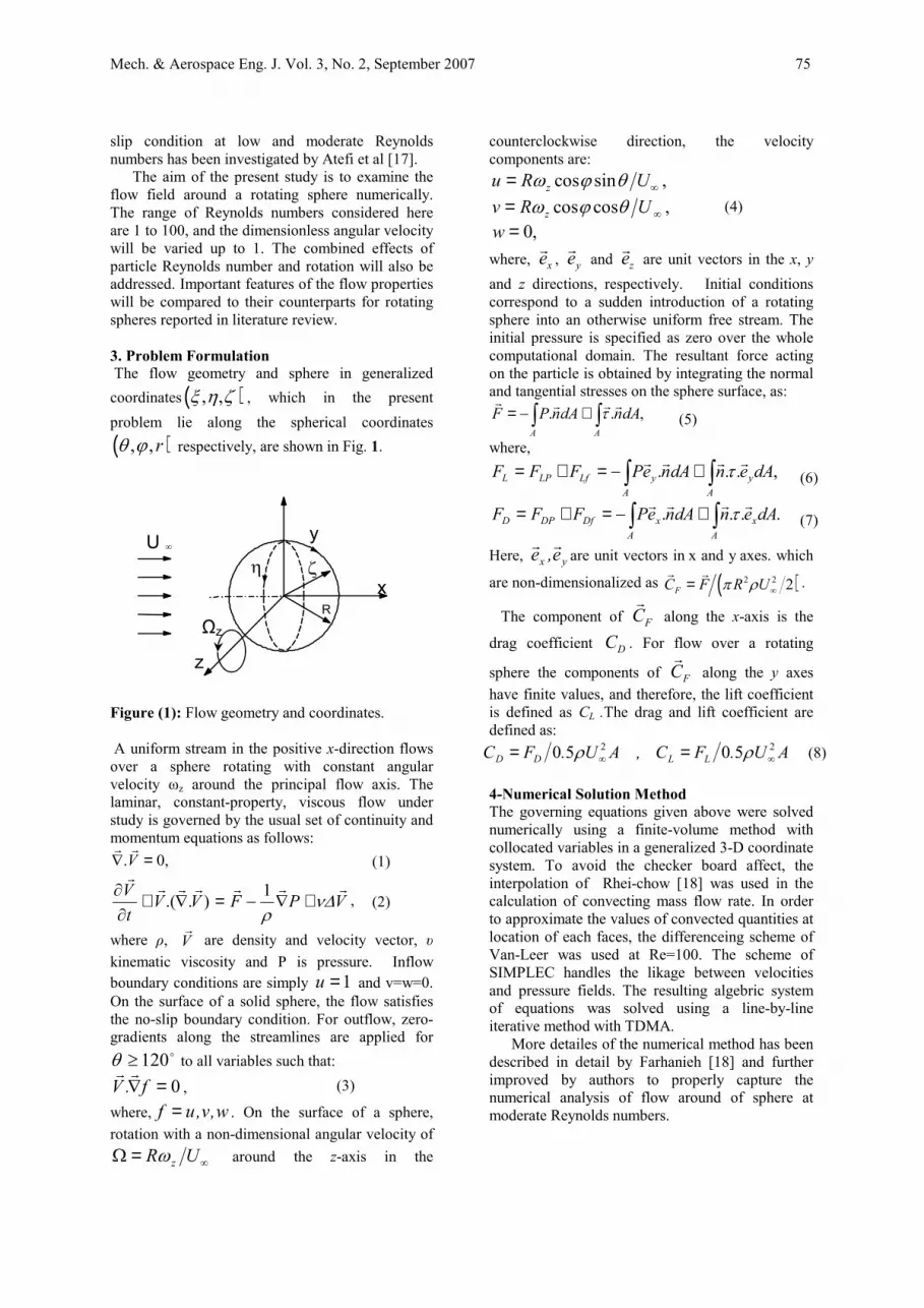
The aim of the present study is to examine the flow field around a rotating sphere numerically. The range of Reynolds numbers considered here are 1 to 100, and the dimensionless angular velocity will be varied up to 1. The combined effects of particle Reynolds number and rotation will also be addressed. Important features of the flow properties will be compared to their counterparts for rotating spheres reported in literature review. 3. Problem Formulation The flow geometry and sphere in generalized coordinates ( ), ,ξ η ζ , which in the present problem lie along the spherical coordinates
( ), , rθ ϕ respectively, are shown in Fig. 1.
Figure (1): Flow geometry and coordinates. A uniform stream in the positive x-direction flows
over a sphere rotating with constant angular velocity ωz around the principal flow axis. The laminar, constant-property, viscous flow under study is governed by the usual set of continuity and momentum equations as follows:
,0. =∇ Vrr
(1)
VPFVVtV rrrrrrr
∆νρ
+∇−=∇+∂∂ 1)..( , (2)
where ρ, Vr
are density and velocity vector, υkinematic viscosity and P is pressure. Inflow boundary conditions are simply 1u = and v=w=0. On the surface of a solid sphere, the flow satisfies the no-slip boundary condition. For outflow, zero-gradients along the streamlines are applied for
o120≥θ to all variables such that:
0=∇f.Vrr
, (3)
where, w,v,uf = . On the surface of a sphere, rotation with a non-dimensional angular velocity of
∞=Ω UR zω around the z-axis in the
counterclockwise direction, the velocity components are:
,sincos ∞= URu z θϕω,coscos ∞= URv z θϕω
,0=w(4)
where, xer , yer and zer are unit vectors in the x, yand z directions, respectively. Initial conditions correspond to a sudden introduction of a rotating sphere into an otherwise uniform free stream. The initial pressure is specified as zero over the whole computational domain. The resultant force acting on the particle is obtained by integrating the normal and tangential stresses on the sphere surface, as:
,.. ∫∫ +−=AA
dAndAnPF rrrrτ (5)
where, ,... ∫∫ +−=+=
Ay
AyLfLPL dAendAnePFFF rrrr τ (6)
.... ∫∫ +−=+=A
xA
xDfDPD dAendAnePFFF rrrr τ (7)
Here, yx e,e rrare unit vectors in x and y axes. which
are non-dimensionalized as ( )2 2 2FC F R Uπ ρ ∞=r r
.
The component of FCr
along the x-axis is the
drag coefficient DC . For flow over a rotating
sphere the components of FCr
along the y axes have finite values, and therefore, the lift coefficient is defined as CL .The drag and lift coefficient are defined as:
AU.FC,AU.FC LLDD22 5050 ∞∞ == ρρ (8)
4-Numerical Solution Method The governing equations given above were solved numerically using a finite-volume method with collocated variables in a generalized 3-D coordinate system. To avoid the checker board affect, the interpolation of Rhei-chow [18] was used in the calculation of convecting mass flow rate. In order to approximate the values of convected quantities at location of each faces, the differenceing scheme of Van-Leer was used at Re=100. The scheme of SIMPLEC handles the likage between velocities and pressure fields. The resulting algebric system of equations was solved using a line-by-line iterative method with TDMA.
More detailes of the numerical method has been described in detail by Farhanieh [18] and further improved by authors to properly capture the numerical analysis of flow around of sphere at moderate Reynolds numbers.
y
ζηx
z
R
U ∞
Ωz

76 Mech. & Aerospace Eng. J. Vol. 3, No. 2, September 2007
5-Computational parameter and Numerical Accuracy We study flow around of sphere in the range of 0.1<Re<100. Transport mechanism of fluid properties at Re=100 is convection mechanism and we use van Leer method for solving numerical problem. The accuracy of numerical algorithm was tested by predicting the axisymmetric flow around a stationary solid sphere at Re=100. we examined effects of grid resolution on drag coefficient, separation angle and dimensionless wake length of flow at Re=100. The details of the grid independence study, as well as evidence of accuracy in predicting wake features, fluid forces and in the range of parameters considered here are given elsewhere [21].
The flow is axisymmetric in this case and three dimentional solution sheme is fully exercised in a time accurate manner for all cases. As shown in Fig. 2 for most cases considered here, a numerical grid of ( ) ( )62,52,62,, maxmaxmax =ζηξ has been used, and the far-field boundary has been set at 10 radii from the center of the sphere. Fig. 2. shows Coordinates, flow geometry and mesh generation around of sphere.
-5
0
5
10
15
x-4
-20
24
z
-4
-2
0
2
4
y
X
Y
Z
Figure (2): Coordinates , flow geometry and mesh around a sphere.
Table 1 lists the drag coefficient as a function of
Reynolds number and compare them experimental
results of Roos and Willmarth [3] and numerical data presented by Clift et al. [14]. The table also includes the separation angle, measured from front stagnation point, which are in good agreement with results from Clift et al. [14]. As shown in Fig. 3, the separation angle is measured from the rear stagnation point by present method with Ωz=0 and they have compared with other numerical and analytical results.
Separation angle
0
20
40
60
80
0 50 100 150 200Re
θ (de
gree
)
Present numerical solutionKarlaMasliyaTanedaRaithbyNakamura
Figure (3): Comparison of separation angle for
flow over an impenetrable stationary sphere.
The comparison is made with numerical results of Nakamura [4], Raithby[18], Masliya [14] and experiment results of Taneda [1] and Karla and Uhlherr[20].
Table 2 shows grid independency of flow around the rotating sphere at Re=100 and Ωz=0.5 for different grid densities. As shown in table 2 the effect of grid resolution on drag and lift coefficient of flow at Re=100 and different outer boundary was investigated. The extend of grid expansion in some cases was adjusted based on the number of grid points and the location of the outer boundary to achieve a comparable grid density near the surface of the sphere. The maximum difference between drag coefficient between all case is about 3%.
Mech. & Aerospace Eng. J. Vol. 3, No. 2, September 2007 77
Table (1): Comparison of our drag coefficient and separation angle with those of Clift et al. [14] and Roos & Willmarth [3] for flow over a solid sphere.
Drag Coefficient Separation angle (θ )a
Re Present work Roos& Willmarth b [3] Clift et al [14] Present work Clift et al [14] 1 27.327046 - 27.315 0 0 50 1.588 1.620 1.57 139.3 139.3 100 1.095 1.090 1.096 126.8 126.5 a values of separation angle measured from the front stagnation point b interpolated values are use
Table (2): Drag and lift coefficients as functions of grid density at Re=100 and at Ωz=0.5.RR∞ mama ζηξ ××max Radial expansion factor Lift coefficient Drag coefficient
10 51×50×51 1.09 00.073361 1.176802 10 51×50×61 1.09 0.073466 1.177260 10 61×50×61 1.05 0.073201 1.173813
10 71×50×71 1.04 0.073265 1.171703 20 71×50×71 1.04 0.073228 1.172564 30 81×50×81 1.04 0.0733459 1.173680
It is Clear that changing the location of the outer boundary from 10 to 20 radii and to 30 radii does not introduce considerable changes to the drag coefficient. The grid points are expanded only in the radial direction with an expansion ratio of about 1.04 at Re=100. A dimensionless time step
0.0025τ∆ = based on diffusion time scale ( 2D
tdif
ντ = , where ν is kinematic viscosity and t
is time) were used to initiate the calculation. It should be note that, in this analysis, the spherical particle does not accelerate owing to aerodynamic forces acting on it from the flow field.
6-Results and Discussion Simulations are performed in the range 0.1<Re<100 covering the Two different flow regimes of classical flow past a stationary solid sphere: (I) steady attached flow for 20Re ≤ , (II) steady axisymmetric flow with separation for 20<Re<100, The effects of particle rotation will be considered for Re < 100, as representative of each flow regime. Transient behavior of the lift, drag will be presented for rotation in the range Ωz ≤1. Computations at different Reynolds number regimes in combination with particle rotation will also be discussed. For most cases considered here, a numerical grid of ( ) ( )62,52,62,, maxmaxmax =ζηξ has been used, and the far-field boundary has been set at 10 radii from the center of the sphere. The grid points are expanded only in the radial direction with an expansion ratio of about 1.04 and a dimensionless time step of 0.0025τ∆ = is used to initiate the calculations. However, this time step is increased by a factor of 1.02 to a maximum value in the range of
max0.01 0.05τ≤ ∆ ≤ depending on the Reynolds number and rotation speed.
Present calculations are confirmed that up to Re ≅ 20, uniform flow past a motionless sphere does not separate despite the pressure asymmetry around the particle. Particle rotation enhances this asymmetry. If dimensionless angular velocity is increased present calculations at different Ωz and Reynolds indicate the onset of variation in Pressure coefficient and vortisity distribution, and other flow characteristics on the surface of sphere and dispersion of flow properties in flow around a spherical particle. As shown in Fig. 4, there is a symmetric wake region at the back of the sphere at Re=100 and Ωz =0 in x-y plane that is perpendicular to rotating axes (z).
Global views of the effects of rotation and Reynolds number on the flow structure at Re=100 are presented in Fig. 4. The streamlines pass through the same grid points in the flow field around the front stagnation point at different angular velocity. As expected at presence of rotation, the streamlines passing on the rotating sphere will not remain symmetric. Flow over a sphere at Re=100, Ωz =0 forms a closed-bubble with recirculating wake of length L = 0.87D, which separates at 127sθ = o .Particle rotation forms an asymmetric wake with a smaller size and sooner flow separation in x-y plane. Two forces are exerted in the flow field around of rotating spherical particle, and they are momentums of flow and force created by rotation of sphere. When dimensionless angular velocity increases, the shear stress force exerted by rotating

78 Mech. & Aerospace Eng. J. Vol. 3, No. 2, September 2007
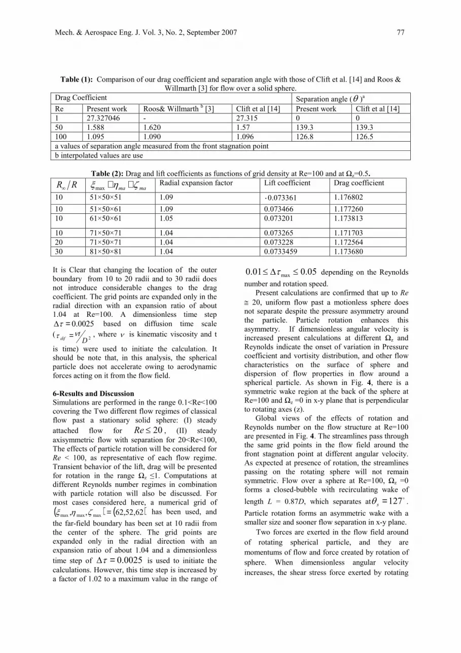
effects is increased with respect to inertia force and flow tends to move in rotating direction. Increasing Ωz >0.5 causes the growth of rotational force whereas at the regions near the spherical surface flow rotates completely around the sphere. Fig. 5 shows the flow patterns of flow around the rotating sphere in x-z plane at Re=100 and different angular velocity. The streamlines of flow around the rotating sphere at Re=100 and x-z plane is symmetric. The wake length and separation angle decreases with increasing Ωz angular velocity of
rotating sphere. The physical reason of this behavior is related to increasing the velocity gradient near the spherical surface. Increasing angular velocity increases shear stress on the particle surface and flow sense sphere presence on the flow field more than before. Increasing rotating number Ωz is more profound at higher rotation. Present calculations indicate the wake length becomes smaller with increasing Ωz
until it will be disappeared at Ωz ≥0.5.
Re=100ΩΖ=0
Re=100ΩΖ=0.1
Re=100ΩΖ=0.16
Re=100ΩΖ=0.25
Re=100ΩΖ=0.5
Re=100ΩΖ=1
Figure (4): Variation of streamlines patterns around the rotating sphere at Re=100 and at different angular velocity in x-y plane.
Mech. & Aerospace Eng. J. Vol. 3, No. 2, September 2007 79
Re=100
Ω=0
Re=100
Ω=0.16
Re=100
Ω=0.25
Re=100
Ω=0.5
Re=100
Ω=1
Re=100
Ω=0.1
Figure (5):Variation of streamlines patterns around the rotating sphere at Re=100 and at different angular velocity in x-z plane.
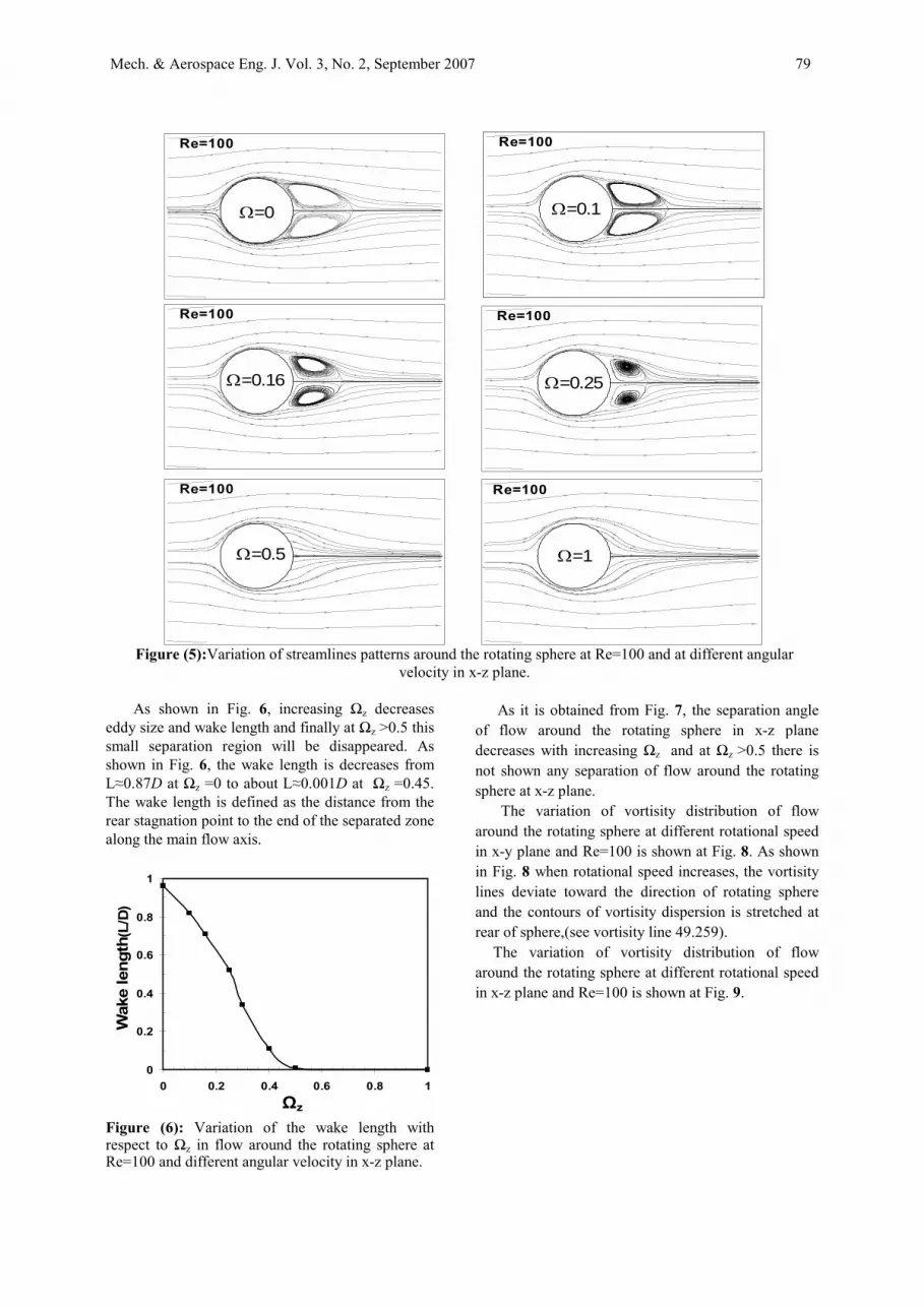
As shown in Fig. 6, increasing Ωz decreases
eddy size and wake length and finally at Ωz >0.5 this small separation region will be disappeared. As shown in Fig. 6, the wake length is decreases from L≈0.87D at Ωz =0 to about L≈0.001D at Ωz =0.45. The wake length is defined as the distance from the rear stagnation point to the end of the separated zone along the main flow axis.
0
0.2
0.4
0.6
0.8
1
0 0.2 0.4 0.6 0.8 1
Wak
ele
ngth
(L/D
)
Ωz
Figure (6): Variation of the wake length with respect to Ωz in flow around the rotating sphere at Re=100 and different angular velocity in x-z plane.
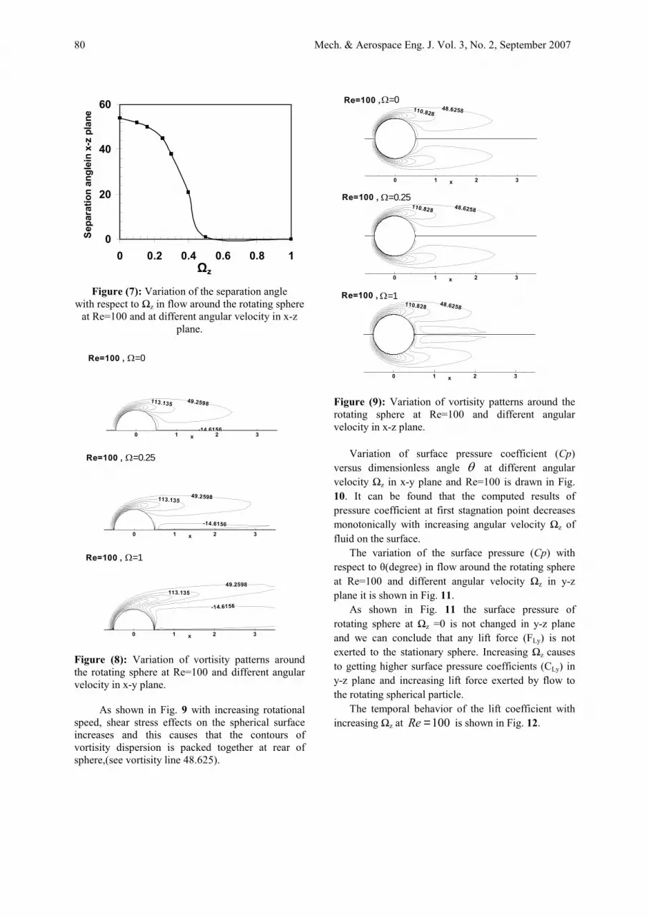
As it is obtained from Fig. 7, the separation angle of flow around the rotating sphere in x-z plane decreases with increasing Ωz and at Ωz >0.5 there is not shown any separation of flow around the rotating sphere at x-z plane.
The variation of vortisity distribution of flow around the rotating sphere at different rotational speed in x-y plane and Re=100 is shown at Fig. 8. As shown in Fig. 8 when rotational speed increases, the vortisity lines deviate toward the direction of rotating sphere and the contours of vortisity dispersion is stretched at rear of sphere,(see vortisity line 49.259).
The variation of vortisity distribution of flow around the rotating sphere at different rotational speed in x-z plane and Re=100 is shown at Fig. 9.
80 Mech. & Aerospace Eng. J. Vol. 3, No. 2, September 2007
0
20
40
60
0 0.2 0.4 0.6 0.8 1
Sepa
ratio
nan
glei
nx-
zpl
ane
Ωz
Figure (7): Variation of the separation angle with respect to Ωz in flow around the rotating sphere
at Re=100 and at different angular velocity in x-z plane.
49.2598
-14.6156
113.135
x0 1 2 3
Re=100 , Ω=0
49.2598
-14.6156
113.135
x0 1 2 3
Re=100 , Ω=0.25
49.2598
-14.6156
113.135
x0 1 2 3
Re=100 , Ω=1
Figure (8): Variation of vortisity patterns around the rotating sphere at Re=100 and different angular velocity in x-y plane.
As shown in Fig. 9 with increasing rotational
speed, shear stress effects on the spherical surface increases and this causes that the contours of vortisity dispersion is packed together at rear of sphere,(see vortisity line 48.625).
48.6258110.828
x0 1 2 3
Re=100 ,Ω=0
48.6258110.828
x0 1 2 3
Re=100 , Ω=0.25
48.6258110.828
x0 1 2 3
Re=100 , Ω=1
Figure (9): Variation of vortisity patterns around the rotating sphere at Re=100 and different angular velocity in x-z plane.
Variation of surface pressure coefficient (Cp)versus dimensionless angle θ at different angular velocity Ωz in x-y plane and Re=100 is drawn in Fig. 10. It can be found that the computed results of pressure coefficient at first stagnation point decreases monotonically with increasing angular velocity Ωz of fluid on the surface.
The variation of the surface pressure (Cp) with respect to θ(degree) in flow around the rotating sphere at Re=100 and different angular velocity Ωz in y-z plane it is shown in Fig. 11.
As shown in Fig. 11 the surface pressure of rotating sphere at Ωz =0 is not changed in y-z plane and we can conclude that any lift force (FLy) is not exerted to the stationary sphere. Increasing Ωz causes to getting higher surface pressure coefficients (CLy) in y-z plane and increasing lift force exerted by flow to the rotating spherical particle.
The temporal behavior of the lift coefficient with increasing Ωz at 100Re = is shown in Fig. 12.

Mech. & Aerospace Eng. J. Vol. 3, No. 2, September 2007 81
θ
CP
50 100 150
-1.2
-0.8
-0.4
0
0.4
0.8
1.2
Ω=1Ω=0.5Ω=0.25Ω=0.1Ω=0
Re=100
Figure (10): Variation of the surface pressure (Cp)with respect to θ(degree) in flow around the rotating sphere at Re=100 and at different angular velocity Ωz in x-y plane.
0 90 180 270 360
-0.0225
-0.02
-0.0175
-0.015
-0.0125
-0.01
omega=1omega=0.5omega=0.25omega=0.16omega=0.1omega=0
Sur
face
pres
sure
θ(degree)
y-z plane
Figure (11): Variation of the surface pressure(Cp)with respect to θ(degree) in flow around the rotating sphere at Re=100 and atdifferent angular velocity Ωzin y-z plane
Increasing angular velocity causes to increase in
the lift coefficient (CL). The effect of angular velocity on lift coefficient is more significant at higher angular velocity numbers such that CL at
Ωz=1 is 38% larger with respect to Ωz =0.5, and 78% larger as compared to Ωz=0.1.
Non dimensional time
Lift
coef
ficie
nt(C
Ly)
50 100-0.6
-0.5
-0.4
-0.3
-0.2
-0.1
0
0.1
0.2
0.3Ω=0Ω=0.1Ω=0.16Ω=0.25Ω=0.5Ω=1
Figure (12): Lift coefficient histories at Re = 100 for different angular velocity Ωz.
A study of the temporal behavior of the lift coefficient at different angular velocity numbers indicates that lift coefficient, CL, remains finally steady despite its considerable diminish in initial instants. A reducing behavior of the lift coefficient is observed at very early dimensionless times as shown in Fig. 12. This is related to the sudden introduction of the rotating sphere into the uniform and steady free stream. Initial lift coefficient behavior is strongly affected by the onset of flow separation and the rate of subsequent wake growth. In an impulsive start, the effects of Ωz
on flow separation and wake growth are immediate whereas the effects of the background flow are delayed (see Fig. 12) by about 20, which is approximately the transit time of a flow over the spherical particle.
Surface global parameters, such as the drag coefficients, are also influenced by variation of the angular velocity of spherical surface. The drag coefficient increases with increase of Ωz on the sphere surface and also the drag coefficient behavior depends on the Reynolds number. The temporal behavior of the drag coefficient with increasing Ωz at 100Re = is shown in Fig. 13. The effect of Ωz on CD at Re=100 is more significant at higher angular velocity such that CD at Ωz=1 is 6% larger that that of Ωz =0.5, and 11.8% larger as compared to Ωz=0 (stationary sphere).

82 Mech. & Aerospace Eng. J. Vol. 3, No. 2, September 2007
Non-Dimensional Time
CD
25 50 75 1001
1.4
Ω=0Ω=0.1Ω=0.16Ω=0.25Ω=0.5Ω=1
Re=100
Figure (13): Drag coefficient histories at Re = 100 for different angular velocity Ωz.
A study of the drag coefficient histories at different angular velocity numbers indicates that drag coefficient (CD) remains finally steady despite of its considerable decrease in initial instants.
As shown in Fig. 14 the drag coefficient is reduced with increasing Reynolds number and decreasing angular velocity but this variation is not uniform in all ranges of Reynolds numbers. We can investigate this subject with study of drag reduction between special cases of Ωz=1 and stationary sphere at low and moderate Reynolds numbers regimes. As it is shown in Fig.14 at low Reynolds regime, Re=0.1, computed drag reduction in Ωz=0 with respect to Ωz=1is negligible and drag reduction at Re=100 approximately is 16% and this feature shows the angular velocity does not effect on drag coefficients at low Reynolds number regimes and it is important at moderate Reynolds numbers, Re>35.
Figs.15 shows the comparison of the drag coefficient (CD) with respect to Reynolds numbers in flow around the rotating sphere at different angular velocity Ωz. As shown in Fig. 15, the drag coefficients of rotating spheres at present 3D numerical analysis at different angular velocity Ωz is compared with other results of flow around of rigid rotating spheres.
Drag coefficient
1
2
3
4
5
0 25 50 75 100Re
CD
Ω=0
Ω=0.1Ω=0.16
Ω=0.25Ω=0.5Ω=1
Figure 14: Variation of drag coefficient (CD) with respect to Reynolds numbers in flowaround the rotating sphere at different angular velocity Ωz.
1
1.5
2
40 60 80 100Re
CD
Omega=0.25,kurose&komori
Omega=0.25,Niazmand
Omega=0.16,kurose&komori
Omega=0.16,Niazmand
Ω=1Ω=0.5
Ω=0.25
Ω=0 Ω=0.1
Figure (15): Comparison of the drag coefficient (CD)versus Reynolds numbers in flow around the rotating sphere at different angular velocity Ωz.
The computed drag coefficients at present study, the steady-state values of CD at different Ωz and 0.1≤Re≤100, have good agreement with other results.
Figure.16 shows the variation of drag coefficient (CD) with respect to angular velocity Ωz in flow around the rotating sphere at moderate Reynolds numbers. As illustrated in Fig. 16, with increasing angular velocity Ωz the drag coefficients of rotating spheres is increased at moderate Reynolds, numbers regimes, (Re=50 and 100) but as shown in Figs. 16 and 17 variation of Ωzdoes not effects on drag coefficient values at low Reynolds number regimes,(Re=1, 10 and 20).

Mech. & Aerospace Eng. J. Vol. 3, No. 2, September 2007 83
0
1
2
3
4
5
-0.1 0.2 0.5 0.8 1.1
CD
Re=100
Re=50
Re=20
Re=10
ΩFigure (16): Variation of drag coefficient versus angular velocity Ωz in flow around the rotating sphere at moderate Reynolds numbers.
Drag coefficient
0
80
160
240
320
-0.1 0.1 0.3 0.5 0.7 0.9 1.1
CD
Re=10Re=1Re=0.1
ΩFigure (17): Variation of drag coefficient versus angular velocity in flow around the rotating sphere at low Reynolds numbers.
Figure.18 shows the comparison of the lift coefficient (CL) with respect to Reynolds numbers in flow around the rotating sphere at different angular velocity Ωz with numerical results of references[12] and [15]. As shown in Fig. 19 the steady-state values of CL at different Ωz and 0.1≤Re≤100, have good agreement with other results.
Lift coefficient
-0.2
0
0.2
0.4
0.6
0.8
1
1.2
0 25 50 75 100Re
CL
Omega=0.25,kurose&komori
Omega=0.25,Niazmand
Omega=0.5,Niazmand
Omega=0.16,kurose&komori
Omega=0.16,Niazmand
Omega=0.05,Niazmand
Ω=1
Ω=0.5
Ω=0.25 Ω=0.16
Ω=0.1Ω=0
Figure (18): Comparison of the lift coefficient (CL)with respect to Reynolds numbers in flow around the rotating sphere at different angular velocity Ωz with numerical results of [12] and [15]. Conclusions Fluid dynamics characteristics of laminar 3-D flow past an impenetrable rotating suspended spherical particle have been studied with effect of rotation Ωz <1 in the range 0.1≤Re≤200. The rotation causes the streamlines passing on the rotating sphere not to remain symmetric in x-y plane, but flow patterns remain symmetric at x-z plane. The wake length and separation angle at x-z plane increases with decreasing Ωz (angular velocity of rotating sphere). Increasing the rotating number, Ωz is more profound at higher rotation and the present calculations indicate the wake length becoming smaller with increasing Ωz until it disappears at Ωz ≤0.5.
It can be found that the computed results of the pressure coefficient at first stagnation point decreases monotonically with increasing angular velocity Ωz of fluid on the surface.
A study of the temporal behavior of the lift and drag coefficients at different angular velocities indicates that lift and drag coefficients, CL, CD, remain finally steady despite its considerable diminish in initial instants. This is related to the sudden introduction of the rotating sphere into the uniform and steady free stream. Initial behavior is strongly affected by the onset of flow separation and the rate of subsequent wake growth. In an impulsive start, the effects of Ωz on flow separation and wake growth are immediate whereas the effects of the background flow are delayed by about 20, which is approximately the transit time of a flow over the spherical particle.
At low Reynolds regime, Re=0.1, computed drag reduction in Ωz=0 with respect to Ωz=1is negligible and drag reduction at Re=100 approximately is 16% and this feature shows the angular velocity does not effect on drag coefficients at low Reynolds number
84 Mech. & Aerospace Eng. J. Vol. 3, No. 2, September 2007
regimes and it is important at moderate Reynolds numbers, Re>35.
The effect of Ωz on CL is more significant at higher angular velocity numbers such that CL atΩz=1 is 38% larger with respect to Ωz =0.5, and 78% larger as compared to Ωz=0.1. It is shown that with increasing angular velocity Ωz the drag coefficients of rotating spheres is increased at moderate Reynolds numbers regimes,(Re=50, 100) but variation of Ωz does not effects on drag coefficient values at low Reynolds number regimes,(Re=1 and 10,20).
It is interesting to say the initial lift coefficient values in z direction at dimensionless time step smaller than 40, which is approximately the transit time of flow over the rotating spherical particle at Ωz.>0.25 is important and at higher time step these values will be vanished. References
1. Best, J.L., “The Influence of Particle Rotation on Wake Stability at Particle Reynolds Numbers, Re 300P < - Implications for Turbulence Modulation in Two-phase Flows”, Int. J. Multiphase Flow, 24, pp. 693-720, 1998.
2. Taneda, S. “Experimental Investigation of the Wake Behind a Sphere at Low Reynolds Numbers”, J. phys. Soc. Jpn.,11, 1104-8, 1956.
3. Roos, F.W., Willmarth, W.W., “Some Experimental Results on Sphere and Disk Drag”, AIAA J., Vol. 9, No. 2, pp. 285-91,1971.
4. Nakamura I. “Steady Wake Behind a Sphere”, Physics of Fluids, Vol. 19, No. 1, pp.5-8, 1976.
5. Kim, I. and Pearlstein, A., “Stability of the Flow Past a Sphere”, J. Fluid Mech., 211, 73-93, 1990.
6. Natarajan, R. and Acrivos, A., “The Instability of the Steady Flow Past Spheres and Disks”, J. Fluid Mech., 254, 323-344, 1993.
7. Magnaudet, J., Rivero, M. and Faber, J. “Accelerated Flows Past a Rigid Sphere or a Spherical Bubble”, Part 1. Steady Straining Flow, J. Fluid Mech., Vol. 284, No. 2, pp. 97-135, 1995.
8. Le Clair, B.P., Hammielec, A.E. and Pruppacher, H.E. “A Numerical Study of the Drag of a Sphere at Low and Intermediate Reynolds Numbers”, J. Atoms. Sci. , Vol. 27, No. 1, pp. 308, 1970.
9. Brakla, HM., Auchterlonie LJ. “The Magnus or Rubins Effect on Rotating Spheres”, J. Fluid Mech., 147, Vol. 147, No. 1, pp.437-47, 1971.
10. Oesterle, B., and Dinh, B., “Experiments on the Lift of a Spinning Sphere in a Range of Intermediate Reynolds Numbers”, Experiments in Fluids, Vol. 25, No. 1, pp. 16-22, 1998.
11. Salem, M.B. and Oesterle, B., “A Shear Flow Around a Spinning Sphere: Numerical Study at Moderate Reynolds Numbers”, Int. J. Multiphase Flow, Vol. 24, No. 1, pp. 563-585, 1998.
12. Kurose, R. and Komori, S., “Drag and Lift Forces on a Rotating Sphere in a Linear Shear Flow,” J. Fluid Mech., Vol. 384, No. 2, pp. 183-206, 1999.
13. Kim, D. and Choi, H., “Laminar Flow Past a Sphere rotating in the Streamwise Direction”, J. Fluid Mech., Vol. 461, No. 1, pp. 365-385, 2002.
14. Clift, R., Grace, J.R., and Weber, M. E., “Bubbles, Drops and Particles”, Academic Press., New York, 1970.
15. Niazmand, H., and Renksizbulut, M., “Transient Three-dimensional Heat Transfer from Rotating Spheres with Surface Blowing”, Chem. Eng. Sci., Vol. 58, No. 1, pp. 3535-3554, 2003.
16. Niazmand, H. and Renksizbulut, M. “Surface Effects on Transient Three-dimensional Flows around Rotating Spheres at Moderate Reynolds Numbers,” Computers & Fluids, Vol. 32, No.1, pp.1405-1433, 2003.
17. Atefi, Gh., Niazmand, H. and Meigounpoory, M.R., “Numerical Analysis of 3D Flow Past a Stationary Sphere with Slip Condition at Low and Moderate Reynolds Numbers” J. of Dispersion Science and Tech.(In print), Vol. 28, No. 4, pp. 591–602, 2007.
18. Davidson, L. and Farhanieh, B. “A Finite Volume Code Employing Collocate Variable Arrangement and Cartesian Velocity Components for Computing of Fluid Flow and Heat Transfer in Complex Three Dimensional Geometries”, Department of Thermo and Fluid Dynamics, Chalmers Univ. of Tech. ,Sweden,1991.
19. Raithby, G.D. , Eckret, E.R.G., Int. J. Heat and Mass Transfer, Vol. 11, No. 2, pp.1233-1252, 1968.
20. Karla, T.R., Uhlherr, P.H.T., 4th Australian. Conf. Hydraulic and Fluid Mechanics, Melborne, 1971
21. Modaress, M.R., Niazmand, H., Mirbozorgi, A., ”Three-dimentional Analysis of Flow Past a Solid Sphere ant Low Reynolds Numbers”, Esteghlal J., Vol. 2, No. 1, pp.191-205, 2001.


