Embed Size (px)
Citation preview

Nonlinear focusing of acoustic shock waves at a caustic cuspRegis Marchianoa) and Francois CoulouvratLaboratoire de Mode´lisation en Mecanique, Universite´ Pierre et Marie Curie and CNRS (UMR 7607),4 place Jussieu, 75252 Paris Cedex 05, France
Jean-Louis ThomasLaboratoire des Milieux De´sordonne´s et Heterogenes, Universite´ Pierre et Marie Curieand CNRS (UMR 7603), 4 place Jussieu, 75252 Paris Cedex 05, France
~Received 4 May 2004; revised 27 October 2004; accepted 7 November 2004!
The present study investigates the focusing of acoustical weak shock waves incoming on a cuspedcaustic. The theoretical model is based on the Khokhlov–Zabolotskaya equation and its specificboundary conditions. Based on the so-called Guiraud’s similitude law for a step shock, a newexplanation about the wavefront unfolding due to nonlinear self-refraction is proposed. This effectis shown to be associated not only to nonlinearities, as expected by previous authors, but also to thenonlocal geometry of the wavefront. Numerical simulations confirm the sensitivity of the process towavefront geometry. Theoretical modeling and numerical simulations are substantiated by anoriginal experiment. This one is carried out in two steps. First, the canonical Pearcey function issynthesized in linear regime by the inverse filter technique. In the second step, the same wavefrontis emitted but with a high amplitude to generate shock waves during the propagation. Theexperimental results are compared with remarkable agreement to the numerical ones. Finally,applications to sonic boom are briefly discussed. ©2005 Acoustical Society of America.@DOI: 10.1121/1.1841551#
PACS numbers: 43.25.Cb, 43.25.Jh, 43.28.Mw@MFH# Pages: 566–577
eder bnco
iutr
r-Alta
tu
oeigi
antheis
-
ce
ite
leme-
ga-
-d to.
hes.ednu-
nu-
u-r-u-lly
ude
esiseSee-
I. INTRODUCTION
The focusing of finite amplitude waves on a cuspcaustic is a physical phenomenon which may occur in diffent circumstances: sonic boom focusing produced eithethe aircraft’s manoeuvres or by the atmospheric turbuleor wavefront distortion encountered in medical imagingnondestructive evaluation through heterogeneous medFor all cases, it is important to better understand and conthis phenomenon in order to either avoid it~sonic boom! ortake benefits from it~imaging or nondestructive evaluation!.
A caustic is an envelope of rays. It corresponds tosurface of amplification of the wavefield. There exist diffeent kinds of caustics: fold, cusp, swallow-tail, and so on.of these are described and classified by the theory of catrophes~Thom, 1972!. An important result of this theory isthat for a wavefield, caustics can be interpreted as strucally stable focuses~Berry, 1976!. In this framework, the per-fect point focus is unstable and is likely to degenerate intstable caustic such as a cusped caustic. Moreover, the thof catastrophes also provides the generic form for the hfrequency limit of the pressure field around the causticsthe linear regime, where diffraction cannot be neglectedis the main physical mechanism. This is the reason whytheory is also called the diffraction theory of catastroph~Berry, 1976!. For a cusped caustic this analytical solutionthe Pearcey function~Pearcey, 1946!. The reader is referredto Marston~1992! for a review of acoustical caustics in linear regime~with smooth waves!.
If the incoming waves are shock waves, the Pear
a!Electronic mail: [email protected]
566 J. Acoust. Soc. Am. 117 (2), February 2005 0001-4966/2005/
r-ye
rm.ol
a
ls-
r-
aoryhndiss
y
function is not valid because it predicts peaks of infinamplitude on the cusped caustic~Coulouvrat, 2000!. Notethat this problem presents many analogies with the probof the fold caustic for which the analytical solution—thAiry function—also leads to an infinite amplitude if the incoming waves present shocks~Guiraud, 1965!. This is obvi-ously physically meaningless, and experimental investitions performed during flight tests~Wanner et al., 1972;Downing et al., 1998! or laboratory experiments~Davy andBlackstock, 1971; Sanaiet al., 1976; Sturtevant andKulkarny, 1976!, despite an important amplification of amplitude and a change in the temporal waveform associatediffraction, clearly show a limitation of the amplitudeGuiraud~1965! was the first to propose nonlinearities as tadditional limiting mechanism for the case of fold causticHe derived the so-called nonlinear Tricomi equation satisfiby the pressure field around the caustic. An approximatemerical solution was designed by Gill and Seebass~1973!based on the hodograph transform, and recently a fullymerical solution has been developed~Marchiano et al.,2003a!. Estimations by Plotkin and Cantril~1976! and laterby Downinget al. ~1998! showed the Gill and Seebass soltion matched reasonably well with flight tests, while Machianoet al. ~2003b! demonstrated nice agreement with nmerical solutions of Guiraud’s model by means of a carefuscaled experiment in water tank.
For cusped caustics, in order to estimate the amplitof the pressure at the tip of a cusped caustic, Pierce~1971!derived a similarity rule stipulating that the amplitude varias the power23 of the incoming shock wave. But that resultvalid for an incoming step function only. Using thasymptotic method of matched expansions, Cramer and
117(2)/566/12/$22.50 © 2005 Acoustical Society of America

retio
e
ns
untiofu
.ci
de
ewo
icaa
att
vep
idve
,it
tt
rehe
ugticea
-
tialthe
de-
ne
tion
on-
r-
usticot the
bass~1978! showed that around the cusped caustic, the psure is governed by the Khokhlov–Zabolotskaya equa~Zabolotskaya and Khokhlov, 1969!. That first model, validfor a 2D homogeneous medium, has been extended to thcase~Cramer, 1981a! and to the case of an axisymetric areˆte~Cramer, 1981b!. In accordance with Guiraud’s assumptioon the fold caustic~Guiraud, 1965! and with the theory ofcatastrophes, Coulouvrat~2000! showed that it is possible toderive the KZ equation considering a boundary layer arothe cusp where the main physical mechanisms are diffracand local nonlinear effects. Moreover, he derived theassociated boundary conditions which make it possiblesolve the problem numerically for any incoming waveform
In this paper, after a brief recall of the modeling assoated with a cusped caustic~Sec. II!, a detailed discussionabout the Guiraud similitude laws for a cusped caustic,rived by Coulouvrat~2000!, is presented~Sec. III!. In par-ticular, the wavefront unfolding observed by Piacsek~2002!is examined with both theoretical and numerical approachand a new mechanism for explaining it is proposed. Hoever, numerical tests are not sufficient by themselves to cclude about the validity of the assumptions of the theoretmodeling, and an experimental confirmation is required,presented in Sec. IV using ultrasonic shock waves in a wtank ~Sec. IV!. To our knowledge, this is the first time thatheory and experiments have been compared quantitatiThis approach allows us to confirm definitively the assumtions of the theory and to validate the computer code.
II. THEORETICAL BACKGROUND: THE KZ EQUATION
In a two-dimensional, homogeneous and inviscid fluof sound speedc0 , we consider the propagation of a concawavefront having at pointO ~chosen as the origin! a mini-mum of radius of curvature, notedR0 . In the present sectionit is assumed the wavefront is part of a continuous wave wangular frequencyv and wave numberk05v/c0 . The caseof a shock front will be discussed in next section. Thex axisis chosen tangent to, and thez axis normal to, the wavefronat the origin~Fig. 1!. During the propagation, that wavefrongenerates a cusped caustic at the distanceR0 from the origin.The wavefront having a minimum of the radius of curvatuthe tip of the caustic is oriented towards the origin. Tcusped caustic splits the space into two distinct zones~Fig.1!: one, labeled zone I, where only one ray passes throeach point~area located outside the branches of the caus!,and one, labeled zone II, where three rays pass throughpoint ~area located within the branches of the caustic!.
Introducing the geometrical parametera5 98R0
2R0i ,
whereR0i is the second derivative with respect tox at the
origin O, Coulouvrat~2000! defines the characteristic diffraction length-scale in thez direction:
Lz5S 4a
27k0D 1/2
, ~1!
and the characteristic diffraction length-scale in thex direc-tion:
J. Acoust. Soc. Am., Vol. 117, No. 2, February 2005
s-n
3D
dn
llto
-
-
s,-n-lser
ly.-
h
,
h
ch
Lx5S a
27k03D 1/4
. ~2!
The diffraction length-scales are used to define the spadimensionless variables characterizing the problem inlongitudinal direction,
z5~z2R0!/Lz , ~3!
and in the transverse direction,
x5x/Lx . ~4!
The dimensionless retarded time is also introduced toscribe propagation in the main direction,t being the physicaltime:
t 5v~ t2z/c0!. ~5!
Lastly, the dimensionless pressure is introduced:
p5p
p0, ~6!
wherep is the acoustical pressure andp0 is chosen as theamplitude of the incoming pressure field before focus at ocharacteristic distanceLz ~the amplitude atz521).
Cramer and Seebass~1978! and Coulouvrat~2000! showthat, in the neighborhood of the cusp, the pressure is soluof the Khokhlov–Zabolotskaya equation~KZ equation!:
]2p
] z] t5
]2p
] x21m
]2p2
] t 2, ~7!
wherem is a parameter measuring the amplitude of the nlinear effects in comparison with diffraction ones:
m5bM S k0a
27 D 1/2
5bp0
r0c02 S k0a
27 D 1/2
, ~8!
with b511B/2A ~whereB/2A is the nonlinearity parameteof the medium! andM5 p0 /r0c0
2 the acoustical Mach number ~wherer0 is the density of the medium at rest!.
FIG. 1. Geometry of the caustic. Note that, in order to emphasize the cageometry, the scales of the transverse and propagation directions are nsame.
567Marchiano et al.: Shock waves focusing at a cusp

emeo
aseiec
t,on
-o
e
i
y
ta
-
-
-roc
tog to
e
,ann-
ar-
e
asne.
ms
tion
ng,on.
thatond
he
ti-
calt
ear
sethe
The boundary conditions associated with the problare determined by an asymptotic matching with the gmetrical acoustics away from the cusp~Coulouvrat, 2000!:
p~ x,z, t ! ——→Ax21 z2→`
1
Au6a22 zuF~ t 1a x1a2z2a4!, ~9!
wherea( x,z) is the only real root ofx12a z24a350 andF is the dimensionless incoming signal waveform. The phfunction t 1a x1a2z2a4 describes the curvature of thwavefront as it approaches the caustic, while the coeffic1/Au6a22 zu measures the subsequent geometrical amplifition. This expression is valid only in zone I~Fig. 1!, whereonly one ray@one roota( x,z)] passes through each poinand sufficiently far from the caustics so that local diffractieffects can be neglected~geometrical approximation!.
The boundary condition Eq.~9! completes the formulation of the problem and makes it numerically tractable. Fthe linear case (m50), Coulouvrat~2000! shows that thesolution of Eqs.~7! and~9! can be expressed in terms of thPearcey function~1946!, in agreement with the diffractioncatastrophe theory~Berry, 1976; Marston, 1992!. For thenonlinear case, a new algorithm solving the KZ equationpresented in Appendix A.
III. GUIRAUD’S SIMILITUDE FOR A STEP SHOCK
We briefly recall here the similitude law obtained bCramer and Seebass~1978! and Coulouvrat~2000! general-izing to a cusped caustic the Guiraud’s similitude~1965! fora fold caustic. Introducing the new scalingp5m21/3p, t
5m4/3t , x5m x, z5m2/3z and a5m1/3a, the KZ equationbecomes
]2p
] z] t5
]2p
] x21
]2
] t 2~ p2!, ~10!
and the associated boundary condition
p~ x,z, t !'1
Auz26a2uF@m~ t 1a x1a2z2a4!# ~11!
with a the only real root of the polynomialx12a z24a3
50.With the new scaling, the KZ equation@Eq. ~10!# no
longer involves the nonlinear parameterm which now ap-pears in the boundary conditions@Eq. ~11!#. Thus, for anincoming step shock which is invariant by temporal dilation @F( t )50 if t ,0 andF( t )51 if t .0], the whole prob-lem @Eqs.~10! and ~11!# is independent of the nonlinear parameter: this is a self-similar solution~with respect to thenonlinear parameter!, known as Guiraud’s similitude. Expressing the similitude variables ‘‘;’’ in physical terms, onefinds
p5pF b
r0c02p0
2 S k0a
27 D 1/2G1/3
.
However, the amplitudep0 is defined as the incoming pressure amplitude at one boundary layer thickness away fthe cusp. But for a step shock, there is no main frequen
568 J. Acoust. Soc. Am., Vol. 117, No. 2, February 2005
-
e
nta-
r
s
-
my,
therefore the choice of this thickness is arbitrary. Taking inaccount the convergence of the pressure field accordinthe boundary condition Eq.~9!, it is therefore suitable towrite p05Pre f(a/Lz)
1/2, wherePre f is a reference pressurlevel now independent of the frequency (a being now theonly physical length of the problem!. This finally yields
p5pF 2b
27r0c02Pre f
2 G1/3
~12!
and results for other variables can be deduced similarly:
t 56
21/3S r0c02
bPre fD 3/4c0
a~ t2z/c0!,
x5541/2S r0c02
bPre fD x
a, z5
9
41/3S r0c02
bPre fD 2/3 z
a,
~13!
a521/6)S r0c02
bPre fD 1/3 a
R0.
Relations~12! and ~13! are all independent of frequencyindicating that Guiraud’s scaling is the correct one forincoming signal with no characteristic frequency. As a couterpart, the scaling is nonlinear. Especially, Eq.~12! showsthat the focused pressure varies as power2
3 of the incomingamplitude, in agreement with Pierce’s~1971! dimensionalanalysis later confirmed by Cramer and Seebass~1978!. Thecharacteristic space variables increase as power2
3 of the am-plitude along the axis, and power 1 transversely, while chacteristic time increases as power3
4.Guiraud’s similitude is the key point in solving the issu
of weak shocks focusing. Whitham~1956! conjectured thatthe nonlinear self-refraction prevents wavefront foldingthe central part of the shock front tends to become plaThat is the mechanism of ‘‘wavefront unfolding.’’ This viewpoint, also supported by Marston~1988!, has been numeri-cally investigated by Prasad and Sangeeta~1999! using aweak nonlinear ray theory but for Mach numbers~from 1.05to 1.2! significantly larger than acoustical ones. This seecontradictory to Guiraud’s similitude, whichdemonstrates~provided the basic assumptions sustaining the KZ equaare valid, as will be demonstrated in Sec. IV! that the solu-tion is independent of the amplitude after correct rescaliat least in the weak shock approximation of the KZ equatiExperiments by Sturtevant and Kulkarny~1976, Figure 17!confirm that for weak shock waves~Mach 1.005 and 1.03!,the geometrical shape of the wavefront remains suchthere is no self-refraction, though for stronger shocks beythe acoustical limit~Mach 1.1 and 1.5! this is no longervalid. On the contrary, using numerical simulations of tNPE equation, Piacsek~2002! observes wavefront unfoldingeven in the acoustical limit. But for the ‘‘ideal’’ wavefronEq. ~9! leading to a ‘‘perfect’’ cusped caustic, Guiraud’s smilitude demonstrates that this should not happen.
To elucidate this issue, we have performed numerisimulations of the two cases: first for the ‘‘ideal’’ wavefronEq. ~9! exactly associated to Pearcey solution in the linregime, and for the wavefront proposed by Piacsek@his equa-tion ~5!#. This last wavefront involves two parameters. Theones have been chosen so that both wavefronts have
Marchiano et al.: Shock waves focusing at a cusp

oghusea
fo
tem
ilsla
m
is
ois
s
’sses
l’’d
uhe
itpedme.
-tion
beave-e ofithany,
lu-ot
lf-ngwith
-
x-are
i-
d-
udecan
smp
spari-
same valuesR0 and R0i at their center. So, locally, the tw
wavefronts have the same geometry. Therefore, accordincatastrophe theory, in the high frequency limit and in tlinear regime, the two are locally equivalent around the cof the caustic. However, far from the center, the ‘‘ideal’’ onEq. ~9!, is still converging with a shape perfectly suited tocusped caustic, while Piacesk’one gets flat, and is therenot focusing any more.
The numerical simulations are performed for a sshock using a new code solving the KZ equation in the teporal domain~see the Appendix for further technical detaand code validation!. Piacsek’ wavefront is used in the initiaplanez50. Laterally, the solution is matched to an analyticsolution of the inviscid Burgers’ equation~nonlinear planewave!. Results of the simulations are shown in linear regi(m50 in the KZ equation! on Fig. 2. The two wavefrontsclearly focus atz50 with the same amplitude. Beyond thpoint, they exhibit the characteristic swallow tail form atz52. Note, however, that the focusing effects are much mlocalized for Piascek’s wavefront, as far from the axis itnot focusing any more. In nonlinear regime (m51, Fig. 3!,the results are quite different. The ‘‘ideal’’ wavefront Eq.~9!always leads to form a cusped caustic but now the focustrongly shifted, around pointz52 ~very similar to the curvefor z50 in linear regime!. On the contrary, the Piascekwavefront is flattened, an effect already described by Piac~2002!. Note that nonlinear effects are visible for both casthe time when the step shock~in x50) occurs is no longerzero but shifted to an earlier time for higher amplitude.
As soon as the wavefront deviates from the ‘‘ideawavefront Eq.~9!, there is some critical amplitude beyonwhich the current shape of the wavefront~which has allchances to deviate at some distance from the ideal one! playsa role. Indeed, as the pressure amplitude increases, Guiraself-similar solution requires rays from a larger region of twavefront@Eq. ~13! for a, increasing as power13 of the am-
FIG. 2. Numerically simulated dimensionless pressure fieldsp at z50 andz52 in linear regime (m50) as a function of time~horizontal! and trans-verse space variablex ~vertical! for a step shock. Vertical bar indicatecorrespondance between gray and dimensionless pressure levels. Coson between Piacsek’s ‘‘real’’ wavefront~left column! and ‘‘ideal’’ wave-front Eq. ~9! ~right column!.
J. Acoust. Soc. Am., Vol. 117, No. 2, February 2005
toep,
re
p-
l
e
re
is
ek:
d’s
plitude#. So, if the transverse size of the wavefront whereis close to the ideal one is not large enough, the cuscaustic cannot be actually synthesized in nonlinear regiThis is equivalent to the linear catastrophe theory~leading tothe Pearcey function!, which is a local, high frequency approximation. When wavelength increases, this approximadegrades or conversely the size of the wavefront shouldincreased. Here, the phenomenon is analogous, but the wlength increase is associated with the nonlinear increasthe characteristic length scales of Guiraud’s similitude wthe amplitude. Consequently, beyond some amplitude,real wavefront will deviate from the Guiraud’s similitudewhich will appear as a wave front unfolding. So the concsion is that there is indeed wave front unfolding, but it is nintrinsically a nonlinear phenomenon~at least for acousticshock waves!. It is a more complex process, where the sesimilar solution of Guiraud becomes invalid with increasiamplitudes because the characteristic lengths increaseamplitude, so that the actual shape of the wavefront~and notonly its local asymptotic shape! gets more and more important.
IV. EXPERIMENTAL SYNTHESIS OF A CUSPEDCAUSTIC
In order to verify the assumptions of the theory, an eperimental study has been performed. The experimentsmade in a water tank with ultrasonic waves~central fre-quency: 1 MHz! emitted by an array of 256 rectangular pezoelectric transducers~Imasonic, France!. The transducersare displayed on a rectangular aperture~32 rows, 8 lines!.Each of them is driven individually by programmable broaband linear amplifiers~Lecoeur Electronique, France!. Thoseamplifiers allow us to specify the shape, phase and amplitof the signal emitted by a transducer. Each transduceremit a plane wave up to 53105 Pa amplitude. A broadbandcalibrated membrane hydrophone~1 to 40 MHz! associated
ari-
FIG. 3. Numerically simulated dimensionless pressure fieldsp at z50 andz52 in nonlinear regime (m51) as a function of time~horizontal! andtransverse space variablex ~vertical! for a step shock. Vertical bar indicatecorrespondance between gray and dimensionless pressure levels. Comson between Piacsek’s ‘‘real’’ wavefront~left column! and ‘‘ideal’’ wave-front Eq. ~9! ~right column!.
569Marchiano et al.: Shock waves focusing at a cusp

h
ont
etw
dceemissi
n
-sin
-ethtteeavea
od
ame-ce
u
edethe: areeen-s toanderi-
thech-be-nts,olu-eldpa--
r-
tionsmentsf the
with a digital oscilloscope measures the acoustic field. Tsmall active diameter of the hydrophone~0.2 mm!, ensures agood resolution to scan the acoustic field. The hydrophcan be moved along the three directions of space insidewater tank by programmable step-by-step motors~Fig. 4!.The whole experimental setup is automated.
The experimental synthesis of a cusped caustic in linand nonlinear regimes presented here is achieved instages. First of all, the signals to be emitted by the arrayorder to synthesize a cusped caustic in linear regime aretermined. That stage is achieved by the inverse filter tenique ~Tanteret al., 2000!. Once the signals producing thcusped caustic are known, the second stage consists inting them with a high amplitude to produce nonlinearity. Thmethodology has been employed successfully to synthefold caustics in the nonlinear regime~Marchiano et al.,2003b!.
The geometrical parameters of the cusp are chosefollows: R05300 mm andR0
i563/R0 . With the choice of
the propagation medium~water,c0'1500 m/s) and the frequency of the waves (f 051 MHz), the choice of the valueof R0 and R0
i fixes the geometry of the problem, andparticular the diffraction length-scales:Lz527.4 mm in thepropagation direction andLx51.8 mm in the transverse direction. This choice results from the compromise betwethe size of the focal length and the distance betweenarray of transducers and the tip of the caustic. The ladistance must be large enough to ensure the presencshock waves. The shock formation distance for a plane wemitted by the array of transducers is about 300 mm. Netheless, this distance is shorter in the case of a focused wsuch as the emitted wave. So, the chosen distance~300 mm!is sufficiently far from the array to ensure the presenceshock wave. Figure 5 shows the acoustical rays launchean unlimited@Fig. 5~a!# and a limited@Fig. 5~b!# wavefrontproducing the cusped caustic with the geometrical paretersR0 andR0
i defined above. The size of the limited wavfront corresponds to the aperture of the array of transduused for the experiments~191 mm!. On both figures, thecusped caustic appears clearly, especially the tip of the clocated 300 mm away from the wavefront~the array!. As
FIG. 4. Experimental setup.
570 J. Acoust. Soc. Am., Vol. 117, No. 2, February 2005
e
ehe
aro
ine-
h-
it-
ze
as
nerof
ver-ve
fby
-
rs
sp
mentioned in Sec. I, for an unlimited wavefront, the cuspcaustic splits the planeOxz into two zones: a zone with onray and a zone with three rays. For a limited aperture,situation is different. Three zones can be distinguishedzone with no ray, a zone with one ray, and a zone with thrays. Nevertheless, near the tip of the cusp, the field is idtical to the modeled phenomenon. That zone correspondthe area where the theory described in Sec. 1 is validwhere we can make comparison between theory and expment.
To synthesize the cusped caustic in linear regime,inverse filter technique is used. The first stage of this tenique consists in measuring the propagation operatortween the array of transducers and a set of control poiwhere the target field must be synthesized. The linear stion to the problem is the Pearcey function. So the target fiis defined from that function, which depends on the two stial variablesx and z and is computed from the code presented in Sec. II withm50. Because of technical consideations~size of the memory, duration of the experiment!, wechoose to impose the Pearcey function not on a plane~natu-ral choice for a function of two variables! but along a seg-
FIG. 5. Acoustical rays launched by~a! an unlimited and~b! a limitedaperture. Note that the scales of the transverse and propagation direcare not the same. The dotted box indicates the domain where measureand simulations are performed. The dotted line represents the position ocontrol segment.
Marchiano et al.: Shock waves focusing at a cusp

d
e
FIG. 6. Spatio temporal pressure fiel~a! imposed and~b! measured alongthe control segment~horizontal: timevariable; vertical: transverse spacvariable; gray levels: pressure levels!.
met
rdsinenti
eg
ntaan
tiongeroopineg
auromau
ze
ine
nu-inga is100xistalnd-eri-s
nheeri-
ay
isis,hisit,rly
on
ment only. We define this control segment located 382 maway from the array. Its length is 54 mm and it is discretizby 108 points equally spaced every 0.5 mm. The size andlocation of the control segment have been chosen in othat the segment is behind the tip of the cusp and crossecaustic so that it is located partially in zone I and partiallyzone II. So, imposing the acoustic field on that segmmakes the acoustic field strongly stressed. The propagaoperator is measured between that control segment andarray of transducers. Then, the propagation operator is rlarized and inversed by a singular value decomposition.
The incoming function used to compute the pattern~thePearcey function! is a sinusoidal function with a dozecycles. Nevertheless, such a computed field does notinto account the finite size of the array of transducerscorresponds to the ideal situation depicted on Fig. 5~a!. Toimpose a realistic pattern on the control segment, a funcis applied on the field previously computed. The windowikeeps the central part of the field and eliminates the latparts as illustrated on Fig. 6~a!. This new pattern is used tcalculate the signals to emit by the transducers. Then, thsignals are emitted at low amplitude to ensure a linear progation and the pressure is measured on the control poFigure 6~b! shows the field measured along the control sment compared to the pattern imposed@Fig. 6~a!#. The agree-ment between the two fields is very good; the main charteristics of the target field are well recovered: the structwith three lobes and the shape of the wavefronts. This cparison proves that the field corresponding to a cusped ctic can be synthesized along a segment.
In order to confirm that the cusped caustic is synthesi
J. Acoust. Soc. Am., Vol. 117, No. 2, February 2005
dheerthe
tontheu-
ked
n
al
sea-ts.-
c-e-s-
d
in the whole space~and not only on the control segment! ascan on a bigger grid is achieved. The grid is 240 mm longthez direction~100 mm before the tip and 140 mm after thtip, the step is 2 mm! and 54 mm large in thex direction~27mm on each side ofOz axis, the step is 0.5 mm!. So, thereare 12 360 points on the new measurement grid~the limits ofthe grid are the dashed lines on Fig. 5!. The pressure ismeasured with a temporal sampling of 50 MHz.
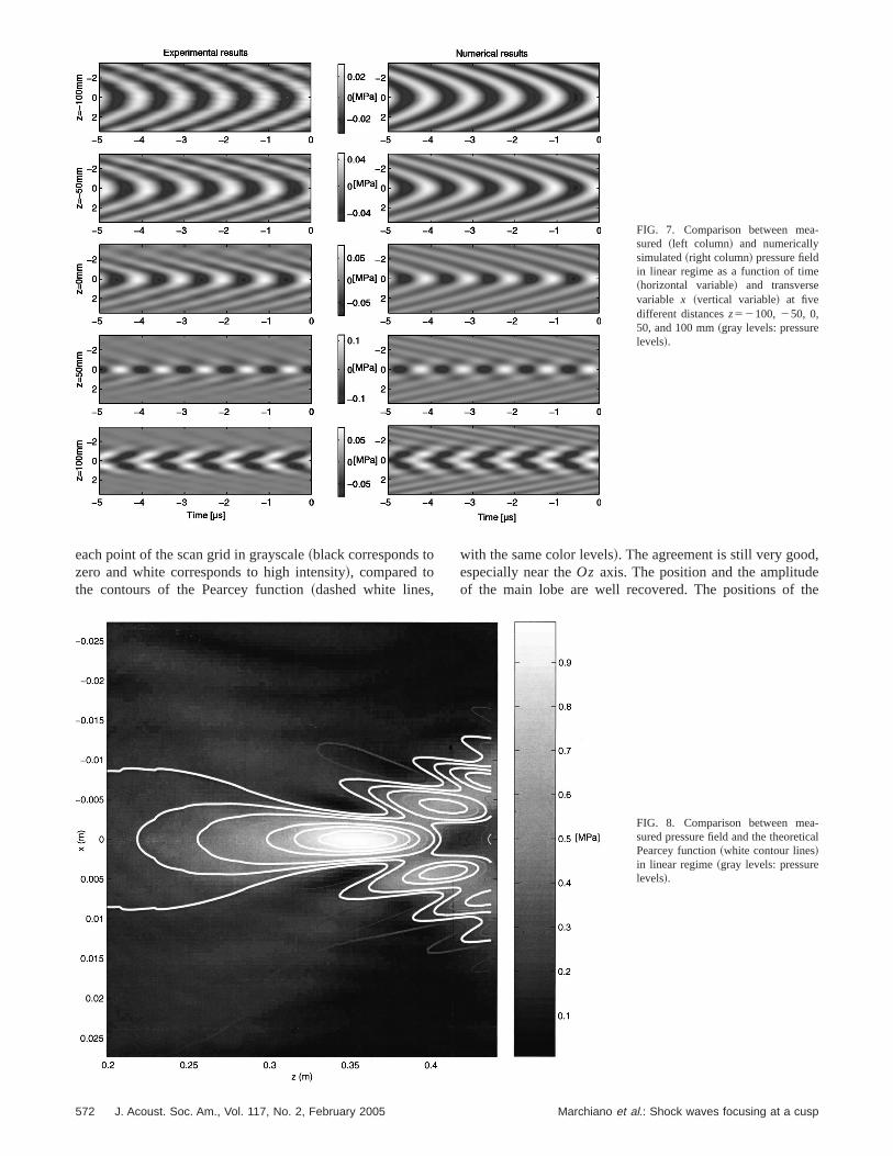
To compare the experimental measurements to themerical simulations discussed in Sec. II, only the incomwaveform is necessary as an input argument. This datextracted directly from the experimental measurementsmm away from the tip of the cusp on the propagation aOz. In order to perform comparisons with the experimenresults, the pressure field is computed on a grid correspoing to the experimental one. Figure 7 presents the expmental field ~left column! and the numerical simulation~right column! in the transverse directionx as a function ofthe time at five different distancesz from the tip of the cusp(2100, 250, 0, 50, and 100 mm!. The agreement betweethe two series of fields is very good, in particular near tsymmetry axis. The main differences between the expmental and the simulated fields are located off axis. Far awfrom the tip of the cusp~100 mm before!, the wavefront isconverging and its amplitude in the transverse directionquite homogeneous. The closer to the tip the wavefrontthe stronger at the center of the beam the amplitude is. Tis due to the focusing effects. At the tip and slightly afterthe beam is narrow and 100 mm after the tip it is cleadiverging.
Figure 8 displays the amplitude at 1 MHz measured
571Marchiano et al.: Shock waves focusing at a cusp
-
FIG. 7. Comparison between measured ~left column! and numericallysimulated~right column! pressure fieldin linear regime as a function of time~horizontal variable! and transversevariable x ~vertical variable! at fivedifferent distancesz52100, 250, 0,50, and 100 mm~gray levels: pressurelevels!.,
,ehe
each point of the scan grid in grayscale~black corresponds tozero and white corresponds to high intensity!, compared tothe contours of the Pearcey function~dashed white lines
572 J. Acoust. Soc. Am., Vol. 117, No. 2, February 2005
with the same color levels!. The agreement is still very goodespecially near theOz axis. The position and the amplitudof the main lobe are well recovered. The positions of t
-al
FIG. 8. Comparison between measured pressure field and the theoreticPearcey function~white contour lines!in linear regime~gray levels: pressurelevels!.
Marchiano et al.: Shock waves focusing at a cusp

-
f
FIG. 9. Comparison between measured ~left column! and numericallysimulated~right column! pressure fieldin nonlinear regime as a function otime ~horizontal variable! and trans-verse variablex ~vertical variable! atfive different distances z52100,250, 0, 50, and 100 mm~gray levels:pressure levels!.
plt
n
holtt
pecththusemoinceba
ashe
e-yean-
n in
tivetof-
er--er-planeises
for1.9
tn
the
ireri-
nd
on
sh
secondary lobes are matching relatively well but the amtudes of the experimental measurements are lower thansimulated ones. These results confirm that the experimesetup is only usable near theOz axis because of the finitesize of the emitting array. Nevertheless, these results sthat the experimental setup associated with the inverse fitechnique permits the synthesis of a cusped caustic inlinear regime of 2-D space.
To study the focusing of weak shock waves at a cuscaustic, the previous computed signals by inverse filter tenique are now emitted with high amplitude. Because ofhigh amplitude, nonlinear effects take place duringpropagation between the array of transducers and the cacusp. The nonlinear effects induce a steepening of the tporal profile of the waves in accordance with the lawsnonlinear acoustics. The shock formation distance beshorter than the distance between the array of transduand the cusped caustic, the incoming signal has shocksfore tangenting the caustic. Once the high amplitude signare emitted, the pressure is measured on the same gridlinear regime but with a temporal sampling of 250 MHz. Tresults are given in Fig. 9~left column!, which shows thepressure fields in the transverse directionx as function of thetime at five different locationsz from the tip of the caustic(2100, 250, 0, 50, and 100 mm!. The five images are dif-ferent from those of the linear case~Fig. 7!. Far before thecaustic (2100 mm), the amplitude distribution is homogneous and the shocks appear to be formed as indicated bsharp transitions between black and white. As for the lincase,250 mm away from the tip, the focusing effects icrease the amplitude of the center of the beam. At the tip
J. Acoust. Soc. Am., Vol. 117, No. 2, February 2005
i-hetal
werhe
dh-eetic-
fgrse-lsin
ther
of
the cusp the transverse size of the beam is narrower thathe linear case. Moreover, the compression phases~whiteareas! are shorter in time than the expansion ones~blackareas!, and the positive peaks are higher than the negaones. This asymmetric waveform distorsion is well-knownresult from a combination of diffraction and nonlinearity efects ~see, for instance, Hamilton, 1998, p. 258!.
The maximal overpressure is 66.823105 Pa peak/peak(48.943105 Pa for the positive part and 17.873105 Pa forthe negative one!. It is detected on theOz axis, 35 mm afterthe tip of the cusp. For a plane wave, the maximum ovpressure at this distance is 103105 Pa peak/peak. The amplification coefficient defined as the ratio between the ovpressure in the focused case and the overpressure for awave is consequently of 6.68. If only the positive parttaken into account, the amplification coefficient becom9.78. This coefficient is greater than for a fold causticwhich the corresponding values are respectively about~peak to peak! and 3.8 ~amplification of the positive paronly!. Moreover, note that this value of the amplificatiocoefficient for a cusped caustic is in agreement withvalue of about 9 found by Wanneret al. ~1972! for sonicboom.
The numerical simulations in nonlinear regime requtwo input arguments which are extracted from the expemental results: the waveform of the incoming function athe nonlinear coefficientm. The waveform of the incomingfunction is directly extracted from the experimental datathe Oz axis 100 mm before the tip of the cusp~sufficientlyfar before the cusp!. The temporal profile for one period igiven in Fig. 10~dash line!. The signal carries a shock whic
573Marchiano et al.: Shock waves focusing at a cusp

mnn-en
efithnd.lt
lvr
f
imt
ionlesgeduoorodinthtec
se
ci
the-to
buttheical
theheatedtothedem-an
menear
r
gnalat
nalin-the
it
r
is practically formed~the rise time is about 80 ns!. The non-linear coefficientm5b (p0 /r0c0
2) (k0a/27)1/2 @Eq. ~8!# iscalculated from the value of the pressure measured 27.4before the tip of the caustic~distance equal to one diffractiolength Lz), in agreement with theory. Note that the two iputs for the numerical code are extracted at two differranges. At that distance, the pressure is 39.53105 Pa and theshock is saturated with a measured rise time of 15 ns@Fig. 10~solid line!#. Consequently, the value of the nonlinear coficient is m50.35. The numerical simulations are made wthose two input arguments for a numerical grid correspoing to the experimental one. The results are given in Fig~right column!. The agreement with the experimental resuis excellent, especially around theOz axis as in the previouscomparisons. These results prove that the numerical sosimulates the physical reality with a good precision. Figu11 shows the pressure~in Pa! as a function of the time~inms! on theOz axis at four different distances from the tip othe caustic (2100,228, 0, and 100 mm!; the solid lines arethe experimental results while the dashed lines are the slated ones. The numerical simulations fit the experimenresults with a very good precision since the amplificatlevel and the shock positions are recovered. Neverthethere is a little disagreement for the rise time, which is lonin the simulations than in the experiments. This may beto numerical dissipation occurring during the resolutionthe diffraction part. Indeed, while the numerical solver fBurgers’ equation is a shock fitting algorithm, the methused to solve the linear KZ equation is a shock capturalgorithm. Shocks are not treated explicitly as such inlinear, diffraction part of the split-step algorithm. The finidifferences automatically stabilize the algorithm by introduing numerical viscosity, which artificially increases the ritime.
CONCLUSION AND OUTLOOKS
A new explanation about the wavefront unfolding effesometimes associated with acoustical shock waves incom
FIG. 10. Incoming signal~one period! measured at one boundary laye(227.4 mm, solid line! and at2100 mm ~dash line! from the tip of thecusped caustic in nonlinear regime.
574 J. Acoust. Soc. Am., Vol. 117, No. 2, February 2005
m
t
-
-9s
ere
u-al
s,ref
ge
-
tng
on a cusped caustic has been proposed through originaloretical and numerical studies. This effect does not seembe intrinsically nonlinear as expected by previous authorsassociated both with nonlinearities and the geometry ofwavefront. Quantitative comparisons between numersimulations and experimental results have demonstratedvalidity of the theoretical modeling and the accuracy of tnumerical code. Besides, as the numerical code is validboth experimentally and numerically, it is now possibleuse it to simulate other configurations than those used inexperiments. In particular, it is interesting to apply this coto the prediction of sonic boom focusing in the case of coplex aircraft maneuvers, that is to say, the focusing of‘‘N’’ wave at a cusped caustic. Figure 12 presents the tidependence of the pressure at three different locationsthe cusp (z50, x50 for casea, z51, x50.45 for caseband z52, x50.8 for casec) for a nonlinearity parametem50.1 and an incoming ‘‘N’’ wave@F(t)52t if utu,1,0else#. On the tip of the caustic@Fig. 12~a!#, the signal has noprecursor and it begins with a steep shock. The second si@Fig. 12~b!# displays a structure with two shocks visiblethe beginning of the signal~noted 1 and 2 on the figure!. Theamplitude is weaker than on theOz axis since the focusingeffects are less important off axis. The structure of the sig@Fig. 12~c!# is made of three shocks associated with theteraction of three different signals in accordance withtheory which stipulates that in zone II three rays~and conse-quently three signals! pass through each point. Therefore,
FIG. 11. Comparisons between measured~solid lines! and simulated~dashlines! pressure waveforms~in Pa! in nonlinear regime on the axisx50 atfour different distances from the tip of the cusped caustic (z52100,228,0, and 100 mm!.
Marchiano et al.: Shock waves focusing at a cusp

inpar
dy,
-thnod
enthedeforudeve-erforthe
onbe
eu-mo-e-, a
ractD-
ro-out
hts
tedes-
,ate
o-ted.aw,lu-
on,re-of
adntosureap-ri-ck
less
re
is possible to compare the numerical results with existexperimental measurements of sonic boom focusing. Inticular, we can notice that the waveform obtained numecally in casesa andb corresponds to the waveforms alreaobserved by Wanneret al. ~1972, Fig. 15, microphones 1718 and 19 and Fig. 16 microphone 13! in the case of a supersonic aircraft entering into turn. Those results are anoqualitative validation of the numerical code. Note thatsignal with the characteristic of Fig. 12~c! has been recorde
FIG. 12. Numerical simulations of the pressure time waveforms at thpoints near the cusped caustic cusp@~a! z50, x50; ~b! z51, x50.45; and~c! z52, x50.8] for an ‘‘N’’ wave in nonlinear regime (m50.1).
J. Acoust. Soc. Am., Vol. 117, No. 2, February 2005
gr-
i-
er
by Wanneret al. ~1972!, since no measurement has beperformed inside the branch of the cusped caustic wherecorresponding point lies. Also noticeable is the magnituorder of amplification in the experimental setup: around 3a fold caustic and 9 for a cusp caustic, the same magnitorders as measured for sonic boom. Finally, complex waforms as illustrated by Fig. 12 indicate caustics of highorder than the fold caustics may play an important roleexplaining messy waveforms observed for sonic boom inturbulent atmospheric boundary layer.
Considering the importance of the geometry effectthe focusing process as demonstrated in Sec. III, it woulddesirable to improve the links between the aircraft manvers and the geometry of the cusped caustic. For real atspheres, this would imply in particular to generalize the thoretical model to a 3D heterogeneous and moving mediumtask far from easy.
ACKNOWLEDGMENTS
This investigation have been carried out under a contawarded by the European Commission, Contract No. G4RCT-2000-00398. No part of this report may be used, repduced and/or disclosed, in any form of by any means withthe prior written permission of Universite´ Pierre et MarieCurie and the SOBER project partners. 16/11/2001 All rigreserved.
APPENDIX: THE NUMERICAL CODE
1. Presentation of the numerical method
To our knowledge, only one previous study is dedicato the numerical simulation of the focusing of shock wavat a cusped caustic~Piacsek, 1995!, based on the NPE equation @nonlinear paraxial equation~McDonald and Kuperman1987!#. This numerical study has been applied to investigdistortion of a sonic boom rippled wavefront~Piacsek,2002!, in order to validate the Pierce and Maglieri~1972!model of sonic boom wavefront folding in a turbulent atmsphere. However, no quantitative validation was presenHere, relying on catastrophe theory and Guiraud scaling lwe are able to validate quantitatively the numerical resotion, before comparing it with experiments.
The theoretical model being based on the KZ equatiwe have modified an algorithm solving the KZ equation pviously used to study the nonlinear Fresnel diffractionshock waves~Coulouvrat and Marchiano, 2003!. That newalgorithm solves the KZ equation@Eq. ~7!# associated withthe boundary conditions@Eq. ~9!# in the temporal domain.The problem is formulated with the potential variable insteof the pressure. The potential is more suited to take iaccount shock waves. Indeed, a discontinuity for the prescorresponds to an angular point for the potential. Thisproach has already been fruitful to solve the nonlinear Tcomi equation in the case of the focusing of weak showaves at a fold caustic~Marchianoet al., 2003a!. The di-mensionless potential is calculated from the dimensionpressure:
e
575Marchiano et al.: Shock waves focusing at a cusp

toy
eeon
tha
byndco
bT
e
teto
–
it-rsZ
th
ri-e
ua-on.en-the
then
ani-
lou-
eenhetheis
tionbil-
de
thehe
tic
for
theu-
wsithcti-
ited
toores a
ndicale
-e
senthethe
p5]f
] t. ~A1!
The KZ equation for the potential is
]2f
] z] t5
]2f
] x21m
]
] tS ]f
] tD 2
, ~A2!
Apart from the nonlinear term, this equation is identicalthe equation for pressure@Eq. ~7!#. The associated boundarconditions, valid only in zone I~Fig. 1!, are
f~ x,z, t ! ——→Ax21 z2→`
1
Au6a22 zu
3E2`
tF~ t 81a x1a2z2a4!d t8. ~A3!
The problem is symmetrical about the propagation axisOz.Therefore it is possible to solve the problem for only onhalf of the planeOxz, in order to reduce the size of thcomputational domain. So the following symmetry conditiis added to the boundary conditions@Eq. ~16!#:
]
] xf~ x50,z, t !50. ~A4!
Note that these boundary conditions correspond tocusped caustic and can be changed. To treat the real wfront in Sec. III, a wavefront similar to the one usedPiacsek~2002! has been computed in the initial plane anonlinear plane waves are used for the other boundaryditions.
In order to calculate the numerical solutions of the prolem, the space variables are discretized on a regular grid.points are equally spaced in thez direction starting fromplaneZ2 to planeZ1 with a stepD z. They are also equallyspaced in thex direction from 0 toX1 with a stepD x. Thetime is discretized with a stepD t .
The KZ equation@Eq. ~15!# is solved plane after planfollowing the z direction. For eachD z, the numerical solu-tions of the KZ equation are computed using the split-smethod~Ames, 1977!. This scheme has been widely usedsolve the KZK @acronym of Khokhlov–ZabolotskayaKuznetsov, see Kuznetsov~1970!# equation which is a KZequation taking into account the attenuation@see Hamilton~1998! for a review#. The split-step scheme consists in splting the KZ equation into two simpler equations. The fione takes into account the diffraction. It is the linear Kequation:
]2f
] z] t5
]2f
] x2. ~A5!
The second one deals with the nonlinear effects. It isBurgers equation for the potential:
]2f
] z] t5m
]
] tS ]f
] tD 2
. ~A6!
576 J. Acoust. Soc. Am., Vol. 117, No. 2, February 2005
-
eve-
n-
-he
p
t
e
At each plane, first the linear KZ equation is solved numecally by an implicit finite differences scheme in the timdomain based on the Lee and Hamilton scheme~1995!. Thisscheme has originally been developed to solve the KZ eqtion for pressure in the framework of the beam propagatiIt can easily be adapted to solve the KZ equation for pottial since these two equations have the same form. Onlyboundary conditions are different. Once the solution oflinear KZ is computed, it is used to initialize the calculatioof the solution of the Burgers equation for potential onelementary stepD z. That solution is calculated semanalytically with the Hayes graphical method~1969!, whichwas recently adapted for the numerical procedure by Couvrat and Marchiano~2003! and Marchianoet al. ~2003a!.Finally, on a D z step, the solution takes into account thdiffraction and the nonlinear effects. The coupling betwediffraction and nonlinearity is assured by the repetition of tprocedure plane after plane. Note that, as the solution oflinear KZ equation, the solution of the Burgers equationobtained in the temporal domain so that the whole resoluis achieved in the time domain. Moreover, there is no staity condition necessary to solve the Burgers equation~thesolution is semi-analytical! or the linear KZ equation~thescheme is fully implicit!. Finally, the pressure is calculatefrom Eq. ~14! by a second-order finite differences schemapplied to the potential solution and a symmetry aboutaxis of propagationOz permits to recover the pressure on twhole domain.
2. Validation of the algorithm
According to Guiraud’s scaling for the cusped caus@see Sec. III and Coulouvrat~2000!#, if the incoming func-tion is a step shock, the following quantities are constantthe point where the pressure is maximal:pmax/m
21/35Cp ,t max/m
4/35Ct , xmax/m5Cx and zmax/m2/35Cz , where pmax
represents the value of the maximal pressure,t max is the timefor which the pressure is maximal,xmax, zmax is the positionwhere the pressure is maximal, andCp , Ct , Cx andCt areconstants. These similitude laws are a good way to checknumerical code quantitatively, as they imply a strong copling between nonlinearity and diffraction. Figure 13 shothat the numerical results are in very good agreement wthe theoretical predictions. Indeed, the four ratios are pracally constant for the values ofm greater than 0.02. Thisagreement shows that the amplitude of the peaks is limand follows the similitude lawpmaxm
21/3. For the values ofthe nonlinear parameter under the thresholdm50.02, the re-sults are not so good because the nonlinear effects aresmall and the numerical resolution would require a morefined mesh grid than the one used. This result providequantitative validation of the numerical procedure. This kiof validation has already been used to validate a numercode solving the nonlinear Tricomi equation with thGuiraud similitude law~Auger and Coulouvrat, 2002; Marchiano et al., 2003a!. Nevertheless, the results of thosworks were not in a such good agreement as the preones, especially concerning the similitude law following ttemporal variable. The very good agreement obtained in
Marchiano et al.: Shock waves focusing at a cusp

rhee
himaahe
inicis
etiio
thTlonca
s
tic
k
ric
t.
t-
er-
u-
R-
.
nic
g of
ndd
at-
ust.
h-
s
-
sp
h-
,’’ J.
.
present work is due to the fact that the numerical solvenow entirely in the time domain, contrarily to the case of tresolution of the nonlinear Tricomi equation for which thdiffraction equation is solved in the frequency domain. Tdifference is important because for an algorithm in the tidomain, it is possible to impose in the boundary conditionincoming step function to check the similitude law, whereit is impossible for the nonlinear Tricomi solver, for whiconly artificially periodic incoming signals are available. Thuse of an algorithm in the frequency domain for the nonlear Tricomi equation was required by the mixed ellipthyperbolic type of the equation, while the KZ equationfully hyperbolic.
Finally, we indicate that a modified version of thpresent code has already been used to confirm theorepredictions in a study about the nonlinear Fresnel diffractof weak shock waves~Coulouvrat and Marchiano, 2003!. Inthat previous study, the numerical code was similar tocode presented here except for the boundary conditions.agreement between theoretical predictions and numericasults on self-similar solutions of the nonlinear KZ equatialso permitted us to validate quantitatively the numerimethod.
Ames, W. F.~1977!. Numerical Methods for Partial Differential Equation~Academic, New York!, pp. 315–467.
Auger, T., and Coulouvrat, F.~2002!. ‘‘Numerical simulation of sonic boomfocusing,’’ AIAA J. 40, 1726–1734.
Berry, M. V. ~1976!. ‘‘Waves and Thom’s theorem,’’ Adv. Phys.25, 1–26.Coulouvrat, F.~2000!. ‘‘Focusing of weak acoustic shock waves at a caus
cusp,’’ Wave Motion32, 233–245.Coulouvrat, F., and Marchiano, R.~2003!. ‘‘Nonlinear Fresnel diffraction of
weak shock waves,’’ J. Acoust. Soc. Am.114, 1749–1757.Cramer, M. S. ~1981a!. ‘‘Focusing of weak three-dimensional shoc
waves,’’ AIAA J. 19, 1363–1365.Cramer, M. S.~1981b!. ‘‘Focusing of weak shock waves at an axisymmet
arete,’’ J. Fluid Mech.110, 249–253.Cramer, M. S., and Seebass, A. R.~1978!. ‘‘Focusing of weak shock waves
at an areˆte,’’ J. Fluid Mech.88, 209–222.Davy, B. A., and Blackstock, D. T.~1971!. ‘‘Measurements of the refraction
and diffraction of a shortN wave by a gas-filled soap bubble,’’ J. AcousSoc. Am.49, 732–737.
FIG. 13. Numerical check of theoretical Guiraud’s similitude law.
J. Acoust. Soc. Am., Vol. 117, No. 2, February 2005
is
sens
-/
caln
ehere-
l
Downing, M., Zamot, N., Moss, C., Morin, D., Wolski, E., Chung, S., Plokin, K., and Maglieri, D.~1998!. ‘‘Controlled focused sonic booms frommaneuvering aircraft,’’ J. Acoust. Soc. Am.104, 112–121.
Gill, P. M., and Seebass, A. R.~1973!. ‘‘Nonlinear acoustic behavior at acaustic: an approximate analytical solution,’’ AIAA Aeroacoustics Confence, Seattle~MIT, Cambridge!, AIAA Paper 73-1037, pp. 353–386.
Guiraud, J.-P.~1965!. ‘‘Acoustique geometrique, bruit balistique des avionssupersoniques et focalisation~Geometrical acoustics, balistic noise of spersonic aircraft and focusing!,’’ J. Mec. 4, 215–267~in French!.
Hamilton, M. F.~1998!. ‘‘Sound beams,’’ inNonlinear Acoustics, edited byM. F. Hamilton and D. T. Blackstock~Academic, San Diego!, pp. 233–261.
Hayes, W. D., Haefeli, R. C., Kulsrud, H. E.~1969!. ‘‘Sonic boom propa-gation in a stratified atmosphere with computer program,’’ NASA C1299.
Kuznetsov, V. P.~1970!. ‘‘Equations of nonlinear acoustics,’’ Sov. PhysAcoust.16, 467–470.
Lee, Y.-S., and Hamilton, M. F.~1995!. ‘‘Time-domain modeling of pulsedfinite-amplitude sound beams,’’ J. Acoust. Soc. Am.97, 906–917.
Marchiano, R., Coulouvrat, F., and Grenon,, R.~2003a!. ‘‘Numerical simu-lation of shock wave focusing at fold caustics, with application to soboom,’’ J. Acoust. Soc. Am.114, 1758–1771.
Marchiano, R., Thomas, J.-L., and Coulouvrat, F.~2003b!. ‘‘Experimentalsimulation of supersonic superboom in a water tank: nonlinear focusinweak shock waves at a fold caustic,’’ Phys. Rev. Lett.91~18!, 184301~1-4!.
Marston, P. L.~1988!. ‘‘Wavefront geometries giving transverse cusp ahyperbolic umbilic foci in acoustic shocks,’’ inShock Waves in CondenseMatter 1987, edited by S. C. Schmidt and N. C. Holmes~Elsevier, Am-sterdam!.
Marston, P. L.~1992!. ‘‘Geometrical and catastrophe optics methods in sctering,’’ in High Frequency and Pulse Scattering, Physical Acoustics, ed-ited by A. D. Pierce and R. N. Thurston~Academic, San Diego!, Vol. XXI,pp. 1–234.
McDonald, B. E., and Kuperman, W. A.~1987!. ‘‘Time domain formulationfor pulse propagation including nonlinear behavior at a caustic,’’ J. AcoSoc. Am.81, 1406–1417.
Pearcey, T.~1946!. ‘‘The structure of an electromagnetic field in the neigbourhood of a cusp of a caustic,’’ Philos. Mag.37, 311–317.
Piacsek, A. A.~1995!. ‘‘A numerical study of a weak step shocks that focuin two dimensions,’’ Ph.D. thesis, Pennsylvania State University.
Piacsek, A. A.~2002!. ‘‘Atmospheric turbulence conditions leading to focused and folded sonic boom wave fronts,’’ J. Acoust. Soc. Am.111,520–529.
Pierce, A. D.~1971!. ‘‘Maximum overpressures of sonic boom near the cuof caustics,’’ inNoise and Vibration Control Engineering, edited by M. J.Crocker~Purdue U. P., West Lafayette!, pp. 478–487.
Pierce, A. D., and Maglieri, D. J.~1972!. ‘‘Effects of atmospheric irregulari-ties on sonic boom propagation,’’ J. Acoust. Soc. Am.51, 702–721.
Plotkin, K. J., and Cantril, J. M.~1976!. ‘‘Prediction of sonic boom atfocus,’’AIAA Paper 76-2, AIAA 14th Aerospace Sciences Meeting, Wasington.
Prasad, P., and Sangeeta, K.~1999!. ‘‘Numerical simulation of convergingnonlinear wavefronts,’’ J. Fluid Mech.385, 1–20.
Sanaı¨, M., Toong, T. Y., and Pierce, A. D.~1976!. ‘‘Ballistic range experi-ments on superboom generated at increasing flight Mach numbersAcoust. Soc. Am.59, 520–524.
Sturtevant, B., and Kulkarny, V. A.~1976!. ‘‘The focusing of weak shockwaves,’’ J. Fluid Mech.73, 651–671.
Tanter, M., Thomas, J.-L., and Fink, M.~2000!. ‘‘Time reversal and inversefilter,’’ J. Acoust. Soc. Am.108, 223–234.
Thom, R.~1972!. Stabilite structurelle et morphogene`se ~Benjamin, Read-ing!, pp. 72–107~in French!; English translation:Structural stability andmorphogenesis~Benjamin, Reading, 1975!.
Wanner, J.-C., Valle´e, J., Vivier, C., and The´ry, C. ~1972!. ‘‘Theoretical andexperimental studies of the focus of sonic booms,’’ J. Acoust. Soc. Am.52,13–32.
Whitham, G. B.~1956!. ‘‘On the propagation of weak shock waves,’’ JFluid Mech.1, 290–318.
Zabolotskaya, E. A., and Khokhlov, R. V.~1969!. ‘‘Quasi-plane waves in thenonlinear acoustics of confined beams,’’ Sov. Phys. Acoust.15, 35–40.
577Marchiano et al.: Shock waves focusing at a cusp


