Embed Size (px)
Citation preview

- 1 -
Safety, Security, Peace of Mind
Covering Gatekeeper Systems NiTRO 401; NiTRO 404 Digital Video Recorders
NiTRO-X 404 Digital Video Recorder
Software Version: S5R16_0715

- 2 -
Table of Contents. Tables..................................................................................................................................................................................................................................... 4 Introduction. ........................................................................................................................................................................................................................... 5
Glossary. 5 Important Safeguards and Warnings. ....................................................................................................................................................................................... 6 Product Overview: NiTRO 400 Series................................................................................................................................................................................... 7 Product Overview: NiTRO-X 400 Series. .............................................................................................................................................................................. 8
NiTRO and NiTRO-X Comparison Chart. 8 Available Download Kits. 9
Installation..............................................................................................................................................................................................................................10 Mounting Installation Instructions. 10 Power Connections. 10 Alarm Button Mounting 11 Record LED Mounting 11 Recommended Location for Alarm Button 12
Suggested System Locations..................................................................................................................................................................................................14 Mounting The System. 14 Routing the Power Harness. CAB000219 (4pin NiTRO)) or (CAB000262 (6pin NiTRO-X) 14 Routing the Sensor Harness CAB000218. 15 Connecting Cameras. 15 Camera Mounting and Connections. 15 S2-Series Camera Installation. 16 S205 Camera Lens Changing. 17 Suggested Camera Locations. 17 Video Alignment Cable: CAB000157 19
System Features. ...................................................................................................................................................................................................................21 NiTRO-X 400 Series Front View. 21 NiTRO 401 / 404 Front View. 21 NiTRO-X 400 Rear View. 22 NiTRO 401 / 404 Rear View. 22
Remote Control and Menu System..........................................................................................................................................................................................23 Quick Configuration 23
Menu System. .......................................................................................................................................................................................................................24 Live. 24
OSD 24 Background 24 Sequence Dwell 24 Video Adjustment 24 Camera Title 24
Record. 25 Record Settings 25 File Length 25 File Type 25 Ask When Stop 25 Record Schedule 26 Channel Mode 26
System. 26 Video Format 26 New Password 26 Login Verify 26 Language 26 System Info 27 Config Setup 27 App Restart 27 O/S Reboot 27
Network. 27 Port 27 Network Type 27 IP Address 27
Storage. 28 Overwrite 28 Format 28 Storage Device 28 Total Capacity 28 Free Capacity 28 Search By Time 28
Alarm. 28 Post Event Record 28 Alarm Action 28
- 3 -
Motion Zone 29 Motion Sensitivity 29
Motor. 29 Vehicle ID 29 Line 29 Overspeed 29 Speed Check 29 Pulses 30 Pulses Unit 30
GPS / GPRS. 30 GPS Device 30 GPS Burnin 30
Power. 30 Power On 30 Power Off 30 Power Off Delay 30 Ignition Signal 30
MaxVIEW™ 400 Video Management System..........................................................................................................................................................................31 PC Requirements. 31 Description. 31 Installation. 31
Retrieving Captured Data........................................................................................................................................................................................................32 SD Card Extraction. 32 Inserting The Card Into A Reader. 32 Opening Captured Video Files. 32
MaxVIEW 400 Operation. .................................................................................................................................................................................................33 Opening a File. 33 Open Recent Files. 33 Audio 33 MaxVIEW 400 Components. 34 Displaying Sensors. 34
GPS. ......................................................................................................................................................................................................................................34 GPS Mapping Options. 35 Using The GPS Zoom Feature. 35
MaxVIEW Features.............................................................................................................................................................................................................35 Using The Scrubber. 35 Using The Calendar Feature. 36 Calendar Definitions. 36 View Video by Clips. 36 Deinterlacing 37
Playback Controls and File Management.................................................................................................................................................................................37 Saving a Clip. 37 Drag and Drop a Video File. 38 Saving a Still Image. 38 Emailing a Still Image. 38
APPENDIX ............................................................................................................................................................................................................................40 Power Connections (CAB000211 connects to CAB000205/6)..............................................................................................................................................40 NiTRO 400 With Cables......................................................................................................................................................................................................40
Power Sensor Connection; NiTRO Pre-December 2011. 40 CAB000271 Connections. 41 CAB000145: 7 Wire; 4 Wire and 3 Wire Terminations. 42 CAB000268 4 PIN Power Connector to 6 PIN Power Connector Adapter. 43
Retrofitting NiTRO 900 and 1000 to NiTRO 400 and NiTRO-X 400..........................................................................................................................44 Retrofitting GSX / VCR Systems to NiTRO and NiTRO-X Systems. 45 VCR/GSX to NiTRO DVR with or without GPS Module 45 GSX Retrofit to NiTRO or NiTRO-X 46
Dome Camera (CAMICAGSC) Installation and Configuration. .............................................................................................................................................47 Routing the Camera Harness(es) ) (GSWHC2-XX). 47 Ceiling Mount. 47 Bulkhead Mount. 47 Focusing Camera Lens. 48 Changing the Camera Lens. 48 Recommended Location for the IR Illuminator. 48 Final Installation 49
Contact Information. ...............................................................................................................................................................................................................51
- 4 -
Tables.
TABLE 1: NITRO AND NITRO-X COMPARISON CHART. ................................................................................................................................................8 TABLE 2: CAB000219 / CAB000262 / CAB000218 WIRING DEFINITIONS. .............................................................................................................................13 TABLE 3: CAMERA CONNECTION CONFIGURATION. ..........................................................................................................................................................15 TABLE 4: VIDEO ALIGNMENT CABLE CONNECTION DESCRIPTIONS. ................................................................................................................................ 20 TABLE 5: NITRO-X POWER AND RUN LED DEFINITION....................................................................................................................................................21 TABLE 6: NITRO-X ALARM LED DEFINITION. ....................................................................................................................................................................22 TABLE 7: NITRO-X SD CARD LED DEFINITION..................................................................................................................................................................22 TABLE 8: NITRO-X SYSTEM STATUS LED DEFINITION. ...................................................................................................................................................22 TABLE 9: STILL IMAGE FILENAME DEFINITION....................................................................................................................................................................38 TABLE 10: CAB000145 TERMINATION DEFINITIONS. ...........................................................................................................................................................42 Table of Figures. FIGURE 1: NITRO OR NITRO-X WITH CABLES. .............................................................................................................................................................10 FIGURE 2: CAB000218 CONNECTIONS.................................................................................................................................................................................12 FIGURE 3: S-SERIES CAMERA..............................................................................................................................................................................................16 FIGURE 4 : FRONT VIEW DESCRIPTION...............................................................................................................................................................................21 FIGURE 5: FRONT VIEW DESCRIPTION................................................................................................................................................................................21 FIGURE 6 : REAR VIEW CONNECTIONS. ..............................................................................................................................................................................22 FIGURE 7: REAR VIEW CONNECTIONS................................................................................................................................................................................22 FIGURE 8: REMOTE CONTROL DEFINITION.........................................................................................................................................................................23 FIGURE 9 : DEFAULT BRIGHTNESS / CONTRAST OPTIONS................................................................................................................................................24 FIGURE 10 : TEXT INPUT BOX...............................................................................................................................................................................................24 FIGURE 11 : DEFAULT RECORD SETTINGS. ........................................................................................................................................................................25 FIGURE 12 : ESTIMATED RECORD TIME. .............................................................................................................................................................................25 FIGURE 13 : SCHEDULED RECORDING................................................................................................................................................................................26 FIGURE 14 : SETTING DATE AND TIME. ...............................................................................................................................................................................26 FIGURE 15 : IP ADDRESS CONFIGURATION. .......................................................................................................................................................................27 FIGURE 16: ALARM ACTION DEFAULTS. ..............................................................................................................................................................................29 FIGURE 17 : DIGITAL INPUT DIALOG BOX. ...........................................................................................................................................................................29 FIGURE 18 : TIME INPUT DIALOG BOX. ................................................................................................................................................................................30 FIGURE 19 : SOFTWARE CHECK. .........................................................................................................................................................................................31 FIGURE 20 : BEGIN INSTALLATION.......................................................................................................................................................................................31 FIGURE 21 : INSTALLATION COMPLETE...............................................................................................................................................................................32 FIGURE 22 : SD CARD ORIENTATION...................................................................................................................................................................................32 FIGURE 23 : OPEN FILE.........................................................................................................................................................................................................33 FIGURE 24 : OPEN RECENT FILE..........................................................................................................................................................................................33 FIGURE 25 : MAXVIEW WINDOW DEFINITIONS. ...............................................................................................................................................................34 FIGURE 26: DISPLAYING SENSORS. ....................................................................................................................................................................................34 FIGURE 27: GPS MAP; SATELLITE; HYBRID FEATURES. .....................................................................................................................................................35 FIGURE 28: GPS SHOW MAP. ...............................................................................................................................................................................................35 FIGURE 29: GPS SHOW VEHICLE LOCATOR........................................................................................................................................................................35 FIGURE 30: GPS ZOOM FEATURE. .......................................................................................................................................................................................35 FIGURE 31: USING THE SCRUBBER BAR. ............................................................................................................................................................................35 FIGURE 32: VEHICLE LOCATOR UPDATED POSITION.........................................................................................................................................................36 FIGURE 33 : CALENDAR FEATURE. ......................................................................................................................................................................................36 FIGURE 34 : CALENDAR DEFINITIONS. ................................................................................................................................................................................36 FIGURE 35 : CLIPS DEFINITION. ...........................................................................................................................................................................................36 FIGURE 36 : PLAYBACK CONTROLS.....................................................................................................................................................................................37 FIGURE 37 : MARKING A CLIP...............................................................................................................................................................................................37 FIGURE 38 : SAVING A VIDEO CLIP ......................................................................................................................................................................................38 FIGURE 39 : EMAILING A STILL IMAGE. ................................................................................................................................................................................38 FIGURE 40: 3 CAMERA CONNECTION. .................................................................................................................................................................................40 FIGURE 41: CAB000145 TERMINATIONS. .............................................................................................................................................................................42 FIGURE 42: CHANGING THE CAMICAGSC CAMERA LENS. .................................................................................................................................................48 FIGURE 43 : IR AND CAMERA. ..............................................................................................................................................................................................48 FIGURE 44: AV OUT CONNECTION FOR CAMERA ALIGNMENT. .........................................................................................................................................49

- 5 -
Introduction.
Please Note: This manual covers two product lines; The NiTRO-X 400 Series (utilizing either SDHC (up to 32GB) and SDXC (over 32GB memory cards) and the NiTRO 400 series (utilizing SDHC (up to 32GB memory cards). Where there is a distinct difference between the two systems these differences will be clearly marked in regards as to which system they relate to.
Congratulations on the purchase of the NiTRO400 series or NiTRO-X 400 series DVR. These Digital Video Recorders, DVR, are solid state single or quad channel digital video recorder. Offering H.264 compression, the same compression technique as used in Blue Ray disk players, which produces crystal clear, best in class, video playback. Due to its small footprint the NiTRO400 series or NiTRO-X 400 series offers flexible mounting possibilities. In place of a spinning hard drive video records to a removable SD memory card. Utilizing state of the art surface mount components the NiTRO 400 series or NiTRO-X 400 series are built to withstand the shock and vibration of school bus operation.
Keeping with tradition, the NiTRO 400 series or NiTRO-X 400 series includes MaxVIEW 400 viewing software. MaxVIEW 400 viewer is a very easy to use application that allows users to quickly find the video of interest and save a clip. With the press of a button users can print images and then send them to qualified staff.
Glossary.
DVR Digital Video Recorder; A DVR functions similarly to a VCR, except it uses a disk to record, as opposed to video-tapes.
H.264 H.264 contains a number of features that allow it to compress video much more effectively than older standards and offers up to twice the compression of the current standards.
OSD On Screen Display; Is an image superimposed on a screen picture commonly used to display information such as volume; channel; time; status, etc. and can be used to change the specific values for all configurable options.
SD Card Secure Digital Card is a non-volatile memory card format for use in mobile devices.
UTC Coordinated Universal Time is a time standard based on International Atomic Time with leap seconds added at irregular intervals to compensate for the Earth's slowing rotation.

- 6 -
Important Safeguards and Warnings.
Remove Main Power Fuse or Disconnect Vehicle Batteries Prior To Any Electrical Work Or Jump Starting The Vehicle.
DO NOT USE THE POWER BUTTON ON THE REMOTE CONTROL
Firmware updates (available from www.gatekeeper-systems.com when released) are system specific, I.E. NiTRO-X 400 firmware updates must only be applied to a NiTRO-X 400 system. If this firmware is applied to any other system warranty will be void.
Do Not remove the SD card from the NiTRO 400 series or NiTRO-X 400 series until the record extend has completed and the Yellow LED (Figure 4) is no longer illuminated, or, use the Stop button on the front of the DVR. Failure to do this will result in permanent damage to the SD card.
Do not remove the cover of the NiTRO 400 series or NiTRO-X 400 series as this will void any warranty.
A Class 6 card is recommended.
The tamperproof retaining cage for the NiTRO-X 400 has a different locking mechanism and the key set for a NiTRO-X 400 system will not work with a NiTRO 400 series system, and vise versa.
When a system has shipped with a GPS antenna, ensure that the GPS antenna is mounted externally on the roof of the bus, magnetic side down.
The NiTRO 400 series and NiTRO-X 400 series are designed for indoor use only. Do Not expose to water or moisture.
When installing a NiTRO 400 DVR unit in an existing NiTRO-X 400 installation cables, CAB000268, 4 pin to 6 pin Power Adapter Cable MUST be utilized (See Appendix for more information).
If at any time there is a question about how to proceed, contact Gatekeeper Systems Inc. at 1-888-666-4833 or 604-864-6187 immediately for directions. Review all installation documentation, including technical bulletins. Additional Technical Bulletins and Product Tutorials can be found in the Gate section of www.gatekeeper-systems.com
Record on a separate sheet the Bus ID along with the Serial Number of the NiTRO™ or NiTRO-X Control Unit and the SD Card for each bus for future reference. Ensure all system components are accounted for prior to installation. Contact Gatekeeper Systems, Inc. if any components are missing or if they appear defective.

- 7 -
Product Overview: NiTRO 400 Series.
NiTRO 401 (DVRIDVMDR-401AV) : NiTRO 404 (DVRIDVMDR-404AV)
NiTRO400 Series
NiTRO Power Harness.
(P/N: CAB000219 (4pin) 30’ )
S-Series Camera
Sensor Harness CAB000218
Alarm Button (SMARTFLAG)
Camera Harness(GSWHC2N-XX) Available in 15’; 30’ and 60’ lengths
Camera Adapter Harness (CAB000209)
Camera Adapter Harness (CAB000202)

- 8 -
Product Overview: NiTRO-X 400 Series.
DVRIDVMDR-401XAV - NiTRO-X Single-Channel H.264 SD Recorder DVRIDVMDR-401XLAV - NiTRO-X Single-Channel H.264/LED SD Recorder DVRIDVMDR-404XAV - NiTRO-X 4-Channel H.264 SD Recorder DVRIDVMDR-404XLAV - NiTRO-X 4-Channel H.264/LED SD Recorder
NiTRO-X400 Series
NiTRO Power Harness. (P/N: CAB000262 (6pin) 30 Feet)
S-Series Camera
Sensor Harness CAB000218
Alarm Button (SMARTFLAG)
Camera Harness(GSWHC2N-XX) Available in 15’; 30’ and 60’ lengths
Camera Adapter Harness (CAB000209)
Camera Adapter Harness (CAB000202)
NiTRO and NiTRO-X Comparison Chart.
NiTRO 401 NiTRO 404 NiTRO-X 401
NiTRO-X 404
# of Video Channels
1 4 1 4
Storage SDHC Up To 32GB
SDHC Up To 32GB
SDXC & SDHC Up To 128GB
SDXC & SDHC Up To 128GB
Lock/Key Single Pin Key Single Pin Key Double Pin Key Double Pin Key Power Connector 4 Pin 4 Pin 6 Pin 6 Pin
Table 1: NiTRO and NiTRO-X Comparison Chart.
Please Note: The SDXC specification states supporting of memory cards of up to 2TB. At the time of writing this manual the currently largest commercially available SDXC card has a capacity of 128GB.

- 9 -
Available Download Kits.
Basic Kit GSXNTR40X-DPBK Remote Control DVRIRRN40X_IR/REMOTE NiTROTM 400 Video/Audio-Out Assembly GSX-N40xVideo/Audio-Out Assy BNC to RCA adapter DVRMAD367-1013-ND CD with Manual and MaxVIEW DVRIVIN40XMAX_CD Printed Manual GSX-N40XMANUAL
Intermediate Kit (P/N: GSX-NTR40X-DPBK-Intermed Kit) Basic Kit (P/N GSX-NTR40X-DPBK-Basic Kit) Video alignment adapter CAB000157 SD Card reader DVRICRC-READER
Intermediate Kit “B” (P/N: GSX-NTR40X-DPBK-INTERMED KIT_B) Intermediate Kit (P/N: GSX-NTR40X-DPBK-Intermed Kit) 12V Monitor VRIPLLMD-6708Y
Advanced Kit (P/N: GSX-NTR40X-DPBK-Advanced Kit ) Intermediate Kit (P/N: GSX-NTR40X-DPBK-Intermed Kit) SD Card reader DVRICRC-READER
DVRWPCRC-150 - RCA Single Patch Cable Used to connect the Video Out cable to a monitor (has male connectors on both ends).
GSX-N40XMANUAL – NiTROTM 400 Series User Manual A user guide for NiTROTM 400 Series recorders installation.
DVRIVIN40XMAX_CD - CD with MAXVIEWTM 400 software & documents The CD contains the MAXVIEW 400 software, softcopy of NiTROTM 400 Series User Manual, a Read Me file and NiTROTM 400 Firmware Upgrade Procedure.
(A) Basic Download Kit (P/N: GSX-NTR40X-DPBK-Basic Kit) DVRIRRN40X_IR/REMOTE - IR Remote Control
Used to program the recorder configuration settings.
GSX-N40xVideo/Audio-Out Assy - NiTROTM 400 Video/Audio-Out Assembly Used/required to connect to the back of the recorder (A/V out port) and then to monitor to aim cameras & program configuration.
(B) Intermediate Download Kit (P/N: GSX-NTR40X-DPBK-Intermed Kit) Basic Download Kit (P/N: GSX-NTR40X-DPBK-BASIC KIT) as listed above. CAB000157 - Video Alignment Adapter Cable
This cable is used to trouble shoot a faulty camera &/or harness versus a faulty DVR video out port.
DVRICRC-READER - SD Card Reader A device used to read the SD Card, connects via USB to a PC.
(C) Intermediate Download Kit-B (P/N: GSX-NTR40X-DPBK-Intermed Kit_B)
Same as Intermediate Download Kit (P/N: GSX-NTR40X-DPBK-Intermed Kit) as listed above except no SD Card Reader. (D) Advanced Download (P/N: GSX-NTR40X-DPBK-Advanced Kit)
Intermediate Download Kit (P/N: GSX-NTR40X-DPBK-Intermed Kit) as listed above. DVRIPLLCD-TV - 7” Wide Screen Handheld LCD TV
Used to connect to the recorder to program Configuration settings and aim cameras.

- 10 -
Installation.
NOTE: As of approximately December 2011 NiTRO and NiTRO-X cabling has changed. The text below describes cabling after December 2011. For systems purchased and installed prior to December 2011 please see Appendix for detailed cabling instructions.
Mounting Installation Instructions.
Remove NiTRO or NiTRO-X DVR and its associated mounting bracket from the shipping box and set aside in a safe location.
Choose an appropriate location on the bus for mounting the NiTRO / NiTRO-X DVR. Various mounting options can be considered e.g. On Bulkhead; Under Dash, etc. as long as the unit is not
inverted. Using the Mounting bracket as a template, orientate and mark the location of the 3 mounting holes. Use supplied self tapping screws, #8 x ½” hex head with internal start washer, to mount the bracket
securely.
Power Connections.
Figure 1: NiTRO or NiTRO-X With Cables.
Figure 1 Definitions. ITEM # DESCRIPTION PART NUMBER
1 N40x SENSOR CABLE CAB000218 2 VIDEO OUT CABLE GSX-N400X/VIDEO/AUDIO-OUT ASSY 3 GPS MODULE W/15’ CABLE DVRGPSN40X_ASSY 4 CAMERA CABLE 15’, 30’ or 60’ CAB000142 5 N40x VIDEO ADAPTER CABLE SINGLE-
CHANNEL CAB000209
6 N40x VIDEO ADAPTER CABLE DUAL CHANNEL
CAB000202
7 NITRO POWER IGN CABLE WITH 4 PIN CONNECTOR
CAB000219 (4 PIN)
7 NITRO-X POWER IGN CABLE WITH 6 PIN CONNECTOR
CAB000262 (6 PIN)
- 11 -
Connections.
Constant 12 volt power must be provided to the NiTRO™ or NITRO-X. The preferred connection is at the main bus battery(s), with an alternate connection source at the 12v terminal in the electrical panel which is supplied power from the battery with a 4 gauge wire or thicker.
This source must maintain a minimum of 8v during engine cranking. The 12V+ side of the constant power connection (CAB000219/CAB000262) must be fused at the power
source with the fuse provided. If main harness extension is required, use only 16 AWG or thicker wire. Main ground needs to be connected to a solid chassis ground, preferably the negative post at the battery, if
not possible ground in the electrical panel, a shake-proof or lock washer is required in the head of the bolt. Scrape away any paint to ensure a clean connection.
Connect ground to a clean, independent source Route CAB000218 harness to the electrical panel and route the “ALARM/LED” harness to the drivers
switch panel ((where the alarm button will be mounted) See Figure 2 for more information). Connect ignition sensor wire (WHITE wire from CAB000219 (4PIN NiTRO) CAB000262 (6PIN NiTRO-
X) to a switched/accessory 12V source (confirm that you are not connected to the Noise circuit) e.g. switched side of body solenoid.
Confirm camera configuration and route camera harness(s) (GSWHC2-15, GSWHC2-30, GSWHC2-60) to desired location (make note of lens size and cable length)
Mount Alarm button in drivers switch panel. Ensure SD card is installed in DVR control unit prior to turning on the system. Connect portable monitor, (VRIPLLMD-6708Y), to DVR with cable to aim camera and program NiTRO
400 or NiTRO-X 400.
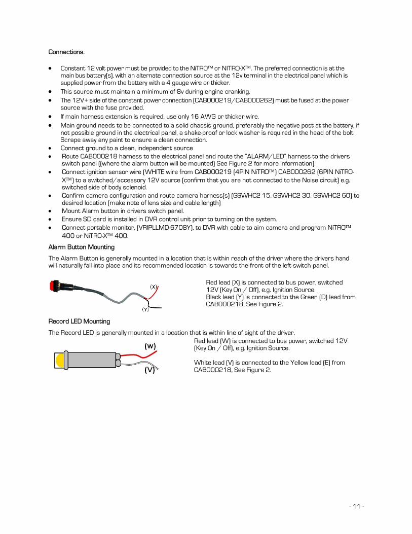
Alarm Button Mounting
The Alarm Button is generally mounted in a location that is within reach of the driver where the drivers hand will naturally fall into place and its recommended location is towards the front of the left switch panel.
Red lead (X) is connected to bus power, switched 12V (Key On / Off), e.g. Ignition Source. Black lead (Y) is connected to the Green (D) lead from CAB000218, See Figure 2.
Record LED Mounting
The Record LED is generally mounted in a location that is within line of sight of the driver.
Red lead (W) is connected to bus power, switched 12V (Key On / Off), e.g. Ignition Source. White lead (V) is connected to the Yellow lead (E) from CAB000218, See Figure 2.

- 12 -
CAB000219 (4 PIN; NiTRO) / CAB000262 (6 PIN; NiTRO-X) POWER CABLE.
CAB00219 (4 PIN) NiTRO DVR Power Cable (30 feet long). See Table 2 for Definitions and Figure 2 for Connections.
CAB00262 (6 PIN) NiTRO-X DVR Power Cable (30 feet long). See Table 2 for Definitions and Figure 2 for Connections.
Figure 2: CAB000218 Connections.
Recommended Location for Alarm Button
The Alarm Button is generally mounted in a location that is within reach of the driver where the drivers hand will naturally fall into place and its recommended location is towards the front of the left switch panel.

- 13 -
The table below indicates the wiring for CAB000218 shown in Figure 2.
POWER CABLE. CAB000219 (4PIN NiTRO) : CAB000262 (6PIN NiTRO-X) A BLACK GROUND B RED POWER IN (Constant 12V) C WHITE IGNITION (Switched 12v) SENSOR CABLE. CAB000218 D GREEN ALARM E YELLOW RECORD LED F BLUE WARNING G ORANGE STOP ARM Table 2: CAB000219 / CAB000262 / CAB000218 Wiring Definitions.
- 14 -
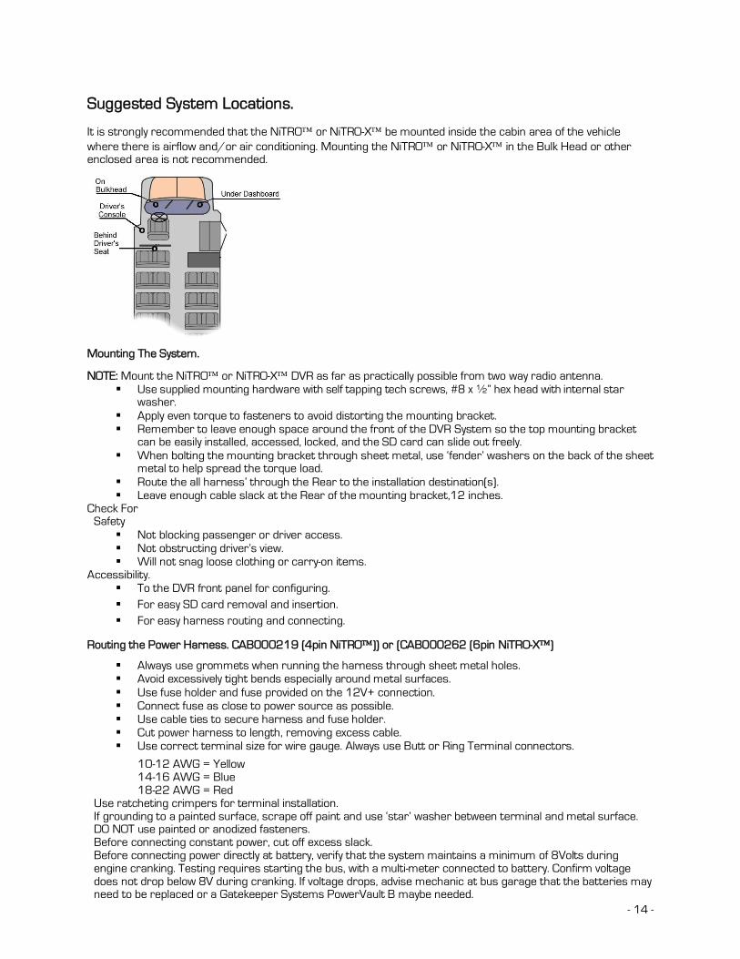
Suggested System Locations.
It is strongly recommended that the NiTRO or NiTRO-X be mounted inside the cabin area of the vehicle where there is airflow and/or air conditioning. Mounting the NiTRO or NiTRO-X in the Bulk Head or other enclosed area is not recommended.
Mounting The System.
NOTE: Mount the NiTRO or NiTRO-X DVR as far as practically possible from two way radio antenna.
Use supplied mounting hardware with self tapping tech screws, #8 x ½” hex head with internal star washer.
Apply even torque to fasteners to avoid distorting the mounting bracket. Remember to leave enough space around the front of the DVR System so the top mounting bracket
can be easily installed, accessed, locked, and the SD card can slide out freely. When bolting the mounting bracket through sheet metal, use ‘fender’ washers on the back of the sheet
metal to help spread the torque load. Route the all harness’ through the Rear to the installation destination(s). Leave enough cable slack at the Rear of the mounting bracket,12 inches.
Check For Safety
Not blocking passenger or driver access. Not obstructing driver’s view. Will not snag loose clothing or carry-on items.
Accessibility. To the DVR front panel for configuring. For easy SD card removal and insertion. For easy harness routing and connecting.
Routing the Power Harness. CAB000219 (4pin NiTRO)) or (CAB000262 (6pin NiTRO-X)
Always use grommets when running the harness through sheet metal holes. Avoid excessively tight bends especially around metal surfaces. Use fuse holder and fuse provided on the 12V+ connection. Connect fuse as close to power source as possible. Use cable ties to secure harness and fuse holder. Cut power harness to length, removing excess cable. Use correct terminal size for wire gauge. Always use Butt or Ring Terminal connectors.
10-12 AWG = Yellow 14-16 AWG = Blue 18-22 AWG = Red
Use ratcheting crimpers for terminal installation. If grounding to a painted surface, scrape off paint and use ‘star’ washer between terminal and metal surface. DO NOT use painted or anodized fasteners. Before connecting constant power, cut off excess slack. Before connecting power directly at battery, verify that the system maintains a minimum of 8Volts during engine cranking. Testing requires starting the bus, with a multi-meter connected to battery. Confirm voltage does not drop below 8V during cranking. If voltage drops, advise mechanic at bus garage that the batteries may need to be replaced or a Gatekeeper Systems PowerVault B maybe needed.

- 15 -
Routing the Sensor Harness CAB000218.
Route the TRIGGERS harness to the electrical panel. Connect Orange lead to stop arm circuit Connect Blue lead to warning lights circuit Always use grommets when running the harness through sheet metal holes. Avoid excessively tight bends especially around metal surfaces.
Connecting Cameras.
Three Camera Cabling Configuration. A CAB000202 : Dual Channel Video-In Connector B CAB000209 : Single Channel Video-In Connector C GSWHC2N-15; GSWHC2N-30 or GSWHC2N-60 : Camera Harness D S-Series Camera :
CABLE P/N DESCRIPTION CAMERA PORT 1 CAM CAB000209 1 CAM ADAPTER 1 / 2 2 CAM CAB000202 2 CAM ADAPTER 1 / 2 3 CAM CAB000202
CAB000209 2 CAM ADAPTER 1 CAM ADAPTER
1 / 2 3 / 4
4 CAM CAB000202 CAB000202
2 CAM ADAPTER 2 CAM ADAPTER
1 / 2 3 / 4
Table 3: Camera Connection Configuration.
Camera Mounting and Connections.
Please refer to the relevant section for your particular model of camera for install instructions. Camera mounting locations are to be determined by the district. Cameras should be mounted to the ceiling whenever possible. Install the foam pad provided with each
camera and use holes as a template. The audio hole on the front of the camera can be used as a aiming guide for the direction the camera needs to be facing.
All camera harnesses must be carefully routed to the NiTRO™ or NiTRO-X unit to avoid pinching or piercing the shielded camera cable.
All cables running through holes in sheet metal (ceiling, bulkhead etc.) must be protected with grommets. Ensure included gasket is in place between dome base plate and mounting surface.

- 16 -
When installing multiple cameras, mark camera harness wires so the school district knows which camera is front and back by looking at the marked Molex output connectors,
S2-Series Camera Installation.
Routing the Camera Harness(es) ) (GSWHC2N-XX).
Route the camera harness(es) with labeled end at NiTRO™ connections. Always use grommets when running the harness through sheet metal holes. Avoid excessively tight bends especially around metal surfaces.. Coil and tie off excess harness in a safe place.
The S2 series camera balls support in-field lens changing. The S1 series Do Not support in-field lens changing. Please contact Gatekeeper Systems on 888-666-4833 for options and pricing for S1 series camera lenses.
DO NOT disassemble the S1 or S250 WDR Camera Ball unless directed to, and under the direction of, a Gatekeeper Systems support technician
Figure 3: S-Series Camera.
A. Rubber Gasket. B. Base Plate. C. Camera Ball. D. Camera Collar. E. Retainer Ring
1. Disassemble the S-Series camera into its five major parts, A, B, C, D, E and carefully place all parts in a clean work area.
2. Position the Base Plate (B), in the mounting location. Ensure that there are no gaps between the Base Plate (B) and the mounting surface. If there are gaps, relocate the camera to a position where there are no gaps.
3. Note the location where the camera harness will come though the bodywork of the vehicle. Drill a 3/8th hole in this location. This 3/8th hole MUST be directly in the center of the Base Plate (B) to allow for the terminal end of the camera harness to correctly connect to the Camera Ball (C). When access behind the camera is not possible, the cable can be routed from the side through one of the cut out notches B1 in the camera base.
4. Center the supplied template guide over the 3/8” hole and mark the location for the 4 screws used to secure the camera base to the vehicle. Alternatively, center the camera base over the 3/8” hole and mark the location of the 4 screws used to secure the camera base to the vehicle. In both cases, ensure that one of the camera cut out notches, B1, is aimed at the viewing target. Drill a suitable pilot hole to accept a #6 screw for each of the supplied screws.
5. Remove the backing on the rubber gasket (A) pad exposing the adhesive. Secure the Rubber Gasket, adhesive side down to the Base Plate (B). The Rubber Gasket is supplied to reduce the possibility of any rattling noise between the camera and vehicle that may be picked up by the microphone. Using the supplied Tek Screws, secure the camera base to the vehicle.
6. Connect the Camera Ball Molex connector to the connector at the end of the camera harness. Hold the Camera Ball firmly against the Base Plate with the Microphone, C1, pointing downwards. Position Camera Collar (D) over Camera Ball (C) with the lens window centered in the arched cut away in the Camera Collar.
7. Hold Camera Collar (D) securely while threading on the Retainer Ring (E) until finger tight. Be careful not to cross-thread the components.
8. To aim the Camera Ball (C), video from the camera can be viewed by connecting a monitor to the back of the DVR “AV-Out” port with a Video Adaptor Cable.
9. Re-position Camera Collar (D) prior to tightening down the Retainer Ring (E) so that it does not interfere with line of sight of the camera and IR LED’s in the Camera Ball (C). Ensure the Camera Ball and Harness pigtail are not pinched or trapped between the Camera Ball (C) or the Base Plate (B), it must be able to move freely.
10. Tighten all accessible set screws on the Retainer Ring (E) and Camera Collar (D). In some installations several of the set screws will not be accessible due to close proximity of the camera to the vehicles bodywork. In this situation tighten down the set screws that are accessible.

- 17 -
S205 Camera Lens Changing.
Please note that this section only relates to the S205 camera range only. DO NOT disassemble the S1 or S250 WDR Camera Ball unless directed to, and under the direction of, a Gatekeeper Systems support technician
1. Uninstall the S205 camera from the bus. 2. The Camera ball should have a Label on the reverse side 3. Remove the two retaining screws. You will now have two
hemispheres joined by a short length of cabling. Be careful not to disconnect or damage this cabling.
4. With the two halves of the camera laid carefully on a clean work area, remove the Camera Screw (A) and retain for re-use.
5. Next Remove the camera lens (B) by un-screwing counter-clockwise.
6. Install the replacement lens.
7. Power up the camera and check the live video. Fine tune the
focus of the camera lens and then tighten the camera screw (B) to permanently secure the camera lens.
8. NOTE: If the video displays “Cutting-Edge” at the corner, it indicates that the installed camera lens is not suitable for this particular camera.
9. Re-Assemble the camera and re-install on the bus.
Part Number CAMILEGSLB2.9 CAMILEGSLB3.6 CAMILEGSLB4.3 CAMILEGSLB6 CAMILEGSLB8 CAMILEGSLB12
Lens Size 2.9mm 3.6mm 4.3mm 6.0mm 8.0mm 12.0mm
Restriction Regarding In-Field Lens Replacements.. Cameras which originally shipped with a 2.9mm or 3.6mm lens can only utilize 2.9mm or 3.6mm lenses. This is due to the size of the internal stand-offs. Cameras which shipped with 4.3mm; 6.0mm; 8.2mm or 12.0mm lens’ can only be replaced by either one of these lens’ 4.3mm; 6.0mm; 8.2mm or 12.0mm. This is due to the size of the internal stand-offs.
Suggested Camera Locations.
Check For: Ceiling mount recommended. Do not obstruct walkways. Avoid contact with abrasive metal to prevent short circuits.
Three Camera Configuration

- 18 -
Wire Routing: Camera harness to be connected through opening in base. Use existing wire paths wherever possible, radio, speakers,
etc. Avoid excessively tight bends especially around metal
surfaces. Always use grommets when routing through sheet metal
holes. Coil and tie off excess harness or tuck up into ceiling.
Four Camera Configuration
Alternate Four Camera Configuration.

- 19 -
Video Alignment Cable: CAB000157
The following information explains the correct use of the Video Alignment Cable CAB000157. With this cable an installer can temporarily view video on a monitor while they are physically close to the camera in order to facilitate the aiming of the camera. The Video Alignment Cable CAB000157 must be removed after the camera aiming is completed.

- 20 -
A: Portable LCD or DVD B: NiTRO or NiTRO-X C: Camera
D: GSWHC2N-XX Camera Harness, 15’; 30’ or 60’ lengths.
E: Yellow RCA Video Output to Video Input on Portable LCD or DVD Player.
F: Red RCA Audio Output to Audio Input on Portable LCD or DVD Player.
G0: 4 Pin Female connector on CAB000157 connects to G1 4 Pin Male connector on Camera Harness (D).
H0 4 Pin Male Connector connects to H1 4 Pin Female Connector on Camera Harness (D) K0 4 Pin Male Connector on CAB000157 Connects to K1 CAB000202 (Dual Channel) or CAB000209 (Single Channel) Camera Adapter Harness. Please Note: On a multi-camera system using CAB000202 K0 should be connected to each additional K1 Camera Adapter Harness, e.g. CH02; CH03 and/or CH04 to ensure complete alignment of all connected cameras. M: Camera Adapter Harness (CAB000202) systems only Connect K0 to align and adjust additional cameras.
Table 4: Video Alignment Cable Connection Descriptions.
An installed, fully functional, powered up NiTRO or NiTRO-X is required when using CAB000157, Video Alignment Cable. When using the Video Alignment Cable CAB000157 there are only four connections to make, one of which, the Audio connection, is optional. If you look at the Video Alignment Cable you will see that there are three cables coming from one end of the Video Alignment Cable and a single cable coming from the other end. 3 Cables. Yellow Video RCA for connection to the LCD or DVD players Video Input connection. This is the connection which will display the image being captured by the camera which is currently being aligned. Red Audio RCA for connection to the LCD or DVD players audio input. This connection is optional. A four pin male connector which connects to CAB000202 or CAB000209 Camera Adapter harness connected to the rear of the NiTRO or NiTRO-X Single Cable. The single cable coming from the other end of the Video Alignment Cable is a 4 pin female connector which connects to the harness of an installed camera. Once these connections are made, alignment of the camera can be completed.

- 21 -
System Features.
NiTRO-X 400 Series Front View.
Figure 4 : Front View Description.
The NiTRO 401 / 404 share a common front interface.
NiTRO 401 / 404 Front View.
Figure 5: Front View Description.
1 Power Indicator 2 Run Indicator 3 Alarm Indicator 4 SD Card Present Indicator 5 System Status Indicator 6 Stop Button. Press and hold until System Status Indicator is out before removing SD Card. IR Communicates with the supplied Remote Control. USB Reserved for future development. RJ45 NET Allows an RJ45 connector to be inserted. Front LED Status Definitions.
POWER LED (1) RUN LED (2) DEFINITION Always On Flashing NiTRO or NiTRO-X is ON and is
either booting up, or, in Record mode.
Flashing Alternatively with RUN Flashing Alternatively with POWER NiTRO or NiTRO-X is in Standby Mode waiting for ignition signal. Ignition line is off
Flashing Together with RUN Flashing Together with POWER Power Off Delay (Record Extend). Ignition is OFF and NiTRO or NiTRO-X is recording. The DVR will power down when Power Off Delay (Record Extend) is reached.
Flashing Off NiTRO or NiTRO-X is OFF, does not respond to ignition signal. Do Not use the Remote Control to turn the NiTRO or NiTRO-X Off
Table 5: NiTRO-X Power and Run LED Definition.
ALARM INDICATOR (3) DEFINITION
On Alarm has been triggered. Note: Alarms are configured in Alarm Menu (Please see manual for detailed information)
Off No Alarm detected.

- 22 -
Table 6: NiTRO-X Alarm LED Definition.
SD CARD PRESENT INDICATOR (4) DEFINITION
Flashing Indicates SD card is present and is being accessed, e.g. writing of video file. Off No SD Card present
Table 7: NiTRO-X SD Card LED Definition.
SYSTEM STATUS INDICATOR (5) DEFINITION On Indicates that the system is active. Do Not Remove the SD card while this
LED is illuminated as doing so will cause damage to the video file(s) on the SD Card. Press the STOP button (6) once and wait until the System Status Indicator LED turns off if the is a need to remove the SD card while the System is active.
Off The NiTRO or NiTRO-X is not in record mode and it is safe to remove the SD Card.
Off with SD Card Present Solid; Power Indicator Solid; Run Indicator Flashing
Unit is initializing after Ignition Signal applied.
Table 8: NiTRO-X System Status LED Definition.
NiTRO-X 400 Rear View.
The image in Figure 6 is viewed from directly behind the NiTRO-X 400 and from left to right.
Figure 6 : Rear View Connections.
NOTE: The Power connector (6 Pin) on the NiTRO-X 400 series is NOT compatible with the NiTRO 400 series. Attempting to utilize the in-correct connector will void the warranty. When installing a NiTRO-X 400 in an existing NiTRO 400 installation a 4 pin to 6pin power adapter cable is available, CAB000268.
NiTRO 401 / 404 Rear View.
The image in Figure 7 is viewed from directly behind the NiTRO 400 and from left to right.
Figure 7: Rear View Connections
NOTE: The Power connector (4 Pin) on the NiTRO 400 series is NOT compatible with the NiTRO-X 400 series. Attempting to utilize the in-correct connector will void the warranty. When installing a NiTRO-X 400 in an existing NiTRO 400 installation a 4 pin to 6pin power adapter cable is available, CAB000268, see Appendix for more information.

- 23 -
Remote Control and Menu System. The NiTRO 400 series and NiTRO-X 400 series use a common remote control and are easily configured and utilized by use of a familiar remote control keys. Currently the Alarm and OSD keys do not function as they are reserved for future use.
Key Definition. 1. Power. Pressing the Power button will disable
the DVR from auto recording when the vehicle is started.
2. Alarm (Currently Not Active) 3. Input Keys 4. Manual Record Key 5. Stop Playback Key 6. Local Playback Key 7. Video Toggle Key 8. Audio Toggle Key 9. Direction Navigational Keys 10. Menu. Press to enter menus; sub-menus and
to make selections from available options. Can also be used as an OK key in some menus
11. OK Key (Use for confirmation) 12. ESC Key (Escape from current menu) 13. Pause Key. 14. Fast Forward. Up to 8X 15. Next. Access’ The Next Video File 16. Previous. Access’ the previous Video File. 17. OSD. (Currently Not Active) 18. Slow. Local Playback can be slowed to ¼
speed.
Figure 8: Remote Control Definition
The NiTRO 400 series and NiTRO-X 400 series have been designed to be user intuitive with options being available in nine separate menus, to access the main menu screen press the Menu key once. To navigate through the nine menu options use the navigation keys, (9), to highlight an option and then press the Menu key again or OK. This will bring up the relevant menu. Some menu options are currently not available and are reserved for future use. Only those options which are active and supported will be covered.
Quick Configuration
Once the bus ignition is triggered the unit should power up and begin recording within 1 minute. The NiTRO and NiTRO-X™ recorders need to be configured as per the specific settings determined by the
district. Use the remote control to navigate through the programming options, aimed at the DVR. Typical configuration requirements are as follows: MOTOR – License ID (program the Bus ID) MOTOR – Speed Check - If using GPS change from Off to “From GPS” SYSTEM – Time Zone (change to reflect your current time zone) SYSTEM – Time Setup (verify the date/time is, correct) RECORD – Quality Settings, under REC MODE navigate down to any channels which do not have cameras attached and change them from AUTO to OFF. Once the unit has been tested, configured and the camera(s) aimed the unit can now be properly shut down by turning the bus ignition off.

- 24 -
Menu System.
Live.
The live menu is divided into six configurable sections.
OSD Determines if camera information; date time, etc will be visible on the screen and also on the recorded video file. Use the menu key to access the drop down menu and then the Up or Down navigation keys to change the value. Once the required option is highlighted, press the OK key.
Options: On / Off Default Value: OFF
Background Sets the background level of opacity for the menus. Use the menu key to access the drop down menu and then the Up or Down navigation keys to change the value. Once the required option is highlighted, press the OK key.
Options: Opaque; Semi-Transparent; Transparent. Default Value: Opaque
Sequence Dwell Sets the time rate for live playback of current video view. Use the menu key to access the drop down menu and then the Up or Down navigation keys to change the value. Once the required option is highlighted, press the OK key.
Options: (All in seconds) 2, 4, 8,16, 32, 52 or Off. Default Value: OFF Video Adjustment Sets the brightness and contrast of the viewed image.
Options: See Figure 9. Use the Up and Down navigation keys to select an option and the Right and Left navigation keys to increase or decrease its value. Once the required option is highlighted, press the OK key.
Default Values: 50% Brightness; Contrast; Hue; Saturation.
The available values for all options are 1% to 100%.
Figure 9 : Default Brightness / Contrast Options.
Camera Title Each video channel can have its own title, e.g. Driver, Rear Seat, etc. First ensure the correct camera is highlighted, the button will have a green background, use the Right and Left navigation keys to select the channel. Once the correct channel is selected, press the Down navigation key. This will change the background Green press the menu button to bring up the Text Input window (Figure 10). There is a limitation of 20 characters which can be entered per title. Please Note: There is a limitation of eight characters being visible on the OSD.
Default Values: Cam 01; Cam 02; Cam 03; Cam 04. Use the Left navigation key to delete the title currently in the text input box. Once cleared you can now add the title which you wish to appear on the screen. Use the input keys on the remote control to make a selection, once a selection is made use the Right navigation key to advance the cursor. Once all characters have been entered use the Down navigation key to highlight OK and press the OK key twice on the remote control, this will take you back to the OSD menu. Figure 10 : Text Input Box.
PTZ Parameter There are five options within the PTZ Parameter. This option is currently reserved for future development.

- 25 -
Record.
The Record menu is divided into nine user configurable sections.
Record Settings Record settings can be set for individual cameras. The NiTRO 400 series and NiTRO-X 400 series are capable of recording at D1 resolution. Use the Right and Left navigation keys to highlight an option and the Menu key to cycle through the available options for that item. As values are changed, the information window at the bottom of the screen will update with an estimate of record hours based on the size of card currently installed (Figure 12).
Figure 11 : Default Record Settings.
Size Directly related to the Quality setting and cannot be changed manually. Quality Sets the amount of compression. Normal will allow for longer record times, but poorer quality
video. High will give a higher quality video capture but shorter record time.
Options Normal, Basic, Good, High.
Default Value: HIGH Default Value: Channel 1 / 2 HIGH; Channel 3/ 4 Normal.
Framerate Sets the FPS, frames per second, in relation to the quality selected. Options 30, 15, 10, 7, 6, 5, 4, 2, 1.
Default Value: 10 REC Mode Rec Mode sets the state of the recorder upon power up. It is recommended that this be set to
AUTO for all required channels. Options Auto; Manual and Off.
Default Value: Auto NET This option is currently reserved. Options On or Off.
Default Value: OFF Audio Determines if the selected video channel will also record audio. Each audio channel is recorded
separately and synchronized with the corresponding Video channel.
Options On or Off.
Default Value: ON
Figure 12 : Estimated Record Time.
File Length Determines the length of the recorded file. Options (All in minutes) 5,10,15, 20, 30, 45, 60
Default Value: 5 Minutes File Type AVI. This option is not user configurable. Ask When Stop
Presents the user with an option to Stop recording when the Stop Button (Item 5, Figure 8) is pressed on the Remote Control.
Options Yes or No
Default Value: Yes
- 26 -
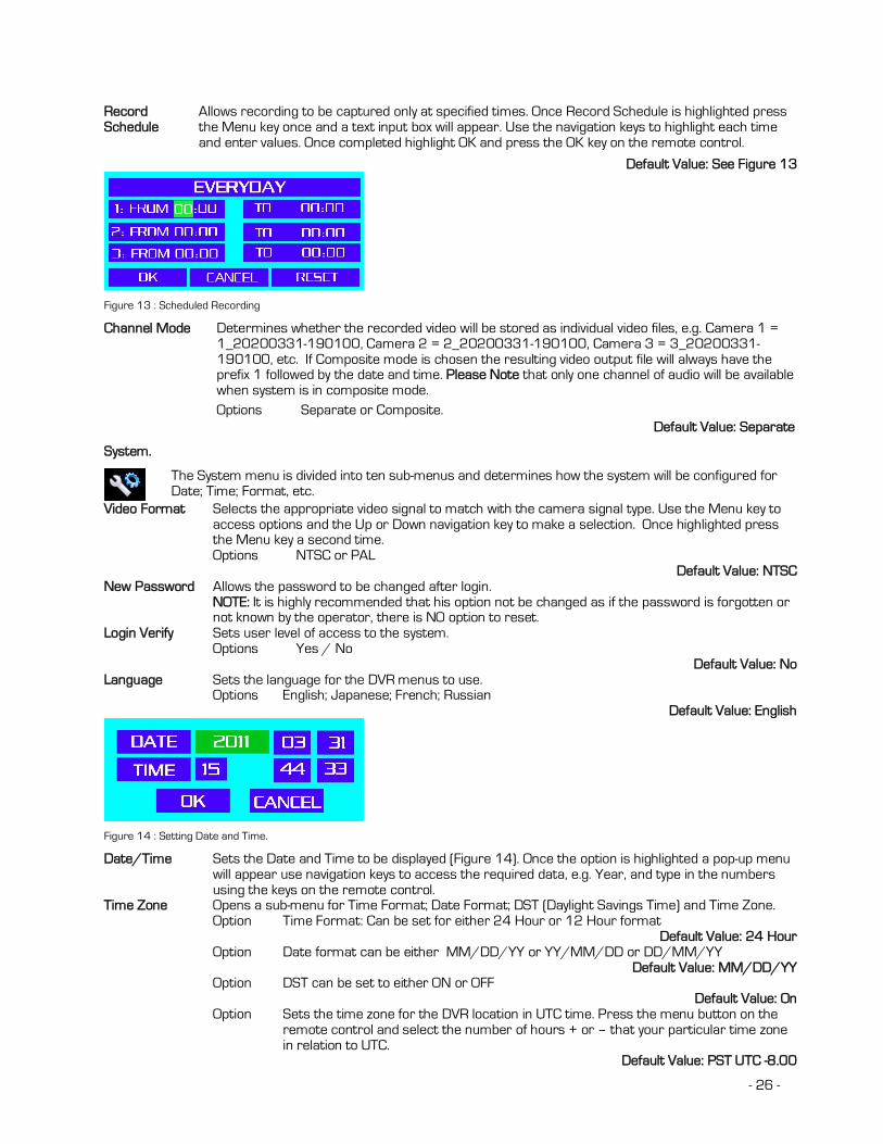
Record Schedule
Allows recording to be captured only at specified times. Once Record Schedule is highlighted press the Menu key once and a text input box will appear. Use the navigation keys to highlight each time and enter values. Once completed highlight OK and press the OK key on the remote control.
Default Value: See Figure 13
Figure 13 : Scheduled Recording
Channel Mode Determines whether the recorded video will be stored as individual video files, e.g. Camera 1 = 1_20200331-190100, Camera 2 = 2_20200331-190100, Camera 3 = 3_20200331-190100, etc. If Composite mode is chosen the resulting video output file will always have the prefix 1 followed by the date and time. Please Note that only one channel of audio will be available when system is in composite mode.
Options Separate or Composite. Default Value: Separate
System.
The System menu is divided into ten sub-menus and determines how the system will be configured for Date; Time; Format, etc.
Video Format Selects the appropriate video signal to match with the camera signal type. Use the Menu key to access options and the Up or Down navigation key to make a selection. Once highlighted press the Menu key a second time.
Options NTSC or PAL Default Value: NTSC New Password Allows the password to be changed after login.
NOTE: It is highly recommended that his option not be changed as if the password is forgotten or not known by the operator, there is NO option to reset.
Login Verify Sets user level of access to the system. Options Yes / No Default Value: No Language Sets the language for the DVR menus to use. Options English; Japanese; French; Russian Default Value: English
Figure 14 : Setting Date and Time.
Date/Time Sets the Date and Time to be displayed (Figure 14). Once the option is highlighted a pop-up menu will appear use navigation keys to access the required data, e.g. Year, and type in the numbers using the keys on the remote control.
Time Zone Opens a sub-menu for Time Format; Date Format; DST (Daylight Savings Time) and Time Zone. Option Time Format: Can be set for either 24 Hour or 12 Hour format
Default Value: 24 Hour Option Date format can be either MM/DD/YY or YY/MM/DD or DD/MM/YY
Default Value: MM/DD/YY Option DST can be set to either ON or OFF
Default Value: On Option Sets the time zone for the DVR location in UTC time. Press the menu button on the
remote control and select the number of hours + or – that your particular time zone in relation to UTC.
Default Value: PST UTC -8.00

- 27 -
System Info Allows the firmware of the NiTRO 400 series and NiTRO-X 400 series to be updated. The firmware is specific to its model, firmware for a NiTRO-X applied to a NiTRO will cause the unit to become un-usable and void the warranty and vise-versa.
Options Update the Application. (This should only be done when directed by Gatekeeper Systems support technicians.)
Config Setup Allows the user to Save, Reset, Export or Import system configurations. Option User Config Save. Saves the current User defined configuration. Option User Config Reset Restores all settings to previous user settings. If YES is
chosen from the pop-up window an application restart is required.
Option Factory Reset Resets the DVR to factory defaults. If YES is chosen from the pop-up window an application restart is required.
Option Config Export Exports the current configuration to the currently installed SD Card.
Option Config Import Imports a previously saved Config file stored on the SD card. If YES is chosen from the pop-up window an application restart is required.
App Restart Restarts the on screen menu system. Once application restarts, the display will show the video feeds and the recording state. Once App Restart is highlighted, press the Menu key once and a confirmation dialog window will appear.
O/S Reboot Restarts NiTRO 400 series or NiTRO-X 400 series digital video recorder. This process will take approximately one minute and maybe required after certain system configurations have been changed. Once O/S Reboot is highlighted, press the Menu key once and a confirmation dialog window will appear.
Network.
There are seven user definable options within the Network menu. Please Note that this feature is currently reserved for future development.
Port Allows the user to specify which port will be used for access to the N400 series. To access press the Menu key on the remote control. A Port dialog window will appear, use the keys on the remote control to enter the required port number. Once completed highlight the OK button and then press OK on the remote control.
Network Type Determines whether the NiTRO 400 series or NiTRO-X 400 series will act as a DHCP server for connection to a notebook, etc., or, be connected via a LAN.
Options DHCP / LAN Default Value: DHCP
IP Address If Network Type is set to LAN, allows the user to manually enter the relevant information, see Figure 15. To access highlight the IP Address option and press the Menu key on the remote control. Use the keys on the remote control to manually enter the required information.
Figure 15 : IP Address Configuration.
Sub Net Sets the IP Address of the Sub Net, see Figure 15. Gateway Sets the IP Address of the Gateway, see Figure 15. DNS Server Sets the IP Address of the DNS Server, see Figure 15.

- 28 -
Storage.
There are six user options within the Storage menu.
Overwrite Determines if the NiTRO 400 series or NiTRO-X 400 series will stop recording once the disk is full to capacity. If Overwrite is set to On, the oldest file will be overwritten first.
Options On / Off
Default Value: On Format Formats the selected disk. Highlight Format Selected Disk, (this refers to Storage Device menu
item), and press the Menu key, this will open a confirmation window. It is highly recommended that when a disk is formatted the system is restarted. This will ensure that recording will automatically begin and not depend upon a User manually pressing the record button on the remote control. NOTE: HC SD cards can be used in NiTRO-X 400 series or NiTRO 400 series systems. A NiTRO 400 can only utilize HC SD cards. Failure to follow these guidelines may result in voiding the warranty.
Options Yes / No
Default Value: Format Selected Disk Storage Device On a SD card system only, there will be one Disk available in the drop down menu.
Total Capacity Displays the total capacity of the currently installed SD card. This total is in decimal and so will not reflect the Bytes capacity. The Total Capacity will always show less than that indicated on the SD card
Free Capacity Shows the amount of free disk space, (in decimal), of the currently installed SD card.
Search By Time Allows a video clip to be selected based on Time frame. The time frame will be based upon the File Length configuration as set under the Record menu.
When the Search By Time option is selected, a single line option will appear, press the Menu button on the remote control. To select a channel use the Right arrow button on the remote until the desired video channel is selected. From here use the Down arrow on the remote to select a file based upon its time stamp you wish to review and press the OK key on the remote control. A second window will now appear with information which directly relates to the Date and Time frame of the file which you have just chosen to playback. At the bottom of this window are two options; Play or Save As. Choose play if you wish to view the file locally. If there are multiple pages available use key 15 or 16 (see Figure 8) on the remote control.
Alarm.
In Alarm setup, there are two user configurable options. PLEASE NOTE: It is highly recommended that the default value of OFF is not changed for Alarm Action. If the Alarm action, (Record), is changed from its default of OFF the resulting video when played back through MaxVIEW will be out of synch with the other video files. For Example: If the Post event Record is set to 30 seconds and the Event itself lasts 20 seconds, the video file will be out of synch in MaxVIEW with the timeline of the other channel(s) video by 50 seconds.
Post Event Record
Sets the amount of time, in seconds, which will be recorded when an alarm is activated. It is recommended to use zero seconds
Options 0, 10, 20, 30, 45, 60, 180. Default Value: 15 Seconds Alarm Action Determines the action which will happen when an alarm is triggered. All three alarms can be set
to individual actions. Record is a toggle controlled by use of the Menu button on the remote control, e.g. CH01; CH01+CH02; CH01+CH02+CH04.

- 29 -
Figure 16: Alarm Action Defaults.
The column TIP contains the information which appears both on the OSD and within MaxVIEW. To change the title of any or all three items highlight the required TIP and then press the menu button on the remote control this will bring up a text dialog box, Enter the descriptions as required and Press OK when completed.
PLEASE NOTE: The descriptions within TIP can be changed but be aware that the ICON which is displayed within MaxVIEW that relates to the TIP action will remain constant. The ICON in MaxVIEW cannot be re-assigned. Motion Zone A 4 X 4 grid that can be configured to be triggered when the subject enters the pre-defined
area. Currently reserved for future development. Motion Action Determines if a channel will record or not when triggered by the defined area in Motion Zone.
Currently reserved for future development. Motion Sensitivity
Determines the level at which Motion will trigger the settings within Motion Action. Currently reserved for future development.
Video Lost Allows an audible alert to be set and sounded when video is lost from single or multiple channels Default Value: Off
Motor.
There are six options which are user configurable.
Vehicle ID Up to twenty characters can be entered for Vehicle ID. To access press the Menu key on the remote control. A text input dialog window will appear, use the keys on the remote control to enter the required text and once completed highlight the OK button and then press OK on the remote control. The Vehicle ID will appear on the OSD if OSD is set to ON. Note: Vehicle ID value also appears in the video file name. It is highly recommended this field be set uniquely for each vehicle.
Default Value: None Line Up to twenty characters can be entered for Line. To access press the Menu key on the remote
control. A text input dialog window will appear, use the keys on the remote control to enter the required text and once completed highlight the OK button and then press OK on the remote control. The text entered for Line will appear on the OSD if OSD is set to ON. Please Note: On OSD, Line will be truncated to six characters only
Default Value: None Overspeed Sets the speed limit when an alarm will be triggered. Up to twenty digits can be entered for Overspeed. To access press the Menu key on the remote
control. A Digital Input dialog window will appear, see figure 17, use the keys on the remote control to enter the required numbers and once completed highlight the OK button and then press OK on the remote control.
Default Value: 100 Mile/Hr
Figure 17 : Digital Input Dialog Box.
Speed Check Verifies the speed of the vehicle. Options From Sensor / From GPS / Off Default Value: Off

- 30 -
Pulses Used to manually input how many pulses there are in one distance unit, e.g. 25/mile Up to twenty digits can be entered for Pulses. To access press the Menu key on the remote control.
A Digital Input dialog window will appear, see figure 17, use the keys on the remote control to enter the required numbers and once completed highlight the OK button and then press OK on the remote control. Currently not supported.
Default Value: 11152/Mile Pulses Unit Sets the default unit of measure for Pulses. Options km / mile Default Value: Mile
GPS / GPRS.
Items in the GPS/GPRS menu screen are device specific.
GPS Device Displays the type of GPS device currently connected to the NiTRO 400 or NiTRO-X 400 series digital video recorder. This item is not user configurable.
GPS Burnin Determines if the GPS data will appear on the OSD and in the recorder video files. Options Off / On / Demo
Default Value: On GPS Time
Sync Global Positioning Systems (GPS) are used to provide a precise time reference for the embedded clock of the NiTRO 400 series or NiTRO-X 400 series ensuring time synchronization even across great distances.
Default Value: On
Power.
There are four user configurable options in the Power menu.
Power On Sets a pre-determined time for the NiTRO 400 series or NiTRO-X 400 series to Power Up. To access press the Menu key on the remote control. A Time Input dialog window will appear, see Figure 18, use the keys on the remote control to enter the required Hour / Minutes. Once completed highlight the OK button and press OK on the remote control.
Default Value: 00:00 Power Off Sets a pre-determined time for the NiTRO 400 series or NiTRO-X 400 series to Power Off. To
access press the Menu key on the remote control. A Time Input dialog window will appear, see figure 18, use the keys on the remote control to enter the required Hour / Minutes. Once completed highlight the OK button and press OK on the remote control.
Default Value: 00:00
Figure 18 : Time Input Dialog Box.
Power Off Delay
Sets a pre-determined time, in seconds, for how long the NiTRO 400 or NiTRO-X 400 series will continue to record once Ignition is switched off. To access press the Menu key on the remote control. A Digital Input dialog window will appear, see figure 17, use the keys on the remote control to enter the required seconds and once completed highlight the OK button and then press OK on the remote control.
Default Value: 300 Seconds Ignition Signal
Determines when the NiTRO 400 series or NiTRO-X 400 series will power up. Please Note: This option should always be set to HIGH as if it is set to LOW when the ignition on the vehicle is turned off the DVR will power up.
Options Low Level / High Level. Default Value: High Level

- 31 -
MaxVIEW™ 400 Video Management System.
PC Requirements.
For optimal performance MaxVIEW 400 software requires the following minimum requirements to operate on a computer: COMPONENT MINIMUM REQUIREMENTS Operating system MS Windows XP\Vista \ Windows 7. Processor Intel\AMD, Dual Core 2.2 GHz processor or better. RAM 4GB or higher Free hard disk space 250GB (recommended) Monitor SVGA 1280 x 768 x 32 bit true color
NOTE: A horizontal resolution of 1440 is required for use of GPS mapping. Video Adaptor 3D accelerated graphics processor with 32 MB dedicated video RAM Connection USB 1.1, USB 2.0
100 Mbps Ethernet Network Card TCP/IP Protocol
Description.
MaxVIEW 400 is designed to be used with the NiTRO 400 or NiTRO-X 400 series of digital Video Recorders and is available as a free download from www.gatekeeper-systems.com or a printed version can be purchased as part of the Basic Kit (P/N: GSX-NTR40X-DPBK-Basic Kit). It is recommended that MaxVIEW be run utilizing Calendar View, as this will reduce the amount of time required to load the video ready for playback. It is highly recommended that all work is saved and currently open programs are closed prior to the installation of MaxVIEW 400. Please note that due to user account settings on Vista and Windows 7, MaxVIEW 400 may not automatically install on these systems when the setup program is run. The example installation in the document will be based on a Windows XP Pro system. The install package will be contained within a ZIP file.
Installation.
To begin installation, unzip the setup files from the ZIP package downloaded previously, (Please make a note of where the zipped files are being extracted to). Navigate to the folder where you have unzipped the files to. Double click on the SETUP.EXE file. Software that needs to be installed on your PC will automatically be checked off, press Next to proceed. Once all is correct, click Next.
Figure 19 : Software Check.
The next window will ask for the destination of the files. It is recommended that the default location, (C:\Program Files\Gatekeeper Systems\MaxVIEW 400), is accepted, Click Next. The next screen will give information on current settings, once reviewed and confirmed, press the Next button to Start Installation.
Figure 20 : Begin Installation.

- 32 -
A progress window will appear displaying information in regards to the setup. Installation Complete:
Once installation is complete you will see a window, Figure 21, stating that MaxVIEW 400 has been successfully installed. Press Finish to complete installation. You may be required to restart your computer.
Figure 21 : Installation Complete.
Once installation is complete you will see the MaxVIEW 400 icon on your desktop. Use this to access the video files on your SD Card or in a dedicated directory.
Retrieving Captured Data.
SD Card Extraction.
When there is a need to review captured video, essential steps need to be performed to ensure that the captured video files are not corrupted, and thereby, made unreadable.
1. Turn Ignition off. 2. Wait until Record Extend has completed, (the only two LED’s still active should be 1: Power Indicator; 2:
Run Indicator), or, press the Stop button on the front of the NiTRO or NiTRO-X recorder. 3. Carefully push the SD card into the NiTRO or NiTRO-X 400 series DVR and listen for a click, this is the
release mechanism. 4. Once the card is released, slowly pullout the SD card ensuring that it is extracted without introducing an
angle to the extraction as this could cause the card to flex.
Inserting The Card Into A Reader.
It is essential that the SD Card is inserted into the reader in the correct orientation or permanent damage may occur to the SD card, the Card reader, or both.
1. Select the slot on the reader. Please check the documentation which came with your SD Card reader as to where the SD Card slot can be found.
2. If your personal computer has an integral reader, select the appropriate slot on that system. 3. Carefully push the card into the slot, check the orientation (Figure 22). The edge which has this profile is
the edge which must be inserted into the reader. 4. Ensure that the SD Card is fully inserted.
SD Card Reader Slot
SD Card Edge View
Figure 22 : SD Card Orientation.
Opening Captured Video Files.
Once the SD Card has been correctly inserted into the reader accessing the files should be done using MaxVIEW400.

- 33 -
MaxVIEW 400 Operation.
Opening a File.
When viewing files directly from an SD Card reader when the card reader is inserted into the host computer a standard Windows dialog window will appear, select Open To View Files and click OK. To view captured and saved video files within MaxVIEW 400 open all of the files on the SD Card double-click on my.gsx, Figure 23. This will produce a list of available files which can be viewed either by Calendar View Figure 33, or by Video Clips Figure 35. Using Calendar view a specific date and time can be zoned in on and a reported incident quickly appraised.
Figure 23 : Open File.
Open Recent Files.
MaxVIEW 400 has a feature which “remembers” recently opened and viewed files. This makes the viewing of frequently accessed files an easier task to accomplish. MaxVIEW 400 will recall up to nine most recently opened files.
From the File menu choose Recent Files. A Pop-Out side window will appear, move the cursor over the files and they will highlight individually, Figure 24. Once the required video file has been located, single left click and this will open the file in MaxVIEW for review.
Figure 24 : Open Recent File.
Audio
When video has been captured using a NiTRO-X 400 or NiTRO 400 series and all four channels have been set to record audio, please note that audio will only be heard from the camera currently in the Playback Window (Item 6 in Figure 25). Once a different view has been selected from the thumb-nails the audio recorded from that camera will be heard.

- 34 -
MaxVIEW 400 Components.
1. Standard Windows Menu bar. 2. Calendar feature. Dates in bold are
quick view enabled. The date high-lighted denotes the file currently being viewed.
3. Clip List. Video available from the currently displayed Date.
4. Video Control Panel. Controls Playback speed; forward/reverse and Speed. Volume can be muted or un-muted.
5. Time Graph and Sensor display. Shows the currently active sensors. Also used for marking and saving of video and still image clips.
6. Playback Window. Displays the currently chosen camera as the primary view.
7. Thumbnail Images. Display additional camera views available. To view as the focus click on a thumbnail and it will swap positions with the camera view currently in the Playback Window (6).
8. Scrubber Bar. Allows Fast-Forward/Reverse to a specific time. 9. Subtitle Information. Displays information which has been configured on the NiTRO 400 or NiTRO-X
400
Figure 25 : MaxVIEW Window Definitions.
Displaying Sensors.
MAXVIEW 400 can display up-to 3 sensors, ALM (Alarm); STP (Stop); and WRN (Warning). These sensors can be turned On or Off as display items within MAXVIEW. To select which sensors to have display in the Time Graph and Sensor display (#5 in Figure 25) click on the Edit menu in MaxVIEW and select Options. Select which of these you want to display in the Time Graph and Sensor display and click Apply and then OK. Please Note: Currently the three available options ALM, STP and WRN are the only active sensors. BRK; 1EX; 2EX; 3EX and IGN are reserved for future development.
Figure 26: Displaying Sensors.
GPS.
Please note: Only NiTRO 400 or NiTRO-X 400 series systems which have a GPS module attached can access GPS information. To fully utilize the GPS feature within MaxVIEW an active internet connection is required. From the main window of MaxVIEW click on View and then select GPS Mapping and then choose Show Map. There will be a slight time delay as MaxVIEW synchronizes the GPS data. Once synchronization has completed MAP view will initially be displayed and this can be changed by selecting one of the other two options at the top right of the screen; Satellite or Hybrid, Figure 27.

- 35 -
Figure 27: GPS Map; Satellite; Hybrid Features.
GPS Mapping Options.
With a new install of MaxVIEW™ the default is not to display the GPS Mapping Options, these have to be set. In MaxVIEW™. Select the View menu, next choose GPS Mapping and then select Show Map (Figure 28). This will bring up the window to the right of the main MaxVIEW™ window. This GPS data mapping window, (Figure 27) is moveable and resizable.
Figure 28: GPS Show Map.
To view where the vehicle is in relation to the GPS Mapping select the View menu, go to GPS Mapping, select Show Vehicle Locator (Figure 29). This will display the inverted Green triangle. There may be a need to move and/or resize the GPS Map window to view the Vehicle Locator.
Figure 29: GPS Show Vehicle Locator.
If you do not see the vehicle marker please check these potential reasons prior to calling technical support. (1) There is no GPS data at the time when the video is paused; (2) There is GPS data at that time but the signal is too weak to place the marker on the map; (3) The marker is on the map but not on the current visible area of the map; (4) The map window is not open.
Using The GPS Zoom Feature.
When viewing the Vehicle Locator if you wish to zoom-in there are two ways with which to achieve this:
1) Use the Slider control to the left of the GPS Mapping Window. 2) Place the cursor towards the Vehicle Locator and when it
changes to the GRAB hand, double- click with the left mouse button. This will auto-zoom in on the image. Continue to do this until the required level of zoom is achieved.
Continued usage will determine which method you personally prefer.
Figure 30: GPS Zoom Feature.
MaxVIEW Features.
Using The Scrubber.
When searching for a specific incident reported during the run of the vehicle a useful tool to become familiar with is the Scrubber. The Scrubber is the vertical bar located in MaxVIEW™ on the grey bar below the actual video display area, A in Figure 31.
With playback paused, Figure 31, the Vehicle Locator becomes static within MAP view. Note the position of the Scrubber Bar in relation to the Time (B) and where the Vehicle Locator (C) is positioned.
Figure 31: Using the Scrubber Bar.

- 36 -
If the Scrubber bar is now moved either Backward or Forward, depending upon the timestamp required, the Vehicle Locator will also change its relative position in the Map window. Note the new position of the Scrubber and the Timestamp (D) and the updated position of the Vehicle Locator (E).
Figure 32: Vehicle Locator Updated Position
Using The Calendar Feature.
It is recommended that MaxVIEW be run utilizing Calendar View as this will reduce the amount of time required to load the video ready for playback.
To view video files by date within MaxVIEW 400 click on the View menu and from there select the Clip Filter option and finally By Date, This will bring up Calendar view.
Figure 33 : Calendar Feature.
Calendar Definitions.
The Calendar feature can be broken down into Four main parts: 1. Displays the Month of the selected video files.
2. The Dates in Bold, (circled), are dates for which there is available video for Playback.
3. The Date highlighted is the date of the current video being reviewed.
4. Highlighted line is the start time for the current video being reviewed and also displays the ID of the vehicle.
Figure 34 : Calendar Definitions.
To navigate through the list of available clips in Calendar view use the Next (5) Button or the Previous (3) Button as shown in Figure 36. As each clip is accessed using either of these buttons the main Playback Window and the Thumbnails will change to reflect the changing video being accessed.
View Video by Clips.
To view all video files within MaxVIEW 400 click on the View menu and from there select the Clip Filter option and finally All Clips, This will bring up the Clips view.
There is only one view for viewing all clips. Navigate to the location where all the video files are located and select all. The files will now be listed (1), By Clip Date, in the status window below the file menu bar in MaxVIEW 400.
Figure 35 : Clips Definition.
To navigate the list of available clips in Video Clips view use the Next (5) Button or the Previous (3) Button, Figure 35. Accessing clips using either of these buttons the main Playback Window and the Thumbnails will change reflecting the changing video being accessed.

- 37 -
Deinterlacing.
MaxVIEW 400 supports three modes of deinterlacing; Off (Default); Forced and Automatic.
OFF: Default value and should only be altered if directed by a Gatekeeper Systems technical support representative.
Forced: Forces deinterlation irrespective of internal flag setting.
Automatic: Automatically checks to determine the current state of the internal deinterlacing flags.
Playback Controls and File Management.
The Playback Controls enable video files to be played sequentially; forward at normal speed; backward at normal speed, and, forward and backward at speed settings between 1/8th to 32X. The volume can also be muted and un-muted using this control. NOTE: Due to complexities of H.264 compression playback in reverse will have variable video quality.
1. Play. Plays current selection and becomes the Pause button during active playback. 2. Direction. Acts as a toggle for Forward playback and Reverse. 3. Previous. Selects the Previous video file in the Clip List if multiple files have been opened. 4. Speed Slider. Determines the playback speed of the selected video file.
Ranges from 1/8th normal speed to 32X normal speed. 5. Next. Selects the Next video file in the Clip List if multiple files have been
opened.
6. Volume. This is a toggle control and sets the audio to be audible or muted. 7. Volume Level. Adjusts loudness of audio.
Figure 36 : Playback Controls
Saving a Clip.
There are two ways in which you can Save a video clip, one using the right-mouse button and the other method uses the File Menu. Both methods use the same steps to first mark the video you wish to take a clip of. 1. Pause the video at the point of the video where you want the clip to start from. 2. Single left-click on the Video Clip Graph where the yellow cursor bar is located. 3. Drag the mouse to the right, the graph will be highlighted in
green, (A). The Subtitle information panel will reflect information regarding the clip being taken. Release mouse at end point.
4. Right-click on the created green section in the video clip graph and choose Save Clip, or, choose File, Save Video Clip.
Figure 37 : Marking a Clip.
Once you have selected the clip which you require, a new pop-up window will appear. This is the Save As dialog box, Figure 38, enter all the relevant information and make your choices, and then choose Save.

- 38 -
1. Ensure that you know where the file is being saved to, this will help with retrieval later.
2. The object name should be; The Date and Time followed by the bus ID. We recommend that you accept the default.
3. There is an option to select All; Current camera view, or, a combination of Selected cameras.
4. In this example we are going to choose Current, which shows in the greyed out box as camera 2.
5. Here you see the estimated size of the resulting file for the clip created.
Once options 1 and 3 are set, click on Save.
Figure 38 : Saving A Video Clip
Drag and Drop a Video File.
You can drag and drop an entire video file into another location, ie: Desktop. To do this Left-click on video file in the Video File and Clip list. Next Drag to your desktop and finally Release the Left-mouse button.
Saving a Still Image.
You can extract a still image (jpeg) using the blue Video Clip Graph, this process is very similar to saving a video clip. 1. Pause Video at the point where you want to extract an image. 2. Right-click on the Video Clip Graph and choose “Save still image”. 3. Or choose File, Save Still image. 4. This will bring up a standard Save As… Windows dialog box. 5. By default, the file name will be the Camera + Date + Time + License ID (see Table 8 for definition), e.g.
1_20110426-112006_1003n0_SDHC.jpg. Camera Date Time Internal Log File License ID 1 20110426 112006 1003n0 SDHC
Table 9: Still Image Filename Definition
Emailing a Still Image.
On occasion you may have a need to e-mail a captured image, when this is the case find the location of the image which you wish to capture, and click on the Pause button (A) in MaxVIEW 400. This will create the image which you are now going to send. Once you have this image, go to the File menu top left hand corner of MaxVIEW 400 and then highlight Send via Email and then click on Still Image.
Figure 39 : Emailing a Still Image.
Once you have clicked on Still Image a window should appear, (this may take a few seconds depending upon your system and its settings), enter the e-mail address of the person who you wish to receive the e-mail (B) and then choose send.

- 39 -
The process to send a captured video clip is very similar, mark your clip in MaxVIEW 400 first and then choose Video Clip. This process can take several minutes depending upon your system and its settings, etc. **Please note your email client, e.g. Outlook, Outlook Express, Thunderbird, etc. may have a different layout to that as shown.

- 40 -
APPENDIX
Power Connections (CAB000211 connects to CAB000205/6)
Please Note: This section only relates to units shipped and containing CAB000205/206; CAB000211 and CAB000145 Sensor/Trigger cable, prior to December 2011.
NiTRO 400 With Cables.
Figure 40: 3 Camera Connection.
ITEM # DESCRIPTION PART NUMBER
1 POWER SENSOR ADAPTER CABLE CAB000205 2 VIDEO OUT CABLE GSX-N40X/VIDEO/AUDIO OUT ASSY
3 POWER SENSOR ADAPTER CABLE W/GPS CAB000206 4 GPS MODULE W/15’ CABLE DVRGPSN40X_ASSY 5 EXTERNAL TRIGGER CABLE CAB000145 6 POWER CABLE AND FUSE CAB000211 7 CAMERA CABLE 15’, 30’ OR 60’ CAB000142 or
GSWHC2N-XX
8 VIDEO ADAPTER CABLE 1 CHANNEL CAB000209 9 VIDEO ADAPTER CABLE 2 CHANNEL CAB000202
Power Sensor Connection; NiTRO Pre-December 2011.
Original Power connection. Prior to December 2011 the following Power / Sensor Cables were shipped with the NiTRO. NOTE: NiTRO-X has only shipped with Power / Sensor connection as covered in the Installation section of this manual.

- 41 -
CAB000271 Connections.

- 42 -
CAB000145: 7 Wire; 4 Wire and 3 Wire Terminations.
Figure 41: CAB000145 Terminations.
A Alarm & LED Bundle (4 Wires; White & Red. Not Used)
G White (7 Wire Bundle) to Warning (Signal +12V to Activate).
B Speed Bundle (NOT USED) (3 Wires) V White Wire on Record LED Connect to Green Wire (D) on 4 Wire Bundle.
C Trigger Bundle (7 Wires; Blue, Red, Orange, Brown, Green. Not Used)
W Red Wire on Record LED to Bus Switched 12V (Key On/Off) Power, e.g. Ignition Source.
D Green (4 Wire Bundle) connect to White (V) on Record LED.
X Red Wire on Alarm Button to Bus Switched 12V (Key On/Off) Power, e.g. Ignition Source.
E Black (4 Wire Bundle) connect to Black (Y) Alarm Button.
Y Black Wire on Alarm Button to Black Wire (E) on 4 wire bundle.
F Yellow (7 Wire Bundle) to Stop Arm (Signal +12V to activate).
Table 10: CAB000145 Termination Definitions.
OTHER CONFIGURATIONS.
CAMERA ADAPTER CABLES.
1 CAMERA: CAB000209 2 CAMERAS: CAB000202 3 CAMERAS: CAB000202 AND CAB000209 4 CAMERAS: 2 X CAB000202
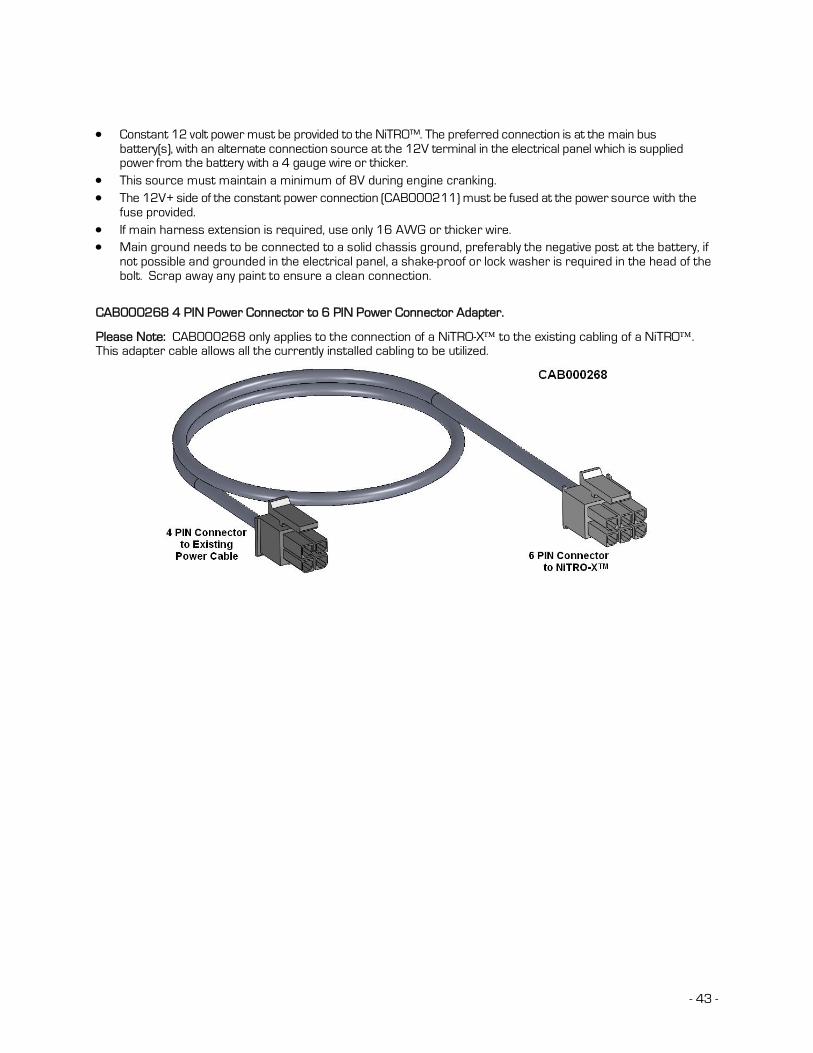
- 43 -
Constant 12 volt power must be provided to the NiTRO™. The preferred connection is at the main bus battery(s), with an alternate connection source at the 12V terminal in the electrical panel which is supplied power from the battery with a 4 gauge wire or thicker.
This source must maintain a minimum of 8V during engine cranking. The 12V+ side of the constant power connection (CAB000211) must be fused at the power source with the
fuse provided. If main harness extension is required, use only 16 AWG or thicker wire. Main ground needs to be connected to a solid chassis ground, preferably the negative post at the battery, if
not possible and grounded in the electrical panel, a shake-proof or lock washer is required in the head of the bolt. Scrap away any paint to ensure a clean connection.
CAB000268 4 PIN Power Connector to 6 PIN Power Connector Adapter.
Please Note: CAB000268 only applies to the connection of a NiTRO-X to the existing cabling of a NiTRO. This adapter cable allows all the currently installed cabling to be utilized.

- 44 -
Retrofitting NiTRO 900 and 1000 to NiTRO 400 and NiTRO-X 400
When utilizing the existing power / sensor cabling of either a NiTRO 900 or NiTRO 1000 an adapter cable, CAB000205 or CAB000206 (GPS) is required. Please Note that if the new system to be installed is a NiTRO-X 400 system an additional power adapter cable, CAB000268, will be required. CAB000268 takes the 4 pin connector (E) and changes it to the required 6 pin power-in connector.
A: 14 Pin Female Connector. Connects to installed sensor cable. B: 2 Pin Power Connector. Connects to installed main power cable. C: 4 Pin Male Connector. Connects to installed GPS module (Only applicable on CAB000206). D: 14 Pin Male Connector. Connects to the Sensor input on the rear of the NiTRO or NiTRO-X DVR. E: 4 Pin Male Connector. Connects to the Power input of the NiTRO DVR.
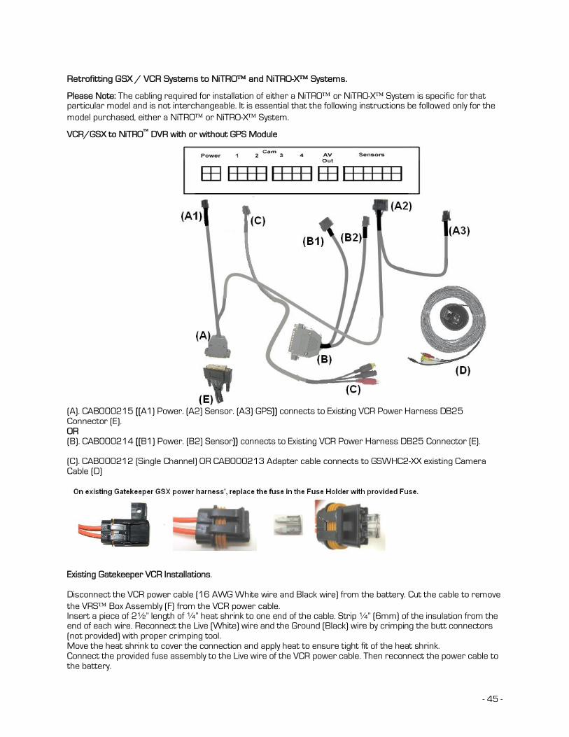
- 45 -
Retrofitting GSX / VCR Systems to NiTRO and NiTRO-X Systems.
Please Note: The cabling required for installation of either a NiTRO or NiTRO-X System is specific for that particular model and is not interchangeable. It is essential that the following instructions be followed only for the model purchased, either a NiTRO or NiTRO-X System.
VCR/GSX to NiTRO DVR with or without GPS Module
(A). CAB000215 ((A1) Power. (A2) Sensor. (A3) GPS)) connects to Existing VCR Power Harness DB25 Connector (E). OR (B). CAB000214 ((B1) Power. (B2) Sensor)) connects to Existing VCR Power Harness DB25 Connector (E). (C). CAB000212 (Single Channel) OR CAB000213 Adapter cable connects to GSWHC2-XX existing Camera Cable (D)
Existing Gatekeeper VCR Installations. Disconnect the VCR power cable (16 AWG White wire and Black wire) from the battery. Cut the cable to remove the VRS Box Assembly (F) from the VCR power cable. Insert a piece of 2½” length of ¼” heat shrink to one end of the cable. Strip ¼” (6mm) of the insulation from the end of each wire. Reconnect the Live (White) wire and the Ground (Black) wire by crimping the butt connectors (not provided) with proper crimping tool. Move the heat shrink to cover the connection and apply heat to ensure tight fit of the heat shrink. Connect the provided fuse assembly to the Live wire of the VCR power cable. Then reconnect the power cable to the battery.

- 46 -
GSX Retrofit to NiTRO or NiTRO-X
Refer to the diagram below when retrofitting a NiTRO or NiTRO-X to an existing GSX installation.
A CAB000215 (Power Sensor/GPS to DB25) A1: Connect to power on NiTRO or NiTRO-X
A2: Connect to Sensor Input on NiTRO or NiTRO-X A3: Connect to GPS module.
B CAB000213 (Composite Video Adapter – 2 Channel) B1: For camera 1/3 : B2: For camera 2/4 C Existing Power Harness Connector. D Existing GSWHC2-30 (camera harness)

- 47 -
Dome Camera (CAMICAGSC) Installation and Configuration.
Routing the Camera Harness(es) ) (GSWHC2-XX).
Route the camera harness(es) with labeled end at NiTRO™ connections. Always use grommets when running the harness through sheet metal holes. Avoid excessively tight bends especially around metal surfaces.. Coil and tie off excess harness in a safe place.
NOTE: Determine appropriate mounting location. Keep in mind the lens size may be different from camera to camera, check with transportation director or immediate supervisor for lens configuration.
Disassemble the dome camera by removing the outer polycarbonate dome. Loosen Phillips screws to allow camera board to move freely. Ensure the included gasket is in place between dome baseplate and mounting surface. This gasket is required as it acts as a cushion to absorb vibration and aid in elimination of wind noise from the roof of the bus. Determine seat position for camera harness and insert camera harness into seat position, as shown below
Camera Gasket
Use the FRONT label as your guide. Ensure the Lens/Microphone assembly is located directly above the FRONT label.
Attach the Molex connector from camera harness to the Molex connector attached to the camera circuitry.
Focus camera by referring to ‘Focusing Camera Lens’. After final check re-attach Polycarbonate dome cover and outer dome with hex screws. Do not clean Polycarbonate dome with any agents.
Ceiling Mount.
Connect camera harness input to camera. Tuck attached camera harness behind the camera circuitry and then mount base to the ceiling with the four screws supplied. Focus camera by referring to ‘Focusing Camera Lens’. After final check re-attach Polycarbonate dome cover and outer dome with hex screws. Do not clean Polycarbonate dome with any agents. NOTE: Before drilling holes in the ceiling make sure you can fish the camera harness past any structural beams.
Bulkhead Mount.
Remove the two bracket mounting screws.
Rotate camera mount 180° (upside down) and reattach to base plate.
Microphone should be situated facing floor.

- 48 -
Adjusting the Field of View. Adjust field of view by loosening the bracket mounting screws and rotating the camera mount bracket. Ensure limited ceiling is seen in camera image. It is best to attach a TV monitor to the NiTRO series or NiTRO-X series to capture the desired field of view of the camera, at the same time the lens focus can be checked.
Focusing Camera Lens.
Connect camera harness input to the back of the NiTRO series or NiTRO-X series and power up the system.
Remove the Polycarbonate Dome cover and outer dome. Connect the’ second video cable’ (available as part of
the Intermediate Kit: GSX-NTR40X-DPBK-Intermed Kit) to the pin connector on the camera board and then to the video input on a monitor a live video image will display on screen to allow for easy lens adjustment.
Loosen the small set screw that is located on the base of the lens. Turn the lens slightly clockwise or counter clockwise until desired focus is reached. Tighten set screw to lock focus in place. Be sure to test the focus of the camera with the Polycarbonate Dome in front of the lens before making final adjustment. Some cameras may be slightly out of focus when the Polycarbonate cover is put back on. Should this occur, simply loosen the set screw on the lens, turn the lens 1/8 of a turn counter clockwise and tighten screw.
Changing the Camera Lens.
Remove Outer Dome Cover and Polycarbonate Dome by removing the two hex screws with the supplied Hex Key.
Remove lens by loosening set screw, then turning lens counter clockwise, replace with new lens.
Focus Camera as per ‘Focusing Camera Lens’.
Figure 42: Changing the CAMICAGSC Camera Lens.
Recommended Location for the IR Illuminator.
Please Note: Only use external IR (P/N: IR20) with Dome Camera (P/N: CAMICAGSC). DO NOT use IR (P/N: IR20) in conjunction with a S-Series Camera.
Be sure to stagger the IR relevant to the front camera to allow easier access to the camera dome screws and IR Illuminator screws.
Generally at the front of the Bus to the drivers side of the front camera, as close to the center as possible.
Avoid areas where artificial light may cause “confusion” for the IR Illuminator which will affect the proper function of the Illuminator.
Position the IR Illuminator so there’s an unobstructed view to the back of the bus. Illuminator should be aimed towards the Emergency Exit sign at the back of the bus.
Bracket must be securely fastened to the ceiling or bulkhead. Power connector should be inside bulkhead or pushed into ceiling cavity. Ensure minimal exposure of the harness.
IR Quick Connect CAB000085
Figure 43 : IR and Camera.

- 49 -
Figure 44: AV Out Connection For Camera Alignment.
Final Installation
The top locking mounting bracket can be installed and locked. All packaging and garbage must be removed from the bus before it is delivered to the school district.
Return all enclosure keys, security Allen wrenches, installation documentation and extra installation hardware to the school district.
Report any defective product to the school district and/or Gatekeeper Systems for direction.
Provide school district with information on the Bus Numbers and the associated DVR serial numbers Obtain signed installation sign-off form from the school district. (as required)

- 50 -
Customer Limited Warranty
GATEKEEPER SYSTEMS INC. (Company) warrants that any product manufactured or supplied by Gatekeeper Systems and found in the reasonable judgment of Gatekeeper Systems to be defective in material or workmanship will be repaired or replaced by Gatekeeper Systems without charge for parts and labor. This warranty shall cover the following periods and equipment:
Camcorder System Cameras - 1 year Battery Adapters - 1 year Plates & Enclosure Boxes – lifetime Gatekeeper System Interior Cameras - 5 years Exterior Cameras - 3 years VCR - 1 year GSX-900 / 1000 Digital Recorder - 1year NiTRO-900 / 1000 Digital Recorder – 5 years (hard drives limited to 3 years) NiTRO 401 and NiTRO 404 Digital Recorder – 3 years NiTRO-X 401 and NiTRO-X 404 Digital Recorder – 3 years Kingston SDHC Memory Card – Lifetime Lexar SDXC Memory Card – 10 Years All Accessories and Other Products Not Identified above - 1 year The warranty periods commence on the date of shipment. During the period of the warranty the Company, at its discretion will repair and/or replace all improperly functioning equipment caused by a manufacturer’s defect. This warranty does not protect against accidental or intentional damage, vehicle electrical systems generating steady state or transients, voltages or currents exceeding product specification, loss, acts of nature, water damage, or any other event that did not originate during the manufacturer of the product. DVR’s must be returned once every twelve months for service otherwise warranty may be void.
The Gatekeeper Systems product including any defective part must be returned to Gatekeeper Systems within the warranty period. The expense of delivering Company product to Gatekeeper Systems for warranty work will be paid by the customer. The expense of delivering Company product back to the customer will be paid by Gatekeeper Systems. Gatekeeper Systems’ responsibility in respect to claims is limited to making the required repairs or replacements and no claim of breach of warranty shall be cause for cancellation or rescission of the contract of sale. Proof of purchase complete with the serial numbers of the products purchased will be required by the customer to substantiate any warranty claim. All warranty work must be performed by an authorized Gatekeeper Systems service representative.
This warranty does not cover any Gatekeeper Systems’ product that has been subject to misuse, neglect, negligence, or accident, or that has been operated in any way contrary to the operating instructions as specified by Gatekeeper Systems either verbally, in writing, by instructions written on the product or in the Gatekeeper Systems Installation and Operating Manual. This warranty does not apply to any damage to the Gatekeeper Systems product that is the result of improper maintenance or to any Gatekeeper Systems’ product that has been altered or modified so as to adversely affect the products’ operation, performance or durability or that has been altered or modified so as to change its intended use.
Gatekeeper Systems’ is not responsible for lost or missing video. The warranty does not extend to repairs made necessary by normal wear or by the use of parts or accessories which are either incompatible with the Company product or adversely affect its operation, performance or durability.
Gatekeeper Systems reserves the right to change or improve the design of any Company product without assuming any obligation to modify any product previously manufactured.
ALL IMPLIED WARRANTIES ARE LIMITED IN DURATION TO THE SPECIFIED PERIOD FOR EACH PRODUCT CATEGORY AS LISTED IN THIS DOCUMENT. ACCORDINGLY, ANY SUCH IMPLIED WARRANTIES INCLUDING MERCHANTABILITY, FITNESS FOR A PARTICULAR PURPOSE, OR OTHERWISE, ARE DISCLAIMED IN THEIR ENTIRETY AFTER THE EXPIRATION OF THE APPROPRIATE WARRANTY PERIOD. GATEKEEPER SYSTEMS’ OBLIGATION UNDER THIS WARRANTY IS STRICTLY AND EXCLUSIVELY LIMITED TO THE REPAIR OR REPLACEMENT OF DEFECTIVE PARTS, AND GATEKEEPER SYSTEMS DOES NOT ASSUME OR AUTHORIZE ANYONE TO ASSUME FOR THEM ANY OTHER OBLIGATION.
GATEKEEPER SYSTEMS ASSUMES NO RESPONSIBILITY FOR INCIDENTAL, CONSEQUENTIAL OR OTHER DAMAGES INCLUDING, BUT NOT LIMITED TO THE EXPENSE OF RETURNING THE COMPANY PRODUCT TO GATEKEEPER SYSTEMS CORPORATE HEAD OFFICE, MECHANIC’S TRAVEL TIME, CUSTOMER LABOR EXPENSES, TELEPHONE OR TELEGRAM CHARGES, RENTAL OF LIKE PRODUCT DURING THE TIME WARRANTY SERVICE IS BEING PERFORMED, TRAVEL, LOSS OF USE OF THE PRODUCT, LOSS OF TIME OR INCONVENIENCE.
Warranty Service
To obtain warranty service, the purchaser must notify the Company during the warranty period. The Purchaser will discuss the defect or problem with a Company technician, and once the problem has been verified the Company will issue a return material authorization number (RMA) authorizing the purchaser to return faulty merchandise to the Company for repair or replacement as determined by the Company. It may be necessary for the customer to assist Gatekeeper Systems in assessing failed product. Gatekeeper Systems may require the customer to remove hardware, manipulate software and/or perform other diagnostic activities. Failure to assist in and allow remote diagnostic activities may result in a service fee being charged.
Advance replacements will be issued for the first 45 days from the date of shipment.
This Warranty applies to all Company products manufactured by Gatekeeper Systems and sold in the United States and Canada.
This warranty gives you specific legal rights, and you may also have other rights which vary from state to state.
USA RECEIVING FACILITY: Gatekeeper Systems Inc. 446 Harrison Street Sumas WA 98295 Tel. 1.604.864.6187 Fax 1.604.864.8490 Toll Free (N.A.) 1.888.666.4833
CANADA OPERATIONS: Gatekeeper Systems Inc. 301-3 1127 Wheel Avenue Abbotsford BC V2T 6H1 Tel. 1.604.864.6187 Fax. 1.604.864.8490 Toll Free (N.A.) 1.888.666.4833

January 5th 2012 - 51 -
Contact Information.
GSI – Canada 301-31127 Wheel Avenue Abbotsford, BC V2T 6H1 Canada GSI – USA 446 Harrison Street Sumas, WA 98295 USA Sales & Technical Support North America: Tel: 1.604.864.6187 Fax: 1.604.864.8472 Toll Free: 1.888.666.4833


![7-Nitro-2-phenylimidazo[2,1- b ][1,3]benzothiazole](https://img.dokumen.tips/doc/110x75/634e8bb86b2f6dfefb0aef86/7-nitro-2-phenylimidazo21-b-13benzothiazole.jpg)

