Embed Size (px)
Citation preview
NFPA 96
Standard for Ventilation Control and Fire Protection
of Commercial Cooking Operations
2001 Edition
NFPA, 1 Batterymarch Park, PO Box 9101, Quincy, MA 02269-9101 An International Codes and Standards Organization
NFPA License Agreement
This document is copyrighted by the National Fire Protection Association (NFPA), 1 Batterymarch Park, Quincy, MA 02269-9101 USA. All rights reserved.
NFPA grants you a license as follows: The right to download an electronic file of this NFPA document for temporary storage on one computer
for purposes of viewing and/or printing one copy of the NFPA document for individual use. Neither the electronic file nor the hard copy print may be reproduced in any way. In addition, the electronic file may not be distributed elsewhere over computer networks or otherwise. The
hard copy print may only be used personally or distributed to other employees for their internal use within your organization.
Copyright National Fire Protection Association, Inc.One Batterymarch ParkQuincy, Massachusetts 02269
IMPORTANT NOTICE ABOUT THIS DOCUMENT
NFPA codes, standards, recommended practices, and guides, of which the document contained herein is one, aredeveloped through a consensus standards development process approved by the American National Standards Institute.This process brings together volunteers representing varied viewpoints and interests to achieve consensus on fire and othersafety issues. While the NFPA administers the process and establishes rules to promote fairness in the development ofconsensus, it does not independently test, evaluate, or verify the accuracy of any information or the soundness of anyjudgments contained in its codes and standards.
The NFPA disclaims liability for any personal injury, property or other damages of any nature whatsoever, whetherspecial, indirect, consequential or compensatory, directly or indirectly resulting from the publication, use of, or relianceon this document. The NFPA also makes no guaranty or warranty as to the accuracy or completeness of any informationpublished herein.
In issuing and making this document available, the NFPA is not undertaking to render professional or other services foror on behalf of any person or entity. Nor is the NFPA undertaking to perform any duty owed by any person or entity tosomeone else. Anyone using this document should rely on his or her own independent judgment or, as appropriate, seekthe advice of a competent professional in determining the exercise of reasonable care in any given circumstances.
The NFPA has no power, nor does it undertake, to police or enforce compliance with the contents of this document.Nor does the NFPA list, certify, test or inspect products, designs, or installations for compliance with this document. Anycertification or other statement of compliance with the requirements of this document shall not be attributable to theNFPA and is solely the responsibility of the certifier or maker of the statement.
NOTICES
All questions or other communications relating to this document and all requests for information on NFPA proceduresgoverning its codes and standards development process, including information on the procedures for requesting FormalInterpretations, for proposing Tentative Interim Amendments, and for proposing revisions to NFPA documents duringregular revision cycles, should be sent to NFPA headquarters, addressed to the attention of the Secretary, StandardsCouncil, National Fire Protection Association, 1 Batterymarch Park, P.O. Box 9101, Quincy, MA 02269-9101.
Users of this document should be aware that this document may be amended from time to time through the issuance ofTentative Interim Amendments, and that an official NFPA document at any point in time consists of the current edition ofthe document together with any Tentative Interim Amendments then in effect. In order to determine whether thisdocument is the current edition and whether it has been amended through the issuance of Tentative InterimAmendments, consult appropriate NFPA publications such as the National Fire Codes Subscription Service, visit the NFPAwebsite at www.nfpa.org, or contact the NFPA at the address listed above.
A statement, written or oral, that is not processed in accordance with Section 5 of the Regulations Governing CommitteeProjects shall not be considered the official position of NFPA or any of its Committees and shall not be considered to be,nor be relied upon as, a Formal Interpretation.
The NFPA does not take any position with respect to the validity of any patent rights asserted in connection with anyitems which are mentioned in or are the subject of this document, and the NFPA disclaims liability for the infringement ofany patent resulting from the use of or reliance on this document. Users of this document are expressly advised thatdetermination of the validity of any such patent rights, and the risk of infringement of such rights, is entirely their ownresponsibility.
Users of this document should consult applicable federal, state, and local laws and regulations. NFPA does not, by thepublication of this document, intend to urge action that is not in compliance with applicable laws, and this document maynot be construed as doing so.
Licensing Policy
This document is copyrighted by the National Fire Protection Association (NFPA). By making this document availablefor use and adoption by public authorities and others, the NFPA does not waive any rights in copyright to this document.
1. Adoption by Reference—Public authorities and others are urged to reference this document in laws, ordinances,regulations, administrative orders, or similar instruments. Any deletions, additions, and changes desired by the adoptingauthority must be noted separately. Those using this method are requested to notify the NFPA (Attention: Secretary,Standards Council) in writing of such use. The term "adoption by reference" means the citing of title and publishinginformation only.
2. Adoption by Transcription—A. Public authorities with lawmaking or rule-making powers only, upon written notice tothe NFPA (Attention: Secretary, Standards Council), will be granted a royalty-free license to print and republish thisdocument in whole or in part, with changes and additions, if any, noted separately, in laws, ordinances, regulations,administrative orders, or similar instruments having the force of law, provided that: (1) due notice of NFPA's copyright iscontained in each law and in each copy thereof; and (2) that such printing and republication is limited to numberssufficient to satisfy the jurisdiction's lawmaking or rule-making process. B. Once this NFPA Code or Standard has beenadopted into law, all printings of this document by public authorities with lawmaking or rule-making powers or any otherpersons desiring to reproduce this document or its contents as adopted by the jurisdiction in whole or in part, in any form,upon written request to NFPA (Attention: Secretary, Standards Council), will be granted a nonexclusive license to print,republish, and vend this document in whole or in part, with changes and additions, if any, noted separately, provided thatdue notice of NFPA's copyright is contained in each copy. Such license shall be granted only upon agreement to pay NFPAa royalty. This royalty is required to provide funds for the research and development necessary to continue the work ofNFPA and its volunteers in continually updating and revising NFPA standards. Under certain circumstances, publicauthorities with lawmaking or rule-making powers may apply for and may receive a special royalty where the public interestwill be served thereby.
3. Scope of License Grant—The terms and conditions set forth above do not extend to the index of this document.
(For further explanation, see the Policy Concerning the Adoption, Printing, and Publication of NFPA Documents,which is available upon request from the NFPA.)
CA2e
2
botw1
tnTst
wtA
ecc
tCOrca
t
p
rmtM
96–1
Copyright © 2001, National Fire Protection Association, All Rights Reserved
NFPA 96
Standard for
Ventilation Control and Fire Protectionof Commercial Cooking Operations
2001 Edition
This edition of NFPA 96, Standard for Ventilation Control and Fire Protection of Commercialooking Operations, was prepared by the Technical Committee on Venting Systems for Cookingppliances and acted on by NFPA at its May Association Technical Meeting held May 13–17,001, in Anaheim, CA. It was issued by the Standards Council on July 13, 2001, with anffective date of August 2, 2001, and supersedes all previous editions.
This edition of NFPA 96 was approved as an American National Standard on August 2,001.
Origin and Development of NFPA 96The subject of the ventilation of restaurant-type cooking equipment was first considered
y the NFPA Committee on Blower and Exhaust Systems. That committee developed materialn ventilation of restaurant-type cooking equipment to be included in NFPA 91, Standard for
he Installation of Blower and Exhaust Systems for Dust, Stock, and Vapor Removal or Conveying. Thisas adopted by the Association in 1946. Revisions to the applicable sections were adopted in947 and 1949.
When the NFPA Committee on Chimneys and Heating Equipment was organized in 1955,he material on ventilation of restaurant cooking equipment in NFPA 91 was assigned to thisew committee with the suggestion that it be revised and published as a separate standard.hus, in recent years this standard has been published as NFPA 96. Previous editions of the
tandard prepared by the Committee on Chimneys and Heating Equipment were adopted byhe Association in 1961, 1964, 1969, 1970, 1971, 1973, 1976, 1978, 1980, and 1984.
The Correlating Committee on Chimneys and Other Heat and Vapor Removal Equipmentas discharged by the Standards Council in 1986. The Technical Committee that prepared
he 1987 edition became known as the Technical Committee on Venting Systems for Cookingppliances.
In the 1991 edition, clearance requirements to combustible material were revised andxpanded, including appendix figures that illustrate examples. A new definition for limited-ombustible was added to the standard, and an appendix table was included to show typicalonstruction assemblies. Chapters 3 and 4 were totally revised.
In the 1994 edition, the Committee changed the name of the standard from Standard forhe Installation of Equipment for the Removal of Smoke and Grease-Laden Vapors from Commercialooking Equipment to Standard for Ventilation Control and Fire Protection of Commercial Cookingperations. The title change reflected other changes in the standard; two new chapters on
ecirculating systems and solid fuel cooking operations were added in 1994. A change tolearance and enclosure requirements in the 1994 edition allowed, for the first time, materi-ls or products to be directly applied to a duct.
The Committee prepared a revision to the standard, reporting to the 1996 Fall Meeting,hat was returned to the Committee at the Technical Committee Reports Session.
The 1998 edition contained new definitions, minor revisions throughout, and a com-letely revised Chapter 7 on fire-extinguishing equipment.
This 2001 edition revises the document scope to clarify the application of the standardegarding residential-type cooking equipment. Further technical changes clarify require-ents for duct installation, roof top terminations, and fire protection equipment. This edi-
ion also contains a significant organizational and editorial revision based on the NFPAanual of Style.
96–2 VENTILATION CONTROL AND FIRE PROTECTION OF COMMERCIAL COOKING OPERATIONS
2001 Ed
Technical Committee on Venting Systems for Cooking Appliances
David P. Demers, Chair
Demers Associates Inc., MA [SE]Phil Ackland, Phillip Ackland Holdings Limited, Canada [SE]Bernard P. Besal, Besal Services, Inc., GA [IM]
Rep. International Kitchen Exhaust CleaningAssociation
David R. Bouchard, Fire Consulting Associates Inc.,RI [SE]Lawrence J. Capalbo, Flame Gard, Inc., CA [M]Laurence W. Caraway, Jr., Kitchen Klean Inc., NH [IM]Lee C. DeVito, FIREPRO Inc., MA [SE]Robert C. Duncan, Reedy Creek Improvement District,FL [E]David L. Foster, Insurance Services Office, Inc., NY [I]Rod Getz, Getz Fire Equipment, IL [IM]
Rep. National Association of Fire EquipmentDistributors Inc.
Charles H. Gibbons, Jr., Lampert, Lee & Associates,WI [SE]Ted W. Giles, Giles Enterprises, Inc., AL [M]
Rep. Gas Appliance Manufacturers Association Inc.Donald L. Griffes, NEVTEC, Limited, VT [M]Edward J. Hard, Koorsen Protection Services, OH [IM]Gary G. Hopson, AON Risk Services, MI [I]
Alternates
Cimf
Tc
Na
ition
William Klingenmaier, Ansul Incorporated/Tyco, WI [M]Rep. Fire Equipment Manufacturers Association
R. T. Leicht, Delaware Fire Marshal’s Office, DE [E]Rep. International Fire Marshals Association
Steven F. Levin, Royal & Sun Alliance, IL [I]Rep. American Insurance Services Group
Philip O. Morton, Gaylord Industries Inc., OR [M]Michael A. O’Hara, The MountainStar Group, MN [M]Irina K. Rashfal, Intertek Testing Services, N.A., Inc.,GA [RT]Daniel P. Restelli, Underwriters Laboratories Inc.,IL [RT]Harry Schildkraut, Cini-Little International, Inc., IL [SE]
Rep. Foodservice Consultants Society InternationalChristopher R. Schulz, Van-Packer Company, Inc., IL [M]Emmanuel A. Sopeju, Underwriters’ Laboratories ofCanada, Canada [RT]Anthony J. Spata, McDonald’s Corporation, IL [U]Lawrence E. Stahl, Stahl Enterprises Inc., NC [U]
Rep. National Restaurant AssociationLaurie K. Szumla, Lane Fire & Safety, NY [IM]James F. Valentine, Jr., James F. Valentine, Jr., Inc.,NJ [SE]
Bruce A. Zimmerman, AVTEC Industries Inc., FL [M]Tammy Lynn Bitting, Van-Packer Company, Inc., IL [M](Alt. to C. R. Schulz)
C. Douglas Burnett, Giles Enterprises, Inc., AL [M](Alt. to T. W. Giles)
Craig C. Campbell, Harleysville Insurance Company,PA [I]
(Alt. to S. F. Levin)Leonard E. Griffes, NEVTEC Limited, VT [M]
(Alt. to D. L. Griffes)Harry P. Jones, Underwriters Laboratories Inc., IL [RT]
(Alt. to D. P. Restelli)
Fred E. Kahn, Guardian Power Cleaning of Dallas, Inc.,TX [IM]
(Alt. to B. P. Besal)Richard Kukla, Robert Rippe & Associates, MN [SE]
(Alt. to H. Schildkraut)Daryl Mirza, Gurnee, IL [SE]
(Alt. to P. Ackland)James Shea, Kidde-Fenwal, MA [M]
(Alt. to W. Klingenmaier)
James D. Lake, NFPA Staff Liaison
ommittee Scope: This Committee shall have primary responsibility for documents on fire safety in the design,nstallation, and use of exhaust systems (including hoods, grease removal devices, exhaust ducts, dampers, air-
oving devices; and auxiliary equipment) for the removal of products of combustion, heat, grease, and vaporsrom cooking equipment, including the application of associated fire extinguishing systems.
his list represents the membership at the time the Committee was balloted on the final text of this edition. Since that time,hanges in the membership may have occurred. A key to classifications is found at the back of the document.
OTE: Membership on a committee shall not in and of itself constitute an endorsement of the Association orny document developed by the committee on which the member serves.
96–3CONTENTS
Contents
Chapter 1 Administration .................................. 96– 41.1 Scope ................................................ 96– 41.2 Purpose ............................................. 96– 41.3 Application ......................................... 96– 41.4 Retroactivity ........................................ 96– 41.5 Equivalency ........................................ 96– 4
Chapter 2 Referenced Publications ...................... 96– 42.1 General ............................................. 96– 4
Chapter 3 Definitions ....................................... 96– 53.1 General ............................................. 96– 53.2 NFPA Official Definitions ....................... 96– 53.3 General Definitions .............................. 96– 5
Chapter 4 General Requirements ........................ 96– 74.1 General ............................................. 96– 74.2 Clearance ........................................... 96– 74.3 Field-Applied and Factory-Built Grease
Duct Enclosures ................................... 96– 84.4 Building and Structural Duct Contact ....... 96– 84.5 Duct Clearances to Enclosures ................ 96– 84.6 Drawings ............................................ 96– 84.7 Authority Having Jurisdiction
Notification ........................................ 96– 8
Chapter 5 Hoods ............................................. 96– 85.1 Construction ....................................... 96– 85.2 Hood Size .......................................... 96– 95.3 Exhaust Hood Assemblies with
Integrated Supply Air Plenums ................ 96– 95.4 Listed Hood Assemblies ......................... 96– 9
Chapter 6 Grease Removal Devices in Hoods ......... 96– 96.1 Grease Removal Devices ........................ 96– 96.2 Installation ......................................... 96– 9
Chapter 7 Exhaust Duct Systems ......................... 96–107.1 General ............................................. 96–107.2 Clearance ........................................... 96–107.3 Openings ........................................... 96–107.4 Openings in Ducts ............................... 96–107.5 Other Grease Ducts .............................. 96–117.6 Exterior Installations ............................ 96–127.7 Interior Installations ............................. 96–127.8 Termination of Exhaust System ............... 96–13
Chapter 8 Air Movement ................................... 96–148.1 Exhaust Fans for Commercial Cooking
Equipment ......................................... 96–148.2 Airflow .............................................. 96–158.3 Replacement Air .................................. 96–168.4 Common Duct (Manifold) Systems .......... 96–16
Chapter 9 Auxiliary Equipment ........................... 96–169.1 Dampers ............................................ 96–169.2 Electrical Equipment ............................ 96–16
9.3 Other Equipment ................................ 96–16
Chapter 10 Fire-Extinguishing Equipment ............. 96–1610.1 General Requirements .......................... 96–1610.2 Types of Equipment .............................. 96–1610.3 Simultaneous Operation ........................ 96–1710.4 Fuel Shutoff ........................................ 96–1710.5 Manual Activation ................................ 96–1710.6 System Annunciation ............................ 96–1810.7 System Supervision ............................... 96–1810.8 Special Design and Application ............... 96–1810.9 Review and Certification ........................ 96–1810.10 Portable Fire Extinguishers .................... 96–18
Chapter 11 Procedures for the Use andMaintenance of Equipment ................. 96–18
11.1 Operating Procedures ........................... 96–1811.2 Inspection of Fire-Extinguishing
Systems .............................................. 96–1811.3 Inspection of Exhaust Systems ................. 96–1911.4 Cleaning of Exhaust Systems ................... 96–19
Chapter 12 Minimum Safety Requirements forCooking Equipment .......................... 96–19
12.1 Cooking Equipment ............................. 96–1912.2 Operating Controls .............................. 96–20
Chapter 13 Recirculating Systems ........................ 96–2013.1 General Requirements .......................... 96–2013.2 Design Restrictions ............................... 96–2013.3 Interlocks ........................................... 96–2013.4 Location and Application Restrictions ...... 96–2013.5 Additional Fire Safety Requirements ........ 96–2113.6 Use and Maintenance ........................... 96–21
Chapter 14 Solid Fuel Cooking Operations ........... 96–2114.1 Venting Application .............................. 96–2114.2 Location of Appliances .......................... 96–2114.3 Hoods for Solid Fuel Cooking ................. 96–2114.4 Exhaust for Solid Fuel Cooking ............... 96–2114.5 Grease Removal Devices for Solid Fuel
Cooking ............................................. 96–2214.6 Air Movement for Solid Fuel Cooking ....... 96–2214.7 Fire-Extinguishing Equipment for
Solid Fuel Cooking ............................... 96–2214.8 Procedures for Inspection, Cleaning,
and Maintenance for Solid FuelCooking ............................................. 96–22
14.9 Minimum Safety Requirements: FuelStorage, Handling, and AshRemoval for Solid Fuel Cooking .............. 96–22
Annex A Explanatory Material ............................ 96–24
Annex B Informational References ...................... 96–31
Index .............................................................. 96–32
2001 Edition
96–4 VENTILATION CONTROL AND FIRE PROTECTION OF COMMERCIAL COOKING OPERATIONS
NFPA 96
Standard for
Ventilation Control and Fire Protection ofCommercial Cooking Operations
2001 EditionNOTICE: An asterisk (*) following the number or letter
designating a paragraph indicates that explanatory materialon the paragraph can be found in Annex A.
Changes other than editorial are indicated by a verticalrule in the margin of the pages on which they appear. Theselines are included as an aid to the user in identifying changesfrom the previous edition. Where one or more complete para-graphs have been deleted, the deletion is indicated by a bulletbetween the paragraphs that remain.
A reference in brackets [ ] following a section or paragraphindicates material that has been extracted from another NFPAdocument. The complete title and edition of the documentthe material is extracted from is found in Annex B. Editorialchanges to extracted material consist of revising references toan appropriate division in this document or the inclusion ofthe document number with the division number when thereference is to the original document. Requests for interpreta-tions or revisions of extracted text shall be sent to the appro-priate technical committee.
Information on referenced publications can be found inChapter 2 and Annex B.
Chapter 1 Administration
1.1 Scope.
1.1.1* This standard shall provide the minimum fire safetyrequirements (preventative and operative) related to the de-sign, installation, operation, inspection, and maintenance ofall public and private cooking operations.
1.1.2 This standard shall apply to residential cooking equip-ment used for commercial cooking operations.
1.1.3 This standard shall not apply to cooking equipmentlocated in a single dwelling unit.
1.1.4* This standard shall not apply to facilities where all ofthe following are met:
(1) Only residential equipment is being used.(2) Fire extinguishers located in all kitchen areas in accor-
dance with NFPA 10, Standard for Portable Fire Extinguishers.(3) Facility is not an assembly occupancy.(4) Subject to the approval of the authority having
jurisdiction.
1.2 Purpose. The purpose of this standard shall be to reducethe potential fire hazard of cooking operations, irrespective ofthe type of cooking equipment used and whether used in pub-lic or private facilities.
1.3 Application.
1.3.1* This standard shall be applied as a united whole.
1.3.2 The authority having jurisdiction shall determine com-pliance with this standard and authorize equivalent deviations
from it in all applications.2001 Edition
1.4 Retroactivity. The provisions of this standard reflect a con-sensus of what is necessary to provide an acceptable degree ofprotection from the hazards addressed in this standard at thetime the standard was issued.
1.4.1 Unless otherwise specified, the provisions of this stan-dard shall not apply to facilities, equipment, structures, or in-stallations that existed or were approved for construction orinstallation prior to the effective date of the standard. Wherespecified, the provisions of this standard shall be retroactive.
1.4.2 In those cases where the authority having jurisdictiondetermines that the existing situation presents an unaccept-able degree of risk, the authority having jurisdiction shall bepermitted to apply retroactively any portions of this standard.
1.4.3 The retroactive requirements of this standard shall bepermitted to be modified if their application clearly would beimpractical in the judgment of the authority having jurisdic-tion, and only where it is clearly evident that a reasonabledegree of safety is provided.
1.5 Equivalency. Nothing in this standard is intended to pre-vent the use of systems, methods, or devices of equivalent orsuperior quality, strength, fire resistance, effectiveness, dura-bility, and safety over those prescribed by this standard. Tech-nical documentation shall be submitted to the authority hav-ing jurisdiction to demonstrate equivalency. The system,method, or device shall be approved for the intended purposeby the authority having jurisdiction.
Chapter 2 Referenced Publications
2.1 General. The documents or portions thereof listed in thischapter are referenced within this standard and shall be con-sidered part of the requirements of this document.
2.1.1 NFPA Publications. National Fire Protection Associa-tion, 1 Batterymarch Park, P.O. Box 9101, Quincy, MA 02269-9101.
NFPA 10, Standard for Portable Fire Extinguishers, 1998 edi-tion.
NFPA 12, Standard on Carbon Dioxide Extinguishing Systems,2000 edition.
NFPA 13, Standard for the Installation of Sprinkler Systems, 1999edition.
NFPA 17, Standard for Dry Chemical Extinguishing Systems,1998 edition.
NFPA 17A, Standard for Wet Chemical Extinguishing Systems,1998 edition.
NFPA 54, National Fuel Gas Code, 1999 edition.NFPA 58, Liquefied Petroleum Gas Code, 2001 edition.NFPA 70, National Electrical Code®, 1999 edition.NFPA80, Standard for Fire Doors and Fire Windows, 1999 edition.NFPA 211, Standard for Chimneys, Fireplaces, Vents, and Solid
Fuel-Burning Appliances, 2000 edition.NFPA 220, Standard on Types of Building Construction, 1999
edition.NFPA 251, Standard Methods of Tests of Fire Endurance of Build-
ing Construction and Materials, 1999 edition.NFPA 255, Standard Method of Test of Surface Burning Charac-
teristics of Building Materials, 2000 edition.NFPA 259, Standard Test Method for Potential Heat of Building
Materials, 1998 edition.
96–5DEFINITIONS
2.1.2 Other Publications.
2.1.2.1 EPA Publication. Environmental Protection Agency(EPA), Crystal Station, 2800 Crystal Drive, Arlington, VA22202.
EPA Test Method 202, Determination of Condensable Particu-late Emissions for Stationary Sources.
2.1.2.2 UL Publications. Underwriters Laboratories Inc.,333 Pfingsten Road, Northbrook, IL 60062.
UL 197, Standard for Commercial Electric Cooking Appliances,1993.
UL 300, Standard for Fire Testing of Fire Extinguishing Systemsfor Protection of Restaurant Cooking Areas, 1996.
UL 723, Standard for Test For Surface Burning Characteristics ofBuilding Materials, 1996.
UL 1046, Standard for Grease Filters for Exhaust Ducts, 2000.
UL 1978, Standard for Safety for Grease Ducts, 1995.
Chapter 3 Definitions
3.1 General. The definitions contained in this chapter shallapply to the terms used in this standard. Where terms are notincluded, common usage of the terms shall apply.
3.2 NFPA Official Definitions.
3.2.1* Approved. Acceptable to the authority having jurisdic-tion.
3.2.2* Authority Having Jurisdiction. The organization, of-fice, or individual responsible for approving equipment, ma-terials, an installation, or a procedure.
3.2.3 Labeled. Equipment or materials to which has beenattached a label, symbol, or other identifying mark of an orga-nization that is acceptable to the authority having jurisdictionand concerned with product evaluation, that maintains peri-odic inspection of production of labeled equipment or mate-rials, and by whose labeling the manufacturer indicates com-pliance with appropriate standards or performance in aspecified manner.
3.2.4* Listed. Equipment, materials, or services included in alist published by an organization that is acceptable to the au-thority having jurisdiction and concerned with evaluation ofproducts or services, that maintains periodic inspection ofproduction of listed equipment or materials or periodic evalu-ation of services, and whose listing states that either the equip-ment, material, or service meets appropriate designated stan-dards or has been tested and found suitable for a specifiedpurpose.
3.2.5 Shall. Indicates a mandatory requirement.
3.2.6 Should. Indicates a recommendation or that which isadvised but not required.
3.2.7 Standard. A document, the main text of which containsonly mandatory provisions using the word “shall” to indicaterequirements and which is in a form generally suitable formandatory reference by another standard or code or for adop-tion into law. Nonmandatory provisions shall be located in anappendix, footnote, or fine-print note and are not to be con-sidered a part of the requirements of a standard.
3.3 General Definitions.
3.3.1 Access Panel. A closure device used to cover an open-ing into a duct, an enclosure, equipment, or an appurtenance.
3.3.2 Air Intakes. An opening in a building’s envelope whosepurpose is to allow outside air to be drawn into the structure toreplace inside air that is removed by exhaust systems or toimprove the quality of the inside air by providing a source ofair having a lower concentration of odors, suspended par-ticles, or heating content.
3.3.3 Air Pollution Control Devices. Equipment and devicesused for the purpose of cleaning air passing through them orby them in such a manner as to reduce or remove the impuri-ties contained therein.
3.3.4* Appliance Flue Outlet. The opening or openings in acooking device where vapors, combustion gases, or both leavethe cooking device.
3.3.5 Appurtenance. An accessory or a subordinate part thatenables the primary device to perform or improve its intendedfunction.
3.3.6 Automatic. Providing a function without the necessityof human intervention.
3.3.7 Baffle Plate. An object placed in or near an applianceto change the direction, or to retard the flow, of air, air–fuelmixtures, or flue gases.
3.3.8 Broiler.
3.3.8.1 High Broiler. See Upright Broiler.
3.3.8.2 Salamander Broiler. See Upright Broiler.
3.3.8.3 Upright Broiler. An appliance used in the prepara-tion of food whereby foods are exposed to intense radiantheat, and perhaps to convective heat, with the food or thefood and the radiant source not limited to a horizontal mode.
3.3.9 Classified. Products or materials of a specific groupcategory that are constructed, inspected, tested, and subse-quently reinspected in accordance with an established set ofrequirements. The classification process is performed by anorganization acceptable to the authority having jurisdiction.[80:1.4]
3.3.10 Clearly Identified. Capable of being recognized by aperson of normal vision without causing uncertainty and inde-cisiveness about the location or operating process of the iden-tified item.
3.3.11* Construction.
3.3.11.1 Closed Combustible Construction. Combustible build-ing construction including walls, structural framing, roofs, roofceilings, floors, and floor–ceiling assemblies continuously enclos-ing a grease duct on four sides where one or more sides areprotected.
3.3.11.2 Open Combustible Construction. Combustible buildingconstruction including wall, structural framing, roof, roof ceil-ing, floor, and floor–ceiling assemblies adjacent to a grease ducton three or fewer sides where one or more sides are protected.
3.3.12* Continuous Weld. A metal-joining method that pro-duces a product without visible interruption or variation inquality.
3.3.13 Damper. A valve or plate for controlling draft or flowof gases including air.
2001 Edition
96–6 VENTILATION CONTROL AND FIRE PROTECTION OF COMMERCIAL COOKING OPERATIONS
3.3.14 Detection Devices. Electrical, pneumatic, thermal,mechanical, or optical sensing instruments, or subcompo-nents of such instruments, whose purpose is to cause an auto-matic action upon the occurrence of some preselected event.
3.3.15 Dips. Depression or cuplike places in horizontal ductruns in which liquids could accumulate.
3.3.16 Discharge. The final portion of a duct or pipe wherethe product being conveyed is emptied or released from con-finement; the termination point of the pipe or duct.
3.3.17 Duct Termination. The final or intended end-portionof a duct system that is designed and functions to fulfill theobligations of the system in a satisfactory manner.
3.3.18 Ducts (or Duct System). A continuous passagewayfor the transmission of air and vapors that, in addition tothe containment components themselves, might includeduct fittings, dampers, plenums, and/or other items or air-handling equipment.
3.3.18.1 Bleed Air Duct. An intake duct in a manifold ductsystem, designed to input air to maintain system balance.
3.3.18.2 Grease Ducts. A containment system for the trans-portation of air and grease vapors that is designed and in-stalled to reduce the possibility of the accumulation of com-bustible condensation and the occurrence of damage if a fireoccurs within the system.
3.3.19 Easily Accessible. Within comfortable reach, withlimited dependence on mechanical devices, extensions, orassistance.
3.3.20 Enclosure.
3.3.20.1 Continuous Enclosure. A recognized architecturalor mechanical component of a building having a fire resis-tance rating as required for the structure and whose purposeis to enclose the vapor removal duct for its full length to itstermination point outside the structure without any portion ofthe enclosure having a fire resistance rating less than the re-quired value.
3.3.20.2 Grease Duct Enclosure.
3.3.20.2.1 Factory-Built Grease Duct Enclosures. A listedfactory-built grease duct system evaluated as an enclosure sys-tem for reduced clearances to combustibles and as an alterna-tive to a duct with its fire-rated enclosure.
3.3.20.2.2 Field-Applied Grease Duct Enclosure. A listed sys-tem evaluated for reduced clearances to combustibles and asan alternative to a duct with its fire-rated enclosure.
3.3.21 Equipment.
3.3.21.1 Fire-Extinguishing Equipment. Automatic fire-extinguishing systems and portable fire extinguishers pro-vided for the protection of grease removal devices, hoods,duct systems, and cooking equipment, and listed for such use.
3.3.21.2* Solid Fuel Cooking Equipment. Cooking equip-ment that utilizes solid fuel.
3.3.22 Filter.
3.3.22.1* Grease Filter. A removable component of thegrease removal system designed to capture grease and direct itto a safe collection point.
3.3.22.2* Mesh-Type Filter. A general purpose air filter notlisted for or intended for grease applications.
2001 Edition
3.3.23 Fire Resistance Rating. The time, in minutes orhours, that materials or assemblies have withstood a fire expo-sure as established in accordance with the test procedures ofNFPA 251, Standard Methods of Tests of Fire Endurance of BuildingConstruction and Materials. [150:1.4]
3.3.24 Fire Wall. A wall separating buildings or subdividing abuilding to prevent the spread of the fire and having a fireresistance rating and structural stability.
3.3.25 Fume Incinerators. Devices utilizing intense heat orfire to break down and/or oxidize vapors and odors containedin gases or air being exhausted into the atmosphere.
3.3.26 Fusible Link. A form of fixed temperature heat de-tecting device sometimes employed to restrain the operationof an electrical or mechanical control until its designed tem-perature is reached.
3.3.27* Grease. Rendered animal fat, vegetable shortening,and other such oily matter used for the purposes of and result-ing from cooking and/or preparing foods.
3.3.28 Grease Removal Devices. A system of components de-signed for and intended to process vapors, gases, and/or air asit is drawn through such devices by collecting the airbornegrease particles and concentrating them for further action atsome future time, leaving the exiting air with a lower amountof combustible matter.
3.3.29 Greasetight. Constructed and performing in such amanner as not to permit the passage of any grease under nor-mal cooking conditions.
3.3.30 High Limit Control Device. An operating device in-stalled and serving as an integral component of a deep fatfryer that provides secondary limitation of the grease tempera-ture by automatically disconnecting the thermal energy inputwhen the temperature limit is exceeded.
3.3.31* Hood. A device provided for a cooking appliance(s)to direct and capture grease-laden vapors and exhaust gases.
3.3.31.1 Fixed Baffle Hood. A listed unitary exhaust hooddesign where the grease removal device is a nonremovableassembly that contains an integral fire-activated water-washfire-extinguishing system listed for this purpose.
3.3.32 Interconnected. Mutually assembled to another com-ponent in such a manner that the operation of one directlyaffects the other or that the contents of one specific duct sys-tem are allowed to encounter or contact the products beingmoved by another duct system.
3.3.33 Liquidtight. Constructed and performing in such amanner as not to permit the passage of any liquid at anytemperature.
3.3.34* Material.
3.3.34.1 Combustible Material. A material capable of under-going combustion.
3.3.34.2 Limited-Combustible Material. As applied to a mate-rial of construction, any material that does not meet the defi-nition of noncombustible, as stated elsewhere in this section,and that, in the form in which it is used, has a potential heatvalue not exceeding 8141 kJ/kg (3,500 Btu/lb) when tested inaccordance with NFPA 259, Standard Test Method for PotentialHeat of Building Materials, and also meets one of the followingsubparagraphs (a) or (b). (a) Materials having a structuralbase of noncombustible material, with a surfacing not exceed-
96–7GENERAL REQUIREMENTS
ing a thickness of 3.2 mm (1⁄8 in.) that has a flame spreadrating not greater than 50, when tested in accordance withNFPA 255, Standard Method of Test of Surface Burning Characteris-tics of Building Materials. (b) Materials, in the form and thick-ness used and not described by (a) above, having neither aflame spread rating greater than 25 nor evidence of continuedprogressive combustion and having such composition that sur-faces that would be exposed by cutting through the material inany plane have neither a flame spread rating greater than 25nor evidence of continued progressive combustion, whentested in accordance with NFPA 255, Standard Method of Test ofSurface Burning Characteristics of Building Materials.
3.3.34.3* Noncombustible Material. A material not capableof supporting combustion.
3.3.35 Pitched. To be fixed or set at a desired angle or incli-nation.
3.3.36 Recirculating Systems. Systems for control of smokeor grease-laden vapors from commercial cooking equipmentthat do not exhaust to the outside.
3.3.37 Removable. Capable of being transferred to anotherlocation with a limited application of effort and tools.
3.3.38 Replacement Air. Air deliberately brought into thestructure, then specifically to the vicinity of either a combus-tion process or a mechanically or thermally forced exhaustingdevice, to compensate for the vapor and/or gases being con-sumed or expelled.
3.3.39 Single Hazard Area. Where two or more hazards canbe simultaneously involved in fire by reason of their proximity,as determined by the authority having jurisdiction.
3.3.40 Solid Cooking Fuel. Any solid, organic, consumablefuel such as briquettes, mesquite, hardwood, or charcoal.
3.3.41 Solvent. A substance (usually liquid) capable of dissolv-ing or dispersing another substance; a chemical compound de-signed and used to convert solidified grease into a liquid or semi-liquid state in order to facilitate a cleaning operation.
3.3.42 Space.
3.3.42.1 Concealed Spaces. That portion(s) of a building be-hind walls, over suspended ceilings, in pipe chases, attics, and inwhose size might normally range from 44.45 mm (13⁄4 in.) studspaces to 2.44 m (8 ft) interstitial truss spaces and that mightcontain combustible materials such as building structural mem-bers, thermal and/or electrical insulation, and ducting.
3.3.42.2 Confined Space. A space whose volume is less than1.42 m3/ 293 W (50 ft3/1000 Btu/hr) of the aggregate inputrating of all appliances installed in that space. [211:1.5]
3.3.43 Spark Arrester. A device or method that minimizesthe passage of airborne sparks and embers into a plenum,duct, and flue.
3.3.44 Thermal Recovery Unit. A device or series of deviceswhose purpose is to reclaim only the heat content of air, va-pors, gases, or fluids that are being expelled through the ex-haust system and to transfer the thermal energy so reclaimedto a location whereby a useful purpose can be served.
3.3.45 Trap. A cuplike or U-shaped configuration located onthe inside of a duct system component where liquids can accu-mulate.
Chapter 4 General Requirements
4.1 General.
4.1.1 Cooking equipment used in processes producingsmoke or grease-laden vapors shall be equipped with an ex-haust system that complies with all the equipment and perfor-mance requirements of this standard.
4.1.2 All such equipment and its performance shall be main-tained in accordance with the requirements of this standardduring all periods of operation of the cooking equipment.
4.1.3 The following equipment shall be kept in good workingcondition:
(1) Cooking equipment(2) Hoods(3) Ducts (if applicable)(4) Fans(5) Fire-extinguishing systems(6) Special effluent or energy control equipment
4.1.4 All airflows shall be maintained.
4.1.5 Maintenance and repairs shall be performed on all com-ponents at intervals necessary to maintain these conditions.
4.1.6* All solid fuel cooking equipment shall comply with therequirements of Chapter 14.
4.1.7 Multiple tenancy applications shall require the con-certed cooperation of design, installation, operation, andmaintenance responsibilities by tenants and by the buildingowner.
4.1.8 All interior surfaces of the exhaust system shall be acces-sible for cleaning and inspection purposes.
4.1.9* Cooking equipment used in fixed, mobile, or tempo-rary concessions, such as trucks, buses, trailers, pavilions,tents, or any form of roofed enclosure, shall comply with thisstandard unless all or part of the installation is exempted bythe authority having jurisdiction.
4.2* Clearance.
4.2.1 Where enclosures are not required, hoods, grease re-moval devices, exhaust fans, and ducts shall have a clearanceof at least 457 mm (18 in.) to combustible material, 76 mm(3 in.) to limited-combustible material, and 0 mm (0 in.) tononcombustible material.
4.2.2 Where a hood, duct, or grease removal device is listedfor clearances less than those required in 4.2.1 the listing re-quirements shall be permitted.
4.2.3 Clearance Reduction.
4.2.3.1 Where a clearance reduction system consisting of0.33 mm (0.013 in.) (28-gauge) sheet metal spaced out 25 mm(1 in.) on noncombustible spacers is provided, there shall be aminimum of 229 mm (9 in.) clearance to combustible material.
4.2.3.2 Where a clearance reduction system consisting of0.69 mm (0.027 in.) (22-gauge) sheet metal on 25 mm (1 in.)mineral wool bats or ceramic fiber blanket reinforced withwire mesh or equivalent spaced out 25 mm (1 in.) on noncom-bustible spacers is provided, there shall be a minimum of76 mm (3 in.) clearance to combustible material.
4.2.3.3 Zero clearance to limited-combustible materials shall bepermitted where protected by metal lath and plaster, ceramic
2001 Edition
96–8 VENTILATION CONTROL AND FIRE PROTECTION OF COMMERCIAL COOKING OPERATIONS
tile, quarry tile, other noncombustible materials or assembly ofnoncombustible materials, or materials and products that arelisted for the purpose of reducing clearance.
4.2.4 Clearance Integrity.
4.2.4.1 In the event of damage, the material or product shallbe repaired and restored to meet its intended listing or clear-ance requirements and shall be acceptable to the authorityhaving jurisdiction.
4.2.4.2* In the event of a fire within a kitchen exhaust system,the duct and its enclosure (rated shaft, factory-built greaseduct enclosure, or field-applied grease duct enclosure) shallbe inspected by qualified personnel to determine whether theduct and protection method are structurally sound, capable ofmaintaining their fire protection function, and in compliancewith this standard for continued operation.
4.2.4.3 Protection shall be provided on the wall from thebottom of the hood to the floor, or to the top of the noncom-bustible material extending to the floor, to the same level asrequired in 4.2.1.
4.2.4.4 The protection methods for ducts to reduce clearanceshall be applied to the combustible or limited-combustible con-struction, not to the duct itself.
4.3 Field-Applied and Factory-Built Grease Duct Enclosures.
4.3.1 Field-applied grease duct enclosures and factory-builtgrease duct enclosures shall be installed in accordance withthe manufacturers’ instructions and the listing requirements.
4.3.2 Field-applied grease duct enclosures and factory-builtgrease duct enclosures shall demonstrate that they providemechanical and structural integrity, resiliency, and stabilitywhen subjected to expected building environmental condi-tions, duct movement under general operating conditions,and duct movement due to fire conditions.
4.3.3 The specifications of material, gauge, and constructionof the duct used in the testing and listing of field-appliedgrease duct enclosures and factory-built grease duct enclo-sures shall be included as minimum requirements in their list-ing and installation documentation.
4.3.4 Clearance Options for Field-Applied and Factory-BuiltGrease Duct Enclosures. The following clearance options forwhich field-applied grease duct enclosures and factory-builtgrease duct enclosures have been successfully evaluated shallbe clearly identified in their listing and installation documen-tation and on their label:
(1) Open combustible clearance at manufacturer’s requesteddimensions
(2) Closed combustible clearance at manufacturer’s re-quested dimensions, with or without specified ventilation
(3) Rated shaft clearance at manufacturer’s requested dimen-sions, with or without specified ventilation
4.4 Building and Structural Duct Contact.
4.4.1 A duct shall be permitted to contact noncombustiblefloors, interior walls, and other noncombustible structures orsupports, but it shall not be in contact for more than 50 per-cent of its surface area per each lineal foot of contact length.
4.4.2 Where duct contact must exceed the requirements of4.4.1, the duct shall be protected from corrosion.
2001 Edition
4.4.3 Where the duct is protected with a material or productlisted for the purpose of reducing clearance to zero, the ductshall be permitted to exceed the contact limits of 4.4.1 withoutadditional corrosion protection.
4.5 Duct Clearances to Enclosures. Clearances between theduct and interior surfaces of enclosures shall meet the re-quirements of Section 4.2.
4.6 Drawings. A drawing(s) of the exhaust system installationalong with a copy of operating instructions for subassembliesand components used in the exhaust system, including electri-cal schematics, shall be kept on the premises.
4.7 Authority Having Jurisdiction Notification. If required bythe authority having jurisdiction, notification in writing shallbe given of any alteration, replacement, or relocation of anyexhaust or extinguishing system or part thereof or cookingequipment.
Chapter 5 Hoods
5.1 Construction.
5.1.1 The hood or that portion of a primary collection meansdesigned for collecting cooking vapors and residues shall beconstructed of and be supported by steel not less than1.09 mm (0.043 in.) (No. 18 MSG) in thickness, stainless steelnot less than 0.94 mm (0.037 in.) (No. 20 MSG) in thickness,or other approved material of equivalent strength and fire andcorrosion resistance.
5.1.2 All seams, joints, and penetrations of the hood enclo-sure that direct and capture grease-laden vapors and exhaustgases shall have a liquidtight continuous external weld to thehood’s lower outermost perimeter.
5.1.3 Seams, joints, and penetrations of the hood shall bepermitted to be internally welded, provided that the weld isformed smooth or ground smooth, so as to not trap grease,and is cleanable.
5.1.4* Internal hood joints, seams, filter support frames, andappurtenances attached inside the hood shall be sealed orotherwise made greasetight.
5.1.5 Penetrations shall be permitted to be sealed by devicesthat are listed for such use and whose presence does not de-tract from the hood’s or duct’s structural integrity.
5.1.6 Listed exhaust hoods with or without exhaust dampersshall be permitted to be constructed of materials required bythe listing.
5.1.7 Listed exhaust hoods with or without exhaust dampersshall be permitted to be assembled in accordance with thelisting requirements.
5.1.8 Eyebrow-Type Hoods.
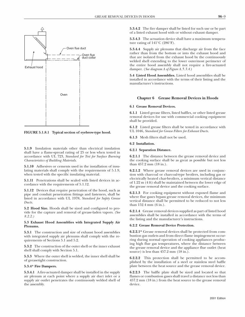
5.1.8.1 Eyebrow-type hoods over gas or electric ovens shall bepermitted to have a duct constructed as required in Chapter 7from the oven flue(s) connected to the hood canopy up-stream of the exhaust plenum as shown in Figure 5.1.8.1.
5.1.8.2 The duct connecting the oven flue(s) to the hoodcanopy shall be connected with a continuous weld or have aduct-to-duct connection [See Figure 8.1.2.2(b) through Figure8.1.2.2(d).]
96–9GREASE REMOVAL DEVICES IN HOODS
5.1.9 Insulation materials other than electrical insulationshall have a flame-spread rating of 25 or less when tested inaccordance with UL 723, Standard for Test for Surface BurningCharacteristics of Building Materials.
5.1.10 Adhesives or cements used in the installation of insu-lating materials shall comply with the requirements of 5.1.9,when tested with the specific insulating material.
5.1.11 Penetrations shall be sealed with listed devices in ac-cordance with the requirements of 5.1.12.
5.1.12 Devices that require penetration of the hood, such aspipe and conduit penetration fittings and fasteners, shall belisted in accordance with UL 1978, Standard for Safety GreaseDucts.
5.2 Hood Size. Hoods shall be sized and configured to pro-vide for the capture and removal of grease-laden vapors. (See8.2.2.)
5.3 Exhaust Hood Assemblies with Integrated Supply AirPlenums.
5.3.1 The construction and size of exhaust hood assemblieswith integrated supply air plenums shall comply with the re-quirements of Sections 5.1 and 5.2.
5.3.2 The construction of the outer shell or the inner exhaustshell shall comply with Section 5.1.
5.3.3 Where the outer shell is welded, the inner shell shall beof greasetight construction.
5.3.4* Fire Dampers.
5.3.4.1 A fire-actuated damper shall be installed in the supplyair plenum at each point where a supply air duct inlet or asupply air outlet penetrates the continuously welded shell ofthe assembly.
Oven flue duct
Oven flueduct collar
Oven
Exhaust hood
FIGURE 5.1.8.1 Typical section of eyebrow-type hood.
5.3.4.2 The fire damper shall be listed for such use or be partof a listed exhaust hood with or without exhaust damper.
5.3.4.3 The actuation device shall have a maximum tempera-ture rating of 141°C (286°F).
5.3.4.4 Supply air plenums that discharge air from the facerather than from the bottom or into the exhaust hood andthat are isolated from the exhaust hood by the continuouslywelded shell extending to the lower outermost perimeter ofthe entire hood assembly shall not require a fire-actuateddamper. (See diagram A of Figure A.5.3.4.)
5.4 Listed Hood Assemblies. Listed hood assemblies shall beinstalled in accordance with the terms of their listing and themanufacturer’s instructions.
Chapter 6 Grease Removal Devices in Hoods
6.1 Grease Removal Devices.
6.1.1 Listed grease filters, listed baffles, or other listed greaseremoval devices for use with commercial cooking equipmentshall be provided.
6.1.2 Listed grease filters shall be tested in accordance withUL 1046, Standard for Grease Filters for Exhaust Ducts.
6.1.3 Mesh filters shall not be used.
6.2 Installation.
6.2.1 Separation Distance.
6.2.1.1 The distance between the grease removal device andthe cooking surface shall be as great as possible but not lessthan 457.2 mm (18 in.).
6.2.1.2 Where grease removal devices are used in conjunc-tion with charcoal or charcoal-type broilers, including gas orelectrically heated char-broilers, a minimum vertical distanceof 1.22 m (4 ft) shall be maintained between the lower edge ofthe grease removal device and the cooking surface.
6.2.1.3 For cooking equipment without exposed flame andwhere flue gases bypass grease removal devices, the minimumvertical distance shall be permitted to be reduced to not lessthan 152.4 mm (6 in.).
6.2.1.4 Grease removal devices supplied as part of listed hoodassemblies shall be installed in accordance with the terms ofthe listing and the manufacturer’s instructions.
6.2.2 Grease Removal Device Protection.
6.2.2.1* Grease removal devices shall be protected from com-bustion gas outlets and from direct flame impingement occur-ring during normal operation of cooking appliances produc-ing high flue gas temperatures, where the distance betweenthe grease removal device and the appliance flue outlet (heatsource) is less than 457.2 mm (18 in.).
6.2.2.2 This protection shall be permitted to be accom-plished by the installation of a steel or stainless steel baffleplate between the heat source and the grease removal device.
6.2.2.3 The baffle plate shall be sized and located so thatflames or combustion gases shall travel a distance not less than457.2 mm (18 in.) from the heat source to the grease removaldevice.
2001 Edition
96–10 VENTILATION CONTROL AND FIRE PROTECTION OF COMMERCIAL COOKING OPERATIONS
6.2.2.4 The baffle shall be located not less than 6 in.(152.4 mm) from the grease removal devices.
6.2.3 Grease Filters.
6.2.3.1 Grease filters shall be listed and constructed of steelor listed equivalent material.
6.2.3.2 Grease filters shall be of rigid construction that willnot distort or crush under normal operation, handling, andcleaning conditions.
6.2.3.3 Grease filters shall be arranged so that all exhaust airshall pass through the grease filters.
6.2.3.4 Grease filters shall be easily accessible and removablefor cleaning.
6.2.3.5 Grease filters shall be installed at an angle not lessthan 45 degrees from the horizontal.
6.2.4 Grease Drip Trays.
6.2.4.1 Grease filters shall be equipped with a grease drip traybeneath their lower edges.
6.2.4.2 Grease drip trays shall be kept to the minimum sizeneeded to collect grease.
6.2.4.3 Grease drip trays shall be pitched to drain into anenclosed metal container having a capacity not exceeding3.785 L (1 gal).
6.2.5 Grease Filter Orientation. Grease filters that require aspecific orientation to drain grease shall be clearly so desig-nated, or the hood shall be constructed so that filters cannotbe installed in the wrong orientation.
Chapter 7 Exhaust Duct Systems
7.1 General.
7.1.1 Ducts shall not pass through fire walls.
7.1.2* All ducts shall lead directly to the exterior of the build-ing, so as not to unduly increase any fire hazard.
7.1.3 Duct systems shall not be interconnected with any otherbuilding ventilation or exhaust system.
7.1.4 All ducts shall be installed without forming dips or trapsthat might collect residues. In manifold (common duct) sys-tems, the lowest end of the main duct shall be connected flushon the bottom with the branch duct.
7.1.5 Openings required for accessibility shall comply withSection 7.3.
7.1.6 A sign shall be placed on all access panels stating thefollowing:
ACCESS PANEL — DO NOT OBSTRUCT
7.1.7 Listed grease ducts shall be installed in accordance withthe terms of the listing and the manufacturers’ instructions.
7.2 Clearance. Clearance between ducts and combustible ma-terials shall be provided in accordance with the requirementsof Section 4.2.
7.3 Openings.
7.3.1 Openings shall be provided at the sides or at the topof the duct, whichever is more accessible, and at changes ofdirection.
2001 Edition
7.3.2 Openings shall be protected by approved access con-structed and installed in accordance with the requirements of7.4.4.
7.3.3 Openings shall not be required in portions of the ductthat are accessible from the duct entry or discharge.
7.3.4 For hoods with dampers in the exhaust or supply collar,an access panel for cleaning and inspection shall be providedin the duct or the hood within 457 mm (18 in.) of the damper.
7.3.5 For common exhaust duct systems, access panel open-ings shall be provided for installation and servicing of the fire-extinguishing system.
7.3.6 Access panel opening shall not be required in portionsof the common exhaust duct or branch duct that are acces-sible from the branch duct connection to the exhaust hood.
7.3.7 Exhaust fans with ductwork connected to both sidesshall have access for cleaning and inspection within 0.92 m(3 ft) of each side of the fan.
7.4 Openings in Ducts. All openings shall comply with therequirements of Section 7.4.
7.4.1 Horizontal Ducts.
7.4.1.1 Horizontal ducting support systems for nonlistedgrease duct systems 24 in. and larger than 609 mm in anycross-sectional dimension shall be designed for the weight ofthe ductwork plus 363 kg (800 lbs) at any point in the ductsystems.
7.4.1.2 On nonlisted ductwork, the edge of the opening shallbe not less than 38.1 mm (11⁄2 in.) from all outside edges of theduct or welded seams.
7.4.2 Vertical Ducts.
7.4.2.1 On vertical ductwork where personnel entry is pos-sible, access shall be provided at the top of the vertical riser toaccommodate descent.
7.4.2.2 Where personnel entry is not possible, adequate ac-cess for cleaning shall be provided on each floor.
7.4.2.3 On nonlisted ductwork, the edge of the opening shallbe not less than 38.1 mm (11⁄2 in.) from all outside edges of theduct or welded seams.
7.4.3 Access Panels.
7.4.3.1 Access panels shall be of the same material and thick-ness as the duct.
7.4.3.2 Access panels shall have a gasket or sealant that israted for 815.6ºC (1500ºF) and shall be greasetight.
7.4.3.3 Fasteners, such as bolts, weld studs, latches, or wingnuts, used to secure the access panels shall be carbon steel orstainless steel and shall not penetrate duct walls.
7.4.3.4 Listed grease duct access door assemblies (access pan-els) shall be installed in accordance with the terms of the list-ing and the manufacturers’ instructions.
7.4.4 Protection of Openings.
7.4.4.1 Openings for installation, servicing, and inspection oflisted fire protection system devices and for duct cleaningshall be provided in ducts and enclosures and shall conform tothe requirements of Section 7.3 and 7.7.4.
96–11EXHAUST DUCT SYSTEMS
7.4.4.2 Enclosure openings required to reach access panelsin the ductwork shall be large enough for the removal of theaccess panel.
7.5 Other Grease Ducts. Other grease ducts shall comply withthe requirements of this section.
7.5.1* Materials. Ducts shall be constructed of and supportedby carbon steel not less than 1.37 mm (0.054 in.) (No. 16MSG) in thickness or stainless steel not less than 1.09 mm(0.043 in.) (No. 18 MSG) in thickness.
7.5.2 Installation.
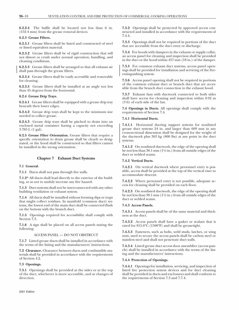
7.5.2.1 All seams, joints, penetrations, and duct-to-hood col-lar connections shall have a liquidtight continuous externalweld.
7.5.2.2 Duct-to-hood collar connections as shown in Figure7.5.2.2 shall not require a liquidtight continuous externalweld.
7.5.2.3 Penetrations shall be permitted to be sealed by otherlisted devices that are tested to be greasetight and are evalu-ated under the same conditions of fire severity as the hood orenclosure of listed grease extractors and whose presence doesnot detract from the hood’s or duct’s structural integrity.
7.5.2.4 Internal welding shall be permitted, provided thejoint is formed or ground smooth and is readily accessible forinspection.
7.5.3 Penetrations shall be sealed with listed devices in accor-dance with the requirements of 4.2.3.3.
7.5.4 Devices that require penetration of the ductwork, suchas pipe and conduit penetration fittings and fasteners, shall belisted in accordance with UL 1978, Standard for Safety for GreaseDucts.
Square, rectangular,or round in shape
Continuous perimeter weld
Joint with (815.6° C) 1500°F ratedgasket or sealant
Detail of sealed hood–duct joint
Weld studs or bolts6.4-mm (¹⁄₄-in.)steel (min)
O.D. of duct3.2 mm (¹⁄₈ in.)less than I.D.of hood collar
25.4-mm × 25.4-mm(1-in. × 1-in.) angle(min), same gaugeas duct(min)
•
•
• •
•
••
•
•
• •
•
•
Perspective
Hood top
6.4-mm (¹⁄₄-in.) weld studs orbolts at each corner and 102-mm 4-in. (max)CL
FIGURE 7.5.2.2 Permitted duct-to-hood collar connection.
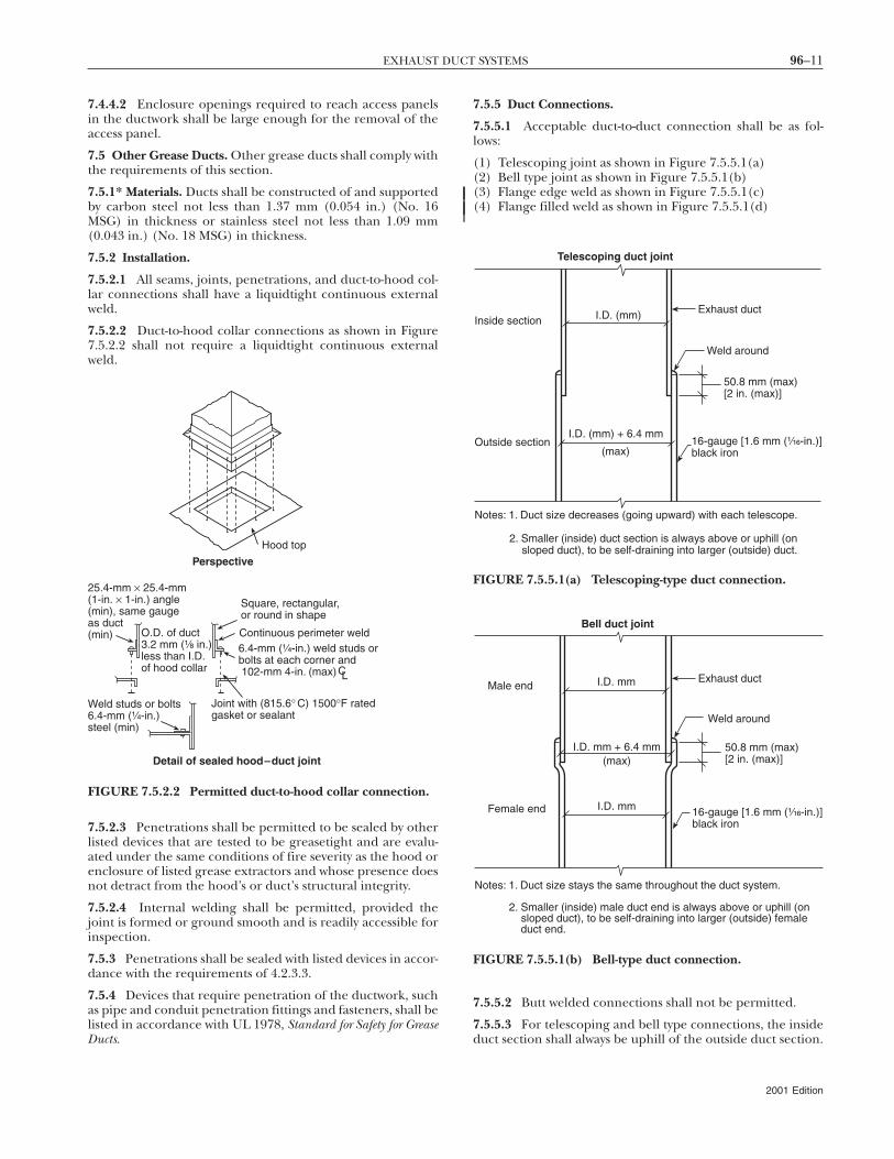
7.5.5 Duct Connections.
7.5.5.1 Acceptable duct-to-duct connection shall be as fol-lows:
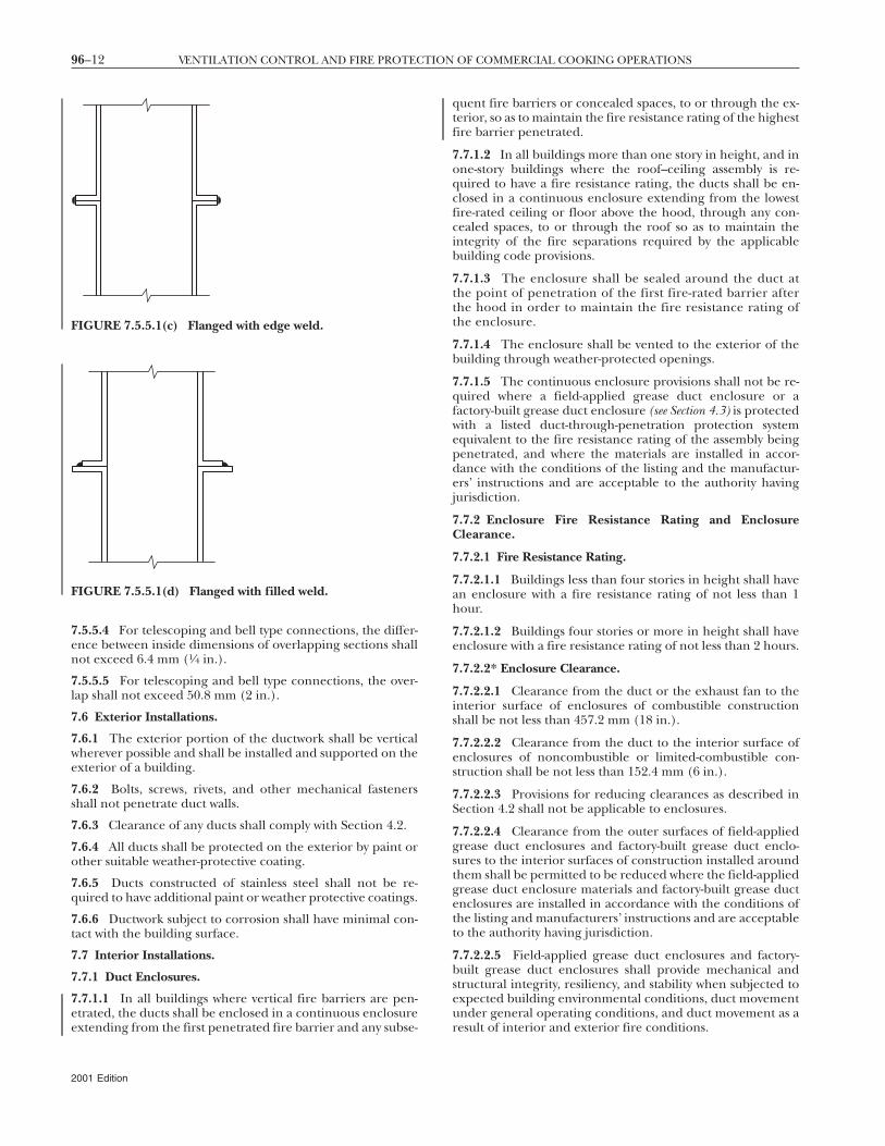
(1) Telescoping joint as shown in Figure 7.5.5.1(a)(2) Bell type joint as shown in Figure 7.5.5.1(b)(3) Flange edge weld as shown in Figure 7.5.5.1(c)(4) Flange filled weld as shown in Figure 7.5.5.1(d)
7.5.5.2 Butt welded connections shall not be permitted.
7.5.5.3 For telescoping and bell type connections, the insideduct section shall always be uphill of the outside duct section.
Inside section
Outside section
I.D. (mm)
I.D. (mm) + 6.4 mm
Weld around
16-gauge [1.6 mm (¹⁄₁₆-in.)]black iron
Telescoping duct joint
50.8 mm (max)[2 in. (max)]
Exhaust duct
Notes: 1. Duct size decreases (going upward) with each telescope.
2. Smaller (inside) duct section is always above or uphill (on sloped duct), to be self-draining into larger (outside) duct.
(max)
FIGURE 7.5.5.1(a) Telescoping-type duct connection.
Bell duct joint
Weld around
Female end
Male end I.D. mm
I.D. mm + 6.4 mm(max)
I.D. mm
Exhaust duct
Notes: 1. Duct size stays the same throughout the duct system.
2. Smaller (inside) male duct end is always above or uphill (on sloped duct), to be self-draining into larger (outside) female duct end.
16-gauge [1.6 mm (¹⁄₁₆-in.)]black iron
50.8 mm (max)[2 in. (max)]
FIGURE 7.5.5.1(b) Bell-type duct connection.
2001 Edition
96–12 VENTILATION CONTROL AND FIRE PROTECTION OF COMMERCIAL COOKING OPERATIONS
7.5.5.4 For telescoping and bell type connections, the differ-ence between inside dimensions of overlapping sections shallnot exceed 6.4 mm (1⁄4 in.).
7.5.5.5 For telescoping and bell type connections, the over-lap shall not exceed 50.8 mm (2 in.).
7.6 Exterior Installations.
7.6.1 The exterior portion of the ductwork shall be verticalwherever possible and shall be installed and supported on theexterior of a building.
7.6.2 Bolts, screws, rivets, and other mechanical fastenersshall not penetrate duct walls.
7.6.3 Clearance of any ducts shall comply with Section 4.2.
7.6.4 All ducts shall be protected on the exterior by paint orother suitable weather-protective coating.
7.6.5 Ducts constructed of stainless steel shall not be re-quired to have additional paint or weather protective coatings.
7.6.6 Ductwork subject to corrosion shall have minimal con-tact with the building surface.
7.7 Interior Installations.
7.7.1 Duct Enclosures.
7.7.1.1 In all buildings where vertical fire barriers are pen-etrated, the ducts shall be enclosed in a continuous enclosureextending from the first penetrated fire barrier and any subse-
FIGURE 7.5.5.1(c) Flanged with edge weld.
FIGURE 7.5.5.1(d) Flanged with filled weld.
2001 Edition
quent fire barriers or concealed spaces, to or through the ex-terior, so as to maintain the fire resistance rating of the highestfire barrier penetrated.
7.7.1.2 In all buildings more than one story in height, and inone-story buildings where the roof–ceiling assembly is re-quired to have a fire resistance rating, the ducts shall be en-closed in a continuous enclosure extending from the lowestfire-rated ceiling or floor above the hood, through any con-cealed spaces, to or through the roof so as to maintain theintegrity of the fire separations required by the applicablebuilding code provisions.
7.7.1.3 The enclosure shall be sealed around the duct atthe point of penetration of the first fire-rated barrier afterthe hood in order to maintain the fire resistance rating ofthe enclosure.
7.7.1.4 The enclosure shall be vented to the exterior of thebuilding through weather-protected openings.
7.7.1.5 The continuous enclosure provisions shall not be re-quired where a field-applied grease duct enclosure or afactory-built grease duct enclosure (see Section 4.3) is protectedwith a listed duct-through-penetration protection systemequivalent to the fire resistance rating of the assembly beingpenetrated, and where the materials are installed in accor-dance with the conditions of the listing and the manufactur-ers’ instructions and are acceptable to the authority havingjurisdiction.
7.7.2 Enclosure Fire Resistance Rating and EnclosureClearance.
7.7.2.1 Fire Resistance Rating.
7.7.2.1.1 Buildings less than four stories in height shall havean enclosure with a fire resistance rating of not less than 1hour.
7.7.2.1.2 Buildings four stories or more in height shall haveenclosure with a fire resistance rating of not less than 2 hours.
7.7.2.2* Enclosure Clearance.
7.7.2.2.1 Clearance from the duct or the exhaust fan to theinterior surface of enclosures of combustible constructionshall be not less than 457.2 mm (18 in.).
7.7.2.2.2 Clearance from the duct to the interior surface ofenclosures of noncombustible or limited-combustible con-struction shall be not less than 152.4 mm (6 in.).
7.7.2.2.3 Provisions for reducing clearances as described inSection 4.2 shall not be applicable to enclosures.
7.7.2.2.4 Clearance from the outer surfaces of field-appliedgrease duct enclosures and factory-built grease duct enclo-sures to the interior surfaces of construction installed aroundthem shall be permitted to be reduced where the field-appliedgrease duct enclosure materials and factory-built grease ductenclosures are installed in accordance with the conditions ofthe listing and manufacturers’ instructions and are acceptableto the authority having jurisdiction.
7.7.2.2.5 Field-applied grease duct enclosures and factory-built grease duct enclosures shall provide mechanical andstructural integrity, resiliency, and stability when subjected toexpected building environmental conditions, duct movementunder general operating conditions, and duct movement as aresult of interior and exterior fire conditions.
96–13EXHAUST DUCT SYSTEMS
7.7.3 Protection of Coverings and Enclosure Materials.
7.7.3.1 Measures shall be taken to prevent physical damageto any covering or enclosure material.
7.7.3.2 Any damage to the covering or enclosure shall berepaired and the covering or enclosure shall be restored tomeet its intended listing and fire-resistive rating and to be ac-ceptable to the authority having jurisdiction.
7.7.3.3 In the event of a fire within a kitchen exhaust system,the duct, the enclosure, or the covering directly applied to theduct shall be inspected by qualified personnel to determinewhether the duct, the enclosure, and the covering directly ap-plied to the duct are structurally sound, capable of maintain-ing their fire protection functions, suitable for continued op-eration, and acceptable to the authority having jurisdiction.
7.7.3.4 Listed grease ducts shall be installed in accordancewith the terms of the listing and the manufacturers’ instruc-tions.
7.7.4 Enclosure Openings.
7.7.4.1 Where openings in the enclosure walls are provided,they shall be protected by listed fire doors of proper rating.
7.7.4.2 Fire doors shall be installed in accordance withNFPA 80, Standard for Fire Doors and Fire Windows.
7.7.4.3 Openings on other listed materials or products shallbe clearly identified and labeled according to the terms of thelisting and the manufacturers’ instructions and shall be ac-ceptable to the authority having jurisdiction.
7.7.4.4 The fire door shall be readily accessible, aligned, andof sufficient size to allow access to the rated access panels onthe ductwork.
7.7.5 Ducts with Enclosure(s).
7.7.5.1 Each duct system shall constitute an individual systemserving only exhaust hoods in one fire zone on one floor.
7.7.5.2 Multiple ducts shall not be permitted in a single en-closure unless acceptable to the authority having jurisdiction.
7.8* Termination of Exhaust System.
7.8.1 The exhaust system shall terminate as follows:
(1)*Outside the building with a fan or duct(2) Through the roof, or to the roof from outside, as in 7.8.2,
or through a wall, as in 7.8.3
7.8.2 Rooftop Terminations.
7.8.2.1 Rooftop terminations shall be arranged with or pro-vided with the following:
(1) A minimum of 3.05 m (10 ft) of horizontal clearance fromthe outlet to adjacent buildings, property lines and airintakes.
(2) A minimum of 1.5 m (5 ft) of horizontal clearance fromthe outlet (fan housing) to any combustible structure.
(3) A vertical separation of 0.92 m (3 ft) below any exhaustoutlets for air intakes within 3.05 m (10 ft) of the exhaustoutlet.
(4) The ability to drain grease out of any traps or low pointsformed in the fan or duct near the termination of thesystem into a collection container that is noncombustible,closed, rainproof, structurally sound for the service towhich it is applied, and will not sustain combustion.
(5) A grease collection device that is applied to exhaust sys-tems that does not inhibit the performance of any fan.
(6) Listed grease collection systems that meet the require-ments of 7.8.2.1(4) and 7.8.2.1(5).
(7) A listed grease duct complying with Section 4.4, or withductwork complying with Section 4.5.
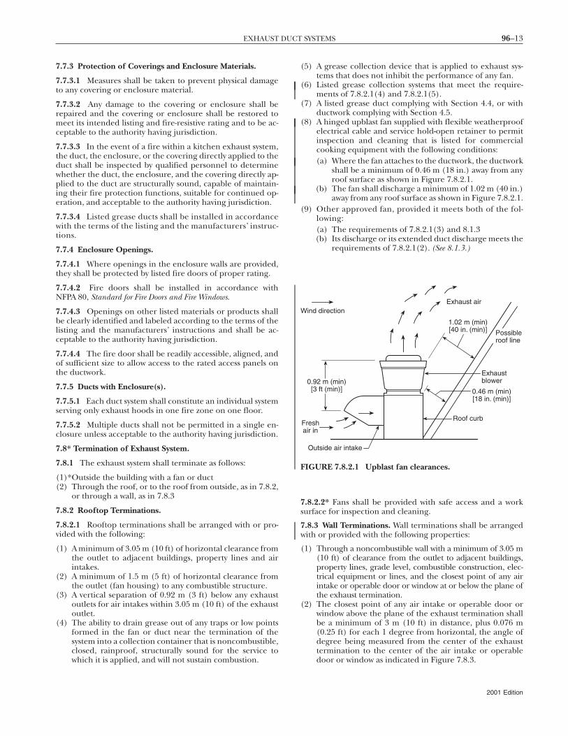
(8) A hinged upblast fan supplied with flexible weatherproofelectrical cable and service hold-open retainer to permitinspection and cleaning that is listed for commercialcooking equipment with the following conditions:(a) Where the fan attaches to the ductwork, the ductwork
shall be a minimum of 0.46 m (18 in.) away from anyroof surface as shown in Figure 7.8.2.1.
(b) The fan shall discharge a minimum of 1.02 m (40 in.)away from any roof surface as shown in Figure 7.8.2.1.
(9) Other approved fan, provided it meets both of the fol-lowing:(a) The requirements of 7.8.2.1(3) and 8.1.3(b) Its discharge or its extended duct discharge meets the
requirements of 7.8.2.1(2). (See 8.1.3.)
7.8.2.2* Fans shall be provided with safe access and a worksurface for inspection and cleaning.
7.8.3 Wall Terminations. Wall terminations shall be arrangedwith or provided with the following properties:
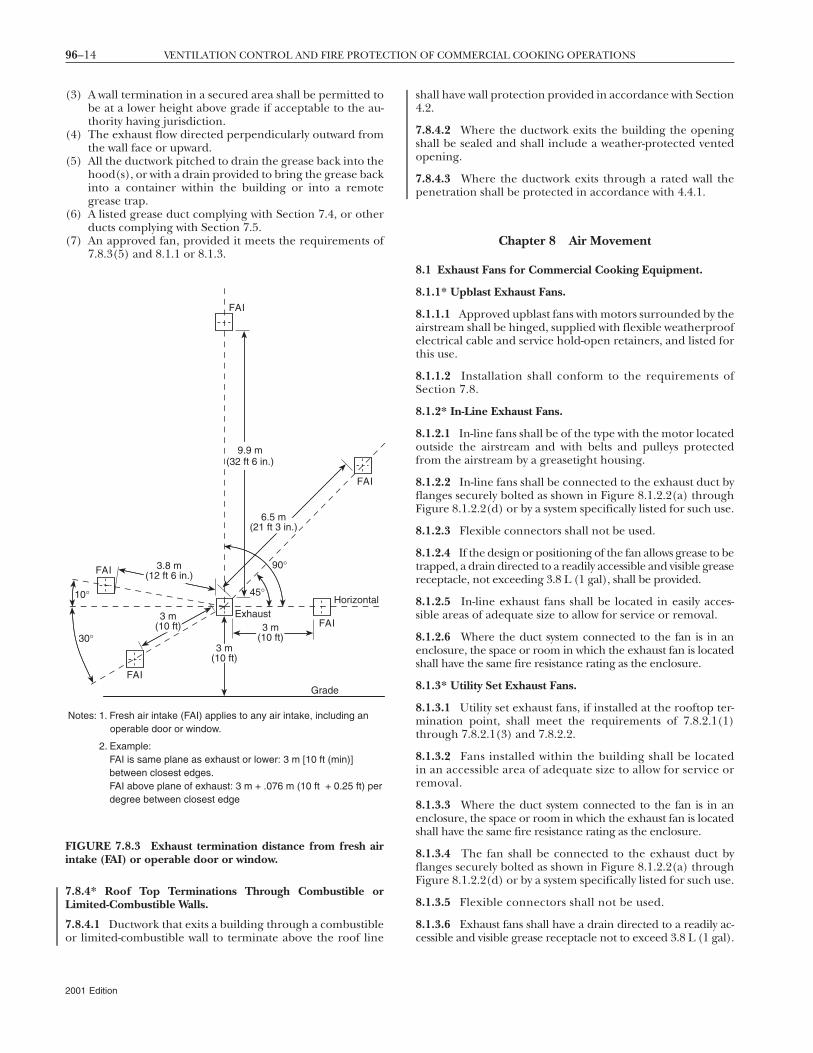
(1) Through a noncombustible wall with a minimum of 3.05 m(10 ft) of clearance from the outlet to adjacent buildings,property lines, grade level, combustible construction, elec-trical equipment or lines, and the closest point of any airintake or operable door or window at or below the plane ofthe exhaust termination.
(2) The closest point of any air intake or operable door orwindow above the plane of the exhaust termination shallbe a minimum of 3 m (10 ft) in distance, plus 0.076 m(0.25 ft) for each 1 degree from horizontal, the angle ofdegree being measured from the center of the exhausttermination to the center of the air intake or operabledoor or window as indicated in Figure 7.8.3.
Freshair in
Possibleroof line
0.92 m (min)[3 ft (min)]
Roof curb
Exhaustblower
Exhaust airWind direction
Outside air intake
1.02 m (min)[40 in. (min)]
0.46 m (min)[18 in. (min)]
FIGURE 7.8.2.1 Upblast fan clearances.
2001 Edition
96–14 VENTILATION CONTROL AND FIRE PROTECTION OF COMMERCIAL COOKING OPERATIONS
(3) A wall termination in a secured area shall be permitted tobe at a lower height above grade if acceptable to the au-thority having jurisdiction.
(4) The exhaust flow directed perpendicularly outward fromthe wall face or upward.
(5) All the ductwork pitched to drain the grease back into thehood(s), or with a drain provided to bring the grease backinto a container within the building or into a remotegrease trap.
(6) A listed grease duct complying with Section 7.4, or otherducts complying with Section 7.5.
(7) An approved fan, provided it meets the requirements of7.8.3(5) and 8.1.1 or 8.1.3.
7.8.4* Roof Top Terminations Through Combustible orLimited-Combustible Walls.
7.8.4.1 Ductwork that exits a building through a combustible
Grade
Exhaust
10°
30°
Horizontal
90°
45°
FAI
Notes: 1. Fresh air intake (FAI) applies to any air intake, including an operable door or window.
2. Example: FAI is same plane as exhaust or lower: 3 m [10 ft (min)] between closest edges. FAI above plane of exhaust: 3 m + .076 m (10 ft + 0.25 ft) per degree between closest edge
FAI
FAI
FAI
FAI
9.9 m(32 ft 6 in.)
3 m(10 ft)
3 m(10 ft)
3.8 m(12 ft 6 in.)
6.5 m(21 ft 3 in.)
3 m(10 ft)
FIGURE 7.8.3 Exhaust termination distance from fresh airintake (FAI) or operable door or window.
or limited-combustible wall to terminate above the roof line
2001 Edition
shall have wall protection provided in accordance with Section4.2.
7.8.4.2 Where the ductwork exits the building the openingshall be sealed and shall include a weather-protected ventedopening.
7.8.4.3 Where the ductwork exits through a rated wall thepenetration shall be protected in accordance with 4.4.1.
Chapter 8 Air Movement
8.1 Exhaust Fans for Commercial Cooking Equipment.
8.1.1* Upblast Exhaust Fans.
8.1.1.1 Approved upblast fans with motors surrounded by theairstream shall be hinged, supplied with flexible weatherproofelectrical cable and service hold-open retainers, and listed forthis use.
8.1.1.2 Installation shall conform to the requirements ofSection 7.8.
8.1.2* In-Line Exhaust Fans.
8.1.2.1 In-line fans shall be of the type with the motor locatedoutside the airstream and with belts and pulleys protectedfrom the airstream by a greasetight housing.
8.1.2.2 In-line fans shall be connected to the exhaust duct byflanges securely bolted as shown in Figure 8.1.2.2(a) throughFigure 8.1.2.2(d) or by a system specifically listed for such use.
8.1.2.3 Flexible connectors shall not be used.
8.1.2.4 If the design or positioning of the fan allows grease to betrapped, a drain directed to a readily accessible and visible greasereceptacle, not exceeding 3.8 L (1 gal), shall be provided.
8.1.2.5 In-line exhaust fans shall be located in easily acces-sible areas of adequate size to allow for service or removal.
8.1.2.6 Where the duct system connected to the fan is in anenclosure, the space or room in which the exhaust fan is locatedshall have the same fire resistance rating as the enclosure.
8.1.3* Utility Set Exhaust Fans.
8.1.3.1 Utility set exhaust fans, if installed at the rooftop ter-mination point, shall meet the requirements of 7.8.2.1(1)through 7.8.2.1(3) and 7.8.2.2.
8.1.3.2 Fans installed within the building shall be locatedin an accessible area of adequate size to allow for service orremoval.
8.1.3.3 Where the duct system connected to the fan is in anenclosure, the space or room in which the exhaust fan is locatedshall have the same fire resistance rating as the enclosure.
8.1.3.4 The fan shall be connected to the exhaust duct byflanges securely bolted as shown in Figure 8.1.2.2(a) throughFigure 8.1.2.2(d) or by a system specifically listed for such use.
8.1.3.5 Flexible connectors shall not be used.
8.1.3.6 Exhaust fans shall have a drain directed to a readily ac-
cessible and visible grease receptacle not to exceed 3.8 L (1 gal).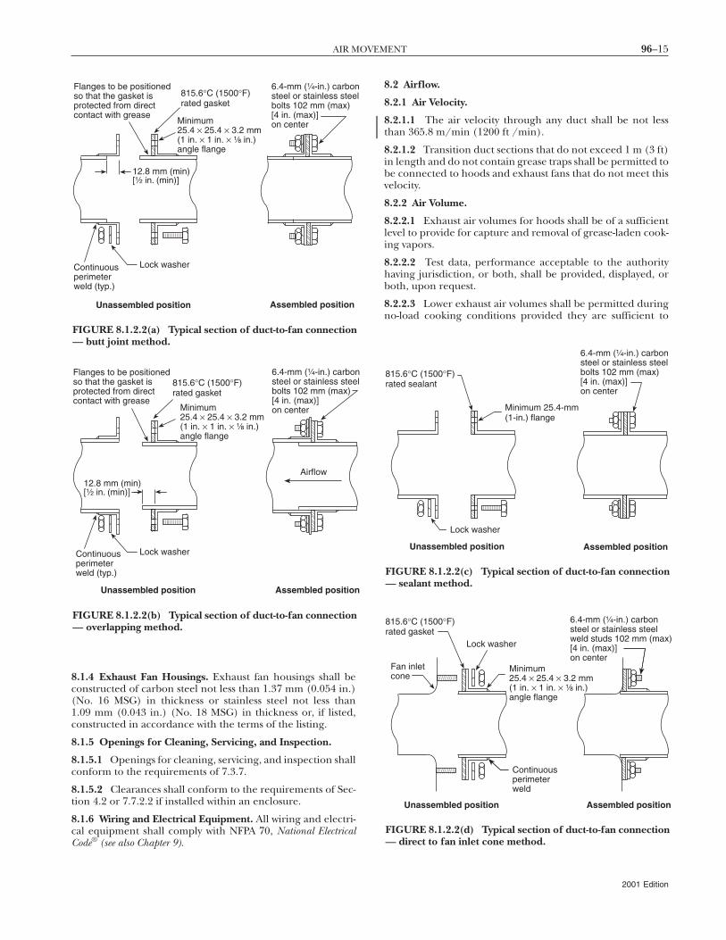
96–15AIR MOVEMENT
8.1.4 Exhaust Fan Housings. Exhaust fan housings shall beconstructed of carbon steel not less than 1.37 mm (0.054 in.)(No. 16 MSG) in thickness or stainless steel not less than1.09 mm (0.043 in.) (No. 18 MSG) in thickness or, if listed,constructed in accordance with the terms of the listing.
8.1.5 Openings for Cleaning, Servicing, and Inspection.
8.1.5.1 Openings for cleaning, servicing, and inspection shallconform to the requirements of 7.3.7.
8.1.5.2 Clearances shall conform to the requirements of Sec-tion 4.2 or 7.7.2.2 if installed within an enclosure.
8.1.6 Wiring and Electrical Equipment. All wiring and electri-cal equipment shall comply with NFPA 70, National ElectricalCode® (see also Chapter 9).
6.4-mm (¹⁄₄-in.) carbonsteel or stainless steebolts 102 mm (max)[4 in. (max)]on center
Flanges to be positionedso that the gasket isprotected from directcontact with grease
Minimum25.4 × 25.4 × 3.2 mm(1 in. × 1 in. × ¹⁄₈ in.)angle flange
Continuousperimeterweld (typ.)
Lock washer
Unassembled position Assembled position
12.8 mm (min)[¹⁄₂ in. (min)]
815.6°C (1500°F)rated gasket
FIGURE 8.1.2.2(a) Typical section of duct-to-fan connection— butt joint method.
Flanges to be positionedso that the gasket isprotected from directcontact with grease
Assembled position
Continuousperimeterweld (typ.)
Lock washer
Unassembled position
Airflow
6.4-mm (¹⁄₄-in.) carbonsteel or stainless steebolts 102 mm (max)[4 in. (max)]on centerMinimum
25.4 × 25.4 × 3.2 mm(1 in. × 1 in. × ¹⁄₈ in.)angle flange
12.8 mm (min)[¹⁄₂ in. (min)]
815.6°C (1500°F)rated gasket
FIGURE 8.1.2.2(b) Typical section of duct-to-fan connection— overlapping method.
8.2 Airflow.
8.2.1 Air Velocity.
8.2.1.1 The air velocity through any duct shall be not lessthan 365.8 m/min (1200 ft /min).
8.2.1.2 Transition duct sections that do not exceed 1 m (3 ft)in length and do not contain grease traps shall be permitted tobe connected to hoods and exhaust fans that do not meet thisvelocity.
8.2.2 Air Volume.
8.2.2.1 Exhaust air volumes for hoods shall be of a sufficientlevel to provide for capture and removal of grease-laden cook-ing vapors.
8.2.2.2 Test data, performance acceptable to the authorityhaving jurisdiction, or both, shall be provided, displayed, orboth, upon request.
8.2.2.3 Lower exhaust air volumes shall be permitted duringno-load cooking conditions provided they are sufficient to
815.6°C (1500°F)rated sealant
Minimum 25.4-mm(1-in.) flange
Lock washer
Unassembled position Assembled position
6.4-mm (¹⁄₄-in.) carbonsteel or stainless steelbolts 102 mm (max)[4 in. (max)]on center
FIGURE 8.1.2.2(c) Typical section of duct-to-fan connection— sealant method.
Unassembled position
Fan inletcone
Lock washer
Assembled position
Continuousperimeterweld
815.6°C (1500°F)rated gasket
Minimum25.4 × 25.4 × 3.2 mm(1 in. × 1 in. × ¹⁄₈ in.)angle flange
6.4-mm (¹⁄₄-in.) carbonsteel or stainless steelweld studs 102 mm (max[4 in. (max)]on center
FIGURE 8.1.2.2(d) Typical section of duct-to-fan connection— direct to fan inlet cone method.
l
l
)
2001 Edition
96–16 VENTILATION CONTROL AND FIRE PROTECTION OF COMMERCIAL COOKING OPERATIONS
capture and remove flue gases and residual vapors from cook-ing equipment.
8.2.3 Exhaust Fan Operation.
8.2.3.1 A hood exhaust fan(s) shall continue to operate afterthe extinguishing system has been activated unless fan shut-down is required by a listed component of the ventilation sys-tem or by the design of the extinguishing system.
8.2.3.2 The hood exhaust fan shall not be required to restartupon activation of the extinguishing system if the exhaust fanand all cooking equipment served by the fan have previouslybeen shut down.
8.3* Replacement Air.
8.3.1 Replacement air quantity shall be adequate to preventnegative pressures in the commercial cooking area(s) fromexceeding 4.98 kPa (0.02 in. water column).
8.3.2 When its fire-extinguishing system discharges, makeupair supplied internally to a hood shall be shut off.
8.4 Common Duct (Manifold) Systems.
8.4.1* Master kitchen exhaust ducts that serve multiple ten-ants shall include provision to bleed air from outdoors or fromadjacent spaces into the master exhaust duct where requiredto maintain the necessary minimum air velocity in the masterexhaust duct.
8.4.2 Bleed air ducts shall connect to the top or side of themaster exhaust duct.
8.4.3 The bleed air duct shall have a fire damper at least304.8 mm (12 in.) from the exhaust duct connection.
8.4.4 The bleed air duct shall have the same construction andclearance requirements as the main exhaust duct from theconnection to the exhaust duct to at least 304.8 mm (12 in.)on both sides of the fire damper.
8.4.5 Each bleed air duct shall have a means of adjusting(e.g., using volume dampers) the bleed air quantity.
8.4.6 Means to adjust the bleed air quantity shall be installedin between the fire damper and the source of bleed air.
8.4.7 A bleed air duct shall not be used for the exhaust ofgrease-laden vapors and shall be so labeled.
8.4.8 Unused tenant exhaust connections to the master ex-haust duct that are not used as bleed air connections shall bedisconnected and sealed at the main duct.
Chapter 9 Auxiliary Equipment
9.1 Dampers.
9.1.1 Dampers shall not be installed in exhaust ducts or ex-haust duct systems.
9.1.2 Where specifically listed for such use or where requiredas part of a listed device or system, dampers in exhaust ductsor exhaust duct systems shall be permitted.
9.2 Electrical Equipment.
9.2.1 Wiring systems of any type shall not be installed in
ducts.2001 Edition
9.2.2 Only where specifically listed for such use shall motors,lights, and other electrical devices be permitted to be installedin ducts or hoods or to be located in the path of travel ofexhaust products.
9.2.3 Lighting Units.
9.2.3.1 Lighting units in hoods shall be listed for use overcommercial cooking appliances and installed in accordancewith the terms of their listing.
9.2.3.2 Lighting units on hoods shall not be located in con-cealed spaces.
9.2.3.3 Lighting units shall be permitted in concealed spaceswhere such units are part of a listed exhaust hood.
9.2.3.4 Listed lighting units specifically listed for such useand installed in accordance with the terms of the listing shallbe permitted to be installed in concealed spaces.
9.2.4* All electrical equipment shall be installed in accor-dance with NFPA 70, National Electrical Code.
9.3 Other Equipment.
9.3.1 Fume incinerators, thermal recovery units, air pollutioncontrol devices, or other devices shall be permitted to be in-stalled in ducts or hoods or to be located in the path of travelof exhaust products where specifically approved for such use.
9.3.2 Downgrading other parts of the exhaust system due tothe installation of these approved devices, whether listed ornot, shall not be allowed.
9.3.3 Any equipment, listed or otherwise, that provides sec-ondary filtration or air pollution control and that is installedin the path of travel of exhaust products shall be provided withan approved automatic fire-extinguishing system for the pro-tection of the component sections of the equipment and shallinclude protection of the ductwork downstream of the equip-ment, whether or not the equipment is provided with adamper.
9.3.4 If the equipment provides a source of ignition, it shallbe provided with detection to operate the fire-extinguishingsystem protecting the equipment.
9.3.5 Where a cooking exhaust system employs an air pollu-tion control device that recirculates air into the building, therequirements of Chapter 13 shall apply.
Chapter 10 Fire-Extinguishing Equipment
10.1 General Requirements.
10.1.1 Fire-extinguishing equipment for the protection ofgrease removal devices, hood exhaust plenums, and exhaustduct systems shall be provided.
10.1.2* Cooking equipment that produces grease-laden va-pors and that might be a source of ignition of grease in thehood, grease removal device, or duct shall be protected byfire-extinguishing equipment.
10.2 Types of Equipment.
10.2.1 Fire-extinguishing equipment shall include both auto-matic fire-extinguishing systems as primary protection and
portable fire extinguishers as secondary backup.
96–17FIRE-EXTINGUISHING EQUIPMENT
10.2.2 A placard identifying the use of the extinguisher as asecondary backup means to the automatic fire-extinguishingsystem shall be conspicuously placed near each portable fireextinguisher in the cooking area.
10.2.2.1 The language and wording for the placard shall beapproved by the authority having jurisdiction.
10.2.3* Automatic fire-extinguishing systems shall complywith standard UL 300, Standard for Fire Testing of Fire Extinguish-ing Systems for Protection of Restaurant Cooking Areas, or otherequivalent standards and shall be installed in accordance withthe requirements of the listing.
10.2.4 Grease removal devices, hood exhaust plenums, ex-haust ducts, and cooking equipment that are not addressed inUL 300 or other equivalent test standards, shall be protectedwith an automatic fire-extinguishing system(s) in accordancewith the applicable NFPA standard(s) and all local buildingand fire codes, and shall be approved by the authority havingjurisdiction.
10.2.5 Automatic fire-extinguishing equipment provided aspart of listed recirculating systems shall comply with standardUL 197, Standard for Commercial Electric Cooking Appliances.
10.2.6 Automatic fire-extinguishing systems shall be in-stalled in accordance with the terms of their listing, themanufacturer’s instructions, and the following standardswhere applicable.
(1) NFPA 12, Standard on Carbon Dioxide Extinguishing Systems(2) NFPA 13, Standard for the Installation of Sprinkler Systems(3) NFPA 17, Standard for Dry Chemical Extinguishing Systems(4) NFPA 17A, Standard for Wet Chemical Extinguishing Systems
10.2.7 Fixed Baffle Hoods with Water Wash.
10.2.7.1 Grease removal devices, hood exhaust plenums, andexhaust ducts requiring protection in accordance with 10.1.1shall be permitted to be protected by a listed fixed baffle hoodcontaining a constant or fire-actuated water-wash system thatis listed to extinguish a fire in the grease removal devices,hood exhaust plenums, and exhaust ducts.
10.2.7.2 Each such area not provided with a listed water-wash extinguishing system shall be provided with a fire-extinguishing system listed for the purpose.
10.2.7.3 The water for listed fixed baffle hood assembliesshall be permitted to be supplied from the domestic watersupply when the minimum water pressure and flow are pro-vided in accordance with the terms of the listing.
10.2.7.4 The water supply shall be controlled by a supervisedwater supply control valve.
10.2.7.5 The water wash in a fixed baffle hood, specificallylisted to extinguish a fire, shall be activated by the cookingequipment extinguishing system.
10.2.7.6 A water-wash system, approved to be used for protec-tion of the grease removal device(s), hood exhaust ple-num(s), exhaust duct(s), or combination thereof shall in-clude instruction and appropriate electrical interface forsimultaneous activation of the water-wash system from an au-tomatic fire-extinguishing system, where the automatic fire-extinguishing system is used for cooking equipment protec-tion only.
10.2.7.7 Where the fire-extinguishing system provides pro-tection for the cooking equipment, hood, and duct, activationof the water wash shall not be required.
10.2.8 The water required for listed automatic fire-extinguishing systems shall be permitted to be supplied fromthe domestic water supply where the minimum water pressureand flow are provided in accordance with the terms of thelisting. The water supply shall be controlled by a supervisedwater supply control valve.
10.2.9 Water Valve Supervision. Valves controlling the watersupply to listed fixed baffle hood assemblies, automatic fire-extinguishing systems, or both shall be listed indicating type ofvalve and shall be supervised open by one of the followingmethods:
(1) Central station, proprietary, or remote station alarmservice
(2) Local alarm service that will cause the sounding of an au-dible signal at a constantly attended point
(3) Locking valves open(4)*Sealing of valves and approved weekly recorded inspection
10.3 Simultaneous Operation.
10.3.1 Fixed pipe extinguishing systems in a single hazardarea (see Section 3.3 for the definition of single hazard area) shall bearranged for simultaneous automatic operation upon actua-tion of any one of the systems.
10.3.2 Simultaneous operation shall not be required wherethe fixed pipe extinguishing system is an automatic sprinklersystem.
10.3.3 Simultaneous operation shall not be required wheredry or wet chemical system shall be permitted to be used toprotect common exhaust ductwork by one of the methodsspecified in NFPA 17, Standard for Dry Chemical ExtinguishingSystems, or NFPA 17A, Standard for Wet Chemical ExtinguishingSystems.
10.4 Fuel Shutoff.
10.4.1 Upon activation of any fire-extinguishing system for acooking operation, all sources of fuel and electric power thatproduce heat to all equipment requiring protection by thatsystem shall automatically shut off.
10.4.2 Steam supplied from an external source shall not berequired to automatically shut off.
10.4.3 Any gas appliance not requiring protection, but lo-cated under the same ventilating equipment, shall also auto-matically shut off upon activation of any extinguishing system.
10.4.4 Shutoff devices shall require manual reset.
10.5 Manual Activation.
10.5.1 A readily accessible means for manual activation shallbe located between 1067 mm and 1219 mm (42 in. and 48 in.)above the floor, be accessible in the event of a fire, be locatedin a path of egress, and clearly identify the hazard protected.
10.5.2 The automatic and manual means of system activationexternal to the control head or releasing device shall be sepa-rate and independent of each other so that failure of one willnot impair the operation of the other.
10.5.3 The manual means of system activation shall be per-mitted to be common with the automatic means if the manual
2001 Edition
96–18 VENTILATION CONTROL AND FIRE PROTECTION OF COMMERCIAL COOKING OPERATIONS
activation device is located between the control head or releas-ing device and the first fusible link.
10.5.4 An automatic sprinkler system shall not require amanual means of system activation.
10.5.5 The means for manual activation shall be mechanicalor rely on electrical power for activation in accordance with10.5.6.
10.5.6 Electrical power shall be permitted to be used formanual activation if a standby power supply is provided or ifsupervision is provided in accordance with Section 10.7.
10.6 System Annunciation.
10.6.1 Upon activation of an automatic fire-extinguishing sys-tem, an audible alarm or visual indicator shall be provided toshow that the system has activated.
10.6.2 Where a fire alarm signaling system is serving the oc-cupancy where the extinguishing system is located, the activa-tion of the automatic fire-extinguishing system shall activatethe fire alarm signaling system.
10.7 System Supervision.
10.7.1 Where electrical power is required to operate the au-tomatic fire-extinguishing system, it shall be monitored by asupervisory alarm, with a standby power supply provided.
10.7.2 System supervision shall not be required where anautomatic fire-extinguishing system(s) includes automaticmechanical detection and actuation as a backup detectionsystem.
10.7.3 System supervision shall not be required where a fire-extinguishing system(s) is interconnected or interlocked withthe cooking equipment power source(s) so that if the fire-extinguishing system becomes inoperable due to power fail-ure, all sources of fuel or electric power that produce heat toall cooking equipment serviced by that hood shall automati-cally shut off.
10.7.4 System supervision shall not be required where an au-tomatic fire-extinguishing system, including automatic me-chanical detection and actuation, is electrically connected to alisted fire-actuated water-wash system for simultaneous opera-tion of both systems.
10.8 Special Design and Application.
10.8.1 Hoods containing automatic fire-extinguishing sys-tems are protected areas; therefore, these hoods are not con-sidered obstructions to overhead sprinkler systems and shallnot require floor coverage underneath.
10.8.2 A single listed detection device shall be permitted formore than one appliance when installed in accordance withthe terms of the listing.
10.9 Review and Certification.
10.9.1 Where required, complete drawing of the system in-stallation, including the hood(s), exhaust duct(s), and appli-ances, along with the interface of the fire-extinguishing systemdetectors, piping, nozzles, fuel shutoff devices, agent storagecontainer(s), and manual actuation device(s), shall be submit-ted to the authority having jurisdiction.
10.9.2* Installation Requirements.
10.9.2.1 Installation of systems shall be performed only bypersons properly trained and qualified to install the specificsystem being provided.
2001 Edition
10.9.2.2 The installer shall provide certification to the au-thority having jurisdiction that the installation is in agreementwith the terms of the listing and the manufacturer’s instruc-tions and/or approved design.
10.10 Portable Fire Extinguishers.
10.10.1* Portable fire extinguishers shall be installed inkitchen cooking areas in accordance with NFPA 10, Standardfor Portable Fire Extinguishers, and shall be specifically listed forsuch use.
10.10.2 Extinguishers shall use agents that saponify uponcontact with hot grease such as sodium bicarbonate and potas-sium bicarbonate dry chemical and potassium carbonate solu-tions.
10.10.3 Class B gas-type portables shall not be permitted inkitchen cooking areas.
10.10.4 Manufacturer’s recommendations shall be followed.
10.10.5 Other fire extinguishers in the kitchen area shall beinstalled in accordance with NFPA 10, Standard for Portable FireExtinguishers.
Chapter 11 Procedures for the Use and Maintenanceof Equipment
11.1 Operating Procedures.
11.1.1 Exhaust systems shall be operated whenever cookingequipment is turned on.
11.1.2 Filter-equipped exhaust systems shall not be operatedwith filters removed.
11.1.3 Openings provided for replacing air exhaustedthrough ventilating equipment shall not be restricted by cov-ers, dampers, or any other means that would reduce the oper-ating efficiency of the exhaust system.
11.1.4 Instructions for manually operating the fire-extinguishing system shall be posted conspicuously in thekitchen and shall be reviewed with employees by the manage-ment.
11.1.5 Listed exhaust hoods shall be operated in accor-dance with the terms of their listings and the manufactur-er’s instructions.
11.1.6 Cooking equipment shall not be operated while itsfire-extinguishing system or exhaust system is nonoperationalor otherwise impaired.
11.2 Inspection of Fire-Extinguishing Systems.
11.2.1* An inspection and servicing of the fire-extinguishingsystem and listed exhaust hoods containing a constant or fire-actuated water system shall be made at least every 6 months byproperly trained and qualified persons.
11.2.2 All actuation components, including remote manualpull stations, mechanical or electrical devices, detectors, ac-tuators, and fire-actuated dampers, shall be checked forproper operation during the inspection in accordance withthe manufacturer’s listed procedures.
11.2.3 In addition to these requirements, the specific inspec-tion requirements of the applicable NFPA standard shall alsobe followed.
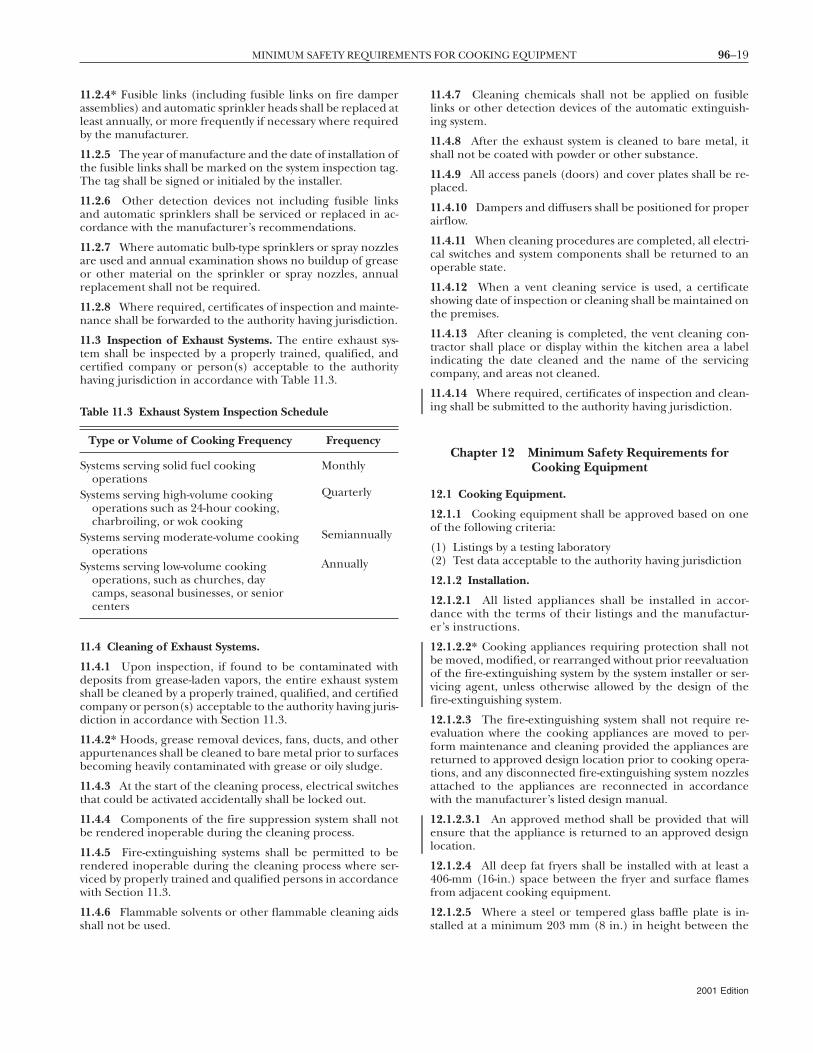
96–19MINIMUM SAFETY REQUIREMENTS FOR COOKING EQUIPMENT
11.2.4* Fusible links (including fusible links on fire damperassemblies) and automatic sprinkler heads shall be replaced atleast annually, or more frequently if necessary where requiredby the manufacturer.
11.2.5 The year of manufacture and the date of installation ofthe fusible links shall be marked on the system inspection tag.The tag shall be signed or initialed by the installer.
11.2.6 Other detection devices not including fusible linksand automatic sprinklers shall be serviced or replaced in ac-cordance with the manufacturer’s recommendations.
11.2.7 Where automatic bulb-type sprinklers or spray nozzlesare used and annual examination shows no buildup of greaseor other material on the sprinkler or spray nozzles, annualreplacement shall not be required.
11.2.8 Where required, certificates of inspection and mainte-nance shall be forwarded to the authority having jurisdiction.
11.3 Inspection of Exhaust Systems. The entire exhaust sys-tem shall be inspected by a properly trained, qualified, andcertified company or person(s) acceptable to the authorityhaving jurisdiction in accordance with Table 11.3.
11.4 Cleaning of Exhaust Systems.
11.4.1 Upon inspection, if found to be contaminated withdeposits from grease-laden vapors, the entire exhaust systemshall be cleaned by a properly trained, qualified, and certifiedcompany or person(s) acceptable to the authority having juris-diction in accordance with Section 11.3.
11.4.2* Hoods, grease removal devices, fans, ducts, and otherappurtenances shall be cleaned to bare metal prior to surfacesbecoming heavily contaminated with grease or oily sludge.
11.4.3 At the start of the cleaning process, electrical switchesthat could be activated accidentally shall be locked out.
11.4.4 Components of the fire suppression system shall notbe rendered inoperable during the cleaning process.
11.4.5 Fire-extinguishing systems shall be permitted to berendered inoperable during the cleaning process where ser-viced by properly trained and qualified persons in accordancewith Section 11.3.
11.4.6 Flammable solvents or other flammable cleaning aidsshall not be used.
Table 11.3 Exhaust System Inspection Schedule
Type or Volume of Cooking Frequency Frequency
Systems serving solid fuel cookingoperations
Monthly
Systems serving high-volume cookingoperations such as 24-hour cooking,charbroiling, or wok cooking
Quarterly
Systems serving moderate-volume cookingoperations
Semiannually
Systems serving low-volume cookingoperations, such as churches, daycamps, seasonal businesses, or seniorcenters
Annually
11.4.7 Cleaning chemicals shall not be applied on fusiblelinks or other detection devices of the automatic extinguish-ing system.
11.4.8 After the exhaust system is cleaned to bare metal, itshall not be coated with powder or other substance.
11.4.9 All access panels (doors) and cover plates shall be re-placed.
11.4.10 Dampers and diffusers shall be positioned for properairflow.
11.4.11 When cleaning procedures are completed, all electri-cal switches and system components shall be returned to anoperable state.
11.4.12 When a vent cleaning service is used, a certificateshowing date of inspection or cleaning shall be maintained onthe premises.
11.4.13 After cleaning is completed, the vent cleaning con-tractor shall place or display within the kitchen area a labelindicating the date cleaned and the name of the servicingcompany, and areas not cleaned.
11.4.14 Where required, certificates of inspection and clean-ing shall be submitted to the authority having jurisdiction.
Chapter 12 Minimum Safety Requirements forCooking Equipment
12.1 Cooking Equipment.
12.1.1 Cooking equipment shall be approved based on oneof the following criteria:
(1) Listings by a testing laboratory(2) Test data acceptable to the authority having jurisdiction
12.1.2 Installation.
12.1.2.1 All listed appliances shall be installed in accor-dance with the terms of their listings and the manufactur-er’s instructions.
12.1.2.2* Cooking appliances requiring protection shall notbe moved, modified, or rearranged without prior reevaluationof the fire-extinguishing system by the system installer or ser-vicing agent, unless otherwise allowed by the design of thefire-extinguishing system.
12.1.2.3 The fire-extinguishing system shall not require re-evaluation where the cooking appliances are moved to per-form maintenance and cleaning provided the appliances arereturned to approved design location prior to cooking opera-tions, and any disconnected fire-extinguishing system nozzlesattached to the appliances are reconnected in accordancewith the manufacturer’s listed design manual.
12.1.2.3.1 An approved method shall be provided that willensure that the appliance is returned to an approved designlocation.
12.1.2.4 All deep fat fryers shall be installed with at least a406-mm (16-in.) space between the fryer and surface flamesfrom adjacent cooking equipment.
12.1.2.5 Where a steel or tempered glass baffle plate is in-stalled at a minimum 203 mm (8 in.) in height between the
2001 Edition
96–20 VENTILATION CONTROL AND FIRE PROTECTION OF COMMERCIAL COOKING OPERATIONS
fryer and surface flames of the adjacent appliance the require-ment for a 406 mm (16 in.) space shall not apply.
12.1.2.5.1 If the fryer and the surface flames are at differenthorizontal planes, the minimum height of 203 mm (8 in.)shall be measured from the higher of the two.
12.2 Operating Controls. Deep fat fryers shall be equippedwith a separate high-limit control in addition to the adjustableoperating control (thermostat) to shut off fuel or energy whenthe fat temperature reaches 246°C (475°F) at 25.4 mm (1 in.)below the surface.
Chapter 13 Recirculating Systems
13.1 General Requirements. Recirculating systems contain-ing or for use with appliances used in processes producingsmoke or grease-laden vapors shall be equipped with compo-nents complying with the following:
(1) The clearance requirements of Section 4.2(2) A hood complying with the requirements of Chapter 5(3) Grease removal devices complying with Chapter 6(4) The air movement requirements of 8.2.1.2 and 8.2.2.3(5) Auxiliary equipment (such as particulate and odor re-
moval devices) complying with Chapter 9(6) Fire-extinguishing equipment complying with the require-
ments of Chapter 10; 10.1.1 and 10.5.1 shall not apply(7) The use and maintenance requirements of Chapter 11(8) The minimum safety requirements of Chapter 11(9) All the requirements of Chapter 13
13.2 Design Restrictions. All recirculating systems shall com-ply with the requirements of Section 13.2.
13.2.1 Only gas-fueled or electrically fueled cooking appli-ances shall be used.
13.2.2 Listed gas-fueled equipment designed for use with spe-cific recirculating systems shall have the flue outlets con-nected in the intended manner.
13.2.3 Gas-fueled appliances shall have a minimum457.2-mm (18-in.) clearance from the flue outlet to the filterinlet in accordance with 6.2.2 and shall meet the installationrequirements of NFPA 54, National Fuel Gas Code, or NFPA 58,Liquefied Petroleum Gas Code.
13.2.4 Recirculating systems shall be listed with a testinglaboratory.
13.2.5 There shall be no substitution or exchange of cookingappliances, filter components, blower components, or fire-extinguishing system components that would violate the list-ing of the appliance.
13.2.6 A recirculating system shall not use cooking equip-ment that exceeds that system’s labeled maximum limits forthat type of equipment, stated in maximum energy input,maximum cooking temperature, and maximum square areaof cooking surface or cubic volume of cooking cavity.
13.2.7 The listing label shall show the type(s) of cookingequipment tested and the preceding maximum limits speci-fied in 13.2.6.
13.2.8 A fire-actuated damper shall be installed at the ex-haust outlet of the system.
2001 Edition
13.2.9 The fire damper shall be constructed of at least thesame gauge as the shell.
13.2.10 The actuation device for the fire damper shall have amaximum temperature rating of 190ºC (375ºF).
13.2.11 The power supply of any electrostatic precipitator(ESP) shall be of the “cold spark,” ferro-resonant type inwhich the voltage falls off as the current draw of a short in-creases.
13.2.12 Listing evaluation shall include the following:
(1) Capture and containment of vapors at published and la-beled airflows
(2) Grease discharge at the exhaust outlet of the system not toexceed an average of 5 mg/m3 of exhausted air sampledfrom that equipment at maximum amount of productthat is capable of being processed over a continuous8-hour test per EPA Test Method 202, Determination of Con-densable Particulate Emissions for Stationary Sources, with thesystem operating at its minimum listed airflow
(3) Listing and labeling of clearance to combustibles from allsides, top, and bottom
(4) Electrical connection in the field in accordance withNFPA 70, National Electrical Code
(5) Interlocks on all removable components that lie in thepath of airflow within the unit to ensure that they are inplace during operation of the cooking appliance
13.3 Interlocks.
13.3.1 The recirculating system shall be provided with in-terlocks of all critical components and operations as indi-cated in 13.3.2 through 13.3.4 such that, if any of theseinterlocks are interrupted, the cooking appliance shall notbe able to operate.
13.3.2 All closure panels encompassing airflow sections shallhave interlocks to ensure the panels are in place and fullysealed.
13.3.3 Each filter component (grease and odor) shall havean interlock to prove the component is in place.
13.3.4 ESP Interlocks.
13.3.4.1 Each ESP shall have a sensor to prove its perfor-mance is as designed, with no interruption of the power toexceed 2 minutes.
13.3.4.2 The sensor shall be a manual reset device or circuit.
13.3.5 Airflow Switch or Transducer.
13.3.5.1 An airflow switch or transducer shall be providedafter the last filter component to ensure that a minimum air-flow is maintained.
13.3.5.2 The airflow switch or transducer shall open the in-terlock circuit when the airflow falls 25 percent below the sys-tem’s normal operating flow or 10 percent below its listedminimum rating, whichever is lower.
13.3.5.3 The airflow switch or transducer shall be a manualreset device or circuit.
13.4 Location and Application Restrictions.
13.4.1 The location of recirculating systems shall be ap-proved by the authority having jurisdiction.
96–21SOLID FUEL COOKING OPERATIONS
13.4.2 Items to be reviewed in the fire risk assessment shallinclude, but not be limited to, life safety, combustibility of sur-roundings, proximity to air vents, and total fuel load.
13.5 Additional Fire Safety Requirements.
13.5.1 In addition to the appliance nozzle(s), a recirculatingsystem shall be listed with the appropriate fire protection forgrease filters, grease filtration, odor filtration units, and duct-work where applicable.
13.5.2 In addition to any other fire-extinguishing system ac-tuation device, there shall be a fire-extinguishing system actua-tion device installed downstream of any ESP.
13.5.3 The requirements of Section 10.6 shall also apply torecirculating system locations.
13.5.4 A means of manual activation of the fire-extinguishingsystem shall be provided in an area where it is safely accessiblein the event of a fire in the appliance.
13.5.5 The manual activation device for the fire-extinguishingsystem shall be clearly identified.
13.6 Use and Maintenance.
13.6.1 Automatic or manual covers on cooking appliances,especially fryers, shall not interfere with the application of thefire suppression system.
13.6.2 All filters shall be cleaned or replaced in accordancewith the manufacturer’s instructions.
13.6.3 All ESPs shall be cleaned a minimum of once per weekfollowing manufacturer’s cleaning instructions.
13.6.4 The entire hood plenum and the blower section shallbe cleaned a minimum of once every 3 months.
13.6.5 Inspection and testing of the total operation and allsafety interlocks in accordance with the manufacturer’s in-structions shall be performed by qualified service personnel aminimum of once every 6 months or more frequently ifrequired.
13.6.6 Fire-extinguishing equipment shall be inspected in ac-cordance with Section 11.2.
13.6.7 A signed and dated log of maintenance as performedin accordance with 13.6.4 and 13.6.5 shall be available on thepremises for use by the authority having jurisdiction.
Chapter 14 Solid Fuel Cooking Operations
14.1 Venting Application. Venting requirements of solid fuelcooking operations shall be determined in accordance with14.1.1 through 14.1.7.
14.1.1 Where solid fuel cooking equipment is required by themanufacturer to have a natural draft, the vent shall complywith Section 14.4.
14.1.2 Where the solid fuel cooking equipment has a self-contained top, is the only appliance to be vented in an isolatedspace (except for a single water heater with its own separatevent), has a separate makeup air system, and is provided withsupply and return air (not supplied or returned from otherspaces), the system shall comply with Sections 14.4 and 14.6.
14.1.3 Where the solid fuel cooking equipment is located in aspace with other vented equipment, all vented equipment
shall have an exhaust system interlocked with a makeup airsystem for the space as per Section 14.6.
14.1.4 Natural draft ventilation systems and power-exhaustedventilation systems shall comply with Sections 14.3, 14.4, and14.6.
14.1.5 Where a solid fuel cooking appliance allows effluent toescape from the appliance opening, this opening shall be cov-ered by a hood and an exhaust system that meets the require-ments of Sections 14.3, 14.4, and 14.6.
14.1.6 Solid fuel cooking operations shall have spark arrest-ers to minimize the passage of airborne sparks and embersinto plenums and ducts.
14.1.7 Where the solid fuel cooking operation is not locatedunder a hood, a spark arrester shall be provided to minimizethe passage of sparks and embers into flues and chimneys.
14.2 Location of Appliances.
14.2.1 Every appliance shall be located with respect to build-ing construction and other equipment so as to permit accessto the appliance.
14.2.2* Solid fuel cooking appliances shall not be installed inconfined spaces.
14.2.3 Solid fuel cooking appliances listed for installation inconfined spaces such as alcoves shall be installed in accor-dance with the terms of the listing and the manufacturer’sinstructions.
14.2.4 Solid fuel cooking appliances shall not be installed inany location where gasoline or any other flammable vapors orgases are present.
14.3 Hoods for Solid Fuel Cooking.
14.3.1 Hoods shall be sized and located in a manner capableof capturing and containing all of the effluent dischargingfrom the appliances.
14.3.2 The hood and its exhaust system shall comply with therequirements of Chapters 5 through 10.
14.3.3 All solid fuel cooking equipment served by hood andduct systems shall be separate from all other exhaust systems.
14.3.4 Cooking equipment not requiring automatic fire-extinguishing equipment (as per the provisions of Chapter10) shall be permitted to be installed under a common hoodwith solid fuel cooking equipment that is served by a ductsystem separate from all other exhaust systems.
14.4 Exhaust for Solid Fuel Cooking. Where a hood is notrequired, in buildings where the duct system is three storiesor less in height, a duct complying with Chapter 7 shall beprovided.
14.4.1 If a hood is used in buildings where the duct system isthree stories or less in height, the duct system shall complywith Chapter 7.
14.4.2 A listed or approved grease duct system shall be pro-vided for solid fuel cooking exhaust systems that is four storiesin height or greater.
14.4.3 Where a hood is used, the duct system shall conformwith the requirements of Chapter 7.
14.4.4 Wall terminations of solid fuel exhaust systems shall beprohibited.
2001 Edition
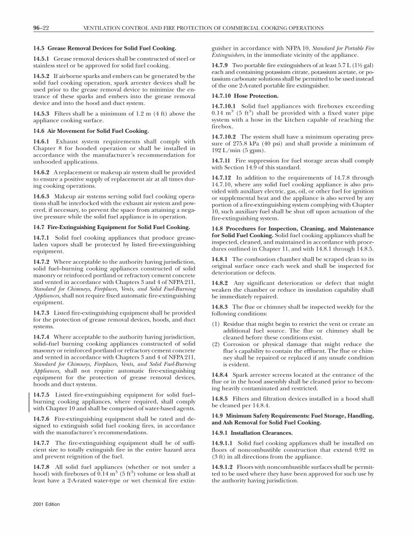
96–22 VENTILATION CONTROL AND FIRE PROTECTION OF COMMERCIAL COOKING OPERATIONS
14.5 Grease Removal Devices for Solid Fuel Cooking.
14.5.1 Grease removal devices shall be constructed of steel orstainless steel or be approved for solid fuel cooking.
14.5.2 If airborne sparks and embers can be generated by thesolid fuel cooking operation, spark arrester devices shall beused prior to the grease removal device to minimize the en-trance of these sparks and embers into the grease removaldevice and into the hood and duct system.
14.5.3 Filters shall be a minimum of 1.2 m (4 ft) above theappliance cooking surface.
14.6 Air Movement for Solid Fuel Cooking.
14.6.1 Exhaust system requirements shall comply withChapter 8 for hooded operation or shall be installed inaccordance with the manufacturer’s recommendation forunhooded applications.
14.6.2 A replacement or makeup air system shall be providedto ensure a positive supply of replacement air at all times dur-ing cooking operations.
14.6.3 Makeup air systems serving solid fuel cooking opera-tions shall be interlocked with the exhaust air system and pow-ered, if necessary, to prevent the space from attaining a nega-tive pressure while the solid fuel appliance is in operation.
14.7 Fire-Extinguishing Equipment for Solid Fuel Cooking.
14.7.1 Solid fuel cooking appliances that produce grease-laden vapors shall be protected by listed fire-extinguishingequipment.
14.7.2 Where acceptable to the authority having jurisdiction,solid fuel–burning cooking appliances constructed of solidmasonry or reinforced portland or refractory cement concreteand vented in accordance with Chapters 3 and 4 of NFPA 211,Standard for Chimneys, Fireplaces, Vents, and Solid Fuel-BurningAppliances, shall not require fixed automatic fire-extinguishingequipment.
14.7.3 Listed fire-extinguishing equipment shall be providedfor the protection of grease removal devices, hoods, and ductsystems.
14.7.4 Where acceptable to the authority having jurisdiction,solid–fuel burning cooking appliances constructed of solidmasonry or reinforced portland or refractory cement concreteand vented in accordance with Chapters 3 and 4 of NFPA 211,Standard for Chimneys, Fireplaces, Vents, and Solid Fuel-BurningAppliances, shall not require automatic fire-extinguishingequipment for the protection of grease removal devices,hoods and duct systems.
14.7.5 Listed fire-extinguishing equipment for solid fuel–burning cooking appliances, where required, shall complywith Chapter 10 and shall be comprised of water-based agents.
14.7.6 Fire-extinguishing equipment shall be rated and de-signed to extinguish solid fuel cooking fires, in accordancewith the manufacturer’s recommendations.
14.7.7 The fire-extinguishing equipment shall be of suffi-cient size to totally extinguish fire in the entire hazard areaand prevent reignition of the fuel.
14.7.8 All solid fuel appliances (whether or not under ahood) with fireboxes of 0.14 m3 (5 ft3) volume or less shall atleast have a 2-A-rated water-type or wet chemical fire extin-
2001 Edition
guisher in accordance with NFPA 10, Standard for Portable FireExtinguishers, in the immediate vicinity of the appliance.
14.7.9 Two portable fire extinguishers of at least 5.7 L (11⁄2 gal)each and containing potassium citrate, potassium acetate, or po-tassium carbonate solutions shall be permitted to be used insteadof the one 2-A-rated portable fire extinguisher.
14.7.10 Hose Protection.
14.7.10.1 Solid fuel appliances with fireboxes exceeding0.14 m3 (5 ft3) shall be provided with a fixed water pipesystem with a hose in the kitchen capable of reaching thefirebox.
14.7.10.2 The system shall have a minimum operating pres-sure of 275.8 kPa (40 psi) and shall provide a minimum of192 L/min (5 gpm).
14.7.11 Fire suppression for fuel storage areas shall complywith Section 14.9 of this standard.
14.7.12 In addition to the requirements of 14.7.8 through14.7.10, where any solid fuel cooking appliance is also pro-vided with auxiliary electric, gas, oil, or other fuel for ignitionor supplemental heat and the appliance is also served by anyportion of a fire-extinguishing system complying with Chapter10, such auxiliary fuel shall be shut off upon actuation of thefire-extinguishing system.
14.8 Procedures for Inspection, Cleaning, and Maintenancefor Solid Fuel Cooking. Solid fuel cooking appliances shall beinspected, cleaned, and maintained in accordance with proce-dures outlined in Chapter 11, and with 14.8.1 through 14.8.5.
14.8.1 The combustion chamber shall be scraped clean to itsoriginal surface once each week and shall be inspected fordeterioration or defects.
14.8.2 Any significant deterioration or defect that mightweaken the chamber or reduce its insulation capability shallbe immediately repaired.
14.8.3 The flue or chimney shall be inspected weekly for thefollowing conditions:
(1) Residue that might begin to restrict the vent or create anadditional fuel source. The flue or chimney shall becleaned before these conditions exist.
(2) Corrosion or physical damage that might reduce theflue’s capability to contain the effluent. The flue or chim-ney shall be repaired or replaced if any unsafe conditionis evident.
14.8.4 Spark arrester screens located at the entrance of theflue or in the hood assembly shall be cleaned prior to becom-ing heavily contaminated and restricted.
14.8.5 Filters and filtration devices installed in a hood shallbe cleaned per 14.8.4.
14.9 Minimum Safety Requirements: Fuel Storage, Handling,and Ash Removal for Solid Fuel Cooking.
14.9.1 Installation Clearances.
14.9.1.1 Solid fuel cooking appliances shall be installed onfloors of noncombustible construction that extend 0.92 m(3 ft) in all directions from the appliance.
14.9.1.2 Floors with noncombustible surfaces shall be permit-ted to be used where they have been approved for such use bythe authority having jurisdiction.
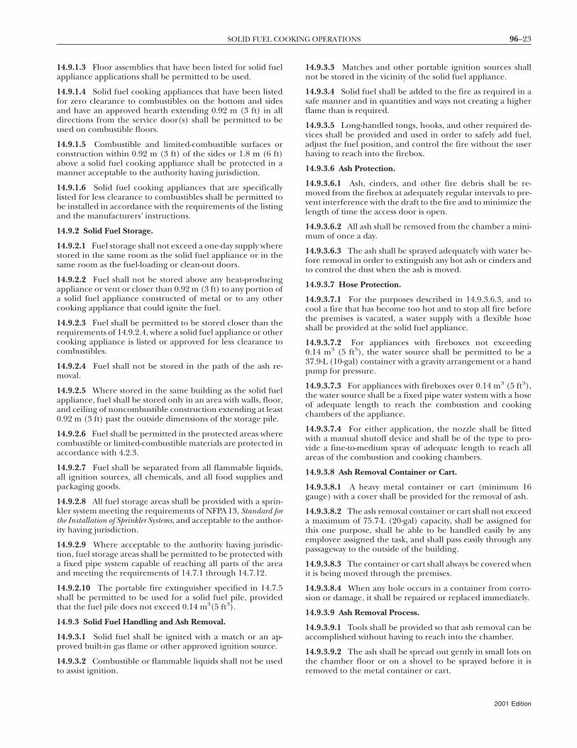
96–23SOLID FUEL COOKING OPERATIONS
14.9.1.3 Floor assemblies that have been listed for solid fuelappliance applications shall be permitted to be used.
14.9.1.4 Solid fuel cooking appliances that have been listedfor zero clearance to combustibles on the bottom and sidesand have an approved hearth extending 0.92 m (3 ft) in alldirections from the service door(s) shall be permitted to beused on combustible floors.
14.9.1.5 Combustible and limited-combustible surfaces orconstruction within 0.92 m (3 ft) of the sides or 1.8 m (6 ft)above a solid fuel cooking appliance shall be protected in amanner acceptable to the authority having jurisdiction.
14.9.1.6 Solid fuel cooking appliances that are specificallylisted for less clearance to combustibles shall be permitted tobe installed in accordance with the requirements of the listingand the manufacturers’ instructions.
14.9.2 Solid Fuel Storage.
14.9.2.1 Fuel storage shall not exceed a one-day supply wherestored in the same room as the solid fuel appliance or in thesame room as the fuel-loading or clean-out doors.
14.9.2.2 Fuel shall not be stored above any heat-producingappliance or vent or closer than 0.92 m (3 ft) to any portion ofa solid fuel appliance constructed of metal or to any othercooking appliance that could ignite the fuel.
14.9.2.3 Fuel shall be permitted to be stored closer than therequirements of 14.9.2.4, where a solid fuel appliance or othercooking appliance is listed or approved for less clearance tocombustibles.
14.9.2.4 Fuel shall not be stored in the path of the ash re-moval.
14.9.2.5 Where stored in the same building as the solid fuelappliance, fuel shall be stored only in an area with walls, floor,and ceiling of noncombustible construction extending at least0.92 m (3 ft) past the outside dimensions of the storage pile.
14.9.2.6 Fuel shall be permitted in the protected areas wherecombustible or limited-combustible materials are protected inaccordance with 4.2.3.
14.9.2.7 Fuel shall be separated from all flammable liquids,all ignition sources, all chemicals, and all food supplies andpackaging goods.
14.9.2.8 All fuel storage areas shall be provided with a sprin-kler system meeting the requirements of NFPA 13, Standard forthe Installation of Sprinkler Systems, and acceptable to the author-ity having jurisdiction.
14.9.2.9 Where acceptable to the authority having jurisdic-tion, fuel storage areas shall be permitted to be protected witha fixed pipe system capable of reaching all parts of the areaand meeting the requirements of 14.7.1 through 14.7.12.
14.9.2.10 The portable fire extinguisher specified in 14.7.5shall be permitted to be used for a solid fuel pile, providedthat the fuel pile does not exceed 0.14 m3(5 ft3).
14.9.3 Solid Fuel Handling and Ash Removal.
14.9.3.1 Solid fuel shall be ignited with a match or an ap-proved built-in gas flame or other approved ignition source.
14.9.3.2 Combustible or flammable liquids shall not be usedto assist ignition.
14.9.3.3 Matches and other portable ignition sources shallnot be stored in the vicinity of the solid fuel appliance.
14.9.3.4 Solid fuel shall be added to the fire as required in asafe manner and in quantities and ways not creating a higherflame than is required.
14.9.3.5 Long-handled tongs, hooks, and other required de-vices shall be provided and used in order to safely add fuel,adjust the fuel position, and control the fire without the userhaving to reach into the firebox.
14.9.3.6 Ash Protection.
14.9.3.6.1 Ash, cinders, and other fire debris shall be re-moved from the firebox at adequately regular intervals to pre-vent interference with the draft to the fire and to minimize thelength of time the access door is open.
14.9.3.6.2 All ash shall be removed from the chamber a mini-mum of once a day.
14.9.3.6.3 The ash shall be sprayed adequately with water be-fore removal in order to extinguish any hot ash or cinders andto control the dust when the ash is moved.
14.9.3.7 Hose Protection.
14.9.3.7.1 For the purposes described in 14.9.3.6.3, and tocool a fire that has become too hot and to stop all fire beforethe premises is vacated, a water supply with a flexible hoseshall be provided at the solid fuel appliance.
14.9.3.7.2 For appliances with fireboxes not exceeding0.14 m3 (5 ft3), the water source shall be permitted to be a37.9-L (10-gal) container with a gravity arrangement or a handpump for pressure.
14.9.3.7.3 For appliances with fireboxes over 0.14 m3 (5 ft3),the water source shall be a fixed pipe water system with a hoseof adequate length to reach the combustion and cookingchambers of the appliance.
14.9.3.7.4 For either application, the nozzle shall be fittedwith a manual shutoff device and shall be of the type to pro-vide a fine-to-medium spray of adequate length to reach allareas of the combustion and cooking chambers.
14.9.3.8 Ash Removal Container or Cart.
14.9.3.8.1 A heavy metal container or cart (minimum 16gauge) with a cover shall be provided for the removal of ash.
14.9.3.8.2 The ash removal container or cart shall not exceeda maximum of 75.7-L (20-gal) capacity, shall be assigned forthis one purpose, shall be able to be handled easily by anyemployee assigned the task, and shall pass easily through anypassageway to the outside of the building.
14.9.3.8.3 The container or cart shall always be covered whenit is being moved through the premises.
14.9.3.8.4 When any hole occurs in a container from corro-sion or damage, it shall be repaired or replaced immediately.
14.9.3.9 Ash Removal Process.
14.9.3.9.1 Tools shall be provided so that ash removal can beaccomplished without having to reach into the chamber.
14.9.3.9.2 The ash shall be spread out gently in small lots onthe chamber floor or on a shovel to be sprayed before it isremoved to the metal container or cart.
2001 Edition
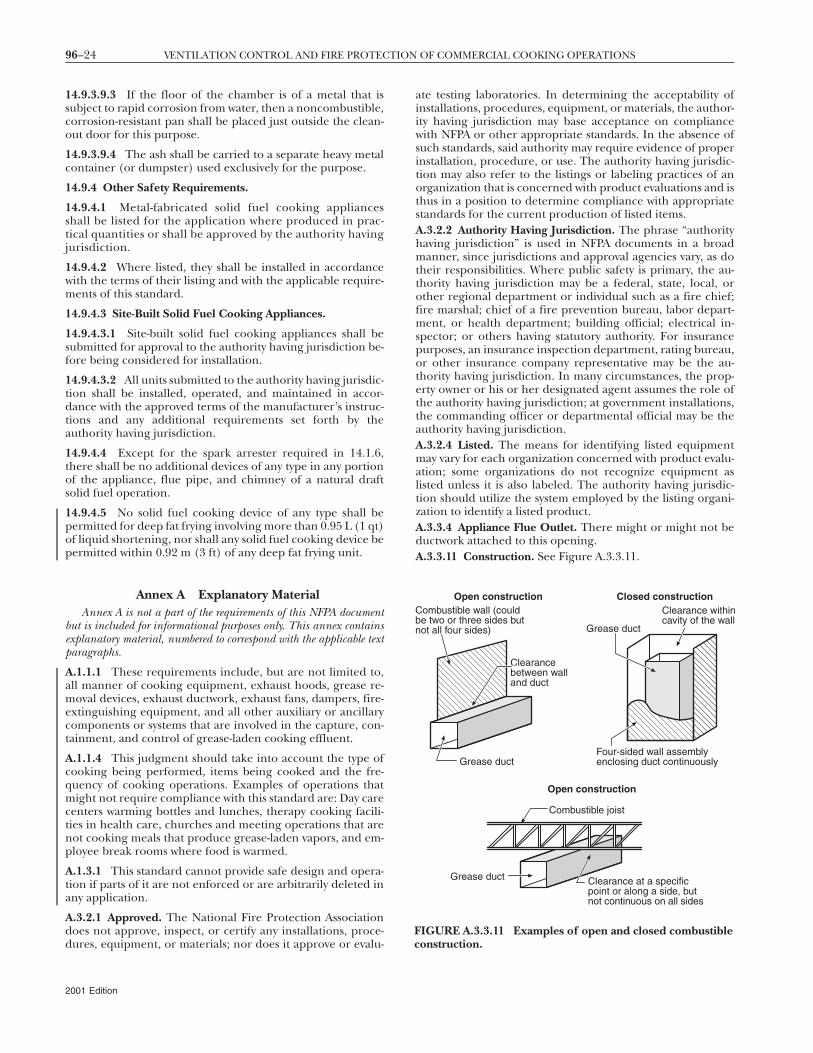
96–24 VENTILATION CONTROL AND FIRE PROTECTION OF COMMERCIAL COOKING OPERATIONS
14.9.3.9.3 If the floor of the chamber is of a metal that issubject to rapid corrosion from water, then a noncombustible,corrosion-resistant pan shall be placed just outside the clean-out door for this purpose.
14.9.3.9.4 The ash shall be carried to a separate heavy metalcontainer (or dumpster) used exclusively for the purpose.
14.9.4 Other Safety Requirements.
14.9.4.1 Metal-fabricated solid fuel cooking appliancesshall be listed for the application where produced in prac-tical quantities or shall be approved by the authority havingjurisdiction.
14.9.4.2 Where listed, they shall be installed in accordancewith the terms of their listing and with the applicable require-ments of this standard.
14.9.4.3 Site-Built Solid Fuel Cooking Appliances.
14.9.4.3.1 Site-built solid fuel cooking appliances shall besubmitted for approval to the authority having jurisdiction be-fore being considered for installation.
14.9.4.3.2 All units submitted to the authority having jurisdic-tion shall be installed, operated, and maintained in accor-dance with the approved terms of the manufacturer’s instruc-tions and any additional requirements set forth by theauthority having jurisdiction.
14.9.4.4 Except for the spark arrester required in 14.1.6,there shall be no additional devices of any type in any portionof the appliance, flue pipe, and chimney of a natural draftsolid fuel operation.
14.9.4.5 No solid fuel cooking device of any type shall bepermitted for deep fat frying involving more than 0.95 L (1 qt)of liquid shortening, nor shall any solid fuel cooking device bepermitted within 0.92 m (3 ft) of any deep fat frying unit.
Annex A Explanatory MaterialAnnex A is not a part of the requirements of this NFPA document
but is included for informational purposes only. This annex containsexplanatory material, numbered to correspond with the applicable textparagraphs.
A.1.1.1 These requirements include, but are not limited to,all manner of cooking equipment, exhaust hoods, grease re-moval devices, exhaust ductwork, exhaust fans, dampers, fire-extinguishing equipment, and all other auxiliary or ancillarycomponents or systems that are involved in the capture, con-tainment, and control of grease-laden cooking effluent.
A.1.1.4 This judgment should take into account the type ofcooking being performed, items being cooked and the fre-quency of cooking operations. Examples of operations thatmight not require compliance with this standard are: Day carecenters warming bottles and lunches, therapy cooking facili-ties in health care, churches and meeting operations that arenot cooking meals that produce grease-laden vapors, and em-ployee break rooms where food is warmed.
A.1.3.1 This standard cannot provide safe design and opera-tion if parts of it are not enforced or are arbitrarily deleted inany application.
A.3.2.1 Approved. The National Fire Protection Associationdoes not approve, inspect, or certify any installations, proce-dures, equipment, or materials; nor does it approve or evalu-
2001 Edition
ate testing laboratories. In determining the acceptability ofinstallations, procedures, equipment, or materials, the author-ity having jurisdiction may base acceptance on compliancewith NFPA or other appropriate standards. In the absence ofsuch standards, said authority may require evidence of properinstallation, procedure, or use. The authority having jurisdic-tion may also refer to the listings or labeling practices of anorganization that is concerned with product evaluations and isthus in a position to determine compliance with appropriatestandards for the current production of listed items.A.3.2.2 Authority Having Jurisdiction. The phrase “authorityhaving jurisdiction” is used in NFPA documents in a broadmanner, since jurisdictions and approval agencies vary, as dotheir responsibilities. Where public safety is primary, the au-thority having jurisdiction may be a federal, state, local, orother regional department or individual such as a fire chief;fire marshal; chief of a fire prevention bureau, labor depart-ment, or health department; building official; electrical in-spector; or others having statutory authority. For insurancepurposes, an insurance inspection department, rating bureau,or other insurance company representative may be the au-thority having jurisdiction. In many circumstances, the prop-erty owner or his or her designated agent assumes the role ofthe authority having jurisdiction; at government installations,the commanding officer or departmental official may be theauthority having jurisdiction.A.3.2.4 Listed. The means for identifying listed equipmentmay vary for each organization concerned with product evalu-ation; some organizations do not recognize equipment aslisted unless it is also labeled. The authority having jurisdic-tion should utilize the system employed by the listing organi-zation to identify a listed product.A.3.3.4 Appliance Flue Outlet. There might or might not beductwork attached to this opening.A.3.3.11 Construction. See Figure A.3.3.11.
Open construction Closed constructionCombustible wall (couldbe two or three sides butnot all four sides)
Clearancebetween walland duct
Grease duct
Grease duct
Clearance withincavity of the wall
Four-sided wall assemblyenclosing duct continuously
Open construction
Combustible joist
Clearance at a specificpoint or along a side, butnot continuous on all sides
Grease duct
IGURE A.3.3.11 Examples of open and closed combustibleonstruction.
Fc
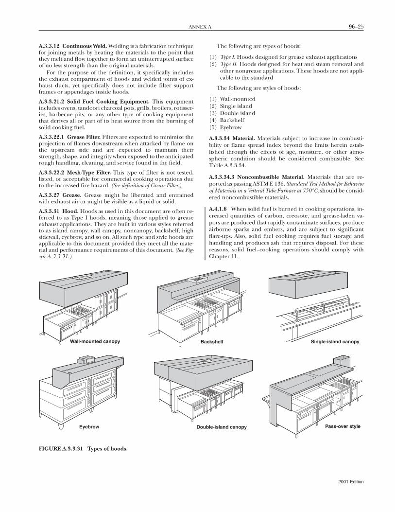
96–25ANNEX A
A.3.3.12 Continuous Weld. Welding is a fabrication techniquefor joining metals by heating the materials to the point thatthey melt and flow together to form an uninterrupted surfaceof no less strength than the original materials.
For the purpose of the definition, it specifically includesthe exhaust compartment of hoods and welded joints of ex-haust ducts, yet specifically does not include filter supportframes or appendages inside hoods.
A.3.3.21.2 Solid Fuel Cooking Equipment. This equipmentincludes ovens, tandoori charcoal pots, grills, broilers, rotisser-ies, barbecue pits, or any other type of cooking equipmentthat derives all or part of its heat source from the burning ofsolid cooking fuel.
A.3.3.22.1 Grease Filter. Filters are expected to minimize theprojection of flames downstream when attacked by flame onthe upstream side and are expected to maintain theirstrength, shape, and integrity when exposed to the anticipatedrough handling, cleaning, and service found in the field.
A.3.3.22.2 Mesh-Type Filter. This type of filter is not tested,listed, or acceptable for commercial cooking operations dueto the increased fire hazard. (See definition of Grease Filter.)
A.3.3.27 Grease. Grease might be liberated and entrainedwith exhaust air or might be visible as a liquid or solid.
A.3.3.31 Hood. Hoods as used in this document are often re-ferred to as Type I hoods, meaning those applied to greaseexhaust applications. They are built in various styles referredto as island canopy, wall canopy, noncanopy, backshelf, highsidewall, eyebrow, and so on. All such type and style hoods areapplicable to this document provided they meet all the mate-rial and performance requirements of this document. (See Fig-ure A.3.3.31.)
Wall-mounted canopy
Eyebrow
The following are types of hoods:
(1) Type I. Hoods designed for grease exhaust applications(2) Type II. Hoods designed for heat and steam removal and
other nongrease applications. These hoods are not appli-cable to the standard
The following are styles of hoods:
(1) Wall-mounted(2) Single island(3) Double island(4) Backshelf(5) Eyebrow
A.3.3.34 Material. Materials subject to increase in combusti-bility or flame spread index beyond the limits herein estab-lished through the effects of age, moisture, or other atmo-spheric condition should be considered combustible. SeeTable A.3.3.34.
A.3.3.34.3 Noncombustible Material. Materials that are re-ported as passing ASTM E 136, Standard Test Method for Behaviorof Materials in a Vertical Tube Furnace at 750°C, should be consid-ered noncombustible materials.
A.4.1.6 When solid fuel is burned in cooking operations, in-creased quantities of carbon, creosote, and grease-laden va-pors are produced that rapidly contaminate surfaces, produceairborne sparks and embers, and are subject to significantflare-ups. Also, solid fuel cooking requires fuel storage andhandling and produces ash that requires disposal. For thesereasons, solid fuel–cooking operations should comply withChapter 11.
Pass-over style
Single-island canopykshelf
le-island canopy
Bac
Doub
FIGURE A.3.3.31 Types of hoods.
2001 Edition
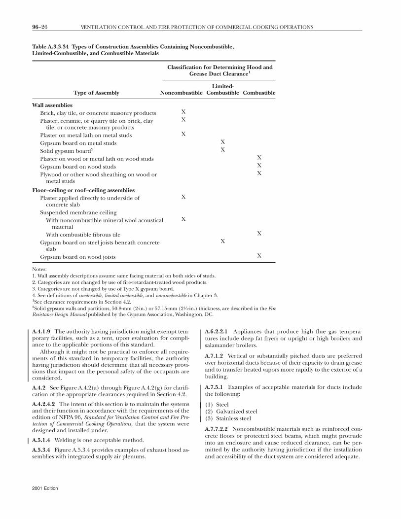
gton,
96–26 VENTILATION CONTROL AND FIRE PROTECTION OF COMMERCIAL COOKING OPERATIONS
A.4.1.9 The authority having jurisdiction might exempt tem-porary facilities, such as a tent, upon evaluation for compli-ance to the applicable portions of this standard.
Although it might not be practical to enforce all require-ments of this standard in temporary facilities, the authorityhaving jurisdiction should determine that all necessary provi-sions that impact on the personal safety of the occupants areconsidered.
A.4.2 See Figure A.4.2(a) through Figure A.4.2(g) for clarifi-cation of the appropriate clearances required in Section 4.2.
A.4.2.4.2 The intent of this section is to maintain the systemsand their function in accordance with the requirements of theedition of NFPA 96, Standard for Ventilation Control and Fire Pro-tection of Commercial Cooking Operations, that the system weredesigned and installed under.
A.5.1.4 Welding is one acceptable method.
A.5.3.4 Figure A.5.3.4 provides examples of exhaust hood as-
Table A.3.3.34 Types of Construction Assemblies ContainingLimited-Combustible, and Combustible Materials
ClassificaG
Type of Assembly Noncombus
Wall assembliesBrick, clay tile, or concrete masonry products X
Plaster, ceramic, or quarry tile on brick, claytile, or concrete masonry products
X
Plaster on metal lath on metal studs X
Gypsum board on metal studsSolid gypsum board2
Plaster on wood or metal lath on wood studsGypsum board on wood studsPlywood or other wood sheathing on wood or
metal studs
Floor–ceiling or roof–ceiling assembliesPlaster applied directly to underside of
concrete slabX
Suspended membrane ceilingWith noncombustible mineral wool acoustical
materialX
With combustible fibrous tileGypsum board on steel joists beneath concrete
slabGypsum board on wood joists
Notes:1. Wall assembly descriptions assume same facing material on both sid2. Categories are not changed by use of fire-retardant-treated wood pr3. Categories are not changed by use of Type X gypsum board.4. See definitions of combustible, limited-combustible, and noncombustible in1See clearance requirements in Section 4.2.2Solid gypsum walls and partitions, 50.8-mm (2-in.) or 57.15-mm (21⁄4-iResistance Design Manual published by the Gypsum Association, Washin
semblies with integrated supply air plenums.
2001 Edition
A.6.2.2.1 Appliances that produce high flue gas tempera-tures include deep fat fryers or upright or high broilers andsalamander broilers.
A.7.1.2 Vertical or substantially pitched ducts are preferredover horizontal ducts because of their capacity to drain greaseand to transfer heated vapors more rapidly to the exterior of abuilding.
A.7.5.1 Examples of acceptable materials for ducts includethe following:
(1) Steel(2) Galvanized steel(3) Stainless steel
A.7.7.2.2 Noncombustible materials such as reinforced con-crete floors or protected steel beams, which might protrudeinto an enclosure and cause reduced clearance, can be per-mitted by the authority having jurisdiction if the installation
mbustible,
or Determining Hood andDuct Clearance1
Limited-Combustible Combustible
XX
XXX
XX
X
tuds..
ter 3.
ckness, are described in the FireDC.
Nonco
tion frease
tible
es of soducts
Chap
n.) thi
and accessibility of the duct system are considered adequate.
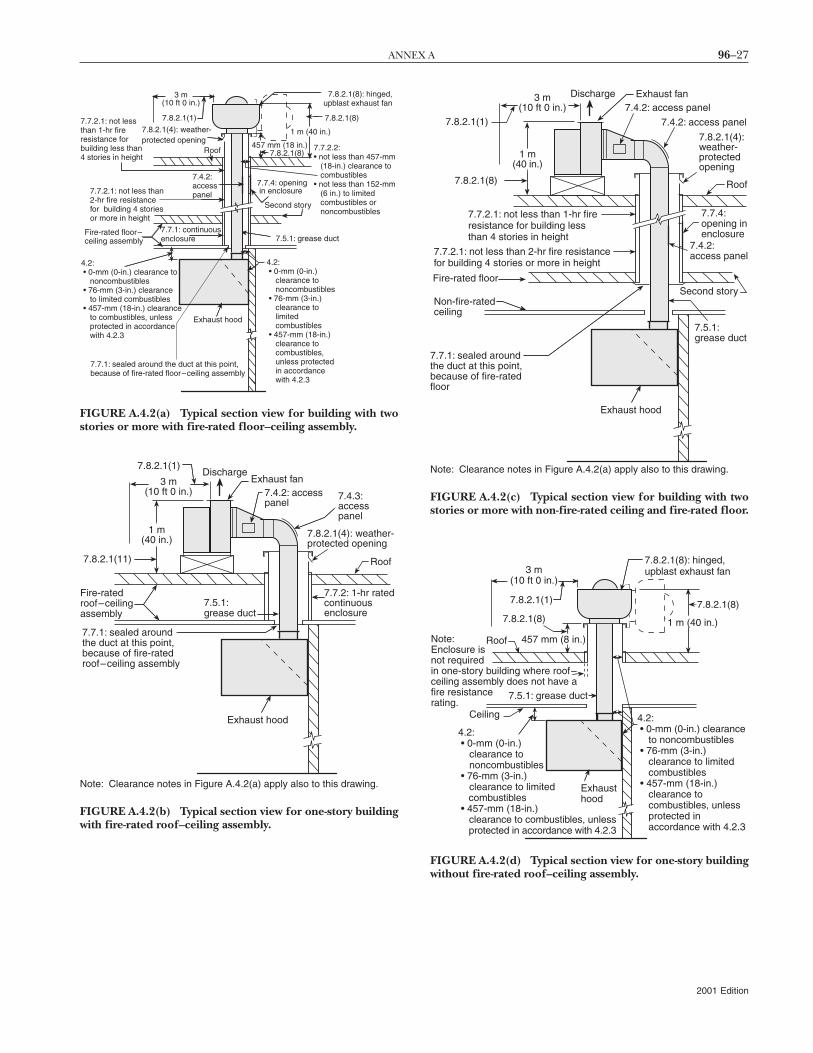
96–27ANNEX A
7.8.2.1(8)
3 m(10 ft 0 in.)
7.7.2.1: not lessthan 1-hr fireresistance forbuilding less than4 stories in height
7.8.2.1(4): weather-protected opening
7.7.2.1: not less than2-hr fire resistancefor building 4 storiesor more in height
Fire-rated floor–ceiling assembly
7.7.1: continuousenclosure
7.7.1: sealed around the duct at this point,because of fire-rated floor–ceiling assembly
Exhaust hood
4.2: • 0-mm (0-in.)
clearance tononcombustibles
• 76-mm (3-in.)clearance tolimitedcombustibles
• 457-mm (18-in.)clearance tocombustibles,unless protectedin accordancewith 4.2.3
7.5.1: grease duct
Second story
7.7.4: opening in enclosure
7.8.2.1(8)
7.8.2.1(8): hinged,upblast exhaust fan
7.4.2:accesspanel
7.8.2.1(1)
4.2: • 0-mm (0-in.) clearance to
noncombustibles • 76-mm (3-in.) clearance
to limited combustibles • 457-mm (18-in.) clearance
to combustibles, unlessprotected in accordancewith 4.2.3
1 m (40 in.)
457 mm (18 in.)Roof 7.7.2.2:
• not less than 457-mm(18-in.) clearance tocombustibles
• not less than 152-mm(6 in.) to limitedcombustibles ornoncombustibles
FIGURE A.4.2(a) Typical section view for building with twostories or more with fire-rated floor–ceiling assembly.
3 m(10 ft 0 in.)
Fire-ratedroof–ceilingassembly
7.7.1: sealed aroundthe duct at this point,because of fire-ratedroof–ceiling assembly
Exhaust hood
7.5.1:grease duct
7.7.2: 1-hr ratedcontinuousenclosure
7.8.2.1(11)
DischargeExhaust fan
7.4.3:accesspanel
7.8.2.1(4): weather-protected opening
Roof
Note: Clearance notes in Figure A.4.2(a) apply also to this drawing.
1 m(40 in.)
7.8.2.1(1)
7.4.2: accesspanel
FIGURE A.4.2(b) Typical section view for one-story buildingwith fire-rated roof–ceiling assembly.
7.7.2.1: not less than 1-hr fireresistance for building lessthan 4 stories in height
1 m(40 in.)
Note: Clearance notes in Figure A.4.2(a) apply also to this drawing.
Fire-rated floor
7.8.2.1(8)
7.8.2.1(1)
Discharge Exhaust fan7.4.2: access panel
7.4.2: access panel
7.8.2.1(4):weather-protectedopening
Roof
7.7.1: sealed aroundthe duct at this point,because of fire-ratedfloor
Exhaust hood
Non-fire-ratedceiling
7.7.2.1: not less than 2-hr fire resistancefor building 4 stories or more in height
7.4.2:access panel
7.7.4:opening inenclosure
Second story
7.5.1:grease duct
3 m(10 ft 0 in.)
FIGURE A.4.2(c) Typical section view for building with twostories or more with non-fire-rated ceiling and fire-rated floor.
457 mm (8 in.)
4.2: • 0-mm (0-in.)
clearance tononcombustibles
• 76-mm (3-in.)clearance to limited
combustibles • 457-mm (18-in.)
clearance to combustibles, unlessprotected in accordance with 4.2.3
Roof
Exhausthood
Ceiling
Note:Enclosure isnot requiredin one-story building where roof–ceiling assembly does not have afire resistancerating.
3 m(10 ft 0 in.)
4.2: • 0-mm (0-in.) clearance
to noncombustibles • 76-mm (3-in.)
clearance to limitedcombustibles
• 457-mm (18-in.)clearance tocombustibles, unlessprotected inaccordance with 4.2.3
7.5.1: grease duct
7.8.2.1(8)
7.8.2.1(8): hinged,upblast exhaust fan
1 m (40 in.)
7.8.2.1(1)
7.8.2.1(8)
FIGURE A.4.2(d) Typical section view for one-story buildingwithout fire-rated roof–ceiling assembly.
2001 Edition
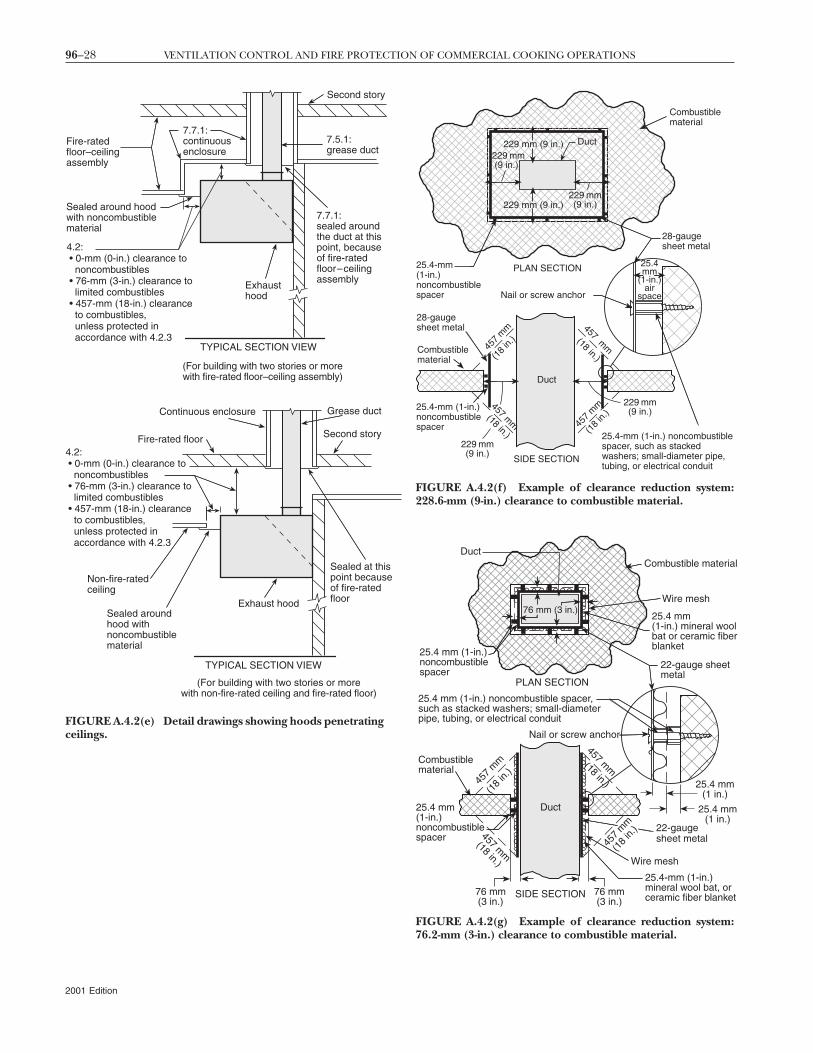
se
l
l
96–28 VENTILATION CONTROL AND FIRE PROTECTION OF COMMERCIAL COOKING OPERATIONS
4.2: • 0-mm (0-in.) clearance to noncombustibles • 76-mm (3-in.) clearance to limited combustibles • 457-mm (18-in.) clearance to combustibles,
unless protected in accordance with 4.2.3
7.7.1:continuousenclosure
7.5.1:grease duct
Fire-ratedfloor–ceilingassembly
Sealed around hoodwith noncombustiblematerial
7.7.1:sealed aroundthe duct at thispoint, becauseof fire-ratedfloor–ceilingassembly
Exhausthood
TYPICAL SECTION VIEW
(For building with two stories or morewith fire-rated floor–ceiling assembly)
(For building with two stories or morewith non-fire-rated ceiling and fire-rated floor)
Non-fire-ratedceiling
Sealed aroundhood withnoncombustiblematerial
Sealed at thipoint becausof fire-ratedfloorExhaust hood
Fire-rated floor
Second story
Continuous enclosure Grease duct
Second story
4.2: • 0-mm (0-in.) clearance to noncombustibles • 76-mm (3-in.) clearance to limited combustibles • 457-mm (18-in.) clearance to combustibles,
unless protected in accordance with 4.2.3
TYPICAL SECTION VIEW
FIGURE A.4.2(e) Detail drawings showing hoods penetratingceilings.
2001 Edition
Duct
28-gaugesheet metal
PLAN SECTION
Nail or screw anchor
25.4-mm(1-in.)noncombustiblespacer
Combustiblematerial
28-gaugesheet metal
Duct
(18
in.)
(18
in.)(18 in.)
(18 in.)
SIDE SECTION
25.4-mm (1-in.) noncombustiblespacer, such as stackedwashers; small-diameter pipe,tubing, or electrical conduit
25.4mm
(1-in.)air
space
Combustiblematerial
229 mm (9 in.)
229 mm(9 in.)229 mm (9 in.)
229 mm (9 in.)
25.4-mm (1-in.)noncombustiblespacer
229 mm(9 in.)
457
mm457 m
m
457
mm 457 m
m
229 mm(9 in.)
FIGURE A.4.2(f) Example of clearance reduction system:228.6-mm (9-in.) clearance to combustible material.
22-gauge sheetmetal
PLAN SECTION
Nail or screw anchor
Combustiblematerial
22-gaugesheet metal
Duct
(18
in.)
(18 in.)
SIDE SECTION
25.4 mm (1-in.) noncombustible spacer,such as stacked washers; small-diameterpipe, tubing, or electrical conduit
Wire mesh
25.4-mm (1-in.)mineral wool bat, orceramic fiber blanket
Combustible materiaDuct
Wire mesh
25.4 mm (1-in.)noncombustiblespacer
25.4 mm(1-in.) mineral woobat or ceramic fiberblanket
76 mm (3 in.)
25.4 mm(1-in.)noncombustiblespacer
25.4 mm(1 in.)
25.4 mm(1 in.)
76 mm(3 in.)
76 mm(3 in.)
457 mm
457
mm
457 mm
(18 in.)
457
mm
(18
in.)
FIGURE A.4.2(g) Example of clearance reduction system:76.2-mm (3-in.) clearance to combustible material.
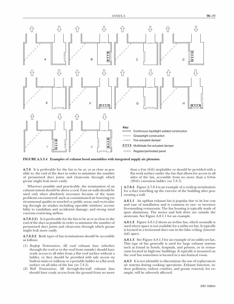
ntegra
96–29ANNEX A
A.7.8 It is preferable for the fan to be at, or as close as pos-sible to, the end of the duct in order to minimize the numberof pressurized duct joints and clean-outs through whichgrease might leak more easily.
Wherever possible and practicable, the termination of anexhaust system should be above a roof. Fans on walls should beused only when absolutely necessary because of the manyproblems encountered: such as contaminated air lowering en-vironmental quality in traveled or public areas; and recirculat-ing through air intakes including operable windows’ accessi-bility to vandalism and accidental damage; and strong windcurrents restricting airflow.
A.7.8.1(1) It is preferable for the fan to be at or as close to theend of the duct as possible in order to minimize the number ofpressurized duct joints and clean-outs through which greasemight leak more easily.
A.7.8.2.2 Both types of fan terminations should be accessibleas follows:
(1) Rooftop Terminations. All roof exhaust fans (whetherthrough the roof or to the roof from outside) should haveready access to all sides from a flat roof surface without aladder, or they should be provided with safe access viabuilt-in stairs or walkway or a portable ladder to a flat worksurface on all sides of the fan (see 7.8.2).
(2) Wall Terminations. All through-the-wall exhaust fansshould have ready access from the ground from no more
A B
E F
I J
FIGURE A.5.3.4 Examples of exhaust hood assemblies with i
than a 2-m (6-ft) stepladder or should be provided with aflat work surface under the fan that allows for access to allsides of the fan, accessible from no more than a 6.0-m(20-ft) extension ladder (see 7.8.3).
A.7.8.4 Figure A.7.8.4 is an example of a rooftop terminationfor a duct travelling up the exterior of the building after pen-etrating a wall.
A.8.1.1 An upblast exhaust fan is popular due to its low costand ease of installation and is common in one- or two-storyfreestanding restaurants. The fan housing is typically made ofspun aluminum. The motor and belt drive are outside theairstream. See Figure A.8.1.1 for an example.
A.8.1.2 Figure A.8.1.2 shows an in-line fan, which normally isused where space is not available for a utility set fan. It typicallyis located in a horizontal duct run in the false ceiling (intersti-tial) space.
A.8.1.3 See Figure A.8.1.3 for an example of an utility set fan.This type of fan generally is used for large exhaust systemssuch as found in hotels, hospitals, and prisons, or in restau-rants located in high-rise buildings. It typically is mounted onthe roof but sometimes is located in a mechanical room.
A.8.3 It is not advisable to discontinue the use of replacementair systems during cooking operations. Exhaust function, in-door pollution, indoor comfort, and grease removal, for ex-ample, will be adversely affected.
C D
G H
Continuous liquidtight welded construction
Greasetight construction
Fire-actuated damper
Multiblade fire-actuated damper
Register/perforated panel
ey:
ted supply air plenums.
K
2001 Edition
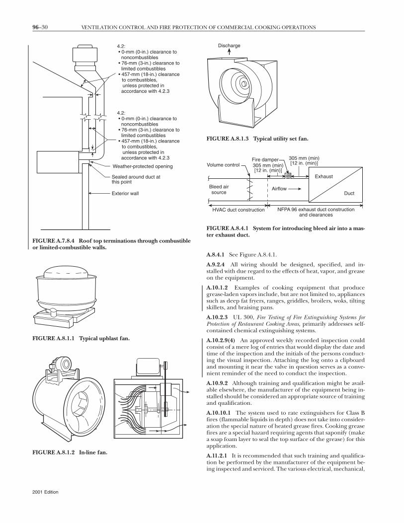
96–30 VENTILATION CONTROL AND FIRE PROTECTION OF COMMERCIAL COOKING OPERATIONS
Weather-protected opening
Sealed around duct atthis point
Exterior wall
4.2: • 0-mm (0-in.) clearance to noncombustibles • 76-mm (3-in.) clearance to limited combustibles • 457-mm (18-in.) clearance to combustibles,
unless protected in accordance with 4.2.3
4.2: • 0-mm (0-in.) clearance to noncombustibles • 76-mm (3-in.) clearance to limited combustibles • 457-mm (18-in.) clearance to combustibles,
unless protected in accordance with 4.2.3
FIGURE A.7.8.4 Roof top terminations through combustibleor limited-combustible walls.
FIGURE A.8.1.1 Typical upblast fan.
FIGURE A.8.1.2 In-line fan.
2001 Edition
A.8.4.1 See Figure A.8.4.1.
A.9.2.4 All wiring should be designed, specified, and in-stalled with due regard to the effects of heat, vapor, and greaseon the equipment.
A.10.1.2 Examples of cooking equipment that producegrease-laden vapors include, but are not limited to, appliancessuch as deep fat fryers, ranges, griddles, broilers, woks, tiltingskillets, and braising pans.
A.10.2.3 UL 300, Fire Testing of Fire Extinguishing Systems forProtection of Restaurant Cooking Areas, primarily addresses self-contained chemical extinguishing systems.
A.10.2.9(4) An approved weekly recorded inspection couldconsist of a mere log of entries that would display the date andtime of the inspection and the initials of the persons conduct-ing the visual inspection. Attaching the log onto a clipboardand mounting it near the valve in question serves as a conve-nient reminder of the need to conduct the inspection.
A.10.9.2 Although training and qualification might be avail-able elsewhere, the manufacturer of the equipment being in-stalled should be considered an appropriate source of trainingand qualification.
A.10.10.1 The system used to rate extinguishers for Class Bfires (flammable liquids in depth) does not take into consider-ation the special nature of heated grease fires. Cooking greasefires are a special hazard requiring agents that saponify (makea soap foam layer to seal the top surface of the grease) for thisapplication.
A.11.2.1 It is recommended that such training and qualifica-tion be performed by the manufacturer of the equipment be-ing inspected and serviced. The various electrical, mechanical,
Fire damper
Airflow
Volume control
Bleed airsource
HVAC duct construction NFPA 96 exhaust duct constructionand clearances
Exhaust
Duct
305 mm (min)[12 in. (min)]
305 mm (min)[12 in. (min)]
FIGURE A.8.4.1 System for introducing bleed air into a mas-ter exhaust duct.
Discharge
FIGURE A.8.1.3 Typical utility set fan.
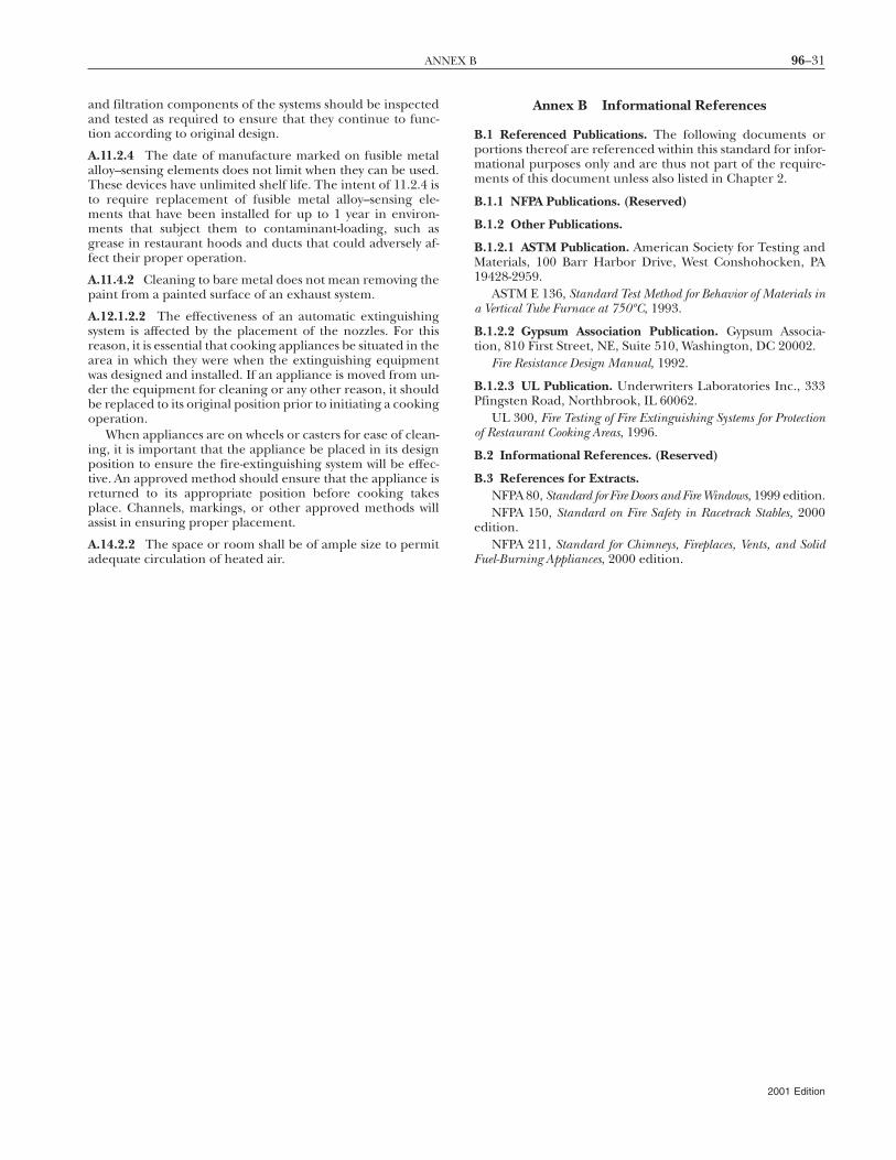
96–31ANNEX B
and filtration components of the systems should be inspectedand tested as required to ensure that they continue to func-tion according to original design.
A.11.2.4 The date of manufacture marked on fusible metalalloy–sensing elements does not limit when they can be used.These devices have unlimited shelf life. The intent of 11.2.4 isto require replacement of fusible metal alloy–sensing ele-ments that have been installed for up to 1 year in environ-ments that subject them to contaminant-loading, such asgrease in restaurant hoods and ducts that could adversely af-fect their proper operation.
A.11.4.2 Cleaning to bare metal does not mean removing thepaint from a painted surface of an exhaust system.
A.12.1.2.2 The effectiveness of an automatic extinguishingsystem is affected by the placement of the nozzles. For thisreason, it is essential that cooking appliances be situated in thearea in which they were when the extinguishing equipmentwas designed and installed. If an appliance is moved from un-der the equipment for cleaning or any other reason, it shouldbe replaced to its original position prior to initiating a cookingoperation.
When appliances are on wheels or casters for ease of clean-ing, it is important that the appliance be placed in its designposition to ensure the fire-extinguishing system will be effec-tive. An approved method should ensure that the appliance isreturned to its appropriate position before cooking takesplace. Channels, markings, or other approved methods willassist in ensuring proper placement.
A.14.2.2 The space or room shall be of ample size to permitadequate circulation of heated air.
Annex B Informational References
B.1 Referenced Publications. The following documents orportions thereof are referenced within this standard for infor-mational purposes only and are thus not part of the require-ments of this document unless also listed in Chapter 2.
B.1.1 NFPA Publications. (Reserved)
B.1.2 Other Publications.
B.1.2.1 ASTM Publication. American Society for Testing andMaterials, 100 Barr Harbor Drive, West Conshohocken, PA19428-2959.
ASTM E 136, Standard Test Method for Behavior of Materials ina Vertical Tube Furnace at 750ºC, 1993.
B.1.2.2 Gypsum Association Publication. Gypsum Associa-tion, 810 First Street, NE, Suite 510, Washington, DC 20002.
Fire Resistance Design Manual, 1992.
B.1.2.3 UL Publication. Underwriters Laboratories Inc., 333Pfingsten Road, Northbrook, IL 60062.
UL 300, Fire Testing of Fire Extinguishing Systems for Protectionof Restaurant Cooking Areas, 1996.
B.2 Informational References. (Reserved)
B.3 References for Extracts.NFPA 80, Standard for Fire Doors and Fire Windows, 1999 edition.NFPA 150, Standard on Fire Safety in Racetrack Stables, 2000
edition.NFPA 211, Standard for Chimneys, Fireplaces, Vents, and Solid
Fuel-Burning Appliances, 2000 edition.
2001 Edition
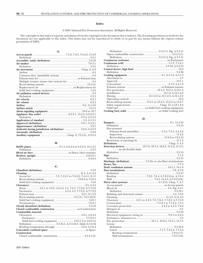
96–32 VENTILATION CONTROL AND FIRE PROTECTION OF COMMERCIAL COOKING OPERATIONS
Index
© 2001 National Fire Protection Association. All Rights Reserved.
The copyright in this index is separate and distinct from the copyright in the document that it indexes. The licensing provisions set forth for thedocument are not applicable to this index. This index may not be reproduced in whole or in part by any means without the express written
permission of NFPA.-A-Access panels . . . . . . . . . . . . . . . . . . . . . . . . . . . . . . . . 7.1.6, 7.4.3, 7.4.4.2, 11.4.9
Definition . . . . . . . . . . . . . . . . . . . . . . . . . . . . . . . . . . . . . . . . . . . . . . . . . . . . . . . . . . 3.3.1Accessible, easily (definition) . . . . . . . . . . . . . . . . . . . . . . . . . . . . . . . . . . . . . 3.3.19Air intakes . . . . . . . . . . . . . . . . . . . . . . . . . . . . . . . . . . . . . . . . . . . . . . . . . . . . . . . . . . 7.8.3.1
Definition . . . . . . . . . . . . . . . . . . . . . . . . . . . . . . . . . . . . . . . . . . . . . . . . . . . . . . . . . . 3.3.2Air movement . . . . . . . . . . . . . . . . . . . . . . . . . . . . . . . . . . . . . . . . . . . . . . . Chap. 8, A.8
Airflow . . . . . . . . . . . . . . . . . . . . . . . . . . . . . . . . . . . . . . . . . . . . . . . . . . . . . . . . . . . . . . . 8.2Common duct (manifold) systems . . . . . . . . . . . . . . . . . . . . . . . . . . . . . . . . 8.4Exhaust fans for . . . . . . . . . . . . . . . . . . . . . . . . . . . . . . . . . . . . . . .see Exhaust fansMultiple tenants, master duct systems for . . . . . . . . . . . . . . . . . . . . . . . . 8.4Recirculating systems . . . . . . . . . . . . . . . . . . . . . . . . . . . . . . . . . . . . . . . . . . 13.1(4)Replacement air . . . . . . . . . . . . . . . . . . . . . . . . . . . . . . . . . .see Replacement airSolid fuel cooking equipment . . . . . . . . . . . . . . . . . . . . . . . . . . . . . . . . . . . . 14.6
Air pollution control devices . . . . . . . . . . . . . . . . . . . . . . . . . . . . . . . . . . . . . . . . . . 9.3Definition . . . . . . . . . . . . . . . . . . . . . . . . . . . . . . . . . . . . . . . . . . . . . . . . . . . . . . . . . . 3.3.3
Air velocity . . . . . . . . . . . . . . . . . . . . . . . . . . . . . . . . . . . . . . . . . . . . . . . . . . . . . . . . . . . . 8.2.1Air volume . . . . . . . . . . . . . . . . . . . . . . . . . . . . . . . . . . . . . . . . . . . . . . . . . . . . . . . . . . . . 8.2.2Airflow . . . . . . . . . . . . . . . . . . . . . . . . . . . . . . . . . . . . . . . . . . . . . . . . . . . . . . . . . 8.2, 11.4.10Airflow switch . . . . . . . . . . . . . . . . . . . . . . . . . . . . . . . . . . . . . . . . . . . . . . . . . . . . . . . 13.3.5Alarm signaling equipment . . . . . . . . . . . . . . . . . . . . . . . . . . . . . . . . . 10.6 to 10.7Appliance flue outlet . . . . . . . . . . . . . . . . . . . . . . . . . . 6.2.2.1, 13.2.2, A.6.2.2.1
Definition . . . . . . . . . . . . . . . . . . . . . . . . . . . . . . . . . . . . . . . . . . . . . . . . 3.3.4, A.3.3.4Application of standard . . . . . . . . . . . . . . . . . . . . . . . . . . . . . . . . . . . . . . 1.3, A.1.3.1Approved (definition) . . . . . . . . . . . . . . . . . . . . . . . . . . . . . . . . . . . . . . 3.2.1, A.3.2.1Appurtenance (definition) . . . . . . . . . . . . . . . . . . . . . . . . . . . . . . . . . . . . . . . . . . 3.3.5Authority having jurisdiction (definition) . . . . . . . . . . . . . . . . 3.2.2, A.3.2.2Automatic (definition) . . . . . . . . . . . . . . . . . . . . . . . . . . . . . . . . . . . . . . . . . . . . . . 3.3.6Auxiliary equipment . . . . . . . . . . . . . . . . . . . . . . . . . . Chap. 9, 13.1(5), A.9.2.4
-B-Baffle plates . . . . . . . . . . . . . . . . . . . . . . . . . . . 6.1.1, 6.2.2.2 to 6.2.2.4, 12.1.2.5
Definition . . . . . . . . . . . . . . . . . . . . . . . . . . . . . . . . . . . . . . . . . . . . . . . . . . . . . . . . . . 3.3.7Bleed air duct . . . . . . . . . . . . . . . . . . . . . . . . . . . . . . . . . . .see Ducts (duct systems)Broilers, upright . . . . . . . . . . . . . . . . . . . . . . . . . . . . . . . . . . . . . . . . . . . . . . . . . A.6.2.2.1
Definition . . . . . . . . . . . . . . . . . . . . . . . . . . . . . . . . . . . . . . . . . . . . . . . . . . . . . . . . 3.3.8.3
-C-Classified (definition) . . . . . . . . . . . . . . . . . . . . . . . . . . . . . . . . . . . . . . . . . . . . . . . 3.3.9Cleaning . . . . . . . . . . . . . . . . . . . . . . . . . . . . . . . . . . . . . . . . . . . . . . . . . . . . . 11.4, A.11.4.2
Access for . . . . . . . . . . . . . . . . . . . . . . . 7.3, 7.4.2.1 to 7.4.2.2, 7.4.4.1, 8.1.5Recirculating systems . . . . . . . . . . . . . . . . . . . . . . . . . . . . . . . . . 13.6.2 to 13.6.4Solid fuel cooking equipment . . . . . . . . . . . . . . . . . . . . . . . . . . . . . . . . . . . . 14.8
Clearances . . . . . . . . . . . . . . . . . . . . . . . . . . . . . . . . . . . . . . . . . . . . . . . . . . . . . . . 4.2, A.4.2Ducts . . . . . . . . . . . . 4.2.1 to 4.2.2, 4.2.4.4, 4.5, 7.6.3, 7.7.2.2, A.7.7.2.2Enclosures . . . . . . . . . . . . . . . . . . . . . . . . . . . . . . . . 4.3.4, 4.5, 7.7.2.2, A.7.7.2.2Exhaust fans . . . . . . . . . . . . . . . . . . . . . . . . . . . . . . . . . . . . . . . . . . . . . . 4.2.1, 8.1.5.2Recirculating systems . . . . . . . . . . . . . . . . . . . . . . . . . . . . 13.1(1), 13.2.12(3)Solid fuel cooking equipment . . . . . . . . . . . . . . . . . . . . . . . . . . . . . . . . . . 14.9.1Terminations . . . . . . . . . . . . . . . . . . . . . . . . . . . . . . . . . . . . . . . . . . . . . . . . . . . . 7.8.2.1
Clearly identified (definition) . . . . . . . . . . . . . . . . . . . . . . . . . . . . . . . . . . . . . 3.3.10Closed combustible construction . . . . . . . . . . . . . . . . . . . . . .see ConstructionCombustible material
Clearances . . . . . . . . . . . . . . . . . . . . . . . . . . . . . . . . . . . . . . . . . . . . . . . . 4.2.1, 4.2.4.4Enclosures . . . . . . . . . . . . . . . . . . . . . . . . . . . . . . . . . . . . . . . . . . . . . . . . . . 7.7.2.2.1Solid fuel cooking equipment . . . . . . . . . . . . . . . . 14.9.1.4 to 14.9.1.6
Definition . . . . . . . . . . . . . . . . . . . . . . . . 3.3.34.1, A.3.3.34.3, Table A.3.3.34Rooftop terminations through . . . . . . . . . . . . . . . . . . . . . . . . . 7.8.4, A.7.8.4
Concealed/confined space . . . . . . . . . . . . . . . . . . . . . . . . . . . . . . . . . . . . .see SpaceConstruction
Closed combustible construction . . . . . . . . . . . . . . . . . . . . . . . . . . 4.3.4.1(2)
2001 Edition
Definition . . . . . . . . . . . . . . . . . . . . . . . . . . . . . . . . . . . . 3.3.11.1, Fig. A.3.3.11Open combustible construction . . . . . . . . . . . . . . . . . . . . . . . . . . . 4.3.4.1(1)
Definition . . . . . . . . . . . . . . . . . . . . . . . . . . . . . . . . . . . . 3.3.11.2, Fig. A.3.3.11Continuous enclosure . . . . . . . . . . . . . . . . . . . . . . . . . . . . . . . . . . . . . .see EnclosuresContinuous weld . . . . . . . . . . . . . . . . . . . . . . . . . . . . . . . . . . . . . . . . . . . . 5.1.2, 7.5.2.1
Definition . . . . . . . . . . . . . . . . . . . . . . . . . . . . . . . . . . . . . . . . . . . . . . 3.3.12, A.3.3.12Control device, high limit . . . . . . . . . . . . . . . . . . . . . . . . . . . . . . . . . . . . . . . . . . . . 12.2
Definition . . . . . . . . . . . . . . . . . . . . . . . . . . . . . . . . . . . . . . . . . . . . . . . . . . . . . . . . 3.3.30Cooking equipment . . . . . . . . . . . . . . . . . . . . . . . . . . . . . . . . . 4.1, A.4.1.6, A.4.1.9
Alterations to . . . . . . . . . . . . . . . . . . . . . . . . . . . . . . . . . . . . . . . . . . . . . . . . . . . . . . . . 4.7Approval . . . . . . . . . . . . . . . . . . . . . . . . . . . . . . . . . . . . . . . . . . . . . . . . . . . . . . . . . . 12.1.1Concessions . . . . . . . . . . . . . . . . . . . . . . . . . . . . . . . . . . . . . . . . . . . . . . 4.1.9, A.4.1.9Exhaust systems . . . . . . . . . . . . . . . . . . . . . . . . . . . . . . . . . . .see Exhaust systemsFire protection . . . . . . . . . . . . . . . . . . . . . . . . . . . . . . . . 10.1.2, 10.2.4, A.10.1.2Installation . . . . . . . . . . . . . . . . . . . . . . . . . . . . . . . . . . . . . . . . . . 12.1.2, A.12.1.2.2Moving . . . . . . . . . . . . . . . . . . . . . . . . . . . . . . . . 12.1.2.2 to 12.1.2.3, A.12.1.2.2Operating controls . . . . . . . . . . . . . . . . . . . . . . . . . . . . . . . . . . . . . . . . . . . . . . . . 12.2Recirculating systems . . . . . . . . . . . . . 13.2.1 to 13.2.3, 13.2.5 to 13.2.7Safety requirements . . . . . . . . . . . . . . . . . . . . . . . . . . . . . Chap. 12, A.12.1.2.2Solid fuel . . . . . . . . . . . . . . . . . . . . . . . . . . .see Solid fuel cooking equipment
Cooking fuel, solid . . . . . . . . . . . . . . . . . . . . . . . . . . . . . . . .see Solid cooking fuel
-D-Dampers . . . . . . . . . . . . . . . . . . . . . . . . . . . . . . . . . . . . . . . . . . . . . . . . . . . . . . . 9.1, 11.4.10
Definition . . . . . . . . . . . . . . . . . . . . . . . . . . . . . . . . . . . . . . . . . . . . . . . . . . . . . . . . 3.3.13Fire-actuated
Exhaust hood assemblies . . . . . . . . . . . . . . . . . . . . . 5.3.4, 7.3.4, A.5.3.4Inspection . . . . . . . . . . . . . . . . . . . . . . . . . . . . . . . . . . . . . . . . . . . . . . . . . . . . . 11.2.2Recirculating systems . . . . . . . . . . . . . . . . . . . . . . . . . . . . 13.2.8 to 13.2.10
Restriction of openings by . . . . . . . . . . . . . . . . . . . . . . . . . . . . . . . . . . . . . . 11.1.3Definitions . . . . . . . . . . . . . . . . . . . . . . . . . . . . . . . . . . . . . . . . . . . . . . . . . . . Chap. 3, A.3Detection devices . . . . . . . . . . . . . . . . . 10.7.2, 10.7.4, 10.8.2, 11.2.2, 11.4.7;
see also Fusible linksDefinition . . . . . . . . . . . . . . . . . . . . . . . . . . . . . . . . . . . . . . . . . . . . . . . . . . . . . . . . 3.3.14
Dips . . . . . . . . . . . . . . . . . . . . . . . . . . . . . . . . . . . . . . . . . . . . . . . . . . . . . . . . . . . . . . . . . . . 7.1.4Definition . . . . . . . . . . . . . . . . . . . . . . . . . . . . . . . . . . . . . . . . . . . . . . . . . . . . . . . . 3.3.15
Discharge (definition) . . . . . . . . . . . . . . . 3.3.16; see also Duct terminationsDoors, fire . . . . . . . . . . . . . . . . . . . . . . . . . . . . . . . . . . . . . . . . . . . . . . . . . . . . . . . . . . . . 7.7.4Draft ventilation systems . . . . . . . . . . . . . . . . . . . . . . . . . . . . . . . . . . 14.1.1, 14.1.4Duct terminations . . . . . . . . . . . . . . . . . . . . . . . . . . . . . . . . . . . . . . . . . . . . . . . 7.8, A.7.8
Definition . . . . . . . . . . . . . . . . . . . . . . . . . . . . . . . . . . . . . . . . . . . . . . . . . . . . . . . . 3.3.17Rooftop . . . . . . . . . . . . . . . . . . . . . . . . . . . . . 7.8.2, 7.8.4, A.7.8.2.2(a), A.7.8.4Wall . . . . . . . . . . . . . . . . . . . . . . . . . . . . . . . . . . . . . . . . . 7.8.3, 14.4.4, A.7.8.2.2(b)
Ducts (duct systems) . . . . . . . . . . . . . . . . . . . . . . . . . . . . . 4.1.3(3), Chap. 7, A.7Access panels . . . . . . . . . . . . . . . . . . . . . . . . . . . . . . . . . . . . . . . . .see Access panelsBleed air . . . . . . . . . . . . . . . . . . . . . . . . . . . . . . . . . . . . . . . . . . . . . . . . . 8.4, Fig. 8.4.1
Definition . . . . . . . . . . . . . . . . . . . . . . . . . . . . . . . . . . . . . . . . . . . . . . . . . . . 3.3.18.1Building and structural contact . . . . . . . . . . . . . . . . . . . . . . . . . . . . 4.4, 7.6.6Cleaning . . . . . . . . . . . . . . . . . . . . . . . . . . . . . . . . . . . . . . . . . . . . . . . 11.4.2, A.11.4.2Clearance . . . . . . . . . . . . . . . . 4.2.1 to 4.2.2, 7.2, 7.6.3, 7.7.2.2, A.7.7.2.2Connections . . . . . . . . . . . . . . . . . . . . . . . . . . . . . . . . . . 7.5.2.1 to 7.5.2.2, 7.5.5Corrosion protection . . . . . . . . . . . . . . . . . . . . . . . . . . . . . 4.4.2 to 4.4.3, 7.6.6Dampers in . . . . . . . . . . . . . . . . . . . . . . . . . . . . . . . . . . . . . . . . . . . . . . . . . . . . . . . . . . 9.1Definition . . . . . . . . . . . . . . . . . . . . . . . . . . . . . . . . . . . . . . . . . . . . . . . . . . . . . . . . 3.3.18Electrical equipment/wiring in . . . . . . . . . . . . . . . . . . . . . . . . 9.2.1 to 9.2.2Enclosures, clearances to . . . . . . . . . . . . . . . . . . . . . . . . . . . . . . . . . . . . . . . . . . . 4.5Fire protection . . . . . . . . . . . . . . . . . . . . . . . . . . 10.1.1, 10.2.4, 13.5.1, 14.7.3Grease
Definition . . . . . . . . . . . . . . . . . . . . . . . . . . . . . . . . . . . . . . . . . . . . . . . . . . . 3.3.18.2Listed . . . . . . . . . . . . . . . . . . . . . . . . . . . . . . . . . . . . . . . . . 7.1.7, 7.4.3.4, 7.7.3.4
Rooftop terminations . . . . . . . . . . . . . . . . . . . . . . . . . . . . . . . . . 7.8.2.1(7)Wall terminations . . . . . . . . . . . . . . . . . . . . . . . . . . . . . . . . . . . . . . 7.8.3.1(6)
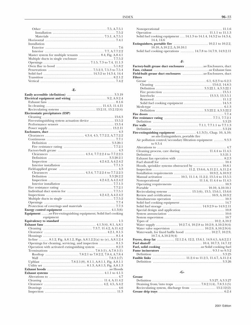
96–33INDEX
Other . . . . . . . . . . . . . . . . . . . . . . . . . . . . . . . . . . . . . . . . . . . . . . . . . . . . 7.5, A.7.5.1Installation . . . . . . . . . . . . . . . . . . . . . . . . . . . . . . . . . . . . . . . . . . . . . . . . . . . 7.5.2Materials . . . . . . . . . . . . . . . . . . . . . . . . . . . . . . . . . . . . . . . . . . . . 7.5.1, A.7.5.1
Horizontal . . . . . . . . . . . . . . . . . . . . . . . . . . . . . . . . . . . . . . . . . . . . . . . . . . . . . . . . . 7.4.1Installation
Exterior . . . . . . . . . . . . . . . . . . . . . . . . . . . . . . . . . . . . . . . . . . . . . . . . . . . . . . . . . . . 7.6Interior . . . . . . . . . . . . . . . . . . . . . . . . . . . . . . . . . . . . . . . . . . . . . . . . 7.7, A.7.7.2.2
Master system for multiple tenants . . . . . . . . . . . . . . . . . 8.4, Fig. A.8.4.1Multiple ducts in single enclosure . . . . . . . . . . . . . . . . . . . . . . . . . . . . 7.7.5.2Openings . . . . . . . . . . . . . . . . . . . . . . . . . . . . . . . . . . . . . . 7.1.5, 7.3 to 7.4, 11.1.3Oven flue to hood . . . . . . . . . . . . . . . . . . . . . . . . . . . . . . . . . . . . . . . . . . . . . . 5.1.8.2Penetrations . . . . . . . . . . . . . . . . . . . . . . . . . . . . . . . . . . . . 7.5.2.3, 7.5.3 to 7.5.4Solid fuel . . . . . . . . . . . . . . . . . . . . . . . . . . . . . . . . . . . . . . . . 14.3.2 to 14.3.4, 14.4Transition . . . . . . . . . . . . . . . . . . . . . . . . . . . . . . . . . . . . . . . . . . . . . . . . . . . . . . . . 8.2.1.2Vertical . . . . . . . . . . . . . . . . . . . . . . . . . . . . . . . . . . . . . . . . . . . . . . . . . . . . . . . . . . . . . 7.4.2
-E-Easily accessible (definition) . . . . . . . . . . . . . . . . . . . . . . . . . . . . . . . . . . . . . . 3.3.19Electrical equipment and wiring . . . . . . . . . . . . . . . . . . . . . . . . . . . . 9.2, A.9.2.4
Exhaust fans . . . . . . . . . . . . . . . . . . . . . . . . . . . . . . . . . . . . . . . . . . . . . . . . . . . . . . . 8.1.6In cleaning . . . . . . . . . . . . . . . . . . . . . . . . . . . . . . . . . . . . . . . . . . . . . . 11.4.3, 11.4.11Recirculating systems . . . . . . . . . . . . . . . . . . . . . . . . . . . . . 13.2.11, 13.2.12(4)
Electrostatic precipitators (ESP)Cleaning . . . . . . . . . . . . . . . . . . . . . . . . . . . . . . . . . . . . . . . . . . . . . . . . . . . . . . . . . . 13.6.3Fire-extinguishing system actuation device . . . . . . . . . . . . . . . . . . . 13.5.2Performance sensors . . . . . . . . . . . . . . . . . . . . . . . . . . . . . . . . . . . . . . . . . . . . 13.3.4Power supply . . . . . . . . . . . . . . . . . . . . . . . . . . . . . . . . . . . . . . . . . . . . . . . . . . . . 13.2.11
Enclosures, duct . . . . . . . . . . . . . . . . . . . . . . . . . . . . . . . . . . . . . . . . . . . . . . . . . . . . . . . . 4.3Clearances . . . . . . . . . . . . . . . . . . . . . . . . . . . . . . . . 4.3.4, 4.5, 7.7.2.2, A.7.7.2.2Continuous . . . . . . . . . . . . . . . . . . . . . . . . . . . . . . . . . . . . . . . . . . . . . . . . . . . . . . . . 7.7.1
Definition . . . . . . . . . . . . . . . . . . . . . . . . . . . . . . . . . . . . . . . . . . . . . . . . . . . 3.3.20.1Fire resistance rating . . . . . . . . . . . . . . . . . . . . . . . . . . . . . . . . . . . . . . . . 7.7.2.1
Factory-built grease . . . . . . . . . . . . . . . . . . . . . . . . . . . . . . . . . . . . . . . . . . . . . . . . . 4.3Clearances . . . . . . . . . . . . . . . . . . . . . . . . . . . . . 4.3.4, 7.7.2.2.4 to 7.7.2.2.5Definition . . . . . . . . . . . . . . . . . . . . . . . . . . . . . . . . . . . . . . . . . . . . . . . . . 3.3.20.2.1Inspection . . . . . . . . . . . . . . . . . . . . . . . . . . . . . . . . . . . . . . . . . 4.2.4.2, A.4.2.4.2Interior installation . . . . . . . . . . . . . . . . . . . . . . . . . . . . . . . . . . . . . . . . . . 7.7.1.5
Field-applied grease . . . . . . . . . . . . . . . . . . . . . . . . . . . . . . . . . . . . . . . . . . . . . . . . 4.3Clearances . . . . . . . . . . . . . . . . . . . . . . . . . . . . . 4.3.4, 7.7.2.2.4 to 7.7.2.2.5Definition . . . . . . . . . . . . . . . . . . . . . . . . . . . . . . . . . . . . . . . . . . . . . . . . . 3.3.20.2.2Inspection . . . . . . . . . . . . . . . . . . . . . . . . . . . . . . . . . . . . . . . . . 4.2.4.2, A.4.2.4.2Interior installation . . . . . . . . . . . . . . . . . . . . . . . . . . . . . . . . . . . . . . . . . . 7.7.1.5
Fire resistance rating . . . . . . . . . . . . . . . . . . . . . . . . . . . . . . . . . . . . . . . . . . . 7.7.2.1Individual duct system for . . . . . . . . . . . . . . . . . . . . . . . . . . . . . . . . . . . . . 7.7.5.1Inspections . . . . . . . . . . . . . . . . . . . . . . . . . . . . . . . . . . . . . . . . . . . 4.2.4.2, A.4.2.4.2Multiple ducts in single . . . . . . . . . . . . . . . . . . . . . . . . . . . . . . . . . . . . . . . . 7.7.5.2Openings . . . . . . . . . . . . . . . . . . . . . . . . . . . . . . . . . . . . . . . . . . . . . . . . . . . . . . . . . . 7.7.4Protection of coverings and materials . . . . . . . . . . . . . . . . . . . . . . . . . . 7.7.3
Energy control equipment . . . . . . . . . . . . . . . . . . . . . . . . . . . . . . . . . . . . . . . 4.1.3(6)Equipment . . . . . .see Fire-extinguishing equipment; Solid fuel cooking
equipmentEquivalency to standard . . . . . . . . . . . . . . . . . . . . . . . . . . . . . . . . . . . . . . . . . . . . . . . 1.5Exhaust fans . . . . . . . . . . . . . . . . . . . . . . . . . . . . . . . . . . . . . . . . . . 4.1.3(4), 8.1, A.8.1
Cleaning . . . . . . . . . . . . . . . . . . . . . . . . . . . . . . . . . . . . . . . . 7.3.7, 11.4.2, A.11.4.2Clearance . . . . . . . . . . . . . . . . . . . . . . . . . . . . . . . . . . . . . . . . . . . . . . . . . . . 4.2.1, 8.1.5Housings . . . . . . . . . . . . . . . . . . . . . . . . . . . . . . . . . . . . . . . . . . . . . . . . . . . . . . . . . . . 8.1.4In-line . . . . . . . . 8.1.2, Fig. A.8.1.2, Figs. A.8.1.2.2(a) to (e), A.8.1.2.4Openings for cleaning, servicing, and inspection . . . . . . . . . . . . . 8.1.5Operation with activated extinguishing system . . . . . . . . . . . . . . . . 8.2.3Terminations . . . . . . . . . . . . . . . . . . . . . . . . . . . . . . . . . . . . . 7.8.1(1), A.7.8.1(1)
Rooftop . . . . . . . . . . . . . . . . . . . . . . . . . . . 7.8.2.1 to 7.8.2.2, 7.8.4, A.7.8.4Wall . . . . . . . . . . . . . . . . . . . . . . . . . . . . . . . . . . . . . . . . . . . . . . . . . . . . . . . . 7.8.3.1(7)
Upblast . . . . . . . . . . . . . . . . . . . . . . . . 7.8.2.1(8), 8.1.1, A.8.1.1, Fig. A.8.1.1Utility set . . . . . . . . . . . . . . . . . . . . . . . . . . . . . . . . . . . 8.1.3, A.8.1.3, Fig. A.8.1.3
Exhaust hoods . . . . . . . . . . . . . . . . . . . . . . . . . . . . . . . . . . . . . . . . . . . . . . . . . . .see HoodsExhaust systems . . . . . . . . . . . . . . . . . . . . . . . . . . . . . . . . . . . . . . . . . . . . 4.1.1 to 4.1.5
Alterations to . . . . . . . . . . . . . . . . . . . . . . . . . . . . . . . . . . . . . . . . . . . . . . . . . . . . . . . . 4.7Cleaning . . . . . . . . . . . . . . . . . . . . . . . . . . . . . . . . . . . . . . . . . . . . . . . . . 11.4, A.11.4.2Clearance . . . . . . . . . . . . . . . . . . . . . . . . . . . . . . . . . . . . . . . . . . . . . . . . 4.2, 4.5, A.4.2Drawings . . . . . . . . . . . . . . . . . . . . . . . . . . . . . . . . . . . . . . . . . . . . . . . . . . . . . . . . . . . . . 4.6Inspection . . . . . . . . . . . . . . . . . . . . . . . . . . . . . . . . . . . . . . . . . . . . . . . . . . . . . . . . . . 11.3
Nonoperational . . . . . . . . . . . . . . . . . . . . . . . . . . . . . . . . . . . . . . . . . . . . . . . . . . 11.1.6Operation . . . . . . . . . . . . . . . . . . . . . . . . . . . . . . . . . . . . . . . . . . . . . . 11.1.1 to 11.1.3Solid fuel cooking equipment . . . . 14.1.3 to 14.1.4, 14.3.2 to 14.3.4,
14.4, 14.6Extinguishers, portable fire . . . . . . . . . . . . . . . . . . . . . . . . . . . . 10.2.1 to 10.2.2,
10.10, A.10.2.2, A.10.10.1Solid fuel cooking operations . . . . . . . . . . . 14.7.8 to 14.7.9, 14.9.2.11
-F-Factory-built grease duct enclosures . . . . . . . . . . . . . . .see Enclosures, ductFans, exhaust . . . . . . . . . . . . . . . . . . . . . . . . . . . . . . . . . . . . . . . . . . . . .see Exhaust fansField-built grease duct enclosures . . . . . . . . . . . . . . . . .see Enclosures, ductFilters
Grease . . . . . . . . . . . . . . . . . . . . . . . . . . . . . . . . . . . . . . . . . . . . . . . 6.1, 6.2.3 to 6.2.5Cleaning . . . . . . . . . . . . . . . . . . . . . . . . . . . . . . . . . . . . . . . . . . . . . . 13.6.2, 14.8.5Definition . . . . . . . . . . . . . . . . . . . . . . . . . . . . . . . . . . . . . . . 3.3.22.1, A.3.3.22.1Fire protection . . . . . . . . . . . . . . . . . . . . . . . . . . . . . . . . . . . . . . . . . . . . . . . . 13.5.1Interlocks . . . . . . . . . . . . . . . . . . . . . . . . . . . . . . . . . . . . . . . . . . . 13.3.3, 13.3.5.1Removed . . . . . . . . . . . . . . . . . . . . . . . . . . . . . . . . . . . . . . . . . . . . . . . . . . . . . . . 11.1.2Solid fuel cooking equipment . . . . . . . . . . . . . . . . . . . . . . . . . . . . . . . 14.5.3
Mesh-type . . . . . . . . . . . . . . . . . . . . . . . . . . . . . . . . . . . . . . . . . . . . . . . . . . . . . . . . . . 6.1.3Definition . . . . . . . . . . . . . . . . . . . . . . . . . . . . . . . . . . . . . . . 3.3.22.2, A.3.3.22.2
Fire doors . . . . . . . . . . . . . . . . . . . . . . . . . . . . . . . . . . . . . . . . . . . . . . . . . . . . . . . . . . . . . 7.7.4Fire resistance rating . . . . . . . . . . . . . . . . . . . . . . . . . . . . . . . . . . . . . . . 7.7.1, 7.7.2.1
Definition . . . . . . . . . . . . . . . . . . . . . . . . . . . . . . . . . . . . . . . . . . . . . . . . . . . . . . . . 3.3.23Fire walls . . . . . . . . . . . . . . . . . . . . . . . . . . . . . . . . . . . . . . . . . 7.1.1, 7.7.1.1 to 7.7.1.3
Definition . . . . . . . . . . . . . . . . . . . . . . . . . . . . . . . . . . . . . . . . . . . . . . . . . . . . . . . . 3.3.24Fire-extinguishing equipment . . . . . . . . . . . . . . . . 4.1.3(5), Chap. 10, A.10;
see also Extinguishers, portable fireAir pollution control/secondary filtration equipment . . . . . . . . 9.3.3
to 9.3.4Alterations to . . . . . . . . . . . . . . . . . . . . . . . . . . . . . . . . . . . . . . . . . . . . . . . . . . . . . . . . 4.7Cleaning process, care during . . . . . . . . . . . . . . . . . . . . . . . 11.4.4 to 11.4.5Definition . . . . . . . . . . . . . . . . . . . . . . . . . . . . . . . . . . . . . . . . . . . . . . . . . . . . . . 3.3.21.1Exhaust fan operation with . . . . . . . . . . . . . . . . . . . . . . . . . . . . . . . . . . . . . . 8.2.3Fuel shutoff for . . . . . . . . . . . . . . . . . . . . . . . . . . . . . . . . . . . . . . . . . . . . . . . . . . . . 10.4Hoods, sprinkler systems obstructed by . . . . . . . . . . . . . . . . . . . . . . . 10.8.1Inspection . . . . . . . . . . . . . . . . . . . . . . . . . . . . . 11.2, 13.6.6, A.11.2.1, A.11.2.4Installation requirements . . . . . . . . . . . . . . . . . . . . . . . . . . . . 10.9.2, A.10.9.2Manual activation . . . . . . . . . . . . . . 10.5, 11.1.4, 11.2.2, 13.5.4 to 13.5.5Nonoperational . . . . . . . . . . . . . . . . . . . . . . . . . . . . . . . 11.1.6, 11.4.4 to 11.4.5Operating requirements . . . . . . . . . . . . . . . . . . . . . . . . . . . . . . . . . . . . . . . . . . 10.3Portable . . . . . . . . . . . . . . . . . . . . . . . . . . . . . . . . . . . . . . . . . . . . . . . 10.10, A.10.10.1Recirculating systems . . . . . . . . . . . . . . . . . . . 13.1(6), 13.5, 13.6.1, 13.6.6Review and certification . . . . . . . . . . . . . . . . . . . . . . . . . . . . . . . . 10.9, A.10.9.2Simultaneous operation . . . . . . . . . . . . . . . . . . . . . . . . . . . . . . . . . . . . . . . . . . 10.3Solid fuel cooking equipment . . . . . . . . . . . . . . . . . . . . . . . . . . . . . . . . . . . . 14.7Solid fuel storage . . . . . . . . . . . . . . . . . . . . . . . . . . . . . . . . 14.9.2.9 to 14.9.2.11Special design and application . . . . . . . . . . . . . . . . . . . . . . . . . . . . . . . . . . . 10.8System annunciation . . . . . . . . . . . . . . . . . . . . . . . . . . . . . . . . . . . . . . . . . . . . . . 10.6System supervision . . . . . . . . . . . . . . . . . . . . . . . . . . . . . . . . . . . . . . . . . . . . . . . . . 10.7Types of . . . . . . . . . . . . . . . . . . . . . . . . . . . . . . . . . . . . . . . . . . . . . . . . . . . . 10.2, A.10.2Water supply . . . . . . . . . . . . . . . . . . 10.2.7.4, 10.2.8 to 10.2.9, A.10.2.9(4)Water valve supervision . . . . . . . . . . . . . . . . . . . . . . . . . . . 10.2.9, A.10.2.9(4)Water-wash, for fixed baffle hood . . . . . . . . . . . . . . . . . . . . . 10.2.7, 10.2.9,
10.7.4, A.10.2.9(4)Fryers, deep fat . . . . . . . . . . . . . . 12.1.2.4, 12.2, 13.6.1, 14.9.4.5, A.6.2.2.1Fuel shutoff . . . . . . . . . . . . . . . . . . . . . . . . . . . . . . . . . . . . . . . . . 10.4, 10.7.3, 14.7.12Fuel, solid cooking . . . . . . . . . . . . . . . . . . . . . . . . . . . . . . . .see Solid cooking fuelFume incinerators . . . . . . . . . . . . . . . . . . . . . . . . . . . . . . . . . . . . . . . . . . 9.3.1 to 9.3.2
Definition . . . . . . . . . . . . . . . . . . . . . . . . . . . . . . . . . . . . . . . . . . . . . . . . . . . . . . . . 3.3.25Fusible links . . . . . . . . . . . . . . . . . . . . . . . . . . . 11.2.4 to 11.2.5, 11.4.7, A.11.2.4
Definition . . . . . . . . . . . . . . . . . . . . . . . . . . . . . . . . . . . . . . . . . . . . . . . . . . . . . . . . 3.3.26
-G-Grease
Definition . . . . . . . . . . . . . . . . . . . . . . . . . . . . . . . . . . . . . . . . . . . . . . 3.3.27, A.3.3.27Draining from/into traps . . . . . . . . . . . . . . . . . . . . . 7.8.2.1(4), 7.8.3.1(5)Recirculating system, discharge from . . . . . . . . . . . . . . . . . . . . 13.2.12(2)
Grease drip trays . . . . . . . . . . . . . . . . . . . . . . . . . . . . . . . . . . . . . . . . . . . . . . . . . . . . . 6.2.4
2001 Edition
96–34 VENTILATION CONTROL AND FIRE PROTECTION OF COMMERCIAL COOKING OPERATIONS
Grease duct enclosures . . . . . . . . . . . . . . . . . . . . . . . . . . . . .see Enclosures, ductGrease ducts . . . . . . . . . . . . . . . . . . . . . . . . . . . . . . . . . . . .see Ducts (duct systems)Grease filters . . . . . . . . . . . . . . . . . . . . . . . . . . . . . . . . . . . . . . . . . . . . . . . . . . . . .see FiltersGrease removal devices . . . . . . . . . . . . . . Chap. 6, A.6.2.21; see also Filters
Cleaning . . . . . . . . . . . . . . . . . . . . . . . . . . . . . . . . . . . . . . . . . . . . . . . 11.4.2, A.11.4.2Clearance . . . . . . . . . . . . . . . . . . . . . . . . . . . . . . . . . . . . . . . . . . . . . . . . . 4.2.1 to 4.2.2Definition . . . . . . . . . . . . . . . . . . . . . . . . . . . . . . . . . . . . . . . . . . . . . . . . . . . . . . . . 3.3.28Fire protection . . . . . . . . . . . . . . . . . . . . . . . . . . . . . . . . . . 10.1.1, 10.2.4, 14.7.3Installation . . . . . . . . . . . . . . . . . . . . . . . . . . . . . . . . . . . . . . . . . . . . . . . 6.2, A.6.2.2.1Recirculating systems . . . . . . . . . . . . . . . . . . . . . . . . . . . . . . . . . . . . . . . . . . 13.1(3)Solid fuel cooking equipment . . . . . . . . . . . . . . . . . . . . . . . . . . 6.2.1.2, 14.5
Greasetight . . . . . . . . . . . . . . . . . . . . . . . . . . . . . . . . 5.1.4, 7.4.3.2, 7.5.2.3, A.5.1.4Definition . . . . . . . . . . . . . . . . . . . . . . . . . . . . . . . . . . . . . . . . . . . . . . . . . . . . . . . . 3.3.29
-H-Hazard area, single
Definition . . . . . . . . . . . . . . . . . . . . . . . . . . . . . . . . . . . . . . . . . . . . . . . . . . . . . . . . 3.3.39Simultaneous system operation . . . . . . . . . . . . . . . . . . . . . . . . . . . . . . . . . . 10.3
High limit control device . . . . . . . . . . . . . . . . . . . . . . . . . . . . . . . . . . . . . . . . . . . . 12.2Definition . . . . . . . . . . . . . . . . . . . . . . . . . . . . . . . . . . . . . . . . . . . . . . . . . . . . . . . . 3.3.30
Hoods . . . . . . . . . . . . . . . . . . . . . . . . . . . . . . . . 4.1.3(2), Chap. 5, A.5.1.4, A.5.3.4Access panels . . . . . . . . . . . . . . . . . . . . . . . . . . . . . . . . . . . . . . . . . . . . . . . . . . . . . . 7.3.4Assemblies
Exhaust . . . . . . . . . . . . . . . . . . . . . . . . . . . . . . . . . . . . . . . . . . . . . . . . . . 5.3, A.5.3.4Listed . . . . . . . . . . . . . . . . . . . . . . . . . . . . . . . . . . . . . . . . . . . . . . . . . . . . . . . . . . . . . . 5.4
Cleaning . . . . . . . . . . . . . . . . . . . . . . . . . . . . . . 11.4.2, 13.6.4, 14.8.5, A.11.4.2Clearance . . . . . . . . . . . . . . . . . . . . . . . . . . . . . . . . . . . . . . . . . . . . . . . . . 4.2.1 to 4.2.2Construction . . . . . . . . . . . . . . . . . . . . . . . . . . . . . . . . . 5.1, 5.3, A.5.1.4, A.5.3.4Definition . . . . . . . . . . . . . . . . . . . . . . . . . . . . . . . . . . . . . . . . . . . . . . 3.3.31, A.3.3.31Exhaust air volumes . . . . . . . . . . . . . . . . . . . . . . . . . . . . . . . . . . . . . . . . . . . . 8.2.2.1Eyebrow-type hoods . . . . . . . . . . . . . . . . . . . . . . . . . . . . . . . . . . . . . . . . . . . . . . 5.1.8Fire protection . . . . . . . . . . . . . . . . . 10.1.1, 10.2.4, 10.2.7, 10.8.1, 14.7.3Fixed baffle (with water wash) . . 10.2.7, 10.2.9, 10.7.4, A.10.2.9(4)
Definition . . . . . . . . . . . . . . . . . . . . . . . . . . . . . . . . . . . . . . . . . . . . . . . . . . . 3.3.31.1Grease removal devices . . . . . . . . . . . . . . . . . .see Grease removal devicesInspection . . . . . . . . . . . . . . . . . . . . . . . . . . . . . . . . . . . . . . . . . . . . . 11.2.1, A.11.2.1Insulation materials . . . . . . . . . . . . . . . . . . . . . . . . . . . . . . . . . . . . . . . . . . . . . . . 5.1.9Integrated supply air plenums . . . . . . . . . . . . . . . . . . . . . . . . . . . 5.3, A.5.3.4Lighting on . . . . . . . . . . . . . . . . . . . . . . . . . . . . . . . . . . . . . . . . . . . . . . 9.2.2 to 9.2.3Listed . . . . . . . . . . . . . . . . . . . . . . . . . . . . . . . . . . . . . . . . . . . . . 5.1.6 to 5.1.7, 11.1.5
Assembly . . . . . . . . . . . . . . . . . . . . . . . . . . . . . . . . . . . . . . . . . . . . . . . . . . . . . . . . . . 5.4Inspection . . . . . . . . . . . . . . . . . . . . . . . . . . . . . . . . . . 11.2, A.11.2.1, A.11.2.4
Recirculating systems . . . . . . . . . . . . . . . . . . . . . . . . . . . . . . . . . . . . . . . . . . 13.1(2)Size . . . . . . . . . . . . . . . . . . . . . . . . . . . . . . . . . . . . . . . . . . . . . . . . . . . . . . . . . . . . . . . . . . . 5.2Solid fuel cooking equipment . . . . . . . . . . . . . . . . . . . . . . . . . . . . . . . . . . . . 14.3Spark arresters . . . . . . . . . . . . . . . . . . . . . . . . . . . . . . . . 14.1.6 to 14.1.7, 14.8.4Types of . . . . . . . . . . . . . . . . . . . . . . . . . . . . . . . . . . . . . . . . . . . . . . . . . . . Fig. A.3.3.31
-I-Incinerators, fume . . . . . . . . . . . . . . . . . . . . . . . . . . . . . . . . . . . . . . . . . 9.3.1 to 9.3.2
Definition . . . . . . . . . . . . . . . . . . . . . . . . . . . . . . . . . . . . . . . . . . . . . . . . . . . . . . . . 3.3.25Inspection and testing . . . . . . . . . . . . . . . . . . . . . . . . . . . . . . . . . . . 11.2.1, A.11.2.1
Duct system . . . . . . . . . . . . . . . . . . . . . . . . . . . . . . . . . . . . . . . . . . . . . . . . . . . . . . 7.7.3.3Recirculating system . . . . . . . . . . . . . . . . . . . . . . . . . . . . . . . . . . . . . . . . . . . . . 13.6.5Solid fuel cooking equipment . . . . . . . . . . . . . . . . . . . . . . . . . . . . . 11.4, 14.8
Insulation materials, hood . . . . . . . . . . . . . . . . . . . . . . . . . . . . . . . . . . . . . . . . . . 5.1.9Interconnected
Definition . . . . . . . . . . . . . . . . . . . . . . . . . . . . . . . . . . . . . . . . . . . . . . . . . . . . . . . . 3.3.32Fire-extinguishing systems, supervision of . . . . . . . . . . . . . . . . . . . . 10.7.3
InterlocksRecirculating system . . . . . . . . . . . . . . . . . . . . . . . . . 13.2.12(5), 13.3, 13.6.5Solid fuel cooking equipment . . . . . . . . . . . . . . . . . . . . . . . . . 14.1.3, 14.6.3
-L-Labeled (definition) . . . . . . . . . . . . . . . . . . . . . . . . . . . . . . . . . . . . . . . . . . . . . . . . . 3.2.3Lighting . . . . . . . . . . . . . . . . . . . . . . . . . . . . . . . . . . . . . . . . . . . . . . . . . . . . . . 9.2.2 to 9.2.3Limited-combustible material
Clearances . . . . . . . . . . . . . . . . . . . . . . . . . . . . . . . . . . . . . . . 4.2.1, 4.2.3.3, 4.2.4.4Enclosures . . . . . . . . . . . . . . . . . . . . . . . . . . . . . . . . . . . . . . . . . . . . . . . . . . 7.7.2.2.2Solid fuel cooking equipment . . . . . . . . . . . . . . . . . . . . . . . . . . . . 14.9.1.5
2001 Edition
Definition . . . . . . . . . . . . . . . . . . . . . . . . . . . . . . . . . . . . . . . . . . . . . . 3.3.34.2, A.3.34Rooftop terminations through . . . . . . . . . . . . . . . . . . . . . . . . . 7.8.4, A.7.8.4
LiquidtightConnections . . . . . . . . . . . . . . . . . . . . . . . . . . . . . . . . . . . . . . . . . . . . . . 5.1.2, 7.5.2.1Definition . . . . . . . . . . . . . . . . . . . . . . . . . . . . . . . . . . . . . . . . . . . . . . . . . . . . . . . . 3.3.33
Listed (definition) . . . . . . . . . . . . . . . . . . . . . . . . . . . . . . . . . . . . . . . . . . 3.2.4, A.3.2.4
-M-Maintenance . . . . . . . . . . . . . . . . . . . . . . . . . . . . . . . . . . . . . . . . . . . . . . . . . . . . . . . . . 11.2.8
Recirculating systems . . . . . . . . . . . . . . . . . . . . . . . . . . . . . . . . . . . . 13.1(7), 13.6Solid fuel cooking equipment . . . . . . . . . . . . . . . . . . . 11.4, 14.8, A.11.4.2
Makeup air . . . . . . . . . . . . . . . . . . . . . . . . . . . . . . . . . . . . . . . . . . .see Replacement airMultiple tenancy applications . . . . . . . . . . . . . . . . . . . 4.1.7, 8.4, Fig. A.8.4.1
-N-Noncombustible material
Clearances . . . . . . . . . . . . . . . . . . . . . . . . . . . . . . . . . . . . . . . . . 4.2.1, 4.2.3, 4.2.4.3Enclosures . . . . . . . . . . . . . . . . . . . . . . . . . . . . . . . . . . . . . . . . . . . . . . . . . . 7.7.2.2.2
Definition . . . . . . . . . . . . . . . . . . . . . . . . . . . . . . . . . . . . 3.3.34.3, Table A.3.3.34Ducts, contact with . . . . . . . . . . . . . . . . . . . . . . . . . . . . . . . . . . . . . . . . . . . . . . . 4.4.1Solid fuel cooking equipment,
installation of . . . . . . . . . . . . . . . . . . . . . . . . . 14.9.1.1 to 14.9.1.2
-O-Open combustible construction . . . . . . . . . . . . . . . . . . . . . . .see ConstructionOperating procedures . . . . . . . . . . . . . . . . . . . . . . . . . . . . . . . . . . . . . . . . . . . . . . . . 11.1
Recirculating systems . . . . . . . . . . . . . . . . . . . . . . . . . . . . . . . . . . . . 13.1(7), 13.6Solid fuel cooking equipment . . . . . . . . . . . . . 11.4, Chap. 14, A.14.2.2
-P-Pitched
Definition . . . . . . . . . . . . . . . . . . . . . . . . . . . . . . . . . . . . . . . . . . . . . . . . . . . . . . . . 3.3.35Ducts . . . . . . . . . . . . . . . . . . . . . . . . . . . . . . . . . . . . . . . . . . . . . . . . . . . . . . . . . . . . . A.7.1.2
Purpose of standard . . . . . . . . . . . . . . . . . . . . . . . . . . . . . . . . . . . . . . . . . . . . . . . . . . . 1.2
-R-Recirculating systems . . . . . . . . . . . . . . . . . . . . . . . . . . . . . . . . . . . . . . . . . . . Chap. 13
Application restrictions . . . . . . . . . . . . . . . . . . . . . . . . . . . . . . . . . . . . . . . . . . . 13.4Components . . . . . . . . . . . . . . . . . . . . . . . . . . . . . . . . . . . . . . . . . . . . . . . . . . . . . . . 13.1Cooking equipment . . . . . . . . . . . . . . . 13.2.1 to 13.2.3, 13.2.5 to 13.2.7Definition . . . . . . . . . . . . . . . . . . . . . . . . . . . . . . . . . . . . . . . . . . . . . . . . . . . . . . . . 3.3.36Design restrictions . . . . . . . . . . . . . . . . . . . . . . . . . . . . . . . . . . . . . . . . . . . . . . . . . 13.2Electrical wiring . . . . . . . . . . . . . . . . . . . . . . . . . . . . . . . . . . . 13.2.11, 13.2.12(4)Fire safety requirements . . . . . . . . . . . . . . . . . . . . . . . . . 13.5, 13.6.1, 13.6.6Inspection and testing . . . . . . . . . . . . . . . . . . . . . . . . . . . . . . . . . . . . . . . . . . 13.6.5Interlocks . . . . . . . . . . . . . . . . . . . . . . . . . . . . . . . . . . . . . 13.2.12(5), 13.3, 13.6.5Location restrictions . . . . . . . . . . . . . . . . . . . . . . . . . . . . . . . . . . . . . . . . . . . . . . 13.4Use and maintenance . . . . . . . . . . . . . . . . . . . . . . . . . . . . . . . . . . . . . . . . . . . . . 13.6
Referenced publications . . . . . . . . . . . . . . . . . . . . . . . . . . . . . . . Chap. 2, App. BRemovable
Definition . . . . . . . . . . . . . . . . . . . . . . . . . . . . . . . . . . . . . . . . . . . . . . . . . . . . . . . . 3.3.37Interlocks, recirculating system . . . . . . . . . . . . . . . . . . . . . . . . . . . 13.2.12(5)
Replacement air . . . . . . . . . . . . . . . . . . . . . . . . . . . . . . . . . . . . . . . . . . . . . . . . 8.3, A.8.3Definition . . . . . . . . . . . . . . . . . . . . . . . . . . . . . . . . . . . . . . . . . . . . . . . . . . . . . . . . 3.3.38Solid fuel cooking equipment . . . . . . . . . . . . . . 14.1.2, 14.6.2 to 14.6.3
Retroactivity of standard . . . . . . . . . . . . . . . . . . . . . . . . . . . . . . . . . . . . . . . . . . . . . . 1.4Rooftop terminations . . . . . . . . . . . . . . . . 7.8.2, 7.8.4, A.7.8.2.2(a), A.7.8.4
-S-Safety requirements . . . . . . . . . . . . . . . . . . . . . . . . . . . . . . . . Chap. 12, A.12.1.2.2
Recirculating systems . . . . . . . . . . . . . . . . . . . . . . . . . . . . . . . . . . . . . . . . . . 13.1(8)Solid fuel cooking equipment . . . . . . . . . . . . . . . . . . . . . . . . . . . . . . . . . . . . 14.9
Scope of standard . . . . . . . . . . . . . . . . . . . . . . . . . . . . . . . . . . . 1.1, A.1.1.1, A.1.1.4Shall (definition) . . . . . . . . . . . . . . . . . . . . . . . . . . . . . . . . . . . . . . . . . . . . . . . . . . . . . 3.2.5Should (definition) . . . . . . . . . . . . . . . . . . . . . . . . . . . . . . . . . . . . . . . . . . . . . . . . . . 3.2.6Single hazard area
Definition . . . . . . . . . . . . . . . . . . . . . . . . . . . . . . . . . . . . . . . . . . . . . . . . . . . . . . . . 3.3.39Simultaneous system operation . . . . . . . . . . . . . . . . . . . . . . . . . . . . . . . . . . 10.3
96–35INDEX
Solid cooking fuelAsh removal . . . . . . . . . . . . . . . . . . . . . . . . . . . . . . . . . . . . . . . . . . . . . . . . . . . . . . 14.9.3Definition . . . . . . . . . . . . . . . . . . . . . . . . . . . . . . . . . . . . . . . . . . . . . . . . . . . . . . . . 3.3.40Handling . . . . . . . . . . . . . . . . . . . . . . . . . . . . . . . . . . . . . . . . . . . . . . . . . . . . . . . . . 14.9.3Storage . . . . . . . . . . . . . . . . . . . . . . . . . . . . . . . . . . . . . . . . . . . . . . . . . . . . . . . . . . . . 14.9.2
Solid fuel cooking equipment . . . . . . . . . . . . . . . . . . . . . . . . . . . . . 4.1.6, A.4.1.6Air movement for . . . . . . . . . . . . . . . . . . . . . . . . . . . . . . . . . . . . . . . . . . . . . . . . . . 14.6Clearances . . . . . . . . . . . . . . . . . . . . . . . . . . . . . . . . . . . . . . . . . . . . . . . . . . . . . . . . 14.9.1Definition . . . . . . . . . . . . . . . . . . . . . . . . . . . . . . . . . . . . . . . . . . 3.3.21.2, A.3.3.21.2Duct systems . . . . . . . . . . . . . . . . . . . . . . . . . . . . . . . . . . . . 14.3.2 to 14.3.4, 14.4Exhaust systems . . . . . . . 14.1.3 to 14.1.4, 14.3.2 to 14.3.4, 14.4, 14.6Fire-extinguishing equipment . . . . . . . . . . . . . . . . . . . . . . . . . . . . . . . . . . . . 14.7Grease removal devices . . . . . . . . . . . . . . . . . . . . . . . . . . . . . . . . . . 6.2.1.2, 14.5Hoods . . . . . . . . . . . . . . . . . . . . . . . . . . . . . . . . . . . . . . . . . . . . . . . . . . . . . . . . . . . . . . . 14.3Inspection and maintenance . . . . . . . . . . . . . . . . . . . . 11.4, 14.8, A.11.4.2Location . . . . . . . . . . . . . . . . . . . . . . . . . . . . . . . . . . . . . . . . . . . . . . . . . 14.2, A.14.2.2Operating procedures . . . . . . . . . . . . . . . . . . . . . . 11.4, Chap. 14, A.14.2.2Replacement air . . . . . . . . . . . . . . . . . . . . . . . . . . . . . . 14.1.2, 14.6.2 to 14.6.3Safety requirements . . . . . . . . . . . . . . . . . . . . . . . . . . . . . . . . . . . . . . . . . . . . . . . 14.9Venting application . . . . . . . . . . . . . . . . . . . . . . . . . . . . . . . . . . . . . . . . . . . . . . . . 14.1
Solvents . . . . . . . . . . . . . . . . . . . . . . . . . . . . . . . . . . . . . . . . . . . . . . . . . . . . . . . . . . . . . . 11.4.6Definition . . . . . . . . . . . . . . . . . . . . . . . . . . . . . . . . . . . . . . . . . . . . . . . . . . . . . . . . 3.3.41
SpaceConcealed spaces . . . . . . . . . . . . . . . . . . . . . . . . . . . . . . . 7.7.1.1, 9.2.3, 9.2.3.4
Definition . . . . . . . . . . . . . . . . . . . . . . . . . . . . . . . . . . . . . . . . . . . . . . . . . . . 3.3.42.1Confined space (definition) . . . . . . . . . . . . . . . . . . . . . . . . . . . . . . . . . 3.3.42.2
Spark arresters . . . . . . . . . . . . . . . . . . . . . . . . . . 14.1.6 to 14.1.7, 14.5.2, 14.8.4Definition . . . . . . . . . . . . . . . . . . . . . . . . . . . . . . . . . . . . . . . . . . . . . . . . . . . . . . . . 3.3.43
Standard (definition) . . . . . . . . . . . . . . . . . . . . . . . . . . . . . . . . . . . . . . . . . . . . . . . . 3.2.7
Cou-E
Supervisory alarms . . . . . . . . . . . . . . . . . . . . . . . . . . . . . . . . . . . . . . . . . . . . . . . . . 10.7.1
-T-Terminations, duct . . . . . . . . . . . . . . . . . . . . . . . . . . . . . . . .see Duct terminationsTesting . . . . . . . . . . . . . . . . . . . . . . . . . . . . . . . . . . . . . . . . .see Inspection and testingThermal recovery unit . . . . . . . . . . . . . . . . . . . . . . . . . . . . . . . . . . . . . 9.3.1 to 9.3.2
Definition . . . . . . . . . . . . . . . . . . . . . . . . . . . . . . . . . . . . . . . . . . . . . . . . . . . . . . . . 3.3.44Transducer . . . . . . . . . . . . . . . . . . . . . . . . . . . . . . . . . . . . . . . . . . . . . . . . . . . . . . . . . . 13.3.5Traps . . . . . . . . . . . . . . . . . . . . . . . . . . . . . . . . . . . . . . . . 7.1.4, 7.8.2.1(4), 7.8.3.1(5)
Definition . . . . . . . . . . . . . . . . . . . . . . . . . . . . . . . . . . . . . . . . . . . . . . . . . . . . . . . . 3.3.45
-U-Upright broilers . . . . . . . . . . . . . . . . . . . . . . . . . . . . . . . . . . . . .see Broilers, upright
-V-Vent cleaning service . . . . . . . . . . . . . . . . . . . . . . . . . . . . . . . . . . 11.4.12 to 11.4.13Ventilation systems . . . . . . . . . . . . . . . . . . . . . . . . . . . . . . . . . . . . . . . . . . . . . . . . . . . 14.1
-W-Wall terminations . . . . . . . . . . . . . . . . . . . . . . . . . . . . . 7.8.3, 14.4.4, A.7.8.2.2(b)Water supplies . . . . . . . . . . . . . . . . . . . . . . . . . . . . . . . . . . . . . . . . . . . . . . . . . . . . 14.9.3.7Water supply, fire extinguishing systems . . . . 10.2.7.4, 10.2.8 to 10.2.9,
A.10.2.9(4)Water valve supervision . . . . . . . . . . . . . . . . . . . . . . . . . . . . . . 10.2.9, A.10.2.9(4)Water-wash system, duct . . . . . . . . . . . . 10.2.7, 10.2.9, 10.7.4, A.10.2.9(4)Weld, continuous . . . . . . . . . . . . . . . . . . . . . . . . . . . . . . . . . . . . . . . . . . . . 5.1.2, 7.5.2.1
Definition . . . . . . . . . . . . . . . . . . . . . . . . . . . . . . . . . . . . . . . . . . . . . . 3.3.12, A.3.3.12
2001 Edition
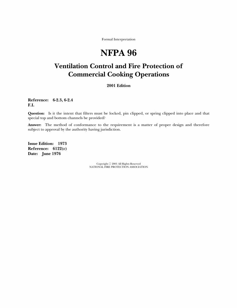
Formal Interpretation
NFPA 96 Ventilation Control and Fire Protection of
Commercial Cooking Operations
2001 Edition
Reference: 6-2.3, 6-2.4 F.I.
Question: Is it the intent that filters must be locked, pin clipped, or spring clipped into place and that special top and bottom channels be provided?
Answer: The method of conformance to the requirement is a matter of proper design and therefore subject to approval by the authority having jurisdiction.
Issue Edition: 1973 Reference: 6122(c) Date: June 1976
Copyright 2001 All Rights Reserved NATIONAL FIRE PROTECTION ASSOCIATION


