Embed Size (px)
Citation preview
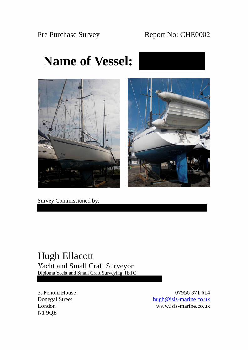
Pre Purchase Survey Report No: CHE0002
Name of Vessel:
Survey Commissioned by:
Hugh EllacottYacht and Small Craft SurveyorDiploma Yacht and Small Craft Surveying, IBTC
3, Penton House 07956 371 614Donegal Street [email protected] www.isis-marine.co.ukN1 9QE

Report No. CHE0002 Pre-Purchase Survey, June 2011
CONTENTS
About the Survey and this Report…………………………………………..………1
1. Particulars of the Vessel........................................................................................2
2. Keel.......................................................................................................................3
3. Hull below Waterline ............................................................................................4
4. Topsides above Waterline .....................................................................................5
5. Deck moulding......................................................................................................5
6. Coachroof .............................................................................................................6
7. Cockpit..................................................................................................................7
8. Hull/Deck Join ......................................................................................................7
9. Bulkheads and Structural Stiffening including Internal Mouldings .....................7
10. Rudder and Steering............................................................................................8
11. Stern Gear ...........................................................................................................9
12. Cathodic Protection...........................................................................................10
13. Skin Fittings and Other Through Hull Apertures..............................................10
14. Main Companionway and Other Access to Accommodation ...........................12
15. Ports ..................................................................................................................13
16. Pulpit, Stanchions, Pushpit and Jackstays.........................................................13
17. Rigging Attachment Points ...............................................................................14
18. Ground Tackle and Mooring Arrangements......................................................14
19. Other Deck Gear and Fittings ...........................................................................15
20. Davits and Boarding Ladders............................................................................15
21. Spars..................................................................................................................15
22. Standing Rigging...............................................................................................16
23. Running Rigging ...............................................................................................16
24. Sails and Covers................................................................................................16
25. Navigation Lights..............................................................................................17
26. Bilge Pumping Arrangements ...........................................................................17
27. Firefighting Equipment .....................................................................................17
28. Lifesaving and Emergency Equipment .............................................................18
29. Engine and Installation......................................................................................18
30. Fuel System.......................................................................................................20
31. General Accommodation...................................................................................21
32. Gas Installation .................................................................................................21
33. Fresh Water Tanks and Delivery .......................................................................22

Report No. CHE0002 Pre-Purchase Survey, June 2011
34. Heads.................................................................................................................22
35. Electrical Installation ........................................................................................22
36. Electronic and Navigation Equipment ..............................................................24
37. Heating and Refrigeration.................................................................................24
Conclusions and Recommendations……………………………………………...25
Report No. CHE0002 Pre-Purchase Survey, June 2011
Page 1 of 27 www.isis-marine.co.uk
About the Survey and this Report
This survey was carried out by Hugh Ellacott at the request of who is aprospective buyer of the vessel.
Scope of Survey
• This is a pre-purchase survey and its purpose is to establish the structural andgeneral condition of the vessel. Where items of equipment have been tested this isstated in the text.
Limitations
• Where access is restricted by fixed panels, linings etc. it was not possible to carryout an examination and I cannot say those areas are free from defects.
• This report has been prepared for the use of the commissioning client and noliability is extended to others who may read it.
• At the time of the survey the mast was stepped and rigging was in place. It wasnot possible to carry out detailed inspection of spars, sails, rigging or otherequipment above head height.
• In some cases it was not possible to detect latent and hidden defects withoutdestructive testing which was not possible without owner’s consent.
• On instruction from the owner, it was not possible to carry out all tests normallyemployed during a pre-purchase survey; notably it was not possible to scrape theanti foul coating from the hull in order to examine the underlying coatings andlaminate. Presence of the anti fouling also affected the confidence in the moisturereadings take on the underbody – this is discussed below.
Conditions of SurveyThe survey took place on June 2011 while was lying ashore at
. According to the vessel was lifted ashore approximately twomonths prior to the survey.
The weather on the day of the survey was overcast with intermittent and occasionallyheavy rain for the most part of the day. This prevented the taking of reliable moisturereadings, and therefore the following day was used to complete the survey. Theweather on the second day was dry, breezy with sunny intervals.
MethodsMoisture MeasurementsAll moisture measurements on the vessel were taken using a Sovereign QuantumMarine Moisture Meter, a capacitance-type moisture meter. The calibration of themeter was checked on the day of survey, prior to any readings being taken. Readingswere taken in the relative mode, which ranges between 0-100. The values should beregarded as an index and do not represent moisture content as a percentage of dryweight. Where appropriate both shallow and deep reading modes were employed.Direct comparisons between readings taken with the Sovereign Quantum and othermeters, including those made by Sovereign, are not valid.
The conditions prevailing when the readings were taken are given below.
Report No. CHE0002 Pre-Purchase Survey, June 2011
Page 2 of 27 www.isis-marine.co.uk
• Air Temperature 22.1°C• Relative Humidity 44.5%• Surface Temperature 23.1° C• Dew Point* 9.2°C• Vessel brought out approximately two months prior to the survey
* Actual dew point and not difference between surface temperature and dew point
In summary, the conditions were good for obtaining moisture readings withinstructural components of the vessel.
Interpretation of Moisture MeasurementsHigh moisture content is not generally a structural defect, and is to be expected inolder boats. However, where some moisture has been absorbed the likelihood ofmoisture-related problems occurring is higher, and the actual state of the laminatecannot be completely guaranteed without destructive testing followed by chemicalanalysis. The opinions given in this report are based on all the evidence available atthe time but without destructive testing. Further discussion is given in the body of thesurvey report.
ConventionsNumbered items in the text are referred to from forward to aft, e.g. frame 4 is thefourth frame aft of the stem and forward of frame 5.
RecommendationsRecommendations in this report fall into two categories, which are explained below.
RecommendationsRecommendations are limited to those defects which should be rectified before thevessel is used (or within a given time span if specified) or may affect the ability toobtain insurance for the vessel.
AdviceAdvice is given concerning defects that do not restrict the use of the vessel or her safeuse. These defects may be cosmetic or concern actions that will prevent more seriousdefects developing in the future. Although these defects may be considered minor, donot assume repair costs are low.
Recommendations and advice made in the body of the report are both printed in italicfont. A table of all recommendations and advice is reproduced at the end of theconclusions.
1. Particulars of the Vessel is advertised by the broker, Yacht Sales, as a Moody 376, designed
by Bill Dixon and built for Moody by Marine Projects in 1988 and launched in 1989.The design is a modern fin keel yacht with a centre cockpit and sugar scoop stern.She is a sloop with a masthead rig. The hull’s construction is a solid glass reinforced
Report No. CHE0002 Pre-Purchase Survey, June 2011
Page 3 of 27 www.isis-marine.co.uk
plastic (GRP) lay up; however, the deck and coachroof employ a sandwichconstruction.
According to the broker, has been in the same ownership for the lastfifteen years and during the sailing season has been on a river mooring and hauledashore each winter apart from 2010/2011. A document on board indicates she wasmoored at .
The broker’s details report the following specifications that accord with dataresearched elsewhere on the internet.
• Length Overall 37' 10"• Length Waterline 31' 3"• Beam 12' 6"• Draft 5' 6"• Displacement 16,250 lbs• Ballast 6,500 lbs
Identifying Numbers
• Lloyds Register No.
A plaque on the port side of the saloon reported the following information: officialnumber 717108 and registered tonnage 13 39/100, indicating the vessel is or has beenPart 1 registered.
The following number was recorded on the battery isolator switch panel on the mainswitchboard, above the chart table.
• Yard No.• Log Reading 3978.85 nautical miles
The broker’s inventory has been checked and found to be correct apart from two itemswhich were not found during the survey. They were the mooring pickup and webbingjackstays. It was also noted that the freshwater tanks were not as described on theinventory.
2. KeelThe vessel has a long fin keel made of cast iron. It was lying fair to the hull and theseam with the hull was visually inspected and no visible defects were found.However, the keel was not seen with the keel bolts in tension, i.e. when the boat islifted in slings. The keel has been antifouled, though there was surface rusting wherethe antifouling had come off in a few places. The forward edge of the keel wasvisually examined and no signs of significant impacts were seen.
Internally access to keel bolts was limited and only four were accessed forexamination. The centre sole board under the table in the saloon was lifted to revealtwo keel bolts. A further two keel bolts were seen under the companionway steps, inthe bilge pump well. Access here was difficult, requiring removal of the steps and a
Report No. CHE0002 Pre-Purchase Survey, June 2011
Page 4 of 27 www.isis-marine.co.uk
locker to provide access to a lifting panel. The keel bolts are studs fastened with whatappeared to be mild steel nuts and backing plates. The four keel bolts were hammertested. Though crusted with surface rust all four nuts were sound.
Salt crystals were noted in the well, which may indicate a very minor leak to betweenthe ballast keel and the hull. However, there was no tidemark present to indicate thata significant amount of water enters the vessel when she is afloat. It would be prudentto monitor water in the bilge.
3. Hull below WaterlineThe hull is solid GRP construction, which was seen in the cockpit locker. The hullwas viewed from various angles; no deflection or unfairness was seen in the vicinityof the keel or shores. The skeg was aggressively tested and no weakness wasdiscovered. The broker's details state that the hull was given an epoxy coating pre1996. This was seen in places where the antifouling had come away from the hull.
The underbody was hammer sounded and no defects were identified.
Moisture measurements were taken at 24 places throughout the underbody. As theowner had not given permission for antifouling to be removed, the locations wereselected where previous patches had been scraped or where antifouling has peeledaway. However, some readings were taken through the antifouling. No differencewas noted between readings with or without antifouling present. The table belowshows the range of moisture readings found in the underbody; above-the-waterlinereadings are included for comparison.
Mode Range Below Waterline Range Above WaterlineShallow Mode 16 – 19 13 – 16Deep Mode 16 – 20 12 – 17
Moisture readings are low for a hull of this age, which to some extent can beattributed to the benefit from the epoxy treatment, but also to the fact that the vesselhas been hauled ashore each winter. Visual inspection did not reveal any evidence ofosmosis, e.g. blistering. This is consistent with the low moisture measurements.
Minor impact damage was found to the bottom edge of the transom, where severalchips in the hull have been repaired. The filler in the repair was no longer adheringand a spike could be inserted to a depth of 8mm. Although, a good depth to the GRPlay up was noted and this point and it was not considered water-tightness should becompromised, the extent of the damage should be investigated and a repair made.Moisture measurements taken around the repair were slightly elevated (20-26 inshallow and deep modes). The degree of moisture ingress is not considered to be ofconcern currently, but the proposed repair should prevent any further waterpenetration.
RecommendationInvestigate and make good the poor repair to the chipped laminate in the lower edgeof the transom.
Report No. CHE0002 Pre-Purchase Survey, June 2011
Page 5 of 27 www.isis-marine.co.uk
The antifouling was in poor condition; the surface is rough in places and there wereextensive areas where the coating has come away from the hull.
AdviceScrape hull back to epoxy coating and apply fresh antifouling coating.
4. Topsides above WaterlineUnlike the underbody the topsides retain their original white gelcoat finish. Thetopsides were lightly hammer sounded and no areas of delamination were detectedapart from those associated with visible damage that is described below.
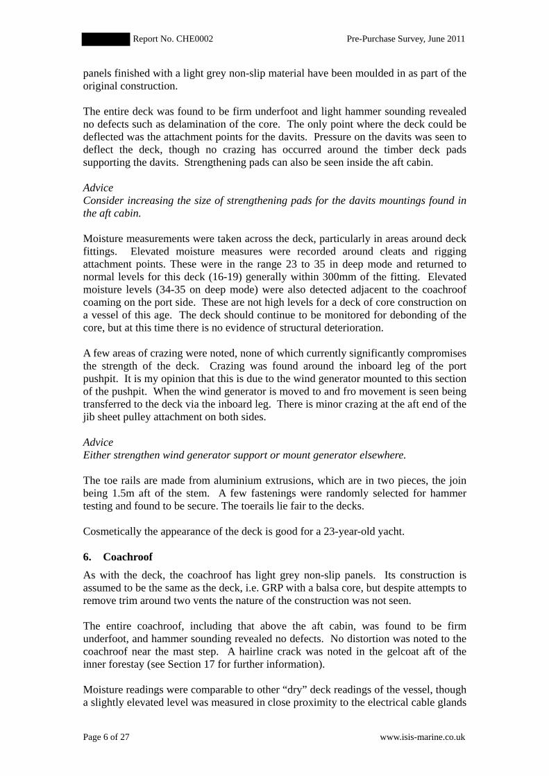
Impact damage was seen on the stem, which appearsto be the effect of two separate collisions, see photoleft. Crazing has occurred in a radius ofapproximately 250mm around the points of impact.Hammer sounding did not identify any delaminationof the laminate within this radius apart from at thevery point of impact. The laminate was spike tested atthe point of impact and it was found to be solid.Moisture was high in the immediate vicinity of thepoint of impact (60-80 on both shallow and deepmodes). In summary, it is considered that there islittle loss of structural strength as a result of thedamage to the stem and main consideration iscosmetic.
Crazing was found on the port topside, in two places 200mm below deck level and 1mand 1.75m aft of the mast. It is thought that this damage may be the result of a singleincident, because of the arced shape of both areas of crazing. Hammer soundingindicated a small and very localised area of delamination in the forward area ofcrazing. Moisture readings corresponded with average readings for the topside. Itwas not possible to inspect the internal structure of the hull at this point. In summary,it is considered that there is little loss of structural strength in this area, especiallygiven the close proximity of the deck which has a reinforcing effect; repair is notnecessary. However, the damage should be monitored during annual inspections.
A minor repair was noted on the port topside, amidships, 300mm above the waterline.
There are no rubbing strakes fitted to the topsides. Cosmetically the topsides are inaverage condition for the age of the hull, though the styling stripes are badly abradedand broken in places. There are minor abrasions present consistent with the age of thehull. Polishing would improve the hull’s appearance.
5. Deck mouldingThe deck is GRP moulded with areas of core construction using endgrain balsa. Anexample of the construction could be seen in the port cockpit locker. The deck lay upin the locker is some 8-10mm thick, where it reverts to solid construction. Surface
Report No. CHE0002 Pre-Purchase Survey, June 2011
Page 6 of 27 www.isis-marine.co.uk
panels finished with a light grey non-slip material have been moulded in as part of theoriginal construction.
The entire deck was found to be firm underfoot and light hammer sounding revealedno defects such as delamination of the core. The only point where the deck could bedeflected was the attachment points for the davits. Pressure on the davits was seen todeflect the deck, though no crazing has occurred around the timber deck padssupporting the davits. Strengthening pads can also be seen inside the aft cabin.
AdviceConsider increasing the size of strengthening pads for the davits mountings found inthe aft cabin.
Moisture measurements were taken across the deck, particularly in areas around deckfittings. Elevated moisture measures were recorded around cleats and riggingattachment points. These were in the range 23 to 35 in deep mode and returned tonormal levels for this deck (16-19) generally within 300mm of the fitting. Elevatedmoisture levels (34-35 on deep mode) were also detected adjacent to the coachroofcoaming on the port side. These are not high levels for a deck of core construction ona vessel of this age. The deck should continue to be monitored for debonding of thecore, but at this time there is no evidence of structural deterioration.
A few areas of crazing were noted, none of which currently significantly compromisesthe strength of the deck. Crazing was found around the inboard leg of the portpushpit. It is my opinion that this is due to the wind generator mounted to this sectionof the pushpit. When the wind generator is moved to and fro movement is seen beingtransferred to the deck via the inboard leg. There is minor crazing at the aft end of thejib sheet pulley attachment on both sides.
AdviceEither strengthen wind generator support or mount generator elsewhere.
The toe rails are made from aluminium extrusions, which are in two pieces, the joinbeing 1.5m aft of the stem. A few fastenings were randomly selected for hammertesting and found to be secure. The toerails lie fair to the decks.
Cosmetically the appearance of the deck is good for a 23-year-old yacht.
6. Coachroof
As with the deck, the coachroof has light grey non-slip panels. Its construction isassumed to be the same as the deck, i.e. GRP with a balsa core, but despite attempts toremove trim around two vents the nature of the construction was not seen.
The entire coachroof, including that above the aft cabin, was found to be firmunderfoot, and hammer sounding revealed no defects. No distortion was noted to thecoachroof near the mast step. A hairline crack was noted in the gelcoat aft of theinner forestay (see Section 17 for further information).
Moisture readings were comparable to other “dry” deck readings of the vessel, thougha slightly elevated level was measured in close proximity to the electrical cable glands
Report No. CHE0002 Pre-Purchase Survey, June 2011
Page 7 of 27 www.isis-marine.co.uk
forward of the mast. There was also elevated moisture in the coaming on both sides(14 –30 in deep mode), probably due to leaking port lights (see page 13).
Both hardwood and chromed handrails were securely attached to the coachroof.Cosmetically the appearance of the coachroof is good for a 23-year-old yacht.
7. CockpitThe cockpit is self-draining with two drains to the aft. The hoses for the two drainsare connected together and discharge from the port topside. The hoses and theirattachments were examined, tested and found to be secure.
The sole boards and bench seats were covered with teak-faced plywood that was invery poor condition. Renovation might be costly because removal of the plywood candamage the underlying laminate.
The cockpit sole is removable to allow lifting of the engine. It is fastened withstainless steel bolts, nuts and washers, some of which were tested at random andfound to be secure.
The pedestal for the steering wheel and compass was tested forcefully and nomovement was found. All four bolt heads were hammer tested and did not fail undertest. Internally the pedestal is mounted on a plywood pad, which appears as good asnew. It was noted that some of the plastic coating was “bubbling” away on thestarboard side of the pedestal, probably as a result of minor surface corrosion on themetallic surface of the pedestal. It is of cosmetic concern only.
Chips were noted to cockpit moulding below the hatch boards; they are only ofcosmetic concern. Cosmetically the appearance of the cockpit is poor owing to thedeterioration in the teak-covered sole boards and bench seats.
8. Hull/Deck JoinThe hull deck join was seen in the porthand cockpit locker. The join is mechanical,whereby the hull moulding is fastened to the deck moulding using stainless steel bolts.Sealant is used to make the join waterproof. The bolts are used to attach thealuminium toe rail to the deck. Four bolts were selected at random and hammer testedand found to be secure.
9. Bulkheads and Structural Stiffening including Internal MouldingsThe mast compression post is stainless steel and is located in the saloon. The soleboard under the saloon table was lifted, revealing the compression post resting on amassive transverse girder. There was no evidence of the post being driven into thegirder. The girder was hammer tested which indicated it was sound.
Bulkheads and structural members were hammer sounded throughout the vessel,where access allowed. This included hammer sounding along the horizontallongitudinal attachment between the hull and inner mouldings, i.e. along berths andsettees in the saloon and cabins. Structural members and GRP attachment betweenbulkheads and the hull were visually inspected, also where access allowed.
Report No. CHE0002 Pre-Purchase Survey, June 2011
Page 8 of 27 www.isis-marine.co.uk
No significant defects were discovered as a result of the above tests. The followingminor defects were noted.
Loose fibres were noted on the forward side of the forward heads bulkhead; spiketesting indicated that the attachment to the hull is secure. On the other side of thisbulkhead, in the locker under the sink, minor delamination of the bulkhead/hullattachment was seen. A feeler could be inserted to a depth of approximately 50mmand this defect extends from the lower end of the bonding upward for some 200mm.The defect is not considered to be of serious concern.
Debonding of the GRP attachment was also observed in the aft bulkhead in the aftheads. This minor defect does not constitute significant loss of structural strength.
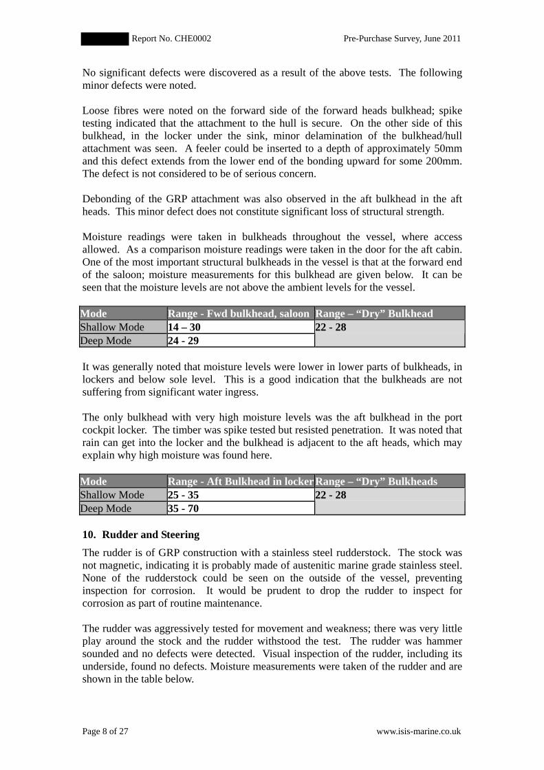
Moisture readings were taken in bulkheads throughout the vessel, where accessallowed. As a comparison moisture readings were taken in the door for the aft cabin.One of the most important structural bulkheads in the vessel is that at the forward endof the saloon; moisture measurements for this bulkhead are given below. It can beseen that the moisture levels are not above the ambient levels for the vessel.
Mode Range - Fwd bulkhead, saloon Range – “Dry” BulkheadShallow Mode 14 – 30Deep Mode 24 - 29
22 - 28
It was generally noted that moisture levels were lower in lower parts of bulkheads, inlockers and below sole level. This is a good indication that the bulkheads are notsuffering from significant water ingress.
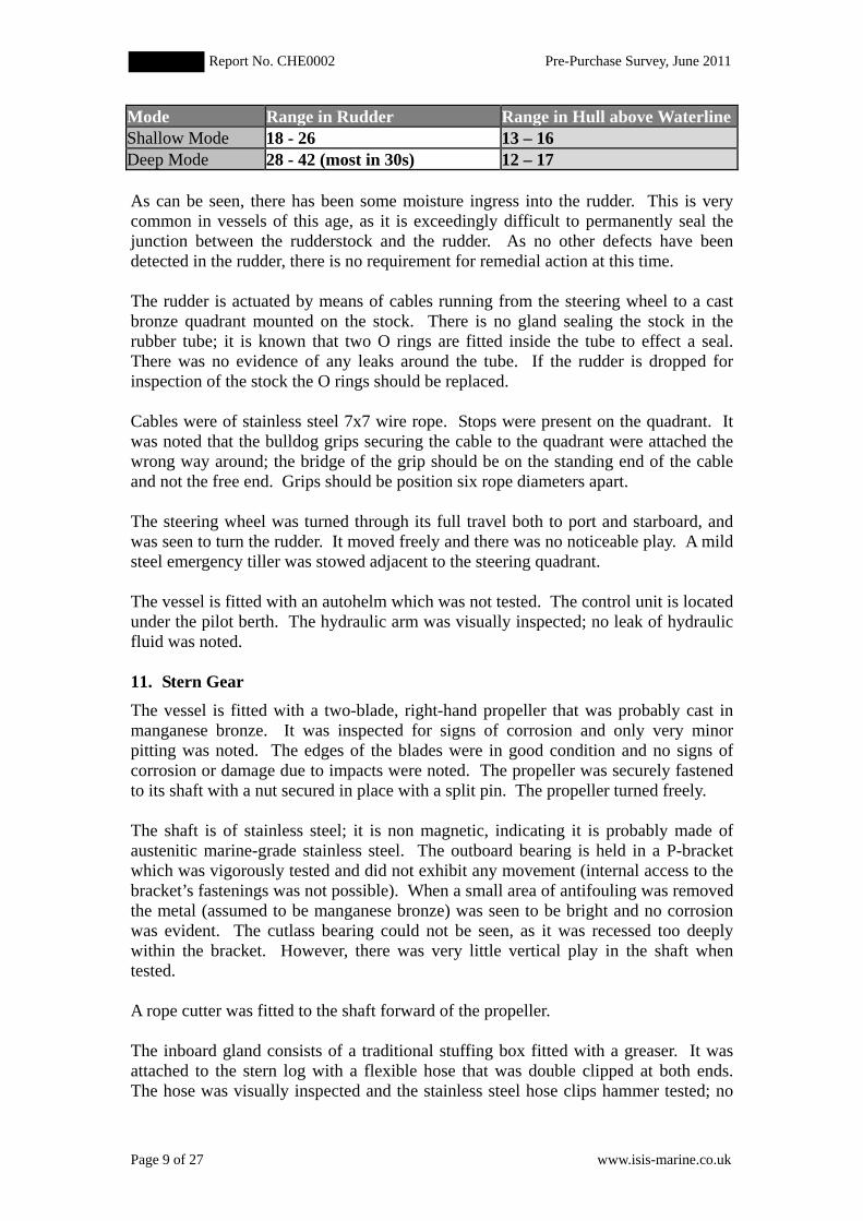
The only bulkhead with very high moisture levels was the aft bulkhead in the portcockpit locker. The timber was spike tested but resisted penetration. It was noted thatrain can get into the locker and the bulkhead is adjacent to the aft heads, which mayexplain why high moisture was found here.
Mode Range - Aft Bulkhead in lockerRange – “Dry” BulkheadsShallow Mode 25 - 35Deep Mode 35 - 70
22 - 28
10. Rudder and SteeringThe rudder is of GRP construction with a stainless steel rudderstock. The stock wasnot magnetic, indicating it is probably made of austenitic marine grade stainless steel.None of the rudderstock could be seen on the outside of the vessel, preventinginspection for corrosion. It would be prudent to drop the rudder to inspect forcorrosion as part of routine maintenance.
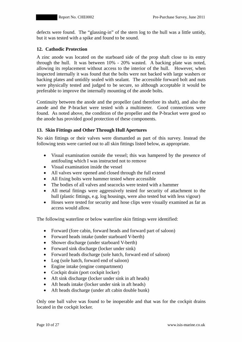
The rudder was aggressively tested for movement and weakness; there was very littleplay around the stock and the rudder withstood the test. The rudder was hammersounded and no defects were detected. Visual inspection of the rudder, including itsunderside, found no defects. Moisture measurements were taken of the rudder and areshown in the table below.
Report No. CHE0002 Pre-Purchase Survey, June 2011
Page 9 of 27 www.isis-marine.co.uk
Mode Range in Rudder Range in Hull above WaterlineShallow Mode 18 - 26 13 – 16Deep Mode 28 - 42 (most in 30s) 12 – 17
As can be seen, there has been some moisture ingress into the rudder. This is verycommon in vessels of this age, as it is exceedingly difficult to permanently seal thejunction between the rudderstock and the rudder. As no other defects have beendetected in the rudder, there is no requirement for remedial action at this time.
The rudder is actuated by means of cables running from the steering wheel to a castbronze quadrant mounted on the stock. There is no gland sealing the stock in therubber tube; it is known that two O rings are fitted inside the tube to effect a seal.There was no evidence of any leaks around the tube. If the rudder is dropped forinspection of the stock the O rings should be replaced.
Cables were of stainless steel 7x7 wire rope. Stops were present on the quadrant. Itwas noted that the bulldog grips securing the cable to the quadrant were attached thewrong way around; the bridge of the grip should be on the standing end of the cableand not the free end. Grips should be position six rope diameters apart.
The steering wheel was turned through its full travel both to port and starboard, andwas seen to turn the rudder. It moved freely and there was no noticeable play. A mildsteel emergency tiller was stowed adjacent to the steering quadrant.
The vessel is fitted with an autohelm which was not tested. The control unit is locatedunder the pilot berth. The hydraulic arm was visually inspected; no leak of hydraulicfluid was noted.
11. Stern GearThe vessel is fitted with a two-blade, right-hand propeller that was probably cast inmanganese bronze. It was inspected for signs of corrosion and only very minorpitting was noted. The edges of the blades were in good condition and no signs ofcorrosion or damage due to impacts were noted. The propeller was securely fastenedto its shaft with a nut secured in place with a split pin. The propeller turned freely.
The shaft is of stainless steel; it is non magnetic, indicating it is probably made ofaustenitic marine-grade stainless steel. The outboard bearing is held in a P-bracketwhich was vigorously tested and did not exhibit any movement (internal access to thebracket’s fastenings was not possible). When a small area of antifouling was removedthe metal (assumed to be manganese bronze) was seen to be bright and no corrosionwas evident. The cutlass bearing could not be seen, as it was recessed too deeplywithin the bracket. However, there was very little vertical play in the shaft whentested.
A rope cutter was fitted to the shaft forward of the propeller.
The inboard gland consists of a traditional stuffing box fitted with a greaser. It wasattached to the stern log with a flexible hose that was double clipped at both ends.The hose was visually inspected and the stainless steel hose clips hammer tested; no
Report No. CHE0002 Pre-Purchase Survey, June 2011
Page 10 of 27 www.isis-marine.co.uk
defects were found. The “glassing-in” of the stern log to the hull was a little untidy,but it was tested with a spike and found to be sound.
12. Cathodic ProtectionA zinc anode was located on the starboard side of the prop shaft close to its entrythrough the hull. It was between 10% - 20% wasted. A backing plate was noted,allowing its replacement without access to the interior of the hull. However, wheninspected internally it was found that the bolts were not backed with large washers orbacking plates and untidily sealed with sealant. The accessible forward bolt and nutswere physically tested and judged to be secure, so although acceptable it would bepreferable to improve the internally mounting of the anode bolts.
Continuity between the anode and the propeller (and therefore its shaft), and also theanode and the P-bracket were tested with a multimeter. Good connections werefound. As noted above, the condition of the propeller and the P-bracket were good sothe anode has provided good protection of these components.
13. Skin Fittings and Other Through Hull AperturesNo skin fittings or their valves were dismantled as part of this survey. Instead thefollowing tests were carried out to all skin fittings listed below, as appropriate.
• Visual examination outside the vessel; this was hampered by the presence ofantifouling which I was instructed not to remove
• Visual examination inside the vessel• All valves were opened and closed through the full extend• All fixing bolts were hammer tested where accessible• The bodies of all valves and seacocks were tested with a hammer• All metal fittings were aggressively tested for security of attachment to the
hull (plastic fittings, e.g. log housings, were also tested but with less vigour)• Hoses were tested for security and hose clips were visually examined as far as
access would allow.
The following waterline or below waterline skin fittings were identified:
• Forward (fore cabin, forward heads and forward part of saloon)• Forward heads intake (under starboard V-berth)• Shower discharge (under starboard V-berth)• Forward sink discharge (locker under sink)• Forward heads discharge (sole hatch, forward end of saloon)• Log (sole hatch, forward end of saloon)• Engine intake (engine compartment)• Cockpit drain (port cockpit locker)• Aft sink discharge (locker under sink in aft heads)• Aft heads intake (locker under sink in aft heads)• Aft heads discharge (under aft cabin double bunk)
Only one ball valve was found to be inoperable and that was for the cockpit drainslocated in the cockpit locker.
Report No. CHE0002 Pre-Purchase Survey, June 2011
Page 11 of 27 www.isis-marine.co.uk
RecommendationAs a minimum, service the cockpit drain ball valve, but as it is almost certainly brasssee advice below concerning the replacement of brass valves on skin fittings.
The external fittings for both heads intakes displayed signs of corrosion and arebelieved to be brass or other high zinc content, copper alloy. No corrosion was notedto any other external fitting; however, the presence of antifouling prevented thoroughinspection.
All valves were ball valves apart from the seawater intake for engine cooling whichwas a traditional bronze seacock. The valves were silvery coloured and to myknowledge there are no bronze or dezincification resistance DZR valves made withthis finish; they are therefore almost certainly made of brass. Yachting Monthly arecurrently investigating the use and suitability of brass through hulls. One marineinsurer has indicated that it might not settle claims where brass through hull fittingshave failed. Internal corrosion to the ball valves may not be seen until it fails.
AdviceIt is strongly advised that the brass ball valves on through hull fittings are replaced,but advice from insurers should be monitored as requirements are evolving at the timeof writing this report. Replace external fittings for the heads intakes with bronze or(DZR) fittings. Examine all other external waterline or below waterline skin fittingsand replace if made of brass or other high zinc content, copper alloy.
With the exception of the log and transducer all skin fittings were hammer tested anddid not yield when so tested. Throughout the vessel hoses attached to skin fittingswere fastened with two stainless steel clips. These were visually inspected andhammer tested and no defects were detected apart from the aft heads intake where oneof the hose clips is pinching the hose and could cause a leak. It is normally goodpractice to double clip all through hull fittings except where the hose tail is too shortto accept two clips, which is the case in this instance.
AdviceRemove second hose clip from aft heads intake.
A log and echo sound transducer are mounted near the centreline immediately forwardof the keel. Both are fastened to the hull utilising a large plastic nut located on thebody. The fittings are secure but there have been a few incidents involving this typeof fitting where the external flange has sheered off, allowing the body of the fitting tocome loose in the boat and leaving a 37mm hole. This is rare but all unreinforcedplastic such as this will deteriorate over time and the life of the fitting is largelydependent on the amount of tension it has endured since being fitted in the first place.Many installers over-tighten these fittings and it is therefore prudent to apply a lightGRP lamination or epoxy fillet over the securing nut and onto the surrounding hullsurface inside the boat in order that the fitting remains in situ should the flange sheeroff. Obviously the flange should be inspected whenever the opportunity arises. Asecond transducer, which does not penetrate the hull, is also present. If it can beestablished that the through hull transducer is not needed, then it may be preferable to
Report No. CHE0002 Pre-Purchase Survey, June 2011
Page 12 of 27 www.isis-marine.co.uk
remove it and make good the hull by grinding back around the aperture, relaminatingwith epoxy resin and finishing.
The following above waterline skin fittings were identified:
• Exhaust discharge for diesel heater (port cockpit locker)• Bilge pump discharge (port cockpit locker)• Drainage for gas locker (port quarter)
14. Main Companionway and Other Access to AccommodationThe main hatch is of perspex and is secure. The companionway steps are wellsecured. There is a plywood hatch board that has ventilation grills let into it. It is insound condition but has a 20mm diameter hole cut on one side near its top. A secondperspex hatch board was found on board. This was of sufficient strength for itspurpose, but was a loose fit and its handle on the upper edge was broken. There wasno means of securing the main hatch or boards from inside the boat.
AdviceProvide means of securing hatch from inside the boat and provide lanyards for hatchboards.
The garage for the main hatch has a number of minor defects; it has cracks to themoulding on both sides at the aft end and the attaching screws do not lie fair. Thecracks have been made good with a soft sealant that appeared to be watertight. Thereis a 100-150mm crack in the starboard side just forward of the hood and another smallcrack around the foremost screw and the starboard side. In summary the garage is inpoor condition but is serviceable.
Both the fore cabin and aft cabin have perspex hatches that provide adequate means ofescape from the vessel. They are secured by means of two lockable handles. Bothhatches exhibit crazing, but are serviceable. No leaks were apparent during theincessant rain during the first day of the survey. The fore hatch has a ventilator set inits centre and it was noted there was some brown staining around the self-tappingscrews holding the ventilator in place. The screws were hammer tested for soundnessand did not yield. However, it would be prudent to replace the screws with 316stainless steel screws during routine maintenance.
The hatch at the forward end of the main saloon was free from leaks but is severelycrazed (worse than all the other hatches). It was tested by application of firm pressure– I stood on it – and did not break, but I consider it is on the borderline of serviceablelife. Replacement of perspex hatches can be quite expensive.
AdviceIt is strongly advised to replace the hatch in the saloon; the fore hatch and aft cabinhatch will require replacement in due course.
Both forward and aft heads have small hatches that are also crazed but are serviceableand did not exhibit any leaks in the rain. The upper part of one of the handles on theforward heads hatch was missing. It was physically tested and found to move more
Report No. CHE0002 Pre-Purchase Survey, June 2011
Page 13 of 27 www.isis-marine.co.uk
than the other handle, but only marginally so and is therefore considered to be secureat the present time. However, it would be prudent to replace during routinemaintenance.
15. PortsThere are six non-opening ports in the coach roof sides, four in the saloon and two inthe aft cabin. The frames are made of aluminium and secured with stainless steelscrews. One screw in each window was loosened and retightened. They were allfound to turn easily and be in good condition, although very minor corrosion wasnoted on the aluminium around some screwheads. All the perspex in the windowswas crazed to a greater or lesser extent. The windows flexed under firm pressure butwere secure and are therefore considered to be serviceable. Leaks were noted in fourof the ports.
AdviceReseal all six non-opening ports or otherwise expect uncomfortably damp berths onlonger passages.
Two small opening ports are found in the aft cabin and are positioned in the transom.Again there is slight crazing of the perspex, but under firm pressure they were foundto be secure. They could be securely closed, but were easily opened with theirhandles.
16. Pulpit, Stanchions, Pushpit and JackstaysThe pulpit is bolted to the toerail; one bolt was tested and found to be secure.
The port and starboard granny bars were vigorously tested and found to be secure.All securing pins in their feet were present.
The pushpit is in two pieces, each part having three feet. The two outboard feet areattached to the toerail and are very secure. However, the inboard legs are attached tothe deck and on the starboard side the attachment is loose. The port one is secure, butcausing crazing to the deck (see page 5).
AdviceTighten fastening for inboard leg of starboard pushpit.
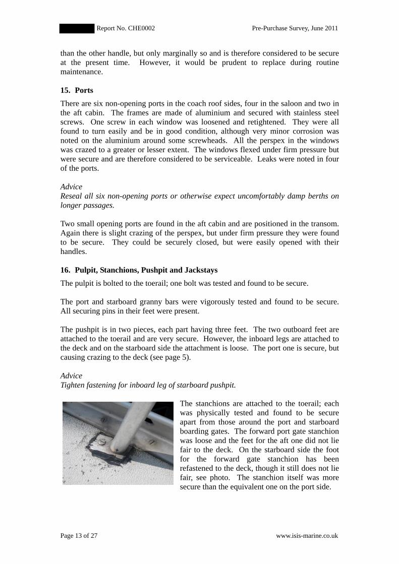
The stanchions are attached to the toerail; eachwas physically tested and found to be secureapart from those around the port and starboardboarding gates. The forward port gate stanchionwas loose and the feet for the aft one did not liefair to the deck. On the starboard side the footfor the forward gate stanchion has beenrefastened to the deck, though it still does not liefair, see photo. The stanchion itself was moresecure than the equivalent one on the port side.
Report No. CHE0002 Pre-Purchase Survey, June 2011
Page 14 of 27 www.isis-marine.co.uk
AdviceFasten gate stanchions more securely.
The guardlines and their terminals were visually inspected for evidence of brokenstrands; none were found. No jackstays were rigged on deck and none were seenamongst the stowed gear, though they are listed in the broker’s details. A completeinventory of gear was not made during the survey, so the jackstays may be presentamongst gear on the vessel.
17. Rigging Attachment PointsThe rigging set up was taut and stays were aggressively swigged to test attachmentpoints. The rigging attachment points are described below.
• Main forestay is attached to a substantial stemhead fitting securely through-bolted.• Inner forestay is attached to a stainless steel chain plate through coachroof; no
internal access was possible from inside the vessel. However, a hairline crack wasnoted just aft of the chain plate, see page 6, which could be a result of stressescause by the stay. No distortion was noted to the coachroof or internal structuressuch as bulkheads or doorways. It is therefore considered that no remedialmeasures are necessary, but the crack should be monitored.
• Main cap and lower shrouds are attached to deck plates that are through bolted tointernal structures. Internal linings prevent visual inspection of the attachmentsinternally. No distortion was noted to the deck plates or in the topsides. The deckplates were lying fair to the deck.
• Backstay is plate bolted through transom that is simple and strong.
18. Ground Tackle and Mooring ArrangementsA Lofrans manual anchor winch is set below deck level in a recess in the bow, under adeck hatch. The winch handle was present allowing the winch to be tested with noload. It was seen to operate. The stemhead fitting has a roller for the anchor chainand the chain can be secured in place by a pin. From the anchor locker (accessedthrough the forward cabin) a mounting plate for the anchor winch can be seen. Alayer of rust was present, but on testing with a hammer the plate and the nuts werefound to secure.
The stemhead fitting is secured by large bolts, which were tested and found to besecure. Some brown staining on the fitting around the boltholes. The security of thefitting should be regularly monitored.
Anchors had been stowed in the cockpit locker. The main anchor is Bruce anchor of33lbs. In addition, a Danforth anchor with chain (not inspected) was also present inthe locker. A very rusty chain was seen in the anchor locker, as was a three-strandedwarp. Further inspection of the anchor chain was not undertaken as the broker'sdetails state it should be replaced. The warp was not inspected.
RecommendationReplace anchor chain.
Report No. CHE0002 Pre-Purchase Survey, June 2011
Page 15 of 27 www.isis-marine.co.uk
There are six mooring cleats fitted to the deck, forward, aft and amidships. All weretested with a bar, and a number of bolt heads hammer tested. All cleats were found tobe very secure and no flexing of the deck was seen around the cleats.
19. Other Deck Gear and FittingsIn the cockpit there are six winches:
• 3 x Lewmar 16• 2 x Lewmar 43 (two speed)• 1 x Lewmar 8
All winches were operated (not under load) and found to work smoothly, apart fromthe starboard forward winch that sounded slightly rough, though it operated wellenough. The winches were vigorously tested and found to be well secured to thecockpit/deck mouldings.
Tracks for the headsails were secure; six bolt heads were tested at random. Similarlythe mainsail track was found to be secure.
Wood pads under the pulleys mounted on the coachroof were deteriorating as a resultof being exposed to the sun and rain. The endgrain on the portside one in particularwas starting to open up. They were spike tested and are both serviceable but theircondition should be monitored.
20. Davits and Boarding LaddersThe arrangement of the davits allows the dinghy to obscure the stern navigation light.
AdviceHang dinghy from davits so that the stern navigation light is not obscured.
The presence of the dinghy hampered examination of the boarding ladder. It wasadjudged to extend at least 1m below the waterline, but this could not be measured.The attachment of the davits is discussed on page 5. No further tests were performedon the davits.
21. SparsMastThe broker’s details state the mast was serviced in 2006. As far as could be seen fromdeck level with mast stepped the silver anodised Kemp aluminium mast is in goodcondition with no serious corrosion around fittings and rivets. All fittings accessiblefrom deck level were secure. No stress cracks were noted to the cast heel fitting.
The mast has been retrofitted with behind-the-mast roller reefing for the mainsail.Two winches are mounted on the mast; a Lewmar 30 and a Lewmar 16. There werenot operated but found to be securely attached.
Report No. CHE0002 Pre-Purchase Survey, June 2011
Page 16 of 27 www.isis-marine.co.uk
BoomThe silver anodised aluminium boom was in similar condition to the mast. Rigidmechanical kicking strap arrangement was secure and in good order. No due play wasnoted in the gooseneck.
Spinnaker PoleThe only other spar, a telescopic spinnaker pole, was inspected. The pin at one endwas jammed.
22. Standing RiggingThe mast is supported by a forestay, inner forestay, backstay and strouds arranged intwo panels. The broker’s details state the rigging was inspected along with the mastin 2006; there was no information on the age of the standing rigging. As far as couldbe seen from deck level with mast stepped the 1x19 stainless steel rigging is in goodcondition with no visible damage or kinks to the wire noted. The shrouds wereaggressively swigged; spreaders were seen to be secure and set correctly. The shroudterminals with the mast were viewed from below and seen to lie true to the line oftension; essential if premature fatigue of the shrouds and attachments is to be avoided.
The four bottle screws and their toggles were examined with a 10x magnificationhand lens; no corrosion or stress cracks were observed. Terminals were swaged.
Headsail roller reefing was found to operate freely and well secured at base.
23. Running RiggingThe running rigging was in below average condition and replacement of sheets andhalyards has not been undertaken in recent seasons. The looped lift for the spinnakerboom slide was very stiff and quite old (the lovely seaman’s whipping on its endssuggests it is not a recent addition to the running rigging). The outhaul for themainsail was frayed in places and in the worst condition of all the running rigging.The headsail sheets, mainsheet, mainsail inhaul, jib inhaul, and halyards wereconsidered serviceable.
24. Sails and CoversThe broker's details list four sails including the original mainsail. A strong breezeprevented unfurling more than a few feet of the furling jib and furling mainsail.Broken stitches were noted on the jib and there was considerable UV degradation tothe foot and luff where the sail is exposed to sunlight and weather on the roller. It wasthe poorest of the sails onboard, though only a small part was seen. The condition ofthe few feet of the mainsail viewed was good apart from the sacrificial clew that isexposed to the weather.
The genoa was viewed onboard so only a very small part of the sail was seen. Nobroken stitches or UV degradation were noted, and on the basis of this limitedinspection the genoa was in good condition.
Also onboard was the original mainsail, though it would be very difficult to set thissail because of the roller reefing now fitted to the mast. It was in poor condition withbroken stitches and UV degradation along its leech.
Report No. CHE0002 Pre-Purchase Survey, June 2011
Page 17 of 27 www.isis-marine.co.uk
Covers were in need of a wash. Those present were a sprayhood, steering wheelcover and six covers for the winches in the cockpit. The piping on the sprayhood hadseriously deteriorated but was in a serviceable condition. The bungies securing thewinch covers had lost their spring and need replacing.
25. Navigation LightsSwitches for the following navigation lights are present on the panel above the charttable:
• Masthead light• Steaming light• Tricolour / Anchor
The labelling is confused because the masthead light and steaming light refer to thesame operation. On testing the port and starboard lights mounted on the pulpit wereseen to work, as was the steaming light at the mast. The stern light did not come on.Owing to bright sunlight it was not possible to test the masthead light or the tricolour.
RecommendationFix the stern light and fully test navigation lights.
26. Bilge Pumping ArrangementsThe only bilge pump aboard the vessel is a hand-operated “Whale Gusher” located inthe cockpit locker. The handle was present but pump was not operated. It dischargesto a skin fitting located high on the port topside. Access to the strum box was difficultrequiring removal of the companionway steps and a locker underneath it.
Although the pumping capacity (thought to be 64 litres per minute) is sufficient withreference to the Marine and Coastguard Agency (MCA) guidance for this size ofvessel1, a single hand-operated pump is considered less than ideal. A second pumpwould provide a backup in case the first pump fails in an emergency, and if it were anelectric pump it would provide protection against sinking in the event of a leakoccurring while the vessel is unattended.
AdviceFit a second bilge pump.
27. Firefighting EquipmentThere are three fire extinguishers on board.
• Under table in saloon• Opposite pilot bunk• In aft cabin• A fire blanket is located in the galley
1 Marine Guidance Note, MGN 280 (M). The note is not a requirement for butprovides a good benchmark for best practice.
Report No. CHE0002 Pre-Purchase Survey, June 2011
Page 18 of 27 www.isis-marine.co.uk
All are dry powder and, judging by the expiry dates (circa 1993), have been on thevessel since she was built. All are out of date. Also, there appears to be a wallbracket for a fire extinguisher in the engine compartment but one was not present.The BSS2, which provides guidance for recreational craft operating on UK inlandwaterways, requires a vessel of 36 feet or more to have at least three extinguisherswith a combined fire rating of 21A/144B. The BSS is not applicable to but it is a good guideline for provision of fire extinguishers.
RecommendationReplace all fire extinguishers and give consideration to including an automaticallyoperated one in the engine compartment.
A smoke alarm was fitted to the headlining in the forward cabin. It was not tested.
28. Lifesaving and Emergency EquipmentA Dan buoy is mounted on the starboard side of the pushpit. It is disintegrating and itis odds on for sinking if deployed. There were also two yellow lifebuoy lights abovethe chart table. Their operation or condition was not examined.
AdviceReplace the Dan buoy.
The two horseshoe lifebuoys noted on the broker’s details were located in the portcockpit locker. Their lights were not tested. Also listed by the broker is a RIBdinghy; it was present in the davits at the time of the survey. It was not inspected.
29. Engine and Installation
According to the broker's details the engine is a Thornycroft T80D rated at 35hp. It ismounted below the cockpit and the main access is via a panel opposite the pilot'sberth. A second access panel, on the port side, can be found via the cockpit locker. Aplate on the engine recorded the following details:
• Engine Serial No.• Engine No.• Engine 80D
The control panel above the chart table records the engine running hours as 1941.1.However, it is not possible to corroborate if this is a true record of engine hourswithout access to a log book and engine service history.
The broker's details recorded that a new sump has been fitted to the engine; this wasseen. An oil absorbent pad has been placed in the bilge below the engine; it did notshow any signs of oil contamination.
2 The Boat Safety Scheme operated by British Waterways and the Environment Agency;www.boatsafetyscheme.com/site/Home_1.asp
Report No. CHE0002 Pre-Purchase Survey, June 2011
Page 19 of 27 www.isis-marine.co.uk
The engine is mounted on massive longitudinal girders attached to the hull. Thesewere hammer-sounded as far as access would allow and no defects were detected.Flexible mounts attach the engine to the girders; the bolts and mounts were physicallytested and found to be secure.
The fan belt was too loose and should be tightened. There is evidence of a leak ofengine coolant from around the thermostat housing. In general hoses and their clipswere in good condition. They were probably replaced during the recent engineoverall and it was nice to see hoses running through a second sacrificial hose wherechafing could occur. A short red hose (located under the secondary fuel filter) wasfastened with what appeared to be mild steel hose clips. Though these were testedand found to be secure it would be prudent to replace these with stainless steel hoseclips.
The filler cap was removed, but the water level was not visible though water wasclearly present. A rusty sludge was noted coating the internal surface of the heatexchanger indicating that the corrosion inhibitor may not have been used. It would beadvisable to flush the engine coolant system and ensure inhibitor (included inproprietary antifreeze) is always used.
Oil was checked in both the engine dipstick and the gearbox dipstick. Engine oil wasblack, did not display signs of water or any untoward odour. Automatic transmissionfluid (ATF) was present in the gearbox and was clean, i.e. still a pinky red.
The overall impression of the engine was good; it was generally clean and thepaintwork was in good condition apart from on the water cooler. However, a visualinspection of the kind undertaken cannot be expected to identify many engine defectsthat may be present and it is always prudent to commission a sea trial or full enginesurvey from a marine engineer when purchasing a used vessel.
A wet exhaust feeds a mild steel muffler mounted to the aft port side of the enginecompartment. The muffler was hammer tested for soundness and no defects weredetected. The exhaust is then discharged through a purpose made GRP pipe justbelow the waterline under the transom. There is no waterlock present on the exhaust.As the gooseneck rises some 1.5m and there is a muffler present, it is not consideredthat seawater could be syphoned into the engine and therefore a waterlock is notconsidered necessary. Visual inspection revealed the exhaust hose to be in goodcondition (possibly new), as were the hose clips (doubled at all locations) which werephysically tested at the join with the GRP pipe.
The gearbox is a Hurth HBW100-2R, serial number . The broker reportsthat it has recently been overhauled, but this can only be confirmed by viewinginvoices for this work. It is suggested that the invoices are requested.
The stainless steel prop shaft is attached to the gearbox with a flexible coupling. Fourof the eight bolts are bright, which suggests they were replaced when the gearbox wasreportedly overhauled. The other four exhibited surface rusting but were found to besecure when hammer tested. The prop shaft was found to be non-magnetic,suggesting that is made from austenitic stainless steel, i.e. marine grade.
Report No. CHE0002 Pre-Purchase Survey, June 2011
Page 20 of 27 www.isis-marine.co.uk
There is a single lever engine control mounted on the pedestal in the cockpit. It wasnot tested.
30. Fuel SystemA diesel tank made of mild steel is located immediately forward of the engine, moreor less in the same compartment as the engine. Access to the tank was difficult asacoustic foam has been glued to its most accessible side. The tank is painted blue andthe sides and top were in good condition, where they could be viewed. The undersidewas viewed with a mirror and tapped with a hammer. Although some minor surfacerust was noted on the underside it is in good condition as far as could be ascertainedduring the inspection. A securing point for the tank could only be viewed at onelocation; a flange welded onto the tank was secured to a longitudinal girder by meansof a stainless steel screw. The screw was tested and did not yield. It is my opinionthat the screws (it is assumed there are four holding the tank, but this could not beconfirmed) are undersize for the function they perform. It would be prudent tomonitor the condition of the bolts securing the fuel tank, particularly after a roughpassage.
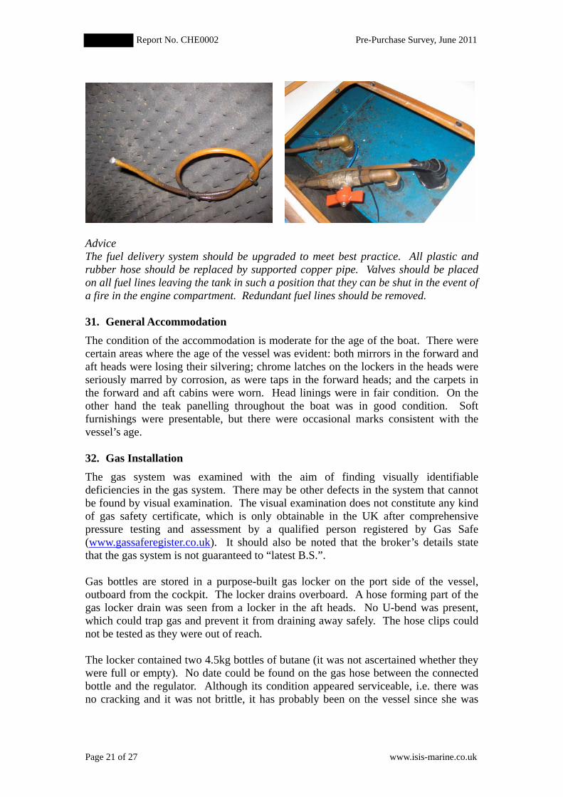
The tank is fed via a marked filler point in the deck via a rubber fuel hose which isdouble clipped to a mild steel pipe extending from the tank. The clips at both endswere tested and found to be secure. A plastic site gauge is fitted by the side of thetank. It is open topped and operated by opening a valve at the bottom of the tank.
AdviceThe sight gauge does not conform to best practice and consideration should be givento its removal and replacement with an alternative type of gauge.
The delivery line from the tank to the engine is from the top and is fitted with a valvenear its junction with the tank. A copper pipe then links to a primary filter with aplastic bowl. The filter is in turn linked to the engine lift pump via both copper pipeand a plastic reinforced hose that does not meet BS EN ISO 7840. Supports for thepipe and hose are lacking.
RecommendationReplace all reinforced plastic hose used as a fuel line with pipe that meets ISO 7840.When this work is undertaken consideration should be given to improvement to therouting of the fuel line from the tank so it can be supported, and replacement of theplastic bowl in the primary fuel filter with a metal one which is fire resistant.
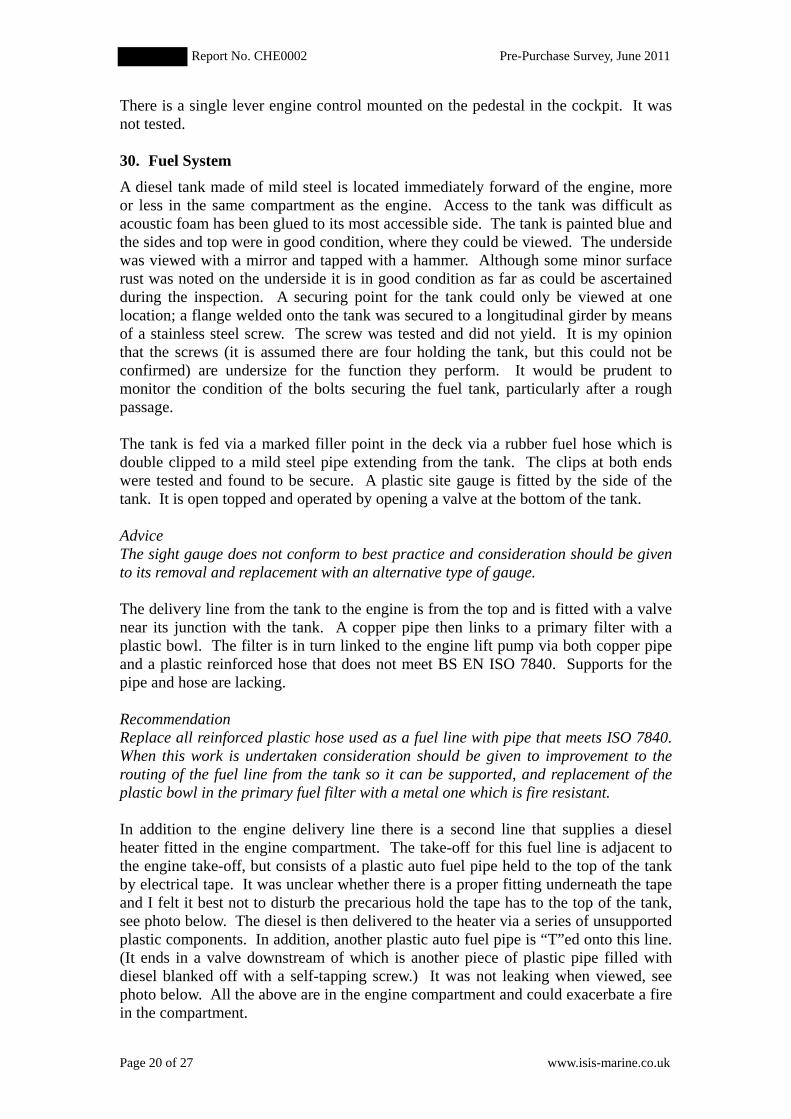
In addition to the engine delivery line there is a second line that supplies a dieselheater fitted in the engine compartment. The take-off for this fuel line is adjacent tothe engine take-off, but consists of a plastic auto fuel pipe held to the top of the tankby electrical tape. It was unclear whether there is a proper fitting underneath the tapeand I felt it best not to disturb the precarious hold the tape has to the top of the tank,see photo below. The diesel is then delivered to the heater via a series of unsupportedplastic components. In addition, another plastic auto fuel pipe is “T”ed onto this line.(It ends in a valve downstream of which is another piece of plastic pipe filled withdiesel blanked off with a self-tapping screw.) It was not leaking when viewed, seephoto below. All the above are in the engine compartment and could exacerbate a firein the compartment.
Report No. CHE0002 Pre-Purchase Survey, June 2011
Page 21 of 27 www.isis-marine.co.uk
AdviceThe fuel delivery system should be upgraded to meet best practice. All plastic andrubber hose should be replaced by supported copper pipe. Valves should be placedon all fuel lines leaving the tank in such a position that they can be shut in the event ofa fire in the engine compartment. Redundant fuel lines should be removed.
31. General AccommodationThe condition of the accommodation is moderate for the age of the boat. There werecertain areas where the age of the vessel was evident: both mirrors in the forward andaft heads were losing their silvering; chrome latches on the lockers in the heads wereseriously marred by corrosion, as were taps in the forward heads; and the carpets inthe forward and aft cabins were worn. Head linings were in fair condition. On theother hand the teak panelling throughout the boat was in good condition. Softfurnishings were presentable, but there were occasional marks consistent with thevessel’s age.
32. Gas InstallationThe gas system was examined with the aim of finding visually identifiabledeficiencies in the gas system. There may be other defects in the system that cannotbe found by visual examination. The visual examination does not constitute any kindof gas safety certificate, which is only obtainable in the UK after comprehensivepressure testing and assessment by a qualified person registered by Gas Safe(www.gassaferegister.co.uk). It should also be noted that the broker’s details statethat the gas system is not guaranteed to “latest B.S.”.
Gas bottles are stored in a purpose-built gas locker on the port side of the vessel,outboard from the cockpit. The locker drains overboard. A hose forming part of thegas locker drain was seen from a locker in the aft heads. No U-bend was present,which could trap gas and prevent it from draining away safely. The hose clips couldnot be tested as they were out of reach.
The locker contained two 4.5kg bottles of butane (it was not ascertained whether theywere full or empty). No date could be found on the gas hose between the connectedbottle and the regulator. Although its condition appeared serviceable, i.e. there wasno cracking and it was not brittle, it has probably been on the vessel since she was
Report No. CHE0002 Pre-Purchase Survey, June 2011
Page 22 of 27 www.isis-marine.co.uk
new. (Similarly the regulator had signs of surface corrosion.) Most advicerecommends replacing regulators and hose at least every ten years.
A plastic hose was seen in the port cockpit locker running forward just below decklevel. The hose contains the copper gas pipe.
In the galley there is a Plastimo Atlantic two burner gas cooker with oven and grill.The cooker was not tested. An armoured hose was seen running from the back of thecooker.
AdviceReplace gas hoses (in gas locker and at back of cooker) and regulator.
33. Fresh Water Tanks and DeliveryThere are two fresh water tanks under both the port and starboard berths in the saloon.Tanks appeared to be constructed of black polyethylene and not stainless steel asstated in the broker's details. The capacity was not obviously marked on either, buttheir total capacity is estimated to be in excess of 600 litres. The water filler isamidships on the starboard side. It was not established how the tanks are interlinked,but it is assumed that they are, given that there is only one filler point on deck.
34. HeadsThere are two heads, one forward and the second accessed from the aft cabin. Bothdischarge directly overboard. Goosenecks are present on intake and discharge hoses.The lid to the aft heads has become detached from the bowl.
35. Electrical Installation240 volt AC
There are a number of 240-volt sockets installed throughout the boat. It appears theseare not part of the original electrical installation. A 240-volt shoreline can be attachedto a 16 amp plug mounted in the cockpit. An RCD was noted in the enginecompartment adjacent to a domestic-type main breaker switch with fuses.
A 240-volt Cetek auto battery charger is mounted in the engine compartment. It israted at 10 amps. It was not tested.
12-volt DC
Two batteries were located in a purpose-made battery box under the double bunk inthe aft cabin. Batteries are well secured with steel straps across the top. The batterybox is vented by means of a duct that terminates in the portside cockpit locker. Thisdischarge for the duct, which is designed to safely vent hydrogen to atmosphere if thebatteries are overcharged, is located within 1.5m of the air intake for the diesel heater.It is unlikely but not impossible that hydrogen could be sucked into the heater.
AdviceRelocate the discharge for the battery box vent or the diesel heater air intakeexternally, i.e. in the port topside near to deck level.
Report No. CHE0002 Pre-Purchase Survey, June 2011
Page 23 of 27 www.isis-marine.co.uk
Two batteries were present in the battery box:
• A 90 amp hour, wet cell battery with an SAE 580 rating; it was wired as adomestic battery, but appears to be an engine starting battery given it has anSAE rating. Its condition indicator was on red, i.e. poor.
• An Exrider XV31MF rated at 800 CCA, which was assumed to be the enginestarting battery judging by the heavy duty cables.
The domestic batteries and engine battery are isolated from one another by anisolating diode, which allows electrical continuity during charging.
A third battery was discovered in a locker under the settee in the aft cabin. It is notproperly installed; the battery box is in a recycled food carton that has split, so wouldnot retain any spilt battery acid; the battery is not restrained in any way; there are noterminal covers and the compartment is not vented. Again the battery is an enginecranking battery, rated at 105 amp hr and 750 CCA. It was not determined how thebattery is connected to the 12v system.
The actuating arm for the autohelm chafes the main battery cable. No wear wasnoted at present but electrical tape has been ineffectually placed around the cable nearthe rub. As the metallic parts of the steering system are bonded, a high current shortcould result if the battery cable wears through, possibly resulting in a fire. Theremedy is simple, would take five minutes and a few pence.
RecommendationClip the positive battery cable so it is not chaffed by the autohelm.
The battery isolator switch is located on the main switch panel above the chart table.There was also a volt meter in the panel for measuring the condition of “Battery 1” or“Battery 2”. Both battery banks had an initial reading of 12.3 volts, but on testing thenavigation lights both fell to 11.7 volts indicating the batteries need replacing.
AdviceReplace engine and domestic battery. Either do without the third battery or install abattery box that will retain a spillage and is vented.
The general impression of the 12 volt system was of a poor installation; a number ofexamples are given below.
• There were no covers on the battery terminals• The domestic battery cable was 4mm2 or 6mm2, which in my opinion is
undersized. Correctly sizing this cable may circumvent the need for a thirdbattery
• Yellow crimp connectors, designed for minimum cable size of 2.63mm2, havebeen crimped to undersize cable
• Two wires, a brown and blue one, were noted twisted together under the aftend of the hatch in the aft cabin. These appear to have been part of aredundant magnetic burglar alarm switch
Report No. CHE0002 Pre-Purchase Survey, June 2011
Page 24 of 27 www.isis-marine.co.uk
AdviceCommission a marine electrician (not a domestic electrician) to examine theelectrical systems with a view to providing a schedule for upgrading both the DC andAC systems.
36. Electronic and Navigation EquipmentNavigation equipment is as listed on the broker’s details. The following equipmentwas turned on and seen to power up. Further testing was not undertaken.
• Furano 1721 radar• Yeoman plotter interface• Philips MK9 GPS• ICS Nav 4 paper-type Navtex• AIS display
The autohelm interface and the VHF radio were not seen to power up, though thisdoes not necessarily indicate any defects.
37. Heating and RefrigerationThe exhaust from the heater is vented overboard via a pipe that passes through thecockpit locker. It expels via a bronze/brass skin fitting in the port topside. The pipe islagged, but it is not fully effective as heat damage can be seen to the plywoodbulkhead in the locker. However, the paint is not scorched and spiking did notindicate any deterioration to the plywood. The lagging was visually examined andwas found to be a woven cloth consisting of a white fibrous material. Where strandsof cloth were broken the fibres were seen to be friable and it is possible the lagging ismade of asbestos. Asbestos was used as pipe lagging until the early 1980s and as theheater does not appear to be part of the original services aboard there is the possibilitythat asbestos was used. It should also be noted that the lagging is right next to theladder into the locker and will be occasionally knocked and rubbed, which increasesthe risks of disturbing fibres if the lagging is made of asbestos.
AdviceTest whether lagging on heater exhaust is asbestos. Arrange for professional removaland disposal if the test is positive, and then replace lagging. If replacement oflagging were necessary it would be an opportunity to place insulation board betweenthe lagged exhaust pipe and bulkhead. However, do not disturb the lagging until itsnature has been confirmed.
A 240v calorifier is located in the port cockpit locker. The broker’s details state that itneeds replacement, but it is unclear whether this refers to the heating element or thewhole calorifier. It was noted that the electric cable to the heating element had beencut.
A 240v fan heater is fitted into the L-shaped settee on the starboard side to the saloon.The heater draws air from inside the locker, but no vents have been cut into the locker.It would advisable to cut holes into the locker so that the heater is not starved ofairflow.
Report No. CHE0002 Pre-Purchase Survey, June 2011
Page 25 of 27 www.isis-marine.co.uk
CONCLUSIONS AND RECOMMENDATIONS:
Conclusions is known to have been built to high standards. The survey did not reveal
any structural defects and it is apparent she has not been sailed hard in the past. Thelow level of moisture in the underbody is a significant advantage which in part mustbe due to the epoxy treatment applied in the mid 1990s. The low moisture levels andthe epoxy coating will protect against the possibility of osmotic defects occurring inthe hull laminate.
However, her cosmetic condition is only moderate and there are signs of “tiredness”inside the yacht. There is also a pressing need to assess the AC and DC electricalsystems and upgrade to acceptable standards. Similarly the diesel feeds from the fueltank really should be improved. Replacement of brass ball valves associated withmost of the skin fittings is certainly advisable and may become a requirement ofinsurance. With these and some other improvements has many years ofsailing ahead of her.
Hugh Ellacott,
List of Recommendations
The recommendations made in the report are listed below with their respective pagenumbers. All recommendations should be carried out before use of the vessel.
Page 4Investigate and make good the poor repair to the chipped laminate in the lower edgeof the transom.
Page 11As a minimum, service the cockpit drain ball valve, but as it is almost certainly brasssee advice below concerning the replacement of brass valves on skin fittings.
Page 14Replace anchor chain.
Page 17Fix the stern light and fully test navigation lights.
Page 18Replace all fire extinguishers and give consideration to including an automaticallyoperated one in the engine compartment.
Report No. CHE0002 Pre-Purchase Survey, June 2011
Page 26 of 27 www.isis-marine.co.uk
Page 20Replace all reinforced plastic hose used as a fuel line with pipe that meets ISO 7840.When this work is undertaken consideration should be given to improvement to therouting of the fuel line from the tank so it can be supported, and replacement of theplastic bowl in the primary fuel filter with a metal one which is fire resistant.
Page 23Clip the positive battery cable so it is not chaffed by the autohelm.
List of Advice
The advice notes given in the report are listed below with their respective pagenumbers. It is not necessary to carry out advice before use of vessel.
Page 5Scrape hull back to epoxy coating and apply fresh antifouling coating.
Page 6Consider increasing the size of strengthening pads for the davits mountings found inthe aft cabin.
Page 6Either strengthen wind generator support or mount generator elsewhere.
Page 11It is strongly advised that the brass ball valves on through hull fittings are replaced,but advice from insurers should be monitored as requirements are evolving at the timeof writing this report. Replace external fittings for the heads intakes with bronze or(DZR) fittings. Examine all other external waterline or below waterline skin fittingsand replace if made of brass or other high zinc content, copper alloy.
Page 11Remove second hose clip from aft heads intake.
Page 12Provide means of securing hatch from inside the boat and provide lanyards for hatchboards.
Page 12It is strongly advised to replace the hatch in the saloon; the fore hatch and aft cabinhatch will require replacement in due course.
Page 13Reseal all six non-opening ports or otherwise expect uncomfortably damp berths onlonger passages.
Page 13Tighten fastening for inboard leg of starboard pushpit.
Report No. CHE0002 Pre-Purchase Survey, June 2011
Page 27 of 27 www.isis-marine.co.uk
Page 14Fasten gate stanchions more securely.
Page 15Hang dinghy from davits so that the stern navigation light is not obscured.
Page 17Fit a second bilge pump.
Page 18Replace the Dan buoy.
Page 20The sight gauge does not conform to best practice and consideration should be givento its removal and replacement with an alternative type of gauge.
Page 21The fuel delivery system should be upgraded to meet best practice. All plastic andrubber hose should be replaced by supported copper pipe. Valves should be placedon all fuel lines leaving the tank in such a position that they can be shut in the event ofa fire in the engine compartment. Redundant fuel lines should be removed.
Page 22Replace gas hoses (in gas locker and at back of cooker) and regulator.
Page 22Relocate the discharge for the battery box vent or the diesel heater air intakeexternally, i.e. in the port topside near to deck level.
Page 23Replace engine and domestic battery. Either do without the third battery or install abattery box that will retain a spillage and is vented.
Page 24Commission a marine electrician (not a domestic electrician) to examine theelectrical systems with a view to providing a schedule for upgrading both the DC andAC systems.
Page 24Test whether lagging on heater exhaust is asbestos. Arrange for professional removaland disposal if the test is positive, and then replace lagging. If replacement oflagging were necessary it would be an opportunity to place insulation board betweenthe lagged exhaust pipe and bulkhead. However, do not disturb the lagging until itsnature has been confirmed.