Embed Size (px)
Citation preview
Multicast routing for multimedia collaborative applications
Emad Eldin Mohamed*, Hussein Abdel-Wahab
Department of Computer Science, Old Dominion University, Norfolk, VA 23529, USA
Received 28 December 2002; revised 6 December 2003; accepted 20 January 2004
Abstract
This paper introduces a multicast routing technique that is suitable for multimedia collaborative applications. Typically, the multicast
groups for such applications are small and of slow membership dynamics. Moreover, the group members are not assumed to be located in a
single domain; rather, they may span a global inter-network. An important requirement for multimedia collaborative applications is the
delivery time—a shortest path delivery tree is of a major interest in constructing the multicast tree. Our routing technique constructs a
distribution tree per source and it uses explicit membership messages to build and maintain the tree. Thus, it combines the advantages of both
broadcast and prune (BAP) and shared tree techniques; that is, it produces shortest path trees, yet the bandwidth consumed in building and
maintaining such trees is minimal. We present a simulation study to compare the performance of our technique against BAP and shared tree
techniques. Results of the simulation show that our technique outperforms previous ones.
q 2004 Elsevier B.V. All rights reserved.
Keywords: IP multicast; Routing protocols; Multimedia communications
1. Introduction
Multicast routing concerns the construction of a tree—
named distribution tree—that is used to efficiently deliver
data from a source to multiple destinations [11]. Optimizing
the distribution tree can be done with respect to either the
cost or the delay of the tree. Building a minimum cost tree is
the Steiner tree problem and is proven to be NP-complete
[7–9]. Assuming delay as the metric of the tree, building a
minimum delay tree corresponds to finding the shortest
path tree. In contrast with the Steiner tree, the shortest path
tree is a tractable problem with many existing efficient
algorithms [5].
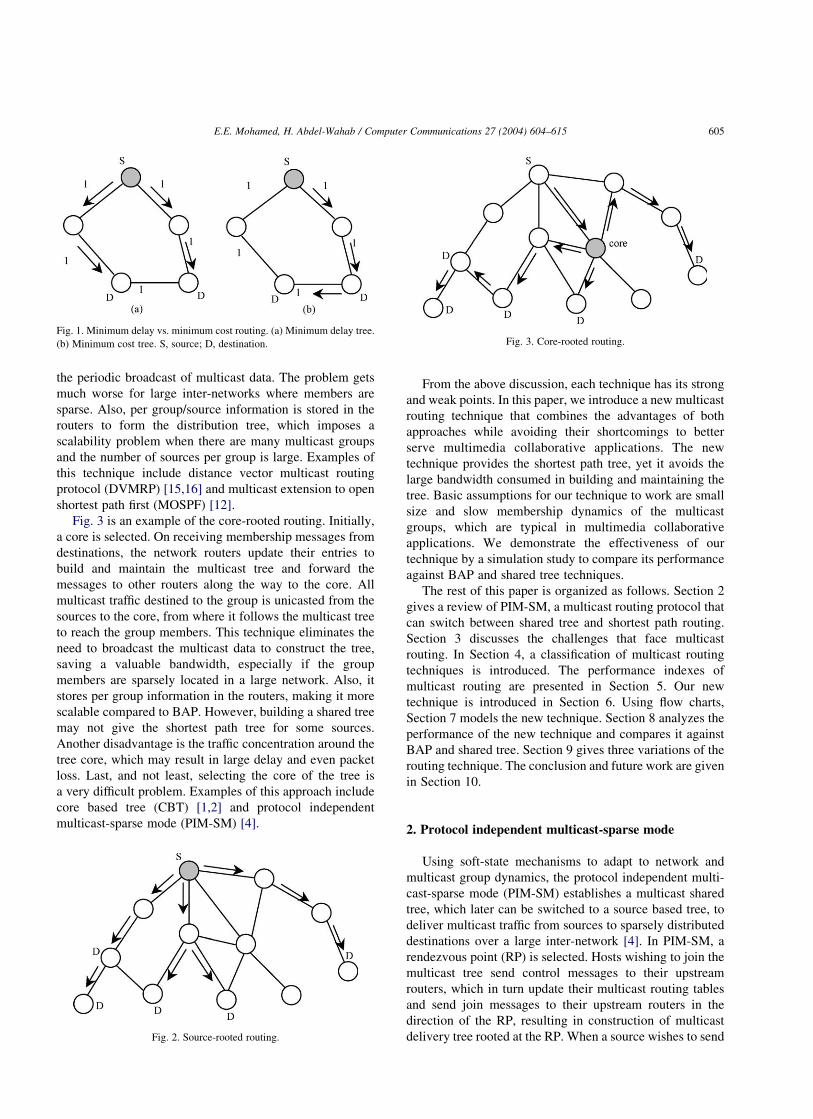
Fig. 1 contrasts the minimum cost and the minimum
delay trees for an example network that has all links of the
same cost (link metric is assumed to be delay). Fig. 1a gives
a shortest path tree from a source to two destinations. The
cost of the tree in this example is 4 units, while the average
delay is 2. Fig. 1b gives a minimum cost tree from the
source to the same destinations. The cost of the tree in this
example is 3 units (minimum cost) while the average delay
is 2.5, resulting in a larger delay than the previous example.
Two factors guide the research in multicast routing:
advances in the communications technology and the
application requirements. The first factor lessens the
importance of the tree cost, whereas the second suggests
the need to have a minimal delay delivery. To this end, most
of the existing multicast protocols sacrifice the cost in favor
of the delay of the tree. Multicast routing protocols mainly
fall into one of two categories: broadcast and prune (BAP)
and shared tree routing. BAP routing builds a tree per each
source [6,13]. Shared tree routing relies on explicit
membership messages originated from the destinations
and directed towards a known core to build and maintain
the distribution tree. Fig. 2 shows a source-rooted routing
tree. BAP routing relies on broadcasting the multicast data
packets periodically along the network edges. To determine
the paths along which the multicast data are forwarded the
reverse path forwarding is used [3]. On receiving the
multicast traffic, uninterested routers prune themselves from
the distribution tree. The periodic broadcast of multicast
traffic is to keep the tree updated in response to group
dynamics. Protocols based on this technique provide the
shortest path tree from the source to the destinations. The
main disadvantage, however, is the waste of the network
bandwidth in building and maintaining the tree due to
Computer Communications 27 (2004) 604–615
www.elsevier.com/locate/comcom
0140-3664/$ - see front matter q 2004 Elsevier B.V. All rights reserved.
doi:10.1016/j.comcom.2004.01.018
* Corresponding author. Present address: College of Information
Technology, United Arab Emirates University, Al Ain P.O. Box 15551,
United Arab Emirates. Tel.: þ971-507133206; fax: þ971-37626309.
E-mail address: [email protected] (E.E. Mohamed).
the periodic broadcast of multicast data. The problem gets
much worse for large inter-networks where members are
sparse. Also, per group/source information is stored in the
routers to form the distribution tree, which imposes a
scalability problem when there are many multicast groups
and the number of sources per group is large. Examples of
this technique include distance vector multicast routing
protocol (DVMRP) [15,16] and multicast extension to open
shortest path first (MOSPF) [12].
Fig. 3 is an example of the core-rooted routing. Initially,
a core is selected. On receiving membership messages from
destinations, the network routers update their entries to
build and maintain the multicast tree and forward the
messages to other routers along the way to the core. All
multicast traffic destined to the group is unicasted from the
sources to the core, from where it follows the multicast tree
to reach the group members. This technique eliminates the
need to broadcast the multicast data to construct the tree,
saving a valuable bandwidth, especially if the group
members are sparsely located in a large network. Also, it
stores per group information in the routers, making it more
scalable compared to BAP. However, building a shared tree
may not give the shortest path tree for some sources.
Another disadvantage is the traffic concentration around the
tree core, which may result in large delay and even packet
loss. Last, and not least, selecting the core of the tree is
a very difficult problem. Examples of this approach include
core based tree (CBT) [1,2] and protocol independent
multicast-sparse mode (PIM-SM) [4].
From the above discussion, each technique has its strong
and weak points. In this paper, we introduce a new multicast
routing technique that combines the advantages of both
approaches while avoiding their shortcomings to better
serve multimedia collaborative applications. The new
technique provides the shortest path tree, yet it avoids the
large bandwidth consumed in building and maintaining the
tree. Basic assumptions for our technique to work are small
size and slow membership dynamics of the multicast
groups, which are typical in multimedia collaborative
applications. We demonstrate the effectiveness of our
technique by a simulation study to compare its performance
against BAP and shared tree techniques.
The rest of this paper is organized as follows. Section 2
gives a review of PIM-SM, a multicast routing protocol that
can switch between shared tree and shortest path routing.
Section 3 discusses the challenges that face multicast
routing. In Section 4, a classification of multicast routing
techniques is introduced. The performance indexes of
multicast routing are presented in Section 5. Our new
technique is introduced in Section 6. Using flow charts,
Section 7 models the new technique. Section 8 analyzes the
performance of the new technique and compares it against
BAP and shared tree. Section 9 gives three variations of the
routing technique. The conclusion and future work are given
in Section 10.
2. Protocol independent multicast-sparse mode
Using soft-state mechanisms to adapt to network and
multicast group dynamics, the protocol independent multi-
cast-sparse mode (PIM-SM) establishes a multicast shared
tree, which later can be switched to a source based tree, to
deliver multicast traffic from sources to sparsely distributed
destinations over a large inter-network [4]. In PIM-SM, a
rendezvous point (RP) is selected. Hosts wishing to join the
multicast tree send control messages to their upstream
routers, which in turn update their multicast routing tables
and send join messages to their upstream routers in the
direction of the RP, resulting in construction of multicast
delivery tree rooted at the RP. When a source wishes to send
Fig. 1. Minimum delay vs. minimum cost routing. (a) Minimum delay tree.
(b) Minimum cost tree. S, source; D, destination.
Fig. 2. Source-rooted routing.
Fig. 3. Core-rooted routing.
E.E. Mohamed, H. Abdel-Wahab / Computer Communications 27 (2004) 604–615 605
multicast traffic, it unicasts the traffic towards the RP, from
which the traffic follows the delivery shared tree towards the
destinations [4].
A main feature that distinguishes PIM-SM from
traditional CBT techniques is its ability to switch from
shared tree mode to a source based tree, which results in
shortest path tree. Switching to the source-based tree is
initiated by the first hop routers of the destinations. When
the first hop router of a destination wishes to switch to a
shortest path tree, it sends a join message towards the
source. When the message reaches the router at which the
shortest path tree and the shared tree diverge, the router
further forwards the join message towards the source and
sends a prune message towards the RP. This way, the
destination joins the shortest path tree rooted at the source
and gets out of the shared tree. However, since there is no
guarantee that all first hop routers of the destinations would
wish to join the source based tree at the same time, the
shared tree is still maintained to accommodate those
destinations not joining the source based tree.
3. Multicast routing: the challenge
In its general form, the multicast routing problem can be
stated as the efficient construction of multicast distribution
trees from sources to multiple destinations while maintain-
ing the following assumptions:
† Destinations’ information is distributed within the
network’s routers.
† Destinations’ information is dynamic.
† Sources’ information is not kept at all within the
network.
A challenge that faces this problem is the size of the
network where sources and destinations are located, which
is normally very large. Satisfying these three assumptions, a
solution to the problem can be one of three:
† Let the sources look for the destinations in the entire
network.
† Let the destinations look for the sources in the entire
network.
† Advertise RPs where sources and destinations can
meet.
Letting sources explore the entire network to find
destinations and build the tree is the BAP technique
described earlier. However, and as explained above, this
technique is very costly in building and maintaining the tree,
rendering it impractical in large networks, where the
destinations are sparse.
Letting destinations explore the entire network to find
sources is more costly than the previous one, since the
solution requires each destination to broadcast membership
messages along the network edges in searching for sources.
Usually, the number of destinations is larger than the
number of sources. Since sources are not known to the
network, these messages should be delivered to every end
system in the network, wasting not only the network
bandwidth, but the computing power of the end systems as
well. The third solution; having RPs where sources and
destinations can meet; tries to get around the first and the
third assumptions stated above. An example of this solution
is core-based tree—a core is selected and destinations and
sources send their membership information and data to the
core. In this paper, we further explore this third solution—
having RPs where sources and destinations can meet—and
we present a technique based on this idea.
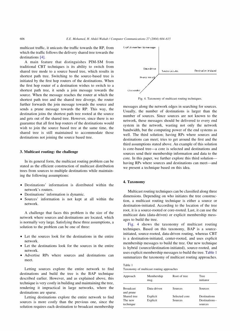
4. Taxonomy
Multicast routing techniques can be classified along three
dimensions. Depending on who initiates the tree construc-
tion, a multicast routing technique is either a source or
destination-initiated. According to the location of the tree
root, it is a source-rooted or core-rooted. Last, it can use the
multicast data (data-driven) or explicit membership mess-
ages to build the tree.
Fig. 4 shows the taxonomy of multicast routing
techniques. Based on this taxonomy, BAP is a source-
initiated, source-rooted, data-driven routing, whereas CBT
is a destination-initiated, center-rooted, and uses explicit
membership messages to build the tree. Our new technique
is hybrid (source/destination-initiated), source-rooted, and
uses explicit membership messages to build the tree. Table 1
summarizes the taxonomy of multicast routing approaches.
Table 1
Taxonomy of multicast routing approaches
Approach Membership
msg.
Root of tree Tree
initiator
Broadcast
and prune
Data-driven Sources Sources
Shared tree Explicit Selected core Destinations
The new
technique
Explicit Sources Destinations–
sources
Fig. 4. Taxonomy of multicast routing techniques.
E.E. Mohamed, H. Abdel-Wahab / Computer Communications 27 (2004) 604–615606
5. Performance indexes
The performance of a multicast routing technique can be
evaluated by several measurements. Cost, delay, traffic
concentration, join latency, overhead, and scalability are the
most popular measures. This is because they are easy to
measure and they directly affect the members of the
multicast group as well as the entire network performance.
The cost of a multicast technique can be defined as the total
network bandwidth consumed in delivering the multicast
data to its destination. Finding the minimum cost distri-
bution tree is an NP-complete problem. However, many
heuristics have been introduced to find a low cost
distribution tree [6,7,14].
A very important factor in multicast routing is the
average end-to-end delay due to data delivery from sources
to destinations. Many recent applications, such as video
conferencing, impose minimum delay restrictions on the
data delivery. Constructing the minimum delay tree usually
conflicts with minimizing the cost of the tree. The
increasing advances in the communications technology
and the imposed application requirements, however, steer
most of the research effort in this field towards minimizing
the delay.
When building the multicast distribution tree, caution
should be taken not to concentrate traffic around some
routers in the network. Traffic concentrations may lead to
delay, and even losses due to overloaded routers, in the
delivery of the multicast data.
Join latency is the time experienced by an end system
that has issued a join membership report to its router until
the time it receives the multicast data. The goal is to
minimize this latency.
Another important measure of multicast routing tech-
niques is the overhead of building and maintaining the
distribution tree. This overhead takes the form of network
bandwidth, routing state stored, and computational effort
performed within the routers. The most important of these
forms, however, is the network bandwidth overhead, since
this affects the overall performance of the network. The goal
is to build the tree with the minimum possible overhead.
Recently, large groups, which are sparse and span a large
inter-network, are common in many applications. When
designing a routing protocol, scalability of the protocol is a
very important factor to accommodate these groups.
Scalability is a measure of how well a routing technique
performs when the network size or the number of
destinations and sources increase.
6. Multicast routing: a new technique
In this section we present a new routing technique that is
suitable for multimedia collaborative applications. Two
basic assumptions underlie this technique: group members
are few and membership dynamics is slow. The new
technique is a source-rooted—it constructs a delivery tree
rooted at each source—and it uses explicit membership
messages to construct the tree; that is, it avoids the periodic
broadcast of data.
The basic idea behind our technique is to advertise a
rendezvous point (RVP) where sources and destinations can
meet. Two lists are kept in the RVP: the destination list
(which contains the destinations’ addresses) and the source
list (which contains the sources’ addresses). Beside the
multicast group that is used to deliver data from sources to
destinations (which we will call data group) another
multicast group (the source group) is used to multicast
control messages from the RVP to the sources of the
multicast data group.
An end system wishing to be a member of the data group
is required to unicast a destination membership join (DMJ)
message to the RVP before it can receive traffic destined to
the group. Similarly, an end system wishing to be a source
of the group is required to unicast a source membership join
(SMJ) message to the RVP and become a member in the
source group before it can send data to the data group. A
destination/source membership join message contains the
message type (join data/source group) and the address of the
sender of the message. Likewise, a destination/source that
wishes to quit the data/source group unicasts destination/-
source membership leave (DML/SML) message to the RVP.
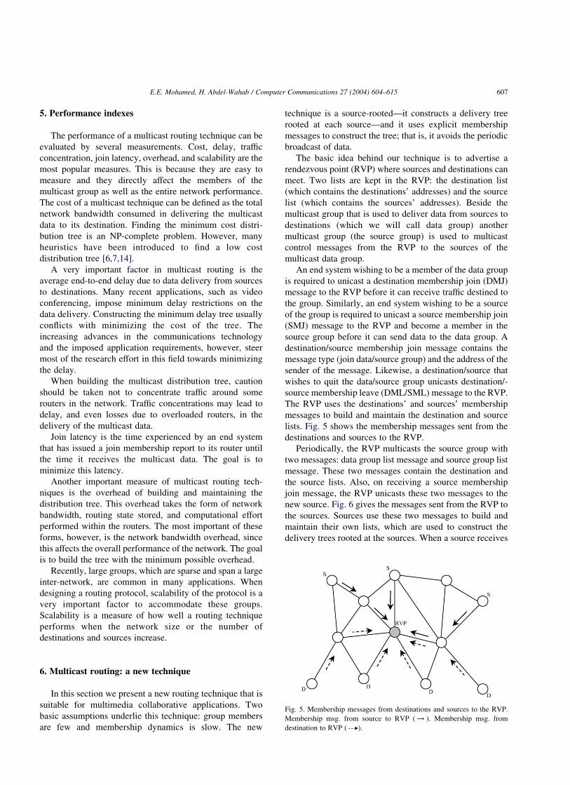
The RVP uses the destinations’ and sources’ membership
messages to build and maintain the destination and source
lists. Fig. 5 shows the membership messages sent from the
destinations and sources to the RVP.
Periodically, the RVP multicasts the source group with
two messages: data group list message and source group list
message. These two messages contain the destination and
the source lists. Also, on receiving a source membership
join message, the RVP unicasts these two messages to the
new source. Fig. 6 gives the messages sent from the RVP to
the sources. Sources use these two messages to build and
maintain their own lists, which are used to construct the
delivery trees rooted at the sources. When a source receives
Fig. 5. Membership messages from destinations and sources to the RVP.
Membership msg. from source to RVP ( ! ). Membership msg. from
destination to RVP ( ).
E.E. Mohamed, H. Abdel-Wahab / Computer Communications 27 (2004) 604–615 607
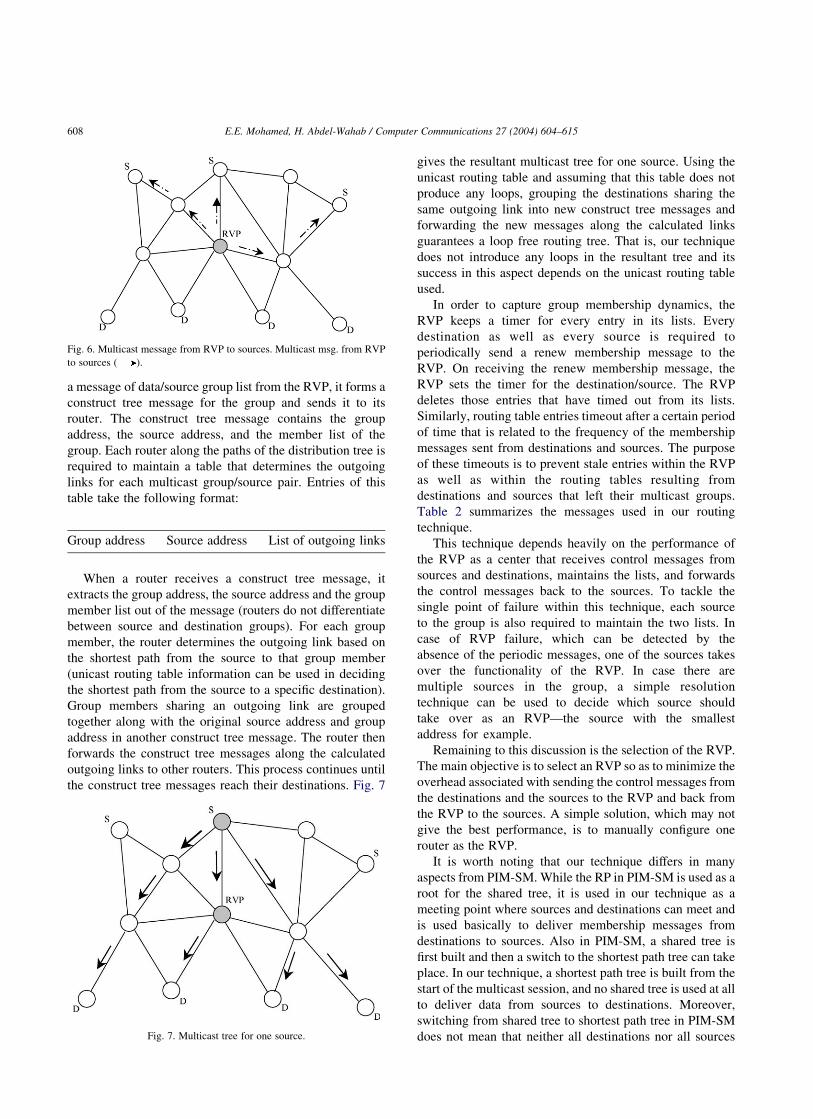
a message of data/source group list from the RVP, it forms a
construct tree message for the group and sends it to its
router. The construct tree message contains the group
address, the source address, and the member list of the
group. Each router along the paths of the distribution tree is
required to maintain a table that determines the outgoing
links for each multicast group/source pair. Entries of this
table take the following format:
Group address Source address List of outgoing links
When a router receives a construct tree message, it
extracts the group address, the source address and the group
member list out of the message (routers do not differentiate
between source and destination groups). For each group
member, the router determines the outgoing link based on
the shortest path from the source to that group member
(unicast routing table information can be used in deciding
the shortest path from the source to a specific destination).
Group members sharing an outgoing link are grouped
together along with the original source address and group
address in another construct tree message. The router then
forwards the construct tree messages along the calculated
outgoing links to other routers. This process continues until
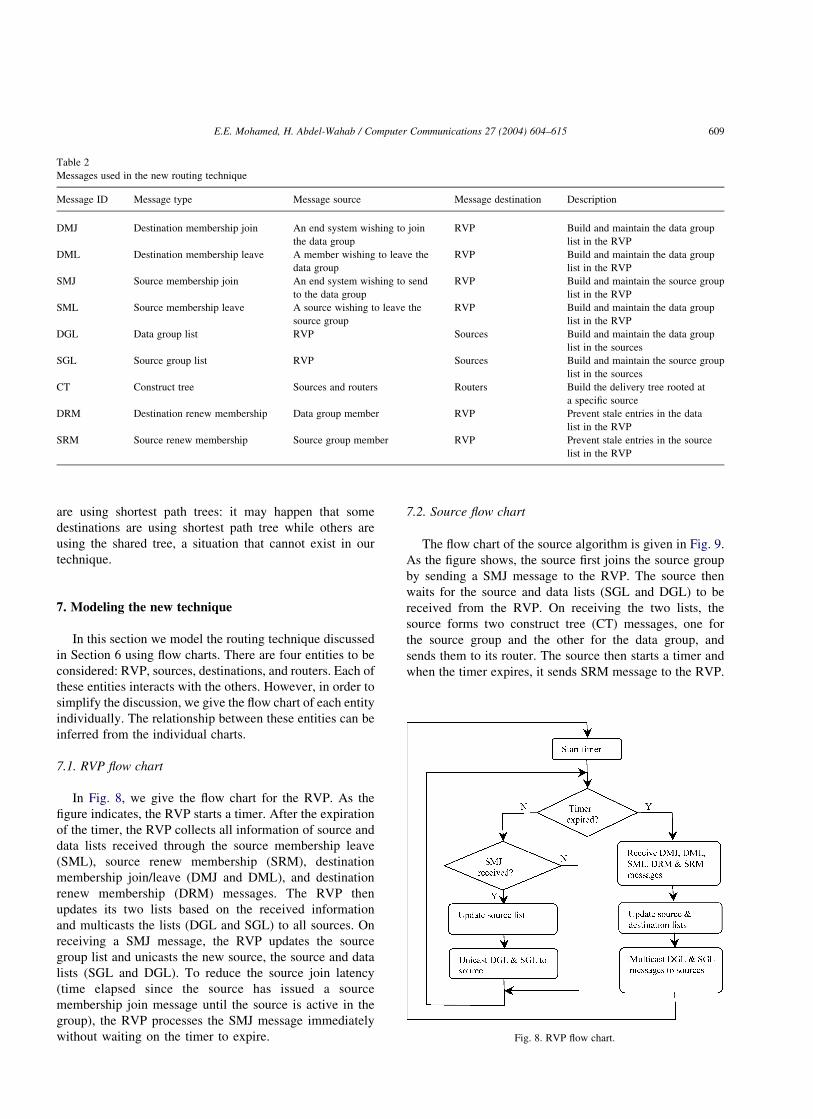
the construct tree messages reach their destinations. Fig. 7
gives the resultant multicast tree for one source. Using the
unicast routing table and assuming that this table does not
produce any loops, grouping the destinations sharing the
same outgoing link into new construct tree messages and
forwarding the new messages along the calculated links
guarantees a loop free routing tree. That is, our technique
does not introduce any loops in the resultant tree and its
success in this aspect depends on the unicast routing table
used.
In order to capture group membership dynamics, the
RVP keeps a timer for every entry in its lists. Every
destination as well as every source is required to
periodically send a renew membership message to the
RVP. On receiving the renew membership message, the
RVP sets the timer for the destination/source. The RVP
deletes those entries that have timed out from its lists.
Similarly, routing table entries timeout after a certain period
of time that is related to the frequency of the membership
messages sent from destinations and sources. The purpose
of these timeouts is to prevent stale entries within the RVP
as well as within the routing tables resulting from
destinations and sources that left their multicast groups.
Table 2 summarizes the messages used in our routing
technique.
This technique depends heavily on the performance of
the RVP as a center that receives control messages from
sources and destinations, maintains the lists, and forwards
the control messages back to the sources. To tackle the
single point of failure within this technique, each source
to the group is also required to maintain the two lists. In
case of RVP failure, which can be detected by the
absence of the periodic messages, one of the sources takes
over the functionality of the RVP. In case there are
multiple sources in the group, a simple resolution
technique can be used to decide which source should
take over as an RVP—the source with the smallest
address for example.
Remaining to this discussion is the selection of the RVP.
The main objective is to select an RVP so as to minimize the
overhead associated with sending the control messages from
the destinations and the sources to the RVP and back from
the RVP to the sources. A simple solution, which may not
give the best performance, is to manually configure one
router as the RVP.
It is worth noting that our technique differs in many
aspects from PIM-SM. While the RP in PIM-SM is used as a
root for the shared tree, it is used in our technique as a
meeting point where sources and destinations can meet and
is used basically to deliver membership messages from
destinations to sources. Also in PIM-SM, a shared tree is
first built and then a switch to the shortest path tree can take
place. In our technique, a shortest path tree is built from the
start of the multicast session, and no shared tree is used at all
to deliver data from sources to destinations. Moreover,
switching from shared tree to shortest path tree in PIM-SM
does not mean that neither all destinations nor all sources
Fig. 6. Multicast message from RVP to sources. Multicast msg. from RVP
to sources ( ).
Fig. 7. Multicast tree for one source.
E.E. Mohamed, H. Abdel-Wahab / Computer Communications 27 (2004) 604–615608
are using shortest path trees: it may happen that some
destinations are using shortest path tree while others are
using the shared tree, a situation that cannot exist in our
technique.
7. Modeling the new technique
In this section we model the routing technique discussed
in Section 6 using flow charts. There are four entities to be
considered: RVP, sources, destinations, and routers. Each of
these entities interacts with the others. However, in order to
simplify the discussion, we give the flow chart of each entity
individually. The relationship between these entities can be
inferred from the individual charts.
7.1. RVP flow chart
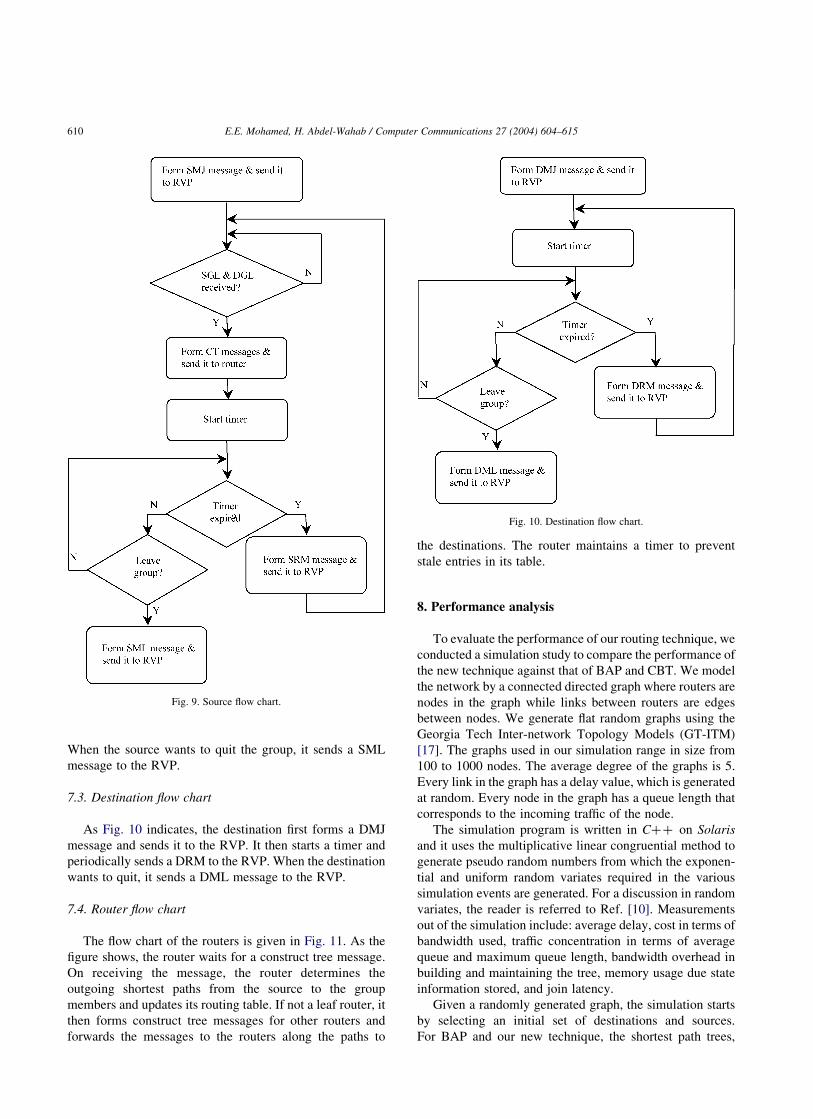
In Fig. 8, we give the flow chart for the RVP. As the
figure indicates, the RVP starts a timer. After the expiration
of the timer, the RVP collects all information of source and
data lists received through the source membership leave
(SML), source renew membership (SRM), destination
membership join/leave (DMJ and DML), and destination
renew membership (DRM) messages. The RVP then
updates its two lists based on the received information
and multicasts the lists (DGL and SGL) to all sources. On
receiving a SMJ message, the RVP updates the source
group list and unicasts the new source, the source and data
lists (SGL and DGL). To reduce the source join latency
(time elapsed since the source has issued a source
membership join message until the source is active in the
group), the RVP processes the SMJ message immediately
without waiting on the timer to expire.
7.2. Source flow chart
The flow chart of the source algorithm is given in Fig. 9.
As the figure shows, the source first joins the source group
by sending a SMJ message to the RVP. The source then
waits for the source and data lists (SGL and DGL) to be
received from the RVP. On receiving the two lists, the
source forms two construct tree (CT) messages, one for
the source group and the other for the data group, and
sends them to its router. The source then starts a timer and
when the timer expires, it sends SRM message to the RVP.
Table 2
Messages used in the new routing technique
Message ID Message type Message source Message destination Description
DMJ Destination membership join An end system wishing to join
the data group
RVP Build and maintain the data group
list in the RVP
DML Destination membership leave A member wishing to leave the
data group
RVP Build and maintain the data group
list in the RVP
SMJ Source membership join An end system wishing to send
to the data group
RVP Build and maintain the source group
list in the RVP
SML Source membership leave A source wishing to leave the
source group
RVP Build and maintain the data group
list in the RVP
DGL Data group list RVP Sources Build and maintain the data group
list in the sources
SGL Source group list RVP Sources Build and maintain the source group
list in the sources
CT Construct tree Sources and routers Routers Build the delivery tree rooted at
a specific source
DRM Destination renew membership Data group member RVP Prevent stale entries in the data
list in the RVP
SRM Source renew membership Source group member RVP Prevent stale entries in the source
list in the RVP
Fig. 8. RVP flow chart.
E.E. Mohamed, H. Abdel-Wahab / Computer Communications 27 (2004) 604–615 609
When the source wants to quit the group, it sends a SML
message to the RVP.
7.3. Destination flow chart
As Fig. 10 indicates, the destination first forms a DMJ
message and sends it to the RVP. It then starts a timer and
periodically sends a DRM to the RVP. When the destination
wants to quit, it sends a DML message to the RVP.
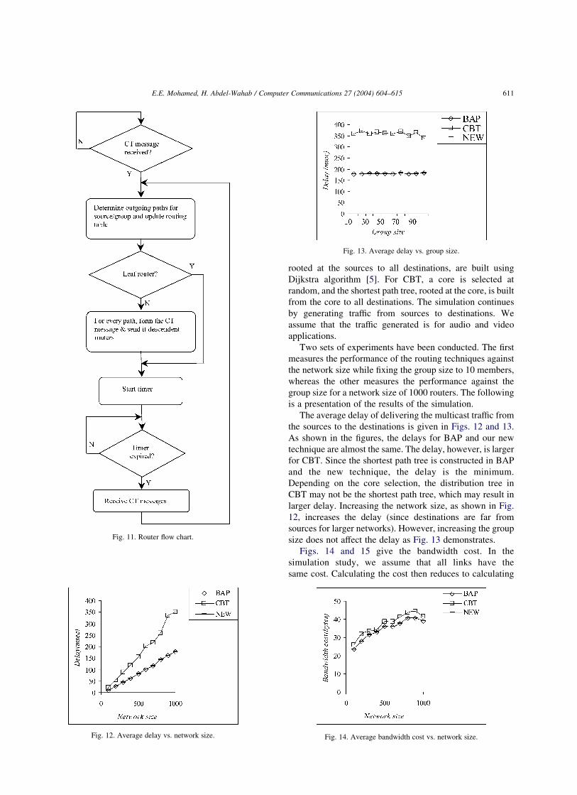
7.4. Router flow chart
The flow chart of the routers is given in Fig. 11. As the
figure shows, the router waits for a construct tree message.
On receiving the message, the router determines the
outgoing shortest paths from the source to the group
members and updates its routing table. If not a leaf router, it
then forms construct tree messages for other routers and
forwards the messages to the routers along the paths to
the destinations. The router maintains a timer to prevent
stale entries in its table.
8. Performance analysis
To evaluate the performance of our routing technique, we
conducted a simulation study to compare the performance of
the new technique against that of BAP and CBT. We model
the network by a connected directed graph where routers are
nodes in the graph while links between routers are edges
between nodes. We generate flat random graphs using the
Georgia Tech Inter-network Topology Models (GT-ITM)
[17]. The graphs used in our simulation range in size from
100 to 1000 nodes. The average degree of the graphs is 5.
Every link in the graph has a delay value, which is generated
at random. Every node in the graph has a queue length that
corresponds to the incoming traffic of the node.
The simulation program is written in Cþþ on Solaris
and it uses the multiplicative linear congruential method to
generate pseudo random numbers from which the exponen-
tial and uniform random variates required in the various
simulation events are generated. For a discussion in random
variates, the reader is referred to Ref. [10]. Measurements
out of the simulation include: average delay, cost in terms of
bandwidth used, traffic concentration in terms of average
queue and maximum queue length, bandwidth overhead in
building and maintaining the tree, memory usage due state
information stored, and join latency.
Given a randomly generated graph, the simulation starts
by selecting an initial set of destinations and sources.
For BAP and our new technique, the shortest path trees,
Fig. 9. Source flow chart.
Fig. 10. Destination flow chart.
E.E. Mohamed, H. Abdel-Wahab / Computer Communications 27 (2004) 604–615610
rooted at the sources to all destinations, are built using
Dijkstra algorithm [5]. For CBT, a core is selected at
random, and the shortest path tree, rooted at the core, is built
from the core to all destinations. The simulation continues
by generating traffic from sources to destinations. We
assume that the traffic generated is for audio and video
applications.
Two sets of experiments have been conducted. The first
measures the performance of the routing techniques against
the network size while fixing the group size to 10 members,
whereas the other measures the performance against the
group size for a network size of 1000 routers. The following
is a presentation of the results of the simulation.
The average delay of delivering the multicast traffic from
the sources to the destinations is given in Figs. 12 and 13.
As shown in the figures, the delays for BAP and our new
technique are almost the same. The delay, however, is larger
for CBT. Since the shortest path tree is constructed in BAP
and the new technique, the delay is the minimum.
Depending on the core selection, the distribution tree in
CBT may not be the shortest path tree, which may result in
larger delay. Increasing the network size, as shown in Fig.
12, increases the delay (since destinations are far from
sources for larger networks). However, increasing the group
size does not affect the delay as Fig. 13 demonstrates.
Figs. 14 and 15 give the bandwidth cost. In the
simulation study, we assume that all links have the
same cost. Calculating the cost then reduces to calculating
Fig. 11. Router flow chart.
Fig. 12. Average delay vs. network size.
Fig. 13. Average delay vs. group size.
Fig. 14. Average bandwidth cost vs. network size.
E.E. Mohamed, H. Abdel-Wahab / Computer Communications 27 (2004) 604–615 611
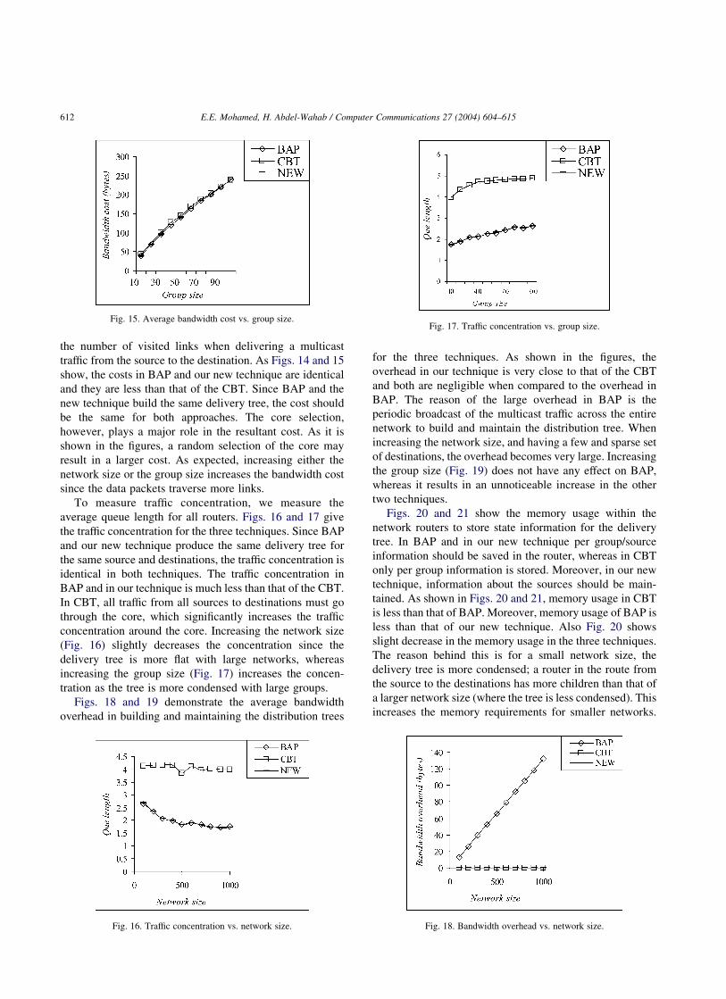
the number of visited links when delivering a multicast
traffic from the source to the destination. As Figs. 14 and 15
show, the costs in BAP and our new technique are identical
and they are less than that of the CBT. Since BAP and the
new technique build the same delivery tree, the cost should
be the same for both approaches. The core selection,
however, plays a major role in the resultant cost. As it is
shown in the figures, a random selection of the core may
result in a larger cost. As expected, increasing either the
network size or the group size increases the bandwidth cost
since the data packets traverse more links.
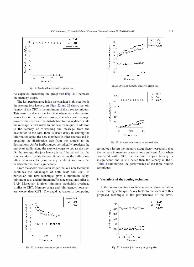
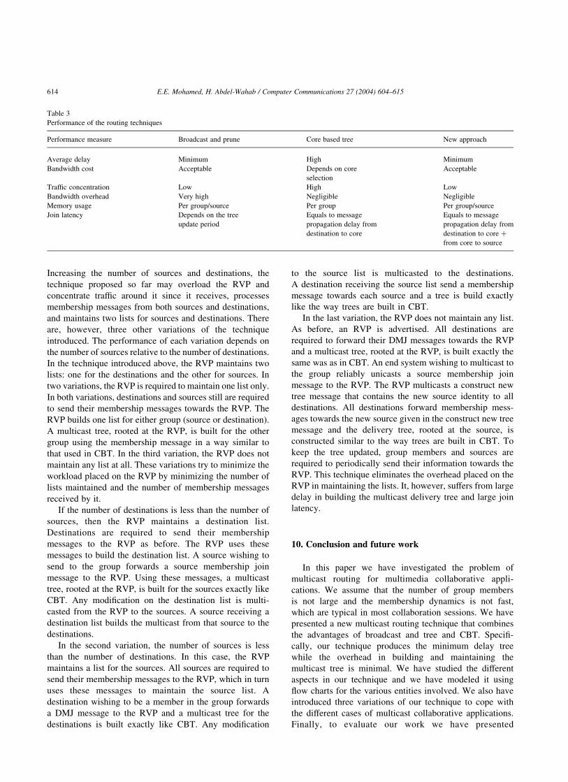
To measure traffic concentration, we measure the
average queue length for all routers. Figs. 16 and 17 give
the traffic concentration for the three techniques. Since BAP
and our new technique produce the same delivery tree for
the same source and destinations, the traffic concentration is
identical in both techniques. The traffic concentration in
BAP and in our technique is much less than that of the CBT.
In CBT, all traffic from all sources to destinations must go
through the core, which significantly increases the traffic
concentration around the core. Increasing the network size
(Fig. 16) slightly decreases the concentration since the
delivery tree is more flat with large networks, whereas
increasing the group size (Fig. 17) increases the concen-
tration as the tree is more condensed with large groups.
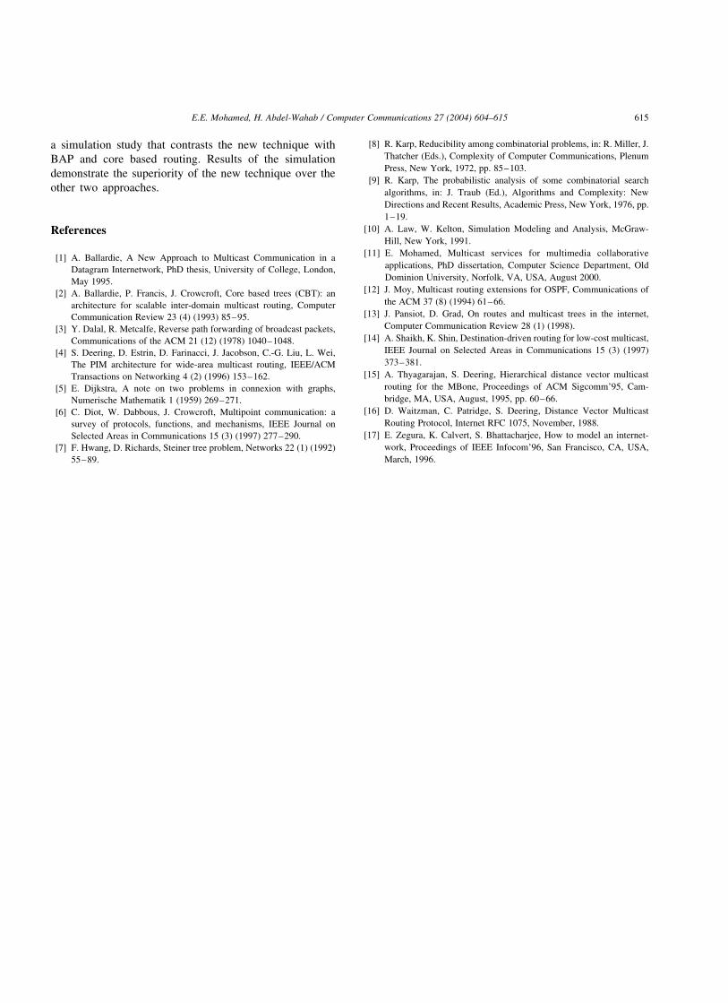
Figs. 18 and 19 demonstrate the average bandwidth
overhead in building and maintaining the distribution trees
for the three techniques. As shown in the figures, the
overhead in our technique is very close to that of the CBT
and both are negligible when compared to the overhead in
BAP. The reason of the large overhead in BAP is the
periodic broadcast of the multicast traffic across the entire
network to build and maintain the distribution tree. When
increasing the network size, and having a few and sparse set
of destinations, the overhead becomes very large. Increasing
the group size (Fig. 19) does not have any effect on BAP,
whereas it results in an unnoticeable increase in the other
two techniques.
Figs. 20 and 21 show the memory usage within the
network routers to store state information for the delivery
tree. In BAP and in our new technique per group/source
information should be saved in the router, whereas in CBT
only per group information is stored. Moreover, in our new
technique, information about the sources should be main-
tained. As shown in Figs. 20 and 21, memory usage in CBT
is less than that of BAP. Moreover, memory usage of BAP is
less than that of our new technique. Also Fig. 20 shows
slight decrease in the memory usage in the three techniques.
The reason behind this is for a small network size, the
delivery tree is more condensed; a router in the route from
the source to the destinations has more children than that of
a larger network size (where the tree is less condensed). This
increases the memory requirements for smaller networks.
Fig. 15. Average bandwidth cost vs. group size.
Fig. 16. Traffic concentration vs. network size.
Fig. 17. Traffic concentration vs. group size.
Fig. 18. Bandwidth overhead vs. network size.
E.E. Mohamed, H. Abdel-Wahab / Computer Communications 27 (2004) 604–615612
As expected, increasing the group size (Fig. 21) increases
the memory usage.
The last performance index we consider in this section is
the average join latency. As Figs. 22 and 23 show, the join
latency of the CBT is the minimum of the three techniques.
This result is due to the fact that whenever a destination
wants to join the multicast group, it sends a join message
towards the core and the distribution tree is updated while
the message is forwarded. In our new technique, in addition
to the latency of forwarding the message from the
destination to the core, there is also a delay in sending the
information about the new members to other sources and in
updating the distribution tree from the sources to the
destinations. As for BAP, sources periodically broadcast the
multicast traffic along the network edges to update the tree.
On the average, the join latency is half the period that the
sources take to update the tree. Broadcasting the traffic more
often decreases the join latency while it increases the
bandwidth overhead significantly.
From the above discussion we see that our new technique
combines the advantages of both BAP and CBT. In
particular, the new technique gives a minimum delay,
minimum cost, and minimum traffic concentration similar to
BAP. Moreover, it gives minimum bandwidth overhead
similar to CBT. Memory usage and join latency, however,
are worse than CBT. The rapid advances in computing
technology lessen the memory usage factor, especially that
the increase in memory usage is not significant. Also, when
compared with CBT, the increase in join latency is
insignificant, and is still better than the latency in BAP.
Table 3 summarizes the performance of the three routing
techniques.
9. Variations of the routing technique
In the previous sections we have introduced one variation
of our routing technique. A key factor to the success of this
proposed technique is the performance of the RVP.
Fig. 19. Bandwidth overhead vs. group size.
Fig. 20. Average memory usage vs. network size.
Fig. 21. Average memory usage vs. group size.
Fig. 22. Average join latency vs. network size.
Fig. 23. Average join latency vs. group size.
E.E. Mohamed, H. Abdel-Wahab / Computer Communications 27 (2004) 604–615 613
Increasing the number of sources and destinations, the
technique proposed so far may overload the RVP and
concentrate traffic around it since it receives, processes
membership messages from both sources and destinations,
and maintains two lists for sources and destinations. There
are, however, three other variations of the technique
introduced. The performance of each variation depends on
the number of sources relative to the number of destinations.
In the technique introduced above, the RVP maintains two
lists: one for the destinations and the other for sources. In
two variations, the RVP is required to maintain one list only.
In both variations, destinations and sources still are required
to send their membership messages towards the RVP. The
RVP builds one list for either group (source or destination).
A multicast tree, rooted at the RVP, is built for the other
group using the membership message in a way similar to
that used in CBT. In the third variation, the RVP does not
maintain any list at all. These variations try to minimize the
workload placed on the RVP by minimizing the number of
lists maintained and the number of membership messages
received by it.
If the number of destinations is less than the number of
sources, then the RVP maintains a destination list.
Destinations are required to send their membership
messages to the RVP as before. The RVP uses these
messages to build the destination list. A source wishing to
send to the group forwards a source membership join
message to the RVP. Using these messages, a multicast
tree, rooted at the RVP, is built for the sources exactly like
CBT. Any modification on the destination list is multi-
casted from the RVP to the sources. A source receiving a
destination list builds the multicast from that source to the
destinations.
In the second variation, the number of sources is less
than the number of destinations. In this case, the RVP
maintains a list for the sources. All sources are required to
send their membership messages to the RVP, which in turn
uses these messages to maintain the source list. A
destination wishing to be a member in the group forwards
a DMJ message to the RVP and a multicast tree for the
destinations is built exactly like CBT. Any modification
to the source list is multicasted to the destinations.
A destination receiving the source list send a membership
message towards each source and a tree is build exactly
like the way trees are built in CBT.
In the last variation, the RVP does not maintain any list.
As before, an RVP is advertised. All destinations are
required to forward their DMJ messages towards the RVP
and a multicast tree, rooted at the RVP, is built exactly the
same was as in CBT. An end system wishing to multicast to
the group reliably unicasts a source membership join
message to the RVP. The RVP multicasts a construct new
tree message that contains the new source identity to all
destinations. All destinations forward membership mess-
ages towards the new source given in the construct new tree
message and the delivery tree, rooted at the source, is
constructed similar to the way trees are built in CBT. To
keep the tree updated, group members and sources are
required to periodically send their information towards the
RVP. This technique eliminates the overhead placed on the
RVP in maintaining the lists. It, however, suffers from large
delay in building the multicast delivery tree and large join
latency.
10. Conclusion and future work
In this paper we have investigated the problem of
multicast routing for multimedia collaborative appli-
cations. We assume that the number of group members
is not large and the membership dynamics is not fast,
which are typical in most collaboration sessions. We have
presented a new multicast routing technique that combines
the advantages of broadcast and tree and CBT. Specifi-
cally, our technique produces the minimum delay tree
while the overhead in building and maintaining the
multicast tree is minimal. We have studied the different
aspects in our technique and we have modeled it using
flow charts for the various entities involved. We also have
introduced three variations of our technique to cope with
the different cases of multicast collaborative applications.
Finally, to evaluate our work we have presented
Table 3
Performance of the routing techniques
Performance measure Broadcast and prune Core based tree New approach
Average delay Minimum High Minimum
Bandwidth cost Acceptable Depends on core
selection
Acceptable
Traffic concentration Low High Low
Bandwidth overhead Very high Negligible Negligible
Memory usage Per group/source Per group Per group/source
Join latency Depends on the tree
update period
Equals to message
propagation delay from
destination to core
Equals to message
propagation delay from
destination to core þ
from core to source
E.E. Mohamed, H. Abdel-Wahab / Computer Communications 27 (2004) 604–615614
a simulation study that contrasts the new technique with
BAP and core based routing. Results of the simulation
demonstrate the superiority of the new technique over the
other two approaches.
References
[1] A. Ballardie, A New Approach to Multicast Communication in a
Datagram Internetwork, PhD thesis, University of College, London,
May 1995.
[2] A. Ballardie, P. Francis, J. Crowcroft, Core based trees (CBT): an
architecture for scalable inter-domain multicast routing, Computer
Communication Review 23 (4) (1993) 85–95.
[3] Y. Dalal, R. Metcalfe, Reverse path forwarding of broadcast packets,
Communications of the ACM 21 (12) (1978) 1040–1048.
[4] S. Deering, D. Estrin, D. Farinacci, J. Jacobson, C.-G. Liu, L. Wei,
The PIM architecture for wide-area multicast routing, IEEE/ACM
Transactions on Networking 4 (2) (1996) 153–162.
[5] E. Dijkstra, A note on two problems in connexion with graphs,
Numerische Mathematik 1 (1959) 269–271.
[6] C. Diot, W. Dabbous, J. Crowcroft, Multipoint communication: a
survey of protocols, functions, and mechanisms, IEEE Journal on
Selected Areas in Communications 15 (3) (1997) 277–290.
[7] F. Hwang, D. Richards, Steiner tree problem, Networks 22 (1) (1992)
55–89.
[8] R. Karp, Reducibility among combinatorial problems, in: R. Miller, J.
Thatcher (Eds.), Complexity of Computer Communications, Plenum
Press, New York, 1972, pp. 85–103.
[9] R. Karp, The probabilistic analysis of some combinatorial search
algorithms, in: J. Traub (Ed.), Algorithms and Complexity: New
Directions and Recent Results, Academic Press, New York, 1976, pp.
1–19.
[10] A. Law, W. Kelton, Simulation Modeling and Analysis, McGraw-
Hill, New York, 1991.
[11] E. Mohamed, Multicast services for multimedia collaborative
applications, PhD dissertation, Computer Science Department, Old
Dominion University, Norfolk, VA, USA, August 2000.
[12] J. Moy, Multicast routing extensions for OSPF, Communications of
the ACM 37 (8) (1994) 61–66.
[13] J. Pansiot, D. Grad, On routes and multicast trees in the internet,
Computer Communication Review 28 (1) (1998).
[14] A. Shaikh, K. Shin, Destination-driven routing for low-cost multicast,
IEEE Journal on Selected Areas in Communications 15 (3) (1997)
373–381.
[15] A. Thyagarajan, S. Deering, Hierarchical distance vector multicast
routing for the MBone, Proceedings of ACM Sigcomm’95, Cam-
bridge, MA, USA, August, 1995, pp. 60–66.
[16] D. Waitzman, C. Patridge, S. Deering, Distance Vector Multicast
Routing Protocol, Internet RFC 1075, November, 1988.
[17] E. Zegura, K. Calvert, S. Bhattacharjee, How to model an internet-
work, Proceedings of IEEE Infocom’96, San Francisco, CA, USA,
March, 1996.
E.E. Mohamed, H. Abdel-Wahab / Computer Communications 27 (2004) 604–615 615


