Embed Size (px)
Citation preview
DOI 10.1515/gps-2012-0054 Green Process Synth 2012; 1: 439–448
Holger Löwe* , Gong Wei , Ma Jiang , Christian Hofmann , Hans-Joachim Kost
and Christian Schütt
Multi-step processing in a microstructured flow reactor: direct nitration of propane–a proof of principle
Abstract: The vapor phase nitration of propane was suc-
cessfully investigated in a multi-step microstructured
reactor. The concept integrates heating, evaporation of
reactants, the reaction channel, and the quenching and
cooling of the product mixture; all done in a reactor with
one plate. The nitration of propane with evaporated nitric
acid was carried out at 380 ° C–450 ° C. This radical chain
reaction was subsequently quenched, in a fast manner due
to the high surface-to-volume ratio of the reaction channel.
Therefore, the conversion of propane was deliberately kept
low (approx. 2%) but at favor of selectivity for 2-nitropro-
pane which increases remarkably. The harsh reaction con-
ditions require a sophisticated microreactor concept, the
use of an exceptional construction material, that is, an
uncommon stainless steel alloy, as well as a process design
which avoids NO x release into the environment.
Keywords: gas-phase; micro reactor; nitration; nitro
alkanes.
*Corresponding author: Holger Löwe, Johannes Gutenberg University
Mainz, 55128 Mainz, Germany, e-mail: [email protected]
Holger Löwe: IMM Institut fuer Mikrotechnik Mainz GmbH, 55129
Mainz, Germany
Gong Wei: Shenyang Cenkey Chemical Co. Ltd., Shenyang 110121,
Liaoning, P. R. China
Ma Jiang: Shenyang Cenkey Chemical Co. Ltd., Shenyang 110121,
Liaoning, P. R. China
Christian Hofmann: IMM Institut fuer Mikrotechnik Mainz GmbH,
55129 Mainz, Germany
Hans-Joachim Kost: IMM Institut fuer Mikrotechnik Mainz GmbH,
55129 Mainz, Germany
Christian Schütt: IMM Institut fuer Mikrotechnik Mainz GmbH, 55129
Mainz, Germany
1 Introduction The vapor-phase nitration of lower alkanes with nitric
acid is an important chemical reaction to produce nitroal-
kanes. It proceeds by a free radical mechanism, where
nitric acid decomposes at temperatures above 350 ° C to
give mainly ‧ OH and ‧ NO 2 or ‧ ONO radicals. If propane is
used as starting material the expected compounds 1-nitro-
propane or 2-nitropropane can be obtained by perform-
ing the reaction at high temperatures, for example, above
400 ° C. In addition, a cleavage of propane can be expected
and therefore nitromethane and nitroethane were also
found in the reaction mixture [ 1 , 2 ]. Not much informa-
tion about this process could be found in the literature,
nevertheless, the vapor-phase process is used in industry
[ 3 , 4 ]. Some information is given about equipment and
use of catalysts or additives, such as oxygen or halides [ 3 ,
5 , 6 ], to enhance the nitration process. Owing to the fact
that gas-phase nitration is a radical reaction, a thermal
explosion of the reaction mixture should be avoided [ 7 ].
The equipment described in the literature is on a macro-
scale, for example, a Pyrex ™ glass tube with a diameter of
200 mm and a length of 8800 mm [ 5 ], or titanium tubes as
upstreaming flow-through reactors [ 4 ]. The reported yield
of nitrated products ranges from 30% to 40%. It should be
pointed out that at a too high surface-to-volume ratio con-
version can decrease because of radical extinction on the
reactor wall, yet favorably shifting the ratio between the
different nitropropanes towards 1-nitropropane [ 8 ].
In addition, nitrous oxide is used for nitration reaction
of lower alkanes [ 9 ]. The yield becomes higher compared
with nitration with nitric acid, but the authors claim that
the presence of oxygen is a precondition. To add oxygen
to the reaction mixture shifts the reaction into an explo-
sive regime [ 10 ]. Oxygen as an additive gives, in certain
cases, higher yields on nitrated alkanes but the amount of
unwanted oxidized products increases remarkably [ 5 , 11 ].
Oxidation can be limited by maximizing molecule-to-wall
collision via providing high surface-to-volume ratio of the
reactor [ 11 ]. To avoid possibility of explosion, a process for
vapor-phase nitration of propane in a fused salt reactor
was also developed [ 12 ].
A catalytic gas-phase nitration process was investi-
gated using a Bi-Mo catalyst. Depending on the molar ratio
of alkanes/nitric acid, reaction temperature and catalyst
440 H. Löwe et al.: Multi-step processing in a microstructured flow reactor
contact time, yield of nitro paraffin increases nearly four
times compared with the non-catalytic process [ 13 ].
Alternatively, liquid-phase processes can be applied.
At low temperatures of approximately 100 ° C and a reac-
tion mixture of nitric acid, propane, 1-trifluoromethyl
benzene with N-hydroxyphthalimide as catalyst, high
yields should also be achievable [ 14 , 15 ]. Nitration of short
chain alkanes (C1 – C6) was carried out with nitronium hexa-
fluorophosphate in methylene chloride or nitro ethane
solution. Results indicate direct electrophilic insertion of
NO + [ 16 ].
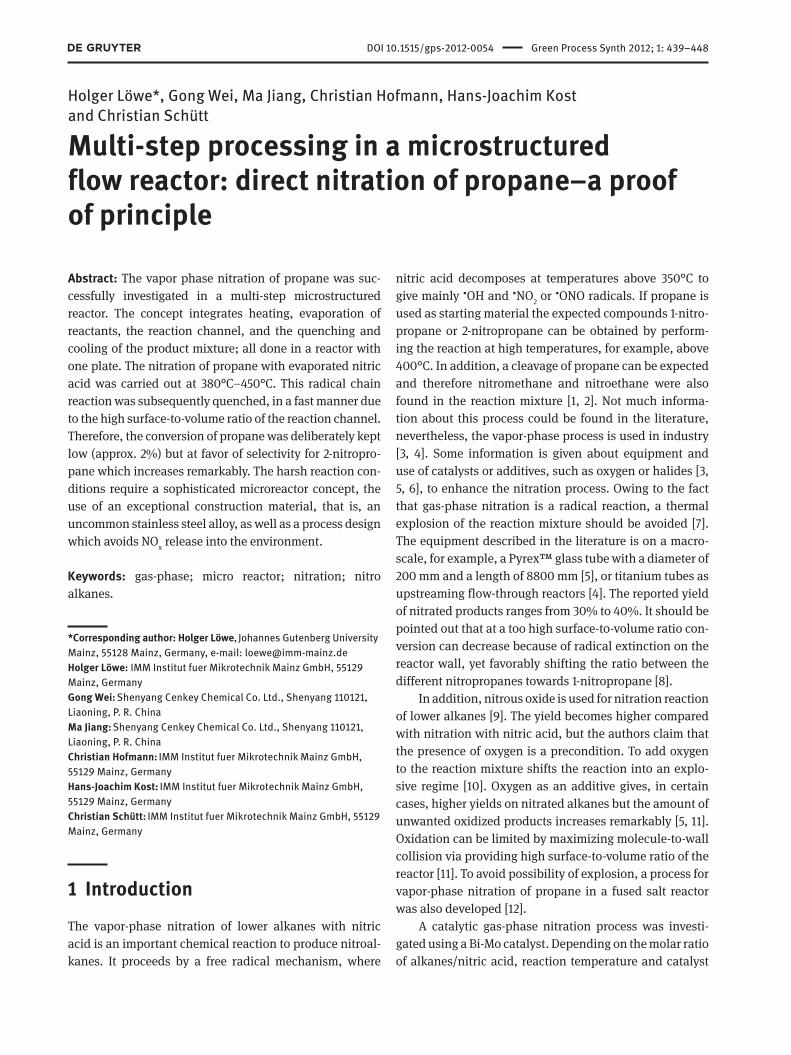
In all cases, a mixture of nitrated alkanes as well as
of undisclosed products were obtained, caused by radical
cleavage of C C bonds ( Figure 1 ). Therefore, the technical
synthesis route uses low carbon alkanes mixtures instead
of a single compound.
Naturally, further post-processing steps, for example,
extraction and fractional distillation are required [ 17 ].
Four nitroalkanes, ( 3 ) to ( 6 ), are of great industrial sig-
nificance and are mainly used as solvents or co-solvents,
as intermediates for drug syntheses or even as additives
for rocket fuels. In particular, 2-nitropropane ( 3 ) is widely
used as solvent due to its excellent chemical and physi-
cal properties (detailed description in [ 18 ]). Therefore,
syntheses routes with a high selectivity towards ( 3 ) are
needed.
2 Experimental Propane ( 1 ) [CAS 74-98-6; 99.95% (3.5)] was delivered from
Linde Gas (Munich, Germany). Nitric acid, red and fuming
( 2 ) (CAS 7697-37-2; > 90%), and reference substances, such
as 2-nitropropane ( 3 ) (CAS 79-46-9; > 96%), 1-nitropropane
( 4 ) (CAS 108-03-2; > 98.5%), nitroethane ( 5 ) (CAS 79-24-3;
99.5%), and nitromethane ( 5 ) (CAS 75-52-5; > 96.5%), were
purchased from Sigma Aldrich (St. Louis, USA).
CH3 CH3
CH3 NO2
NO2CH3
CH3NO2
CH3
NO2
CH3(HNO3)
>400°C(1)
(2)
(3)
(4)
(5)
(6)
2-Nitropropane
1-Nitropropane
Nitroethane
Nitromethane
+
+
+
+.....
Figure 1 Expected product mixture for high temperature gas-phase
nitration of propane. In addition, undisclosed compounds (marked
as … ) are formed by C-C bond cleavage and induced reaction of ‧ OH
radicals.
Continuous and nearly pulsation-free feed of nitric
acid was realized by using a syringe pump (Postnova
PN1610, Postnova Analytics GmbH, Landsberg, Germany).
NiCrNi thermocouples were used for temperature
measurements combined with a Voltkraft ™ K204 (Conrad
Electronic, Hirschau, Germany) data logger.
Two types of electrical heaters were used: 10 cartridge
heaters (200 W each) to provide base load and two heating
cables (250 W each) for temperature control management
(both from Horst GmbH, Lorsch, Germany).
Mass-flow controllers were purchased from Bronk-
horst-M ä ttig GmbH, Germany.
The product mixtures were characterized with GC
(Varian CP-3900) methods. The GC detector was calibrated
with 2-nitropropane ( 3 ) as standard.
2.1 Reactor set-up, general
The corrosive reactants and harsh reaction conditions
applied, as well as the multi-step processing within one
reactor, require a sophisticated reactor and process design.
In addition to the actual chemical processing, material
issues, heat management and safety considerations must
be taken into account. In general, for multi-step process-
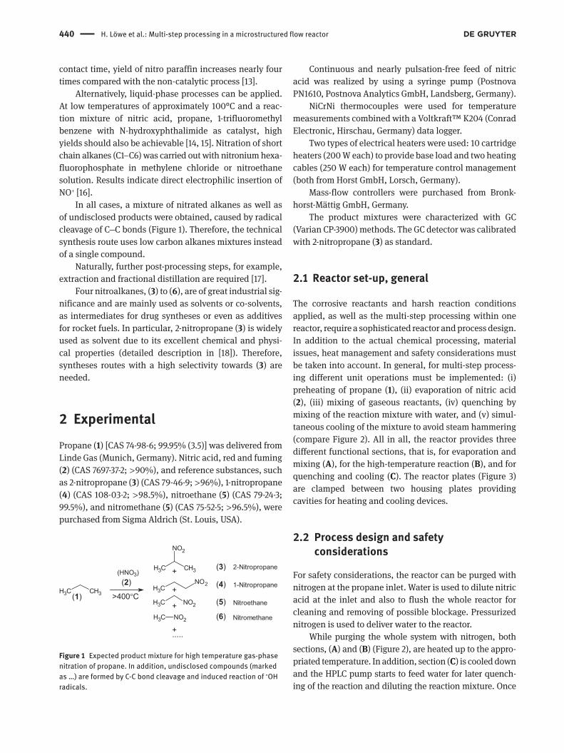
ing different unit operations must be implemented: (i)
preheating of propane ( 1 ), (ii) evaporation of nitric acid
( 2 ), (iii) mixing of gaseous reactants, (iv) quenching by
mixing of the reaction mixture with water, and (v) simul-
taneous cooling of the mixture to avoid steam hammering
(compare Figure 2 ). All in all, the reactor provides three
different functional sections, that is, for evaporation and
mixing ( A ), for the high-temperature reaction ( B ), and for
quenching and cooling ( C ). The reactor plates ( Figure 3 )
are clamped between two housing plates providing
cavities for heating and cooling devices.
2.2 Process design and safety considerations
For safety considerations, the reactor can be purged with
nitrogen at the propane inlet. Water is used to dilute nitric
acid at the inlet and also to flush the whole reactor for
cleaning and removing of possible blockage. Pressurized
nitrogen is used to deliver water to the reactor.
While purging the whole system with nitrogen, both
sections, ( A ) and ( B ) ( Figure 2 ), are heated up to the appro-
priated temperature. In addition, section ( C ) is cooled down
and the HPLC pump starts to feed water for later quench-
ing of the reaction and diluting the reaction mixture. Once
H. Löwe et al.: Multi-step processing in a microstructured flow reactor 441
the reaction conditions are stable, pressurized propane ( 1 ),
provided from a commercial high-pressure gas cylinder, is
fed into the reactor via heating up in section ( A ). The initial
pressure was set to 6 bar and the gas-volume flow of ( 1 ) is
controlled by a Bronckhorst mass-flow controller. An addi-
tional check valve secures the gas line. Nitric acid is pumped
in the evaporator, section ( A ), by a corrosion-resistant glass
syringe pump. The gaseous reactants are mixed in the
integrated caterpillar micro mixer 1. After mixing the reac-
tion subsequently takes place along the electrically heated
reaction channel. Having passed this channel, the mixture
is cooled by heat dissipation to an outside pressed water
cooler at section ( C ). The reaction mixture is diluted with
water by integrated caterpillar micro mixer 2 and subse-
quently sparged through an ice-water filled flask to con-
dense volatile nitric compounds. To avoid contamination of
the environment, a scrubber filled with diluted NaOH solu-
tion removes gaseous nitric species.
Figure 2 Scheme of the used reactor design.
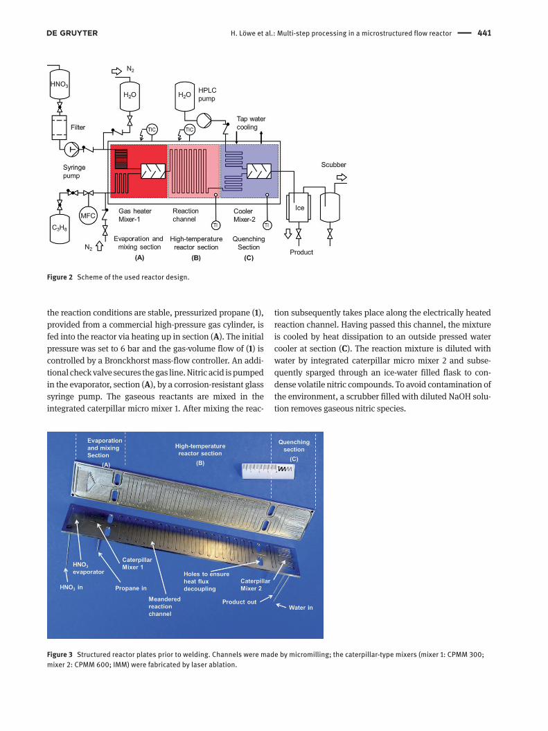
Figure 3 Structured reactor plates prior to welding. Channels were made by micromilling; the caterpillar-type mixers (mixer 1: CPMM 300;
mixer 2: CPMM 600; IMM) were fabricated by laser ablation.
442 H. Löwe et al.: Multi-step processing in a microstructured flow reactor
Short-chain nitro alkanes are slightly soluble in water,
and therefore the mixture of condensed nitrated products
in ice-water was extracted with methylene chloride. The
separated organic phase was neutralized with diluted
NaHCO 3 solution (10% in water), dried with sodium sulfate
and directly used for GC analysis.
2.3 Description of the reactor system
The reactor consists of two microstructured plates made of
corrosion-resistant special stainless steel (1.4361, X1CrNi
Si18154) ( Figure 3 ). The reaction channel, as well as in
and outlet channels were made by precision machining.
The two caterpillar-type micro mixers, a CPMM 300 type
in section ( A ), with a 300 μ m wide internally structured
channel, and a CPMM 600 type in section ( C ) with a 600
μ m wide channel (both IMM), and the small channels for
the evaporation part were made by electro-spark erosion
techniques. All relevant dimensions are given in Table 1 .
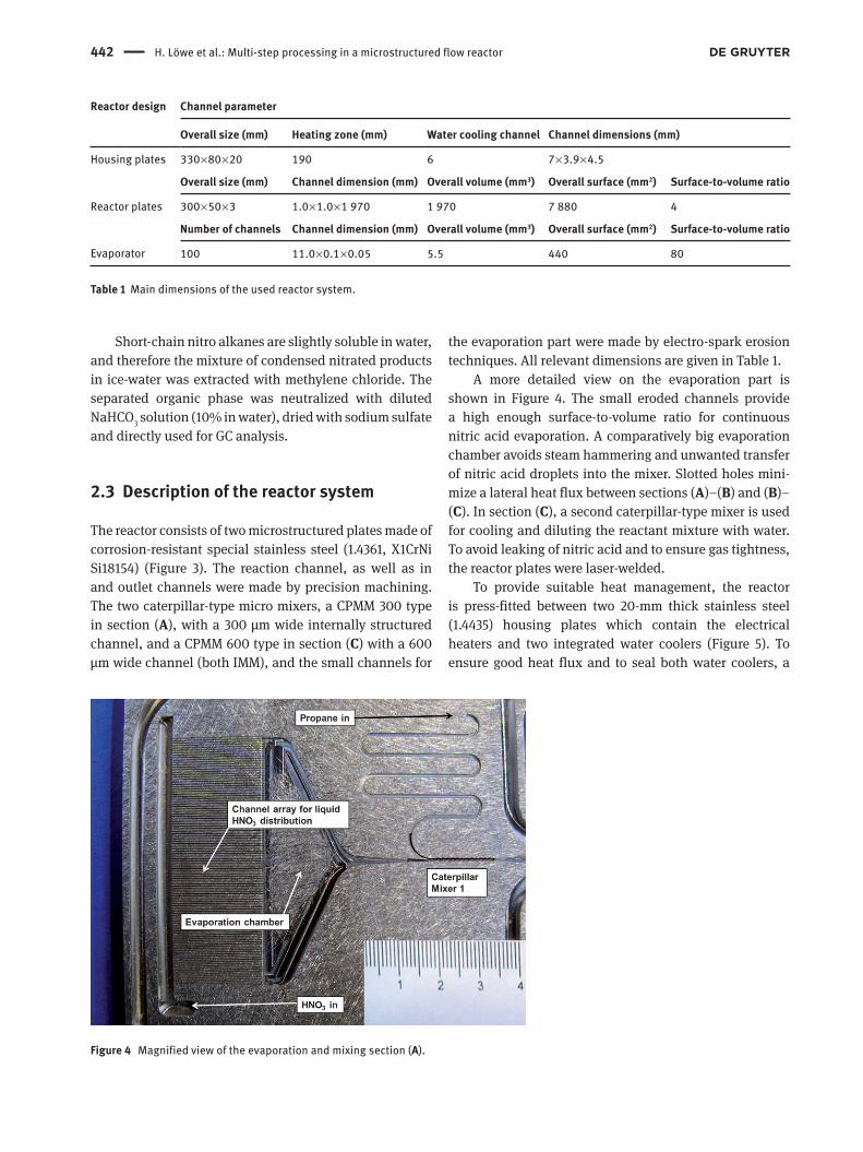
A more detailed view on the evaporation part is
shown in Figure 4 . The small eroded channels provide
a high enough surface-to-volume ratio for continuous
nitric acid evaporation. A comparatively big evaporation
chamber avoids steam hammering and unwanted transfer
of nitric acid droplets into the mixer. Slotted holes mini-
mize a lateral heat flux between sections ( A ) – ( B ) and ( B ) –
( C ). In section ( C ), a second caterpillar-type mixer is used
for cooling and diluting the reactant mixture with water.
To avoid leaking of nitric acid and to ensure gas tightness,
the reactor plates were laser-welded.
To provide suitable heat management, the reactor
is press-fitted between two 20-mm thick stainless steel
(1.4435) housing plates which contain the electrical
heaters and two integrated water coolers ( Figure 5 ). To
ensure good heat flux and to seal both water coolers, a
Reactor design Channel parameter
Overall size (mm) Heating zone (mm) Water cooling channel Channel dimensions (mm)
Housing plates 330 × 80 × 20 190 6 7 × 3.9 × 4.5
Overall size (mm) Channel dimension (mm) Overall volume (mm3) Overall surface (mm2) Surface-to-volume ratio
Reactor plates 300 × 50 × 3 1.0 × 1.0 × 1 970 1 970 7 880 4
Number of channels Channel dimension (mm) Overall volume (mm3) Overall surface (mm2) Surface-to-volume ratio
Evaporator 100 11.0 × 0.1 × 0.05 5.5 440 80
Table 1 Main dimensions of the used reactor system.
Figure 4 Magnified view of the evaporation and mixing section ( A ).
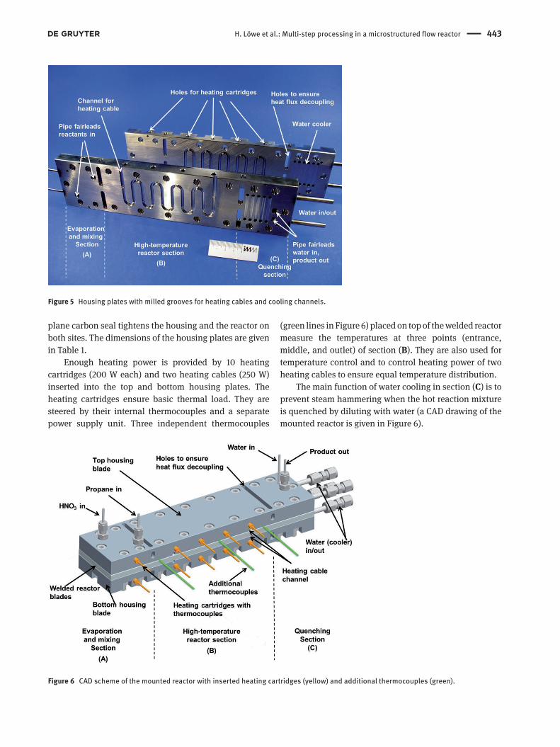
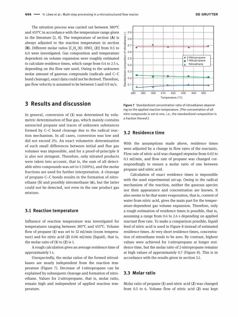
H. Löwe et al.: Multi-step processing in a microstructured flow reactor 443
plane carbon seal tightens the housing and the reactor on
both sites. The dimensions of the housing plates are given
in Table 1 .
Enough heating power is provided by 10 heating
cartridges (200 W each) and two heating cables (250 W)
inserted into the top and bottom housing plates. The
heating cartridges ensure basic thermal load. They are
steered by their internal thermocouples and a separate
power supply unit. Three independent thermocouples
(green lines in Figure 6 ) placed on top of the welded reactor
measure the temperatures at three points (entrance,
middle, and outlet) of section ( B ). They are also used for
temperature control and to control heating power of two
heating cables to ensure equal temperature distribution.
The main function of water cooling in section ( C ) is to
prevent steam hammering when the hot reaction mixture
is quenched by diluting with water (a CAD drawing of the
mounted reactor is given in Figure 6 ).
Figure 5 Housing plates with milled grooves for heating cables and cooling channels.
Figure 6 CAD scheme of the mounted reactor with inserted heating cartridges (yellow) and additional thermocouples (green).
444 H. Löwe et al.: Multi-step processing in a microstructured flow reactor
The nitration process was carried out between 380 ° C
and 455 ° C in accordance with the temperature range given
in the literature [ 2 , 8 ]. The temperature of section ( A ) is
always adjusted to the reaction temperature in section
( B ). Different molar ratios [C 3 H
8 ( 1 ): HNO
3 ( 2 )] from 0.5 to
6.0 were investigated. Gas composition and temperature
dependent on volume expansion were roughly estimated
to calculate residence times, which range from 0.4 to 2.5 s,
depending on the flow rate used. Owing to the unknown
molar amount of gaseous compounds (radicals and C C
bond cleavage), exact data could not be derived. Therefore,
gas flow velocity is assumed to be between 5 and 0.9 m/s.
3 Results and discussion In general, conversion of ( 1 ) was determined by volu-
metric determination of flue gas, which mainly contains
unreacted propane and traces of unknown substances
formed by C C bond cleavage due to the radical reac-
tion mechanism. In all cases, conversion was low and
did not exceed 2%. An exact volumetric determination
of such small differences between initial and flue gas
volumes was impossible, and for a proof-of-principle it
is also not stringent. Therefore, only nitrated products
were taken into account, that is, the sum of all detect-
able nitro compounds was set to 1 (100%), and the molar
fractions are used for further interpretation. A cleavage
of propane C C bonds results in the formation of nitro-
ethane ( 5 ) and possibly nitromethane ( 6 ), but the latter
could not be detected, not even in the raw product gas
mixture.
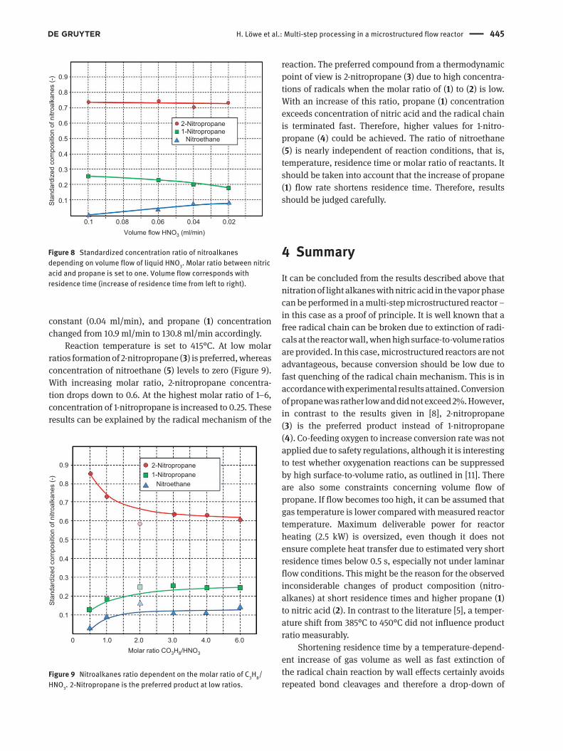
3.1 Reaction temperature
Influence of reaction temperature was investigated for
temperatures ranging between 385 ° C and 455 ° C. Volume
flow of propane ( 1 ) was set to 32 ml/min (room tempera-
ture) and for nitric acid ( 2 ) 0.06 ml/min (liquid), that is,
the molar ratio of ( 1 ) to ( 2 ) is 1.
A rough calculation gives an average residence time of
approximately 1 s.
Unexpectedly, the molar ratios of the formed nitroal-
kanes are nearly independent from the reaction tem-
perature ( Figure 7 ). Decrease of 1-nitropropane can be
explained by subsequent cleavage and formation of nitro-
ethane. Values for 2-nitropropane, that is, molar ratio,
remain high and independent of applied reaction tem-
perature.
0.9
0.8
0.7
0.6
0.5
Sta
ndar
dize
d co
mpo
sitio
n of
nitr
oalk
anes
(-)
0.4
0.3
0.2
0.1
380 390 400 410 420Temperature (°C)
430
1-NitropropaneNitroethane
2-Nitropropane
440 450
Figure 7 Standardized concentration ratio of nitroalkanes depend-
ing on the applied reaction temperature. (The concentration of all
nitro compounds is set to one, i.e., the standardized composition is
a fraction thereof.)
3.2 Residence time
With the assumptions made above, residence times
were adjusted by a change in flow rates of the reactants.
Flow rate of nitric acid was changed stepwise from 0.02 to
0.1 ml/min, and flow rate of propane was changed cor-
respondingly to ensure a molar ratio of one between
propane and nitric acid.
Calculation of exact residence times is impossible
with the used experimental set-up. Owing to the radical
mechanism of the reaction, neither the gaseous species
nor their appearance and concentration are known. It
also seems to be that water evaporation, that is, content of
water from nitric acid, gives the main part for the temper-
ature-dependent gas volume expansion. Therefore, only
a rough estimation of residence times is possible, that is,
assuming a range from 0.4 to 2.4 s depending on applied
reactant flow rate. To make a comparison possible, liquid
feed of nitric acid is used in Figure 8 instead of estimated
residence times. At very short residence times, concentra-
tion of nitroethane tends to be zero. By contrast, highest
values were achieved for 1-nitropropane at longer resi-
dence time, but the molar ratio of 2-nitropropane remains
at high values of approximately 0.7 ( Figure 8 ). This is in
accordance with the results given in section 3.1.
3.3 Molar ratio
Molar ratio of propane ( 1 ) and nitric acid ( 2 ) was changed
from 0.5 to 6. Volume flow of nitric acid ( 2 ) was kept
H. Löwe et al.: Multi-step processing in a microstructured flow reactor 445
constant (0.04 ml/min), and propane ( 1 ) concentration
changed from 10.9 ml/min to 130.8 ml/min accordingly.
Reaction temperature is set to 415 ° C. At low molar
ratios formation of 2-nitropropane ( 3 ) is preferred, whereas
concentration of nitroethane ( 5 ) levels to zero ( Figure 9 ).
With increasing molar ratio, 2-nitropropane concentra-
tion drops down to 0.6. At the highest molar ratio of 1–6,
concentration of 1-nitropropane is increased to 0.25. These
results can be explained by the radical mechanism of the
0.9
0.8
0.7
0.6
0.5
Sta
ndar
dize
d co
mpo
sitio
n of
nitr
oalk
anes
(-)
0.4
0.3
0.2
0.1
0.1 0.08 0.06 0.04 0.02Volume flow HNO3 (ml/min)
1-NitropropaneNitroethane
2-Nitropropane
Figure 8 Standardized concentration ratio of nitroalkanes
depending on volume flow of liquid HNO 3 . Molar ratio between nitric
acid and propane is set to one. Volume flow corresponds with
residence time (increase of residence time from left to right).
0.9
0.8
0.7
0.6
0.5
Sta
ndar
dize
d co
mpo
sitio
n of
nitr
oalk
anes
(-)
0.4
0.3
0.2
0.1
1.00 2.0 3.0 4.0 6.0Molar ratio CO3H8/HNO3
1-NitropropaneNitroethane
2-Nitropropane
Figure 9 Nitroalkanes ratio dependent on the molar ratio of C 3 H
8 /
HNO 3 . 2-Nitropropane is the preferred product at low ratios.
reaction. The preferred compound from a thermodynamic
point of view is 2-nitropropane ( 3 ) due to high concentra-
tions of radicals when the molar ratio of ( 1 ) to ( 2 ) is low.
With an increase of this ratio, propane ( 1 ) concentration
exceeds concentration of nitric acid and the radical chain
is terminated fast. Therefore, higher values for 1-nitro-
propane ( 4 ) could be achieved. The ratio of nitroethane
( 5 ) is nearly independent of reaction conditions, that is,
temperature, residence time or molar ratio of reactants. It
should be taken into account that the increase of propane
( 1 ) flow rate shortens residence time. Therefore, results
should be judged carefully.
4 Summary It can be concluded from the results described above that
nitration of light alkanes with nitric acid in the vapor phase
can be performed in a multi-step microstructured reactor –
in this case as a proof of principle. It is well known that a
free radical chain can be broken due to extinction of radi-
cals at the reactor wall, when high surface-to-volume ratios
are provided. In this case, microstructured reactors are not
advantageous, because conversion should be low due to
fast quenching of the radical chain mechanism. This is in
accordance with experimental results attained. Conversion
of propane was rather low and did not exceed 2%. However,
in contrast to the results given in [ 8 ], 2-nitro propane
( 3 ) is the preferred product instead of 1-nitropropane
( 4 ). Co-feeding oxygen to increase conversion rate was not
applied due to safety regulations, although it is interesting
to test whether oxygenation reactions can be suppressed
by high surface-to-volume ratio, as outlined in [ 11 ]. There
are also some constraints concerning volume flow of
propane. If flow becomes too high, it can be assumed that
gas temperature is lower compared with measured reactor
temperature. Maximum deliverable power for reactor
heating (2.5 kW) is oversized, even though it does not
ensure complete heat transfer due to estimated very short
residence times below 0.5 s, especially not under laminar
flow conditions. This might be the reason for the observed
inconsiderable changes of product composition (nitro-
alkanes) at short residence times and higher propane ( 1 )
to nitric acid ( 2 ). In contrast to the literature [ 5 ], a temper-
ature shift from 385 ° C to 450 ° C did not influence product
ratio measurably.
Shortening residence time by a temperature-depend-
ent increase of gas volume as well as fast extinction of
the radical chain reaction by wall effects certainly avoids
repeated bond cleavages and therefore a drop-down of
446 H. Löwe et al.: Multi-step processing in a microstructured flow reactor
nitropropane concentration in favor of shorter chain
nitroalkanes. An indication of fast breakdown of the
radical chain reaction is also the absence of nitromethane
in the product mixture. A continuous flow of liquid nitric
acid below 0.05 ml/min, in particular constant continu-
ous evaporation, could not be achieved and therefore an
increase of residence time was not possible with the given
set-up.
5 Conclusions on reactor and process design
Some constraints concerning the reactor itself must be
taken into account. Because tightness of the reactor was
not achievable by sealing and screwing, the reactor plates
were welded together. In this case, maintenance of inner
reactor structures was not possible anymore, and the reac-
tion must be carried out carefully to avoid blockage and
pressure overshooting. After every run, the reactor had to
be cleaned by back-flushing with concentrated nitric acid
and subsequent blowing dry with nitrogen to avoid corro-
sion by diluting nitric acid by feeding water or moisture
air. It should be noted that some particles and rusty liquid
came out of the reactor. We assume that the connectors
could not sustain the harsh reaction conditions.
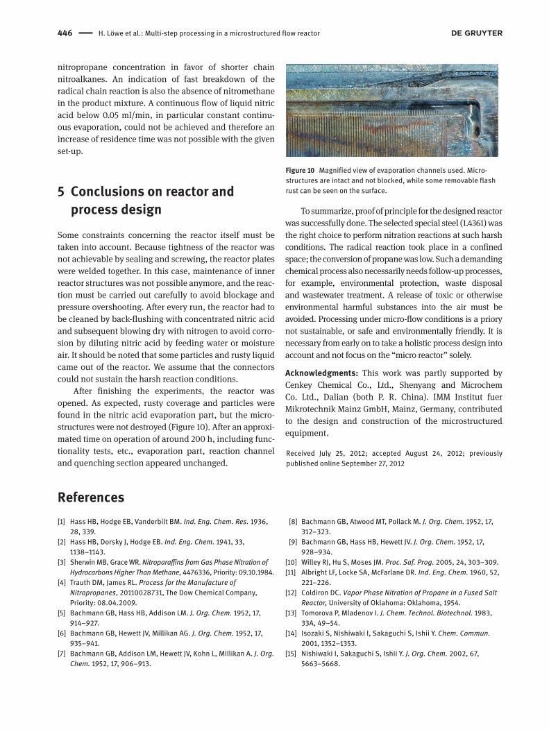
After finishing the experiments, the reactor was
opened. As expected, rusty coverage and particles were
found in the nitric acid evaporation part, but the micro-
structures were not destroyed ( Figure 10 ). After an approxi-
mated time on operation of around 200 h, including func-
tionality tests, etc., evaporation part, reaction channel
and quenching section appeared unchanged.
To summarize, proof of principle for the designed reactor
was successfully done. The selected special steel (1.4361) was
the right choice to perform nitration reactions at such harsh
conditions. The radical reaction took place in a confined
space; the conversion of propane was low. Such a demanding
chemical process also necessarily needs follow-up processes,
for example, environmental protection, waste disposal
and wastewater treatment. A release of toxic or other wise
environmental harmful substances into the air must be
avoided. Processing under micro-flow conditions is a priory
not sustainable, or safe and environmentally friendly. It is
necessary from early on to take a holistic process design into
account and not focus on the “ micro reactor ” solely.
Acknowledgments: This work was partly supported by
Cenkey Chemical Co., Ltd., Shenyang and Microchem
Co. Ltd., Dalian (both P. R. China). IMM Institut fuer
Mikrotechnik Mainz GmbH, Mainz, Germany, contributed
to the design and construction of the microstructured
equipment.
Received July 25, 2012; accepted August 24, 2012; previously
published online September 27, 2012
References [1] Hass HB, Hodge EB, Vanderbilt BM. Ind. Eng. Chem. Res. 1936,
28, 339.
[2] Hass HB, Dorsky J, Hodge EB. Ind. Eng. Chem. 1941, 33,
1138 – 1143.
[3] Sherwin MB, Grace WR. Nitroparaffins from Gas Phase Nitration of Hydrocarbons Higher Than Methane , 4476336, Priority: 09.10.1984.
[4] Trauth DM, James RL. Process for the Manufacture of Nitropropanes , 20110028731, The Dow Chemical Company,
Priority: 08.04.2009.
[5] Bachmann GB, Hass HB, Addison LM. J. Org. Chem. 1952, 17,
914 – 927.
[6] Bachmann GB, Hewett JV, Millikan AG. J. Org. Chem. 1952, 17,
935 – 941.
[7] Bachmann GB, Addison LM, Hewett JV, Kohn L, Millikan A. J. Org. Chem. 1952, 17, 906 – 913.
[8] Bachmann GB, Atwood MT, Pollack M. J. Org. Chem. 1952, 17,
312 – 323.
[9] Bachmann GB, Hass HB, Hewett JV. J. Org. Chem. 1952, 17,
928 – 934.
[10] Willey RJ, Hu S, Moses JM. Proc. Saf. Prog. 2005, 24, 303 – 309.
[11] Albright LF, Locke SA, McFarlane DR. Ind. Eng. Chem. 1960, 52,
221 – 226.
[12] Coldiron DC. Vapor Phase Nitration of Propane in a Fused Salt Reactor, University of Oklahoma: Oklahoma, 1954.
[13] Tomorova P, Mladenov I. J. Chem. Technol. Biotechnol. 1983,
33A, 49 – 54.
[14] Isozaki S, Nishiwaki I, Sakaguchi S, Ishii Y. Chem. Commun. 2001, 1352 – 1353.
[15] Nishiwaki I, Sakaguchi S, Ishii Y. J. Org. Chem. 2002, 67,
5663 – 5668.
Figure 10 Magnified view of evaporation channels used. Micro-
structures are intact and not blocked, while some removable flash
rust can be seen on the surface.

H. Löwe et al.: Multi-step processing in a microstructured flow reactor 447
[16] Olah GA, Ramaiah P, Prakash GKS. Proc. Natl. Acad. Sci. USA
1997, 94, 11783 – 11785.
[17] Yang X-S, Guan Q, Wu K-F. Chem. Eng. (Chin.) 2009, 167, 65 – 68.
[18] Markofsky SB. Nitro Compounds, Aliphatic, Ullmann’s
Encyclopedia of Industrial Chemistray, Wiley-VCH,
2011.
Gong Wei graduated from the Anshan University of Science and
Technology with a bachelor’s degree in chemical technology in
1995. In 2002, she received her Master’s degree from Liaoning
University of Petroleum and Chemical Technology. From 1995
to 2000, she worked for Fushun Special Steel Co. Ltd., who are
involved in gas production, where she became a chemical engineer.
In June 2005, Gong Wei joined Shenyang Cenkey Chemical Co.
Ltd., where her principal research interests include research and
development of fluorescent whitening agents and other chemical
products.
Christian Hofmann was educated as a precision mechanic
followed by studies of process engineering at Fachhochschule
Bingen in 1998 and graduated as an engineer. He joined Institut
fuer Mikrotechnik Mainz GmbH (IMM) in Mainz, Germany in 1996
and is a member of the mixing and fine chemistry department. He is
involved in several public and industrial funded R&D projects and is
mainly involved with construction and realization of manifold differ-
ent micro reactors.
Professor Holger Löwe received his PhD, after some years of work in
industry, in 1984 from the former Technical University Merseburg.
Later he moved to the Faculty of Electrochemistry at the Technical
University, Ilmenau/Germany and worked as a research assistant
and lecturer. In 1991, he started work at the Institut für Mikrotechnik
Mainz GmbH (IMM). He established the Chemistry/Micro-reaction
Technology Department and a Bio-microfluidic group at IMM. Since
2005, he has been Professor of Chemical Micro Process Technology
at Mainz University. In 2007, he was appointed as visiting professor
at Dalian University of Technology, since 2008 as guest professor at
East China University, Shanghai, and since 2011 as professor at Zhe-
jiang University, Hangzhou (China). His current research activities
comprise chemical synthesis and engineering and processing in
combination with aspects of micro fluidics. His current major sub-
jects of interest are magnetic ionic liquids for C-C coupling reaction
and the combination of micro-nanoparticles for catalytic.
Ma Jiang received his PhD in molecular engineering from the Kyushu
University in 1997. In 2000, he secured the appointment of part-time
professor and doctoral supervisor in Dalian University of Technology,
and he was awarded as a specialist and state government advisor in
2005. He was engaged as concurrently supervisor of postgraduates
of the Shenyang institute of chemical in 2006 and as a senior
professional of the Sinochem Group in 2008. He is currently the
general manager of Shenyang Cenkey Chemical Co., Ltd, and BMD
Chemical Co., Ltd. His research interests involve studies of fine
chemicals, in particular for fluorescent whitening agents.

448 H. Löwe et al.: Multi-step processing in a microstructured flow reactor
Christian Schütt received his baccalaureate at the Ludwig Erhard
high school, Kiel. He finished his studies as a diploma engineer
in biotechnology/process engineering at the Flensburg University
of Applied Sciences in Flensburg and he received his PhD from the
Institute of Phythopathology at the Christian-Albrechts-University,
Kiel. Since 2005 he has been employee of the Institut fuer Mikro-
technik Mainz GmbH. The main tasks of his work are dimensioning,
design, production control and testing of mixers, heat exchangers
and reactors.
Hans-Joachim Kost studied physical engineering and received his
diploma at the Technical University Wiesbaden, Germany. Since
1998, he is an employee of the Institut fuer Mikrotechnik Mainz
GmbH. He is responsible for process and plant development for fine
chemicals.


