Embed Size (px)
Citation preview

Composite Structures 109 (2014) 240–245
Contents lists available at ScienceDirect
Composite Structures
journal homepage: www.elsevier .com/locate /compstruct
Multi-mode morphing using initially curved composite plates
0263-8223/$ - see front matter � 2013 Elsevier Ltd. All rights reserved.http://dx.doi.org/10.1016/j.compstruct.2013.11.005
⇑ Corresponding author. Tel.: +44 7534803669.E-mail address: [email protected] (E. Eckstein).
E. Eckstein ⁄, A. Pirrera, P.M. WeaverAdvanced Composites Centre for Innovation and Science, University of Bristol, Queen’s Building, Bristol BS8 1TR, United Kingdom
a r t i c l e i n f o
Article history:Available online 20 November 2013
Keywords:Multi-mode morphingComposite shellsBistabilityMultistabilityThermal actuationInitial curvature
a b s t r a c t
Thermally loaded unsymmetric laminates can display separate bending and twisting responses combinedwith alternating regions of bistability when fabricated with initial curvature in the unstressed state. Thetwist response is bistable, and represents the minimum potential energy paths that join two orthogo-nally-oriented bending modes. These two bending modes are each monostable for moderate changesin temperature, but become bistable for large changes. A Rayleigh–Ritz model using von Kármán platekinematics extended to account for initial curvature is presented. Results are compared against bothexperimental data and a finite element model. The present model captures the shell-like behavior of ini-tially curved laminates without the need for more complex shell kinematics, and thus represents a usefultool for the initial design of thermally actuated morphing structures.
� 2013 Elsevier Ltd. All rights reserved.
1. Introduction
Thermally actuated morphing structures respond to tempera-ture change with an associated change in shape and/or stability,and thus can be used as a passive means of fluid or structural con-trol. The effects of geometric nonlinearity present in thin-walledplates and shells can be used to drastically modify the structure’sresponse to temperature, such that the classic linear responsecan be replaced by a variety of nonlinear behaviors, such as ther-mal buckling and multistability.
The goal of this work is twofold. First, we seek to show that theaddition of initial curvature in unsymmetric laminates gives rise toan additional type of bifurcation beyond the classically observedsaddle-to-cylindrical transitions. This in turn gives rise to a twist-ing deformation within a specific temperature range, with theclassic bending deformations being observed outside this range.
The second objective of this work is to provide the practicingengineer with an easy-to-use, Rayleigh–Ritz-type analytical toolfor the preliminary design of initially curved, multistable, ther-mally-actuated morphing structures. The inherent ability of ana-lytical multistability models to simulate nonlinear response withrelatively little computational effort makes them an appealingchoice for the simulation of these structures. While early multista-bility models required the laminates to be initially flat [1,2], morerecent efforts have succeeded in modeling initially curved shells,albeit with restrictions on permissible laminate constitutive rela-tions [3] or external forcing terms and initial Gaussian curvature[4]. Pirrera et al. developed a multistable shell model free of theserestrictions [5], however it requires higher-order polynomial shape
functions for accurate results, and thus carries a higher computa-tional cost. Nonlinear finite element (FE) methods are also free ofthe aforementioned restrictions, but have no built-in ability todetermine all possible stable solution branches. Instead, the ana-lyst must have some knowledge of the potential stable solutionsa priori, such that the proper perturbations may be applied tonudge the solution towards the stable branches [6,7]. Thus, FEmethods are generally unsuitable for initial design studies, at leastwith currently available FE path-following algorithms.
The present model seeks to strike a balance between speed andaccuracy. The most significant factors that determine structuralresponse are accounted for, including initial curvature, tempera-ture-dependent material properties, thermal gradients, and non-thermoelastic strains such as those resulting from matrix cureshrinkage. Simultaneously, simple shape functions are employedto keep the model complexity and computational cost to a mini-mum. Initial curvature is of particular importance to thermalmorphing as the current work demonstrates, as it provides for arich variety of deformation behavior that goes well beyond theclassic saddle-cylindrical transitions of initially flat plates.
2. Methodology
2.1. Modeling framework
The present model is a Rayleigh–Ritz formulation which findsequilibria via minimization of a total potential energy expressionbased on second order in-plane strain functions and transverse dis-placement shape functions. Its origins lie with Dano and Hyer’splate multistability model [8], however several extensions havebeen incorporated. Temperature dependent material propertiesand thermal gradients are accounted for using methods covered
E. Eckstein et al. / Composite Structures 109 (2014) 240–245 241
in Ref. [9], while inclusion of initial curvature and matrix cureshrinkage effects are presently developed.
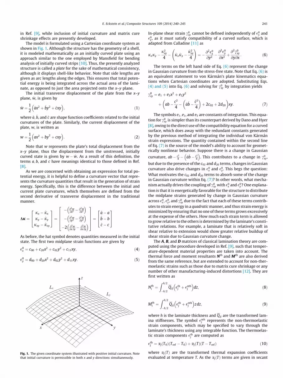
The model is formulated using a Cartesian coordinate system asshown in Fig. 1. Although the structure has the geometry of a shell,it is modeled mathematically as an initially curved plate using anapproach similar to the one employed by Mansfield for bendinganalysis of initially curved strips [10]. Thus, the presently analyzedstructure is called a plate for the sake of mathematical consistency,although it displays shell-like behavior. Note that side lengths aregiven as arc lengths along the edges. This ensures that total poten-tial energy is being integrated across the actual area of the lami-nate, as opposed to just the area projected onto the x–y plane.
The initial transverse displacement of the plate from the x–yplane, w, is given by
w ¼ 12
ax2 þ by2 þ cxy� �
; ð1Þ
where a; b, and c are shape function coefficients related to the initialcurvatures of the plate. Similarly, the current displacement of theplate, w, is written as
w ¼ 12
ax2 þ by2 þ cxy� �
: ð2Þ
Note that w represents the plate’s total displacement from thex–y plane, thus the displacement from the unstressed, initiallycurved state is given by w� w. As a result of this definition, theterms a; b, and c have meanings identical to those defined in Ref.[8].
As we are concerned with obtaining an expression for total po-tential energy, it is helpful to define a curvature vector that repre-sents the curvature quantities that result in the generation of strainenergy. Specifically, this is the difference between the initial andcurrent plate curvatures, which themselves are defined from thesecond derivative of transverse displacement in the traditionalmanner.
Dj ¼jx � jx
jy � jy
jxy � jxy
264
375 ¼
� @2w@x2 � @2w
@x2
� �� @2w
@y2 � @2w@y2
� ��2 @2w
@x @y� @2w@x @y
� �
266664
377775 ¼
a� a
b� b
c � c
264
375
As before, the hat symbol denotes quantities measured in the initialstate. The first two midplane strain functions are given by
�0x ¼ c00 þ c20x2 þ c02y2 þ c11xy; ð4Þ
�0y ¼ d00 þ d20x2 þ d02y2 þ d11xy: ð5Þ
Fig. 1. The given coordinate system illustrated with positive initial curvature. Notethat initial curvature is permissible in both x and y directions simultaneously.
In-plane shear strain c0xy cannot be defined independently of �0
x and�0
y , as it must satisfy compatibility of a curved surface, which isadapted from Calladine [11] as
jxjy �j2
xy
4� jxjy �
j2xy
4
!¼ � @
2�0x
@y2 �@2�0
y
@x2 þ@2c0
xy
@y@x: ð6Þ
The terms on the left hand side of Eq. (6) represent the changein Gaussian curvature from the stress-free state. Note that Eq. (6) isan equivalent statement to von Kármán’s plate kinematics equa-tions when Cartesian coordinates are adopted. Substituting Eqs.(4) and (5) into Eq. (6) and solving for c0
xy by integration yields
c0xy ¼ e1 þ e3x2 þ e5y2
þ ab� c2
4� ab� c2
4
� �þ 2c02 þ 2d20
� �xy: ð7Þ
The symbols e1; e3, and e5 are constants of integration. This equa-tion for c0
xy is simpler than its counterpart derived by Dano and Hyer[8], owing to the direct use of the compatibility equation for a curvedsurface, which does away with the redundant constants generatedby the previous method of integrating the individual von Kármánstrain expressions. The quantity contained within the second lineof Eq. (7) is the source of the model’s ability to account for geomet-rically nonlinear behavior. Suppose there is a change in Gaussian
curvature, ab� c2
4 � ab� c2
4
� �. This contributes to a change in c0
xy,
but due to the presence of the c02 and d20 terms, changes in Gaussiancurvature also drive changes in �0
x and �0y . This begs the question:
What motivates the c02 and d20 terms to absorb some of the changein Gaussian curvature within Eq. (7)? In other words, what mecha-nism actually drives the coupling of c0
xy with �0x and �0
y? One explana-tion is that it is energetically favorable for the structure to distributethe midplane strains generated by change in Gaussian curvatureacross �0
x ; �0y , and c0
xy due to the fact that each of these terms contrib-utes to strain energy in a quadratic manner, and thus strain energy isminimized by ensuring that no one of these terms grows excessivelyat the expense of the others. How much each strain term is allowedto grow relative to the others is determined by the laminate’s consti-tutive relations. For example, a laminate that is relatively soft inshear relative to extension would show greater relative buildup ofshear strain due to Gaussian curvature change.
The A, B, and D matrices of classical lamination theory are com-puted using the procedure developed in Ref. [9], such that temper-ature-dependent material properties are taken into account. Thethermal force and moment resultants Nth and Mth are also derivedfrom the same reference, but are extended to account for non-ther-moelastic strains such as those due to matrix cure shrinkage or anynumber of other manufacturing-induced distortions [12]. They arefirst written as
Nthi ¼
Z h=2
�h=2Qij �th
j þ �nthj
� �dz; ð8Þ
Mthi ¼
Z h=2
�h=2Q ij �th
j þ �nthj
� �zdz; ð9Þ
where h is the laminate thickness and Qij are the transformed lam-ina stiffnesses. The symbol �nth
j represents the non-thermoelasticstrain components, which may be specified to vary through thelaminate’s thickness using any integrable function. The thermoelas-tic strain components �th
j are computed as
�thj ¼ aj T0ð Þ Tref � T0ð Þ þ aj Tð Þ T � Trefð Þ ð10Þ
where aj Tð Þ are the transformed thermal expansion coefficientsevaluated at temperature T. As the aj Tð Þ terms are given in secant

Table 2Test article manufacturing parameters.
Layup ½03=903�Total thickness (mm) 1.57Lx; Ly (mm) 230x-Direction tool curvature (mm�1) 0y-Direction tool curvature (mm�1) �1=400
242 E. Eckstein et al. / Composite Structures 109 (2014) 240–245
form as per convention, a reference temperature Tref must be sup-plied. When the reference temperature coincides with the mate-rial’s stress-free temperature T0, or when aj Tð Þ is constant withrespect to temperature, Eq. (10) reduces to its familiar form�th
j ¼ aj T � T0ð Þ. Temperature may be specified to vary throughthe thickness using any integrable function.
Total potential energy P is given by
P ¼Z Lx
2
�Lx2
Z Ly2
�Ly2
12�0
Dj
� �> A BB D
� ��0
Dj
� �� Nth
Mth
� �>�0
Dj
� � !dy dx;
ð11Þ
where the superscript > denotes transpose while the vector �0 hascomponents given by Eqs. (4) and (5). After performing the integra-tion, P is minimized with respect to the shape function coefficientsembedded within �0 and Dj. Shape function coefficients satisfyingthe minimization represent equilibria whose stability is subse-quently determined using second variations of P.
Some intuition behind the tactic of subtracting out initial curva-ture terms in the energy formulation as well as the use of sidelengths measured by arc-length can be gained with the followingillustration. Suppose that the structure under the present analysisis first cast as a flat plate, albeit one possessing zero stiffness, andthus does not accumulate strain energy upon deformation. Thekinematics described in Eqs. (1)–(7) still hold true regardless, astheir existence requires no input from constitutive relations.Now, suppose that the plate is deformed to the initially curvedshape the designer wishes to simulate, and once this initial stateof curvature is achieved, the plate’s material ‘‘hardens’’, such thatthe plate is now engendered with its actual constitutive properties.At this point, further deformation generates strain energy viabending and stretching effects. In this manner, the von Kármánplate kinematic relations originally developed for flat plates stillhold true. Meanwhile, strain energy is computed correctly as longas the initially curved shape is taken to be the stress-free state.
2.2. Experimental method
Hexcel AS7/M21 unidirectional prepreg was chosen for thisstudy. Its temperature-dependent elastic properties were deter-mined by tensile testing of specimens in an oven chamber at seventemperature points between 30 �C and 180 �C as per ASTM D3039and D3518 specifications. Determination of modulus in the fiberdirection is fairly straightforward, as the stress–strain curve isessentially linear until failure. On the other hand, transverse andshear properties are dominated by the matrix, which results in anonlinear stress–strain curve. Specifically, we observed strain-softening behavior, especially at temperatures above 150 �C. As adirect result, the modulus calculated from the stress–strain curvedepends on the peak strain the test is run to. For example, strainsoftening behavior would result in lower calculated modulus forhigher tested strain magnitude. Thus, it is important to calculatemoduli at strains representative of what will be experienced bythe morphing laminate to be tested. In doing so, our transverse
Table 1Thermoelastic material data for AS7/M21. Thermal expansion coefficients a1 and a2 calcu
Temp. (�C) E1 (GPa) E2 (GPa) G12 (GPa
30 129.55 8.85 5.2860 127.99 8.42 4.8890 127.47 7.92 4.65
120 127.18 7.57 4.50150 126.11 7.18 4.26170 125.58 6.76 4.01180 125.31 6.48 3.77
and shear moduli were calculated by a linear fit of stress straindata over 10 cycles to a strain magnitude of 3:0� 10�3, whichapproximately corresponds to the maximum matrix mechanicalstrain expected during the laminated plate testing described laterin this section. Because this peak strain is only experienced at largeDT , our calculated transverse and shear moduli are expected to beslight underestimates of their actual values throughout most of thesimulated temperature range.
Temperature-dependent thermal expansion properties weredetermined via dilatometry testing of 0� and 90� specimens from30 �C to 180 �C. Elastic data is averaged over two specimens at eachtemperature, expansion over three. The resultant material data iscompiled in Table 1.
A square-planform laminate was fabricated and autoclave curedat 180 �C on a singly-curved tool to the according to the parame-ters in Table 2. After trimming to size, a 6 mm diameter hole wasdrilled at the center of the laminate, through which a single screwjoined the laminate to a dial gauge rig via a post, as shown in Fig. 2.The rig consisted of a steel bed, to which an array of four dialgauges were mounted so as to measure transverse displacementat a point along 0�, 90�, and ±45� paths from the laminate’scenterpoint.
In order to minimize the laminate’s distortion due to contactforces from the dial gauge probes, the gauges’ internal returnsprings were removed, thus the weight of the probe itself wasthe sole contributor of contact force. This was measured to be0.09 N per gauge, which subsequent finite element analysisshowed to have a negligible effect on the laminate’s shape. Graph-ite lubricant was applied at each probe contact point to minimizemeasurement error due to friction.
Curvature components jx and jy were found by determiningthe radii of circular arcs constrained to be tangent to the laminatecenterpoint while passing through the point where the respective0� and 90� dial gauges made contact. Twist curvature jxy was com-puted from the difference in displacements along the ±45� paths.The laminate was heated by placing the complete dial gaugeassembly in an oven and ramping the temperature up to 180 �Cat a rate of 1 �C/min. Temperature was measured using a thermo-couple adhered to the laminate with the aid of thermally conduc-tive paste. Expansion of the rig itself upon heating was measuredby replacing the laminate with a steel plate, and was found to benegligible. Curvature data was collected for a single heating cycle,and the difference between the laminate’s measured curvature at180 �C and the tool curvature was used to determine the contribu-tion from non-thermoelastic strains as per the procedure devel-oped by Gigliotti et al. [13].
lated from thermal strain data using Tref ¼ 20 �C.
) m12 (–) a1 (10�6/�C) a2 (10�6/�C)
0.33 �2.3 23.40.33 �2.1 27.80.33 �1.5 28.60.33 �0.5 30.00.33 1.7 32.10.33 2.6 33.50.33 2.3 33.5

Fig. 2. Test article mounted to dial-gauge rig.
E. Eckstein et al. / Composite Structures 109 (2014) 240–245 243
3. Results
Analytical results are computed under the assumption thattemperature is uniform across the laminate. Non-thermoelasticstrain was determined to be negligible in the fiber direction, and�6:9� 10�4 perpendicular to the fibers. This shrinkage corre-sponds to a reduction in cure-temperature curvature by approxi-mately 10% relative to the tool curvature. The resultingbistability phase diagram is shown in Fig. 3. Two regions of bista-bility are found upon cooldown from cure temperature. Region Arepresents the classically observed 0� and 90� oriented, while Re-gion B indicates the presence of cylinders oriented at oblique an-gles of ±h. The symbol h is the angle of the principle curvatureaxes relative to the x–y axes, and varies continuously with temper-ature within Region B. For the case of zero initial curvature, only 0�and 90� oriented cylinders are observed upon cooldown from curetemperature. The sharp cusp at the right boundary of Region Aindicates the high-degree of imperfection sensitivity with respectto the effect of initial curvature on bifurcation temperature.The presence of positive initial curvature requires additional
Fig. 3. Bistability phase diagram of the given laminate, showing the effect of initialcurvature and temperature on the existence of bistable solutions. Shaded areasrepresent bistable solutions, with Region A denoting bistability of 0� and 90�
oriented cylinders, while Region B refers to the existence of bistable cylinders ofoblique orientations. The dotted line indicates the set of solutions predicted for theexperiment described in Section 2.2. Additional results for this initial curvature aregiven in Fig. 4.
temperature change from cure to induce bistability for the givenlaminate, while negative initial curvature gives rise to an addi-tional regionof bistability where obliquely oriented cylinders are present.Region A is also accessible to laminates possessing negative initialcurvature when sufficient thermal loading is applied. Thus wecan see that it is possible to construct a laminate which isdisplays two separate modes of bistability, albeit at differenttemperatures. The slight waviness visible along the boundaries ofRegions A and B is due to material property variation with respectto temperature.
Predicted laminate curvatures from 20 �C to 180 �C are plottedwith experimentally measured curvatures in Fig. 4 for the laminatedescribed in Table 2. Three separate modes of deformation are dis-cernible across the plotted temperature range. There are two bend-ing modes, each with a different direction of actuation, separatedby a twisting mode where obliquely oriented cylinders are present.Starting from room temperature, the magnitude of jx shrinks line-arly with respect to temperature. Meanwhile, jy remains fixed atnearly zero curvature. At approximately 85 �C, the solution bifur-cates, transitioning from a cylinder with principle curvature fixedin the x-direction to one in which the principle curvature directionvaries continuously with temperature, such that the laminate takeson one of two oblique shapes. Both of these shapes have identicaljx and jy values, but opposite signs of jxy. Three additionalbranches representing unstable cylindrical and spherical shapesexist in the range between 85 �C and 164 �C, though they are omit-ted for clarity. They are later represented in Fig. 7, and are qualita-tively similar to the unstable branches seen in Fig. 7 in Ref. [9].Within this temperature range, the laminate is bistable, and maybe snapped from one oblique shape to the opposite using externalforce. After the bifurcation at 85 �C, jx continues decreasing in alinear fashion until it nearly vanishes at approximately 164 �C,where the solutions coalesce to a monostable cylindrical shapewith principle curvature fixed in the y-direction. As temperatureis increased beyond 164 �C, jx remains approximately zero.Both jx and jy display essentially tri-linear behavior across thewhole temperature range, and are nearly symmetric about thetemperature of maximum jxy, their deviation from perfect symme-try due to the presence of temperature-dependent materialproperties.
Agreement between the analytical model and experiment isexcellent for both jx and jy, however the present model overpre-dicts the magnitude of jxy within the temperature range markedby oblique cylindrical shapes. The experimental data illustratesthe effects of manufacturing imperfections on laminate behavior,especially near the two bifurcation points where jxy shows asmoother response to temperature change than the analyticaland FE models predict. Additionally, only shapes of negative jxy
were observed to naturally occur without the help of external forc-ing. Results from an FE model consisting of 256 ABAQUS S8R ele-ments are also shown in Fig. 4. Agreement between theanalytical and FE model is also very good for both jx and jy, butthe analytical model overpredicts jxy when oblique shapes arepresent. The analytical model appears to better predict bifurcationtemperatures relative to the FE model, however this result ismerely coincidental. The discrepancy between experimental andFE results near the bifurcation temperatures is due to geometricand material imperfections in the laminate.
Both the analytical and FE-predicted jx diverge from experi-ment by up to 6.5% for temperatures below 60 �C. Given that thetwo models are in excellent agreement for this temperature range,the discrepancy is likely due to error in measurement of materialproperties. In particular, determination of the CTEs near room tem-perature is prone to error, as the relatively small temperaturechanges can induce only very small thermal strains, which

Fig. 4. Curvature diagram showing the laminate’s combined bending-twisting behavior. Unstable solution branches are omitted for clarity.
244 E. Eckstein et al. / Composite Structures 109 (2014) 240–245
themselves may not be much larger than dilatometer’s measure-ment error.
Time-lapse images of the laminate were captured during cool-down with dial gauges removed, and are shown in Fig. 5.
4. Discussion
4.1. Investigation of obliquely oriented cylindrical shapes
The existence of bistable oblique cylinders in flat ½0n=90n� lam-inates has been predicted [9] and observed [14] in previous litera-ture. In both of the aforementioned cases, the oblique shapes weredue to the fact that the laminates under analysis were least stiff inbending along ±45� directions, and thus when loaded with equal
Fig. 5. Image sequence showing transition from twisting to bending behaviorduring cool-down.
moments in all directions, naturally sought out cylindrical shapesoriented at ±45�. On the other hand, the initially curved laminateunder present analysis is loaded with oppositemoments in eachdirection, and thus the same explanation does not apply. One par-allel that can be drawn is that in both the present and past cases ofoblique shapes, the linear shape predicted by classical laminationtheory was spherical, or at least nearly spherical in nature. In otherwords, oblique shapes arose when the laminate would have takenon spherical shapes if not for the restraining effect of geometricnonlinearity. Whether the classically-predicted spherical shapewas due to equal moments applied to a flat plate, or opposite mo-ments superimposed on an initially curved plate seemed to matterlittle, the result was qualitatively the same in either case. This sug-gests that the approach taken by Fernandes et al. [15] and Vidoli[16], whereby thermal loads are represented in the potential en-ergy formulation in terms of residual curvatures, may yield betterinsight into the connection between loads and initial curvaturesthan that given by the present model.
The analytical model’s overprediction of curvature when obli-que shapes are present is a result of the limitations of the simplestrain functions utilized, given by Eqs. (4), (5), and (7). In particular,the present model’s representation of shear strain is especiallyprone to error at temperatures where jxy – 0, as shown in Fig. 6.The artificial stiffness imposed by the limited membrane stretchingdegrees of freedom makes it more energetically favorable for thelaminate to store strain energy via bending deformation relativeto stretching, and thus curvature magnitudes are overpredicted.
Fig. 6. Comparison of predicted midplane shear strain between the presentanalytical and finite element models. T = 122 �C corresponds to the temperatureat which jxy is maximized.

Fig. 7. Principle curvatures j1 and j2 plotted along with principle curvatureorientation h, showing constant principle curvature response when oblique shapesare present. Dotted lines indicate unstable solution branches.
E. Eckstein et al. / Composite Structures 109 (2014) 240–245 245
The method presented in Ref. [15], whereby the membrane strainsare solved a priori using a suitable numerical method (e.g. FEM),would likely yield better results for cases of nonzero jxy on accountof the greater membrane degrees of freedom available; howeverimmediate comparisons are difficult as that model requires mate-rial properties to remain constant with respect to temperature foreach membrane solution.
The oblique shapes can also be described as the minimum po-tential energy method of transition from 0� to 90� cylinders, or viceversa, due to the fact that they retain nearly zero Gaussian curva-ture. Interestingly, the laminate’s principle curvatures are approx-imately constant with respect to temperature when oblique shapesare present, as illustrated in Fig. 7. If material properties were con-stant with respect to temperature, the principle curvatures wouldbe exactly constant across that range.
4.2. Laminate behavior at extreme DT
Results from the analytical model predict that the laminatewould see a bifurcation to 0� and 90� oriented bistable cylindersat both �143 �C and 345�C. Although these temperatures are notimportant in the practical sense, the results give some insight intothe role of initial curvature. This type of bifurcation is the same asthat observed with initially flat plates, represented by Region A inFig. 3. It appears that for cases of increasing internal moments, theeffect of initial curvature becomes smaller such that the laminatetakes on initially flat plate behavior. It is also interesting to notethat the temperature of maximum jxy, which is also the tempera-ture where jx and jy are equal, corresponds to the mid-point be-tween the two extreme DT bifurcations mentioned previously. Itwould appear that at least when considering large DT , additionof initial curvature has a similar effect to offsetting the stress-freetemperature of an initially flat plate.
5. Conclusion
A Rayleigh–Ritz based analytical model has been formulated topredict the behavior of thermally actuated morphing structures
constructed with initial curvature. The model demonstrated goodaccuracy with respect to both experimental and FE results for thesimulation of large shell deformations, despite being formulatedusing relatively simple plate kinematics. The presence of initialcurvature in thermally loaded unsymmetric laminates was foundto give rise to multiple deformation modes, whereby two orthogo-nal bending modes occurred adjacent to an intermediate twistingmode. Within the temperature range where oblique shapes werepresent, principle curvature was invariant with respect to temper-ature, apart from a small deviation due to temperature-dependentmaterial properties.
The ability to model the effects of initial curvature in a mannerthat can be applied at the preliminary design stage represents asignificant advance towards the successful adaptation of morphingand multistable structures. Meanwhile, the use of initial curvaturein multistable laminates opens up a rich variety of behavior nototherwise attainable with initially flat laminates.
Acknowledgments
This effort was sponsored by the European Office of Air ForceResearch and Development, Air Force Office of Scientific Research,USAF, under Grant No. FA8655-11-1-3063. The US Government isauthorized to reproduce and distribute reprints for governmentalpurpose notwithstanding any copyright notation thereon. Theviews and conclusions contained herein are those of the authorsand should not be interpreted as necessarily representing the offi-cial policies or endorsements, either expressed or implied, of theAir Force Office of Scientific Research or the US Government. Theauthors also acknowledge the support of the EPSRC under its ACCISDoctoral Training Centre Grant, EP/G036772/1.
References
[1] Hyer M. Calculations of the room-temperature shapes of unsymmetriclaminates. J Compos Mater 1981;15:296.
[2] Hamamoto A, Hyer M. Non-linear temperature–curvature relationshipsfor unsymmetric graphite-epoxy laminates. Int J Solids Struct 1987;23(7):919–35.
[3] Galletly DA, Guest SD. Bistable composite slit tubes. II. A shell model. Int JSolids Struct 2004;41(16–17):4503–16.
[4] Guest S, Pellegrino S. Analytical models for bistable cylindrical shells. Proc RSoc A: Math Phys Eng Sci 2006;462(2067):839–54.
[5] Pirrera A, Avitabile D, Weaver P. On the thermally induced bistability ofcomposite cylindrical shells for morphing structures. Int J Solids Struct2012;49(5):685–700.
[6] Schlecht M, Schulte K, Hyer M. Advanced calculation of the room-temperatureshapes of thin unsymmetric composite laminates. Compos Struct 1995;32(1–4):627–33.
[7] Pirrera A, Avitabile D, Weaver P. Bistable plates for morphing structures: arefined analytical approach with high-order polynomials. Int J Solids Struct2010;47(25–26):3412–25.
[8] Dano M-L, Hyer MW. Thermally-induced deformation behavior ofunsymmetric laminates. Int J Solids Struct 1998;35(17):2101–20.
[9] Eckstein E, Pirrera A, Weaver P. Morphing high-temperature composite platesutilizing thermal gradients. Compos Struct 2013;100:363–72.
[10] Mansfield EH. The bending and stretching of plates. 2nd ed. CambridgeUniversity Press; 1989.
[11] Calladine CR. Theory of shell structures. Cambridge: Cambridge UniversityPress; 1983.
[12] Radford DW, Rennick TS. Separating sources of manufacturing distortion inlaminated composites. J Reinf Plast Compos 2000;19(8):621–41.
[13] Gigliotti M, Wisnom M, Potter K. Development of curvature during the cure ofAS4/8552 [0/90] unsymmetric composite plates. Compos Sci Technol2003;63(2):187–97.
[14] Dai F, Li H, Du S. Cured shape and snap-through of bistable twisting hybrid [0/90/metal]T laminates. Compos Sci Technol 2013;86:76–81.
[15] Fernandes A, Maurini C, Vidoli S. Multiparameter actuation for shape control ofbistable composite plates. Int J Solids Struct 2010;47(10):1449–58.
[16] Vidoli S. Discrete approximations of the Foppl-Von Karman shell model: fromcoarse to more refined models. Int J Solids Struct 2013;50(9):1241–52.


