Embed Size (px)
Citation preview

- 1 -
Safety Precautions
Safety FirstRegardless of how enthusiastic you may be about getting on your equipment andexercising, take the time to ensure that your safety is not jeopardized. A moment’slack of attention can result in an accident, as can failure to observe certain simplesafety precautions.
1. Read, study and understand the Owner’s Manual and all the warning labels on thisproduct. Furthermore, it is recommended to familiarize yourself and others withthe proper operation and workout recommendations for this product prior to use.Some of this information can be obtained in this Owner’s Manual, as-well-as fromyour local retailer.
2. It is imperative that you retain this Owner’s Manual and be sure all warning labelsare legible and intact. Replacement Owner’s Manuals and labels are available fromyour local retailer.
3. It is recommended that another person assist you with the assembly of this unit.
4. Consult with your physician before beginning any exercise program.
5. Use proper discretion when children are present.
6. Frayed or worn cables can be dangerous and may cause injury. Periodically checkthese cables for any indication of wear.
7. Keep hands, limbs, loose clothing and long hair well out of the way of movingparts.
8. Do not attempt to lift more weight than you can control safely.
9. Inspect the machine for any sign of wear on parts, hardware becoming loose orcracks on welds. If a problem is found do not use or allow the machine to be useduntil the defective part is repaired or replaced.
10. You can use the WRENCH and the INNER HEX WRENCH to complete theassembly.

- 2 -
Part List

- 3 -
Part List

- 4 -
Part List

- 5 -
Part List
- 6 -
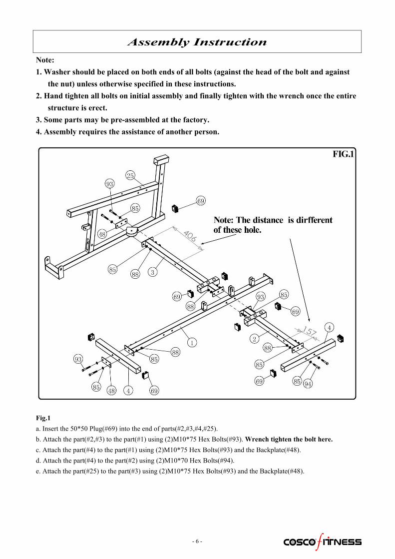
Assembly InstructionNote:1. Washer should be placed on both ends of all bolts (against the head of the bolt and against
the nut) unless otherwise specified in these instructions.2. Hand tighten all bolts on initial assembly and finally tighten with the wrench once the entire
structure is erect.3. Some parts may be pre-assembled at the factory.4. Assembly requires the assistance of another person.
Fig.1a. Insert the 50*50 Plug(#69) into the end of parts(#2,#3,#4,#25).b. Attach the part(#2,#3) to the part(#1) using (2)M10*75 Hex Bolts(#93).Wrench tighten the bolt here.c. Attach the part(#4) to the part(#1) using (2)M10*75 Hex Bolts(#93) and the Backplate(#48).d. Attach the part(#4) to the part(#2) using (2)M10*70 Hex Bolts(#94).e. Attach the part(#25) to the part(#3) using (2)M10*75 Hex Bolts(#93) and the Backplate(#48).
- 7 -
Assembly Instruction
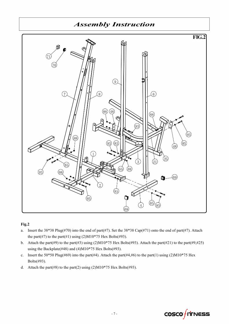
Fig.2a. Insert the 38*38 Plug(#70) into the end of part(#7). Set the 38*38 Cap(#71) onto the end of part(#7). Attach
the part(#7) to the part(#1) using (2)M10*75 Hex Bolts(#93).b. Attach the part(#9) to the part(#3) using (2)M10*75 Hex Bolts(#93). Attach the part(#21) to the part(#9,#25)
using the Backplate(#48) and (4)M10*75 Hex Bolts(#93).c. Insert the 50*50 Plug(#69) into the part(#4). Attach the part(#4,#6) to the part(1) using (2)M10*75 Hex
Bolts(#93).d. Attach the part(#8) to the part(2) using (2)M10*75 Hex Bolts(#93).
- 8 -
Assembly Instruction
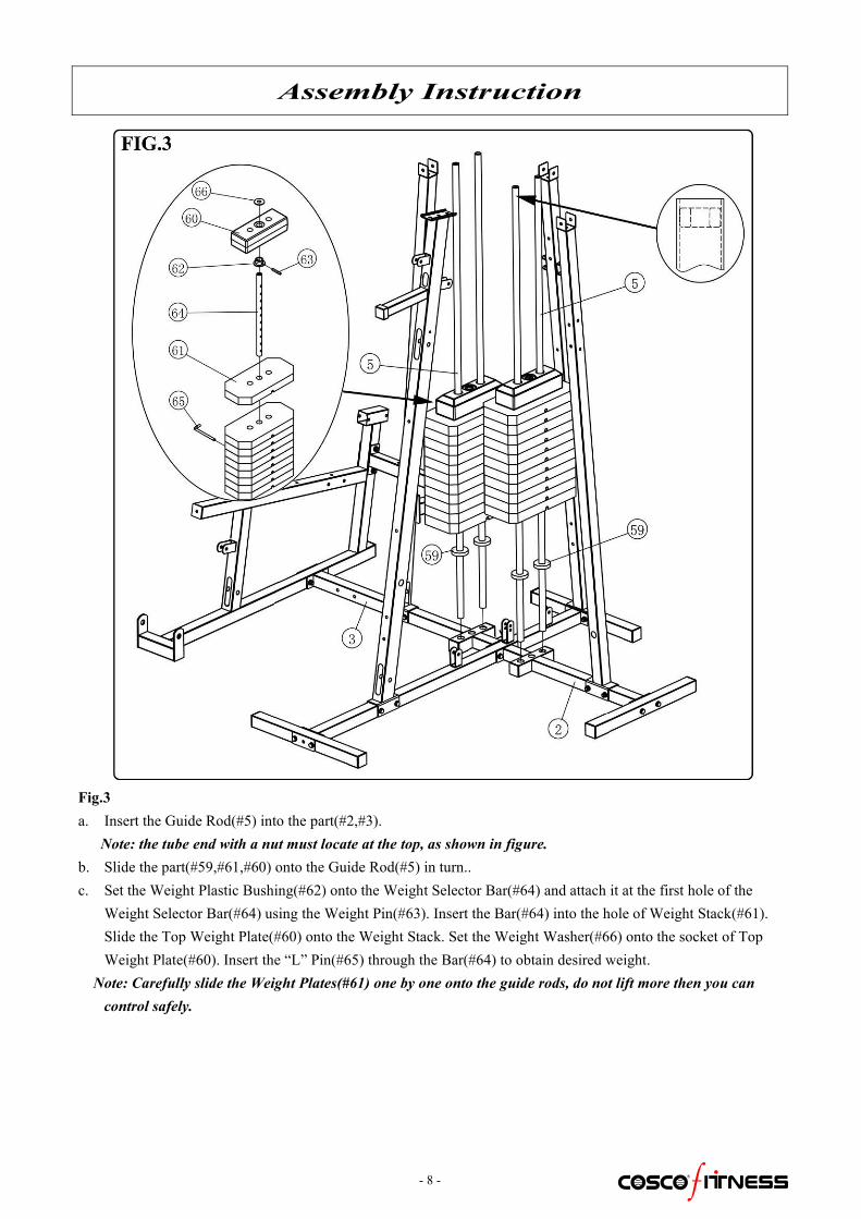
Fig.3a. Insert the Guide Rod(#5) into the part(#2,#3).
Note: the tube end with a nut must locate at the top, as shown in figure.b. Slide the part(#59,#61,#60) onto the Guide Rod(#5) in turn..c. Set the Weight Plastic Bushing(#62) onto the Weight Selector Bar(#64) and attach it at the first hole of the
Weight Selector Bar(#64) using the Weight Pin(#63). Insert the Bar(#64) into the hole of Weight Stack(#61).Slide the Top Weight Plate(#60) onto the Weight Stack. Set the Weight Washer(#66) onto the socket of TopWeight Plate(#60). Insert the “L” Pin(#65) through the Bar(#64) to obtain desired weight.
Note: Carefully slide the Weight Plates(#61) one by one onto the guide rods, do not lift more then you cancontrol safely.

- 9 -
Assembly Instruction
Fig.4a. Insert the 70*50 Plug(#68) into the part(#10). Attach the part(#10) to the part(#8,#9) using (2)M10*75 Hex
Bolts(#93).b. Attach the part(#5) to the part(#10) using (4)M10*25 Hex Bolts(#97).

- 10 -
Assembly InstructionFig.5a. Insert the 70*50 Plug(#68) into the part(#11,#13).b. Attach the part(#13) to the part(#6) using (1)M10*75 Hex Bolt(#93).c. Attach the part(#11) to the part(#7) using (2)M10*90 Hex Bolts(#91).d. Attach the part(#11,#13) to the part(#10) using (2)M10*75 Hex Bolts(#93).
Fig.6a. Insert the 50*50 Plug(#69) into the part(#12). Use a mallet, insert the Shaft(#34) through the part(#12) and
through the part(#11) until it is flush with both ends. Attach the Shaft(#34) to the part(#12) using (2)M8*20Hex Bolts(#103).
b. Set the End Cap with hole(#75) and the Comfort Grip(#76) onto the part(#12).c. Attach the Pulley(#56) and the Long Pulley Bushing(#27) to the part(#12) using (2)M10*185 Hex Bolts(#89).d. Set the Comfort Grip(#76) onto the Handlebar(#15). Attach the Handlebar(#15) to the part(#12) using
(4)M10*25 Hex Bolts(#97).

- 11 -
Assembly Instruction
Fig.7a. Insert the 50*50 Plug(#69) into the part(#35). Attach the part(#35) to the part(#7) using the Backplate(#48) and
(2)M10*90 Hex Bolts(#91).b. Insert the 50*50 Plug(#69) into the part(#37). Attach the part(#37) to the part(#35) using (1)M10*85 Hex
Bolt(#92).c. Insert the φ25 Plug(#74) into the end of parts(#32,#33). Insert the Long Foam Roller Tube(#32) through the
part(#7). Insert the Short Foam Roller Tube(#33) through the part(#35,#37).d. Slide the Foam Roller(#55) onto the Tube(#32,#33).

- 12 -
Assembly Instruction
Fig.8a. Set the Comfort Grip(#76) onto the part(#19,#20), and then attach the part(#19,#20) to the part(#25) using
(2)M10*70 Hex Bolts(#94).b. Screw the Buffer(#53) to the part(#25).c. Insert the 50*50 Plug(#69) into the part(#22). Use a mallet, insert the Shaft(#24) through the part(#25,#22).
Attach the Shaft(#24) using (2)M10*16 Hex Bolts(#98) and (2)φ10 Big Washers(#84).
Fig.9a. Use a mallet, insert the Shaft(#24) through
the part(#22,#23). Attach the Shaft(#24)using (2)M10*16 Hex Bolts(#98) and (2)φ10 Big Washers(#84).
b. Attach the Pulley(#56) and the ShortBushing(#26) to the part(#22) using(1)M10*175 Hex Bolt(#90).

- 13 -
Assembly Instruction
Fig.10a. Attach the part(#14) to the part(#6) using the Backplate(#48) and (2)M10*70 Hex Bolts(#94).b. Attach the part(#16) to the part(#6) using the Backplate(#48) and (2)M10*70 Hex Bolts(#94). Insert the 50*50
Plug(#69) into the end.c. Attach the part(#41) to the part(#6) using (2)M10*65 Hex Bolts(#95).d. Insert the 50*50 Plug(#69) into the part(#31). Attach the part(#31) to the part(#16) using (1)M16 Nylon Lock
Nut(#87) and (1)φ16 Washer(#83).e. Slide theφ90*245 Foam(#57) onto the part(#31).f. Assemble the other Pec Arm(#30) using same method.
Fig.11a. Insert the Short Foam Roller Tube(#33) through the part(#8).b. Set the Comfort Grip(#76) onto the Tube(#33).

- 14 -
Assembly Instruction
Fig.12a. Attach the part(#28,#29) to the part(#8) using (2)M10*75 Hex Bolts(#93).b. Attach the part(#44) to the part(#8) using (2)M8*70 Hex Bolts(#100).c. Attach the part(#45) to the part(#28,#29) using (4)M8*70 Hex Bolts(#100).d. Set the Comfort Grip(#76) onto the part(#15), and then attach the part(#15) to the part(#28,#29) using
(2)M10*25 Hex Bolts(#97).e. Set the End Cap with hole(#75) and the Comfort Grip(#76) onto the part(#28,#29).
Fig.13a. Attach the part(#43) to the part(#25) using (2)M8*70 Hex
Bolts(#100).

- 15 -
Assembly Instruction
Fig.14a. Insert the Sleeve(#77) into the part(#25).
Screw the Locking-Pin(#54) to the part(#25).b. Insert the 38*38 Plug into the part(#18).c. Attach the part(#44) to the part(#18) using
(2)M8*25 Hex Bolts(#102).d. Insert the part(#18) through the sleeve, adjust
to desire length and release the Pin(#54) tolock the part(#18) in place.
Fig.15a. Insert the Sleeve(#77) into the part(#14). Screw the
Locking-Pin to the part(#14).b. Attach the part(#46) to the part(#17) using (2)M8*25
Hex Bolts(#102).c. Insert the part(#17) through the sleeve, adjust to desire
height and release the Pin(#54) to lock the part(#17) inplace.
d. Attach the part(#42) to the part(#6) using (2)M8*70 HexBolts(#100).

- 16 -
Assembly Instruction
Fig.16a. Insert the Sleeve(#77) into the part(#35). Screw the Locking-Ping(#54) to the part(#35).b. Insert the 50*25 Plug(#72) into the part(#36). Attach the part(#43) to the part(#36) using (2)M8*45 Hex
Bolts(#101).c. Insert the part(#36) through the sleeve, adjust to desire height and release the Pin(#54) to lock the part(#36) in
place.d. Attach the part(#42) to the part(#7) using (2)M8*90 Hex Bolts(#99).

- 17 -
Assembly InstructionCABLE DIAGRAMS
After the Machine is assembled, check whether the cable is tensioned. (Atcorrect tension, there should be a gap of 3-5mm between the Top WeightPlate and the Weight Stack).
If the Cable is slightly loose, adjust it by tightening the Bolt at the top ofthe weight stack.
If the Cable is very loose, adjust the Pulley to lower position on Pulleyplate(#47) or adjust the length of Coil Chain(#81), using the Snap Link(#82).
FIG.17
Loosen nut andthread bolt in/outof top plate togive the cablecorrect tension.Re-tighten nut.
- 18 -
Assembly Instruction
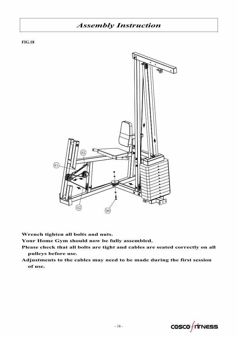
FIG.18
Wrench tighten all bolts and nuts.Your Home Gym should now be fully assembled.Please check that all bolts are tight and cables are seated correctly on allpulleys before use.
Adjustments to the cables may need to be made during the first sessionof use.

- 19 -
Maintenance
Maintenance Information
1. Lubrication of all moving parts is essential to the longevity and optimal performance of your Machine.Initial lubrication of some parts of your gym has been done at the factory, but the weight stack guiderods must be lubricated at the time of assembly. We recommend a clear aerosol, silicone or Teflonspray.
Note: Do not use oil based lubricants as they will attract dust, dirt and grime, and will eventually gum upand erode bushings and sealed bearings.
2. All pulleys and bushings should be checked regularly for signs of wear.
3. Check and adjust cable tension periodically as it will maintain proper anatomical function.
4. Periodically check all moving parts, upholstery and grips for signs of wear or damage. If there is aproblem or replacement part which is necessary, STOP USING THE EQUIPMENT and immediatelycontact your local retailer. Replace parts using only genuine parts.
5. As needed, upholstery may be cleaned with a mild solution of soap and water. Regular use of a vinyltreatment will add to the life and appearance of your upholstery.
6. All chrome plated surfaces should be cleaned regularly to prolong the life and luster of the finish.Wipe machine down with a damp cloth and dry thoroughly each day. At least once a week yourchrome equipment should be polished with a commercial grade or automotive type chrome polish.
7. When checking the bolts and nuts, be sure they are all fully fastened. If there is a bolt or nut thatcontinuously loosens obtain a replacement through your local retailer.
8. Check welds to be free of cracks.
9. Failure to perform routine maintenance could result in personal injury and/or equipment damage.


