Embed Size (px)
Citation preview
NORTH SHORE LEVEE
Aberdeen & Hoquiam, WA
MT – 2 FORMS
KPFF Project No. 41600177
July 10, 2017

Table of Contents
FORM 1: Overview & Concurrence Form FORM 2: Riverine Hydrology & Hydraulics Form FORM 3: Riverine Structures Form FORM 4: Costal Analysis Form FORM 5: Costal Structures Form ATTACHMENTS:
• Attachment #1 – North Shore Levee Sediment Transport Explanations
• Attachment #2 – North Shore Levee Closure Summary
• Attachment #3 – North Shore Levee Pipe Penetrations
• Attachment #4 – North Shore Levee Drainage Basins and Pump Capacities


FORM 1
Overview & Concurrence Form

FEMA Form 086-0-27, (2/2011) Previously FEMA Form 81-89 MT-2 Form 1 Page 1 of 3
U.S. DEPARTMENT OF HOMELAND SECURITY FEDERAL EMERGENCY MANAGEMENT AGENCY
OVERVIEW & CONCURRENCE FORM
O.M.B No. 1660-0016
Expires February 28, 2014
PAPERWORK BURDEN DISCLOSURE NOTICE
Public reporting burden for this form is estimated to average 1 hours per response. The burden estimate includes the time for reviewing instructions, searching existing data sources, gathering and maintaining the needed data, and completing, reviewing, and submitting the form. You are not required to respond to this collection of information unless it displays a valid OMB control number. Send comments regarding the accuracy of the burden estimate and any suggestions for reducing this burden to: Information Collections Management, Department of Homeland Security, Federal Emergency Management Agency, 1800 South Bell Street, Arlington, VA 20958-3005, Paperwork Reduction Project (1660-0016). Submission of the form is required to obtain or retain benefits under the National Flood Insurance Program. Please do not send your completed survey to the above address.
PRIVACY ACT STATEMENT
AUTHORITY: The National Flood Insurance Act of 1968, Public Law 90-448, as amended by the Flood Disaster Protection Act of 1973, Public Law 93-234.
PRINCIPAL PURPOSE(S): This information is being collected for the purpose of determining an applicant's eligibility to request changes to National Flood Insurance Program (NFIP) Flood Insurance Rate Maps (FIRM).
ROUTINE USE(S): The information on this form may be disclosed as generally permitted under 5 U.S.C § 552a(b) of the Privacy Act of 1974, as amended. This includes using this information as necessary and authorized by the routine uses published in DHS/FEMA/NFIP/LOMA-1 National Flood Insurance Program (NFIP); Letter of Map Amendment (LOMA) February 15, 2006, 71 FR 7990.
DISCLOSURE: The disclosure of information on this form is voluntary; however, failure to provide the information requested may delay or prevent FEMA from processing a determination regarding a requested change to a (NFIP) Flood Insurance Rate Maps (FIRM).
A. REQUESTED RESPONSE FROM DHS-FEMA
This request is for a (check one):
CLOMR: A letter from DHS-FEMA commenting on whether a proposed project, if built as proposed, would justify a map revision, or proposed hydrology changes (See 44 CFR Ch. 1, Parts 60, 65 & 72).
LOMR: A letter from DHS-FEMA officially revising the current NFIP map to show the changes to floodplains, regulatory floodway or flood
elevations. (See 44 CFR Ch. 1, Parts 60, 65 & 72)
B. OVERVIEW
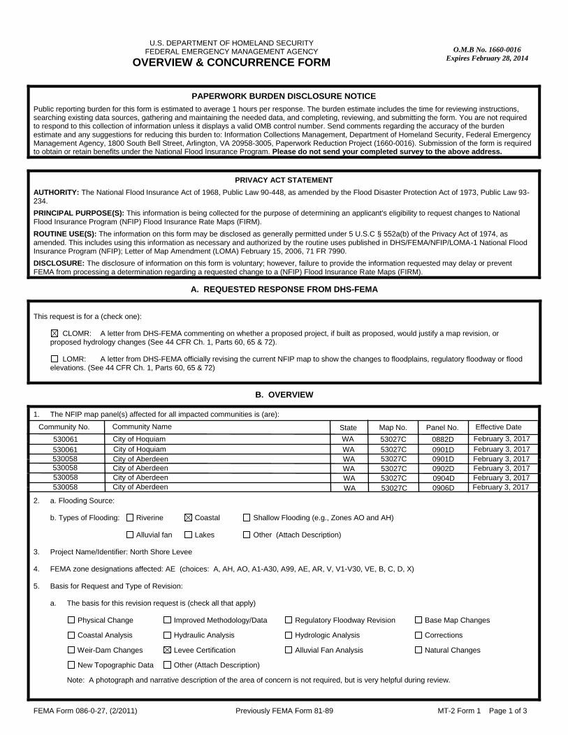
1. The NFIP map panel(s) affected for all impacted communities is (are):
Community No. Community Name State Map No. Panel No. Effective Date
Example: 480301 480287
City of Katy Harris County
TX TX
48473C 48201C
0005D 0220G
02/08/83 09/28/90
2. a. Flooding Source: b. Types of Flooding: Riverine Coastal Shallow Flooding (e.g., Zones AO and AH)
Alluvial fan Lakes Other (Attach Description) 3. Project Name/Identifier: North Shore Levee 4. FEMA zone designations affected: AE (choices: A, AH, AO, A1-A30, A99, AE, AR, V, V1-V30, VE, B, C, D, X) 5. Basis for Request and Type of Revision:
a. The basis for this revision request is (check all that apply)
Physical Change Improved Methodology/Data Regulatory Floodway Revision Base Map Changes
Coastal Analysis Hydraulic Analysis Hydrologic Analysis Corrections
Weir-Dam Changes Levee Certification Alluvial Fan Analysis Natural Changes
New Topographic Data Other (Attach Description)
Note: A photograph and narrative description of the area of concern is not required, but is very helpful during review.
530061530061530058530058530058
City of Hoquiam WA 53027C 0882D February 3, 2017February 3, 2017February 3, 2017February 3, 2017February 3, 2017
0901D0901D0902D0904D
53027C53027C53027C53027C
WAWAWAWA
City of HoquiamCity of AberdeenCity of AberdeenCity of Aberdeen
Community No. Community Name State Map No. Panel No. Effective Date
February 3, 201753027CWA 0906D530058 City of Aberdeen


FEMA Form 086-0-27, (2/2011) Previously FEMA Form 81-89 MT-2 Form 1 Page 3 of 3
Ensure the forms that are appropriate to your revision request are included in your submittal.
Form Name and (Number) Required if …
Riverine Hydrology and Hydraulics Form (Form 2) New or revised discharges or water-surface elevations
Riverine Structures Form (Form 3) Channel is modified, addition/revision of bridge/culverts, addition/revision of levee/floodwall, addition/revision of dam
Coastal Analysis Form (Form 4) New or revised coastal elevations
Coastal Structures Form (Form 5) Addition/revision of coastal structure
Alluvial Fan Flooding Form (Form 6) Flood control measures on alluvial fans
Seal (Optional)

FORM 2
Riverine Hydrology & Hydraulics Form

FEMA Form 086-0-27A, (2/2011) Previously FEMA Form 81-89 MT-2 Form 2 Page 1 of 3
U.S. DEPARTMENT OF HOMELAND SECURITY FEDERAL EMERGENCY MANAGEMENT AGENCY
RIVERINE HYDROLOGY & HYDRAULICS FORM O.M.B No. 1660-0016
Expires February 28, 2014
PAPERWORK BURDEN DISCLOSURE NOTICE
Public reporting burden for this form is estimated to average 3.5 hours per response. The burden estimate includes the time for reviewing instructions, searching existing data sources, gathering and maintaining the needed data, and completing, reviewing, and submitting the form. You are not required to respond to this collection of information unless a valid OMB control number appears in the upper right corner of this form. Send comments regarding the accuracy of the burden estimate and any suggestions for reducing this burden to: Information Collections Management, Department of Homeland Security, Federal Emergency Management Agency, 1800 South Bell Street, Arlington VA 20958-3005, Paperwork Reduction Project (1660-0016). Submission of the form is required to obtain or retain benefits under the National Flood Insurance Program. Please do not send your completed survey to the above address.
PRIVACY ACT STATEMENT
AUTHORITY: The National Flood Insurance Act of 1968, Public Law 90-448, as amended by the Flood Disaster Protection Act of 1973, Public Law 93-234.
PRINCIPAL PURPOSE(S): This information is being collected for the purpose of determining an applicant's eligibility to request changes to National Flood Insurance Program (NFIP) Flood Insurance Rate Maps (FIRM).
ROUTINE USE(S): The information on this form may be disclosed as generally permitted under 5 U.S.C § 552a(b) of the Privacy Act of 1974, as amended. This includes using this information as necessary and authorized by the routine uses published in DHS/FEMA/NFIP/LOMA-1 National Flood Insurance Program (NFIP); Letter of Map Amendment (LOMA) February 15, 2006, 71 FR 7990.
DISCLOSURE: The disclosure of information on this form is voluntary; however, failure to provide the information requested may delay or prevent FEMA from processing a determination regarding a requested change to a NFIP Flood Insurance Rate Maps (FIRM).
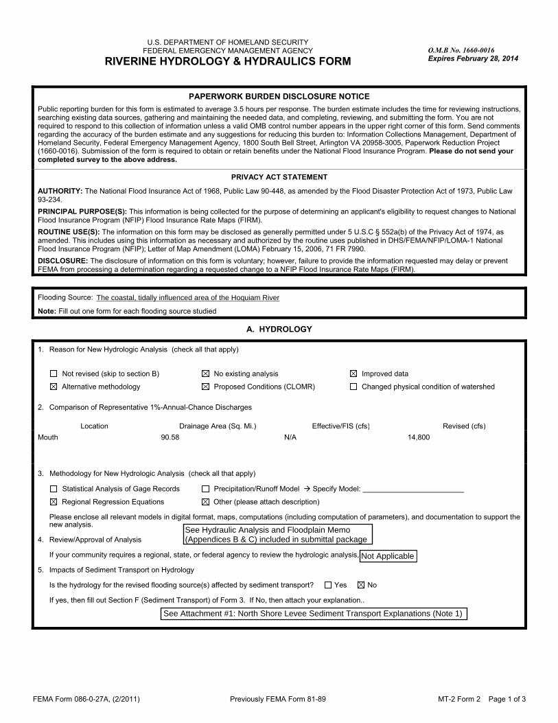
Flooding Source: Hoquiam River
Note: Fill out one form for each flooding source studied
A. HYDROLOGY
1. Reason for New Hydrologic Analysis (check all that apply)
Not revised (skip to section B) No existing analysis Improved data
Alternative methodology Proposed Conditions (CLOMR) Changed physical condition of watershed
2. Comparison of Representative 1%-Annual-Chance Discharges
Location Drainage Area (Sq. Mi.) Effective/FIS (cfs) Revised (cfs)
Mouth 90.58 N/A 14,800
3. Methodology for New Hydrologic Analysis (check all that apply)
Statistical Analysis of Gage Records Precipitation/Runoff Model � Specify Model:
Regional Regression Equations Other (please attach description)
Please enclose all relevant models in digital format, maps, computations (including computation of parameters), and documentation to support the new analysis.
4. Review/Approval of Analysis
If your community requires a regional, state, or federal agency to review the hydrologic analysis, please attach evidence of approval/review. 5. Impacts of Sediment Transport on Hydrology
Is the hydrology for the revised flooding source(s) affected by sediment transport? Yes No If yes, then fill out Section F (Sediment Transport) of Form 3. If No, then attach your explanation..
See Attachment #1: North Shore Levee Sediment Transport Explanations (Note 1)
See Hydraulic Analysis and Floodplain Memo(Appendices B & C) included in submittal package
The coastal, tidally influenced area of the Hoquiam River
Not Applicable

FEMA Form 086-0-27A, (2/2011) Previously FEMA Form 81-89 MT-2 Form 2 Page 2 of 3
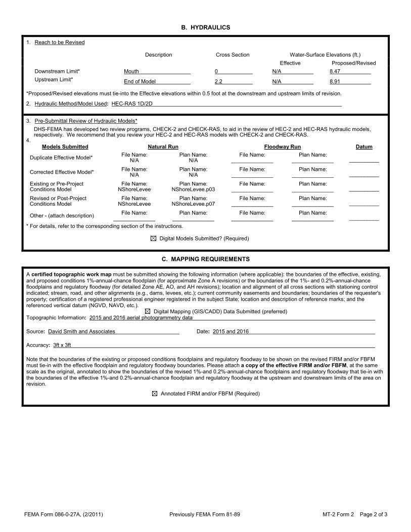
B. HYDRAULICS
1. Reach to be Revised
Description Cross Section Water-Surface Elevations (ft.)
Effective Proposed/Revised
Downstream Limit* Mouth 0 N/A 8.47
Upstream Limit* End of Model 2.2 N/A 8.91
*Proposed/Revised elevations must tie-into the Effective elevations within 0.5 foot at the downstream and upstream limits of revision.
2. Hydraulic Method/Model Used: HEC-RAS 1D/2D
3. Pre-Submittal Review of Hydraulic Models*
DHS-FEMA has developed two review programs, CHECK-2 and CHECK-RAS, to aid in the review of HEC-2 and HEC-RAS hydraulic models, respectively. We recommend that you review your HEC-2 and HEC-RAS models with CHECK-2 and CHECK-RAS.
4.
Models Submitted Natural Run Floodway Run Datum
Duplicate Effective Model* File Name:
N/A Plan Name:
N/A File Name:
______________ Plan Name:
______________ __________
Corrected Effective Model* File Name:
N/A Plan Name:
N/A File Name:
______________ Plan Name:
______________ __________
Existing or Pre-Project Conditions Model
File Name: NShoreLevee
Plan Name: NShoreLevee.p03
File Name: ______________
Plan Name: ______________ __________
Revised or Post-Project Conditions Model
File Name: NShoreLevee
Plan Name: NShoreLevee.p07
File Name: ______________
Plan Name: ______________ __________
Other - (attach description) File Name:
______________ Plan Name:
______________ File Name:
______________ Plan Name:
______________ __________
* For details, refer to the corresponding section of the instructions. Digital Models Submitted? (Required)
C. MAPPING REQUIREMENTS
A certified topographic work map must be submitted showing the following information (where applicable): the boundaries of the effective, existing, and proposed conditions 1%-annual-chance floodplain (for approximate Zone A revisions) or the boundaries of the 1%- and 0.2%-annual-chance floodplains and regulatory floodway (for detailed Zone AE, AO, and AH revisions); location and alignment of all cross sections with stationing control indicated; stream, road, and other alignments (e.g., dams, levees, etc.); current community easements and boundaries; boundaries of the requester's property; certification of a registered professional engineer registered in the subject State; location and description of reference marks; and the referenced vertical datum (NGVD, NAVD, etc.). Digital Mapping (GIS/CADD) Data Submitted (preferred) Topographic Information: 2015 and 2016 aerial photogrammetry data
Source: David Smith and Associates Date: 2015 and 2016
Accuracy: 3ft x 3ft
Note that the boundaries of the existing or proposed conditions floodplains and regulatory floodway to be shown on the revised FIRM and/or FBFM must tie-in with the effective floodplain and regulatory floodway boundaries. Please attach a copy of the effective FIRM and/or FBFM, at the same scale as the original, annotated to show the boundaries of the revised 1%-and 0.2%-annual-chance floodplains and regulatory floodway that tie-in with the boundaries of the effective 1%-and 0.2%-annual-chance floodplain and regulatory floodway at the upstream and downstream limits of the area on revision.
Annotated FIRM and/or FBFM (Required)


FEMA Form 086-0-27A, (2/2011) Previously FEMA Form 81-89 MT-2 Form 2 Page 3 of 3
D. COMMON REGULATORY REQUIREMENTS*
1. For LOMR/CLOMR requests, do Base Flood Elevations (BFEs) increase? Yes No
a. For CLOMR requests, if either of the following is true, please submit evidence of compliance with Section 65.12 of the NFIP regulations:
• The proposed project encroaches upon a regulatory floodway and would result in increases above 0.00 foot compared to pre-project conditions.
• The proposed project encroaches upon a SFHA with or without BFEs established and would result in increases above 1.00 foot compared to pre-project conditions.
b. Does this LOMR request cause increase in the BFE and/or SFHA compared with the effective BFEs and/or SFHA? Yes No
If Yes, please attach proof of property owner notification and acceptance (if available). Elements of and examples of property owner notifications can be found in the MT-2 Form 2 Instructions.
2. Does the request involve the placement or proposed placement of fill? Yes No
If Yes, the community must be able to certify that the area to be removed from the special flood hazard area, to include any structures or proposed structures, meets all of the standards of the local floodplain ordinances, and is reasonably safe from flooding in accordance with the NFIP regulations set forth at 44 CFR 60.3(A)(3), 65.5(a)(4), and 65.6(a)(14). Please see the MT-2 instructions for more information.
3. For LOMR requests, is the regulatory floodway being revised? Yes No
If Yes, attach evidence of regulatory floodway revision notification. As per Paragraph 65.7(b)(1) of the NFIP Regulations, notification is required for requests involving revisions to the regulatory floodway. (Not required for revisions to approximate 1%-annual-chance floodplains [studied Zone A designation] unless a regulatory floodway is being established. Elements and examples of regulatory floodway revision notification can be found in the MT-2 Form 2 Instructions.)
4. For CLOMR requests, please submit documentation to FEMA and the community to show that you have complied with Sections 9 and 10 of the Endangered Species Act (ESA).
For actions authorized, funded, or being carried out by Federal or State agencies, please submit documentation from the agency showing its compliance with Section 7(a)(2) of the ESA. Please see the MT-2 instructions for more detail.
* Not inclusive of all applicable regulatory requirements. For details, see 44 CFR parts 60 and 65.

FEMA Form 086-0-27A, (2/2011) Previously FEMA Form 81-89 MT-2 Form 2 Page 1 of 3
U.S. DEPARTMENT OF HOMELAND SECURITY FEDERAL EMERGENCY MANAGEMENT AGENCY
RIVERINE HYDROLOGY & HYDRAULICS FORM O.M.B No. 1660-0016
Expires February 28, 2014
PAPERWORK BURDEN DISCLOSURE NOTICE
Public reporting burden for this form is estimated to average 3.5 hours per response. The burden estimate includes the time for reviewing instructions, searching existing data sources, gathering and maintaining the needed data, and completing, reviewing, and submitting the form. You are not required to respond to this collection of information unless a valid OMB control number appears in the upper right corner of this form. Send comments regarding the accuracy of the burden estimate and any suggestions for reducing this burden to: Information Collections Management, Department of Homeland Security, Federal Emergency Management Agency, 1800 South Bell Street, Arlington VA 20958-3005, Paperwork Reduction Project (1660-0016). Submission of the form is required to obtain or retain benefits under the National Flood Insurance Program. Please do not send your completed survey to the above address.
PRIVACY ACT STATEMENT
AUTHORITY: The National Flood Insurance Act of 1968, Public Law 90-448, as amended by the Flood Disaster Protection Act of 1973, Public Law 93-234.
PRINCIPAL PURPOSE(S): This information is being collected for the purpose of determining an applicant's eligibility to request changes to National Flood Insurance Program (NFIP) Flood Insurance Rate Maps (FIRM).
ROUTINE USE(S): The information on this form may be disclosed as generally permitted under 5 U.S.C § 552a(b) of the Privacy Act of 1974, as amended. This includes using this information as necessary and authorized by the routine uses published in DHS/FEMA/NFIP/LOMA-1 National Flood Insurance Program (NFIP); Letter of Map Amendment (LOMA) February 15, 2006, 71 FR 7990.
DISCLOSURE: The disclosure of information on this form is voluntary; however, failure to provide the information requested may delay or prevent FEMA from processing a determination regarding a requested change to a NFIP Flood Insurance Rate Maps (FIRM).
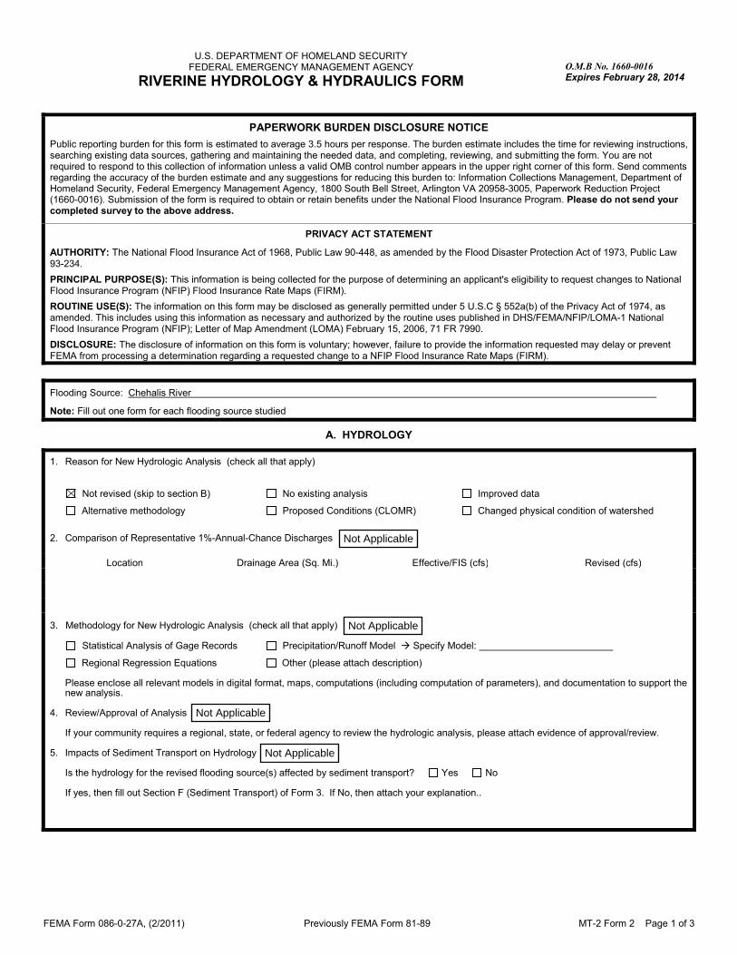
Flooding Source: Chehalis River
Note: Fill out one form for each flooding source studied
A. HYDROLOGY
1. Reason for New Hydrologic Analysis (check all that apply)
Not revised (skip to section B) No existing analysis Improved data
Alternative methodology Proposed Conditions (CLOMR) Changed physical condition of watershed
2. Comparison of Representative 1%-Annual-Chance Discharges
Location Drainage Area (Sq. Mi.) Effective/FIS (cfs) Revised (cfs)
3. Methodology for New Hydrologic Analysis (check all that apply)
Statistical Analysis of Gage Records Precipitation/Runoff Model � Specify Model:
Regional Regression Equations Other (please attach description)
Please enclose all relevant models in digital format, maps, computations (including computation of parameters), and documentation to support the new analysis.
4. Review/Approval of Analysis
If your community requires a regional, state, or federal agency to review the hydrologic analysis, please attach evidence of approval/review. 5. Impacts of Sediment Transport on Hydrology
Is the hydrology for the revised flooding source(s) affected by sediment transport? Yes No If yes, then fill out Section F (Sediment Transport) of Form 3. If No, then attach your explanation..
Not Applicable
Not Applicable
Not Applicable
Not Applicable

FEMA Form 086-0-27A, (2/2011) Previously FEMA Form 81-89 MT-2 Form 2 Page 2 of 3
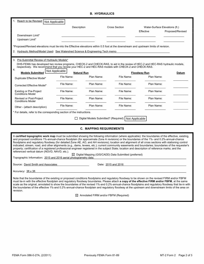
B. HYDRAULICS
1. Reach to be Revised
Description Cross Section Water-Surface Elevations (ft.)
Effective Proposed/Revised
Downstream Limit*
Upstream Limit*
*Proposed/Revised elevations must tie-into the Effective elevations within 0.5 foot at the downstream and upstream limits of revision.
2. Hydraulic Method/Model Used: See Watershed Science & Engineering Tech memo
3. Pre-Submittal Review of Hydraulic Models*
DHS-FEMA has developed two review programs, CHECK-2 and CHECK-RAS, to aid in the review of HEC-2 and HEC-RAS hydraulic models, respectively. We recommend that you review your HEC-2 and HEC-RAS models with CHECK-2 and CHECK-RAS.
4.
Models Submitted Natural Run Floodway Run Datum
Duplicate Effective Model* File Name:
______________ Plan Name:
______________ File Name:
______________ Plan Name:
______________ __________
Corrected Effective Model* File Name:
______________ Plan Name:
______________ File Name:
______________ Plan Name:
______________ __________
Existing or Pre-Project Conditions Model
File Name: ______________
Plan Name: ______________
File Name: ______________
Plan Name: ______________ __________
Revised or Post-Project Conditions Model
File Name: ______________
Plan Name: ______________
File Name: ______________
Plan Name: ______________ __________
Other - (attach description) File Name:
______________ Plan Name:
______________ File Name:
______________ Plan Name:
______________ __________
* For details, refer to the corresponding section of the instructions. Digital Models Submitted? (Required)
C. MAPPING REQUIREMENTS
A certified topographic work map must be submitted showing the following information (where applicable): the boundaries of the effective, existing, and proposed conditions 1%-annual-chance floodplain (for approximate Zone A revisions) or the boundaries of the 1%- and 0.2%-annual-chance floodplains and regulatory floodway (for detailed Zone AE, AO, and AH revisions); location and alignment of all cross sections with stationing control indicated; stream, road, and other alignments (e.g., dams, levees, etc.); current community easements and boundaries; boundaries of the requester's property; certification of a registered professional engineer registered in the subject State; location and description of reference marks; and the referenced vertical datum (NGVD, NAVD, etc.). Digital Mapping (GIS/CADD) Data Submitted (preferred) Topographic Information: 2015 and 2016 aerial photogrametry data.
Source: David Smith and Associates Date: 2015 and 2016
Accuracy: 3ft x 3ft
Note that the boundaries of the existing or proposed conditions floodplains and regulatory floodway to be shown on the revised FIRM and/or FBFM must tie-in with the effective floodplain and regulatory floodway boundaries. Please attach a copy of the effective FIRM and/or FBFM, at the same scale as the original, annotated to show the boundaries of the revised 1%-and 0.2%-annual-chance floodplains and regulatory floodway that tie-in with the boundaries of the effective 1%-and 0.2%-annual-chance floodplain and regulatory floodway at the upstream and downstream limits of the area on revision.
Annotated FIRM and/or FBFM (Required)
Not Applicable
Not Applicable
Not Applicable

FEMA Form 086-0-27A, (2/2011) Previously FEMA Form 81-89 MT-2 Form 2 Page 3 of 3
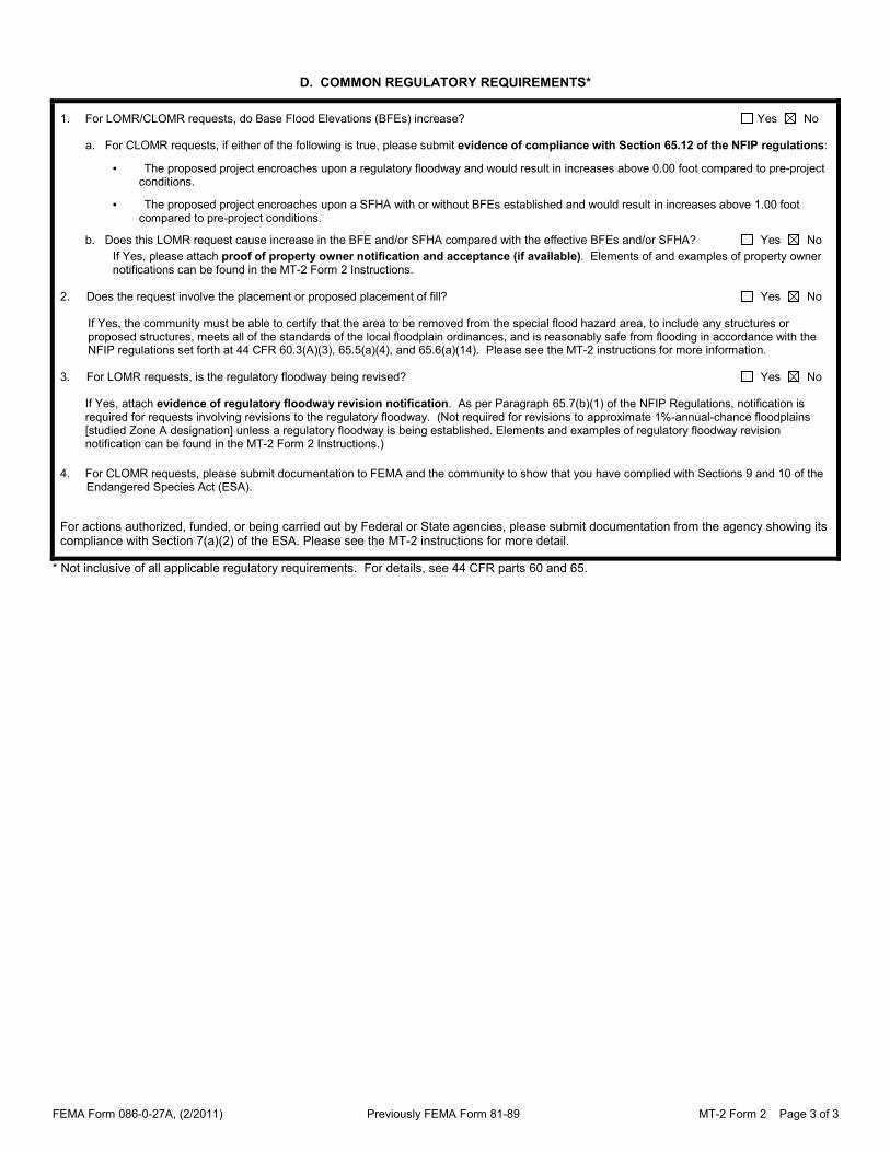
D. COMMON REGULATORY REQUIREMENTS*
1. For LOMR/CLOMR requests, do Base Flood Elevations (BFEs) increase? Yes No
a. For CLOMR requests, if either of the following is true, please submit evidence of compliance with Section 65.12 of the NFIP regulations:
• The proposed project encroaches upon a regulatory floodway and would result in increases above 0.00 foot compared to pre-project conditions.
• The proposed project encroaches upon a SFHA with or without BFEs established and would result in increases above 1.00 foot compared to pre-project conditions.
b. Does this LOMR request cause increase in the BFE and/or SFHA compared with the effective BFEs and/or SFHA? Yes No
If Yes, please attach proof of property owner notification and acceptance (if available). Elements of and examples of property owner notifications can be found in the MT-2 Form 2 Instructions.
2. Does the request involve the placement or proposed placement of fill? Yes No
If Yes, the community must be able to certify that the area to be removed from the special flood hazard area, to include any structures or proposed structures, meets all of the standards of the local floodplain ordinances, and is reasonably safe from flooding in accordance with the NFIP regulations set forth at 44 CFR 60.3(A)(3), 65.5(a)(4), and 65.6(a)(14). Please see the MT-2 instructions for more information.
3. For LOMR requests, is the regulatory floodway being revised? Yes No
If Yes, attach evidence of regulatory floodway revision notification. As per Paragraph 65.7(b)(1) of the NFIP Regulations, notification is required for requests involving revisions to the regulatory floodway. (Not required for revisions to approximate 1%-annual-chance floodplains [studied Zone A designation] unless a regulatory floodway is being established. Elements and examples of regulatory floodway revision notification can be found in the MT-2 Form 2 Instructions.)
4. For CLOMR requests, please submit documentation to FEMA and the community to show that you have complied with Sections 9 and 10 of the Endangered Species Act (ESA).
For actions authorized, funded, or being carried out by Federal or State agencies, please submit documentation from the agency showing its compliance with Section 7(a)(2) of the ESA. Please see the MT-2 instructions for more detail.
* Not inclusive of all applicable regulatory requirements. For details, see 44 CFR parts 60 and 65.

FEMA Form 086-0-27A, (2/2011) Previously FEMA Form 81-89 MT-2 Form 2 Page 1 of 3
U.S. DEPARTMENT OF HOMELAND SECURITY FEDERAL EMERGENCY MANAGEMENT AGENCY
RIVERINE HYDROLOGY & HYDRAULICS FORM O.M.B No. 1660-0016
Expires February 28, 2014
PAPERWORK BURDEN DISCLOSURE NOTICE
Public reporting burden for this form is estimated to average 3.5 hours per response. The burden estimate includes the time for reviewing instructions, searching existing data sources, gathering and maintaining the needed data, and completing, reviewing, and submitting the form. You are not required to respond to this collection of information unless a valid OMB control number appears in the upper right corner of this form. Send comments regarding the accuracy of the burden estimate and any suggestions for reducing this burden to: Information Collections Management, Department of Homeland Security, Federal Emergency Management Agency, 1800 South Bell Street, Arlington VA 20958-3005, Paperwork Reduction Project (1660-0016). Submission of the form is required to obtain or retain benefits under the National Flood Insurance Program. Please do not send your completed survey to the above address.
PRIVACY ACT STATEMENT
AUTHORITY: The National Flood Insurance Act of 1968, Public Law 90-448, as amended by the Flood Disaster Protection Act of 1973, Public Law 93-234.
PRINCIPAL PURPOSE(S): This information is being collected for the purpose of determining an applicant's eligibility to request changes to National Flood Insurance Program (NFIP) Flood Insurance Rate Maps (FIRM).
ROUTINE USE(S): The information on this form may be disclosed as generally permitted under 5 U.S.C § 552a(b) of the Privacy Act of 1974, as amended. This includes using this information as necessary and authorized by the routine uses published in DHS/FEMA/NFIP/LOMA-1 National Flood Insurance Program (NFIP); Letter of Map Amendment (LOMA) February 15, 2006, 71 FR 7990.
DISCLOSURE: The disclosure of information on this form is voluntary; however, failure to provide the information requested may delay or prevent FEMA from processing a determination regarding a requested change to a NFIP Flood Insurance Rate Maps (FIRM).
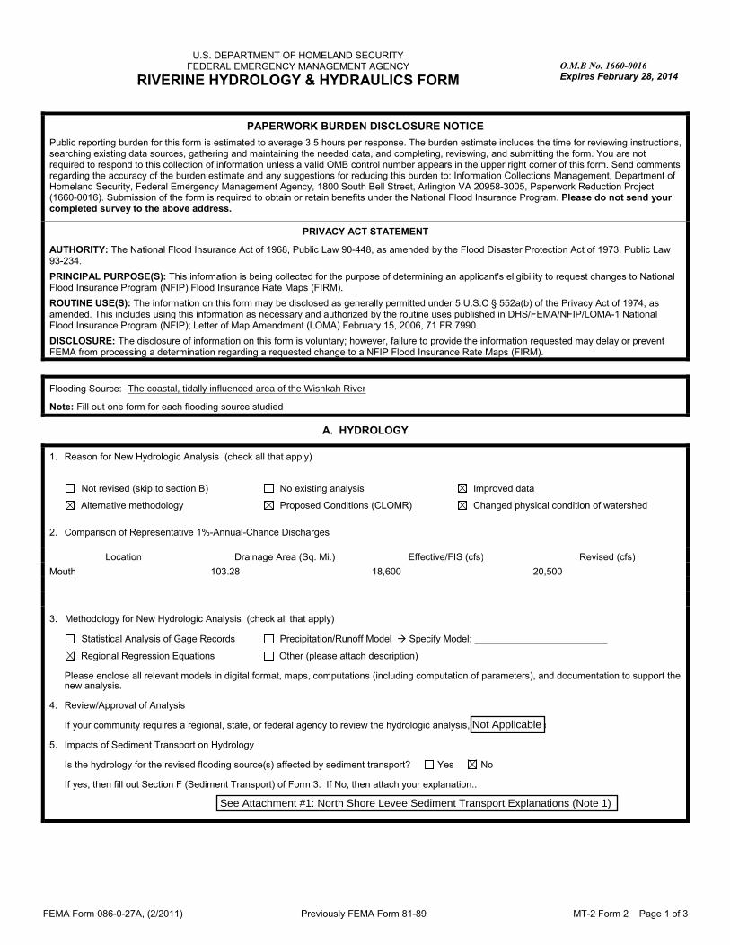
Flooding Source: Wishkah River
Note: Fill out one form for each flooding source studied
A. HYDROLOGY
1. Reason for New Hydrologic Analysis (check all that apply)
Not revised (skip to section B) No existing analysis Improved data
Alternative methodology Proposed Conditions (CLOMR) Changed physical condition of watershed
2. Comparison of Representative 1%-Annual-Chance Discharges
Location Drainage Area (Sq. Mi.) Effective/FIS (cfs) Revised (cfs)
Mouth 103.28 18,600 20,500
3. Methodology for New Hydrologic Analysis (check all that apply)
Statistical Analysis of Gage Records Precipitation/Runoff Model � Specify Model:
Regional Regression Equations Other (please attach description)
Please enclose all relevant models in digital format, maps, computations (including computation of parameters), and documentation to support the new analysis.
4. Review/Approval of Analysis
If your community requires a regional, state, or federal agency to review the hydrologic analysis, please attach evidence of approval/review. 5. Impacts of Sediment Transport on Hydrology
Is the hydrology for the revised flooding source(s) affected by sediment transport? Yes No If yes, then fill out Section F (Sediment Transport) of Form 3. If No, then attach your explanation..
See Attachment #1: North Shore Levee Sediment Transport Explanations (Note 1)
The coastal, tidally influenced area of the Wishkah River
Not Applicable

FEMA Form 086-0-27A, (2/2011) Previously FEMA Form 81-89 MT-2 Form 2 Page 2 of 3
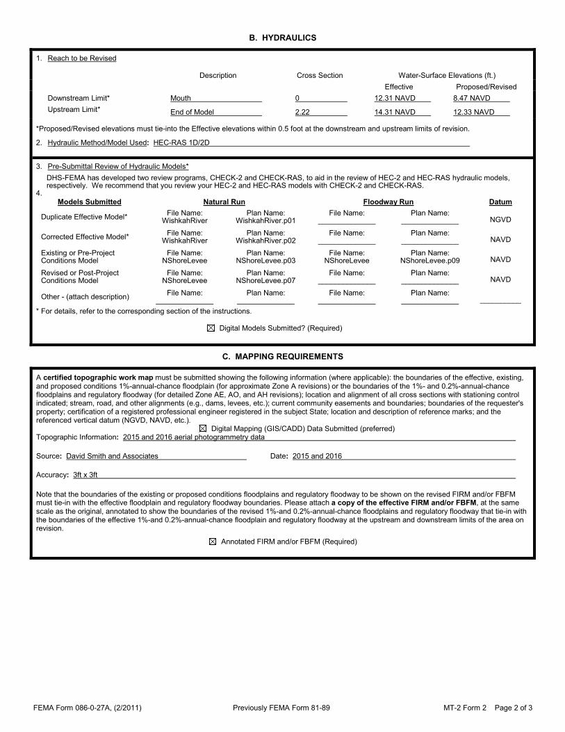
B. HYDRAULICS
1. Reach to be Revised
Description Cross Section Water-Surface Elevations (ft.)
Effective Proposed/Revised
Downstream Limit* Mouth 0 12.31 NAVD 8.47 NAVD
Upstream Limit* End of Model 2.22 14.31 NAVD 12.33 NAVD
*Proposed/Revised elevations must tie-into the Effective elevations within 0.5 foot at the downstream and upstream limits of revision.
2. Hydraulic Method/Model Used: HEC-RAS 1D/2D
3. Pre-Submittal Review of Hydraulic Models*
DHS-FEMA has developed two review programs, CHECK-2 and CHECK-RAS, to aid in the review of HEC-2 and HEC-RAS hydraulic models, respectively. We recommend that you review your HEC-2 and HEC-RAS models with CHECK-2 and CHECK-RAS.
4.
Models Submitted Natural Run Floodway Run Datum
Duplicate Effective Model* File Name:
WishkahRiver Plan Name:
WishkahRiver.p01 File Name:
______________ Plan Name:
______________ NGVD
Corrected Effective Model* File Name:
WishkahRiver Plan Name:
WishkahRiver.p02 File Name:
______________ Plan Name:
______________ NAVD
Existing or Pre-Project Conditions Model
File Name: NShoreLevee
Plan Name: NShoreLevee.p03
File Name: NShoreLevee
Plan Name: NShoreLevee.p09 NAVD
Revised or Post-Project Conditions Model
File Name: NShoreLevee
Plan Name: NShoreLevee.p07
File Name: ______________
Plan Name: ______________ NAVD
Other - (attach description) File Name:
______________ Plan Name:
______________ File Name:
______________ Plan Name:
______________ __________
* For details, refer to the corresponding section of the instructions. Digital Models Submitted? (Required)
C. MAPPING REQUIREMENTS
A certified topographic work map must be submitted showing the following information (where applicable): the boundaries of the effective, existing, and proposed conditions 1%-annual-chance floodplain (for approximate Zone A revisions) or the boundaries of the 1%- and 0.2%-annual-chance floodplains and regulatory floodway (for detailed Zone AE, AO, and AH revisions); location and alignment of all cross sections with stationing control indicated; stream, road, and other alignments (e.g., dams, levees, etc.); current community easements and boundaries; boundaries of the requester's property; certification of a registered professional engineer registered in the subject State; location and description of reference marks; and the referenced vertical datum (NGVD, NAVD, etc.). Digital Mapping (GIS/CADD) Data Submitted (preferred) Topographic Information: 2015 and 2016 aerial photogrammetry data
Source: David Smith and Associates Date: 2015 and 2016
Accuracy: 3ft x 3ft
Note that the boundaries of the existing or proposed conditions floodplains and regulatory floodway to be shown on the revised FIRM and/or FBFM must tie-in with the effective floodplain and regulatory floodway boundaries. Please attach a copy of the effective FIRM and/or FBFM, at the same scale as the original, annotated to show the boundaries of the revised 1%-and 0.2%-annual-chance floodplains and regulatory floodway that tie-in with the boundaries of the effective 1%-and 0.2%-annual-chance floodplain and regulatory floodway at the upstream and downstream limits of the area on revision.
Annotated FIRM and/or FBFM (Required)


FEMA Form 086-0-27A, (2/2011) Previously FEMA Form 81-89 MT-2 Form 2 Page 3 of 3
D. COMMON REGULATORY REQUIREMENTS*
1. For LOMR/CLOMR requests, do Base Flood Elevations (BFEs) increase? Yes No
a. For CLOMR requests, if either of the following is true, please submit evidence of compliance with Section 65.12 of the NFIP regulations:
• The proposed project encroaches upon a regulatory floodway and would result in increases above 0.00 foot compared to pre-project conditions.
• The proposed project encroaches upon a SFHA with or without BFEs established and would result in increases above 1.00 foot compared to pre-project conditions.
b. Does this LOMR request cause increase in the BFE and/or SFHA compared with the effective BFEs and/or SFHA? Yes No
If Yes, please attach proof of property owner notification and acceptance (if available). Elements of and examples of property owner notifications can be found in the MT-2 Form 2 Instructions.
2. Does the request involve the placement or proposed placement of fill? Yes No
If Yes, the community must be able to certify that the area to be removed from the special flood hazard area, to include any structures or proposed structures, meets all of the standards of the local floodplain ordinances, and is reasonably safe from flooding in accordance with the NFIP regulations set forth at 44 CFR 60.3(A)(3), 65.5(a)(4), and 65.6(a)(14). Please see the MT-2 instructions for more information.
3. For LOMR requests, is the regulatory floodway being revised? Yes No
If Yes, attach evidence of regulatory floodway revision notification. As per Paragraph 65.7(b)(1) of the NFIP Regulations, notification is required for requests involving revisions to the regulatory floodway. (Not required for revisions to approximate 1%-annual-chance floodplains [studied Zone A designation] unless a regulatory floodway is being established. Elements and examples of regulatory floodway revision notification can be found in the MT-2 Form 2 Instructions.)
4. For CLOMR requests, please submit documentation to FEMA and the community to show that you have complied with Sections 9 and 10 of the Endangered Species Act (ESA).
For actions authorized, funded, or being carried out by Federal or State agencies, please submit documentation from the agency showing its compliance with Section 7(a)(2) of the ESA. Please see the MT-2 instructions for more detail.
* Not inclusive of all applicable regulatory requirements. For details, see 44 CFR parts 60 and 65.

FORM 3
Riverine Structures Form

FEMA Form 086-0-27B, (2/2011) Previously FEMA Form 81-89B MT-2 Form 3 Page 1 of 12
DEPARTMENT OF HOMELAND SECURITY FEDERAL EMERGENCY MANAGEMENT AGENCY
RIVERINE STRUCTURES FORM
O.M.B. NO. 1660-0016 Expires February 28, 2014
PAPERWORK BURDEN DISCLOSURE NOTICE Public reporting burden for this form is estimated to average 7 hours per response. The burden estimate includes the time for reviewing instructions, searching existing data sources, gathering and maintaining the needed data, and completing, reviewing, and submitting the form. You are not required to respond to this collection of information unless a valid OMB control number appears in the upper right corner of this form. Send comments regarding the accuracy of the burden estimate and any suggestions for reducing this burden to: Information Collections Management, Department of Homeland Security, Federal Emergency Management Agency, 1800 South Bell Street, Arlington, VA 20598-3005, Paperwork Reduction Project (1660-0016). Submission of the form is required to obtain or retain benefits under the National Flood Insurance Program. Please do not send your completed survey to the above address.
PRIVACY ACT STATEMENT
AUTHORITY: The National Flood Insurance Act of 1968, Public Law 90-448, as amended by the Flood Disaster Protection Act of 1973, Public Law 93-234.
PRINCIPAL PURPOSE(S): This information is being collected for the purpose of determining an applicant's eligibility to request changes to National Flood Insurance Program (NFIP) Flood Insurance Rate Maps (FIRM).
ROUTINE USE(S): The information on this form may be disclosed as generally permitted under 5 U.S.C § 552a(b) of the Privacy Act of 1974, as amended. This includes using this information as necessary and authorized by the routine uses published in DHS/FEMA/NFIP/LOMA-1 National Flood Insurance Program; Letter of Map Amendment (LOMA) February 15, 2006, 71 FR 7990.
DISCLOSURE: The disclosure of information on this form is voluntary; however, failure to provide the information requested may delay or prevent FEMA from processing a determination regarding a requested change to a NFIP Flood Insurance Rate Maps (FIRM).
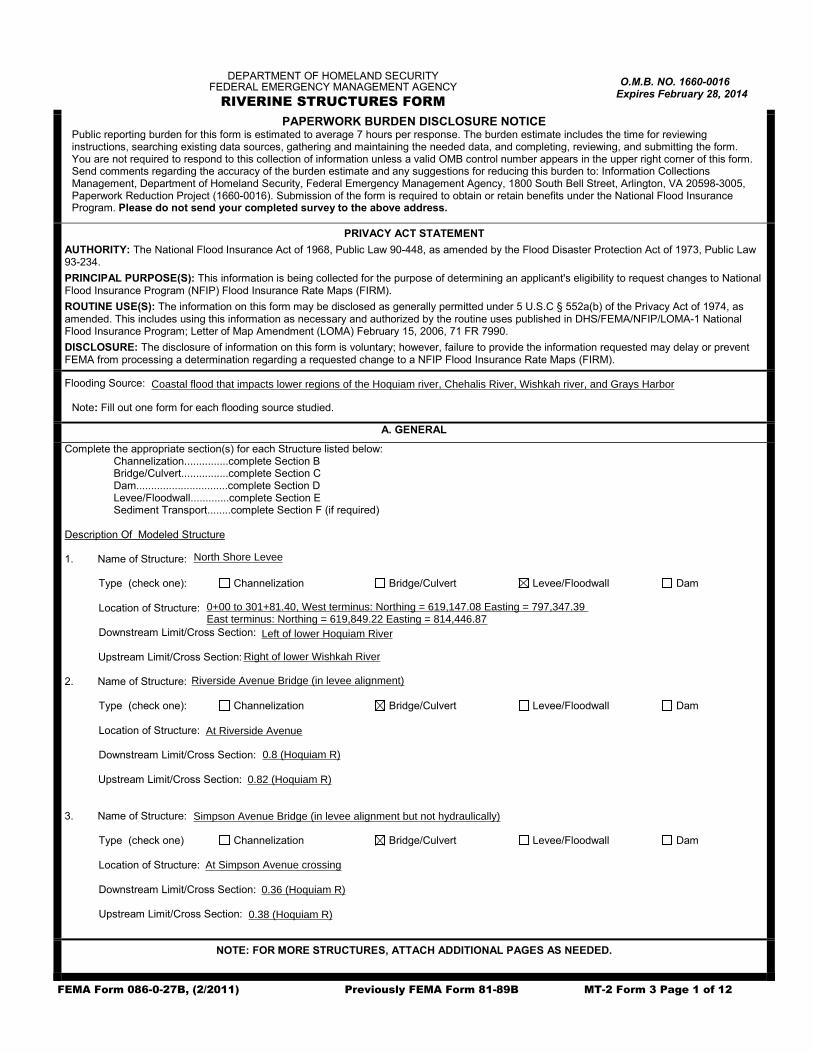
Flooding Source: Grays Harbor, Wishkah River, Hoquiam River, Chehalis River
Note: Fill out one form for each flooding source studied.
A. GENERAL
Complete the appropriate section(s) for each Structure listed below: Channelization...............complete Section B Bridge/Culvert................complete Section C Dam...............................complete Section D Levee/Floodwall.............complete Section E Sediment Transport........complete Section F (if required)
Description Of Modeled Structure 1. Name of Structure:
Type (check one): Channelization Bridge/Culvert Levee/Floodwall Dam Location of Structure: Downstream Limit/Cross Section: Upstream Limit/Cross Section:
2. Name of Structure: Young Street Bridge Type (check one): Channelization Bridge/Culvert Levee/Floodwall Dam Location of Structure: At Young Street Downstream Limit/Cross Section: 1.01 (Wishkah R) Upstream Limit/Cross Section: 1.03 (Wishkah R)
3. Name of Structure: US Highway 12 West Bridge
Type (check one) Channelization Bridge/Culvert Levee/Floodwall Dam Location of Structure: At East Wishkah Street Downstream Limit/Cross Section: 0.26 (Wishkah R) Upstream Limit/Cross Section: 0.27 (Wishkah R)
NOTE: FOR MORE STRUCTURES, ATTACH ADDITIONAL PAGES AS NEEDED.
0+00 to 301+81.40, West terminus: Northing = 619,147.08 Easting = 797,347.39 East terminus: Northing = 619,849.22 Easting = 814,446.87
Coastal flood that impacts lower regions of the Hoquiam river, Chehalis River, Wishkah river, and Grays Harbor
Riverside Avenue Bridge (in levee alignment)
At Riverside Avenue
0.8 (Hoquiam R)
0.82 (Hoquiam R)
Simpson Avenue Bridge (in levee alignment but not hydraulically)
At Simpson Avenue crossing
0.36 (Hoquiam R)
0.38 (Hoquiam R)
North Shore Levee
Left of lower Hoquiam River
Right of lower Wishkah River

FEMA Form 086-0-27B, (2/2011) Previously FEMA Form 81-89B MT-2 Form 3 Page 2 of 12
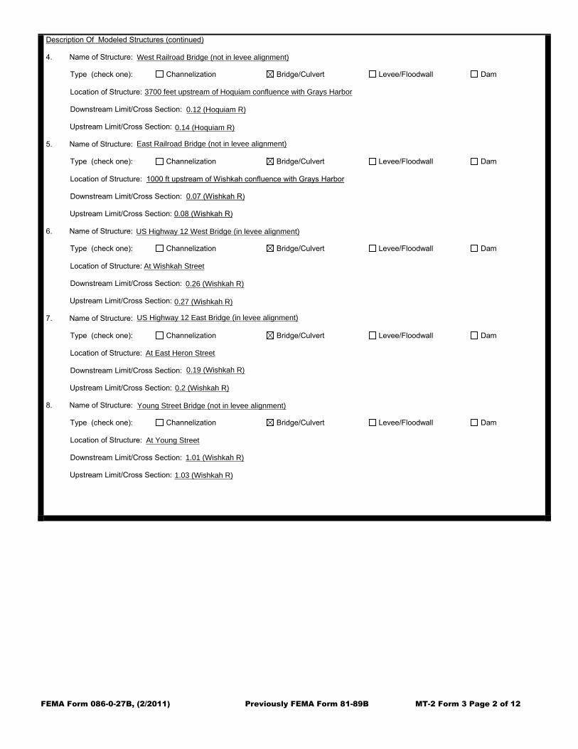
Description Of Modeled Structures (continued) 4. Name of Structure: US Highway 12 East Bridge
Type (check one): Channelization Bridge/Culvert Levee/Floodwall Dam Location of Structure: At East Heron Street Downstream Limit/Cross Section: 0.19 (Wishkah R) Upstream Limit/Cross Section: 0.2 (Wishkah R)
5. Name of Structure: Railroad Bridge Type (check one): Channelization Bridge/Culvert Levee/Floodwall Dam Location of Structure: 1000 ft upstream of Wishkah confluence with Grays Harbor Downstream Limit/Cross Section: 0.07 (Wishkah R) Upstream Limit/Cross Section: 0.08 (Wishkah R)
6. Name of Structure: 6
th Street Bridge
Type (check one): Channelization Bridge/Culvert Levee/Floodwall Dam Location of Structure: At Riverside Avenue Downstream Limit/Cross Section: 0.8 (Hoquiam R) Upstream Limit/Cross Section: 0.82 (Hoquiam R)
7. Name of Structure: Simpson Avenue Bridge Type (check one): Channelization Bridge/Culvert Levee/Floodwall Dam Location of Structure: At Simpson Avenue crossing Downstream Limit/Cross Section: 0.36 (Hoquiam R) Upstream Limit/Cross Section: 0.38 (Hoquiam R)
8. Name of Structure: Railroad Bridge Type (check one): Channelization Bridge/Culvert Levee/Floodwall Dam Location of Structure: 3700 feet upstream of Hoquiam confluence with Grays Harbor Downstream Limit/Cross Section: 0.12 (Hoquiam R) Upstream Limit/Cross Section: 0.14 (Hoquiam R)
Riverside Avenue Bridge
West Railroad Bridge (not in levee alignment)
3700 feet upstream of Hoquiam confluence with Grays Harbor
0.12 (Hoquiam R)
0.14 (Hoquiam R)
US Highway 12 West Bridge (in levee alignment)
At Wishkah Street
0.26 (Wishkah R)
0.27 (Wishkah R)
US Highway 12 East Bridge (in levee alignment)
At East Heron Street
0.19 (Wishkah R)
0.2 (Wishkah R)
1.01 (Wishkah R)
1.03 (Wishkah R)
At Young Street
Young Street Bridge (not in levee alignment)
East Railroad Bridge (not in levee alignment)

FEMA Form 086-0-27B, (2/2011) Previously FEMA Form 81-89B MT-2 Form 3 Page 3 of 12
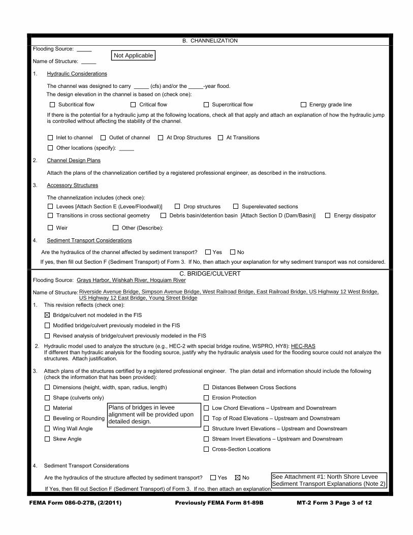
B. CHANNELIZATION
Flooding Source: Name of Structure: 1. Hydraulic Considerations The channel was designed to carry (cfs) and/or the -year flood.
The design elevation in the channel is based on (check one):
Subcritical flow Critical flow Supercritical flow Energy grade line
If there is the potential for a hydraulic jump at the following locations, check all that apply and attach an explanation of how the hydraulic jump is controlled without affecting the stability of the channel.
Inlet to channel Outlet of channel At Drop Structures At Transitions
Other locations (specify): 2. Channel Design Plans Attach the plans of the channelization certified by a registered professional engineer, as described in the instructions. 3. Accessory Structures
The channelization includes (check one):
Levees [Attach Section E (Levee/Floodwall)] Drop structures Superelevated sections
Transitions in cross sectional geometry Debris basin/detention basin [Attach Section D (Dam/Basin)] Energy dissipator
Weir Other (Describe):
4. Sediment Transport Considerations
Are the hydraulics of the channel affected by sediment transport? Yes No
If yes, then fill out Section F (Sediment Transport) of Form 3. If No, then attach your explanation for why sediment transport was not considered.
C. BRIDGE/CULVERT Flooding Source: Grays Harbor, Wishkah River, Hoquiam River Name of Structure: Young St, US HWY 12 West, US HWY 12 East, Railroad (Wishkah), 6
th St, Simpson Ave, and Railroad (Hoquiam) Bridges
1. This revision reflects (check one):
Bridge/culvert not modeled in the FIS
Modified bridge/culvert previously modeled in the FIS
Revised analysis of bridge/culvert previously modeled in the FIS
2. Hydraulic model used to analyze the structure (e.g., HEC-2 with special bridge routine, WSPRO, HY8): HEC-RAS If different than hydraulic analysis for the flooding source, justify why the hydraulic analysis used for the flooding source could not analyze the structures. Attach justification.
3. Attach plans of the structures certified by a registered professional engineer. The plan detail and information should include the following
(check the information that has been provided):
Dimensions (height, width, span, radius, length) Distances Between Cross Sections
Shape (culverts only) Erosion Protection
Material Low Chord Elevations – Upstream and Downstream
Beveling or Rounding Top of Road Elevations – Upstream and Downstream
Wing Wall Angle Structure Invert Elevations – Upstream and Downstream
Skew Angle Stream Invert Elevations – Upstream and Downstream
Cross-Section Locations
4. Sediment Transport Considerations
Are the hydraulics of the structure affected by sediment transport? Yes No If Yes, then fill out Section F (Sediment Transport) of Form 3. If no, then attach an explanation.
See Attachment #1: North Shore LeveeSediment Transport Explanations (Note 2)
Not Applicable
Riverside Avenue Bridge, Simpson Avenue Bridge, West Railroad Bridge, East Railroad Bridge, US Highway 12 West Bridge,US Highway 12 East Bridge, Young Street Bridge
Plans of bridges in leveealignment will be provided upondetailed design.

FEMA Form 086-0-27B, (2/2011) Previously FEMA Form 81-89B MT-2 Form 3 Page 3 of 11
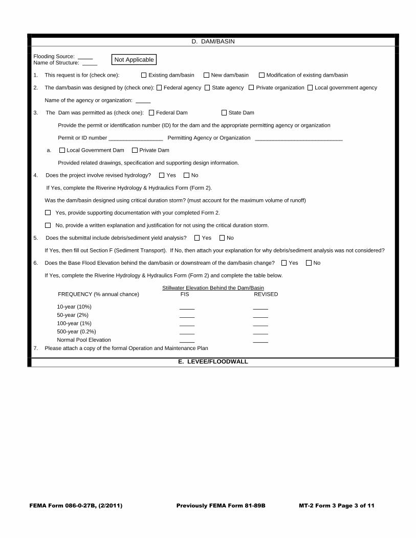
D. DAM/BASIN
Flooding Source: Name of Structure: 1. This request is for (check one): Existing dam/basin New dam/basin Modification of existing dam/basin 2. The dam/basin was designed by (check one): Federal agency State agency Private organization Local government agency Name of the agency or organization: 3. The Dam was permitted as (check one): Federal Dam State Dam
Provide the permit or identification number (ID) for the dam and the appropriate permitting agency or organization Permit or ID number __________________ Permitting Agency or Organization _____________________________
a. Local Government Dam Private Dam
Provided related drawings, specification and supporting design information.
4. Does the project involve revised hydrology? Yes No If Yes, complete the Riverine Hydrology & Hydraulics Form (Form 2).
Was the dam/basin designed using critical duration storm? (must account for the maximum volume of runoff)
Yes, provide supporting documentation with your completed Form 2.
No, provide a written explanation and justification for not using the critical duration storm.
5. Does the submittal include debris/sediment yield analysis? Yes No If Yes, then fill out Section F (Sediment Transport). If No, then attach your explanation for why debris/sediment analysis was not considered? 6. Does the Base Flood Elevation behind the dam/basin or downstream of the dam/basin change? Yes No If Yes, complete the Riverine Hydrology & Hydraulics Form (Form 2) and complete the table below.
Stillwater Elevation Behind the Dam/Basin FREQUENCY (% annual chance) FIS REVISED
10-year (10%)
50-year (2%)
100-year (1%)
500-year (0.2%)
Normal Pool Elevation
7. Please attach a copy of the formal Operation and Maintenance Plan
E. LEVEE/FLOODWALL
Not Applicable

FEMA Form 086-0-27B, (2/2011) Previously FEMA Form 81-89B MT-2 Form 3 Page 4 of 11
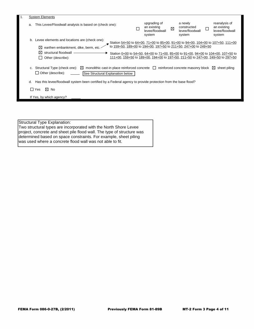
1. System Elements a. This Levee/Floodwall analysis is based on (check one):
b. Levee elements and locations are (check one): earthen embankment, dike, berm, etc. Station to
structural floodwall Station to
Other (describe): Station to
c. Structural Type (check one): monolithic cast-in place reinforced concrete reinforced concrete masonry block sheet piling
Other (describe):
d. Has this levee/floodwall system been certified by a Federal agency to provide protection from the base flood? Yes No If Yes, by which agency?
upgrading of an existing levee/floodwall system
a newly constructed levee/floodwall system
reanalysis of an existing levee/floodwall system
Station 0+00 to 54+50, 64+00 to 71+00, 85+00 to 91+00, 94+00 to 104+00, 107+50 to111+00, 159+50 to 189+00, 194+00 to 197+50, 211+50 to 247+00, 249+50 to 297+50
Station 54+50 to 64+00, 71+00 to 85+00, 91+00 to 94+00, 104+00 to 107+50, 111+00to 159+50, 189+00 to 194+00, 197+50 to 211+50, 247+00 to 249+50
Structural Type Explanation:Two structural types are incorporated with the North Shore Leveeproject, concrete and sheet pile flood wall. The type of structure wasdetermined based on space constraints. For example, sheet pilingwas used where a concrete flood wall was not able to fit.
See Structural Explanation below

FEMA Form 086-0-27B, (2/2011) Previously FEMA Form 81-89B MT-2 Form 3 Page 5 of 11
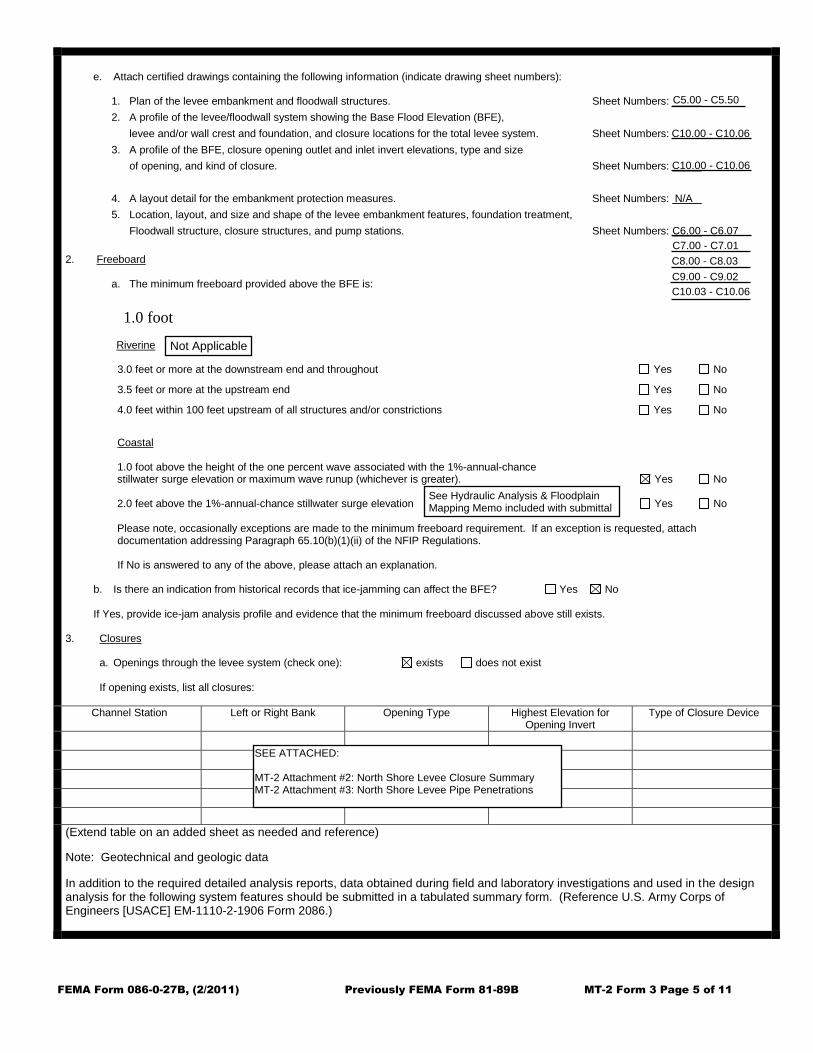
e. Attach certified drawings containing the following information (indicate drawing sheet numbers):
1. Plan of the levee embankment and floodwall structures. Sheet Numbers:
2. A profile of the levee/floodwall system showing the Base Flood Elevation (BFE),
levee and/or wall crest and foundation, and closure locations for the total levee system. Sheet Numbers:
3. A profile of the BFE, closure opening outlet and inlet invert elevations, type and size
of opening, and kind of closure. Sheet Numbers:
4. A layout detail for the embankment protection measures. Sheet Numbers:
5. Location, layout, and size and shape of the levee embankment features, foundation treatment,
Floodwall structure, closure structures, and pump stations. Sheet Numbers:
2. Freeboard
a. The minimum freeboard provided above the BFE is:
1.0 foot Riverine
3.0 feet or more at the downstream end and throughout Yes No
3.5 feet or more at the upstream end Yes No
4.0 feet within 100 feet upstream of all structures and/or constrictions Yes No
Coastal 1.0 foot above the height of the one percent wave associated with the 1%-annual-chance stillwater surge elevation or maximum wave runup (whichever is greater). Yes No 2.0 feet above the 1%-annual-chance stillwater surge elevation Yes No Please note, occasionally exceptions are made to the minimum freeboard requirement. If an exception is requested, attach documentation addressing Paragraph 65.10(b)(1)(ii) of the NFIP Regulations. If No is answered to any of the above, please attach an explanation.
b. Is there an indication from historical records that ice-jamming can affect the BFE? Yes No If Yes, provide ice-jam analysis profile and evidence that the minimum freeboard discussed above still exists.
3. Closures
a. Openings through the levee system (check one): exists does not exist
If opening exists, list all closures:
Channel Station Left or Right Bank Opening Type Highest Elevation for Opening Invert
Type of Closure Device
(Extend table on an added sheet as needed and reference) Note: Geotechnical and geologic data In addition to the required detailed analysis reports, data obtained during field and laboratory investigations and used in the design analysis for the following system features should be submitted in a tabulated summary form. (Reference U.S. Army Corps of Engineers [USACE] EM-1110-2-1906 Form 2086.)
Not Applicable
See Hydraulic Analysis & FloodplainMapping Memo included with submittal
SEE ATTACHED:
MT-2 Attachment #2: North Shore Levee Closure SummaryMT-2 Attachment #3: North Shore Levee Pipe Penetrations
C5.00 C5.50
C10.00 C10.06
C10.00 C10.06
N/A
C6.00 C6.07C7.00 C7.01C8.00 C8.03C9.00 C9.02C10.03 C10.06


FEMA Form 086-0-27B, (2/2011) Previously FEMA Form 81-89B MT-2 Form 3 Page 6 of 11
4. Embankment Protection
a. The maximum levee slope land side is: n/a
b. The maximum levee slope flood side is: n/a
c. The range of velocities along the levee during the base flood is: (min.) to (max.)
d. Embankment material is protected by (describe what kind):
e. Riprap Design Parameters (check one): Velocity Tractive stressAttach references
Stone RiprapReach Sideslope
Flow Depth Velocity
Curve or Straight D100 D50 Thickness
Depth of Toedown
Sta to
Sta to
Sta to
Sta to
Sta to
Sta to
(Extend table on an added sheet as needed and reference each entry)
f. Is a bedding/filter analysis and design attached? Yes No
g. Describe the analysis used for other kinds of protection used (include copies of the design analysis):
Attach engineering analysis to support construction plans.
5. Embankment And Foundation Stability
a. Identify locations and describe the basis for selection of critical location for analysis: 3+50; section of proposed sheetpile wall closest to the rivers edge
Overall height: Sta.: 3+50, height 3.2 ft.
Limiting foundation soil strength:
Strength = 0 degrees, c = 260 psf
Slope: SS = n/a (h) to n/a (v)
(Repeat as needed on an added sheet for additional locations)
b. Specify the embankment stability analysis methodology used (e.g., circular arc, sliding block, infinite slope, etc.):circular arc
c. Summary of stability analysis results: Meets all criteria applicable to this study ***(see Geotechnical Analysis Report for details)***.
Not Applicable
Not Applicable
Not Applicable
Not Applicable
NOTE: A copy of this page is included for each stretch analyzed.Some stretches were analyzed at multiple critical locations.Copy 1A: Structural floodwallSTATION 00+00 to 80+00
0 ft/s 1.3 ft/s
See Section 3.3 of the Geotechnical Report included with submittal package for stabilityanalysis results


FEMA Form 086-0-27B, (2/2011) Previously FEMA Form 81-89B MT-2 Form 3 Page 6 of 11
4. Embankment Protection
a. The maximum levee slope land side is: n/a
b. The maximum levee slope flood side is: n/a
c. The range of velocities along the levee during the base flood is: (min.) to (max.)
d. Embankment material is protected by (describe what kind):
e. Riprap Design Parameters (check one): Velocity Tractive stressAttach references
Stone RiprapReach Sideslope
Flow Depth Velocity
Curve or Straight D100 D50 Thickness
Depth of Toedown
Sta to
Sta to
Sta to
Sta to
Sta to
Sta to
(Extend table on an added sheet as needed and reference each entry)
f. Is a bedding/filter analysis and design attached? Yes No
g. Describe the analysis used for other kinds of protection used (include copies of the design analysis):
Attach engineering analysis to support construction plans.
5. Embankment And Foundation Stability
a. Identify locations and describe the basis for selection of critical location for analysis: 20+50; soldier pile wall improvements with bridge embankment fill surcharge
Overall height: Sta.: 20+50, height varies ft.
Limiting foundation soil strength:
Strength = 0 degrees, c = 260 psf
Slope: SS = n/a (h) to n/a (v)
(Repeat as needed on an added sheet for additional locations)
b. Specify the embankment stability analysis methodology used (e.g., circular arc, sliding block, infinite slope, etc.):circular arc
c. Summary of stability analysis results: Meets all criteria applicable to this study.
Not ApplicableNot Applicable
Not Applicable
Not Applicable
NOTE: A copy of this page is included for each stretch analyzed.Some stretches were analyzed at multiple critical locations.Copy 1B: Structural floodwallSTATION 00+00 to 80+00
0 ft/s 1.3 ft/s
See Section 3.3 of the Geotechnical Report included with submittal package for stabilityanalysis results


FEMA Form 086-0-27B, (2/2011) Previously FEMA Form 81-89B MT-2 Form 3 Page 6 of 11
4. Embankment Protection
a. The maximum levee slope land side is: n/a
b. The maximum levee slope flood side is: n/a
c. The range of velocities along the levee during the base flood is: (min.) to (max.)
d. Embankment material is protected by (describe what kind):
e. Riprap Design Parameters (check one): Velocity Tractive stressAttach references
Stone RiprapReach Sideslope
Flow Depth Velocity
Curve or Straight D100 D50 Thickness
Depth of Toedown
Sta to
Sta to
Sta to
Sta to
Sta to
Sta to
(Extend table on an added sheet as needed and reference each entry)
f. Is a bedding/filter analysis and design attached? Yes No
g. Describe the analysis used for other kinds of protection used (include copies of the design analysis):
Attach engineering analysis to support construction plans.
5. Embankment And Foundation Stability
a. Identify locations and describe the basis for selection of critical location for analysis: 42+00; T-wall section closest ot the river on the erosional side of river
Overall height: Sta.: 42+00, height 3.2 ft.
Limiting foundation soil strength:
Strength = 0 degrees, c = 260 psf
Slope: SS = n/a (h) to n/a (v)
(Repeat as needed on an added sheet for additional locations)
b. Specify the embankment stability analysis methodology used (e.g., circular arc, sliding block, infinite slope, etc.):circular arc
c. Summary of stability analysis results: Meets all criteria applicable to this study.
Not Applicable
Not Applicable
Not Applicable
Not Applicable
NOTE: A copy of this page is included for each stretch analyzed.Some stretches were analyzed at multiple critical locations.Copy 1C: Structural floodwallSTATION 00+00 to 80+00
0 ft/s 1.3 ft/s
See Section 3.3 of the Geotechnical Report included with submittal package for stabilityanalysis results

FEMA Form 086-0-27B, (2/2011) Previously FEMA Form 81-89B MT-2 Form 3 Page 6 of 11
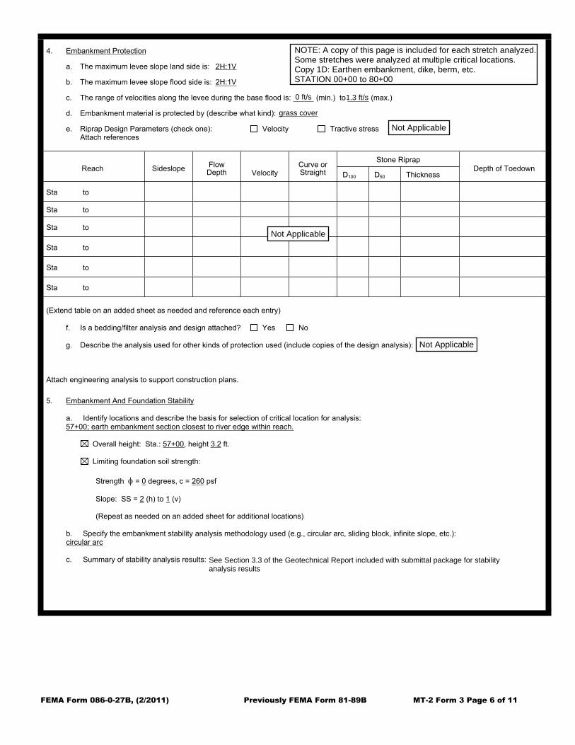
4. Embankment Protection
a. The maximum levee slope land side is: 2H:1V
b. The maximum levee slope flood side is: 2H:1V
c. The range of velocities along the levee during the base flood is: (min.) to (max.)
d. Embankment material is protected by (describe what kind):
e. Riprap Design Parameters (check one): Velocity Tractive stressAttach references
Stone RiprapReach Sideslope
Flow Depth Velocity
Curve or Straight D100 D50 Thickness
Depth of Toedown
Sta to
Sta to
Sta to
Sta to
Sta to
Sta to
(Extend table on an added sheet as needed and reference each entry)
f. Is a bedding/filter analysis and design attached? Yes No
g. Describe the analysis used for other kinds of protection used (include copies of the design analysis):
Attach engineering analysis to support construction plans.
5. Embankment And Foundation Stability
a. Identify locations and describe the basis for selection of critical location for analysis: 57+00; earth embankment section closest to river edge within reach.
Overall height: Sta.: 57+00, height 3.2 ft.
Limiting foundation soil strength:
Strength = 0 degrees, c = 260 psf
Slope: SS = 2 (h) to 1 (v)
(Repeat as needed on an added sheet for additional locations)
b. Specify the embankment stability analysis methodology used (e.g., circular arc, sliding block, infinite slope, etc.):circular arc
c. Summary of stability analysis results: Meets all criteria applicable to this study.
Not Applicable
Not Applicable
Not Applicable
NOTE: A copy of this page is included for each stretch analyzed.Some stretches were analyzed at multiple critical locations.Copy 1D: Earthen embankment, dike, berm, etc.STATION 00+00 to 80+00
0 ft/s 1.3 ft/s
grass cover
See Section 3.3 of the Geotechnical Report included with submittal package for stabilityanalysis results


FEMA Form 086-0-27B, (2/2011) Previously FEMA Form 81-89B MT-2 Form 3 Page 6 of 11
4. Embankment Protection
a. The maximum levee slope land side is: 2H:1V
b. The maximum levee slope flood side is: 2H:1V
c. The range of velocities along the levee during the base flood is: (min.) to (max.)
d. Embankment material is protected by (describe what kind):
e. Riprap Design Parameters (check one): Velocity Tractive stressAttach references
Stone RiprapReach Sideslope
Flow Depth Velocity
Curve or Straight D100 D50 Thickness
Depth of Toedown
Sta to
Sta to
Sta to
Sta to
Sta to
Sta to
(Extend table on an added sheet as needed and reference each entry)
f. Is a bedding/filter analysis and design attached? Yes No
g. Describe the analysis used for other kinds of protection used (include copies of the design analysis):
Attach engineering analysis to support construction plans.
5. Embankment And Foundation Stability
a. Identify locations and describe the basis for selection of critical location for analysis: 91+00; Earth embankment topography results in tallest waterside slope.
Overall height: Sta.: 91+00, height 6.2 ft.
Limiting foundation soil strength:
Strength = 0 degrees, c = 280 psf
Slope: SS = 2 (h) to 1 (v)
(Repeat as needed on an added sheet for additional locations)
b. Specify the embankment stability analysis methodology used (e.g., circular arc, sliding block, infinite slope, etc.):circular arc
c. Summary of stability analysis results: Meets all criteria applicable to this study.
Not Applicable
Not Applicable
Not Applicable
NOTE: A copy of this page is included for each stretch analyzed.Some stretches were analyzed at multiple critical locations.Copy 2A: Earthen embankment, dike, berm, etc.STATION 80+00 to 120+00
0 ft/s 1.3 ft/s
grass cover
See Section 3.3 of the Geotechnical Report included with submittal package for stabilityanalysis results


FEMA Form 086-0-27B, (2/2011) Previously FEMA Form 81-89B MT-2 Form 3 Page 6 of 11
4. Embankment Protection
a. The maximum levee slope land side is: n/a
b. The maximum levee slope flood side is: n/a
c. The range of velocities along the levee during the base flood is: (min.) to (max.)
d. Embankment material is protected by (describe what kind):
e. Riprap Design Parameters (check one): Velocity Tractive stressAttach references
Stone RiprapReach Sideslope
Flow Depth Velocity
Curve or Straight D100 D50 Thickness
Depth of Toedown
Sta to
Sta to
Sta to
Sta to
Sta to
Sta to
(Extend table on an added sheet as needed and reference each entry)
f. Is a bedding/filter analysis and design attached? Yes No
g. Describe the analysis used for other kinds of protection used (include copies of the design analysis):
Attach engineering analysis to support construction plans.
5. Embankment And Foundation Stability
a. Identify locations and describe the basis for selection of critical location for analysis: 100+50; topography at T-wall results in tallest waterside slope.
Overall height: Sta.: 100+50, height 3.2 ft.
Limiting foundation soil strength:
Strength = 0 degrees, c = 280 psf
Slope: SS = n/a (h) to n/a (v)
(Repeat as needed on an added sheet for additional locations)
b. Specify the embankment stability analysis methodology used (e.g., circular arc, sliding block, infinite slope, etc.):circular arc
c. Summary of stability analysis results: Meets all criteria applicable to this study.
Not Applicable
Not Applicable
Not Applicable
Not Applicable
NOTE: A copy of this page is included for each stretch analyzed.Some stretches were analyzed at multiple critical locations.Copy 2B: Structural floodwallSTATION 80+00 to 120+00
0 ft/s 1.3 ft/s
See Section 3.3 of the Geotechnical Report included with submittal package for stabilityanalysis results

FEMA Form 086-0-27B, (2/2011) Previously FEMA Form 81-89B MT-2 Form 3 Page 6 of 11
4. Embankment Protection
a. The maximum levee slope land side is: 2H:1V
b. The maximum levee slope flood side is: 2H:1V
c. The range of velocities along the levee during the base flood is: (min.) to (max.)
d. Embankment material is protected by (describe what kind):
e. Riprap Design Parameters (check one): Velocity Tractive stressAttach references
Stone RiprapReach Sideslope
Flow Depth Velocity
Curve or Straight D100 D50 Thickness
Depth of Toedown
Sta to
Sta to
Sta to
Sta to
Sta to
Sta to
(Extend table on an added sheet as needed and reference each entry)
f. Is a bedding/filter analysis and design attached? Yes No
g. Describe the analysis used for other kinds of protection used (include copies of the design analysis):
Attach engineering analysis to support construction plans.
5. Embankment And Foundation Stability
a. Identify locations and describe the basis for selection of critical location for analysis: 155+00
Overall height: Sta.: 155+00, height 3.2 ft.
Limiting foundation soil strength:
Strength = 0 degrees, c = 430 psf
Slope: SS = 2 (h) to 1 (v)
(Repeat as needed on an added sheet for additional locations)
b. Specify the embankment stability analysis methodology used (e.g., circular arc, sliding block, infinite slope, etc.):Circular Arc
c. Summary of stability analysis results: Meets all criteria applicable to this study.
Not Applicable
Not Applicable
Not Applicable
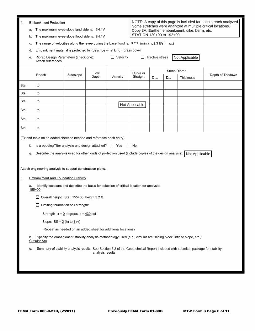
NOTE: A copy of this page is included for each stretch analyzed.Some stretches were analyzed at multiple critical locations.Copy 3A: Earthen embankment, dike, berm, etc.STATION 120+00 to 192+00
0 ft/s 1.3 ft/s
grass cover
See Section 3.3 of the Geotechnical Report included with submittal package for stabilityanalysis results


FEMA Form 086-0-27B, (2/2011) Previously FEMA Form 81-89B MT-2 Form 3 Page 6 of 11
4. Embankment Protection
a. The maximum levee slope land side is: 2H:1V
b. The maximum levee slope flood side is: 2H:1V
c. The range of velocities along the levee during the base flood is: (min.) to (max.)
d. Embankment material is protected by (describe what kind):
e. Riprap Design Parameters (check one): Velocity Tractive stressAttach references
Stone RiprapReach Sideslope
Flow Depth Velocity
Curve or Straight D100 D50 Thickness
Depth of Toedown
Sta to
Sta to
Sta to
Sta to
Sta to
Sta to
(Extend table on an added sheet as needed and reference each entry)
f. Is a bedding/filter analysis and design attached? Yes No
g. Describe the analysis used for other kinds of protection used (include copies of the design analysis):
Attach engineering analysis to support construction plans.
5. Embankment And Foundation Stability
a. Identify locations and describe the basis for selection of critical location for analysis: 192+50;
Overall height: Sta.: 192+50, height 4.2 ft.
Limiting foundation soil strength:
Strength = 0 degrees, c = 420 psf
Slope: SS = 2 (h) to 1 (v)
(Repeat as needed on an added sheet for additional locations)
b. Specify the embankment stability analysis methodology used (e.g., circular arc, sliding block, infinite slope, etc.):circular arc
c. Summary of stability analysis results: Meets all criteria applicable to this study.
Not Applicable
Not Applicable
Not Applicable
NOTE: A copy of this page is included for each stretch analyzed.Some stretches were analyzed at multiple critical locations.Copy 4A: Earthen embankment, dike, berm, etc.STATION 192+00 to 225+00
0 ft/s 1.3 ft/s
grass cover
See Section 3.3 of the Geotechnical Report included with submittal package for stabilityanalysis results

FEMA Form 086-0-27B, (2/2011) Previously FEMA Form 81-89B MT-2 Form 3 Page 6 of 11
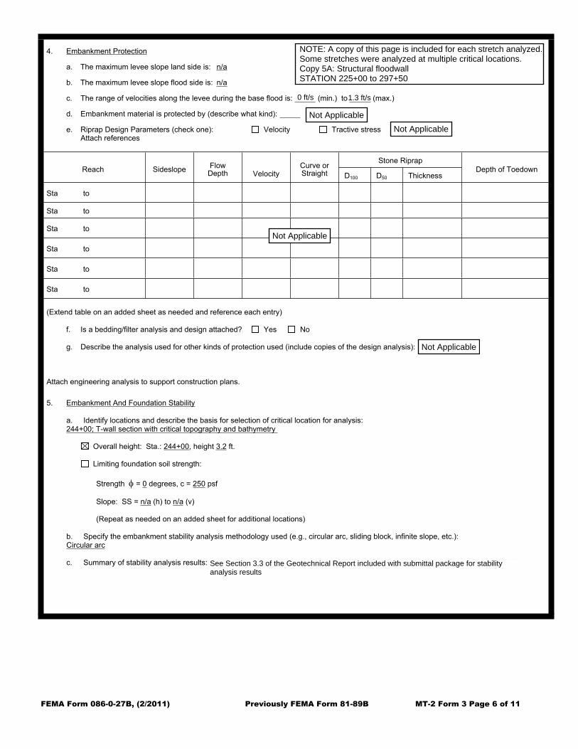
4. Embankment Protection
a. The maximum levee slope land side is: n/a
b. The maximum levee slope flood side is: n/a
c. The range of velocities along the levee during the base flood is: (min.) to (max.)
d. Embankment material is protected by (describe what kind):
e. Riprap Design Parameters (check one): Velocity Tractive stressAttach references
Stone RiprapReach Sideslope
Flow Depth Velocity
Curve or Straight D100 D50 Thickness
Depth of Toedown
Sta to
Sta to
Sta to
Sta to
Sta to
Sta to
(Extend table on an added sheet as needed and reference each entry)
f. Is a bedding/filter analysis and design attached? Yes No
g. Describe the analysis used for other kinds of protection used (include copies of the design analysis):
Attach engineering analysis to support construction plans.
5. Embankment And Foundation Stability
a. Identify locations and describe the basis for selection of critical location for analysis: 244+00; T-wall section with critical topography and bathymetry
Overall height: Sta.: 244+00, height 3.2 ft.
Limiting foundation soil strength:
Strength = 0 degrees, c = 250 psf
Slope: SS = n/a (h) to n/a (v)
(Repeat as needed on an added sheet for additional locations)
b. Specify the embankment stability analysis methodology used (e.g., circular arc, sliding block, infinite slope, etc.):Circular arc
c. Summary of stability analysis results: Meets all criteria applicable to this study ***(see Geotechnical Analysis Report for details)***.
Not ApplicableNot Applicable
Not Applicable
Not Applicable
NOTE: A copy of this page is included for each stretch analyzed.Some stretches were analyzed at multiple critical locations.Copy 5A: Structural floodwallSTATION 225+00 to 297+50
0 ft/s 1.3 ft/s
See Section 3.3 of the Geotechnical Report included with submittal package for stabilityanalysis results


FEMA Form 086-0-27B, (2/2011) Previously FEMA Form 81-89B MT-2 Form 3 Page 6 of 11
4. Embankment Protection
a. The maximum levee slope land side is: 2H:1V
b. The maximum levee slope flood side is: 2H:1V
c. The range of velocities along the levee during the base flood is: (min.) to (max.)
d. Embankment material is protected by (describe what kind):
e. Riprap Design Parameters (check one): Velocity Tractive stressAttach references
Stone RiprapReach Sideslope
Flow Depth Velocity
Curve or Straight D100 D50 Thickness
Depth of Toedown
Sta to
Sta to
Sta to
Sta to
Sta to
Sta to
(Extend table on an added sheet as needed and reference each entry)
f. Is a bedding/filter analysis and design attached? Yes No
g. Describe the analysis used for other kinds of protection used (include copies of the design analysis):
Attach engineering analysis to support construction plans.
5. Embankment And Foundation Stability
a. Identify locations and describe the basis for selection of critical location for analysis: 248+00; earth embankment section closest to river edge within reach.
Overall height: Sta.: 248+00, height 3.2 ft.
Limiting foundation soil strength:
Strength = 0 degrees, c = 250 psf
Slope: SS = 2 (h) to 1 (v)
(Repeat as needed on an added sheet for additional locations)
b. Specify the embankment stability analysis methodology used (e.g., circular arc, sliding block, infinite slope, etc.):circular arc
c. Summary of stability analysis results: Meets all criteria applicable to this study ***(see Geotechnical Analysis Report for details)***.
Not Applicable
Not Applicable
Not Applicable
NOTE: A copy of this page is included for each stretch analyzed.Some stretches were analyzed at multiple critical locations.Copy 5B: Earthen embankment, dike, berm, etc.STATION 225+00 to 297+50
0 ft/s 1.3 ft/s
grass cover
See Section 3.3 of the Geotechnical Report included with submittal package for stabilityanalysis results


FEMA Form 086-0-27B, (2/2011) Previously FEMA Form 81-89B MT-2 Form 3 Page 6 of 11
4. Embankment Protection
a. The maximum levee slope land side is: n/a
b. The maximum levee slope flood side is: n/a
c. The range of velocities along the levee during the base flood is: (min.) to (max.)
d. Embankment material is protected by (describe what kind):
e. Riprap Design Parameters (check one): Velocity Tractive stressAttach references
Stone RiprapReach Sideslope
Flow Depth Velocity
Curve or Straight D100 D50 Thickness
Depth of Toedown
Sta to
Sta to
Sta to
Sta to
Sta to
Sta to
(Extend table on an added sheet as needed and reference each entry)
f. Is a bedding/filter analysis and design attached? Yes No
g. Describe the analysis used for other kinds of protection used (include copies of the design analysis):
Attach engineering analysis to support construction plans.
5. Embankment And Foundation Stability
a. Identify locations and describe the basis for selection of critical location for analysis: 291+00; section of proposed sheetpile wall closest to the rivers edge
Overall height: Sta.: 291+00, height 5.2 ft.
Limiting foundation soil strength:
Strength = 0 degrees, c = 250 psf
Slope: SS = n/a (h) to n/a (v)
(Repeat as needed on an added sheet for additional locations)
b. Specify the embankment stability analysis methodology used (e.g., circular arc, sliding block, infinite slope, etc.):Circular arc
c. Summary of stability analysis results: Meets all criteria applicable to this study.
Not ApplicableNot Applicable
Not Applicable
Not Applicable
NOTE: A copy of this page is included for each stretch analyzed.Some stretches were analyzed at multiple critical locations.Copy 5C: Structural floodwallSTATION 225+00 to 297+50
0 ft/s 1.3 ft/s
See Section 3.3 of the Geotechnical Report included with submittal package for stabilityanalysis results

FEMA Form 086-0-27B, (2/2011) Previously FEMA Form 81-89B MT-2 Form 3 Page 7 of 11
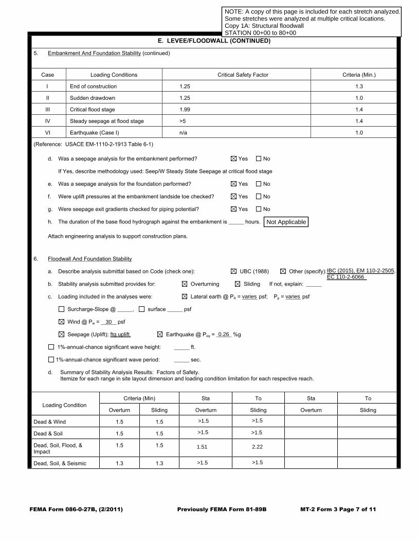
E. LEVEE/FLOODWALL (CONTINUED)
5. Embankment And Foundation Stability (continued)
Case Loading Conditions Critical Safety Factor Criteria (Min.)
I End of construction 1.25 1.3
II Sudden drawdown 1.25 1.0
III Critical flood stage 1.99 1.4
IV Steady seepage at flood stage >5 1.4
VI Earthquake (Case I) n/a 1.0
(Reference: USACE EM-1110-2-1913 Table 6-1)
d. Was a seepage analysis for the embankment performed? Yes No
If Yes, describe methodology used: Seep/W Steady State Seepage at critical flood stage
e. Was a seepage analysis for the foundation performed? Yes No
f. Were uplift pressures at the embankment landside toe checked? Yes No
g. Were seepage exit gradients checked for piping potential? Yes No
h. The duration of the base flood hydrograph against the embankment is hours.
Attach engineering analysis to support construction plans.
6. Floodwall And Foundation Stability
a. Describe analysis submittal based on Code (check one): UBC (1988) Other (specify):
b. Stability analysis submitted provides for: Overturning Sliding If not, explain:
c. Loading included in the analyses were: Lateral earth @ PA = psf; Pp = psf
Surcharge-Slope @ , surface psf
Wind @ Pw = psf
Seepage (Uplift); Earthquake @ Peq = %g
1%-annual-chance significant wave height: ft.
1%-annual-chance significant wave period: sec.
d. Summary of Stability Analysis Results: Factors of Safety.Itemize for each range in site layout dimension and loading condition limitation for each respective reach.
Criteria (Min) Sta To Sta To
Loading ConditionOverturn Sliding Overturn Sliding Overturn Sliding
Dead & Wind 1.5 1.5
Dead & Soil 1.5 1.5
Dead, Soil, Flood, & Impact
1.5 1.5
Dead, Soil, & Seismic 1.3 1.3
R1: CS1ANOTE: A copy of this page is included for each stretch analyzed.Some stretches were analyzed at multiple critical locations.Copy 1A: Structural floodwallSTATION 00+00 to 80+00
IBC (2015), EM 11022505,EC 11026066
ftg uplift
30
0.26
>1.5
>1.5
>1.5
>1.5
>1.5 >1.5
1.51 2.22
varies varies
Not Applicable


FEMA Form 086-0-27B, (2/2011) Previously FEMA Form 81-89B MT-2 Form 3 Page 7 of 11
E. LEVEE/FLOODWALL (CONTINUED)
5. Embankment And Foundation Stability (continued)
Case Loading Conditions Critical Safety Factor Criteria (Min.)
I End of construction 1.34 1.3
II Sudden drawdown 1.35 1.0
III Critical flood stage 1.96 1.4
IV Steady seepage at flood stage >5 1.4
VI Earthquake (Case I) n/a 1.0
(Reference: USACE EM-1110-2-1913 Table 6-1)
d. Was a seepage analysis for the embankment performed? Yes No
If Yes, describe methodology used: Seep/W Steady State Seepage at critical flood stage.
e. Was a seepage analysis for the foundation performed? Yes No
f. Were uplift pressures at the embankment landside toe checked? Yes No
g. Were seepage exit gradients checked for piping potential? Yes No
h. The duration of the base flood hydrograph against the embankment is hours.
Attach engineering analysis to support construction plans.
6. Floodwall And Foundation Stability
a. Describe analysis submittal based on Code (check one): UBC (1988) Other (specify):
b. Stability analysis submitted provides for: Overturning Sliding If not, explain:
c. Loading included in the analyses were: Lateral earth @ PA = psf; Pp = psf
Surcharge-Slope @ , surface psf
Wind @ Pw = psf
Seepage (Uplift); Earthquake @ Peq = %g
1%-annual-chance significant wave height: ft.
1%-annual-chance significant wave period: sec.
d. Summary of Stability Analysis Results: Factors of Safety.Itemize for each range in site layout dimension and loading condition limitation for each respective reach.
Criteria (Min) Sta To Sta To
Loading ConditionOverturn Sliding Overturn Sliding Overturn Sliding
Dead & Wind 1.5 1.5
Dead & Soil 1.5 1.5
Dead, Soil, Flood, & Impact
1.5 1.5
Dead, Soil, & Seismic 1.3 1.3
R1: CS1CNOTE: A copy of this page is included for each stretch analyzed.Some stretches were analyzed at multiple critical locations.Copy 1B: Structural floodwallSTATION 00+00 to 80+00
IBC (2015), EM 11022505,EC 11026066
ftg uplift
30
0.26
>1.5
>1.5
>1.5
>1.5
>1.5 >1.5
1.51 2.22
varies varies
Not Applicable


FEMA Form 086-0-27B, (2/2011) Previously FEMA Form 81-89B MT-2 Form 3 Page 7 of 11
E. LEVEE/FLOODWALL (CONTINUED)
5. Embankment And Foundation Stability (continued)
Case Loading Conditions Critical Safety Factor Criteria (Min.)
I End of construction 1.47 1.3
II Sudden drawdown 1.47 1.0
III Critical flood stage 2.38 1.4
IV Steady seepage at flood stage >5 1.4
VI Earthquake (Case I) n/a 1.0
(Reference: USACE EM-1110-2-1913 Table 6-1)
d. Was a seepage analysis for the embankment performed? Yes No
If Yes, describe methodology used: Seep/W Steady State Seepage at critical flood stage.
e. Was a seepage analysis for the foundation performed? Yes No
f. Were uplift pressures at the embankment landside toe checked? Yes No
g. Were seepage exit gradients checked for piping potential? Yes No
h. The duration of the base flood hydrograph against the embankment is hours.
Attach engineering analysis to support construction plans.
6. Floodwall And Foundation Stability
a. Describe analysis submittal based on Code (check one): UBC (1988) Other (specify):
b. Stability analysis submitted provides for: Overturning Sliding If not, explain:
c. Loading included in the analyses were: Lateral earth @ PA = psf; Pp = psf
Surcharge-Slope @ , surface psf
Wind @ Pw = psf
Seepage (Uplift); Earthquake @ Peq = %g
1%-annual-chance significant wave height: ft.
1%-annual-chance significant wave period: sec.
d. Summary of Stability Analysis Results: Factors of Safety.Itemize for each range in site layout dimension and loading condition limitation for each respective reach.
Criteria (Min) Sta To Sta To
Loading ConditionOverturn Sliding Overturn Sliding Overturn Sliding
Dead & Wind 1.5 1.5
Dead & Soil 1.5 1.5
Dead, Soil, Flood, & Impact
1.5 1.5
Dead, Soil, & Seismic 1.3 1.3
R1: CS1DNOTE: A copy of this page is included for each stretch analyzed.Some stretches were analyzed at multiple critical locations.Copy 1C: Structural floodwallSTATION 00+00 to 80+00
IBC (2015), EM 11022505,EC 11026066
ftg uplift
30
0.26
>1.5
>1.5
>1.5
>1.5
>1.5 >1.5
1.51 2.22
varies varies
Not Applicable


FEMA Form 086-0-27B, (2/2011) Previously FEMA Form 81-89B MT-2 Form 3 Page 7 of 11
E. LEVEE/FLOODWALL (CONTINUED)
5. Embankment And Foundation Stability (continued)
Case Loading Conditions Critical Safety Factor Criteria (Min.)
I End of construction 1.69 1.3
II Sudden drawdown 1.71 1.0
III Critical flood stage 2.82 1.4
IV Steady seepage at flood stage 3.22 1.4
VI Earthquake (Case I) n/a 1.0
(Reference: USACE EM-1110-2-1913 Table 6-1)
d. Was a seepage analysis for the embankment performed? Yes No
If Yes, describe methodology used: Seep/W Steady State Seepage at critical flood stage
e. Was a seepage analysis for the foundation performed? Yes No
f. Were uplift pressures at the embankment landside toe checked? Yes No
g. Were seepage exit gradients checked for piping potential? Yes No
h. The duration of the base flood hydrograph against the embankment is hours.
Attach engineering analysis to support construction plans.
6. Floodwall And Foundation Stability
a. Describe analysis submittal based on Code (check one): UBC (1988) Other (specify):
b. Stability analysis submitted provides for: Overturning Sliding If not, explain:
c. Loading included in the analyses were: Lateral earth @ PA = psf; Pp = psf
Surcharge-Slope @ , surface psf
Wind @ Pw = psf
Seepage (Uplift); Earthquake @ Peq = %g
1%-annual-chance significant wave height: ft.
1%-annual-chance significant wave period: sec.
d. Summary of Stability Analysis Results: Factors of Safety.Itemize for each range in site layout dimension and loading condition limitation for each respective reach.
Criteria (Min) Sta To Sta To
Loading ConditionOverturn Sliding Overturn Sliding Overturn Sliding
Dead & Wind 1.5 1.5
Dead & Soil 1.5 1.5
Dead, Soil, Flood, & Impact
1.5 1.5
Dead, Soil, & Seismic 1.3 1.3
R1: CS1ENOTE: A copy of this page is included for each stretch analyzed.Some stretches were analyzed at multiple critical locations.Copy 1D: Earthen embankment, dike, berm, etc.STATION 00+00 to 80+00
<1

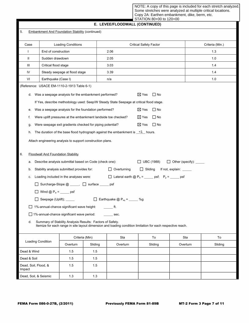
FEMA Form 086-0-27B, (2/2011) Previously FEMA Form 81-89B MT-2 Form 3 Page 7 of 11
E. LEVEE/FLOODWALL (CONTINUED)
5. Embankment And Foundation Stability (continued)
Case Loading Conditions Critical Safety Factor Criteria (Min.)
I End of construction 2.06 1.3
II Sudden drawdown 2.05 1.0
III Critical flood stage 3.03 1.4
IV Steady seepage at flood stage 3.39 1.4
VI Earthquake (Case I) n/a 1.0
(Reference: USACE EM-1110-2-1913 Table 6-1)
d. Was a seepage analysis for the embankment performed? Yes No
If Yes, describe methodology used: Seep/W Steady State Seepage at critical flood stage.
e. Was a seepage analysis for the foundation performed? Yes No
f. Were uplift pressures at the embankment landside toe checked? Yes No
g. Were seepage exit gradients checked for piping potential? Yes No
h. The duration of the base flood hydrograph against the embankment is hours.
Attach engineering analysis to support construction plans.
6. Floodwall And Foundation Stability
a. Describe analysis submittal based on Code (check one): UBC (1988) Other (specify):
b. Stability analysis submitted provides for: Overturning Sliding If not, explain:
c. Loading included in the analyses were: Lateral earth @ PA = psf; Pp = psf
Surcharge-Slope @ , surface psf
Wind @ Pw = psf
Seepage (Uplift); Earthquake @ Peq = %g
1%-annual-chance significant wave height: ft.
1%-annual-chance significant wave period: sec.
d. Summary of Stability Analysis Results: Factors of Safety.Itemize for each range in site layout dimension and loading condition limitation for each respective reach.
Criteria (Min) Sta To Sta To
Loading ConditionOverturn Sliding Overturn Sliding Overturn Sliding
Dead & Wind 1.5 1.5
Dead & Soil 1.5 1.5
Dead, Soil, Flood, & Impact
1.5 1.5
Dead, Soil, & Seismic 1.3 1.3
R2: CS2ANOTE: A copy of this page is included for each stretch analyzed.Some stretches were analyzed at multiple critical locations.Copy 2A: Earthen embankment, dike, berm, etc.STATION 80+00 to 120+00
<1


FEMA Form 086-0-27B, (2/2011) Previously FEMA Form 81-89B MT-2 Form 3 Page 7 of 11
E. LEVEE/FLOODWALL (CONTINUED)
5. Embankment And Foundation Stability (continued)
Case Loading Conditions Critical Safety Factor Criteria (Min.)
I End of construction 3.00 1.3
II Sudden drawdown 2.97 1.0
III Critical flood stage >5 1.4
IV Steady seepage at flood stage 4.36 1.4
VI Earthquake (Case I) n/a 1.0
(Reference: USACE EM-1110-2-1913 Table 6-1)
d. Was a seepage analysis for the embankment performed? Yes No
If Yes, describe methodology used: Seep/W Steady State Seepage at critical flood stage.
e. Was a seepage analysis for the foundation performed? Yes No
f. Were uplift pressures at the embankment landside toe checked? Yes No
g. Were seepage exit gradients checked for piping potential? Yes No
h. The duration of the base flood hydrograph against the embankment is hours.
Attach engineering analysis to support construction plans.
6. Floodwall And Foundation Stability
a. Describe analysis submittal based on Code (check one): UBC (1988) Other (specify):
b. Stability analysis submitted provides for: Overturning Sliding If not, explain:
c. Loading included in the analyses were: Lateral earth @ PA = psf; Pp = psf
Surcharge-Slope @ , surface psf
Wind @ Pw = psf
Seepage (Uplift); Earthquake @ Peq = %g
1%-annual-chance significant wave height: ft.
1%-annual-chance significant wave period: sec.
d. Summary of Stability Analysis Results: Factors of Safety.Itemize for each range in site layout dimension and loading condition limitation for each respective reach.
Criteria (Min) Sta To Sta To
Loading ConditionOverturn Sliding Overturn Sliding Overturn Sliding
Dead & Wind 1.5 1.5
Dead & Soil 1.5 1.5
Dead, Soil, Flood, & Impact
1.5 1.5
Dead, Soil, & Seismic 1.3 1.3
R2: CS2BNOTE: A copy of this page is included for each stretch analyzed.Some stretches were analyzed at multiple critical locations.Copy 2B: Structural floodwallSTATION 80+00 to 120+00
IBC (2015), EM 11022505,EC 11026066
ftg uplift
30
0.26
>1.5
>1.5
>1.5
>1.5
>1.5 >1.5
1.51 2.22
varies varies
Not Applicable

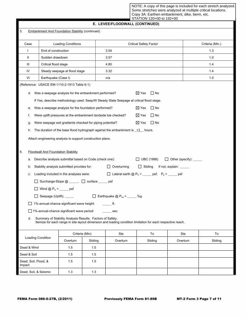
FEMA Form 086-0-27B, (2/2011) Previously FEMA Form 81-89B MT-2 Form 3 Page 7 of 11
E. LEVEE/FLOODWALL (CONTINUED)
5. Embankment And Foundation Stability (continued)
Case Loading Conditions Critical Safety Factor Criteria (Min.)
I End of construction 3.54 1.3
II Sudden drawdown 3.57 1.0
III Critical flood stage 4.80 1.4
IV Steady seepage at flood stage 3.32 1.4
VI Earthquake (Case I) n/a 1.0
(Reference: USACE EM-1110-2-1913 Table 6-1)
d. Was a seepage analysis for the embankment performed? Yes No
If Yes, describe methodology used: Seep/W Steady State Seepage at critical flood stage.
e. Was a seepage analysis for the foundation performed? Yes No
f. Were uplift pressures at the embankment landside toe checked? Yes No
g. Were seepage exit gradients checked for piping potential? Yes No
h. The duration of the base flood hydrograph against the embankment is hours.
Attach engineering analysis to support construction plans.
6. Floodwall And Foundation Stability
a. Describe analysis submittal based on Code (check one): UBC (1988) Other (specify):
b. Stability analysis submitted provides for: Overturning Sliding If not, explain:
c. Loading included in the analyses were: Lateral earth @ PA = psf; Pp = psf
Surcharge-Slope @ , surface psf
Wind @ Pw = psf
Seepage (Uplift); Earthquake @ Peq = %g
1%-annual-chance significant wave height: ft.
1%-annual-chance significant wave period: sec.
d. Summary of Stability Analysis Results: Factors of Safety.Itemize for each range in site layout dimension and loading condition limitation for each respective reach.
Criteria (Min) Sta To Sta To
Loading ConditionOverturn Sliding Overturn Sliding Overturn Sliding
Dead & Wind 1.5 1.5
Dead & Soil 1.5 1.5
Dead, Soil, Flood, & Impact
1.5 1.5
Dead, Soil, & Seismic 1.3 1.3
R3: CS3ANOTE: A copy of this page is included for each stretch analyzed.Some stretches were analyzed at multiple critical locations.Copy 3A: Earthen embankment, dike, berm, etc.STATION 120+00 to 192+00
<1

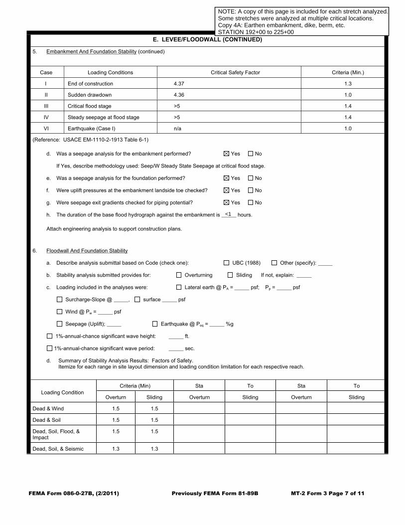
FEMA Form 086-0-27B, (2/2011) Previously FEMA Form 81-89B MT-2 Form 3 Page 7 of 11
E. LEVEE/FLOODWALL (CONTINUED)
5. Embankment And Foundation Stability (continued)
Case Loading Conditions Critical Safety Factor Criteria (Min.)
I End of construction 4.37 1.3
II Sudden drawdown 4.36 1.0
III Critical flood stage >5 1.4
IV Steady seepage at flood stage >5 1.4
VI Earthquake (Case I) n/a 1.0
(Reference: USACE EM-1110-2-1913 Table 6-1)
d. Was a seepage analysis for the embankment performed? Yes No
If Yes, describe methodology used: Seep/W Steady State Seepage at critical flood stage.
e. Was a seepage analysis for the foundation performed? Yes No
f. Were uplift pressures at the embankment landside toe checked? Yes No
g. Were seepage exit gradients checked for piping potential? Yes No
h. The duration of the base flood hydrograph against the embankment is hours.
Attach engineering analysis to support construction plans.
6. Floodwall And Foundation Stability
a. Describe analysis submittal based on Code (check one): UBC (1988) Other (specify):
b. Stability analysis submitted provides for: Overturning Sliding If not, explain:
c. Loading included in the analyses were: Lateral earth @ PA = psf; Pp = psf
Surcharge-Slope @ , surface psf
Wind @ Pw = psf
Seepage (Uplift); Earthquake @ Peq = %g
1%-annual-chance significant wave height: ft.
1%-annual-chance significant wave period: sec.
d. Summary of Stability Analysis Results: Factors of Safety.Itemize for each range in site layout dimension and loading condition limitation for each respective reach.
Criteria (Min) Sta To Sta To
Loading ConditionOverturn Sliding Overturn Sliding Overturn Sliding
Dead & Wind 1.5 1.5
Dead & Soil 1.5 1.5
Dead, Soil, Flood, & Impact
1.5 1.5
Dead, Soil, & Seismic 1.3 1.3
R4: CS4ANOTE: A copy of this page is included for each stretch analyzed.Some stretches were analyzed at multiple critical locations.Copy 4A: Earthen embankment, dike, berm, etc.STATION 192+00 to 225+00
<1


FEMA Form 086-0-27B, (2/2011) Previously FEMA Form 81-89B MT-2 Form 3 Page 7 of 11
E. LEVEE/FLOODWALL (CONTINUED)
5. Embankment And Foundation Stability (continued)
Case Loading Conditions Critical Safety Factor Criteria (Min.)
I End of construction 1.17 1.3
II Sudden drawdown 1.16 1.0
III Critical flood stage 1.92 1.4
IV Steady seepage at flood stage 4.39 1.4
VI Earthquake (Case I) n/a 1.0
(Reference: USACE EM-1110-2-1913 Table 6-1)
d. Was a seepage analysis for the embankment performed? Yes No
If Yes, describe methodology used: Seep/W Steady State Seepage at critical flood stage
e. Was a seepage analysis for the foundation performed? Yes No
f. Were uplift pressures at the embankment landside toe checked? Yes No
g. Were seepage exit gradients checked for piping potential? Yes No
h. The duration of the base flood hydrograph against the embankment is hours.
Attach engineering analysis to support construction plans.
6. Floodwall And Foundation Stability
a. Describe analysis submittal based on Code (check one): UBC (1988) Other (specify):
b. Stability analysis submitted provides for: Overturning Sliding If not, explain:
c. Loading included in the analyses were: Lateral earth @ PA = psf; Pp = psf
Surcharge-Slope @ , surface psf
Wind @ Pw = psf
Seepage (Uplift); Earthquake @ Peq = %g
1%-annual-chance significant wave height: ft.
1%-annual-chance significant wave period: sec.
d. Summary of Stability Analysis Results: Factors of Safety.Itemize for each range in site layout dimension and loading condition limitation for each respective reach.
Criteria (Min) Sta To Sta To
Loading ConditionOverturn Sliding Overturn Sliding Overturn Sliding
Dead & Wind 1.5 1.5
Dead & Soil 1.5 1.5
Dead, Soil, Flood, & Impact
1.5 1.5
Dead, Soil, & Seismic 1.3 1.3
NOTE: A copy of this page is included for each stretch analyzed.Some stretches were analyzed at multiple critical locations.Copy 5A: Structural floodwallSTATION 225+00 to 297+50
IBC (2015), EM 11022505,EC 11026066
ftg uplift
30
0.26
>1.5
>1.5
>1.5
>1.5
>1.5 >1.5
1.51 2.22
varies varies
Not Applicable

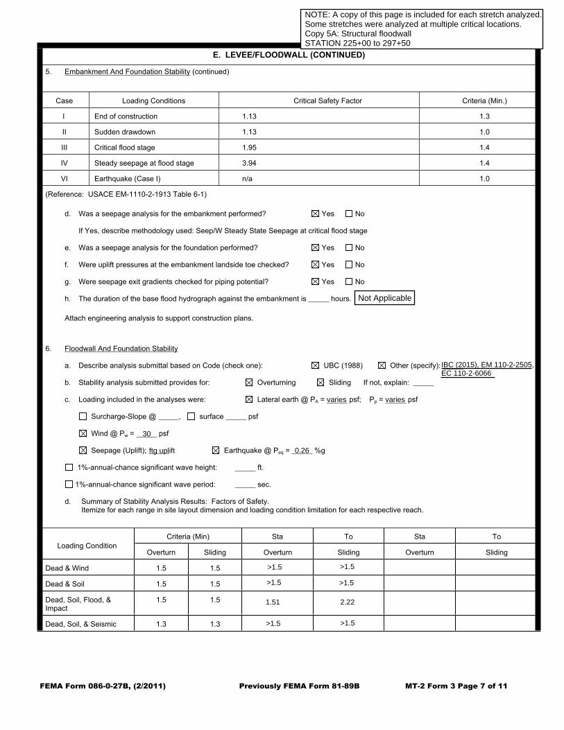
FEMA Form 086-0-27B, (2/2011) Previously FEMA Form 81-89B MT-2 Form 3 Page 7 of 11
E. LEVEE/FLOODWALL (CONTINUED)
5. Embankment And Foundation Stability (continued)
Case Loading Conditions Critical Safety Factor Criteria (Min.)
I End of construction 1.13 1.3
II Sudden drawdown 1.13 1.0
III Critical flood stage 1.95 1.4
IV Steady seepage at flood stage 3.94 1.4
VI Earthquake (Case I) n/a 1.0
(Reference: USACE EM-1110-2-1913 Table 6-1)
d. Was a seepage analysis for the embankment performed? Yes No
If Yes, describe methodology used: Seep/W Steady State Seepage at critical flood stage
e. Was a seepage analysis for the foundation performed? Yes No
f. Were uplift pressures at the embankment landside toe checked? Yes No
g. Were seepage exit gradients checked for piping potential? Yes No
h. The duration of the base flood hydrograph against the embankment is hours.
Attach engineering analysis to support construction plans.
6. Floodwall And Foundation Stability
a. Describe analysis submittal based on Code (check one): UBC (1988) Other (specify):
b. Stability analysis submitted provides for: Overturning Sliding If not, explain:
c. Loading included in the analyses were: Lateral earth @ PA = psf; Pp = psf
Surcharge-Slope @ , surface psf
Wind @ Pw = psf
Seepage (Uplift); Earthquake @ Peq = %g
1%-annual-chance significant wave height: ft.
1%-annual-chance significant wave period: sec.
d. Summary of Stability Analysis Results: Factors of Safety.Itemize for each range in site layout dimension and loading condition limitation for each respective reach.
Criteria (Min) Sta To Sta To
Loading ConditionOverturn Sliding Overturn Sliding Overturn Sliding
Dead & Wind 1.5 1.5
Dead & Soil 1.5 1.5
Dead, Soil, Flood, & Impact
1.5 1.5
Dead, Soil, & Seismic 1.3 1.3
R5: CS5BNOTE: A copy of this page is included for each stretch analyzed.Some stretches were analyzed at multiple critical locations.Copy 5A: Structural floodwallSTATION 225+00 to 297+50
IBC (2015), EM 11022505,EC 11026066
ftg uplift
30
0.26
>1.5
>1.5
>1.5
>1.5
>1.5 >1.5
1.51 2.22
varies varies
Not Applicable


FEMA Form 086-0-27B, (2/2011) Previously FEMA Form 81-89B MT-2 Form 3 Page 7 of 11
E. LEVEE/FLOODWALL (CONTINUED)
5. Embankment And Foundation Stability (continued)
Case Loading Conditions Critical Safety Factor Criteria (Min.)
I End of construction 1.33 1.3
II Sudden drawdown 1.33 1.0
III Critical flood stage 2.31 1.4
IV Steady seepage at flood stage >5 1.4
VI Earthquake (Case I) n/a 1.0
(Reference: USACE EM-1110-2-1913 Table 6-1)
d. Was a seepage analysis for the embankment performed? Yes No
If Yes, describe methodology used: Seep/W Steady State Seepage at critical flood stage
e. Was a seepage analysis for the foundation performed? Yes No
f. Were uplift pressures at the embankment landside toe checked? Yes No
g. Were seepage exit gradients checked for piping potential? Yes No
h. The duration of the base flood hydrograph against the embankment is hours.
Attach engineering analysis to support construction plans.
6. Floodwall And Foundation Stability
a. Describe analysis submittal based on Code (check one): UBC (1988) Other (specify):
b. Stability analysis submitted provides for: Overturning Sliding If not, explain:
c. Loading included in the analyses were: Lateral earth @ PA = psf; Pp = psf
Surcharge-Slope @ , surface psf
Wind @ Pw = psf
Seepage (Uplift); Earthquake @ Peq = %g
1%-annual-chance significant wave height: ft.
1%-annual-chance significant wave period: sec.
d. Summary of Stability Analysis Results: Factors of Safety.Itemize for each range in site layout dimension and loading condition limitation for each respective reach.
Criteria (Min) Sta To Sta To
Loading ConditionOverturn Sliding Overturn Sliding Overturn Sliding
Dead & Wind 1.5 1.5
Dead & Soil 1.5 1.5
Dead, Soil, Flood, & Impact
1.5 1.5
Dead, Soil, & Seismic 1.3 1.3
R5: CS5ENOTE: A copy of this page is included for each stretch analyzed.Some stretches were analyzed at multiple critical locations.Copy 5C: Structural floodwallSTATION 225+00 to 297+50
IBC (2015), EM 11022505,EC 11026066
ftg uplift
30
0.26
>1.5
>1.5
>1.5
>1.5
>1.5 >1.5
1.51 2.22
varies varies
Not Applicable

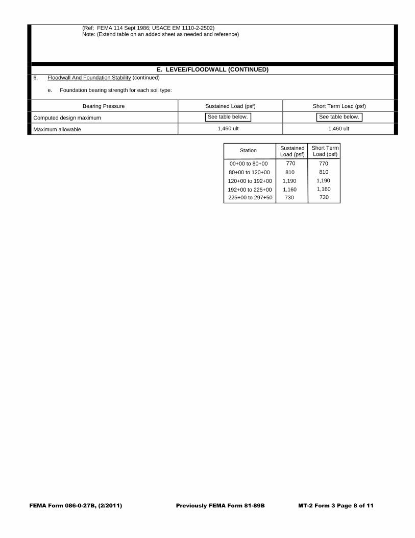
FEMA Form 086-0-27B, (2/2011) Previously FEMA Form 81-89B MT-2 Form 3 Page 8 of 11
(Ref: FEMA 114 Sept 1986; USACE EM 1110-2-2502) Note: (Extend table on an added sheet as needed and reference)
E. LEVEE/FLOODWALL (CONTINUED)
6. Floodwall And Foundation Stability (continued)
e. Foundation bearing strength for each soil type:
Bearing Pressure Sustained Load (psf) Short Term Load (psf)
Computed design maximum
Maximum allowable
See table below. See table below.
1,460 ult 1,460 ult
Station SustainedLoad (psf)
Short TermLoad (psf)
00+00 to 80+0080+00 to 120+00120+00 to 192+00192+00 to 225+00225+00 to 297+50
770 770810 810
1,190 1,1901,160 1,160730 730

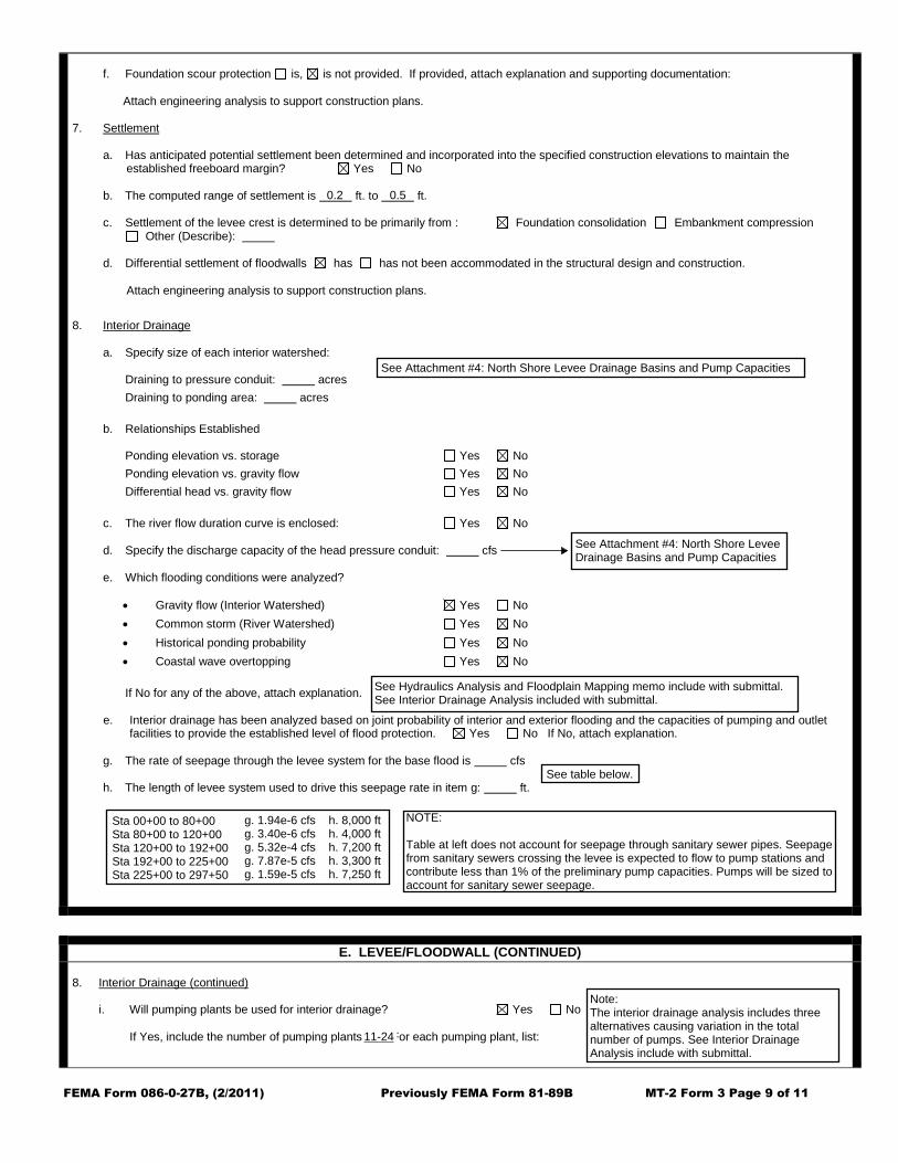
FEMA Form 086-0-27B, (2/2011) Previously FEMA Form 81-89B MT-2 Form 3 Page 9 of 11
f. Foundation scour protection is, is not provided. If provided, attach explanation and supporting documentation: Attach engineering analysis to support construction plans. 7. Settlement a. Has anticipated potential settlement been determined and incorporated into the specified construction elevations to maintain the
established freeboard margin? Yes No b. The computed range of settlement is ft. to ft. c. Settlement of the levee crest is determined to be primarily from : Foundation consolidation Embankment compression
Other (Describe):
d. Differential settlement of floodwalls has has not been accommodated in the structural design and construction.
Attach engineering analysis to support construction plans.
8. Interior Drainage a. Specify size of each interior watershed: Draining to pressure conduit: acres
Draining to ponding area: acres
b. Relationships Established Ponding elevation vs. storage Yes No
Ponding elevation vs. gravity flow Yes No
Differential head vs. gravity flow Yes No
c. The river flow duration curve is enclosed: Yes No d. Specify the discharge capacity of the head pressure conduit: cfs e. Which flooding conditions were analyzed?
Gravity flow (Interior Watershed) Yes No
Common storm (River Watershed) Yes No
Historical ponding probability Yes No
Coastal wave overtopping Yes No
If No for any of the above, attach explanation. e. Interior drainage has been analyzed based on joint probability of interior and exterior flooding and the capacities of pumping and outlet
facilities to provide the established level of flood protection. Yes No If No, attach explanation.
g. The rate of seepage through the levee system for the base flood is cfs h. The length of levee system used to drive this seepage rate in item g: ft.
E. LEVEE/FLOODWALL (CONTINUED)
8. Interior Drainage (continued)
i. Will pumping plants be used for interior drainage? Yes No
If Yes, include the number of pumping plants: 24 For each pumping plant, list:
0.2 0.5
See Attachment #4: North Shore Levee Drainage Basins and Pump Capacities
See Attachment #4: North Shore LeveeDrainage Basins and Pump Capacities
See Hydraulics Analysis and Floodplain Mapping memo include with submittal.See Interior Drainage Analysis included with submittal.
See table below.
Sta 00+00 to 80+00Sta 80+00 to 120+00Sta 120+00 to 192+00Sta 192+00 to 225+00Sta 225+00 to 297+50
g. 1.94e6 cfs h. 8,000 ftg. 3.40e6 cfs h. 4,000 ftg. 5.32e4 cfs h. 7,200 ftg. 7.87e5 cfs h. 3,300 ftg. 1.59e5 cfs h. 7,250 ft
NOTE:
Table at left does not account for seepage through sanitary sewer pipes. Seepagefrom sanitary sewers crossing the levee is expected to flow to pump stations andcontribute less than 1% of the preliminary pump capacities. Pumps will be sized toaccount for sanitary sewer seepage.
1124
Note:The interior drainage analysis includes threealternatives causing variation in the totalnumber of pumps. See Interior DrainageAnalysis include with submittal.

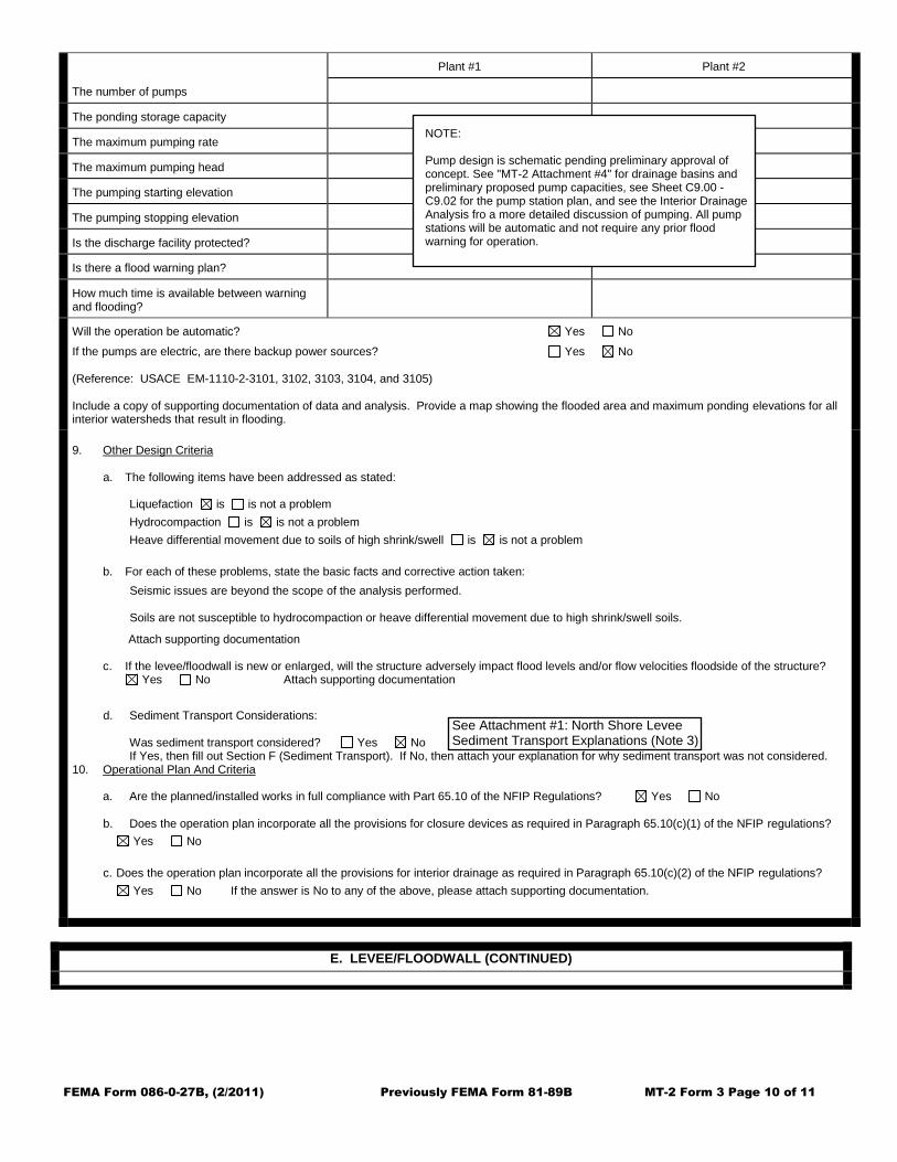
FEMA Form 086-0-27B, (2/2011) Previously FEMA Form 81-89B MT-2 Form 3 Page 10 of 11
The number of pumps
Plant #1 Plant #2
The ponding storage capacity
The maximum pumping rate
The maximum pumping head
The pumping starting elevation
The pumping stopping elevation
Is the discharge facility protected?
Is there a flood warning plan?
How much time is available between warning and flooding?
Will the operation be automatic? Yes No
If the pumps are electric, are there backup power sources? Yes No (Reference: USACE EM-1110-2-3101, 3102, 3103, 3104, and 3105) Include a copy of supporting documentation of data and analysis. Provide a map showing the flooded area and maximum ponding elevations for all interior watersheds that result in flooding.
9. Other Design Criteria
a. The following items have been addressed as stated:
Liquefaction is is not a problem
Hydrocompaction is is not a problem
Heave differential movement due to soils of high shrink/swell is is not a problem
b. For each of these problems, state the basic facts and corrective action taken: Attach supporting documentation c. If the levee/floodwall is new or enlarged, will the structure adversely impact flood levels and/or flow velocities floodside of the structure? Yes No Attach supporting documentation
d. Sediment Transport Considerations:
Was sediment transport considered? Yes No If Yes, then fill out Section F (Sediment Transport). If No, then attach your explanation for why sediment transport was not considered. 10. Operational Plan And Criteria
a. Are the planned/installed works in full compliance with Part 65.10 of the NFIP Regulations? Yes No b. Does the operation plan incorporate all the provisions for closure devices as required in Paragraph 65.10(c)(1) of the NFIP regulations?
Yes No
c. Does the operation plan incorporate all the provisions for interior drainage as required in Paragraph 65.10(c)(2) of the NFIP regulations?
Yes No If the answer is No to any of the above, please attach supporting documentation.
E. LEVEE/FLOODWALL (CONTINUED)
NOTE:
Pump design is schematic pending preliminary approval ofconcept. See "MT2 Attachment #4" for drainage basins andpreliminary proposed pump capacities, see Sheet C9.00 C9.02 for the pump station plan, and see the Interior DrainageAnalysis fro a more detailed discussion of pumping. All pumpstations will be automatic and not require any prior floodwarning for operation.
See Attachment #1: North Shore LeveeSediment Transport Explanations (Note 3)
Seismic issues are beyond the scope of the analysis performed.
Soils are not susceptible to hydrocompaction or heave differential movement due to high shrink/swell soils.

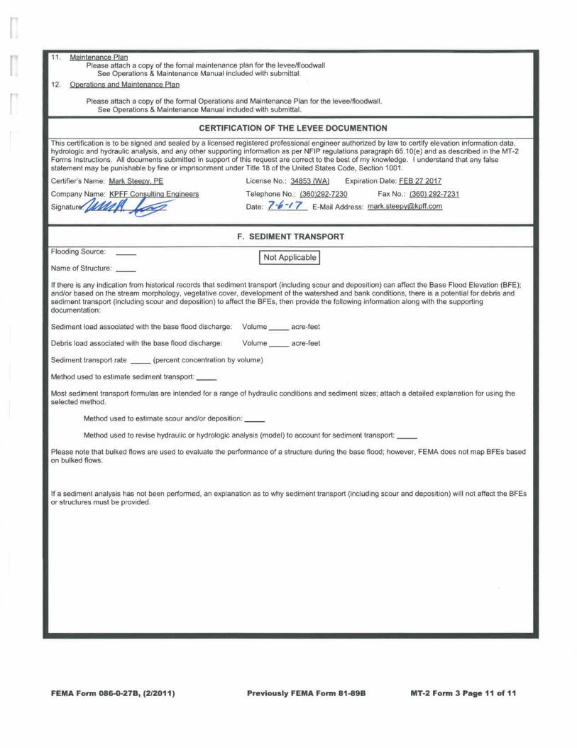

FORM 4
Coastal Analysis Form

FEMA Form 086-0-27C, (2/2011) Previously FEMA Form 81-89C MT-2 Form 4 Page 1 of 2
DEPARTMENT OF HOMELAND SECURITY FEDERAL EMERGENCY MANAGEMENT AGENCY
COASTAL ANALYSIS FORM
O.M.B No. 1660-0016
Expires February 28, 2014
PAPERWORK REDUCTION ACT
Public reporting burden for this form is estimated to average 1 hour per response. The burden estimate includes the time for reviewing instructions, searching existing data sources, gathering and maintaining the needed data, and completing, reviewing, and submitting the form. You are not required to respond to this collection of information unless a valid OMB control number appears in the upper right corner of this form. Send comments regarding the accuracy of the burden estimate and any suggestions for reducing this burden to: Information Collections Management, U.S. Department of Homeland Security, Federal Emergency Management Agency, 1800 South Bell Street, Arlington VA 20958-3005, Paperwork Reduction Project (1660-0016). Submission of the form is required to obtain or retain benefits under the National Flood Insurance Program. Please do not send your completed survey to the above address.
PRIVACY ACT STATEMENT AUTHORITY: The National Flood Insurance Act of 1968, Public Law 90-448, as amended by the Flood Disaster Protection Act of 1973, Public Law 93-234.
PRINCIPAL PURPOSE(S): This information is being collected for the purpose of determining an applicant's eligibility to request changes to National Flood Insurance Program (NFIP) Flood Insurance Rate Maps (FIRM).
ROUTINE USE(S): The information on this form may be disclosed as generally permitted under 5 U.S.C § 552a(b) of the Privacy Act of 1974, as amended. This includes using this information as necessary and authorized by the routine uses published in DHS/FEMA/NFIP/LOMA-1 National Flood Insurance Program (NFIP); Letter of Map Amendment (LOMA) February 15, 2006, 71 FR 7990.
DISCLOSURE: The disclosure of information on this form is voluntary; however, failure to provide the information requested may delay or prevent FEMA from processing a determination regarding a requested change to a NFIP Flood Insurance Rate Maps (FIRM).
Flooding Source: Grays Harbor Note: Fill out one form for each flooding source studied.
A. COASTLINE TO BE REVISED
Describe limits of study area: No Proposed Revisions to Coastal Analysis
B. EFFECTIVE FIS
The area being revised in the effective FIS was studied by detailed methods using (check all that apply):
Storm surge modeling Wave setup computations
Wave height computations Wave runup computations
Wave overtopping computations Dune erosion computations
Primary Frontal Dune Assessment N/A (area not studied by detailed methods)
C. REVISED ANALYSIS
1. Number of transects in revised analysis: Not Revised 2. Information used to prepare the revision (check all that apply):
Wave setup analyses (complete Items 3, 4, and 5 below) Wave overtopping assessment (complete Items 4 and 5)
Stillwater elevation determinations (complete Item 3) More detailed topographic information (complete Section E)
Erosion considerations (complete Item 4) Shore protection structures (attach completed Coastal Structures Form - Form 5)
Wave runup analysis (complete Items 4 and 5) Primary frontal dune assessment (complete Item 5)
Wave height analysis (complete Items 4 and 5) Other, attach basis of revision request with explanation
3. Stillwater Elevation Determination
a. How were stillwater elevations determined?
Gage analysis (If revised gage analysis was used, provide copies of gage data and revised analysis.)
Storm surge analysis
Other (Describe):
b. Specify what datum was used in the calculations:
If not the FIS datum, have the calculations been adjusted to the FIS datum? Yes No Conversion factor:
c. Was the storm surge analysis revised? Yes No
d. If a new storm surge model was used, attach a detailed description of the differences between the current and the revised analyses, and why
the revised analysis should replace the current analysis.
Not Applicable

FEMA Form 086-0-27C, (2/2011) Previously FEMA Form 81-89C MT-2 Form 4 Page 2 of 2
C. REVISED ANALYSIS (continued)
e. If wave setup was computed, attach a description of methodology used. Amount of wave setup added to stillwater elevation: feet
4. Revised Analysis (i.e., erosion, wave height, wave runup, primary frontal dune, and wave overtopping)
If DHS-FEMA procedures were utilized to perform the revision, attach a detailed description of differences between the current and the revised analyses, and why the revised analysis should replace the current analysis.
If DHS-FEMA procedures were not utilized to perform the revision, provide full documentation on methodology and/or models used; including operational program, detailed differences between methodology and/or models utilized and DHS-FEMA's methodology and/or models. Also, attach an explanation of why new methodology and/or models should replace current methodology and/or models. If revision reflects more detailed topographic information and fill has been/will be placed in a V Zone, and is not protected from erosion by a shore protection structure, provide a detailed description of how the fill has been treated in the revised analysis.
5. Wave Runup, Wave Height, And Wave Overtopping Analysis
Wave height analyses along a transect are greatly affected by starting wave conditions that propagate inland. Wave runup and overtopping analyses are typically considered when wave heights and/or wave runup are close to or greater than the crest of shore protection structures or natural land forms.
a. Was an analysis performed to determine starting wave height and period for input into WHAFIS?
If Yes, attach an explanation of the method utilized. If No, explain why these analyses were not performed.
Yes No
b. Was wave setup included in wave height analysis and removed for erosion and wave runup analyses?
Yes No
c. Was an overtopping analysis performed for any coastal shore protection structures or natural land forms that may be overtopped?
Yes No
If Yes, attach an explanation of the methodology utilized and describe in detail the results of the analysis.
If overtopping was not analyzed, attach an explanation for why these analyses were not performed.
D. RESULTS
1. Stillwater storm surge elevation: feet Datum 2. Wave setup: feet 3. Starting deep-water significant wave condition:
height: period:
4. Maximum wave height elevation: feet 5. Maximum wave runup elevation: feet 6. Estimated amount of maximum overtopping: cfs/feet 7. Has this revision changed the Limit of Moderate Wave Action
(LiMWA)? Yes No N/A 8. The areas designated as coastal high hazard areas (V Zones) have: increased decreased both
Attach a description where they have increased and/or decreased.
9. As a result of the revised analyses, the V Zone location has shifted a maximum of feet seaward and feet
landward of its existing position. 10. Does this revision reflect the location of the primary frontal dune? Yes No 11. The Base Flood Elevations have:
increased decreased a. What was the greatest increase? feet b. What was the greatest decrease? feet 12. The special flood hazard area has:
increased decreased both Attach a description where it has increased or decreased.
E. MAPPING REQUIREMENTS
A certified topographic map must be submitted showing the following information (where applicable): effective, existing conditions, and proposed conditions 1%-annual-chance floodplain boundaries, revised shoreline due to either erosion or accretion, location and alignment of all transects, correct location and alignment of any structures, current community easements and boundaries, boundary of the requester's property, certification of a professional engineer registered in the subject State, location and description of reference marks, and the referenced vertical datum (NGVD, NAVD, etc.). Note that the existing or proposed conditions floodplain boundaries to be shown on the revised FIRM must tie-in with the effective floodplain boundaries. Please attach a copy of the current FIRM annotated to show the revised 1%-annual-chance floodplain boundaries that tie-in with effective 1%-annual-chance floodplain boundaries along the entire extent of the area of revision.
Not Applicable


FORM 5
Coastal Structures Form


FEMA Form 086-0-27D, (2/2011) Previously FEMA Form 81-89DMT-2 Form 5 Page 1 of 4
DEPARTMENT OF HOMELAND SECURITY FEDERAL EMERGENCY MANAGEMENT AGENCY
COASTAL STRUCTURES FORM
O.M.B No. 1660-0016
Expires February 28, 2014
PAPERWORK BURDEN DISCLOSURE NOTICE
Public reporting burden for this form is estimated to average 1 hour per response. The burden estimate includes the time for reviewing instructions, searching existing data sources, gathering and maintaining the needed data, and completing, reviewing, and submitting the form. You are not required to respond to this collection of information unless a valid OMB control number appears in the upper right corner of this form. Send comments regarding the accuracy of the burden estimate and any suggestions for reducing this burden to: Information Collections Management, U.S. Department of Homeland Security, Federal Emergency Management Agency, 1800 South Bell Street, Arlington, VA 20598-3005, Paperwork Reduction Project (1660-0016). Submission of the form is required to obtain or retain benefits under the National Flood Insurance Program. Please do not send your completed survey to the above address.
PRIVACY ACT STATEMENT
AUTHORITY: The National Flood Insurance Act of 1968, Public Law 90-448, as amended by the Flood Disaster Protection Act of 1973, Public Law 93-234.
PRINCIPAL PURPOSE(S): This information is being collected for the purpose of determining an applicant's eligibility to request changes to National Flood Insurance Program (NFIP) Flood Insurance Rate Maps (FIRM).
ROUTINE USE(S): The information on this form may be disclosed as generally permitted under 5 U.S.C § 552a(b) of the Privacy Act of 1974, as amended. This includes using this information as necessary and authorized by the routine uses published in DHS/FEMA/NFIP/LOMA-1 National Flood Insurance Program (NFIP); Letter of Map Amendment (LOMA) February 15, 2006, 71 FR 7990.
DISCLOSURE: The disclosure of information on this form is voluntary; however, failure to provide the information requested may delay or prevent FEMA from processing a determination regarding a requested change to a (NFIP) Flood Insurance Rate Maps (FIRM).
Flooding Source: Hoquiam River, Grays Harbor, Chehalis River, Wishkah River (coastal flooding: one source)
Note: Fill out one form for each flooding source studied.
A. BACKGROUND
1. Name of structure (if applicable): North Shore Levee 2. Structure location: City of Aberdeen and City of Hoquiam, WA 3. Type of structure (check one):
Levee/Floodwall* Anchored Bulkhead Revetment Gravity Seawall
Breakwater Pile supported seawall Other:
*Note: If the coastal structure is a levee/floodwall, complete Section E of Form 3 (Riverine Structures Form). The remainder of this form does not need to be completed.
4. Material structure is composed of (check all that apply):
Stone Earthen fill Concrete Steel Sand
Other
5. The structure is (check one):
New or proposed Existing Modification of existing structure
Replacement structure of the same size and design as what was previously at the site
Describe in detail the existing structure and/or modifications being made to the structure and the purpose of the modifications: If existing, please include date of construction:
6. Copies of certified "as-built" plans are are not attached. Attach all design analyses that apply.
If "as-built" plans are not available for submittal, please explain why and attach a sketch with general structure dimensions including: face slope, height, length, depth, and toe elevation referenced to the appropriate datum (e.g. NGVD 1929, NAVD 1988, etc.).
Coastal structure is alevee/floodwall. Theremainder of the formdoes not need to becompleted.
Coastal flood that impacts lower regions of the Wishkah River, Chehalis River, and Grays Harbor

FEMA Form 086-0-27D, (2/2011) Previously FEMA Form 81-89DMT-2 Form 5 Page 2 of 4
A. BACKGROUND (continued)
7. Has a Federal agency with responsibility for the design of coastal flood protection structures designed or certified that the structures have been adequately designed and constructed to provide protection against the 1%-annual-chance event?
Yes No
If Yes, specify the name of the agency and dates of project completion and certification.
If Yes, then no other sections of this form need to be completed.
8. An Operation & Maintenance Plan has been provided.(required for all coastal structures)
B. DESIGN CRITERIA
1. Design Parameters a. Were physical parameters representing the 1%-annual-chance event or greater used to design the coastal flood protection structure?
Yes No
b. The number of design water levels that were evaluated (number) range from the mean low water elevation of feet to the 1%-annual-chance stillwater surge elevation of feet. The critical water level is feet. The datum that these elevations are referenced to is e.g.,(NGVD)
Attach an explanation specifying which water levels and associated wave heights and periods were analyzed.
c. Were breaking wave forces used to design the structure?
Yes No If No, attach an explanation why they were not used for design.
2. Settlement a. What is the expected settlement rate at the site of the structure?
Please attach a settlement analysis.
3. Freeboard
a. Does the structure have 1 foot of freeboard above the height of the 1%-annual-chance wave-height elevation or maximum wave runup (whichever is greater)?
Yes No
b. Does the structure have freeboard of at least 2 feet above the 1% annual chance stillwater surge elevation? Yes No
4. Toe Protection Specify the type of toe protection: If no toe protection is provided, provide analysis of scour potential and attach an evaluation of structural stability performed with potential scour
at the toe. 5. Backfill Protection Will the structure be overtopped during the 1%-annual-chance event? Yes No If the structure will be overtopped, attach an explanation of what measures are used to prevent the loss of backfill from rundown over the
structure, drainage landward, under or laterally around the ends of the structure, or through seams and drainage openings in the structure.
6. Structural Stability - Minimum Water Level
a. For coastal revetments, was a geotechnical analysis of potential failure in the landward direction by rotational gravity slip performed for maximum loads associated with minimum seaward water level, no wave action, saturated soil conditions behind the structure, and maximum toe scour?
Yes No
b. For gravity and pile-supported seawalls, were engineering analyses of landward sliding, landward overturning, and of foundation adequacy using maximum pressures developed in the sliding and overturning calculations performed?
Yes No
c. For anchored bulkheads, were engineering analyses performed for shear failure, moment failure, and adequacy of tiebacks and deadmen to resist loading under low-water conditions?
Yes No

FEMA Form 086-0-27D, (2/2011) Previously FEMA Form 81-89DMT-2 Form 5 Page 3 of 4
B. DESIGN CRITERIA (CONTINUED)
7. Structural Stability - Critical Water Level (Note: All structures must be designed to resist the maximum loads associated with the critical water level to be credited as providing protection from the 1% annual chance event.) a. For coastal revetments, were geotechnical analyses performed investigating the potential failure in the seaward direction by rotational gravity slip or foundation failure due to inadequate bearing strength?
Yes No
b. For revetments, were engineering analyses of rock, riprap, or armor blocks' stability under wave action or uplift forces on the rock, riprap, or
armor blocks performed?
Yes No
c. Are the rocks graded?
Yes No
d. Are soil or geotextile filters being used in the design?
Yes No
e. For gravity and pile supported seawalls, were engineering analyses of landward sliding, landward overturning, and foundation adequacy performed?
Yes No f. For anchored bulkheads, were engineering analyses of shear and moment failure performed using "shock" pressures?
Yes No
For all analyses marked “No” above for the appropriate type of structure, please attach an explanation why the analyses were not performed.
8. Material Adequacy The design life of the structure given the existing conditions at the structure site is years. 9. Ice and Impact Alignment
a. Will the structure be subjected to ice forces? Yes No If Yes, attach impact analysis and design details for such forces.
b. Will the structure be subjected to impact forces from boats, ships, or large debris? Yes No If Yes, attach impact analysis. 10. Structure Plan Alignment The structure is (check one): Isolated Part of a continuous structure with redundant return walls at frequent intervals.
Please provide a map showing the location of the structure and any natural land features that shelter the structure from wave actions.
C. ADVERSE IMPACT EVALUATION
If the structure is new, proposed, or modified, will the structure impact flooding and erosion for areas adjacent to the structure? Yes No
If Yes, attach an explanation.
D. COMMUNITY AND/OR STATE REVIEW
Has the design, maintenance, and impact of the structure been reviewed and approved by the community, and any Federal, State, or local agencies having jurisdiction over flood control and coastal construction activities in the area the structure impacts?
Yes No If Yes, attach a list of agencies who have reviewed and approved the project. If No, attach an explanation why review and approval by the appropriate community or agency has not been obtained.


MT – 2 ATTACHMENTS
Attachment #1 – North Shore Levee Sediment Transport Explanations
Attachment #2 – North Shore Levee Closure Summary
Attachment #3 – North Shore Levee Pipe Penetrations
Attachment #4 – North Shore Levee Drainage Basins and Pump Capacities

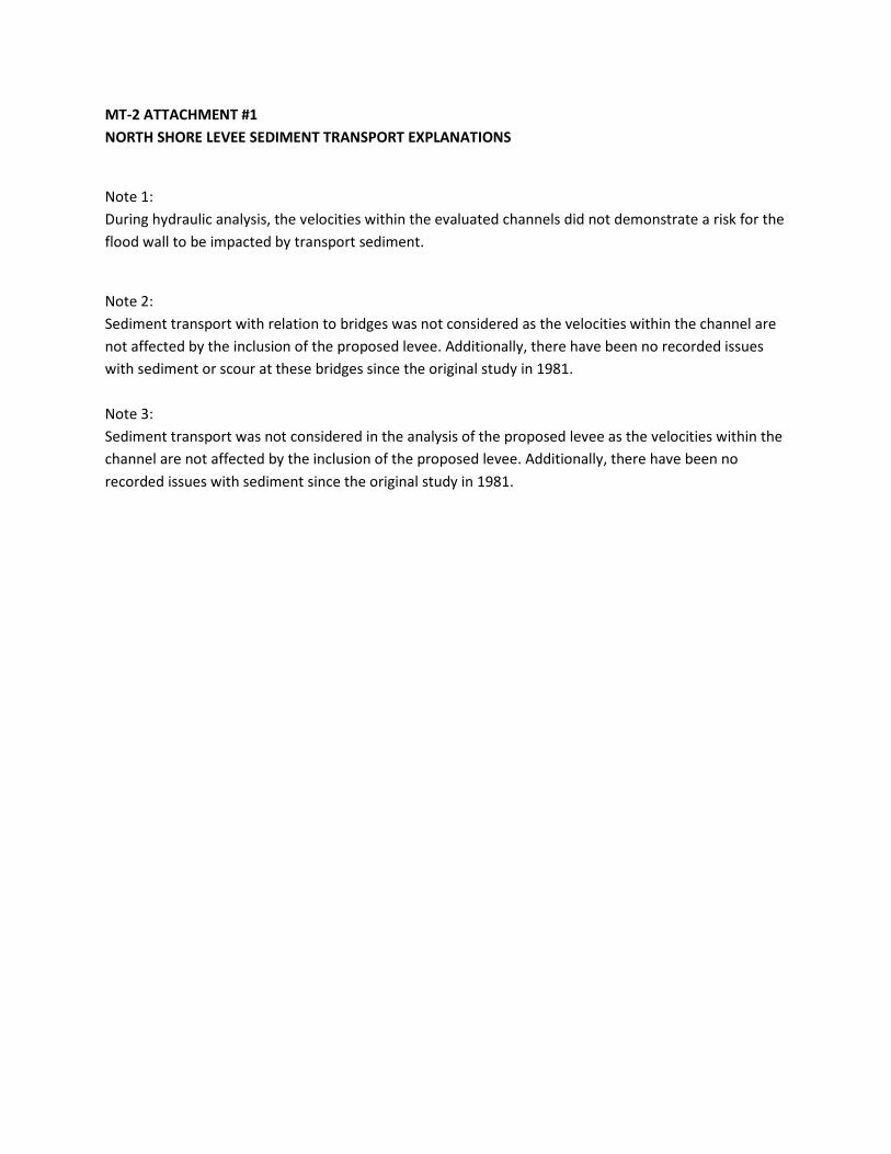
MT-2 ATTACHMENT #1
NORTH SHORE LEVEE SEDIMENT TRANSPORT EXPLANATIONS
Note 1:
During hydraulic analysis, the velocities within the evaluated channels did not demonstrate a risk for the
flood wall to be impacted by transport sediment.
Note 2:
Sediment transport with relation to bridges was not considered as the velocities within the channel are
not affected by the inclusion of the proposed levee. Additionally, there have been no recorded issues
with sediment or scour at these bridges since the original study in 1981.
Note 3:
Sediment transport was not considered in the analysis of the proposed levee as the velocities within the
channel are not affected by the inclusion of the proposed levee. Additionally, there have been no
recorded issues with sediment since the original study in 1981.

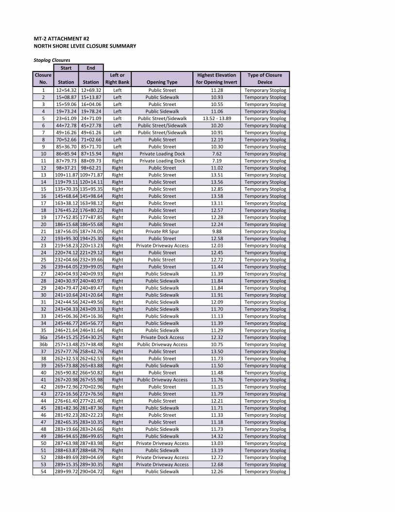
MT-2 ATTACHMENT #2
NORTH SHORE LEVEE CLOSURE SUMMARY
Stoplog Closures
Start End
Closure
No. Station Station
Left or
Right Bank Opening Type
Highest Elevation
for Opening Invert
Type of Closure
Device
1 12+54.32 12+69.32 Left Public Street 11.28 Temporary Stoplog
2 15+08.87 15+13.87 Left Public Sidewalk 10.93 Temporary Stoplog
3 15+59.06 16+04.06 Left Public Street 10.55 Temporary Stoplog
4 19+73.24 19+78.24 Left Public Sidewalk 11.06 Temporary Stoplog
5 23+61.09 24+71.09 Left Public Street/Sidewalk 13.52 - 13.89 Temporary Stoplog
6 44+72.78 45+27.78 Left Public Street/Sidewalk 10.20 Temporary Stoplog
7 49+16.26 49+61.26 Left Public Street/Sidewalk 10.91 Temporary Stoplog
8 70+52.66 71+02.66 Left Public Street 12.19 Temporary Stoplog
9 85+36.70 85+71.70 Left Public Street 10.30 Temporary Stoplog
10 86+85.94 87+15.94 Right Private Loading Dock 7.62 Temporary Stoplog
11 87+79.73 88+09.73 Right Private Loading Dock 7.19 Temporary Stoplog
12 98+37.21 98+62.21 Right Public Street 11.02 Temporary Stoplog
13 109+11.87 109+71.87 Right Public Street 13.51 Temporary Stoplog
14 119+79.11 120+14.11 Right Public Street 13.56 Temporary Stoplog
15 135+70.35 135+95.35 Right Public Street 12.85 Temporary Stoplog
16 145+68.64 145+98.64 Right Public Street 13.58 Temporary Stoplog
17 163+38.12 163+98.12 Right Public Street 13.11 Temporary Stoplog
18 176+45.22 176+80.22 Right Public Street 12.57 Temporary Stoplog
19 177+52.85 177+87.85 Right Public Street 12.28 Temporary Stoplog
20 186+15.68 186+55.68 Right Public Street 12.24 Temporary Stoplog
21 187+56.05 187+74.05 Right Private RR Spur 9.88 Temporary Stoplog
22 193+95.30 194+25.30 Right Public Street 12.58 Temporary Stoplog
23 219+58.23 220+13.23 Right Private Driveway Access 12.03 Temporary Stoplog
24 220+74.12 221+29.12 Right Public Street 12.45 Temporary Stoplog
25 232+04.66 232+39.66 Right Public Street 12.72 Temporary Stoplog
26 239+64.05 239+99.05 Right Public Street 11.44 Temporary Stoplog
27 240+04.93 240+09.93 Right Public Sidewalk 11.39 Temporary Stoplog
28 240+30.97 240+40.97 Right Public Sidewalk 11.84 Temporary Stoplog
29 240+79.47 240+89.47 Right Public Sidewalk 11.84 Temporary Stoplog
30 241+10.64 241+20.64 Right Public Sidewalk 11.91 Temporary Stoplog
31 242+44.56 242+49.56 Right Public Sidewalk 12.09 Temporary Stoplog
32 243+04.33 243+09.33 Right Public Sidewalk 11.70 Temporary Stoplog
33 245+06.36 245+16.36 Right Public Sidewalk 11.13 Temporary Stoplog
34 245+46.77 245+56.77 Right Public Sidewalk 11.39 Temporary Stoplog
35 246+21.64 246+31.64 Right Public Sidewalk 11.29 Temporary Stoplog
36a 254+15.25 254+30.25 Right Private Dock Access 12.32 Temporary Stoplog
36b 257+13.48 257+38.48 Right Public Driveway Access 10.75 Temporary Stoplog
37 257+77.76 258+42.76 Right Public Street 13.50 Temporary Stoplog
38 262+32.53 262+62.53 Right Public Street 11.73 Temporary Stoplog
39 265+73.88 265+83.88 Right Public Sidewalk 11.50 Temporary Stoplog
40 265+90.82 266+50.82 Right Public Street 11.48 Temporary Stoplog
41 267+20.98 267+55.98 Right Public Driveway Access 11.76 Temporary Stoplog
42 269+72.96 270+02.96 Right Public Street 11.15 Temporary Stoplog
43 272+16.56 272+76.56 Right Public Street 11.79 Temporary Stoplog
44 276+61.40 277+21.40 Right Public Street 12.21 Temporary Stoplog
45 281+82.36 281+87.36 Right Public Sidewalk 11.71 Temporary Stoplog
46 281+92.23 282+22.23 Right Public Street 11.33 Temporary Stoplog
47 282+65.35 283+10.35 Right Public Street 11.18 Temporary Stoplog
48 283+19.66 283+24.66 Right Public Sidewalk 11.73 Temporary Stoplog
49 286+94.65 286+99.65 Right Public Sidewalk 14.32 Temporary Stoplog
50 287+63.98 287+83.98 Right Private Driveway Access 13.03 Temporary Stoplog
51 288+63.87 288+68.79 Right Public Sidewalk 13.19 Temporary Stoplog
52 288+89.69 289+04.69 Right Private Driveway Access 12.72 Temporary Stoplog
53 289+15.35 289+30.35 Right Private Driveway Access 12.68 Temporary Stoplog
54 289+99.72 290+04.72 Right Public Sidewalk 12.26 Temporary Stoplog

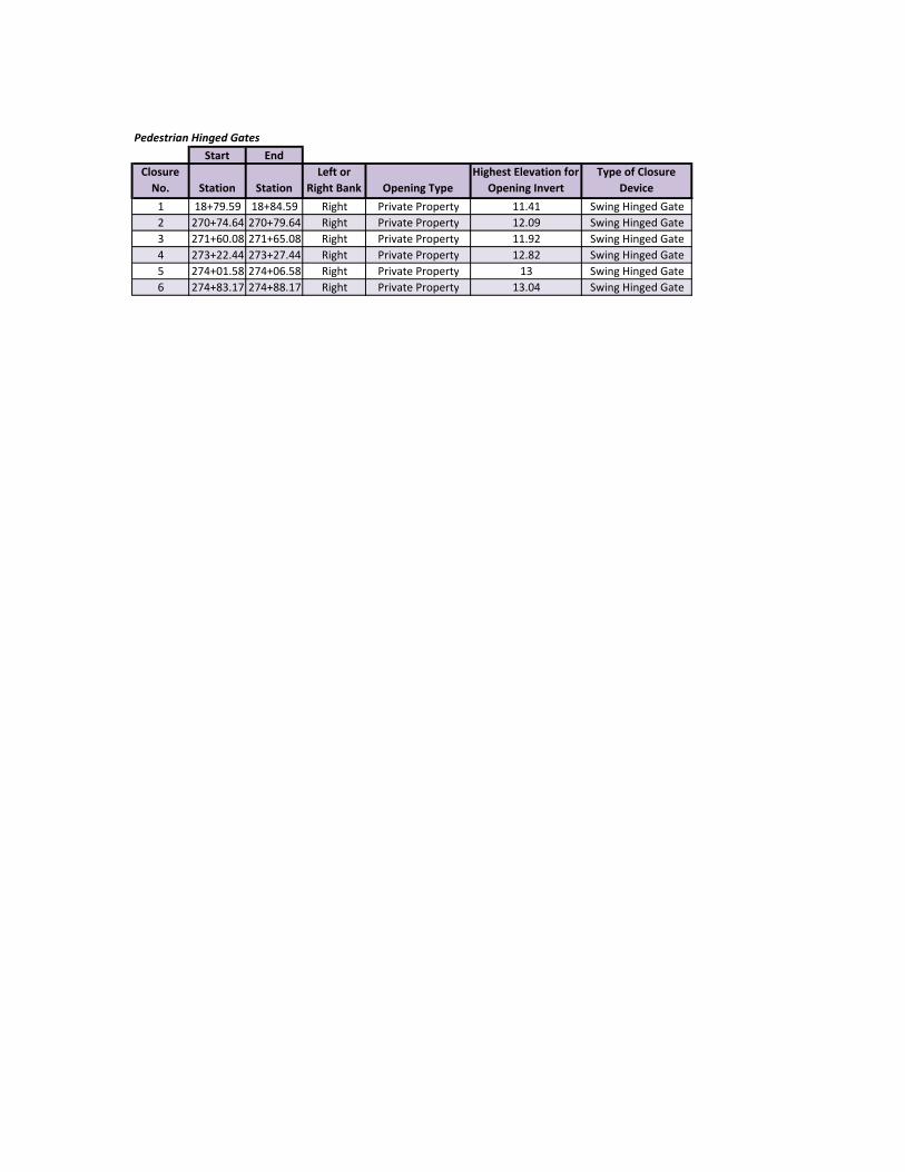
Pedestrian Hinged Gates
Start End
Closure
No. Station Station
Left or
Right Bank Opening Type
Highest Elevation for
Opening Invert
Type of Closure
Device
1 18+79.59 18+84.59 Right Private Property 11.41 Swing Hinged Gate
2 270+74.64 270+79.64 Right Private Property 12.09 Swing Hinged Gate
3 271+60.08 271+65.08 Right Private Property 11.92 Swing Hinged Gate
4 273+22.44 273+27.44 Right Private Property 12.82 Swing Hinged Gate
5 274+01.58 274+06.58 Right Private Property 13 Swing Hinged Gate
6 274+83.17 274+88.17 Right Private Property 13.04 Swing Hinged Gate

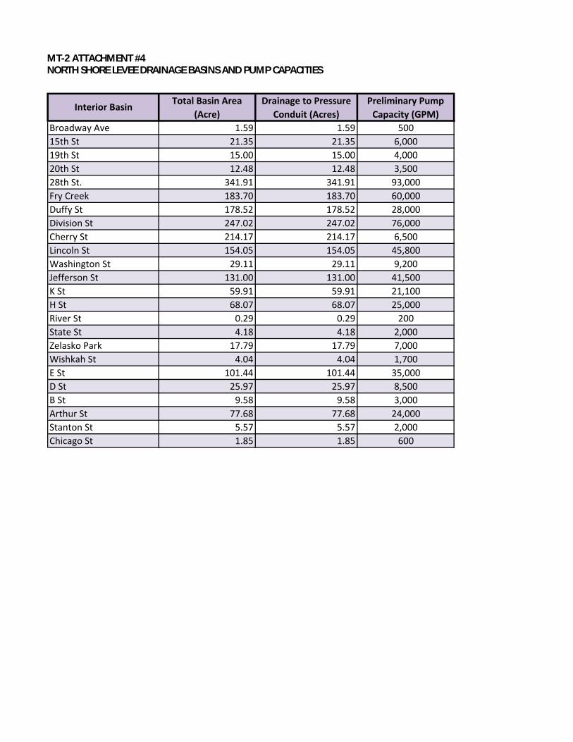
MT-2 ATTACHMENT #4
NORTH SHORE LEVEE DRAINAGE BASINS AND PUMP CAPACITIES
Broadway Ave 1.59 1.59
15th St 21.35 21.35
19th St 15.00 15.00
20th St 12.48 12.48
28th St. 341.91 341.91
Fry Creek 183.70 183.70
Duffy St 178.52 178.52
Division St 247.02 247.02
Cherry St 214.17 214.17
Lincoln St 154.05 154.05
Washington St 29.11 29.11
Jefferson St 131.00 131.00
K St 59.91 59.91
H St 68.07 68.07
River St 0.29 0.29
State St 4.18 4.18
Zelasko Park 17.79 17.79
Wishkah St 4.04 4.04
E St 101.44 101.44
D St 25.97 25.97
B St 9.58 9.58
Arthur St 77.68 77.68
Stanton St 5.57 5.57
Chicago St 1.85 1.85 600
2,000
24,000
3,000
8,500
500
6,000
3,500
4,000
25,000
21,100
41,500
9,200
45,800
35,000
1,700
7,000
2,000
200
Interior BasinTotal Basin Area
(Acre)
Drainage to Pressure
Conduit (Acres)
Preliminary Pump
Capacity (GPM)
6,500
76,000
28,000
60,000
93,000
MT2 ATTACHMENT #4NORTH SHORE LEVEE DRAINAGE BASINS AND PUMP CAPACITIES


