Embed Size (px)
Citation preview

NO POWER
& SIGNAL
CABLES
TOGETHER
READ CAREFULLY IN THE TEXT!
MPXzeroElectronic controller for refrigeration applications
USER MANUAL
MPXone
+0300106EN - ENGUp to date version available on
www.carel.com
ENG


3
ENG
MPXzero +0300106EN rel. 1.0 - 29.11.2021
GENERAL WARNINGS
CAREL bases the development of its products on decades of experience
in HVAC, on continuous investments in technological innovations to prod-
ucts, procedures and strict quality processes with in-circuit and functional
testing on 100% of its products, and on the most innovative production
technology available on the market. CAREL and its subsidiaries/affiliates
nonetheless cannot guarantee that all the aspects of the product and the
software included with the product respond to the requirements of the
final application, despite the product being developed according to start-
of-the-art techniques. The customer (manufacturer, developer or installer
of the final equipment) accepts all liability and risk relating to the config-
uration of the product in order to reach the expected results in relation
to the specific final installation and/or equipment. CAREL may, based on
specific agreements, act as a consultant for the successful commissioning
of the final unit/application, however in no case does it accept liability for
the correct operation of the final equipment/system. The CAREL product
is a state-of-the-art product, whose operation is specified in the technical
documentation supplied with the product or can be downloaded, even
prior to purchase, from the website www.carel.com. Each CAREL product,
in relation to its advanced level of technology, requires setup/configura-
tion/programming/commissioning to be able to operate in the best pos-
sible way for the specific application. Failure to complete such operations,
which are required/indicated in the user manual, may cause the final prod-
uct to malfunction; CAREL accepts no liability in such cases. Only qualified
personnel may install or carry out technical service on the product. The
customer must only use the product in the manner described in the doc-
umentation relating to the product. In addition to observing any further
warnings described in this manual, the following warnings must be heed-
ed for all CAREL products:
• prevent the electronic circuits from getting wet. Rain, humidity and
all types of liquids or condensate contain corrosive minerals that may
damage the electronic circuits. any case, the product should be used or
stored in environments that comply with the temperature and humidity
limits specified in the manual;
• do not install the device in particularly hot environments. Too high tem-
peratures may reduce the life of electronic devices, damage them and
deform or melt the plastic parts. In any case, the product should be used
or stored in environments that comply with the temperature and hu-
midity limits specified in the manual;
• do not attempt to open the device in any way other than described in
the manual.
• do not drop, hit or shake the device, as the internal circuits and mecha-
nisms may be irreparably damaged;
• do not use corrosive chemicals, solvents or aggressive detergents to
clean the device;
• do not use the product for applications other than those specified in the
technical manual.
All of the above suggestions likewise apply to the controllers, serial cards,
programming keys or any other accessory in the CAREL product portfolio.
CAREL adopts a policy of continual development. Consequently, CAREL
reserves the right to make changes and improvements to any product
described in this document without prior warning. The technical speci-
fications shown in the manual may be changed without prior warning.
The liability of CAREL in relation to its products is specified in the CAR-
EL general contract conditions, available on the website www.carel.com
and/or by specific agreements with customers; specifically, to the extent
where allowed by applicable legislation, in no case will CAREL, its employ-
ees or subsidiaries/affiliates be liable for any lost earnings or sales, losses
of data and information, costs of replacement goods or services, damage
to things or people, downtime or any direct, indirect, incidental, actual,
punitive, exemplary, special or consequential damage of any kind whatso-
ever, whether contractual, extra-contractual or due to negligence, or any
other liabilities deriving from the installation, use or impossibility to use
the product, even if CAREL or its subsidiaries/affiliates are warned of the
possibility of such damage.
DISPOSAL
Fig. 1 Fig. 2
INFORMATION FOR USERS ON THE CORRECT HANDLING OF WASTE ELECTRICAL AND ELECTRONIC EQUIPMENT (WEEE)The product is made up of metal parts and plastic parts. In reference to Eu-
ropean Union directive 2002/96/EC issued on 27 January 2003 and related
national legislation, please note that:
• WEEE cannot be disposed of as municipal waste and such waste must
be collected and disposed of separately;
• the public or private waste collection systems defined by local legisla-
tion must be used. In addition, the equipment can be returned to the
distributor at the end of its working life when buying new equipment;
• the equipment may contain hazardous substances: the improper use or
incorrect disposal of such may have negative effects on human health
and on the environment;
• the symbol (crossed-out wheeled bin) shown on the product or on the
packaging and on the technical leaflet indicates that the equipment has
been introduced onto the market after 13 August 2005 and that it must
be disposed of separately;
• in the event of illegal disposal of electrical and electronic waste, the
penalties are specified by local waste disposal legislation.
Warranty on materials: 2 years (from production date, excluding consum-
ables).
Approval: the quality and safety of CAREL S.p.A. products are guaranteed
by the ISO 9001 certified design and production system.
NO POWER
& SIGNAL
CABLES
TOGETHER
READ CAREFULLY IN THE TEXT!
Separate as much as possible the probe and digital input cables from
cables to inductive loads and power cables, so as to avoid possible
electromagnetic disturbance. Never run power cables (including the
electrical panel cables) and signal cables in the same conduits.
Key to the symbols:
Important: to bring critical issues to the attention of those using the prod-
uct.
Notice: to focus attention on important topics; in particular the practical
application of the various product functions.
Important: this product is to be integrated and/or incorporated into the
final apparatus or equipment. Verification of conformity to the laws and
technical standards in force in the country where the final apparatus or
equipment will be operated is the manufacturer’s responsibility. Before
delivering the product, Carel has already completed the checks and tests
required by the relevant European directives and harmonised standards,
using a typical test setup, which however cannot be considered as repre-
senting all possible conditions of the final installation.
Warnings

HACCP: CAUTION
Food Safety programs based on procedures such as HACCP and, more
generally, certain national regulations, require that the devices used for
food storage be periodically checked to ensure that measurement errors
are within the limits allowed for the application used. Carel recommends
users to follow, for example, the indications of the European standard
“Temperature recorders and thermometers for the transport, storage
and distribution of chilled, frozen, deep-frozen/quick-frozen food and ice
cream - PERIODIC VERIFICATION”, EN 13486 - 2001 (or subsequent updates)
or similar regulations and provisions in force in the country in question.
Further information can be found in the manual regarding the technical
characteristics, correct installation and configuration of the product.

5
ENG
MPXzero +0300106EN rel. 1.0 - 29.11.2021
Index
1. Introduction ............................................................... 71.1 Functions and main features .....................................................................7
1.2 Models and accessories ................................................................................8
2. Installation ............................................................... 112.1 Warnings ............................................................................................................. 11
2.2 Panel version ..................................................................................................... 11
2.3 Description of the terminals ................................................................... 12
2.4 Probe connections ........................................................................................ 13
2.5 Connection diagrams ................................................................................. 13
2.6 Positioning inside the panel ................................................................... 15
2.7 Electrical installation .................................................................................... 15
2.8 Serial port connections .............................................................................. 15
2.9 Functional diagrams .................................................................................... 15
2.10 Installation .......................................................................................................... 17
2.11 SPARK: configuration and commissioning software ................ 17
2.12 SPARKLY: command line tool .................................................................. 18
2.13 Setting the default parameters/loading the parameter sets .....18
2.14 Applica: copy configuration .................................................................... 19
2.15 Applica: date/time and time bands ................................................... 19
3. User interface ........................................................... 203.1 Introduction ...................................................................................................... 20
3.2 User terminal .................................................................................................... 20
4. Commissioning........................................................ 254.1 Wizard ................................................................................................................... 25
4.2 APPLICA app ..................................................................................................... 25
4.3 Description of the initial configuration parameters................. 26
4.4 Checks after commissioning .................................................................. 28
5. Functions .................................................................. 295.1 Inputs and outputs ....................................................................................... 29
5.2 Control .................................................................................................................. 39
5.3 Defrost .................................................................................................................. 45
5.4 Evaporator fans ............................................................................................... 52
5.5 Anti-sweat heater or fan modulation ................................................ 54
5.6 Compressor ....................................................................................................... 55
5.7 Variable capacity compressor (VCC) .................................................. 57
5.8 Pump down ...................................................................................................... 61
5.9 Generic functions .......................................................................................... 63
6. Parameter table ....................................................... 676.1 System .................................................................................................................. 67
6.2 Configuring the MPXzero controller via the APPLICA app .........75
7. Technical specifications ......................................... 777.1 Connector/cable table ............................................................................... 78
8. Alarms and signals .................................................. 798.1 Signals ................................................................................................................... 79
8.2 Types of alarms ................................................................................................ 79
8.3 Display alarm log ........................................................................................... 80
8.4 Alarm table ........................................................................................................ 80
8.5 Alarm parameters .......................................................................................... 81
8.6 HACCP alarms .................................................................................................. 83
9. Logs ........................................................................... 84
10. Release notes ........................................................... 85
Index


7
ENG
MPXzero +0300106EN rel. 1.0 - 29.11.2021 Introduction
MPXzero is a range of electronic controllers for centralised food retail refrigeration applications The user terminal, with capaci-
tive touch screen, features wireless connectivity with mobile devices. The range includes two versions, standard and advanced,
which differ in terms of the number of inputs/outputs, the number of serial ports available (Fieldbus) and wireless connectivity.
Near Field Connection (NFC) is always available, while Bluetooth (BLE) is optional on the Advanced version. The power supply is
always 115-230 Vac.
The CAREL “APPLICA” app is available on Google Play for the Android operating system and on the Apple Store for iOS (Bluetooth
only). This simplifies parameter configuration and unit commissioning in the field (also available in Desktop mode). The following
tools complete the solution:
• “Spark” PC commissioning tool, used to manage user profiles, configure parameters and change descriptions of the variables.
The possibility to use these two tools simultaneously, even by different users in separate locations - for example, modify a user
profile with “Spark” in the technical office, and apply it to the system using “Applica”, highlights the potential made available
by the complete package;
• “Sparkly” command-line production line tool, which, also via the RS485 serial port, is used in production systems for configur-
ing the devices (unit parameters or information) and end-of-line testing.
1.1 Functions and main featuresMPXzero, which shares many of the features already available on the MPXone range of controllers, has been designed to offer
maximum flexibility thanks to modular hardware. The advanced version, compared to the standard version:
• has a higher number of digital outputs;
• with the built-in Fieldbus port allows management via serial of a VCC compressor (Secop/Embraco specifications) or alterna-
tively the control of Main/Secondary local networks.
The functions assigned to the various analogue inputs are those for controlling the refrigerated cabinet temperature - outlet,
intake and defrost probe - while the software features can be used to configure the probes for different purposes, such as defrost
temperature for the second evaporator or an auxiliary temperature. In addition, up to four virtual probes are available, physically
connected to other devices and shared via the supervisor, and can be used to manage one of the specific functions listed above.
The two analogue outputs, when available on the advanced model, can be used to control the speed of a VCC compressor ion
frequency mode (PWM), or the speed of the evaporator fans and/or to modulate the anti-sweat heaters. The digital inputs can
be used for day/night switching, defrost calls, the door or curtain switch or activating alarms and other special functions. The
digital outputs (up to 4 relays) can be configured to control activation of the solenoid valve/compressor, evaporator fans, defrost,
lights and/or alarms.
Main features:
• compact structure: panel mounting;
• 115/230Vac power supply;
• hardware equipped with two 0-10 V modulating outputs for managing anti-sweat heaters and evaporator fans (MPXzero
advanced version with VCC by frequency only);
• NFC wireless connectivity as standard (Bluetooth optional on the advanced version);
• commissioning tool to optimise configuration of the controller;
• possibility to control a VCC compressor in serial or frequency mode, to Secop/Embraco specifications, advanced version only;
• possibility to configure a Main/Secondary network (up to 6 cabinets, advanced version without VCC only);
• built-in RS485 serial port for connection to supervisors and remote service systems (CAREL or Modbus protocol);
• defrost activated via keypad, digital input, network signal from Main, supervisor or scheduled with built-in RTC;
• management of various types of defrosts, on one or two evaporators: heater, natural (compressor off );
• smart defrost functions;
• coordination of network defrosts;
• management of cabinet lights and curtain;
• digital input broadcast from Main to Secondary devices;
• display Secondary alarms on Main;
• share one or more network probes;
• Main gateway to supervisor for all Secondary devices;
• HACCP alarm management.
1. INTRODUCTION

8
ENG
MPXzero +0300106EN rel. 1.0 - 29.11.2021Introduction
1.2 Models and accessoriesThe single-pack versions come with connector kits. The table below shows the list of part numbers and distinctive features for
the standard and advanced versions.
Fig. 1.a
P/N Description
S0MPSS3R02S0333 MPXzero, Standard, 115/230V, 3 relays, BMS, NFC, with connectors, single pack
S0MPSA4R03SA000 MPXzero, Advanced, 115/230V, 4 relays, BMS+Fbus, NFC, with connectors, single pack
S0MPSA4B03S0274 MPXzero, Advanced, 115/230V, 4 relays, BMS+Fbus, NFC, Bluetooth, with connectors, single pack
S0MPSA4R06S0319 MPXzero, Advanced, 115/230V, 4 relays, BMS, VCC frequency / 2 analogue outputs, NFC, with connectors, single pack
S0MPSA4B04S0320 MPXzero, Advanced, 115/230V, 4 relays, BMS, VCC serial, NFC, Bluetooth, with connectors, single pack
1.2.1 User terminal
The built-in user terminal includes the display and keypad, comprising four buttons that, when pressed alone or combined
with other buttons, are used to display and set the controller’s parameters (see “User interface”). Connectivity - NFC or NFC +
Bluetooth (BLE) based on the model - allows interaction with mobile devices and simplifi es unit commissioning (after having
installed the CAREL “Applica” APP for the Android/IOS operating systems).
1.2.2 Accessories
Notice: this list of ACCESSORY part numbers is updated as of the release date of this manual; please contact CAREL for any
additional part numbers available.
Notice: connectors and brackets are always included with the single packs!
Connector kit
P/N Description
BXOPZB35002B1 plug-in connector kit, 2 pins, 3.5 mm pitch, black (10 pcs)
BXOPZB35003B1 plug-in connector kit, 3 pins, 3.5 mm pitch, black (10 pcs)
BXOPZB38102G1 plug-in connector kit, 2 pins, 3.81 mm pitch, green (10 pcs)
BXOPZB38104G1 plug-in connector kit, 4 pins, 3.81 mm pitch, green (10 pcs)
BXOPZB38105G1 plug-in connector kit, 5 pins, 3.81 mm pitch, green (10 pcs)
BXOPZB50802O1 plug-in connector kit, 2 pins, 5.08 mm pitch, orange (10 pcs)
BXOPZB50803G1 plug-in connector kit, 3 pins, 5.08 mm pitch, green (10 pcs)
BXOPZB50805G1 plug-in connector kit, 5 pins, 5.08 mm pitch, green (10 pcs)
BXOPZB50807G1 plug-in connector kit, 7 pins, 5.08 mm pitch, green (10 pcs)
Fig. 1.b Tab. 1.a
Fixing brackets
P/N Description
BXOPZMBRC0002 bracket kit for panel version, multiple pack (20 pcs)
Tab. 1.b
Fig. 1.c
Cables
P/N Description
BXOPZC3000050 3-pin mini JST/free end cable, 50 cm (1 pc)
BXOPZC3S00250 3-pin mini JST/free end shielded cable, 250 cm (1 pc)
BXOPZC4000150 4-pin mini JST/mini JST cable, 150 cm (1 pc)
BXOPZC4000300 4-pin mini JST/mini JST cable, 300 cm (1 pc)
BXOPZC4010300 Multipurpose 4-pin mini JST/free end cable (VCC freq / AO / HMI display) 300 cm 1
pc.
BXOPZC3000050 Multipurpose 4-pin mini JST/free end cable (FBS, VCC serial) 300 cm 1 pc.
BXOPZC3S00250 Multipurpose 4-pin mini JST/free end shielded cable (FBS, VCC serial) 250 cm 1 pc.
BXOPZC30E010* Plug & play serial cable for Embraco inverters. 3-wire cable, with mini JST connector
at one end and Embraco inverter connector at the other
BXOPZC30E010* Plug & play serial cable for Secop inverters. 3-wire cable, with mini JST connector at
one end and Secop inverter connector at the other
Fig. 1.d Tab. 1.c

9
ENG
MPXzero +0300106EN rel. 1.0 - 29.11.2021 Introduction
Adapter kits
P/N Description
BXOPZC4020010 4-pin mini JST/removable cable adapter, 10 cm (1 pc)
Tab. 1.d
Fig. 1.e
Converters
P/N Description
CVSTDUMOR0 USB/RS485 converter
Tab. 1.e
Fig. 1.f
1.2.3 Temperature sensors
CAREL offers probes that are designed to facilitate installation:
Fig. 1.g
P/N Type Description Range
NTC***HP0* 10 kΩ±1%@25 °C, IP67, β 3435 Cabinet ambient temperature probe -50 to 50 °C (105°C in air)
PT1060HP01 PT1000 Class B, IP67 Temperature probe -50T105°C in air
Tab. 1.f
Notice: see manual +040010025 (ITA- ENG) /+040010026 (FRE-GER) for guidelines on installing the sensors on the unit.
Installation example with one evaporator
Sm
Sd
Sr
E
Key:
Code Description
Sm Outlet probe
Sr Intake probe
Sd Defrost probe
E Evaporator
Fig. 1.h Tab. 1.g
10
ENG
MPXzero +0300106EN rel. 1.0 - 29.11.2021Introduction
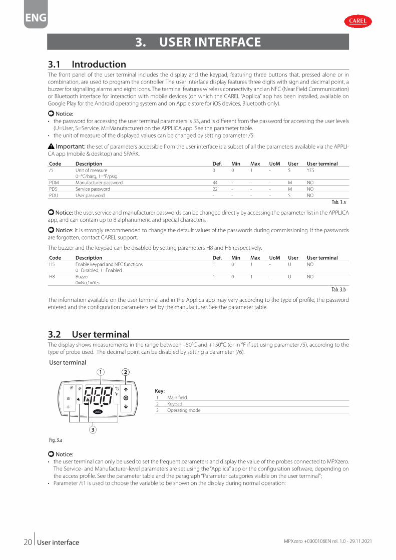
1.2.4 USB/RS485 converter (CVSTDUMOR0)
Electronic device used to interface an RS485 network to a personal computer via the
USB port. See technical leaflet +050000590.
The image below shows a connection example.
Fig. 1.i
CVSTDUMOR0USB/RS485 converter
RS485
Shield
BMS
Commissioning tool
CA ER L isolated BSU - 84SR 5 coverter
RS485
netw
ork
G DNRx+/Tx+Rx-/Tx-
S1 S2 GND
+V
++
MPXzero ADVANCED
DI1 DI2 GND
J5 B
MS
NO1
C1 NO2
NO3
Fig. 1.j

11
ENG
MPXzero +0300106EN rel. 1.0 - 29.11.2021 Installation
2. INSTALLATION
2.1 WarningsImportant: avoid installing the controller in environments with the following characteristics:
• temperature and humidity that do not comply with the ambient operating conditions (see “Technical specifi cations”);
• strong vibrations or knocks;
• exposure to water sprays or condensate;
• exposure to aggressive and polluting atmospheres (e.g.: sulphur and ammonia gases, saline mist, smoke) which may cause
corrosion and/or oxidation;
• strong magnetic and/or radio frequency interference (thus avoid installation near transmitting antennae);
• exposure to direct sunlight and the elements in general;
• wide and rapid fl uctuations in ambient temperature;
• exposure of the controller to dust (formation of corrosive patina with possible oxidation and reduction of insulation);
2.2 Panel version
2.2.1 Dimensions mm (inch)
84,80 (3.34)
39,6
(1.5
6)
79 (3.11)
max 95,5 (3.76)
28,5
(1.2
2)
3,8 (0.15) 75,2 (2.96)
71 (2.80)
29 (1
.14)
70,5 (2.76)
dima di foraturadrilling template
Fig. 2.a
2.2.2 Assembly
Important: before carrying out any maintenance, disconnect the controller from the power supply by moving the Main
system switch to “off ”.
1
2
H= 0,8-2,5 (0.03-0.10)
optional = H<2 (0.08)mandatory = H >2 (0.08)
CLICK
Fig. 2.b
1. Place the controller in the opening, pressing lightly on the side anchoring tabs.
2. Then press on the front until fully inserted (the side tabs will bend, and the catches will attach the controller to the panel, up
to a maximum thickness of 2 mm).
3. If necessary, fi t the fi xing brackets.

12
ENG
MPXzero +0300106EN rel. 1.0 - 29.11.2021Installation
Important: IP65 front protection is guaranteed only if the following conditions are met:
• maximum deviation of the rectangular opening from fl at surface: ≤ 0.5 mm (0.02 in);
• thickness of the electrical panel sheet metal: 0.8-2 mm (0.03-0.1 in); for thicknesses from 2-2.5 mm (0.08-0.1 in), the optional
fi xing brackets are required;
• maximum roughness of the surface where the gasket is applied: ≤ 120 μm.
Notice: the thickness of the sheet metal (or material) used to make the electrical panel must be adequate to ensure safe and
stable mounting of the product.
2.2.3 Removal
Important: before carrying out any maintenance, disconnect the controller from the power supply by moving the Main
system switch to “off ”.
3
2
2
1
Open the electrical panel and from the rear:
1. remove the fi xing brackets (if fi tted);
2. gently press the side anchoring tabs on the con-
troller;
3. exert slight pressure on the controller until it is re-
moved.
Important: the operation does not require the
use of a screwdriver or other tools.
Fig. 2.c
2.3 Description of the terminals
MPXzero STANDARD MPXzero ADVANCED
S1 S2 GND NO1
C1 NO2
NO3 L N
Tx/R
xGN
D
+BMS
DI1 DI2 GND
100-240 Vac
or S3
J5
J3bJ3a
J2
J1
S1 S2 GND C1NO1
NO2
NO3
NO4 L N
Tx/R
xGN
D
+BMS
DI1 DI2 GND
100-240 Vac
or S3
J5
J3bJ3a
J2
J1
+FBus
J6+V
Fig. 2.d Fig. 2.e
VCC Serial mode VCC Frequency mode
S1 S2 GND C1NO1
NO2
NO3
NO4 L N
Tx/R
xGN
D
+BMS
DI1 DI2 GND
100-240 Vac
or S3
J5
J3bJ3a
J2
J1
+
VCC
ser J7
+V
S1 S2 GND C1NO1
NO2
NO3
NO4 L N
Tx/R
xGN
D
+BMS
DI1 DI2 GND
100-240 Vac
or S3
J5
J3bJ3a
J2
J1
J9Y1
Y2VCC
PWM
Fig. 2.f Fig. 2.g
Ref. Description Ref. Description
J1 L Power supply J6 - Fieldbus serial port (RS485) / VCC serial: Rx-/Tx-
N + Fieldbus serial port (RS485) / VCC serial: Rx/Tx + /
Y2 for VCC frequency versionJ2 NO1 Digital output (relay) 1
C1 Common for relay 1 O Fieldbus serial port (RS485) / VCC serial: GND
NO2 Digital output (relay) 2 +V Fieldbus serial port (RS485): +V
NO3 Digital output (relay) 3 J7 - VCC serial port Rx/Tx -
NO4 Digital output (relay) 4 + VCC serial port Rx/Tx +
J3a S1 Analogue input 1 (NTC, PT1000) O VCC serial port GND
S2 Analogue input 2 (NTC, PT1000) J9 Y1 Analogue output 1
GND Analogue inputs 1,2 GND O GND: analogue output reference
J3b DI1 Digital input 1 (or analogue input 3) Y2 Analogue output 2
DI2 Digital input 2 O GND: analogue output reference
GND Digital input 1, 2 GND
J5 - BMS serial port (RS485): Rx-/Tx-
+ BMS serial port (RS485): Rx+/Tx+
O BMS serial port (RS485): GND Tab. 2.a

13
ENG
MPXzero +0300106EN rel. 1.0 - 29.11.2021 Installation
2.4 Probe connections
Notice: • the probe connections relate to the default parameter configuration;
• probes S1, S2, S3 can be configured as NTC or PT1000;
• the temperature probes must all be the same type.
MPXzero ADVANCED (3xNTC) MPXzero ADVANCED (2xNTC, 1xDI)
S1 S2 GND C1NO1
NO2
NO3
NO4 L N
+
DI1 DI2 GNDJ3b
J3a
+
+V
NTC - Air-off temper. probe (Sm)
NTC - Air-on temper. probe (Sr)
DI2- Digital input
NTC - Defrost temper. probe (Sd)
S1 S2 GND C1NO1
NO2
NO3
NO4 L N
+
DI1 DI2 GNDJ3b
J3a
+
+V
DI1- Digital input
NTC - Air-off temper. probe (Sm)
NTC - Defrost temper. probe (Sd)
DI2- Digital input
Fig. 2.h Fig. 2.i
2.5 Connection diagrams Notice: the “APPLICA” app can be used to change the configuration of the probes without needing to rewire or change the
functions of the relays, thus taking advantage of different capacities when needed.
2.5.1 Advanced model
S1 S2 GND C1NO1
NO2
NO3
NO4 L N
+
DI1 DI2 GND
L
N
J5 BMS
J3bJ3a
J2
J1
+
J6 Fieldbus+V
Only “Main units” to be connected on RS485
100/240 Vac
shie
ld
S1 S2 GND C1NO1
NO2
NO3
NO4 L N
+
DI1 DI2 GND
J5 BMS
J3bJ3a
J2
J1
+
J6 Fieldbus+V
S1 S2 GND C1NO1
NO2
NO3
NO4 L N
+
DI1 DI2 GND
J5 BMS
J3bJ3a
J2
J1
+
J6 Fieldbus+V
Main
Secondary 1 Secondary 2
Fig. 2.j

14
ENG
MPXzero +0300106EN rel. 1.0 - 29.11.2021Installation
2.5.2 Advanced VCC version
S1 S2 GND C1NO1
NO2
NO3
NO4 L N
+
DI1 DI2 GND
L
N
J5 BMS
J3bJ3a
J2
J1
+
J7 VCC ser+V
Only “Main units” to be connected on RS485
100/240 Vac
shie
ld
Main
C1C2
L1/L L2/N L3 U V W1 2 3 4 5 6 7 8 9 10
Inverter
VCC
Fig. 2.k
2.5.3 Advanced VCC frequency version
S1 S2 GND C1NO1
NO2
NO3
NO4 L N
+
DI1 DI2 GND
L
N
J5 BMS
J3bJ3a
J2
J1
J9 VCC PWMY1
Y2
Only “Main units” to be connected on RS485
100/240 Vac
shie
ld
Main
C1C2
L1/L L2/N L3 U V W1 2 3 4 5 6 7 8 9 10
Inverter
VCC
Notice: the MPXzero Advanced
VCC frequency version, on the out-
put not used to control the variable
speed compressor, can confi gure
outputs Y1 and/or Y2 for managing
modulating functions, such as varia-
ble speed fans or anti-sweat heaters
.
Fig. 2.l

15
ENG
MPXzero +0300106EN rel. 1.0 - 29.11.2021 Installation
2.6 Positioning inside the panelThe position of the controller in the electrical cabinet must be chosen so as to guarantee correct physical separation from the
power components (solenoids, contactors, actuators, inverters, ...) and the connected cables. Proximity to such devices/cables
may create random malfunctions that are not immediately evident. The structure of the panel must allow the correct flow of
cooling air.
2.7 Electrical installation Important:
when laying the wiring, “physically” separate the power part from the control part. The proximity of these two sets of wires will,
in most cases, cause problems of induced disturbance or, over time, malfunctions or damage to the components. The ideal
solution is to house these two circuits in two separate cabinets. Sometimes this is not possible, and therefore the power part and
the control part must be installed in two separate areas inside the same panel. For the control signals, it is recommended to use
shielded cables with twisted wires. If the control cables have to cross over the power cables, the intersections must be as near as
possible to 90 degrees, always avoiding running the control cables parallel to the power cables.
Pay attention to the following warnings:
• use cable ends suitable for the corresponding terminals. Loosen each screw and insert the cable ends, then tighten the
screws. When the operation is completed, slightly tug the cables to check they are sufficiently tight;
• separate as much as possible the sensor signal, digital input and serial line cables
• from cables to inductive loads and power cables, so as to avoid possible electromagnetic disturbance.. Never run power
cables (including the electrical cables) and probe signal cables in the same conduits. Do not install the probe cables in the
immediate vicinity of power devices (contactors, circuit breakers or similar);
• reduce the path of the probe cables as much as possible, and avoid spiral paths that enclose power devices;
• avoid touching or nearly touching the electronic components fitted on the boards to avoid electrostatic discharges (extreme-
ly damaging) from the operator to the components;
• do not secure the cables to the terminals by pressing the screwdriver with excessive force, to avoid damaging the controller:
maximum tightening torque: 0.22-0.25 N•m.
• for applications subject to considerable vibrations (1.5 mm pk-pk 10/55 Hz), secure the cables connected to the controller
around 3 cm from the connectors using cable ties.
2.8 Serial port connectionsFor serial connections (FBus and BMS ports), the cables used must be suitable for the RS485 standard (shielded twisted pair, see
the specifications in the following table).
Main device Serial port Lmax (m)Wire/wire capaci-
tance (pF/m)
Resistance on first
and last device
Max no. secondary
devices on busBaud rate (bit/s)
MPXzero FBus 500 <90 120 Ω 5 19200
MPXzero VCC 500 <90 - 1 600
PC (supervision) BMS 500 <90 120 Ω - 19200
Tab. 2.b
The serial connection between the two controllers (FBus on Main and BMS on Secondary) must be made as shown in the fol-
lowing figures (+ to + and - to -).
Notice: connect a 120 Ω terminating resistor between the Tx/Rx+ and Tx/Rx- terminals on the last controller on the RS485
line. Do not connect GND to earth.
2.9 Functional diagramsMPXzero can control stand-alone refrigeration units (plug-in with onboard compressor, either on-off or VCC) or multiple units
(for example, one or more multiplexed showcases). These systems are made up of stand-alone controllers, or controllers that are
connected to each other in a Main/Secondary arrangement in which each Main controller can manage up to five Secondary
controllers. The following functional diagrams illustrate some typical applications.

16
ENG
MPXzero +0300106EN rel. 1.0 - 29.11.2021Installation
2.9.1 Stand-alone confi guration
Panel
MPXzero Standard and MPXzero Advanced
Main
J5
Fig. 2.m
MPXzero ADVANCED VCC Serial/Frequency
C1C2
L1/L L2/N L3 U V W1 2 3 4 5 6 7 8 9 10
Inverter
VCCMain
J5J7
C1C2
L1/L L2/N L3 U V W1 2 3 4 5 6 7 8 9 10
Inverter
VCCMain
J5J9
Fig. 2.n Fig. 2.o
Main/Secondary network for MPXzero Advanced M/S
S1 S2 GND C1NO1
NO2
NO3
NO4 L N
+
DI1 DI2 GND
J5 BMS
J3bJ3a
J2
J1
+
J6 Fieldbus+V
S1 S2 GND C1NO1
NO2
NO3
NO4 L N
+
DI1 DI2 GND
J5 BMS
J3bJ3a
J2
J1
+
J6 Fieldbus+V
Secondary 1
S1 S2 GND C1NO1
NO2
NO3
NO4 L N
+
DI1 DI2 GND
J5 BMS
J3bJ3a
J2
J1
+
J6 Fieldbus+V
Main Secondary 2
LN
Fig. 2.p
RS485 supervisor network
Notice: if confi guring a Main/Secondary local network, on the main controller, parameter H3 must be set based on the
protocol used by the supervisory system (Modbus/Carel). On the Secondary devices, parameter H3 should always be left at the
default value (1=Modbus).
BMSMain 1
J5
Main 2
J5
Main 3
J5
Fig. 2.q

17
ENG
MPXzero +0300106EN rel. 1.0 - 29.11.2021 Installation
2.10 InstallationFor installation proceed as follows, with reference to the wiring diagrams:
• before performing any operations on the control board, disconnect the main power supply by turning the main switch in the
electrical panel OFF;
• avoid touching the control board, as electrostatic discharges may damage the electronic components;
• the index of protection required for the application must be ensured by the manufacturer of the cabinet or by suitable as-
sembly of the controller;
• connect any digital inputs, Lmax = 10 m;
• connect the actuators: the actuators should only be connected after having programmed the controller. Carefully evaluate
the maximum ratings of the relay outputs as indicated in “Controller electrical and physical specifications”;
• program the controller: see “User interface”;
• for the connection of the Main/Secondary network and user interfaces, use shielded cable and check the maximum distances
and cable sizes specified in “Electrical specifications”;
• for safety devices (e.g. circuit breakers), comply with the following requirements:
– IEC 60364-4-41;
– standards in force in the country;
– connection technical requirements of the power company.
Important: the following warnings must be observed when connecting the controllers:
• incorrect connection to the power supply may seriously damage the controller;
• use cable ends suitable for the corresponding terminals. Loosen each screw and insert the cable ends, then tighten the screws
and lightly tug the cables to check correct tightness;
• separate as much as possible the probe and digital input cables from cables to inductive loads and power cables, so as to
avoid possible electromagnetic disturbance. Never run power cables (including the electrical panel cables) and probe signal
cables in the same conduits;
• do not install the probe cables in the immediate vicinity of power devices (contactors, circuit breakers, etc.). Reduce the path
of probe cables as much as possible, and avoid spiral paths that enclose power devices.
2.11 SPARK: configuration and commissioning softwareSPARK is the configuration software, available for laptops, specifically designed to meet the needs of manufacturers and installers
of multiplexed cabinets. The software is used to:
• configure access and password levels;
• change parameter sets and create custom read/write lists to upload to the device;
• add languages and parameter descriptions;
• view the trends of physical quantities in real time, with the possibility to save data in Excel format.
In order to carry out the operations mentioned above, a specific “workspace” (extension .spark) is required; this can be down-
loaded from ksa.carel.com.
Notice: the workspace is specific for each firmware version; the correct combination of file-controller firmware version is
required for correct communication.
For the electrical connection, use the USB/RS485 converter CVSTDUMOR0.
Any authorisation, under license, is issued by CAREL.
S1 S2 GND C1NO1
NO2
NO3
NO4 L N
+
DI1 DI2 GND
J5 BMS
J3bJ3a
J2
J1
+
J6 Fieldbus+V
S1 S2 GND C1NO1
NO2
NO3
NO4 L N
+
DI1 DI2 GND
J5 BMS
J3bJ3a
J2
J1
+
J6 Fieldbus+V
Main Secondary
CVSTDUMOR0USB/RS485 converter
RS485
Shield
BMS
Commissioning tool
CA ER L isolated BSU - 84SR 5 coverter
RS485
netw
ork
G DNRx+/Tx+Rx-/Tx-
Fig. 2.r

18
ENG
MPXzero +0300106EN rel. 1.0 - 29.11.2021Installation
2.12 SPARKLY: command line toolSPARKLY is command-line software designed to be integrated into production systems, and is used to:
• load the parameter configuration onto the controller;
• update the device software;
• write specific information directly to the controller’s s internal memory (serial number, production date, etc.);
• perform end-of-line tests (if properly integrated with a high-level system).
2.13 Setting the default parameters/loading the parameter setsTwo different sets of parameters can be saved in the MPXzero memory. These default sets can never be overwritten, being stored
in a non-modifiable memory area. When resetting the system using the configuration wizard, one of the two configurations can
be selected. Alternatively, a parameter set, differentiated by the user to control the specific refrigeration system, can be saved
and uploaded to the linked cloud account using the Applica app, or using Sparkly directly on the production line.
Procedure for setting the default parameters/loading the parameter setSet 0, called the working set, contains the set of parameters used by MPXzero during normal operation. This set is loaded
whenever MPXzero is started, and the parameters can be modified at any time from the terminal, supervisor, APPLICA app and
configuration software. The other two sets of parameters, numbered 1 and 2, contain other lists of parameters, preloaded by
CAREL during production, which can be copied as desired to the working set (Set 0). These sets of parameters, unlike Set 0, can
only be modified using the appropriate configuration software (SPARK). The sets of parameters (configured on the production
line using SPARKLY), once differentiated by the manufacturer of the unit, can be loaded so as to rapidly set a list of parameters,
with corresponding values, to control the refrigeration system.
User terminalProcedure:
1. power down the controller;
2. power up the controller and when the software revision is shown (e.g. r1.3), press and hold PRG: at the end, the number 0 is
displayed, which signifies the parameters have been reset to the default values;
3. to reset the parameters to the default values, press PRG and select 0, otherwise go to step 5;
4. press UP/DOWN to choose the set of parameters (1 or 2) to be loaded as the working set, and confirm by pressing PRG;
5. complete (if required) the commissioning procedure (see “Commissioning”).
ApplicaProcedure:
1. open Applica on the smartphone;
2. access the controller via NFC or Bluetooth, entering your profile credentials;
3. follow the path “Configurations/Configuration list”;
4. select the “Default” or “Custom” label;
5. if required, confirm the configuration to be opened (if connected to the controller via NFC, select Upload at the top right and
move the smartphone closer to MPXzero, while via Bluetooth the update will be completed automatically).

19
ENG
MPXzero +0300106EN rel. 1.0 - 29.11.2021 Installation
2.14 Applica: copy configurationTo simplify operations in the field, Applica includes a “Clone” feature to acquire the configuration from one unit and replicate it
“one-for-one” to other cabinets.
Procedure:
1. open Applica on the smartphone;
2. access the controller via NFC or Bluetooth, entering the profile credentials;
3. follow the path “Configurations/Clone”;
4. move the smartphone closer to the MPXzero to acquire the configuration from;
5. following the acknowledgement message, move the smartphone closer to the MPXzero to apply the same configuration to;
6. wait for the cloning confirmation message to be shown.
2.15 Applica: date/time and time bandsIt is possible to set smartphone’s date and time on the controller, via the drop-down menu on the side, selecting “settings-->de-
vice-->set date/time”.
To set the day/night time bands:Procedure:
1. open Applica on the smartphone;
2. access the controller via NFC or Bluetooth, entering your profile credentials;
3. open the “Scheduler” section;
4. define the day/night time bands for the different days of the week;
5. apply the set schedule to the controller (upload button at the top-right for connection via NFC).
Notice: up to 8 daily time bands can be configured by setting parameters tS1, tE1 to tS8, tE8.
20
ENG
MPXzero +0300106EN rel. 1.0 - 29.11.2021User interface
3. USER INTERFACE
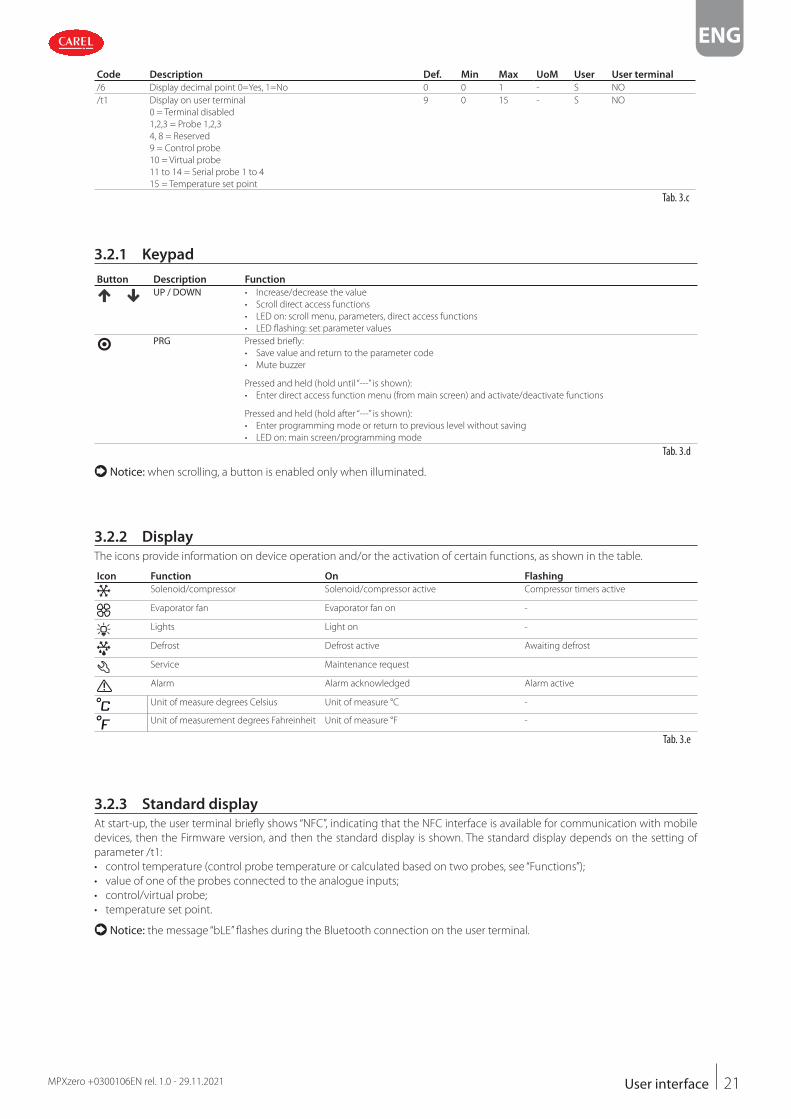
3.1 IntroductionThe front panel of the user terminal includes the display and the keypad, featuring three buttons that, pressed alone or in
combination, are used to program the controller. The user interface display features three digits with sign and decimal point, a
buzzer for signalling alarms and eight icons. The terminal features wireless connectivity and an NFC (Near Field Communication)
or Bluetooth interface for interaction with mobile devices (on which the CAREL “Applica” app has been installed, available on
Google Play for the Android operating system and on Apple store for iOS devices, Bluetooth only).
Notice:• the password for accessing the user terminal parameters is 33, and is diff erent from the password for accessing the user levels
(U=User, S=Service, M=Manufacturer) on the APPLICA app. See the parameter table.
• the unit of measure of the displayed values can be changed by setting parameter /5.
Important: the set of parameters accessible from the user interface is a subset of all the parameters available via the APPLI-
CA app (mobile & desktop) and SPARK.
Code Description Def. Min Max UoM User User terminal
/5 Unit of measure
0=°C/barg, 1=°F/psig
0 0 1 - S YES
PDM Manufacturer password 44 - - - M NO
PDS Service password 22 - - - M NO
PDU User password - - - - S NO
Tab. 3.a
Notice: the user, service and manufacturer passwords can be changed directly by accessing the parameter list in the APPLICA
app, and can contain up to 8 alphanumeric and special characters.
Notice: it is strongly recommended to change the default values of the passwords during commissioning. If the passwords
are forgotten, contact CAREL support.
The buzzer and the keypad can be disabled by setting parameters H8 and H5 respectively.
Code Description Def. Min Max UoM User User terminal
H5 Enable keypad and NFC functions
0=Disabled, 1=Enabled
1 0 1 - U NO
H8 Buzzer
0=No,1=Yes
1 0 1 - U NO
Tab. 3.b
The information available on the user terminal and in the Applica app may vary according to the type of profi le, the password
entered and the confi guration parameters set by the manufacturer. See the parameter table.
3.2 User terminalThe display shows measurements in the range between –50°C and +150°C (or in °F if set using parameter /5), according to the
type of probe used. The decimal point can be disabled by setting a parameter (/6).
User terminal
3
1 22
Key:
1 Main fi eld
2 Keypad
3 Operating mode
Fig. 3.a
Notice:• the user terminal can only be used to set the frequent parameters and display the value of the probes connected to MPXzero.
The Service- and Manufacturer-level parameters are set using the “Applica” app or the confi guration software, depending on
the access profi le. See the parameter table and the paragraph “Parameter categories visible on the user terminal”;
• Parameter /t1 is used to choose the variable to be shown on the display during normal operation:
21
ENG
MPXzero +0300106EN rel. 1.0 - 29.11.2021 User interface
Code Description Def. Min Max UoM User User terminal
/6 Display decimal point 0=Yes, 1=No 0 0 1 - S NO
/t1 Display on user terminal
0 = Terminal disabled
1,2,3 = Probe 1,2,3
4, 8 = Reserved
9 = Control probe
10 = Virtual probe
11 to 14 = Serial probe 1 to 4
15 = Temperature set point
9 0 15 - S NO
Tab. 3.c
3.2.1 Keypad
Button Description Function
UP / DOWN • Increase/decrease the value
• Scroll direct access functions
• LED on: scroll menu, parameters, direct access functions
• LED flashing: set parameter values
PRG Pressed briefly:
• Save value and return to the parameter code
• Mute buzzer
Pressed and held (hold until “---” is shown):
• Enter direct access function menu (from main screen) and activate/deactivate functions
Pressed and held (hold after “---” is shown):
• Enter programming mode or return to previous level without saving
• LED on: main screen/programming mode
Tab. 3.d
Notice: when scrolling, a button is enabled only when illuminated.
3.2.2 Display
The icons provide information on device operation and/or the activation of certain functions, as shown in the table.
Icon Function On Flashing
Solenoid/compressor Solenoid/compressor active Compressor timers active
Evaporator fan Evaporator fan on -
Lights Light on -
Defrost Defrost active Awaiting defrost
Service Maintenance request
Alarm Alarm acknowledged Alarm active
Unit of measure degrees Celsius Unit of measure °C -
Unit of measurement degrees Fahreinheit Unit of measure °F -
Tab. 3.e
3.2.3 Standard display
At start-up, the user terminal briefly shows “NFC”, indicating that the NFC interface is available for communication with mobile
devices, then the Firmware version, and then the standard display is shown. The standard display depends on the setting of
parameter /t1:
• control temperature (control probe temperature or calculated based on two probes, see “Functions”);
• value of one of the probes connected to the analogue inputs;
• control/virtual probe;
• temperature set point.
Notice: the message “bLE” flashes during the Bluetooth connection on the user terminal.

22
ENG
MPXzero +0300106EN rel. 1.0 - 29.11.2021User interface
3.2.4 Programming mode
The user terminal only provides access to the Basic confi guration parameters, such as direct functions and active alarms without
password protection, or, with password protection, unit set-up (*). Press PRG, the display will show “Loc” (display locked), on the
main screen, hold PRG for 3s until the display is unlocked “---”, enter the password 33 to access programming mode; see the
menu description for details of the items available.
Notice: (*) for any optimisations, use the APPLICA app.
Parameter categories visible on the MPXzero Standard and Advanced user terminal
VIS
(Display)
Direct com-
mands
CtL
(Control) / Ana-
logue inputs
DEF
(Defrost)
ALM Thr
(Alarms)
FAN
(Fan)
CNF
Connectivity/
Fieldbus/
Control/Display
RTC
Sm ** Lht On d0 AA F0 H0 y_
Sd ** Cnt St dI A0 F1 H2 M_
Sr dEF rd dt1 AL F2 H1 d_
Sa dFn /P1 dP1 AH F3 H3 h_
SU CLn /FA Ad ESC In * m_
Svt On/Off /Fb ESC rES Sn * d_
Vsr ** ESC /Fc HMr r7 * u_
ESC ESC ESC /5 ESC
ESC
Tab. 3.f
* = Advanced only
** = parameters displayed (VIS) for MPXzero VCC.
Notice**: parameters not available on the Standard version.
Parameter categories visible on the user terminal, MPXzero VCC model
VIS
(Display)
Direct
com-
mands
CtL
(Control) / Ana-
logue inputs
DEF
(Defrost)
ALM Thr
(Alarms)
FAN
(Fan)
CNF
Connectivity/
Fieldbus/
Control/Display
RTC
Vdc
(Variable
Compressor)
Sm Lht On d0 AA F0 H0 y_ /P5 **
Sd Cnt St dI A0 F1 H2 M_ /P6 **
Sr dEF rd dt1 AL F2 H1 d_ CMi
Sa dFn /P1 dP1 AH F3 H3 h_ CMA
SU CLn /FA Ad Ac /5 m_ Cnf
Svt On/Off /Fb ESC rES AE ESC d_ CMf
vSr ESC /Fc HMr Acd u_ Csc
ESC ESC ESC F00 ESC Cdf
F4 cct
ESC ESC
Tab. 3.g
** Available only on the VCC Frequency version
ProcedureTo navigate the menu tree, use the following buttons:
• UP and DOWN to navigate the menu and set the values;
• PRG to enter the menu items and save the changes made;
• PRG (3s) to select the menu item or ESC to return to the previous branch. Example of how to set parameter St (set point):
1. Wait for the standard display to be
shown;
2. Press PRG, the display will show
“Loc” (display locked)
3. Press and hold PRG and until “PSd”
is shown
4. When PSd is shown, press PRG and
use the UP arrow to enter the pass-
word: 33
5. Press PRG: the fi rst category of
parameters is displayed: VIS (=Dis-
play)
6. Press DOWN: the second catego-
ry of parameters is displayed: CtL
(=Control)

23
ENG
MPXzero +0300106EN rel. 1.0 - 29.11.2021 User interface
7. Press DOWN until reaching param-
eter St (=set point) and PRG to dis-
play the value
8. Press UP/DOWN to modify the val-
ue
9. Press PRG to save the setting and
return to the parameter code
10. Press PRG for 3 sec or alternatively,
in the parameter level select ESC
and press PRG to return to the pa-
rameter categories
11. Press DOWN to move to the next
category dEF (=Defrost) and follow
steps 5 to 9 to set the other param-
eters
12. After having completed the set-
tings, to exit either: a) from the cat-
egories press ESC and then PRG; or
b) press PRG for 3 s
Notice: if no button is pressed, after around 1 minute the terminal will automatically return to the standard display.
Mobile device and PCThe “APPLICA” app and SPARK software can be used to confi gure the controller from a mobile device (smartphone, tablet), via
NFC (Near Field Communication) or Bluetooth. The controller can be programmed according to the profi le used for access to
APPLICA or SPARK, with diff erent parameter visibility depending on the rights associated with each profi le (User, Service, Man-
ufacturer). Procedure:
1. download the“Applica” app;
2. (on the mobile device) start the app for commissioning the controller;
3. activate NFC;
4. move the device closer to the controller, less than 10 mm away;
5. follow the instructions shown on the display.
3.2.5 Direct functions
The following functions can be activated directly from the keypad or via the app:
Icon Display On/Off
Lht Cabinet light
+ Cnt Continuous cycle
dEF Defrost
dFn Network defrost (Main only)
CLn Clean cabinet
ON Unit ON with control request
Tab. 3.h
Procedure:
1. go to the standard display;
2. press PRG until “---” is shown and then release immediately to unlock the display
3. press PRG again to access the direct commands (the fi rst item will be the light command Lht);
4. press PRG to turn the light on/off and DOWN to move to the next direct function;
5. follow the previous steps for all the other functions;
6. When fi nished, press Esc to exit.

24
ENG
MPXzero +0300106EN rel. 1.0 - 29.11.2021User interface
1. Go to the standard display; 2. Press PRG until “---” is displayed and then release immediately.
3. Press PRG again: Lht is displayed,
the UP and DOWN buttons light
up. Press PRG to turn the light on/
off : the icon will come on or go
off . Press DOWN to activate the
next function (Cnt) or press Esc
to exit
4. Select Esc to exit 5. The standard display is shown

25
ENG
MPXzero +0300106EN rel. 1.0 - 29.11.2021 Commissioning
4. COMMISSIONING
Once the electrical connections have been completed (see “Installation”) and the power supply has been connected, the oper-
ations required for commissioning the controller depend on the type of interface used, however essentially involve setting the
so-called initial configuration parameters.
The initial configuration procedure can be run on the user terminal or mobile device (with the APPLICA app).
The parameters used for commissioning are shown in the Parameter table.
Important: the parameters that can be set on the user terminal and in the APPLICA app may vary according to the rights
assigned to the access profile, defined by the manufacturer. Therefore, not all of the following parameters may be visible or
modifiable.
4.1 WizardMPXzero features highly configurable inputs and outputs. CAREL in any case recommends a configuration following the default
settings of the parameters. By following this suggestion, the controller can independently manage the main functions in most
applications, without having to significantly modify the settings of the parameters.
4.1.1 User terminal
When first started, MPXzero runs a procedure (configuration wizard) that requires the settings of the critical parameters, relating to:
• correct configuration of the probe types;
• correct communication between controller and supervisor;
• correct configuration of the VCC compressor or Main/Secondary network parameters.
Notice: the configuration wizard can also be:
• run via the “APPLICA” app
• skipped by creating a parameter configuration using the SPARK configuration software.
During this procedure, the device remains in standby and all of its functions are deactivated (including control and communi-
cation via RS485). Only after having set all of the required parameters will it be possible to continue with normal configuration.
Notice: at the end of the guided procedure (wizard), the controller uses the default parameters (for example, set point at the
default value 50°C, and therefore there will be no request).
4.2 APPLICA appThe “APPLICA” app can be used to configure the controller from a mobile device (smartphone, tablet), via NFC (Near Field Com-
munication, Android devices only) or Bluetooth.
Procedure (modify parameters):
• download the CAREL “Applica” App, available on the Google Play Store and Apple Store;
• (on the mobile device) enable NFC and/or Bluetooth(*) communication and mobile data;
• open Applica;
• if using NFC communication, move the device to a distance of less than 10 mm from the user terminal, so as to recognise the
model and firmware;
• select the access profile and enter the required password (**);
• set the parameters as needed;
• move the mobile device near to the user terminal again to upload the configuration parameters.
(*) some Android devices may require geolocation to be enabled in order to view the list of Bluetooth devices in the area.
(*) pre-assigned by the unit manufacturer to allow maintenance only by authorised service technicians. See the parameter table.

26
ENG
MPXzero +0300106EN rel. 1.0 - 29.11.2021Commissioning
BLENFC
max10mm
CAREL APPs
Local and remotetechnical appfor Service
Fig. 4.a
4.2.2 Applica Desktop
Applica Desktop is confi guration software for laptops that provides the following functions via an RS485 serial connection:
• confi gure the controller;
• change parameter sets and create custom lists to upload to the device;
• view the trends of physical quantities in real time, with the possibility to save data in Excel format.
For the electrical connection, see “Spark: confi guration and commissioning software”’
Commissioning parameters
Par. Desc. Visibility
In Type of unit MPXzero Advanced M/S
Sn Number of Secondary units in the local network (*) MPXzero Advanced M/S
H0 Serial or Main/Secondary network address MPXzero Standard, Advanced M/S, Advanced VCC
H3 BMS serial port protocol MPXzero Standard, Advanced M/S, Advanced VCC
/P1 Type of probe, group 1 (S1, S2, S3) MPXzero Standard, Advanced M/S, Advanced VCC
Cnf Minimum compressor control frequency MPXzero Advanced VCC
CMf Maximum compressor control frequency MPXzero Advanced VCC
cSc Compressor activation frequency MPXzero Advanced VCC
End Exit the initial confi guration procedure
Tab. 4.a
(*) not displayed if In = 0;
Important: at the end of the confi guration wizard, the unit will be ON and the temperature set point = 50°C.
4.3 Description of the initial confi guration parameters
In: Type of unitParameter In assigns the function, Main or Secondary, to the controller.
Code Description Def Min Max UOM User User terminal
In Type of unit
0=Secondary, 1=Main
0 0 1 - S YES
Sn: Number of Secondary devices in the local networkThis parameter tells the Main controller how many Secondary controllers it needs to manage in the local network. If Sn = 0, this
is a stand-alone unit. The maximum number of Secondary controllers in a subnet is 5. On Secondary controllers, the parameter
must be left at 0.
Code Description Def Min Max UOM User User terminal
Sn Number of Secondary devices in the local network
0 = no Secondary device
0 0 5 - S YES
H0: Serial or Main/Secondary network addressOn a Main controller, this represents the address of the controller in the CAREL or Modbus supervisor network.
On the Secondary devices, only the address H0 needs to be set, as follows:
In = 0
Sn = 0
H3 = 1

27
ENG
MPXzero +0300106EN rel. 1.0 - 29.11.2021 Commissioning
The address of Secondary controllers must comply with the following rule (see the example):
H0slave = H0master + n
n = 1... 5 Notice: On the Main controller, to avoid slower network management, Sn must exactly coincide with the number of Second-
ary devices physically connected and with the address correctly set in the Main/Secondary network.
Code Description Def Min Max UOM User User terminal
H0 Serial or Main/Secondary network address 199 1 247 - S YES
Important: if multiple Main controllers, with their own local networks, are connected to a supervisor network, the address
set for each Main controller must consider the number of Secondary devices in the previous network.
Important: when using CAREL protocol (H3=0), the maximum limit of parameter H0 is 207.
Notice: only the Main controller needs to be connected to the RS485 serial line (BMS connector), all of the Secondary con-
trollers communicate with the supervisor via the Main, connected to the Main’s RS485 Fieldbus port (FBus connector). See
“Functional diagrams”.
ExampleThe addresses must be configured for a supervisor network comprising three Main controllers, which respectively manage 5, 3
and 1 Secondary controllers.
SolutionFor example, assign to the three Main controllers the addresses H0 = 100, 110, 120 respectively, which also represent the con-
troller address in the supervisor network. See the figure below for the addresses to be assigned to the Secondary controllers.
Main 1
Field busBMS MainBMS Secondary
Secondary 1
Main 2 Main 3
In: 0Sn: 0H0: 101H3: 1
In: 0Sn: 0H0: 102H3: 1
In: 0Sn: 0H0: 103H3: 1
In: 0Sn: 0H0: 111H3: 1
In: 0Sn: 0H0: 121H3: 1
In: 0Sn: 0H0: 112H3: 1
In: 0Sn: 0H0: 113H3: 1
In: 0Sn: 0H0: 104H3: 1
In: 0Sn: 0H0: 105H3: 1
In: 1Sn: 5H0: 100H3: 0/1
In: 1Sn: 3H0: 110H3: 0/1
In: 1Sn: 1H0: 120H3: 0/1
J5J6
J5
Secondary 2
J5
Secondary 3
J5
Secondary 4
J5
Secondary 5
J5
Secondary 1
J5
Secondary 1
J5
Secondary 2
J5
Secondary 3
J5J5
J6
J5J7
Fig. 4.b
Notice: MPXzero is compatible with Carel and Modbus® supervisor networks. The type of protocol is set via parameter H3,
only on Main controllers.

28
ENG
MPXzero +0300106EN rel. 1.0 - 29.11.2021Commissioning
H3: BMS serial protocolMPXzero is compatible with Carel and Modbus supervisor networks, which can be selected using parameter H3.
Notice: on the Main controller, parameter H3 must be set based on the protocol used by the supervisory system (Modbus/
Carel). On the secondary devices, parameter H3 must always be left at the default value (1=Modbus).
Code Description Def Min Max UOM User User terminal
H3 BMS serial port protocol
0 = CAREL, 1 = Modbus
1 0 1 - S YES
/P1: Type of probe, group 1 (S1, S2, S3)This is used to select the type of temperature probe to be used for inputs S1, S2 and S3.
Code Description Def Min Max UOM User User terminal
/P1 Type of probe, group 1 (S1, S2, S3)
0 = PT1000 Standard Range –50T150 °C
1 = NTC Standard Range –50T90°C
1 0 1 - S YES
Cnf: Minimum compressor control frequencyThis is used to define the minimum frequency fro driving the VCC compressor.
Code Description Def Min Max UOM User User terminal
Cnf Minimum compressor control frequency 52 0 255 - S YES
CMf: Maximum compressor control frequencyThis is used to define the maximum frequency for driving the VCC compressor.
Code Description Def Min Max UOM User User terminal
CMf Maximum compressor control frequency 100 0 255 - S YES
cSc: Compressor activation frequencyThis is used to define the frequency required to start the VCC compressor.
Code Description Def Min Max UOM User User terminal
cSc Compressor activation frequency 53 0 255 - S YES
4.4 Checks after commissioningOnce having completed the installation, configuration and programming operations, after commissioning the controller check
that:
• the programming logic is suitable to control the unit and the system in question;
• the time has been set on the controller;
• the day/night time bands have been set correctly;
• the standard display has been set on the user terminal;
• the appropriate unit of measure has been set for the temperature probes (°C or °F);
• the passwords have been changed to avoid unwanted parameter settings;
• the label on each controller shows:
– serial address;
– whether Main or Secondary;
– the number of Secondary devices featured on the Fieldbus line;
– any notes.
Important: at the end of the commissioning procedure, the alarm log can be reset via the APPLICA app. See “Alarms”.

29
ENG
MPXzero +0300106EN rel. 1.0 - 29.11.2021 Functions
5. FUNCTIONS
If the settings made during commissioning are not sufficient to achieve the desired operation, further (detailed) configuration
of the parameters can be performed, as described in the following paragraphs.
The parameters described below can be configured via the configuration software or the “APPLICA” app.
Important: the information available in Applica may vary according to the password set and the configuration defined by
the unit manufacturer, and consequently not all of the parameters shown may be visible or modifiable.
For details on the parameters and the related access levels, see the “Parameter table”.
5.1 Inputs and outputsMPXzero features up to 2 analogue inputs, 1 multifunction input (analogue/digital) and 1 digital input. See the description of the
terminals in “Description of the terminals”.
The probes (NTC, PT1000 temperature) that can be connected to the analogue inputs are divided into a single group, and is
therefore the same for all probes. See the parameter table.
Model P/N
Passive probes Digital outputs Fielbus / VCC serial Outputs (Y1, Y2)
NTC
(–50T90 °C)
Pt1000
(–50T150 °C)PWM 0 to 10 Vdc
STANDARD S0MPSS3R02S0333 YES YES 3 NO NO NO
ADVANCED S0MPSA4R03SA000 YES YES 4 Fieldbus NO NO
S0MPSA4B03S0274 YES YES 4 Fieldbus NO NO
S0MPSA4R06S0319 YES YES 4 NO YES YES
S0MPSA4B04S0320 YES YES 4 VCC serial NO NO
Tab. 5.a
Important: observe the maximum allowable current limits on the relays. See the technical specifications table.
5.1.1 Probes (analogue inputs)
MPXzero version Standard Advanced
Analogue input S1 S2 S3 S1 S2 ID1
Parameter for type of probe /P1 /P1
0 = PT1000 Standard (range –50T150 °C)
1 = NTC Standard (range –50T90 °C)
Tab. 5.b
To assign the function to each physical or serial probe, configure parameters /FA, /Fb, ... /Fn. See the parameter table.
Probe Par. Probe Par.
Outlet (Sm) /FA Auxiliary temperature 2 (Saux 2) /FH
Defrost (Sd) /Fb Ambient temperature /FI
Intake (Sr) /Fc Glass temperature /FM
Defrost probe 2 (Sd2) /FF Ambient humidity (SU) /FL
Dewpoint /Fn Condenser temperature /Fo *
Auxiliary temperature 1 (Saux 1) /FG Tab. 5.c
*MPXzero VCC version only
Assign probe functions (parameters /FA, /Fb, /Fc)
Code Description Def Min Max UOM User User terminal
/FA Assign outlet temperature probe (Sm)
Val. Desc. Val. Desc.0 Function disabled -1 Serial probe S11
1 Probe S1 -2 Serial probe S12
2 Probe S2 -3 Serial probe S13
3 Probe S3 -4 Serial probe S14
1 -4 3 - S YES
/Fb Assign defrost temperature probe (Sd) - see /FA 2 -4 3 - S YES
/Fc Assign intake temperature probe (Sr) - see /FA 3 -4 3 - S YES

30
ENG
MPXzero +0300106EN rel. 1.0 - 29.11.2021Functions
Sm (/FA)
Sr (/Fc)
Regulation probes parameters
Sd (/Fb)
Fig. 5.a
MPXzero, inside the showcase or cold room, can use temperature probes to measure:
• the air outlet temperature (at the evaporator outlet);
• the defrost temperature (in contact with the coldest point of the evaporator);
• the air intake temperature (at the evaporator inlet).
The default configuration for assigning the control probes is as follows:
• S1 = Outlet probe (Sm);
• S2 = Defrost probe (Sd);
• S3 = Intake probe (Sr).
The default configuration also involves these three probes being standard CAREL NTC. However, other PT1000 probes can be
connected by setting parameter /P1. On MPXzero the default settings can be changed to choose the function associated with
any of the probes connected. There are also cases where the characteristics of the applications require different settings.
Share control status - multi-evaporator applicationsThis function is used to satisfy the needs of cold rooms or showcases with multiple evaporators, where the Secondary devices
are essentially used as expansions for the management of different evaporators. This function shares the Main control status
across the LAN (RS485). In this way, the Main determines the control status, and each Secondary operates as a consequence,
ignoring the parameters set locally. Consequently, the Secondary controllers can be used without the air outlet and intake
probes. If the Secondary controller is not accessible from the Main, duty setting operating mode must be activated, setting the
corresponding parameter c4 >0.
Activation: to activate sharing of the control status, set /FA = 0 and /Fc = 0 on the MPXzero Secondary controllers.
Notice:• the configuration /FA = 0 and /Fc = 0 on a Main controller causes the alarm ‘rE’ (control probe alarm)
• if the Secondary controller is not accessible from the Main, alarm ‘MA’ is displayed (Communication error with the Main - only
on the Secondary)
The function manages the control status (activation and deactivation of the cooling request) on the Secondary controllers from
the Main via the LAN (RS485). This means that only the Main parameters (set point, differential, night-time set point variation,
control offset in the event of probe error) affect the control algorithm. The value of the same parameters on the Secondary devic-
es has absolutely no influence. If the Secondary controller is not accessible from the Main (the user interface shows alarm ‘MA’),
“duty setting” mode is activated based on the local setting of parameter c4, and the corresponding management (duty setting
starts with compressor on if this was on, and with compressor off if it was off ).
Notice:• if the Main controller enters duty setting mode, the related Secondary controllers follow as regards the compressor manage-
ment times and the user interface does not show the icon flashing when the compressor is off, due to the fact that they ignore
the Main control mode. On the other hand, if the Secondary controllers enter duty setting mode due to lack of communica-
tion with the Main; in this case they manage the user interface correctly;
• activation of continuous cycle on the Main means all the dependent Secondary devices observe the compressor manage-
ment times set on the Main (parameter cc on the Main only will take effect, while the settings on the Secondary devices will
be ignored). This operating mode is only highlighted on the Main user terminal, as the Secondary controllers ignore the Main
control mode. This means that a Secondary controller serving the Main, even in the continuous cycle, manages the user inter-
face as if it were in normal control (solenoid/compressor icon on during cooling request and off when no request). Attempts
to activate continuous cycle on a Secondary serving the Main are ignored, both local and sent from the Main.
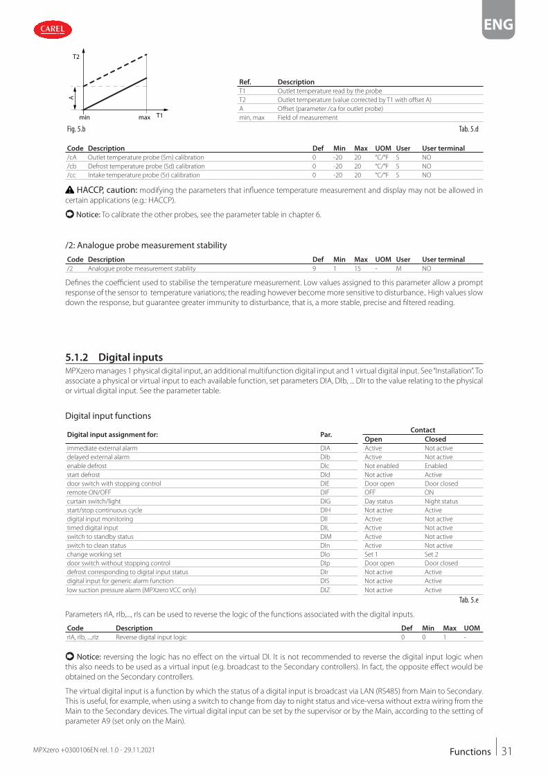
Calibration (parameters /cA to /co)MPXzero allows the possibility to calibrate values read by the probes associated with the various functions set by parameters /
FA to /Fn and some internal variables. In particular, parameters /cA, .../cn, /cc are used to increase or decrease the values read by
the probes connected to the analogue inputs across the range of measurement.
Important, HACCP: this modification may not be allowed by HACCP procedures as it alters the measured value. Verify that
you have authorisation and record the changes where required.
31
ENG
MPXzero +0300106EN rel. 1.0 - 29.11.2021 Functions
A
T1
T2
min max
Ref. Description
T1 Outlet temperature read by the probe
T2 Outlet temperature (value corrected by T1 with offset A)
A Offset (parameter /ca for outlet probe)
min, max Field of measurement
Fig. 5.b Tab. 5.d
Code Description Def Min Max UOM User User terminal
/cA Outlet temperature probe (Sm) calibration 0 -20 20 °C/°F S NO
/cb Defrost temperature probe (Sd) calibration 0 -20 20 °C/°F S NO
/cc Intake temperature probe (Sr) calibration 0 -20 20 °C/°F S NO
HACCP, caution: modifying the parameters that influence temperature measurement and display may not be allowed in
certain applications (e.g.: HACCP).
Notice: To calibrate the other probes, see the parameter table in chapter 6.
/2: Analogue probe measurement stability
Code Description Def Min Max UOM User User terminal
/2 Analogue probe measurement stability 9 1 15 - M NO
Defines the coefficient used to stabilise the temperature measurement. Low values assigned to this parameter allow a prompt
response of the sensor to temperature variations; the reading however become more sensitive to disturbance.. High values slow
down the response, but guarantee greater immunity to disturbance, that is, a more stable, precise and filtered reading.
5.1.2 Digital inputs
MPXzero manages 1 physical digital input, an additional multifunction digital input and 1 virtual digital input. See “Installation”. To
associate a physical or virtual input to each available function, set parameters DIA, DIb, ... DIr to the value relating to the physical
or virtual digital input. See the parameter table.
Digital input functions
Digital input assignment for: Par.Contact
Open Closed
immediate external alarm DIA Active Not active
delayed external alarm DIb Active Not active
enable defrost DIc Not enabled Enabled
start defrost DId Not active Active
door switch with stopping control DIE Door open Door closed
remote ON/OFF DIF OFF ON
curtain switch/light DIG Day status Night status
start/stop continuous cycle DIH Not active Active
digital input monitoring DII Active Not active
timed digital input DIL Active Not active
switch to standby status DIM Active Not active
switch to clean status DIn Active Not active
change working set DIo Set 1 Set 2
door switch without stopping control DIp Door open Door closed
defrost corresponding to digital input status DIr Not active Active
digital input for generic alarm function DIS Not active Active
low suction pressure alarm (MPXzero VCC only) DIZ Not active Active
Tab. 5.e
Parameters rIA, rIb,..., rIs can be used to reverse the logic of the functions associated with the digital inputs.
Code Description Def Min Max UOM
rIA, rIb, ...,rIz Reverse digital input logic 0 0 1 -
Notice: reversing the logic has no effect on the virtual DI. It is not recommended to reverse the digital input logic when
this also needs to be used as a virtual input (e.g. broadcast to the Secondary controllers). In fact, the opposite effect would be
obtained on the Secondary controllers.
The virtual digital input is a function by which the status of a digital input is broadcast via LAN (RS485) from Main to Secondary.
This is useful, for example, when using a switch to change from day to night status and vice-versa without extra wiring from the
Main to the Secondary devices. The virtual digital input can be set by the supervisor or by the Main, according to the setting of
parameter A9 (set only on the Main).

32
ENG
MPXzero +0300106EN rel. 1.0 - 29.11.2021Functions
Code Description Def Min Max UOM User User terminal
A9 Select digital input broadcast from Main to Secondary devices (only on Main)
Val. Desc. Val. Desc.-1 from the supervisor 1 digital input 1 (ID1)
0 disabled 2 digital input 1 (ID2)
1 -1 2 - S NO
Setting parameters DIA, DIb, ... DIr to -1 allows the virtual digital input to be selected on the Secondary as an input. If needed,
different functions can be configured on the Secondary devices, meaning when the status of the contact on the Main changes,
different functions are activated on the Secondary devices.
Code Description Def Min Max UOM
DIA, DIb, ... DIr Assign digital input function
- 1: serial digital input
0 -1 2 -
Immediate external alarm (par. DIA)Activation of the alarm causes:
• message ‘IA’ shown on the display and ALARM flashing;
• activation of the buzzer (see par. H8);
• activation of the alarm relay (see par. DOb);
• deactivation of the solenoid/compressor output (see par. A10).
Notice: activation of the external alarm shuts down the evaporator fans only if these follow the status of the compressor
output, as set for parameter F2. When the compressor is shut down due to an external alarm the compressor minimum ON time
is ignored (parameter c3).
Code Description Def Min Max UOM User User terminal
DIA Select digital input broadcast from Main to Secondary devices (only on Main)
Val. Desc. Val. Desc.-1 from the supervisor 1 digital input 1 (ID1)
0 disabled 2 digital input 1 (ID2)
1 -1 2 - S NO
Delayed external alarm (par. DIb)The behaviour of this alarm is the same as for the immediate external alarm, with a delay in activation (parameter A11). If set to
0, the alarm is signal-only.
Code Description Def Min Max UOM User User terminal
DIb Assign delayed external alarm digital input - see DIA 0 -1 2 - S NO
Enable defrost (par. DIc)This is used to disable any defrost calls. When the contact is open, all defrost calls are ignored. Par. d5 can be used to delay acti-
vation.
Notice:• if the contact is open while a defrost is in progress, this is immediately stopped, the defrost icon flashes on the display indicat-
ing the defrost call is active (this starts again when the contact closes);
• this function can be useful to prevent defrosting the units at unwanted times.
Code Description Def Min Max UOM User User terminal
DIc Assign enable defrost digital input - see DIA 0 -1 2 - S NO
Start defrost (par. DId)Closing the digital contact starts a defrost, if enabled. With a Main-Secondary network connection, if the controller is the Main,
the defrost will be a network defrost, while if it is a Secondary, it will only be a local defrost. The defrost digital input can be used
effectively to perform real time defrosts. Simply connect a timer to the multifunction digital input on the Main and use d5 to
delay the defrosts on the various Secondary devices and thus avoid current overloads.
Notice: if the defrost is disabled by another digital input configured as “enable defrost”, the defrost calls are ignored. The de-
frost does not end when the contact opens again, but rather follows the set defrost times and configurations.
Code Description Def Min Max UOM User User terminal
DIb Assign delayed external alarm digital input
- see DIA
0 -1 2 - S NO
d5 Defrost delay at power-on or (for Secondary) after control signal from Main
0 = delay disabled
0 0 240 min S NO

33
ENG
MPXzero +0300106EN rel. 1.0 - 29.11.2021 Functions
Door switch with stop control (par. DIE)Door open:
• stop control (solenoid/compressor and evaporator fans off ); alternatively, control can be kept active by setting parameter DIP
(see the description below);
• light on (see par. DOE);
• ALARM fl ashing;
• disable temperature alarms.
Door closed:
• resume control;
• light off (see par. DOE) with delay set by par. H14;
• ALARM stops fl ashing;
• enable temperature alarms with delay Ad after bypass time defi ned by par. Add
Code Description Def Min Max UOM User User terminal
DIE Assign digital input for door switch with solenoid/compressor
and evaporator fans OFF - see DIA
0 -1 2 - S NO
DOE Assign light digital output - see DOA 4 0 4 - S NO
H14 Time light stays on after closing the door 0 0 240 min U NO
Ad Delay time for high and low temperature alarms (AH, AHA, AL, ALA) 120 0 240 min U YES
Add High temperature alarm bypass time for door open 30 1 240 min U NO
Tdoor Door open: alarm delay 30 1 240 min S NO
Important: check compatibility of disabling/delaying
the alarm with the site’s HACCP procedures.
Notice:• when control resumes, the compressor times are ob-
served (see the paragraph “Compressor”);
• if the door remains open for longer than the value of
par. Tdoor, control resumes in any case. The light remains
on, the measurement shown on the display fl ashes, the
buzzer and the alarm relay are activated, and the tem-
perature alarms are enabled with delay Ad+Add.
Fig. 5.c
Remote ON/OFF (par. DIF)When the controller is OFF:
• the user terminal shows the value measured by the set probe (parameter /t1) alternating with the message OFF;
• the auxiliary relays set as AUX and light remain active, while the other auxiliary outputs are deactivated;
• the buzzer and alarm relay are deactivated;
• the following are not performed: control, defrosts, continuous cycle, temperature alarm signals;
• the compressor protection times are observed.
When the controller is ON again, all the functions are reactivated, except for the defrost on start-up and compressor and evap-
orator fan delay at power on (par. c0).
Notice:• the OFF command from digital input has priority over those from the keypad or supervisor;
• if the controller remains OFF for a longer time than the value set for parameter dI, a defrost is performed when the controller
is switched on again.
Code Description Def Min Max UOM User User terminal
DIF Assign remote ON/OFF digital input - see DIA 0 -1 2 - S NO
dI Maximum interval between consecutive defrosts 8 0 240 hours S YES
c0 Delay to enable solenoid/compressor and evaporator
fans at power on
0 0 240 min M NO

34
ENG
MPXzero +0300106EN rel. 1.0 - 29.11.2021Functions
Curtain switch (par. DIG)During night status:
• the night-time set point Stn is used for control, calculated based on the set point St plus the offset defined by parameter r4
(Stn = St + r4). The control probe can also be modified according to the setting of parameter r6 (0 = virtual probe, 1 = probe),
see the paragraph “Control”;
• the AUX or light output is deactivated according to the setting of parameter H9.
During day status:
• normal operation resumes: set point = St, virtual probe used as control probe;
• AUX or light output activated according to the setting of parameter H9.
Code Description Def Min Max UOM User User terminal
DIG Assign curtain switch digital input - see DIA 0 -1 2 - S NO
H9 Output switched with time bands 0 = Light 1 = AUX 0 0 1 - S NO
r4 Automatic night set point variation 0 -50 50 °C/°F S NO
r6 Probe for night-time control
0/1 = virtual probe Sv/air on probe Sr
0 0 1 - S NO
Start/stop continuous cycle (par. DIH)When the contact is closed, the continuous cycle is activated, based on parameters cc and c6 (see “Functions”). When the con-
tact opens again, the continuous cycle is deactivated.
Code Description Def Min Max UOM User User terminal
DIH Assign start/stop continuous cycle digital input - see DIA 0 -1 2 - S NO
Timed input (timer) (par. DIL)The timed digital input is a special configuration that allows, in the transition from not active to active, the activation status of a
specific digital variable to be maintained on the supervisor for a time set by parameter. To enable the function, select the desired
digital input using parameter DIL.
Code Description Def Min Max UOM User User terminal
DIL Assign timed digital input
- see DIA
0 -1 2 - S NO
When a digital input is configured as a timed digital input and a transition occurs from not active to active, supervisor variable
FOo is set to ON and remains ON regardless of the physical status of digital input for the time set by parameter dIt. Setting pa-
rameter dIt to 0 disables the function. The “Timer” variable can be associated with an AUX digital output (relay) by suitably setting
the related parameter DOo, thus aligning it with the status of the “Timer” variable. The timed digital input can be controlled not
only by a physical digital input but also from the supervisor using the related digital control variable, with the same result. The
same function can be used to set the “Timer” variable OFF regardless of whether or not the time set for parameter dIt has elapsed.
Special features:
• when the “Timer” variable is ON, another transition from OFF to ON of the same digital input resets the timeout;
• as it is possible to configure an output as a replica of the “Timer” variable, following a transition of the variable, all of the out-
puts will switch simultaneously.
Code Description Def Min Max UOM User User terminal
dIt Timer duration (timed input) 0 = function disabled 0 0 999 min S NO
DOo Assign timed digital output - see DOA 0 0 4 - M NO
Switch to standby status (par. DIM)Standby status is an intermediate state between ON and OFF: control is interrupted, the expansion valve is closed (0%), the con-
trol alarms and probe alarms remain active. ON status (normal operation) resumes after the time Stt has elapsed, after switching
off (OFF status) or when the controller is restarted.
Code Description Def Min Max UOM User User terminal
DIM Assign standby mode switch digital input
- see DIA
0 -1 2 - S NO
Stt Maximum time for standby status 0 0 240 min S NO

35
ENG
MPXzero +0300106EN rel. 1.0 - 29.11.2021 Functions
Switch to clean status (par. DIn)Clean status is an intermediate state between ON and OFF: control is interrupted, the solenoid valve is closed (0%), and only the
probe fault alarms remain active. ON status (normal operation) resumes after the time CLt has elapsed, after switching off (OFF
status) or when the controller is restarted.
Code Description Def Min Max UOM User User terminal
DIn Assign clean mode switch digital input
- see DIA
0 -1 2 - S NO
CLt Max time for clean status 0 0 999 min U NO
The meaning of each status, OFF, ON, standby and clean, is summarised in the following table:
Unit OFF Unit ON Standby Clean
Control OFF ON OFF OFF
Light independent independent independent independent
Probe fault alarms enabled enabled enabled enabled
Other alarms disabled enabled enabled disabled
User terminal OFF based on /t1 Stb CLn
Tab. 5.f
Change working set (par. DIo)In this case, it is possible to choose between configuration 1 (digital input not active) and configuration 2 (digital input active).
The changeover between sets occurs during the transition in status.
Important: when changing sets, the default parameters for the chosen configuration are loaded, and any settings made by
the user will be overwritten.
Notice: use the configuration software to set the two default configurations. (see “Installation”).
Code Description Def Min Max UOM User User terminal
DIo Assign working parameter set change digital input - see DIA 0 -1 2 - S NO
Door switch without stopping control (par. DIP)Operating mode that allows the door to be opened without stopping control. In this case, when opening the door, only the light
will switch on. This operating mode can be configured by setting parameter DIP with one of the digital inputs. Opening the door
introduces a temperature alarm delay as described for the door switch function (par. DIE).
Code Description Def Min Max UOM User User terminal
DIP Assign door switch without control stop digital input - see DIA 0 -1 2 - S NO
Start/stop defrost from digital input (par. DIr)If configured in this new mode, a digital input can be used to start a defrost when closing and end the defrost when opening
(independently of par. d0). If the defrost ends after the maximum time (par.dP1), alarm Ed1 is activated if enabled (r3 = 1).
Code Description Def Min Max UOM User User terminal
DIr Assign defrost according to DI status digital input - see DIA 0 -1 2 - S NO
dP1 Maximum defrost duration 45 1 240 min S YES
r3 End defrost by timeout signal
0/1 = disabled/enabled
0 0 1 - S NO
5.1.3 Analogue outputs
MPXzero Advanced (VCC frequency version) has the following analogue outputs: Y1, Y2, either 0-10 V or PWM. The analogue
outputs set as PWM can be used as a control signal to manage loads such as modulating evaporator fans or anti-sweat heaters,
and require connection to a solid state relay (SSR).
Notice: for VCC frequency control, output Y1 is by default used to control the VCC compressor. Output Y2 remains available
and configurable for other specific functions.

36
ENG
MPXzero +0300106EN rel. 1.0 - 29.11.2021Functions
Code Description Def Min Max UOM User User terminal
/AA Assign analogue output for modulating evaporator fans
0 = not configured
1 = analogue output 1 (Y1)
2 = analogue output 2 (Y2)
0 0 2 - M NO
/Ac Assign analogue output for modulating anti-sweat heaters
- see /AA
0 0 2 - M NO
/AE Assign analogue output for modulating condenser fans 0 0 2 - M NO
/AG Assign analogue output for modulating compressor 0 0 2 - M NO
5.1.4 Digital outputs
MPXzero Standard and Advanced have 3 and 4 digital outputs respectively: NO1, NO2, NO3 and NO4. To associate the digital
outputs with the available functions, set parameters DOA, DOb, ... DOq to the value of the physical digital output. See the pa-
rameter table.
Digital output functions
Digital output assignment for: Par. Default
Solenoid/compressor DOA Digital output 3 (NO3)
Alarm DOb -
Auxiliary DOc -
Auxiliary serving the Main on the Secondary devices DOd * -
Light DOE Digital output 4 (NO4)
Light serving the Main on the Secondary devices DOF * -
Defrost DOG Digital output 1 (NO1)
Auxiliary evaporator defrost DOH -
Compressor alarm management DOK
Evaporator fans DOI Digital output 2 (NO2)
Output associated with the timer function DOo -
Condensate drain heater DOP -
Anti-sweat heater DOQ -
Generic On/Off function (stage) DOS -
Maximum speed for two-speed fans DOt -
Minimum speed for two-speed fans DOu -
Hot gas defrost valve (VCC version only) DOAA -
Condenser fans (VCC version only) DOAB -
Liquid valve for pump-down (VCC version only) DOn -
Tab. 5.g
* = MPXzero Advanced only
If the opposite logic to the default setting is required, or to correct a wiring error, the logic of the functions associated with the
digital outputs using parameters rOA, rOb, ... rOp can be reversed.
Code Description Def Min Max UOM User User terminal
rOA, rOb, ...,rOS Digital output logic ...
0 = direct, 1 = reverse
0 0 1 - M NO
Important: report the changes on diagrams, connection labels and in the user manuals.
Solenoid/compressor (par. DOA)This allows the liquid solenoid valve to be used in applications with thermostatic expansion valves
Code Description Def Min Max UOM User User terminal
DOA Assogn solenoid/compressor digital output
Val. Desc. Val. Desc.0 not configured 3 digital output 3 (NO3)
1 digital output 1 (NO1) 4 digital output 4 (NO4)
2 digital output 2 (NO2)
3 0 4 - S NO
Alarm (par. DOb)The relay associated with the alarm function can work as follows:
• normally de-energised: the relay is energised when an alarm occurs (rOb = 0);
• normally energised: the relay is de-energised when an alarm occurs (rOb = 1);
Notice: operation with the relay de-energised (rOb = 0) when an alarm occurs ensures maximum safety when the alarm is
due to a power failure or power cable disconnection.
Code Description Def Min Max UOM User User terminal
DOb Assign alarm digital output - see DOA 0 0 4 - S NO

37
ENG
MPXzero +0300106EN rel. 1.0 - 29.11.2021 Functions
Auxiliary (par. DOc)The actuator can be activated/deactivated using a command from the supervisor and based on the changeover in day/night
status (linked to the curtain switch or the setting of the time bands); activation/deactivation of the actuator is signalled by the
AUX icon switching on/off. The AUX output to be activated or deactivated based on the night/day time band can be selected
(see parameters tS1...8, tE1...8 and H9).
Code Description Def Min Max UOM User User terminal
DOc Assign auxiliary digital output - see DOA 0 0 4 - S NO
H9 Output switched with time bands 0 = Light 1 = AUX 0 0 1 - S NO
Auxiliary serving the Main on the Secondary devices (par. DOd) *From the Main controller, the action of the auxiliary output is broadcast via LAN to the Secondary devices whose digital output
is configured with DOd greater than 0.
Code Description Def Min Max UOM User User terminal
DOd Assign auxiliary digital output serving the Main on the Secondary
devices - see DOA
0 0 4 - S NO
* = MPXzero Advanced only
Light (par. DOE)The actuator can be activated/deactivated directly using the functions on the user terminal, using a command from the super-
visor and based on the changeover in day/night status (linked to the curtain/door switch or the setting of the time bands); acti-
vation/deactivation of the actuator is signalled by the light icon switching on/off. The light output to be activated or deactivated
based on the night/day time band can be selected (see parameters tS1...8, tE1...8 and H9).
Code Description Def Min Max UOM User User terminal
DOE Assign auxiliary digital output serving the Main on the Secondary
devices - see DOA
4 0 4 - S NO
Light serving the Main on the Secondary devices (par. DOF) *From the Main, the action of the light output is broadcast via LAN to the Secondary devices whose digital output is configured
with DOF greater than 0. Activation (or deactivation) of the actuator is signalled by the light icon switching on (off ) on the Sec-
ondary user terminal.
Code Description Def Min Max UOM User User terminal
DOF Assign light digital output serving the Main on the Secondary devices
- see DOA
0 0 4 - S NO
* = MPXzero Advanced only
Defrost (par. DOG)The actuator is activated/deactivated based on the defrost settings (see the paragraph “Defrost”). Activation/deactivation of the
actuator is signalled by the defrost icon switching on/off on the user terminal.
Auxiliary evaporator defrost (par. DOH)A heater can be activated for defrosting the main and auxiliary evaporator.
M
E
E
V
V
SV
T
T
Ref. Description
E Evaporator with electric defroster
V Thermostatic expansion valve
SV Solenoid valve
Fig. 5.d

38
ENG
MPXzero +0300106EN rel. 1.0 - 29.11.2021Functions
MPXzero can manage defrosts with one or two outputs and one or two end defrost probes. The table below summarises the
possible cases:
Defrost outputs Evaporator probes Control
1 1 normal
2 1 defrost managed on two outputs with reference to the same evaporator probe
1 2 defrost managed on the same output with reference to the two evaporator probes
(minimum evaporation temperature)
2 2 defrost managed independently on the two evaporator circuits
Tab. 5.h
Code Description Def Min Max UOM User User terminal
/Fb Assign defrost temperature probe (Sd) - see /FA 2 -4 3 - S YES
/FF Assign defrost temperature probe 2 (Sd2) - see /FA 0 -4 3 - S NO
DOG Assign defrost digital output - see DOA 1 0 4 - S NO
DOH Assign auxiliary evaporator defrost digital output - see DOA 0 0 4 - S NO
Evaporator fans (par. DOI)Once the digital output has been selected, the evaporator fan on/off is signalled by the the evaporator fan icon switching on/
off on the display. See the paragraph “Evaporator fans”
Code Description Def Min Max UOM User User terminal
DOI Assign light digital output serving the Main on the Secondary devices
- see DOA
2 0 4 - M NO
Auxiliary compressor without rotation (par. DOk)Select the output for the auxiliary compressor without rotation (see “Control”). This output can be set to
activate an auxiliary compressor as a second control step, without rotation, i.e. always starting
after the main compressor.
Code Description Def Min Max UOM User User terminal
DOk Assign auxiliary compressor without rotation digital output - see DOA 0 0 4 - S NO
Condensate drain heater (par. DOP)During defrosting there may be frozen condensate on the bottom of the cabinet that prevents the water thawed from the
evaporator from being drained correctly. The digital output can be configured to manage the condensate drain heater function.
The heater is started on activation of the pump down stage and stays on throughout the defrost procedure, until the end of the
dripping phase. The heater can be activated by selecting a digital output with par. DOP.
Notice: the heater must be protected against overheating (e.g. thermal protector).
Code Description Def Min Max UOM User User terminal
DOP Assign drain heater digital output - see DOA 0 0 4 - M NO
Anti-sweat heater (par. DOQ)Select the digital output for demisting the glass (control with fixed activation, see the paragraph “Anti-sweat heaters”).
Code Description Def Min Max UOM User User terminal
DOQ Assign anti-sweat heater digital output - see DOA 0 0 4 - S NO
Generic On/Off stage function (par. DOS)Select the digital output for configuring a generic stage function.
Code Description Def Min Max UOM User User terminal
DOS Assign generic stage function digital output - see DOA 0 0 4 - S NO
Maximum speed of two-speed evaporator fans (par. DOt)For two-speed fans (generally with three wires), the digital output to be assigned to maximum speed can be selected.
Code Description Def Min Max UOM User User terminal
DOt Assign digital output for maximum fan speed 0 0 4 - S NO
Minimum speed of two-speed evaporator fans (par. DOu)For two-speed fans (generally with three wires), the digital output to be assigned to minimum speed can be selected.
Code Description Def Min Max UOM User User terminal
DOu Assign digital output for minimum fan speed 0 0 4 - S NO

39
ENG
MPXzero +0300106EN rel. 1.0 - 29.11.2021 Functions
5.2 Control IntroductionThere are various modes for controlling air temperature for the preservation of foodstuffs in cold rooms and showcases. The fol-
lowing figure shows the position of the intake probe Sr and the outlet probe Sm. To control the temperature using the average
between outlet and intake, configure the virtual probe Sv that, based on the setting of parameter /4, will provide the value given
by the formula:
Sv = Sm (100 –/4) + Sr (/4)100
Code Description Def Min Max UOM User User terminal
/4 Virtual probe composition 0 = Outlet probe Sm 100 = Intake probe Sr 0 0 100 % S NO
For example, if /4=50, Sv=(Sm+Sr)/2 represents an estimated value of the air temperature around the refrigerated food.
Notice for HACCP: parameter /4 can be set to change the temperature used for control and for display. This operation may
be prohibited by HACCP procedures or require record keeping and authorisation.
Example: vertical showcaseDAY
Sm
Sv=(Sm+Sr)/2
SrRef. Description
Sm Outlet probe
Sr Intake probe
Sv Virtual probe
Fig. 5.e
During the day, most of the load in a refrigerated showcase is due to warm air that enters from the outside and mixes with the
cold air inside. Control based on the intake probe, due to high temperature outside the showcase and the mixing of the air, may
not manage to reach the set point. Displaying the intake temperature would show a temperature that is too high. Setting a set
point that is too low for the intake probe Sr may cause the food to freeze. On the other hand, displaying the outlet temperature
would show a temperature that is too low. Consequently, the display of the control probe, set point or virtual probe can be
configured using parameter /t1. ON/OFF control on the outlet probe is defined by:
• set point;
• differential
These values determine the control request and consequently, allowing for the protection times, disabling functions or activa-
tion/deactivation delays, the opening/closing of the solenoid valve.
Code Description Def Min Max UOM User User terminal
St Set point 50 r1 r2 °C/°F U YES
rd Differential 2 0.1 99.9 °C/°F U YES
rC Operating mode
0/1 = Direct/Reverse
0 0 1 - U NO
Notice for HACCP: the set point and differential are critical parameters for food storage. Modifications to these settings may
be prohibited by HACCP procedures or require record keeping and authorisation.

40
ENG
MPXzero +0300106EN rel. 1.0 - 29.11.2021Functions
Sreg
DIRECT
rd
St
ON
R
OFF
Sreg
REVERSE
rd
St
ON
R
OFF
Ref. Description
St Set point
rd Differential
Sreg Control probe
R Control request
Fig. 5.f
ON/OFF control depends on the capacity of the produce to absorb and release heat, as well as on the evaporator cooling time.
The temperature therefore fluctuates above and below the set point, and this may cause a decline in the quality of food pres-
ervation. Decreasing the differential to make control more precise increases the frequency of solenoid valve opening/closing
cycles.
Setting parameter rC=1 enables reverse operation, suitable for hot cabinet applications.
Minimum and maximum set point values (parameters r1 and r2)The minimum and maximum value of the set point can be set by parameter.
Code Description Def Min Max UOM User User terminal
r1 Minimum set point -50 -50 r2 °C/°F M NO
r2 Maximum set point 50 r1 200 °C/°F M NO
Night-time operationDuring night-time operation the curtain on the display case is closed and consequently less cold inside air is mixed with warm
outside air. The thermal load decreases. The temperature of the air that cools the produce is near the outlet temperature, and
therefore to avoid excessively low temperatures and reduce energy consumption, the set point needs to be increased at night,
by setting parameter r4. Parameter r6 can then be used to assign the virtual probe Sv or intake probe Sr as the control probe.
Naturally, the change to night-time operation must be signalled externally. This is usually done using the curtain switch, set with
parameter DIG, signalling that the curtain has been lowered, or by setting the time bands (parameters tS1 to tS8 and tE1 to tE8),
from the supervisor, or from the Main controller via the Main/Secondary network. To set the time bands, see “Setting the day/
night time bands”.
Code Description Def Min Max UOM User User terminal
r4 Automatic night set point variation 0 -50 50 °C/°F S NO
r6 Night control probe 0/1 = virtual probe Sv/intake probe Sr 0 0 1 - S NO
tS1..8-d Start time band 1 to 8 day: day - see (td1...8-d) 0 0 11 day S NO
tS1..8-hh Start time band 1 to 8 day: hours 0 0 23 hours S NO
tS1..8-mm Start time band 1 to 8 day: minutes 0 0 59 minutes S NO
tE1..8-d End time band 1 to 8 day: day - see (td1...8-d) 0 0 11 day S NO
tE1..8-hh End time band 1 to 8 day: hours 0 0 23 hours S NO
tE1..8-mm End time band 1 to 8 day: minutes 0 0 59 minutes S NO
Notice for HACCP: verify that modification of the night-time set point (parameter /4) is permitted by site HACCP procedures.
If required, obtain the required authorisation and record the changes.
Variable Daytime controlNight-time control
r6 = 0 r6 = 1
Control probe (Sreg) Virtual probe (Sv) Virtual probe (Sv) Intake probe (Sr)
Set point St St+r4
Tab. 5.i
t
night
tS1
day
tE1 tS2 tE2 tS8 tE8
Fig. 5.g
During day status:
• Set point = St
• light on
• control on virtual probe Sv During night status:
• Set point = St + r4
• light off
• control on Sr (if r6=1) or on Sv (if r6=0)
“Weighted control” and “double thermostat” can be used for automatic changeover to night-time operation without an external
signal.

41
ENG
MPXzero +0300106EN rel. 1.0 - 29.11.2021 Functions
“Weighted control” (or on virtual probe Sv)This function compensates for the disadvantages of control based solely on the outlet probe or the intake probe. The control
probe becomes the virtual probe:
Sv = Sm (100 –/4) + Sr (/4)100
The weighted average of the outlet and intake probes is used to compensate for the mixing of air from outside the showcase.
Normally the weight of /4 is set to 50% and the value of the virtual probe can be chosen for both display and temperature
recording.
The value of the virtual probe thus becomes the mean value of the outlet and intake probes and the measurement that best
corresponds to the produce temperature. Another advantage is automatic adaptation to night-time operation with the curtain
closed, without needing an external signal. When the curtain is open there is immediately an increase in load on the evaporator,
consequently the outlet temperature is lowered so as to keep the average temperature constant.
t
T night day
Sr
Sm
SvRef. Description
T temperature
t time
Sr Intake probe
Sv Virtual probe
Sm Outlet probe
Fig. 5.h
Shared network solenoidFor applications where the solenoid valve is installed only on the Main controller, the solenoid output can be configured as a
network solenoid output: r7=1 on the Main and Secondary devices. The valve on the Main controller will be open when there is
a cooling request on any of the Secondary controllers.
Code Description Def Min Max UOM User User terminal
DOA Select digital input broadcast from Main to Secondary devices (only on Main)
Val. Desc. Val. Desc.0 not configured 3 digital output 3 (NO3)
1 digital output 1 (NO1) 4 digital output 4 (NO4)
2 digital output 2 (NO2)
3 0 4 - S NO
r7 Main solenoid valve configuration
0/1 = local valve/network valve (connected to Main)
0 0 1 - S YES
If configured as the network solenoid, the valve is:
• open: if at least one of the controllers requires cooling;
• closed: if no controller has a refrigeration request or if at least one of the controllers has a serious alarm
Notice: on Main/Secondary networks with a shared solenoid valve, parameter r7 must be correctly set on all of the devices
(r7=1).
ON/OFF (par. ONParameter ON is used to switch the controller ON/OFF. If there is a digital input configured as remote ON/OFF, this has higher
priority than the supervisor command or the ON parameter.
Code Description Def Min Max UOM User User terminal
P10 ON/OFF command - 0=OFF, 1=ON 1 0 1 - S YES
In this operating mode, the display shows the standard display, alternating with the message “OFF”.
When OFF, the following are possible:
• access the parameters on the user terminal;
• activate remote ON/OFF;
• display the probe alarms (rE, E1, E2, E3, etc.) and errors EE, EF, Etc, Edc, alternating with the message OFF.
When OFF, the following alarms are reset:
• high and low temperature;
• open door alarm (dor);

42
ENG
MPXzero +0300106EN rel. 1.0 - 29.11.2021Functions
Double thermostatThe double thermostat function is activated by setting parameter rd2> 0 and selecting mode AND or OR logic mode (parameter
db1). It is used to automatically adapt, that is, without changing the set point and without an external signal, control of the unit
based on a change in compressor load, especially when switching from day to night and vice-versa. In fact, at night the show-
case curtains are closed, there is less heat exchange with the surrounding air and the compressor works less.
To do this, two set points and two differentials are defined:
• St and rd, associated with the outlet probe;
• St2 and rd2, associated with the intake probe.
Code Description Def Min Max UOM User User terminal
St2 Intake probe set point with double thermostat 50 r1 r2 °C/°F S NO
rd2 Set point St2 differential with double thermostat
0.0 = function disabled
0 0 99.9 °C/°F S NO
db1 Double thermostat function logic
0/1 : logical AND/logical OR
0 0 1 - M NO
The control request occurs:
• when this is active on both probes, as if there were two thermostats in series, when db1 = 0
• when one of the probes signals the request, as if there were two thermostats in parallel, when db1 = 1.
Sr
Sm
Cooling
AND
Sr
OR
Sm
CoolingSmrd
St
ON
R
OFF
Srrd2
St2
ON
R
OFF
Ref. Description
Sm outlet probe
Sr intake probe
R control request
rd differential for St
rd2 differential for St2
Fig. 5.i Fig. 5.j
Below is an example of the temperature trend on a vertical showcase during the day and at night.
t
T night day
Sr
Sm
Sv=(Sm+Sr)/2
-15...-17 °C
-19...-21 °C
-22 °C -21...-23 °C
-16 °C
-12...-14 °C
Ref. Description
Sm outlet probe
Sr intake probe
T temperature
Sv virtual probe
t time
Fig. 5.k
Sm
Sr
Sr = - 12 to -14°C, St = -16°C
Sm
Sr
Sr = - 17 to -15°C, St = -16°C
Ref. Description
Sm outlet probe
Sr Intake probe
Fig. 5.l Fig. 5.m
Notice: • if one of the probes has an error or is missing, it is considered as signalling the request;
• if both probes are faulty or missing, the controller switches to duty setting mode.
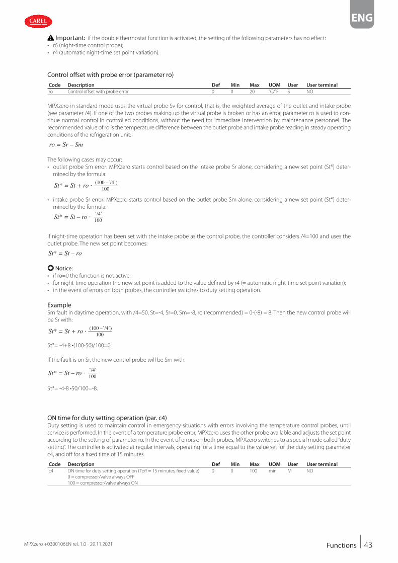
43
ENG
MPXzero +0300106EN rel. 1.0 - 29.11.2021 Functions
Important: if the double thermostat function is activated, the setting of the following parameters has no effect:
• r6 (night-time control probe);
• r4 (automatic night-time set point variation).
Control offset with probe error (parameter ro)
Code Description Def Min Max UOM User User terminal
ro Control offset with probe error 0 0 20 °C/°F S NO
MPXzero in standard mode uses the virtual probe Sv for control, that is, the weighted average of the outlet and intake probe
(see parameter /4). If one of the two probes making up the virtual probe is broken or has an error, parameter ro is used to con-
tinue normal control in controlled conditions, without the need for immediate intervention by maintenance personnel. The
recommended value of ro is the temperature difference between the outlet probe and intake probe reading in steady operating
conditions of the refrigeration unit:
ro = Sr – Sm
The following cases may occur:
• outlet probe Sm error: MPXzero starts control based on the intake probe Sr alone, considering a new set point (St*) deter-
mined by the formula:
St* = St + ro (100 –’/4’)100
• intake probe Sr error: MPXzero starts control based on the outlet probe Sm alone, considering a new set point (St*) deter-
mined by the formula:
St* = St – ro ’/4’100
If night-time operation has been set with the intake probe as the control probe, the controller considers /4=100 and uses the
outlet probe. The new set point becomes:
St* = St – ro
Notice: • if ro=0 the function is not active;
• for night-time operation the new set point is added to the value defined by r4 (= automatic night-time set point variation);
• in the event of errors on both probes, the controller switches to duty setting operation.
ExampleSm fault in daytime operation, with /4=50, St=-4, Sr=0, Sm=-8, ro (recommended) = 0-(-8) = 8. Then the new control probe will
be Sr with:
St* = St + ro (100 –’/4’)100
St*= -4+8 •(100-50)/100=0.
If the fault is on Sr, the new control probe will be Sm with:
St* = St – ro ’/4’100
St*= -4-8 •50/100=-8.
ON time for duty setting operation (par. c4)Duty setting is used to maintain control in emergency situations with errors involving the temperature control probes, until
service is performed. In the event of a temperature probe error, MPXzero uses the other probe available and adjusts the set point
according to the setting of parameter ro. In the event of errors on both probes, MPXzero switches to a special mode called “duty
setting”. The controller is activated at regular intervals, operating for a time equal to the value set for the duty setting parameter
c4, and off for a fixed time of 15 minutes.
Code Description Def Min Max UOM User User terminal
c4 ON time for duty setting operation (Toff = 15 minutes, fixed value)
0 = compressor/valve always OFF
100 = compressor/valve always ON
0 0 100 min M NO

44
ENG
MPXzero +0300106EN rel. 1.0 - 29.11.2021Functions
c4 15 mint
ON
R
OFF
3000
86_0
65_R
01
Ref. Description
R Control
c4 ON time
t Time
Fig. 5.n
With duty setting active, during the ON time the solenoid/compressor icon remains on, while it flashes during the OFF time.
The table below describes the possible fault situations relating to the control probes and the function that is activated.
Type of systemControl probe fault
Control ParameterSm Sr
1 probe Duty setting c4
Duty setting c4
2 probes control on Sr ro(*)
control on Sm ro(*)
Duty setting c4
Tab. 5.j
* ro must be > 0.
Duty setting with shared control status (MPXzero Advanced only)Activation of the duty setting mode is signalled on the Main user interface with the solenoid/compressor icon on steady; the
Secondary controllers ignore the Main control mode. On the other hand, if a Secondary device activates duty setting mode due
to lack of communication with the Main, the Secondary manages the display on the user interface as standard.
Notice: • activation of duty setting mode on the Main controller implies that all the related Secondary devices observe the Main con-
troller compressor management times.
• in duty setting mode, the compressor protection times are ignored.
Notice: • if a second ON/OFF compressor is managed with an activation delay, both compressors will start based on the set times.
Parameter c4 must be set correctly in relation to the activation delay c11.
Continuous cycle (parameter cc)Continuous cycle is a function used to keep the refrigeration cycle active continuously for a settable duration, irrespective of the
temperature inside the unit. This may be useful when requiring a rapid decrease in the temperature, even below the set point.
Activation of the low temperature alarm when exceeding the threshold AL or AL2 can be delayed by setting parameter c6.
Important: the time defined by parameter cc is in hours, the alarm delay c6 is in minutes.
Code Description Def Min Max UOM User User terminal
cc Continuous cycle running time, 0 = Disabled 0 0 15 hours M NO
c6 Low temperature alarm bypass time after continuous cycle 60 0 240 min M NO
The continuous cycle can be activated using the direct continuous cycle function on the user terminal (see “Direct functions”),
from the supervisor or via digital input. When the continuous cycle is running:
• the + icons are displayed.
• the solenoid valve/compressor output (with icon) is activated;
• the low temperature alarm with threshold AL is enabled relating to the probe defined by parameter AA as well as the low
temperature alarm with threshold AL2 relating to the probe defined by parameter AA2.
Important: for correct activation of the low temperature alarms, set the parameters as follows:
• AA = outlet probe;
• AA2 = intake probe.

45
ENG
MPXzero +0300106EN rel. 1.0 - 29.11.2021 Functions
Notice: 1. the continuous cycle cannot be activated if:
– the duration of the continuous cycle is set to 0 (cc=0);
– the measurements of the probes defined by AA and AA2 have exceeded their respective thresholds AL, AL2;
– the device is OFF.
2. The continuous cycle remains in standby if:
– the compressor protection times are set (c1, c2, c3);
– the immediate or delayed alarm from external digital input delays activation of the solenoid valve;
– defrost, dripping, post-dripping are running;
– the door is open. When the door is opened, the continuous cycle is interrupted. It restarts for the remaining time when
the door is closed.
3. The continuous cycle ends:
– when deactivating the direct function from the user terminal (see “Direct functions”);
– when reaching the low temperature threshold (AL or AL2 in double thermostat mode), whichever is reached first;
– at the end of the time cc;
– when the controller is switched off from the supervisor (logical OFF);
– from the supervisor.
Notice: if a second ON/OFF compressor is managed with an activation delay, during continuous cycle both compressors will
start based on the set times.
Continuous cycle with shared control statusThis operating mode is highlighted on the Main user interface by the corresponding icons on steady; the Secondary controllers
ignore the Main control mode and manage the display as normal (solenoid icon on during the cooling request and off when
there is no request).
Defrost priority over continuous cycle
Code Description Def Min Max UOM User User terminal
c7 Defrost priority over continuous cycle 0=No, 1=Yes 0 0 1 - M NO
If c7=0 the defrost and continuous cycle are not mutually interruptible (same priority): any defrost or continuous cycle request
remains pending if activated when running the other procedure. If c7=1 the defrost calls activated when the continuous cycle
is running terminate the latter and activate the defrost.
5.3 Defrost
IntroductionParameters td1 to td8 can be used to set up to 8 defrost events based on the controller clock (RTC) and to activate the power
defrost (see the end of the paragraph).
To set parameters td1 to td8, use the supervisor or the “Applica” app.
Code Description Def Min Max UOM User User terminal
td1..8-d Defrost 1 to 8 - day
0 = event disabled
1 to 7 = Monday to Sunday
8 = Monday to Friday
9 = from Monday to Saturday
10 = Saturday & Sunday
11 = every day
0 0 11 day S NO
td1..8-hh Defrost 1 to 8 - hours 0 0 23 hours S NO
td1..8-mm Defrost 1 to 8 - minutes 0 0 59 minutes S NO
td1..8-P Defrost 1 to 8 - enable power defrost:
0/1 = normal/power defrost
0 0 1 - S NO
MPXzero can manage different types of defrosts, depending on the setting of parameter d0.
The defrost can end by temperature, in which case the defrost probe Sd must be installed, or by time. In the first case the defrost
ends when the defrost probe Sd exceeds the end defrost value dt1 or the time dP1 has elapsed, in the second case when the
defrost phase reaches the maximum time dP1.

46
ENG
MPXzero +0300106EN rel. 1.0 - 29.11.2021Functions
End defrost in advance due to high temperatureMPXzero can end the defrost in advance if the value measured by a configurable probe exceeds a certain maximum value; this
helps prevent, especially with electric heater defrosts, the temperature inside the showcase or cold room from climbing too
high. If the defrost ends in advance, the controller shows the corresponding signal (dEA) on the display, which will be cleared
only when the next defrost ends correctly.
Code Description Def Min Max UOM User User terminal
dEP Assign probe for end defrost in advance
0 Not configured
1 Air off-outlet (Sm)
2 Defrost (Sd)
3 Air on-intake (Sr)
4 Auxiliary defrost (Sd2)
5 Auxiliary 1 (Saux1)
6 Auxiliary 2 (Saux2)
7 Ambient temp (SA)
8 Ambient humidity (SU)
9 Glass temperature (Svt)
10 Dew point (SdP)
11 Virtual probe (Sv)
0 0 11 - S NO
dET Temperature threshold for end defrost in advance 50 -99.9 99.9 °C S NO
At the end of the defrost the dripping phase can be enabled (if dd>0), during which the solenoid valve is closed and the fans are
off, followed by the post-dripping phase (if Fd>0), during which control resumes and the fans work based on the setting of par.
Fpd. The type of display on the user terminal during defrosting can be selected by setting parameter d6.
Notice: high temperature alarms can be disabled after defrosting by setting par. d8.
Code Description Def Min Max UOM User User terminal
d0 Type of defrost
0 heater by temperature 3 hot gas by time
1 hot gas by temperature 4 heater by time with
temperature control2 heater by time
0 0 4 - S YES
dt1 End defrost temperature (read by Sd) 8 -50 50 °C/°F S YES
dP1 Maximum defrost duration 45 1 240 min S YES
d6 Display on terminals during defrost
0 = temperature alternating with ‘dEF’
1 = freeze display
2 = ‘dEF’
1 0 2 - U NO
d8 Bypass high temperature alarm time after defrost 30 1 240 min S NO
F3 Evaporator fan status during defrost 0 = on, 1 = off 1 0 1 - S F3
Fd Post-dripping time after defrost (fans off with control active) 2 0 15 min S NO
Fpd Evaporator fans during post-dripping
0=On, 1=Off
0 0 1 - 0 NO
Below is the trend of the defrost output based on the setting of parameter d0.
t
dP1
dt1Sd
OFFDEF
d0=4
d0=2,3
d0=0,1
DEF
DEF
ON
OFF
ON
OFF
ON
t
t
t
Ref. Description
t Time
dt1 End defrost temperature
dP1 Maximum defrost duration
Sd Defrost probe
DEF Defrost
Fig. 5.o
The heater defrost by time with temperature control (d0=4) activates the defrost output only if the evaporator temperature (Sd)
is less than the value of parameter dt1, and ends after the time defined by dP1. This function is useful for energy saving and to
prevent excessive temperatures on the evaporator with timed defrosts.

47
ENG
MPXzero +0300106EN rel. 1.0 - 29.11.2021 Functions
5.3.1 Heater defrost (d0 = 0, 2, 4): duty cycle
The duty cycle refers to the default values of parameters F2 and F3.
t
F3F2
OFF
SV/CMP
FAN
DEF
refrig refrigpumpdown
drip(dd)
post drip(Fd)
res
ON
OFF
ON
OFF
ON
Ref. Description
t Time
FAN Fan
DEF Defrost
drip Dripping
SV/CMP Solenoid/compressor
Fig. 5.p
The pump down phase is the period in which the evaporator is emptied of liquid refrigerant, and can be disabled by setting
dH1=0 (see “Pump down duration”).
Operation of the fan during the pump down phase depends on parameters F2 and F3.
During the dripping phase the fan is always off, while during the post-dripping phase operation depends on the setting of
parameter Fpd.
Code Description Def Min Max UOM User User terminal
dd Dripping time after defrost (fans off )
0 = no dripping
2 0 15 min S NO
dH1 Pump down duration
0 = pump down disabled
0 0 999 s M NO
F2 Evaporator fans with compressor off
0 = see F0 1 = always off
1 0 1 - S YES
F3 Evaporator fans during defrost
0 = on, 1 = off
1 0 1 - S F3
Fd Post-dripping time after defrosting
(fans off with control active)
2 0 15 min S NO
5.3.2 Hot gas defrost (d0 = 1, 3): duty cycle
MPXzero can manage defrosts by installing a hot gas injection solenoid valve.
This type of defrost can be controlled in two ways:
• Hot gas by temperature (d0=1);
• Hot gas by time (d0 = 3).
In the former case, the defrost ends when reaching the temperature set for parameter dt1 (end defrost threshold (read by Sd)).
In the latter case, the defrost ends after a set time (parameter dP1 = maximum defrost duration).
Notice: parameter dP1 is also taken into account when end defrost by temperature is selected. If the threshold dT1 is not
reached, the defrost will end after the maximum duration (dP1).
t
F3F2
OFF
SV/CMP
FAN
HGSV
refrig refrigpumpdown
drip(dd)
post drip(Fd)
hotgas
ON
OFF
ON
OFF
ON
Ref. Description
t Time
FAN Fan
HGSV Hot gas valve
drip Dripping
SV/CMP Solenoid/compressor
post drip Post-dripping
Fig. 5.q

48
ENG
MPXzero +0300106EN rel. 1.0 - 29.11.2021Functions
The pump down phase is the period in which the evaporator is emptied of liquid refrigerant, and can be disabled by setting
dH1=0 (see “Pump down duration”). In the hot gas defrost phase, the solenoid valve for hot gas injection (HGSV) is opened. Op-
eration of the fan during the pump down and hot gas phases depends on parameters F2 and F3. During the dripping phase, the
fan is always off, while during the post-dripping phase operation depends on the setting of parameter Fpd.
5.3.3 Advanced parameters
Maximum interval between consecutive defrosts (par. dI)
Code Description Def Min Max UOM User User terminal
dI Maximum interval between consecutive defrosts 8 0 240 hours S YES
Parameter dI is a safety parameter used to perform cyclical defrosts every “dI” hours. It is also useful if the LAN or RS485 serial
network is disconnected. At the start of each defrost, irrespective of the duration, an interval starts being counted. If this interval
exceeds dI without a defrost being performed, one is started automatically. The count is always active even if the controller is
OFF. If set on the Main controller, the parameter affects the entire connected LAN subnet, while if set on a Secondary controller,
it only has an effect locally.
ExampleIf the defrosts are controlled by a centralised system and there is no communication, the request will not be received, so after
the safety time a defrost is started automatically.
ttd1
DEFON
OFF
td2td3
dl
Ref. Description
dI Maximum interval between consecutive defrosts
td1…td3 Scheduled defrosts
t time
DEF Defrost
Fig. 5.r
Staggered defrostsThis function is used to perform a series of daily defrosts by setting just the first using parameter td1 and then indicating the
number of defrosts per day using parameter d1S. The controller automatically schedules all the defrosts to be performed at
regular intervals over the 24 hours following the event defined by td1. The same applies to td2 and dS2.
Code Description Def Min Max UOM User User terminal
d1S Number of daily defrosts (td1)
0 Disabled 5 4 hours and 48
minutes
10 2 hours and 24
minutes
1 24 hours and 0
minutes
6 4 hours and 0
minutes
11 2 hours and 11
minutes
2 12 hours and 0
minutes
7 3 hours and 26
minutes
12 2 hours and 0
minutes
3 8 hours and 0
minutes
8 3 hours and 0
minutes
13 1 hour and 0
minutes
4 6 hours and 0
minutes
9 2 hours and 40
minutes
14 30 minutes
0 0 14 - S NO
d2S Number of daily defrosts (td2) - see d1S 0 0 14 - S NO
Remember that the sub-parameter “d_” of td1 (td2) defines the defrost day, as follows:
d_ = Defrost - day
0 = event disabled 9 = from Monday to Saturday
1 to 7 = Monday to Sunday 10 = Saturday & Sunday
8 = Monday to Friday 11 = every day
Notice:• if event td1 includes a series of days, the programming always ends at 24.00 on the last day. If event td1 includes one day only,
the programming ends at 24.00 on the same day;
• if both td1 and td2 are set, when the defrost events overlap, only the sequence of defrosts that start first are performed..

49
ENG
MPXzero +0300106EN rel. 1.0 - 29.11.2021 Functions
Start/end defrost synchronised by Main (par. d2, d3)These parameters determine whether or not, in a local network, MPXzero awaits a start/end defrost signal from the Main con-
troller at the start/end of the defrost.
Code Description Def Min Max UOM User User terminal
d2 End defrost synchronised by Main
0 = not synchronised
1 = synchronised
1 0 1 - S NO
d3 Send start network defrost signal (for Main)
0 = Yes, 1 = No
Ignore start network defrost signal (for Secondary)
0 = No, 1 = Yes
0 0 1 - S NO
End defrost by timeout signal (par. r3)For defrosts that end by temperature (d0=0), this enables the end defrost by timeout signals Ed1 and Ed2 when the maximum
time is reached (dP1).
Code Description Def Min Max UOM User User terminal
r3 End defrost by timeout signal
0 = disabled, 1 = enabled
0 0 1 - S NO
Defrost at power on (par. d4)The defrost call at power-on has priority over the control request and activation of the continuous cycle. For Main controllers,
the defrost at power-on will be a network defrost, while it will be ignored on Secondary controllers where d3=0; for Secondary
controllers it will be local.
Code Description Def Min Max UOM User User terminal
d4 Defrost at power on (Main = network defrost;
Secondary = local defrost) 0 = No, 1 = Yes
0 0 1 - S NO
Defrost delay at power on (parameter d5)Also active when d4=0. If the digital input is set to enable or start a defrost from an external contact, parameter d5 represents
the delay between when the defrost is enabled or called, and when it effectively starts.
Code Description Def Min Max UOM User User terminal
d5 Defrost delay at power-on or (for Secondary) after control signal from
Main
0 = delay disabled
0 0 240 min S NO
For Main/Secondary networks where the defrost needs to be activated from a digital input on the Main, it is recommended to
use parameter d5 to delay the various defrosts, thus avoiding current overloads.
Dripping time after defrost (par. dd)This parameter defines the time that the compressor and the evaporator fans stop following a defrost so as to allow the evapo-
rator to drip. If dd=0 no dripping time is enabled, and at the end of the defrost control resumes immediately, without stopping
the compressor and the fan, if active.
Code Description Def Min Max UOM User User terminal
dd Dripping time after defrost (fans off ) 0 = no dripping 2 0 15 min S NO
Pump down duration (par. dH1)*The pump down phase is the period in which the evaporator is emptied of liquid refrigerant. Parameter dH1 defines the duration
of the pump down phase during all types of defrost.
Code Description Def Min Max UOM User User terminal
dH1 Pump down duration
0 = pump down disabled
0 0 999 s M NO
*for the VCC version see the specific section of the manual.
Important: the controller does not have two separate outputs to manage the compressor and solenoid valve.

50
ENG
MPXzero +0300106EN rel. 1.0 - 29.11.2021Functions
Running time defrost (par. d10, d11)Running time is a function that determines when the refrigeration unit needs defrosting. In particular, it is assumed that if the
evaporator temperature measured by probe Sd remains continuously below a certain set threshold (d11) for a certain time (d10),
the evaporator may be frozen and a defrost is activated. The time is reset if the temperature returns above the threshold.
Notice: d11 should be set to a temperature that is lower than the value normally expected on the evaporator in normal
operation.
Code Description Def Min Max UOM User User terminal
d10 Defrost time in running time mode
0 = function disabled
0 0 240 min S NO
d11 Defrost temperature threshold in running time mode -30 -50 50 °C/°F S NO
d10t
tON
Sd
DEFOFF
dt1
d11
Ref. Description
Sd Defrost probe
DEF Defrost
t time
Fig. 5.s
Defrost by temperature differential and time (par.dd1, dd2, dTd, tdd)This function determines when the refrigeration unit needs defrosting. In particular, if the difference between two probe read-
ings (dd1, dd2) is higher than a predefined threshold (dTd) for a certain time (tdd), the evaporator may be frozen and a defrost
is activated.
tdd
dTd
ΔT>10 °C
t
tON
DEFOFF
dd2
dd1
Ref. Description
Sd Defrost probe
DEF Defrost
t time
Fig. 5.t
Code Description Def Min Max UOM User User terminal
dd1 Assign probe 1 to determine start defrost (dd1-dd2) 11 0 11 - S NO
dd2 Assign probe 2 to determine start defrost (dd1-dd2) 2 0 11 - S NO
dTd Temperature differential threshold to start defrost 50 -99.9 99.9 °C S NO
tdd Threshold evaluation time to start defrost 60 15 240 min S NO
Sequential stops (par.dS1, dS2)Sequential stop mode is especially useful for advanced temperature refrigeration units, is based on the intelligent stopping of
control to allow the evaporator to defrost naturally by the flow of ambient air only, without activating the defrost output. If the
function is enabled (parameter dS1>0), two countdowns are activated during normal control:
• OFFTIME: this is decreased when the unit is at the set temperature, therefore when SV/COMP = OFF. Unchanged when the
unit has an active request;
• ONTIME: this is decreased when the unit has an active request, therefore when SV/COMP = ON. Unchanged when the unit is
at the set temperature. Two events may occur, with reference to the following figure:
1. OFFTIME is reset (instant C): OFFTIME and ONTIME are reset with the values dS1 and dS2 and the defrost is considered
completed. Control resumes;
2. ONTIME is reset (instant A): OFFTIME is reset with the default value and the natural defrost starts, lasting the entire time
dS1. At the end of the defrost (instant B), OFFTIME and ONTIME are reset with the values dS1 and dS2 and control resumes.
Code Description Def Min Max UOM User User terminal
dS1 Compressor off time in sequential stop
defrost mode - 0 = function disabled
0 0 45 min M NO
dS2 Compressor operating time in sequential stop
defrost mode
120 0 240 min M NO

51
ENG
MPXzero +0300106EN rel. 1.0 - 29.11.2021 Functions
dS1
C
OFFTIME=0
t
t
ON
1
CMP
regulation regulation
OFF
ONTIME=0
A B
t
regulationregulation defrost
ON
2
CMPOFF
Ref. Description
CMP Compressor
t time
Fig. 5.u
The purpose is to stop control and allow natural defrosts only when necessary.
When control stops in sequential stop mode, the defrost icon will come on, the defrost status will be sent to the supervisor and
the display will reflect the setting of parameter d6.
Notice: the setting of parameter F3 has no effect. Evaporator fan management depends on parameter F0.
Skip defrost (par. d7, dn)If defrosts ending by temperature are set, the skip defrost function evaluates whether the defrost duration is less than a certain
threshold dn1 (dn2) and based on this establishes whether or not the following defrosts can be skipped.
Code Description Def Min Max UOM User User terminal
dP1 Maximum defrost duration 45 1 240 min S YES
dP2 Max auxiliary evaporator defrost duration 45 1 240 min S YES
d7 Skip defrost: 0 = Disabled - 1 = Enabled 0 0 1 - M NO
dn Nominal defrost duration for skip defrost 75 0 100 % M NO
Thresholds dn1 (evaporator 1) and dn2 (evaporator 2) are calculated based on the parameter settings:
dn1 = dn· dP1
100dn2 = dn
· dP2100
The algorithm keeps a counter of the defrosts to be skipped:
• at power-on, the defrost is performed 7 times without increasing the counter, from the eighth on the counter is updated.
• if the defrost ends in a time less than dn1 (dn2), the counter of the defrosts to be skipped is increased by 1;
• when the counter reaches 3, the next defrost is skipped; if the next defrost ends in a time less than dn1 (dn2), the counter is in-
creased and the next 2 defrosts are skipped; if the next defrost also ends in a time less than dn1 (dn2), the counter is increased
and the next 3 defrosts are skipped, the counter is reset and the algorithm restarts (see the table).
Defrost sequence 1 2 3 4 5 6 7 8 9 10 11 12 13 14 15 16 17 18 19 20 21 22
Defrost duration
< dn1?
- - - - - - - S S S - S - - S - - - S S S -
Counter - - - - - - - 1 2 3 - 4 - - 5 - - - 1 2 3 -
Defrost skipped? N N N N N N N N N N S N S S N S S S N N N S
Restart algorithm
Notice: if at any time the defrost ends after dn1 (dn2), the next defrost is performed and the counter is reset.
Notice: the algorithm only applies to defrosts scheduled by time bands or cyclical defrosts (par. DI); manual defrosts or those
started by the supervisor are always performed and do not affect the counter.

52
ENG
MPXzero +0300106EN rel. 1.0 - 29.11.2021Functions
Power defrost (par. ddt, ddP)Power defrost is used to increase the end defrost threshold dt1 (dt2 for the second evaporator) and/or the maximum defrost
duration dP1 (dP2 for the second evaporator). These increases allow more effective defrosts. Power defrosts are performed on
each defrost call during night status or when suitably configured by the RTC parameters (sub-parameter P of parameters td1 to
td8), so as to allow the user to choose the conditions that are most suitable for this special procedure. Power defrost is activated
when at least one of the increases, ddt or ddP, has any value other than zero.
Code Description Def Min Max UOM User User terminal
ddt Additional end defrost temperature delta in power defrost mode 0 -20 20 °C/°F S NO
ddP Additional maximum defrost time delta in power defrost mode 0 0 60 min S NO
td1..8-P Defrost 1 to 8 - enable power defrost:
0 = normal, 1 = power defrost
0 0 1 - S NO
5.4 Evaporator fansThe evaporator fans can be managed, if required, according to the temperature measured by any two of the probes connected
to the MPXzero controller. The deactivation threshold is equal to the value of parameter F1, and the hysteresis is equal to the
value of Frd.
Notice: during the dripping waiting time (in the event of network defrosts), and during the dripping time, the evaporator fans
are always off, while during the post-dripping time, if set, evaporator fan operation depends on the setting of par. Fpd.
Fixed-speed fansThe parameters used to manage fixed-speed fans are shown below (see the connection diagram).
MPXzero manages the evaporator fans as follows:
• F0 = 0 always on;
• F0 = 1 off when the difference between the two probe values Sa and Sb (defined by parameters FSa and FSb) exceeds the
threshold set for parameter F1;
• F0 = 2 on/off based on Sa probe, defined by parameter FSa.
Code Description Def Min Max UOM User User terminal
F0 Evaporator fan management
0 = always on
1 = activation based on Sa - Sb (see FSa and FSb)
2 = activation based on Sa (Sa = first probe, Sb = second probe)
0 0 2 - S YES
F1 Evaporator fan activation threshold (only if F0 = 1 or 2) -5 -50 50 °C/°F S YES
Frd Fan activation differential (including variable speed) 2 0.1 20 °C/°F S YES
FSa First fan control probe
0 Not config. 1
1 Air off-outlet (Sm)
2 Defrost (Sd)
3 Air on-intake (Sr)
4 Auxiliary defrost (Sd2)
5 Auxiliary 1 (Saux1)
6 Auxiliary 2 (Saux2)
7 Ambient temp (SA)
8 Ambient humidity (SU)
9 Glass temperature (Svt)
10 Dew point (SdP)
11 Virtual probe (Sv)
2 0 11 - M NO
FSb Second fan control probe - see FSa 11 0 11 - M NO
Sa-S
b
t
t
F0 = 1F1
F1-Frd
ON
OFFFAN
Sa
t
t
F0 = 2F1
F1-Frd
ON
OFFFAN
Fig. 5.v Fig. 5.w
Ref. Description
Sa Probe set by parameter FSa
Sb Probe set by parameter FSb
F1 Fan activation threshold
Ref. Description
Frd Differential
t time
FAN Evaporator fans

53
ENG
MPXzero +0300106EN rel. 1.0 - 29.11.2021 Functions
The fans can be turned off in the following situations:
• when the solenoid valve (or compressor) is deactivated (parameter F2);
• during defrosts (parameter F3).
During the dripping time (parameter dd > 0) the fans are off, and during the post-dripping time (parameter Fd > 0), the evapo-
rator fans are on or off depending on the value of parameter Fpd.
This is useful to allow the evaporator to return to temperature after defrosting, thus avoiding blowing warm hot and moist air
into the refrigerated environment.
The evaporator fans can be forced on during control (parameter F2) and during defrosts (parameter F3).
Code Description Def Min Max UOM User User terminal
dd Dripping time after defrost (fans off )
0 = no dripping
2 0 15 min S NO
F2 Evaporator fans with compressor off
0 = see F0 1 = always off
1 0 1 - S YES
F3 Evaporator fan status during defrost 0 = on, 1 = off 1 0 1 - S F3
Fd Post-dripping time after defrost (fans off with control active) 2 0 15 min S NO
Fpd Evaporator fans during post-dripping
0 = on, 1 = off
0 0 1 - 0 NO
Variable-speed fans (EC fans)On MPXzero Advanced (VCC frequency) only - version with two modulating outputs - it may be useful to connect variable speed
fans so as to optimie energy consumption. In this case, the fans are powered by the mains, while the control signal may come
via output Y1 or Y2, set as 0-10 Vdc.
Notice: function available only on: MPXzero VCC frequency version with analogue outputs (Y1, Y2).
The maximum and minimum fan speed can be set using advanced parameters F6 and F7.
If using the fan speed controller, F5 represents the temperature below which the fans are activated. There is a fixed hysteresis of
1°C for deactivation.
Code Description Def Min Max UOM User User terminal
F5 Evaporator fan cut-off temperature (hysteresis 1°C) 50 F1 50 °C/°F S NO
Sa-S
b
t
t
F0 = 1F5+1F5F1
F1-Frd
F6FAN
F70%
Sa
t
t
F0 = 2F5+1F5F1
F1-Frd
F6FAN
F70%
Fig. 5.x Fig. 5.y
Ref. Description
Sa Probe set by parameter FSa
Sb Probe set by parameter FSb
F5 Fan cut-off temperature
F1 Fan deactivation threshold
Ref. Description
Frd Differential
t time
FAN Evaporator fans
The advanced parameters for the evaporator fans concern the minimum and maximum speed and the peak time.
Code Description Def Min Max UOM User User terminal
F6 Maximum evaporator fan speed 100 F7 100 % M NO
F7 Minimum evaporator fan speed 0 0 F6 % M NO
F8 Evaporator fan peak time
0 = Function disabled
0 0 240 s M NO
F10 Evaporator fan forcing time at maximum speed
0 = Function disabled
0 0 240 min M NO
F6: is the maximum fan speed, expressed as a % of the output. For 0 to 10 V outputs, it represents the output voltage at maximum
speed as a percentage. The same is true for the minimum speed set for F7.
The fan peak time F8 represents the operating time at maximum speed set using parameter F6 to overcome the mechanical
inertia of the motor.
F10 represents the frequency at which the fan is operated at maximum speed for the peak time (F8). If the fan operates too long
at low speed, ice may form on the blades; to avoid this, at intervals of every F10 minutes, the fan is switched on at maximum
speed for the time set for parameter F8.

54
ENG
MPXzero +0300106EN rel. 1.0 - 29.11.2021Functions
F5+1
F5
F1
T
FANSPEED
0%
F7
F6
F1-Frd
Ref. Description
T temperature
F1 Fan activation threshold
Frd Differential
F5 Fan cut-off temperature
F6 Maximum speed
F7 Minimum speed
Fig. 5.z
5.5 Anti-sweat heater or fan modulationThe control of anti-sweat heaters is performed by comparing the dew point calculated based on the ambient temperature and
humidity, and the temperature of the showcase glass, measured by a probe or estimated using the showcase outlet, intake and
ambient temperature. Anti-sweat heaters can be controlled in two ways on the MPXzero Advanced (VCC frequency version with
modulating outputs):
• PI (proportional, integral);
• fixed activation (manual control).
The conditions for the activation of the algorithms are as follows:
Algorithm Activation condition
PI rHd > 0
fixed activation (manual control) rHd = 0; rHt >0
If the temperature read by the glass temperature probe is only estimated, PI control becomes proportional only. If both algo-
rithms are activated, the PI algorithm has priority over fixed activation, which for activation does not require the ambient tem-
perature and humidity probes. There are a series of conditions whereby the PI algorithm stops operating and, if enabled, fixed
activation control takes over.
Condition Cause
Glass temperature probe
not valid
• physical probe not configured or faulty;
• the estimated glass temperature probe value cannot be used as the outlet probe or intake probe is not configured or
is faulty or the ambient probe is broken or absent (*)
Dew point not valid • humidity probe and ambient temperature probe are both not configured or not working;
• the serial dew point value is not available
Tab. 5.k
(*) If the intake probe is not configured or is faulty, only the outlet probe is used.
PI control
InputsThe ambient humidity (SU) and temperature (SA) probe readings may be (see parameters /FL, /FI) sent from the supervisor via
the serial probes.
Alternatively, the supervisor can directly supply the dew point value (Sdp) using the serial probes (see parameter /Fn). The glass
temperature probe (Svt) can be connected directly to each controller (see parameter /FM), or the value can be estimated. The
estimate of the glass temperature probe reading is performed internally when: ambient temperature (SA), outlet temperature
(Sm) and intake temperature (Sr) are available, and depends on parameters rHA, rHb and rHS. Parameters rHo, rHd and rHL de-
termine the modulating output.
Code Description Def Min Max UOM User User terminal
/Ac Assign analogue output for variable speed fans -
see /AA
0 0 2 - M NO
rHS Virtual probe composition for glass temp. probe estimate
0 = Outlet probe Sm
100 = Intake probe Sr
20 0 100 % S NO
rHA Coeff. A for glass temp. probe estimate 2 -20 20 °C/°F S NO
rHb Coeff. B for glass temp. probe estimate 22 0 100 - S NO
rHo Offset for anti-sweat modulation 2 -20 20 °C/°F S NO
rHd Differential for anti-sweat heater modulation 0 0 20 °C/°F S NO
If one of the probes is not available (SA or either Sm or Sr), only fixed activation control will be possible, according to parameters
rHu and rHt.

55
ENG
MPXzero +0300106EN rel. 1.0 - 29.11.2021 Functions
OutputsThe percentage of activation (OUT) for anti-sweat heater control depends on the difference between the dew point calculated
and the value read by the glass temperature probe, the value of parameter rHo (offset) and the value of parameter rHd (differen-
tial), as shown in the following figure. The CUTOFF is a constant of 5°C and the hysteresis is 1°C.
Svt
OUT
Sdp rHo rHd
1°C
CUTOFF
0%
Max
Min
Ref. Description
SdP Dew point
rHo Offset for anti-sweat modulation
rHd Diff. for anti-sweat heater modulation
OUT Anti-sweat control
Svt Glass temperature probe
Min Minimum fan speed
Max Maximum fan speed
Fig. 5.aa
Min: fixed minimum output of 10%; Max: fixed maximum output of 100%.
The action is proportional only if the estimate of the glass temperature is used, and proportional and integral (Tint=240 s, con-
stant) if the actual glass temperature probe is us. The aim of the integral action is to bring the glass temperature towards the set
point (Sdp+rHo).
Important: if the serial probes from the supervisor are used for sending the ambient temperature and humidity values,
MPXzero has four auxiliary variables that save the last useful value available for 30 minutes. This may be useful in the event where
there is no communication with the supervisor.
When starting for the first time and these variables have not yet been initialised, it is normal for alarms to be shown temporarily
relating to probes that have not been updated
Fixed activation control (manual control)Control depends only on parameters rHu and rHt and follows the trend shown in the figure.
Code Description Def Min Max UOM User User terminal
DOQ Assign anti-sweat heater digital output
Val. Desc. Val. Desc.0 not configured 3 digital output 3 (NO3)
1 digital output 1 (NO1) 4 digital output 4 (NO4)
2 digital output 2 (NO2)
0 0 4 - S NO
rHu Manual anti-sweat heater activation percentage (of period ‘rHt’)
0 = function disabled
70 0 100 % S NO
rHt Manual anti-sweat heater activation period
0 = function disabled
5 0 180 min S NO
trHu
ON
OFF
A
rHt
trHu
10 Vdc
0
B
rHt
Ref. Description
A Relay output
B 0-10 Vdc output
rHu Manual anti-sweat heater activation percentage
rHt Manual anti-sweat heater activation period
t Time
Notice: ON-OFF output on Y1 or Y2 (0-10
Vdc)
Fig. 5.ab
5.6 CompressorMPXzero features the following compressor protection parameters.
Notice: The paragraph refers to applications with on-board compressor. Most of the functions apply similarly to the solenoid
valve (refrigerant supply) in centralised applications.
Code Description Def Min Max UOM User User terminal
d9 Defrost priority over compressor protection times
0/1 = protection times observed/protection times not observed
1 0 1 - M NO
c0 Delay to enable solenoid/compressor and evaporation fans at pow-
er-on
0 0 240 min M NO
c1 Min time between consecutive compressor starts 0 0 15 min M NO
c2 Min compressor OFF time 0 0 15 min M NO
c3 Min compressor ON time 0 0 15 min M NO
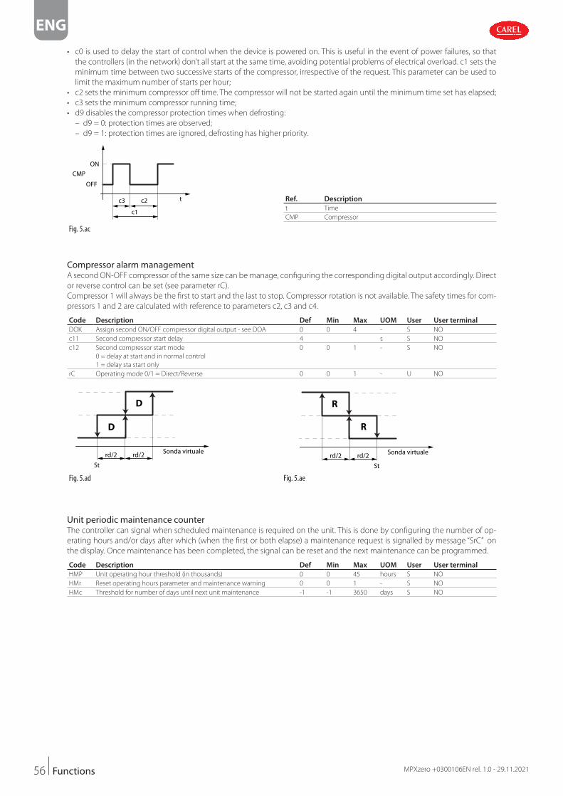
56
ENG
MPXzero +0300106EN rel. 1.0 - 29.11.2021Functions
• c0 is used to delay the start of control when the device is powered on. This is useful in the event of power failures, so that
the controllers (in the network) don’t all start at the same time, avoiding potential problems of electrical overload. c1 sets the
minimum time between two successive starts of the compressor, irrespective of the request. This parameter can be used to
limit the maximum number of starts per hour;
• c2 sets the minimum compressor off time. The compressor will not be started again until the minimum time set has elapsed;
• c3 sets the minimum compressor running time;
• d9 disables the compressor protection times when defrosting:
– d9 = 0: protection times are observed;
– d9 = 1: protection times are ignored, defrosting has higher priority.
c3 c2
c1
t
ON
CMP
OFF
Ref. Description
t Time
CMP Compressor
Fig. 5.ac
Compressor alarm managementA second ON-OFF compressor of the same size can be manage, configuring the corresponding digital output accordingly. Direct
or reverse control can be set (see parameter rC).
Compressor 1 will always be the first to start and the last to stop. Compressor rotation is not available. The safety times for com-
pressors 1 and 2 are calculated with reference to parameters c2, c3 and c4.
Code Description Def Min Max UOM User User terminal
DOK Assign second ON/OFF compressor digital output - see DOA 0 0 4 - S NO
c11 Second compressor start delay 4 s S NO
c12 Second compressor start mode
0 = delay at start and in normal control
1 = delay sta start only
0 0 1 - S NO
rC Operating mode 0/1 = Direct/Reverse 0 0 1 - U NO
Sonda virtualerd/2
St
rd/2
D
D
Sonda virtuale
R
R
rd/2
St
rd/2
Fig. 5.ad Fig. 5.ae
Unit periodic maintenance counterThe controller can signal when scheduled maintenance is required on the unit. This is done by configuring the number of op-
erating hours and/or days after which (when the first or both elapse) a maintenance request is signalled by message “SrC” on
the display. Once maintenance has been completed, the signal can be reset and the next maintenance can be programmed.
Code Description Def Min Max UOM User User terminal
HMP Unit operating hour threshold (in thousands) 0 0 45 hours S NO
HMr Reset operating hours parameter and maintenance warning 0 0 1 - S NO
HMc Threshold for number of days until next unit maintenance -1 -1 3650 days S NO

57
ENG
MPXzero +0300106EN rel. 1.0 - 29.11.2021 Functions
5.7 Variable capacity compressor (VCC)The MPXzero Advanced VCC controller calculates the optimum compressor speed based on the value read by the control probe,
and sends this data to the VCC inverter, which then drives the compressor, based on the model, in one of two modes: frequency
or serial protocol. In the serial protocol version, analogue outputs Y1 and Y2 are not available.
5.7.1 VCC with frequency control
To drive frequency-controlled inverters, the output signal is a digital square wave, with a voltage range from 0 to +10 Vdc, as
described below. The duty cycle is 50%.
Par. Description Def Min Max UOM User User terminal
/AG Assign analogue output for modulating compressor
0 = not configured;
1 = analogue output 1 (Y1);
2 = analogue output 2 (Y2).
1 0 2 - S NO
/P5 Configuration of analogue output Y1: 0 = 0-10 V; 6 = PWM. 6 0 6 - S NO
/P6 Configuration of analogue output Y2: 0 = 0-10 V; 6 = PWM. 6 0 6 - S NO
The analogue output to be used, Y1 or Y2, is selected by parameter /AG, with the corresponding parameter /P5 or /P6 then set
as a PWM output. The other analogue output remains available for a different function, where necessary.
10 Vdc
0 V
Fig. 5.af
The compressor speed follows the input frequency signal, with a relationship such as the one shown in the figure.
Notice: the reference frequencies and speeds vary according to the type of compressor and the parameter settings (see
below).
5000
4000
3000
4500
3500
2000
2500
1000
1500
0
0 20 40 60 80 100 120 140 160
500
input fraquency signal (Hz)
output (RPM)
Fig. 5.ag
The following diagrams show two examples of connection to the Embraco and Secop inverters. It is recommended to refer to
the inverter manufacturer’s user manual for more detailed instructions and installation instructions.
Inverter Secop Y1
Y2
Tx/R
xGN
D
+BMS
SWI Freq.
0-10
VPW
M
V+
1 2 3 1 2 3
D1 GND
GND
CIK
Inverter
Embraco
Y1
Y2
Tx/R
xGN
D
+BMS
0-10
VPW
M
IN
IN
OUT
Fig. 5.ah Fig. 5.ai

58
ENG
MPXzero +0300106EN rel. 1.0 - 29.11.2021Functions
5.7.2 VCC with serial control
To drive inverters via serial, the connection is direct, as shown in the following table. The following diagrams show two examples
of connection to the Embraco and Secop inverters. It is recommended to refer to the inverter manufacturer’s user manual for
more detailed instructions and installation instructions.
Inverter Secop
SWI Freq.
V+
1 2 3 1 2 3
D1 GND
GND
CIK
Tx/R
xGN
D
+BMS
+VCC Serial connection terminal cross-reference
MPXzero Vcc Secop Embraco
+V Not used Not used
GND GND O
- O IN
+ CIK OUT
Fig. 5.aj Tab. 5.l
The serial communication protocol complies with the following technical specifications:
Asynchronous communication (start-stop)Baud rate 600 baud
Start bits 1
Data bits 8
Stop bits 1
Parity None
Flow control None
Unit size 5 bytes
Tab. 5.m
The compressor speed is sent to the inverter via a specific serial protocol command. The compressor speed reflects the value
sent.
Notice: the reference frequencies and speeds vary according to the type of compressor and the parameter settings.
5000
4000
3000
4500
3500
2000
2500
1000
1500
0
0 20 40 60 80 100 120 140 160
500
input fraquency signal (Hz)
output (RPM)
Fig. 5.ak
5.7.3 VCC compressor configuration
All of the VCC configuration parameters are expressed in units of frequency (Hz). The corresponding compressor rotation speed
(rpm) depends on the relationship:
Compressor speed (rpm) = Frequency (Hz) * cuF
where cuF is the conversion factor between frequency and compressor speed.
Par. Description Def. Min Max UOM User User terminal
cdf VCC compressor frequency for hot gas defrost 140 0 255 Hz M NO
cMA Maximum VCC compressor rotation frequency 150 0 250 Hz M NO
cMf Maximum VCC compressor control frequency 100 0 255 Hz M NO
cMi VCC compressor switch-off frequency 30 0 250 Hz M NO
cnf Minimum VCC compressor control frequency 52 0 255 Hz M NO
cuF Conversion factor from frequency (Hz) to compressor speed (rpm) 30 0 999 - M NO

59
ENG
MPXzero +0300106EN rel. 1.0 - 29.11.2021 Functions
Each VCC model works between two operating limit frequencies, the switch-off frequency and the maximum rotation frequen-
cy. The MPXzero controller uses the following preset values:
• cMi = switch-off frequency = 30 Hz (thermostat present signal, but VCC is off, 0 rpm)
• cMA = maximum rotation frequency = 150 Hz (4500 rpm)
For VCCs that use values other than those shown previously, see “Advanced VCC configuration”.
To adapt the cooling capacity of the VCC to the actual needs of the application, set the following parameters:
• cnf = minimum control frequency; preset value = 52 Hz (1560 rpm);
• cMf = maximum control frequency; preset value = 100 Hz (3000 rpm).
During normal control, when the conditions require the VCC to restart, the compressor runs at the soft-start frequency for the
soft-start time (a few seconds). To adapt this frequency to the VCC oil recovery specifications, set the following parameters:
• cSc = soft-start frequency; preset value = 53 Hz (1590 rpm);
• cSt = soft-start time; preset value = 5 s.
When defrosting, if set in hot gas mode, the compressor runs at a fixed frequency, defined by the following parameter:
• cdf = hot gas defrost frequency; preset value = 140 Hz (4200 rpm).
5.7.4 VCC compressor control
The VCC compressor speed is controlled using a PID algorithm. The compressor remains off until the control temperature ex-
ceeds the value St + rd, at which point the compressor starts at the soft-start frequency cSc. After the soft-start time cSt, the PID
algorithm manages the compressor speed within the operating range defined by cnF and cMF.
Par. Description Def. Min Max UOM User User terminal
cct VCC compressor off time 1 0 250 min M NO
cdt PID control derivative term 1 0 255 s M NO
cPr PID control proportional term 2 0 800 - M NO
ctl PID control integral term 120 0 999 s M NO
Temperature
PID regulationFrequency
MIN freq.
MAX freq.
St+rd
Start freq. cSc
Ref. Description
Sv Control probe
St Set point
rd Control differential
cnf Minimum control frequency
cSc Soft start frequency
cMf Maximum control frequency
Fig. 5.al
The PID control algorithm can be adapted to the needs of the application by setting the following parameters:
• cPr = PID control proportional term;
• ctl = PID control integral term;
• cdt = PID control derivative term.
The preset values are suitable and safe for starting any application the first time. When making adaptations, it is recommended
to modify one parameter at a time and check the behaviour of the application in a controlled environment.
always heeding the limits declared by the manufacturer of the Vcc compressor.
If the compressor is on, the controller switches it off when the temperature read by the control probe Sv reaches the low tem-
perature alarm threshold or the set point St for a time equal to cct:
• if cct is set to 0, the compressor stops immediately when Sv = St.
• if cct is set to 255, the compressor never stops.
rd
Temperature
St
ON
VCC CompressorStatus
OFF
AL / cct
Ref. Description
Sv Control probe
St Set point
rd Control differential
AL / cct Low temperature
threshold or deactivation
time reached
Fig. 5.am
To protect the refrigerated products, management of the two alarm thresholds has priority over normal control:
• AL = low temperature alarm threshold; when the temperature read by the control probe Sv is lower than the threshold AL, the
controller immediately stops the compressor.
• AH = high temperature alarm threshold; when the temperature read by the control probe Sv is higher than the threshold AH,
the controller activates the continuous cycle for the compressor (if cc> 0). See “Continuous cycle”.

60
ENG
MPXzero +0300106EN rel. 1.0 - 29.11.2021Functions
Par. Description Def. Min Max UOM User User terminal
AH High temperature alarm threshold 0 0 555/999 Δ °C/°F U YES
AHA Absolute high temperature alarm threshold 537/999 -100 /-148 537/999 °C/°F U YES
AL Low temperature alarm threshold 0 0 200/360 Δ °C/°F U YES
ALA Absolute low temperature alarm threshold -100/-148 -100 /-148 537/999 °C/°F U YES
cct
St
St + rd
AL
AH
Compressor OFF
Cooling capacity / compressor speed modulation
Compressor ON at MINIMUM speed
Temperature
t Compressor status
Stato OFF perraggiungimentosoglia AL(tempistica cctnon rispettata)
Stato OFF perraggiungimentosoglia AL(tempistica cctnon rispettata)
ON
OFFt
Compressor ON at MAXIMUM speed
Ref. Description
St Set point
rd Control differential
AH High temperature alarm
threshold
AL Low temperature alarm
threshold
Fig. 5.an
5.7.5 Defrost with VCC compressor
When there is a hot gas defrost request, the variable speed compressor operates at the speed set by cdF. Activation of the defrost
relay is delayed by the time dHA, while the drain heater is activated and remains on throughout the defrost, until the end of
the post-heating phase dHE. The defrost relay is delayed by the drain heater activation time dHA. At the end of the defrost, the
compressor switches back to normal control. The following diagram describes hot gas defrost with drain heater management.
Par. Description Def. Min Max UOM User User terminal
cdf VCC compressor frequency for hot gas defrost 140 0 255 hz M NO
ddF VCC compressor frequency for dripping 140 cMi 255 hz M NO
Status
Defrostsignal
End of Defrost by temperature or time
Comp. Capacity during defrost settable by:cdF
Comp. OFF with Heater ManagementComp.
Capacity
Defrost ValveRelay
Drain
Drain heaterAUX Drain
preheaterdH1
Heat Drip offHold
Drip offtime
max Pull Downfrequency fix at
150 Hz
Pull downonly if T > AH & cPd >1
H1 = 14 AUX = Drain
Fig. 5.ao
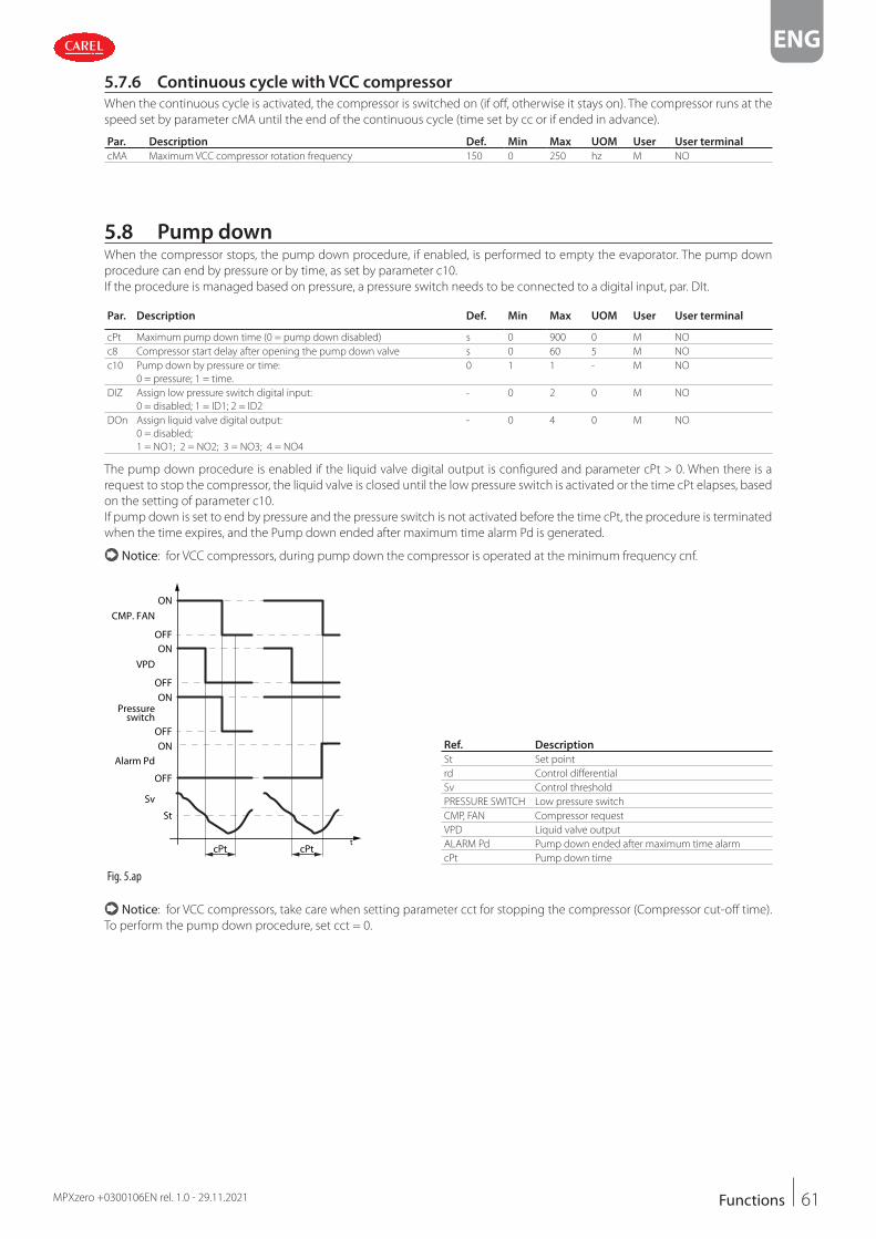
61
ENG
MPXzero +0300106EN rel. 1.0 - 29.11.2021 Functions
5.7.6 Continuous cycle with VCC compressor
When the continuous cycle is activated, the compressor is switched on (if off, otherwise it stays on). The compressor runs at the
speed set by parameter cMA until the end of the continuous cycle (time set by cc or if ended in advance).
Par. Description Def. Min Max UOM User User terminal
cMA Maximum VCC compressor rotation frequency 150 0 250 hz M NO
5.8 Pump downWhen the compressor stops, the pump down procedure, if enabled, is performed to empty the evaporator. The pump down
procedure can end by pressure or by time, as set by parameter c10.
If the procedure is managed based on pressure, a pressure switch needs to be connected to a digital input, par. DIt.
Par. Description Def. Min Max UOM User User terminal
cPt Maximum pump down time (0 = pump down disabled) s 0 900 0 M NO
c8 Compressor start delay after opening the pump down valve s 0 60 5 M NO
c10 Pump down by pressure or time:
0 = pressure; 1 = time.
0 1 1 - M NO
DIZ Assign low pressure switch digital input:
0 = disabled; 1 = ID1; 2 = ID2
- 0 2 0 M NO
DOn Assign liquid valve digital output:
0 = disabled;
1 = NO1; 2 = NO2; 3 = NO3; 4 = NO4
- 0 4 0 M NO
The pump down procedure is enabled if the liquid valve digital output is configured and parameter cPt > 0. When there is a
request to stop the compressor, the liquid valve is closed until the low pressure switch is activated or the time cPt elapses, based
on the setting of parameter c10.
If pump down is set to end by pressure and the pressure switch is not activated before the time cPt, the procedure is terminated
when the time expires, and the Pump down ended after maximum time alarm Pd is generated.
Notice: for VCC compressors, during pump down the compressor is operated at the minimum frequency cnf.
ON
OFFON
OFFON
OFFON
OFF
Sv
VPD
CMP. FAN
Alarm Pd
Pressureswitch
St
tcPt cPt
Ref. Description
St Set point
rd Control differential
Sv Control threshold
PRESSURE SWITCH Low pressure switch
CMP, FAN Compressor request
VPD Liquid valve output
ALARM Pd Pump down ended after maximum time alarm
cPt Pump down time
Fig. 5.ap
Notice: for VCC compressors, take care when setting parameter cct for stopping the compressor (Compressor cut-off time).
To perform the pump down procedure, set cct = 0.

62
ENG
MPXzero +0300106EN rel. 1.0 - 29.11.2021Functions
ON
OFFON
OFFON
OFFON
OFF
Sv
VPD
CMP. FAN
AlS
Pressureswitch
St
tcPtcPt
Ref. Description
St Set point
rd Control differential
Sv Control threshold
PRESSURE SWITCH Low pressure switch
CMP, FAN Compressor request
VPD Liquid valve output
Ats Restart in pump down alarm
cPt Pump down time
Fig. 5.aq
When the compressor starts, the liquid valve is opened for the time set by parameter c8, to allow the pressure to equalise. If c8
= 0 pump down at power on is disabled.
5.8.1 Dead band and VCC compressor
If the reverse output is set for dead band control, the VCC compressor starts when St + rn/2 + rd, as described in “Dead band
control”. To activate the reverse output, the compressor must be off.
Par. Description Def. Min Max UOM User User terminal
cct VCC compressor off time 1 0 255 min M NO
Note the following:
• The compressor stops when the control temperature Sv < St and the time cct elapses.
• If cct is set to 0, the compressor stops immediately when the temperature reaches the set point St
• If cct is set to 255, the compressor never stops and the reverse output can never be activated.
5.8.2 On/Off compressor and VCC compressor
If the auxiliary compressor without rotation is configured, the first compressor to be activated is the VCC, as described in “VCC
compressor control”. The On/Off compressor will be activated second.
Par. Description Def Min Max UOM User User terminal
c1 Min time between consecutive compressor starts 0 0 15 min M NO
c2 Min compressor OFF time 0 0 15 min M NO
c3 Min compressor ON time 0 0 15 min M NO
Sv
DIRECT
St
ON
OFF
ON
OFF
COMP2
VCC
rd/2rd/2
Ref. Description
Sv Control probe
St Set point
rd Control differential
VCC VCC compressor request
COMP2 Auxiliary compressor request
Fig. 5.ar
The time set by parameter c11 is always observed between activation of the VCC compressor and activation of the On/Off
compressor.
If the auxiliary compressor is configured as a parallel compressor, the auxiliary compressor is activated together with the VCC
compressor, after the delay time c11.

63
ENG
MPXzero +0300106EN rel. 1.0 - 29.11.2021 Functions
5.8.3 High and low voltage protection (HLVP)
Some MPXzero models feature protection against high and low power supply voltages, allowing the compressor to operate only
at voltages within the operating limits. This function stops the compressor if the mains voltage is outside of a range specified by
parameters uHo and uLo. The compressor is switched off after a delay that can be set by parameter ucd. The compressor starts
again when the voltage returns within the limits set by parameters uHI and uLI.
Par. Description Def Min Max UOM User User terminal
c1 Minimum time between consecutive compressor starts 0 0 15 min M NO
c2 Minimum compressor OFF time 0 0 15 min M NO
c3 Minimum compressor ON time 0 0 15 min M NO
ucd Compressor stop delay after HLVP protection activated 5 0 60 s M NO
udE Enable display of HLVP protection alarms
(EHI and ELO, see alarm table)
0 0 1 - M NO
uHi High voltage protection start threshold 245 0 350 V M NO
uHo High voltage protection end threshold 255 0 350 V M NO
uEn Enable HLVP protection: 0 = disabled; 1 = enabled 0 0 1 - M NO
uLi Low voltage protection start threshold 205 0 350 V M NO
uLo Low voltage protection end threshold 195 0 350 V M NO
Supplyvoltage
Compressor
ON
Vin
uHo
uHI
uLI
uLo
ucd ucdOFF
Notice: the compressor protection times c1 and c3
are ignored when the high or low voltage conditions
occur, while c2 is always observed.
Important:
• this function cannot be considered a compressor
safety function;
• operation of the controller outside of the rated oper-
ating voltage range described in the technical speci-
fications is the customer’s responsibility.
Fig. 5.as
5.9 Generic functionsMPXzero can exploit unused inputs and outputs to configure a “generic function”. Each generic function can be enabled/disa-
bled from the APPLICA app or SPARK program.
Important: the generic functions available vary according to the model of controller. The following can be activated (max-
imum configuration):
• 1 generic function with On/Off output;
• 1 generic function with modulating output (MPXzero Advanced VCC frequency model only);
• 1 generic alarm function (set as warning or serious alarm).
The generic function can be controlled based on:
• 1 specific probe, or
• difference between 2 suitably configured probes.
Important: the controller cannot verify the consistency of the settings, if two analogue functions are mistakenly assigned
to the same analogue inputs or the same digital output.
5.9.1 Enabling
The generic function can be enabled always, or when the unit is in a certain status.
Code Description Def Min Max UOM User User terminal
GFS_E Generic On/Off function: enable
0 Always 6 Duty setting
1 Unit ON 7 Standby
2 Unit OFF 8 Control
3 Defrost 9 Door open
4 Clean 10 Alarm active
5 Continuous cycle
0 0 10 - S NO
GFM_E Generic modulating function: enable, see GFS_E 0 0 10 - S NO
GFA_E Generic alarm function: enable, see GFS_E 0 0 10 - S NO

64
ENG
MPXzero +0300106EN rel. 1.0 - 29.11.2021Functions
Assign control probeSelect the control probes for the generic function.
Code Description Def Min Max UOM User User terminal
GFS_1 Generic On/Off function: control probe 10
0 Not config.
1 Air off-outlet (Sm)
2 Defrost (Sd)
3 Air on-intake (Sr)
4 Auxiliary defrost (Sd2)
5 Auxiliary 1 (Saux1)
6 Auxiliary 2 (Saux2)
7 Ambient temp (SA)
8 Ambient humidity (SU)
9 Glass temperature (Svt)
10 Dew point (SdP)
11 Virtual probe (Sv)
0 0 11 - S NO
GFS_2 Generic On/Off function: control probe 2 - see GFS_1 0 0 11 - S NO
GFM_1 Generic modulating function: control probe 1- see GFS_1 0 0 11 - S NO
GFM_2 Generic modulating function: control probe 2- see GFS_1 0 0 11 - S NO
GFA_1 Generic alarm function: control probe 1 - see GFS_1 0 0 11 - S NO
GFA_2 Generic alarm function: control probe 2 - see GFS_1 0 0 11 - S NO
5.9.2 On/Off output
Assign the digital output for the generic function, the type (direct/reverse) and the activation logic (see parameter rOA).
Code Description Def Min Max UOM User User terminal
GFS_T Generic On/Off function: type 0 = Direct, 1 = Reverse 0 0 1 - S NO
GFS_S Generic On/Off function: set point 0 -50 50 °C/°F S NO
GFS_D Generic On/Off function: differential 0 0.0 99.9 °C/°F S NO
DOS Generic On/Off function: digital output
0 = disabled 1 = NO1 2 = NO2 3 = NO3 4 = NO4
0 0 4 - S NO
rOS Generic On/Off function: logic 0 = Direct, 1 = Reverse 0 0 1 - S NO
Ref. Description
Set Set point
Diff Differential
Sreg1 -
Sreg2
Control probe 1
Control probe 2
OUT Digital output
Fig. 5.at Fig. 5.au
5.9.3 Modulating output (Advanced VCC frequency only)
Assign the modulating output for the generic function and the type (direct/reverse). It is possible to use proportional control
only or PID, as well as a cut-off differential with hysteresis.
Code Description Def Min Max UOM User User terminal
GFM_T Generic modulating function: type
0 = Direct, 1 = Reverse
0 0 1 - S NO
GFM_S Generic modulating function: set point 0 -50 50 °C/°F S NO
GFM_D Generic modulating function: differential 0 0 99.9 °C/°F S NO
GFM_Kp Generic modulating function: proportional gain 0 0 100 - S NO
GFM_Td Generic modulating function: derivative time 0 0 100 - S NO
GFM_Ti Generic modulating function: integral time 0 0 900 - S NO
GFM_CD Generic modulating function: cut-off differential 0 0 20 - S NO
GFM_H Generic modulating function: hysteresis 0 0 20 - S NO
GFM_Max Generic modulating function: max output value 0 0 100 - S NO
GFM_Min Generic modulating function: min output value 0 0 100 - S NO
/Ad Generic modulating function: analogue output
0 = disabled 1 = Y1 2 = Y2
0 0 2 - S NO

65
ENG
MPXzero +0300106EN rel. 1.0 - 29.11.2021 Functions
Ref. Description
Set Set point
Diff Differential
H Hysteresis
Sreg1 - Sreg2 Control probe1 - Control probe 2
OUT Digital output
CutOff_Diff Cut-off differential
Fig. 5.av
5.9.4 Alarm signal
The alarm can be activated for two reasons:
1. switching of the digital input, assigned by parameter DIs: the display shows “GHI”
2. if the difference between the values of the control probes exceeds the high or low threshold: the display shows GHI or GLO
respectively.
Notice: the generic alarm can be configured as a warning or a serious alarm by setting parameter GFA_AlType.
The generic alarm function reset can be configured as: automatic (default), semi-automatic or manual.
For semi-automatic reset, it is possible to set the number of occurrences of the alarm and corresponding time interval before
requiring manual reset directly on the display, via supervisor or APPLICA.
Code Description Def Min Max UOM User User terminal
DIs Assign digital input for generic alarm function
0 = Function disabled 2 = digital input 2 (ID2)
1 = digital input 1 (ID1) - 1 = serial digital input
0 -1 2 - S NO
GFA_AlType Generic alarm function: type
0 = Warning, 1 = Serious
0 0 1 - S NO
GFA_AA Generic alarm function: action performed when the alarm is generated
0 = no action 2 = reduce control capacity
1 = stop control 3 = switch off lights
0 0 3 - S NO
GFA_r Generic alarm function: reset type
0 = automatic 2 = manual 3 = semi-automatic
0 0 2 - S NO
GFA_n Generic alarm function: number of occurrences for semi-automatic
alarm reset
0 0 99 - S NO
GFA_P Generic alarm function: time period to monitor semi-automatic alarm
reset
0 0 999 min S NO
GFA_De General alarm function: delay 0 0 254 - S NO
GFA_D Generic alarm function: differential 0 0 99.9 - S NO
GFA_Hth Generic alarm function: high temperature threshold 0 -50 50 - S NO
GFA_Lth General alarm function: low temperature threshold 0 -50 50 - S NO
Ref. Description
Lth Low temperature threshold
HTh High temperature threshold
diff Differential
Del Delay
t Time
Sreg1 - Sreg2 Control probe1 - Control probe 2
GHI High temperature alarm message
GLO Low temperature alarm message
Fig. 5.aw

66
ENG
MPXzero +0300106EN rel. 1.0 - 29.11.2021Functions
ExampleDisplay of the generic alarm when exceeding the thresholds.
Fig. 5.ax
Generic warning function (prevent)Before the generic alarm function is activated, a warning signal with automatic reset can also be enabled. Parameters GFA_1 and
GFA_2 defi ne the activation conditions for both functions.
Code Description Def Min Max UOM User User terminal
GFA_We Generic alarm function: enable warning
0= not active, 1 = active
0 0 1 - S NO
GFA_WA Generic alarm function: action to be performed when warning activated
0 = no action 2 = reduce control capacity
1 = stop control 3 = switch off lights
0 0 3 - S NO
GFA_WDe Generic alarm function: warning activation delay 0 0 30000 s S NO
GFA_WD Generic alarm function: warning reset diff erential 0 0 99.9 - S NO
GFA_WHth General alarm function: high warning threshold 0 -50 200 - S NO
GFA_WLth General alarm function: low warning threshold 0 -50 200 - S NO

67
ENG
MPXzero +0300106EN rel. 1.0 - 29.11.2021 Parameter table
6. PARAMETER TABLE
Below is the table of the parameters that can be displayed on the terminal or can be modified using the commissioning software
or APPLICA app.
The APPLICA app and commissioning tools for MPXzero have three predefined parameter access levels: User (U), Service (S) and
Manufacturer (M).
The default passwords to access the Service and Manufacturer parameters from the APPLICA app for MPXzero are 22 and 44
respectively. The Manufacturer level password also allows access to the Service parameters, and the level S password also allows
access to the User parameters. The password for navigating the menu from the display, on the other hand, is 33.
Code Description Def Min Max UOM User User terminal
PDM Manufacturer password 44 - - - M NO
PDS Service password 22 - - - M NO
PDU User password - - - - S NO
Notice:• the read-only parameters are not visible from the Applica app using NFC, as NFC memory cannot be overwritten frequently;
• to avoid any fraudulent activities, the default password values should be changed at the end of the commissioning procedure.
For example, with the APPLICA app, parameters PDM, PDS and PDU can be used to set new passwords, with a maximum
length of 8 characters, both alphanumeric and special.
Important: the operation to reset the default values is not reversible, unless a user configuration has been previously saved
for loading using the commissioning software/Applica app, see the paragraph on configurations.
6.1 System
Code Description Def Min Max UOM User User terminal
/P1 Type of probe, group 1 (S1, S2, S3)
0 = PT1000 Standard Range –50T150 °C
1 = NTC Standard Range –50T90°C
1 0 1 - S YES
/P5 Configuration of analogue output Y1: 0 = 0-10 V; 6 = PWM. 6 0 6 - S NO
/P6 Configuration of analogue output Y2: 0 = 0-10 V; 6 = PWM. 6 0 6 - S NO
/FA 0 Function disabled -1 Serial probe S11
1 Probe S1 -2 Serial probe S12
2 Probe S2 -3 Serial probe S13
3 Probe S3 -4 Serial probe S14
1 -4 3 - S YES
/Fb Assign defrost temperature probe (Sd) - see /FA 2 -4 3 - S YES
/Fc Assign intake temperature probe (Sr) - see /FA 3 -4 3 - S YES
/FF Assign defrost temperature probe 2 (Sd2) - see /FA 0 -4 3 - S NO
/FG Assign auxiliary temperature/pressure probe 1 (Saux1) - see /FA 0 -4 3 - S NO
/FH Assign auxiliary temperature/pressure probe 2 (Saux2) - see /FA 0 -4 3 - S NO
/FI Assign ambient temperature probe (SA) - see /FA 0 -4 3 - S NO
/FL Assign ambient humidity probe (SU) - see /FA 0 -4 3 - S NO
/FM Assign glass temperature probe (Svt) - see /FA 0 -4 3 - S NO
/Fn Assign dewpoint value (SdP) - see /FA 0 -4 3 - S NO
/cA Outlet temperature probe (Sm) calibration 0 -20 20 °C/°F S NO
/cb Defrost temperature probe (Sd) calibration 0 -20 20 °C/°F S NO
/cc Intake temperature probe (Sr) calibration 0 -20 20 °C/°F S NO
/cF Defrost temperature probe 2 (Sd2) calibration 0 -20 20 °C/°F S NO
/cG Auxiliary temperature/pressure probe 1 (Saux1) calibration 0 -20 20 - M NO
/cH Auxiliary temperature/pressure probe 2 (Saux2) calibration 0 -20 20 - M NO
/cI Ambient temperature probe (SA) calibration 0 -20 20 °C/°F S NO
/cL Ambient humidity probe (SU) calibration 0 -20 20 °C/°F S NO
/cM Glass temperature probe (Svt) calibration 0 -20 20 °C/°F S NO
/cn Dewpoint value (SdP) calibration 0 -20 20 °C/°F S NO
/co Condenser temperature probe calibration 0 -20 20 °C/°F S NO
/2 Analogue probe measurement stability 9 1 15 - M NO
Tab. 6.a

68
ENG
MPXzero +0300106EN rel. 1.0 - 29.11.2021Parameter table
Code Description Def Min Max UOM User User terminal
Digital inputs
DIA Assign digital input for immediate external alarm
0 Function disabled 2 Digital input 2 (ID2)
1 Digital input 1 (ID1)
0 -1 2 - S NO
DIs Assign digital input for generic alarm function
1 Function disabled 3 digital input 2 (ID2)
2 digital input 1 (ID1) -1 serial digital input
0 -1 2 - S NO
DIb Assign delayed external alarm digital input - see DIA 0 -1 2 - S NO
DIc Assign enable defrost digital input - see DIA 0 -1 2 - S NO
DId Assign start defrost digital input - see DIA 0 -1 2 - S NO
DIE Assign digital input for door switch with solenoid/compressor and
evaporator fans OFF - see DIA
0 -1 2 - S NO
DIF Assign remote ON/OFF digital input - see DIA 0 -1 2 - S NO
DIG Assign curtain switch digital input - see DIA 0 -1 2 - S NO
DIH Assign start/stop continuous cycle digital input - see DIA 0 -1 2 - S NO
DIL Assign timed digital input - see DIA 0 -1 2 - S NO
DIM Assign digital input for switching to standby mode - see DIA 0 -1 2 - S NO
DIn Assign digital input for switching to clean mode - see DIA 0 -1 2 - S NO
DIo Assign working parameter set change digital input - see DIA 0 -1 2 - S NO
DIP Assign door switch without control stop digital input - see DIA 0 -1 2 - S NO
DIr Assign defrost according to DI status digital input - see DIA 0 -1 2 - S NO
DIZ Assign low pressure switch digital input - see DIA 0 -1 2 - S NO
rIA Immediate alarm digital input logic 0 = direct logic 1 = reverse logic 0 0 1 - S NO
rIb Delayed external alarm digital input logic - see rIA 0 0 1 - S NO
rIc Enable defrost digital input logic - see rIA 0 0 1 - S NO
rId Start defrost digital input logic - see rIA 0 0 1 - S NO
rIE Door with solenoid/compressor and evaporator fans OFF digital
input logic - see rIA
0 0 1 - S NO
rIF Remote ON/OFF digital input logic - see rIA 0 0 1 - S NO
rIG Curtain switch digital input logic - see rIA 0 0 1 - S NO
Rih Start/stop continuous cycle digital input logic - see rIA 0 0 1 - S NO
rIL Timed digital input logic - see rIA 0 0 1 - S NO
rIM Standby mode switch digital input logic - see rIA 0 0 1 - S NO
rIn Clean mode switch digital input logic - see rIA 0 0 1 - S NO
rIo Change working parameter configuration digital input logic - see rIA 0 0 1 - S NO
rIZ Low pressure switch digital input logic - see rIA 0 0 1 - S NO
rIP Door switch without control stop digital input - see rIA 0 0 1 - S NO
rIr Defrost according to DI status digital input logic - see rIA 0 0 1 - S NO
rIs Generic function alarm digital input logic - see rIA 0 0 1 - S NO
A9 Select digital input broadcast from Main to Secondary (only on
Main)
-1 from the supervisor 1 digital input 1 (ID1)
0 disabled 2 digital input 2 (ID2)
0 -1 2 - S NO
dIt Timer duration (timed input) 0 = function disabled 0 0 999 min S NO
Digital outputs
DOA Assogn solenoid/compressor digital output
0 not configured 3 digital input 3 (ID3)
1 digital input 1 (ID1) 4 digital input 4 (ID4)
2 digital input 2 (ID2)
2 0 4 - S NO
DOb Assign alarm digital output - see DOA 0 0 4 - S NO
DOc Assign auxiliary digital output - see DOA 0 0 4 - S NO
DOd Assign auxiliary digital output serving the Main on the Secondary
devices - see DOA
0 0 4 - S NO
DOE Assign light digital output - see DOA 4 0 4 - S NO
DOF Assign light digital output serving the Main on the
Secondary devices - see DOA
0 0 4 - S NO
DOG Assign defrost digital output - see DOA 1 0 4 - S NO
DOH Assign auxiliary evaporator defrost digital output - see DOA 0 0 4 - S NO
DOK Assign second ON/OFF compressor digital output - see DOA 0 0 4 - S NO
DOI Assign evaporator fan digital output
- see DOA
3 0 4 - M NO
DOn Assign digital output for liquid valve (pump down) 0 0 4 - S NO
DOo Assign timed digital output
- see DOA
0 0 4 - M NO
DOP Assign drain heater digital output
- see DOA
0 0 4 - M NO
DOQ Assign anti-sweat heater digital output
- see DOA
0 0 4 - S NO
DOAA Assign hot gas defrost digital output - see DOA 0 0 4 - M NO
DOt Assign digital output for max fan speed connection 0 0 4 - M NO
DOu Assign digital output for min fan speed connection 0 0 4 - M NO
rOA Solenoid/compressor digital output logic 0 = direct, 1 = reverse 0 0 1 - M NO
rOb Alarm digital output logic - see rOA 0 0 1 - M NO
rOc Auxiliary digital output logic - see rOA 0 0 1 - M NO

69
ENG
MPXzero +0300106EN rel. 1.0 - 29.11.2021 Parameter table
Code Description Def Min Max UOM User User terminal
rOd Auxiliary serving the Main on the Secondary devices digital output
logic - see rOA
0 0 1 - M NO
rOE Light digital output logic - see rOA 0 0 1 - S NO
rOF Light serving the Main on the Secondary devices digital output
logic - see rOA
0 0 1 - S NO
rOG Defrost digital output logic - see rOA 0 0 1 - S NO
rOH Auxiliary evaporator defrost digital output logic - see rOA 0 0 1 - S NO
rOI Evaporator fan digital output logic - see rOA 0 0 1 - S NO
rOn Liquid valve digital output logic - see rOA 0 0 1 - M NO
rOP Drain heater digital output logic - see rOA 0 0 1 - M NO
rOQ Anti-sweat heater digital output logic - see rOA 0 0 1 - M NO
rOAA Hot gas defrost digital output logic - see rOA 0 0 1 - M NO
rOt Maximum fan speed connection digital output logic - see rOA 0 0 1 - M NO
rOu Minimum fan speed connection digital output logic - see rOA 0 0 1 - M NO
H9 Output switched with time bands
0 = Light
1 = AUX
0 0 1 - S NO
Analogue outputs (MPXzero Advanced versions with modulating outputs only)
/AA Assign analogue output for modulating evaporator
modulating
0 = not configured
1 = analogue output 1 (Y1)
2 = analogue output 2 (Y2)
0 0 2 - M NO
/Ac Assign analogue output for modulating anti-sweat heaters - see /AA 0 0 2 - M NO
/Ad Assign analogue output for generic modulating function - see /AA 0 0 2 - M NO
/AE Assign analogue output for condenser fans (Advanced VCC frequen-
cy model only) - see /AA
0 0 2 - M NO
/AF Assign analogue output for LED lights (Advanced VCC frequency
model only) - see /AA
0 0 2 - M NO
/AG Assign analogue output for VCC compressor (Advanced VCC fre-
quency model only) - see /AA
0 0 2 - M NO
Control
ON ON/OFF command 0 = OFF, 1 = ON 0 0 1 - S YES
/4 Virtual probe composition 0 = Outlet probe Sm 100 = Intake probe
Sr
0 0 100 % S NO
r1 Minimum set point -50 -50 r2 °C/°F M NO
r2 Maximum set point 50 r1 200 °C/°F M NO
r4 Automatic night set point variation 0 -50 50 °C/°F S NO
r6 Probe for night-time control
0 = virtual probe Sv, 1 = intake probe Sr
0 0 1 - S NO
ro Control offset with probe error 0 0 20 °C/°F S NO
r7 Main solenoid valve configuration
0 = local valve, 1 = network valve (connected to Main)
0 0 1 - S YES
St Set point 50 r1 r2 °C/°F U YES
St2 Intake probe set point with double thermostat 50 r1 r2 °C/°F S NO
rd Differential 2 0.1 99.9 °C/°F U YES
rC Operating mode 0 = Direct, 1 = Reverse 0 0 1 - U NO
rd2 Set point St2 differential with double thermostat
0.0 = function disabled
0 0 99.9 °C/°F S NO
rHS Virtual probe composition for glass temp. probe estimate
0 = Outlet probe Sm 100 = Intake probe Sr
20 0 100 % S NO
rHA Coeff. A for glass temp. probe estimate 2 -20 20 °C/°F S NO
rHb Coeff. B for glass temp. probe estimate 22 0 100 - S NO
rHo Offset for anti-sweat modulation 2 -20 20 °C/°F S NO
rHd Differential for anti-sweat heater modulation 0 0 20 °C/°F S NO
rHu Manual anti-sweat heater activation percentage (of period ‘rHt’)
0 = function disabled
70 0 100 % S NO
rHt Manual anti-sweat heater activation period
0 = function disabled
5 0 180 min S NO
CLt Max time for clean status 0 0 999 min U NO
Stt Maximum time for standby status 0 0 240 min S NO
H14 Time light stays on after closing the door 0 0 240 min U NO
dbS Safety timeout for double thermostat function 0 0 240 min M NO
db1 Double thermostat function logic
0 = logical AND, 1 = logical OR
0 0 1 - M NO
Pump down
C8 Compressor start delay after opening the pump down valve 5 0 60 s S YES
C10 End pump down mode (time or pressure)
0 = time mode, 1 = pressure mode
0 0 1 - S NO
cPt Maximum pump down time
0 = mode disabled
30 0 900 s S NO

70
ENG
MPXzero +0300106EN rel. 1.0 - 29.11.2021Parameter table
Code Description Def Min Max UOM User User terminal
Defrost
d0 Type of defrost
0 heater by temperature 3 hot gas by time
1 hot gas by temperature 4 temperature control
with heater by time2 heater by time
0 0 4 - S YES
dEP Assign probe for end defrost in advance
0 Not configured 6 Auxiliary 2 (Saux2)
1 Outlet (Sm) 7 Ambient (SA)
2 Defrost (Sd) 8 Ambient humidity (SU)
3 Intake (Sr) 9 Glass temperature (Svt)
4 Defrost 2 (Sd2) 10 Dew point (SdP)
5 Auxiliary 1 (Saux1) 11 Virtual probe (Sv)
0 0 11 - S NO
dET Temperature threshold for end defrost in advance 50 99.9 99.9 °C S NO
d2 End defrost synchronised by Main
0 = not synchronised, 1 = synchronised
1 0 1 - S NO
d3 Send start network defrost signal (for Main)
0 = yes, 1 = no
Ignore start network defrost signal (for Secondary)
0 = no, 1 = yes
0 0 1 - S NO
dI Maximum interval between consecutive defrosts 8 0 240 hours S YES
dt1 End defrost temperature (read by Sd) 8 -50 50 °C/°F S YES
dt2 End defrost temperature (read by Sd2) 8 -50 50 °C/°F S NO
dP1 Maximum defrost duration 45 1 240 min S YES
dP2 Max Secondary evaporator defrost duration 45 1 240 min S NO
d4 Defrost at power on
(Main = network defrost; Secondary = local defrost)
0 = No, 1 = Yes
0 0 1 - S NO
d5 Defrost delay at power-on or (for Secondary) after control signal
from Main
0 = delay disabled
0 0 240 min S NO
d6 Display on terminals during defrost
0 = temperature alternating with ‘dEF’
1 = freeze display
2 = ‘dEF’
1 0 2 - U NO
dd Dripping time after defrost (fans off )
0 = no dripping
2 0 15 min S NO
d7 Skip defrost
0 = disabled, 1 = enabled
0 0 1 - S NO
d8 Bypass high temperature alarm time after defrost 30 1 240 min S NO
d9 Defrost priority over compressor protection times
0 = compressor protection times observed,
1 = compressor protection times ignored
1 0 1 - M NO
d10 Defrost time in running time mode
0 = function disabled
0 0 240 min S NO
d11 Defrost temperature threshold in running time mode -30 -50 50 °C/°F S NO
dH1 Pump down duration 0 = pump down disabled 0 0 999 s M NO
dS1 Compressor off time in sequential stop defrost mode
0 = function disabled
0 0 45 min M NO
dS2 Compressor operating time in sequential stop defrost mode 120 0 240 min M NO
ddt Additional end defrost temperature delta in power defrost mode 0 -20 20 °C/°F S NO
ddP Additional maximum defrost time delta in power defrost mode 0 0 60 min S NO
dn Nominal defrost duration for skip defrost 75 0 100 % S NO
r3 End defrost by timeout signal
0 = disabled, 1 = enabled
0 0 1 - S NO
c7 Defrost priority over continuous cycle
0 = No, 1 = Yes
0 0 1 - M NO
dd1 Assign probe 1 to determine start defrost (dd1-dd2) - see FSa 0 0 14 - S NO
dd2 Assign probe 2 to determine start defrost (dd1-dd2) - see FSa 0 0 14 - S NO
dTd Temperature differential threshold to start defrost 50 99.9 99.9 °C S NO
tdd Threshold evaluation time to start defrost 60 15 240 min S NO
cdF Compressor frequency during hot gas defrost procedure 140 0 255 Hz S NO
ddf Compressor frequency during dripping phase after hot gas defrost 140 0 255 Hz S NO
dHG Hot gas activation delay 0 0 300 s S NO
Defrost scheduling
td1..8-d Defrost 1 to 8 - day
0 = event disabled
1 to 7 = Monday to Sunday
8 = Monday to Friday
9 = from Monday to Saturday
10 = Saturday & Sunday
11 = every day
0 0 11 day S NO
td1..8-hh Defrost 1 to 8 - hours 0 0 23 hours S NO
td1..8-mm Defrost 1 to 8 - minutes 0 0 59 minutes S NO
td1..8-P Defrost 1 to 8 - enable power defrost:
0 = normal, 1 = power defrost
0 0 1 - S NO

71
ENG
MPXzero +0300106EN rel. 1.0 - 29.11.2021 Parameter table
Code Description Def Min Max UOM User User terminal
d1S Number of daily defrosts (td1)
0 = Disabled 5 = 4 hours and 48
minutes
10 = 2 hours and 24
minutes
1 = 24 hours and 0
minutes
6 = 4 hours and 0
minutes
11 = 2 hours and 11
minutes
2 = 12 hours and 0
minutes
7 = 3 hours and 26
minutes
12 = 2 hours and 0
minutes
3 = 8 hours and 0
minutes
8 = 3 hours and 0
minutes
13 = 1 hour and 0
minutes
4 = 6 hours and 0
minutes
9 = 2 hours and 40
minutes
14 = 30 minutes
0 0 14 - S NO
d2S Number of daily defrosts (td2) - see d1S 0 0 14 - S NO
Evaporator fans
F0 Evaporator fan management
0 = always on
1 = activation based on Sa - Sb (see FSa and FSb)
2 = activation based on Sa
(Sa = first probe, Sb = second probe)
0 0 2 - S YES
F1 Evaporator fan activation threshold (only if F0 = 1 or 2) -5 -50 50 °C/°F S YES
F2 Evaporator fans with compressor off
0 = see F0
1 = always off
1 0 1 - S YES
F3 Evaporator fans during defrost
0 = on, 1 = off
1 0 1 - S F3
Fd Post-dripping time after defrost (fans off with control active) 2 0 15 min S NO
Frd Fan activation differential (including variable speed) 2 0.1 20 °C/°F S YES
F5 Evaporator fan cut-off temperature (hysteresis 1°C) 50 F1 50 °C/°F S NO
F6 Maximum evaporator fan speed 100 F7 100 % M NO
F7 Minimum evaporator fan speed 0 0 F6 % M NO
F8 Evaporator fan peak time
0 = Function disabled
0 0 240 s M NO
F10 Evaporator fan forcing time at maximum speed
0 = Function disabled
0 0 240 min M NO
FSa First fan control probe
0 Not configured 6 Auxiliary 2 (Saux2)
1 Outlet (Sm) 7 Ambient (SA)
2 Defrost (Sd) 8 Ambient humidity (SU)
3 Intake (Sr) 9 Glass temperature (Svt)
4 Defrost 2 (Sd2) 10 Dew point (SdP)
5 Auxiliary 1 (Saux1) 11 Virtual probe (Sv)
2 0 11 - M NO
FSb Second fan control probe - see FSa 11 0 11 - M NO
Fpd Evaporator fans during post-dripping
0 = On, 1 = Off
0 0 1 - 0 NO
POM Unit cooling capacity indication 4000 0 32000 watts M NO
Condenser fans
F00 Condenser fan management:
0 = follows compressor ON-OFF
1 = modulating
0 0 1 - S YES
F4 Condenser fan deactivation temperature 40 -50 200 °C S YES
F5d Condenser fan activation differential 5 0.1 60 °C S NO
/Fo Assign condenser temperature probe (Sc)
0 Function disabled -1 S11 (serial probe)
1 S1 -2 S12 (serial probe)
2 S2 -3 S13 (serial probe)
4 S3 -4 S14 (serial probe)
0 -4 3 - S NO
FCC Condenser fan cut-off threshold 2 0 50 °C S NO
FCH Maximum modulating condenser fan speed 100 0 100 % S NO
FCL Minimum modulating condenser fan speed 0 0 100 % S NO
Ac Temperature threshold for condenser cleaning alarm 70 0 250 °C S YES
AE Differential threshold for resetting condenser cleaning alarm 5 0.1 20 °C S YES
Acd Condenser cleaning alarm signal delay 0 0 240 min S YES
Solenoid/compressor
c0 Delay to enable solenoid/compressor and evaporation fans at
power-on
0 0 240 min M NO
c1 Minimum time between consecutive compressor starts 0 0 15 min M NO
c2 Minimum compressor OFF time 0 0 15 min M NO
c3 Minimum compressor ON time 0 0 15 min M NO
c4 ON time for duty setting operation (Toff = 15 minutes, fixed value)
0 = compressor/valve always OFF
100 = compressor/valve always ON
0 0 100 min M NO
cc Running time in continuous cycle
0 = Disabled
0 0 15 hours M NO
c6 Low temperature alarm bypass time after continuous cycle 60 0 240 min M NO
c11 Second compressor start delay 4 0 250 s S NO

72
ENG
MPXzero +0300106EN rel. 1.0 - 29.11.2021Parameter table
Code Description Def Min Max UOM User User terminal
c12 Second compressor start mode
0 = delay at start and in normal control
1 = delay sta start only
0 0 1 - S NO
Variable speed compressor (VCC)
cMi Compressor switch-off frequency 30 0 255 Hz S YES
cMA Nominal compressor rotation frequency 150 0 255 Hz S YES
Cnf Minimum compressor rotation frequency during control 52 0 255 Hz S YES
CMf Maximum compressor rotation frequency during control 100 0 255 Hz S YES
cSc Compressor activation frequency 53 0 255 Hz S YES
cSt Compressor start time at frequency cSc 5 0 240 s S NO
cPr PID: proportional control coefficient 2 0 800 - S NO
ctI PID: integral time control coefficient 120 0 999 s S NO
cdt PID: derivative time control coefficient 1 0 255 s S NO
cct Compressor cut-off time
cct=255 always on
1 0 255 min S YES
cuF Conversion factor from Hz to rpm 30 0 99.9 - M NO
Ctd Inverter communication alarm signal delay
Ctd = 0 COM alarm disabled
15 0 60 s M NO
CoA Enable UCF alarm 1 0 1 - M NO
Alarms
A0 High and low temperature alarm reset differential 2 0.1 20 °C/°F S YES
A1 Alarm thresholds (AL, AH) relative to the set point St or absolute
(ALA, AHA)
0 = relative, 1 = absolute
0 0 1 - S NO
A2 Alarm thresholds (AL2, AH2) relative to the set point St2 or absolute
(ALA2, AHA2) 0 = relative, 1 = absolute
0 0 1 - S NO
A6 Configure compressor operation during external alarm (immediate
or delayed) with fixed 15 min OFF time
0 = always OFF
100 = always ON
0 0 100 min S NO
A10 Configure solenoid/compressor control during external alarm (im-
mediate or delayed) with fixed 15 min OFF time 0 = always ON
100 = always ON
0 0 100 min S NO
A11 Delay time for delayed external alarm 0 = Signal-only alarm 0 0 240 min S NO
AA Assign probe for high (AH(AHA) and low (AL/ALA) temperature
alarms
0 Not configured 6 Auxiliary 2 (Saux2)
1 Outlet (Sm) 7 Ambient (SA)
2 Defrost (Sd) 8 Reserved
3 Intake (Sr) 9 Glass temperature (Svt)
4 Defrost 2 (Sd2) 10 Dew point (SdP)
5 Auxiliary 1 (Saux1) 11 Virtual probe (Sv)
1 0 11 - S YES
AA2 Assign probe for high (AH2, AHA2) and low (AL2,
ALA2) temperature alarms - see AA
1 0 11 - S NO
AL Low temperature alarm threshold (relative to set point) 4 0 50 °C/°F S YES
ALA * Low temperature alarm threshold (absolute threshold) 0 -50 50 °C/°F S NO
AH High temperature alarm threshold (relative to set point) 10 0 50 °C/°F S YES
AHA * High temperature alarm threshold (absolute threshold) 0 -50 200 °C/°F S NO
AL2 Low temperature alarm threshold 2 0 0 50 °C/°F S NO
ALA2 * Low temperature alarm threshold 2 (absolute threshold) 0 -50 50 °C/°F S NO
AH2 High temperature alarm threshold 2 0 0 50 °C/°F S NO
AHA2 * High temperature alarm threshold 2 (absolute threshold) 0 -50 200 °C/°F S NO
Ad Delay time for high and low temperature alarms (AH/AHA, AL/ALA) 120 0 240 min U YES
Ad2 Delay time for high and low temp. alarms (AH2/AHA2, AL2/ALA2) 30 1 240 min U NO
Ar Signal alarms from Secondary to Main
0 = not enabled, 1 = enabled
1 0 1 - S NO
Add High temperature alarm bypass time for door open 30 1 240 min U NO
Tdoor Door open: alarm delay 30 1 240 min S NO
Htd HACCP alarm delay - 0 = monitoring disabled 0 0 240 min S NO
Notice *: for alarms with an absolute activation threshold (A1=1) the thresholds ALA/ALA2 and AHA/AHA2 need to be set correctly (default full scale,
absolute alarms disabled).
RTC (Real Time Clock)
y__ Date/time: year - 17 99 - S NO
M_ Date/time: month - 1 12 - S NO
d__ Date/time: day of the month - 1 31 - S NO
h__ Date/time: hour - 0 23 - S NO
m__ Date/time: minute - 0 59 - S NO
u__ Date/time: day of the week - 0 7 - S NO
Connectivity
In Type of unit
0 = Secondary, 1 = Main
0 0 1 - S YES
H0 Serial or Main/Secondary network address 199 1 247 - S YES

73
ENG
MPXzero +0300106EN rel. 1.0 - 29.11.2021 Parameter table
Code Description Def Min Max UOM User User terminal
H1 BMS serial port configuration (stop bits and parity)
0 1 stop bit, no parity 3 2 stop bits, even parity
1 2 stop bit, no parity 4 1 stop bit, odd parity
2 1 stop bit, even parity 5 2 stop bit, odd parity
1 0 5 - S YES
H2 BMS serial port baudrate (bit/s)
0 1200 3 9600 6 57600
1 2400 4 19200 7 115200
2 4800 5 38400
4 0 8 - S YES
H3 BMS port serial protocol 0 = Carel, 1 = Modbus 1 0 1 - S YES
Fieldbus
Sn Number of Secondary devices in the local network
0 = no Secondary devices (not available for VCC models)
0 0 5 - S YES
H4 FBus serial port baud rate (bit/s)
0 1200 3 9600 6 57600
1 2400 4 19200 7 115200
2 4800 5 38400 8 375000
4 0 8 - S NO
Notice: on fixed DEFAULT values for VCC serial
Display
/5 Unit of measure
0 = °C/barg, 1 = °F/psig
0 0 1 - S YES
/6 Display decimal point
0 = Yes, 1 = No
0 0 1 - S NO
/t1 Display on user terminal
0 Terminal disabled 10 Virtual probe
1 to 3 Probe 1 to 3 11 to
14
Serial probe 1 to 4
4 to 8 Reserved 15 Temp. set point
9 Control probe
9 0 15 - S NO
H5 Enable keypad and NFC functions
0 = Disabled, 1 = Enabled
1 0 1 - U NO
H8 Buzzer
0 = No, 1 = Yes
1 0 1 - U NO
ON Unit On/Off command on display 1 0 1 - S NO
ONK Enable unit On/Off from display 1 0 1 - S NO
ONS Enable unit On/Off from supervisor 0 0 1 - S NO
Day/Night
tS1..8-d Start time band 1 to 8 day: day - see (td1...8-d) 0 0 11 day S NO
tS1..8-hh Start time band 1 to 8 day: hours 0 0 23 hours S NO
tS1..8-mm Start time band 1 to 8 day: minutes 0 0 59 minutes S NO
tE1..8-d End time band 1 to 8 day: day - see (td1...8-d) 0 0 11 day S NO
tE1..8-hh End time band 1 to 8 day: hours 0 0 23 hours S NO
tE1..8-mm End time band 1 to 8 day: minutes 0 0 59 minutes S NO
Periodic logs
Log_h Periodic log: hours (start sampling) 0 0 23 hours S NO
Log_m Periodic log: minutes (start sampling) 0 0 59 minutes S NO
Maintenance counters
HMP Unit operating hour threshold (in thousands) 0 0 45 hours S NO
HMr Reset operating hours parameter and maintenance warning 0 0 1 - S NO
HMc Threshold for number of days until next unit maintenance -1 -1 3650 days S NO
Generic function
GFS_E Display on user terminal
0 Always 4 Clean 8 Control
1 Unit ON 5 Continuous
cycle
9 Door open
2 Unit OFF 6 Duty setting 10 Alarm active
3 Defrost 7 Standby
0 0 10 - S NO
GFS_1 Generic On/Off function: control probe 1
0 Not configured 6 Auxiliary 2 (Saux2)
1 Outlet temperature (Sm) 7 Ambient temp. (SA)
2 Defrost temp. (Sd) 8 Ambient humidity (SU)
3 Intake temperature (Sr) 9 Glass temperature (Svt)
4 Defrost temp. 2 (Sd2) 10 Dew point (SdP)
5 Auxiliary 1 (Saux1) 11 Virtual probe (Sv)
0 0 11 - S NO
GFS_2 Generic On/Off function: control probe 2 - see GFS_1 0 0 11 - S NO
GFS_T Generic On/Off function: type
0 = Direct, 1 = Reverse
0 0 1 - S NO
GFS_S Generic On/Off function: set point 0 -50 50 °C/°F S NO
GFS_D Generic On/Off function: differential 0 0.0 99.9 °C/°F S NO

74
ENG
MPXzero +0300106EN rel. 1.0 - 29.11.2021Parameter table
Code Description Def Min Max UOM User User terminal
10 - S NO
GFM_1 Generic modulating function: control probe 1- see GFS_1 0 0 11 - S NO
GFM_2 Generic modulating function: control probe 2- see GFS_1 0 0 11 - S NO
GFM_T Generic modulating function: type
0 = Direct, 1 = Reverse
0 0 1 - S NO
GFM_S Generic modulating function: set point 0 -50 50 °C/°F S NO
GFM_D Generic modulating function: differential 0 0 99.9 °C/°F S NO
GFM_Kp Generic modulating function: proportional gain 0 0 100 - S NO
GFM_Td Generic modulating function: derivative time 0 0 100 - S NO
GFM_Ti Generic modulating function: integral time 0 0 900 - S NO
GFM_CD Generic modulating function: cut-off differential 0 0 20 - S NO
GFM_H Generic modulating function: hysteresis 0 0 20 - S NO
GFM_Max Generic modulating function: max output value 0 0 100 - S NO
GFM_Min Generic modulating function: min output value 0 0 100 - S NO
/Ad Generic modulating function: analogue output
0 = disabled, 1 = Y1, 2 = Y2
0 0 2 - S NO
GFA_E Generic alarm function: enable - see GFS_E 0 0 10 - S NO
GFA_1 Generic alarm function: control probe 1 - see GFS_1 0 0 14 - S NO
GFA_2 Generic alarm function: control probe 2 - see GFS_1 0 0 14 - S NO
GFA_De General alarm function: delay 0 0 254 - S NO
GFA_
AlType
Generic alarm function: type
0 = Warning, 1 = Serious
0 0 1 - S NO
GFA_AA Generic On/Off function: control probe 1
0 no action 2 reduce control capacity
1 stop control 3 lights off
0 0 3 - S NO
GFA_n Generic alarm function: number of occurrences for semi-automatic
alarm reset
0 0 99 - S NO
GFA_P Generic alarm function: time period to monitor semi-automatic
alarm reset
0 0 999 - S NO
GFA_r Generic alarm function: reset type
0 = automatic
3 = semi-automatic
2 = manual
0 0 2 - S NO
GFA_D Generic alarm function: differential 0 0 99.9 - S NO
GFA_Hth Generic alarm function: high temperature threshold 0 -50 50 - S NO
GFA_Lth General alarm function: low temperature threshold 0 -50 50 - S NO
GFA_We Generic alarm function: enable warning
0= not active, 1 = active
0 0 1 - S NO
GFA_WA Generic alarm function: action to be performed when warning
activated
0 no action 2 reduce capacity
1 stop control 3 lights off
0 0 3 - S NO
GFA_WDe Generic alarm function: warning activation delay 0 0 30000 s S NO
GFA_WD Generic alarm function: warning reset differential 0 0 99.9 - S NO
GFA_
WHth
General alarm function: high warning threshold 0 -50 200 - S NO
GFA_
WLth
General alarm function: low warning threshold 0 -50 200 - S NO
Compressor overvoltage protection (HLVP)
uEn Enable compressor overvoltage protection function 0 0 1 - S NO
udE Enable alarms on display 0 0 1 - S NO
uLo Power cut-off low threshold 195 0 350 V S NO
uLi Power cut-in low threshold 205 0 350 V S NO
uHo Power cut-off high threshold 255 0 350 V S NO
uHi Power cut-in high threshold 245 0 350 V S NO
ucd Compressor switch-off delay if HLPV thresholds are exceeded 5 5 60 s S NO
Tab. 6.b

75
ENG
MPXzero +0300106EN rel. 1.0 - 29.11.2021 Parameter table
6.2 Confi guring the MPXzero controller via the APPLICA appThe “Applica” app can be used to confi gure the controller from a mobile device (smartphone, tablet), via NFC (Near Field Com-
munication) or BLE (Bluetooth Low Energy).
The app is used to confi gure the commissioning parameters and set groups of preset parameters according to specifi c needs
(confi gurations).
Procedure:
1. download the CAREL “Applica” app from the Google Play Store or Apple Store (for the latter, Bluetooth version only);
2. (on the mobile device) start the app for commissioning the controller;
3. activate NFC and/or BLE;
4. If using an NFC connection: move the device near to the controller, maximum distance 10 mm, to upload the confi guration
parameters;
5. If using a BLE connection (*):
1. select “BLUETOOTH SCAN” to view the MPXzero devices available within a range of 10 m.
2. select the device to connect to
BLENFC
max10mm
Fig. 6.a
Notice: for Bluetooth connections, geolocation may been to be enabled on the mobile device in order to view the list of
available controllers. This depends on the Android operating system.
Notice: when fi rst connecting, the devices will be identifi able by the UID code shown on the product label. Once the con-
nection has been established (HMI shows the message “bLE”), the device can be renamed.
Notice: during the fi rst connection, the Applica app aligns itself with the software version on the MPXzero controller via a
cloud connection; this means a mobile data connection is needed at least for this fi rst connection. If the data connection is not
available, the required packet can be retrieved from the could as soon as the connection is restored (access the packet manager
section of APPLICA).
Applica makes it easy to set the parameters on the MPXzero controller and manage parameter confi gurations using the ham-
burger menu at the top left of the screen.
6.2.1 Confi gurations
Parameter confi gurations can be created and saved, and then uploaded to the MPXzero controller using the confi guration
software or APPLICA app.
Confi gurations can be created either using the default values loaded by Carel, or starting from user-set values on the controller
MPXzero, or alternatively only certain specifi c values can be modifi ed.
To create a confi guration using the SPARK confi guration software - released under license directly by Carel - and starting from
the default values on the controller, connect the PC to connector J4 BMS (RS485) using converter P/N CVSTDUMOR0, as shown
in the fi gure
S1 S2 GND C1NO1
NO2
NO3
NO4 L N
+
DI1 DI2 GND
J5 BMS
J3bJ3a
J2
J1
+
J6 Fieldbus+V
S1 S2 GND C1NO1
NO2
NO3
NO4 L N
+
DI1 DI2 GND
J5 BMS
J3bJ3a
J2
J1
+
J6 Fieldbus+V
Main Secondary
CVSTDUMOR0USB/RS485 converter
RS485
Shield
BMS
Commissioning tool
CA ER L isolated BSU - 84SR 5 coverter
RS485
netw
ork
G DNRx+/Tx+Rx-/Tx-
Fig. 6.b

76
ENG
MPXzero +0300106EN rel. 1.0 - 29.11.2021Parameter table
Proceed as follows:
1. After starting the configuration software, from the “File” tab open the commissioning file (workspace) provided by Carel
2. In the “Target” tab add a “target”, i.e. the MPXzero controller to communicate with.
3. Set the type of serial communication and change the connection parameters (default for MPXzero baud rate 19200, parity
None and 1 stop bit)
4. Select “Connect”.
5. From the “Configurations” tab, select “Add configuration” (e.g. MyConfiguration1).
6. After having created and selected the chosen configuration, select “Copy values to configuration”.
7. The “Configuration value” column will now be populated with the current values on the MPXzero controller. The values can
now be modified to create a custom configuration.
8. The configuration thus created can be immediately loaded onto the MPXzero controller by selecting “Apply
9. configuration” or saved for future uses by selecting “Export configuration”.
Notice: to create a configuration based on the default values loaded by Carel on the MPXzero controller, simply follow the
same procedure as described above, and in step 6 select “Apply default values” rather than “Copy values to configuration”.
6.2.2 Profiles
Different profiles can be created for displaying the parameters using the configuration software.
Proceed as follows:
1. After starting the configuration software, open the commissioning file provided by Carel;
2. From the “Profiles” tab select “Add profile”;
3. Select “Profiling”’;
4. Select the variables to assign to the profile. These will only be the variables that are visible via the configuration/commission-
ing software and the Applica app to any M-level user who has the password for profile MyProfile1.
5. Now, selecting profile MyProfile1, the variables to assign to the profile as read-only can be selected by checking the check
box in the corresponding column;
6. Select “Edit” to set the password associated with the profile;
7. The profile is now ready to be exported; select “Export profile” and upload it to the cloud service used by the Applica app.

77
ENG
MPXzero +0300106EN rel. 1.0 - 29.11.2021 Technical specifications
7. TECHNICAL SPECIFICATIONS
Physical specifications
Dimensions See figures
Case Polycarbonate
Mounting panel
Ball pressure test temperature 125°C
Ingress protection IEC: IP20 rear - IP65 front UL: Type 1
Front cleaning Use soft, non-abrasive cloth and neutral detergent or water
Environmental conditions
Storage conditions -20T60 °C, <90% RH non-condensing
Operating conditions -20T85 °C, <90% RH non-condensing
Electrical specifications
Rated power supply 100-240Vac
Operating power supply voltage 90-264Vac
Input frequency (AC) 50/60 Hz
Maximum current draw 100mArms
Min power consumption 700mW
Clock Precision: 20 ppm at 25°C;
100 ppm in the temperature range -20T60 ˚C.
Date/time storage with controller off up to 2 years (-20T60°C).
Software class and structure A
Pollution degree 2
Class of protection against electric shock To be incorporated in class I or II appliances
Type of action and disconnection 1.C
Rated impulse voltage 100 - 240 Vac input and relay output: 2.5 kV
Surge immunity category 100 - 240 Vac input and relay outputs: II
Control device construction Device to be incorporated
Terminal block NO1, C1, NO2, NO3, NO4, L, N:
• Removable male-female 30-12 AWG/0.05-3.3 mm2
• Screw terminals 30-14 AWG/0.05-2 mm2
S1, S2, S3, DI1, DI2, GND:
• Removable male-female 30-17 AWG/0.05-1 mm2
• Screw terminals 30-17 AWG/0.05-1 mm2
BMS:
• Removable male-female 30-17 AWG/0.05-1 mm2
FieldBus / Analogue outputs / VCC serial or frequency:
• JST ZH connector 32-26 AWG/0.03-0.13 mm2
User interface
Buzzer built-in
Display built-in, 3 digits, decimal point, and multi-function icons
Keypad 3 buttons
Connectivity
NFC Max distance 10mm, variable according to the mobile device used
Bluetooth Low Energy Max distance 10m, variable according to the mobile device used
BMS serial interface RS485 not optically-isolated
FieldBUS serial interface. RS485 not optically-isolated
Analogue inputs (Lmax=10m)
S1, S2, S3: NTC / PT1000 NTC: resolution 0.1°C; 10 kΩ@25°C; beta 3435; error: ±1 °C in the range -50T50°C,
±3 °C in the range 50T90°C
PT1000: resolution 0.1°C; 1 kΩ@0°C; error: ± 1°C in the range - 60T120°C
Digital inputs
DI1, DI2 Voltage-free contact, not optically-isolated, typical closing current 6 mA, voltage
with contact open 13 V, max contact resistance 50Ω
Analogue outputs
Y1, Y2, independently configurable as DC or PWM outputs 0-10V: 1kΩ, 10 mA max - PWM: 100 Hz, max amplitude 10V, 10 mA max
Digital outputs
NO1 (2 hp): EN60730: 10(6) A, 250 Vac; UL60730: 16A, 250 Vac; 8FLA, 48LRA, 250
Vac; Pilot duty B300, 250 Vac
NO2 (8 A): EN60730: 8(3) A, 240 Vac;
UL60730: 8A, 240 Vac; 2FLA, 12LRA, 240 Vac; Pilot duty C300, 240 Vac
NO3, NO4 (5 A): EN60730: 5(1) A, 240 Vac;
UL60730: 5A, 240 Vac; 1FLA, 6LRA, 240 Vac; Pilot duty C300, 240 Vac
Cable lengths
Analogue inputs/outputs, digital inputs/outputs <10 m

78
ENG
MPXzero +0300106EN rel. 1.0 - 29.11.2021Technical specifications
BMS and Fieldbus serial cables <500 m with shielded cable
Conformity
Electrical safety compliance - LVD directive and certification IEC/EN/UL 60730-1, CSA E60730-1, IEC 60335-1 (sections 29 & 30)
Electromagnetic compatibility - EMC directive. IEC/EN 61000-6-1, IEC/EN 61000-6-2, IEC/EN 61000-6-3, IEC/EN 61000-6-4
Applications with flammable refrigerant gases For use with flammable refrigerants, the controllers described in this document
have been tested and found to comply with the following requirements of the IEC
60335 series standards:
• Annex CC of IEC 60335-2-24: 2010, referred to in clause 22.109, and Annex BB
of IEC 60335-2-89: 2010, referred to in clause 22.108; components that produce
arcs or sparks during normal operation have been tested and found to comply
with the requirements of UL/IEC 60079-15;
• IEC/EN/UL 60335-2-24 (clauses 22.109, 22.110) for household refrigerators and
freezers;
• IEC/EN/UL 60335-2-40 (clauses 22.116, 22.117) for electric heat pumps, air con-
ditioners and dehumidifiers;
• IEC/EN/UL 60335-2-89 (clauses 22.108, 22.109) for commercial refrigerating ap-
pliances.
The controllers have been verified for the maximum temperatures of all
components, which during the tests required by IEC 60335 cl. 11 and 19 do not
exceed 272°C. The acceptability of these controllers in the final application where
flammable refrigerants are used needs to be reviewed and verified depending on
the final application.
Wireless compliance RED directive, FCC (section 15, subsection B), IC.
Tab. 7.a
7.1 Connector/cable table
Ref. Description Wiring terminalsWire cross-section
(mm2)Lmax (m)
L/N Controller power supply Removable screw terminal, 2-pin, pitch 5.08mm 0.05-3.3 (30-12 AWG) 10
S1, S2, S3 Probes Removable screw terminal, 2x3 pin, pitch 3.5mm 0.05-3.3 (30-12 AWG) 10
ID1, ID2 Digital inputs Removable screw terminal, 2x3 pin, pitch 3.5mm 0.05-3.3 (30-12 AWG) 10
NO1..NO3 Digital outputs
(MPXzero Standard)
Removable screw terminal, 4-pin, pitch 5.08mm 0.05-3.3 (30-12 AWG) 10
NO1...NO4 Digital outputs
(MPXzero Advanced)
Removable screw terminal, 5-pin, pitch 5.08mm 0.05-3.3 (30-12 AWG) 10
Y1, Y2 0-10V/PWM outputs JST ZH connector, 4-pin, pitch 2 mm
- Coded connection cable (see “Introduction”)
0.03-13 (32-26 AWG) 10
BMS BMS Removable screw terminal, 3-pin, pitch 3.5 mm 0.05-1 (30-17 AWG) 500 with
shielded cable
Fbus Fbus JST ZH connector, 4-pin, pitch 2 mm
- Coded connection cable (see “Introduction”)
0.03-13 (32-26 AWG) 500 with
shielded cable
VCC VCC serial output JST ZH connector, 4-pin, pitch 2 mm
- Coded connection cable (see “Introduction”)
0.03-13 (32-26 AWG) 500 with
shielded cable
Tab. 7.b

79
ENG
MPXzero +0300106EN rel. 1.0 - 29.11.2021 Alarms and signals
8. ALARMS AND SIGNALS
8.1 SignalsSignals are messages shown on the display to notify the user of the control procedures in progress (e.g. defrost) or to confi rm
keypad input.
Code Description
dEF Defrost running
Ed1 Defrost on evaporator 1 ended by timeout
Ed2 Defrost on evaporator 2 ended by timeout
OFF Switch OFF
Stb Standby status
CLn Clean status
dEA End defrost in advance due to high temperature
SrC Unit maintenance signal
uGH Generic warning function - high threshold exceeded
uGL Generic warning function - low threshold exceeded
MAn Output status forced to manual mode
Tab. 8.a
8.2 Types of alarmsThere are three types of alarms:
• system: EEPROM, communication, HACCP, high (HI and HI2) and low (LO and LO2) temperature;
• generic alarm function (warning/serious) (see Functions for the corresponding parameters).
The EEPROM memory alarm always shuts down the controller. The digital outputs can be confi gured to signal the alarm status,
normally open or normally closed. See “Digital outputs”. The controller indicates alarms due to faults on the controller itself, on
the probes or in network communication between the Main and Secondary devices. An alarm can also be activated from an
external contact, immediate or
delayed. See “Digital inputs”. The display shows “IA” and at the same time the alarm icon (triangle) fl ashes and the buzzer is ac-
tivated. If more than one error occurs, these are displayed in sequence. A maximum of 5 errors can be saved, in a FIFO list. The
error log can be accessed from the user terminal, via supervisor or Applica app (BLE connection only).
8.2.1 Active alarms
Active alarms are signalled by the buzzer and the fl ashing of the ALARM icon. Pressing any button mutes the buzzer and displays
the alarm code, alternating with the value shown on the display. Alarm activation is recorded in the alarm log.
If the alarm is reset automatically, the ALARM icon goes off , the alarm code is cleared from the list and the alarm reset event is
recorded in the alarm log.
Procedure (alarm acknowledgement):
1. press any button: the buzzer is muted, the alarm code is shown on the display;
2. scroll the menu to access the section with the list of alarms;
3. when fi nished, press ESC and then PRG to exit.
ExampleDisplay after HI error.
The alarm log can be deleted via APPLICA on
a smartphone, with BLE connection, using the
specifi c function on the alarm page (“Service”
level access is required).
Notice: deletion of the alarm log is irre-
versible.
Fig. 8.a

80
ENG
MPXzero +0300106EN rel. 1.0 - 29.11.2021Alarms and signals
8.3 Display alarm logThe alarm log can be displayed via the supervisor, the APPLICA app with Bluetooth connection or on the user interface.
Procedure:1. press PRG until the display shows “---”
2. press PRG again until the display shows: “PSD”;
3. enter the Password 33;
4. press UP/DOWN until reaching the ALM category; confirm by pressing PRG;
5. press UP/DOWN until displaying “HSt”: a submenu is opened, where the UP and DOWN buttons can be used to scroll
through the alarms, from HS0 to HS9;
6. select an alarm by pressing PRG and display the code, date, time, minutes and duration (if reset)
7. press ESC one or more times to retrun to the standard display.
Example:‘HI’ -> ‘y18’ -> ‘m11’ -> ‘d20‘ -> ‘h17’ -> ‘m23’ -> ‘65’
indicates that ‘HI’ (high temperature alarm) occurred on 20/11/2018 at 17:23 and lasted 65 minutes.
8.4 Alarm table
Display
codeDescription
Disp.
icon
flash-
ing
Alarm
relayBuzzer Reset Compressor Defrost
Evaporator
fans
Continu-
ous cycle
Comm.
to LAN
Network
solenoid
valve
rE Control probe ON ON automatic duty setting (c4) unchanged unchanged un-
changed
YES NO
E1 Probe S1 fault OFF OFF automatic duty setting (c4) unchanged unchanged un-
changed
YES NO
E2 Probe S2 fault OFF OFF automatic unchanged unchanged unchanged un-
changed
YES NO
E3 Probe S3 fault OFF OFF automatic unchanged unchanged unchanged un-
changed
YES NO
E11 Serial probe S11
not updated
OFF OFF automatic duty setting (c4) unchanged unchanged un-
changed
YES NO
E12 Serial probe S12
not updated
OFF OFF automatic duty setting (c4) unchanged unchanged un-
changed
YES NO
E13 Serial probe S13
not updated
OFF OFF automatic duty setting (c4) unchanged unchanged un-
changed
YES NO
E14 Serial probe S14
not updated
OFF OFF automatic duty setting (c4) unchanged unchanged un-
changed
YES NO
LO Low temperature
ON ON automatic unchanged unchanged unchanged un-
changed
YES NO
HI High temperature
ON ON automatic unchanged unchanged unchanged un-
changed
YES NO
LO2 Low temperature
ON ON automatic unchanged unchanged unchanged un-
changed
YES NO
HI2 High temperature
ON ON automatic unchanged unchanged unchanged un-
changed
YES NO
IA Immediate alarm
from external contact
ON ON automatic duty setting (A6) unchanged unchanged un-
changed
YES NO
dA Delayed alarm
from external contact
ON ON automatic duty setting (A6)
if A7≠0
unchanged unchanged un-
changed
YES NO
dor Door open for too
long
ON ON automatic unchanged unchanged unchanged un-
changed
YES NO
Etc Real time clock
not updated OFF OFF automatic unchanged unchanged unchanged un-
changed
YES NO
HA HACCP type HA OFF OFF manual unchanged unchanged unchanged un-
changed
YES NO
HF HACCP type HF OFF OFF manual unchanged unchanged unchanged un-
changed
YES NO
MA Communication error
with Main (only on
Secondary)
ON ON automatic unchanged unchanged unchanged un-
changed
NO NO
u1...u5 Communication error
with Secondary (only
on Main)
ON ON automatic unchanged unchanged unchanged un-
changed
NO NO
n1...n5 Alarm on unit
1 to 9 in the network
ON ON automatic unchanged unchanged unchanged un-
changed
NO NO
GHI Generic function:
MAX threshold
exceeded alarm
OFF OFF automatic unchanged unchanged unchanged un-
changed
YES NO

81
ENG
MPXzero +0300106EN rel. 1.0 - 29.11.2021 Alarms and signals
Display
codeDescription
Disp.
icon
flash-
ing
Alarm
relayBuzzer Reset Compressor Defrost
Evaporator
fans
Continu-
ous cycle
Comm.
to LAN
Network
solenoid
valve
GLO Generic function: MIN
threshold exceeded
alarm
OFF OFF automatic unchanged unchanged unchanged un-
changed
YES NO
VCC only
UCF VCC malfunction
ON ON Automatic Off unchanged Off un-
changed
YES NA
COM No communication
with compressor
ON ON Automatic Off unchanged Off un-
changed
YES NA
CHt High condensing
temperature alarm
(dirty condenser)
ON ON Automatic Off unchanged Off un-
changed
YES NA
CUt High condensing
temperature warning
(dirty condenser)
OFF OFF Automatic unchanged unchanged unchanged un-
changed
YES NA
PD Maximum pump
down time alarm
ON ON Automatic Off unchanged off Off YES NA
At5 Autostart in pump
down
ON ON Automatic unchanged unchanged unchanged un-
changed
YES NA
LP Low suction pressure
alarm
ON ON Automatic Off Off off Off YES NA
EHI Power overvoltage
detected
ON ON Automatic unchanged unchanged unchanged un-
changed
YES NA
ELO Power undervoltage
detected
ON ON Automatic unchanged unchanged unchanged un-
changed
YES NA
Tab. 8.b
Notice: in the event of a permanent “Err” message on the display, contact service (possible display communication error).
8.5 Alarm parameters
Assign probe for high and low temperature alarms (parameters AA, AA2)AA selects the probe to be used for measuring the high and low temperature alarms with reference to thresholds AL and AH.
AA2 is the same as AA for thresholds AL2 and AH2.
Code Description Def Min Max UOM User User terminal
AA Assign probe for high (AH/AHA) and low (AL/ALA) temperature
alarms
0 Not configured 7 Auxiliary 1 (Saux1)
1 Outlet (Sm) 8 Auxiliary 2 (Saux2)
2 Defrost (Sd) 9 Ambient (SA)
3 Intake (Sr) 10 Reserved
5 Reserved 11 Glass temperature (Svt)
6 Defrost 2 (Sd2) 13 Virtual probe (Sv)
1 0 13 - S YES
AA2 Assign probe for high (AH2,AHA2) and low (AL2,ALA2) temperature
alarms - see AA
1 0 13 - S NO
Alarm parameters and activationAL/ALA (AH/AHA) determine the activation threshold for the low (high) temperature alarm - LO (HI). The set value of AL/ALA (AH/
AHA) is continuously compared against the value measured by the probe defined by parameter AA. Parameter Ad represents the
alarm activation delay in minutes; the low temperature alarm (LO) is activated only if the temperature remains below the value
of AL/ALA for a time longer than Ad.
Important: the thresholds can be relative or or absolute, depending on the value of parameter A1:
• A1 = 0: the value of AL indicates the deviation from the set point and thus the activation point for the low temperature alarm
is: set point - AL. If the set point changes, the activation point also changes automatically. The high temperature alarm, on the
other hand, will be activated at the set point + AH.
• A1 = 1, the value of ALA indicates the absolute low temperature alarm threshold. If the set point changes, the activation point
remains the same.

82
ENG
MPXzero +0300106EN rel. 1.0 - 29.11.2021Alarms and signals
The low temperature alarm is signalled by the buzzer and code LO on the display. The same applies to the high temperature
alarm (HI), with AH/AHA instead of AL/ALA.
Notice: the meaning of parameters AL2/ALA2, AH2/AHA2, AA2, A2 and Ad2 are similar to AL/ALA, AH/AHA, AA, A1 and Ad
however relating to St2.
Notice: for alarms with an absolute activation threshold (A1=1) the thresholds ALA/ALA2 and AHA/AHA2 need to be set
correctly (default 0).
Code Description Def Min Max UOM User User terminal
A0 High and low temperature alarm reset differential 2 0.1 20 °C/°F S YES
A1 Alarm thresholds (AL, AH) relative to the set point St or absolute (ALA,
AHA)
0 = relative, 1 = absolute
0 0 1 - S NO
A2 Alarm thresholds (AL2, AH2) relative to the set point St2 or absolute
(ALA2, AHA2)
0 = relative, 1 = absolute
0 0 1 - S NO
A10 Configure solenoid/compressor control during external alarm (imme-
diate or delayed) with fixed 15 min OFF time
0 = always OFF, 100 = always ON
0 0 100 min S NO
A11 Delay time for delayed external alarm
0 = Signal-only alarm
0 0 240 min S NO
AL Low temperature alarm threshold (relative to set point) 4 0 50 °C/°F S YES
ALA * Low temperature alarm threshold (absolute threshold) 0 -50 50 °C/°F S NO
AH High temperature alarm threshold (relative to set point) 10 0 50 °C/°F S YES
AHA * High temperature alarm threshold (absolute threshold) 0 -50 200 °C/°F S NO
AL2 Low temperature alarm threshold 2 0 0 50 °C/°F S NO
ALA2 * Low temperature alarm threshold 2 (absolute threshold) 0 -50 50 °C/°F S NO
AH2 High temperature alarm threshold 2 0 0 50 °C/°F S NO
AHA2 * High temperature alarm threshold 2 (absolute threshold) 0 -50 200 °C/°F S NO
Ad Delay time for high and low temperature alarms (AH/AHA, AL/ALA) 120 0 240 min U YES
Ad2 Delay time for high and low temp. alarms (AH2/AHA2, AL2/ALA2) 30 1 240 min U NO
*: for alarms with an absolute activation threshold (A1=1) the thresholds ALA/ALA2 and AHA/AHA2 need to be set correctly
(default full scale, absolute alarms disabled).
Notice:
• the LO (LO2) and HI (HI2) alarms are reset automatically. A0 represents the hysteresis between the alarm activation and deac-
tivation value;
• for delayed alarms from digital input (dlb=3, code dA), the contact must remain open for a time greater than A11. When an
alarm event occurs, a counter starts and generates an alarm when reaching the minimum time A11. If during the count the
value measured returns within the threshold or the contact closes, the alarm is not signalled and the count is reset. When a
new alarm condition occurs, the count starts from 0 again. Parameter A10 has a similar meaning to parameter c4 (duty set-
ting). If an external alarm occurs (immediate or delayed) the compressor works for a time equal to the value set for A10 and
remains off for a fixed time of 15 minutes.
A0
AL AH
S1
LO HION
OFF
A0
A0
AL2 AH2
S2
LO2 HI2ON
OFF
A0
Ref. Description
LO, LO2 Low temperature alarms
HI, HI2 High temperature alarms
S1, S2 Probes
Fig. 8.b
Signal alarms from Secondary to MainThe Main controllers, if Ar=1, can indicate when a Secondary in the LAN has an alarm. If an alarm occurs on a Secondary device,
the Main controller shows the signal “nx”, alternating with the temperature display, where x is the address of the Secondary with
the alarm (x=1 to 9). If parameter DOb is set on the Main (value other than zero), then the Main alarm relay is also activated.
Code Description Def Min Max UOM User User terminal
Ar Signal alarms from Secondary to Main
0/1 = not enabled/enabled
1 0 1 - S NO

83
ENG
MPXzero +0300106EN rel. 1.0 - 29.11.2021 Alarms and signals
8.6 HACCP alarms(HACCP = Hazard Analysis and Critical Control Point).
Specific alarms for controlling the operating temperature, recording any anomalies due to power failures or an increase in the
temperature due to other causes (breakages, extreme operating conditions, user errors, etc.); see “HACCP alarm parameters and
control activation for HACCP” for details.
Two types of potentially critical HACCP events are managed:
• type HA alarms, high temperature during operation; example:
The critical temperature was exceeded, the alarm was not managed and the temperature remained above the threshold for
longer than the maximum tolerable time. (thresholds defined by site HACCP procedures). The event is critical and potentially
hazardous.
• type HF alarms, high temperature after power failure; example:
The unit was powered off. When restarted, the temperature is above the threshold and does not return to an acceptable level
within an appropriate time. (parameters defined by site HACCP procedures). The event is critical and potentially hazardous.
When an alarm occurs, the HACCP LED flashes, the display shows the alarm code, the alarm is logged and the alarm relay and
buzzer are activated.
8.6.1 Parameters and control activation for HACCP
Important: for details on the actions to be taken following the alarms shown below, and for all configurations and parame-
ters that have an impact on food safety, always refer to the HACCP procedures in the place of installation.
Type HA alarmsThe type HA alarm is generated if during normal operation the temperature read by the probe set for parameter AA exceeds
the high temperature threshold for the time Ad+Htd. Consequently, compared to the normal high temperature alarm already
signalled by the controller, the type HA HACCP alarm is delayed by a further time Htd specifically for HACCP recording.
Code Description Def Min Max UOM User User terminal
Htd HACCP alarm delay
0 = monitoring disabled
0 0 240 min S NO
tAd Htd
tON
OFFALARM
AH
St
S
Ref. Description
S Measurement probe
St Set point
AH Low temperature alarm threshold
ALARM Type HA HACCP alarm
Ad Delay time for high and low temperature alarms
Htd HACCP alarm delay - 0 = monitoring disabled
t Time
Fig. 8.c
Code Description Def Min Max UOM User User terminal
Ht0 (*) HACCP alarms present 0 0 1 - S NO
HAn (*) Number of type HA alarms 0 0 15 - S NO
Type HF alarmsThe type HF HACCP alarm is generated following a power failure for an extended time (> 1 minute), if when power returns the
temperature read by probe set for parameter AA exceeds the high temperature threshold AH. HFn indicates the number of type
HF alarms activated.
Code Description Def Min Max UOM User User terminal
HFn (*) Number of type HF alarms 0 0 15 - S NO
tblack out
tON
OFFALARM
AH
St
S
Ref. Description
S Measurement probe
St Set point
AH Low temperature alarm threshold
ALARM Type HA HACCP alarm
t Time
Fig. 8.d
(*) Parameters visible to supervisor and APPLICA.

84
ENG
MPXzero +0300106EN rel. 1.0 - 29.11.2021Logs
9. LOGSThe MPXzero controller records data logs, which can be viewed and downloaded using the Applica APP (via Blue-
tooth for the mobile version) and the commissioning tools (Applica desktop version and Spark). To view the logs
from Applica mobile, select the hamburger menu -> Data [1] -> Live / Logs (tab) [2].
1
2
Fig. 9.a Fig. 9.b
Notice: remember to precisely set the time on the controller (RTC).
Notice: the start of logging must be set precisely using the specific parameters Log_h and Log_m, which define
the exact moment when the controller will start logging the data.
The log view is pre-set, however it can be changed using the editing tools. In addition, the pre-set views loaded on
the device allow the main values to be filtered (temperature, HACCP alarms, blackouts, etc.). To download the logs,
use the drop-down menu at the top right.
Notice: in Applica mobile, the report format and email addresses of the default recipients can be set, as follows:
Hamburger menu -> Settings -> Data management.
The logs can be used to record the main values of interest at regular intervals, with a default, non-modifiable sam-
pling period of 5 minutes, guaranteeing 25 days of logged data.
Logged value UoM Sampling period
Outlet probe temperature (air off, Sm) °C/F 5 min
Intake probe temperature (air on, Sr) °C/F 5 min
Defrost probe temperature (Sd) °C/F 5 min
Defrost status - 5 min
Solenoid valve logical status (FOA) - 5 min
Auxiliary compressor logical status (FOk) - 5 min
Evaporator fan logical status (FOI) - 5 min
Light logical status (FOE) - 5 min
Tab. 9.a

85
ENG
MPXzero +0300106EN rel. 1.0 - 29.11.2021 Release notes
10. RELEASE NOTES
Software version Manual version Description
1.2
**-01-2021
1.0
**-**-2021
First release

86
ENG
MPXzero +0300106EN rel. 1.0 - 29.11.2021Logs
Notes


CAREL INDUSTRIES - HeadquartersVia dell’Industria, 11 - 35020 Brugine - Padova (Italy)
Tel. (+39) 049.9716611 - Fax (+39) 049.9716600
e-mail: [email protected] - www.carel.com MPXzero +0300106EN rel. 1.0 - 29.11.2021


