Embed Size (px)
Citation preview


MEDICAL PHYSICS INTERNATIONAL Journal, Special Issue, History of Medical Physics 3, 2020
231
MEDICAL PHYSICS INTERNATIONAL
THE JOURNAL OF
THE INTERNATIONAL ORGANIZATION FOR MEDICAL PHYSICS
MEDICAL PHYSICS INTERNATIONAL Journal, Special Issue, History of Medical Physics 3, 2020

MEDICAL PHYSICS INTERNATIONAL Journal, Special Issue, History of Medical Physics 3, 2020
232
MEDICAL PHYSICS INTERNATIONAL
The Journal of the International Organization for Medical Physics Aims and Coverage:
Medical Physics International (MPI) is the official IOMP journal. The journal provides a new platform for medical physicists to share their experience, ideas and new information generated from their work of scientific, educational and professional nature. The e- journal is available free of charge to IOMP members.
MPI Co-Editors in Chief
Slavik Tabakov, IOMP Past-President (2018-2021), IOMP President (2015-2018), UK
Perry Sprawls, Atlanta, USA
Editorial Board
KY Cheung, IUPESM Previous President (2018-2021), IOMP President (2012-2015), Hong Kong, China
Madan Rehani, IOMP President (2018-2021), Boston, USA
John Damilakis, IOMP Vice-President (2018-2021), EFOMP Past-President, Greece
Virginia Tsapaki, IOMP Secretary General (2018-2021), Greece
Ibrahim Duhaini, IOMP Treasurer (2018-2021), MEFOMP Past-President, Lebanon
Geoffrey Ibbott, IOMP Scientific Com Chair (2018-2021), Texas, USA
Paulo Russo, IOMP Publication Com Chair (2018-2021), Italy
Yakov Pipman, IOMP PRC Chair (2018-2021), New York, USA
Arun Chougule, IOMP ETC Chair (2018-2021), AFOMP President, India
Simone Kodlulovich Renha, IOMP Awards Committee Chair (2018-2021), ALFIM Past President, Brazil
Taofeeq Ige, FAMPO President, Nigeria
Marco Brambilla, EFOMP President, Italy
Anchali Krisanachinda, SEAFOMP Past President, Thailand
Renato Padovani, EFOMP Past Secretary General, ICTP, Italy
Colin Orton, IOMP Previous President (2000-2003), AAPM Past-President, Michigan, USA
Magdalena Stoeva, IOMP Chair Medical Physics World Board (2015-2021), Bulgaria
Medical Physics History Project Editors: Slavik Tabakov, Perry Sprawls and Geoffrey Ibbott
Technical Editors: Magdalena Stoeva & Asen Cvetkov, Bulgaria
Editorial Assistant: Vassilka Tabakova, UK
MPI web address: www.mpijournal.org Published by: The International Organization for Medical Physics (IOMP), web address: www.iomp.org ; post address: IOMP c/o IPEM,
230 Tadcaster Road, York YO24 1ES, UK.
Copyright ©2013 International Organisation Medical Physics. All rights reserved. No part of this publication may be reproduced, stored,
transmitted or disseminated in any form, or by any means, without prior permission from the Editors-in-Chief of the Journal, to whom all
request to reproduce copyright material should be directed in writing.
All opinions expressed in the Medical Physics International Journal are those of the respective authors and not the Publisher. The Editorial
Board makes every effort to ensure the information and data contained in this Journal are as accurate as possible at the time of going to
press. However IOMP makes no warranties as to the accuracy, completeness or suitability for any purpose of the content and disclaim all
such representations and warranties whether expressed or implied.
ISSN 2306 - 4609

MEDICAL PHYSICS INTERNATIONAL Journal, Special Issue, History of Medical Physics 3, 2020
233
CONTENTS
Contents
EDITORIAL Slavik Tabakov, Perry Sprawls and Geoffrey Ibbott
234
HISTORY OF DENTAL RADIOGRAPHY: EVOLUTION OF 2D AND 3D IMAGING MODALITIES R. Pauwels
235
THE HISTORY OF CONTRAST MEDIA DEVELOPMENT IN X-RAY DIAGNOSTIC RADIOLOGY Adrian M K Thomas
278
MEDICAL PHYSICS DEVELOPMENT IN AFRICA – STATUS, EDUCATION, CHALLENGES, FUTURE T.A. Ige, F. Hasford, S. Tabakov, C.J. Trauernicht, A. Rule, G. Azangwe, D. Ndlovu, T. Thatha, L. Mhatiwa, E. Mhukayesango, M.A. Aweda, M. A. Adewole, S. Inkoom, A.K. Kyere, C. Schandorf, J.H. Amuasi, H. Saikouk, I. Ou-Saada, F. Bentayeb, S. Boutayeb, K. Eddaoui, M. Besbes, L. Bensalem, C. Nasr, N.A. Deiab, E.M. Attalla, K.M. Elshahat, A.I. Seddik, G. Lazarus, O. Samba
303
INFORMATION FOR AUTHORS 317

MEDICAL PHYSICS INTERNATIONAL Journal, Special Issue, History of Medical Physics 3, 2020
234
EDITORIAL
Slavik Tabakov, Perry Sprawls and Geoffrey Ibbott
MPI Special Issues Co-Editors
In this Edition we provide the three most recent articles from the IOMP History Project and also are pleased to introduce Dr. Geoffrey Ibbott as the Co-Editor of the MPI Special Issues on History of Medical Physics, who will be leading the development of historical publications in the field of radiation oncology physics. Dr. Ibbott is Professor Emeritus at the UT MD Anderson Cancer Center in the USA. His extensive experience and leadership is a major factor in advancing the field of medical physics both within the USA and internationally. His interest and dedication to the preservation of our history and heritage is of great value to this project. The purpose of the IOMP History Project is to research, organize, preserve, and publish on the evolution and developments of medical physics and clinical applications that are the foundation of our profession. The objectives are different from many other historical articles that typically provide a chronological review of activities and events. A value provided by this project is considering the factors such as the scientific research and technological advancements plus professional developments that were the driving forces in the evolution of medical physics clinical applications. Both a better understanding and appreciation of medical physics as practiced today is enhanced by knowledge of the past developments, both challenges and achievements, as revealed through the articles in this history series. All of the medical physics history articles can be accessed through: http://www.mpijournal.org/history.aspx The previous MPI Special Issues on History covered aspects on Diagnostic Radiology and Professional/Educational topics. Each of these has thousands of downloads, which shows the need of the History project (which started its realization in 2017). It was encouraging to see that these Special issues were of interest also to our medical colleagues. The topics extensively covered so far include: MPI Special Edition I (http://www.mpijournal.org/pdf/2018-SI-01/MPI-2018-SI-01.pdf ) : * X-ray Tubes Development - IOMP History of Medical Physics. R. Behling * Film-Screen Radiography Receptor Development – A Historical Perspective. P Sprawls * History of Medical Physics e-Learning Introduction and First Steps. S Tabakov MPI Special Edition II (http://www.mpijournal.org/pdf/2019-SI-02/MPI-2019-SI-02.pdf ) : *Fluoroscopic Technology from 1895 to 2019 Drivers: Physics and Physiology. S. Balter *The Scientific and Technological Developments in Mammography. P. Sprawls *Review of the Physics of Mammography. C R Wilson Additionally we published Summative papers related to the development of medical physics in the Middle East (A Niroomand-Rad et al, MPI vol.5 No.2, 2017) and in Central America (W Chanta et all, MPI vol.7 No1, 2019). In this current Special Issue we include papers related to the History of Dental Radiography (by R Pauwels, one of the leading authors of the recent IAEA project on Radiation Protection in Dental Radiology) and the History of Contrast Media in X-Ray Diagnostic Radiology (by A Thomas, Honorary Historian to the British Institute of Radiology). We also include a paper about medical physics development in Africa (by the FAMPO President T Ige and colleagues). We welcome the contribution of colleagues from all societies, organizations and companies, who plan to join the History project in its various volumes. We look forward to your contributions to the Project.
Prof. Slavik Tabakov Prof. Perry Sprawls Prof. Geoffrey Ibbott

MEDICAL PHYSICS INTERNATIONAL Journal
235
HISTORY OF DENTAL RADIOGRAPHY: EVOLUTION OF 2D AND 3D
IMAGING MODALITIES
R. Pauwels1
1 Aarhus Institute of Advanced Studies, Aarhus University, Aarhus, Denmark
Abstract— Dental radiography is one of the most frequently performed type of medical imaging. The teeth and associated
structures form a unique anatomical complex, being in direct contact with an extensive intra-oral microbiome as well as outside
agents. Oral pathology covers a wide array of diseases and trauma to the teeth, gums, jaw bones, and associated structures such as
salivary glands and temporomandibular joint. Dentistry has evolved into a highly specialized profession, comprising general
practitioners, orthodontists, periodontists, prosthodontists, endodontists, oral & maxillofacial surgeons, pediatric dentists, and
others. Furthermore, in many countries, oral radiology is recognized as a specialty, acknowledging the need for adequate training
and experience in the diagnosis and treatment planning of the wide array of oral diseases. Nowadays, several dental radiographic
techniques are used in practice to complement the clinical examination, with the most frequent modalities being unique to this
profession (i.e. intra-oral and panoramic radiography).
Considering the high diagnostic efficacy of dental radiographs, it is to no surprise that they were among the first X-ray images
obtained of humans, and that this occurred mere days after Röntgen’s report regarding his discovery. Whereas the first recorded
dental radiograph was not considered to be of diagnostic image quality, and required an exposure time of 25 min, it took only a
few weeks until images with demonstrable diagnostic benefit were produced. After the initial hype of medical X-ray application
had passed, it took several years before radiography became an integral part of dental practice. When it did, however, rapid
improvements were made to each aspect of the radiographic imaging chain, and new techniques were developed to address specific
practical or diagnostic challenges in dentistry. This review covers the history of dental radiography, and the evolution of 2D and
3D imaging modalities used in dentistry throughout the past 125 years.
Keywords— Dental imaging, intra-oral radiography, panoramic radiography, cone-beam computed tomography, imaging
technology
CONTENT
I. A NEW KIND OF RAYS (1895) II. THE HAND(S) WITH THE RING – THE FIRST HUMAN RADIOGRAPHS III. THE FIRST DENTAL RADIOGRAPHS: THE EARLY ADOPTERS IV. THE PIONEERING WORK OF DENTISTS IN RADIOPROTECTION V. INTRA-ORAL PROJECTION TECHNIQUES VI. EVOLUTION OF DENTAL (INTRA-ORAL) X-RAY UNITS VII. EVOLUTION OF DENTAL (INTRA-ORAL) X-RAY IMAGE RECEPTORS – FROM PLATE TO PLATE VIII. HISTORY OF PANORAMIC RADIOGRAPHY IX. OTHER EXTRAORAL RADIOGRAPHIC TECHNIQUES X. DENTAL TOMOGRAPHY XI. CONE-BEAM COMPUTED TOMOGRAPHY XII. RADIOLOGICAL VIEWING/DISPLAY SYSTEMS
I. A NEW KIND OF RAYS (1895)
Wilhelm Röntgen’s discoveries, as well as the contributions by other contemporaries, have been extensively covered in literature and will not be reiterated in excessive detail in this paper. Nonetheless, it is pivotal to start our narrative on Friday November 8, 1895; in his laboratory in Würzburg, Germany, Röntgen was investigating fluorescent effects of cathode rays generated by a Crookes-Hittorf tube. Covering the tube with cardboard, he did a quick check to ensure the set-up was light-tight by darkening the room and passing a charge through the tube. While preparing the next step in his experiment, a flicker caught his eye. He noticed that the faint light came from a barium platinocyanide screen that he intended to use in a subsequent phase of his experiment. As this screen was nearly 3 m away from the tube at that time, he correctly deduced that this effect could not have been due to cathode rays, which travel only a few cm in air. A few weeks of further experimentation in total seclusion resulted in the submission of his seminal paper on December 28, 1895, and its publication three days later [1]. The impact of this paper cannot be overstated. The speed at which the news of his discovery spread was astounding, considering that this discovery predates the first e-mail by 75 years and the world wide web by almost 100 years.

MEDICAL PHYSICS INTERNATIONAL Journal, Special Issue, History of Medical Physics 3, 2020
236
Not only did fellow scientists eagerly attempt to reproduce the experiments described by Röntgen mere weeks into 1896, rapid development of tubes allowing for a more consistent and efficient generation of these new rays took place [2].
Whereas Röntgen has received most of the credit for the discovery of X-rays, the role of several predecessors should be recognized (Fig. 1), including but not limited to:
• Sir William Morgan and Michael Faraday: believed to be among the first researchers who generated X-rays (1795 and 1800, respectively).
• Wilhelm Hittorf (1870) and William Crookes (1879): implemented modifications to vacuum tubes and generated X-rays during their experiments. The latter even noticed the fogging of photographic film that was left in the vicinity of his experimental set-up, but did not make the connection that Röntgen did, even complaining to the film manufacturer regarding the poor quality of their product.
• Philip Lenard (1890s) studied cathode rays, and was the primary inspiration to Röntgen’s experiment, which was essentially a repetition of Lenard’s work with a different type of tube (i.e. a Crookes-Hittorf tube with a thicker glass wall). The reason why Lenard did not notice the production of X-rays has been attributed to the use of a material that, unlike barium platinocyanide, shows no fluoresce from X-rays.
• Arthur Goodspeed and William Jennings (1890) accidentally created a radiograph, showing the outline of two coins, by leaving a photographic plate in the vicinity of a Crookes-Hittorf tube [3].
Fig. 1 Non-exhaustive overview of pioneers in the discovery of X-rays. Public domain.

MEDICAL PHYSICS INTERNATIONAL Journal, Special Issue, History of Medical Physics 3, 2020
237
II. THE HAND(S) WITH THE RING – THE FIRST HUMAN RADIOGRAPHS
With the knowledge we have now about the dangers of exposing living tissues to X-rays, it may seem that Röntgen was a bit too eager in finding a test subject to undergo exposure to rays with unknown properties. However, at the time of his discovery, nothing was known regarding the nature and interactions of X-rays, let alone the dangers. In his excitement, Röntgen convinced the person that was literally and figuratively closest to take up the role of test subject. His wife, Anna Bertrand Röntgen, has gone down in history as the first person that underwent X-ray radiography on December 22, 1895, by placing her left hand on a photographic plate for 15 min. However, it is more than likely that Röntgen acquired an image of his own hand first [4]; the post-mortem burning of his records at his own request makes this hard to verify. Nonetheless, it was Mrs. Röntgen’s radiograph that was distributed to colleagues, with her wedding ring on prominent display (Fig. 2). For a period of time, these images produced by a type of radiation other than visible light were referred to as ‘skiagraphs’.
One can find a second radiograph showing a hand with a ring in literature, which is often incorrectly annotated as being the one Röntgen took of his wife. While it was indeed Röntgen who acquired this image, the hand belonged to Albert von Kölliker, a Swiss anatomist and friend of Röntgen (Fig. 2). This radiograph was made at a public lecture before the Würzburg Physico-Medical Society on 23 January 1896. One can see drastic improvements in image quality between the two hand radiographs, taken only one month apart. The contrast between bone and soft tissues, as well as the clear depiction of the ‘foreign body’, immediately caught interest of the medical community. Within days, exposures were made of various body parts, including the visualization of fractures, the localization of bullets in injured soldiers, and even early attempts at radiotherapy [5].
Fig. 2 Left: X-ray of Anna Bertrand Röntgen’s hand (1895-12-22). Right: X-ray of Albert von Kölliker’s hand (1896-01-23).

MEDICAL PHYSICS INTERNATIONAL Journal, Special Issue, History of Medical Physics 3, 2020
238
III. THE FIRST DENTAL RADIOGRAPHS: THE EARLY ADOPTERS
Two weeks after the publication of Röntgen’s discovery, the German dentist Otto Walkhoff acquired a radiograph of his own teeth with the help of Fritz Giesel. An exposure time of a whopping 25 min was used (Fig. 3). A lack of diagnostic quality of Walkhoff’s blot-like ‘bitewing’ image can be perceived. Subsequent attempts by fellow pioneers showed rapid improvement of the diagnostic image quality. In 1896, Walkhoff and Giesel established the first dental X-ray laboratory in the world. Later-on, Walkhoff also produced extra-oral radiographs [6].
Fig. 3 Left: Otto Walkhoff. Right: Walkhoff’s dental radiographs.
Across the Channel, an English dentist named Frank Harrison experimented with dental radiography in early 1896. He presented his findings at the Annual General Meeting of the Midland Branch of the British Dental Association 26 June 26, 1896 [7]. He mentioned in particular the potential applicability of dental radiography for artificial crowns, endodontic treatment, and eruption issues [8]. Furthermore, he provided details regarding the acquisition procedure: “The film is cut to the required size and enclosed in black paper and then covered with rubber dam; if in the upper jaw a
small square simply laid over the film is sufficient to protect it, but if in the lower jaw, it must be completely enclosed in
rubber. The whole is then held in position with a frame of stent which has been previously adjusted to the required area and
held in place by closing the teeth upon it much after the form of an interdental splint.” (F. Harrison, as quoted by Figures & Smith [8]) Around the same time, the physicist Walter König performed tests on a wide variety of radiographic applications; among the objects he exposed were different animals, paintings and Egyptian mummies [9]. In March 1896 at the Physical Society of Frankfort, König published an overview of his work [10], containing radiographs of the anterior teeth of upper and lower jaw (Fig. 4). König’s adaptation of the Crookes-Hittorf tube, containing an angled platinum disc, allowed the exposure time to be reduced considerably [11]. The radiographs, in his words: “are not only able to prove the position and the form of the fillings in the teeth but we are also able to examine parts of the
teeth which are sticking into the jaw bones ...’. (W. König, as quoted by Forrai [11]). In the US, several forerunners in dental radiography can be mentioned. C. Edmund Kells [12], an American dentist, was informed of Röntgen’s discovery on 6 January 1896 by attending a presentation on Röntgen’s discovery by Brown Ayres, a physicist at Tulane University. Kells immediately took action in exploring the potential use of X-rays in dentistry, procuring equipment for generating X-rays with the help of Ayres, and acquiring an intraoral radiograph of a living subject (i.e. his dental assistant). He later estimated that this occurred in April/May 1896 [13], using a film holder he developed himself that allowed the patient to swallow during the 15 min of exposure. Furthermore, to stabilize the head, a thin board was placed between the tube and the face, which could be considered as one of the first (albeit inadvertent) uses of X-ray filtration. Kells started demonstrating his radiography technique to eager audiences, including the first clinic in which dental radiography

MEDICAL PHYSICS INTERNATIONAL Journal, Special Issue, History of Medical Physics 3, 2020
239
performed on a patient was shown (July 1896; Southern Dental Association annual meeting). By emphasizing the need for parallel film placement as well as minimal object-film distance he can be considered as the first pioneer of the paralleling technique described several years later by Price [14] and McCormick [15]. He also advocated the use of holders for proper film positioning (Fig. 5) and designed an aluminum/rubber-based film holder [16]. Furthermore, he is alleged to be the first to propose the simultaneous use of two films for the purpose of record keeping.
Fig. 4 König’s dental radiographs
Fig. 5 Kells’ film holder
William J. Morton presented intraoral radiographs (Fig. 6, 7) acquired of a dry skull at a lecture for the New York Odontological Society on 24 April 1896. One of his earliest quotes regarding the potential of radiography in dentistry was:
“Already painless dentistry is within your grasp by aid of electricity and simple anesthetics, and now the X ray more than
rivals your exploring mirror, your probe, your most delicate sense of touch, and your keenest powers of hypothetical
diagnosis.” (W.J. Morton, as quoted by Martinez [17]) His work was published in the journal Dental Cosmos [18], mentioning the applicability of radiography for
impacted/unerupted teeth, inflammatory jaw lesions, necrotic bone, and endodontic applications (detecting broken instruments in root canals as well as fillings beyond the apical foramen)[19]. Kells expanded on the endodontic applications by being the first to determine the working length of a root canal using a radiopaque wire. In 1896, Morton published “The X-Ray or Photography of the Invisible and Its Value in Surgery” along with Edwin W. Hammer. This highly informative textbook was seemingly aimed at researchers and medical/dental professionals, containing operational instructions as well as an overview of clinical applications [20].

MEDICAL PHYSICS INTERNATIONAL Journal, Special Issue, History of Medical Physics 3, 2020
240
Fig. 6 Morton’s radiograph, showing an artificial crown on a molar [18].
Fig. 7 Skiagraph showing upper and lower jaw teeth.
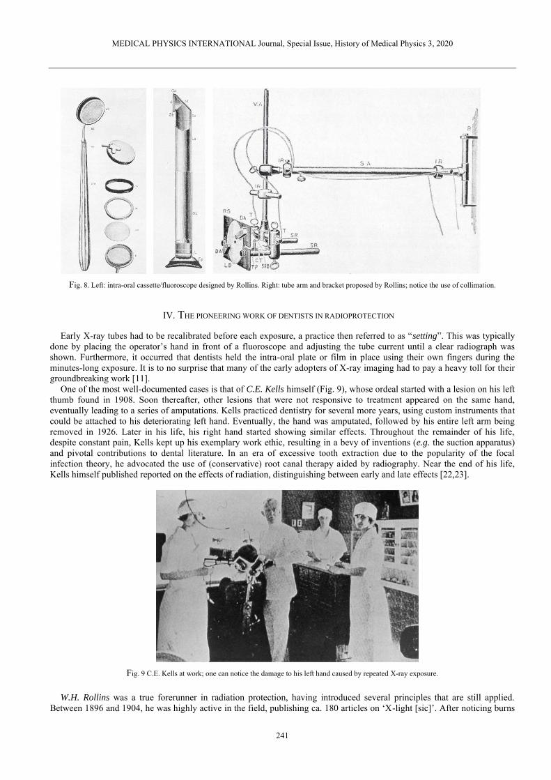
William H. Rollins, a Boston-based dentist, was another early adopter of dental radiography. In July 1896, he showed the design of an intraoral cassette with accompanying fluoroscope, which could be used to visualize the posterior teeth (Fig. 8); for more on dental fluoroscopy, see section V. Rollins also designed an X-ray tube arm, with a bracket for wall mounting and the use of a (rectangular) collimator, which was never commercially manufactured (Fig. 8). Rollins’ legacy is further expanded upon in section IV.
Weston A. Price [21] was at a forefront of radiographic record keeping by meticulously labeling the radiographs he acquired using a thin copper wire, ensuring that the images could not be mixed up. He is also considered as the creator of the bisecting-angle technique described further below. He was among the first to acknowledge the expertise required to interpret dental radiographs.
MEDICAL PHYSICS INTERNATIONAL Journal, Special Issue, History of Medical Physics 3, 2020
241
Fig. 8. Left: intra-oral cassette/fluoroscope designed by Rollins. Right: tube arm and bracket proposed by Rollins; notice the use of collimation.
IV. THE PIONEERING WORK OF DENTISTS IN RADIOPROTECTION
Early X-ray tubes had to be recalibrated before each exposure, a practice then referred to as “setting”. This was typically done by placing the operator’s hand in front of a fluoroscope and adjusting the tube current until a clear radiograph was shown. Furthermore, it occurred that dentists held the intra-oral plate or film in place using their own fingers during the minutes-long exposure. It is to no surprise that many of the early adopters of X-ray imaging had to pay a heavy toll for their groundbreaking work [11].
One of the most well-documented cases is that of C.E. Kells himself (Fig. 9), whose ordeal started with a lesion on his left thumb found in 1908. Soon thereafter, other lesions that were not responsive to treatment appeared on the same hand, eventually leading to a series of amputations. Kells practiced dentistry for several more years, using custom instruments that could be attached to his deteriorating left hand. Eventually, the hand was amputated, followed by his entire left arm being removed in 1926. Later in his life, his right hand started showing similar effects. Throughout the remainder of his life, despite constant pain, Kells kept up his exemplary work ethic, resulting in a bevy of inventions (e.g. the suction apparatus) and pivotal contributions to dental literature. In an era of excessive tooth extraction due to the popularity of the focal infection theory, he advocated the use of (conservative) root canal therapy aided by radiography. Near the end of his life, Kells himself published reported on the effects of radiation, distinguishing between early and late effects [22,23].
Fig. 9 C.E. Kells at work; one can notice the damage to his left hand caused by repeated X-ray exposure.
W.H. Rollins was a true forerunner in radiation protection, having introduced several principles that are still applied. Between 1896 and 1904, he was highly active in the field, publishing ca. 180 articles on ‘X-light [sic]’. After noticing burns

MEDICAL PHYSICS INTERNATIONAL Journal, Special Issue, History of Medical Physics 3, 2020
242
on his body in exposed regions, including his hands, he linked these effects to X-rays in a letter to the editor in the Boston Medical and Surgical Journal [24]. In this paper, with the candid title “X-light kills”, he detailed an experiment involving guinea pigs, concluding that “when electricity is excluded, death can be produced with x-light without burning.” Two years later, he published his findings regarding the effects of X-rays on the eye lens [25]. He proposed the use of shielding of the operator’s eyes (e.g. using lead-lined glasses), the tube and the patient, a principle which is still used in current radioprotection. Furthermore, he advocated the use of proper beam collimation to avoid exposure to areas of the body outside the region of diagnostic interest, which is one of the most efficient practical applications of the ‘optimization of exposures’ principle. Unfortunately, Rollins was largely ignored by his colleagues; several decades later, after the atomic bombings of Hiroshima and Nagasaki, the interest in dental radioprotection resurged. Perhaps owing to his caution regarding the harmful effects of X-rays, Rollins did not suffer the same, excruciating fate of Kells and many other contemporaries [26,27].
V. INTRA-ORAL PROJECTION TECHNIQUES
A. Conventional Projections
In 1904, Weston A. Price proposed an isometric X-ray projection technique, which later gained popularity under the name ‘bisecting-angle’ (Fig. 10). This technique was introduced due to practical difficulties in having the image receptor placed parallel to the long axis of the teeth, especially in the upper jaw. Whereas this practical issue has recently reemerged with the use of (relatively bulky) solid-state receptors, a ‘rectangular’ technique has been favored over a revisit to the bisecting-angle technique [28]. With the rectangular technique, the focus is on ensuring perpendicularity between X-ray beam and receptor, regardless of tooth orientation.
Franklin W. McCormack, a medical technician, focused on the application of the paralleling technique (Fig. 10) in intra-oral dental radiography. This was facilitated through the attachment of the film to a rigid metal plate, with the added benefit of reducing backscatter. He advocated the use of long source-skin distances (36” or ca. 91 cm) in a 1920 paper [15], mentioning several benefits: reduced X-ray burns when making multiple exposures, improved image quality owing to beam hardening, and avoiding overlap of the zygomatic bone with the apices of the maxillary molars [29]. Gordon M. Fitzgerald was in close contact with McCormack throughout his career and applied his technique to actual dental practice. He also advocated the use of high kV (80-100 kVp) X-rays. However, for several decades, dental X-ray tubes operated at a much lower voltage; the low tube output coupled with the limited film speed at the time necessitated the use of short source-detector distances (SDD) of 10 cm and below (i.e. ‘short cone’ units). At such short distances, the bisecting-angle technique was preferred due to its lower distortion of the root. Subsequent technological improvements made it possible to use an SDD of ca. 20 cm (‘long cone’), which is considered the standard today. Along with this increased SDD, the paralleling technique became the most common projection technique. Whereas SDDs of 30-40 cm were proposed they proved to be impractical in a confined dental environment, even with the focal spot at the back side of the unit as described in an article by AG Richards in 1966 [30]. Neither the slight dose reduction achieved with such an ‘extra-long cone’, nor the improved projection geometry was enough to overcome this practical limitation, resulting in little or no commercial success [31].
Fig. 10 Left: the paralleling technique, in which the X-ray beam is perpendicular to the long axis of the tooth as well as the image receptor. Right: the
bisecting-angle technique, in which the X-ray beam is perpendicular to the bisector of the tooth axis and receptor.
Out of the three types of intra-oral radiographs used today (periapical / occlusal / bitewing), the first two were employed from the start, albeit with somewhat inconsistent positioning of the receptor. Howard R. Raper, considered among the first dental radiology ‘specialists’, proposed the development of a bitewing film to Eastman Kodak in 1925, with the aim of

MEDICAL PHYSICS INTERNATIONAL Journal, Special Issue, History of Medical Physics 3, 2020
243
visualizing interproximal caries. He also invented an anglemeter that could be used for proper angulation of the X-ray beam when using the bisecting-angle technique [29].
As shown in Fig. 5, film holders were used early-on; commercial film holders have been used for decades (Fig. 11 & 12), although several dental offices still do not make use of them (Fig. 12). A UK study in 1994 involving four types of film holders showed differences in practicality and patient comfort, with the ‘Superbite’ holder showing the highest performance [32]. In 2009, a study in Lithuania reported that 32.7% of dental practitioners had the patient hold the receptor with their finger, and 48.0% used film holders and the patient’s finger alternatively [33].
Fig. 11. Top: Vintage film holder. Bottom left: temporomandibular joint film holder and positioning device. Bottom right: occlusal film holder. Courtesy of
S. Anamali (University of Iowa).

MEDICAL PHYSICS INTERNATIONAL Journal, Special Issue, History of Medical Physics 3, 2020
244
Fig. 12 Left: receptor holders and positioning devices used in petiapical (top) and bitewing (bottom) radiography. Courtesy of P. Sinpitaksakul
(Chulalongkorn University). Right: Despite the large difference between beam area and receptor area, misalignment of the beam (collimator cut / beam cut) can still occur when positioning devices are not used.
B. Parallax technique
Despite the immeasurable enthusiasm regarding the use of X-rays in medicine, the limitations of projection radiography became apparent quickly. To visualize three-dimensional relationships, the use of complementary angles and stereoscopic viewing (Fig. 13) was proposed by W.S. Hedley in 1898 [34]. C.A. Clark elaborated on the parallax concept in 1910 [35]. Common application in dentistry include the determination of the relative position of unerupted teeth (i.e. buccally / palatally to, or in line with, erupted teeth), and the visualization of multi-rooted teeth. Both horizontal and vertical parallax techniques have been employed [36], and different rules for interpreting the multiple radiographs have been defined, such as:
• Same Lingual Opposite Buccal (SLOB) [37] or Buccal Always Moves Away (BAMA): considering radiographs of two objects acquired at different angles, the object furthest from the tube will appear to move along with the tube and vice versa. This concept was introduced by Clark in his 1910 paper through the use of three radiographs [35]. AG Richards revised the rule in 1952, simplifying the technique to only two radiographs [38,39].
• Mesial-Buccal-Distal (MBD) [40]: for an exposure obtained at a slight angle to the mesial surface, the buccal root is situated distally.
Fig. 13 Ritter intra-oral ‘stereoscope and diagnostic lamp’ (ca. 1930, pre-patent [41]), used for pseudo-3D diagnosis based on multiple radiographs until at least the 1950s. Pictures and information provided by the Oak Ridge Associated Universities (ORAU) Health Physics Historical Instrumentation Museum
Collection under a non-transferable, non-exclusive, limited license [42].
C. Dental fluoroscopy
After its invention by Thomas Edison, fluoroscopy was used in medical radiography early-on. A fluoroscope consists of a calcium tungstate screen, allowing for real-time X-ray imaging. W.H. Rollins’ dental fluoroscope has been mentioned above (Fig. 8); W.J. Morton also showed interest in this technique in his early work [18], predicting that it would eventually replace

MEDICAL PHYSICS INTERNATIONAL Journal, Special Issue, History of Medical Physics 3, 2020
245
the use of still images, as it could speed up the examination by avoiding exposures of several minutes as well as film processing. The technique was abandoned rather quickly, however, due to its unjustifiable high radiation exposure as well as the relatively poor image quality. In 1908, a medical doctor named G.E. Pfahler made a strong statement in Dental Cosmos, claiming that the fluoroscope had no place in dentistry [43]. Later attempts to revive this technology (Fig. 14) were quelled. Whereas fluoroscopy is commonly used in contemporary interventional radiology, its use in dentistry has waned: the closest thing to ‘interventional’ dental radiography involves static images (i.e. periapical radiographs) acquired during different phases of root canal treatment.
Fig. 14 Top left: the Dentoscope, an intra-oral fluoroscope produced in Switzerland (ca. 1930s). Bottom left: the Indian Head X-ray Reflector of the Union
Broach Company (US, ca. 1955). Distribution was halted by the State of New York. Pictures and information provided by the Oak Ridge Associated Universities (ORAU) Health Physics Historical Instrumentation Museum Collection under a non-transferable, non-exclusive, limited license [44,45].
VI. EVOLUTION OF DENTAL (INTRA-ORAL) X-RAY UNITS
After the initial wave of dental radiographs produced in 1896 within weeks of Röntgen’s publication, one would expect rapid adoption of this new technology in routine dental practice. However, commercialization and widespread clinical implementation took quite some time. In 1905, the first dental X-ray machines were manufactured in Germany by the company now known as Siemens. In 1910 it was reported that only a few dentists in the USA used radiography, but in 1912-1913 dental X-ray units reached the US. In 1932, a survey by the American Dental Association showed that nearly half of newly graduated dentists procured an X-ray unit for their office.
One of the main reasons why so many researchers started experimenting with X-rays in early 1896 was the accessibility to the tools used by W. Röntgen and his predecessors. No new equipment or machines needed to be produced; one simply required an induction coil coupled to a Crookes-Hittorf (or similar vacuum) tube to generate X-rays. Both tools could be purchased or borrowed from physics labs, as they were commonly used for energy-based experiments. The reason why the Crookes-Hittorf tube was well-suited for X-ray generation is attributed to its relatively high vacuum. The dispersion of the remaining air molecules in the tube resulted in a constant electron stream; W.H. Rollins reported that high vacuum tubes resulted in increased radiographic detail [46]. Early improvements to the basic Crookes-Hittorf tube were implemented by König (see above). F. Harrison (UK) has been credited for designed a custom vacuum tube for dental radiography in January 1896 [16]. C.E. Kells also showed interested in the optimization of the technology used for generating X-rays at that time. In an 1899 paper published in Dental Cosmos [47], he evaluated the state-of-the-art in radiographic technology. Out of different available vacuum tubes, he found that the Crookes-Hittorf type was preferred. He also noted that the Tesla coil or the static (friction-based) Ranney-Wimshurst-Holtz machine were adequate substitutes of the Ruhmkorff coil, although a report of the US military showed preference for the latter due to its ease of use and lower bulk [48], both of which are relevant in a dental clinical environment as well.
A limitation of the Crookes-Hittorf tube set-up was a lack of consistency in the quantity and quality of X-rays. George M.
Mackee and John Remer addressed this issue by proposing the use of a ‘radiochromometer’ that could measure the hardness of the X-ray beam, and a radiometer to measure the tube output [49].

MEDICAL PHYSICS INTERNATIONAL Journal, Special Issue, History of Medical Physics 3, 2020
246
Subsequent changes to the X-ray tube design, culminating in the Coolidge-type tube, which is still used today, are described in a prior paper [2]. In summary, in 1913, William David Coolidge (General Electric Co. New York) designed a tube in which a heated tungsten wire (cathode) served as the source of electrons, rather than residual air molecules in the vacuum. The new design improved safety as well as a more controlled X-ray quantity and quality. Furthermore, he discovered the dual purpose of oil immersion for electrical insulation and cooling. An adapted Coolidge tube for dental radiography was developed several years later. The following figures show the evolution of dental x-ray tubes throughout the decades (Fig. 15-29).
Fig. 15 Left: 1917 brochure for X-ray tube stand and wall brackets, used to adapt medical X-ray units for dental radiography. Multi-jointed arms of current
intra-oral X-ray tubes were still years removed. Instead, the tube was stationary, and the patient was adjusted accordingly. Right: first commercial X-ray unit in the US (1913), produced by American X-ray Equipment Co. This unit used an induction coil, and was suited for AC or DC input, with exposures
times of 10-20 s. The tube was shielded using lead glass [52].
Fig. 16 Component of a "therapeutic" X-ray unit. Ca. 1914, the use of X-rays in combination with high-frequency current was being considered e.g. for
periodontal treatment [52]. The application of this technique was short-lived.

MEDICAL PHYSICS INTERNATIONAL Journal, Special Issue, History of Medical Physics 3, 2020
247
Fig. 17 Coolidge-tube (10 mA), ca. 1922. Courtesy of D. Bednarek (University at Buffalo).
Fig. 18 Wall-mounted (left) and mobile (middle) ‘CDX’ Coolidge-type dental X-ray units (1923, Victor X-ray Corp., later General Electric X-ray Corp.).
These units were shock-proof by collecting high-tension components within a grounded housing. Their compact design was possible owing to using smaller transformers as well as an autotransformer (vs. a rheostat) [52]. In 1933, the redesigned CDX model E (middle & right) was released, showing the typical closed ‘pointed cone’ position indicating device that would be used for several decades (i.e. the era of ‘short cone bisecting-angle’ intra-oral radiography).
The unit shown on the right was still operational in 1981 (Science Museum Group under CC BY-NC-SA 4.0) [53].
Fig. 19 Coolidge-type RD (Radiator Dental) dental x-ray tube (Victor X-Ray Corporation), manufactured ca. 1926-1932. The right-angled design was
suited for dental radiography, allowing close tube positioning. The cathode, which was closest to the patient, was grounded, and the high-potential anode was deliberately positioned away from the patient, according to the original 1919 patient [54]. Left: the spherical part of the tube shows the focusing cup
and the target (embedded in a slanted copper block). Right: close-up of the focusing cup, showing the tungsten filament. When in use, a finned metal radiation was placed over the copper rod for heat dissipation (not shown on figure). This type of tube was self-rectifying, meaning that it could be directly attached to an induction coil or transformer. Figure and information provided by the Oak Ridge Associated Universities (ORAU) Health Physics Historical
Instrumentation Museum Collection under a non-transferable, non-exclusive, limited license [55].

MEDICAL PHYSICS INTERNATIONAL Journal, Special Issue, History of Medical Physics 3, 2020
248
Fig. 20 Left: early X-ray unit with exposed high-tension wire, which is believed to have several grave (even fatal) accidents [52]. Right: the Ritter dental X-
ray unit (1928), despite using a Coolidge tube, still had an exposed wire. Open-tube units were manufactured until the 1930s. Courtesy of D. Bednarek (University at Buffalo) [56].
Fig. 21 Left: Ritter X-ray unit. Courtesy of P. Pittayapat (Chulalongkorn University). Middle: Weber no. 5 Raydex mobile dental X-ray unit, with a design typical of the late 1930s and 1940s. Right: the compact design of the Philips Oralix X-ray unit (1940s-1950s) allowed it to be attached to the dental chair; it
was also produced as a wall-mounted or mobile unit [52].

MEDICAL PHYSICS INTERNATIONAL Journal, Special Issue, History of Medical Physics 3, 2020
249
Fig. 22 Top. Single focus dental XPD Coolidge tube (General Electric, ca. 1930s-1940s). Bottom: shock-proof dental x-ray tube (likely by General Electric,
ca. 1935) [57]. The housing is made of several lead layers, separated by an insulating material. Figures and information provided by the Oak Ridge Associated Universities (ORAU) Health Physics Historical Instrumentation Museum Collection under a non-transferable, non-exclusive, limited license
[58,59].
Fig. 23 X-ray tube with static anode (low power). 1. Anode stem. 2. Electron capture hood. 3. Beryllium window over the Anode. 4. Metallization of the
glass envelope. Courtesy of S. Tabakov (King’s College London).

MEDICAL PHYSICS INTERNATIONAL Journal, Special Issue, History of Medical Physics 3, 2020
250
Fig. 24 Ritter Dual-X unit (ca. 1950). Notice the double-cone design of the tube head, combining a longer source-skin distance with a position indicating device. Courtesy of P. Pittayapat (Chulalongkorn University).
Fig. 25 Left: Ritter Model E X-ray unit (1956), with kilovoltages from 65 to 90 kVp. Throughout the 1950s, innovation to X-ray units included electronic
timers, beam collimation and filtration [52]. Middle: Ritter Mark 75 model H (1966). This unit had preset mA and kV. Right: Heliodent X-ray machine (1957-1962) attached to an Artiflex dental unit (Siemens, Germany) (Science Museum Group under CC BY-NC-SA 4.0) [60].

MEDICAL PHYSICS INTERNATIONAL Journal, Special Issue, History of Medical Physics 3, 2020
251
Fig. 26 MAX-GL dental X-ray unit (South Korea, ca. 1972) with built-in chair. Courtesy of P. Pittayapat (Chulalongkorn University).
Fig. 27 Oralix 50 (left; ca. 1960s-1970s) and Oralix 65 (right; ca. 1984) intra-oral X-ray units (Philips, The Netherlands). The model number seemingly referred to the kV at stability (i.e. not the kVp) of the tube [61]; a ‘45’ model was also produced. Absorbed dose to the skin inside the primary beam ranged
between 3.3 mGy and 9.7 mGy for these two units [61]. Right: Gendex GX 1000 (ca. late 1980s). Courtesy of J.K.M. Aps (University of Western Australia).

MEDICAL PHYSICS INTERNATIONAL Journal, Special Issue, History of Medical Physics 3, 2020
252
Fig. 28 Left: the MINRAY (1982-1992, Soredex, Tuusula, Finland), a high-frequency DC intra-oral X-ray unit. Courtesy of Soredex Oy and Dr Jörg
Mudrak. Right: The MAX-F (1985, J. Morita, Kyoto, Japan), using a straight-cylindrical tube exit. Courtesy of J Morita.
Fig. 29 Intra-oral X-ray tube with circular (left, ca. 2005) and rectangular (right) collimation. The use of circular collimation is still prevalent, despite the
considerable dose reduction obtained using rectangular collimation [61-64]. Right figure courtesy of K. Horner (University of Manchester)
The use of hand-held (portable) X-ray units for intra-oral radiography was first described in 1993, when the commercially developed PXS7 (Kevex X-Ray Corporation, USA) unit, with intended applications ranging from contraband/drug inspection to quality control in manufacturing, was compared with a conventional X-ray machine. In the folowing years, the interest in hand-held units increased in forensic [65] and clinical dentistry (Fig. 30). The main limitation of this technology is the proximity of the operator, resulting in exposure to scatter radiation. Furthermore, it was found that several hand-held units exhibited a low tube output, requiring a longer exposure time. Thus, it was recommended that they should only be used in specific environments, including but not limited to remote areas and facilities with immobile or confined patients (e.g. elderly homes and detention centers), and only if a mobile unit is not available [66,67].

MEDICAL PHYSICS INTERNATIONAL Journal, Special Issue, History of Medical Physics 3, 2020
253
Fig. 30 Portable hand-held intra-oral units. Reproduced from Pittayapat et al. 2012 [65] with the author’s permission.
VII. EVOLUTION OF DENTAL (INTRA-ORAL) X-RAY IMAGE RECEPTORS – FROM PLATE TO PLATE
A. Film
Several practical difficulties were found in the early implementation of dental radiographs. To produce dental radiographs the photographic glass plates had to be cut in small pieces, wrapped in lightproof paper, and placed in a rubber dam [68]. Due to the extremely long exposure time as well as the weight and bulk of the plates, it was reported to be a quite uncomfortable experience by O. Walkhoff himself:
“It was a true torture, but I felt a great joy at the sight of the results when I become aware of the importance of the
Röntgen rays for dentistry.” (O. Walkhoff, as quoted by Forrai [11])
The fragility and the cost of the plates was another issue to consider. W. Röntgen himself remarked that film can be used instead of glass plates [69]. Initially, Eastman NC films were meticulously cut and wrapped in black paper. Early use of film in dental radiography was challenging due to stability issues as well as the necessity to maintain the film dry. Morton proposed the use of gutta percha receptacles to avoid that the emulsion became wet [18].
The following timeline (Table 1) and figures (Fig. 31-35) show the evolution of dental X-ray film throughout the years, as described by Campbell [70] and other reviews.
Table 1 Evolution of dental X-ray film, starting with initial commercialization
Year 1913 The first commercial, hand-wrapped dental x-ray film was marketed by Kodak, comprising a waxed, water-proof paper packet and two single-
emulsion films. 1919 A film with a cellulose nitrate base allows for the exposure of a molar in 9 s. The film was highly flammable, however, and burning would
release poisonous gases [70]. 1921 Machine-made dental film packets were produced. 1924/1925 Radiatized fine-grain dental film with a double-sided emulsion and a non-flammable cellulose triacetate base was introduced, doubling the
film speed and avoiding curling of the film. 1941 Ultraspeed film reached the market, again doubling the speed of radiatized film. 1955 D-speed film was introduced with an increased graininess, showing an 8 to 20 times higher speed than original film. 1960 A stronger, polyester (Polyethylene terephthalate a.k.a. Dacron) film base was developed 1967 Polysoft water-proof dental film packets were introduced for enhanced comfort 1981 E-speed (Ektaspeed) film was introduced, showing an approximately two times higher speed as D-speed film at the cost of reduced film
contrast. Clinical acceptance was further limited die to its sensitivity to long-term storage [71]. 1994 Kodak Ektaspeed Plus film becomes available, with flattened silver halide crystals (T-Mat emulsion) rather than traditional pebble-shaped
grains, resulting in improved resolution at a relatively high speed. The dose reduction from D-speed to E-speed was reported to be 30-40% 2000 F-speed film became available in 2000 (Kodak/Carestream Dental Insight), using the same emulsion as E-Plus but with an optimized silver
grain distribution (T-Grain), allowing for the exposure to be further reduced by 20-25% [71].

MEDICAL PHYSICS INTERNATIONAL Journal, Special Issue, History of Medical Physics 3, 2020
254
Fig. 31 Left: Eastman (Kodak) radiatized dental film. Right: Victor-Bolin dental film container (ca. 1930; patent by Bolin granted in 1925 [72]). Figure and
information provided by the Oak Ridge Associated Universities (ORAU) Health Physics Historical Instrumentation Museum Collection under a non-transferable, non-exclusive, limited license [73].
Fig. 32 Wolf X-ray intra-oral cassette for occlusal radiography (ca. 6.4 x 8.3 cm). The cassette appeared in a 1955 catalog, which mentioned an exposure time of 1.5-2 s. Figure and information provided by the Oak Ridge Associated Universities (ORAU) Health Physics Historical Instrumentation Museum
Collection under a non-transferable, non-exclusive, limited license [74].
Fig. 33 Dental film holders (ca. 1937). The text on the box reads "The wood block film holder is used to radiograph films in the mouth, especially where it is difficult for patient to hold the film in proper position or when patient is distressed by film. Insert film, folded side against rounded part of the block, and have patient bite on adjoining flat surface. Can be used either upper or lower." One block is approx. 1.8 cm across. A box of 10 blocks sold for $0.25 [75]. Figure and information provided by the Oak Ridge Associated Universities (ORAU) Health Physics Historical Instrumentation Museum Collection under a
non-transferable, non-exclusive, limited license [76].

MEDICAL PHYSICS INTERNATIONAL Journal, Special Issue, History of Medical Physics 3, 2020
255
Fig. 34 ‘Sta-put’ bitewing tabs and Minimax bitewing film packets. Courtesy of D. Bednarek (University at Buffalo).
Fig. 35 Wall-mounted shielded X-ray film containers for storing film prior to development. Left: Eastman Dental Film Safe (1920s), with two
compartments for a total of 24 film packets. Right: more recent units by Eastman/Kodak; the rightmost is shown in a 1955 catalog. All containers seem to be made of a lead alloy. Figure and information provided by the Oak Ridge Associated Universities (ORAU) Health Physics Historical Instrumentation
Museum Collection under a non-transferable, non-exclusive, limited license [77].
The development process of plates and film was based on previously established concepts in photography. The importance of this aspect of radiography may have been underestimated during the early years. In a 1922 paper, C.E. Kells reviewed the significance of proper film development, emphasizing that radiographic image quality it is as affected by the operator’s expertise as the X-ray exposure itself [78]. He also focused on the importance of having constant environmental factors (e.g. temperature). An automatic developer was introduced early-on, with the dual benefit of reducing operator-dependency and saving time; regardless, manual film development is still performed to this day (Fig. 36-39).
Fig. 36 Left: A dental assistant (hygienist) developing an X-ray film (original source and year unknown). Middle and right: automatic processors for intra-
oral films and large films. Courtesy of A. Al-Ekrish (King Saud University).

MEDICAL PHYSICS INTERNATIONAL Journal, Special Issue, History of Medical Physics 3, 2020
256
Fig. 37 Left: Litton automatic dental film processor with daylight loading. Courtesy of D. Bednarek (University at Buffalo). Right: Manual development
using a lightproof glovebox.
Fig. 38 Left: Safelight filter for intra-oral films. Middle: Kodak dental film dispenser. Courtesy of S. Anamali (University of Iowa). Right: Rinn dental film dispenser. Courtesy of D. Bednarek (University at Buffalo).
Fig. 39 Left: Digital densitometer (DD500 S&S X-Ray Products). Right: troubleshooting guide for dark and light radiographs. Courtesy of S. Anamali (University of Iowa).

MEDICAL PHYSICS INTERNATIONAL Journal, Special Issue, History of Medical Physics 3, 2020
257
B. Digital receptors
The transition to digital dental radiography was gradual [79] and is still on-going. In 1987, a digital charge-coupled device (CCD) intra-oral detector was introduced (RadioVisioGraphy, Trophy Radiologic, France; Fig. 40) [80]. The advantages of reduced patient exposure and immediate availability of the image were immediately apparent, although the spatial resolution was less than that of film [79]. Further improvements to CCD-based sensors were made in the following years. Photostimulable phosphor (PSP) receptors were introduced in 1994 (DIGORA, Soredex, Finland; Fig. 40)) despite having been used in medicine as early as 1983. Whereas resolution was considered somewhat inferior to CCD systems, PSPs showed an improved dynamic range [81,82] and signal-to-noise ratio [83]. Complementary metal-oxide semiconductor (CMOS) sensors were commercialized in 1998 (CDR-APS, Schick Technologies, USA) and have largely replaced CCD sensors in intra-oral radiography owing to several advantages such as cost, dynamic range and the absence of blooming/smearing effects [79]. In a 2001 survey involving Norwegian dentists, two thirds of the respondents found that digital (solid state sensors or PSP) receptors yielded equal or better image quality than film, at a mean reduction in exposure time of 55% [84]. Furthermore, the use of digital receptors saved an average of 36 min/day and 25 min/day for sensors and PSPs, respectively. A dosimetric study published in 2008, using the latest tissue weighting factors from the International Commission on Radiological Protection [85], found a 56% effective dose reduction for PSPs or F-speed film vs. D-speed film [86]. A more detailed overview digital receptors in intra-oral radiography, including their performance vs. film, can be found in the review by Yoshida et al [79].
Fig. 40 Left: the RadioVisioGraphy a digital charge-coupled device (CCD) intra-oral detector (1987, Trophy Radiologic, France). Courtesy of A. Wenzel, Aarhus University. Right: The DIGORA (‘DIGitalORAl’) system intraoral imaging system using storage phosphor plates (1994, Soredex, Tuusula,
Finland). Courtesy of Soredex Oy and J. Mudrak.
C. Xeroradiography
Xeroradiography was invented by the American physicist and patent attorney F. Chester Carlson, aided by Otto Kornei, in 1937. Ten years later, the Haloid Company (later known as Xerox) started commercial development. The technique was used in several areas of medicine and was first used for dental radiography in 1963 [87]. It was applied for panoramic and cephalometric radiography as well as sialography [88]. In 1978, intraoral xenoradiography was introduced and evaluated for endodontic use; it was found to depict anatomical structures more clearly than film radiographs at a third of the dose, along with a rapid image generation (20 s after exposure) [89]. Xeroradiography is performed using a plate containing a 150-320 µm amorphous selenium layer and a 2 mm thick aluminum substrate. Prior to X-ray exposure, a uniform positive charge is applied to the plate surface using a ‘scorotron’ [90]. If used intra-orally, the cassette is covered by plastic to avoid contact with saliva. When the surface is exposed with X-rays, the charge will be passed to the grounded conductive backing in proportion with the exposure, resulting in a latent image. Development involves electrophoresis with a negatively charged (powder or liquid) toner, which is (1) deposited on the photoconductor, (2) attaches itself to the remaining negatively charged areas, and (3) is transferred and fixed to a paper or plastic sheet. After cleaning the plate, it can be reused. Advantages of the technique include a low sensitivity to ambient light, high resolution, high dynamic range, low cost, straightforward copying of radiographs, and high (development) speed. On the other hand, contradictory reports regarding the relative dose of xeroradiography vs. film radiography can be found [91-93]. Xeroradiography gained interest for use in endodontics, as its contrast in the soft tissue density range allowed the visualization of calcification in the pulp and its spatial resolution allowed the depiction of fine anatomical details as well as instruments. However, several disadvantages of the technique became apparent, such as the impracticality of using charged plates intra-orally due to the presence of saliva. Furthermore, the ‘speed’ of the system was proportionate to its thickness, which in turn was limited by the space in the oral

MEDICAL PHYSICS INTERNATIONAL Journal, Special Issue, History of Medical Physics 3, 2020
258
cavity. The surface of the plate was also rather fragile. The technique has since faded from clinical dental use, despite calls for its reintroduction [94].
VIII. HISTORY OF PANORAMIC RADIOGRAPHY
Panoramic radiographic is a unique imaging modality, specifically designed for dental applications. The challenge addressed by this technology was to acquire a single radiograph that encompassed all teeth of the upper and lower jaw. The invention of the panoramic radiography unit is largely attributed to Yrjö Paatero [95], a Finnish dentist whose work resulted in widespread clinical practice and commercial distribution after the second World War (Fig. 41). However, the technique itself is much older; in 1922, Zulauf (USA) proposed a narrow-beam scanning technique for upper and lower jaw, obtaining a patent [96]. He also coined the term ‘panoramic radiography’. Numata (Japan) published clinical results of a prototype ‘parabolic radiography’ device in 1933 [97]. Heckmann (Germany) obtained a patient for narrow-beam radiography of curved objects in 1939 [98].
Fig. 41 Yrjö Paatero and one of his early experimental set-ups. Courtesy of Instrumentarium Oy and J. Mudrak.
After the second World War, Paatero took up a position at the Institute of Dentistry of the University of Helsinki and was seemingly pushed into taking charge (and becoming the only member) of the Department of Radiology. Despite a high clinical workload and scarce resources, Paatero was able to make important contributions to the field. It has been speculated that one of the driving forces behind Paatero’s dedication was the unsustainable work pressure in his one-man department; indeed, the workflow in dental radiography could be sped up considerably by replacing several radiographic acquisitions by a single panoramic radiograph. His work progressed quickly, despite being unaware of previous publications and patents on this technique: in 1946, a preliminary report was published in the Proceedings of the Finnish Dental Society. Initially, he used a long, curved film placed intra-orally, exposed with a moving narrow X-ray beam that passed along the patient’s face. The resulting image was dubbed ‘parablograph’ in 1949. In the same year, Paatero altered this technique by placing the film extraorally (curved around the face) and having a relative rotation of the X-ray tube posterior to the patient (Fig. 42). Paatero referred to this technique as the orthoradial pantomograph, eventually shortened into the trade name ‘Orthopantomograph’, which is still used as a generic term for panoramic radiography, along with its abbreviation ‘OPG’. Whereas the X-ray tube was stationary in early iterations, eventually prototypes were constructed in which the tube rotated.
An important step towards eventual commercialization of this technique was made in the early 1950s, when Paatero liaised with an engineer named Timo Nieminen via the Finnish company Lääkintäsähkö. The two would closely collaborate for the next decade. Paatero also spent a few years at the University of Washington, contributing to the development of a double eccentric rotation technique that was later patented by Hudson et al. (USA) [99]. After returning to Finland, Paatero and Nieminen developed a panoramic radiography unit with a triple rotation center [100], followed by extensive clinical testing [101-105] (Fig. 42).
Through collaboration with Siemens, who produced the X-ray tube and generators, the commercialization of the Orthopantomograph commenced in 1960 (Fig. 43-44). In 1965, the company Palomex (Panoramic Layer Observing Machine for Export) was established. In the USA, after clinical testing of the double eccentric machine of Hudson et al., production of the ‘Panorex’ commenced by the S.S. White company (Pennwalt Corporation). In the UK, after gaining expertise with a panoramic radiography unit produced in Helsinki, S. Blackman worked with the company Watson & Sons in the development of a panoramic machine named the Rotograph [106]. Soon enough, other manufacturers around the world produced panoramic radiography units (Fig. 45-55).

MEDICAL PHYSICS INTERNATIONAL Journal, Special Issue, History of Medical Physics 3, 2020
259
Fig. 42 Panoramic radiography applied in dental practice. Left: schematic (1949). Right: unit for clinical testing (1951). Courtesy of Instrumentarium Oy
and J. Mudrak.
Fig. 43 The Orthopantomograph OP1 (1961-1964, Instrumentarium, Tuusula, Finland). Courtesy of Instrumentarium Oy and J. Mudrak.
Fig. 44 Early use of panoramic radiographic for planning (left) and post-operative evaluation (right) of enossal (spiral) implants (1962). Courtesy of
Instrumentarium Oy and J. Mudrak.

MEDICAL PHYSICS INTERNATIONAL Journal, Special Issue, History of Medical Physics 3, 2020
260
Fig. 45 The Orthopantomograph OP2 (1964-1972, Instrumentarium, Tuusula, Finland) featured an improved imaging geometry and a redesigned, curved
cassette. Courtesy of Instrumentarium Oy and J. Mudrak.
Fig. 46 Left and middle: the Orthopantomograph OP3 (1972-1978, Instrumentarium, Tuusula, Finland) combined panoramic and cephalometric
radiography. Over 10 000 units were produced. Right: the Orthopantomograph OP5 (1978-1983, Instrumentarium) featured new patient positioning tools and an improved imaging geometry. Over 20 000 units were produced. Courtesy of Instrumentarium Oy and J. Mudrak.
Fig. 47 The Orthopantomograph OP10 (1983-1984, Instrumentarium, Tuusula, Finland) implemented horizontal (Frankfort) positioning lights and
advanced imaging programs. Courtesy of Instrumentarium Oy and J. Mudrak.

MEDICAL PHYSICS INTERNATIONAL Journal, Special Issue, History of Medical Physics 3, 2020
261
Fig. 48 Left: The Panex-E by (1972, J Morita, Kyoto, Japan). Middle: The Panex-EC panoramic/cephalometric unit (1975, J Morita). Right: the Veraview
(1979, J Morita), brandishing an electronic control system. Courtesy of J Morita.
Fig. 49 Vintage calibration phantoms for panoramic radiography. Separate phantoms were used for small, medium and large jaws. Courtesy of S. Anamali
(University of Iowa).
Further development of panoramic radiography was aided by its clinical implementation: whereas AC generators used in early models were often of the one-pulse type, the use of this modality in hospitals allowed them to be coupled to 12-pulse generators, which in turn allowed the use of rotating anode tubes [100]. DC generators were introduced by Soredex (Finland) in 1978.
A dosimetric study in 1979 found that the energy imparted in the head and neck from panoramic radiography was between 0.45 mJ and 4.5 mJ; for different combinations of conventional radiographs, the same range was found (i.e. from 0.40 mJ for left and right oblique, up to 4.4 mJ for full mouth series at 65 kV) [107]. The highest local absorbed dose was 3.7 mGy for panoramic radiography, whereas an absorbed dose at the corner of the mouth of 10 mGy and 12 mGy was measured for a full mouth series at 45 kV and 65 kV, respectively [107].
Mechanical movement was gradually replaced by step motors and electronic control systems. The ergonomics of the device was also improved through innovation in patient position devices. Whereas mechanical movement allowed for variations in exposure geometry for visualization of non-dental structures (e.g. optic foramina and cervical spine), further development initially focused on image layers that followed the dental arch, until electronics allowed for the customization and further refinement of image layers as described by Hallikainen (Fig. 50) [100].

MEDICAL PHYSICS INTERNATIONAL Journal, Special Issue, History of Medical Physics 3, 2020
262
Fig. 50 The Zonarc (Palomex Oy, Helsinki, Finland) unit allowed for the visualization of structures outside of the dental region. The patient is in a supine
position, and the movement of the X-ray tube and receptor rotate in the vertical plane. Rotation of the tube/receptor was complemented by up/down movement of the unit to create eccentric motion paths [108]. Courtesy of J.K.M. Aps (University of Western Australia).
Fig. 51 Panoramic single-jaw radiograph with intra-oral X-ray source and extra-oral film, placed in a flexible cassette (top right), which was held by the
patient wrapped around the face. The cross marker on the cassette faced the operator and served as a guide in determining the midsagittal plane. Maxillary views (left) were made with the patient in an upright position and the cassette placed above the tube. For mandibular views, the patient's head was slightly
tilted back and they would bite on the X-ray tube. The tube was a small cylinder covered with a disposable sleeve. Courtesy of K. Sansare and F. Karjodkar (Nair Hospital Dental College).

MEDICAL PHYSICS INTERNATIONAL Journal, Special Issue, History of Medical Physics 3, 2020
263
Fig. 52 Quality control on a film-based panoramic radiography unit (ca. 1990). The dosimeter was firmly affixed to the rotating assembly. Note the metals
slits of the X-ray tube and of the film holder (marked with arrows). Courtesy of S. Tabakov (King’s College London)
Along with the digitization of other radiographic techniques in dentistry and medicine, ‘computed’ panoramic radiography (Fig. 53-55) was developed in the 1980s, first described by Kashima et al. in 1985 [109]. Direct digital panoramic radiography followed in the early 1990s [110,111]. Some current-generation panoramic units have incorporated direct-conversion (CdTe) receptors. Recent dosimetric studies involving panoramic radiography are somewhat scarce. A 2019 study found an absorbed dose of 0.62 mGy for CCD panoramic radiography vs 0.80 mGy for intra-oral radiography [112]. One of the most recently reported effective dose values is 17.6 µSv for a full-size panoramic radiograph with a CCD detector, with dose reductions between 4.5% and 86.9% for collimated radiographs [113]. A 2008 study involving two CCD-type panoramic units found effective doses of 14-24 µSv [86]. A 2005 study, using now-outdated tissue weighting factors, found effective doses between 5-15 µSv for digital (CCD or PSP) panoramic radiography [114].
Fig. 53 The Orthopantomograph OP100 (1992-2006, Instrumentarium, Tuusula, Finland) implemented automatic exposure control, computed radiology
(CR) and linear tomography (OrthoTrans). Courtesy of Instrumentarium Oy and J. Mudrak.

MEDICAL PHYSICS INTERNATIONAL Journal, Special Issue, History of Medical Physics 3, 2020
264
Fig. 54 The Orthopantomograph OP100D and two-in-one Orthoceph OC100D (1999-2006, Instrumentarium, Tuusula, Finland) had digital (charge-coupled
device, CCD) image receptors. CCD image receptors were used as well in the OP30 model (2009). In the OP300 (2010), complementary metal–oxide–semiconductor (CMOS) digital sensors are used. Courtesy of Instrumentarium Oy and J. Mudrak.
Fig. 55 Left: Digital panoramic system ‘Veraviewepocs’ (1998, J Morita, Kyoto, Japan). Middle: Veraviewepocs 3D, a ‘3-in-1’
(panoramic/cephalometric/cone-beam CT) system (2007, J Morita). Right: Veraview X800 (2016, J Morita) 3-in-1 unit. Courtesy of J Morita.
IX. OTHER EXTRAORAL RADIOGRAPHIC TECHNIQUES
The most common type of extra-oral, non-tomographic radiographic technique in dentistry is the lateral cephalometric radiograph. The posteroanterior cephalometric radiograph is used less frequently, e.g. for the evaluation of left-right symmetry. Other projections (Fig. 56-57) usually require isocentric (or formerly Lysholm) skull units and are not performed in a typical dental office; the most common techniques are shown in Fig 56.

MEDICAL PHYSICS INTERNATIONAL Journal, Special Issue, History of Medical Physics 3, 2020
265
Fig. 56 Overview of common extra-oral projection radiography techniques. Own work, from the IAEA Training Material “Radiation Protection in Dental
Radiology” [115]. Radiographs courtesy of P. Pittayapat, Chulalongkorn University, Bangkok, Thailand.
Fig. 57 Left and middle: transcranial radiograph in open and closed mouth position, indicating degenerative joint disease. Right: lateral oblique radiograph
showing temporomandibular joint ankylosis. Courtesy of K. Sansare, Nair Hospital Dental College.
A. Cephalometric radiography
The origin of head measurements can be traced back to Leonardo da Vinci and other Renaissance scientists and artists. Facial proportions and angles were used in the next centuries for ethnic evaluation and the analysis of human remains, using the ‘cephalic index’. In 1931, the use of cephalometric analysis in orthodontics commenced [116,117]; the use of a cephalostat for standard head positioning allowed for the evaluation of normal/average cephalometric features [118]. After World War II, cephalometric radiography gained acceptance (Fig. 58-59), and several cephalometric analyses were defined, including those by Steiner (1953), Ricketts (1960) and McNamara (1983) (Fig. 60). Computerized cephalometrics, with a much-improved workflow due to the automatic calculation of distances and angles, was introduced in the late 1960s [119]. The evolution of image receptors in cephalometric radiography was concurrent with that of panoramic radiography, with the latest innovation being the use of direct-conversion CdTe sensors.

MEDICAL PHYSICS INTERNATIONAL Journal, Special Issue, History of Medical Physics 3, 2020
266
Fig. 58 Vintage cephalostat. Courtesy of A. Wenzel, Aarhus University
Fig. 59 Experimental cephalostat used with the Orthopantomograph OP1 panoramic radiography unit (Instrumentarium, Tuusula, Finland). Two-in-one
panoramic/cephalometric units gained popularity in the 1970s with the introduction of the Orthopantomograph OP3 (Fig. 46). Courtesy of Instrumentarium Oy and J. Mudrak.

MEDICAL PHYSICS INTERNATIONAL Journal, Special Issue, History of Medical Physics 3, 2020
267
Fig. 60 Lateral cephalometric radiograph (left) and corresponding Ricketts cephalometric analysis (right). Courtesy of K.F. Vasconcelos (Catholic
University of Leuven).
B. Sialography
Another type of radiography used in dentistry is sialography (Fig. 61), which originated in 1925 [120]. By injecting contrast medium (typically into a salivary gland, and acquiring an extra-oral radiograph, different types of pathosis could be evaluated, including tumors, duct obstruction (e.g. calculus), and inflammatory disorders such as Sjögren's syndrome [121]. The main reason why sialography had difficulty getting accepted in clinical practice was the rather impractical technique, with an excess of contrast medium (i.e. a type of iodobenzene known as Pantopaque/Myodil) resulting in both pain to the patient and impaired diagnostic efficacy. Whereas modified sialographic techniques were proposed [122,123], including the use of more suitable contrast media, catheters, and gland stimulation techniques, the advent of advanced imaging techniques (CT, MRI, ultrasound) [124] has rendered sialography largely obsolete.
Fig. 61 Sialogram of the parotid gland. Cortesy of Asma'a Al-Ekrish, King Saud University, Riyadh, Saudi Arabia.
X. DENTAL TOMOGRAPHY
Panoramic radiography, discussed in the previous section, is in fact a special type of tomography in which a curved ‘slice’ is formed that follows the dental arch. Whereas panoramic radiography has remained a routine imaging technique in dentistry, other types of tomography were used for several years in dentistry but have faded from clinical use since the introduction of computed tomography.
The origin of tomography has been the source of debate [125], with claims of the invention coming from Netherlands, France, Italy, USA, and Germany. The theoretical aspects were described in the late 1910s, but the first experimental units were produced around 1930. The problem that was addressed by tomography was the same reason radiostereoscopy was

MEDICAL PHYSICS INTERNATIONAL Journal, Special Issue, History of Medical Physics 3, 2020
268
developed (Section V), i.e. overcoming superimposition of anatomical structures to reveal hidden pathosis. The solution offered by tomography was the use of a moving X-ray source and receptor. The movement is controlled in a way that points within a place of interesting (i.e. the section plane) are always projected on the same part of the receptor, appearing sharp on the tomogram (Fig. 62-65). Conversely, points outside the section plane are projected differently on the receptor throughout the motion and are thus blurred, with the degree of blurring determined by the distance to the section plane. The location of the section plane can be altered either by changing the fulcrum of the tube/receptor movement or by adjusting the position of the patient. The thickness of the slice is inversely correlated to the distance of the tube movement. In the 1980s, dedicated dental tomographic units were developed with a spiral movement (not to be confused with the misnomer ‘spiral CT’, which refers to a different modality altogether) (Fig. 62, Fig. 66).
Fig. 62 Left: principle of tomography. The section plane (A) is determine by the relative position and motion of the X-ray tube, patient and receptor. Points
outside the section plane (B) are projected on different areas of the receptor throughout the motion, and appear blurred, whereas points within the section plane appear sharp. Right: tomography using a spiral motion path, popularized in dentistry in the late 1980s [126]. Right figure courtesy of Soredex Oy and
J. Mudrak.
Fig. 63 Left: Polytome universal tomograph (Philips Medical Systems, 1950s). Right: Quint Sectograph (USA) used from the 1960s onward. In dentistry, this unit could be used for cephalometric imaging and, using its linear tomographic function, for imaging of the temporomandibular joint. The tube would
move along the slot shown on the left side, and a metal rod ensured reciprocal movement of the image receptor. A grid was typically used. Information provided by Stuart White, University of California, Los Angeles. Left figure obtained from Science Museum Group under CC BY-NC-SA 4.0 [127]. Right
figure retrieved from www.dotmed.com, original source unknown.

MEDICAL PHYSICS INTERNATIONAL Journal, Special Issue, History of Medical Physics 3, 2020
269
Fig. 64 Tomographic images of Orthopantomograph OP100 (Instrumentarium, Tuusula, Finland). Orthogonal views are generated from distal to mesial (left
half of figure) and from buccal to palatal (right half of figure). Courtesy of Instrumentarium Oy and J. Mudrak.
Fig. 65 Tomogram of the temporomandibular joint. Courtesy of K. Sansare (Nair Hospital Dental College).
Fig. 66 Left: Early prototype of a tomographic unit with six degrees of motion by Prof. Tammisalo. Right: the SCANORA dental (spiral) tomographic unit
(Soredex, Tuusula, Finland), released in 1988. Different programs were available; the selection of the program selection was performed on a panoramic image. Courtesy of Soredex Oy and J. Mudrak.

MEDICAL PHYSICS INTERNATIONAL Journal, Special Issue, History of Medical Physics 3, 2020
270
XI. CONE-BEAM COMPUTED TOMOGRAPHY
The development of dedicated dental CBCT units was a logical outcome of the increased necessity for cross-sectional imaging in dentistry, primarily due to the increasing popularity of implant placement. Whereas helical CT has been applied in dentistry since its inception, and is still used to some extent, CBCT has become the convention in 3D dental imaging. In the footsteps of dental tomography (section X), dental CBCT scanners were developed in the 1990s. Prior to dental CBCT, this technology was used for applications such as angiography as early as 1982 [128]. Commercialization of dental CBCT happened in parallel in Europe [129] and Japan [130], followed by the USA. The number of dental CBCT models on the market has increased from 23 devices in 2008 [131], to 43 devices in 2013 [132], to 280 devices at the time of writing [133].
The technical aspects of CBCT have been described in a previous review [134], and patient dose has been measured by a multitude of studies [135-140]. Most CBCT models have the patient in a standing or seated position; a few units use supine patient positioning (Fig. 67). The first generation(s) dental CBCT units used image intensifier detector systems, but from the mid-2000s the use of scintillator-type (indirect) flat panel detectors (FPD) increased and has since become the norm. FPDs showed several benefits over image intensifier systems, including reduced bulk, improved spatial resolution at equal noise level, and higher geometric accuracy [141]. Several of the first- and second-generation CBCT units used continuous exposure, with an exposure time typically between 15-20 s. Due to the limited frame rate of FPD detectors and the presence of afterglow, pulsed X-ray exposure was introduced, with total exposure time decreasing to a few seconds. Automatic exposure control (AEC) is still largely absent in dental CBCT: a pre-scan AEC system based on the signal distribution of a scout image (topogram) was introduced on NewTom (QR, Italy) systems several years ago (SafeBeamTM); more recently, the same manufacturer has introduced tube current modulation during the scan based on pre-set mA curves [142], with a relatively lower tube output for lateral projection angles due to the lower attenuation. The majority of current commercial CBCT units, however, involve manual exposure set-up and/or the use of presets (e.g. adult male/female vs child protocols). Reconstruction is typically based on the adapted filtered backprojection technique by Feldkamp-Davis-Kress [143].
Fig. 67 Seated (left), standing (middle) and supine (right) cone-beam computed tomography units.
Following the implementation of dual-energy scanning in medical CT, dual-energy CBCT was recently introduced [144,145]. The main potential benefit of dual-energy CBCT in dentistry is artefact reduction; dual-energy imaging could also allow for improved soft tissue contrast and/or density estimation, but there are few clinical indications in dentistry for which this could be of benefit. Metal artefacts, however, are one of the most prominent artefacts in dental CBCT, often deteriorating image quality to unacceptable levels. Whereas several CBCT units have incorporated a metal artefact reduction (MAR) technique in their reconstruction algorithm, several studies have shown that diagnostic image quality was not improved [146,147] or even impaired [148] when using MAR. This is likely due to the fact that currently used MAR techniques on commercial units are fast, interpolation-based techniques; while they may lead to an esthetically improved image, the additional diagnostic information provided by MAR can be limited. Iterative techniques that model the physics of the system could offer a more robust solution to metal artefacts, but they are often computationally expensive and thus impractical in a dental clinical environment. The use of artificial intelligence for real-time artefact correction could combine the robustness of physics-based correction with the speed of backprojection, but requires further validation [149,150].
Another common artefact is due to patient motion; while this is mainly apparent in cases with severe movement, even swallowing, breathing or reverberation of the jaw causes some degree of blurring. Motion correction based on selective elimination of projections was introduced ca. 2007 (Iluma, IMTEC Imaging, USA) and has been implemented on a few CBCT models; it has been shown that this approach can reduce motion artefacts and thus avoid the need for re-exposure

MEDICAL PHYSICS INTERNATIONAL Journal, Special Issue, History of Medical Physics 3, 2020
271
[151]. Recently, head tracking (X1, 3Shape, Denmark) [152] and reconstruction-based motion correction (CALMTM, Planmeca, Helsinki, Finland) [153] were introduced.
XII. RADIOLOGICAL VIEWING/DISPLAY SYSTEMS
Along with the drastic improvement in image quality in the early years in radiographs came the necessity of appropriate viewing systems (Fig. 68-72). Once film became ubiquitous in radiography, so did the lightbox [154]. Furthermore, projections were used for the purpose of zooming, and specialized equipment was designed for stereoscopic (‘parallax’) radiology as mentioned in section V.
Fig. 68 Left: Vintage lightbox (ca. 1930s). Picture formerly hosted on Hoarde Vintage; original source unknown. Right: dental X-ray projector (ca. 1940, Spencer Lens Company). Figure and information provided by the Oak Ridge Associated Universities (ORAU) Health Physics Historical Instrumentation
Museum Collection under a non-transferable, non-exclusive, limited license [155].
Fig. 69 X-ray film illuminator; estimated manufacturing date 1950s. The level of illumination by the incandescent bulb was adjustable. Figure and
information provided by the Oak Ridge Associated Universities (ORAU) Health Physics Historical Instrumentation Museum Collection under a non-transferable, non-exclusive, limited license [156].

MEDICAL PHYSICS INTERNATIONAL Journal, Special Issue, History of Medical Physics 3, 2020
272
Fig. 70 High intensity illuminator (Picker X-Ray, USA) with attached magnifying glass. Courtesy of S. Anamali (University of Iowa)
Fig. 71 Vintage intra-oral film mount. Courtesy of A. Wenzel (Aarhus University)

MEDICAL PHYSICS INTERNATIONAL Journal, Special Issue, History of Medical Physics 3, 2020
273
Fig. 72 Left: Radiograph copying machine. Courtesy of A. Al-Ekrish (King Saud University) Right: intra-oral film duplicator. Courtesy of S. Anamali
(University of Iowa).
For digital radiographs, although it still occurs to this day that they are printed on film (e.g. for external requests), cathode ray tube (CRT) screens were initially used. More recently, (1) liquid-crystal display (LCD) with thin-film transistor (TFT) technology and (2) light-emitting-diode (LED) display systems have become the norm. With recent improvements in commercial off-the-shelf monitor technology, the benefit of costly ‘medical grade’ displays has been questioned, as the improved technical specifications of the latter type could be overcome by proper use of software tools like display calibration, window/level adjustment, zooming and filters. Furthermore, several recent studies have investigated the use of tablets for displaying dental radiographs. For the diagnosis of vertical root fractures on periapical radiographs, no difference was found between PC displays and tablets [157]. In the evaluation of caries on bitewing radiographs, increased performance was found for DICOM-calibrated consumer-grade displays vs. uncalibrated displays [158], although diagnostic accuracy was not assessed due to the absence of a ground truth. Tablet displays showed an almost equal performance to calibrated consumer-grade displays, both of which performed slightly worse than medical-grade displays [158]. Another study found that tablet displays performed equal to PACS-LCD monitors in the identification of anatomical landmarks in panoramic and lateral cephalometric radiographs [159]. In an evaluation of anatomical structures on cone-beam CT scans, a tablet display, PACS-LCD monitor, consumer-grade LCD monitor and laptop display all showed similar performance [160].
Recently, the use of augmented reality and virtual reality in image-guided surgery, both during pre-operative planning and intra-operatively, has gained attention [161-163]; further validation of this technology is needed in terms of effects on surgical time and outcome.
A NOTE ON HISTORICAL ACCURACY, COMPLETENESS AND SCOPE
During the preparation of this review, care was taken to ensure accuracy in terms of people, actions, dates and technology, relying on primary sources when possible. However, due to the limited availability/accessibility of such courses (most famously Röntgen’s notes, burned at his own request after his death), and conflicting information found in secondary/tertiary sources, a fully accurate representation of the 125-year old history of dental radiography cannot be guaranteed. The discrepancy between previously published information was mainly apparent when dealing with issues such as “In [year], [person/company] was the first to [develop/use something] in [country/region].”
Furthermore, several role-players in dental X-ray history were omitted from this review, either due to a lack of information regarding their exact contribution, or for conciseness. Little or no history of CT was included, as this is better suited for a separate review. Modalities that do not make use of ionizing radiation (i.e. magnetic resonance imaging, ultrasound) are outside of the scope of this review.
ACKNOWLEDGMENTS
R. Pauwels is supported by the European Union Horizon 2020 Research and Innovation Programme under the Marie Skłodowska-Curie grant agreement number 754513 and by Aarhus University Research Foundation (AIAS-COFUND).
The author is heavily indebted to the extensive collection of historical information on dental radiography performed by authors of previously published work, and would like to emphasize in particular the publications by AAOMR [29], Campbell

MEDICAL PHYSICS INTERNATIONAL Journal, Special Issue, History of Medical Physics 3, 2020
274
[70], Forrai [11], Glenner [52], Hallikainen [100], Jacobsohn & Fedran [16], Martinez [17], and Serman & Singer [19], and to recommend each of them for further reading.
A special thanks to Asma'a Al-Ekrish (King Saud University), Sindhura Anamali (University of Iowa), Johan K.M. Aps (University of Western Australia), Daniel Bednarek (University at Buffalo, Museum of Radiology and Medical Physics), Pam Bonee & Paul Frame (Oak Ridge Associated Universities, Health Physics Historical Instrumentation Museum Collection), Keith Horner (University of Manchester), Instrumentarium (Tuusula, Finland), Freny Karjodkar (Nair Hospital Dental College), Jörg Mudrak, J Morita (Kyoto, Japan), Pisha Pittayapat (Chulalongkorn University), Kaustubh Sansare (Nair Hospital Dental College), Steven R. Singer (Rutgers, The State University of New Jersey), Phonkit Sinpitaksakul (Chulalongkorn University), Soredex (Tuusula, Finland), Slavik Tabakov (King’s College London), Karla de Faria Vasconcelos (Catholic University of Leuven), Rick Waters, Ann Wenzel (Aarhus University) and Stuart White (University of California, Los Angeles) for providing various source material.
The Author declares that there is no conflict of interest.
REFERENCES
1. Röntgen W (1895) Ueber eine neue Art von Strahlen. Vorläufige Mitteilung. Aus den Sitzungsberichten der Würzburger Physik.-medic. Gesellschaft Würzburg: 137-147
2. Behling R (2018) X-ray tubes development - IOMP history of medical physics. Med Phys Int: 6:8-55 3. Walden TL Jr (1991) The first radiation accident in America: a centennial account of the x-ray photograph made in 1890. Radiology 181:635-639 4. Conrad C (2011) Vergleich der metrischen Genauigkeit von extraoralen Röntgenverfahren: in vitro Studie an humanen Schädelpräparaten.
Dissertation, Justus Liebig University Giessen. 5. Gianfaldoni S, Gianfaldoni R, Wollina U et al. (2017) An Overview on Radiotherapy: From Its History to Its Current Applications in Dermatology.
Open Access Maced J Med Sci 5:521-525 DOI 10.3889/oamjms.2017.122 6. Sansare K, Khanna V, Karjodkar F (2011) Early victims of X-rays: a tribute and current perception. Dentomaxillofac Radiol 40:123-125 DOI
10.1259/dmfr/73488299 7. Harrison F (1896) The New Photography and its Application to Dental Practice. J Br Dent Assoc 17:343-344 8. Figures K, Smith C (2012) A profile of Frank Harrison: a pioneering Sheffield dentist from 100 years ago. Br Dent J 213:405–408 DOI
10.1038/sj.bdj.2012.931 9. Zesch S, Panzer S, Rosendahl W, et al (2016) From first to latest imaging technology: Revisiting the first mummy investigated with X-ray in 1896 by
using dual-source computed tomography. Eur J Radiol Open 25:172-181. DOI 10.1016/j.ejro.2016.07.002 10. König W (1896) 14 Photographien mit Röntgen-Strahlen aufgenommen im Physikalischen Verein zu Frankfurt a. M. Johann Ambrosius Barth,
Leipzig. 11. Forrai J (2007) History of X-ray in dentistry. Rev Clín Pesq Odontol 3:205-211 12. Langland OE, Peter Fortier A (172) C. Edumund Kells. Oral Surg Oral Med Oral Path 34:680-689 DOI 10.1016/0030-4220(72)90353-2 13. Kells CE (1926) Three score years and nine. Self-published. 14. Price WA (1904) The technique necessary for making good dental skiagraphs. Dent Items Interest 26:161-171 15. McCormack FW (1920) A Plea for a Standardized Technique for Oral Radiography, with an Illustrated Classification of Findings and Their Verified
Interpretations. J Dent Res 2:467-509 DOI 10.1177/00220345200020030401 16. Jacobsohn PH, Fedran RJ (1995) Making Darkness Visible: The Discovery of X-ray and Its Introduction to Dentistry. J Am Dent Assoc 126:1359-
1366 17. Martinez B (2013) In a New Light: Early X-Ray Technology in Dentistry, 1890-1955. Dissertation, Arizona State University. 18. Morton WJ (1896) The x-ray and its application in dentistry. Dent Cosmos 38:478-485 19. Serman N, Singer SR (1995) The history of dental radiology. N Y State Dent J 61:78-81 20. Morton WJ, Hammer EW (1896) The X-Ray or Photography of the Invisible and its Value in Surgery. American Technical Book Co., New York. 21. Price WA (1900) The Roentgen rays with associated phenomena and their applications to dentistry. Dent Cosmos 42:117-129 22. Kells CE (1926) Thirty years’ experience in the field of radiography. J Am Dent Assoc 13:693-711 23. Kells CE (1927) Roentgen-ray burns. J Am Dent Assoc 14:235 24. Rollins WH (1901) X-light kills. Boston Med Surg J 144:173 25. Rollins WH (1903) Notes on x-light: the effect of x-light on the crystalline lens. Boston Med Surg J 148:364-365. 26. Wynbrandt J (1998) The Excruciating History of Dentistry. St. Martin’s Griffin, New York 27. Kathren RL (1964) William Rollins (1852-1929): X-ray protection pioneer. J Hist Med Allied Sci 19:287-294 28. Roeder F, von Rechenberg I, d'Hoedt B, et al. (2011). Spatial relation between a rigid (digital) intraoral X-ray receptor and longitudinal axes of
maxillary teeth. Clin Oral Investig 15:715-9. DOI 10.1007/s00784-010-0430-x 29. AAOMR at https://www.aaomr.org/assets/History/early_pioneers_of_oral_and_m.pdf 30. Richards AG (1966) New concepts in dental X-ray machines. J Am Dent Assoc 73:69-76 DOI 10.14219/jada.archive.1966.0232 31. ‘Oradlist’ Oral Radiology Discussion Group contribution by R. Molteni (2013) 32. Rushton VE, Horner K (1994) The acceptability of five periapical radiographic techniques to dentists and patients. Br Dent J 177:325-331 33. Peciuliene V, Rimkuviene J, Maneliene R, et al (2009) Use of dental radiography among Lithuanian general dentists. Stomatologija 11:77-82 34. Hedley WS (1898) Radiostereoscopy. Lancet 151:639 35. Clark CA (1910) A Method of ascertaining the Relative Position of Unerupted Teeth by means of Film Radiographs. Proc R Soc Med 3:87-90 36. Armstrong C, Johnston C, Burden D, et al (2003) Localizing ectopic maxillary canines--horizontal or vertical parallax?. Eur J Orthod 25:585-589 37. Hubar JS, Caballero P (2017) Localization of Objects (SLOB Rule). In: Fundamentals of Oral and Maxillofacial Radiology. John Wiley & Sons,
Hoboken DOI 10.1002/9781119411871.ch18 38. Richards AG (1952) Roentgenographic localization of the mandibular canal. J Oral Surg 10:325-329 39. Richards AG (1953) The buccal object rule. J Tennessee State Dent Assoc 33:263-268 40. Ingle JI, Bakland LK, Baumgartner JC (2008). Ingle's Endodontics 6 (6th ed.). BC Decker, Hamilton 41. Pieper AF, Kester GL (1931) Stereoscopic view box. U.S. Pat. No. 1808176.

MEDICAL PHYSICS INTERNATIONAL Journal, Special Issue, History of Medical Physics 3, 2020
275
42. Oak Ridge Associated Universities (ORAU) Health Physics Historical Instrumentation Museum Collection at https://www.orau.org/ptp/collection/Radiology/Stereo%20viewer.htm
43. Pfahler GE (1908) The use of the roentgen rays in dentistry. Dent Cosmos 50:916-919 44. Oak Ridge Associated Universities (ORAU) Health Physics Historical Instrumentation Museum Collection at
https://www.orau.org/ptp/collection/Radiology/dentoscope.htm 45. Oak Ridge Associated Universities (ORAU) Health Physics Historical Instrumentation Museum Collection at
https://www.orau.org/ptp/collection/Radiology/indianheadreflector.htm 46. Rollins WH (1898) Roentgen-ray notes. Electr Rev 32:12 47. Kells CE (1899) Roentgen rays. Dent Cosmos 41:1014-1029 48. Borden WC (1898) The use of the Röntgen ray by the medical department of the United States military in the war with Spain. 49. Mackee GM, Remer J (1914) Measurement of the amount of x ray employed in making dental radiographs. Dent Cosmos 56:35-42 50. Jacobsohn PH, Fedran RJ (1995) Harnessing the x-ray: Coolidge’s contribution. J Am Dent Assoc 126:1365 DOI 10.14219/jada.archive.1995.0045 51. Coolidge WD (1919). X-ray apparatus. U.S. Patent 1408989 52. Glenner RA (1975) 80 years of dental radiography. J Am Dent Assoc 90:549-563. 53. Science Museum Group at https://collection.sciencemuseumgroup.org.uk/objects/co100154/cdx-model-e-dental-x-ray-unit-chicago-usa-1935-1936-x-
ray-machine 54. Coolidge WD (1919) X-ray Apparatus. U.S. Patent 1310061. 55. Oak Ridge Associated Universities (ORAU) Health Physics Historical Instrumentation Museum Collection at
https://www.orau.org/ptp/collection/xraytubescoolidge/Victordental.htm 56. UB Museum of Radiology and Medical Physics at http://ubradiologymuseum.com/ 57. Gross MJ (1935) Progress in the Design of Shock Proof Roentgen Tubes for Therapy and Industrial Roentgenography. Am J Roent Radium Therapy
34:518-522 58. Oak Ridge Associated Universities (ORAU) Health Physics Historical Instrumentation Museum Collection at
https://www.orau.org/ptp/collection/xraytubescoolidge/GEXPD.htm 59. Oak Ridge Associated Universities (ORAU) Health Physics Historical Instrumentation Museum Collection at
https://www.orau.org/ptp/collection/xraytubescoolidge/grossshockproof.htm 60. Science Museum Group at https://collection.sciencemuseumgroup.org.uk/objects/co100221/artiflex-dental-unit-by-siemens-reiniger-werke-a-dental-
units 61. Velders XL, van Aken J, van der Stelt PF (1991) Absorbed dose to organs in the head and neck from bitewing radiography. Dentomaxillofac Radiol
20:161-165 62. Shetty A, Almeida FT, Ganatra S, et al. (2019) Evidence on radiation dose reduction using rectangular collimation: a systematic review. Int Dent J
69:84-97. DOI 10.1111/idj.12411 63. Magill D, Ngo NJH, Felice MA, et al. (2019) Kerma area product (KAP) and scatter measurements for intraoral X-ray machines using three different
types of round collimation compared with rectangular beam limiter. Dentomaxillofac Radiol 48:20180183. DOI 10.1259/dmfr.20180183. 64. Ludlow JB, Davies-Ludlow LE, White SC (2008) Patient risk related to common dental radiographic examinations: the impact of 2007 International
Commission on Radiological Protection recommendations regarding dose calculation. J Am Dent Assoc 139:1237-1243. 65. Pittayapat P, Jacobs R, De Valck E, et al. (2012) Forensic odontology in the disaster victim identification process. J Forensic Odontostomatol 30:1-12 66. Berkhout WER, Suomalainen A, Brullmann D, et al. (2015) Justification and good practice in using handheld portable dental x-ray equipment: a
position paper prepared by the European Academy of Dentomaxillofacial Radiology (EADMFR) Dentomaxillofac Radiol 44:20140343 DOI 10.1259/dmfr.20140343
67. HERCA (2014) Position statement on use of handheld portable dental x-ray equipment. http://www.herca.org/uploaditems/documents/HERCA%20position%20statement%20on%20use%20of%20handheld%20portable%20dental%20x-ray%20equipment.pdf
68. Thunthy KH. Timeline of Oral and Maxillofacial Radiology. https://www.aaomr.org/assets/History/timeline_of_omr.pdf 69. Röntgen W (1897) Further Observations on the Properties of X-ray. Prussian Academy of Sciences, Berlin. 70. Campbell DJ (1995) A brief history of dental radiography. N Z Dent J 91:127-133 71. U.S. Food and drug administration. Nationwide Evaluation of X-Ray Trends (NEXT). Dental Radiography: Doses and Film Speed. 72. Bolin L (1925) Dental x-ray-film package. U.S. Pat. No. 1,537,925 73. Oak Ridge Associated Universities (ORAU) Health Physics Historical Instrumentation Museum Collection at
https://www.orau.org/ptp/collection/Radiology/Dental%20Film.htm 74. Oak Ridge Associated Universities (ORAU) Health Physics Historical Instrumentation Museum Collection at
https://www.orau.org/ptp/collection/Radiology/Dental%20cassettes.htm 75. Geo. W. Brady & Company (1937) Paragon X-ray Supplies and Accessories. 76. Oak Ridge Associated Universities (ORAU) Health Physics Historical Instrumentation Museum Collection at
https://www.orau.org/ptp/collection/Radiology/intra-oral%20film%20blocks.htm 77. Oak Ridge Associated Universities (ORAU) Health Physics Historical Instrumentation Museum Collection at
https://www.orau.org/ptp/collection/Radiology/intra-oral%20film%20blocks.htm 78. Kells CE (1922) Practical development of dental films. Dent Items Interest 44:927-937 79. Yoshida M, Yoshihara H, Honda E (2018) History of Digital Detectors in Intraoral Radiography. Dent Health Curr Res 4 DOI 10.4172/2470-
0886.1000135 80. Duret F, Coste BC, Duret, B (1988) The Radio Visiography (RVG): where reality surpasses radiological fiction a hope that is becoming reality. J Dent
Pract Admin 5:138-140 81. Borg E (1999) Some characteristics of solid-state and photo-stimulable phosphor detectors for intra-oral radiography. Swed Dent J Suppl 139:1-67 82. Borg E, Grondahl HG (1996) On the dynamic range of different X-ray photon detectors in intra-oral radiography. a comparison of image quality in
film, charge-coupled device and storage phosphor systems. Dentomaxillofac Radiol 25: 82-88. 83. Attaelmanan AG, Borg E, Gröndahl HG (2001) Signal-to-noise ratios of 6 intraoral digital sensors. Oral Surg Oral Med Oral Pathol Oral Radiol Endod
91:611-615 84. Wenzel A, Møystad A (2001) Experience of Norwegian general dental practitioners with solid state and storage phosphor detectors. Dentomaxillofac
Radial 30:203-208 85. ICRP (2007) The 2007 Recommendations of the International Commission on Radiological Protection. ICRP publication 103. Ann ICRP 37:1-332 86. Ludlow JB, Davies-Ludlow LE, White SC (2008) Patient risk related to common dental radiographic examinations: the impact of 2007 International
Commission on Radiological Protection recommendations regarding dose calculation. J Am Dent Assoc 139:1237-1243 87. Pogorzelska-Stronczak B (1963) Attempted application of xeroradiography in stomatology. Pol Przegl Radiol Med Nukl 27:265-275

MEDICAL PHYSICS INTERNATIONAL Journal, Special Issue, History of Medical Physics 3, 2020
276
88. Ferguson MM, Davison M, Evans A, et al. (1976) Application of xeroradiography in sialography. Int J Oral Surg 5:176-179 89. Gratt BM, Sickles EA, Nguyen NT (1979) Dental xeroradiography for endodontics: a rapid X-ray system that produces highquality images. J Endod
5:266-270 90. Jeromin LS, Geddes GF, White SC, et al. (1980) Xeroradiography for intraoral dental radiology. A process description. Oral Surg Oral Med Oral
Pathol 49:178-183 91. Barkhordar RA, Nicholson RJ, Nguyen NT, et al. (1987) An evaluation of xeroradiographs and radiographs in length determination in endodontics.
Oral Surg Oral Med Oral Pathol 64:747-750 92. Gratt BM, Sickles EA, Nguyen NT (1979) Dental xeroradiography for endodontics: a rapid X-ray system that produces highquality images. J Endod
5:266-270 93. Wilson NH, Grant AA (1986) A clinical trial of dental xeroradiography. Br Dent J 161:327-335 94. Udoye CI, Jafarzadeh H (2010) Xeroradiography: stagnated after a promising beginning? A historical review. Eur J Dent 4:95-99 95. Tammisalo EH (1975) Professor Yrjö v. Paatero - the pioneer of panoramic oral tomography. Dentomaxillofac Radiol 4:53-56. DOI
10.1259/dmfr.1975.0010 96. Zulauf AF (1922) Panoramic X-ray apparatus. U.S. Patent No 1408559 97. Numatha H (1933) Consideration of the parabolic radiography of the dental arch. J Shimazu Stud 10:13 98. Heckmann K (1939) Die Rontgenperspektive und ihre Umwandlung durch eine neue Aufnahmetechnik. RöFo 60:144-157 99. Dickson G, Hudson DC, Kumpula JW (1957) A panoramic x-ray dental machine. U S Armed Forces Med J 13:46-55 100. Hallikainen D (1996) History of panoramic radiography. Acta Radiol 37:441-445 101. Paatero YV (1952) Thickness of layer reproduced on pantomogram in relation to location of the object, speed of rotation, and divergence of roentgen
rays. Soumen Hammaslaiikariseuran Toimituksia 48:113-128 102. Paatero YV (1953) Radiography of the temporo-mandibular joint. A new method. Ann Chir Gynaecol Fenn 42:259-264 103. Paatero YV (1954) Geometrical study on possibilities of making double eccentric pantomograms with a single exposure. Suomen
Hammaslaiikariseuran Toimituksia 50:36-43 104. Paatero YV (1955) Die Andwendungen der Pantomographie fur klinische Untersuchungen. RöFo 82:525-528 105. Paatero YV (1957) Pantomography of spherical layers. Acta Radiol 48:181-187 106. Blackman S (1956) Mass dental radiography. Radiography 22:21-25 107. Br J Radiol. 1979 Sep;52(621):727-34. Doses to patients from pantomographic and conventional dental radiography. Wall BF, Fisher ES, Paynter R,
Hudson A, Bird PD. 108. McDavid WD, Tronje G, Welander U (1989) Image layers in the Zonarc. Dentomaxillofac Radiol 18:1-10 109. Kashima I, Kanno M, Higashi T, et al. (1985) Computed panoramic tomography with scanning laser-stimulated luminescence. Oral Surg Oral Med
Oral Pathol 60:448-453 110. McDavid WD, Dove SB, Welander U, et al. (1991) Electronic system for digital acquisition of rotational panoramic radiographs. Oral Surg Oral Med
Oral Pathol 71:499-502 111. Dove SB, McDavid WD, Welander U, et al. (1992) Preliminary evaluation of a digital system for rotational panoramic radiography. Oral Surg Oral
Med Oral Pathol 73:623-632 112. Qiang W, Qiang F, Lin L (2019) Estimation of effective dose of dental x-ray devices. Radiat Prot Dosimetry. 183:417-421. DOI 10.1093/rpd/ncy159 113. Benchimol D, Koivisto J, Kadesjö N, et al. (2018) Effective dose reduction using collimation function in digital panoramic radiography and possible
clinical implications in dentistry. Dentomaxillofac Radiol 47:20180007. DOI 10.1259/dmfr.20180007 114. Gijbels F, Jacobs R, Bogaerts R, et al. (2005) Dosimetry of digital panoramic imaging. Part I: Patient exposure. Dentomaxillofac Radiol 34:145-149 115. IAEA at https://www.iaea.org/resources/rpop/resources/training-material#11 116. Broadbent HB (1931) A new X-ray technique and its application to orthodontia. Angle Orthod 1:45-66 117. Hofrath H (1931) Die Bedeutung der Röntgenfern– und Abstandsaufnahme für die Diagnostik der Kieferanomalien. Fortschritte Orthod 1:232-258 118. Broadbent HB (1937) The face of the normal child. Angle Orthod 7:183-208. 119. Ricketts RM (1969) The evolution of diagnosis to computerized cephalometrics. Am J Orthod Dentofacial Orthop 55:795-803 120. Barsony T (1925) Idiopathic Dilatation of Stenson's Duct. Klin Wchnschr 4:2500-2501 121. Holt JF (1957). Sialography. Radiology 68:584–585 122. Rubin P, Blatt M (1955) Sialography, Preliminary Report. Univ Michigan M Bull 21:57-63 123. Rubin P, Blatt M, Holt JF, Maxwell JH (1955) Physiological or Secretory Sialography. Ann Oto1 Rhin Laryng 64:667-688 124. Afzelius P, Nielsen MY, Ewertsen C, et al. (2016) Imaging of the major salivary glands. Clin Physiol Funct Imaging 36:1-10. DOI 10.1111/cpf.12199 125. Littleton JT, Littleton MLD (1996) Conventional tomography. A History of the Radiological Sciences. American Roentgen Society, Leesburg. 126. Tammisalo E, Hallikainen D, Kanerva H, et al. (1992) Comprehensive oral X-ray diagnosis: Scanora multimodal radiography. A preliminary
description. Dentomaxillofac Radiol 21:9-15 127. Science Museum Group at https://collection.sciencemuseumgroup.org.uk/objects/co440061/tomograph-united-kingdom-1950-1959-tomograph 128. Robb RA (1982) The dynamic spatial reconstructor: an x-ray video-fluoroscopic CT scanner for dynamic volume imaging of moving organs. IEEE
Trans Med Imaging 1:22-33 129. Mozzo P, Procacci C, Tacconi A, et al. (1998) A new volumetric CT machine for dental imaging based on the cone-beam technique: preliminary
results. Eur Radiol 8:1558-1564 130. Arai Y, Tammisalo E, Iwai K, et al. (1999) Development of a compact computed tomographic apparatus for dental use. Dentomaxillofac. Radiol
28:245-248 131. Kau CH, Bozic M, English J, et al. (2009) Cone-beam computed tomography of the maxillofacial region: an update. Int J Med Robot Comput Assist
Surg 5:366-80 132. Nemtoi A, Czink C, Haba D, et al. Cone beam CT: a current overview of devices. Dentomaxillofacial Radiol 42:20120443 133. Gaêta-Araujo H, Alzoubia T, Vasconcelos KF, et al. Cone-beam computed tomography in Dentomaxillofacial radiology: a two-decade overview. Pre-
published. 134. Pauwels R, Araki K, Siewerdsen JH, et al. (2015) Technical aspects of dental CBCT: state of the art. Dentomaxillofac Radiol 44:20140224 DOI
10.1259/dmfr.20140224 135. Al-Okshi A, Lindh C, Salé H, et al. (2015) Effective dose of cone beam CT (CBCT) of the facial skeleton: a systematic review. Br J Radiol
88:20140658 DOI 10.1259/bjr.20140658 136. Ludlow JB, Timothy R, Walker C, et al. (2015) Effective dose of dental CBCT-a meta analysis of published data and additional data for nine CBCT
units. Dentomaxillofac Radiol 44:20140197 DOI 10.1259/dmfr.20140197 137. Pauwels R, Beinsberger J, Collaert B, et al. (2012) Effective dose range for dental cone beam computed tomography scanners. Eur J Radiol 81:267-
271 DOI 10.1016/j.ejrad.2010.11.028

MEDICAL PHYSICS INTERNATIONAL Journal, Special Issue, History of Medical Physics 3, 2020
277
138. Bornstein MM, Scarfe WC, Vaughn VM, et al. (2014) Cone beam computed tomography in implant dentistry: a systematic review focusing on guidelines, indications, and radiation dose risks. Int J Oral Maxillofac Implants 29S:55-77 DOI 10.11607/jomi.2014suppl.g1.4
139. Rottke D, Patzelt S, Poxleitner P, et al. (2013) Effective dose span of ten different cone beam CT devices. Dentomaxillofac Radiol 42:20120417 DOI 10.1259/dmfr.20120417
140. Pauwels R (2015) Cone beam CT for dental and maxillofacial imaging: dose matters. Radiat Prot Dosimetry 165:156-161. DOI 10.1093/rpd/ncv057 141. Baba R, Konno Y, Ueda K et al. (2002) Comparison of flat-panel detector and image-intensifier detector for cone-beam CT. Comput Med Imaging
Graph 26:153-158 142. Stratis A, Zhang G, Lopez-Rendon X, et al. (2017) Two examples of indication specific radiation dose calculations in dental CBCT and Multidetector
CT scanners. Phys Med 41:71-77 DOI 10.1016/j.ejmp.2017.03.027 143. Feldkamp LA, Davis LC, Kress JW (1984) Practical cone-beam algorithm. J Opt Soc Am A 1:612-619 144. Kim HJ, Kim JE, Choo J, et al. (2019) A clinical pilot study of jawbone mineral density measured by the newly developed dual-energy cone-beam
computed tomography method compared to calibrated multislice computed tomography. Imaging Sci Dent 49:295-299 DOI 10.5624/isd.2019.49.4.295 145. Zhu L, Chen Y, Yang J, et al. (2019) Evaluation of the dental spectral cone beam CT for metal artefact reduction. Dentomaxillofac Radiol
48:20180044 DOI 10.1259/dmfr.20180044 146. Kamburoğlu K, Yılmaz F, Yeta EN, et al. (2016) Assessment of furcal perforations in the vicinity of different root canal sealers using a cone beam
computed tomography system with and without the application of artifact reduction mode: an ex vivo investigation on extracted human teeth. Oral Surg Oral Med Oral Pathol Oral Radiol 121:657-665 DOI 10.1016/j.oooo.2016.01.010
147. de-Azevedo-Vaz SL, Peyneau PD, Ramirez-Sotelo LR, et al. (2016) Efficacy of a cone beam computed tomography metal artifact reduction algorithm for the detection of peri-implant fenestrations and dehiscences. Oral Surg Oral Med Oral Pathol Oral Radiol 121:550-556 DOI 10.1016/j.oooo.2016.01.013
148. Bezerra IS, Neves FS, Vasconcelos TV, et al. (2015) Influence of the artefact reduction algorithm of Picasso Trio CBCT system on the diagnosis of vertical root fractures in teeth with metal posts. Dentomaxillofac Radiol 44:20140428 DOI 10.1259/dmfr.20140428
149. Pauwels R, Oliveira-Santos C, Oliveira ML, et al. (2019) Artefact reduction in cone beam CT through deep learning: a pilot study using neural networks in the projection domain. The 22nd International Congress of DentoMaxilloFacial Radiology, Philadelphia, PA, USA, 2019
150. Pauwels R, Oliveira-Santos C, Watanabe P, et al. (2020) Correction of exomass artefacts in dental cone-beam CT using convolutional neural networks poster. EPOS C-14953, European Congress of Radiology, Vienna, Austria, 2020
151. Yeung AWK, Azevedo B, Scarfe WC, et al. (2019) Patient motion image artifacts can be minimized and re-exposure avoided by selective removal of a sequence of basis images from cone beam computed tomography data sets: a case series. Oral Surg Oral Med Oral Pathol Oral Radiol. In press. DOI 10.1016/j.oooo.2019.07.003
152. 3Shape at https://www.3shape.com/en/scanners/x1-cbct 153. Planmeca at https://www.planmeca.com/imaging/3d-imaging/planmeca-calm/ 154. Seeley GW, McNeill K, Dallas WJ (1987) Displays in radiology: past, present, and future. Radiographics 7:1261-1266 155. Oak Ridge Associated Universities (ORAU) Health Physics Historical Instrumentation Museum Collection at
https://www.orau.org/ptp/collection/Radiology/Dental%20xray%20projector.htm 156. Oak Ridge Associated Universities (ORAU) Health Physics Historical Instrumentation Museum Collection at
https://www.orau.org/ptp/collection/Radiology/xrayviewer.htm 157. Vasconcelos TV, Santaella GM, Nascimento HA, et al. (2016) Digital radiographs displayed on different devices: effect on the detection of vertical
root fractures. Int Endod J 49:386-392 DOI 10.1111/iej.12466 158. Kallio-Pulkkinen S, Huumonen S, Haapea M, et al. (2016) Effect of display type, DICOM calibration and room illuminance in bitewing radiographs.
Dentomaxillofac Radiol 45:20150129 DOI 10.1259/dmfr.20150129 159. Tadinada A, Mahdian M, Sheth S, et al. (2015) The reliability of tablet computers in depicting maxillofacial radiographic landmarks. Imaging Sci Dent
45:175-180. DOI 10.5624/isd.2015.45.3.175 160. Carrasco A, Jalali E, Dhingra A, et al. (2017) Analyzing dental implant sites from cone beam computed tomography scans on a tablet computer: a
comparative study between iPad and 3 display systems. Implant Dent 26:393-399 DOI 10.1097/ID.0000000000000595 161. Kwon HB, Park YS, Han JS (2018) Augmented reality in dentistry: a current perspective. Acta Odontol Scand 76:497-503 DOI
10.1080/00016357.2018.1441437 162. Bartella AK, Kamal M, Scholl I, et al. (2019) Virtual reality in preoperative imaging in maxillofacial surgery: implementation of "the next level"? Br J
Oral Maxillofac Surg 57:644-648 DOI 10.1016/j.bjoms.2019.02.014 163. Jiang W, Ma L, Zhang B, et al. (2018) Evaluation of the 3D augmented reality-guided intraoperative positioning of dental implants in edentulous
mandibular models. Int J Oral Maxillofac Implants 33:1219-1228 DOI 10.11607/jomi.6638 Contacts of the corresponding author:
Author: Ruben Pauwels Institute: Aarhus Institute of Advanced Studies Street: Høegh-Guldbergs Gade 6B City: 8000 Aarhus Country: Denmark Email: [email protected]

MEDICAL PHYSICS INTERNATIONAL Journal, Special Issue, History of Medical Physics 3, 2020
278
The History of Contrast Media Development in X-Ray Diagnostic Radiology
Adrian M K Thomas FRCP FRCR FBIR
Canterbury Christ Church University, Canterbury, Kent UK. Abstract: The origins and development of contrast media in X-ray imaging are described. Contrast media were used
from the earliest days of medical imaging and a large variety of agents of widely different chemical natures and properties have been used. The use of contrast media, which should perhaps be seen as an unavoidable necessity, have contributed significantly to the understanding of anatomy, physiology and pathology.
Keywords: Contrast Media, Pyelography, Angiography, X-ray, Neuroimaging.
I. INTRODUCTION
Contrast media have been used since the earliest days of radiology [1], and developments in medical imaging have not
removed the need for their use as might have been predicted. The history of contrast media is complex and interesting and has recently been reviewed by Christoph de Haën [2] . The need for contrast media was well expressed by the pioneer radiologist Alfred Barclay when he said in 1913 that ‘The x-rays penetrate all substances to a lesser or greater extent, the resistance that is offered to their passage being approximately in direct proportion to the specific gravity’ [3]. Barclay continued by noting that ‘The walls of the alimentary tract do not differ from the rest of the abdominal contents in this respect, and consequently they give no distinctive shadow on the fluorescent screen or radiogram.’ Barclay clearly states the essential problem confronting radiologists. The density differences that are seen on the plain radiographs are those of soft tissue (which is basically water), bony and calcified structures, fatty tissues, and gas. The liver has the same density as the heart and therefore the two structures cannot be separated on plain films. It was only when the CT scanner was invented by Sir Godfrey Hounsfield [4] that density differences within soft tissues could be readily appreciated, and even with CT scanning the administration of contrast media are commonly needed. We identify structures radiographically when a border is present between tissues of differing radiodensities, and when the tissues are of the same density that border is lost. This is the basis of the silhouette sign that was popularised by Ben Felson from Cincinnati [5]. This sign was first described by H Kennon Dunham, also from Cincinnati, in 1935. Dunham noted that if the left heart border is not visible then this implies disease in the adjacent lung, the lingual segment of the left upper lobe. The basis of contrast media consists in the artificial manipulation of tissue density so that specific structures are revealed, and as Barclay says, ‘The method depends on filling the cavities with some substance that differs as widely as possible in density from that of the tissue structures, i.e. by something very heavy such as a bismuth salt, or by inflating them with air or gas.’
II. TYPES OF CONTRAST MEDIA.
Contrast media may be divided therefore into positive contrast media that are of high atomic number, and negative
contrast media that are of low atomic number (table 1). Material used for radiographic contrast may be solid, liquid, or gaseous. Liquid contrast media may be found as solutions or suspensions. The double contrast arthrogram (fig 1) is an example of combining a positive contrast (an iodinated contrast media), which is coating the meniscus, and a negative contrast (carbon dioxide) distending the knee joint.

MEDICAL PHYSICS INTERNATIONAL Journal, Special Issue, History of Medical Physics 3, 2020
279
Fig.1 An example of positive and negative contrast media. A double-contrast knee arthrogram, showing the meniscus outlined with
water-soluble iodinated contrast and the joint distended with carbon dioxide gas Table 1. Positive and Negative Contrast Media.
Example Use Positive Bismuth subnitrate
Barium sulphate Iodinated contrast
media
Gastrointestinal radiology Gastrointestinal radiology Many uses including intravascular examinations.
Negative Room Air Carbon dioxide Oxygen
Ventriculography, myelography, cystography.
Combined positive and negative
Iodinated contrast or barium and gas
Double contrast studies, including barium meals, enemas and arthrograms.
III. THE GASTROINTESTINAL TRACT.
Since, as Alfred Barclay has already indicated, ‘The walls of the alimentary tract do not differ from the rest of the
abdominal contents in this respect, and consequently they give no distinctive shadow’, many considered how it would be possible to show the oesophagus and stomach using Röntgen’s new rays following their discovery in 1895. In March 1896 Wolf Becher was able to show the stomach and intestine of the guinea pig using a lead subacetate solution, and in April 1896 Carl Wegele proposed radiography after passing a stomach tube that contained a thin metal wire. In the February of 1897 Lindermann from Hamburg was able to demonstrate radiographically the greater curvature of the stomach using a gastric tube that was covered with fine wire netting. Only limited information could be obtained using an opaque gastric tube. In June and July of 1897 Jean-Charles Roux and Victor Balthazard in Paris were able to observe gastric peristalsis in the frog and dog, and then a human. They used bismuth subnitrate at 200mg/ml of food, and in all three cases divided the stomach into an upper inactive reservoir and an active pre-pyloric region.
The most significant of the early workers was Walter Bradford Cannon, who as a first year medical student at Harvard
Medical School, and with his fellow student Albert Moser, started researching the gastrointestinal tract using x-rays. This was following the suggestion of Professor Bowdich. Cannon used bismuth mixed in with bread, meat, mush and viscid fluids. This was fed to a goose and peristalsis was shown clearly with waves of contractions moving regularly down the oesophagus. There was no evidence of squirting from the mouth. This contradicted the current belief that food was pushed into the stomach from the actions of the mouth and pharynx. As a medical student Cannon worked with Francis Williams, who was the pioneer radiologist at Boston City Hospital. In 1898 Cannon assisted Williams in looking at the stomachs of two children [6]. They used a fluorescent screen covered with a sheet of celluloid, which could be marked directly using a pencil with the position of the stomach (fig 2). Radiography was not possible in the very early days because of the low power of the apparatus. Cannon and Williams observed changes in the position of the stomach between the prone position and standing, the movements of the stomach on respiration, and the changes in shape of the stomach during digestion. Whilst

MEDICAL PHYSICS INTERNATIONAL Journal, Special Issue, History of Medical Physics 3, 2020
280
such observations may seem obvious to us today, at that time these basic anatomical and physiological changes had not previously been observed. These observations were innovative and important. Canon made further useful observations on the nature of peristalsis (fig 3) [7].
Fig. 2 Cut of X-ray tracing of child examined by Williams and Cannon in September 1899. Stomach outlined by a mixture of milk, bread and bismuth. Broken line shows size and position of stomach on expiration, full line on inspiration, from Williams (1901).
Fig.3 Tracings of the shadows on the stomach and small bowel, from Cannon (1911)
The early radiologists initially used bismuth subnitrate to visualize the human alimentary tract. In the early period
drawings were made (fig 4), and as the power of the apparatus improved it became possible to obtain radiographs, even through the dense abdomen (fig 5). Early attempts to use air or gas alone were unsuccessful. The subject was reviewed by Russell Carman and Albert Miller, both from the Mayo Clinic, in 1917 [8] . Bismuth subnitrate was toxic and resulted in some fatalities and so its use was abandoned. It was replaced by bismuth subcarbonate, which was subsequently used extensively. The oxychloride of bismuth was used occasionally, since it was lighter and could be more readily held in suspension. Bismuth salts had been used therapeutically for indigestion since they are alkaline and would neutralise the gastric acid. It was therefore believed that bismuth would also suppress peristalsis and that this would of be of aid in radiography. Other agents used for the opaque meal were oxides of zirconium (marketed as kontrastin) and thorium, and the magnetic oxide of iron.
Fig.4 Drawings of the filling of the stomach with opaque meal,
from Barclay (1913) Fig.5 Penetrating gastric ulcer (arrowed) on a single contrast
opaque meal, by Sebastian Gilbert Scott in 1913.

MEDICAL PHYSICS INTERNATIONAL Journal, Special Issue, History of Medical Physics 3, 2020
281
Bismuth salts were gradually replaced by barium salts. Barium was found to be equally as satisfactory as bismuth and
was less than a tenth of the cost. The barium was manufactured as a finely divided powder, and had to be free of the soluble salts which were toxic. Barium neither inhibited nor suppressed peristalsis, and by the time Carman and Miller were writing in 1917 had largely superseded the use of bismuth.
As the use of barium progressed, there was the need to show fine mucosal detail and so a dense barium reconstituted with
water was used. For a double contrast study, pioneered in Japan where there was a high incidence of gastric cancer, an effervescent was swallowed to distend the stomach with carbon dioxide. The double contrast method that was first applied to the colon was promoted in Japan by Shirakabe, Ichikawa and Kumakuru who, by looking at the mucosal pattern on the stomach, were able to diagnose early gastric cancer. The method was both accurate and reliable. The double contrast barium meal was able to demonstrate the stomach and duodenum with remarkable clarity (fig 6). A different barium formulation was commonly used for studies of the small bowel, and an agent was added to prevent flocculation.
The Japanese company Fushimi Pharmaceutical Co. of Kagawa manufactured barium as Barytgen de luxe which was
distributed by Eisai Co. of Tokyo. The formulation was successful, and promoted for its high stability against stomach acids, its optimal adhesiveness to stomach mucosa, its constancy in colloidal suspension, and its pleasant taste and odour. They recommended mixing the Barytgen de luxe to water and mixing thoroughly, and preparing the mixture on the night before the day of administration.
The company Schering marketed ‘X-opaque’ barium as a powder in a 300gm sachet which was to be mixed with 70ml of
water. This resulted in a high density suspension, approximately 216% w/v, with a low viscosity. The barium was a blend of precipitated and crushed barium sulphate of varying particle sizes that was said to be essential for good mucosal coating. The barium sulphate was to be powdered into rough particles with jagged edges, and having a size range of 0.5m to 30m. For the double contrast technique and effervescent gas-producing agent was used and this needed to be compatible with the barium sulphate preparation. The effervescent granules typically consisted of sodium bicarbonate 44.8%, citric acid 18%, potassium acid tartrate 26.9%, with the addition of a sweetener and flavouring. An anti-foaming and de-foaming agent was needed for both double contrast barium meals and enemas since a bubble might simulate a polyp, and typically 12% w/v of simethicone was added.
For the opaque enema, barium was again mixed with a variety of compounds including condensed milk, fermented milk,
or starch. Carman preferred a mixture of mucilage of acacia, condensed milk and barium. Mucilage of Acacia is a viscid liquid used as a soothing agent in inflammatory conditions of the respiratory, digestive and urinary tract. In his classic 1933 textbook book on gastrointestinal radiology [9], the Cambridge radiologist Alfred Barclay recommended adding Tragacanth for both meals and enemas. Tragacanth is a plant and an extract is used to treat both diarrhoea and constipation.
A colonic activator was sometimes added to the barium mixture in the period before the adoption of the double contrast
technique. Agents used were oxyphenisatin [10] (marketed as Veripaque) or tannic acid. Veripaque in a dose of 3gm was added to 1 to 2 litres of the barium mixture. The colon was completely filled with the mixture and images were obtained. The barium was voided and the image of the contracted colon gave mucosal detail. Tannic acid and oxyphenisatin stimulated the contracture of the colon, and made the barium sulphate adhere to the bowel wall. The concentration of tannic acid recommended for use in barium enema examinations varies between 0.25 and 3.0 per cent. However neither oxyphenisatin nor tannic acid were without complications [11].
As is the case in a number of areas of human endeavour, just as a technique is perfected it becomes obsolete. Examples
include intracranial air studies, oral and intravenous examinations of the biliary tree with iodinated contrast agents, and optimisation of barium for barium examinations. In the 1980s May & Baker marketed EPI-C, for use as a barium enema, as a liquid dispersion for a 1 to 1 dilution with water and for combination with a foam control preparation. The preparation was a barium sulphate suspension 70% w/w (150% w/v) and formulated to provide optimal coating of the mucosa of the large bowel in double contrast barium enemas. The data sheets give little information about what was added to the barium. As with many medications and pharmaceuticals, in the early period they were made locally by pharmacists or doctors and are now produced in factories with minimal local preparation needed, if any at all.

MEDICAL PHYSICS INTERNATIONAL Journal, Special Issue, History of Medical Physics 3, 2020
282
Fig.6 The duodenal cap is demonstrated in this double-contrast barium meal
IV. THE RENAL TRACT.
IV.1. Retrograde Pyelography/Pyelo-ureterography. That the new rays could be used to investigate the urinary tract was appreciated soon after their discovery in 1895. Before
the use of radiography the investigation of urinary disease was not easy. For example, the surgeon could perform a cystoscopy and a ureteric bougie with wax fixed on to its tip would be passed up the ureter. Any obstruction to the passage of the bougie could be felt and the distance inserted noted, and when removed if the wax was seen to be scratched then this this was evidence a stone. The early apparatus was of low power and visualisation of the abdomen was not easy, although abdominal compression devices were of some assistance. It was only following the development of more powerful X-ray apparatus from about 1905 with ‘instantaneous radiography’ that the image quality improved. The X-ray shadow pictures, or skiagrams, that were obtained were often confusing and it was difficult to define and differentiate the nature of the calcifications. The calcifications had a number of origins, including calcified lymph nodes, calcified atheroma, ureteric calculi, or to phleboliths. It should be noted that traditionally our radiological techniques were used to confirm a suspected clinical diagnosis, and since the technique was often quite invasive it was only applied when there was a reasonable chance of the examination being positive.
Using the cystoscope it was now possible to introduce a ureteric bougie, which could be followed by abdominal
radiography. This was performed by Schmidt and Kolischer independently in 1901, having been suggested by Tuffier in 1898.
Edwin Hurry Fenwick was a urologist at the Royal London Hospital and a pioneer of electrical cystoscopy [12].
Following the discovery of the X-rays Hurry Fenwick recognised the potential of the discovery and became an enthusiastic supported of the new technique. Fenwick had in 1905 developed ureteric bougies with their walls impregnated with a metal for radiographic contrast. Following positing of the bougie at cystoscopy, radiography would be performed and this would demonstrate the course of the ureters and the potential urinary location of calcifications (fig 7). The position of an opacity in relation to the ureter could be determined with confidence, and a phlebolith could be confidently distinguished from a ureteric calculus. Figure 8 was obtained in a 42 year old man with bilateral opaque ureteric bougies. No stone could be felt when the bougie was advanced, and a radiograph was obtained with both bougies in position. A phlebolith is clearly demonstrated outside the ureteric X-ray bougie. Figure 9 shows a comparison radiograph of two ureteric radiographic bougies. The opaque bougie labeled EHF ‘stands out in good black shadow’, however the bougie labeled ‘foreign’ ‘shows only a faint shadow.’ Fenwick notes that it was ‘important to secure a radiographic bougie which throws the darkest shadow.’ In 1897 he had also used a small fluorescent screen (the cryptoscope) to examine diseased kidneys at the time of operative surgery. In addition to the radiopaque bougies as a positive contrast, Hurry Fenwick used a negative contrast with air inflation of the bladder (fig 10). The ureteric bougie is in the right ureter and an atheromatous plaque is seen outside the ureter. The central lucency is air in the bladder showing its position.

MEDICAL PHYSICS INTERNATIONAL Journal, Special Issue, History of Medical Physics 3, 2020
283
Fig.7 A ureteric bougie impregnated with metal has been
inserted in the ureter at cystoscopy. The calcification is outside the ureter. A case of the radiologist Sebastian Gilbert Scott, and the examination probably performed by Hurry Fenwick
Fig.8 A 42-year-old man with bilateral opaque ureteric bougies (double white arrows). A phlebolith is clearly demonstrated outside the ureteric X-ray bougie on the right (upper right white arrow), from Hurry Fenwick (1908). This would be a time-consuming examination to perform, and would require general anaesthesia.
Hurry Fenwick commented on the distressing situation with the failure of operative surgery when a kidney was opened,
and therefore was damaged to some extent, to remove a stone when it was in fact no longer in the kidney and was now within the ureter. Hurry Fenwick estimated that this happened in about 30% of cases when the ‘X-ray expert’ was not called upon to help in the diagnosis. That the ‘X-ray expert’ (or radiologist as they came to be called) can ‘guide the urinary surgeon (urologist) with a precision unattainable before the introduction of the (X-ray) method is without cavil (or disagreement).’ Hurry Fenwick was writing in 1908 when the techniques used were still quite primitive and before the introduction of retrograde or intravenous pyelography. In 1908 Hurry Fenwick produced his well-known book The Value of
Radiography in the Diagnosis and Treatment of Urinary Stone in which he described his experience with radiography [13]. Hurry Fenwick was one of the first to practice clinical-radiological-pathological correlation, correlating the clinical findings with the radiography and then with the operative findings. Quite remarkably he was teaching operative cystoscopy using a bladder phantom before 1900.
Fig.9 A ‘Comparison radiograph of shadowgraph bougies for
ureteric examination.’ From Hurry Fenwick (1908). The densely opaque bougie labeled EHF is markedly superior to the foreign product.
Fig.10 The ureteric bougie is in the right ureter and an atheromatous plaque is seen outside the ureter (white arrow). The central lucency is air in the bladder showing its position. From Hurry Fenwick (1908).
The impregnation of catheters and bougies with material of high atomic number as a contrast material is now used almost
universally. The anatomical position of the catheter or medical device may be identified with confidence, and this is essential in angiography, both for diagnosis and to guide intervention. Either the entire catheter may be rendered opaque, or specific parts may be opaque depending on the function of the device. So, for example, the gastric Ryle’s tube had metal balls or a marker at its tip for location (Fig 11,) and a tracheal intubating bougie has barium in its tip for improved X-ray guidance. A

MEDICAL PHYSICS INTERNATIONAL Journal, Special Issue, History of Medical Physics 3, 2020
284
further use of contrast material to identify the presence of a device is the use of a radiopaque thread in a surgical swab [14]. If the swab is retained following surgery its presence can be shown by abdominal radiography (fig 12). It is therefore important for the radiologist to know the differing radiographic appearances of medical devices.
Once the use of radiopaque bougies was appreciated, the injection of a liquid radio-opaque material via an opaque
catheter was an obvious progression, and was suggested by Klose in 1904. It was already appreciated that the alimentary tract could be outlined with a radio-opaque material such as a bismuth salt, and so a similar technique in the renal tract was a logical progression. For retrograde pyelography or pyelo-ureterography, that is demonstration of the pelvis of the kidney and ureter from below, a suspension of bismuth sub nitrate was initially used, however this procedure was difficult and it was not easy to remove the bismuth from the renal tract. The technique of retrograde pyelography was refined by Voelcker and von Lichtenberg in 1906 and they produced the first complete outline of the ureter and renal pelvis [15]. They were trying to outline the bladder with colloidal silver and on a radiograph noted that the solution had entered the ureter and renal pelvis. They were encouraged by this and therefore injected a 2% solution of Collargol (colloidal silver) followed by a 5% solution of the same (fig 13). The technique was again not without its problems. These were related to the difficulties in inserting ureteric catheters, and in the toxicity of the contrast agents used. The early history of pyelography was well recorded by William Braasch from the Mayo Clinic in 1915 [16] and 1927 [17]. However the technique gradually gained acceptance. Other workers used Argyrol, which was a 40 or 50% solution of silver nitrate. These silver based compounds were toxic to the kidneys and if excessive pressure was used for injection, they sometimes resulted in renal necrosis and some fatalities occurred. In the USA Braasch investigated these compounds extensively, and showed areas of renal necrosis. These severe toxic effects demonstrated the need for safer contrast agents.
Because of the problems with the silver compounds, in 1907 Burkhardt and Polano injected oxygen into the renal pelvis,
but the radiographic shadow produced was difficult to distinguish from bowel gas. It was also difficult to maintain a full distension of the pelvis and ureter during the exposure.
By 1915 thorium salts were being used with good radiographic opacification, but a major advance took place in March
1918 when Douglas Cameron, a surgeon from Minnesota, recommended the use of sodium or potassium iodide for retrograde pyelography as a 25% solution [18]. Cameron was aware that halogen salts were of a sufficient molecular weight to give good opacification on radiographs. After some investigations Cameron recommended sodium iodide as the medium of choice, and erroneously thought it was non-toxic even when introduced into the circulation. The 25% solution that he recommended was hypertonic to blood plasma, and as he thought that this might be undesirable, he used a 13.5% solution. His published paper was a preliminary report before he served in the US Navy in the Great War. Experiments showed the better utility of the iodide salt over the bromide as a pyelographic agent. A 14.56% sodium iodide solution was isotonic to a 10% sodium bromide solution and the higher molecular weight of iodide produced a greater radio opacification. Braasch therefore recommended a 12% sodium iodide solution in his book of 1927. Braasch emphasised the importance of the sterility of the solution, which could be boiled and kept in individual containers for each patient. For making larger amounts of the solution sterilization could be performed in bulk by the addition of 1 gram of mercuric iodide for each 3 litres of the 12% sodium iodide solution.
Following the successful introduction of retrograde pyelography, Alexander von Lichtenberg, who was Professor of
Urology at St. Hedwick’s Hospital in Berlin, undertook extensive laboratory work in an attempt to develop clinical intravenous urography (IVP), but without success. The nearest approach to a successful IVP was achieved by Hryntschalk of Vienna in 1929 [19] who succeeded in producing good radiographic visualisation of the renal calyces and pelves in
Fig.11 A chest radiograph. The metallic density seen in the
lower right lung field is a naso-gastric tube in the right lower lobe bronchus.
Fig.12 A retained surgical swab following abdominal surgery, seen as a coiled dense line on the left side of the abdomen.

MEDICAL PHYSICS INTERNATIONAL Journal, Special Issue, History of Medical Physics 3, 2020
285
laboratory animals after intravenous injection of iodinated pyridine compounds, probably synthesised by Binz and Räth, but he did not disclose the nature of the products, and his work was not fully accepted by the medical establishment.
IV.2. Intravenous Pyelography. Achieving reliable, safe, diagnostic imaging of the urinary tract was a major objective. Retrograde pyelo-ureterography
was an invasive procedure and a procedure that could be performed as an out-patient was essential. In 1923 a multidisciplinary team at the Mayo Clinic described the use of intravenous and oral sodium iodide to visualise the urinary tract [20]. The group comprised ED Osborne who was a syphilologist, CG Sutherland a radiologist, AJ Scholl Jr a urologist, and LG Rowntree the Professor of Medicine. Osborne had noticed that the urinary bladder was visible on radiographs of patients taking large doses of oral and intravenous sodium iodide for treatment of syphilis. The visualisation of the renal pelvis was poor but the authors were able to calibrate the dose of iodine against the urinary iodine concentration and the degree of bladder radiopacity. Sodium iodide was, however, far too toxic for use in clinical diagnosis. Other workers used sodium iodo-urea but these compounds could not be given in large enough doses to produce adequate visualisation.
Arthur Binz and Curt Räth were Professors of Chemistry from the Agricultural College in Berlin. In 1925 and 1926
they synthesised many organic iodine and arsenical preparations that were based on the pyridine ring in an attempt to produce an improved drug for the treatment of syphilis and other infections. The pyridine ring is a six pointed ring made up of five carbon atoms and one nitrogen atom. Linkage to this ring greatly detoxified the arsenic and iodine atoms, and Binz and Räth synthesised more than 700 of these compounds. One group of iodinated pyridine compounds was found to be selectively excreted by the liver and kidney and was therefore called the Selectans. Some of these synthesised pyridine drugs were therefore sent to several clinicians for evaluation for the treatment of biliary and renal infections.
In 1928 Moses Swick, who was working as a urology intern at Mount Sinai Hospital in New York, was awarded the
Libman Scholarship to perform medical research overseas [21]. He chose to work with Professor Leopold Lichtwitz at the Altona Krankenhaus in Hamburg, Germany, where he had some success in the treatment of human biliary coccal infections with some of Binz and Räth’s iodinated Selectan drugs. Since these drugs contained iodine, it occurred to Swick that they might be of value in visualising the renal tract by X-rays. Swick then made radiological, chemical and toxicological studies in laboratory animals and patients. The initial studies were encouraging and Swick transferred his work to gain access to the large number of patients at the urological department of Professor Alexander von Lichtenberg at St Hedwig’s Hospital in Berlin. The first successful human intravenous urograms were produced with the non-ionic N methyl-5-iodo-2 pyridone (Selectan neutral) but Swick preferred the less toxic, more soluble salt 5 iodo-2-pyridone-N-acetate sodium (Uroselectan) that had been patented by Räth in May 1927. This new compound Uroselectan produced excellent quality intravenous urograms with relatively little toxicity (fig 14).
Fig.13 A retrograde pyelogram, with Collargol in the renal
pelvis. A case of the radiologist Sebastian Gilbert Scott, and the examination probably performed by Hurry Fenwick
Fig.14 Early IVP from Swick (1929). A 22-year-old female with recurrent pyelonephritis. Note the high quality of the study and the dense pyelograms
Swick and von Lichtenberg presented the work to the Ninth Congress of the German Urological Society in September
1929. Swick presented the first paper based on the animal work but with several excellent quality human studies exhibiting

MEDICAL PHYSICS INTERNATIONAL Journal, Special Issue, History of Medical Physics 3, 2020
286
various disease processes (e.g. hydronephrosis and horseshoe kidney). Von Lichtenberg and Swick together presented the second paper on the human clinical uses with the paper read by von Lichtenberg. The two papers were published in November 1929 in Klinische Wochenschrift [22, 23].
Unfortunately Swick and von Lichtenberg could not agree on who should be accorded priority of discovery of this new
and revolutionary technique [24]. Assigning priority in any discovery is always difficult. The reality is that Arthur Binz and Curt Räth synthesisied the agents used, Moses Swick performed essential clinical and laboratory research, and Alexander von Lichtenberg had a long-term goal of the IVP and provided the facilities and resources. The IVP or intravenous urogram (IVU) as it became known was the result of the work of many different groups over many years.
V. CONTRAST MEDIA DESIGN.
V.1. Early Contrast Media. Within two years following the introduction in 1929 of Uroselectan into clinical practice, Binz and Räth made two further
modifications to the pyridine ring. These were marketed as diodrast (Diodone) and neo-ipax (Uroselectan B, Iodoxyl). Each molecule contained two iodine atoms. Binz and Räth were fully supported by the Berlin based company Schering Kahlbaum in the development of these pyridine agents, and as a result Schering became the world’s leading manufacturer of intravascular contrast agents. These compounds, and their variants, were highly successful, and became the standard intravascular and urologic contrast media for the next 20 years.
Moses Swick continued his interest in contrast media. He was working at Mount Sinai Hospital in New York with
Vernon Wallingford (b.1897) who was a research chemist from Mallinckrodt Chemical Works of St. Louis. In 1933 they introduced the six-carbon atom benzene ring as the iodine carrier instead of the five-carbon atom and one nitrogen atom heterocyclic pyridine ring that was used by Binz and Räth. A difficulty that was encountered using Swick and Wallingford’s original benzene ring compound (sodium iodohippurate) was its toxicity, so it cannot be seen as a major clinical improvement. The use of the benzene ring was an important innovation and in 1933 they were awarded the Billing’s Gold Medal of the American Medical Association.
There a number of changes that had to be made to the benzene ring before its iodinated derivatives were suitable for
clinical use. These were:
1. Approximately twenty years later, Wallingford showed that if an amine group were to be introduced into the meta position (C3), then it allowed three iodine atoms to be introduced at C2, C4 and C6. An amine in the ortho (C2) or para (C4) position allowed only two iodine atoms to be introduced.
2. In 1953 Wallingford demonstrated that an amine (-NH2) group at the C3 position allowed a side chain such as acetyl (-COCH3) to replace one of its hydrogen atoms [25]. This acetyl-amino group significantly reduced the toxicity of the tri-iodo compound and sodium acetrizoate (marketed as Urokon and Diaginol) was introduced clinically in 1952 by Mallinckrodt. This was the first tri-iodinated contrast medium.
3. In 1956 Hoppe and colleagues with others demonstrated that a second acetyl amino- group could be added to the benzene ring at the C5 position to produce a fully substituted tri-iodinated acid radical [26]. The toxicity was reduced even further. This compound sodium diatrizoate was introduced in the mid-1950s as Urografin (Schering AG, Germany), Renografin (Squibb, USA) and Hypaque (Sterling Drug). Sodium diatrizoate and its derivatives became the standard intravascular contrast agents until the development of the lower osmolar and non-ionic agents in the early 1970s. Urografin remains in use today as a 30% solution for cystography and retrograde urography (pyelography).
In 1959 the small Norwegian pharmaceutical company Nyegaard & Co. of Oslo were accused by Schering of infringing
their patent on diatrizoate, which they thought had not been patented in Norway. Following this, Nyegaard tried to synthesise diatrizoate by another means, and developed a new fully substituted tri-iodinated benzene ring compound (metrizoic acid), which they then marketed as Isopaque (Triosil).
V.2. The Cation.

MEDICAL PHYSICS INTERNATIONAL Journal, Special Issue, History of Medical Physics 3, 2020
287
The conventional tri-iodinated contrast agents (diatrizoate, iothalamate, metrizoate) designed for intravascular use are ionic monomeric salts of tri-iodinated fully substituted benzoic acids and are referred to as high osmolar contrast media (HOCM) because of their very high osmolality. The only chemical difference between them is in the nature of the substituted side chains.
In the 1960s it became apparent that the cation used was important. Each of these newer intravascular contrast media
molecules were a salt, comprising three radio-opaque atoms of iodine and one cation. The cation was either sodium or N-methylglucamine (meglumine), or a mixture of the two, as the non-radio-opaque cation necessary to produce the salt molecule. Meglumine produced less pain and less vasodilatation when injected into arteries, but it produced more diuresis and was therefore not ideal for urography. Vosse in 1960 showed that the sodium salt produced more damaging effects on the blood brain barrier and in 1964 Gensini and di Giorgi demonstrated an increased myocardial toxicity when pure sodium salt solution was used for coronary arteriography [27].
For coronary angiography a mixture of sodium and meglumine salts is essential to minimise cardiac arrhythmia. Sodium
cations produced less viscous solutions than meglumine and therefore a mixture of the two was often preferred. The balance of cations was further investigated by Nyegaard and in 1963 and 1965 they introduced several versions of Isopaque with a balance of sodium, meglumine, magnesium and calcium salts, different formulations being recommended for cerebral, coronary, vascular and urinary tract visualisation. Contrast media were marketed in various formulations and concentrations depending on the precise clinical need.
V.3. Low Osmolar Contrast Media. Torsten Almén is a Swedish radiologist interested in contrast media, who was working at Malmö (fig 15). He studied the
pharmacology of contrast agents and believed that the very high osmolality of the high-osmolality contrast media, that is up to eight times physiological osmolality, was responsible for much of its toxicity. He was doing angiography on a daily basis and could observe how painful the patients found the injections. Almén knew that an arterial injection of contrast medium that was isotonic to serum, such as a suspension of thorium dioxide or and emulsion of iodised oil, did not produce pain. Almén grew up on the most southern coast of Sweden and recalls a family holiday taken as a boy in Bohuslän on the west coast of Sweden. He found swimming in the water uncomfortable because as soon as he opened his eyes they started to hurt. The salty water at Bohuslän made his eyes sore whereas the brackish water around Ystad did not cause any discomfort. He reasoned that ‘a plasma-isotonic aqueous solution of contrast medium molecules might not cause pain, and should therefore be created!’ Almén reasoned that an isotonic contrast medium would both cause less pain and also be less toxic.
Almén taught himself the relevant chemistry and suggested reducing the osmolality of contrast media by substituting the
non-radio-opaque cation by a non-ionizing radical such as an amide. His paper on this topic was prepared when he was a Research Fellow in Philadelphia in 1968 to 1969. His thesis, which was completely theoretical and unsupported by chemical or clinical research, was rejected by the leading radiological journals but was eventually accepted and published by the Journal of Theoretical Biology in 1969, a journal of which most radiologists were unaware [28]. As a result, the most important paper on contrast media since Moses Swick’s 1929 paper was lost to the radiological publications.
Almén’s ideas were rejected by several pharmaceutical manufacturers but Hugo Holtermann, the Research Director of
Nyegaard, encouraged his team to attempt synthesis of some of Almén’s theoretical molecules. The research team at was not fully convinced that Almén’s proposal could be implemented, and Holtermann who was the developer of Isopaque was unsure as to their likely success, however they were willing to try Almén’s ideas. Almén also made known his ideas as to how these compounds might be constructed to facilitate water solubility and hydrophilicity and to reduce their viscosity. It is remarkable that fewer than 6 months were to elapse between the first meeting of Almén and the Nyegaard research group in June 1968 and the production of the first compound [29]. The team produced 80 different compounds. A consultant reviewer of Almén’s 1969 paper stated ‘The general principles of Dr. Almén’s proposal are probably sound. The implementation of it is probably impractical. He seems to be unaware that the ionic nature of the iodinated compounds is an essential property for their solubility in water—so part of his proposal, namely using non-ionic hydrophilic compounds, may be invalid’. In November 1969 after biological and pharmacological testing, compound 16 (called ‘Sweet Sixteen’) was shown to be the most promising and it was marketed as Amipaque, the first low-osmolar contrast medium (LOCM)). Amipaque was based on the glucose amide of Isopaque (metrizoate) leading to its generic name of metrizamide (Amipaque). As it contained the glucose radical, metrizamide could not be autoclaved. Because of the complex nature of its production, it was expensive and inconvenient to use, being presented as a freeze-dried powder with a diluent. It was, however, a major toxicological improvement on all pre-existing water-soluble myelographic and vascular agents and in the late 1970s it became the internationally recognized agent for myelography, enabling water-soluble myelography to replace oily Myodil (Pantopaque) myelography. Although it had an advantageous intravascular profile, metrizamide was generally regarded as

MEDICAL PHYSICS INTERNATIONAL Journal, Special Issue, History of Medical Physics 3, 2020
288
too expensive and too inconvenient for vascular studies. In recognition of his achievement Torsten Almén was presented with the Antoine Béclère Prize at the 1989 World Congress of Radiology.
In the mid-1970s, metrizamide was supplanted by the second generation of low osmolar contrast media. These were
Iohexol (marketed as Omnipaque by Nycomed previously called Nyegaard) and Iopamidol (marketed as Niopam by Bracco of Milan) which were easier to synthesise and were therefore much less expensive. They did not contain the glucose radical and could therefore be autoclaved and were stable in solution. These two second generation LOCM, together with similar molecules, became the contrast media of choice for all intravascular procedures in the mid 1990s [30]. Omnipaque was almost completely excreted by the kidneys and was of very low toxicity.
V.4. Myelographic Agents. Prior to 1970, only iodinated oils such as iophendylate (Myodil, Pantopaque) were available for myelography. Ionic
compounds such as meglumine iothalamate (Conray) and methiodal (Abrodil) were generally considered too irritant and toxic, although they were occasionally used for lumbo-sacral radiculography.
The French company Guerbet, following original research performed by Mallinckrodt, developed the ionic compound
meglumine iocarmate (Dimer-X) combining two tri-iodinated benzene rings into one large dimeric molecule containing six atoms of iodine and so reducing the osmolality. Dimer-X could only be used in the lower portions of the spinal canal below the spinal cord for radiculography but it produced excellent quality radiographs of the lumbo-sacral nerve roots. It was presented as a 60% w/v solution, and unfortunately its high osmolarity was responsible for some of the adverse reactions. It was promoted for use in lumbo-sacral radiculography, cerebral ventriculography, and double-contrast knee arthrography. Though much less toxic than the previous aqueous contrast media, it had to be used with great care and in a strictly limited dose. By contrast, metrizamide could be used throughout the spinal canal and was much less toxic than meglumine iocarmate, which it replaced for myelography and radiculography in the late 1970s.
V.5.i. The Second Generation Low Osmolar contrast Media. The introduction of metrizamide revolutionised the use of contrast agents and marked the boundary between the older
conventional ionic high osmolar media (HOCM) and the modern low osmolar compounds (LOCM). Iohexol and iopamidol were the first two second generation non-ionic LOCM agents to be synthesised and in the 1990s were the intravascular and myelographic agents of choice.
In 1977 the French company Laboratoire Guerbet produced a new contrast agent of low osmolality, which was a
derivative of meglumine iocarmate (Dimer X). This new molecule consisted of two tri-iodinated benzene rings that were linked together, and it was therefore a dimer. The dimer had one carboxyl group replaced by a non-ionising radical. The second carboxyl group was attached to either a sodium or meglumine cation. The resulting product (sodium and meglumine ioxaglate [31], marketed as Hexabrix 320) proved a good arteriographic agent but often caused nausea and vomiting on intravenous injection. Being ionic Hexabrix was not suitable for myelography or radiculography.
V.5.ii. Non-ionic dimers. In order to reduce the osmolality even further, two molecules of non-ionic monomers have been linked to produce a large
non-ionising molecule containing six atoms of iodine. Such products include visipaque (Iodixanol) and iotrolan (Isovist), which are of physiological osmolality at all concentrations. These non-ionic dimers were believed to have advantages for myelography and be beneficial for arteriography. These new agents have additional benefits and are significantly less nephrotoxic [32] .
Torsten Almén has reviewed the development of the non-ionic contrast media [33]. Development has resulted in agents
isotonic with plasma and causing less pain and toxicity. The current agents in use for X-ray examinations are tri-iodinated, non-ionic contrast agents. It has been the development of these safe contrast agents that has greatly facilitated the development of modern radiology in general, and of interventional radiology in particular.
V.6. The Graham Test and Biliary Contrast Agents. In the early 1920s the diagnosis of gallbladder disease was largely related to having a typical history and to physical
examination. Everts Graham, who was Professor of Surgery at Washington University in St. Louis, knew that the opaque meal could outline the alimentary tract and was looking for an opaque substance that could be introduced into the

MEDICAL PHYSICS INTERNATIONAL Journal, Special Issue, History of Medical Physics 3, 2020
289
gallbladder. In 1909 Abel and Rowntree had noted that 90% of orally administered phenoltetrachlorophthalein was excreted by the liver. Graham and Warren Cole thought that bromide and iodide compounds of phenopthalein could be tried experimentally. The first compound used was tetraiodophenolpthalein, and good results with opacification of the gallbladder were obtained in dogs. The technique was introduced into clinical practice as the Graham test after it was announced in 1924 [34] . In 1933 Barclay described both oral and intravenous administration of the agent.
The agents were slowly perfected, with the introduction in the 1970s of Endobil (the N-methylglucanine salt of
iodoxamic acid) for cholecystography and cholangiography, and Biliscopin (meglumine iotroxinate) for intravenous cholangiography. It must have been quite frustrating for the contrast media companies who had devoted time and money in the synthesis and testing of these newer agents, that as they were optimised they became obsolete being replaced by ultrasound and MRI.
VI. ANGIOGRAPHY.
VI.1. Post-Mortem Angiography in Vienna. It is remarkably how rapidly ideas about visualisation of the soft tissues of the body with contrast media developed. In the
case of the alimentary tract it was possible immediately to demonstrate anatomy and physiology in vivo. This was not to be the case in the vascular system until non-toxic agents were developed. However that angiography could be performed post mortem using non-physiological and toxic agents demonstrated that vessels could be visualised, and held out the possibility of clinical use when physiological agents were developed. There is considerable current interest in post-mortem angiography [35] and virtual autopsy or ‘virtopsy’ [36] , and it should be remembered that angiography developed from post-mortem studies [37]. The first angiographic procedure was performed in January 1896 by the physicist Edward Haschek and his medical friend D Th Lidenthal. They injected a calcium carbonate emulsion (Teichmann’s mixture) into an arm that had been separated from a cadaver (fig 16). The exposure time was 57 minutes, which is not unreasonable when one remembers the low power of the apparatus that was then available. This procedure was performed in Vienna, and the radiograph can be seen at the Museum in the Josephinum (Währinger Straße 25. A - 1090 Wien). Sigismund Exner was professor of physics at the University of Vienna and was a friend of Wilhelm Röntgen, and had received a personally dedicated copy of the first communication and a collection of radiographs. The hand used for the experiment was provided by Dr. Julius Tandler who later became the Professor of Anatomy in Vienna.
Fig.15 Torsten Almén, the designer of metrizamide and LOCM Fig. 16 The first angiogram of the hand from January 1896,
made by Haschek and Lidenthal.
VI.2. The New Photography in Sheffield. The angiographic work in Vienna was soon followed by the work of the group in Sheffield, England. Prof. Hicks, who
was the Principal of Firth College in Sheffield, and Dr. Addison, achieved both a renal and a hand arteriogram [38]. Radiological work had been started at Firth College in Sheffield on February 1, 1896. Hicks and Addison injected specimens that were available in the medical school with red lead and their results were published later that month in the British Medical Journal of 22 February 1896 in an article entitled The New Photography In Sheffield. The apparatus was simple and consisted of an ordinary battery of cells with an induction coil and a Crooke’s tube. The apparatus was of low power and the current was never above the strength of one that would give a spark of 3 inches. In their earlier experiments the exposure time varied between 20 minutes to half an hour however they stated that more recently they had obtained good shadows of the bones of the fingers using an exposure of a minute and a half. The Crookes tube was used with a glass shield, with a window in it of about three quarters of an inch in diameter. The vascular injections had been performed by Dr. Addison in

MEDICAL PHYSICS INTERNATIONAL Journal, Special Issue, History of Medical Physics 3, 2020
290
the medical school and on February 6 1896 he had injected samples using the ordinary red lead mass, which was used in the dissecting rooms showing radiographic images of the arteries in the hand and kidney. The hand was nailed to a half-inch wooden board and injected, whereas the kidney was simply laid on to a photographic plate, which had been previously wrapped. The delicate branching pattern of the arteries in the kidney and hand were shown in a similar manner to those that had been demonstrated in Vienna a few weeks earlier and have fascinated the observers.
VI.3. William Morton. William J Morton MD was an important early figure in radiology in the United States. Morton was ‘Professor of Diseases
of the Mind and Nervous System and Electro Therapeutics’ in the New York Post Graduate Medical School and Hospital. His book The X-Ray or Photography of the Invisible is undated, however the preface is dated September 11, 1896 [39]. Morton’s co-author was Edwin Hammer who was an electrical engineer. This book was written following the huge worldwide interest that had taken place following the discovery of x-rays by Wilhelm Conrad Röntgen. This book is important because it is the first book on radiology written by a physician. Morton covers all areas of radiology known at the time with speculations about potential future uses for the new rays. Morton makes the very pertinent observation that:
‘In teaching the anatomy of the blood vessels the X Ray opens out a new and feasible method. The arteries and
veins of dead bodies may be injected with a substance opaque to the X Ray, and thus their distributions may be more accurately followed than by any possible dissection. The feasibility of this method applies equally well to the study of other structures and organs of the dead body. To a certain extent, therefore, X Ray photography may replace both dissection and vivisection. And in the living body the location and size of a hollow organ, as for instance the stomach, may be ascertained by causing the subject to drink a harmless fluid, more or less opaque to the X-Ray, or an effervescent mixture which will cause distension, and then taking the picture.’
This passage is quoted fully because Morton's words are so very perceptive. In this very early book, which was written
less than a year following the discovery of X-rays, Morton is not only predicting contrast gastrointestinal studies, but also the use of radiology in the equivalent of modern virtopsy. The pioneers so often realise the exact significance and importance of their observations. Morton had immediately seen that the radiological examination of the body, either living or dead, could produce more information than could be found in either the anatomy theatre or the pathology department.
VI.4. H C Orrin and his Atlas. The first X-ray atlas of the arteries of the body was written by H C Orrin, and was published in 1920 as The X-ray Atlas
of the Systemic Arteries of the Body [40]. Orrin is described as a Civil Surgeon who was attached to the 3rd London General Hospital RAMC (T) located in Wandsworth. The book is beautifully illustrated with many high-quality radiographs. The book was designed to be used by students of anatomy, surgical anatomy, and of operative surgery. The book depicts a series of natural illustrations of the systemic arteries in continuity, and precisely as they exist in situ in the undissected body (figs 17, 18). The aims of the book were therefore purely anatomical in nature. Orrin wrote in his introduction that:
‘No matter how well dissection is performed, complete continuity of the vessels; their exact relationship to
bones; their finest terminal branches; the series of anastomosis into which they enter are seldom if ever accurately displayed or intelligently appreciated by dissection alone.’
Orrin therefore echoes the previous words of William Morton. The beautiful illustration of the coronary arteries
prefigures modern coronary arteriography (fig 19). The atlas was accompanied by a full set of stereoscopic radiographs which could be cut out and viewed with a hand-held stereoscope (fig 20), ‘which provide the only possible means of accurately rendering visible the points and details specified.’ It is fascinating that in 1920 Orrin recognizes the value of 3-D angiography, which is obtained in modern reconstructions of cross-sectional imaging.

MEDICAL PHYSICS INTERNATIONAL Journal, Special Issue, History of Medical Physics 3, 2020
291
Fig.17 The systemic vessels of the upper half of the body, from
Orrin (1920).
Fig.18 The systemic vessels of the lower half of the body, from Orrin (1920).
Fig. 19 The coronary vessels beautifully depicted, from
Orrin (1920).
Fig. 20 Stereoscopic radiographs of the abdominal vessels. The plate was designed to be cut out of the book and viewed in a hand-held stereoscope. From Orrin (1920).
VI.5. Egas Moniz and the Portuguese School of Angiography. From the earliest days of the application of X-rays, in vitro or post mortem angiograms had been obtained [41], and its
early history has been reviewed by Dolby [42]. The main problems encountered related to the nature of what was injected and to its toxicity. Direct puncture and/or cut down arteriography was achieved in the early 1920s by Brooks using sodium iodide and bromide solutions [43] , and by Berberich and Hirsch who injected Strontium Bromide into the femoral artery of a living subject and obtained useful images [44]. The major breakthrough in angiography was achieved in the Santa Marta Hospital in Lisbon, Portugal on 28 June 1928 when the first successful human carotid arteriogram was performed.
It was thanks to the work of Portuguese radiologists that the goal of practical angiography in the living was finally
realized. The two key names are those of Egas Moniz, and Reynaldo dos Santos. Veiga-Pires and Grainger have reviewed his outstanding contribution and that of his Portuguese colleagues in the development of arteriography [45].
The charismatic leader of the Portuguese team was Egas Moniz, who was Professor of Neurology in Lisbon. Moniz was a
brilliant polymath, author, politician (he was the Portuguese Foreign Secretary), researcher and clinician. Moniz went on to develop the now discredited technique of pre-frontal leucotomy and for this Moniz received the Nobel Prize in 1949. Moniz

MEDICAL PHYSICS INTERNATIONAL Journal, Special Issue, History of Medical Physics 3, 2020
292
was severely handicapped by gout which affected his fingers, and although he was unable to make any injections himself, he meticulously planned his research project on the diagnosis and localisation of cerebral tumours.
Moniz was dissatisfied with the recently developed technique of ventriculography, which he found could make a correct
diagnosis in less than a third of patients. At this time there was little known about the use of intravascular injection of radio-opaque substances. Moniz had been aware of the pioneer work of the Frenchmen Jean Sicard and Jacques Forestier in early angiography. They had tried with an intravascular injection of Lipiodol, an oily contrast medium, but their experiments were unsuccessful. Moniz’s desire to directly show the brain prefigures modern cross-sectional imaging with intra-venous contrast enhancement. Moniz and his team made experiments on animals and cadavers and showed satisfactory radiographic appearances with arterial injections. Moniz produced a classification of the cerebral arteries in 1928 based on his cadaveric studies, and this was to prove useful in interpreting angiograms in the living subject.
Moniz had reasoned that if he could concentrate radiopaque material within the brain then the brain would become
visible on radiographs. Moniz made experiments in 1926-27 with dozens of substances in various concentrations placed in small rubber tubes and radiographed inside a dry skull. The tubes were of a bore similar to that of the larger cerebral arteries. He knew that bromides were used as sedatives, so since they accumulated in the brain they might show up on radiographs. Moniz gave large amounts of bromides orally but showed nothing. He then tried injecting bromine directly into a carotid artery but apart from giving the patient a headache he again showed nothing. Moniz then attempted opacifying the brain itself by intravenous or parenteral administration of a variety of agents, giving large doses of lithium bromide and strontium bromide. The patients chosen suffered either from severe epilepsy or Parkinson’s disease, since it was thought that at the very least such patients would benefit from the injected bromine. When 10ml of a 30% solution of strontium bromide was administered the patient had no symptoms. When higher concentrations were used there was a feeling of warmth, and at over 40% the patient developed more generalized symptoms, but they were not prolonged. Moniz finally determined that a 10ml of a 70% solution of strontium bromide produced satisfactory opacification of the cerebral arteries.
Moniz then made intra carotid injections in four patients using a percutaneous injection but showed little. Partly because
of patient movement related to pain. He then tried exposing the carotid artery and 4ml of 70% strontium bromide was injected. It was felt that the agent was being diluted, and so an injection was made following a temporary ligation of the carotid artery below the point of injection. There was some visualisation of the arterial tree, and the first cerebral arteriogram in the living was obtained. However the patient developed severe post-procedure symptoms and unfortunately died, partly thought to be due to the carotid ligation and strength of the contrast. The death was a great shock to the team and Moniz wrote ‘This accident, the only one we had in the course of our early investigations before arriving at the desired conclusion, was a great shock to us. We thought much about it, but considering the films obtained, we gave heed to the opinion of some competent colleagues to the effect that we should continue, though more cautiously, the experiments we had begun. They gave us their valuable support.’
Moniz further wrote ‘The main idea in our work to obtain cerebral arteriography as the following. With a precise picture
of the normal arrangement of the cerebral arteries made opaque to X-rays, we thought it would be possible to make the diagnosis of the localization of the majority of tumours through the alteration in the normal arterial pattern in the cerebrum. Many tumours, or at least the very vascular ones, should also show their own circulation.’
There was about a month of indecision and it was decided to use a new group of substances opaque to X-rays, the iodides.
After these techniques failed he tried using intra-arterial injections using an iodide salt. Moniz chose iodine because of its higher atomic weight compared to bromine. The team again made preliminary experiments using iodides of ammonium, sodium, potassium, and rubidium. For patient studies a 25% solution of sodium iodide was used and the effect of dilution and arterial capacity were determined. It was felt that 5ml would be enough. In two patients injections of 3ml of 25% sodium iodide were made with limited success. In the third patient an intra carotid injection with a temporary ligature was made using the rapid injection of 5ml of 25% sodium iodide. The injection was successful with arterial filling and their positions were altered due to the presence of an intracranial tumour. His successful patient, on 28th June 1927, was the ninth in his series, a young man with a pituitary tumour. Moniz wrote and published describing the new technique in detail. The head had to be held still for angiography (fig 21), and figure 22 shows a typical labeled angiogram and using Thorotrast as a contrast medium.
Following the successful patient there was a period of development of the technique, including the use of stereoscopic
angiography, and a deepening of the understanding of the appearances [46]. Perhaps not unsurprisingly the cerebral arteriograms and subsequent venograms revealed anatomy that differed from classical descriptions and therefore supported Morton’s prediction.

MEDICAL PHYSICS INTERNATIONAL Journal, Special Issue, History of Medical Physics 3, 2020
293
Fig. 21 Positioning of the head for cerebral angiography, from
Moniz (1931).
Fig. 22 Cerebral angiography with the vessels labelled, from Moniz (1931). T is tumour.
In 1929 Moniz’s surgical colleague Reynaldo dos Santos, Professor of Surgery in Lisbon, introduced percutaneous Trans
Lumbar Aortography (TLA) by direct aortic puncture with injection of a sodium iodide solution. Dos Santos described the technique [47]. Punctures were made into the aorta with a long needle in a variety of positions including above the coeliac trunk, above the kidneys, above the inferior mesenteric artery and above the origin of the common iliac artery (fig 23). Figures 24 shows abnormal vascularity in a sigmoid tumour in a TLA performed by dos Santos, and also note the stationary grid lines. The contrast used was a 100% solution of pure sodium iodide, which was quite toxic. The injection was painful and therefore required anaesthesia. The TLA became the standard vascular examination for decades and was being routinely performed over 50 years after the procedure was first described. There were surprisingly few complications from the procedure. The examination illustrated (fig 25) was performed in 1982.
Fig. 23 The technique of trans-lumbar aortography, from Dos
Santos (1932).
Fig. 24 A TLA for a sigmoid tumour showing abnormal vascularity. Note the stationary grid lines. From Dos Santos (1932).
Other members of Moniz’s team ware equally innovative and successfully introduced angiopneumography (that is
pulmonary angiography) by de Carvalho [48], lymphography by Monteiro, phlebography (that is venography) by Joäo Cid des Santos who was the son of Reynaldo, and portal venography by Pereira. It was in 1929 Werner Forssmann had introduced a well-oiled ureteral catheter via an antecubital vein into his own right atrium, and it was in 1931 that Moniz, de Carvalho and Almeida Lima using the Forssmann method demonstrated the pulmonary vasculature with an injection of sodium iodide. The Portuguese School therefore introduced many aspects of clinical angiography in the 1930 to 1950 period but the international adoption of their techniques was severely delayed by the Second World War.
VI.6. Thorotrast in Angiography and its Consequences. In 1931 Thorotrast was introduced as a contrast medium and in the October was first used in cerebral angiography. The
new contrast medium was seen as a great improvement since it was not irritant and gave an excellent opacity. In 1950 Almedia Lima described Thorotrast and compared its use favourably to the organic iodine derivatives used at the time [49]. Thorotrast was a colloidal suspension of thorium dioxide, being a stable aqueous colloidal solution containing 25% thorium

MEDICAL PHYSICS INTERNATIONAL Journal, Special Issue, History of Medical Physics 3, 2020
294
dioxide by volume in a tapioca-dextrin medium. A preservative of 0.15% methyl p-hydroxybenxoate was added to the solution. Lima wished for a better contrast medium however felt that at that time none was available. Lima knew of no other substance that gave such satisfactory results as Thorotrast. He had not seen any serious disturbances following its use and had personally performed 2,000 angiograms. He saw the problems related to local tissue reactions and the fact that it was not eliminated from the body. He therefore recommended the abandonment of its use for ventriculography and encephalography. Of all myelographic agents Thorotrast was found to be the most irritant to the pia-arachnoid resulting in both systemic and local reactions. The local reactions caused a severe arachnoiditis and a cauda-equina syndrome.
Problems could arise following the local injection of Thorotrast with extravasation and the development of a local
reaction and mass, the so-called Thorotrastoma (fig 26) [50]. Thorotrast was retained in the walls of the vessels and histology showed little balls of Thorotrast in the branches of small cerebral vessels. However the main danger lay in the permanent retention of a radioactive substance in the body (fig 27). Thorotrast conglomerates emitted radiation as part of the decay of thorium 232. The majority of the radiation was α-radiation and β and γ-radiation contributed less than 10% to the total dose. Somewhat surprisingly Almedia Lima concluded as late as 1950 that ‘the tissue alterations and the radioactivity of Thorotrast are of no importance in the dosage of this substance as used in angiography,’ and he recommend angiography with Thorotrast (20% colloidal suspension of thorium dioxide) with a dose of 8ml to either side. Unfortunately Lima’s optimism was to prove unfounded, partly as a result on the work of Hermann Muth and the German Thorotrast Study [51]. Thorotrast was in use in Germany from 1929 to 1955, and the first quantitative biophysical studies to determine the activity concentrations of radionuclides derived from the naturally occurring thorium series were undertaken in Germany from 1946 to 1949. The dose estimates were of such concern that production of Thorotrast was stopped, and it was withdrawn from the market in 1949 to 1950. This makes it all the more curious that Lima was recommending its use in 1950. A detailed German Thorotrast Study started in 1968 and reported after 20 years in 1988. The results were interesting [52]. The study found an excess rate of various neoplasms including malignant liver tumours, myeloid leukaemia, and tumours of bile ducts, pancreas, oesophagus and larynx. The Thorotrast patients had a statistically significant loss of lifetime as a function of the dose rate, and this could not be accounted for purely by the known Thorotrast specific diseases. The Study concluded that the long-term irradiation of the reticuloendothelial system not only resulted in an excess death rate of certain neoplasms, but that there was also an acceleration of the manifestation of other illnesses leading to premature death.
Fig.25 Trans Lumbar Aortogram, 1982.
Fig.26 A Thorotrastoma shown as dense shadowing on the right side of the neck
VI.7. The Seldinger Technique and the development of Catheter Angiography. A major development related to the method of delivery of contrast medium into vessels and the heart chambers was
achieved by Sven Seldinger in 1956, working at the Karolinska Clinic in Stockholm [53]. He introduced the needle-guidewire-catheter replacement technique which permits selective catheterisation and injection of most arteries, veins and cardiac chambers of the body from a simple femoral arterial or venous puncture. This technique is fully established as the optimum method of visualising any important artery including the carotid, vertebral, coronary, renal and mesenteric arteries and for cardiac catheterisation and selective angiocardiography. This catheter technique, aided by the low osmolar contrast agents permits virtually painless, safe arteriographic visualisation of any arterial or venous territory or cardiac chamber, so

MEDICAL PHYSICS INTERNATIONAL Journal, Special Issue, History of Medical Physics 3, 2020
295
revolutionising diagnostic imaging. This extremely versatile percutaneous catheterisation technique has been very successfully developed to introduce therapeutic equipment, so permitting angioplasty, vessel occlusion, atherectomy etc., introducing the modern era of intravascular interventional therapy. It is noteworthy that just as the techniques for catheter angiography for diagnosis were perfected that they were swept away by newer and non-invasive techniques including ultrasound and cross-sectional imaging. Vascular access is now almost completely used for interventional procedures.
VII. NEURORADIOLOGY
VII.1. Ventriculography, encephalography and air myelography. There had been several case reports of patients surviving with intracranial air. One such case was described by Sebastian
Gilbert Scott in 1915, showing spontaneous pneumocephaly in a woman who complained of her brain splashing (fig 28). Walter Dandy from Johns Hopkins Hospital was aware of such instances, and also of the value of the appearances of abnormal gas collections to diagnose abdominal disease. In 1918 Dandy described ventriculography followed by encephalography in 1919. In the latter procedure, air is injected by lumbar puncture in order to fill the ventricular system. Dandy also predicted the development of air myelography for spinal lesions, and subsequently this was performed by Jacobaeus from Stockholm who demonstrated three spinal tumours in 1921. There were disadvantages to air myelography. Since gas did not mix with the cerebro-spinal fluid the fluid needed to be removed and replaced with gas. This resulted in significant post myelography headaches. However air, or the more rapidly absorbed oxygen, was the least irritating of all myelographic agents. Unfortunately the contrast produced using air was relatively poor, even when combined with tomography, and overlying gas filled organs caused confusing images. In the 1960s gas myelography was still occasionally performed, and survived into the CT era as air meatography when a small quantity of gas was used to outline the acoustic nerve in the internal auditory canal before the universal use of magnetic resonance imaging (MRI).
Fig.27 Thorotrast seen as densities in the liver, in a shrunken
spleen, and centrally in lymphatic tissue.
Fig.28 Air in head, a patient of Sebastian Gilbert Scott (1915).
Encephalography was not easy to perform, and at the first International Congress of Radiology held in London in 1925,
JW Pierson, who was a colleague of Dandy, said that the procedure was dangerous and complicated, but in favour said that in competent hands it should not be nearly so dangerous as exploratory craniotomy and could give more information. Dandy had only three deaths in a series of 500 examinations. Following the description of ventriculography by Dandy in 1918, the neurosurgeon Harvey Cushing reproached him for spoiling the intellectual challenge of deducing the site of the brain lesion from the history and physical examination. Currently the issue is reversed, and it has been quipped that the patient is now referred to the neurologist when the CT or MRI scan is normal!
VII.2. Myelographic agents VII.2.i. Lipiodol.

MEDICAL PHYSICS INTERNATIONAL Journal, Special Issue, History of Medical Physics 3, 2020
296
Jean Sicard and Jacques Forestier had been using epidural injections of Lipiodol to treat sciatica and had injected it intrathecally without obvious harm [54]. They described its use in intra-arachnoid, intramuscular, intravenous, intratracheal, and oral locations. They were able to demonstrate the subarachnoid space in health (fig 29) and in the presence of disease including tumours (fig 30). Lipiodol is a viscid, halogenated, poppy seed oil containing 40% iodine as an organic combination. It was a light yellow colour and slowly turned brown due to the release of free iodine. It did not mix with the spinal fluid and was only absorbed slowly. It was viscous which made removal difficult and tended to break up into globules. Lipiodol was irritant and could cause a late painful arachnoiditis.
Fig.29 The normal subarachnoid space shown with Lipiodol,
which was injected into cisterna magna and allowed to flow own into the lover spine. From Sicard & Forestier (1928).
Fig.30 An intradural tumour with subarachnoid space injection of Lipiodol into the cisterna magna. The movement of the contrast is blocked by the tumour. From Sicard & Forestier (1928).
Lipiodol was used in many areas, including gynaecological (fig 31), and was a versatile agent. Lipiodol ultrafluid was
used for lymphangiography in the 1980s until the procedure became obsolete, and was also used for sialography. VII.2.ii. Myodil (Pantopaque). Lipiodol was used for myelography until iopendylate (Pantopaque or Myodil) was introduced in the 1940s. Iopendylate
was not water-soluble and was absorbed only slowly. There was again a small risk of adhesive arachnoiditis following its use. Pantopaque is a mixture of ethyl esters of isomeric iodopentyllundecyclic acids containing 30.5% of firmly bound organic iodine. Similar to Lipiodol the solution became discoloured on exposure to light due to the release of free iodine and needed to be discarded. Pantopaque was less viscous than Lipiodol and so had less of a tendency to break up into globules and was easier to remove. Pantopaque had reactions including meningitis and a delayed arachnoiditis. Robert Shapiro writing in 1968 said ‘All in all, Pantopaque is an eminently satisfactory medium for most problems in the spinal canal, with a low incidence of untoward reactions’ [55]. In addition to myelography Myodil was used for ventriculography, and had also been introduced into the amniotic sac to outline the foetus prior to intra-uterine blood transfusion.
The practice in the UK was to use a smaller quantity of Myodil for myelography and to aspirate it after the procedure,
which is part of the reason for the lower incidence of adhesive arachnoiditis in the UK. If the Myodil was left in place then there would be a prolonged elevation of the serum iodine.
The topic of informed consent of patients before radiological procedures is important. By the 1990s it was good practice
to discuss possible side effects and complications with the patient before a radiological procedure but this did not apply during the period of Myodil use. It was generally believed, somewhat paternalistically, that a patient should not be worried unnecessarily by an overemphasis on side effects since they might then refuse a procedure that the doctor believed would be in their best interests.

MEDICAL PHYSICS INTERNATIONAL Journal, Special Issue, History of Medical Physics 3, 2020
297
VII.2.iii. Water Soluble Agents Before 1970, only iodinated oils including Myodil (Pantopaque) were available for myelography. Ionic compounds were
generally considered too toxic although occasionally they were used for lumbosacral radiculography. The possibility of using Conray was considered. Conray is sodium iothalamate mixed with a methyl meglumine salt,
however it produced severe local reactions in several patients and could not be recommended. The advances were made in the 1970s when the ionic water soluble Dimer X was introduced in 1972, and the non-ionic metrizamide in 1977.
The French company Guerbet developed the ionic compound meglumine iocarmate (Dimer-X), combining two tri-
iodinated benzene rings into one large molecule (hence it was a dimer) containing six atoms of iodine and so reducing the osmolality. Dimer-X could only be used in the lower portions of the spinal canal below the spinal cord for radiculography but it produced superb quality radiographs of the lumbosacral nerve roots. Though much less toxic than the previous aqueous contrast media, it had to be used with great care and in a strictly limited dosage. By contrast, metrizamide could be used throughout the spinal canal and was much less toxic than meglumine iocarmate, which it replaced for myelography and radiculography in the late 1970s. The images obtained were elegant and beautiful (fig 32). Initially metrizamide was limited in use to the thoracolumbar region, and until 1980 a special licence was needed from the Department of Health to examine the basal cisterns. The water-soluble agents showed the nerve root sheaths better and so Myodil was gradually abandoned.
Fig.31 Lipiodol hysterosalpingography, with filling of the
uterine cavity and Fallopian tubes, from Sicard & Forestier (1928).
Fig.32 A lumbar radiculogram using metrizamide. The lower spinal cord and nerve roots (cauda equina) are shown beautifully.
VIII. BRONCHOGRAPHY.
The bronchial tree could be opacified with an opaque medium using a variety of techniques. The first experimental
bronchogram was performed by Karl Springer from Prague in 1906, which is surprisingly early. In the illustration (fig 33) a catheter was used with contrast injected. The examination shows a normal right bronchogram. The examination was unpleasant for the patient and there was therefore a high threshold of referral for performing the examination. The chest physician would be reluctant to submit the patient for the procedure unless there was a degree of confidence about the examination. The introduction of high resolution computed tomography (HRCT) has considerably changed attitudes to bronchiectasis. Since so many more patients are investigated than was possible with bronchography it is now known that bronchiectasis is very much more common than had previously been appreciated. Over the years many contrast agents were used in the bronchial tree, including colloidal silver and bismuth. In the classical technique Dionosil was introduced by direct tracheal injection or was dripped over the back of the tongue. It could also introduced using a catheter, or a bronchoscope. It was used not only to diagnosis bronchiectasis, but also to investigate lung tumours, cysts and abscesses in the time before fibreoptic bronchoscopy and CT scanning.

MEDICAL PHYSICS INTERNATIONAL Journal, Special Issue, History of Medical Physics 3, 2020
298
Dionosil (propyliodone) was a contrast agent allied to diodone in a firm organic combination to prevent it breaking down to iodides or to free iodine. The aqueous form was a 50% aqueous suspension, and the oily form was a 60% suspension in arachis oil.
IX. INTERSTITIAL AIR STUDIES
A gas used as a negative contrast medium could be introduced into the tissues by direct injection. Examples include
retroperitoneal air studies and pneumo-mammography. IX.1.i. Retroperitoneal Air Studies. In this technique the retro peritoneum around the kidney is outlined by gas. Paul Rosenstein from Berlin and Humberto
Carelli from Buenos Aires both described the technique independently in 1921. A 10cm needle was used to make a retroperitoneal injection directly. Rosenstein injected 600ml of oxygen and Carelli injected about 200-400 ml of carbon dioxide. The examination was introduced in the days before the IVU to show the kidney. Rosenstein emphasised that it was ‘important that the radiologist became independent of the clinician for these pictures.’ Rosenstein said that this technique was of value in:
• Determining the presence of one or both kidneys. Removal of a solitary kidney would be a disaster. • Determining the size of a kidney. • Showing the presence of kidney stones more clearly. • Looking for displacements of kidneys. This would diagnose the ‘floating kidney’ which was thought to be a
cause of symptoms as a part of visceroptosis. • Diagnosis of renal tumours and tumours around the kidney. • To study ‘acute stresses’ of the kidney. In unexplained renal colic the enlarged pelvis could be shown outlined
by gas. In later years the technique was combined with tomography and was primarily used to show the adrenal glands. The
examination illustrated was performed in 1943 by Rohan Williams by direct retroperitoneal interstitial injection (fig 34).
Fig.33 Normal right bronchogram. The branching bronchial tree
is shown beautifully. The central dense line is the opaque catheter used for injection.
Fig.34 Retroperitoneal air study. The injecting needle is seen and the kidney is outlined by gas.
IX.1.ii. Presacral Perirenal Pneumography. A variant of the technique was presacral perirenal pneumography. This was reviewed by John Laws in 1958 and it was
then almost exclusively used to visualize the adrenal glands [56]. The gas, when injected in front of the sacrum, passes up in the retroperitoneum and outlines both kidneys and adrenal glands. Laws believed that the technique he described and used

MEDICAL PHYSICS INTERNATIONAL Journal, Special Issue, History of Medical Physics 3, 2020
299
was safe and avoided the risk of gas embolism. Laws described the use of pure oxygen on the grounds that its greater solubility in serum makes the risk of inadvertent intravascular injection less serious. The use of carbon dioxide was also described. Carbon dioxide is more than 20 times more soluble in serum than oxygen, and up to 100 ml of carbon dioxide as a gas may be injected intravenously with no serious effects. The preferred gas for presacral injection was therefore carbon dioxide and the quick absorption meant that the procedure caused the patient discomfort for only a short period of time, with the whole examination including the taking of films being completed in approximately 30 minutes.
IX.2. Pneumo-mammography/Roentgen Pneumastasia. The injection of gas into the breast was proposed by Alberto Baraldi in Argentina in 1933. He initially injected purified
air into the anterior and posterior regions of the breast producing emphysema. He further developed the technique by the use of oxygen which was better absorbed. He described the technique as absolutely innocuous, and with minimal symptoms. The gas was injected into three areas, being retromammary, retropectoral and subcutaneous. The technique would show masses within the breast, or evidence of chest wall invasion. Figure 35 shows a later examination using carbon dioxide, with a fibroadenoma demonstrated. Gas might also be injected into a cyst following aspiration of the fluid contents and followed by mammography to assess the cyst contents in the period before ultras0und.
Contrast studies of the ductal system of the breast were also performed using a wide variety of agents, including
Thorotrast, bismuth, lipiodol, sodium iodide, air, and iodinated water soluble contrast agents. These studies were performed to investigate bloodstained discharges.
X. DIAGNOSTIC PNEUMOPERITONEUM/GYNAECOGRAPHY.
In the technique of pneumogynaecography an abdominal radiograph is made following the induction of a
pneumoperitoneum. The technique was first developed by Eugen Weber from Kiev in 1912. A specifically gynaecological use was described by Otto Goetze from Halle in 1918. Following the induction of a pneumoperitoneum the patient was placed head down and prone, and a pelvic radiograph was obtained with the pelvic viscera clearly outlined with air. The bowel would fall out of the pelvis, and the uterus, bladder and ovaries could be identified. Goetze said that he used the technique to diagnose pregnancy in the early months, infantilism, myomata, uterine and adnexal adhesions, pyosalpinx and ovarian tumours. The technique was reviewed by Marchesi and others in 1955 [57]. The authors used between 1500 and 2000 ml of gas. The outlines of the uterus and ovaries were demonstrated in this examination, however like most contrast studies there is no indication of internal structure. Marchesi was able to show some internal structure by combining gynaecography with hysterosalpingography (fig 36), that is by using a negative contrast medium around the uterus and by filling the uterus with a positive contrast medium.
Fig.35 Pneumo-mammography/Roentgen Pneumastasia. The
central mass, a fibroadenoma, is outlined with the carbon dioxide injected into the breast.
Fig.36 Gynaecography combined with hysterosalpinography – normal examination, From Marchesi (1955)

MEDICAL PHYSICS INTERNATIONAL Journal, Special Issue, History of Medical Physics 3, 2020
300
The patient illustrated (fig 37) was examined in 1967 and the examination was normal. This examination was performed
before the introduction of ultrasound, which rendered the examination obsolete. The technique of pneumoperitoneum is now routinely used with the introduction of intraperitoneal air prior to
laparoscopy, or aqueous iodinated contrast may be injected to outline the peritoneal space in the diagnosis of hernia, although this latter technique has been replaced by MRI.
Fig.37 Gynaecography in 1967 – normal examination. The pelvic organs are seen clearly outlined by gas.
XI. DISCUSSION
In the years since November 8, 1895 when Röntgen discovered X-rays in his laboratory at Würzburg, there have been
major developments in all aspects of medical imaging, and many undreamt of by the pioneers. In the forefront has been the synthesis of safer, more effective, more physiological, lower osmolar water soluble iodinated contrast media, and methods for their delivery [58] . This sequential development has fully realised the most optimistic dreams of Cameron, Binz, Räth, Swick, Wallingford, Hoppe, Almén and the many other researchers.
Many of the examinations that are described in this paper are invasive and are not without complications. However it
should be noted that these examinations were best practice for their time. Even a relatively short time ago, what for us today would be a simple question to answer, could be surprisingly difficult to answer and would require an invasive diagnostic procedure. The traditional paradigm of medical care commonly involved invasive diagnostic procedures which were followed by invasive therapy. Modern medicine has replaced this with the model of non-invasive diagnosis and minimally invasive therapy. Medical practice continuously changes and advances are sequentially made, and an advance in one area may facilitate a change in another [59]. The development of safe contrast media had facilitated this change. So successful have been these new imaging technologies, that ultrasound systems and magnetic resonance angiography can produce excellent vessel demonstration with additional data on blood flow. Most of the conventional contrast medium examinations are now largely obsolete, however the newer agents have a firm place in interventional minimally invasive procedures [60].
© Adrian Thomas, 2020 Contacts of the corresponding author:
Adrian M K Thomas FRCP FRCR FBIR Canterbury Christ Church University, Canterbury, Kent UK. Visiting Professor School of Allied Health Professions Faculty of Health and Wellbeing Canterbury Christ Church University North Holmes Campus, Canterbury, Kent CT1 1QU (UK)

MEDICAL PHYSICS INTERNATIONAL Journal, Special Issue, History of Medical Physics 3, 2020
301
REFERENCES
1. Grainger, R.G., Thomas, A.M.K. 1999. History of Intravascular Iodinated contrast Media. in Textbook of Contrast Media Eds. Dawson P,
Cosgrove D & Allison DJ, Isis Medical Media (1999) 2. de Haën, C. 2019. X-Ray Contrast Technology. A Revolutionary History. Boca Raton: CRC Press. 3. Barclay, A.E. 1913. The Stomach and Oesophagus. A Radiographic Study. London: Serrate & Hughes. 4. Bates, S., Beckmann, E., Thomas, A.M.K., & Waltham, R. 2012. Godfrey Hounsfield: Intuitive Genius of CT. London: The British Institute of
Radiology. 5. Felson, B. 1973. Chest Roentgenology. Philadelphia: W B Saunders. 6. Williams, F.H. 1901. The Roentgen Rays in Medicine and Surgery. New York: The Macmillan company. 7. Cannon, W.B. 1911. The Mechanical Factors of Digestion. London: Edward Arnold. 8. Carman, R.D., Miller, A. 1917. The Roentgen Diagnosis of Diseases of the Alimentary Canal. Philadelphia: WB Sanders Company 9. Barclay, A.E. 1933 .The Digestive Tract. A Radiological Study of its Anatomy, Physiology, and Pathology. London: Cambridge University
Press. 10. McLaren, J.W., King, J.B., Copland, W.A. 1955. Preliminary Observations on Veripaque, a Colonic Actuator for Use with Barium Enemata. The
British Journal of Radiology 28 (330) pp: 285-294. 11. McAlister, WH., Anderson, MS., Bloomberg, GR., Margulis, AR. 1963. Lethal Effects of Tannic Acid in the Barium Enema. Radiology. 80(5)
765-775 12. Fenwick, E.H. 1893. The Cardinal Symptoms of Urinary Disease, Their diagnostic significance and treatment. London: J&A Churchill. 13. Fenwick, E.H. 1908. The Value of Radiography in the Diagnosis and Treatment of Urinary Stone, A study in clinical and operative surgery.
London: J&A Churchill. 14. de Lacey, G. 1978. Retained surgical swabs: possible causes for errors in X-ray detection and an atlas to assist recognition. The British Journal of
Radiology, 51, 691-698. 15. Voelcker F, von Lichtenberg A. 1906. Pyelographie (Röntgenographie des Nierenbeckens nach Kollargolfüllung). Münchener Medizinische
Wochenschrift 1906 53: 105-106. 16. Braasch, W.F. 1915. Pyelography (Pyelo-Ureterography). Philadelphia and London: W B Saunders 17. Braasch, W.F. 1927. Urography. Philadelphia: W B Sanders Company. 18. Cameron D. 1917. Aqueous solutions of potassium & sodium iodides as opaque media in roentgenography. J American Medical Association 70:
754-755. 19. Hryntschalk, T. 1929. Studien zur röntgenologischen Darstellung von Nierenparenchym und Nierenbecken auf intravenösem Wege. Zeitschrift
für Urologie 23: 893-904. 20. Osborne, E.D., Sutherland, C.G., Scholl Jr, A.J., Rowntree, L.G. 1923. Roentgenology of the urinary tract during excretion of sodium iodide.
Journal of the American Medical Association 80: 368-373. 21. Swick, M. 1978. Radiographic media in urology, the discovery of excretion urography. Surgical Clinics of North America 58: 977-994. 22. Swick, M. 1929. Darstellung der Niere und Harnwege in Roentgenbild durch intravenose Einbringung eines neuen Kontraststoffes: des
Uroselectans. Klinische Wochenschrift 8: 2087-2089. 23. Von Lichtenberg, A., Swick, M. 1929. Klinische Prüfung des Uroselectans. Klinische Wochenschrift 8: 2089-2091. 24. Marshall, V.F. 1977. The controversial history of excretory urography. In: Emmett, J., ed. Clinical Urology. Vol. 1. Saunders: Philadelphia: 2-5. 25. Wallingford, V.H. 1953. The development of organic iodide compounds as X-ray contrast media. Journal of American Pharmacological
Association (Scientific Edition) 42: 721-728. 26. Hoppe , J.O., Larsen, H.A., Coulston, F.J. 1956. Observations on the toxicity of a new urographic contrast medium, sodium 3,5-diacetamido-2,
4, 6 tri-iodobenzoate (Hypaque sodium) and related compounds. Journal of Pharmacological and Experimental Therapeutics 116: 394-403. 27. Gensini, G., DiGiorgi, S. 1964. Myocardial toxicity of contrast agents used in angiography. Radiology 82: 24-34. 28. Almén, T. 1969. Contrast agent design. Some aspects on the synthesis of water-soluble contrast agents of low osmolality. Journal of Theoretical
Biology 24: 216-226. 29. Amdam, R.P., Sogner, K. 1994. Wealth of contrasts. Nyegaard & Co. A Norwegian Pharmaceutical Company 1874 – 1985. Oslo: Ad Notam
Gyldendal 30. Dawson, P., Grainger, R.G., Pitfield, J. 1983. The new low-osmolar contrast media: a simple guide. Clinical Radiology 34: 221-226. 31. Holm, M., Præstholm, J. 1979. Ioxaglate, a new low osmolar contrast medium used in femoral angiography. The British Journal of Radiology
52; 169-172. 32. Aspelin, P., Aubry, P., Fransson, S.G., Strasser, R., Willenbrock, R., Berg, K.J. 2003.Nephrotoxic effects in high-risk patients undergoing
angiography. New England Journal of Medicine 348:491-499 33. Almén, T. 1985. Development of non-ionic contrast media. Investigative Radiology 20: 2-9 34. Cole, W.H. 1978. Gallbladder Disease. Surgical Clinics of North America 58: 917-926. 35. Ross, S.G. et al. 2012. Suddenly Death after Chest Pain: Feasibility of Virtual Autopsy with Postmortem CT Angiography and Biopsy.
Radiology 264: 250-259. 36. Thali, M., Dirnhofer, R., Vock, P (Eds). 2009. The Virtopsy Approach: 3D Optical and Radiological Scanning and Reconstruction in Forensic
Medicine. CRC Press) 37. Thomas, A.M.K.2016. Postmortem Imaging: Development and Historical Review. in Atlas of Postmortem Angiography. by Grabherr, S.,
Grimm J.M., Heinemann, A. Springer. 38. Anon. 1896. The New Photography in Sheffield. British Medical Journal 22 February, pp. 495-496. 39. Morton, W.J. The X Ray or Photography of the Invisible and its Value in Surgery. London: Simpkin, Marshall, Hamilton, Kent & Co. Ltd. (no
date) 40. Orrin, H.C. 1920. The X-ray Atlas of the Systemic Arteries of the Body. London: Bailière, Tindall and Cox. 41. Rowland, S. 1896. Report on the application of the new photography to medicine and surgery. British Medical Journal Feb 22: 492-497. 42. Dolby, T. Development of angiography and cardiac catheterisation. Littleton, MA, Publishing Sciences Group, 1976. 43. Brooks, B. 1923. Intra-arterial injection of sodium iodide. Journal of the American Medical Association 82:1016-1019. 44. Berberich, J., Hirsch, S.R. 1923. Die Roentgenographische Darstellung der Arterien und Venen am lebenden Menschen. Klin Wochenschr 2226-
2228. 45. Veiga-Pires, J.A., Grainger, R.G. 1982. The Portuguese School of Angiography. (Second Edition) Lancaster UK/ Boston USA MTP Press.

MEDICAL PHYSICS INTERNATIONAL Journal, Special Issue, History of Medical Physics 3, 2020
302
46. Moniz, E. 1931. Diagnostic des Tumeurs Cérébrales et épreuve de l’Éncephalographie Artérielle. Paris: Masson et Cie, Éditeurs. 47. Dos Santos, R, Lamas, A.C., Caldas, J.P. 1932. Artériographie des Membres et de l’Aorte Abdominale. Paris: Masson et Cie, Éditeurs. 48. Moniz, E., De Carvalho L. 1932. A visibilidade dos vasos pulmonares (Angiopneumografia). Lisboa: Imprensa Libanio da Silva. 49. Lima, P.A. 1950. Cerebral Angiography. London: Oxford University Press. 50. Thomas, A.M.K. 19895. Thorotrast Granuloma of the Neck. Journal of the Royal Society of Medicine 78,419 51. Muth, H. History of the German Thorotrast Study. In Taylor, D.M., Mays, C.W., Gerber, G.B. & Thomas, R.G. 1989. BIR Report 21. Risks
from Radium and Thorotrast. London: The British Instiotute of Radiology. P93-97. 52. Kaick, G van., Wesch, H., Lührs, H., Liebermann, D., Kaul, A., & Muth, H. The German Thorotrast Study – A report on 20 years follow-up. in.
Taylor, D.M., Mays, C.W., Gerber, G.B. & Thomas, R.G. 1989. BIR Report 21. Risks from Radium and Thorotrast. London: The British Instiotute of Radiology. P98-104.
53. Seldinger, S.I. 1953. Catheter replacement of the needle in percutaneous arteriography: A new technique. Acta radiol. 39: 368-376 54. Sicard, J.A. Forestier, J.F. 1928. Diagnostic et Thérapeutic par le Lipiodol. Paris: Masson et Cie, Éditeurs. 55. Shapiro, R. 1968. Myelography (2nd Ed). Chicago: Year Book Medical Publications. 56. Laws, J. 1958. Radiology in the Investigation and Management of Hypertension. Postgraduate Medical Journal 34, 514-523. 57. Marchesi, F., Olivia, L., Albano, V. & Maneschi, M. 1955. La Pneumoginecografia. Edizioni Minerva Medica. 58. Grainger, R.G. 1982. Intravascular contrast media - the past, the present and the future. The British Journal of Radiology. 55: 1-18. 59. Thomas, A.M.K., Banerjee, A.K. 2013. The History of Radiology. Oxford: Oxford University Press. 60. Morris, T.W. 1993. X-Ray Contrast Media. Where are we now & where are we going? Radiology 188:11-16.

MEDICAL PHYSICS INTERNATIONAL Journal, Special Issue, History of Medical Physics 3, 2020
303
MEDICAL PHYSICS DEVELOPMENT IN AFRICA –
STATUS, EDUCATION, CHALLENGES, FUTURE
T.A. Ige1, F. Hasford2, S. Tabakov3, C.J. Trauernicht4, A. Rule5, G. Azangwe6,7, D. Ndlovu7, T.
Thatha8, L. Mhatiwa9, E. Mhukayesango9, M.A. Aweda10, M. A. Adewole1, S. Inkoom2, A.K. Kyere2, C. Schandorf2, J.H. Amuasi2, H. Saikouk11,12, I. Ou-Saada12, F. Bentayeb12, S. Boutayeb13, K.
Eddaoui14, M. Besbes15, L. Bensalem15, C. Nasr15, N.A. Deiab16, E.M. Attalla16, K.M. Elshahat17, A.I. Seddik18, G. Lazarus19, O. Samba20
1 Medical Physics Department, National Hospital Abuja, FCT, Nigeria.
2 Medical Physics Department, School of Nuclear and Allied Sciences, University of Ghana, Accra, Ghana. 3 IOMP Past President, King’s College London, United Kingdom.
4 Tygerberg Hospital and Stellenbosch University, Division of Medical Physics, Cape Town, South Africa. 5 Livingstone Tertiary Hospital, Division of Medical Physics, Port Elizabeth, South Africa.
6 NUST, Applied Physics Department, Bulawayo, Zimbabwe. 7 Mpilo Central Hospital, Radiotherapy Department, Bulawayo, Zimbabwe.
8 United Bulawayo Hospitals, Bulawayo, Zimbabwe. 9 Parirenyatwa Group Hospitals, Radiotherapy Department, Harare, Zimbabwe.
10 College of Medicine, University of Lagos, Lagos-State, Nigeria. 11 Nuclear Medicine Department, Mohammed VI University Hospital, Marrakech, Morocco.
12 Faculty of Science, Mohammed V University, Rabat, Morocco. 13 Oncology National Institute, Moulay Abdellah Hospital, Ibn Sina University Hospital, Rabat, Morocco.
14 Nuclear Medicine Department, Ibn Sina University Hospital, Rabat, Morocco. 15Radiotherapy Department, Salah Azaiez Institute, Tunis, Tunisia.
16 Radiotherapy Department, National Cancer Institute, Cairo University, Cairo, Egypt. 17 Radiation Oncology Department, Faculty of Medicine, Al-Azhar University, Cairo, Egypt.
18 Centre National des Neurosciences, Rabat, Morocco. 19 Inkosi Albert Luthuli Central Hospital, Durban, South Africa.
20 Hôpital Général de Yaoundé, Yaoundé, Cameroon.
I. INTRODUCTION AND 10 YEARS OF FAMPO
Formation of FAMPO
At the 48th Annual South African Association of Physicists in Medicine and Biology (SAAPMB) meeting in Durban (South
Africa) in 2008, the idea of establishing an African regional body of medical physics was mooted by the then IOMP Vice-
President, Prof. Fridjtof Nuesslin. A letter of intent was prepared to the IOMP executive committee, after which a draft
constitution was developed. The draft constitution was unveiled in March 2009. The first Executive Committee of FAMPO
was elected at the African Radiation Oncology Group (AFROG) conference in Harare (Zimbabwe) in December 2009, with
Ahmed ibn Seddik (Morocco) elected as President and Rebecca Nakatude (Uganda) as Vice-President. Other elected
members were Khaled El-Shahat (Egypt) and Taofeeq Ige as Treasurer and Secretary-General respectively. In March 2010,
the IOMP council approved FAMPO’s application as the newest and youngest regional organization of the International
Organization for Medical Physics (IOMP). As part of FAMPO 10th Anniversary celebrations, the IOMP Journal Medical
Physics International made its issue of Dec 2019 focused on medical physics development in Africa [MPI, 2019].
Aims and Functions
FAMPO was established to improve and solve the challenges faced by Medical Physicists in Africa and with aims and functions as follows: (i) To promote improved quality service to patients and the community in the region (ii) To promote the co-operation and communication between medical physics organization in the region, and where such organizations do not exist between individual medical physicists (iii) To promote the profession and practice of medical physics and related activities in the

MEDICAL PHYSICS INTERNATIONAL Journal, Special Issue, History of Medical Physics 3, 2020
304
region (iv) To promote the advancement in status and standard of practice of medical physics profession (v) To promote and improve the training of medical physicists (vi) To promote research and development in the field of medical physics (vii) To promote appropriate use of technology to the benefit of rural populations (viii) To organize and / or sponsor international conferences, regional and other meetings or courses (ix) To collaborate or affiliate with other scientific organizations.
Current Status and Some Achievements
The current (2020) Executive Committee members are: Taofeeq Ige – Nigeria (President), Chris Trauernicht – South Africa (Vice-President), Ahmed ibn Seddik - Morocco (Past President), Odette Samba – Cameroon (Treasurer) and Francis Hasford – Ghana (Secretary General). The three committee chairs are: Nadia Toutaoui-Khelassi – Algeria (Education and Training); Graeme Lazarus – South Africa (Professional Development) and Ehab Attalla – Egypt (Scientific). There is a 24-member FAMPO Council which was inaugurated on 10th October 2018, thus, devolving the governance of the body to the “grass-root/member-state” level and fulfilling a major constitutional requirement. The AJMP (African Journal of Medical Physics) was launched in November 2018 with Prof. O.B. Awojoyogbe (Nigeria) as the Editor-in-Chief and the second edition was recently released. The FAMPO website (www.fampo-africa.org) has been a success story and major information dissemination attraction. The FAMPO newsletter debuted in January 2019 and the fourth edition is set to be released soon.
Globally, Africa is one of the continents with very low number of MPs per million population (MP/mill), and it is the aim of the Executive Committee of the Federation to increase the numbers as well as the capacities of trained personnel in the near future.
Figure 1 presents an approximate global picture of medical physics workforce as per the Regional Organizations (RO) of IOMP (N.B. some medical physicists work in private and other institutions, and are not members of the RO, hence the total global number is usually higher).
Fig. 1: Global MPs workforce presented in geographical regions [Information based on data from IOMP and its Regional Organisations, also Tabakov (2016), and Tsapaki, Tabakov and Rehani (2018)]
From Fig.1 is obvious that Africa has about 0.6 MP/mill, while in the three Federations in Asia (AFOMP, SEAFOMP, MEFOMP) this number is about 1.5 MP/mill in average; in Latin America

MEDICAL PHYSICS INTERNATIONAL Journal, Special Issue, History of Medical Physics 3, 2020
305
(ALFIM) this number is about 2.0 MP/mill; in Europe (EFOMP) this number is about 13 MP/mill, and in USA+Canada this number is about 26 MP/mill. We have to underline that inside the Regions there are further significant variations between MP/mill for specific countries. These figures show that the development of medical physics in Africa (FAMPO) will need significant backing in order to have sufficient number of medical physicists to support the healthcare delivery in the region.
Professional, Education and Training, and Scientific Activities
The Professional Development Committee (PDC) has the sole mandate to promote the professional development, status and recognition of medical physicists in Africa. The PDC has a constituted membership and is liaising with the Education and Training Committee (ETC) to establish professional certification scheme for medical physicists. Through this, professional medical physicists in the region will gain desired recognition in status and standard.
The ETC works to promote activities related to education and training of FAMPO medical physicists for the purpose of improving the quality of medical services for patients in Africa. The Committee has sub-committees working to promote regional education and training programmes, establish database of medical physics training sites, develop accreditation methodology, and develop regional continuous development (CPD) scheme.
The Scientific Committee (SC) is mandated to undertake projects and programmes aimed at promoting collaboration in scientific research and exchange of scientific information and materials between FAMPO medical physicists and other relevant bodies. This is achieved through communications, publications, workshops, symposia and conferences. The SC has a constituted membership and on course to roll out its programmes.
II. POPULATION AND GDP OF AFRICAN COUNTRIES
Africa is the world's second-largest and second-most populous continent. At about 30.3 million km² including adjacent islands, it covers 6% of Earth's total surface area and 20% of its land area. With 1.3 billion people as of 2018, it accounts for about 16% of the world's human population. The continent is surrounded by the Mediterranean Sea to the north, the Isthmus of Suez and the Red Sea to the northeast, the Indian Ocean to the southeast and the Atlantic Ocean to the west. The continent includes Madagascar and various archipelagos. It contains 54 fully recognised sovereign states (countries), four territories and two de facto independent states with limited or no recognition. The majority of the continent and its countries are in the Northern Hemisphere, with a substantial portion and number of countries in the Southern Hemisphere.
Africa hosts a large diversity of ethnicities, cultures and languages. Ten countries within the region have national medical physics societies, all of which have membership to the Federation of African Medical Physics Organizations (FAMPO). The countries with national member organizations (NMOs) are Algeria, Egypt, Ghana, Morocco, Niger, Nigeria, South Africa, Tunisia and Uganda. Figure 2 indicates countries with FAMPO NMOs and Table 1 presents the data on GDP per capita and numbers of medical physicists per million population for countries. Medical physicists in the remaining countries also serve as members of FAMPO in individual capacities. Such members, as well as NMOs, have delegates serving on the FAMPO Council to bring the governance to the grassroots.

MEDICAL PHYSICS INTERNATIONAL Journal, Special Issue, History of Medical Physics 3, 2020
306
Fig 2: African countries with medical physics societies (indicated in red dots)
Table 1: Information about African countries with medical physics societies [Wikipedia, 2020]
Country GDP per
capita No. of MPs
Population
(per million)
MPs per
million population
Algeria 4,229 129 43.0 3.0 Egypt 3,047 374 99.6 3.7 Ghana 2,262 58 31.1 1.9 Morocco 3,441 61 35.7 1.7 Niger 510 4 22.4 0.2 Nigeria 2,244 100 200.9 0.5 South Africa 6,331 136 58.8 2.3 Sudan 808 28 41.6 0.7 Tunisia 3,587 37 11.5 3.1 Uganda 769 5 42.8 0.1
III. MEDICAL DEVICES FOR RADIOTHERAPY (RT), DIAGNOSTIC RADIOLOGY (DR) AND NUCLEAR MEDICINE (NM)
Increasing incidence of cancers, cardiovascular diseases, orthopaedic disorders and other degenerative conditions among the general population is presenting a pool of patients who would need medical imaging and radiotherapy procedures for adequate healthcare. A rapidly growing population like Africa records a pool of patient population suffering from age-related disorders. The aim of meeting health challenges posed by cancers and other conditions in Africa has driven countries within the region to invest heavily in medical equipment and radiotherapy equipment. Table 2 presents an approximate distribution of major equipment available in radiation medicine as at December 2019.

MEDICAL PHYSICS INTERNATIONAL Journal, Special Issue, History of Medical Physics 3, 2020
307
Table 2: Radiation medicine equipment approximate distribution in Africa
Country
Radiotherapy Diagnostic Radiology Nuclear Medicine
Teletherapy
(Linac, Co-60)
Brachyther
apy (LDR,
HDR)
CT FL /
IR
Mam
mo
SPE
CT
SPECT/
CT
PET/
CT
Algeria 37 12 >570 170 280 24 11 1
Angola 3 1 - - - - - - Benin 0 0 5 - 6 0 0 0 Botswana 1 2 - - - - - - Burkina Faso 0 0 10 - - 1 0 0 Cameroon 1 0 - - - 1 0 0 Congo
Republic 1 0 >10 0 >5 0 0 0
Cote D’Ivoire 2 0 - - - 0 1 0 Egypt 110 23 725 622 185 72 15 52 Ethiopia 1 1 91 27 28 1 0 0 Gabon 2 0 12 5 13 0 1 0 Ghana 4 3 48 35 42 1 0 0 Kenya 11 5 - - - 1 1 0 Libya 6 1 - - - 2 3 1 Madagascar 2 0 - - - - - - Mali 1 0 - - - 0 0 0 Mauritania 2 1 1 - 1 0 1 0 Mauritius 3 1 - - - - - - Morocco 42 10 360 - - 12 11 11 Mozambique 1 0 - - - - - - Namibia 2 1 - - - - - - Niger 0 0 10 3 10 0 2 0 Nigeria 10 6 150 8 50 2 1 0 Rwanda 2 0 - - - - - - Senegal 3 0 - - - 1 0 0 South Africa 97 24 - - - - - - Sudan 8 2 - - - - 5 0 Tanzania 5 2 21 400 <21 - - - Tunisia 23 4 191 66 - 11 4 4 Uganda 1 1 26 1 12 0 1 0 Zambia 3 2 2 - - - - - Zimbabwe 7 3 - - - 1 0 0
*CT – Computed Tomography; FL – Fluoroscopy; IR – Interventional Radiology; SPECT – Single Photon Computed Tomography; PET – Positron Emission Tomography; N/A – No Data Available
IV. MEDICAL PHYSICISTS (MP) IN AFRICA
Medical physicists within Africa are mainly found in the radiotherapy, diagnostic radiology and nuclear medicine sectors (Table 3). Other sectors where services of medical physicists are deployed are in radiation safety, academia, research and industry. South Africa and Ghana are the two countries within the region with proper legislation for regulation of the medical physics profession [Vetter, Stoeva, 2015]. A summary of the distribution of medical physicists is presented in Figure 3.

MEDICAL PHYSICS INTERNATIONAL Journal, Special Issue, History of Medical Physics 3, 2020
308
Table 3: Distribution of MPs in the sub-disciplines (FAMPO collated data as at January 2020)
N.B. Historically some of these do not have MSc, but the new University courses on the subject are quickly filling this gap. Also some of the countries in the list are not yet members of FAMPO.
Country
No. of MPs
Radiothera
py
Diagnostic
Radiology
Nuclear
Medicine
Other
fields Total
Algeria 112 4 13 0 129 Angola 4 0 0 0 4 Benin 0 1 2 0 3 Botswana 4 0 0 0 4 Burkina Faso 0 0 2 0 2 Cameroon 2 0 0 0 2 Congo DR 1 0 0 0 1 Cote d’Ivoire 1 0 1 0 2 Egypt 232 86 56 0 374 Eritrea 0 2 0 0 2 Ethiopia 2 1 1 0 4 Gabon 3 0 1 0 4 Ghana 32 8 6 12 58 Kenya 3 2 2 0 7 Libya 22 0 5 0 27 Madagascar 2 0 0 0 2 Malawi 2 0 0 0 2 Mauritania 3 0 3 0 6 Mauritius 4 1 0 0 5 Morocco 57 0 4 0 61 Namibia 0 0 2 4 6 Niger 0 0 2 0 2 Nigeria 40 10 4 46 100 Senegal 0 0 3 0 3 Sierra Leone 0 1 0 0 1 South Africa 86 17 13 20 136 Sudan 28 0 0 0 28 Tanzania 2 1 1 0 4 Tunisia 37 0 0 0 37 Uganda 6 3 0 1 10 Zambia 4 0 2 0 6 Zimbabwe 8 0 1 0 9
Total 1,041
Figure 3 below summarizes the distribution of the clinical activities in which MPs in the region are
engaged. It is obvious that about 2/3 of medical physicists work in the field of Radiotherapy (this is a typical figure worldwide).

MEDICAL PHYSICS INTERNATIONAL Journal, Special Issue, History of Medical Physics 3, 2020
309
Fig. 3: Distribution of activities of MPs in Africa
Professional development
Background information (i.e. year of establishment, name of first president and membership) of the ten FAMPO NMOs have been presented in Table 4.
Table 4: Data on FAMPO national member organizations (NMOs)
NMO Year
Established Name of 1st President
Membership
% Men % Women
Ghana 2011 Prof. John H. Amuasi 85 15 Algeria 1994 Prof. Habib Zaidi 50 50? Niger 2017 Moussa Also 75 25 Egypt 1998 Dr. Ahmed Reda Shafeai 60 40 Nigeria 1986 Prof. Tagirin A. Fregene 75 25 Morocco 1996 Ahmed ibn Seddik 60 40 South Africa 1968 PLM le Roux 60 40
Sudan 1999 Mustafa Mohammed Elhassan 75 25
Uganda 2019 Dr. Kavuma Awusi 57 43 Tunisia 2011 Prof. M Maalej 43 57
V. EDUCATIONAL COURSES DEVELOPMENT
Close collaboration has existed between FAMPO and the International Atomic Energy Agency (IAEA) over so many years in efforts to raise the level of medical physicist in the region. Through these collaborations, FAMPO has endorsed some IAEA publications developed to support the training of medical physicists. The documents include Technical Course Series 37, 47 and 50, which provide guidelines on the clinical training of medical physicists specialising in Radiation Oncology, Diagnostic Radiology and Nuclear Medicine, respectively.
Generally, there has been a lack of recognition of medical physics as a profession in most of the African countries. In addressing this challenge, the African Regional Cooperative Agreement (AFRA) and the International Atomic Energy Agency (IAEA), in collaboration with FAMPO, has through series
Radiotherapy64%
Diagnostic Radiology
15%
Nuclear Medicine
14%
Other Fields7%

MEDICAL PHYSICS INTERNATIONAL Journal, Special Issue, History of Medical Physics 3, 2020
310
of Task Force Meetings, produced the AFRA Syllabus on Medical Physics Academic and Clinical Training for the Africa region. The syllabus spells out the roles and responsibilities, and education and training requirements for clinically qualified medical physicists (CQMP) in an attempt to promote the profession internationally. The publication has received endorsement by the Federation of African Medical Physics Organizations (FAMPO).
The schematic diagram (Fig. 4) shows the recommended education requirements for recognition as a CQMP in Africa. Alternatively, the academic programme would prepare a student for an academic career in medical physics research or industry.
Fig. 4: Structure for education and training of clinically qualified medical physicists [IAEA HHS 25 (2013)]
With the publication of this syllabus and its adoption by a number of the African countries, the education and training of MPs has been largely harmonized within the African region. Countries which currently offer academic and clinical training programmes in medical physics in the region are Algeria, Egypt, Ghana, Morocco, Nigeria, South Africa, Tunisia and Zimbabwe. Table 5 and Table 6 present brief lists about these education and training programmes, as per the available data at the time of this publication.
Table 5: Universities offering academic degrees in medical physics
Countr
y
University Academic
Programme
Curriculum
used
Year
established
Gradua
tes per
year
Algeria Université des Sciences et de la Technologie Houari Boumediene (USTHB) Algiers
MSc; PhD 2004 10

MEDICAL PHYSICS INTERNATIONAL Journal, Special Issue, History of Medical Physics 3, 2020
311
Université Saad Dahlab Blida MSc 2007 15 Université des Sciences et de la
Technologie d'Oran MSc; PhD 2007 20
Université de Constantine MSc 2009 10 Université Farhat Abbas Sétif MSc; PhD 2013 10 Université Abou Bakr Belkaid
Tlemcen MSc 2013 10
Egypt Cairo University MSc, PhD
Ain Shams University MSc, PhD Helwan University MSc, PhD Mansoura University MSc, PhD Suez Canal University MSc, PhD Assiut University MSc, PhD Fayoum University MSc, PhD Minia University MSc, PhD
Ghana University of Ghana MPhil; PhD
AFRA syllabus; TCS 37, TCS 47, TCS 50, TCS 56
2004 8
Morocco
Mohammed V University MSc; PhD TCS 37, TCS 47, TCS 50, TCS 56
2007
Nigeria Benue State University,
Makurdi. MSc; PhD
Federal University, Lafia. MSc; PhD Federal University of
Technology, Minna. MSc; PhD
Nasarawa State University, Keffi.
MSc; PhD
Nnamdi Azikiwe University, Awka.
MSc; PhD
Obafemi Awolowo University, Ile-Ife.
MSc; PhD
University of Benin, Benin-City MSc; PhD University of Calabar, Calabar. MSc; PhD University of Lagos, Lagos. MSc; PhD University of Nigeria, Nsukka. MSc; PhD
South Africa
University of Witwatersrand BSc (Hons); MSc; PhD
University of Free State BSc (Hons); MSc; PhD
University of Cape Town BSc (Hons); MSc; PhD
Stellenbosch University BSc (Hons); MSc; PhD
University of Pretoria BSc (Hons); MSc; PhD
Tunisia Salah Azaiez Institute, Tunis. MSc; PhD Habib Bourguiba Hospital
Zimbab National University of Science MSc AFRA 2016 10

MEDICAL PHYSICS INTERNATIONAL Journal, Special Issue, History of Medical Physics 3, 2020
312
we and Technology, Bulawayo syllabus, TCS 37, TCS 47, TCS 50, TCS 56
Table 6: Centres offering clinical training
Country Centre Curriculum
used
Year
established
Gradua
tes per
year
Egypt National Cancer Institute, Cairo University, Cairo.
Ghana Korle-Bu Teaching Hospital, Accra. TCS 50; AFRA syllabus
2006 5
Morocco INO, Rabat. 2007 Nigeria National Hospital, Abuja. TCS 50;
AFRA syllabus
University College Hospital, Ibadan. TCS 50; AFRA syllabus
South Africa
Charlotte Maxeke Johannesburg Academic Hospital (CMJAH), Johannesburg.
Tunisia Salah Azaiez Institute, Tunis. Habib Bourguiba Hospital
Zimbabwe Mpilo Central Hospital, Bulawayo. TCS 50; AFRA syllabus
2016 10
The majority of the faculty and students in the above University Programmes in Africa have very
good command of either English or French language. This allows use in the educational process of contemporary teaching resources, including the IAEA Handbooks (Radiotherapy, Diagnostic Radiology and Nuclear Medicine), other IAEA and WHO materials and websites, as well as online resources as Emerald training materials, AAPM Virtual Library (both specially made free after 2000), Sprawls resources and EMITEL Encyclopaedia. All attendees at ICTP College on Medical Physics and Radiotherapy School receive free all lecture slides and teaching materials, which they can use in the educational process. The Journal Medical Physics International (issue December 2019, vol.7, No.3) presents in more detail the medical physics education and training development in 8 African countries (S. Africa, Zimbabwe, Nigeria, Ghana, Morocco, Algeria, Tunisia, Egypt).
VI. TRAINING COURSES AND WORKSHOPS
The International Centre for Theoretical Physics (ICTP) also runs the 3-year Advance Masters Programme in Medical Physics, a programme which many African Medical Physicists have benefitted from. The programme has components of didactic lectures, research work and internship, and it is built in line with the AFRA syllabus developed by the IAEA. So far about 40 MPs from Africa have graduated from the programme.
In addition to these education and training programmes, MPs from the region have participated in a number of short-term training courses / workshops contributing to capacity building of MPs within the Africa region. Below are some activities held in the last 2 years:
• Regional (AFRA) Training Course on CT QA and Dosimetry for French-speaking Countries, 30 June – 04 July 2019, Algiers, Algeria.
• Regional (AFRA) Training Course on Computed Tomography Quality Assurance and

MEDICAL PHYSICS INTERNATIONAL Journal, Special Issue, History of Medical Physics 3, 2020
313
Dosimetry Lusaka, Zambia, 11 – 15 February 2019. • Regional (AFRA) Training Course on Quality Control Practices in Nuclear Medicine Dar es
Salaam, United Republic of Tanzania; 01 – 05 April 2019. • IAEA National Project, Work-plan Meeting, Vienna Austria, 25 – 26 February 2019. • National Training Course on Radiation Dosimetry of Patients and Workers in Diagnostic and
Interventional Radiology, Ethiopia, 04 – 08 February 2019 • Joint IAEA/ICTP Advanced School on QA requirements in Digital Diagnostic Radiology, Italy,
11 – 15 November 2019. • National Training Course on Quality Assurance in CT, Mammography and Diagnostic
Reference Levels, Accra, Ghana; 04 – 08 November 2019 • Regional (AFRA) Training Course on Train-the-Trainer for Clinical Training of Medical
Physicists, Abuja, Nigeria: 18 – 20 December, 2018. • Training on Enhancing Capacity Building of Medical Physicists to Improve Safety and
Effectiveness of Medical Imaging (AFRA), 19 - 23 November 2018, Zimbabwe. • Joint ICTP-IAEA School on Quality Assurance and Dose Management in Hybrid Imaging
(SPECT/CT and PET/CT), 17 – 28 September 2018, Italy. • 14th Radiology Days of Francophone Africa; 25 – 28 April 2018, Douala, Cameroon. • Regional (AFRA) Training Course on QA for Non-imaging Equipment and Radiation Monitoring
Instrumentation in Nuclear Medicine, 22-26 January 2018, Cape Town, South Africa.
• National Training Course on Train-the-Trainer for Clinical Training of Medical Physicists, Accra, Ghana: 09 – 11 December, 2019.
• The Egyptian Association of Medical Physics (EAMP) Summer Science Club 3 Nasser Institute, August 2018, Cairo, Egypt.
VII. COMMUNICATION:
FAMPO Newsletter
The FAMPO newsletter is a bulletin issued quarterly to FAMPO membership and other interested persons and agencies to convey important information necessary to be shared. Issuance of the newsletter was initiated in 2019 and three editions were released within the year. In the year 2020, four editions are planned for release.
FAMPO Journal
The African Journal of Medical Physics (AJMP), (ISSN 2643-5977) is the official scientific journal of FAMPO. It is published by the Harvard University Press and issued in both print and electronic versions. The journal has already released two editions and is in the process of issuing the 3rd edition in the Q1/2020. Below is the cover page of AJMP.
FAMPO Website
FAMPO has an active website which conveys important information relating to the Federation to its membership and the outside world. Visit the site at https://fampo-africa.org.

MEDICAL PHYSICS INTERNATIONAL Journal, Special Issue, History of Medical Physics 3, 2020
314
Fig. 5: Snapshot of FAMPO website
Fig. 6: FAMPO newsletter Fig. 7: Cover page of AJMP
Conferences:
Below are some recent conferences held within the region and which members of FAMPO have immensely benefited from:

MEDICAL PHYSICS INTERNATIONAL Journal, Special Issue, History of Medical Physics 3, 2020
315
• Second National Annual Scientific Conference of Medical Physicists (NAMP), 22 – 24 November, 2018, Abuja, Nigeria.
• South African Association of Physics in Medicine and Biology Congress and School: 22- 26 October 2018, Pretoria, South Africa.
• 5th African Regional Congress on Radiation Protection of IRPA, 6 - 9 September, 2018, Tunis, Tunisia.
• Uganda Society for Advancement of Radiology and Imaging (USOFARI) Annual Conference, 5th - 8th November 2018, Uganda.
• Annual National Scientific Conference of Medical Physicists (NAMP), Lagos Nigeria, 13 – 15 November, 2019.
• SAAPMB Congress and School, Cape Town, South Africa, October 2019.
FAMPO plans to organize its first ever regional conference (FAMPO-2020 Conference) in Marrakech, Morocco, from 27 – 29 November 2020.
VIII. REGIONAL PROJECTS WITH THE INTERNATIONAL ATOMIC ENERGY AGENCY (IAEA)
Radiotherapy Medical Physics
The objective of the regional project on radiotherapy medical physics is to facilitate the implementation of regional harmonized academic and clinical training programs for clinically qualified medical physicists and promote skills upgrade for all professionals including radiation oncologists, radiotherapy technologists and oncology nurses. The project is run through one of the IAEA regional projects in Africa. IAEA member states participating in this project are Algeria, Botswana, Cameroon, Cote d'Ivoire, Egypt, Ethiopia, Ghana, Kenya, Libya, Madagascar, Malawi, Mali, Mauritania, Mauritius, Morocco, Namibia, Nigeria, Senegal, South Africa, Sudan, Tunisia, Uganda, United Republic of Tanzania, Zambia and Zimbabwe. Several regional training courses, expert missions, scientific and technical visits, and national training courses were held under the project.
Imaging Medical Physics:
This imaging medical physics project is aimed to improve the overall safety and effectiveness of nuclear medicine and diagnostic radiology services in Africa through dose optimization and appropriate quality assurance QA programmes conducted by MPs. Algeria, Burkina Faso, Cameroon, Cote d'Ivoire, Egypt, Ethiopia, Gabon, Ghana, Kenya, Mauritania, Morocco, Niger, Nigeria, Republic of Congo, South Africa, Uganda, Zambia and Zimbabwe are the countries participating in this project. Training Courses held under the project in 2018 and 2019 include – Regional Training Course on Enhancing Capacity Building of MPs in Medical Imaging; Development of Protocols for Adult and Paediatric CT Examinations; Quality Assessment and Dose Optimization in Diagnostic Radiology; Establishment of Diagnostic Reference Levels for High Dose Emitting Equipment in Diagnostic and Interventional Radiology.
IX. CONCLUSIONS AND SUGGESTIONS FOR FUTURE
The development of medical physics in Africa has made a substantial progress from 2010 [Tabakov et al, 2011] [Ige et al, 2013], when a survey showed about 350 medical physicists in the continent. For the period 2012-2017 it has approximately doubled - 700 [Tsapaki et al, 2018], and in the period 2017-2020 it has reached 1041 (as per the current paper). This demonstrates that the activities of Medical

MEDICAL PHYSICS INTERNATIONAL Journal, Special Issue, History of Medical Physics 3, 2020
316
Physics Societies in Africa, united by FAMPO, have been very effective. Significant role for this have been played by the supporting IAEA projects, the educational programmes of the ICTP (College on Medical Physics, School of Radiotherapy and MSc programme), the support with free educational materials by various institutions and colleagues mentioned in this publication and in the MPI issue Dec 2019, focussed on Africa [J. MPI, December 2019]. A number of new University educational programmes have been opened in Africa and this underpinned the growth of specialists in the continent. Coupled with the educational programmes are clinical training programmes which are undergoing formalized FAMPO accreditation and certification schemes. Looking at the predictions for the need of medical physicist in radiotherapy by 2035 [Atun et al, 2015], and its further rough estimation for approximately tripling of this specialists globally [Tabakov, 2018], we have to aim to have at least 3000 medical physicists in Africa by 2035. This will present a number of over two medical physicists per million population. The growth of medical physicists seen Africa for the past 8 years shows that this goal is achievable. It also shows that the external support received from Organisations and colleagues has been effective and that such support really boost the development of the profession in Africa. The next steps will have to address simultaneously the overall growth of the profession and the more equal distribution of this workforce in Africa. This activity will directly support the healthcare provision in the continent.
ACNOWLEDGEMENTS
The authors would like to express gratitude, on behalf of FAMPO and its member societies, to the IAEA, WHO, ICTP, IOMP and other Organisations who supported various projects in Africa as well as to all colleagues who shared their expertise and resources, for the development of medical physics in Africa.
REFERENCES
Journal Medical Physics International, (2019), vol.7, No.3, available free at: http://www.mpijournal.org/pdf/2019-03/MPI-2019-03.pdf
Tabakov, S. (2016), Global Number of Medical Physicists and its Growth 1965-2015, Journal Medical Physics International, v.4, p 78-81
Tsapaki V, Tabakov S, Rehani M (2018), Medical physics workforce: A global perspective, Physica Medica 55, 2018, p.33-39
Vetter R, Stoeva M (Editors) (2015), Radiation Protection in Medical Imaging and Radiation Oncology, Taylor & Francis, CRC Press
MPI Report, IOMP Project Supporting the Development of Medical Physics in Africa in Collaboration with IAEA & WHO (2014), J. Medical Physics International, vol.2, No.1, p 25-26
Rifat Atun, D A Jaffray, M B Barton, F Bray, M Baumann, B Vikram, T P Hanna, F M Knaul, Y Lievens, T Y M Lui, M Milosevic, B O’Sullivan, D L Rodin, E Rosenblatt, J Van Dyk, M L Yap, E Zubizarreta, M Gospodarowicz (2015), Expanding global access to radiotherapy, Lancet Oncol 2015; 16: 1153–86
Tabakov, S. (2018), Growth of Medical Physics, SCOPE, v.27, March 2018, p 10-11 Ige T, Ibn Seddik A, Nakatudde R, El-Shahat K (2013), Medical Physicists in Africa – Consolidating the Database
(Presentation at ICMP2013, Brighton, UK), J. Medical Physics International, vol.1, No.2, p 208 International Atomic Energy Agency (2013), Roles and Responsibilities, and Education and Training Requirements for
Clinically Qualified Medical Physicists, Human Health Series No. 25, IAEA, Vienna. Corresponding Author:
Dr. Taofeeq A. Ige, President FAMPO Chief Consultant Physicist Head, Dept. of Medical Physics National Hospital Abuja, FCT 900001 NIGERIA Email: [email protected]

MEDICAL PHYSICS INTERNATIONAL Journal, Special Issue, History of Medical Physics 3, 2020
317
INFORMATION FOR AUTHORS
PUBLICATION OF DOCTORAL THESIS AND DISSERTATION ABSTRACTS
A special feature of Medical Physics International (on
line at www.mpijournal.org ) is the publication of thesis and dissertation abstracts for recent graduates, specifically those receiving doctoral degrees in medical physics or closely related fields in 2010 or later. This is an opportunity for recent graduates to inform the global medical physics community about their research and special interests.
Abstracts should be submitted by the author along with
a letter/message requesting and giving permission for publication, stating the field of study, the degree that was received, and the date of graduation. The abstracts must
be in English and no longer than 2 pages (using the MPI manuscript template) and can include color images and illustrations. The abstract document should contain the thesis title, author’s name, and the institution granting the degree.
Complete information on manuscript preparation is
available in the INSTRUCTIONS FOR AUTHORS section of the online journal: www.mpijournal.org.
For publication in the next edition abstracts must be
submitted not later than Април 1, 2019.

MEDICAL PHYSICS INTERNATIONAL Journal, Special Issue, History of Medical Physics 3, 2020
318
INSTRUCTIONS FOR AUTHORS
The goal of the new IOMP Journal Medical Physics International (http://mpijournal.org) is to publish manuscripts that will enhance medical physics education and professional development on a global basis. There is a special emphasis on general review articles, reports on specific educational methods, programs, and resources. In general, this will be limited to resources that are available at no cost to medical physicists and related professionals in all countries of the world. Information on commercial educational products and services can be published as paid advertisements. Research reports are not published unless the subject is educational methodology or activities relating to professional development. High-quality review articles that are comprehensive and describe significant developments in medical physics and related technology are encouraged. These will become part of a series providing a record of the history and heritage of the medical physics profession.
A special feature of the IOMP MPI Journal will be the publication of thesis and dissertation abstracts for will be the publication of thesis and dissertation abstracts for recent doctoral graduates, specifically those receiving their doctoral degrees in medical physics (or closely related fields) in 2010 or later.
MANUSCRIPT STYLE
Manuscripts shall be in English and submitted in WORD. Either American or British spelling can be used but it must be the same throughout the manuscript. Authors for whom English is not their first language are encouraged to have their manuscripts edited and checked for appropriate grammar and spelling. Manuscripts can be up to 10 journal pages (approximately 8000 words reduced by the space occupied by tables and illustrations) and should include an unstructured abstract of no more than 100 words.
The style should follow the template that can be downloaded from the website at:
http://mpijournal.org/authors_submitapaper.aspx
ILLUSTRATIONS SPECIAL REQUIREMENTS
Illustrations can be inserted into the manuscript for the review process but must be submitted as individual files when a manuscript is accepted for publication.
The use of high-quality color visuals is encouraged. Any published visuals will be available to readers to use in their educational activities without additional approvals.
REFERENCE WEBSITES
Websites that relate to the manuscript topic and are sources for additional supporting information should be included and linked from within the article or as references.
EDITORIAL POLICIES, PERMISSIONS AND
APPROVALS
AUTHORSHIP
Only persons who have made substantial contributions to the manuscript or the work described in the manuscript shall be listed as authors. All persons who have contributed to the preparation of the manuscript or the work through technical assistance, writing assistance, financial support shall be listed in an acknowledgements section.
CONFLICT OF INTEREST
When they submit a manuscript, whether an article or a letter, authors are responsible for recognizing and disclosing financial and other conflicts of interest that might bias their work. They should acknowledge in the manuscript all financial support for the work and other financial or personal connections to the work.
All submitted manuscripts must be supported by a document (form provided by MPI) that:
• Is signed by all co-authors verifying that they have participated in the project and approve the manuscript as submitted.
• Stating where the manuscript, or a substantially similar manuscript has been presented, published, or is being submitted for

MEDICAL PHYSICS INTERNATIONAL Journal, Special Issue, History of Medical Physics 3, 2020
319
publication. Note: presentation of a paper at a conference or meeting does not prevent it from being published in MPI and where it was presented can be indicated in the published manuscript.
• Permission to publish any copyrighted material, or material created by other than the co-authors, has been obtained.
• Permission is granted to MPI to copyright, or use with permission copyrighted materials, the manuscripts to be published.
• Permission is granted for the free use of any published materials for non-commercial educational purposes.
SUBMISSION OF MANUSCRIPTS
Manuscripts to be considered for publication should be submitted as a WORD document to: Slavik Tabakov, Co-editor: [email protected]
MANUSCRIPT PROPOSALS
Authors considering the development of a manuscript for a Review Article can first submit a brief proposal to the editors. This should include the title, list of authors, an abstract, and other supporting information that is appropriate. After review of the proposal the editors will consider issuing an invitation for a manuscript. When the manuscript is received it will go through the usual peer-review process.


www.mpijournal.org ISSN 2306-4609


