Embed Size (px)
Citation preview
1/7/16
1
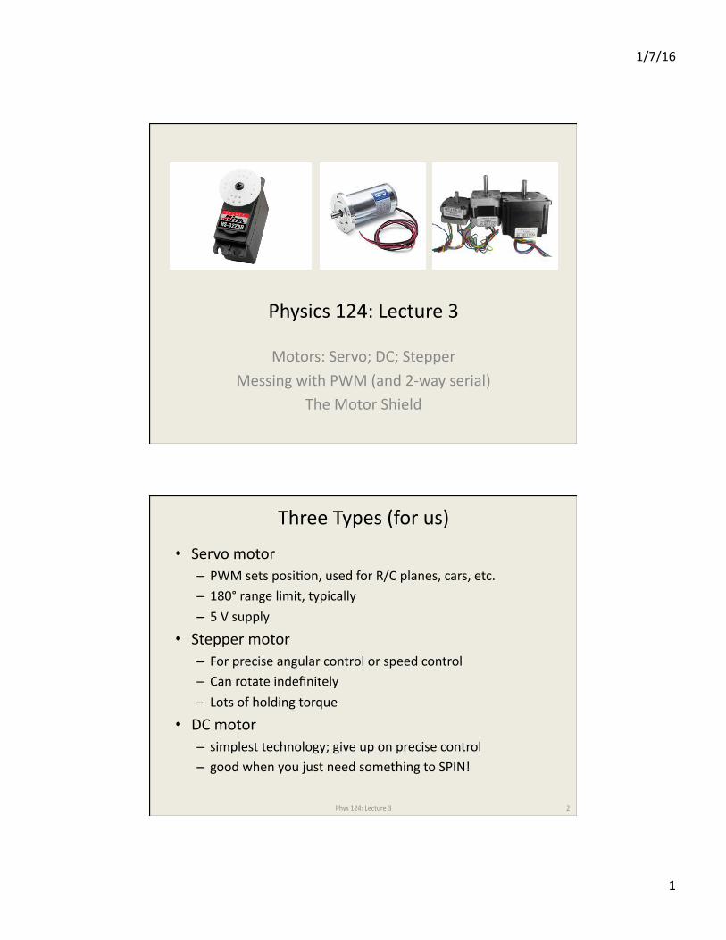
Physics 124: Lecture 3
Motors: Servo; DC; Stepper
Messing with PWM (and 2-‐way serial) The Motor Shield
Three Types (for us)
• Servo motor – PWM sets posiJon, used for R/C planes, cars, etc. – 180° range limit, typically
– 5 V supply • Stepper motor – For precise angular control or speed control – Can rotate indefinitely – Lots of holding torque
• DC motor – simplest technology; give up on precise control – good when you just need something to SPIN!
2 Phys 124: Lecture 3
1/7/16
2
When any old PWM won’t do
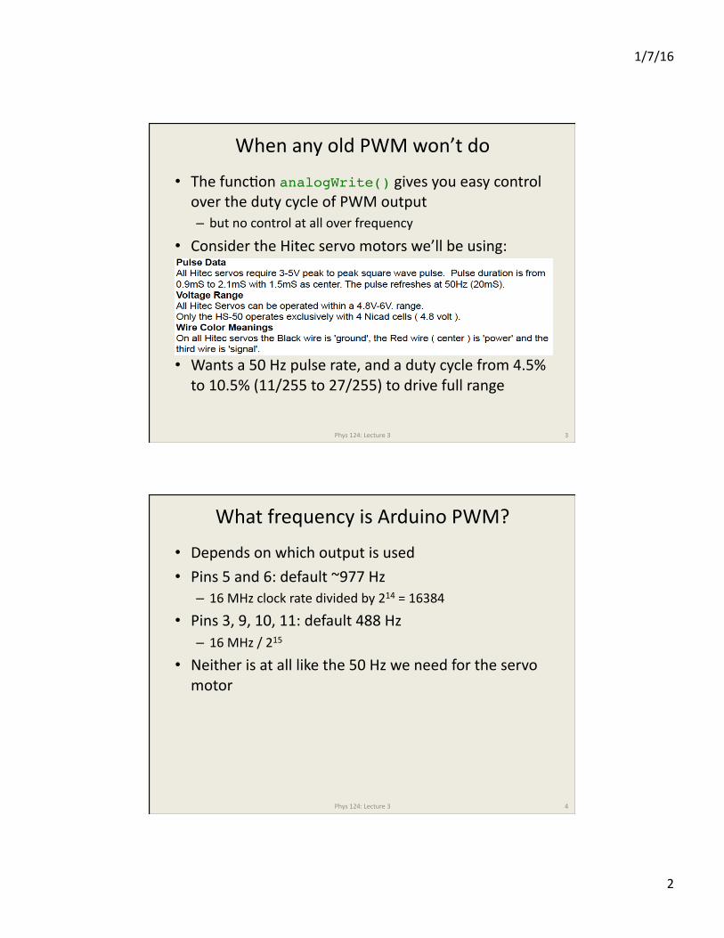
• The funcJon analogWrite() gives you easy control over the duty cycle of PWM output – but no control at all over frequency
• Consider the Hitec servo motors we’ll be using:
• Wants a 50 Hz pulse rate, and a duty cycle from 4.5% to 10.5% (11/255 to 27/255) to drive full range
3 Phys 124: Lecture 3
What frequency is Arduino PWM?
• Depends on which output is used • Pins 5 and 6: default ~977 Hz – 16 MHz clock rate divided by 214 = 16384
• Pins 3, 9, 10, 11: default 488 Hz – 16 MHz / 215
• Neither is at all like the 50 Hz we need for the servo motor
Phys 124: Lecture 3 4
1/7/16
3
What choice do we have?
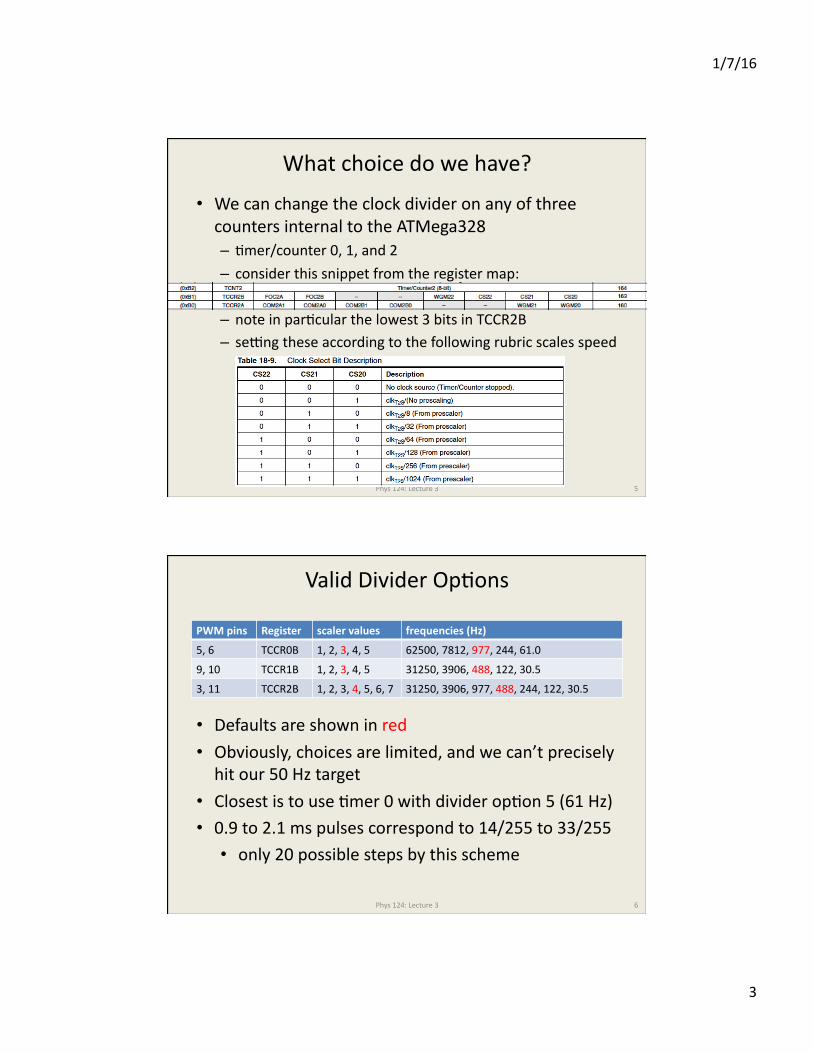
• We can change the clock divider on any of three counters internal to the ATMega328 – Jmer/counter 0, 1, and 2
– consider this snippet from the register map:
– note in parJcular the lowest 3 bits in TCCR2B – sefng these according to the following rubric scales speed
Phys 124: Lecture 3 5
Valid Divider OpJons
PWM pins Register scaler values frequencies (Hz)
5, 6 TCCR0B 1, 2, 3, 4, 5 62500, 7812, 977, 244, 61.0
9, 10 TCCR1B 1, 2, 3, 4, 5 31250, 3906, 488, 122, 30.5
3, 11 TCCR2B 1, 2, 3, 4, 5, 6, 7 31250, 3906, 977, 488, 244, 122, 30.5
Phys 124: Lecture 3 6
• Defaults are shown in red • Obviously, choices are limited, and we can’t precisely hit our 50 Hz target
• Closest is to use Jmer 0 with divider opJon 5 (61 Hz) • 0.9 to 2.1 ms pulses correspond to 14/255 to 33/255 • only 20 possible steps by this scheme
1/7/16
4
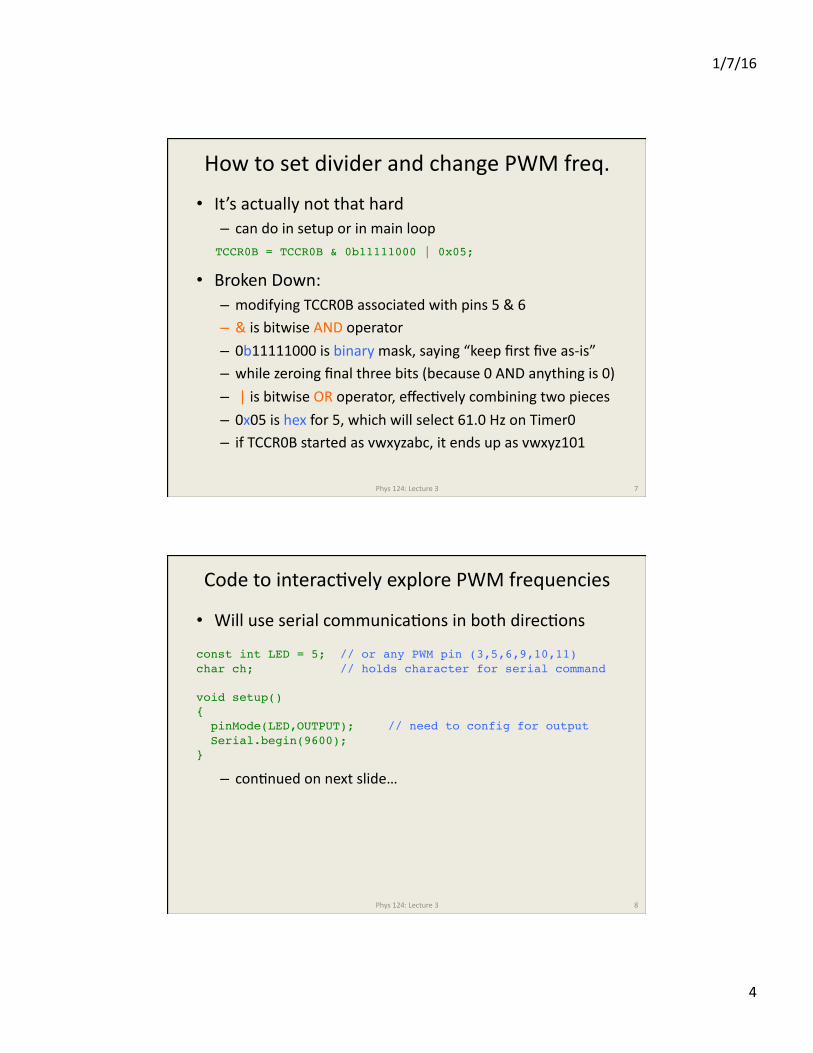
How to set divider and change PWM freq.
• It’s actually not that hard – can do in setup or in main loop
• Broken Down: – modifying TCCR0B associated with pins 5 & 6 – & is bitwise AND operator – 0b11111000 is binary mask, saying “keep first five as-‐is” – while zeroing final three bits (because 0 AND anything is 0) – | is bitwise OR operator, effecJvely combining two pieces
– 0x05 is hex for 5, which will select 61.0 Hz on Timer0 – if TCCR0B started as vwxyzabc, it ends up as vwxyz101
Phys 124: Lecture 3 7
TCCR0B = TCCR0B & 0b11111000 | 0x05;
Code to interacJvely explore PWM frequencies
• Will use serial communicaJons in both direcJons
– conJnued on next slide…
Phys 124: Lecture 3 8
const int LED = 5; // or any PWM pin (3,5,6,9,10,11)char ch; // holds character for serial command
void setup(){ pinMode(LED,OUTPUT); // need to config for output Serial.begin(9600);}
1/7/16
5
…conJnued
Phys 124: Lecture 3 9
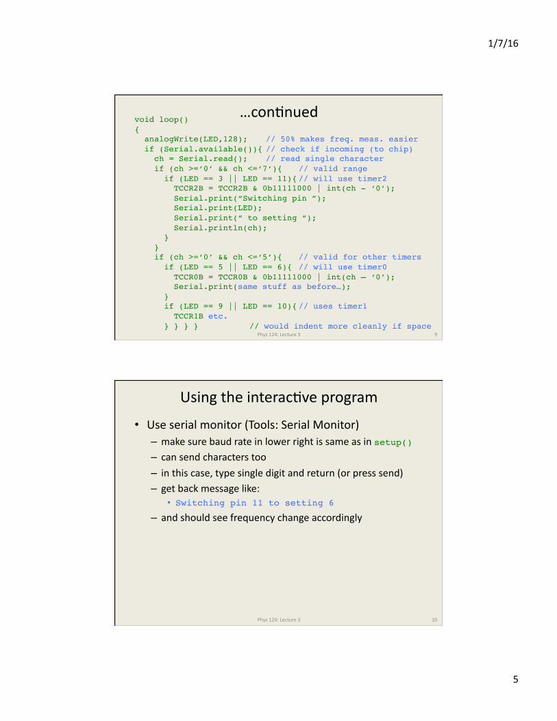
void loop(){ analogWrite(LED,128); // 50% makes freq. meas. easier if (Serial.available()){ // check if incoming (to chip) ch = Serial.read(); // read single character if (ch >=‘0’ && ch <=‘7’){ // valid range if (LED == 3 || LED == 11){ // will use timer2 TCCR2B = TCCR2B & 0b11111000 | int(ch - ‘0’); Serial.print(“Switching pin ”); Serial.print(LED); Serial.print(“ to setting “); Serial.println(ch); } } if (ch >=‘0’ && ch <=‘5’){ // valid for other timers if (LED == 5 || LED == 6){ // will use timer0 TCCR0B = TCCR0B & 0b11111000 | int(ch – ‘0’); Serial.print(same stuff as before…); } if (LED == 9 || LED == 10){ // uses timer1 TCCR1B etc. } } } } // would indent more cleanly if space
Using the interacJve program
• Use serial monitor (Tools: Serial Monitor) – make sure baud rate in lower right is same as in setup()– can send characters too – in this case, type single digit and return (or press send) – get back message like:
• Switching pin 11 to setting 6– and should see frequency change accordingly
Phys 124: Lecture 3 10
1/7/16
6
Rigging a Servo to sort-‐of work
• Original moJvaJon was gefng a 50 Hz servo to work
– conJnued next slide…
Phys 124: Lecture 3 11
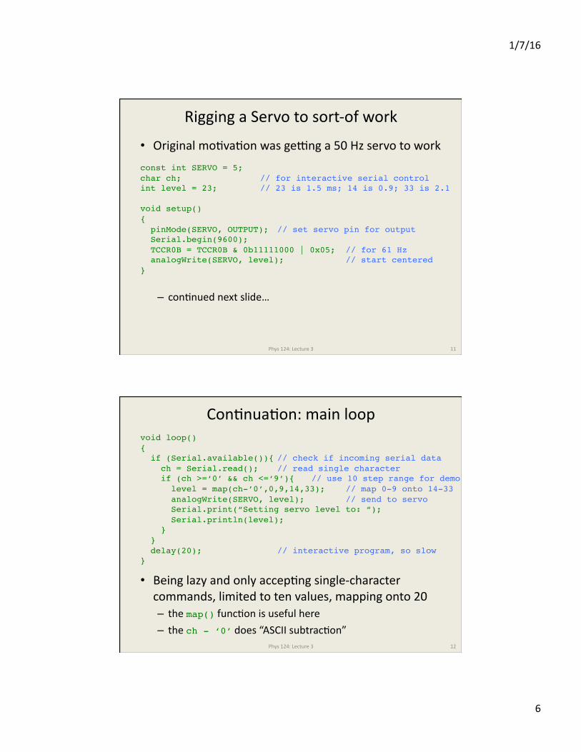
const int SERVO = 5;char ch; // for interactive serial controlint level = 23; // 23 is 1.5 ms; 14 is 0.9; 33 is 2.1
void setup(){ pinMode(SERVO, OUTPUT); // set servo pin for output Serial.begin(9600); TCCR0B = TCCR0B & 0b11111000 | 0x05; // for 61 Hz analogWrite(SERVO, level); // start centered}
ConJnuaJon: main loop
• Being lazy and only accepJng single-‐character commands, limited to ten values, mapping onto 20 – the map() funcJon is useful here – the ch - ‘0’ does “ASCII subtracJon”
Phys 124: Lecture 3 12
void loop(){ if (Serial.available()){ // check if incoming serial data ch = Serial.read(); // read single character if (ch >=‘0’ && ch <=‘9’){ // use 10 step range for demo level = map(ch-’0’,0,9,14,33); // map 0-9 onto 14-33 analogWrite(SERVO, level); // send to servo Serial.print(“Setting servo level to: “); Serial.println(level); } } delay(20); // interactive program, so slow}

1/7/16
7
A beper (and easier!) way
• The previous approach was a poor fit – poor match to frequency, and not much resoluJon
• Arduino has a library specifically for this: Servo.h • Various libraries come with the Arduino distribuJon – in /ApplicaJons/Arduino.app/Contents/Resources/Java/libraries on my Mac
– Handles stepper and servo motors, LCDs, memory storage in either EEPROM (on-‐board) or SD card; several common communicaJon protocols (ethernet—for use with shield, SPI, 2-‐wire, and emulated serial)
– can look at code as much as you want
Phys 124: Lecture 3 13
EEPROM/ Firmata/ SD/ Servo/ Stepper/Ethernet/ LiquidCrystal/ SPI/ SoftwareSerial/ Wire/
Example using Servo library
• Watch how easy: one degree resoluJon
Phys 124: Lecture 3 14
// servo_test . . . . slew servo back and forth thru 180 deg#include <Servo.h>
Servo hitec; // instantiate a servoint deg; // where is servo (in degrees)
void setup(){ hitec.attach(9,620,2280); // servo physically hooked to pin 9 // 620, 2280 are min, max pulse duration in microseconds // default is 544, 2400; here tuned to give 0 deg and 180 deg}void loop(){ for(deg = 0; deg <= 180; deg++){ // visit full range hitec.write(deg); // send servo to deg delay(20); } for(deg = 180; deg >= 0; deg--){ // return trip hitec.write(deg); // send servo to deg delay(20); }}
1/7/16
8
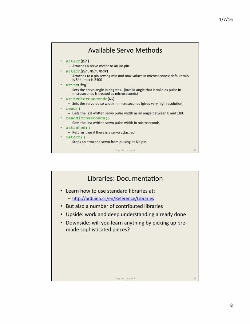
Available Servo Methods • attach(pin)
– Apaches a servo motor to an i/o pin. • attach(pin, min, max)
– Apaches to a pin sefng min and max values in microseconds; default min is 544, max is 2400
• write(deg) – Sets the servo angle in degrees. (invalid angle that is valid as pulse in
microseconds is treated as microseconds) • writeMicroseconds(us)
– Sets the servo pulse width in microseconds (gives very high resoluJon) • read()
– Gets the last wripen servo pulse width as an angle between 0 and 180. • readMicroseconds()
– Gets the last wripen servo pulse width in microseconds • attached()
– Returns true if there is a servo apached. • detach()
– Stops an apached servo from pulsing its i/o pin.
Phys 124: Lecture 3 15
Libraries: DocumentaJon
• Learn how to use standard libraries at: – hpp://arduino.cc/en/Reference/Libraries
• But also a number of contributed libraries • Upside: work and deep understanding already done • Downside: will you learn anything by picking up pre-‐made sophisJcated pieces?
Phys 124: Lecture 3 16
1/7/16
9
DC Motor
• Coil to produce magneJc field, on rotaJng shau
• Permanent magnet or fixed electromagnet • Commutator to switch polarity of rotaJng magnet as it revolves – the “carrot” is always out front (and will also get push from behind if switchover is Jmed right)
Phys 124: Lecture 3 17
DC Torque-‐speed Curve
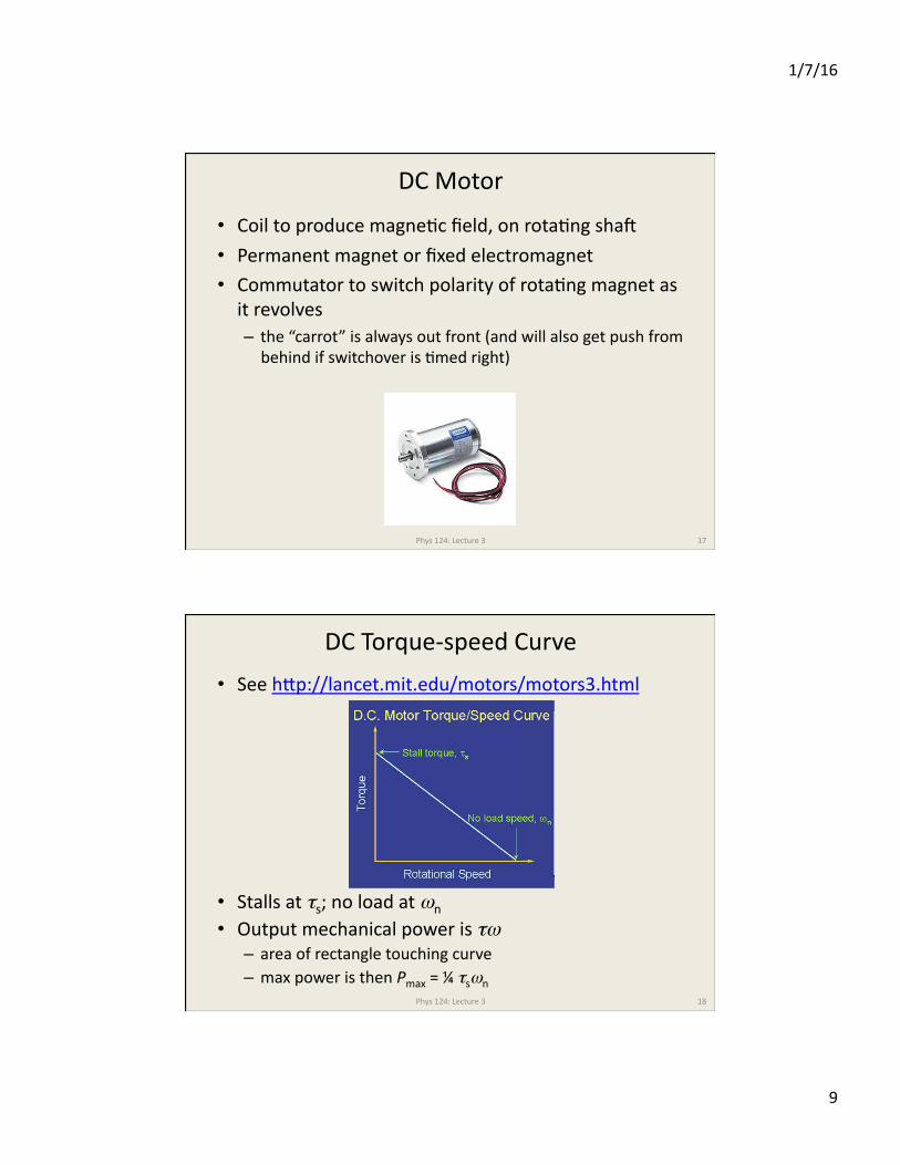
• See hpp://lancet.mit.edu/motors/motors3.html
• Stalls at τs; no load at ωn • Output mechanical power is τω – area of rectangle touching curve – max power is then Pmax = ¼ τsωn
Phys 124: Lecture 3 18
1/7/16
10
Electrical ExpectaJons
• Winding has resistance, R, typically in the 10 Ω range
• If provided a constant voltage, V – winding eats power Pw = V2/R – motor delivers Pm = τω
– current required is Itot = (Pw + Pm)/V • At max power output (Pm = ¼ τsωn) – turns out winding loss is comparable, for ~50% efficiency
Phys 124: Lecture 3 19
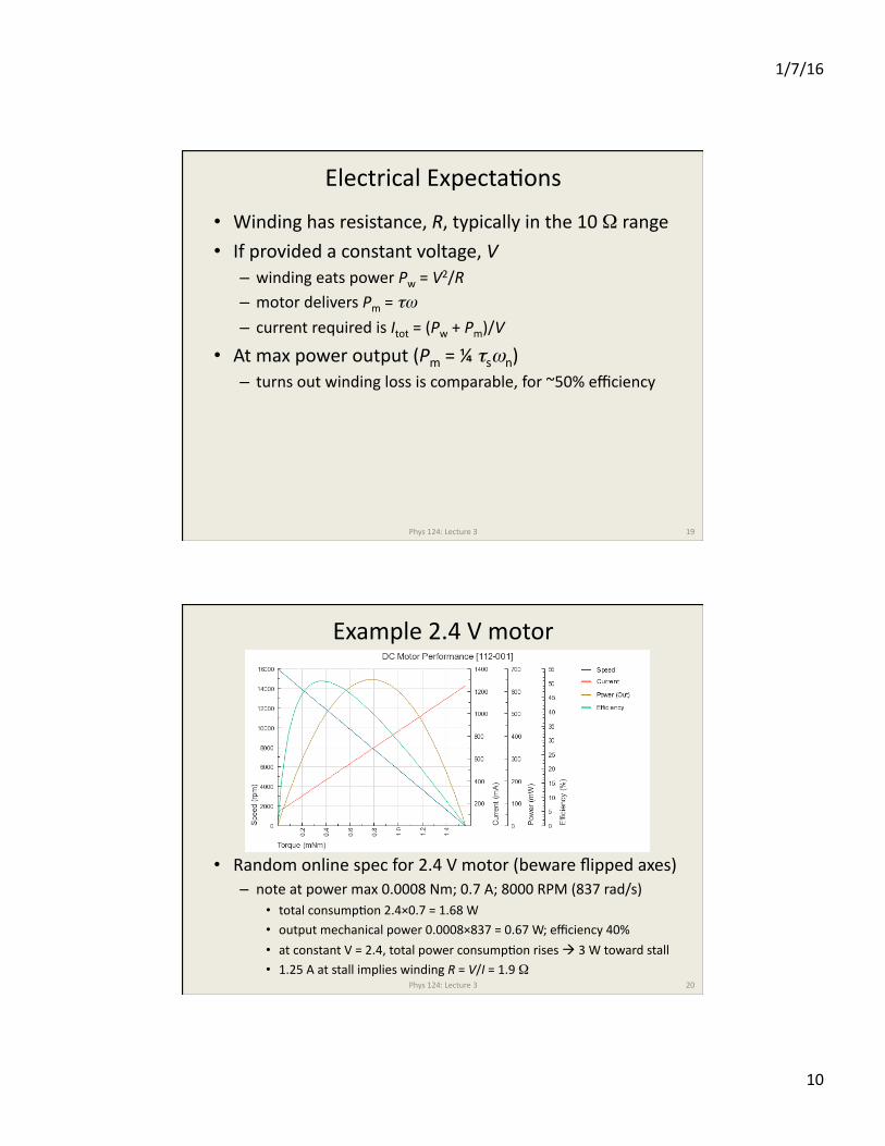
Example 2.4 V motor
• Random online spec for 2.4 V motor (beware flipped axes) – note at power max 0.0008 Nm; 0.7 A; 8000 RPM (837 rad/s)
• total consumpJon 2.4×0.7 = 1.68 W • output mechanical power 0.0008×837 = 0.67 W; efficiency 40%
• at constant V = 2.4, total power consumpJon rises ! 3 W toward stall • 1.25 A at stall implies winding R = V/I = 1.9 Ω
Phys 124: Lecture 3 20
1/7/16
11
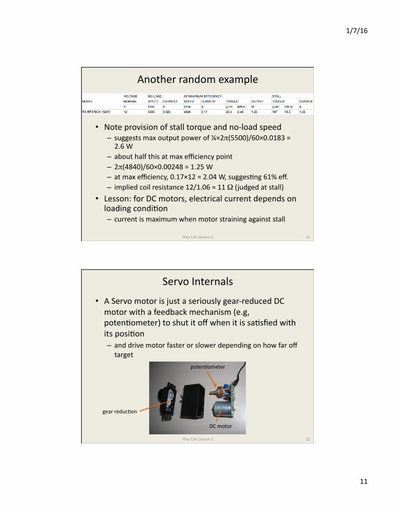
Another random example
• Note provision of stall torque and no-‐load speed – suggests max output power of ¼×2π(5500)/60×0.0183 = 2.6 W
– about half this at max efficiency point – 2π(4840)/60×0.00248 = 1.25 W – at max efficiency, 0.17×12 = 2.04 W, suggesJng 61% eff. – implied coil resistance 12/1.06 ≈ 11 Ω (judged at stall)
• Lesson: for DC motors, electrical current depends on loading condiJon – current is maximum when motor straining against stall
Phys 124: Lecture 3 21
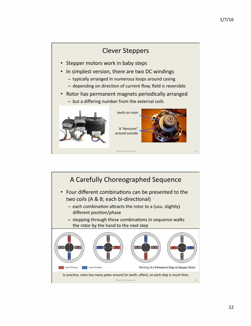
Servo Internals
• A Servo motor is just a seriously gear-‐reduced DC motor with a feedback mechanism (e.g, potenJometer) to shut it off when it is saJsfied with its posiJon – and drive motor faster or slower depending on how far off target
Phys 124: Lecture 3 22
DC motor
potenJometer
gear reducJon
1/7/16
12
Clever Steppers
• Stepper motors work in baby steps
• In simplest version, there are two DC windings – typically arranged in numerous loops around casing – depending on direcJon of current flow, field is reversible
• Rotor has permanent magnets periodically arranged – but a differing number from the external coils
Phys 124: Lecture 3 23
teeth on rotor
8 “dentures” around outside
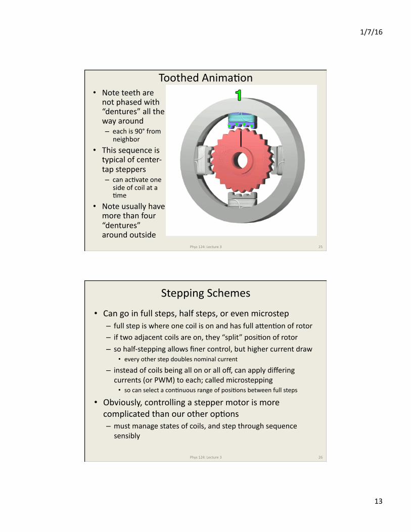
A Carefully Choreographed Sequence
• Four different combinaJons can be presented to the two coils (A & B; each bi-‐direcJonal) – each combinaJon apracts the rotor to a (usu. slightly) different posiJon/phase
– stepping through these combinaJons in sequence walks the rotor by the hand to the next step
Phys 124: Lecture 3 24
In pracJce, rotor has many poles around (in teeth, ouen), so each step is much finer.
1/7/16
13
Toothed AnimaJon • Note teeth are
not phased with “dentures” all the way around – each is 90° from
neighbor
• This sequence is typical of center-‐tap steppers – can acJvate one
side of coil at a Jme
• Note usually have more than four “dentures” around outside
Phys 124: Lecture 3 25
Stepping Schemes
• Can go in full steps, half steps, or even microstep – full step is where one coil is on and has full apenJon of rotor – if two adjacent coils are on, they “split” posiJon of rotor – so half-‐stepping allows finer control, but higher current draw
• every other step doubles nominal current
– instead of coils being all on or all off, can apply differing currents (or PWM) to each; called microstepping • so can select a conJnuous range of posiJons between full steps
• Obviously, controlling a stepper motor is more complicated than our other opJons – must manage states of coils, and step through sequence sensibly
Phys 124: Lecture 3 26
1/7/16
14
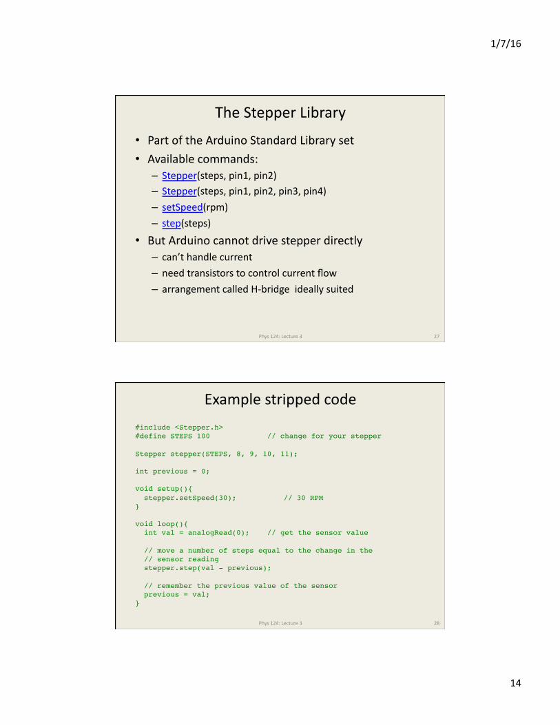
The Stepper Library
• Part of the Arduino Standard Library set • Available commands: – Stepper(steps, pin1, pin2) – Stepper(steps, pin1, pin2, pin3, pin4) – setSpeed(rpm)
– step(steps) • But Arduino cannot drive stepper directly – can’t handle current – need transistors to control current flow – arrangement called H-‐bridge ideally suited
Phys 124: Lecture 3 27
Example stripped code
Phys 124: Lecture 3 28
#include <Stepper.h> #define STEPS 100 // change for your stepper
Stepper stepper(STEPS, 8, 9, 10, 11);
int previous = 0;
void setup(){ stepper.setSpeed(30); // 30 RPM }
void loop(){ int val = analogRead(0); // get the sensor value
// move a number of steps equal to the change in the // sensor reading stepper.step(val - previous);
// remember the previous value of the sensor previous = val; }
1/7/16
15
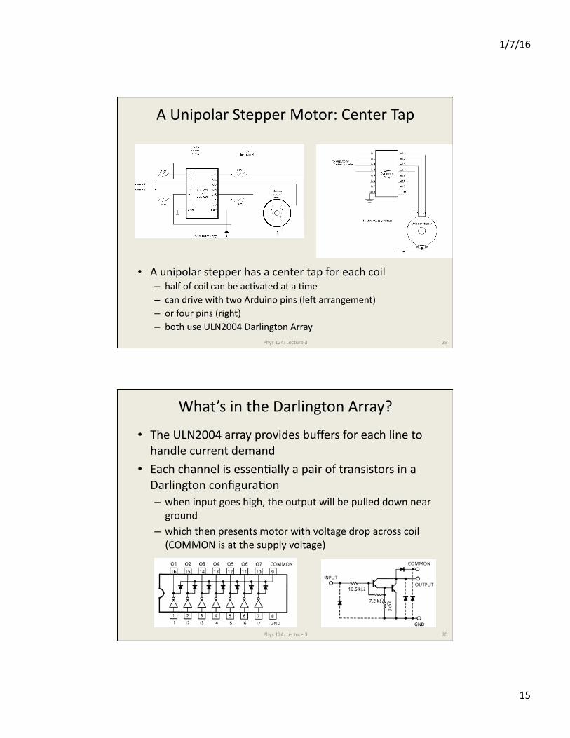
A Unipolar Stepper Motor: Center Tap
• A unipolar stepper has a center tap for each coil – half of coil can be acJvated at a Jme – can drive with two Arduino pins (leu arrangement) – or four pins (right) – both use ULN2004 Darlington Array
Phys 124: Lecture 3 29
What’s in the Darlington Array?
• The ULN2004 array provides buffers for each line to handle current demand
• Each channel is essenJally a pair of transistors in a Darlington configuraJon – when input goes high, the output will be pulled down near ground
– which then presents motor with voltage drop across coil (COMMON is at the supply voltage)
Phys 124: Lecture 3 30
1/7/16
16
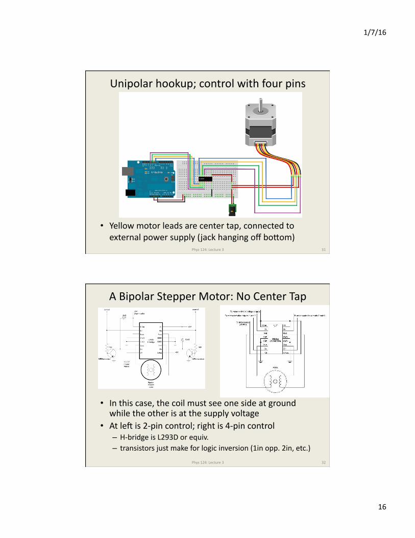
Unipolar hookup; control with four pins
• Yellow motor leads are center tap, connected to external power supply (jack hanging off bopom)
Phys 124: Lecture 3 31
A Bipolar Stepper Motor: No Center Tap
• In this case, the coil must see one side at ground while the other is at the supply voltage
• At leu is 2-‐pin control; right is 4-‐pin control – H-‐bridge is L293D or equiv. – transistors just make for logic inversion (1in opp. 2in, etc.)
Phys 124: Lecture 3 32
1/7/16
17
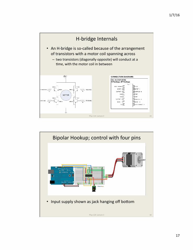
H-‐bridge Internals
• An H-‐bridge is so-‐called because of the arrangement of transistors with a motor coil spanning across – two transistors (diagonally opposite) will conduct at a Jme, with the motor coil in between
Phys 124: Lecture 3 33
Bipolar Hookup; control with four pins
• Input supply shown as jack hanging off bopom
Phys 124: Lecture 3 34
1/7/16
18
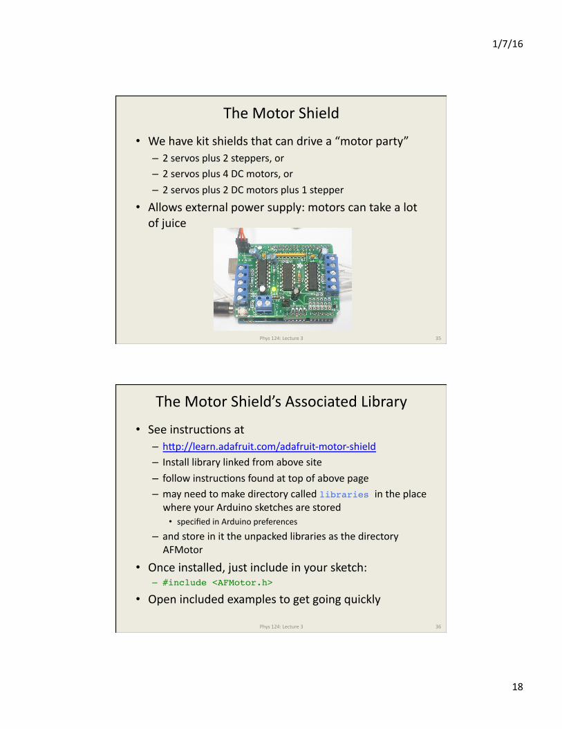
The Motor Shield
• We have kit shields that can drive a “motor party” – 2 servos plus 2 steppers, or – 2 servos plus 4 DC motors, or
– 2 servos plus 2 DC motors plus 1 stepper
• Allows external power supply: motors can take a lot of juice
Phys 124: Lecture 3 35
The Motor Shield’s Associated Library
• See instrucJons at – hpp://learn.adafruit.com/adafruit-‐motor-‐shield – Install library linked from above site
– follow instrucJons found at top of above page – may need to make directory called libraries in the place where your Arduino sketches are stored • specified in Arduino preferences
– and store in it the unpacked libraries as the directory AFMotor
• Once installed, just include in your sketch: – #include <AFMotor.h>
• Open included examples to get going quickly
Phys 124: Lecture 3 36
1/7/16
19
Example Code
• Stepper Commands in AFMotor – #include <AFMotor.h>
• grab library – AF_Stepper my_stepper(# S/R, port);
• my_stepper is arbitrary name you want to call motor
• arguments are steps per revoluJon, which shield port (1 or 2) – my_stepper.setSpeed(30);
• set RPM of motor for large moves (here 30 RPM)
– my_stepper.step(NSTEPS, DIRECTION, STEP_TYPE);• take NSTEPS steps, either FORWARD or BACKWARD• can do SINGLE, DOUBLE, INTERLEAVE, MICROSTEP
– my_stepper.release();• turn off coils for free moJon
Phys 124: Lecture 3 37
Step Types • SINGLE
– one lead at a Jme energized, in sequence 3, 2, 4, 1 • as counted downward on leu port (port 1) on motor shield
– normal step size • DOUBLE
– two leads at a Jme are energized: 1/3, 3/2, 2/4, 4/1 • splits posiJon of previous steps; tug of war
– normal step size, but twice the current, power, torque • INTERLEAVE
– combines both above: 1/3, 3, 3/2, 2, 2/4, 4, 4/1, 1 – steps are half-‐size, alternaJng between single current and
double current (so 50% more power than SINGLE) • MICROSTEP
– uses PWM to smoothly ramp from off to energized – in principle can be used to go anywhere between hard steps
Phys 124: Lecture 3 38
1/7/16
20
DC Motors with motor shield/AFMotor
• DC motors are handled with the following commands – #include <AFMotor.h>
• grab library – AF_DCMotor mymotor(port);
• port is 1, 2, 3, or 4 according to M1, M2, M3, M4 on shield
– mymotor.setSpeed(200);• just a PWM value (0−255) to moderate voltage sent to motor
• not RPM, not load-‐independent, etc. — crude control
– mymotor.run(DIRECTION);• FORWARD, BACKWARD, or RELEASE• depends, of course, on hookup direcJon
Phys 124: Lecture 3 39
Servos on the Shield
• Two Servo hookups are provided on the shield • Really just power, ground, and signal control – signal control is Arduino pins 9 and 10 – use Servo.h standard library – pin 9 ! Servo2 on shield; pin 10 ! Servo1 on shield
Phys 124: Lecture 3 40
1/7/16
21
Announcements
• TA office hours: – Clayton: M 3-‐4; Tu 1-‐2 – Paul: F 2-‐3; M 2-‐3
• Turn in prev. week’s lab by start of next lab period, at 2PM (day dep. on Tue/Wed secJon) – can drop in slot on TA room in back of MHA 3544 anyJme
• Midterm to verify basic understanding of Arduino coding – blank paper, will tell you to make Arduino do some simple task (at the level of first week labs, without complex logic aspects)
Phys 124: Lecture 3 41


